Honeywell Regelsysteme YD190 Platform Track Intrusion Detection System (TIS) User Manual Titel aus Datei Info
Honeywell Regelsysteme GmbH Platform Track Intrusion Detection System (TIS) Titel aus Datei Info
Installation Instructions

PTIDS System Description Honeywell
Page 1 of 24
1 PTIDS DESCRIPTION (LAYOUT / FUNCTION)
The Track Intrusion Detection System (TIS) fulfils the requirements of a Platform Track Intrusion
Detection System (PTIDS) at platform area as well a Tunnel Track Intrusion Detection System
(TTIDS) for automated and non automated subways.
The TIS YD190 consists of the following main components:
- HD193C1/D1, Central Processor Unit (CCU)
- AD191, Transmitter Module
- AD192, Receiver Module
The Across track active radar transponder pairs are mounted along platform approximately every 6
inch to cover the complete surveillance area. One PTIDS module is approximately 8 ft long and
contains 16 equally spaced sensors. The surveillance area has to be extended into the tunnel resp.
free track, which is not accessible for the public, for approx. 6.5 ft to provide early distinction
between train and persons (see Figure 3 and Figure 4), with no gaps in between the PTIDS modules.
Each transponder pair consists of transmitter and receiver, each mounted at one side of the track.
The central processing unit (CCU) activates the transmitter units via RS485 data bus and collects
the results from the receiver units via the data bus. Within each module a microprocessor performs
the sensor data processing and performs the communication via RS485 data bus to the central
processing unit.
As shown in Figure 1, an object entering the surveillance area defined by the antenna beams of
transmitter and receiver units covers part of the cross section which results in detection by the
receiver unit. The assignment of the transmitter units to the corresponding receiver units is
performed by sequential scanning in each of the groups of 16 transmitter/receiver pairs within each
module.
As a train can only enter the PTIDS surveillance area from the tunnel / free track this information
will be used to distinguish an incoming and stopping train from a person or object falling into the
track area from the platform. Once an entering train is detected, the train position relative to the
PTIDS sensors will be computed and position will propagate as the train continues to enter the
platform area.
The distinction between train and an object or a person is derived by the detected length of the
object entering the PTIDS sensors. An object is always assumed when it enters from the platform
area and not via the tunnel / free track area.
1.1 System Concept
The PTIDS provides two detection functions
Platform Track Monitoring (PTM)
PTIDS System Description Honeywell
Page 2 of 24
Tunnel Entry Monitoring (TEM)
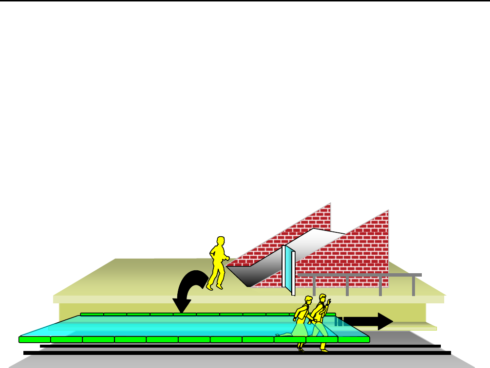
as shown in Figure 1 : PTIDS/TTIDS . Persons falling through the detection plane are detected and
reported as platform track alarm, whereas intrusion into the sensors at the most left or most right
module (TTIDS) sensors is reported as tunnel penetration alarm also. Therefore a platform
installation will require that the right-most and left-most PTIDS module is mounted outside of the
generally accessible platform area behind the platform end doors.
Figure 1 : PTIDS/TTIDS Detection Capability
1.1.1 Measuring method of PTIDS
The HF transponder system in particular fulfils the requirements of an automatic Platform Track
and Tunnel Penetration Monitoring System. Across the track active radar transponder pairs are
mounted in an along track distance of 6 inch along the complete surveillance area. The surveillance
area will be extended into the tunnel resp. free track by at least 6.5 ft (see Figure 2 and Figure 3).
Each transponder pair consists of a transmitter and receiver module. All transmitter modules are
mounted under the platform edge at the rear wall outside the train profile, and all receiver modules
are mounted opposite side at the tunnel wall, also outside of the train profile.
Transmitter and receiver modules need a direct sensing sight line with a defined opening angle free
from installations. The central processing unit (CCU) activates all transmitter modules via RS485
data bus and also collects the results from all receiver modules via the data bus. A number of 16
transmitter resp. receiver modules are mounted into one module housing. Within each module a
redundant microprocessor performs the sensor data processing and performs the communication via
the RS485 data bus to the central processing unit. As shown in Figure 2, an object entering the
surveillance area completely or partly covers the cross section which results in detection by the
PTIDS
TTIDS
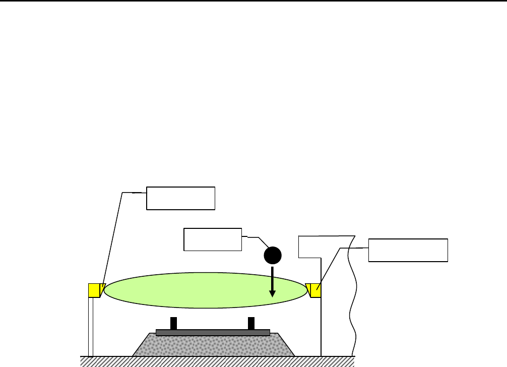
PTIDS System Description Honeywell
Page 3 of 24
receiver unit. The assignment of the individual transmitter units to the corresponding receiver units
is performed by sequential scanning in each of the groups of 16 transmitter / receiver pairs within
each module.
By analyzing the detection sequences, the system can distinguish between trains and persons falling
into the track area. Persons leaving the track area in direction of the tunnel are detected by their
presence in the first / last module. So both requirements for platform track monitoring and tunnel
penetration monitoring are covered.
Figure 2 : Cross section transponder arrangement, basic principle
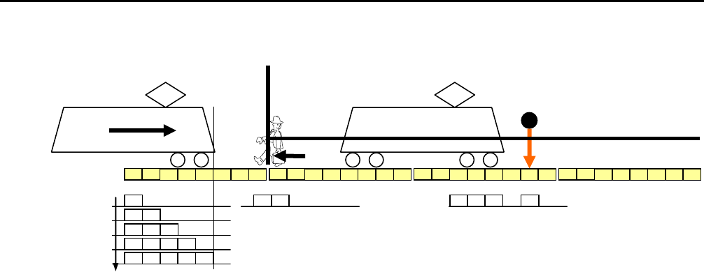
Analysis of the activation sequences is described in Figure 4. A train can only enter the surveillance
area when arriving from the tunnel / free track side. In case an object enters the surveillance area
having been extended into the tunnel, the system waits until an object length of approximately 2,5ft
has been reached. Then, the system assumes an incoming train. If at this time an end of the object is
detected, the object is considered as a person and is reported as alarm. The discrimination
train/person is performed using the length and sequence when entering from either tunnel side or
free track.
A person falling into the track area >16.4 ft in front/back of the moving train is always situated at
least beyond the next module not covered by the train and therefore can clearly be distinguished
from the incoming train. A person falling into the track in front/back of a moving train can be
detected, depending on current position, in a minimal distance between 8.2 ft to 16.4 ft. This
minimum distance is determined by the actual position of the train relative to the PTIDS module
installation grid (8.2 ft). The train entrance is reported from module to the next using module
internal discrete signals.
When a train stopped, a person falling into the track area can be detected down to a minimum
distance of 20 inches from the front/rear side of the train, when trains position can be detected
accurately.
Object
Receiver
Transmitter
PTIDS System Description Honeywell
Page 4 of 24
Remark: Exact train position detection requires sufficient coverage of the PTIDS sensors at the
front and rear side of the train.
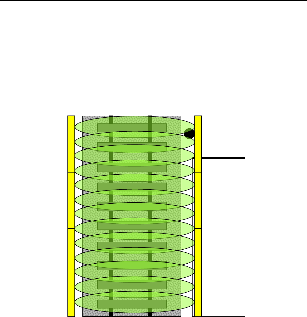
The PTIDS sensors are equally spaced within a grid of approx. 6 inch, which provides a detection
area along the platform track without any sensing gap. Periodical scanning is performed in groups
of 16 sensors each of a module with a repeating rate sufficient for the defined object detection, so
that a continuous surveillance is achieved by a sufficiently high scanning rate (see Figure 3).
Figure 3 : Principle Arrangement of radar transponders along track, basic principle
Platform
PTIDS System Description Honeywell
Page 5 of 24
Figure 4 : Analysis of Detection Sequences, basic principle
A person walking along the track is distinguished from the train by its length and by its intrusion in
the middle of the track. Thus, by extension of the modules into the tunnel, penetration monitoring
can be performed by sequence analysis.
For discrimination between the test object and smaller objects like e.g. beverage cans, the detection
of a person is only reported when two adjacent transponder pairs are covered and the filter within
the software algorithm has triggered. A single covered transponder pair does not generate an alarm.
If one transponder pair fails through a defect, the system reports the defect to the higher level train
control system and continues operation in a degraded mode, which reports an alarm when already
one of the adjacent transponder pairs (near the defect pair) is covered. Also, the minimum distance
for detecting a person in front/back of a train is extended to 26 inch at this dedicated position, until
the repair has been performed, which has to be considered in the safety case´s quantitative analysis.
1.1.2 Details of Sensor Arrangement at Platform Track
The sensor detection plane is arranged as low as reasonable below the platform edge. This reduces
the possibility of alarms caused by objects of a defined size which passengers hold hanging down
before the platform edge.
The modules are mounted in an equidistant grid of 8.2 ft along the complete platform with an
extension of at least one module at the area completely behind the platform ends accessible by the
public (e.g. platform end doors or fenced platform edge).
The maximum distance from transmitter to receiver module is 15 ft. Minimum distance is 11.5 ft. If
the distance is less than minimum distance, modules can be misaligned from the transmitter to the
receiver modules - and vice versa – to some extent.
The system for demonstration has modules to cover a platform length of 656 ft length.
t
Platform
Tunnel

PTIDS System Description Honeywell
Page 6 of 24
1.1.3 PTIDS Hardware Components
The following PTIDS components are required for the trial at a 656ft platform:
80 PTIDS receiver modules for 656ft platform length
80 PTIDS transmitter modules for 656 ft platform length PTIDS length
2 sets of CCU/PTIDS module interface cabling (cables W1, W2, W3)
1 CCU system controller cabinet containing:
- 2 CCU system controllers
- VIDEO camera system consisting of 6 cameras, incl. external video and power cabling
- 1 File Server for permanent CCU event data logging
- 1 Remote Control equipment for remote data readout and status monitoring
- 1 Maintenance PC with LAN connection for feeding the PTIDS status to the RCC
- Complete interface cabling for CCU housing internal infrastructure
PTIDS System Description Honeywell
Page 7 of 24
Fehler! Verweisquelle konnte nicht gefunden werden. / Fehler! Verweisquelle konnte nicht gefunden werden. / Fehler! Verweisquelle konnte nicht gefunden werden. © Honeywell
Regelsysteme GmbH Fehler! Verweisquelle konnte nicht gefunden werden. / Refer to protection notice ISO 16016 Fehler! Verweisquelle konnte nicht gefunden werden.
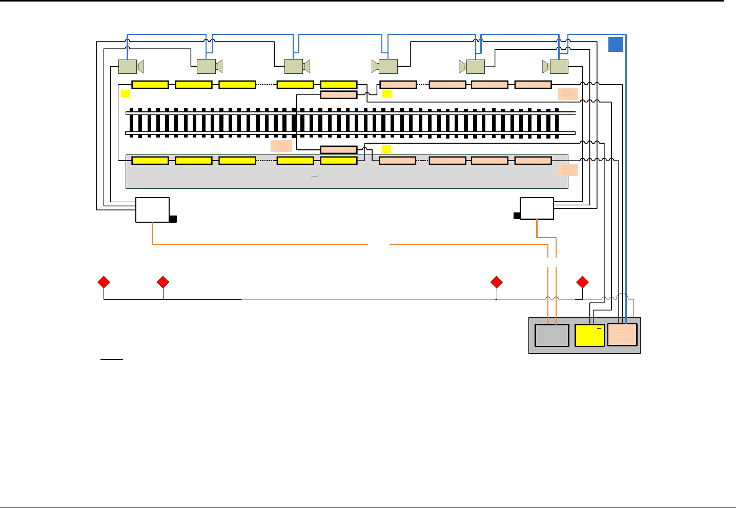
T1 R40T41T40T3T2 R3 R2 R1
R41
R1 T40R41R40R3R2 T3 T2 T1
T41
VC6VC5
VC4VC3VC2
VC1
Platform
LAN
Switch 3
Legend:
VC1 … VC6 Video Camera (for pilot installation only)
T Video Trigger ( 4 wires, for pilot installation only)
R1 … R41 PITDS Receiver Module
T1 … R41 PITDS Transmitter Module
CCU PITDS Control Computer Unit
W1 … W3 PTIDS System Cable
CCU 1 CCU 2
W3
W2
W1
W1²
W3²
W2²
Warning Lamps in Tunnel Area
LAN
Switch 2
FOC
LAN
Switch 1
FOC
230V 230V
T
Warning Lamps in Tunnel Area
Figure 5: PTIDS Block Diagram
PTIDS System Description Honeywell
Page 8 of 24
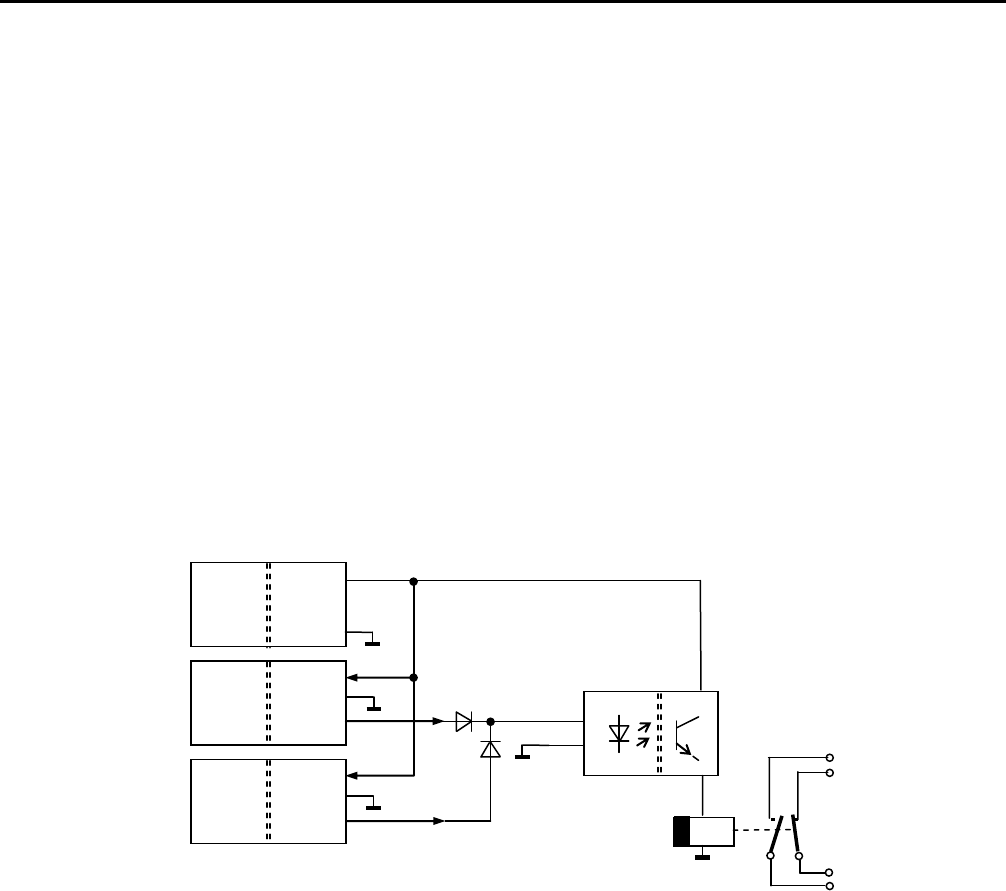
1.1.4 PTIDS Status Indicator
The function of the PTIDS Status Indicator is implemented by discrete outputs of the CCU.
The output is operated with 24V level according to IEC 1131-2. The structure for the individual
functions is described in the following:
Channel A and B of the CCU have a digital output cards with 24V output each, separated in
potential, insulation voltage to the system 500V DC. The supply with 24V auxiliary voltage is
common for all discrete signal functions, so there is no separation of potential between the
partial outputs of both channels and the other discrete functions. The maximum load is 20mA for
the optical output. For that reason an additional relay is added to provide a potential free power
output with adjustable release delay for the PTIDS Status Indicator. The reaction time for
activation by the sensor system has to be less than 500ms. Filtering against fast signal changes is
implemented by software.
Figure 6: PTIDS Status Indicator Output Signal Interface
1.2 Optional Discrete Signals and Functions
The functions bescribed below are not used for the PTIDS trial but may be used for future
expansion of the installation after the trial and can easily be controlled by the CCU programme.
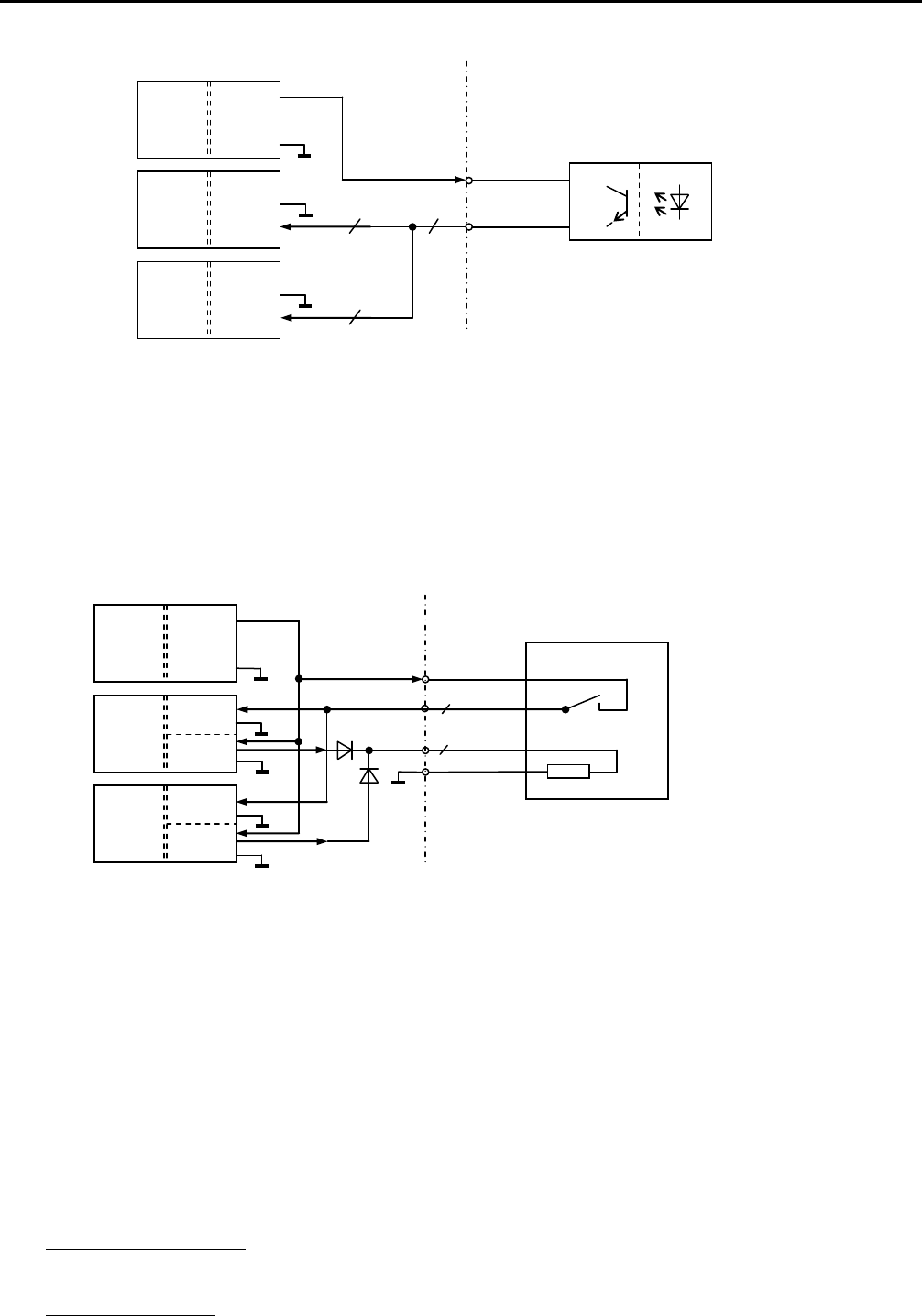
1.2.1 Platform End Door Monitoring
The purpose of this function is to survey doors, which allow access to the tunnel area from the
platform. The doors are equipped with contacts sensing the door open. The contacts themselves
are sensed by an external idle current device (not included), which provides an opto-coupler
output to the CCU. The door status is sensed by the CCU and reported to the Control Panel (not
available at trial setup) system on the LAN interface.
ATC and IXL
CCU
230V
AC
DC
16 DIO
Kanal B
OUT_B
16 DIO
Kanal A
OUT_A
PTIDS System Description Honeywell
Page 9 of 24
1.2.2 Auxiliary Functions
A set of 6 discrete input and output signals is provided for auxiliary purpose, like monitoring a
UPS or other equipment having discrete interfaces. This interface for the auxiliary outputs can
drive up to 100mA.
1.3 Optional LAN Interface
The CCU system controller already is equipped with one LAN interface per CCU channel, which
will transfer PTIDS status signals to the automatic train control system or safety relevant units.
The status data, containing Built-In-Test results and Alarm conditions as well, will be sent at 5s
intervals if no event is occurring. Prompt status transmission will take place when an alarm
condition arises.
1.4 Performance Characteristic
(1) Frequency of scanning: The PTIDS sensors are scanned periodically at a rate of approx. 200
Hz.
(2) Speed of detection: For a PTIDS of 100m length the maximum time measured from
interrupting two transmitter/receiver sensor pairs up to the activation of the discrete alarm is
230V
AC
24V
DC
Door sensing unit
16 DIO
Ch. B
IN_B
16 DIO
Ch. A
IN_A
Ea. 8x
230V
AC
24V
DC
e.g. relay in
equipment rack
16 DIO
Ch. B
OUT_B
16 DIO
Ch. A
OUT_A
IN_A
IN_B
each 6x

PTIDS System Description Honeywell
Page 10 of 24
less than 250 ms for a dual channel system. For single channel operation the maximum
response time will increase to less than 380ms. Above mentioned delay times are worst case
values. Actual values can be in the range of 80ms up to the maximum value as present above
depending on the asynchronous event of the detection of an object in relation to sensor
sampling time.
(3) Failure modes: The PTIDS has extensive Continuous Built-In-Test (CBIT) functionality to
detect failures down to single component level and even to subcomponent level of the
system. Failure status is available via LAN interface and will be logged internal to the CCU
and the PTIDS modules. BIT history can be accessed in Maintenance Mode for analysis. A
short section of last history failures can also be accessed without leaving the active operation,
allowing the operation to inspect the performance without affecting the system operation.
(4) Power consumption of CCU rack: Power consumption of a PTIDS of 656 ft length is less
than 1000W. Additional power of approx. 800W is required for the logging equipment of the
trial setup.
(5) Space requirements for CCU rack: (approx. 7,5’x 4’x 5’, H x W x D) including working
zone
(6) Minimum size of object that could be detected: Objects of approx. 0,32’ diameter size can
be detected, but will not lead to an alarm. Due to sensor arrangement the resolution will be
approx. 0,5 ft. Objects of 1 ft or greater will generate an alarm when falling through the
sensor plane.
(7) Object detection / test object: Persons jumping or falling from the platform edge into the
defined hazard area have to be detected to 100% of all cases (No false negatives!). As a
standard test object for verification of this requirement, the sphere determined in VDV399,
consisting of suitable material, with a diameter of 1 ft shall be used.
(8) Object detection at moving train: Objects falling into the track area at more than 5m distance
between train and object in front of or behind the moving train are detected.
(9) Object detection at stopped train: Objects falling into the track area at a distance greater than
0.50m (19,68”), measured between most protruding part of the train and the object side
nearest to the train, either at front or behind the train will be detected.
(10) Surveillance area: Horizontal plane limited by receiver and transmitter modules using
sensing sight lines equidistant at 0.5 ft, where partial coverage of 40-50% of each single
sensor by an object leads to detection of the object. The vertical arrangement is by the
connecting line between the transmitter and receiver modules, resulting from Figure 2 : Cross
section transponder arrangement, basic principle. By the selected arrangement, manipulations by
passengers and alarms caused by smaller objects laying on the track are avoided. The
detailed vertical arrangement needs to be adapted choosing appropriate mounting locations to
obtain compatibility with the train shape.
(11) Train detection: The incoming train with a maximum speed of 30 mph, stopped and
outgoing train is detected automatically and is not reported as an alarm. The internal

PTIDS System Description Honeywell
Page 11 of 24
algorithm detects the train using the entrance sequence and the continuous coverage of
sensors over train length. Internal status signals announce the moving train from sensor
module to sensor module.
(12) Train state distinction: The train state – if present within the PTIDS sensor area - will
either be detected as “moving” or “still standing”. The transition from “moving” to “still
standing” will be assumed if the train does not move further within 600ms. Movement will
be detected by a comparison of the sensor status taken at 200ms intervals at the front/rear
side of the train. If the sensor status is three times identical, the train is assumed as “still
standing”. For a train which is “still standing” the sensitive area before/behind the train is
reduced to 1.6’ distance to the coupler device, which must be visible to the sensors in order
to fulfil the 1.6’ detection range as specified in VDV-399.
(13) Tunnel penetration monitoring: Persons leaving the track area in direction to the tunnel
will be detected and will cause an alarm. Since for the trial there is only one PTIDS Status
Indicator, the tunnel penetration cannot be distinguished from platform penetration, but data
logging will separate the events.
(14) Alarm output: The system is designed in such a way that the sensors give an alarm output
when the test object is falling through the detection plane from a maximum height of 1m
above the platform surface level.
(15) Control Display: The system status and the alarm location will be indicated at the control
panel, which is connected to the CCU LAN output. The control panel will be used for alarm
notification only and therefore will not require SIL approval.
(16) Redundancy: The PTIDS system is a fully redundant 2-channel system, which allows 1
channel to fail, still operating in degraded mode. Degradation means that the maximum alarm
response time will increase from approx. 200ms to 310ms. In case of a single sensor failure
the response time will still be in the range of 200ms, but a small object falling through the
sensor plain next to a defect sensor will generate an alarm. So the PTIDS system can tolerate
any single failure without affecting the train operation, except for a short time during
transition from one channel to the other. The redundant operation allows further operation of
the system and the maintenance personell may schedule a maintenance action at a later time.
In case of a second failure of same nature the system will fall to its safe state.
1.5 System Limits of the Sensor System
(1) Object detection: The radar transponder may detect objects, besides persons, of similar size,
when the material is not transparent for the microwave frequency used (24GHz). For object
detection, two adjacent radar transponders need to be covered. Smaller objects covering only
one sensor will not lead to an alarm when they are falling through the detection area. If one
transponder fails due to a defect, single sensor coverage of the neighbour sensor by an object
leads to an alarm. In this operational mode, also smaller objects locally will lead to an alarm.

PTIDS System Description Honeywell
Page 12 of 24
(2) Atmospherical effects like fog, rain and snow, smoke in the limits specified in section 7.7.1
do not impact the safe and reliable function. The measuring method principally does not react
to disturbing light. According to standard literature, the atmospherical attenuation for 24
GHz is less than 1 dB for the necessary distance of 16.4 ft. Experience from other projects
shows that dust from train braking collected over a longer period of time causing a certain
deposit thickness does not impact transmission at 24GHz.
(3) Train detection: The front / rear of the train is understood as the most extending parts, e.g. of
the coupling device (according to VDV399 3.1). In case the PTIDS can mechanically not be
mounted such that the line of sight between transmitter and receiver modules will cross the
coupling device, the detection zone in front/ at rear train position will be increased by the
distance of projecting coupler to car body accordingly.
(4) Train detection: For definite recognition of the train, especially it´s front/rear position, it is
necessary that the train completely covers the sensors when entering the surveillance area.
For special vehicles, e.g. work trains, organisational or technical measures at the vehicle are
necessary by the Customer, if necessary.
(5) Object detection (still standing train): If an object falls into the 20 inch detection zone in
front/at rear of the stopped train and then moves away from the train, this is considered as an
outgoing train. Only after reaching a distance of one complete PTIDS module for a stopped
train, resp. >16,4ft for a moving train, the object can be detected
(6) Object detection (moving train): In case an object falling directly through the sensor area
within the 8.2ft to 16,4ft area at front/rear of a moving train, then the object is considered as
a part of the train, which leads to dislocation of the space not to be surveyed to the location
of the object. Thus, a second falling object might not be detected when it is in the
surveillance gap now having been dislocated
1.6 Methodology / Approach
(1) Manual calibration: The PTIDS can be calibrated either remotely (for the trial only) or by
operator intervention onsite without requiring access to the track. Calibration must not be
performed if an object or a train is in the detection area, which can be visually inspected at
the Maintenance PC.
(2) Installation process: Installation will be performed by operator personnel and will be
supervised by HON member for proper mounting levels. The PTIDS components will be
delivered from HON Maintal to operator facilities and will be stored there prior installation.
(3) Spare parts: A set of spare parts will be delivered to local Honeywell office.
(4) Test data analysis: Once the PTIDS is commissioned the data logging equipment for this
trial will record the
- CCU event logs send out once per night
- CCU detailed event logs, at the time the event occurs

PTIDS System Description Honeywell
Page 13 of 24
- Video data from up to six video cameras, with a defined pre- and post-trigger
capability around the event time
Log data will be available in different formats:
- Video data, can be viewed and replayed using a standard PC and video viewer
- CCU error log, history event log and event log data use a binary format which has to
be converted to a text file using the Maintenance PC (for online-conversion onsite)
or any other PC (for off-line conversion) containing a small conversion programme,
which can be provided by HON
1.7 Details of sensor arrangement at platform
The sensor detection plane is arranged as low as reasonable possible below the platform edge to
avoid false alarms caused by objects, which passengers hold hanging down. See also Figure 7.
The sensor modules are mounted in a 2.5m (8.2ft) equidistant line along the platform with an
extension of at least one 2.0m (6.5ft) sensor module at the area not accessible to the public to
allow the required distinction between incoming train and objects to be detected. This also
provides the function of Tunnel Entry Monitoring.
The maximum distance from transmitting to receiving sensor module is 4.5 m (14.7ft).
Figure 7 indicates possible mounting positions for the PTIDS sensor modules. The direct line of
sight between transmitter and receiver modules has to cross the center point of the train coupler.
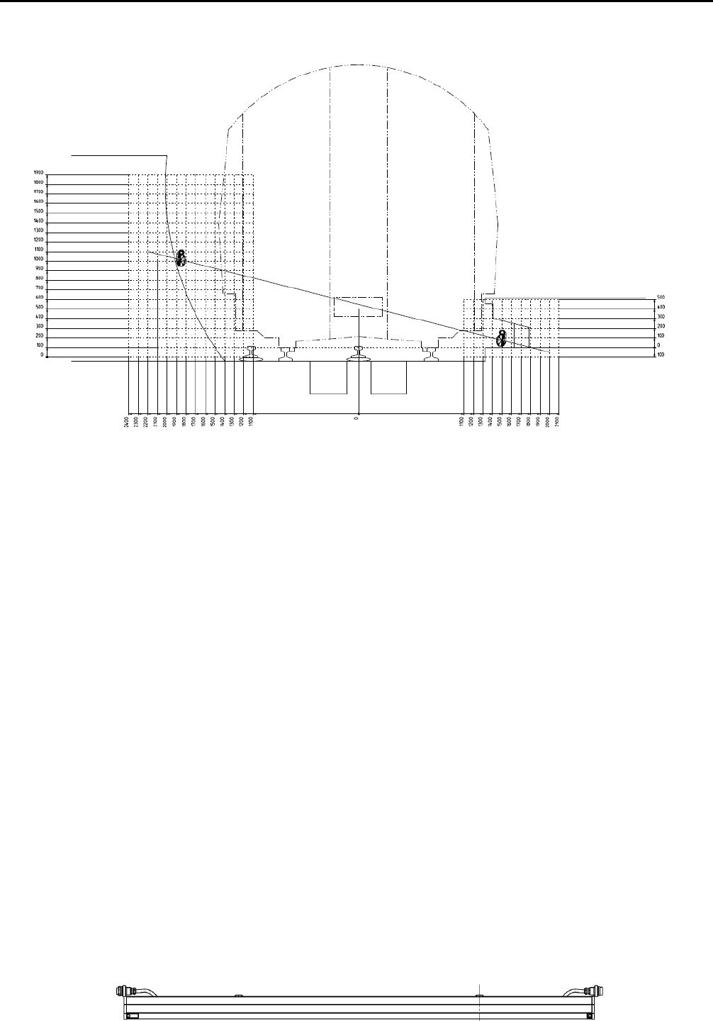
PTIDS System Description Honeywell
Page 14 of 24
Figure 7: Example for PTIDS Module Installation Position
1.8 Mechanical installation
Figure 8: Mounting of module shows the mechanics of the modules. Construction is provided to
be of an aluminium extruded profile with a microwave transparent cover. The printed circuit
boards are inserted in slots. A flexible harness provides the electrical connections from the data
and power supply bus to the next module.
The module is mounted to the tunnel wall using adjustable brackets at 2 fixing points per
module. Outside tunnels or between tracks a mounting structure will be provided.
Dimensions of the modules: max. 0.32’ x 0.44’ x 8.0’ (height x width x length), including
installation space. Mass: Equal or less than 25lbs per module.
Temperature extension and track curve with a curve radius >2130ft is considered by appropriate
mounting system and installation procedures. A smaller track radius requires correction of the
PTIDS module installation position at the inner radius.
Single modules are exchangeable without additional electrical address coding.
Front View:
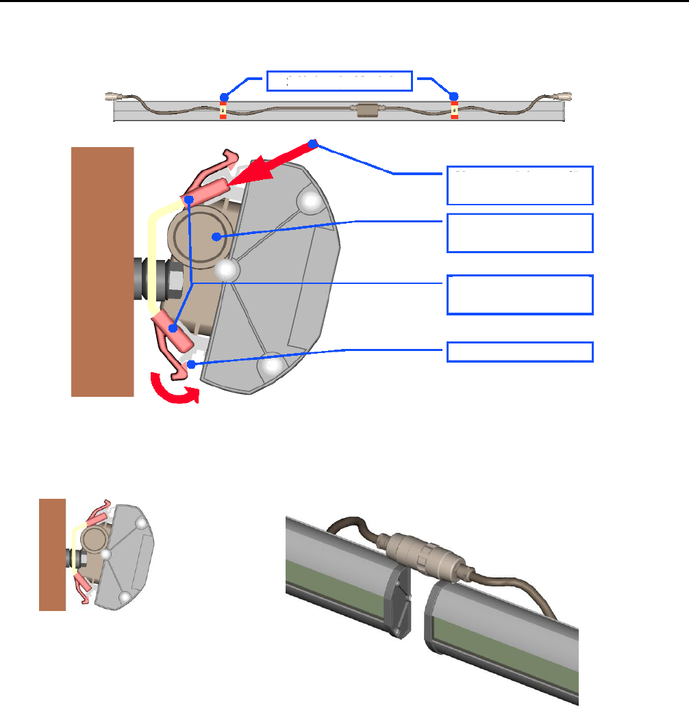
PTIDS System Description Honeywell
Page 15 of 24
Back / Side View:
Figure 8: Mounting of module
Figure 9: Mechanical Construction of PTIDS Modules
The installation of the modules at the platform track area is dependent on the available space and
the construction of the station. Since the platform length actually exceeds the maximum length of
the PTIDS system as it is designed for, two PTIDS system will be installed in series, overlapping
with one complete module in the middle of the track. Overlapping is required since the very first
and the very last modules of a PTIDS system serve as detection modules for train or object.
Since an incoming train must not generate an alarm, the very first fife sensors of the most
left/right module is used for object type detection and will not generate an alarm. In order to
prevent a detection gap between two portions of the PTIDS, the last and the first modules have to
2 fixtures / module
direction for inserting
module on fixture
cable and connectors not
shown
snap in mount and
insulation
snap in, lower part

PTIDS System Description Honeywell
Page 16 of 24
overlap. See also figure Figure 5. To prevent interference of the two overlapping modules, the
receiver and transmitter modules of the second (rightmost) system will be mounted at the
opposite site as the modules for the leftmost system. Thus for the rightmost PTIDS the
transmitter modules will be installed at the wall side and the receiver modules will be installed
underneath the platform.
1.9 Fail Safety
(1) The system is designed as a single channel structure to fulfil requirements of Safety Integrity
Level (SIL) 1.
The calculated hazardous failure rate is <10-6/h saying we achieve SIL 2 hazard rates
according to EN50129. It is proven within the safety case using fault tree analysis and
FMEA. The quantitative result will be obtained by weighting the fault tree with results from
the failure rate calculation. The redundancy provided is used to optimize the availability.
The following measures are used to detect and report faults:
(2) Self test of processors/controllers. RAM/ROM/processor self tests as far as possible within
the applied processor technology.
(3) Monitoring of power supplies
(4) Measures against overtemperature: The PTIDS modules are designed for a temperature range
of -27.4°F to +140°F. This ensures sufficient protection against unknown faulty functions by
exceeding the specified operational temperature range. The CCU is equipped with
overtemperature detection, issuing at least a maintenance request.
(5) Monitoring of transponder pairs: Particularly by single triggering of each transponder pair
both a “go” as well as “no go” test of the complete function is possible (signal change at train
passage has to take place (except head stations, where scheduled manual maintenance is
required at a one year interval.
(6) Watchdog-timer / timeouts for data bus transmissions
(7) Check of system function with reference to completeness and sequence of the messages from
the PTIDS receiver modules by the CCU and the LAN messages from the CCU by the ATC.
(8) Check of system function by incoming train. According to the result of the calculations for
fault detection, the passage of at least one train at defined intervals is required (30 days).
(9) Self test by incoming train after start-up, e.g. after repair.
1.10 Failure modes / Redundancy
The PTIDS uses a dual channel structure within the CCU system controller and the PTIDS
receiver/transmitter modules in order to increase the availablility of the system. Channel A is the
so called Master channel which is the primary channel controlling the complete PTIDS from

PTIDS System Description Honeywell
Page 17 of 24
start up. Channel B is the secondary channel which operates parallel to the Master channel and
provides the required redundancy to improve the availability of the system. Even if only the
CCU Master channel is requesting sensor data, the PTIDS modules will respond on both busses
allowing data comparison within the CCU before setting an alarm. Since both PTIDS channels
will send status data from different PTIDS modules at the same time, any temporary external
disturbance on the transmission line may only affect one channel. The CCU will check data
consistency evaluating the Cyclic Redundancy Checksum (CRC) of the data protocol. Once a
wrong CRC checksum is detected on one bus, the status of the affected module will be ignored
and the information from the other channel will be evaluated for consistency and correctness.
If the CCU Master channel is unable to control the PTIDS, channel B will immediately take over
and from now on this bus will be the master. Returning control to channel A is prohibited once
channel B has taken over. The PTIDS will survive a single CCU failure without losing the
performance of the system.
The sensors within the PTIDS modules are approx. 0.5’ apart from each other. This
configuration will tolerate a single sensor failure with local degradation of the performance at
that sensor location. The rest of the system will not be affected by this single sensor failure.
Impact of other RF devices using 24 GHz
During tender preparation HON engineering made some investigation to find out if other RF
components broadcasting in the 24 GHz frequency band may impact the functionality or
performance of the system. Considerations made with devices transmitting less than 100 mWatts
EIRP.
We came to the conclusion that due to the antenna diagram of the used receiver the device must
either transmit directly into the main lobe from 3 to 4 meters (10ft to 13ft) or from about 1.2 m
(3.9ft) into the minor lobes. Commercially available Doppler Speed and Distance Radars
normally direct their beam to the ground area between the tracks. An impact seems to be
unlikely.
In addition we used a Honeywell Doppler Radar Speed Sensor for trains in an outdoor test setup
to get confirmation for the above thoughts. In no case we could generate a false alarm nor an
unsafe situation.
1.11 Software
The software for the PTIDS module controllers as well as in the central controller unit are
designed according to the requirements of EN50128, SIL1. The structured performance of the
development activities using the V-model leads to a traceable, modularized development and
avoidance of systematic faults. For maintenance purposes, a log memory will be provided for
operational processes and fault messages.
The measures against random and systematic faults are at least:
Programme sequence check / safety key functions

PTIDS System Description Honeywell
Page 18 of 24
Message counter for serial transmissions
CRC-checksum for serial messages (according to EN 50159-1)
Self test function to check the hardware (transponder function, overtemperature,
RAM/ROM-test, timeouts)
Use of compiler proven in field experience
Use of subset of programming languages (ANSI-C for controller, Delphi for central
processing unit) and programming rules. Assembler will only be used for time critical tasks.
1.12 Maintenance PC
An off-the shelf laptop personal computer uses two RS232 interfaces to communicate with the
two channels of the embedded computers within the CCU and provides the following
maintenance and supervision functions by means of the maintenance software:
- Check of the system status
- Readout and display of fault memories and log files
- Initiation of functional tests
- Identification of defect units / modules down to the smallest exchangeable units
- Readout and modification of configuration parameters
- Installation of SW
The maintenance PC uses a standard operating system (Win 2000, XP or compatible) and two
RS232 interfaces.
Configuration data are stored on a PC Card flash memory.
Checks, functional tests and other operational actions by the maintenance PC shall be recorded in
the CCU log memory.
To avoid unwanted influence on the safe operation of the PPE, the maintenance PC has to
comply with EN60950.
To avoid unauthorized access to the PPE, the following password levels are used to enable
different access levels:
- No Password: Only display of the system status outputs, only read out of log/fault data,
only reading access without influence on system operation.
- Password first level: Operations like functional tests or switch-off, which could influence
system operation.
- Password second level: Modification of user configurable parameters, installation of SW,
and other safety related actions.

PTIDS System Description Honeywell
Page 19 of 24
2 TECHNICAL DATA / REQUIREMENT / PERFORMANCE
CHARACTERISTIC
2.1 Power Supply
The system shall be supplied by 230V / 50Hz (2 separate phases)
Power consumption:
≤580 Watts (for TIS system with 100m of sensor modules)
≤800 Watts (for CCTV system, file server, Maintenance-PC, remote control
equipment
The main power supplied to the GPC-housing shall have short circuit and overload protection of
16A for each phase.
2.2 Interface Data
2.2.1 Electrical Interface
(1) 2x 230V connector for power supplies
(2) Connector for discrete input/output signals and 2
(3) Cable connections from central processing unit to modules:
2 twisted shielded pairs, diameter 2.0mm,
2 twisted triples (Z=120Ω), diameter 1.0mm, additional full screen,
Each one cable to transmitter and receiver modules.
Further details are documented in the cable specification.
Cross connection at the end of module row.
Maximum length GPC to end of module row: 100m
(4) LAN 10Base RJ45 connector at each GPC channel
(5) 2xRS232 maintenance PC connection at GPC
2.2.2 Mechanical Interface
(1) See also chapter 2.3
(2) Minimum track curve radius: 300m (984ft) when module grid is 2,5m (8.2ft).
An 80m (262ft) radius can be achieved, installing the modules at the outer radius at
2,57m (8.4ft) and the modules at the inner radius adjacent to each other, with no gap
between.

PTIDS System Description Honeywell
Page 20 of 24
Caution: This will decrease the detection probability for a 30cm (11.8inch) test object at
the end of each module, but when a person is falling through that sensor area it will still
be detected.
(3) Maximum train speed: 55km/h (34mph) for a 100m (328ft) system, when entering from
tunnel/free track;
(4) Modules are replaceable without dismounting of neighbor modules
(5) Replaced modules will detect the location within the module row automatically, so no
address switches have to be set.
(6) The sensor modules include the mounting bracket. Building specific accessories like
mounting screws, wall mounting bolts and dowels are not covered, but for the trial test
these material will be provided by a subcontractor
(7) The sensor modules are mounted such that the train profile is not compromised, sufficient
installation space is a prerequisite.
(8) The mounting space for the sensor modules including tool access space is approximately
100mm (3.9inch) depth, 280mm (11inch) height.
2.3 Dimensions
(1) Modules: approx.80 x 100 x 2470 mm³ (3,15 x 3.9 x 97.2) inch³, (H x W x L)
(2) Mass: approx. 11,5 kg (25.4lbs) per module
(3) Cabinet: 19-inch rack – (600 x 800 x 2000)mm³ (23.6 x 31.5 x 78,8) inch³, (D,W,H)
(4) GPC: 19-inch, 7 units height
2.4 Moisture / Dust Sealing
(1) IP 20 - for Central processing unit (GPC) to be mounted in 19-inch rack
(2) IP 55 - for GPC 19 inch rack
(3) IP 65 - for TIS modules (at track platform)
2.5 Surface treatment
(1) All surfaces are corrosion resistant
2.6 Environmental conditions
2.6.1 Climatic Conditions
Climatic conditions for GPC (mounted in 19” rack):
- EN60721-3-3, class 3K5
- Temperature range -5°C to +55°C
Climatic conditions for sensor modules:

PTIDS System Description Honeywell
Page 21 of 24
- EN60721-3-4, class 4K2
- Temperature range –40°C to +50°C
2.6.2 Vibration / Shock
Requirements for GPC:
- EN60721-3-3, class 3M2
Requirements for sensor modules:
- EN60721-3-4, class 4M4
2.7 Special Data
2.7.1 Electromagnetic Compatibility (EMC)
The TIS YD190 is compliant to the requirements of
- EN 50081-2 (March 1994)
- DIN EN 61000-6-2 (March 2000),
o remark: This is the replacement for EN 50082-2 (Feb. 1996)
- DIN EN 50121-4 (May 2001)
2.7.2 Grounding and Shielding
Shielding:
- The cables from Central Processing Unit (GPC) to the modules and to the train control
system have to be shielded.
- The 19“-rack housing will be shielded
Grounding:
- The modules have provisions for grounding connections.
2.7.3 Reliablility (Mean Time To Fail – MTTF)
(1) The failure rate is calculated according to MIL-HDBK-217F, Notice 2, for a mean
temperature of 25°C. The environmental stress will be classified as „Ground Fixed“ for
the modules and „Ground Benign“ for the central processing unit.

PTIDS System Description Honeywell
Page 22 of 24
(2) The following detailed reliability data is provided for information:
Without redundancy:
MTBF of 1 transmitter module (1 channel): 216 857 h
MTBF of 1 receiver module (1 channel): 222 768 h
MTBF of GPC (1 channel) 34 727 h
The experienced MTBF from field data (accumulated 34 748 000 h of unit
operation for sensor modules, 476 000 h of unit operation hours for GPC):
MTBF of 1 transmitter/receiver module (1 channel): ca. 1 080 900 h
MTBF of GPC (1 channel) ca. 317 600 h
(3) By using redundant channels through the system, the following MTTF is achieved under
the assumption of the MTTR stated (including response time), V = availability, MIL-
HDBK-217F calculation:
Estimated figures for 140m system (135m platform):
MTTR = 12h MTTF = 64315h V = 0.99981
MTTR = 1h MTTF = 97387h V = 0.99999
2.7.4 Maintainability
(1) The TIS does not need any scheduled maintenance for a 1-year period.
(2) The maintenance PC is used besides the LAN connection to identify the faulty assembly
which is field replaceable. Some defects, e.g. power supply defects, have to be identified
using status lamps or test sockets for standard test equipment.
(3) Plug in modules of the GPC are identified with type numbers. Wrong insertion is prevented
by coded connectors or frame space. GPC processor units are SW coded for channel A resp.
B.
(4) Scheduled maintenance by functional testing is required due to safety case calculations every
2 years. Every 10 years, scheduled maintenance shall take care of the ventilation fans of the
GPC and memory backup.
(5) The mean time to repair, excluding travel/reaction time, will be less than 1h under the
assumption of qualified and trained maintenance personnel.

PTIDS System Description Honeywell
Page 23 of 24
2.7.5 Flammability / Corrosive and Acid Gas Emission
All used materials shall be flame resistant, halogen-free, non-combustible or self-extinguishing.
Short, equipment-internal cables shall be in accordance with class A of DIN VDE 0472, part
804, and IEC 332.
External cables shall be in accordance with the following requirements:
- Halogen-free: Materials shall be non-corrosive according to DIN VDE 0472, part 813,
and IEC 754-1, halogen contents according to IEC754-1 < 0,5%
- Flame resistance and self- extinguishing: According to DIN VDE 0472, part 804B and
IEC 332.1 and DIN VDE 0472, part 804C and IEC 332-3C.
- Smoke emissions: Low smoke emissions according to DIN VDE 0472, part 816 and IEC
1034.
2.8 Other Approvals
2.8.1 Safety of persons in electromagnetic fields
The system YD190 complies to
DIN 57848 Part 2: Safety in electromagnetic fields, protection of persons in the frequency range
30kHz to 300GHz (July 84)
to ensure the safety of persons.
2.8.2 Radio licensing
The system YD190 complies to
47 CFR Part 15 Title 47 of the Code of Federal Regulations; Chapter I;
Part 15 - Radio frequency devices
RSS - 210 Issue 8 Spectrum Management and Telecommunications Radio Standards
Specification;
Licence-exempt Radio Apparatus (All Frequency Bands): Category I Equipment
The effective isotropic radiated power (EIRP) of a transmitter module is max. 20dBm.
The frequency range used for the TIS transmitter modules is 24,125GHz ± 50MHz.

PTIDS System Description Honeywell
Page 24 of 24
NOTE for YD190:
Changes or modifications made to this equipment not expressly approved by Honeywell Regelsysteme
GmbH may void the FCC authorization to operate this equipment.
NOTE for Class A device - HD193, AD192 only
This equipment has been tested and found to comply with the limits for a Class A digital device, pursuant
to Part 15 of the FCC Rules. These limits are designed to provide reasonable protection against harmful
interference when the equipment is operated in a commercial environment. This equipment generates, uses,
and can radiate radio frequency energy and, if not installed and used in accordance with the instruction
manual, may cause harmful interference to radio communications. Operation of this equipment in a
residential area is likely to cause harmful interference in which case the user will be required to correct the
interference at his own expense.
NOTE for Class B device - AD191 only
This equipment has been tested and found to comply with the limits for a Class B digital device, pursuant
to Part 15 of the FCC Rules. These limits are designed to provide reasonable protection against harmful
interference in a residential installation. This equipment generates, uses and can radiate radio frequency
energy and, if not installed and used in accordance with the instructions, may cause harmful interference to
radio communications. However, there is no guarantee that interference will not occur in a particular
installation. If this equipment does cause harmful interference to radio or television reception, which can
be determined by turning the equipment off and on, the user is encouraged to try to correct the interference
by one or more of the following measures:
Increase the separation between the equipment and receiver.
Consult the dealer for help.