Honeywell Sensing and Control WBX001 WBX001 User Manual Exhibit D Users Manual per 2 1033 b3
Honeywell Sensing and Control WBX001 Exhibit D Users Manual per 2 1033 b3
Exhibit D Users Manual per 2 1033 b3

m WARNING
PERSONAL INJURY
DO NOT USE these products as safety or emergency stop
devices or in any other application where failure of the product
could result in personal injury.
Failure to comply with these instructions could result in
death or serious injury.
Installation and Technical Manual for the
Limitless™ Series WBX Limit Switch
Used in conjunction with the Limitless™ WPMM or WDRR Series
Sensing and Control
Issue 1
50096377
m WARNING
Honeywell does not recommend using devices for critical
control applications where there is, or may be, a single point of
failure or where single points of failure may result in an unsafe
condition. It is up to the end-user to weigh the risks and benefits
to determine if the products are appropriate for the application
based on security, safety and performance. Additionally, it is
up to the end-user to ensure that the control strategy results in
a safe operating condition if any crucial segment of the control
solution fails. Honeywell customers assume full responsibility
for learning and meeting the required Declaration of Conformity,
Regulations, Guidelines, etc. for each country in their distribution
market.
m WARNING
RF EXPOSURE
To satisfy FCC RF exposure requirements for mobile transmitting
devices, a separation distance of 20 cm or more should be
maintained between the antenna of this device and persons
during device operation To ensure compliance, operation at
closer than this distance is not recommended. The antenna
used for this transmission must not be co-located in conjunction
with any other antenna or transmitter.
Failure to comply with these instructions could result in
death or serious injury.
m WARNING
The WBX must be installed in accordance with the requirements
specified in this document in order to comply with the specific
Country Communication Agency requirements (i.e., FCC, IC,
ETSI, ACMA, etc.). See Section 3 as this requires choosing the
correct Country Use Code and thus allowable antenna and/or
cable usage.
m WARNING
RISK OF DEATH OR SERIOUS INJURY FROM
EXPLOSION OR FIRE
Connection and disconnection of the antennas should only be
performed in a non-hazardous area and with no battery power
applied to the WBX. This is due to the risk of possibly damaging
the internal WBX electronics and/or igniting the surrounding
hazardous atmosphere.
Failure to comply with these instructions could result in
death or serious injury.
m WARNING
POTENTIAL ELECTROSTATIC CHARGING
HAZARD
When the WBX Series is installed in potentially hazardous
locations, care should be taken not to electrostatically charge
the surface of the antenna shroud by rubbing the surface with a
cloth, or cleaning the surface with a solvent. If electrostatically
charged, discharge of the antenna shroud to a person or a tool
could possibly ignite a surrounding hazardous atmosphere. m WARNING
RISK OF DEATH OR SERIOUS INJURY FROM
EXPLOSION OR FIRE
Connection and disconnection of the batteries should only be
performed in a non-hazardous area. The batteries used in this
device may present a risk of fire or chemical burn if mistreated.
Do not recharge, disassemble, heat above 100 °C [212 °F], or
incinerate.
Failure to comply with these instructions could result in
death or serious injury.
m WARNING
POTENTIAL IMPACT HAZARD
Care should be taken during installation of the WBX switch to not
apply an impact force to the device. (i.e. dropping the WBX on a
hard surface, impact with a hammer/wrench, etc.).
m WARNING
Device cannot be used without metal “S” shaped clamp and
screw securely fastened to switch.
m WARNING
Enclosure contains aluminum. Care must be taken to avoid
ignition hazard due to impact.
Honeywell Sensing and Control i
Limitless™ Series WBX Limit Switch ISSUE 1 50096377
TABLE OF CONTENTS
1 DESCRIPTION .................................................................1
1.1 General ...............................................................................1
1.2 Principle of Operation ...................................................................1
1.3 Model Reference for Hazardous Area Limit Switch Options ....................................1
1.4 Abbreviations and Denitions ............................................................3
1.5 Symbol Denitions .....................................................................4
2 SPECIFICATIONS ..............................................................5
2.1 Intended Country Usage .................................................................5
2.2 Certication and Approvals ..............................................................6
2.3 Radio Module Specications .............................................................6
2.4 Electrical Specications .................................................................6
2.5 EMC Specications .....................................................................7
2.6 Functional Specications ................................................................7
2.7 Environmental Specications .............................................................7
2.8 Agency Compliance Information ..........................................................7
2.8.1 FCC Compliance Statements ...........................................................7
2.8.2 IC Compliance Statements .............................................................8
2.8.3 Radio Frequency (RF) Safety Statement (FCC & IC) ..........................................8
2.8.4 European Restrictions .................................................................8
3 ANTENNA OPTIONS ALLOWED .................................................10
3.1 ANTENNA OPTIONS ...................................................................11
4 WBX BASIC START UP AND FUNCTIONAL MODES .................................13
4.1 Antenna Connection ...................................................................13
4.2 Battery Connection Procedure ...........................................................14
4.3 Update Rate/DIP Switches ..............................................................16
4.4 Pairing Mode .........................................................................16
4.5 Mounting .............................................................................19
4.6 Antenna Adjustment ...................................................................20
4.7 Purge Mode ..........................................................................20
4.8 WPMM/WDRR Operation and LED functions ...............................................21
4.8.1 Principle of Operation of the WPMM and Limitless™ Switch ..................................21
4.8.2 WDRR Operation and LED functions ....................................................23
5 ANTENNA CONSIDERATIONS/OPTIONS & ANTENNA INSTALLATION. . . . . . . . . . . . . . . . . .24
5.1 Overview of Antenna Options ...........................................................24
5.1.1 Omni-directional Antenna Design .......................................................24
5.2 Antenna Mounting and Considerations ....................................................25
5.2.1 Antenna Mounting Location with Respect to RF Signal ......................................25
5.2.2 Outdoor Installation Warnings ..........................................................26
5.2.3 Antenna Connection, Styles, and Mounting Options ........................................27
5.2.3.1 Antenna Connection, Styles, and Mounting Options .....................................27
5.2.4 Antenna Adjustment Considerations .....................................................30
5.3 Signal Range of an Antenna .............................................................31
ii Honeywell Sensing and Control
Limitless™ Series WBX Limit Switch ISSUE 1 50096377
5.4 Choosing an Antenna Gain (dBi) With Acceptable Fade-Margin ................................31
5.5 Environment Usage/Concerns ...........................................................32
5.5.1 Choosing an Antenna/Cable to Meet Application Exposure Conditions .........................32
5.5.2 1RF Interference ....................................................................33
5.6 WBX Mounting .......................................................................34
5.6.1 WBX Switch with Mechanical Actuators ..................................................34
6 INSPECTION AND MAINTENANCE ...............................................38
6.1 WBX Inspection and Replacement ........................................................38
6.2 Antenna Inspection and Replacement .....................................................38
6.3 Battery Replacement ...................................................................38
7 ACCESSORIES ...............................................................41
7.1 Antenna Options ......................................................................41
7.2 Antenna Cable Options .................................................................41
7.3 Mounting Options .....................................................................41
8 INSTALLATION DRAWINGS ....................................................41
8.1 Drawing Availability ....................................................................41
9 TROUBLESHOOTING GUIDES ..................................................42
9.1 WBX used in conjunction with a WPMM ...................................................42
9.2 WBX used in conjunction with a WDRR ...................................................45
Honeywell Sensing and Control iii
Limitless™ Series WBX Limit Switch ISSUE 1 50096377
List of Figures
Figure 1. European Declaration of Conformity (DoC) ...................................................................... 9
Figure 2. Removal of Radome ....................................................................................... 13
Figure 3. Unscrewing Antenna ...................................................................................... 13
Figure 4. Limitless™ WBX RP-SMA Connection, Remote .................................................................. 14
Figure 5. Limitless™ WBX Housing .................................................................................. 15
Figure 6. Limitless™ WBX Battery and Insulator ......................................................................... 15
Figure 7. Limitless™ WBX Housing ................................................................................... 17
Figure 8. Limitless™ WPMM Housing ................................................................................ 17
Figure 9. Limitless™ WBX with Function Button Depressed ................................................................ 17
Figure 10. Limitless™ WDRR Housing ................................................................................ 19
Figure 11. Limitless™ WBX and WPMM in Parallel ....................................................................... 20
Figure 12. WPMM Operations and LED Functions - part 1 ................................................................. 21
Figure 13. WPMM Operations and LED Functions - part 2 ................................................................. 22
Figure 14. Radiation Pattern of an Omni-directional Antenna ............................................................... 24
Figure 15. WBX to WPMM or WDRR Antennas with RF Signal Line of Sight (LOS) Free From Obstacles ............................. 25
Figure 16. WBX to WPMM or WDRR Antennas with RF Signal Line of Sight (LOS) Affected by Obstacles ............................ 25
Figure 17. Straight Antennas ........................................................................................ 27
Figure 18. Adhesive Mount Antenna – Step 1. Pre-clean the surface ........................................................ 28
Figure 19. Adhesive Mount Antenna – Step 2. Peel Protection from Adhesive Strip ............................................. 28
Figure 20. Adhesive Mount Antenna – Step 3. Mount the Antenna .......................................................... 28
Figure 21. Mast Mount Antenna ..................................................................................... 29
Figure 22. Mast Mount Antenna .................................................................................... 29
Figure 23. Magnetic Mount Bracket with Antenna – Mounted on Steel Surface ................................................. 30
Figure 24. Highest RF signal when antennas are as parallel to each other as possible .......................................... 30
Figure 25. Tapes applied to an antenna location (as shown on a WPS Series Pressure Sensor) .................................... 33
Figure 26. Limitless™ WBX Dimensions (Side Rotary) .................................................................... 34
Figure 27. Limitless™ WBX Dimensions (Pin Plunger) .................................................................... 35
Figure 28. Limitless™ WBX Dimensions (Wobble) ....................................................................... 36
Figure 29. Limitless™ WBX Available Levers ........................................................................... 37
Figure 30. Limitless™ WBX Battery Replacement ....................................................................... 40
Figure 31. Limitless™ WPMM with call-outs ............................................................................ 42
Figure 32. Limitless™ WDRR with call-outs ............................................................................ 47
List of Tables
Table 1 – Actuator Codes ........................................................................................... 2
Table 2 – Table of Abbreviations and Definitions ......................................................................... 3
Table 3 – Table Symbol Definitions .................................................................................... 4
Table 4 – North America ............................................................................................ 5
Table 5 – Australia ................................................................................................. 5
Table 6 – European Union ........................................................................................... 5
Table 7 – Other European Countries ................................................................................... 5
Table 8 – Approvals and Ratings ..................................................................................... 6
Table 9 – Hazardous Location Standards and Certifications ................................................................ 6
Table 10 – Radio Module Specifications ................................................................................ 6
Table 11 – Electrical Specifications .................................................................................... 6
Table 12 – WBX Mechanical Actuator Cycle Testing with WDRR Monitoring .................................................... 7
Table 13 – Environmental Specifications ................................................................................ 7
Table 14 – Antenna Options for North America and Australia. . . . . . . . . . . . . . . . . . . . . . . . . . . . . . . . . . . . . . . . . . . . . . . . . . . . . . . . . . . . . . . 11
Table 15 – Antenna Options for All Other Approved Countries .............................................................. 11
Honeywell Sensing and Control 1
Limitless™ Series WBX Limit Switch ISSUE 1 50096377
1 DESCRIPTION
1.1 General
The Limitless™ product line combines the best of MICRO SWITCH™ Heavy Duty limit switches with the latest commercial off-the-
shelf wireless technology. Wireless-enabled limit switches can now be used for position sensing and presence/absence detection for
a wide variety of applications. The Limitless™ Series is especially beneficial for remote monitoring applications where wiring or wire
maintenance is not physically possible or economically feasible. Combining this greater flexibility with proven harsh duty packaging
can result in increased efficiencies and improved safety for machine and equipment OEMs and operators. This document will provide
installation instructions to properly install a Limitless™ Hazardous Area limit switch, WBX switch, or simply the WBX .
1.2 Principle of Operation
The WBX will transmit the position of its actuator to a Limitless™ Wireless Panel Mount Monitor (WPMM Series) or Limitless™ Wire-
less DIN Rail Receiver (WDRR Series). The WPMM or WDRR will then indicate the actuator position of the WBX via a visual indicator,
audible indicator and/or electronic output. The WBX supports no electrical signal inputs and is powered by a replaceable battery.
1.3 Model Reference for Hazardous Area Limit Switch options
WBX Nomenclature
WBX
Switch type
B
Country use
code
AUS, Canada,
Australia
A
A
Operating
head code
1
Actuator code
WBX
Series
Wireless
Side rotary,
momentary
C
J
Top plunger,
plain
Wobble stick
1
Gen Code
A
RF Code
1Version 1 A2.4 GHz;
IEEE 802.15.4
00
12
00 No antenna; RP-SMA
connector jack
2.0 dBi omni w/switch
mount; straight design
with radome 3
4
5
3
Modification
code
Head assembled
with actuator to
right side
Head assembled
with actuator to
left side
Head assembled
with actuator to
mounting surface
Antenna
type code
B2.4 GHz;
ISA 100.11a
1Rollerless
1A
1C
Fixed 0.75 in x
0.25 in nylon
roller, front mount
Fixed 0.75 in x
0.25 in nylon
roller, back mount
2Adjustable,
rollerless
2A
2C
Adjust. 0.75 in x
0.25 in nylon
roller, front mount
Adjust. 0.75 in x
0.25 in nylon
roller, back mount
2J Adjust. 1 in x
0.5 in nylon
roller, front mount
2K Adjust. 1.5 in x
0.25 in nylon
roller, front mount
3E Yoke, 0.75 in x
0.25 in nylon
roller, back/front
3M
3S
Yoke, 0.75 in x
1.25 in nylon
roller, back/front
Yoke, 0.75 in x
0.25 in nylon
roller, back/back
4Hub only
4M
5
Hub rod, 5.5 in,
aluminum
Offset, rollerless
5A Offset, 0.75 in x
0.25 in nylon
roller, back mount
5C Offset, 0.75 in x
0.25 in nylon
roller, front mount
7A Delrin™ rod,
5.5 inches*
9A
9C
Short fixed, 0.75
x 0.25 in nylon
roller, front mount
Short fixed, 0.75
x 0.25 in nylon
roller, back mount
BAll approved
countries
0
Zone use
code
AZone 0
BZone 1
Head assembled
with actuator to
nameplate side
Zone 0:
An area in which
an explosive gas
atmosphere is
present continuously
or for long periods.
Zone 1
An area in which
an explosive gas
atmosphere is
likely to occur in
normal operation.
* 7A to be assembled to
operating head code J only.

2 Honeywell Sensing and Control
Limitless™ Series WBX Limit Switch ISSUE 1 50096377
Table 1 – Actuator Code Table
Code Catalog
Listing
Material Roller Dia.
(in)
Roller Width
(in)
Roller
Mounting
Fixed 1.5 inch radius
1 Rollerless n/a n/a n/a
1A LSZ51A Nylon 0.75 0.25 Front
1C LSZ51C Nylon 0.75 0.25 Back
Adjustable 1.5 in to 3.5 in radius
2 Rollerless n/a n/a n/a
2A LSZ52A Nylon 0.75 0.25 Back
2C LSZ52C Nylon 0.75 0.25 Front
2J LSZ52J Nylon 1.0 0.50 Front
2K LSZ52K Nylon 1.5 0.25 Front
Yoke – 1.5 in radius
3E LSZ53E Nylon 0.75 0.25 Back/Front
3M LSZ53M Nylon 0.75 1.25 Back/Front
3S LSZ53S Nylon 0.75 0.25 Front/Front
Code Catalog
Listing
Material Roller Dia.
(in)
Roller Width
(in)
Roller
Mounting
Rod
4 Hub only n/a n/a n/a
4M LSZ54M Alum, 5.5 in n/a n/a n/a
Offset – 1.5 in radius
5 Rollerless n/a n/a n/a
5A LSZ55A Nylon 0.75 0.25 Back
5C LSZ55C Nylon 0.75 0.25 Front
Wobble stick
7A LSZ1JGA Delrin™ rod, 5.5 n/a n/a n/a
Short xed - 1.3 in radius
9A LSZ59A Nylon 0.75 0.25 Front
9C LSZ59C Nylon 0.75 0.25 Back

Honeywell Sensing and Control 3
Limitless™ Series WBX Limit Switch ISSUE 1 50096377
1.4 Abbreviations and Denitions
Table 2 – Table of Abbreviations and Denitions
ACMA Australian Communications and Media Authority
dB Decibel
dBi Decibel Isotropic
dBm Decibel above or below 1 milliwatt
DSSS Direct Sequence Spread Spectrum
EIRP Equivalent isotropic radiated power
EMC Electromagnetic Compatibility
ETSI European Telecommunications Standards Institute
EU European Union
FCC Federal Communications Committee
ft-lbs Foot-pounds
GHz GigaHertZ
IC Industry Canada
ICES Industry Canada Electrical Specification
IEEE Institute of Electrical and Electronics Engineers
I.S. Intrinsically Safe
kbps KiloBits Per Second
LED Light Emitting Diode
Mhz MegaHertZ
MPE Maximum Permissible Exposure
NA North America – United States of America and Canada
NEMA National Electrical Manufacturers Association
R&TTE Radio and Telecommunications Terminal Equipment
RP-SMA Reverse Polarity SMA connector
RF Radio Frequency
TX Transmit
WBX Wireless Hazardous Area Limit Switch Series
WDRR Wireless DIN Rail Receiver
WOI Wireless Operator Interface
WPMM Wireless Panel Mount Monitor Series
4 Honeywell Sensing and Control
Limitless™ Series WBX Limit Switch ISSUE 1 50096377
1.5 Symbol Denitions
The following table lists those symbols used in this document to denote certain conditions.
Table 3 – Table Symbol Denitions
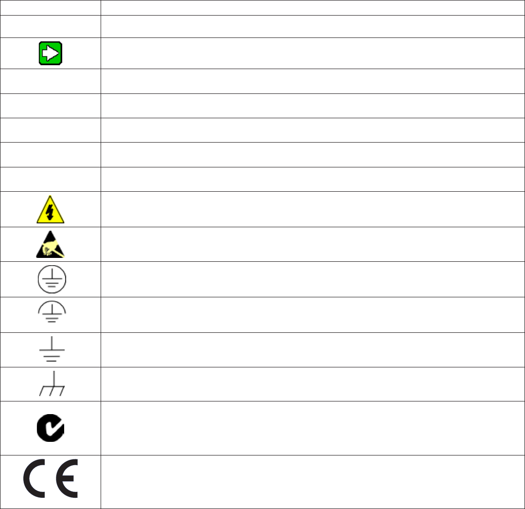
Symbol Denition
,ATTENTION: Identifies information that requires special consideration.
TIP: Identifies advice or hints for the user, often in terms of performing a task.
CAUTION Indicates a situation which, if not avoided, may result in equipment or work (data) on the system
being damaged or lost, or may result in the inability to properly operate the process.
mCAUTION: Indicates a potentially hazardous situation which, if not avoided, may result in minor
or moderate injury. It may also be used to alert against unsafe practices.
mCAUTION symbol on the equipment refers the user to the product manual for additional infor-
mation. The symbol appears next to required information in the manual.
mWARNING: Indicates a potentially hazardous situation, which, if not avoided, could result in
serious injury or death.
mWARNING symbol on the equipment refers the user to the product manual for additional infor-
mation. The symbol appears next to required information in the manual.
WARNING, Risk of electrical shock: Potential shock hazard where HAZARDOUS LIVE volt-
ages greater than 30 Vrms, 42.4 Vpeak, or 60 Vdc may be accessible.
ESD HAZARD: Danger of an electro-static discharge to which equipment may be sensitive.
Observe precautions for handling electrostatic sensitive devices.
Protective Earth (PE) terminal: Provided for connection of the protective earth (green or green/
yellow) supply system conductor.
Functional earth terminal: Used for non-safety purposes such as noise immunity improve-
ment. NOTE: This connection shall be bonded to Protective Earth at the source of supply in
accordance with national local electrical code requirements.
Earth Ground: Functional earth connection. NOTE: This connection shall be bonded to Protec-
tive Earth at the source of supply in accordance with national and local electrical code require-
ments.
Chassis Ground: Identifies a connection to the chassis or frame of the equipment shall be
bonded to Protective Earth at the source of supply in accordance with national and local electri-
cal code requirements.
C-Tick Mark. The C-Tick Mark is a certification trade mark registered to ACMA (Australian Com-
munications and Media Authority) in Australia under the Trade Marks Act 1995 and to RSM in
New Zealand under section 47 of the NZ Trade Marks Act. The mark is only to be used in accor-
dance with conditions laid down by ACMA and RSM. This mark is equal to the CE Mark used in
the European Union.
Notied Body. For radio equipment used in the European Union in accordance with the R&TTE
Directive, the CE Mark and the notified body (NB) identification number is used when the NB is
involved in the conformity assessment procedure. The alert sign must be used when a restric-
tion on use (output power limit by a country at certain frequencies) applies to the equipment
and must follow the CE marking.

Honeywell Sensing and Control 5
Limitless™ Series WBX Limit Switch ISSUE 1 50096377
2 SPECIFICATIONS
2.1 Intended Country Usage
Table 4 – North America
Country ISO 3166 2 letter code
UNITED STATES US
CANADA CA
Table 5 – Australia
Country ISO 3166 2 letter code
AUSTRALIA AU
Table 6 – European Union
Country ISO 3166 2 letter code Country ISO 3166 2 letter code
Austria AT Latvia LV
Belgium BE Lithuania LT
Bulgaria BG Luxembourg LU
Cyprus CY Malta MT
Czech Republic CZ Netherlands NL
Denmark DK Poland PL
Estonia EE Portugal PT
Finland FI Romania RO
France FR Slovak Republic SK
Germany DE Slovenia SI
Greece GR Spain ES
Hungary HU Sweden SE
Ireland IE United Kingdom BG
Italy IT
Table 7 – Other European Countries
Country ISO 3166 2 letter code Country ISO 3166 2 letter code
Bosnia and Herzegovina BA Norway NO
Croatia HR Russian Federation RU
Iceland IS Serbia RS
Liechtenstein LI Switzerland CH
Macedonia MK Turkey TR

6 Honeywell Sensing and Control
Limitless™ Series WBX Limit Switch ISSUE 1 50096377
2.2 Certication and Approvals
See the product label for applicable approvals and ratings.
Table 8 – Approvals and Ratings
Approval/Item Ratings/Description
Enclosure Type Type 1, 3, 4, 13
Federal Communications Commission (FCC) FCC Part 15.247
Industry Canada (IC) Canadian ICES-003
European Telecommunications Standards Institute (ETSI) CE mark
Hazardous Location APPROVALS cULus, ATEX, IECEx, ACMA
Table 9 – Hazardous Location Standards and Certications
cULus Listing ATEX Certication IECEx Certication
Standards: UL913 8th edition;
CAN/CSA-C22.2 NO. 157-92 (R2012)
Standards: EN60079-0:2012 +
A11:2013; EN60079-11:2012; EN60079-
26-2007
Standards: IEC60079-0 ed6.0;
IEC60079-11 ed6.0; IEC60079-26 ed 2.0
Class I, Div 1, Groups A, B, C, D T4
Class I, Zone 1 AEx ia IIC T4 Ga
Class I, Zone 1 Ex ia IIC T4 Ga
Class I, Zone 0 AEx ia IIC T4 Ga
Class I, Zone 0 Ex ia IIC T4 Ga
Tambient -40C to 70C
Zone 1 AEx ia IIC T4 Ga
Zone 1 Ex ia IIC T4 Ga
Zone 0 AEx ia IIC T4 Ga
Zone 0 Ex ia IIC T4 Ga
Zone 1 AEx ia IIC T4 Ga
Zone 1 Ex ia IIC T4 Ga
Zone 0 AEx ia IIC T4 Ga
Zone 0 Ex ia IIC T4 Ga
The above certifications are applicable only for the WBX limit switch product and the listed antenna options.
2.3 Radio Module Specications
Table 10 – Radio Module Specications
Item Specication
Radio module Honeywell RF-PCBa
Wireless standard IEEE Standard: 802.15.4, 2.4 GHz global, license-free bands
Protocol: Limitless point-to-point
Data rate 250 kbps
Operating frequency ISM 2.4 GHz
Module transmit power (max.) Country code A: 14 dBm max; Country code B: 8 dBm max.
Receive sensitivity (typ.) -98 dBm
m WARNING
The WBX must be installed in accordance with the requirements specified in this document in order to comply with the specific
Country Communication Agency requirements (i.e., FCC, IC, ETSI, ACMA).
Specific Conditions of Safe Use:
• Aluminiumenclosure–Careshouldbetakentominimizetheriskofignitionduetoimpactorfriction.
• Potentialelectrostaticdischarge–Cleanproductonlywithadampcloth.
• Themetal“S-shaped”clampwhichprovidessecurementofthelidtotheenclosurehousingshallalwaysbesecuredinplace,whenprod-
uctisinuse.
• Donotopenwhenanexplosiveatmospheremaybepresent.
• Donotreplacethebatterywhenanexplosiveatmosphereispresent.
• UseonlyXenoEnergy–XL-060F,Tadiran–TL-5903,orBi-PowerER14505Hbatteries
, ATTENTION
The following additional previous editions of Standards noted under the “Standards” section of this Certificate where applied to
integral Components as itemized below. There are no significant safety related changes between these previous editions and the
editions noted under the “Standards” section.
Fuse, Part No. 0259.125TX913 manufactured by Littelfuse IEC 60079-0:2007-10, IEC 60079-11:2006

Honeywell Sensing and Control 7
Limitless™ Series WBX Limit Switch ISSUE 1 50096377
2.4 Electrical Specications
Table 11 – Electrical Specications
Item Specication
Battery 3.6 Vdc Lithium Thionyl Chloride; AA size, Qty: 2;
Manufacturer: Xeno Energy, P/N XL-060F; Tadiran, P/N TL-5903/S; Bi-power, P/N: ER14505H
2.5 EMC Specications
The latest applicable EMC Standards are as follows:
• EN300328,V1.7.1
• EN61326-1(2006)
• EN301489-1,V1.8.1
• EN301489-17,V2.1.1
2.6 Functional Specications
Table 12 – WBX Mechanical Actuator Cycle Testing with WDRR Monitoring (99.9 % count detection)
Item Specication
High temperature endurance 70 °C, 10,000 cycles, 15 cpm
Low temperature endurance -40 °C, 10,000 cycles, 15 cpm
Electrical operation (normal speed) 25 °C, 100K cycles, 15 cpm
Electrical operation (low speed) 25 °C, 1.1 million cycles, 100 cpm
2.7 Environmental Specications
Table 13 – Environmental Specications
Item Specication
Operating temperature -40 °C to 70 °C [-40 °F to 158 °F]
Storage temperature -40 °C to 70 °C [-40 °F to 158 °F]
Operating humidity 0 %RH to 100 %RH
Vibration IEC 60068-2-6: 10 Hz to 58 Hz w/0,35 mm peak-to-peak,
58 Hz to 500 Hz, 10g 58 Hz to 500 Hz – 10g amplitude
Shock IEC60068-2-27; half sine, 50 g, 6 mS, 3 AXIS
Sealing Type 1, 3, 4, 13
8 Honeywell Sensing and Control
Limitless™ Series WBX Limit Switch ISSUE 1 50096377
2.8 Agency Compliance Information
2.8.1 FCC Compliance Statements
• ThisdevicecomplieswithPart15ofFCCRulesandRegulations.Operationissubjecttothefollowingtwoconditions:(1)This
device may not cause harmful interference and (2) this device must accept any interference received, including interference
that may cause undesired operation.
• ThisequipmenthasbeentestedandfoundtocomplywiththelimitsforaClassBdigitaldevice,pursuanttoPart15ofthe
FCC Rules. These limits are designed to provide reasonable protection against harmful interference in a residential installa-
tion. This equipment generates, uses, and can radiate radio frequency energy and, if not installed and used in accordance
with these instructions, may cause harmful interference to radio communications. Operation of this equipment in a residential
area is likely to cause harmful interference in which case the user will be required to correct the interference at his/her own
expense.
• IntentionalorunintentionalchangesormodicationsmustnotbemadetotheWBXunlessundertheexpressconsentofthe
party responsible for compliance. Any such modifications could void the user’s authority to operate the equipment and will
void the manufacturer’s warranty.
2.8.2 IC Compliance Statements
• Toreducepotentialradiointerferencetootherusers,theantennatypeanditsgainshouldbechosensothattheequivalent
isotropic radiated power (EIRP) is not more than that permitted for successful communication.
• Operationissubjecttothefollowingtwoconditions:(1)thisdevicemaynotcauseinterference,and(2)thisdevicemustac-
cept any interference, including interference that may cause undesired operation of the device.
• ThisClassBdigitalapparatushasbeentestedandfoundtocomplywithCanadianICES-003.
• French:CetappareilnumériquedelaclasseBestconformeàlanormeNMB-003duCanada.
2.8.3 Radio Frequency (RF) Safety Statement (FCC & IC)
To comply with FCC’s and Industry Canada’s RF exposure requirements, the following antenna installation and device operating con-
figurations must be satisfied.
• Remoteantennaforthisunitmustbexedandmountedonoutdoorpermanentstructureswithaseparationdistancebe-
tween any other antenna(s) of greater than 20 cm and a separation distance of at least 20 cm [7.87 in] from all persons.
• Furthermore,whenusinganintegralantennawiththeWBX,itmustnotbeco-locatedwithanyotherantennaortransmitter
device and have a separation distance of at least 20 cm [7.87 in] from all persons.
2.8.4 European Restrictions
• Informationregardingnationalrestrictionscanbefoundindocument:ERC/REC70-03(Relatingtotheuseofshort-range
devices including appendixes and annexes). Documentation may be found in the document database in the European Com-
munication’s office.
• http://www.erodocdb.dk/doks/dochistory.aspx?docintid=1622
Pour réduire les interférences radio potentielles aux autres utilisateurs, le type d'antenne et son gain doivent être choisis de telle sorte que
l'équivalent isotrope puissance rayonnée (PIRE) ne est pas supérieure à celle permise pour une communication réussie.
Son fonctionnement est soumis aux deux conditions suivantes : (1) ce dispositif ne doit pas causer d'interférences et
(2) cet appareil doit accepter toute interférence, y compris les interférences qui peuvent causer un mauvais fonctionnement de l'appareil.
Cet appareil numérique de classe B a été testé et déclaré conforme à la norme ICES-003 du Canada .
Honeywell Sensing and Control 9
Limitless™ Series WBX Limit Switch ISSUE 1 50096377
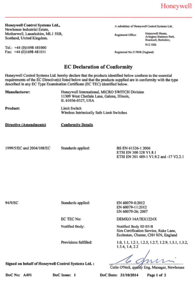
2.9 European (CE) Declaration of Conformity (DoC)
2.9.1 European Declaration of Conformity Statements
This section contains the European Declaration of Conformity (DoC) statement for the radio used in the Limitless™ WBX switch.
Figure 1. European Declaration of Conformity (DoC)
2.9.2 For more information about the R&TTE Directive
The following website contains additional information about the Radio and Telecommunications Terminal Equipment (R&TTE) directive:
http://ec.europa.eu/enterprise/sectors/rtte/faq/

10 Honeywell Sensing and Control
Limitless™ Series WBX Limit Switch ISSUE 1 50096377
3 ANTENNA OPTIONS ALLOWED
This section defines the antenna options that can be used in either North America or other approved countries. The integral antenna
mounts directly to the WBX RP-SMA jack while the remote antenna mounts to the WBX RP-SMA jack via a cable assembly (see Sec-
tion 5.2.3.1). Further technical information on the WAN Series antennas, WAMM Series magnetic mounts and WCA Series cable as-
semblies can be found in Section 5.1.
m WARNING
The WBX must be installed in accordance with the requirements specified in this document in order to comply with the specific
Country Communication Agency requirements. (i.e. FCC, IC, ETSI)
m WARNING
POTENTIAL ELECTROSTATIC CHARGING HAZARD
When the WBX Series is installed in potentially hazardous locations care should be taken not to electrostatically charge the surface
of the antenna shroud by rubbing the surface with a cloth, or cleaning the surface with a solvent. If electrostatically charged,
discharge of the antenna shroud to a person or a tool could possibly ignite a surrounding hazardous atmosphere.
m WARNING
RISK OF DEATH OR SERIOUS INJURY FROM EXPLOSION OR FIRE
Connection and disconnection of the antennas should only be performed in a non-hazardous area and with no battery power
applied to the WBX. This is due to the risk of possibly damaging the internal WBX electronics and/or igniting the surrounding
hazardous atmosphere.
Failure to comply with these instructions could result in death or serious injury.

Honeywell Sensing and Control 11
Limitless™ Series WBX Limit Switch ISSUE 1 50096377
3.1 ANTENNA OPTIONS
Table 14 - Antenna Options for United States, Canada, and Australia
ANTENNAS FOR USE IN UNITED STATES, CANADA, AND AUSTRALIA
(Note: all columns are independent of each other)
Antenna Type Code
(antenna provided with
product)
Antenna Accessory: Must be ordered separately
Remote Mount Anten-
nas (allowed for use)
Magnetic Remote
Mount Assemblies/
Antennas
WAMM100RSP-005
WAMM100RSP-010
(allowed for use)
Extension Cable As-
semblies/Antennas for
Remote Mount
WCA200RSJRSP-002
WCA200RSJRSP-005
WCA200RSJRSP-010
WCA200RSJRSP-015
WCA200RSJRSP-020
(allowed for use)
Extension Cable As-
semblies/Antennas for
Remote Mount
WCA200RNPRSP-002
WCA200RNPRSP-010
(allowed for use)
00 WAN03RSP WAN04RSP WAN03RSP WAN06RNJ
12 WAN09RSP WAN05RSP WAN04RSP
WAN10RSP WAN08RSP WAN05RSP
WAN08RSP
WAN09RSP
WAN10RSP
WAN11RSP
Table 15 - Antenna Options for All Other Approved Countries
ANTENNAS FOR USE IN ALL OTHER APPROVED COUNTRIES
(Note: all columns are independent of each other)
Antenna Type Code
(antenna provided with
product)
Antenna Accessory: Must be ordered separately
Remote Mount Anten-
nas (allowed for use)
Magnetic Remote
Mount Assemblies/
Antennas
WAMM100RSP-005
(allowed for use)
Magnetic Remote
Mount Assemblies/
Antennas
WAMM100RSP-010
(allowed for use)
Extension Cable As-
semblies/Antennas for
Remote Mount
WCA200RSJRSP-002
WCA200RSJRSP-005
WCA200RSJRSP-010
WCA200RSJRSP-015
WCA200RSJRSP-020
(allowed for use)
00 WAN03RSP WAN08RSP WAN04RSP WAN03RSP
12 WAN09RSP WAN08RSP WAN08RSP
WAN10RSP WAN09RSP
WAN10RSP
WAN11RSP
Remote mount: Remote mount antenna uses a cable with a RP-SMA plug that connects directly to the WBX RP-SMA jack (exception,
WAN06RNJ)

12 Honeywell Sensing and Control
Limitless™ Series WBX Limit Switch ISSUE 1 50096377
, ATTENTION
The WBX cannot be used in a portable application. It must be used in a fixed location.
, ATTENTION
The antenna cables should not be modified (i.e. cut short and/or re-terminated) as it may affect Communication Agency approval.
Notes for Section 3.1 • Tables 13-14:
1. Antennas listed in this chart are approved and are the only antennas allowed for use with the WBX.
2. Industry Canada Compliance Statement: This device has been designed to operate with the antenna types listed in this
document, and having a maximum gain of 9 dBi. Antenna types not included in this list or having a gain greater than 9 dBi
are strictly prohibited for use with this device. The required antenna impedance is 50 Ohm.
Honeywell Sensing and Control 13
Limitless™ Series WBX Limit Switch ISSUE 1 50096377
4 WBX BASIC START UP AND FUNCTIONAL MODES
This section provides basic installation instructions for the WBX used in conjunction with a Limitless™ Wireless Panel Mount Monitor
(WPMM) or a Limitless™ Wireless DIN Rail Receiver (WDRR). If necessary, refer to the WDRR or WPMM Installation and Technical
Manual for further detailed information regarding installation.
4.1 Antenna Connection (if required)
m WARNING
RF EXPOSURE
To satisfy FCC RF exposure requirements for mobile transmitting devices, a separation distance of 20 cm [7.87 in] or more should
be maintained between the antenna of this device and persons during device operation To ensure compliance, operation at closer
than this distance is not recommended. The antenna used for this transmission must not be co-located in conjunction with any
other antenna or transmitter.
Failure to comply with these instructions could result in death or serious injury.
CAUTION
Power to the WBX should not be applied (ensure battery is removed) during installation of antenna as damage could occur to the
WBX electronics and/or ignite the surrounding hazardous atmosphere.
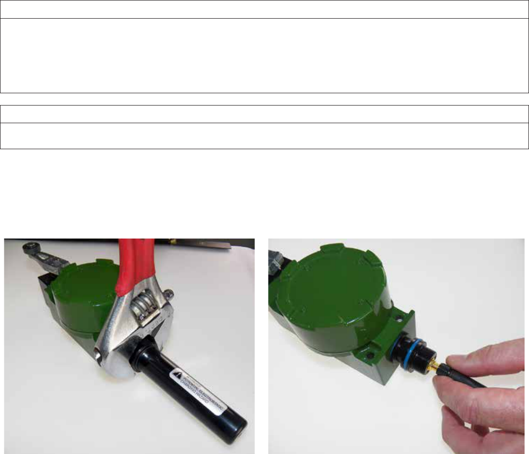
The WBX is normally shipped with a direct mount 2.0 dBi antenna and radome. To use one another style of direct mount antenna or
remote mount antenna per Section 3.1, the radome must be removed by using a 30 mm open-end or adjustable wrench; unscrew the
radome by turning it CCW (see Figures 2 and 3). If the WBX you purchased was not provided with an antenna and radome, you can
proceed to using another style of antenna recommended and approved for use with this product by Honeywell (see Tables 14 & 15).
Figure 2. Removal of Radome Figure 3. Unscrew Antenna
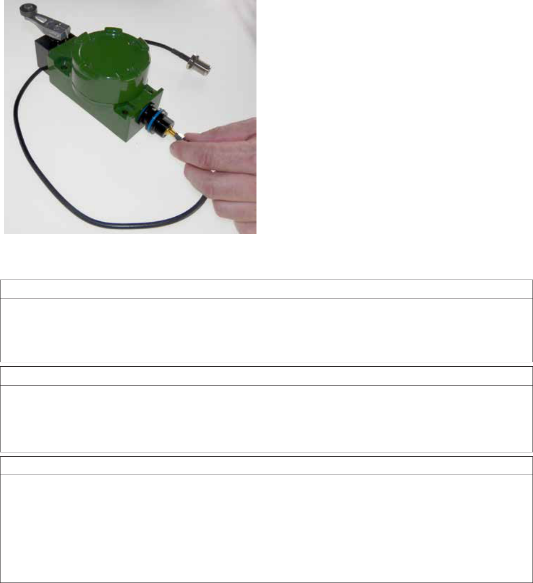
A remote mount antenna requires the use of an extension cable to allow the antenna to be mounted in a different location than the
WBX location. The extension cable will need to have one end with a RP-SMA plug connector which will mate with the WBX connector
jack under the same mounting procedure as the direct mount antenna. The other end of the extension cable will need to mate with
antenna connector directly or it may be integral to the particular remote mount antenna chosen. See Figure 4.
14 Honeywell Sensing and Control
Limitless™ Series WBX Limit Switch ISSUE 1 50096377
Figure 4. Limitless™ WBX RP-SMA Connection,
Remote
4.2 Battery Connection Procedure
m WARNING
RISK OF DEATH OR SERIOUS INJURY FROM EXPLOSION OR FIRE
Connection and disconnection of the batteries should only be performed in a non-hazardous area. The batteries used in this
device may present a risk of fire or chemical burn if mistreated. Do not recharge, disassemble, heat above 100 °C [212 °F], or
incinerate.
Failure to comply with these instructions could result in death or serious injury.
m WARNING
RISK OF DEATH OR SERIOUS INJURY FROM EXPLOSION OR FIRE
If WBX is to be returned to Honeywell for any reason, the battery MUST be removed prior to shipping. Dispose of used batteries
promptly per local regulations or the battery manufacturer’s recommendations. Keep away from children. Do not disassemble and
do not dispose of in fire.
Failure to comply with these instructions could result in death or serious injury.
m WARNING
RISK OF DEATH OR SERIOUS INJURY FROM EXPLOSION OR FIRE
Both batteries must be the same model from the same manufacturer. Mixing old and new batteries or different manufacturers is
not permitted.
Use only the following 3.6 V lithium thionyl chloride (Li-SOCl2) battery (non-rechargeable), size AA. No other batteries are
approved for use in the WBX Series. Always replace both batteries.
•XENOEnergy,partnumber:XL-060F
•Tadiran,partnumber:TL-5903/S
•Bi-Power,partnumber:ER14505H
Honeywell Sensing and Control 15
Limitless™ Series WBX Limit Switch ISSUE 1 50096377
, ATTENTION
When the WBX switch is being installed or operating in a hazardous environment, the end customer/user should issue a work
permit to a trained professional installer prior to any work performed on the Limitless™ WBX switch. This includes the following
actions:
•Installationand/oroperationoftheLimitless™WBXswitch
•Installationand/oradjustmentofaremoteantennafortheLimitless™WBXswitch
•MaintenanceontheLimitless™WBXswitch,includingbatteryreplacement,pairing,purging,etc.
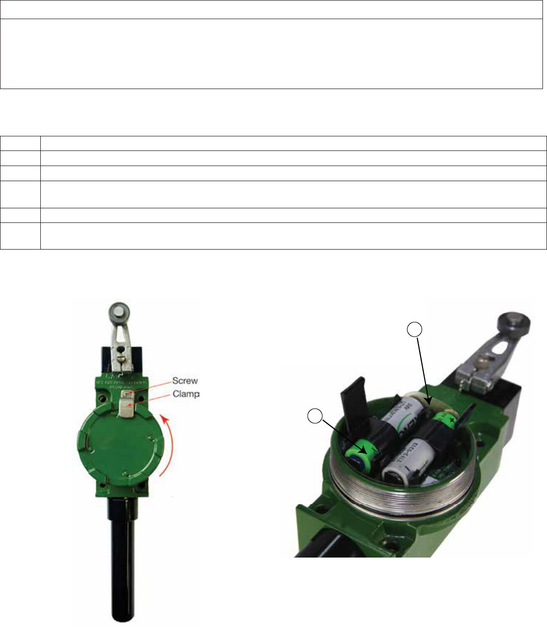
WBX battery activation (see Figures 5 and 6):
Tools required: Slotted or Phillips screwdriver
Step Action
1 Loosen the screw and remove the S-shaped clamp holding down the housing cover.
2 Remove the WBX housing cover by turning CCW as shown in Figure 6.
3Using a finger, press down slightly on the batteries and remove the battery insulator (see Figure 6). Ensure that the
batteries are properly seated and making good contact.
4 Replace cover and ensure it is turned fully CW until tight or immediately proceed to Section 4.4 Pairing Mode.
5 Place the S-shaped clamp in place and tighten the screw using 1,5 Nm[13.3 in-lb] torque to firmly hold down the housing
cover.
Figure 5. Limitless™ WBX housing Figure 6. Limitless™ WBX battery and Insulator
3
2
After removing the battery insulator observe the AMBER LED blinks one time.
This visual indication confirms device functionality is normal.
16 Honeywell Sensing and Control
Limitless™ Series WBX Limit Switch ISSUE 1 50096377
4.3 Update Rate/DIP Switches
The WBX update rate is the frequency at which the WBX will automatically communicate with the receiver when the switch is not be-
ing actuated or de-actuated. It is adjustable from 2 seconds to 300 seconds. If the operator is cycling the switch faster than what the
update rate is set, the auto communication will not occur. The update rate “clock” will also be reset upon an actuation or de-actuation
of the switch so communication will happen at the next switch activation or update rate time; whichever occurs first. An advantage
of increasing the update rate frequency is allowing a faster indication of a lost RF signal between the switch and receiver which is
important in some applications. A disadvantage of increasing the update rate is that it can decrease the battery life as increasing the
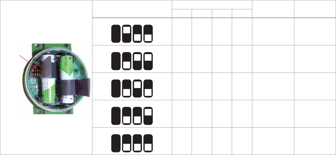
frequency of communication consumes more battery power. The WBX has the capability to change the update rate via DIP switch
settings located inside the housing; see the table below. The allowable DIP switch settings are seen in the table below along with the
Lost RF receiver indication time. The Lost RF receiver indication time is the amount of time it takes the receiver to indicate a lost RF
condition via LED indication and/or Lost RF electrical output change.
DIP switches
location
DIP Switch Setting Switch Position Update Rate
(seconds)
Lost RF
Signal*
1234
1234
NOT
USED
n/a ON OFF OFF 1.5 5
1234
NOT
USED
n/a OFF ON ON 4.5 18
1234
NOT
USED
n/a OFF ON OFF 11 45
1234
NOT
USED
n/a OFF OFF ON 30 120
1234
NOT
USED
n/a OFF OFF OFF 90 360
*Time that elapses from the last successful communication signal that was received, either automatic or from a switch actuation/de-actuation
NOTICE: Firmware (FW) operation differences with Limitless™ monitor/receiver due to update rate chosen; FW# of monitor/
receiver is noted on product label.
WPMM Series monitor
• FW7271:Anyupdateratechosendoesnotchangeoperationastheyarealldefaultedto30seconds
• FW7273:AnyupdateratechosenwillallownormaloperationwithonlyoneWBXswitchconnectedtoWPMM
WDRR Series receiver
• FW7404:Anyupdateratechosenwillallownormaloperation
• FW7406:Anyupdateratechosenwillallownormaloperation
4.4 Pairing Mode
Pairing is required to initiate and establish an RF communication link between each single WBX and a single WPMM or WDRR. As
there are up to 16 WBX devices that can be paired to a single WPMM or WDRR, it is advised that you identify each WBX switch by
physically marking them (permanent marker) from #1 to #16. The initial WBX paired to the WPMM or WDRR will be Sequence #1; the
second WBX paired will be Sequence #2 and so on. If replacing a WBX that has been purged, as applicable(see section 6.5 of the
WPMM Installation and Technical Manual or Section 7.3 of the WDRR Installation & Technical Manual), identify the correct replacement
Sequence # on the WBX.
Pairing steps when using a WPMM: The battery will need to be activated in the WBX and proper power applied to the WPMM (green
LED illuminated) before proceeding with this pairing procedure. Once the pairing is completed, the WBX selected will only commu-
nicate with the WPMM it was paired to and no other device.
Honeywell Sensing and Control 17
Limitless™ Series WBX Limit Switch ISSUE 1 50096377
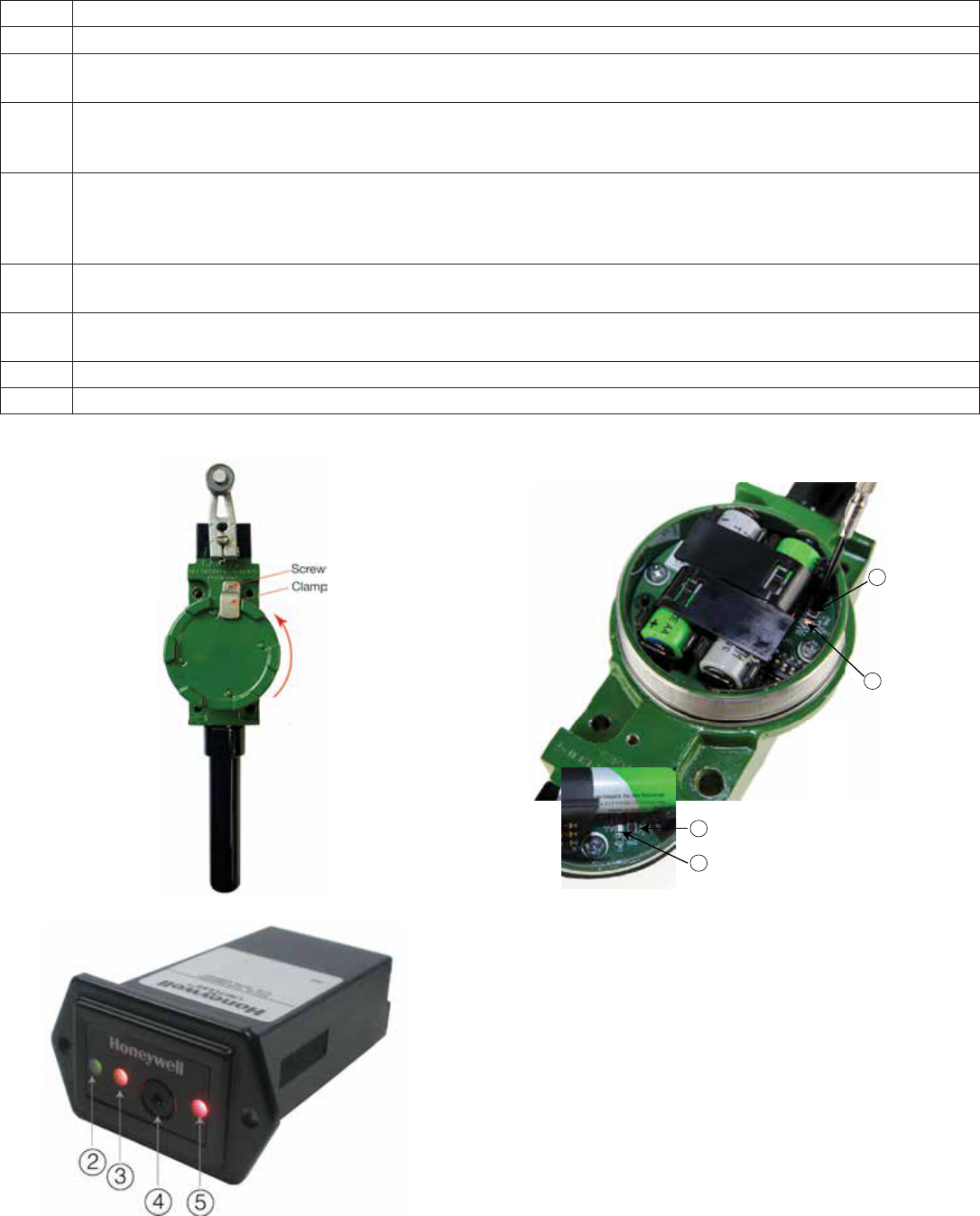
Figure 7. Limitless™ WBX Housing Figure 9. Limitless™ WBX with Function Button De-
pressed
Figure 8. Limitless™ WPMM Housing NOTE: Use a blunt object, such as a paper clip to actuate the
function switch .
7
8
7
8
Step Action
1 Completely read this procedure before starting in order to understand the timing of events that need to be performed.
2WBX: Remove (if required) the housing cover (See Figure 7) of the WBX and locate the function button (See Figure 9) to
be used in Step 4.
3WPMM: Press the Function button on WPMM (See Figure 8) for more than four seconds and less than eight seconds at
which time the green and yellow LEDs will be flashing which indicates to release the function button immediately as it
has entered the pairing mode.
4WBX: Within a 30 second interval of Step 3, depress the WBX switch function button (See Figure 9) and hold depressed
for more than one second and less than 12 seconds at which time the orange LED turns on. While in pairing mode, the
orange led will flash on for 100 ms every second. The orange LED flashes three times 100 ms on, 100 ms off when pair-
ing succeeds. If pairing does not succeed, the orange LED will turn off and user needs to repeat steps starting with #3.
5WPMM: Successful pairing will be indicated by the green and yellow LEDs (See Figure 9) ceasing to flash and re-
maining on for a few seconds before turning off. A short buzzer beep will also occur.
6To confirm proper pairing between the WBX and WPMM: actuate the WBX actuator and the red LED should illuminate
along with a buzzer sound.
7 Record the WBX Sequence # on the WBX housing.
8 Repeat Steps 2-7 to add additional WBX switches. Up to 16 WBX can be paired to a single WPMM.

18 Honeywell Sensing and Control
Limitless™ Series WBX Limit Switch ISSUE 1 50096377
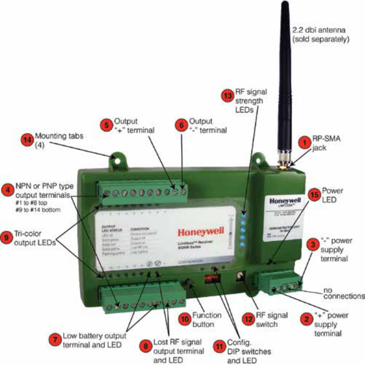
Pairing Steps when using a WDRR (see Figure 10): The battery will need to be activated in the WBX and proper power applied to
the WDRR (green LED illuminated) before proceeding with this pairing procedure. Once the pairing is completed, the WBX selected
will only communicate with the WDRR it was paired to and no other device.
Step Action
1 Completely read this procedure before starting in order to understand the timing of events that need to be performed.
2WBX: Remove (if required) the housing cover (See Figure 7) of the WBX and locate the function button (see Figure 9) to
be used in Step 4.
3WDRR: Press the Function button on WDRR (See Figure 10) for more than four seconds and less than eight seconds at
which time the green and yellow LEDs (see Figure 10) will be flashing which indicates to release the function button im-
mediately as it has entered the pairing mode.
4WBX: Within a 30 second interval of Step 3, depress the WBX function button (See Figure 9) and hold depressed for
more than one second and less than 12 seconds at which time the orange LED turns on (see Figure 9). While in pairing
mode, the orange LED will flash on for 100 ms every second. The orange LED flashes three times 100 ms on, 100 ms
off when pairing succeeds. If pairing does not succeed, the orange LED will turn off and user will need to repeat steps
starting with Step 3.
5WDRR Receiver: Successful pairing will be indicated by the green and yellow LEDs (see Figure 10) ceasing to flash and
remaining on for a few seconds before turning off. The specific Tricolor Output LED will also turn on.
6To confirm proper pairing between the WBX and WDRR: actuate the WBX actuator and the Tricolor Output LED (see
Figure 10) should turn on to indicate the proper output status.
7 Record the WBX Sequence # on the WBX housing.
8 Repeat Steps 2-7 to add additional Limitless™ switch. Up to 14 WBX can be paired to a single WDRR.
NOTICE: Lost RF or no change in switch state may occur with already paired switches when the WDRR is in pairing mode.
Honeywell Sensing and Control 19
Limitless™ Series WBX Limit Switch ISSUE 1 50096377
Figure 10. Limitless™ WDRR Housing
4.5 WBX Mounting
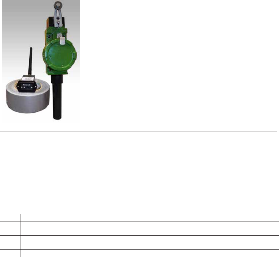
Mounting: The WBX housing has two slotted mounting holes that will accept a M5 or #10 size screw and it also has two 10-32 UNF
tapped holes for mounting from the back. Refer to Section 5.6 in this manual for more detail
20 Honeywell Sensing and Control
Limitless™ Series WBX Limit Switch ISSUE 1 50096377
4.6 Antenna Adjustment
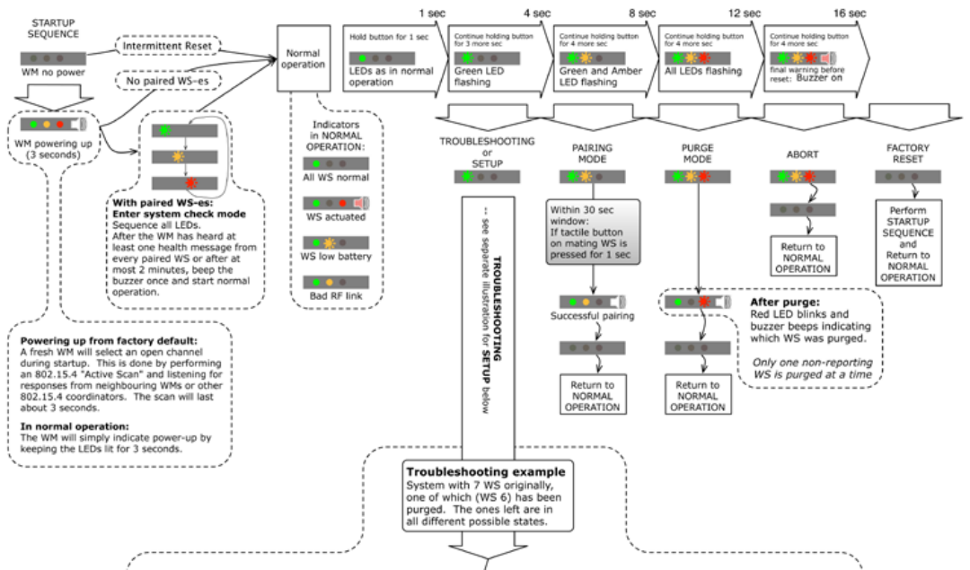
The antenna of the WBX and WPMM or WDRR should be oriented with respect to each other such that they are parallel. This will in
most cases allow the longest range and highest RF communication link/signal. The least RF signal is normally in a direction in-line with
the top of the antenna, so it is best to avoid having the antennas pointed directly toward each other, or directly away from each other.
An acceptable RF signal is also indicated by the RF signal strength LEDs on the WDRR; see the WDRR Installation and Technical
Manual for further information.
Figure 11. Limitless™ WBX and WPMM in Parallel
m WARNING
RF EXPOSURE
To satisfy FCC RF exposure requirements for mobile transmitting devices, a separation distance of 20 cm [7.87 in] or more should
be maintained between the antenna of this device and persons during device operation. To ensure compliance, operations at
closer than this distance is not recommended. The antenna used for this transmitter must not be co-located in conjunction with any
other antenna or transmitter.
Failure to comply with these instructions could result in death or serious injury.
4.7 Purge Mode
The purging of a WBX is required when a previously paired WBX is desired to paired again per Section 4.4. Follow the procedure
below which will then allow a new pairing to be conducted after successful purging:
Step Action
1Remove (if required) the housing cover of the WBX (See Figure 8) and locate the WBX function button & orange LED
(See Figure 9).
2Press and hold the WBX function button for greater than 12 seconds. Initially the orange LED turns on and after the 12
seconds will turn off indicating the WBX has been purged.
3 Repeat above steps if necessary to purge more Limitless™ switch(es).
Honeywell Sensing and Control 21
Limitless™ Series WBX Limit Switch ISSUE 1 50096377
4.8 WPMM Operation and LED functions
4.8.1 Principle of Operation of the WPMM and Limitless™ Switch:
A Limitless™ WBX will send an RF signal to the WPMM when the actuator of the WBX switch changes position. There are up to 16 Lim-
itless™ WBX switches that will communicate and indicate their actuation position with a single WPMM. The mechanical actuation (free
position to full overtravel) of any one of the WBX switches will cause a single red output LED to illuminate, a buzzer to sound, and/or a
change in the electrical output.* However, there will be no differentiation of outputs (visual, audible or electrical state change) between
any of the WBX switches being actuated. Further, if a WBX switch causes the single red output LED to illuminate, a buzzer to sound,
and a change in the electrical output, actuation of any other Limitless™ WBX will not cause another output change (visual, audible or
electrical state change).
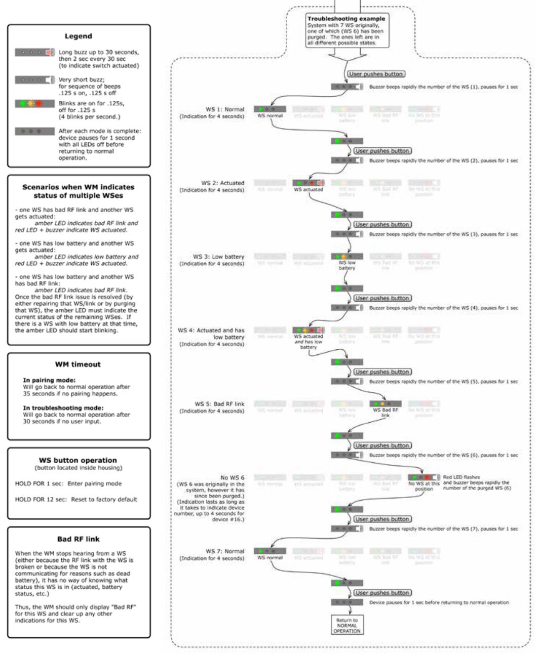
The operation and LED functions for the WPMM are visually depicted and described in the attached file. This file is also located as a
separate file at sensing.honeywell.com.
Figure 12. WPMM Operation and LED Functions Chart – part 1
* Refer to the WPMM Installation and Technical Manual for further set-up instructions(buzzer mute and/or reversed output).
22 Honeywell Sensing and Control
Limitless™ Series WBX Limit Switch ISSUE 1 50096377
Figure 13. WPMM Operation and LED Functions Chart – part 2
Honeywell Sensing and Control 23
Limitless™ Series WBX Limit Switch ISSUE 1 50096377
4.8.2 WDRR Operation and LED functions
A Limitless™ WBX will send an RF signal to the WDRR when the actuator of the WBX switch changes position. There are up to
14 WBX switches will communicate and indicate their actuation position with a single WDRR. The actuation of any one of the WBX
switches will cause a single red output LED to illuminate and change in the electrical output for the associated output (#1 thru 14) that
it is paired to.
The operation and LED functions for the WPMM are visually depicted and described in the WDRR Installation and Technical Manual
located at sensing.honeywell.com/limitless.
24 Honeywell Sensing and Control
Limitless™ Series WBX Limit Switch ISSUE 1 50096377
5 ANTENNA CONSIDERATIONS/OPTIONS & SWITCH/ANTENNA INSTALLATION
5.1 Overview of Antenna Options
The following chart lists the antenna options along with the various characteristics that will be referenced throughout this section.
This section is intended to assist an end user in determining which antenna(s) are worth investigating and subjecting to application
requirements for proof of suitability.
, ATTENTION
The antenna cables should not be modified (i.e. cut short and/or re-terminated) as it may affect Communication Agency approval.
m WARNING
The WBX must be installed in accordance with the requirements specified in this document in order to comply with the specific
Country Communication Agency requirements (i.e., FCC, IC, ETSI).
5.1.1 Omni-directional Antenna Design
The omni-directional antennas offered in the Limitless™ Series were chosen for their ability to be used in applications where transmit-
and-receiver antennas may be moving with respect to each other or could also be stationary. They are dipole antennas that radiate
power (power from the internal radio of the WBX) in a 360° outward pattern in a plane perpendicular to the length of the antenna ele-
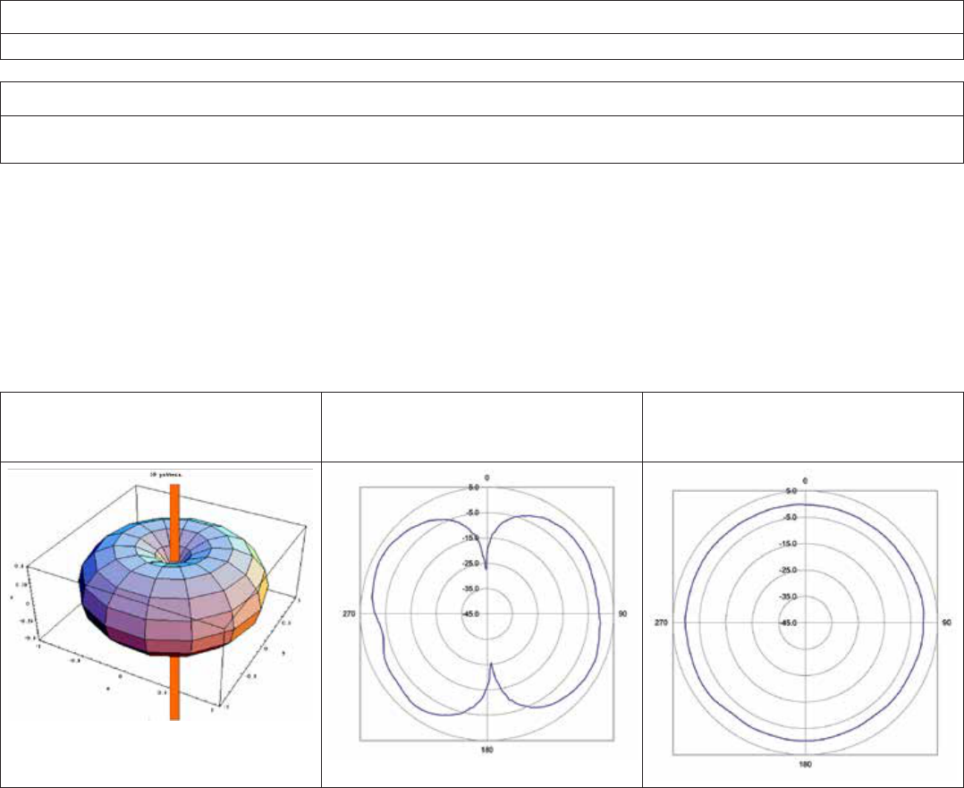
ment. “Omni” may suggest the antenna radiates power in all directions, but that is not the case. The actual antenna radiation pattern
looks more like a toroid (doughnut-shape) as shown in Figure 14.
Figure 14. Radiation Pattern of an Omni-directional Antenna
Toroid Radiation Pattern - Pattern
is 360 degrees in the vertical plane,
but not the horizontal plane
2.2 dBi RF Antenna Pattern - Hori-
zontal
2.2 dBi RF Antenna Pattern - Vertical
The antenna radiates virtually zero power in the Z axis and most of the power in the X and Y axis. Increasing the antenna’s gain will
increase the power only in the X and Y axis. As a result, the radiation pattern becomes narrower. For instance, this is analogous to
the reflector in an automobile’s headlight. The reflector does not add light or increase the luminous intensity of the light bulb, rather it
simply directs all the light energy in the forward direction where the light is needed most.
Honeywell Sensing and Control 25
Limitless™ Series WBX Limit Switch ISSUE 1 50096377
5.2 Antenna Mounting and Considerations
5.2.1 Antenna Mounting Location with Respect to RF Signal
m WARNING
RF EXPOSURE
To satisfy FCC RF exposure requirements for mobile transmitting devices, a separation distance of 20 cm [7.87 in] or more should
be maintained between the antenna of this device and persons during device operation. To ensure compliance, operation at closer
than this distance is not recommended. The antenna used for this transmission must not be co-located in conjunction with any
other antenna or transmitter.
Failure to comply with these instructions could result in death or serious injury.
There are several environmental factors to consider with respect to antenna location during installation. These factors can affect the
radio frequency (RF) signal strength being both transmitted and received by the WBX and corresponding WPMM monitor or WDRR re-
ceiver. It is desirable for the antenna to be mounted to limit exposure of adjacent materials/objects between the Limitless™ WBX and
WPMM or WDRR receiver, as they will have an effect on RF signal strength. If the mounting location for an omni-directional antenna is
on the side of a building or tower, the antenna pattern will be degraded on the building or tower side.
Obstacles that affect antenna patterns and RF signal strength:
• Indoor:Concrete,wood,drywall,andmetalwalls,etc.
• Outdoor:Vehicles,buildings,trees,structures,topology,weatherconditions,chainlinkfence,majorpowercables,etc.
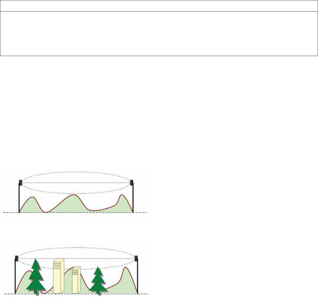
Best performance is achieved when antennas for both the WBX and WPMM monitor are mounted at the same height and in a direct
line of sight (LOS) with no obstructions. Generally, the higher the antenna is above ground, the better it performs. Another concern is
RF interference, discussed in Section 5.5.3.
Figure 15. WBX to WPMM or WDRR Antennas with RF Signal Line of Sight (LOS) Free From Obstacles
Figure 16. WBX to WPMM or WDRR Antennas with RF Signal Line of Sight (LOS) Affected by Obstacles

26 Honeywell Sensing and Control
Limitless™ Series WBX Limit Switch ISSUE 1 50096377
5.2.2 Outdoor Installation Warnings
m WARNING
LIVES MAY BE AT RISK!
Carefully observe these instructions and any special instructions included with the equipment being installed.
m WARNING
CONTACTING POWER LINES COULD BE FATAL
Look over the site before beginning any installation and anticipate possible hazards, especially these:
• Makesurenopowerlinesarenearwherepossiblecontactcanbemade.Antennas,masts,towers,guywires,orcables
may lean or fall and contact these lines. People may be injured or killed if they are touching or holding any part of equip-
ment when it contacts electric lines. Make sure there is NO possibility that equipment or personnel can come in contact
directly or indirectly with power lines.
• Assumealloverheadlinesarepowerlines.
• Thehorizontaldistancefromatower,mast,orantennatothenearestpowerlineshouldbeatleasttwicethetotallength
of the mast/antenna combination. This will ensure that the mast will not contact power if it falls during either installation or
later.
m WARNING
TO AVOID FALLING, USE SAFE PROCEDURES WHEN WORKING AT HEIGHTS ABOVE GROUND
• Selectequipmentlocationsthatwillallowsafe,simpleequipmentinstallation
• Don’tworkalone.Afriendorco-workercansavealifeifanaccidenthappens.
• Useapproved,non-conductingladdersandothersafetyequipment.Makesureallequipmentisingoodrepair.
• Ifatowerormastbeginsfalling,don’tattempttocatchit.Standbackandletitfall.
• Ifanythingsuchasawireormastdoescomeincontactwithapowerline,DON’TTOUCHITORATTEMPTTOMOVEIT.
Instead, save a life by calling the power company.
• Don’tattempttoerectantennasortowersonwindydays.
m WARNING
MAKE SURE ALL TOWERS AND MASTS ARE SECURELY GROUNDED, AND ELECTRICAL CABLES
CONNECTED TO ANTENNAS HAVE LIGHTNING ARRESTORS.
This will help prevent fire damage or human injury in case of lightning, static build up, or short circuit within equipment connected
to antenna.
• Thebaseoftheantennamastortowermustbeconnecteddirectlytothebuildingprotectivegroundortoone-or-moreap-
proved grounding rods, using 1 AWG ground wire and corrosion-resistant connectors.
• RefertotheNationalElectricalCodeforgroundingdetails.
• LightningarrestorsforantennafeedcoaxialcablesareavailablefromHyperLinkTechnologies,Inc.
m WARNING
If a person comes in contact with electrical power, and cannot move
DO NOT TOUCH THAT PERSON OR RISK ELECTROCUTION.
• Useanon-conductivedryboard,stick,orropetopush,pull,ordragthemsotheynolongerareincontactwithelectrical
power.
• Oncetheyarenolongercontactingelectricalpower,administerCPRifcertied,andmakesureemergencymedicalaid
has been requested.
, ATTENTION
When the WBX switch is being installed or operating in a hazardous environment, the end customer/user should issue a work
permit to a trained professional installer prior to any work performed on the Limitless™ WBX switch. This includes the following
actions:
•Installationand/oroperationoftheLimitless™WBXswitch
•Installationand/oradjustmentofaremoteantennafortheLimitless™WBXswitch
•MaintenanceontheLimitless™WBXswitch,includingbatteryreplacement,pairing,purging,etc.
Honeywell Sensing and Control 27
Limitless™ Series WBX Limit Switch ISSUE 1 50096377
5.2.3 Antenna Styles and Mounting Options
m WARNING
RF EXPOSURE
To satisfy FCC RF exposure requirements for mobile transmitting devices, a separation distance of 20 cm [7.87 in] or more should
be maintained between the antenna of this device and persons during device operation. To ensure compliance, operation at closer
than this distance is not recommended. The antenna used for this transmission must not be co-located in conjunction with any
other antenna or transmitter.
Failure to comply with these instructions could result in death or serious injury.
m WARNING
POTENTIAL ELECTROSTATIC CHARGING HAZARD
When the WBX Series is installed in potentially hazardous locations care should be taken not to electrostatically charge the surface
of the antenna shroud by rubbing the surface with a cloth, or cleaning the surface with a solvent. If electrostatically charged,
discharge of the antenna shroud to a person or a tool could possibly ignite a surrounding hazardous atmosphere.
m WARNING
RISK OF DEATH OR SERIOUS INJURY FROM EXPLOSION OR FIRE
Connection and disconnection of the antennas should only be performed in a non-hazardous area and with no battery power
applied to the WBX. This is due to the risk of possibly damaging the internal WBX electronics and/or igniting the surrounding
hazardous atmosphere.
Failure to comply with these instructions could result in death or serious injury.
5.2.3.1 Antenna Connection, Styles, and Mounting Options
Choosing an antenna mounting style depends on application conditions, along with antenna benefits and/or features and user pref-
erence. The antenna’s gain (discussed further in Section 5.4) to some extent determines physical size; also a consideration is the
amount of room available in the application.
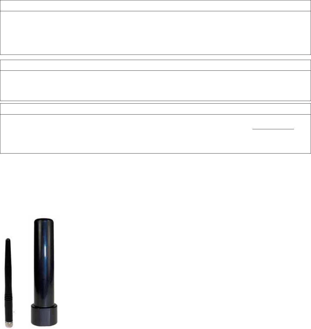
Figure 17. Straight Antennas (Radome included with 2.0 dBi straight antenna)
Adhesive mount: The benefit of the remote adhesive mount antenna is mounting flexibility to a number of surfaces and in various ori-
entations. Remember, the surface that the antenna is being mounted to will affect the radiation pattern so it is suggested that masking
tape be used to temporarily attach the antenna. Perform fade-margin testing, as described in Section 5.4 before permanently mount-
ing.
28 Honeywell Sensing and Control
Limitless™ Series WBX Limit Switch ISSUE 1 50096377
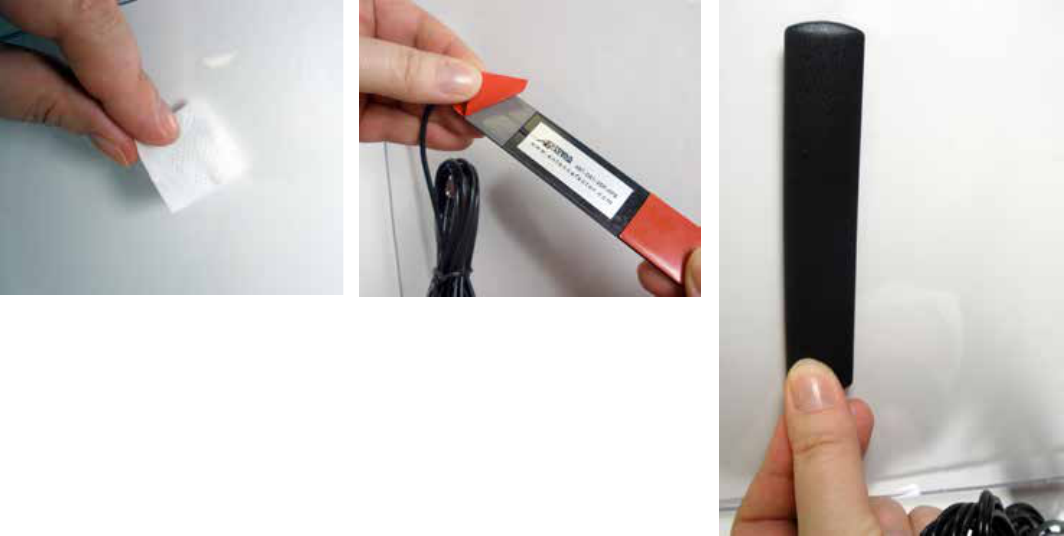
Permanent mounting: Pre-clean the surface where the antenna is to be mounted with an alcohol wipe. Peel paper protection from
adhesive strip and mount to the cleaned surface (see Figures 19, 20, and 21).
Figure 18. Adhesive Mount Antenna
– Step 1. Pre-clean the surface
Figure 19. Adhesive Mount Antenna
– Step 2. Peel Protection from Adhe-
sive Strip
Figure 20. Adhesive Mount Antenna
– Step 3. Mount the Antenna
Honeywell Sensing and Control 29
Limitless™ Series WBX Limit Switch ISSUE 1 50096377
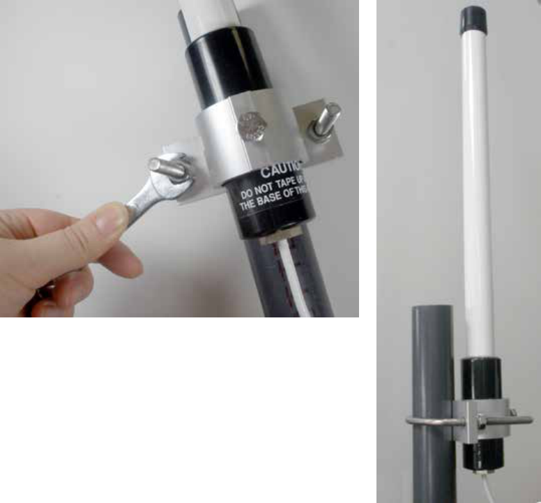
Mast mount: The benefit of the mast-mount antenna is its rigid design and resistance to displacement when subjected to shock,
vibration, wind, etc. It can be easily mounted high above the ground to obtain greater RF signal performance and it withstands winds
up to 100 mph.
• Mast-mountbracket(Includedwiththe8dBiantenna):Attachantennatoitsmountingbracketandtightennut.Assembletwo
U-clamps around mast and tighten nuts to ensure lock washers provided are compressed to a flat condition (See Figures 21
and 22).
Figure 21. Mast Mount Antenna –
Tighten nut on mounting bracket
Figure 22. Mast Mount Antenna –
Side View with Attachment to Pipe
30 Honeywell Sensing and Control
Limitless™ Series WBX Limit Switch ISSUE 1 50096377
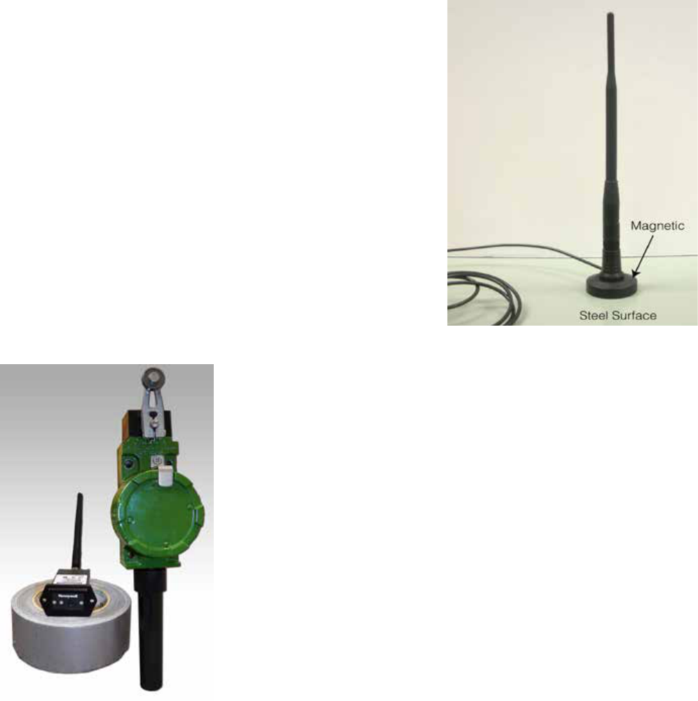
Magnetic mount: The benefit of the magnetic-mount antenna is
its ability to mount on any ferrous-metal surface and in various
orientations. A smooth metal surface is preferred to allow the best
attraction of the magnet to the surface. First, the user will need
to determine if the magnetic attraction is sufficient to hold the
antenna in the desired position (i.e., shock, vibration, etc. in the
application). Placing the antenna in a location where it cannot be
inadvertently displaced may help. Magnetic-mount antennas are
not designed for mobile applications (see Figure 23).
5.2.4 Antenna Adjustment Considerations
The antenna of the WBX and WPMM monitor or WDRR receiver
should be oriented in parallel. This will, in most cases, allow
the longest range and highest RF signal. The least RF signal is
normally in a direction in-line with the top of the antenna, so avoid
having antennas pointed directly toward or directly away from
each other.
Figure 23. Magnetic Mount Bracket with Antenna –
Mounted on Steel Surface
Figure 24. Highest RF Signal When Antennas are as Parallel to Each Other as Possible

Honeywell Sensing and Control 31
Limitless™ Series WBX Limit Switch ISSUE 1 50096377
5.3 Signal Range of an Antenna
The signal range is defined as the physical distance between the WBX and WPMM monitor or WDRR receiver. It’s a function of the
antenna’s gain, radio output of the WBX switch and WPMM monitor or and cable loss (if used) in conjunction with the environment (i.e.
outdoor urban, indoors, etc.) that the Limitless™ product is operating in.
Signal range specication:
305 m [1000 ft] (nominal)
Line of sight with a 2.0 dBi antenna installed on the WBX and WPMM monitor or WDRR receiver
5.4 Choosing an Antenna Gain (dBi) With Acceptable Fade-Margin
There are several different antenna gain options in the Limitless™ Series to choose from. This section helps determine the antenna
version(s) that will provide suitable RF signal performance for specific applications.
m WARNING
The attenuator shall be used for testing purposes only. The connection and disconnection of the antennas/attenuator should only
be performed in a non-hazardous area and with no battery power applied to the WBX. This is due to the risk of possibly damaging
the internal WBX electronics and/or igniting the surrounding hazardous atmosphere.
Failure to comply with these instructions could result in death or serious injury.
The Limitless™ Series antenna’s actual gain is measured by how much of the input power from the internal radio of the WBX is con-
centrated in a particular direction. The WBX’s antenna transmits RF signals, and also receives RF signals from a Limitless™ WPMM
monitor or WDRR receiver. In a particular application, transmit signal strength may be better than the receive signal strength or vice
versa. The intent is to choose an antenna with the optimum gain relative to application conditions for both transmitting and receiving.
Fade-margin is the amount of excess power available above and beyond what is necessary to maintain a reliable RF signal between
the transmitter and receiver. Normally, an acceptable threshold of excess power to ensure effective operation in a variety of environ-
mental conditions is 10 dB. A simple way to determine if the signal strength is sufficient is to temporarily install a 10 dB attenuator*
between the RP-SMA plug of the antenna or remote cable and RP-SMA jack of the WBX. This should be completed in an operating
application environment with good nominal environmental conditions. When using a WPMM monitor and starting with the antenna cho-
sen in Section 3.1, install the attenuator and operate the system until exposure of all normal application conditions is completed while
monitoring the amber yellow LED (RF link/signal indicator of the WPMM monitor). If the fade-margin is unacceptable, the LED turns on
solid indicating that the antenna position on the WBX and/or WPMM monitor will need to be changed or another antenna type should
be chosen. If using a WDRR receiver; the RF signal strength can be monitored via the RF Signal Strength LEDs. Please refer to the
FUNCTIONAL INDICATOR section in the WDRR Installation and Technical Manual for further details of operation.
Try several mounting locations and/or antennas while retesting each with the attenuator to determine the optimal set-up that provides
an acceptable fade-margin. Remember to remove the attenuator after testing is completed.
*Suggested sources/part numbers
• 10dBattenuator(i.e.Crystek–Partnumber:CATTEN-0100)
• RP-SMAfemaletoSMAmaleconnectorAdapter(i.e.ConnectorCity–Partnumber:ADP-SMAM-RPSF)
• RP-SMAmaletoSMAfemaleconnectorAdapter(i.e.ConnectorCity–Partnumber:ADP-RPSM-SMAF)

32 Honeywell Sensing and Control
Limitless™ Series WBX Limit Switch ISSUE 1 50096377
5.5 Environment Usage/Concerns
5.5.1 Choosing an Antenna/Cable to Meet Application Exposure Conditions
There is no antenna or cable design impervious to every environmental condition that it could be exposed to. So it is suggested that
the application environment be reviewed as follows:
Step Action
1 Determine where the antenna will be installed and the application conditions: indoor, outdoor, or limited outdoor exposure.
Even if the antenna is going to be used indoors, an outdoor antenna may be more suitable (i.e., resistant to fluids, rigid
construction, etc.)
2 Determine what the antenna may be subjected to (i.e., fluids, chemicals, oils, wind, shock, vibration, etc.).
3 A. Review antenna and/or cable materials (listed in Section 5.1) against resistance to chemicals and fluids. If choos-
ing an adhesive mount, adhesive resistance testing may be necessary.
B. If shock, vibration, wind, rain, sleet/snow, etc. are in the application, choose an antenna rated for outdoors and
has a rigid design as defined in Sections 5.1 and 5.2.3.2.
4 The WBX’s enclosure is designed to meet Type seal requirements; however, this step may be required to provide an extra
level of protection, especially if the application may be subjecting antennas and cables to liquids. The RP-SMA connec-
tions, tilt/swivel joints, and cable entrances are potential leak paths that could lead to corrosion. The following procedure is
one way to provide extra protection to these connections and joints.
Ensure that the area you are applying tape to is clean from contaminants by first cleaning with mild detergent/water and
completely dry. Follow with an isopropyl alcohol wipe of the area.
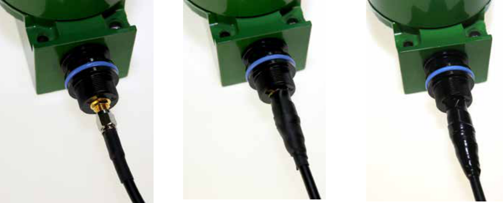
Layer 1: Wrap a layer of polyvinyl chloride insulating tape
Layer 2: Wrap a layer of Rubber splicing tape i.e. Scotch™ 23
Layer 3: Wrap a layer of UV stable polyvinyl chloride insulating tape
Layer 1 allows the user to remove Layer 2 for connector inspection, antenna replacement, repositioning of the tilt/
swivel antenna, etc.
See Figure 25 as an example of the tapes applied to a RP-SMA jack antenna connection. The lime/black antenna guard is
not required to be installed.
If the antenna and connectors are not protected by the radome, the connector and threads should be protected from the elements
thorugh an application of protective tape.
• ArecommendedprotectivetapeisCOAX-SEAL#104HandMoldablePlasticWeatherproongTape,availablefromLCOM,
Inc.
• AlsoacceptableisScotch® Premium Vinyl Electrical Tape 88-Super tape, available from 3M.
Honeywell Sensing and Control 33
Limitless™ Series WBX Limit Switch ISSUE 1 50096377
Figure 25 – Application of Protective Tape
Step 1 - Remove radome. Step 2 - First apply 1/2 inch wide Coax
Seal (exible and moldable material)
Step 3 - Secondly, apply 3M Scotch®
Premium Vinyl Electrical Tape 88-Super
In the end, the antenna/cable choice may need to be tested in the actual application conditions to prove suitability.
5.5.2 RF Interference
The WBX and WPMM or WDRR radio operate in the 2.4 GHz range. Upon initial pairing with the WBX, the WPMM’s or WDRR’s radio
will automatically scan each of the 9 or 12 channels in the 2.4 GHz range and choose a channel with the least amount of usage. This
provides a level of protection from RF interference as the chosen channel where RF communication is low will have a lower chance of
signal collision.
However, if multiple RF sources exist in the chosen channel or the external source has an extremely high power intensity or it is in
close proximity to the Limitless™ Series antenna, RF interference can cause an RF signal to not reach the WBX or WPMM monitor, or
WDRR receiver. RF interference can be caused by many sources (i.e., other radios in the same operating range, solar activity, high
frequency digital products, conventional microwave ovens, etc.). If the Limitless™ Series is in an environment with a high usage of
products in the 2.4 GHz range, or the RF environment is unknown, an on-site RF survey may prove to be valuable in identifying pos-
sible RF interference sources along with other existing wireless devices.
Once the RF sources are identified and located, it may allow the Limitless™ Series antennas to be moved away from the identified RF
sources to achieve acceptable performance. The other option is removing the external source, if feasible.
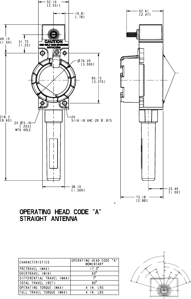
34 Honeywell Sensing and Control
Limitless™ Series WBX Limit Switch ISSUE 1 50096377
5.6 WBX Mounting
5.6.1 WBX Heavy-Duty Intrinsically Safe Limit Switch with Mechanical Actuators
The housing has two slotted mounting holes that will accept a M5 or #10 size screw and allow adjustment of the switch actuator to the
customer actuator during installation. The switch also has two 10-32 UNF tapped holes for mounting from the back.
Note: The adjustment process should not allow preload of the switch actuator and the full travel of the switch actuator should not ex-
ceed the switch over travel maximum specification. (See installation drawing at sensing.honeywell.com)
Figure 26. Limitless™ WBX Dimensions (Side Rotary)
Operating point given in relation to lever mounting shaft. Free Position
T.T.
O.T.
P. T.
R.T.
D.T.
Total
Travel
Pretravel
Overtravel
Differential
Travel
Release
Travel
Mounting Pad
s
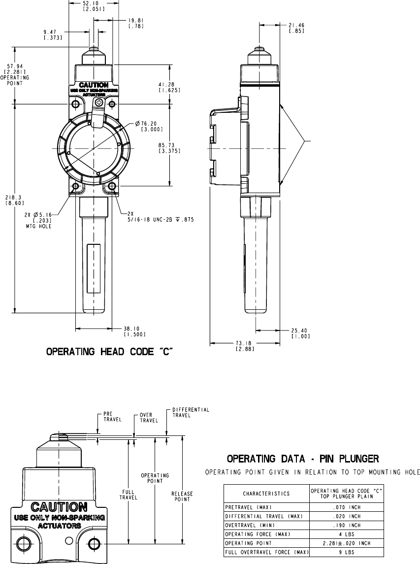
Honeywell Sensing and Control 35
Limitless™ Series WBX Limit Switch ISSUE 1 50096377
Figure 27. Limitless™ WBX Dimensions
Pin Plunger
STRAIGHT ANTENNA
Mounting Pads
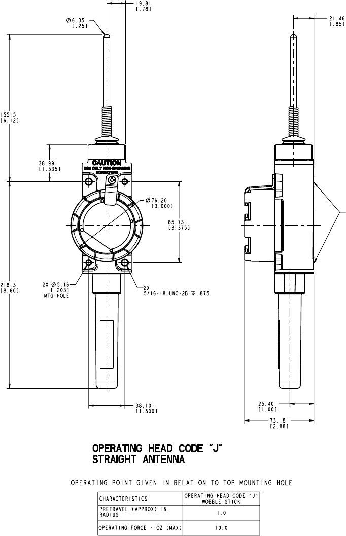
36 Honeywell Sensing and Control
Limitless™ Series WBX Limit Switch ISSUE 1 50096377
Figure 28. Limitless™ WBX Dimensions
Wobble
Mounting Pads
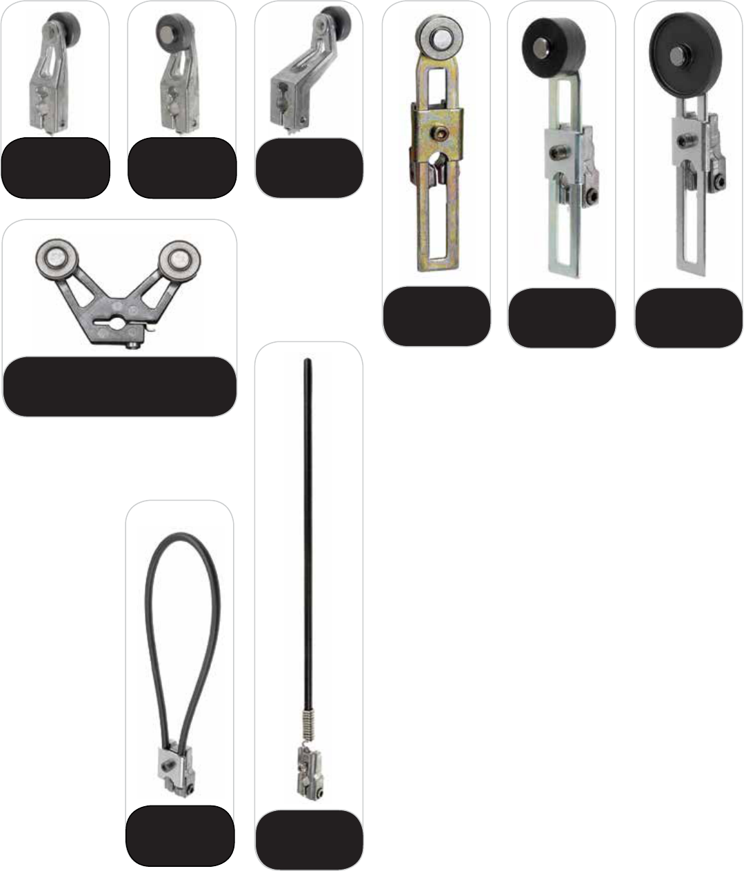
Honeywell Sensing and Control 37
Limitless™ Series WBX Limit Switch ISSUE 1 50096377
LSZ51A
fixed rotary lever,
nylon roller, front
LSZ51C
fixed rotary lever,
nylon roller, back
LSZ53E
yoke lever, nylon rollers,
back/front placement
LSZ55A/C
offset lever, nylon
front & back
LSZ52A/C
adj. lever, nylon,
front/back
LSZ52J
adjustable lever,
1-inch nylon roller
LSZ52K
adjustable lever,
1.5-inch nylon roller
LSZ61
6-inch
loop
LSZ68
12-inch rod
with spring
Figure 29. Limitless™ WBX Available Levers

38 Honeywell Sensing and Control
Limitless™ Series WBX Limit Switch ISSUE 1 50096377
6 INSPECTION AND MAINTENANCE
6.1 WBX Inspection and Replacement
Periodic inspection
• ChecktheWBXhousingandtheactuator,cablegrip,and/orconnectors,etc.forsignsofdamage.Replaceifnecessary
, ATTENTION
When the WBX switch is being installed or operating in a hazardous environment, the end customer/user should issue a work
permit to a trained professional installer prior to any work performed on the Limitless™ WBX switch. This includes the following
actions:
•Installationand/oroperationoftheLimitless™WBXswitch
•Installationand/oradjustmentofaremoteantennafortheLimitless™WBXswitch
•MaintenanceontheLimitless™WBXswitch,includingbatteryreplacement,pairing,purging,etc.
6.2 Antenna Inspection and Replacement
Periodic inspection
• CheckradomeorcableconnectiontoWBXconnectortoensureitistightandnosignsofdamageorcorrosion.Replaceif
necessary per Section 5.2.3.1.
, ATTENTION
When the WBX switch is being installed or operating in a hazardous environment, the end customer/user should issue a work
permit to a trained professional installer prior to any work performed on the Limitless™ WBX switch. This includes the following
actions:
•Installationand/oroperationoftheLimitless™WBXswitch
•Installationand/oradjustmentofaremoteantennafortheLimitless™WBXswitch
•MaintenanceontheLimitless™WBXswitch,includingbatteryreplacement,pairing,purging,etc.
6.3 Battery Replacement
When to replace
• Batteryisdeadorlow.TheWPMMandWDRRwillindicateadeadorlowbatteryconditionwhenayellowLEDisashing.
Upon this indication, proceed with replacing the battery in the WBX as per below.
Tools required
• SlottedorPhillipsscrewdriver
m WARNING
RISK OF DEATH OR SERIOUS INJURY FROM EXPLOSION OR FIRE
Connection and disconnection of the batteries should only be performed in a non-hazardous area. The batteries used in this de-
vice may present a risk of fire or chemical burn if mistreated. Do not recharge, disassemble, heat above 100°C [212°F], or inciner-
ate.
Failure to comply with these instructions could result in death or serious injury.
m WARNING
RISK OF DEATH OR SERIOUS INJURY FROM EXPLOSION OR FIRE
If the WBX is to be returned to Honeywell for any reason, the battery MUST be removed prior to shipping. Dispose of used batter-
ies promptly per local regulations or the battery manufacturer’s recommendations. Keep away from children. Do not disassemble
and do not dispose of in fire.
Failure to comply with these instructions could result in death or serious injury.

Honeywell Sensing and Control 39
Limitless™ Series WBX Limit Switch ISSUE 1 50096377
m WARNING
When installing the battery, do not snag the battery terminal on the clip or the battery may be damaged. Do not apply excessive
force. Do not drop. Dropping the battery may cause damage. If a battery is dropped, do not install the dropped battery into the
WBX. Dispose of dropped battery promptly per local regulations or per the battery manufacturer’s recommendations
Failure to comply with these instructions could result in death or serious injury.
m WARNING
RISK OF DEATH OR SERIOUS INJURY FROM EXPLOSION OR FIRE
Both batteries must be the same model from the same manufacturer. Mixing old and new batteries or different manufacturers is
not permitted.
Use only the following 3.6 V lithium thionyl chloride (Li-SOCl2) battery (non-rechargeable), size AA. No other batteries are
approved for use in the WBX Series. Always replace both batteries.
•XENOEnergy,partnumber:XL-060F
•Tadiran,partnumber:TL-5903/S
•Bi-Power,partnumber:ER14505H
, ATTENTION
When the WBX switch is being installed or operating in a hazardous environment, the end customer/user should issue a work
permit to a trained professional installer prior to any work performed on the Limitless™ WBX switch. This includes the following
actions:
•Installationand/oroperationoftheLimitless™WBXswitch
•Installationand/oradjustmentofaremoteantennafortheLimitless™WBXswitch
•MaintenanceontheLimitless™WBXswitch,includingbatteryreplacement,pairing,purging,etc.
Reference Figure 30.
Step Action
1 Remove the housing cover by turning CCW as shown in Figure 30.
2Remove old battery from the battery holder by using pulling on the battery extractors as shown. Remove the battery
extractors and install on the new battery housings.
3 Install battery as follows to avoid damage to the battery and holder:
• Seelabelinbatteryholderdeningthe“+”and“-”terminals to ensure battery is placed in holder with correct
polarity.
• Donotattempttobendthebattery’shold-downtabsforward.
• Insertthebatterynegativeendunderthehold-downtab,atanangle,andagainsttheendofthespringtab.
Simultaneously move the negative end of the battery into position, compressing the spring tab, and angle the
positive end into the holder .
4 Replace cover and ensure it is turn fully CW until tight; see Figure 30.
5 Dispose of used battery promptly per local regulations or the battery manufacturer’s recommendations. Keep away from
children. Do not disassemble and do not expose of in fire.
Note: Re-pairing via pairing mode is not required after installing a new battery
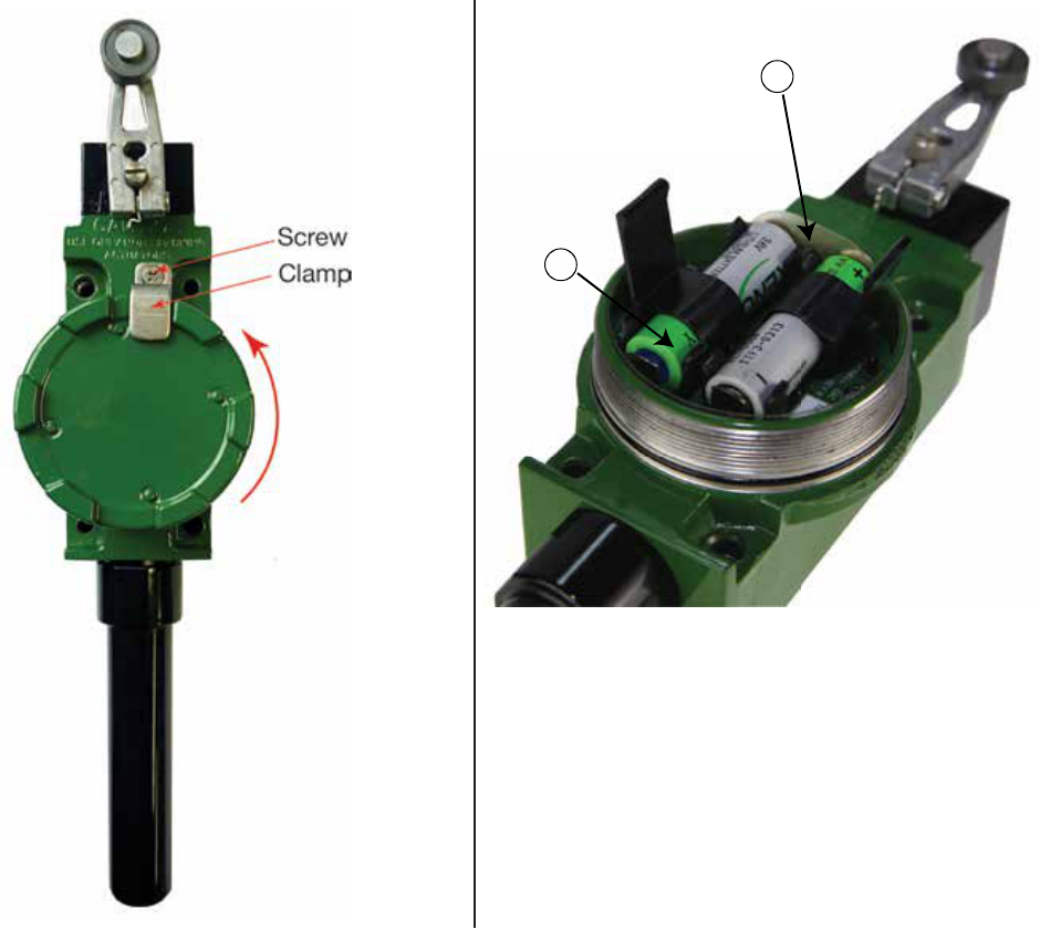
40 Honeywell Sensing and Control
Limitless™ Series WBX Limit Switch ISSUE 1 50096377
Figure 30. Limitless™ WBX Battery Replacement
3
2
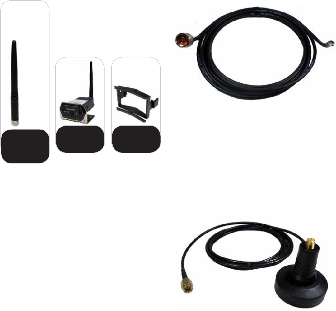
Honeywell Sensing and Control 41
Limitless™ Series WBX Limit Switch ISSUE 1 50096377
7 ACCESSORIES
7.1 Antenna Options
WAN01RSP
straight design,
2.2 dBi gain,
direct mount
connector
WPB1
WPMM mounting
bracket
WPR1
WPMM panel mount
retainer
Antenna
Type Code
“01”
7.2 Antenna Cable Options
WCA200RNPRSP-002 Cable Assembly: 2 ft1
WCA200RNPRSP-010 Cable Assembly: 10 ft1
1 use only with WAN06RNJ antenna and when extra cable is desired
WCA200RNJRSP-002 Cable Assembly: 2 feet length2
WCA200RNJRSP-005 Cable Assembly: 5 feet length2
WCA200RNJRSP-010 Cable Assembly: 10 feet length2
WCA200RNJRSP-015 Cable Assembly: 15 feet length2
WCA200RNJRSP-020 Cable Assembly: 20 feet length2
2 Use when extra cable length is desired and allows connection from RP-SMA jack
to RP-SMA plug
7.3 Antenna Mounting Options
WAMM100RSP-005 Magnetic Antenna Mount: w/ 5 ft of cable3
WAMM100RSP-010 Magnetic Antenna Mount: w/ 10 ft of cable3
3 Use only with WAN01RSP, WAN02RSP, WAN04RSP, WAN05RSP, or WAN08RSP
antennas
8 INSTALLATION DRAWINGS
8.1 Drawing Availability
Complete installation drawings for each listing of the Limitless™ WBX Series switch and accessories are available
at sensing.honeywell.com
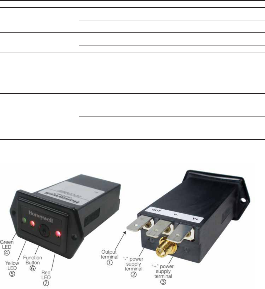
42 Honeywell Sensing and Control
Limitless™ Series WBX Limit Switch ISSUE 1 50096377
9 TROUBLESHOOTING GUIDES
9.1 WBX used in conjunction with a WPMM
The troubleshooting guide includes WPMM indications and symptoms as it is being used in conjunction with the WBX. Refer to Figure
31 for layout of LEDs, terminals, connections, etc.
SYMPTOM CAUSE RESOLUTION
Green LED is not ON
10 Vdc to 30 Vdc is not applied to
"+" & "-" terminals
Check for proper connection and 10 Vdc to 30 Vdc to
"+" and "-" terminals
Power leads connected in reverse Check for proper connection of power: "+" and “-”
terminals
Green , yellow and/or red
LEDs do not blink ON at start-up
WPMM internal electronics dam-
aged Replace WPMM
LED(s) burnt out Replace WPMM
Green , yellow , and red
LEDs are momentarily OFF then ON
with possible output change during
normal operation. Resulting in only
green LED on and possibly incor-
rect yellow and red LED indica-
tion/output for up to 30 seconds.
ESD/EMI exposure beyond pub-
lished specifications or device
performing self check
Determine source for ESD/EMI emissions in application
and take action to remove
Yellow LED is flashing
Low battery in WBX
• DeterminewhichWBXhasalowbatteryusingthe
procedure in the TROUBLESHOOTING MODE sec-
tion of the WPMM Installation and Technical manual.
• ReplaceWBXbatteryperSection6.3
Incorrect battery installed in WBX
switch
• DeterminewhichWBXhasalowbatteryusingthe
procedure in the TROUBLESHOOTING MODE sec-
tion of the WPMM Installation and Technical manual.
• ReplaceWBXbatteryperSection6.3
Figure 31. Limitless™ WPMM With Call-outs

Honeywell Sensing and Control 43
Limitless™ Series WBX Limit Switch ISSUE 1 50096377
SYMPTOM CAUSE RESOLUTION
Yellow LED is constantly ON
Dead or low battery in WBX
• DeterminewhichWBXhasalowbatteryusingthe
procedure in the TROUBLESHOOTING MODE sec-
tion of the WPMM Installation and Technical manual
• WBXstatuswillinthiscasebereportedasinsuf-
ficient RF
• ReplaceWBXbatteryperSection6.3
Incorrect battery installed in WBX
• DeterminewhichWBXhasalowbatteryusingthe
procedure in the TROUBLESHOOTING MODE sec-
tion of the WPMM Installation and Technical manual.
• WBXstatuswillinthiscasebereportedasinsuf-
ficient RF
• ReplaceWBXbatteryperSection6.3
RF range/distance between
WPMM and WBX is beyond
capability
Reposition WBX closer to the WPMM until yellow LED
is no longer ON
Exposure to adjacent materials/
objects and/or materials/objects
Reposition WBX away from objects until yellow LED
is no longer ON
Damage or missing antenna from
WPMM and/or WBX Replace antenna; reference Section 5.2.3.1
Antenna alignment is not accept-
able Reposition antenna; reference Section 5.2.4
Damage to antenna cable Replace antenna cable; reference Section 5.2.3.1
Loose antenna or cable connec-
tions
Check connections and tighten as necessary; refer-
ence Section 5.2.3.1

44 Honeywell Sensing and Control
Limitless™ Series WBX Limit Switch ISSUE 1 50096377
SYMPTOM CAUSE RESOLUTION
Red LED is not ON and buzzer
does not sound when WBX is actu-
ated (green LED ON, yellow LED
OFF) *
WBX is not paired to WPMM Pair WBX to WPMM per Section 4.4
WPMM buzzer was set to “mute”
during initial set-up
Refer to WPMM Installation and Technical Manual as
the WPMM will need to be factory reset, and paired to
the WBX(es)
Actuator is nonfunctional or
defective Replace actuator
WBX internal electronics dam-
aged Replace WBX
Yellow LED burnt out or dam-
aged electronics of WPMM Replace WPMM
Red LED burnt out Replace WPMM
Buzzer not sounding when WBX actu-
ated (green LED ON, yellow LED
OFF) *
*Dependant on if the WPMM Set-up mode was
used during initial set-up, this operation may be
expected
WBX is not paired to WPMM Pair WBX to WPMM per Section 4.4
WPMM buzzer was set to “mute”
during initial set-up
Refer to WPMM Installation and Technical Manual as
the WPMM will need to be factory reset, and paired to
the WBX(es)
Actuator defective Replace actuator
WBX internal electronics dam-
aged Replace WBX
Yellow LED burnt out or dam-
aged electronics of WPMM Replace WPMM
Buzzer burnt out Replace WPMM
Electrical output is not changing state
when WBXis actuated (green LED
ON, yellow LED OFF)
*Dependant on if the WPMM Set-up mode was
used during initial set-up, this operation may be
expected
WBX is not paired to WPMM Pair WBX to WPMM per Section 4.4
Incorrect connections Check for correct connections to output terminal "O"
with respect to minus "-" terminal
Actuator in WBX IS nonfunctional
or defective Replace actuator
WBX internal electronics dam-
aged Replace WBX
Damaged output Replace WPMM

Honeywell Sensing and Control 45
Limitless™ Series WBX Limit Switch ISSUE 1 50096377
9.2 WBX used in conjunction with a WDRR
The troubleshooting guide includes WDRR indications and symptoms as it is being used in conjunction with the WBX. Refer to Figure
32 for layout of LEDs, terminals, connections, etc.
SYMPTOM CAUSE RESOLUTION
Green power LED is not ON
10 Vdc to 28 Vdc is not applied to
"+" & "-" terminals 2 3
Check for proper connection and 10 Vdc to 28 Vdc to
"+" and "-" terminals 2 3
Power leads connected in reverse Check for proper connection of power: "+" and “-”
terminals 2 3
Green, yellow and/or red configu-
ration LEDs do not blink ON at
start-up
WDRR internal electronics dam-
aged Replace WDRR
LED(s) burnt out
Check LED operation referencing “Tri-color Output
LEDs” section (RF Link position “F”) described in the
WDRR Installation and Technical Manual and replace
WDRR if necessary
Tri-color output LEDs 9 are momen-
tarily OFF then ON with possible NPN/
PNP output change during normal op-
eration. Resulting in only green Power
LED on and possibly incorrect yellow
and red LED 9 indication/output for
up to 30 seconds.
ESD/EMI exposure beyond pub-
lished specifications or device
performing self check
Determine source for ESD/EMI emissions in application
and take action to remove
Yellow LED 9 is flashing
Low battery in WBX
• DeterminewhichWBXhasalowbatterybyvisually
inspecting the tri-color output LEDs 9 as one or
more should be flashing yellow (see WDRR Installa-
tion and Technical Manual)
• ReplaceWBXbatteryperSection6.3
Incorrect battery installed in WBX
• DeterminewhichWBXhasalowbatterybyvisually
inspecting the tri-color output LEDs 9 as one or
more should be flashing yellow (see WDRR Installa-
tion and Technical Manual)
• ReplaceWBXbatteryperSection6.3

46 Honeywell Sensing and Control
Limitless™ Series WBX Limit Switch ISSUE 1 50096377
SYMPTOM CAUSE RESOLUTION
Yellow tri-color output LED 9 is con-
stantly ON
Dead or low battery in WBX
• DeterminewhichWBXhasalowbatterybyvisually
inspecting the tri-color output LEDs 9 as one or
more should be flashing yellow (see WDRR Installa-
tion and Technical Manual)
• WBXstatuswillinthiscasebereportedaslostRF
• ReplaceWBXbatteryperSection6.3
Incorrect battery installed in WBX
• DeterminewhichWBXhasalowbatterybyvisually
inspecting the tri-color output LEDs 9 as one or
more should be flashing yellow (see WDRR Installa-
tion and Technical Manual)
• WBXstatuswillinthiscasebereportedaslostRF
• ReplaceWBXbatteryperSection6.3
RF range/distance between
WDRR and in WBX is beyond
capability
Reposition WBX closer to the WDRR until yellow LED 9
is no longer ON
Exposure to adjacent materials/
objects and/or materials/objects
Reposition WBX away from objects until yellow LED 9
is no longer ON
Damage or missing antenna from
WDRR and/or in WBX Replace antenna; reference Section 5.2.3.1
Antenna alignment is not accept-
able Reposition antenna; reference Section 5.2.4
Damage to antenna cable Replace antenna cable; reference Section 5.2.3.1
Loose antenna or cable connec-
tions
Check connections and tighten as necessary; refer-
ence Section 5.2.3.1
Red tri-color output LED 9 is not ON
when WBX is actuated (green power
LED ON, yellow LED 9 OFF)
*Dependant on if the WPMM Set-up mode was
used during initial set-up, this operation may be
expected
WBX is not paired to WDRR Pair in WBX to WDRR
Actuator is nonfunctional or
defective Replace actuator
WBX internal electronics dam-
aged Replace in WBX
Tri-color LED 9 burnt out or dam-
aged electronics of WDRR Replace WDRR
Tri-color red LED 9 burnt out
Check LED operation referencing “Tri-color Output
LEDs” section (RF Link position “F”) described in the
WDRR Installation and Technical Manual and replace
WDRR if necessary
NPN/PNP output(s) 4 is not changing
state when WBX is actuated (green
power LED ON, yellow LEDs 9
OFF)
*Dependant on if the WPMM Set-up mode was
used during initial set-up, this operation may be
expected
WBX(es) not paired to WDRR Pair WBX to WDRR per Section 4.4
Incorrect connections Check for correct connections to output terminal(s) 4
Replace actuator Actuator defective
WBX internal electronics dam-
aged Replace WBX
Damaged output(s) Replace WDRR receiver
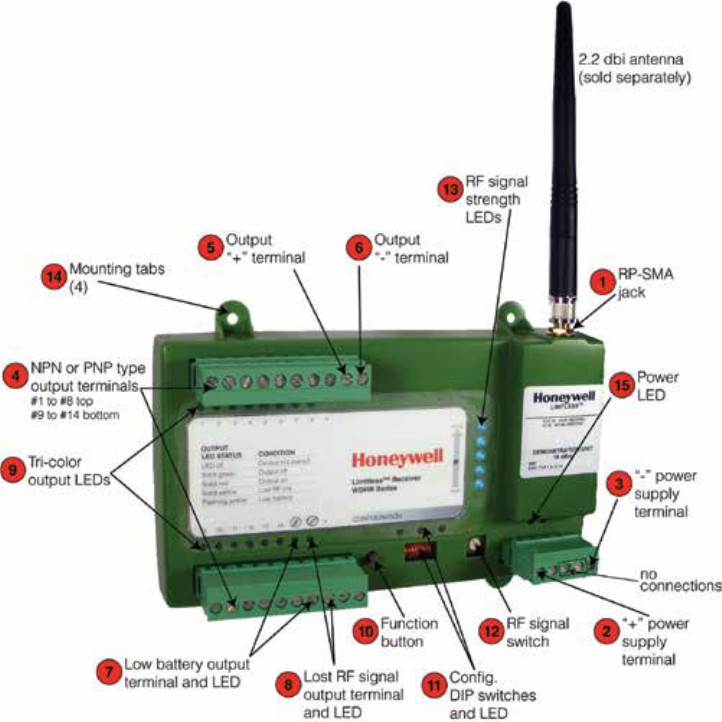
Honeywell Sensing and Control 47
Limitless™ Series WBX Limit Switch ISSUE 1 50096377
Figure 32. Limitless™ WDRR with call-outs
9.3 WBX BATTERY INSTALLATION OR REPLACEMENT
This troubleshooting guide captures a rare symptom of WBX device during battery installation or replacement.
AMBER LED

Sensing and Control
Honeywell
1985 Douglas Drive North
Golden Valley, MN 55422
honeywell.com
50096377-1-EN IL50 GLO Printed in USA.
October 2014
© 2014 Honeywell International Inc. All rights reserved.
WARRANTY/REMEDY
Honeywell warrants goods of its manufacture as being free of
defective materials and faulty workmanship. Honeywell’s stan-
dard product warranty applies unless agreed to otherwise by
Honeywell in writing; please refer to your order acknowledgement
or consult your local sales office for specific warranty details. If
warranted goods are returned to Honeywell during the period of
coverage, Honeywell will repair or replace, at its option, without
charge those items it finds defective. The foregoing is buyer’s
sole remedy and is in lieu of all other warranties, expressed
or implied, including those of merchantability and tness for
a particular purpose. In no event shall Honeywell be liable for
consequential, special, or indirect damages.
While we provide application assistance personally, through our
literature and the Honeywell web site, it is up to the customer to
determine the suitability of the product in the application.
Specifications may change without notice. The information we
supply is believed to be accurate and reliable as of this printing.
However, we assume no responsibility for its use.
Limitless™ Series WBX Limit Switch ISSUE 1 50096377
SALES AND SERVICE
Honeywell serves its customers through a worldwide network of
sales offices, representatives and distributors. For application
assistance, current specifications, pricing or name of the nearest
Authorized Distributor, contact your local sales office or:
E-mail: info.sc@honeywell.com
Internet: sensing.honeywell.com
Phone and Fax:
Asia Pacific +65 6355-2828
+65 6445-3033 Fax
Europe +44 (0) 1698 481481
+44 (0) 1698 481676 Fax
Latin America +1-305-805-8188
+1-305-883-8257 Fax
USA/Canada +1-800-537-6945
+1-815-235-6847
+1-815-235-6545 Fax