Honeywell 201104TXR B578 Ethernet to RF Protocol Converter User Manual INNCOM B574
INNCOM International Inc. B578 Ethernet to RF Protocol Converter INNCOM B574
User Manual.pdf
1
Copyright 2014 INNCOM by Honeywell
INNCOM B578 Datasheet
Overview
INNCOM’s multifunctional controller works in three configurations to facilitate different
Integrated Room Automation System (IRAS) operations:
As the B578S Edge Router, it networks Ethernet to INNCOM’s Deep Mesh RF
network. It provides backhaul networks with up to 200
*
rooms per PAN ID. It
supports multiple IP protocols (UDP, ICMP). The expanded addressing facilitates
transport reliability and multicasting. The Edge Router enhances security and
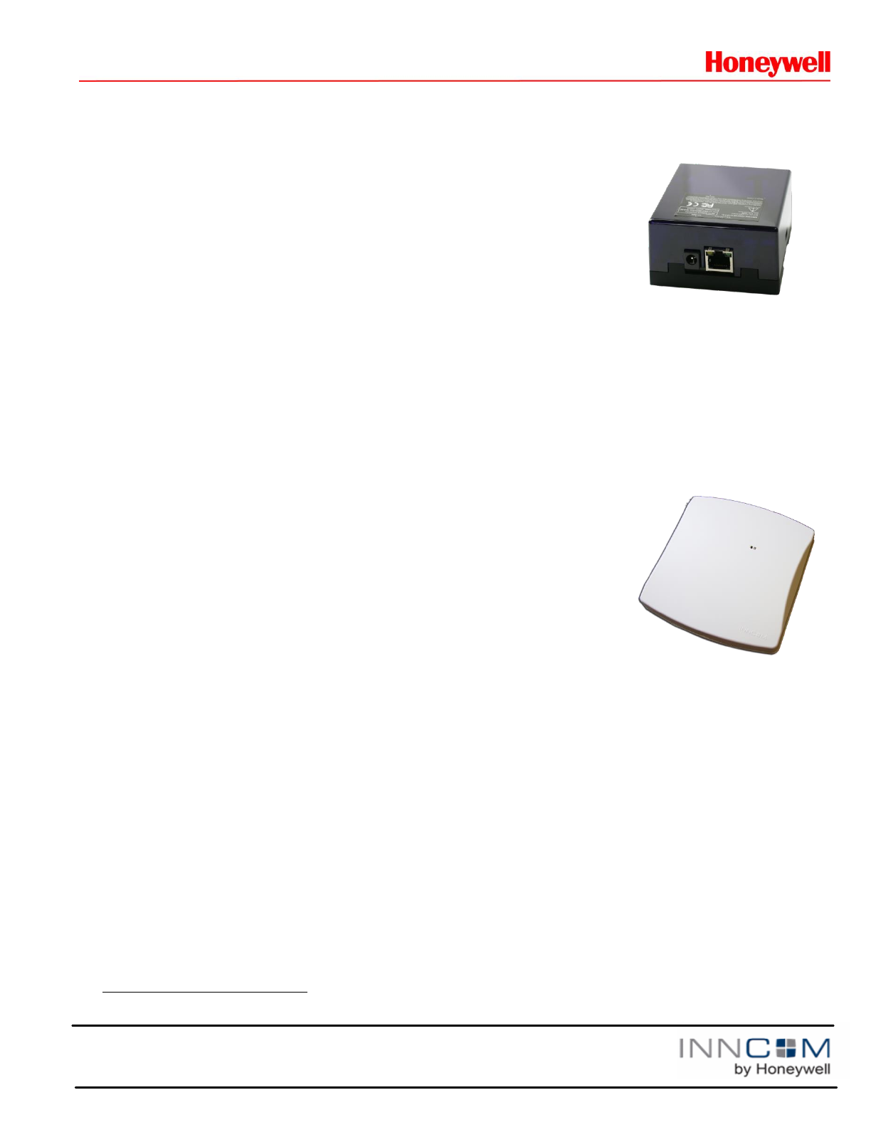
offers RF-to-Ethernet protocol conversion, with the availability of a PoE power supply for Power over Ethernet
applications.
As the B578N, the Edge Router interfaces with the Tridium Niagara JACE (Java Application Control Engine)
controller to provide connectivity to numerous common network protocols such as LonWorks and BACNet, as
well as proprietary networks.
As the PC-803, the device acts as a protocol converter, converting in-room RF traffic to Ethernet towards the
server.
Note: The device will generally be referred to as the “B578” throughout this
document. Statements specific to a particular configuration will be noted
accordingly.
Features
Supports CBL32 control algorithms
RS485 System Interface dongle
10MBit Ethernet
Available in PoE and +12VDC powered models
128 bit AES encryption (Ethernet link and RF network)
Typical indoor RF range up to 100ft
Supports 2.4Ghz IEEE 802.15.4 compliant RF transceiver
Supports S5bus (through external adapter)
Compact physical dimension
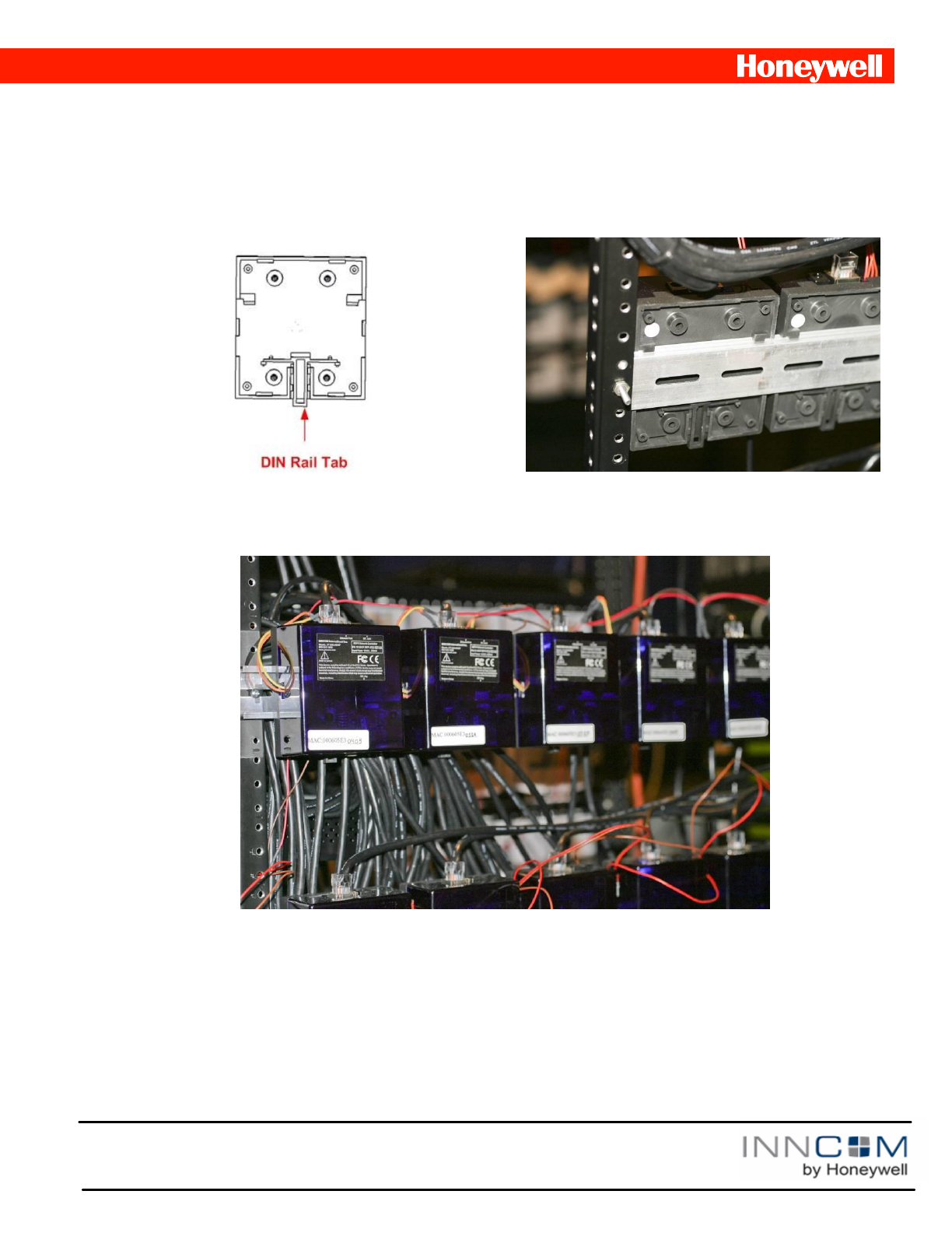
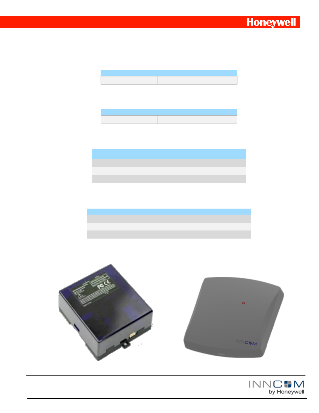
DIN rail mounting option (Figure 1)
Wall or ceiling mount on standard 2-gang ring (Figure 2)
Supports up to 200 rooms depending on the guestroom application deployed and the selected RF environment
at the site.
4 kBytes mailbox memory usable as a relay-buffer for battery operated devices (Edge Router)
IPv6 support (Edge Router)
*
The 200 device limit is based on timing considerations used by the communication protocols of a Deep Mesh network. Local RF interference
sources, conditions, and device placement can decrease this number.
Figure 2 B578 Wall/Ceiling Mountable
Figure 1 B578 DIN

2
Copyright 2014 INNCOM by Honeywell
Specifications
Parameter
B578
RF Data Rate
250kbps
Indoor/Urban RF range
100ft
RF Transmit Power
50mW (+17dBm)
RF Receive Sensitivity
-97.7dBm
Frequency Band
2.4Ghz
Encryption
AES-128
Protocol
802.15.4
Frequency Channels
11–26
Network Topology
Mesh
Maximum devices per IP network segment
50 B578 PAN coordinators; 2000 PC-803 room gateways; 200 Edge Routers
Maximum devices per RF mesh network
Up to 200 (depending on application profile and site situation)
Maximum in-room devices per room
Up to 50
Supply Voltage
12VDC
Current Consumption
200mA peak, 100mA RMS
Operating Ambient Temperature
0–40 °C
Dimensions
86mm x 78mm x 40mm (DIN rail mount); 20.65mm x 22.25mm (wall mount)
Agency Approvals
FCC Part 15, CE Mark ETSI, RoHS
This device contains FCC ID: GTC201104TXR.
This device complies with part 15 of the FCC Rules. Operation is subject to the following two conditions: (1) This
device may not cause harmful interference, and (2) this device must accept any interference received, including
interference that may cause undesired operation.
This equipment has been tested and found to comply with the limits for a Class B digital device, pursuant to Part
15 of the FCC Rules. These limits are designed to provide reasonable protection against harmful interference in a
residential installation. This equipment generates, uses, and can radiate radio frequency energy and, if not
installed and used in accordance with the instructions, may cause harmful interference to radio communications.
However, there is no guarantee that interference will not occur in a particular installation. If this equipment does
cause harmful interference to radio or television reception, which can be determined by turning the equipment off
and on, the user is encouraged to try to correct the interference by one of the following measures:
Reorient or relocate the receiving antenna.
Increase the separation between the equipment and receiver.
Connect the equipment into an outlet on a circuit different from that to which the receiver is connected.
Consult the dealer or an experienced radio/TV technician for help. Modifications not expressly approved by
INNCOM International Inc. could void the user’s authority to operate the equipment.
3
Copyright 2014 INNCOM by Honeywell
Mounting Considerations
The B578 Network Controllers are designed for mounting in a variety of applications. The bottom housing is
equipped with a channel and tab for DIN rail mounting and therefore does not require any additional screws or
hardware for installation. For screw-mounted applications, there are 4 countersunk holes located in the bottom
housing that can be accessed by removing the top cover and Printed Circuit Board Assembly (PCBA).
Figure 3 B578 Network
The B578 can be attached to an X-type DIN rail. To attach the B578 to a DIN rail, pull the tab (Figure 3) down and
attach the bottom of the housing to the DIN rail (always mount the DIN rail with the tab at the bottom). Once the unit is
sitting flush on the rail, release the tab. To remove the B578 from the DIN rail, pull the tab down and lift the bottom edge
of the unit off the DIN rail first. This ensures that the cable, cable channels, and connections are always aligned in the
correct orientation in a daisy-chained application.
Please note that the above picture is from the INNCOM QC lab. In field deployment, B578s will typically be distributed
throughout the building.
Figure 2 DIN Rail Mounting
4
Copyright 2014 INNCOM by Honeywell
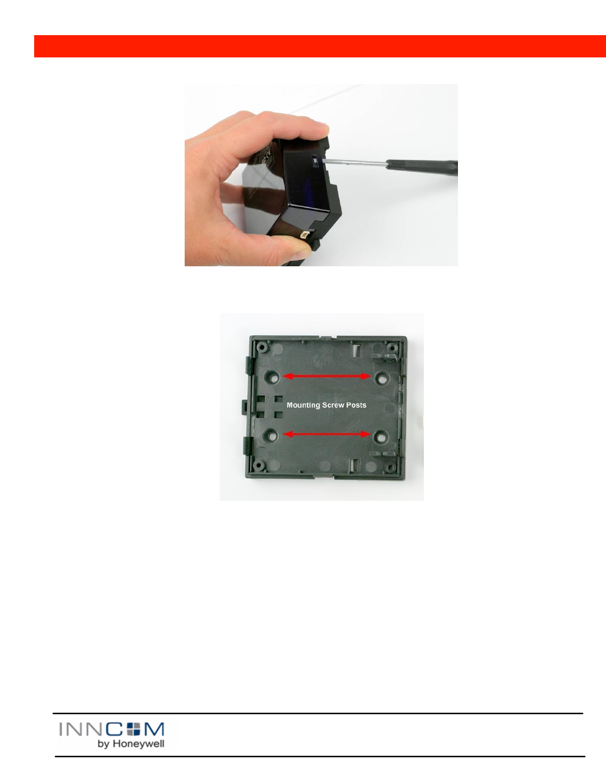
Figure 4 Top Housing Removal
To gain access to headers and connectors located on the PCBA, remove the B578 from the DIN rail or NEMA box
enclosure. Using a flat screw driver, lift the top housing away from the snap tangs on the bottom housing.
Figure 5 Mounting Screw Locations
To screw mount the B578, open the B578 as described above and remove the PCBA, which is held in place by 4
tangs located at its perimeter. Once the PCBA is removed
locate the 4 countersink posts
mount the bottom housing to the intended fixture using a self-tapping screw
mount the PCBA back on to the bottom housing
make the necessary wire connections (see Headers and Connectors below)
connect power to the DC jack
plug in Ethernet connection
snap the top housing back onto the unit
The Edge Router design mounts externally on a wall or ceiling or even on furnishings, if need be.

5
Copyright 2014 INNCOM by Honeywell
Input/Output Connections
Headers: The B578 contains the following headers:
H1: In Circuit Programming Header
J1: DC Jack 12VDC Input
M1: PoE Module header (02-9949)
H2: NU
H3: ES1 / ES2 header
H4: RS485 (203-251)
H5: RS485 (203-251)
Note: RS485 connectivity is not supported: these headers may be used to connect to an S5bus adapter
(203-255).
Output Function
The following table describes the function of the indicator LEDs on the B578 PCBA.
LED
Function
Red
Flash on power-up to indicate proper hardware initialization.
Steady on to indicate no connectivity to B573 floor bridge.
Flashes fast to indicate a valid CIS connection.
Flashes slow to indicate 75 seconds have passed with no packets from the CIS network.
Blue
Toggles when RF Rx tunnel packet is received
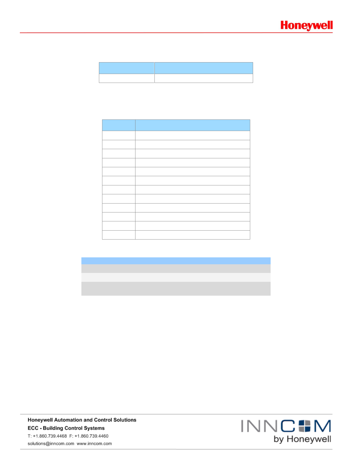
Power Supplies
The B578 provides power supply options for three specific applications. For each configuration, follow the current
consumption ratings below to determine the device’s power budget.
Mode
Peak Current Consumption
B578 logic board (basic)
200mA peak, 100mA RMS
PC-803 logic board w/ 0dB radio
120mA
PC-803 logic board w/ 20dB radio
175mA
PC-803 logic board w/ IR5 eye
200mA
Locally powered B578
The B578 can be powered directly with an external +12VDC power supply using the DC jack (J1). Typically, the
INNCOM 204-005 power supply and 262-301 100-120VAC power cable are provided for the B578 in this power
configuration.
6
Copyright 2014 INNCOM by Honeywell
PoE Powered B578
The B578 is an IEEE 802.3af compliant Powered Device (PD) interface with a current mode switching regulator,
providing a complete power solution for PD applications. The B578 is an IEEE class 2 device. PoE devices are
classified below:
IEEE Class
Minimum Power Output at the PSE
Maximum power Input at the Powered Device
0
15.4W
0.44 to 12.95W
1
4.0W
0.44 to 3.84W
2
7.0W
3.84 to 6.49W
3
15.4W
6.49 to 12.95W
Powering another INNCOM device on the +12VDC rail directly from H2 or H3 when powering the B578 from PoE
is not recommended. If the B578 exceeds its IEEE 802.3af class-2 power rating (i.e., draws more than 7W), the
PSE switch in the network will shut down the power and Ethernet connectivity to the B578.
For B578 to support PoE power, order the PoE module (02-9949). Connect the module to M1 on the B578 logic
board, then connect the PoE-powered Ethernet patch cable to J3 (RJ45) and power up the unit.
FCC Statement
This device complies with part 15 of the FCC Rules. Operation is subject to the following two conditions (1) this
device may not cause harmful interference, and (2) this device must accept any interference received, including
interference that may cause undesired operation.
IC Statement
This Class B Digital Apparatus complies with Candian ICES-003
Cet apparel numerique de la classes B est conforme a la norme NMB-o003 du Canada.
Ordering Information
The B57x is available in several operating ranges all based on the same fundamental hardware platform. The
ordering part numbers (OPN) are formed by a combination of the elements, as shown below.
Model =
Power Supply =
Configuration =
=
201-104- POE - B578N B0-
Housing Configuration
Example: 201-104-POE-B578S-B0: B578 with PoE power supply, configured as a Deep Mesh RF Edge Router
in a surface mount housing configuration.
Example: 201-104-P12-B578N-A0: B578 with a +12VDC power supply configured as a Deep Mesh RF Edge
Router and Tridium Niagara Interface, in a DIN rail housing configuration.
Example: 201-104-P12-PC-803S-A0: PC-803 with a +12VDC power supply configured as a PC-803 room
7
Copyright 2014 INNCOM by Honeywell
gateway used for Ethernet to S5bus protocol conversion in a DIN rail housing configuration.
SAP VC Configuration Material Name
When entering the model number in SAP, use the following description:
Name
Description
B578_Controller
B57x Platform
Root Part Number
This character set defines the model name for the B57x Platform Controller.
OP/N Code
Description
201-104
B57x Platform
Power Supply Option
This character set defines the power supply options available for the B57x platform.
OP/N Code
Power Supply Type
Part Number
P00
No Power Supply
-
POE
Power over Ethernet
02-9499
P12
External inline power supply with AC cable
204-005 / 262-301
Configuration Option
This character set defines the software configuration of B57x.
OP/N Code
Logic Board Type
Part Number
PC-803
(4G) Ethernet to RF protocol converter
B578S
Deep Mesh RF Edge Router
B578N
Deep Mesh RF Edge Router with Niagara Interface
Housing Configuration Option
This character set defines the software configuration of B57x.
B57x Din Rail Housings A0
B57x Surface Mount Housings B0

8
Copyright 2014 INNCOM by Honeywell
OP/N Code
Logic Board Type
Part Number
A0
DIN Rail Mounted Housings
See “Individual Components” chapter
B0
Surface Mounted Housings
See “Individual Components” chapter
9
Base Models
The base model is used as the baseline configuration from which to build the variant configuration options and
models.
Name
Description
201-104-P00-B578S-B0
Base Model in a surface mount configuration.
Individual Components
Below are a set of components such as housings, PCBA’s and harnesses which can be ordered or added for final
configuration.
OP/N Code
Description
202-104
PC-803, B578S, B578N logic board PCBA
02-9949
PC-803, B578S, B578N PoE power supply PCBA
204-005
Meanwell GS15A 100-240VAC, +12VDC 15W SMPS
262-301
AC Power Cable (used with 204-005)
53-8083
B57x DIN rail latch
53-9918
B57x DIN rail bottom housing
53-8292
B57x DIN rail top housing
253-532
B57x Surface mount bottom housing
253-533
B57x Surface mount top housing
04-8047.7B
7’ black CAT5E patch cable
62-2035
3 pin cable, 300mm
241-018 x 4
FASTENER SCREW 6x1.25 OVAL PHILIPS
Document Revision History
Revision
Date Issued
Reason
0.1
12-Apr-2014
FCC for B578
0.2
23-Apr-2014
Formatted
0.3
03-Jun-2014
Input from “NPI: CBL32 Dimmer
andController Platform Updates”