Honeywell 201528100 E7 Thermostat User Manual 31 00093 03 BACnet Fixed Function Thermostat
Honeywell International Inc E7 Thermostat 31 00093 03 BACnet Fixed Function Thermostat
Contents
- 1. User manual.pdf
- 2. User manual_e7 Install Instructions and Regulatory information_Rev 1.pdf.pdf
User manual_e7 Install Instructions and Regulatory information_Rev 1.pdf.pdf
REQUIRED TOOLS AND SOFTWARE
36-00012-01
INNCOM e7
Installation Requirements
READ ME FIRST
Required Installation Hardware:
• Four #6/32, 1" Philip's Pan Head Screws
• e7 Smart Wall Mounting Plate
• e7 Power and HVAC signal Harness
• Phillips Screw driver
• Wire cutters / strippers
• Orange wire nuts
Optional Installation Hardware:
• e7 Spacer Ring
• 3 wires for low voltage / S5bus in-room communications (typically CAT-5 or CAT-3 wiring)
• Door, window, balcony switch and harness (wired to H2); see property specific documentation for
remote door, window and balcony switch requirements
• Remote thermistor (04-1096.FL, wired to H2)
Required Installation Software
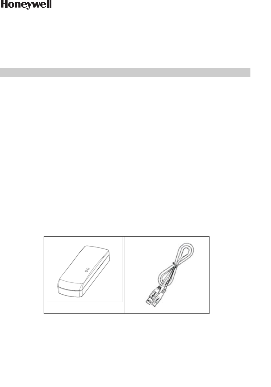
DO NOT THROW THIS UNIT AWAY: One PC-503 USB Commissioning Tool and USB cable per property /
project is shipped to the site.
This tool is used in conjunction with Honeywell's engINN commissioning software when advanced commissioning of
the e7 is required by a trained and certified INNCOM technician. DO NOT THROW THIS UNIT AWAY. Contact
Honeywell technical support for more information.
PC-503 USB Commissioning Tool and Cable
INSTALLATION INSTRUCTIONS
https://pages1.honeywell.com/e7_Install_Instructions.html
INNCOM e7 Thermostat
Installation Instructions
FOR ALL UNITS IN CARTON. DO NOT THROW AWAY!
CAUTION
Disconnect the power supply before beginning
installation to prevent electrical shock or equipment
damage. All wiring must comply with local codes and
ordinances.
• Read instructions carefully. Failure to follow them could
damage the product or create a hazard.
• Check the ratings given in the instructions and on the product
to make sure the product is suitable for your application.
• Installer must be a trained, experienced service technician.
• After installation is complete, check product operation as
indicated in instructions.
• For variations of these systems, refer to the installation
instructions of the controlled equipment.
INSTALLATION
Location
Select a location about 1.5m (5ft.) above the floor with good air
circulation at average temperature. Do not mount thermostat
where it may be affected by:
• Drafts or dead spots behind doors or in corners.
• Hot or cold air from ducts.
• Radiant heat from sun or appliances.
• Concealed pipes or chimneys.
• Unheated (un-cooled) areas behind the thermostat.
• If RF equipped, do not install near other RF sources/
transmitters.
• When the thermostat is equipped with PIR, consider view
angle, range characteristics, and mounting position for proper
coverage.
Mounting
The INNCOM e7 thermostat is typically mount on a standard
double-gang (4 x 4) junction box. The installation kit provides a
Smart Wall Mounting Plate and an optional Spacer Ring. The
optional Spacer Ring is only required when a standard double-
gang (4 x 4) junction box is not available, or when more space is
required for wiring.
If mounted on a single-gang box, the right side (keypad side) of
the e7 overlaps the wall area to the right. A low-voltage mounting
plate, mud ring, or low-voltage caddy may be used for mounting
24 volt applications.
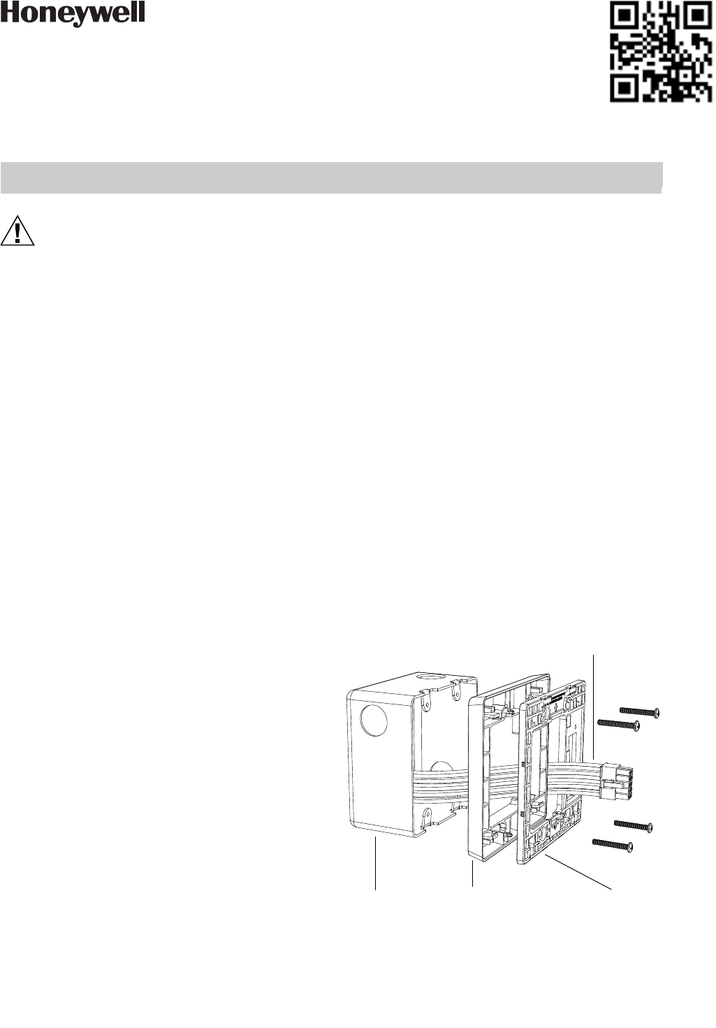
To mount the e7, complete the following steps:
1. Position the optional spacer ring (if used) and Smart Wall
Mounting Plate as shown in Fig. 1.
2. Ensure the optional spacer ring (if used) and Smart
Mounting Plate are oriented with the raised arrow point-
ing UP. Attach them to the junction box using the mount-
ing screws provided.
3. Use wire nuts to connect the Power and HVAC wiring
harness to the power and valve/fan control signal wires
within the electrical box. See the pre-defined commission-
ing document for application-specific wire connections.
4. To connect the unit to the input power and the relays to
the loads, plug the pre-wired power and HVAC signal har-
ness connector into the female receptacle at the back of the
e7 (H1). When using mixed voltage, voltage separation
must be maintained. Line voltage must reside in the left
side of the gang box. Low voltage must reside in the right
side of the gang box.
5. Hook the tabs at the top rear of the e7 housing into the
matching depressions at the top of the Smart Mounting
Plate and rotate the bottom of the housing toward the wall
until it snaps into place.
6. Secure the housing to the Smart Mounting Plate with the
two small captive screws at the bottom of the housing.
7. Apply power to the e7 by closing the applicable supply
breaker. Verify that the e7 powers up. Values should begin
appearing on the LCD display.
Fig. 1. e7 Exploded View Assembly Reference
Optional Spacer Ring
4 Junction Box Smart Mounting Ring
Power/HVAC signal
harness to thermostat
INNCOM E7 THERMOSTAT INSTALLATION INSTRUCTIONS
36-00012—01 2
WIRING
Wiring Diagrams
NOTE: If the HVAC configuration for your application is not
shown here, refer to the document: e7 Wiring Configurations
found online at:
https://pages1.honeywell.com/e7_Install_Instructions.html
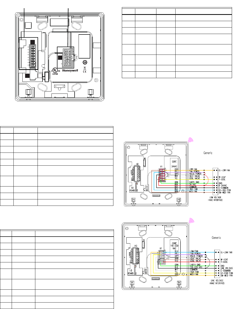
Generic FCU:24 VAC
Generic FCU: 110-220 VAC
Table 1. H1 Red Connector: 24 VAC Power/HVAC Sig-
nals
Pin Color Typical Function
1 Green Ground
2 Red 24 VAC
3 Black Common
4Blue High Fan
5 Brown Medium Fan or Second Stage Heat
6 Yellow Cold Water Valve (FCU) or Compressor
Signal (Heat Pump)
7 White Hot Water Valve (FCU) or Reversing Valve
(Heat Pump)
8Grey Valve Power
9 Violet Fan Power
10 Orange Low Fan
Table 2. H1 White Connector: 110-220 VAC Power/
HVAC Signals
Pin Color Typical Function
1 Green Ground
2 Black Line
3 White Neutral
4 Yellow High Fan
5 Orange Medium Fan or Second Stage Heat
6 Red Cold Water Valve (FCU) or Compressor
Signal (Heat Pump)
7 Brown Hot Water Valve (FCU) or Reversing Valve
(Heat Pump)
8Grey Valve Power
9 Violet Fan Power
10 Blue Low Fan
H1
FCC ID: HS9-201528
Niantic, CT 06357
Country of Origin: Mexico
Patent Pending
AI
1
10
AO
DIN3
DIN2
DIN1
S5bus
12VDC
GND
IC: 573R-201528
BLE
H4
RS485
H1
H3
H2
Honeywell GmbH
Boeblinger Str. 17
71101 Schoenaich
Germany
E361577
Sensing Control
H2 - Low Voltage Signals H1 - Power/HVAC Signals
Table 3. H2 Low Voltage Signals
Pin Color Signal Typical Function
1 Green GND Ground
2 Black VEE 12 VDC
3 White S5bus Communications
4 Yellow DIN1 Entry Door, 2 transitions to
active
5 Orange DIN2 Balcony Door/Window, 2
transitions to active
6 Red DIN3 External PIR/Motion Sensor, 2
transitions to active
7 Brown AO 0-10 V VFD Fan
8 Grey AI Remote Thermistor
INNCOM E7 THERMOSTAT INSTALLATION INSTRUCTIONS
336-00012—01
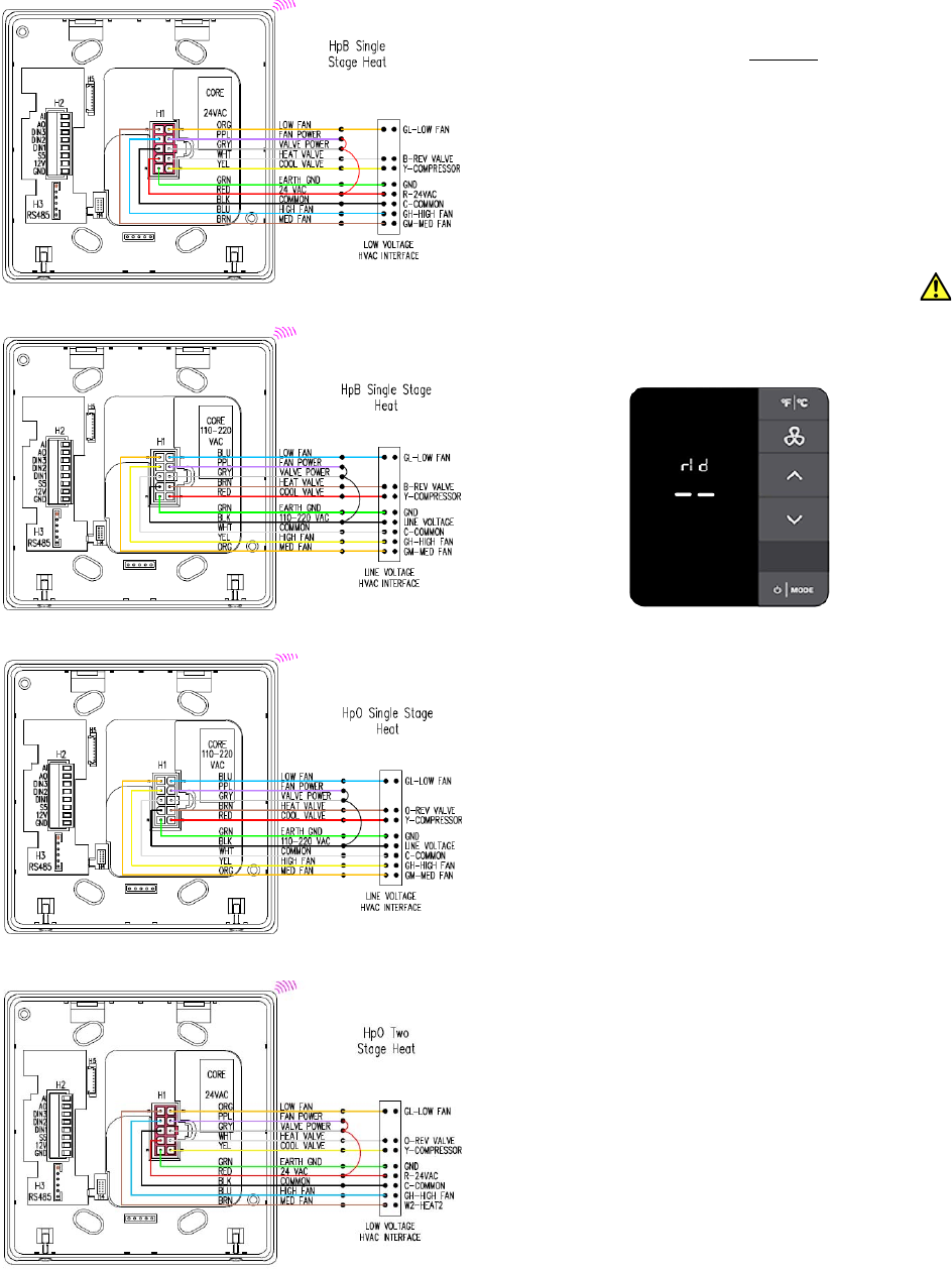
HpB Single-Stage Heat: 24 VAC
HpB Single-Stage Heat: 100-220 VAC
HpO Single-Stage Heat: 110-220 VAC
HpO Two-Stage Heat: 24 VAC
INITIAL SETUP
IMPORTANT: Before going through the initial setup sequences,
ensure the thermostat is mounted and connected to the Smart Wall
Plate.
NOTE: Prior to completing Initialization Mode, or pushing the
thermostat configuration from engINN, the thermostat is
configured with factory defaults to disable any call for heat, cool,
or low, medium and high fan speeds to protect the HVAC
equipment.
• When properly connected, the thermostat will proceed into
INTIALIZATION MODE and display rId.
• When not properly connected to the Smart Wall Plate,
the unit will display the alert message SWp and the
alert icon will illuminate until the Smart Wall Plate is
connected.
SETUP ROOM ID
1. Once rid is displayed, press MODE. The default Room ID
value (65535) is displayed and will begin scrolling across
the screen one numerical setting at a time, from highest to
lowest (left most to right most value). Note that the five-
digit number is comprised of three fields: highest digit, mid-
dle two digits, lowest two digits. Three settings must be
made.
2. Scrolling will stop at the highest digit first. Use the UP/
DOWN arrow buttons to change this value (range is 0-6).
Press FAN to continue.
3. Set the next two values in the sequence using the UP/
DOWN arrow buttons (range is 0-99). Press MODE to
continue. Repeat this step for the lowest two values (range
is 0-99) and press MODE. Press MODE to accept the
value.
4. The new ID number scrolls across the display. The unit
beeps when the value is stored to memory. Once the scroll-
ing is completed, Press the DOWN arrow button to dis-
play HVAC (HAC) menu.
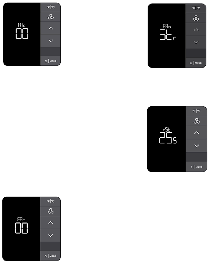
36-00012—01 4
SETUP HVAC TYPE
1. After HAC is displayed, press MODE.
2. Set the HVAC type desired using the UP/DOWN arrow
buttons to choose one of the following options:
00:Not Defined
FC4: 4 pipe fan coil unit
FW2: 2 pipe fan coil unit with W2
FC2: 2 pipe fan coil unit
PAC:PTAC unit
HbW: Heat Pump B with W2 assist
HpB: Heat Pump B with W2 replace
HoW: Heat Pump O with W2 assist
HpO: Heat Pump O with W2 replace
3. Press MODE to accept the value. The unit beeps to con-
firm the value has been set.
4. The display will show - -. Press the DOWN arrow button
to display the Fan speed (FAN) menu.
SETUP FAN SPEED
1. Once FAN is displayed, use the Up/DOWN arrow buttons
to choose the fan speed:
00:Not Defined
Lo: Low Speed (single speed)
LH:Low / High
LMh:Low / Medium* / High
*For heat pump models utilizing reversing valve, medium
heat and medium fan speed will not be available.
2. Press MODE to execute the setting, the unit beeps to con-
firm it is set.
EXIT INITIALIZATION MODE
When setup is complete, exit INITIALIZATION MODE by
pressing the F/C key. Str is displayed, indicating the setup values
are stored in memory, the unit reboots and begins operating the
HVAC equipment as configured.
RESETTING INITIALIZATION MODE
If the user needs to return to the settings made in
INITIALIZATION MODE, do the following:
1. Enter SERVICE MODE:
2. 1. Press and hold F/C.
3. 2. Press and hold MODE.
4. 3. Press and hold FAN.
5. 4. Release F/C.
6. Use the UP/DOWN arrow buttons to display rst, then
press MODE.
7. Use the DOWN button to select 255.
8. Press FAN.
9. The unit will reset, clear all previous values, and enter INI-
TIALIZATION MODE again.
INNCOM E7 THERMOSTAT INSTALLATION INSTRUCTIONS
The material in this document is for information purposes only. The content and the product it describes are subject to change without notice. Honeywell
makes no representations or warranties with respect to this document. In no event shall Honeywell be liable for technical or editorial omissions or mistakes
in this document, nor shall it be liable for any damages, direct or incidental, arising out of or related to the use of this document. No part of this document
may be reproduced in any form or by any means without prior written permission from Honeywell.
Copyright © 2017 by Honeywell International, Inc. All Rights Reserved.
Honeywell | 277 West Main Street | Niantic, CT 06357 | Phone: 1.860-739-4468 | www.INNCOM.com
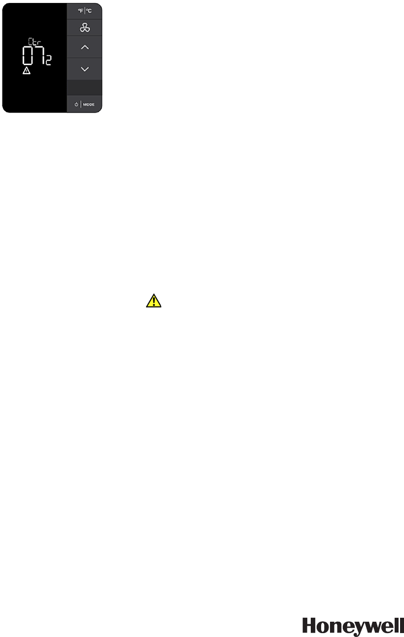
CONTRACTOR MODE
Contractor mode allows conditioning a space during the
construction phase to a defined set temperature and locking out
the key pad to prevent tampering. To configure this mode, do the
following:
1. Enter SERVICE MODE:
(1) Press and hold F/C.
(2) Press and hold MODE.
(3) Press and hold FAN.
(4) Release F/C.
2. Use the UP/DOWN arrow buttons to select ctr.
3. Use the UP/DOWN arrow buttons to select the target
temperature (range: Off - 80 degrees F).
4. Press FAN to continue. Once FAN is pressed, the display
scrolls the set temperature and the unit beeps to confirm
the value has been set.
5. Press F/C to exit SERVICE MODE. The unit dis-
plays the target and measured temperature, and the
alert icon. Any key press to change set temperature,
fan speed or mode are locked out.
EXIT CONTRACTOR MODE
1. Enter SERVICE MODE (Step 1 in the previous section).
2. Use the UP/ DOWN arrows to display - - then press FAN
to turn off CONTRACTOR MODE.
3. Press F/C to exit SERVICE MODE.
Property Specific Configurations
Once initial setup is completed, the e7 can support a range of
expanded Integrated Room Automation System functionality.
This additional functionality is deployed using Honeywell's
software tools INNtool and engINN. Training for INNtool and
engINN for system design and commissioning is now included in
the Level 2 and Level 3 classes.
INNCOM Authorized Systems Integrators should contact their
respective E&ES Regional Support Teams to inquire about
enrolling in upcoming training sessions. If you have already
received training or you are a Honeywell employee supporting the
INNCOM business, you can download the software here:
https://www.inncom.com/login
REGULATORY COMPLIANCE
UL Listing
This device meets UL 60730-2-9, CAN/CSA-E60730-9 Standard for Automatic Electrical Controls -
Part 2-9: Particular Requirements for Temperature Sensing Control
Federal Communications Commission (FCC)
Changes or modifications not expressly approved by Honeywell International, Inc. could void the
user’s authority to operate the equipment.
This equipment has been tested and found to comply with the limits for a Class B digital device,
pursuant to Part 15 of the FCC Rules. These limits are designed to provide reasonable protection
against harmful interference in a residential installation. This equipment generates, uses and can
radiate radio frequency energy and, if not installed and used in accordance with the instructions, may
cause harmful interference to radio communications. However, there is no guarantee that
interference will not occur in a particular installation. If this equipment does cause harmful
interference to radio or television reception, which can be determined by turning the equipment off
and on, the user is encouraged to try to correct the interference by one of the following measures:
- Reorient or relocate the receiving antenna.
- Increase the separation between the equipment and receiver.
- Connect the equipment into an outlet on a circuit different from that to which the receiver is connected.
- Consult the dealer or an experienced radio/TV technician for help.
This equipment has been tested and found to comply with the limits for a Class A digital device,
pursuant to Part 15 of the FCC Rules. These limits are designed to provide reasonable protection
against harmful interference when the equipment is operated in a commercial environment. This
equipment generates, uses and can radiate radio frequency energy and, if not installed and used in
accordance with the instruction manual, may cause harmful interference to radio communications.
Operation of this equipment in a residential area is likely to cause harmful interference in which case
the user will be required to correct the interference at his own expense.
This device complies with FCC and IC radiation exposure limits set forth for an uncontrolled
environment. This device should be installed and operated with minimum distance of 20cm between
the radiator and your body. This device must not be co-located or operating in conjunction with any
other antenna or transmitter.
This device complies with part 15 of the FCC Rules. Operation is subject to the following two
conditions: (1) This device may not cause harmful interference, and (2) this device must accept any
interference received, including interference that may cause undesired operation.
Tout changement ou modification n’ayant pas été expressément approuvé par Honeywell
International, Inc. pourrait annuler l’autorisation de l’utilisateur d’utiliser l’équipement.
Cet équipement a subi des tests prouvant sa conformité aux limites prescrites pour les appareils
numériques de classe B, selon la partie 15 des règlements de la FCC. Ces limites ont été conçues pour
fournir une protection raisonnable contre les interférences
nuisibles lorsque l’appareil est utilisé dans un environnement résidentiel. Cet équipement génère,
utilise et peut émettre de l’énergie radioélectrique et, s’il n’est pas installé et utilisé conformément aux
instructions, peut causer des interférences nuisibles aux communications radio. Toutefois, il n’y a
aucune garantie que ces interférences ne puissent survenir dans une installation donnée. Si cet
équipement cause des interférences nuisibles à la réception de signaux de radio ou de télévision, ce
qui peut être déterminé en l’éteignant et en l’allumant, l’utilisateur peut essayer de corriger ces
interférences par les mesures suivantes :
- Réorienter ou déplacer l’antenne réceptrice.
- Augmenter la distance entre l’équipement et le récepteur.
- Brancher l’équipement sur un circuit différent de celui sur lequel le récepteur est branché.
- Consulter le détaillant ou un technicien expérimenté en radio/télévision pour de l’aide.
Cet équipement a subi des tests prouvant sa conformité aux limites prescrites pour les appareils
numériques de classe A, selon la partie 15 des règlements de la FCC. Ces limites ont été conçues pour
fournir une protection raisonnable contre les interférences nuisibles lorsque l’appareil est utilisé dans
un environnement commercial. Cet équipement génère, utilise et peut émettre de l’énergie
radioélectrique et, s’il n’est pas installé et utilisé conformément aux instructions, peut causer des
interférences nuisibles aux communications radio. L’utilisation de cet équipement dans une zone
résidentielle est susceptible de causer des interférences nuisibles auquel cas l’utilisateur sera tenu de
corriger ces interférences à ses propres frais
Cet équipement est conforme aux limites d’exposition aux rayonnements FCC et IC établies pour un
environnement non contrôlé. Cet équipement doit être installé et utilisé avec un minimum de 20cm
de distance entre la source de rayonnement et votre corps. Cet appareil ne doivent pas être placés à
côté de ou fonctionner en conjonction avec toute autre antenne ou transmetteur.
Industry Canada (IC)
This device complies with Industry Canada licence-exempt RSS standard(s). Operation is subject to
the following two conditions: (1) this device may not cause interference, and (2) this device must
accept any interference, including interference that may cause undesired operation of the device.
Le présent appareil est conforme aux CNR d'Industrie Canada applicables aux appareils radio
exempts de licence. L'exploitation est autorisée aux deux conditions suivantes : (1) l'appareil ne doit
pas produire de brouillage, et (2) l'appareil doit accepter tout brouillage radioélectrique subi, même si
le brouillage est susceptible d'en compromettre le fonctionnement.