Honeywell 202124TXR Repeater User Manual Manual
INNCOM International Inc. Repeater Manual
Manual.pdf
INNCOM PC-502.1 Datasheet
Overview
The INNCOM PC-502 wall mounted module can be used to expand the range of a
network (IR or Layer-1 or Layer-2 RF) or to provide the protocol gateway from
INNCOM S5-bus to Layer-1 or Layer-2 RF protocol.
In an IR network, the PC-502 module can be used to provide remote eye functionality or
protocol gateway from INNCOM S5-bus to IR wireless protocols. The PC-502 adds
functionality beyond the traditional remote eye because, as a smart 5-bus device, it can
be powered from a standard 3-pin 5-bus connection.
In a Layer-1 RF network, the PC-502 provides S5-bus to RF protocol conversion, giving any
INNCOM product participating in the INNCOM Integrated Room Automation System
(IRAS) an RF transceiver for control of wireless products in the guestroom.
In the Deep Mesh 802.15.4 network, the PC-502 is designed to patch areas within the
network where signal strength is lost due to distance limitations or interference. It
also serves to create multiple pathways, increasing the redundancy of the mesh communications to ensure
maximum network reliability.
Features
Small wall mountable form factor
2.4Ghz IEEE 802.15.4 compliant RF transceiver (CC2430 radio core)
Medium and long range variants available
Industrial temperature ratings 0–65 degrees C
FCC Part 15b listed
Specification
Parameter
PC-502.1
RF Data Rate
250kbps
Antenna Type
SMT
Indoor Range
70ft
Outdoor/ RF line-of-sight range
540ft
Transmit Power
1mW (+0dBm)
Receive Sensitivity
-94.6dBm
Frequency Band
2.4Ghz
Encryption
AES-128
Protocol
802.15.4
Frequency Channels
11-26
Input Voltage
12VDC
Current Consumption
50mA (Peak)
Operating Ambient Temperature
0°C
Figure 1 PC-502
INNCOM PC-502 Datasheet P a g e | 2
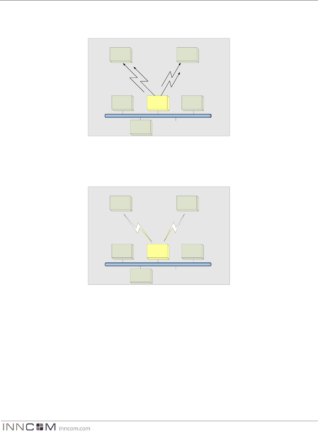
Network Topology
In this application, the PC-502 provides S5-bus to IR protocol conversion giving any INNCOM product
participating in the INNCOM Integrated Room Automation System (IRAS) an IR transceiver for control of
wireless products in the guestroom.
S5bus
e527 PC-502.1
D254.DIN
S55x Lamp
Controller
L208 Lamp
Controller
X07 HVAC
Controller
Layer-1 RF Network
Figure 3 PC-502 Layer-1 Topology
In this application, the PC-502 is providing S5-bus to RF protocol conversion, giving any INNCOM product
participating in the INNCOM Integrated Room Automation System (IRAS) an RF transceiver for control of
wireless products in the guestroom.
S5bus
e527 PC-502..IR
D254.DIN
S55 x Lamp
Controller
L 208 Lamp
Controller
X 07 HVAC
Controller
Figure 2 PC-502.IR Topology
INNCOM PC-502 Datasheet P a g e | 3
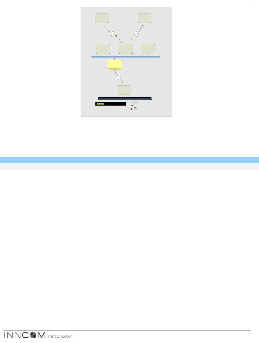
S5bus
GS-528H E528.3G
PC-502.2
S55x Lamp
Controller
L208 Lamp
Controller
X07 HVAC
Controller
Layer-1 RF Network
Layer-2 RF Network
TCT.RF
Ethernet
B573-MBX
Figure 4 PC-502 Layer-2 Topology
In this application, the PC-502 in participation with the e528.3G provides the Layer-1 to Layer-2 RF Bridge where
both wireless in-room and wireless back-end networking are required. The PC-502 can also patch areas within the
Layer-2 network where signal strength is lost due to distance limitations or interference.
Safety/Regulatory
Parameter
Condition
Status
FCC
Part 15b
FCC ID: GTC202124TXR
Warning
Any Changes or modifications not expressly approved by the party responsible for compliance could void the
user's authority to operate the equipment.
This device complies with part 15 of the FCC Rules. Operation is subject to the following two conditions: (1) This
device may not cause harmful interference, and (2) this device must accept any interference received, including
interference that may cause undesired operation.
FCC & ICC Compliance Statements
This equipment has been tested and found to comply with the limits for a Class B digital device, pursuant to Part
15 of the FCC Rules. These limits are designed to provide reasonable protection against harmful interference in a
residential installation. This equipment generates uses and can radiate radio frequency energy and, if not
installed and used in accordance with the instructions, may cause harmful interference to radio communications.
However, there is no guarantee that interference will not occur in a particular installation. If this equipment does
cause harmful interference to radio or television reception, which can be determined by turning the equipment off
and on, the user is encouraged to try to correct the interference by one of the following measures:
— Reorient or relocate the receiving antenna.
— Increase the separation between the equipment and receiver.
— Connect the equipment into an outlet on a circuit different from that to which the receiver is connected.
— Consult the dealer or an experienced radio/TV technician for help.
Any changes or modifications not expressly approved by the party responsible for compliance could void the
user's authority to operate this equipment.
IC:1609A-202124TXR
INNCOM PC-502 Datasheet P a g e | 4
This device complies with Industry Canada licence-exempt RSS standard(s). Operation is subject to the following
two conditions: (1) this device may not cause interference, and (2) this device must accept any interference,
including interference that may cause undesired operation of the device.
Le présent appareil est conforme aux CNR d’industrie Canada applicables aux appareils
radio exempts de licence. L’exploitation est autorisée aux deux conditions suivantes: (1)
l’appareil ne doit pas produire de brouillage, et (2) l’utilisateur de l’appareil doit accepter
tout brouillage radioélectrique subi, même si le brouillage est susceptible d’en
compromettre le fonctionnement.
IMPORTANT NOTE:
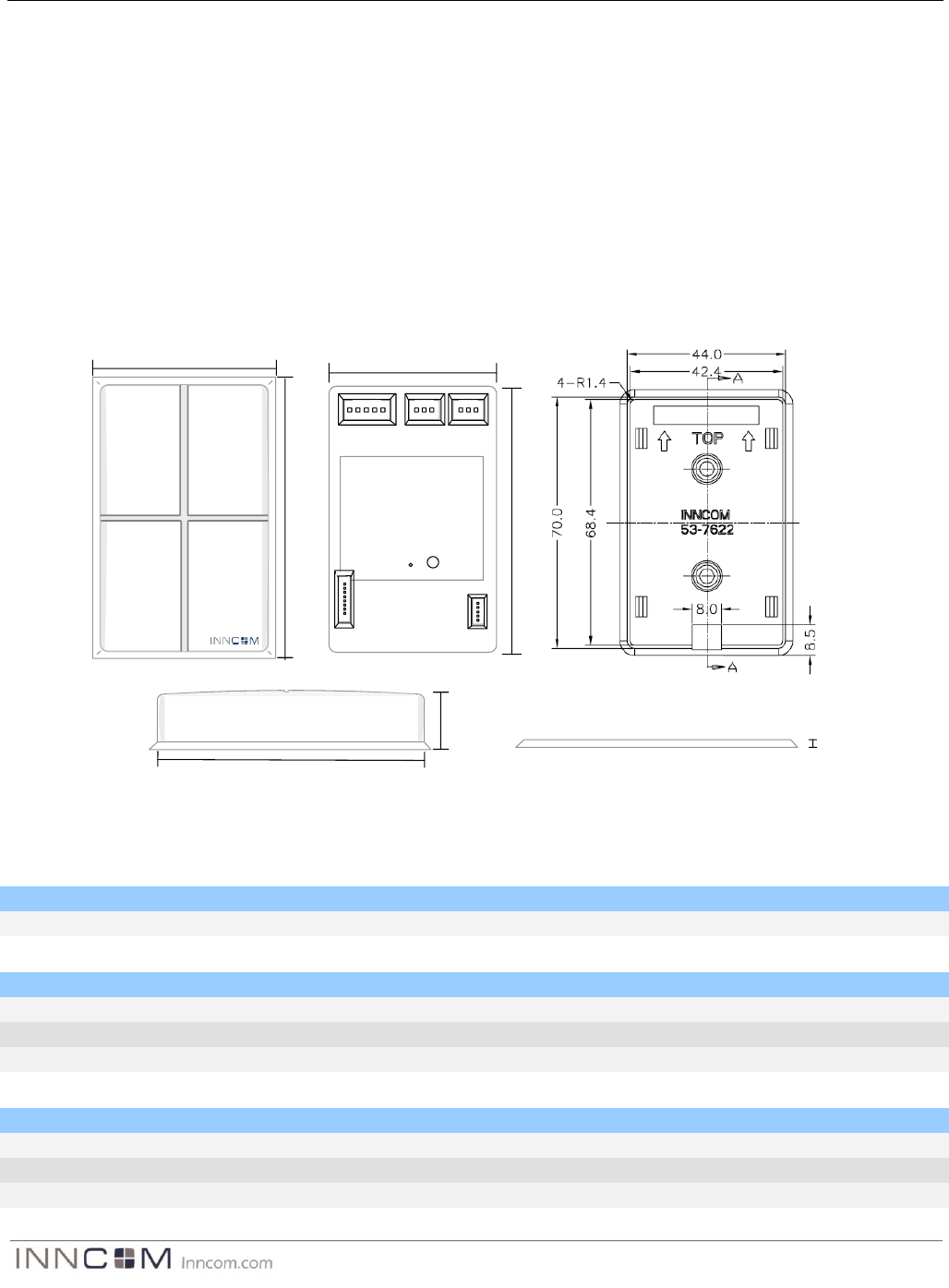
PC-502 Dimensions
System-5 S5-In S5-Out
Radio ICPICP
Diag
Model: Remote PC-502
P/N 01-5010.__
Date Code _______________
This device complies with part 15 of the FCC Rules.
Operation is subject to the following two conditions:
(1) this device may not cause harmful interference,
and (2) this device must accept any interference
received, including interference that may cause
undesired operation
FCC Part 15, Class B
PC-502 Back View
44mm
70mm
74mm
PC-502 Front View
48mm
21mm
70mm
PC-502 Side View
2mm
Mounting Plate
Side View
Mounting Plate
Front View
Header and Connections
H3 (In System Programming)
Pin
Function
Type
Min
Max
1-8
Programming
-
-
-
H4 / H5 (S5-bus In/Out)
Pin
Function
Type
Min
Max
1-GND
Common
-
-
-
2-12VDC
Input voltage
In
11.75
12.25
3-S5-bus
Multi-drop
In/Out
-
H6 (System-5)
Pin
Function
Type
Min
Max
1-GND
Common
-
-
-
2-12VDC
Input voltage
In
11.75
12.25
3-S5-bus
Multi-drop
In/Out
-

INNCOM PC-502 Datasheet P a g e | 5
4 –InOut1
TTL
In/Out
-
5- InOut2
TTL
In/Out
-
3-pin to 3-pin harness for 12VDC and 5-bus connection
3-pin-to-3-pin harness, PN 62-2035,
length 12" (300 mm)

INNCOM PC-502 Datasheet P a g e | 6
Ordering Information
Part Number
OPN
Description
201-502.1
PC-502.1
PC-502 with 0dB Transceiver
Document Revision History
Revision
Date Issued
Reason
0.1
14-May-2013
FCC for PC-502