Honeywell 202152TXR Thermostat User Manual E528 Product Guide v7 0 PG
INNCOM International Inc. Thermostat E528 Product Guide v7 0 PG
Manual
Global Leader in Integrated Room Automation Systems
Confidential Copyright © 2010 INNCOM
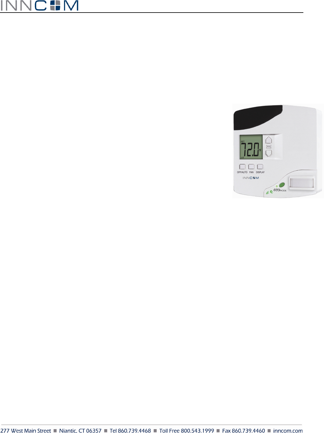
e528 Smart Digital Thermostat
Product Guide
Overview
INNCOM's e4 Smart Digital Thermostat is a powerful, multi-purpose Direct Digital Control (DDC) device that
can control virtually any HVAC system found in hotel guestrooms.
The three e4 models meet different application requirements. The e528 and e527 are
wired and are typically used for new installation. The e529 is battery-powered and is
designed to meet the needs of existing properties where rewiring is not practicable.
This document describes Model e528; information on the e529 and e527 can be found
in their respective product guides.
Application
In its most basic form, the e528 functions as a programmable DDC thermostat,
automatically adjusting fan speeds and valves to achieve set temperature (Note:
Guests can manually select heat or cool by pressing the OFF/AUTO button and
cycling through OFF, AUTO, HEAT and COOL). The e528 is also an “intelligent”
device capable of linking ancillary sensors and serving as an information gateway.
For example, coupled with a magnetic door switch (wired or wireless), motion detectors, and other devices, the
e528 becomes the brain of a highly effective Energy Management System (EMS) application, communicating EMS
information requirements to central servers. It comes standard with five relays and can be equipped with an on-
board Infrared (IR) or radio frequency (RF) transceiver and Passive Infrared (PIR) motion detector.
The e528 interfaces with all common HVAC unit voltage configurations (24 volt to 277 volt). The e528 can be
installed in a wired or wireless INNCOM guestroom control system, which makes installation feasible and
affordable in either new construction or retrofit installations.
Through interfaces with other devices and sensors, the e528 supports the following functions:
• Remote HVAC control
• Guestroom HVAC diagnostics
• Remote room occupancy indication
• Automatic lighting control
• Remote mini-bar access reporting
• Remote smoke detector annunciation
• Central Electronic Lock control
• Humidity control
• Remote drape control
• Outside temperature display
• Peak demand load shedding
• Property/Building Management System (PMS/BMS) interface
Figure 1 e528 Digital Thermostat
E 5 2 8 P r o d u c t G u i d e P a g e 2 o f 1 8
A centrally controlled EMS package is created when the e528 is connected to the property's Central Interface
Network (CINET) with a pair of low voltage wires or by the property’s high-speed TCP/IP network with the
addition of a TCT (an Ethernet gateway device). RF networking is possible with radio equipped models.
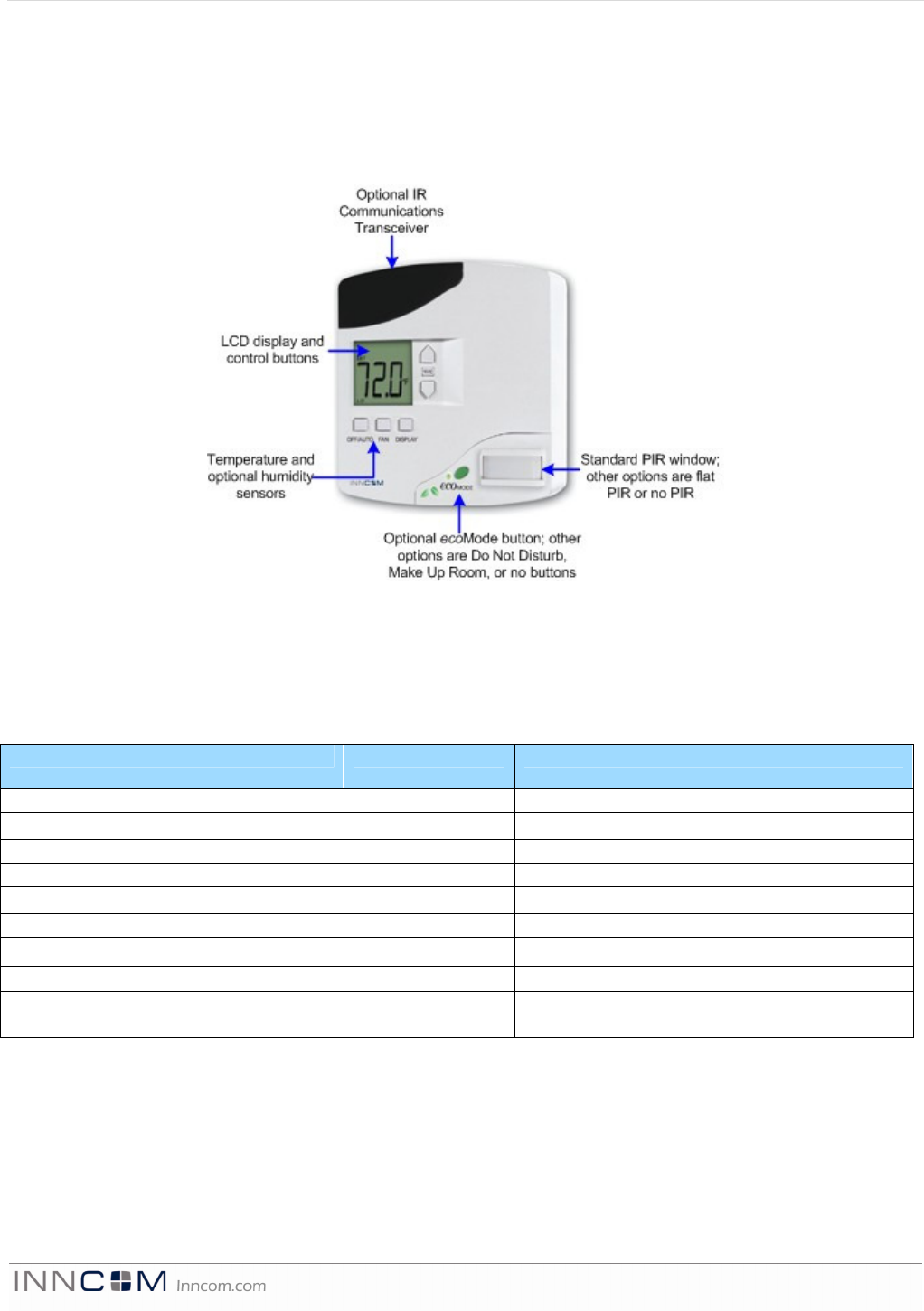
The e528 features a guest-friendly graphic interface with intuitive controls (Figure 2). A user guide for the e528,
written primarily for installers and facility management personnel, is available (see References below).
Wireless Communication
2.4Ghz wireless RF
Table 1 e528 RF Characteristics
Performance 0dB 20dB
RF Data Rate 250kbps 250kbps
Antenna Type SMT SMT
Indoor Range 70ft 100ft
Outdoor/ RF line-of-sight range 540ft 1000ft+
Transmit Power 1mW 10mW
Receive Sensitivity -94.6dBm -94.6dBm
Frequency Band 2.4Ghz 2.4Ghz
Encryption AES-128 AES-128
Protocol 802.15.4 802.15.4
Frequency Channels 11-26 11-26
Ranges are determined by performing an RF link quality test using two identical e528 thermostats containing
radios as defined in tables 2 and 3. The maximum distance threshold is based on a 95% overall link quality.
Outdoor ranges were conducted in a low noise, free air environment. Indoor ranges are for reference. Indoor
ranges are impacted by the ambient environmental noise floor, and building construction materials.
Figure
2
e528 Graphic Inter
face
E 5 2 8 P r o d u c t G u i d e P a g e 3 o f 1 8
IR5 (Infrared)
Table 2 e528 IR5 Characteristics
Performance IR5
Indoor Range Up to 80ft
IR Data Rate 2500 bps
The IR Eye5 works within INNCOM's System-5 protocol and can be used in a fluorescent light environment.
However, it may be subject to interference from plasma televisions, and care must be taken in situating the device
if a plasma television is present.
Installation Requirements
Location: The e528 must be located on a partitioning interior wall, approximately 1.5 m (5 ft) above the floor, in a
site of average temperature. It is important to ensure that the thermostat is located away from direct sunlight or
radiant heat, air discharge grills, stairwells, outside doors, steam or water pipes, warm air stacks,
unheated/uncooled areas, or sources of electrical or radio interference. The unit should not be placed on an outside
wall or behind a door. It is essential that the e4 is mounted flush to the wall and mounted level in both the horizontal
and vertical planes; incorrect mounting can degrade IR, PIR, and temperature measurement performance.
Installation Requirements for e4 equipped with PIR Motion Detection
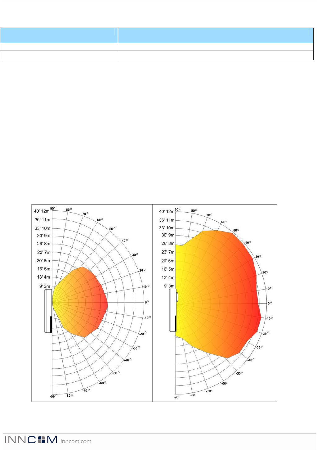
The e4 thermostat can be equipped with a PIR detector to augment the energy management scheme by detecting
motion in the guestroom. Consider the PIR’s view angle, range characteristics, and mounting position to ensure
proper coverage. Figure 3 below shows the ranges of the flat and standard PIRs.
Flat PIR Detection Range (Single Pyro) Standard PIR Detection Range (Dual Pyro)
Figure 3 PIR Detection Ranges
E 5 2 8 P r o d u c t G u i d e P a g e 4 o f 1 8
Mounting: The e528 is usually mounted on a standard double-gang (4 x 4) junction box. If mounted on a single-
gang box, the left side (display side) of the e528 overlaps the wall area to the left of the junction box. A low-
voltage mounting plate, mud ring, or low-voltage caddy may be used for mounting 24 volt applications.
To mount the e528:
1) Remove the two small screws at the base of the e528.
2) Pull the bottom of the back-mounting plate slightly away from the front housing and then pull the back-
mounting plate down.
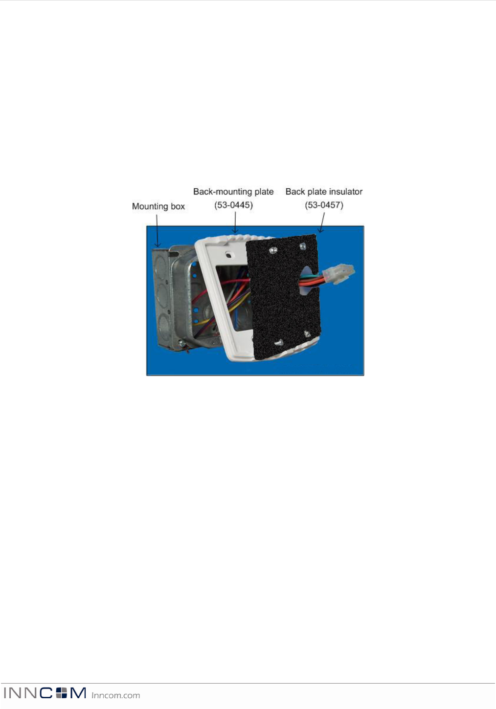
3) Position the back plate insulator within the mounting plate as shown in Figure 4.
4) Attach the mounting plate to the junction box, using the mounting screws provided with the e528. Ensure
that the plate is mounted with the raised arrow pointing UP.
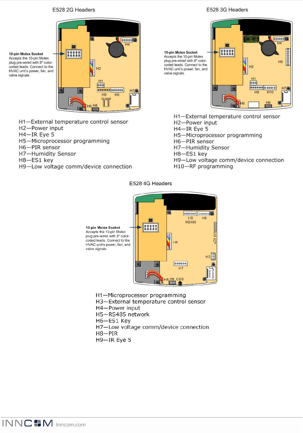
To simplify installing and removing the e528, the headers and sockets described below and shown in Figure 5 are
located on the back of the e528. These accept pre-made wiring harnesses provided by INNCOM. (Note: Take care
to note which e528 model is being used. Each model has slightly changed headers and connectors as identified in
the drawings below.)
Figure
4
Mounting Assembly
E 5 2 8 P r o d u c t G u i d e P a g e 5 o f 1 8
Figure
5
Back View Showing Headers and Sockets
E 5 2 8 P r o d u c t G u i d e P a g e 6 o f 1 8
Headers
The headers for the e528.2G, 3G and 4G
*
thermostats are substantially the same, though the layouts and labeling on
the PCB are slightly different (see Figure 5 above). The statements and tables below detail only the headers that differ
in function.
Low Voltage comm / device connector: This header accepts the provided 6-pin harness used to connect low
voltage communication, door/window position switch, and other room devices to the e528. Table 3 shows the
pinout for the 2G low voltage comm / device connector and lists typical functions for each pin. Table 3a shows
pinout and function for the 3G and 4G. For specifics, refer to the as-built wiring diagrams.
Table 3. e528 2G Low Voltage Harness (P/N 62-1462) Pinout
Wire Color Female
Connector
Male
Connector
Function Comment
Brown 1 1 Common GND
Red 2 2 12VDC Out/In 12VDC Supply
Orange 3 3 S5 Bus Data Tx/Rx or IN 2 Communication Bus
Yellow 4 4 IN 1 Door, Window, PIR, Other
Green 5 5 CINET B RS485 Twisted Pair
Blue 6 6 CINET A RS485 Twisted Pair
Table 3a. e528 3G/4G Low Voltage Harness (P/N 62-1467) Pinout
Wire Color Female
Connector
Male
Connector
Function Comment
Brown 1 1 Common GND
Red 2 2 12VDC Out/In 12VDC Supply
Orange 3 3 S5 Bus Data Communication Bus
Yellow 4 4 Digital Input Door, Window, PIR, Other
Green 5 5 No Connection
Blue 6 6 No Connection
External temperature control sensor: This header accepts the wiring harness from an external temperature probe
that can be used to supply the e528 with remote temperature measurements. The e528 uses a 10K 1% thermistor
for external temperature measurement. This external temperature sensor can be used to monitor room
temperature at a different location from where the e528 is mounted or to monitor pipe water temperature.
RS485 Networks: (refer to Figure 5)
E528.2G can be connected to the RS485 FLN5 network by installing the 02-9496 module, then connecting the
RS485 network to pins 5 and 6 of the low voltage comm /device connector as described in Table 3 above.
E528.3G cannot act as the media gateway for in-room traffic towards the RS485 network. The most common
way to connect the e528.3G is to connect a PC-485.S5 (P/N: 01-9905) on the S5bus.
E528.4G
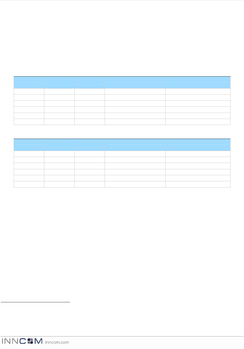
E528.4G to 2G RS485 Networked Application: with or without door switch input (See Figure 6 below)
• Using the adapter (P/N 203-251), connect the harness from the wall box (P/N 62-1462) previously
connected to the thermostat being replaced to H1 of the adapter.
• Connect the harness H3 (rainbow) of 203-251 to the low voltage comm/device connection of the e528.4G
*
“2G,” “3G,” and “4G” are internal INNCOM product designations used for convenience to differentiate
individual hardware configurations. No difference in device capability or effectiveness is implied. Due to end-of-
life for certain 2G and 3G components, the e528.4G is now the standard INNCOM install, but 2G and 3G
installations are still supported.
E 5 2 8 P r o d u c t G u i d e P a g e 7 o f 1 8
• Connect the harness H2 (black) of 203-251 to the RS485 header of the e528.4G
NOTE: Take care to not reverse the connections to the e528.4G!
E528.4G New Installation
Stand alone application with/without door switch input
• Using the harness (P/N 62-1467), make the appropriate wire connections, then plug the harness into the
low voltage comm/device connection of the e528.4G
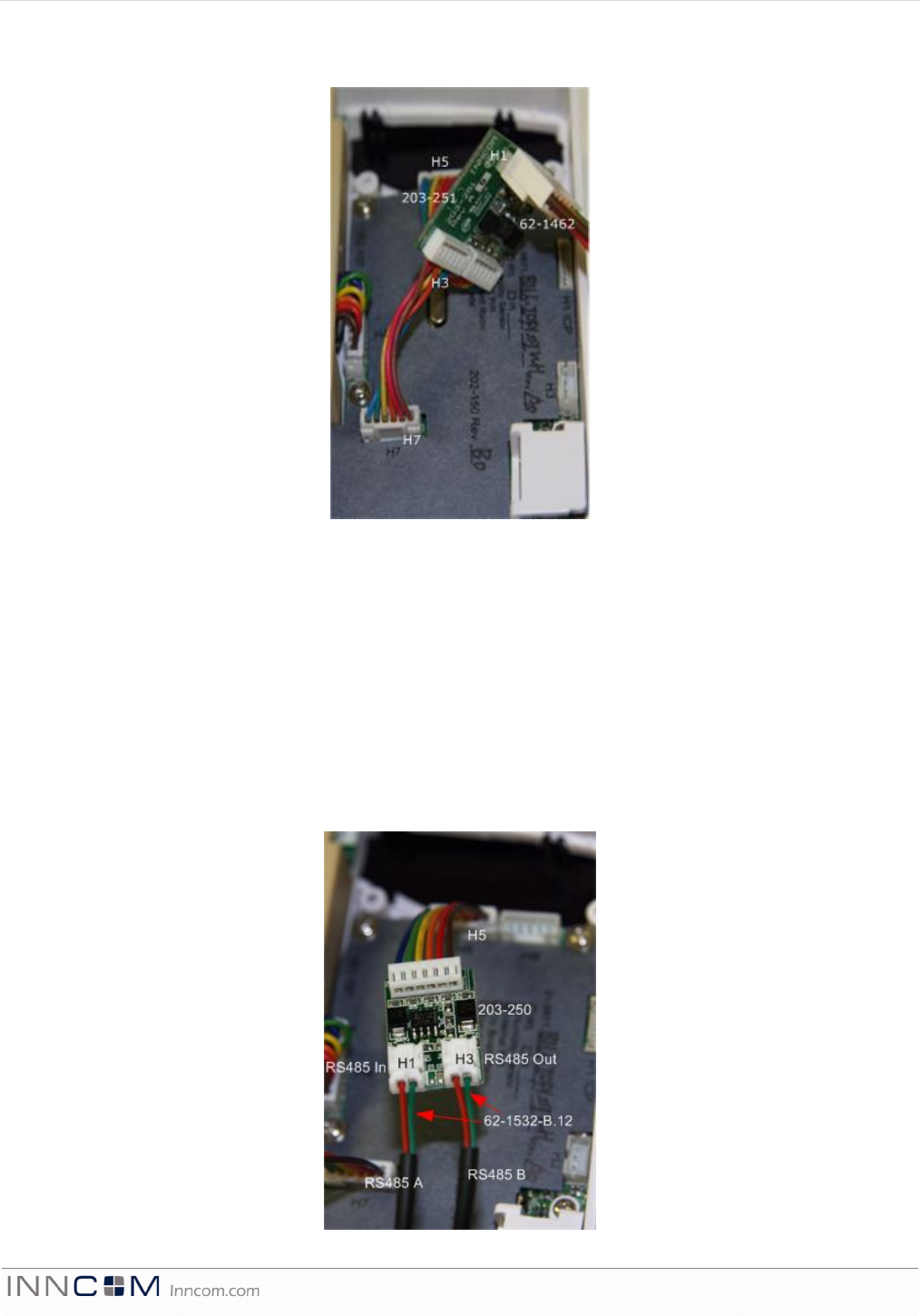
RS485 Networked Application with/without door switch input (See Figure 7)
• Using the harness (P/N 62-1467), make the appropriate wire connections, then plug the harness into the
low voltage comm/device connection of the e528.4G.
• Using the adapter (P/N 203-250) and P/N 62-1532-B.12 cables, connect the RS485 A pair to the two pin
RS485 In header and the RS485 B pair going to the next thermostat to RS485 Out header on the 203-250.
• Connect the harness of 203-250 to the RS485 network header of the e528.4G.
Figure
7
E528.4G New RS485 Networked Application
Figure
6
4G to 2G RS485 Networked Application
E 5 2 8 P r o d u c t G u i d e P a g e 8 o f 1 8
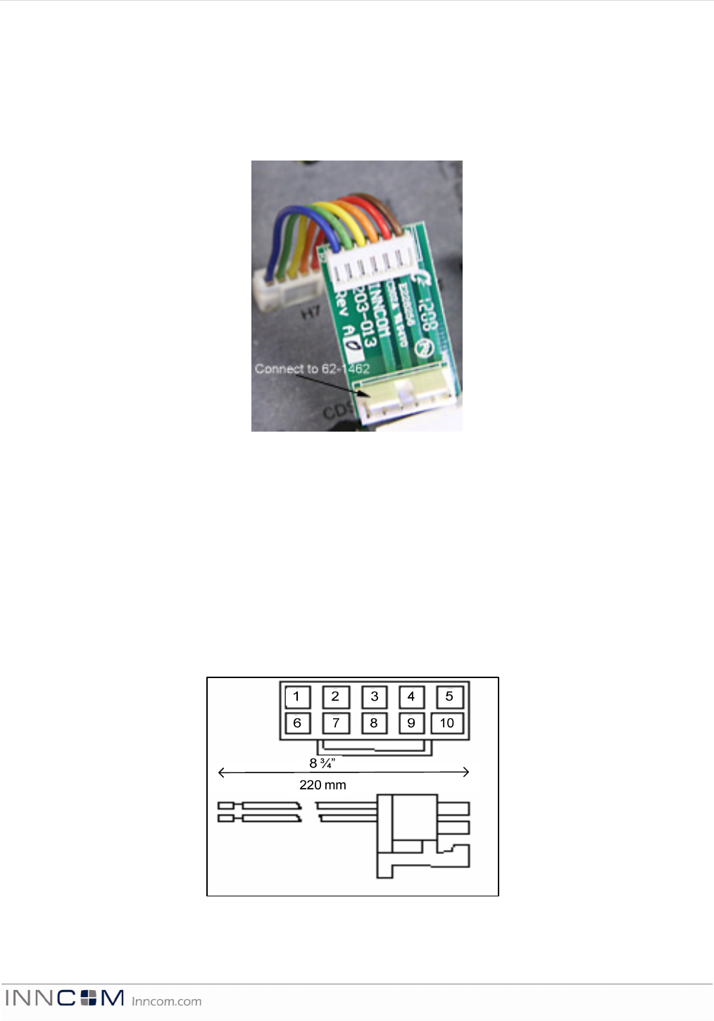
E528.4G Retrofit Installation
The e528.4G can be used to retrofit an application where a legacy e528 was used. Follow the procedure below:
4G to 2G Standalone application: with/without door switch input (no backhaul network)
• Using the adapter (P/N 203-013) connect the harness from the wall box (P/N 62-1462) previously
connected to the thermostat being replaced to H1 of the adapter (see Figure 8).
• Connect the harness of 203-013 to the low voltage comm/device connection of the e528.4G.
Molex 10-position female socket: This female socket accepts the provided 10-pin Molex connector pre-wired
with 8-inch, color-coded wiring leads. These leads should be connected to the 24VAC or 100–277VAC power,
valve/fan control wiring from the FCU, or other HVAC device with wire nuts inside in the wall junction box in
accordance with the wiring diagram provided by INNCOM.
Note: For installations in which all leads are not required, the extraneous leads should be cut off at the Molex connector.
Figure 8 shows the pinout for the 10-position Molex male connector supplied with all relay output models of the
thermostat. The end view of the male connector from the wire insertion side with the pin numbers is indicated.
This is the same as looking at the female connector point on the back of the e528.
Typical functions for each wire are listed in Tables 4 and 5. For specifics, refer to the as-built wiring diagrams.
Table 4. 24VAC Harness Color Code, Pinout, and Typical Functions
Figure 8 e528.4G to 2G Standalone application
Figure
9
10
-
Pin Molex Connector (Part No. 62.1455 or 62.1464.R)
E 5 2 8 P r o d u c t G u i d e P a g e 9 o f 1 8
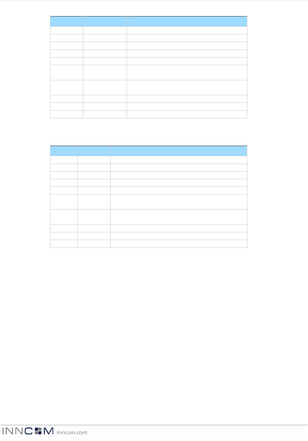
24VAC harness (INNCOM Part # 62-1464 R)
Pin Color Typical Function
1 Green Ground
2 Red 24VAC
3 Black Common
4 Blue High Fan
5 Brown Medium Fan or Second Stage Heat
6 Yellow Cold Water Valve (FCU) or Compressor Signal
(Heat Pump)
7 White Hot Water Valve (FCU) or Reversing Valve
(Heat Pump)
8 Grey Valve Power
9 Violet Fan Power
10 Orange Low Fan
Table 5. 100-277VAC Harness Color Code, Pinout, and Typical Functions
100-277VAC harness (INNCOM Part # 62-1455)
Pin Color Typical Function
1 Green Ground
2 Black Line
3 White Neutral
4 Yellow High Fan
5 Orange Medium Fan or Second Stage Heat
6 Red Cold Water Valve (FCU) or Compressor Signal (Heat
Pump)
7 Brown Hot Water Valve (FCU) or Reversing Valve (Heat
Pump)
8 Grey Valve Power
9 Violet Fan Power
10 Blue Low Fan
Wiring: The steps below provide an overview of the wiring process. Refer to the as-built wiring diagrams
provided for exact details.
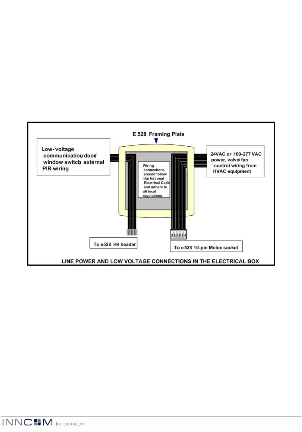
1. If applicable, use wire nuts to connect the 6-pin low-voltage harness wires to the applicable low-voltage
communication (if e528 is part of a wired RS485 centrally controlled system), door/window switch, or
external PIR wiring within the electrical box (Figure 8). Plug the 6-pin low voltage harness onto the e528 low
voltage comm. / device connection header.
2. Use wire nuts to connect the 10-pin Molex wiring harness to the power and valve/fan control signal wires
within the electrical box.
3. Plug the pre-wired 10-pin connector into the female receptacle at the back of the e528.
4. Hook the tabs at the top rear of the e528 housing into the matching depressions at the top of the mounting
plate and rotate the bottom of the housing toward the wall until it snaps into place on the mounting plate.
5. Secure the housing to the mounting plate with the two small screws removed in Step 1 of the Mounting section.
6. Apply power to the e528 by closing the applicable supply breaker. Verify that the e528 powers up. Several
values should begin appearing on the LCD display.
7. Once installed and connected to power, the e528 Digital Thermostat typically requires some configuration,
specifically:
• If installing the e528 as part of a networked, centrally controlled EMS, a unique network address must be
assigned to the e528. This is done by entering Service Parameter mode on the e528 and changing the
E 5 2 8 P r o d u c t G u i d e P a g e 1 0 o f 1 8
values of Parameters 10, 11, and 12, which hold the 5-digit network address of the e528. This 5-digit
number is typically the room number in most applications. A “Room List” document is typically
available that lists all rooms and the associated values to set into Parameters 10, 11, and 12. Refer to
Reference A, Section 5.1, for complete instructions for setting the e528 network address.
• If the particular HVAC equipment installed was not known when the e528 was shipped, the fan and
heat/cool control outputs of the e528 must be configured to correctly operate the installed HVAC
equipment. Setting the appropriate HVAC control parameters of the e528 to the required values and
resetting the device reconfigures the e528 to properly control most HVAC units. Refer to Reference A,
Section 5.2, for instructions on changing the e528 HVAC related parameters, if required.
NOTE: If installing 01-9560 64K memory e528 Digital Thermostats, be aware that these devices support the
INNCOM ES-1 Flash Memory Module. The ES-1 provides the ability to copy HVAC related parameter settings
from a “golden” e528 that has previously been installed in a room and had its HVAC related parameters set
correctly and verified operationally with the HVAC equipment. Once these settings are copied to the ES-1
module, plugging the ES-1 into a new thermostat automatically uploads the settings.
Figure
7
Electrical Box Connections
Line and Low Voltage
E 5 2 8 P r o d u c t G u i d e P a g e 1 1 o f 1 8
Load Specifications
The following load specification table (Table 6) describes the submitted load characteristics for testing and UL
certification of UL 873. The device complies with the requirements of CAN/CSA C22.2 No. 24-93.
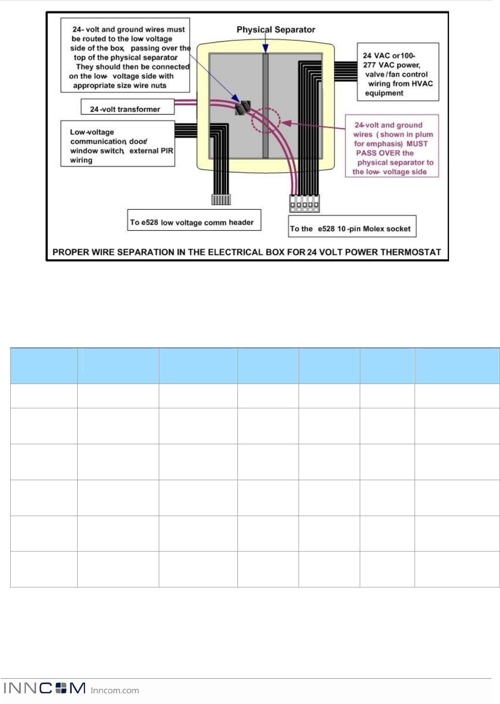
Table 6. Load Specifications
MODEL e528-A2L2-I0P0-
00WH
e528-A3L2-I0P0-
00WH
e528-A1L2-
I0P0-00WH
e528-B0L2-
I0P0-00WH
e528-C0L2-
I0P0-
00WH
e528-B1L2-I0P0-
00WH
Voltage 24VAC 24VAC 24VAC 100-240VAC 220-
277VAC
100-277VAC
Heat
Relay K4-5
3 amps
125-277VAC
General purpose
3 amps
125-277VAC
General purpose
240 VA PD 240 VA PD 240 VA PD 3 amps
125-277VAC
General purpose
Cool
Relay K4-5
3 amps
125-277VAC
General purpose
3 amps
125-277VAC
General purpose
240 VA PD 240 VA PD 240 VA PD 3 amps
125-277VAC
General purpose
High Fan
Relay K1
3 amps
125-277VAC
General purpose
3 amps
125-277VAC
General purpose
2.2 FLA
13.2 LRA
3.6 FLA
21.6 LRA
3.6 FLA
21.6 LRA
3.6 FLA
21.6 LRA
Medium Fan
Relay K2-3
3 amps
125-277VAC
General purpose
3 amps
125-277VAC
General purpose
2.2 FLA
13.2 LRA
2.2 FLA
13.2 LRA
2.2 FLA
13.2 LRA
2.2 FLA
13.2 LRA
Low Fan
Relay K2-3
3 amps
125-277VAC
General purpose
3 amps
125-277VAC
General purpose
2.2 FLA
13.2 LRA
2.2 FLA
13.2 LRA
2.2 FLA
13.2 LRA
2.2 FLA
13.2 LRA
Figure 8 Electrical Box Connections 24VAC

E 5 2 8 P r o d u c t G u i d e P a g e 1 2 o f 1 8
Technical Specifications
Table 7. Technical Specifications
Power Requirements 24 VAC at 50/60 Hz, 24 VDC nominal, 2.4 VA (e528-3xx/7xx and e528-4xx)
100 to 277 VAC at 50/60 Hz, 2.4 VA (e528-8xx)
Relay Contact Rating See Table 4.
Triac Relay Contact Rating 50 m at minimum, 250 m at maximum (e528-4xx)
Recommended Wire Size 18 gauge
Thermostat Measurement Range 33 to 99 degrees F (1 to 37 degrees C)
Outdoor Air Temperature 0 to 99 degrees F (-18 to 37 degrees C)
Display Resolution Whole degree F, 0.5 degree C (0.1 degree F in test mode)
Standard Deadband 2 degrees F (1 degree C) between heating and cooling
Degrees C/Degrees F Display Toggle Button located on front display
Ambient Operating 41 to 149 degrees F (5 to 65 degrees C), 0-95% RH noncondensing
Ambient Storage 33 to 149 degrees F (1 to 65 degrees C)
Dimensions (H x W x D) 4.7 x 4.7 x 1.2 in. (120 x 120 x 30 mm)
Shipping Weight 0.6 lb (0.27 kg)
Approvals UL listed #873, CAN/CSA C22.2 No. 24-93 File #E202540/Part 15 of the FCC Rules
RF Specifications See TXR RF Datasheet
Warning: Power supply MN PS564 must be used to provide power.
FCC ID: GTC202150TXR, or GTC202152TXR
This equipment has been tested and found to comply with the limits for a Class B digital device, pursuant to Part
15 of the FCC Rules. These limits are designed to provide reasonable protection against harmful interference in a
residential installation. This equipment generates uses and can radiate radio frequency energy and, if not
installed and used in accordance with the instructions, may cause harmful interference to radio communications.
However, there is no guarantee that interference will not occur in a particular installation. If this equipment does
cause harmful interference to radio or television reception, which can be determined by turning the equipment off
and on, the user is encouraged to try to correct the interference by one of the following measures:
— Reorient or relocate the receiving antenna.
— Increase the separation between the equipment and receiver.
— Connect the equipment into an outlet on a circuit different from that to which the receiver is connected.
— Consult the dealer or an experienced radio/TV technician for help.
Any changes or modifications not expressly approved by the party responsible for compliance could void the
user's authority to operate this equipment.
IC ID: 1609A-202150TXR, or 1609A-202152TXR
This device complies with Industry Canada licence-exempt RSS standard(s). Operation is subject to the following two
conditions: (1) this device may not cause interference, and (2) this device must accept any interference, including interference
that may cause undesired operation of the device.
E 5 2 8 P r o d u c t G u i d e P a g e 1 3 o f 1 8
Le présent appareil est conforme aux CNR d’industrie Canada applicables aux appareils
radio exempts de licence. L’exploitation est autorisée aux deux conditions suivantes: (1)
l’appareil ne doit pas produire de brouillage, et (2) l’utilisateur de l’appareil doit accepter
tout brouillage radioélectrique subi, même si le brouillage est susceptible d’en
compromettre le fonctionnement.
Ordering Specifications
Note: Ordering schemes are based on the latest PCB revision. The tables and examples in this section are correct
only to the date of this document version. Verify part numbers and inventory availability before ordering.
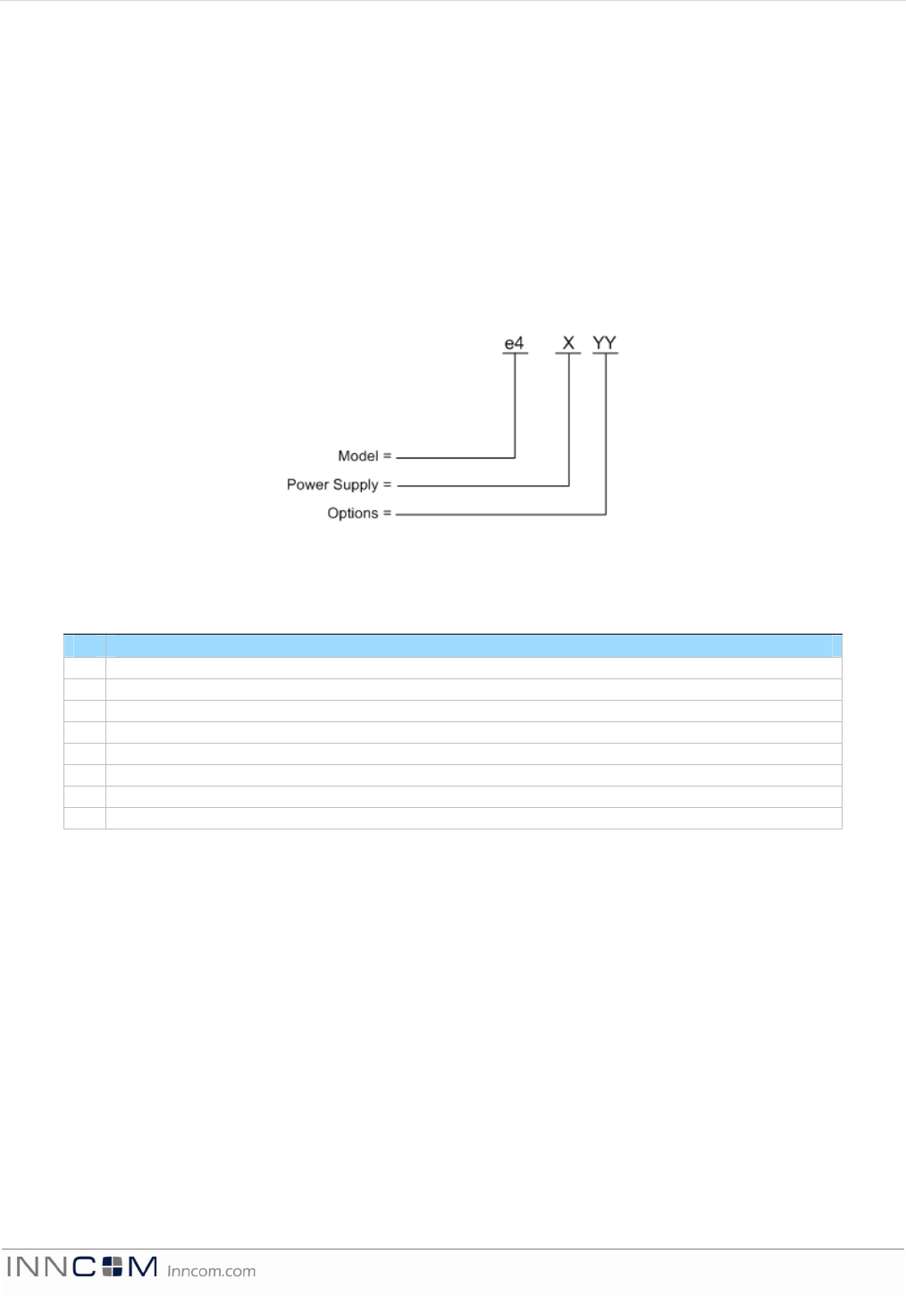
The IR-only e4 ordering part number (OPN) scheme uses only 3 digits to indicate power supply and options:
The “X” number is the first of the three digits and designates the power supply type
Table 8. IR only e528 Power Supply Ordering
X Power Supply Type
0
12VDC S5BUS (Power Supply removed, powered by external X06 or X05
3
24
VAC 50/60 Hz
4
24
VAC Triac
5
Nominal Voltages: 100
–
240
VAC 50/60 Hz w/ 3.6 FLA Hi
gh Fan Relay
6
Nominal Voltages: 265
–
277
VAC 50/60 Hz w/ 3.6 FLA High Fan Relay
7
24
VAC 50/60 Hz (02
-
9561)
8
100
-
277VAC Hz (02
-
9560)
9
24VAC 50/60 Hz (02
-
9565)
Figure 9 IR Only E528.2G OPN Scheme
E 5 2 8 P r o d u c t G u i d e P a g e 1 4 o f 1 8
The “YY” numbers are the second and third digits and designate the option or combination of options. When
more than one option is selected, the “YY” option numbers are added, as in Examples B and C shown below.
YY Option # Option Description
00 None No Options
01 IR3
02-9464.1 IR3 PCBA option
02 IR5 02-9467 IR5 PCBA option
03 IR3+ 02-9464.3 IR3+ PCBA option
04 H Humidity Sensor
08 PIR Passive IR Motion Sensor
16 DM Do-Not-Disturb & Make-Up-Room Buttons
32 P2 Flat PIR
Example A
100V-277VAC e
4
with no options = Model e
4
-800 [X = 8, YY = 00]
(with 2.2 FLA high fan relay)
Example B
100-277V e4 with H + PIR options = Model e4-812 [X = 5, YY = (04 {H} + 08 {PIR}) = 12]
(with 3.6 FLA high fan relay)
Example C
OLD 24V e4 with IR5 + PIR options = Model e4-310 [X = 3, YY = (02 {IR5} + 08 {PIR} = 10]
NOTE: This assembly would be 01-9560.310 and calls for a 03-9460 which uses old P supply and 9496.
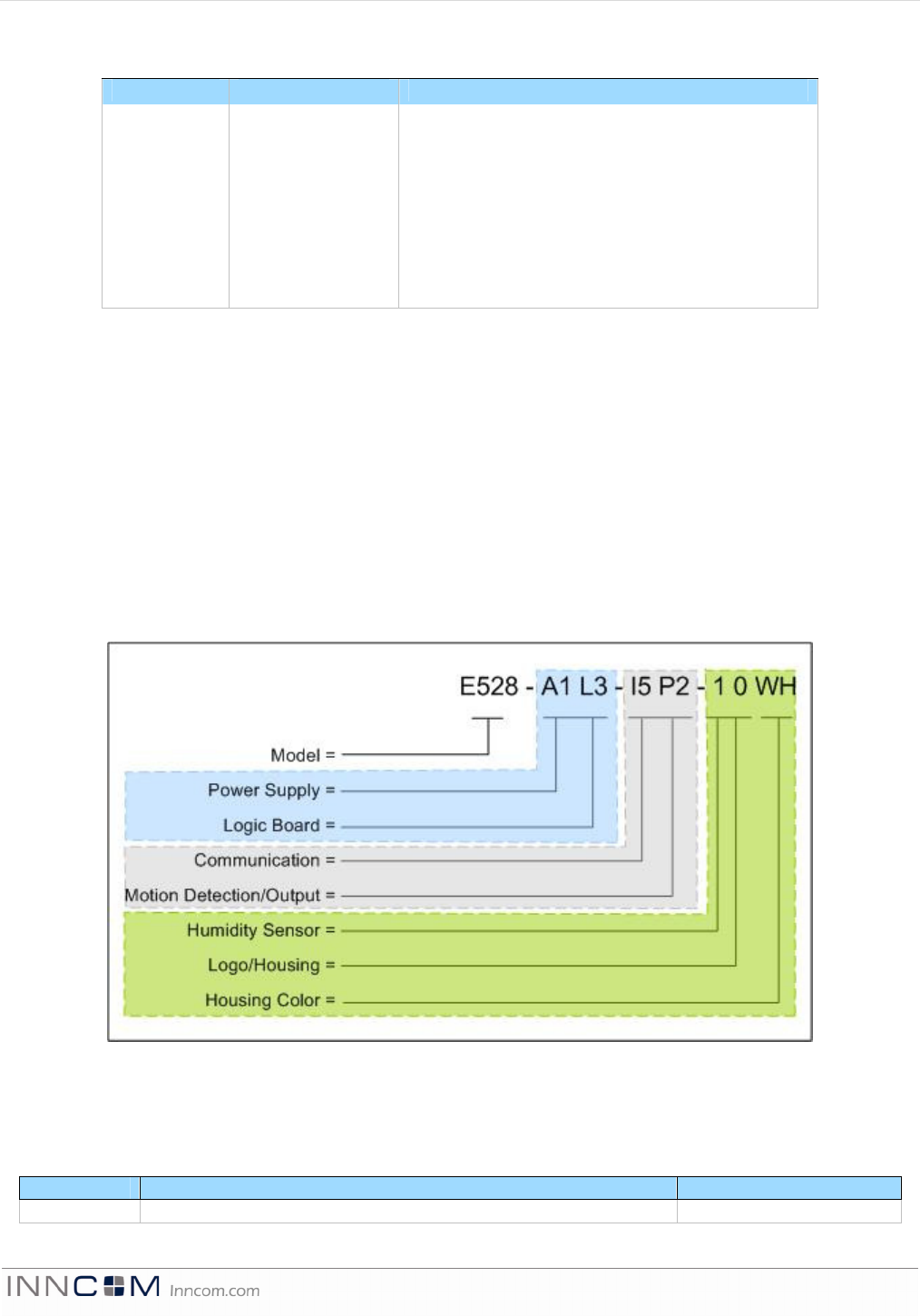
For the RF capable thermostats, the complexity engendered by the multiplicity of power supplies, logic boards,
and communications and other option call for a larger OPN incorporating a more granular scheme (Figure 13,
below). Table 9 lists the options available for the RF E528:
Table 9. RF capablee528 Ordering Options
Model
This character set defines the model name for the e528.
OP/N Code Description Part Number
e528 DDC Thermostat 01-9911
Figure
10
e528 3G OPN
Figure
11
RF Capable e
52
8 OPN
E 5 2 8 P r o d u c t G u i d e P a g e 1 5 o f 1 8
Power Supply
This character set defines the power supply options available for the e528.
OP/N Code Power Supply Type Part Number
A0 No power supply -
A1 24VAC 50/60Hz power supply (300 series) 02-9461
A2 24VAC 50/60Hz power supply (700 series) 02-9561
A3 24VAC 50/60Hz power supply (900 series*) 02-9565.C1
B0 110-240VAC 50/60Hz w/ 3.6FLA high fan relay (500 series) 02-9460.5
B1 120-277VAC 50/60Hz w/ 2.2FLA high fan relay (800 series) 02-9560
C0 265-277VAC 50/60Hz w/ 3.6FLA high fan relay 02-9460.6
Logic Board
This character set defines the logic board options available for the e528.
OP/N Code Logic Board Type Part Number
L0 No logic board -
L3 e528 3G hermetic enclosure w/ 0dB radio 02-9911.L1
L4 e528 3G hermetic enclosure w/ 20dB radio 02-9911.L2
L6 E528 4G logic board with 0dB radio 202-150
L7 E528.4G logic board with 20dB radio 202-152
Communication
This character set defines the auxiliary communication options for the e528.
OP/N Code Auxiliary Communication Type Part Number
I0 No auxiliary communication device -
I5 IR5 only 02-9467.e8d
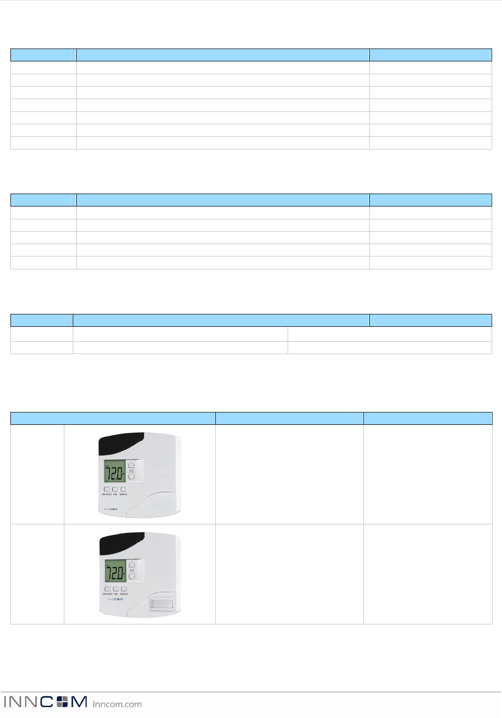
Motion Detection/Output
This character set defines the motion detection/output options for the e528s (Note: photos are for reference only.
Actual product models may differ slightly in appearance).
OP/N Code Motion Detection/Output Type Part Number
P0 Blank 53-0446
P1 Standard PIR 02-9465-B
E 5 2 8 P r o d u c t G u i d e P a g e 1 6 o f 1 8
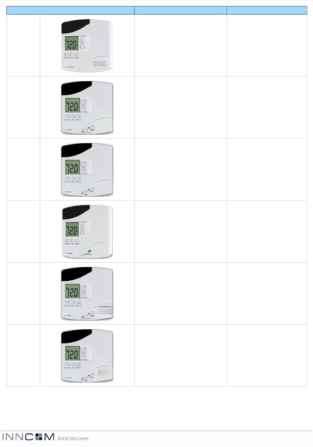
OP/N Code Motion Detection/Output Type Part Number
P2 Flat PIR 02-9499
Q0 DND/MUR only 53-0448
Q1 Manual heat/cool selection only TBD
Q2 ecoMODE only 53-9209
R0 Standard PIR with DND/MUR 53-0448
R1 Standard PIR with heat/cool
output
TBD
E 5 2 8 P r o d u c t G u i d e P a g e 1 7 o f 1 8
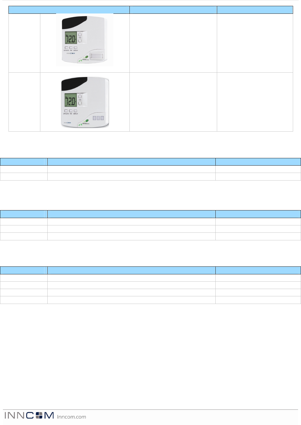
OP/N Code Motion Detection/Output Type Part Number
R2
Standard PIR with ecoMODE 53-9210
R4 Flat PIR with ecoMODE 53-9211
Humidity Sensor
This character set defines the humidity sensor options for the e528.
OP/N Code Humidity Sensor Option Part Number
0 No humidity sensor -
1 Humidity sensor 02-9463
Logo/Housing
This character set defines the housing logo for the e528.
OP/N Code Logo Option Part Number
0 No logo -
I INNCOM logo -
J JCI logo (Johnson Controls) -
Color
This character set defines the housing color options for the e528.
OP/N Code Housing Color Option Part Number
WH White -
EA Eagle Almond -
BK Black -
XX Custom -
Ordering Example:
e528-A1-L2-I5-P2-1-O-WH = An e528 with a 24VAC 50/60Hz power supply (300 series), 64K logic board, IR5
auxiliary communication device, flat PIR motion detector, humidity sensor, no logo, manufactured in white.
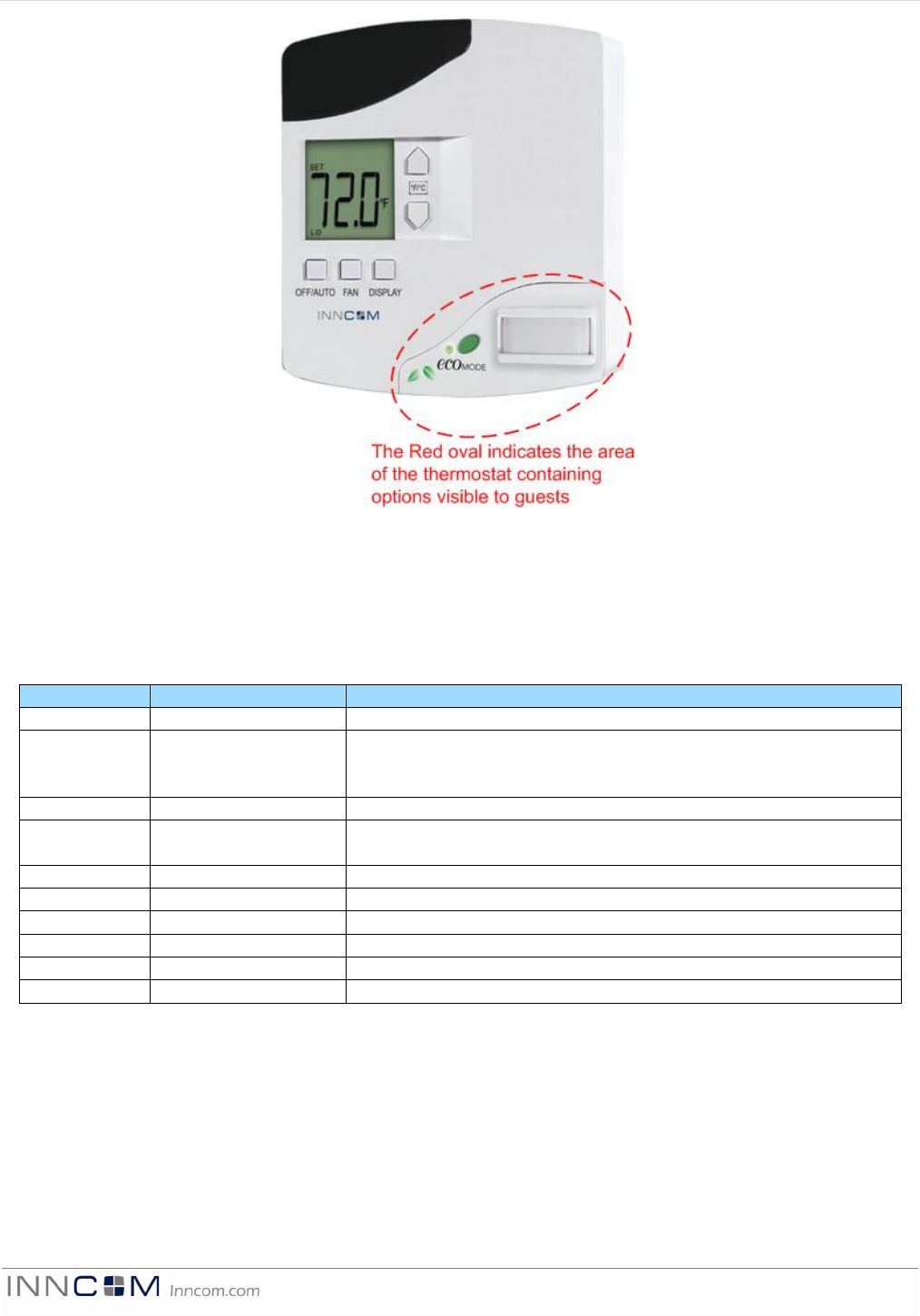
Figure 14 indicates the area of the thermostat that has options VISIBLE to the guest.
E 5 2 8 P r o d u c t G u i d e P a g e 1 8 o f 1 8
References
e528 Operation Manual, INNCOM Document 3000, Version 2.0, Dated April 29, 2005
Document Revision History
REVISION DATE ISSUED REASON FOR CHANGE
First issue 26-Apr-2006
v1 30-Jul-2007 Reformatted for consistency with other product guides. Information
about the other e4 models added to the Overview section. Information on
all ordering options and new features added to the Ordering section.
v2 Not issued Product photos updated. Part number corrected. Figure 3 redrawn.
v3 27-Jun-2008 New Figure 2 added (PIR range figures) and figure numbers changed to
accommodate the added figure.
v4 30-Jun-2008 Switched to new document format.
v5 30-Jun-2008 Error in Figure 4 corrected; font discrepancies corrected.
v6 18-Feb-2010 Reformatted to new template, RF data updated
v6.1 22-Apr-2010 OP/N rewritten to include old scheme; photos updated.
v6.2 28-Oct-2010 Added 3G pinout note
v7.0 05-Apr-2012 Added 4G information
Figure 12 Area of Thermostat with Options Visible to the Guest