Honeywell 202153TXR Battery Powered Thermostat User Manual S217 S Series Light Switch
INNCOM International Inc. Battery Powered Thermostat S217 S Series Light Switch
User Manual.pdf
PN 292-120
Copyright 2013 INNCOM by Honeywell
E529.RF Thermostat
Installation Guide
The e529.RF battery-
operated thermostat is
designed to work in
conjunction with an
HVAC controller to
monitor and maintain
room temperature (other
devices may also be
controlled from the
e529.RF).
There are three general
scenarios for using the e529.RF:
A basic IRAS application with the e529.RF
communicating wirelessly to another device
An IRAS application with RF communication
to a network backbone
An IRAS application with wired
communication to a network backbone
Installation
CAUTION!
The e529.RF is intended for indoor use only.
The E529.RF installer must be a trained,
experienced service technician.
All wiring must comply with local codes and
ordinances.
Failure to follow the instructions provided with the
product could damage the product or cause a
hazardous condition.
Placement
Without the need for power input, the e529.RF
affords great placement options for optimal
performance with virtually any fan coil unit, heat
pump, or packaged terminal air conditioner found in
guestrooms.
Since RF is critical to the e529.RF’s operation,
placement of the device and careful consideration of
possible sources of radio interference are important.
For instance, the unit should not be placed close to
floor or ceiling or near pipe or other metal pieces.
To minimize external conditions interference with
room temperature measurement, locate the e529.RF
away from external doors or windows and areas in
direct sunlight.
Mounting Instructions
Separate the e529.RF
body and the
mounting plate by
pulling the bottom of
the mounting plate
away from the
e529.RF body and
then pull the mounting
plate down.
NOTE: If the back-
mounting plate is rotated more than 2 or 3
degrees, the plastic tabs at the top of the plate
may fracture or break off.
Attach the mounting plate to the wall or
electrical box with the arrow embossed on
the mounting plate pointing upward.
The e529.RF is provided with four 6-32 ¾”
sheet metal screws for mounting the plate to
an existing 4” × 4” electrical box. If attaching
the mounting plate to sheetrock or a similar
wall surface, install four 6-8 × ¾ anchors. The
four holes on the mounting plate can be used
to mark the location for the anchors.
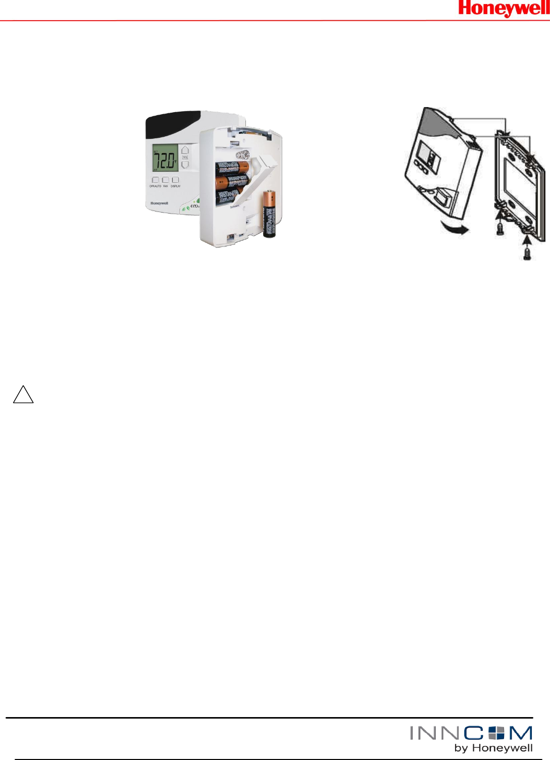
Install the four AA alkaline batteries (NOTE:
Use alkaline batteries only) provided into the
battery compartment located on the rear of
the e529.RF. Depress the battery clamp latch
at the top of the battery compartment and
then swing open the battery clamp. Insert the
4 AA alkaline batteries, matching the “+”
terminals on the batteries to the “+” symbols
in the battery compartment. Close the battery
clamp and verify the latch is securely
fastened.
Verify that the e529.RF display is now
showing information. If the display is blank,
verify that the batteries are completely
installed with the right polarities and that the
batteries are not dead.
!

PN 292-120
2
Copyright 2013 INNCOM by Honeywell
Hook the tabs at the top rear of the e529.RF
housing into the matching depressions at the
top of mounting plate and rotate the bottom of
the e529.RF housing toward the wall until it
snaps into the place on the mounting plate.
Secure the e529.RF housing to the mounting
plate with the two small screws provided with
the e529.RF. The screws thread into two
small holes on the bottom of the e529.RF
housing (see figure above).
Service Mode
The installation technician must enters the
e529.RF’s Service Mode to set parameters for
uniquely identifying a room, binding the INNCOM
devices in the room to that identity, setting the
operational characteristics of the devices, and, if
necessary, connecting the room to floor- or building-
wide network.
Entering Service Mode
To enter Service Mode
1. Press and hold the °F/°C button on the e529.RF
2. Press and release the OFF/AUTO button
3. Press and release the DISPLAY button
4. Release the °F/°C button
Entering Values in Service Mode
rId— Sets Room ID, a number that uniquely identifies the
room to other device or on a network. Room ID consists of 5
digits divided into 3 bytes of data labeled HI_MED_LO (default
is 6_55_35). The number will be included on the
commissioning list and generally corresponds to the actual
room number.
o Enter Service Mode
o At rId, press OFF/AUTO; the Room ID scrolls across the
LCD, then the first digit (HI) appears
o Use the UP/DOWN arrow to scroll to the first number of
the Room ID entry from the commissioning list (HI values
can be from 0 to 6)
o Accept the HI number by pressing DISPLAY. The MED
value will now show on the LCD
o Enter the MED 2 digits in the same manner (value 0–99).
LCD shows LO
o Enter the LO 2-digit value (0–99). On pressing DISPLAY,
the new rId will scroll across the LCD, then the e529.RF
returns to the menu list
PAn—The ID number of a network coordinating device, e.g., a
B574, in a network bridge application. The number will be
included on the commissioning list.
o Enter Service Mode if not already there
o Scroll to PAn and press OFF/AUTO
o Use the UP/DOWN arrows to find the PAN ID on the
commissioning list
o Press DISPLAY. The e529.RF beeps to confirm the Pan
ID value is stored, and the LCD returns to the menu list
rF—Selects the RF channel for IRAS communication. The
number will be included on the commissioning list.
o Enter Service Mode if not already there
o Scroll to rF and enter using OFF/AUTO
o Use UP/DOWN to set the RF channel between 11 and
26
o Press DISPLAY. The e529.RF beeps to confirm the
value is stored and the LCD returns to menu
Adr—Used to “teach” IRAS devices the unique identification
information (e.g., Room ID, PAN ID, I/O map for a room) that
binds them to a room or network.
o Enter Service Mode if not already there
o Scroll to Adr and enter using OFF/AUTO
o Prepare the partner device to learn from the e529.RF
o Scroll to the Address for the device to be taught (from the
commissioning list)
o Press DISPLAY. The unit will send the teach command
on all RF channels (11–26), then the LCD displays the
selected address
o Accept in partner device
Note: When in Address mode, the FAN button can be used to
Reset the target device.
Io—Used to configure the Input/Output map of a partner
device. [Note: Some INNCOM devices can have variable roles
in a room, e.g., an S217 can be configured to control a light or
a switch. The device roles are contained in the I/O map.]
o Enter Service Mode if not already there
o Scroll to Io and enter using OFF/AUTO
o Prepare the partner device to learn from the e529.RF
o Scroll to the Address for the device to be taught (from the
commissioning list)
o Press DISPLAY. The unit sends the I/O map out over all
channels
Note: Whenever a device is taught information, it is important
to verify that the instruction was received and accepted by
“pinging” the device. See PnG below.
SEr—In legacy (3G) e529s, configures CBL8 Partner (Server)
devices (e.g., X07). The e529.RF will eventually be able to
configure CBL32 devices (e.g., X47) from here. Press
DISPLAY to write parameters; press FAN to execute them.
Loc—Menu of local parameters. This menu is typically not
used by Installation Technicians. The entry below is provided
solely for informational purposes. The list of local parameters
below will change and grow.
o Enter Service Mode if not already there
o Scroll to Loc and enter using OFF/AUTO. The LCD
shows a “P” and a number for each parameter (0–255).

PN 292-120
3
Copyright 2013 INNCOM by Honeywell
o Select a parameter; press OFF/AUTO again to get the
value of the parameter
- P0, 1: Set Room ID (Room ID should be set using rId)
- P2, 3: Set PAN ID (set PAN ID using the PAn
parameter). Not required for RF
- P4: Set the transmission (Tx) radio power. Tx may need
to be boosted to meet local conditions.
- P5: Set the RF channel (set RF channel using the rF
parameter)
- P6: Set the e529.RF local address (default is 13)
- P7: Set the P5 channel (default channel is 1)
- P8: Set P5 partner (default partner is e528.36_X529.RF)
run—Selects built-in tests of the e529.RF
o Enter Service Mode if not already there
o Scroll to run and enter using OFF/AUTO.
o Use the UP/DOWN arrows to select one of the following
tests. Use the DISPLAY button to begin test
- 1—Reset: On execution, the LCD screen flashes red,
then briefly shows reset information from a bound device
- 2—CI Connectivity test
- 3—Broadcast Room ID, Network ID, and PAN ID to RF
bridge device
- 11—PIR test: On execution, the LCD shows Pir and the
unit emits a loud noise when movement is detected by
the passive infrared module.
- 12—Door Test: On execution, the e529 responds with a
beep when the door switch is actuated
- 13—Window Test: On execution, the E529 responds with
a beep when the window switch is actuated
- 14—Remote PIR Test: On execution, the LCD shows PIr
and the unit emits a noise when movement is detected
by a remote device with a passive infrared module
- 20—Reset counter: On execution, the LCD displays the
number of times that the unit has been reset, then reverts
to the test number
- 23— Press DISPLAY to start a real-time temperature
test. The Set temperature ticks up every second for one
minute.
- 24—Tests room relative humidity (if sensor available)
- 25—Tests the built-in light sensor
- 26—Tests battery power (255 = full charge)
- PnG—Sends a signal to connected devices and registers
response
o Enter Service Mode if not already there
o Scroll to PnG
o Scroll to the address of the device to be pinged. After 2
seconds, the version of the partner device will scroll across
the LCD, verifying communication with the e529.RF
Note: Pressing DISPLAY after a device has
been pinged allows entry into the NVRAM of
partner devices. Activity in the NVRAM space
can severely affect functionality. This parameter
should be used only by INNCOM technicians.
Commissioning Process
As noted in the Application Overview, the e529.RF
may be employed in 3 scenarios. For each scenario,
establishing the unique room ID, binding devices, and
establishing communication will be different. Some
devices for instance, initiate binding (reverse bind)
and some must be actively “taught” (forward bind).
Consult the Commissioning instructions for the
particular device. See also the e529.RF User Manual
for detailed instructions.
Testing
Testing the e529.RF Operational Controls
The e529.RF and the other INNCOM devices in a
room setup or network have been subjected to
rigorous unit, integration, operational and production
testing prior to shipment for installation. The
installation technician needs only to test generally
that the thermostat functions as intended.
1. At power ON, confirm all segments and characters
are displayed on the LCD display.
2. Press the DISPLAY button to verify that the LCD
briefly shows the Room (measured) temperature
(which should be close to or equal the Set
temperature). If the e529.RF is networked to an
outdoor sensor, press DISPLAY again to check
that outside temperature is displayed.
3. Press the °F/°C button once to verify that the
temperature scale changes. Verify that the LCD
resets to the default scale in 5 seconds.

PN 292-100
Copyright 2013 INNCOM by Honeywell
4. Use the OFF/AUTO button to test Heat/Cool
functions (depending on the HVAC system, fan
operation may only subside to a minimal level).
Press OFF/AUTO to return to Auto mode. Press
the FAN button to cycle fan speed from LO to
MED to HI.Press the ecoMODE™ button. Verify
that the LCD displays notification that the
ecoMODE option has been chosen.
5. Test the PIR by entering the Run menu and
selecting Value 11. On execution, the LCD shows
Pir and the unit emits a buzzing noise when
movement is detected by the passive infrared
module.
6. Test the door monitor by entering the Run menu
and selecting value 12.
7. If balcony door or window sensors are linked to the
e529.RF, open the linked opening. Verify that the
e529.RF displays notification that the door or
window is open.
Testing e529.RF IRAS and RF network
connections
1. Use the PING parameter to test each device on
the network.
2. Verify that e529.RF LCD displays a dot in lower
right corner of the screen indicating RF link to
HVAC partner.
3. Enter the RUN menu value 2. Execute a test of
the IWAN. If the test is successful, the Room ID
will scroll across the LCD, indicating
communication with the server.
FCC Statement
This equipment has been tested and found to comply with the
limits for Class B digital device, pursuant of part 15 of the FCC
Rules. These limits are designed to provide reasonable protection
against harmful interference in a residential installation. This
equipment generates, uses and can radiate radio frequency
energy and , if not installed and used in accordance with the
guarantee that interference will not occur in a particular
installation. If this equipment does cause harmful interference to
radio or television reception, which can be determined by turning
the equipment off and on, the user is encouraged to try to correct
the interference by one or more of the following measures:
Reorient or relocate the receiving antenna.
Increase the separation between the equipment and
receiver.
Connect the equipment into an outlet on a circuit
different from that to which the receiver is connected.
Consult the dealer or experienced radio/TV technician
for help

PN 292-120
5