Honeywell 60SL0 DOLPHIN 60S User Manual
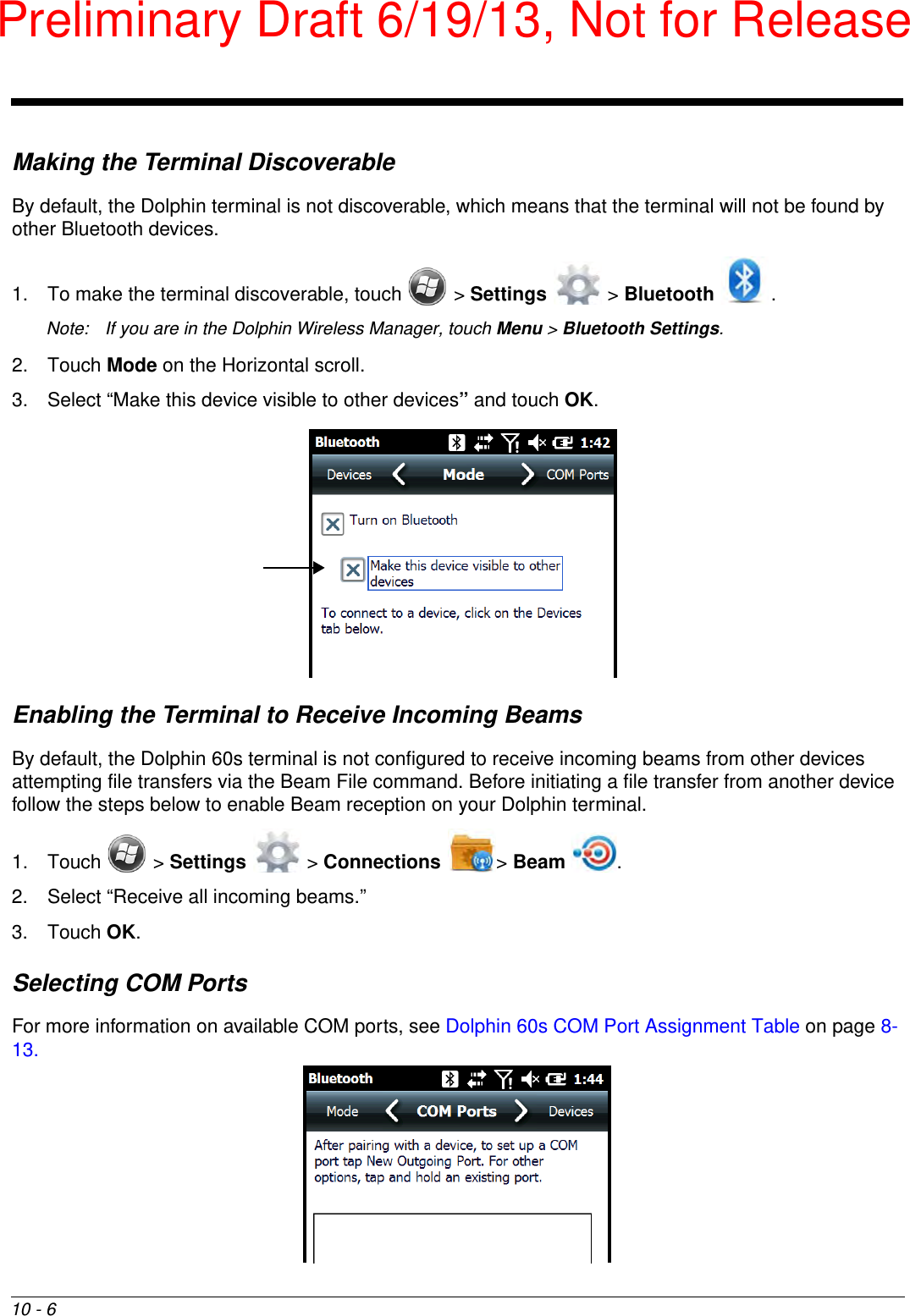
Honeywell International Inc DOLPHIN 60S
UserManual.wiki
>
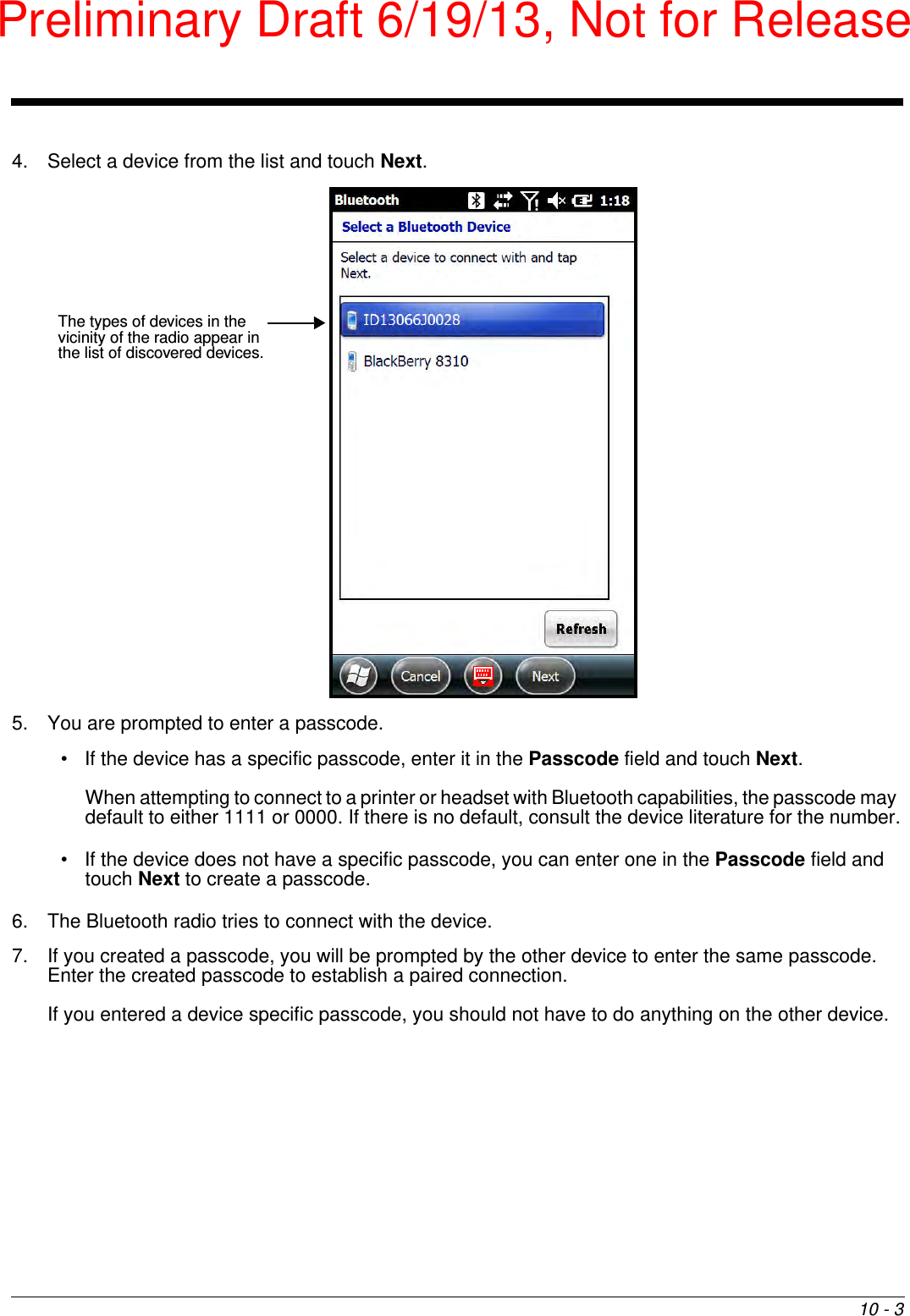
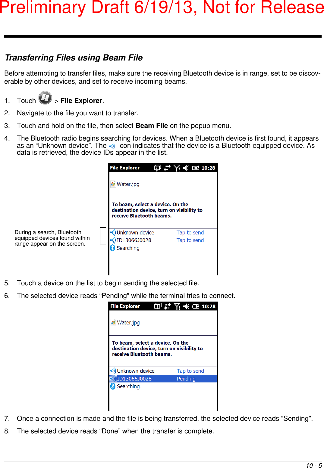
Honeywell
>
60SL0 User Manual
User Manual
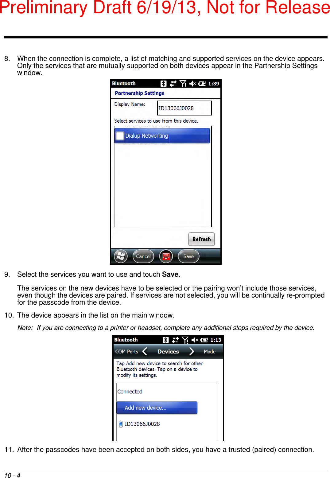
Navigation menu
Upload a User Manual
Namespaces
Wiki Guide
HTML
PDF
Info
Views
User Manual
Discussion / Help
Navigation


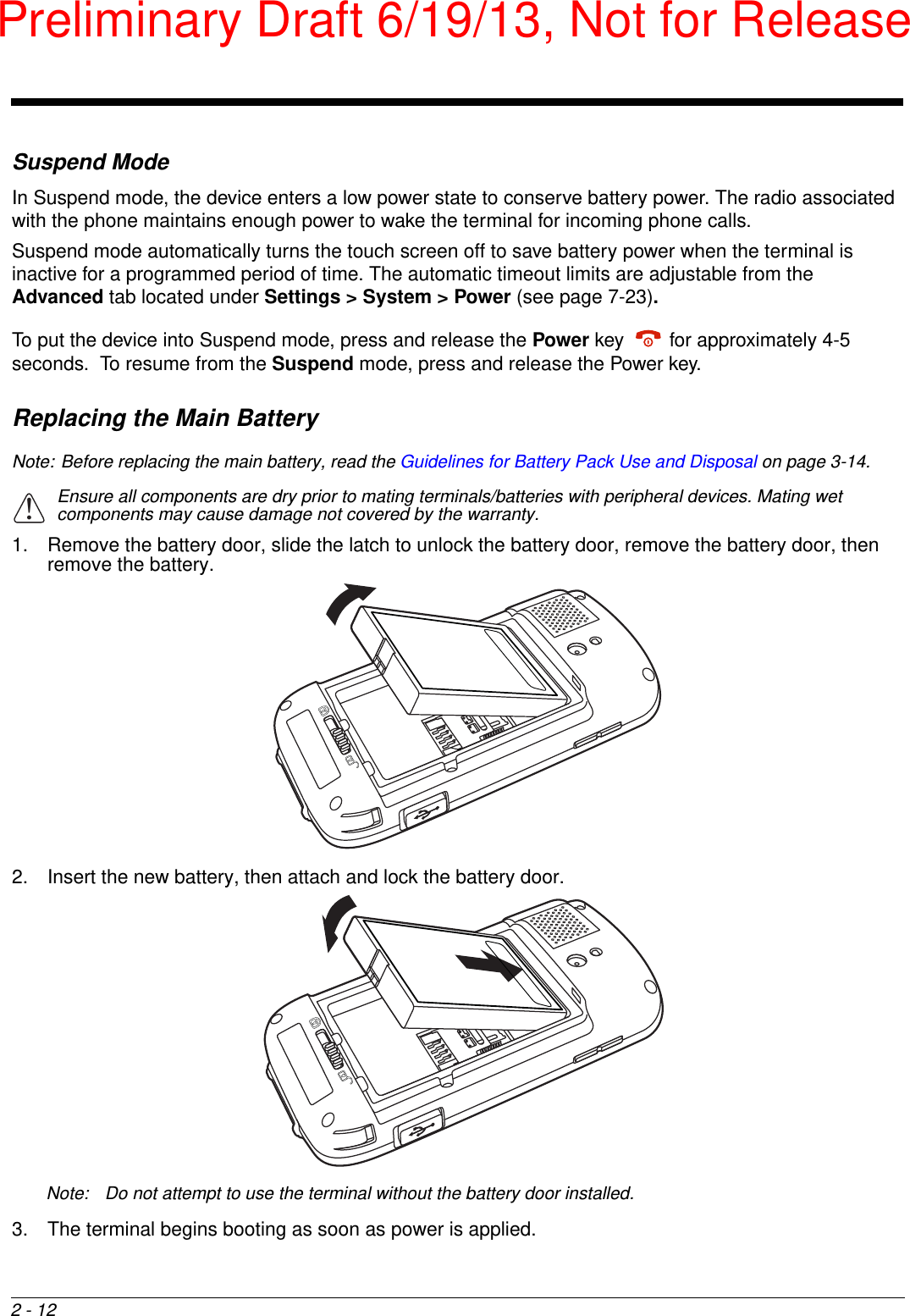


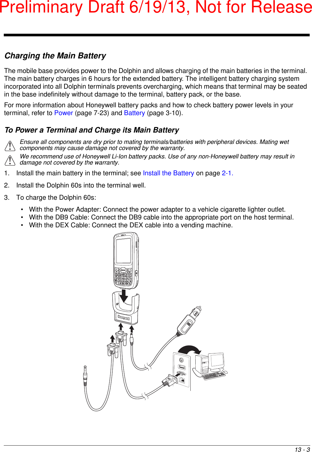
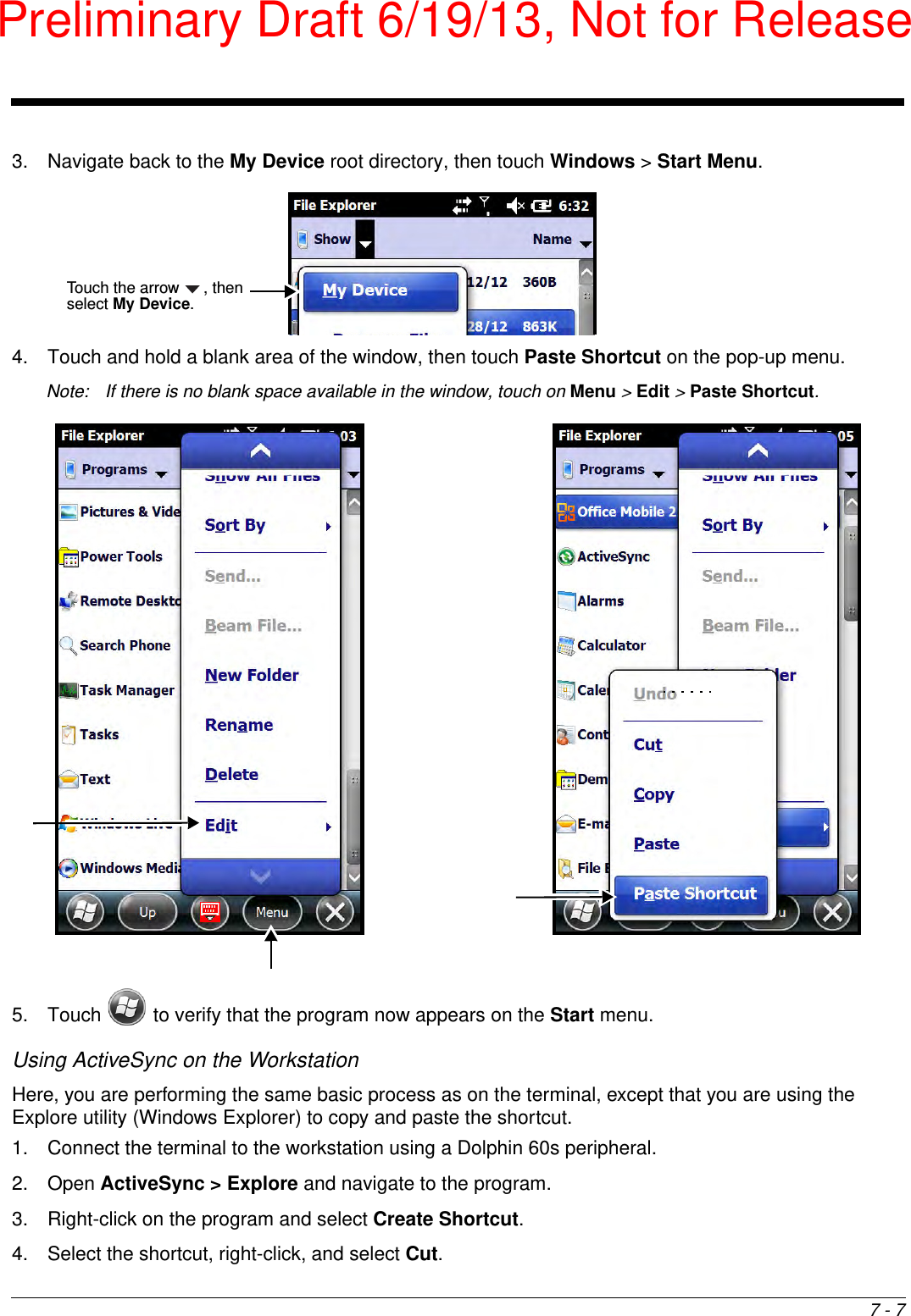
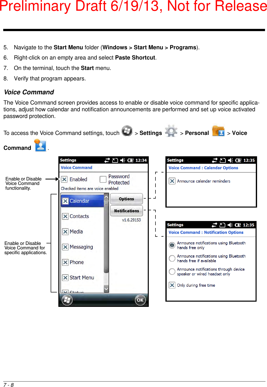
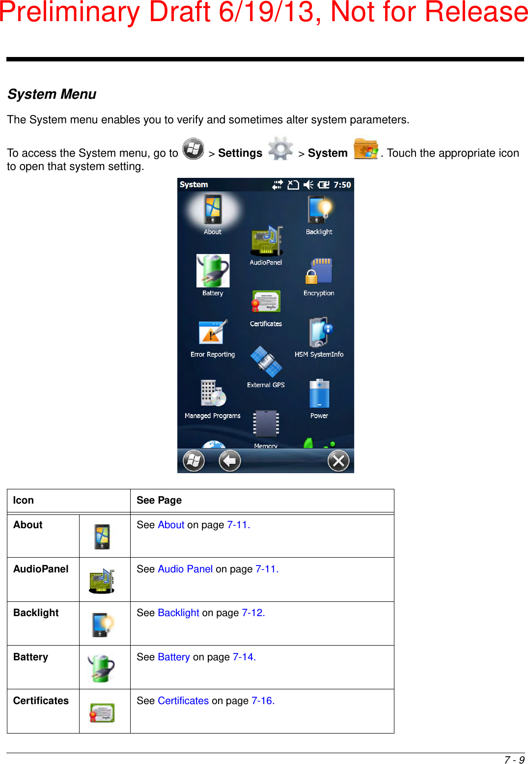
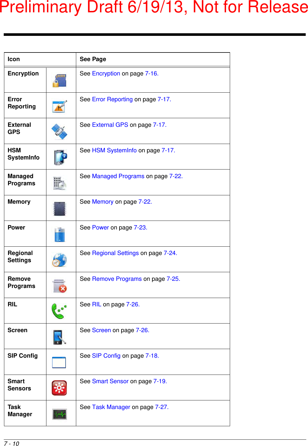
![3 - 14Guidelines for Battery Pack Use and DisposalThe following are general guidelines for the safe use and disposal of batteries:• Do not disassemble or open crush, bend or deform, puncture or shred. • Do not modify or remanufacture, attempt to insert foreign objects into the battery, immerse or expose to water or other liquids, expose to fire, explosion or other hazard.• Improper battery use may result in a fire, explosion or other hazard.• We recommend use of Honeywell Li-ion battery packs. Use of any non-Honeywell battery may pose a personal hazard to the user. • Only use the battery for the system for which it is specified. Do not use a battery in any other manner outside its intended use in Dolphin terminals and peripherals. • Only use the battery with a charging system that has been qualified with the system per CTIA Certification Requirements for Battery System Compliance to IEEE 1725. Use of an unqualified battery or charger may present a risk of fire, explosion, leakage, or other hazard.• Replace the battery only with another battery that has been qualified with the system per this standard, IEEE-Std-1725. Use of an unqualified battery may present a risk of fire, explosion, leakage or other hazard.• Replace defective batteries immediately; using a defective battery could damage the Dolphin terminal.• Never throw a used battery in the trash. Promptly dispose of used batteries in accordance with local regulations.• Do not short-circuit a battery or throw it into a fire; it can explode and cause severe personal injury. Do not allow metallic conductive objects to contact battery terminals.• If you observe that the Honeywell battery supplied is physically damaged, please send it to Honeywell International Inc. or an authorized service center for inspection, see Product Service and Repair on page 14-1.• Battery usage by children should be supervised.• Avoid dropping the terminal or battery. If the terminal or battery is dropped, especially on a hard surface, and the user suspects damage, send it to a Honeywell International Inc. or an authorized service center for inspection.• If you are not sure the battery or charger is working properly, send it to Honeywell International Inc. or an authorized service center for inspection, see Product Service and Repair on page 14-1.• Excessive discharge can degrade battery performance. Recharge the battery when your terminal indicates low battery power. • Although your battery can be recharged many times, the battery life is limited. Replace it after the battery is unable to hold an adequate charge.• The Dolphin 60s should only be connected via its microUSB connector to CTIA certified adapters, products that bear the USB-IF logo or products that have completed, the USB-IF compliance program.Managing Battery Power Letting the battery become fully discharged causes the terminal to lose all data in RAM. Honeywell recommends, you keep a charged battery in the terminal at all times to help prevent data loss. Removing the battery from the terminal erases all non-persistent memory. Default Critical and Low Battery PointsWhen the terminal is running on battery power (as opposed to external power), warnings are displayed when the battery reaches critical and low battery points. The warning points are determined by the following registry entry: [HKEY_LOCAL_MACHINE\ControlPanel\Power] Preliminary Draft 6/19/13, Not for Release](https://usermanual.wiki/Honeywell/60SL0/User-Guide-1996837-Page-44.png)


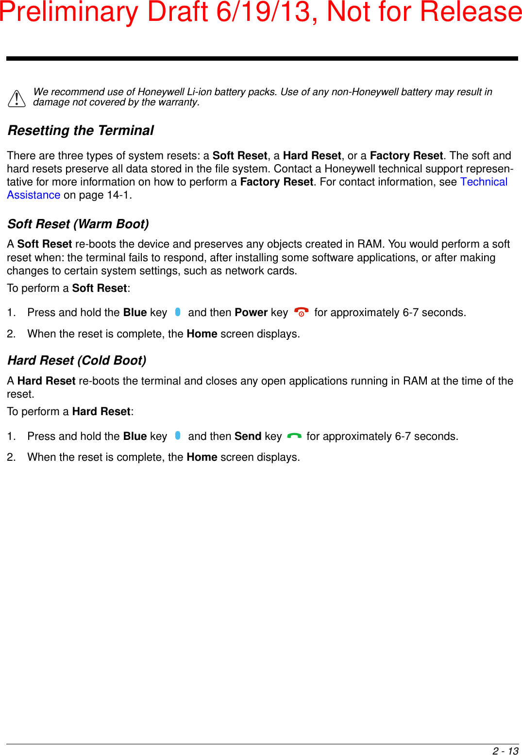
![12 - 2Convenient Storage The intelligent battery charging system makes this base a safe and convenient storage receptacle for your Dolphin terminal. CapacityThe base holds one terminal and features an auxiliary battery well behind the terminal well that can charge a battery pack independently of the terminal well. This means that one base can charge two battery packs: the one installed in the terminal and a spare. We recommend use of Honeywell peripherals, power cables, and power adapters. Use of any non-Honeywell peripherals, cables, or power adapters may cause damage not covered by the warranty.DimensionsWeight HomeBase weight: XXXg [XXX lbs]!Need dimensionsPreliminary Draft 6/19/13, Not for Release](https://usermanual.wiki/Honeywell/60SL0/User-Guide-1996837-Page-140.png)