Honeywell 6110GP Mobile Computer User Manual
Honeywell International Inc Mobile Computer
UserManual.wiki
>
Honeywell
>
6110GP User Manual
User Manual
Navigation menu
Upload a User Manual
Namespaces
Wiki Guide
HTML
PDF
Info
Views
User Manual
Discussion / Help
Navigation

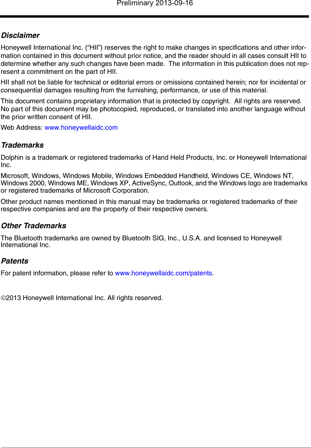


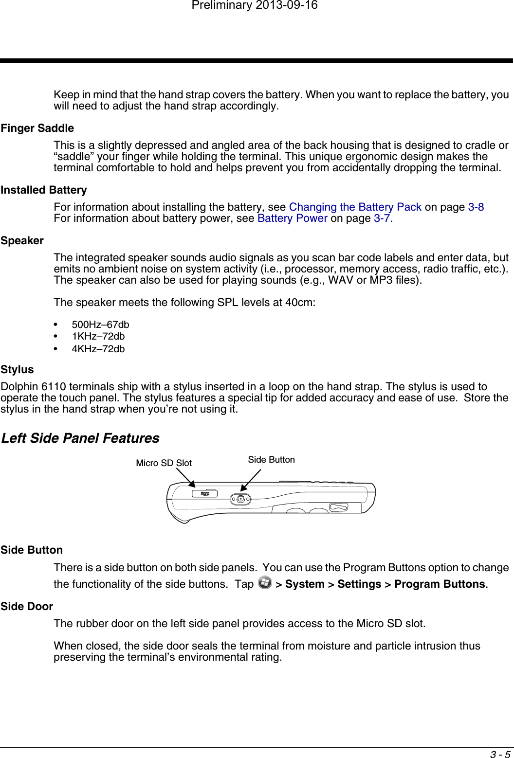
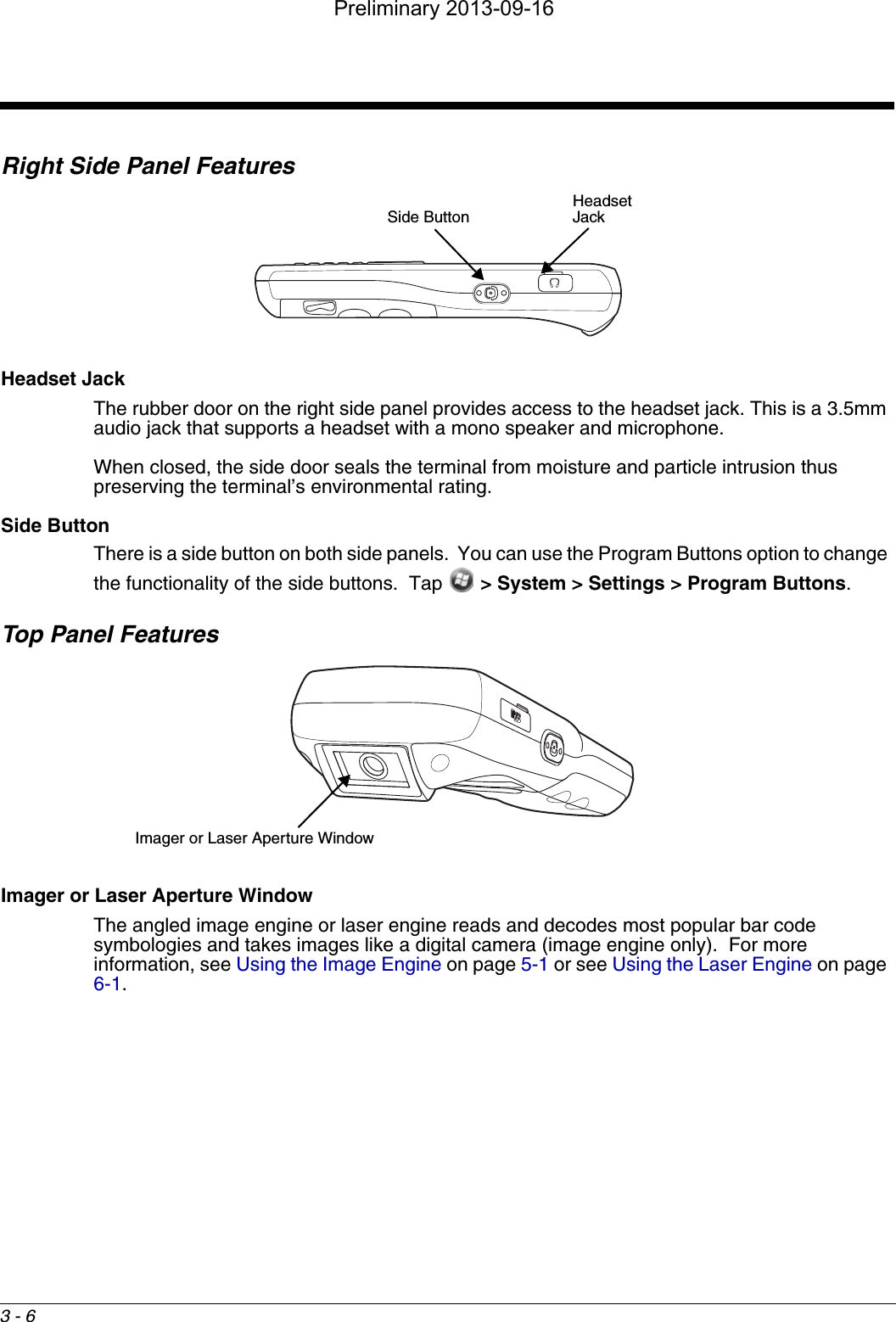
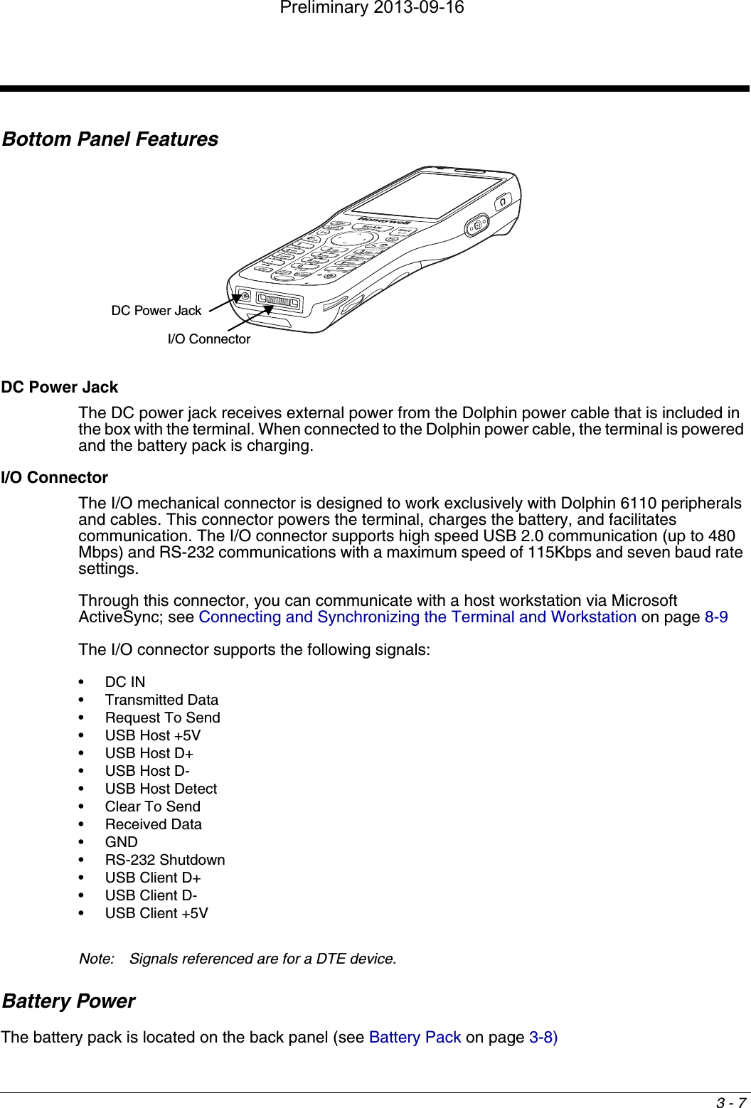
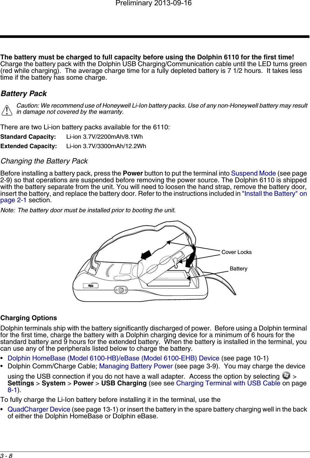


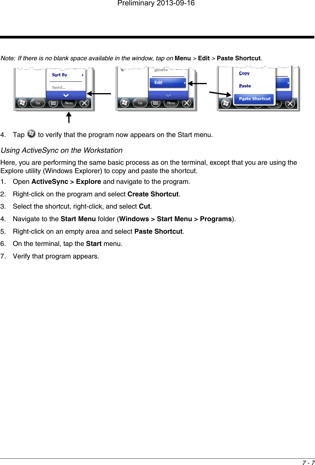
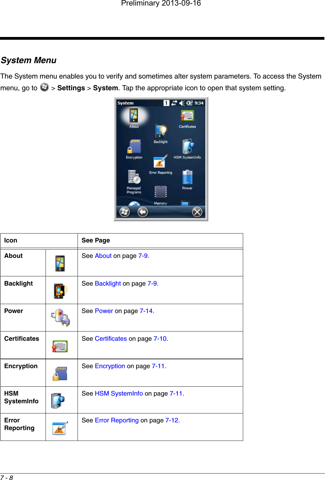
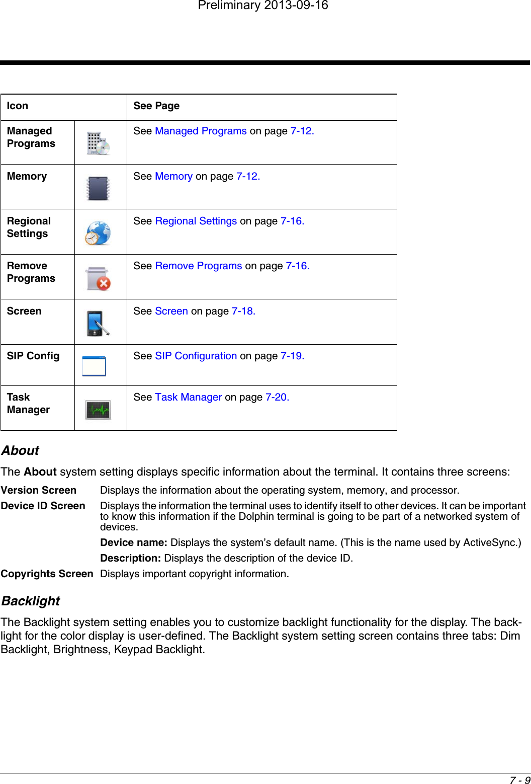
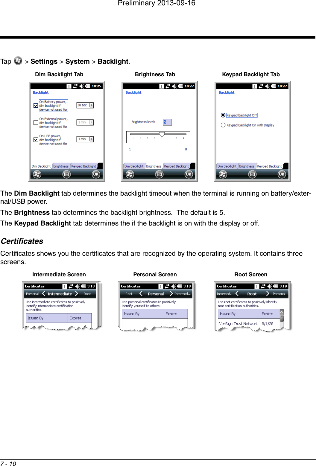
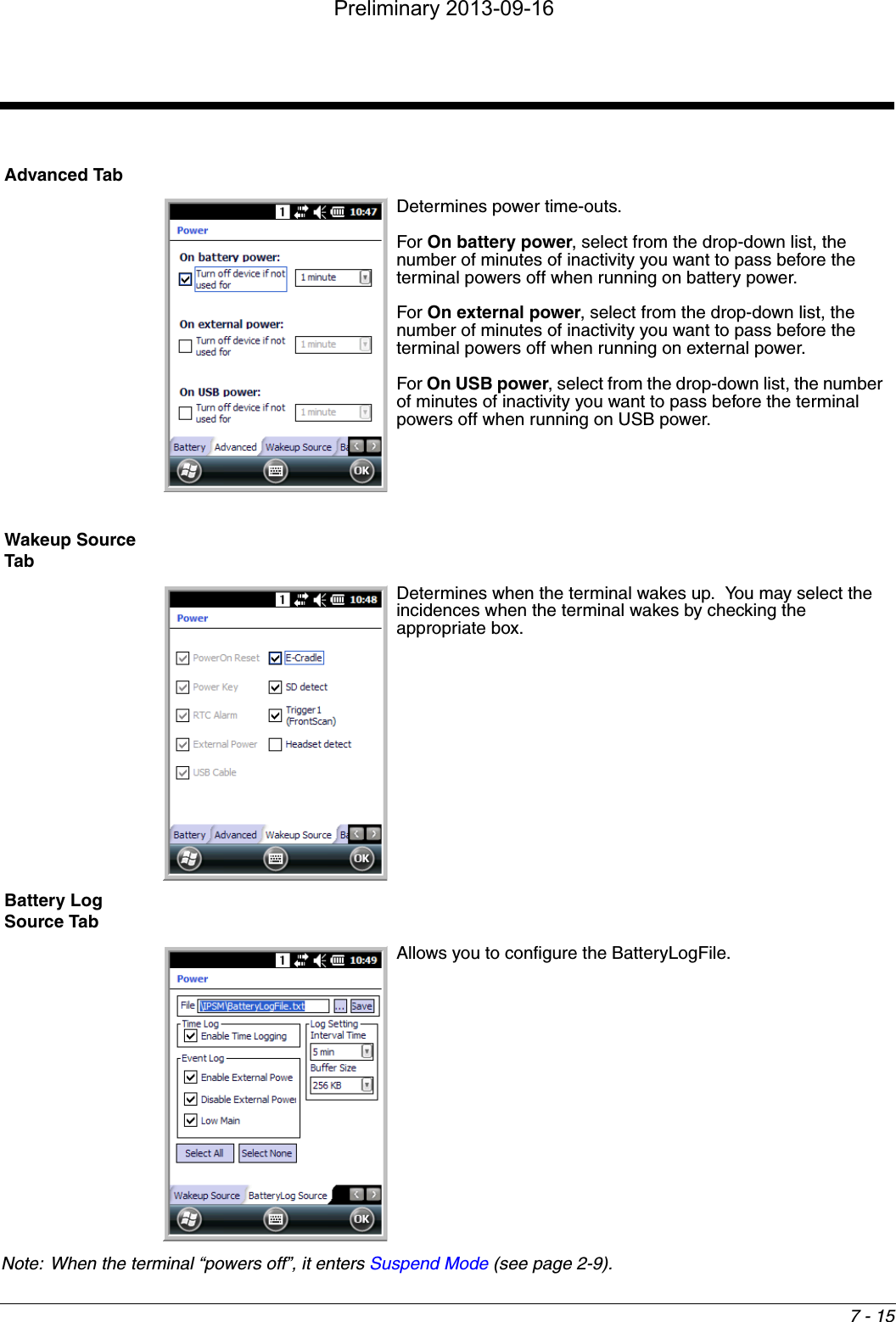

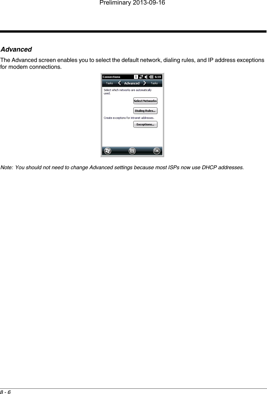
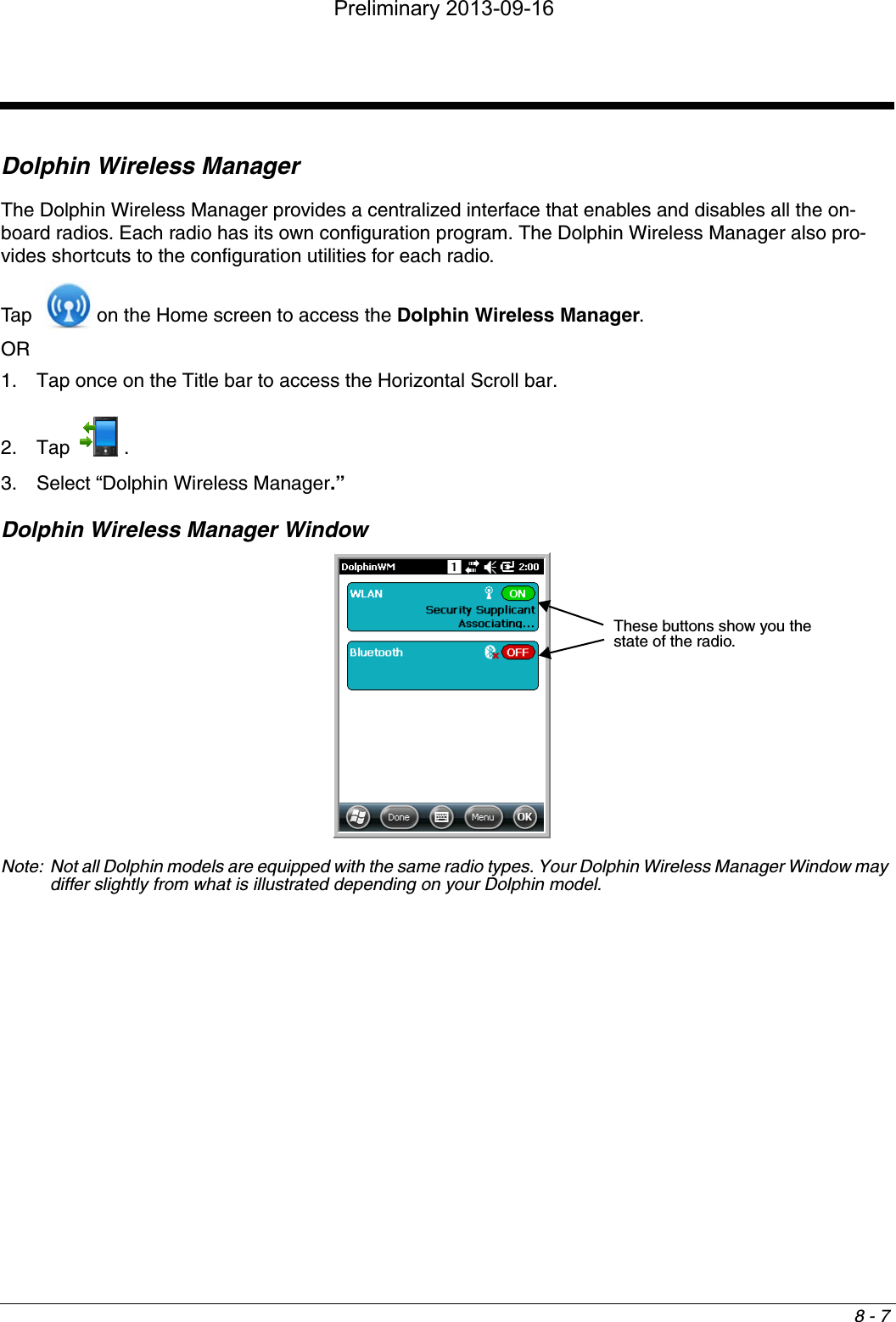
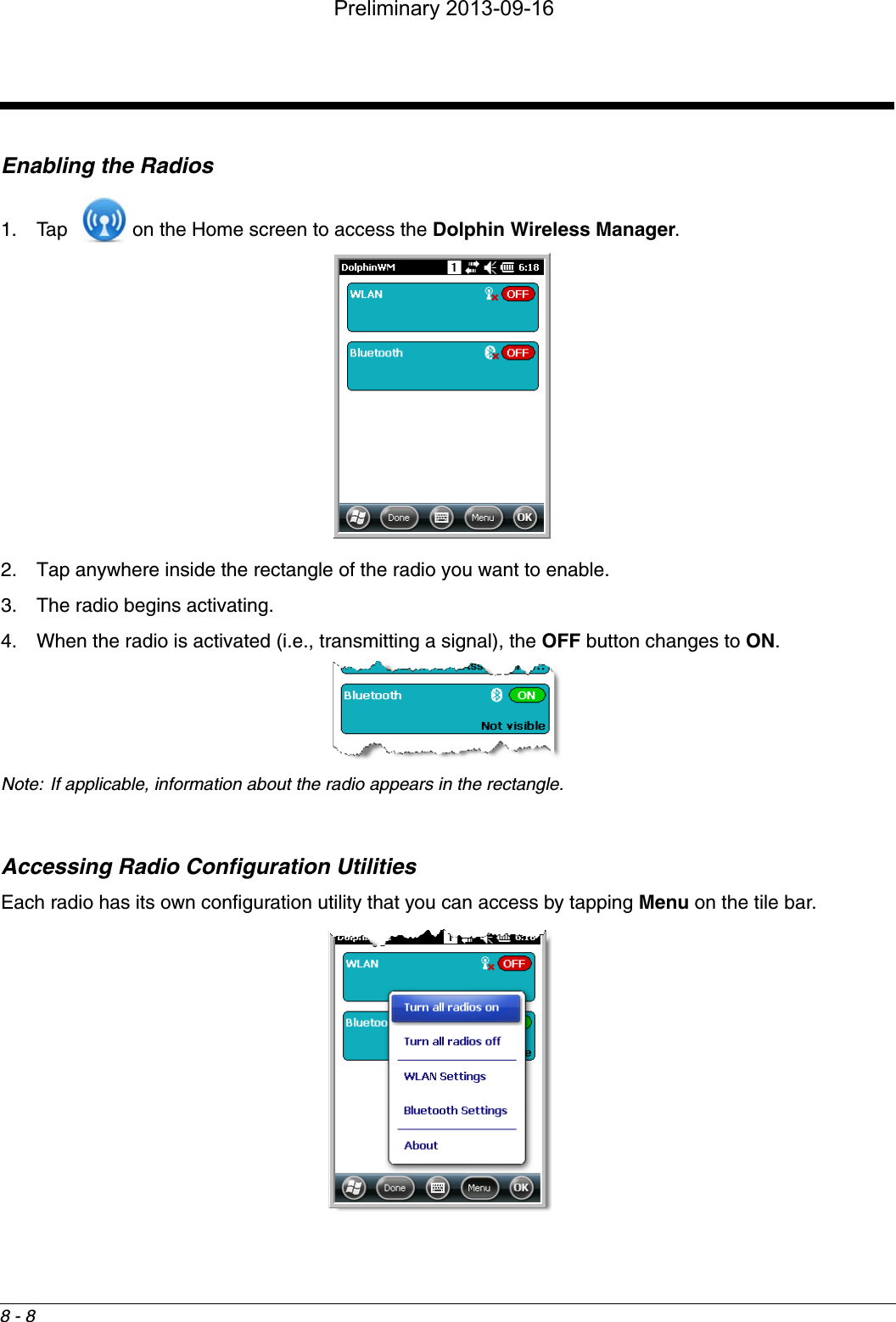
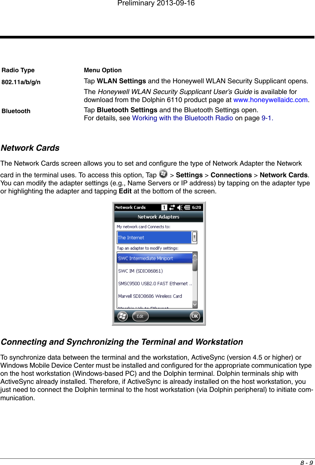
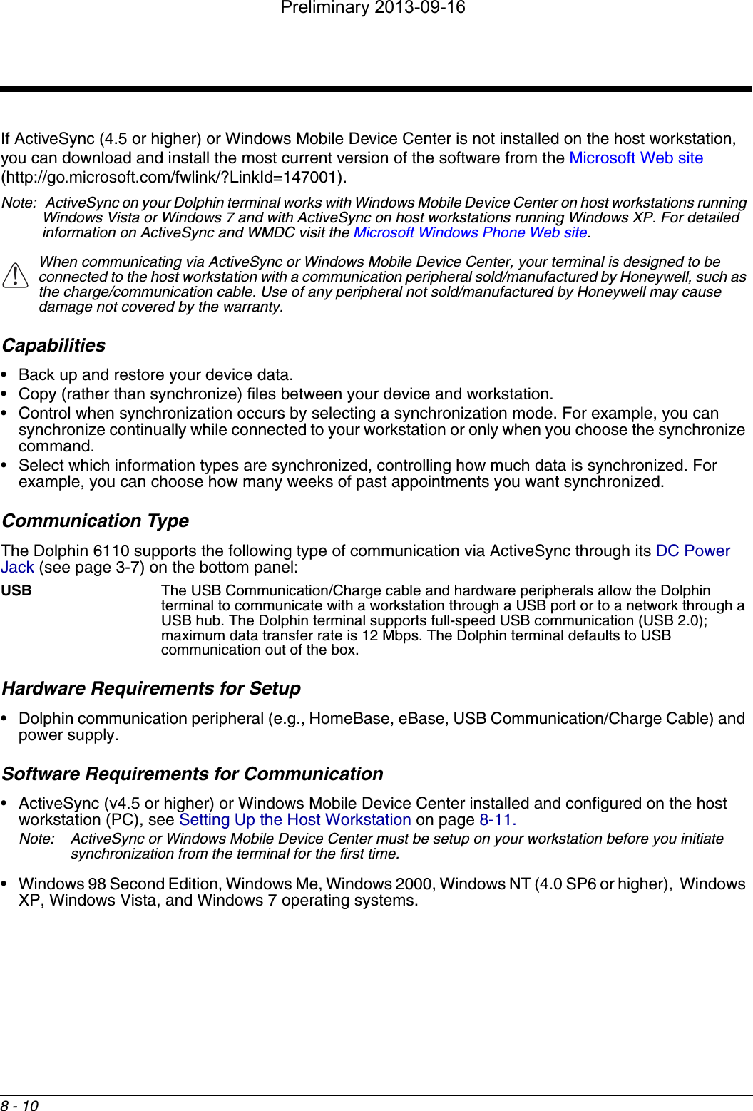
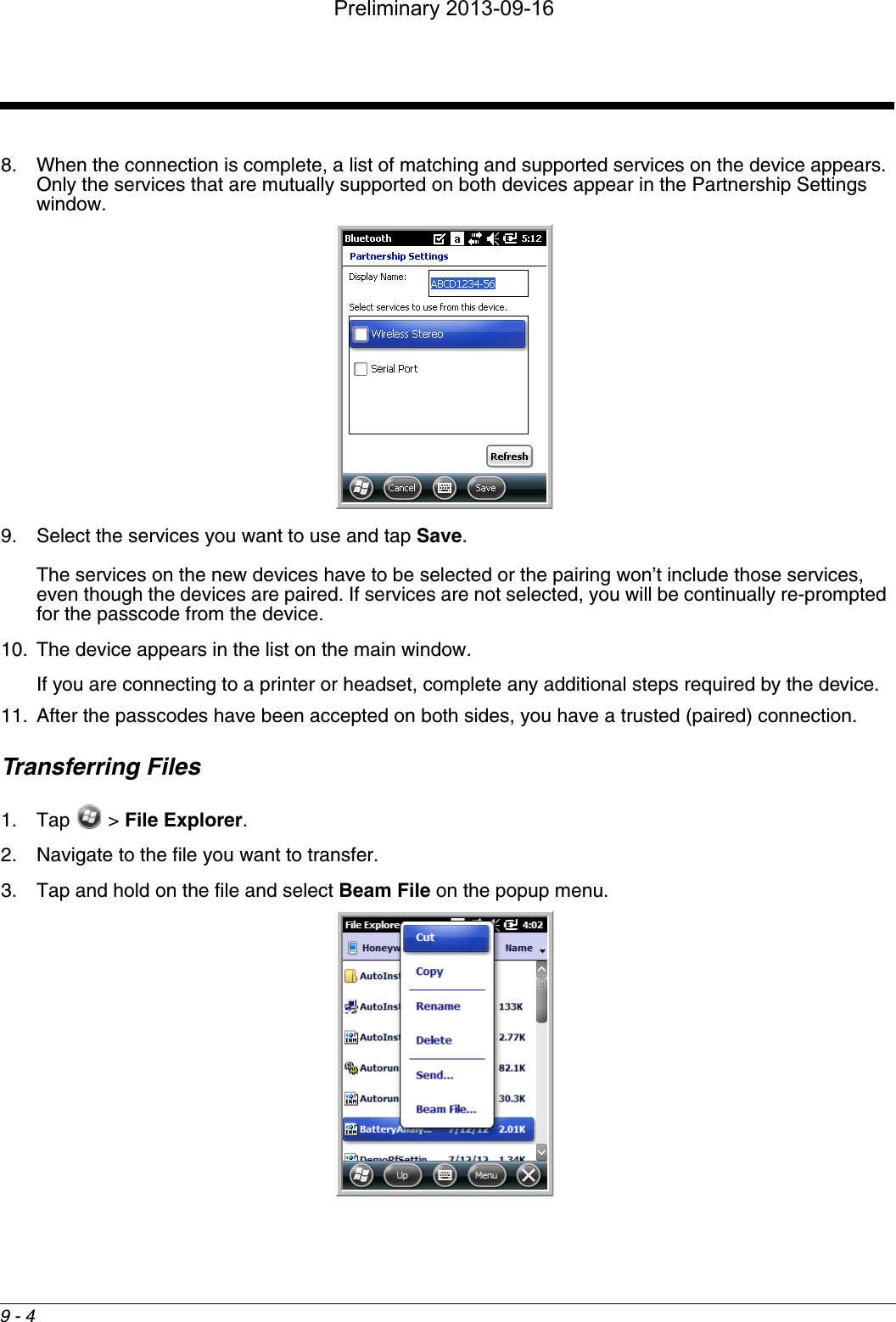
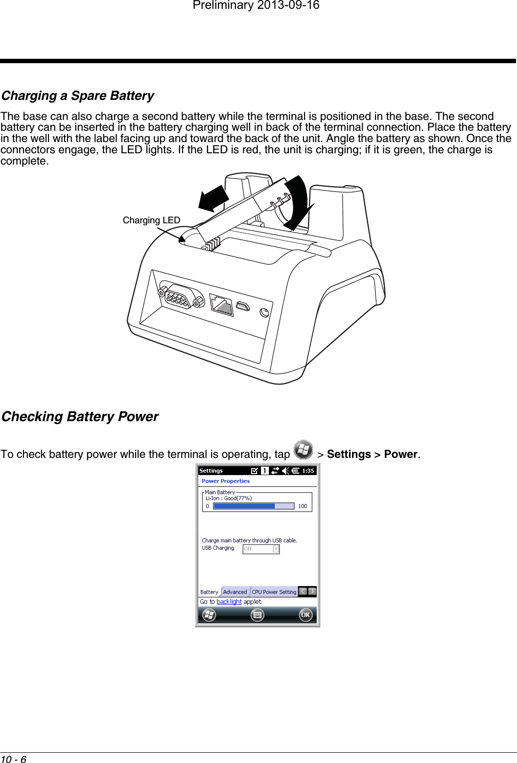


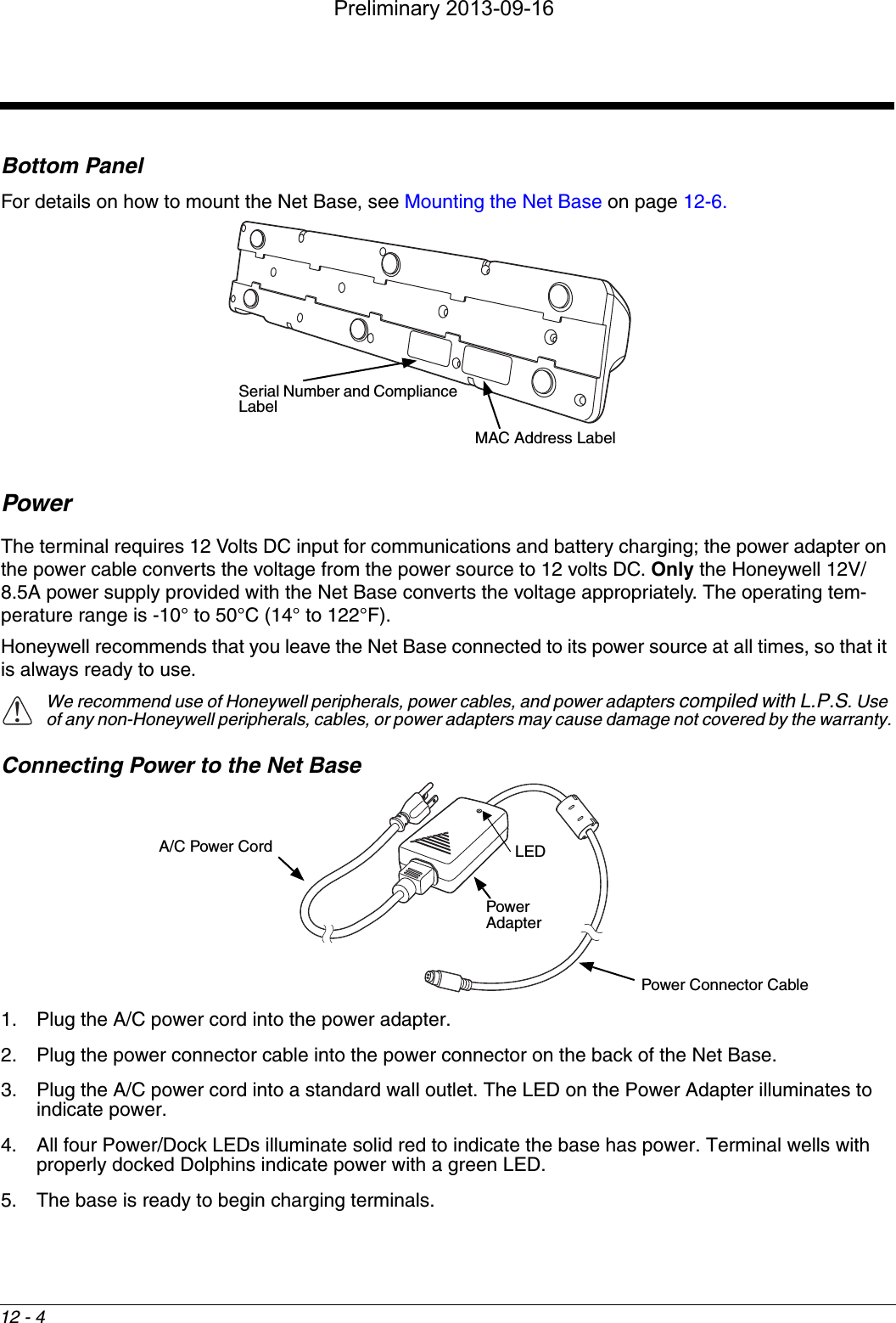
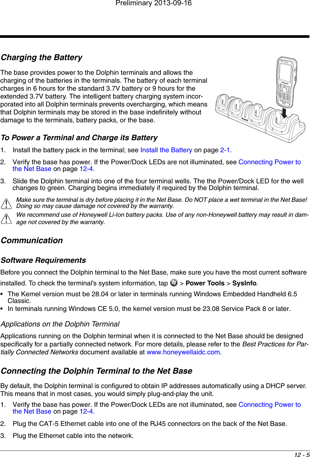
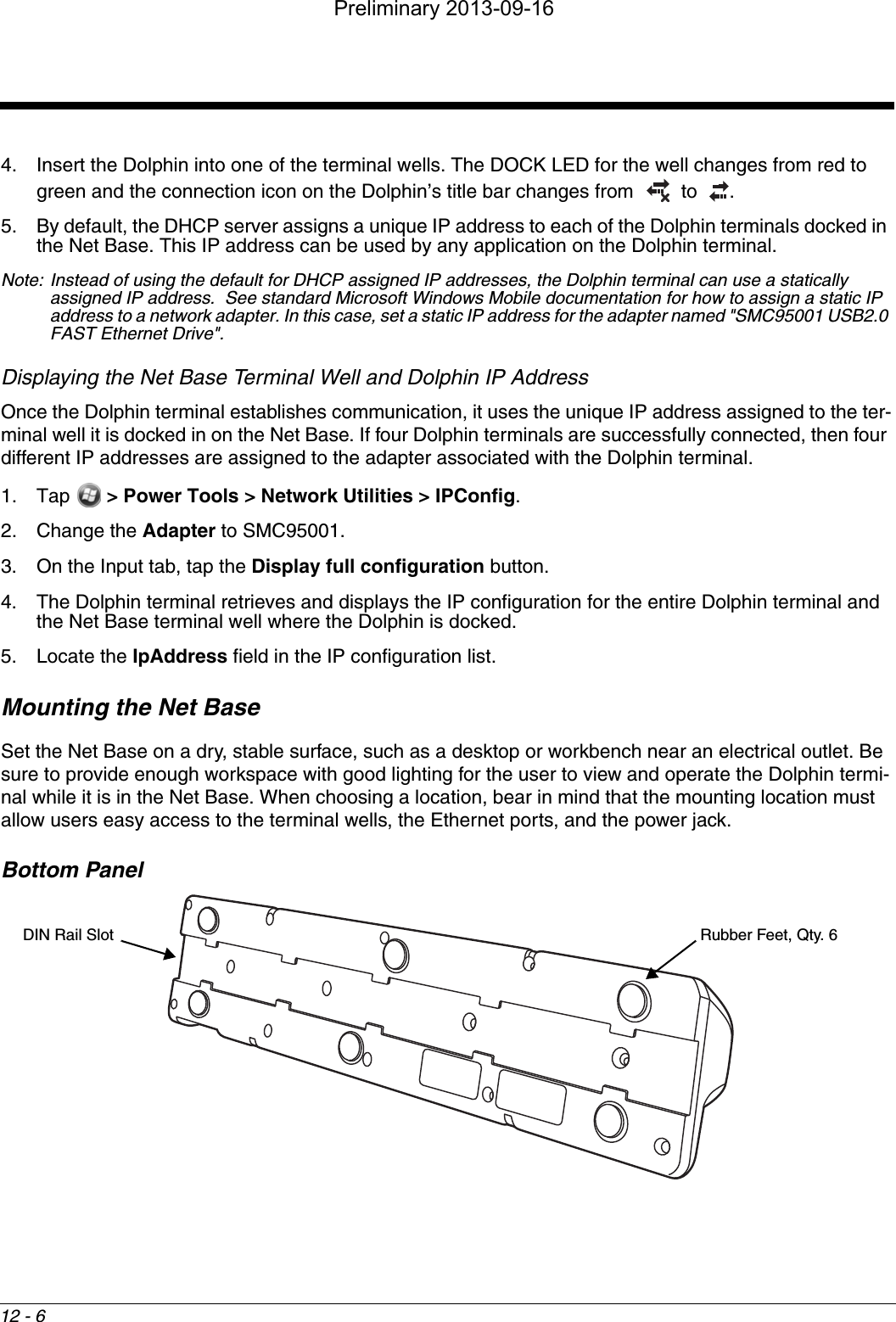
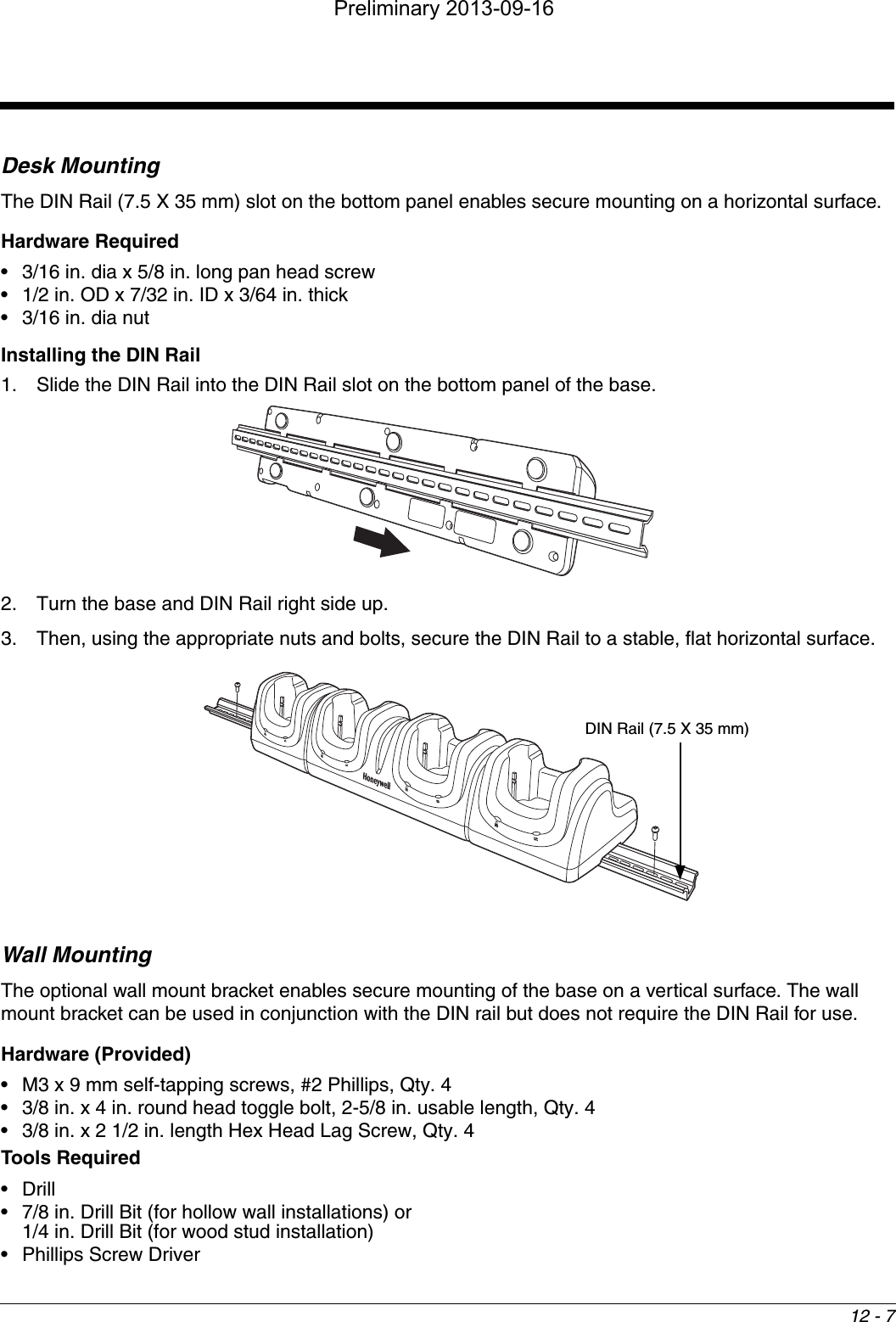
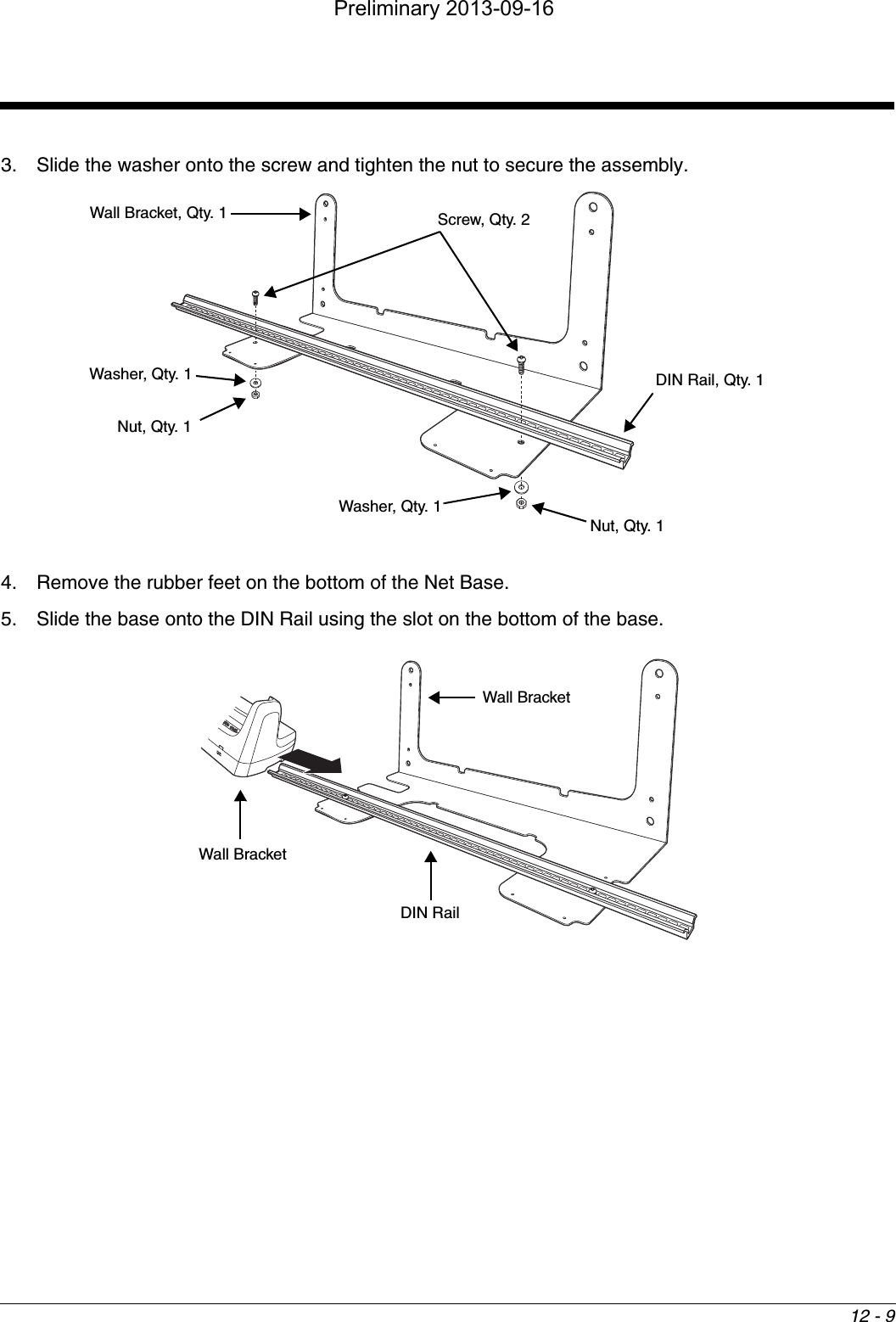
![12 - 8Hollow Wall Installation1. Drill four pilot holes in the wall using a 7/8 in. drill bit.2. Slide the bolt through the wall bracket, and thread the toggle nut onto the bolt.3. Press the ends of the toggle nut together, and insert the bolt/nut into the pilot hole until the nut clears inside wall surface. The toggle nut should spring open preventing the screw from being removed. 4. Repeat steps 2 and 3 for each of the remaining mounting holes.5. Tighten all four bolts to secure the bracket to the wall. 6. Once the bracket is installed, secure the base to the wall bracket, see Securing the Base to the Wall Bracket for detailed instructions.Wood Stud Installation1. Drill four pilot holes in the wall/wood stud using the 1/4 in. drill bit.2. Secure the bracket to the wall using the four Hex Head Lag Screws provided.3. Once the bracket is installed, secure the base to the wall bracket, Securing the Base to the Wall Bracket for detailed instructions.Securing the Base to the Wall BracketYou can secure the base to the wall bracket using the optional DIN rail.Hardware Required• DIN Rail, Qty. 1• 3/16 in. dia x 5/8 in. long pan head screw, Qty. 2• 1/2 in. OD x 7/32 in. ID x 3/64 in. thick washer, Qty. 2• 3/16 in. dia nut, Qty. 21. Position the DIN Rail on the wall bracket, as shown below.2. Slide the screw through the slot on the DIN Rail and the mounting hole in the bracket. Wall Mount Holes6.5 in. [16.5 cm]13.78 in. [35 cm]Wall Mount BracketBoltBracketWallToggle NutOpen Tog g l e N u tWallBracketPreliminary 2013-09-16](https://usermanual.wiki/Honeywell/6110GP/User-Guide-2082438-Page-102.png)