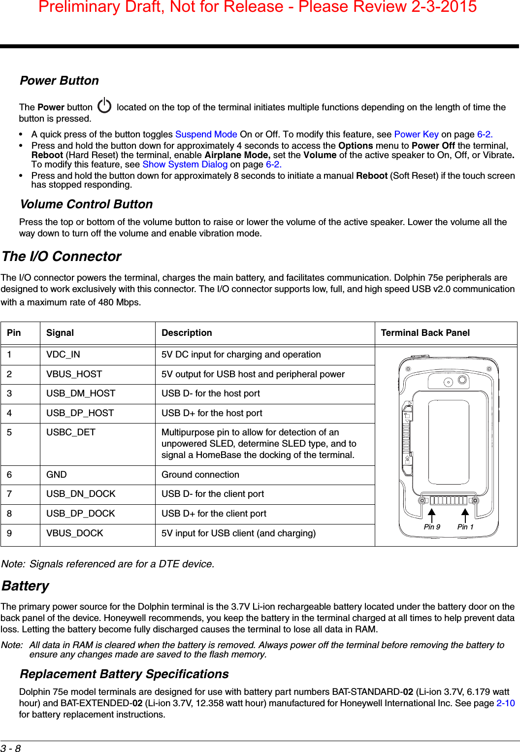
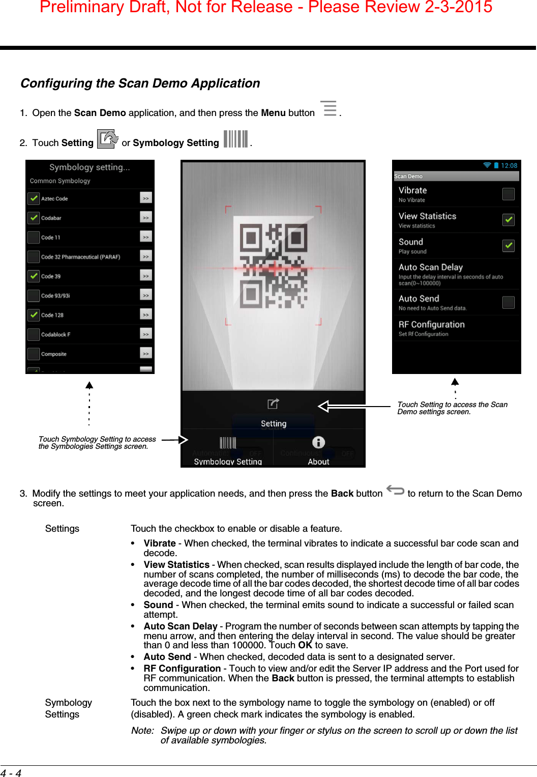
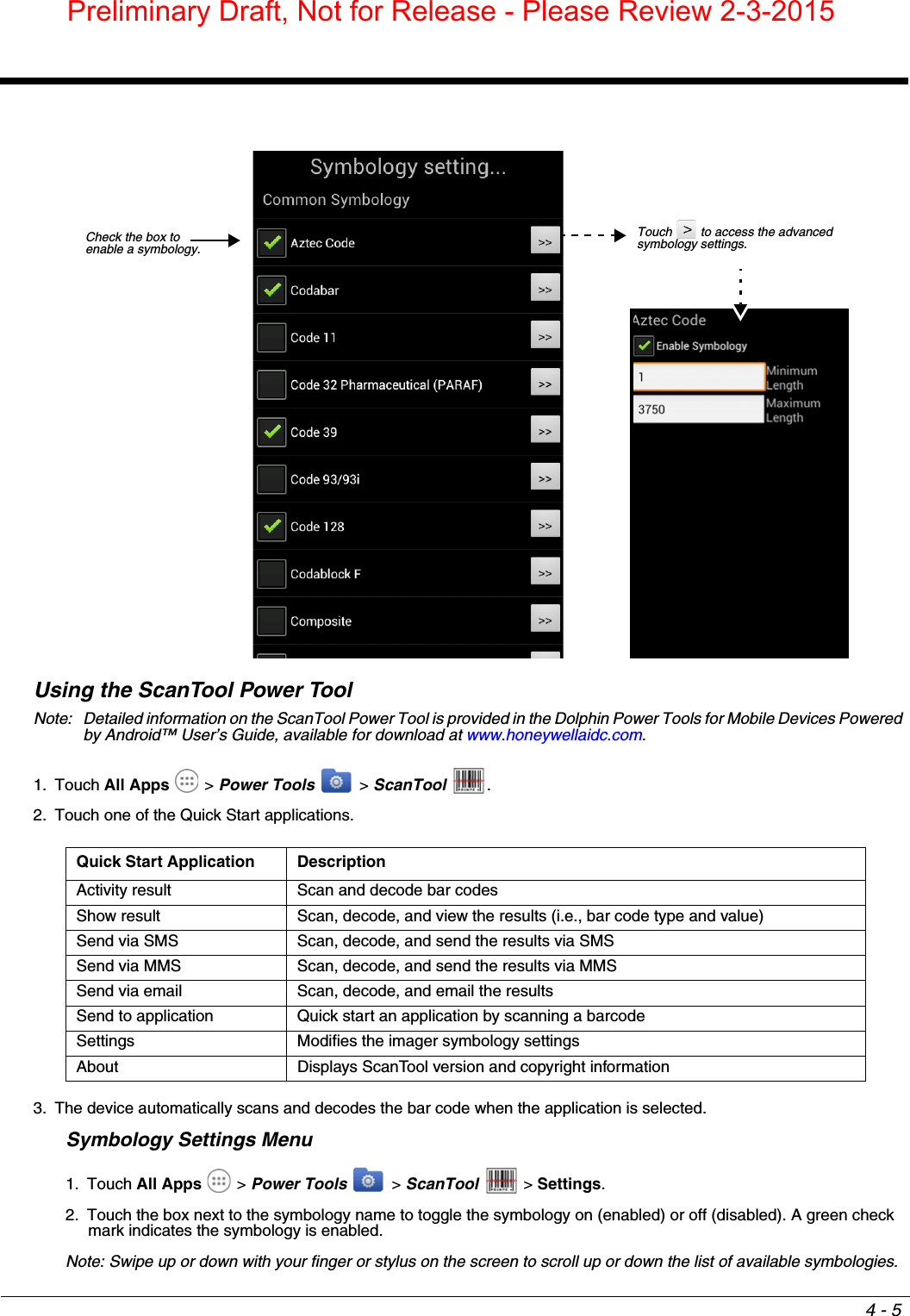
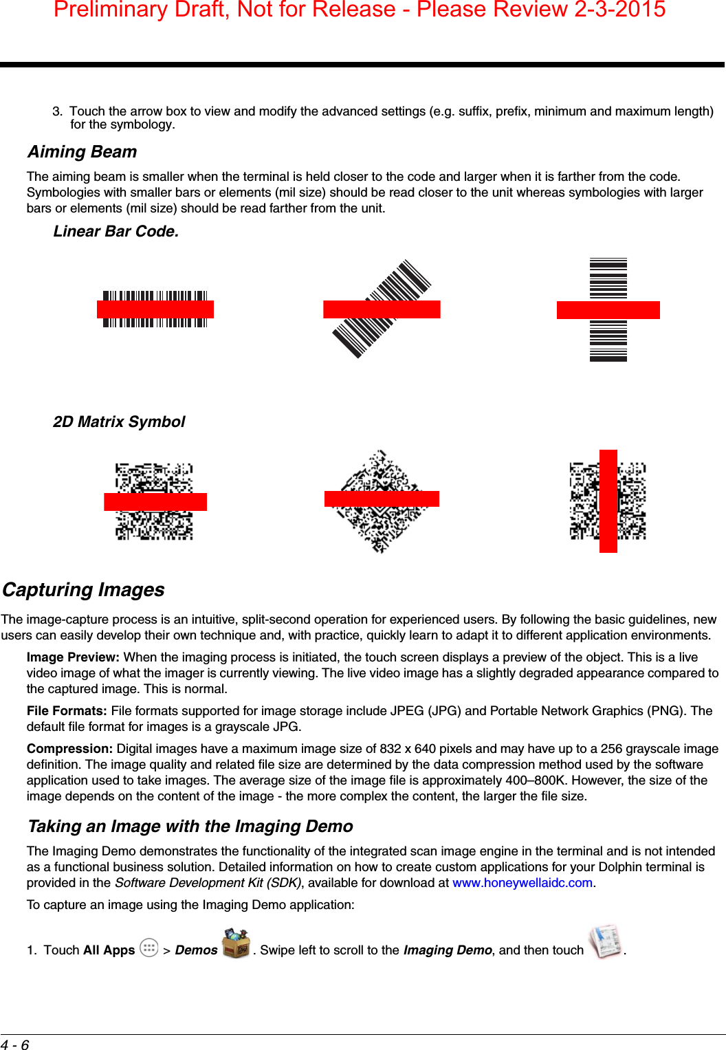
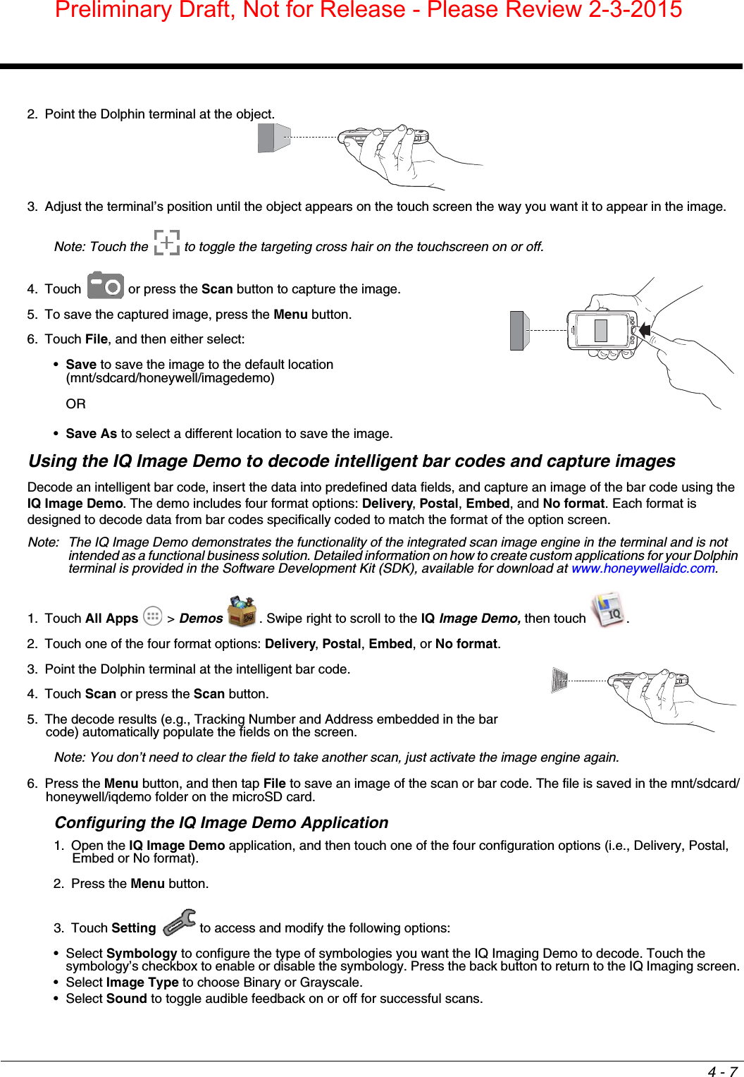
Honeywell 75EL00 Dolpin 75e, Handheld Computer User Manual user guide
Honeywell International Inc Dolpin 75e, Handheld Computer user guide
UserManual.wiki
>
Honeywell
>
75EL00 User Manual
>
user guide
Contents
1.
user guide - regulatory leaflet
2.
user guide
3.
user guide - regulatory info
user guide
Navigation menu
Upload a User Manual
Namespaces
Wiki Guide
HTML
PDF
Info
Views
User Manual
Discussion / Help
Navigation


![9 - 2CapacityThe base holds one terminal and features an auxiliary battery well behind the terminal well that can charge a battery pack independently of the terminal well. This means that one base can charge two battery packs: the one installed in the terminal and a spare. DimensionsWeight HomeBase weight: 303g [.668 lbs]Note: Weight excludes packaging, cables and power supply.We recommend use of Honeywell peripherals, power cables, and power adapters. Use of any non-Honeywell peripherals, cables, or power adapters may cause damage not covered by the warranty.!129.3 mm [5.09 inches]116.3 mm [4.58 inches]65.6 mm [2.58 inches]Preliminary Draft, Not for Release - Please Review 2-3-2015](https://usermanual.wiki/Honeywell/75EL00.user-guide/User-Guide-2526845-Page-74.png)

![10 - 2CapacityThe base holds one terminal and features an auxiliary battery well behind the terminal well that can charge a battery pack independently of the terminal well. This means that one base can charge two battery packs: the one installed in the terminal and a spare.DimensionsWeight eBase weight: 310g [.683 lbs]Note: Weight excludes packaging, cables and power supply.129.3 mm [5.09 inches]116.3 mm [4.58 inches]65.6 mm [2.58 inches]Preliminary Draft, Not for Release - Please Review 2-3-2015](https://usermanual.wiki/Honeywell/75EL00.user-guide/User-Guide-2526845-Page-82.png)


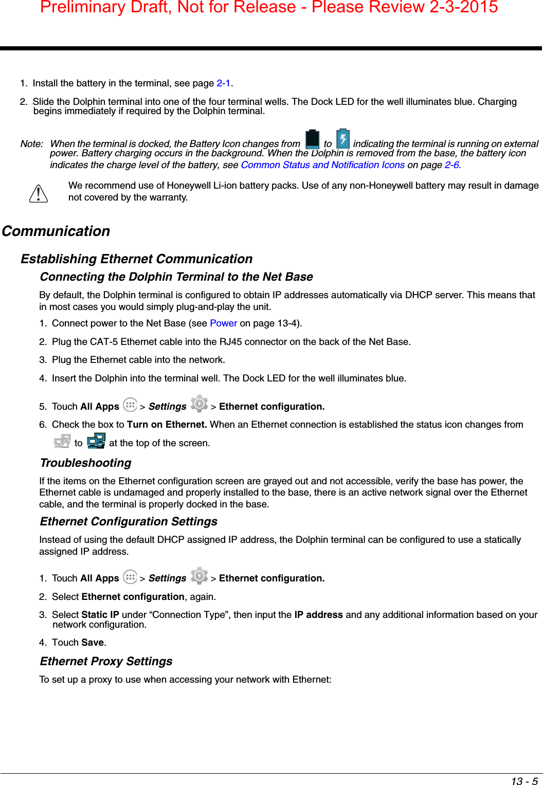
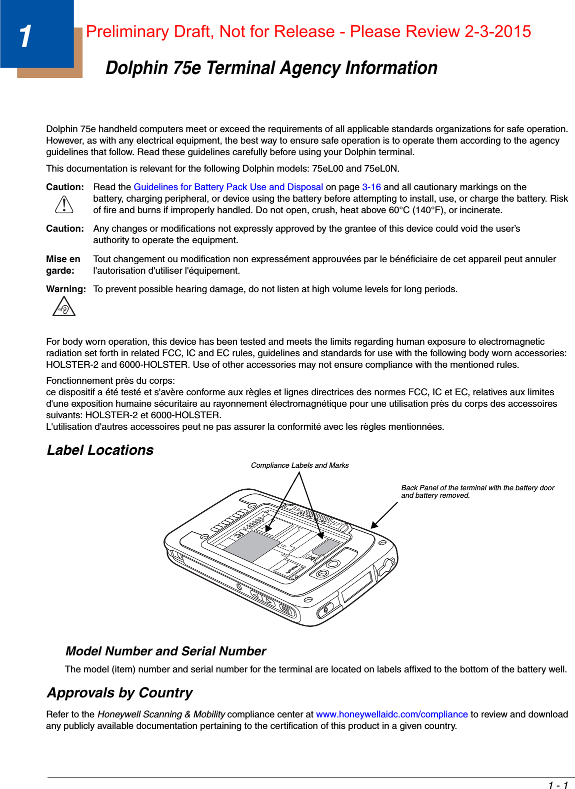
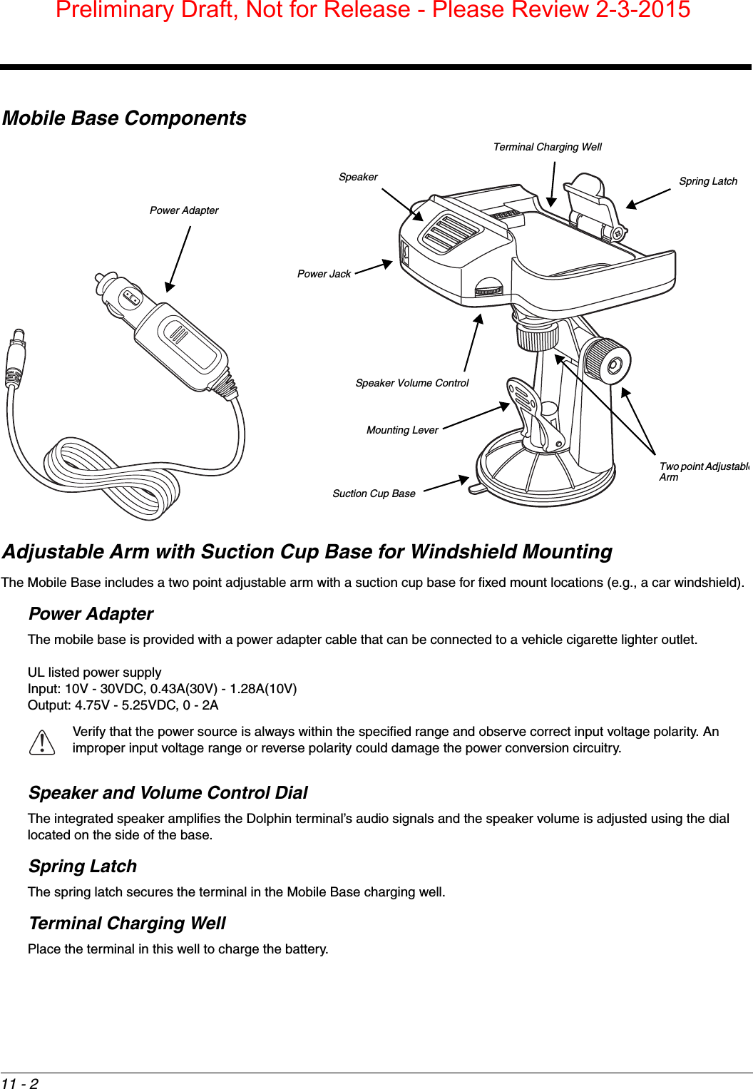
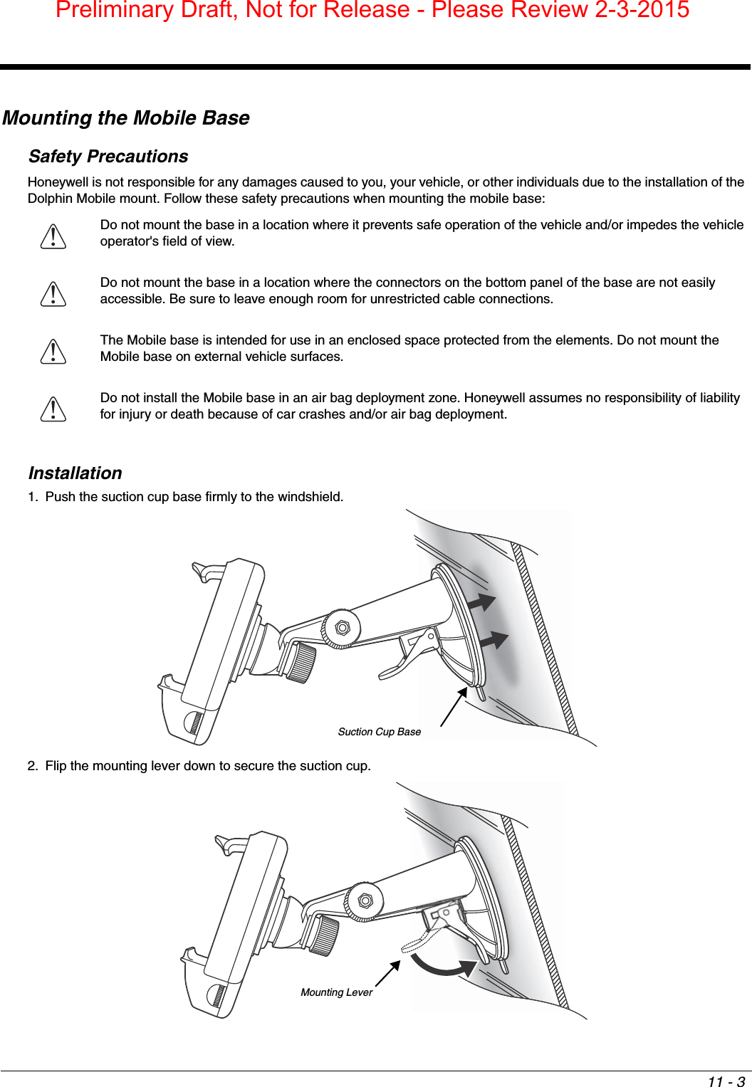
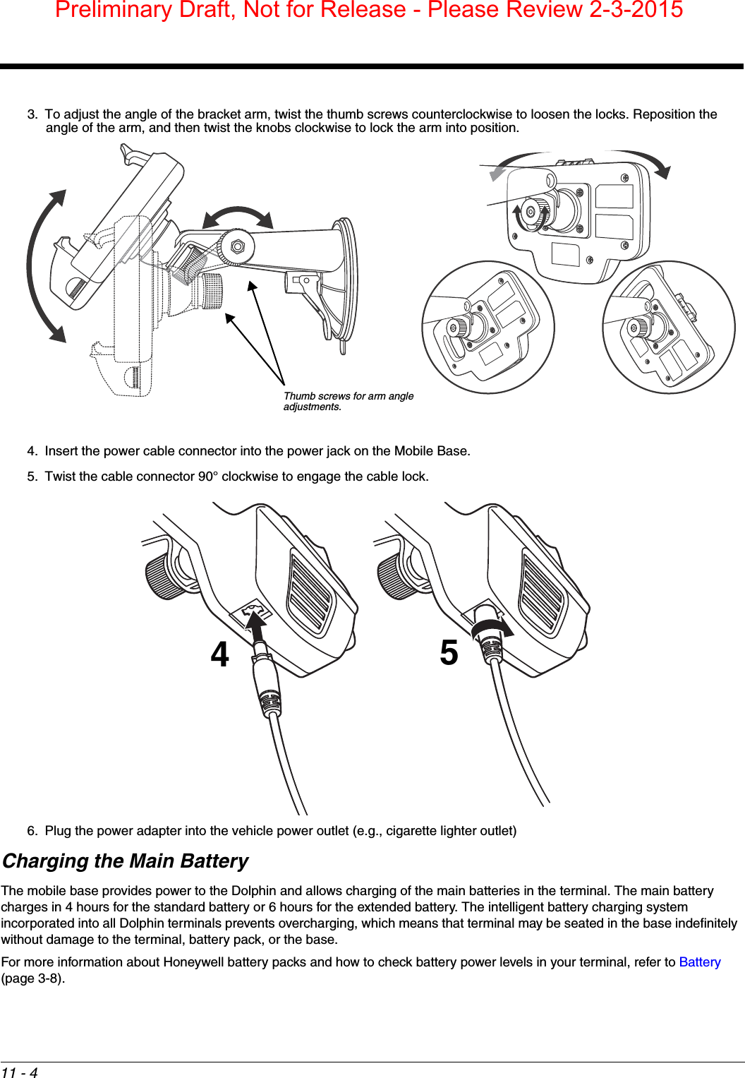
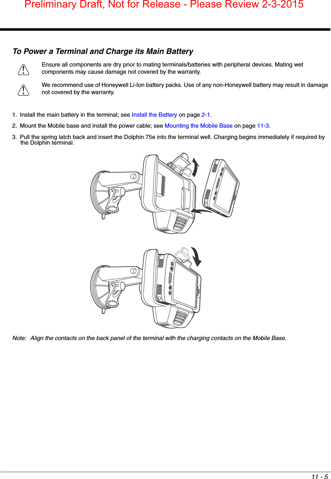
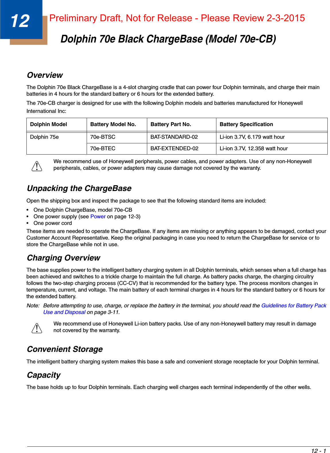
![11 - 111Dolphin 70e Black Mobile Base (Model 70e-MB)OverviewThe Dolphin Mobile Base charging cradle is designed specifically for in-premise and in-transit data collection applications. The base features a mounting bracket and a cigarette lighter adapter to adapt it to your environment.The 70e-MB charger is designed for use with the following Dolphin models and batteries manufactured for Honeywell International Inc:Charging OverviewThe base provides power to the intelligent battery charging system in all terminals that senses when a full charge has been achieved and switches to a trickle charge to maintain the full charge. The base completes a full charge of the main battery in 4 hours for the standard battery pack or 6 hours for the extended battery pack.Note: Before attempting to use, charge, or replace the battery in the terminal, you should read the Guidelines for Battery Pack Use and Disposal on page 3-11.We recommend use of Honeywell Li-Ion battery packs. Use of any non-Honeywell battery may result in damage not covered by the warranty. Convenient StorageIntelligent battery charging makes the base a safe and convenient storage receptacle for your Dolphin terminal.DimensionsWeight Mobile Base and adjustable arm weight: 270g [.595 lbs]Dolphin Model Battery Model No. Battery Part No. Battery SpecificationDolphin 75e 70e-BTSC BAT-STANDARD-02 Li-ion 3.7V, 6.179 watt hour70e-BTEC BAT-EXTENDED-02 Li-ion 3.7V, 12.358 watt hourWe recommend use of Honeywell peripherals, power cables, and power adapters. Use of any non-Honeywell peripherals, cables, or power adapters may cause damage not covered by the warranty.!!159.98 mm [6.30 inches]109.82 mm [4.32 inches]42.15 mm [1.66 inches]Preliminary Draft, Not for Release - Please Review 2-3-2015](https://usermanual.wiki/Honeywell/75EL00.user-guide/User-Guide-2526845-Page-91.png)
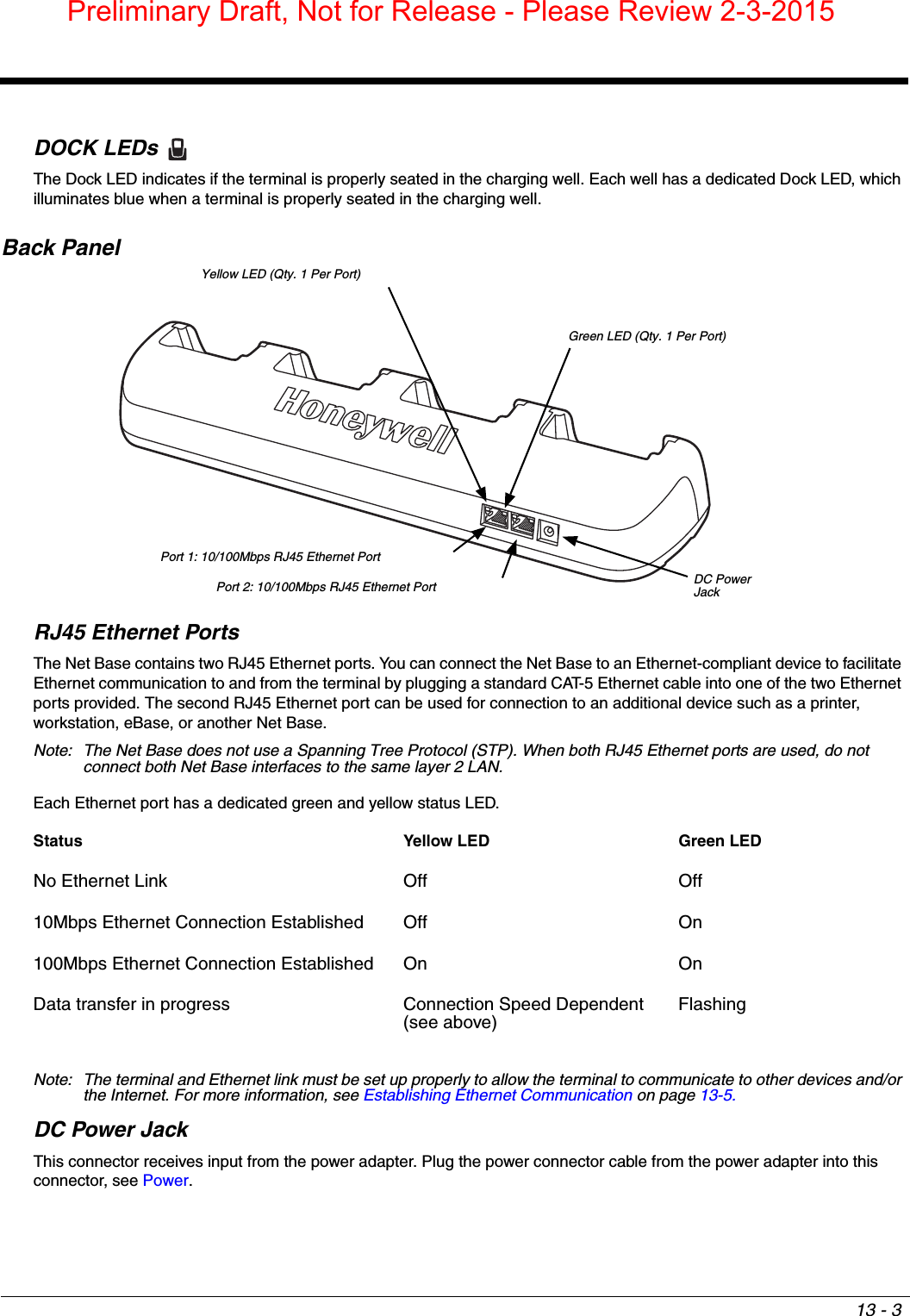
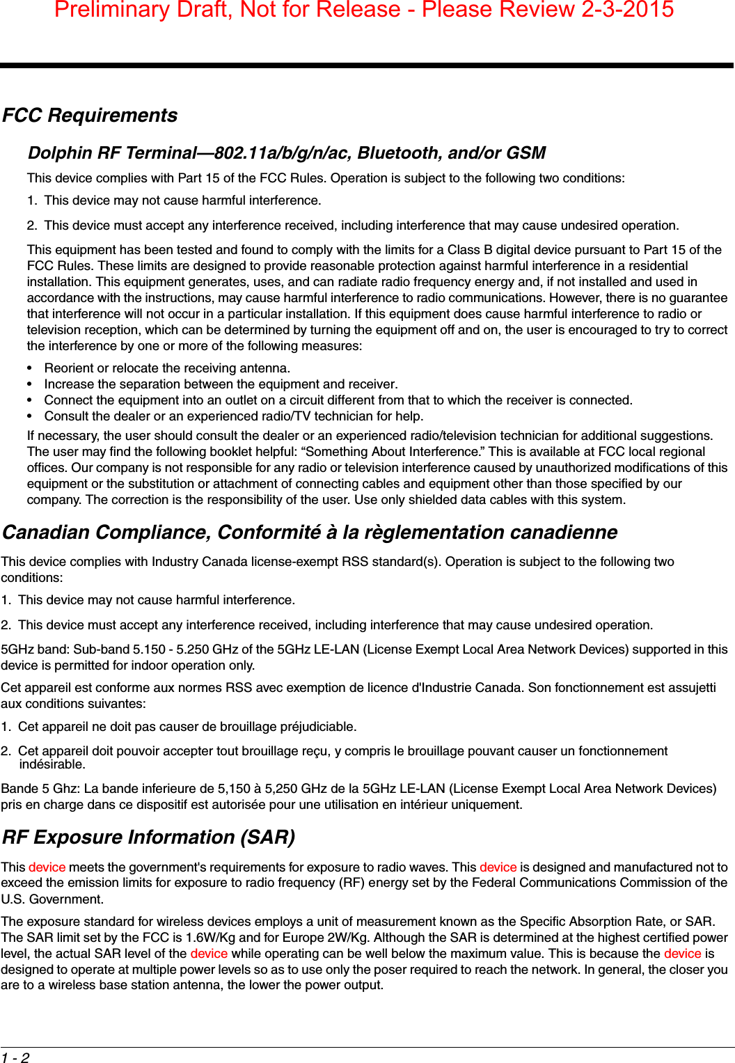
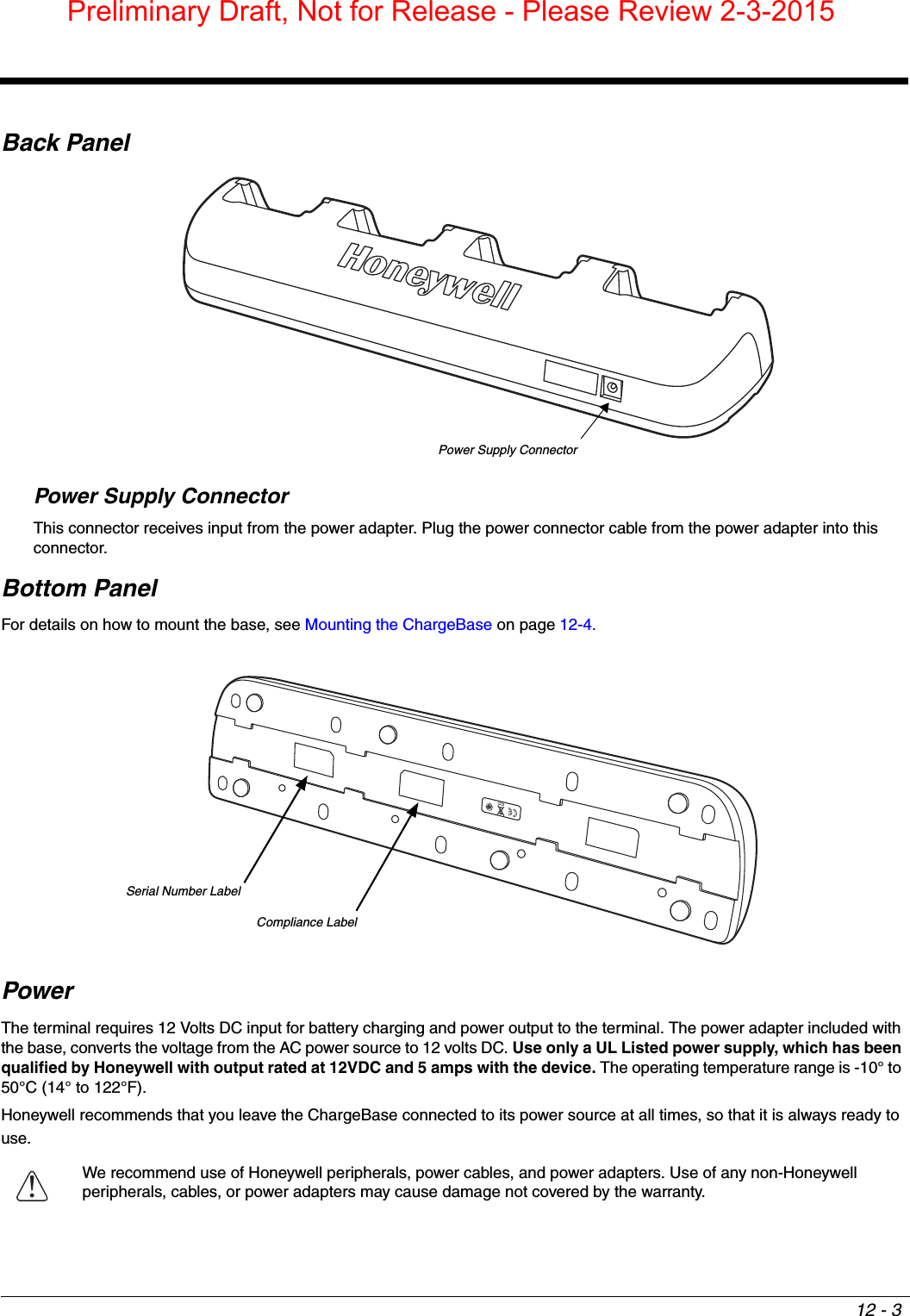
![12 - 2DimensionsWeight ChargeBase weight: 674g [1.49 lbs.]Note: Weight excludes packaging, cables and power supply.Parts and FunctionsFront PanelTerminal WellsThe base contains four terminal wells, which offer independent battery charging for each docked terminal.Dock LEDsThe Dock LED indicates if the terminal is properly seated in the charging well. Each well has a dedicated Dock LED, which illuminates blue when a terminal is properly seated in the charging well.427.11 mm [16.80 inches]98.8 mm [3.89 inches]59.75 mm [2.35 inches]Dock LED (Qty. 4)Terminal Wells (Qty. 4)Preliminary Draft, Not for Release - Please Review 2-3-2015](https://usermanual.wiki/Honeywell/75EL00.user-guide/User-Guide-2526845-Page-98.png)

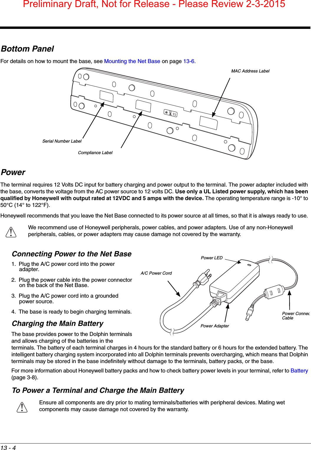
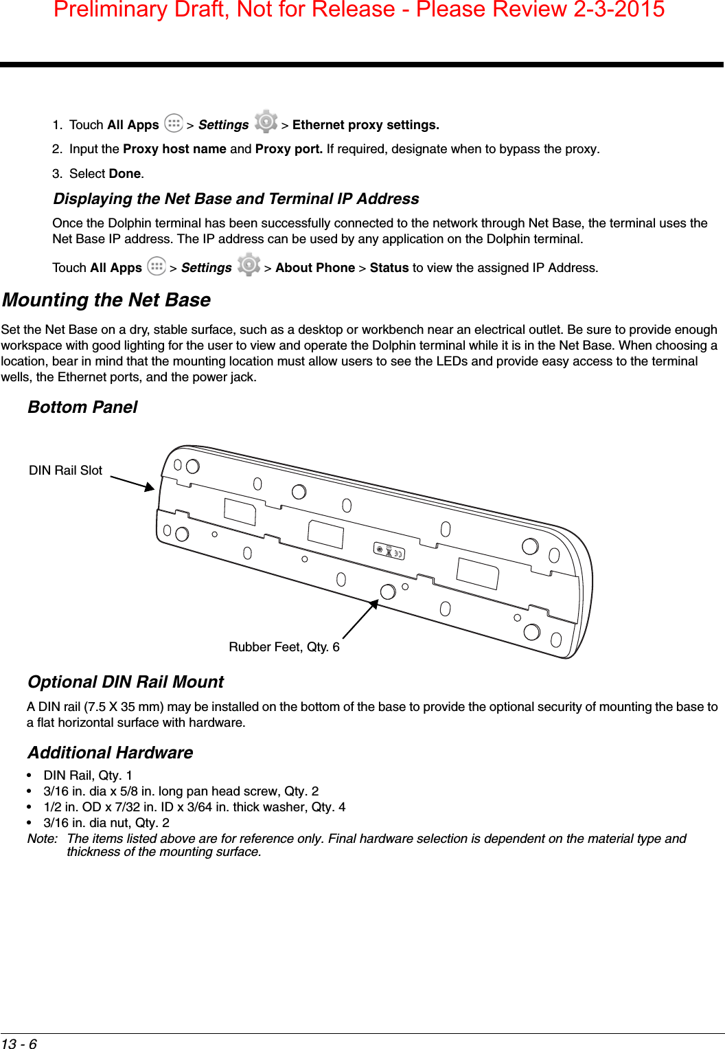
![13 - 2DimensionsWeight Net Base weight: 694g [1.53 lbs.]Note: Weight excludes packaging, cables and power supply.Parts and FunctionsFront PanelTerminal Wells The base contains four terminal wells, which offer independent battery charging for each docked terminal.427.11 mm [16.80 inches]98.8 mm [3.89 inches]59.75 mm [2.35 inches]Dock LED (Qty. 4)Terminal Wells (Qty. 4)Preliminary Draft, Not for Release - Please Review 2-3-2015](https://usermanual.wiki/Honeywell/75EL00.user-guide/User-Guide-2526845-Page-104.png)