Honeywell 9700LUP DOLPHIN 9700 MOBILE COMPUTER User Manual final
Honeywell International Inc DOLPHIN 9700 MOBILE COMPUTER final
UserManual.wiki
>
Honeywell
>
9700LUP User Manual
>
USERS MANUAL
Contents
1.
USERS MANUAL
2.
USER MANUAL
USERS MANUAL
Navigation menu
Upload a User Manual
Namespaces
Wiki Guide
HTML
PDF
Info
Views
User Manual
Discussion / Help
Navigation


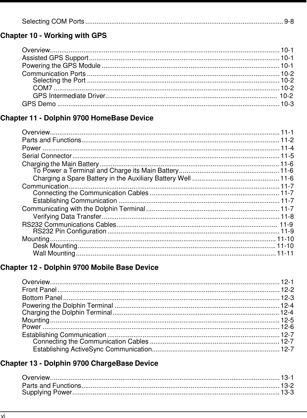

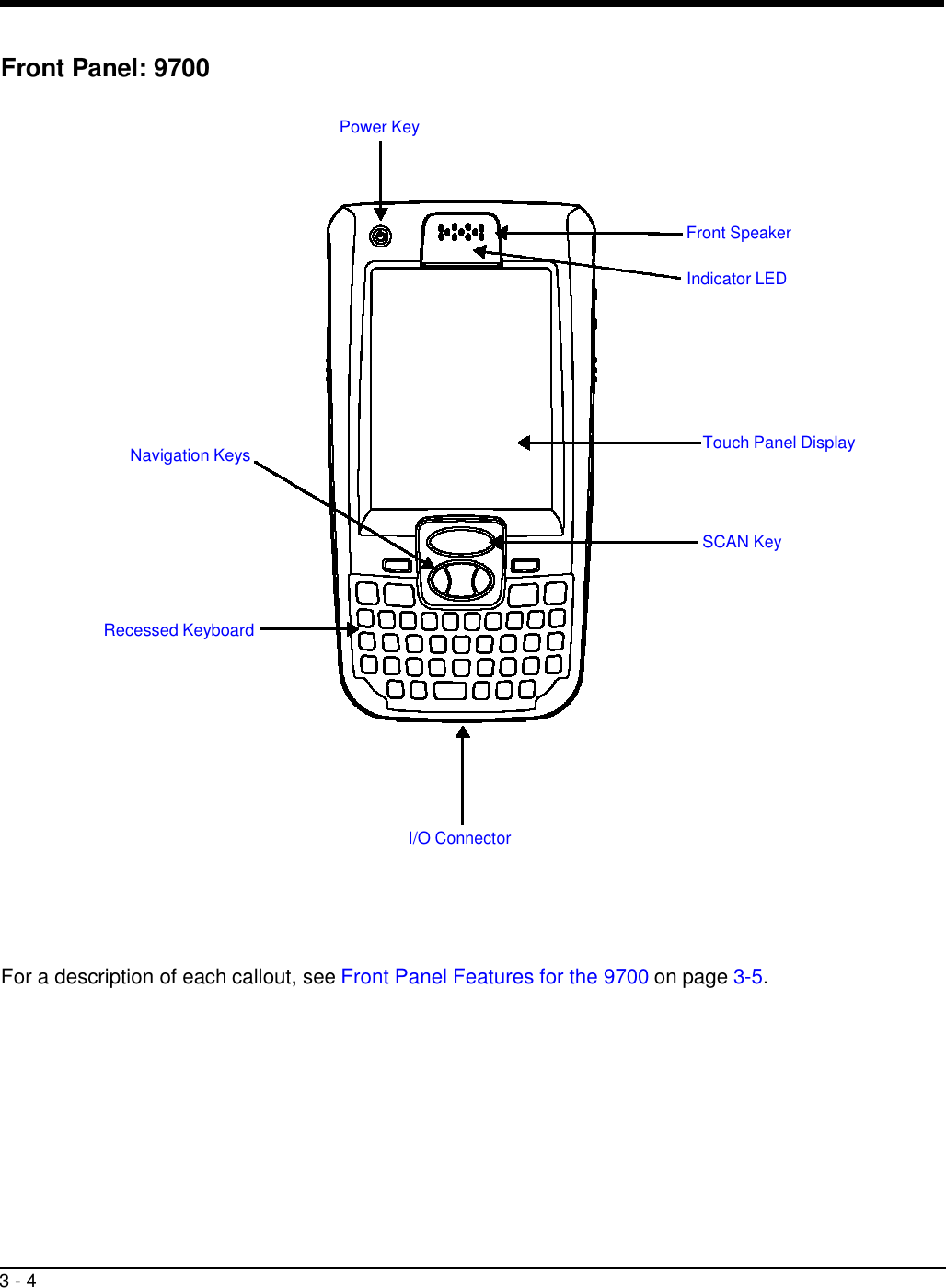
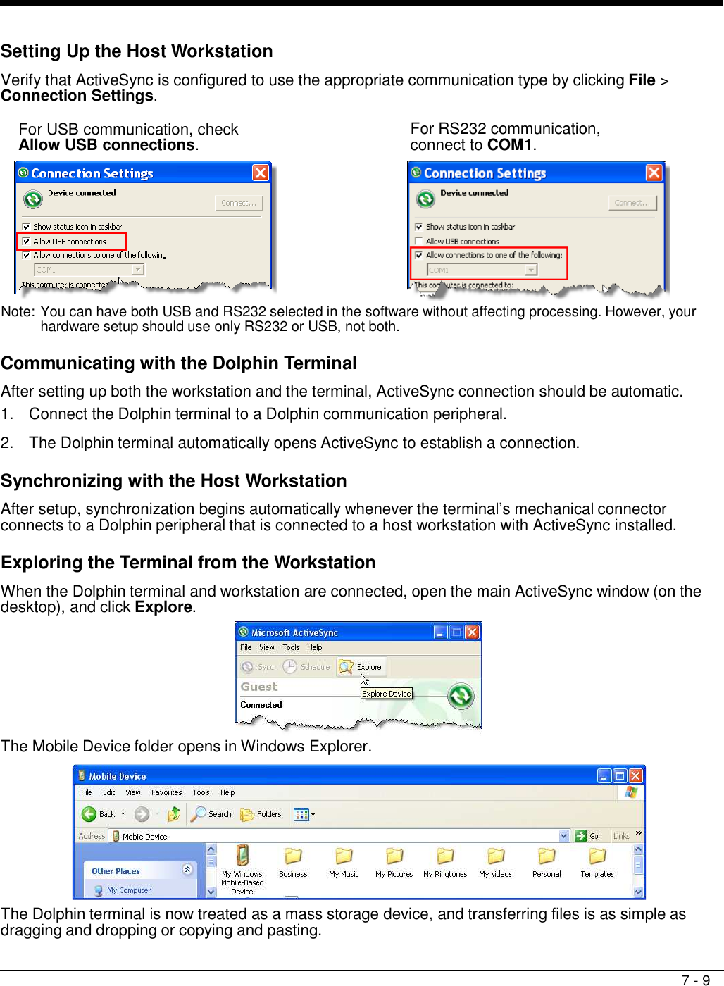
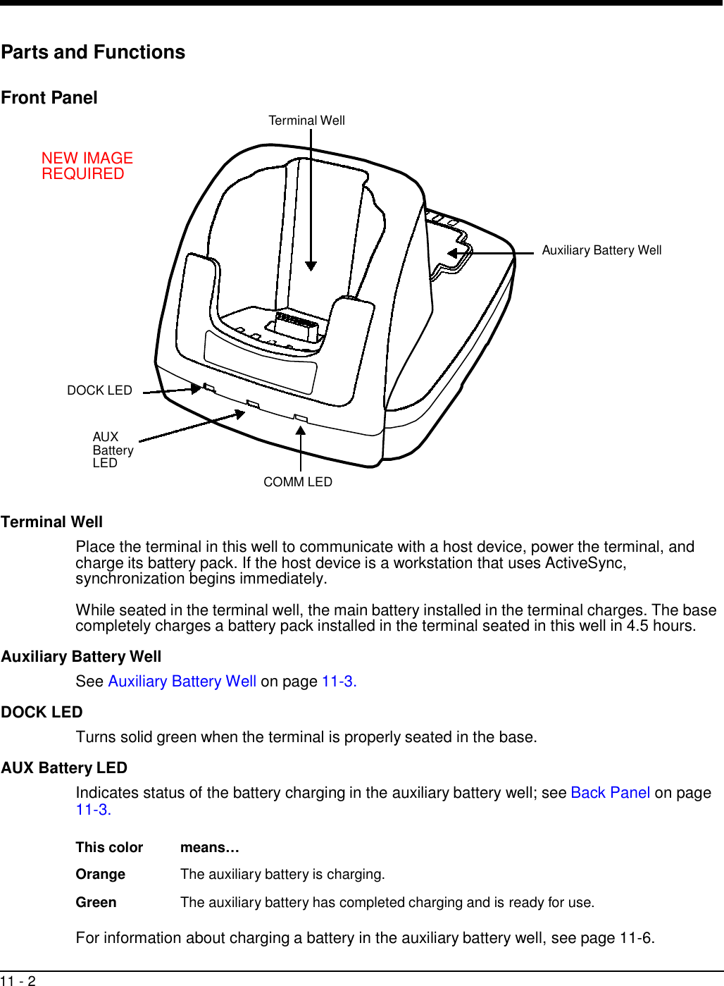
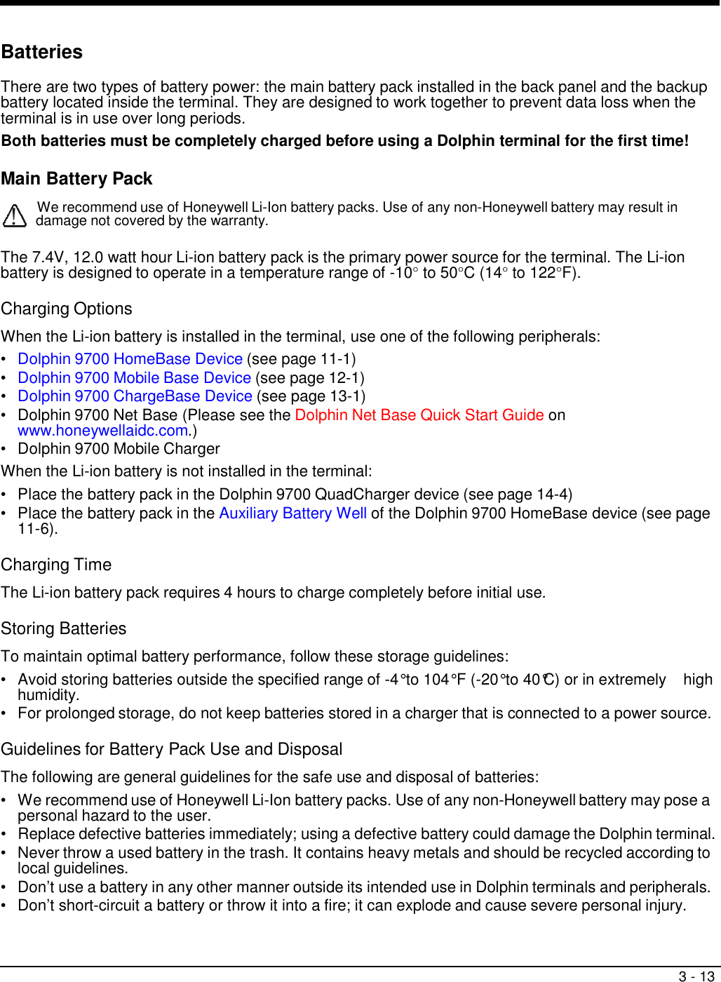
![3 - 10 16 15 14 13 12 11 10 9 8 7 6 5 4 3 2 1 Bottom Panel: 9700 Pin Description 1 GND 2 MIC_IN 3 RI 4 USB_D- 5 USB_D+ 6 NO CONNECT 7 USB_5V_IN 8 5V_OUT 9 TXD 10 RXD 11 RTS 12 CTS 13 DTR 14 DSR 15 MONO SPEAKER 16 VDC_IN Note: Signals referenced are for a DTE device. I/O Connector The I/O connector powers the terminal, charges the main battery, and facilitates communication. All Dolphin peripherals are designed to work exclusively with this connector. The I/O connector supports RS232 and USB communication. For RS232, the maximum communication speed is 115.2 Kbps with seven baud rate settings. For USB, the communication speed is up to 12 Mbps. Powering Out The I/O connector also provides power out (to peripheral devices) +5V at 500mA. This means that, with the proper cable, the terminal can power another device. By default, power out is disabled. To enable power out, alter the registry as follows: [HKEY_LOCAL_MACHINE\Drivers\BuiltIn\Serial4] Conn5Venable=1](https://usermanual.wiki/Honeywell/9700LUP.USERS-MANUAL/User-Guide-1225381-Page-30.png)
![3 - 14 • Excessive discharge damages a battery. Recharge the battery when your terminal indicates low battery power. • If you observe that the Honeywell battery supplied is physically damaged, please send it to Honeywell International Inc. or an authorized service center for inspection. Refer to the Product Service and Repair section of this guide. • Although your battery can be recharged many times, it will eventually be depleted. Replace it after the battery is unable to hold an adequate charge. • If you are not sure the battery or charger is working properly, please send it to Honeywell International or an authorized service center for inspection. Internal Backup Battery Located inside the terminal, the backup battery is a 3.6 Volt nickel metal hydride (NiMH) battery. The internal backup battery prevents the terminal from being reset if you need to remove and replace the main battery pack. It retains RAM data and allows the real-time clock to remain operational for up to 30 minutes when the main battery pack is removed. If the terminal is left without the main battery pack for more than 30 minutes, the internal backup battery needs to be recharged to function according to its specifications. Note: Data and programs stored in Flash memory are not lost even if the internal backup battery fails. However, you must reset the real-time clock; see Set the Time and Date on page 2-2. Charging The internal backup battery is powered by the main battery pack. Therefore, charging the internal backup battery requires that the main battery pack be installed in the terminal and the terminal be connected to a charging device. The internal backup battery must be fully charged before using the terminal for the first time. The initial charge cycle takes approximately 8 hours. After that, if the internal backup battery becomes fully discharged of power, it requires a minimum of 10 hours of charging time to function normally. Guidelines for Use Follow these guidelines to maximize the life of the internal backup battery: • Keep a charged Li-ion battery pack in the terminal; the backup battery prematurely discharges if there is not at least a partially charged battery in the terminal. • Keep the terminal connected to power when the terminal is not in use. Managing Battery Power Data and files saved on Dolphin terminals may be stored in RAM memory, which does not persist through a hard reset. Therefore, to help prevent data loss, maintain a continuous power supply to the terminal. Letting the backup battery become fully discharged causes the terminal to lose all data in RAM. Therefore, you should keep a charged battery pack in the terminal at all times. The internal battery discharges prematurely if there is not at least a partially charged battery in the terminal. When you remove a battery pack, insert another charged battery pack in the terminal immediately. Default Critical and Low Battery Points When the terminal is running on battery power (as opposed to external power), warnings are displayed when the battery reaches critical and low battery points. The warning points are determined by the following registry entry: [HKEY_LOCAL_MACHINE\System\CurrentControlSet\Control\Power]](https://usermanual.wiki/Honeywell/9700LUP.USERS-MANUAL/User-Guide-1225381-Page-34.png)