Honeywell 99EXLF 99EX mobile computer User Manual 1
Honeywell International Inc 99EX mobile computer Users Manual 1
UserManual.wiki
>
Honeywell
>
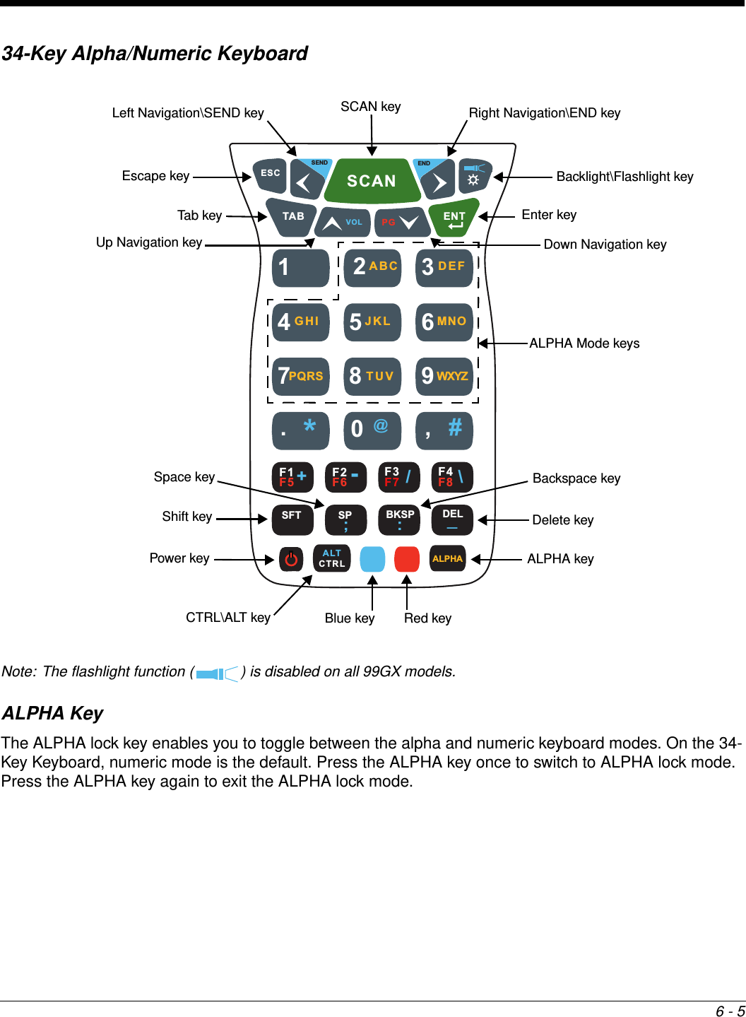
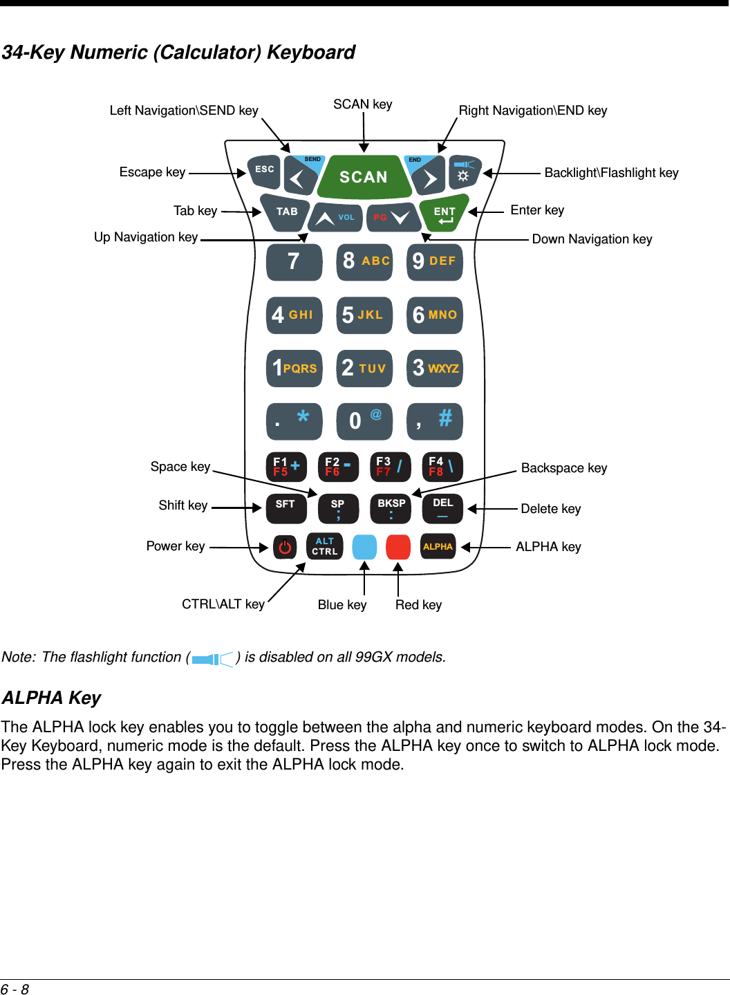
99EXLF User Manual
>
Users Manual 1
Contents
1.
Users Manual 1
2.
Users Manual 2
Users Manual 1
Navigation menu
Upload a User Manual
Namespaces
Wiki Guide
HTML
PDF
Info
Views
User Manual
Discussion / Help
Navigation


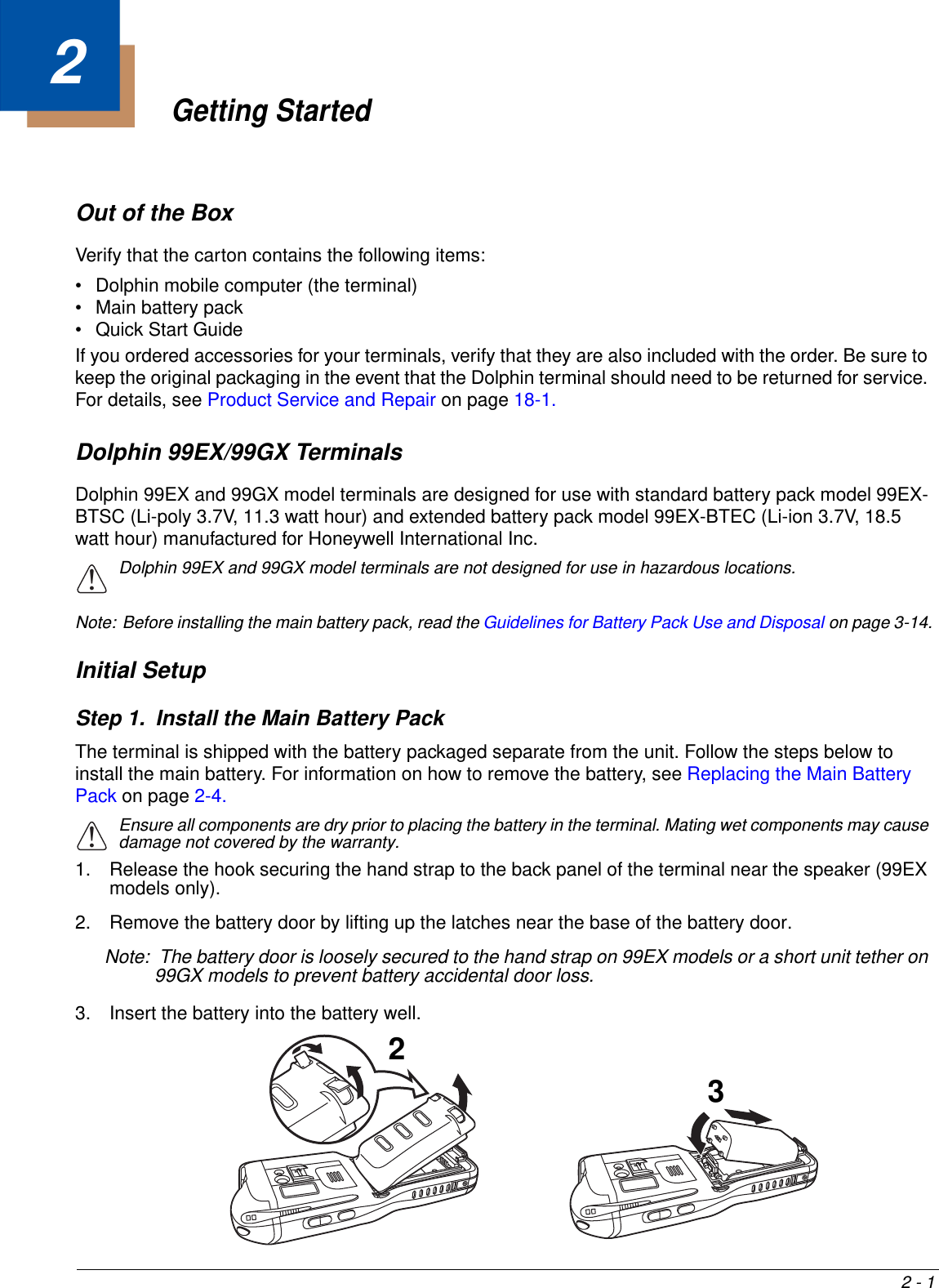
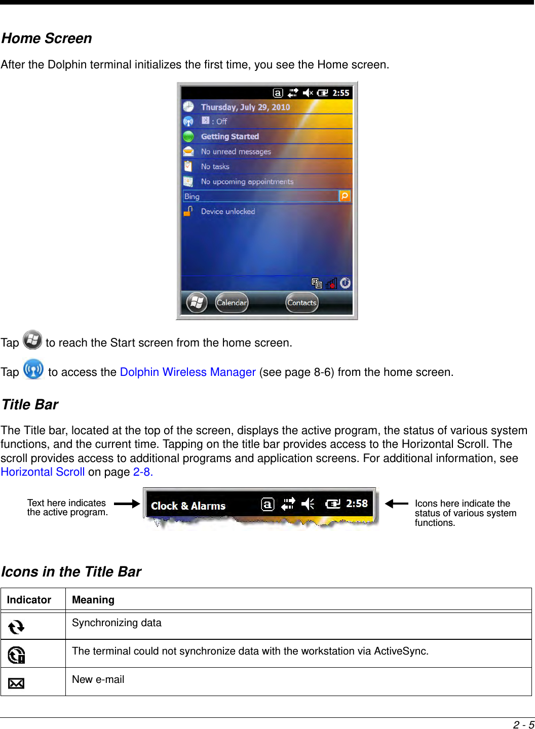


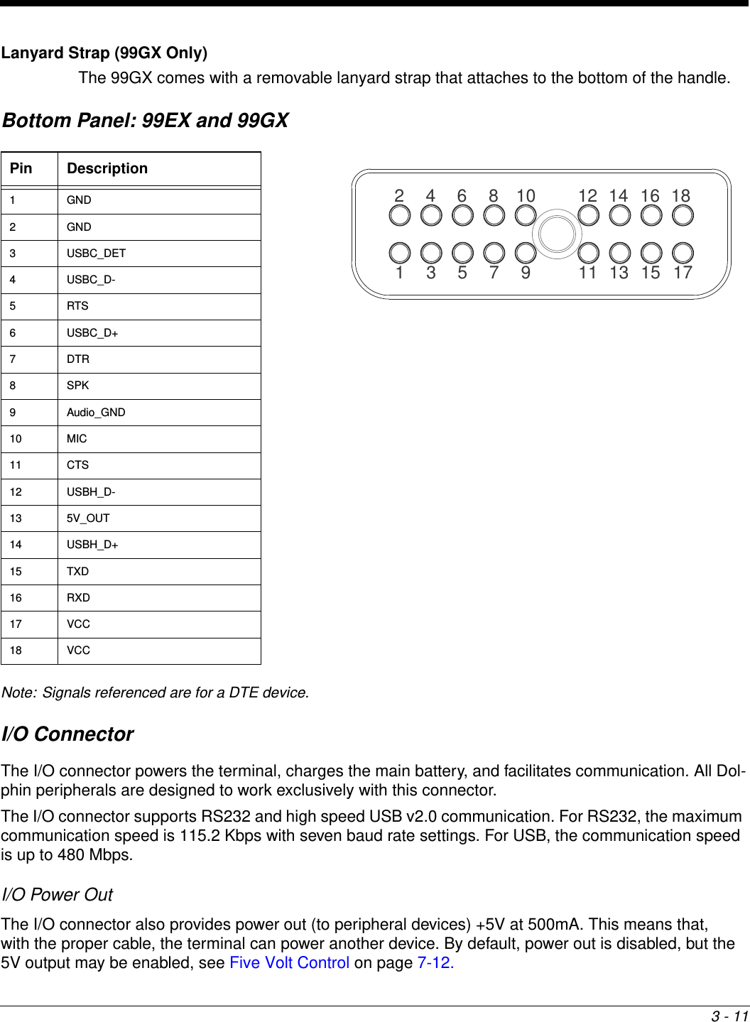
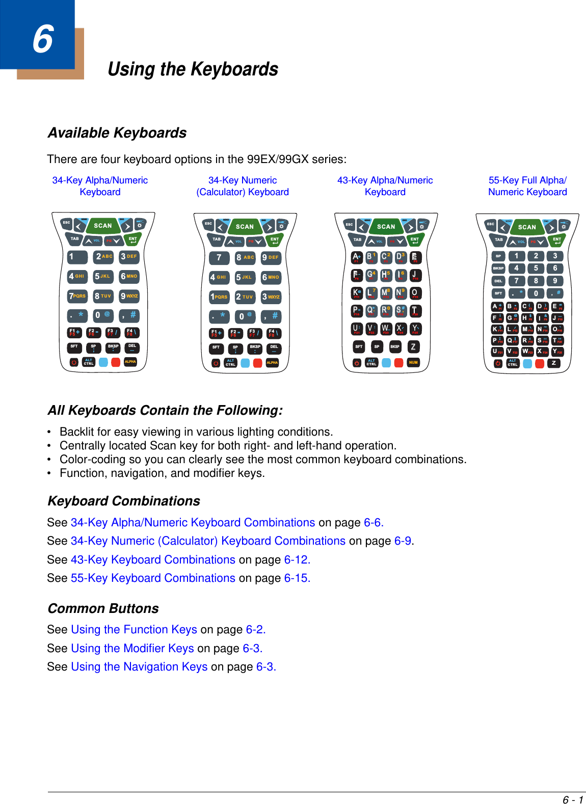
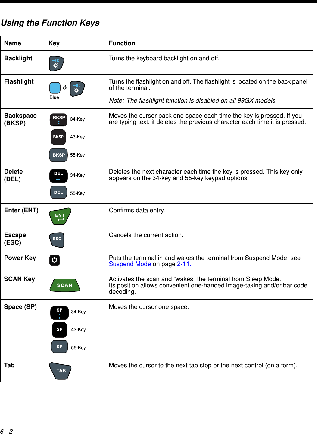
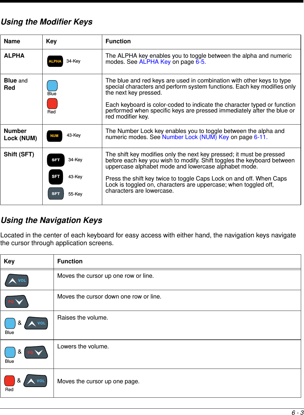
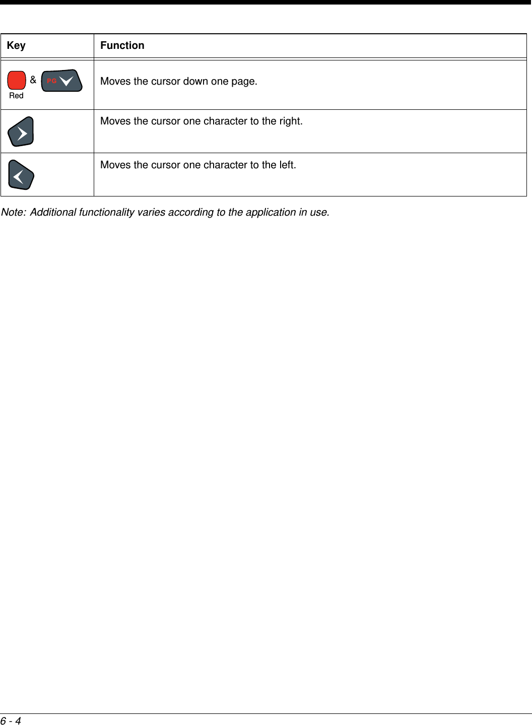
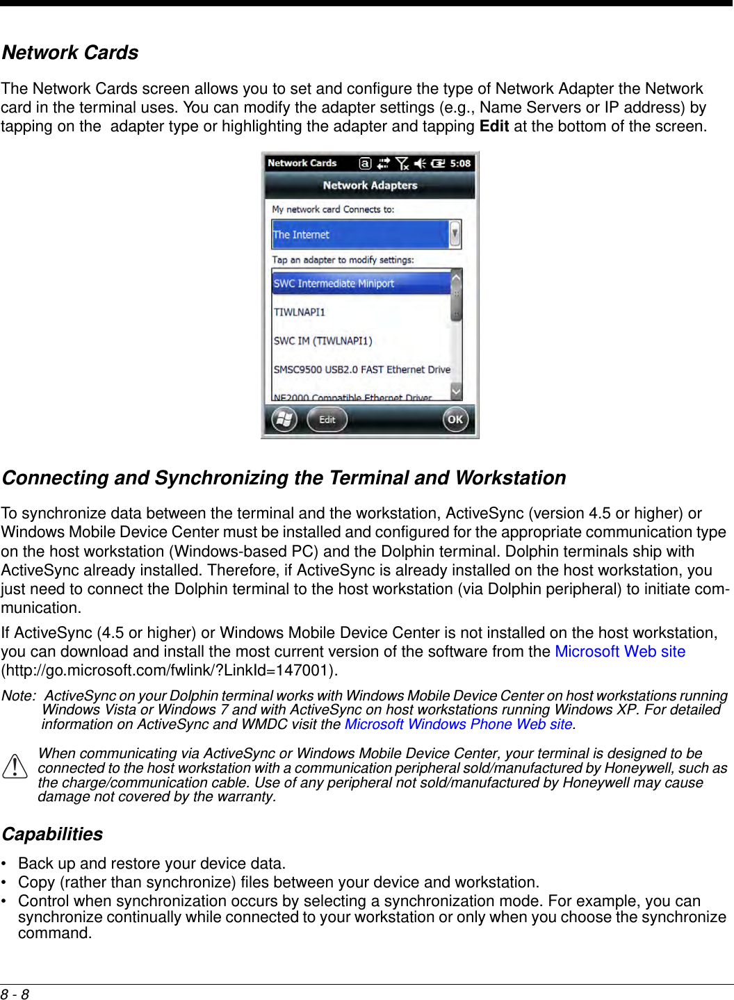
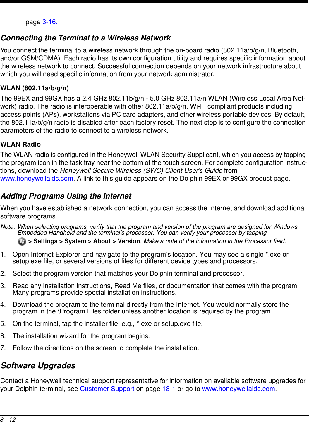
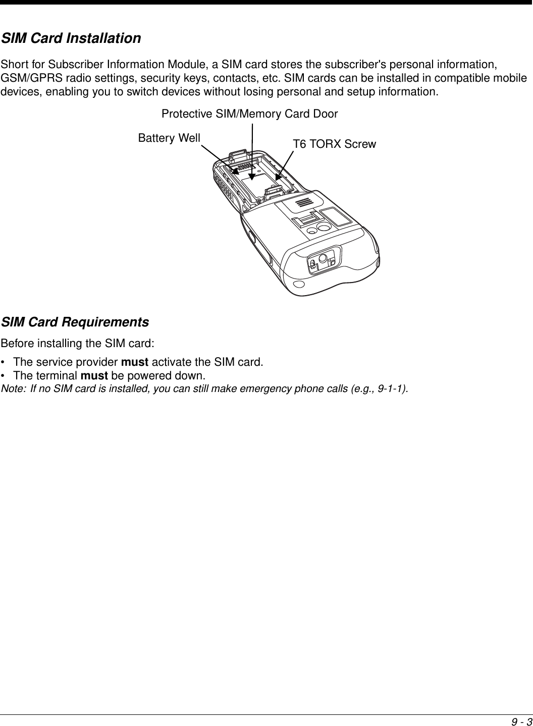
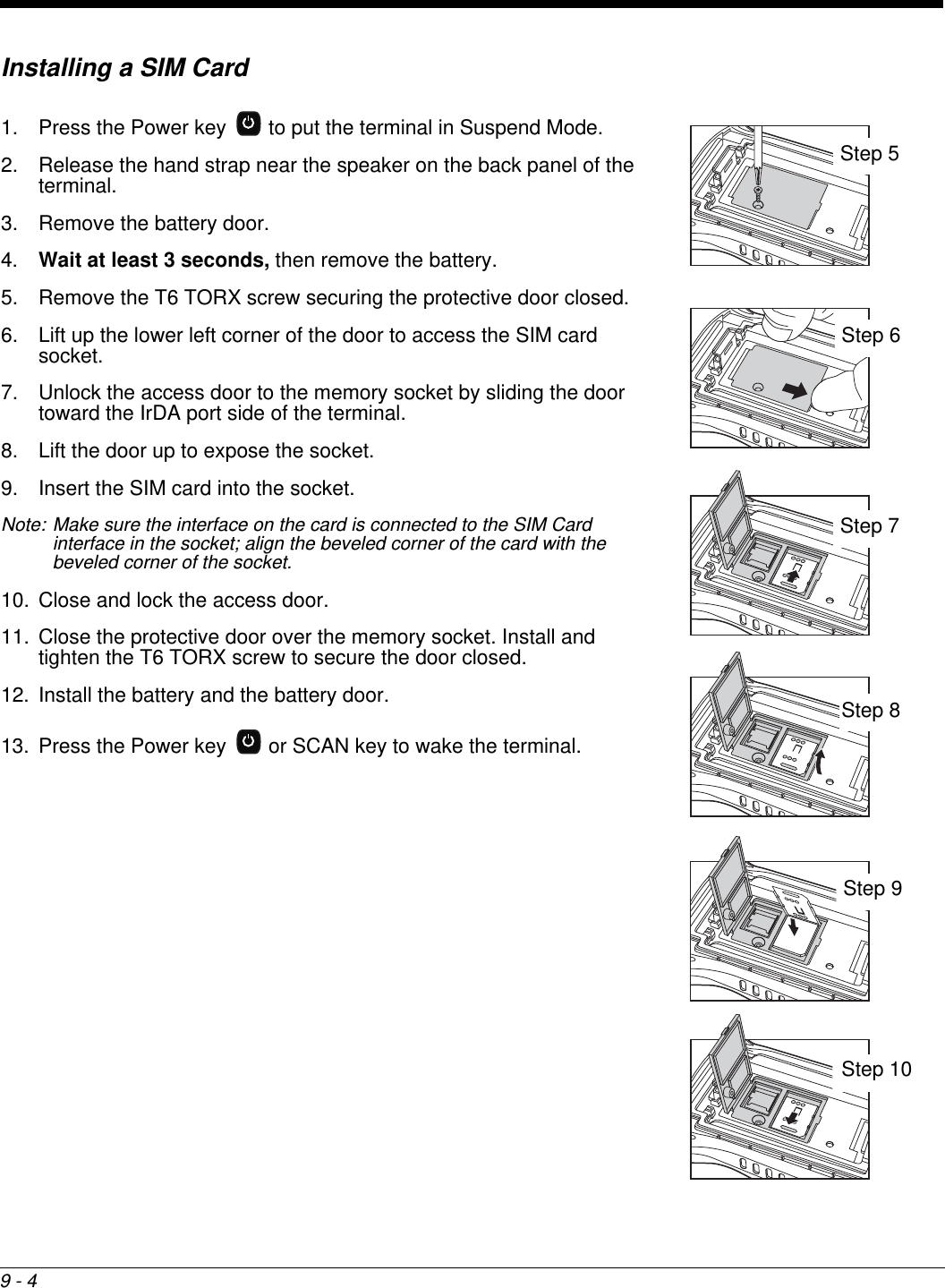
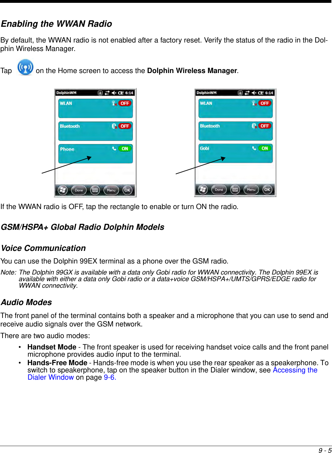
![3 - 15• Although your battery can be recharged many times, the battery life is limited. Replace it after the battery is unable to hold an adequate charge.Internal Backup BatteryLocated inside the terminal is a 3.6 Volt nickel metal hydride (NiMH) backup battery. The backup battery prevents the terminal from being reset if you need to replace the main battery pack. It retains RAM data during the battery pack exchange. A fully charged backup battery provides 30 minutes of backup time. Note: When removing a battery from the terminal, put the device in Suspend Mode (see page 2-11) before removing the battery door. Once the battery door is removed, wait at least 3 seconds before removing the main battery. This process allows the device to shut down properly and maintains memory during the battery swap.If at any time the backup battery becomes fully discharged of power (e.g., the terminal is left without the main battery pack for more than 30 minutes), the terminal resets when power is supplied. All files are retained, but you may need to restart any running applications. In addition, a fully discharged backup battery requires a minimum of 24 hours of charging time to reach a full charge.Note: Data and programs stored in Flash memory are not lost even if the internal backup battery fails.ChargingThe internal backup battery and the RTC battery are powered by the main battery pack. Therefore, charging the internal batteries requires a charged main battery pack be installed in the terminal and the terminal be connected to a charging device.The internal backup battery must be fully charged before using the terminal for the first time. Honeywell recommends charging the Dolphin terminal for at least 24 hours prior to initial use to ensure the internal backup battery is fully charged. After that, if the internal backup battery becomes fully discharged of power, it requires a minimum of 24 hours of charging time to function normally.Guidelines for UseFollow these guidelines to maximize the life of the internal backup battery:• Keep a charged Li-ion or Li-poly battery pack in the terminal; the backup battery prematurely discharges if there is not at least a partially charged battery in the terminal.• Keep the terminal connected to power when the terminal is not in use. Managing Battery Power Letting the backup battery become fully discharged causes the terminal to lose all data in RAM. Honey-well recommends, you keep a charged battery pack in the terminal at all times to help prevent data loss. The internal battery discharges prematurely if there is not at least a partially charged battery in the termi-nal. When you remove a battery pack, insert another charged battery pack in the terminal immediately. Default Critical and Low Battery PointsWhen the terminal is running on battery power (as opposed to external power), warnings are displayed when the battery reaches critical and low battery points. The warning points are determined by the fol-lowing registry entry: [HKEY_LOCAL_MACHINE\ControlPanel\Power]](https://usermanual.wiki/Honeywell/99EXLF.Users-Manual-1/User-Guide-2821963-Page-45.png)