Honeywell 99EXLG 99EX Mobile computer User Manual Dolphin 9700 User s Guide Rev a
Honeywell International Inc 99EX Mobile computer Dolphin 9700 User s Guide Rev a
Contents
- 1. User Manual 1 of 2
- 2. user manual 2 of 2
- 3. user manual 1 of 2
- 4. User Manual 2 of 2
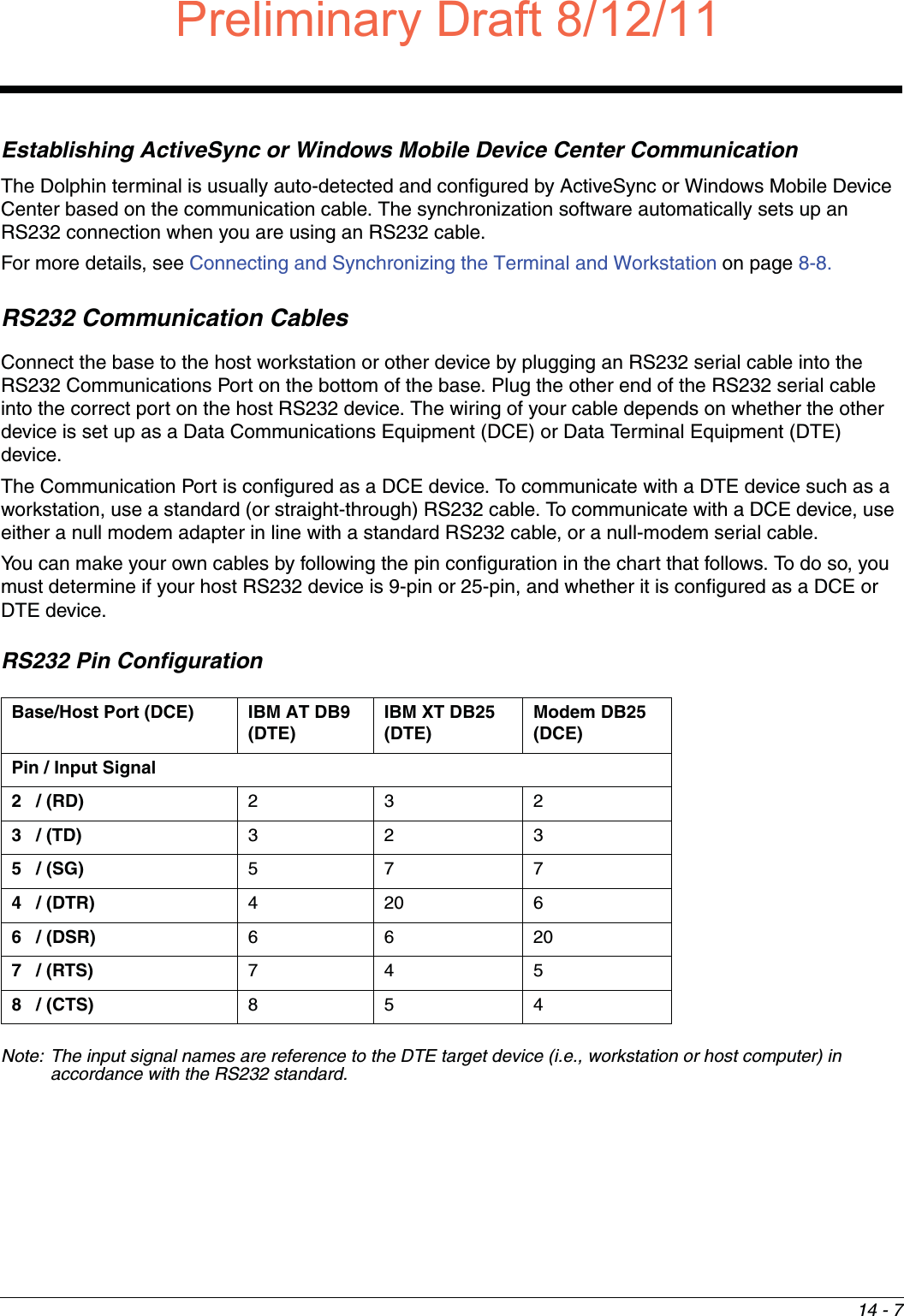
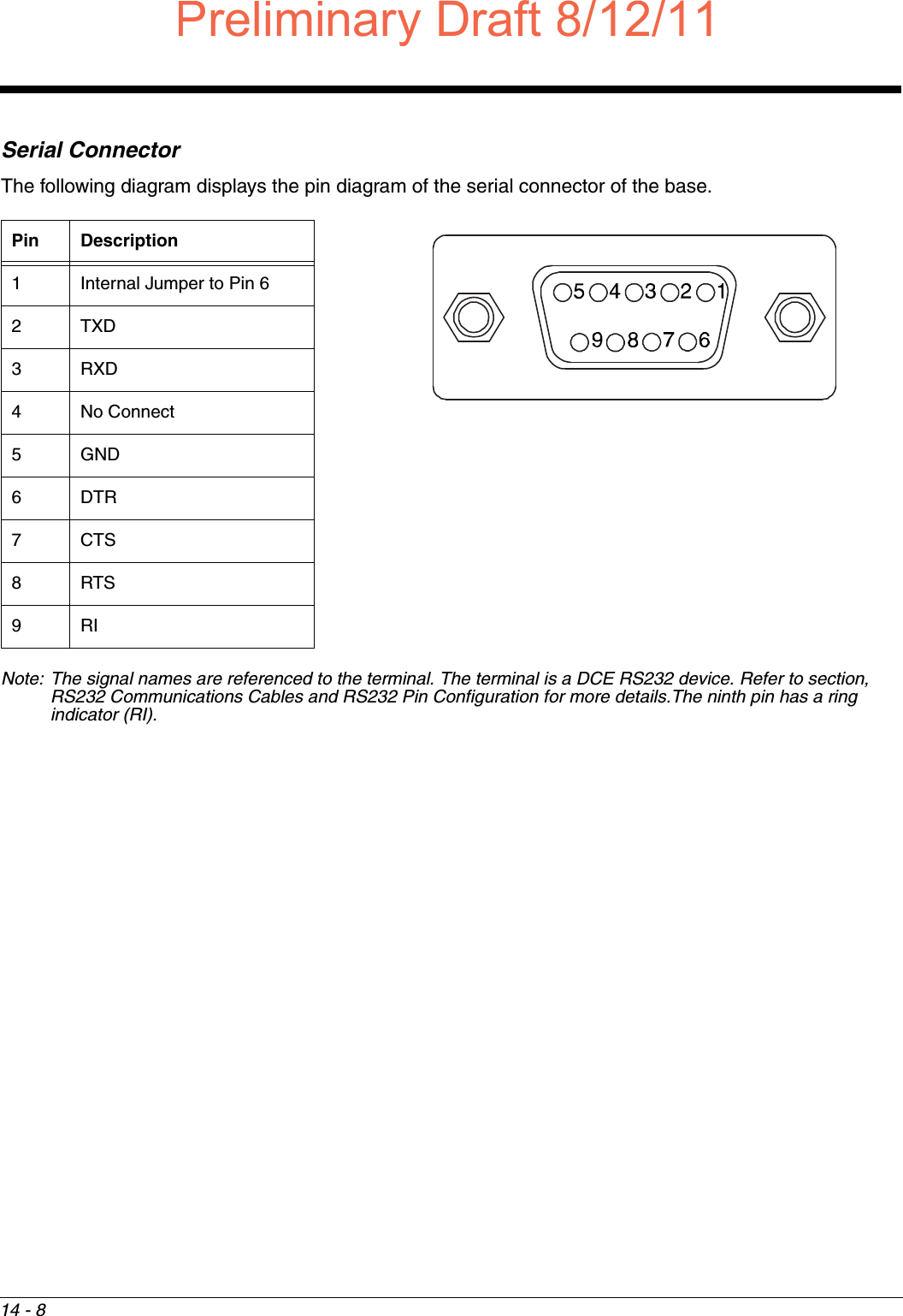
User Manual 2 of 2
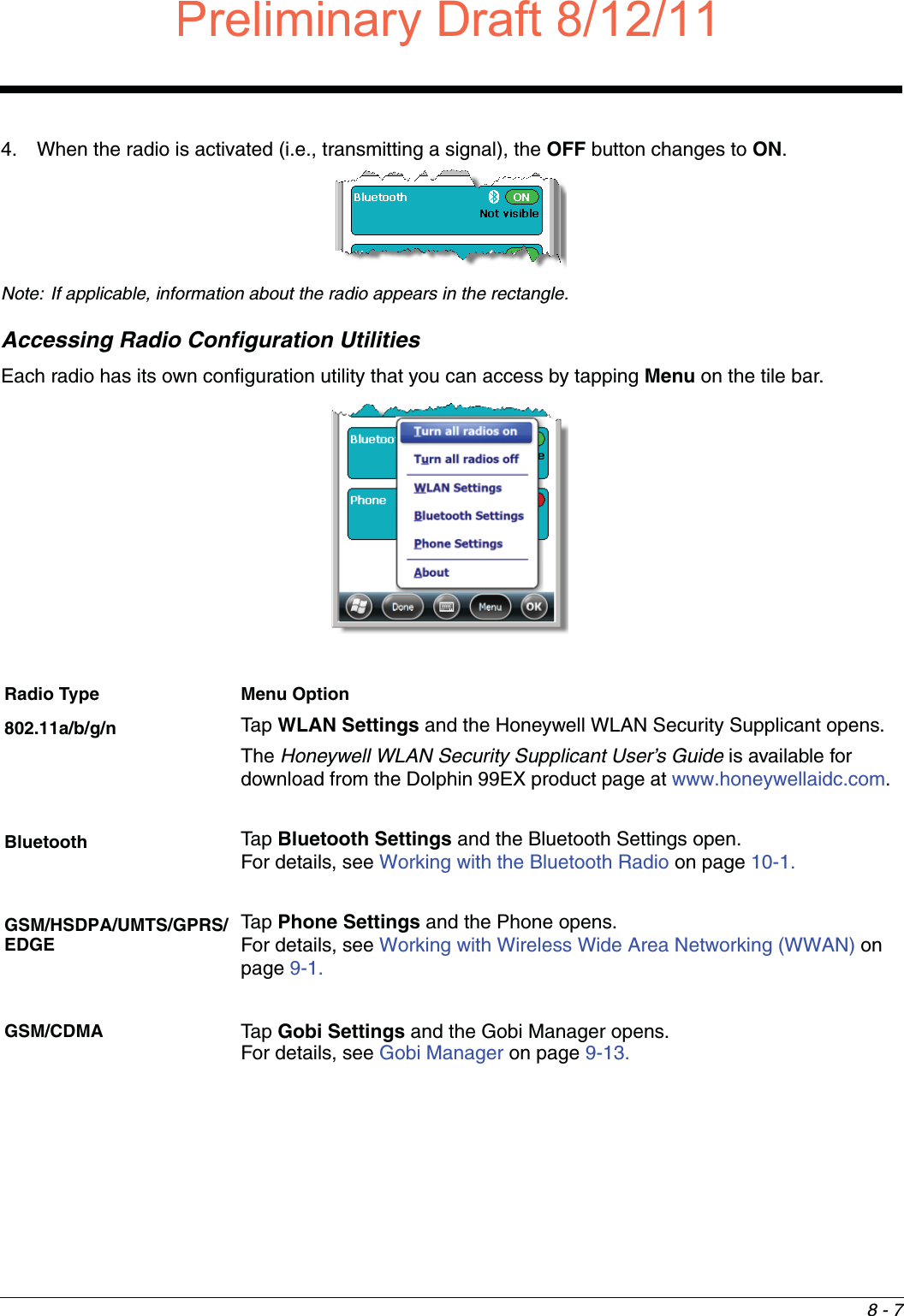
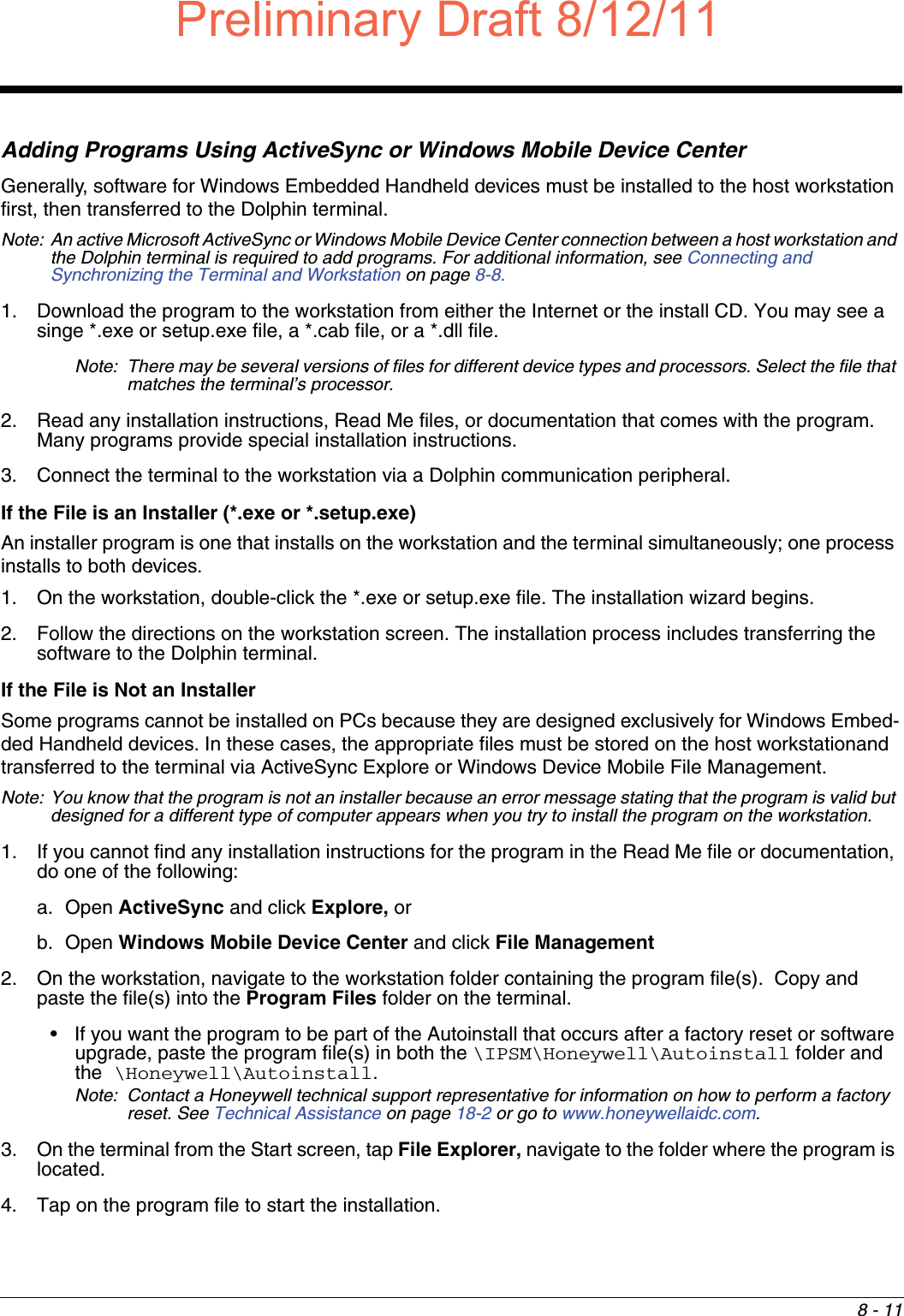

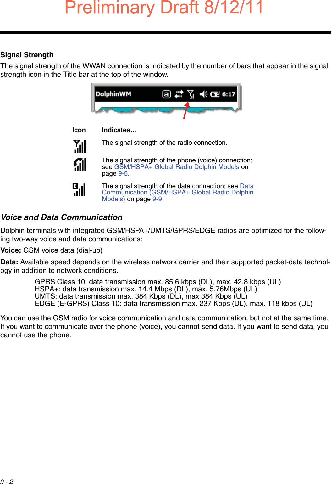
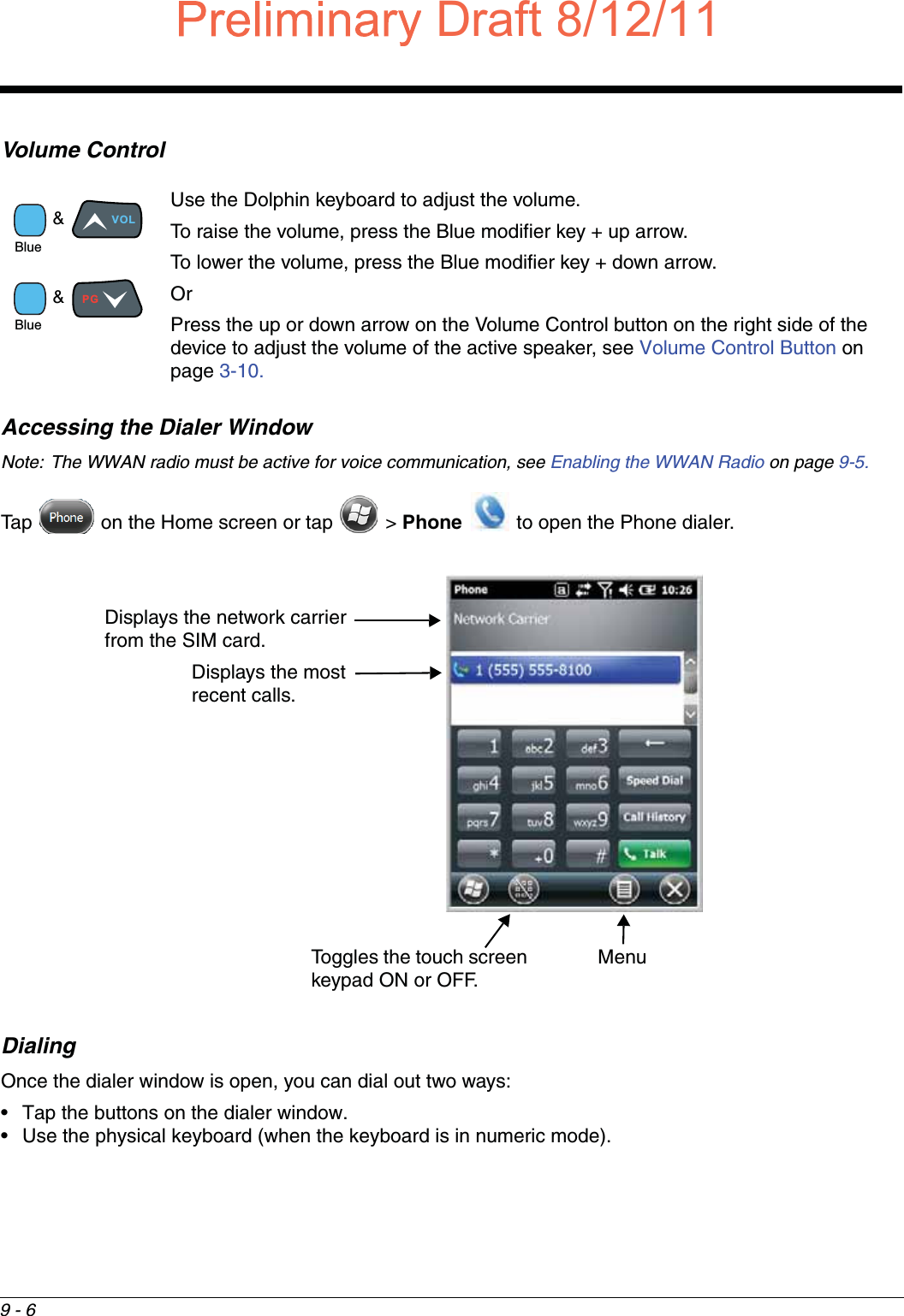
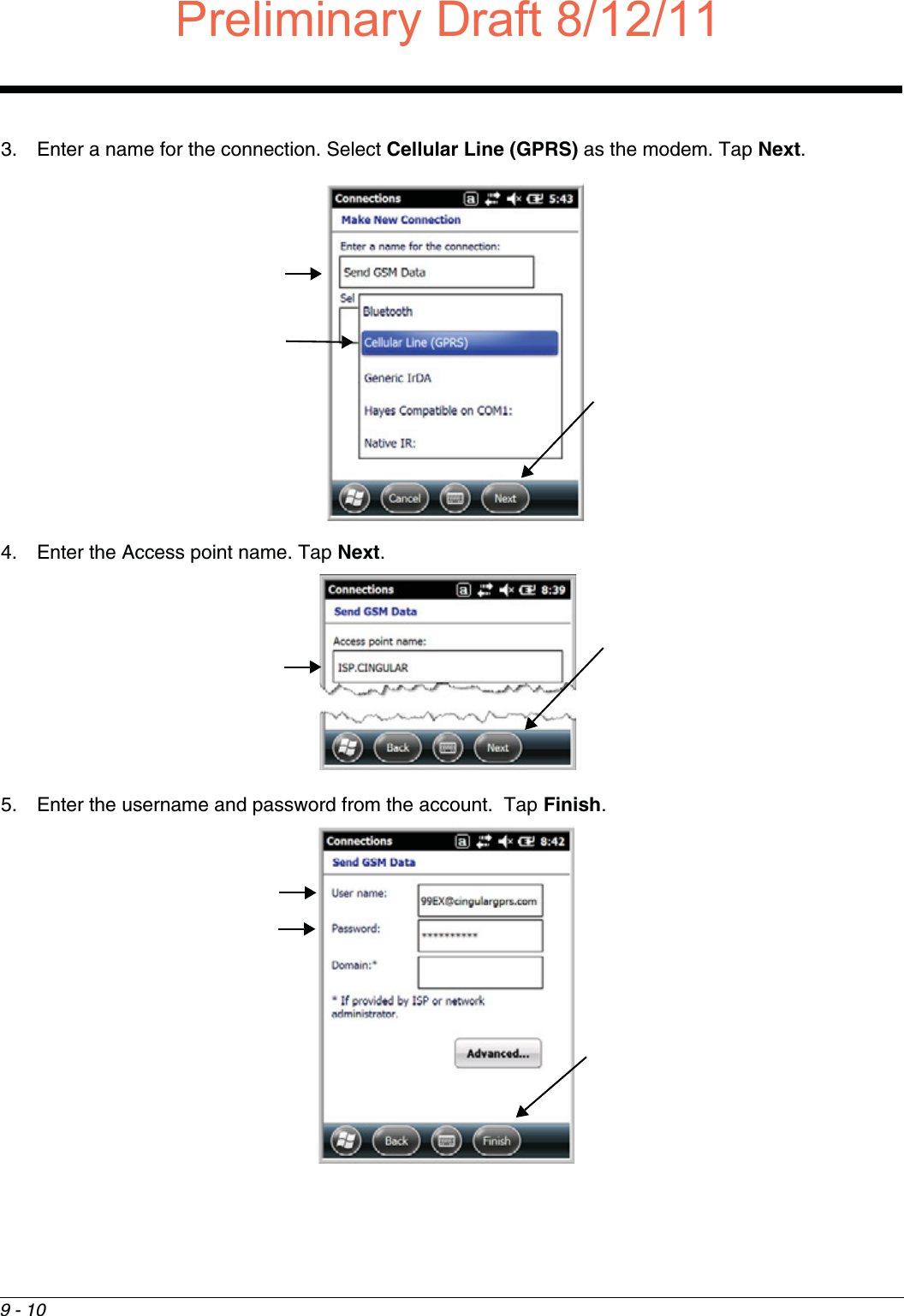
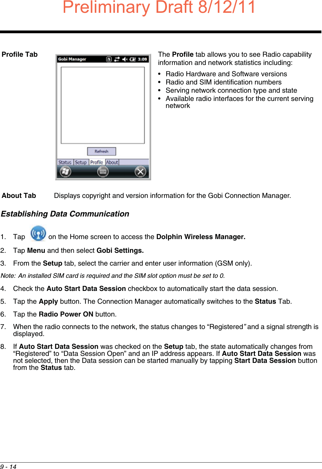
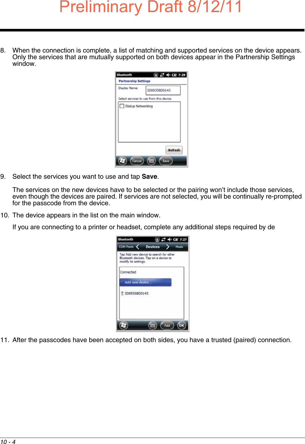
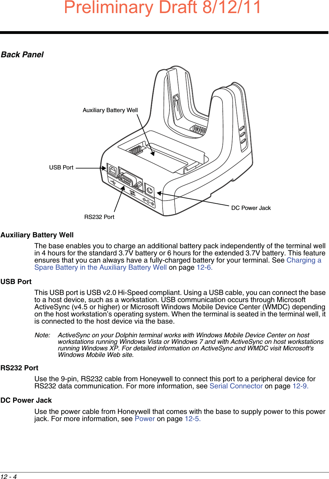

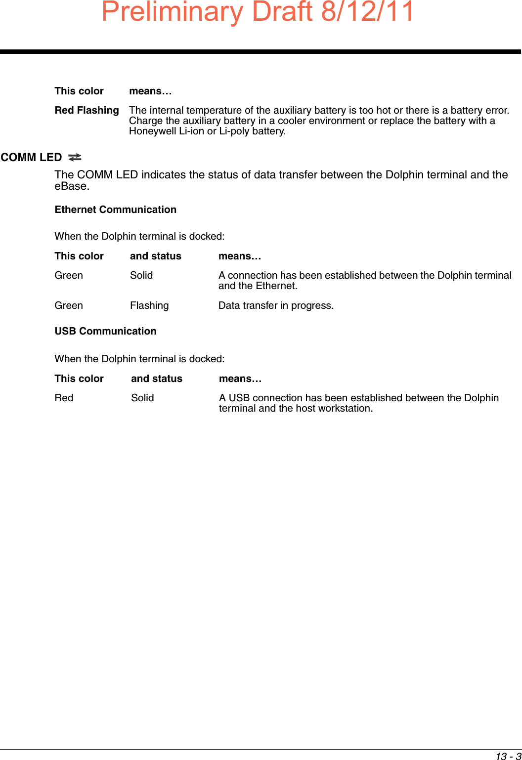
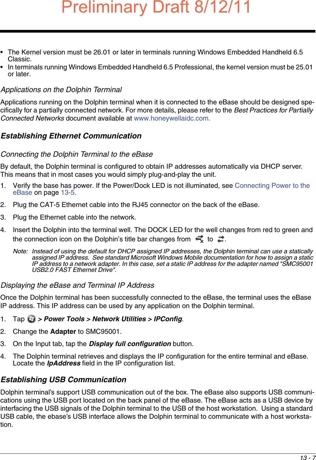
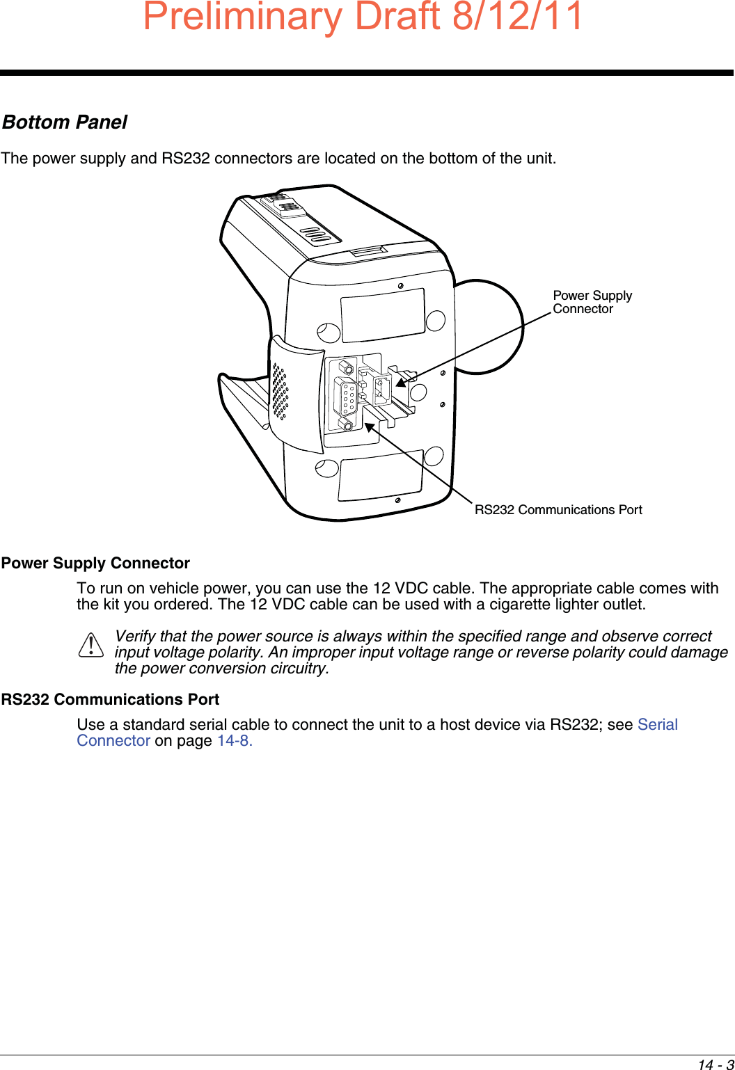
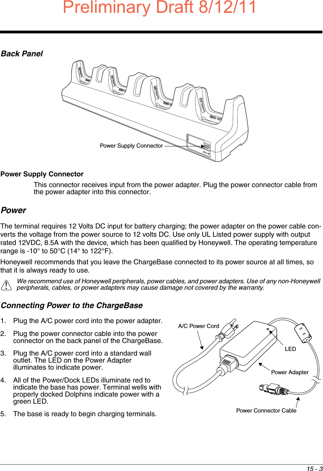
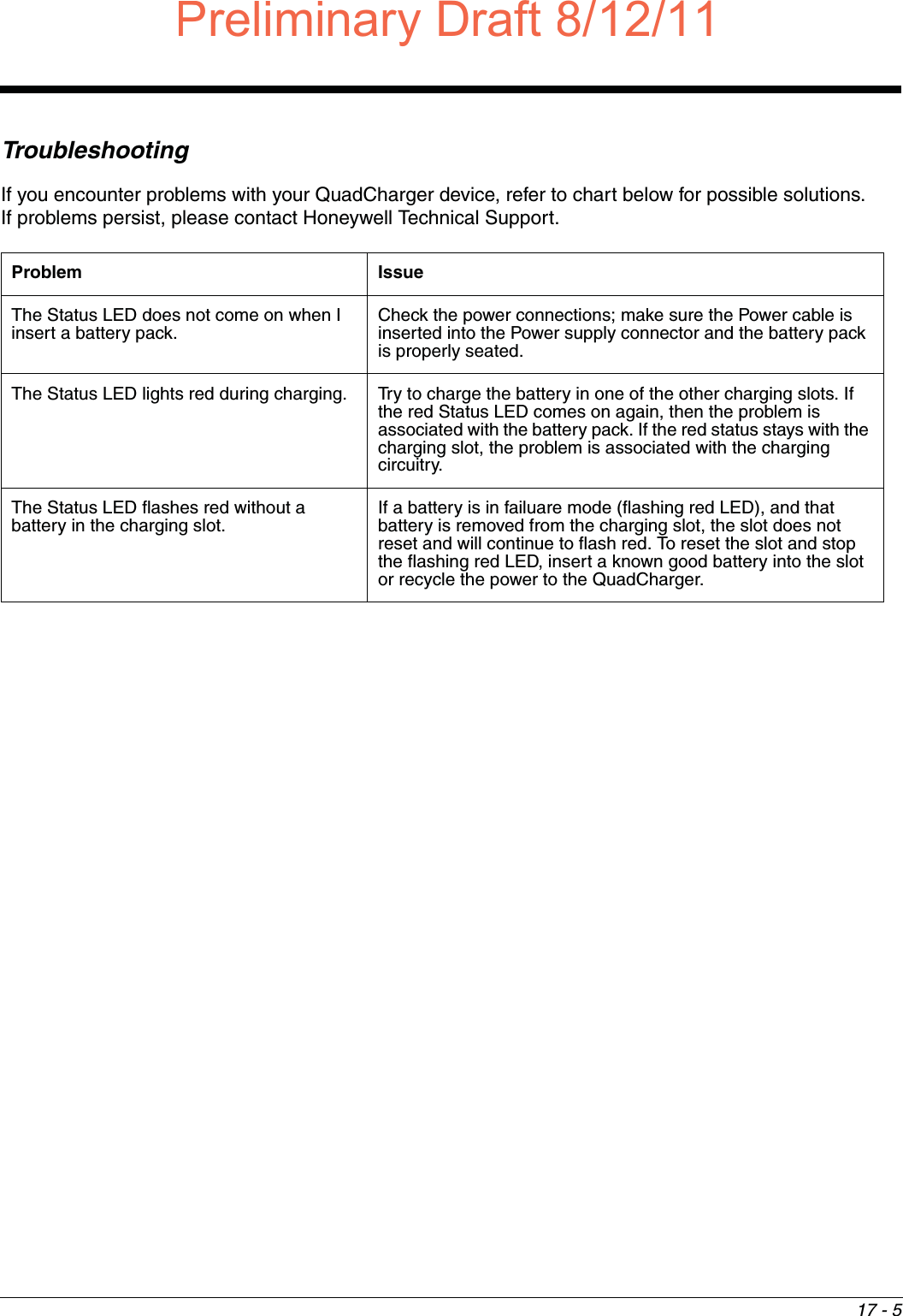
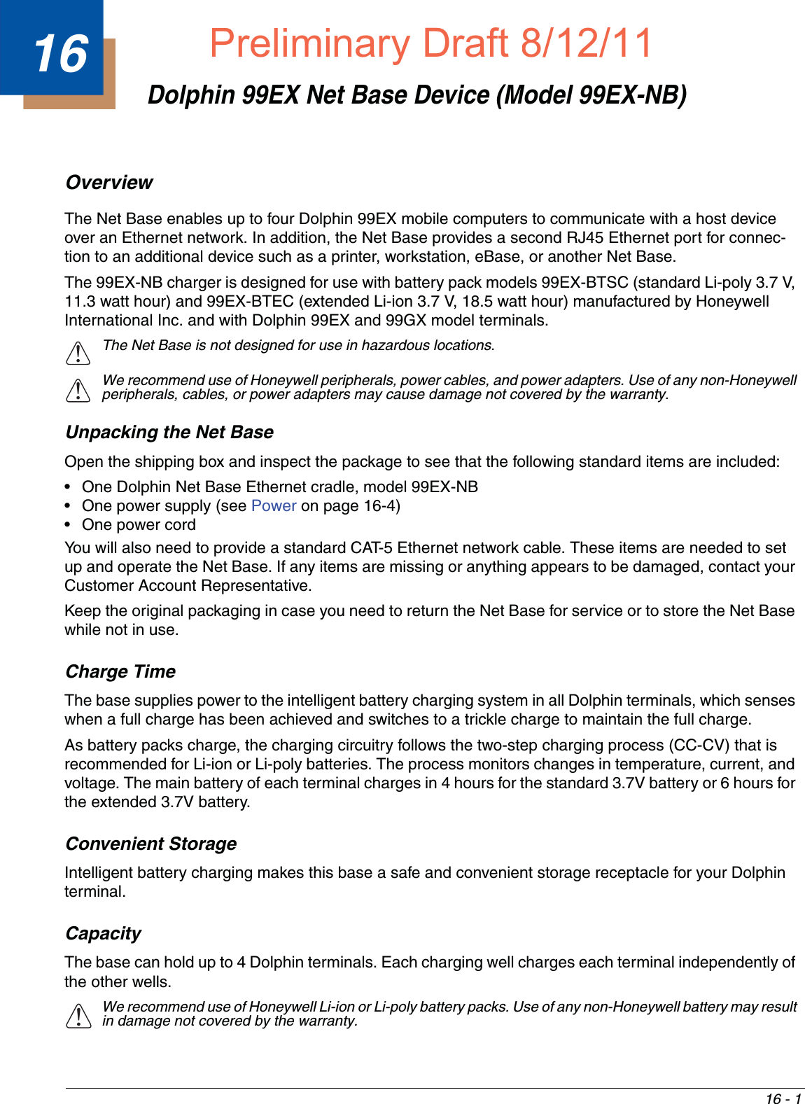
![15 - 6Hollow Wall Installation1. Drill four pilot holes in the wall using a 7/8 in. drill bit.2. Slide the bolt through the wall bracket, and thread the toggle nut onto the bolt.3. Press the ends of the toggle nut together, and insert the bolt/nut into the pilot hole until the nut clears inside wall surface. The toggle nut should spring open preventing the screw from being removed. 4. Repeat steps 2 and 3 for each of the remaining mounting holes.5. Tighten all four bolts to secure the bracket to the wall. 6. Once the bracket is installed, secure the base to the wall bracket, see Securing the Base to the Wall Bracket for detailed instructions.Wood Stud Installation1. Drill four pilot holes in the wall/wood stud using the 1/4 in. drill bit.2. Secure the bracket to the wall using the four Hex Head Lag Screws provided.3. Once the bracket is installed, secure the base to the wall bracket, see Securing the Base to the Wall Bracket for detailed instructions.Securing the Base to the Wall BracketYou can secure the base to the wall bracket by using the self tapping screws provided or you can use the optional DIN Rail. To secure the base using the self tapping screws:1. Position the base on the wall bracket, as shown.2. Secure the base to the bracket using the four M3 x 9 mm self-tapping screws.Wall Mount Holes6.5 in. [16.5 cm]13.78 in. [ 35 cm ]Wall Mount BraketBoltBracketWallToggle NutOpen Toggle NutWallBracketWall BracketM3 x 9 mm Self-tapping Screws, Qty. 4Preliminary Draft8/12/11Draft_99EX-UG_Rev-b-1.pdf 164 8/12/2011 4:14:00 PM](https://usermanual.wiki/Honeywell/99EXLG.User-Manual-2-of-2/User-Guide-1528834-Page-64.png)

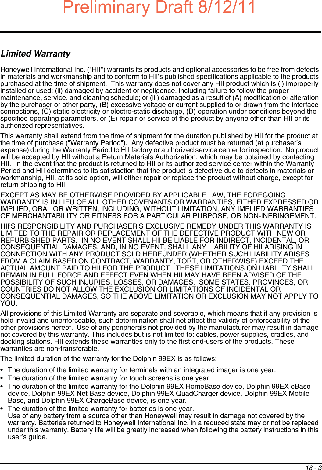
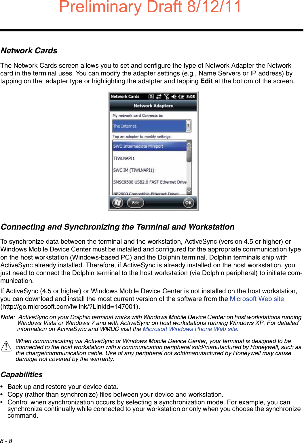
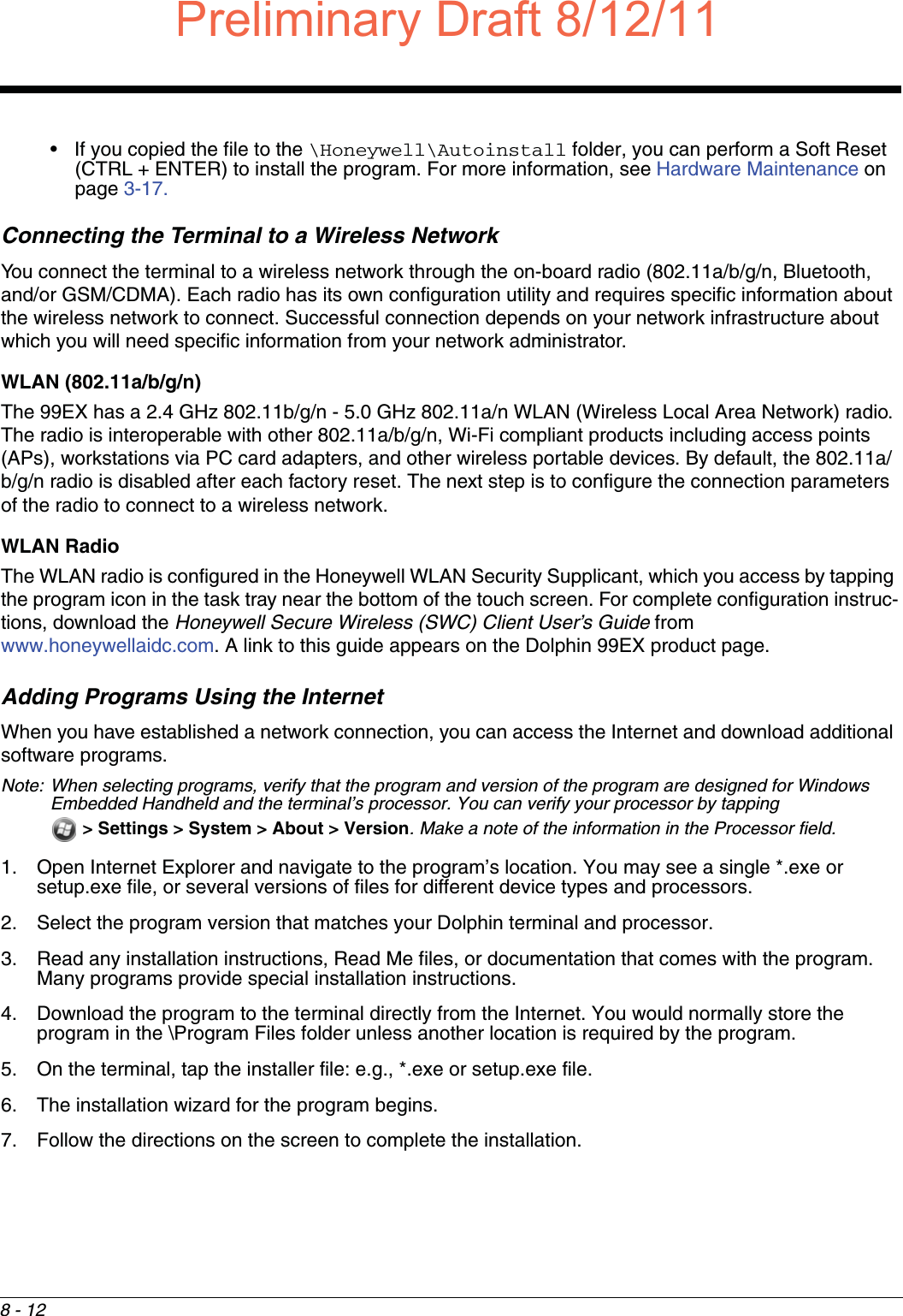
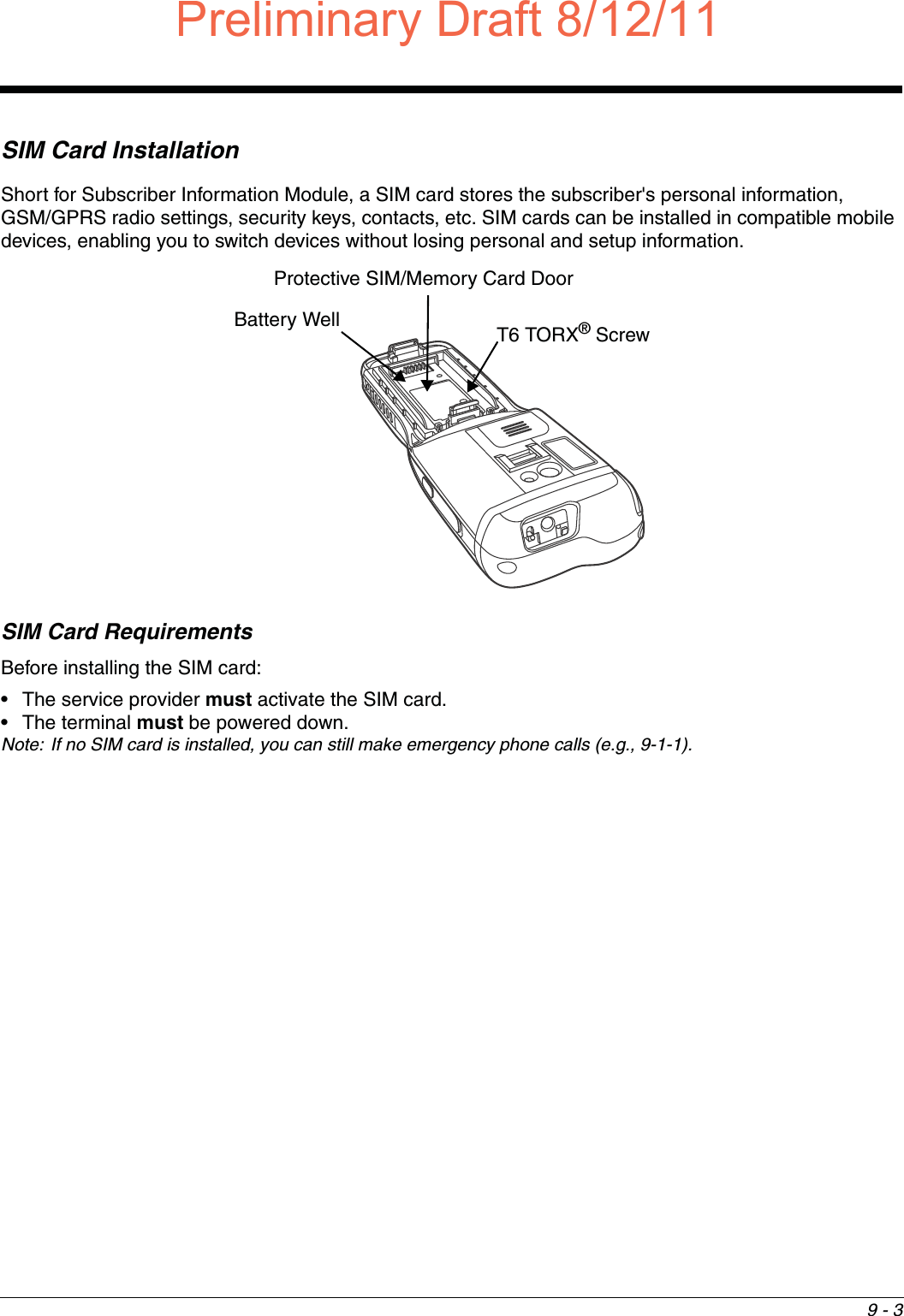
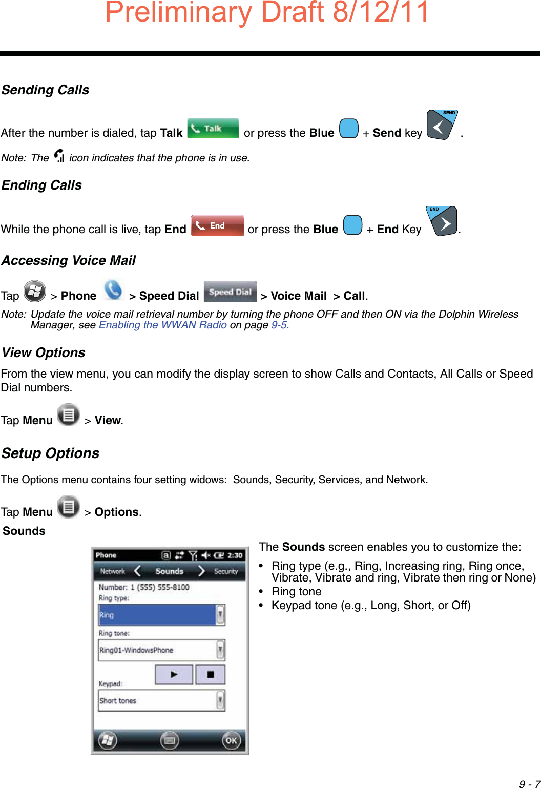
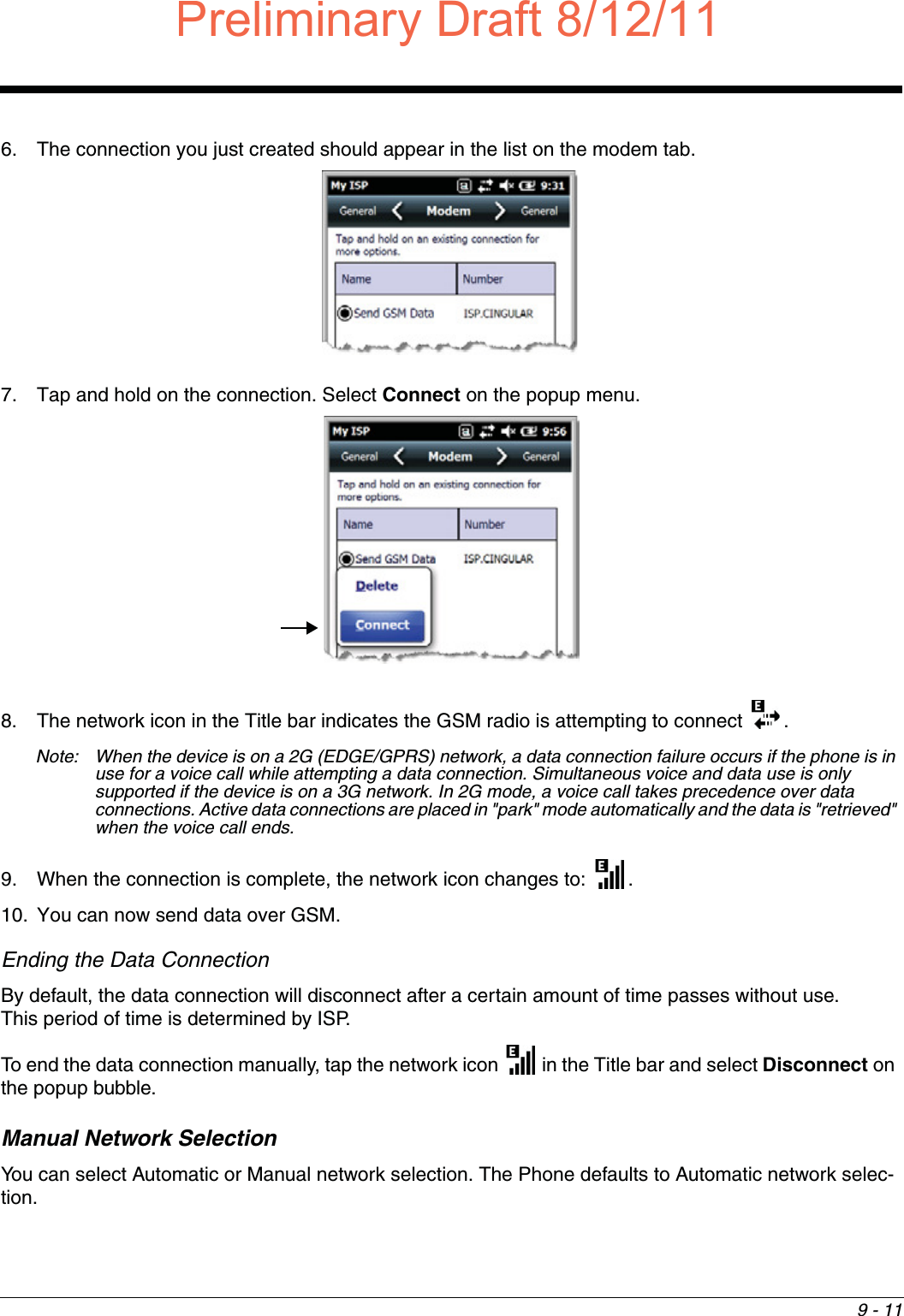
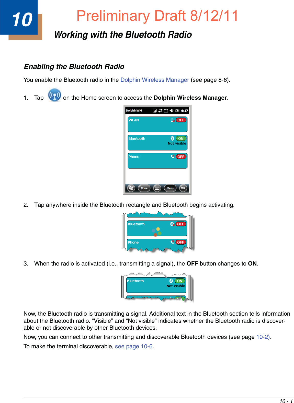
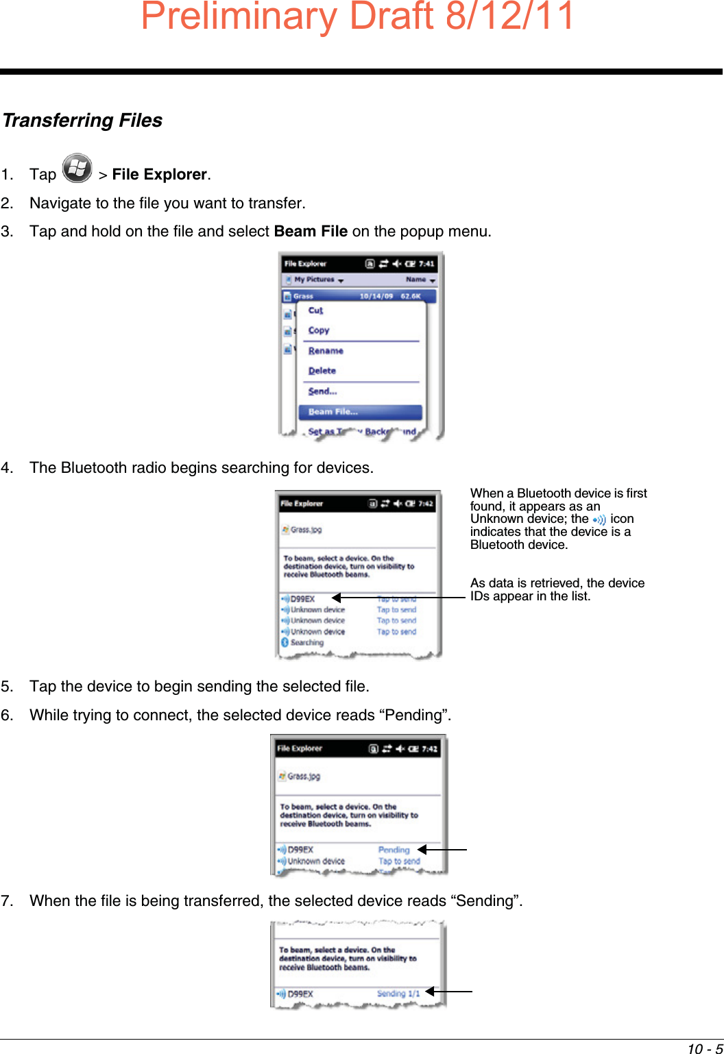
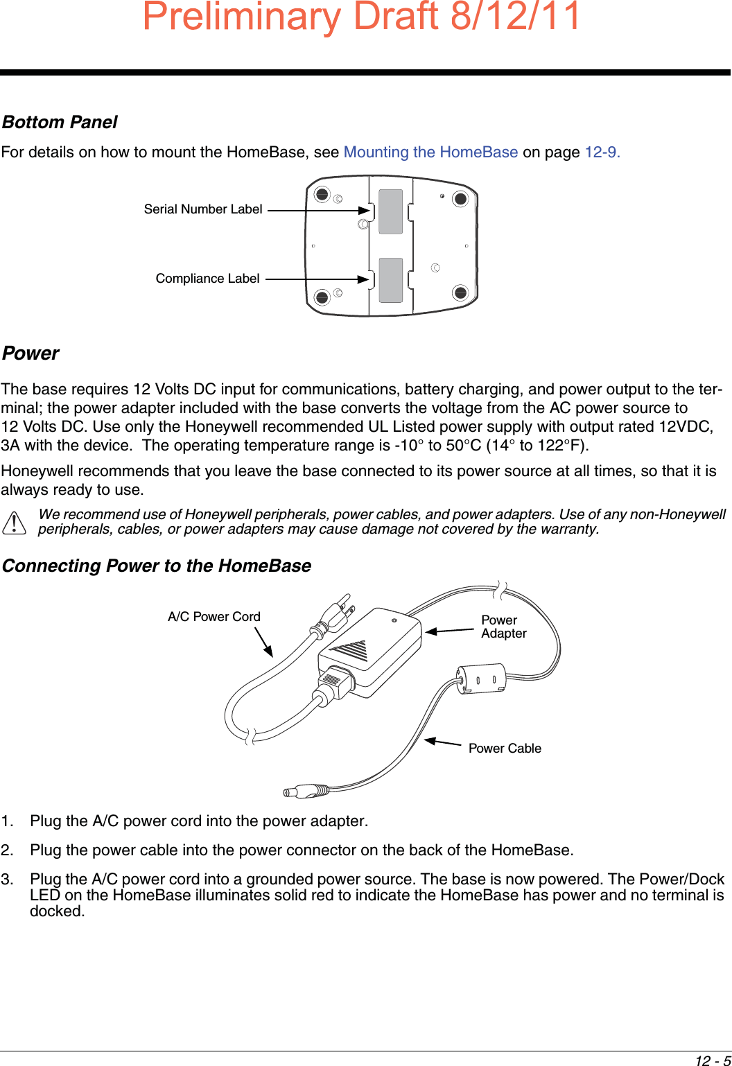
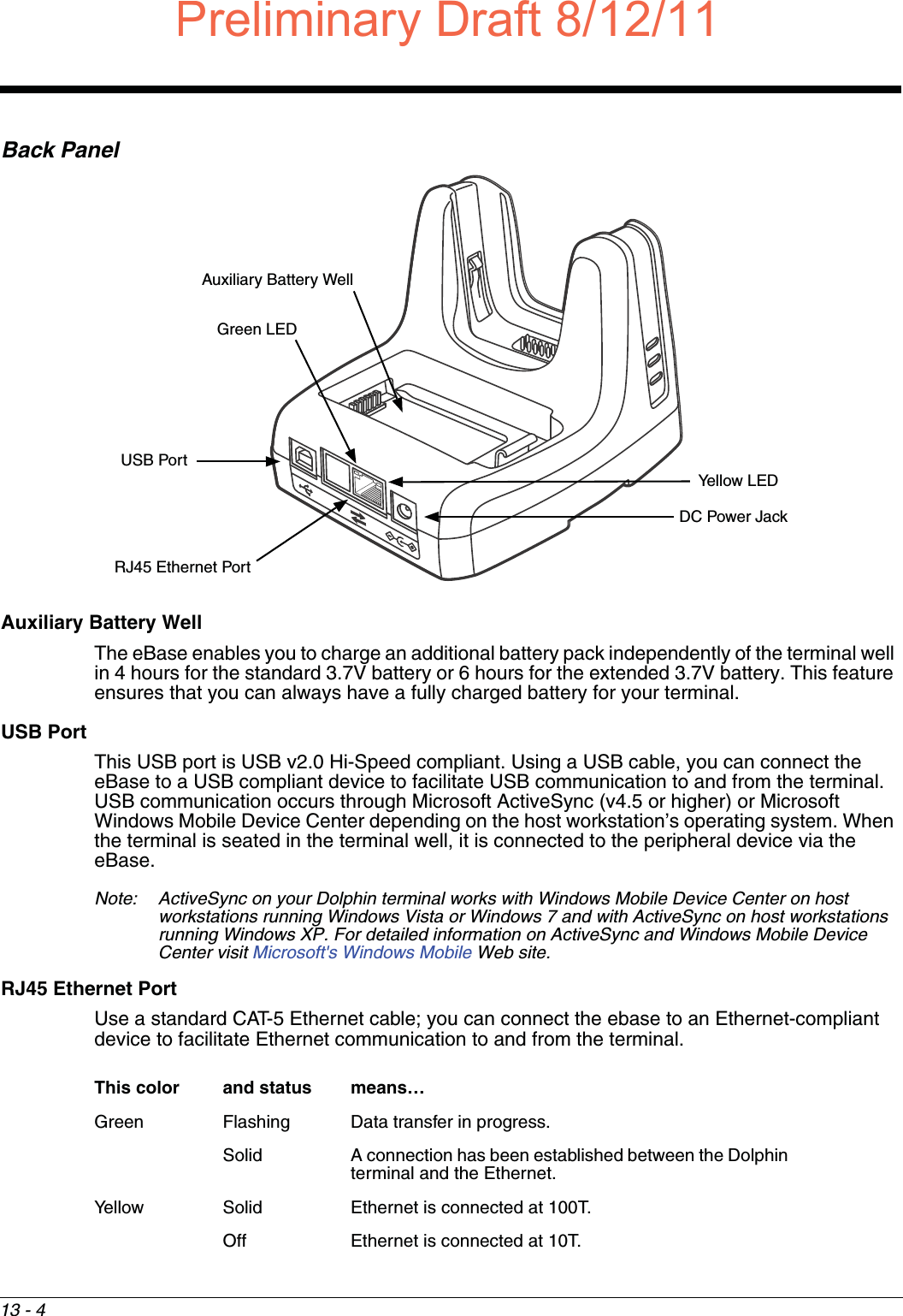
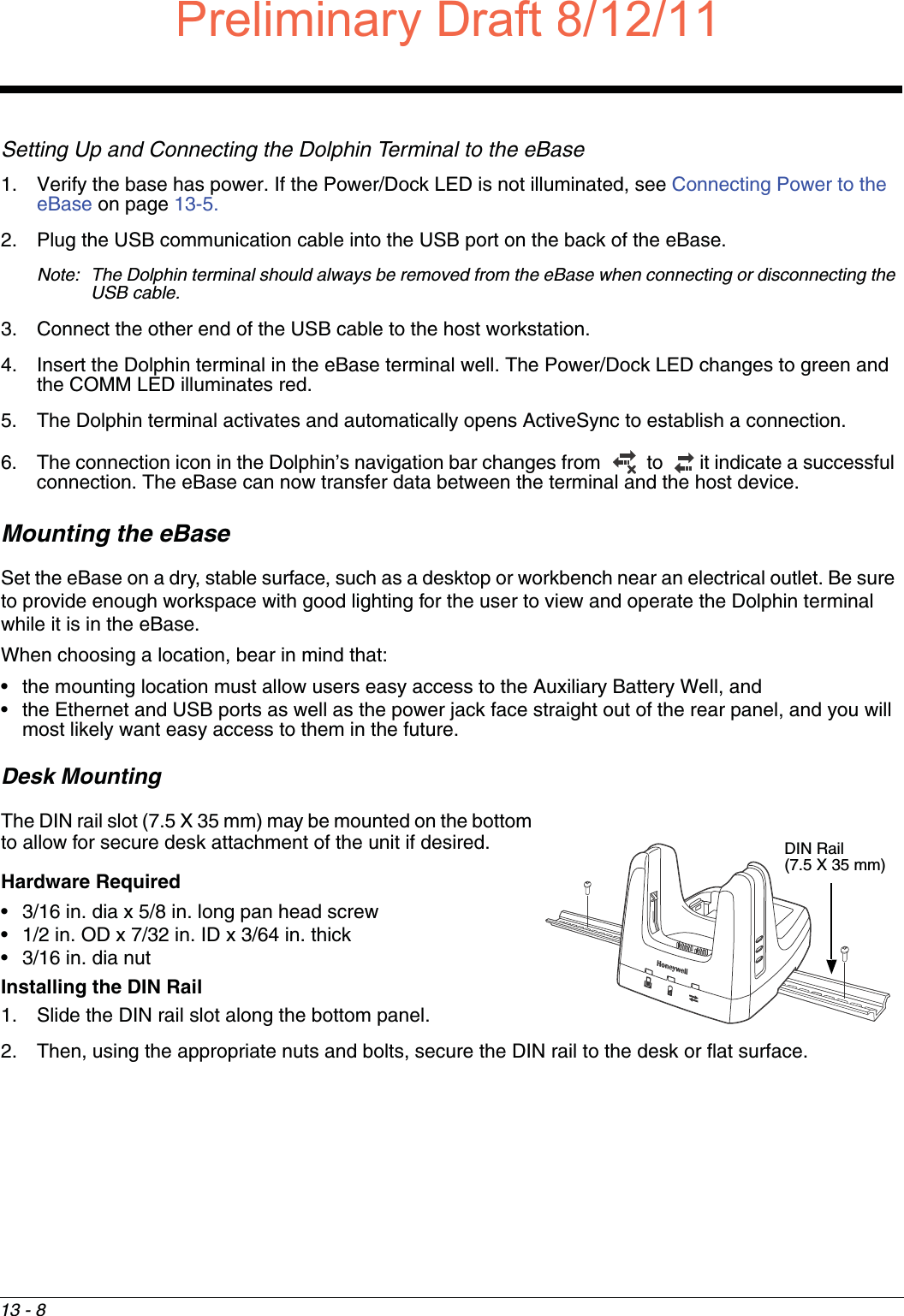
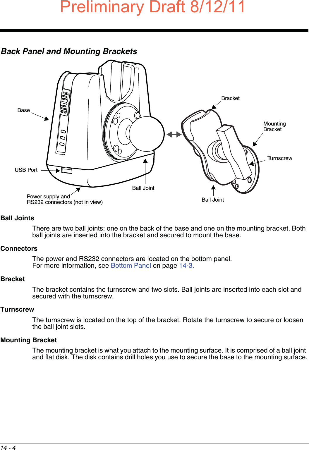
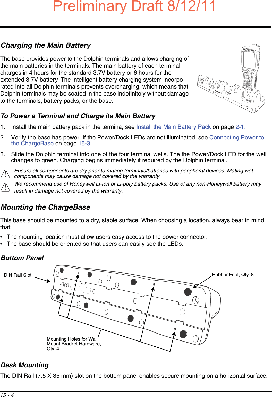
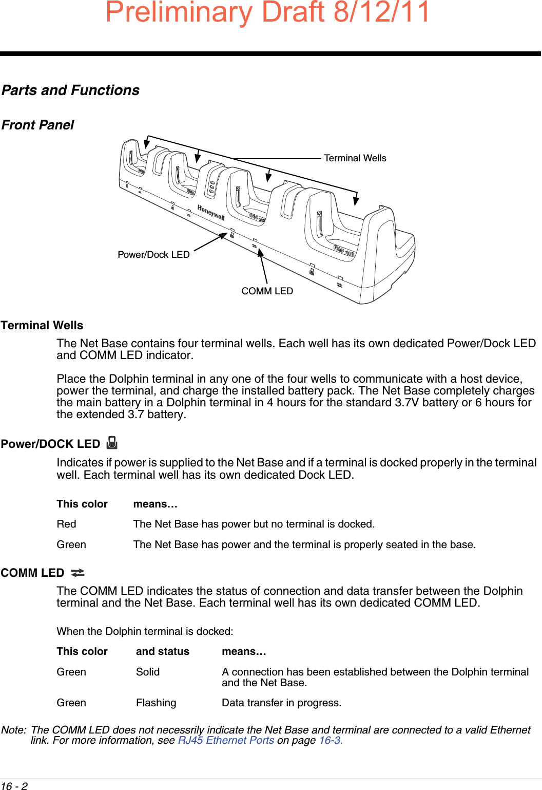
![15 - 8Channel Bracket Installation (Pre-existing Hardware Installations) When choosing a location and installing the optional channel bracket:• Do not exceed 150 lbs. maximum load on the channel bracket. • Leave a minimum of 16 in. (40.64 cm) of horizontal space between the hardware used to attach the channel bracket to the wall. • An electrical outlet must be easily accessible.• The mounting location should be dry, stable, easily accessible, and well lighted.Tools Required• Drill• 7/8 in. Drill Bit (for hollow wall installations) or 1/4 in. Drill Bit (for wood stud installations)• #2 Phillips Screw Driver• Medium Flat Head Screw Driver• 9/16 in.Socket WrenchHardware Required• 3/8 in.-16 spring nut, for 13/16 in. deep strut, Qty. 4 per wall bracket• 3/8 in. flat washer, Qty. 4 per wall braket • 3/8 in.-16 x 1.00 in., cap screw, grade 5, Qty. 4 per wall bracket•Hollow Wall Installations: 3/8 in. x 4 in. round head toggle bolt, 2-5/8 in. usable length, Qty. 43/8 in. flat washer, Qty. 4•Wood Stud Installations: 3/8 in. x 2 1/2 in. length hex head lag screw, Qty. 43/8 in. fat washer, Qty. 4Installation1. Slide the spring nuts into the channel of the bracket and position them to line up with the mounting holes on the wall bracket.Wall Mount Holes6.5 in. [16.5 cm]13.78 in. [ 35 cm ]Wall BracketChannel Bracket Spring NutDraft8/12/11Draft_99EX-UG_Rev-b-1.pdf 166 8/12/2011 4:14:01 PM](https://usermanual.wiki/Honeywell/99EXLG.User-Manual-2-of-2/User-Guide-1528834-Page-66.png)

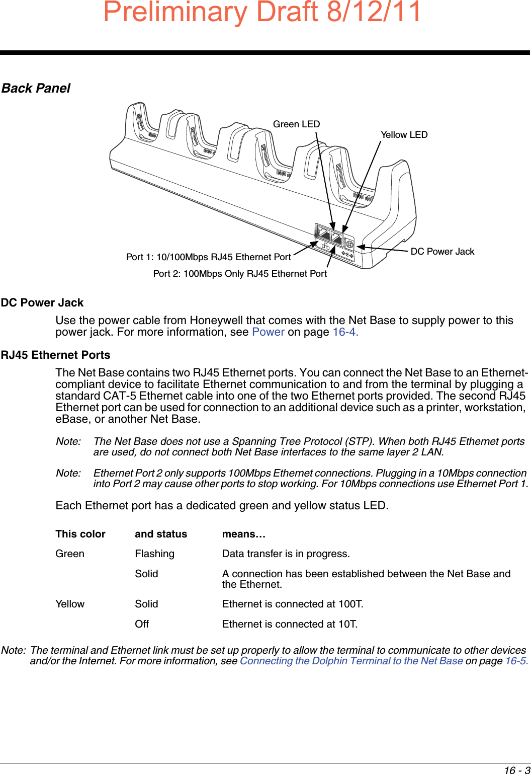
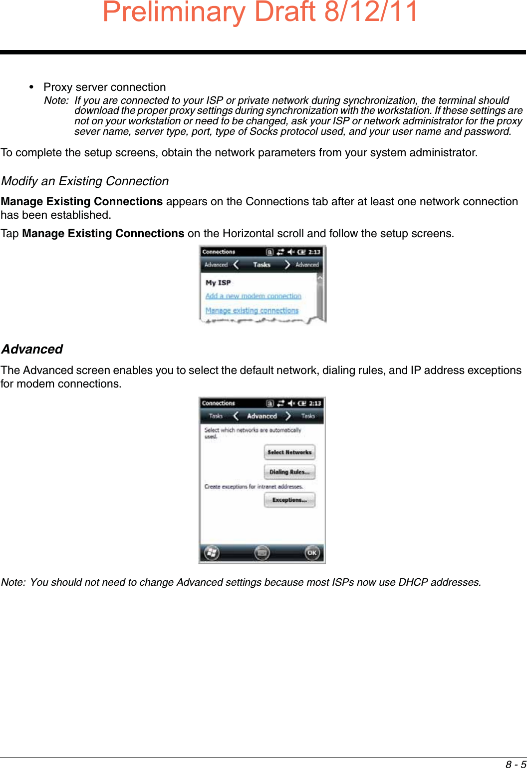
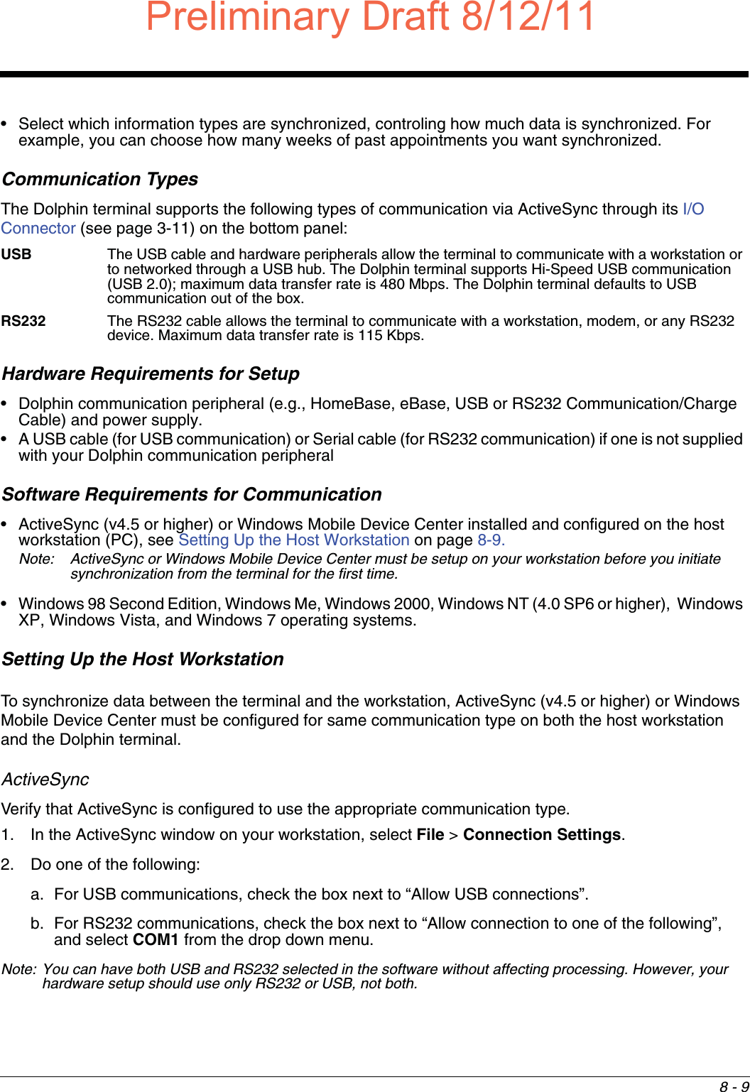
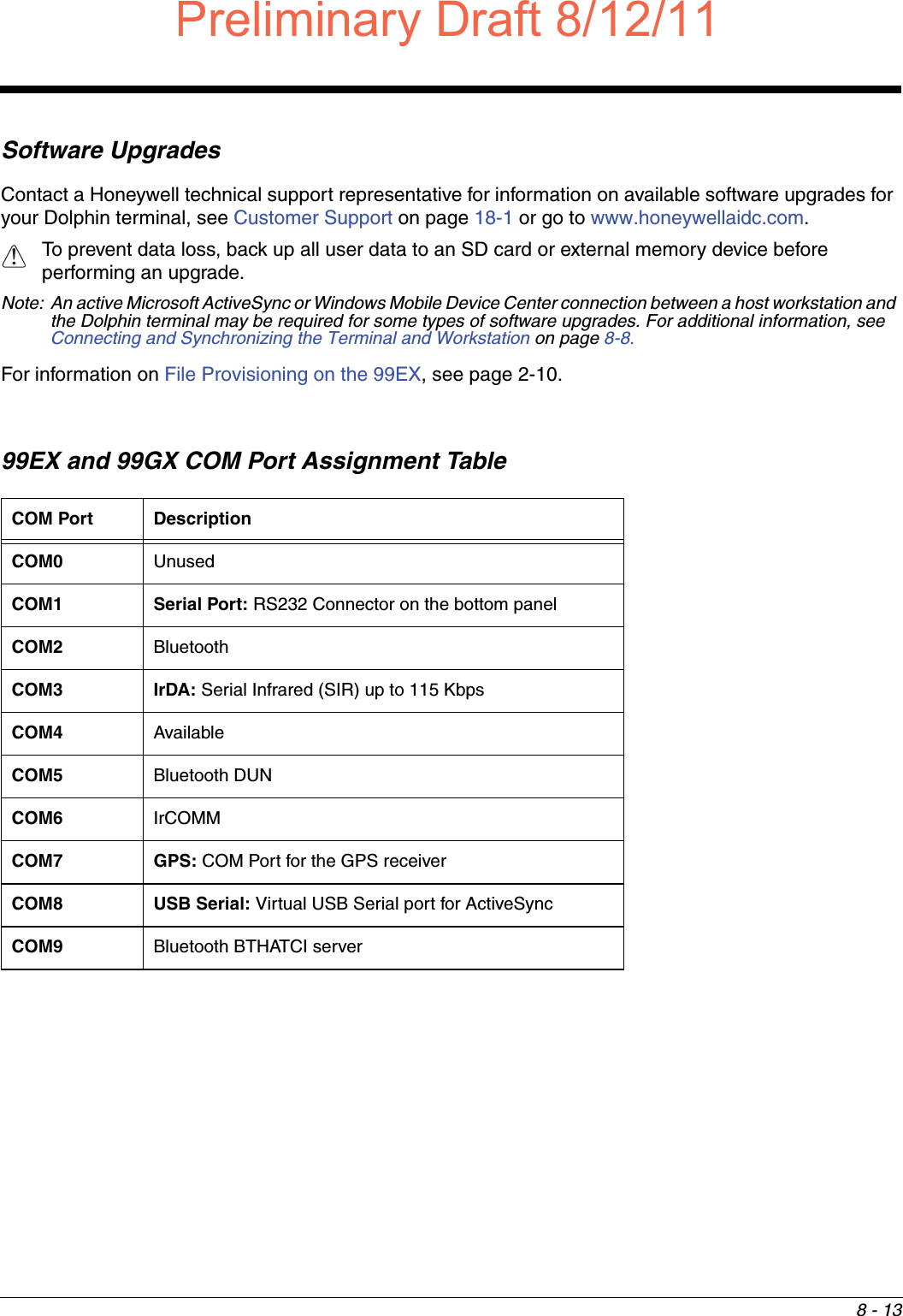
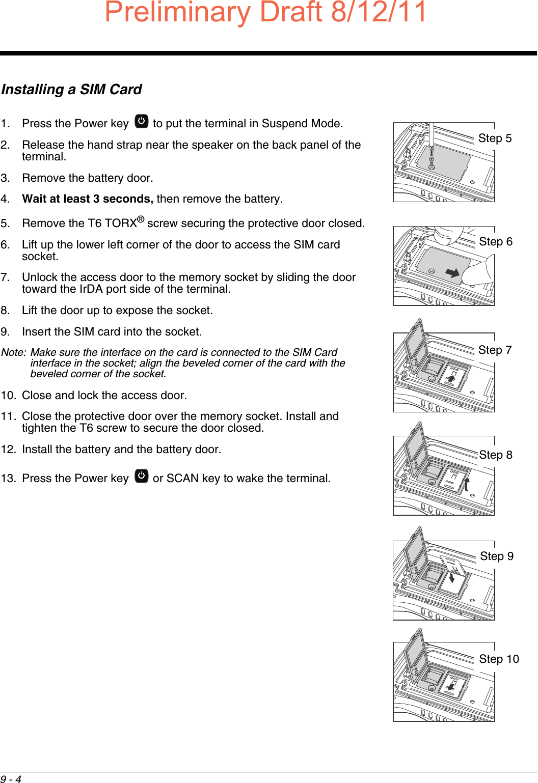
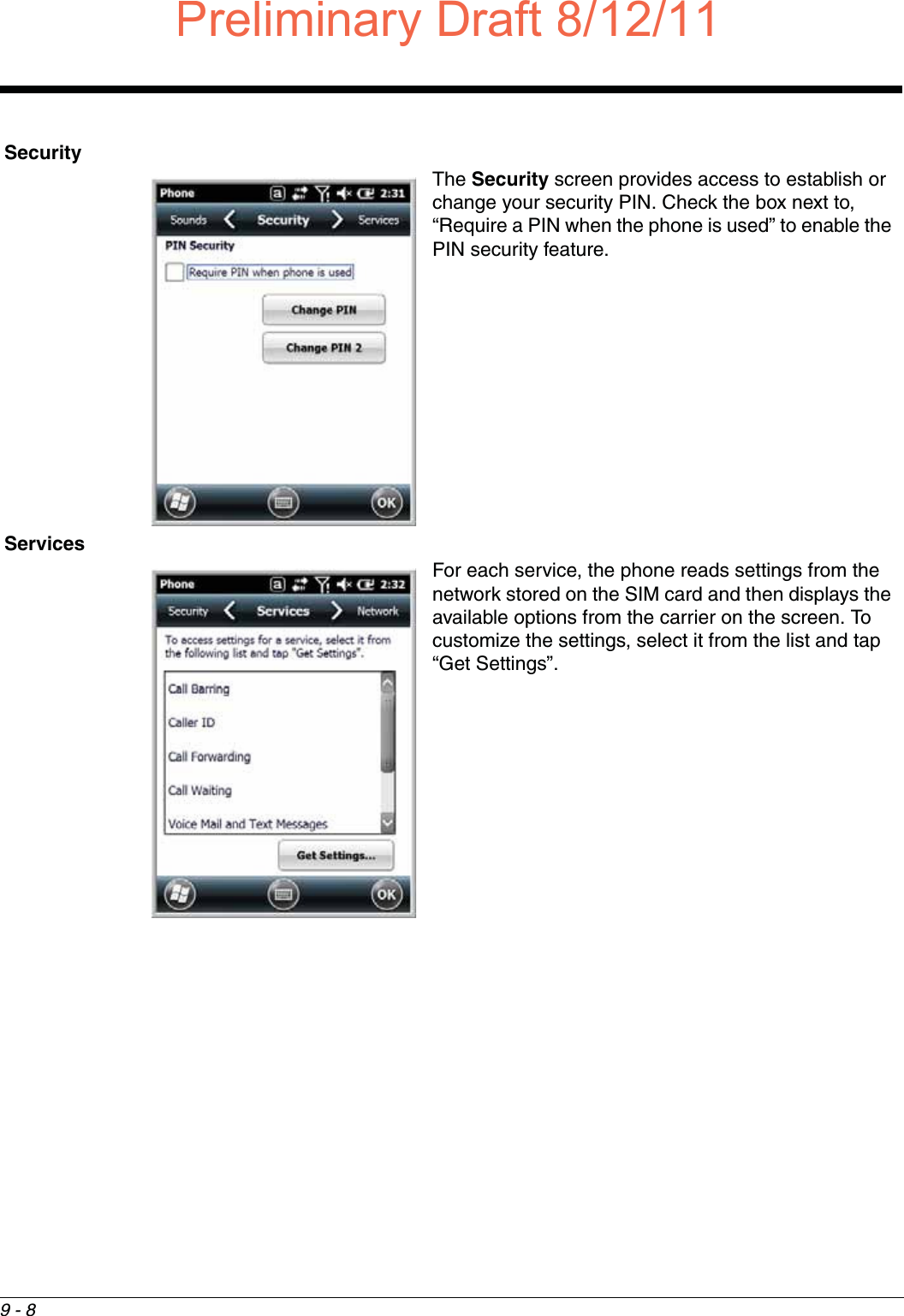
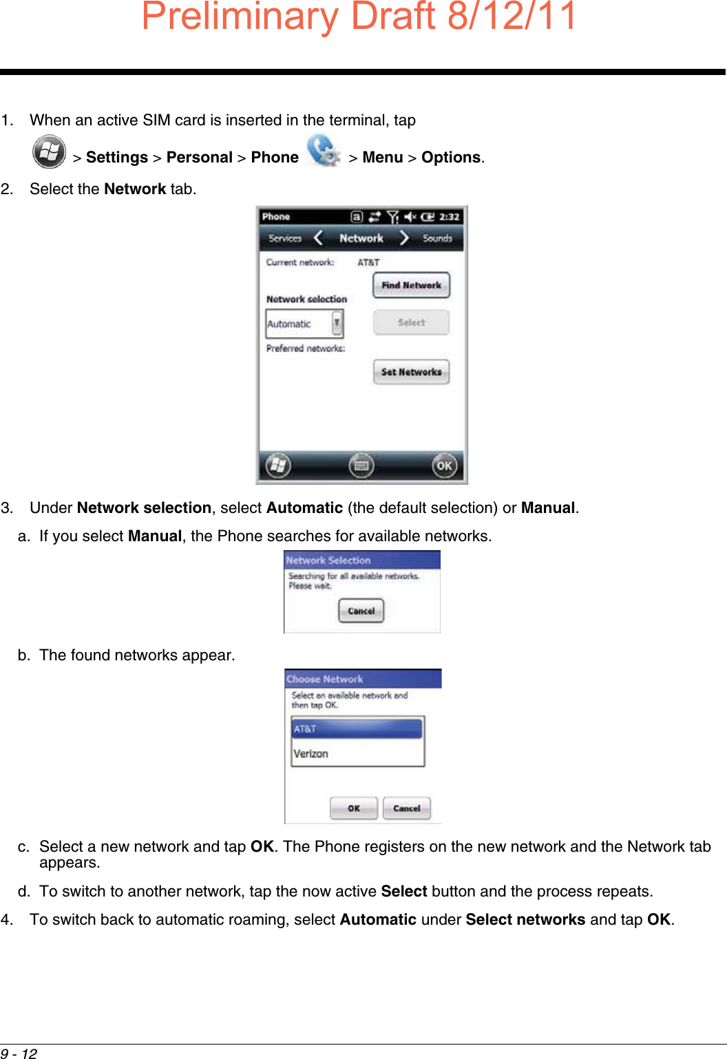
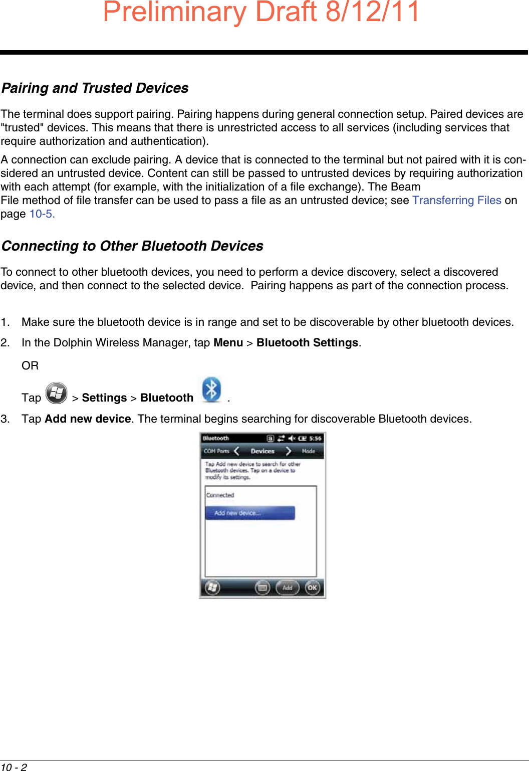
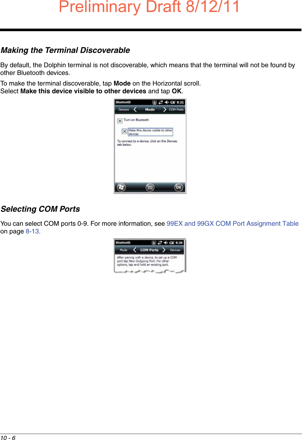
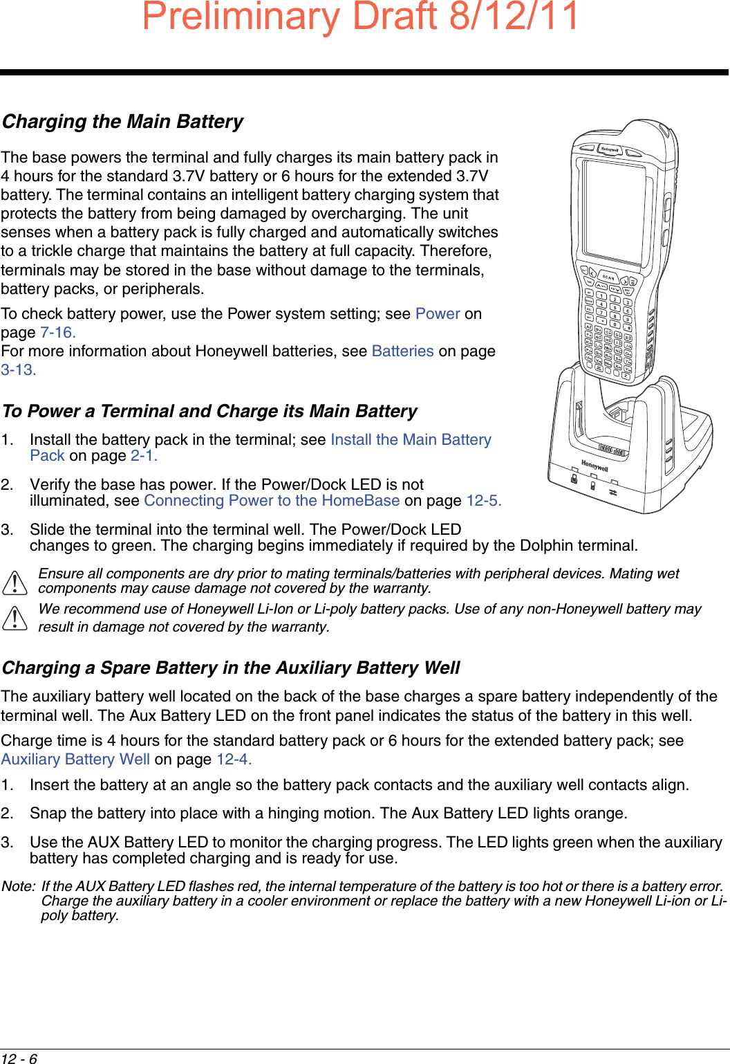
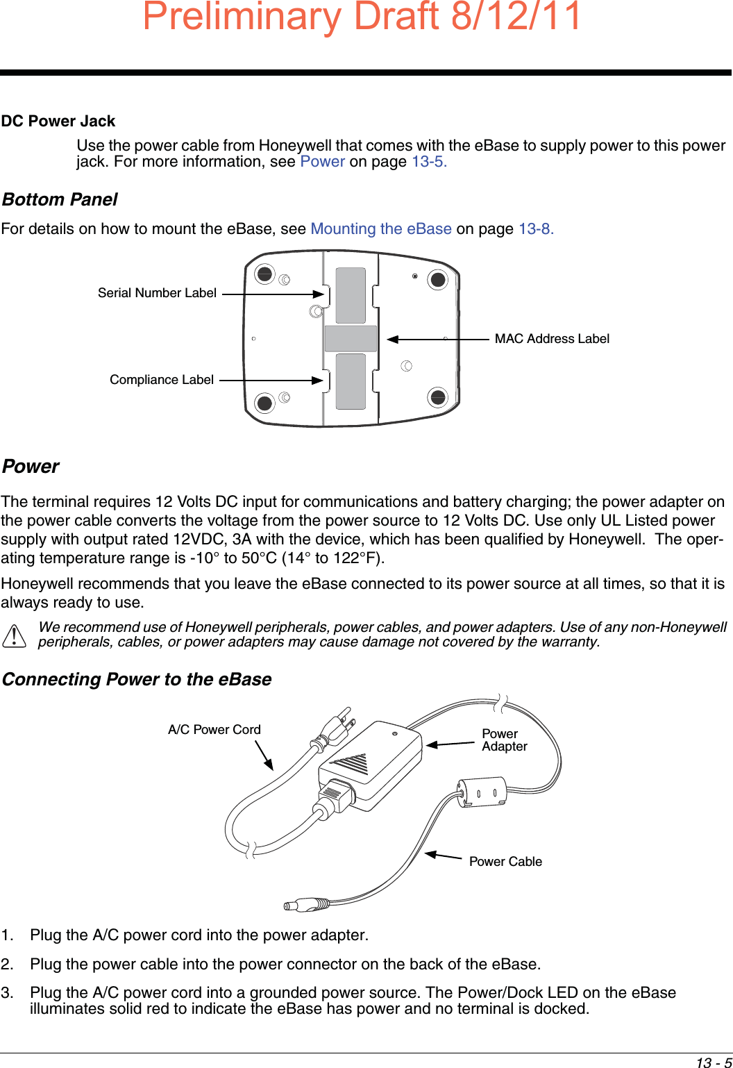
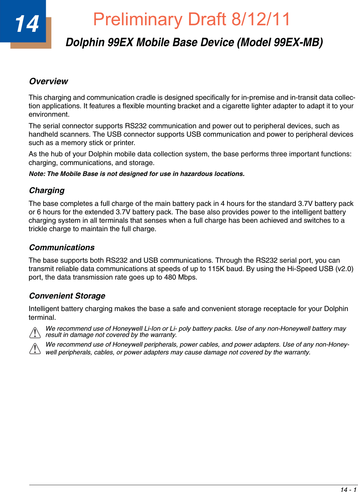
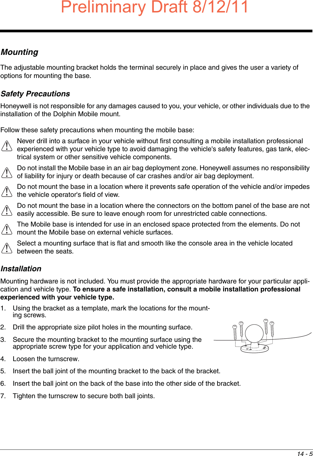
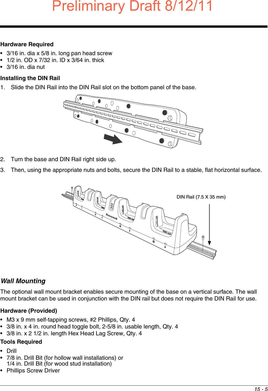
![16 - 8Hollow Wall Installation1. Drill four pilot holes in the wall using a 7/8 in. drill bit.2. Slide the bolt through the wall bracket, and thread the toggle nut onto the bolt.3. Press the ends of the toggle nut together, and insert the bolt/nut into the pilot hole until the nut clears inside wall surface. The toggle nut should spring open preventing the screw from being removed. 4. Repeat steps 2 and 3 for each of the remaining mounting holes.5. Tighten all four bolts to secure the bracket to the wall. 6. Once the bracket is installed, secure the base to the wall bracket, see Securing the Base to the Wall Bracket for detailed instructions.Wood Stud Installation1. Drill four pilot holes in the wall/wood stud using the 1/4 in. drill bit.2. Secure the bracket to the wall using the four Hex Head Lag Screws provided.3. Once the bracket is installed, secure the base to the wall bracket, Securing the Base to the Wall Bracket for detailed instructions.Securing the Base to the Wall BracketYou can secure the base to the wall bracket by using the self tapping screws provided or you can use the optional DIN Rail. To secure the base using the self tapping screws:1. Position the base on the wall bracket, as shown.2. Secure the base to the bracket using the four M3 x 9 mm self-tapping screws provided.Wall Mount Holes6.5 in. [16.5 cm]13.78 in. [ 35 cm ]Wall Mount BraketBoltBracketWallToggle NutOpen Toggle NutWallBracketWall BracketM3 x 9 mm Self-tapping Screws, Qty. 4Preliminary Draft8/12/11Draft_99EX-UG_Rev-b-1.pdf 176 8/12/2011 4:14:03 PM](https://usermanual.wiki/Honeywell/99EXLG.User-Manual-2-of-2/User-Guide-1528834-Page-76.png)
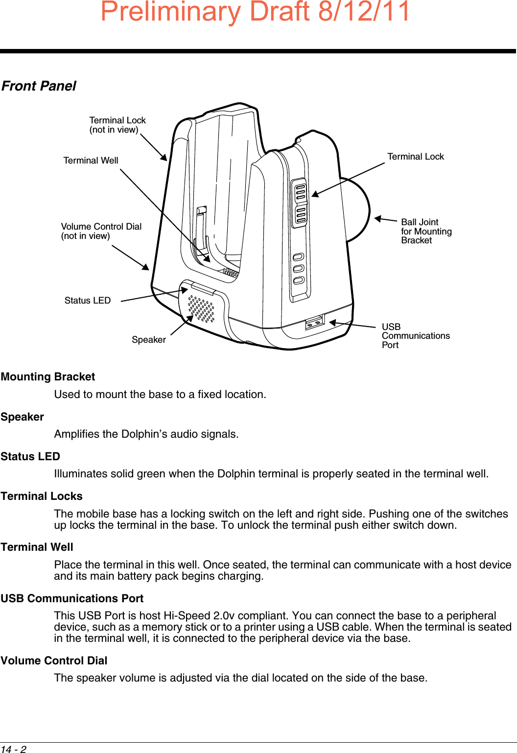
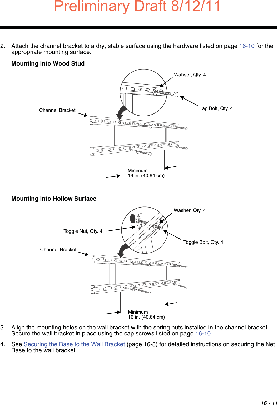
![16 - 10Channel Bracket Installation (Pre-existing Hardware Installations) When choosing a location and installing the optional channel bracket:• Do not exceed 150 lbs. maximum load on the channel bracket. • Leave a minimum of 16 in. (40.64 cm) of horizontal space between the hardware used to attach the channel bracket to the wall. • An electrical outlet must be easily accessible.• The mounting location should be dry, stable, easily accessible, and well lighted.Tools Required• Drill• 7/8 in. Drill Bit (for hollow wall installations) or 1/4 in. Drill Bit (for wood stud installations)• #2 Phillips Screw Driver• Medium Flat Head Screw Driver• 9/16 in.Socket WrenchHardware Required• 3/8 in.-16 spring nut, for 13/16 in. deep strut, Qty. 4 per wall bracket• 3/8 in. flat washer, Qty. 4 per wall braket • 3/8 in.-16 x 1.00 in., cap screw, grade 5, Qty. 4 per wall bracket•Hollow Wall Installations: 3/8 in. x 4 in. round head toggle bolt, 2-5/8 in. usable length, Qty. 43/8 in. flat washer, Qty. 4•Wood Stud Installations: 3/8 in. x 2 1/2 in. length hex head lag screw, Qty. 43/8 in. fat washer, Qty. 4Installation1. Slide the spring nuts into the channel of the bracket and position them to line up with the mounting holes on the wall bracket.Wall Mount Holes6.5 in. [16.5 cm]13.78 in. [ 35 cm ]Wall BracketChannel Bracket Spring NutDraft8/12/11Draft_99EX-UG_Rev-b-1.pdf 178 8/12/2011 4:14:04 PM](https://usermanual.wiki/Honeywell/99EXLG.User-Manual-2-of-2/User-Guide-1528834-Page-78.png)

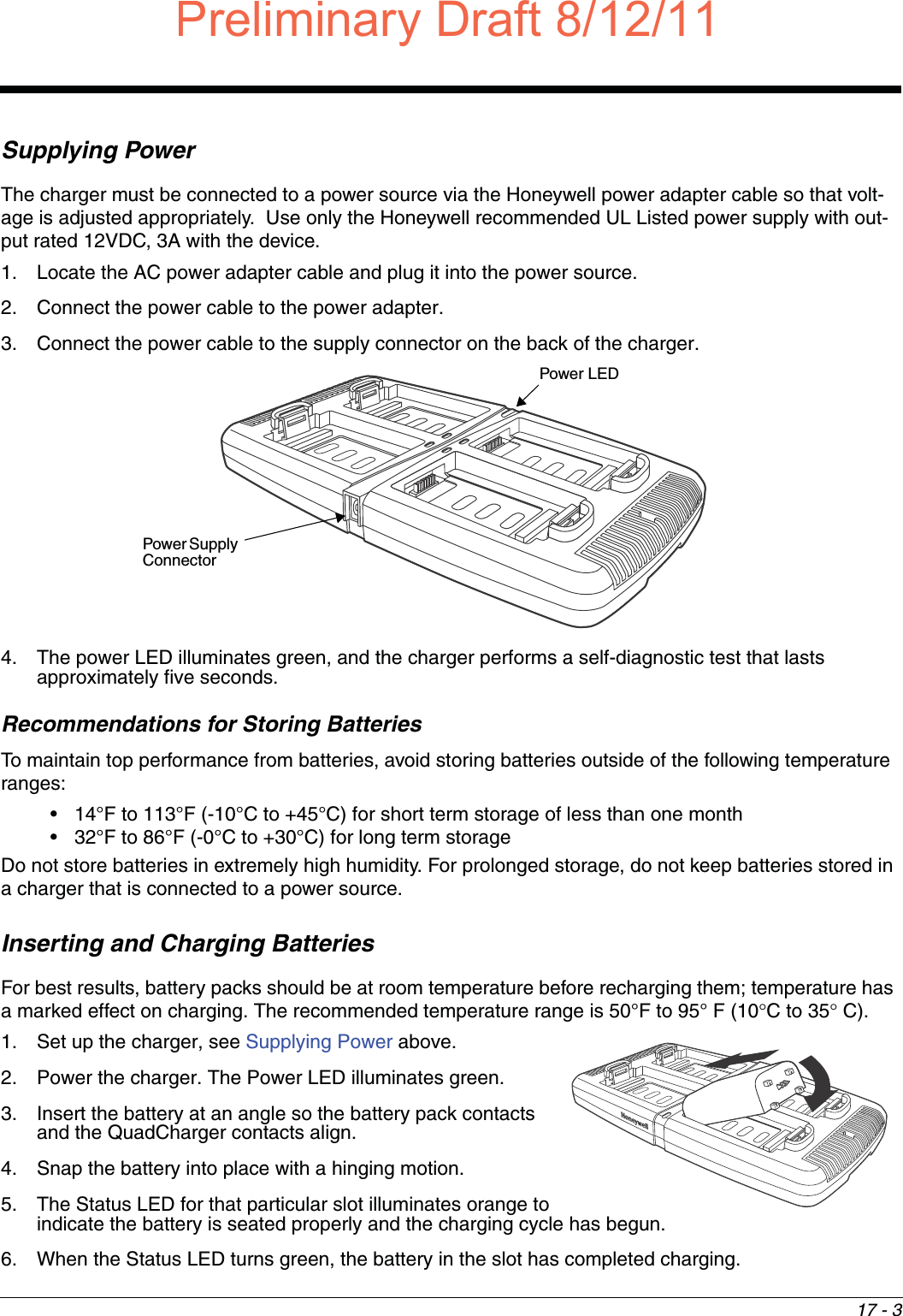
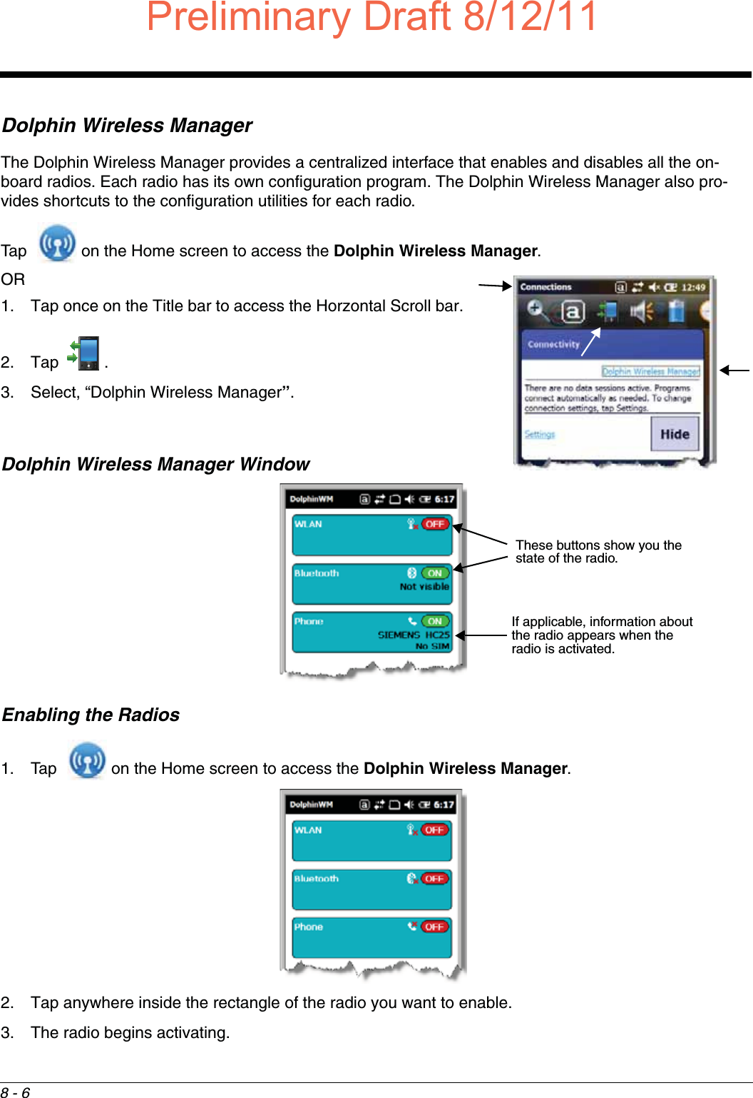
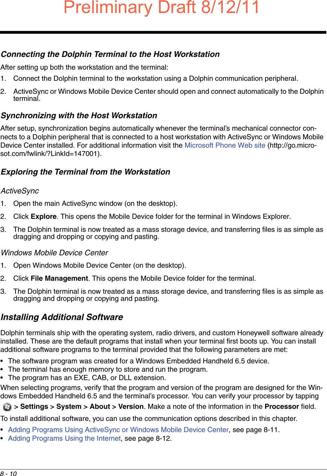
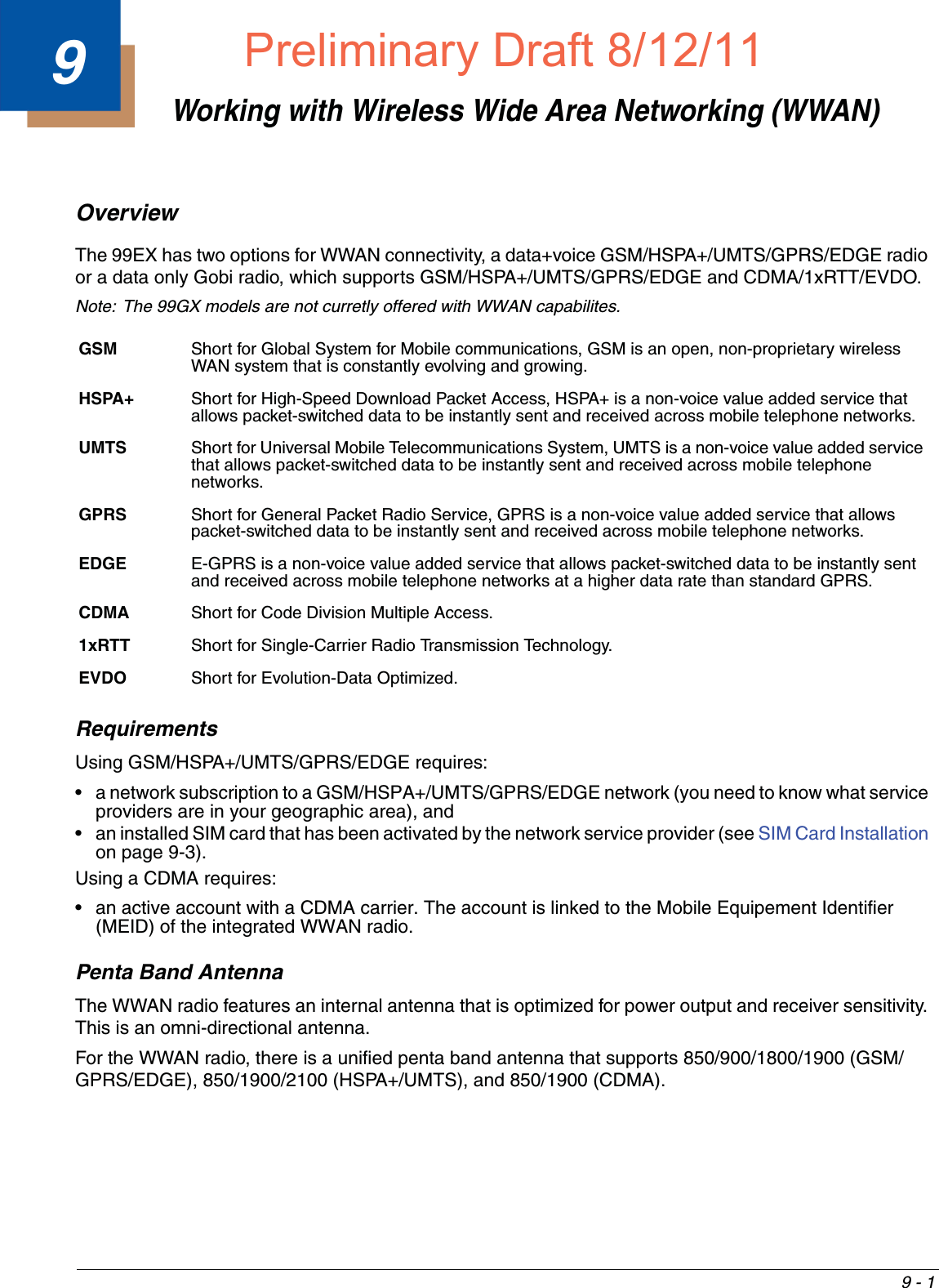
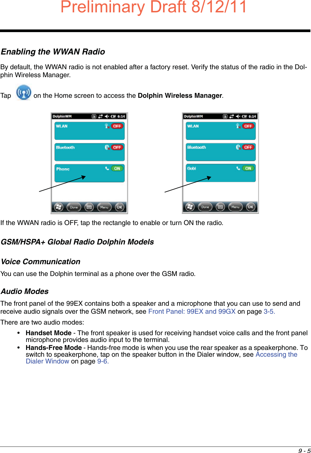
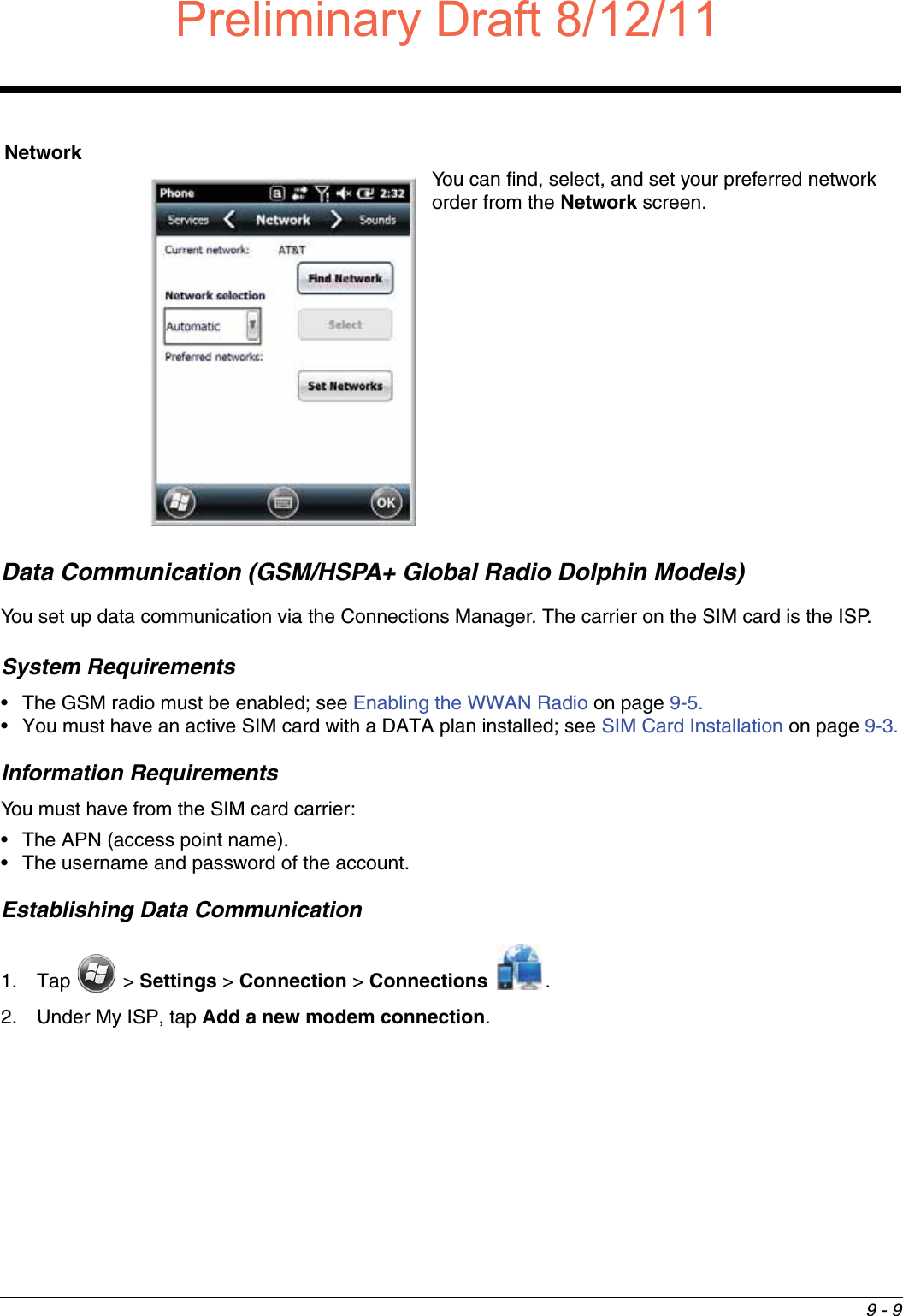
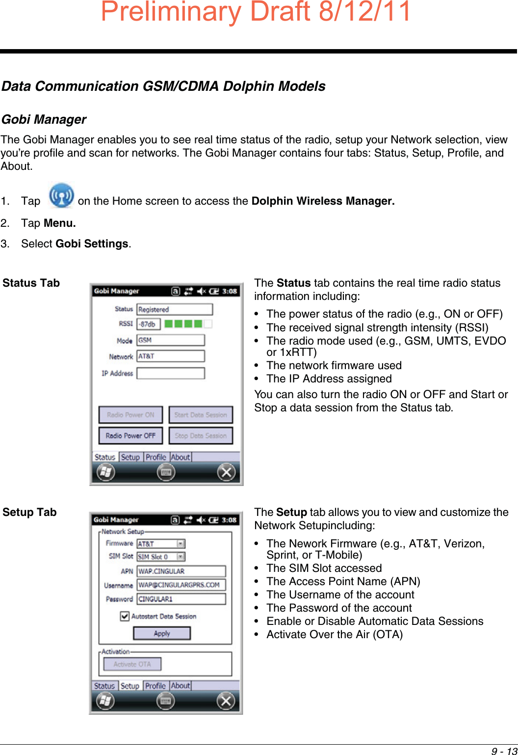
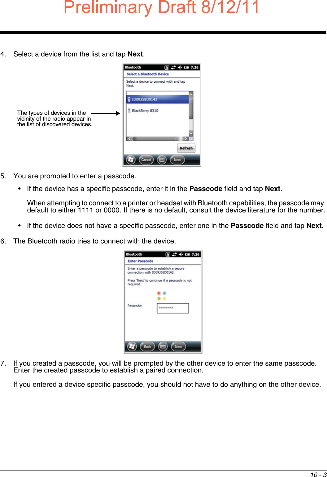
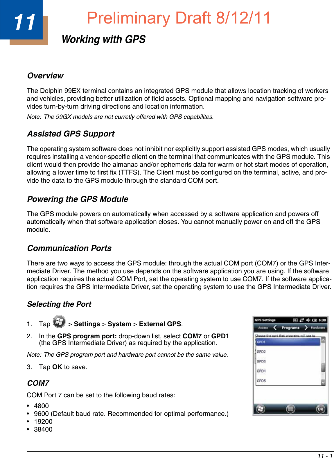
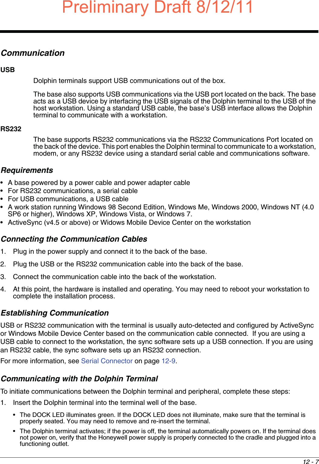
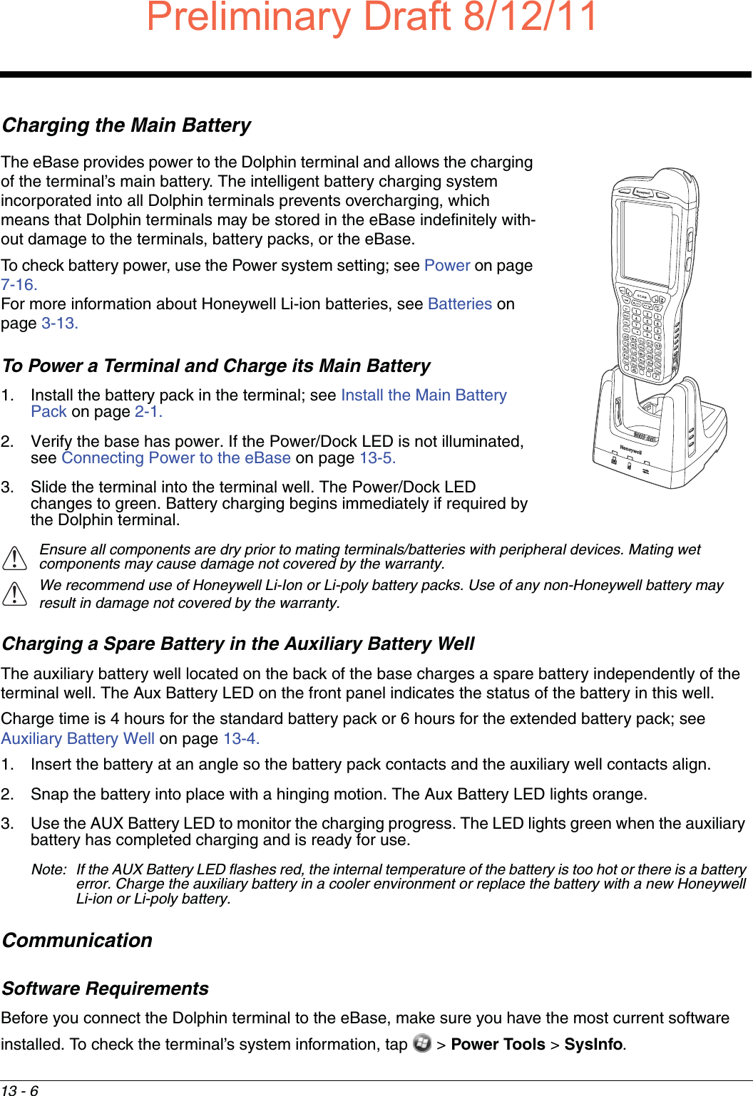
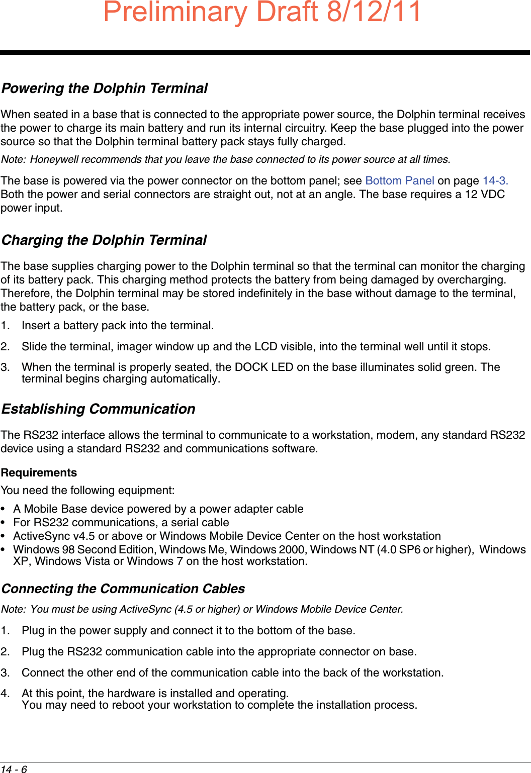
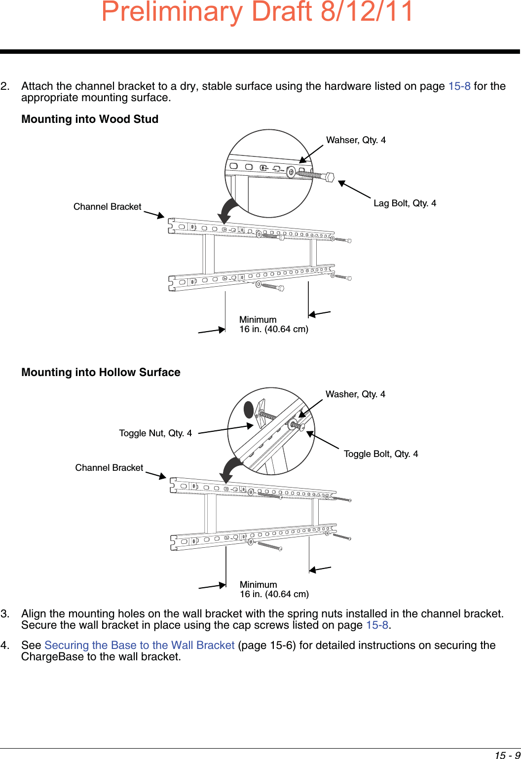
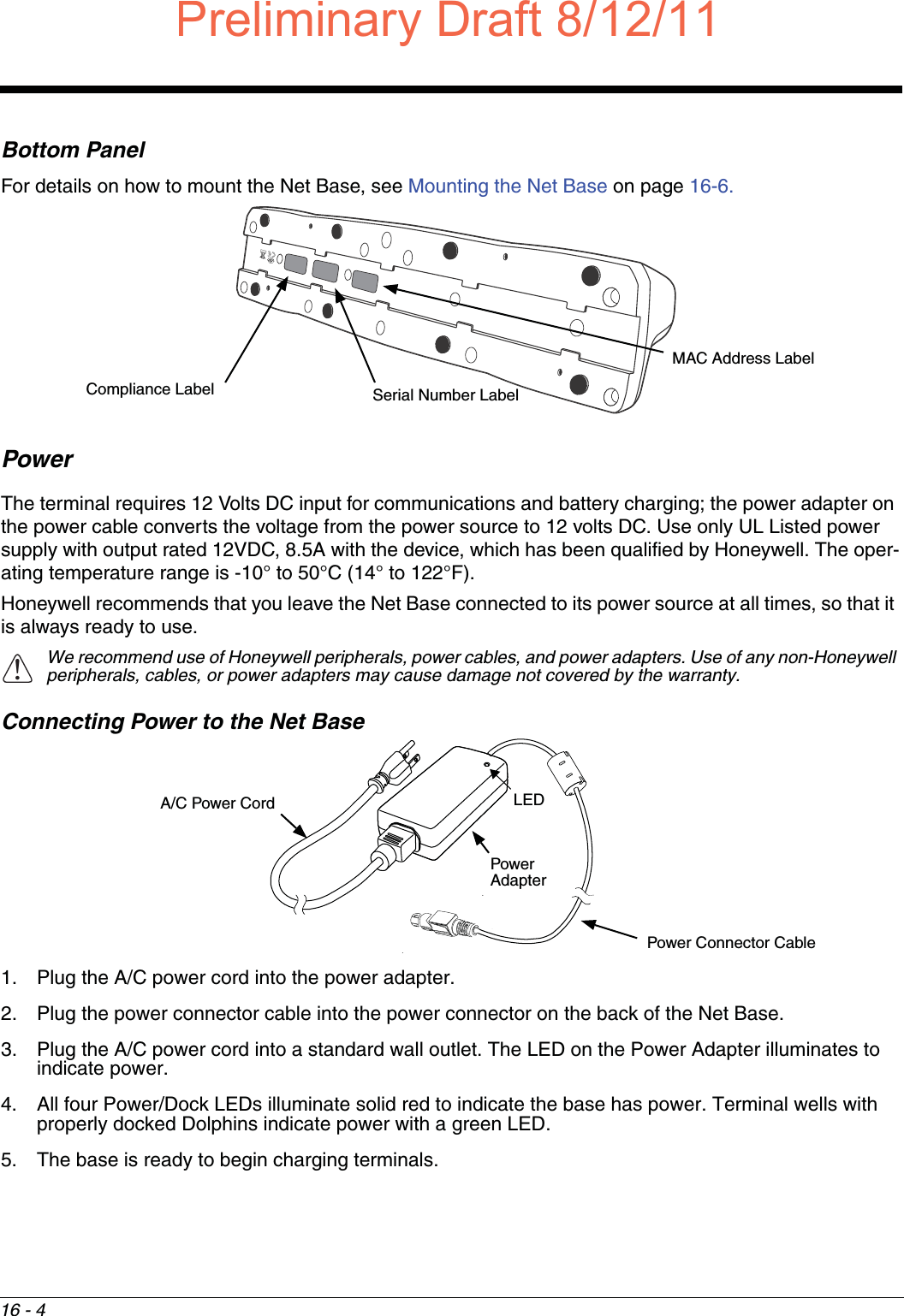
![17 - 4Mounting the QuadChargerThe charger should be on a dry, stable surface and can be mounted on a flat, horizontal surface such as a desktop or workbench. When choosing a location, always bear in mind that: • the mounting location must allow users easy access to the power connector.• the charger should be oriented so that users can easily insert and remove battery packs and see the LEDs.Bottom PanelDesk MountingThe DIN rail slot on the bottom panel enables secure mounting to a horizontal surface. Hardware Required• 3/16 in. dia x 5/8 in. long pan head screw• 1/2 in. OD x 7/32 in. ID x 3/64 in. thick• 3/16 in. dia nutInstalling the DIN Rail1. Slide the DIN rail into the DIN rail slot (7.5 X 35 mm) on the bottom of the QuadCharger. 2. Then, using the appropriate nuts and bolts listed above, secure the DIN rail to the desktop. DIN Rail SlotRubber Feet, Qty. 43.94 in.[10 cm]3.66 in.[9.3 cm]Optional Mounting Holes for M3 Self-Tapping Screws, Qty. 4DIN RailPreliminary Draft8/12/11Draft_99EX-UG_Rev-b-1.pdf 184 8/12/2011 4:14:06 PM](https://usermanual.wiki/Honeywell/99EXLG.User-Manual-2-of-2/User-Guide-1528834-Page-84.png)