Honeywell CCB02A CHARGE AND COMMUNICATION BASE User Manual UserMan
Honeywell International Inc CHARGE AND COMMUNICATION BASE UserMan
UserManual.wiki
>
Honeywell
>
CCB02A User Manual
UserMan
Navigation menu
Upload a User Manual
Namespaces
Wiki Guide
HTML
PDF
Info
Views
User Manual
Discussion / Help
Navigation
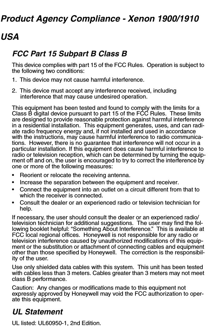

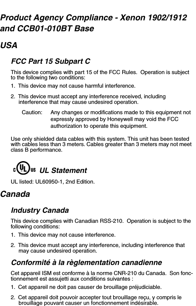
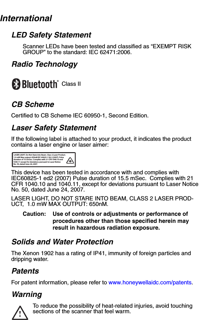
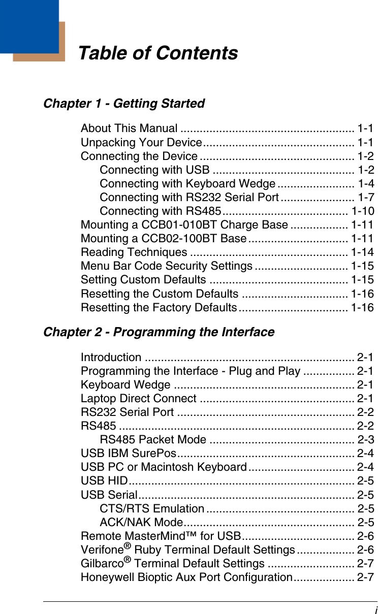
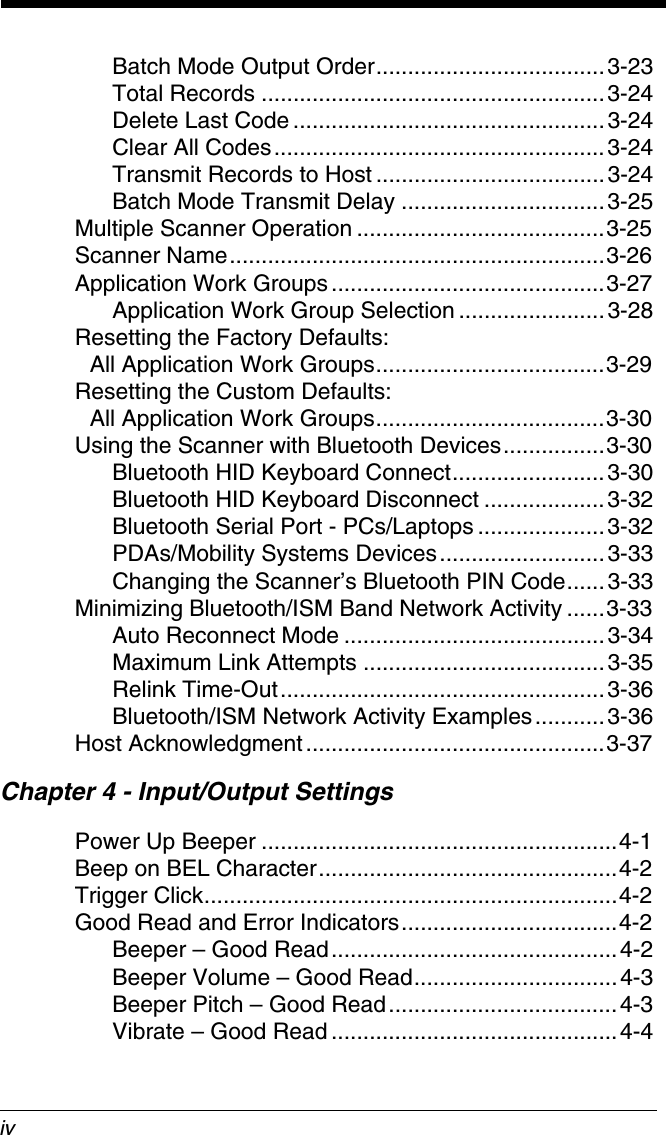
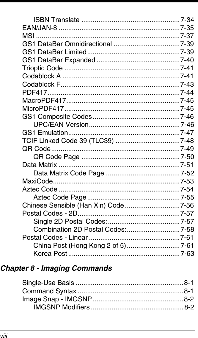

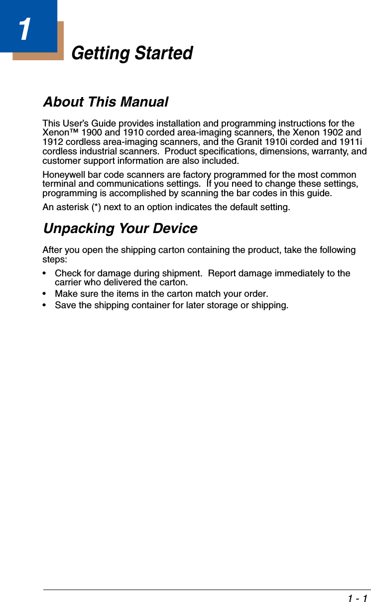
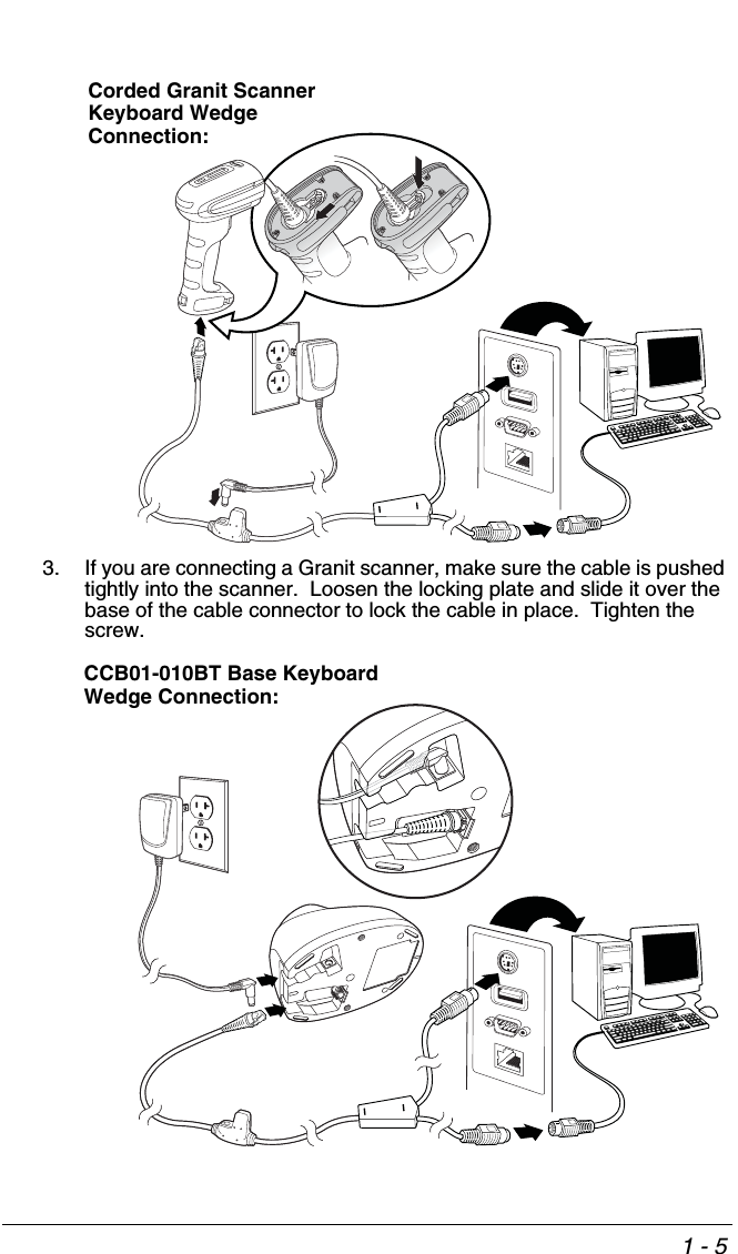
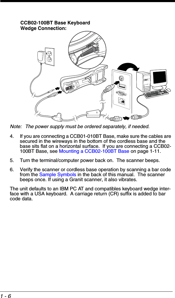
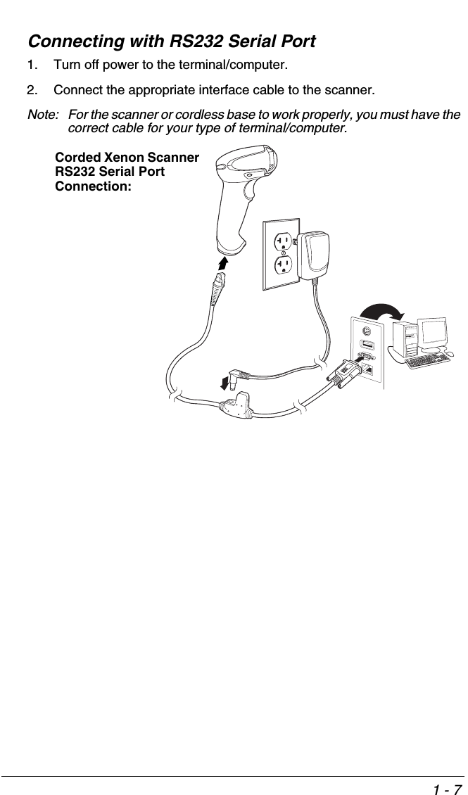
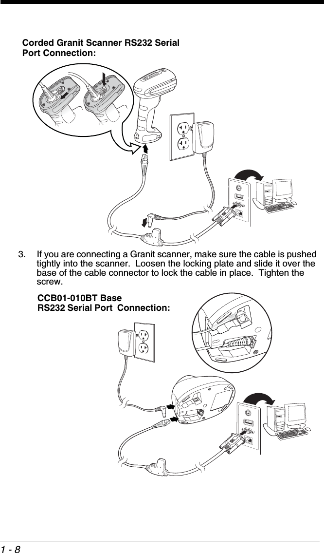
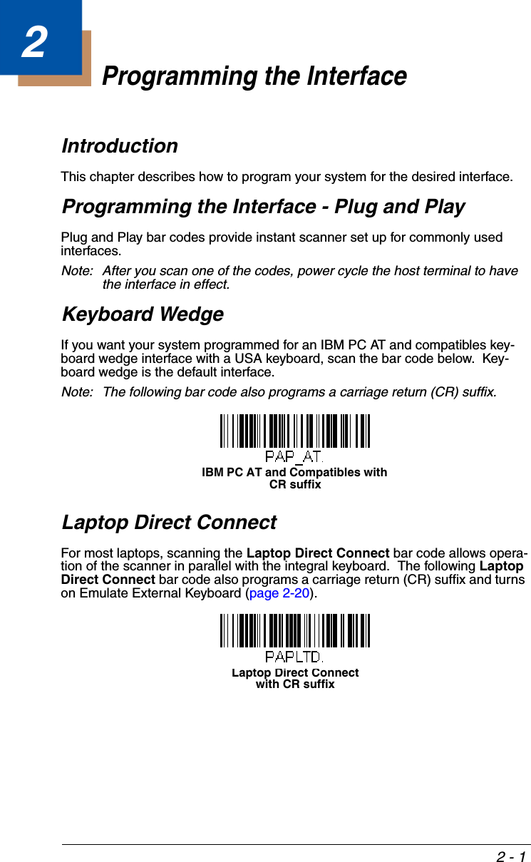
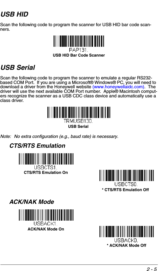
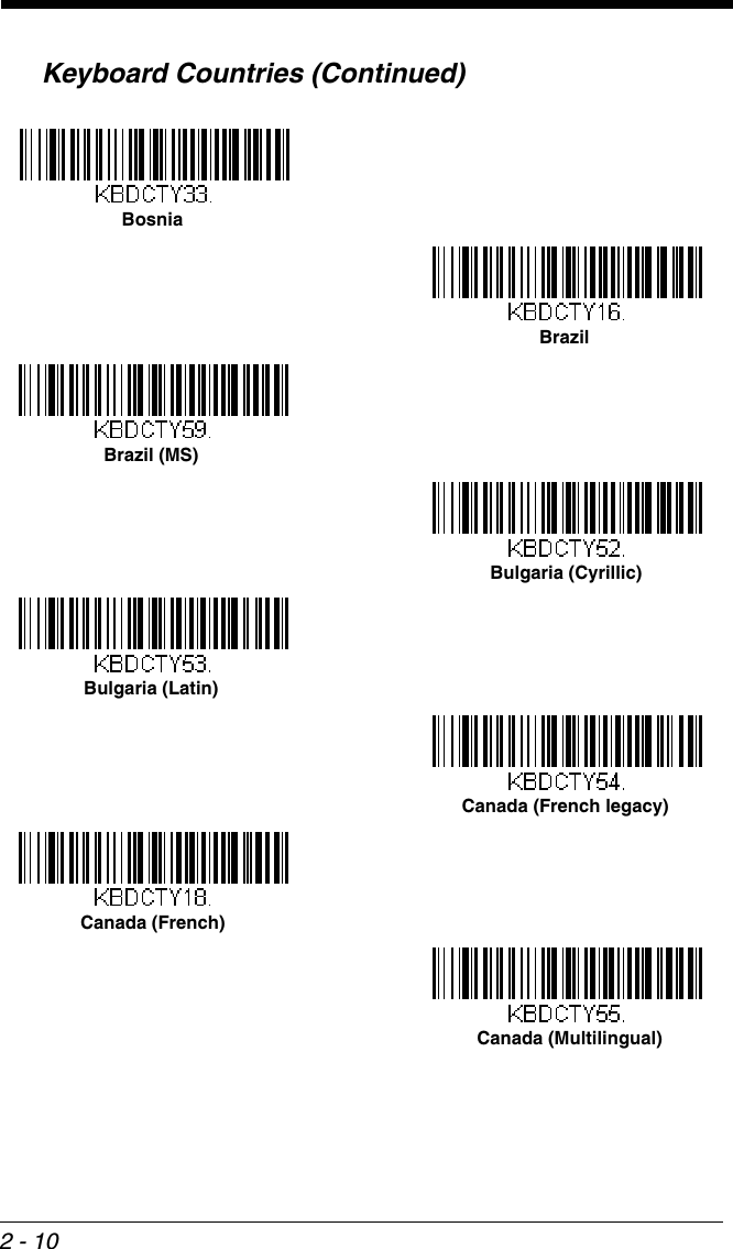
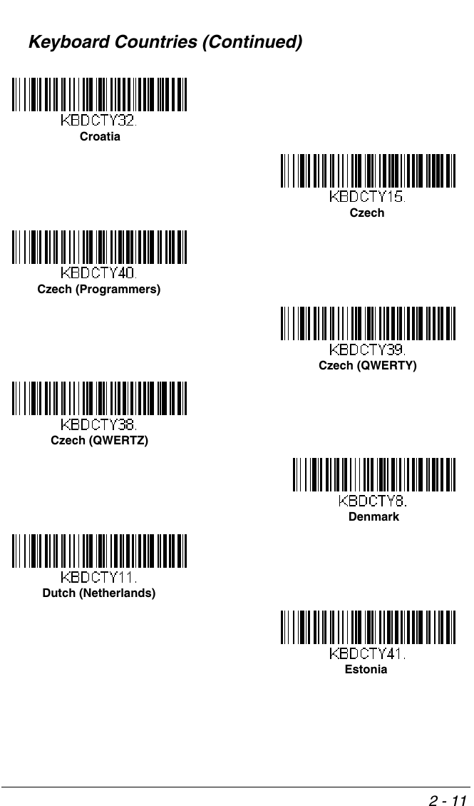
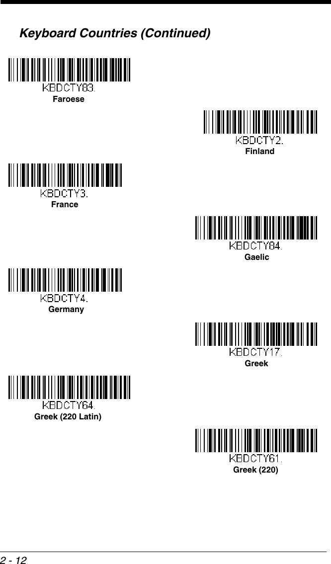
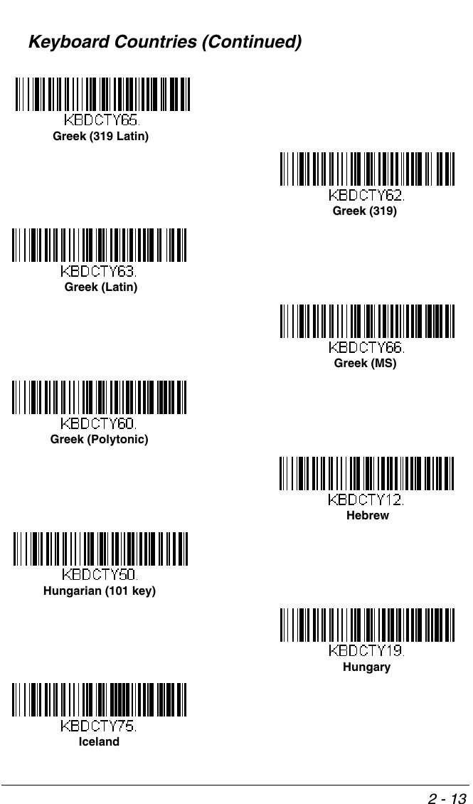
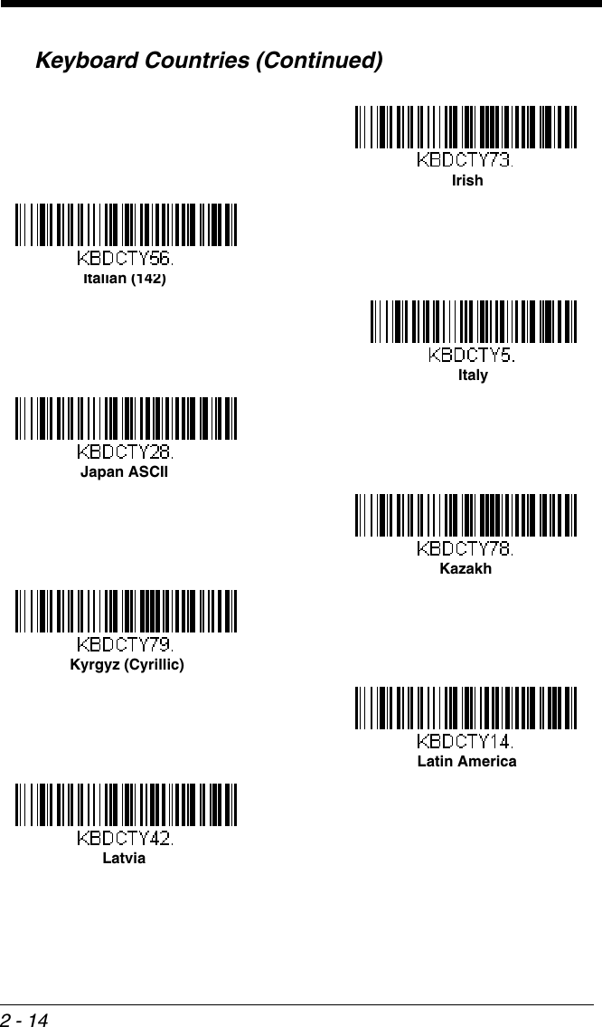
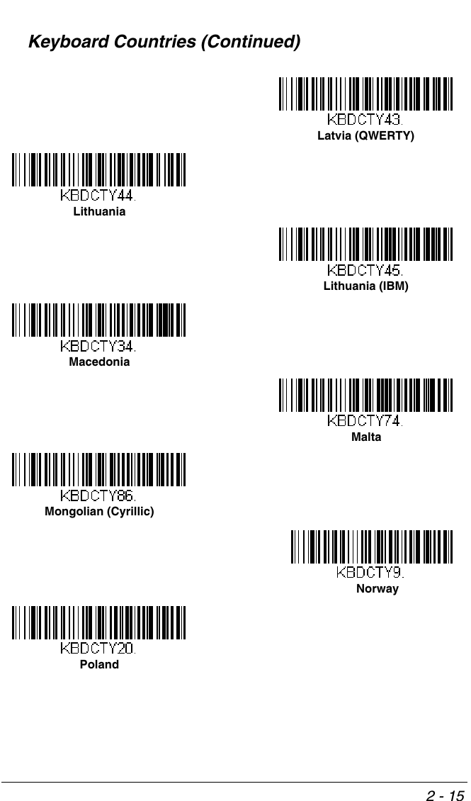
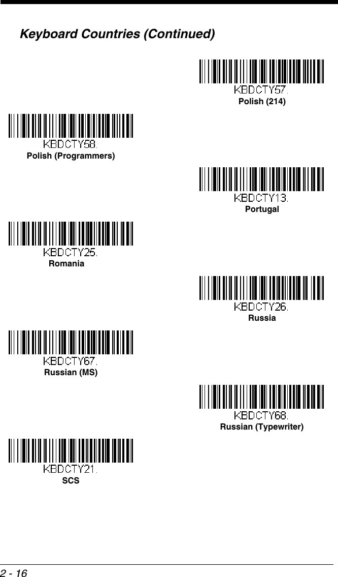
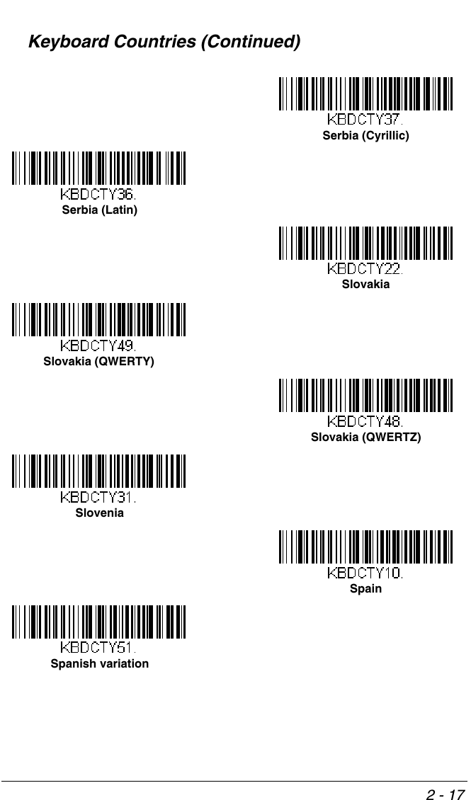
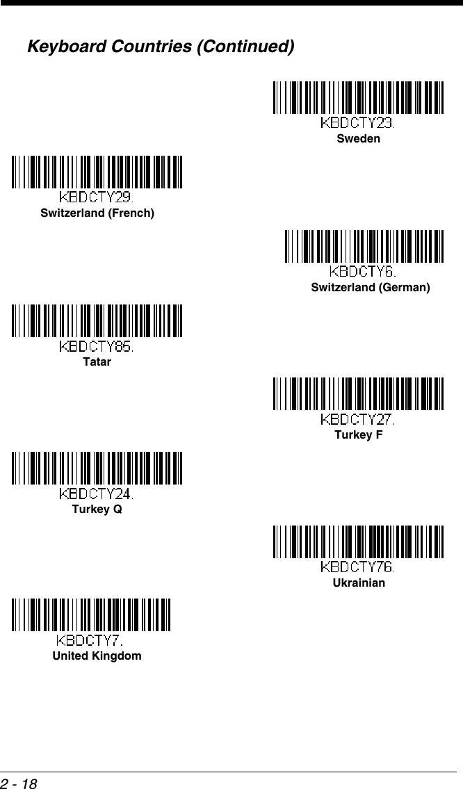
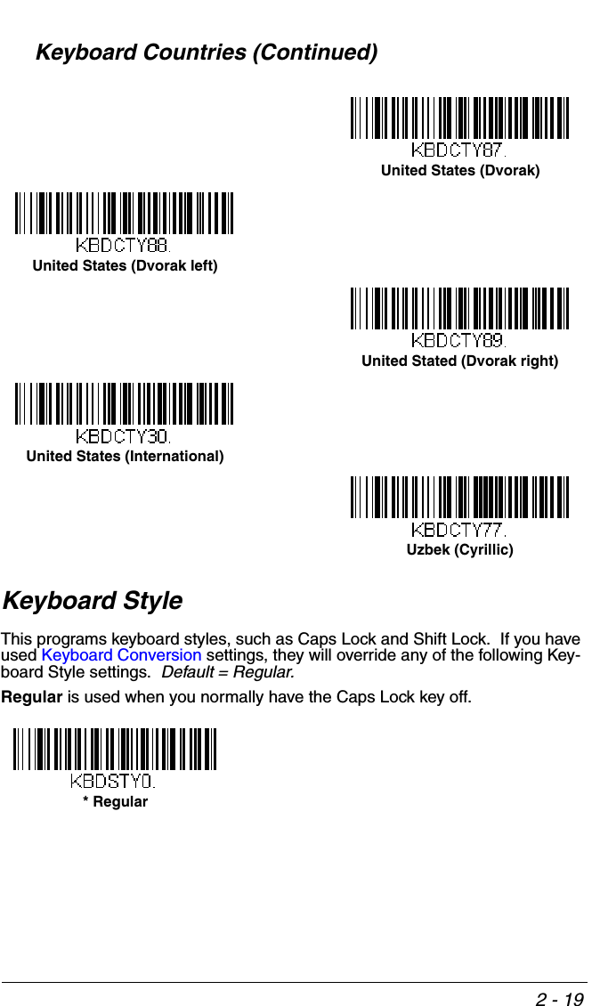
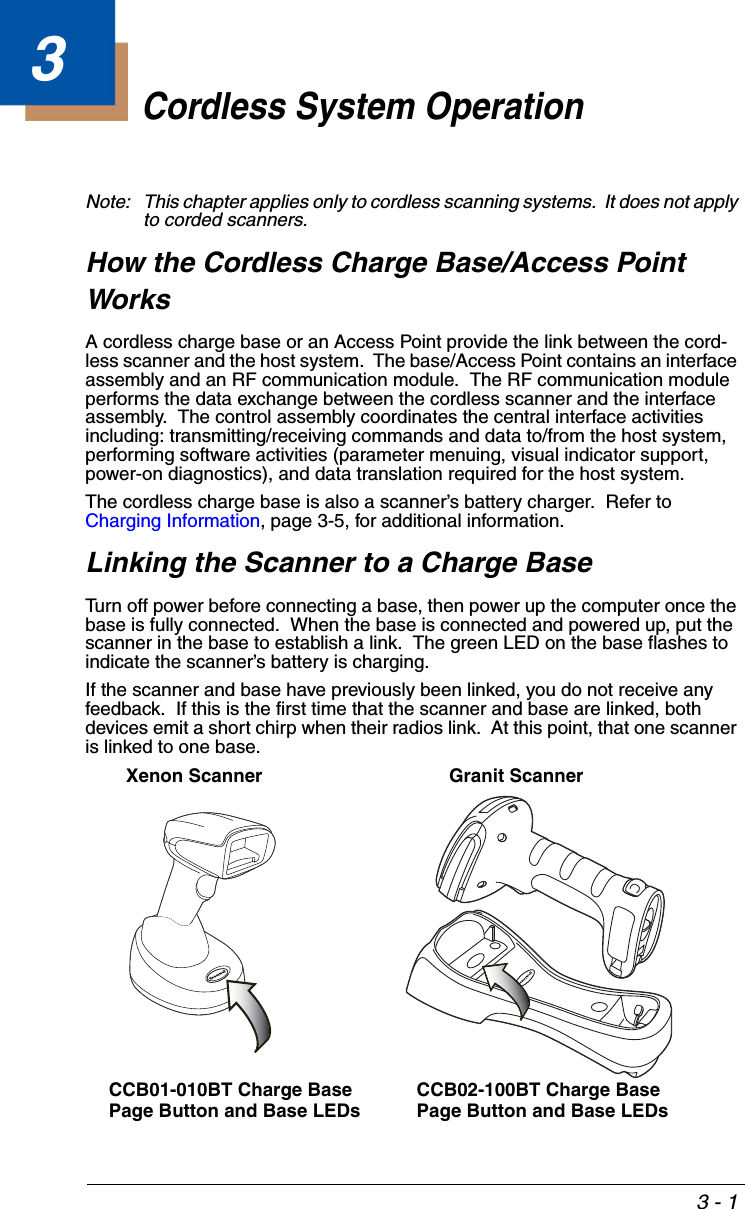
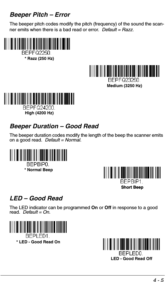
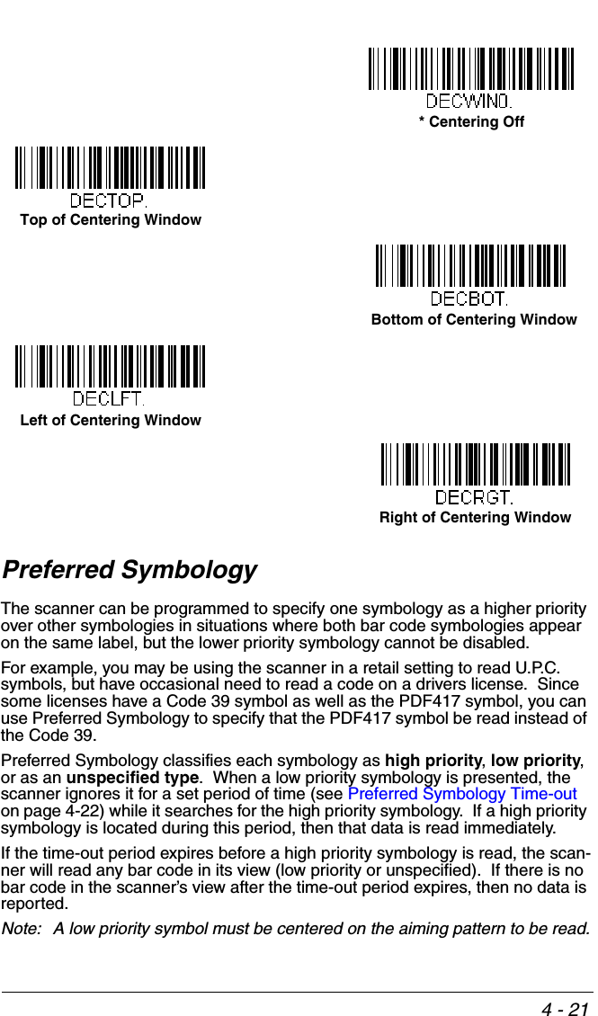
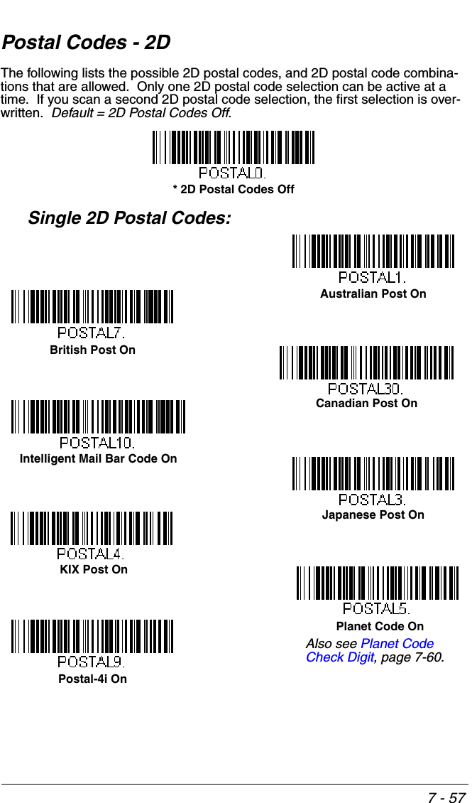
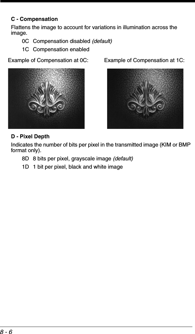
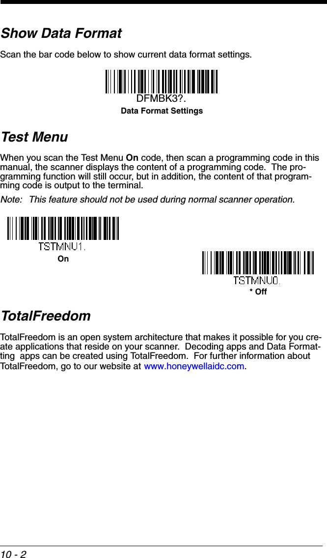
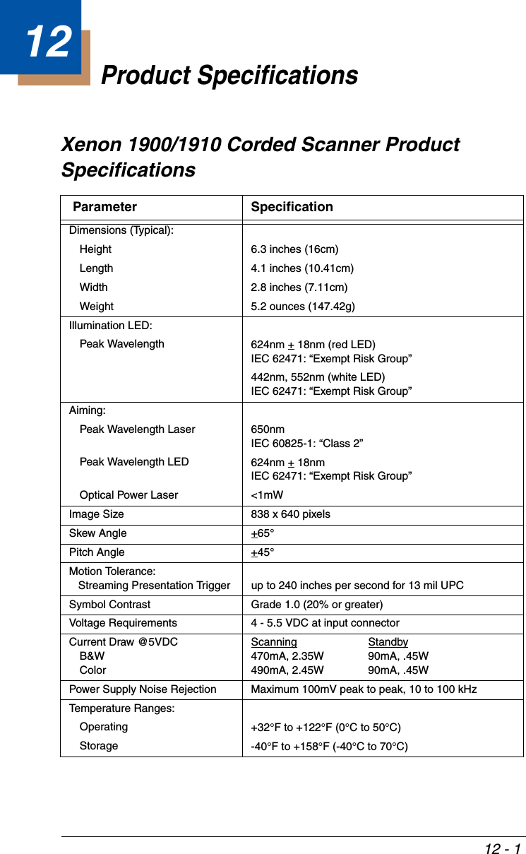
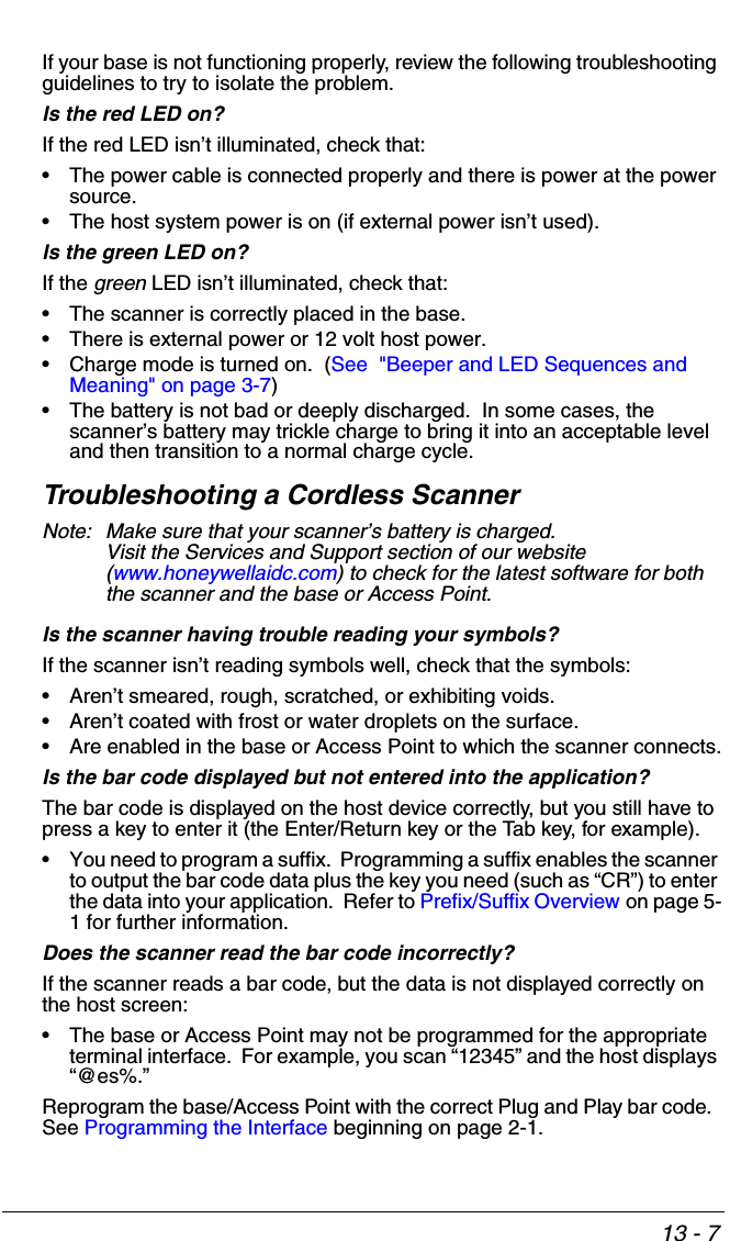
![2 - 9Keyboard Country LayoutScan the appropriate country code below to program the keyboard layout for your country or language. As a general rule, the following characters are sup-ported, but need special care for countries other than the United States:@ | $ # { } [ ] = / ‘ \ < > ~ Keyboard CountriesWincor Nixdorf Beetle Settings* United States AlbaniaAzeri (Cyrillic)Azeri (Latin)BelarusBelgium](https://usermanual.wiki/Honeywell/CCB02A/User-Guide-1911770-Page-61.png)
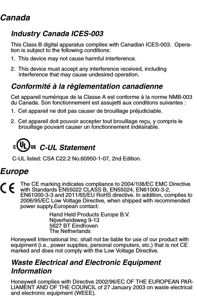
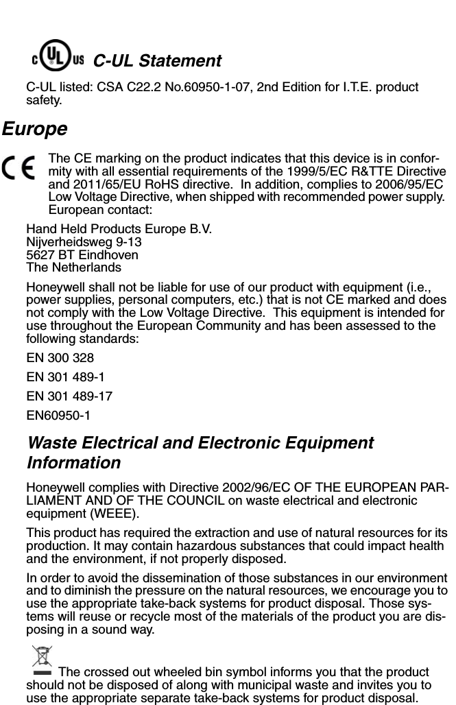
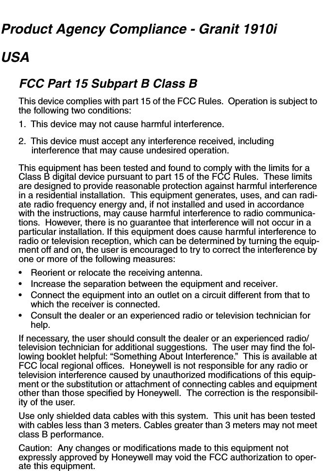
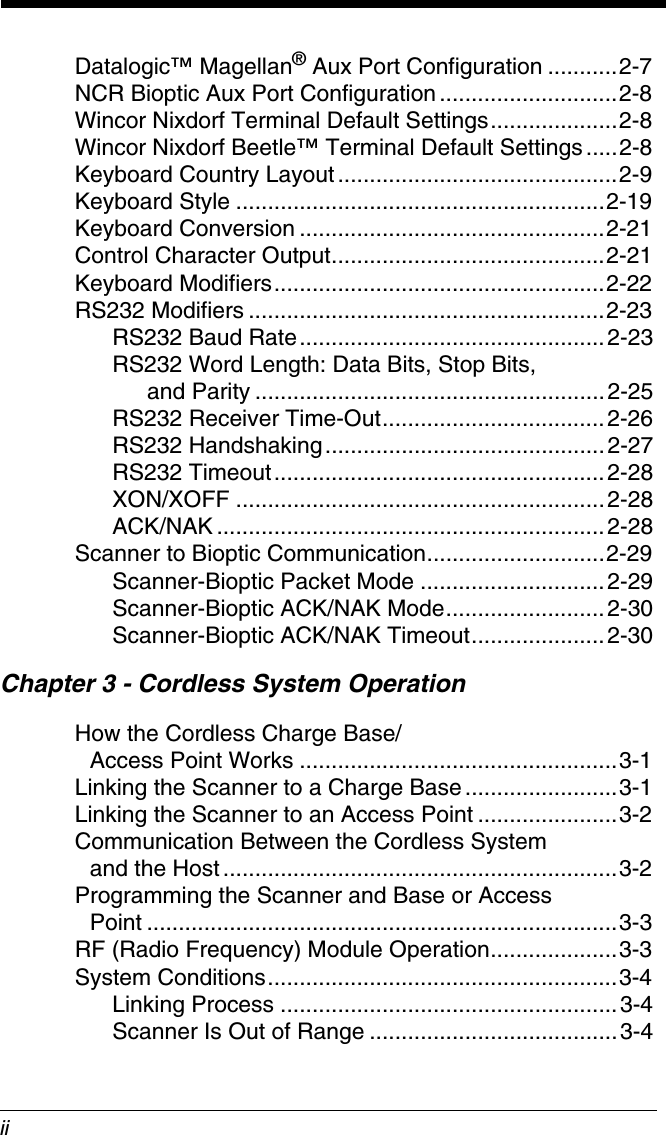
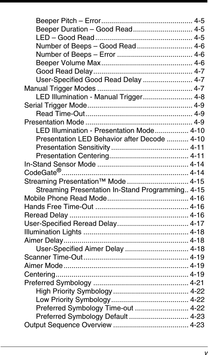
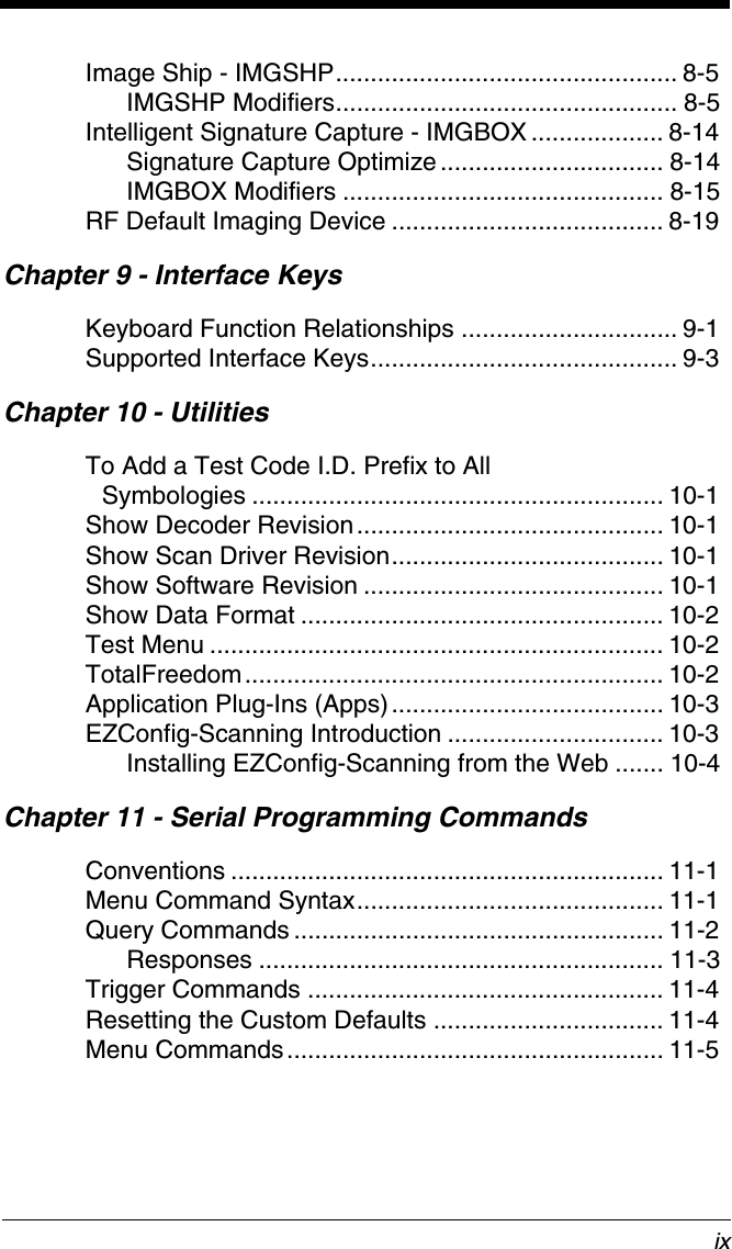
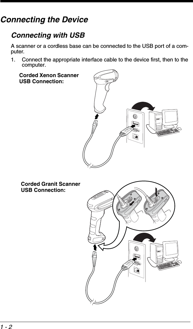
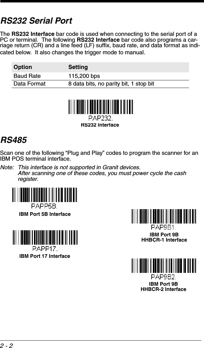
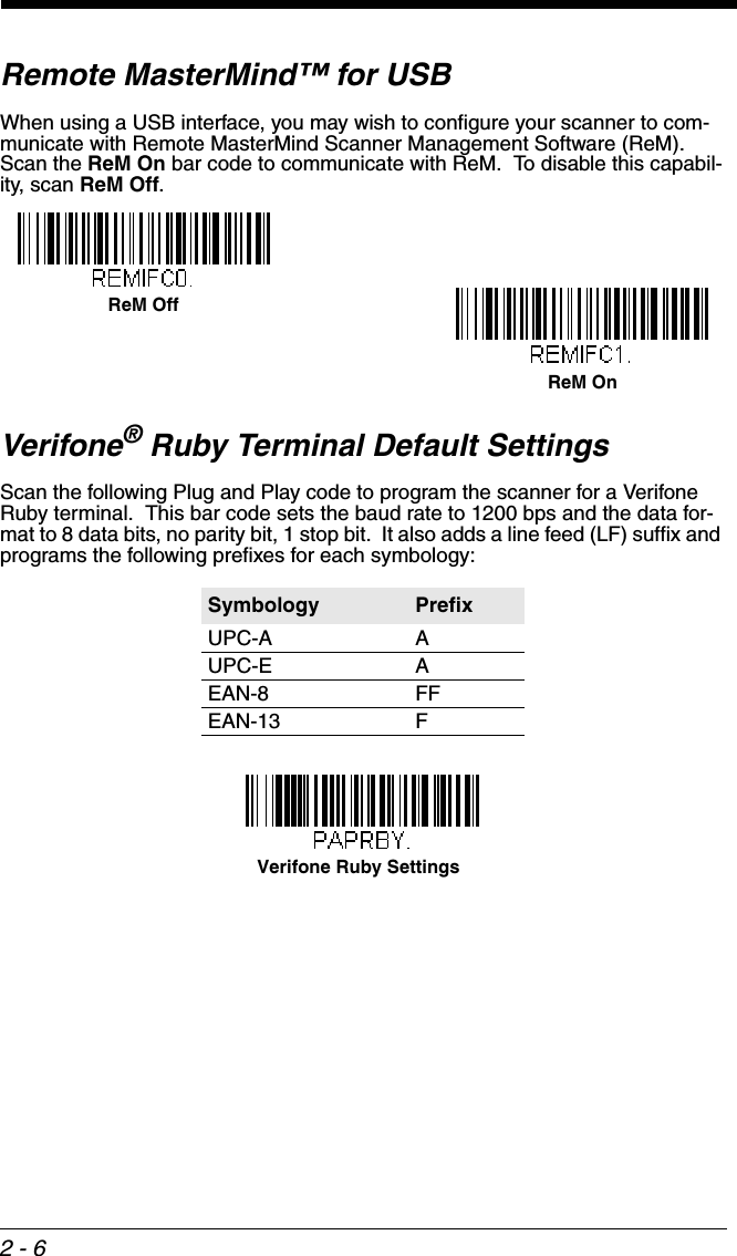
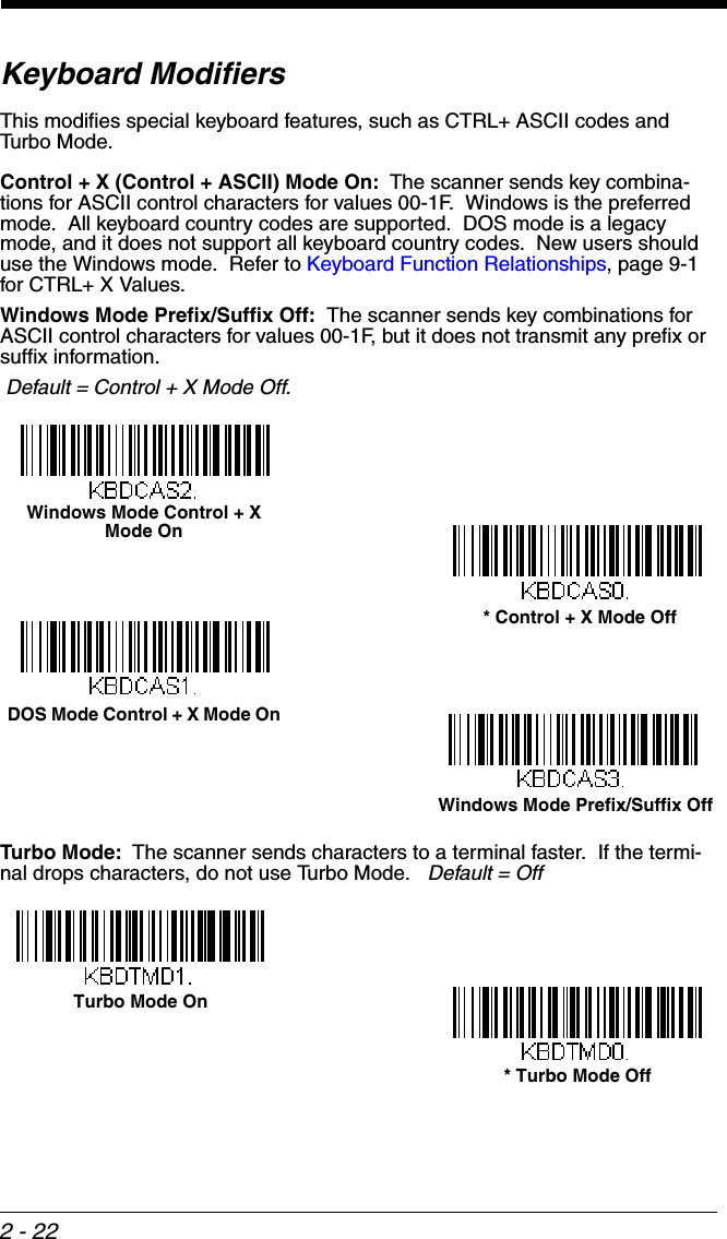
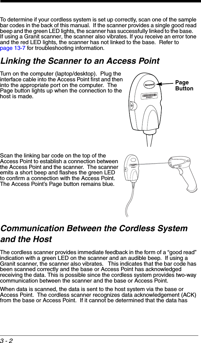
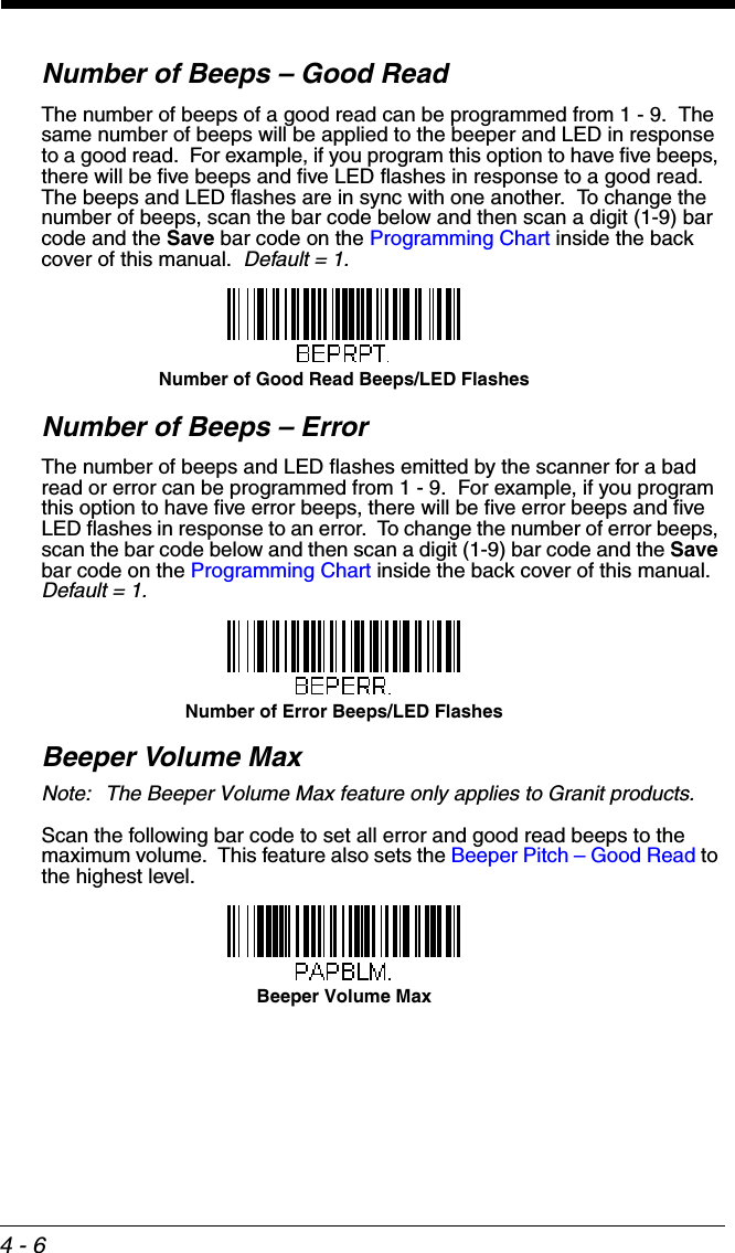
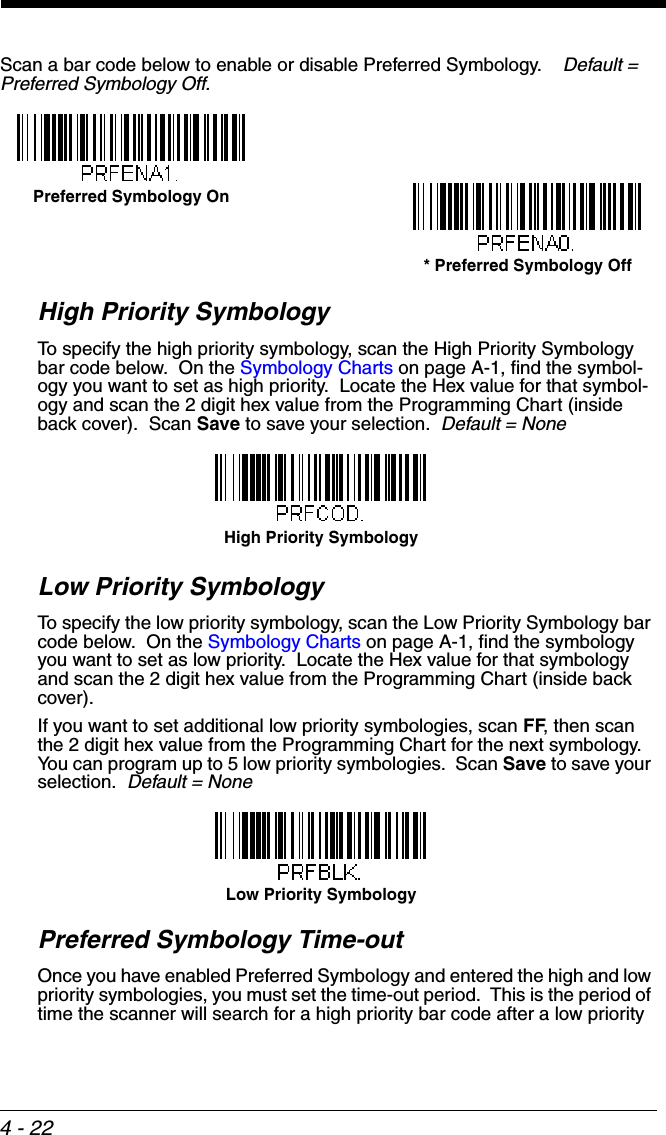
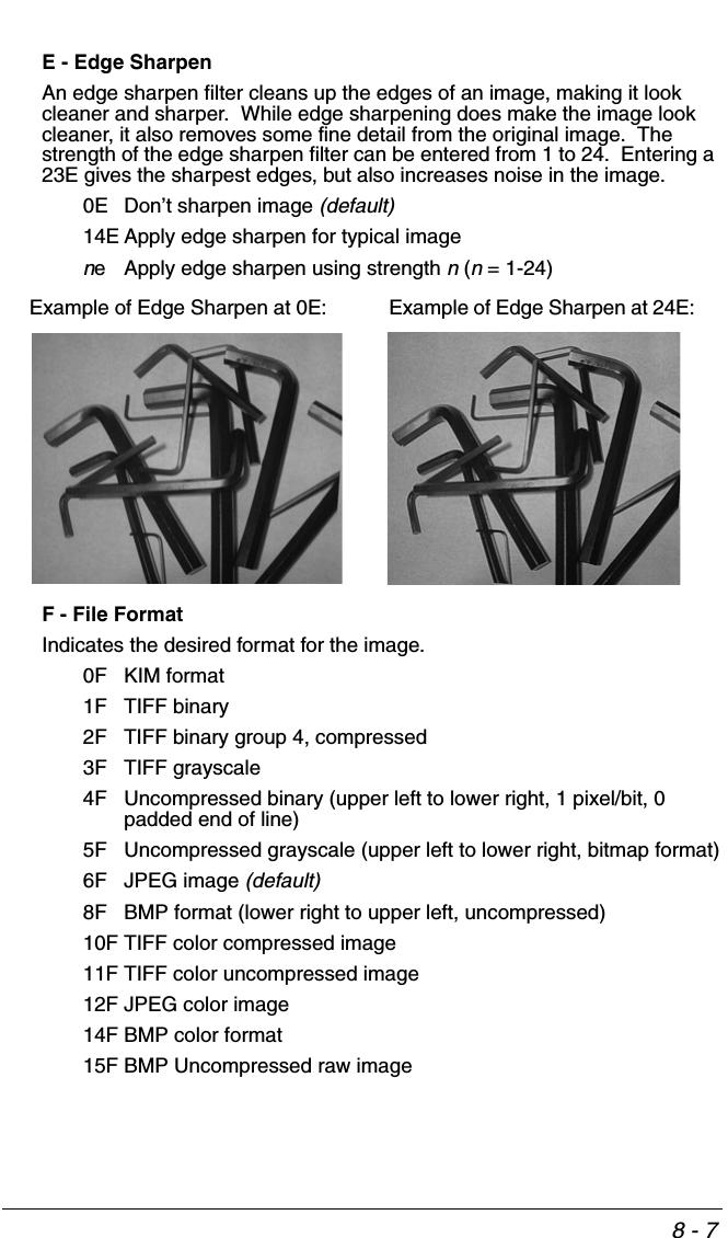
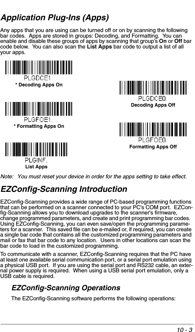
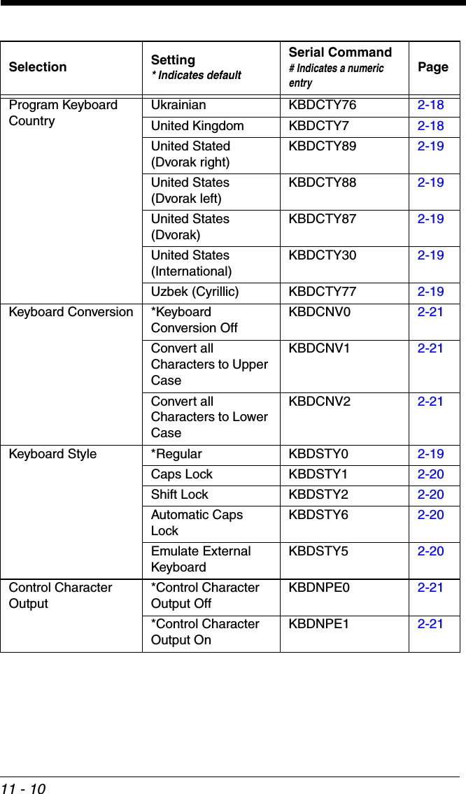
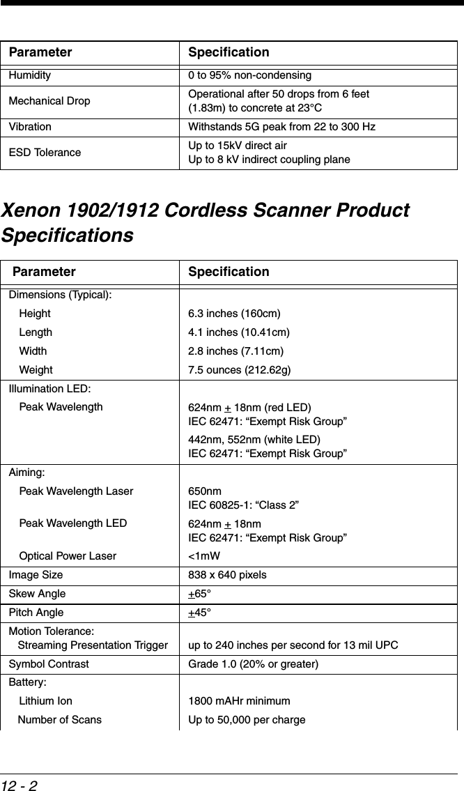
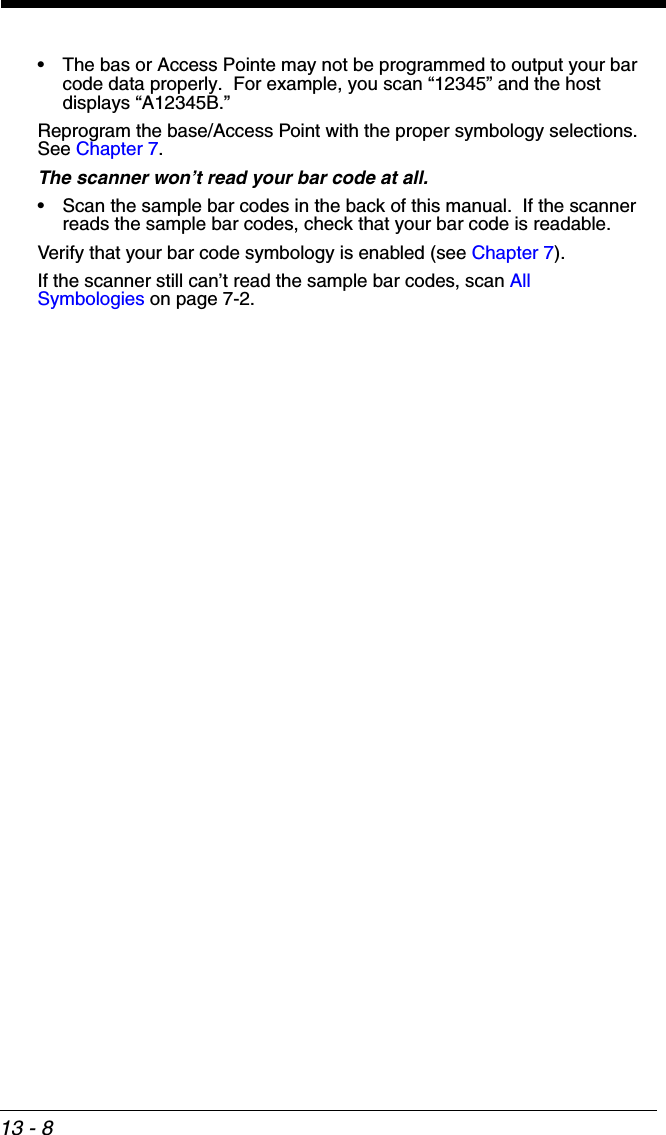
![2 - 21Keyboard ConversionAlphabetic keyboard characters can be forced to be all upper case or all lower-case. So if you have the following bar code: “abc569GK,” you can make the out-put “ABC569GK” by scanning Convert All Characters to Upper Case, or to “abc569gk” by scanning Convert All Characters to Lower Case. These settings override Keyboard Style selections. Note: If your interface is a keyboard wedge, first scan the menu code for Automatic Caps Lock (page 2-20). Otherwise, your output may not be as expected. Default = Keyboard Conversion Off. Control Character OutputThis selection sends a text string instead of a control character. For example, when the control character for a carriage return is expected, the output would display [CR] instead of the ASCII code of 0D. Refer to ASCII Conversion Chart (Code Page 1252) on page A-4. Only codes 00 through 1F are converted (the first column of the chart). Note: Control + X (Control + ASCII) Mode overrides this mode. Default = Off.* Keyboard Conversion OffConvert All Characters to Upper CaseConvert All Characters to Lower CaseControl Character Output On* Control Character Output Off](https://usermanual.wiki/Honeywell/CCB02A/User-Guide-1911770-Page-73.png)
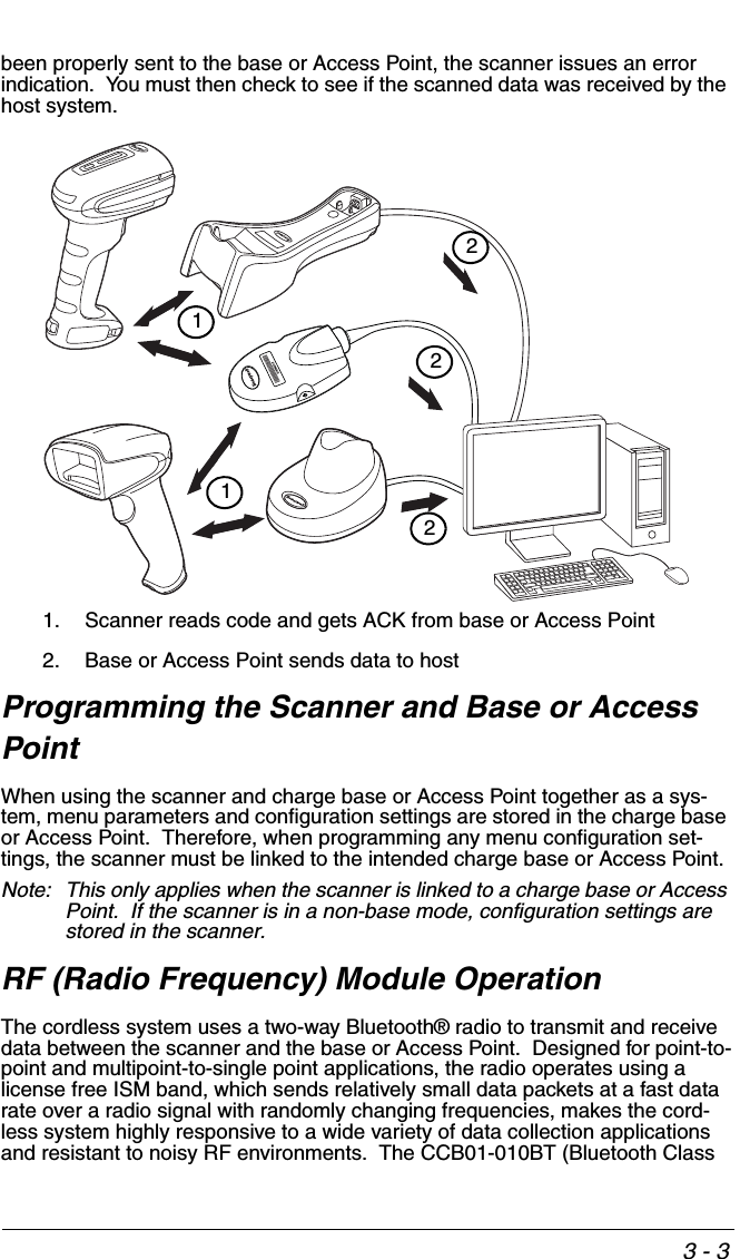
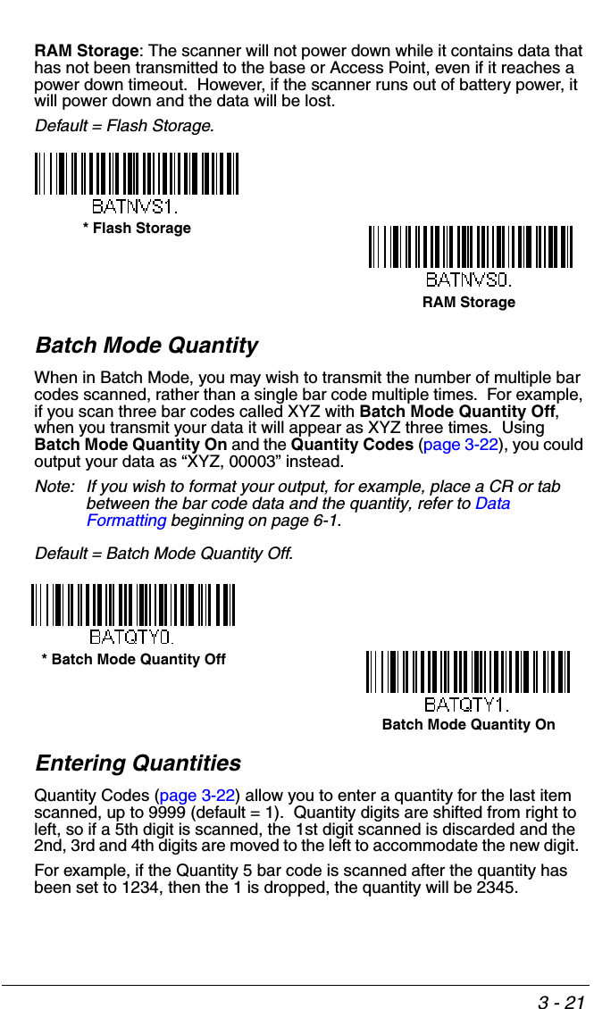
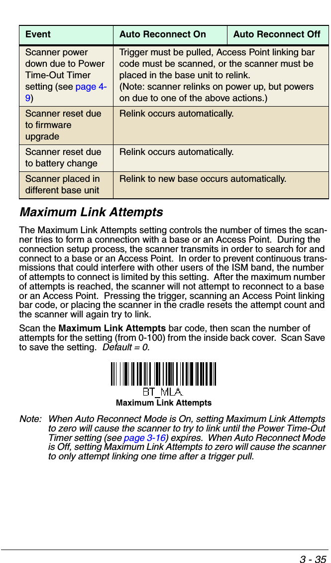
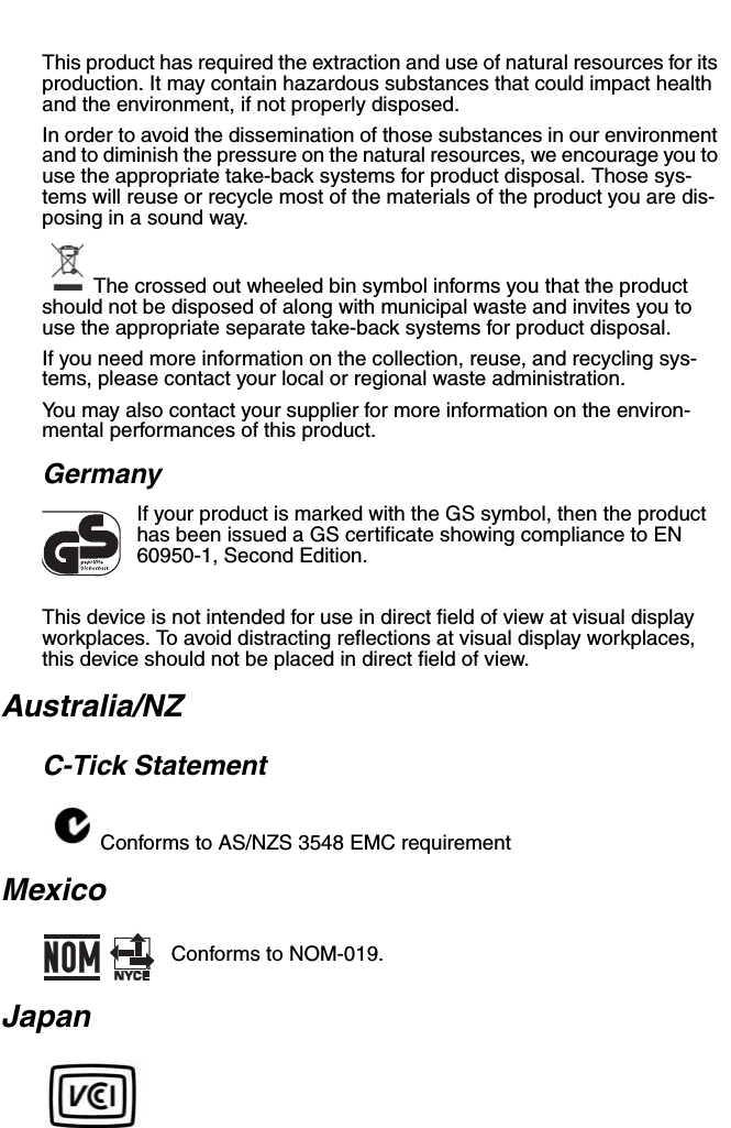
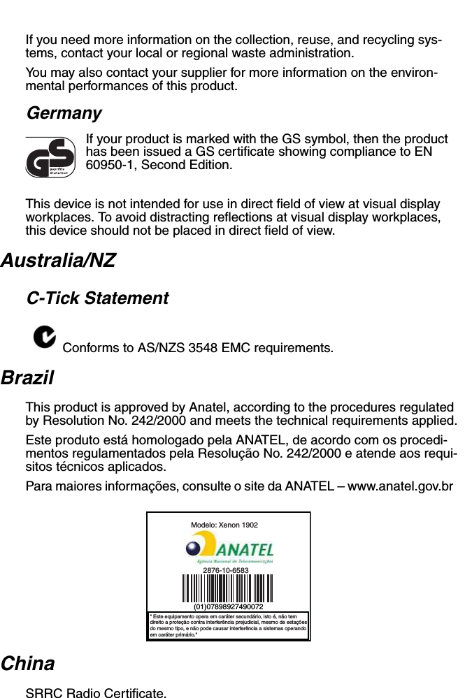
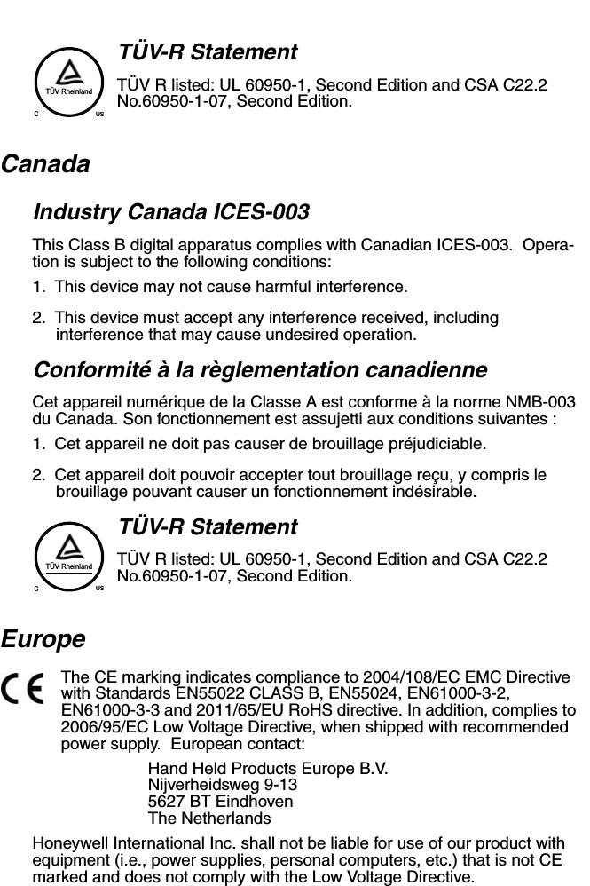
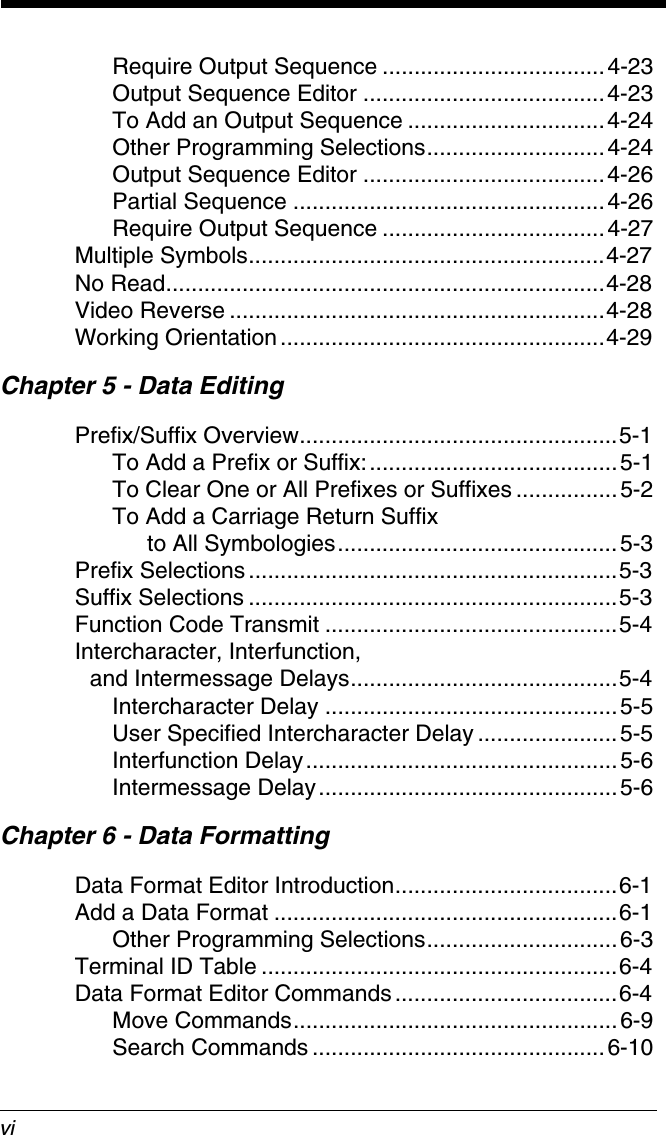
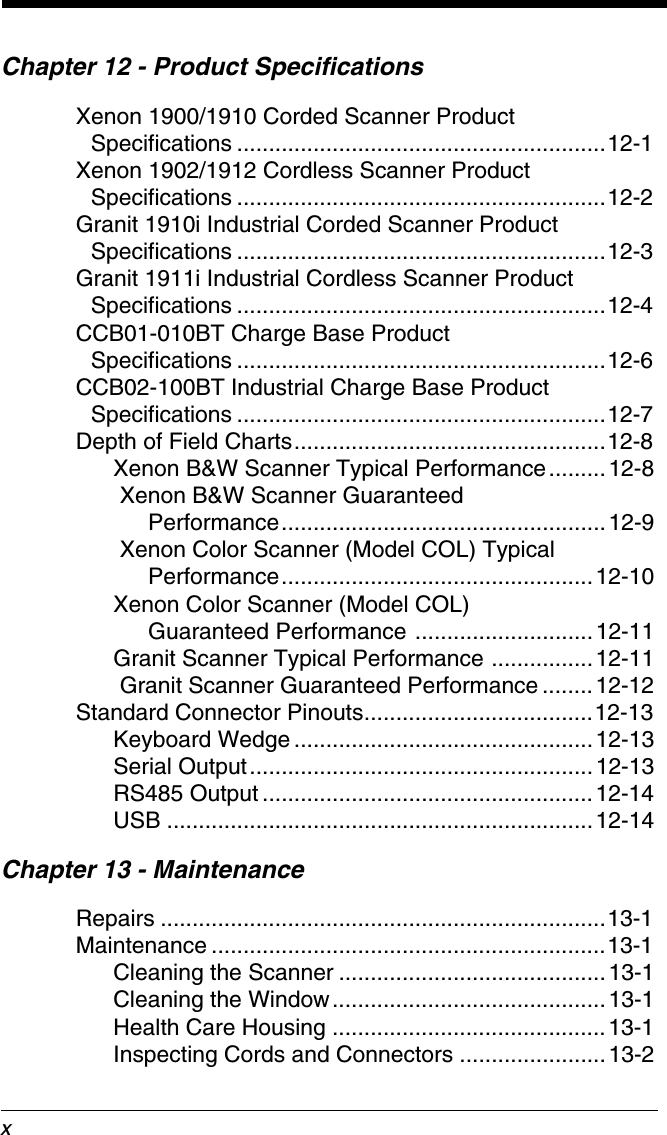
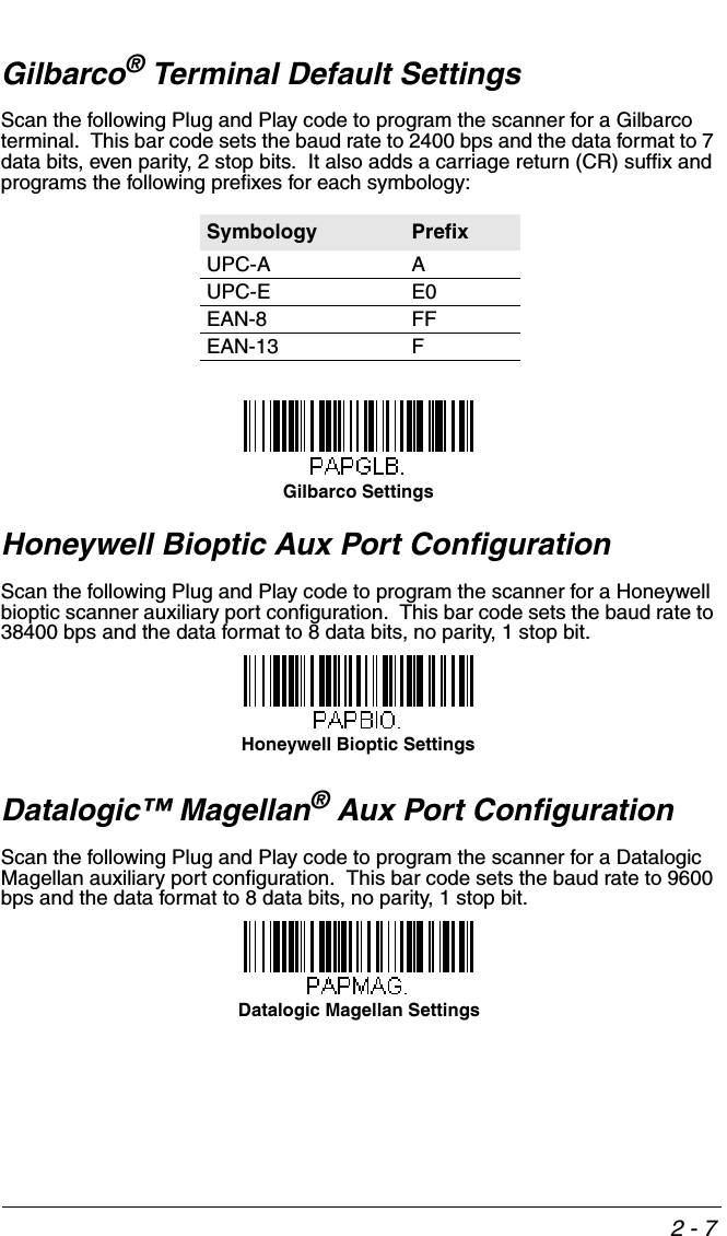
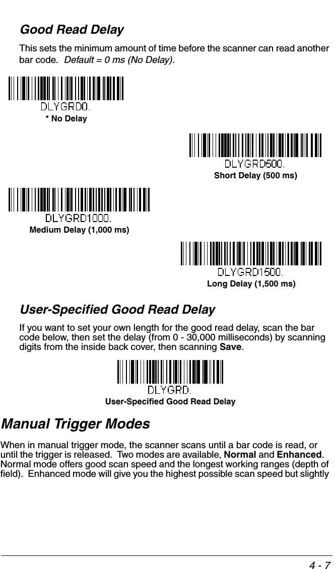
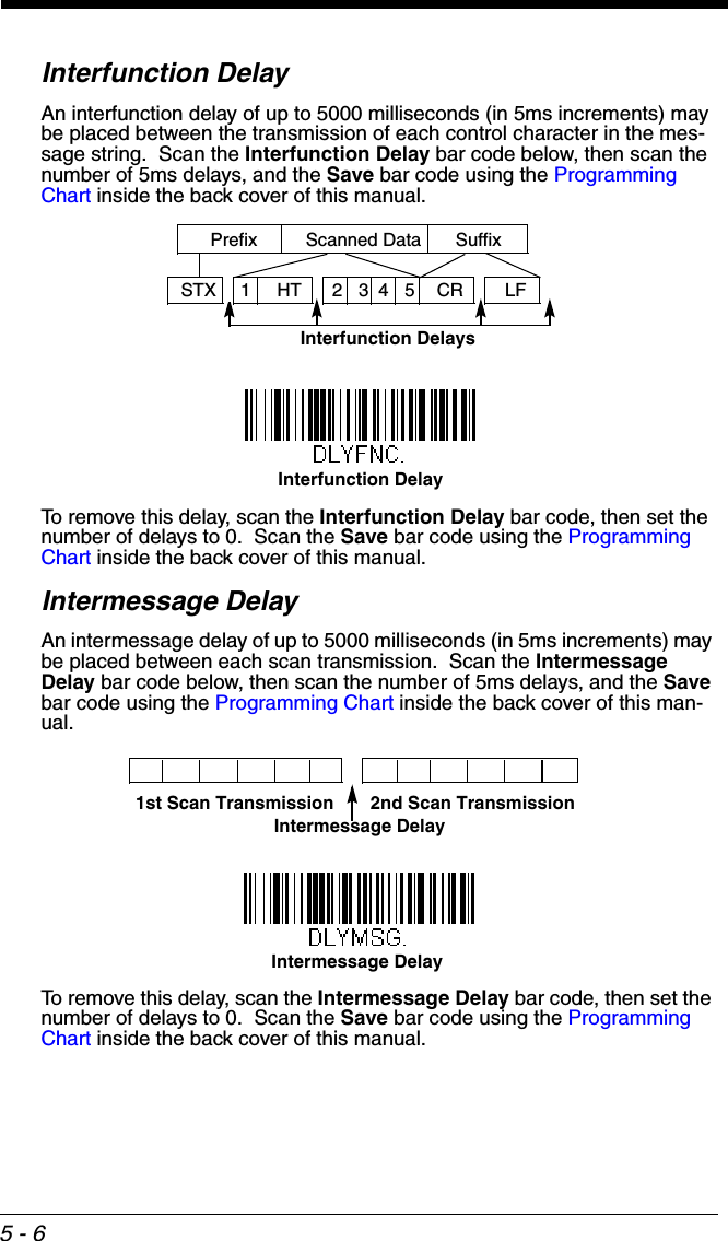
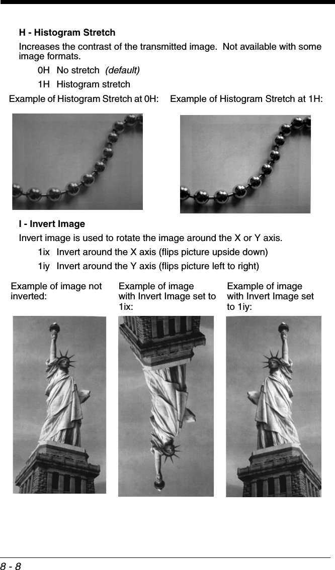
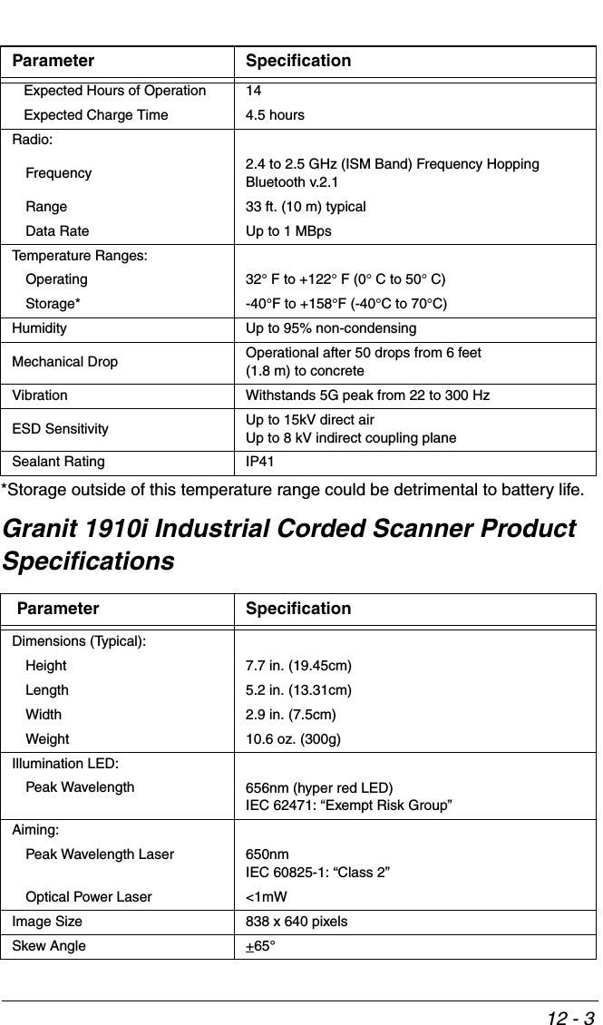
![3 - 37Auto Reconnect Mode set to 1Maximum Link Attempts set to 0 Relink Time-Out set to 10Scanner Power Time-Out Timer set to 1800Note: See Scanner Power Time-Out Timer on page 3-16.The scanner attempts to connect to the base or Access Point every 15 sec-onds, measured from one attempt start to the next attempt start. After one half hour, the scanner powers off.Host AcknowledgmentSome applications require that the host terminal (or server) validate incoming bar code data (database look-up) and provide acknowledgement to the scanner whether or not to proceed. In Host ACK Mode, the scanner waits for this acknowledgement after each scan. Visual and audible acknowledgements pro-vide valuable feedback to the scan operator. The Host ACK functionality is con-trolled via a number of pre-defined escape commands that are sent to the scanner to make it behave in different ways.Note: System performance degrades when using Host ACK at rates lower than 9600 baud.The following criteria must be met for the Host ACK to work correctly:• The cordless system must be configured for Host Port RS232 (terminal ID = 000) or USB COM Emulation (terminal ID = 130).• RTS/CTS is defaulted off. You must enable it if the host system requires it.• Host ACK must be set to On (page 3-38). • A comma must be used as a terminator.• The host terminal software must be capable of interpreting the bar code data, make decisions based on the data content, and send out appropriate escape commands to the scanner.Escape commands are addressed to the scanner via “Application Work Groups.” Once a command is sent, all scanners in a group respond to that com-mand. Because of this, it is recommended that each scanner is assigned to its own group in Host ACK mode.The commands to which the scanner responds are listed on page 3-38. The [ESC] is a 1B in hex. A typical command string is y [ESC] x, where “y” is the application work group number, “[ESC] x” is the escape command, and the comma is the terminator, which is required. (When “y” is not specified, the com-mand is sent to the default Application Work Group 0.)Example: Commands may be strung together to create custom response sequences. An example of a command string is listed below.0[ESC]4,[ESC]5,[ESC]6,The above example will make a scanner that is in application work group zero beep low, then medium, then high.](https://usermanual.wiki/Honeywell/CCB02A/User-Guide-1911770-Page-119.png)
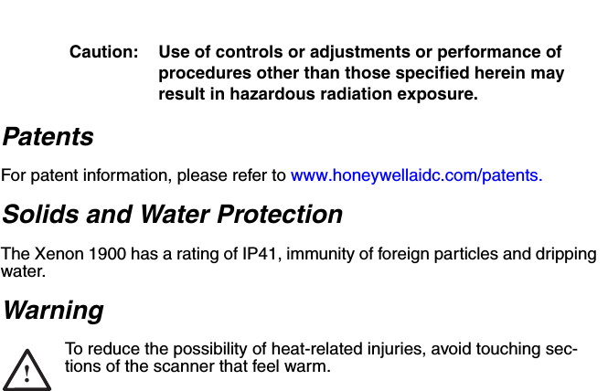
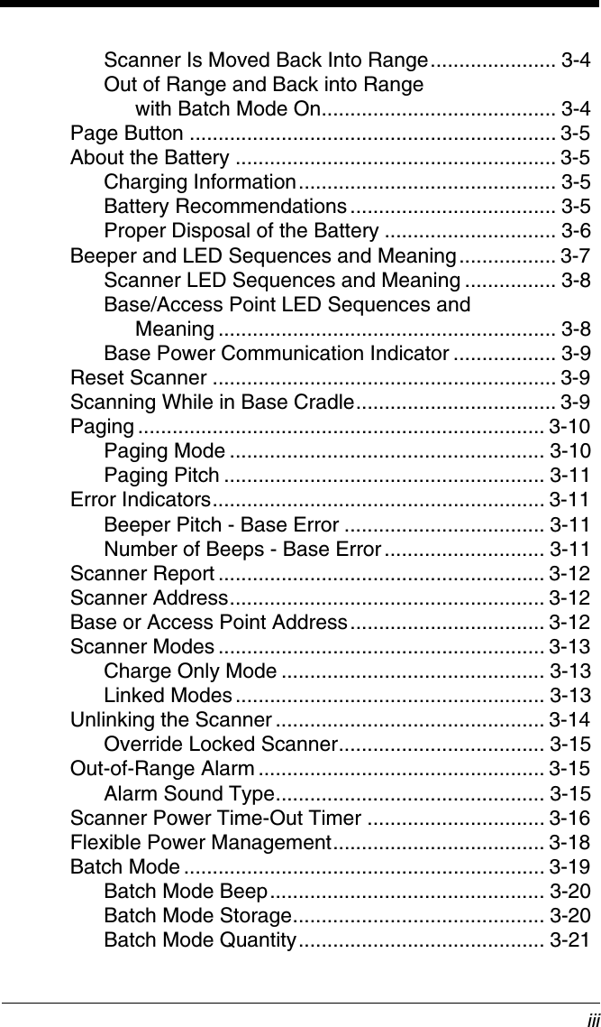
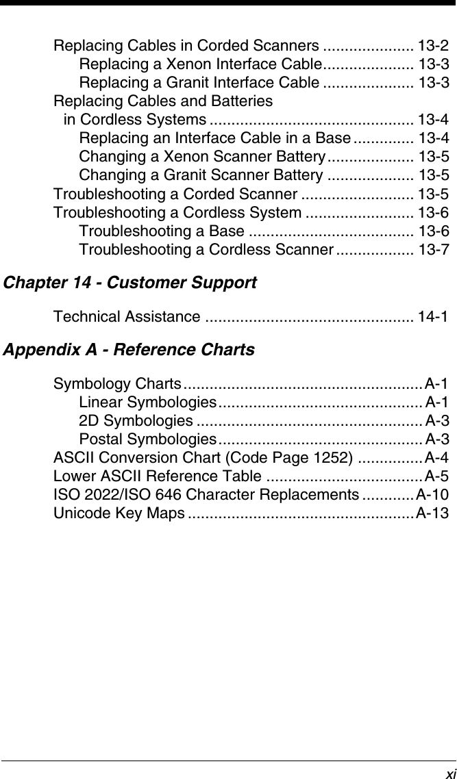
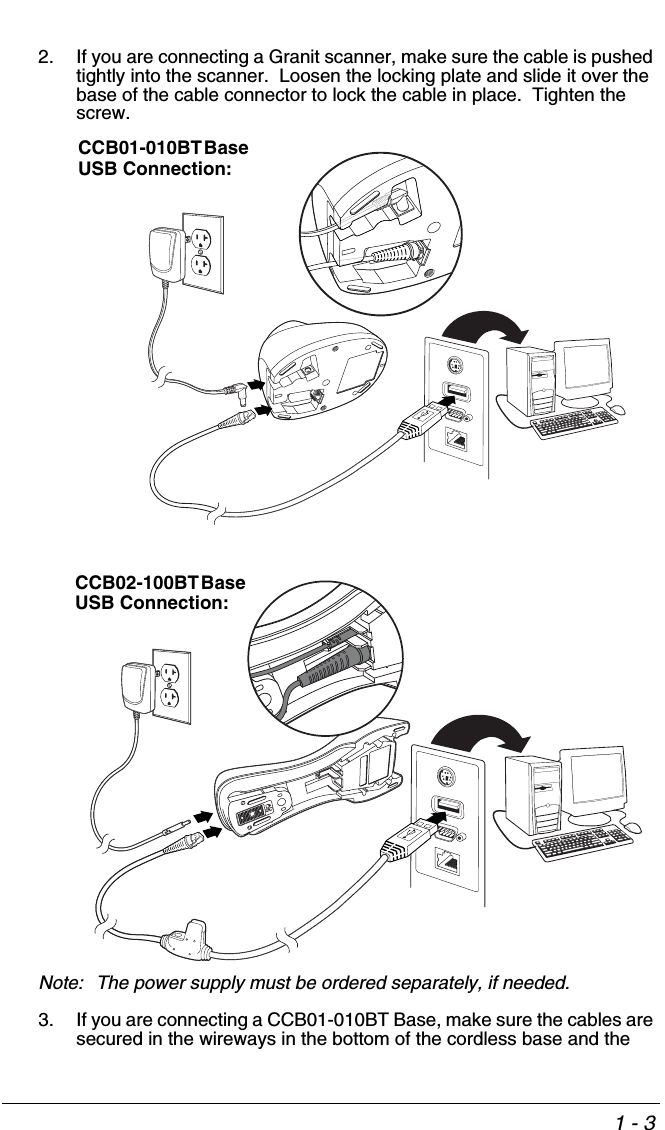
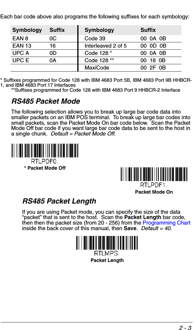
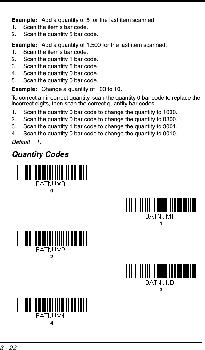
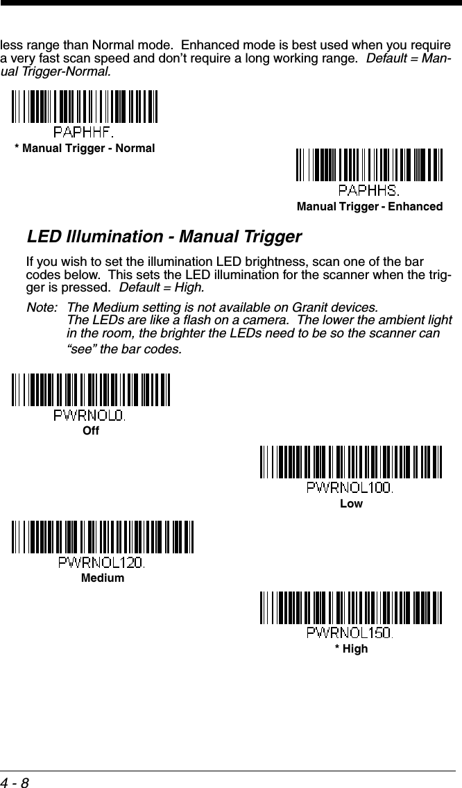
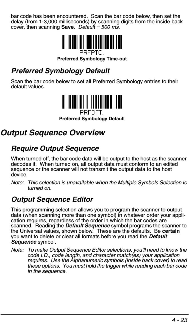
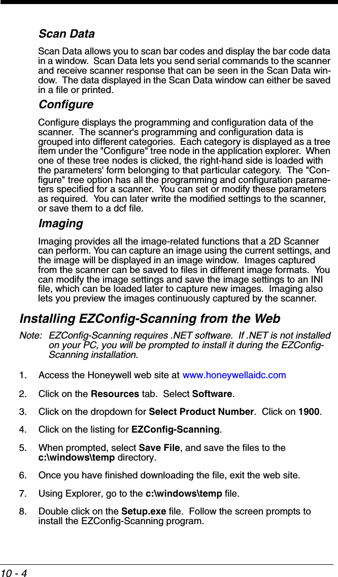
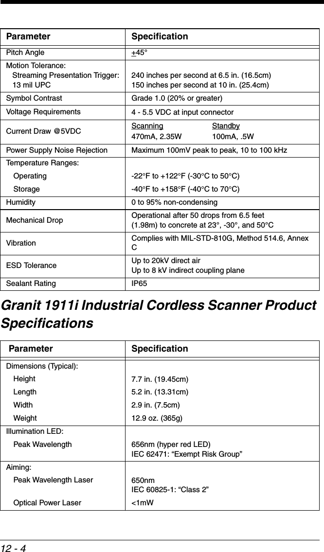
![3 - 38Example: A good read beep is required for any item on file, but a razz or error tone is required if the item is not on file. In this case,[ESC]7, is sent to the host for an on-file product[ESC]8,[ESC]8, is sent to the host for a not-on-file productWhen a bar code is scanned, the scanner enters a timeout period until either the host ACK sequence is received, or the timeout expires (in 10 seconds, by default).Once Host ACK is enabled, the system works as follows when a bar code is scanned:• The scanner reads the code and sends data to the base or Access Point to transmit to the host system. No audible or visual indication is emitted until the scanner receives an escape command. The scanner read illumination goes out when there’s a successful read.• Scanner operation is suspended until 1) a valid escape string is received from the host system or 2) the scanner times out.• Once condition 1 or 2 above has been met, the scanner is ready to scan again, and the process repeats.A time-out occurs if the scanner does not receive a valid escape command within 10 seconds. A time-out is indicated by an error tone. If a time-out occurs, the operator should check the host system to understand why a response to the scanner was not received.Host ACK On/OffHost ACK ResponsesCommand Action[ESC] a, Double beeps to indicate a successful menu change was made.[ESC] b, Razz or error tone to indicate a menu change was unsuccessful.[ESC] 1, The green LED illuminates for 135 milliseconds followed by a pause.Host ACK On* Host ACK Off](https://usermanual.wiki/Honeywell/CCB02A/User-Guide-1911770-Page-120.png)
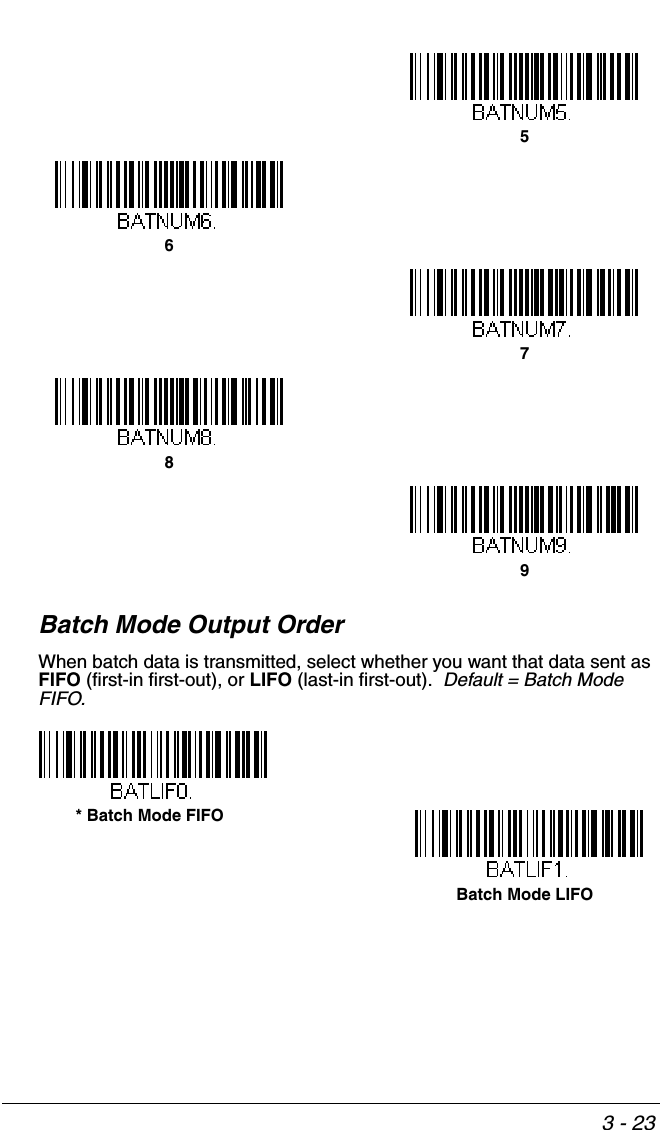
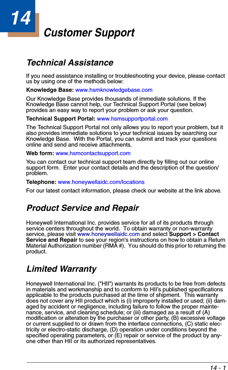
![3 - 39[ESC] 2, The green LED illuminates for 2 seconds followed by a pause.[ESC] 3, The green LED illuminates for 5 seconds followed by a pause.[ESC] 4, Emits a beep at a low pitch.[ESC] 5, Emits a beep at a medium pitch.[ESC] 6, Emits a beep at a high pitch.[ESC] 7, Beeps to indicate a successful decode and communication to host. [ESC] 8,[ESC] 8, Razz or error tone to indicate a decode/communication to host was unsuccessful.Command Action](https://usermanual.wiki/Honeywell/CCB02A/User-Guide-1911770-Page-121.png)

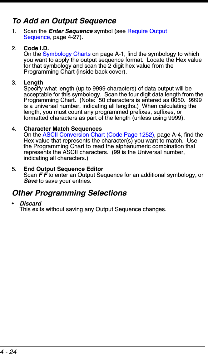


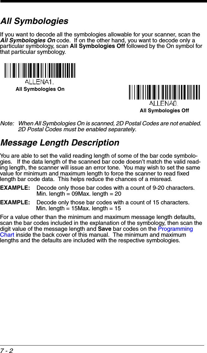
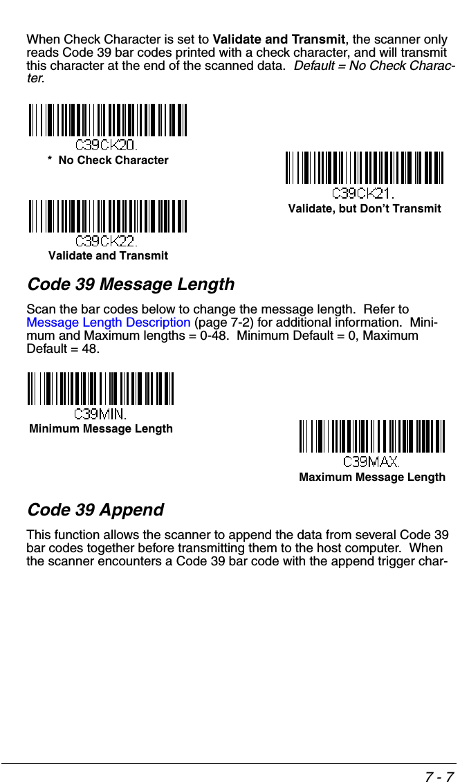
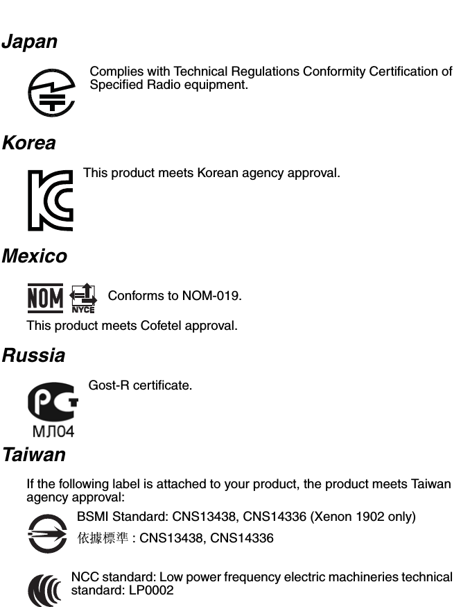
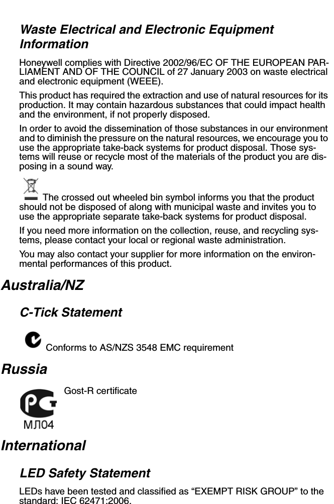
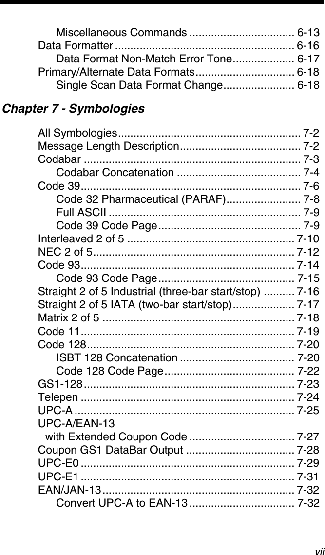
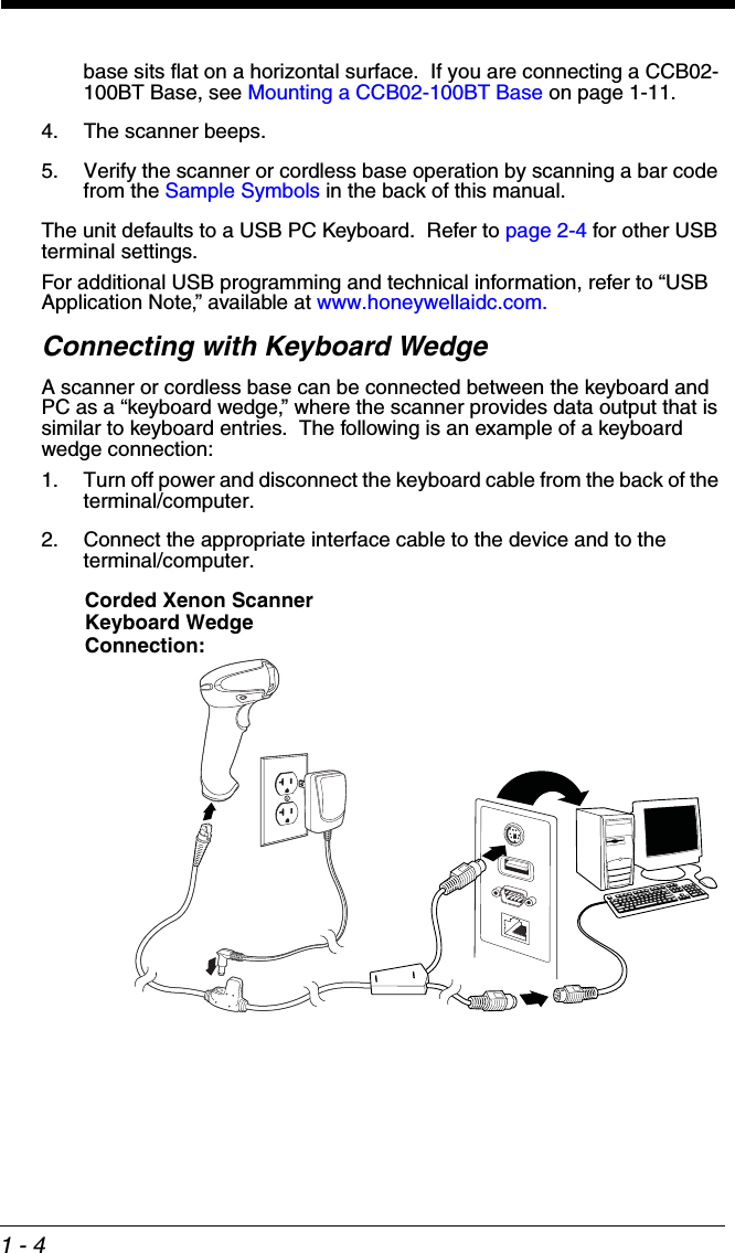
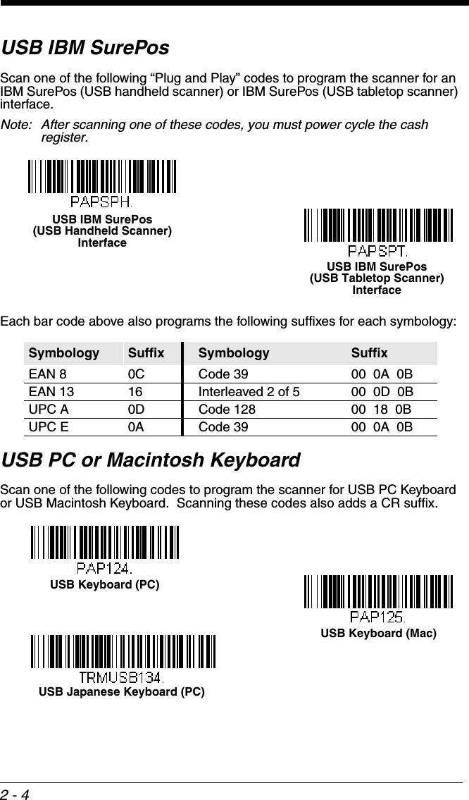
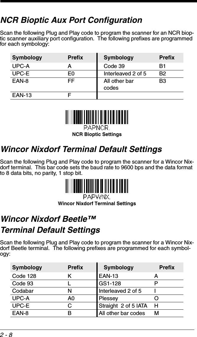
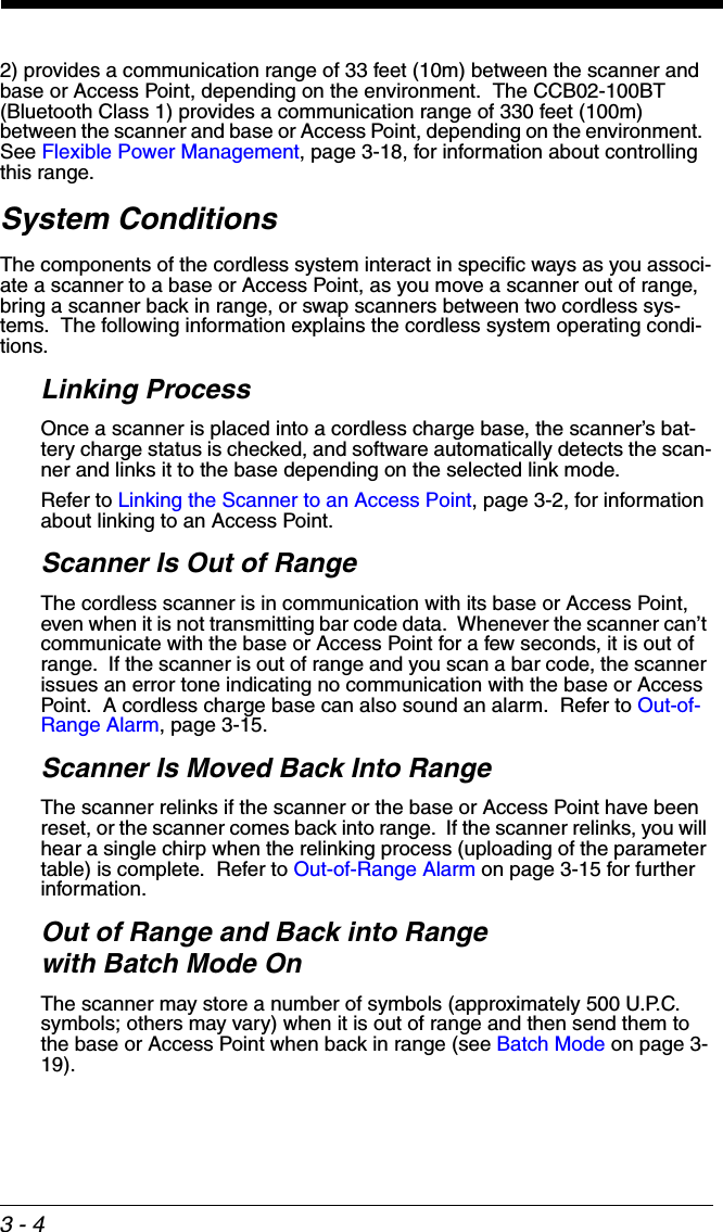
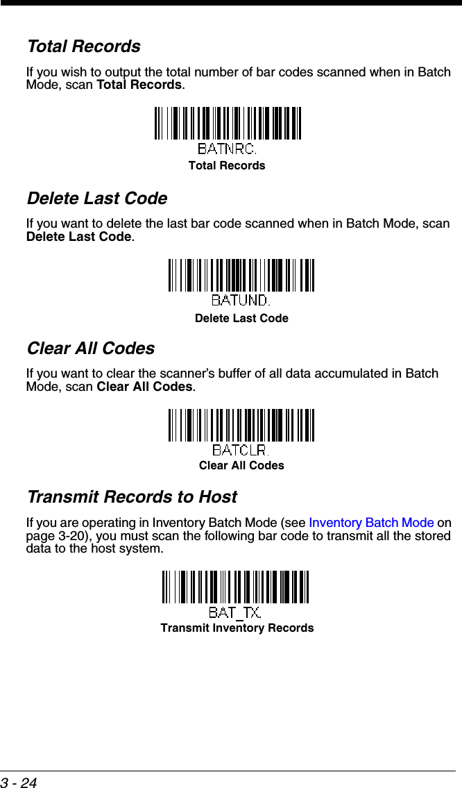
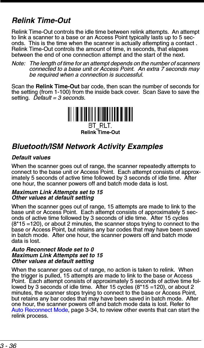
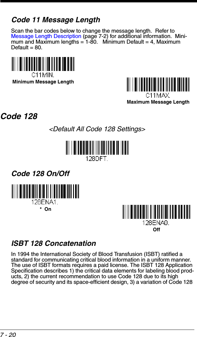
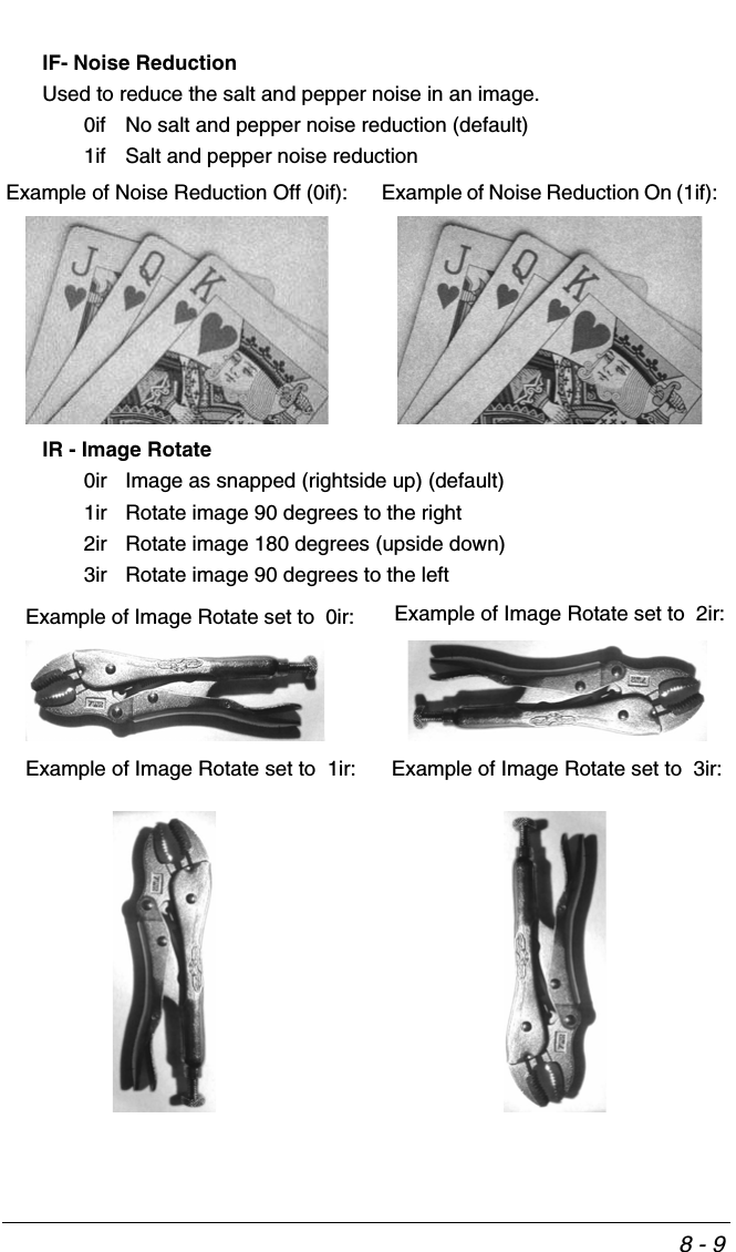
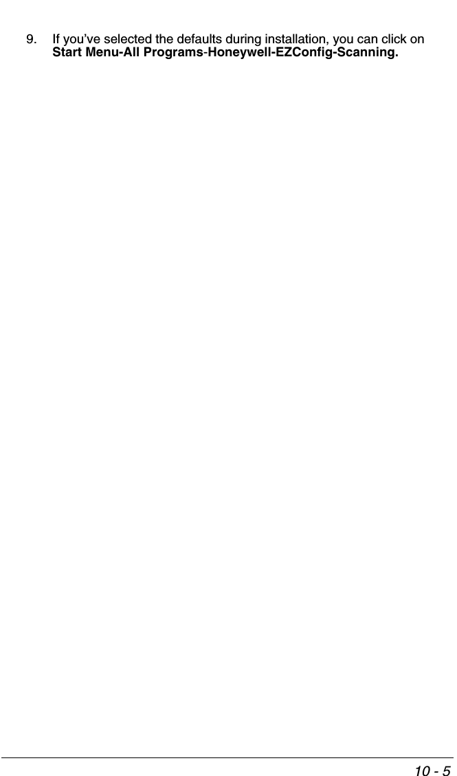
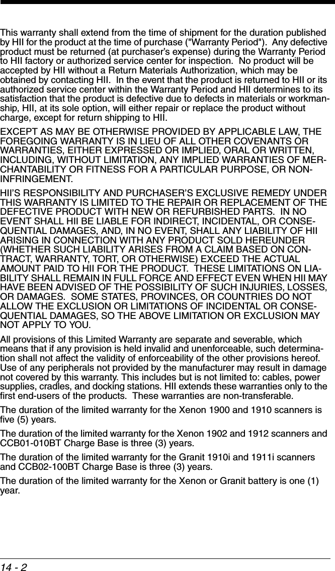
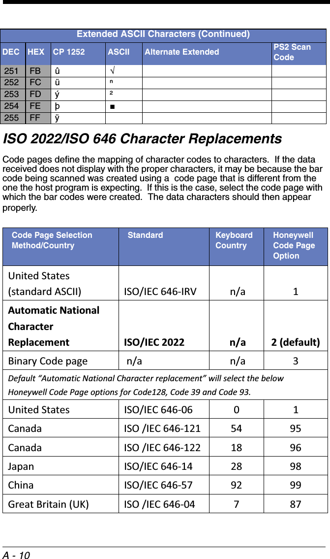
![7 - 9Full ASCIIIf Full ASCII Code 39 decoding is enabled, certain character pairs within the bar code symbol will be interpreted as a single character. For example: $V will be decoded as the ASCII character SYN, and /C will be decoded as the ASCII character #. Default = Off.Character pairs /M and /N decode as a minus sign and period respectively.Character pairs /P through /Y decode as 0 through 9.Code 39 Code PageCode pages define the mapping of character codes to characters. If the data received does not display with the proper characters, it may be because the bar code being scanned was created using a code page that is different from the one the host program is expecting. If this is the case, scan the bar code below, select the code page with which the bar codes were created (see ISO 2022/ISO 646 Character Replacements on page A-NUL %U DLE $PSP SPACE00@%VPP‘%Wp+PSOH $A DC1 $Q !/A 11AAQQa+Aq+QSTX $B DC2 $R “/B 22BBRRb+Br+RETX $C DC3 $S #/C 33CCSSc+Cs+SEOT $D DC4 $T $/D 44DDTTd+Dt+TENQ $E NAK $U %/E 55EEUUe+Eu+UACK $F SYN $V &/F 66FFVVf+Fv+VBEL $G ETB $W ‘/G77GGWWg+Gw+WBS $H CAN $X (/H 88HHXXh+Hx+XHT $I EM $Y )/I 99IIYYi+Iy+YLF $J SUB $Z */J :/ZJJZZj+Jz+ZVT $K ESC %A +/K ;%FKK[%Kk+K{%PFF $L FS %B ,/L <%GLL\%Ll+L|%QCR $M GS %C -- =%HMM]%Mm+M}%RSO $N RS %D .. >%INN^%Nn+N~%SSI $O US %E //O ?%JOO_%Oo+ODEL %T* Full ASCII OffFull ASCII On](https://usermanual.wiki/Honeywell/CCB02A/User-Guide-1911770-Page-187.png)
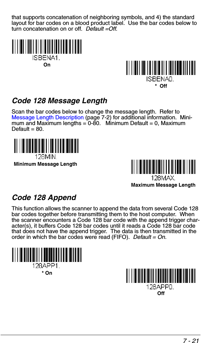
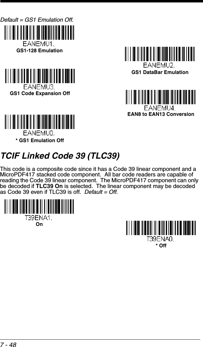
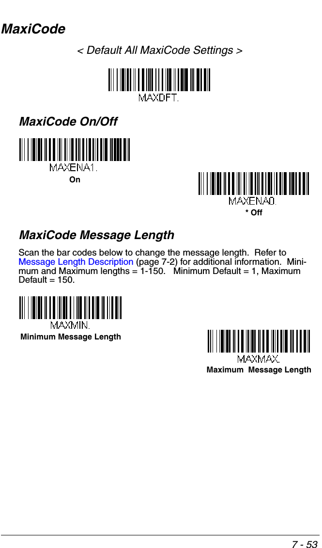
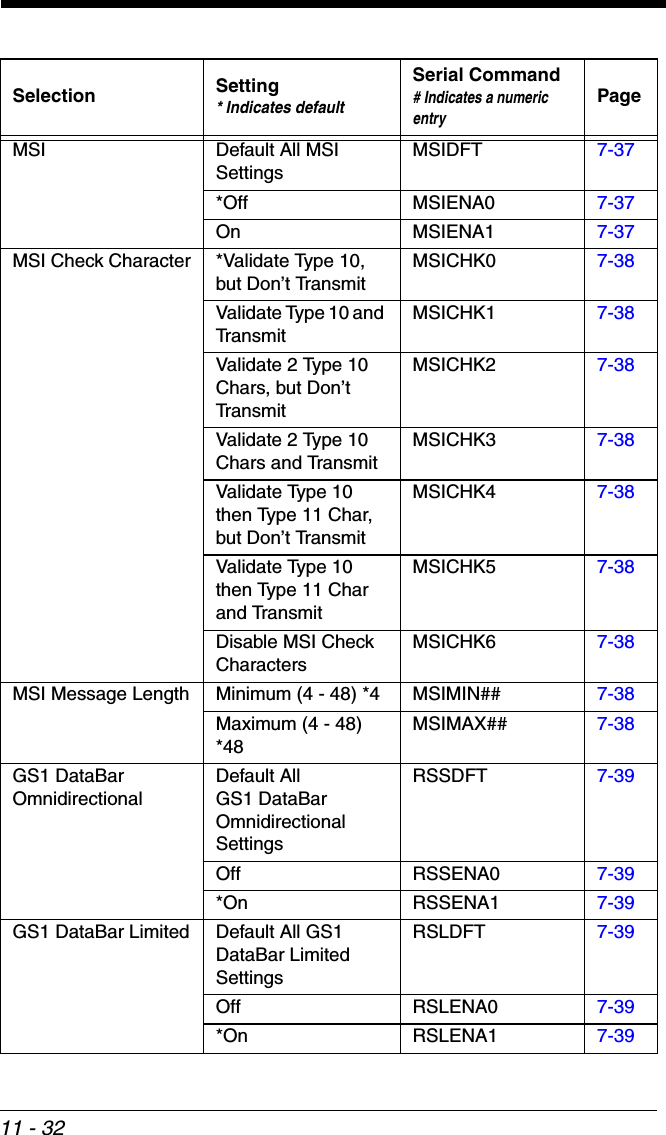
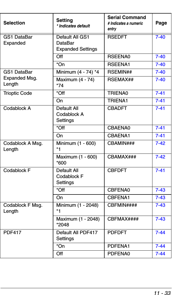
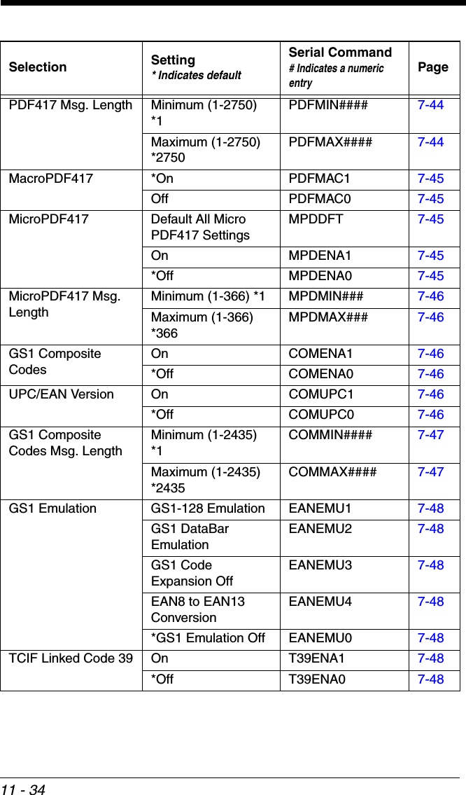
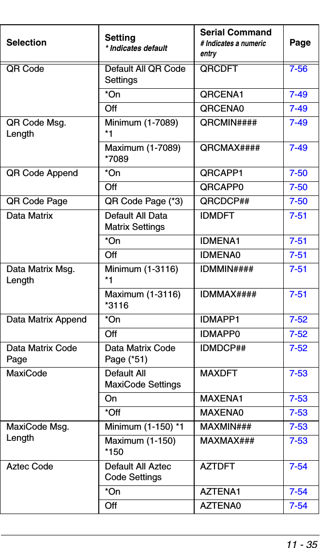
![7 - 47GS1 Composite Code Message LengthScan the bar codes below to change the message length. Refer to Message Length Description (page 7-2) for additional information. Mini-mum and Maximum lengths = 1-2435. Minimum Default = 1, Maximum Default = 2435.GS1 EmulationThe scanner can automatically format the output from any GS1 data carrier to emulate what would be encoded in an equivalent GS1-128 or GS1 DataBar symbol. GS1 data carriers include UPC-A and UPC-E, EAN-13 and EAN-8, ITF-14, GS1-128, and GS1-128 DataBar and GS1 Composites. (Any applica-tion that accepts GS1 data can be simplified since it only needs to recognize one data carrier type.)If GS1-128 Emulation is scanned, all retail codes (U.P.C., UPC-E, EAN8, EAN13) are expanded out to 16 digits. If the AIM ID is enabled, the value will be the GS1-128 AIM ID, ]C1 (see Symbology Charts on page A-1).If GS1 DataBar Emulation is scanned, all retail codes (U.P.C., UPC-E, EAN8, EAN13) are expanded out to 16 digits. If the AIM ID is enabled, the value will be the GS1-DataBar AIM ID, ]em (see Symbology Charts on page A-1).If GS1 Code Expansion Off is scanned, retail code expansion is disabled, and UPC-E expansion is controlled by the UPC-E0 Expand (page 7-29) setting. If the AIM ID is enabled, the value will be the GS1-128 AIM ID, ]C1 (see Symbology Charts on page A-1).If EAN8 to EAN13 Conversion is scanned, all EAN8 bar codes are converted to EAN13 format. Maximum Message LengthMinimum Message Length](https://usermanual.wiki/Honeywell/CCB02A/User-Guide-1911770-Page-225.png)


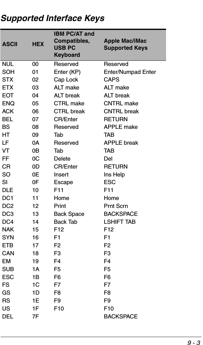
![9 - 19Interface KeysKeyboard Function RelationshipsThe following Keyboard Function Code, Hex/ASCII Value, and Full ASCII “CTRL”+ relationships apply to all terminals that can be used with the scanner. Refer to page 2-22 enable Control + X (Control + ASCII) Mode.Function Code HEX/ASCII Value Full ASCII (CTRL + X Mode)NUL 00 @SOH 01 ASTX 02 BETX 03 CEOT 04 DENQ 05 EACK 06 FBEL 07 GBS 08 HHT 09 ILF 0A JVT 0B KFF 0C LCR 0D MSO 0E NSI 0F ODLE 10 PDC1 11 QDC2 12 RDC3 13 SDC4 14 TNAK 15 USYN 16 VETB 17 WCAN 18 XEM 19 YSUB 1A ZESC 1B [FS 1C \GS 1D ]RS 1E ^US 1F _](https://usermanual.wiki/Honeywell/CCB02A/User-Guide-1911770-Page-263.png)
![9 - 2The last five characters in the Full ASCII “CTRL”+ column ( [ \ ] 6 - ), apply to US only. The following chart indicates the equivalents of these five characters for different countries.Country CodesUnited States [\]6-Belgium [ < ] 6 -Scandinavia 8 < 9 6 -France ^8$6=Germany à + 6 -Italy \ + 6 -Switzerland <. . 6 -United Kingdom [ ¢ ] 6 -Denmark 8 \ 9 6 -Norway 8\ 96-Spain [\]6-](https://usermanual.wiki/Honeywell/CCB02A/User-Guide-1911770-Page-264.png)


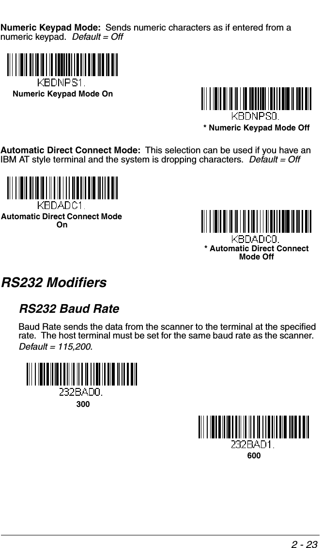
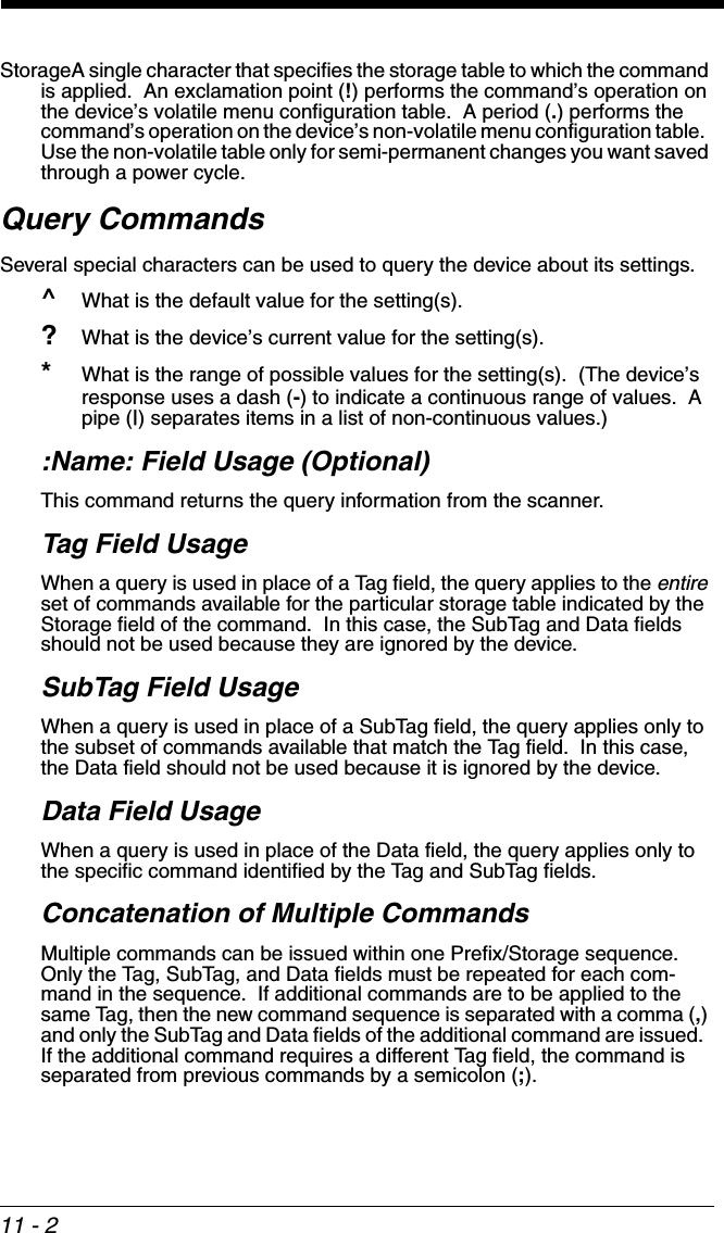
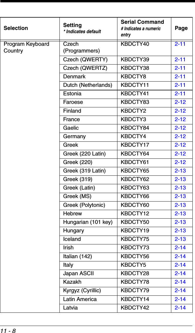
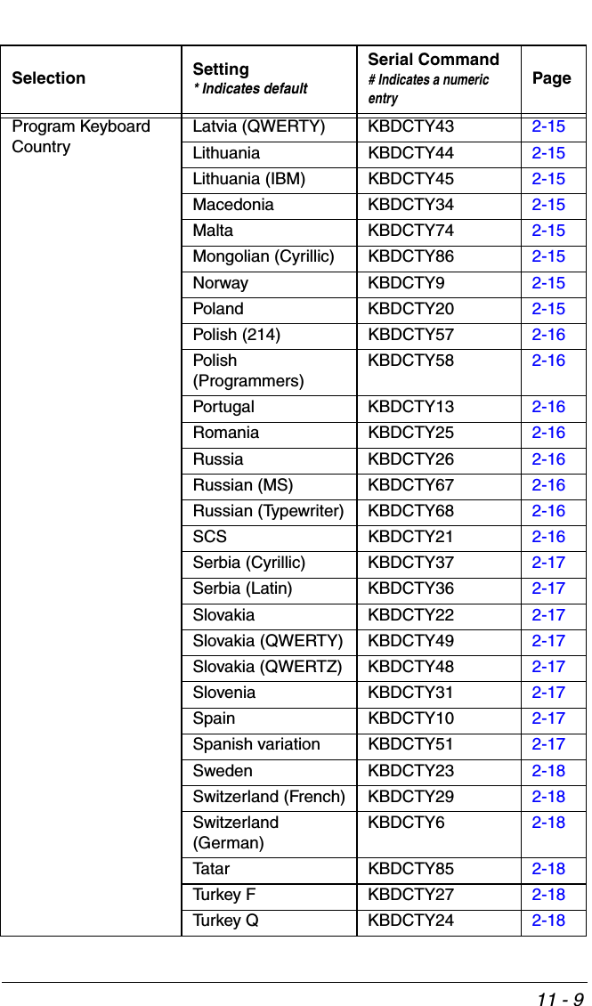
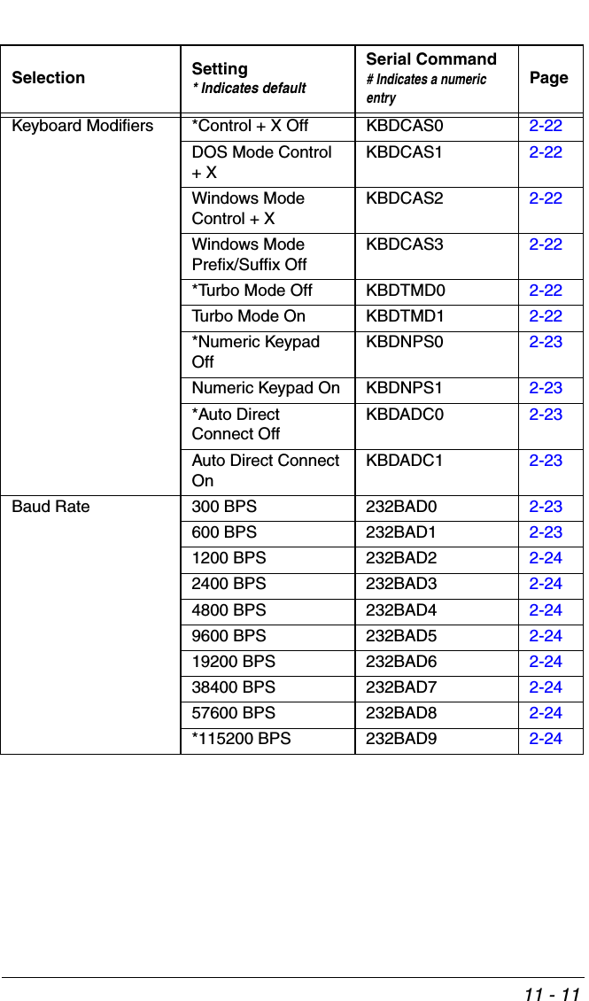
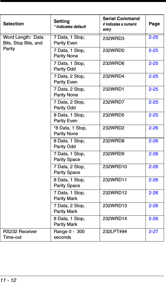
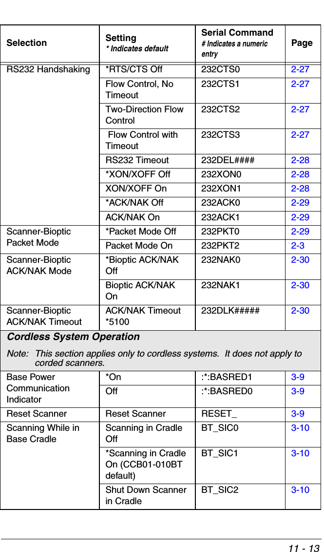
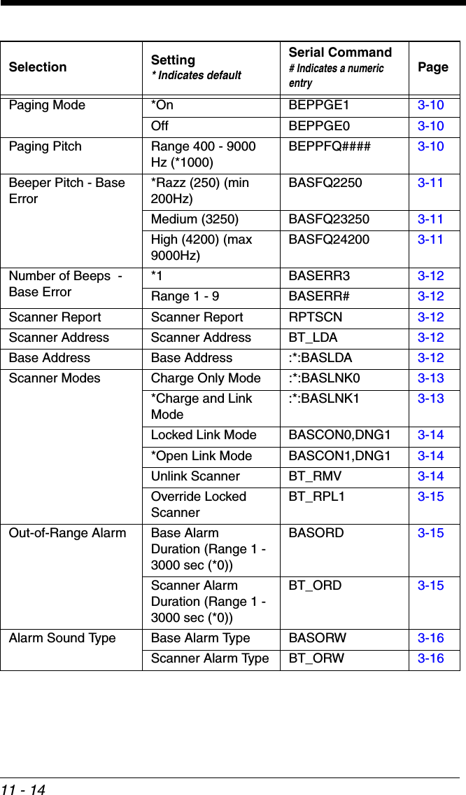
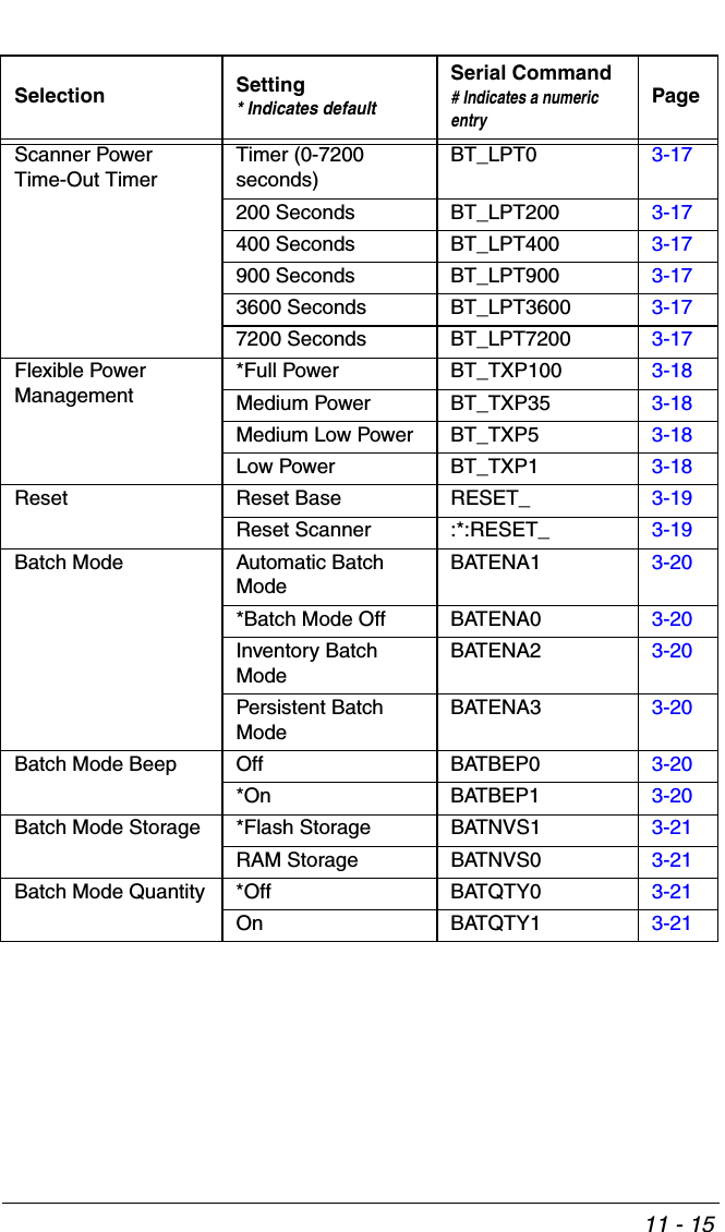
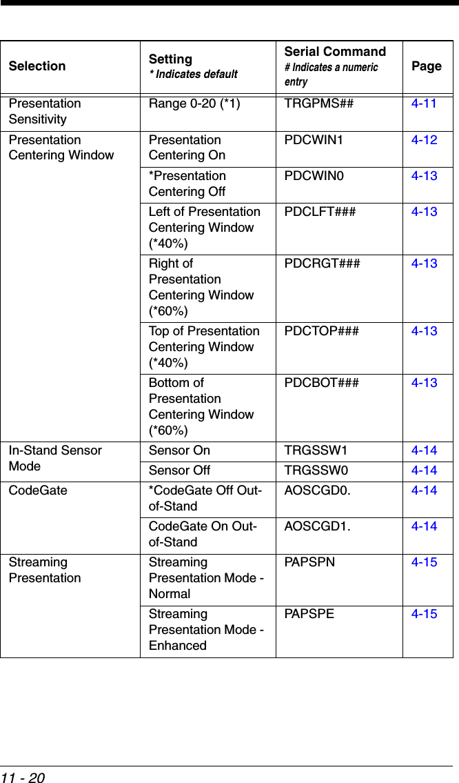
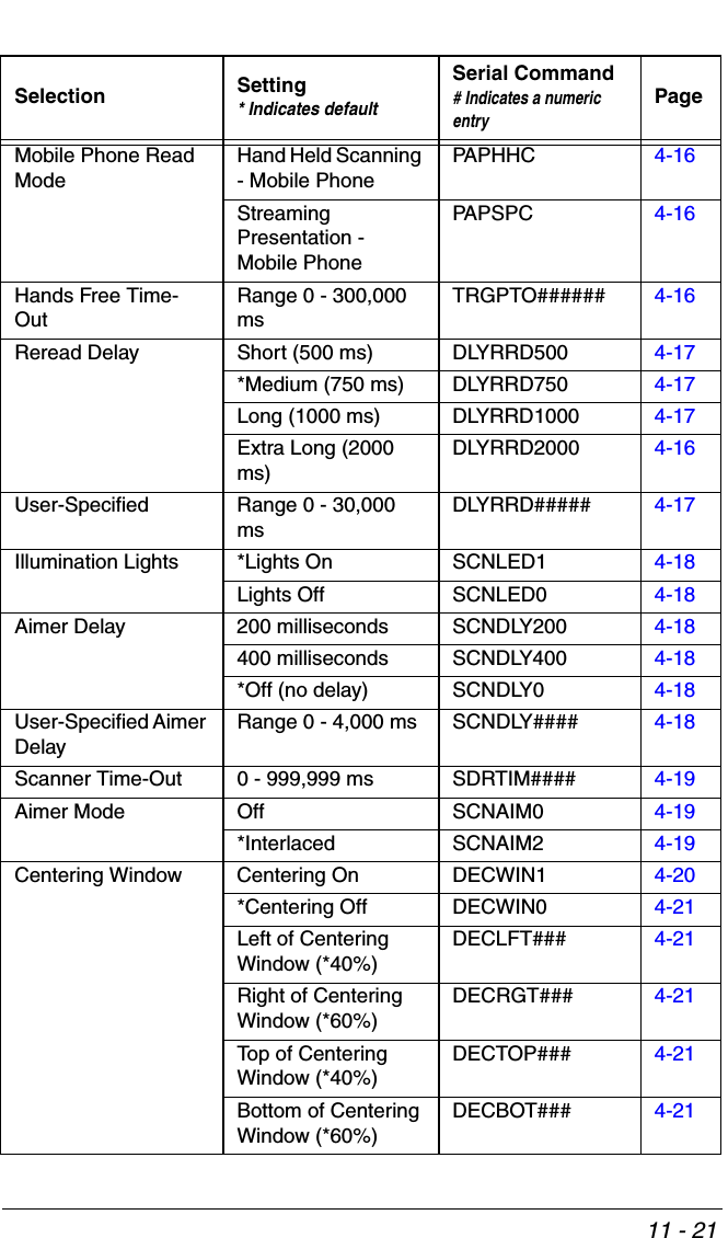
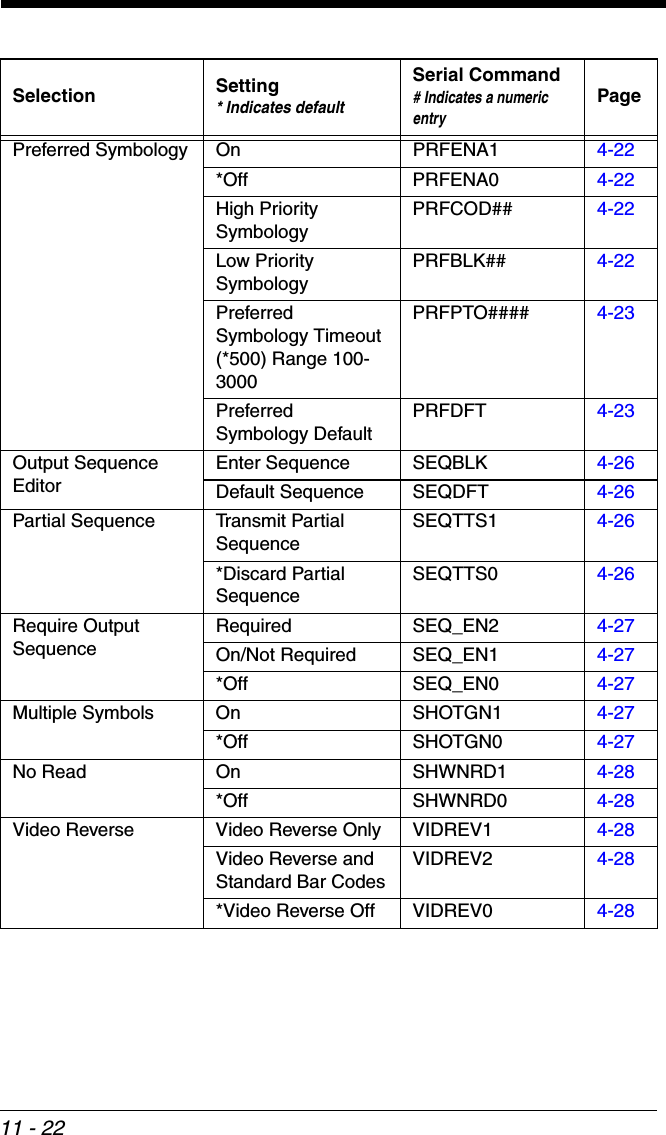
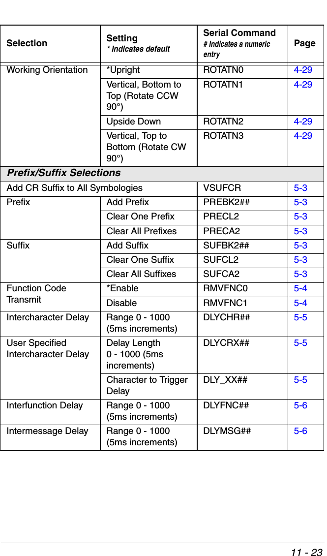
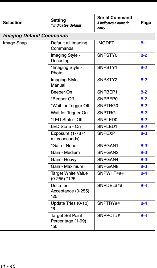
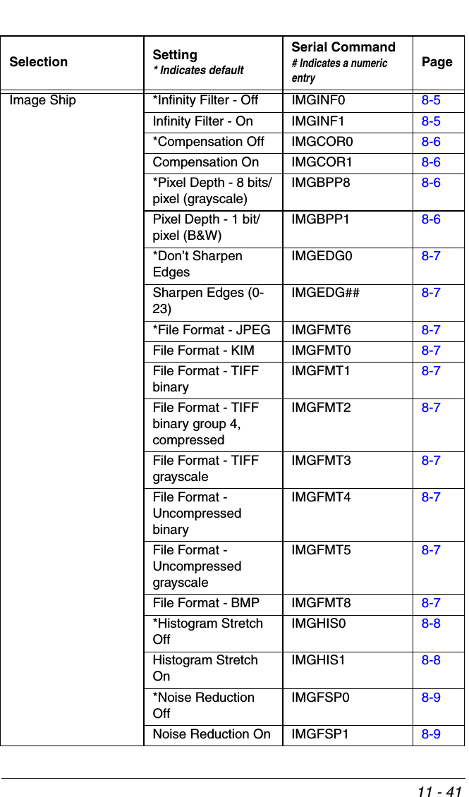
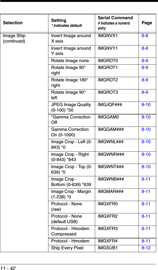
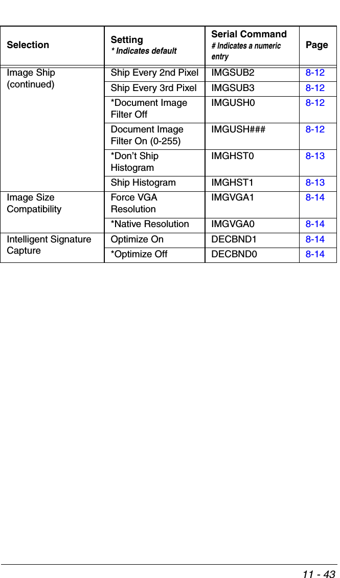
![11 - 111Serial Programming CommandsThe serial programming commands can be used in place of the programming bar codes. Both the serial commands and the programming bar codes will pro-gram the scanner. For complete descriptions and examples of each serial pro-gramming command, refer to the corresponding programming bar code in this manual.The device must be set to an RS232 interface (see page 2-2). The following commands can be sent via a PC COM port using terminal emulation software.ConventionsThe following conventions are used for menu and query command descriptions:parameterA label representing the actual value you should send as part of a command.[option]An optional part of a command.{Data}Alternatives in a command.boldNames of menus, menu commands, buttons, dialog boxes, and windows that appear on the screen.Menu Command SyntaxMenu commands have the following syntax (spaces have been used for clarity only):Prefix [:Name:] Tag SubTag {Data} [, SubTag {Data}] [; Tag SubTag {Data}] […] StoragePrefixThree ASCII characters: SYN M CR (ASCII 22,77,13).:Name:To send information to the scanner (with the base connected to host), use :Xenon: The default factory setting for a Xenon scanner is Xenon scanner. This setting is changed by using the BT_NAM command, which accepts alphanumeric values. If the name is not known, a wildcard (*) can be used :*:.Note: Since the base stores all work group settings and transfers to them to scanner once they are linked, changes are typically done to the base and not to the scanner.Tag A 3 character case-insensitive field that identifies the desired menu command group. For example, all RS232 configuration settings are identified with a Tag of 232.SubTagA 3 character case-insensitive field that identifies the desired menu command within the tag group. For example, the SubTag for the RS232 baud rate is BAD.DataThe new value for a menu setting, identified by the Tag and SubTag.](https://usermanual.wiki/Honeywell/CCB02A/User-Guide-1911770-Page-273.png)
![11 - 3ResponsesThe device responds to serial commands with one of three responses:ACKIndicates a good command which has been processed.ENQIndicates an invalid Tag or SubTag command. NAKIndicates the command was good, but the Data field entry was out of the allowable range for this Tag and SubTag combination, e.g., an entry for a minimum message length of 100 when the field will only accept 2 characters.When responding, the device echoes back the command sequence with the status character inserted directly before each of the punctuation marks (the period, exclamation point, comma, or semicolon) in the command.Examples of Query CommandsIn the following examples, a bracketed notation [ ] depicts a non-displayable response.Example: What is the range of possible values for Codabar Coding Enable?Enter: cbrena*.Response: CBRENA0-1[ACK]This response indicates that Codabar Coding Enable (CBRENA) has a range of values from 0 to 1 (off and on). Example: What is the default value for Codabar Coding Enable?Enter: cbrena^.Response: CBRENA1[ACK]This response indicates that the default setting for Codabar Coding Enable (CBRENA) is 1, or on. Example: What is the device’s current setting for Codabar Coding Enable?Enter: cbrena?.Response: CBRENA1[ACK]This response indicates that the device’s Codabar Coding Enable (CBRENA) is set to 1, or on. Example: What are the device’s settings for all Codabar selections?Enter: cbr?.Response: CBRENA1[ACK],SSX0[ACK],CK20[ACK],CCT1[ACK],MIN2[ACK],](https://usermanual.wiki/Honeywell/CCB02A/User-Guide-1911770-Page-275.png)
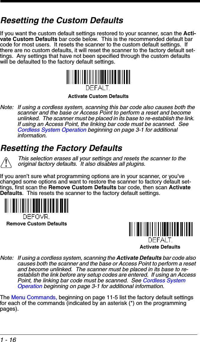
![11 - 4MAX60[ACK],DFT[ACK].This response indicates that the device’s Codabar Coding Enable (CBRENA) is set to 1, or on; the Start/Stop Character (SSX) is set to 0, or Don’t Transmit; the Check Character (CK2) is set to 0, or Not Required;concatenation (CCT) is set to 1, or Enabled; the Minimum Message Length (MIN) is set to 2 characters; the Maximum Message Length (MAX) is set to 60 characters; and the Default setting (DFT) has no value. Trigger CommandsYou can activate and deactivate the scanner with serial trigger commands. First, the scanner must be put in Manual Trigger Mode by scanning a Manual Trigger Mode bar code (page 4-7), or by sending a serial menu command for triggering (page 4-9). Once the scanner is in serial trigger mode, the trigger is activated and deactivated by sending the following commands:Activate: SYN T CRDeactivate: SYN U CRThe scanner scans until a bar code has been read, until the deactivate com-mand is sent, or until the serial time-out has been reached (see "Read Time-Out" on page 4-9 for a description, and the serial command on page 11-19).Resetting the Custom DefaultsIf you want the custom default settings restored to your scanner, scan the Acti-vate Custom Defaults bar code below. This resets the scanner to the custom default settings. If there are no custom defaults, it will reset the scanner to the factory default settings. Any settings that have not been specified through the custom defaults will be defaulted to the factory default settings.Note: If using a cordless system, scanning this bar code also causes both the scanner and the base or Access Point to perform a reset and become unlinked. The scanner must be placed in its base to re-establish the link. If using an Access Point, the linking bar code must be scanned. See Cordless System Operation beginning on page 3-1 for additional information.The charts on the following pages list the factory default settings for each of the commands (indicated by an asterisk (*) on the programming pages).Activate Custom Defaults](https://usermanual.wiki/Honeywell/CCB02A/User-Guide-1911770-Page-276.png)

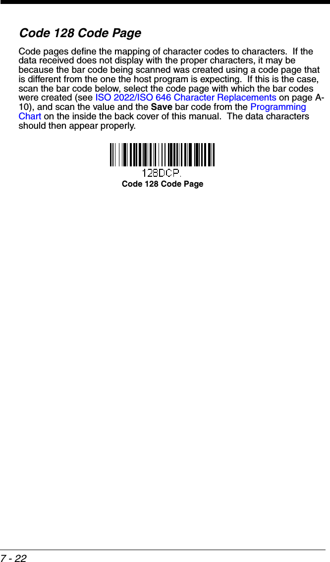
![A - 1AReference ChartsSymbology ChartsNote: “m” represents the AIM modifier character. Refer to International Technical Specification, Symbology Identifiers, for AIM modifier character details.Prefix/Suffix entries for specific symbologies override the universal (All Symbologies, 99) entry.Refer to Data Editing beginning on page 5-1 and Data Formatting beginning on page 6-1 for information about using Code ID and AIM ID.Linear SymbologiesAIM HoneywellSymbology IDPossible modifiers (m)ID HexAll Symbologies99Codabar ]Fm0-1 a 61Code 11 ]H3 h 68Code 128 ]Cm0, 1, 2, 4 j 6ACode 32 Pharmaceutical (PARAF)]X0 < 3CCode 39 (supports Full ASCII mode)]Am0, 1, 3, 4, 5, 7 b 62TCIF Linked Code 39 (TLC39)]L2 T 54Code 93 and 93i ]Gm0-9, A-Z, a-mi69EAN ]Em0, 1, 3, 4 d 64EAN-13 (including Bookland EAN)]E0 d 64EAN-13 with Add-On ]E3 d 64EAN-13 with Extended Coupon Code]E3 d 64EAN-8 ]E4 D 44EAN-8 with Add-On ]E3 D 44](https://usermanual.wiki/Honeywell/CCB02A/User-Guide-1911770-Page-341.png)
![A - 2GS1GS1 DataBar ]em0y79GS1 DataBar Limited ]em{ 7BGS1 DataBar Expanded ]em}7DGS1-128 ]C1 I 492 of 5China Post (Hong Kong 2 of 5)]X0 Q 51Interleaved 2 of 5 ]Im0, 1, 3 e 65Matrix 2 of 5 ]X0 m 6DNEC 2 of 5 ]X0 Y 59Straight 2 of 5 IATA ]Rm0, 1, 3 f 66Straight 2 of 5 Industrial ]S0 f 66MSI ]Mm0, 1 g 67Telepen ]Bmt74UPC 0, 1, 2, 3, 8, 9, A, B, CUPC-A ]E0 c 63UPC-A with Add-On ]E3 c 63UPC-A with Extended Coupon Code]E3 c 63UPC-E ]E0 E 45UPC-E with Add-On ]E3 E 45UPC-E1 ]X0 E 45Add Honeywell Code ID 5C80Add AIM Code ID 5C81Add Backslash 5C5CBatch mode quantity 5 35AIM HoneywellSymbology IDPossible modifiers (m)ID Hex](https://usermanual.wiki/Honeywell/CCB02A/User-Guide-1911770-Page-342.png)
![A - 32D SymbologiesPostal SymbologiesAIM HoneywellSymbology IDPossible modifiers (m)ID HexAll Symbologies99Aztec Code ]zm0-9, A-C z 7AChinese Sensible Code (Han Xin Code)]X0 H 48Codablock A ]O6 0, 1, 4, 5, 6 V 56Codablock F ]Om0, 1, 4, 5, 6 q 71Code 49 ]Tm0, 1, 2, 4 l 6CData Matrix ]dm0-6 w 77GS1 ]em0-3GS1 Composite ]em0-3 y 79GS1 DataBar Omnidirectional]emy79MaxiCode ]Um0-3 x 78PDF417 ]Lm0-2 r 72MicroPDF417 ]Lm3-5 R 52QR Code ]Qm0-6 s 73Micro QR Code ]Qms73AIM HoneywellSymbology IDPossible modifiers (m)ID HexAll Symbologies99Australian Post ]X0 A 41British Post ]X0 B 42Canadian Post ]X0 C 43](https://usermanual.wiki/Honeywell/CCB02A/User-Guide-1911770-Page-343.png)
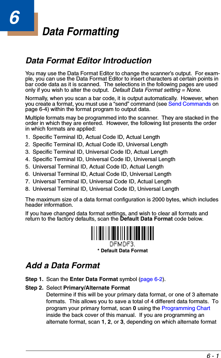
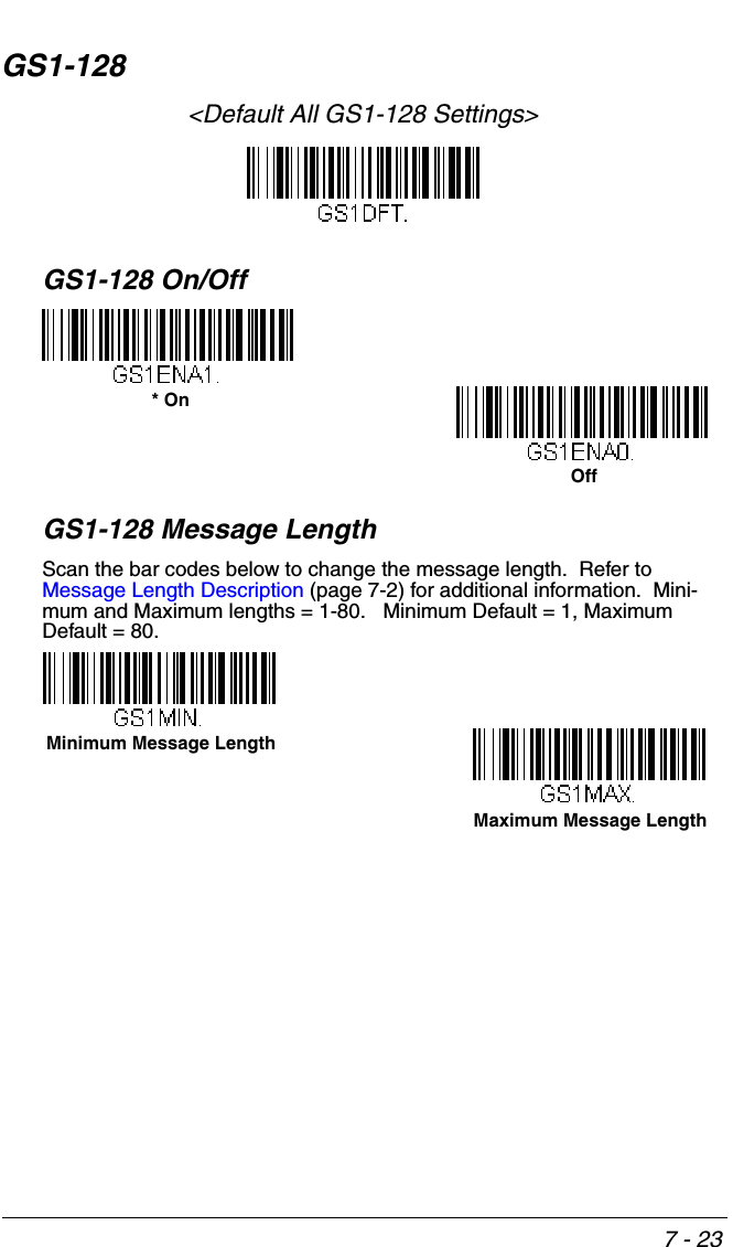
![A - 4ASCII Conversion Chart (Code Page 1252)In keyboard applications, ASCII Control Characters can be represented in 3 dif-ferent ways, as shown below. The CTRL+X function is OS and application dependent. The following table lists some commonly used Microsoft functional-ity. This table applies to U.S. style keyboards. Certain characters may differ depending on your Country Code/PC regional settings. China Post ]X0 Q 51InfoMail ]X0 , 2cIntelligent Mail Bar Code ]X0 M 4DJapanese Post ]X0 J 4AKIX (Netherlands) Post ]X0 K 4BKorea Post ]X0 ? 3FPlanet Code ]X0 L 4CPostal-4i ]X0 N 4EPostnet ]X0 P 50Non-printable ASCII control charactersKeyboard Control + ASCII (CTRL+X) Mode Control + X Mode Off (KBDCAS0)Windows Mode Control + X Mode On (KBDCAS2)DEC HEX Char CTRL + X CTRL + X function000 NUL Reserved CTRL+ @ 101 SOH NP Enter CTRL+ A Select all202 STX Caps Lock CTRL+ B Bold303 ETX ALT Make CTRL+ C Copy404 EOT ALT Break CTRL+ D Bookmark505 ENQ CTRL Make CTRL+ E Center606 ACK CTRL Break CTRL+ F Find707 BEL Enter / Ret CTRL+ G 808 BS(Apple Make)CTRL+ H History909 HT Tab CTRL+ I Italic10 0A LF(Apple Break)CTRL+ J JustifyAIM HoneywellSymbology IDPossible modifiers (m)ID Hex](https://usermanual.wiki/Honeywell/CCB02A/User-Guide-1911770-Page-344.png)
![A - 5Lower ASCII Reference TableNote: Windows Code page 1252 and lower ASCII use the same characters. 11 0B VT Tab CTRL+ K hyperlink12 0C FF Delete CTRL+ L list, left align13 0D CR Enter / Ret CTRL+ M 14 0E SO Insert CTRL+ N New15 0F SI ESC CTRL+ O Open16 10 DLE F11 CTRL+ P Print17 11 DC1 Home CTRL+ Q Quit18 12 DC2 PrtScn CTRL+ R 19 13 DC3 Backspace CTRL+ S Save20 14 DC4 Back Tab CTRL+ T 21 15 NAK F12 CTRL+ U 22 16 SYN F1 CTRL+ V Paste 23 17 ETB F2 CTRL+ W 24 18 CAN F3 CTRL+ X 25 19 EM F4 CTRL+ Y 26 1A SUB F5 CTRL+ Z 27 1B ESC F6 CTRL+ [ 28 1C FS F7 CTRL+ \ 29 1D GS F8 CTRL+ ] 30 1E RS F9 CTRL+ ^ 31 1F US F10 CTRL+ - 127 7F ⌂NP Enter Printable CharactersDEC HEX Character DEC HEX Character DEC HEX Character 32 20 <SPACE> 64 40 @96 60 `33 21 !65 41 A97 61 a34 22 "66 42 B98 62 b35 23 #67 43 C99 63 cNon-printable ASCII control charactersKeyboard Control + ASCII (CTRL+X) Mode Control + X Mode Off (KBDCAS0)Windows Mode Control + X Mode On (KBDCAS2)DEC HEX Char CTRL + X CTRL + X function](https://usermanual.wiki/Honeywell/CCB02A/User-Guide-1911770-Page-345.png)
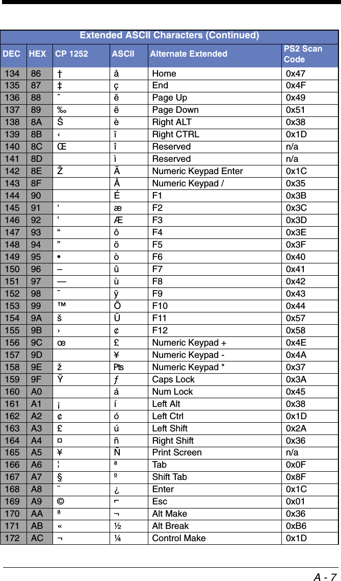
![A - 636 24 $68 44 D100 64 d37 25 %69 45 E101 65 e38 26 &70 46 F102 66 f39 27 '71 47 G103 67 g40 28 (72 48 H104 68 h41 29 )73 49 I105 69 i42 2A *74 4A J106 6A j43 2B +75 4B K107 6B k44 2C ,76 4C L108 6C l45 2D -77 4D M109 6D m46 2E .78 4E N110 6E n47 2F /79 4F O111 6F o48 30 080 50 P112 70 p49 31 181 51 Q113 71 q50 32 282 52 R114 72 r51 33 383 53 S115 73 s52 34 484 54 T116 74 t53 35 585 55 U117 75 u54 36 686 56 V118 76 v55 37 787 57 W119 77 w56 38 888 58 X120 78 x57 39 989 59 Y121 79 y58 3A :90 5A Z122 7A z59 3B ;91 5B [123 7B {60 3C <92 5C \124 7C |61 3D =93 5D ]125 7D }62 3E >94 5E ^126 7E ~63 3F ?95 5F _127 7F ⌂Extended ASCII CharactersDEC HEX CP 1252 ASCII Alternate Extended PS2 Scan Code128 80 €€ Ç up arrow ↑0x48129 81 üdown arrow ↓0x50130 82 ‚éright arrow →0x4B131 83 ƒâleft arrow ←0x4D132 84 „äInsert 0x52133 85 …àDelete 0x53Printable Characters (Continued)DEC HEX Character DEC HEX Character DEC HEX Character](https://usermanual.wiki/Honeywell/CCB02A/User-Guide-1911770-Page-346.png)
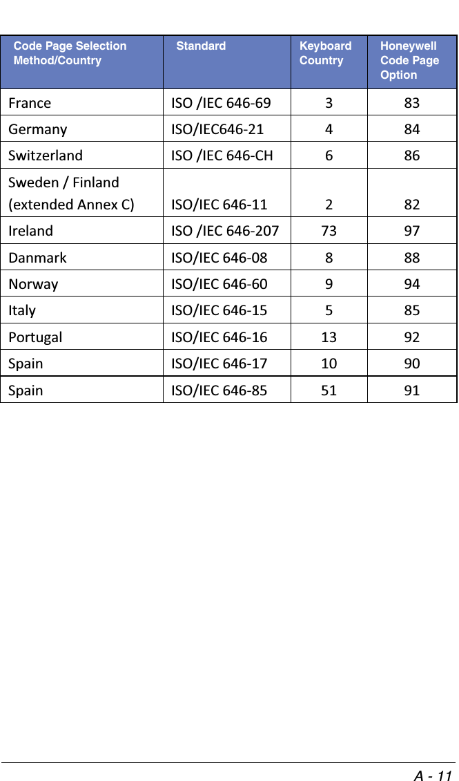
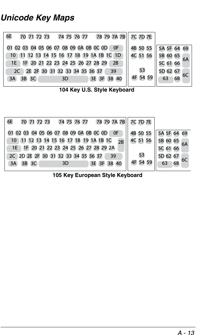
![A - 12Dec 35 36 64 91 92 93 94 96 123 124 125 126Hex 23 24 40 5B 5C 5D 5E 60 7B 7C 7D 7EUS 0 1 # $ @ [ \ ] ^ ` { | } ~CA 54 95 # $ à â ç ê î ô é ù è ûCA 18 96 # $ à â ç ê É ô é ù è ûJP 28 98 # $ @ [ ¥ ] ^ ` { | } CN 92 99 # ¥ @ [ \ ] ^ ` { | } GB 787 £ $ @ [ \ ] ^ ` { | } ˜FR 383 £ $ à ° ç § ^ µ é ù è ¨DE 484 # $ § Ä Ö Ü ^ ` ä ö ü ßCH 6 86 ù $ à é ç ê î ô ä ö ü ûSE/FI 282 # ¤ É Ä Ö Å Ü é ä ö å üDK 888 # $ @ Æ Ø Å ^ ` æ ø å ˜NO 994 # $ @ Æ Ø Å ^ ` æ ø å ¨IE 73 97 £ $ Ó É Í Ú Á ó é í ú áIT 585 £ $ § ° ç é ^ ù à ò è ìPT 13 92 # $ § Ã Ç Õ ^ ` ã ç õ °ES 10 90 # $ § ¡ Ñ ¿ ^ ` ° ñ ç ˜ES 51 91 # $ · ¡ Ñ Ç ¿ ` ´ ñ ç ¨COUNTRYCountry KeyboardHoneywell CodePageISO / IEC 646 National Character Replacements](https://usermanual.wiki/Honeywell/CCB02A/User-Guide-1911770-Page-352.png)