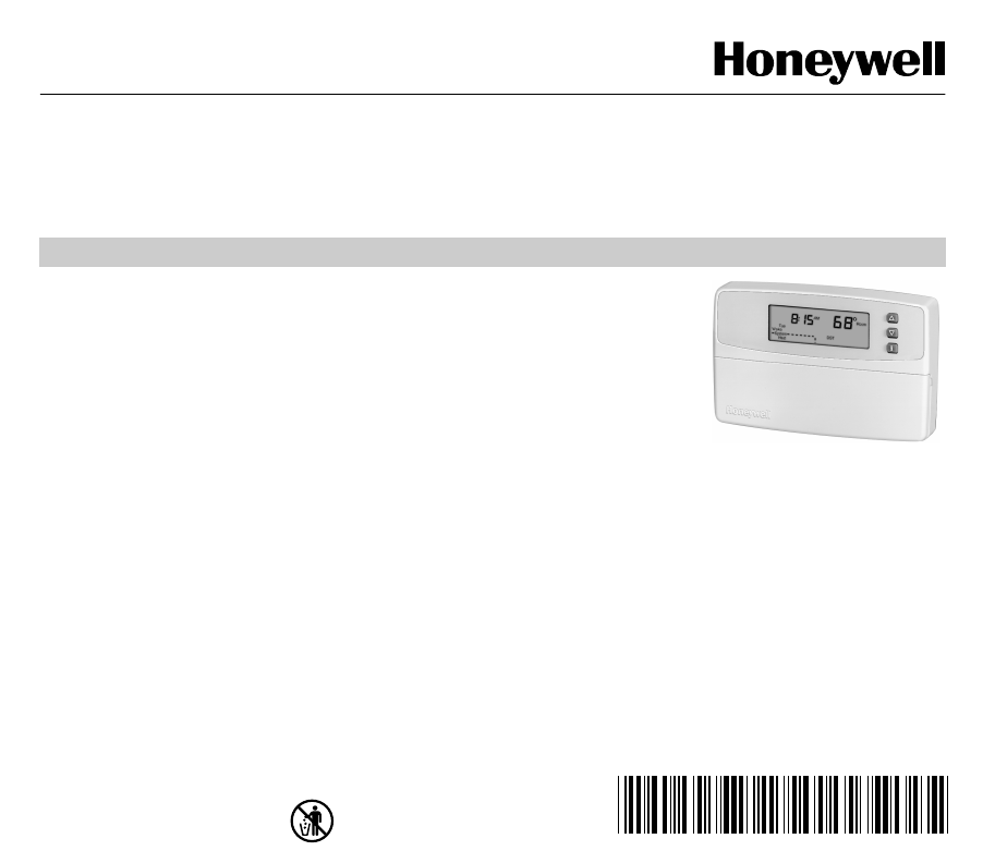
Honeywell CT3500CT3595 69 1199 CT3500/CT3595 PROGRAMMABLE THERMOSTAT User Manual To The E6284fde 8d67 4577 A9dc F92052cd8457
User Manual: Honeywell CT3500CT3595 to the manual
Open the PDF directly: View PDF ![]() .
.
Page Count: 24
- Total comfort temperature management with Smart Response™ Technology.
- Step 1. Prepare for Installation
- Step 2. Remove Old Thermostat
- Step 3. Mount Thermostat Wallplate
- Step 4. Wire Wallplate Terminals
- Step 5. Install the Batteries
- Step 6. Set Fan Operation Switch
- Step 7. Mount the Thermostat
- Step 8. Customize Your Thermostat
- Step 9. Set the Clock
- Step 10. Programming
- Step 11. Operating Your Thermostat
- Step 12. Set the Fan and System Switches
- If You Have a Problem
- Smart Response™ Technology
- Wiring Diagrams
69- 1199- 2
OWNER’S GUIDE
® U.S. Re
g
istered Trademark
Cop
y
ri
g
ht © 2001 Hone
y
well • •All Ri
g
hts Reserved
Honeywell CT3500/CT3595
PROGRAMMABLE THERMOSTAT
Weekda
y
, Saturda
y
and Sunda
y
Pro
g
rammable Heat and/or Cool
Low Volta
g
e
(
20 to 30 Vac
)
Thermostat and Wallplate
Model CT3500/CT3595
Para pedir estas instrucciones en español, llame al 1-800-468-1502.
Pour obtenir ce ode demploi en fran
ç
ais, composer le 1-800-468-1502.
Table of Contents
Step 1. Prepare for Installation .................................................................................................................................. 5
Step 2. Remove Old Thermostat ............................................................................................................................... 6
Step 3. Mount Thermostat Wallplate ......................................................................................................................... 7
Step 4. Wire Wallplate Terminals ............................................................................................................................... 8
Step 5. Install the Batteries ....................................................................................................................................... 9
Step 6. Set Fan Operation Switch ............................................................................................................................. 10
Step 7. Mount the Thermostat ................................................................................................................................... 11
Step 8. Customize Your Thermostat .......................................................................................................................... 11
Step 9. Set the Clock ................................................................................................................................................. 13
Step 10. Pro
g
rammin
g
.............................................................................................................................................. 14
Step 11. Operatin
g
Your Thermostat ......................................................................................................................... 17
Step 12. Set the Fan and S
y
stem Switches .............................................................................................................. 18
If You Have a Problem ............................................................................................................................................... 19
Smart Response™ Technolo
gy
................................................................................................................................. 21
Wirin
g
Dia
g
rams ........................................................................................................................................................ 22
69-1199—22
Total comfort temperature management with Smart Response™ Technology.
Con
g
ratulations! You made a smart choice b
y
purchasin
g
y
our new Hone
y
well thermostat the smart thermostat that;
•
Keeps you comfortable
b
y
automaticall
y
calculatin
g
exactl
y
when the furnace or air conditionin
g
should
g
o on to
have the house at the desired comfort temperature b
y
the time
y
ou wake up or return home.
•
Saves the maximum amount of energy
and money
b
y
automaticall
y
rememberin
g
to adjust the temperature when
y
ou leave home or
g
o to sleep.
•
Provides the ultimate in comfort and convenience
. It comes prepro
g
rammed. You can use the prepro
g
rammed
schedule, or set
y
our own.
This manual answers man
y
of the questions that can arise as
y
ou become familiar and comfortable with
y
our
Hone
y
well thermostat — the state of the art in home comfort controls.
Read these instructions carefull
y
. Failure to follow these instructions can dama
g
e the product or cause a hazardous
condition.
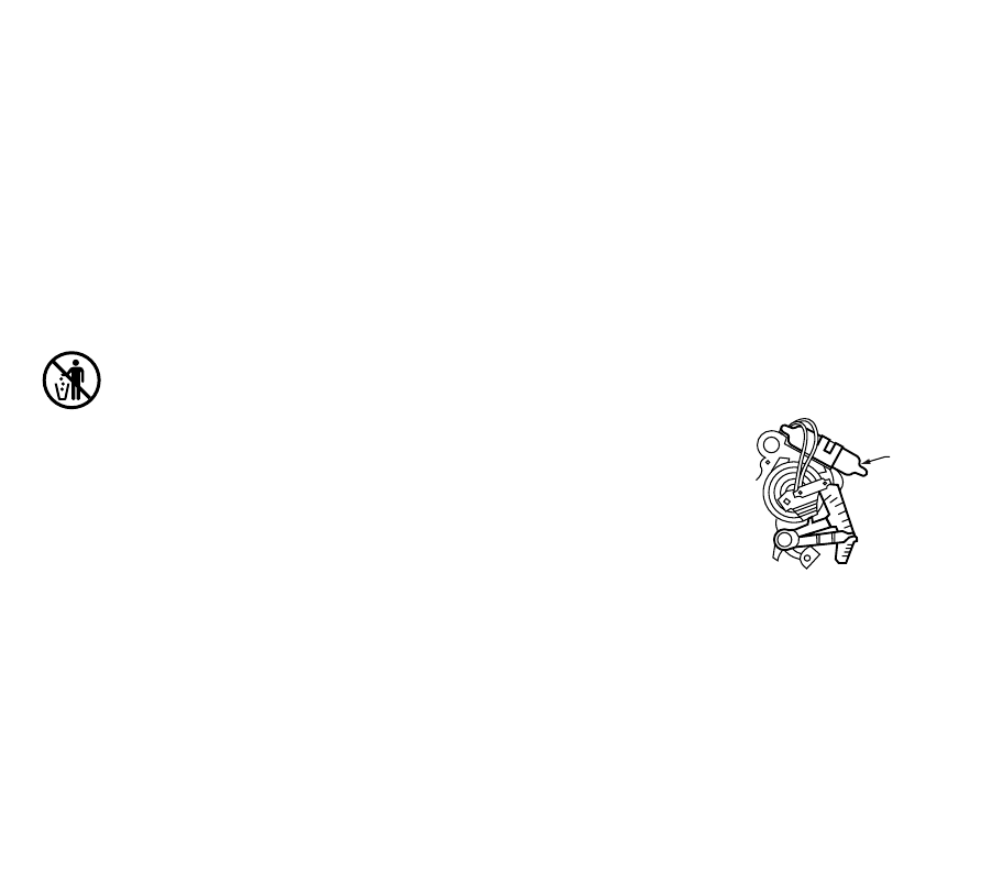
MERCURY NOTICE
If this thermostat is replacin
g
a control that contains mercur
y
in a sealed
tube, do not place
y
our old control in the trash. Contact
y
our local waste
mana
g
ement authorit
y
for instructions re
g
ardin
g
rec
y
clin
g
and the proper
disposal of this control, or of an old control containin
g
mercur
y
in a sealed
tube.
If
y
ou have questions, call Hone
y
well Inc. at 1-800-468-1502.
M10614
MERCURY
SWITCH
TYPICAL LOCATION OF A MERCURY
SWITCH IN A THERMOSTAT
3 69-1199—2
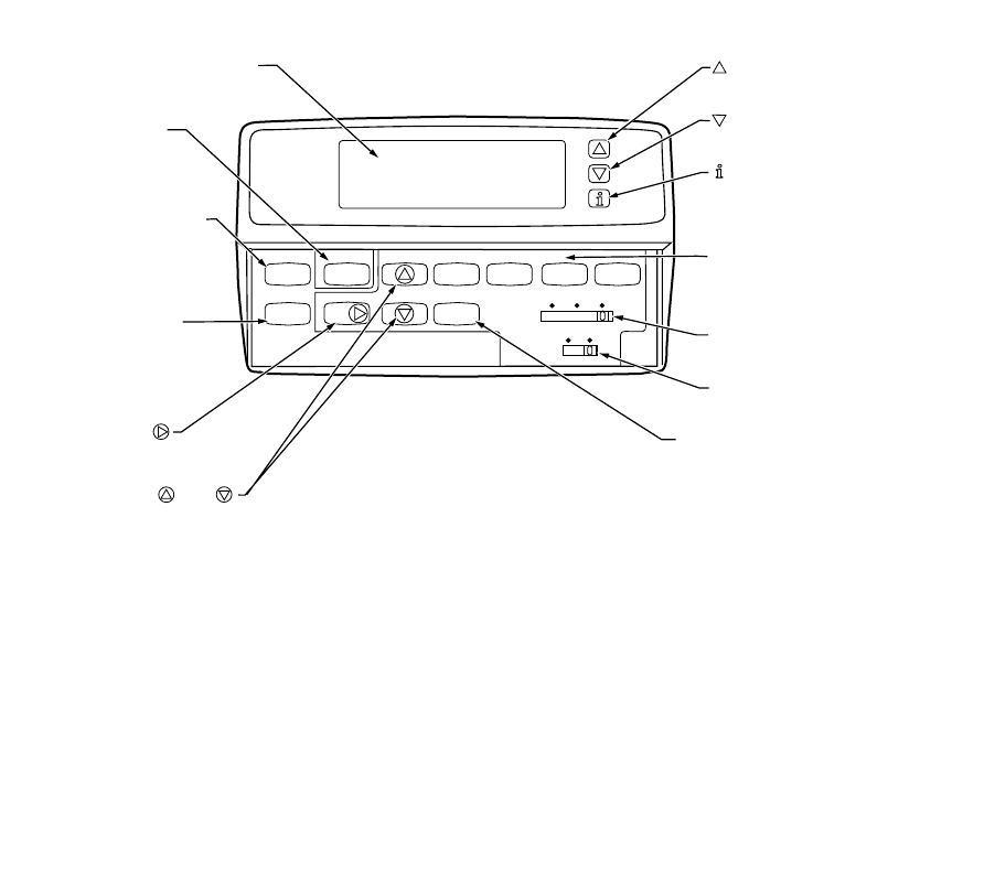
Time Set Program
Run
Program
Hold Temp
Set Current
Day/Time
Day Heat/Cool
Settings System
Fan
Wake Leave Return Sleep
Heat Off Cool
On Auto
M18589
RAISES TEMPERATURE
SETTING
LOWERS TEMPERATURE
SETTING
DISPLAYS CURRENT
HEAT/COOL
TEMPERATURE SETTING
PROGRAM PERIODS
WAKE/LEAVE/RETURN/SLEEP:
ENTERS PROGRAMMING MODE
FAN SWITCH
SELECTS AUTO/ON
SYSTEM SWITCH
SELECTS HEAT/OFF/COOL
DIGITAL DISPLAY
SET CURRENT
DAY/TIME
SETS CURRENT
TIME AND DAY
RUN PROGRAM
RETURNS
THERMOSTAT
TO NORMAL
OPERATING MODE
HEAT/COOL SETTING
SWITCHES BETWEEN
HEAT SETPOINTS AND
COOL SETPOINTS
WHILE PROGRAMMING
TIME /TIME
SETS TIME FORWARD OR BACK
DAY
SETS DAY OF
THE WEEK
HOLD TEMP
SETS A HOLD
TEMPERATURE
AND ACTIVATES
VACATION HOLD
FEATURE.
69-1199—24
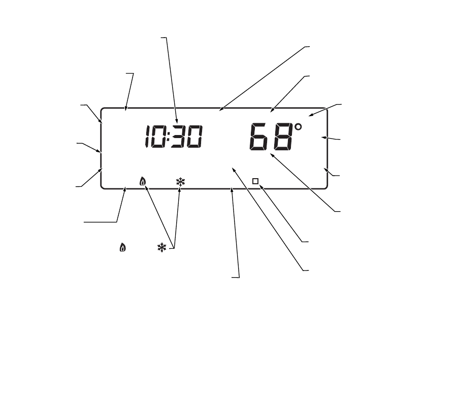
M18590
Aux Ht
System Off Auto
WakeLeaveReturnSleep
Mon
Wait
In
Room
Humid
Outdoor
Filter
AM
Hold for
Repl Batt
Recovery
Cool
TueWedThuFriSatSun Days
Set Program
Set Day/Time
Temporary Setting
Em Heat
Em Ht
DISPLAYS EITHER CURRENT
TIME OF DAY OR PROGRAM TIMES
SHOWS THERMOSTAT IS IN
THE SET DAY/TIME MODE
SHOWS TEMPERATURE SETTING
CHANGED FOR THIS PROGRAM PERIOD
SHOWS THE TEMPERATURE
DISPLAYED IS THE CURRENT
SET TEMPERATURE
SHOWS THE TEMPERATURE
DISPLAYED IS THE CURRENT
ROOM TEMPERATURE
SHOWS THE BATTERIES ARE
LOW AND MUST BE
REPLACED
DISPLAYES EITHER ROOM
OR SET TEMPERATURES
SHOWS THERMOSTAT IS PROCESSING
INFORMATION AND WAITING TO CALL FOR HEAT OR COOL
SHOWS SMART RESPONSE IS
CHANGING THE TEMPERATURE
TO MEET THE CURRENT PROGRAMS
SHOWS THAT THERMOSTAT IS
"CALLING" FOR HEAT OR COOL
SHOWS CURRENT
SYSTEM SWITCH POSITION
HEAT/OFF/COOL
SHOWS CURRENT
PROGRAM PERIOD
OR PERIOD BEING
PROGRAMMED
SHOWS CURRENT
DAY OR DAYS BEING
PROGRAMMED
SHOWS VACATION
HOLD DURATION
SHOWS WHEN
THERMOSTAT IS IN THE
PROGRAMMING MODE
SHOWS SMART RESPONSE IS OFF
CONVENTIONAL RECOVERY IS ON

5 69-1199—2
STEP 1. PREPARE FOR INSTALLATION
❑Check Table 1, the compatibilit
y
chart, to make sure the thermostat is compatible with
y
our s
y
stem. If
y
our s
y
stem
is not compatible, call Hone
y
well Customer Relations Center, toll-free, 1-800-468-1502.
Table 1. Compatibility Chart.
aCompatible with 2-wire Hone
y
well and Taco zone valves. Not compatible with 3-wire zone valves or 2-wire White
Rod
g
ers no. 1361 zone valves.
bMillivolt s
y
stem must be heatin
g
onl
y
.
cNot compatible with an
y
120/240 volt s
y
stem.
Package Contents
•Thermostat •Wallplate •Screws and anchors
•Wirin
g
labels •3 Ener
g
izer® AA batteries •Owners manual
Tools Required
•Screwdriver
•Drill
System Type Compatibility with CT3500/CT3595
Gas — Standin
g
Pilot Yes
Gas — Electronic I
g
nition Yes
Gas-fired Boilers Yesa
Gas — 750 Millivolt Heat onl
y
bYes
Oil-Fired Boilers Yesa
Oil-Fired Furnace Yes
Electric Furnace Yes
Electric Air Conditionin
g
Yes
Baseboard Electric (120/240 line volt)cNo
Sin
g
le Sta
g
e Heat Pump Yes
Multista
g
e Heat Pumps/Multista
g
e Equipment No

69-1199—26
STEP 2. REMOVE OLD THERMOSTAT
❑Test
y
our heatin
g
and coolin
g
s
y
stems to make sure the
y
work properl
y
. If either s
y
stem does not work, contact
y
our local heatin
g
/air-conditionin
g
dealer. To avoid compressor dama
g
e, do not operate the coolin
g
s
y
stem when
outdoor temperature is below 50°F (10°C).
❑Turn off power to the s
y
stem at the furnace or the fuse/circuit breaker panel.
❑Carefull
y
unpack
y
our new thermostat and wallplate. Save packa
g
e of screws, instructions, and receipt.
❑Remove the cover from the old thermostat. If the cover does not snap off when pulled firml
y
from the bottom, check
for a screw or screws used to lock on the cover.
❑Loosen the screw or screws holdin
g
the thermostat to the wallplate and lift the thermostat awa
y
.
❑Disconnect the wires from the old thermostat. As
y
ou disconnect each wire, attach the enclosed labels with the old
terminal desi
g
nation. If there are onl
y
two wires, the
y
do not need to be labeled. Wrap the wires around a pencil as
shown to keep them from fallin
g
back into the wall.
Special Installations
Read this section if
y
ou are replacin
g
:
•Clock thermostat with separate wires for the clock.
•Thermostat with six or more wires connected to it.
•Thermostat in a heatin
g
onl
y
s
y
stem with three wires.
Replacing a Clock Thermostat that has C or C1 Clock Terminals
If
y
ou are replacin
g
a Hone
y
well Chronotherm® Thermostat,
y
ou ma
y
find one or two
wires
g
oin
g
to the C or C1 clock terminals on the Chronotherm wirin
g
wallplate. Do not allow them to touch, or
y
ou can
dama
g
e the transformer. Disconnect the wires and wrap them separatel
y
usin
g
electrical tape. Do not wrap them
to
g
ether. Place the wires where the
y
will not interfere with the operation of the new thermostat. Record the colors and
terminal desi
g
nation labels of the remainin
g
wires.
Replacing a Thermostat that has Six or More Wires
If there are six or more wires (excludin
g
clock wires attached to terminals),
y
ou probabl
y
have a variation of a
multista
g
e heat pump or other multista
g
e s
y
stem. This thermostat is not compatible with multista
g
e s
y
stems, so return
the product to the place of purchase. For information about which pro
g
rammable thermostats will work with
y
our
s
y
stem, call Hone
y
well Customer Relations Center, at 1-800-468-1502.
WIRES THROUGH
WALL OPENING
M5136
7 69-1199—2
Replacing a Thermostat that has Three Wires
If
y
ou have three wires for a heatin
g
onl
y
s
y
stem and can operate the fan usin
g
the fan ON switch this thermostat
works with
y
our s
y
stem. However, some hot water (zoned) heatin
g
s
y
stems also have three wires. Your thermostat will
work onl
y
if
y
ou install an isolatin
g
rela
y
on these s
y
stems. For details, call
y
our local heatin
g
and/or coolin
g
contractor.
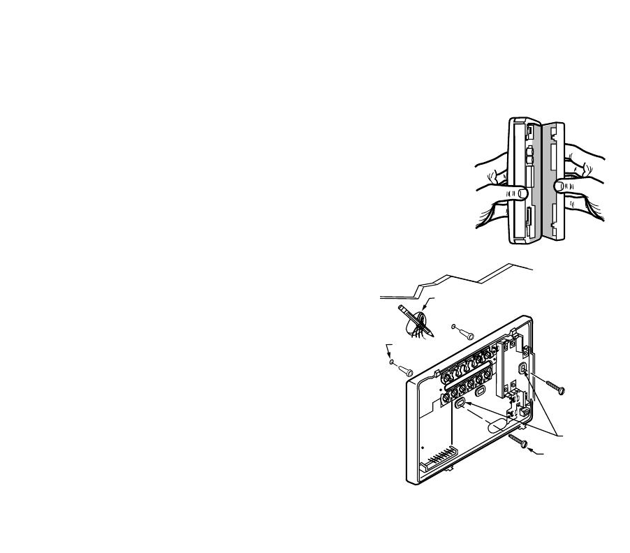
STEP 3. MOUNT THERMOSTAT WALLPLATE
❑Separate the wallplate from the thermostat b
y
placin
g
y
our thumb or fin
g
ers between
the bottom of the wallplate and the thermostat, and pullin
g
the wallplate up and awa
y
from the thermostat. See illustration at ri
g
ht.
❑Position the wallplate on the wall. Level the wallplate for appearance if desired. Use a
pencil to mark the two mountin
g
holes that best fit the application.
❑Remove the wallplate from the wall. Drill two 3/16 in. holes in wall
(if dr
y
wall) as shown. For materials such as plaster or wood, drill
7/32 in. holes where marked. Gentl
y
, tap the (provided) anchors
into the drilled holes until the
y
are flush with the wall.
❑Reposition the wallplate over the holes. Pull the wires throu
g
h the
wirin
g
openin
g
. Loosel
y
insert mountin
g
screws into each of the
holes
❑Level the wallplate if desired. Thermostat functions properl
y
when
not level.
❑Ti
g
hten mountin
g
screws.
M16427
WIRES
THROUGH WALL
WALL
MOUNTING
HOLES
M15044
MOUNTING
SCREWS
WALL
ANCHORS (2)
69-1199—28
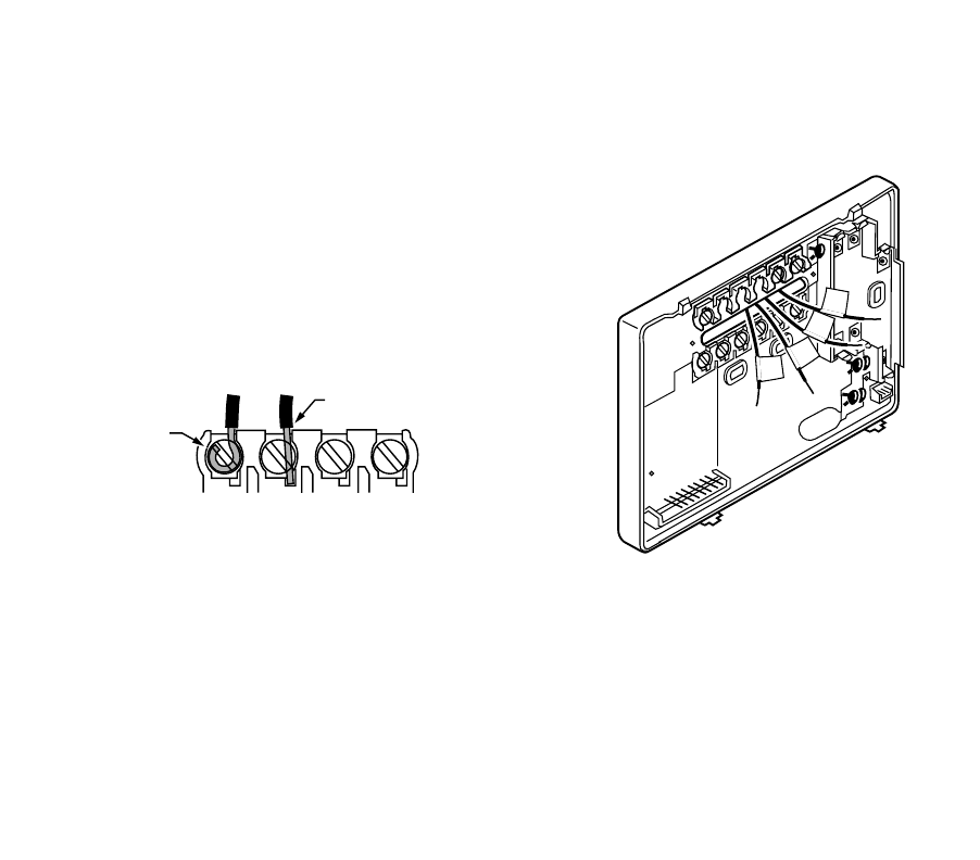
STEP 4. WIRE WALLPLATE TERMINALS
IMPORTANT
All wiring must comply with local codes and ordinances. If unsure about household wiring procedures, call
your local heating/air-conditioning contractor.
Refer to the labels
y
ou placed on the wires when
y
ou removed the
old thermostat (see illustration).
❑Match the letter of
y
our old thermostat wire with the
correspondin
g
terminal letter on
y
our new thermostat. Refer to
Table 2.
❑Remove the factor
y
-installed jumper connectin
g
terminals R and
RC if wires are connected to both of those terminals.
❑For wirin
g
dia
g
rams, if needed, see pp 21-22.
❑Loosen the terminal screws. Slip each wire beneath its matchin
g
terminal. Wraparound and strai
g
ht connections are both
acceptable, (see illustration). Ti
g
hten the terminals.
❑Plu
g
the hole in the wall with insulation to help prevent drafts
from adversel
y
affectin
g
thermostat operation. M16425
R
W
Y
G
M4826
FOR WRAPAROUND
INSERTION STRIP
7/16 IN. (11 MM).
FOR STRAIGHT INSERTION
STRIP 5/16 IN. (8 MM).
9 69-1199—2
Table 2. Terminal Designations on Old and New Thermostats
aIf both RH and R terminals are present on existin
g
thermostat, remove jumper and connect Rh to R and R to Rc.
bDo not connect both O and B when wirin
g
to a sin
g
le sta
g
e heat pump. Connect O to O. Tape off B.
cTape off end of the wire with electrical tape and push the taped wire back into the wirin
g
hole in the wall.
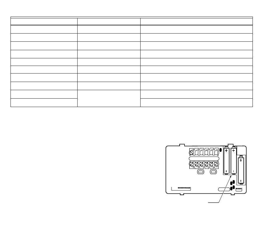
STEP 5. INSTALL THE BATTERIES
IMPORTANT
Three AA alkaline batteries are included with the thermo-
stat. Batteries must be installed for programming and
operation of the thermostat and the heating/cooling sys-
tem.
❑Install the batteries in the wallplate so the positive terminals all
point up (see illustration).
Terminal on Old Thermostat Connect To Description
R, RHa, 4, V R Power
Rc, RaRc Power for coolin
g
W, W1, H W Heat
Y, Y 1, M Y Coolin
g
G, F G Fan
O O Chan
g
eover in cool. (Sin
g
le sta
g
e heat pump onl
y
).
BbBbChan
g
eover in heat. (Sin
g
le sta
g
e heat pump onl
y
).
Cc, Xc, BbDo not connect. Transformer common
W2, H2Do not continue installation.
Call 1-800-468-1502. Second sta
g
e heat.
Y2Second sta
g
e cool.
M10622
INSTALL 3 AA ALKALINE BATTERIES
AS SHOWN, POSITIVE (+) TERMINALS
TOWARD TOP.
WALLPLATE
B
RRCOWYG
69-1199—210
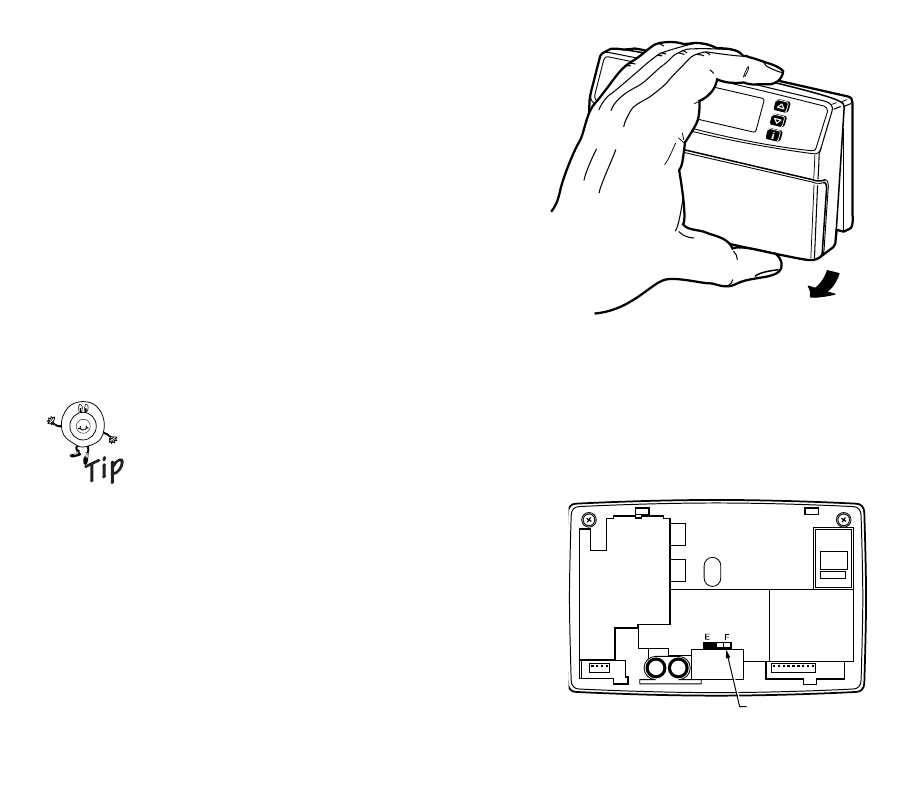
❑If the thermostat is alread
y
mounted on the wall, remove the
thermostat b
y
placin
g
y
our thumb between the thermostat and
wallplate and pullin
g
the thermostat up and awa
y
as shown.
When the batteries are runnin
g
low, a REPL BAT messa
g
e flashes
for one to two months before the batteries run out completel
y
.
Replace the batteries as soon as possible once the messa
g
e
flashes.
IMPORTANT
Although the thermostat has a low battery indicator,
replace the batteries once per year to prevent leakage
and to prevent the thermostat and heating/cooling sys-
tem from shutting down due to lack of battery power in
the thermostat.
If
y
ou insert new batteries within 20 to 30 seconds of removin
g
the
old batteries, the s
y
stem retains the current time and da
y
. If the
displa
y
is blank, the batteries are dead or installed incorrectl
y
. You must reset the time and da
y
. Refer to Set the Clock
for instructions.
As a precaution when leavin
g
home for lon
g
er than a month, chan
g
e batteries before leavin
g
to prevent
the s
y
stem from shuttin
g
down due to lack of power. Alwa
y
s use fresh alkaline batteries. Nonalkaline
batteries do not last as lon
g
. The
y
also can leak, causin
g
dama
g
e to the thermostat and the wall
surface. Hone
y
well recommends Ener
g
izer® batteries.
STEP 6. SET FAN OPERATION SWITCH
The thermostat fan operation switch, labeled FUEL SWITCH is factor
y
set
in the F position. This is the correct settin
g
for most s
y
stems. If
y
our
s
y
stem is an electric heat s
y
stem, set the switch to E. The E settin
g
allows
the fan to turn on immediatel
y
with the heatin
g
or coolin
g
in a s
y
stem
where the G terminal is connected.
M16424
80
90
70
60
90
80
70
60
M12676
FUEL SWITCH
11 69-1199—2
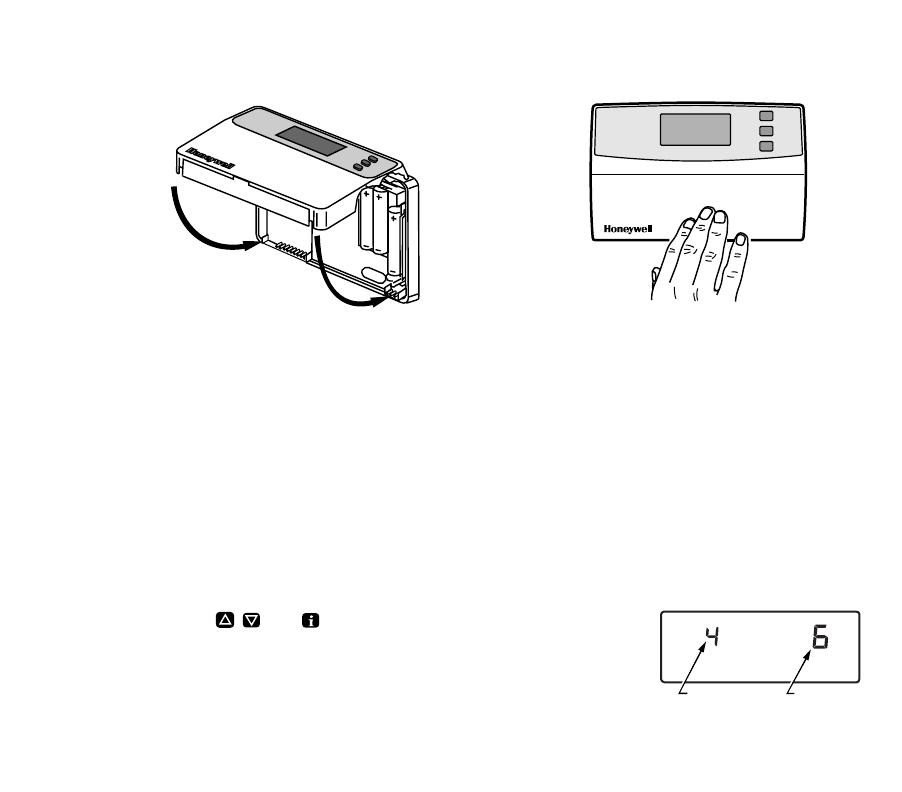
STEP 7. MOUNT THE THERMOSTAT
STEP 8. CUSTOMIZE YOUR THERMOSTAT
Your Hone
y
well thermostat comes preset to the most commonl
y
used settin
g
s. The settin
g
s are:
—Gas or oil forced air furnace.
—Smart Response technolo
gy
on.
—Temperature °F.
—12-hour clock format.
You can chan
g
e an
y
or all of these settin
g
s.
IMPORTANT
Always press the keys with your fingertip or a similar blunt tool. Sharp instruments like pens and pencil
points can damage the keyboard.
❑Press and hold down , , and , simultaneousl
y
until the screen shows.
You now can chan
g
e an
y
of these settin
g
s.
M12703
B.
PRESS LOWER
EDGE OF CASE
TO LATCH.
A.
ENGAGE TABS AT TOP
OF THERMOSTAT
AND WALLPLATE.
M13330
FEATURE
NUMBER
OPTION
69-1199—212
System Type (Feature Number 4)
S
y
stem t
y
pe options are:
—1 = Gravit
y
or steam s
y
stem.
—3 = Hot water, hi
g
h efficienc
y
furnace (90% or better), or sin
g
le sta
g
e heat pump.
—6 = Gas or oil forced air furnace (preset).
—9 = Electric furnace.
To chan
g
e
y
our s
y
stem t
y
pe:
❑Press until displa
y
shows
y
our furnace or boiler t
y
pe.
❑Press Time to move to next feature or to return to main displa
y
.
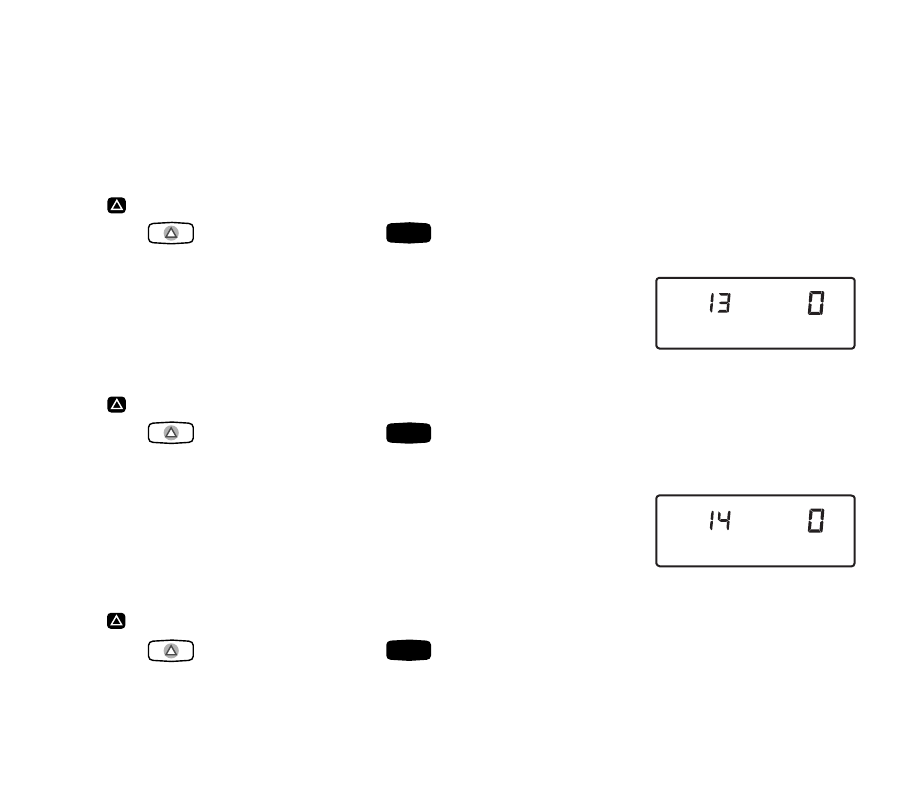
Smart Response™ Technology (Feature Number 13)
Smart Response technolo
gy
options are:
—0 = Smart Response technolo
gy
on (preset).
—1 = Smart Response technolo
gy
off.
To turn Smart Response technolo
gy
on or off:
❑Press once.
❑Press Time to move to next feature or to return to main displa
y
.
NOTE: See Smart Response technolo
gy
(pa
g
e 20) for information about this feature.
Temperature Format (Feature Number 14)
Temperature format options are:
—0 = °F (preset).
—1 = °C.
To chan
g
e temperature format:
❑Press once.
❑Press Time to move to next feature or to return to main displa
y
.
Run
Program
M13343
Run
Program
M13344
Run
Program
13 69-1199—2
Time Format (Feature Number 16)
Time format options are:
—0 = 12-hour clock (preset).
—1 = 24-hour clock.
To chan
g
e time format:
❑Press once.
❑Press to return to main displa
y
.
Factory Set Function (Feature Number 37)
Do not chan
g
e this settin
g
.
STEP 9. SET THE CLOCK
Set Current Day and Time
NOTE: On initial power-up, the screen flashes 1:00 pm until
y
ou press a ke
y
.
❑Press .
❑Press until screen shows current da
y
.
❑Press time or until screen shows current time. (Tappin
g
the will advance the time in one hour
increments).
❑Press .
M13345
Run
Program
M13346
Set Current
Day/Time
Day
Set Current
Day/Time
Run
Program

69-1199—214
STEP 10. PROGRAMMING
The ke
y
board is located behind the thermostat cover. The three most frequentl
y
used ke
y
s are near the displa
y
.
Pressin
g
displa
y
s the current temperature settin
g
s. Pressin
g
the and ke
y
s chan
g
e the temperature. The
thermostat displa
y
s da
y
, time, pro
g
ram period, temperature and s
y
stem settin
g
s.
There is an individual ke
y
for each of the four pro
g
ram periods:
—The pro
g
ram period when
y
ou want the house at a comfortable temperature when
y
ou
g
et up and while
y
ou
g
et read
y
for work or school. (This is a hi
g
her temperature durin
g
the heatin
g
season and a lower
temperature durin
g
the coolin
g
season).
—The pro
g
ram period
y
ou can set for an ener
gy
-savin
g
temperature while
y
ou are awa
y
at work or school.
(This is a lower temperature durin
g
the heatin
g
season and a hi
g
her temperature durin
g
the coolin
g
season).
—The pro
g
ram period when
y
ou want the house at a comfortable temperature for activities before bedtime.
(This is a hi
g
her temperature durin
g
the heatin
g
season and a lower temperature durin
g
the coolin
g
season).
—The pro
g
ram period
y
ou can set for an ener
gy
-savin
g
temperature while
y
ou sleepin
g
. (This is a lower
temperature durin
g
the heatin
g
season and a hi
g
her temperature durin
g
the coolin
g
season).
Table 3 can be helpful when plannin
g
y
our schedule of time and temperature settin
g
s. The thermostat prepro
g
rammed
settin
g
s are shown in parentheses ( ).
Wake
Leave
Return
Sleep
15 69-1199—2
Table 3. Personal Programming Table.
aYour heatin
g
setpoints cannot be hi
g
her than 90°F (32°C) or lower than 40°F (4.5°C).
bYour coolin
g
setpoints cannot be hi
g
her than 99°F (37°C) or lower than 45°F (7°C).
Program Weekdays
Start b
y
pro
g
rammin
g
the wake time and temperature for weekda
y
s.
❑Press and release .
❑Press until (Mon-Fri) displa
y
s.
❑Press Time or ke
y
until the desired time shows in the displa
y
.
NOTE: Pro
g
ram times are in 15 minute intervals. For example, 8:00, 8:15, 8:30.
❑Press or ke
y
until the desired wake temperature displa
y
s.
Period Default Setting Weekday (Mon-Fri) Saturday (Sat) Sunday (Sun)
Wake Time (6:00AM)
Heata (70°F/21°C)
Coolb (78°F/25.5°C)
Leave Time (8:00AM)
Heata (62°F/16.5°C)
Coolb (85°F/29.5°C)
Return Time (6:00PM)
Heata (70°F/21°C)
Coolb (78°F/25.5°C)
Sleep Time (10:00PM)
Heata (62°F/16.5°C)
Coolb (82°F/28°C)
Wake
Day
69-1199—216
The setpoint temperature ran
g
e is 40°F to 90°F (4.5°C to 32°C) for heatin
g
and 45°F to 99°F (7°C to 37°C) for coolin
g
.
❑Press to switch between heatin
g
and coolin
g
setpoints.
NOTE: Pro
g
ram times are the same for heatin
g
and coolin
g
.
❑Press or until the displa
y
shows the desired temperature setpoint.
❑Press , or and repeat these steps for each time period. Your weekda
y
is now pro
g
rammed.
Program Saturday and Sunday
Repeat each step in Pro
g
ram Weekda
y
s for Saturda
y
and Sunda
y
.
❑Press when the entire week is pro
g
rammed.
Clear a Program Period
NOTE: Wake cannot be cleared.
❑Press , , or for the pro
g
ram period
y
ou want to clear.
❑Press until the desired da
y
displa
y
s (Mon-Fri Sat; Sun).
❑Press and hold the , , or for approximatel
y
3 seconds until the time and temperature clear.
❑Repeat the above steps for each period to be cleared.
❑Press .
Heat/Cool
Settings
Leave Return Sleep
Run
Program
Leave Return Sleep
Day
Leave Return Sleep
Run
Program
17 69-1199—2
STEP 11. OPERATING YOUR THERMOSTAT
Change Temperature Setting Until the Next Program Period (Temporary Change)
❑Press or until the screen shows the desired temperature settin
g
.
NOTE: The temporar
y
temperature settin
g
is displa
y
ed for about 3 seconds and then the room temperature is dis-
pla
y
ed. Temporar
y
appears in the displa
y
. The settin
g
cancels when the next pro
g
ram period starts or when
y
ou press .
Change Temperature Setting Indefinitely (Hold)
❑Move the S
y
stem switch to the desired position (Heat or Cool).
❑Press then or to chan
g
e
y
our settin
g
if desired. (The displa
y
chan
g
es from showin
g
the setpoint
temperature to room temperature after approximatel
y
three seconds).
❑To cancel “Hold” press .
Change the Temperature Setting Until a Designated Day and Period (Vacation Hold)
❑Press twice.
❑Press or until the displa
y
shows the desired temperature setpoint.
❑Press Time until the desired number of da
y
s that
y
ou will be awa
y
(1 throu
g
h 255) is displa
y
ed.
❑Press , , or to select the pro
g
ram period when
y
ou want the pro
g
ram to restart.
NOTE: If the Vacation Hold needs to be cancelled before the desi
g
nated time, press to return to the pro-
g
ram.
Run
Program
Hold Temp
Run
Program
Hold Temp
Wake Leave Return Sleep
Run
Program
69-1199—218
STEP 12. SET THE FAN AND SYSTEM SWITCHES
First set the fan switch. Fan On: The fan runs continuousl
y
. Use for improved air
circulation or for more efficient central air cleanin
g
. (In a
heat-onl
y
s
y
stem, fan runs continuousl
y
onl
y
if fan rela
y
is
connected to the G thermostat terminal).
Fan Auto: Normal settin
g
for most homes. The equipment
controls the fan operation.
Then set the s
y
stem
switch. Heat: The thermostat controls
y
our heatin
g
s
y
stem.
Off: Both the heatin
g
and air conditionin
g
s
y
stems are off.
Cool: The thermostat controls
y
our air conditionin
g
s
y
stem.
Fan
On Auto
Fan
On Auto
System
Heat Off Cool
System
Heat Off Cool
System
Heat Off Cool

19 69-1199—2
IF YOU HAVE A PROBLEM
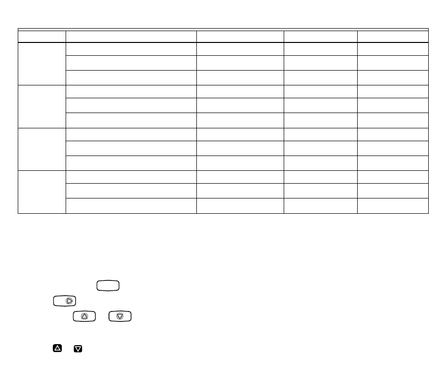
Table 4. Solution Guide.
If... Then…
Displa
y
does not appear. •Make sure the batteries are installed correctl
y
.
•Make sure the thermostat is mounted and latched on the wallplate.
Mount and latch the thermostat on the wallplate if it is not.
Temperature settin
g
s will not chan
g
e
(example; cannot set the heatin
g
hi
g
her
or the coolin
g
lower).
•Make sure the temperature setpoints are:
—40 to 90°F (4.5 to 32°C) for heatin
g
.
—45 to 99°F (7 to 37°C) for coolin
g
.
Heatin
g
does not come on. •Make sure the heatin
g
setpoint is above the room temperature.
•Make sure the circuit breaker is not tripped, and reset it if necessar
y
.
•Make sure the power switch at the equipment is in the On position, and
set it to On if it is in the Off position.
•Wait five minutes for the s
y
stem to respond.
•Set the s
y
stem switch to Heat.
69-1199—220
Toll-Free Customer Assistance
Please read and follow the provided instructions for this thermostat. For additional information,
g
o to
www.hone
y
well.com/
y
ourhome or call the Hone
y
well Customer Relations Center at 1-800-468-1502. The Center
hours are Monda
y
throu
g
h Frida
y
, 7:00AM to 5:30PM Central Time.
Before callin
g
, please have the followin
g
information available:
•Thermostat model number. (Located on back of thermostat).
•Thermostat date code. (Located below model number).
•T
y
pe of heatin
g
/coolin
g
s
y
stem (for example, hot water, warm air, oil, or
g
as).
•Location and number of wires connected to the thermostat.
Coolin
g
does not come on. •Make sure the coolin
g
setpoint is below the room temperature.
•Make sure the circuit breaker is not tripped, and reset it if necessar
y
.
•Make sure the s
y
stem switch at the air conditioner is in the On position,
and set it to On if it is in the Off position.
•Wait five minutes for the s
y
stem to respond.
•Set the s
y
stem switch to Cool.
S
y
stem on indicator ( = heat, =
cool) is lit, but no warm or cool air is
comin
g
from the re
g
isters.
Wait five minutes after seein
g
the flame or snowflake and check the
re
g
isters a
g
ain. If no there is no hot or cool air comin
g
from the re
g
isters,
refer to Heatin
g
does not come on or Coolin
g
does not come on. If all of this
has been checked, contact
y
our local heatin
g
and coolin
g
contractor.
Displa
y
flashes durin
g
pro
g
rammin
g
. Temperature settin
g
limit has been reached. The heatin
g
settin
g
ran
g
e is 40
to 90°F (4.5 to 32°C). The coolin
g
settin
g
ran
g
e is 45 to 99°F (7 to 37°C).
Temperature chan
g
es occur at the
wron
g
times. •Check the pro
g
ram times for the period in question.
•Make sure the AM and PM settin
g
s are correct.
•Make sure the current time and da
y
settin
g
s are correct.
•Repro
g
ram an
y
incorrect settin
g
s.
NOTE: If
y
our thermostat is set for Smart Response™ technolo
gy
, the
start times occur before
y
our pro
g
rammed comfort period.
Table 4. Solution Guide.
If... Then…
21 69-1199—2
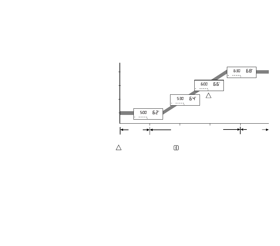
SMART RESPONSE™ TECHNOLOGY
Your thermostat is actuall
y
a small computer. The Smart Response technolo
gy
calculates the correct time of da
y
to
turn on
y
our heatin
g
or coolin
g
s
y
stem. Smart Response technolo
gy
considers the followin
g
information.
•Air temperature.
•Wall temperature.
•The time of da
y
when
y
ou want the comfort temperature established.
When the thermostat activates Smart
Response technolo
gy
, the thermostat
displa
y
s In Recover
y
, chan
g
es the
setpoint, and turns on the s
y
stem.
•Your thermostat learns from
experience. Each da
y
it checks how
closel
y
it hit the recover
y
tar
g
et and
then adjusts the next da
y
s recover
y
start time accordin
g
l
y
.
•It takes a few da
y
s after installation for
the thermostat to adjust to the local
weather,
y
our lifest
y
le, the
construction of
y
our home, and
y
our
heatin
g
/coolin
g
s
y
stem.
•You can turn off Smart Response
technolo
gy
b
y
selectin
g
Conventional
Recover
y
. See Step 8. Customize
Your Thermostat.
System Operating in
Energy Savings Mode
Recovery
Begins
Recovery
Continues
System Operating
in Comfort Mode
ENERGY
SAVINGS
PERIOD
RECOVERY FROM ENERGY SAVINGS
5:305:00 6:00 6:30
COMFORT
PERIOD
TIME
THERMOSTAT USES THE SAME SCHEME TO RETURN TO LOWER COMFORT TEMPERATURE DURING
THE COOLING SEASON.
M18591
62°F
64°F
66°F
68°F
Heat
System
Mon In
Room
AM
Recovery
Sleep
Heat
System
Wake
Mon
Room
AM
Heat
Heat
System
Mon In
Room
AM
Recovery
Sleep
Heat
System
Mon
Room
AM
Sleep
Heat
IF In Recovery IS DISPLAYED, PRESS TO SEE THE COMFORT SETPOINT.
1
1
TEMPERATURE
69-1199—222
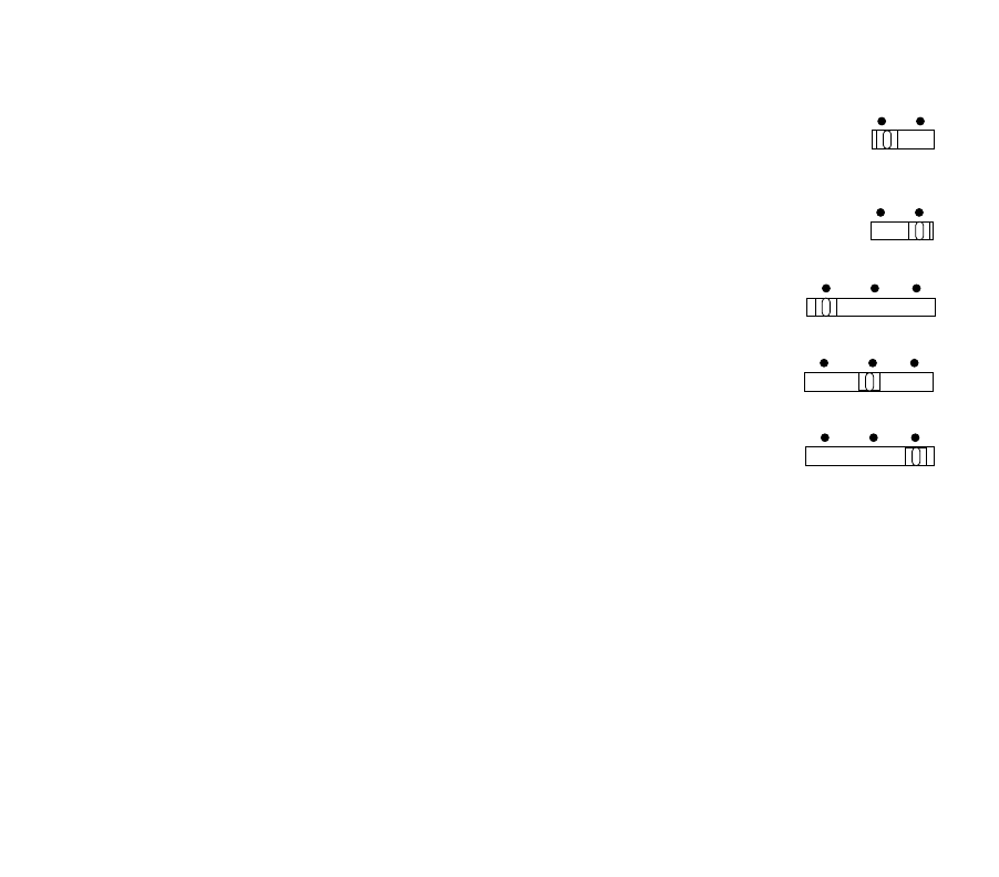
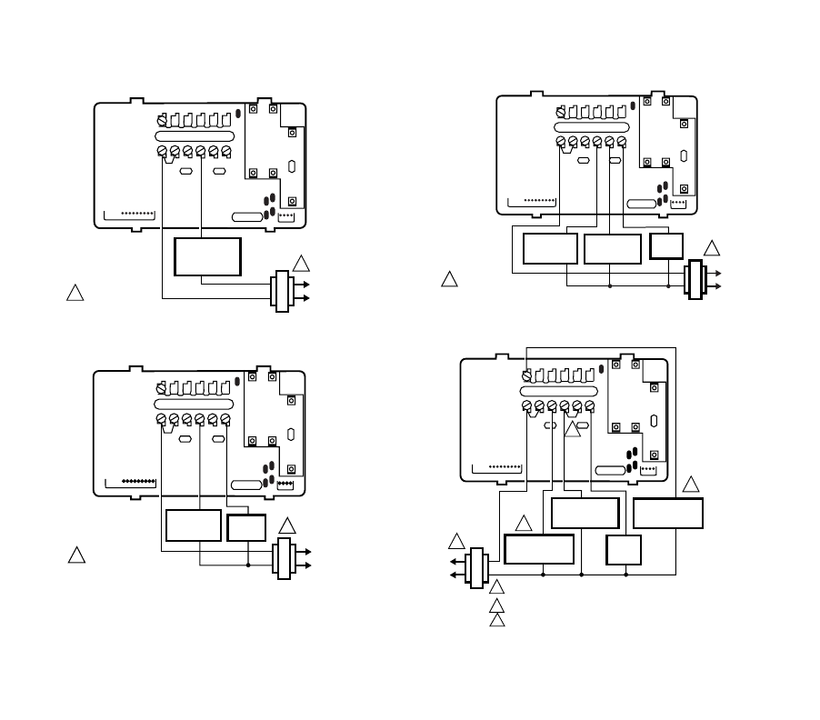
WIRING DIAGRAMS
THERMOSTAT
1 POWER SUPPLY.
PROVIDE DISCONNECT MEANS
AND OVERLOAD PROTECTION AS REQUIRED.
1
HEATING
RELAY OR
VALVE COIL
B
R
RC
OW Y
G
2-WIRE HEAT-ONLY
(JUMPER INTACT)
M10616
M10617
THERMOSTAT
1 POWER SUPPLY. PROVIDE
DISCONNECT MEANS AND
OVERLOAD PROTECTION AS REQUIRED.
1
4-WIRE HEAT/COOL
(JUMPER INTACT)
HEATING
RELAY OR
VALVE COIL
COOLING
CONTACTOR
COIL
FAN
RELAY
B
R
RC
OW Y
G
M10618
THERMOSTAT
1 POWER SUPPLY. PROVIDE
DISCONNECT MEANS AND
OVERLOAD PROTECTION AS REQUIRED.
1
3-WIRE HEAT ONLY WITH FAN
(JUMPER INTACT)
HEATING
RELAY OR
VALVE COIL
FAN
RELAY
B
R
RC
OW Y
G
M12739
THERMOSTAT
4-WIRE SINGLE-STAGE HEAT PUMP
(JUMPER INTACT)
B
R
RC
OW Y
G
POWER SUPPLY. PROVIDE DISCONNECT MEANS
AND OVERLOAD PROTECTION AS REQUIRED.
USE EITHER O OR B FOR HEAT PUMP CHANGEOVER.
USING A JUMPER WIRE (NOT SUPPLIED) CONNECT W TO Y.
1
2
2
2
1
COMPRESSOR
CONTACTOR
COOL
CHANGEOVER
VALVE
HEAT
CHANGEOVER
VALVE
FAN
RELAY
3
3
23 69-1199—2
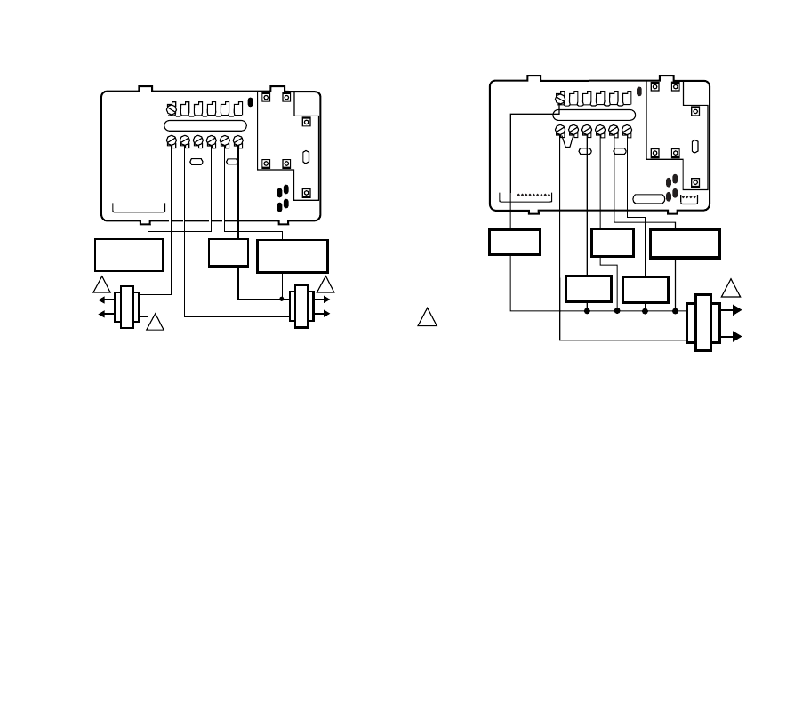
Notice:
This thermostat is a Class B di
g
ital apparatus that complies with Canadian Radio Interference Re
g
ulations,
CRC c. 1374.
M10619
THERMOSTAT
1 POWER SUPPLY. PROVIDE
DISCONNECT MEANS AND OVERLOAD
PROTECTION AS REQUIRED.
11
5-WIRE HEAT/COOL
(JUMPER REMOVED)
HEATING
RELAY OR
VALVE COIL
COOLING
CONTACTOR
COIL
FAN
RELAY
B
R
RC
OW Y
G
M18738
HEAT
RELAY COMPRESSOR
CONTACTOR
COOL
DAMPER
1POWER SUPPLY. PROVIDE
DISCONNECT MEANS AND
OVERLOAD PROTECTION
AS REQUIRED.
1
5-WIRE HEAT/COOL WITH DAMPER
(JUMPER INTACT)
B
R
RC
OW Y
G
FAN
RELAY
HEAT
DAMPER
THERMOSTAT
Home and Building Control Home and Building Control
Honeywell Honeywell Limited-Honeywell Limitée
1985 Douglas Drive North 35 Dynamic Drive
Golden Valley, MN 55422 Scarborough, Ontario
M1V 4Z9
69-1199—2 J.H. Rev. 04-01 www.hone
y
well.com/
y
ourhome
Printed in U.S.A. on recycled
paper containing at least 10%
post-consumer paper fibers.
Limited One-Year Warranty
Honeywell warrants this product, excluding battery, to be free from defects in the workmanship or materials, under normal use and
service, for a period of one (1) year from the date of purchase by the consumer. If, at any time during the warranty period, the product is
defective or malfunctions, Honeywell shall repair or replace it (at Honeywells option) within a reasonable period of time.
If the product is defective,
(i) return it, with a bill of sale or other dated proof of purchase, to the retailer from which you purchased it, or
(ii) package it carefully, along with proof of purchase (including date of purchase) and a short description of the malfunction, and mail
it, postage prepaid, to the following address:
Honeywell Inc. USA Honeywell Canada:
Dock 4 — MN10-3860 Honeywell Limited/Honeywell Limitée
1885 Douglas Drive North 35 Dynamic Drive
Golden Valley, MN 55422-3992 Scarborough, Ontario M1V 4Z9
This warranty does not cover removal or reinstallation costs. This warranty shall not apply if it is shown by Honeywell that the defect or
malfunction was caused by damage which occurred while the product was in the possession of a consumer.
Honeywells sole responsibility shall be to repair or replace the product within the terms stated above. HONEYWELL SHALL NOT BE
LIABLE FOR ANY LOSS OR DAMAGE OF ANY KIND, INCLUDING ANY INCIDENTAL OR CONSEQUENTIAL DAMAGES
RESULTING, DIRECTLY OR INDIRECTLY FROM ANY BREACH OF ANY WARRANTY, EXPRESS OR IMPLIED, OR ANY OTHER
FAILURE OF THIS PRODUCT. Some states do not allow the exclusion or limitation of incidental or consequential damages, so this
limitation may not apply to you.
THIS WARRANTY IS THE ONLY EXPRESS WARRANTY HONEYWELL MAKES ON THIS PRODUCT. THE DURATION OF ANY
IMPLIED WARRANTIES, INCLUDING THE WARRANTIES OF MERCHANTABILITY AND FITNESS FOR A PARTICULAR PURPOSE,
IS HEREBY LIMITED TO THE ONE YEAR DURATION OF THIS WARRANTY. Some states do not allow limitations on how long an
implied warranty lasts, so the above limitation may not apply to you.
This warranty gives you specific legal rights, and you may have other rights which vary from state to state.
If you have any questions concerning this warranty, please write our Customer Relations Center, Honeywell Inc., 1885 Douglas Dr. N.,
Golden Valley, MN 55422-3992, or call 1-800-468-1502, Monday-Friday, 7:00 a.m. to 5:30 p.m., Central time. In Canada, write Retail
Products ON30 Honeywell Limited/Honeywell Limitée, 155 Gordon Baker Road, North York, Ontario M2H 3N7.
