Honeywell D6000 Mobile Computer User Manual D6000 Users Manual
Honeywell International Inc Mobile Computer D6000 Users Manual
User Manual

Dolphin 6000 Mobile Computers
with Windows Mobile 6.5
Users Guide

ii
Disclaimer
Honeywell International Inc. ( HII ) reserves the right to make changes in specifications and
other information contained in this document without prior notice, and the reader should in all
cases consult HII to determine whether any such changes have been made. The information
in this publication does not represent a commitment on the part of HII.
HII shall not be liable for technical or editorial errors or omissions contained herein; nor for
incidental or consequential damages resulting from the furnishing, performance, or use of this
material.
This document contains proprietary information that is protected by copyright. All rights are
reserved. No part of this document may be photocopied, reproduced, or translated into
another language without the prior written consent of HII.
Web Address: www.honeywellaidc.com
Trademarks
Dolphin 6000, Dolphin 6000 RF, HomeBase, Mobile Base, and QuadCharger are trademarks
or registered trademarks of Hand Held Products, Inc. or Honeywell International Inc.
Microsoft, Windows, Windows Mobile, Windows CE, Windows 98 Second Edition, Windows
NT, Windows 2000, Windows ME, Windows XP, ActiveSync, Outlook, and the Windows logo
are trademarks or registered trademarks of Microsoft Corporation.
Other product names mentioned in this manual may be trademarks or registered trademarks
of their respective companies and are the property of their respective owners.
Patents
Please refer to the product packaging for a list of patents.
Other Trademarks
The Bluetooth trademarks are owned by Bluetooth SIG, Inc., U.S.A. and licensed to
Honeywell.
Conventions
The touch panel display can be activated by using the stylus (included with the device) or a
finger. To activate the display, open a file or select a menu, use the bottom tip of the stylus to
Tap the touch panel display or gently press the touch panel with your finger.

iii
Safety Information
Label Locations. . . . . . . . . . . . . . . . . . . . . . . . . . . . . . . . . . . . . 1-1
Laser Safety Label. . . . . . . . . . . . . . . . . . . . . . . . . . . . . . . . . 1-1
LED Safety Statement. . . . . . . . . . . . . . . . . . . . . . . . . . . . . . . . 1-2
Operating Temperature . . . . . . . . . . . . . . . . . . . . . . . . . . . . . . 1-2
RoHS Chart . . . . . . . . . . . . . . . . . . . . . . . . . . . . . . . . . . . . . . . . 1-2
Agency Information . . . . . . . . . . . . . . . . . . . . . . . . . . . . . . . . . 1-2
UL and cUL Statement . . . . . . . . . . . . . . . . . . . . . . . . . . . . . 1-2
Approvals by Country . . . . . . . . . . . . . . . . . . . . . . . . . . . . . . 1-3
R&TTE Compliance Statement . . . . . . . . . . . . . . . . . . . . . . . . 1-4
Dolphin 6000 RF Device. . . . . . . . . . . . . . . . . . . . . . . . . . . . . . 1-4
FCC+IC Exposure :. . . . . . . . . . . . . . . . . . . . . . . . . . . . . . . . 1-5
Canadian Compliance. . . . . . . . . . . . . . . . . . . . . . . . . . . . . . . . 1-5
For European Community Users. . . . . . . . . . . . . . . . . . . . . . . 1-6
Waste Electrical and Electronic Equipment. . . . . . . . . . . . . . 1-6
Electrically Powered Devices. . . . . . . . . . . . . . . . . . . . . . . . . . 1-6
Microwaves . . . . . . . . . . . . . . . . . . . . . . . . . . . . . . . . . . . . . . . . 1-6
Getting Started
Out of the Box. . . . . . . . . . . . . . . . . . . . . . . . . . . . . . . . . . . . . . 2-1
Install Main Battery Pack . . . . . . . . . . . . . . . . . . . . . . . . . . . . . 2-1
Charge the Batteries. . . . . . . . . . . . . . . . . . . . . . . . . . . . . . . . . 2-2
Before Initial Use. . . . . . . . . . . . . . . . . . . . . . . . . . . . . . . . . . . . 2-2
Charging Using the Communication Cable . . . . . . . . . . . . . . 2-2
Boot the Device. . . . . . . . . . . . . . . . . . . . . . . . . . . . . . . . . . . . . 2-3
Using Touch Panel Display . . . . . . . . . . . . . . . . . . . . . . . . . . . 2-3
Today Screen. . . . . . . . . . . . . . . . . . . . . . . . . . . . . . . . . . . . . . . 2-4
Navigation Bar. . . . . . . . . . . . . . . . . . . . . . . . . . . . . . . . . . . . 2-4
Command Bar . . . . . . . . . . . . . . . . . . . . . . . . . . . . . . . . . . . . 2-4
Navigation Bar Icons . . . . . . . . . . . . . . . . . . . . . . . . . . . . . . . . 2-5
Set Time Zone, Time, and Date . . . . . . . . . . . . . . . . . . . . . . . . 2-7
Pop-Up Menus. . . . . . . . . . . . . . . . . . . . . . . . . . . . . . . . . . . . . . 2-8
Selecting Programs . . . . . . . . . . . . . . . . . . . . . . . . . . . . . . . . . 2-9
File Explorer . . . . . . . . . . . . . . . . . . . . . . . . . . . . . . . . . . . . . . . 2-9
Search Phone . . . . . . . . . . . . . . . . . . . . . . . . . . . . . . . . . . . . . . 2-11
Hardware Overview
Standard Configurations . . . . . . . . . . . . . . . . . . . . . . . . . . . . . 3-1
Peripherals. . . . . . . . . . . . . . . . . . . . . . . . . . . . . . . . . . . . . . . . . 3-1
HomeBase. . . . . . . . . . . . . . . . . . . . . . . . . . . . . . . . . . . . . . . 3-1
Accessories. . . . . . . . . . . . . . . . . . . . . . . . . . . . . . . . . . . . . . . . 3-2
Communication/Charging Cables . . . . . . . . . . . . . . . . . . . . . 3-2
Li-ion Battery Pack. . . . . . . . . . . . . . . . . . . . . . . . . . . . . . . . . 3-2
Vehicle Charging Cable. . . . . . . . . . . . . . . . . . . . . . . . . . . . . 3-2
USB Client Holder Cable. . . . . . . . . . . . . . . . . . . . . . . . . . . . 3-2
Front View . . . . . . . . . . . . . . . . . . . . . . . . . . . . . . . . . . . . . . . . . 3-3

iv
Base View . . . . . . . . . . . . . . . . . . . . . . . . . . . . . . . . . . . . . . . . . 3-5
Left View . . . . . . . . . . . . . . . . . . . . . . . . . . . . . . . . . . . . . . . . . . 3-7
Right View . . . . . . . . . . . . . . . . . . . . . . . . . . . . . . . . . . . . . . . . . 3-7
Memory Card Installation. . . . . . . . . . . . . . . . . . . . . . . . . . . . . 3-8
Installing a SIM Card. . . . . . . . . . . . . . . . . . . . . . . . . . . . . . . . . 3-10
Bottom Rear Panel . . . . . . . . . . . . . . . . . . . . . . . . . . . . . . . . . . 3-12
I/O Connector . . . . . . . . . . . . . . . . . . . . . . . . . . . . . . . . . . . . . . 3-13
Using the Touch Panel. . . . . . . . . . . . . . . . . . . . . . . . . . . . . . . 3-13
Battery Pack . . . . . . . . . . . . . . . . . . . . . . . . . . . . . . . . . . . . . . . 3-14
Charging Options. . . . . . . . . . . . . . . . . . . . . . . . . . . . . . . . . . 3-14
Charging Time. . . . . . . . . . . . . . . . . . . . . . . . . . . . . . . . . . . . 3-14
Storing Batteries . . . . . . . . . . . . . . . . . . . . . . . . . . . . . . . . . . 3-14
Battery Pack Use and Disposal. . . . . . . . . . . . . . . . . . . . . . . 3-14
Managing Battery Power . . . . . . . . . . . . . . . . . . . . . . . . . . . . . 3-14
Checking Battery Power. . . . . . . . . . . . . . . . . . . . . . . . . . . . . . 3-15
Resetting the Device. . . . . . . . . . . . . . . . . . . . . . . . . . . . . . . . . 3-16
Soft Reset (Warm Boot). . . . . . . . . . . . . . . . . . . . . . . . . . . . . 3-16
Hard Reset (Cold Boot). . . . . . . . . . . . . . . . . . . . . . . . . . . . . 3-16
Suspend Mode. . . . . . . . . . . . . . . . . . . . . . . . . . . . . . . . . . . . . . 3-17
Hardware Maintenance. . . . . . . . . . . . . . . . . . . . . . . . . . . . . . . 3-17
Using the Scan Image Engine
Overview . . . . . . . . . . . . . . . . . . . . . . . . . . . . . . . . . . . . . . . . . . 4-1
Angled Imaging . . . . . . . . . . . . . . . . . . . . . . . . . . . . . . . . . . . 4-1
Image Engine Specifications. . . . . . . . . . . . . . . . . . . . . . . . . 4-1
Laser Specifications. . . . . . . . . . . . . . . . . . . . . . . . . . . . . . . . 4-1
Supported Bar Code Symbologies . . . . . . . . . . . . . . . . . . . . . 4-2
Decoding . . . . . . . . . . . . . . . . . . . . . . . . . . . . . . . . . . . . . . . . . . 4-3
Decode a Bar Code. . . . . . . . . . . . . . . . . . . . . . . . . . . . . . . . 4-3
Aiming Options. . . . . . . . . . . . . . . . . . . . . . . . . . . . . . . . . . . . . 4-4
Using the Camera
Overview . . . . . . . . . . . . . . . . . . . . . . . . . . . . . . . . . . . . . . . . . . 5-1
Taking a picture. . . . . . . . . . . . . . . . . . . . . . . . . . . . . . . . . . . . . 5-1
Menu. . . . . . . . . . . . . . . . . . . . . . . . . . . . . . . . . . . . . . . . . . . . . . 5-1
Options. . . . . . . . . . . . . . . . . . . . . . . . . . . . . . . . . . . . . . . . . . . . 5-2
Recording Video . . . . . . . . . . . . . . . . . . . . . . . . . . . . . . . . . . . . 5-2
Using the Keypad
Keypad. . . . . . . . . . . . . . . . . . . . . . . . . . . . . . . . . . . . . . . . . . . . 6-1
Using the Function Keys . . . . . . . . . . . . . . . . . . . . . . . . . . . . . 6-2
Using the Navigation Keys. . . . . . . . . . . . . . . . . . . . . . . . . . . . 6-3
29-Key Numeric Keypad. . . . . . . . . . . . . . . . . . . . . . . . . . . . . . 6-3
Keypad Combinations . . . . . . . . . . . . . . . . . . . . . . . . . . . . . . . 6-3
System Settings
Overview . . . . . . . . . . . . . . . . . . . . . . . . . . . . . . . . . . . . . . . . . . 7-1
Clock & Alarms . . . . . . . . . . . . . . . . . . . . . . . . . . . . . . . . . . . . . 7-2

v
Personal Menu. . . . . . . . . . . . . . . . . . . . . . . . . . . . . . . . . . . . . . 7-3
Using File Explorer . . . . . . . . . . . . . . . . . . . . . . . . . . . . . . . . 7-4
Using ActiveSync on the Workstation . . . . . . . . . . . . . . . . . . 7-5
System Menu. . . . . . . . . . . . . . . . . . . . . . . . . . . . . . . . . . . . . . . 7-6
About . . . . . . . . . . . . . . . . . . . . . . . . . . . . . . . . . . . . . . . . . . . . . 7-7
Backlight . . . . . . . . . . . . . . . . . . . . . . . . . . . . . . . . . . . . . . . . . . 7-8
Backlight Intensity . . . . . . . . . . . . . . . . . . . . . . . . . . . . . . . . . 7-9
Certificates. . . . . . . . . . . . . . . . . . . . . . . . . . . . . . . . . . . . . . . . . 7-9
Encryption. . . . . . . . . . . . . . . . . . . . . . . . . . . . . . . . . . . . . . . . . 7-10
Error Reporting. . . . . . . . . . . . . . . . . . . . . . . . . . . . . . . . . . . . . 7-10
External GPS. . . . . . . . . . . . . . . . . . . . . . . . . . . . . . . . . . . . . . . 7-11
Memory . . . . . . . . . . . . . . . . . . . . . . . . . . . . . . . . . . . . . . . . . . . 7-12
Main. . . . . . . . . . . . . . . . . . . . . . . . . . . . . . . . . . . . . . . . . . . . 7-12
Storage Card. . . . . . . . . . . . . . . . . . . . . . . . . . . . . . . . . . . . . 7-13
Power. . . . . . . . . . . . . . . . . . . . . . . . . . . . . . . . . . . . . . . . . . . . . 7-14
Battery. . . . . . . . . . . . . . . . . . . . . . . . . . . . . . . . . . . . . . . . . . 7-14
Advanced Tab . . . . . . . . . . . . . . . . . . . . . . . . . . . . . . . . . . . . 7-14
Regional Settings . . . . . . . . . . . . . . . . . . . . . . . . . . . . . . . . . . . 7-15
Remove Programs . . . . . . . . . . . . . . . . . . . . . . . . . . . . . . . . . . 7-15
Screen . . . . . . . . . . . . . . . . . . . . . . . . . . . . . . . . . . . . . . . . . . . . 7-17
General . . . . . . . . . . . . . . . . . . . . . . . . . . . . . . . . . . . . . . . . . 7-17
ClearType . . . . . . . . . . . . . . . . . . . . . . . . . . . . . . . . . . . . . . . 7-18
Text Size . . . . . . . . . . . . . . . . . . . . . . . . . . . . . . . . . . . . . . . . 7-18
Task Manager . . . . . . . . . . . . . . . . . . . . . . . . . . . . . . . . . . . . . . 7-20
Using the Task Manager . . . . . . . . . . . . . . . . . . . . . . . . . . . . 7-20
Communication
Connections Menu . . . . . . . . . . . . . . . . . . . . . . . . . . . . . . . . . . 8-1
Connections Manager. . . . . . . . . . . . . . . . . . . . . . . . . . . . . . . . 8-2
Tasks Tab . . . . . . . . . . . . . . . . . . . . . . . . . . . . . . . . . . . . . . . 8-2
Modify an Existing Connection . . . . . . . . . . . . . . . . . . . . . . . 8-3
Advanced Tab . . . . . . . . . . . . . . . . . . . . . . . . . . . . . . . . . . . . 8-4
Online Help . . . . . . . . . . . . . . . . . . . . . . . . . . . . . . . . . . . . . . . . 8-4
Wireless Manager . . . . . . . . . . . . . . . . . . . . . . . . . . . . . . . . . . . 8-5
ActiveSync Communication. . . . . . . . . . . . . . . . . . . . . . . . . . . 8-5
Capabilities . . . . . . . . . . . . . . . . . . . . . . . . . . . . . . . . . . . . . . . . 8-5
Communication Types . . . . . . . . . . . . . . . . . . . . . . . . . . . . . . . 8-5
Hardware Requirements for Setup . . . . . . . . . . . . . . . . . . . . . 8-6
Software Requirements for Communication . . . . . . . . . . . . . 8-6
Setting Up the Host Workstation. . . . . . . . . . . . . . . . . . . . . . . 8-7
Communicating with the Dolphin 6000 device. . . . . . . . . . . . 8-7
Synchronizing with the Host Workstation . . . . . . . . . . . . . . . 8-7
Exploring the Device from the Workstation. . . . . . . . . . . . . . 8-8
Installing Additional Software . . . . . . . . . . . . . . . . . . . . . . . . . 8-8
Adding Programs to the Device Using ActiveSync. . . . . . . . 8-9

vi
Installer File. . . . . . . . . . . . . . . . . . . . . . . . . . . . . . . . . . . . . . 8-9
Non-Installer File . . . . . . . . . . . . . . . . . . . . . . . . . . . . . . . . . . 8-9
Adding Programs Directly from the Internet . . . . . . . . . . . . . 8-10
COM Port Assignment Table . . . . . . . . . . . . . . . . . . . . . . . . . . 8-10
Working with GSM/GPRS/EDGE
Overview . . . . . . . . . . . . . . . . . . . . . . . . . . . . . . . . . . . . . . . . . . 9-1
Requirements . . . . . . . . . . . . . . . . . . . . . . . . . . . . . . . . . . . . . . 9-1
Voice and Data Communication . . . . . . . . . . . . . . . . . . . . . . . 9-2
SIM Card Installation. . . . . . . . . . . . . . . . . . . . . . . . . . . . . . . . . 9-2
SIM Card Requirements . . . . . . . . . . . . . . . . . . . . . . . . . . . . 9-2
Installing a SIM Card. . . . . . . . . . . . . . . . . . . . . . . . . . . . . . . . . 9-3
Enabling the GSM Radio . . . . . . . . . . . . . . . . . . . . . . . . . . . . . 9-4
Voice Communication . . . . . . . . . . . . . . . . . . . . . . . . . . . . . . . 9-4
Audio Modes . . . . . . . . . . . . . . . . . . . . . . . . . . . . . . . . . . . . . 9-4
Volume Control. . . . . . . . . . . . . . . . . . . . . . . . . . . . . . . . . . . . . 9-5
Accessing the Dialer Window . . . . . . . . . . . . . . . . . . . . . . . . . 9-5
Dialing . . . . . . . . . . . . . . . . . . . . . . . . . . . . . . . . . . . . . . . . . . 9-5
Sending Calls. . . . . . . . . . . . . . . . . . . . . . . . . . . . . . . . . . . . . 9-6
Ending Calls. . . . . . . . . . . . . . . . . . . . . . . . . . . . . . . . . . . . . . 9-6
Keypad Combinations for Calls. . . . . . . . . . . . . . . . . . . . . . . . 9-6
Accessing Voice Mail . . . . . . . . . . . . . . . . . . . . . . . . . . . . . . . . 9-6
View Options. . . . . . . . . . . . . . . . . . . . . . . . . . . . . . . . . . . . . . . 9-7
Setup Options . . . . . . . . . . . . . . . . . . . . . . . . . . . . . . . . . . . . . . 9-7
Sounds. . . . . . . . . . . . . . . . . . . . . . . . . . . . . . . . . . . . . . . . . . 9-8
Services. . . . . . . . . . . . . . . . . . . . . . . . . . . . . . . . . . . . . . . . . 9-8
Network . . . . . . . . . . . . . . . . . . . . . . . . . . . . . . . . . . . . . . . . . 9-9
Security . . . . . . . . . . . . . . . . . . . . . . . . . . . . . . . . . . . . . . . . . 9-9
Data Communication . . . . . . . . . . . . . . . . . . . . . . . . . . . . . . . . 9-10
System Requirements . . . . . . . . . . . . . . . . . . . . . . . . . . . . . . . 9-10
Information Requirements. . . . . . . . . . . . . . . . . . . . . . . . . . . . 9-10
Establishing Data Communication . . . . . . . . . . . . . . . . . . . . . 9-10
Ending the Data Connection . . . . . . . . . . . . . . . . . . . . . . . . . . 9-13
Manual Network Selection . . . . . . . . . . . . . . . . . . . . . . . . . . . . 9-14
Working with Bluetooth Radio
Enabling the Bluetooth Radio . . . . . . . . . . . . . . . . . . . . . . . . . 10-1
Connecting to Bluetooth Devices . . . . . . . . . . . . . . . . . . . . . . 10-2
Pairing and Trusted Devices . . . . . . . . . . . . . . . . . . . . . . . . . . 10-5
Types of Devices and Services . . . . . . . . . . . . . . . . . . . . . . . . 10-6
Connecting to Bluetooth Printers . . . . . . . . . . . . . . . . . . . . . . 10-7
Connecting to Bluetooth Headsets. . . . . . . . . . . . . . . . . . . . . 10-7
Transferring Files . . . . . . . . . . . . . . . . . . . . . . . . . . . . . . . . . . . 10-8
Making the Device Discoverable. . . . . . . . . . . . . . . . . . . . . . . 10-10

vii
Selecting COM Ports. . . . . . . . . . . . . . . . . . . . . . . . . . . . . . . . . 10-10
Working with GPS
Overview . . . . . . . . . . . . . . . . . . . . . . . . . . . . . . . . . . . . . . . . . . 11-1
Assisted GPS Support . . . . . . . . . . . . . . . . . . . . . . . . . . . . . . . 11-1
Powering the GPS Module. . . . . . . . . . . . . . . . . . . . . . . . . . . . 11-1
Communication Ports. . . . . . . . . . . . . . . . . . . . . . . . . . . . . . . . 11-1
COM . . . . . . . . . . . . . . . . . . . . . . . . . . . . . . . . . . . . . . . . . . . . . . 11-2
GPS Intermediate Driver. . . . . . . . . . . . . . . . . . . . . . . . . . . . . . 11-2
Dolphin 6000 HomeBase
Overview . . . . . . . . . . . . . . . . . . . . . . . . . . . . . . . . . . . . . . . . . . 12-1
Capacity. . . . . . . . . . . . . . . . . . . . . . . . . . . . . . . . . . . . . . . . . . . 12-1
Charge Time . . . . . . . . . . . . . . . . . . . . . . . . . . . . . . . . . . . . . . . 12-1
Charging Process. . . . . . . . . . . . . . . . . . . . . . . . . . . . . . . . . . . 12-1
Communications. . . . . . . . . . . . . . . . . . . . . . . . . . . . . . . . . . . . 12-1
Parts and Functions . . . . . . . . . . . . . . . . . . . . . . . . . . . . . . . . . 12-2
Front Panel . . . . . . . . . . . . . . . . . . . . . . . . . . . . . . . . . . . . . . 12-2
Device Well . . . . . . . . . . . . . . . . . . . . . . . . . . . . . . . . . . . . . . 12-2
AUX Battery Status LED . . . . . . . . . . . . . . . . . . . . . . . . . . . . 12-2
Back Panel. . . . . . . . . . . . . . . . . . . . . . . . . . . . . . . . . . . . . . . 12-3
Auxiliary Battery Well. . . . . . . . . . . . . . . . . . . . . . . . . . . . . . . 12-3
USB Port . . . . . . . . . . . . . . . . . . . . . . . . . . . . . . . . . . . . . . . . 12-3
RS232 Port . . . . . . . . . . . . . . . . . . . . . . . . . . . . . . . . . . . . . . 12-3
DC Power Jack . . . . . . . . . . . . . . . . . . . . . . . . . . . . . . . . . . . 12-3
Power. . . . . . . . . . . . . . . . . . . . . . . . . . . . . . . . . . . . . . . . . . . . . 12-4
Serial Connector. . . . . . . . . . . . . . . . . . . . . . . . . . . . . . . . . . . . 12-4
Charging the Battery. . . . . . . . . . . . . . . . . . . . . . . . . . . . . . . . . 12-5
To Power a Device and Charge its Battery. . . . . . . . . . . . . . . 12-5
Charging a Battery in the Auxiliary Battery Well. . . . . . . . . . 12-6
Communication . . . . . . . . . . . . . . . . . . . . . . . . . . . . . . . . . . . 12-7
Requirements . . . . . . . . . . . . . . . . . . . . . . . . . . . . . . . . . . . . 12-7
Connecting the Communication Cables . . . . . . . . . . . . . . . . 12-7
Establishing Communication. . . . . . . . . . . . . . . . . . . . . . . . . 12-7
Communicating with the Dolphin 6000 Device . . . . . . . . . . . 12-8
Verifying Communication. . . . . . . . . . . . . . . . . . . . . . . . . . . . 12-8
Verifying Data Transfer . . . . . . . . . . . . . . . . . . . . . . . . . . . . . 12-8
RS232 Communications Cables . . . . . . . . . . . . . . . . . . . . . . 12-8
RS232 Pin Configuration. . . . . . . . . . . . . . . . . . . . . . . . . . . . 12-9

viii
Safety Information 1-1
Safety Information
Dolphin 6000 mobile computers meet or exceed the requirements of all applicable standards
organizations for safe operation. Read the following guidelines carefully before using the
mobile computer.
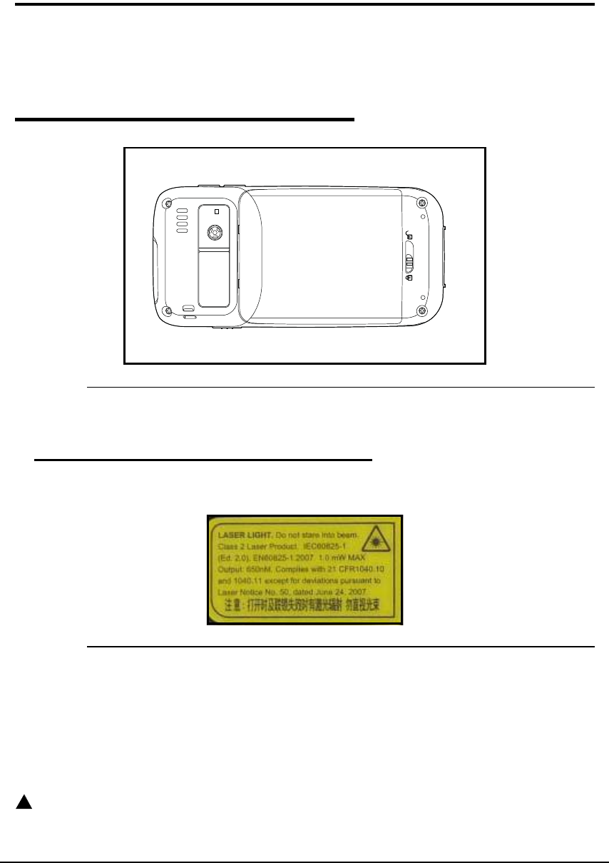
Label Locations 0
Figure 1-1. Laser Safety Label Location
Laser Safety Label 0
If the label in figure 1-2 indicates the product contains an engine with a laser light:
Figure 1-2. Laser Safety Label
Laser Eye Safety Statement 0
This device has been tested in accordance with and complies with IEC60825-1 (Ed. 2.0),
EN60825-1: 2007. Complies with 21 CFR 1040.10 and 1040.11, except for deviations
pursuant to Laser Notice No. 50, dated June 24, 2007. LASER LIGHT, DO NOT STARE INTO
BEAM. CLASS 2 LASER PRODUCT, 1.0 mW MAX OUTPUT: 650nM.
WARNING:
!
Use of controls or adjustments to performance or procedures other than those
specified herein may result in hazardous radiation .
1-2 Safety Information
LED Safety Statement 0
The LED output on this device has been tested in accordance with IEC60825-1 LED safety
and certified to be a Class 1 LED device.
The maximum power outputs for the:
Visible laser diode @ 650nm, Power 1mW
Operating Temperature 0
The recommended operating temperature for the device is -10 C - 50 C.
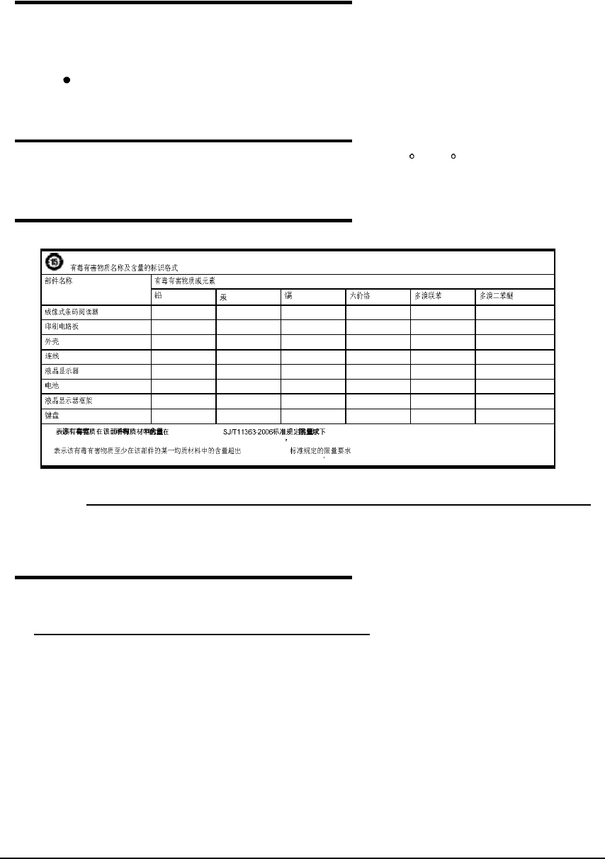
RoHS Chart 0
Figure 1-3. China RoHS Chart
Agency Information 0
UL and cUL Statement 0
UL (Underwriters Laboratories) and cUL (Canadian Underwriters Laboratory) listed:
UL60950-1 and CSA C22.2 No. 60950-1-03.
(Names and Content of Hazardous Substances or Elements)
(Parts Name) (Toxic and Hazardous Substances or Elements)
(Pb) (Hg) (Cd) (Cr6+
)(PBB) (PBDE)
(Imager) x o o o o o
(PCB) x o o o o o
(Housing) o o o o o o
(Cables) x o o o o o
(LCD) x o o o o o
(Battery) o o o o o o
(LCD frame) o o o o o o
(Keypad) o o o o o o
o: (Indicates that this toxic or hazardous substance contained in all of
the homogeneous materials for this part is below the limit requirement in China s SJ/T11363-2006.)
x: SJ/T11363-2006 (Indicates that this toxic or hazardous substance contained in at
least one of the homogeneous materials for this part is above the limit requirement in China s SJ/T11363-2006. )

Safety Information 1-3
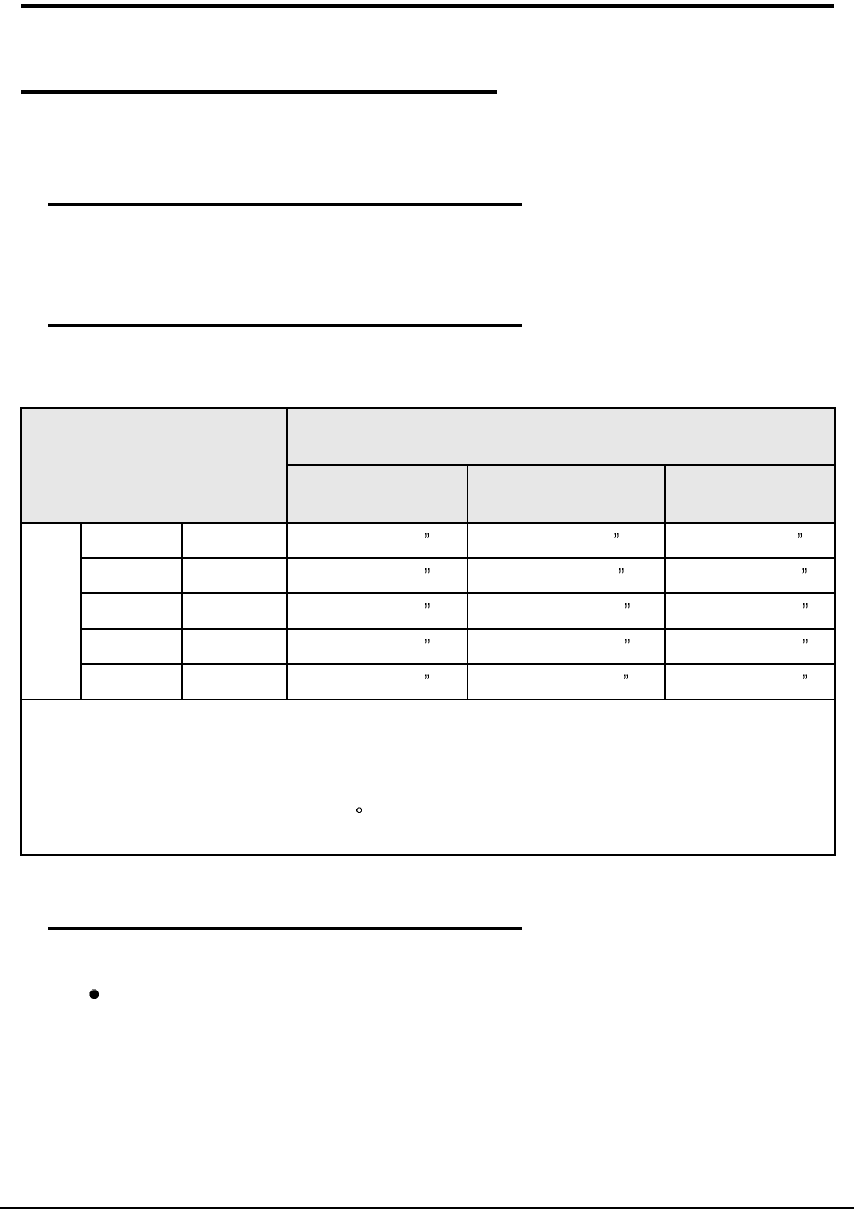
Approvals by Country 0
This Class 2 Laser Product is in accordance with the requirements of IEC 60825-1 Ed. 1.2
Clause 6.2(a).
Table 1-1. Approvals by Country Table
Country EMC, Radio, & SAR Safety
U.S.A. FCC Part 15, Subpart B
FCC Part 15, Subpart C, 15.247
FCC Part 15, Subpart E
FCC Part 22H
FCC Part 24E
FCC SAR OET 65 Supplement C
UL60950-1
Canada ICES-003 (Class B)
RSS 132
RSS 133
RSS 210
cUL60950
European
Community/CE
EN300328
EN301893
EN55022
EN55024
EN301489-1
EN301489-7/24
EN301489-17
EN300328
3GPPTS 51.010-1
EN301511
EN301908
EN50360
EN50361
EN50371
EN50392
IEC6220-1 and IEC6220-2
EN300440
EN/IEC60950-1
EN/IEC60825-1
China SRRC GB4943
MII
CCC
Brazil Anatel
Mexico COFETEL and NOM NOM-019-SCFI-1998
AUS/NZ A Tick (GSM) and Ctick (WLAN,
BT)

1-4 Safety Information
R&TTE Compliance Statement 0
Dolphin 6000 RF devices (802.11 b/g, Bluetooth and/or GSM) are in conformity with all
essential requirements of the R&TTE Directive (1999/5/EC).
This device is marked with CE0682 in accordance with the Class II product requirements
specified in the R&TTE Directive. This device complies to 2006/95/EC Low Voltage Directive
when supplied with the recommended power supply. The manufacturer shall not be liable for
use of our product with equipment (i.e., power supplies, personal computers, etc.) that is not
CE marked and does not comply with the Low Voltage Directive.
The equipment is intended for use throughout the European Community; PAN European
Frequency Range: 2.402 2.480 GHz. Restrictions for use in France are as follows:
Indoor use: Maximum power (EIRP*) of 100 mW for the entire 2.400 2.4835 GHz
Outdoor use: Maximum power (EIRP*) of 100 mW for the 2.400 2.454 GHz band &
maximum power (EIRP*) of 10 mW for the 2.454 2.483 MGHz band.
Dolphin 6000 RF Device 0
This device complies with Part 15 of the FCC Rules. Operation is subject to the following two
conditions:
This device may not cause harmful interference.
This device must accept any interference received, including interference that may
cause undesired operation.
This device has been tested and found to comply with the limits for a Class B digital device
pursuant to Part 15 of the FCC Rules. These limits are designed to provide reasonable
protection against harmful interference in a residential installation. This device generates,
uses, and can radiate radio frequency energy and, if not installed and used in accordance
with the instructions, may cause harmful interference to radio communications. There is no
guarantee that interference will not occur in a particular installation. If this device causes
harmful interference to radio or television reception, which can be determined by turning the
device off and on, the user is encouraged to try to correct the interference by one or more of
the following measures:
Reorient or relocate the receiving antenna.
Increase the separation between the equipment and receiver.
Connect the device into an outlet on a circuit different from that to which the receiver is
connected.
Consult the dealer or an experienced radio/TV technician for help.
If necessary, consult the dealer or an experienced radio/television technician for additional
suggestions. For additional information, refer to Something About Interference, available at
the FCC local regional offices. Our company is not responsible for any radio or television
interference caused by unauthorized modifications of this equipment or the substitution or
attachment of connecting cables and equipment other than those specified by our company.
The correction is the responsibility of the user. Use only shielded data cables with this system.
N
O
TE
:
N
O
TE
:
In accordance with FCC 15.21, unauthorized changes or modifications could void the
user s authority to operate the equipment.
FCC : IEEE 802.11b or 802.11g operation of this product in the U.S.A. is firmware-limited to
channels 1 through 11.

Safety Information 1-5
FCC+IC Exposure : 0
I
M
P
O
R
T
ANT
:
+
FCC Radiation Exposure Statement:
The product comply with the US/Canada portable RF exposure limit set forth
for an uncontrolled environment and are safe for intended operation as
described in this manual. The further RF exposure reduction can be achieved
if the product can be kept as far as possible from the user body or reduce
output power if it doesn't affect the transmission/receiving quality.
This transmitter must not be co-located or operating in conjunction with any
other antenna or transmitter.
IC (French) : 0
Ce dispositif est conforme la norme CNR-210 d'Industrie Canada applicable
aux appareils radio exempts de licence. Son fonctionnement est sujet aux
deux conditions suivantes: (1) le dispositif ne doit pas produire de brouillage
pr judiciable, et (2) ce dispositif doit accepter tout brouillage re u, y compris
un brouillage susceptible de provoquer un fonctionnement ind sirable.
I
M
P
O
R
T
ANT
:
+
(Pour l'utilisation des appareils portables)
D claration d'exposition aux radiations:
Le produit est conforme aux limites d'exposition pour les appareils portables
RF pour les Etats-Unis et le Canada tablies pour un environnement non
contr l .
Le produit est s r pour un fonctionnement tel que d crit dans ce manuel. La
r duction aux expositions RF peut tre augment e si l'appareil peut tre
conserv aussi loin que possible du corps de l'utilisateur ou que le dispositif
est r gl sur la puissance de sortie la plus faible si une telle fonction est
disponible.
Canadian Compliance 0
This Class B digital device complies with Canadian ICES-003. Operation is subject to the
following two conditions:
The device may not cause harmful interference
This device must accept any interference received, including interference that may
cause undesired operation.
To prevent radio interference to the licensed service, this device is intended to be operated
indoors and away from windows to provide maximum shielding. The device (or its transmit
antenna) installed outdoors is subject to licensing.
Cet appareil num rique de la Classe B est conforme la norme NMB-003 du Canada.

1-6 Safety Information
For European Community Users 0
The manufacturer complies with Directive 2002/96/EC of The European Parliament, and of
The Council of 27 January 2003 on waste electrical and electronic equipment (WEEE).
Waste Electrical and Electronic Equipment 0
CAUTION:
!
This device requires the extraction and use of natural resources for its production.
It may contain hazardous substances that could impact health and the
environment, if not properly disposed.
In order to avoid the dissemination of those substances in our environment and to
diminish the pressure on the natural resources, it is encouraged to use the
appropriate procedures for product disposal. Those procedures will reuse or
recycle most of the materials of the product being disposed of.
The crossed out wheeled bin symbol indicates the product should not be
disposed of along with municipal waste and encourages the appropriate
procedure for device disposal.
If more information is needed on the collection, reuse, and recycling systems,
contact the local or regional waste administration.
Electrically Powered Devices 0
Most manufacturers of medical devices adhere to the IEC 601-1-2 standard. Pacemakers and
hearing aids are considered electrically powered devices.This standard requires devices to
operate properly in an EM Field with a strength of 3V/m over a frequency range of 26 to
1000MHz. The maximum allowable field strength emitted by the Dolphin 6000 device is
0.3V/m according to Subpart B of Part 1 of the FCC rules. The RF from the Dolphin 6000
device has no effect on medical devices that meet the IEC specification.
Microwaves 0
The radio in the Dolphin 6000 RF device operates on the same frequency band as a
microwave oven. If a microwave is used within range of the Dolphin 6000 RF device, a
performance degradation in the wireless network may be noticeable. The microwave and
wireless network will continue to function.
Getting Started 2-1
Getting Started
Out of the Box 0
Verify that the carton contains the following items:
Dolphin 6000 mobile computer (the device)
Main battery pack (5.7V Li-ion)
Quick Start Guide
N
O
TE
:
N
O
TE
:
If accessories were ordered, make sure they are included with the order.
Keep original packaging to return device for service if required.
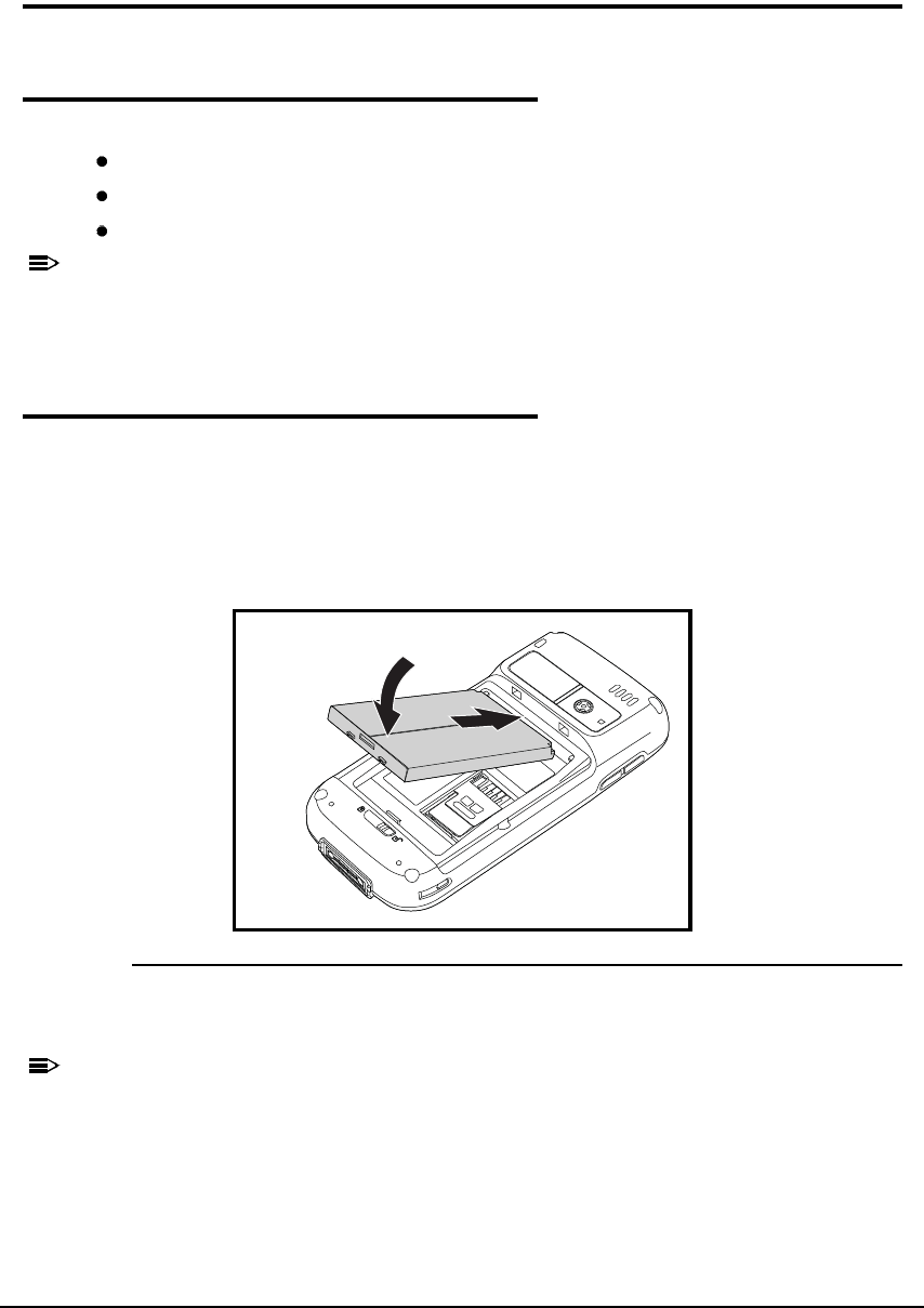
Install Main Battery Pack 0
The Dolphin 6000 is shipped with the battery packaged separately from device. Perform the
following to install main battery:
1. Slide latch to unlock battery door.
2. Open battery door.
3. Install battery into battery well.
Figure 2-1. Inserting Battery
4. Install battery door.
N
O
TE
:
N
O
TE
:
Install battery door before powering device.
2-2 Getting Started
Charge the Batteries 0
Power for Dolphin 6000 device comes from main battery pack, accessed from back panel.
Before Initial Use 0
Devices are shipped with both batteries discharged of all power. Initial charging time for main
battery pack is 4 hours. Insert the device into the cradle to charge.
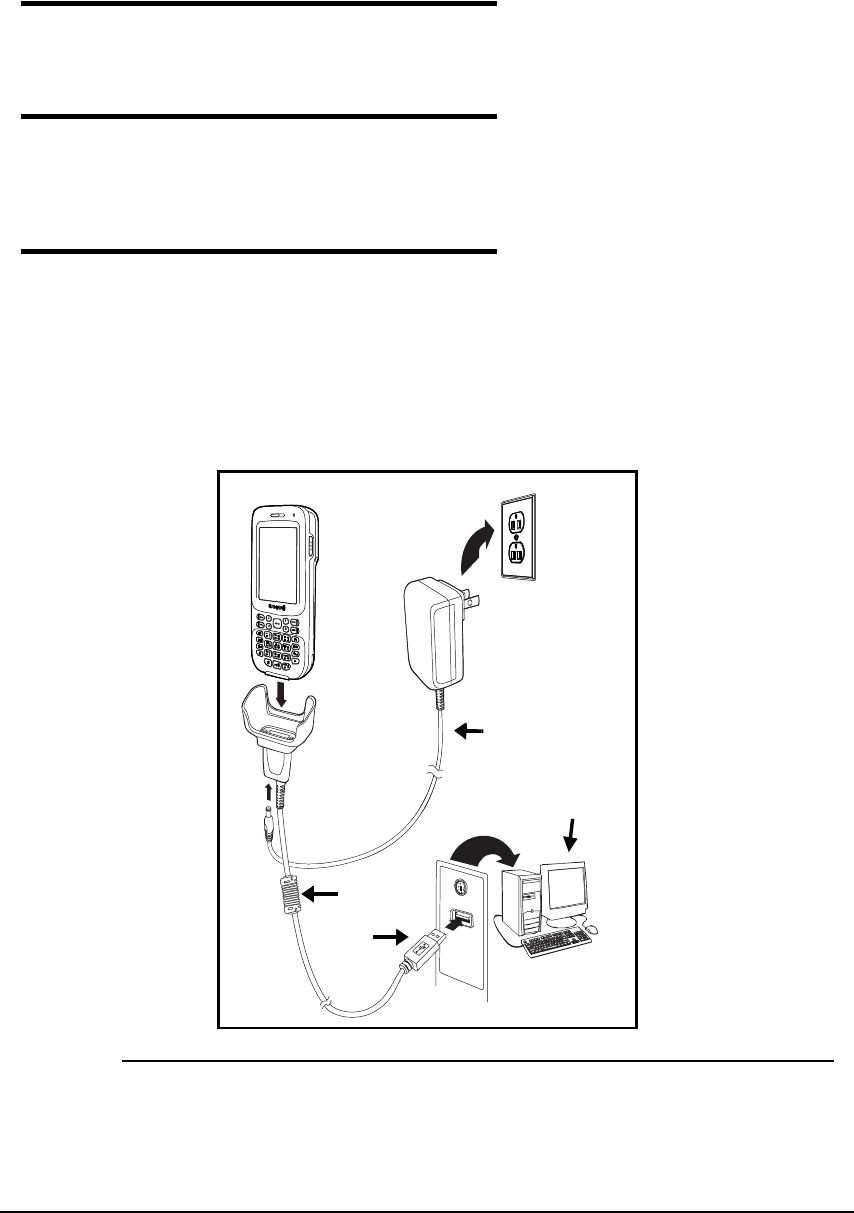
Charging Using the Communication Cable 0
1. Connect USB to I/O connector on device.
2. Plug power cord into power adapter.
3. Plug power adapter cable into power connector on COMM cable.
4. Plug COMM cable into appropriate port on host device.
5. Plug power cord into standard wall outlet. LED on front of device flashes and illuminates
red when device starts initializing boot process.
Figure 2-2. Charging Connections

Getting Started 2-3
Boot the Device 0
The device boots when power is applied and the PWR button is pressed.
CAUTION:
!
Do not press any keys or interrupt the boot process. When boot process is
complete, Today screen appears, and device is ready for use.
N
O
TE
:
N
O
TE
:
Today screen appears several times during boot process. Wait several seconds before
using device to make sure boot process is complete.
Using Touch Panel Display 0
The touch panel display is activated by using stylus (included with the device) or a finger. To
activate display, open a file or select a menu. Use bottom of stylus to tap touch panel display
or gently press touch panel with a finger.
2-4 Getting Started
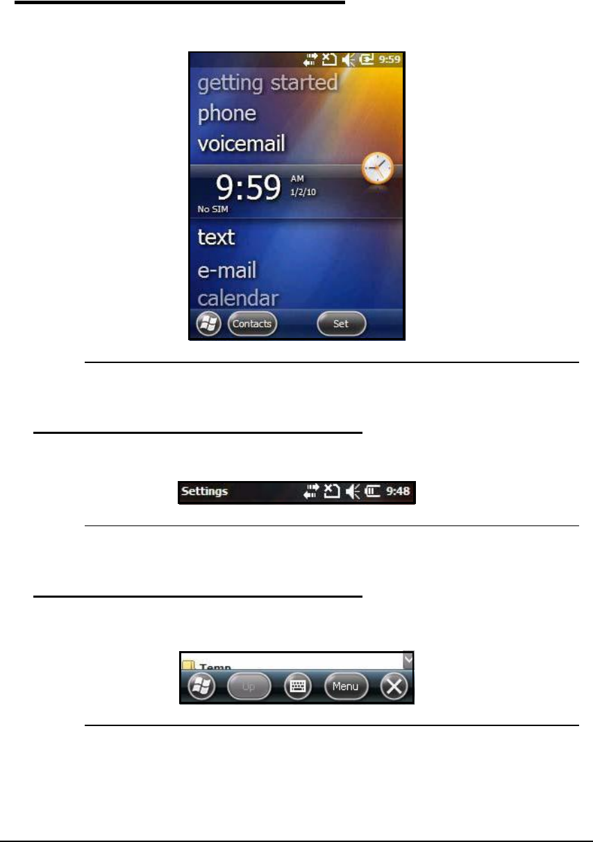
Today Screen 0
After the device initializes the first time, the Today screen appear.
Figure 2-3. Today Screen
Navigation Bar 0
The Navigation bar is found on top of the screen. The active program and current time are
shown.
Figure 2-4. Navigation Bar
Command Bar 0
The Command bar is found on bottom of the screen.
Figure 2-5. Command Bar
Getting Started 2-5
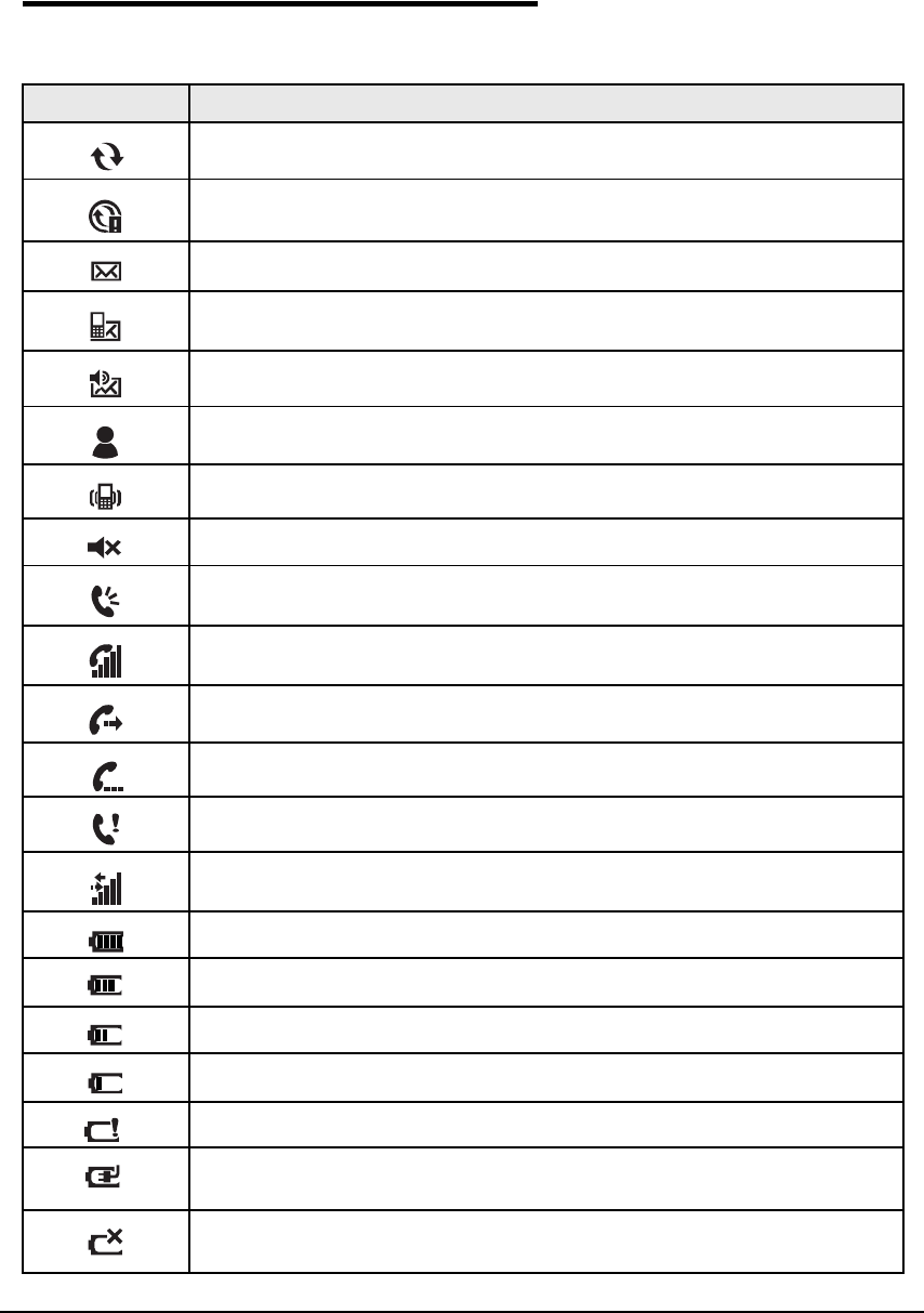
Navigation Bar Icons 0
Table 2-1. Icons Table
Indicator Meaning
Synchronizing data
The device could not synchronize data with the workstation via ActiveSync
New e-mail
New text message
New voicemail
New instant message
Vibrate on
Ringer off
Speakerphone on
Voice call in progress
Calls are forwarded
Call on hold
Missed call
Data call in progress
Battery has a full charge
Battery has a high charge
Battery has a medium charge
Battery has a low charge
Battery has a very low charge and requires charging
Device is running on external power. If a battery pack is installed, battery is
charging in the background
The device is not connected to external power. A battery is installed, but is
defective; its charge level cannot be measured
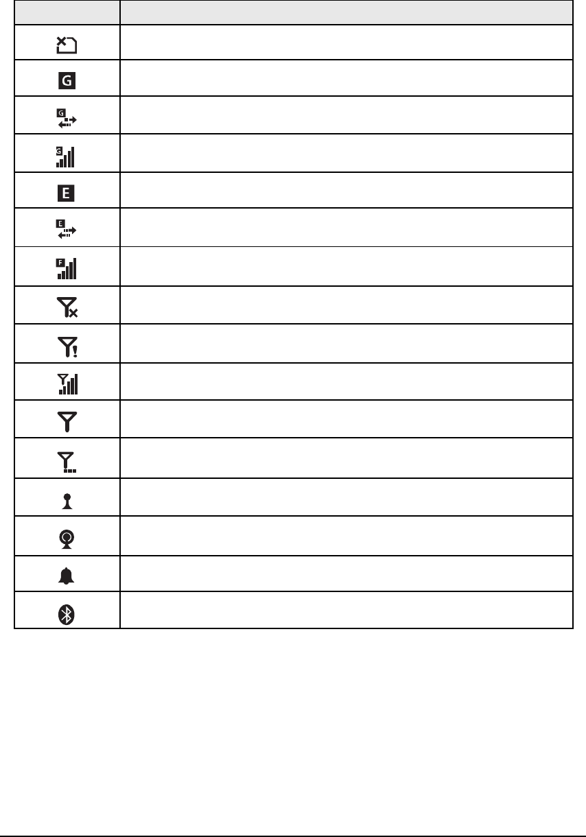
2-6 Getting Started
No SIM card is installed
GPRS available
GPRS connecting
GPRS in use
EDGE available
EDGE connecting
EDGE in use
Radio is off
The radio is not connected to a network
The radio is connected. The bars indicate signal strength
No radio signal
The device is searching for a signal
Wi-Fi is on, but device is not connected
Wi-Fi data call
Pending alarm
Bluetooth
Table 2-1. Icons Table (Continued)
Indicator Meaning
Getting Started 2-7
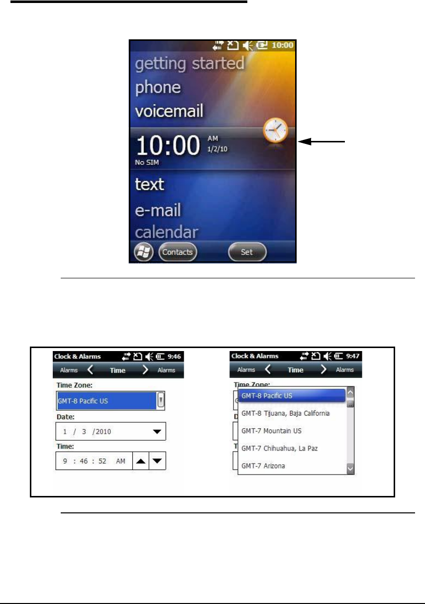
Set Time Zone, Time, and Date 0
1. On the Today screen, tap the time and date section (A).
Figure 2-6. Time and Date
The Clock & Alarms menu will open.
2. Select Time tab to set system clock.
Figure 2-7. Clock Settings
3. Tap Time Zone box to open drop-down menu.
4. Set correct time zone from drop-down menu.
5. Set correct time and date in remaining fields and tap OK to save.
A
2-8 Getting Started
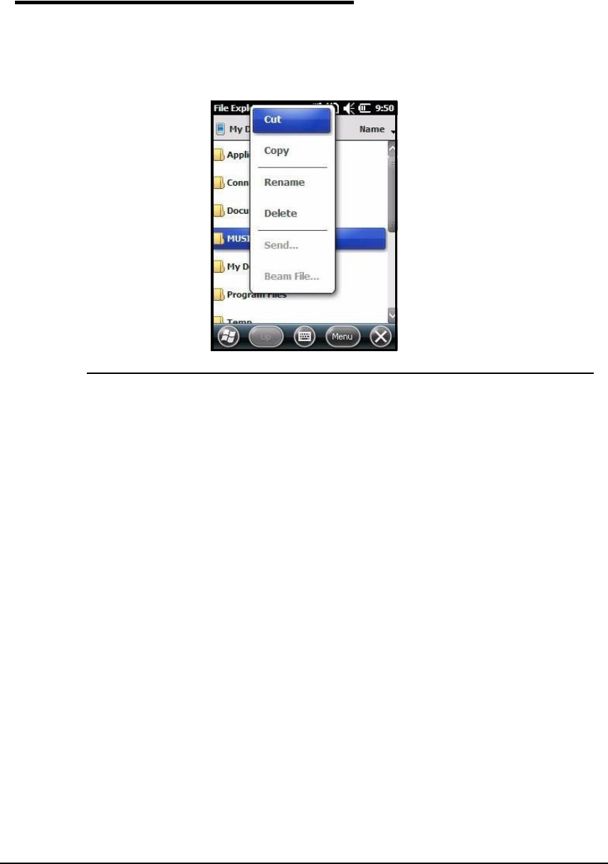
Pop-Up Menus 0
Pop-up Menus allow a choice of action for a selected file.
1. Tap and hold the stylus on the action to open the pop-up menu.
2. When menu appears, lift the stylus, and tap the action desired.
Figure 2-8. Pop-Up Menu
3. Tap outside the menu to close without performing an action.
Getting Started 2-9
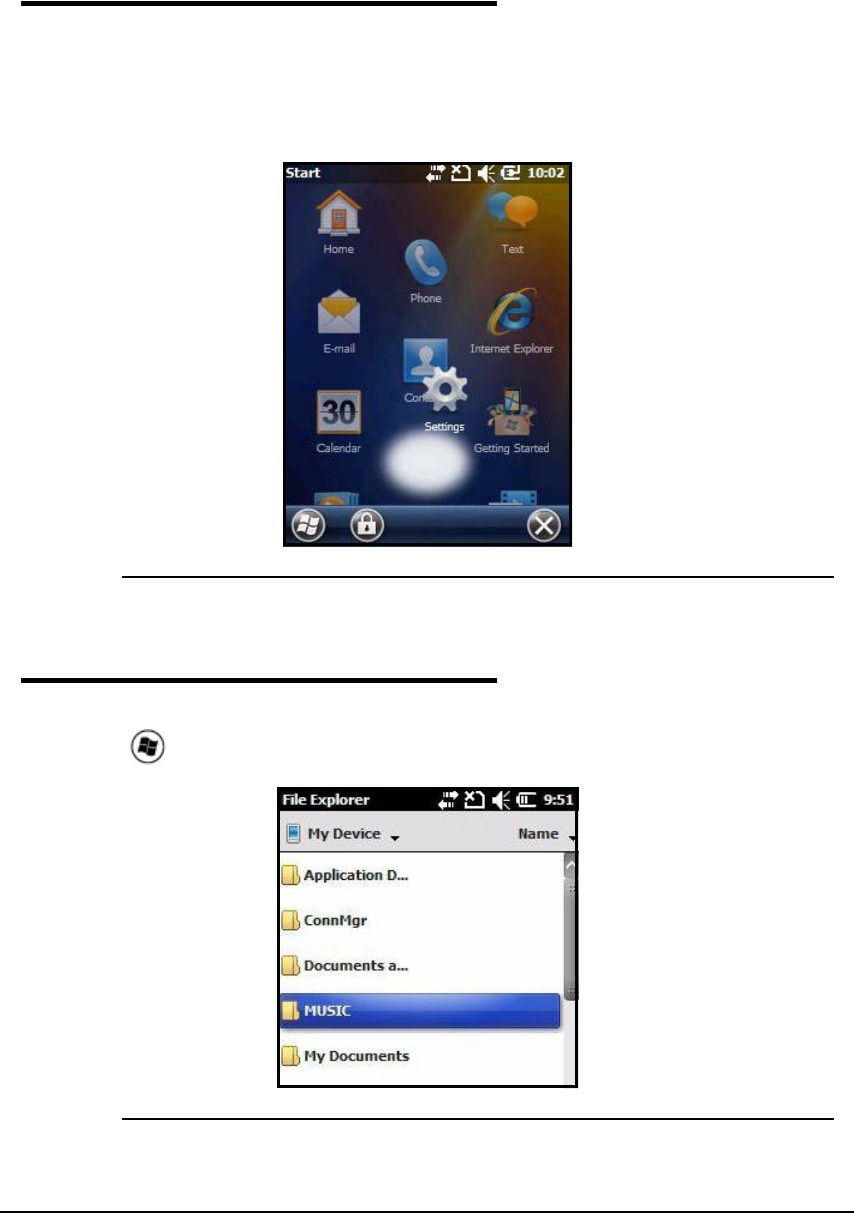
Selecting Programs 0
1. Tap the WindowsIcon to view the Start Menu.
2. Open the desired program by tapping on the program icon.
3. Move an icon to top of the Start Menu by tapping then holding the stylus on the icon, while
dragging the icon to the top of the Start Menu.
Figure 2-9. Moving an Icon
File Explorer 0
Use File Explorer to find and move files.
1. Tap >File Explorer.
Figure 2-10. File Explorer Menu
2-10 Getting Started
2. Locate file.
3. To move file, hold the stylus on the file to bring up the menu shown in Figure2-11. Tap Cut
or Copy on menu.
Figure 2-11. Cut or Copy
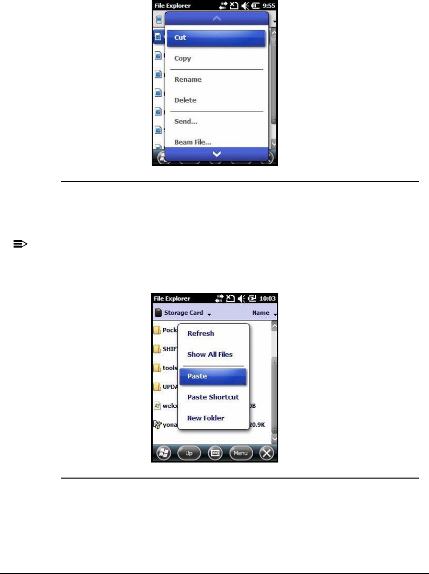
4. Navigate to the desired destination.
5. Hold stylus in the blank area of the window.
N
O
TE
:
N
O
TE
:
If there is no blank area in the window go to step 7.
6. Tap Paste on menu (Figure2-12).
Figure 2-12. Paste
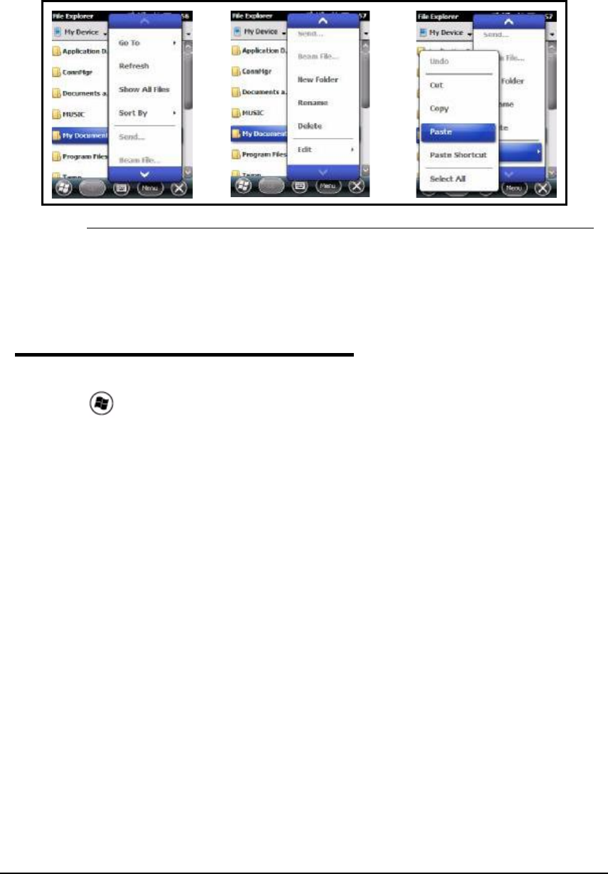
7. Tap Menu on Command bar. A pop-up menu will appear (Figure 2-13).
Getting Started 2-11
Figure 2-13. Paste Procedure
8. Tap down arrow to view Edit.
9. Tap Edit > Paste
Search Phone 0
Use the Search Phone application to quickly find information.
1. Tap > Search Phone.
2. To find a file, type name of file in Search For box.
3. Select type of data in Type box
4. Tap Search on the Command bar.
5. Select Larger than 64 KB in the Type box drop-down menu to find large files.

2-12 Getting Started

Hardware Overview 3-1
Hardware Overview
Standard Configurations 0
WLAN, WPAN, WWAN with GPS and Camera 0
WLAN- Wireless Local Area Network
WPAN- Wireless Personal Area Network
WWAN- Wireless Wide Area Network
The following is a list of configuration features:
Microsoft Windows Mobile 6.5 Professional
MTK MT6516 ARM9 416MHz Processor
256MB SDRAM X 512MB Flash
29-Key Numeric Keypad
5.7V Li-ion rechargeable battery pack
Adaptus Imaging Technology: IS4813 single line laser scan engine
802.11b/g, Bluetooth, and GSM/GPRS/EDGE
GPS
3 megapixel auto focus color camera
Peripherals 0
HomeBase 0
The Dolphin 6000 HomeBase provides charging and communication functionality. It supports
both RS232 and USB communications, that enables the device to interact with the majority of
PC-based enterprise systems.
The device also contains an auxiliary battery well that can charge a spare Li-ion battery.
The following is a list of the HomeBase features:
RS232 (RX, TX, CTS, RTS), D-sub connector
USB Client, Mini USB connector
DC-IN
Separate battery charger.
N
O
TE
:
N
O
TE
:
USB cable must be used within 125 cm to guarantee transmission quality.
For more information, refer to Dolphin 6000 HomeBase.

3-2 Hardware Overview
Accessories 0
Communication/Charging Cables 0
The Dolphin 6000 communication/charging cable kit is an all-in-one solution for mobile
applications. The cable kit performs the following:
Powers the device
Charges the system Main Battery
Communicates with host or peripheral devices without a cradle
Supports USB communication
Functions with U.S., E.U., U.K., China, Brazil, Mexico, Australia and New Zealand power
cords. Refer to Approvals by Country Table.
N
O
TE
:
N
O
TE
:
The system is available with U.K or European power cord.
Li-ion Battery Pack 0
The 5.7V Li-ion rechargeable battery pack provides the main power for the device.
Vehicle Charging Cable 0
The vehicle charging cable for the Dolphin 6000 is an optional accessory.
USB Client Holder Cable 0
The USB Client Holder Cable includes the following:
USB Client
DC-IN
Hardware Overview 3-3
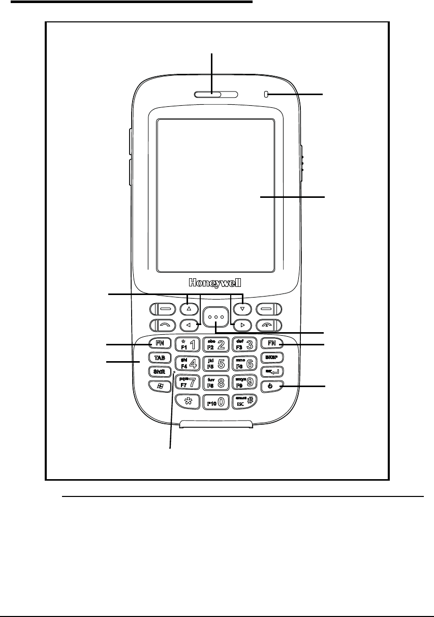
Front View 0
Figure 3-1. Front View
5
1
7
2
10
6
8
9
4
3

3-4 Hardware Overview
Table 3-1. Front View
No Item Description
1 Front Speaker Receives voice calls when using a handset. Refer to Voice
Communication.
2Indicator Light
Emitting Diode (LED)
Flashes and illuminates during resets and scanning/imaging.
Can be programmed by various software applications.
3Touch Panel Display A color 2.8 inch liquid crystal display (LCD) touch panel is
covered with an industrial, protective lens
The video graphic array (QVGA) display resolution of 240 X
320.
4SCAN Key Activates the scanner/imager.
Is a system wakeup control for the device.
5Blue FN Key Switches the numeric keypad to an alpha/numeric mode or to
F1-F10 function keys mode.
6Power Key Puts the device in the Suspend Mode or wakes the device
from the Suspend Mode. Refer to Suspend Mode.
7Microphone Provides audio input for the handset and speakerphone voice
calls. Refer to Voice Communication.
8Recessed Keypad The device has a 29-key alpha/numeric keypad. For more
information refer to Using the Keypad.
9Orange FN Key Switches the numeric keypad from lower case or upper case
modes.
10 Navigation Keys When selected, move through the software programs. Refer to
Using the Navigation Keys.
Hardware Overview 3-5
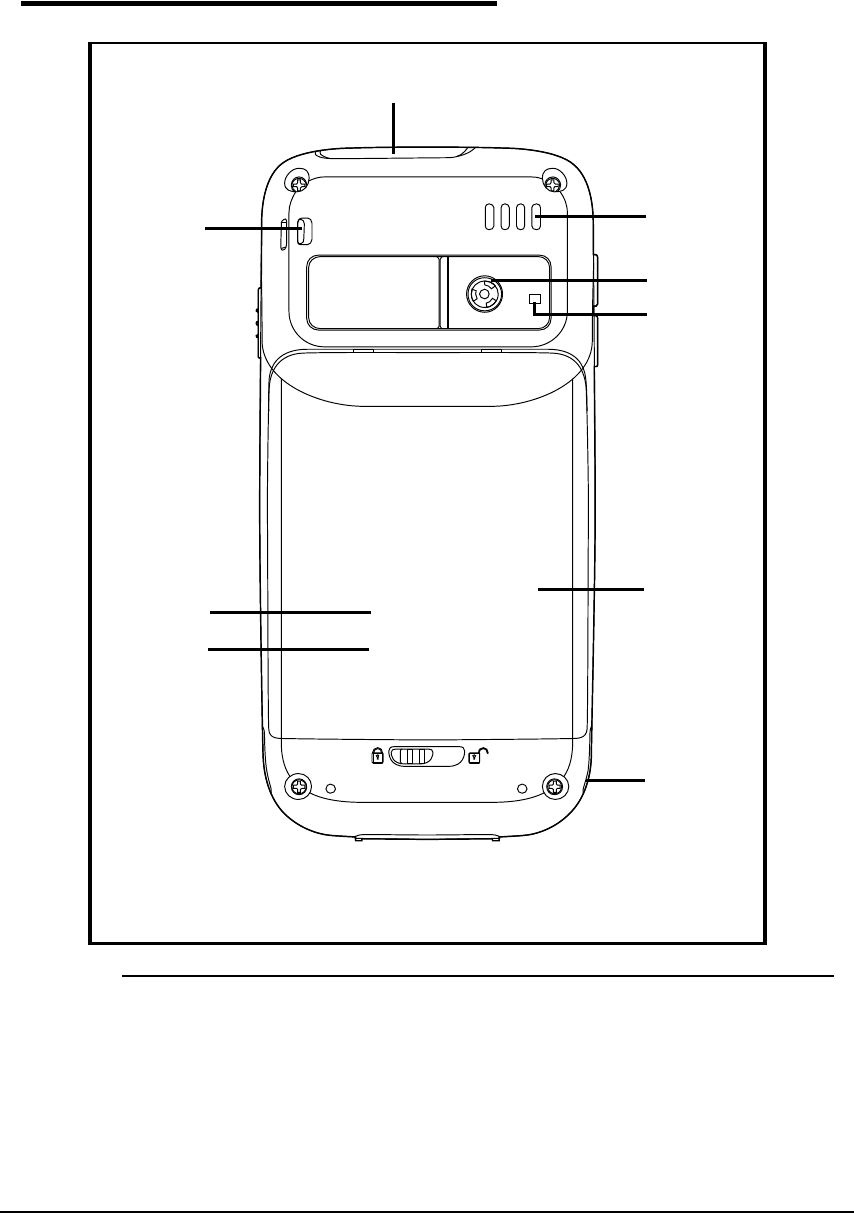
Base View 0
Figure 3-2. Base View
5
4
3
2
1
9
8
7
6
3-6 Hardware Overview
Table 3-2. Base View
No Item Description
1 Image/Scan Engine
Window
The image engine reads and decodes linear, stacked linear
(e.g., PDF417), and 1D matrix bar code symbologies. For
greater accuracy contains a laser aimer. Refer to Using the
Scan Image Engine.
2Rear Speaker Provides audio signals when scanning bar code labels or
entering data. Supports playback for wave and MP3 files,
software mixer, and Speakerphone for WWAN/GSM audio and
VoIP. The operating frequency range is 1000-4000Hz at >86
dB.
3Color Camera Provides easy picture caption with Automated Camera Control
(ACC). Additional features include automated picture profiles
and an Application Programming Interface (API).
4Camera Flash Can be used and is controlled by the devices color camera.
5Battery Door Secures the Li-ion Battery Pack in the device battery well.
Refer to Battery Pack.
6Fastener for the
Stylus Tether
A coiled, elastic cord that tethers the stylus to the device
7Subscriber Identity
Module (SIM)Card
Socket
Connection for SIM Card use. Refer to Installing a SIM Card.
N
O
T
E
:
SIM Card is located underneath the battery door.
8Memory Card Socket Provides the user with an option to expand the device s
memory capacity. Supports industry-standard MicroSD and
MicroSDHC memory interfaces. Refer to Memory Card
Installation.
N
O
T
E
:
Memory Card Socket is located underneath the battery
door.
9Lanyard Slot Attach point for lanyard
Hardware Overview 3-7
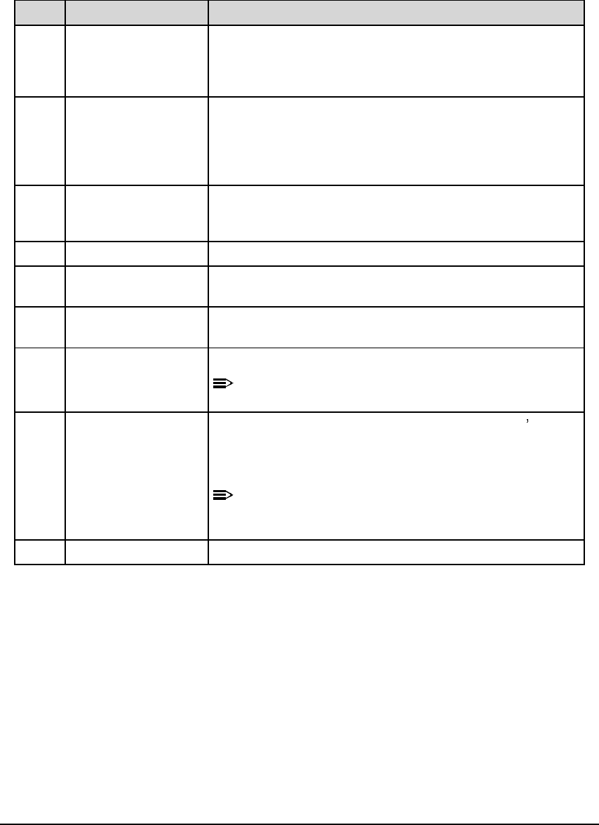
Left View 0
Figure 3-3. Left View
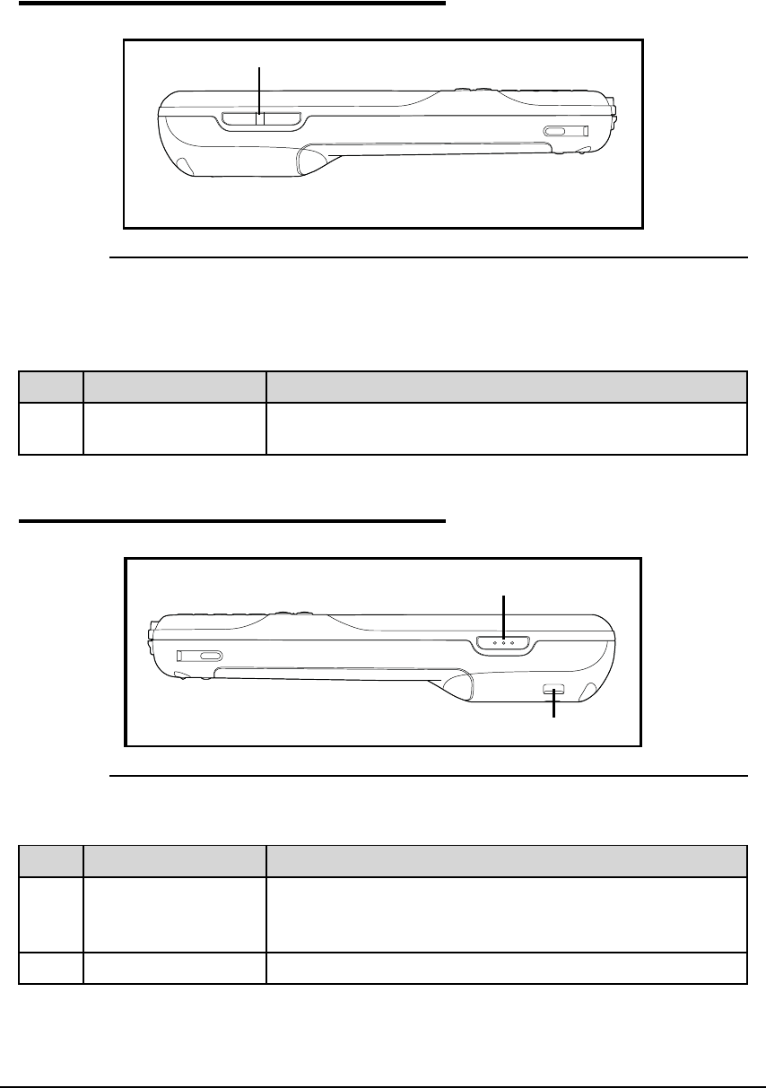
Right View 0
Figure 3-4. Right View
Table 3-3. Left View
No Item Description
1Volume Control
Button
Used to raise or lower the device volume.
Table 3-4. Right View
No Item Description
1Right Button Triggers the scanner/imager.
Can be reassigned to launch applications or execute
commands.
2Lanyard Slot Attach point for lanyard
1
1
2
3-8 Hardware Overview
Memory Card Installation 0
Perform the following to install the Memory Card:
1. Power down device.
2. Unlock Battery Door.
3. Remove Battery Door and Battery.
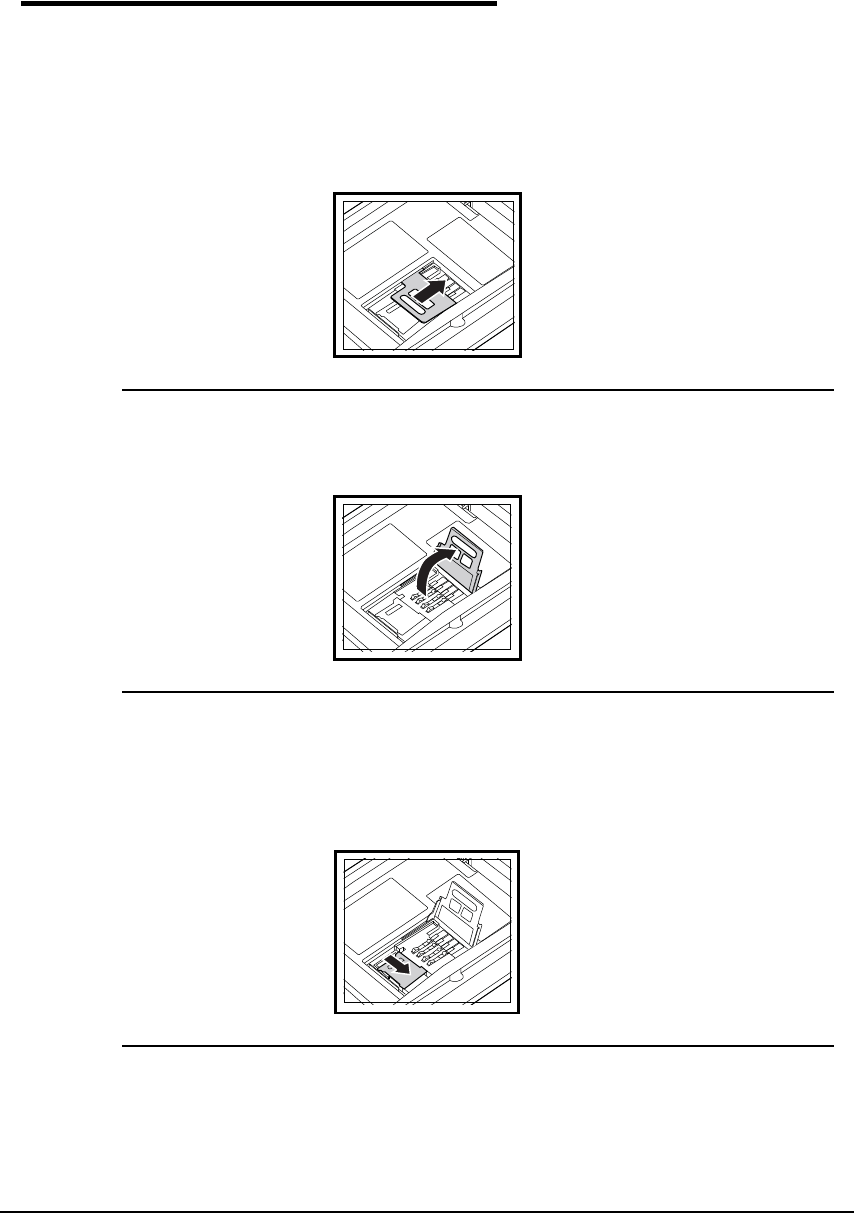
4. Slide latch toward top of device to unlock SIM card.
Figure 3-5. SIM Card latch
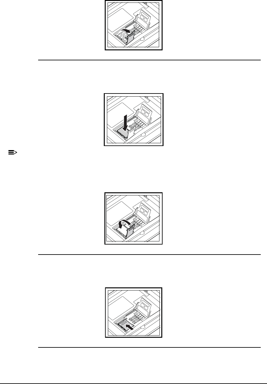
5. Lift SIM card latch to reveal Sim card.
Figure 3-6. SIM Card latch
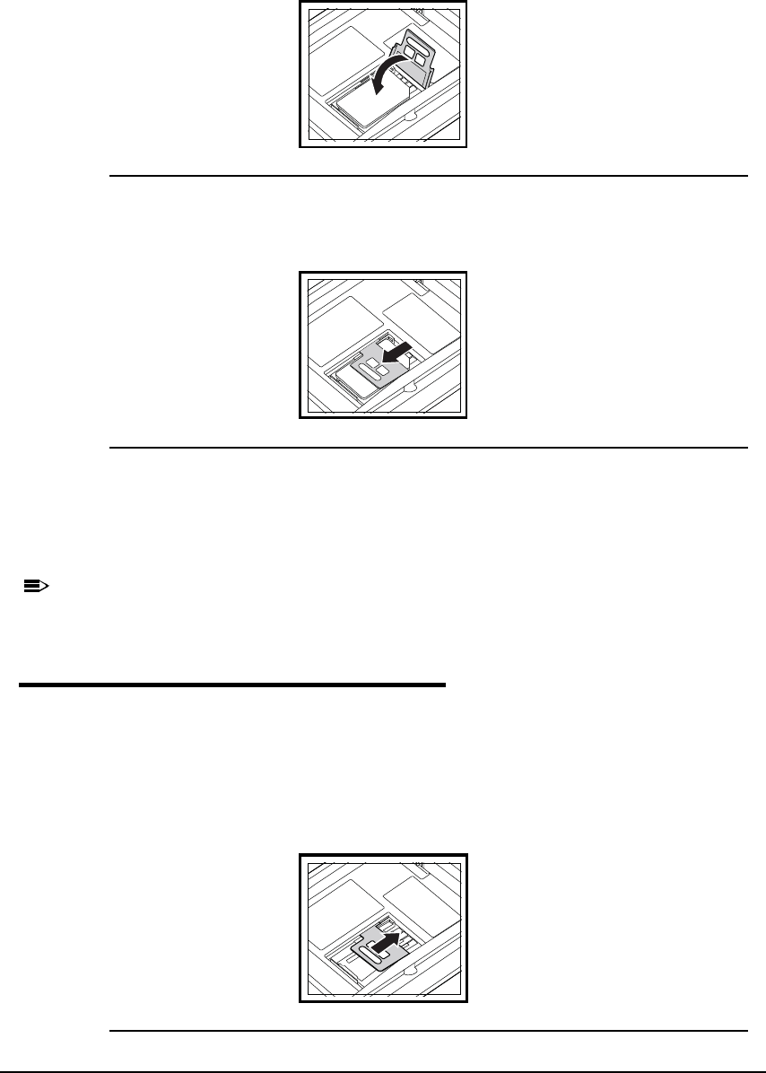
6. Remove Sim card and reveal memory card latch.
7. Unlock memory card latch by sliding latch away from serial number label located in battery
well.
Figure 3-7. Memory Card latch
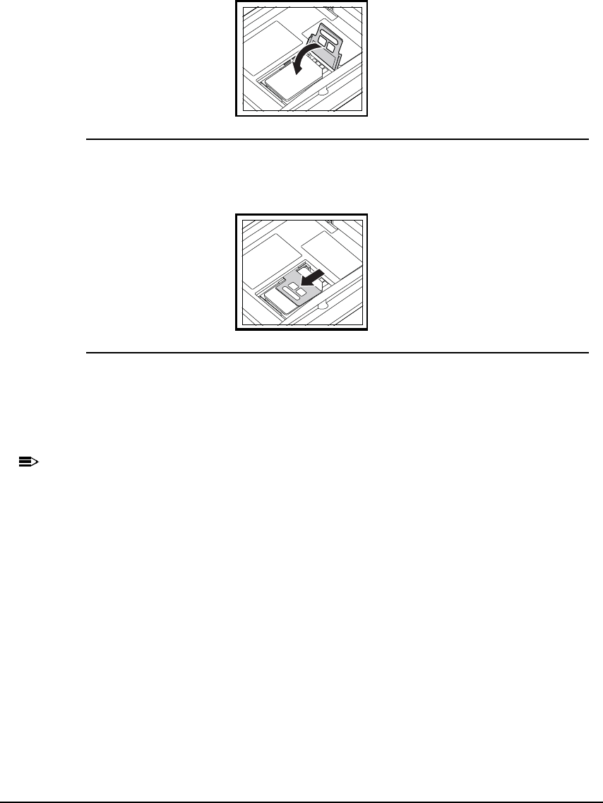
8. Lift latch up to expose MicroSD or MicroSDHC socket.
Hardware Overview 3-9
Figure 3-8. Memory Card socket
9. Insert microSD or microSDHC card into microSD or microSDHC socket.
N
O
TE
:
N
O
TE
:
Make sure interface on memory card is connected to interface in the socket.
10.Align corner on card with corner of socket.
11.Close memory card latch.
Figure 3-9. Memory Card latch
12.Lock memory card latch by sliding latch toward serial number label.
Figure 3-10. Memory Card latch
13.Insert SIM card into SIM card socket.
3-10 Hardware Overview
14.Close SIM card latch.
Figure 3-11. SIM card latch
15.Lock SIM card latch by sliding latch up towards bottom of device.
Figure 3-12. SIM card latch
16.Install Battery
17.Install and lock Battery Door.
18.Power on device.
N
O
T
E
:
N
O
TE
:
It is recommended to format all SD cards before initial use.
Installing a SIM Card 0
Perform the following to install the Sim card:
1. Power down device.
2. Unlock Battery Door.
3. Remove Battery Door and Battery.
4. Slide latch toward top of device to unlock SIM latch if applicable.
Figure 3-13. SIM Card latch
Hardware Overview 3-11
5. Lift SIM card latch
6. Insert SIM card into SIM card socket.
7. Close SIM card latch.
Figure 3-14. SIM card latch
8. Lock SIM card latch by sliding latch up towards bottom of device.
Figure 3-15. SIM card latch
9. Install Battery
10.Install and lock Battery Door.
11.Power on device.
N
O
TE
:
N
O
TE
:
It is recommended to format all SD cards before initial use.
3-12 Hardware Overview
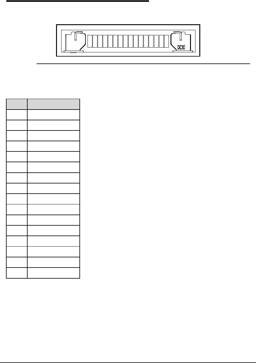
Bottom Rear Panel 0
Figure 3-16 and Table 3-5 provide a description of the 16 pin I/O connector.
Figure 3-16. I/O Connector
Table 3-5. Bottom Rear Panel
Pin Description
1GND
2VBUS
3 USBC-
4 USBC+
5 UART4_RTS
6UART1_RX
7 UART1_TX
8GND
9 UART4_CTS
10 GND
11 GND
12 Cradle_Detect
13 UART4_TX
14 UART4_RX
15 VCC
16 VCC

Hardware Overview 3-13
I/O Connector 0
The I/O connector provides the following:
Support DC charging of device and battery
Facilitate RS232 serial communications interface, including RX, TX, RTS, CTS and GND signals
USB interface to a host workstation via cradle or communication table
All Dolphin 6000 peripherals are designed to work exclusively through this connector. The I/O
connector supports RS232 and USB communication. For RS232, the maximum
communication speed is 115.2 Kbps with seven baud rate settings. For USB, communication
speed is up to 12 Mbps.
Using the Touch Panel 0
When using the device touch panel, it is recommended to use screen protectors and proper
stylus. Screen protectors are meant to defend the touch panel when using high to medium
level user interaction with the device through the touch panel.
For general use, it is suggested to replace the screen protector every thirty (30) days. Cycles
may vary according to the average level of the usage of the touch panel.

3-14 Hardware Overview
Battery Pack 0
The 5.7V, 12W hour Li-ion Battery Pack is the primary power source for the Device. The Li-ion
Battery is designed to operate in a temperature range of -10 C to 50 C (14 F to 122 F).
Charging Options 0
If the battery is installed in the device, it will be charged if the device is in the HomeBase. If
the battery is not installed in the device, it may be charged by placing it in the battery well.
Use the Dolphin 6000 HomeBase (Refer to Dolphin 6000 HomeBase).
Charging Time 0
The Li-ion Battery Pack requires 4 hours to charge completely before initial use.
Storing Batteries 0
To maintain optimal battery performance, follow these storage guidelines:
Avoid storing batteries outside the specified range of -4 to 104 F (-20 to 40 C) or in extremely
high humidity.
For prolonged storage, do not keep batteries stored in a charger that is connected to a power
source.
Battery Pack Use and Disposal 0
The following are guidelines for the safe use and disposal of batteries:
Follow local regulations for battery disposal.
Replace defective batteries immediately. Using a defective battery could damage the Dolphin
6000 device.
Do not use a battery in any other manner outside its intended use in Dolphin 6000 device and
peripherals.
Excessive discharge damages a battery. Recharge the battery when the device indicates low
battery power.
Battery life is limited. Replace after battery is unable to hold an adequate charge.
If the battery or charger are not working properly, replace as soon as possible.
Managing Battery Power 0
Default Critical and Low Battery Points 0
When the device is running on battery power (as opposed to external power), warnings are
displayed when the battery reaches critical and low battery points.
Hardware Overview 3-15
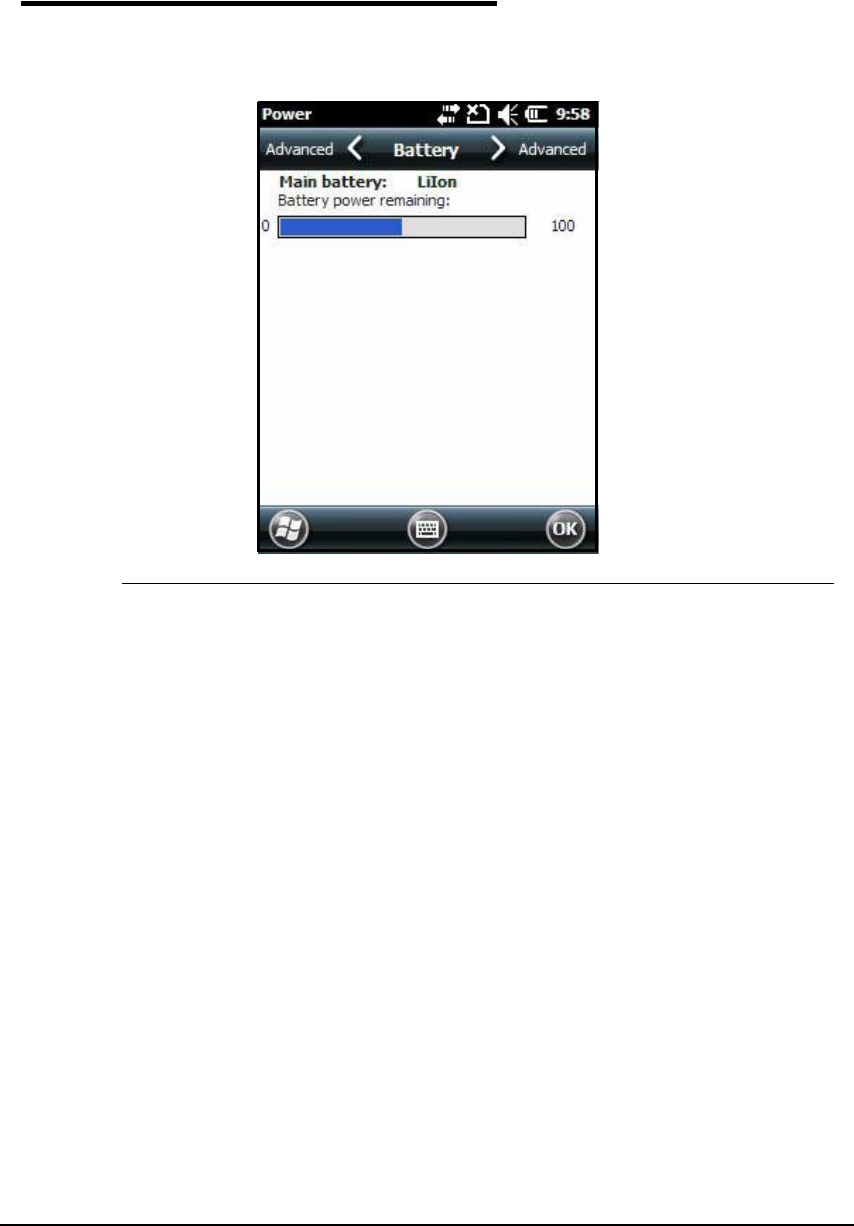
Checking Battery Power 0
In order to check the battery power:
1. Navigate to Start >Settings >System > Power.
Figure 3-17. Power Menu
3-16 Hardware Overview
Resetting the Device 0
Two options to reset the system are:
Soft Reset
Hard Reset.
Soft Reset (Warm Boot) 0
Soft Reset clears program memory and keeps storage memory. A Soft Reset can be
implemented through the System API.
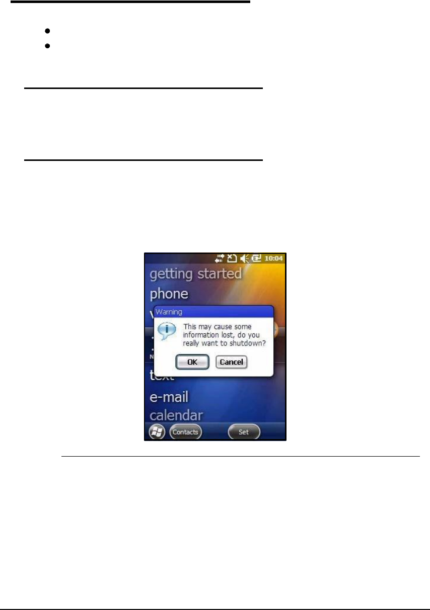
Hard Reset (Cold Boot) 0
A Hard Reset is defined as the toggling of a hardware reset input signal to a processor and
other system hardware components. It does not flush or attempt to preserve buffered file
system contents. A Hard Reset can be implemented through the System API.
In order to perform a Cold Boot:
1. Press and hold the power button for 3 seconds. The pop-up in Figure3-18 appears.
Figure 3-18. Hard Reset

Hardware Overview 3-17
Suspend Mode 0
The device goes into the Suspend Mode automatically when inactive for a period of time. To
set a time interval, select Advanced in the Power System Setting menu. Refer to Power.
To set the device into Suspend Mode, press the Power key and the screen goes blank.
N
O
TE
:
N
O
TE
:
If is not on the Today screen, press the Power key to return to Today screen and press
the Power key again to set device into Suspend Mode.
To wake the device from Suspend Mode, press the Power key.
Hardware Maintenance 0
When needed, clean the image engine window and the LCD display with a clean,
non-abrasive, lint-free cloth. The device can be cleaned with a damp cloth.

3-18 Hardware Overview
Using the Scan Image Engine 4-1
Using the Scan Image Engine
Overview 0
The barcode engine in the Dolphin 6000 is the Honeywell IS4813.
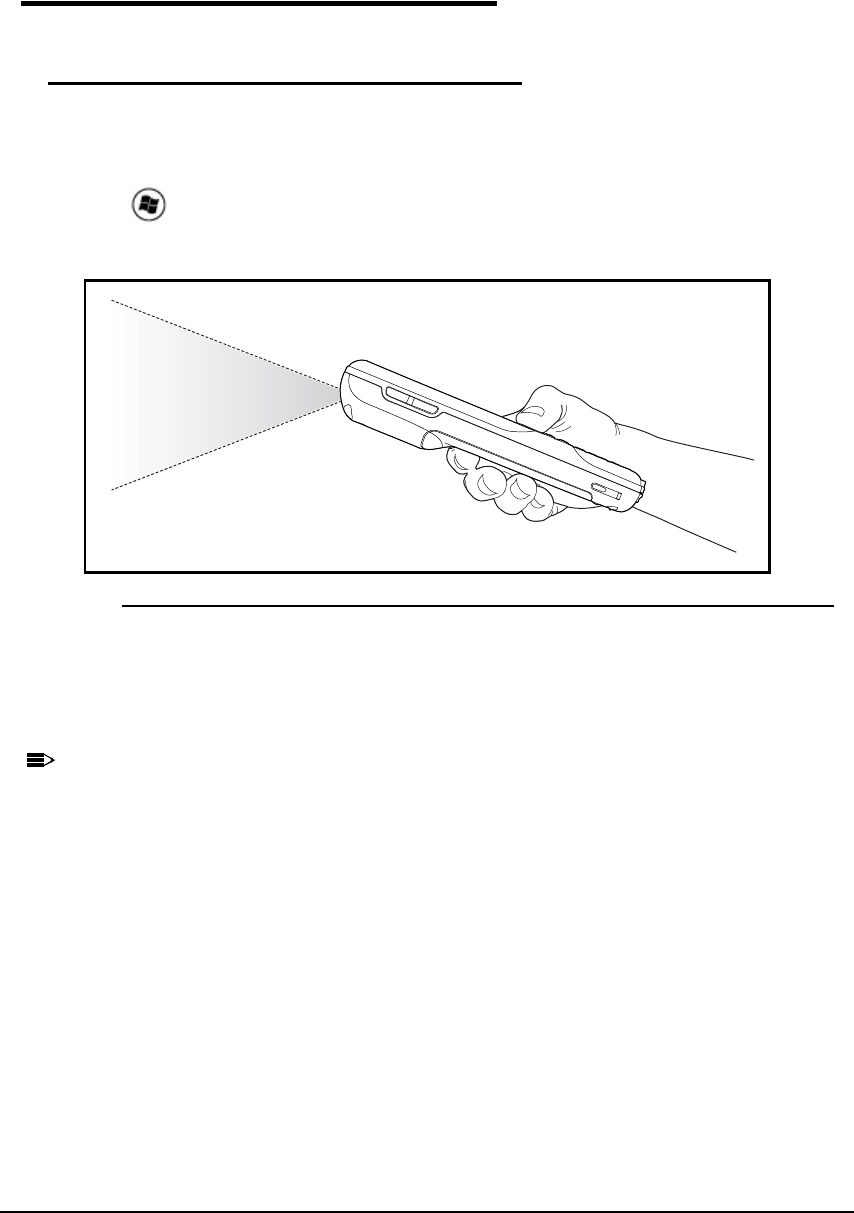
Angled Imaging 0
The scan engine view of field is 54 degrees.
Image Engine Specifications 0
Laser Specifications 0
The maximum power output for each diode is:
Illumination LED: 194.0 uW
Table 4-1. Depth of Field vs. Minimum Bar Code Element
Bar Code
Element Width
Depth of Field*
(In the Field of View)
Start
(Frm Engine Face)
End
(Frm Engine Face)
Total
1D
.13 mm 5.2 mil 70 mm (2.75 ) 95 mm (3.75 ) 25 mm (1.00 )
.19 mm 7.5 mil 57 mm (2.25 ) 171 mm (6.75 ) 114 mm (4.50 )
.26 mm 10.4 mil 50 mm (2.00 ) 210 mm (10.00 ) 160 mm (6.25 )
.33 mm 13.0 mil 50 mm (2.00 ) 254 mm (10.00 ) 204 mm (8.00 )
.49 mm 19.5 mil 75 mm (2.95 ) 300 mm (11.81 ) 225 mm (8.86 )
* For non-decode IS4813 and IS4815 engines, depth of field data is for reference only. Actual
values may vary depending on environmental conditions, host hardware, and decoding
software.
Depth of field data was measured at 25 C under typical indoor lighting. Performance may vary
depending on testing conditions.

4-2 Using the Scan Image Engine
Supported Bar Code Symbologies 0
Table 4-2. Symbology List
Symbology Type Symbology Name
1D Symbology UPC A
1D Symbology UPC E
1D Symbology EAN 8
1D Symbology EAN 13
1D Symbology BOOKLAND EAN
1D Symbology CODE 128
1D Symbology GS1 128 (EAN 128)
1D Symbology ISBT 128
1D Symbology CODE 39
1D Symbology TRIOPTIC CODE 39
1D Symbology CODE 93
1D Symbology CODE 11
1D Symbology INTERLEAVED 2 OF 5
1D Symbology MATRIX 2 OF 5
1D Symbology AIRLINE 2 OF 5
1D Symbology HONG KONG 2 OF 5
1D Symbology DISCRETE 2 OF 5 (STANDARD 2 OF 5)
1D Symbology CODABAR
1D Symbology MSI PLESSEY
1D Symbology UK PLESSEY
1D Symbology TELEPEN
1D Symbology GS1_DATABAR 14
1D Symbology GS1_DATABAR LIMITED
1D Symbology GS1_DATABAR EXPANDED
1D Symbology UCC_COUPON
Using the Scan Image Engine 4-3
Decoding 0
Decode a Bar Code 0
Point the aiming beam at bar code. The aiming beam must align with bar code for better
results.
A range of 4-10 inches (10-25 cm) from bar code is recommended.
1. Tap > IS4813_Demo.
2. Aim scanner at bar code.
Figure 4-1. Scanning a Bar Code
3. Activate and point aiming beam by pressing and holding the SCAN key.
4. The scan LED flashes red.
5. Hold device with aiming beam over bar code
N
O
TE
:
N
O
TE
:
See Aiming Options on page 4-4.
When bar code is decoded, the LED flashes green and there is a beep sound. The bar code
information is entered into IS4813_Demo application.
4-4 Using the Scan Image Engine
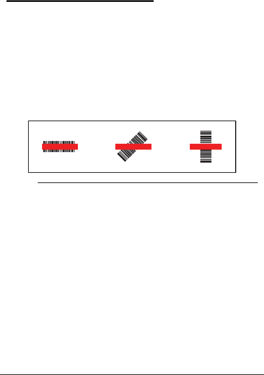
Aiming Options 0
The aiming beam is smaller when holding the device closer to bar code and the aiming beam
is larger when it is farther from bar code.
The aiming beam must be aimed closer to symbologies that have smaller bars or elements
(mil size). The aiming beam must be aimed farther from symbologies that have larger bars or
elements (mil size).
5300 Red High-Vis Aiming Pattern 0
The Dolphin 6000 device has a 5300 imager. The high-vis aimers frames the bar code
accurately.
5100 Red Aiming Beam 0
Linear Bar Code 0
Figure 4-2. Red Aiming Beam

Using the Camera 5-1
Using the Camera
Overview 0
The Dolphin 6000 device is installed with a 3.0-megapixel color camera, Automated Camera
Control (ACC) and an Application Programming Interface (API). The API provides easy
access to color picture and video capture functions. The camera lens and camera flash are
located on the back of the device.
Taking a picture 0
1. Tap >Pictures & Videos -> Camera
2. Point camera lens at object.
3. Adjust position of camera lens to make sure object is showing on screen.
4. Press ENT key on keypad to take picture.
Menu 0
Tap Menu on the Command Bar to change camera settings, switch to video mode to see
more camera options.
Item Descriptions
Video Start Video Mode
Mode Normal Mode, Burst Mode, Timer Mode
Brightness Set the brightness setting from +3.0 EV to -3.0 EV in .5 EV increments
Resolution Set picture resolution (i.e., 320 x 240, 640 x 480, 1280x960, 2048x1536)
Zoom Set zoom (x1, x2, x3, x4, x5, x6)
Focus Mode Focus On, Focus Off, Focus on Trigger, or Fixed-Focus
Focus Trigger
White Balance Set mode to Auto, Cloudy, Sunlight, Incandescent, Fluorescent, Tungsten
Flash Turn Camera Flash On or Camera Flash Off
Options Set General, Slide Show, Camera, and Video options
5-2 Using the Camera
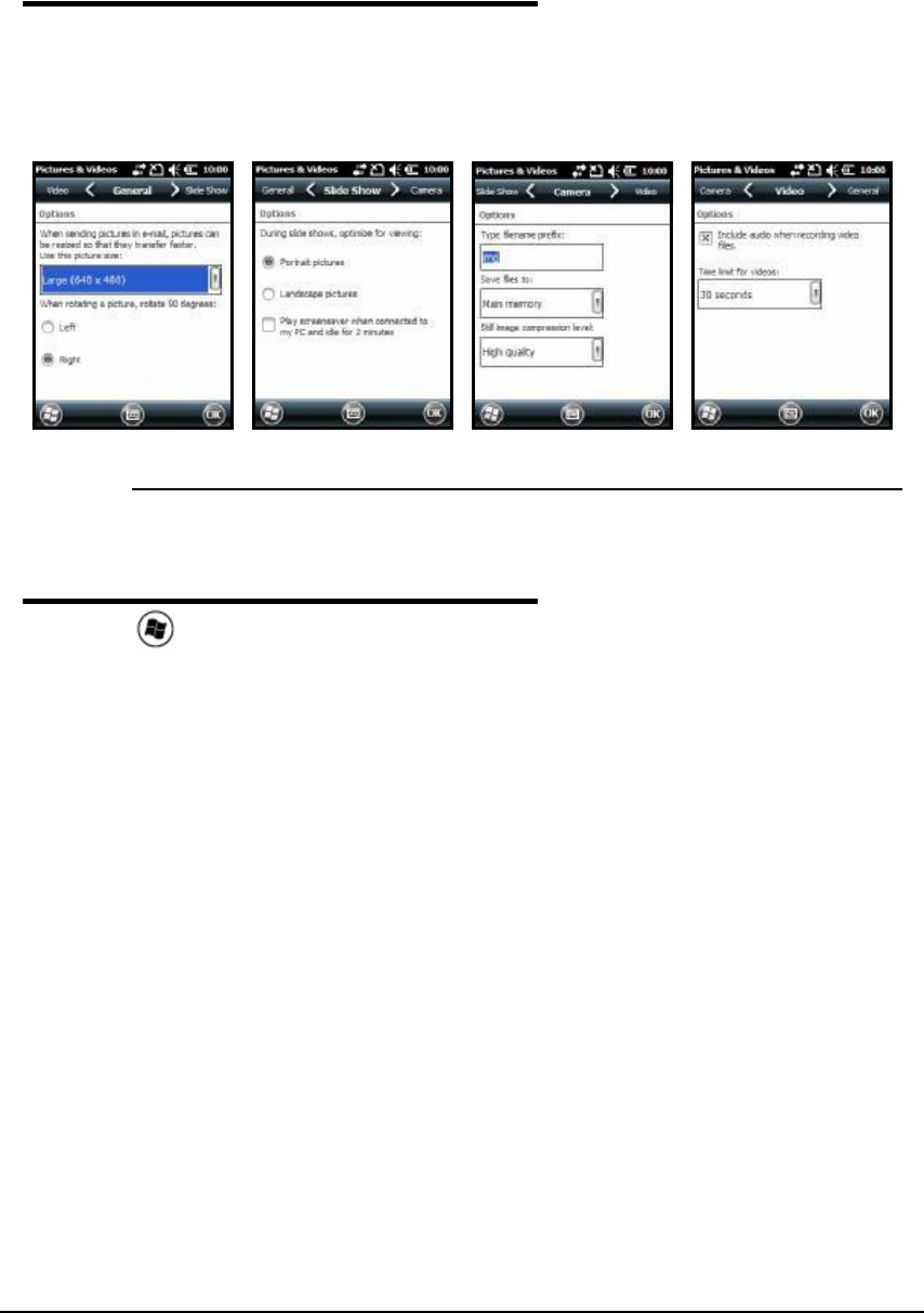
Options 0
Tap Menu -> Options. The Options menu contains four tabs:
Figure 5-1. Options Menu Tabs
Recording Video 0
1. Tap > Pictures & Videos -> Camera -> Menu -> Video
2. Point camera lens at object.
3. Adjust position of camera lens to make sure object is showing on screen.
4. Press ENT key on keypad to start recording.
5. Tap Stop on the screen or press ENT on keypad to stop recording.
General Tab Slide Show Tab Camera Tab Video Tab
Using the Keypad 6-1
Using the Keypad
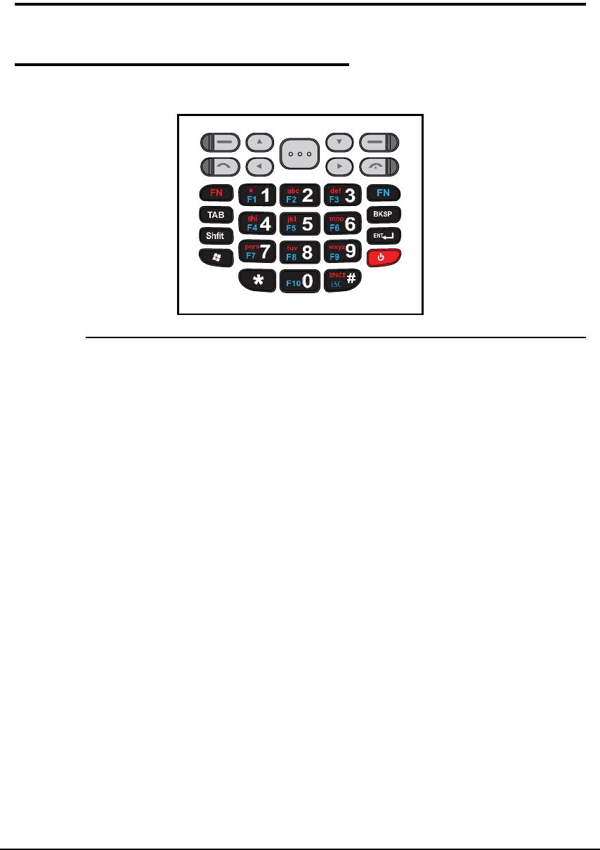
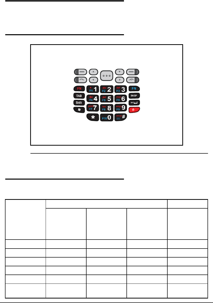
Keypad 0
The Dolphin 6000 series has a 29-key alpha/numeric keypad.
Figure 6-1. Keypad

6-2 Using the Keypad
Using the Function Keys 0
Table 6-1. Function Keys Table
Name Key Function
Backspace Moves cursor back one space each time key is pressed. If
typing text, it deletes previous character each time it is
pressed.
Enter (ENT) Confirms data entry.
Escape
(ESC)
Cancels current action. Press esc key to return to
previous menu.
Power Key Puts the device into and wakes the device from Suspend
Mode; see Suspend Mode on page 17.
SCAN Key Wakes the device from Sleep Mode and activates the
scan application.
SPACE Moves cursor ahead one space.
TAB Moves cursor to next tab stop or next control (on a form).
4-way
Navigation
Keys
Moves cursor left, right, up or down.
Volume Up
Input
Volume level increases.
Volume
Down Input
Volume level decreases.
Shift Key Changes keyboard between uppercase alphabet mode
and lowercase alphabet mode.
Orange FN
Key
The orange FN key has 3 operating modes for Normal
(default), Upper case and Lower case mode. Press
orange key to change each mode.
Blue FN Key The blue FN key activates F1~F10 function keys. Press
blue key again to return to default mode.
Using the Keypad 6-3
Using the Navigation Keys 0
Located below the touchpanel display, the navigation keys moves the cursor through text,
icons, folders and application screens.
29-Key Numeric Keypad 0
Figure 6-2. Keypad Buttons
Keypad Combinations 0
Table 6-2. Keypad Combinations Table
Numeric
Keypad
Orange FN Key Blue FN Key
Numeric Mode
(Default)
Lower Case
Mode
Upper Case
Mode
Toggle On/Off,
the Off mode
will operate on
default mode of
Orange FN Key
Left - Left - Left - Left - Left -
Up Up Up Up Up
Scan Scan Scan Scan Scan
Down Down Down Down Down
Right - Right - Right - Right - Right -
(Green Call
Button)
(Green Call
Button)
(Green Call
Button)
(Green Call
Button)
(Green Call
Button)

6-4 Using the Keypad
Left Left Left Left Left
Right Right Right Right Right
(Red End Call
Button)
(Red End Call
Button)
(Red End Call
Button)
(Red End Call
Button)
(Red End Call
Button)
1 F1 * 1 **F1
2 F2 abc 2 abc ABC F2
3 F3 def 3 def DEF F3
4 F4 ghi 4 ghi GHI F4
5 F5 jkl 5 jkl JKL F5
6 F6 mno 6 mno MNO F6
7 F7 pqrs 7 pqrs PQRS F7
8 F8 tuv 8 tuv TUV F8
9 F9 wxyz 9 wxyz WXYZ F9
* *
0 F10 0 F10
# ESC SPACE # SPACE SPACE ESC
BKSP BKSP BKSP BKSP BKSP
Shift Shift Shift Shift Shift
Enter Enter Enter Enter Enter
Windows Windows Windows Windows Windows
Tab Tab Tab Tab Tab
Right Side Scan Scan Scan Scan
Volume Up Volume Up Volume Up Volume Up Volume Up
Volume Down Volume Down Volume Down Volume Down Volume Down
Power Power Power Power Power
Table 6-2. Keypad Combinations Table (Continued)
System Settings 7-1
System Settings
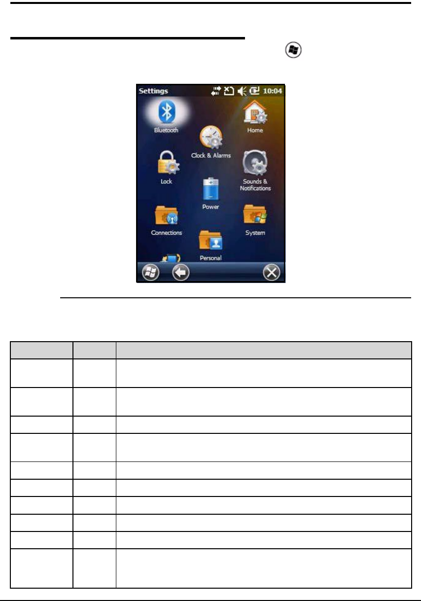
Overview 0
The device settings can be changed in the Settings menu. Tap -> Settings and Settings
menu will open.
Figure 7-1. Settings Menu
Table 7-1. Settings Menu Icons Table
Icon Description
Bluetooth Adjust Bluetooth radio settings. This icon will show only if Bluetooth
radio and driver are installed. See Working with Bluetooth Radio.
Clocks &
Alarms
Set system clock, date, time and schedule alarms. See Clock &
Alarms.
Lock Make password to limit access to device.
Sounds &
Notifications
Set sound volume, enable or disable sounds, change sound settings
and enable or disable vibrator.
Today Change appearance and information on Todayscreen.
Connections Change network connections settings. See Connections Menu.
Personal Change button settings and set SIP options. See Personal Menu.
Power See Power.
System Change system settings. See System Menu.
Microsoft My
Phone
Synchronize phone contacts, calendar, tasks, text messages, music,
photos, videos, and other documents with a My Phone account at
http:\\myphone.microsoft.com.
7-2 System Settings
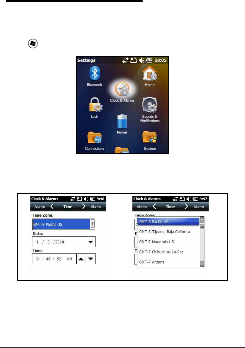
Clock & Alarms 0
To adjust the time and date:
1. Navigate to Clock & Alarms menu.
2. Use stylus or finger and tap time and date section.
OR
Tap > Settings -> Clock & Alarms. The Clock & Alarms menu will open.
Figure 7-2. Time and Date
3. Select Time tab. This setting sets system clock.
Figure 7-3. Clock Settings
4. Tap Time Zone box to open the drop-down menu.
5. Set correct time zone from drop-down menu.
6. Set correct time and date in the remaining fields
7. Tap OK to save.
System Settings 7-3
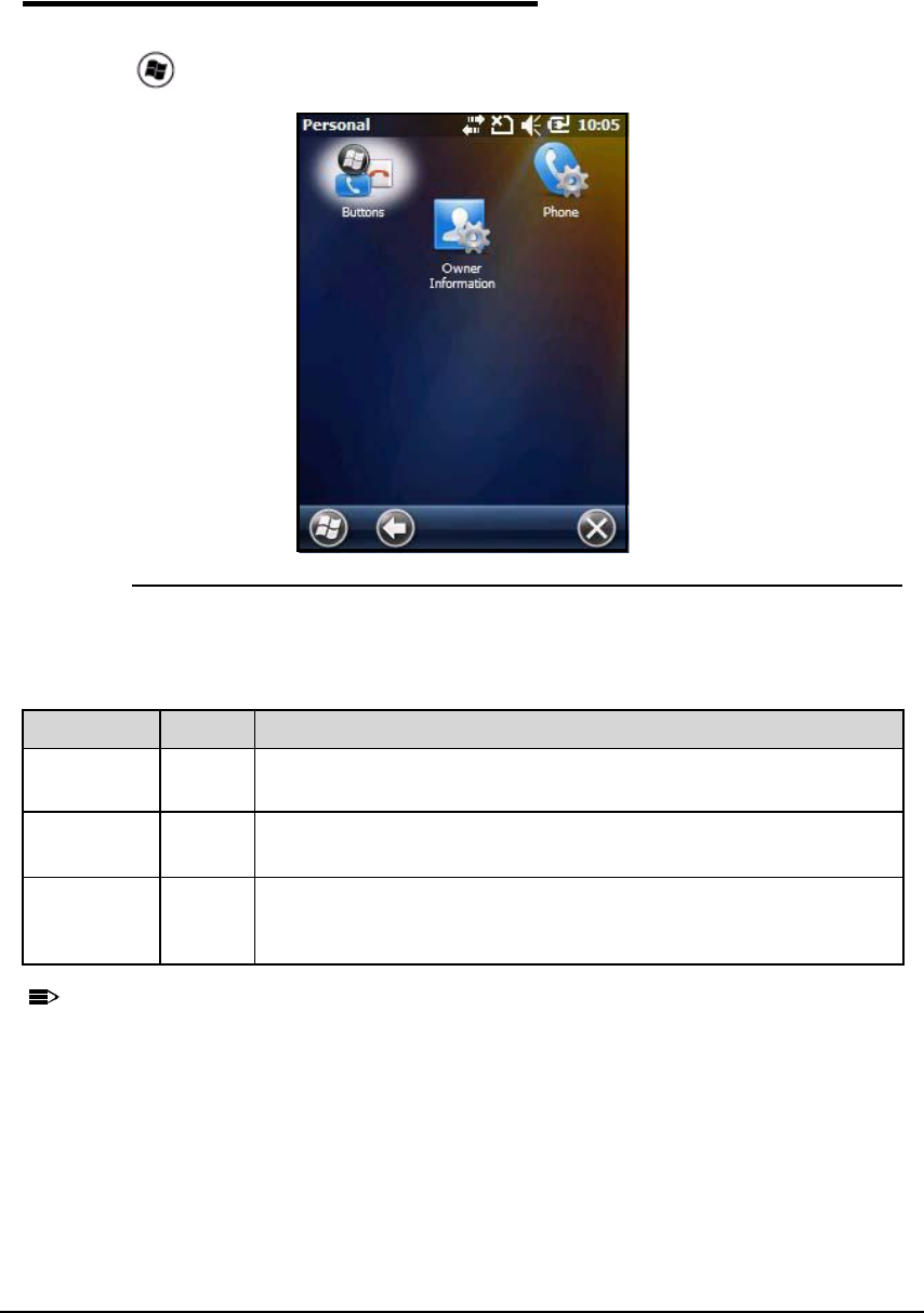
Personal Menu 0
To view the Personal Menu:
1. Tap > Settings -> Personal
Figure 7-4. Personal Menu
N
O
TE
:
N
O
TE
:
Personal settings are kept in RAM memory. They are replaced by system defaults after
a Hard Reset. For more information about resets, see Resetting the Device.
Table 7-2. Personal Menu Icons Table
Icon Description
Buttons Program side buttons on Dolphin 6000 to do specified tasks. See
Keypad.
Owner
Information
Enter contact information.
This information will appear on the Today screen.
Phone When GSM radio is turned on, tap this icon to set up user settings and
enable or disable vibrator function. See Setup Options for system
notifications.
7-4 System Settings
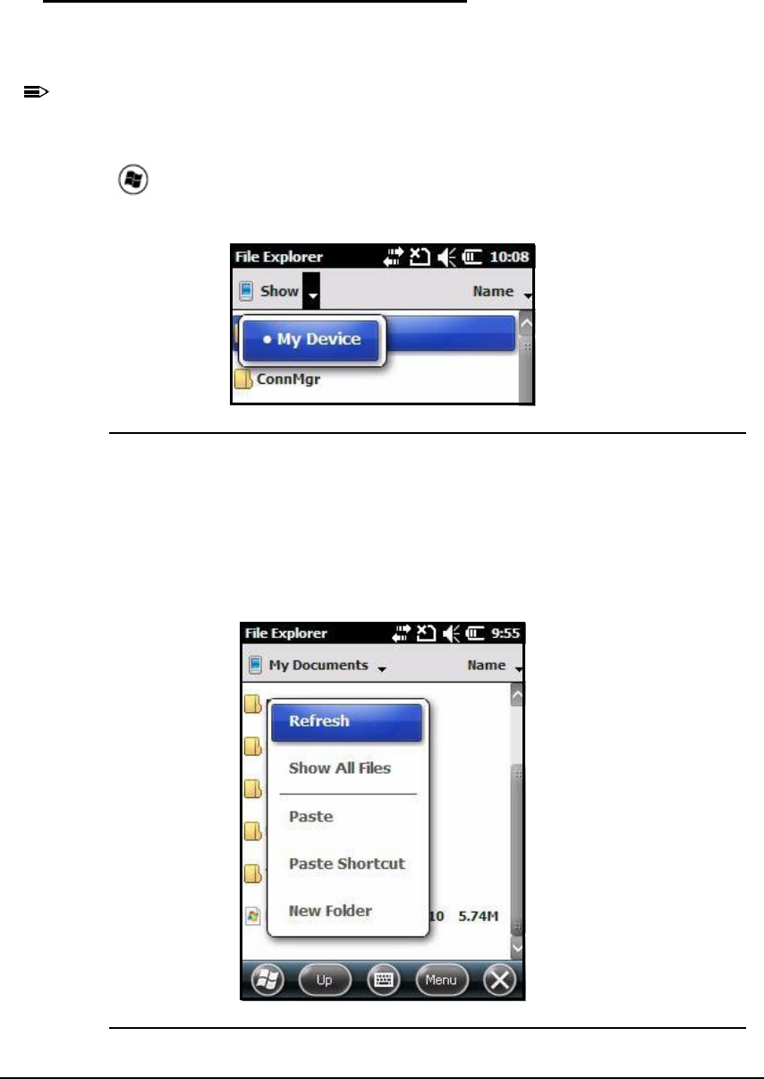
Using File Explorer 0
If a specific program is not found, use File Explorer on the device or ActiveSync on a
workstation to make a shortcut of a program and put shortcut in Start menu folder.
N
O
TE
:
N
O
TE
:
It is recommend to Copy and Paste a shortcut so that program settings are not changed
by accident. Use Copy and Paste shortcut to help make sure program files stay where
they must be for system to find them.
1. Tap > File Explorer
2. Navigate to My Device -> Program Files.
Figure 7-5. Selecting My Device
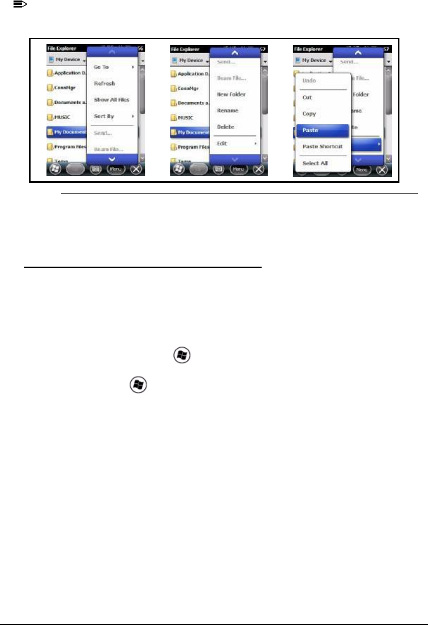
3. Use stylus to hold the program. A pop-up menu appears.
4. Tap Copy on pop-up menu.
5. Navigate to the Windows folder and open Start Menu (My Device -> Windows -> Start
Menu). Then tap and hold a blank area in the window, and tap Paste Shortcut on pop-up
menu.
Figure 7-6. Selecting Paste Shortcut
System Settings 7-5
N
O
TE
:
N
O
TE
:
If there is no blank area in window, tap Menu -> Edit -> Paste Shortcut.
Figure 7-7. Paste Procedure
6. Go to Start menu to make sure copied program is in Start menu folder.
Using ActiveSync on the Workstation 0
In ActiveSync, perform the same process as on device, except that Explore utility (Windows
Explorer) is used to copy and paste the shortcut.
1. Open ActiveSync -> Explore and navigate to program.
2. Right-click on program and click Create Shortcut.
3. Select shortcut, right-click, and select Cut.
4. Navigate to StartMenu folder ( > Start Menu).
5. Right-click on empty area and select Paste Shortcut.
6. On device, click on to go to Start menu.
7. Make sure program is there.
7-6 System Settings
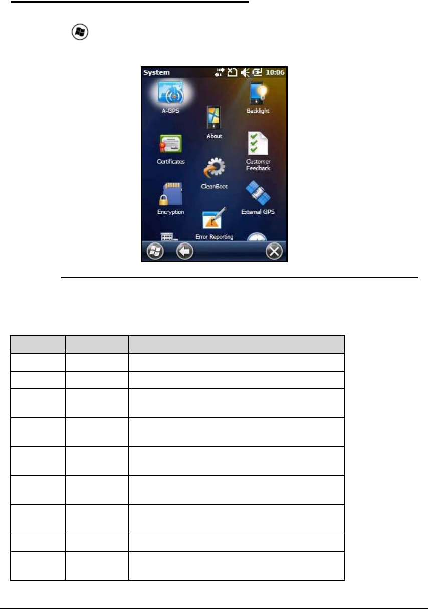
System Menu 0
The system settings can be changed in the System menu. To view the System menu:
1. Go to Settings -> System.
2. Tap an icon to open a system setting.
Figure 7-8. System Menu
Table 7-3. System Menu Icons Table
Icon See Page
About See About.
Backlight See Backlight.
Certificate
s
See Certificates.
Encryptio
n
See Encryption.
Error
Reporting
See Error Reporting.
External
GPS
See External GPS.
Managed
Programs
Memory See Memory.
Regional
Settings
See Regional Settings.

System Settings 7-7
About 0
The About menu shows information about device. There are four tabs:
Version Tab:Shows information about software, operating system, processor and
memory.
Device ID Tab:Shows information the device uses to identify itself to other devices. It is
important to know this information if device will be a part of a network.
Device Name: Shows system s default name. (This is the name used by
ActiveSync.)
Description: Shows description of the device ID.
Copyrights Tab: Shows copyright information.
Phone Tab:Shows hardware version, software version, IMEI serial number, bluetooth
firmware version and driver information.
Remove
Programs
See Remove Programs.
Screen See Screen.
Task
Manager
See Task Manager.
A-GPS
CleanBoot
Customer
Feedback
Version
Network
Time
Schedule
Power
On/Off
Windows
Update
Table 7-3. System Menu Icons Table (Continued)
Icon See Page
7-8 System Settings
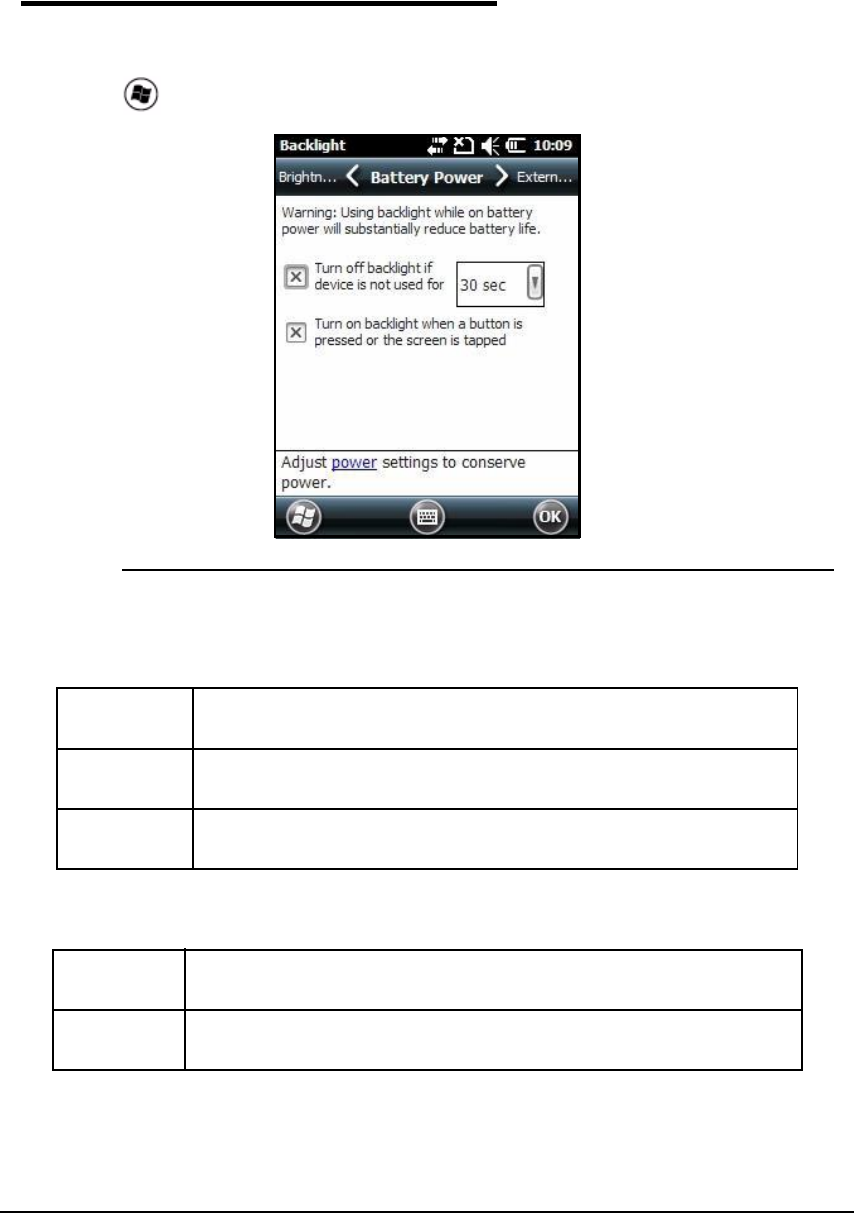
Backlight 0
The Backlight menu adjusts the backlight level for screen.
To adjust the backlight level settings:
1. Tap > Settings -> System -> Backlight.
Figure 7-9. Battery Power Tab
There are three tabs:
The options on Battery Power tab and External Power tab are same.
Battery
Power
Settings for backlight to turn off when device is using battery power.
External
Power
Settings for backlight to turn off when device is using external power.
Brightness Settings for backlight brightness when device is using battery power or
external power.
Turn Off
Backlight
Choose this option when for backlight to automatically turn off.
Turn On
Backlight
Choose this option for backlight to turn on when a button or touch
screen is tapped with stylus or pressed with finger.
System Settings 7-9
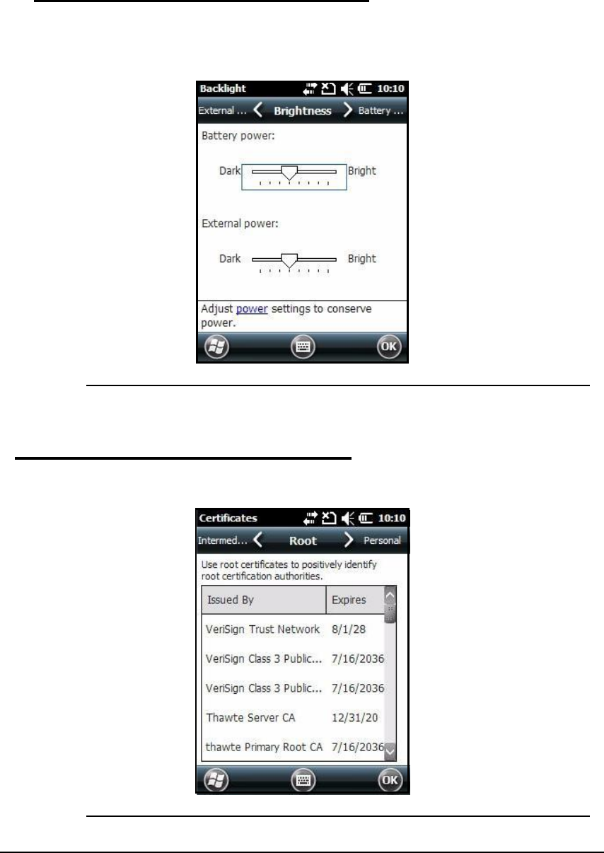
Backlight Intensity 0
In the backlight menu, tap Brightnesstab and move slider to change screen brightness for
battery power and external power settings. The default setting is 4.
Figure 7-10. Brightness Tab
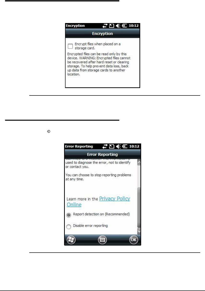
Certificates 0
The Certificatesmenu shows certificates that the operating system recognizes.
Figure 7-11. Certificates Menu
7-10 System Settings
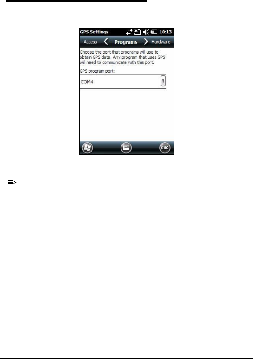
Encryption 0
The Encryption menu can be adjusted to encrypt files on storage cards so those files cannot
be read by another device.
Figure 7-12. Encryption Menu
Error Reporting 0
The Error Reporting menu can be adjusted enable or disable error reporting function of
Windows Mobile 6.5.
Figure 7-13. Error Reporting Menu
System Settings 7-11
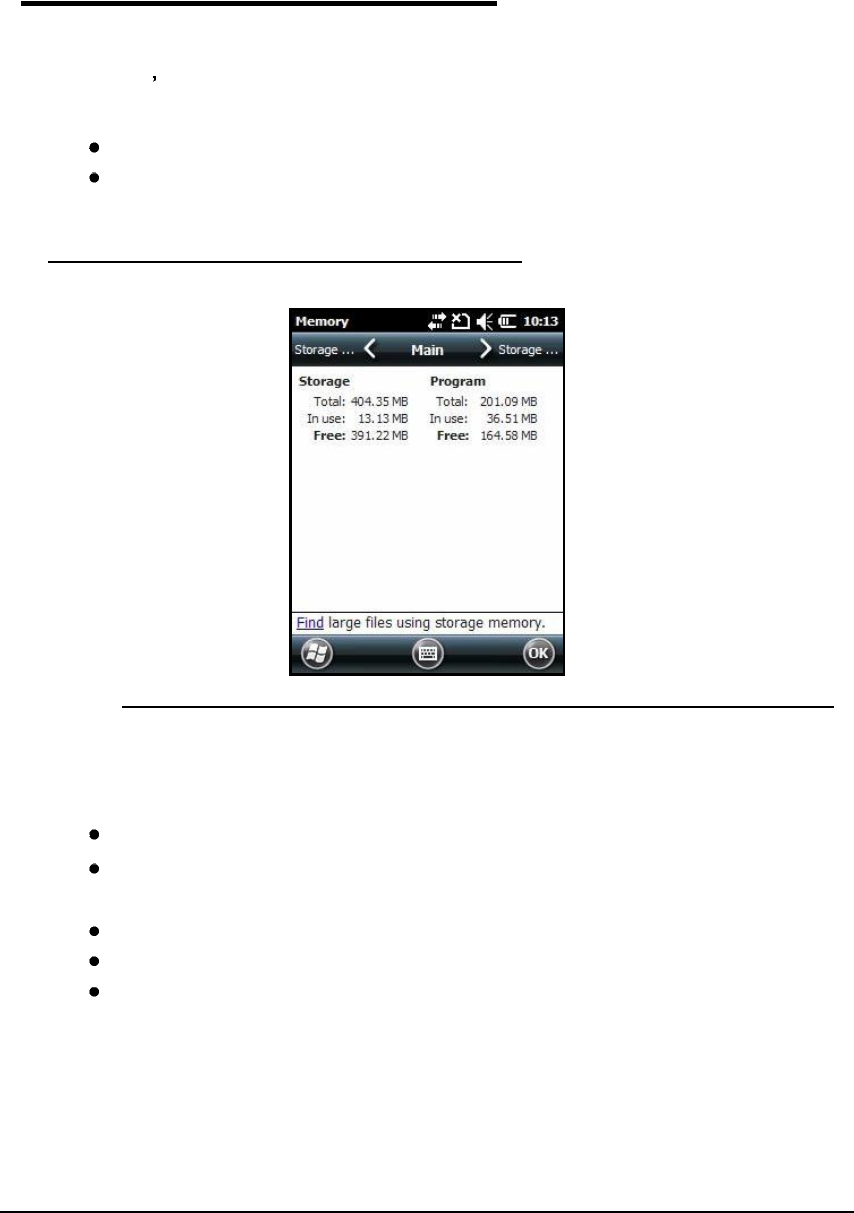
External GPS 0
The External GPS menu gives the option to choose a port for a third-party GPS software
application to access GPS receiver.
Figure 7-14. External GPS Menu
N
O
TE
:
N
O
TE
:
Installation settings from GPS manufacturer to set connection is required.
7-12 System Settings
Memory 0
The Memory menu shows capacity and usage statistics for RAM (volatile and Storage Card
non-volatile) memory. View this setting when system messages about memory is received.
The device s memory allocation cannot be changed in Memory menu.
There are two tabs:
Main
Storage Card
Main 0
Figure 7-15. Main
The Main tab shows usage statistics of on-board RAM (volatile) memory.
Columns:
Storage =RAM memory used to keep programs and program data.
Program =RAM memory used to run programs.
Rows:
Total = Shows current Megabytes (MB) of memory that can be used.
In use = Shows total MB of memory being used.
Free = Shows total MB of available memory.
System Settings 7-13
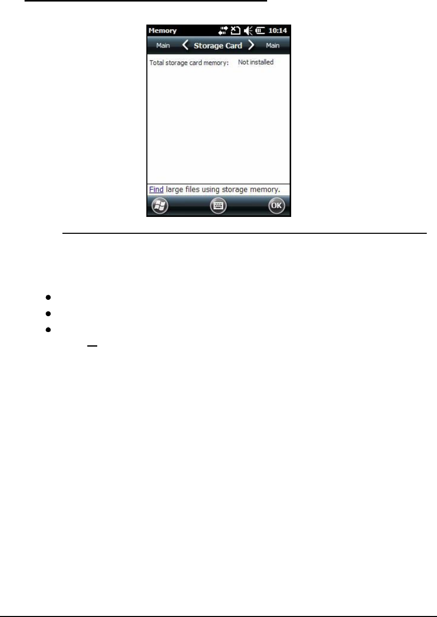
Storage Card 0
Figure 7-16. Storage Card
The Storage Card tab shows capacity and usage statistics of Storage Card.
Select memory type from drop-down list.
Total storage card memory = Total Megabytes (MB) of memory capacity of Storage Card
In use = MB currently being used
Free = MB that can still be used
Storage Card One memory card can be installed in the Dolphin 6000 device. If memory card
is installed in the device, select it in drop-down list and see capacity and usage statistics for
card.
7-14 System Settings
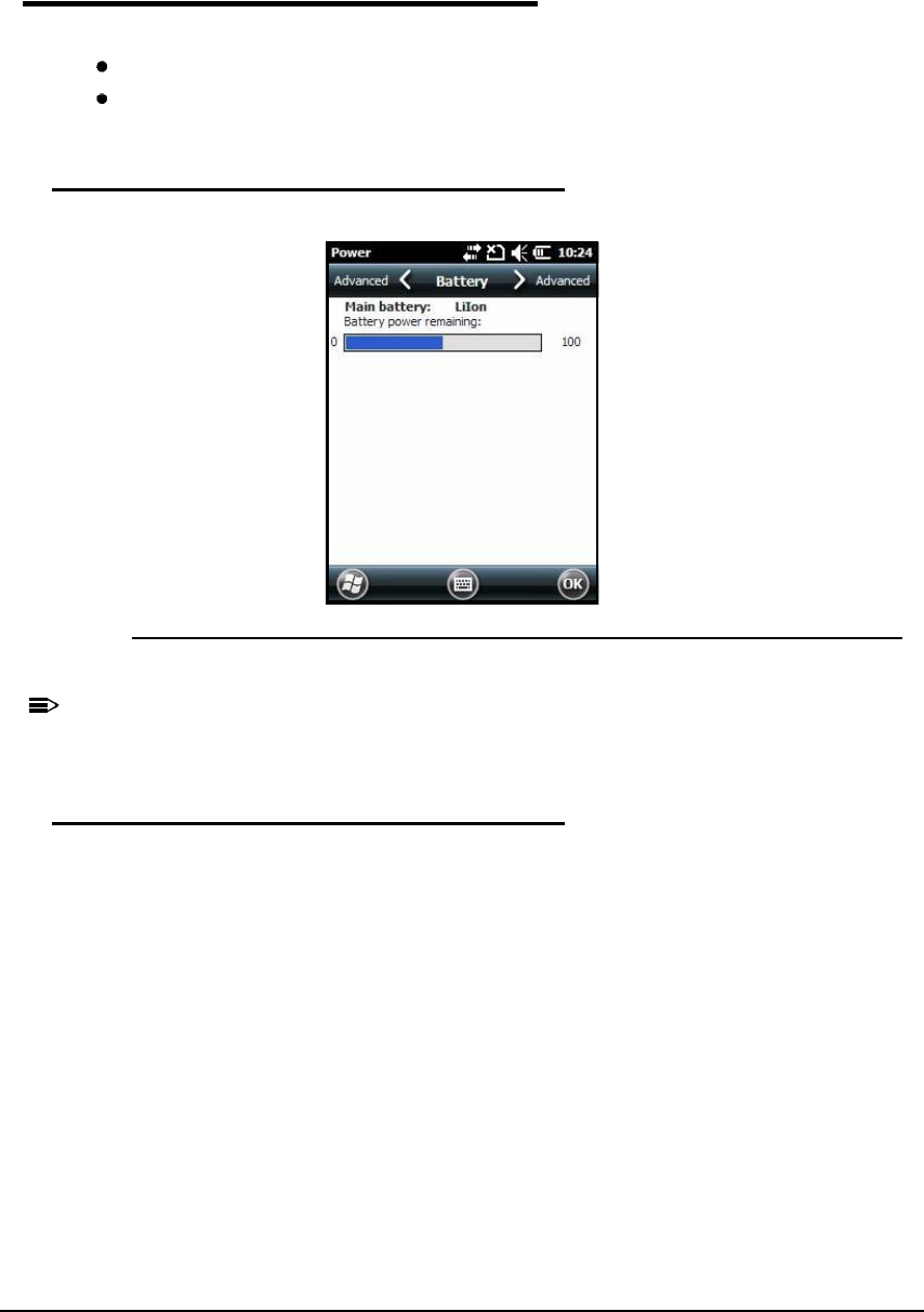
Power 0
The Power settings menu has two tabs:
Battery
Advanced
Battery 0
Figure 7-17. Battery
N
O
TE
:
N
O
TE
:
For more information, see Battery Pack.
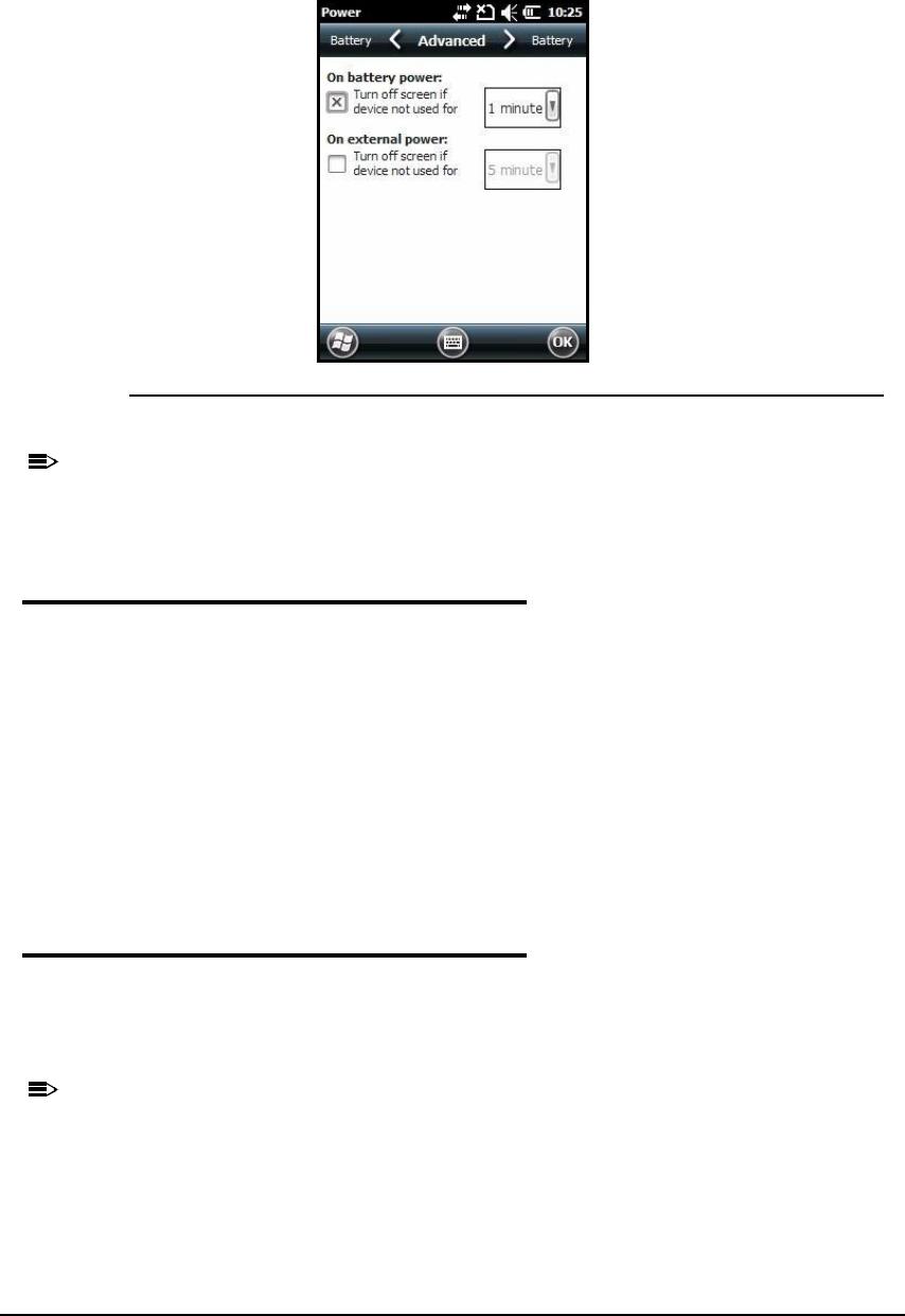
Advanced Tab 0
In the Advanced tab, settings can be adjusted for screen to turn off when device is not in use.
To change settings for On battery power:
1. Tap box that shows time. A drop-down list will open.
2. Set amount of time to pass before screen will turn off when device is not in use.
To change settings for On external power:
1. Tap box that shows time. A drop-down list will open.
2. Set amount of time to pass before screen will turn off when device is not in use.
System Settings 7-15
Figure 7-18. Advanced Tab
N
O
TE
:
N
O
TE
:
There is an option to set automatic turn-off times for device to save power. When device
is turned off, that means device is in Suspend Mode. See Suspend Mode.
Regional Settings 0
The appearance and formatting can be adjusted to a geographic region in Regional Settings
menu. Numbers (decimal places), currency (using $), time and date changes can be made.
These settings apply to all screens. The Region tab shows region in drop-down list at top.
The device has many pre-programmed regional settings. Choose one from list and results
appear on screen.
To see settings or change a setting:
1. Choose a tab
2. Make change
3. Tap OK on Command bar to save.
Remove Programs 0
In Remove Programs menu, programs installed on the device can be removed. Use this
setting to troubleshoot when a messages is received and says device has no more memory.
The programs will be removed from RAM memory. Any program (usually CAB or DLL files)
saved in Auto-install folder (My Device -> IPSM -> Autoinstall) will re-install after hard reset.
N
O
TE
:
N
O
TE
:
For information about hard reset process, see Hard Reset (Cold Boot).
1. Tap the Remove Programs Icon.
2. Select program to remove.
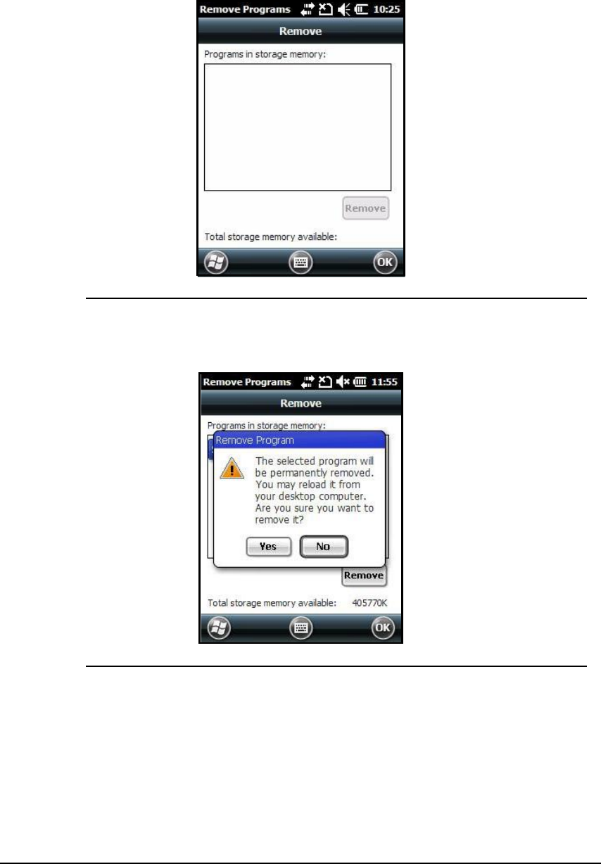
7-16 System Settings
Figure 7-19. Remove Programs Menu
3. Tap Remove. The message in Figure7-20 appears.
Figure 7-20. Remove Program Pop-Up
4. Tap Yes. Wait for program to be removed.
5. Check and see that program is not showing in list.
System Settings 7-17
Screen 0
The Screen menu has three tabs:
General
ClearType
Text Size
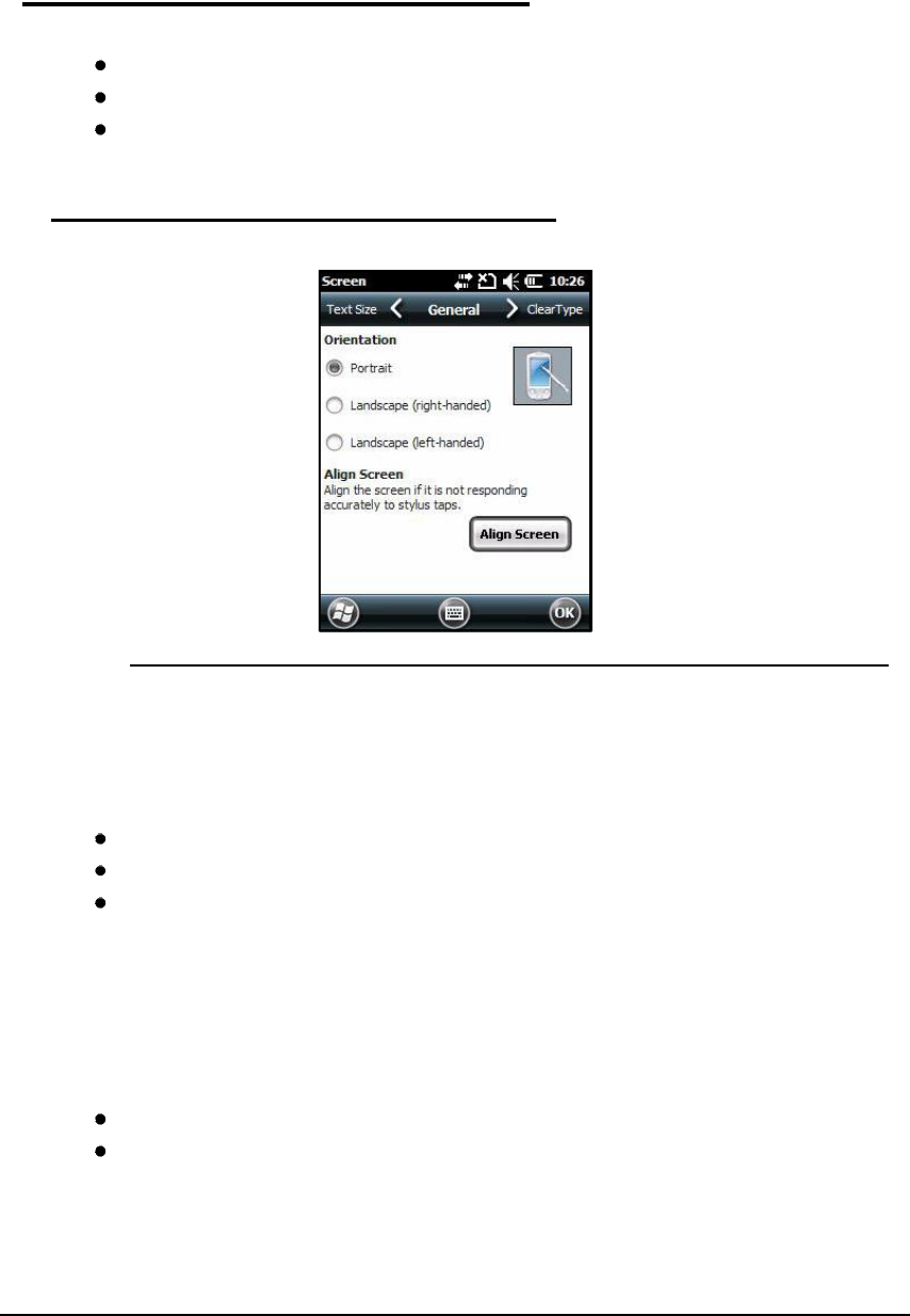
General 0
Figure 7-21. General Tab
Orientation 0
The General tab is used to set dynamic screen rotation. There are three types of screen
orientations:
Portrait
Landscape (right-handed)
Landscape (left-handed)
Align Screen 0
The screen can be re-aligned in General tab. If tapping buttons or icons with stylus does not
work correctly, the screen must be re-aligned.
1. Tap Align Screen to open align screen window.
2. Tap a target several times with stylus. This re-calibrates touch screen.
Align Screen must be done using the stylus. The stylus tip is necessary for calibration.
Tap stylus into center of target once and release. Do not tap target more than one time.
7-18 System Settings
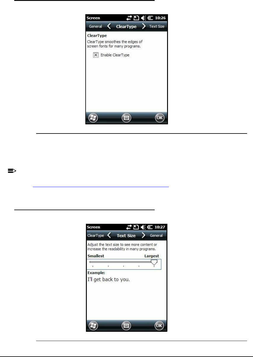
ClearType 0
Figure 7-22. ClearType Tab
The screen supports ClearType font rendering.
To turn on ClearType font rendering, tap Enable ClearType and tap OK.
N
O
TE
:
N
O
TE
:
For more information about ClearType font rendering, visit:
www.microsoft.com/typography/WhatIsClearType.mspx.
Text Size 0
Figure 7-23. Text Size Tab

System Settings 7-19
In Text Size tab, font scaling can change in:
Today screen
Contacts
Calendar
Messaging
Tasks
Font scaling means point size of fonts can increase or decrease in applications.
To change font size:
1. Move slider to Smallest or Largest. The Example text changes to show the font change.
2. Tap OK to save font size setting.
7-20 System Settings
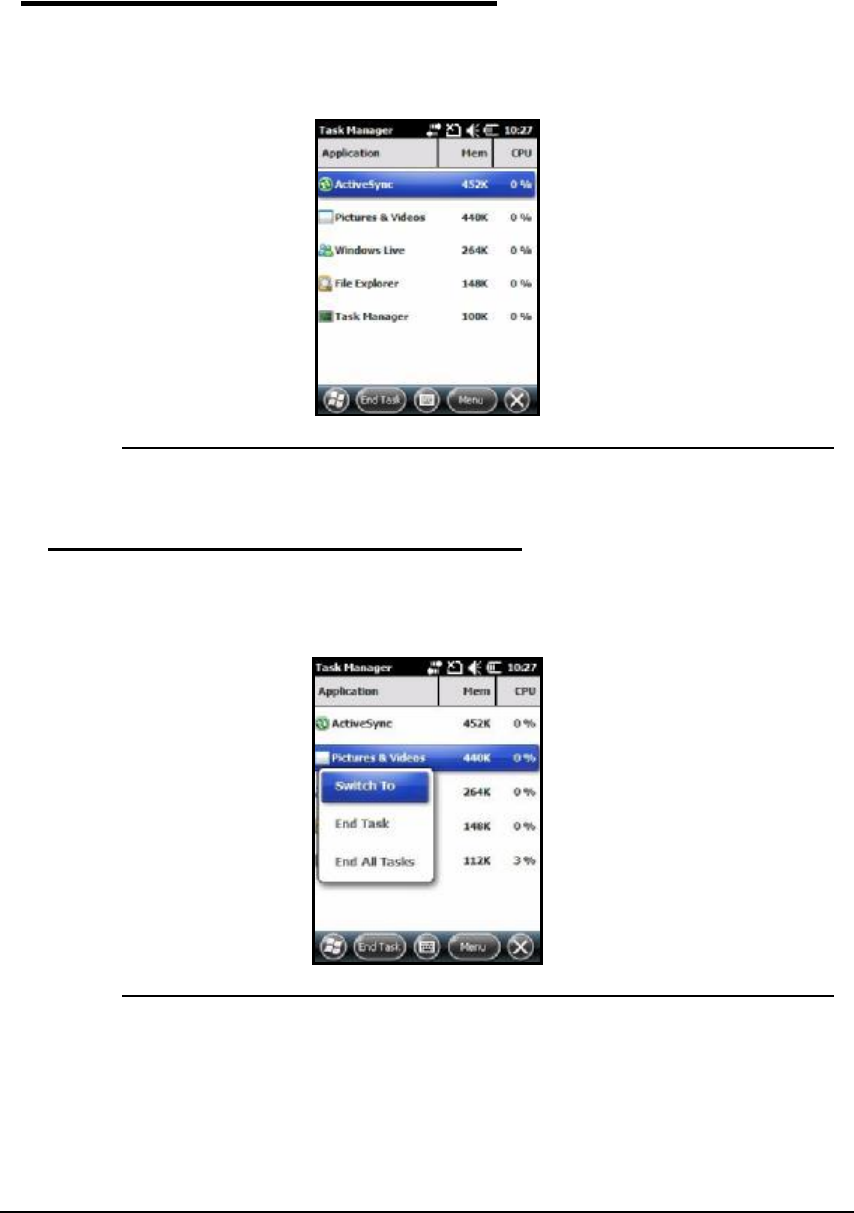
Task Manager 0
Task Manager shows information about applications and processes that are being used on
device. Use Task Manager to view memory and CPU usage of applications and processes.
View Task Manager when memory errors are received or when device operation is slow.
Figure 7-24. Task Manager Menu
Using the Task Manager 0
Applications 0
Figure 7-25. Applications in the Task Manager
To see status of programs running:
1. Tap Menu button on Command bar
2. Tap View -> Applications.
3. Tap and hold on an application
4. Tap Switch To on pop-up menu.
System Settings 7-21
5. Tap and hold on an application.
6. Tap End Task or End All Tasks on pop-up menu.
N
O
TE
:
N
O
TE
:
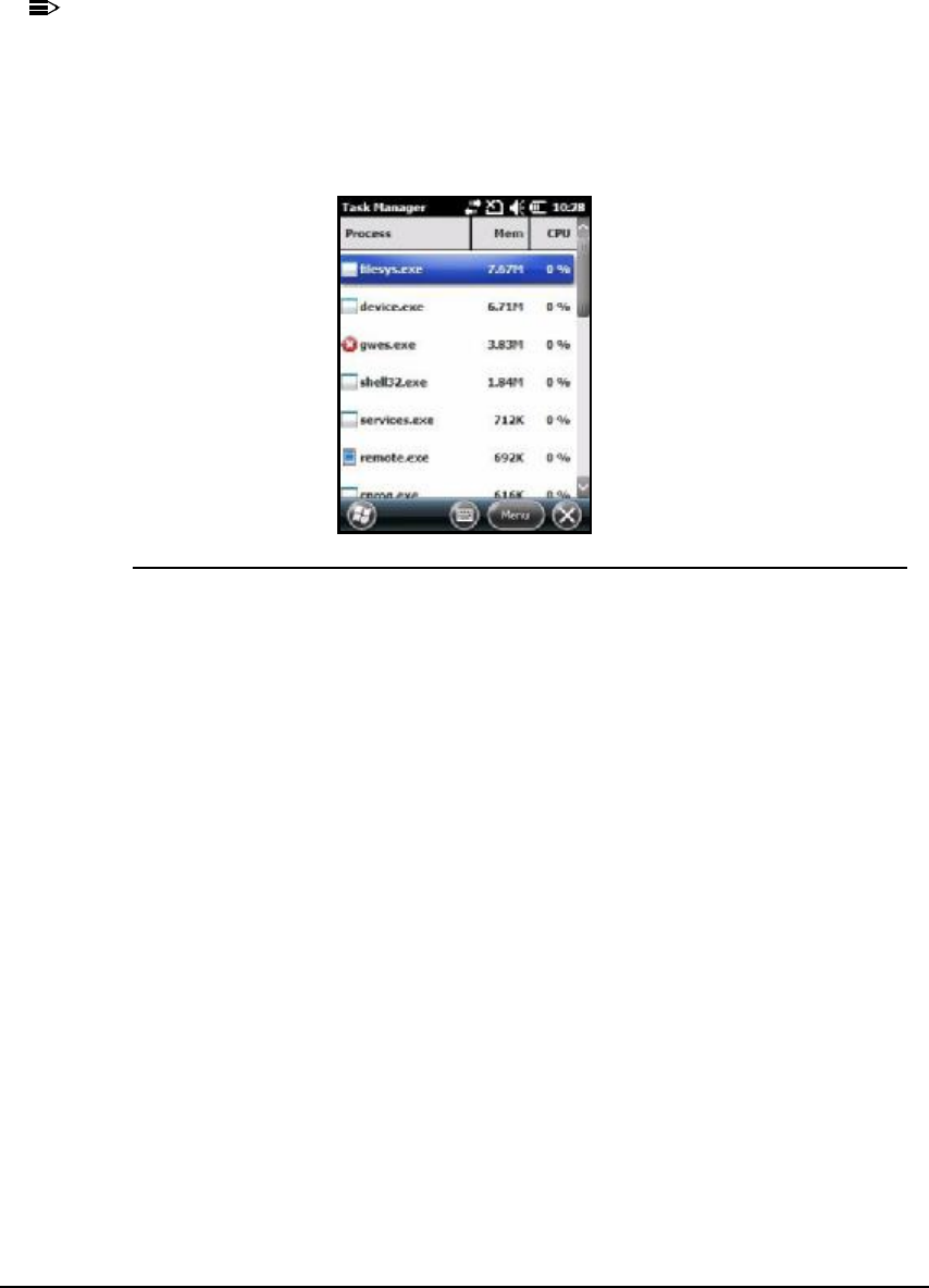
When stopping a program, more RAM memory will be available. When stopping a
program in TaskManager, unsaved data in that program is lost. To make more available
memory and not lose data, go to active program and save data before closing program.
Processes 0
Figure 7-26. Processes in the Task Manager
To view information about processes:
1. Tap Menu button on Command bar.
2. Tap View -> Processes.

7-22 System Settings
Communication 8-1
Communication
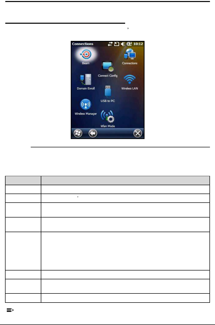
Connections Menu 0
The Connections menu provides access to the device s wireless communication options.
Figure 8-1. Connections Menu
N
O
TE
:
N
O
TE
:
All server-assigned IP addresses use Dynamic Host Configuration Protocol (DHCP).
Table 8-1. Connection Menu
Icon Description
Beam Enables infrared communication.
Connections Opens Microsoft s connections manager. Refer to Connections Manager.
Wireless
Manager
Manages the wireless radios installed on the device. Refer to Wireless
Manager.
USB to PC Enables advanced wired USB to PC communication via ActiveSync. Refer to
ActiveSync Communication.
Wireless LAN Enables to configure Wireless Zero Config (WZC). This icon appears only if
the 802.11b/g driver is loaded on the device and the WLAN Security
Supplicant is not loaded.
By default, the Wireless Zero Config is disabled and the supplicant is loaded.
This icon appears only if the supplicant is removed and the device is Cold
Booted.
Domain Enroll Connects the phone to the company resources.
Connect
Config
Enables automatic data configuration.
WLAN Mode Enables WLAN configuration.
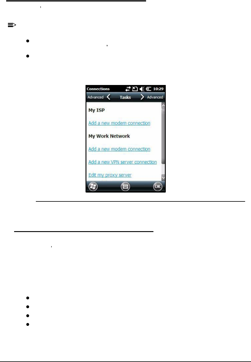
8-2 Communication
Connections Manager 0
Microsoft s Connections Manager sets up multiple network connections to the Internet
Service Providers (ISPs) via the external modem.
N
O
TE
:
N
O
TE
:
Do not enter connection parameters in the connections manager if:
One of the on-board wireless radios is used to connect to a network. The Dolphin 6000 device
uses the settings from each radio s configuration utility to connect.
Wireless Zero Config is used. By default, WZC is disabled on Dolphin 6000 devices.
To open the Connections Manager, navigate to Start-> Settings->Connections->Connections
icon .
Figure 8-2. Connections Manager
Tasks Tab 0
The Tasks tab enables to initially configure, then manage network settings when using a
modem. User s should select an item from the menu and follow the instructions on the screen
to complete the network configuration.
My ISP 0
Enables to add and manage modem connections to an ISP. To complete the setup screens,
get the following information from the ISP:
ISP dial-up access telephone number
Username
Password
TCP/IP settings
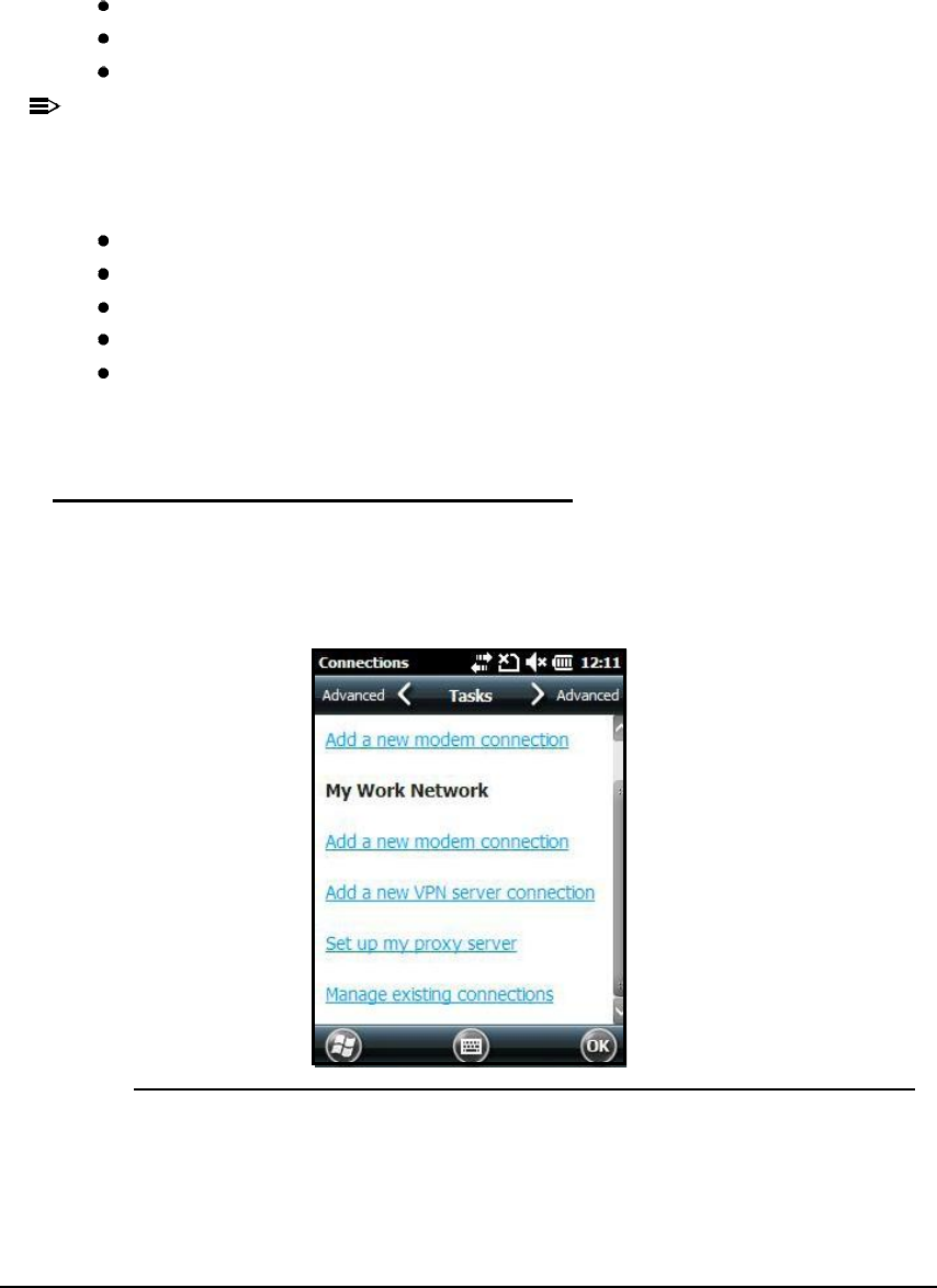
Communication 8-3
My Work Network 0
Enables to establish the following connection types:
Modem
Virtual Private Network (VPN)
Proxy server connection
N
O
T
E
:
N
O
TE
:
When connected to ISP or private network, during synchronization with the PC, the
device downloads the proper proxy settings. If the network connection is not configured
on PC or need to be changed, then the ISP or network administrator should provide the
following information:
Proxy sever name
Server type
Port
Type of Socks protocol used
User name and password.
To complete the setup screens, get the network parameters from system administrator.
Modify an Existing Connection 0
Manage Existing Connectionsappears on the Connections tab after at least one network
connection has been established.
Tap Manage Existing Connectionson the Tasks tab and follow the setup screens.
Figure 8-3. Manage Existing Connections
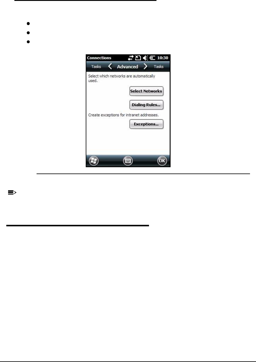
8-4 Communication
Advanced Tab 0
The Advanced tab enables to select the following:
Default network
Dialing rules
IP address exceptions for modem connections.
Figure 8-4. Advanced Tab
N
O
TE
:
N
O
TE
:
Advanced settings should not be modified. Most ISPs use DHCP addresses.
Online Help 0
For more information about modem connection setup, tap on the Help icon in setup screens.

Communication 8-5
Wireless Manager 0
ActiveSync Communication 0
ActiveSync 4.5 or higher enables to synchronize data between the device and the
workstation. In order to perform the synchronization, the program must be installed and
configured for the appropriate communication type on the host workstation and Dolphin 6000
device. Dolphin 6000 devices ship with ActiveSync installed by default.
If ActiveSync is already installed on the host workstation, then the workstation and Dolphin
6000 device need to be connected (via Dolphin 6000 peripheral) in order to initiate the
communication.
If ActiveSync 4.5 or higher is not installed on the host workstation, it s possible to download
the latest version of the program from the www.microsoft.com website.
CAUTION:
!
When communicating via ActiveSync, the device is designed to be connected to
the host workstation with a communication peripheral, such as the
charge/communication cable.
N
O
TE
:
N
O
TE
:
If communication in ActiveSync fails, remove the USB cable and connect the USB
cable to the host workstation again to initiate the process.
Capabilities 0
The following is a list of the device s capabilities:
Back up and restore the device data
Copy files between the device and workstation.
N
O
TE
:
N
O
TE
:
It is suggested to copy, rather than synchronize the data.
Defining a synchronization mode. It is possible to synchronize continuously while connected to
the workstation or only when the synchronization command is selected.
Defining the time period and data type to be synchronized. It is possible to choose how many
weeks from the past appointments will be synchronized.
Communication Types 0
The Dolphin 6000 device supports the following types of communication via ActiveSync
through its I/O Connector (see page 3-10) on the bottom panel:
USB The USB cable and hardware peripherals allow the device to communicate with a
workstation or to networked through a USB hub. The Dolphin 6000 device supports full-speed
USB communication (USB 1.1) with maximum data transfer rate: 12 Mbps. The Dolphin 6000
device defaults to USB communication out of the box.

8-6 Communication
Hardware Requirements for Setup 0
The following is a list of the hardware requirements needed for Setup:
Dolphin 6000 communication peripheral or cable
Dolphin 6000 power cable
USB cable (for USB communication).
Software Requirements for Communication 0
To synchronize successfully, ActiveSync v4.5 or higher must be configured for the same
communication type on the host workstation and Dolphin 6000 device. ActiveSync must be
setup on workstation before initializing synchronization from the device for the first time.
The following is a list of the supported operating systems:
Windows 98 Second Edition
Windows ME
Windows 2000
Windows NT (4.0 SP6 or higher)
Windows XP operating systems.
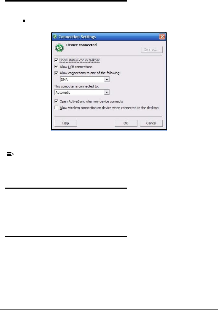
Communication 8-7
Setting Up the Host Workstation 0
1. Verify that ActiveSync is configured to use the appropriate communication type by tapping
File > Connection Settings.
For USB communication, check AllowUSBconnections.
Figure 8-5. USB Connection Settings
N
O
TE
:
N
O
TE
:
USB can be selected in the software, without affecting the processing. The hardware
setup should use only USB.
Communicating with the Dolphin 6000 device 0
After setting up the workstation and the device, ActiveSync connection should be established
automatically. Perform the following:
1. Connect the Dolphin 6000 device to a Dolphin 6000 communication peripheral. The
Dolphin 6000 device automatically opens ActiveSync, in order to establish a connection.
Synchronizing with the Host Workstation 0
The synchronization process begins automatically after Setup, if ActiveSync has been
installed to the host workstation and the workstation has been connected to the device.
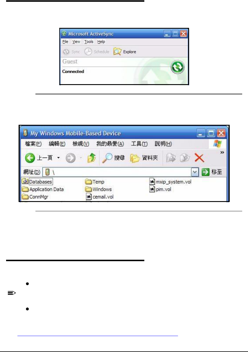
8-8 Communication
Exploring the Device from the Workstation 0
When the Dolphin 6000 device and workstation are connected, open the main ActiveSync
window (on the desktop), and tap Explore.
Figure 8-6. ActiveSync Window
The Mobile Device folder opens in Windows Explorer.
Figure 8-7. Mobile Device Folder
The Dolphin 6000 device is treated as a mass storage device, and transferring files can be
dragged and dropped or copied and pasted.
Installing Additional Software 0
In addition to the default programs, the user can install any other program that meets the
following requirements:
It is designed for Windows Mobile-based device and for the version of processor of the device.
N
O
T
E
:
N
O
TE
:
To verify the processor, navigate to Start-> Settings-> System-> About-> Version
Has an EXE, CAB, or DLL extension.
The requirement to the device is that it must have enough memory to store the program.
The most popular place to find the software is on the Windows Mobile website:
www.microsoft.com/windowsmobile/en-us/downloads/default.mspx

Communication 8-9
Adding Programs to the Device Using ActiveSync 0
CAUTION:
!
When selecting programs, verify that the program and version of the program are
designed for Windows Mobile and processor. To verify the processor tap on
Start-> Settings-> System-> About-> Version.
Depending on the application, the software must be stored or installed on the host PC.
Perform the following:
1. Download the program to the desktop computer from the Internet, CD or disk. It can be a
single setup.exe,EXE-,CAB- or DLL-file or several files for different types of devices and
processors.
2. Many programs provide special installation instructions. Read the installation instructions
in Read Me files, or documentation that comes with the program.
3. Connect the device to the desktop computer via a communication peripheral.
Installer File 0
The idea of an installer program is to install on the PC and the device simultaneously. Perform
the following:
1. On the PC, double-click the *.setup.exe or EXE-file. The installation wizard begins.
2. Follow the directions on the PC screen. The installation process includes transferring the
software to the device.
Non-Installer File 0
There are programs that cannot be installed on PCs because they are designed for devices. If
the instructions cannot be found in the Read Me file or documentation, perform the following:
1. Store the appropriate file or files on the host PC
2. Open ActiveSyncand click Explore
3. Click on the My Windows Mobile-Based Device folder and copy the program file or files
to the Program Filesfolder on the device.
If the program has to be part of the Autoinstall that occurs after every Hard Reset, place the
program file in the Autoinstallfolder located at My Windows Mobile-> Based Device-> IPSM->
Autoinstall
CAUTION:
!
Hard Reset erases RAM data.
4. If the file or files have been copied to the Autoinstallfolder, the user can tap on the
program inside the folder or perform a Hard Reset and the program installation starts
automatically. For more information, refer to Hard Reset (Cold Boot).
After the installation on the device is complete, tap Start.The program and its icon appears
on the Start screen. Tap on the icon to run the program.
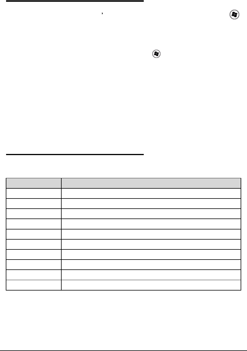
8-10 Communication
Adding Programs Directly from the Internet 0
When selecting programs, verify that the program and version of the program are designed
for Windows Mobile and the device s processor. Processor can be verified by tapping on >
Settings-> System-> About-> Version tab. Make a note of the information in the Processor
field.
Perform the following:
1. Choose the version of the software that is designed for the specific device and processor.
To determine the device and processor type, tap on Settings-> System-> About.
Make a note of the information in the Processor field.
2. Download the program to the device straight from the Internet, using Internet Explorer
Mobile. It can be a single setup.exe, EXE-, CAB- or DLL-file or several files for different
types of devices and processors.
3. Many programs provide special installation instructions. Read the installation instructions
in Read Me files, or documentation that comes with the program.
4. Tap on an EXE-file. The installation wizard begins. Follow the directions on the screen.
5. Select the radio or radio combination and tap Apply. The Radio Manager begins enabling
radio or radio combination.
6. When enabled, the Statusfield reads Success.
COM Port Assignment Table 0
Table 8-2. COM Port Assignment Table
COM Port Description
COM0 Not accessible
COM1 Not accessible
COM2 Not accessible
COM3 Serial Port: Rs232 Connector on the bottom panel
COM4 GPS Com Port
COM5 Bluetooth DUN
COM6 Unused
COM7 Unused
COM8 Unused
COM9 BT BTHATCI server

Working with GSM/GPRS/EDGE 9-1
Working with GSM/GPRS/EDGE
Overview 0
The Dolphin 6000 device is designed with an integrated, embedded GSM/GPRS/EDGE
penta-band radio module for WWAN communication.
Requirements 0
Using GSM/GPRS/EDGE requires:
Network subscription to a GSM/GPRS/EDGE network (must know what service providers are in
the area)
An installed SIM card that has been activated by the network service provider (see SIM Card
Installation on page 9-2).
GSM Global System for Mobile communications, GSM is an open, non-proprietary
wireless WAN system.
GPRS General Packet Radio Service, GPRS is a non-voice service that allows
packet-switched data to be instantly sent and received across mobile telephone
networks.
EDGE E-GPRS is a non-voice service that allows packet-switched data to be instantly
sent and received across mobile telephone networks at a higher data rate than
standard GPRS.
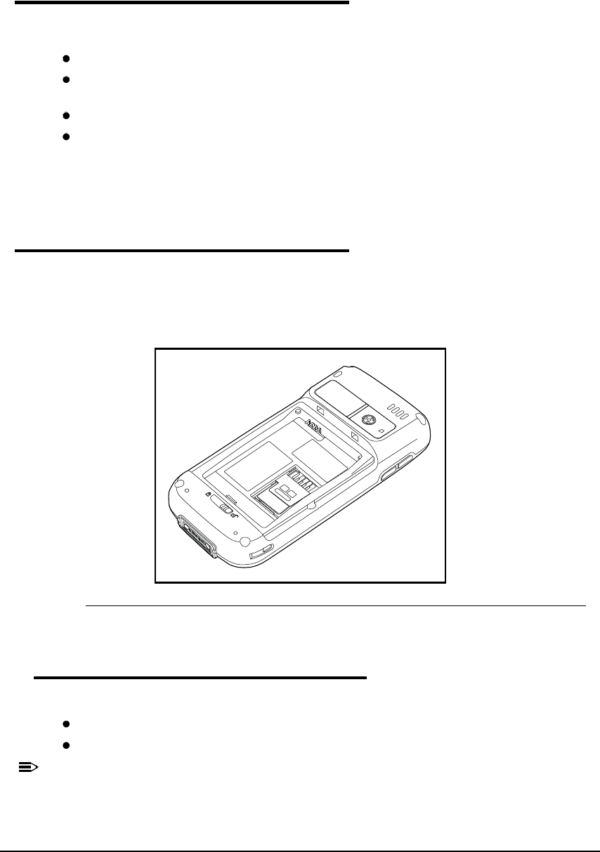
9-2 Working with GSM/GPRS/EDGE
Voice and Data Communication 0
Dolphin 6000 devices with integrated GSM/GPRS/EDGE radios are best for the following
two-way voice and data communications:
Voice: GSM voice data (dial-up)
Data: Available speed depends on the wireless network carrier and their supported packet-data
technology and network conditions.
GPRS Class 10: data transmission max. 85.6 kbps (DL), max. 42.8 kbps (UL)
EDGE (E-GPRS) Class 10: data transmission max. 237 Kbps (DL), max. 118 kbps (UL)
GSM radio for voice communication and data communication can be used, but not at same
time. If making a voice call, the device cannot send data. If sending data, the device cannot
make voice calls.
SIM Card Installation 0
Subscriber Information Module, a SIM card contains subscriber's personal information,
GSM/GPRS radio settings, security keys, contacts, etc. SIM cards can be installed in
compatible mobile devices that can switch devices without losing personal and setup
information.
Figure 9-1. SIM Card Location
SIM Card Requirements 0
Before installing the SIM card:
The service provider mustactivate the SIM card.
The device mustbe turned off.
N
O
TE
:
N
O
TE
:
If no SIM card is installed, emergency phone calls such as 9-1-1 can still be done.
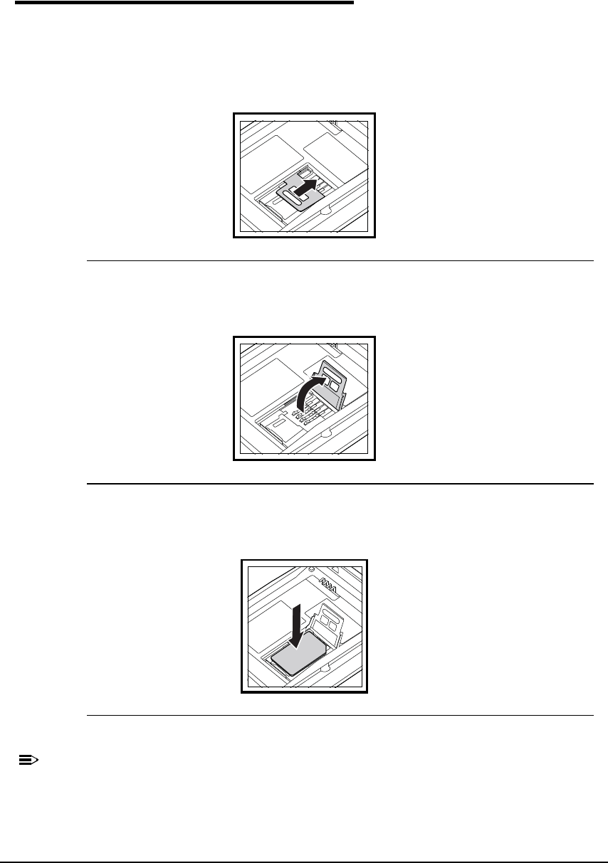
Working with GSM/GPRS/EDGE 9-3
Installing a SIM Card 0
1. Power down device.
2. Unlock battery door.
3. Remove battery door and battery.
4. Unlock SIM card latch by sliding the latch toward top of device.
Figure 9-2. SIM Card latch
5. Lift latch up to expose SIM card socket.
Figure 9-3. SIM Card latch
6. Insert SIM card into SIM card socket.
Figure 9-4. SIM Card
N
O
TE
:
N
O
TE
:
Make sure interface on the card is connected to SIM Card interface in socket, align
corner of the card with corner of the socket.
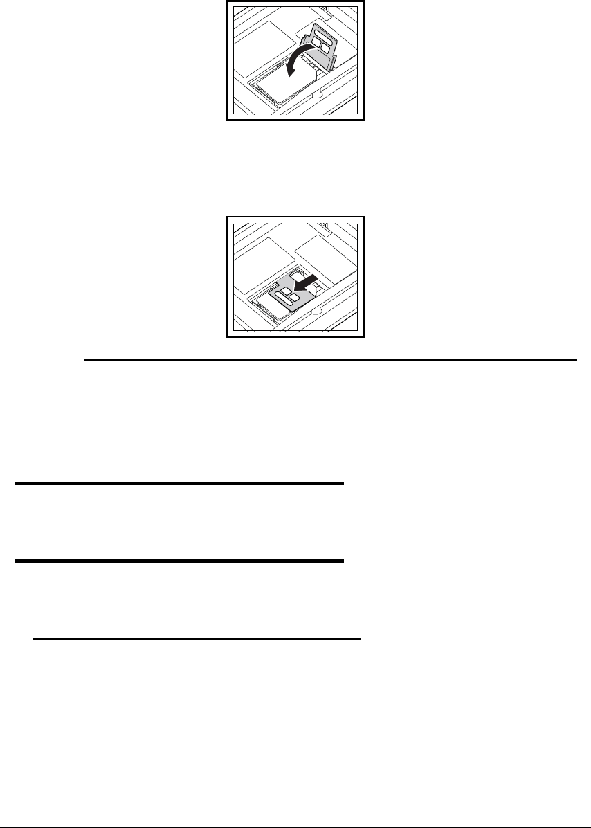
9-4 Working with GSM/GPRS/EDGE
7. Close SIM card latch.
Figure 9-5. SIM Card latch
8. Lock SIM card latch by sliding the latch toward bottom of device.
Figure 9-6. SIM Card latch
9. Install battery and battery door.
10.Lock battery door.
Enabling the GSM Radio 0
Voice Communication 0
Dolphin 6000 device can operate as a phone over GSM radio.
Audio Modes 0
Hands-free
Mode
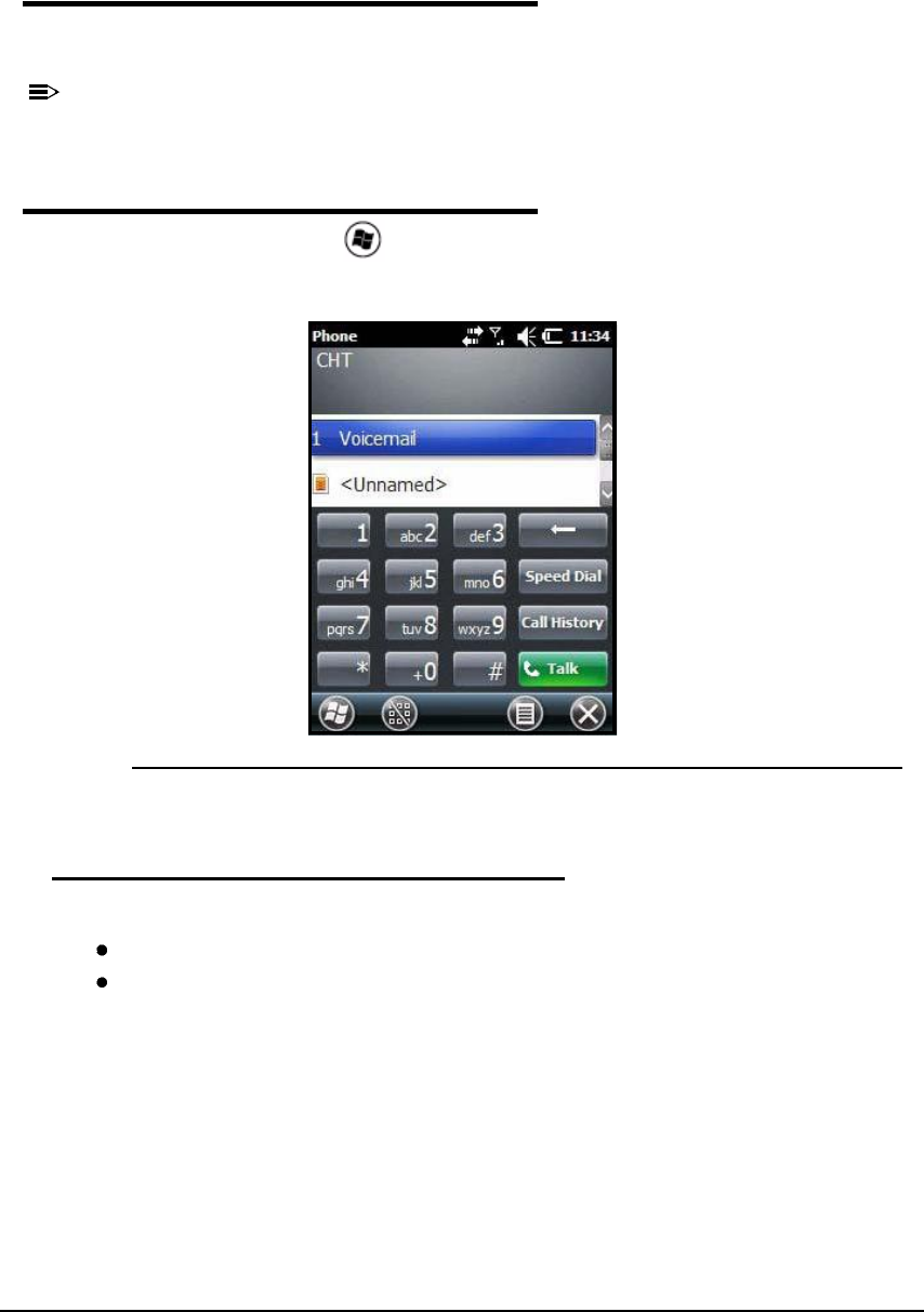
Working with GSM/GPRS/EDGE 9-5
Volume Control 0
Press the up or down arrow on Volume Control button on left side of device to adjust volume
of speaker
N
O
TE
:
N
O
TE
:
For more information, see Volume Control Button on page 3-7.
Accessing the Dialer Window 0
When GSM radio is active, tap > Phone.
The Phone dialer opens.
Figure 9-7. Phone Dialer
Dialing 0
Once the dialer window is open, the device can dial two ways:
Use touch screen and tap buttons on dialer window.
Use physical keypad (when keypad is in numeric mode).
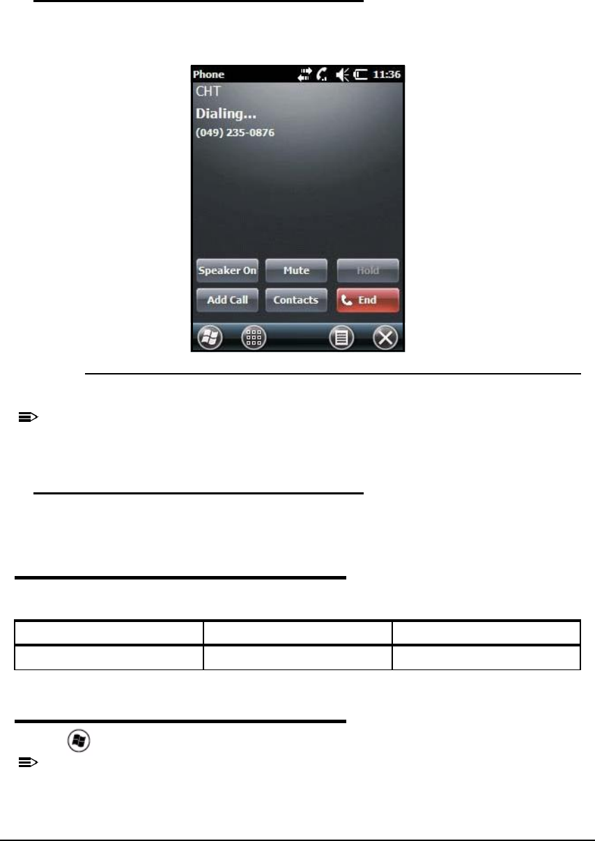
9-6 Working with GSM/GPRS/EDGE
Sending Calls 0
After number is dialed, tap Talk on the screen or press green Send key on keypad.
Figure 9-8. Phone Dialer Options
N
O
TE
:
N
O
TE
:
The Voice call in progress icon in the navigation bar indicates phone is in use.
Ending Calls 0
While the phone call is active, tap End on the screen or press red End keyon keypad.
Keypad Combinations for Calls 0
Accessing Voice Mail 0
Tap > Phone -> Speed Dial -> Voice Mail -> Call.
N
O
TE
:
N
O
TE
:
Update voice mail retrieval number by turning off device and then turn on device in
Wireless Manager. See Enabling the GSM Radio on page 9-4.
Keypad To Send a Call, Please... To End a Call, Please...
29-key numeric keypad Green Send Key Red End Key
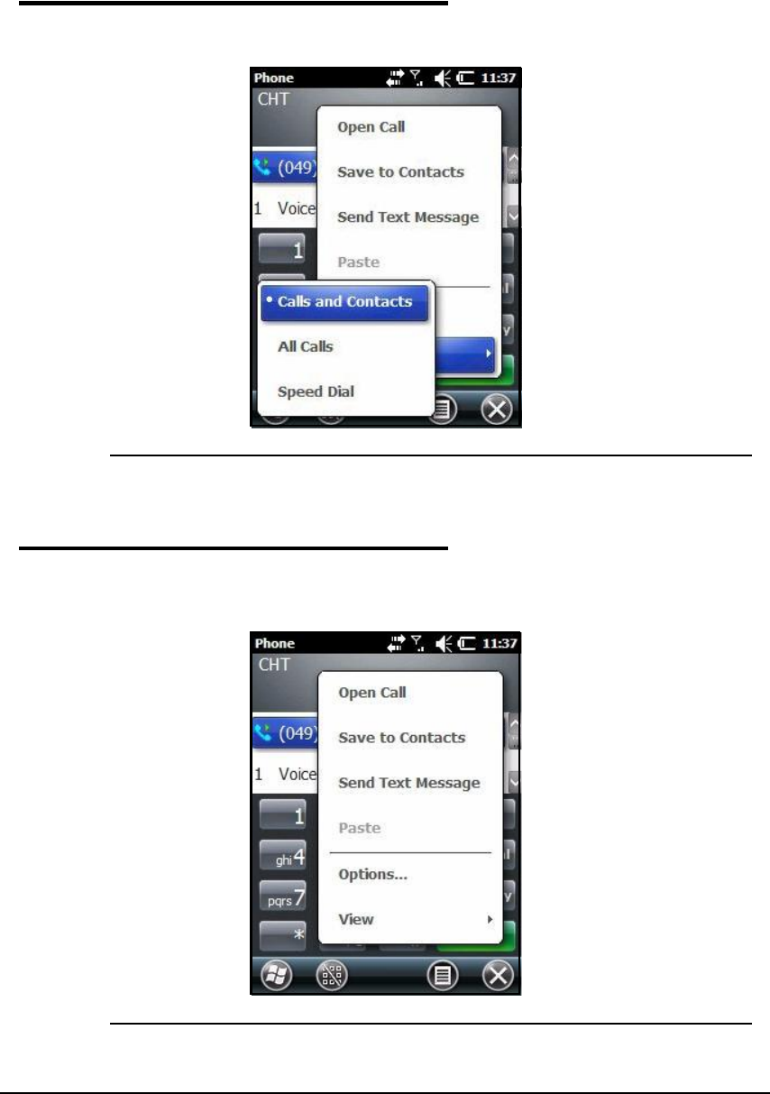
Working with GSM/GPRS/EDGE 9-7
View Options 0
Tap Menu -> View.
Figure 9-9. View Options Pop-Up Menu
Setup Options 0
Tap Menu -> Options. The Phone menu will open and there are sounds, services, network
and security tabs.
Figure 9-10. Options Pop-Up
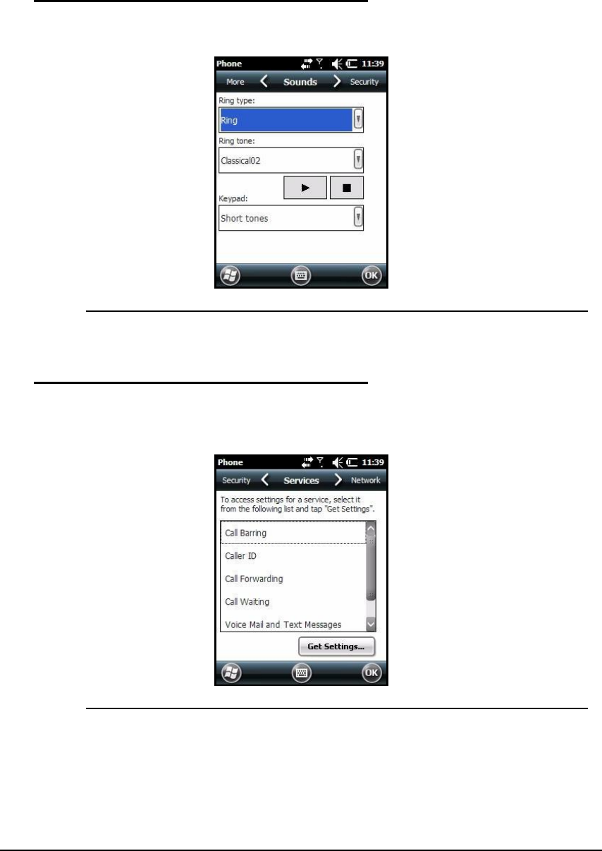
9-8 Working with GSM/GPRS/EDGE
Sounds 0
In Sounds tab, ring tones, ring types and keypad sounds can be changed.
Figure 9-11. Sounds Tab
Services 0
The phone will read settings for each service on SIM card and show the available options
from carrier.
Figure 9-12. Services Tab
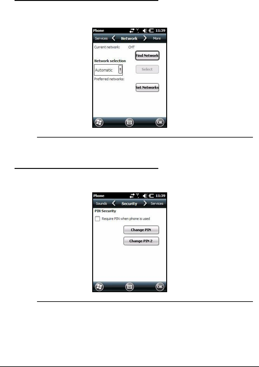
Working with GSM/GPRS/EDGE 9-9
Network 0
There are options to find and set networks on Network tab.
Figure 9-13. Network Tab
Security 0
There are options to make or change a PIN on Security tab.
Figure 9-14. Security Tab
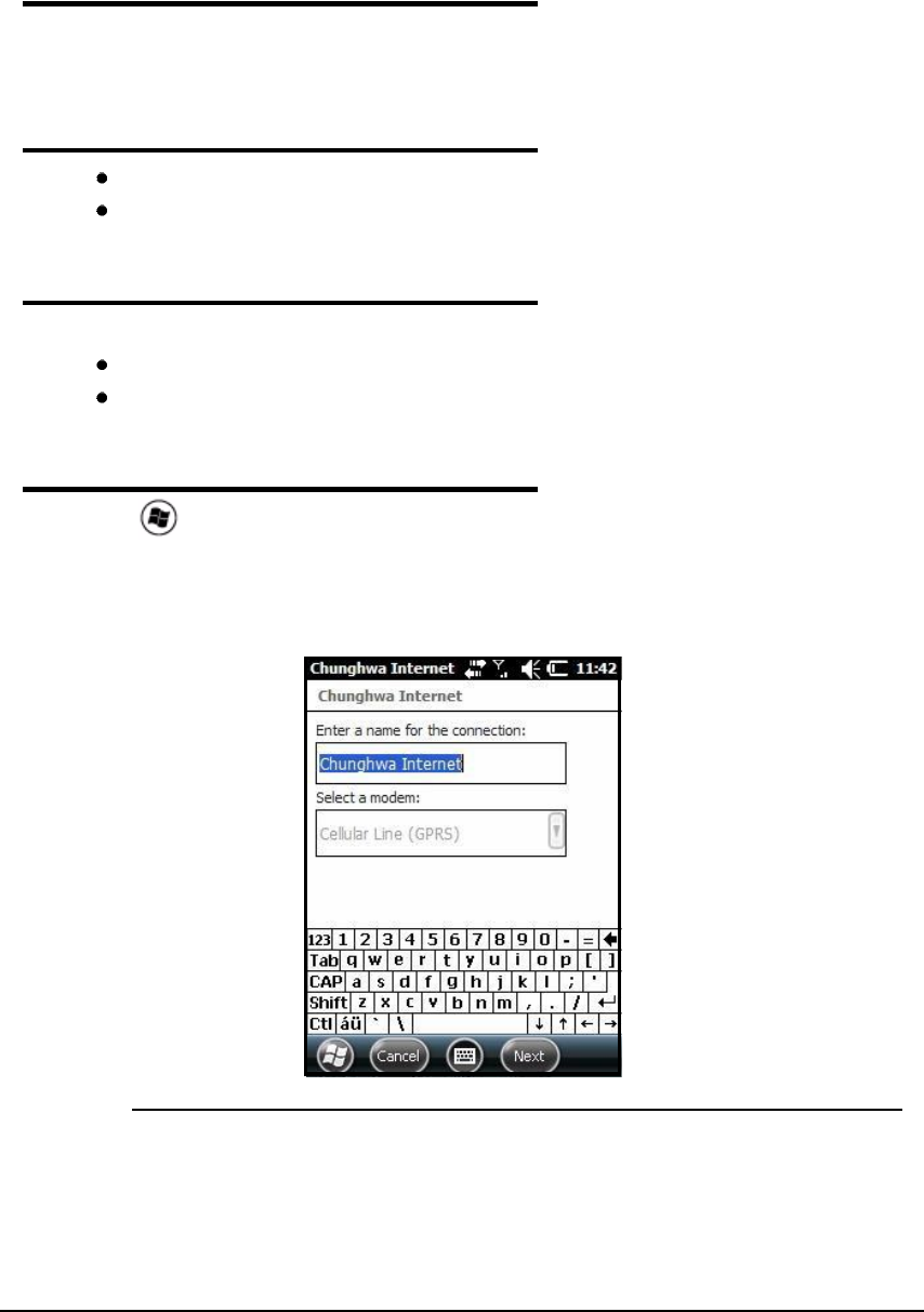
9-10 Working with GSM/GPRS/EDGE
Data Communication 0
Data communication can be set up in Connections Manager. The carrier on SIM card is the
ISP.
System Requirements 0
The GSM radio must be enabled. Refer to Enabling the GSM Radio.
Must have an active SIM card with a data plan installed. Refer to SIM Card Installation.
Information Requirements 0
The following is required from SIM card carrier:
APN (access point name).
Username and password of account.
Establishing Data Communication 0
1. Tap > Settings -> Connection -> Connections.
2. Under My ISP, tap Add a new modem connection.
3. Enter a name for connection. Select Cellular Line (GPRS) as modem
4. Tap Next.
Figure 9-15. Make New Connection
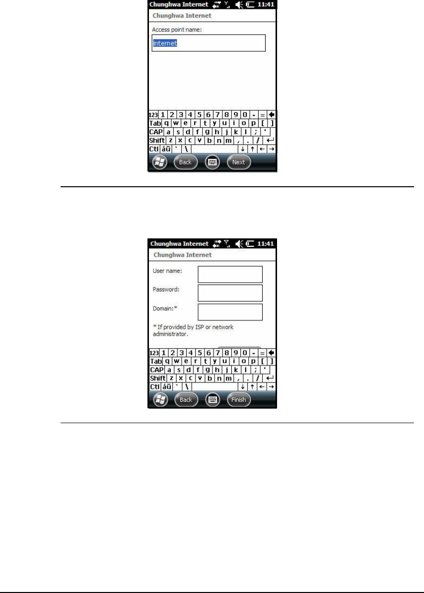
Working with GSM/GPRS/EDGE 9-11
5. Enter Access point name. Tap Next.
Figure 9-16. Access Point Name
6. Enter username and password from account. Tap Finish.
Figure 9-17. Username and Password
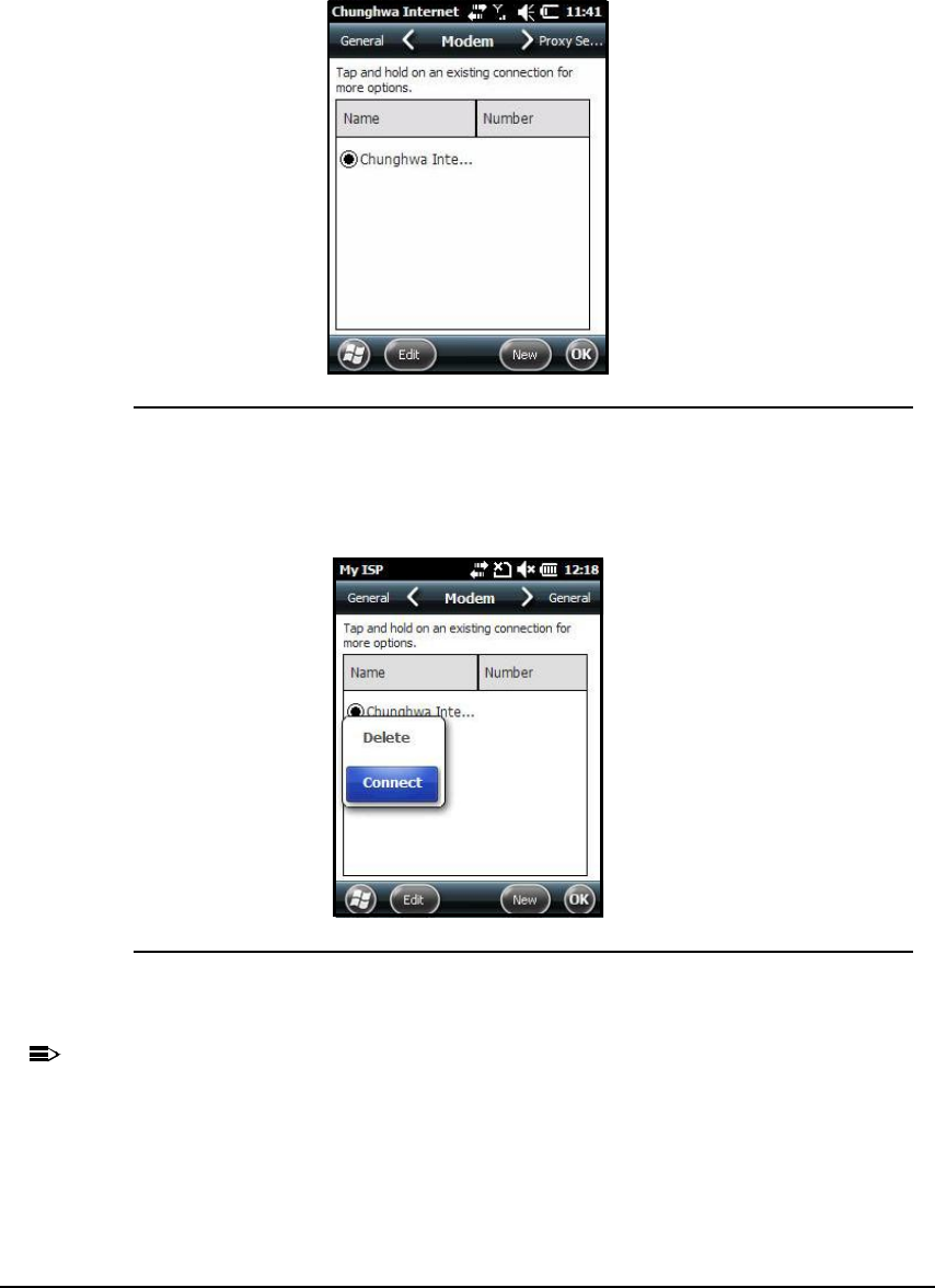
9-12 Working with GSM/GPRS/EDGE
7. In Connections window, tap Manage existing connections. The new connection should
show on list in modem tab.
Figure 9-18. Modem Tab
8. Press the connection. A pop-up menu appears. (Figure 9-19)
9. Select Connect on the pop-up menu.
Figure 9-19. Connect on the Pop-Up Menu
10.The network icon in the navigation bar shows GSM radio is attempting to connect.
N
O
TE
:
N
O
TE
:
When the device is on a 2G (EDGE/GPRS) network, a data connection failure occurs if
device is in use for a voice call while trying data connection. Voice and data use at the
same time is only supported if device is on a 3G network. In 2G mode, a voice call has
priority over data connection. Active data connection is automatically set in park mode
and data is retrieved when voice call ends.
11.When connection is complete, network icon changes to Signal Strength Icon. Data can
now be sent over GSM.

Working with GSM/GPRS/EDGE 9-13
Ending the Data Connection 0
The default setting makes data connection disconnect after an specific amount of time passes
and is not in use. This amount of time is set by the ISP.
To end data connection manually, tap network icon in navigation bar and tap Disconnect on
the pop-up bubble.
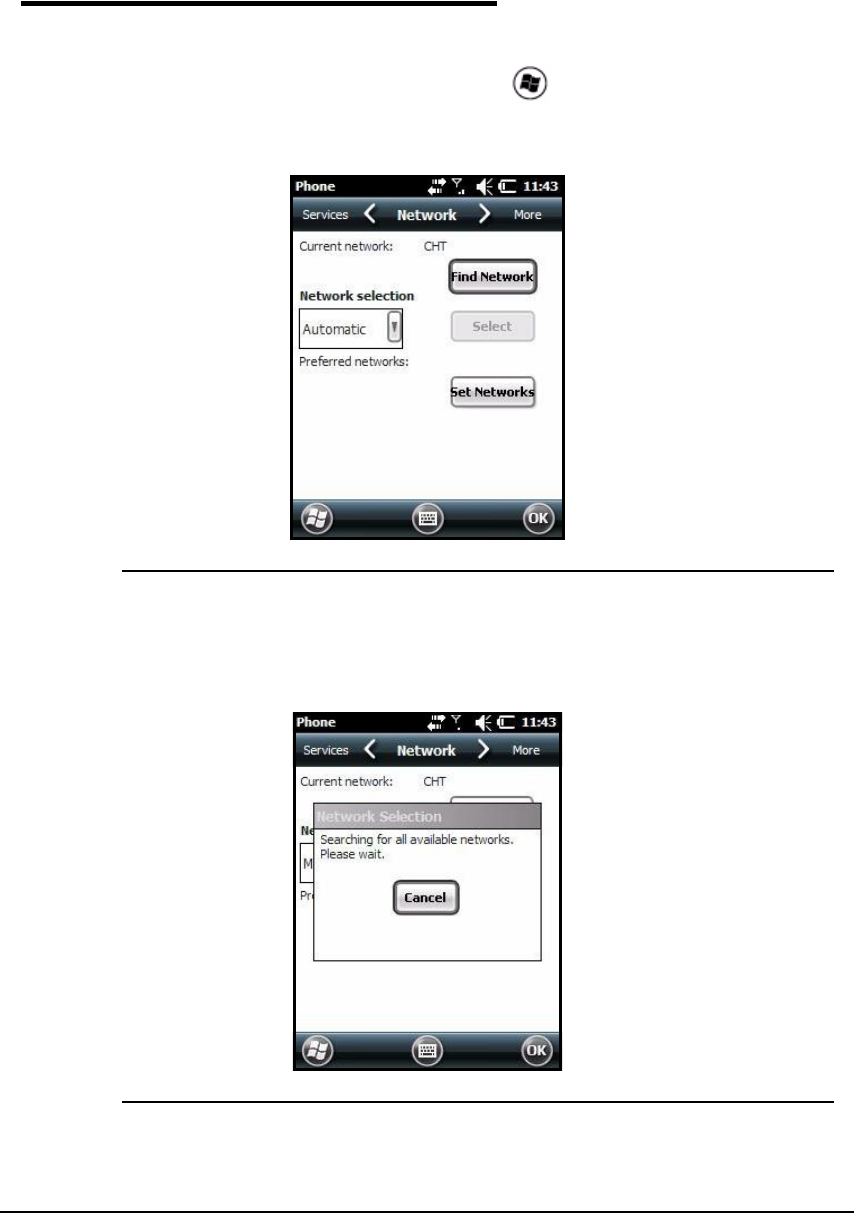
9-14 Working with GSM/GPRS/EDGE
Manual Network Selection 0
Select Automatic or Manual network selection in the Network tab. The device defaults to
Automatic network selection.
1. When an active SIM card is inserted in device, tap > Settings -> Personal ->
Phone -> Menu -> Options. The Phone menu window opens.
2. Choose Network tab.
Figure 9-20. Network Tab
3. Under Network selection, choose Automatic (the default setting) or Manual.
a. If Manual is selected, the device will search for available networks.
Figure 9-21. Network Selection Pop-Up
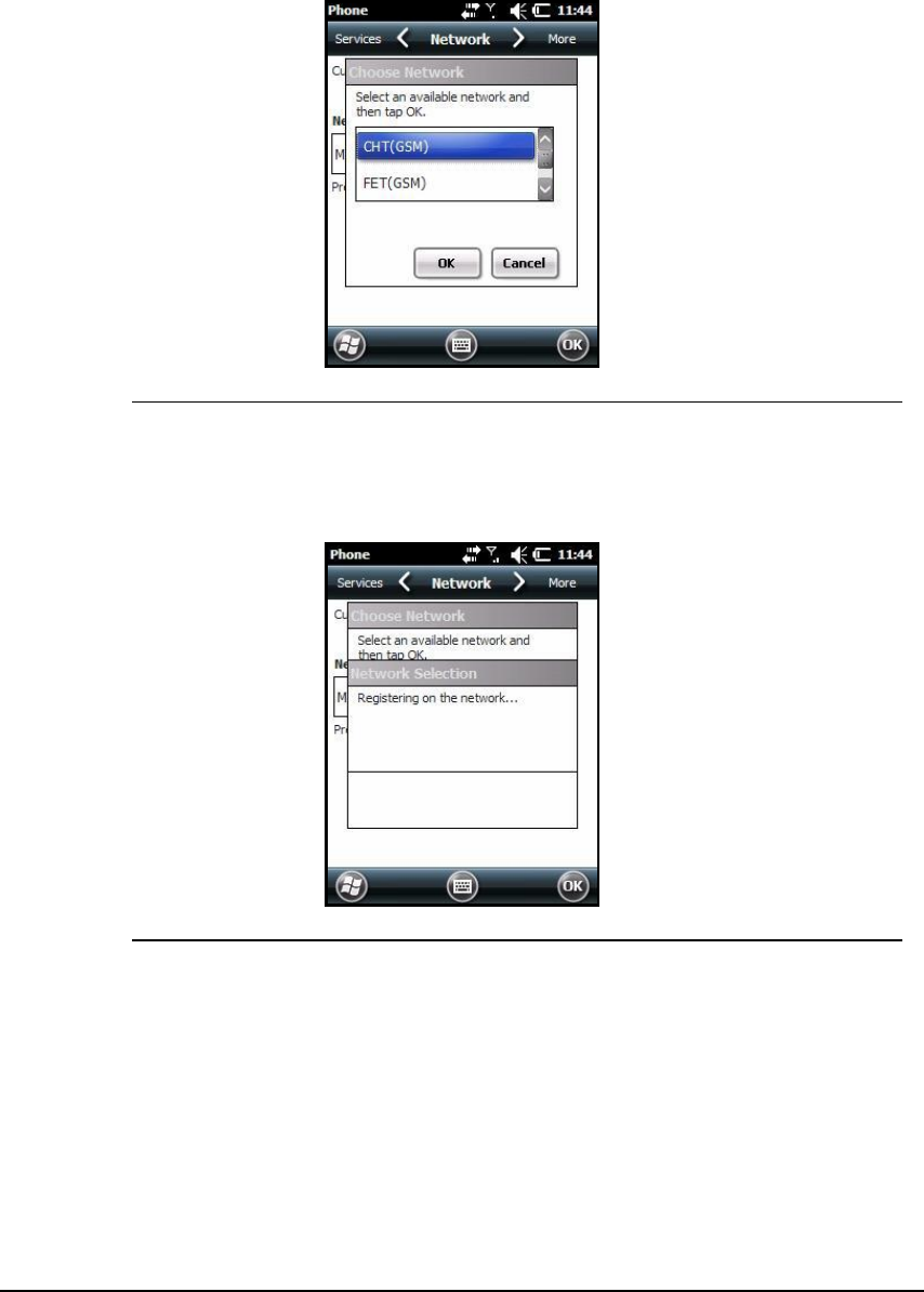
Working with GSM/GPRS/EDGE 9-15
b. The available networks are shown.
Figure 9-22. Choose Available Network
c. Choose a new network and tap OK. The device registers on new network and
Network tab will open.
Figure 9-23. Register Network
d. To switch to another network, tap Select button and process repeats.
4. To switch back to automatic roaming, select Automatic under Select networksand tap OK.

9-16 Working with GSM/GPRS/EDGE

Working with Bluetooth Radio 10-1
Working with Bluetooth Radio
Enabling the Bluetooth Radio 0
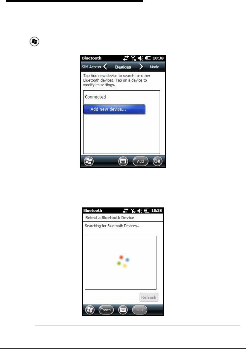
10-2 Working with Bluetooth Radio
Connecting to Bluetooth Devices 0
The device must find other bluetooth devices. Choose an available device and connect to it.
Pairing occurs as part of connection process.
1. In Wireless Manager, tap Menu> Bluetooth Settings.
OR
Tap > Settings> Bluetooth.
Figure 10-1. Devices Tab
2. Tap Add new device. The device will start looking for other Bluetooth devices.
Figure 10-2. Searching for Bluetooth Devices
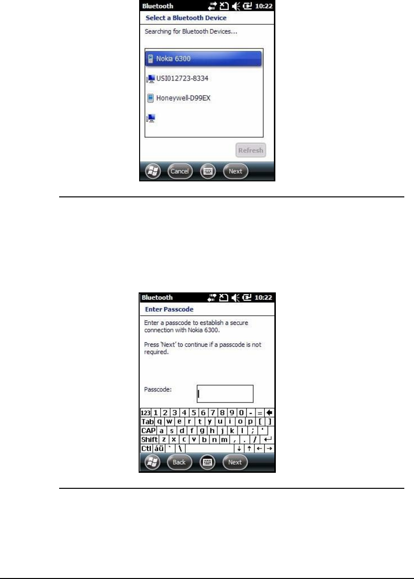
Working with Bluetooth Radio 10-3
3. Choose a device in list and tap Next.
Figure 10-3. Select a Bluetooth Device
4. It is necessary to enter a passcode:
a. If device has a passcode, enter it in Passcodebox and tap Next.
b. If device does not have a specific passcode, enter one in the Passcodebox
and tap Next. The Bluetooth radio tries to connect with device.
Figure 10-4. Enter a Passcode
5. If a passcode is created, the other device will ask to enter same passcode.
6. Enter passcode to make paired connection. If you entered a device specific passcode, it is
not necessary to do anything on other device.
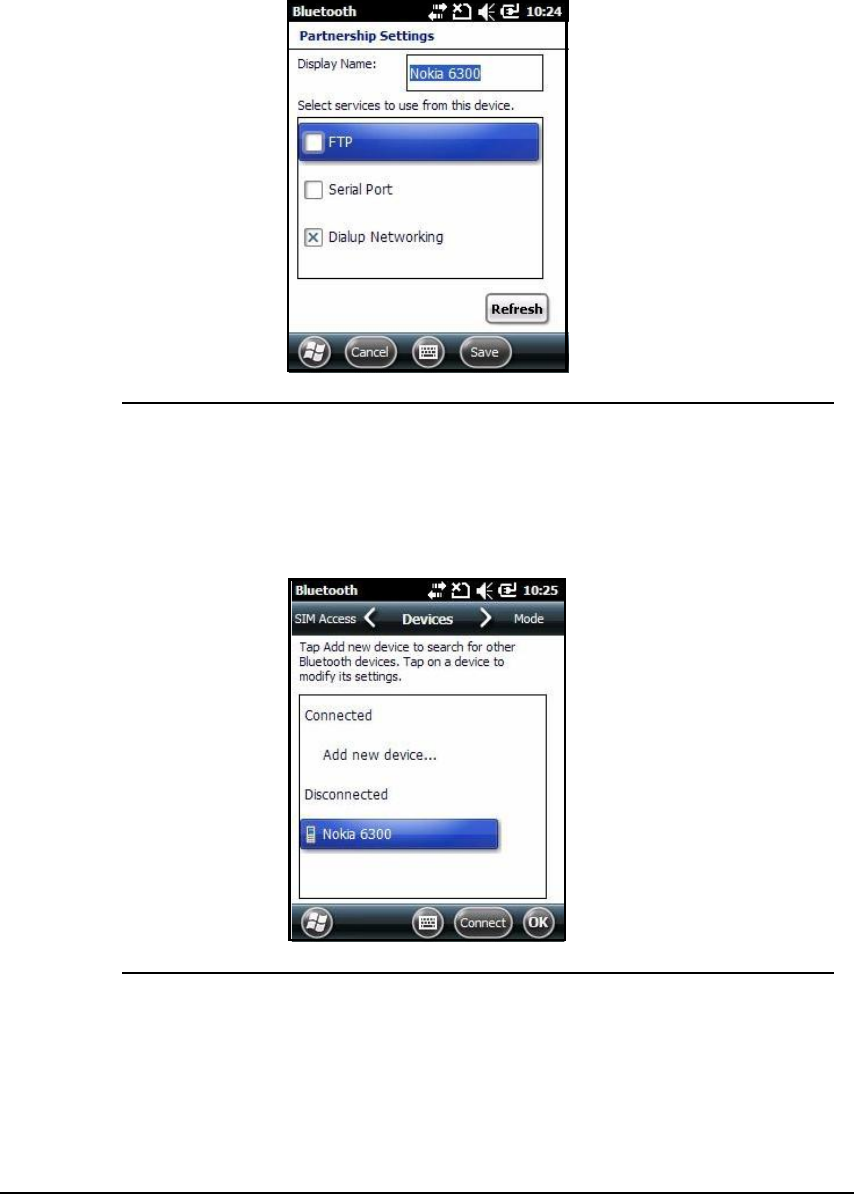
10-4 Working with Bluetooth Radio
7. When connection is complete, a list of supported services is shown.
Figure 10-5. List of Supported Services
8. Choose services to use and tap Save. The services on new devices must be selected or
pairing will not include those services, even if devices are paired. If services are not
selected, the device will keep asking for passcode. The device appears in the list on the
main window.
Figure 10-6. Devices List
After passcodes have been accepted on both devices, there is now a trusted (paired)
connection.

Working with Bluetooth Radio 10-5
Pairing and Trusted Devices 0
The Dolphin 6000 supports pairing. Pairing happens during general connection setup. Paired
devices are trusted devices. This means there is unrestricted access to all services (including
services that require authorization and authentication).
A connection can remove pairing. A device that is connected to Dolphin 6000 device but not
paired with it is an untrusted device. Transferring content to untrusted devices can be done by
requiring authorization each time (i.e. the beginning of a file exchange). Use the Beam File
method of file transfer to send a file as an untrusted device.
N
O
TE
:
N
O
TE
:
See Transferring Files.
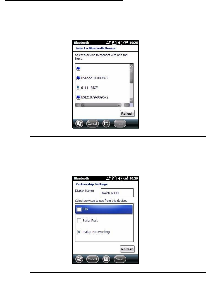
10-6 Working with Bluetooth Radio
Types of Devices and Services 0
The Bluetooth radio scans for available Bluetooth devices in range if Add new device is
tapped on the Devices tab. These are Bluetooth devices that are discoverable.
Device Types 0
Figure 10-7. Selecting a Bluetooth Device
Supported Services 0
The Partnership Settings menu will only show services that are supported on both devices.
Figure 10-8. Partnership Settings

Working with Bluetooth Radio 10-7
Connecting to Bluetooth Printers 0
1. Make sure the Bluetooth printer is in range and set to discoverable by other Bluetooth
devices.
2. Look up Bluetooth printer s broadcasted ID.
3. Search for compatible bluetooth devices (Tap Settings > Bluetooth > Add new device)
4. Look for Bluetooth printer s broadcasted ID in list of available devices.
5. Click on Bluetooth printer s ID and wait to enter Passcode.
6. Enter Passcodeand tap Next. The passcode can default to "1111" or "0000." If there is no
default, look in printer manual for passcode.
7. Choose a printing-related service in list of services.
8. Tap Save to make a connection on the device.
Connecting to Bluetooth Headsets 0
1. Make sure the Bluetooth headset is in range and set to discoverable by other Bluetooth
devices.
2. Look up headset s broadcasted ID.
3. Search for compatible bluetooth devices (Tap Settings > Bluetooth > Add new device)
4. Look for headset s broadcasted ID in list of available devices.
5. Click on headset s ID and wait to enter a passcode.
6. Enter Passcodeand tap Next. The passcode can default to "1111" or "0000." If there is no
default, look in the headset manual for the passcode.
7. Choose Headset in list of services.
8. Tap Save to make a connection on device.
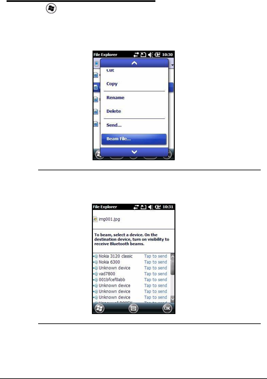
10-8 Working with Bluetooth Radio
Transferring Files 0
1. Press > File Explorer.
2. Navigate to file to transfer.
3. Press hold on the file for pop-up menu to open
4. Tap Beam File.
Figure 10-9. Beam File on the Pop-Up Menu
5. The Bluetooth radio will begin to search for available devices.
Figure 10-10. List of Bluetooth Devices
6. Choose device to send selected file.
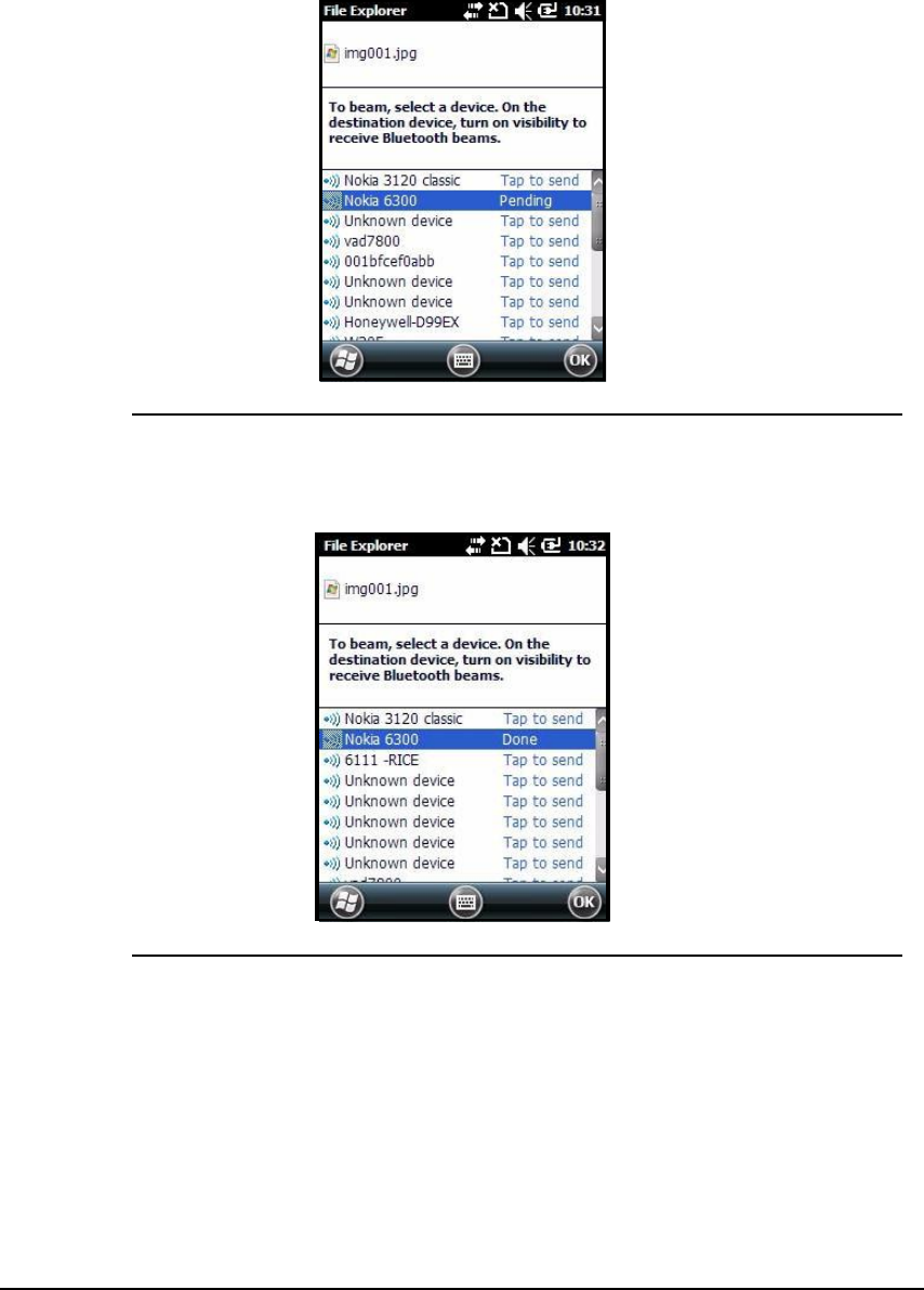
Working with Bluetooth Radio 10-9
7. When trying to connect, the selected device shows Pending.
Figure 10-11. Bluetooth Device Connection
8. When the file is being transferred, the selected device shows Sending.
Figure 10-12. File Transfer
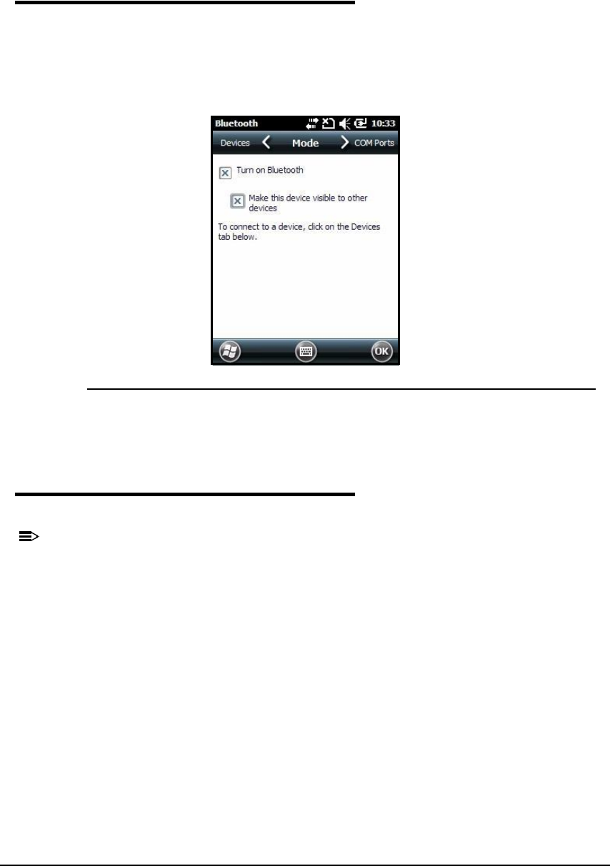
10-10 Working with Bluetooth Radio
Making the Device Discoverable 0
The default setting of the Dolphin 6000 device is not discoverable, which means the Dolphin
6000 device will not be found by other Bluetooth devices.
To make device discoverable:
1. Tap Mode tab in Bluetooth menu.
Figure 10-13. Mode Tab
2. Choose Make this device visible to other devices and tap OK.
Selecting COM Ports 0
COM ports 0-9 can be selected.
N
O
TE
:
N
O
TE
:
For more information, see Dolphin 6000 COM Port Assignment Table.

Working with GPS 11-1
Working with GPS
Overview 0
The Dolphin 6000 uses a MT3326, a high performance single chip, single die host-based
GPS solution that has an on-chip CMOS RF and digital baseband. The MT3326 meets the
industry s highest levels of sensitivity, accuracy, and Time-to-First-Fix (TTFF) with lowest
power consumption in a small-footprint lead-free package. Its small footprint and minimal
accessory gives important reductions in the design, manufacturing and testing resources
needed for navigation devices and handsets.
With an on-chip integrated LNA, the MT3326 has a total receiver noise figure of 4 dB (before
ADC). With its on-chip image-rejection mixer, the spec of an external SAW filter is decreased.
With an on-chip automatic center frequency calibration band pass filter, an external filter is not
needed. The integrated PLL with Voltage Controlled Oscillator (VCO) gives excellent phase
noise performance and fast locking time.
The MT3326 supports up to 210 PRN channels. With 66 search channels and 22
simultaneous tracking channels, the MT3326 finds and tracks satellites in the shortest time,
even at indoor signal levels. The MT3326 supports various location and navigation
applications, including GPS, SBAS (WAAS, EGNOS, GAGAN, MSAS), DPGS (RTCM), and
AGPS.
The on-chip power management design makes the MT3326 easily included into the system
without an extra voltage regulator. With its linear regulator embedded, the MT3326 gives the
user plenty of choices for an application circuit.
Through the MT3326 s excellent low power consumption properties (acquisition 50mW,
tracking 38mW), power sensitive devices, especially embedded systems, do not have to
worry about operating time.
With MT3326 s powerful interface, a host system can communicate with the MT3326
efficiently through UART and SPI at baud rates as fast as 921600 bps, which saves the host
CPU processing time.
From a system design view, if a host system already has TCXO or RTC, the MT3326 can
share these sources with a host system and this will save system BOM costs and system
PCB area.
Assisted GPS Support 0
Powering the GPS Module 0
Communication Ports 0
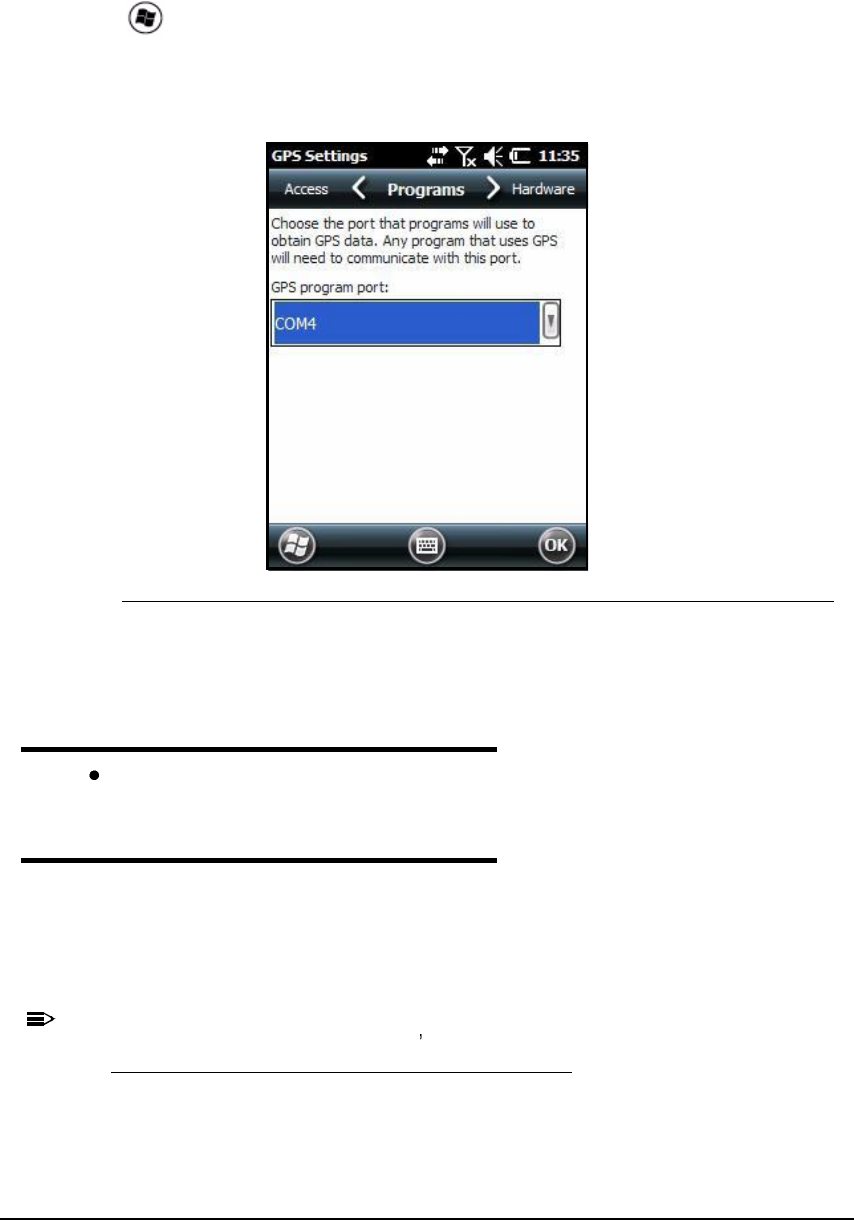
11-2 Working with GPS
Selecting the Port 0
1. Tap > Settings -> System -> External GPS.
2. Tap the GPS program port box. A drop-down list will open.
3. In GPS program portdrop-down list, choose COM4 or GPD1 (the GPS Intermediate
Driver) as needed by the application.
Figure 11-1. Programs Tab
4. Tap OK to save.
COM 0
C38400
GPS Intermediate Driver 0
When the first user of GPD1 opens the port, the GPS Intermediate Driver opens port COM4.
The GPS Intermediate Driver lets multiple applications open GPD1, and GPS data is
transmitted to all open ports.
When the GPSID driver is in use, the COM4 port is given to GPSID as READ/WRITE (COM4
is still available for access mode of 0).
N
O
TE
:
N
O
TE
:
For more information about Microsoft s GPS Intermediate Driver, refer to:
http://msdn.microsoft.com/en-us/library/ms850332.aspx

Dolphin 6000 HomeBase 12-1
Dolphin 6000 HomeBase
Overview 0
The Dolphin 6000 HomeBase supports both RS232 and USB communications, which makes
it able to connect with majority of PC-based enterprise systems.
Capacity 0
The HomeBase holds one Dolphin 6000 device and has an auxiliary battery well behind the
device well. The HomeBase can charge two battery packs:
Battery installed in Dolphin 6000
Spare battery
Charge Time 0
The HomeBase completes a full charge of battery pack installed in the device well in 4 hours.
The HomeBase completes a full charge of battery pack in Auxiliary Battery Well in 4 hours
(see Auxiliary Battery Well).
Charging Process 0
The HomeBase gives power to the intelligent battery charging system in Dolphin 6000 device.
The charging systems know when a full charge of battery has been completed and switches
to a trickle charge to keep a full charge of the battery.
Communications 0
Satisfactory data communications at speeds of up to 115k baud can be transmitted by
HomeBase through RS232 serial port. The data transmission rate goes up to 12 Mbps when
using USB port.
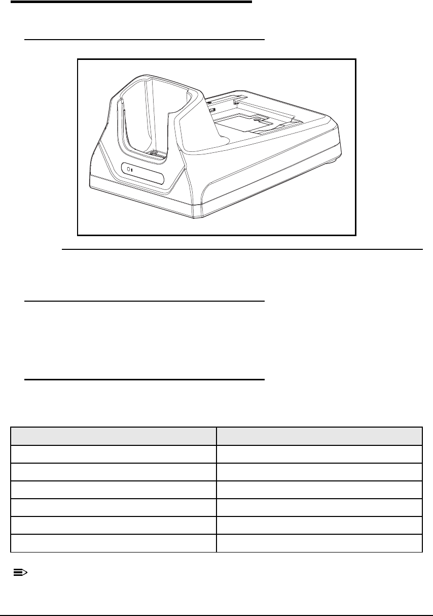
12-2 Dolphin 6000 HomeBase
Parts and Functions 0
Front Panel 0
Figure 12-1. HomeBase Front View
Device Well 0
Place the Dolphin 6000 in the device well to use the device and to charge battery pack in the
device. The HomeBase charges the main battery in 4 hours. If host device is a workstation
that uses ActiveSync, synchronization begins immediately.
AUX Battery Status LED 0
The AUX battery status LED shows the status of battery charging in auxiliary battery well; see
Back Panel.
N
O
TE
:
N
O
TE
:
For information about charging a battery in auxiliary battery well,see Charging a
Battery in the Auxiliary Battery Well.
Status LED color
Pre-charge (for a very low battery?) Orange
Fast Charge Red
Full (completed charge) Green
Battery cannot be charged Orange Blinking
No Battery Off
Fault or Over Temperature Off
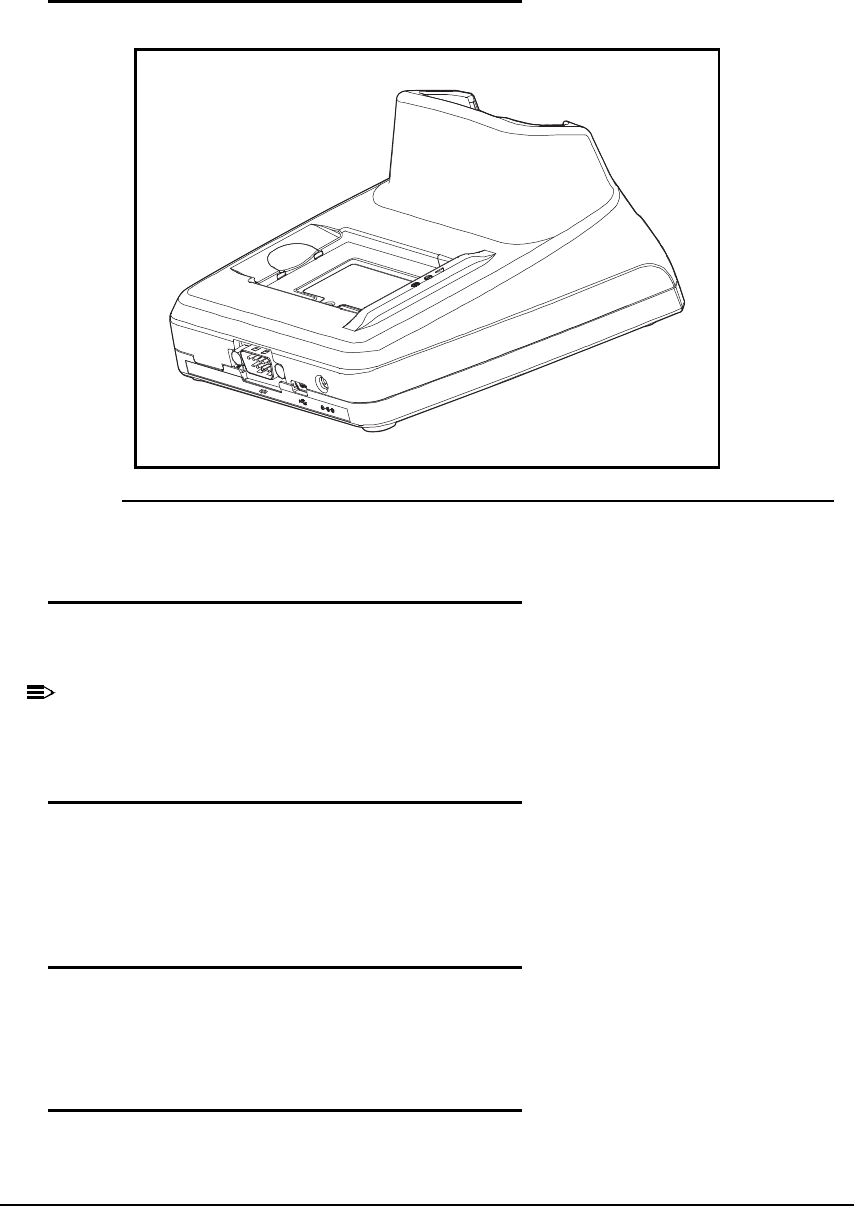
Dolphin 6000 HomeBase 12-3
Back Panel 0
Figure 12-2. HomeBase Rear View
Auxiliary Battery Well 0
The HomeBase can charge an additional Li-ion battery pack in 4 hours in the well behind the
device. This feature lets you have a separate fully-charged battery for Dolphin 6000.
N
O
TE
:
N
O
TE
:
See Charging a Battery in the Auxiliary Battery Well.
USB Port 0
USB PortThis USB Port is full-speed and 2.0 compliant. Using a USB cable, you can connect
the base to a peripheral device, such as a workstation. When the terminal is seated in the
terminal well, it is connected to the workstation device via the base.
RS232 Port 0
Use 9-pin, RS232 cable from Honeywell to connect this port to a peripheral device for RS232
data communication. For more information, see Serial Connector.
DC Power Jack 0
Use power cable from Honeywell that comes with HomeBase to supply power to this power
jack. For more information, see Power section that follows.
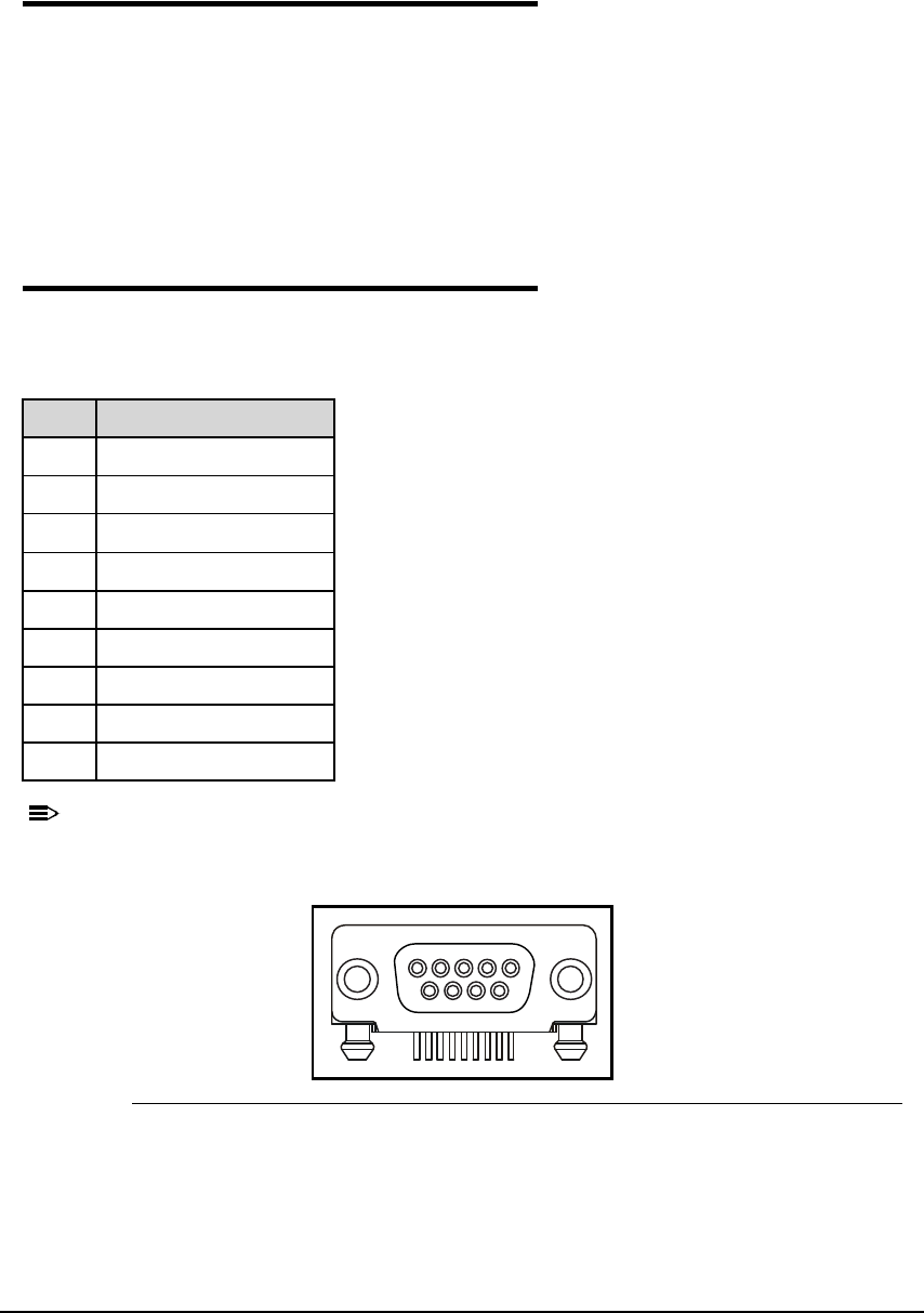
12-4 Dolphin 6000 HomeBase
Power 0
The device requires 5V, 2A DC input for communications and battery charging; the power
adapter on power cable converts voltage from power source to 5V, 2A DC. Onlythe
Honeywell 5 VDC, 2A power supply provided with HomeBase converts voltage correctly.
It is recommended that the HomeBase be left connected to its power source at all times, so
that it is always ready to use.
1. Connect adaptor barrel plug to DC jack on rear panel of HomeBase
2. Plug adaptor AC to indoor wall receptacle
Serial Connector 0
The following diagram shows pin diagram of serial connector of HomeBase.
N
O
TE
:
N
O
TE
:
Signals referenced are for a DTE device. The HomeBase is at a right-angle to the
printed circuit board (PCB).
Figure 12-3. Serial Connector Pins
Table 12-1. Serial Connector Pins
Pin Description
1N/C
2 TXD
3RXD
4DSR
5GND
6N/C
7CTS
8RTS
9N/C
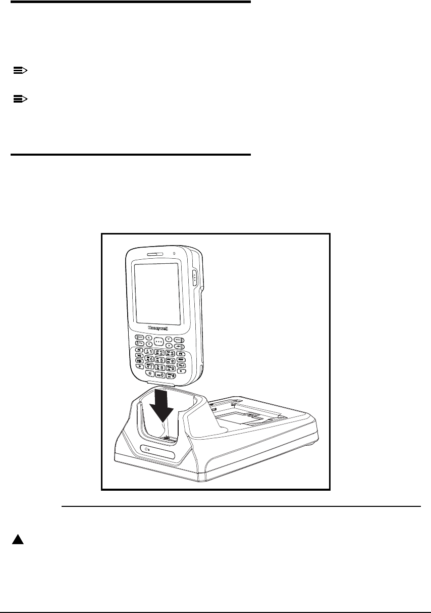
Dolphin 6000 HomeBase 12-5
Charging the Battery 0
The HomeBase powers the device and charges its battery pack in 4 hours.
The cradle knows when battery pack is fully charged and automatically changes to a trickle
charge that keeps the battery at full capacity. The device can stay in the HomeBase without
damaging the device or battery packs.
N
O
TE
:
N
O
TE
:
To check battery power, use Power menu setting; see Power.
N
O
TE
:
N
O
TE
:
For more information about Li-ion batteries, see Li-ion Battery Pack.
To Power a Device and Charge its Battery 0
1. Install battery pack in device. Refer to Install Main Battery Pack.
2. Connect HomeBase to power supply.
3. Put device into device well until HomeBase LED on the device turns Red, indicating that it
is charging. Make sure the device is seated in order to see the red LED on device. The
battery pack will begin to charge.
Figure 12-4. Charging the Device
CAUTION:
!
Make sure device is dry before putting it in HomeBase. Do not put a wet device in
HomeBase! This can cause damage not covered by the warranty.

12-6 Dolphin 6000 HomeBase
Charging a Battery in the Auxiliary Battery Well 0
The auxiliary battery well located is on the back of the HomeBase and charges a spare
battery separately from device well. The Auxiliary Battery LED on front panel shows status of
battery in this well.
Complete charge time is 4 hours.
1. Insert end of battery without locking tab into bottom of auxiliary well opening.
2. Put battery into place. The Auxiliary Battery LED becomes red.
3. See Auxiliary Battery LED to monitor charging progress.

Dolphin 6000 HomeBase 12-7
Communication 0
USB
Dolphin 6000 devices support USB communications.
The HomeBase also supports USB communications via USB port located on back of cradle.
The HomeBase can be a USB device by interfacing USB signals of Dolphin 6000 device to
USB of host workstation. Using a standard USB cable, the HomeBase s USB interface lets
Dolphin 6000 communicate with a workstation.
RS232
The HomeBase supports RS232 communications by RS232 Communications Port located on
back of cradle. This port lets Dolphin 6000 device communicate to a workstation, modem, or
any RS232 device when using a standard serial cable and communications software.
Requirements 0
A HomeBase powered by a power cable and power adapter cable
For RS232 communications, use serial cable
For USB communications, use USB cable
ActiveSync v4.5 or above on the host workstation
Windows XP 2003 Server, Windows Vista, or Windows 7 on the host workstation.
Connecting the Communication Cables 0
N
O
TE
:
N
O
TE
:
ActiveSync 4.5 or higher must be used.
1. Plug in power supply and connect to back of HomeBase.
2. Plug USB or RS232 communication cable into back of HomeBase.
3. Connect communication cable into back of workstation.
N
O
TE
:
N
O
TE
:
The hardware should be installed and operating. Workstation may need to be rebooted
to complete the installation process.
Establishing Communication 0
USB or RS232 communication with the device is usually auto-detected and set by ActiveSync
based on the communication cable. ActiveSync will usually set up a USB connection if using
a USB cable to connect to workstation. ActiveSync will normally set up a RS232 connection if
using a RS232 cable.
N
O
TE
:
N
O
TE
:
For more details, see ActiveSync Communication.

12-8 Dolphin 6000 HomeBase
Communicating with the Dolphin 6000 Device 0
Verifying Communication 0
Verifying Data Transfer 0
RS232 Communications Cables 0
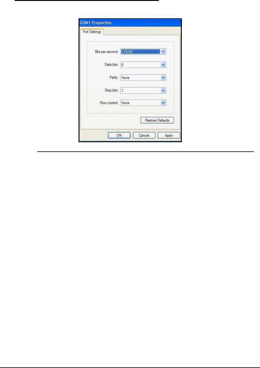
Dolphin 6000 HomeBase 12-9
RS232 Pin Configuration 0
Figure 12-5. COM1 Properties
FCC Hearing-Aid Compatibility (HAC) Regulations for Wireless
Devices
On July 10, 2003, the U.S. Federal Communications Commission (FCC) Report and Order in WT
Docket 01-309 modified the exception of wireless phones under the Hearing Aid Compatibility Act
of 1988 (HAC Act) to require digital wireless phones be compatible with hearing-aids. The intent of
the HAC Act is to ensure reasonable access to telecommunications services for persons with
hearing disabilities. While some wireless phones are used near some hearing devices (hearing aids
and cochlear implants), users may detect a buzzing, humming, or whining noise. Some hearing
devices are more immune than others to this interference noise, and phones also vary in the
amount of interference they generate. The wireless telephone industry has developed a rating
system for wireless phones, to assist hearing device users find phones that may be compatible with
their hearing devices. Not all phones have been rated. Phones that are rated have the rating
on their box or a label located on the box. The ratings are not guarantees. Results will vary
depending on the user’s hearing device and hearing loss. If your hearing device happens to be
vulnerable to interference, you may not be able to use a rated phone successfully. Trying out the
phone with your hearing device is the best way to evaluate it for your personal needs.
M-Ratings: Phones rated M3 or M4 meet FCC requirements and are likely to generate less
interference to hearing devices than phones that are not rated. M4 is the better/higher of the two
ratings.
T-Ratings: Phones rated T3 or T4 meet FCC requirements and are likely to be more usable with a
hearing aid’s telecoil than phones that are not rated. T4 is the better/higher of the two ratings.
Dolphin 6000 complies with the FCC’s requirements, and the M rating in this mode is M3 and the T
rating in this mode is T3.
Your hearing device manufacturer or hearing health professional may help you find this rating.
Higher ratings mean that the hearing device is relatively immune to interference noise. The hearing
aid and wireless phone rating values are then added together. A sum of 5 is considered acceptable
for normal use. A sum of 6 is considered for better use. A sum of 8 is considered for best use.
In the above example, if a hearing aid meets the M2 level rating and the wireless phone meets the
M3 level rating, the sum of the two values equal M5. This should provide the hearing aid user with
“normal usage” while using their hearing aid with the particular wireless phone. “Normal usage” in
this context is defined as a signal quality that is acceptable for normal operation.
This methodology applies equally for T ratings. The M mark is intended to be synonymous with the
U mark.