Honeywell F50E Electronic Air Cleaner User Manual To The Bccdd584 1cc6 4dce 9af3 9e394ee7ffbd
User Manual: Honeywell F50E to the manual
Open the PDF directly: View PDF ![]() .
.
Page Count: 24
PRODUCT DATA
Copyright © 1998 Honeywell Inc. • All Rights Reserved
APPLICATION
The F50E high efficiency electronic air cleaner is mounted in
the return air duct of a forced air heating, cooling, or
ventilating system. It captures a significant amount of the
airborne particles 0.5 microns and larger from the air
circulated through it.
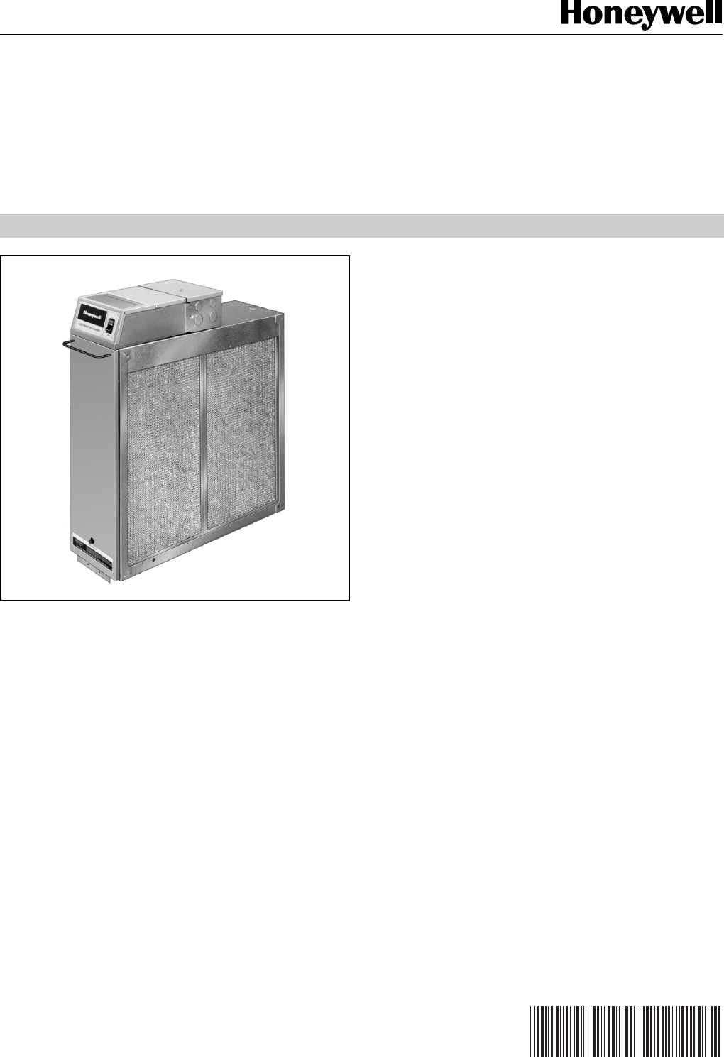
F50E
Duct Mounted Electronic Air Cleaner
FEATURES
• Available in two sizes to fit most ducts; adapts to air
flow from either side.
• Has two cells.
• Capacity of 1400 cfm (2380 m3/hr) or 2000 cfm
(3400 m3hr), depending on size.
• Solid state power supply is self-regulating and
maintains peak efficiency over a wide range of cell dirt
loading conditions.
• Pressure drop is approximately equal to that of a
regular fiberglass filter.
• Optional W8600E Solid State Performance Indicator
monitors air cleaner performance, reminds
homeowner when a cell and prefilter wash is past due,
and when to check system.
• Electronic cells can be washed in most home
dishwashers.
• Remote mount kit is available for mounting power
supply and junction box separately when access
space is not available.
• Galvanized cabinet protects against rust.
• Automatic interlock switch disconnects power and
discharges cell when door is opened.
• Test button checks system operation.
• Troubleshooting guide mounted inside cell access
door.
• Permanent wash reminder schedule mounted on top
of power supply box.
• Prefilter screens protect cells from large dirt particles.
Contents
Application........................................................................... 1
Features .............................................................................. 1
Specifications ...................................................................... 2
Ordering Information ........................................................... 2
Planning The Installation ..................................................... 4
Installation ........................................................................... 8
Checkout ............................................................................. 15
Service ................................................................................ 15
Electrical Troubleshooting ................................................... 18
Parts List ............................................................................. 22
68-0072-5
Note: Click for earlier F50E manual with a parts drawing that shows more replaceable parts
F50E DUCT MOUNTED ELECTRONIC AIR CLEANER
68-0072—5 2
ORDERING INFORMATION
When purchasing replacement and modernization products from your TRADELINE® wholesaler or distributor, refer to the
TRADELINE® Catalog or price sheets for complete ordering number .
1. Order number. 4. Accessories, if desired.
2. Voltage and frequency. 5. W8600E Solid State Performance Indicator (SSPI), if desired.
3. Dimensions: 16 x 25 or 20 x 25 in. 6. Model with or without solid state air flow switch.
(406 x 635 or 508 x 635 mm).
If you have additional questions, need further information, or would like to comment on our products or services, please write or
phone: 1. Your local Home and Building Control Sales Office (check white pages of your phone directory).
2. Home and Building Control Customer Logistics
Honeywell Inc., 1885 Douglas Drive North
Minneapolis, Minnesota 55422-4386 (612) 951-1000
In Canada—Honeywell Limited/Honeywell Limitee, 155 Gordon Baker Road, North York, Ontario M2H 3N7 International Sales
and Service Offices in all principal cities of the world. Manufacturing in Australia, Canada, Finland, France, Germany, Japan,
Mexico, Netherlands, Spain, Taiwan, United Kingdom, U.S.A.
SPECIFICATIONS
IMPORTANT
The specifications given in this publication do not
include normal manufacturing tolerances. Therefore,
this unit may not match the listed specifications
exactly. Also, this product is tested and calibrated
under closely controlled conditions, and some minor
differences in performance can be expected if those
conditions are changed.
Model:
F50E Electronic Air Cleaner. Includes cabinet, access door,
solid state power supply, junction box, 2 electronic cells and
2 prefilters.
Electrical Ratings:
Voltage and frequency: 120V, 60 Hz.
Power consumption: 33W maximum.
Current draw: See Table 1.
Ionizer voltage: 8150 Vdc.
Collector voltage: 4075 Vdc.
Table 1. F50E Current Draw.
F50E Size No. Maximum Current (A)
in. mm Cells 120V 240V or 220/240V
16 x 25 406 x 635 2 0.3 0.2
20 x 25 508 x 635 2 0.3 0.2
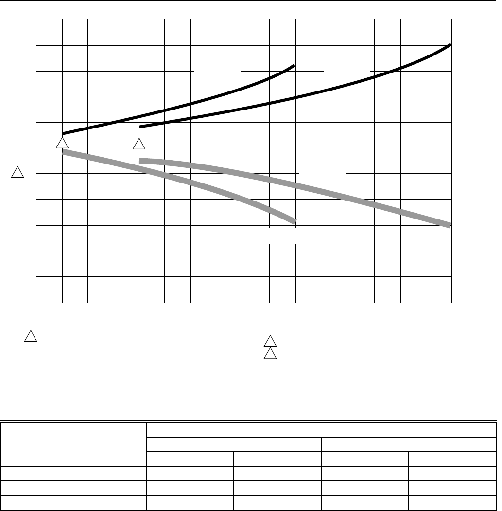
Capacity, Efficiency, Pressure Drop:
See Fig. 1.
Temperature Ratings:
Operating Ambient: 40°F to 125°F (4°C to 52°C).
Temperature of Airflow through Cells: 40°F to 125°F
(4°C to 52°C).
Maximum Cell Washing Temperature: 220°F (140°C).
Storage and Shipping Ambient: -40°F to +140°F
(-40°C to +60°C).
Mounting:
Mounts in the return air duct of a forced air heating, cooling,
or ventilating system. Should be mounted upstream of
atomizing humidifier. See Planning the Installation.
Weight:
See Table 2.
Dimensions:
See Fig. 2.
Approvals:
Underwriters Laboratories Inc. Listed:
File No. E30954, Guide No. AGGZ.
Canadian Standards Association Certified:
File No. LR20633—L, Guide No. 2010.
Option:
W8600E Solid State Performance Indicator (SSPI).
Accessories:
S688A Sail Switch.
136377A Remote Mounting Kit for power supply and
junction box. Kit includes galvanized steel base (5 in.
[127 mm] wide x 16-1/2 in. [419 mm] long x 13/16 in.
[21 mm] deep), prewired flexible conduit with
connectors (10 ft. [3m] long), knockout plug, and
mounting hardware.
Repair Parts:
See Parts List section.
F50E DUCT MOUNTED ELECTRONIC AIR CLEANER
68-0072—5
3
CAPACITY IN cfm (m /hr)
3
1 EFFICIENCY RATINGS BASED ON NATIONAL BUREAU OF
STANDARDS INITIAL DUST SPOT METHOD USING ATMOSPHERIC
DUST, AND AMERICAN SOCIETY OF HEATING, REFRIGERATING
AND AIR CONDITIONING ENGINEERS STANDARDS 52-76.
2 MINIMUM RECOMMENDED cfm FOR 16 x 25 in. (406 x 635 mm) MODEL.
3 MINIMUM RECOMMENDED cfm FOR 20 x 25 in. (508 x 635 mm) MODEL.
M4686
700
(1190) 800
(1360) 900
(1530) 1000
(1700) 1100
(1870) 1200
(2040) 1300
(2210) 1400
(2380) 1500
(2550) 1600
(2720) 1700
(2890) 1800
(3060) 1900
(3230) 2000
(3400)
.25
(62.2)
.20
(49.7)
.15
(37.3)
.10
(24.9)
.05
(12.4)
0
PRESSURE DROP IN in. wc (Pa)
50
60
70
80
90
100
EFFICIENCY, PERCENT
600
(1020)
500
(850)
400
(680)
1
16 x 25 in.
(406 x 635 mm)
16 x 25 in.
(406 x 635 mm)
2
20 x 25 in.
(508 x 635 mm)
20 x 25 in.
(508 x 635 mm)
3
Fig. 1. Air cleaner efficiency and pressure drop at various airflow rates.
Table 2. Shipping and Installation Weight.
Weight
16 x 25 in. (406 x 635 mm) 20 x 25 in. (508 x 635 mm)
lb. kg lb. kg
Electronic Cell (each) 6-1/2 3.0 8-3/16 3.7
Shipping Weight 38 17.2 43 19.5
Installed Weight (cells included) 33 15.0 38 17.2
F50E DUCT MOUNTED ELECTRONIC AIR CLEANER
68-0072—5 4
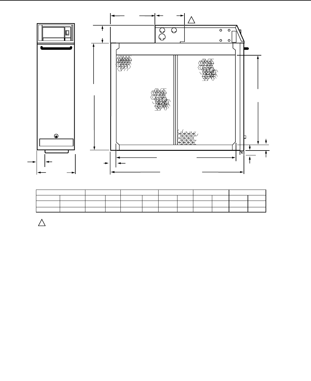
M4697
UNIT SIZE
IN.
16 X 25
20 X 25
MM
406 X 635
508 X 635
DIM. A
17-3/4
21-3/4
450
553
DIM. B
14-3/8
18-3/8
365
467
10-7/16
10-7/16
DIM. C
265
265
DIM. D
23-1/4
23-1/4
591
591
DIM. D (SEE TABLE)
DIM. E (SEE TABLE)
DIM. B
(SEE TABLE)
DIM. A
(SEE TABLE)
DIM. C
(SEE TABLE)
IN. MM IN. MM IN. MM IN. MM
DIM. E
25-1/2
25-1/2
648
648
IN. MM
6-3/4 (171)
1-1/8
(29) 15/16
(24) 5/8
(16)
7/8
(22)
5-9/16
(142)
3-3/4
(95)
1 JUNCTION BOX AND POWER SUPPLY CAN BE REMOTE-MOUNTED USING 136377A REMOTE MOUNT KIT.
1
Fig. 2. Installation dimensions in in. (mm in brackets) of 2-cell electronic air cleaner.
PLANNING THE INSTALLATION
Application
The F50E is used in a forced air heating, cooling, or
ventilating system. It operates when the system blower is on.
Models with internal solid state air flow switch require only
line voltage connection. Models without the air flow switch can
be energized through the fan switch, a dpdt fan relay or an air
flow switch such as the S688 Sail Switch. Unless the F50E
with solid state air flow switch is used, an isolating fan relay or
air flow switch is required if the system has a multispeed or
modulating blower motor.
Review Installation Requirements
The air cleaner should be installed where all the air passing
through the system circulates through it. The best location is
in the return air duct next to the blower compartment so the
air cleaner can help keep the blower motor and evaporator
coils clean. Do not mount in the discharge air duct.
For most efficient air cleaning, airflow must be spread evenly
across the face of the air cleaner. If the duct is a different size
than the air cleaner cabinet, gradual transitions are
recommended. If the duct turns sharply just before the air
cleaner, turning vanes are recommended.
Applications with Air Conditioning
The air cleaner should be installed upstream of the
evaporator coil. The air cleaner helps keep the coil clean,
reducing maintenance. Also, if the air cleaner is downstream,
the high relative humidity of the cooled air leaving the
evaporator coil can cause water condensation on the cells,
reducing air cleaner efficiency.
Applications with a Humidifier
An evaporative humidifier can be mounted upstream of the air
cleaner. An atomizing humidifier should be mounted
downstream of the air cleaner, even though hard water salts
will be blown into the living space and deposited as dust. If an
atomizing humidifier must be mounted upstream of the air
cleaner:
1. Mount it as far as possible upstream of the air cleaner.
2. Install a standard disposable furnace filter between the
humidifier and the air cleaner to trap water droplets and
hard water salts.
3. Clean the air cleaner frequently to prevent a hard water
salt buildup.
4. Note that the volume of water that passes through an
atomizing humidifier can overload the air cleaner,
resulting in hard water salts being deposited as dust in
the living space.
F50E DUCT MOUNTED ELECTRONIC AIR CLEANER
68-0072—5
5
Applications with an Activated Carbon Filter
If desired, an activated carbon (charcoal) filter can be used to
remove odors or other gaseous contaminants (not particle-
based), which are not removed by the air cleaner. Locate the
carbon filter:
• Downstream from the air cleaner. This means, of course,
that dust from the carbon filter will not be collected by the
air cleaner and will be deposited in the living space.
• Outside the air cleaner cabinet. Some carbon filters are
combustible, and contact with high voltage could result in
smoke or fire.
• Where carbon granules cannot fall into the electronic
cell(s). Use a disposable furnace filter if necessary
between the carbon filter and the electronic cell(s).
• With proper transitions, if the activated carbon filter
requires a different size duct than the air cleaner. Allow
20 degrees expansion per side, per fitting.
Applications with Outdoor Air Intake
Return air temperature must be at least 40°F (4°C). Lower
temperatures can cause ionizer wire failure. If outdoor air is
used, warm it ahead of the air cleaner by:
• Making sure the outdoor intake is far enough ahead of the
air cleaner so the return and outdoor air is thoroughly
mixed. Stratified air can dump a stream of very cold air into
one section of the air cleaner.
• Adding baffles ahead of the air cleaner to force thorough
air mixing.
• Installing a preheater, if large amounts of outdoor air are
used. The preheater, which could be an electric strip
heater or hot water coil, should be controlled by a
thermostat. Hot water or steam coils should be protected
by a freeze-up control.
Choose Location
Choose a location that is readily accessible for regular
inspection and cleaning. Allow at least 13 in. (330 mm) in front
of the access door for removing the prefilters and electronic
cells. Allow enough room above the power supply so the
power supply can be serviced without removing pipes, ducts,
or other heating system components.
The air cleaner
must
be installed where the temperature will
not exceed the ratings in the SPECIFICATIONS section.
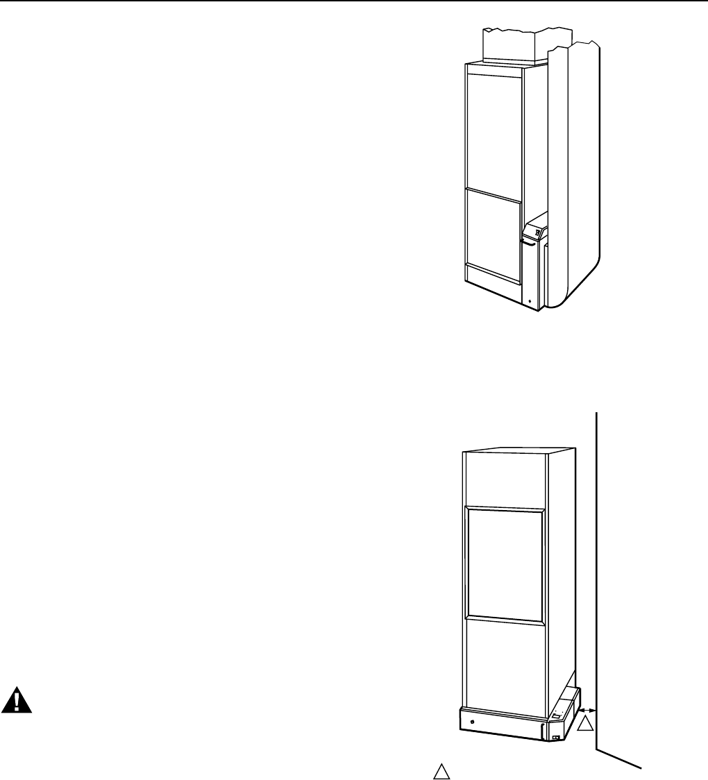
Choose Mounting Position
WARNING
Heavy Equipment.
Can cause injury or equipment damage.
If the access door faces down, the latch may not hold,
and the cells and prefilters can fall unexpectedly. Also,
nothing holds the cells and prefilters in place once the
access door is opened.
The air cleaner can be mounted in any position except with
the access door facing down. Figs. 3-10 show proper air
cleaner mounting with a variety of furnace installations.
M6028A
Fig. 3. Highboy furnace, side installation,
air cleaner is mounted vertically where
return enters side inlet of furnace.
M4691
1
1 ALLOW AT LEAST 2 IN. (51 MM) BETWEEN TOP
OF POWER BOX NAD ADJACENT WALL.
Fig. 4. Highboy furnace. Installation beneath furnace
(air cleaner cabinet can easily support weight of
furnace and air conditioner coil). Air cleaner is mounted
horizontally where return enters from below.
F50E DUCT MOUNTED ELECTRONIC AIR CLEANER
68-0072—5 6
M4695
ALLOW AT LEAST 13 IN. (0.3M) CLEARANCE BETWEEN ACCESS
DOOR AND WALL FOR CELL AND PREFILTER MAINTENANCE.
LOCAL CODES MAY PRESCRIBE GRILLE DESIGN AND PROVISION
FOR MAKE UP AIR. A SEAL FROM F50 TO GRILLE MAY BE REQUIRED.
1
1
2
2
Fig. 5. Highboy furnace. Closet installation. Air cleaner is
mounted vertically on furnace between furnace and
louvered return air opening in closet door.
Fig. 6. Lowboy furnace. Air cleaner is mounted
horizontally in return plenum just above
furnace, opposite supply plenum.
M4692
ALLOW AT LEAST 2 IN. (51 MM) CLEARANCE BETWEEN POWER
BOX AND FLUE PIPE.
ALLOW AT LEAST 13 IN. (0.3M) CLEARANCE BETWEEN ACCESS
DOOR AND WALL FOR CELL AND PREFILTER MAINTENANCE.
1
2
2
1
ACCESS TO AIR CLEANER FROM ATTIC IS REQUIRED FOR CELL
AND PREFILTER MAINTENANCE. CONSIDER USING F52E
CEILING MOUNT AIR CLEANER.
1
1
M4690
Fig. 7. Horizontal furnace. Air cleaner is mounted
horizontally above ceiling. Unless air cleaner is
easily accessible from attic, consider using F52
ceiling mount air cleaner instead.
M4687
Fig. 8. Horizontal furnace. Air cleaner is mounted
vertically in the return duct near the furnace.
Note transition.
F50E DUCT MOUNTED ELECTRONIC AIR CLEANER
68-0072—5
7
IN CLOSET INSTALLATION, AIR CLEANER MUST BE BELOW TOP OF
DOOR FRAME FOR CELL AND PREFILTER MAINTENANCE.
IF FLUE PIPE IS IN FRONT OF AIR CLEANER, ALLOW AT LEAST
13 IN. (0.3 M) CLEARANCE BETWEEN ACCESS DOOR AND FLUE PIPE.
1
2
1
2
M4688
Fig. 9. Counterflow furnace. Air cleaner is mounted
horizontally in return duct or plenum just above furnace.
ALLOW AT LEAST 13 in. (0.3 m) CLEARANCE BETWEEN ACCESS DOORS
AND ANY OBSTRUCTION FOR CELL AND PREFILTER MAINTENANCE.
1
M4689
Fig. 10. High capacity system. Two or more air cleaners
can be used together. At least 13 in. (0.3m) clearance is
required between access doors and walls for cells
and prefilter maintenance.
Determine Sheetmetal Requirements
The air cleaner is adaptable to all new or existing residential
forced air heating, cooling and ventilating systems.
Sheetmetal transitions, turning vanes, or offsets may be
needed in some applications.
Transitions
Transitions are needed when the duct is a different size than
the air cleaner cabinet. Gradual transitions reduce air
turbulence and increase efficiency. Limit expansion to
20 degrees (about 4 in. per running foot [100 mm per 300
linear mm]) on each side of a transition fitting. See Fig. 11.
20 DEGREE EXPANSION
PER SIDE. PER FITTING
(4 IN. PER RUNNING
FOOT [100 MM PER
300 LINEAR MM])
RETURN AIR
DUCT
TRANSITION FITTING
AIR CLEANER
CABINET M6026
Fig. 11. Change duct size gradually
to minimize turbulence.
Turning Vanes
If the air cleaner is installed close to an elbow or angle fitting,
install turning vanes inside the angle to distribute airflow more
evenly across the face of the cells. See Fig. 12.
TURNING
VANES
M5651
Fig. 12. Turning vanes installed in a bend help distribute
airflow evenly over the face of the electronic cells.
F50E DUCT MOUNTED ELECTRONIC AIR CLEANER
68-0072—5 8
Offsets
If the duct connection to the furnace in a side installation
allows less than 7 in. (178 mm) for mounting air cleaner
cabinet, shorten the lateral trunk or add an offset to the elbow.
See Fig. 13.
M6027A
LESS
THAN
7 INCHES
(178 MM)
OFFSET
AT LEAST
7 INCHES
(178 MM)
1
1 REQUIRED TURNING VANES HELP DISTRIBUTE AIRFLOW EVENLY.
Fig. 13. Typical use of duct offset to make room
for electronic air cleaner.
INSTALLATION
When Installing this Product…
1. Read these instructions carefully. Failure to follow them
could damage the product or cause a hazardous
condition.
2. Check the ratings given in the instructions and on the
product to make sure the product is suitable for your
application.
3. Installer must be a trained, experienced service
technician.
4. After installation is complete, check out product
operation as provided in these instructions.
CAUTION
Electric Shock Hazard.
Can cause electrical shock or equipment damage.
Disconnect power supply before installing air cleaner.
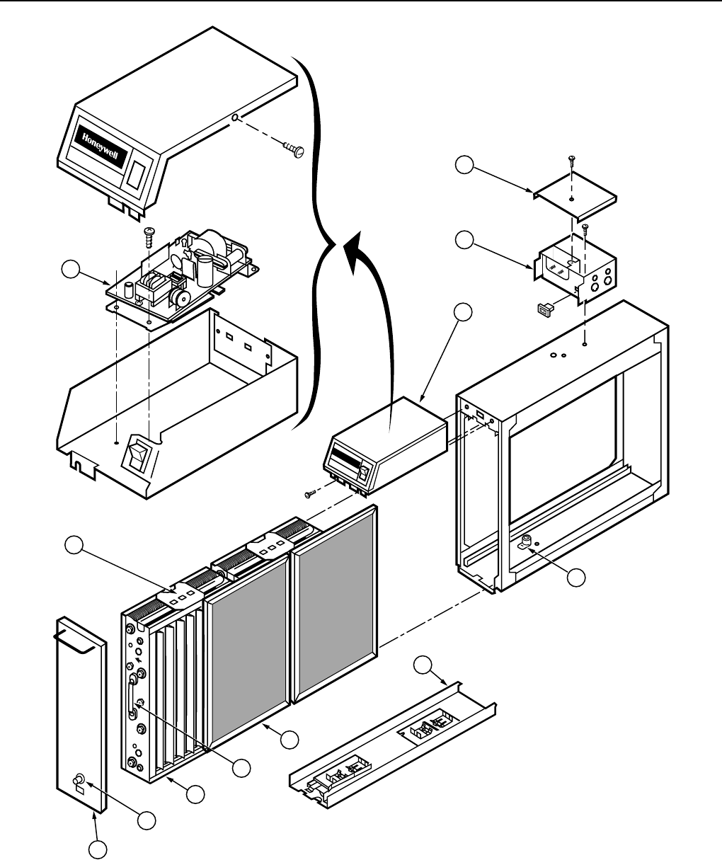
Unpack Electronic Air Cleaner
❑Check that all components are included. The electronic air
cleaner is shipped assembled. See Fig. 14. The unit
consists of:
• Galvanized steel cabinet.
• Power supply with on-off switch and neon light.
• Junction box.
• Two electronic cells.
• Two prefilters.
• Access door with test button.
• Literature package.
❑W8600E (optional) and mounting hardware must be
ordered separately.
ON-OFF SWITCH WITH NEON LIGHT
WASH REMINDER SCHEDULE
POWER SUPPLY JUNCTION BOX
CABINET
ELECTRONIC
CELLS
PREFILTERS
TEST
BUTTON
ACCESS DOOR
OPTIONAL W8600E WALL PANEL M7682
Fig. 14. Components of the F50E Air Cleaner
(2-cell model shown).
Clean Blower Compartment
❑Remove and discard the existing furnace filter.
❑Thoroughly clean the blower compartment.
❑If possible, power vacuum ductwork to remove accumulated
dust in existing home, or construction dirt in a new home.
The electronic air cleaner cannot remove dust that has
settled in the blower compartment and distribution ducts.
❑Check the edges of the furnace fan blades for dirt buildup
and clean as necessary. The fan will not deliver the rated
cfm if the blades are dirty.
Review the Installation Plan
❑Temporarily place the cabinet on the floor; position as it will
be when installed.
❑Remove and set aside the access door, electronic cells
and prefilters, checking that the selected location provides
enough clearance for easy removal and replacement of
these components. Unless the power supply will be
remotely mounted, make sure there is room above the
unit to wire and service the power supply, including the
optional W8600E.
❑Make sure that shop-fabricated sheetmetal components,
such as turning vanes, are on hand.
Remote Mount Power Supply, if Desired
❑
If remote mount is not desired, go on to Fasten the
Cabinet to the Furnace section.
F50E DUCT MOUNTED ELECTRONIC AIR CLEANER
68-0072—5
9
CAUTION
Electric Shock Hazard.
Can cause personal injury or equipment damage.
Do not attempt to remote-mount the power supply
without the remote mount kit. The special high voltage
wire in the kit has extra thick insulation to protect
against electric shock from the high voltage carried
between the air cleaner cells and the power supply.
Standard NEC class 1 wire is rated for only 600 volts
and will fail if used. Do not try to pull any other wires
through the flexible conduit in the kit.
Mount Remote Base
❑Select an easily accessible location for the power supply
within reach of the conduit assembly. Make sure the on-off
switch and neon light are readily visible.
❑Mount the remote mounting base using four screws
(obtained locally).
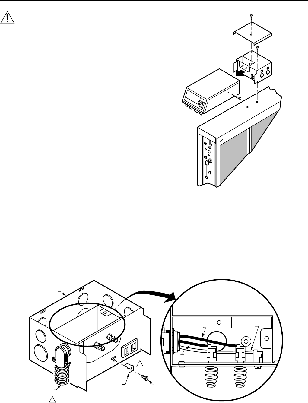
Mount Power Box and Junction Box
❑Loosen the screws holding the power supply; lift it slightly to
clear the screws, then pull it straight away from the junction
box to remove. Remove and retain screws. Set aside.
❑Remove the cover from the junction box. Set aside.
❑Disconnect the two leadwires from the quick connect
terminals in the junction box. See Fig. 15.
❑Remove the junction box from the cabinet.
❑Remove the knockout on the side of the junction box and
connect the end of the conduit assembly with the shorter
leadwires. See Fig. 16.
❑Install ground terminal in junction box. See Fig. 16.
❑Connect the leadwires as shown in Fig. 16.
❑Fasten the junction box to the base with the two screws
removed earlier.
❑Replace the junction box cover and secure with screw
removed earlier.
❑Loosely reinsert screws into power supply base. Plug the
power supply into the junction box. Push it straight in to
avoid bending the plug. Tighten screws. See Fig. 17.
Fig. 16. Make wiring connections in junction box.
M4696
Fig. 15. Disconnect the wires and remove the
power box and junction box.
AIR CLEANER
JUNCTION BOX
RED
LEADWIRE
BLACK
LEADWIRE
TOP VIEW
WHITE GROUND
LEADWIRE
M6499
CONDUIT
CONNECTOR
QUICK-
CONNECT
TERMINAL SCREW
1
1 SCREW AND QUICK-CONNECT TERMINAL IN 136377A REMOTE MOUNT KIT.
F50E DUCT MOUNTED ELECTRONIC AIR CLEANER
68-0072—5 10
M6498
POWER
BOX)
REMOTE
MOUNTING
BASE
JUNCTION
BOX
SCREWS (2)
PROVIDED IN 136377A REMOTE MOUNT KIT.
SCREWS (2)
1
1
Fig. 17. Mount the power box and the junction box
on the remote base.
Connect Cable to Air Cleaner Cabinet
❑Remove the screws holding the front of the contact tray
in place and lower the contact tray. Remove and discard
the two loose wires attached to the ionizer and
collector terminals.
❑Remove desired knockout from the top or back of the air
cleaner cabinet and install end of conduit assembly with
high voltage leadwire ends.
❑Connect the black wire to the collector terminal and the red
wire to the ionizer terminal. See Fig. 18.
❑Mount one of the quick-connect ground terminals and the
leaf spring supplied in the kit on the contact tray and
connect the white wire to it. See Fig. 18.
❑Replace the contact tray and secure with the two screws
removed earlier. Be careful not to pinch the wires between
the cabinet and tray.
❑Plug the hole in the top of the cabinet with the metal
plug provided.
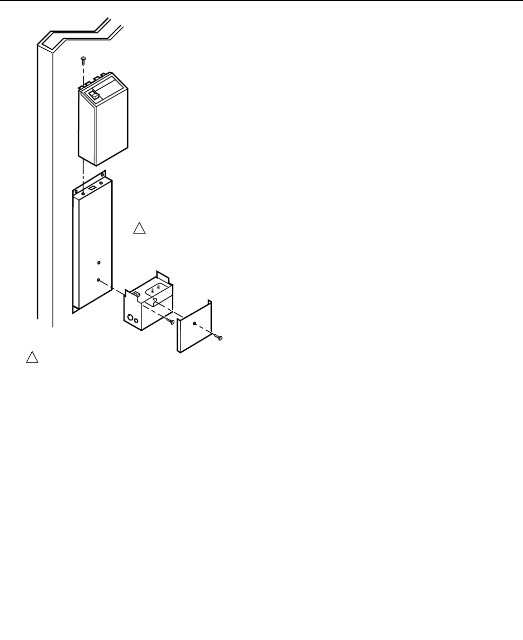
Fasten the Cabinet to the Furnace
NOTE: This procedure shows a side installation on a typical
highboy furnace. You may need to alter the
procedure to fit your application.
❑Align the cabinet with the return air opening.
❑Install a transition when the furnace and air cleaner
openings are different sizes. See Fig. 11.
❑Place blocks under the cabinet so the unit is firmly
supported and level. The 5/8 in. (16 mm) mounting foot on
the cabinet hinge plate provides the minimum clearance
required for the access door hinge.
❑Attach the cabinet securely to the furnace. The unit can be
attached directly, as shown, or a starting collar can first be
fitted in the furnace opening. Either drill holes and fasten
with sheetmetal screws or rivets, or use slip joints. If you
are drilling holes, locking pliers help to hold the unit in
place during drilling. See Fig. 20.
Install Turning Vanes
❑Mount turning vanes inside the elbow or angle fitting that is
directly against the air cleaner cabinet.
Fasten Cabinet To Ductwork
❑Install a transition when the opening in the air cleaner
cabinet and the duct are different sizes. See Fig. 11.
❑Fasten the other side of the cabinet to the elbow using
sheetmetal screws, rivets, or slip joints, as appropriate.
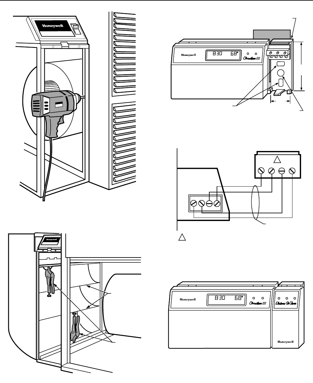
Install Optional W8600E Solid State
Performance Indicator
When the W8600E Solid State Performance Indicator is part
of the installation, install the W8600E in the desired location
and run 4-wire thermostat cable (up to 18 gauge),
independent of any other current-carrying wires, to the air
cleaner’s power box as follows.
W8600E Location
The styling of the W8600E is designed to blend with the
Chronotherm III® Thermostats. A special mounting template
is included in the bag assembly for mounting next to the
thermostat. The W8600E Indicator can, however, be mounted
at any other convenient location in the living area, or it can be
mounted in the furnace room. It shares no electrical
connections with the thermostat.
Make certain the location makes it convenient for the
homeowner to observe the LEDs of the device.
Mounting W8600E
The following mounting instructions assume that the W8600E
will be mounted next to a Chronotherm III® Thermostat.
When installing the wall panel at another location, modify the
procedure to fit the installation.
❑Remove the cover from the W8600E.
❑Hold the mounting template (included in the W8600E bag
assembly) next to the thermostat as shown in Fig. 21.
❑Hold the base for the W8600E next to the template and
mark holes for screw anchors and access hole for 4-wire
thermostat cable from the terminal strip on the F50E
power box to the W8600E base.
❑Remove the W8600E base and drill the holes. Install the
anchors and screws so that the base is mounted firmly on
the wall at the correct distance from the thermostat.
F50E DUCT MOUNTED ELECTRONIC AIR CLEANER
68-0072—5
11
1 PROVIDED WITH 136377A REMOTE MOUNT KIT.
QUICK
CONNECT
TERMINAL
SCREW
(1)
SPRING
CLIP
1
1
1
1
1
1
1
CONTACT
TRAY
AIR CLEANER
CABINET (TOP)
CONTACT TRAY
BLACK
LEADWIRE
RED LEADWIRE
WHITE
GROUND
LEADWIRE
CONTACT TRAY
MOUNTING SLOT
CONDUIT
CONNECTOR
FLEXIBLE
CONDUIT
CONTAINING
THREE
SPECIAL
LEADWIRES
RATED
FOR
15KV.
AIR CLEANER
CABINET (FRONT)
SCREWS (2)
M6500
Wiring W8600E
IMPORTANT
Run wires separately from any other current-
carrying wires.
❑All wiring must comply with local codes and ordinances.
❑Run 4-wire thermostat cable (up to 18 gauge), independent
of any other current-carrying wires, from the W8600E base
to the terminal strip on the power box of the F50E.
Fig. 18. Install the conduit on the cabinet and make wiring connections to contact tray.
❑Strip 1/4 in. of insulation from the ends of the wires and
connect them (1 to 1, 2 to 2, 3 to 3, 4 to 4) as shown in
Fig. 22.
❑Install the W8600E cover and visually check the
installation appearance as shown in Fig. 23.
F50E DUCT MOUNTED ELECTRONIC AIR CLEANER
68-0072—5 12
M6167
ENRG. SAV. SYSTEM
HEAT ON
MON
WAKE
AM
T8600 THERMOSTAT
MOUNTING
TEMPLATE
W8600E
BASE
MOUNTING HOLES
WIRING HOLE
3-11/16
(94)
1-5/8
(42)
Fig. 21. Mounting the W8600E indicator next to the T8600
thermostat, dimensions in in. (mm).
M5629A
W8600E
TERMINAL STRIP
ON POWER BOX
FOUR-WIRE
THERMOSTAT CABLE
1234
GREEN
YELLOW
RED
BLUE
GYRB
1
2
3
4
G
Y
R
B
1
1 CONNECT TO W8600E TERMINALS BEFORE CONNECTING TO
POWER BOX.
ELECTRONIC AIR CLEANER
Fig. 22. Wiring W8600E to air cleaner
power box terminal strip.
ENRG. SAV. SYSTEM ON. WASH CHECK
HEAT ON
MON
WAKE
AM
M6166
Fig. 23. Completed T8600/W8600E installation.
M4698
ELECTRONIC AIR CLEANER
Fig. 19. Fasten cabinet to furnace.
M4699
LOCKING
PLIERS
TURNING
VANES
ELECTRONIC AIR CLEANER
Fig. 20. Connect ductwork to air cleaner. Note turning
vanes. Locking pliers hold duct to air cleaner cabinet
during installation.
F50E DUCT MOUNTED ELECTRONIC AIR CLEANER
68-0072—5
13
Complete Wiring
CAUTION
Electric Shock Hazard.
Can cause personal injury.
• The line voltage power source must match the
voltage and frequency printed on the label inside
the access door.
• Opening the access door disconnects high voltage
power and discharges the cell. Always turn off the
air cleaner and open the access door before
touching any internal components.
• The air cleaner must be permanently connected to
the power source and properly grounded. Do not
use an extension cord.
❑Disconnect power source before beginning wiring to avoid
electrical shock or equipment damage. All wiring must
comply with local codes and ordinances.
IMPORTANT
In a multispeed blower application, isolate the air
cleaner with a dpdt fan relay or sail switch. The air
cleaner overheats and burns out if it is connected in
parallel with one winding of a multispeed fan motor,
and a different winding is powered during a
thermostat call for cooling.
❑Wire the air cleaner to run only when the system
blower is running.
1. If the system blower is driven by a single-speed, single-
phase motor, wire the air cleaner into the fan circuit.
See Fig. 24.
2. If the system blower is driven by a 3-phase, variable
speed or a 2-speed motor, the air cleaner
must
be
isolated from the blower motor. Use a sail switch
mounted in the return air duct (see Fig. 25), a dpdt fan
relay (see Fig. 26), or furnace manufacturer supplied
terminals. Connecting the air cleaner in parallel with
one speed of a multispeed motor can create an
auto-
transformer effect
. If connected with the high speed,
voltage supplied to the air cleaner at low speed is too
low, and the air cleaner may not operate at all. If con-
nected with the low speed, voltage to the air cleaner at
high speed is too high and the air cleaner will burn out.
Connect Ductwork
❑Connect the vertical duct section to the elbow. If the
vertical drop of the duct is less than 7 in. (178 mm) from
the side of the furnace, shorten the horizontal trunk or
attach an offset fitting to the elbow.
❑When ductwork is properly aligned, connect vertical duct
to horizontal trunk. See Fig. 25.
Seal Joints
❑Seal all joints in the return air system between the air
cleaner and the furnace to prevent dust from entering the
clean airstream.
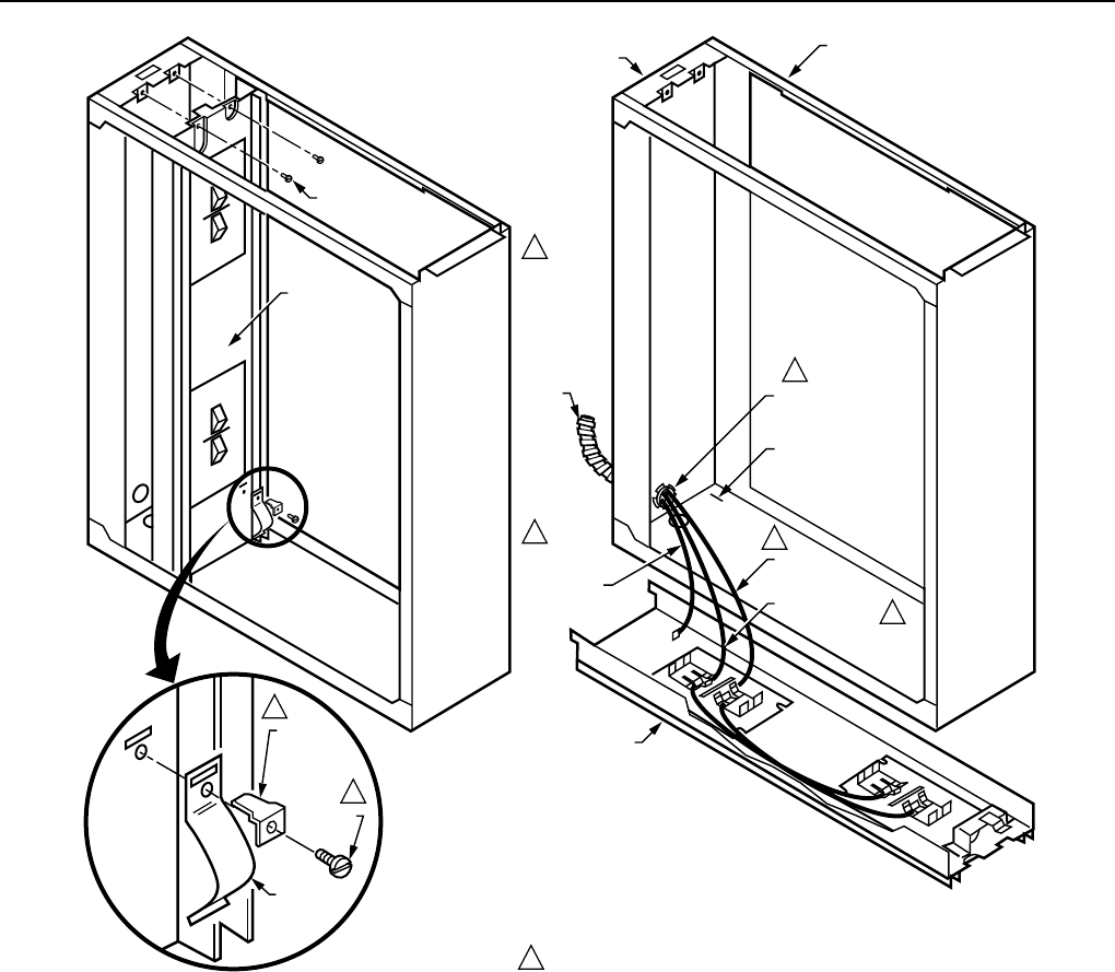
Disable Unused Prefilter Guide
❑Crimp the end of the downstream (closest to furnace)
prefilter guide to prevent incorrect prefilter installation
following cleaning. See Fig. 26.
M4684
L1
(HOT)
L2
1
1POWER SUPPLY. PROVIDE DISCONNECT MEANS AND
OVERLOAD PROTECTION AS REQUIRED.
HEAT
COOL
HUMIDISTAT
TRANSFORMER
HUMIDIFIER
F50
ELECTRONIC
AIR CLEANER
WITHOUT
SOILD STATE
AIR FLOW
SWITCH
JUMPER
R8222D
FAN
CONTROL
SYSTEM
TRANSFORMER
BLOWER
MOTOR
BROWN
BLACK
HI
LO
C
1
4
2
3
5
6
G
W
R
Y
Fig. 24. Two-speed blower motor. F50 without solid state
air flow switch is controlled through a dpdt fan relay.
Note power humidifier connections.
Fig. 25. Complete the duct installation.
F50E DUCT MOUNTED ELECTRONIC AIR CLEANER
68-0072—5 14
Fig. 26. Crimp End Of Unused Prefilter Guide.
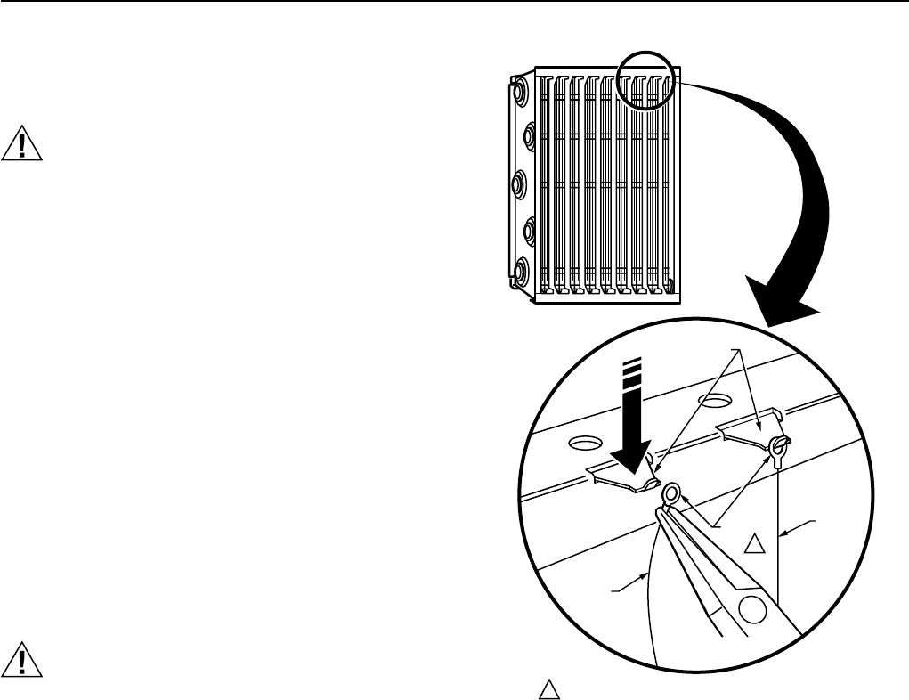
Position Cell Key
❑The electronic cells must always be installed so the ionizer
section is on the upstream side. A factory-installed cell key
on the bottom of the cabinet allows the cells to be inserted
in only one direction. As long as the arrow molded into the
plastic key points the same direction as the airflow, the
ionizer is always on the upstream side.
❑If the position of the key must be reversed, proceed as
follows:
1. Remove electronic cells.
2. Loosen the screw holding the cell key in place. See
Fig. 27.
3. Turn the key around and place it over the opposite
holes. The tab on the bottom fits into the larger hole,
and the screw fits into the smaller hole. Make sure the
arrow on the key points in the direction of air flow
(downstream).
4. Tighten the screw.
5. Insert the electronic cells. The ionizer section is now on
the air-entering (upstream) side of the cabinet.
Attach Cell Handles
❑The cell handles are included in the packet of literature.
They must be installed on the end of the cells that will be
closest to the access door. To install:
1. Orient the cells as they will be when installed. The red
contact board must be up and the airflow arrow
stamped into the cell must point downstream.
2. Hold the handle sideways and insert the solid tab on
the back of the handle into the slot in the cell. Turn the
handle 90 degrees clockwise to align the divided tab
with the square hole. See Fig. 28.
3. Insert the divided tab into the square hole.
4. Fold up the wedge and insert into the divided tab to lock
the handle in place. When necessary, press with a blunt
instrument like the end of a pliers.
PREFILTER GUIDES
CELL KEY
M5639
CELL
KEY
ALTERNATE
HOLES FOR
KEY
CELL KEY
SCREW
DOWNSTREAM
AIRFLOW
Fig. 27. Position of cell key determines orientation of cell.
Arrow on key must point downstream.
M6047A
ROTATE 90
DEGREES
FOLD TAB
TO LOCK
HANDLE
IN PLACE
INSTALL HANDLE ON END OF CELL
CLOSEST TO ACCESS DOOR.
Fig. 28. Install handle on end of cell that will be
closest to access door.
Reassemble Air Cleaner
❑Insert the electronic cells with the red contact board up
and the airflow arrow pointing downstream. If the cells do
not slide easily into the cabinet, check the orientation of
the cell key.
❑Insert the prefilters on the upstream side of the cabinet in
the guides provided.
❑Replace the access door. Insert the tab on the bottom of
the door into the slot in the cabinet, then swing closed and
press into place. See Fig. 29. The door must be firmly in
place or the air cleaner will not operate.
❑If the cell washing schedule on the power box is not
conveniently located, mount the schedule from the
literature package on the furnace or other convenient
location near the air cleaner.
M4700
ELECTRONIC AIR CLEANER
F50E DUCT MOUNTED ELECTRONIC AIR CLEANER
68-0072—5
15
Fig. 29. Close access door to complete
air cleaner installation.
CHECKOUT
Inspect the Installation
Make sure:
• Turning vanes and transitions, as needed, are
properly installed.
• Sheet metal joints between air cleaner and furnace
are sealed.
• All sheet metal connections are complete.
• Original furnace filter was removed and the blower
compartment cleaned.
• If an atomizing humidifier is installed upstream of the air
cleaner, that a disposable furnace filter is installed
between the humidifier and the air cleaner.
• If the furnace has a multispeed or modulating blower (and
an air cleaner without solid state air flow switch is used),
that an interlock (sail switch or dpdt relay) provides
electrical isolation.
• Outside air, if used, is mixed with return air or heated as
necessary before it can reach the air cleaner.
• The high voltage contacts on the cell touch the spring
contacts in the contact tray.
• The airflow arrows on the electronic cells point downstream.
• The prefilters are on the upstream side of the cells.
• The cell handles face outward.
• The electronic cells and prefilters are clean and dry.
• The wiring connections inside the junction box or power
box are properly made. See Fig. 24.
• That W8600E (if included) wiring connections are
properly made.
Check Air Cleaner Operation
With all components in place, turn on the air cleaner switch
and energize the system blower. Check the following points of
operation:
1. The neon light in the on-off switch is on. If a W8600E is
part of the installation, also check the wall panel and
make sure the ON LED is lit.
2. Turn off the system blower. The neon light should go off.
The neon light comes on to show that the air cleaner is
energized and the high voltage power supply is working
properly. If W8600E is used with air cleaner that has air
flow switch, the neon light shows only that the air
cleaner is energized. The CHECK LED will come on if
there is a problem with the high voltage power supply.
3. Turn the system blower back on. With the air cleaner
energized, push the test button. A snapping sound
indicates that collector voltage is present on the cells.
On air cleaner with a W8600E, the CHECK LED will
come on.
4. With a multispeed blower, repeat steps 1 through 3 for
each fan speed.
5. With a meter, check the ionizer voltage between P3 (red
lead) and ground, and the collector voltage between P4
(black lead) and ground. The correct voltages are
printed on the label inside the access door.
6. If operation is not as described, refer to the Electrical
Troubleshooting section.
SERVICE
CAUTION
Sharp Edges.
Can cause personal injury.
Handle the cells carefully or wear protective gloves to
avoid cuts from the sharp metal edges.
Cleaning the Cells and Prefilters
When enough lint accumulates to block the air flow, the
prefilter can quickly become clogged. Inspect the prefilters
monthly, and clean if necessary to prevent possible lint
clogging. The cell washing can also be done at this time, or
can wait until next inspection if cells still look clean.
Regardless, clean the cells and prefilters regularly—every
one to six months. Variables such as number of family
members, pets, activities and whether anyone smokes
indoors determine how often cleaning is required. Use the
wash reminder schedule on top of the air cleaner to record
dates of cell washings, to help establish and to maintain a
regular cleaning schedule.
If the air cleaner has the optional W8600E Solid State
Performance Indicator, the WASH LED will come on to remind
you that a cell and prefilter washing is past due. If the WASH
LED seems to light soon after a cell washing, thorough wiping
of the ionizer wires may be all that is needed. Cells should be
washed and ionizer wires wiped frequently enough to prevent
WASH LED from coming on. The WASH LED will not come on
when the prefilters get clogged; clean the prefilters every time
the cells are cleaned.
NOTE: If an ultrasonic room humidifier is used often,
especially when filled with tap (undistilled) water, the
cells will require more frequent washing. A white
residue will accumulate on the cells from the
minerals in the water.

F50E DUCT MOUNTED ELECTRONIC AIR CLEANER
68-0072—5 16
The cells can be washed in many home dishwashers, by
soaking in a tub or at a do-it-yourself, coin-operated car wash.
The prefilters can be vacuumed, brushed, sprayed with a
garden hose, or washed with the electronic cells
Automatic Dishwasher
CAUTION
Burn Hazard.
Can cause personal injury.
Allow the cells to cool completely in the dishwasher at
the end of the wash cycle or wear protective gloves to
avoid burns. Hot water can accumulate in the tubes
supporting the collector plates; tip the cells so these
tubes drain.
IMPORTANT
• Check your dishwasher owner manual. Some
manufacturers do not recommend washing
electronic cells in their dishwashers.
• If the dishwasher has upper and lower arms, carefully
position the cells to allow good water circulation.
• Use care to avoid damaging the cells when placing
them in the dishwasher.
• Very dirty cells, especially from tobacco or cooking
smoke, can discolor the plastic parts of the
dishwasher. This discoloration is not harmful. To
minimize it, wash the cells more frequently or try a
different brand of detergent.
• Do not allow the dishwasher to run through the
dry cycle. This bakes on any contaminants not
removed during the wash cycle and reduces air
cleaner efficiency.
1. Put the cells on the lower rack of the dishwasher with
the airflow arrow pointing up. It may be necessary to
remove the upper rack. Do not block water flow to the
upper arm, if provided on your dishwasher.
2. If you are washing the prefilters with the cells, place
them where they will not block the water flow to the
electronic cells.
3. Using the detergent that works best for normal
dishwashing, allow the dishwasher to run through the
complete wash and rinse cycle. Do not use the dry
cycle. To avoid burns, let the cells cool completely
before removing, or wear protective gloves when
removing the cells. Remember that water may be
trapped in the tubes that support the collector plates; tip
the cells so these tubes can drain.
4. Wipe each ionizer wire and red contact board on top of
the cell with a clean cloth.
5. Inspect the dishwasher. You may want to rerun the wash
and/or rinse cycle with the dishwasher empty if you see
dirt or residue from washing the cells. If dirt or residue
seems excessive, wash the cells more often or try a
different detergent.
Soaking in Tub
CAUTION
Hazardous Chemical.
Can cause personal injury.
Do not splash the detergent solution in eyes.
Wear rubber gloves to avoid prolonged detergent
contact with skin. Keep detergent and solution out of
reach of children.
NOTE: Always wash the cells first, then the prefilters to keep
heavy lint from getting caught in the cells.
1. Use a container such as a laundry tub or trash
container that is large enough to hold one or both cells.
NOTE: Sharp corners on the cells can scratch the
surface of a bathtub.
2. Dissolve about 3/4 cup of automatic dishwasher
detergent in enough very hot water to cover the cells. If
the detergent does not dissolve readily, or forms a scum
on the water, try another brand, or use softened water.
3. After the detergent is completely dissolved, place the
electronic cells in the container and let soak for 15 to
20 minutes. Agitate the cells up and down a few times
and then remove.
4. Next, wash the prefilters the same way. Empty and rinse
the wash container.
5. Rinse the cells and prefilters with a hard spray of very
hot water; rinse the tub clean then fill the tub with clean,
hot water and soak for 5 to 15 minutes. Rinse until the
water draining from the cells and prefilters no longer
feels slippery.
6. Wipe the ionizer wires and red contact board on the
end of cell with a clean cloth.
Car Wash
Use the hand sprayer at a coin-operated car wash to wash
the cells and prefilters. Hold the nozzle at least two feet away
from the unit to avoid damage from the high pressure stream
of water. Follow the same sequence of wash and rinse as
recommended for cars. However, do not wax the cells or the
prefilters. Rinse until the water draining from the cells and
prefilters no longer feels slippery.
Reinstall the Cells and Prefilters
1. Inspect the cells for broken ionizer wires and bent
collector plates. Repair as necessary.
2. Slide the prefilters into the upstream prefilter guides.
3. Slide in the air cleaner cells so the air flow arrow points
downstream and the handles face outward.
4. Firmly close the access door.
5. Turn on the air cleaner. If the cells and prefilters are
wet, the neon light may not come on and you may hear
arcing. If the arcing is annoying, simply turn off the air
cleaner for two to three hours, or until dry.
Ionizer Wire Replacement
Broken or bent ionizer wires can cause a short to ground,
often resulting in visible arcing or sparking. On air cleaners
without a W8600E, any short in the ionizer section causes the
neon light to go out. On air cleaners with a W8600E, any
short in the ionizer or collector section lights the CHECK LED
on the wall panel. The cell should not be used until the pieces
of broken wire are removed. It can be used temporarily with
one wire missing, although the wire should be replaced as
soon as possible. See the Parts List section for order number.
Replacement wires come cut to length with eyelets on both
ends for easy installation. To install:
1. Hook the eyelet on one end of the wire over the spring
connector on one end of the cell. See Fig. 30. Be
careful to avoid damaging the spring connector or other
parts of the cell.
F50E DUCT MOUNTED ELECTRONIC AIR CLEANER
68-0072—5
17
2. Hold the opposite eyelet with a needlenose pliers and
stretch the wire the length of the cell. Depress the
opposite spring connector and hook the eyelet over it.
Reducing Ozone Odor
CAUTION
Electric Shock Hazard.
Can cause personal injury.
Always disconnect power and open the access door to
discharge the high voltage power supply before
opening the power supply cover.
The electronic air cleaner generates a small amount of ozone
in normal operation. During the first week or two of operation,
the amount may be higher because of sharp edges on some
of the new high voltage metal parts. However, normal use
dulls these edges in a short time.
The average person can detect the odor of ozone in
concentrations as low as 0.003 to 0.010 parts per million
(ppm). The electronic air cleaner contributes 0.005 to
0.010 ppm of ozone to the indoor air. The U.S. Food and Drug
Administration and Health and Welfare Canada recommend
that indoor ozone concentration should not exceed
0.050 ppm. As a comparison, the
outdoor
ozone level in
major cities is sometimes as high 0.100 ppm. However, if
desired, the ozone generated by the air cleaner can be
reduced in one of two ways:
1. Install an activated carbon filter downstream of the air
cleaner. Make sure particles from the air filter cannot fall
into the air cleaner.
CAUTION
Only a trained service technician should perform the
following procedure.
2. Clip out the J2 jumper on the power supply. This
reduces ozone production about 20 to 25 percent, and
reduces efficiency about 7 to 10 percent, depending on
actual airflow delivered by the furnace blower.
a. Turn off power to the air cleaner.
b. Open the access door to discharge the high
voltage power supply.
c. If power supply is remotely mounted, make sure
the access door is left open. Remove the power
box cover. See Fig. 32.
d. Find the J2 jumper and clip it out. See Fig. 31.
e. Replace power supply cover and access door.
Turn on power.
M1540B
IONIZER
WIRE
IONIZER
WIRE
NEEDLENOSE
PLIERS
SPRING
CONNECTORS
PRESS
DOWN
EYELETS
REPLACING AN IONIZER WIRE.
TWO EYELETS HOLD INOIZER WIRE TO CELL.
1
1
Fig. 30. Install new ionizer wire by hooking
eyelets over spring connectors.
F50E DUCT MOUNTED ELECTRONIC AIR CLEANER
68-0072—5 18
P3
P4
P1
P2
M5685A
CABLE CLAMP CLIP
2
4
3
1
J2
J2 JUMPER. CLIP OUT TO REDUCE
OZONE PRODUCTION
R43
R43. CLIP OUT
TO REDUCE
W8600E
WASH LED
SENSITIVITY
CLIP OUT J2 JUMPER TO REDUCE OZONE
PRODUCTION ABOUT 20 TO 25 PERCENT.
Fig. 31. Clip out J2 jumper to reduce ozone
production about 20 to 25 percent.
ELECTRICAL TROUBLESHOOTING
WARNING
Electric Shock Hazard.
Can cause personal injury or equipment damage.
The following procedures expose hazardous live parts.
Disconnect power supply between checks and
proceed carefully.
CAUTION
The following instructions are for use by qualified
personnel only.
Tools and Equipment
Troubleshooting the electronic air cleaner requires only a few
tools:
• Needlenose pliers for stringing ionizer wires.
• Test meter.
Troubleshooting Procedure
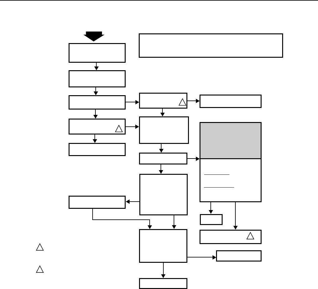
The Electronic Air Cleaner Troubleshooting Charts, Fig. 34
and 35, show how to quickly isolate a problem in the air
cleaner. Although a meter is needed for some steps, (see
Fig. 33) the primary diagnostic tools are the neon light on air
cleaners without a W8600E, the CHECK LED on air cleaners
with W8600E, and the test button.
Fig. 32. You must remove two-cell model power box from
air cleaner to remove cover.
Fig. 33. Use an ohmmeter to check the electronic cells
for short circuits.
M1204A
COLLECTOR
TERMINAL
COLLECTOR
TERMINAL
IONIZER
TERMINAL
M6494
1
3
2
F50E DUCT MOUNTED ELECTRONIC AIR CLEANER
68-0072—5
19
NO
TO USE THIS CHART:
START
OFF
ON
YES
YES
REPLACE LIGHT/
SWITCH ASSEMBLY.
MAKE SURE ELECTRONIC
CELLS ARE CLEAN, DRY
AND PROPERLY INSTALLED.
TURN ON ELECTRONIC AIR
CLEANER AND SYSTEM
FAN.
CHECK NEON LIGHT ON
AIR CLEANER.
PUSH TEST BUTTON AND
LISTEN FOR SNAPPING
SOUND.
NO
PUSH TEST BUTTON
AND LISTEN FOR
SNAPPING SOUND.
TURN OFF AIR CLEANER
AND REMOVE CELLS .
CLOSE ACCESS DOOR
AND TURN ON AIR
CLEANER.
OFF
ON
1
1
CHECK FOR CORRECT INPUT
VOLTAGE ACROSS:
120V MODELS: P1 AND P2
TERMINALS ON POWER
SUPPLY
220/240 MODELS: QUICK-
CONNECT TERMINALS ON
POWER SUPPLY
TRANSFORMER.
INSPECT CELLS FOR:
•
•
•
•
BENT COLLECTOR
PLATES
BROKEN IONIZER
WIRES
DIRT ON INSULATORS
DAMAGED IONIZER
OR COLLECTOR
CONTACT TABS
YES
NO YES
NO FIX
WIRING.
REPAIR OR REPLACE
CELLS.
WITH OHMMETER,
CHECK FOR SHORT
BETWEEN:
•
•
CELL FRAME AND
IONIZER SECTION
CELL FRAME AND
COLLECTOR SECTION
CELL
SHORTED
INFINITE
RESISTANCE
REPLACE CELL.
CELL OK.
REPLACE COMPLETE
POWER SUPPLY
1THE SNAPPING SOUND ON THE AIR CLEANER,
WITH A SOLID STATE POWER SUPPLY, IS
ABOUT HALF AS LOUD AS ON MODELS WITH
THE W919 POWER SUPPLY.
COMPONENTS ARE NOT FIELD REPLACEABLE.
2
M1347A
FOLLOW THE STEPS IN ORDER; DO NOT SKIP AROUND.
EACH TIME YOU ISOLATE AND FIX A PROBLEM, GO BACK TO START.
REPEAT ALL THE STEPS UNTIL THE AIR CLEANER CHECKS OUT OK.
1.
2.
3.
2
THIS STEP EXPOSES
DANGEROUSLY HIGH
VOLTAGE. ONLY A
QUALIFIED SERVICE
TECHNICIAN SHOULD
ATTEMPT THIS STEP.
WARNING
CHECK NEON LIGHT
ON AIR CLEANER.
ELECTRONIC AIR
CLEANER IS OK.
TROUBLESHOOTING F50E AIR CLEANERS WITHOUT SOLID STATE
PERFORMANCE INDICATOR TERMINALS ON POWER BOX
Fig. 34. Electrical troubleshooting procedure for F50E electronic air cleaners without a W8600E.
Neon Light
The NEON LIGHT is in the on-off switch. It is powered
through the power supply and is ON when the power supply
is working properly. See internal schematic, Fig. 36.
On models with the W8600E printed wiring board, the neon
light in the on-off switch indicates only that the air cleaner is
powered. See internal schematic, Fig. 36.
CHECK LED (air cleaners with W8600E)
The CHECK LED is on the W8600E. It lights to indicate the
following problems: excessive dirt loading (beyond that
required to activate the WASH LED), partial shorting of the
collector, continuous ionizer or collector arcing, power supply
failure, excessive ionizer current, or any condition causing a
major reduction in high voltage.
F50E DUCT MOUNTED ELECTRONIC AIR CLEANER
68-0072—5 20
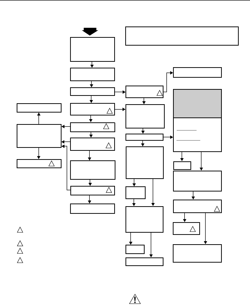
NO
TO USE THIS CHART:
START
OFF
ON YES
YES
REPLACE LIGHT/
SWITCH ASSEMBLY.
MAKE SURE ELECTRONIC
CELLS ARE CLEAN, DRY
AND PROPERLY INSTALLED.
MAKE SURE PREFILTERS
ARE IN SLOT ON FURNACE
SIDE OF CELLS.
TURN ON ELECTRONIC AIR
CLEANER AND SYSTEM
FAN.
CHECK NEON LIGHT.
PUSH TEST BUTTON AND
LISTEN FOR SNAPPING
SOUND.
NO
PUSH TEST BUTTON
AND LISTEN FOR
SNAPPING SOUND.
TURN OFF AIR CLEANER
AND REMOVE CELLS
ONLY (NOT PREFILTERS).
CLOSE ACCESS DOOR
AND TURN ON
AIR CLEANER.
OFF
ON
OFF
ON
CHECK
ON
LED IN
W8600E
OPEN ACCESS DOOR.
CHECK
LED IN W8600E
SHOULD COME ON
3
3
1
1
1
OFF
WIRING
NOT OK
CHECK WIRING BETWEEN
W8600E AND AIR CLEANER.
USE MAX NO. 18 4-WIRE
THERMOSTAT CABLE
CONNECTED 1 TO 1,
2 TO 2, 3 TO 3, AND 4 TO 4.
WIRING OK
CORRECT
WIRING.
REPLACE
W8600E. 4
CHECK FOR CORRECT INPUT
VOLTAGE ACROSS:
120V MODELS: P1 AND P2
TERMINALS ON POWER
SUPPLY
220/240 MODELS: QUICK-
CONNECT TERMINALS ON
POWER SUPPLY
TRANSFORMER.INSPECT CELLS FOR:
•
•
•
•
BENT COLLECTOR
PLATES
BROKEN IONIZER
WIRES
DIRT ON INSULATORS
DAMAGED IONIZER
OR COLLECTOR
CONTACT TABS
YES
NO YES
NO
FIX
WIRING.
REPAIR OR
REPLACE
CELLS.
WITH OHMMETER,
CHECK FOR SHORT
BETWEEN:
•
•
CELL FRAME AND
IONIZER SECTION
CELL FRAME AND
COLLECTOR SECTION
CELL
SHORTED
INFINITE
RESISTANCE
REPLACE
CELL.
CELL OK.
TURN OFF AIR CLEANER,
REPLACE CELLS AND
DISCONNECT FOUR W8600E
LEADS AT AIR CLEANER.
REPLACE ACCESS DOOR.
TURN ON AIR CLEANER. PUSH
TEST BUTTON AND LISTEN
FOR SNAPPING SOUND.
NO
YES
REPLACE
POWER
BOX .
AIR CLEANER OK. TURN OFF
AIR CLEANER AND RECONNECT
W8600E LEADS 1 TO 1,
2 TO 2, 3 TO 3, AND 4 TO 4.
1THE SNAPPING SOUND ON THE AIR CLEANER, WITH A
SOLID STATE POWER SUPPLY, IS ABOUT HALF AS
LOUD AS ON MODELS WITH THE W919 POWER SUPPLY.
COMPONENTS ARE NOT FIELD REPLACEABLE.
W8600E HAS THREE LIGHT-EMITTING DIODES (LEDS):
ON, WASH, AND CHECK.
W8600E OPERATION CAN BE CHECKED SEPARATELY.
SEE W8600E INSTRUCTIONS.
2
3
4
M2002D
FOLLOW THE STEPS IN ORDER; DO NOT SKIP AROUND.
EACH TIME YOU ISOLATE AND FIX A PROBLEM, GO BACK TO START.
REPEAT ALL THE STEPS UNTIL THE AIR CLEANER CHECKS OUT OK.
1.
2.
3.
2
THIS STEP EXPOSES
DANGEROUSLY HIGH
VOLTAGE. ONLY A
QUALIFIED SERVICE
TECHNICIAN SHOULD
ATTEMPT THIS STEP.
WARNING
CHECK NEON LIGHT.
TURN OFF AIR CLEANER
AND REMOVE CELLS
ONLY (NOT PREFILTERS).
CLOSE ACCESS DOOR
AND TURN ON AIR CLEANER.
ON
ON
WASH
LED IN W8600E
SHOULD COME ON.
OFF
ELECTRONIC AIR CLEANER
AND W8600E ARE OK.
3
TROUBLESHOOTING F50E AIR CLEANERS WITH A W8600E
SOLID STATE PERFORMANCE INDICATOR AND AIR FLOW SWITCH
Fig. 35. Electrical troubleshooting procedure for F50E electronic air cleaners with a
W8600E and solid state air flow switch.
Test Button
The TEST BUTTON is near the bottom of the access door.
When pushed, it shorts from a hot collector plate to ground.
See internal schematic, Fig. 36. The resulting arcing sound
indicates that high voltage is being supplied to the collector.
The solid state power supply controls current flow to the
collector, so the arcing sound is only about half as loud as the
sound on air cleaners with W919-style power supplies. On air
cleaners with a W8600E, the CHECK LED comes on when
the test button is pushed.
Power Supply Problem
CAUTION
Electric Shock Hazard.
Can cause personal injury.
Always turn off power and remove access door before
removing power box or its cover.
F50E DUCT MOUNTED ELECTRONIC AIR CLEANER
68-0072—5
21
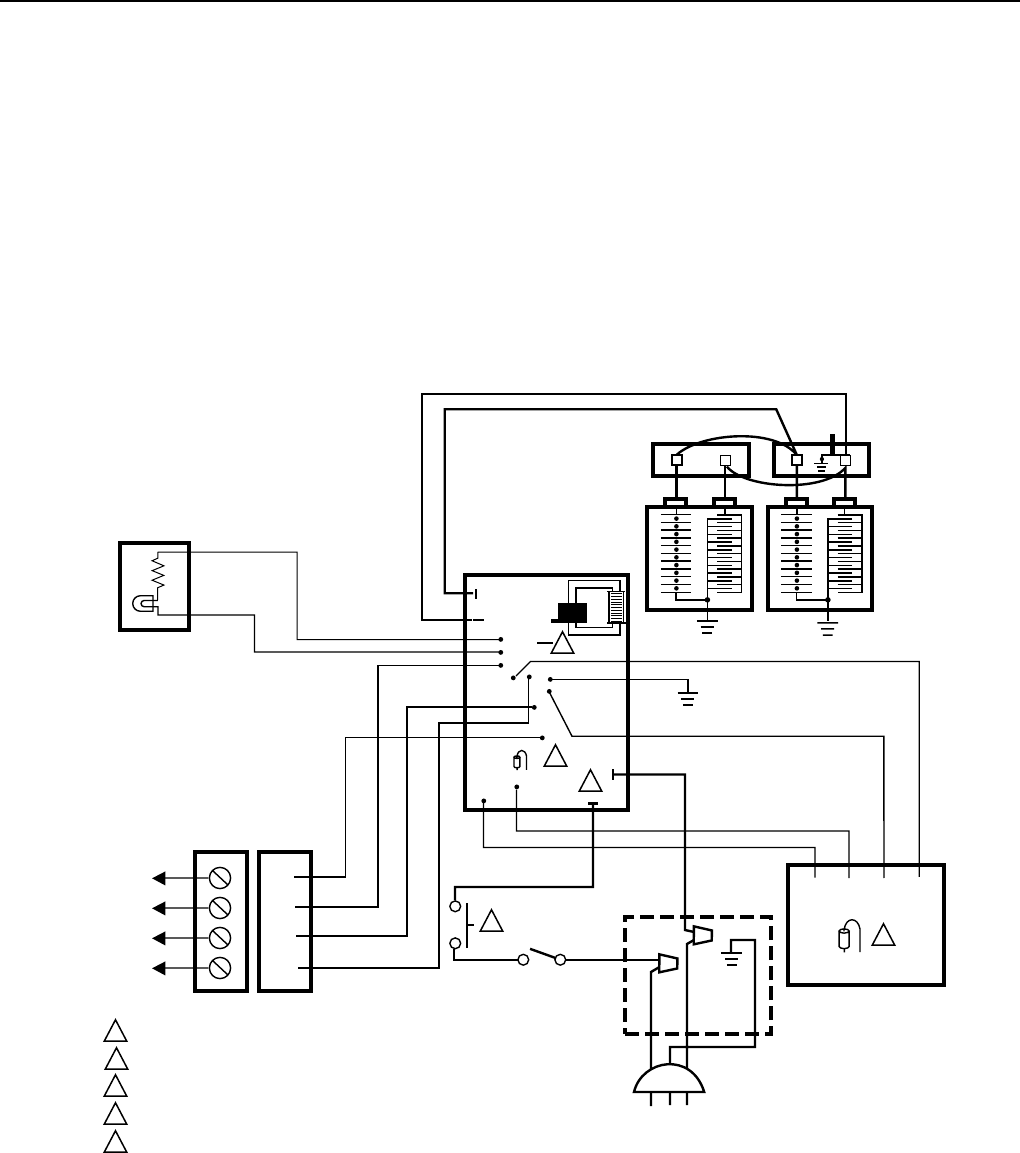
P3
P4
P1
P2
P17 P18
2
1
P14
P5
P12
3
P21 4
BLACK
1
2
3
4
1
2
3
4
TERMINAL STRIP
FRONT BACK
TO
W8600E
WALL
PANEL
W4 W2 W1 W3
AIRFLOW SWITCH BOARD
ORANGE
GRAY
VIOLET
BLACK
1 INTERLOCK SWITCH.
2 OUTPUT REDUCTION JUMPER.
3 AIRFLOW SWITCH DISABLE JUMPER.
4 RESISTOR FOR W8600 WASH INDICATION THRESHOLD.
5 P1, P2 TERMINALS ON 120V MODELS ONLY. POWER CONNECTIONS ON 240V MODELS ARE TO QUICK-CONNECTS ON POWER
SUPPLY TRANSFORMER. BROWN LEAD GOES TO TOP TERMINAL AND BLACK LEAD TO BOTTOM TERMINAL.
M4702
POWER
SUPPLY
2
BLACK
RED
TEST
BUTTON
CONTACT
BOARD
RED IONIZER
BLACK COLLECTOR
BLACK
J2
5
4
R43
BLACK BLACK
BROWN
BLACK
BLACK
WHITE
GREEN
3
1
GREEN
J7
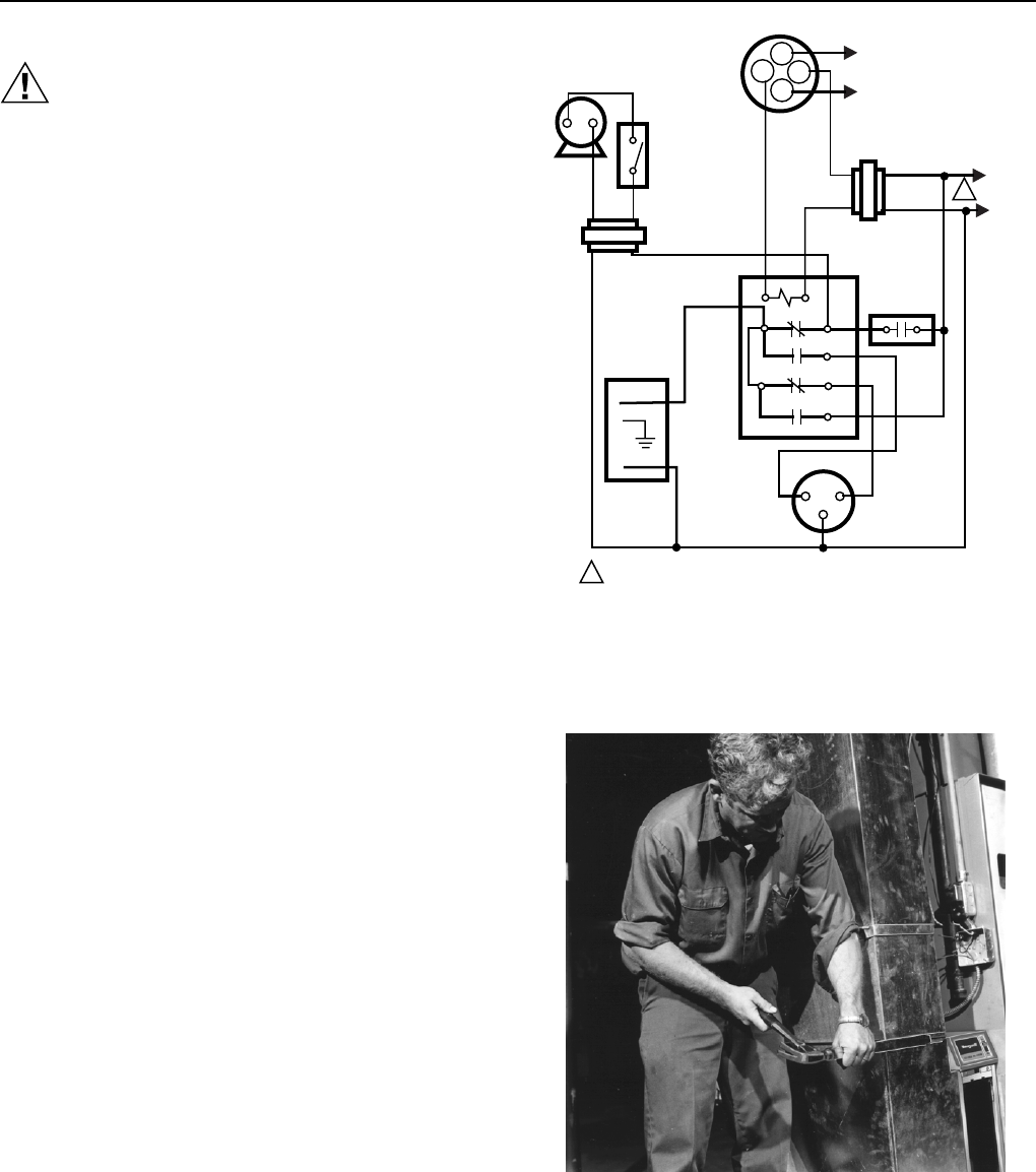
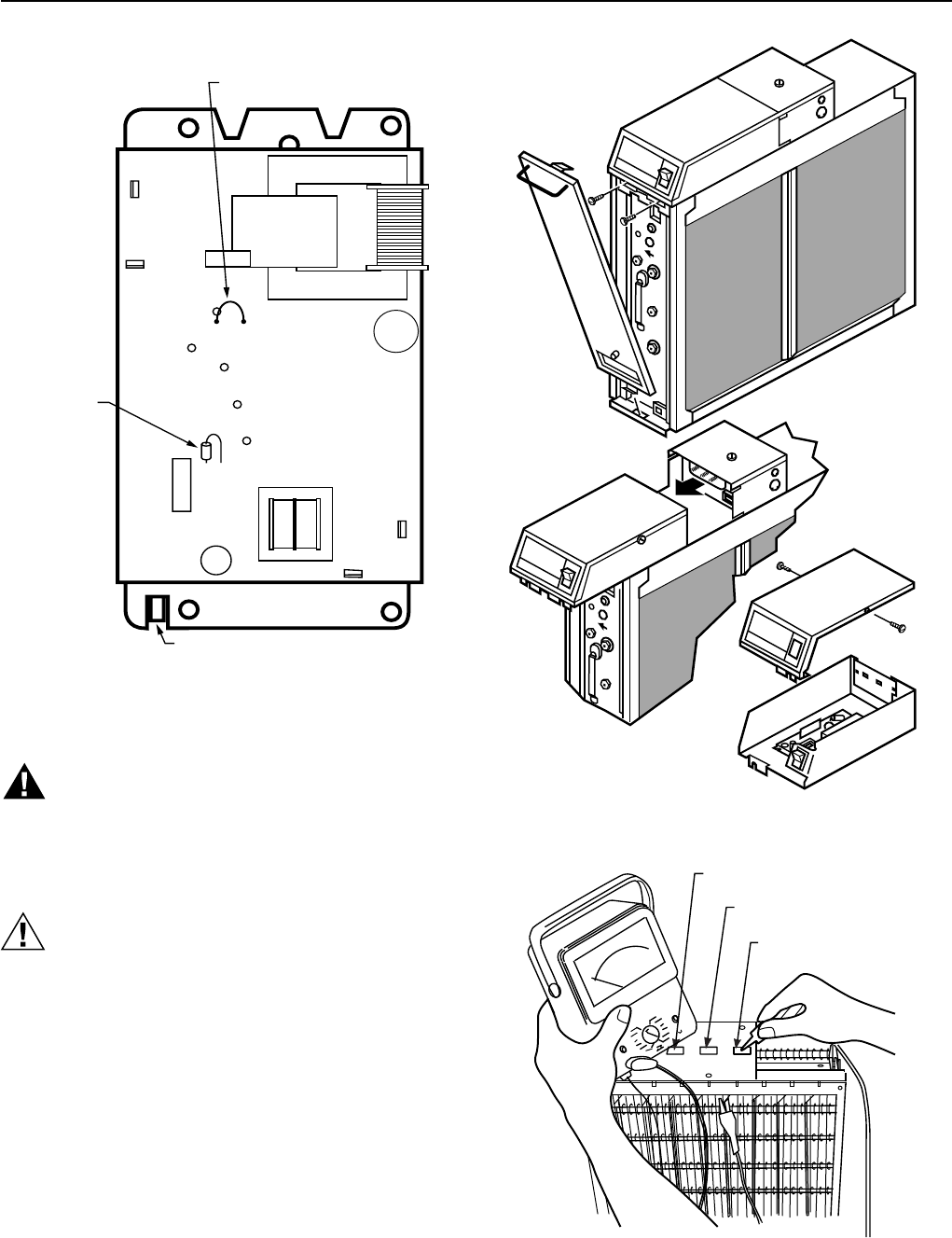
INTERNAL SCHEMATIC FOR ELECTRONIC AIR CLEANER WITH W8600E.
The solid state power supply provided in this air cleaner has
no field-serviceable components. If troubleshooting indicates
a power supply problem, replace the entire power supply. See
Parts List section for order number.
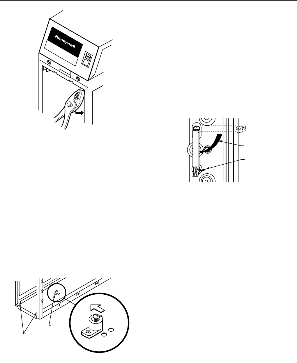
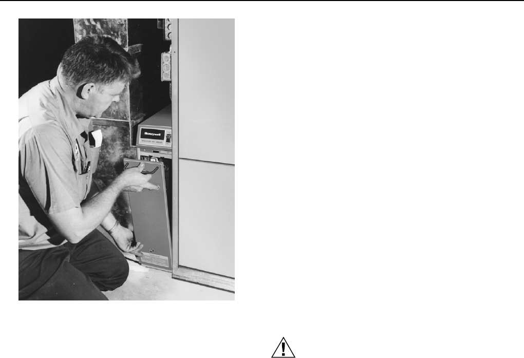
To Access Power Supply
1. Turn off power.
2. Remove the access door and loosen the two screws
holding the power box. See Fig. 32.
3. To pull the plug connector out of the receptacle in the
junction box, lift slightly to clear screws, then pull the
power box straight toward you.
4. Take out the two screws holding on the cover. Remove
the cover.
5. Replace the power box by resting it on the cabinet,
lifting slightly to clear two screws, and pushing it
straight toward the junction box. Do not bend the spring
contacts sideways. The power plug must slide straight
into the receptacle.
6. Replace the access door and restore power.
Fig. 36. Internal schematic of an F50E Electronic Air Cleaner with a W8600E.
F50E DUCT MOUNTED ELECTRONIC AIR CLEANER
68-0072—5 22
Nominal Return Air Opening
Description 16 x 25 in. (406 x 635 mm) 20 x 25 in. (508 x 635 mm)
Ionizer Wires (multiples of 5) 136434BA 136434AA
Remote Mount Kit 136377A (1) 136377A (1)
Remote Mount Base 136377 (1) 136377 (1)
Conduit Assembly (10 ft.) 136376A (1) 136376A (1)
Cabinet Knockout Plug 136743 (1) 136743 (1)
Mounting Screws 136375 (6) 136375 (6)
Quick-Connect Terminal 111690 (2) 111690 (2)
Spring Leaf Contact 136529 (1) 136529 (1)
Sail Switch S688A1007 (1) S688A1007 (1)
Replacement Sail 123773A (1) 123773A (1)
2-Stage EAC Cell for F50 with Collector Clip FC37A1247 (2) FC37A1239 (2)
(#) = Qty Required Per Unit
Nominal Return Air Opening
No. Description 16 x 25 in. (406 x 635 mm) 20 x 25 in. (508 x 635 mm)
1 Access Door includes #2 136393AL (1) 136392AQ (1)
2 Test Button Assembly 137980A (1) 137980A (1)
3 Electronic Cell FC37A1130 (2) FC37A1064 (2)
4 Cell Handle 137266 (2) 137266 (2)
5 Prefilter 203371 (2) 203372 (2)
6 Cell Key 136518 (1) 136518 (1)
7 Contact Panel Assembly 136399A (1) 136399A (1)
8 Junction Box Assembly 136394B (1) 136394B (1)
9 Junction Box Cover 136386 (1) 136386 (1)
10 Power Box Assembly With W8600E capability
120V, 60 Hz 200583B (1) 200583A (1)
11 Power Supply, 120V, 60 Hz 203327F 203327D
12 FC37A Bag Assembly for cell repair.
Contains 2 Connector Clips, 1 Terminal Board
and Instructions.
4074EHG 4074EHG
(#) = Qty Required Per Unit
PARTS LIST
Parts and Accessories Not Illustrated
Note: Click for earlier F50E manual with a parts drawing that shows more replaceable parts
F50E DUCT MOUNTED ELECTRONIC AIR CLEANER
68-0072—5
23
M6493
1
2
3
4
5
6
8
9
11
12
10
7
Fig. 37. Components of F50E Electronic Air Cleaner (2-cell model shown).
This equipment is a class B digital apparatus which complies with Canadian Radio Interference Regulations, CRC c. 1374.
Note: Click for earlier F50E manual with a parts drawing that shows more replaceable parts

F50E DUCT MOUNTED ELECTRONIC AIR CLEANER
68-0072—5 24
Honeywell Europe S.A.
3 Avenue du Bourget
1140 Brussels
Belgium
Honeywell Asia Pacific Inc.
Room 3213-3225
Sun Hung Kai Centre
No. 30 Harbour Road
Wanchai
Hong Kong
Home and Building Control
Honeywell Limited-Honeywell Limitée
155 Gordon Baker Road
North York, Ontario
M2H 3N7
Honeywell Latin American Region
480 Sawgrass Corporate Parkway
Suite 200
Sunrise FL 33325
68-0072—5 R.R. Rev. 9-98
Home and Building Control
Honeywell Inc.
Honeywell Plaza
P.O. Box 524
Minneapolis MN 55408-0524
Printed in U.S.A. on recycled
paper containing at least 10%
post-consumer paper fibers. www.honeywell.com
