Honeywell HS-720 High Speed Data Unit for the MCS-7200 SATCOM System User Manual SDIM Multi Channel SATCOM System A15 5111 010
Honeywell International Inc. High Speed Data Unit for the MCS-7200 SATCOM System SDIM Multi Channel SATCOM System A15 5111 010
Contents
- 1. HS-720 User Manual Part1
- 2. HS-720 User Manual Part2
- 3. HS-720 User Manual Part3
HS-720 User Manual Part1

SYSTEM DESCRIPTION, INSTALLATION, AND MAINTENANCE MANUAL
MCS-4200/7200
TEMPORARY REVISION NO. 23-1
23-20-35 Page 1 of 53
28 Sep 2009
Publication Number A15-5111-010
© Honeywell International Inc. Do not copy without express permission of Honeywell.
TO HOLDERS OF MULTI-CHANNEL SATCOM SYSTEM, SYSTEM DESCRIPTION, INSTALLATION, AND
MAINTENANCE MANUAL WITH ILLUSTRATED PARTS LIST 23-20-35, REVISION 0, DATED 15 JUL 2006.
INSERT THIS PAGE AS THE FIRST PAGE OF THE MANUAL.
Temporary
Revision
Number
Applicable Page Number
23-1 TC-9
INTRO-5
INTRO-6
INTRO-7
INTRO-8
1-1
1-3
1-4
1-5
1-6
1-7/1-8
1-9
1-10
1-11
1-12
1-13
1-14
1-15
1-17
1-18
1-21
1-22
1-23
1-24
1-25
1-45
2-1
2-3
2-8

SYSTEM DESCRIPTION, INSTALLATION, AND MAINTENANCE MANUAL
MCS-4200/7200
TEMPORARY REVISION NO. 23-1
23-20-35 Page 2 of 53
28 Sep 2009
© Honeywell International Inc. Do not copy without express permission of Honeywell.
2-9
2-13
2-14
2-15
2-19
2-20
3-1
5-41/5-42
5-57
5-64
6-96
6-100
6-108
6-116
C-15
C-16
D-11
F-21
Copyright - Notice
Copyright 2009 Honeywell International Inc. All rights reserved.
Honeywell is a registered trademark of Honeywell International Inc.
All other marks are owned by their respective companies.
Honeywell – Confidential
THIS COPYRIGHTED WORK AND ALL INFORMATION ARE THE PROPERTY OF HONEYWELL
INTERNATIONAL INC., CONTAIN TRADE SECRETS AND MAY NOT, IN WHOLE OR IN PART, BE USED,
DUPLICATED, OR DISCLOSED FOR ANY PURPOSE WITHOUT PRIOR WRITTEN PERMISSION OF
HONEYWELL INTERNATIONAL INC. ALL RIGHTS RESERVED.

This document contains technical data and is subject to U.S. export regulations. These commodities,
technology, or software were exported from the United States in accordance with the export administration
regulations. Diversion contrary to U.S. law is prohibited.
Honeywell International Inc.
21111 N. 19th Ave.
Phoenix, AZ 85027-2708
U.S.A.
(CAGE 55939)
Publication Number A15--5111--010, Revision 000
23--20--35
Page T--1
15 Jul 2006
Honeywell International Inc. Do not copy without express permission of Honeywell.
Telephone: (800) 601--3099 (U.S.A.)
Telephone: (602) 365--3099 (International)
System Description, Installation, and
Maintenance Manual
with illustrated parts list
Multi--Channel SATCOM System
System Designation Type
MCS--4200 4--Channel
MCS--7200 7--Channel

SYSTEM DESCRIPTION, INSTALLATION, AND MAINTENANCE MANUAL
MCS--4200/7200 Multi--Channel SATCOM System
23--20--35 15 Jul 2006
Honeywell International Inc. Do not copy without express permission of Honeywell.
Page T--2
Honeywell--Confidential
THIS COPYRIGHTED WORK AND ALL INFORMATION ARE THE PROPERTY OF HONEYWELL
INTERNATIONAL INC., CONTAIN TRADE SECRETS AND MAY NOT, IN WHOLE OR IN PART, BE
USED, DUPLICATED, OR DISCLOSED FOR ANY PURPOSE WITHOUT PRIOR WRITTEN
PERMISSION OF HONEYWELL INTERNATIONAL INC. ALL RIGHTS RESERVED.
Honeywell Materials License Agreement
The documents and information contained herein (“the Materials”) are the proprietary data of
Honeywell International Inc. and Honeywell Intellectual Properties Inc (collectively
“Honeywell”). These Materials are provided for the exclusive use of Honeywell Service Centers;
Honeywell--authorized repair facilities; operators of Honeywell aerospace products subject to an
applicable product support agreement, their wholly owned--subsidiaries or a formally
designated third party service provider thereunder; and direct recipients of Materials from
Honeywell’s Aerospace Technical Publication Distribution. The terms and conditions of this
License Agreement govern your use of these Materials, except to the extent that any terms and
conditions of another applicable agreement with Honeywell regarding the operation,
maintenance, or repair of Honeywell aerospace products conflict with the terms and conditions
of this License Agreement, in which case the terms and conditions of the other agreement will
govern. However, this License Agreement will govern in the event of a conflict between its
terms and conditions and those of a purchase order or acknowledgement.
1. License Grant -- If you are a party to an applicable product support agreement, a Honeywell Service Center
agreement, or an authorized repair facility agreement, Honeywell hereby grants you a limited, non--exclusive license
to use these Materials to operate, maintain, or repair Honeywell aerospace products only in accordance with that
agreement.
If you are a direct recipient of these Materials from Honeywell’s Aerospace Technical Publication Distribution and are
not a party to an agreement related to the operation, maintenance or repair of Honeywell aerospace products,
Honeywell hereby grants you a limited, non--exclusive license to use these Materials to maintain or repair the subject
Honeywell aerospace products only at the facility to which these Materials have been shipped (“the Licensed
Facility”). Transfer of the Materials to another facility owned by you is permitted only if the original Licensed Facility
retains no copies of the Materials and you provide prior written notice to Honeywell.
2. Rights In Materials -- Honeywell retains all rights in these Materials and in any copies thereof that are not
expressly granted to you, including all rights in patents, copyrights, trademarks, and trade secrets. No license to use
any Honeywell trademarks or patents is granted under this License Agreement.
3. Confidentiality -- You acknowledge that these Materials contain information that is confidential and proprietary to
Honeywell. You agree to take all reasonable efforts to maintain the confidentiality of these Materials.
4. Assignment And Transfer -- This License Agreement may be assigned to a formally designated service
designee to the extent allowed under an applicable product support agreement or transferred to a subsequent owner
or operator of an aircraft containing the subject Honeywell aerospace products. However, the recipient of any such
assignment or transfer must assume all of your obligations under this License Agreement. No assignment or transfer
shall relieve any party of any obligation that such party then has hereunder.
5. Copies of Materials -- Unless you have the express written permission of Honeywell, you may not make or permit
making of copies of the Materials. Notwithstanding the foregoing, you may make copies of only portions of the
Material for your internal use. You agree to return the Materials and any copies thereof to Honeywell upon the
request of Honeywell.

SYSTEM DESCRIPTION, INSTALLATION, AND MAINTENANCE MANUAL
MCS--4200/7200 Multi--Channel SATCOM System
23--20--35 15 Jul 2006
Honeywell International Inc. Do not copy without express permission of Honeywell.
Page T--3
6. Term -- This License Agreement is effective until terminated as set forth herein. This License Agreement will
terminate immediately, without notice from Honeywell, if you fail to comply with any provision of this License
Agreement or will terminate simultaneously with the termination or expiration of your applicable product support
agreement, authorized repair facility agreement, or your formal designation as a third party service provider. Upon
termination of this License Agreement, you will return these Materials to Honeywell without retaining any copies and
will have one of your authorized officers certify that all Materials have been returned with no copies retained.
7. Remedies -- Honeywell reserves the right to pursue all available remedies and damages resulting from a breach
of this License Agreement.
8. Limitation of Liability -- Honeywell does not make any representation regarding the use, accuracy or sufficiency
of the Materials. THERE ARE NO OTHER WARRANTIES, WHETHER WRITTEN OR ORAL, EXPRESS, IMPLIED
OR STATUTORY, INCLUDING, BUT NOT LIMITED TO, (i) WARRANTIES ARISING FROM COURSE OF
PERFORMANCE, DEALING, USAGE, OR TRADE, WHICH ARE HEREBY EXPRESSLY DISCLAIMED, OR (ii)
WARRANTIES AGAINST INFRINGEMENT OF INTELLECTUAL PROPERTY RIGHTS OF THIRD PARTIES, EVEN
IF HONEYWELL HAS BEEN ADVISED OF ANY SUCH INFRINGEMENT. IN NO EVENT WILL HONEYWELL BE
LIABLE FOR ANY INCIDENTAL DAMAGES, CONSEQUENTIAL DAMAGES, SPECIAL DAMAGES, INDIRECT
DAMAGES, LOSS OF PROFITS, LOSS OF REVENUES, OR LOSS OF USE, EVEN IF INFORMED OF THE
POSSIBILITY OF SUCH DAMAGES. TO THE EXTENT PERMITTED BY APPLICABLE LAW, THESE LIMITATIONS
AND EXCLUSIONS WILL APPLY REGARDLESS OF WHETHER LIABILITY ARISES FROM BREACH OF
CONTRACT, WARRANTY, TORT (INCLUDING BUT NOT LIMITED TO NEGLIGENCE), BY OPERATION OF LAW,
OR OTHERWISE.
9. Controlling Law -- This License shall be governed and construed in accordance with the laws of the State of New
York without regard to the conflicts of laws provisions thereof. This license sets forth the entire agreement between
you and Honeywell and may only be modified by a writing duly executed by the duly authorized representatives of
the parties.
Copyright -- Notice
Copyright 2006, Honeywell International Inc. All rights reserved.

SYSTEM DESCRIPTION, INSTALLATION, AND MAINTENANCE MANUAL
MCS--4200/7200 Multi--Channel SATCOM System
23--20--35 15 Jul 2006
Honeywell International Inc. Do not copy without express permission of Honeywell.
Page T--4
Blank Page

SYSTEM DESCRIPTION, INSTALLATION, AND MAINTENANCE MANUAL
MCS--4200/7200 Multi--Channel SATCOM System
23--20--35 15 Jul 2006
Honeywell International Inc. Do not copy without express permission of Honeywell.
Page RR--1
RECORD OF REVISIONS
For each revision, put the changed pages in your manual and discard the replaced pages. Write
the revision number and date, and the date put in the manual. Put your initials in the applicable
columns on the Record of Revisions. The initial H shows that Honeywell put the changed pages in
the manual.
Revision
Number
Revision
Date
Date Put
In Manual By
Revision
Number
Revision
Date
Date Put
In Manual By

SYSTEM DESCRIPTION, INSTALLATION, AND MAINTENANCE MANUAL
MCS--4200/7200 Multi--Channel SATCOM System
23--20--35 15 Jul 2006
Honeywell International Inc. Do not copy without express permission of Honeywell.
Page RR--2
Blank Page

SYSTEM DESCRIPTION, INSTALLATION, AND MAINTENANCE MANUAL
MCS--4200/7200 Multi--Channel SATCOM System
23--20--35 15 Jul 2006
Honeywell International Inc. Do not copy without express permission of Honeywell.
Page RTR--1
RECORD OF TEMPORARY REVISIONS
Instructions on each page of a temporary revision tell you where to put the pages in your manual.
Remove temporary revision pages only when discard instructions are given. For each temporary
revision, put the applicable data in the record columns on this page.
Temporary
Revision
Number
Temporary
Revision
Date
Temporary
Revision
Status
Date Put
in Manual By *
Date
Removed
from Manual By *
* The initial H in this column shows Honeywell has done this task.
** Temporary revisions are incorporated in the manual by normal revision.

SYSTEM DESCRIPTION, INSTALLATION, AND MAINTENANCE MANUAL
MCS--4200/7200 Multi--Channel SATCOM System
23--20--35 15 Jul 2006
Honeywell International Inc. Do not copy without express permission of Honeywell.
Page RTR--2
Blank Page

SYSTEM DESCRIPTION, INSTALLATION, AND MAINTENANCE MANUAL
MCS--4200/7200 Multi--Channel SATCOM System
23--20--35 15 Jul 2006
Honeywell International Inc. Do not copy without express permission of Honeywell.
Page SBL--1
SERVICE BULLETIN LIST
Service Bulletin
Identified
Mod
Date Included
in this Manual Description

SYSTEM DESCRIPTION, INSTALLATION, AND MAINTENANCE MANUAL
MCS--4200/7200 Multi--Channel SATCOM System
23--20--35 15 Jul 2006
Honeywell International Inc. Do not copy without express permission of Honeywell.
Page SBL--2
Blank Page

SYSTEM DESCRIPTION, INSTALLATION, AND MAINTENANCE MANUAL
MCS--4200/7200 Multi--Channel SATCOM System
23--20--35 15 Jul 2006
Honeywell International Inc. Do not copy without express permission of Honeywell.
Page LEP--1
LIST OF EFFECTIVE PAGES
Subeading and Page Date Subeading and Page Date
Title
T--1 15 Jul 2006
T--2 15 Jul 2006
T--3 15 Jul 2006
T--4 15 Jul 2006
Record of Revisions
RR--1 15 Jul 2006
RR--2 15 Jul 2006
Record of Temporary Revisions
RTR--1 15 Jul 2006
RTR--2 15 Jul 2006
Service Bulletin List
SBL--1 15 Jul 2006
SBL--2 15 Jul 2006
List of Effective Pages
LEP--1 15 Jul 2006
LEP--2 15 Jul 2006
LEP--3 15 Jul 2006
LEP--4 15 Jul 2006
LEP--5 15 Jul 2006
LEP--6 15 Jul 2006
LEP--7 15 Jul 2006
LEP--8 15 Jul 2006
Table of Contents
TC--1 15 Jul 2006
TC--2 15 Jul 2006
TC--3 15 Jul 2006
TC--4 15 Jul 2006
TC--5 15 Jul 2006
TC--6 15 Jul 2006
TC--7 15 Jul 2006
TC--8 15 Jul 2006
TC--9 15 Jul 2006
TC--10 15 Jul 2006
TC--11 15 Jul 2006
TC--12 15 Jul 2006
TC--13 15 Jul 2006
TC--14 15 Jul 2006
TC--15 15 Jul 2006
TC--16 15 Jul 2006
Introduction
INTRO--1 15 Jul 2006
INTRO--2 15 Jul 2006
INTRO--3 15 Jul 2006
INTRO--4 15 Jul 2006
INTRO--5 15 Jul 2006
INTRO--6 15 Jul 2006
INTRO--7 15 Jul 2006
INTRO--8 15 Jul 2006
INTRO--9 15 Jul 2006
INTRO--10 15 Jul 2006
System Description
1--1 15 Jul 2006
1--2 15 Jul 2006
1--3 15 Jul 2006
1--4 15 Jul 2006
1--5 15 Jul 2006
1--6 15 Jul 2006
F1--7/1--8 15 Jul 2006
1--9 15 Jul 2006
1--10 15 Jul 2006
1--11 15 Jul 2006
1--12 15 Jul 2006
1--13 15 Jul 2006
1--14 15 Jul 2006
1--15 15 Jul 2006
1--16 15 Jul 2006
1--17 15 Jul 2006
1--18 15 Jul 2006
F indicates a foldout page.

SYSTEM DESCRIPTION, INSTALLATION, AND MAINTENANCE MANUAL
MCS--4200/7200 Multi--Channel SATCOM System
23--20--35 15 Jul 2006
Honeywell International Inc. Do not copy without express permission of Honeywell.
Page LEP--2
Subeading and Page Date Subeading and Page Date
F1--19/1--20 15 Jul 2006
1--21 15 Jul 2006
1--22 15 Jul 2006
1--23 15 Jul 2006
1--24 15 Jul 2006
1--25 15 Jul 2006
1--26 15 Jul 2006
1--27 15 Jul 2006
1--28 15 Jul 2006
1--29 15 Jul 2006
1--30 15 Jul 2006
1--31 15 Jul 2006
1--32 15 Jul 2006
1--33 15 Jul 2006
1--34 15 Jul 2006
1--35 15 Jul 2006
1--36 15 Jul 2006
1--37 15 Jul 2006
1--38 15 Jul 2006
1--39 15 Jul 2006
1--40 15 Jul 2006
1--41 15 Jul 2006
1--42 15 Jul 2006
1--43 15 Jul 2006
1--44 15 Jul 2006
1--45 15 Jul 2006
1--46 15 Jul 2006
System Operation
2--1 15 Jul 2006
2--2 15 Jul 2006
2--3 15 Jul 2006
2--4 15 Jul 2006
2--5 15 Jul 2006
2--6 15 Jul 2006
2--7 15 Jul 2006
2--8 15 Jul 2006
2--9 15 Jul 2006
2--10 15 Jul 2006
2--11 15 Jul 2006
2--12 15 Jul 2006
2--13 15 Jul 2006
2--14 15 Jul 2006
2--15 15 Jul 2006
2--16 15 Jul 2006
2--17 15 Jul 2006
2--18 15 Jul 2006
2--19 15 Jul 2006
2--20 15 Jul 2006
2--21 15 Jul 2006
2--22 15 Jul 2006
2--23 15 Jul 2006
2--24 15 Jul 2006
2--25 15 Jul 2006
2--26 15 Jul 2006
2--27 15 Jul 2006
2--28 15 Jul 2006
Cabin/Cockpit Communications
3--1 15 Jul 2006
3--2 15 Jul 2006
F3--3/3--4 15 Jul 2006
3--5 15 Jul 2006
3--6 15 Jul 2006
3--7 15 Jul 2006
3--8 15 Jul 2006
3--9 15 Jul 2006
3--10 15 Jul 2006
3--11 15 Jul 2006
3--12 15 Jul 2006
3--13 15 Jul 2006
3--14 15 Jul 2006
3--15 15 Jul 2006
3--16 15 Jul 2006
3--17 15 Jul 2006
3--18 15 Jul 2006
Mechanical Installation
4--1 15 Jul 2006
4--2 15 Jul 2006
F indicates a foldout page.

SYSTEM DESCRIPTION, INSTALLATION, AND MAINTENANCE MANUAL
MCS--4200/7200 Multi--Channel SATCOM System
23--20--35 15 Jul 2006
Honeywell International Inc. Do not copy without express permission of Honeywell.
Page LEP--3
Subeading and Page Date Subeading and Page Date
4--3 15 Jul 2006
4--4 15 Jul 2006
F4--5/4--6 15 Jul 2006
F4--7/4--8 15 Jul 2006
F4--9/4--10 15 Jul 2006
F4--11/4--12 15 Jul 2006
F4--13/4--14 15 Jul 2006
F4--15/4--16 15 Jul 2006
F4--17/4--18 15 Jul 2006
F4--19/4--20 15 Jul 2006
Electrical Installation
5--1 15 Jul 2006
5--2 15 Jul 2006
5--3 15 Jul 2006
5--4 15 Jul 2006
5--5 15 Jul 2006
5--6 15 Jul 2006
5--7 15 Jul 2006
5--8 15 Jul 2006
F5--9/5--10 15 Jul 2006
F5--11/5--12 15 Jul 2006
5--13 15 Jul 2006
5--14 15 Jul 2006
F5--15/5--16 15 Jul 2006
F5--17/5--18 15 Jul 2006
5--19 15 Jul 2006
5--20 15 Jul 2006
5--21 15 Jul 2006
5--22 15 Jul 2006
F5--23/5--24 15 Jul 2006
F5--25/5--26 15 Jul 2006
F5--27/5--28 15 Jul 2006
5--29 15 Jul 2006
5--30 15 Jul 2006
F5--31/5--32 15 Jul 2006
5--33 15 Jul 2006
5--34 15 Jul 2006
5--35 15 Jul 2006
5--36 15 Jul 2006
F5--37/5--38 15 Jul 2006
F5--39/5--40 15 Jul 2006
F5--41/5--42 15 Jul 2006
F5--43/5--44 15 Jul 2006
F5--45/5--46 15 Jul 2006
F5--47/5--48 15 Jul 2006
F5--49/5--50 15 Jul 2006
F5--51/5--52 15 Jul 2006
F5--53/5--54 15 Jul 2006
F5--55/5--56 15 Jul 2006
5--57 15 Jul 2006
5--58 15 Jul 2006
5--59 15 Jul 2006
5--60 15 Jul 2006
5--61 15 Jul 2006
5--62 15 Jul 2006
5--63 15 Jul 2006
5--64 15 Jul 2006
5--65 15 Jul 2006
5--66 15 Jul 2006
5--67 15 Jul 2006
5--68 15 Jul 2006
5--69 15 Jul 2006
5--70 15 Jul 2006
5--71 15 Jul 2006
5--72 15 Jul 2006
5--73 15 Jul 2006
5--74 15 Jul 2006
Testing/Fault Isolation
6--1 15 Jul 2006
6--2 15 Jul 2006
6--3 15 Jul 2006
6--4 15 Jul 2006
6--5 15 Jul 2006
6--6 15 Jul 2006
6--7 15 Jul 2006
6--8 15 Jul 2006
6--9 15 Jul 2006
6--10 15 Jul 2006
F indicates a foldout page.

SYSTEM DESCRIPTION, INSTALLATION, AND MAINTENANCE MANUAL
MCS--4200/7200 Multi--Channel SATCOM System
23--20--35 15 Jul 2006
Honeywell International Inc. Do not copy without express permission of Honeywell.
Page LEP--4
Subeading and Page Date Subeading and Page Date
6--11 15 Jul 2006
6--12 15 Jul 2006
6--13 15 Jul 2006
6--14 15 Jul 2006
6--15 15 Jul 2006
6--16 15 Jul 2006
6--17 15 Jul 2006
6--18 15 Jul 2006
6--19 15 Jul 2006
6--20 15 Jul 2006
6--21 15 Jul 2006
6--22 15 Jul 2006
6--23 15 Jul 2006
6--24 15 Jul 2006
6--25 15 Jul 2006
6--26 15 Jul 2006
F6--27/6--28 15 Jul 2006
6--29 15 Jul 2006
6--30 15 Jul 2006
6--31 15 Jul 2006
6--32 15 Jul 2006
6--33 15 Jul 2006
6--34 15 Jul 2006
6--35 15 Jul 2006
6--36 15 Jul 2006
6--37 15 Jul 2006
6--38 15 Jul 2006
6--39 15 Jul 2006
6--40 15 Jul 2006
6--41 15 Jul 2006
6--42 15 Jul 2006
6--43 15 Jul 2006
6--44 15 Jul 2006
6--45 15 Jul 2006
6--46 15 Jul 2006
6--47 15 Jul 2006
6--48 15 Jul 2006
6--49 15 Jul 2006
6--50 15 Jul 2006
6--51 15 Jul 2006
6--52 15 Jul 2006
6--53 15 Jul 2006
6--54 15 Jul 2006
6--55 15 Jul 2006
6--56 15 Jul 2006
6--57 15 Jul 2006
6--58 15 Jul 2006
6--59 15 Jul 2006
6--60 15 Jul 2006
6--61 15 Jul 2006
6--62 15 Jul 2006
6--63 15 Jul 2006
6--64 15 Jul 2006
6--65 15 Jul 2006
6--66 15 Jul 2006
6--67 15 Jul 2006
6--68 15 Jul 2006
6--69 15 Jul 2006
6--70 15 Jul 2006
6--71 15 Jul 2006
6--72 15 Jul 2006
6--73 15 Jul 2006
6--74 15 Jul 2006
6--75 15 Jul 2006
6--76 15 Jul 2006
6--77 15 Jul 2006
6--78 15 Jul 2006
6--79 15 Jul 2006
6--80 15 Jul 2006
6--81 15 Jul 2006
6--82 15 Jul 2006
6--83 15 Jul 2006
6--84 15 Jul 2006
6--85 15 Jul 2006
6--86 15 Jul 2006
6--87 15 Jul 2006
6--88 15 Jul 2006
6--89 15 Jul 2006
F indicates a foldout page.

SYSTEM DESCRIPTION, INSTALLATION, AND MAINTENANCE MANUAL
MCS--4200/7200 Multi--Channel SATCOM System
23--20--35 15 Jul 2006
Honeywell International Inc. Do not copy without express permission of Honeywell.
Page LEP--5
Subeading and Page Date Subeading and Page Date
6--90 15 Jul 2006
6--91 15 Jul 2006
6--92 15 Jul 2006
6--93 15 Jul 2006
6--94 15 Jul 2006
6--95 15 Jul 2006
6--96 15 Jul 2006
6--97 15 Jul 2006
6--98 15 Jul 2006
6--99 15 Jul 2006
6--100 15 Jul 2006
6--101 15 Jul 2006
6--102 15 Jul 2006
6--103 15 Jul 2006
6--104 15 Jul 2006
6--105 15 Jul 2006
6--106 15 Jul 2006
6--107 15 Jul 2006
6--108 15 Jul 2006
6--109 15 Jul 2006
6--110 15 Jul 2006
6--111 15 Jul 2006
6--112 15 Jul 2006
6--113 15 Jul 2006
6--114 15 Jul 2006
6--115 15 Jul 2006
6--116 15 Jul 2006
6--117 15 Jul 2006
6--118 15 Jul 2006
6--119 15 Jul 2006
6--120 15 Jul 2006
6--121 15 Jul 2006
6--122 15 Jul 2006
Maintenance Practices
7--1 15 Jul 2006
7--2 15 Jul 2006
7--3 15 Jul 2006
7--4 15 Jul 2006
7--5 15 Jul 2006
7--6 15 Jul 2006
Appendix A
Vendor Equipment
A--1 15 Jul 2006
A--2 15 Jul 2006
A--3 15 Jul 2006
A--4 15 Jul 2006
FA--5/A--6 15 Jul 2006
FA--7/A--8 15 Jul 2006
FA--9/A--10 15 Jul 2006
FA--11/A--12 15 Jul 2006
FA--13/A--14 15 Jul 2006
FA--15/A--16 15 Jul 2006
FA--17/A--18 15 Jul 2006
A--19 15 Jul 2006
A--20 15 Jul 2006
A--21 15 Jul 2006
A--22 15 Jul 2006
FA--23/A--24 15 Jul 2006
A--25 15 Jul 2006
A--26 15 Jul 2006
A--27 15 Jul 2006
A--28 15 Jul 2006
A--29 15 Jul 2006
A--30 15 Jul 2006
A--31 15 Jul 2006
A--32 15 Jul 2006
A--33 15 Jul 2006
A--34 15 Jul 2006
A--35 15 Jul 2006
A--36 15 Jul 2006
A--37 15 Jul 2006
A--38 15 Jul 2006
A--39 15 Jul 2006
A--40 15 Jul 2006
F indicates a foldout page.

SYSTEM DESCRIPTION, INSTALLATION, AND MAINTENANCE MANUAL
MCS--4200/7200 Multi--Channel SATCOM System
23--20--35 15 Jul 2006
Honeywell International Inc. Do not copy without express permission of Honeywell.
Page LEP--6
Subeading and Page Date Subeading and Page Date
Appendix B
Installation Procedures For
SATCOM Air Filtration
B--1 15 Jul 2006
B--2 15 Jul 2006
B--3 15 Jul 2006
B--4 15 Jul 2006
FB--5/B--6 15 Jul 2006
B--7 15 Jul 2006
B--8 15 Jul 2006
B--9 15 Jul 2006
B--10 15 Jul 2006
Appendix C
Owner Requirements Table
C--1 15 Jul 2006
C--2 15 Jul 2006
C--3 15 Jul 2006
C--4 15 Jul 2006
C--5 15 Jul 2006
C--6 15 Jul 2006
C--7 15 Jul 2006
C--8 15 Jul 2006
C--9 15 Jul 2006
C--10 15 Jul 2006
C--11 15 Jul 2006
C--12 15 Jul 2006
C--13 15 Jul 2006
C--14 15 Jul 2006
C--15 15 Jul 2006
C--16 15 Jul 2006
Appendix D
Call Events Log (CEL)
D--1 15 Jul 2006
D--2 15 Jul 2006
D--3 15 Jul 2006
D--4 15 Jul 2006
D--5 15 Jul 2006
D--6 15 Jul 2006
D--7 15 Jul 2006
D--8 15 Jul 2006
D--9 15 Jul 2006
D--10 15 Jul 2006
D--11 15 Jul 2006
D--12 15 Jul 2006
D--13 15 Jul 2006
D--14 15 Jul 2006
D--15 15 Jul 2006
D--16 15 Jul 2006
Appendix E
Messaging
E--1 15 Jul 2006
E--2 15 Jul 2006
E--3 15 Jul 2006
E--4 15 Jul 2006
E--6 15 Jul 2006
E--7 15 Jul 2006
E--8 15 Jul 2006
E--9 15 Jul 2006
E--10 15 Jul 2006
E--11 15 Jul 2006
E--12 15 Jul 2006
E--13 15 Jul 2006
E--14 15 Jul 2006
E--15 15 Jul 2006
E--16 15 Jul 2006
E--17 15 Jul 2006
E--18 15 Jul 2006
E--19 15 Jul 2006
E--20 15 Jul 2006
E--21 15 Jul 2006
E--22 15 Jul 2006
E--23 15 Jul 2006
E--24 15 Jul 2006
F indicates a foldout page.

SYSTEM DESCRIPTION, INSTALLATION, AND MAINTENANCE MANUAL
MCS--4200/7200 Multi--Channel SATCOM System
23--20--35 15 Jul 2006
Honeywell International Inc. Do not copy without express permission of Honeywell.
Page LEP--7
Subeading and Page Date Subeading and Page Date
Appendix F
Failure Overview
F--1 15 Jul 2006
F--2 15 Jul 2006
F--3 15 Jul 2006
F--4 15 Jul 2006
F--5 15 Jul 2006
F--6 15 Jul 2006
F--7 15 Jul 2006
F--8 15 Jul 2006
F--9 15 Jul 2006
F--10 15 Jul 2006
F--11 15 Jul 2006
F--12 15 Jul 2006
F--13 15 Jul 2006
F--14 15 Jul 2006
F--15 15 Jul 2006
F--16 15 Jul 2006
F--17 15 Jul 2006
F--18 15 Jul 2006
F--19 15 Jul 2006
F--20 15 Jul 2006
F--21 15 Jul 2006
F--22 15 Jul 2006
F--23 15 Jul 2006
F--24 15 Jul 2006
F--25 15 Jul 2006
F--26 15 Jul 2006
F--27 15 Jul 2006
F--28 15 Jul 2006
F--29 15 Jul 2006
F--30 15 Jul 2006
F--31 15 Jul 2006
F--32 15 Jul 2006
F--33 15 Jul 2006
F--34 15 Jul 2006
F--35 15 Jul 2006
F--36 15 Jul 2006
Index
INDEX--1 15 Jul 2006
INDEX--2 15 Jul 2006
INDEX--3 15 Jul 2006
INDEX--4 15 Jul 2006
INDEX--5 15 Jul 2006
INDEX--6 15 Jul 2006
F indicates a foldout page.

SYSTEM DESCRIPTION, INSTALLATION, AND MAINTENANCE MANUAL
MCS--4200/7200 Multi--Channel SATCOM System
23--20--35 15 Jul 2006
Honeywell International Inc. Do not copy without express permission of Honeywell.
Page LEP--8
Blank Page

SYSTEM DESCRIPTION, INSTALLATION, AND MAINTENANCE MANUAL
MCS--4200/7200 Multi--Channel SATCOM System
23--20--35 15 Jul 2006
Honeywell International Inc. Do not copy without express permission of Honeywell.
Page TC--1
TABLE OF CONTENTS
Subject Page
INTRODUCTION INTRO--1...........................................................
1. How to Use This Manual INTRO--1................................................
A. General INTRO--1...........................................................
B. Symbols INTRO--1..........................................................
C. Weights and Measurements INTRO--2.........................................
2. Customer Support INTRO--2......................................................
A. Honeywell Aerospace Online Technical Publications Web Site INTRO--2...........
B. Customer Response Center INTRO--2.........................................
3. References INTRO--2............................................................
A. Honeywell Publications INTRO--2.............................................
B. Other Publications INTRO--3..................................................
4. Acronyms and Abbreviations INTRO--3............................................
A. General INTRO--3...........................................................
5. Maximum Permissible Exposure Level INTRO--9....................................
A. General INTRO--9...........................................................
SECTION 1
SYSTEM DESCRIPTION 1--1...................................................
1. Overview 1--1..............................................................
A. General 1--1...........................................................
B. Aircraft Earth Station – General 1--4......................................
C. Space Segment 1--14....................................................
D. Ground Earth Station/Land Earth Station 1--14..............................
E. Terrestrial Data and Voice Networks 1--14..................................
2. System Components 1--16...................................................
A. General 1--16...........................................................
3. System Description 1--17.....................................................
A. General 1--17...........................................................
B. Satellite Data Unit 1--21..................................................
C. High Speed Data Unit 1--23...............................................
D. High Power Amplifier 1--24...............................................
E. Avionics Configurations 1--25.............................................

SYSTEM DESCRIPTION, INSTALLATION, AND MAINTENANCE MANUAL
MCS--4200/7200 Multi--Channel SATCOM System
23--20--35 15 Jul 2006
Honeywell International Inc. Do not copy without express permission of Honeywell.
Page TC--2
Subject Page
4. MCS--4200/7200 Component Descriptions 1--25................................
A. Physical Description 1--25................................................
B. Satellite Data Unit (SDU) 1--25............................................
C. High Speed Data Unit (HSU) 1--30.........................................
D. High--Power Amplifier (60 Watt) 1--34......................................
E. Radio Frequency Unit Interface Adapter (RFUIA) 1--38.......................
F. ARINC 429 Data Requirements 1--42......................................
G. Nameplates (SDU, HSU, HPA) 1--42.......................................
H. Software and Hardware Compatibility (SDU, HSU and HPA) 1--44.............
5. Summary 1--45..............................................................
A. General 1--45...........................................................
SECTION 2
SYSTEM OPERATION 2--1.....................................................
1. Overview 2--1..............................................................
A. General 2--1...........................................................
2. AES Management 2--1......................................................
A. General 2--1...........................................................
B. HSDU Installed 2--3....................................................
3. System Log-On/Log-Off 2--3.................................................
A. General 2--3...........................................................
B. Automatic Log-On 2--5..................................................
C. Constrained Log-On 2--6................................................
D. Log-On Mode Selection 2--6.............................................
E. Handover 2--7.........................................................
F. Log-Off 2--7...........................................................
4. System Software/Database Updates 2--8......................................
A. General 2--8...........................................................
B. Software Upload Process 2--8...........................................
C. Validation of the Software Upload File 2--9.................................
5. Owner Requirements Table 2--10..............................................
A. General 2--10...........................................................
6. ORT Upload/Download Process 2--11..........................................
A. General 2--11...........................................................

SYSTEM DESCRIPTION, INSTALLATION, AND MAINTENANCE MANUAL
MCS--4200/7200 Multi--Channel SATCOM System
23--20--35 15 Jul 2006
Honeywell International Inc. Do not copy without express permission of Honeywell.
Page TC--3
Subject Page
B. Startup 2--11............................................................
C. ORT Download 2--11....................................................
D. Control Mode ORT Upload Procedures 2--11................................
E. Auto Mode ORT Upload Procedure 2--13...................................
7. Circuit-Mode Services 2--13..................................................
A. Circuit-Mode Voice 2--13.................................................
B. Circuit-Mode Data 2--13..................................................
8. Packet-Data Services 2--15...................................................
A. General 2--15...........................................................
9. Dual SATCOM Configuration 2--16............................................
A. Overview 2--16..........................................................
B. Dual System Control/Status Interfaces 2--17................................
C. System Reversion 2--18..................................................
D. Antenna Configurations 2--19.............................................
E. Cockpit Voice Configurations and Functionality 2--27.........................
SECTION 3
CABIN/COCKPIT COMMUNICATIONS 3--1.......................................
1. Cabin Communications 3--1.................................................
A. General 3--1...........................................................
B. Cabin Communications System 3--1......................................
C. Analog Audio Channels 3--2.............................................
2. Cockpit Communications 3--14................................................
A. General 3--14...........................................................
B. Headset Off-Hook Signaling 3--14.........................................
C. Headset On-Hook Signaling 3--15.........................................
D. Voice Codec Module Audio Switching 3--15.................................
E. Voice Codec Module Sidetone 3--15.......................................
F. Voice Interface Module Stored Audio Messages 3--15........................
G. Voice Interface Module Dedication 3--17....................................
SECTION 4
MECHANICAL INSTALLATION 4--1..............................................
1. Overview 4--1..............................................................
A. General 4--1...........................................................

SYSTEM DESCRIPTION, INSTALLATION, AND MAINTENANCE MANUAL
MCS--4200/7200 Multi--Channel SATCOM System
23--20--35 15 Jul 2006
Honeywell International Inc. Do not copy without express permission of Honeywell.
Page TC--4
Subject Page
2. Equipment and Materials 4--1................................................
A. General 4--1...........................................................
3. Mechanical Installation Design 4--1...........................................
A. LRU Mechanical Installation 4--1.........................................
B. Installation Dependent Considerations 4--2................................
C. Owner Requirements Table (ORT) Uploading 4--2..........................
D. Cable Loss Requirements 4--2...........................................
E. Cooling Requirements 4--3..............................................
F. Vendor Supplied Equipment 4--4.........................................
SECTION 5
ELECTRICAL INSTALLATION 5--1..............................................
1. Overview 5--1..............................................................
A. General 5--1...........................................................
2. Equipment and Materials 5--1................................................
A. General 5--1...........................................................
3. Electrical Installation Procedure 5--1..........................................
A. Connector Layout and Contact Arrangement 5--1...........................
B. Electrical Installation 5--21................................................
4. Configuration Pins 5--57......................................................
A. General 5--57...........................................................
B. Availability of ARINC 429 ICAO ADDRESS (AES ID) from 429 Ports 5--58......
C. FMC Connection to SDU 5--60............................................
D. ARINC 429 Speed to/from CMU No. 1 and CMU No. 2 5--60..................
E. Cabin Packet Data Function (CPDF) 5--61..................................
F. ARINC 429 BUS Speed of AES ID Input 5--61..............................
G. HSU Presence 5--61.....................................................
H. SDU Controller Type 5--62................................................
I. Call Light On (Air/Ground Calls) 5--62......................................
J. Strap Parity (ODD) 5--62.................................................
K. Cabin Communications System (CCS) 5--63................................
L. Inertial Reference System (IRS) 5--63......................................
M. HPA/Antenna Subsystem Configuration 5--64...............................
N. CFDS/CMC 5--65........................................................

SYSTEM DESCRIPTION, INSTALLATION, AND MAINTENANCE MANUAL
MCS--4200/7200 Multi--Channel SATCOM System
23--20--35 15 Jul 2006
Honeywell International Inc. Do not copy without express permission of Honeywell.
Page TC--5
Subject Page
O. SDU Configuration 5--66.................................................
P. SDU Number 5--66......................................................
Q. CMU No. 1 and No. 2 Configuration 5--67..................................
R. MCDU/WSC No. 1 thru No. 3 Configuration 5--67............................
S. Priority 4 Calls to/from Cockpit 5--68.......................................
T. ARINC 429 BUS Speed to MCDU No. 1/MCDU No. 2/MCDU No. 3 5--69.......
U. Cockpit Voice Call Light/Chime Option 5--69................................
V. SDU CODEC 1 and CODEC 2 Wiring 5--70.................................
W. Cockpit Hookswitch Signaling Method 5--70................................
X. CM--250 CGU Connection Configuration 5--72..............................
Y. Cockpit Call Discrete Signaling Mode 5--72.................................
Z. Strap Parity 5--73........................................................
SECTION 6
TESTING/FAULT ISOLATION 6--1...............................................
1. Overview 6--1..............................................................
A. General 6--1...........................................................
B. Definitions 6--2.........................................................
C. Failure Detection and Reporting Levels 6--3...............................
D. LRU Coverage 6--3.....................................................
E. Monitoring and Testing Functions 6--4.....................................
F. Failure Recording 6--7..................................................
G. Failure Reporting 6--8...................................................
H. Miscellaneous BITE Requirements 6--20...................................
I. Maintenance Activity Log 6--20............................................
2. SATCOM Control and Display Unit 6--21.......................................
A. General 6--21...........................................................
B. SCDU Display Terminology and Basic Operation 6--21.......................
C. SCDU Page Hierarchy 6--25..............................................
D. SCDU Pages 6--25......................................................
3. Maintenance Computer Interface 6--90.........................................
A. General 6--90...........................................................
B. Boeing 747--400 CMC/777 OMS 6--90.....................................
C. Airbus/Douglas CFDS 6--93...............................................

SYSTEM DESCRIPTION, INSTALLATION, AND MAINTENANCE MANUAL
MCS--4200/7200 Multi--Channel SATCOM System
23--20--35 15 Jul 2006
Honeywell International Inc. Do not copy without express permission of Honeywell.
Page TC--6
Subject Page
D. Central Aircraft Information and Maintenance System 6--94...................
E. Level I Failure Messages and ATA Reference Numbers 6--95.................
4. SCDU for Dual SATCOM 6--121................................................
A. General 6--121...........................................................
B. SATCOM Logical Channels 6--121..........................................
C. SATCOM (Cross-Talk Bus Failed) 6--121....................................
D. SATCOM 6--121..........................................................
E. SATCOM Menus 6--121...................................................
5. Maintenance Panel Assembly 6--121............................................
A. General 6--121...........................................................
SECTION 7
MAINTENANCE PRACTICES 7--1...............................................
1. Overview 7--1..............................................................
A. General 7--1...........................................................
2. Equipment and Materials 7--1................................................
A. General 7--1...........................................................
3. Procedure for Antennas 7--2.................................................
A. General 7--2...........................................................
B. Antenna Weather Protection 7--2.........................................
C. Antenna Hardware 7--2.................................................
D. General Antenna Removal Instructions 7--3................................
4. Procedure for the LRUs 7--3.................................................
A. LRU Removal 7--3......................................................
B. LRU Installation 7--3....................................................
5. Owner Requirements Table Uploading 7--4....................................
A. General 7--4...........................................................
6. Instructions for Continued Airworthiness, FAR 25.1529 7--5......................
A. General 7--5...........................................................
APPENDIX A
VENDOR EQUIPMENT A--1.....................................................
1. Overview A--1..............................................................
A. General A--1...........................................................
2. Electronic Cable Specialists A--1.............................................

SYSTEM DESCRIPTION, INSTALLATION, AND MAINTENANCE MANUAL
MCS--4200/7200 Multi--Channel SATCOM System
23--20--35 15 Jul 2006
Honeywell International Inc. Do not copy without express permission of Honeywell.
Page TC--7
Subject Page
A. General A--1...........................................................
B. Radio Frequency Components A--1.......................................
C. Cable Assembly Fabrication A--1.........................................
D. Cable Assembly Testing A--2.............................................
E. ARINC 600 Connectors A--2.............................................
F. SATCOM Avionics Unit Mounting Hardware A--4...........................
G. SATCOM Hardware Component Kits A--4..................................
H. Air Filtration Assemblies A--19.............................................
I. SATCOM Shelf Assemblies A--19..........................................
J. Additional Avionics Installation Components A--19...........................
K. Antenna System Provisions A--19..........................................
L. Cabin Communications System Provisions A--19............................
M. Wire Harnesses A--19....................................................
N. Complete Integrated SATCOM Installation Kits A--20.........................
3. Hollingsead International A--20................................................
A. General A--20...........................................................
B. Engineering Services A--20...............................................
C. LRU Mounting Requirements A--21........................................
D. Installation Kit Components A--21..........................................
4. Signal Conditioning Unit A--26.................................................
A. General A--26...........................................................
B. Operator Functions A--27.................................................
C. Control Functions A--28..................................................
D. System Functions A--29..................................................
E. ARINC 600 Connector Pin Assignments A--33...............................
APPENDIX B
INSTALLATION PROCEDURES FOR SATCOM AIR FILTRATION SYSTEMS B--1.....
1. Introduction B--1............................................................
A. General B--1...........................................................
2. Continued Airworthiness B--1................................................
A. General B--1...........................................................
3. Equipment and Materials B--2................................................
A. General B--2...........................................................

SYSTEM DESCRIPTION, INSTALLATION, AND MAINTENANCE MANUAL
MCS--4200/7200 Multi--Channel SATCOM System
23--20--35 15 Jul 2006
Honeywell International Inc. Do not copy without express permission of Honeywell.
Page TC--8
Subject Page
4. Installation Instructions B--4..................................................
A. Top Mount Assembly B--4...............................................
B. Body--Mounted Assembly B--8...........................................
C. Tray--Mounted Assembly B--9............................................
APPENDIX C
OWNER REQUIREMENTS TABLE C--1...........................................
1. Overview C--1..............................................................
A. General C--1...........................................................
APPENDIX D
CALL EVENTS LOG (CEL) D--1.................................................
1. Call Events Log D--1........................................................
A. General D--1...........................................................
2. Commentary D--4...........................................................
A. Most Significant Digit D--4...............................................
B. SLCV And Detailed Code Definitions D--4.................................
C. HSD ISDN Call SLCV And Detailed Codes D--9............................
APPENDIX E
MESSAGING E--1..............................................................
1. PPPoE Messaging E--1.....................................................
A. General E--1...........................................................
B. PPPoE Active Discovery Offer (PADO) E--1................................
C. PPPoE Active Discovery Request (PADR) E--3.............................
D. PPPoE Active Discovery Session--Confirmation (PADS) E--5.................
E. PPPoE Active Discovery Termination (PADT) E--5..........................
APPENDIX F
FAILURE OVERVIEW F--1......................................................
1. Fault Codes F--1...........................................................
INDEX INDEX--1....................................................................

SYSTEM DESCRIPTION, INSTALLATION, AND MAINTENANCE MANUAL
MCS-4200/7200
TEMPORARY REVISION NO. 23-1
23-20-35 Page 3 of 53
28 Sep 2009
© Honeywell International Inc. Do not copy without express permission of Honeywell.
INSERT PAGE 3 OF 53 FACING PAGE TC-9.
Reason: To change Four-Region to Seven-Region and to change the capitalization of INMARSAT to
Inmarsat for Figure 1-3 in the List of Illustrations in the Table of Contents.
The List of Illustrations is changed as follows:
Figure 1-3. Inmarsat Seven-Region Satellite Coverage . . . . . . . . . . . . . . . . . . . . . . . . . . . . .. . . . . . . . . .1-13

SYSTEM DESCRIPTION, INSTALLATION, AND MAINTENANCE MANUAL
MCS--4200/7200 Multi--Channel SATCOM System
23--20--35 15 Jul 2006
Honeywell International Inc. Do not copy without express permission of Honeywell.
Page TC--9
List of Illustrations
Figure Page
Figure Intro--1. Symbols INTRO--2...................................................
Figure Intro--2. Radio Frequency Energy Levels INTRO--10..............................
Figure 1-1. Aviation Satellite Communications System 1--3.....................
Figure 1-2. Aircraft Earth Station Block Diagram 1--7..........................
Figure 1-3. INMARSAT Four-Region Satellite Coverage 1--13...................
Figure 1-4. MCS--4200/7200 Avionics Block Diagram 1--19......................
Figure 1-5. MCS--7200 SDU Equipment Description 1--21.......................
Figure 1-6. Satellite Data Unit 1--27..........................................
Figure 1-7. High Speed Data Unit 1--31.......................................
Figure 1-8. High Power Amplifier 1--35........................................
Figure 1-9. RFUIA System Interface Diagram 1--39.............................
Figure 1-10. Radio Frequency Unit Interface Adapter 1--40.......................
Figure 1-11. MCS--4200/7200 SDU LRU Labels 1--43...........................
Figure 2-1. Satellite Audio System 2--14......................................
Figure 2-2. Dual System Wiring Diagram 2--18.................................
Figure 2-3. HGA + LGA Configuration with Top-Mounted HGAs 2--21.............
Figure 2-4. HGA + LGA Configuration with Side-Mounted HGAs 2--21............
Figure 2-5. HGA + HGA Configuration with Two Top-Mounted HGAs 2--22........
Figure 2-6. HGA + HGA Configuration with Two Side-Mounted HGAs 2--22.......
Figure 2-7. HGA + HGA Configuration with One Side-Mounted
HGA + One Top-Mounted HGA (Dissimilar HGA) 2--23...............
Figure 2-8. LGA + LGA Configuration 2--23...................................
Figure 2-9. (HGA + LGA) + HGA Configuration with Two Side-Mounted HGAs 2--24
Figure 2-10. (HGA + LGA) + HGA Configuration with the LGA Paired with
One Side-Mounted HGA 2--25....................................
Figure 2-11. (HGA + LGA) + HGA Configuration with the LGA Paired with
One Top-Mounted HGA 2--26.....................................
Figure 2-12. (HGA + LGA) + HGA Configuration with Two Top-Mounted HGAs 2--27.
Figure 3-1. Audio Interfaces 3--3............................................
Figure 4-1. Cable Attenuations 4--3.........................................
Figure 4-2. SD-700 and SD-720 (7516119) Outline and Installation Diagram 4--5.
Figure 4-3. HP--720 (7520006) Outline and Installation Diagram 4--7............
Figure 4-4. RFUIA Outline and Installation Diagram 4--13.......................

SYSTEM DESCRIPTION, INSTALLATION, AND MAINTENANCE MANUAL
MCS--4200/7200 Multi--Channel SATCOM System
23--20--35 15 Jul 2006
Honeywell International Inc. Do not copy without express permission of Honeywell.
Page TC--10
List of Illustrations (cont)
Figure Page
Figure 4-5. HS--720 (7520063) Outline and Installation Diagram 4--17............
Figure 5-1. SDU ARINC 600 Connector Layout 5--4...........................
Figure 5-2. Contact Arrangements for Bottom Insert, SDU ARINC 600
Connector 5--7.................................................
Figure 5-3. HPA ARINC 600 Connector Layout 5--8...........................
Figure 5-4. Contact Arrangements for the Top Insert 60 Watt HPA
ARINC 600 Connector 5--9......................................
Figure 5-5. Contact Arrangements for Middle Insert, HPA (60 Watt)
ARINC 600 5--11................................................
Figure 5-6. Contact Arrangements for Bottom Insert, HPA (60 Watt)
ARINC 600 Connector 5--13......................................
Figure 5-7. HS--720 ARINC 600 Connector Layout 5--14........................
Figure 5-8. Contact Arrangements for Top Insert, HSU ARINC 600
Connector 5--15.................................................
Figure 5-9. Contact Arrangements for the Middle Insert, HSU ARINC 600
Connector 5--17.................................................
Figure 5-10. Contact Arrangements for the Bottom Insert, HSU ARINC 600
Connector 5--19.................................................
Figure 5-11. RFUIA ARINC 600 Connector Layout 5--20.........................
Figure 5-12. Satellite Data Unit & HSU Interface Diagram 5--23...................
Figure 5-13. CMC Top--mounted High Gain Antenna (HGA) Interface Diagram 5--31
Figure 5-14. WH--10 Handset Interface Diagram 5--33...........................
Figure 5-15. HF-SAT Transfer Panel Interface Diagram 5--34.....................
Figure 5-16. Signal Conditioning Unit Interface Diagram 5--35....................
Figure 5-17. Maintenance Panel Assembly Interface Diagram 5--37...............
Figure 5-18. HS--720 Interface Diagram 5--39..................................
Figure 5-19. HS--720 Forward ID & Configuration Pins 5--41......................
Figure 5-20. Tecom Top--Mount High Gain Antenna Interface Diagram 5--43........
Figure 5-21. Thales Mechanically Steered High Gain Antenna Interface
Diagram 5--45...................................................
Figure 5-22. EMS AMT--50 Mechanically Steered High Gain Antenna Interface
Diagram 5--47...................................................
Figure 5-23. Dassault Conformal High Gain Antenna Interface Diagram 5--49......
Figure 5-24. Ball Conformal High Gain Antenna Interface Diagram 5--51...........
Figure 5-25. Low Gain Antenna Interface Diagram 5--53.........................

SYSTEM DESCRIPTION, INSTALLATION, AND MAINTENANCE MANUAL
MCS--4200/7200 Multi--Channel SATCOM System
23--20--35 15 Jul 2006
Honeywell International Inc. Do not copy without express permission of Honeywell.
Page TC--11
List of Illustrations (cont)
Figure Page
Figure 5-26. Toyocom Top--mounted High Gain Antenna Interface Diagram 5--55...
Figure 6-1. System BITE Communication 6--1................................
Figure 6-2. SATCOM SCDU Page Hierarchy 6--27.............................
Figure 6-3. SATCOM SCDU Main Menu Page 6--29............................
Figure 6-5. SATCOM MAINTENANCE Page 6--34.............................
Figure 6-6. TEST Page 6--36................................................
Figure 6-7. SATCOM SELF--TEST Page 6--41.................................
Figure 6-8. Configuration Data 6--44..........................................
Figure 6-9. DATA LOADER MENU 6--67......................................
Figure 6-10. LAST LEG REPORT Page 6--73...................................
Figure 6-11. PREVIOUS LEG REPORT Page 6--75.............................
Figure 6-12. LRU IDENTIFICATION Page 6--79.................................
Figure 6-13. TROUBLESHOOTING DATA Page 6--82...........................
Figure 6-14. LAST LEG CLASS 3 FAULTS Page 6--84...........................
Figure 6-15. GROUND REPORT Page 6--86...................................
Figure 6-16. GROUND REPORT TROUBLE SHOOTING DATA Page 6--88........
Figure 6-17. Configuration Data Pages for Boeing 777 Installation 6--92...........
Figure A--1. ARINC Connectors A--3.........................................
Figure A--2. ARINC Assembly A--3...........................................
Figure A--3. Dimensions for ECS Tray Assemblies A--5.........................
Figure A--4. Dimensions for Hollingsead Tray Assemblies A--23...................
Figure B--1. ECS Top Mount Air Filtration Assembly B--5........................
Figure B--2. Front and Side Views Showing Filter Removal B--10.................

SYSTEM DESCRIPTION, INSTALLATION, AND MAINTENANCE MANUAL
MCS--4200/7200 Multi--Channel SATCOM System
23--20--35 15 Jul 2006
Honeywell International Inc. Do not copy without express permission of Honeywell.
Page TC--12
List of Tables
Table Page
Table 1-1. Classes of Installations 1--11.....................................
Table 1-2. Types of Baseband RF Channels 1--12............................
Table 1-3. Ground Earth Stations for Aero H/H+ Services 1--15.................
Table 1-4. Land Earth Stations for Aero Swift64 Services 1--15.................
Table 1-5. System Components Supplied by Honeywell/Thales 1--16...........
Table 1-6. System Components Not Supplied by Honeywell 1--16..............
Table 1-7. SDU Configurations 1--17........................................
Table 1-8. HSU Configuration 1--17.........................................
Table 1-9. HPA Configuration 1--17.........................................
Table 1-10. RFUIA Configuration 1--17.......................................
Table 1-11. SD--720 SDU Leading Particulars 1--28............................
Table 1-12. SD--720 SDU DO--160D Environmental Categories 1--29............
Table 1-13. HS--720 HSU Leading Particulars 1--32............................
Table 1-14. HS--720 HSU DO--160D Environmental Categories 1--33............
Table 1-15. HP--720 60W HPA Leading Particulars 1--36.......................
Table 1-16. HP--720 60W HPA Environmental Categories 1--37.................
Table 1-17. RFUIA Leading Particulars 1--41..................................
Table 1-18. RFUIA DO--160D Environmental Categories 1--41...................
Table 2-1. Data Set Upload/Download 2--8.................................
Table 2-2. Basic Antenna Configurations 2--20...............................
Table 3-1. SDU to WH-10 Handset Actions 3--5.............................
Table 3-2. Global-Wulfsberg Flitephone WH-10 Commands 3--7...............
Table 3-3. Assignment of DTMF Digits in the APBX Interface 3--13.............
Table 3-4. SDU to APBX Off-Hook Actions 3--13..............................
Table 3-5. Stored Audio Messages 3--16....................................
Table 4-1. Cable Loss Requirements 4--3...................................
Table 4-2. Cooling Requirements 4--4......................................
Table 5-1. ARINC 615 Connector Pin Callouts 5--2..........................
Table 5-2. HSU Front Panel RJ--45 Pin Arrangements 5--2...................
Table 5-3. ARINC 600 Connector Requirements 5--3.........................
Table 5-4. Contact Arrangements for Top Insert, SDU ARINC 600 Connector 5--5
Table 5-5. Contact Arrangements for Middle Insert, SDU ARINC 600
Connector 5--6................................................

SYSTEM DESCRIPTION, INSTALLATION, AND MAINTENANCE MANUAL
MCS--4200/7200 Multi--Channel SATCOM System
23--20--35 15 Jul 2006
Honeywell International Inc. Do not copy without express permission of Honeywell.
Page TC--13
List of Tables (cont)
Table Page
Table 5-6. ICAO Block Strapping 5--29......................................
Table 5-7. Configuration Pins 5--57.........................................
Table 5-8. Availability of ARINC 429 ICAO ADDRESS (AES ID) from 429
Ports 5--59.....................................................
Table 5-9. FMC Connection to SDU 5--60....................................
Table 5-10. ARINC 429 Speed to/from CMU No. 1 and CMU No. 2 5--60.........
Table 5-11. Cabin Packet Data Function (CPDF) 5--61.........................
Table 5-12. ARINC 429 Bus Speed of AES ID Input 5--61.......................
Table 5-13. HSU Presence 5--61............................................
Table 5-14. SDU Controller Type 5--62.......................................
Table 5-15. Call Light On (Air/Ground Calls) 5--62..............................
Table 5-16. Strap Parity (ODD) 5--62.........................................
Table 5-17. Cabin Communications System (CCS) 5--63........................
Table 5-18. Inertial Reference System (IRS) 5--63.............................
Table 5-19. HPA/Antenna Subsystem Configuration 5--64.......................
Table 5-20. CFDS/CMC 5--65...............................................
Table 5-21. SDU Configuration 5--66.........................................
Table 5-22. SDU Number 5--66..............................................
Table 5-23. CMU No. 1 5--67................................................
Table 5-24. CMU No. 2 5--67................................................
Table 5-25. MCDU/WSC No. 1 5--67.........................................
Table 5-26. MCDU/WSC No. 2 5--67.........................................
Table 5-27. MCDU/WSC No. 3 5--68.........................................
Table 5-28. Priority 4 Calls to/from Cockpit 5--68...............................
Table 5-29. ARINC 429 Bus Speed to MCDU No. 1/MCDU No.2/MCDU No. 3 5--69
Table 5-30. Cockpit Voice Call Light/Chime Option 5--69........................
Table 5-31. SDU Analog Interface No. 1 Wiring 5--70...........................
Table 5-32. SDU Analog Interface No. 2 Wiring 5--70...........................
Table 5-33. Cockpit Hookswitch Signaling Method 5--70........................
Table 5-34. CM--250 CGU Connection Configuration 5--72......................
Table 5-35. Cockpit Call Discrete Signaling Mode 5--72.........................
Table 5-36. Call Signaling Definitions 5--72....................................

SYSTEM DESCRIPTION, INSTALLATION, AND MAINTENANCE MANUAL
MCS--4200/7200 Multi--Channel SATCOM System
23--20--35 15 Jul 2006
Honeywell International Inc. Do not copy without express permission of Honeywell.
Page TC--14
List of Tables (cont)
Table Page
Table 5-37. Per Channel State Definition (MP11F=0) 5--73......................
Table 5-38. Strap Parity 5--73...............................................
Table 6-1. Levels of Failure 6--3...........................................
Table 6-2. HPA Indicators/Controls 6--9....................................
Table 6-3. HSU Indicators/Controls 6--10....................................
Table 6-4. SDU Indicators/Controls 6--12....................................
Table 6-5. Level 1 Failure Messages 6--13...................................
Table 6-6. List of Part Numbers 6--18.......................................
Table 6-7. MAR Information 6--20...........................................
Table 6-8. LS Key/Line Pair Relations 6--22..................................
Table 6-9. Special Symbols 6--25...........................................
Table 6-10. System Configuration Pin Mapping 6--44...........................
Table 6-11. Textual Message Display (Page 6 -- Lines 4 thru 9) 6--51.............
Table 6-12. Textual Message Display (Page 7 -- Lines 4, 5, and 6) 6--53..........
Table 6-13. Textual Message Display (Page 9 -- Lines 8 and 9) 6--57.............
Table 6-14. Textual Message Display (Page 10 -- Lines 4 and 5) 6--59............
Table 6-15. Textual Message Display (Page 10 -- Lines 8 and 9) 6--59............
Table 6-16. DATA LOADER MENU Page Prompts 6--70........................
Table 6-17. LRU Acronyms 6--78............................................
Table 6-18. Boeing Level I Failure Messages and ATA Reference Numbers 6--96..
Table 6-19. Airbus Level I (SDU No. 1) Failure Messages and ATA No. 6--100......
Table 6-20. Airbus Level I (SDU No. 2) Failure Messages and ATA No. 6--108......
Table 6-21. McDonnell Douglas Level I Failures Messages and
ATA Reference Numbers 6--116....................................
Table 6-22. Commissioning and Maintenance Terminal Panel Lamps 6--122........
Table 7-1. Materials 7--1..................................................
Table A--1. ECS Cables and Connectors A--2................................
Table A--2. ECS Attenuators A--2...........................................
Table A--3. SD--720 (120--10141--1XX) Pressurized Hardware Kit A--7..........
Table A--4. SD--720 (120--10142--1XX) Unpressurized Hardware Kit A--9........
Table A--5. HS--720 (120--10267--1XX) Pressurized Hardware Kit A--11..........
Table A--6. HS--720 (120--10268--1XX) Unpressurized Hardware Kit A--13........

SYSTEM DESCRIPTION, INSTALLATION, AND MAINTENANCE MANUAL
MCS--4200/7200 Multi--Channel SATCOM System
23--20--35 15 Jul 2006
Honeywell International Inc. Do not copy without express permission of Honeywell.
Page TC--15
List of Tables (cont)
Table Page
Table A--7. HP--720 (120--99510--1XX) Pressurized Hardware Kit A--15..........
Table A--8. HP--720 (120--99509--1XX) Unpressurized Hardware Kit A--17........
Table A--9. Tray Assembly Part Numbers A--22................................
Table A--10. ARINC 429 Data Requirements A--27..............................
Table A--11. SCU Discrete Functions A--27....................................
Table A--12. SCU Error Code A--28...........................................
Table A--13. SCU Manual Signal Selection A--29...............................
Table A--14. ARINC 561 Binary Data A--30.....................................
Table A--15. ARINC 561 BCD Data A--30......................................
Table A--16. ARINC 571 Data, ARINC 429 Format A--31.........................
Table A--17. ARINC 571 Data, ARINC 419 Format A--31.........................
Table A--18. ARINC 404 Data, ARINC 429 Format A--31.........................
Table A--19. SCU Attitude Data Inputs A--32...................................
Table A--20. Contact Arrangements for SCU ARINC 600 Connector A--34.........
Table A--21. Signal Source Select Lines A--38..................................
Table A--22. SCU Program Pin Combinations A--39.............................
Table B--1. Materials B--2..................................................
Table B--2. Air Filtration Systems from ECS for a Top Mount Assembly B--2......
Table B--3. Air Filtration Systems from ECS for a Body--Mounted Design B--3....
Table B--4. Air Filtration Systems from ECS for a Tray--Mounted Design B--3.....
Table C--1. ORT Characteristics C--1........................................
Table D--1. Call Events Log D--1............................................
Table D--2. SCLV and Detailed Code Descriptions D--4........................
Table D--3. SLCV Description for HSD ISDN Call Terminations D--9.............
Table D--4. Detailed Codes D--15............................................
Table E--1. PADO Services E--1............................................
Table E--2. PADR Services E--3............................................
Table E--3. Service Name Error E--5........................................
Table E--4. SLCV Cause Codes and Strings E--6.............................
Table E--5. Q.850 Cause Codes and Strings E--18.............................
Table E--6. MPDS +WQ Cause Codes and Strings E--20.......................

SYSTEM DESCRIPTION, INSTALLATION, AND MAINTENANCE MANUAL
MCS--4200/7200 Multi--Channel SATCOM System
23--20--35 15 Jul 2006
Honeywell International Inc. Do not copy without express permission of Honeywell.
Page TC--16
Blank Page

SYSTEM DESCRIPTION, INSTALLATION, AND MAINTENANCE MANUAL
MCS--4200/7200 Multi--Channel SATCOM System
23--20--35 15 Jul 2006
Honeywell International Inc. Do not copy without express permission of Honeywell.
Page INTRO--1
INTRODUCTION
1. How to Use This Manual
A. General
(1) This manual gives general system description and installation information for the
MCS--4200/7200 Multi--Channel SATCOM System. It also gives block diagram and
interconnect information to permit a general understanding of the system interface.
(2) The purpose of this manual is to help you install, operate, maintain, and troubleshoot
the MCS--4200/7200 Multi--channel SATCOM System. Common system maintenance
procedures are not presented in this manual. The best established shop and flight
line practices should be used.
(3) Warnings, cautions, and notes in this manual give the data that follows:
•A WARNING gives a condition that, if you do not obey, can cause injury or death.
•A CAUTION gives a condition that, if you do not obey, can cause damage to the
equipment.
•A NOTE gives data to make the work easier or gives direction to go to a
procedure.
(4) Warnings and cautions go before the applicable paragraph or step. Notes follow the
applicable paragraph or step.
(5) All personnel who operate equipment and do the specified maintenance must know
and obey the safety precautions.
WARNING: HIGH VOLTAGES MAY BE PRESENT ON SYSTEM INTERCONNECT
CABLES. MAKE SURE THAT SYSTEM POWER IS OFF BEFORE YOU
DISCONNECT LRU MATING CONNECTORS.
WARNING: BEFORE YOU USE A MATERIAL, REFER TO THE MANUFACTURERS’
MATERIAL SAFETY DATA SHEETS FOR SAFETY INFORMATION. SOME
MATERIALS CAN BE DANGEROUS.
CAUTION: DO NOT USE MATERIALS THAT ARE NOT EQUIVALENT TO
MATERIALS SPECIFIED BY HONEYWELL. MATERIALS THAT ARE NOT
EQUIVALENT CAN CAUSE DAMAGE TO THE EQUIPMENT AND CAN
VOID THE WARRANTY.
CAUTION: THE MCS--4200/7200 MULTI--CHANNEL SATCOM SYSTEM CONTAINS
ITEMS THAT ARE ELECTROSTATIC DISCHARGE SENSITIVE (ESDS). IF
YOU DO NOT OBEY THE NECESSARY CONTROLS, A FAILURE OR
UNSATISFACTORY OPERATION OF THE UNIT CAN OCCUR FROM
ELECTROSTATIC DISCHARGE. USE APPROVED INDUSTRY
PRECAUTIONS TO KEEP THE RISK OF DAMAGE TO A MINIMUM WHEN
YOU TOUCH, REMOVE, OR INSERT PARTS OR ASSEMBLIES.
B. Symbols
(1) The symbols in Figure Intro--1 identify ESDS and moisture sensitive devices in this
manual, if applicable.

SYSTEM DESCRIPTION, INSTALLATION, AND MAINTENANCE MANUAL
MCS--4200/7200 Multi--Channel SATCOM System
23--20--35 15 Jul 2006
Honeywell International Inc. Do not copy without express permission of Honeywell.
Page INTRO--2
ESDS Moisture Sensitive
Figure Intro--1. Symbols
C. Weights and Measurements
(1) All weights and measurements are in U.S. and SI (metric) values.
(2) The letter symbols for this units of measurement are the same as shown in
ANSI/IEEE Std 260.
2. Customer Support
A. Honeywell Aerospace Online Technical Publications Web Site
(1) If you have access to the Internet, go to the Honeywell Online Technical Publications
web site at https://pubs.cas.honeywell.com/ to:
•Download or see publications online
•Make an order for a publication
•Tell Honeywell of a possible data error in a publication.
B. Customer Response Center
(1) If you do not have access to the Internet, send an e--mail message or a fax, or speak
to a person at the Customer Response Center:
•E--mail: cas--publications--distribution@honeywell.com
•Fax: 602--822--7272
•Phone: 800--601--3099 (U.S.A.)
•Phone: 602--365--3900 (International).
(2) Also, the Customer Response Center is available if you need to:
•Identify a change of address, telephone number, or e--mail address
•Make sure that you get the next revision of this manual.
3. References
A. Honeywell Publications
(1) The list that follows identifies Honeywell publications that are related to this manual:
•ATA No. 23--20--26 (Pub. No. A09--5111--026), SD--700/720 Satellite Data Unit
CMM

SYSTEM DESCRIPTION, INSTALLATION, AND MAINTENANCE MANUAL
MCS--4200/7200 Multi--Channel SATCOM System
23--20--35 15 Jul 2006
Honeywell International Inc. Do not copy without express permission of Honeywell.
Page INTRO--3
•ATA No. 23--20--50 (Pub. No. A32--5111--008), HP--720 High Power Amplifier
CMM
•ATA No. 23--20--52 (Pub No. A32--5111--001), HS--720 High Speed Data Unit
Assembly CMM
•Pub. No. A09--1100--001, Handling, Storage, and Shipping Procedures for
Honeywell Avionics Equipment Instruction Manual
•Pub. No. A09--1100--004, Standard Repair Procedures for Honeywell Avionics
Equipment Instruction Manual
•Pub. No. A62--0119--001, Honeywell Material Number (HMN) Codes.
B. Other Publications
(1) These publications are standard references:
•The United States Government Printing Office (GPO) Style Manual 2000
(available at http://www.gpoaccess.gov/stylemanual/browse.html)
•ANSI/IEEE Std 260 (1978), Standard Letter Symbols for Units of Measurement
(available from the American National Standards Institute, New York, NY)
•ASME Y14.38--1999 (Formerly ASME Y1.1--1989), Abbreviations for Use on
Drawings and in Text (available from the American National Standards Institute,
New York, NY)
•ANSI/IEEE Std 315--1975 (Replaces ANSI Y32.2--1975), Graphic Symbols for
Electrical and Electronics Diagrams (available from the American National
Standards Institute, New York, NY)
•ANSI/IEEE Std 91 (1984), Graphic Symbols for Logic Functions (available from
the American National Standards Institute, New York, NY)
•H4/H8 Commercial and Government Entity (CAGE) Codes (available at
http://www.dlis.dla.mil/cage_welcome.asp).
4. Acronyms and Abbreviations
A. General
(1) Refer to the list that follows for acronyms and abbreviations in this manual.
List of Acronyms and Abbreviations
Term Full Term
AAC aeronautical administrative communications
ACARS aircraft communications addressing and reporting system
ACP audio control panel
ACU antenna control unit
ADL airborne data loader

SYSTEM DESCRIPTION, INSTALLATION, AND MAINTENANCE MANUAL
MCS--4200/7200 Multi--Channel SATCOM System
23--20--35 15 Jul 2006
Honeywell International Inc. Do not copy without express permission of Honeywell.
Page INTRO--4
List of Acronyms and Abbreviations (cont)
Term Full Term
ADS automatic dependent surveillance
AES aircraft earth station
AFIS aircraft flight information system
AMS audio management system
AMU audio managment unit
ANSI American National Standards Institute
AOC aeronautical operational control
AOR--E Atlantic Ocean Region--East
AOR--W Atlantic Ocean Region--West
APBX analog private branch exchange
APC aeronautical passenger communications
APHONE analog telephone
APOS actual power out status
ARINC Aeronautical Radio, Inc.
ASME American Society of Mechanical Engineers
ATA Air Transport Association
ATC air traffic control
ATN aircraft telecommunications network
BIT built--in test
BITE built--in test equipment
BSU Beam Steering Unit
CAIMS central aircraft information and maintenance system
CCA circuit card assembly
CCS cabin communications system
CEL call events log
CF/M cubic feet per minute
CFDIU centralized fault display interface unit
CFDS central fault display system
CGU communications gateway unit
CLR clear

SYSTEM DESCRIPTION, INSTALLATION, AND MAINTENANCE MANUAL
MCS-4200/7200
TEMPORARY REVISION NO. 23-1
23-20-35 Page 4 of 53
28 Sep 2009
© Honeywell International Inc. Do not copy without express permission of Honeywell.
INSERT PAGE 4 OF 53 FACING PAGE INTRO-5.
Reason: To add two acronyms, GNSS and GPS to the List of Acronyms and Abbreviations and the
change the definition for GES from ground earth stations to ground earth station.
Add GNSS and GPS and change the definition of GES as follows:
GES ground earth station
GNSS global navigation satellite system
GPS global positioning system

SYSTEM DESCRIPTION, INSTALLATION, AND MAINTENANCE MANUAL
MCS--4200/7200 Multi--Channel SATCOM System
23--20--35 15 Jul 2006
Honeywell International Inc. Do not copy without express permission of Honeywell.
Page INTRO--5
List of Acronyms and Abbreviations (cont)
Term Full Term
CM continuous monitoring
CMC central maintenance computer
CMM component maintenance manual
CMT commissioning and maintenance terminal
CMU communications management unit
CPDF cabin packet data function
CRC cyclic redundancy check
CTM cabin telecommunications
CTU cabin telecommunications unit
D/LNA diplexer/low noise amplifier
DEL delete
DIP dual in--line packaging
DIU data interface unit
DSLCV most significant digit of the detailed code
DTE data terminal equipment
DTMF dual tone multifrequency
EAR Export Administration Regulations
ECS Electronic Cable Specialists
EIRP effective isotopic radiated power
ESDS electrostatic discharge sensitive
FID forward ID
FMC flight management computer
FRLP forward/return link pair
FWP fault warning processor
GES ground earth stations
GMT Greenwich Mean Time
GPO Government Printing Office
GSDB GES--specific data broadcast
GSPD groundspeed
HDM HSU data module

SYSTEM DESCRIPTION, INSTALLATION, AND MAINTENANCE MANUAL
MCS--4200/7200 Multi--Channel SATCOM System
23--20--35 15 Jul 2006
Honeywell International Inc. Do not copy without express permission of Honeywell.
Page INTRO--6
List of Acronyms and Abbreviations (cont)
Term Full Term
HGA high gain antenna
HMN Honeywell Material Number
HPA high power amplifier
HPR high power relay
HSD high speed data
HSDU high speed data unit
HSU high speed data unit
I/O input/output
ICAO International Civil Aviation Organization
ID identification
IEEE Institute of Electrical and Electronics Engineers
IGA intermediate gain antenna
INMARSAT International Maritime Satellite Organization
IOM input/output module
IOR Indian Ocean Region
IPC illustrated parts catalog
IRS inertial reference system
ISDN integrated services digital network
ISN Inmarsat serial number
ISO International Standards Organization
ISU initial signal unit
ITAR International Traffic in Arms Regulations
ITU International Telecommunications Union
LED light emitting diode
LES land earth station
LGA low gain antenna
LNA low noise amplifier
LRU line replaceable unit
LS line select
MAR maintenance activity record

SYSTEM DESCRIPTION, INSTALLATION, AND MAINTENANCE MANUAL
MCS-4200/7200
TEMPORARY REVISION NO. 23-1
23-20-35 Page 5 of 53
28 Sep 2009
© Honeywell International Inc. Do not copy without express permission of Honeywell.
INSERT PAGE 5 OF 53 FACING PAGE INTRO-6.
Reason: To change the capitalization of INMARSAT to Inmarsat in the List of Acronyms and
Abbreviations.
The List of Acronyms and Abbreviations is changed as follows:
Inmarsat International Maritime Satellite Organization

SYSTEM DESCRIPTION, INSTALLATION, AND MAINTENANCE MANUAL
MCS-4200/7200
TEMPORARY REVISION NO. 23-1
23-20-35 Page 6 of 53
28 Sep 2009
© Honeywell International Inc. Do not copy without express permission of Honeywell.
INSERT PAGE 6 OF 53 FACING PAGE INTRO-7.
Reason: To add four acronyms, MES, MIB, PBX, and POTS to the List of Acronyms and Abbreviations.
Add MES, MIB, PBX, and POTS as follows:
MES mobile earth station
MIB management information base
PBX private (automatic) branch exchange
POTS plain-old telephone service or system

SYSTEM DESCRIPTION, INSTALLATION, AND MAINTENANCE MANUAL
MCS--4200/7200 Multi--Channel SATCOM System
23--20--35 15 Jul 2006
Honeywell International Inc. Do not copy without express permission of Honeywell.
Page INTRO--7
List of Acronyms and Abbreviations (cont)
Term Full Term
MCDU multifunction control display unit
MCS Multi--Channel SATCOM
MEL minimum equipment list
MISDN mobile integrated services digital network
MPDS mobile packet--data service
MPEL maximum permissible exposure level
MTBF mean--time--between--failure
MU management unit
NVM non--volatile memory
OCXO oven controlled crystal oscillator
OEM Original Equipment Manufacturer
OMS on--board maintenance system
ORT owner requirements table
PABX Private Automatic Branch Exchange
PAST person--activated self--test
PDL portable data loader
PF power factor
PLO phase--locked oscillator
PMAT portable maintenance access terminal
POC power--on counter
POR Pacific Ocean Region
POST power--on self--test
PPPoE point--to--point protocol over Ethernet
PROM programmable read--only memory
PSTN Public Switched Telephone Networks
PSU power supply unit
PTT push--to--talk
RF radio frequency
RFM radio frequency module
RFU radio frequency unit

SYSTEM DESCRIPTION, INSTALLATION, AND MAINTENANCE MANUAL
MCS--4200/7200 Multi--Channel SATCOM System
23--20--35 15 Jul 2006
Honeywell International Inc. Do not copy without express permission of Honeywell.
Page INTRO--8
List of Acronyms and Abbreviations (cont)
Term Full Term
RFUIA Radio Frequency Unit Interface Adapter
RID return ID
RMP Radio Management Panel
RTC real--time clock
RTCA radio technical commission for aeronautics
SAL system address label
SCDU SATCOM control and display unit
SCM swift channel module
SCPC single channel per carrier
SCU signal conditioning unit
SDI source destination identifier
SDU satellite data unit
SITA Satellite AIRCOM
SSM sign--status matrix
Std standard
TDM time division multiplex
TDMA time division multiple access
TIF terminal interface function
TOTC total on--time clock
TSPO time since power--on
TTCM triple transcoder modem
UTC universal time coordinated
VCM voice codec module
VIM voice interface module
VSWR voltage standing wave ratio
WSC Williamsburg SDU controller
XTB cross--talk bus

SYSTEM DESCRIPTION, INSTALLATION, AND MAINTENANCE MANUAL
MCS-4200/7200
TEMPORARY REVISION NO. 23-1
23-20-35 Page 7 of 53
28 Sep 2009
© Honeywell International Inc. Do not copy without express permission of Honeywell.
INSERT PAGE 7 OF 53 FACING PAGE INTRO-8.
Reason: To add nine acronyms, SAS, SBB, SBS, SIM, SNMP, UE, UMTS, USIM, and UT to the List of
Acronyms and Abbreviations.
Add SAS, SBB, SBS, SIM, SNMP, UE, UMTS, USIM, and UT as follows:
SAS satellite access station
SBB SwiftBroadband
SBS satellite base station
SIM subscriber identity module
SNMP simple network management protocol
UE user equipment
UMTS universal mobile telecommunications service
USIM universal (or UMTS) SIM
UT user terminal

SYSTEM DESCRIPTION, INSTALLATION, AND MAINTENANCE MANUAL
MCS--4200/7200 Multi--Channel SATCOM System
23--20--35 15 Jul 2006
Honeywell International Inc. Do not copy without express permission of Honeywell.
Page INTRO--9
5. Maximum Permissible Exposure Level
A. General
(1) The radio frequency energy generated by the MCS system may be hazardous to
personal health. To eliminate the potential danger, Honeywell recommends that
operators of the MCS system implement safety procedures.
(2) When the MCS system is in operation, personnel should remain at a distance from
the antenna that is greater than the maximum permissible exposure level (MPEL)
radius. Because there are many possible antenna locations, antenna gains, and
system output powers, it is the responsibility of the operator to ascertain the MPEL
radius for their MCS system configuration and train their personnel in safe ground
procedures. The following warnings state Honeywell’s MPEL recommendations for
both high and low gain antennas.
WARNING: TO AVOID POTENTIALLY DANGEROUS EXPOSURE TO RADIO
FREQUENCY ENERGY ABOVE THE ANSI C95.1 LIMIT AND OTHER
WORLD STANDARDS (SEE FIGURE INTRO--2) WHEN USING A HIGH
GAIN ANTENNA (12 dB NOMINAL ANTENNA), DO NOT OPERATE THE
MCS SYSTEM WHEN ANY PERSONNEL ARE WITHIN 8.5 FEET OF THE
ANTENNA OR WITHIN 20 FEET OF THE ANTENNA FOR PERIODS OF
LONGER THAN 3 MINUTES PER HOUR.
WARNING: TO AVOID POTENTIALLY DANGEROUS EXPOSURE TO RADIO
FREQUENCY ENERGY ABOVE THE ANSI C95.1 LIMIT AND OTHER
WORLD STANDARDS (SEE FIGURE INTRO--2) WHEN USING A
INTERMEDIATE GAIN ANTENNA (6 dB NOMINAL ANTENNA), DO NOT
OPERATE THE MCS SYSTEM WHEN ANY PERSONNEL ARE WITHIN 3
FEET OF THE ANTENNA OR WITHIN 6 FEET OF THE ANTENNA FOR
PERIODS OF LONGER THAN 3 MINUTES PER HOUR.
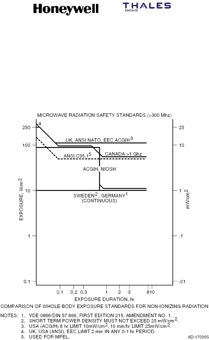
SYSTEM DESCRIPTION, INSTALLATION, AND MAINTENANCE MANUAL
MCS--4200/7200 Multi--Channel SATCOM System
23--20--35 15 Jul 2006
Honeywell International Inc. Do not copy without express permission of Honeywell.
Page INTRO--10
WARNING: TO AVOID POTENTIALLY DANGEROUS EXPOSURE TO RADIO
FREQUENCY ENERGY ABOVE THE ANSI C95.1 LIMIT AND OTHER
WORLD STANDARDS (SEE FIGURE INTRO--2) WHEN USING A LOW
GAIN ANTENNA (0 dB NOMINAL ANTENNA), DO NOT OPERATE THE
MCS SYSTEM WHEN ANY PERSONNEL ARE WITHIN 1.5 FEET OF THE
ANTENNA OR WITHIN 3 FEET OF THE ANTENNA FOR PERIODS OF
LONGER THAN 3 MINUTES PER HOUR.
Figure Intro--2. Radio Frequency Energy Levels

SYSTEM DESCRIPTION, INSTALLATION, AND MAINTENANCE MANUAL
MCS-4200/7200
TEMPORARY REVISION NO. 23-1
23-20-35 Page 8 of 53
28 Sep 2009
© Honeywell International Inc. Do not copy without express permission of Honeywell.
INSERT PAGE 8 OF 53 FACING PAGE 1-1.
Reason: To change the text in Paragraphs (4) and (5) to add Classic Aero, to change the capitalization of
INMARSAT to Inmarsat, and to delete text, as applicable.
Paragraphs (4) and (5) are changed as follows:
(4) The MCS-4200/7200 system provides seven Classic Aero communication channels capable of
supporting six simultaneous full-duplex circuit mode voice connections and one channel of packet-
mode data. In addition, the MCS-4200/7200 system provides multiple channels of Inmarsat Swift64
and SwiftBroadband functionality. This Swift capability is configurable to support four MISDN
channels, four MPDS channels, or a mixture of each (when operating with Inmarsat-3 satellites); or a
maximum of two SwiftBroadband channels when operating with Inmarsat-4 satellites.
(5) The MCS-4200 system operates identically to the MCS-7200, except that it supports only four Classic
Aero communication channels (including one packet-mode data channel) rather than the seven that
are provided by the MCS-7200. The MCS system accommodates all four airborne categories of
communications:
• ATC
• AOC
• AAC
• APC.

SYSTEM DESCRIPTION, INSTALLATION, AND MAINTENANCE MANUAL
MCS--4200/7200 Multi--Channel SATCOM System
23--20--35 15 Jul 2006
Honeywell International Inc. Do not copy without express permission of Honeywell.
Page 1--1
SECTION 1
SYSTEM DESCRIPTION
1. Overview
A. General
(1) The MCS--4200/7200 MCS is an augmented version of the MCS--4000/7000 system
currently certified and in use today by hundreds of operators. The MCS--4200/7200 is
a mobile avionics communications system that supplies continuous worldwide voice
and data communications services to and from the aircraft via satellite.
(2) The MCS system interfaces at baseband with various avionics data equipment, as
well as with crew and passenger voice equipment onboard the aircraft. It also
provides narrowband connectivity to support data--intensive airborne user
applications. The MCS--4200/7200 system utilizes the antenna subsystem to
transmit/receive L--band RF signals to/from satellites in geostationary orbit. These
satellites convey the information to and from ground stations that interface with the
terrestrial telephone network.
(3) The MCS system augments and/or supersedes the present HF transceiver by
supplying higher quality voice service and by supplying data services at higher bit
rates needed by datalink ATN applications, such as ADS and the international
ACARS. Additional services include cockpit communications with administrative and
operational personnel and with governmental bodies such as ATS. The system is
designed to make sure that communications involving safety and regularity of flight
are not delayed by the transmission and reception of other message types.
(4) The MCS--4200/7200 system provides seven baseband communication channels
capable of supporting six simultaneous full--duplex circuit mode voice connections
and one channel of packet--mode data. In addition, the MCS--4200/7200 system
provides multiple channels of INMARSAT Swift64 and SwiftBroadband functionality.
This Swift capability is configurable to support four MISDN channels, four MPDS
channels, or a mixture of each. By late ’07 or early ’08, this functionality will be
enhanced (with a software upgrade to the HSU and perhaps the SDU, combined with
a system configuration strap change) to supply a maximum of two SwiftBroadband
channels as well. This is subject to the constraint that the resources necessary to
support one SwiftBroadband channel are reserved at the expense of two Swift64
channels, and vice versa.
(5) The MCS--4200 system operates identically to the MCS--7200, except that it supports
only four baseband communication channels (including one packet--mode data
channel) rather than the seven that are provided by the MCS--7200. The MCS
system accommodates all four airborne categories of communications:
•ATC
•AOC
•AAC
•APC.

SYSTEM DESCRIPTION, INSTALLATION, AND MAINTENANCE MANUAL
MCS--4200/7200 Multi--Channel SATCOM System
23--20--35 15 Jul 2006
Honeywell International Inc. Do not copy without express permission of Honeywell.
Page 1--2
(6) The four airborne communication categories are recognized by the ICAO and the
ITU, and are assigned priorities for communications purposes.
(7) The total aviation satellite communications system, shown in Figure 1-1, is made up
of the following:
•Aircraft earth station (airborne avionics subsystems and antenna subsystem)
•Space segment (satellite network)
•Ground earth stations
•Terrestrial data and voice networks.
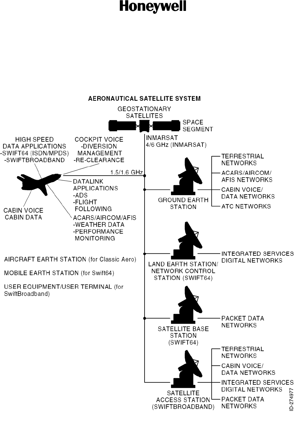
SYSTEM DESCRIPTION, INSTALLATION, AND MAINTENANCE MANUAL
MCS-4200/7200
TEMPORARY REVISION NO. 23-1
23-20-35 Page 9 of 53
28 Sep 2009
© Honeywell International Inc. Do not copy without express permission of Honeywell.
INSERT PAGE 9 OF 53 FACING PAGE 1-3.
Reason: To add aircraft earth station (for Classic Aero), mobile earth station (for Swift64), and user
equipment/user terminal (for SwiftBroadband) to Figure 1-1.
Replace Figure 1-1 with the revised illustration as follows:
Figure 1-1. Aviation Satellite Communications System
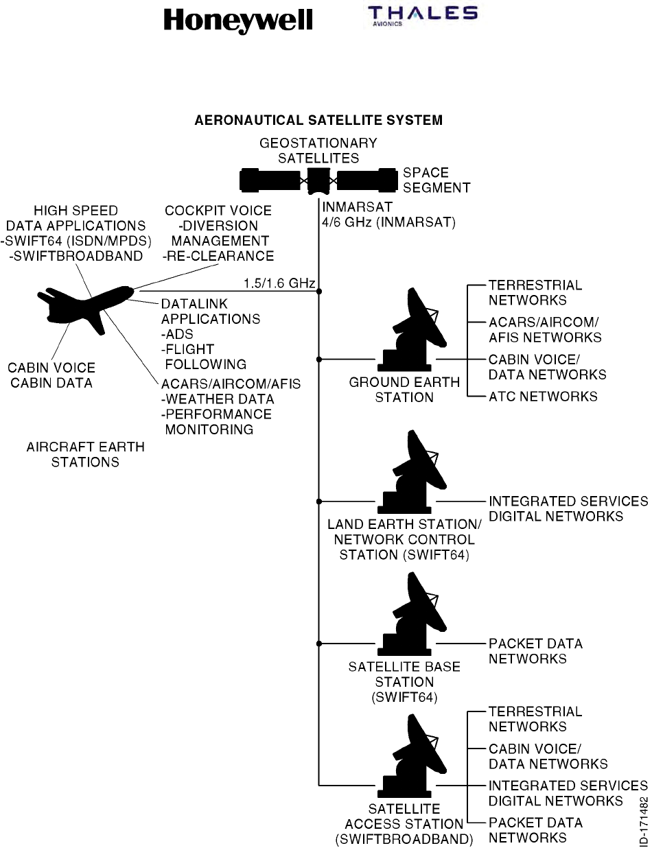
SYSTEM DESCRIPTION, INSTALLATION, AND MAINTENANCE MANUAL
MCS--4200/7200 Multi--Channel SATCOM System
23--20--35 15 Jul 2006
Honeywell International Inc. Do not copy without express permission of Honeywell.
Page 1--3
Figure 1-1. Aviation Satellite Communications System

SYSTEM DESCRIPTION, INSTALLATION, AND MAINTENANCE MANUAL
MCS--4200/7200 Multi--Channel SATCOM System
23--20--35 15 Jul 2006
Honeywell International Inc. Do not copy without express permission of Honeywell.
Page 1--4
B. Aircraft Earth Station – General
(1) General
(a) The AES is fully compliant with requirements of ARINC Characteristics 741/761.
Standard interfaces between the MCS--4200/7200 avionics and other aircraft
avionics enables the AES to accept data and voice messages from various
sources, encode and modulate this information onto appropriate RF carrier
frequencies, and transmit these carriers to the space segment for relay to a
GES. The AES also receives RF signals from a GES through the satellite,
demodulates these signals, performs the necessary decoding of the encoded
messages, and outputs the data or voice message for use by the cockpit crew
(pilot and copilot), the cabin crew or the passengers.
(2) AES Components
(a) General
1A block diagram of the AES is shown in Figure 1--2. The AES is made up of
the following components:
•MCS SATCOM avionics
•Antenna subsystem
•Cabin communications system
•Analog connected telephones
•Cockpit voice sources
•Aircraft avionics.
(b) MCS Avionics
1The MCS--4200/7200 avionics is made up of the SDU, the HSU and the
HPA.
2The SDU supplies the digital and analog interface to all aircraft avionics, and
implements all functionality associated with modulation/demodulation, error
correction, channel rate/frequency selection, and RF translation for the
system’s seven baseband communication channels. The SDU’s seven
baseband channels support six simultaneous full--duplex circuit--mode voice
connections and one packet--mode channel.
3The HSU incorporates the firmware necessary to support four narrowband
(Swift64) channels, which provide simultaneous circuit--mode and/or
packet--mode connectivity concurrently with the SDU’s baseband channels
at rates of 64 kbps (per single channel) or 256 kbps (four combined [bonded
ISDN] channels). Ultimately, the HSU will be augmented – by software
upgrade to the HSU, and perhaps the SDU, coupled with a system
configuration strap change – to support an additional two wideband
channels of 432 kbps (per single channel) SwiftBroadband functionality as
well. Note that when the HSU commits the resources necessary to support a
single SwiftBroadband channel, it simultaneously loses the capability to
provide two channels of Swift64 service (and vice versa).

SYSTEM DESCRIPTION, INSTALLATION, AND MAINTENANCE MANUAL
MCS-4200/7200
TEMPORARY REVISION NO. 23-1
23-20-35 Page 10 of 53
28 Sep 2009
© Honeywell International Inc. Do not copy without express permission of Honeywell.
INSERT PAGE 10 OF 53 FACING PAGE 1-4.
Reason: To update headings and text to include references to MES, UE, LES, SAS, and Classic Aero, as
applicable, to Paragraphs B. (1) (a), B. (2) (a) 1, and B. (2) (b) 2 and 3.
The headings and text are changed as follows:
B. Aircraft Earth Station/Mobile Earth Station/User Equipment – General
(1) General
(a) The AES/MES/UE is fully compliant with requirements of ARINC Characteristics 741/761.
Standard interfaces between the MCS-4200/7200 avionics and other aircraft avionics enable it
to accept data and voice messages from various sources, encode and modulate this
information onto appropriate RF carrier frequencies, and transmit these carriers to the space
segment for relay to a GES/LES/SAS. The AES/MES/UE also receives RF signals from a
GES/LES/SAS through the satellite, demodulates these signals, performs the necessary
decoding of the encoded messages, and outputs the data or voice message for use by the
cockpit crew (pilot and copilot), the cabin crew or the passengers.
(2) AES/MES/UE Components
(a) General
1 A block diagram of the AES/MES/UE is shown in Figure 1-2. It is made up of the following
components:
• MCS avionics
2 The SDU supplies the digital and analog interface to all aircraft avionics, and implements
all functionality associated with modulation/demodulation, error correction, channel
rate/frequency selection, and RF translation for the system’s seven baseband
communication channels. The SDU’s seven Classic Aero channels support six
simultaneous full-duplex circuit-mode voice connections and one packet-mode channel.
3 The HSU incorporates the firmware necessary to support four narrowband (Swift64)
channels, which provide simultaneous circuit-mode and/or packet-mode connectivity
concurrently with the SDU’s baseband channels at rates of 64 kbps (per single channel)
or 256 kbps (four combined [bonded ISDN] or two channels of up to 432 kbps (per single
channel) SwiftBroadband functionality. When operating through an Inmarsat-3 satellite
and its GESs/LESs, Classic Aero and Swift64 services are possible; when operating
through an Inmarsat-4 satellite and its GESs/SASs, Classic Aero and SwiftBroadband
services are possible; i.e., only one type of Swift service is possible at any given time,
depending on the type of satellite and ground station being used at any given time.

SYSTEM DESCRIPTION, INSTALLATION, AND MAINTENANCE MANUAL
MCS-4200/7200
TEMPORARY REVISION NO. 23-1
23-20-35 Page 11 of 53
28 Sep 2009
© Honeywell International Inc. Do not copy without express permission of Honeywell.
INSERT PAGE 11 OF 53 FACING PAGE 1-5.
Reason: To change the text in Paragraphs 6, 7, and 9 as applicable to the latest version of the system.
Some text was deleted.
Replace the text in Paragraphs 6, 7, and 9 as follows:
6 The CMU or equivalent, route packet-data messages to and from the SDU. Cabin
communications use either a CCS or an analog equivalent (cabin unit) to provide
baseband voice telephone communication (including FAX and PC modem services). The
HSU’s Swift64 and SwiftBroadband communication channels supporting data-intensive e-
mail, web surfing, video-conferencing transmittals, and other data, are interfaced to the
user by way of a server/router, which is part of the airborne network.
7 To permit operation of the MCS-4200/7200 system to be easily tailored around aircraft-
specific and user-specific needs, the SDU incorporates an ORT. The ORT contains more
than 100 configurable entries (each with a default value) that are individually designated
as either a user or secure (that is, installation-specific) item, as well as either Airbus
modifiable or Airbus non-modifiable. The ORT affects not only the operation of the
conventional Aero channels but the HSU channel complement (that is, the four Swift64
channels or the two SwiftBroadband channels) as well.
9 The SDU/HSU combination supplies all essential services required to accommodate
effective air/ground communications by way of satellite which use the antenna and related
RF components for both the cockpit and cabin environments. The 60-Watt HPA assists in
supporting multiple simultaneous channel communications by supplying linear power
amplification to boost the RF signals associated with each channel to the levels required
for transmission to the satellite.

SYSTEM DESCRIPTION, INSTALLATION, AND MAINTENANCE MANUAL
MCS--4200/7200 Multi--Channel SATCOM System
23--20--35 15 Jul 2006
Honeywell International Inc. Do not copy without express permission of Honeywell.
Page 1--5
4The HPA implements the linear power amplification of the SDU’s and HSU’s
combined RF signals needed to assure their successful transmission from
the aircraft to the satellite and to the ground network.
5A cockpit audio system conveys cockpit voice to and from the SDU.
Messages requiring cockpit action or initiation appear on the appropriate
cockpit display – RMP -- for the A380 -- or MCDU for all other platforms, with
the correct protocol selected by the SDU based on data present on the
display buses and/or other cockpit annunciators.
6The CMU or equivalent, route packet--data messages to and from the SDU.
Cabin communications use either a CCS or an analog equivalent (cabin unit)
to provide baseband voice telephone communication (including FAX and PC
modem services). The HSU’s narrowband Swift64 and SwiftBroadband
communication channels supporting data--intensive e--mail, web surfing,
video--conferencing transmittal, and other data, are interfaced to the user by
way of a server/router, which is part of the airborne network.
7To permit operation of the MCS--4200/7200 system to be easily tailored
around aircraft--specific and user--specific needs, the SDU incorporates an
ORT. The ORT contains more than 60 configurable entries (each with a
default value) that is individually designated as either a user or secure (that
is, installation--specific) item. The ORT affects not only the operation of the
conventional Aero channels but the HSU channel complement (that is, the
four Swift64 channels initially, and the two additional SwiftBroadband
channels ultimately) as well.
8The ORT is subject to configuration management to the extent that the
ORT’s version number is incremented whenever significant changes to the
database occur (for example, introduction of SwiftBroadband items). Once
made, the ORT selections are preserved by the SDU across power and test
cycles in non--volatile memory. In addition, the ORT is able to be
downloaded from or uploaded to the SDU from an external file storage
medium (such as diskettes) which serve as the file destination or file source,
respectively.
9The SDU/HSU combination supplies all essential services required to
accommodate effective air/ground communications by way of satellite which
use the antenna and related RF components for both the cockpit and cabin
environments. The 60--Watt HPA assists in supporting multiple simultaneous
baseband and narrowband (Swift64) channel communications by supplying
linear power amplification to boost the RF signals associated with each
channel to the levels required for transmission to the satellite.
10 The extensive variety of functionality that is afforded by the MCS--4200/7200
system results largely from the software direction of the hardware operation.
The SDU’s hardware platform uses the MCS--4000/7000 designs, which are
already certified on various other aircraft, as the baseline.

SYSTEM DESCRIPTION, INSTALLATION, AND MAINTENANCE MANUAL
MCS--4200/7200 Multi--Channel SATCOM System
23--20--35 15 Jul 2006
Honeywell International Inc. Do not copy without express permission of Honeywell.
Page 1--6
11 These proven platforms provide a solid structure on which the
MCS--4200/7200 SATCOM enhancements (both hardware and software) are
being built. The software that drives the MCS--4200/7200 system operation
is DO--178B Level D for the SDU and HPA from their first release into
production. However, the initial (that is, Swift64--only) HSU will migrate to
DO--178B Level D from Level E when its capabilities are upgraded to
support full SwiftBroadband functionality.

SYSTEM DESCRIPTION, INSTALLATION, AND MAINTENANCE MANUAL
MCS-4200/7200
TEMPORARY REVISION NO. 23-1
23-20-35 Page 12 of 53
28 Sep 2009
© Honeywell International Inc. Do not copy without express permission of Honeywell.
INSERT PAGE 12 OF 53 FACING PAGE 1-6.
Reason: To change the text in Paragraph 11 as applicable to the latest version of the system. Some text
was deleted.
Replace the text in Paragraph 11 as follows:
11 These proven platforms provide a solid structure on which the MCS-4200/7200 SATCOM
enhancements (both hardware and software) are built. The software that drives the MCS-
4200/7200 system operation is DO-178B Level D for the SDU and HPA from their first
release into production. However, the HSU is DO-178B Level E.
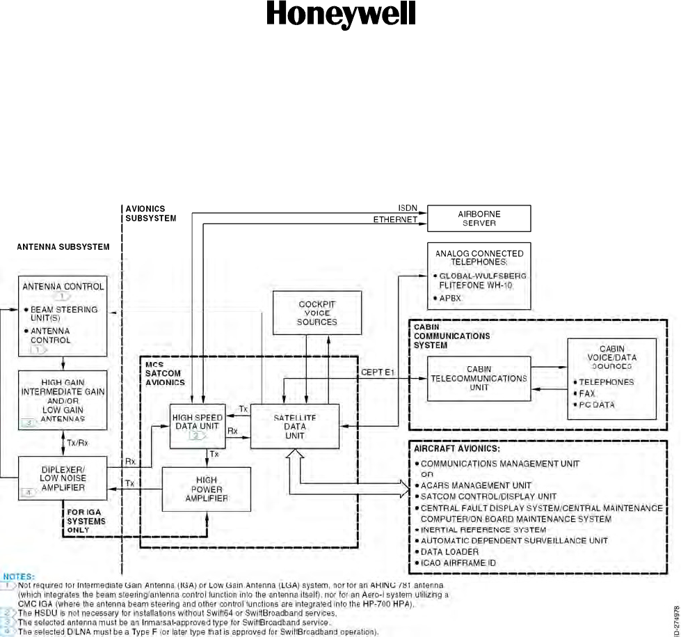
SYSTEM DESCRIPTION, INSTALLATION, AND MAINTENANCE MANUAL
MCS-4200/7200
TEMPORARY REVISION NO. 23-1
23-20-35 Page 13 of 53
28 Sep 2009
© Honeywell International Inc. Do not copy without express permission of Honeywell.
INSERT PAGE 13 OF 53 FACING PAGE 1-7/1-8.
Reason: To change Figure 1-2 to change the text of Note 1 and to add new Note 3 and Note 4.
Replace Figure 1-2 with the illustration that follows:
Figure 1-2. Aircraft Earth Station Block Diagram
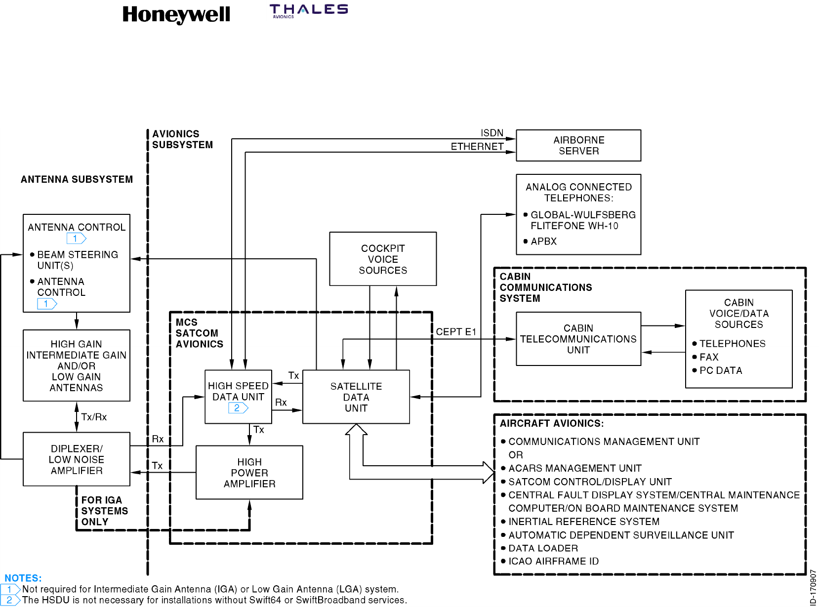
SYSTEM DESCRIPTION, INSTALLATION, AND MAINTENANCE MANUAL
MCS--4200/7200 Multi--Channel SATCOM System
23--20--35 15 Jul 2006
Honeywell International Inc. Do not copy without express permission of Honeywell.
Page 1--7/1--8
Figure 1-2. Aircraft Earth Station Block Diagram

SYSTEM DESCRIPTION, INSTALLATION, AND MAINTENANCE MANUAL
MCS-4200/7200
TEMPORARY REVISION NO. 23-1
23-20-35 Page 14 of 53
28 Sep 2009
Publication Number A15-5111-010
© Honeywell International Inc. Do not copy without express permission of Honeywell.
INSERT PAGE 14 OF 53 FACING PAGE 1-9.
Reason: To change INMARSAT to show initial capitalization only in Paragraph 13 and Paragraph (c) 1.
To change text in Paragraphs (c) 1, 2, and 3 as applicable to add references to MES, UE, LES,
SAS, ACU, Classic Aero, and additional data about SwiftBroadband operations.
Paragraph 13 and Paragraphs (c) 1, 2, and 3 are changed as follows:
13 In those applications for which the Swift64/SwiftBroadband capability is not required, an
additional LRU may be necessary; this is the RFUIA. The RFUIA is used in place of the
RFU in a conventional ARINC 741 system, and replaces the HSU in those installations
which utilize only the MCS-4200/7200 SATCOM system’s classic Inmarsat baseband
features.
1 The primary function of the antenna subsystem is to complete the communication link
between the GES/LES/SAS, the space segment, and the AES/MES/UE. The D/LNA is a
three-port RF device (antenna, transmit, and receive) which provides signal routing and
filtering – signals in the receive band are routed from the antenna port to the receive port,
and transmit signals are routed from the transmit port to the antenna port. The LNA
establishes the noise floor of the communication system’s receiver by boosting the signals
received from the antenna to the maximum level relative to the noise received with the
signals, as well as the noise developed by the LNA itself. For SwiftBroadband operations,
the D/LNA must be a Type F (or later type approved for SwiftBroadband operation). Also,
the selected antenna must be an Inmarsat-approved type for SwiftBroadband operation.
2 The HGA transmits L-band RF signals from the HPA to a satellite, and receives L-band
RF signals from a satellite for the SDU and HSU. When installed, the LGA supplies
backup communications (packet-data only) for the HGA by providing low-rate, Classic
Aero (only) packet-data communication services.
3 The BSU or ACU is used in the HGA system to convert tracking and pointing coordinates
(that is, aircraft-relative azimuth and elevation) from the SDU into signals needed to select
the antenna array elements in combinations that point the antenna beam in the desired
direction towards the satellite.

SYSTEM DESCRIPTION, INSTALLATION, AND MAINTENANCE MANUAL
MCS--4200/7200 Multi--Channel SATCOM System
23--20--35 15 Jul 2006
Honeywell International Inc. Do not copy without express permission of Honeywell.
Page 1--9
12 The MCS--4200/7200 system LRUs (building on their legacy
MCS--4000/7000 background) maintains extensive logs of information that is
useful in the monitoring of normal system activity as well as identifying any
failure conditions experienced during operation, whether in flight or on the
ground. This is accomplished through a combination of self--test suites that
are performed at POST or as the result of PAST, as well as by CM. The
maintenance logs are continuously updated, and accessible for download
using the ARINC 615 ADL and PDL.
13 In those applications for which the Swift64/SwiftBroadband capability is not
required, an additional LRU may be necessary; this is the RFUIA. The
RFUIA is used in place of the RFU in a conventional ARINC 741 system,
and replaces the HSU in those installations which utilize only the
MCS--4200/7200 SATCOM system’s classic INMARSAT baseband features.
(c) Antenna Subsystem
1The primary function of the antenna subsystem is to complete the
communication link between the GES, the space segment, and the AES.
The D/LNA is a three-port RF device (antenna, transmit, and receive) which
provides signal routing and filtering -- signals in the receive band are routed
from the antenna port to the receive port, and transmit signals are routed
from the transmit port to the antenna port. The LNA establishes the noise
floor of the communication system’s receiver by boosting the signals
received from the antenna to the maximum level relative to the noise
received with the signals, as well as the noise developed by the LNA itself.
2The HGA transmits L--band RF signals from the HPA to a satellite, and
receives L--band RF signals from a satellite for the SDU and HSU. When
installed, the LGA supplies backup communications (packet--data only) for
the HGA by providing low--rate, packet--data communication services.
3The BSU is used in the HGA system to convert tracking and pointing
coordinates (that is, aircraft--relative azimuth and elevation) from the SDU
into signals needed to select the antenna array elements in combinations
that point the antenna beam in the desired direction towards the satellite.
(d) CCS
1The CCS, in conjunction with the MCS avionics and a worldwide network of
ground stations, supplies cabin services such as baseband telephone,
facsimile, and PC modem communication interfaces. The CCS is partitioned
into two sections: the CTU and cabin/passenger communications equipment
(digitally connected telephones).

SYSTEM DESCRIPTION, INSTALLATION, AND MAINTENANCE MANUAL
MCS--4200/7200 Multi--Channel SATCOM System
23--20--35 15 Jul 2006
Honeywell International Inc. Do not copy without express permission of Honeywell.
Page 1--10
2The CTU performs onboard PABX telephony functions, letting the digitally
connected telephones make the best use of resources supplied by the MCS
avionics. The ARINC 746 CTU supplies the conversion interface between
the digitally connected phones and the ARINC 741/761 SDU, and connects
to the SDU by means of a high-speed serial bus pair (CEPT--E1) that
accommodates up to 30 digitized voice channels along with status and
control information.
3The digitally connected phones (handsets) are primarily supplied for
passenger use and can be located throughout the aircraft. The digital
handsets interface indirectly to the satellite communications equipment and
are controlled by the CCS.
(e) Airborne Server
1The airborne server provides the means by which data streams from multiple
cabin (or other) users are collected and processed into formats suitable for
assignment onto the HSU’s narrowband or wideband channels. The HSU
interfaces with the airborne server by way of two Ethernet 10BaseT ports for
MPDS/SwiftBroadband and MISDN service, and by way of two ISDN ports
for MISDN service.
2When using the Ethernet port for either MISDN or MPDS services, PPPoE
protocol is used to choose the service and to give to the HSU all the
parameters needed to access the correct ground service provider for the
service chosen.
3A configuration discrete is used to configure the Ethernet ports so that all
Swift64 channels use only one Ethernet port or both Ethernet ports.
(f) Analog Connected Telephones
1The SDU is provisioned to support two simultaneous analog audio channels
which use any four--wire analog telephone (such as, Global--Wulfsberg
Flitephone WH--10 handsets) by way of the APBX. The WH--10 is a
standalone handset with a 12--button keypad. The APBX has analog trunk
lines and in--line DTMF signaling.
(g) Cockpit Voice Sources
1The SDU supports headset interfaces for cockpit use only. These interfaces
incorporate off--hook/on--hook signaling and dialing through the combination
of a control and display unit (either by the way of the MCDU or RMP), and
PTT or similar switches. When the PTT switch is pushed, a microphone
audio signal is sent to the selected voice channel and a discrete signal is
sent to the SDU. An audible chime combined with lit or flashing call lamps
announces call connections.

SYSTEM DESCRIPTION, INSTALLATION, AND MAINTENANCE MANUAL
MCS-4200/7200
TEMPORARY REVISION NO. 23-1
23-20-35 Page 15 of 53
28 Sep 2009
© Honeywell International Inc. Do not copy without express permission of Honeywell.
INSERT PAGE 15 OF 53 FACING PAGE 1-10.
Reason: To change the text in Paragraphs (e) 1, 2, and 3 and (f) 1 to add references to SwiftBroadband
and to make other changes to the text as applicable. Some text was deleted.
Replace the text in Paragraphs (e) 1, 2, and 3 and (f) 1 as follows:
1 The airborne server provides the means by which data streams from multiple cabin (or
other) users are collected and processed into formats suitable for assignment onto the
HSU’s narrowband or wideband channels. The HSU interfaces with the airborne server by
way of two Ethernet 10BaseT ports for MPDS, SwiftBroadband, and MISDN service, and
by way of two ISDN ports for MISDN and SwiftBroadband service.
2 When using the Ethernet port for either SwiftBroadband, MISDN or MPDS services,
PPPoE along with an SNMP-based ARINC MIB (in accordance with ARINC 781
Attachment 5) protocol is used to choose the service and to give to the HSU all the
parameters needed to access the correct ground service provider for the service chosen.
3 A configuration discrete is used to configure the Ethernet ports so that all
Swift64/SwiftBroadband channels use only one Ethernet port or both Ethernet ports.
1 The SDU is provisioned to support two simultaneous analog audio channels which use
four-wire analog telephone interfaces such as Global-Wulfsberg Flitephone WH-10
handsets or an analog PBX (APBX). The WH-10 is a standalone handset with a 12-button
keypad that utilizes discretes for call signaling functions. The APBX has analog trunk lines
and in-line DTMF signaling.

SYSTEM DESCRIPTION, INSTALLATION, AND MAINTENANCE MANUAL
MCS-4200/7200
TEMPORARY REVISION NO. 23-1
23-20-35 Page 16 of 53
28 Sep 2009
© Honeywell International Inc. Do not copy without express permission of Honeywell.
INSERT PAGE 16 OF 53 FACING PAGE 1-11.
Reason: To change the text in Paragraphs (h) 1 (bullet 4 and bullet 7) to add a reference to GNSS and
Swift64 operation, as applicable.
Replace the text in Paragraphs (h) 1 (bullet 4 and bullet 7) as follows:
• The IRS and GNSS (GPS), where installed, to supply the SDU with navigation
coordinates for positioning the antenna platform
• The 24-bit ICAO address identifies the aircraft in which the SDU is installed. Address pins
identified to take on the binary one state must be left open. Address pins identified to take
on the binary zero state must be wired to address common on the airframe side of the
connector. ARINC 429 interface options for the ICAO address are also supplied. Similar
configuration pins on the HSU identify a 24-bit Forward ID for similar addressing purposes
for Swift64 operation. Similar addressing and other functionality are handled for
SwiftBroadband operations by the SIM cards in the HSU's HDM.

SYSTEM DESCRIPTION, INSTALLATION, AND MAINTENANCE MANUAL
MCS--4200/7200 Multi--Channel SATCOM System
23--20--35 15 Jul 2006
Honeywell International Inc. Do not copy without express permission of Honeywell.
Page 1--11
(h) Aircraft Avionics
1Standard interfaces between the MCS--4200/7200 avionics and the other
aircraft avionics include the following:
•CMU, or the MU of the ACARS, where installed
•SCDU, implemented as either MCDUs or RMPs, where installed, to
supply an interface to the MCS system for system log--on, GES selection,
cockpit voice call setup, data loading, and to access the SATCOM
maintenance pages including fault messages
•CFDS, CMC, or OMS, where installed, for fault reporting
•The IRS, where installed, to supply the SDU with navigation coordinates
for positioning the antenna platform
•Channels are also supplied for voice and data communication with ATC
to support departure clearances by datalink, as well as ADS for
non--radar position reporting in oceanic regions
•There is an ARINC 615 ADL or PDL for uploading operational software
and the ORT. Connections are made through the front and back panel
connectors on the MCS avionics LRUs
•The 24--bit ICAO address identifies the aircraft in which the SDU is
installed. Address pins identified to take on the binary one state must be
left open. Address pins identified to take on the binary zero state must be
wired to address common on the airframe side of the connector. ARINC
429 interface options for the ICAO address are also supplied.
(3) AES Classifications
(a) Each AES is classified according to the configuration and dynamic capabilities of
its aircraft avionics baseband communications capability and antenna
subsystem. Accordingly, an AES can be fitted with any combination of the
classes of installations given in Table 1-1.
Table 1-1. Classes of Installations
Class Description
1A Class 1 AES installation uses a low gain antenna only and supplies low rate
packet--mode data services only.
2A Class 2 AES installation uses a high gain antenna or intermediate gain antenna,
and supplies telephony and optional circuit--mode services.
3A Class 3 AES installation uses a high gain antenna or intermediate gain antenna,
and supplies telephony services, packet--mode data services, and optional
circuit--mode data services.
4A Class 4 AES installation uses a high gain antenna or intermediate gain antenna,
and supplies packet--mode data services only.

SYSTEM DESCRIPTION, INSTALLATION, AND MAINTENANCE MANUAL
MCS--4200/7200 Multi--Channel SATCOM System
23--20--35 15 Jul 2006
Honeywell International Inc. Do not copy without express permission of Honeywell.
Page 1--12
(4) GES Communication Links
(a) The MCS--4200/7200 avionics supply access to ground--based networks through
the GES for baseband communications. Each GES supplies system
synchronization and coordination through ground--to--aircraft transmissions. Four
types of RF channels supporting baseband communications are defined for use
with the MCS--4200/7200 avionics as listed in Table 1-2.
Table 1-2. Types of Baseband RF Channels
RF Channel Description
P--Channel Packet--mode TDM channel used in the forward
(outbound) direction (ground--to--aircraft) to carry
signaling and packet--mode data. The transmission
is continuous from each GES in the satellite network.
R--Channel Random access (slotted Aloha) channel used in the
return (inbound) direction (aircraft--to--ground) to
carry signaling and packet--mode data, specifically
the initial signals of a transaction (typically request
signals).
T--Channel Reservation TDMA channel used in the return
direction only. The receiving GES reserves time slots
for transmissions requested by an AES according to
message length. The sending AES transmits the
messages in the reserved time slots.
C--Channel Circuit--mode SCPC channel used in both forward
and return directions to carry digital voice or
data/facsimile traffic. The use of the channel is
controlled by assignment and release signaling at
the start and end of each call or FAX transmission.

SYSTEM DESCRIPTION, INSTALLATION, AND MAINTENANCE MANUAL
MCS-4200/7200
TEMPORARY REVISION NO. 23-1
23-20-35 Page 17 of 53
28 Sep 2009
© Honeywell International Inc. Do not copy without express permission of Honeywell.
INSERT PAGE 17 OF 53 FACING PAGE 1-12.
Reason: To change the text in Paragraph (4) (a) to add a reference to Classic Aero and to delete text, as
applicable.
Replace the text in Paragraph (4) (a) as follows:
(a) The MCS-4200/7200 avionics supply access to ground-based networks through the GES for
Classic Aero communications. Each GES supplies system synchronization and coordination
through ground-to-aircraft transmissions. Four types of RF channels supporting baseband
communications are defined for use with the MCS-4200/7200 avionics as listed in Table 1-2.
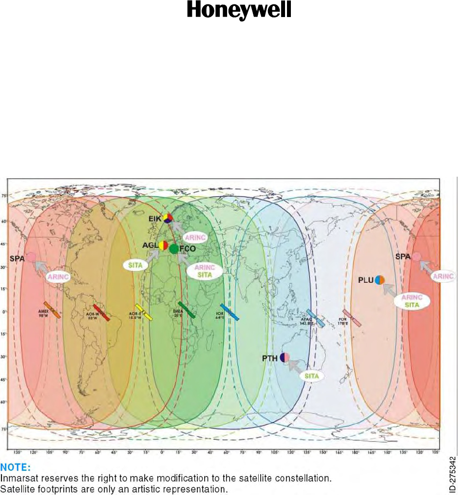
SYSTEM DESCRIPTION, INSTALLATION, AND MAINTENANCE MANUAL
MCS-4200/7200
TEMPORARY REVISION NO. 23-1
23-20-35 Page 18 of 53
28 Sep 2009
© Honeywell International Inc. Do not copy without express permission of Honeywell.
INSERT PAGE 18 OF 53 FACING PAGE 1-13.
Reason: To change the art in Figure 1-3 to show seven regions instead of four and to change INMARSAT
in the figure title to show initial capitalization only.
Figure 1-3 and the title of Figure 1-3 are changed as follows:
Figure 1-3. Inmarsat Seven-Region Satellite Coverage
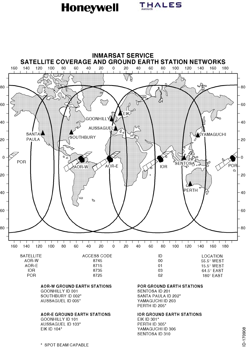
SYSTEM DESCRIPTION, INSTALLATION, AND MAINTENANCE MANUAL
MCS--4200/7200 Multi--Channel SATCOM System
23--20--35 15 Jul 2006
Honeywell International Inc. Do not copy without express permission of Honeywell.
Page 1--13
Figure 1-3. INMARSAT Four-Region Satellite Coverage

SYSTEM DESCRIPTION, INSTALLATION, AND MAINTENANCE MANUAL
MCS--4200/7200 Multi--Channel SATCOM System
23--20--35 15 Jul 2006
Honeywell International Inc. Do not copy without express permission of Honeywell.
Page 1--14
C. Space Segment
(1) The space segment is made up of satellites placed in geostationary orbits that
support air-to-ground/ground-to-air packet-switched data services and
circuit-switched telephony communications on both baseband and narrowband
channels all of which use worldwide standardized conventions and capabilities. The
satellites function as communication transponders to support L-band links to and
from the aircraft, and supply links to and from ground earth stations. The space
segment supplier for airline aeronautical satellite communications is the INMARSAT,
whose system provides near--worldwide coverage (that is, some problems may be
encountered when the aircraft flies in Polar Regions with a latitude greater than 75
degrees). The four-region satellite system supplied by INMARSAT is shown in
Figure 1-3.
D. Ground Earth Station/Land Earth Station
(1) Each GES (and LES for Swift64) has the necessary equipment to communicate both
with terrestrial networks and through satellites with the aircraft. The ground earth
stations/land earth stations are designed to supply the airline customer with a diverse
routing of national and international voice and data communications through
submarine cable, satellite, and microwave links to all destinations. Automatic traffic
management systems ensure efficient routing of communications by using optimum
links into PSTN and avoiding multiple satellite connections whenever possible.
(2) Ground earth stations/land earth stations are located strategically around the globe to
supply redundancy and diversity in the terrestrial extension of communications.
Aircraft are connected to a GES or LES through an in-view satellite depending on the
service preference settings encoded in the SDU ORT.
E. Terrestrial Data and Voice Networks
(1) Baseband data and voice services available through satellites and ground earth
stations include 9.6 and 4.8 kilobit/second (kbps) digital voice, 4.8 and 2.4 kbps FAX,
2.4 kbps PC modem data, and packet-mode data at RF channel rates ranging from
600 bit/second (bps) up to 10.5 kbps. Narrowband data services currently available
through satellites and land earth stations include 64 kbps circuit-switched ISDN
channels and 64 kbps packet--switched MPDS channels, either of which can be
combined to afford the user higher data rate throughput (for example, up to 256
kbps). By mid to late ’07, SwiftBroadband channels are planned to be available to
support wideband packet--data services at rates up to 432 kbps per channel. The
present worldwide complement of ground earth stations providing support for
baseband services, and land earth stations providing support for narrowband
services (including location, operator, and coverage region) are summarized in
Table 1-3 and Table 1-4. Aeronautical communications through the INMARSAT
satellites are transmitted to and from the terrestrial phone, and data networks through
these ground earth stations and land earth stations. The satellite regions that service
these ground earth stations/land earth stations are shown in Figure 1--3.

SYSTEM DESCRIPTION, INSTALLATION, AND MAINTENANCE MANUAL
MCS-4200/7200
TEMPORARY REVISION NO. 23-1
23-20-35 Page 19 of 53
28 Sep 2009
© Honeywell International Inc. Do not copy without express permission of Honeywell.
INSERT PAGE 19 OF 53 FACING PAGE 1-14.
Reason: To change Subhead D. and the text in Paragraphs C. (1), D. (1) and (2), and E. (1) as applicable
to the latest version of the system; some text was deleted and INMARSAT was changed to
show initial capitalization only.
Replace Subhead D. and Paragraphs C. (1), D. (1) and (2), and E. (1) as follows:
(1) The space segment is made up of satellites placed in geostationary orbits that support air-to-
ground/ground-to-air packet-switched data services and circuit-switched telephony
communications on both baseband and narrowband channels all of which use worldwide
standardized conventions and capabilities. The satellites function as communication transponders
to support L-band links to and from the aircraft, and supply links to and from ground earth stations.
The space segment supplier for airline aeronautical satellite communications is the Inmarsat,
whose system provides near-worldwide coverage (that is, some problems may be encountered
when the aircraft flies in Polar Regions with a latitude greater than 75 degrees). The seven-region
satellite system (which includes four-each Inmarsat-3 satellites and three-each Inmarsat-4
satellites) is shown in Figure 1-3. An eighth region (not shown in Figure 1-3) is the single-
functional MTSAT satellite (which consists of two satellites, one of which is a hot spare).
D. Ground Earth Station/Land Earth Station/Satellite Base Station
(1) Each GES/LES/SAS has the necessary equipment to communicate both with terrestrial networks
and through satellites with the aircraft. The ground stations are designed to supply the airline
customer with a diverse routing of national and international voice and data communications
through submarine cable, satellite, and microwave links to all destinations. Automatic traffic
management systems ensure efficient routing of communications by using optimum links into
PSTN and avoiding multiple satellite connections whenever possible.
(2) Ground stations are located strategically around the globe to supply redundancy and diversity in
the terrestrial extension of communications. Aircraft are connected to one or more ground stations
through an in-view satellite depending on the service preference settings encoded in the SDU
ORT.
(1) Classic Aero data and voice services available through satellites and ground earth stations include
9.6 and 4.8 kilobit/second (kbps) digital voice, 4.8 and 2.4 kbps FAX, 2.4 kbps PC modem data,
and packet-mode data at RF channel rates ranging from 600 bit/second (bps) up to 10.5 kbps.
Swift64 circuit- and packet-mode data services currently available through satellites and land earth
stations include 64 kbps circuit-switched ISDN channels and 64 kbps packet-switched MPDS
channels, either of which can be combined to afford the user higher data rate throughput (for
example, up to 256 kbps). SwiftBroadband channels support circuit- and packet-data services at
rates up to 432 kbps per channel. The present worldwide complement of ground stations are
summarized in Table 1-3 and Table 1-4. Aeronautical communications through the Inmarsat
satellites are transmitted to and from the terrestrial phone, and data networks through these
ground earth stations and land earth stations. The satellite regions that service these ground
stations are shown in Figure 1-3.

SYSTEM DESCRIPTION, INSTALLATION, AND MAINTENANCE MANUAL
MCS-4200/7200
TEMPORARY REVISION NO. 23-1
23-20-35 Page 20 of 53
28 Sep 2009
© Honeywell International Inc. Do not copy without express permission of Honeywell.
INSERT PAGE 20 OF 53 FACING PAGE 1-15.
Reason: To update Table 1-3 and Table 1-4 with the latest data and to delete the Service Provider
column in Table 1-3.
Replace Table 1-3 and update Table 1-4, Row 3 and Row 4, the LES code for Xantic, as follows:
Table 1-3. Ground Earth Stations for Aero H/H+ Services
GES ID SAT ID GES Name
002
005
103
000 (I3 AOR-W)
000 (I3 AOR-W)
000 (I3 AOR-W)
Eik
Aussaguel
Aussaguel
104
120
161
001 (I3 AOR-E)
005 (I4 APAC)
004 (MTSAT)
Eik
Paumalu
Kobe/Hitachiota
202
205
220
002 (I3 POR)
002 (I3 POR)
006 (I4 EMEA)
Santa Paula
Perth
Fucino
301
305
320
003 (I3 IOR)
003 (I3 IOR)
007 (I4 AMER)
Eik
Perth
Paumalu
Table 1-4. Land Earth Stations for Aero Swift64 Services
LES Code SAT ID Service Provider
001
002
012
000 (AOR-W)
000
000
Telenor
Stratos
Xantic
001
002
012
001 (AOR-E)
001
001
Telenor
Stratos
Xantic
001
002
012
002 (POR)
002
002
Telenor
Stratos
Xantic
001
002
012
003 (IOR)
003
003
Telenor
Stratos
Xantic

SYSTEM DESCRIPTION, INSTALLATION, AND MAINTENANCE MANUAL
MCS--4200/7200 Multi--Channel SATCOM System
23--20--35 15 Jul 2006
Honeywell International Inc. Do not copy without express permission of Honeywell.
Page 1--15
Table 1-3. Ground Earth Stations for Aero H/H+ Services
GES Name GES ID SAT ID Service Provider
Goonhilly--AW 001 000 (AOR--W) Stratos
Southbury--AW 002 000 Telenor
Aussaguel--AW 005 000 SITA
Goonhilly--AE 101 001 (AOR--E) Stratos
Aussaguel--AE 103 001 SITA
Eik--AE 104 001 Telenor
Sentosa--P 201 002 (POR) Stratos
Santa Paula--P 202 002 Telenor
Yamaguchi--P 203 002 KDD
Perth--P 205 002 SITA
Eik--I 301 003 (IOR) Telenor
Perth--I 305 003 SITA
Yamaguchi--I 306 003 KDD
Sentosa--I 310 003 Stratos
Table 1-4. Land Earth Stations for Aero Swift64 Services
LES Code SAT ID Service Provider
001 000 (AOR--W) Telenor
002 000 Stratos
012 000 Xantic
001 001 (AOR--E) Telenor
002 001 Stratos
012 001 Xantic
001 002 (POR) Telenor
002 002 Stratos
022 002 Xantic
001 003 (IOR) Telenor
002 003 Stratos
022 003 Xantic
SYSTEM DESCRIPTION, INSTALLATION, AND MAINTENANCE MANUAL
MCS--4200/7200 Multi--Channel SATCOM System
23--20--35 15 Jul 2006
Honeywell International Inc. Do not copy without express permission of Honeywell.
Page 1--16
2. System Components
A. General
(1) The MCS--4200/7200 system avionics consists of the following components:
•SDU
•HSU
•HPA.
(2) These components are compatible with ARINC Characteristics 741 and 761.
Table 1-5 lists the MCS--4200/7200 system components to be supplied by
Honeywell/Thales. Table 1-6 lists the MCS--4200/7200 system components not
supplied by Honeywell/Thales. Table 1-7, Table 1-8, Table 1-9, and Table 1-10 list
system component configuration information.
Table 1-5. System Components Supplied by Honeywell/Thales
Component Model No. Honeywell Part No. 1
Satellite Data Unit (SDU) SD--720 7516118--xxyyy
High Speed Data Unit (HSU) HS--720 7520061--xxyyy
High Power Amplifier (60 W) (HPA) HP--720 7520000--xxyyy
Radio Frequency Unit Interface Adapter (RFUIA) 2RF--700 7516222--901
NOTES:
1. The five--digit dash number corresponds to the hardware/software version of the unit where the first two digits
correspond to the hardware version and the last three digits correspond to the software version.
2. The RFUIA is installed in place of the HSU to eliminate wiring changes in aircraft provisioned for the HSU’s
presence.
Table 1-6. System Components Not Supplied by Honeywell
Component Comments
SDU Installation Equipment (See Note) ARINC 600 6--MCU tray, cables, connectors,
assemblies, mounting hardware, and kits
HSU Installation Equipment (See Note) ARINC 600 4--MCU tray, cables, connectors,
assemblies, mounting hardware, and kits
HPA (60 W) Installation Equipment (See Note) ARINC 600 8--MCU tray, cables, connectors,
assemblies, mounting hardware, and kits
RFUIA Installation Equipment (See Note) ARINC 600 4--MCU tray, cables, connectors,
assemblies, mounting hardware, and kits
High Gain Antenna Equipment CMC Electronics - Canada,Chelton Inc - USA,
Tecom - USA, Thales--UK, EMS -- Canada
NOTE: Installation of this equipment is dependent on the specific requirements of the operator and will involve
interaction with suppliers of this equipment (such as, ECS, EMTEQ)

SYSTEM DESCRIPTION, INSTALLATION, AND MAINTENANCE MANUAL
MCS-4200/7200
TEMPORARY REVISION NO. 23-1
23-20-35 Page 22 of 53
28 Sep 2009
© Honeywell International Inc. Do not copy without express permission of Honeywell.
Table 1-8A. HDM Configuration
HDM Part Number Description
7520033-901 HDM (all platforms)

SYSTEM DESCRIPTION, INSTALLATION, AND MAINTENANCE MANUAL
MCS-4200/7200
TEMPORARY REVISION NO. 23-1
23-20-35 Page 21 of 53
28 Sep 2009
© Honeywell International Inc. Do not copy without express permission of Honeywell.
INSERT PAGE 21 OF 53 THRU PAGE 22 OF 53 FACING PAGE 1-17.
Reason: To update Table 1-7 to replace baseband with Classic Aero and add part numbers and
descriptions applicable to the SwiftBroadband SDU.
To update Table 1-8 to replace narrowband with Swift64 and add one new part number and
description applicable to both Swift64 and SwiftBroadband.
To add a new Table 1-8A to incorporate the HDM configuration.
Table 1-7 and Table 1-8 are changed and Table 1-8A is added as follows:
Table 1-7. SDU Configurations
SDU Part Number Description
7516118-24130 115 V ac/320-800 Hz, or 28 V dc , 4-channel
Classic Aero (3 voice, 1 data) SDU for Boeing
corporate and military applications
7516118-27130 115 V ac/320-800 Hz, or 28 V dc 7-channel
Classic Aero (6 voice, 1 data) SDU for Boeing
corporate and military applications
7516118-24140 115 V ac/320-800 Hz, or 28 V dc 4-channel
Classic Aero (3 voice, 1 data) SDU for Airbus
applications
7516118-27140 115 V ac/320-800 Hz, or 28 V dc 7-channel
Classic Aero (6 voice, 1 data) SDU for Airbus
applications
7516118-27150 SwiftBroadband SDU for Airbus Long Range
7516118-27145 SwiftBroadband SDU for Airbus A380
7516118-24145 SwiftBroadband SDU for Airbus A380
7516118-27135 SwiftBroadband SDU for all non-Airbus,
including Boeing [particularly 777] and biz jets
7516118-24135 SwiftBroadband SDU for all non-Airbus,
including Boeing and biz jets
Table 1-8. HSU Configurations
HSU Part Number Description
7520061-34010 115 V ac/320-800 Hz, or 28 V dc 4-channel
Swift64 HSU for all applications
7520061-34015 115 V ac/320-800 Hz, or 28 V dc 4-channel
Swift64 and SwiftBroadband HSU for all
applications

SYSTEM DESCRIPTION, INSTALLATION, AND MAINTENANCE MANUAL
MCS--4200/7200 Multi--Channel SATCOM System
23--20--35 15 Jul 2006
Honeywell International Inc. Do not copy without express permission of Honeywell.
Page 1--17
Table 1-7. SDU Configurations
SDU Part Number Description
7516118--24130 115 V ac/320--800 Hz, or 28 V dc , 4--channel
baseband (3 voice, 1 data) SDU for Boeing
corporate and military applications
7516118--27130 115 V ac/320--800 Hz, or 28 V dc 7--channel
baseband (6 voice, 1 data) SDU for Boeing
corporate and military applications
7516118--24140 115 V ac/320--800 Hz, or 28 V dc 4--channel
baseband (3 voice, 1 data) SDU for Airbus
applications
7516118--27140 115 V ac/320--800 Hz, or 28 V dc 7--channel
baseband (6 voice, 1 data) SDU for Airbus
applications
Table 1-8. HSU Configuration
HSU Part Number Description
7520061--34010 115 V ac/320--800 Hz, or 28 V dc 4--channel
narrowband HSU for all applications.
Table 1-9. HPA Configuration
HPA Part Number Description
7520000--20140 115 V ac/320--800 Hz, or 28 V dc, 60 W HPA for all
applications.
Table 1-10. RFUIA Configuration
RFUIA Part Number Description
7516222--901 RFU Interface Adapter for all applications.
3. System Description
A. General
(1) The system description gives a general overview and summary of the features and
interfaces that the MCS--4200/7200 system implements. Figure 1--4 is a simplified
block diagram of the MCS--4200/7200 system as well as the other airborne systems
with which it interfaces.

SYSTEM DESCRIPTION, INSTALLATION, AND MAINTENANCE MANUAL
MCS-4200/7200
TEMPORARY REVISION NO. 23-1
23-20-35 Page 23 of 53
28 Sep 2009
© Honeywell International Inc. Do not copy without express permission of Honeywell.
INSERT PAGE 23 OF 53 FACING PAGE 1-18.
Reason: To update the text in Paragraphs 3. A. (2) and (3) to replace baseband with Classic Aero, add a
reference to MES and UE, and delete some text, as necessary.
Paragraph (2) and (3) are changed as follows:
2) The core of the AES avionics subsystem is the MCS-4000/7000 avionics, supporting Classic
Aero data and voice communications (inclusively) at single channel rates from 600 to 21,000
bits per second as well as Swift64 and SwiftBroadband data communications at single
channel rates of up to 64 and 432 kbps, respectively. Interfaces to various aircraft systems
including cockpit voice, cabin voice/data, aircraft avionics, and the antenna subsystem enable
the MCS avionics to handle data and voice messaging functions for the AES/MES/UE.
(3) The SDU supplies all essential services required to accommodate effective air/ground
communications through the satellite, using the antenna and related RF components. The
SDU manages the RF link protocols on the AES side and supplies the system interface to
other aircraft avionics. The HSU administers all aspects of the Swift64 and SwiftBroadband
channels’ operation, from call setup through termination, in coordination with the SDU. The
HPA boosts the signal to be radiated by the antenna to the power level required for
transmission to the satellite.

SYSTEM DESCRIPTION, INSTALLATION, AND MAINTENANCE MANUAL
MCS--4200/7200 Multi--Channel SATCOM System
23--20--35 15 Jul 2006
Honeywell International Inc. Do not copy without express permission of Honeywell.
Page 1--18
(2) The core of the AES avionics subsystem is the MCS--4000/7000 avionics, supporting
baseband data and voice communications (inclusively) at single channel rates from
600 to 21,000 bits per second as well as narrowband (Swift64 initially)/wideband
(SwiftBroadband ultimately) data communications at single channel rates of 64 and
432 Kbps, respectively. Interfaces to various aircraft systems including cockpit voice,
cabin voice/data, aircraft avionics, and the antenna subsystem enable the MCS
avionics to handle data and voice messaging functions for the AES.
(3) The SDU supplies all essential services required to accommodate effective
air/ground communications through the satellite, using the antenna and related RF
components. The SDU manages the RF link protocols on the AES side and supplies
the system interface to other aircraft avionics. The HSU administers all aspects of the
narrowband and wideband channels’ operation, from call setup through termination,
in coordination with the SDU. The HPA boosts the signal to be radiated by the
antenna to the power level required for transmission to the satellite.
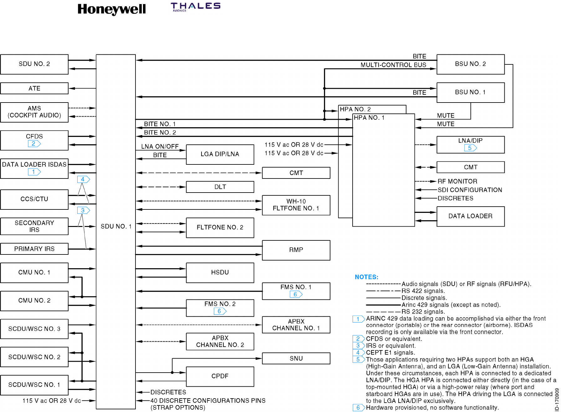
SYSTEM DESCRIPTION, INSTALLATION, AND MAINTENANCE MANUAL
MCS--4200/7200 Multi--Channel SATCOM System
23--20--35 15 Jul 2006
Honeywell International Inc. Do not copy without express permission of Honeywell.
Page 1--19/1--20
Figure 1-4. MCS--4200/7200 Avionics Block Diagram

SYSTEM DESCRIPTION, INSTALLATION, AND MAINTENANCE MANUAL
MCS-4200/7200
TEMPORARY REVISION NO. 23-1
23-20-35 Page 24 of 53
28 Sep 2009
© Honeywell International Inc. Do not copy without express permission of Honeywell.
INSERT PAGE 24 OF 53 FACING PAGE 1-21.
Reason: To change Paragraph B. (1) (a) to replace baseband with Classic Aero.
Paragraph (a) is changed as follows:
(a) The SDU is the core element of the MCS–4200/7200 avionics and responsible for overall
AES control and monitoring. The unit interfaces to many aircraft avionics (for example,
CFDS, primary/secondary IRS, CMU 1/2, MCDU [or RMP] 1/2/3, ADL, etc.) and has
operational functionality, including coding and decoding all system voice and data signals
and defining system protocols. The SDU contains six channels capable of supplying
simultaneous full-duplex Classic Aero voice communication, one channel of Classic Aero
data 2/3 communication, and RF circuitry sufficient to operate the AES. Figure 1-5 shows
the CCA listing and block diagram for the MCS-7200 SDU. Removal of one of the TTCM
CCAs results in the MCS-4200 SDU.
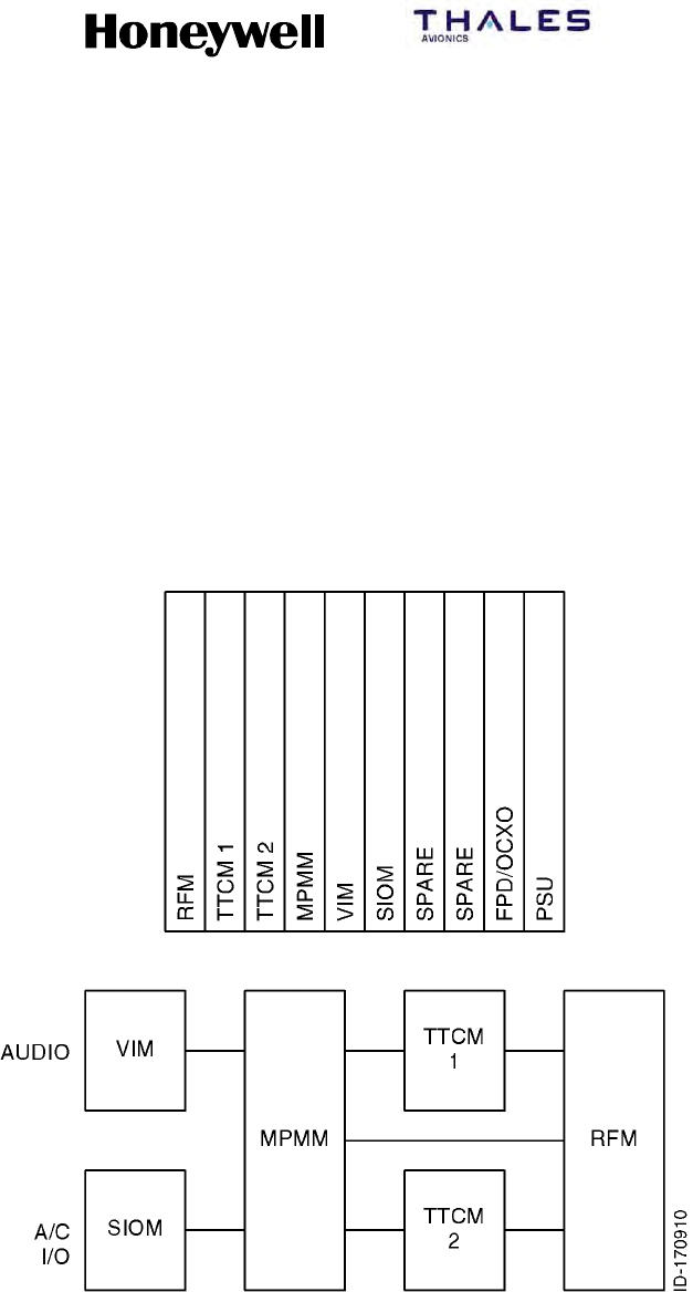
SYSTEM DESCRIPTION, INSTALLATION, AND MAINTENANCE MANUAL
MCS--4200/7200 Multi--Channel SATCOM System
23--20--35 15 Jul 2006
Honeywell International Inc. Do not copy without express permission of Honeywell.
Page 1--21
B. Satellite Data Unit
(1) General
(a) The SDU is the core element of the MCS–4200/7200 avionics and responsible
for overall AES control and monitoring. The unit interfaces to many aircraft
avionics (for example, CFDS, primary/secondary IRS, CMU 1/2, MCDU [or RMP]
1/2/3, ADL, etc) and has operational functionality, including coding and decoding
all system voice and data signals and defining system protocols. The SDU
contains six channels capable of supplying simultaneous full--duplex baseband
voice communication, one channel of baseband data 2/3 communication, and
RF circuitry sufficient to operate the AES. Figure 1--5 shows the CCA listing and
block diagram for the MCS--7200 SDU. Removal of one of the TTCM CCAs
results in the MCS--4200 SDU.
Figure 1-5. MCS--7200 SDU Equipment Description

SYSTEM DESCRIPTION, INSTALLATION, AND MAINTENANCE MANUAL
MCS--4200/7200 Multi--Channel SATCOM System
23--20--35 15 Jul 2006
Honeywell International Inc. Do not copy without express permission of Honeywell.
Page 1--22
(b) The format for baseband voice/data encoding follows the INMARSAT system
definitions for voice and data transmission and reception. The INMARSAT
system uses a digital format for voice and data. The SDU digitizes the voice or
data signal and adds special codes to make the aircraft–to–ground station
connection possible. Voice signals are transmitted at a rate designed to supply
high voice quality (perceived quality is close to that of a good quality public
telephone line). When signal processing is complete, the coded voice/data signal
is sent to HPA. The SDU also controls the protocols for automatic call setup and
clear–down. System protocols are defined so the designated GES recognizes it
is being called by the AES.
(c) The SDU houses the voice interface modules and transcoder modems required
for baseband voice and data services, and the RF transmit/receive circuitry
needed to convert modulated signals of either type to an L–band frequency (and
vice versa). All AES satellite signals use digital coding and modulation, which
include the voice circuits. The voice interface modules translate baseband
analog voice signals to and from the 9600 bps or 4800 bps digital coding
standard. Efficient information compression and coding techniques supply high
voice quality at an economical bit rate. The modems, one for each
communication channel, perform all of the physical layer signal processing
functions, including multiplexing/demultiplexing, interleaving/de--interleaving,
scrambling/unscrambling, modulation/demodulation, and Doppler effect
correction.
(d) The SDU system table memory contains the location of all satellites. When a
GES is selected, the SDU uses this location information and aircraft positional
information (through an ARINC 429 interface) from the IRS to compute the
position of the satellite relative to the aircraft. The SDU then transmits pointing
and tracking coordinates (aircraft relative azimuth and elevation) to the beam
steering unit (BSU) to permit optimum signal transmission and reception between
the high gain antenna subsystem and the satellite.
(e) The high gain antenna subsystem translates these steering commands into
control signals to the antenna(s). Once the beam has been steered toward the
satellite, the SDU receives the pilot tone from the satellite transponder through
its receive RF link from the antenna subsystem.
(f) In the SDU, the baseband data modulates RF carriers, which are sent to the
HPA for amplification, and then to the antenna subsystem for transmission to the
satellite. The SDU can adjust the transmission frequency in one--Hertz
increments to compensate for the Doppler shift caused by the speed of the
aircraft. The receive mode is handled in a similar manner. Since the
MCS--4200/7200 is a full--duplex system, the transmit and receive signals are
processed simultaneously as in conventional terrestrial telephone equipment.

SYSTEM DESCRIPTION, INSTALLATION, AND MAINTENANCE MANUAL
MCS-4200/7200
TEMPORARY REVISION NO. 23-1
23-20-35 Page 25 of 53
28 Sep 2009
© Honeywell International Inc. Do not copy without express permission of Honeywell.
INSERT PAGE 25 OF 53 FACING PAGE 1-22.
Reason: To change Paragraph (b) to replace baseband with Classic Aero and to change the
capitalization of INMARSAT to Inmarsat.
To add the ACU and ARINC 781 antenna to Paragraph (d).
Paragraphs (b) and (d) are changed as follows:
(b) The format for Classic Aero voice/data encoding follows the Inmarsat system definitions
for voice and data transmission and reception. The Inmarsat system uses a digital format
for voice and data. The SDU digitizes the voice or data signal and adds special codes to
make the aircraft-to-ground station connection possible. Voice signals are transmitted at a
rate designed to supply high voice quality (perceived quality is close to that of a good
quality public telephone line). When signal processing is complete, the coded voice/data
signal is sent to HPA. The SDU also controls the protocols for automatic call setup and
clear-down. System protocols are defined so the designated GES recognizes it is being
called by the AES.
(d) The SDU system table memory contains the location of all satellites. When a GES is
selected, the SDU uses this location information and aircraft positional information
(through an ARINC 429 interface) from the IRS to compute the position of the satellite
relative to the aircraft. The SDU then transmits pointing and tracking coordinates (aircraft
relative azimuth and elevation) to the beam steering unit (BSU), antenna control unit
(ACU), or ARINC 781 antenna to permit optimum signal transmission and reception
between the high gain antenna subsystem and the satellite.

SYSTEM DESCRIPTION, INSTALLATION, AND MAINTENANCE MANUAL
MCS-4200/7200
TEMPORARY REVISION NO. 23-1
23-20-35 Page 26 of 53
28 Sep 2009
© Honeywell International Inc. Do not copy without express permission of Honeywell.
INSERT PAGE 26 OF 53 FACING PAGE 1-23.
Reason: To change the text of Paragraphs C. (1) (a), (b), and (c) to include additional references to
SwiftBroadband and Swift64, as well as references to POTS. Some text was deleted.
Paragraphs (a), (b), and (c) are changed as follows:
(a) The HSU provides four additional simultaneous full-duplex Swift64 64 kbps channels or two
additional simultaneous full-duplex SwiftBroadband up-to-432 kbps channels to the MCS
system when operated in conjunction with the SDU. The Swift64 channels accommodate
digitized voice and data signals relayed to and from the airborne server at a maximum rate of
256 kbps when all four Swift64 channels are bonded to serve a single user or 128 kbps when
two channels are bonded together.
(b) The channels provided by the HSU are accessed by way of the two BRI ISDN interfaces
and/or the two Ethernet interfaces and/or the two POTS interfaces. The ISDN interface
provides the following services: 64 kbits/s UDI, 64 kbits/s 3.1 kHz Audio, 64 kbits/s Speech
and 56 kbits/s Data. The 10 Base T Ethernet interfaces are accessed through the PPPoE
using PPPoE tags for service selection.
(c) A configuration discrete is provided to control the functionality of the Ethernet user interfaces,
whether all channels are available on a first-come, first-served basis through either Ethernet
interface, or whether half of the channels are available by way of one (and only one) of the
Ethernet interfaces, and the other half of the channels are available by way of the other
Ethernet interface (and only that interface). The default (open-circuit) state of this discrete is
the former (first-come, first-served). The HSU supports APC calls only through its ISDN and/or
Ethernet and/or POTS connections to the airborne server.

SYSTEM DESCRIPTION, INSTALLATION, AND MAINTENANCE MANUAL
MCS--4200/7200 Multi--Channel SATCOM System
23--20--35 15 Jul 2006
Honeywell International Inc. Do not copy without express permission of Honeywell.
Page 1--23
(2) Installation Dependent Considerations
(a) General
1The SDU stores the following installation dependent values to enable it to
set the EIRPs accurately:
•SDU to HPA loss
•HPA to antenna loss
•HSDU to antenna loss.
C. High Speed Data Unit
(1) The HSU is partitioned into functional SRUs that are electronically interconnected by
way of the motherboard. The major SRUs are:
•PSU -- Power Supply Unit
•CP -- Control Processor
•DIO -- Data Input / Output
•CC -- Channel Card (2 per unit).
(a) The HSU provides four additional simultaneous full--duplex Swift64 64 kbps
channels to the MCS system when operated in conjunction with the SDU. This
expands (with a software upgrade to the HSU and perhaps SDU, in conjunction
with a system configuration strap change) to include two more channels of
simultaneous full--duplex SwiftBroadband 432 kbps channels (subject to the
constraint that resources consumed by one SwiftBroadband channel preclude
operation of two Swift64 channels, and vice versa). The channels provided by
the HSU are not (in contrast to the SDU) capable of supporting analog voice
transactions directly. Instead, these channels accommodate digitized voice and
data signals relayed to and from the airborne server at a maximum rate of 256
kbps when all four Swift64 channels are bonded to serve a single user.
(b) The channels provided by the HSU are accessed by way of the two BRI ISDN
interfaces and/or the two Ethernet interfaces. The ISDN interface provides the
following services 64 kbits/s UDI, 64 kbits/s 3.1 kHz Audio, 64 kbits/s Speech
and 56 kbits/s Data. The 10 Base T Ethernet interfaces are accessed through
the PPPoE using PPPoE tags for service selection.
(c) A configuration discrete is provided to control the functionality of the Ethernet
user interfaces, whether all channels are available on a first--come, first--served
basis through either Ethernet interface, or whether half of the channels are
available by way of one (and only one) of the Ethernet interfaces, and the other
half of the channels are available by way of the other Ethernet interface (and
only that interface). The default (open--circuit) state of this discrete is the former
(first--come, first--served). The HSU supports APC calls only through its ISDN
and/or Ethernet connections to the airborne server.

SYSTEM DESCRIPTION, INSTALLATION, AND MAINTENANCE MANUAL
MCS--4200/7200 Multi--Channel SATCOM System
23--20--35 15 Jul 2006
Honeywell International Inc. Do not copy without express permission of Honeywell.
Page 1--24
(2) The HSU accepts the coded voice/data signals from the airborne server and
modulates them with the proper radio frequency for transmission to the HPA (for
amplification) and on to the satellite. The transmission frequency is in the L--band
range between 1626.5 and 1660.5 MHz, with 17.5 kHz (minimum) separating each
communication channel. The HSU adjusts the transmission frequency in 1--Hertz
increments to compensate for the Doppler shift caused by the speed of the aircraft.
Navigation information from the SDU is required for the adjustment.
(3) The HSU uses two 24--bit IDs, called a FRLP, for each Swift64 channel. Each pair
consists of a FID and a RID. Each HSU contains, in an ordered tabular format, all
FRLPs allocated by INMARSAT to this HSU product. The HSU is pin programmed
through its rear connector for one 24--bit FID. The HSU assigns this FID and the
three FIDs following it in the FRLP table, along with the associated RIDs, to the four
Swift64 channels. For security reasons, the FRLP is encrypted and the table contents
are not accessible to the user.
(4) Honeywell uses a secure web database to store and allocate FRLPs to aircraft when
HSUs are installed. Installers need to contact a Honeywell customer support person
and provide an aircraft ICAO and tail number, aircraft type and HSU part number to
obtain an FRLP allocation. Additionally, the aircraft customer name and contact
information needs to be provided. The support person accesses the database and
enters the aircraft information. The web site checks that no IDs have been assigned
to any of the parameters entered and returns the four FIDs, which indicate the one
that must be strapped. The customer support person conveys the FID assignment to
the installer and the customer.
(5) The HSU is provisioned with an HSU Data Module (HDM) that contains channel
identification information required for SwiftBroadband operation. The HDM slides into
and out of the HSU via the front panel. Once the SwiftBroadband channel
identification information is assigned to an aircraft, the HDM must be tethered to the
airframe and separated from the HSU if the HSU requires removal. Until the HSU is
upgraded for SwiftBroadband operation (available late ’07 or early ’08), no channel
identification information is contained in the HDM, and it need not be tethered.
D. High Power Amplifier
(1) The SDU sends such information as power amplifier on/off commands and
amplification gain commands to the HPA. The bi--directional link carries status and
maintenance information to the SDU such as gain verification, standing wave ratio
data, and indication of dangerous system conditions such as temperature warnings
or power supply failures.
(2) The HPA supplies RF power amplification of the L-band signals generated by the
SDU and HSU to a power level required for transmission to the satellite. Because
multiple signals are transmitted through the HPA, the HPA is a linear device (that is,
operating class AB) capable of amplifying more than one signal at a time. An average
of 60 Watts RF output power is developed by the HPA while passing multiple signals
without generating excessive intermodulation products.

SYSTEM DESCRIPTION, INSTALLATION, AND MAINTENANCE MANUAL
MCS-4200/7200
TEMPORARY REVISION NO. 23-1
23-20-35 Page 27 of 53
28 Sep 2009
© Honeywell International Inc. Do not copy without express permission of Honeywell.
INSERT PAGE 27 OF 53 FACING PAGE 1-24.
Reason: To change the text of Paragraphs C. (2) and (5) to include the latest system data and to change
the capitalization of INMARSAT to Inmarsat in Paragraph (3).
Paragraphs C. (2), (3), and (5) are changed as follows:
(2) The HSU accepts the coded voice/data signals from the airborne server or analog voice/fax/PC
modem signals from the POTS interfaces and modulates them with the proper radio frequency for
transmission to the HPA (for amplification) and on to the satellite. The transmission frequency is in
the L-band range between 1626.5 and 1660.5 MHz, with 17.5 kHz (minimum) separating each
communication channel. The HSU adjusts the transmission frequency in 1-Hertz increments to
compensate for the Doppler shift caused by the speed of the aircraft. Navigation information from
the SDU is required for the adjustment.
(3) The HSU uses two 24-bit IDs, called a FRLP, for each Swift64 channel. Each pair consists of a
FID and a RID. Each HSU contains, in an ordered tabular format, all FRLPs allocated by Inmarsat
to this HSU product. The HSU is pin programmed through its rear connector for one 24--bit FID.
The HSU assigns this FID and the three FIDs following it in the FRLP table, along with the
associated RIDs, to the four Swift64 channels. For security reasons, the FRLP is encrypted and
the table contents are not accessible to the user.
(5) The HSU is provisioned with an HSU Data Module (HDM). The HDM slides into and out of the
HSU via the front panel. The HDM for the SwiftBroadband-capable HSU (PN 7520061-34015)
contains channel identification information required for SwiftBroadband operation. Once the
SwiftBroadband channel identification information is assigned to an aircraft, the SwiftBroadband
HDM must remain with the airframe and be separated from the HSU if the HSU requires removal.
Conversely, the HDM in the Swift64-capable HSU (PN 7520061-34010) has no channel
identification information, and should not be retained with the aircraft. The Swift64 HDM must
remain with the HSU if the HSU requires removal.

SYSTEM DESCRIPTION, INSTALLATION, AND MAINTENANCE MANUAL
MCS-4200/7200
TEMPORARY REVISION NO. 23-1
23-20-35 Page 28 of 53
28 Sep 2009
© Honeywell International Inc. Do not copy without express permission of Honeywell.
INSERT PAGE 28 OF 53 FACING PAGE 1-25.
Reason: To delete references to baseband, narrowband, and wideband in Paragraph E. (2) and add
references to Classic Aero.
To update the component descriptions in Paragraphs 4. A. (1) and (2) and change SRU to LRU,
as necessary. Some text was deleted.
Paragraphs E. (2) and 4. A. (1) and (2) are changed as follows:
(2) The MCS-4200/7200 system requires installation of an SDU, a 60-Watt HPA, and (optionally) an
HSU. The SDU/HPA combination supports seven independent simultaneous channels for Classic
Aero voice and data communications. One channel is dedicated to data and system management
transactions. The remaining six channels are available for analog or digital voice communications.
The SDU/HSU/HPA combination allows up to four Swift64 channels or up to two SwiftBroadband
channels to operate concurrently with the system’s seven Classic Aero channels.
(1) The MCS-4200/7200 system LRUs perform reliably under field conditions and permit ease of
maintenance when required. Each unit is an LRU, as defined by ARINC Characteristic 600, to
permit easy replacement of each unit. The internal SRUs use both digital and analog solid state
circuitry constructed using a mixture of SMT and DIP technology.
(2) All LRUs are built to standards that qualify them for both airline and business aircraft usage.

SYSTEM DESCRIPTION, INSTALLATION, AND MAINTENANCE MANUAL
MCS--4200/7200 Multi--Channel SATCOM System
23--20--35 15 Jul 2006
Honeywell International Inc. Do not copy without express permission of Honeywell.
Page 1--25
(3) In addition to providing RF power amplification, the HPA controls output power to
supply the desired EIRP from the AES. The SDU controls the gain of the HPA over a
25-dB range in 1-dB increments through the ARINC 429 interface. This permits the
automatic adjustment of signal strength to compensate for a wide variety of
conditions. The HPA also measures output power and available power and reports to
the SDU, which uses the information to determine if additional calls can be
accommodated.
(4) Under favorable propagation conditions, the full output power capability of the HPA is
not required. The HPA automatically consumes less power and dissipates less heat
when full power is not used.
E. Avionics Configurations
(1) The SDU determines the configuration installed on the aircraft, including the
presence of optional peripherals, by examining the system configuration pins. The
SDU supports interaction only with those peripherals indicated as being present by
the configuration pins.
(2) The MCS--4200/7200 system requires installation of an SDU, a 60--Watt HPA, and
(optionally) an HSU. The SDU/HPA combination supports seven independent
simultaneous channels for baseband voice and data communications. One channel
is dedicated to baseband data and system management transactions. The remaining
six channels are available for baseband analog or digital voice communications. The
SDU/HSU/HPA combination allows up to four narrowband Swift64 channels (initially)
or up to two wideband SwiftBroadband channels (ultimately) to operate concurrently
with the system’s seven baseband channels.
4. MCS--4200/7200 Component Descriptions
A. Physical Description
(1) The MCS--4200/7200 system LRUs perform reliably under field conditions and permit
ease of maintenance when required. Each LRU is a MCU, as defined by ARINC
Characteristic 600, to permit easy replacement of each SRU. The SRUs use both
digital and analog solid state circuitry constructed using a mixture of SMT and DIP
technology.
(2) All SRUs are built to standards that qualify them for both airline and business aircraft
usage.
(3) The MCS--4200/7200 system components meet the requirements specified in parts A
and B of the Minimum Operational Performance Standards for Aeronautical Mobile
Satellite Services Document, Document No. RTCA/DO--210.
B. Satellite Data Unit (SDU)
(1) The SDU is packaged as an ARINC 600 6 MCU LRU suitable for mounting in the
equipment bay. The mechanical chassis is constructed of lightweight aluminum alloy
sheet metal. Forced air which moves through the chassis in an upward or downward
direction supplies internal cooling. Two hold-down clamps enable the unit to be firmly
secured in the mounting rack. The unit is carried by a fixed C-shaped handle
mounted to the front panel assembly.

SYSTEM DESCRIPTION, INSTALLATION, AND MAINTENANCE MANUAL
MCS--4200/7200 Multi--Channel SATCOM System
23--20--35 15 Jul 2006
Honeywell International Inc. Do not copy without express permission of Honeywell.
Page 1--26
(2) The front panel assembly contains a 20-character alphanumeric display for displaying
BITE failure messages, system LRU part numbers, AES ID (ICAO), ISN for each
Swift64 channel and the ORT identification. The display remains active regardless of
temperature. The front panel also contains two momentary action buttons labeled
TEST and CM/SCROLL. The TEST button initiates BITE in the SDU. The
CM/SCROLL button lets the alphanumeric display scroll through the BITE failure
messages and the software confirmation numbers.
(3) The front panel also contains an ARINC 615 portable data loader connector and a
primary cell for the real-time clock/calendar function of the processor module.
(4) The rear connector receptacle is a size No. 2 shell assembly (in accordance with
ARINC 600) that engages a mating connector in the mounting rack when the SDU is
installed. The top and middle inserts are type 02 arrangements and the bottom insert
is a type 04 arrangement. Index pin code 04 is used on both the SDU and the
mounting rack connectors.
(5) The SDU is shown in Figure 1-- 6. The SDU leading particulars are listed in
Table 1-11. DO--160D environmental categories for the SDU are listed in Table 1-12.
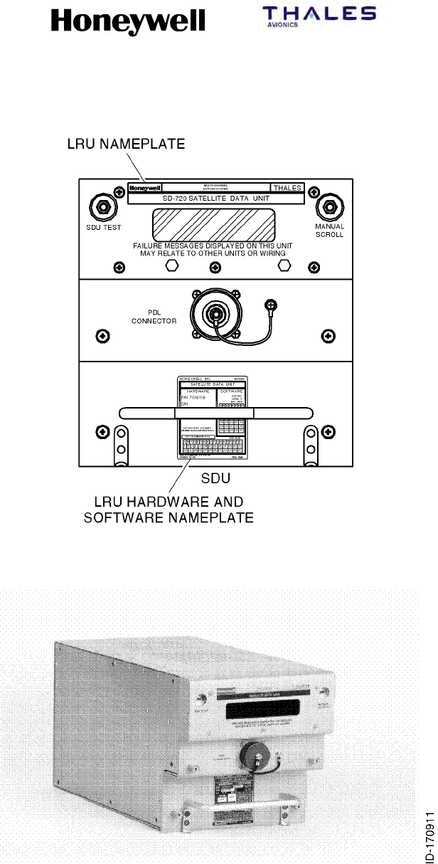
SYSTEM DESCRIPTION, INSTALLATION, AND MAINTENANCE MANUAL
MCS--4200/7200 Multi--Channel SATCOM System
23--20--35 15 Jul 2006
Honeywell International Inc. Do not copy without express permission of Honeywell.
Page 1--27
Figure 1-6. Satellite Data Unit

SYSTEM DESCRIPTION, INSTALLATION, AND MAINTENANCE MANUAL
MCS--4200/7200 Multi--Channel SATCOM System
23--20--35 15 Jul 2006
Honeywell International Inc. Do not copy without express permission of Honeywell.
Page 1--28
Table 1-11. SD--720 SDU Leading Particulars
Characteristic Specification
Dimensions (maximum):
•Height 7.624 in. (193.65 mm)
•Width 7.51 in. (190.75 mm)
•Length 15.26 in. (337.60 mm)
Weight (maximum) 25 lb. (11.4 kg)
Power requirements:
•AC Voltage at SDU terminals 100 to 122 V ac, 360 to 800 Hz (normal operation)
92 V ac, 320 Hz minimum; 134 V ac, 800 Hz
maximum; > 96 V ac, 320 to 800 Hz (startup)
•DC Voltage at SDU terminals 22.0 to 30.3 V dc (nominal operation)
20.5 to 32.2 V dc (maximum)
AC current requirements 1:
•Nominal at 115 V ac (current/power factor) 1.3 amps/0.70 @ 400 Hz
•Maximum at 92 V ac (current/power factor) 2.0 amps/0.82 @ 800 Hz
DC current requirements:
•Nominal at 28 V dc 3.8 amps
•Maximum at 20.5 V dc 7.0 amps
Circuit breaker ratings:
•115 V ac circuit breaker 3 amp TYPE A
•28 V dc circuit breaker 15 amp TYPE A
User replaceable parts None
Operating temperature -- 6 7 °F(--55°C) to + 158 °F(70°C)
Operating altitude to 55,000 ft (16.8 kilometers)
Cooling requirements 2:
•Minimum 0.15 ±0.05 in. (3.81 ±1.27 mm) of water at a flow
rate of 72.8 ±2.0 lb. (33.0 ±0.9 kg) per hour
•Maximum 0.25 ±0.05 in. (6.35 ±1.27 mm) of water at a flow
rate of 96.2 ±2.0 lb. (43.6 ±0.9 kg) per hour
Power dissipation 3:
•Nominal 105 W (OCXO at nominal current draw)
•Maximum 150 W (OCXO at maximum current draw)
NOTES:
1. All PF are leading.
2. Mounting trays with integral cooling fans that meet the cooling requirements are available from suitable vendors
(such as, ECS, EMTEQ).
3. The SDU draws an additional 20 W during the first 10 minutes (maximum) of operation at 77 °F(25°C) because of
the OCXO. The OCXO continuously dissipates this additional 20 W at --67 °F(--55°C).

SYSTEM DESCRIPTION, INSTALLATION, AND MAINTENANCE MANUAL
MCS--4200/7200 Multi--Channel SATCOM System
23--20--35 15 Jul 2006
Honeywell International Inc. Do not copy without express permission of Honeywell.
Page 1--29
Table 1-11. SD--720 SDU Leading Particulars (cont)
Characteristic Specification
Mating connectors:
•J1 Radiall Part No. NSXN2P201X0004
•J2 Honeywell Part No. 4004295--160, ITT Part No.
KJ6F18A53P
Mounting ARINC 600 6--MCU Tray Assembly
NOTES:
1. All PF are leading.
2. Mounting trays with integral cooling fans that meet the cooling requirements are available from suitable vendors
(such as, ECS, EMTEQ).
3. The SDU draws an additional 20 W during the first 10 minutes (maximum) of operation at 77 °F(25°C) because of
the OCXO. The OCXO continuously dissipates this additional 20 W at --67 °F(--55°C).
Table 1-12. SD--720 SDU DO--160D Environmental Categories
Environmental Condition Category
Temperature and altitude Category A2F21Z
Temperature variation Category B
Humidity Category A
Shock Category B
Vibration Category SB
Explosion Category E
Waterproofness Category X
Fluids susceptibility Category X
Sand and dust Category X
Fungus resistance Category X
Salt spray Category X
Magnetic effect Category Z
Power input Category A(WF)XBZ
Voltage spike Category A
Audio frequency susceptibility Category JZ
Induced signal susceptibility Category Z
Radio frequency susceptibility Category RR
Radio frequency emissions Category M
Lightning induced Category A2J33
Lightning direct Category X
Icing Category X
Electrostatic discharge Category A

SYSTEM DESCRIPTION, INSTALLATION, AND MAINTENANCE MANUAL
MCS--4200/7200 Multi--Channel SATCOM System
23--20--35 15 Jul 2006
Honeywell International Inc. Do not copy without express permission of Honeywell.
Page 1--30
C. High Speed Data Unit (HSU)
(1) The HSU is packaged as an ARINC 600 4 MCU LRU suitable for mounting in the
equipment bay. The mechanical chassis is constructed of lightweight aluminum alloy
sheet metal. Forced air which moves through the chassis in an upward or downward
direction supplies internal cooling. Two hold-down clamps enable the unit to be firmly
secured in the mounting rack. The unit is carried by a fixed C-shaped handle
mounted to the front panel assembly.
(2) The front panel assembly contains a PTT switch to initiate BITE and a red (FAIL) and
green (PASS) LED to indicate BITE status. The front panel also contains an ARINC
615 portable data loader connector and a test port (Ethernet). The HDM is accessed
via the front panel.
(3) The rear connector receptacle is a size No. 2 shell assembly (in accordance with
ARINC 600) that engages a mating connector in the mounting rack when the HSU is
installed. The top insert is a type 08 arrangement, the middle insert is a type 02
arrangement, and the bottom insert is a type 04 arrangement. Index pin code 03 is
used on both the HSU and the mounting rack connectors.
(4) The HSU is shown in Figure 1-7. The HSU leading particulars are listed in Table 1-13.
DO--160D environmental categories for the HSU are listed in Table 1-14.
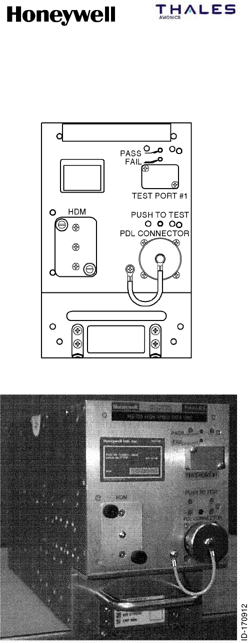
SYSTEM DESCRIPTION, INSTALLATION, AND MAINTENANCE MANUAL
MCS--4200/7200 Multi--Channel SATCOM System
23--20--35 15 Jul 2006
Honeywell International Inc. Do not copy without express permission of Honeywell.
Page 1--31
Figure 1-7. High Speed Data Unit

SYSTEM DESCRIPTION, INSTALLATION, AND MAINTENANCE MANUAL
MCS--4200/7200 Multi--Channel SATCOM System
23--20--35 15 Jul 2006
Honeywell International Inc. Do not copy without express permission of Honeywell.
Page 1--32
Table 1-13. HS--720 HSU Leading Particulars
Characteristic Specification
Dimensions (maximum):
•Height 7.624 in. (193.65 mm)
•Width 5.04 in. (128.02 mm)
•Length 15.07 in. (382.78 mm)
Weight (maximum) 16 lb. (7.3 kg)
Power requirements:
•AC Voltage at HSU terminals
•DC Voltage at HSU terminals
96 to 122 V ac, 360 to 800 Hz (normal operation) 92
V ac, 320 Hz minimum; 134 V ac, 800 Hz maximum;
≥96 V ac, 320 to 800 Hz (startup)
22.0 to 30.3 V dc (normal operation) 20.5 V dc
minimum, 32.2 V dc maximum
AC current requirements 1:
•Nominal at 115 V ac (current/power factor) 1.2 amps/0.70 @ 400 Hz
•Maximum at 92 V ac (current/power factor) 1.8 amps/0.79 @ 800 Hz
DC current requirements:
•Nominal at 28 V dc
•Maximum at 20.5 V dc
2.0 amps
5.0 amps
Circuit breaker ratings:
•115 V ac circuit breaker
•28 V dc circuit breaker
3 amp TYPE A
7.5 amp TYPE A
User replaceable parts None
Operating temperature -- 6 7 °F(--55°C) to + 158 °F(70°C)
Operating altitude to 55,000 ft (16.8 kilometers)
Cooling requirements 2:
•Minimum 0.15 ±0.05 in. (3.81 ±1.27 mm) of water at a flow
rate of 48.5 ±2.0 lb. (22.0 ±0.9 kg) per hour
•Maximum 0.25 ±0.05 in. (6.35 ±1.27 mm) of water at a flow
rate of 63.1 ±2.0 lb. (28.7 ±0.9 kg) per hour
NOTES:
1. All PFs are leading.
2. Mounting trays with integral cooling fans that meet the cooling requirements are available from suitable vendors
(such as, ECS, EMTEQ).
3. The HSU draws an additional 20 W during the first 10 minutes (maximum) of operation at 77 °F(25°C) because of
the OCXO. The OCXO continuously dissipates this additional 20 W at --67 °F(--55°C).

SYSTEM DESCRIPTION, INSTALLATION, AND MAINTENANCE MANUAL
MCS--4200/7200 Multi--Channel SATCOM System
23--20--35 15 Jul 2006
Honeywell International Inc. Do not copy without express permission of Honeywell.
Page 1--33
Table 1-13. HS--720 HSU Leading Particulars (cont)
Characteristic Specification
Power dissipation 3:
•Nominal 55 W (OCXO at nominal current draw)
•Maximum 100 W (OCXO at maximum current draw)
Mating connectors:
•J1 Radiall Part No. NSXN2P221X0003
•J2 Honeywell Part No. 4004295--160, ITT Part No.
KJ6F18A53P
Mounting ARINC 600 4--MCU Tray Assembly
NOTES:
1. All PFs are leading.
2. Mounting trays with integral cooling fans that meet the cooling requirements are available from suitable vendors
(such as, ECS, EMTEQ).
3. The HSU draws an additional 20 W during the first 10 minutes (maximum) of operation at 77 °F(25°C) because of
the OCXO. The OCXO continuously dissipates this additional 20 W at --67 °F(--55°C).
Table 1-14. HS--720 HSU DO--160D Environmental Categories
Environmental Condition Category
Temperature and altitude Category A2F2/Z
Temperature variation Category B
Humidity Category A
Shock Category B
Vibration Category SB
Explosion Category E
Waterproofness Category X
Fluids susceptibility Category X
Sand and dust Category X
Fungus resistance Category X
Salt spray Category X
Magnetic effect Category Z
Power input Category A(WF)HBZ
Voltage spike Category A
Audio frequency susceptibility Category JZ
Induced signal susceptibility Category Z
Radio frequency susceptibility Category RR
Radio frequency emissions Category M

SYSTEM DESCRIPTION, INSTALLATION, AND MAINTENANCE MANUAL
MCS--4200/7200 Multi--Channel SATCOM System
23--20--35 15 Jul 2006
Honeywell International Inc. Do not copy without express permission of Honeywell.
Page 1--34
Table 1-14. HS--720 HSU DO--160D Environmental Categories (cont)
Environmental Condition Category
Lightning induced Category A3J33
Lightning direct Category X
Icing Category X
Electrostatic discharge Category A
D. High--Power Amplifier (60 Watt)
(1) The HPA is an ARINC 600 8--MCU LRU suitable for mounting in the equipment bay
or near the antenna system. The mechanical chassis is constructed of lightweight
aluminum alloy sheet metal. Forced air which moves through the chassis in an
upward or downward direction supplies internal cooling. Two hold-down clamps hold
the unit firmly secured in the mounting rack. The unit is carried by a fixed C-shaped
handle mounted to the front panel assembly.
(2) The front panel assembly contains a PTT switch to initiate BITE and a red (FAIL) and
green (PASS) light emitting diode (LED) to indicate BITE status. The front panel also
contains an ARINC 615 portable data loader connector.
(3) The rear connector receptacle is a size No. 2 shell assembly (in accordance with
ARINC 600) that engages a mating connector in the mounting rack when the HPA is
installed. The top insert is a type 08 arrangement, the middle insert is a type 05
arrangement, and the bottom insert is a type 04 arrangement. Index pin code 08 is
used on both the HPA and mounting rack connectors.
(4) The 60 W HPA is shown in Figure 1--8. The leading particulars for the 60 W HPA are
listed in Table 1-15. DO--160D environmental categories for the 60 W HPA are listed
in Table 1-16.
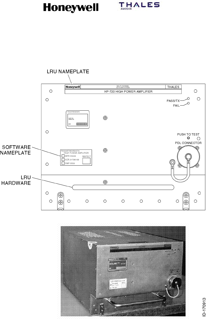
SYSTEM DESCRIPTION, INSTALLATION, AND MAINTENANCE MANUAL
MCS--4200/7200 Multi--Channel SATCOM System
23--20--35 15 Jul 2006
Honeywell International Inc. Do not copy without express permission of Honeywell.
Page 1--35
Figure 1-8. High Power Amplifier

SYSTEM DESCRIPTION, INSTALLATION, AND MAINTENANCE MANUAL
MCS--4200/7200 Multi--Channel SATCOM System
23--20--35 15 Jul 2006
Honeywell International Inc. Do not copy without express permission of Honeywell.
Page 1--36
Table 1-15. HP--720 60W HPA Leading Particulars
Characteristic Specification
Dimensions (maximum):
•Height 7.813 in. (198.45 mm)
•Width 10.22 in. (259.59 mm)
•Length 15.20 in. (386.08 mm)
Weight (maximum) 32.0 lb (14.5 kg)
Power requirements:
•AC voltage at HPA terminals
•DC voltage
96 to 122 V ac, 360 to 800 Hz (normal operation) 92
V ac, 320 Hz minimum; 134 V ac, 800 Hz maximum;
>96 V ac, 320 to 800 Hz (startup)
22.0 to 30.3 V dc (normal operation), 20.5 V dc
minimum, 32.2 V dc maximum
AC current requirements1:
•Nominal at 115 V ac (current/power factor) 2.5 amps/0.89 @ 400 Hz
•Maximum at 92 V ac (current/power factor) 5.1 amps/0.91 @ 800 Hz
DC current requirements:
•Nominal at 28 V dc
•Maximum at 20.5 V dc
9amps
21 amps
RF power output:
•Rated operating power 60 W (multiple carriers)
•Maximum power 80 W (short duration, single carrier)
Circuit breaker ratings:
•15 V ac circuit breaker
•28 V dc circuit breaker
7.5 amp TYPE A
30 amp TYPE A
User replaceable parts None
Operating temperature -- 6 7 °F(--55°C) to + 158 °F(70°C)
Operating altitude to 55,000 ft (16.8 km)
Cooling requirements 2:
•Minimum 0.2 ±0.12 in. (5.0 ±3.0 mm) of water at a flow rate
of 121.3 ±2.0 lb (55.0 ±0.9 kg) per hour
•Maximum 0.25 ±0.05 in. (6.35 ±1.27 mm) of water at a flow
rate of 176.4 ±2.0 lb (80.0 ±0.9 kg) per hour
Power dissipation:
•Nominal 250 W for VSWR = 1.0
NOTES:
1. All PFs are leading.
2. Mounting trays with integral cooling fans that meet the cooling requirements can be obtained from suitable vendors
(such as, ECS, EMTEQ).

SYSTEM DESCRIPTION, INSTALLATION, AND MAINTENANCE MANUAL
MCS--4200/7200 Multi--Channel SATCOM System
23--20--35 15 Jul 2006
Honeywell International Inc. Do not copy without express permission of Honeywell.
Page 1--37
Table 1-15. HP--720 60W HPA Leading Particulars (cont)
Characteristic Specification
•Maximum 425 W for VSWR = 1.0
Mating connectors:
•J1 Radiall Part No. NSXN2P221X0008
•J2 Honeywell Part No. 4004295--160, ITT Part No.
KJ6F18A53P
•J3 BNC Plug
Mounting ARINC 600 8--MCU Tray Assembly
NOTES:
1. All PFs are leading.
2. Mounting trays with integral cooling fans that meet the cooling requirements can be obtained from suitable vendors
(such as, ECS, EMTEQ).
Table 1-16. HP--720 60W HPA Environmental Categories
Environmental Condition Category
Temperature and altitude Category A2F2/Z
Temperature variation Category B
Humidity Category A
Shock Category B
Vibration Category SCLMY
Explosion Category E
Waterproofness Category X
Fluids susceptibility Category X
Sand and dust Category X
Fungus resistance Category X
Salt spray Category X
Magnetic effect Category Z
Power input Category A(WF)HBZ
Voltage spike Category A
Audio frequency susceptibility Category JZ
Induced signal susceptibility Category Z
Radio frequency susceptibility Category RR
Radio frequency emissions Category M
Lightning induced Category A3J33
Lightning direct Category X

SYSTEM DESCRIPTION, INSTALLATION, AND MAINTENANCE MANUAL
MCS--4200/7200 Multi--Channel SATCOM System
23--20--35 15 Jul 2006
Honeywell International Inc. Do not copy without express permission of Honeywell.
Page 1--38
Table 1-16. HP--720 60W HPA Environmental Categories (cont)
Environmental Condition Category
Icing Category X
Electrostatic discharge Category A
E. Radio Frequency Unit Interface Adapter (RFUIA)
(1) The RFUIA is an ARINC 600 4-MCU mounted in the equipment bay or near the
antenna system. It consists of a housing assembly integrated with an ARINC 600
connector on the back of the unit.
(2) The RFUIA is not an operational unit and it does not contain any active internal
electronic components. No aircraft power is needed. This unit is installed in the
aircraft in place of the RFU or HSU to complete the RF receive and transmit paths for
the MCS-4200/7200 system.
(3) The housing is constructed of lightweight aluminum alloy sheet metal. No forced-air
cooling is required. Two hold-down clamps hold the unit firmly in the mounting rack.
The unit is carried by a fixed C-shaped handle mounted to the front panel assembly.
(4) Figure 1--9 is a block diagram that shows how the RFUIA interfaces to the other
system LRUs. The RFUIA is shown in Figure 1--10. The leading particulars for the
RFUIA are listed in Table 1-17. DO--160D environmental categories for the RFUIA
are listed in Table 1-18.

SYSTEM DESCRIPTION, INSTALLATION, AND MAINTENANCE MANUAL
MCS--4200/7200 Multi--Channel SATCOM System
23--20--35 15 Jul 2006
Honeywell International Inc. Do not copy without express permission of Honeywell.
Page 1--39
Figure 1-9. RFUIA System Interface Diagram
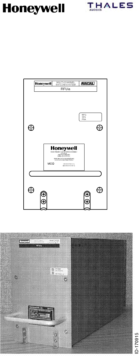
SYSTEM DESCRIPTION, INSTALLATION, AND MAINTENANCE MANUAL
MCS--4200/7200 Multi--Channel SATCOM System
23--20--35 15 Jul 2006
Honeywell International Inc. Do not copy without express permission of Honeywell.
Page 1--40
Figure 1-10. Radio Frequency Unit Interface Adapter

SYSTEM DESCRIPTION, INSTALLATION, AND MAINTENANCE MANUAL
MCS--4200/7200 Multi--Channel SATCOM System
23--20--35 15 Jul 2006
Honeywell International Inc. Do not copy without express permission of Honeywell.
Page 1--41
Table 1-17. RFUIA Leading Particulars
Characteristic Specification
Dimensions (maximum):
•Length
•Width
•Height
12.76 in. (324.1 mm)
4.90 in. (124.5 mm)
7.64 in. (194.1 mm)
Weight (maximum) 4lb.(1.82kg)
Power requirements None
Cooling Convection, no forced air required
Table 1-18. RFUIA DO--160D Environmental Categories
Environmental Condition Category
Temperature and altitude Category XXX
Temperature variation Category X
Humidity Category X
Shock Category B
Vibration Category SCLMY
Explosion Category X
Waterproofness Category X
Fluids susceptibility Category X
Sand and dust Category X
Fungus resistance Category X
Salt spray Category X
Magnetic effect Category Z
Power input -- 115 V ac Category X
Voltage spike Category X
Audio frequency susceptibility -- 115 V ac Category X
Induced signal susceptibility Category X
Radio frequency susceptibility Category XXX
Radio frequency emissions Category X
Lightning induced Category XXXX
Lightning direct Category X
Icing Category X
Electrostatic discharge Category X

SYSTEM DESCRIPTION, INSTALLATION, AND MAINTENANCE MANUAL
MCS--4200/7200 Multi--Channel SATCOM System
23--20--35 15 Jul 2006
Honeywell International Inc. Do not copy without express permission of Honeywell.
Page 1--42
F. ARINC 429 Data Requirements
(1) The MCS--4200/7200 system requires ARINC 429 data for antenna pointing, antenna
stabilization, and Doppler frequency correction.
G. Nameplates (SDU, HSU, HPA)
(1) General
(a) Except for the RFUIA, each MCS--4200/7200 LRU has three
externally--displayed, front panel--mounted nameplates which consist of:
•A logo nameplate
•A data matrix nameplate
•An identification (ID) nameplate.
(b) An example of the SD--720’s actual nameplate complement is shown in
Figure 1-11. The nameplates for the HS--720 and HP--720 are similar.
(2) Logo Nameplate
(a) Each logo nameplate contains both company logos (Honeywell and Thales), the
name of the system, the LRU equipment name, and the LRU model number
(such as, SD--720, HS--720, or HP--720).
(3) Data Matrix Nameplate
(a) Each data matrix nameplate contains the information that follows:
•Name of the certifying and manufacturing company
•LRU equipment name
•Manufacturer’s FSCM code (MFR)
•LRU serial number (SER)
•LRU inspection marking
•LRU inspection date (DMF).
(4) Identification (ID) Nameplate
(a) Each identification (ID) nameplate contains the information that follows:
•Name of the manufacturing company
•Model number (such as, SD--720, HS--720 or HP--720)
•LRU equipment name
•LRU end--item part number (including hardware and software portions)
•Weight
•Applicable DO--160D categories
•FCC identifier
•LRU hardware modification level
•LRU software modification level
•Applicable DO--178B software level
•Applicable DO--254 hardware level.
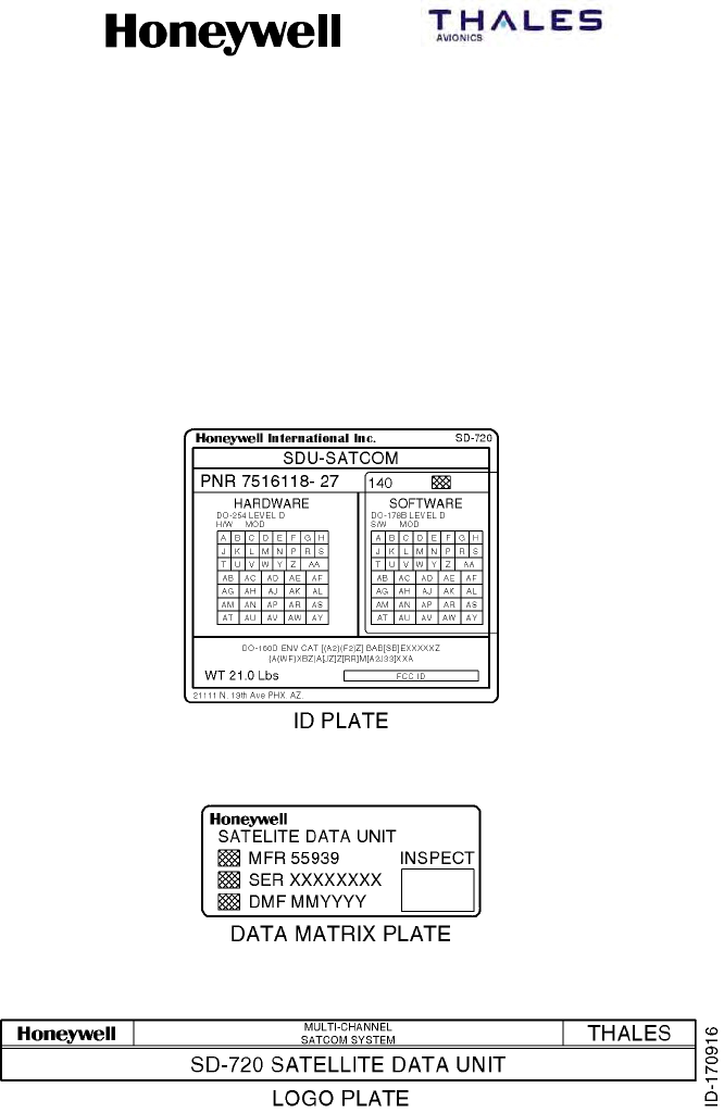
SYSTEM DESCRIPTION, INSTALLATION, AND MAINTENANCE MANUAL
MCS--4200/7200 Multi--Channel SATCOM System
23--20--35 15 Jul 2006
Honeywell International Inc. Do not copy without express permission of Honeywell.
Page 1--43
Figure 1-11. MCS--4200/7200 SDU LRU Labels

SYSTEM DESCRIPTION, INSTALLATION, AND MAINTENANCE MANUAL
MCS--4200/7200 Multi--Channel SATCOM System
23--20--35 15 Jul 2006
Honeywell International Inc. Do not copy without express permission of Honeywell.
Page 1--44
(b) The LRU model number is a five--digit alphanumeric sequence. The first two
digits are upper--case alphabetic characters in the range AA to ZZ and the last
three digits are numeric characters in the range 100 to 999. The LRU equipment
name is displayed with as many upper--case letters as are required to spell out
the equipment name. The LRU serial number consists of an eight--digit numeric
sequence.
(c) The DO--160D categories applicable to the MCS–4200/7200 system consist of a
mix of numeric and upper case alphabetic characters. See Table 1-12,
Table 1-14, or Table 1-16 for a list of environmental categories applicable to the
MCS--4200/7200 LRUs.
(d) The FCC identifier applicable to all MCS--4200/7200 LRUs is GB8MCS--4000 or
GB8MCS--7000. The LRU hardware modification level is indicated by the set of
all marked modification level identifiers. Each modification level identifier is a
maximum of two upper--case alphabetic characters that range from A to ZZ, with
letters I, O, Q, and X excluded.
(e) The MCS--4200/7200 LRU end item part number consists of a seven--digit base
part number and a five--digit dash number. The first two digits of the dash
number indicate the LRU hardware configuration and consist of numeric values
ranging from 10 to 99. The last three digits of the dash number reflect the LRU
software configuration and consist of numeric values ranging from 001 to 999.
(f) The hardware and software modification levels for any of the MCS--4200/7200
LRUs each consists of a maximum of two upper--case alphabetic characters
ranging from A (or “--”) to ZZ, with letters I, O, Q, and X excluded. Usage of this
nameplate characteristic reflects the implementation of minor hardware and
software changes in the given LRU.
(g) The DO--178B software levels and DO--254 hardware levels applicable to each
MCS--4200/7200 LRU indicate the level to which a given LRU was certified. The
identification (ID) nameplate can be removed and replaced when a software
change is significant enough to require the three--digit software configuration
number be incremented or a hardware change is significant enough to require
that the two--digit hardware configuration number be incremented.
H. Software and Hardware Compatibility (SDU, HSU and HPA)
(1) Provisions are included in each MCS--4200/7200 LRU to ensure hardware and
software compatibility. The settings for these provisions are manually changed each
time a hardware revision is made that is not compatible with all previously released
versions of software. The status of these settings is tested every time an LRU
undergoes a cold start (power--on self--test [POST], or person--activated self--test
[PAST]), and every time a software load is attempted from an ARINC 615 portable
data loader.

SYSTEM DESCRIPTION, INSTALLATION, AND MAINTENANCE MANUAL
MCS-4200/7200
TEMPORARY REVISION NO. 23-1
23-20-35 Page 29 of 53
28 Sep 2009
© Honeywell International Inc. Do not copy without express permission of Honeywell.
INSERT PAGE 29 OF 53 FACING PAGE 1-45.
Reason: To delete text that is not applicable, change the capitalization of INMARSAT to Inmarsat, and to
add “and” to Paragraph 5. A. (1).
Paragraph (1) is changed as follows:
(1) The MCS-4200/7200 SATCOM system is a powerful and versatile airborne communications
system. It provides the cockpit crew, cabin crew, and passengers with access to multi-channel
satellite-based telephony and packet-data functionality based on the proven ARINC 741/761
specifications. In addition, it furnishes the cabin with Inmarsat Swift64 connectivity through both
the circuit-switched (ISDN) and packet-switched (MPDS) versions of that service and the newer,
faster generation of SwiftBroadband services (that is, 432 kbps channel rates). In all respects, the
characteristics of the MCS-4200/7200 SATCOM system – size, weight, features, timeliness of
development, etc. – are well-suited to meet airline satellite communication needs well into the
future.

SYSTEM DESCRIPTION, INSTALLATION, AND MAINTENANCE MANUAL
MCS--4200/7200 Multi--Channel SATCOM System
23--20--35 15 Jul 2006
Honeywell International Inc. Do not copy without express permission of Honeywell.
Page 1--45
(2) The MCS--4200/7200 LRU header records in the ARINC 615 data loader software
upload file and in the operational software itself contain a list of hardware/software
compatibility strap codes which is compatible with the software. This list of codes is
compared with the wired hardware/software compatibility strap code in the LRU. If
any of the codes in the software upload file match the hardware/software
compatibility strap code in the LRU, the software upload process will be allowed
(otherwise, it will be inhibited). Similarly, if any of the codes in the software itself
match the strap code in the LRU, normal LRU operation will be allowed. Otherwise, it
will remain in a de--activated state.
5. Summary
A. General
(1) The MCS--4200/7200 SATCOM system is a powerful and versatile airborne
communications system. It provides the cockpit crew, cabin crew, and passengers
with access to multi-channel satellite-based telephony and packet-data functionality
based on the proven ARINC 741/761 specifications. In addition, it furnishes the cabin
with INMARSAT Swift64 connectivity through both the circuit--switched (ISDN) and
packet--switched (MPDS) versions of that service in a configuration easily modified to
accommodate the newer, faster generation of SwiftBroadband services (that is, 432
kbps channel rates) planned for late ’07 or ’08. In all respects, the characteristics of
the MCS-4200/7200 SATCOM system – size, weight, features, timeliness of
development, etc. – are well--suited to meet airline satellite communication needs
well into the future.

SYSTEM DESCRIPTION, INSTALLATION, AND MAINTENANCE MANUAL
MCS--4200/7200 Multi--Channel SATCOM System
23--20--35 15 Jul 2006
Honeywell International Inc. Do not copy without express permission of Honeywell.
Page 1--46
Blank Page

SYSTEM DESCRIPTION, INSTALLATION, AND MAINTENANCE MANUAL
MCS-4200/7200
TEMPORARY REVISION NO. 23-1
23-20-35 Page 30 of 53
28 Sep 2009
© Honeywell International Inc. Do not copy without express permission of Honeywell.
INSERT PAGE 30 OF 53 FACING PAGE 2-1.
Reason: To add references to MES, UE, LES, SAS, and SwiftBroadband to Paragraph 1. A. (1) and to
change the capitalization of INMARSAT to Inmarsat in Paragraph 2. A. (1).
Paragraphs 1. A. (1) and 2. A. (1) are changed as follows:
(1) The AES/MES/UE accepts data and voice signals from various sources, encodes the signals,
modulates the information onto the appropriate RF carrier frequencies, and transmits these
carriers to a GES/LES/SAS through satellite. The AES/MES/UE also receives RF signals from the
satellites, demodulates and decodes these signals, and outputs data or voice messages for
passengers or flight crew members. System operation begins when the P-channel transmission
from a GES in the satellite region is received. The AES then logs onto the GES to establish the
uplink and exchange information. If an HSU is installed, each of the Swift64 or SwiftBroadband
channels will sequentially register with an LES/SAS. System operation terminates when the AES
logs off from the GES.
(1) At any time, different satellite regions can have different satellite configurations. All satellites have
the global beam capability to receive the continuous Psmc-channel transmission of every GES in
view. For a spot beam satellite, each spot beam is associated with at least one GES having a
continuous P-channel transmission. Selected channels from the Psmc- and Pd-channels are
designated by Inmarsat for satellite and spot beam selection.

SYSTEM DESCRIPTION, INSTALLATION, AND MAINTENANCE MANUAL
MCS--4200/7200 Multi--Channel SATCOM System
23--20--35 15 Jul 2006
Honeywell International Inc. Do not copy without express permission of Honeywell.
Page 2--1
SECTION 2
SYSTEM OPERATION
1. Overview
A. General
(1) The AES accepts data and voice signals from various sources, encodes the signals,
modulates the information onto the appropriate RF carrier frequencies, and transmits
these carriers to a GES through satellite. The AES also receives RF signals from the
satellites, demodulates and decodes these signals, and outputs data or voice
messages for passengers or flight crew members. System operation begins when the
P--channel transmission from a GES in the satellite region is received. The AES then
logs onto the GES to establish the uplink and exchange information. If an HSU is
installed, each of the Swift64 channels will sequentially register with an LES. System
operation terminates when the AES logs off from the GES.
2. AES Management
A. General
(1) At any time, different satellite regions can have different satellite configurations. All
satellites have the global beam capability to receive the continuous Psmc--channel
transmission of every GES in view. For a spot beam satellite, each spot beam is
associated with at least one GES having a continuous P--channel transmission.
Selected channels from the Psmc-- and Pd--channels are designated by INMARSAT
for satellite and spot beam selection.
(2) An AES logs onto a GES to enter the satellite communications system and logs off to
terminate its operation in the system. Log-off is initiated automatically or by a user
command issued as part of normal operational procedures.
(3) The AES also logs off before initiating handover. The AES does not log off if
handover is initiated because of degradation or loss of the P--channel. Handover can
be initiated by the flight crew, or can be carried out automatically by the AES without
human intervention. A handover procedure is followed automatically when an AES
needs to change the log-on GES or to access a different satellite.
(4) When an AES receives a higher level instruction, for example, a command from the
flight crew, to change its log-on to another GES operating in the same satellite
region, any previously established data communication channels are maintained until
clearing before the handover is carried out. In the case of a user command-initiated
satellite-to-satellite handover, the AES ensures all communication channels are clear
prior to starting the handover procedure. If any connections are in progress, the AES
applies time supervision of three minutes and then clears any remaining connections.
(5) Automatic handover is initiated upon detection of Pd--channel link degradation
defined as:
•Error rate above 104over an averaging period of 3 minutes
•More than 10 short--term interruptions (loss of P--channel clock synchronization for
less than 10 seconds) in any 3 minute period.

SYSTEM DESCRIPTION, INSTALLATION, AND MAINTENANCE MANUAL
MCS--4200/7200 Multi--Channel SATCOM System
23--20--35 15 Jul 2006
Honeywell International Inc. Do not copy without express permission of Honeywell.
Page 2--2
(6) Automatic handover is also initiated upon detection of loss of the Pd--channel defined
as:
•Loss of clock synchronization for more than 10 seconds
•An unsucessful log-on renewal procedure.
(7) A GES-to-GES handover is carried out by logging onto a new GES in the same
satellite region. The required P--channel frequency can be found in the system table.
Each GES maintains an up-to-date status table of all AESs that have logged on.
Each GES also has an inter-GES signaling capability that permits the GES to set up
calls with any AES operating in the same satellite region as that GES, and manages
the AESs during handover.
(8) If the AES attempts to renew its log-on and fails to log on to its previous GES or to
the preferred alternative GES after a log-on prompt, loss of P--channel quality, or a
log-on renewal request from an application, the AES returns to the latter stages of
the initial search procedure and scans the spot beam primary Pd--channels on its
current satellite to identify an alternative spot beam. The required P--channel
frequencies are found in the system table. Once an alternative spot beam is
identified, the AES renews its log-on automatically to a preferred GES.
(9) During log-on renewal, if the AES is unable to log onto its previous GES or to another
GES in the same satellite region, then the AES enters the search mode to select the
Psmc--channel frequency of a GES operating in a new satellite region. The required
P--channel frequency is found in the system table. Having selected a new suitable
quality Psmc--channel (in another satellite region) and updating the system table for
the new satellite region (if necessary), the AES carries out a log-on procedure with
the new GES.
(10) Each AES maintains a system table stored in nonvolatile memory in the SDU. The
system table contains the data EIRP table, the satellite and GES identifying
information, such as satellite Psid--channel frequencies, satellite locations and
associated GES IDs, GES capabilities, and GES Psmc--channel frequencies. The
system table does not lose its contents because of loss of primary power.
(11) The SDU also maintains a bootstrap system table containing a default set of satellite
and GES identifying information. This information includes satellite Psid--channel
frequencies, satellite location and associated GES IDs, plus satellite inclination and
right ascension, spot beam support, and GES Psmc--channel frequencies that are set
to zero.
(12) The bootstrap system table is loaded into the SDU as an inseparable part of the
upload of executable software. The SDU defaults to the bootstrap system table in the
absence of a stored system table, or upon execution of a factory settings restart. The
default data for a satellite is used until that satellite is first accessed. Then a complete
update of the data for that satellite happens. Satellite region blocks that have not yet
been updated over the air are marked with a null revision number.

SYSTEM DESCRIPTION, INSTALLATION, AND MAINTENANCE MANUAL
MCS-4200/7200
TEMPORARY REVISION NO. 23-1
23-20-35 Page 31 of 53
28 Sep 2009
© Honeywell International Inc. Do not copy without express permission of Honeywell.
INSERT PAGE 31 OF 53 FACING PAGE 2-3.
Reason: To add references to Swift64, SwiftBroadband, and SAS, as well as incorporate other minor
changes, to Paragraphs B. (1) thru (4). Some text was deleted.
Paragraphs B. (1) thru (4) are changed as follows:
(1) If an HSDU is installed, each of its channels sequentially register for Swift64 or
SwiftBroadband service when the AES achieves log-on.
(2) The LES/SAS selected for registration is based on satellite and LES/SAS preference set in the
ORT.
(3) Two sets of preferences in the ORT define MPDS and ISDN preferences since service
providers may be different between MPDS and ISDN. The respective MPDS or ISDN Swift64
service is only initiated if and when the service is initiated by a ground or airborne user.
(4) The registration process starts with the preferred LES/SAS. A preference level of 9 is the
highest and 1 is the lowest and 0 indicates no access.

SYSTEM DESCRIPTION, INSTALLATION, AND MAINTENANCE MANUAL
MCS--4200/7200 Multi--Channel SATCOM System
23--20--35 15 Jul 2006
Honeywell International Inc. Do not copy without express permission of Honeywell.
Page 2--3
B. HSDU Installed
(1) If an HSDU is installed, each of the four channels sequentially register for ISDN
service when the AES achieves log--on.
(2) The LES selected for registration is based on satellite and LES preference set in the
ORT.
(3) A second set of preferences in the ORT defines MPDS operation since service
providers may be different between MPDS and ISDN. MPDS registration only occurs
if and when an MPDS session is initiated.
(4) The registration process starts with the preferred LES. A preference level of 9 is the
highest and 1 is the lowest and 0 indicates no access.
3. System Log-On/Log-Off
A. General
(1) Two operational modes are available for AES log-on:
•Automatic
•User commanded (constrained).
(2) In the automatic mode, the AES operation is fully automatic with satellite log-on and
handover procedures occurring without external control. In the user commanded
mode, the flight crew or flight control system is able to select the satellite and GES for
log-on and handover, and can initiate handovers at any time. The automatic mode is
considered the normal mode of operation.
(3) The log-on/log-off of an AES to/from the satellite communications system lets the
GES manage the number of AESs that can receive a P--channel (Pd) and transmit on
each R--channel (Rd). This controls the queuing delays and burst collision
probabilities that can be experienced. When an AES is powered up, it enters a GES
selection mode if the log-on policy is set to automatic. This permits the AES to select
the most preferred GES operating in its visible satellite region (there may be one or
two satellites visible to the AES), and that GES is selected for log-on. If the log-on
policy is not set to automatic, the AES waits for the GES to be selected through the
user commanded mode (or for a reversion to the automatic mode).
(4) After selecting a GES, the AES tries to acquire one of the identifying Psmc--channel
(Psid) frequencies of the satellite contained in the initial system table. Typically there
are two frequencies per satellite (or group of satellites if several satellites supply
service to essentially one region). The AES receives that Psmc--channel until one of
the system table’s broadcast signal units is received, which permits the AES to
determine whether the revision number of the system table currently stored in the
SDU is valid. If the revision number for the AES is out-of-date, an AES updating
procedure is implemented.

SYSTEM DESCRIPTION, INSTALLATION, AND MAINTENANCE MANUAL
MCS--4200/7200 Multi--Channel SATCOM System
23--20--35 15 Jul 2006
Honeywell International Inc. Do not copy without express permission of Honeywell.
Page 2--4
(5) When the revision number is verified as correct, the AES checks for any entries in the
satellite spot beam search table. If an entry exists, the AES checks the Pd--channel
frequencies of all spot beams supported by the selected GES to identify the most
applicable spot beam. The AES then determines which Pd--channel has the highest
signal quality. Once this task is complete, the AES is ready to log-on to the satellite
communications system using the selected GES and the optimum spot beam, or the
global beam if the GES does not operate a P--channel in the required spot beam.
(6) The AES initiates the log-on procedure by tuning to the Psmc--channel (global beam)
of the selected GES and sending a log-on request signal unit on one of the
corresponding Rsmc--channels. If the log-on request signal unit cannot be accepted
by the GES, because of reasons like GES overload, invalid message, unauthorized
access, etc, the GES responds with a log-on reject signal unit, which includes the
cause of the rejection. Upon receipt of a log--on reject, the AES will select the next
most preferred GES.
(7) The AES uses the log-on request signal unit to supply the selected GES with its own
identification (a 24-bit ICAO aircraft identification code), plus the identification of the
spot beam where the AES is located. A zero value is used in the spot beam
identification field of the log-on message if:
•No spot beam on the selected satellite
•AES is out of any spot beam coverage area
•Selected GES does not operate a Pd--channel in the required spot beam.
(8) The AES also informs the GES of the number of C--channels the AES is equipped to
handle, the bit rate/coding algorithm in use on the voice channels, and the data bit
rate capability for the R--channels, P--channels, and T--channels. Except for the
number of C--channels and the data bit rate capability, this information is repeated in
the log-on confirm signal unit for use by other GESs.
(9) An AES having circuit-mode data service capability and desiring allocation of
circuit-mode data capable channel units at the GES for every ground-to-air call,
informs the GES of the type of interface required. The interface is either analog
interconnect or digital interconnect. If the GES does not support circuit-mode data
service, it ignores the information. If the GES supports the service, it registers the
information in its log-on AES table and retransmits the information for use by other
GESs.
(10) The AES supplies the GES with its flight identification number at log-on, if the
owner/operator of the AES desires to use the aircraft flight identification as the
address for ground originated calls. The use of this information in the GES depends
upon the services being offered, and therefore is at the discretion of the GES
operator.

SYSTEM DESCRIPTION, INSTALLATION, AND MAINTENANCE MANUAL
MCS--4200/7200 Multi--Channel SATCOM System
23--20--35 15 Jul 2006
Honeywell International Inc. Do not copy without express permission of Honeywell.
Page 2--5
(11) The AES selects the appropriate EIRP setting for Rd--channels and T--channels from
the data EIRP table. The GES assigns a Pd--channel from the available channels,
taking into account the loadings on the channels, the need to use a P--channel of low
power if possible, and the need to supply some means of recovery from P--channel
degradation or failure. The ability to work with a low power P--channel is determined
by the AES class. If the GES assigns a Pd--channel different than the Psmc--channel,
the GES transmits the new channel frequency to the AES using the P/R--channel
control signaling message following the log-on confirm.
(12) If the GES is using more than one set of R--channel frequencies and assigns new
Rd--channels to the aircraft, the GES transmits the new channel frequencies (up to
eight) to the AES using the signaling message(s) that follow the log-on confirm. In
addition, the GES transmits from one to four T--channel frequencies to the AES if
data services are supplied.
(13) The GES assigns data channels at the highest agreeable bit rate supplied in both the
AES and GES, and supported by the combination of the satellite in use and the class
of AES. Subsequent log-on transactions for handover use Rsmc-- and
Psmc--channels in the same manner as the initial log-on transaction.
B. Automatic Log-On
(1) The SDU supports two types of log-on:
•Automatic
•Constrained mode.
(2) The SDU implements the automatic log-on mode upon user command if the AES is
currently logged-off, AES is logging-on, or AES is logged-on in the constrained mode.
Automatic log-on is also implemented by the SDU, if ORT item i (log-on policy)
indicates automatic at startup. The user command can originate from either the
SCDU, from the analog connected telephone handsets, or from the commissioning
and maintenance terminal (CMT).
(3) When the AES is in the automatic mode, the log-on GES/satellite/spot beam chosen
is based on the GES preference (ORT item iii). A GES with a preference level of zero
is not considered for automatic log-on. The SDU allows the use of tied GES
preferences. The SDU resolves tied preferences by selecting the GESs in
descending order of satellite elevation. During GES selection, the set (as yet untied)
of GESs with the highest preference are initially processed to exclude those GESs
associated with satellites not in view.
(4) Satellites are deemed in view if they are above the elevation handover threshold
specified in ORT item xxxix, or their elevation is higher than 1 degree less than the
elevation of the highest satellite. If no IRS data is available and the currently selected
antenna is the low gain antenna, then all satellites are deemed to be in view. The
remainder of the GESs in the preference group are then sorted into a list by satellite
elevation and GES on the highest elevation satellite chosen for initial access. If more
than one GES in the preference group have the same satellite elevation, then those
GESs are ordered by a pseudo-random choice algorithm with a uniform probability
density.

SYSTEM DESCRIPTION, INSTALLATION, AND MAINTENANCE MANUAL
MCS--4200/7200 Multi--Channel SATCOM System
23--20--35 15 Jul 2006
Honeywell International Inc. Do not copy without express permission of Honeywell.
Page 2--6
C. Constrained Log-On
(1) Constrained log-on is where the user manually selects the specific GES to be used
for log-on. The user command can originate from either the SCDU, from the
analog-connected telephone handsets, or from the CMT. The GES preferences
specified in ORT item iii have no effect in the constrained log-on mode, and it is
possible to execute a constrained log-on to a GES with a preference level of zero.
(2) If the user has manually selected the log-on GES, and therefore also selected the
satellite, the SDU is constrained to search for the specific GES-related satellite Psid
frequency (or frequencies), the set of spot beam Pd frequencies where the selected
GES radiates P--channels, and the selected GES Psmc frequency during the log-on
sequences. If the specific GESs satellite Psid frequencies cannot be acquired, the
SDU takes no action other than to reattempt the acquisition with alternate modems. If
none of the GES-related spot beam Pd frequencies can be acquired, the SDU starts
the GES Psmc frequency search as it would normally do after acquiring a spot beam
frequency. If the GES Psmc frequency cannot be acquired, the SDU reattempts the
acquisition indefinitely. This state of unsuccessful satellite/GES Psmc frequency
acquisition is exited either by the frequency being acquired, or by a user command to
select automatic log-on, by selection of a different satellite/GES, or to log-off.
(3) Once logged-on in this mode with the GES constrained, only spot beam handover
takes place. The user is able to exit this constrained log-on mode by commanding
log-off, by selecting the automatic log-on mode, or by cycling SDU primary power (if
ORT item i log--on policy is auto log--on.
D. Log-On Mode Selection
(1) User selection of the automatic log-on mode while the AES is logging-on in the
constrained mode causes the SDU to abort the current log-on attempt and revert to
the automatic mode. User selection of the automatic log-on mode while the AES is
logged-on in the constrained mode causes the SDU to log-off from the current
constrained GES, and to revert to the automatic mode if there are GESs in view with
higher preference levels than the current log-on GES. User selection of the automatic
mode when the AES is logged-off causes the SDU to implement automatic log-on.
The SDU lets the user command log-off while the AES is logging-on or logged-on in
the constrained or automatic mode.
(2) The user is able to change the selected GES if the AES is logging-on or is logged on
in the constrained mode. The user can enter the constrained mode by selecting a
specified GES while the SDU is logging-on or is logged-on in the automatic mode. In
both cases, providing the constrained GES selection is different from the
automatically chosen GES, the SDU either aborts the current log-on attempt or
logs-off from the current GES before attempting to log-on to the new GES, depending
upon the current status.

SYSTEM DESCRIPTION, INSTALLATION, AND MAINTENANCE MANUAL
MCS--4200/7200 Multi--Channel SATCOM System
23--20--35 15 Jul 2006
Honeywell International Inc. Do not copy without express permission of Honeywell.
Page 2--7
E. Handover
(1) The SDU causes the AES to initiate a handover procedure for the following reasons:
•Automatic handover occurs when the AES is logged-on in the automatic or
constrained mode, because of P--channel degradation.
•Automatic handover occurs when the AES is logged-on in the automatic mode,
because of the log-on satellite being below the elevation handover threshold
specified in ORT item xxxix, with another satellite being at least 1 degree higher
than the log-on satellite for more than 10 seconds.
•Automatic handover occurs as specified in ORT item xxii for 10 seconds because
of the reported HGA Tx gain being less than the threshold value when the AES is
logged-on in the automatic or constrained mode.
•User command is issued to select the constrained mode when the AES is
logged-on (or awaiting log-on acknowledge) in the automatic mode if the
constrained selection is different from the current, automatically selected GES.
•User command is issued to select the constrained mode for a particular GES
when the AES is currently logged-on (or awaiting log-on acknowledge) to a
different GES, but also in the constrained mode.
•User command is issued to select the automatic mode when the AES is logged-on
(or awaiting log-on acknowledge) in the constrained mode if a GES exists with a
higher preference level than the current log-on GES.
•User command is issued to adjust the GES preference levels if the AES is
logged-on (or awaiting log-on acknowledge) in the automatic mode, and the
adjustment results in any GES having a higher preference level than the current
log-on GES.
(2) The SDU logs off from the current log-on GES before logging onto the new GES for
all of the above handover stimuli, except for automatic handover because of
P--channel degradation and automatic handover because of the reported HGA Tx
gain being less than the threshold value.
(3) If any modems are being used for circuit--mode voice when a handover to a GES in a
different satellite region occurs, then the SDU terminates the current C--channel calls
with an SLCV cause of 1221x. The SDU also causes a suitable voice pacifier
message (Sorry, your call can no longer be sustained) to be sent to each currently
in-use digital or analog headset to inform each user of the reason for the call
termination. The SDU does not clear down any ongoing C--channel calls if the
handover is local to the current satellite region.
F. Log-Off
(1) Log-off is initiated in the AES by a user command, either from the SCDU, from the
analog-connected telephone handset, or from the CMT. Log-off is also initiated by the
SDU as part of the handover sequence, except for handovers implemented because
of P--channel degradation.

SYSTEM DESCRIPTION, INSTALLATION, AND MAINTENANCE MANUAL
MCS--4200/7200 Multi--Channel SATCOM System
23--20--35 15 Jul 2006
Honeywell International Inc. Do not copy without express permission of Honeywell.
Page 2--8
4. System Software/Database Updates
A. General
(1) Each MCS LRU (SDU and HPA) has an ARINC 615 Airborne Data Loader (ADL) and
PDL port. The SDU and HPA are capable of transferring the data sets listed in
Table 2-1 through these ports.
Table 2-1. Data Set Upload/Download
LRU Data Set Upload/Download
SDU Operational Software Upload Only
Owner Requirements Table Upload and Download
Event and Failure Logs Download Only
Maintenance Activity Log Download Only
Periodic Data Logging (SDU system and
operational parameters)
Download Only
HPA Operational Software Upload Only
(2) In Table 2-1, upload is defined as the transfer of a data set from the ARINC 615 data
loader to the appropriate LRU. A download is defined as the transfer of a data set
from an appropriate LRU to the ARINC 615 data loader. The data set to be
transferred is independent of the port used. If during a data transfer session the other
port becomes active, the session associated with the initially activated port continues
to completion before initiating any session with the other port. The software upload
function is resident in the bootstrap program and functions independently of any
uploadable software in the LRU.
B. Software Upload Process
(1) The uploading of the software is done by either connecting a PDL to the ARINC 615
connector port on the LRU to be programmed, or (in the case of an ADL) by the user
selecting the LRU to be programmed. With the data loader connected, the Link A
connection is completed.
(2) The diskette containing a configuration file and a file containing the software to be
uploaded is inserted into the disk drive of the data loader. The configuration file
contains information for the data loader (ADL or PDL) to configure itself for operation.
All MCS ORT download/upload diskettes contain a configuration file located in the
root directory of the diskette with the filename CONFIG.LDR. The data loader reads
the configuration file and initializes itself according to the parameters read. The data
loader then repeatedly transmits an RTS word.

SYSTEM DESCRIPTION, INSTALLATION, AND MAINTENANCE MANUAL
MCS-4200/7200
TEMPORARY REVISION NO. 23-1
23-20-35 Page 32 of 53
28 Sep 2009
© Honeywell International Inc. Do not copy without express permission of Honeywell.
INSERT PAGE 32 OF 53 FACING PAGE 2-8.
Reason: To add references to HSU to Paragraph 4. A. (1).
Paragraph 4. A. (1) is changed as follows:
(1) Each MCS LRU (SDU, HSU, and HPA) has an ARINC 615 Airborne Data Loader (ADL) and PDL
port. The SDU and HPA are capable of transferring the data sets listed in Table 2-1 through these
ports. The HSU is capable of software loading through its ADL/PDL ports and via its front-panel
RJ-45 Ethernet port.

SYSTEM DESCRIPTION, INSTALLATION, AND MAINTENANCE MANUAL
MCS-4200/7200
TEMPORARY REVISION NO. 23-1
23-20-35 Page 33 of 53
28 Sep 2009
© Honeywell International Inc. Do not copy without express permission of Honeywell.
INSERT PAGE 33 OF 53 FACING PAGE 2-9.
Reason: To add HSU to Paragraph (4).
Paragraph (4) is changed as follows:
(4) The HPA and HSU software is similarly initiated only after the requirements mentioned are
satisfied, except software uploading is also enabled when a valid air/ground status from the
SDU is not available to the LRU.

SYSTEM DESCRIPTION, INSTALLATION, AND MAINTENANCE MANUAL
MCS--4200/7200 Multi--Channel SATCOM System
23--20--35 15 Jul 2006
Honeywell International Inc. Do not copy without express permission of Honeywell.
Page 2--9
(3) With the operational software running, the SDU software upload is initiated only after:
•SDU senses the low impedance state on Link A.
•SDU determines it is not airborne (unless the operational software is not valid
where the on-ground/airborne state is ignored).
•SDU detects receiving an RTS word with a system address label (SAL) equal to
307.
(4) The HPA software is similarly initiated only after the requirements mentioned are
satisfied, except software uploading is also enabled when a valid air/ground status
from the SDU is not available to the LRU.
(5) For the LRUs, the software upload is a single pass process. Upload validation checks
both the LRU and SRU header records for applicability. Each data loader block is
then transferred directly to the program store. When the software upload is
completed, the program store CRC is checked over defined regions of the program
store. If either validation process fails, the software upload process aborts. Further
upload attempts can only be initiated by resetting both the data loader and the LRU.
When successfully validated, the LRU causes the data loader to initiate the transfer
complete function and the LRU remains in the data load state, while the Link A
connection remains intact. When the Link A connection is removed, the HPA
performs a POST and the SDU performs a factory settings restart. A factory settings
restart results in Category C nonvolatile data being set to default values followed by
execution of POST/PAST.
C. Validation of the Software Upload File
(1) The following items are validated when software is loaded:
•First two bytes of each LRU/SRU header record indicates a valid record type for
the record position in the data sequence.
•Company name in the LRU header record must be HONEYWELL/RACAL.
•LRU name and base part number must match the current LRU specification as
given on the LRU nameplates.
•Software compatibility codes in each SRU ID PROM must appear in the list of
compatible hardware/software codes for every SRU listed in the LRU header.

SYSTEM DESCRIPTION, INSTALLATION, AND MAINTENANCE MANUAL
MCS--4200/7200 Multi--Channel SATCOM System
23--20--35 15 Jul 2006
Honeywell International Inc. Do not copy without express permission of Honeywell.
Page 2--10
5. Owner Requirements Table
A. General
(1) The ORT is stored in nonvolatile memory in the SDU. The ORT contains information
relating to different areas of functionality like log-on and telephony. The ORT does
not lose its contents because of the loss of SDU primary power or as a result of
PAST. All ORT contents are set to default values by a factory settings restart. The
ORT contains all pilot and aircraft operator entered information preserved when the
SDU is powered-down.
(2) Validity of the ORT content is determined by the SDU using a checksum process.
This verification is performed at the time of each power-up. An invalid checksum
results in the SDU reverting to the default values specified in TESTING/FAULT
ISOLATION, ORT default value usage. The contents of the ORT are specified in
Appendix C.
(3) The ORT items are organized into two distinct partitions:
•Secured
•User.
(4) The individual ORT items defined in Table C--1 are assigned to a partition by the
designation of secured or user in the attributes column.
(5) The secured partition contains those items the equipment manufacturer, aircraft
manufacturers, and certification authorities have determined to be
configuration-dependent and crucial to the proper operation of the SATCOM system.
The user partition contains all other items of the ORT. The user partition typically
includes items the aircraft operator is able to set or modify, enabling the efficient use
of the equipment in normal operation. A composite ORT file contains all items (both
partitions) in the ORT. This version of ORT is defined to supply a consistent interface
(single ORT file) to those users that do not require the additional security supplied by
the management of two partitions for essential certification.
(6) The content of the ORTs in both SDUs in a dual system is intended to be identical.
For the sake of ORT requirements that must be capable of being different in SDUs 1
and 2, the ORT items affected are duplicated within the ORT. Each of those items is
capable of storing separate, independent entries for SDUs 1 and 2, to be used by
each particular SDU as appropriate based on the strapping of its system
configuration pins TP13E/F. The lone SDU in a single system uses the entry for SDU
1 for duplicated items. ORT items not duplicated are said to be common, where the
single entry applies to SDUs 1 and 2 in dual systems as well as to the lone SDU in a
single system.

SYSTEM DESCRIPTION, INSTALLATION, AND MAINTENANCE MANUAL
MCS--4200/7200 Multi--Channel SATCOM System
23--20--35 15 Jul 2006
Honeywell International Inc. Do not copy without express permission of Honeywell.
Page 2--11
6. ORT Upload/Download Process
A. General
(1) Each ORT download/upload diskette contains a configuration file. The configuration
file contains information for the data loader (ADL or PDL) to configure itself for
operation. All MCS ORT download/upload diskettes contain a configuration file
located in the root directory of the diskette with the filename CONFIG.LDR.
(2) The ORT upload/download file is named SDU_ORT.TAB. This file is made up of an
ORT header record followed by the ORT data. The ORT format version in the ORT
header record is an indication of the ORT data contained in the upload/download file.
B. Startup
(1) ORT downloading/uploading is initiated through the SCDU page or the CMT page.
The diskette containing a configuration file is inserted into the data loader, which
reads the configuration files and initializes itself according to the parameters read.
The data loader then repeatedly transmits a POLL word. The LRU detects receiving a
POLL word and initiates the ORT download/upload.
(2) In the event no configuration file is present or the diskette is not formatted, the data
loader solicits a subsystem identification. The SDU does not respond to the
command and the data loader performs a change disk or a read/write fail.
C. ORT Download
(1) The ORT file is transferred using the control mode download sequence. If insufficient
space exists to contain an ORT, the transfer operation terminates. A file name
SDU_ORT.TAB is created on the ORT diskette. This file replaces any existing file with
the same name. An ORT header is written at the head of the file. The ORT format
version written into the header is the latest version supported by the installed
software build. After transferring the header record, the ORT data is written to the file
until the whole data table is transferred. The file is then closed and a load complete
function is commanded. When an error is detected during the ORT download (that is,
unable to create file, ARINC 615 transfer failure, etc.) the download process aborts
and an ADL/PDL error status is indicated on the SCDU/CMT.
D. Control Mode ORT Upload Procedures
(1) Upload the ORT through the MCDU (SCDU)
(a) Make sure the ADL switch in the cockpit has SDU (SAT or SATCOM) selected, or
a PDL is connected to the SDU and the MCS system is logged off.
(b) Insert an ORT diskette containing the ORT file SDU_ORT.TAB, plus the
CONFIG.LDR file into the ADL/PDL.

SYSTEM DESCRIPTION, INSTALLATION, AND MAINTENANCE MANUAL
MCS--4200/7200 Multi--Channel SATCOM System
23--20--35 15 Jul 2006
Honeywell International Inc. Do not copy without express permission of Honeywell.
Page 2--12
(c) Access the SDU data loader menu from the MCDU through the following path:
•MCDU main menu
•SATCOM main menu
•Submenu
•Maintenance (Boeing aircraft only)
•Data loader.
(d) Make sure line 1L indicates ready.
(e) Select line 2L (*UPLD OWNER REQS).
(f) When the MCDU displays CONNECTED, the data upload is complete. Remove
the diskette from the ADL/PDL. Disconnect the ADL/PDL from the SDU and
initiate PAST in the SDU.
(2) Upload the ORT through the CMT
(a) Make sure the PDL is connected to the SDU through the appropriate connector
on the interface cable, and the MCS system is logged off.
(b) Insert an ORT diskette containing the ORT file SDU_ORT.TAB, plus the
CONFIG.LDR file into the PDL.
(c) Access the SDU data loader menu from the CMT by performing the following key
entries from the CMT main menu:
•D (SDU maintenance menu)
•B (data loader menu).
(d) Make sure the data loader menu screen indicates PDL ready.
(e) Select G (load owner requirements table from diskette).
(f) When the PDL diskette activity stops, push enter and make sure the CMT
displays ADL or PDL CONNECTED. The data upload is complete. Remove the
diskette from the ADL/PDL. Disconnect the PDL from the SDU and initiate PAST
in the SDU.
(3) Upload the ORT through the CMTI (Windows)
(a) Make sure the PDL is connected to the SDU through the appropriate connector
on the interface cable, and the MCS system is logged off.
(b) Insert an ORT diskette containing the ORT file SDU_ORT.TAB, plus the
CONFIG.LDR file into the PDL.
(c) Access the SDU data loader menu from the CMT by performing the following
from the CMTI main menu:
•Select the ORT menu
•Select the ORT Transfer menu
•Select the PDL to SDU option.

SYSTEM DESCRIPTION, INSTALLATION, AND MAINTENANCE MANUAL
MCS-4200/7200
TEMPORARY REVISION NO. 23-1
23-20-35 Page 34 of 53
28 Sep 2009
© Honeywell International Inc. Do not copy without express permission of Honeywell.
INSERT PAGE 34 OF 53 FACING PAGE 2-13.
Reason: To change the capitalization of INMARSAT to Inmarsat in Paragraph 7. A. (1).
Paragraph 7. A. (1) is changed as follows:
(1) The SDU supports cockpit and cabin voice services (refer to SYSTEM DESCRIPTION for a
description of cabin/cockpit communications) that use the Inmarsat aeronautical satellite
system. Cockpit voice services use the equipment currently found on the flight deck (that is,
headsets, call lamps, chime, chime reset, push-to-talk switches, and audio control panels and
audio management systems) as shown in Figure 2-1. Cabin voice services are
accommodated by the following:

SYSTEM DESCRIPTION, INSTALLATION, AND MAINTENANCE MANUAL
MCS--4200/7200 Multi--Channel SATCOM System
23--20--35 15 Jul 2006
Honeywell International Inc. Do not copy without express permission of Honeywell.
Page 2--13
(d) Make sure the status line indicates Data Transfer in Progress.
(e) When the PDL diskette activity stops, the status line should indicate Transfer
Complete. Remove the diskette from the ADL/PDL. Disconnect the PDL from the
SDU and initiate PAST in the SDU.
E. Auto Mode ORT Upload Procedure
(1) Make sure the PDL is connected to the SDU through the appropriate connector on
the interface cable, and the MCS system is logged off.
(2) Insert into the PDL an ORT diskette containing a CONFIG.LDR file and a ORT file
created by the ORTool as an Auto Mode,Boeing Mode,orB777 Mode Loader File
Type.
(3) Make sure the status line indicates Data Transfer in Progress.
(4) When the PDL diskette activity stops, the status line should indicate Transfer
Complete. Remove the diskette from the ADL/PDL. Disconnect the PDL from the
SDU and initiate PAST in the SDU.
7. Circuit-Mode Services
A. Circuit-Mode Voice
(1) The SDU supports cockpit and cabin voice services (refer to SYSTEM
DESCRIPTION for a description of cabin/cockpit communications) that use the
INMARSAT aeronautical satellite system. Cockpit voice services use the equipment
currently found on the flight deck (that is, headsets, call lamps, chime, chime reset,
push-to-talk switches, and audio control panels and audio management systems) as
shown in Figure 2-1. Cabin voice services are accommodated by the following:
•CCS including a CTU interfacing with the SDU.
•Standard interwiring interfaces reserved for cabin audio to supply priority 4
services. These SDU interfaces support analog voice with in-band DTMF dialing
and some discrete signaling.
B. Circuit-Mode Data
(1) General
(a) Once a call is established and two-way communication exists using a C--channel,
the C--channel can be used for purposes other than the initial (default) purpose
of carrying real-time voice signals using the defined codec standard.
Circuit-mode data services can be used to support a variety of communication
applications like interactive or bulk data communication, encrypted voice/data
communication, and facsimile transmission.
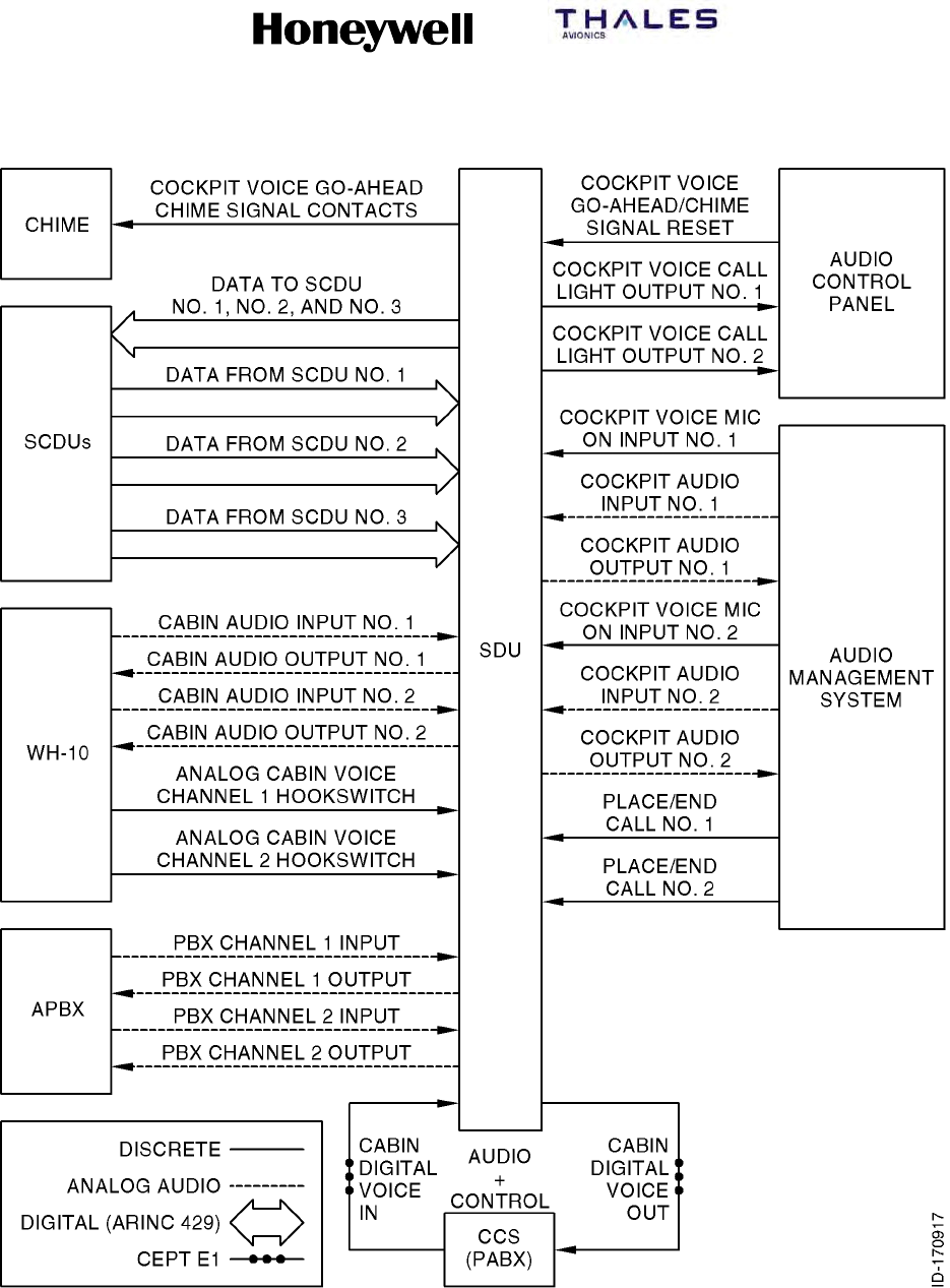
SYSTEM DESCRIPTION, INSTALLATION, AND MAINTENANCE MANUAL
MCS--4200/7200 Multi--Channel SATCOM System
23--20--35 15 Jul 2006
Honeywell International Inc. Do not copy without express permission of Honeywell.
Page 2--14
Figure 2-1. Satellite Audio System

SYSTEM DESCRIPTION, INSTALLATION, AND MAINTENANCE MANUAL
MCS-4200/7200
TEMPORARY REVISION NO. 23-1
23-20-35 Page 35 of 53
28 Sep 2009
© Honeywell International Inc. Do not copy without express permission of Honeywell.
INSERT PAGE 35 OF 53 FACING PAGE 2-14.
Reason: To add Classic Aero to the figure title for Figure 2-1.
The title for Figure 2-1 is changed as follows:
Figure 2-1. Classic Aero Satellite Audio System

SYSTEM DESCRIPTION, INSTALLATION, AND MAINTENANCE MANUAL
MCS-4200/7200
TEMPORARY REVISION NO. 23-1
23-20-35 Page 36 of 53
28 Sep 2009
© Honeywell International Inc. Do not copy without express permission of Honeywell.
INSERT PAGE 36 OF 53 FACING PAGE 2-15.
Reason: To add Classic Aero to the subhead for Paragraph 8 and to Paragraph 8. A. (1), and to change
the capitalization of INMARSAT to Inmarsat.
Paragraph 8 subhead and Paragraph 8. A. (1) are changed as follows:
8. Classic Aero Packet-Data Services
(1) Classic Aero data services are available in the form of a standard data interface that
supports Data-2 and Data-3 as defined by Inmarsat. Data-3 complies with International
Standards Organization (ISO) standard 8208 for open systems interconnection. Data-3
permits the operator to connect to the MCS system any data terminal equipment (DTE)
compatible with this international standard. The transmission rate available to the operator
depends on the aircraft equipment, and in particular on the antenna gain. It also depends on
the capabilities of the satellite serving that particular region of the earth and the GES
logged-on to the satellite.

SYSTEM DESCRIPTION, INSTALLATION, AND MAINTENANCE MANUAL
MCS--4200/7200 Multi--Channel SATCOM System
23--20--35 15 Jul 2006
Honeywell International Inc. Do not copy without express permission of Honeywell.
Page 2--15
(2) Sub-Band Signaling
(a) Support of circuit-mode data services is achieved through the use of sub-band
signaling, and/or primary-band signaling. The call setup sequence for a
circuit-mode data call is identical to a standard telephone call setup sequence,
except when the AES must indicate to the GES circuit-mode data operation can
be invoked at some point during the call. Sub-band signaling circuit-mode data is
implemented using the data interface unit (DIU) technique, which is a
nontransparent design that uses sub-band C--channel capacity for end-to-end
signaling. These signaling transactions require diversion of the input/output (I/O)
bit-stream from the SDU codecs to either a DIU (for PC modem applications) or a
secure voice coding unit.
(3) Primary-Band Signaling
(a) Primary-band circuit-mode data is implemented using the terminal interface
function (TIF) technique, which uses primary-band C--channel capacity for
end-to-end signaling. The TIF is integrated within the SDU codec. All
circuit-mode data activation and deactivation procedures relating to circuit-mode
data operation are automatically performed within the TIF. The TIF
encodes/decodes circuit-mode PC modem data and facsimile data using an
algorithm.
8. Packet-Data Services
A. General
(1) Data services are available in the form of a standard data interface that supports
Data-2 and Data-3 as defined by INMARSAT. Data-3 complies with International
Standards Organization (ISO) standard 8208 for open systems interconnection.
Data-3 permits the operator to connect to the MCS system any data terminal
equipment (DTE) compatible with this international standard. The transmission rate
available to the operator depends on the aircraft equipment, and in particular on the
antenna gain. It also depends on the capabilities of the satellite serving that particular
region of the earth and the GES logged-on to the satellite.
(2) Within the scope of the normal mode of operation, packet mode data messages are
handled by two basic types of data service. Small messages (up to 128 bytes) are
handled by one self-contained message that includes the information required to set
up and clear the circuit as well as the data itself. This connectionless message
traverses the communication link autonomously and quickly.
(3) Longer messages must be divided into a string of shorter messages for which a
connection-oriented circuit is set up. When the connection is established, all
subsequent data packets carry abbreviated address and control information. This
supplies more efficiency for longer messages and inquiry/response data dialogues
with no limit set on the length of individual messages.

SYSTEM DESCRIPTION, INSTALLATION, AND MAINTENANCE MANUAL
MCS--4200/7200 Multi--Channel SATCOM System
23--20--35 15 Jul 2006
Honeywell International Inc. Do not copy without express permission of Honeywell.
Page 2--16
9. Dual SATCOM Configuration
A. Overview
(1) General
(a) Dual SATCOM configuration is one where two SDUs work together in a
master/slave relationship. This configuration also uses dual antenna systems.
(b) Dual SATCOM systems can be used to supply backup redundancy for
circuit-mode and packet-mode safety communications, or for additional
circuit-mode channel capability, or both. Each system in a dual system has the
capability to function without the other if necessary (as a sole single system while
the other has failed or is disabled), or to work with the other system as a
coordinated pair. There are three distinctions made for dual systems regarding
the SDUs:
(2) No. 1 versus No. 2
(a) This is a static distinction as determined by the programmed state of the SDU
system configuration pin. (No. 1 and No. 2 can also be referred to as left and
right, respectively, on Boeing aircraft.)
(3) Master versus Slave
(a) This is a logical and potentially dynamic distinction. Because an aircraft can have
only one ICAO address assigned to it, dual MCS systems operate with a single
master SDU and the other as slave SDU. Each SDU is capable of providing its
services with no assistance from the other SDU (such as, when the other SDU is
powered-down). Each SDU is capable of being the master or the slave. There
are never two masters or two slaves (except during brief switching transients and
certain failure plus manual override conditions). The master does not depend on
the slave for any of the services supplied directly by the master.
(b) The master is in control. Only the master is allowed to use the P, R, and T
packet-mode channels for log-on and other satellite system management,
Data--2, Data--3, and GES--specific data broadcast (GSDB) packet-mode data
services, and circuit-mode call setups. The slave (which must be equipped with
an HGA in order to be a true slave from the perspective of offering additional
channel capacity) does not perform log-on or any packet-mode data function, but
is only used to supply additional C-channels for circuit-mode services under
control of the master. The master controls all circuit-mode call setups,
preemptions, and selective releases. Normal ongoing slave system call
management (such as, power control) and call termination are controlled by the
slave SDU.
(c) In a dual system made up of an HGA and an LGA, if the LGA-equipped SDU is
the master, it cannot use the HGA-equipped system as a slave. The LGA master
must be capable of operation through its LGA and must log-on as a Class 1
AES. If the slave is only equipped with an LGA, it cannot function as a true slave,
but only as a standby backup system for low-rate packet-mode data services,
ready to take over as master in case the original master fails.

SYSTEM DESCRIPTION, INSTALLATION, AND MAINTENANCE MANUAL
MCS--4200/7200 Multi--Channel SATCOM System
23--20--35 15 Jul 2006
Honeywell International Inc. Do not copy without express permission of Honeywell.
Page 2--17
(d) A system is said to be disabled when it is inhibited from making any RF
transmissions. This disabling can be because of a failure or being manually
inhibited through the control interfaces. Any disabled SDU indicates this in bit 12
of its label 276 status word. If a system is not disabled, it is enabled. When one
system is disabled, the other is usually selected, that is, the selected system is
essentially a single system and cannot use any potential slave resources in the
disabled system. It is possible both systems can be manually disabled for special
purposes like when maintenance or deicing personnel are in close proximity to
the antennas. The master controls the system functional capability indicators and
indicates itself as the master to the MU, cabin packet data function (CPDF), and
CTU. This is true even when both SDUs are disabled (there must still be a
designated master).
(4) This versus Other
(a) This is a relational distinction where this refers to any and all SDUs in dual
systems, and other refers to the companion SDU interfaced to this SDU ARINC
429 cross-talk bus (XTB) and select/disable discretes.
B. Dual System Control/Status Interfaces
(1) Manual and automatic control of the master/slave/select/disable attributes of the two
systems are done by using the XTB between the two SDUs (one high-speed ARINC
429 bus in each direction), and by the dual system select discrete I/O and dual
system disable discrete input discretes, which are cross-wired between the two
SDUs. Figure 2-2 shows a classic wiring diagram.
(2) The select and disable discretes are normally in a high-impedance state. The select
output supplies a low-impedance to ground when it is asserting, and the select and
disable inputs are pulled low to be asserted. An optional external switch can also be
supplied to manually select one system while disabling the other. A switch normally
leaves both discretes open-circuited, enabling fully automatic control. The optional
switch can additionally have the enhanced capability of simultaneously disabling both
systems while selecting neither. Manual control is also supplied through the SCDUs
for cases where the optional external switch is not supplied.
(3) The disable discrete is an input only. It is automatically asserted by the other SDU
select output when attempting to perform an aggressive handover of mastery. It can
also be manually asserted when the crew has determined this system has failed.
(4) The select discrete is a combination input and open-collector-type output. Activation
of this discrete by the crew indicates this system should be the sole master and it
must not attempt to use the other as a slave. If an SDU detects the other system has
failed, it can activate its own select output, which disables the other system and
typically becomes the sole master.
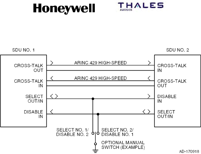
SYSTEM DESCRIPTION, INSTALLATION, AND MAINTENANCE MANUAL
MCS--4200/7200 Multi--Channel SATCOM System
23--20--35 15 Jul 2006
Honeywell International Inc. Do not copy without express permission of Honeywell.
Page 2--18
Figure 2-2. Dual System Wiring Diagram
C. System Reversion
(1) General
(a) The dual MCS system can change which SDU is master automatically or
manually. Automatic system reversion of handover of mastery from the current
master to the current slave is done through cooperative, aggressive, and special
handovers.
(2) Automatic System Reversion
(a) Cooperative handover of mastery is performed through the XTB and does not
make use of the select/disable discretes. The current master continually
assesses the potential service capabilities of each system, including the usage of
the other’s resources as a slave for providing additional voice services. Since
different aircraft owners/operators can value the individual assessed service
capabilities differently, weighting factors are selected in the ORT to reflect the
relative importance of the various capabilities. This flexibility allows all
capabilities to be compared equally, or for any one capability to outweigh all of
the others combined, or any combination between these extremes. When the
current master determines the current slave should become the new master, the
current master indicates it is abdicating its mastery. The slave detects the
abdication of the master and takes over as master.

SYSTEM DESCRIPTION, INSTALLATION, AND MAINTENANCE MANUAL
MCS-4200/7200
TEMPORARY REVISION NO. 23-1
23-20-35 Page 37 of 53
28 Sep 2009
© Honeywell International Inc. Do not copy without express permission of Honeywell.
INSERT PAGE 37 OF 53 FACING PAGE 2-19.
Reason: To add a new Paragraph D. (2) and (3) to incorporate references to SBB operation and to
renumber the existing Paragraph D. (2) to (4).
Paragraph (2) is renumbered to (4) and new Paragraphs D. (2) and (3) are added as follows:
(2) For SBB operation, the selected antenna must be an Inmarsat-approved type for this service
class.
(3) For SBB operation, the selected D/LNA must be Type F (or later type that is approved for SBB
operation).
(4) The basic configurations supported by the MCS dual system design are as given in Table 2-2.

SYSTEM DESCRIPTION, INSTALLATION, AND MAINTENANCE MANUAL
MCS--4200/7200 Multi--Channel SATCOM System
23--20--35 15 Jul 2006
Honeywell International Inc. Do not copy without express permission of Honeywell.
Page 2--19
(b) Aggressive handover of mastery (used when cooperation is impossible because
of XTB failure, manual intervention, or other reasons) makes use of the
select/disable discretes for mastery handover. An SDU asserts its select output
(connected to the Disable input of the other SDU) and commands Disable Other
SATCOM on its XTB output to the other SDU (in its Dual Control/Status word).
When an SDU detects its disable discrete input has been asserted, or it has
received a Disable Other SATCOM command through the XTB, it immediately
asserts its My Disable Is Asserted bit in its dual control/status word on its XTB
output, and after being so disabled for 1 second or longer, it then inhibits RF
transmissions and asserts its This SDU Is Disabled bit in its dual control/status
word.
(c) If the master SDU main processor resets itself, handover of mastery occurs
when the slave detects XTB inactive (unless the slave is externally disabled).
(3) Manual System Reversion
(a) The cockpit crew can manually select one system as the sole master and disable
the other system using an external select/disable switch or through the SCDU
disable other SATCOM line select key. This permits manual system reversion for
special cases, like undetected failures. Some external select/disable switches
may permit both systems to be disabled simultaneously for special cases
involving close proximity to the SATCOM antennas of maintenance or deicing
personnel.
(b) The SCDU line select key makes use of the XTB as well as the select/disable
discretes to send the appropriate command to the other SDU, thus optimizing the
robustness of this function.
D. Antenna Configurations
(1) A number of dual system antenna configurations can be assembled to address
various user requirements for availability and channel capability, containing various
combinations of LGA--, HGA-- or IGA--equipped systems — that is, HGA(IGA) +
HGA(IGA), HGA(IGA) + LGA, or LGA + LGA. The IGA equipment can be used
interchangeably (when airplane installation supports) with the HGA equipment. Any
HGA in a dual (or single) system can function as a logically distinct steered LGA
when its gain drops below 7 dB. Also possible is one pseudo-dual system plus one
HGA system — that is, (HGA+LGA) + HGA.
(2) The basic configurations supported by the MCS dual system design are as given in
Table 2-2.

SYSTEM DESCRIPTION, INSTALLATION, AND MAINTENANCE MANUAL
MCS--4200/7200 Multi--Channel SATCOM System
23--20--35 15 Jul 2006
Honeywell International Inc. Do not copy without express permission of Honeywell.
Page 2--20
Table 2-2. Basic Antenna Configurations
SDU No. 1 SDU No. 2 Notes
HGA LGA Original ARINC 741 dual system architecture
HGA HGA MD--11 and 777 dual standard
LGA LGA -- --
HGA + LGA HGA SDU No. 1 is pseudo--dual
(3) Some specific examples of these configurations are shown in the following figures.
Only unique combinations (as opposed to permutations) are shown.
(4) Figure 2-3 and Figure 2-4 show the two types of the HGA + LGA configuration. This
configuration is normally capable of providing six circuit-mode channels plus one
(potentially) high-rate packet-mode data channel. It supplies single-point failure
tolerance for low--rate packet-mode data services. Channel unit redundancy within
the HGA system supplies a limited but very flexible degree of failure tolerance for
circuit-mode and high-rate packet-mode services.
(5) Figure 2-5, Figure 2-6, and Figure 2-7 show the three types of the HGA + HGA
configuration. This configuration is normally capable of providing 12 circuit-mode
channels plus one (potentially) high-rate packet-mode data channel. It supplies
single-point failure tolerance for all grades of all services. Channel unit redundancy
within each half of the dual system supplies a limited but very flexible degree of
failure tolerance for all grades of all services before more serious failures force a
handover of mastery.
(6) Figure 2-8 shows the LGA + LGA configuration. This configuration is capable of
providing only one low-rate packet-mode data channel, and supplies single-point
failure tolerance for that capability.
(7) Figure 2-9 thru Figure 2-12 shows the different types of the pseudo-dual (HGA +
LGA) + HGA configuration. This configuration contains all of the normal and
failure-tolerance capabilities as the HGA + HGA configuration, and adds the
capability of one low-rate packet-mode data channel in instances where both HGAs
are unusable because of trying to point into keyholes. (The use of dissimilar dual
HGAs, like those shown in Figure 2-7, helps to minimize the need for such a
configuration.)

SYSTEM DESCRIPTION, INSTALLATION, AND MAINTENANCE MANUAL
MCS-4200/7200
TEMPORARY REVISION NO. 23-1
23-20-35 Page 38 of 53
28 Sep 2009
© Honeywell International Inc. Do not copy without express permission of Honeywell.
INSERT PAGE 38 OF 53 FACING PAGE 2-20.
Reason: To add a new Paragraph (8) to incorporate SBB operation.
Paragraph (8) is added as follows:
(8) For SBB operation, the selected antenna must be an Inmarsat-approved type for this service
class.
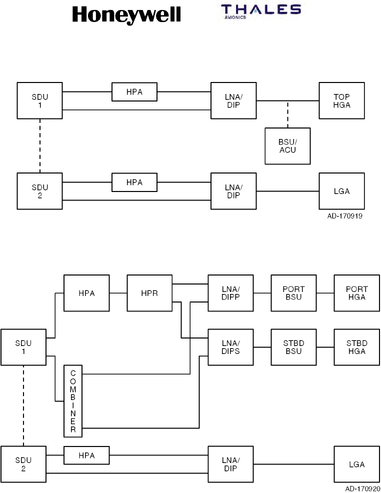
SYSTEM DESCRIPTION, INSTALLATION, AND MAINTENANCE MANUAL
MCS--4200/7200 Multi--Channel SATCOM System
23--20--35 15 Jul 2006
Honeywell International Inc. Do not copy without express permission of Honeywell.
Page 2--21
Figure 2-3. HGA + LGA Configuration with Top-Mounted HGAs
Figure 2-4. HGA + LGA Configuration with Side-Mounted HGAs
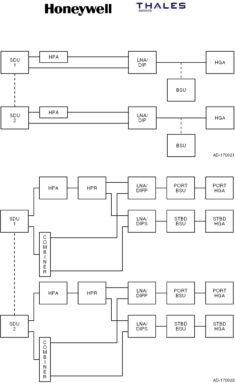
SYSTEM DESCRIPTION, INSTALLATION, AND MAINTENANCE MANUAL
MCS--4200/7200 Multi--Channel SATCOM System
23--20--35 15 Jul 2006
Honeywell International Inc. Do not copy without express permission of Honeywell.
Page 2--22
Figure 2-5. HGA + HGA Configuration with Two Top-Mounted HGAs
Figure 2-6. HGA + HGA Configuration with Two Side-Mounted HGAs
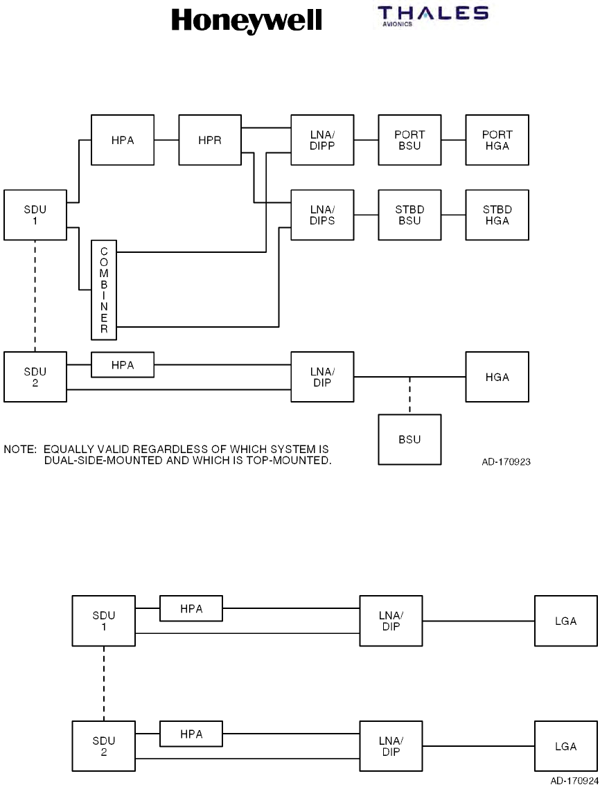
SYSTEM DESCRIPTION, INSTALLATION, AND MAINTENANCE MANUAL
MCS--4200/7200 Multi--Channel SATCOM System
23--20--35 15 Jul 2006
Honeywell International Inc. Do not copy without express permission of Honeywell.
Page 2--23
Figure 2-7. HGA + HGA Configuration with One Side-Mounted HGA + One Top-Mounted
HGA (Dissimilar HGA)
Figure 2-8. LGA + LGA Configuration
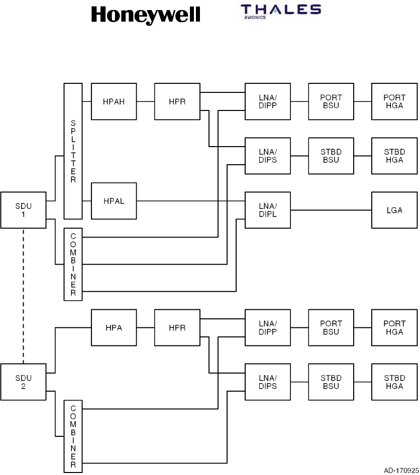
SYSTEM DESCRIPTION, INSTALLATION, AND MAINTENANCE MANUAL
MCS--4200/7200 Multi--Channel SATCOM System
23--20--35 15 Jul 2006
Honeywell International Inc. Do not copy without express permission of Honeywell.
Page 2--24
Figure 2-9. (HGA + LGA) + HGA Configuration with Two Side-Mounted HGAs
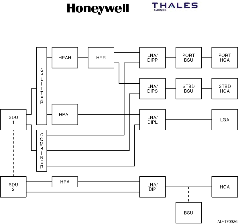
SYSTEM DESCRIPTION, INSTALLATION, AND MAINTENANCE MANUAL
MCS--4200/7200 Multi--Channel SATCOM System
23--20--35 15 Jul 2006
Honeywell International Inc. Do not copy without express permission of Honeywell.
Page 2--25
Figure 2-10. (HGA + LGA) + HGA Configuration with the LGA Paired with
One Side-Mounted HGA
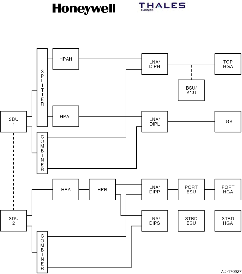
SYSTEM DESCRIPTION, INSTALLATION, AND MAINTENANCE MANUAL
MCS--4200/7200 Multi--Channel SATCOM System
23--20--35 15 Jul 2006
Honeywell International Inc. Do not copy without express permission of Honeywell.
Page 2--26
Figure 2-11. (HGA + LGA) + HGA Configuration with the LGA Paired with
One Top-Mounted HGA
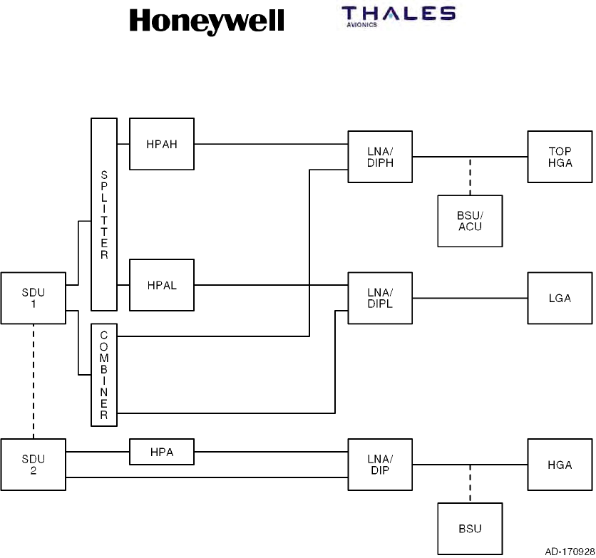
SYSTEM DESCRIPTION, INSTALLATION, AND MAINTENANCE MANUAL
MCS--4200/7200 Multi--Channel SATCOM System
23--20--35 15 Jul 2006
Honeywell International Inc. Do not copy without express permission of Honeywell.
Page 2--27
Figure 2-12. (HGA + LGA) + HGA Configuration with Two Top-Mounted HGAs
E. Cockpit Voice Configurations and Functionality
(1) System configuration pins TP13F and TP13J specify the physical wiring for the
codecs of each SDU to the possible interfaces -- a codec/channel can only be
available to the cockpit if the wiring strap is set to Cockpit or Both (and not if the
wiring is to Cabin or Neither).
(2) An additional issue with dual systems is how to map the potentially available four
physical SDU cockpit voice channels with the one or two (maximum) usable logical
cockpit channels controllable through the audio control panels (ACPs) and the
SCDUs (that is, as seen by the audio management system [AMS] user). Two
configurations are defined, which are identified by ORT item xlviii (Cockpit Channel
Interface Type for Dual): (1) interfacing each ACP/SCDU logical channel to one
physical channel on one SDU only (fixed), and (2) interfacing an ACP/SCDU logical
channel to one physical channel on each of the two SDUs (shared). Note the
interfacing referred to is conceptual and not necessarily physical — that is, for
shared, the physical wiring can be literally paralleled, or it can be simple
point-to-point, with some form of signal splitting/combining or paralleling being
performed within the AMS itself. The system configuration straps for codec wiring let
the SDU determine the physical channels which are candidate channels for each
logical channel.

SYSTEM DESCRIPTION, INSTALLATION, AND MAINTENANCE MANUAL
MCS--4200/7200 Multi--Channel SATCOM System
23--20--35 15 Jul 2006
Honeywell International Inc. Do not copy without express permission of Honeywell.
Page 2--28
Blank Page

SYSTEM DESCRIPTION, INSTALLATION, AND MAINTENANCE MANUAL
MCS-4200/7200
TEMPORARY REVISION NO. 23-1
23-20-35 Page 39 of 53
28 Sep 2009
© Honeywell International Inc. Do not copy without express permission of Honeywell.
INSERT PAGE 39 OF 53 FACING PAGE 3-1.
Reason: To add Classic Aero to the heading of Paragraph 1.
Paragraph 1 is changed as follows:
1. Classic Aero (SDU-based) Cabin Communications

SYSTEM DESCRIPTION, INSTALLATION, AND MAINTENANCE MANUAL
MCS--4200/7200 Multi--Channel SATCOM System
23--20--35 15 Jul 2006
Honeywell International Inc. Do not copy without express permission of Honeywell.
Page 3--1
SECTION 3
CABIN/COCKPIT COMMUNICATIONS
1. Cabin Communications
A. General
(1) Cabin communications are done with both digitally connected phones and analog
connected phones (see Figure 3-1). The user interface with digitally connected
phones is handled by the cabin communications system (CCS). The SDU has
provisions to support up to two analog connected channels, one per installed codec.
Each analog channel supports two interface types:
•Global-Wulfsberg Flitephone WH--10
•Analog Private Branch Exchange (APBX).
B. Cabin Communications System
(1) The CCS, in conjunction with the MCS avionics and a worldwide network of ground
stations, supply cabin services like telephone, facsimile, and PC data interfaces. The
CCS is partitioned into two sections:
•Cabin telecommunications unit (CTU)
•Cabin/passenger communications equipment (digitally connected telephones).
(2) The CTU performs on-board PABX telephone functions that let the digitally
connected telephones make the best use of resources supplied by the MCS avionics.
Other functions supplied by the CTU include signal processing (for example,
analog-to-digital and digital-to-analog), dial tone generation, call queuing, call
transfer, call conferencing, and generating pacifier messages (like please hold, your
call is being processed).
(3) The CTU supplies the interface between the digitally connected phones and the
SDU. The digital phones (handsets) are primarily supplied for passenger use and
may be located throughout the aircraft. The digital handsets interface indirectly to the
satellite communications equipment and they are controlled by the CCS. Each digital
handset supplies all the normal functions of a domestic telephone. Some handset
types are battery powered and can be used anywhere in the aircraft. When not in
use, handsets are stowed in a holster with a built-in battery charger for recharging the
batteries.

SYSTEM DESCRIPTION, INSTALLATION, AND MAINTENANCE MANUAL
MCS--4200/7200 Multi--Channel SATCOM System
23--20--35 15 Jul 2006
Honeywell International Inc. Do not copy without express permission of Honeywell.
Page 3--2
C. Analog Audio Channels
(1) General
(a) The SDU has provisions to support up to two analog channels. Each audio
channel supports two interface types:
•Global-Wulfsberg Flitephone WH--10
•Analog private branch exchange (APBX).
(b) The WH--10 is a stand-alone handset with a 12-button keypad. The APBX CTU
or handset has analog trunk lines and in-line DTMF signaling. The SDU can
support both analog handsets being connected simultaneously.
(c) Two in-use discrete outputs are supplied for analog channels 1 and 2. These
discretes are asserted (that is, turn on the call lamps) while the voice codec
associated with that analog channel is in use (off-hook) by the analog handset.
(d) These interfaces can be connected to individual or up to five parallel
aircraft-suitable handsets. The interface presented to the SDU must emulate a
single handset. The analog handsets, which can be located in the cabin or
cockpit areas, supply only APC priority (priority 4) level service. This does not
preclude their use for other communications, but the SDU assigns an APC
priority to the call.
(e) Figure 3-1 shows Audio Interfaces.
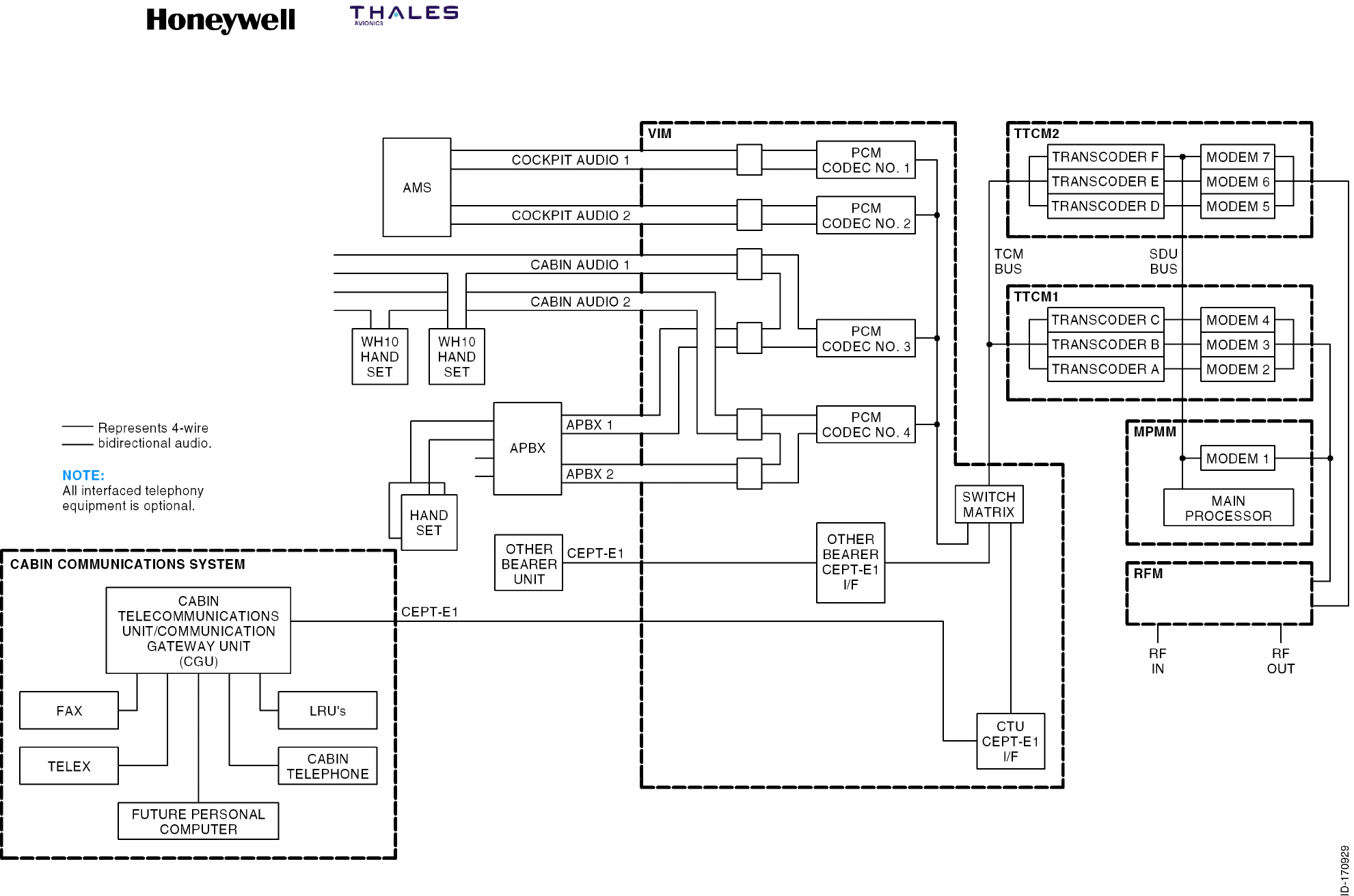
SYSTEM DESCRIPTION, INSTALLATION, AND MAINTENANCE MANUAL
MCS--4200/7200 Multi--Channel SATCOM System
23--20--35 15 Jul 2006
Honeywell International Inc. Do not copy without express permission of Honeywell.
Page 3--3/3--4
Figure 3-1. Audio Interfaces

SYSTEM DESCRIPTION, INSTALLATION, AND MAINTENANCE MANUAL
MCS--4200/7200 Multi--Channel SATCOM System
23--20--35 15 Jul 2006
Honeywell International Inc. Do not copy without express permission of Honeywell.
Page 3--5
(2) Global-Wulfsberg Flitephone WH--10 Interface
(a) Taking an analog WH--10 handset off-hook results in the following processes.
The SDU to WH--10 handset actions are defined in Table 3-1.
•If the voice codec is being used by another analog phone user, the handset
may be placed in parallel with the other analog phone. Buffering and sidetone
arrangements are supplied by the analog connected phone, not by the
SATCOM equipment.
•If the voice codec is reserved by a headset user, is dedicated to a headset, or
is failed, the analog phone user hears silence.
•If the SDU is not logging-on, logged-on, or in the idle (standby) state, the
analog phone user hears silence.
•If the call barring level is 2 (ORT item xxiv), the SDU performs action 1.
•If sufficient resources are not available due to equipment failure, the SDU
performs action 2.
•If the SDU is logging-on, the SDU performs action 3.
•If the SDU is in the idle (standby) state, the SDU performs action 4.
•If a SDU modem is not available or there is not sufficient power to sustain a
new voice call, or the AES class is currently 1 or 4, the SDU performs action
5.
•Or else the SDU performs action 6 and the respective analog phone channel
is deemed usable for placing a call.
(b) If the system condition, as determined by the SDU, changes from usable (action
6) to unusable while the analog phone is off-hook and a call is not in progress,
then the appropriate handset action is performed to annunciate the new
condition. An analog channel does not change from unusable to usable while the
analog phone is off-hook unless there is a call termination on that channel.
Table 3-1. SDU to WH-10 Handset Actions
Action
1Play message 10 as defined in Table 3-5 (outgoing calls have been disallowed) followed by
an interrupted dial tone.
2Play message 1 as defined in Table 3-5 (equipment failure) followed by an interrupted dial
tone.
3Play message 2 as defined in Table 3-5 (attempting satellite access) followed by an
interrupted dial tone.
4Play message 3 as defined in Table 3-5 (log-on disabled) followed by an interrupted dial
tone.
5Play message 4 as defined in Table 3-5 (channel not available) followed by an interrupted
dial tone.
6Play the dial tone.

SYSTEM DESCRIPTION, INSTALLATION, AND MAINTENANCE MANUAL
MCS--4200/7200 Multi--Channel SATCOM System
23--20--35 15 Jul 2006
Honeywell International Inc. Do not copy without express permission of Honeywell.
Page 3--6
(c) The commands given in Table 3-2 are executable from the analog WH--10
handset. The inter-key push time-out is 15 seconds. After this time, a # sign is
automatically appended to the end of the keyed sequence by the SDU, and the
command given by the user is parsed and executed. Commands shown in the
table as not being terminated by a # sign are parsed and executed as soon as
the valid key sequence has been entered. An invalid sequence only generates
voicemessage18(Commandrejected)whena#isappended, either by the user
or by the SDU after the 15-second time-out (Table 3-5).
(d) Codec-generated pacifiers or messages issued as a direct result of the user
keying a command start with one second of silence to allow the user enough
time to bring the handset to their ear. During the playing of any codec-generated
messages and pacifiers, receipt of the # key immediately mutes the codec,
aborting the current message sequence. The voice codec plays the appropriate
dial tone (normal or interrupted) as specified in Table 3-2.
(e) An inactivity check is implemented so the SDU considers an off-hook channel to
be in the on-hook state if no call has been in progress on that channel and no
DTMF digits have been received for at least 120 seconds, except where
indicated in Table 3-2. A WH--10 handset in this state must have its hookswitch
cycled (that is, go on-hook, then off-hook) to signal the off-hook state to the SDU.

SYSTEM DESCRIPTION, INSTALLATION, AND MAINTENANCE MANUAL
MCS--4200/7200 Multi--Channel SATCOM System
23--20--35 15 Jul 2006
Honeywell International Inc. Do not copy without express permission of Honeywell.
Page 3--7
Table 3-2. Global-Wulfsberg Flitephone WH-10 Commands
Command Sequence Command Description
dddd...# Dial a short phone number (between 2 and 6 digits – the first two can not be 00).
00dddd...# Dial a long phone number (between 6 and 18 digits including the two leading
zeros).
*0 Redial the last called phone number
(refer to NOTE).
*m Dial a stored phone number from memory location m (refer to NOTE).
There are 10 memory locations assigned to each of the two analog (APHONE) channels (ORT item xvi).
Memory location 0 of each channel holds the last number called on that channel. Memory locations 1 thru 9
are user-programmable. If ORT item xxvi is set to TRUE, then the channel memory locations are separate
(i.e., modifying memory locations from a handset connected to channel 1 does not affect the memory
locations assigned to channel 2). However, if ORT item xxvi is set to FALSE, then modifying memory
locations from a handset connected to channel 1 causes channel 2 memory locations to also be modified.
The store phone number memory commands are specified as follows:
**1mdddd...# This store phone number memory command causes the phone number (dddd...) to
be stored in memory location m. If the call barring level (ORT item xxiv) is 1 or 2,
then message 9 or 10 (dialed calls have been disallowed/outgoing calls have been
disallowed) are played; otherwise, the entered data is checked. A valid command
causes message 17 (command accepted) to be played and the number stored. An
invalid command causes message 18 (command rejected) to be played.
**2# This announce phone number memory command causes the phone numbers
stored in memory locations 1 thru 9 to be read out using a series of message 19s
(the phone number stored in memory...) for non-empty locations, and message 5s
(phone number memory ... is empty) for empty locations. If this command is
entered through the WH--10 handset, the inactivity check is disabled until the next
key-push or until the next on-hook/off-hook transition.
**2m This announce phone number memory command causes the phone number in
memory location m to be read out using message 19 (the phone number stored in
memory ...) or message 5 (phone number memory ... is empty). If m is not
between 1 and 9, then message 18 (command rejected) is played instead. The
digit 0 is announced as oh, not as zero.
If the call barring level is 1 or 2 (ORT item xxiv), the SDU plays messages 9 or 10 (dialed calls have been
disallowed/outgoing calls have been disallowed) if an attempt is made to place a call. For all the following
call barring commands, an invalid security code (cccc) causes the command to be rejected and message
18 (command rejected) to be played. If the command is valid, then the action is performed and message 17
(command accepted) is played. The call barring commands are specified as follows:
**30cccc This command sets the call barring level (ORT item xxiv) to 0, which allows all
outgoing calls.
**31cccc This command sets the call barring level (ORT item xxiv) to 1, which disallows all
manual dialing of full-length phone numbers (6 to 18 digits starting with 00). No
memory locations can be updated using the store phone number memory
command.

SYSTEM DESCRIPTION, INSTALLATION, AND MAINTENANCE MANUAL
MCS--4200/7200 Multi--Channel SATCOM System
23--20--35 15 Jul 2006
Honeywell International Inc. Do not copy without express permission of Honeywell.
Page 3--8
Table 3-2. Global-Wulfsberg Flitephone WH-10 Commands (cont)
Command Sequence Command Description
**32cccc This command sets the call barring level (ORT item xxiv) to 2, which disallows all
outgoing calls, both manual and stored number. No memory locations can be
updated using the store phone number memory command.
**39cccc nnn nnnn This command changes the security code to nnnn unless the first four n’s are not
the same as the second four n’s, in which case message 18 (command rejected) is
played.
**4ggg# This command causes ggg to be the GES ID used in the access request signal unit
for any calls initiated on that channel until the next on-hook.
If ORT item xxiii is set to disable the analog (APHONE) system management commands, the following
commands are rejected; i.e., the SDU responds to the commands with message 18 (command rejected).
The APHONE system management commands are specified as follows:
**50 This log-off/standby command sets the log-on policy (ORT item i) to User
Commanded Log-on. If already logged-on, the SDU logs off (refer to SYSTEM
OPERATION). If logging-on, the SDU terminates the logging on procedure. If the
command is valid, message 17 (command accepted) is played immediately without
waiting for the log-off to be achieved. If the SDU is already in the standby state,
then message 18 (command rejected) is played.
**51 This auto log-on command sets the log-on policy (ORT item i) to Automatic
Log-on. If the SDU is in the standby state, the SDU initiates the automatic log-on
procedure (refer to SYSTEM OPERATION). If the SDU is in the constrained log-on
mode, a handover stimulus is generated to initiate automatic satellite/GES
selection. If the command is valid, message 17 (command accepted) is played
immediately without waiting for the log-on to be achieved. If the SDU is already in
the automatic mode, message 18 (command rejected) is played.
**52ggg#
**52gggsss#
These commands set the SDU to the constrained log-on mode for selection of a
specified GES. The log-on policy (ORT item i) is set to Manual Log-on.IftheSDU
is not logged-on to the GES ggg (or gggsss as appropriate), the SDU attempts a
log-on to that GES alone. Any other number of digits causes message 18
(command rejected) to be played. If the specified GES does exist in the system
table, then the command is rejected. If the command is valid, message 17
(command accepted) is played immediately without waiting for the log-on to be
achieved. If the SDU is already constrained to GES ggg (or gggsss as
appropriate), then message 18 (command rejected) is played.
**59 This log-on status command causes the SDU log-on status to be announced using
message 20 (the SATCOM is in ...). If the SDU is logged-on, message 21
(logged-on to ...) is also played. Digit 0 for the GES and satellite ID is announced
as oh.
If any of the following GES preference commands are determined to be invalid, the SDU plays message 18
(command rejected). If a specific message is not specified, then message 17 (command accepted) is
played. If ORT item xxiii is set to disable the APHONE system management commands, the next three
commands (the preference changing commands) are rejected. That is, the SDU responds to the commands
with message 18 (command rejected). The GES preference commands are specified as follows.
**60 This command sets the preference levels for all GESs to 1.

SYSTEM DESCRIPTION, INSTALLATION, AND MAINTENANCE MANUAL
MCS--4200/7200 Multi--Channel SATCOM System
23--20--35 15 Jul 2006
Honeywell International Inc. Do not copy without express permission of Honeywell.
Page 3--9
Table 3-2. Global-Wulfsberg Flitephone WH-10 Commands (cont)
Command Sequence Command Description
**61gggp#
**61gggsssp#
These commands cause the GES with ID ggg (or ggg and assigned to satellite sss)
to be set to preference level p in the system table. The SDU accepts either four or
seven digits following the **61... and preceding the # sign. Any other number of
digits is interpreted to be an invalid command. If no GES listed in the system table
matches the one specified in the command, the command is invalid and the user is
so informed through message 18 (command rejected).
**62ggg#
**62gggsss#
These commands cause all current GES preference levels of 9 to be lowered to 8.
The GES with ID ggg (or ggg and assigned to satellite sss) has its preference level
set to 9. The SDU accepts either three or six digits following the 62... and
preceding the # sign. Any other number of digits is interpreted to be an invalid
command. If no GES listed in the system table matches the one specified in the
command, the command is invalid and the user is so informed through message 18
(command rejected).
**69# This command causes all GES preference levels to be announced using a
sequence of message 22s (The preference level of GES ID...). If this command is
entered through the WH--10 handset, the inactivity check is disabled until the next
key-push, or until the next on-hook/off-hook transition.
**69ggg#
**69gggsss#
These commands cause the SDU to announce the preference level of GES ggg or
(ggg and assigned to satellite sss) using message 22 (The preference level of GES
ID...). The SDU accepts either three or six digits following the **69... and preceding
the # sign. Any other number of digits is interpreted to be an invalid command. If no
GES listed in the ORT (item iii) matches the one specified in the command, the
command is invalid and the user is so informed through message 18 (command
rejected).
If any of the following incoming call management commands are rejected, the SDU plays message 18
(command rejected); otherwise, if a specific message is not specified, then message 17 (command
accepted) is played. If ORT item xxiii is set to disable the APHONE system management commands, the
following commands are rejected: that is, the SDU responds to the commands with message 18 (command
rejected). The four DDI CTid commands allow ddd to be up to three decimal digits (including leading zeros,
such as, 02), validating the number to be within the range of 0 to 999. The incoming call management
commands are specified as follows.
**70# This command sets ORT item xlv for APHONE Channel 1 to the default value: no
CTid assigned.
**70ddd# This command sets ORT item xlv for APHONE Channel 1 to ddd, Nonexclusive,
unless the configuration straps indicate Channel 1 is not wired for APHONE, or ddd
is already assigned as the CTid for Channel 2, or (in a dual system) ddd is already
assigned to one of the other SDU APHONE channels, in which case, the command
is rejected. Additionally, if ORT item xiii indicates ground-to-air Priority 4 calls are
disallowed, it is adjusted to specify routing to APHONE.
**71ddd# This command sets ORT item xlv for APHONE Channel 1 to ddd, Exclusive, unless
the configuration straps indicate Channel 1 is not wired for APHONE, or ddd is
already assigned as the CTid for Channel 2, or (in a dual system) ddd is already
assigned to one of the other SDU APHONE channels, in which case, the command
is rejected. Additionally, if ORT item xiii indicates ground-to-air Priority 4 calls are
disallowed, it is adjusted to specify routing to APHONE.

SYSTEM DESCRIPTION, INSTALLATION, AND MAINTENANCE MANUAL
MCS--4200/7200 Multi--Channel SATCOM System
23--20--35 15 Jul 2006
Honeywell International Inc. Do not copy without express permission of Honeywell.
Page 3--10
Table 3-2. Global-Wulfsberg Flitephone WH-10 Commands (cont)
Command Sequence Command Description
**72# This command sets ORT item xlv for APHONE Channel 2 to the default value; i.e.,
no CTid assigned.
**72ddd# This command sets ORT item xlv for APHONE Channel 2 to ddd, Nonexclusive,
unless the configuration straps indicate Channel 2 is not wired for APHONE, or ddd
is already assigned as the CTid for Channel 1, or (in a dual system) ddd is already
assigned to one of the other SDU APHONE channels, in which case, the command
is rejected. Additionally, if ORT item xiii indicates ground-to-air Priority 4 calls are
disallowed, it is adjusted to specify routing to APHONE.
**73ddd# This command sets ORT item xlv for APHONE Channel 2 to ddd, Exclusive, unless
the configuration straps indicate Channel 2 is not wired for APHONE, or ddd is
already assigned as the CTid for Channel 1, or (in a dual system) ddd is already
assigned to one of the other SDU APHONE channels, in which case, the command
is rejected. Additionally, if ORT item xiii indicates ground-to-air Priority 4 calls are
disallowed, it is adjusted to specify routing to APHONE.
**740# This command sets ORT item xiii to disallowed and causes message 33 to be
played with the destination announced as disallowed.
**741# This command sets ORT item xiii to APHONE and causes message 33 to be
played with the destination announced as APHONE, unless no codec channel is
wired for APHONE (as defined by the configuration straps), in which case, the
command is rejected and the ORT item is set to Disallowed.
**742# This command sets ORT item xiii to DPHONE and causes message 33 to be
played with the destination announced as DPHONE, unless no codec channel is
wired for CCS (as defined by the configuration straps), in which case, the
command is rejected and the ORT item is set to Disallowed.
**743# This command sets ORT item xiii to headset and causes message 33 to be played
with the destination announced as headset, unless no codec channel is wired for
AMS (as defined by the configuration straps), or if configuration pin TP13A is zero,
in which case, the command is rejected and the ORT item is set to Disallowed.
**750# This command sets ORT item x to disallow incoming circuit mode data calls and
causes message 34 to be played to announce such calls as disallowed, unless
the SDU is logging on or logged on, in which case, the command is rejected.
**751# This command sets ORT item x to allow incoming circuit mode data calls and
causes message 34 to be played to announce such calls as allowed, unless the
SDU is logging on or logged on, in which case, the command is rejected.
**79# This command causes the SDU to announce the DDI CTid assignment for
channels 1 and 2 using message 31, if no ID is assigned, and message 32 if an ID
is assigned, where the type of ID assignment is announced as exclusive or
nonexclusive.
SYSTEM DESCRIPTION, INSTALLATION, AND MAINTENANCE MANUAL
MCS--4200/7200 Multi--Channel SATCOM System
23--20--35 15 Jul 2006
Honeywell International Inc. Do not copy without express permission of Honeywell.
Page 3--11
Table 3-2. Global-Wulfsberg Flitephone WH-10 Commands (cont)
Command Sequence Command Description
Legend: cSecurity code digit (0 thru 9)
dDecimal digit (0 thru 9)
gGES ID octal digit, where ggg is in range (000 thru 377)
mMemory location (1 thru 9)
nNew security code digit (0 thru 9)
pGES preference level (0 thru 9), where 1 is the least preferred and
9 is the most preferred, and 0 indicates never to be selected for
automatic log-on
sSatellite ID octal digit, where sss is in range (000 thru 076)
NOTE: There are 10 memory locations for each channel to store phone numbers (0 thru 9). Memory number 0 is used
by the SDU to store the last called phone number.
(3) Call Initiation from Analog (WH--10) Phone
(a) The analog phone user can initiate a call using any of the following commands:
•Short number manual dialing (dd...#). Between two and six digits can be
specified, with the first two digits not 00. The 00 digits are used as the
called–party address.
•Long number manual dialing (00dddd...#). Between seven and 18 digits can
be specified including the leading 00. The 00 digits are used as the
called–party address.
•Last call redial (*0). The last phone number called by an analog phone user
on a channel is used as the called-party address. If the phone number stored
in memory location 0 (i.e., last number called location) is not defined (length
field set to zero), then message 5 (phone number memory ... is empty.) is
played. Otherwise, the phone number is used as the called-party address.
•Stored phone dialing (*m). Parameter m specifies a memory location between
1 and 9. If the phone number stored in memory location m is not defined
(length field set to zero), then message 5 (phone number memory ... is
empty.) is played. Otherwise, the phone number is used as the called-party
address.
(4) Analog Private Branch Exchange (APBX) Interface
(a) General
1The APBX/SATCOM avionics interface protocol is based on the bidirectional
DTMF tones being signaled in-band. In the APBX-to-SATCOM direction, the
DTMF digits are assigned to the on- and off-hook transitions as specified in
Table 3-3, and are valid only from the APBX handset. All other DTMF digits
are common to both the WH--10 and APBX interfaces.

SYSTEM DESCRIPTION, INSTALLATION, AND MAINTENANCE MANUAL
MCS--4200/7200 Multi--Channel SATCOM System
23--20--35 15 Jul 2006
Honeywell International Inc. Do not copy without express permission of Honeywell.
Page 3--12
2Taking an APBX handset off-hook results in the same decisions as specified
for the WH--10 handset. However, the SDU to APBX off--hook actions are
specified in Table 3-4, where the DTMF tone sequence <DTMF--C>,
<DTMF--n> (n is 0, 1, 2, or 4) sent to the APBX handset indicates the
SATCOM channel status:
•An outgoing call cannot be supported (n = 1, 2, or 4) or
•An outgoing call can be attempted (n = 0).
3If the channel status indicates a call can be attempted, the SDU accepts any
command determined to be valid from an APBX interface, including the
on-hook DTMF tone. If the channel status indicates a call can not be
attempted, the APBX handset is expected to send the on-hook DTMF tone.
Otherwise, the SDU still accepts any command determined to be valid from
an APBX interface; though the checked B-party address transfer command
is guaranteed to produce a call setup failure. Subsequent to call setup
commands sent to the SDU, call setup progress, failure, and termination
DTMF tone sequences are sent to the APBX handset.
4The SDU considers an off-hook channel to be in the on-hook state if no call
has been in progress on that channel and no DTMF signals have been
received for at least 120 seconds. A channel in the on-hook state must issue
another DTMF off-hook signal to enable the reentry into the off-hook state.
(b) Checked Credit Card Data Transfer Command
1The *2284*c*ddd# command, if valid, loads the transferred three-digit value
into the SDU calling terminal ID buffer. This data is used in place of the
default 000 in the calling terminal field of the call information service address
initial signal unit (ISU) (S5) for any outgoing call setups on this channel until
the next APBX on-hook is received. The command is accepted only if the
modulo 10 sum of all the decimal digits in the command, including 2284, the
three-digit calling terminal ID, and the check digit c is zero.
(c) Checked B-Party Address Transfer Command
1The *2262*cdddd....# command, if valid, initiates a call setup request to the
GES using the transferred digits dddd... as the B-party address and any
track 2 credit card data stored since the previous on-hook transition on this
channel. The command is only accepted if the modulo 10 sum of all decimal
digits in the command, including 2262 and the check digit c is zero. A valid
command causes the SDU to send the DTMF sequence <DTMF--C>,
<DTMF--8> to the APBX handset. An invalid command causes the SDU to
send the DTMF sequence <DTMF--C>, <DTMF--9> to the APBX handset.

SYSTEM DESCRIPTION, INSTALLATION, AND MAINTENANCE MANUAL
MCS--4200/7200 Multi--Channel SATCOM System
23--20--35 15 Jul 2006
Honeywell International Inc. Do not copy without express permission of Honeywell.
Page 3--13
Table 3-3. Assignment of DTMF Digits in the APBX Interface
DTMF Digit Low (Hz) High (Hz) Meaning To/From SDU
1697 1209 1Both
2697 1336 2Both
3697 1477 3Both
4770 1209 4Both
5770 1336 5Both
6770 1477 6Both
7852 1209 7Both
8852 1336 8Both
9852 1477 9Both
0941 1336 0Both
*941 1209 */STX To
#941 1477 #/ETX To
A697 1633 FS/Answer Both
B770 1633 Off--Hook To
C852 1633 Status From
D941 1633 On--Hook To
NOTE: STX (start sentinel), ETX (end sentinel), and FS (frame separator) are used in the transfer of ISO 7813 track 2
data from the APBX to the SDU.
Table 3-4. SDU to APBX Off-Hook Actions
Action Description
1Play <DTMF--C>, <DTMF--2> followed by silence (idle).
2Play <DTMF--C>, <DTMF--1> followed by silence (failure).
3Play <DTMF--C>, <DTMF--4> followed by silence (accessing).
4Play <DTMF--C>, <DTMF--2> followed by silence (idle).
5Play <DTMF--C>, <DTMF--4> followed by silence (accessing).
6Play <DTMF--C>, <DTMF--0> followed by silence (available).

SYSTEM DESCRIPTION, INSTALLATION, AND MAINTENANCE MANUAL
MCS--4200/7200 Multi--Channel SATCOM System
23--20--35 15 Jul 2006
Honeywell International Inc. Do not copy without express permission of Honeywell.
Page 3--14
2. Cockpit Communications
A. General
(1) The SDU codecs support headset interfaces for cockpit use only. These interfaces
incorporate 600-ohm, 4-wire, off-hook/on-hook signaling and dialing through the
combination of a control and display unit (either SCDU or MCDU), and (at the user’s
option) PTT, mic-on, or place/end call switches. If used, when the PTT button is
pushed, the microphone audio signal is sent to the selected voice channel; activation
of one of the discretes is signalled to the SDU. Also, an off-hook signal can be sent to
the SDU through the SCDU. An audible chime and call lamps announce a
ground-to-air call.
(2) The cockpit headsets interface with the codecs in the SDU through an audio
management unit (AMU), which is also connected to other aircraft radios. The ACP
associated with the AMU can be capable of selecting either a single or dual voice
channels for the MCS system. When single-channel AMUs are installed, voice
channel 1 is wired to AMU No. 1 and voice channel 2 is wired to AMU No. 2. This
permits operation of two independent channels. When dual-channel AMUs are
installed, voice channels No. 1 and No. 2 are wired in parallel to each AMU, enabling
two voice channels to be shared by the cockpit users.
(3) Two functionally identical voice codec modules (VCM) are installed in the SDU and
designated Codec A and Codec B.
(4) Associated with the SATCOM channels are SCDU pages, call lamps, channel
selection switches, a chime, and a chime reset. The SDU hookswitch signaling can
be supplied:
•When the ACP SATCOM channel select switch is activated
•When a PTT switch is activated
•When signaling through the SCDU, where the SDU hookswitch signaling discrete
is inactive.
(5) Once off-hook, microphone audio is supplied to the selected SATCOM voice channel
and the appropriate signaling is exchanged for call lamp and chime reset.
Conversely, once on-hook, microphone audio is removed from the selected SATCOM
voice channel and the call lamp is turned off.
B. Headset Off-Hook Signaling
(1) The headset is capable of going off-hook (to connect the call and to acknowledge the
call signaling) if the cockpit voice call light output has transitioned for either the
flashing or steady light activation, at which time:
•If the latched ACP hookswitch signaling is strapped, the headset is considered
off-hook whenever the cockpit voice mic-on input is activated (connected to
ground).
•If the switched PTT hookswitch signaling is strapped, the headset is considered
off-hook whenever the cockpit voice mic-on input is activated for the first time after
the call light activation for an incoming call, or when the place/end call input is
activated to initiate an outgoing call.

SYSTEM DESCRIPTION, INSTALLATION, AND MAINTENANCE MANUAL
MCS--4200/7200 Multi--Channel SATCOM System
23--20--35 15 Jul 2006
Honeywell International Inc. Do not copy without express permission of Honeywell.
Page 3--15
(2) If ORT item xliii is enabled, the headset is capable of going off-hook when ANSWER
CALL is selected on the SATCOM main menu page (TESTING/FAULT ISOLATION)
after the call light activation and irrespective of hookswitch signaling.
C. Headset On-Hook Signaling
(1) If latched ACP hookswitch signaling is strapped, the headset is placed on-hook when
an open is present on the cockpit voice mic-on input. Regardless of the hookswitch
signaling, the cockpit voice place/end call 1 and 2 discrete inputs place the headset
interface on-hook for cockpit audio channels 1 and 2, respectively, when a call clear
event occurs. If ORT item xliii is enabled, the selection of END CALL or REJECT on
the SATCOM main menu page (TESTING/FAULT ISOLATION) places the headset
interface on-hook. Placing the headset on-hook results in normal call termination.
D. Voice Codec Module Audio Switching
(1) Headsets and analog connected phones interface to the SDU through the VCMs.
Using a switch internal to the modules, each VCM can be connected to one of the
cabin audio interfaces, or to one of the cockpit audio interfaces (or to both). Each
VCM can be switched between either of its audio interfaces as follows:
•Codec A can be used in conjunction with either cabin audio No. 1 (WH--10 or
APBX) or cockpit audio No. 1
•Codec B can be used in conjunction with either cabin audio No. 2 (WH--10 or
APBX) or cockpit audio No. 2.
E. Voice Codec Module Sidetone
(1) Sidetone is supplied by each VCM. The sidetone level is adjustable for the cockpit
audio, and is set to off for cabin audio. The adjustment range for cockpit sidetone is
from 0 dB below the receive audio to off, with the default value set to 14.1 dB below
the receive audio level. This setting is stored in nonvolatile memory within the SDU.
F. Voice Interface Module Stored Audio Messages
(1) The VIMs are capable of playing standard telephony supervisory lone signals, DTMF
tones, and voice messages to the headset and analog phone users. These pacifiers
are only sent to the analog interfaces:
•Headset
•WH--10 handsets
•APBX handsets.
(2) Stored audio messages are summarized in Table 3-5.

SYSTEM DESCRIPTION, INSTALLATION, AND MAINTENANCE MANUAL
MCS--4200/7200 Multi--Channel SATCOM System
23--20--35 15 Jul 2006
Honeywell International Inc. Do not copy without express permission of Honeywell.
Page 3--16
Table 3-5. Stored Audio Messages
Message No. Message
1Sorry, equipment failure, please refer to the user guide.
2Sorry, attempting satellite access, please try later.
3Sorry, log-on disabled, please refer to the user guide.
4Sorry, no channel available, please try later.
5Phone number memory <one> is empty.
6Sorry, your call can no longer be sustained, please try later.
7Sorry, your call has been preempted, please try later.
8Sorry, connection failure, please try later.
9Sorry, dialed calls have been disallowed, please refer to the user guide.
10 Sorry, outgoing calls have been disallowed, please refer to the user guide.
11 Sorry, number unobtainable.
12 Sorry, number busy, please try later.
13 Sorry, network congestion, please try later.
14 Sorry, credit card not honored at the ground station.
15 Sorry, access unauthorized.
16 Please wait, connecting your call.
17 Command accepted.
18 Command rejected.
19 The phone number stored in memory <one> is <oh> <oh> <one>...
20 The SATCOM is in <standby> |<auto log-on| <constrained log-on> mode.
21 Logged on to GES ID <one> <oh> <three>.
22 The preference level of GES ID <three> <oh> <two> on satellite <oh> <oh> <three> is
<six>.
23 Equipment failure, equipment failure.
24 No channel available, no channel available.
25 Your call can no longer be sustained.
26 Your call has been preempted.
27 Connection failure, connection failure.
28 Number unobtainable, number unobtainable.
29 Number busy, number busy.
30 Network congestion, network congestion.
31 Channel <one> terminal ID is not assigned.
32 Channel <two> terminal ID is <oh> <one> <three> <nonexclusive>.

SYSTEM DESCRIPTION, INSTALLATION, AND MAINTENANCE MANUAL
MCS--4200/7200 Multi--Channel SATCOM System
23--20--35 15 Jul 2006
Honeywell International Inc. Do not copy without express permission of Honeywell.
Page 3--17
Table 3-5. Stored Audio Messages (cont)
Message No. Message
33 Ground-to-air public calls destination set to <disallowed>.
34 Ground-to-air circuit mode data calls are <allowed>.
G. Voice Interface Module Dedication
(1) Each VIM has the property of dedication, which is different from the codec wiring.
This property is of value on aircraft that have both headset and cabin (analog and
digital) interface wiring, where contention for codec use can arise. Each VIM
dedication is set to cabin, headset, or automatic through ORT item vi.
(2) A VIM with its dedication set to automatic can be allocated to a headset call or a
cabin call, and is allocated on a first-come, first-served basis. A VIM can be
reallocated to a headset call of priority 1, 2, or 3 through the preemption mechanism.
A VIM with its dedication set to cabin is dedicated to its cabin (WH--10 or APBX)
interface.
(3) A VIM with its dedication set to headset is unusable by the cabin interface. A VIM can
be reallocated to a different headset call of priority 1, 2, or 3 through the preemption
mechanism. ORT item vii (Appendix C) specifies whether a modem and HPA power
should be reserved for a VIM dedicated to headset. This lets the pilot reserve one
channel for cockpit use only.

SYSTEM DESCRIPTION, INSTALLATION, AND MAINTENANCE MANUAL
MCS--4200/7200 Multi--Channel SATCOM System
23--20--35 15 Jul 2006
Honeywell International Inc. Do not copy without express permission of Honeywell.
Page 3--18
Blank Page

SYSTEM DESCRIPTION, INSTALLATION, AND MAINTENANCE MANUAL
MCS--4200/7200 Multi--Channel SATCOM System
23--20--35 15 Jul 2006
Honeywell International Inc. Do not copy without express permission of Honeywell.
Page 4--1
SECTION 4
MECHANICAL INSTALLATION
1. Overview
A. General
(1) This section contains information on how and where to mount each component of the
MCS system. For new installations, plan the installation in two stages. First,
determine the location of the LRUs in the aircraft. Next, determine the length of RF
and electrical interconnections for selected locations.
2. Equipment and Materials
A. General
(1) Refer to SYSTEM DESCRIPTION for mounting tray and mating connector
information. For all other components, refer to the applicable Outline and Installation
Diagram in this section.
(2) No additional special equipment or materials, other than those commonly used in the
shop, are required to install the units in existing trays and clamps, and to adjust the
system. Do not over tighten mounting screws. Where torque values are not given, it
is acceptable to finger tighten the mounting screws.
3. Mechanical Installation Design
A. LRU Mechanical Installation
(1) The SDU and HPA are installed in mounting racks (ARINC 600) typically in the
equipment bay of the aircraft. For a SATCOM installation, the primary installation
dependent parameter is the RF coax cable loss requirements identified in Table 4-1.
To make sure these requirements are met, some installations require the HPA(s) be
installed in close proximity to the antenna subsystem components. Refer to the
aircraft installation drawings for the location of the SATCOM equipment. For new
installations, refer to Table 4-1 to determine the location of the SATCOM equipment
to make sure the cable loss requirements are met.
(2) Mechanical installation data for the SDU, HPA, HSDU, and RFUIA are shown in
Figure 4-2 thru Figure 4--5.

SYSTEM DESCRIPTION, INSTALLATION, AND MAINTENANCE MANUAL
MCS--4200/7200 Multi--Channel SATCOM System
23--20--35 15 Jul 2006
Honeywell International Inc. Do not copy without express permission of Honeywell.
Page 4--2
CAUTION: BEFORE AN LRU IS INSTALLED, PULL THE CIRCUIT BREAKERS THAT
SUPPLY POWER TO THE LRU TO REMOVE POWER.
CAUTION: MOISTURE AND DIRT CAUSE DAMAGE TO LRUS.
CAUTION: LRU FAILURE RATES INCREASE WITH A RISE IN TEMPERATURE.
INSTALL THE LRUS WITH CLEARANCE. LET THE AIR FLOW ON TOP
AND BOTTOM OF LRUS TO PREVENT OVERHEATING.
CAUTION: MAKE SURE THAT THE LATEST ORT DATABASE SOFTWARE IS
INSTALLED IN THE SDU BEFORE PERFORMING SYSTEM
OPERATIONS.
NOTE: Honeywell/Thales recommends the MCS LRUs be installed so their
installation is level (zero degrees) to the horizontal plane of the aircraft.
Compliance with RTCA/DO--160D has been demonstrated with this
orientation.
NOTE: Ambient temperature at the LRU location must be less than 104 °F(40°C)
during operation for best reliability.
B. Installation Dependent Considerations
(1) Refer to the SYSTEM DESCRIPTION section for the installation dependent
considerations for the SDU.
C. Owner Requirements Table (ORT) Uploading
(1) When the SDU is changed, the ORT needs to be uploaded before normal operation
can begin. Refer to the SYSTEM OPERATION section for the ORT upload
procedures.
D. Cable Loss Requirements
(1) The attenuation and voltage standing wave ratio (VSWR) of coaxial cable used in the
MCS system must meet the requirements specified in Table 4-1 to make sure the
system operates correctly. Figure 4-1 shows the specific cable attenuations for the
SATCOM equipment. All specified cable attenuations include connector losses, which
are assumed to be 0.1 dB each. Honeywell recommends each cable assembly be
sweep tested for loss and VSWR.
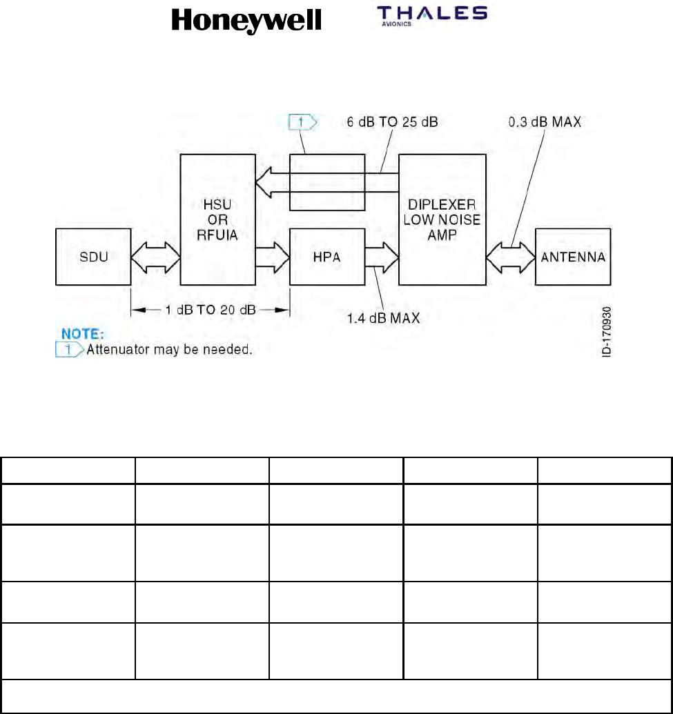
SYSTEM DESCRIPTION, INSTALLATION, AND MAINTENANCE MANUAL
MCS--4200/7200 Multi--Channel SATCOM System
23--20--35 15 Jul 2006
Honeywell International Inc. Do not copy without express permission of Honeywell.
Page 4--3
Figure 4-1. Cable Attenuations
Table 4-1. Cable Loss Requirements
Cable Assembly Location Minimum Loss Maximum Loss Maximum VSWR
TX Cable Between SDU,
HSU and HPA
1dB 20 dB 2.0
RX Cable Between
Diplexer/LNA and
SDU
6dB 25 dB 2.0
TX Cable Between HPA and
Diplexer/LNA
N/A 1.4 dB
(See Note)
1.3
RF Cable Between
Diplexer/LNA and
Antenna
N/A 0.3 dB 1.3
NOTE: In installations that use a high power relay (HPR), the HPR loss must be included. The maximum Tx cable loss
between the HGA and the antenna must not exceed 2.5 dB.
E. Cooling Requirements
(1) The cooling requirements for the MCS avionics are specified in Table 4-2 as follows:
•Power dissipation is in Watts.
•Mass airflow is in pounds per hour.
•CF/M is cubic feet per minute at sea level and 104 °F(40°C).
•Pressure drop is in inches of water.
(2) In most cases, a cooling system that meets the sea level requirements also meets
the cooling requirements at --67 °F(--55°C) and 70,000 feet.

SYSTEM DESCRIPTION, INSTALLATION, AND MAINTENANCE MANUAL
MCS--4200/7200 Multi--Channel SATCOM System
23--20--35 15 Jul 2006
Honeywell International Inc. Do not copy without express permission of Honeywell.
Page 4--4
Table 4-2. Cooling Requirements
Power
Dissipation Mass Airflow CF/M Pressure Drop
LRU Max. Nom. Max. Min. Max. Min. Max. Min.
SDU 150 105 96 (44 kg/hr) 73 (33 kg/hr) 23 18 0.25
(6.35 mm)
0.15
(3.81 mm)
HPA
(60W)
425 250 176 (80 kg/hr) 121 (55 kg/hr) 42 29 0.25
(6.35 mm)
0.2
(5.0 mm)
HSU 100 55 63 (29 kg/hr) 49 (22 kg/hr) 15 11 0.25
(6.35 mm)
0.15
(3.81 mm)
NOTE: The SDU draws an additional 20 W during the first 10 minutes (maximum) of operation at 25 _C because of the
oven controlled crystal oscillator (OCXO). The OCXO continuously dissipates this additional 20 W at --55 _C.
F. Vendor Supplied Equipment
(1) Installation equipment like mounting trays, connectors, and cables can be obtained
from various vendors. Refer to Appendix A for additional information about vendor
manufactured equipment. For vendor supplied avionics, refer to the vendor
documentation.
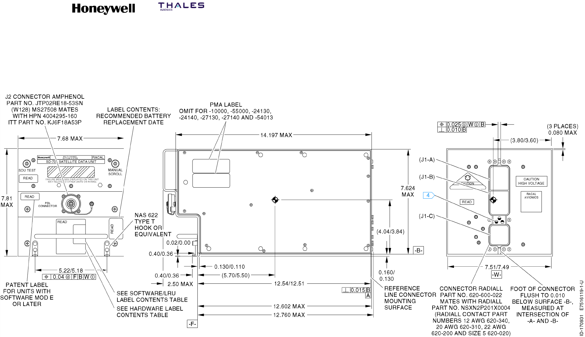
SYSTEM DESCRIPTION, INSTALLATION, AND MAINTENANCE MANUAL
MCS--4200/7200 Multi--Channel SATCOM System
23--20--35 15 Jul 2006
Honeywell International Inc. Do not copy without express permission of Honeywell.
Page 4--5/4--6
Figure 4-2. SD-700 and SD-720 (7516119) Outline and Installation Diagram
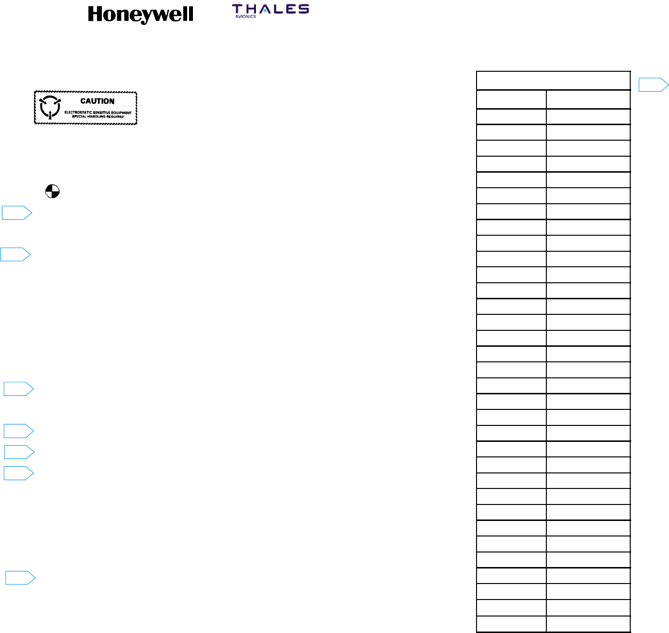
SYSTEM DESCRIPTION, INSTALLATION, AND MAINTENANCE MANUAL
MCS--4200/7200 Multi--Channel SATCOM System
23--20--35 15 Jul 2006
Honeywell International Inc. Do not copy without express permission of Honeywell.
Page 4--7/4--8
NOTES:
1. This assembly includes components which are subject
to damage by electrostatic charges: Therefore all
components shall be handled in accordance with
guidelines for electrostatic discharge control.
2. Unit Weight:
Nominal: 28.0 pounds (12.70 kilograms).
Maximum: 32.0 pounds (14.50 kilograms).
3. Denotes approximate center of gravity.
4. Darkened portion indicates raised part of polarizing keyway.
5. This installation is in accordance with ARINC 600--12 Number 8 MCU.
6. Dimensions are in inches. See the Metric Conversion Table for corresponding
dimensions in millimeters.
7. Cooling airflow requirements:
Minimum: 0.25 ±0.05 inches of water (6.35 ±1.27 millimeters of water) at a flow rate
of 176.4 ±2.0 pounds per hour (80.00 ±0.91 kilograms per hour).
8. Unit finish: gold chemical film.
9. This unit defines 7520000--XXYYY.
XX = Hardware dash number 1 thru 99
YYY = Software Part No. 001 through 999.
10. 0.10 maximum rear panel thickness is required in connector mounting area defined
as zone A. No other projections except connector mounting hardware are permitted
in area defined as zone A.
11. Applies 0.750 from datum B.
12. Electrostatic dust covers shown partially removed for clarity.
13. ARINC 600 connector, receptacle, size 2
Unit Part No.: Radiall NSXFR221Y0908. Tray mating plug Part No. Radiall
NSX2P221X0008.
ARINC 600 connector contact Radiall Part Nos.:
Size 22: Unit Part No. 620--361, tray mating Part No. 620--200.
Size 20: Unit Part No. 620--210, tray mating Part No. 620--310.
Size 12: Unit Part No. 620--240, tray mating Part No. 620--340.
Size 1 coax: Unit Part No. 620--044, see SDIM for tray mating contact Part No.
Size 5 coax: Unit Part No. 620--134, see SDIM for tray mating contact Part No.
14. ARINC 615 connector (PDL):
Unit connector Honeywell Part No. 4008114--160 or MS27508E18B53S, mating
connectors Honeywell Part No. 4004295--160 or ITT Part No. KJ6F18A53P.
METRIC CONVERSION TABLE
INCHES MILLIMETERS
.010 0.254
.015 0.381
.020 0.508
.025 0.635
.030 0.762
.040 1.016
.060 1.524
.080 2.032
.100 2.240
.120 3.048
.145 3.683
.160 4.064
.184 4.674
.188 4.775
.200 5.080
.380 9.652
.750 19.050
1.400 35.560
1.810 45.974
1.970 50.038
2.500 63.500
3.590 91.186
4.500 114.300
5.310 134.874
5.750 146.050
6.890 175.006
7.640 194.056
7.800 198.120
10.070 255.778
10.110 256.794
10.790 274.066
11.300 287.020
12.520 318.008
Figure 4-3 (Sheet 1). HP--720 (7520006) Outline and Installation Diagram
6
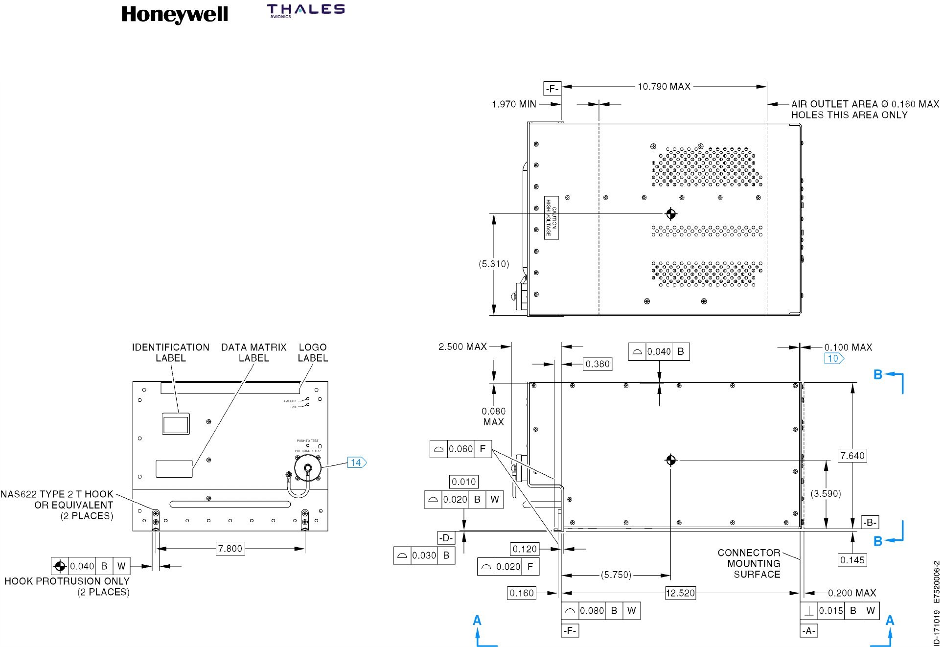
SYSTEM DESCRIPTION, INSTALLATION, AND MAINTENANCE MANUAL
MCS--4200/7200 Multi--Channel SATCOM System
23--20--35 15 Jul 2006
Honeywell International Inc. Do not copy without express permission of Honeywell.
Page 4--9/4--10
Figure 4-3 (Sheet 2). HP--720 (7520006) Outline and Installation Diagram
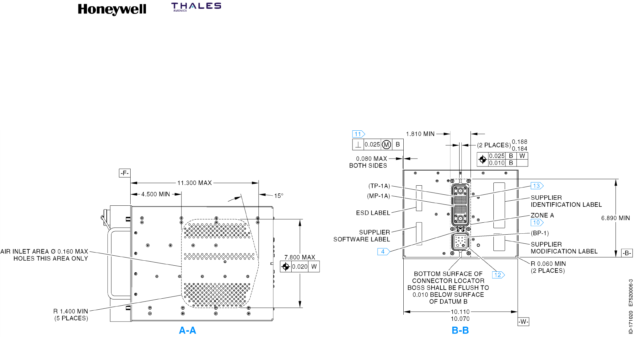
SYSTEM DESCRIPTION, INSTALLATION, AND MAINTENANCE MANUAL
MCS--4200/7200 Multi--Channel SATCOM System
23--20--35 15 Jul 2006
Honeywell International Inc. Do not copy without express permission of Honeywell.
Page 4--11/4--12
Figure 4-3 (Sheet 3). HP--720 (7520006) Outline and Installation Diagram
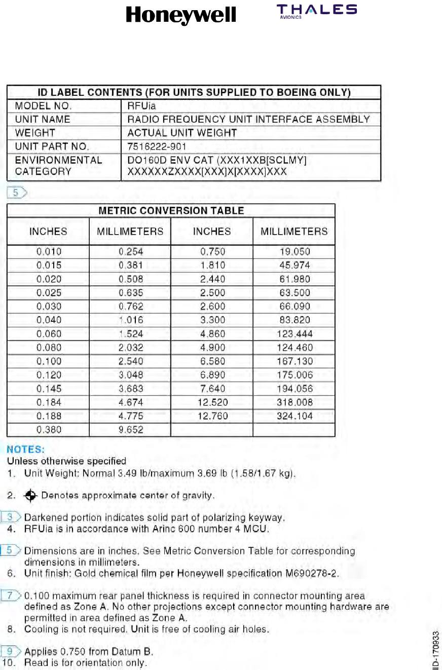
SYSTEM DESCRIPTION, INSTALLATION, AND MAINTENANCE MANUAL
MCS--4200/7200 Multi--Channel SATCOM System
23--20--35 15 Jul 2006
Honeywell International Inc. Do not copy without express permission of Honeywell.
Page 4--13/4--14
Figure 4-4 (Sheet 1). RFUIA Outline and Installation Diagram
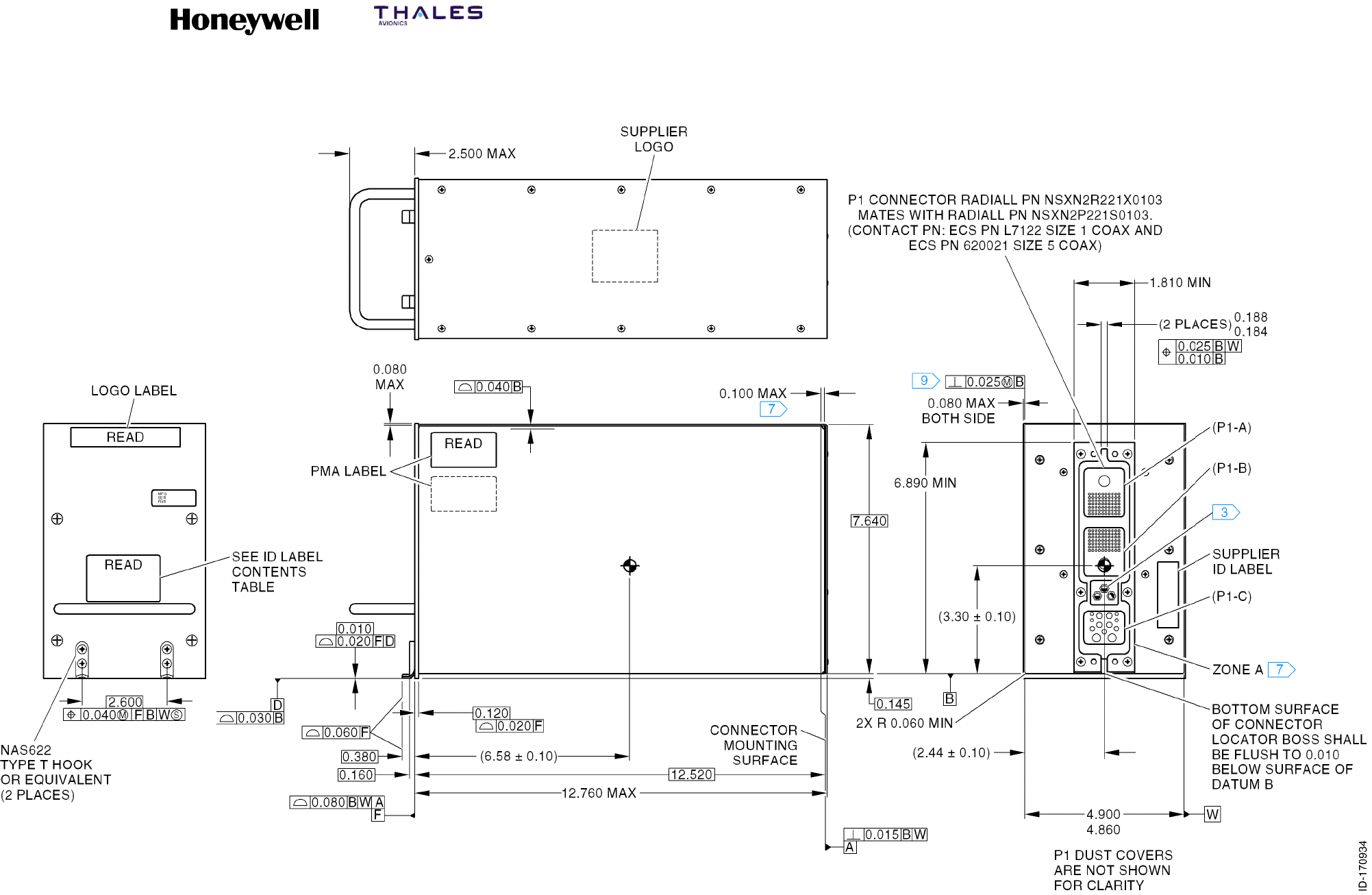
SYSTEM DESCRIPTION, INSTALLATION, AND MAINTENANCE MANUAL
MCS--4200/7200 Multi--Channel SATCOM System
23--20--35 15 Jul 2006
Honeywell International Inc. Do not copy without express permission of Honeywell.
Page 4--15/4--16
Figure 4-4 (Sheet 2). RFUIA Outline and Installation Diagram
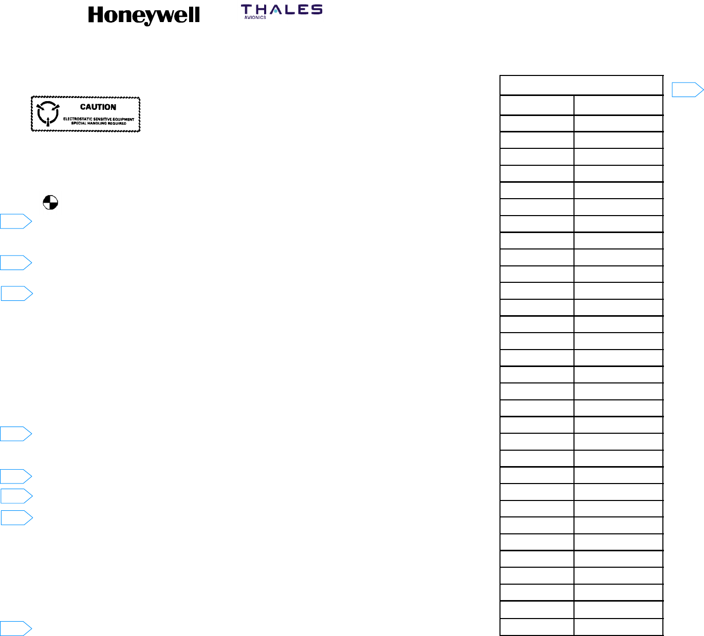
SYSTEM DESCRIPTION, INSTALLATION, AND MAINTENANCE MANUAL
MCS--4200/7200 Multi--Channel SATCOM System
23--20--35 15 Jul 2006
Honeywell International Inc. Do not copy without express permission of Honeywell.
Page 4--17/4--18
NOTES:
1. This assembly includes components which are subject
to damage by electrostatic charges: Therefore all
components shall be handled in accordance with
guidelines for electrostatic discharge control.
2. Unit Weight:
Nominal: 15.4 pounds (6.98 kilograms).
Maximum: 16.0 pounds (7.26 kilograms).
3. Denotes approximate center of gravity.
4. Darkened portion indicates raised part of polarizing keyway.
5. This installation is in accordance with ARINC 600--12 Number 4 MCU.
6. Dimensions are in inches. See the Metric Conversion Table for corresponding
dimensions in millimeters.
7. Cooling airflow requirements:
Minimum: 0.15 ±0.05 inches of water (13.81 ±1.27 millimeters of water) at a flow
rate of 49.5 ±2.0 pounds per hour (22.00 ±0.91 kilograms per hour). For added
reliability the following may be used: 0.25 ±0.05 inches of water (6.35 ±1.27
millimeters of water) at a flow rate of 63.1 ±2.0 pounds per hour (28.62 ±0.91
kilograms per hour).
8. Unit finish: gold chemical film.
9. This unit defines 7520061--XXYYY.
XX = Hardware dash number 1 thru 99
YYY = Software Part No. 001 through 999.
10. 0.10 maximum rear panel thickness is required in connector mounting area defined
as zone A. No other projections except connector mounting hardware are permitted
in area defined as zone A.
11. Applies 0.750 from datum B.
12. Electrostatic dust covers shown partially removed for clarity.
13. ARINC 600 connector, receptacle, size 2
Unit Part No.: Radiall NSXFR221Y0903. Tray mating plug Part No. Radiall
NSX2P221X0003.
ARINC 600 connector contact Radiall Part Nos.:
Size 22: Unit Part No. 620--361, tray mating Part No. 620--200.
Size 20: Unit Part No. 620--210, tray mating Part No. 620--310.
Size 12: Unit Part No. 620--240, tray mating Part No. 620--340.
Size 1 coax: Unit Part No. 620--044, see SDIM for tray mating contact Part No.
Size 5 coax: Unit Part No. 620--134, see SDIM for tray mating contact Part No.
14. ARINC 615 connector (PDL):
Unit connector Honeywell Part No. 4008114--160 or MS27508E188535, mating
connectors Honeywell Part No. 4004295--160 or ITT Part No. KJ6F18A53P.
METRIC CONVERSION TABLE
INCHES MILLIMETERS
.010 0.254
.015 0.381
.020 0.508
.025 0.635
.030 0.762
.040 1.016
.060 1.524
.080 2.032
.100 2.240
.120 3.048
.145 3.683
.160 4.064
.184 4.674
.188 4.775
.200 5.080
.380 9.652
.750 19.050
1.810 45.974
1.970 50.038
2.500 63.500
2.600 66.040
4.000 101.600
4.500 114.300
4.860 123.444
4.900 124.460
5.390 136.906
6.890 175.006
7.640 194.056
10.790 274.066
11.300 287.020
12.520 318.008
Figure 4-5 (Sheet 1). HS--720 (7520063) Outline and Installation Diagram
6
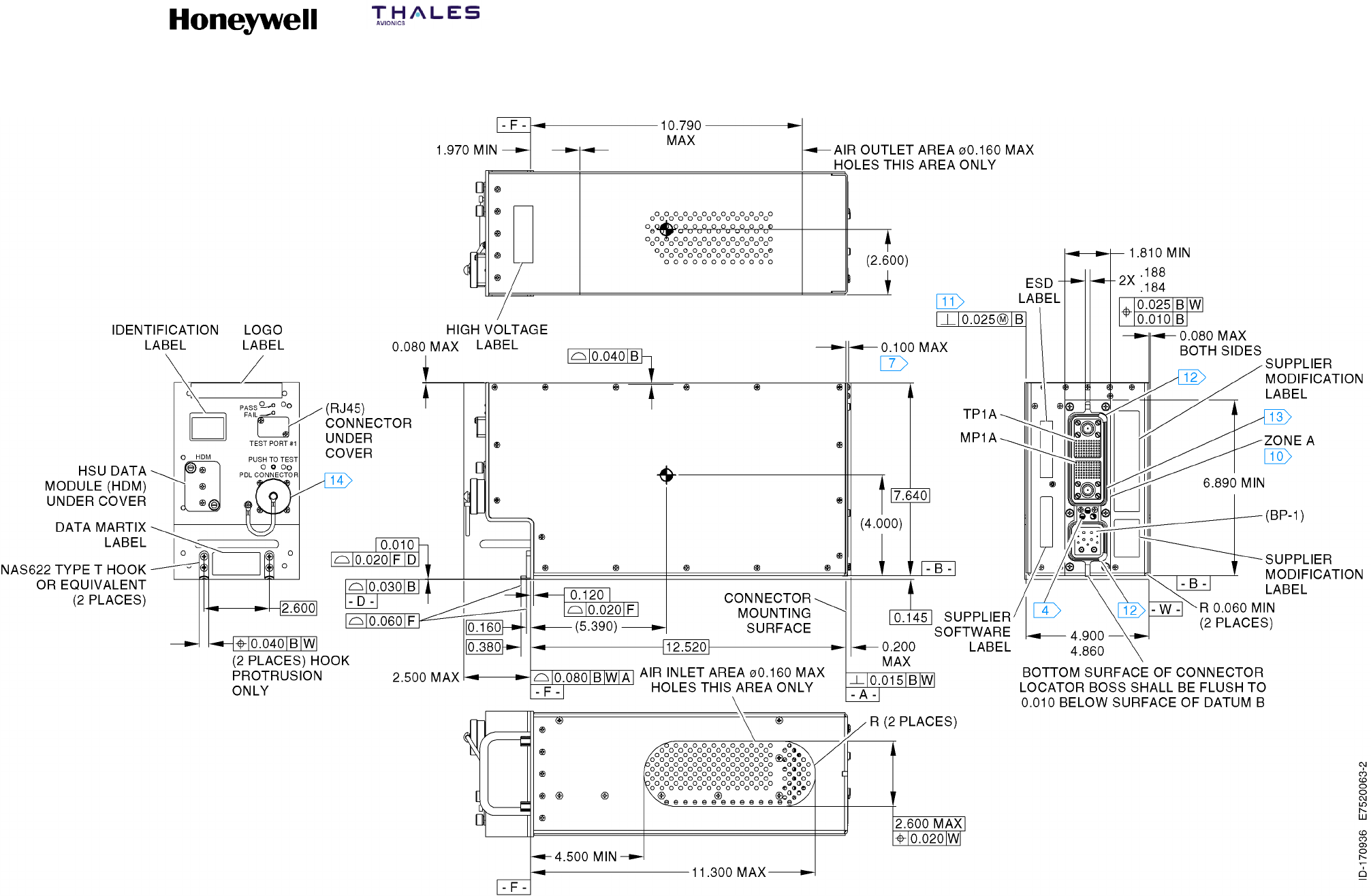
SYSTEM DESCRIPTION, INSTALLATION, AND MAINTENANCE MANUAL
MCS--4200/7200 Multi--Channel SATCOM System
23--20--35 15 Jul 2006
Honeywell International Inc. Do not copy without express permission of Honeywell.
Page 4--19/4--20
Figure 4-5 (Sheet 2). HS--720 (7520063) Outline and Installation Diagram