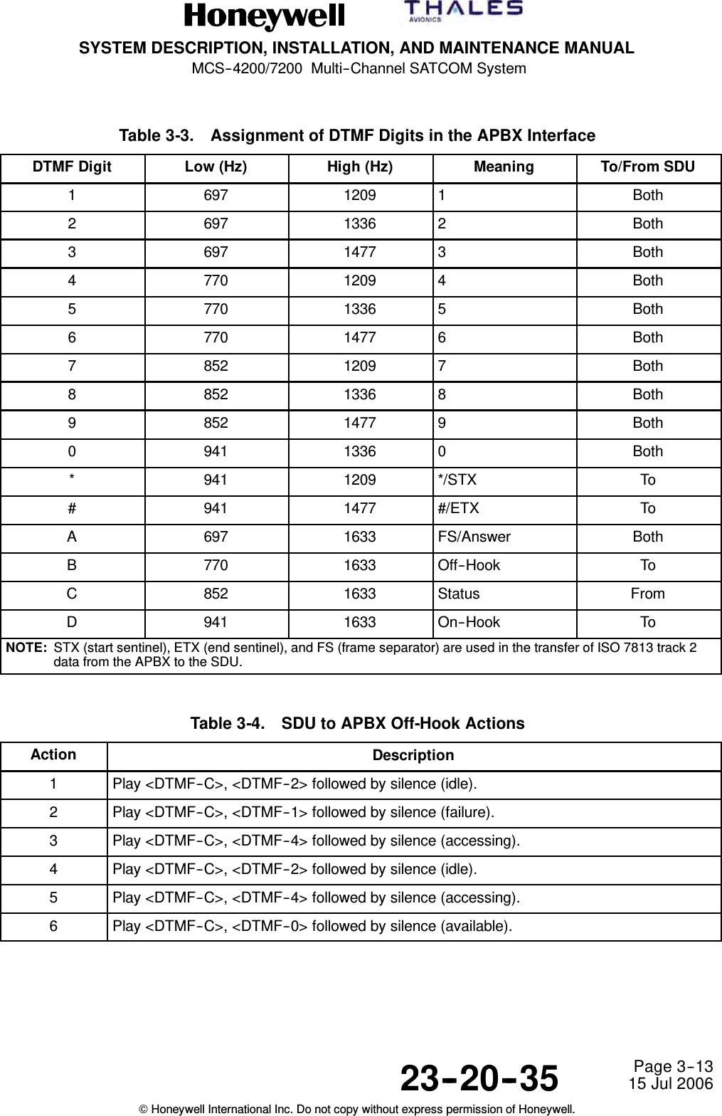
Honeywell HS-720 High Speed Data Unit for the MCS-7200 SATCOM System User Manual SDIM Multi Channel SATCOM System A15 5111 010
Honeywell International Inc. High Speed Data Unit for the MCS-7200 SATCOM System SDIM Multi Channel SATCOM System A15 5111 010
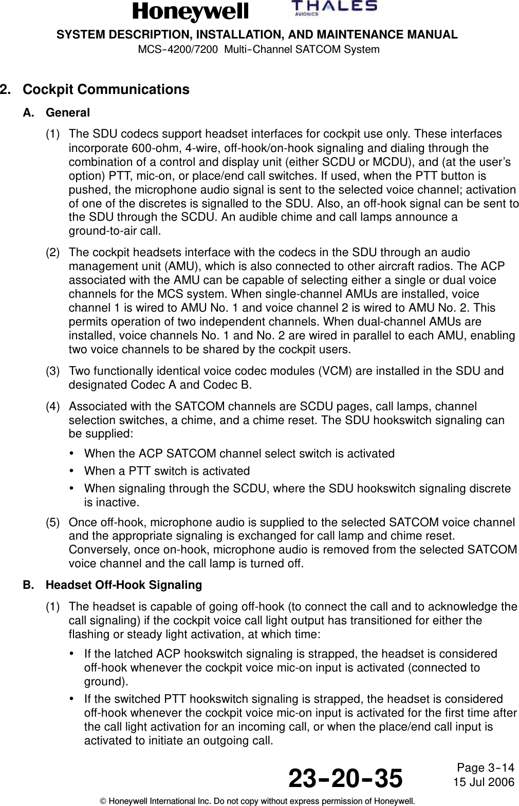
Contents
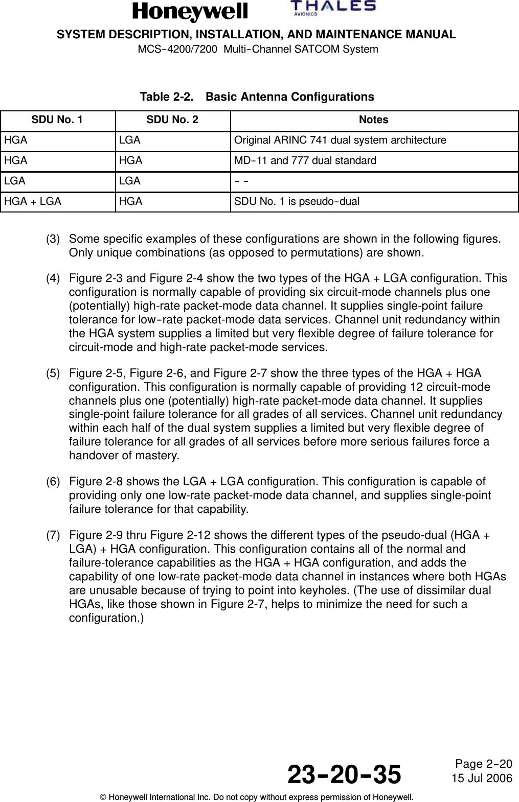
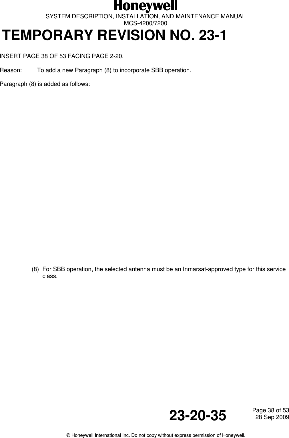
- 1. HS-720 User Manual Part1
- 2. HS-720 User Manual Part2
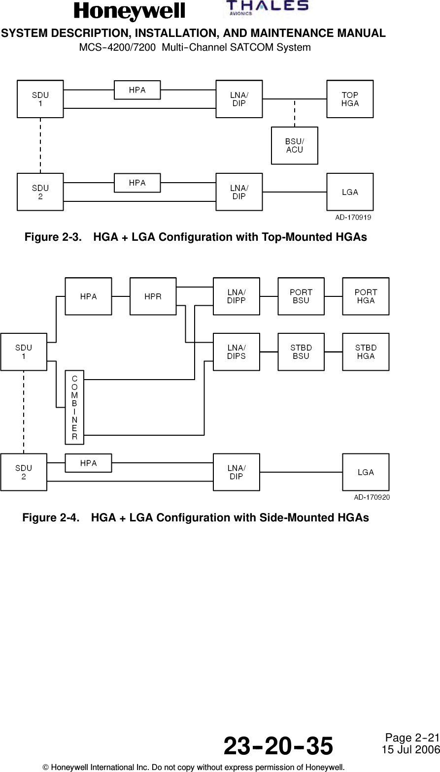
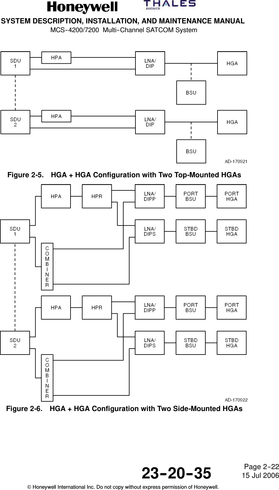
- 3. HS-720 User Manual Part3
HS-720 User Manual Part1
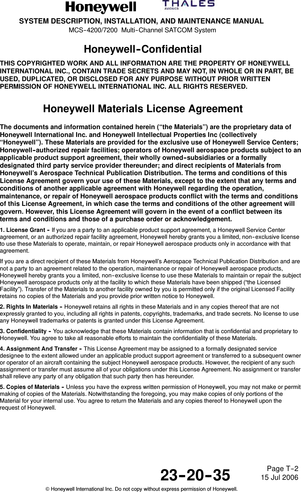


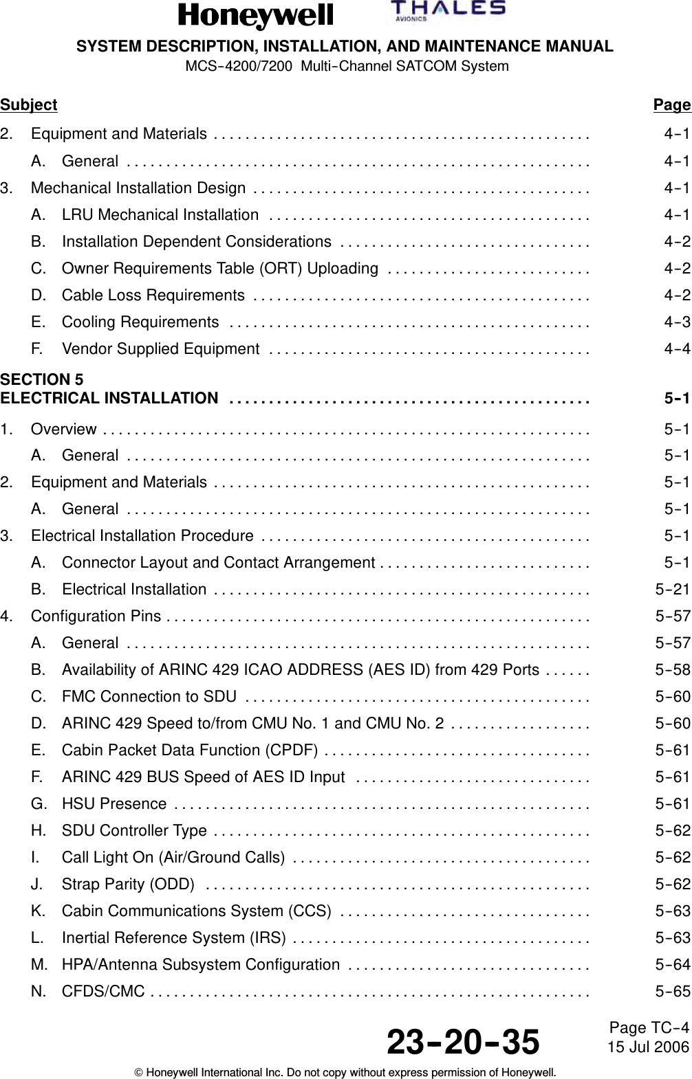
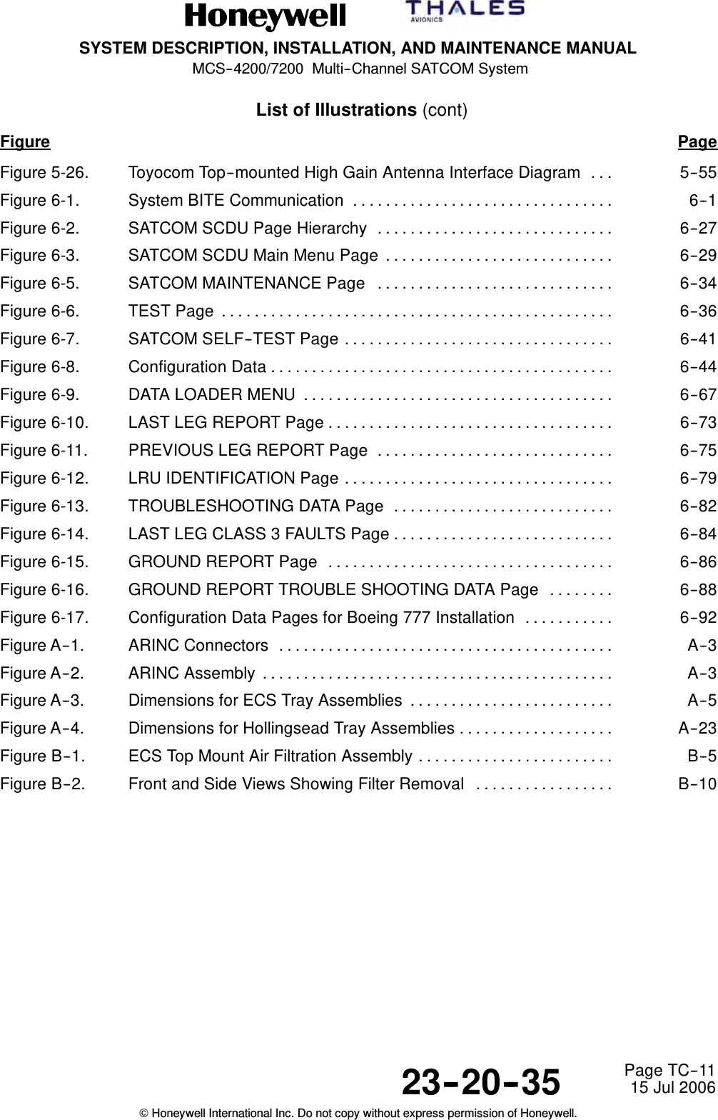
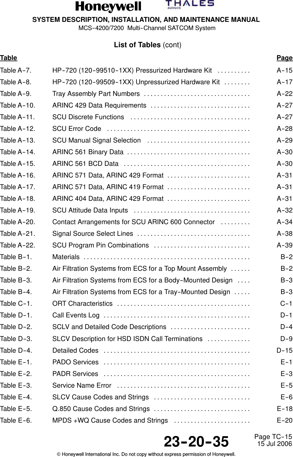

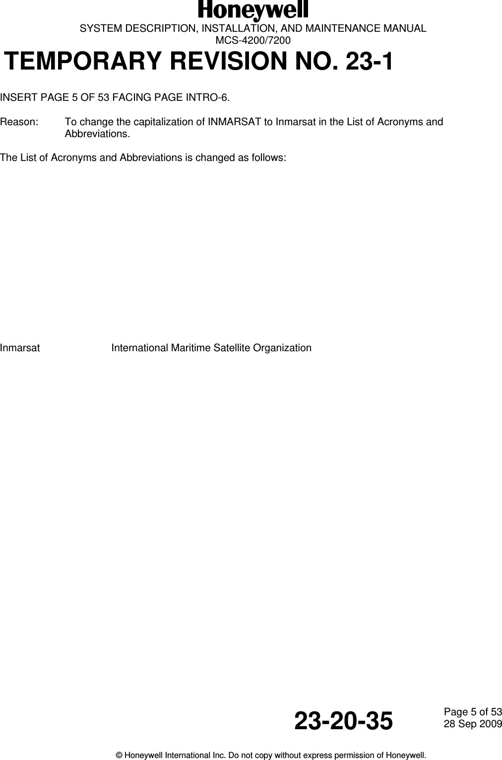
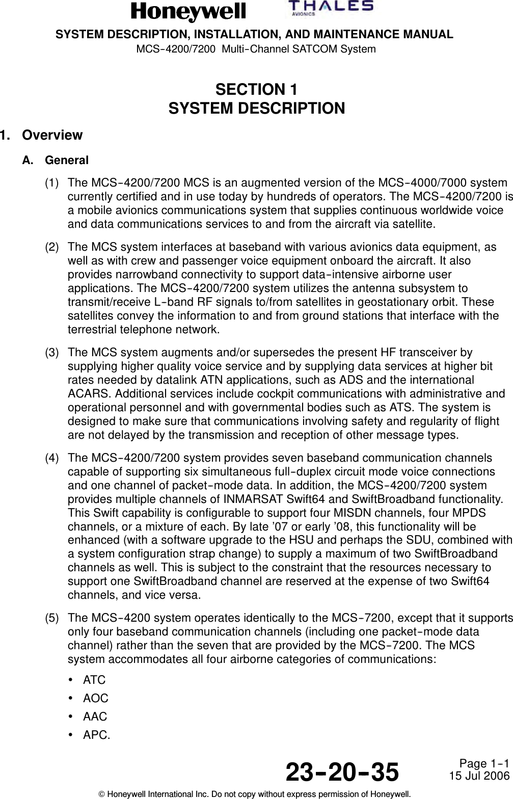
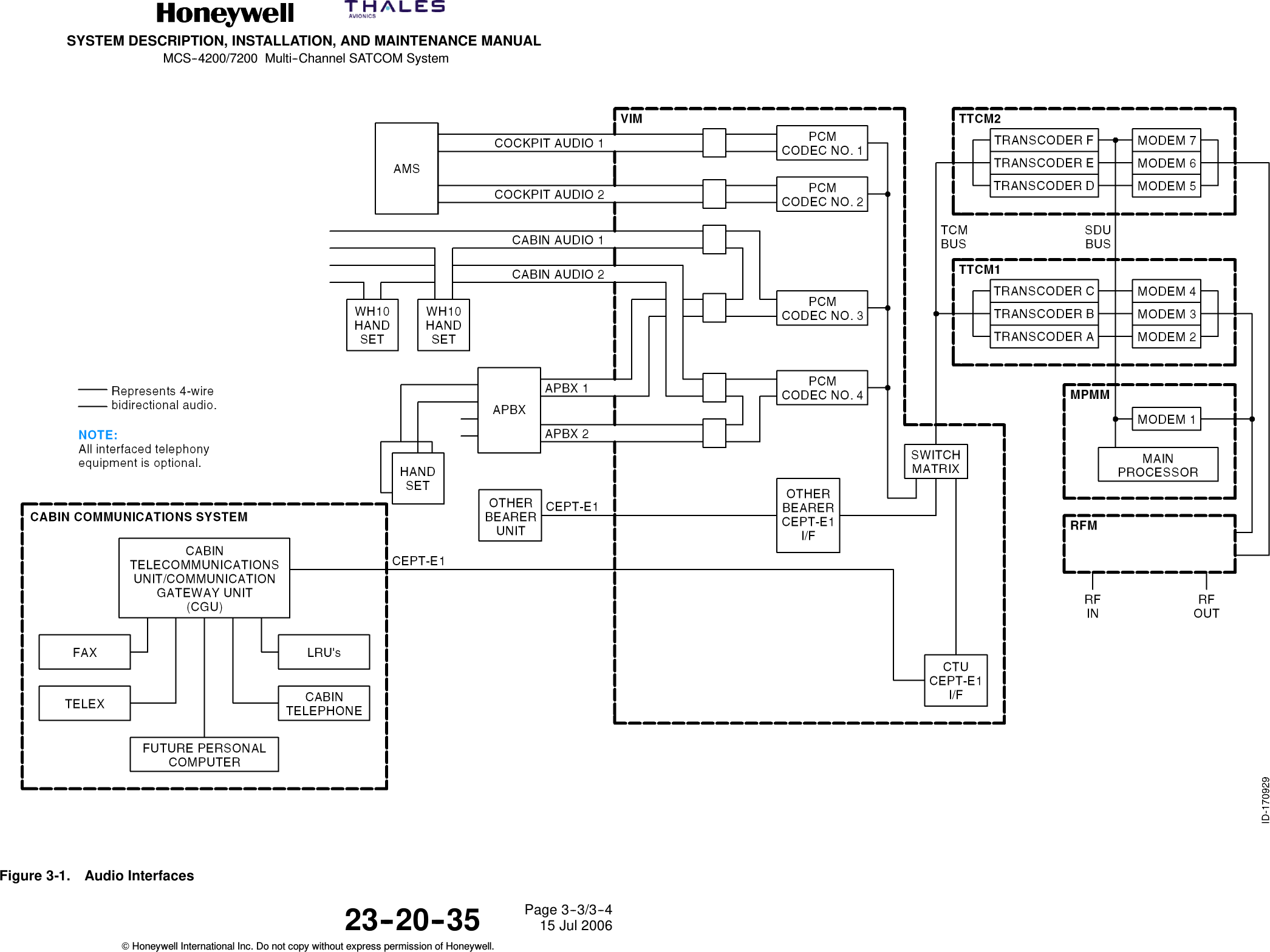
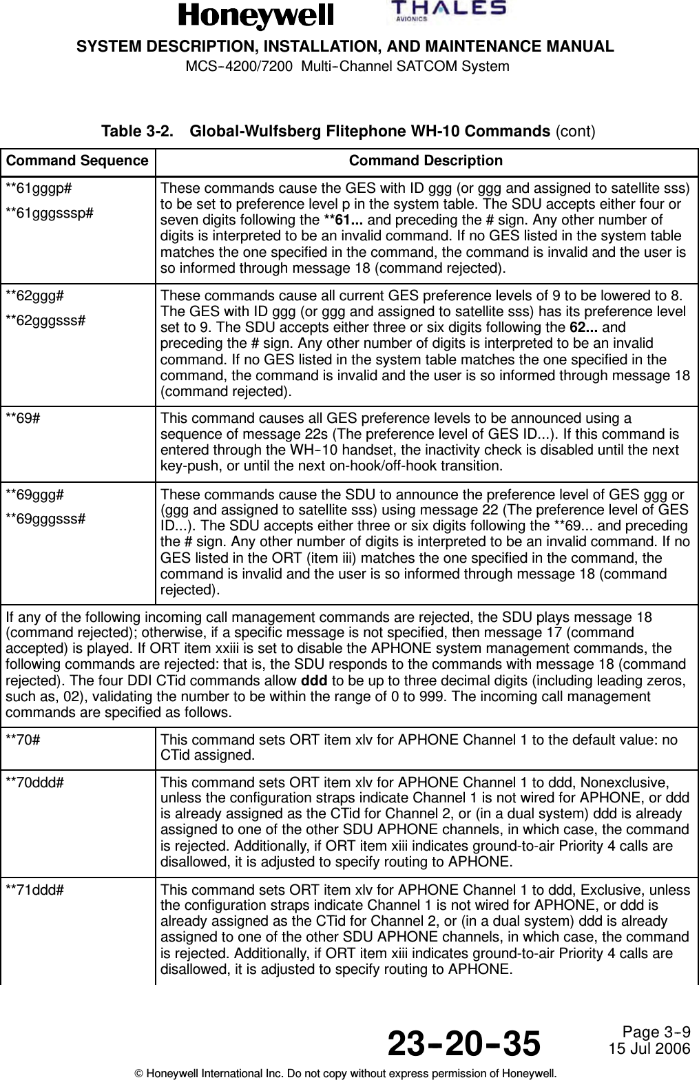
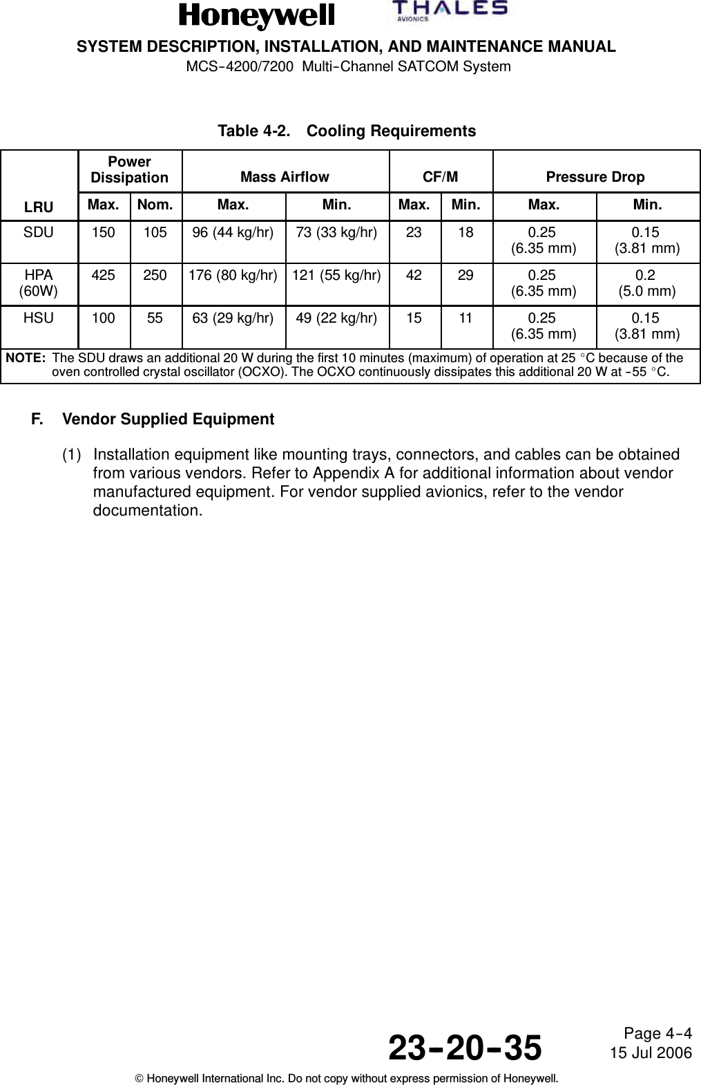
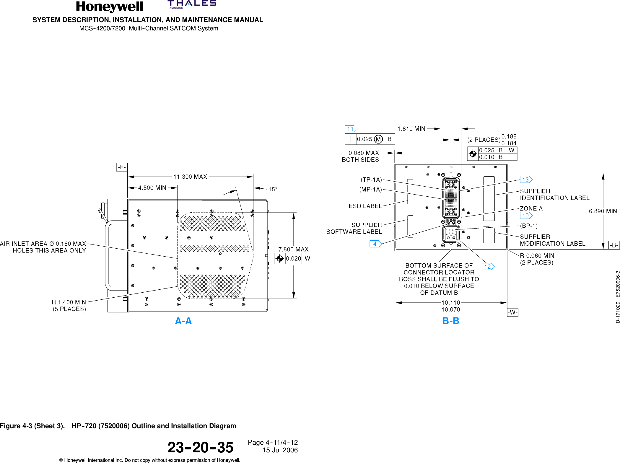
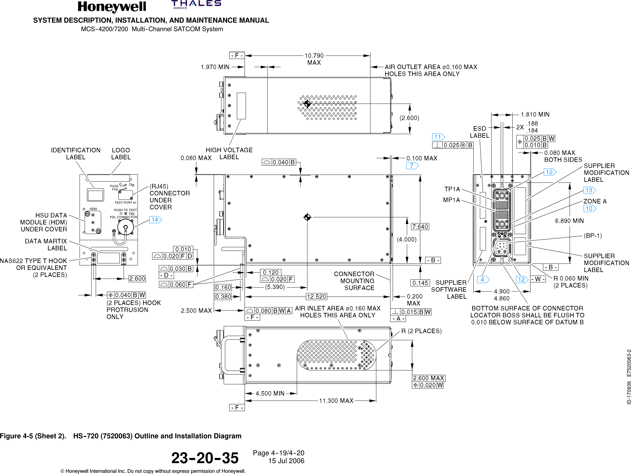
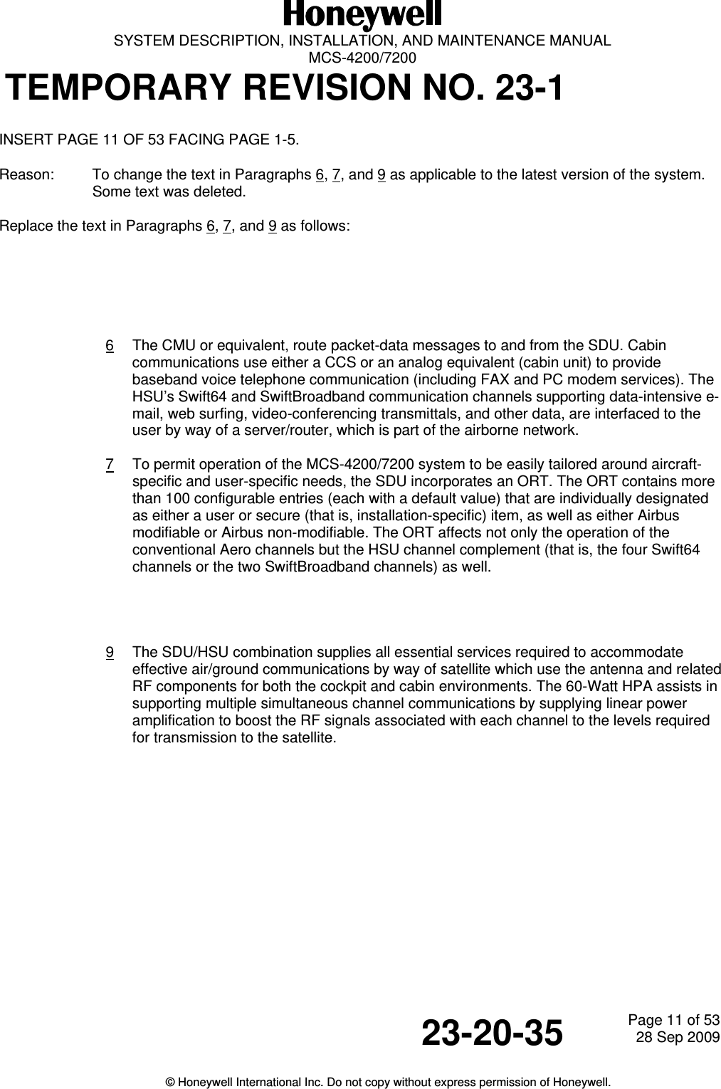
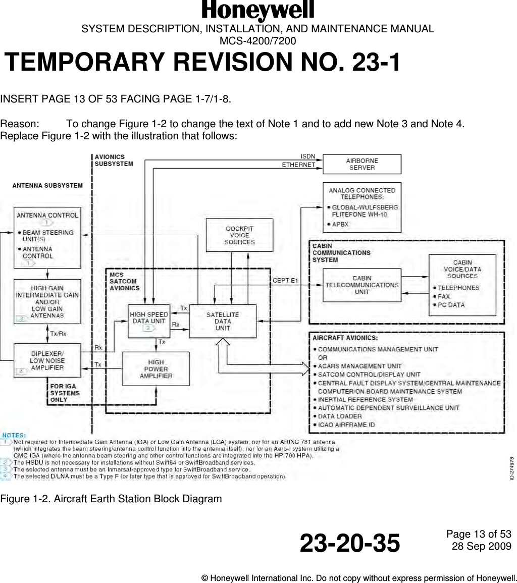
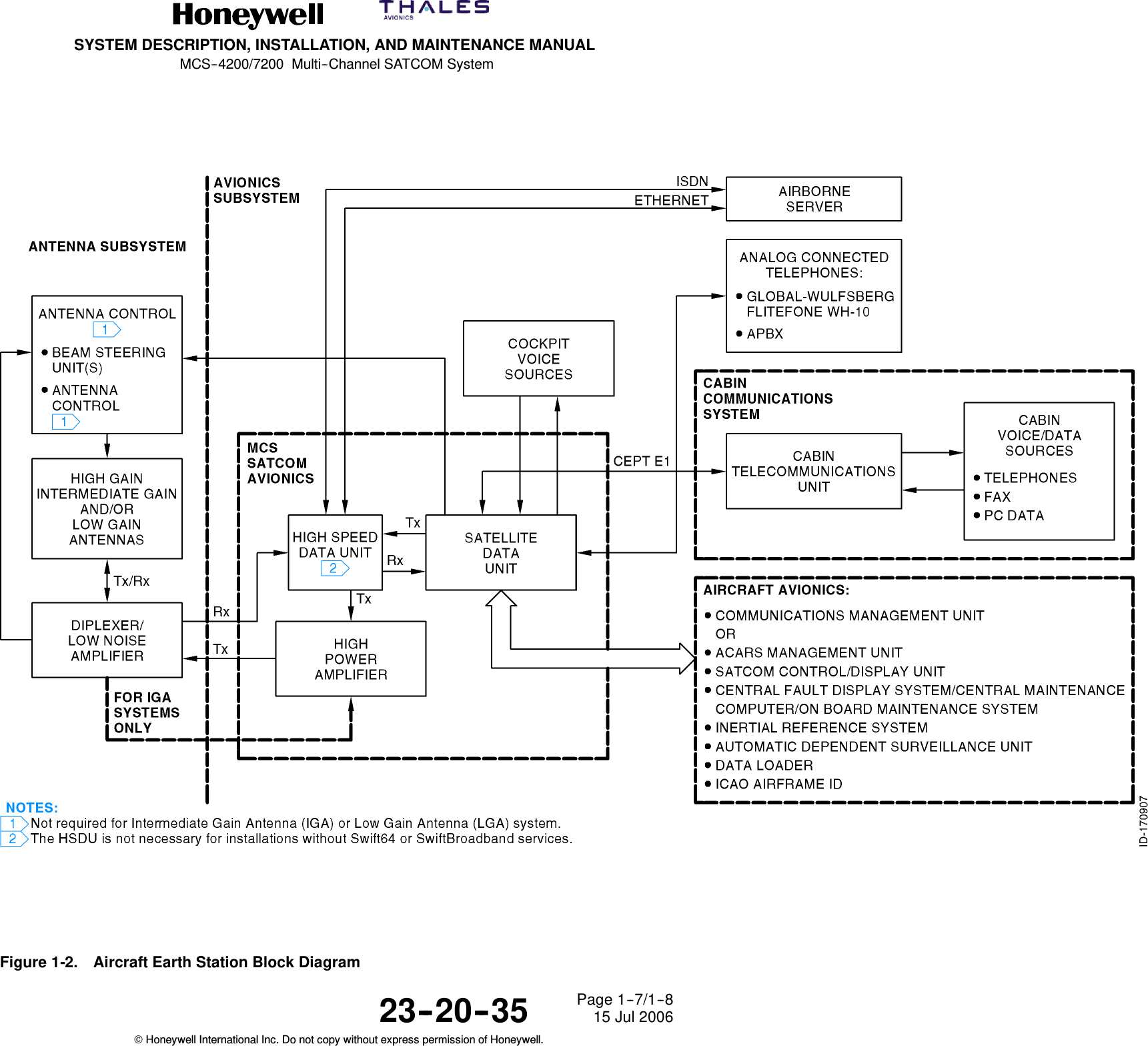
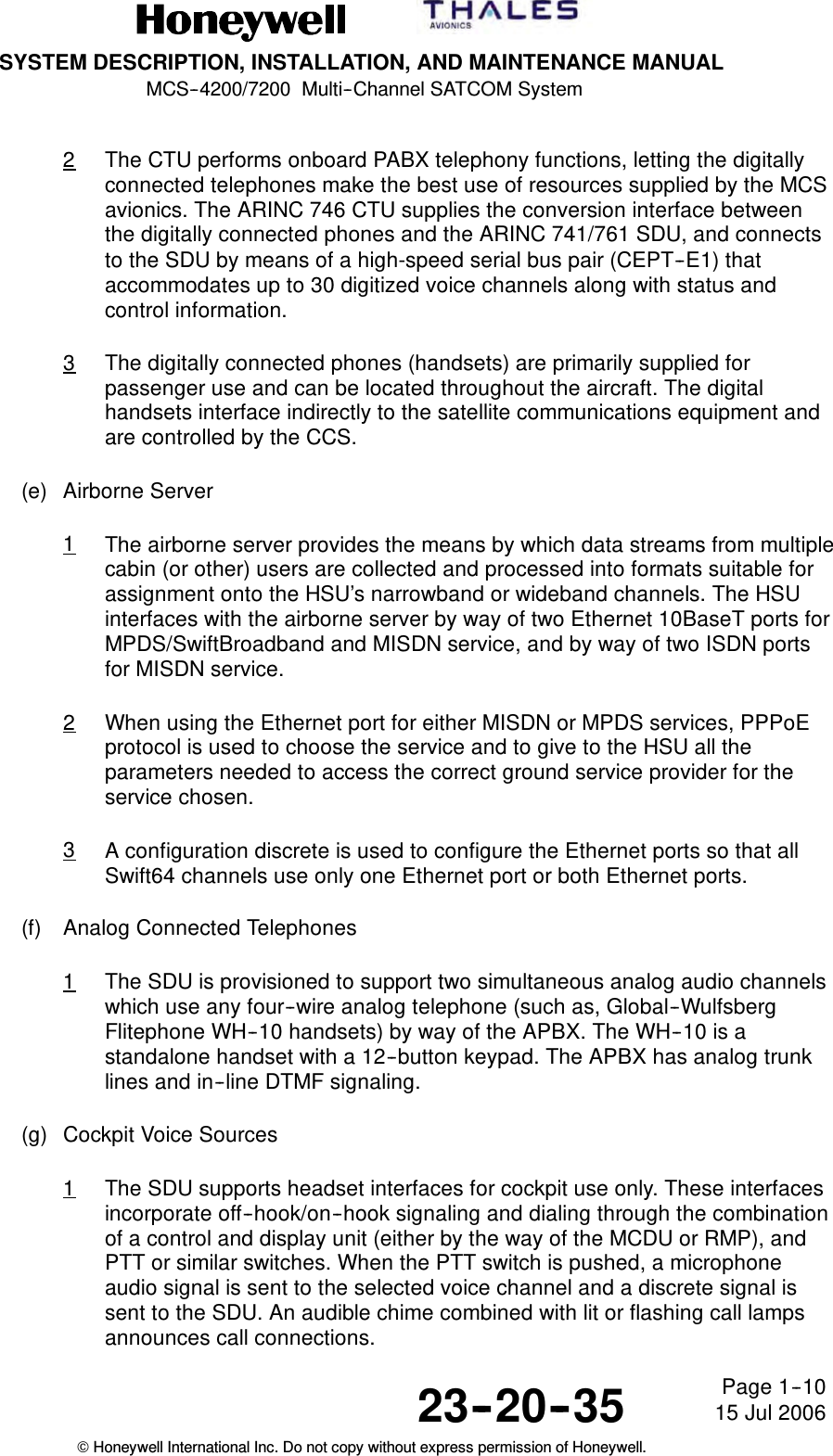
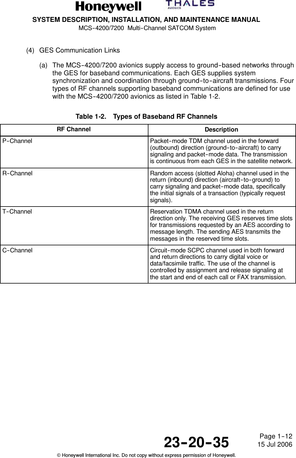
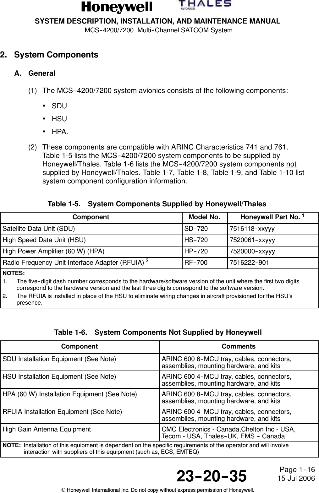
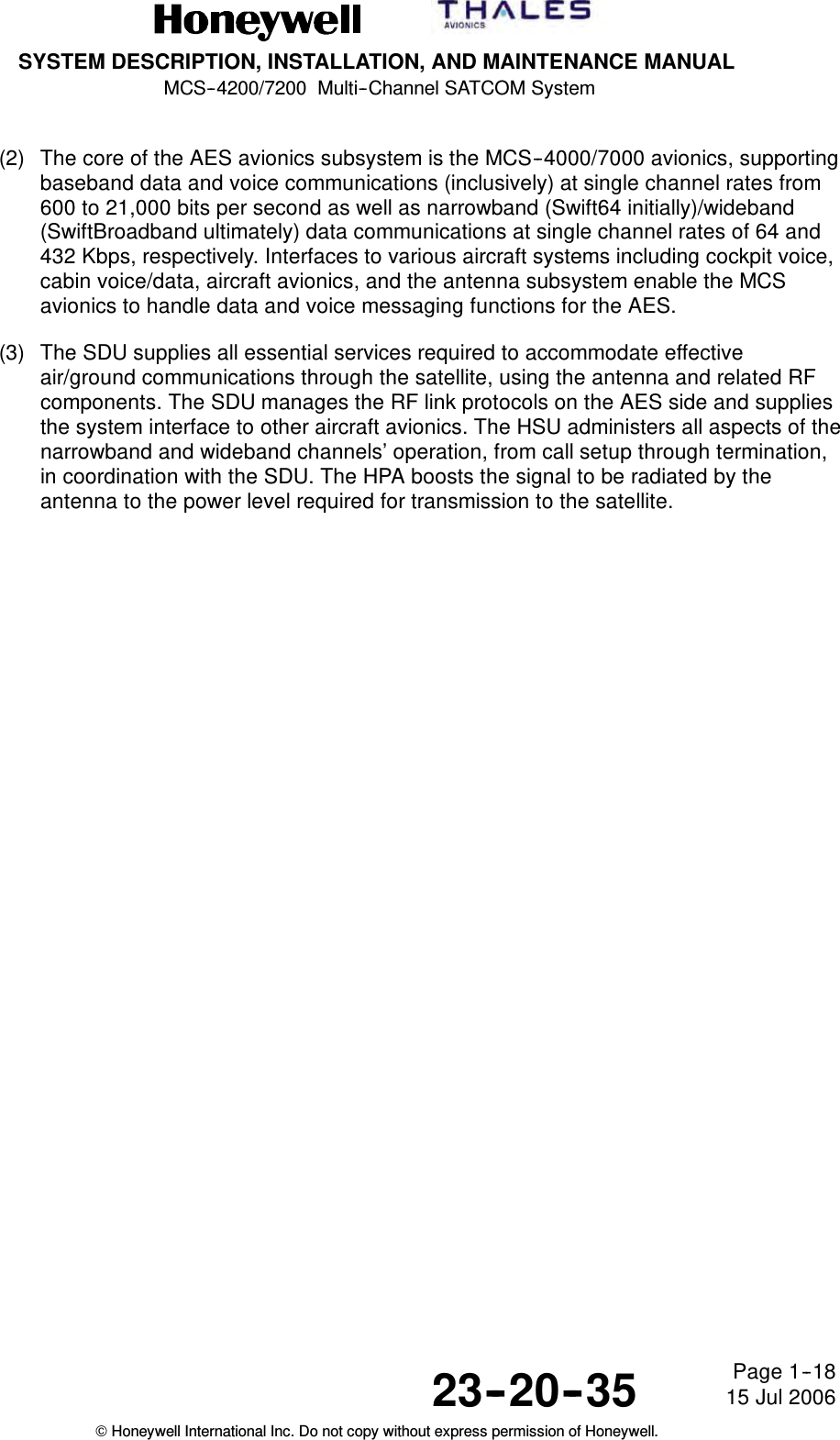
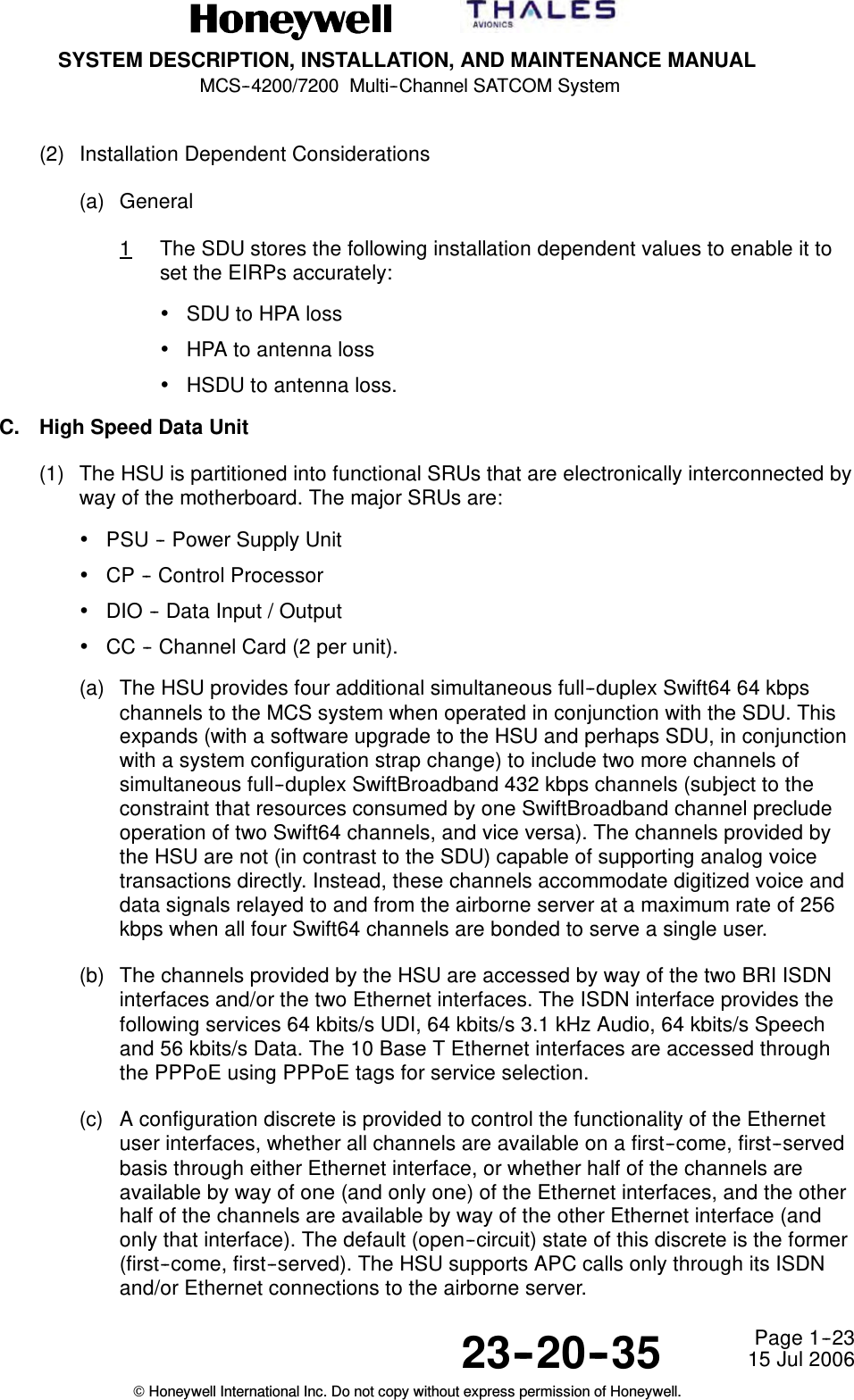
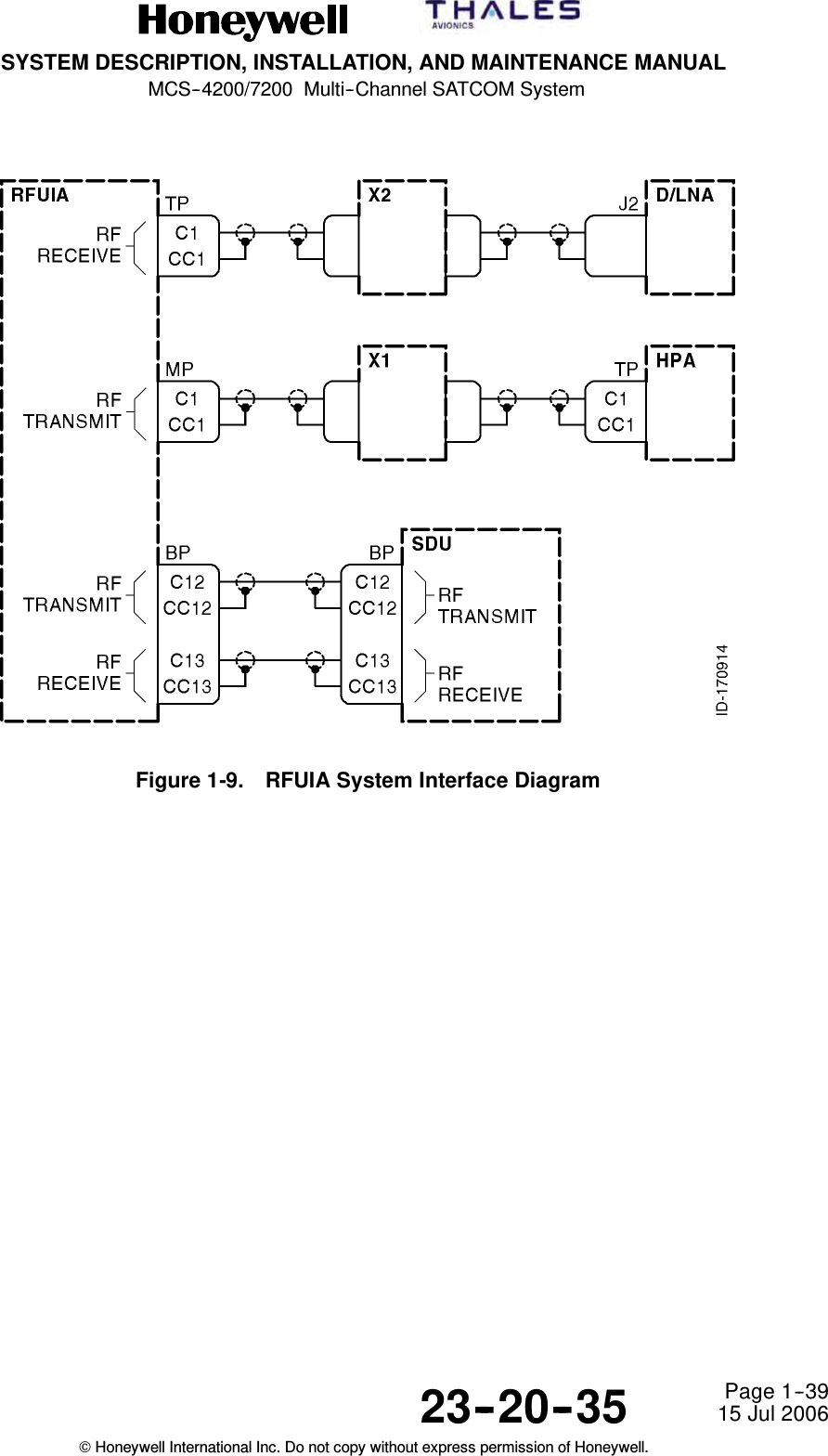
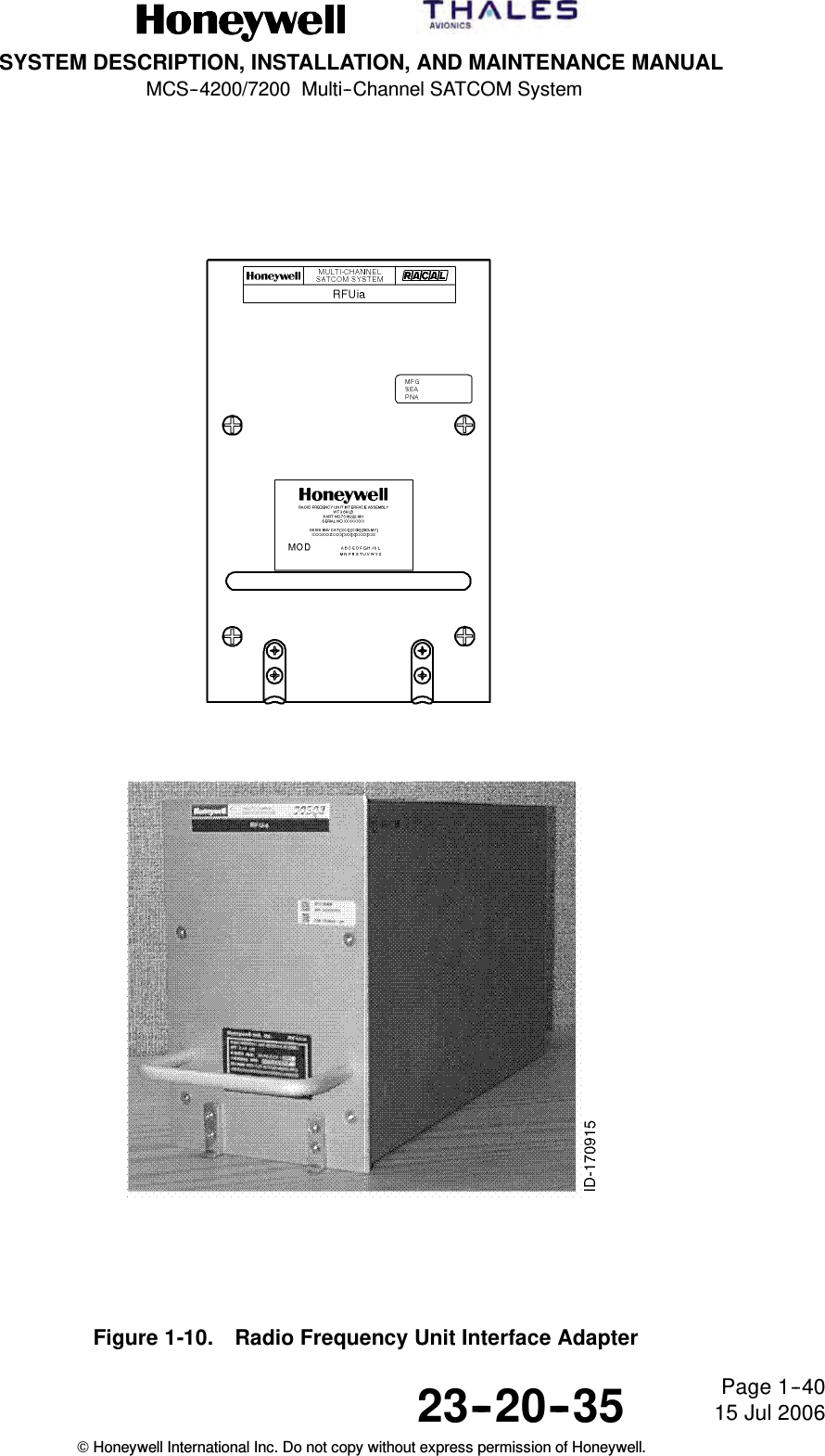
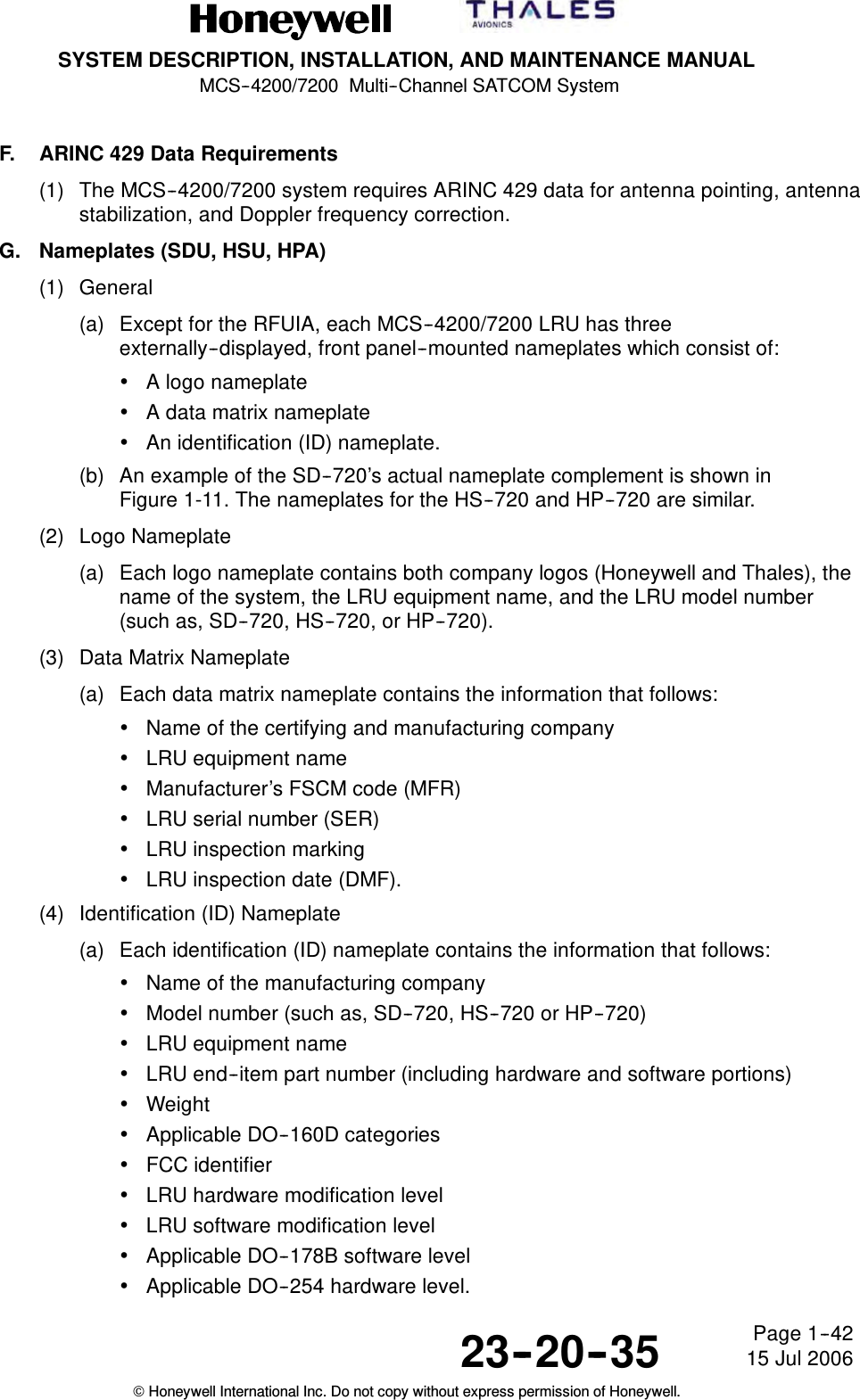
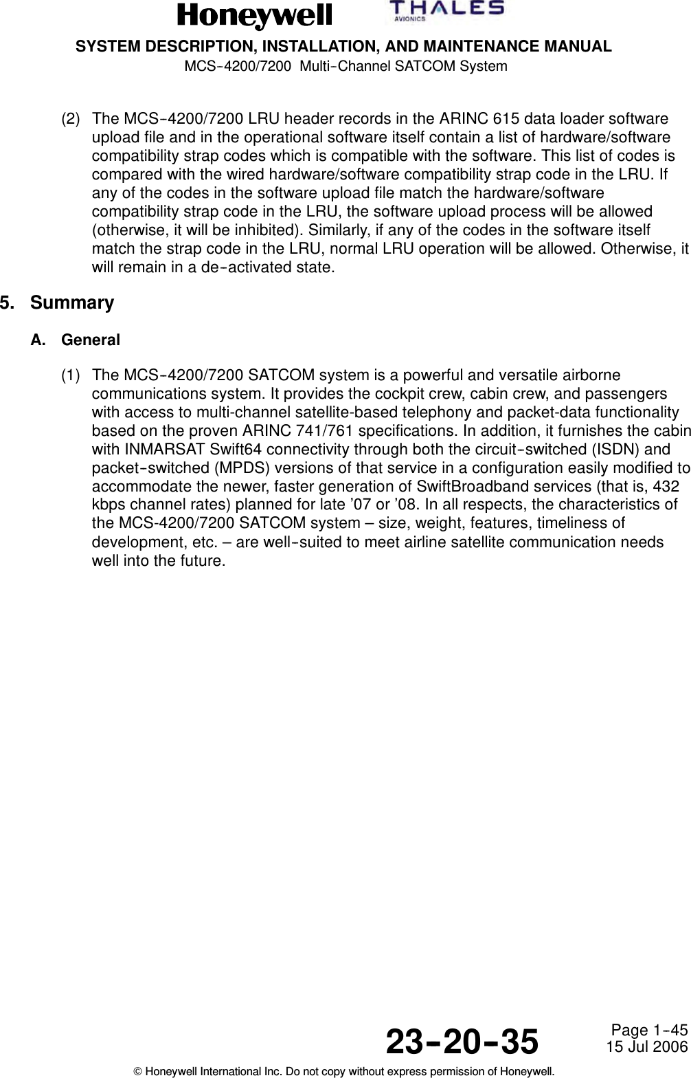
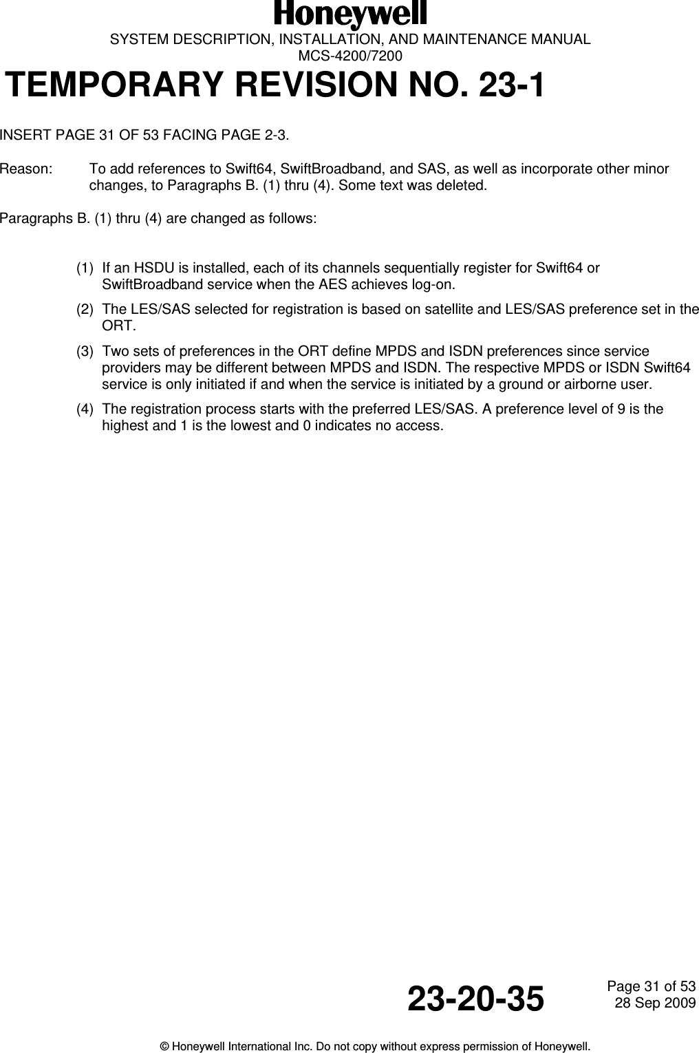
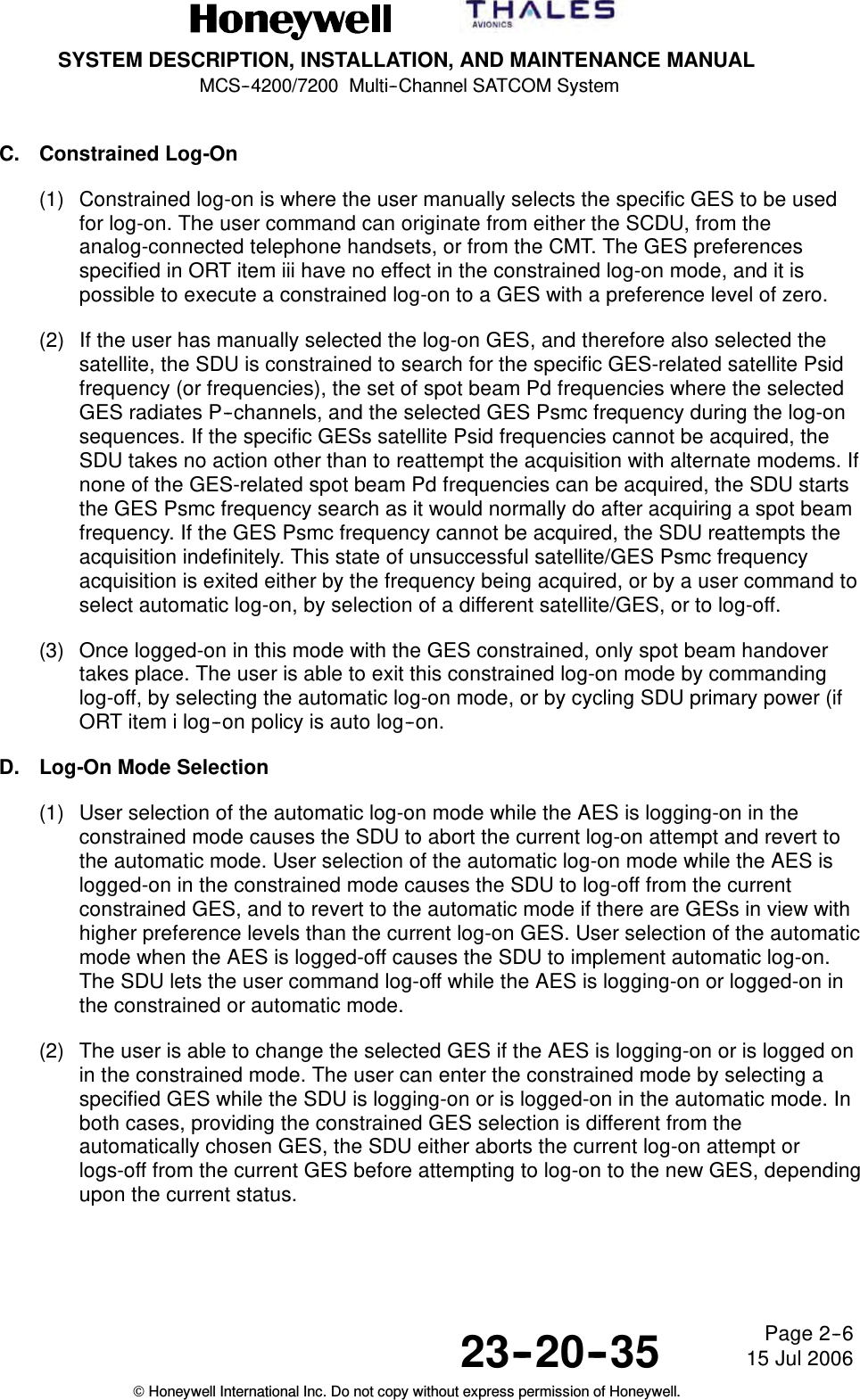
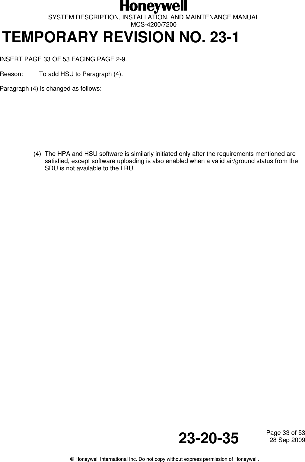
![SYSTEM DESCRIPTION, INSTALLATION, AND MAINTENANCE MANUALMCS--4200/7200 Multi--Channel SATCOM System23--20--35 15 Jul 2006Honeywell International Inc. Do not copy without express permission of Honeywell.Page 1--4B. Aircraft Earth Station – General(1) General(a) The AES is fully compliant with requirements of ARINC Characteristics 741/761.Standard interfaces between the MCS--4200/7200 avionics and other aircraftavionics enables the AES to accept data and voice messages from varioussources, encode and modulate this information onto appropriate RF carrierfrequencies, and transmit these carriers to the space segment for relay to aGES. The AES also receives RF signals from a GES through the satellite,demodulates these signals, performs the necessary decoding of the encodedmessages, and outputs the data or voice message for use by the cockpit crew(pilot and copilot), the cabin crew or the passengers.(2) AES Components(a) General1A block diagram of the AES is shown in Figure 1--2. The AES is made up ofthe following components:•MCS SATCOM avionics•Antenna subsystem•Cabin communications system•Analog connected telephones•Cockpit voice sources•Aircraft avionics.(b) MCS Avionics1The MCS--4200/7200 avionics is made up of the SDU, the HSU and theHPA.2The SDU supplies the digital and analog interface to all aircraft avionics, andimplements all functionality associated with modulation/demodulation, errorcorrection, channel rate/frequency selection, and RF translation for thesystem’s seven baseband communication channels. The SDU’s sevenbaseband channels support six simultaneous full--duplex circuit--mode voiceconnections and one packet--mode channel.3The HSU incorporates the firmware necessary to support four narrowband(Swift64) channels, which provide simultaneous circuit--mode and/orpacket--mode connectivity concurrently with the SDU’s baseband channelsat rates of 64 kbps (per single channel) or 256 kbps (four combined [bondedISDN] channels). Ultimately, the HSU will be augmented – by softwareupgrade to the HSU, and perhaps the SDU, coupled with a systemconfiguration strap change – to support an additional two widebandchannels of 432 kbps (per single channel) SwiftBroadband functionality aswell. Note that when the HSU commits the resources necessary to support asingle SwiftBroadband channel, it simultaneously loses the capability toprovide two channels of Swift64 service (and vice versa).](https://usermanual.wiki/Honeywell/HS-720.HS-720-User-Manual-Part1/User-Guide-1350370-Page-62.png)
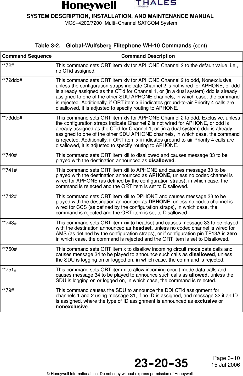
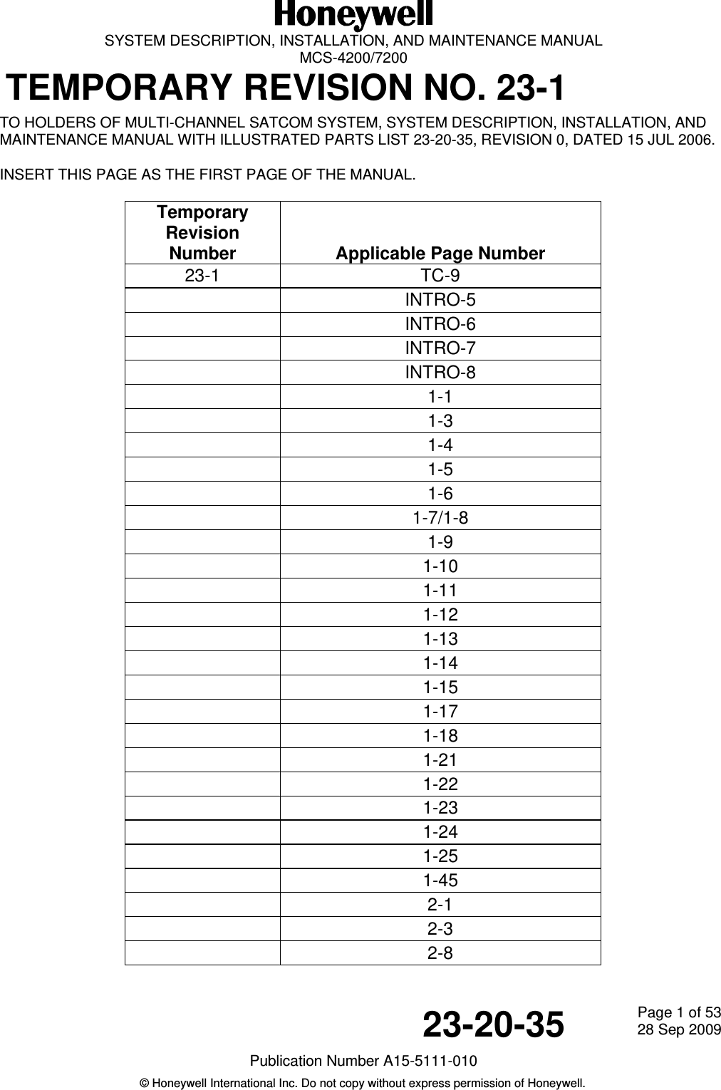
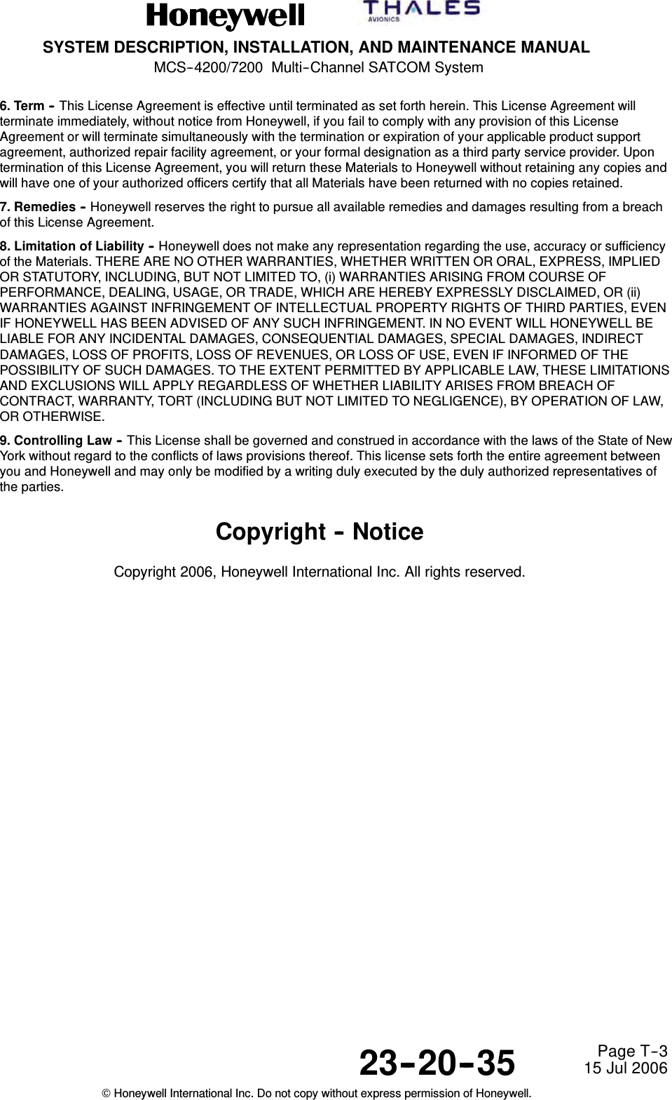
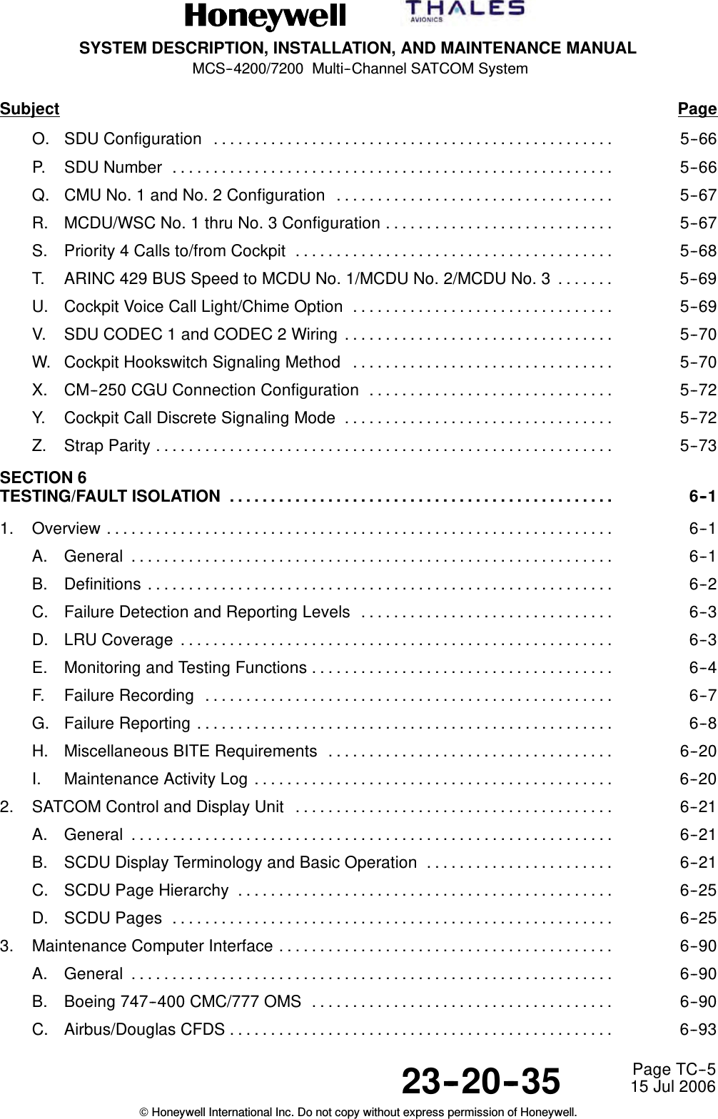
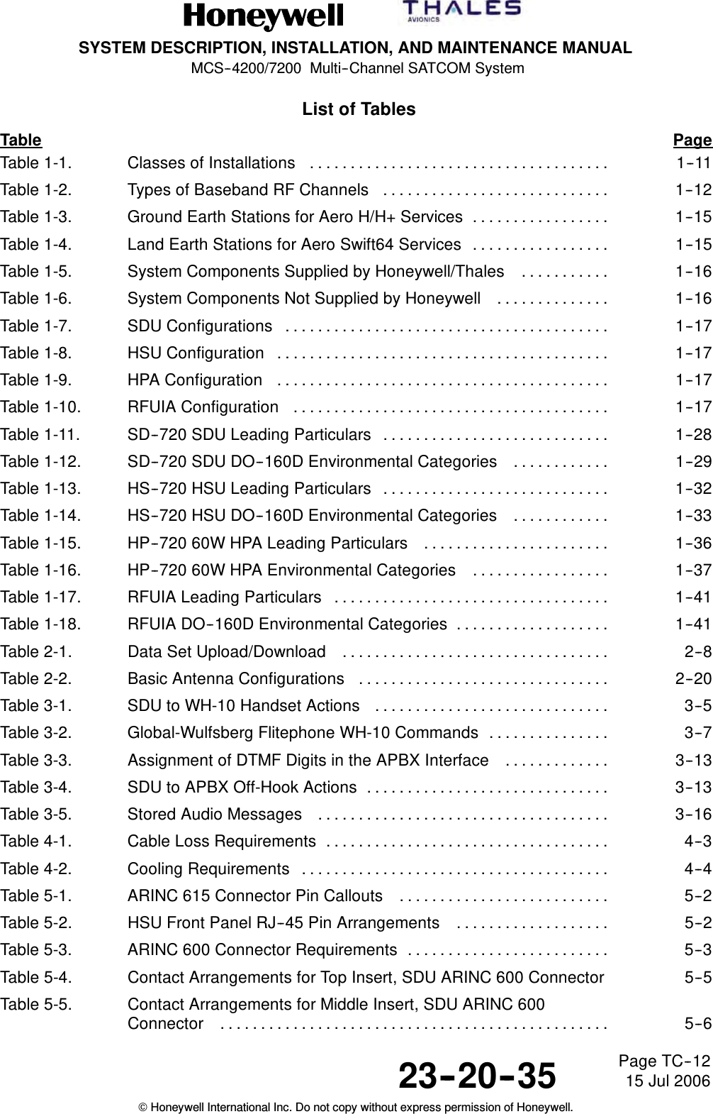
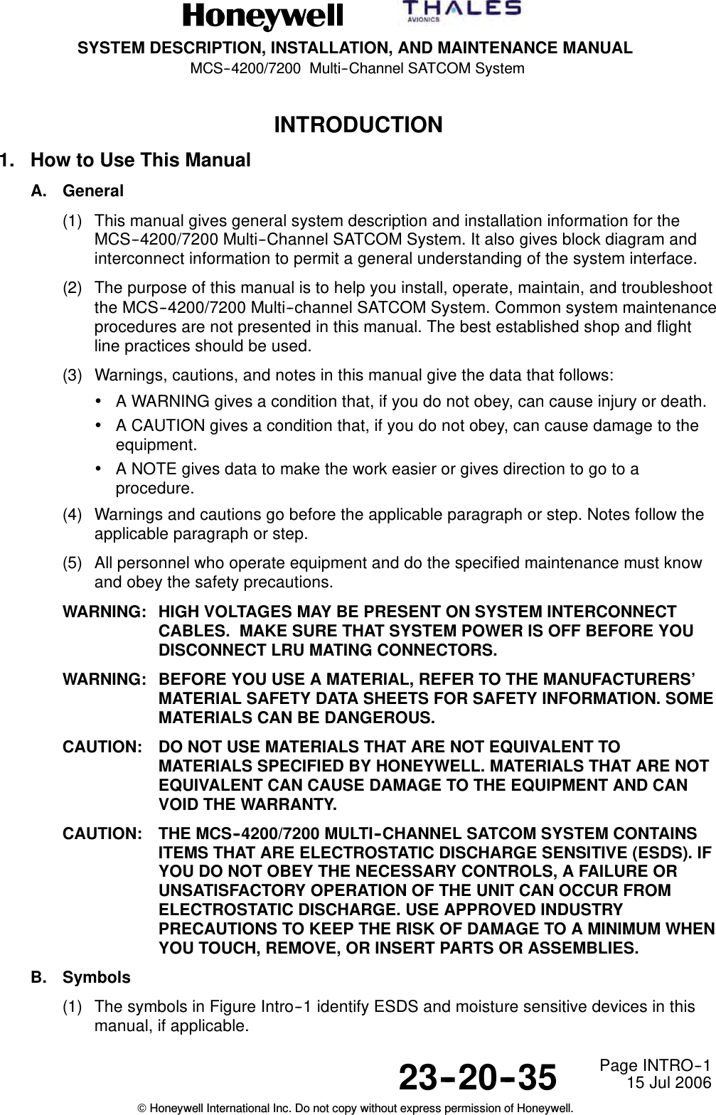
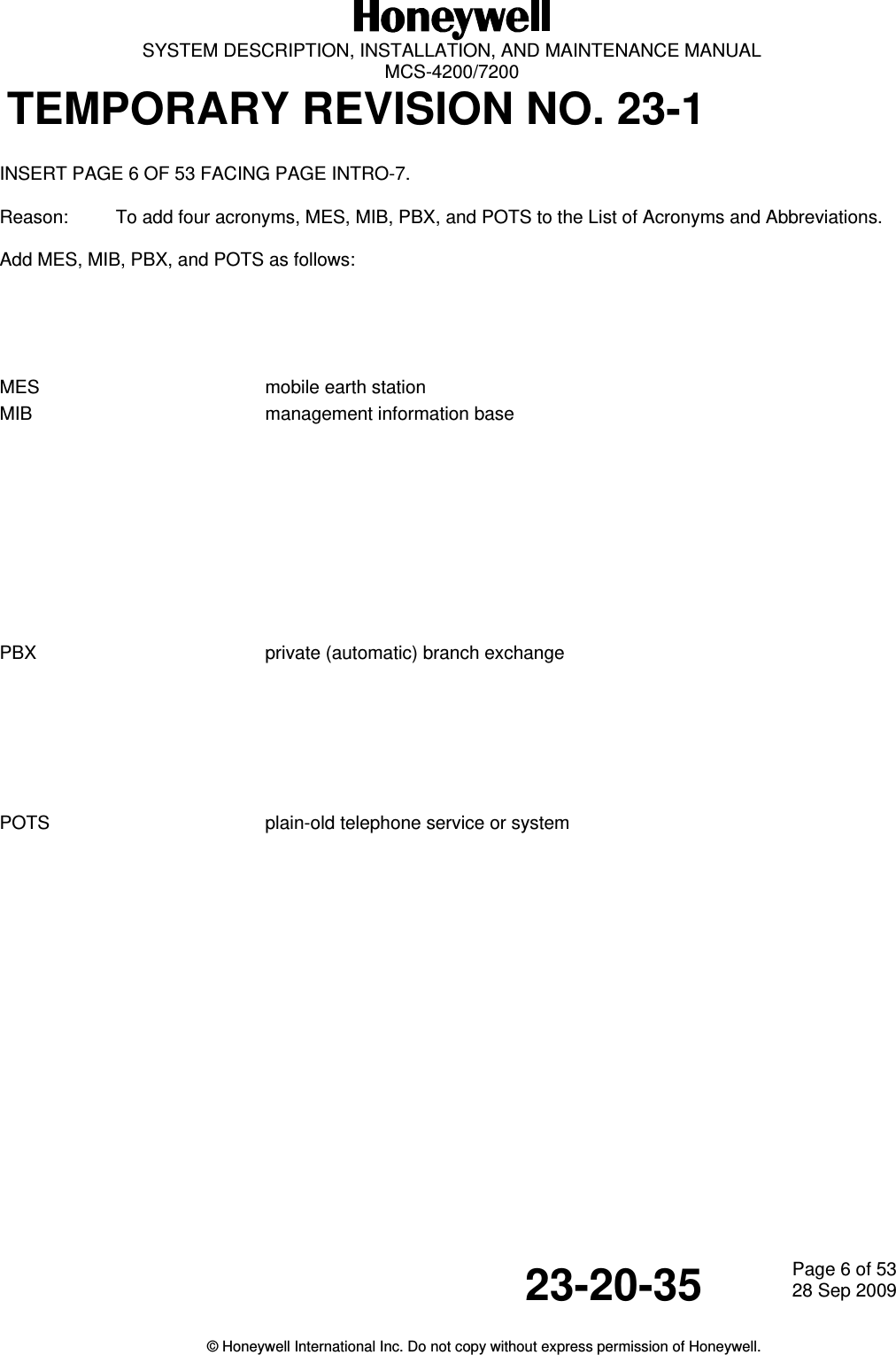
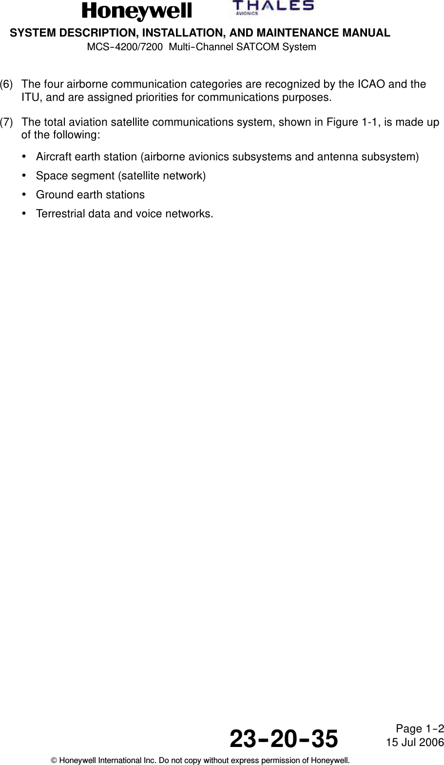
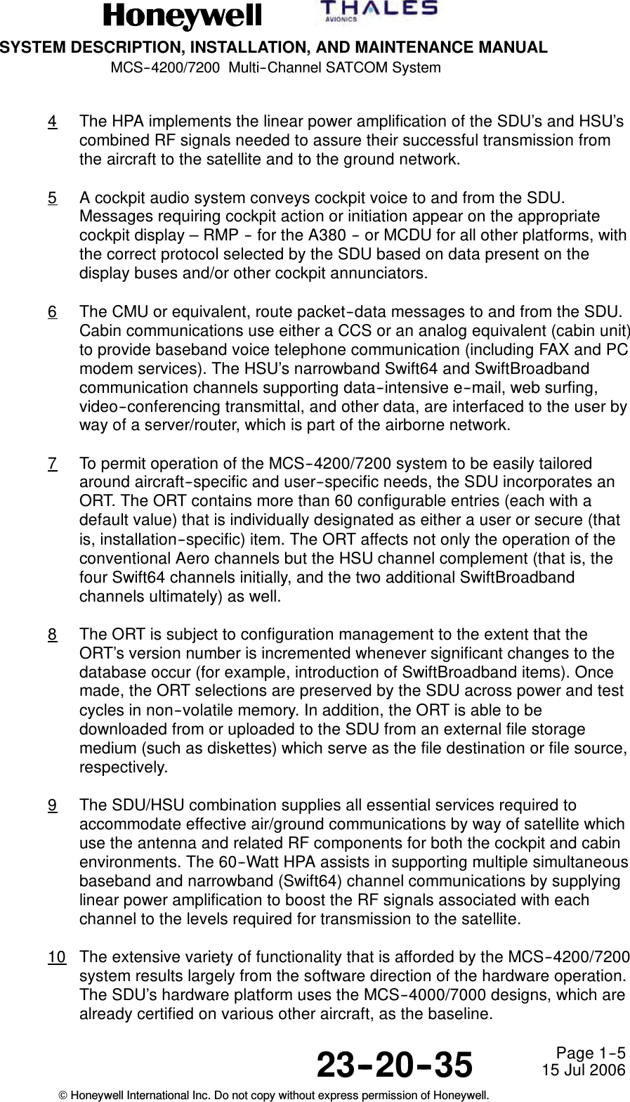
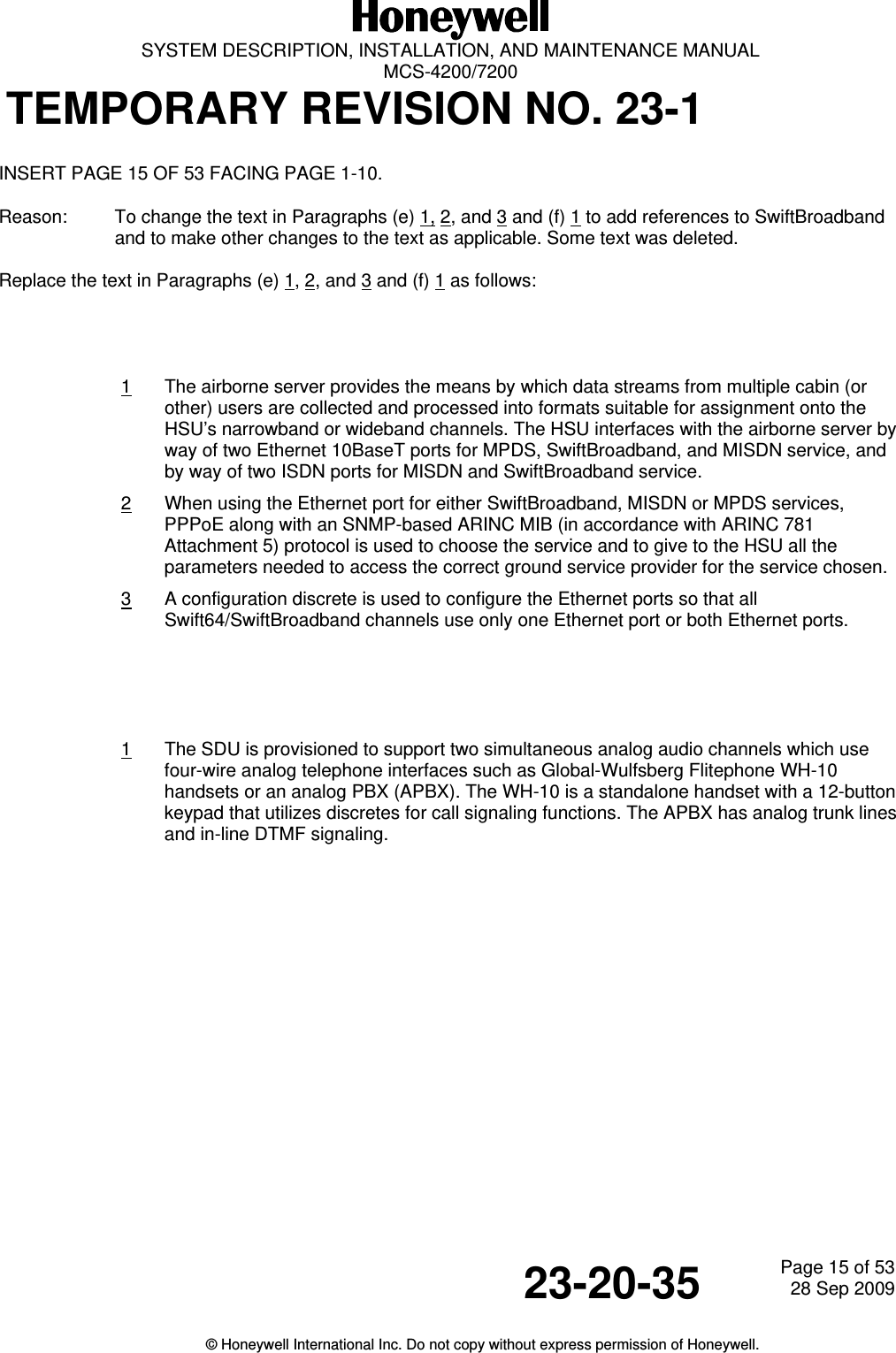
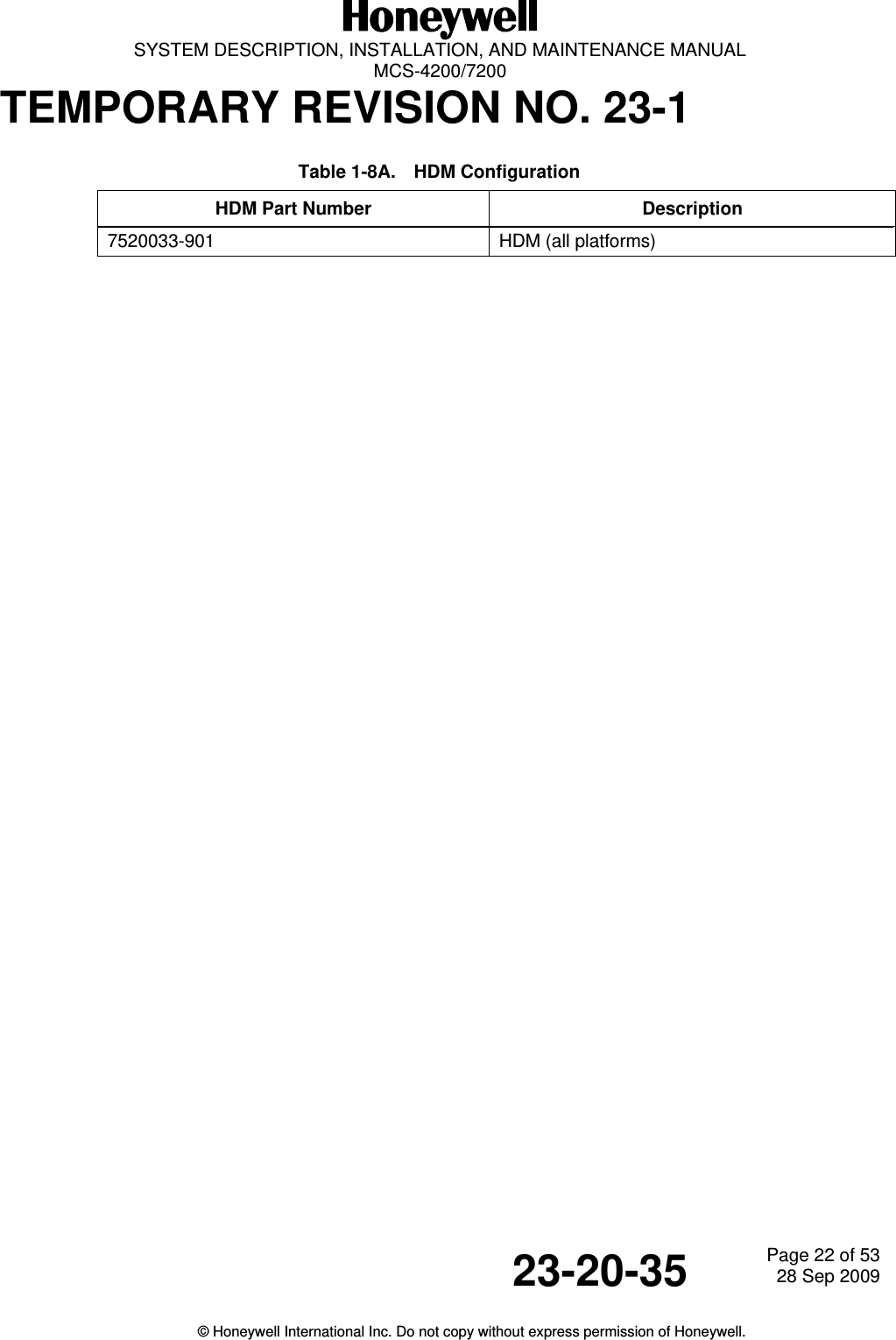
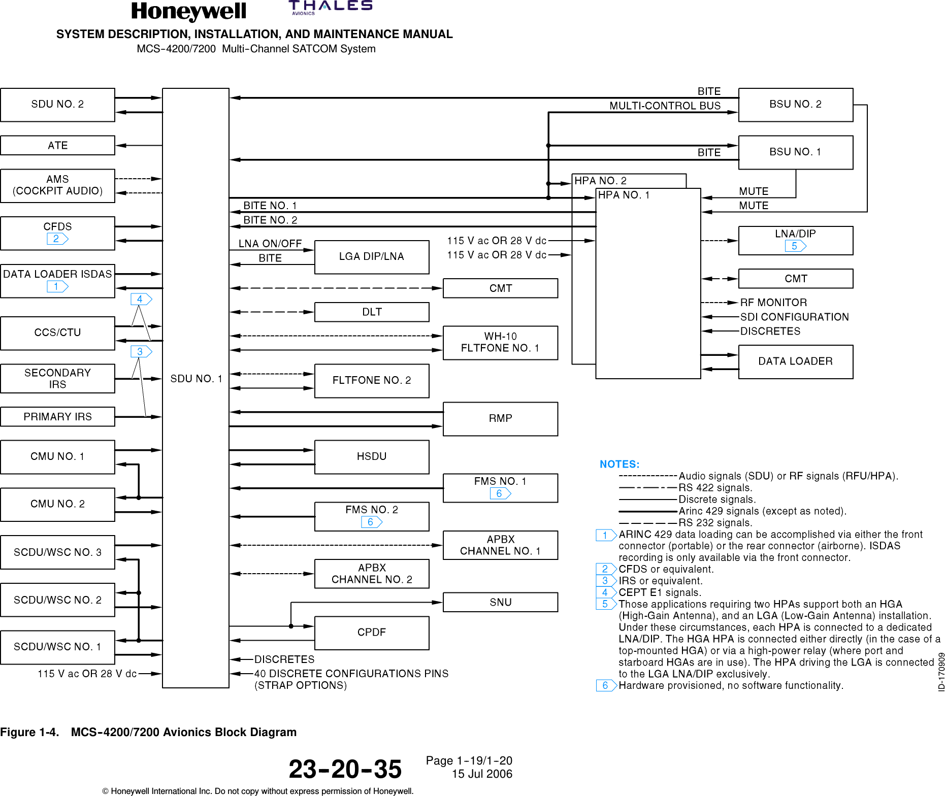
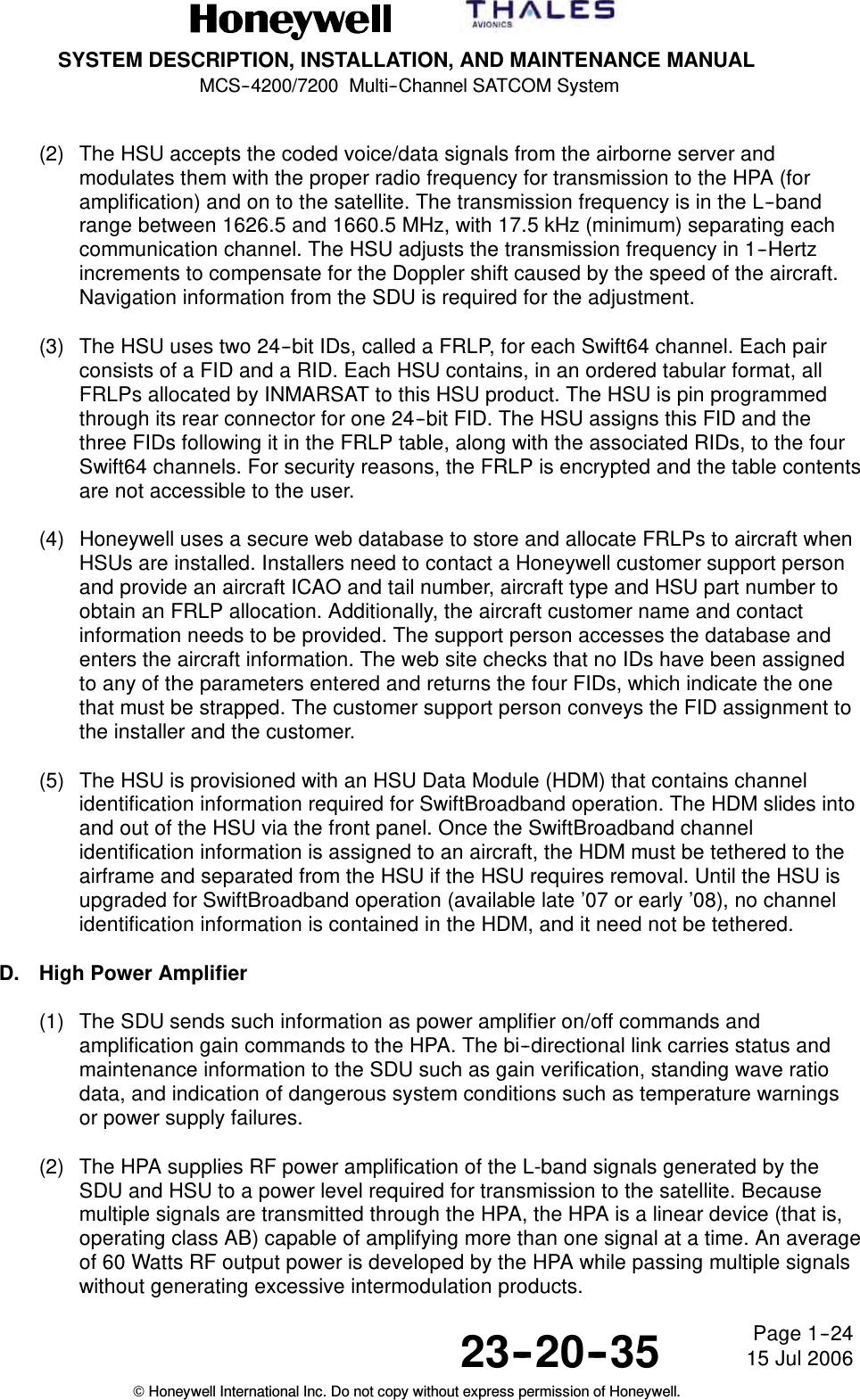
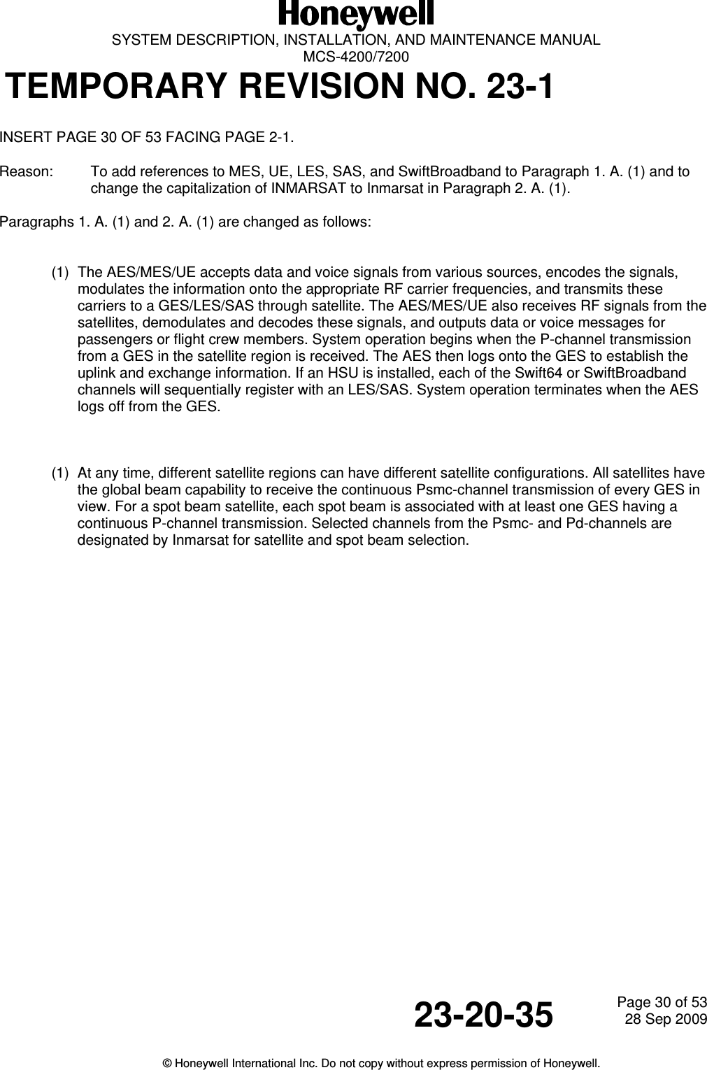
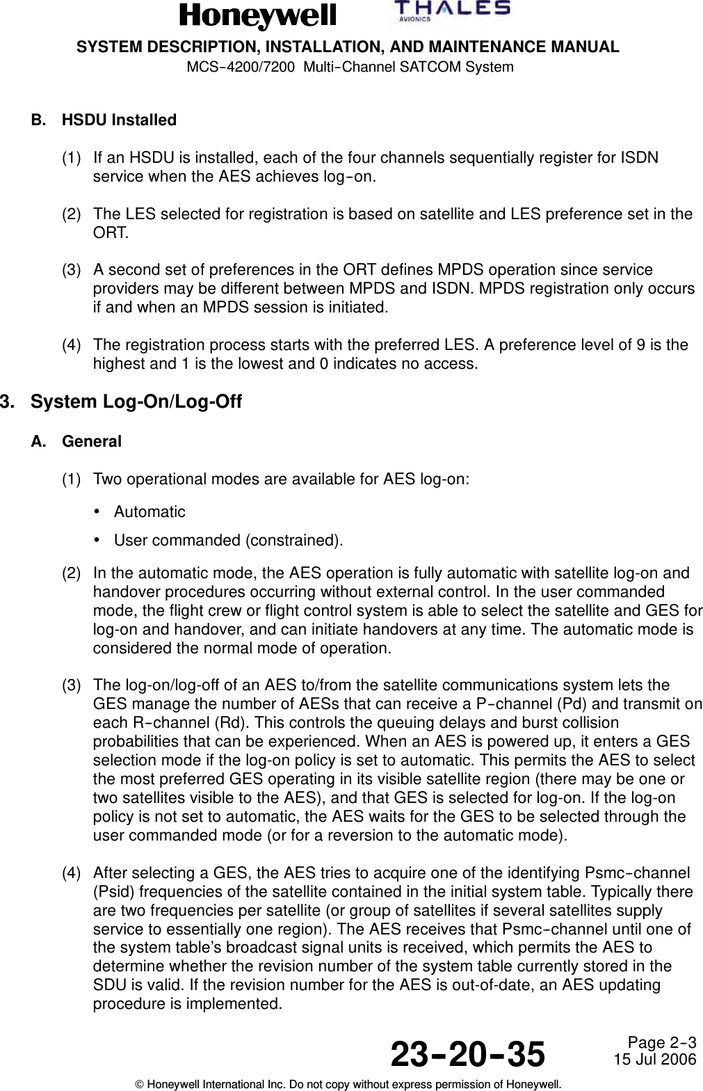
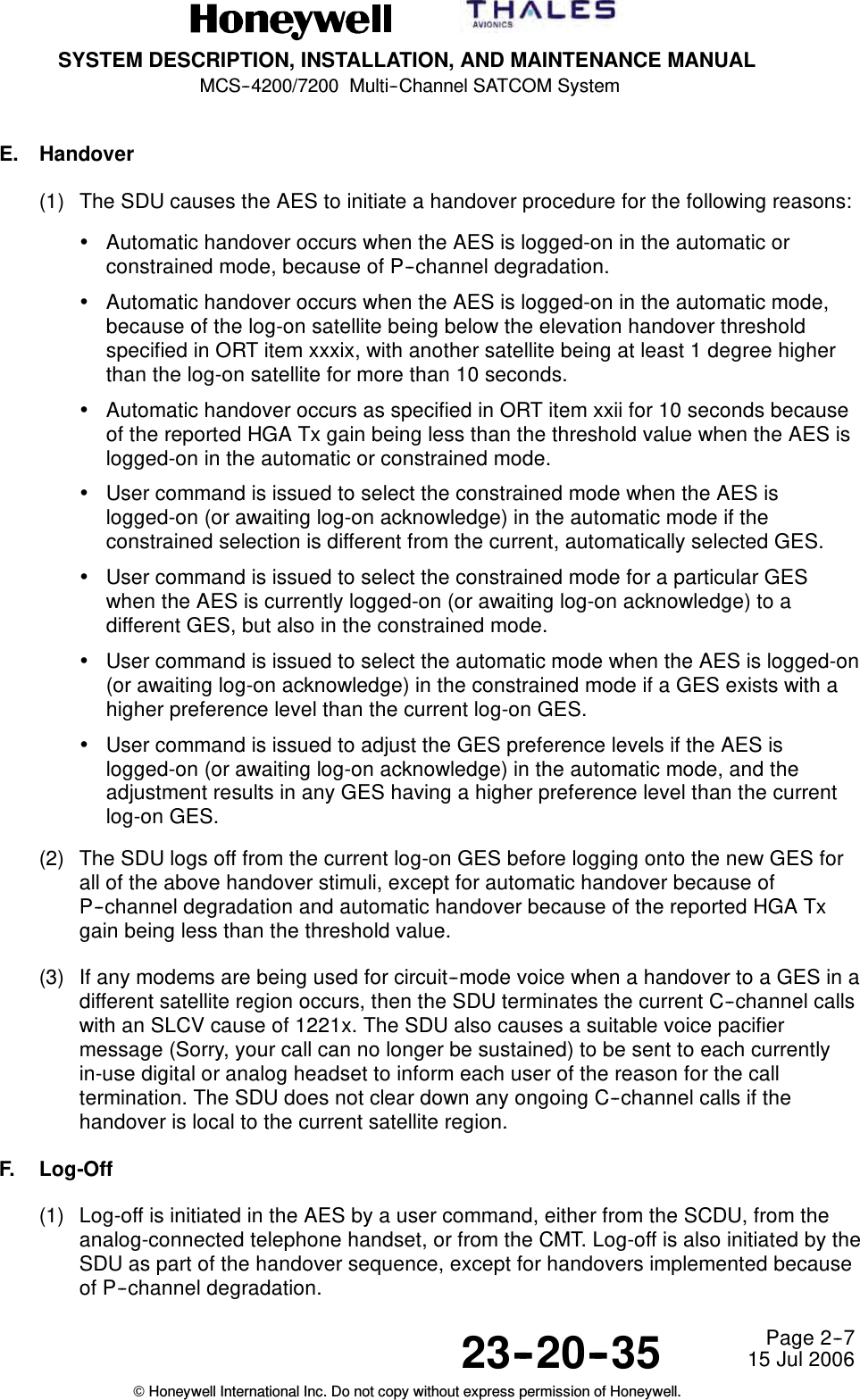
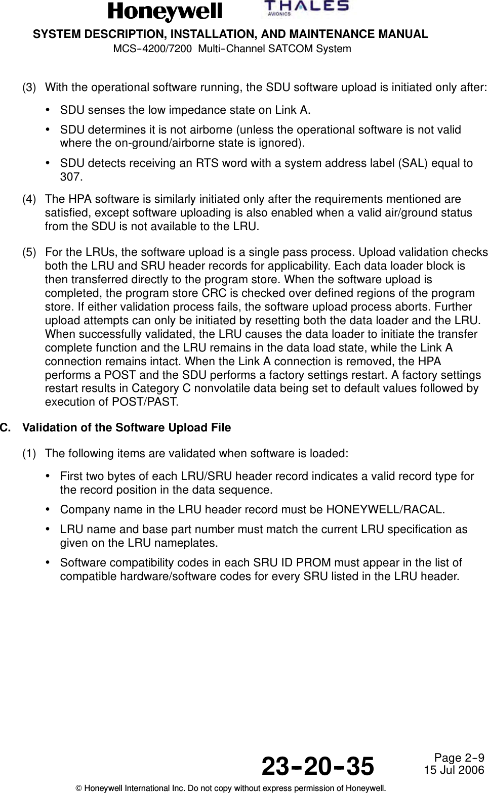
![SYSTEM DESCRIPTION, INSTALLATION, AND MAINTENANCE MANUAL MCS-4200/7200 TEMPORARY REVISION NO. 23-1 23-20-35 Page 10 of 5328 Sep 2009 © Honeywell International Inc. Do not copy without express permission of Honeywell. INSERT PAGE 10 OF 53 FACING PAGE 1-4. Reason: To update headings and text to include references to MES, UE, LES, SAS, and Classic Aero, as applicable, to Paragraphs B. (1) (a), B. (2) (a) 1, and B. (2) (b) 2 and 3. The headings and text are changed as follows: B. Aircraft Earth Station/Mobile Earth Station/User Equipment – General (1) General (a) The AES/MES/UE is fully compliant with requirements of ARINC Characteristics 741/761. Standard interfaces between the MCS-4200/7200 avionics and other aircraft avionics enable it to accept data and voice messages from various sources, encode and modulate this information onto appropriate RF carrier frequencies, and transmit these carriers to the space segment for relay to a GES/LES/SAS. The AES/MES/UE also receives RF signals from a GES/LES/SAS through the satellite, demodulates these signals, performs the necessary decoding of the encoded messages, and outputs the data or voice message for use by the cockpit crew (pilot and copilot), the cabin crew or the passengers. (2) AES/MES/UE Components (a) General 1 A block diagram of the AES/MES/UE is shown in Figure 1-2. It is made up of the following components: • MCS avionics 2 The SDU supplies the digital and analog interface to all aircraft avionics, and implements all functionality associated with modulation/demodulation, error correction, channel rate/frequency selection, and RF translation for the system’s seven baseband communication channels. The SDU’s seven Classic Aero channels support six simultaneous full-duplex circuit-mode voice connections and one packet-mode channel. 3 The HSU incorporates the firmware necessary to support four narrowband (Swift64) channels, which provide simultaneous circuit-mode and/or packet-mode connectivity concurrently with the SDU’s baseband channels at rates of 64 kbps (per single channel) or 256 kbps (four combined [bonded ISDN] or two channels of up to 432 kbps (per single channel) SwiftBroadband functionality. When operating through an Inmarsat-3 satellite and its GESs/LESs, Classic Aero and Swift64 services are possible; when operating through an Inmarsat-4 satellite and its GESs/SASs, Classic Aero and SwiftBroadband services are possible; i.e., only one type of Swift service is possible at any given time, depending on the type of satellite and ground station being used at any given time.](https://usermanual.wiki/Honeywell/HS-720.HS-720-User-Manual-Part1/User-Guide-1350370-Page-63.png)
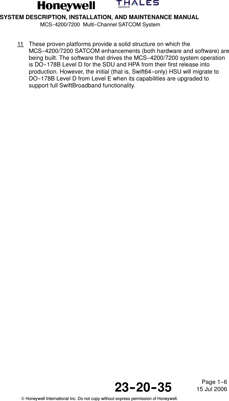
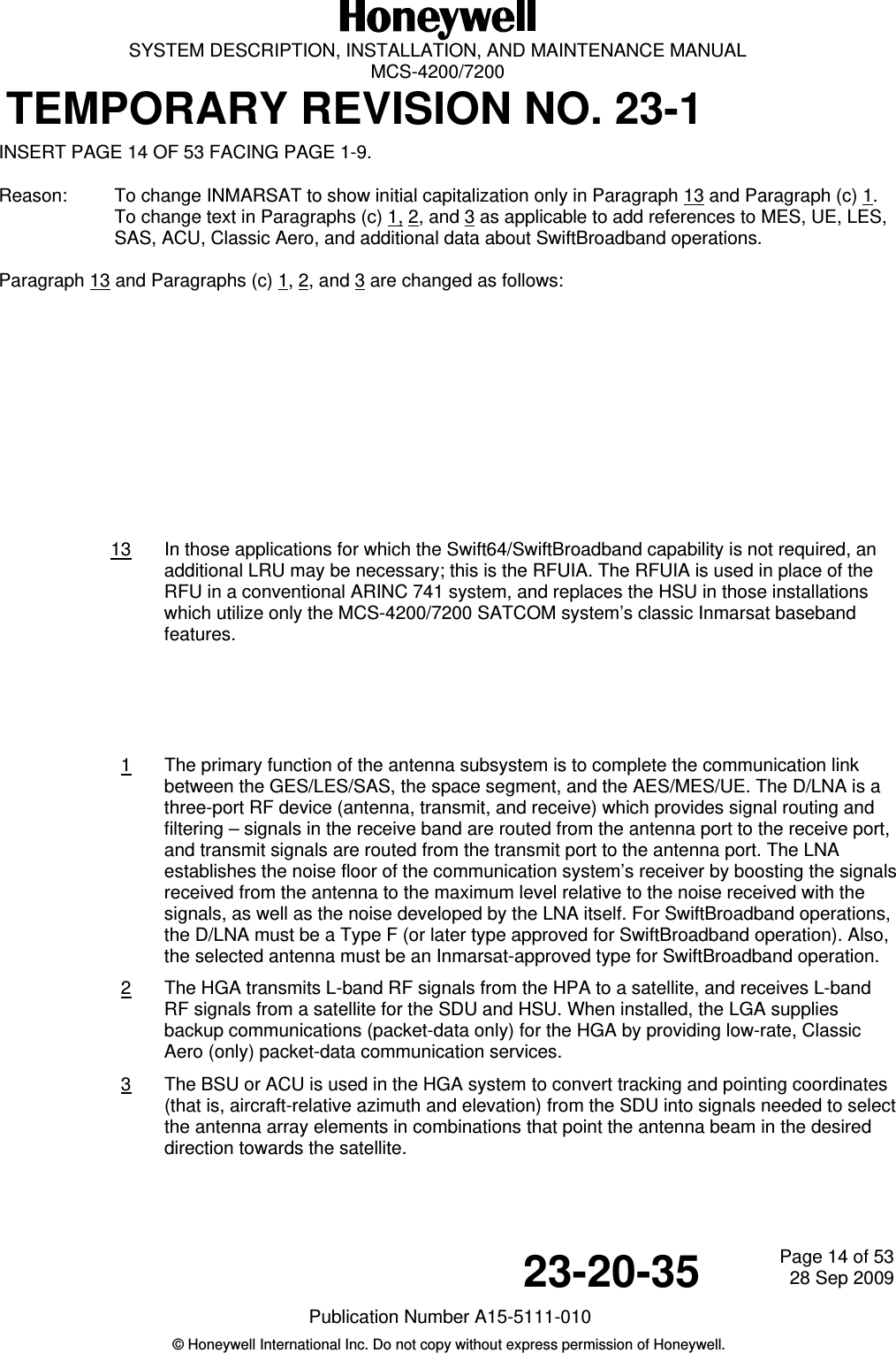
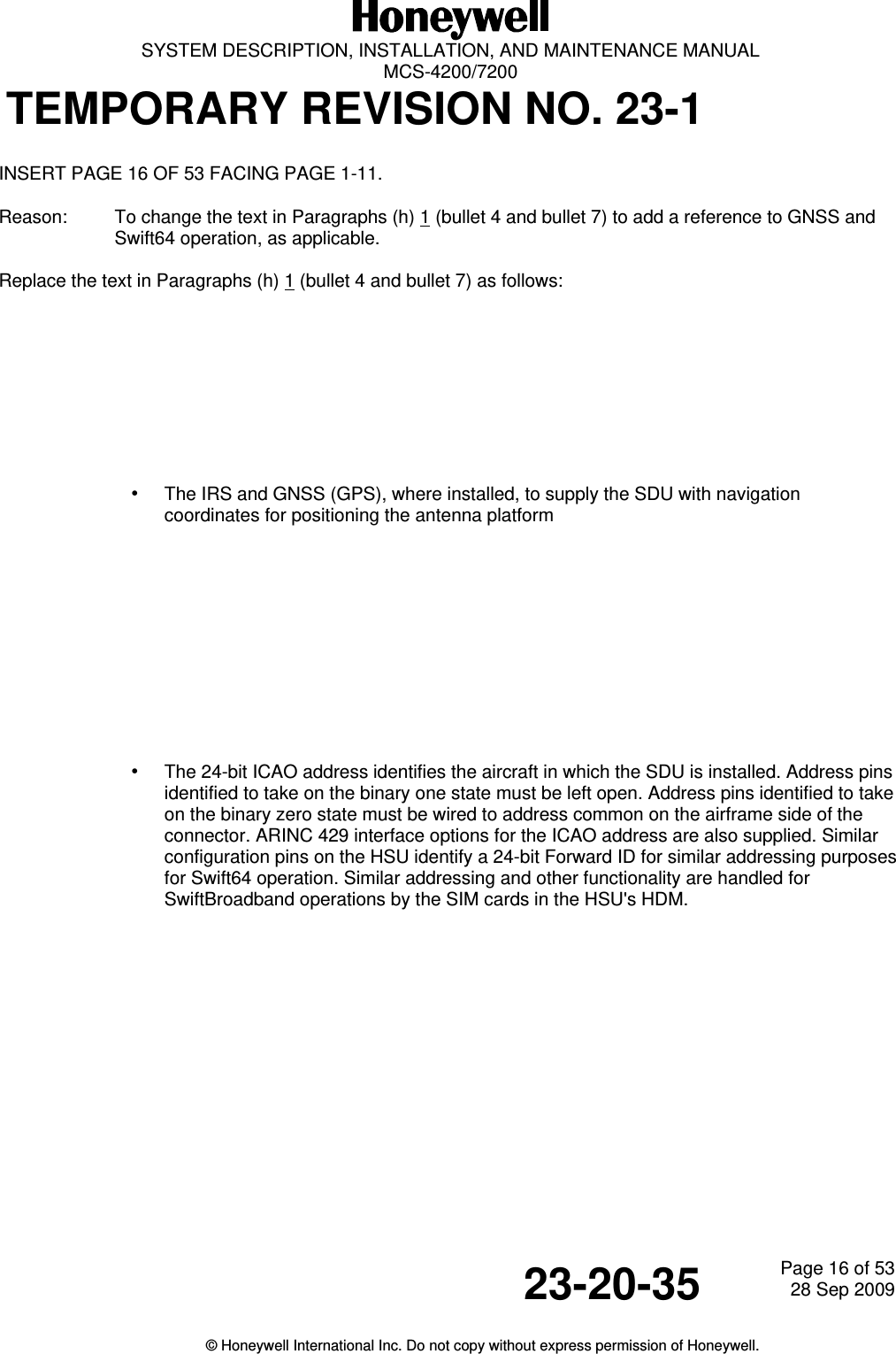
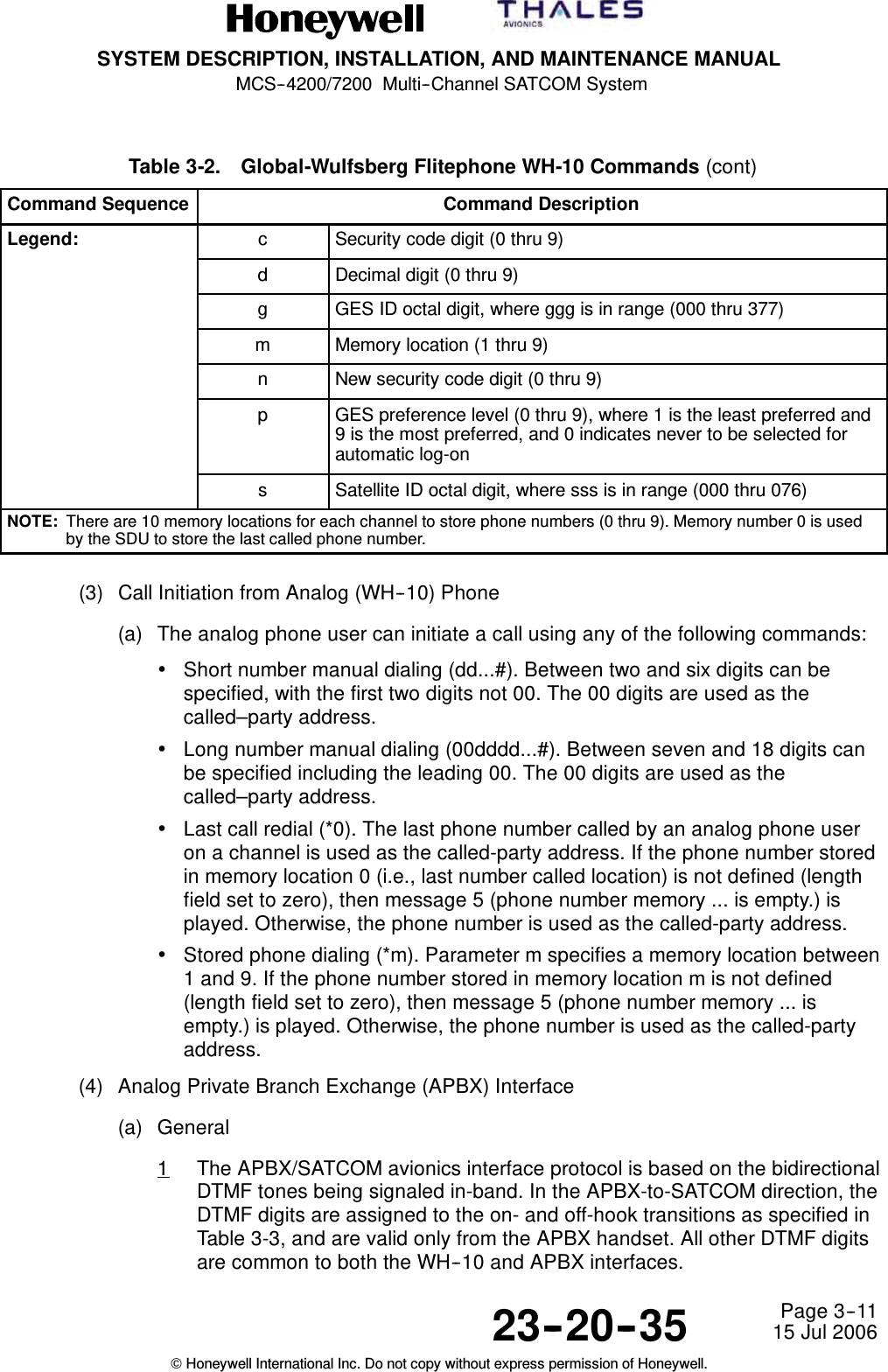
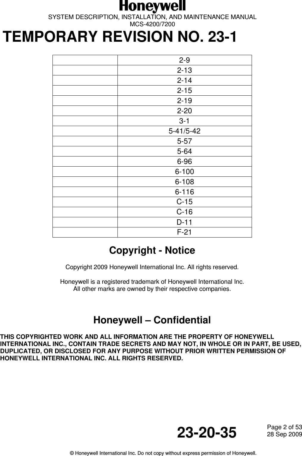
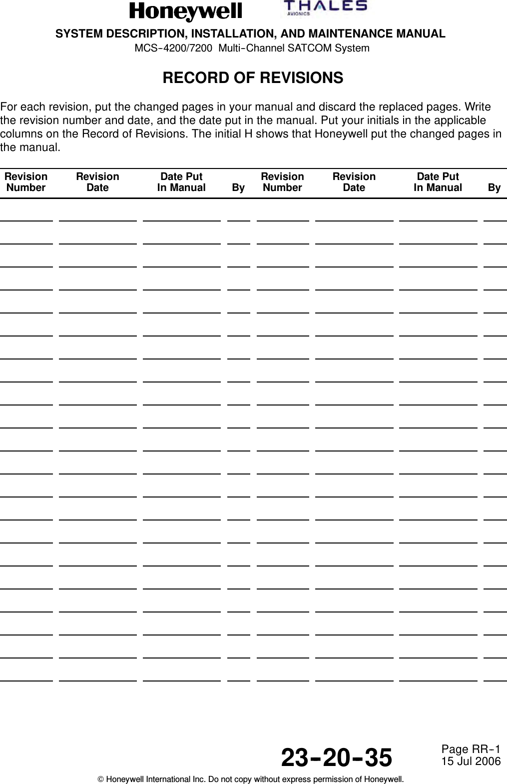
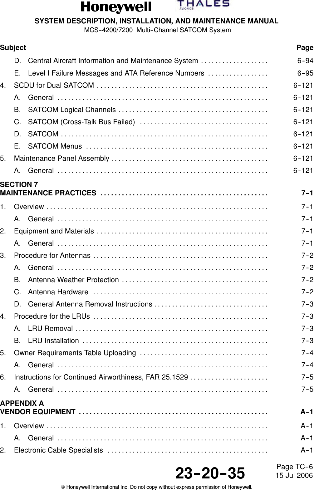
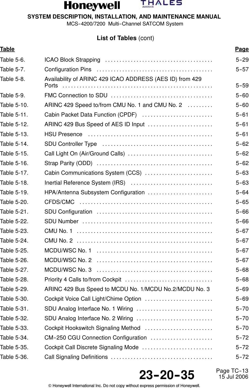
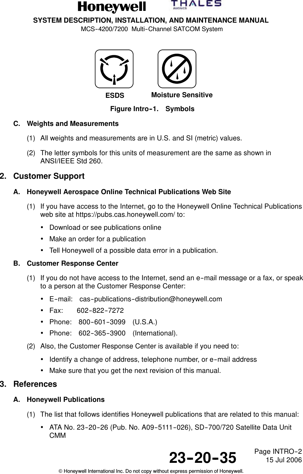
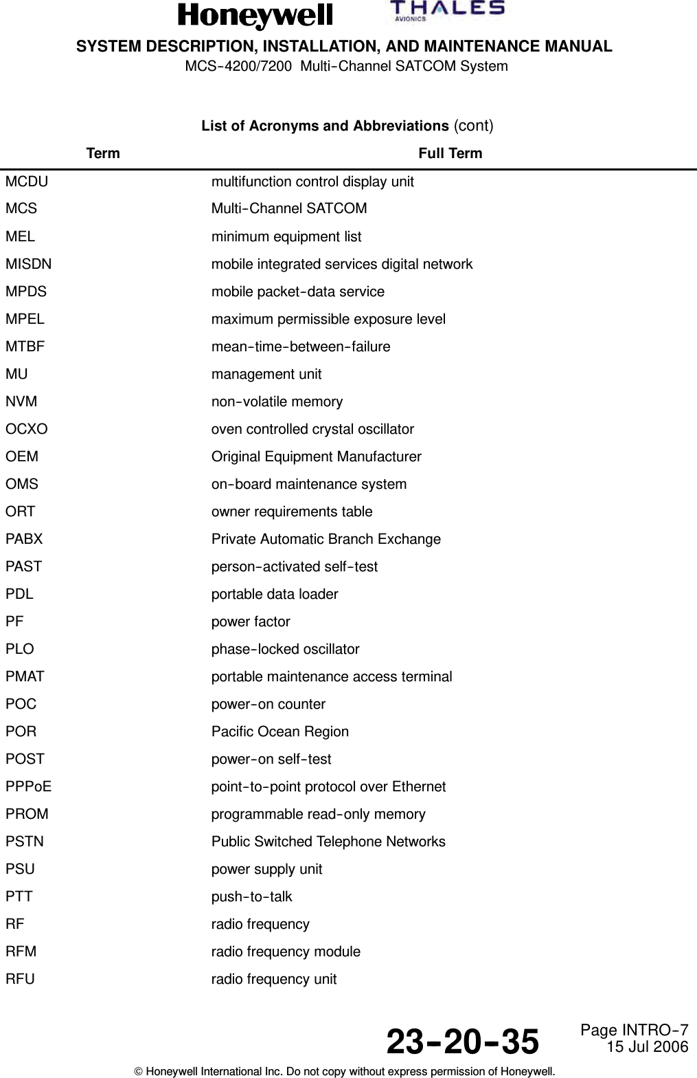
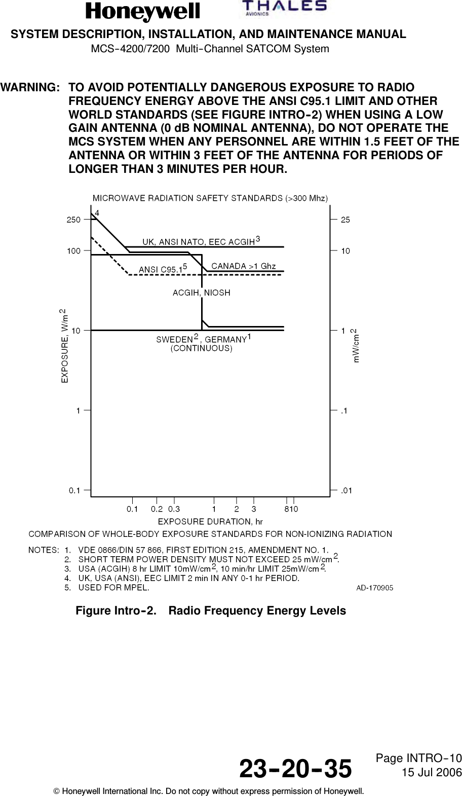
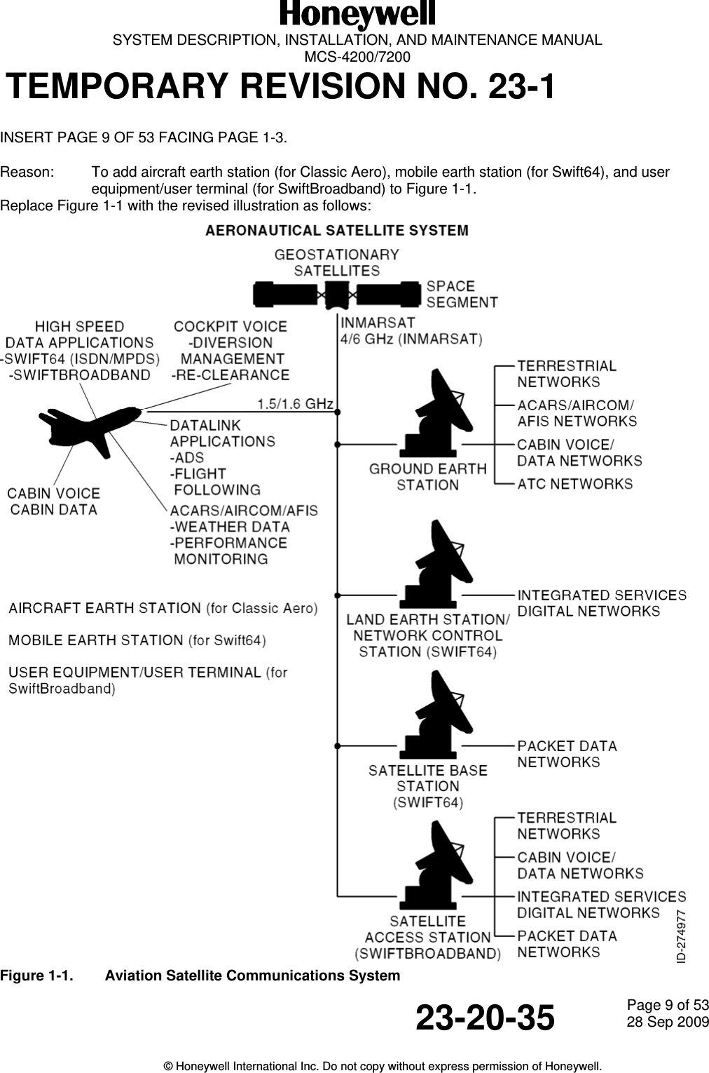
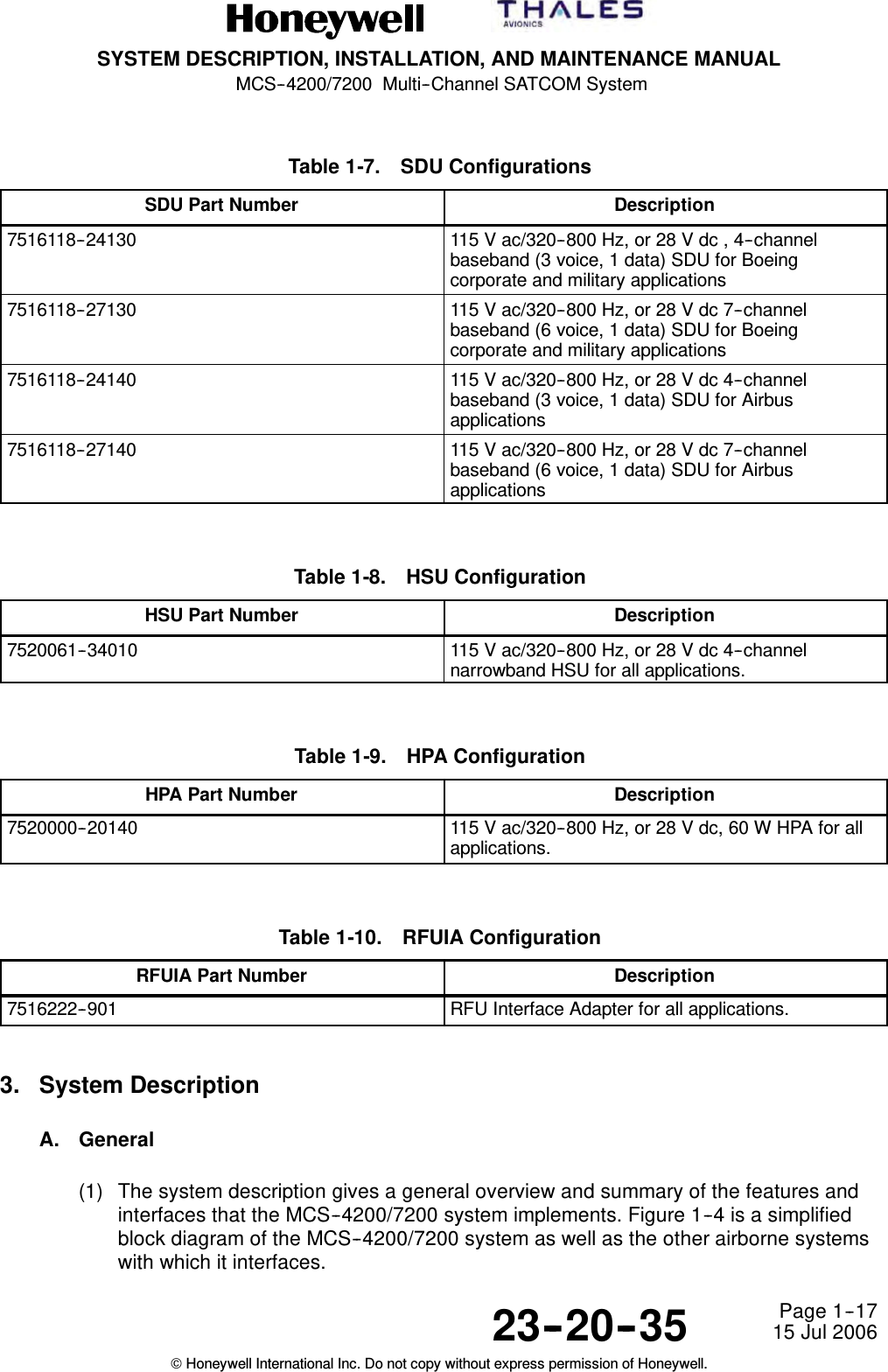
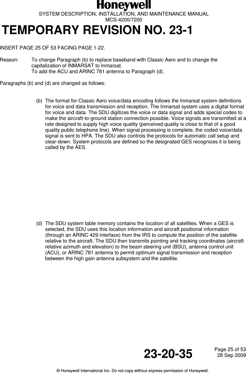
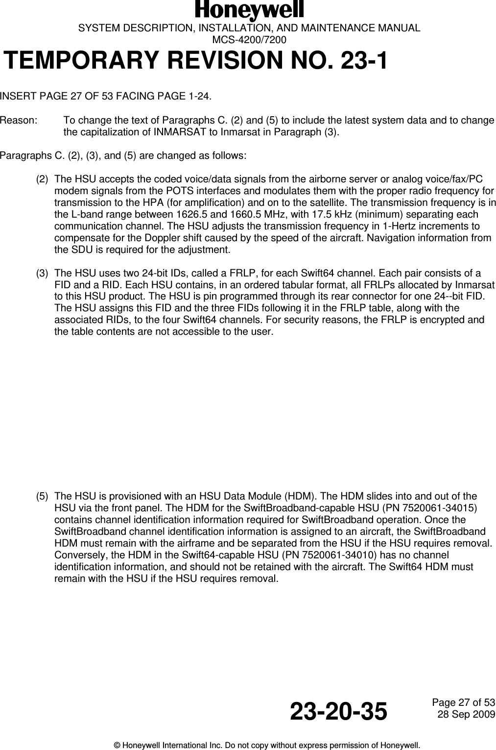
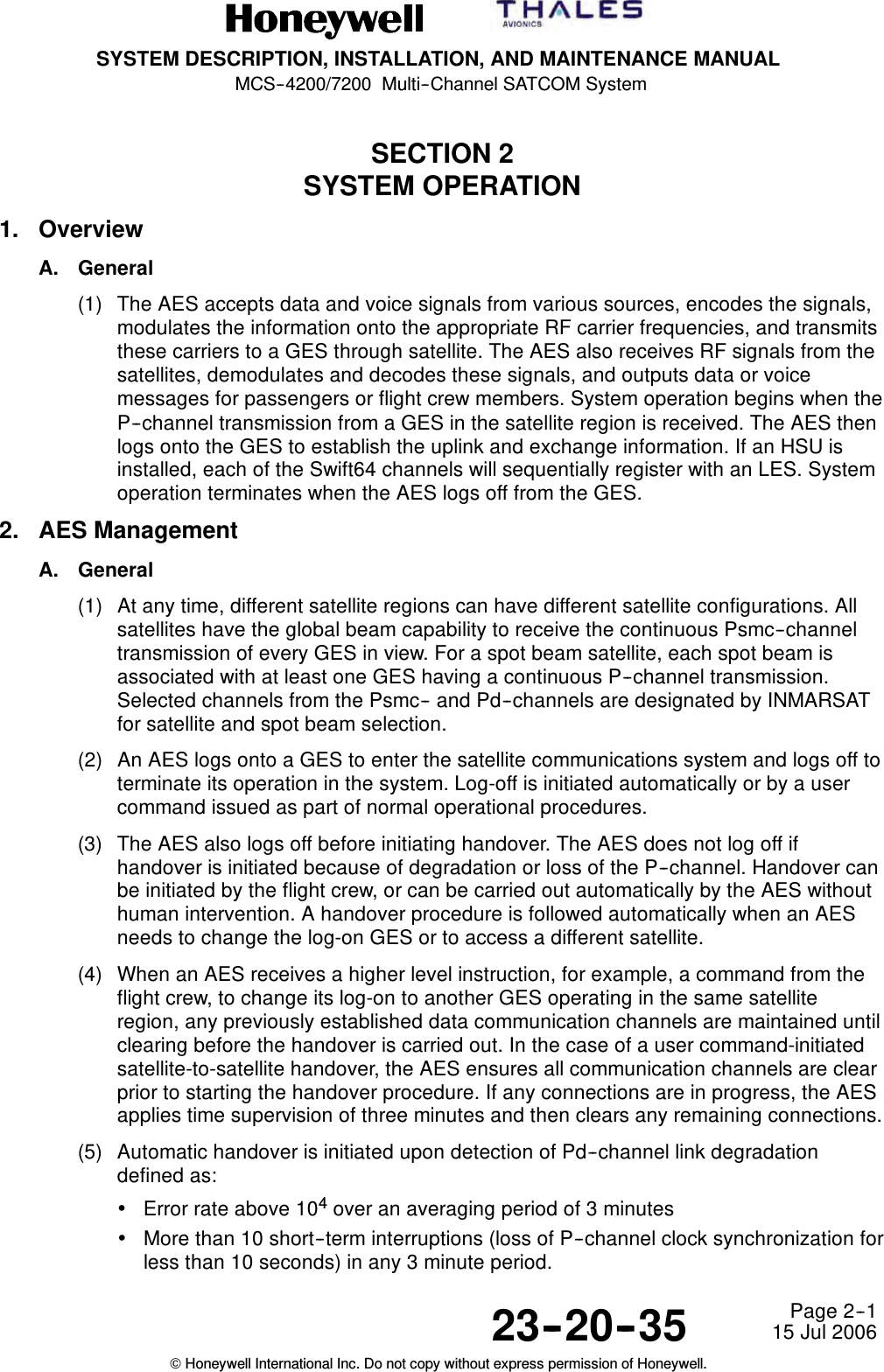
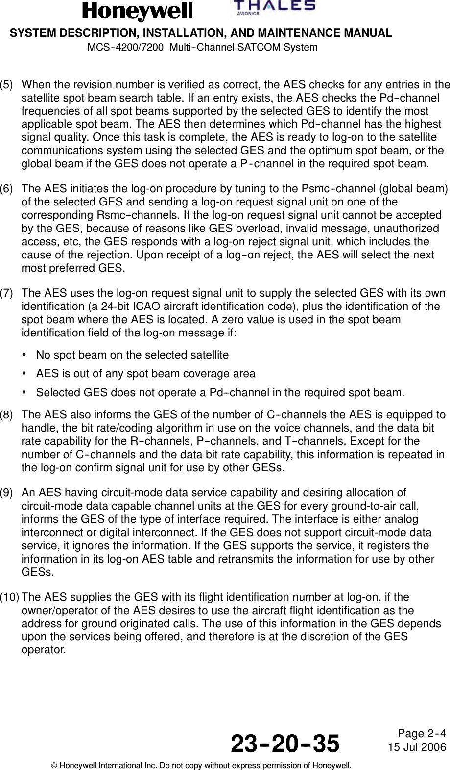
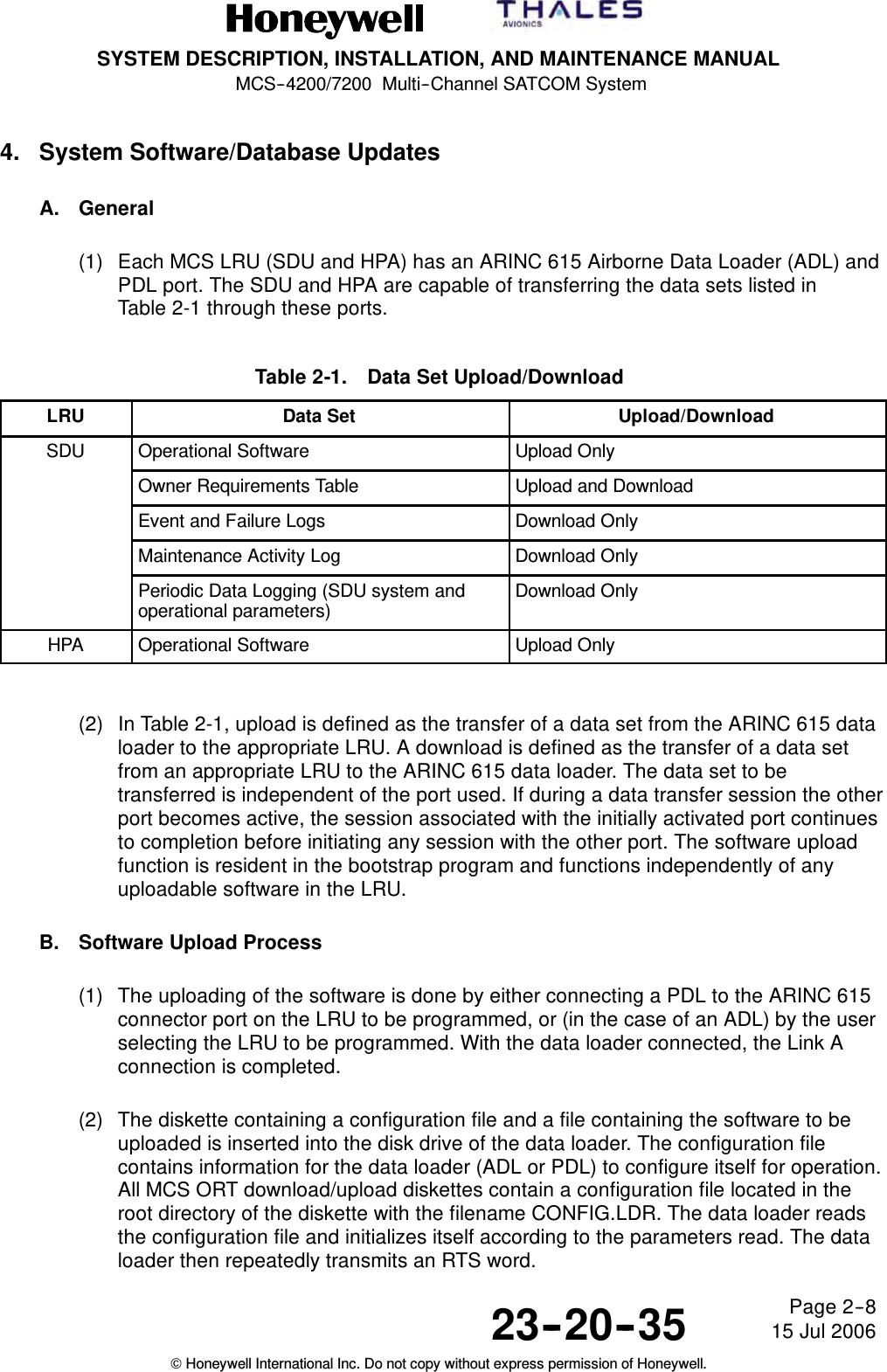
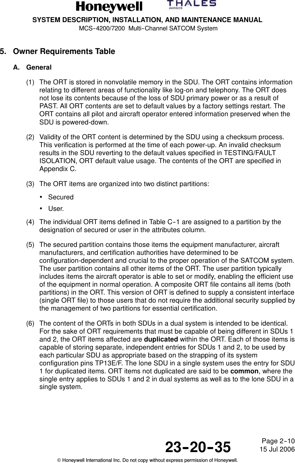
![SYSTEM DESCRIPTION, INSTALLATION, AND MAINTENANCE MANUAL MCS-4200/7200 TEMPORARY REVISION NO. 23-1 23-20-35 Page 21 of 5328 Sep 2009 © Honeywell International Inc. Do not copy without express permission of Honeywell. INSERT PAGE 21 OF 53 THRU PAGE 22 OF 53 FACING PAGE 1-17. Reason: To update Table 1-7 to replace baseband with Classic Aero and add part numbers and descriptions applicable to the SwiftBroadband SDU. To update Table 1-8 to replace narrowband with Swift64 and add one new part number and description applicable to both Swift64 and SwiftBroadband. To add a new Table 1-8A to incorporate the HDM configuration. Table 1-7 and Table 1-8 are changed and Table 1-8A is added as follows: Table 1-7. SDU Configurations SDU Part Number Description 7516118-24130 115 V ac/320-800 Hz, or 28 V dc , 4-channel Classic Aero (3 voice, 1 data) SDU for Boeing corporate and military applications 7516118-27130 115 V ac/320-800 Hz, or 28 V dc 7-channel Classic Aero (6 voice, 1 data) SDU for Boeing corporate and military applications 7516118-24140 115 V ac/320-800 Hz, or 28 V dc 4-channel Classic Aero (3 voice, 1 data) SDU for Airbus applications 7516118-27140 115 V ac/320-800 Hz, or 28 V dc 7-channel Classic Aero (6 voice, 1 data) SDU for Airbus applications 7516118-27150 SwiftBroadband SDU for Airbus Long Range 7516118-27145 SwiftBroadband SDU for Airbus A380 7516118-24145 SwiftBroadband SDU for Airbus A380 7516118-27135 SwiftBroadband SDU for all non-Airbus, including Boeing [particularly 777] and biz jets 7516118-24135 SwiftBroadband SDU for all non-Airbus, including Boeing and biz jets Table 1-8. HSU Configurations HSU Part Number Description 7520061-34010 115 V ac/320-800 Hz, or 28 V dc 4-channel Swift64 HSU for all applications 7520061-34015 115 V ac/320-800 Hz, or 28 V dc 4-channel Swift64 and SwiftBroadband HSU for all applications](https://usermanual.wiki/Honeywell/HS-720.HS-720-User-Manual-Part1/User-Guide-1350370-Page-88.png)
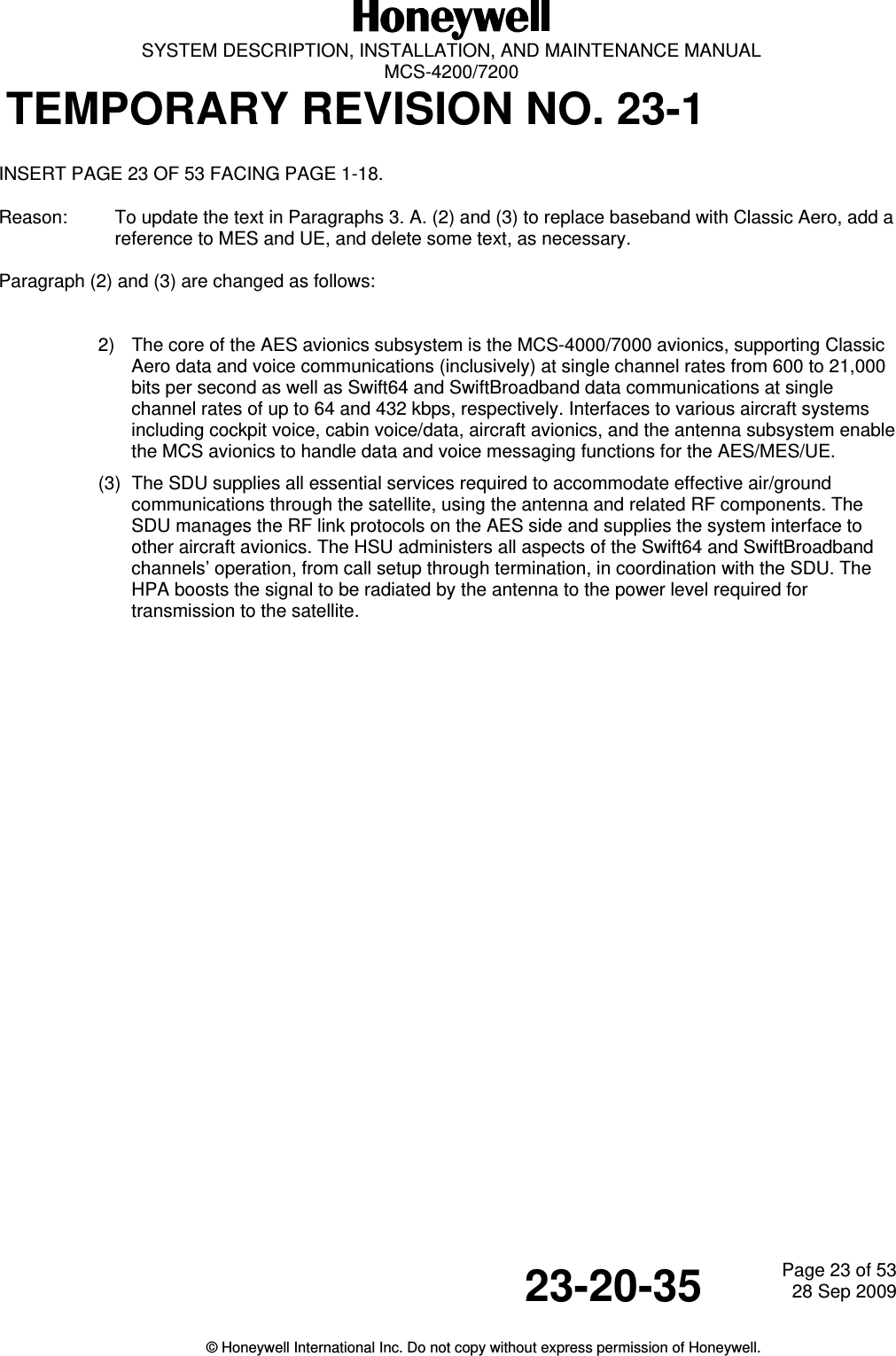
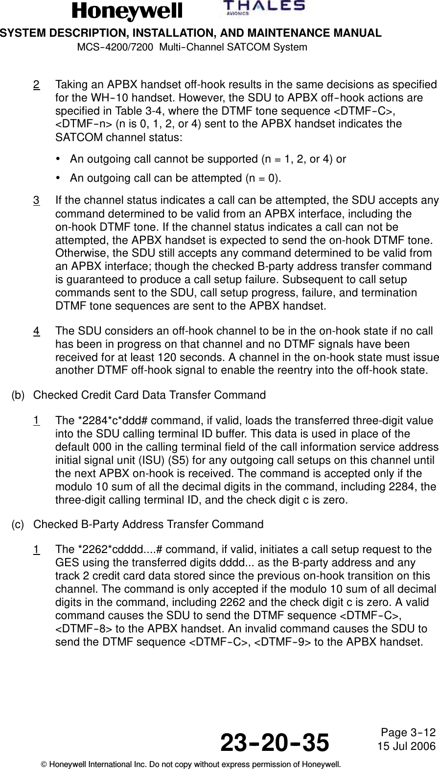
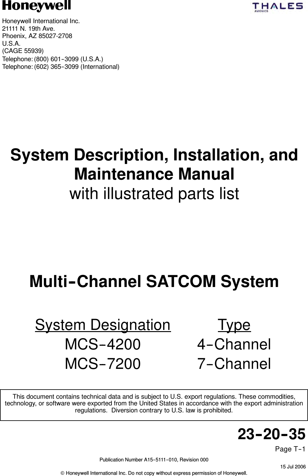
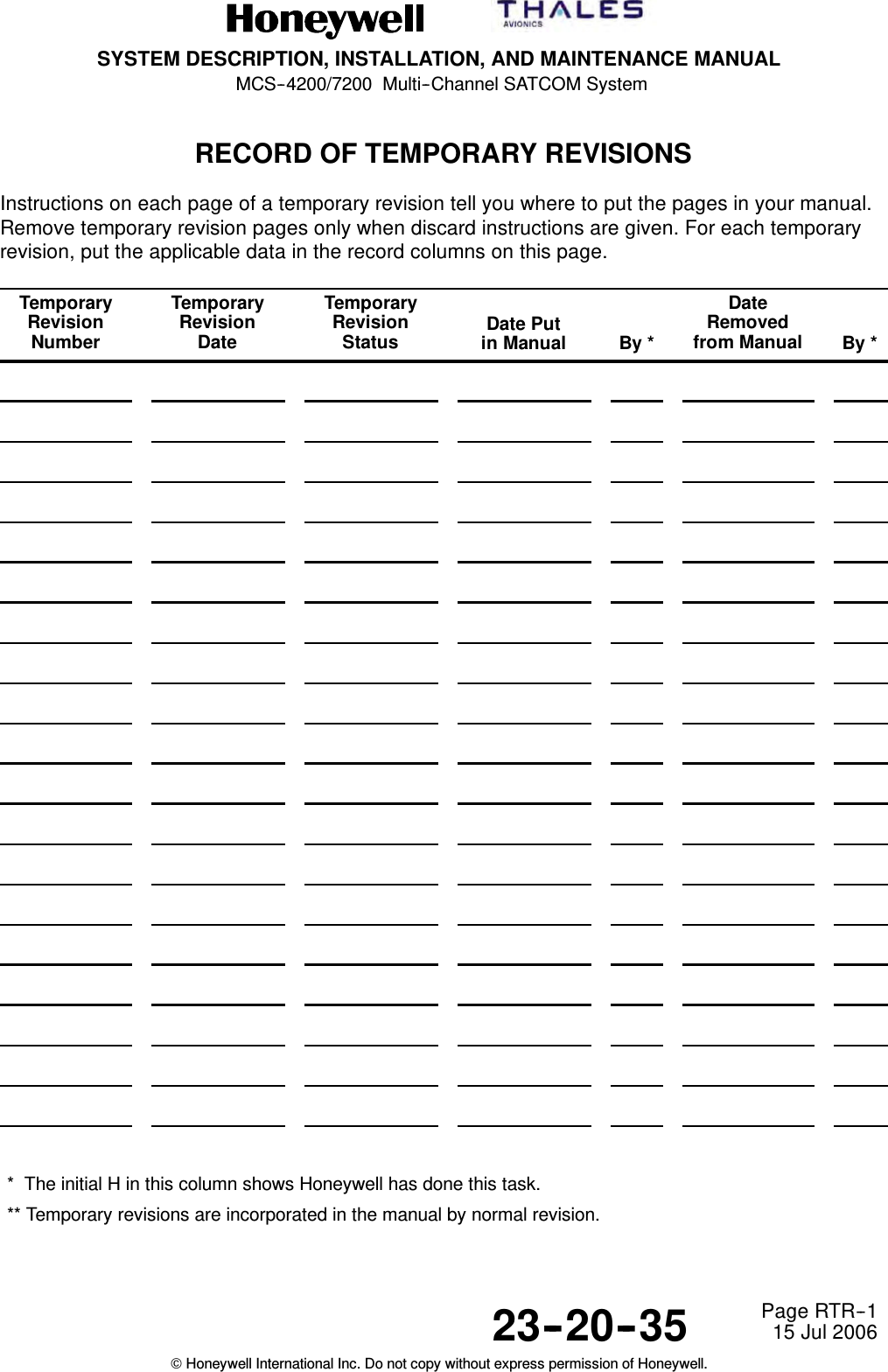
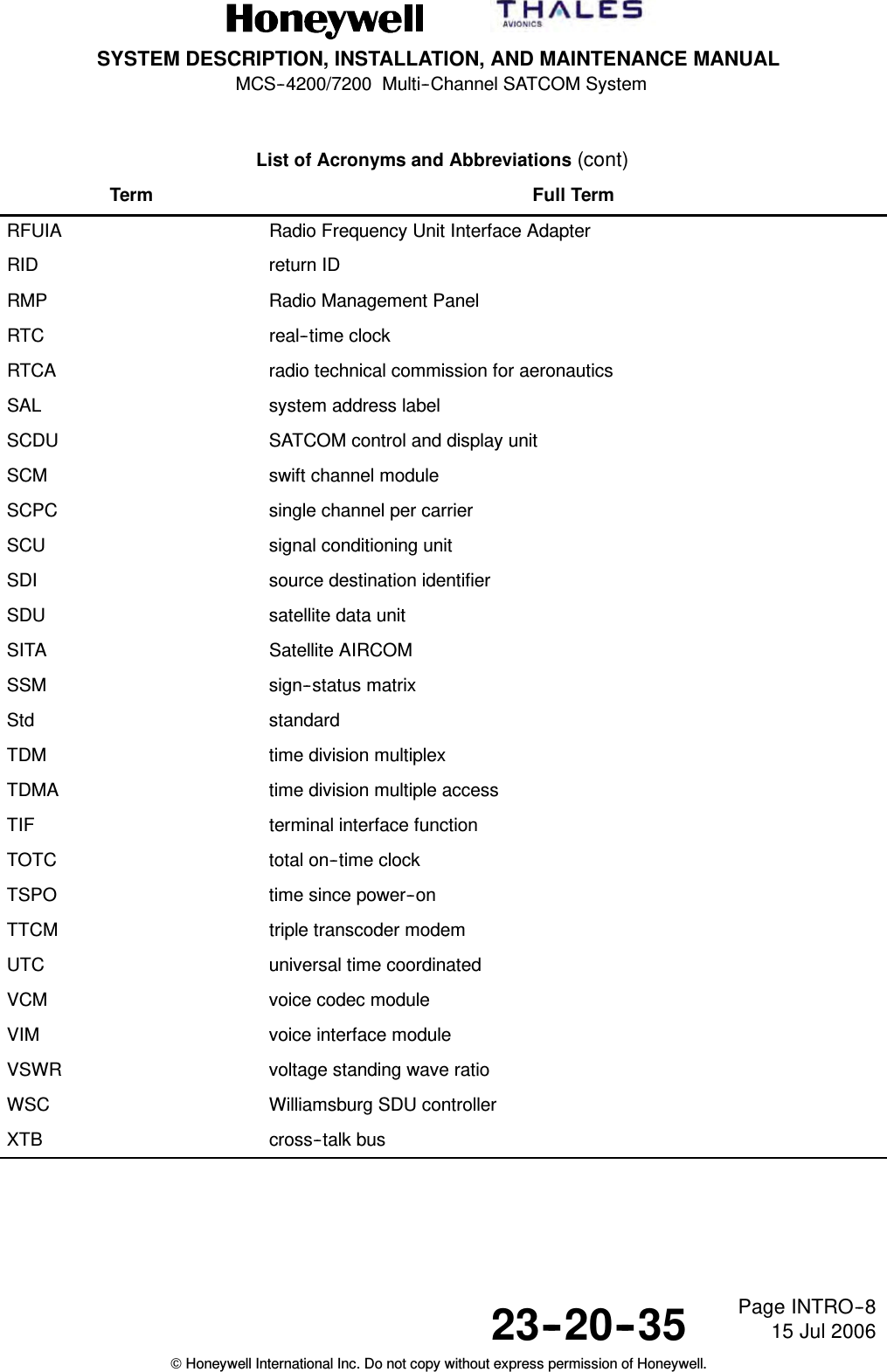
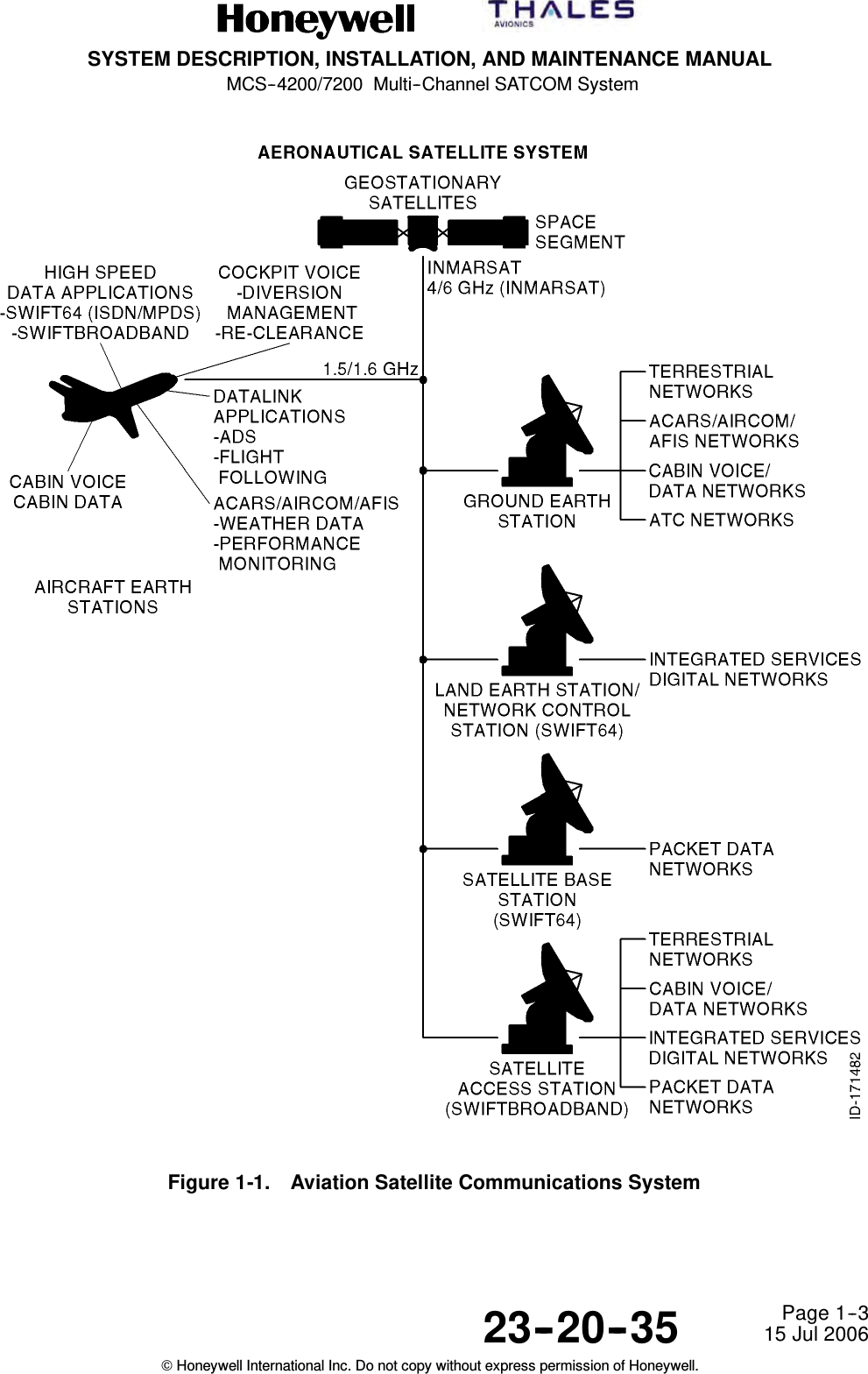
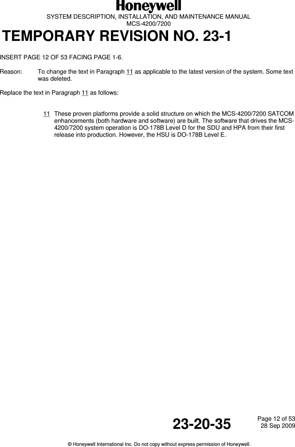
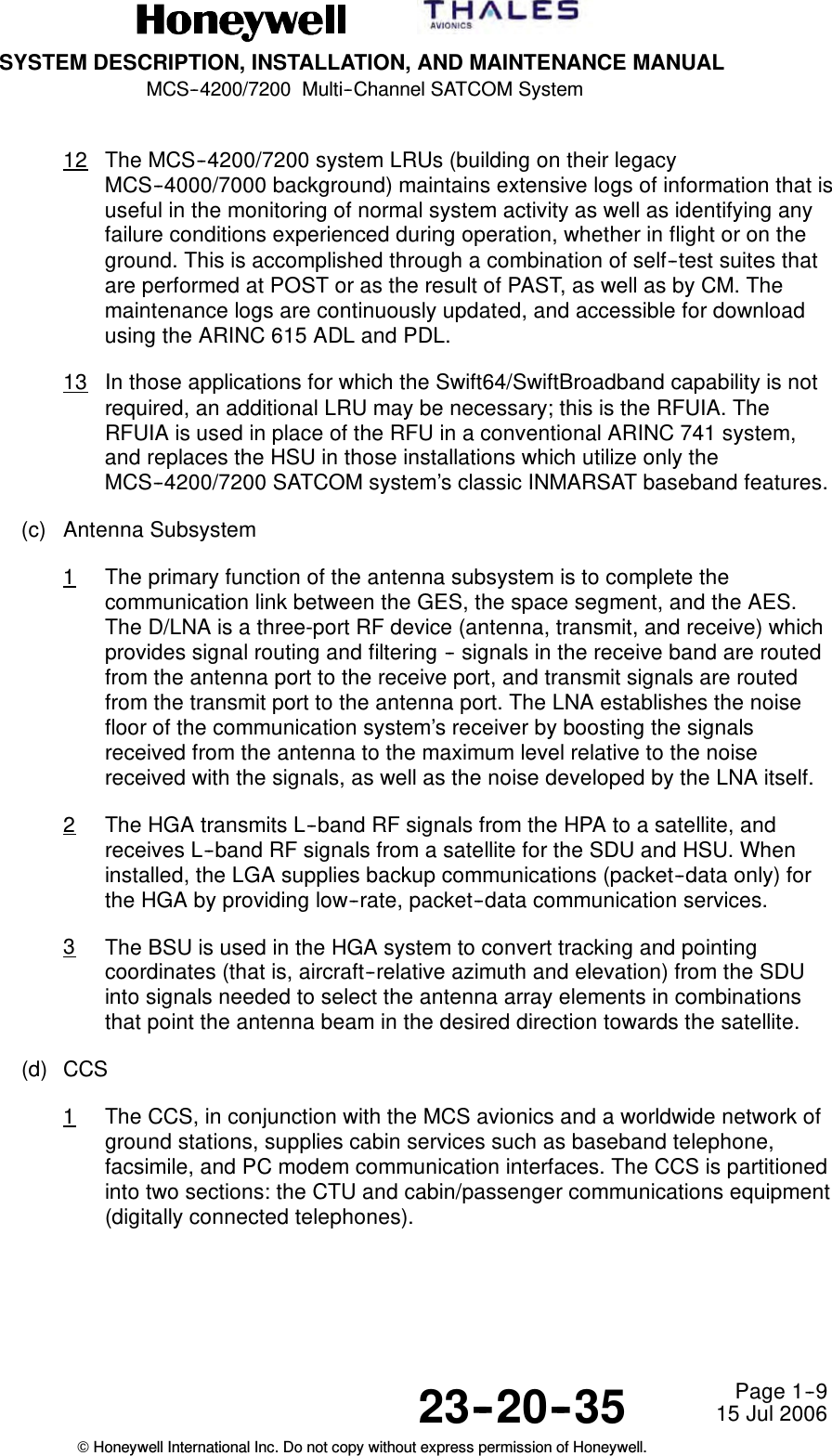
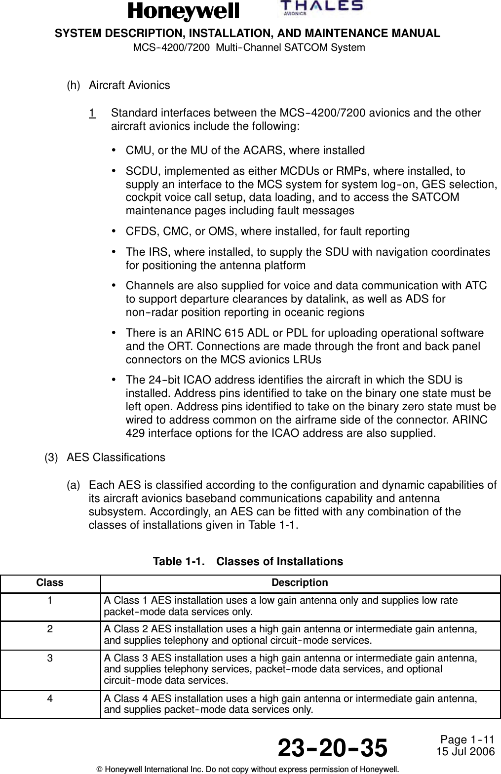
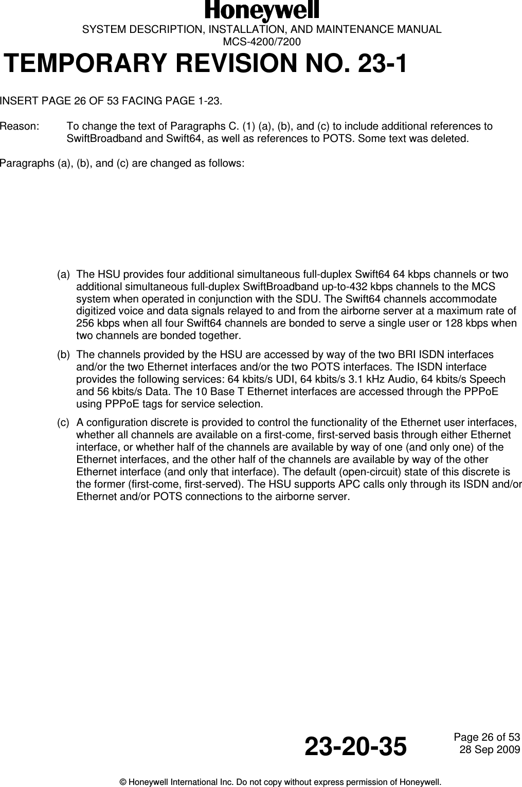
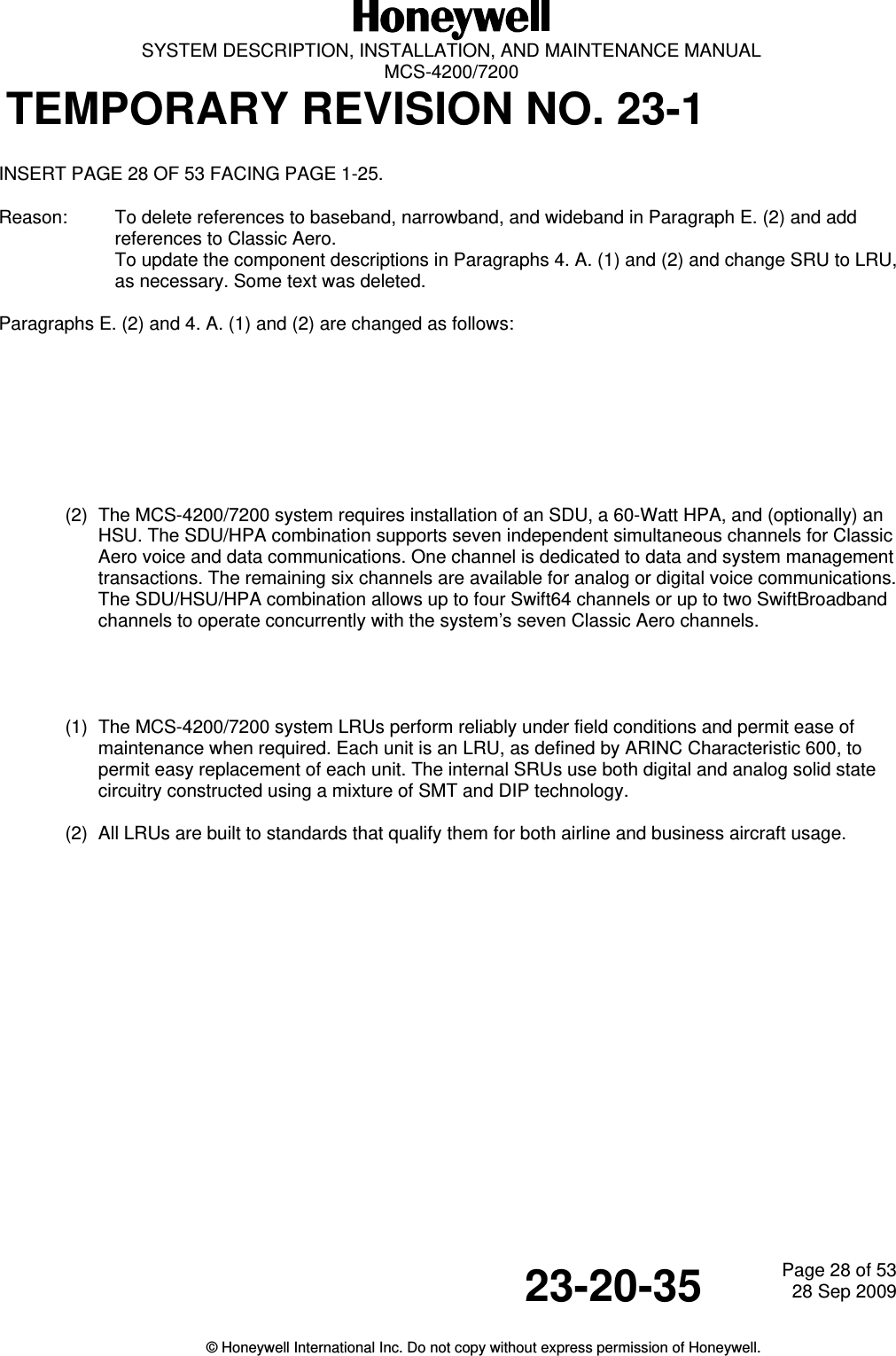
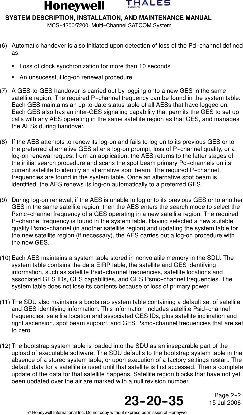
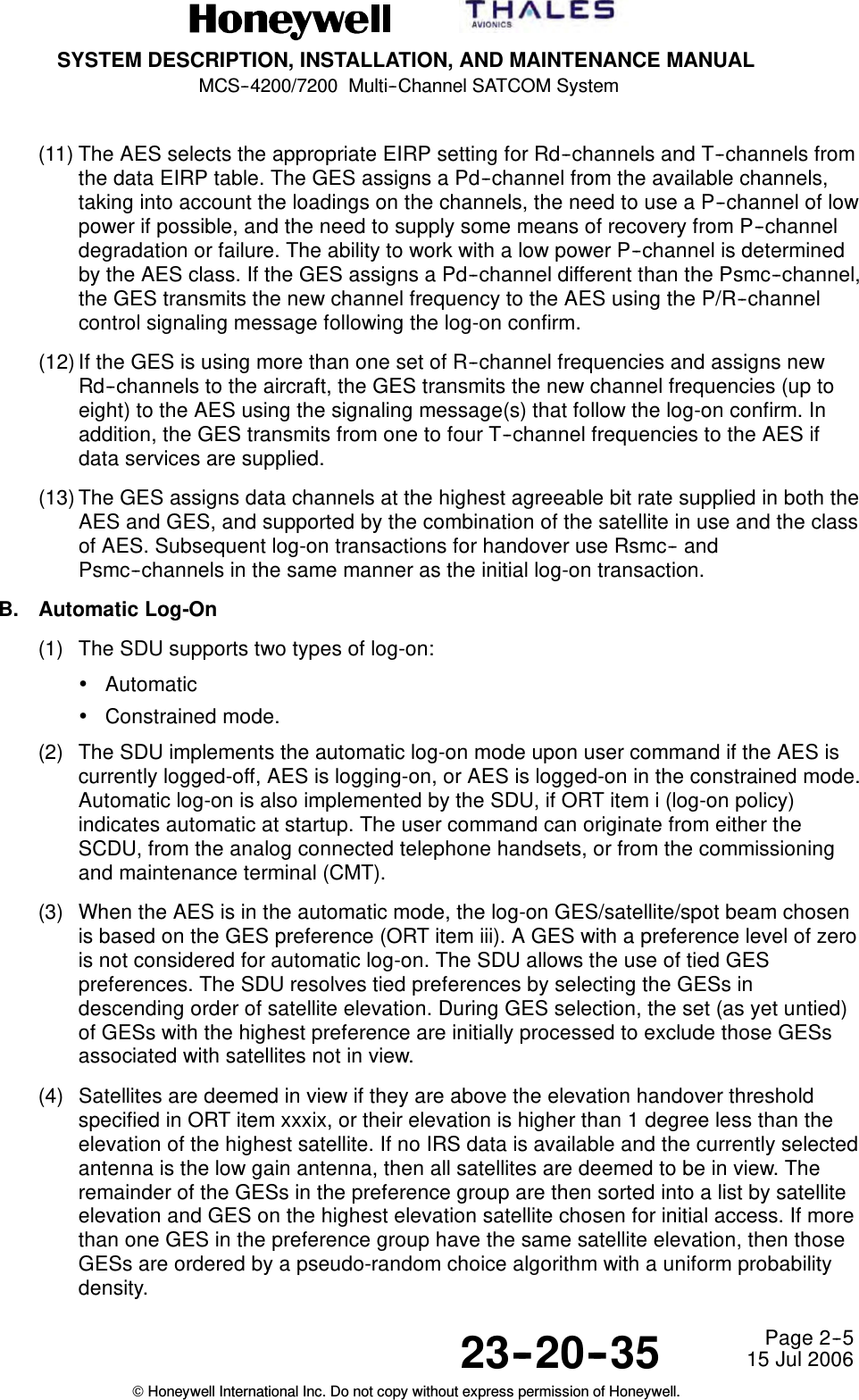
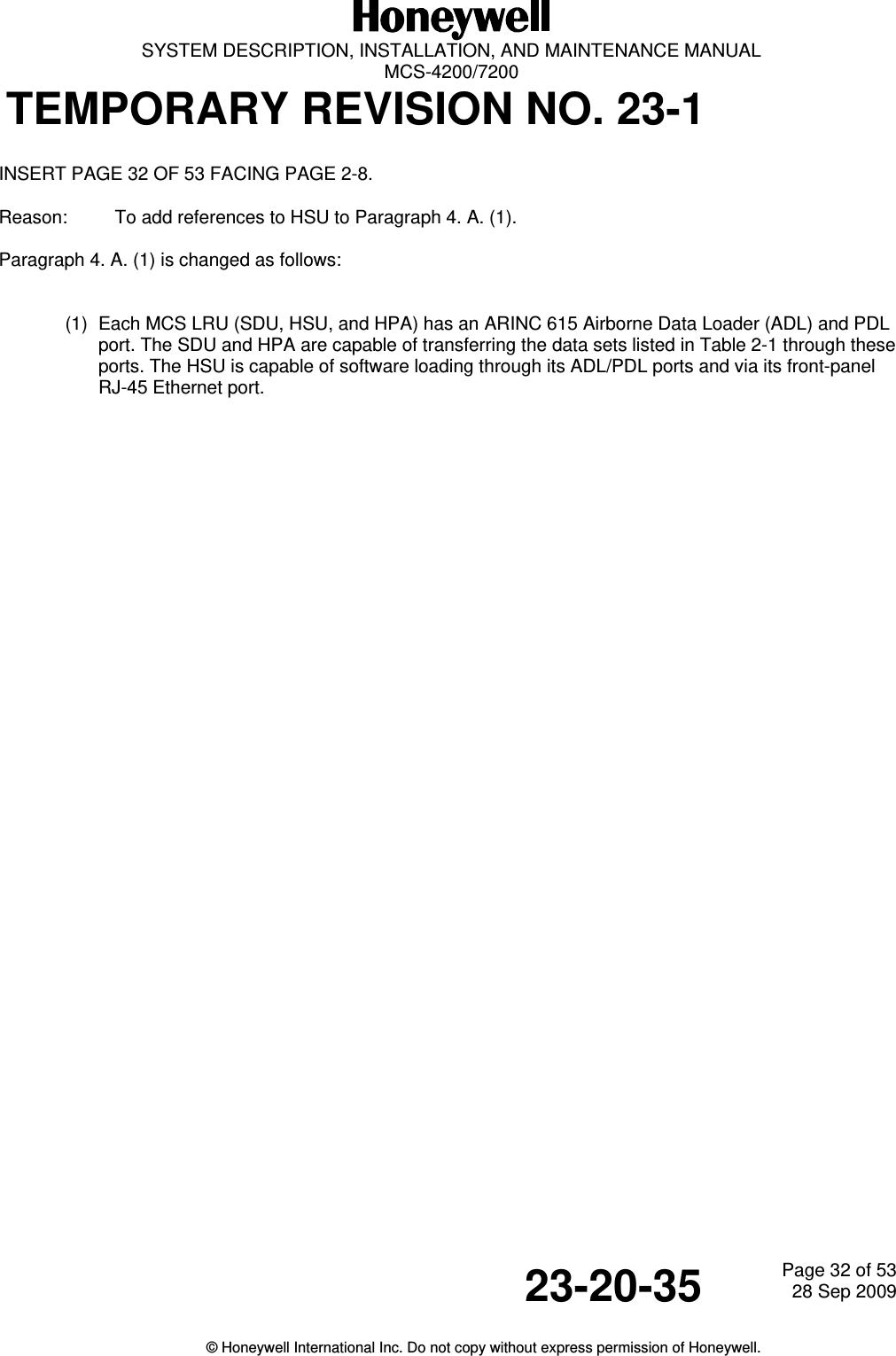
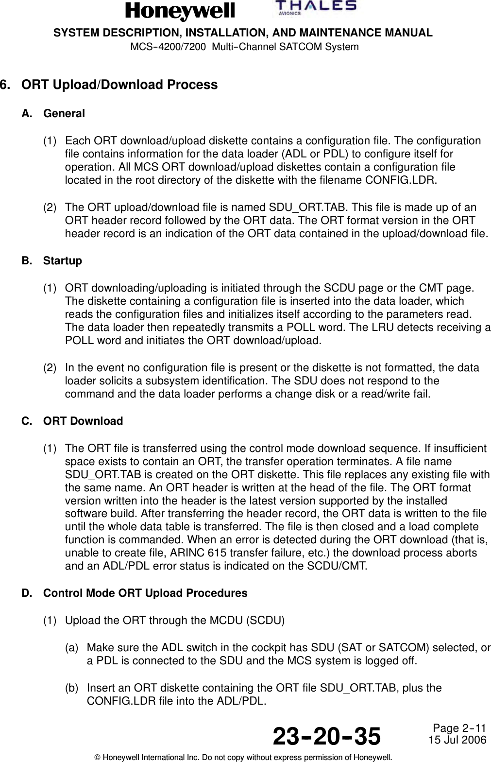
![SYSTEM DESCRIPTION, INSTALLATION, AND MAINTENANCE MANUAL MCS-4200/7200 TEMPORARY REVISION NO. 23-1 23-20-35 Page 24 of 5328 Sep 2009 © Honeywell International Inc. Do not copy without express permission of Honeywell. INSERT PAGE 24 OF 53 FACING PAGE 1-21. Reason: To change Paragraph B. (1) (a) to replace baseband with Classic Aero. Paragraph (a) is changed as follows: (a) The SDU is the core element of the MCS–4200/7200 avionics and responsible for overall AES control and monitoring. The unit interfaces to many aircraft avionics (for example, CFDS, primary/secondary IRS, CMU 1/2, MCDU [or RMP] 1/2/3, ADL, etc.) and has operational functionality, including coding and decoding all system voice and data signals and defining system protocols. The SDU contains six channels capable of supplying simultaneous full-duplex Classic Aero voice communication, one channel of Classic Aero data 2/3 communication, and RF circuitry sufficient to operate the AES. Figure 1-5 shows the CCA listing and block diagram for the MCS-7200 SDU. Removal of one of the TTCM CCAs results in the MCS-4200 SDU.](https://usermanual.wiki/Honeywell/HS-720.HS-720-User-Manual-Part1/User-Guide-1350370-Page-95.png)
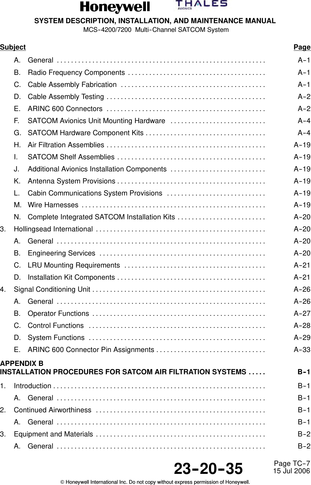
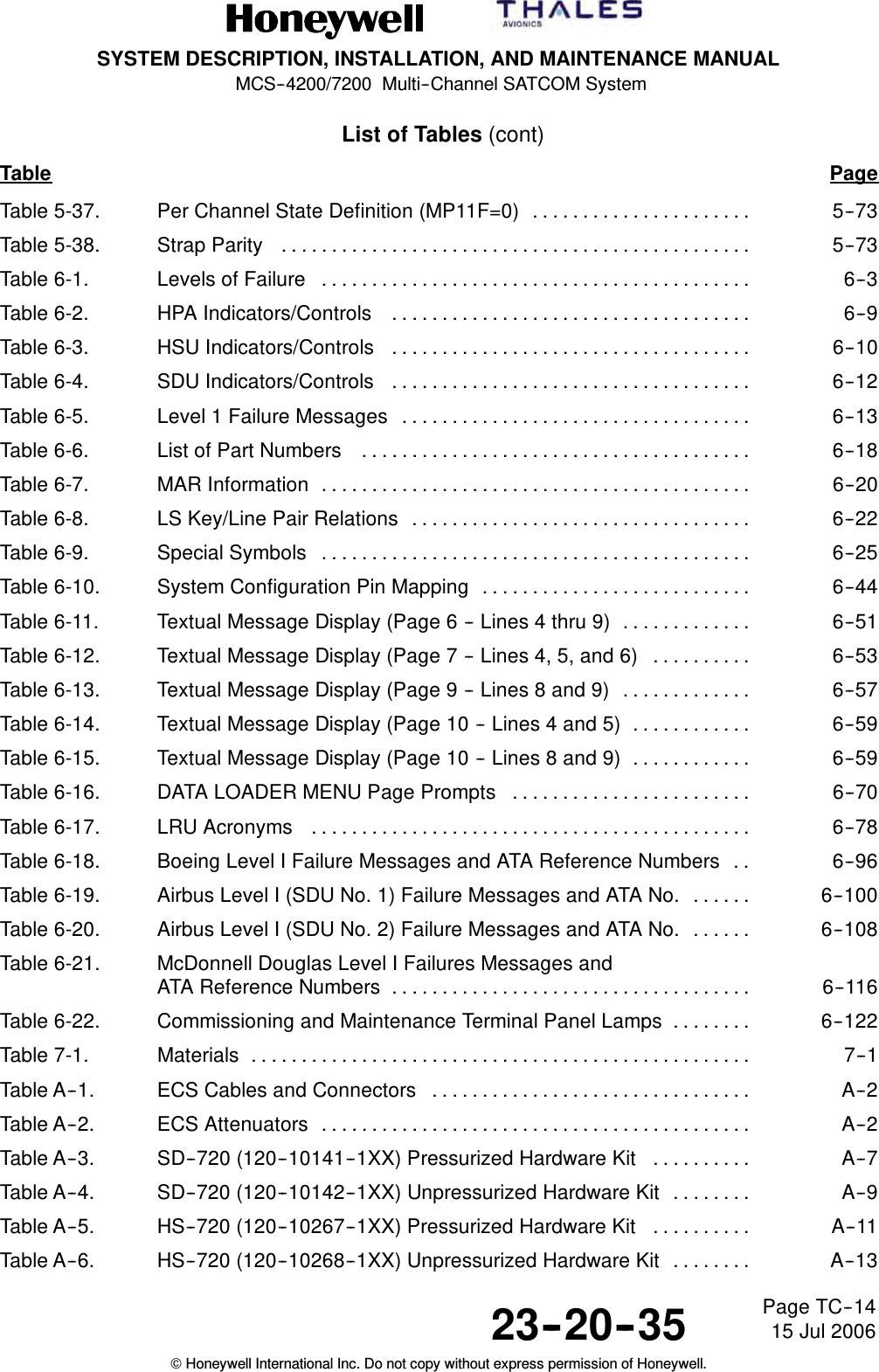
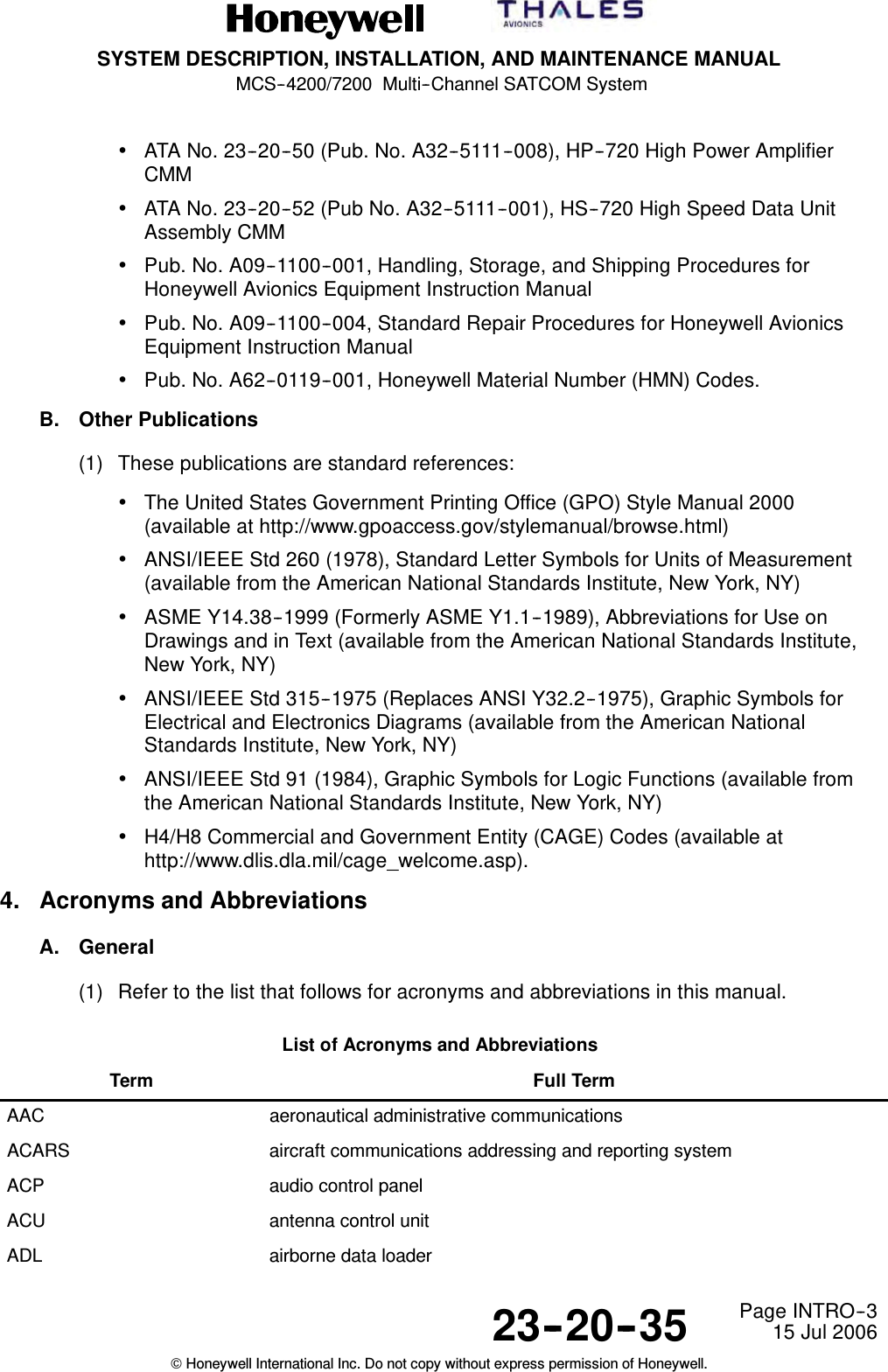
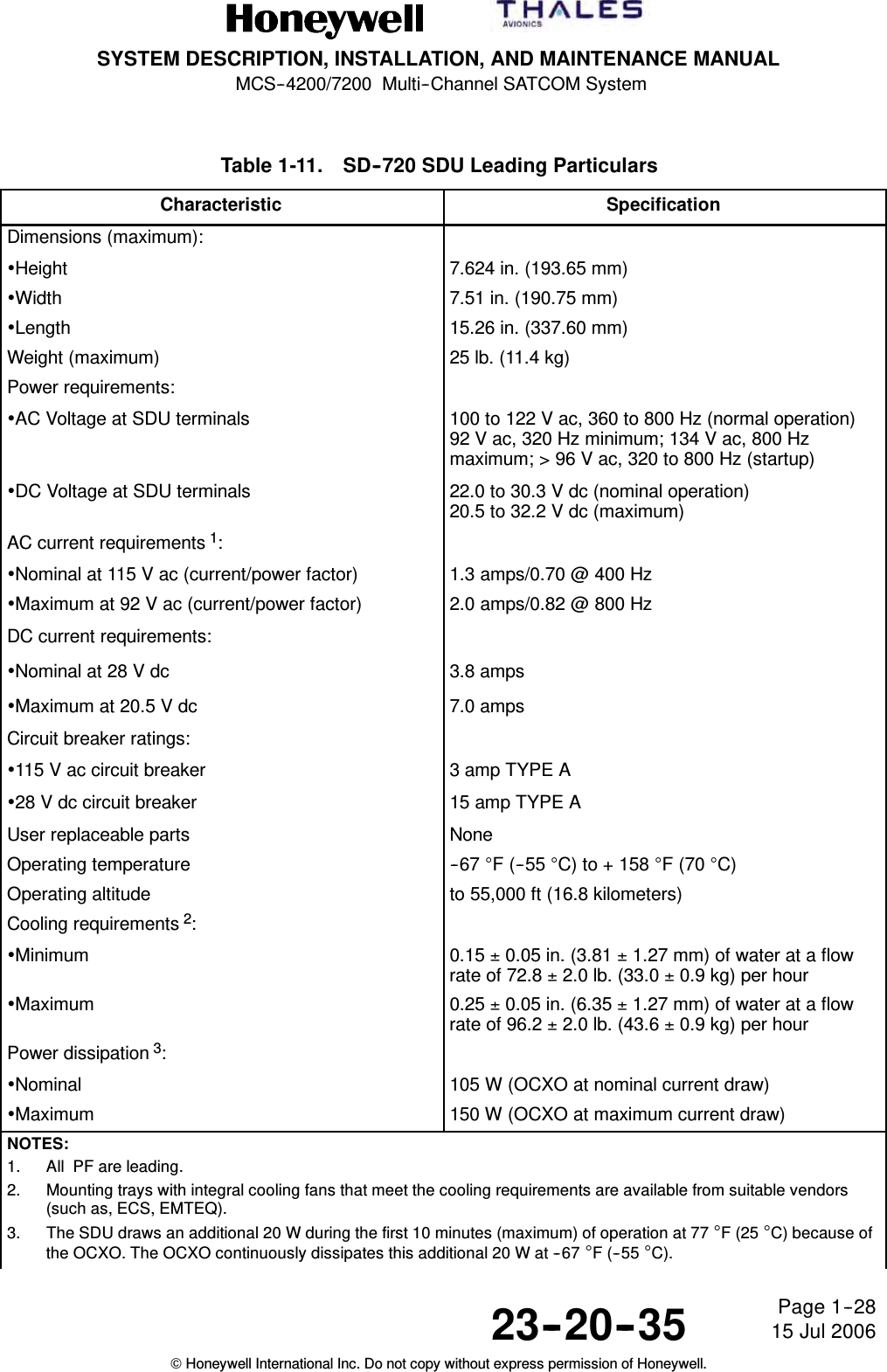
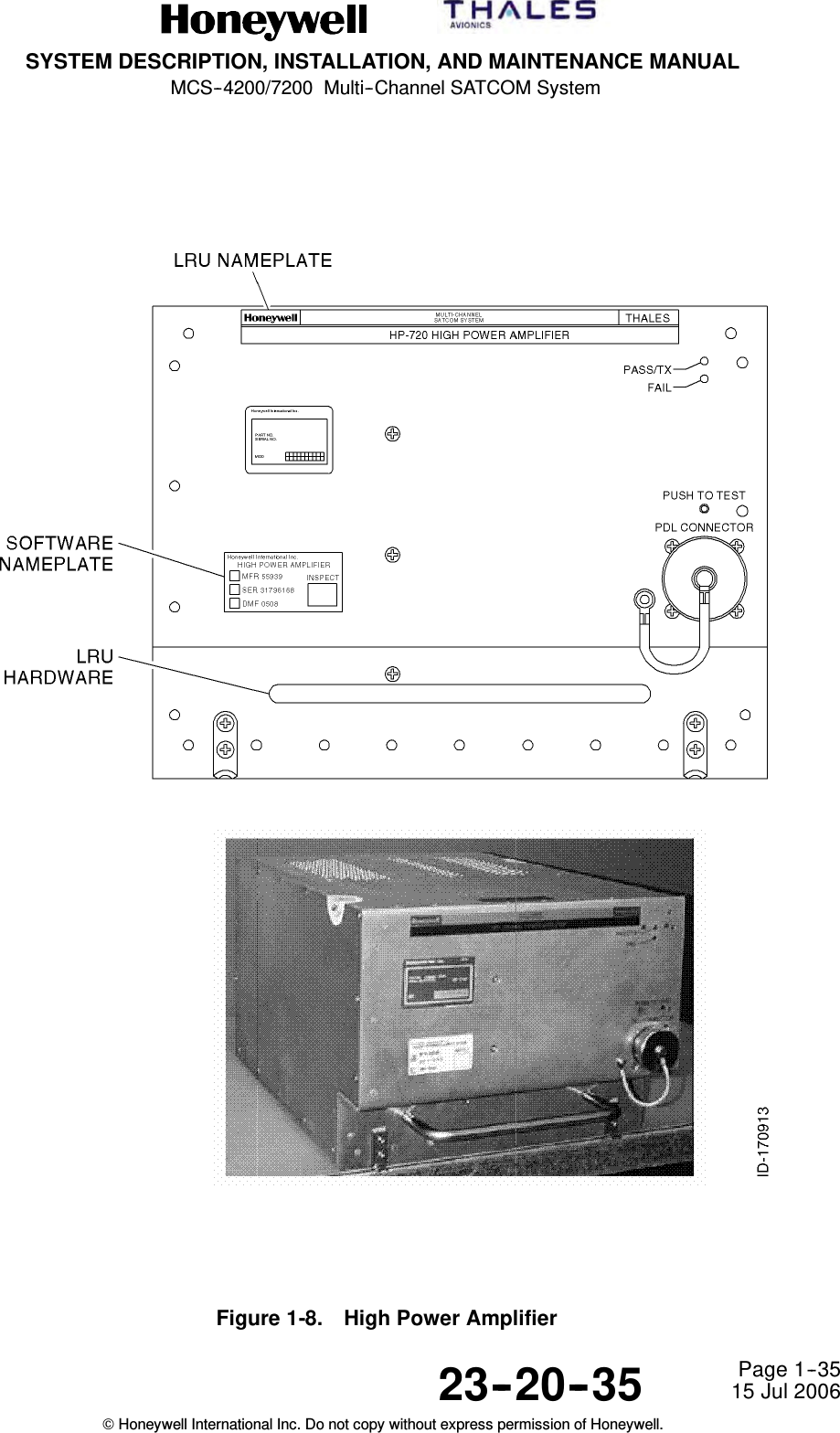
![SYSTEM DESCRIPTION, INSTALLATION, AND MAINTENANCE MANUALMCS--4200/7200 Multi--Channel SATCOM System23--20--35 15 Jul 2006Honeywell International Inc. Do not copy without express permission of Honeywell.Page 1--21B. Satellite Data Unit(1) General(a) The SDU is the core element of the MCS–4200/7200 avionics and responsiblefor overall AES control and monitoring. The unit interfaces to many aircraftavionics (for example, CFDS, primary/secondary IRS, CMU 1/2, MCDU [or RMP]1/2/3, ADL, etc) and has operational functionality, including coding and decodingall system voice and data signals and defining system protocols. The SDUcontains six channels capable of supplying simultaneous full--duplex basebandvoice communication, one channel of baseband data 2/3 communication, andRF circuitry sufficient to operate the AES. Figure 1--5 shows the CCA listing andblock diagram for the MCS--7200 SDU. Removal of one of the TTCM CCAsresults in the MCS--4200 SDU.Figure 1-5. MCS--7200 SDU Equipment Description](https://usermanual.wiki/Honeywell/HS-720.HS-720-User-Manual-Part1/User-Guide-1350370-Page-96.png)

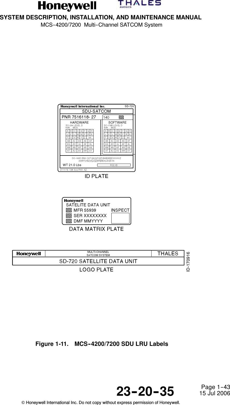
![SYSTEM DESCRIPTION, INSTALLATION, AND MAINTENANCE MANUALMCS--4200/7200 Multi--Channel SATCOM System23--20--35 15 Jul 2006Honeywell International Inc. Do not copy without express permission of Honeywell.Page 1--44(b) The LRU model number is a five--digit alphanumeric sequence. The first twodigits are upper--case alphabetic characters in the range AA to ZZ and the lastthree digits are numeric characters in the range 100 to 999. The LRU equipmentname is displayed with as many upper--case letters as are required to spell outthe equipment name. The LRU serial number consists of an eight--digit numericsequence.(c) The DO--160D categories applicable to the MCS–4200/7200 system consist of amix of numeric and upper case alphabetic characters. See Table 1-12,Table 1-14, or Table 1-16 for a list of environmental categories applicable to theMCS--4200/7200 LRUs.(d) The FCC identifier applicable to all MCS--4200/7200 LRUs is GB8MCS--4000 orGB8MCS--7000. The LRU hardware modification level is indicated by the set ofall marked modification level identifiers. Each modification level identifier is amaximum of two upper--case alphabetic characters that range from A to ZZ, withletters I, O, Q, and X excluded.(e) The MCS--4200/7200 LRU end item part number consists of a seven--digit basepart number and a five--digit dash number. The first two digits of the dashnumber indicate the LRU hardware configuration and consist of numeric valuesranging from 10 to 99. The last three digits of the dash number reflect the LRUsoftware configuration and consist of numeric values ranging from 001 to 999.(f) The hardware and software modification levels for any of the MCS--4200/7200LRUs each consists of a maximum of two upper--case alphabetic charactersranging from A (or “--”) to ZZ, with letters I, O, Q, and X excluded. Usage of thisnameplate characteristic reflects the implementation of minor hardware andsoftware changes in the given LRU.(g) The DO--178B software levels and DO--254 hardware levels applicable to eachMCS--4200/7200 LRU indicate the level to which a given LRU was certified. Theidentification (ID) nameplate can be removed and replaced when a softwarechange is significant enough to require the three--digit software configurationnumber be incremented or a hardware change is significant enough to requirethat the two--digit hardware configuration number be incremented.H. Software and Hardware Compatibility (SDU, HSU and HPA)(1) Provisions are included in each MCS--4200/7200 LRU to ensure hardware andsoftware compatibility. The settings for these provisions are manually changed eachtime a hardware revision is made that is not compatible with all previously releasedversions of software. The status of these settings is tested every time an LRUundergoes a cold start (power--on self--test [POST], or person--activated self--test[PAST]), and every time a software load is attempted from an ARINC 615 portabledata loader.](https://usermanual.wiki/Honeywell/HS-720.HS-720-User-Manual-Part1/User-Guide-1350370-Page-123.png)

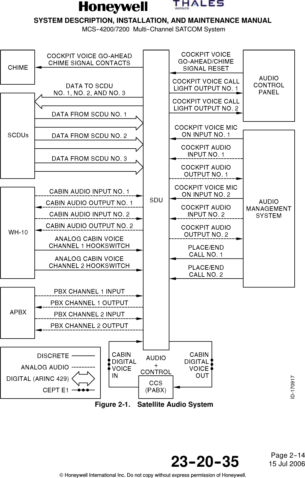
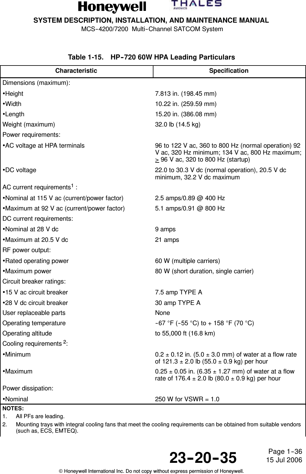
![SYSTEM DESCRIPTION, INSTALLATION, AND MAINTENANCE MANUALMCS--4200/7200 Multi--Channel SATCOM System23--20--35 15 Jul 2006Honeywell International Inc. Do not copy without express permission of Honeywell.Page 2--27Figure 2-12. (HGA + LGA) + HGA Configuration with Two Top-Mounted HGAsE. Cockpit Voice Configurations and Functionality(1) System configuration pins TP13F and TP13J specify the physical wiring for thecodecs of each SDU to the possible interfaces -- a codec/channel can only beavailable to the cockpit if the wiring strap is set to Cockpit or Both (and not if thewiring is to Cabin or Neither).(2) An additional issue with dual systems is how to map the potentially available fourphysical SDU cockpit voice channels with the one or two (maximum) usable logicalcockpit channels controllable through the audio control panels (ACPs) and theSCDUs (that is, as seen by the audio management system [AMS] user). Twoconfigurations are defined, which are identified by ORT item xlviii (Cockpit ChannelInterface Type for Dual): (1) interfacing each ACP/SCDU logical channel to onephysical channel on one SDU only (fixed), and (2) interfacing an ACP/SCDU logicalchannel to one physical channel on each of the two SDUs (shared). Note theinterfacing referred to is conceptual and not necessarily physical — that is, forshared, the physical wiring can be literally paralleled, or it can be simplepoint-to-point, with some form of signal splitting/combining or paralleling beingperformed within the AMS itself. The system configuration straps for codec wiring letthe SDU determine the physical channels which are candidate channels for eachlogical channel.](https://usermanual.wiki/Honeywell/HS-720.HS-720-User-Manual-Part1/User-Guide-1350370-Page-168.png)