Honeywell HS-720 High Speed Data Unit for the MCS-7200 SATCOM System User Manual SDIM Multi Channel SATCOM System A15 5111 010
Honeywell International Inc. High Speed Data Unit for the MCS-7200 SATCOM System SDIM Multi Channel SATCOM System A15 5111 010
Contents
- 1. HS-720 User Manual Part1
- 2. HS-720 User Manual Part2
- 3. HS-720 User Manual Part3
HS-720 User Manual Part2
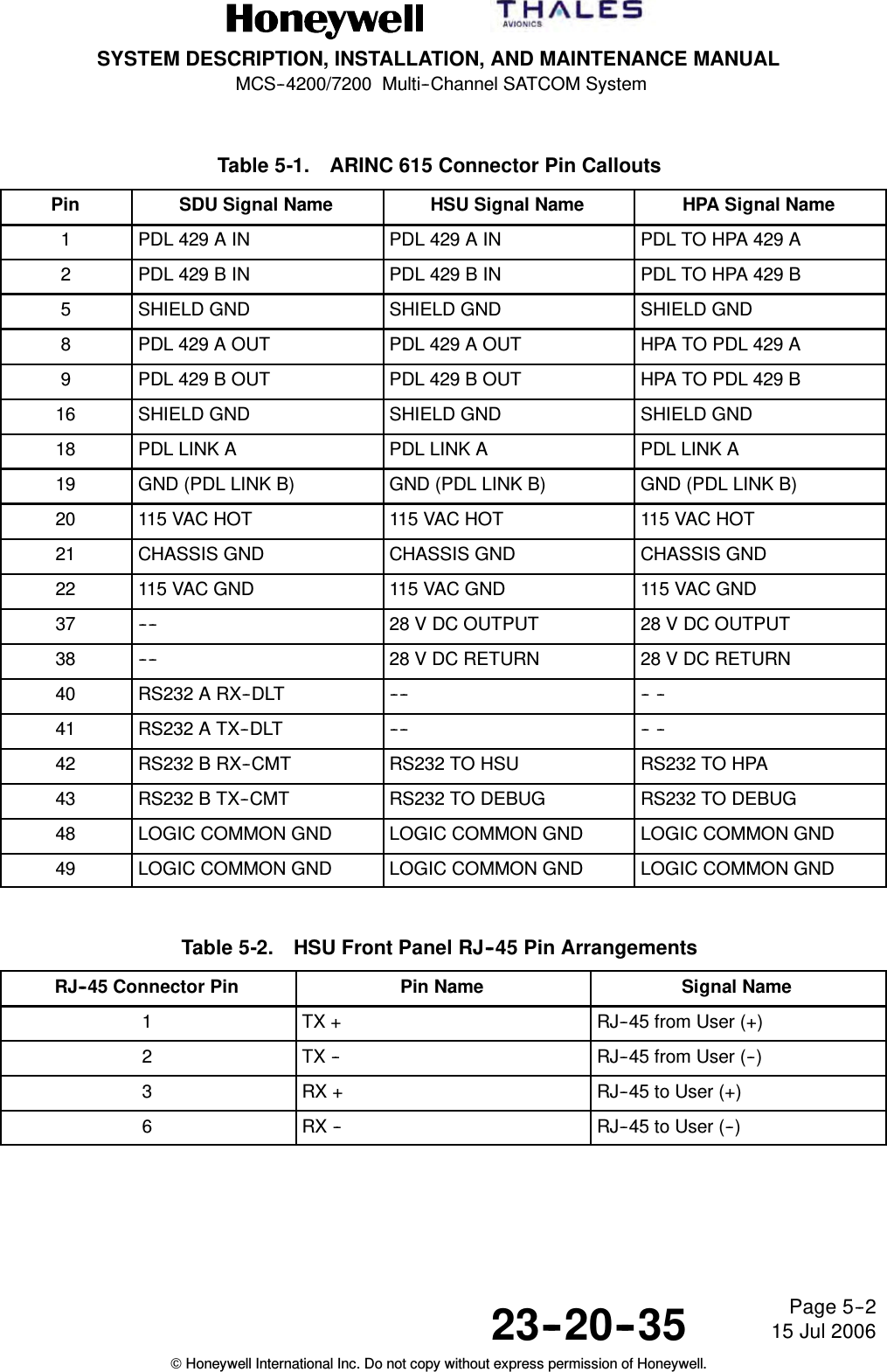
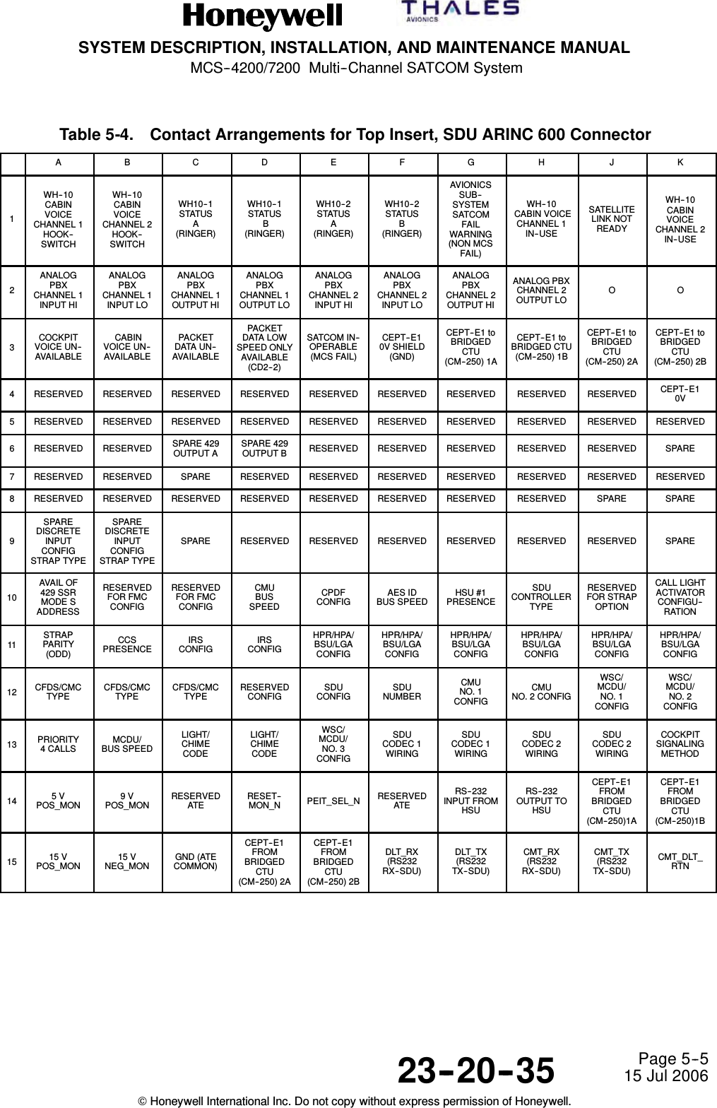
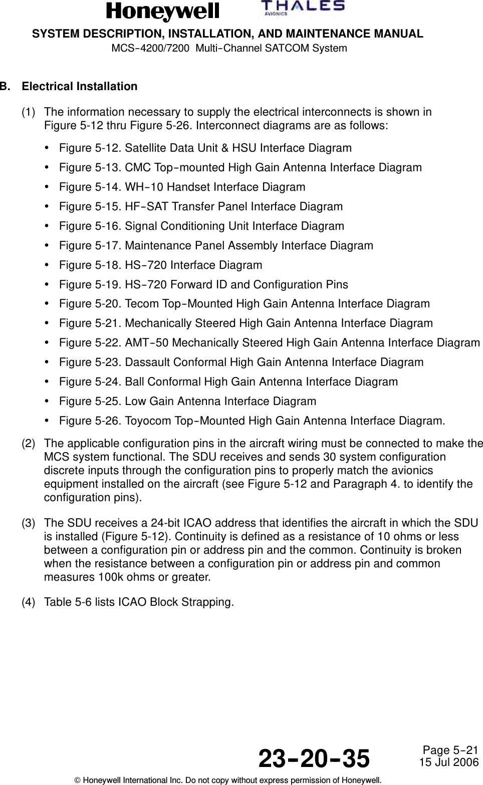

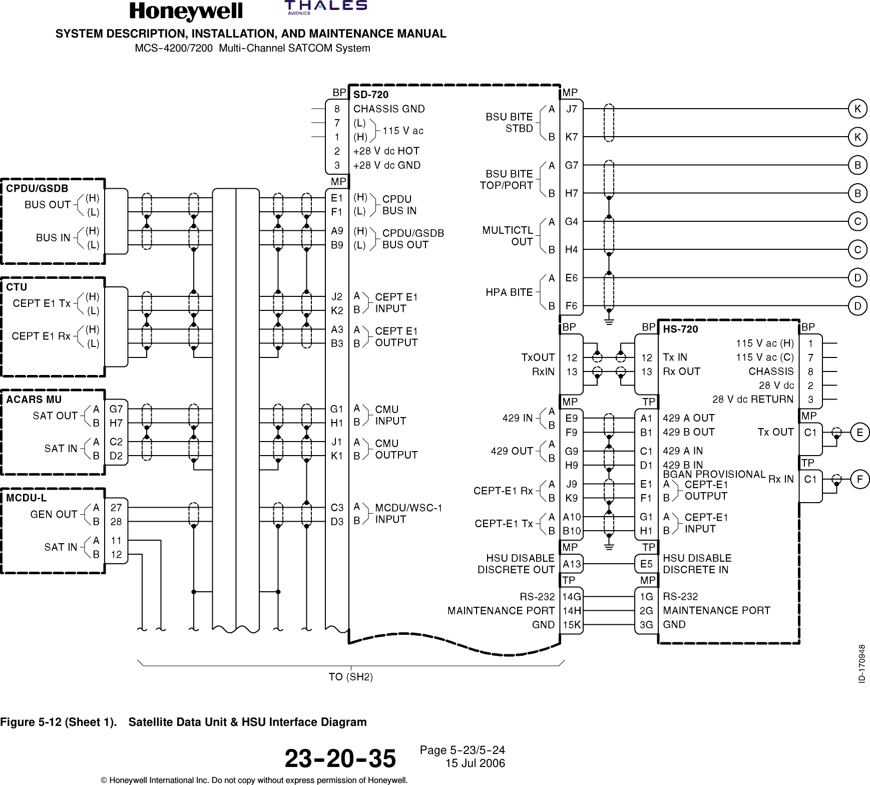
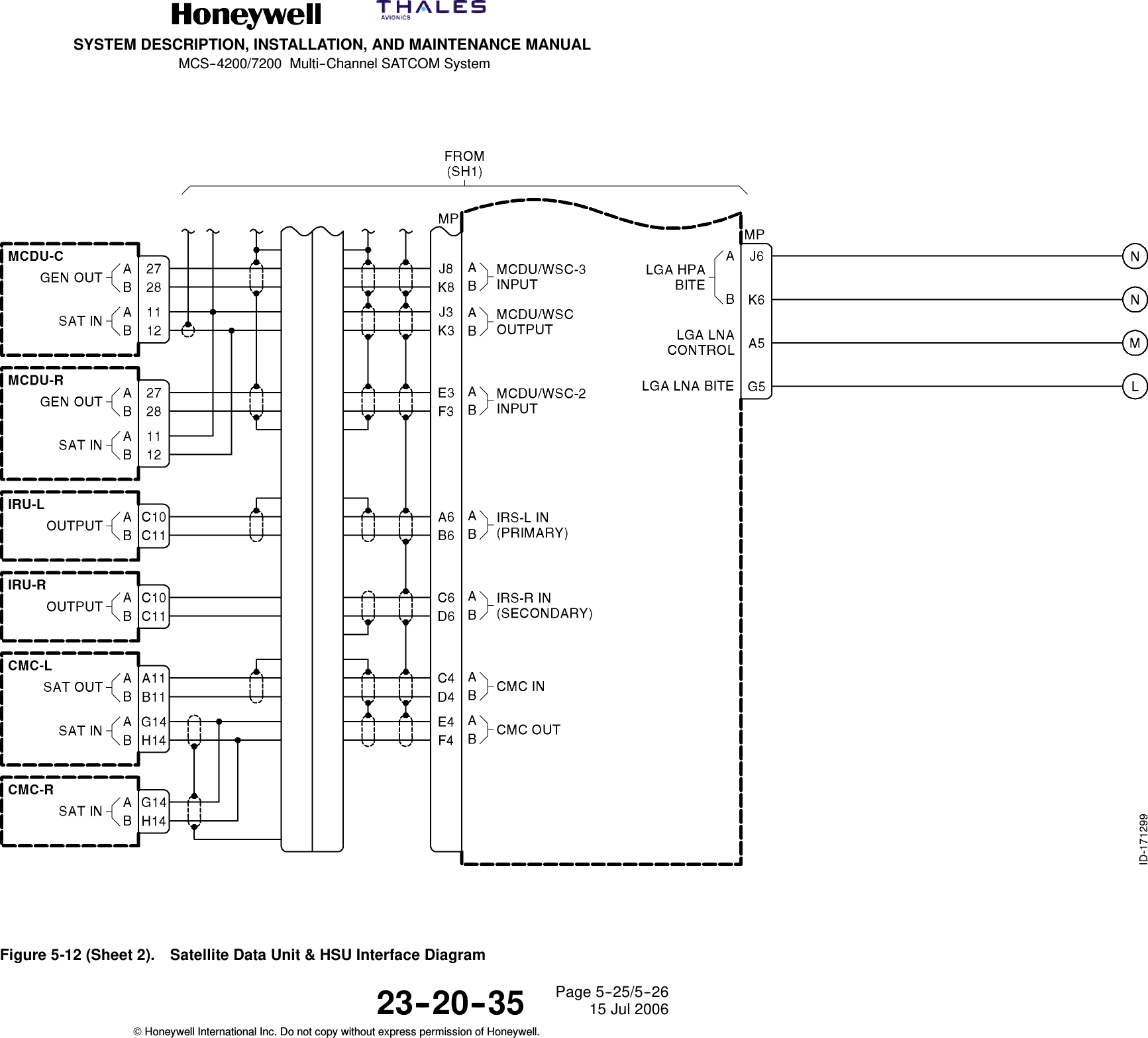
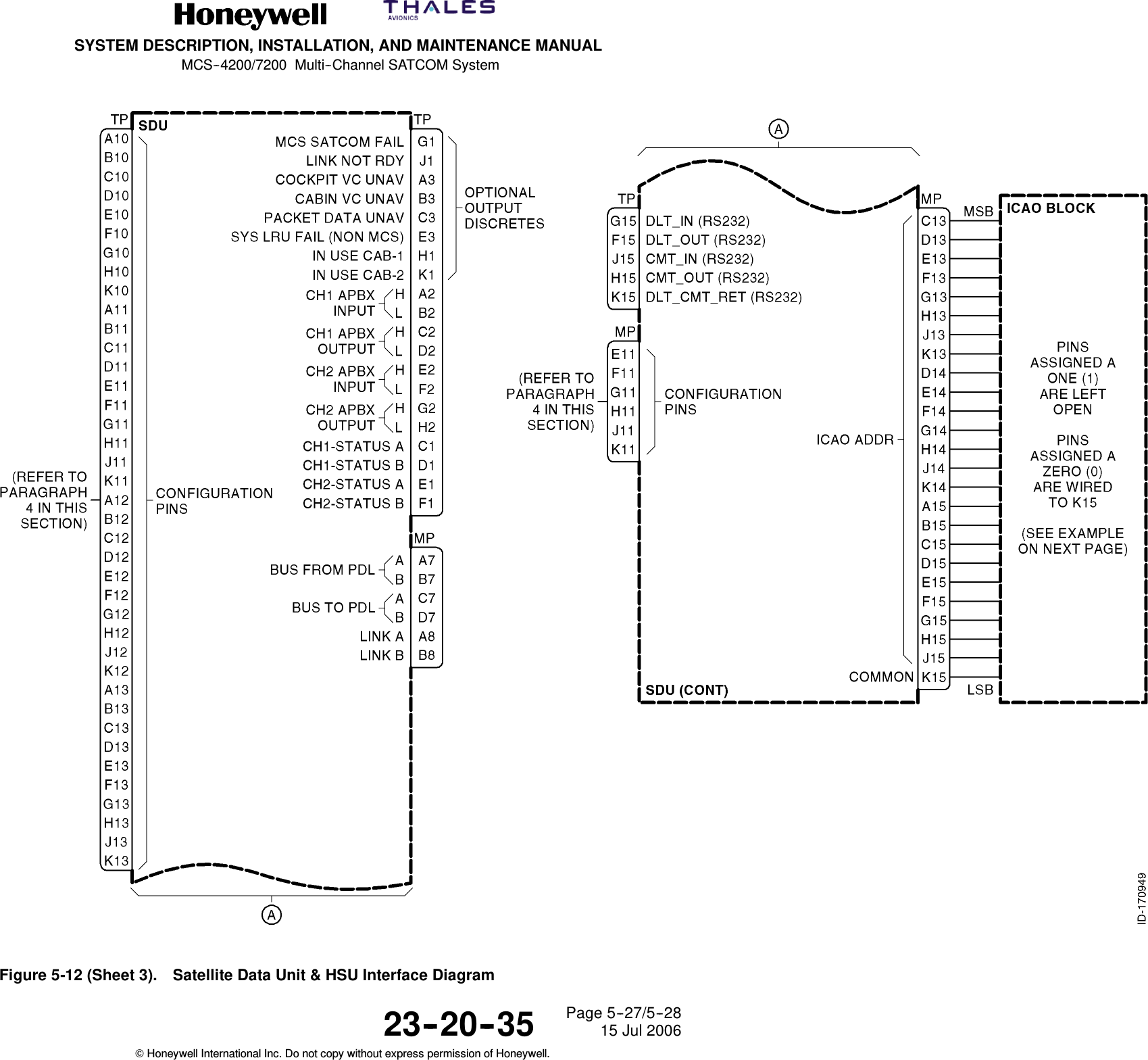

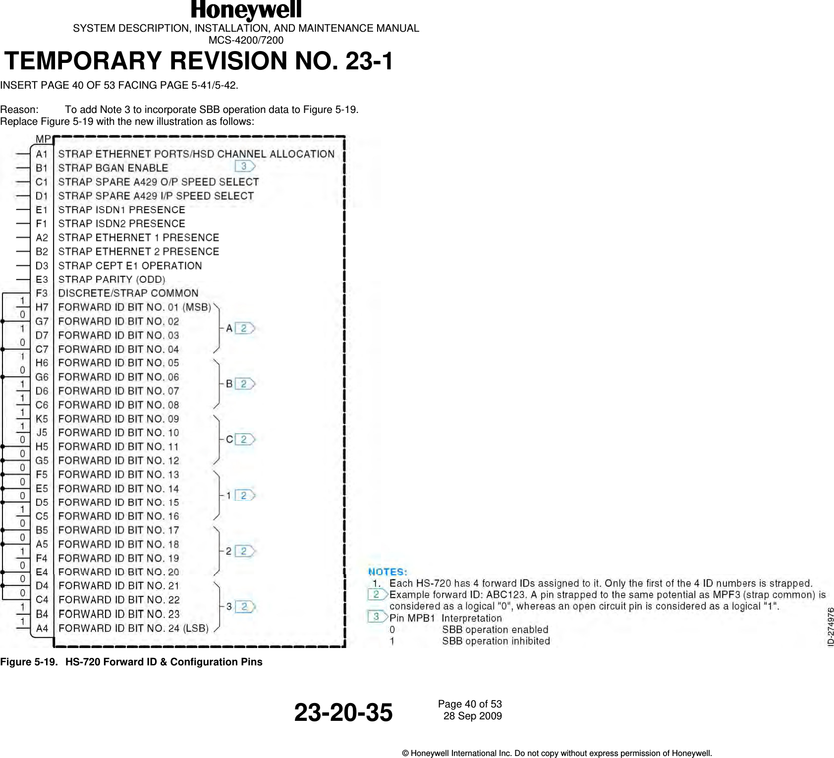
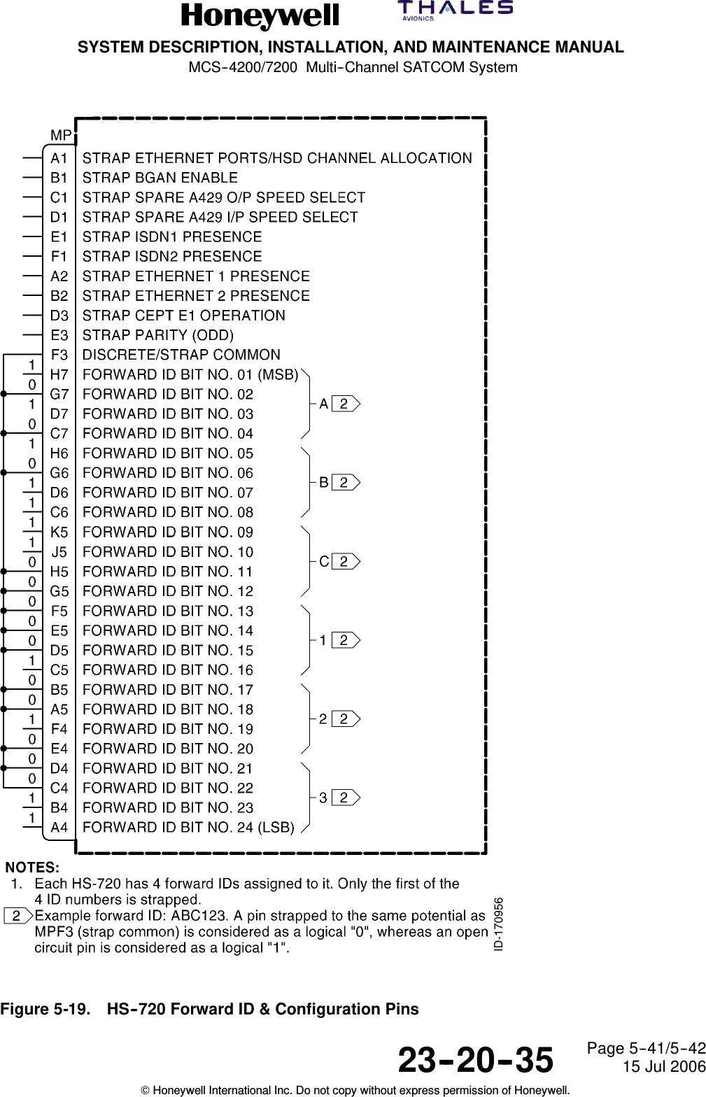
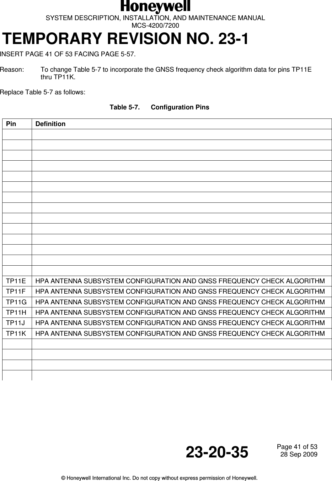
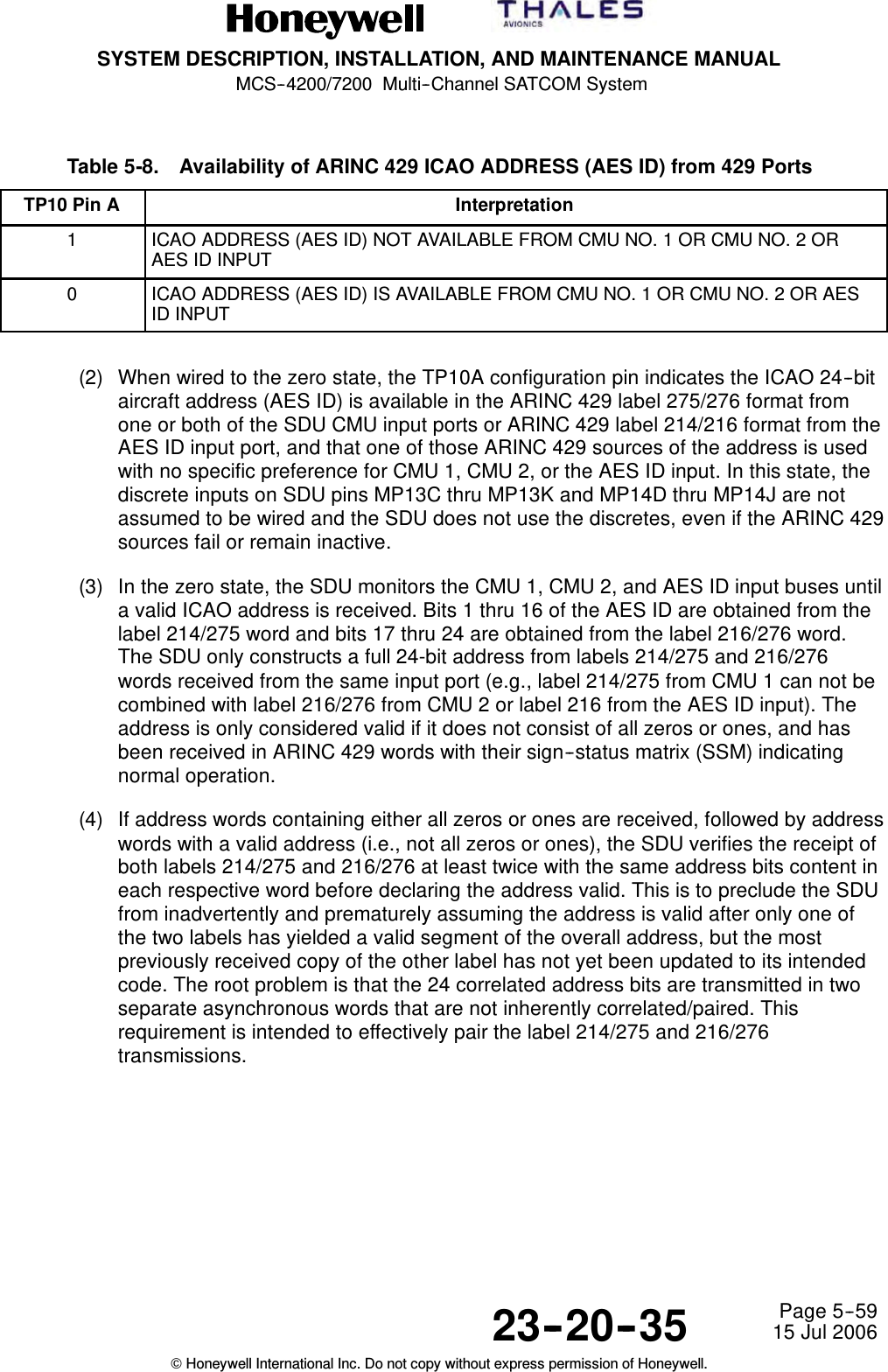
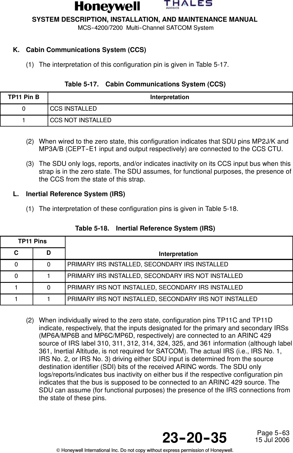
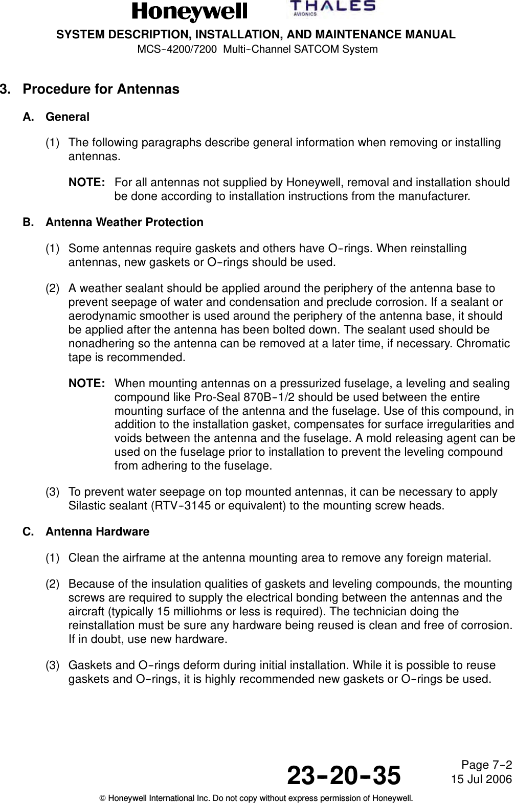
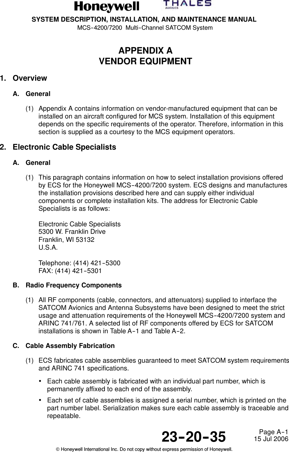
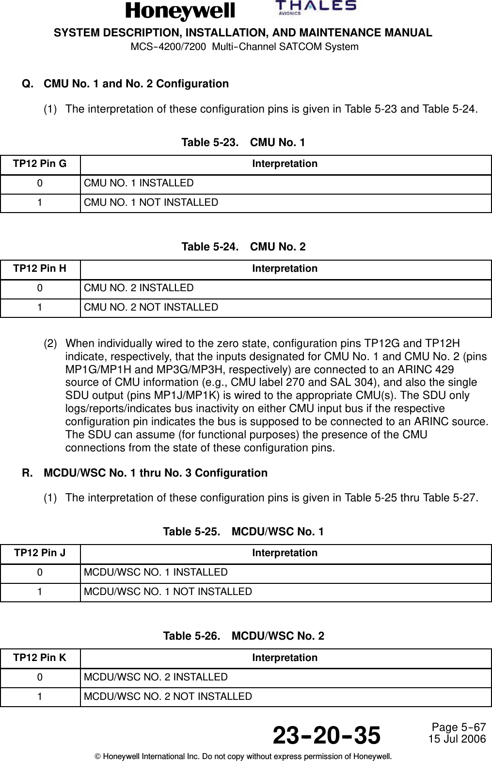
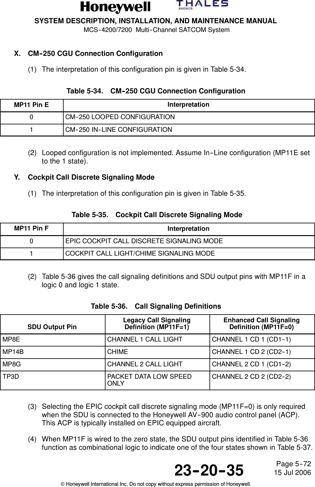
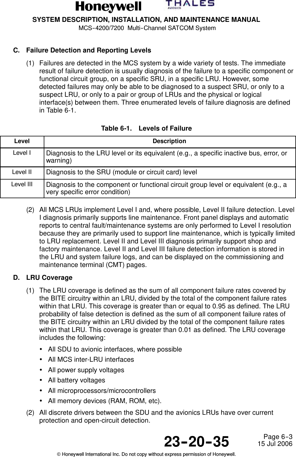
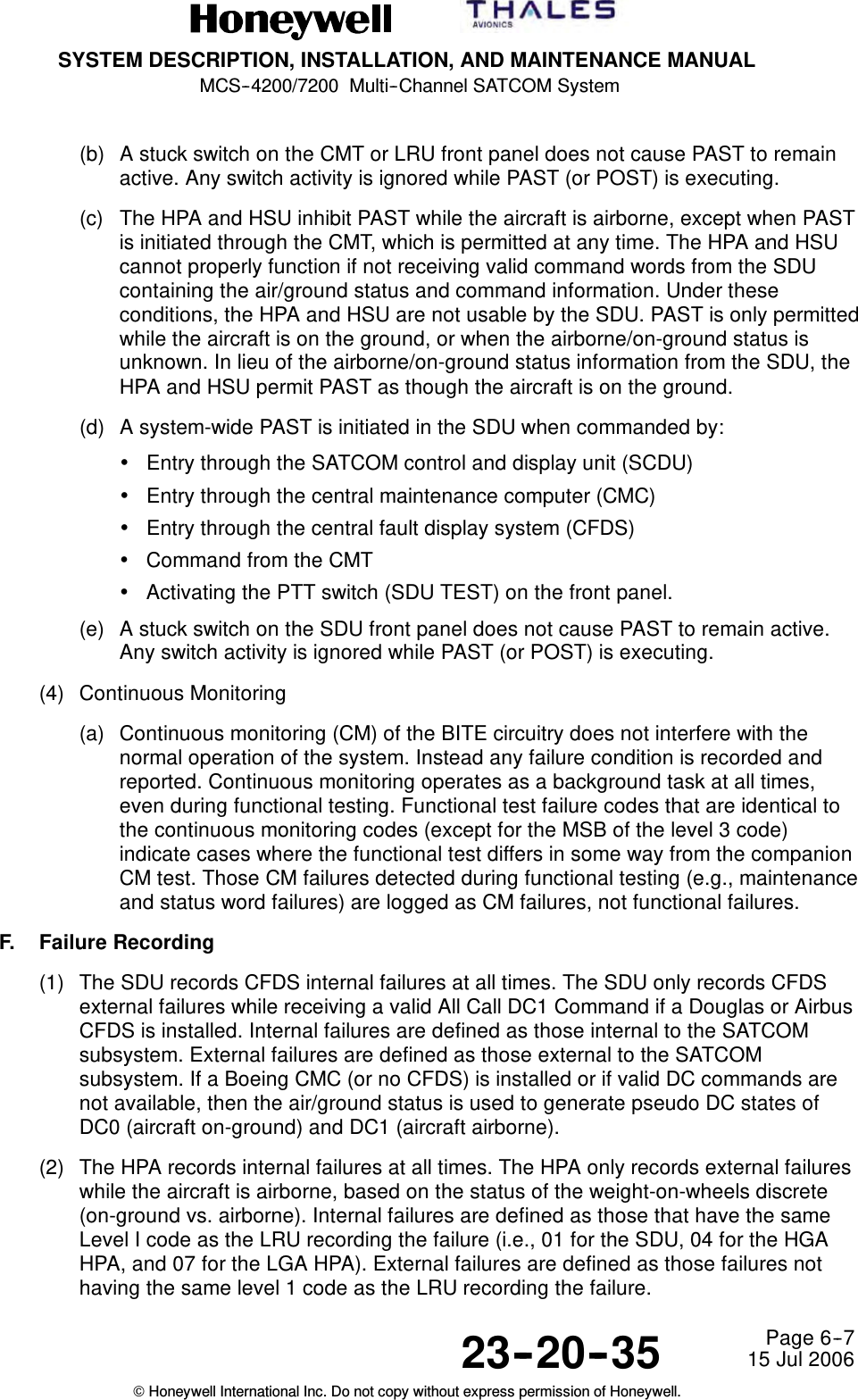
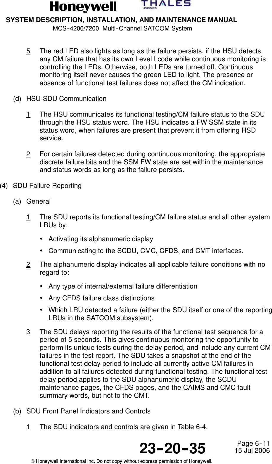
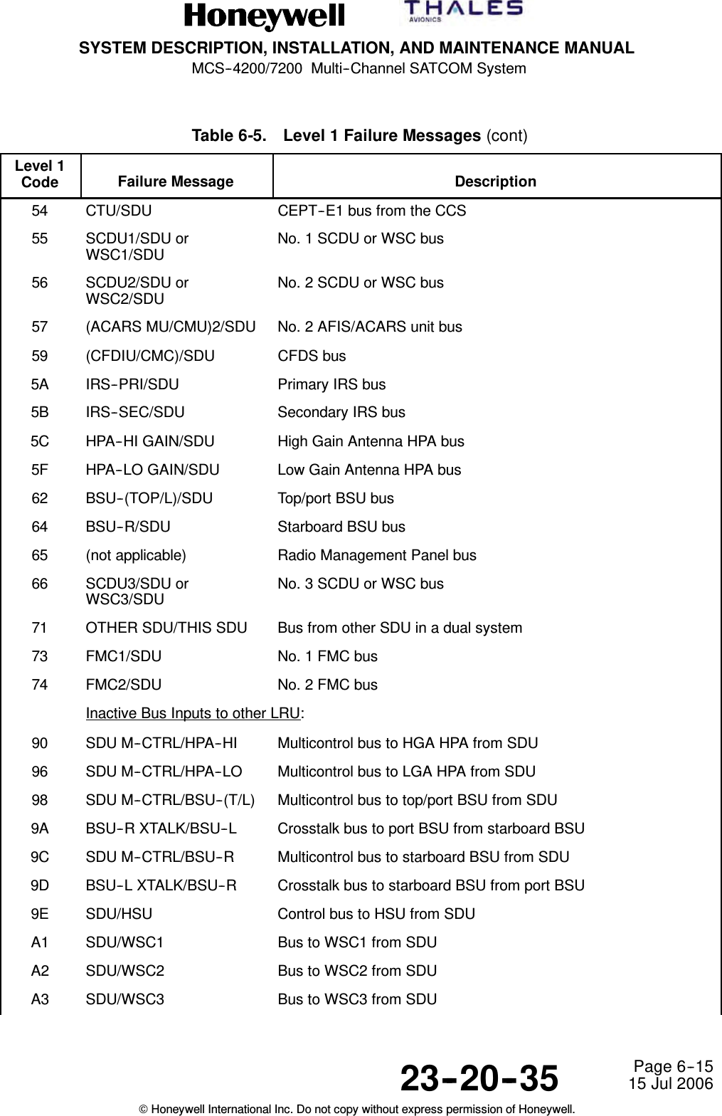
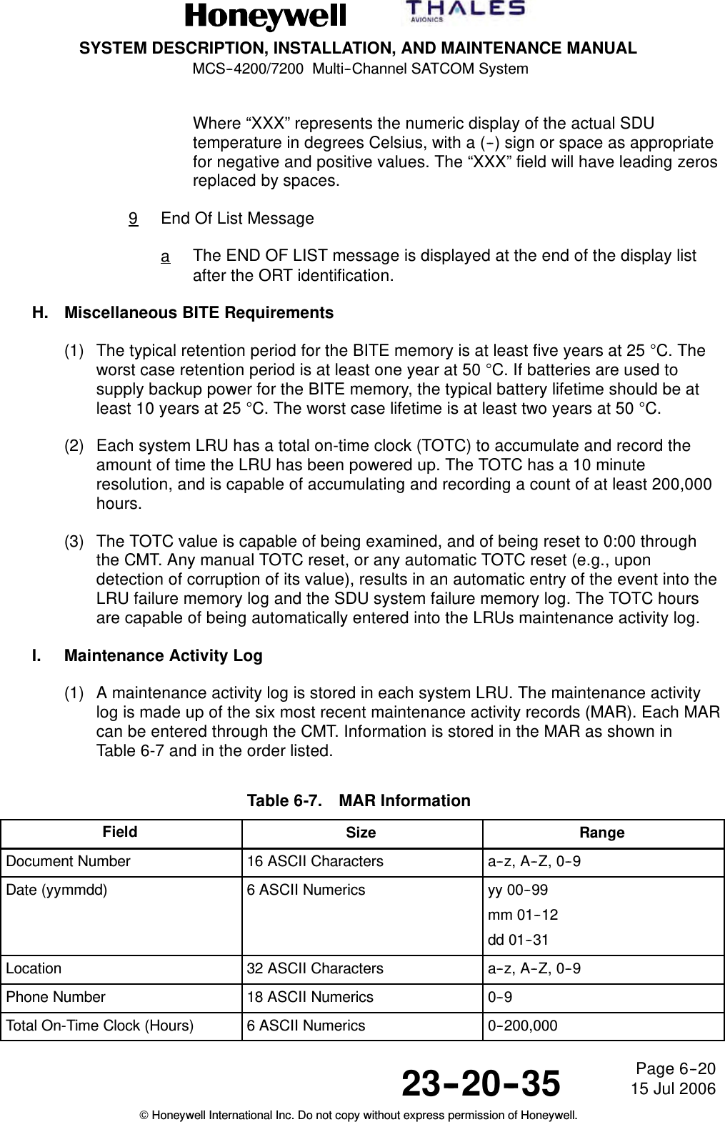
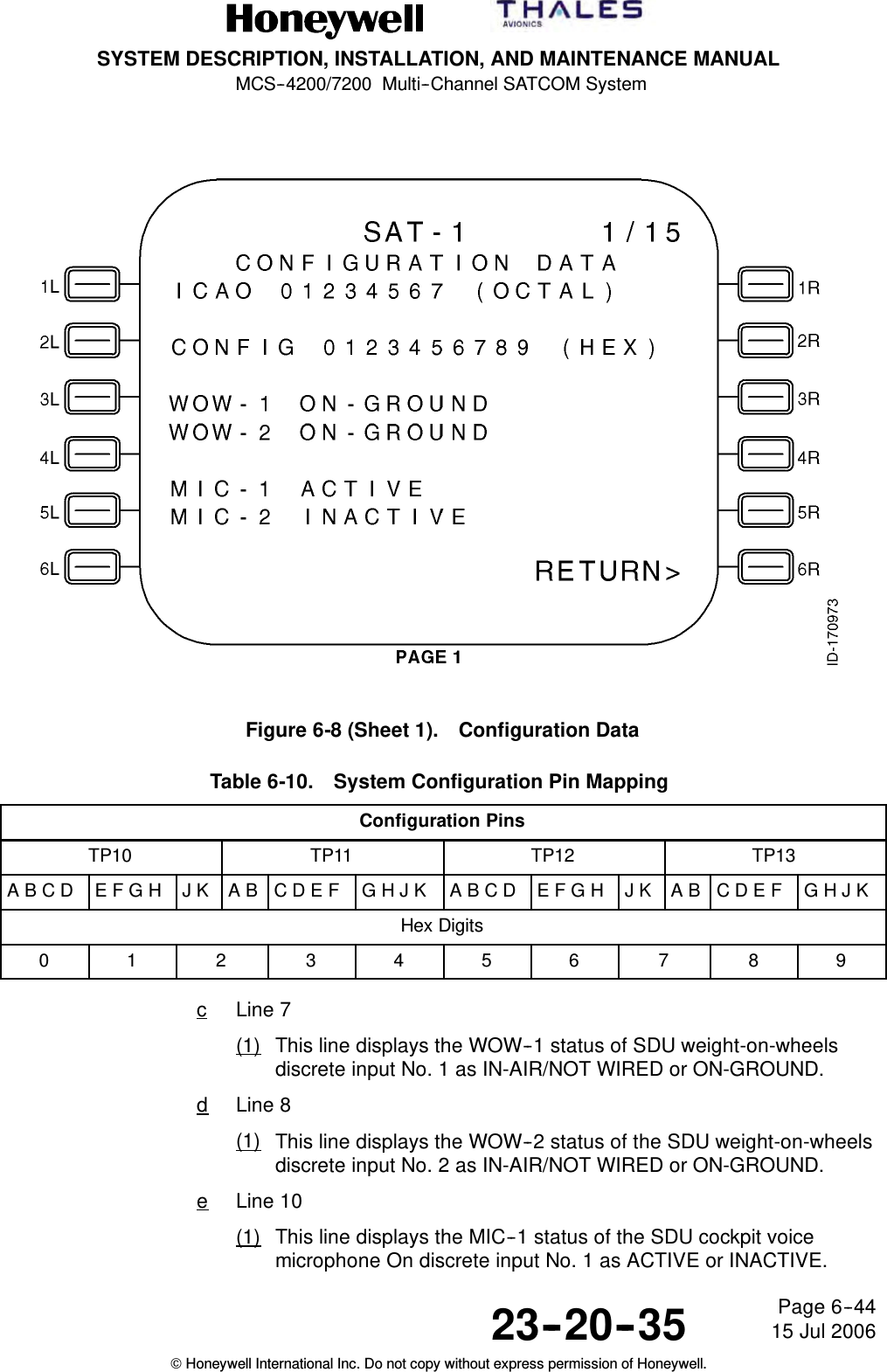
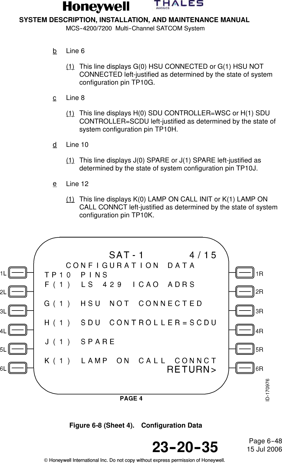
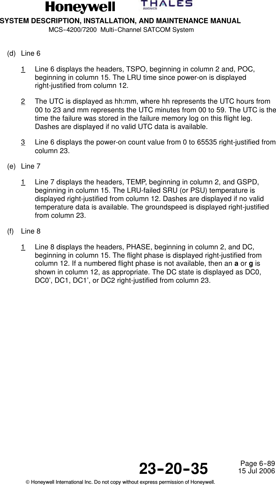
![SYSTEM DESCRIPTION, INSTALLATION, AND MAINTENANCE MANUAL MCS-4200/7200 TEMPORARY REVISION NO. 23-1 23-20-35 Page 42 of 5328 Sep 2009 © Honeywell International Inc. Do not copy without express permission of Honeywell. INSERT PAGE 42 OF 53 FACING PAGE 5-64. Reason: To change Table 5-19 to incorporate the GNSS frequency check algorithm data. Replace Table 5-19 as follows: Table 5-19. (TP11E – K) HPA/Antenna Subsystem Configuration and GNSS Frequency Check Algorithm1 [10] Decimal Code Pins TP11 LGA LGA HPA TOP/PORT BSU + HGA STARBOARD BSU + HGA HGA HPA HPRGNSS FREQ CHK REQDGNSS FREQ CHK NOT REQDARINC 781 HGA RESERVED FOR FUTURE RESERVED FOR MFR NOTES E F G H J K 63 1 1 1 1 1 1 * * * 62 0 1 1 1 1 1 * * * 61 1 0 1 1 1 1 * * * * * 60 0 0 1 1 1 1 * * * * * * * 59 1 1 0 1 1 1 * * 58 0 1 0 1 1 1 * * 57 1 0 0 1 1 1 * * 56 0 0 0 1 1 1 * * 55 1 1 1 0 1 1 * * * * * 54 0 1 1 0 1 1 * * * 48-53 1 0 0 0 1 0 0 0 1 1 1 1 to * 47 1 1 1 1 0 1 * * * 46 0 1 1 1 0 1 * * * 45 1 0 1 1 0 1 * * * * * 44 0 0 1 1 0 1 * * * * * * * 43 1 1 0 1 0 1 * * 42 0 1 0 1 0 1 * * 41 1 0 0 1 0 1 * * 40 0 0 0 1 0 1 * * 39 1 1 1 0 0 1 * * * * * 38 0 1 1 0 0 1 * * * 8-37 1 0 0 0 1 0 0 1 0 0 1 0 to * 0-7 1 0 1 0 1 0 0 0 0 0 0 0 to * Note 1: Other configurations are possible and may be added at a later date. Note that ARINC Characteristic 761 Attachment 1-4B Table 1-3K (which is an extension of ARINC Characteristic 741 Table 1-4K) defines configurations which include intermediate-gain antennas (IGAs). Those IGA configurations may also apply to ARINC Characteristic 741-compatible equipment; therefore, the IGA codes defined in ARINC Characteristic 761 should be considered as reserved for those definitions in this table as well. Any changes to this table should be coordinated with ARINC Characteristic 761. Note that the configuration codes for “GNSS Frequency Check Required” and “GNSS Frequency Check Not Required” are identical except for TP11J. Refer to ARINC 741 Part 2 Section 3.5.4.1.1 regarding the frequency check for GNSS interference prevention.](https://usermanual.wiki/Honeywell/HS-720.HS-720-User-Manual-Part2/User-Guide-1350371-Page-50.png)
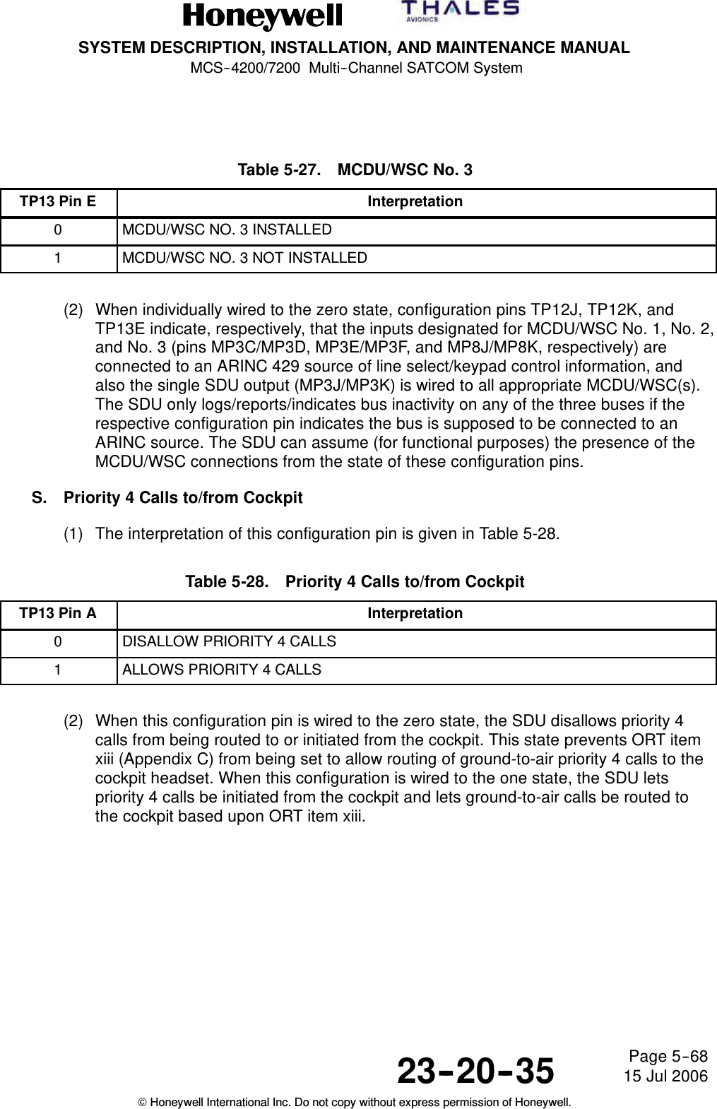
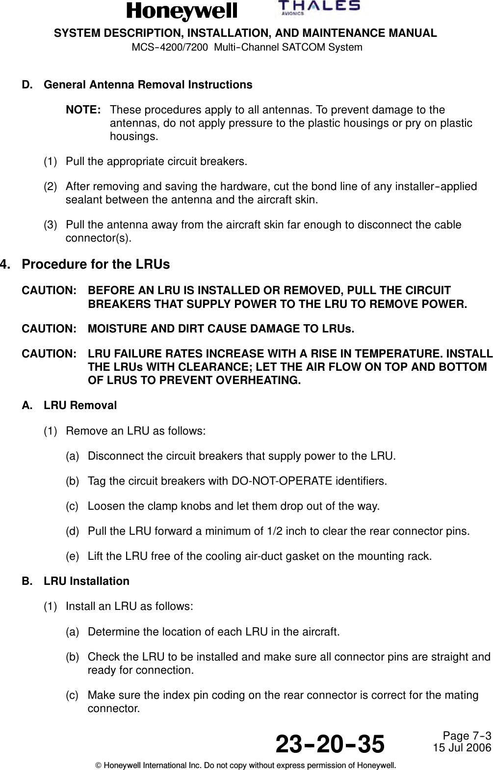
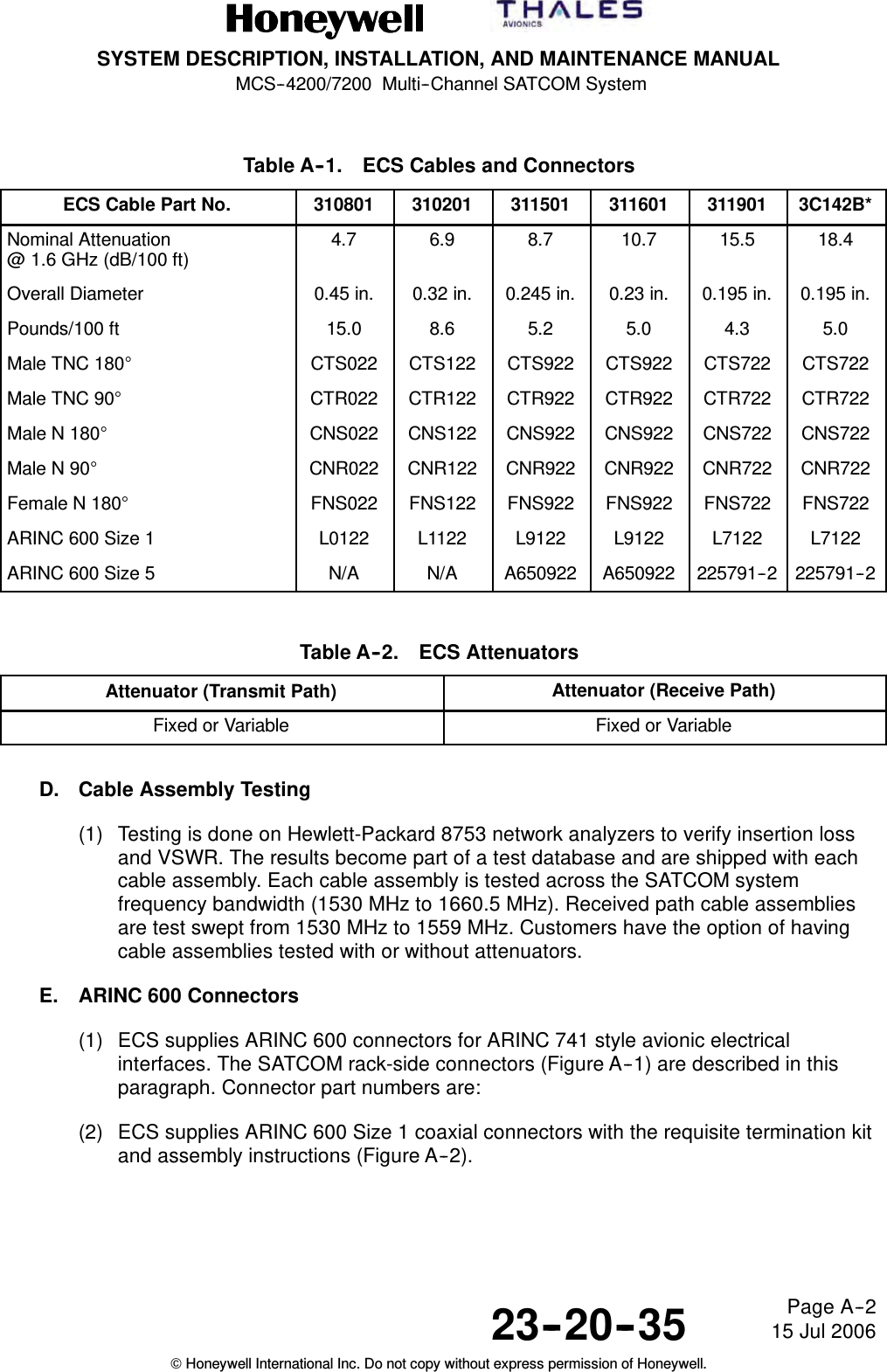
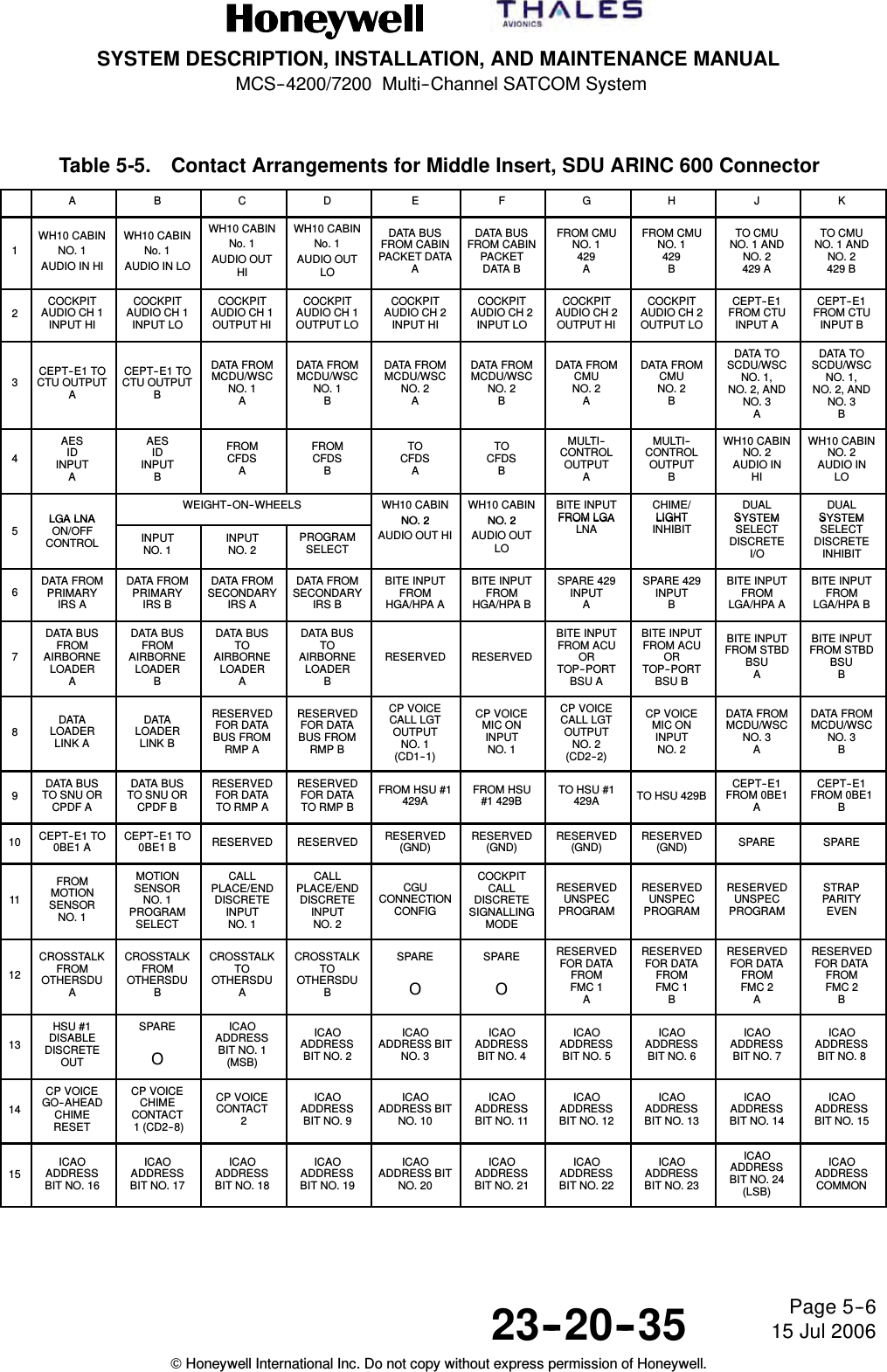
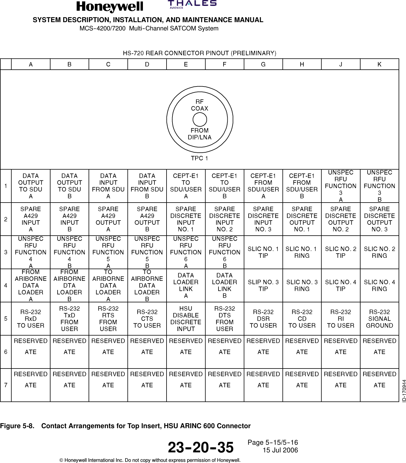
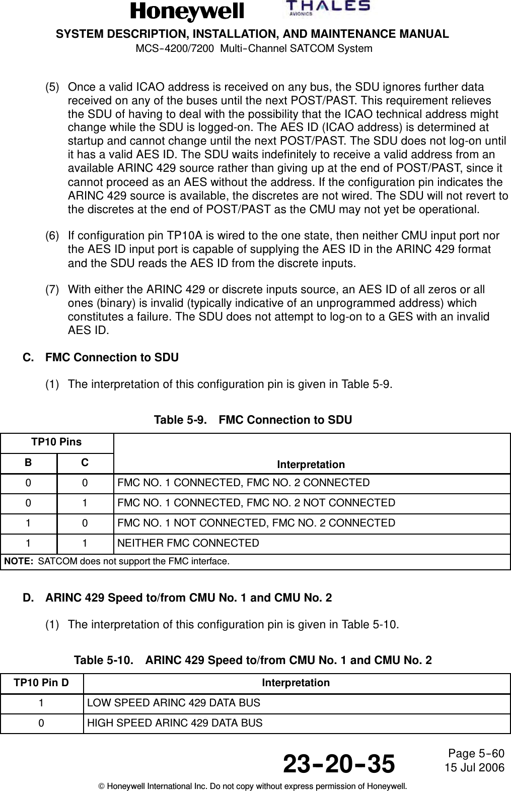
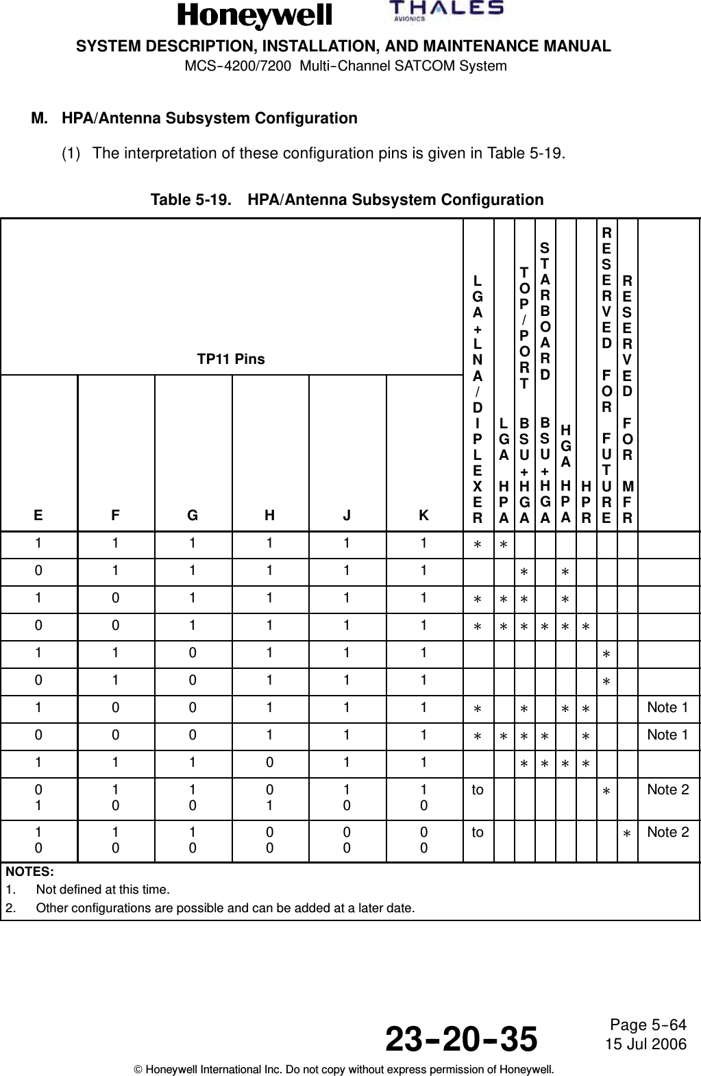
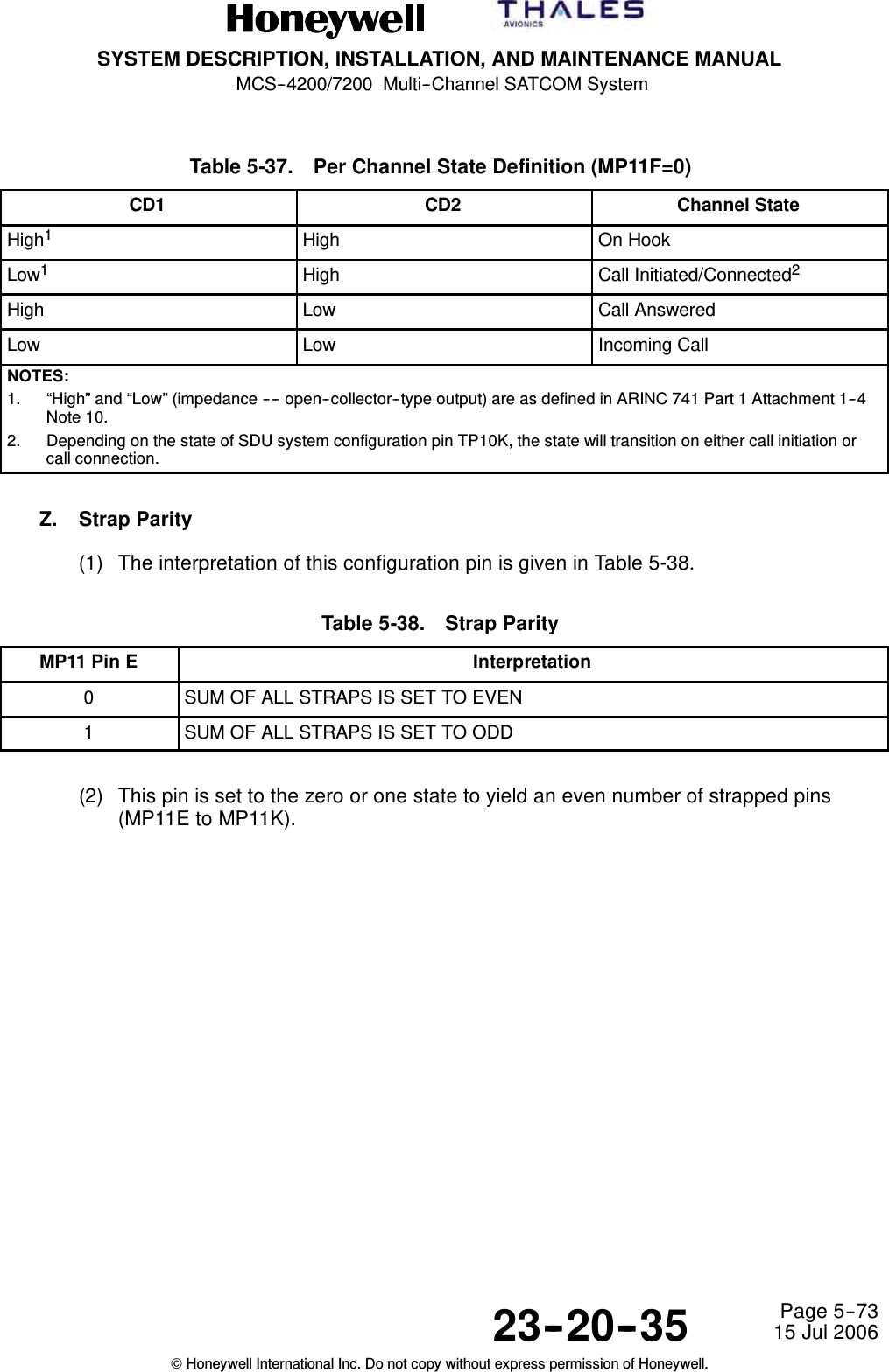
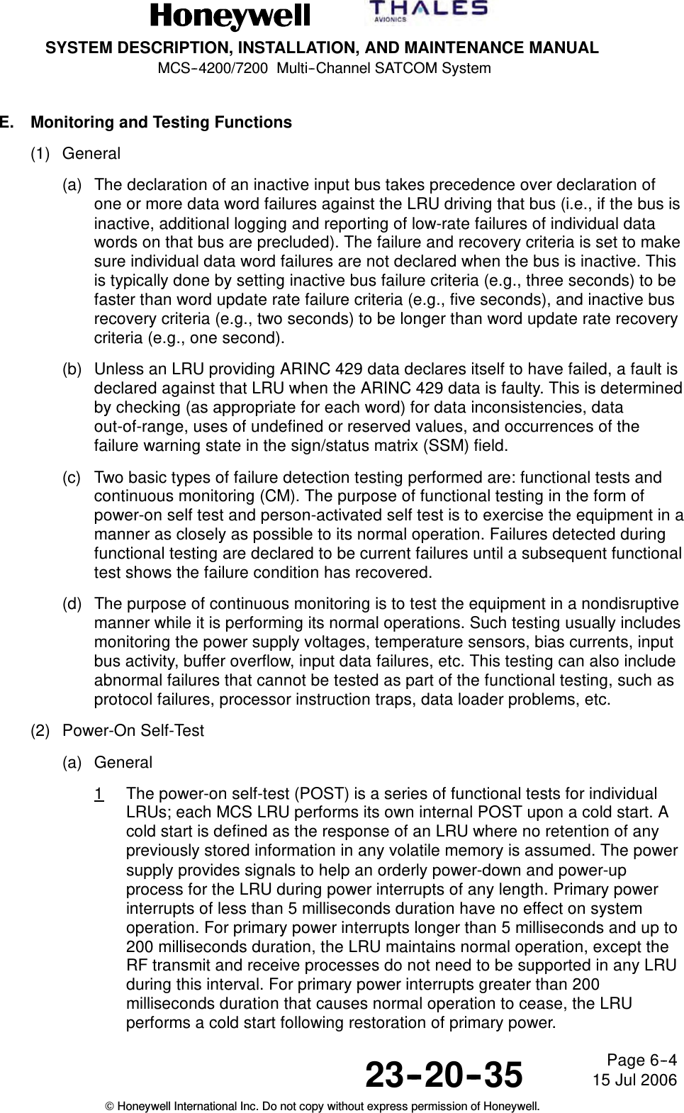
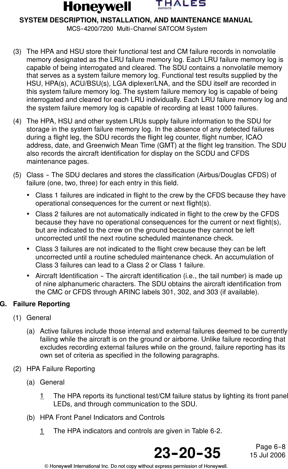
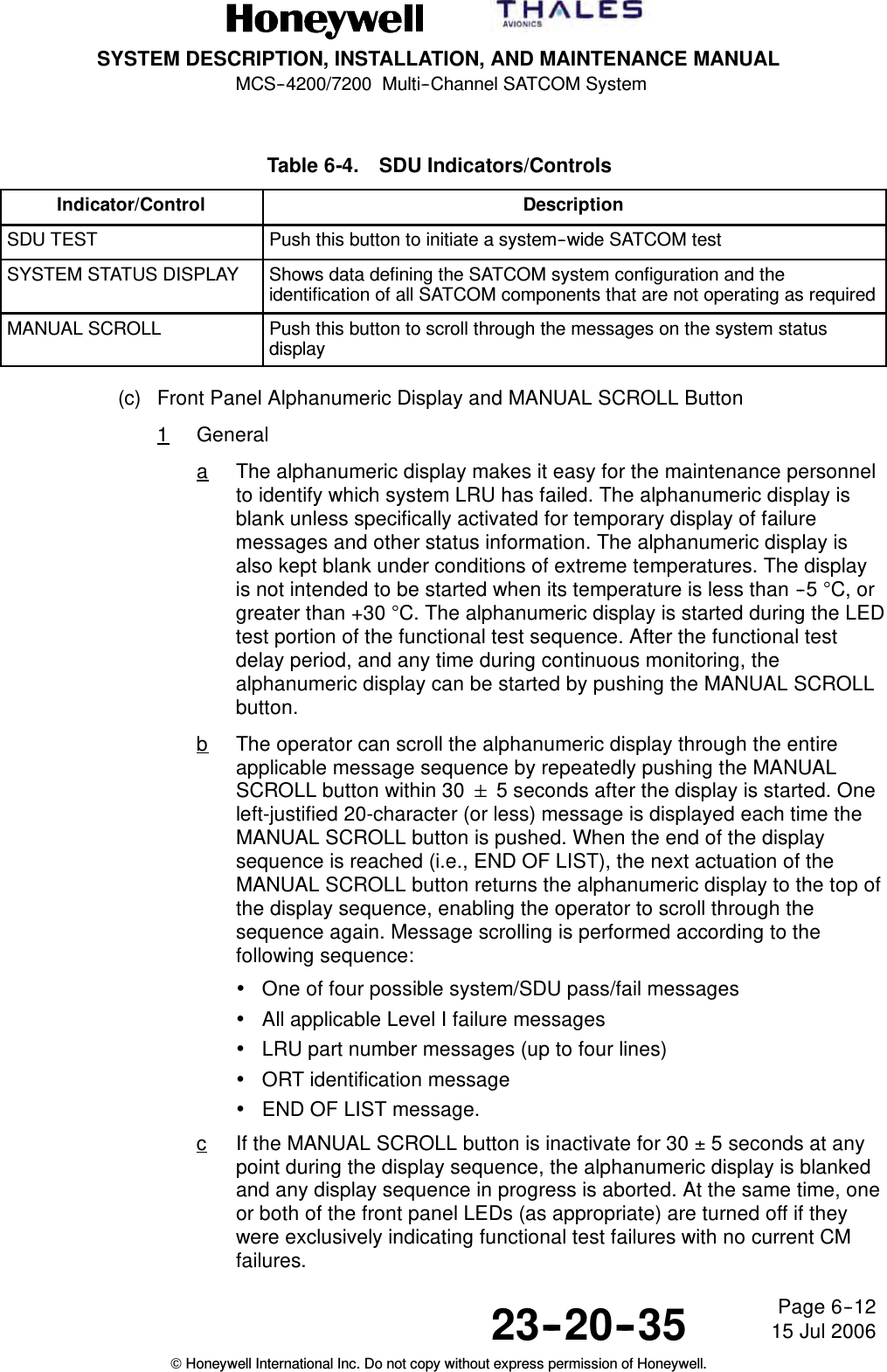
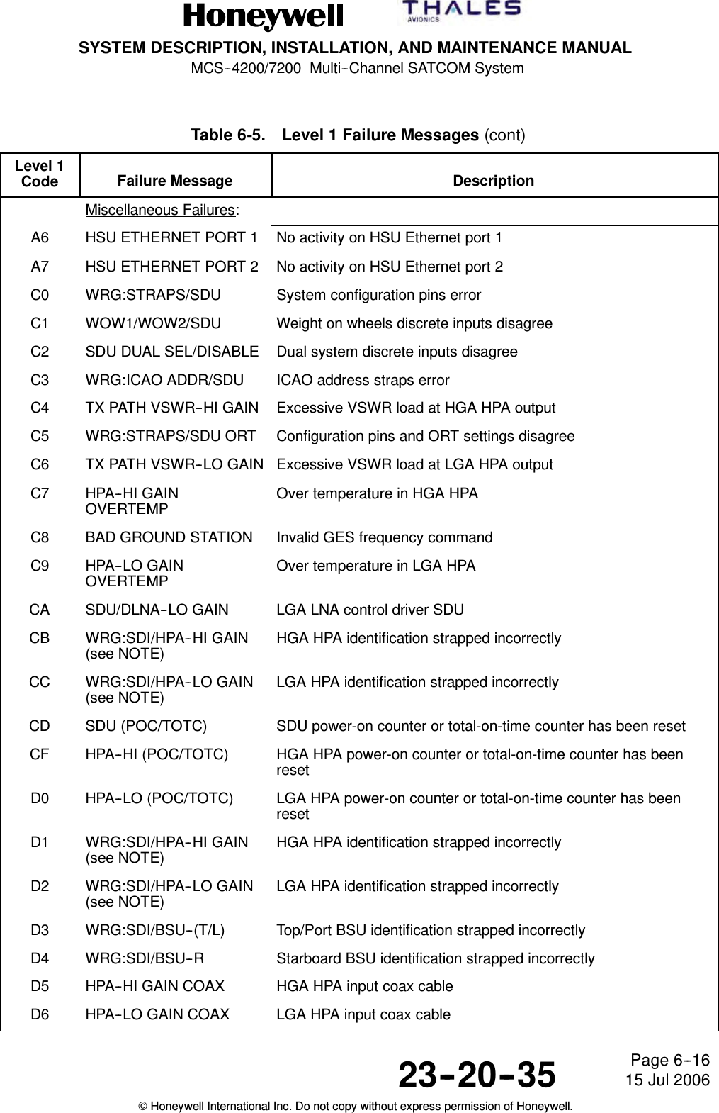
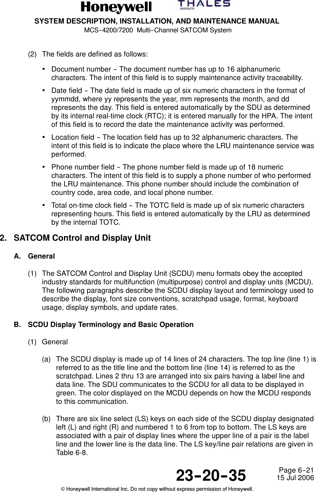
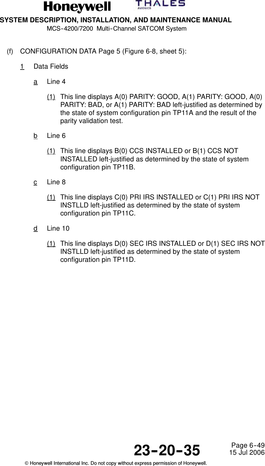
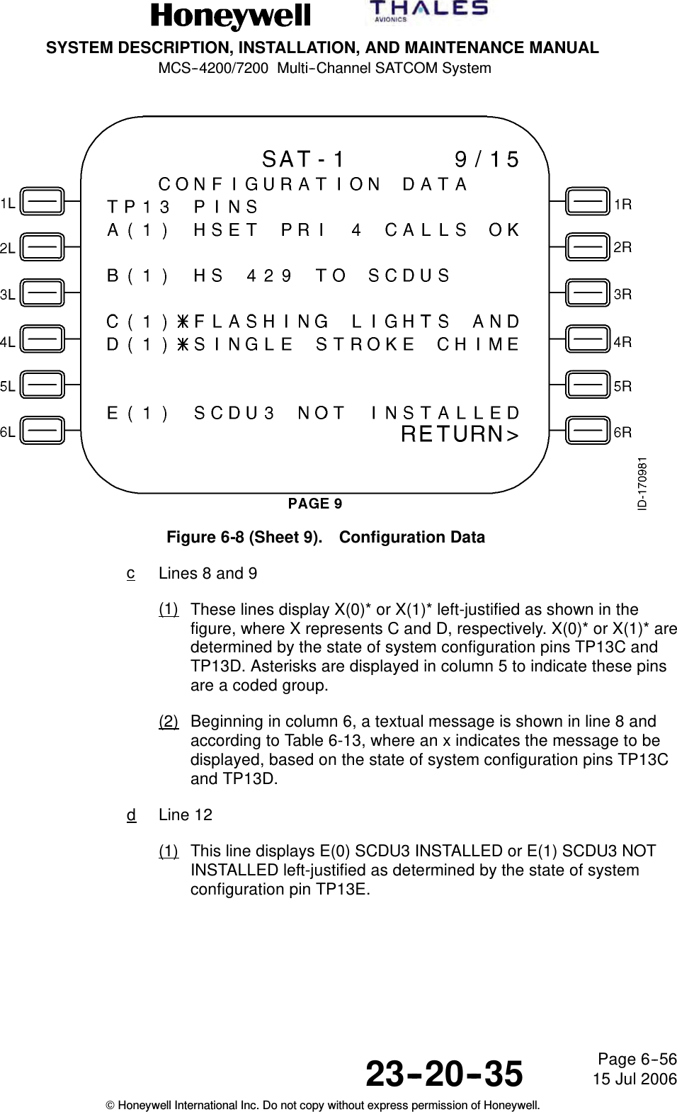
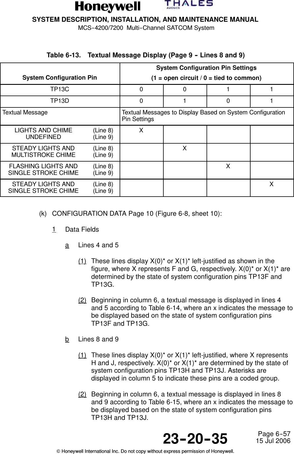
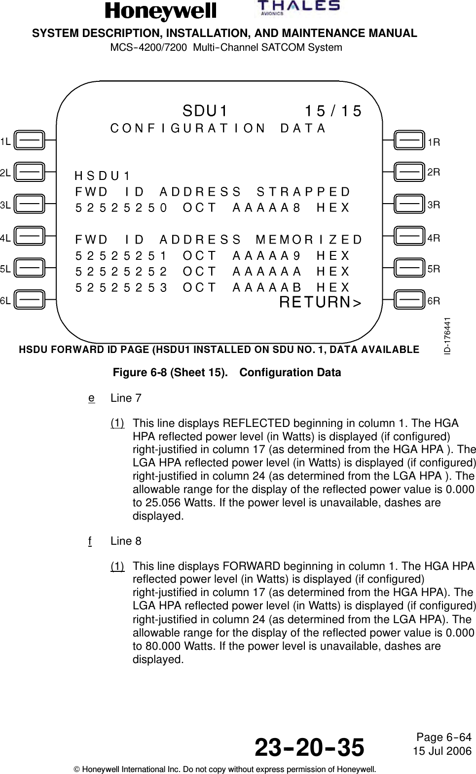
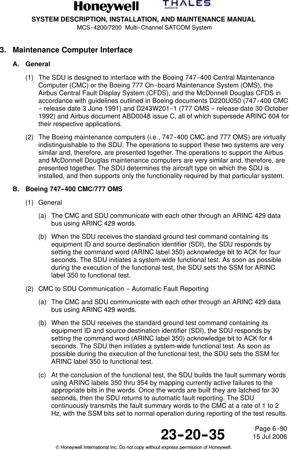
![SYSTEM DESCRIPTION, INSTALLATION, AND MAINTENANCE MANUALMCS--4200/7200 Multi--Channel SATCOM System23--20--35 15 Jul 2006Honeywell International Inc. Do not copy without express permission of Honeywell.Page 5--71(b) This configuration pin specifies the functionality of the SDU Cockpit VoiceMic-On Input No. 1 (and No. 2) discrete inputs (referred to as the mic-oninputs). When TP13K is wired to the one state, the SDU utilizes the switchedPTT and/or MCDU/SCDU line switch(es) (referred to as switched PTT) methodfor cockpit hookswitch signaling on the mic-on inputs. When TP13K is wired tothe zero state, the SDU utilizes the latched audio control panel SATCOMmicrophone switch (referred to as the latched ACP) method. These twomethods are described below.(2) Switched PTT Method(a) With the switched PTT method, the SDU assumes the mic-on inputs are wired toconventional microphone momentary push-to-talk switches (i.e., they aredynamically active [on/off] throughout the duration of the call). The SDUassumes the air- or ground-initiated call annunciation to have beenacknowledged (i.e., the call to be in the off-hook state) when the appropriatemic-on input is activated (connected to ground) for the first time after the callannunciation for a particular channel. Successive activations of that mic-on inputfor the duration of that call have no effect on the status of that call until the callhas been cleared.(b) With the switched PTT method, the off-hook state is also entered followingactivation of the Answer Call line select switch on the MCDU/SCDU. Theon-hook state is entered following activation of the End Call line select switch onthe MCDU/SCDU that results in call clearing.(c) This method also allows usage of the place/end call discrete input andassociated switch to initiate calls to preselected numbers, as well as to terminateexisting calls.(3) Latched ACP Method(a) With the latched ACP method, the SDU assumes the mic-on inputs are wired toSATCOM microphone select switches on the ACP that are latched on(connected to ground) for the entire duration of a call. The SDU considers theair- or ground-initiated call annunciation to have been acknowledged (i.e., thecall to be in the off-hook state) when the appropriate mic-on input is active(connected to ground) for a particular channel. The call is cleared and thechannel is considered to be in the on-hook state when the mic-on input is in theopen-circuit state.(b) With the latched ACP method, all hookswitch signaling for answering andterminating all air- and ground-initiated calls is handled by the mic-on inputs; theMCDU/SCDU Answer Call and End Call options are blanked (the MCDU/SCDUis only necessary for specifying the called-party number and initiating the callprocess for air-to-ground calls).(c) This method also allows usage of the mic--on discrete input and switch to initiatecalls to preselected numbers.](https://usermanual.wiki/Honeywell/HS-720.HS-720-User-Manual-Part2/User-Guide-1350371-Page-58.png)

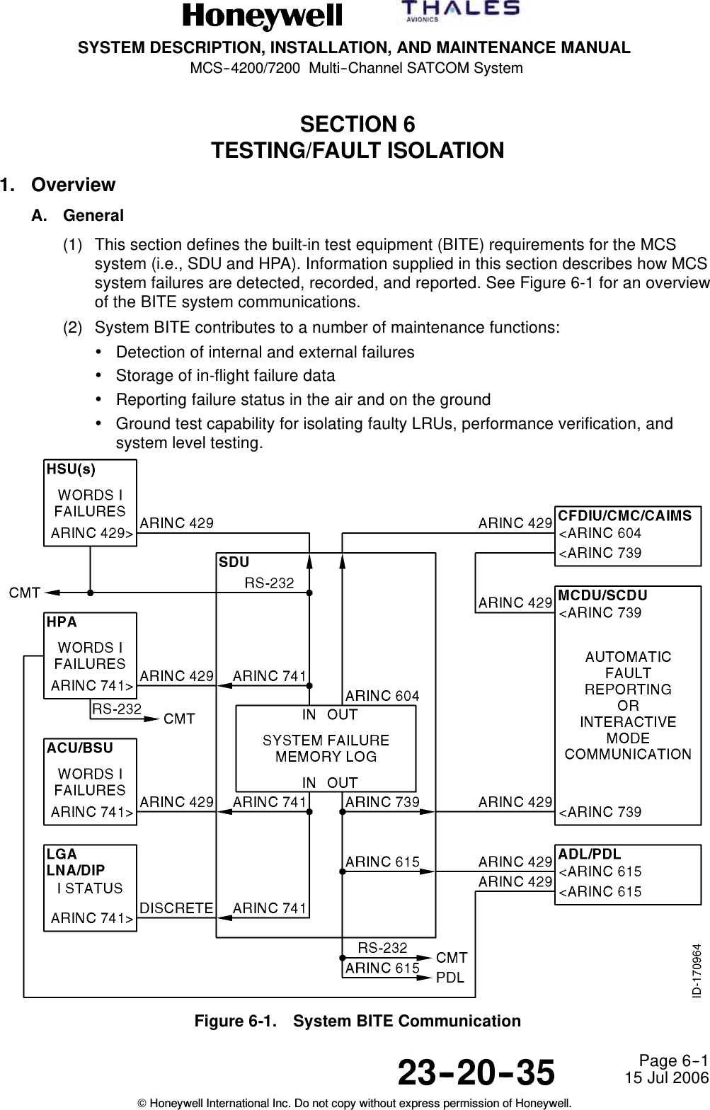
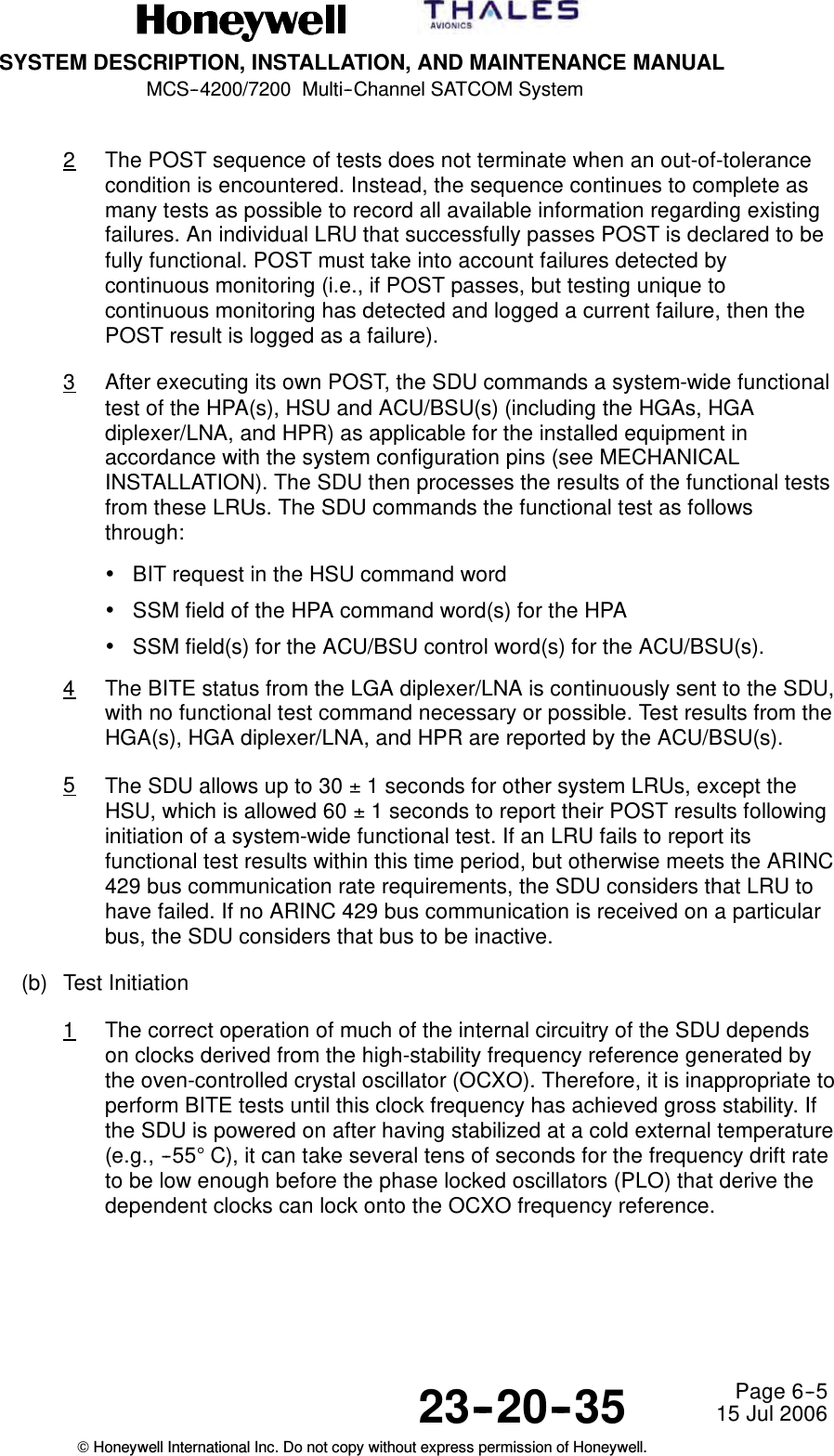
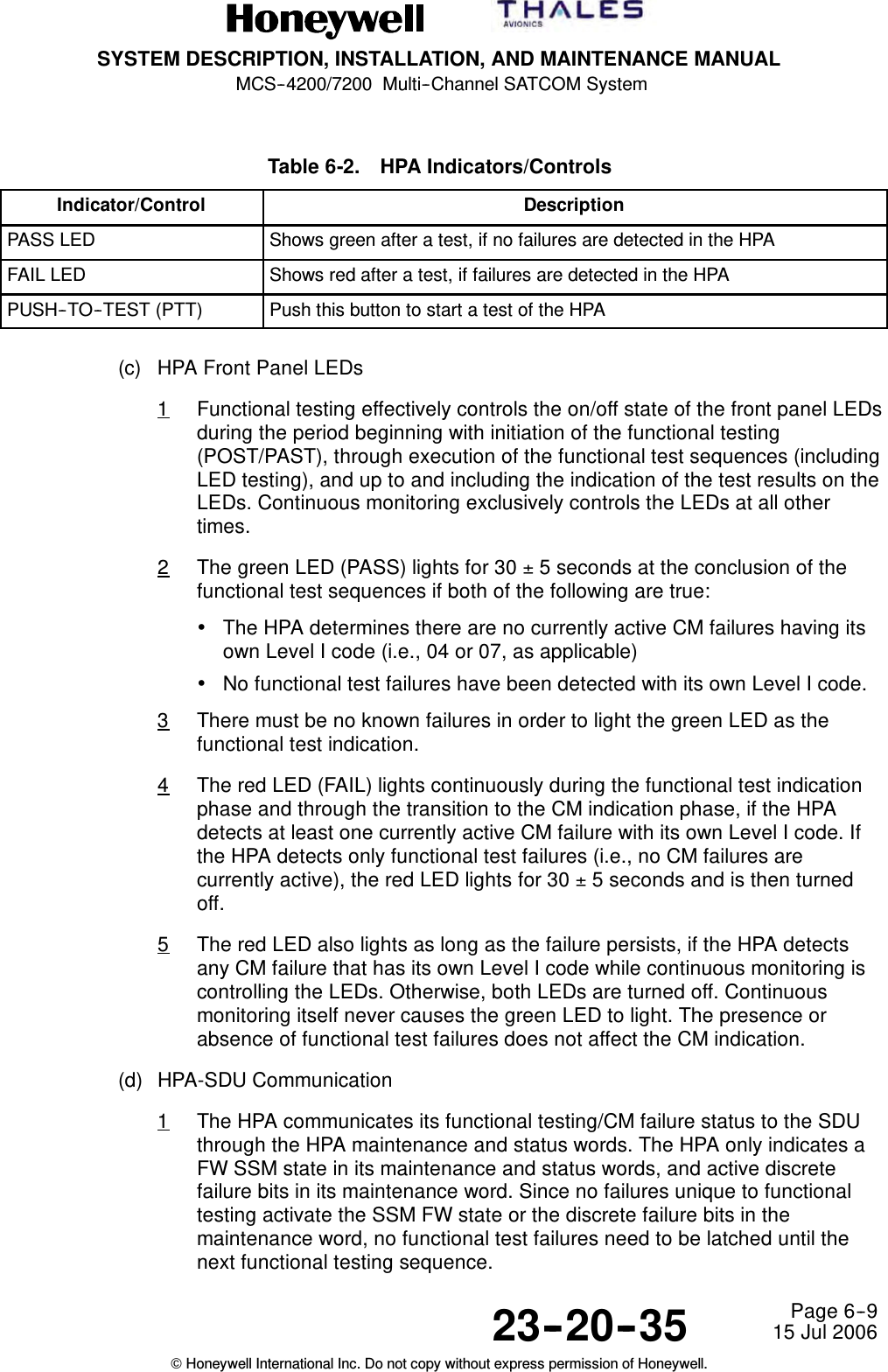
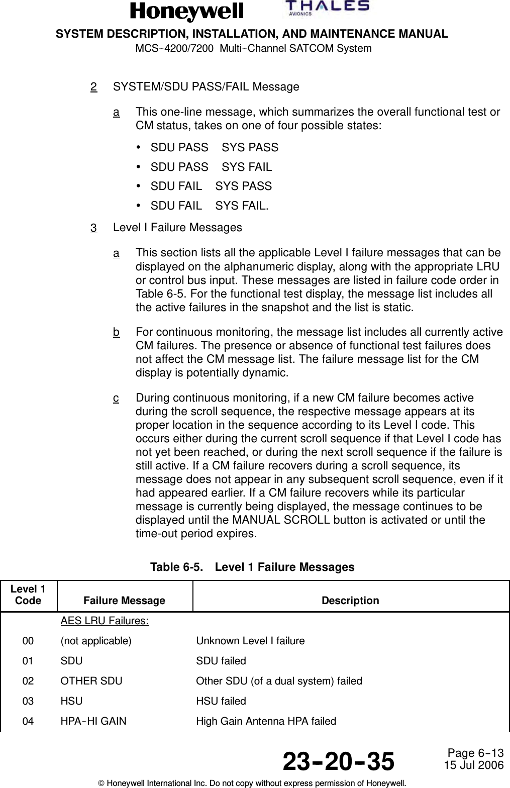

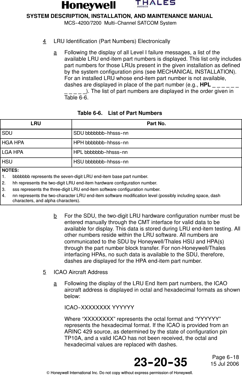
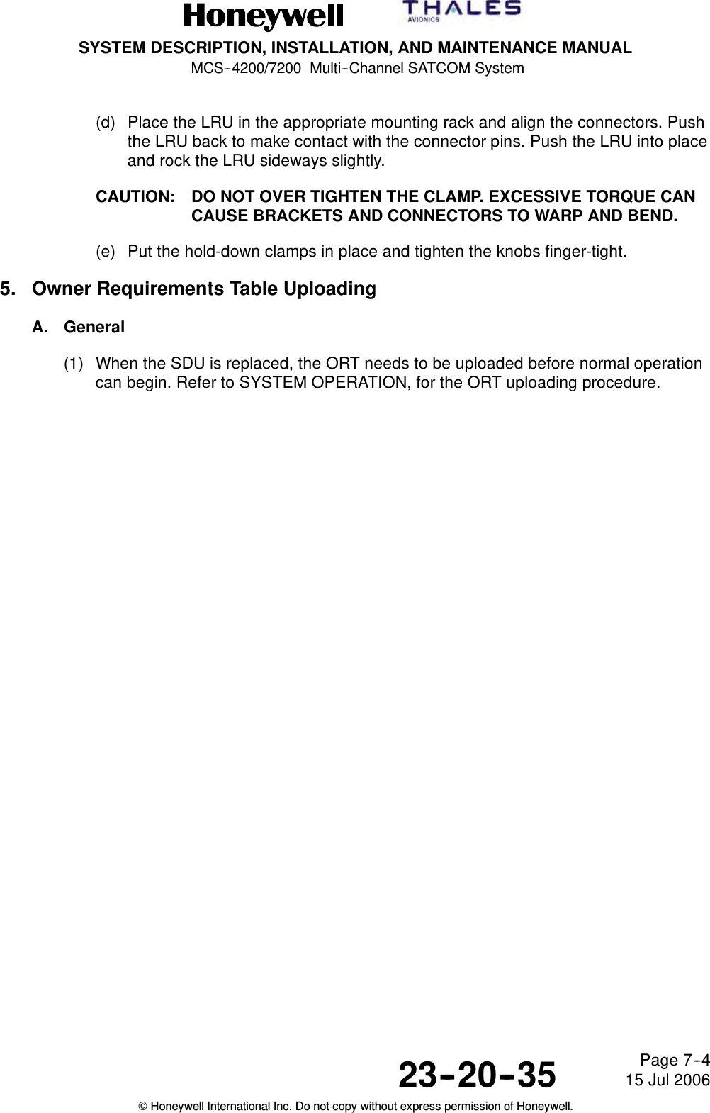
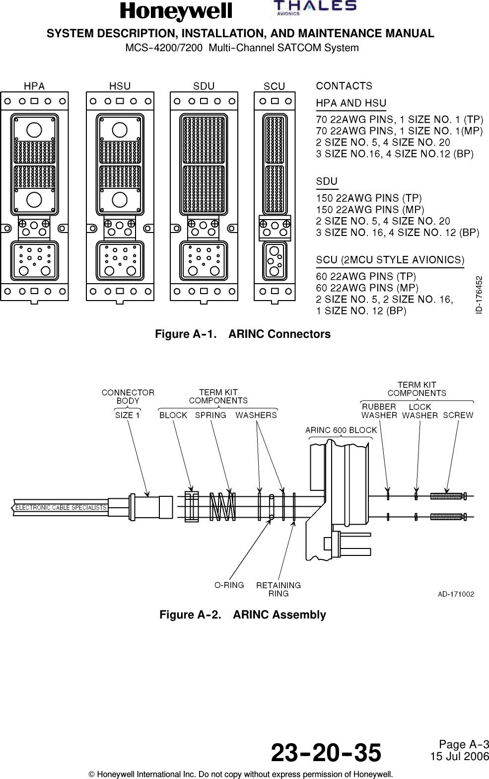
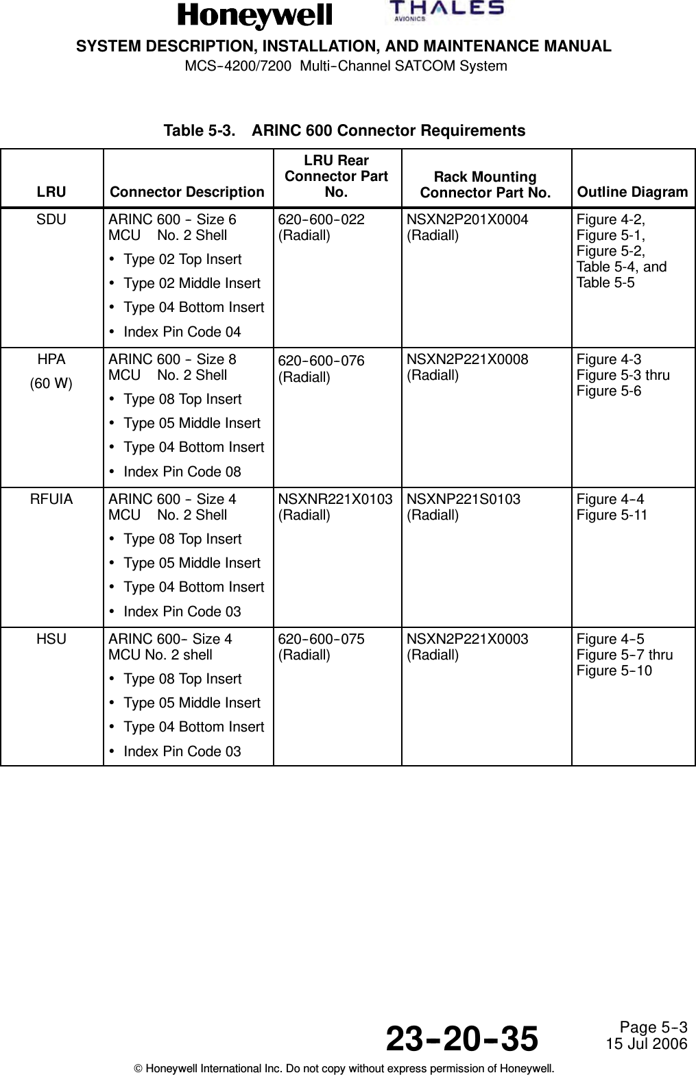
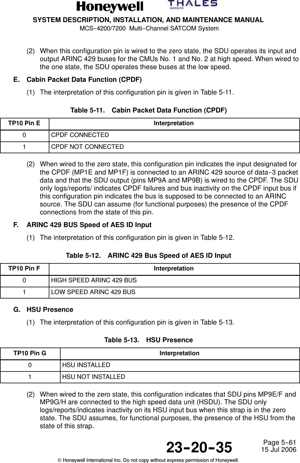
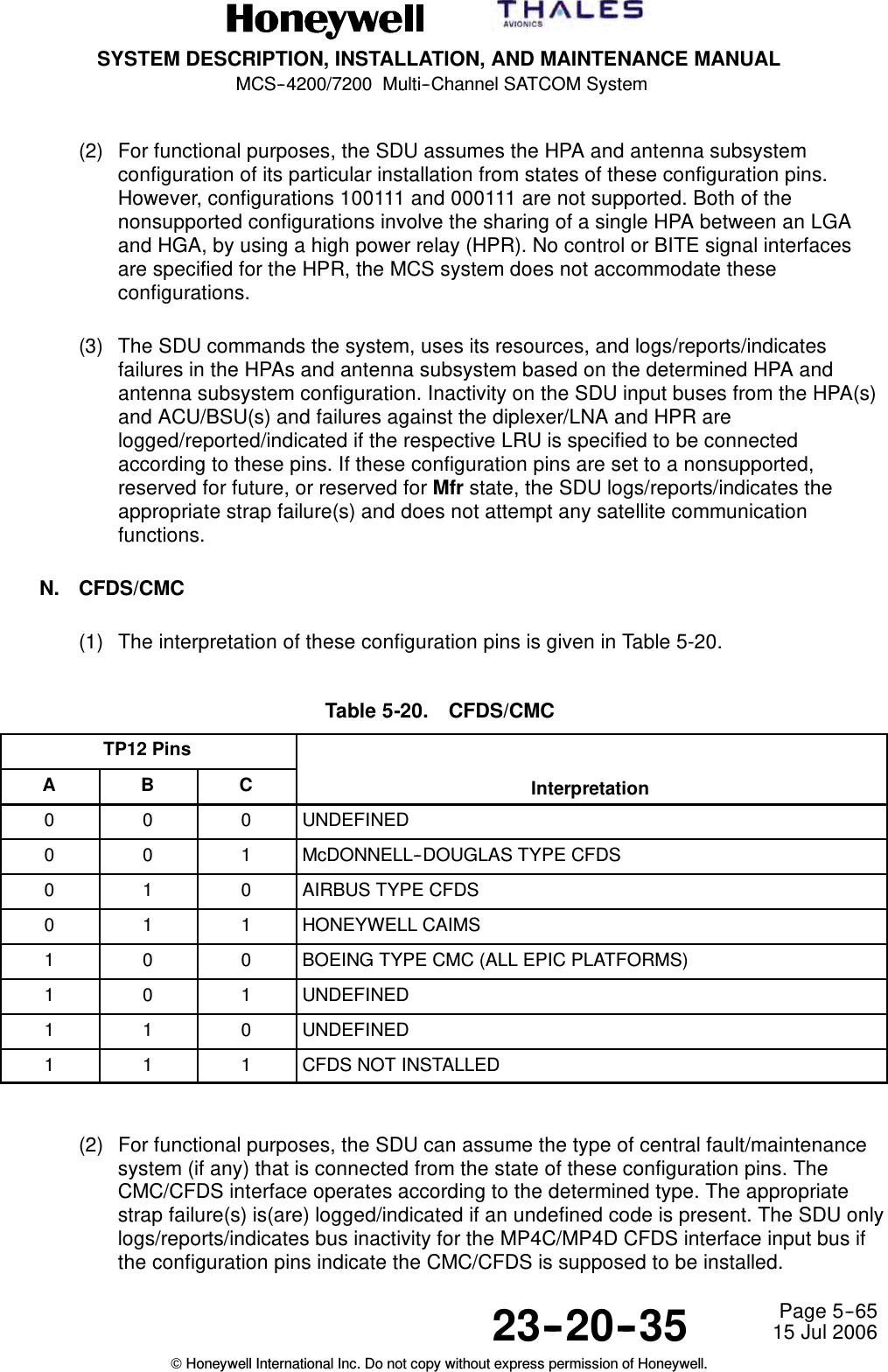
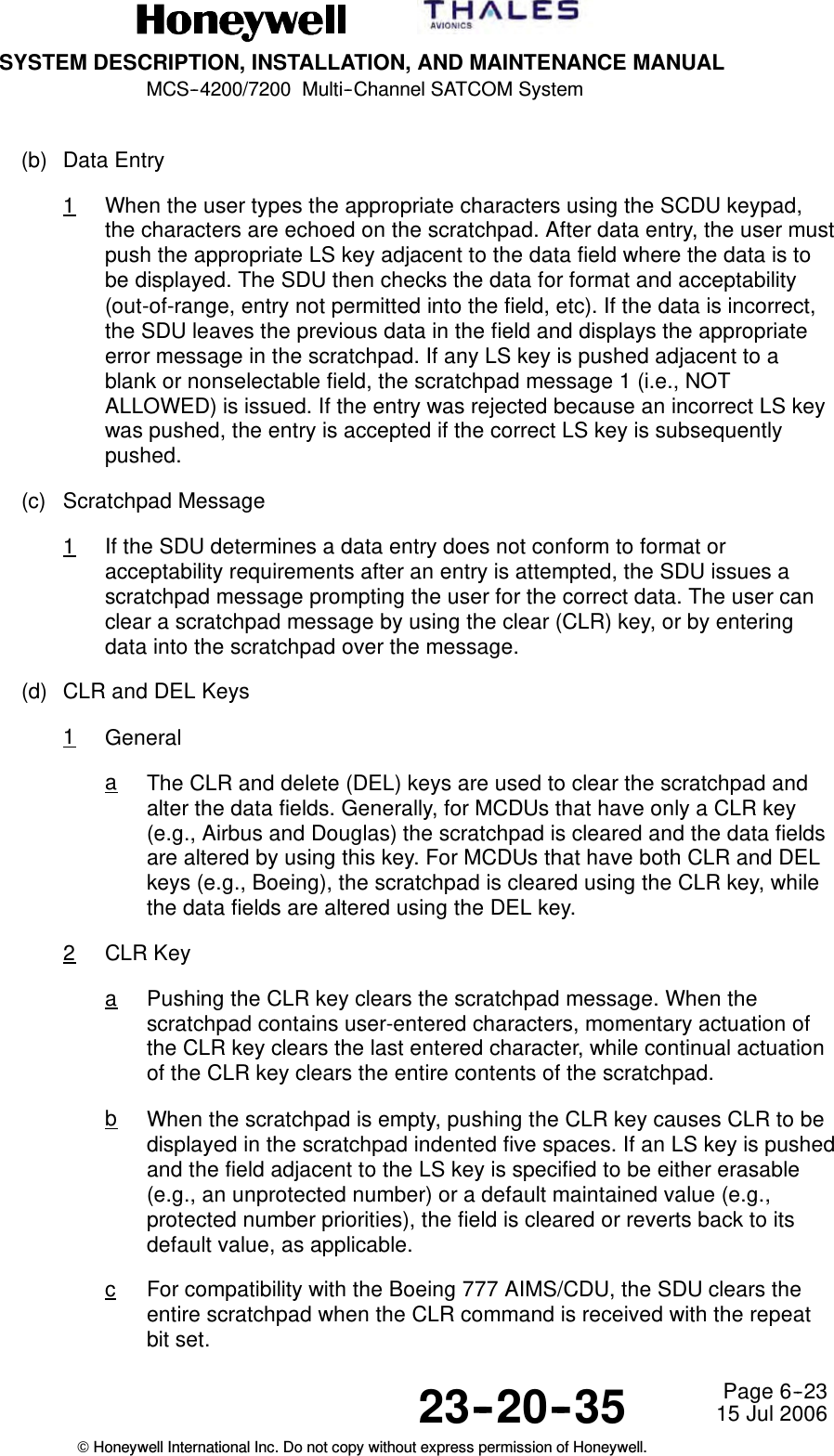
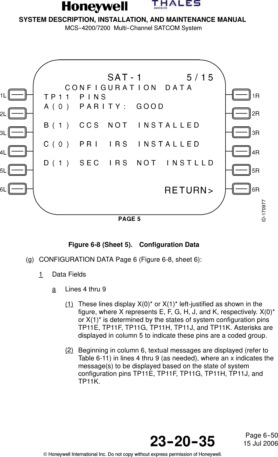
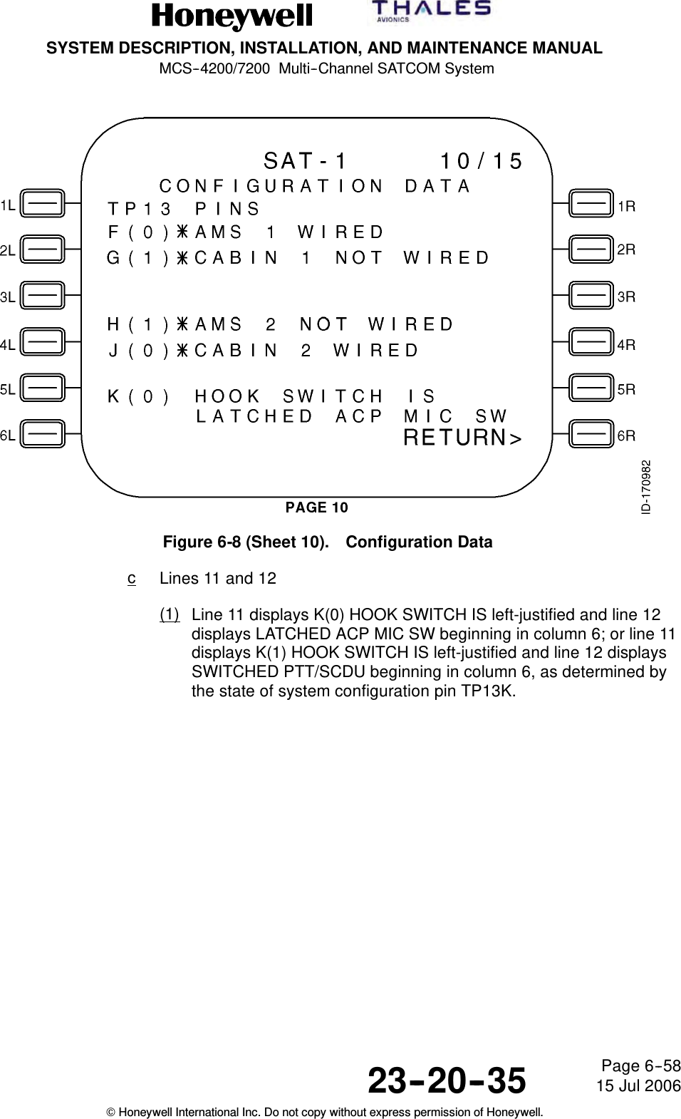
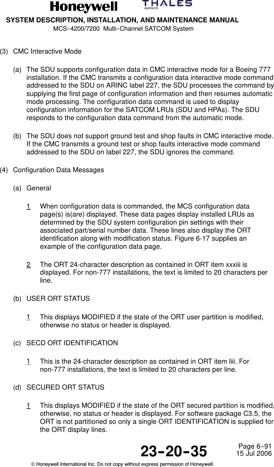
![SYSTEM DESCRIPTION, INSTALLATION, AND MAINTENANCE MANUALMCS--4200/7200 Multi--Channel SATCOM System23--20--35 15 Jul 2006Honeywell International Inc. Do not copy without express permission of Honeywell.Page 6--22(c) The SCDU can display a large and small font size. Different character fonts arenot shown in the example SCDU page figures given in this section. The use oflarge font is indicated by the presence of uppercase letters in the SCDU pagefigures, while the use of small fonts are demonstrated by lowercase letters. Ingeneral, page names displayed in the title line are in large font. For pages wherep/t is specified to be displayed in the title line, the p/t is in small font. Dataentered into the scratchpad is displayed in large font. Data in the label lines isdisplayed in small font, while data in the data lines is displayed in large font.Numerical character font sizes cannot be shown in the figures, but their fontsizes follow the same conventions.Table 6-8. LS Key/Line Pair RelationsLS Keys Display Lines1L -- 1R 2 and 32L -- 2R 4 and 53L -- 3R 6 and 74L -- 4R 8 and 95L -- 5R 10 and 116L -- 6R 12 and 13(d) Labels on the left side of the SCDU display are displayed beginning in column 2of the label line. Data on the left side is left-justified in the data line. Labels anddata on the right side of the SCDU display is right-justified. This is the caseunless specified otherwise.(2) Scratchpad(a) General1The scratchpad is used for data entry and displaying SDU generatedmessages. Pushing an alphanumeric key on the keypad (0 through 9, Athrough Z, +/-- [plus or minus], / [slash, space]) enters that character into thescratchpad. The scratchpad is not used for fixed format display purposes.The mechanism used for data entry is described below.](https://usermanual.wiki/Honeywell/HS-720.HS-720-User-Manual-Part2/User-Guide-1350371-Page-83.png)
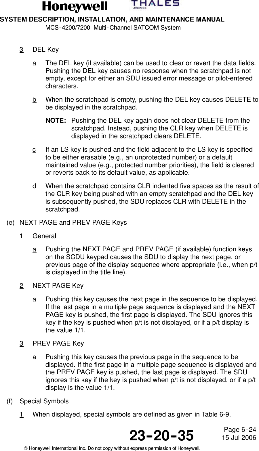
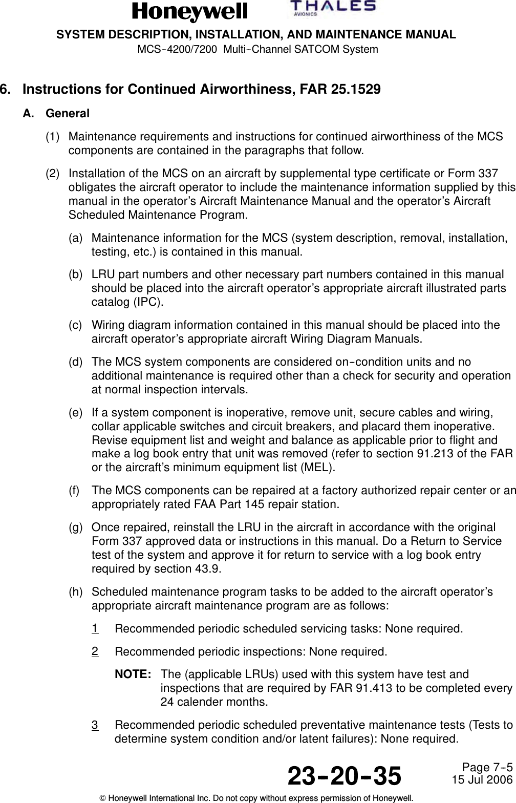
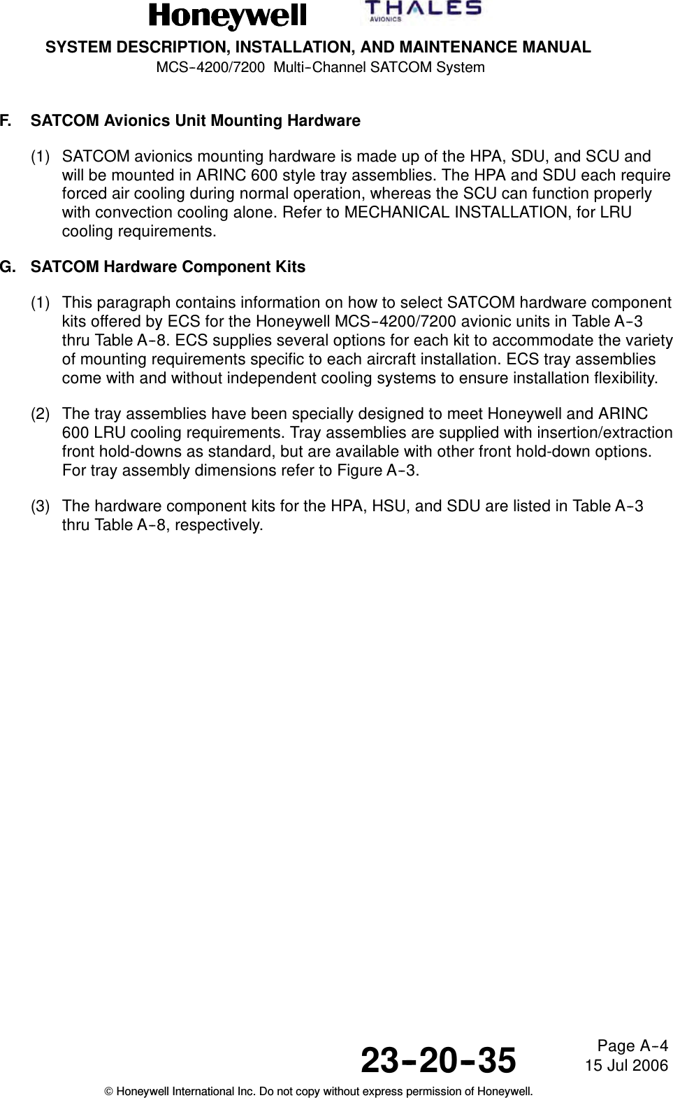
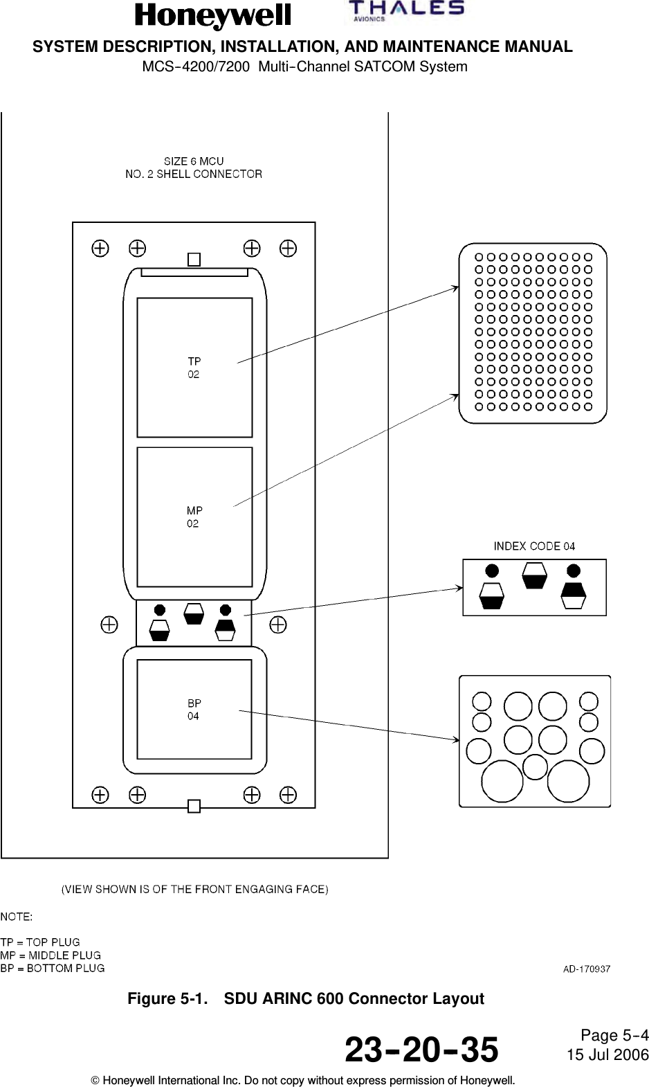
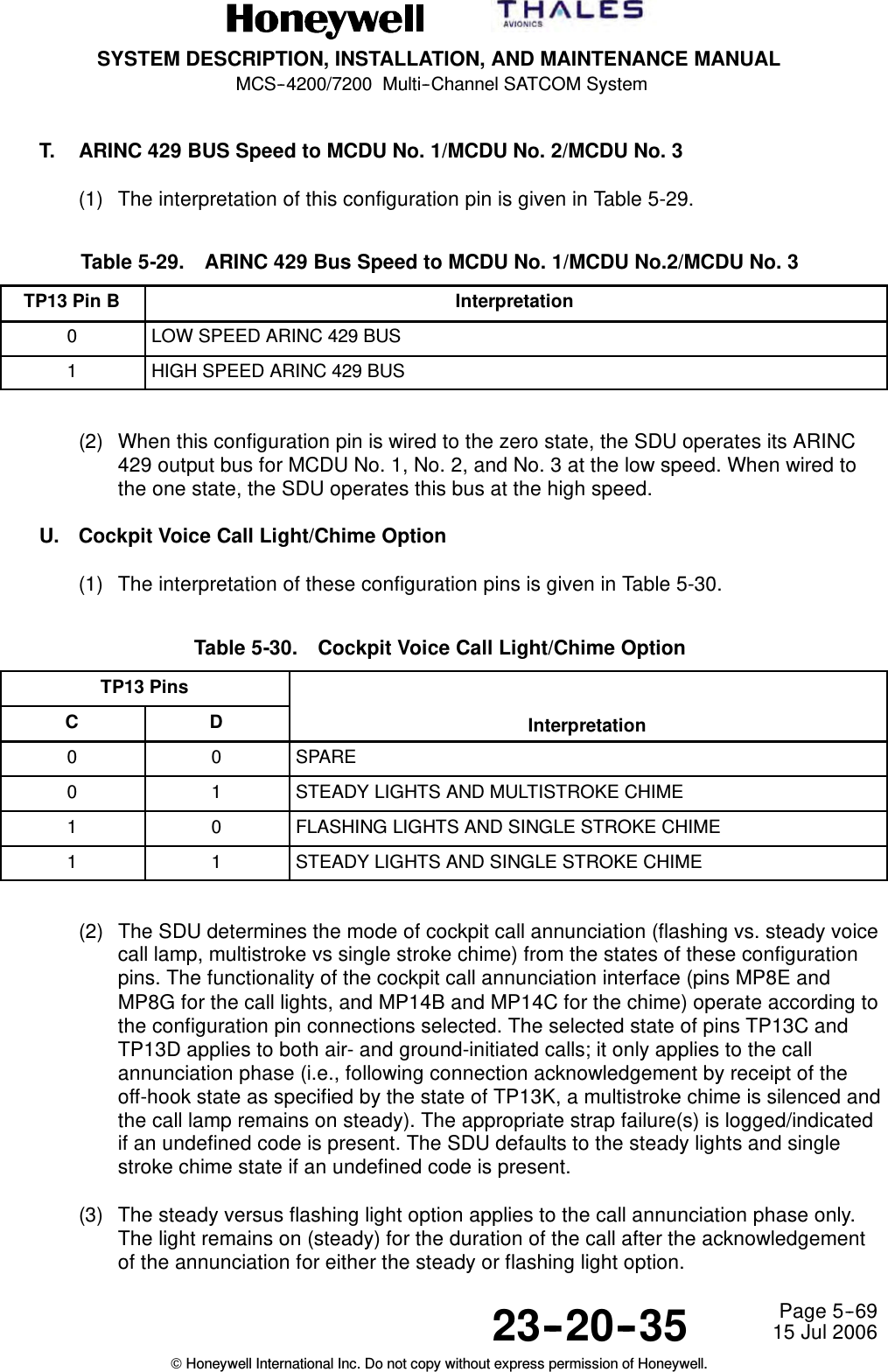
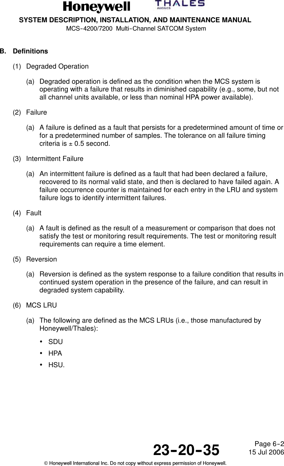
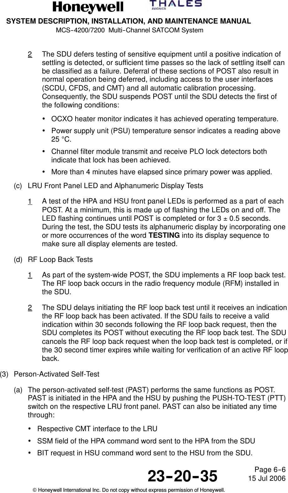
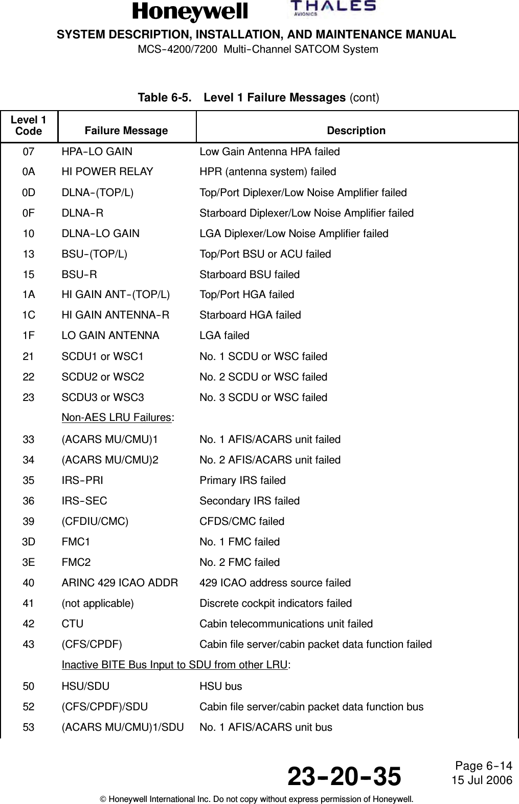
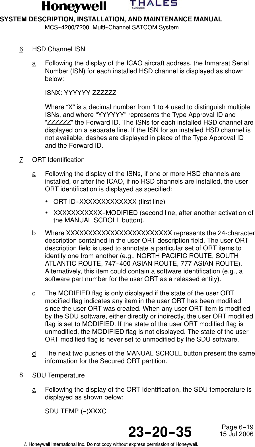
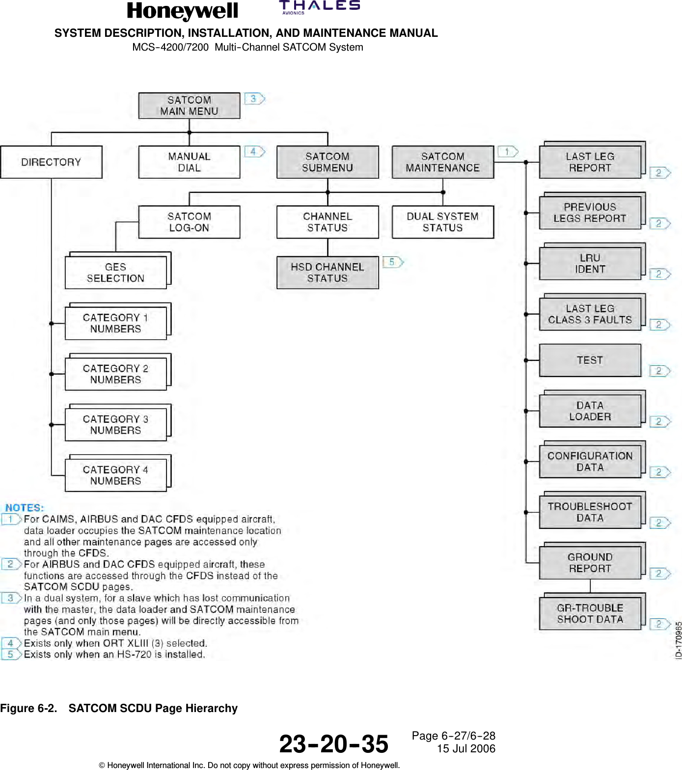
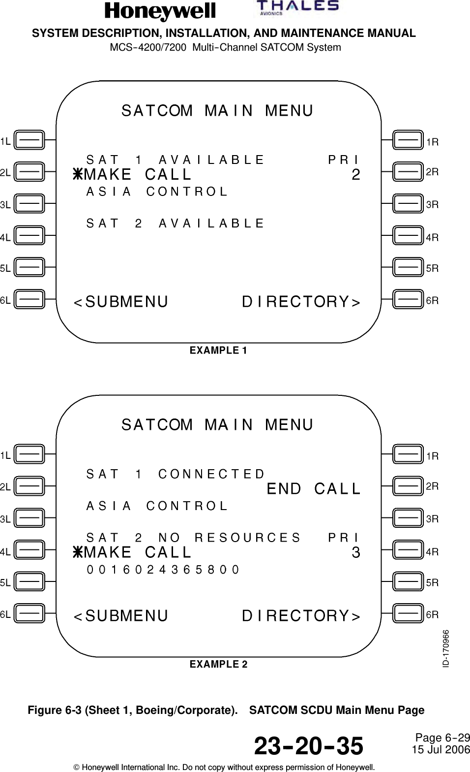
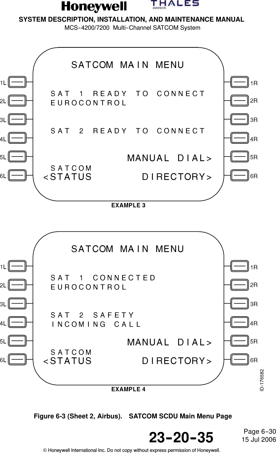
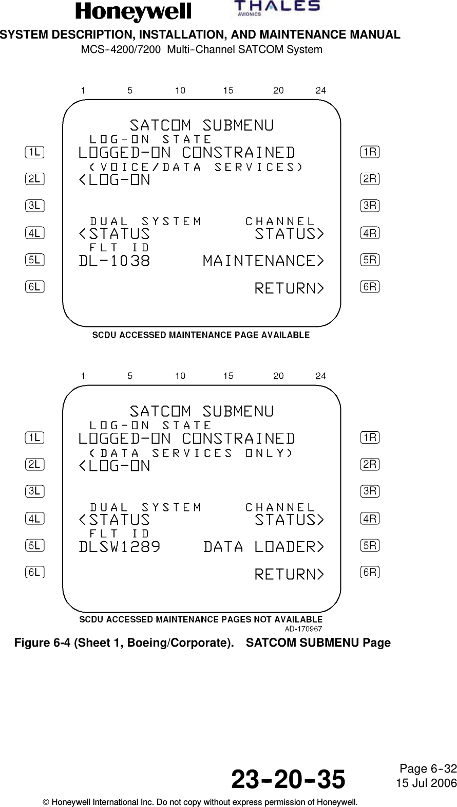
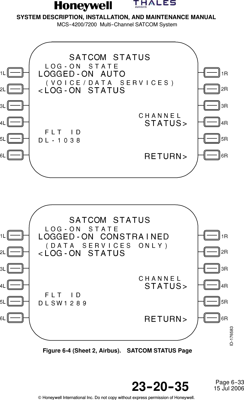
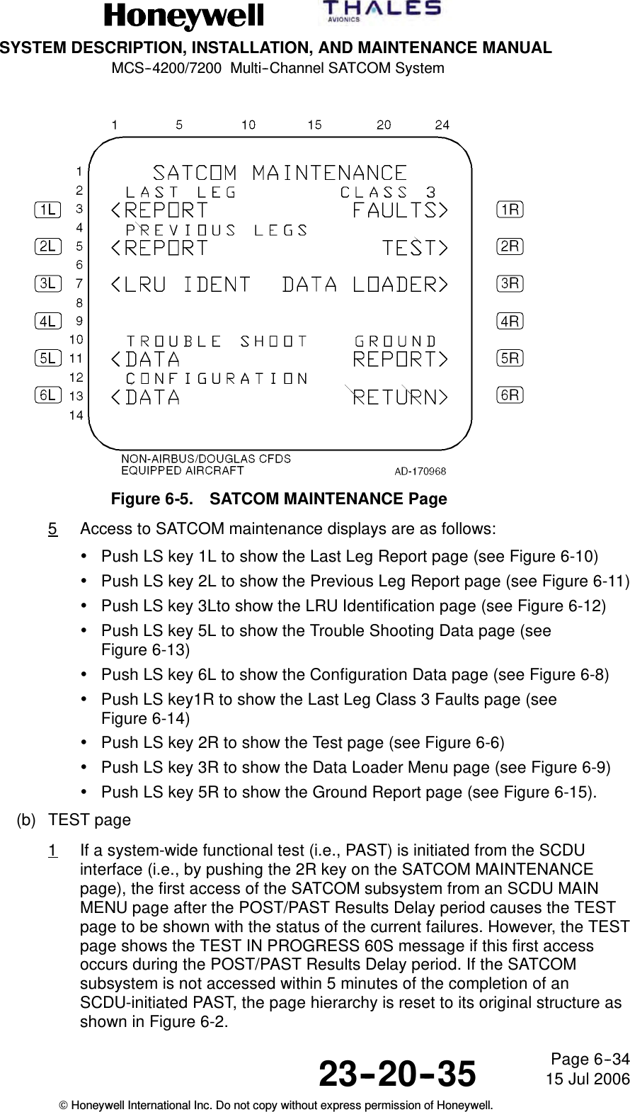
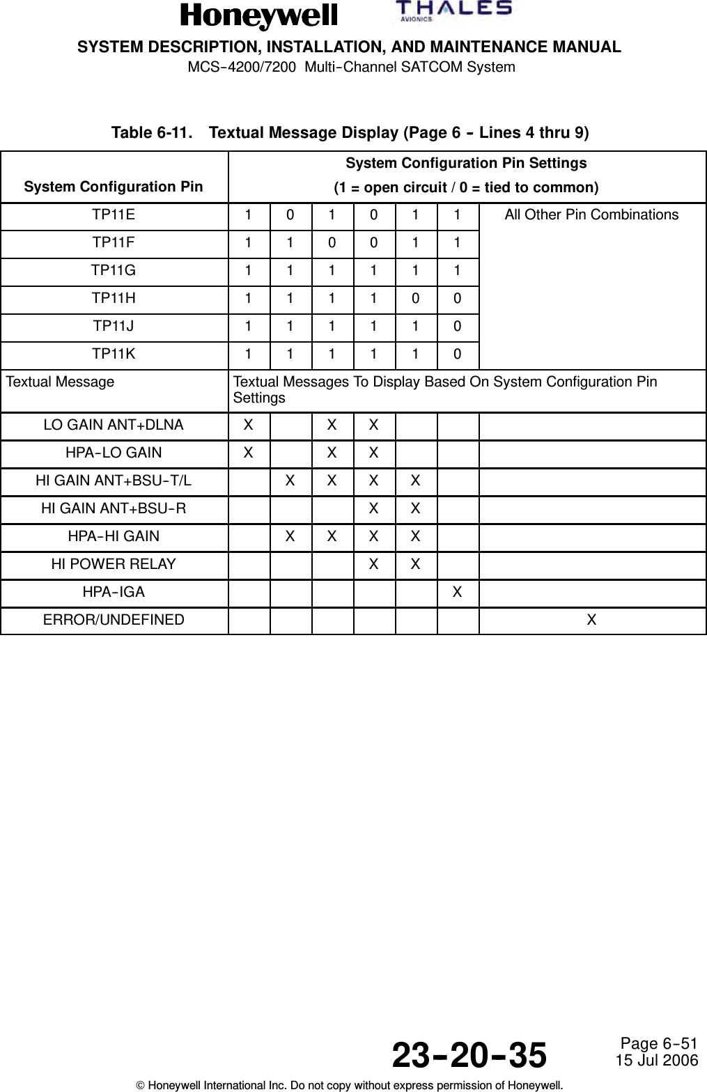
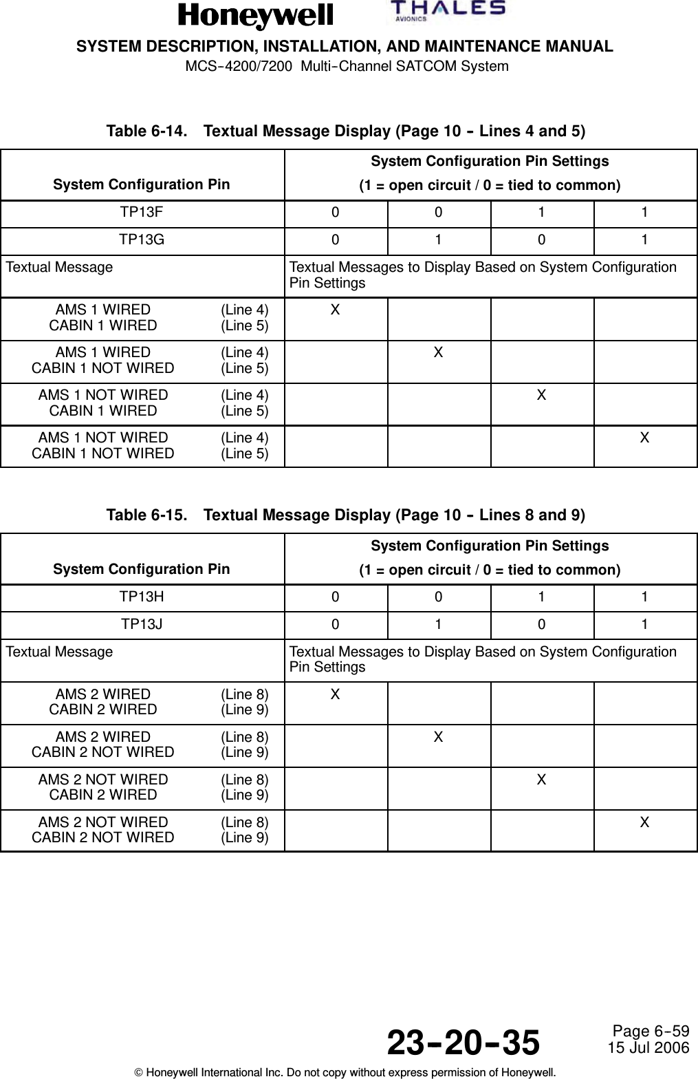
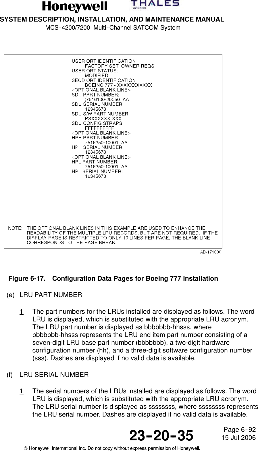
![SYSTEM DESCRIPTION, INSTALLATION, AND MAINTENANCE MANUALMCS--4200/7200 Multi--Channel SATCOM System23--20--35 15 Jul 2006Honeywell International Inc. Do not copy without express permission of Honeywell.Page 6--25Table 6-9. Special SymbolsSymbol Description* (Asterisk) Pushing the LS key adjacent to this symbol (when it appears) causes anaction of some kind to occur (e.g., making a phone call, sorting a phonelist, or initiating log-off).[ ] (Brackets) Empty brackets prompt the user for data entry into the field. However, dataentry is not mandatory. Brackets surrounding data indicate the data isunprotected and can be modified or deleted. Not all fields modifiable aresurrounded by brackets. When brackets are used to enclose existing data,as opposed to prompting entry of data into an empty field, they areintended as an indication the data is unprotected (i.e., an unprotectedphone number). Conversely, protected phone numbers do not havebrackets, indicating the phone number cannot be modified or deleted.<,>(Carets) A caret adjacent to an LS key indicates if the key is pushed the displaychanges to a new page. The new page is either the one indicated next tothe caret or, in case of RETURN>, the higher level page.<SEL> Indicates the data in the field is currently selected (e.g., the selected GESor antenna).(g) Updates1Dynamically generated display fields, whose contents have changed, areupdated by the SDU both periodically (at a rate of at least 1 Hz), and uponcompletion of an LS key action that could have caused the display or thedisplay field to change. With multiple SCDU configurations, the SDU onlymaintains one version of each page for display. The SDU responds to LSkey actuations from all SCDUs in a serial fashion and updates the displaypage(s). Each SCDU scratchpad and the channel selection fields areindependent from all others, allowing each user to perform independentactions.C. SCDU Page Hierarchy(1) The SCDU page hierarchy is shown in Figure 6-2. The SATCOM MAIN MENU pageis accessed by pushing the LS key adjacent to <SAT for single SDU installations.Highlighted blocks in Figure 6-2 represent maintenance pages that are discussed indetail in paragraph D. Refer to the appropriate MCS SATCOM System Guide foradditional non highlighted SATCOM displays.D. SCDU Pages(1) SATCOM MAIN MENU Page(a) Access to this page is from the MCDU MAIN MENU page. The purpose of thispage is to display call status information, to optionally make, answer, andterminate calls, and to supply access to lower level pages. See Figure 6-3 forexample pages.](https://usermanual.wiki/Honeywell/HS-720.HS-720-User-Manual-Part2/User-Guide-1350371-Page-86.png)

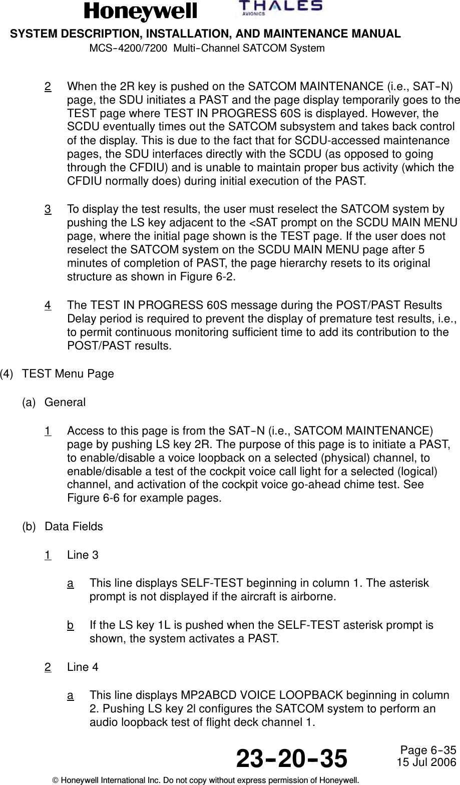
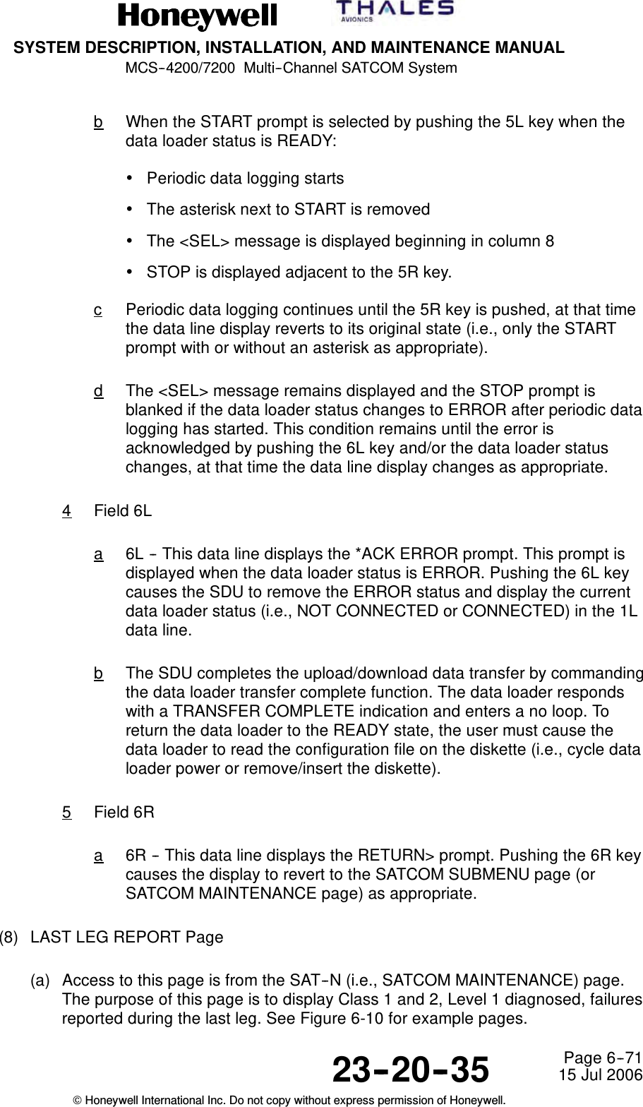
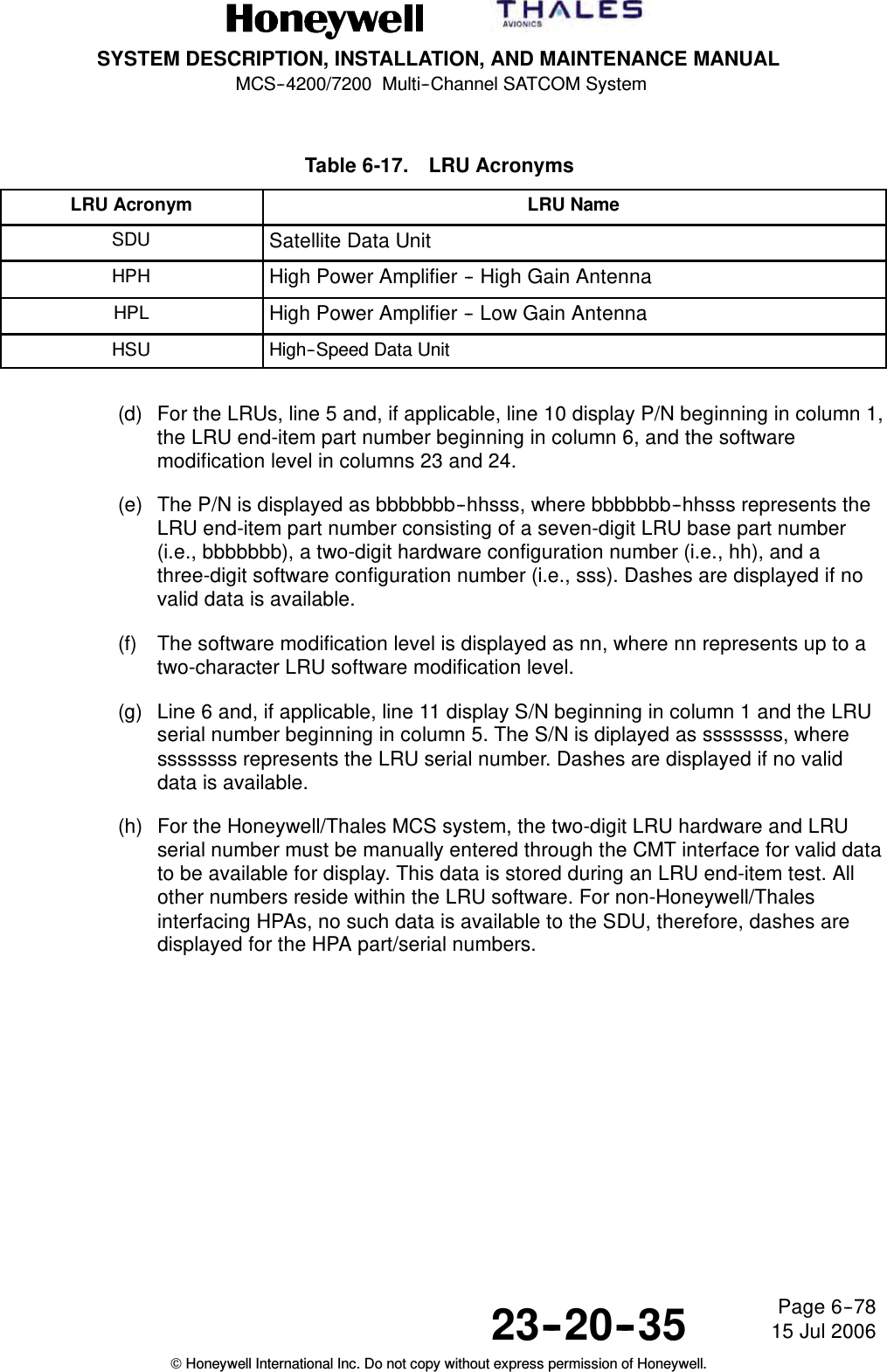

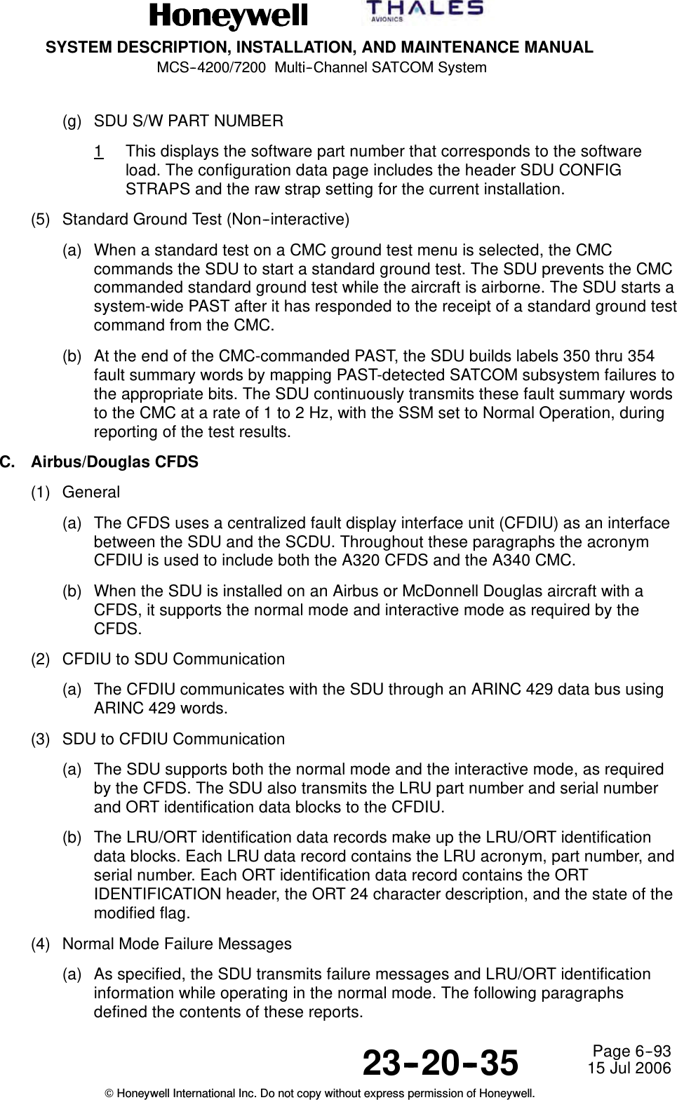
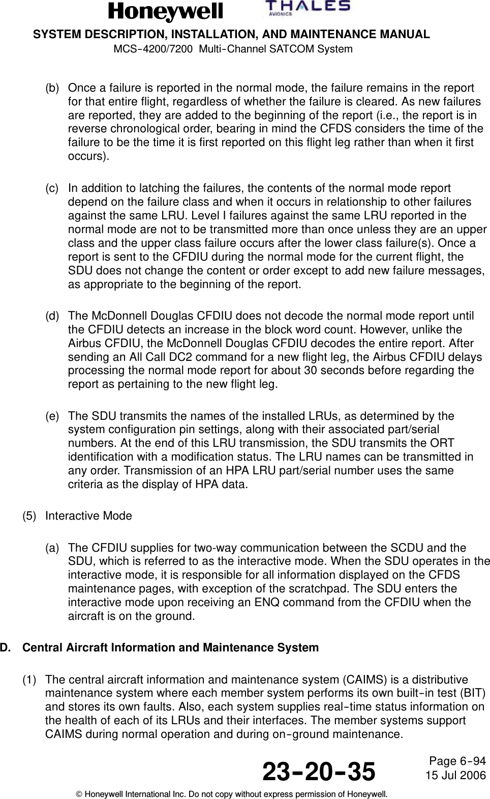
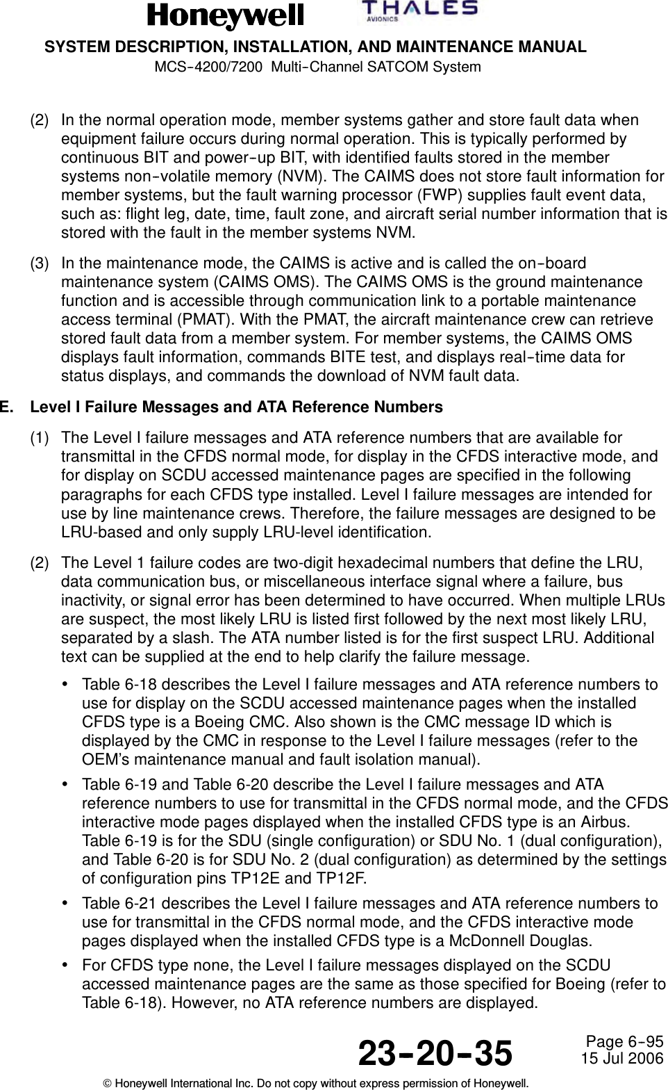
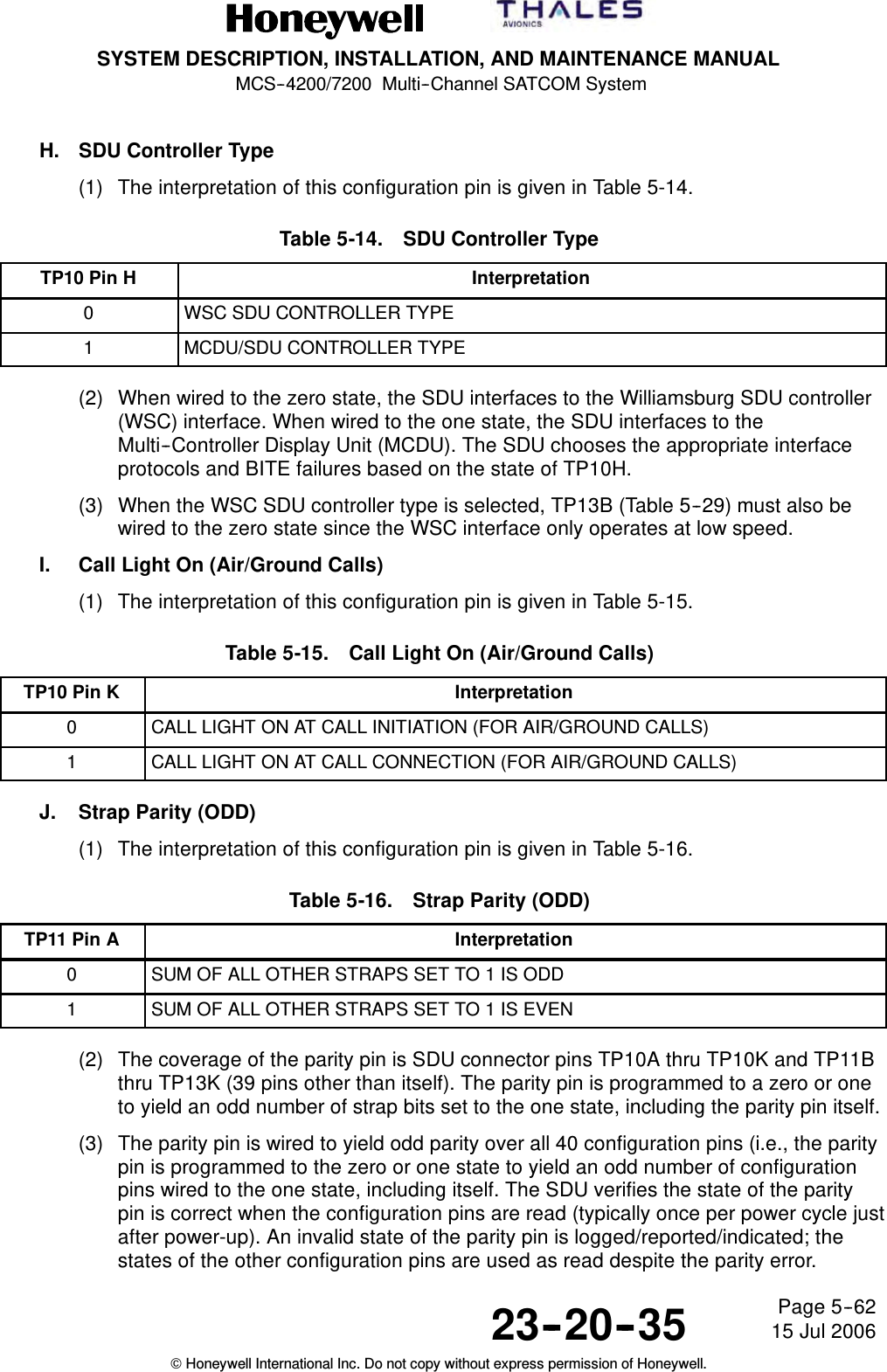
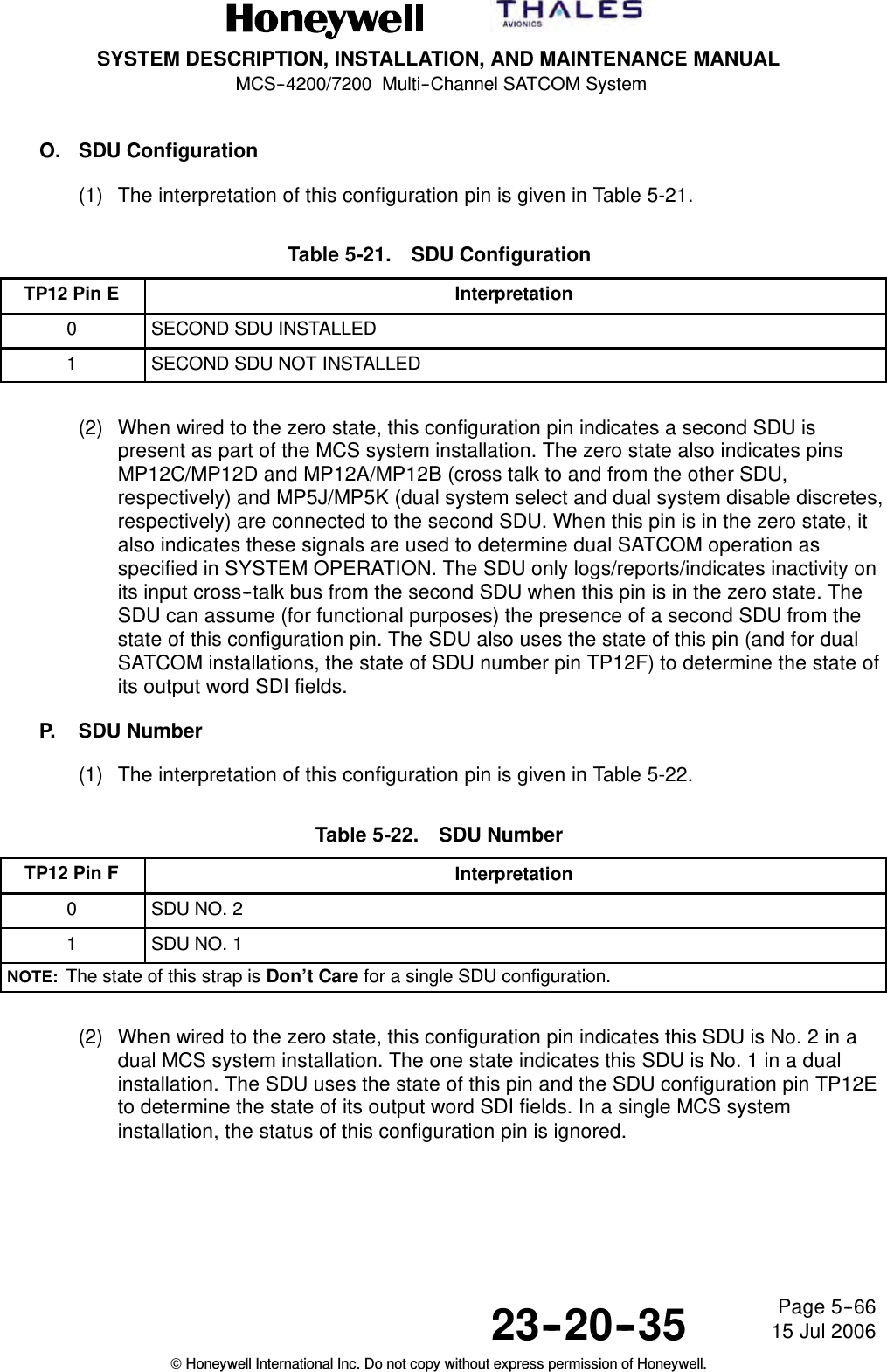
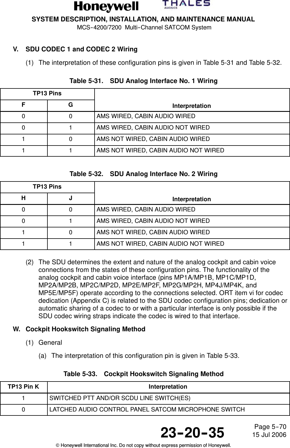
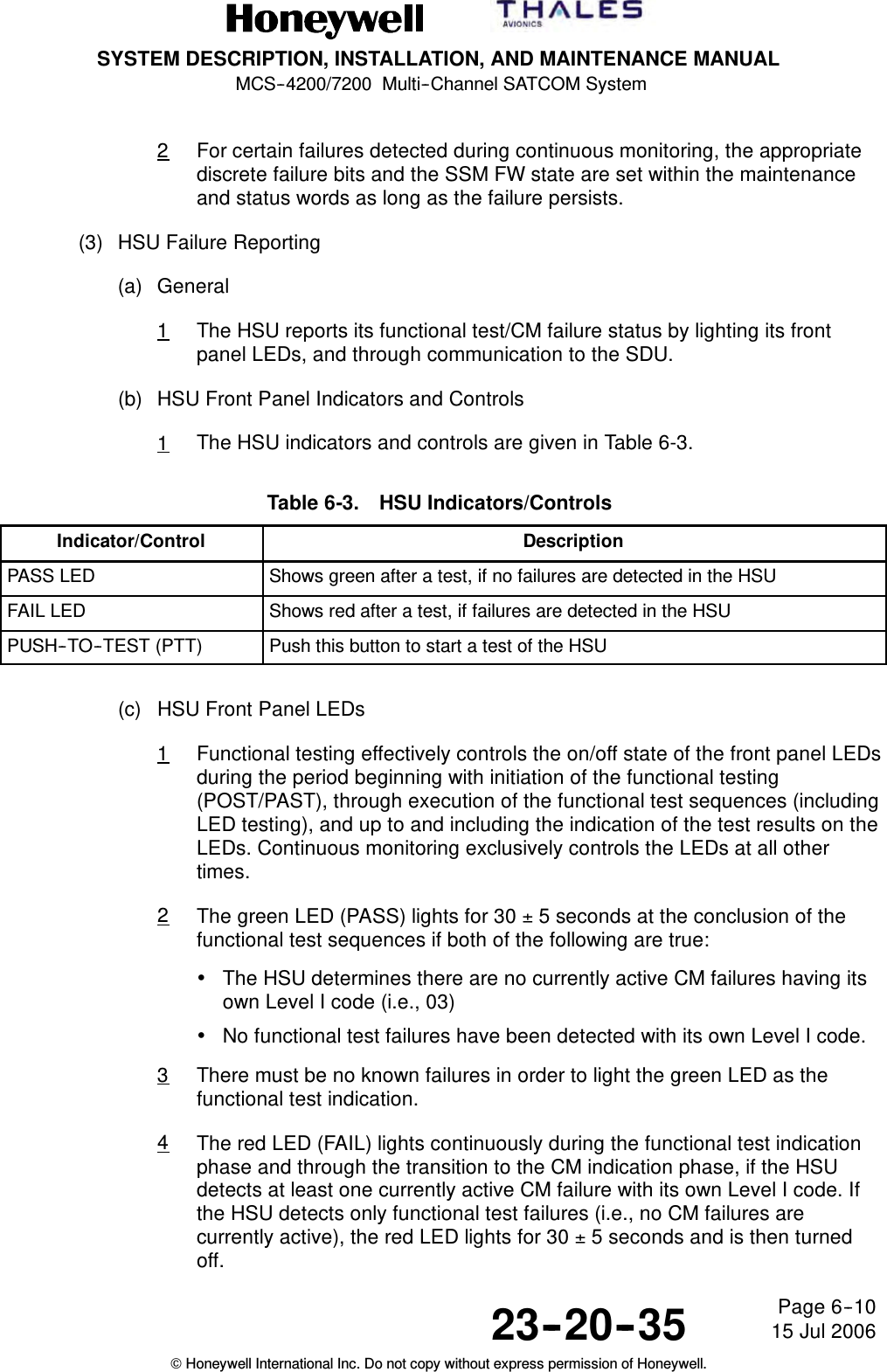
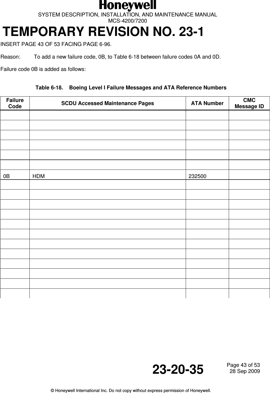
![SYSTEM DESCRIPTION, INSTALLATION, AND MAINTENANCE MANUALMCS--4200/7200 Multi--Channel SATCOM System23--20--35 15 Jul 2006Honeywell International Inc. Do not copy without express permission of Honeywell.Page 6--96(3) For Level I codes identified as not applicable in the tables, the SDU does not reportthe failure on that particular interface (i.e., CFDS normal and interactive modes orSCDU accessed maintenance pages as appropriate). Where TBD is used in theLevel I failure message column, it is coded as literally read. For failures that occurthat are undefined in the tables, the SDU does not report the failure on that particularinterface.Table 6-18. Boeing Level I Failure Messages and ATA Reference NumbersFailureCode SCDU Accessed Maintenance Pages ATA NumberCMCMessage ID01 SDU 232500 2320502 OTHER SDU INCOMPATIBILITY 232500 2320503 HSU 23250004 HPA--HI GAINHPA--HI GAIN[IGA][HGA] 232500 2320707 HPA--LO GAIN 232500 232090A HI POWER RELAY 232500 232180D LNA/DIP--(TOP/PORT) 232500 232100F LNA/DIP--STBD 232500 2321110 LNA/DIP--LO GAIN 232500 2321213 BSU--(TOP/PORT) 232500 2321315 BSU--STBD 232500 232141A IN GAIN ANTENNA--TOPHI GAIN ANTENNA--(TOP/PORT)[IGA][HGA] 232500 232151C HI GAIN ANTENNA--STBD 232500 232161F LO GAIN ANTENNA 232500 2322521 MCDU1 34610022 MCDU2 34610023 MCDU3 34610033 (ACARS MU/CMU)1 232700 2321934 (ACARS MU/CMU)2 232700 2321935 IRS--PRI 342100 3422236 IRS--SEC 342100 3422437 RESERVED38 RESERVED](https://usermanual.wiki/Honeywell/HS-720.HS-720-User-Manual-Part2/User-Guide-1350371-Page-156.png)
![SYSTEM DESCRIPTION, INSTALLATION, AND MAINTENANCE MANUALMCS--4200/7200 Multi--Channel SATCOM System23--20--35 15 Jul 2006Honeywell International Inc. Do not copy without express permission of Honeywell.Page 6--97Table 6-18. Boeing Level I Failure Messages and ATA Reference Numbers (cont)FailureCodeCMCMessage IDATA NumberSCDU Accessed Maintenance Pages39 RESERVED3D FMC1 3461003E FMC2 34610040 ARINC 429 ICAO ADDRESS None 2325142 CTU 231900 2323543 (CFS/CPDF) 23320050 HSU/SDU 23250052 (CFS/CPDF)/SDU 23320053 (ACARS MU/CMU)1/SDU 232700 2321954 CTU/SDU 231900 2323555 MCDU1/SDU 34610056 MCDU2/SDU 34610057 (ACARS MU/CMU)2/SDU 232700 2323559 CMC/SDU 454500 232015A IRS--PRI/SDU 342100 232225B IRS--SEC/SDU 342100 232245C HPA--IN GAIN/SDUHPA--HI GAIN/SDU[IGA][HGA] 232500 232265F HPA--LO GAIN/SDU 232500 2322562 BSU--(TOP/PORT)/SDU 232500 2321364 BSU--STBD/SDU 232500 2321466 MCDU3/SDU 34610067 RESERVED68 RESERVED6A RESERVED6C RESERVED6D RESERVED6E RESERVED6F RESERVED](https://usermanual.wiki/Honeywell/HS-720.HS-720-User-Manual-Part2/User-Guide-1350371-Page-159.png)
![SYSTEM DESCRIPTION, INSTALLATION, AND MAINTENANCE MANUALMCS--4200/7200 Multi--Channel SATCOM System23--20--35 15 Jul 2006Honeywell International Inc. Do not copy without express permission of Honeywell.Page 6--98Table 6-18. Boeing Level I Failure Messages and ATA Reference Numbers (cont)FailureCodeCMCMessage IDATA NumberSCDU Accessed Maintenance Pages71 OTHER SDU/THIS SDU 23250073 FMC1/SDU 34610074 FMC2/SDU 34610080 RESERVED82 RESERVED88 RESERVED90 SDU M--CTRL/HPA--IN GAINSDU M--CTRL/HPA--HI GAIN[IGA][HGA] 232500 2324696 SDU M--CTRL/HPA--LO GAIN 232500 2324898 SDU M--CTRL/BSU--(TOP/PORT) 232500 232499A BSU--STBD XTALK/BSU--PORT 232500 232529C SDU M--CTRL/BSU--STBD 232500 232509D BSU--PORT XTALK/BSU--STBD 232500 232539E SDU/HSU 232500A6 HSU ETHERNET PORT 1 232500A7 HSU ETHERNET PORT 2 232500A8 HSUISDNPORT1 232500A9 HSUISDNPORT2 232500C0 WRG:CONFIG PIN PROG/SDU 232500 23236C1 SDU WOW MISCOMPARE N/AC2 SDU/OTHER SDU SELECT--DISABLE DISCRETE 232500C3 WRG:ICAO ADDRESS PIN PROG/SDU 232500 23251C4 TX PATH VSWR--IN GAINTX PATH VSWR--HI GAIN[IGA][HGA] 232500 23257C5 WRG:CONFIG PIN PROG/SDU OWNER REQS 232500C6 TX PATH VSWR--LO GAIN 232500 23216C7 HPA--HI GAIN/OVER TEMPERATUREHPA--HI GAIN/OVER TEMPERATURE[IGA][HGA] 232500 23247C8 BAD DATA FROM GROUND EARTH STATION None](https://usermanual.wiki/Honeywell/HS-720.HS-720-User-Manual-Part2/User-Guide-1350371-Page-160.png)
![SYSTEM DESCRIPTION, INSTALLATION, AND MAINTENANCE MANUALMCS--4200/7200 Multi--Channel SATCOM System23--20--35 15 Jul 2006Honeywell International Inc. Do not copy without express permission of Honeywell.Page 6--99Table 6-18. Boeing Level I Failure Messages and ATA Reference Numbers (cont)FailureCodeCMCMessage IDATA NumberSCDU Accessed Maintenance PagesC9 HPA--LO GAIN/OVER TEMPERATURE 232500 23254CA SDU/LNA/DIP--LO GAIN 232500 23237CB WRG:SDI PIN PROG/HPA--IN GAINWRG:SDI PIN PROG/HPA--HI GAIN[IGA][HGA] 232500CC WRG:SDI PIN PROG/HPA--HI GAIN 232500CD SDU (POC/TOTC) DATA RESET NoneCE RESERVEDCF HPA--IN GAIN (POC/TOTC) DATA RESETHPA--HI GAIN (POC/TOTC)DATA RESET[IGA][HGA] NoneD0 HPA--LO GAIN (POC/TOTC) DATA RESET NoneD1 WRG:SDI PIN PROG/HPA--IN GAINWRG:SDI PIN PROG/HPA--HI GAIN[IGA][HGA] 232500D2 WRG:SDI PIN PROG/HPA--LO GAIN 232500D3 WRG:SDI PIN PROG/BSU--(TOP/PORT) 232500D4 WRG:SDI PIN PROG/BSU--STBD 232500D5 SDU COAX/HPA--IN GAINSDU COAX/HPA--HI GAIN[IGA][HGA] 232500 23237D6 SDU COAX/HPA--LO GAIN 232500 23237D7 RESERVEDD8 LNA/DIP/ (SDU)--(TOP/PORT) 232500 23236D9 LNA/DIP/ (SDU)--STBD 232500 23236DA LNA/DIP/ (SDU)--LO GAIN 232500 23236DB LO GAIN SUBSYSTEM 232500DC NO ACTIVE ACARS MU/CMU 232700DD SDU OWNER REQS -- SECURED NoneDE SDU OWNER REQS -- USER NoneDF IN GAIN SUBSYSTEMHI GAIN SUBSYSTEM[IGA][HGA] 232500E0 RESERVEDE1 BAD HSU DISABLE DISCRETE 232500](https://usermanual.wiki/Honeywell/HS-720.HS-720-User-Manual-Part2/User-Guide-1350371-Page-161.png)
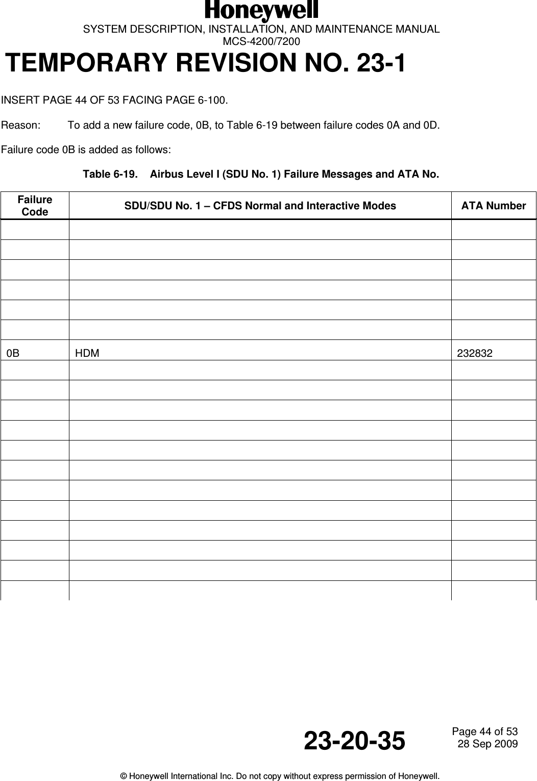
![SYSTEM DESCRIPTION, INSTALLATION, AND MAINTENANCE MANUALMCS--4200/7200 Multi--Channel SATCOM System23--20--35 15 Jul 2006Honeywell International Inc. Do not copy without express permission of Honeywell.Page 6--100Table 6-18. Boeing Level I Failure Messages and ATA Reference Numbers (cont)FailureCodeCMCMessage IDATA NumberSCDU Accessed Maintenance PagesE4 HSU/SDU INTERFACE VER INCOMPATIBILITY 232500E6 HSU/HPA TX RF PATH 232500E8 DLNA/HSU RX RF PATH 232500EC WRG: CONFIG PIN PROG/HSU 232500ED WRG: CONFIG PIN PROG/HSUSDU OWNER REQS232500EE WRG: FWD ID PIN PROG/HSU 232500FE POWER SUPPLY INTERRUPT NoneTable 6-19. Airbus Level I (SDU No. 1) Failure Messages and ATA No.FailureCode SDU/SDU No. 1 -- CFDS Normal and Interactive Modes ATA Number01 SDU1(105RV1)SDU1(5RV1)[IGA][HGA]23283423283402 SDU2(105RV2)SDU2(5RV2) INCOMPATIBILITY[IGA][HGA]23283423283403 HSDU1 (63RV1) 23283904 HPA1(110RV1)HPA--HI GAIN(7RV1)[IGA][HGA]23283123283107 HPA--LO GAIN(9RV) 2328350A HI POWER RELAY(21RV) 2328420D DLNA1(119RV1)DLNA--TOP(19RV1)DLNA--L(20RV1)[IGA][Top Mount][Conformal]2328382328382328370F DLNA--R(20RV2) [Conformal] 23283710 DLNA--LO GAIN(14RV) 23283613 BSU(8RV1)BSU--L(15RV1)[Top Mount][Conformal]23284623284415 BSU--R(15RV2) [Conformal] 232844](https://usermanual.wiki/Honeywell/HS-720.HS-720-User-Manual-Part2/User-Guide-1350371-Page-162.png)
![SYSTEM DESCRIPTION, INSTALLATION, AND MAINTENANCE MANUALMCS--4200/7200 Multi--Channel SATCOM System23--20--35 15 Jul 2006Honeywell International Inc. Do not copy without express permission of Honeywell.Page 6--101Table 6-19. Airbus Level I (SDU No. 1) Failure Messages and ATA No. (cont)FailureCode ATA NumberSDU/SDU No. 1 -- CFDS Normal and Interactive Modes1A ANTENNA1(116RV1)HI GAIN ANTENNA--TOP(16RV1)HI GAIN ANTENNA--L(17RV)[IGA][Top Mount][Conformal]2328132328132328121C HI GAIN ANTENNA--R(18RV) [Conformal] 2328121F LO GAIN ANTENNA(13RV) 23281121 MCDU1(2CA1) [A330/A340] 228212MCDU1(3CA1) [A320] 22821222 MCDU2(2CA2) [A330/A340] 228212MCDU2(3CA2) [A320] 22821223 MCDU3(2CA3) [A330/A340] 228212MCDU3(3CA3) [A320] 22821233 ATSU1(1TX1) [ATSU] 462134ACARS MU(1RB) [A320 ACARS] 232434ACARS MU1(1RB1) [A330/A340 ACARS] 23243434 ATSU2 (1TX2) [ATSU] 462134ACARS MU2 [A320 ACARS] 232434ACARS MU2(1RB2) [A330/A340 ACARS] 23243435 ADIRU1(1FP1) 34123436 ADIRU2(1FP2) 34123437 RESERVED N/A38 RESERVED N/A39 RESERVED N/A3D FMGC1(1CA1)FMGEC1(1CA1)[A320][A330/A340]2283342283343E FMGC2(1CA2)FMGEC2(1CA2)[A320][A330/A340]22833422833440 ARINC 429 ICAO N/A](https://usermanual.wiki/Honeywell/HS-720.HS-720-User-Manual-Part2/User-Guide-1350371-Page-165.png)
![SYSTEM DESCRIPTION, INSTALLATION, AND MAINTENANCE MANUALMCS--4200/7200 Multi--Channel SATCOM System23--20--35 15 Jul 2006Honeywell International Inc. Do not copy without express permission of Honeywell.Page 6--102Table 6-19. Airbus Level I (SDU No. 1) Failure Messages and ATA No. (cont)FailureCode ATA NumberSDU/SDU No. 1 -- CFDS Normal and Interactive Modes42 CTU--CU CEPT--E1 BUS/SDU1 (105RV1)CTU--CU CEPT--E1 BUS/SDU1 (105RV1)CTU--CU CEPT--E1 BUS/SDU1 (5RV1)CTU--CU CEPT--E1 BUS/SDU1 (5RV1)[IGA A320][IGA A330/A340][HGA A320][HGA A330/A340]23350023920023350023920043 IFE 429 BUS/SDU1 (5RV1)IFE 429 BUS/SDU1 (105RV1)IFE 429 BUS/SDU1 (105RV1)IFE 429 BUS/SDU1 (5RV1)[A330/A340 HGA][A330/A340 HGA][A320 IGA][A320 HGA]23300023300050 HSDU1 (63RV1)/SDU1 (5RV1) 23283952 IFE 429 BUS/SDU1 (5RV1)IFE 429 BUS/SDU1 (105RV1)IFE 429 BUS/SDU1 (105RV1)IFE 429 BUS/SDU1 (5RV1)[A330/A340 HGA][A330/A340 HGA][A320 IGA][A320 HGA]23300023300053 ATSU1 (1TX1)/SDU1(105RV1) [IGA ATSU] 462134ATSU1 (1TX1)/SDU1(5RV1) [HGA ATSU] 462134ACARS MU (1RB)/SDU1(105RV1) [IGA A320 ACARS] 232434ACARS MU1 (1RB1)/SDU1(105RV1) [IGA A330/A340 ACARS] 232434ACARS MU (1RB)/SDU1(5RV1) [HGA A320 ACARS] 232434ACARS MU1 (1RB1)/SDU1(5RV1) [HGA A330/A340 ACARS] 23243454 CTU--CU CEPT--E1 BUS/SDU1(105RV1) [IGA A320] 233500CTU--CU CEPT--E1 BUS/SDU1(105RV1) [IGA A330/A340] 239200CTU--CU CEPT--E1 BUS/SDU1(5RV1) [HGA A320] 233500CTU--CU CEPT--E1 BUS/SDU1(5RV1) [HGA A330/A340] 23920055 MCDU1(2CA1)/SDU1(105RV1)MCDU1(2CA1)/SDU1(5RV1)MCDU1(3CA1)/SDU1(105RV1)MCDU(3CA1)/SDU1(5RV1)[IGA A330/A340][HGA A330/A340][IGA A320][HGA A320]22821222821222821222821256 MCDU2(2CA2)/SDU1(105RV1)MCDU2(2CA2)/SDU1(5RV1)MCDU2(3CA2)/SDU1(105RV1)MCDU2(3CA2)/SDU1(5RV1)[IGA A330/A340][HGA A330/A340]IGA A320HGA A320228212228212228212228212](https://usermanual.wiki/Honeywell/HS-720.HS-720-User-Manual-Part2/User-Guide-1350371-Page-166.png)
![SYSTEM DESCRIPTION, INSTALLATION, AND MAINTENANCE MANUALMCS--4200/7200 Multi--Channel SATCOM System23--20--35 15 Jul 2006Honeywell International Inc. Do not copy without express permission of Honeywell.Page 6--103Table 6-19. Airbus Level I (SDU No. 1) Failure Messages and ATA No. (cont)FailureCode ATA NumberSDU/SDU No. 1 -- CFDS Normal and Interactive Modes57 ATSU2 (1TX2)/SDU1(105RV1) [IGA ATSU] 462134ATSU2 (1TX2)/SDU1(5RV1) [HGA ATSU] 462134ACARS MU2/SDU1(105RV1) [IGA A320 ACARS] 232434ACARS MU2 (1RB2)/SDU1(105RV1) [IGA A330/A340 ACARS] 232434ACARS MU2/SDU1(5RV1) [HGA A320 ACARS] 232434ACARS MU2 (1RB2)/SDU1(5RV1) [HGA A330/A340 ACARS] 23243459 CFDIU(1TW)/SDU1(105RV1) [IGA A320] 313234CMC1(1TM1)/SDU1(105RV1) [IGA A330/A340] 451334CFDIU(1TW)/SDU1(5RV1) [HGA A320] 313234CMC1(1TM1)/SDU1(5RV1) [HGA A330/A340] 4513345A ADIRU1(1FP1)/SDU1(105RV1)ADIRU1(1FP1)/SDU1(5RV1)[IGA][HGA]3412343412345B ADIRU2(1FP2)/SDU1(105RV1)ADIRU2(1FP2)/SDU1(5RV1)[IGA][HGA]3412343412345C HPA1 (110RV1)/SDU1(105RV1)HPA--HI GAIN(7RV1)/SDU1(5RV1)[IGA][HGA]2328312328315F HPA--LO GAIN(9RV)/SDU1(5RV1)HPA--LO GAIN(9RV)/SDU1(105RV1)[HGA + LGA][IGA + LGA]23283523283562 BSU(8RV1)/SDU1(5RV1)BSU--L(15RV1)/SDU1(5RV1)[Top Mount][Conformal]23284623284464 BSU--R(15RV2)/SDU1(5RV1) [Conformal] 23284466 MCDU3(2CA3)/SDU1(105RV1)MCDU3(2CA3)/SDU1(5RV1)MCDU3(3CA3)/SDU1(105RV1)MCDU3(CA3)/SDU1(5RV1)[IGA A330/A340][HGA A330/A340][IGA A320][HGA A320]22821222821222821222821267 RESERVED68 RESERVED6A RESERVED6C RESERVED6D RESERVED](https://usermanual.wiki/Honeywell/HS-720.HS-720-User-Manual-Part2/User-Guide-1350371-Page-167.png)
![SYSTEM DESCRIPTION, INSTALLATION, AND MAINTENANCE MANUALMCS--4200/7200 Multi--Channel SATCOM System23--20--35 15 Jul 2006Honeywell International Inc. Do not copy without express permission of Honeywell.Page 6--104Table 6-19. Airbus Level I (SDU No. 1) Failure Messages and ATA No. (cont)FailureCode ATA NumberSDU/SDU No. 1 -- CFDS Normal and Interactive Modes6E RESERVED6F RESERVED71 SDU2(105RV2)CROSSTALK BUS/SDU1(105RV1)SDU2(5RV2)CROSSTALK BUS/SDU15RV1)[IGA][HGA]23283423283473 FMGC1(1CA1)/SDU1(105RV1) [IGA A320] 228334FMGEC1(1CA1)/SDU1(105RV1) [IGA A330/A340] 228334FMGC1(1CA1)/SDU1(5RV1) [HGA A320] 228334FMGEC1(1CA1)/SDU1(5RV1) [HGA A330/A340] 22833474 FMGC2(1CA2)/SDU1(105RV1) [IGA A320] 228334FMGEC2(1CA2)/SDU1(105RV1) [IGA A330/A340] 228334FMGC2(1CA2)/SDU1(5RV1) [HGA A320] 228334FMGEC2(1CA2)/SDU1(5RV1) [HGA A330/A340] 22833480 RESERVED82 RESERVED88 RESERVED90 SDU1(105RV1) BUS M--CTRL/HPA1(110RV1) [IGA] 232834SDU1(5RV1) BUS M--CTRL/HPA--HIGAIN(7RV1)[HGA] 23283496 SDU1(5RV1) BUS M--CTRL/HPA--LOGAIN(9RV)[HGA+LGA] 232834SDU1(105RV1) BUS M--CTRL/HPA--LOGAIN(9RV)[IGA+LGA] 23283498 SDU1(5RV1) BUS M--CTRL/BSU(8RV1)SDU1(5RV1) BUS M--CTRL/BSU--L(15RV1)[Top Mount][Conformal]2328342328349A BSU--R (15RV2) XTALK BUS/BSU--L(15RV1) [Conformal] 2328449C SDU1(5RV1) BUS M--CTRL/BSU--R(15RV2) [Conformal] 2328349D BSU--L (15RV1) XTALK BUS/BSU--R(15RV2) [Conformal] 2328449E SDU1 (5RV1) /HSDU1 (63RV1) 2328349F Not applicable for package 6.0 and beyond N/A](https://usermanual.wiki/Honeywell/HS-720.HS-720-User-Manual-Part2/User-Guide-1350371-Page-168.png)
![SYSTEM DESCRIPTION, INSTALLATION, AND MAINTENANCE MANUALMCS--4200/7200 Multi--Channel SATCOM System23--20--35 15 Jul 2006Honeywell International Inc. Do not copy without express permission of Honeywell.Page 6--105Table 6-19. Airbus Level I (SDU No. 1) Failure Messages and ATA No. (cont)FailureCode ATA NumberSDU/SDU No. 1 -- CFDS Normal and Interactive ModesA1 SDU1(105RV1)/MCDU1(2CA1) [IGA] 228212SDU1(5RV1)/MCDU1(2CA1) [HGA] 228212A2 SDU1(105RV1).MCDU2(2CA2) [IGA] 228212SDU1(5RV1)/MCDU2(2CA2) [HGA] 228212A3 SDU1(105RV1)/MCDU3(2CA3) [IGA] 228212SDU1(5RV1)/MCDU3(2CA3) [HGA] 228212A6 ESU(101RF) ETHERNET 1/HSDU1(63RV1) 464131A7 ESU(101RF) ETHERNET 2/HSDU1(63RV1) 464131A8 ESU(101RF) ISDN 1/HSDU1(63RV1) 464131A9 ESU(101RF) ISDN 2/HSDU1(63RV1) 464131C0 WRG:CONFIG PIN PROG/SDU1(105RV1) [IGA] 232800WRG:CONFIG PIN PROG/SDU1(5RV1) [HGA] 232800C1 LGCIU1(5GA1)/LGCIU2(5GA2)/SDU1(105RV1) [IGA] 323171LGCIU1(5GA1)/LGCIU2(5GA2)/SDU1(5RV1) [HGA] 323171C2 SDU1(105RV1) SEL--DISABLEDISCRETE/SDU2(105RV2)[IGA] 232834SDU1(5RV1) SEL--DISABLEDISCRETE/SDU2(5RV2)[HGA] 232834C3 WRG:ICAO ADDRESS PINPROG/SDU1(105RV1)[IGA] 232800WRG:ICAO ADDRESS PINPROG/SDU1(5RV1)[HGA] 232800C4 HPA1 (110RV1)/VSWR [IGA] 232831HPA--HI GAIN(7RV1)/VSWR [HGA] 232831C5 WRG:CONFIG PIN PROG/SDU1(105RV1)OWNER REQS DB[IGA] 232800WRG:CONFIG PIN PROG/SDU1(5RV1)OWNER REQS DB[HGA] 232800C6 HPA--LO GAIN(9RV)/VSWR 232835C7 HPA(110RV1)/OVER TEMPERATURE [IGA] 232831HPA--HI GAIN(7RV1)/OVER TEMPERATURE [HGA] 232831](https://usermanual.wiki/Honeywell/HS-720.HS-720-User-Manual-Part2/User-Guide-1350371-Page-169.png)
![SYSTEM DESCRIPTION, INSTALLATION, AND MAINTENANCE MANUALMCS--4200/7200 Multi--Channel SATCOM System23--20--35 15 Jul 2006Honeywell International Inc. Do not copy without express permission of Honeywell.Page 6--106Table 6-19. Airbus Level I (SDU No. 1) Failure Messages and ATA No. (cont)FailureCode ATA NumberSDU/SDU No. 1 -- CFDS Normal and Interactive ModesC8 SDU1(105RV1)/BAD DATA FROM GROUNDSTATION[IGA] 232834SDU1(5RV1)/BAD DATA FROM GROUNDEARTH STATION[HGA] 232834C9 HPA--LO GAIN(9RV)/OVER TEMPERATURE 232835CA SDU1(5RV1)CTRL DISCRETE/DLNA--LOGAIN(14RV)[HGA+LGA] 232834SDU1(105RV1)CTRL DISCRETE/DLNA--LOGAIN(14RV)[IGA+LGA] 232834CB WRG:SDI PIN PROG/HPA1(110RV1) [IGA] 232800WRG:SDI PIN PROG/HPA--HI GAIN(7RV1) [HGA] 232800CC WRG:SDI PIN PROG/HPA--LO GAIN(9RV) 232800CD N/A N/ACE RESERVEDCF N/A N/AD0 N/A N/AD1 WRG:SDI PIN PROG/HPA1(110RV1) 232800WRG:SDI PIN PROG/HPA--HI GAIN(7RV1) 232800D2 WRG:SDI PIN PROG/HPA--LO GAIN(9RV) 232800D3 WRG:SDI PIN PROG/BSU(8RV1)WRG:SDI PIN PROG/BSU--L(15RV1)[Top Mount][Conformal]232800232800D4 WRG:SDI PIN PROG/BSU--R(15RV2) [Conformal] 232800D5 SDU1(105RV1)/TXCOAX [IGA] 232834SDU1(5RV1)/TXCOAX [HGA] 232834D6 SDU1 (105RV1)/TXCOAX [IGA+LGA] 232834SDU1(5RV1)/TXCOAX [HGA+LGA] 232834D7 RESERVEDD8 SDU1(105RV1)/RXCOAXSDU1(5RV1)/RXCOAX[IGA][HGA]232834232834D9 SDU2(5RV1)/RXCOAX 232834DA SDU1(105RV1)/RXCOAX [IGA+LGA] 232834](https://usermanual.wiki/Honeywell/HS-720.HS-720-User-Manual-Part2/User-Guide-1350371-Page-170.png)
![SYSTEM DESCRIPTION, INSTALLATION, AND MAINTENANCE MANUALMCS--4200/7200 Multi--Channel SATCOM System23--20--35 15 Jul 2006Honeywell International Inc. Do not copy without express permission of Honeywell.Page 6--107Table 6-19. Airbus Level I (SDU No. 1) Failure Messages and ATA No. (cont)FailureCode ATA NumberSDU/SDU No. 1 -- CFDS Normal and Interactive ModesSDU1(5RV1)/RXCOAX [HGA+LGA] 232834DB LO GAIN ANTENNA(13RV)LOG ON FAILURE232811DC N/A N/A to AirbusDD SDU1(105RV1) OWNER REQS DB SECUREDPARTITION[IGA] 232834SDU1(5RV1) OWNER REQS DB SECUREDPARTITION[HGA] 232834DE SDU1(105RV1) OWNER REQS DB USERPARTITION[IGA] 232834SDU1(5RV1) OWNER REQS DB USERPARTITION[HGA] 232834DF SDU1(105RV1)LOG ON FAILURE[IGA] 232834SDU1(5RV1)LOG ON FAILURE[HGA] 232834E0 RESERVEDE1 SDU1(5RV1) DISCRETE/HSDU1(63RV1) 232834E2 N/A N/AE3 N/A N/A to AirbusE4 SDU1(5RV1)/HSDU1(63RV1) 232834E5 N/A N/A to AirbusE6 HSDU1(63RV1)/TXCOAX 232839E7 N/A N/AE8 HSDU1(63RV1)/RXCOAX 232839E9 N/A N/AEA N/A N/A to AirbusEB MCDU1(2CA1)+MCDU2(2CA2)+MCDU3(2CA3)INACTIVE[RMP only] 228212EC WRG:CONFIG PIN PROG/HSDU1(63RV1) 232800ED WRG:CONFIG PIN PROG/HSDU1(63RV1)SDU ORT232800](https://usermanual.wiki/Honeywell/HS-720.HS-720-User-Manual-Part2/User-Guide-1350371-Page-171.png)
![SYSTEM DESCRIPTION, INSTALLATION, AND MAINTENANCE MANUALMCS--4200/7200 Multi--Channel SATCOM System23--20--35 15 Jul 2006Honeywell International Inc. Do not copy without express permission of Honeywell.Page 6--108Table 6-19. Airbus Level I (SDU No. 1) Failure Messages and ATA No. (cont)FailureCode ATA NumberSDU/SDU No. 1 -- CFDS Normal and Interactive ModesEE WRG:FWD ID1 ADDRESS PINPROG/HSDU1(63RV1)232800FE POWER SUPPLY INTERRUPT 240000Table 6-20. Airbus Level I (SDU No. 2) Failure Messages and ATA No.FailureCode SDU/SDU No. 2 -- CFDS Normal and Interactive Modes ATA Number01 SDU2(105RV2)SDU2(5RV2)[IGA][HGA]23283423283402 SDU1(105RV1) INCOMPATIBILITYSDU1(5RV1) INCOMPATIBILITY[IGA][HGA]23283423283403 HSDU2(63RV2) 23283904 HPA2(110RV2)HPA--HI GAIN(7RV2)[IGA][HGA]23283123283107 HPA--LO GAIN(9RV) 2328350A HI POWER RELAY(21RV) 2328420D DLNA2 (119RV2)DLNA--TOP(19RV2)DLNA--L(20RV3)[IGA][Top Mount][Conformal]2328382328382328370F DLNA--R(20RV4) [Conformal] 23283710 DLNA--LO GAIN(14RV) 23283613 BSU(8RV2)BSU--L(15RV3)[Top Mount][Conformal]23284623284415 BSU--R(15RV4) [Conformal] 2328441A ANTENNA2(116RV2)HI GAIN ANTENNA--TOP(16RV1)HI GAIN ANTENNA--L(17RV)[IGA][Top Mount][Conformal]2328132328132328121C HI GAIN ANTENNA--R(18RV) [Conformal] 2328121F LO GAIN ANTENNA(13RV) 23281121 MCDU1(2CA1)MCDU1(3CA1)[A330/A340][A320]228212228212](https://usermanual.wiki/Honeywell/HS-720.HS-720-User-Manual-Part2/User-Guide-1350371-Page-172.png)

![SYSTEM DESCRIPTION, INSTALLATION, AND MAINTENANCE MANUALMCS--4200/7200 Multi--Channel SATCOM System23--20--35 15 Jul 2006Honeywell International Inc. Do not copy without express permission of Honeywell.Page 6--109Table 6-20. Airbus Level I (SDU No. 2) Failure Messages and ATA No. (cont)FailureCode ATA NumberSDU/SDU No. 2 -- CFDS Normal and Interactive Modes22 MCDU2(2CA2)MCDU2(3CA2)[A330/A340][A320]22821222821223 MCDU3(2CA3)MCDU3(3CA3)[A330/A340][A320]22821222821233 ATSU1(1TX1) [ATSU] 462134ACARS MU(1RB) [A320 ACARS] 232434ACARS MU1(1RB1) [A330/A340 ACARS] 23243434 ATSU2 (1TX2) [ATSU] 462134ACARS MU(1RB) [A320 ACARS] 232434ACARS MU2(1RB2) [A320/A340 ACARS] 23243435 ADIRU1(1FP1) 34123436 ADIRU2(1FP2) 34123437 RESERVED N/A38 RESERVED N/A39 RESERVED N/A3D FMGC1(1CA1)FMGEC1(1CA1)[A320][A330/A340]2283342283343E FMGC2(1CA2)FMGEC2(1CA2)[A320][A330/A340]22833422833440 ARINC 429 ICAO 23280042 CTU -- CU CEPT--E1 BUS/SDU2(105RV2)CTU -- CU CEPT--E1 BUS/SDU2(105RV2)CTU -- CU CEPT--E1 BUS/SDU2(5RV2)CTU -- CU CEPT--E1 BUS/SDU2(5RV2)[IGA A320][IGA A330/A340][HGA A320][HGA A330/A340]23350023920023350023920043 IFE 429 BUS/SDU2(5RV2)IFE 429 BUS/SDU2(105RV2)IFE 429 BUS/SDU2(105RV2)IFE 429 BUS/SDU2(5RV2)[A330/A340 HGA][A330/A340 IGA][A320 IGA][A320 HGA]23300023300050 HSDU2(63RV2)/SDU2(5RV2) 23283951 RESERVED](https://usermanual.wiki/Honeywell/HS-720.HS-720-User-Manual-Part2/User-Guide-1350371-Page-175.png)
![SYSTEM DESCRIPTION, INSTALLATION, AND MAINTENANCE MANUALMCS--4200/7200 Multi--Channel SATCOM System23--20--35 15 Jul 2006Honeywell International Inc. Do not copy without express permission of Honeywell.Page 6--110Table 6-20. Airbus Level I (SDU No. 2) Failure Messages and ATA No. (cont)FailureCode ATA NumberSDU/SDU No. 2 -- CFDS Normal and Interactive Modes52 IFE 429 BUS/SDU2(5RV2)IFE 429 BUS/SDU2(105RV2)IFE 429 BUS/SDU2(105RV2)IFE 429 BUS/SDU2(5RV2)[A330/A340 HGA][A330/A340 IGA][A320 IGA][A320 HGA]23300023300053 ATSU1 (1TX1)/SDU2(105RV2) [IGA ATSU] 462134ATSU1 (1TX1)/SDU2(5RV2) [HGA ATSU] 462134ACARS MU(1RB1)/SDU2(105RV2) [IGA ACARS A330/A340] 232434ACARS MU1(1RB1)/SDU2(5RV2) [HGA ACARS A330/A340] 232434ACARS MU(1RB)/SDU2(105RV2) [IGA ACARS A320] 232434ACARS MU1(1RB)/SDU2(5RV2) [HGA ACARS A320] 23243454 CTU -- CU CEPT--E1 BUS/SDU2(105RV2) [IGA A320] 233500CTU -- CU CEPT--E1 BUS/SDU2(105RV2) [IGA A330/A340] 239200CTU -- CU CEPT--E1 BUS/SDU2(5RV2) [HGA A320] 233500CTU -- CU CEPT--E1 BUS/SDU2(5RV2) [HGA A330/A340] 23920055 MCDU1(2CA1)/SDU2(105RV2)MCDU1(2CA1)/SDU2(5RV2)MCDU1(3CA1)/SDU2(105RV2)MCDU1(3CA1)/SDU2(5RV2)[IGA A330/A340][HGA A330/A340][IGA A320][HGA A320]22821222821222821222821256 MCDU2(2CA2)/SDU2(105RV2)MCDU2(2CA2)/SDU2(5RV2)MCDU2(3CA2)/SDU2(105RV2)MCDU2(3CA2)/SDU2(5RV2)[IGA][HGA][IGA A320][HGA A320]22821222821222821222821257 ATSU2 (1TX2)/SDU2(105RV2) [IGA ATSU] 462134ATSU2 (1TX2)/SDU2(5RV2) [HGA ATSU] 462134ACARS MU2/SDU2(105RV2) [IGA A320 ACARS] 232434ACARS MU2 (1RB2)/SDU2(105RV2) [IGA A330/A340 ACARS] 232434ACARS MU2/SDU2(5RV2) [HGA A320 ACARS] 232434ACARS MU2(1RB2)/SDU2(5RV2) [HGA A330/A340 ACARS] 232434](https://usermanual.wiki/Honeywell/HS-720.HS-720-User-Manual-Part2/User-Guide-1350371-Page-176.png)
![SYSTEM DESCRIPTION, INSTALLATION, AND MAINTENANCE MANUALMCS--4200/7200 Multi--Channel SATCOM System23--20--35 15 Jul 2006Honeywell International Inc. Do not copy without express permission of Honeywell.Page 6--111Table 6-20. Airbus Level I (SDU No. 2) Failure Messages and ATA No. (cont)FailureCode ATA NumberSDU/SDU No. 2 -- CFDS Normal and Interactive Modes59 CFDIU(1TW)/SDU2(105RV2) [IGA A320] 313234CMC1(1TM1)/SDU2(105RV2) [IGA A330/A340] 451334CFDIU(1TW)/SDU2(5RV2) [HGA A320] 313234CMC1(1TM1)/SDU2(5RV2) [HGA A330/A340] 4513345A ADIRU1(1FP1)/SDU2(105RV2) [IGA] 341234ADIRU1(1FP1)/SDU2(5RV2) [HGA] 3412345B ADIRU2(1FP2)/SDU2(105RV2) [IGA] 341234ADIRU2(1FP2)/SDU2(5RV2) [HGA] 3412345C HPA2(110RV2)/SDU2(105RV2) [IGA] 232831HPA--HI GAIN(7RV2)/SDU2(5RV2) [HGA] 2328315F HPA--LO GAIN(9RV)/SDU2(5RV2)HPA--LO GAIN(9RV)/SDU2(105RV2)HGA+LGAIGA+LGA23283523283562 BSU(8RV2)/SDU2(5RV2)BSU--L(15RV3)/SDU2(5RV2)[Top Mount][Conformal]23284623284464 BSU--R(15RV4)/SDU2(5RV2) [Conformal] 23284466 MCDU3(2CA3)/SDU2(105RV2)MCDU3(2CA3)/SDU2(5RV2)MCDU3(3CA3)/SDU2(105RV2)MCDU3(3CA3)/SDU2(5RV2)[IGA A330/A340][HGA A330/A340][IGA A320][HGA A320]22821222821222821222821267 RESERVED68 RESERVED6A RESERVED6C RESERVED6D RESERVED6E RESERVED6F RESERVED71 SDU1(105RV1)CROSSTALKBUS/SDU2(105RV2)SDU1(5RV1)CROSSTALK BUS/SDU2(5RV2)[IGA][HGA]232834232834](https://usermanual.wiki/Honeywell/HS-720.HS-720-User-Manual-Part2/User-Guide-1350371-Page-177.png)
![SYSTEM DESCRIPTION, INSTALLATION, AND MAINTENANCE MANUALMCS--4200/7200 Multi--Channel SATCOM System23--20--35 15 Jul 2006Honeywell International Inc. Do not copy without express permission of Honeywell.Page 6--112Table 6-20. Airbus Level I (SDU No. 2) Failure Messages and ATA No. (cont)FailureCode ATA NumberSDU/SDU No. 2 -- CFDS Normal and Interactive Modes73 FMGC1(1CA1)/SDU2(105RV2) [IGA A320] 228334FMGEC1(1CA1)/SDU2(105RV2) [IGA A330/A340] 228334FMGC1(1CA1)/SDU2(5RV2) [HGA A320] 228334FMGEC1(1CA1)/SDU2(5RV2) [HGA A330/A340] 22833474 FMGC2(1CA2)/SDU2(105RV2) [IGA A320] 228334FMGEC2(1CA2)/SDU2(105RV2) [IGA A330/A340] 228334FMGC2(1CA2)/SDU2(5RV2) [HGA A320] 228334FMGEC2(1CA2)/SDU2(5RV2) [HGA A330/A340] 22833480 RESERVED82 RESERVED88 RESERVED90 SDU2(105RV2) BUS M--CTRL/HPA2(110RV2) [IGA] 232834SDU2(5RV2) BUS M--CTRL/HPA--HIGAIN(7RV2)[HGA] 23283496 SDU2(5RV2) BUS M--CTRL/HPA--LOGAIN(9RV)SDU2(105RV2) BUS M--CTRL/HPA--LOGAIN(9RV)HGA+LGAIGA+LGA23283423283498 SDU2(5RV2) BUS M--CTRL/BSU(8RV2) [Top Mount] 232834SDU2(5RV2) BUS M--CTRL/BSU--L(15RV3) [Conformal] 2328349A BSU--R(15RV4) XTALK/BSU--L(15RV3) [Conformal] 2328449C SDU2(5RV2) BUS M--CTRL/BSU--R(15RV4) [Conformal] 2328349D BSU--L(15RV3) XTALK BUS/BSU--R(15RV4) [Conformal] 2328449E SDU2(5RV2)/HSDU2(63RV2) 2328349F Not applicable for package 6.0 and beyond N/AA1 SDU2(105RV2)/MCDU1(2CA1)SDU2(5RV2)/MCDU1(2CA1)[IGA][HGA]228212228212A2 SDU2(105RV2)/MCDU2(2CA2)SDU2(RV2)/MCDU2(2CA2)[IGA][HGA]228212228212](https://usermanual.wiki/Honeywell/HS-720.HS-720-User-Manual-Part2/User-Guide-1350371-Page-178.png)
![SYSTEM DESCRIPTION, INSTALLATION, AND MAINTENANCE MANUALMCS--4200/7200 Multi--Channel SATCOM System23--20--35 15 Jul 2006Honeywell International Inc. Do not copy without express permission of Honeywell.Page 6--113Table 6-20. Airbus Level I (SDU No. 2) Failure Messages and ATA No. (cont)FailureCode ATA NumberSDU/SDU No. 2 -- CFDS Normal and Interactive ModesA3 SDU2(105RV2)/MCDU3(2CA3)SDU2(5RV2)/MCDU3(2CA3)[IGA][HGA]228212228212A6 ESU(101RF) ETHERNET 1/HSDU2(63RV2) 464131A7 ESU(101RF) ETHERNET 2/HSDU2(63RV2) 464131A8 ESU(101RF) ISDN 1/HSDU2(63RV2) 464131A9 ESU(101RF) ISDN 2/HSDU2(63RV2) 464131C0 WRG:CONFIG PIN PROG/SDU2(105RV2)WRG:CONFIG PIN PROG/SDU2(5RV2)[IGA][HGA]232800232800C1 LGCIU1(5GA1)/LGCIU2(5GA2)/SDU2(105RV2) [IGA] 323171LGCIU1(5GA1)/LGCIU2(5GA2)/SDU2(5RV2) [HGA] 323171C2 SDU2(105RV2) SEL--DISABLEDISCRETE/SDU1(105RV1)[IGA] 232834SDU2(5RV2) SELECT--DISABLEDISCRETE/SDU1(5RV1)[HGA] 232834C3 WRG:ICAO ADDRESS PIN PROG/SDU2(105RV2)[IGA] 232800WRG:ICAO ADDRESS PIN PROG/SDU2(5RV2)[HGA] 232800C4 HPA2(110RV2)/COAX [IGA] 232831HPA--HI GAIN(7RV1)/COAX [HGA] 232831C5 WRG:CONFIG PIN PROG/SDU2(105RV2)OWNER REQS DB[IGA] 232800WRG:CONFIG PIN PROG/SDU2(5RV2)OWNER REQS DB[HGA] 232800C6 LPA--LO GAIN(9RV)/COAX 232835C7 HPA2(110RV2)/OVER TEMPERATURE [IGA] 232831HPA--HI GAIN(7RV2)/OVER TEMPERATURE [HGA] 232831C8 SDU2(105RV2)/BAD DATA FROM GROUNDSTATION[IGA] 232834SDU2(5RV2)/BAD DATA FROM GROUNDEARTH STATION[HGA] 232834C9 HPA--LO GAIN(9RV)/OVER TEMPERATURE 232835](https://usermanual.wiki/Honeywell/HS-720.HS-720-User-Manual-Part2/User-Guide-1350371-Page-179.png)
![SYSTEM DESCRIPTION, INSTALLATION, AND MAINTENANCE MANUALMCS--4200/7200 Multi--Channel SATCOM System23--20--35 15 Jul 2006Honeywell International Inc. Do not copy without express permission of Honeywell.Page 6--114Table 6-20. Airbus Level I (SDU No. 2) Failure Messages and ATA No. (cont)FailureCode ATA NumberSDU/SDU No. 2 -- CFDS Normal and Interactive ModesCA SDU2(5RV2)CTRL DISCRETE/DLNA--LOGAIN(14RV)SDU2(105RV2)CTRL DISCRETE/DLNA--LOGAIN(14RV)[HGA+LGA][IGA+LGA]232834232834CB WRG:SDI PIN PROG/HPA2(110RV1) [IGA] 232800WRG:SDI PIN PROG/HPA--HI GAIN(7RV2) [HGA] 232800CC WRG:SDI PIN PROG/HPA--LO GAIN(9RV) 232800CD N/A N/ACE RESERVEDCF N/A N/AD0 N/A N/AD1 WRG:SDI PIN PROG/HPA2(110RV1) [IGA] 232800WRG:SDI PIN PROG/HPA--HI GAIN(7RV2) [HGA] 232800D2 WRG:SDI PIN PROG/HPA--LO GAIN(9RV) 232800D3 WRG:SDI PIN PROG/BSU(8RV2)WRG:SDI PIN PROG/BSU--L(15RV3)[Top Mount][Conformal]232800232800D4 WRG:SDI PIN PROG/BSU--R(15RV4) [Conformal] 232800D5 SDU2(105RV2)/TXCOAX [IGA] 232834SDU2(5RV2)/TXCOAX [HGA] 232834D6 SDU2(105RV2)/TXCOAXSDU2(5RV2)/TXCOAX[LGA][HGA or IGA]232834232834D7 RESERVEDD8 SDU2(105RV2)/RXCOAX [IGA] 232834SDU2(5RV2)/RXCOAX [HGA] 232834D9 SDU2(5RV2)/RXCOAX [HGA] 232834DA SDU2(105RV2)/RXCOAXSDU2(5RV2)/RXCOAXLGA+(HGA or IGA)LGA+(HGA or IGA)232834232834DB LO GAIN ANTENNA(13RV) LOG ON FAILURE 232811DC N/A N/A](https://usermanual.wiki/Honeywell/HS-720.HS-720-User-Manual-Part2/User-Guide-1350371-Page-180.png)
![SYSTEM DESCRIPTION, INSTALLATION, AND MAINTENANCE MANUALMCS--4200/7200 Multi--Channel SATCOM System23--20--35 15 Jul 2006Honeywell International Inc. Do not copy without express permission of Honeywell.Page 6--115Table 6-20. Airbus Level I (SDU No. 2) Failure Messages and ATA No. (cont)FailureCode ATA NumberSDU/SDU No. 2 -- CFDS Normal and Interactive ModesDD SDU2 (105RV2) OWNER REQS DB SECUREDPARTITION[IGA] 232834SDU2 (5RV2) OWNER REQS DB SECUREDPARTITION[HGA] 232834DE SDU2 (105RV2) OWNER REQS DB USERPARTITION[IGA] 232834SDU2 (5RV2) OWNER REQS DB USERPARTITION[HGA] 232834DF SDU2 (105RV2) LOG ON FAILURE [IGA] 232834SDU2 (5RV2) LOG ON FAILURE [HGA] 232834E0 RESERVEDE1 SDU2(5RV2) DISCRETE/HSDU2(63RV2) 232834E2 N/A N/AE3 N/A N/AE4 SDU2(5RV2)/HSDU2(63RV2) 232834E5 N/A N/AE6 HSDU2(63RV2)/TXCOAX 232839E7 N/A N/AE8 HSDU2(63RV2)/RXCOAX 232839E9 N/A N/AEA N/A N/AEB MCDU1(2CA1)+MCDU2(2CA2)+MCDU3(2CA3)INACTIVE[RMP only] 228212EC WRG:CONFIG PIN PROG/HSDU2(63RV2) 232800ED WRG:CONFIG PIN PROG/HSDU2(63RV2)SDU ORT232800EE WRG:FWD ID1 ADDRESS PINPROG/HSDU2(63RV2)232800FE POWER SUPPLY INTERRUPT 240000](https://usermanual.wiki/Honeywell/HS-720.HS-720-User-Manual-Part2/User-Guide-1350371-Page-181.png)
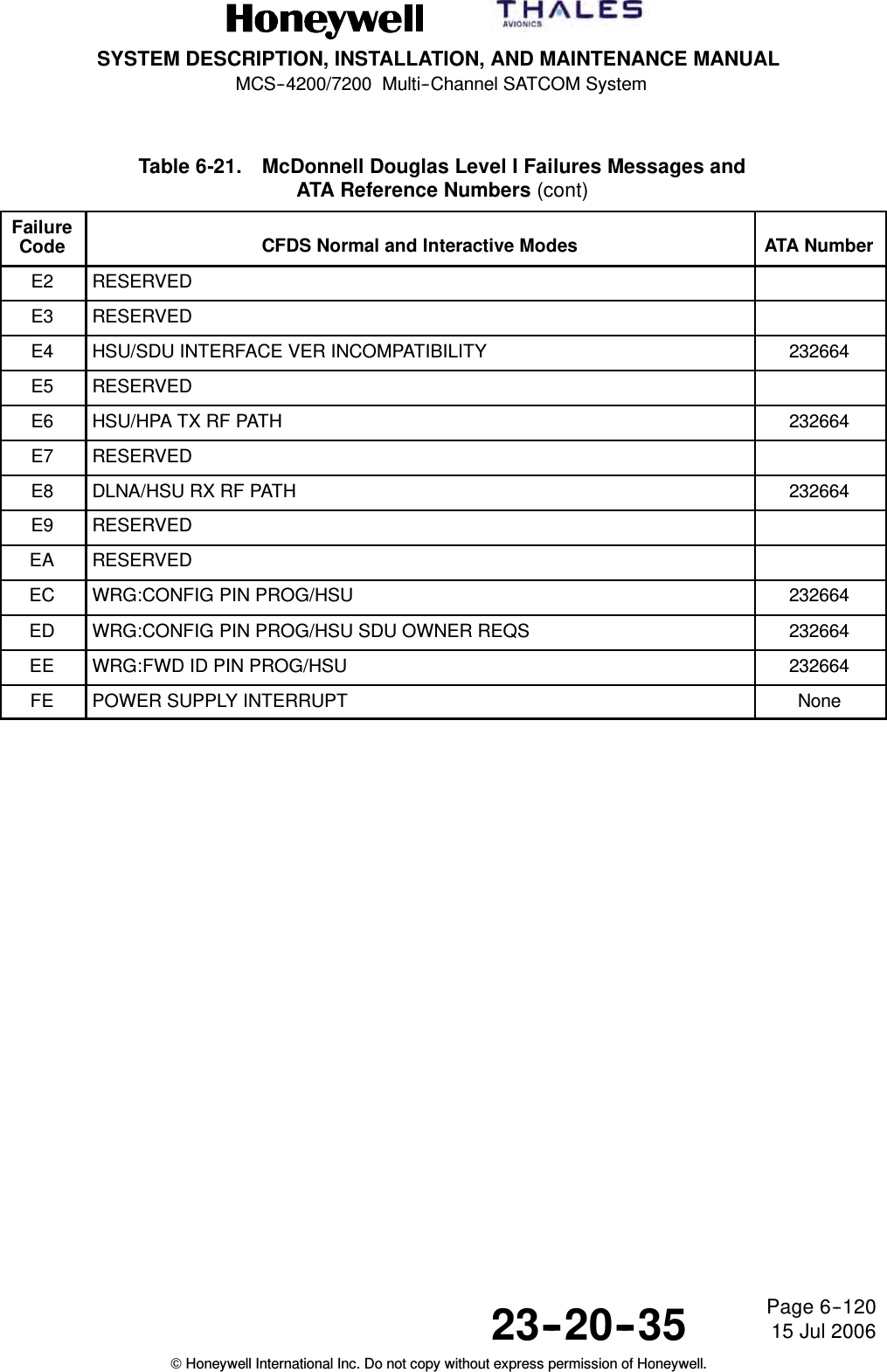
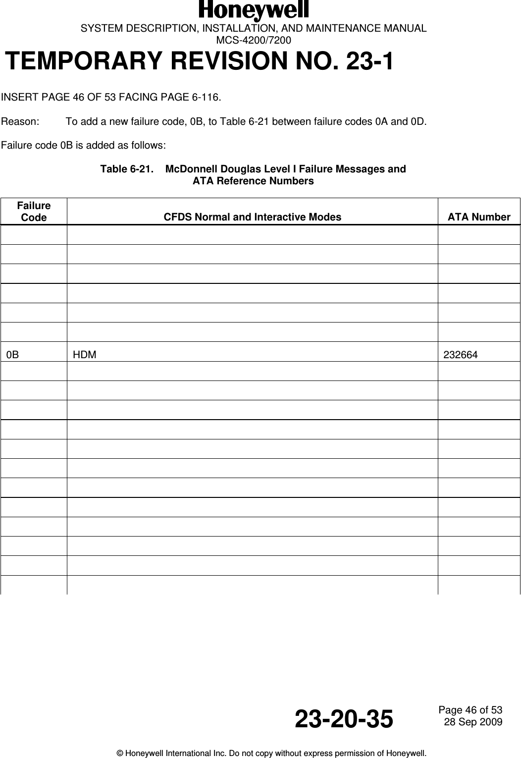
![SYSTEM DESCRIPTION, INSTALLATION, AND MAINTENANCE MANUALMCS--4200/7200 Multi--Channel SATCOM System23--20--35 15 Jul 2006Honeywell International Inc. Do not copy without express permission of Honeywell.Page 6--116Table 6-21. McDonnell Douglas Level I Failures Messages andATA Reference NumbersFailureCode CFDS Normal and Interactive Modes ATA Number01 SDU 23261002 OTHER SDU INCOMPATIBILITY 23261103 HSU 23266404 HPA--IN GAIN [IGA] 232600HPA--HI GAIN [HGA] 23261307 HPA--LO GAIN 2326140A HI POWER RELAY 2326150D DLNA--(TOP/L) 2326160F DLNA--R 23261810 DLNA--LO GAIN 23261913 BSU--(TOP/L) 23261B15 BSU--R 23261C1A IN GAIN ANTENNA--TOP [IGA] 232600HI GAIN ANTENNA--(TOP/L) [HGA] 23261D1C HI GAIN ANTENNA--R 23261F1F LO GAIN ANTENNA 23262021 MCDU1 23263522 MCDU2 23263623 MCDU3 23263733 (ACARS MU/CMU) 23243C34 (ACARS MU/CMU)2 N/A35 (IRS/ADIRU)--PRI 23263E36 (IRS/ADIRU)--SEC 23263F37 RESERVED38 RESERVED39 RESERVED3D (FMC/VIA)1 2326423E (FMC/VIA)2 232643](https://usermanual.wiki/Honeywell/HS-720.HS-720-User-Manual-Part2/User-Guide-1350371-Page-182.png)
![SYSTEM DESCRIPTION, INSTALLATION, AND MAINTENANCE MANUALMCS--4200/7200 Multi--Channel SATCOM System23--20--35 15 Jul 2006Honeywell International Inc. Do not copy without express permission of Honeywell.Page 6--117Table 6-21. McDonnell Douglas Level I Failures Messages andATA Reference Numbers (cont)FailureCode ATA NumberCFDS Normal and Interactive Modes40 ARINC 429 ICAO ADDRESS N/A42 CTU 23264443 (CFS/CPDF) TBD50 HSU/SDU 23266452 (CFS/CPDF)/SDU TBD53 (ACARS MU/CMU)/SDU 23263C54 CTU/SDU 23264455 MCDU1/SDU 23263556 MCDU2/SDU 23263657 (ACARS MU/CMU)2/SDU N/A59 CFDIU/SDU 2326415A (IRS/ADIRU)--PRI/SDU 23263E5B (IRS/ADIRU)--SEC/SDU 23263F5C HPA--IN GAIN/SDU [IGA] 232600HPA--HI GAIN/SDU [HGA] 2326005F HPA--LO GAIN/SDU 23262362 BSU--(TOP/L)/SDU 23262664 BSU--R/SDU 23262766 MCDU3/SDU 23263767 RESERVED68 RESERVED6A RESERVED6C RESERVED6D RESERVED6E RESERVED6F RESERVED71 OTHER SDU/THIS SDU 23260073 (FMC/VIA)1/SDU 232642](https://usermanual.wiki/Honeywell/HS-720.HS-720-User-Manual-Part2/User-Guide-1350371-Page-185.png)
![SYSTEM DESCRIPTION, INSTALLATION, AND MAINTENANCE MANUALMCS--4200/7200 Multi--Channel SATCOM System23--20--35 15 Jul 2006Honeywell International Inc. Do not copy without express permission of Honeywell.Page 6--118Table 6-21. McDonnell Douglas Level I Failures Messages andATA Reference Numbers (cont)FailureCode ATA NumberCFDS Normal and Interactive Modes74 (FMC/VIA)2/SDU 23264380 RESERVED82 RESERVED88 RESERVED90 SDU M--CTRL/HPA--IN GAINSDU M--CTRL/HPA--HI GAIN[IGA][HGA]23260023260096 SDU M--CTRL/HPA--LO GAIN 23262D98 SDU M--CTRL/BSU--(TOP/L) 2326009A BSU--R XTALK/BSU--L 2326009C SDU M--CTRL/BSU--R 2326309D BSU--L XTALK/BSU--R 2326009E SDU/HSU 2326649F RESERVED 232664A6 HSU ETHERNET PORT 1 232664A7 HSU ETHERNET PORT 2 232664A8 HSUISDNPORT1 232664A9 HSUISDNPORT2 232664C0 WRG:CONFIG PIN PROG/SDU 232600C1 SDU WOW MISCOMPARE N/AC2 SDU/OTHER SDU SELECT--DISABLE DISCRETE 232600C3 WRG:ICAO ADDRESS PIN PROG/SDU 232631C4 TX PATH VSWR--IN GAINTX PATH VSWR--HI GAIN[IGA][HGA]232600232600C5 WRG:CONFIG PIN PROG/SDU OWNER REQS 232600C6 TX PATH VSWR--LO GAIN 232600C7 HPA--IN GAIN/OVER TEMPERATUREHPA--HI GAIN/OVER TEMPERATURE[IGA][HGA]23260023262CC8 BAD DATA FROM GROUND EARTH STATION NoneC9 HPA--LO GAIN/OVER TEMPERATURE 232634](https://usermanual.wiki/Honeywell/HS-720.HS-720-User-Manual-Part2/User-Guide-1350371-Page-186.png)
![SYSTEM DESCRIPTION, INSTALLATION, AND MAINTENANCE MANUALMCS--4200/7200 Multi--Channel SATCOM System23--20--35 15 Jul 2006Honeywell International Inc. Do not copy without express permission of Honeywell.Page 6--119Table 6-21. McDonnell Douglas Level I Failures Messages andATA Reference Numbers (cont)FailureCode ATA NumberCFDS Normal and Interactive ModesCA SDU/DLNA--LO GAIN 232619CB WRG:SDI PIN PROG/HPA--IN GAINWRG:SDI PIN PROG/HPA--HI GAIN[IGA][HGA]232600232600CC WRG:SDI PIN PROG/HPA--LO GAIN 232600CD SDU (POC/TOTC) DATA RESET NoneCE RESERVEDCF HPA--IN GAIN (POC/TOTC) DATA RESETHPA--HI GAIN (POC/TOTC) DATA RESET[IGA][HGA]NoneNoneD0 HPA--LO GAIN (POC/TOTC) NoneD1 WRG:SDI PIN PROG/HPA--IN GAINWRG:SDI PIN PROG/HPA--HI GAIN[IGA][HGA]232600232600D2 WRG:SDI PIN PROG/HPA--LO GAIN 232600D3 WRG:SDI PIN PROG/BSU--(TOP/L) 232600D4 WRG:SDI PIN PROG/BSU--R 232600D5 SDU COAX/HPA--IN GAINSDU COAX/HPA--HI GAIN[IGA][HGA]232600232600D6 SDU COAX/HPA--LO GAIN 232600D7 RESERVEDD8 DLNA/(SDU)--(TOP/L) 232600D9 DLNA/(SDU)--R 232600DA DLNA/(SDU)--LO GAIN 232600DB LO GAIN SUBSYSTEM 232600DC NO ACTIVE ACARS MU/CMU 232400DD SDU OWNER REQS -- SECURED NoneDE SDU OWNER REQS -- USER NoneDF IN GAIN SUBSYSTEMHI GAIN SUBSYSTEM[IGA][HGA]232600232600E0 RESERVEDE1 BAD HSU DISABLE DISCRETE 232664](https://usermanual.wiki/Honeywell/HS-720.HS-720-User-Manual-Part2/User-Guide-1350371-Page-187.png)