Honeywell HS-720 High Speed Data Unit for the MCS-7200 SATCOM System User Manual SDIM Multi Channel SATCOM System A15 5111 010
Honeywell International Inc. High Speed Data Unit for the MCS-7200 SATCOM System SDIM Multi Channel SATCOM System A15 5111 010
Contents
- 1. HS-720 User Manual Part1
- 2. HS-720 User Manual Part2
- 3. HS-720 User Manual Part3
HS-720 User Manual Part3
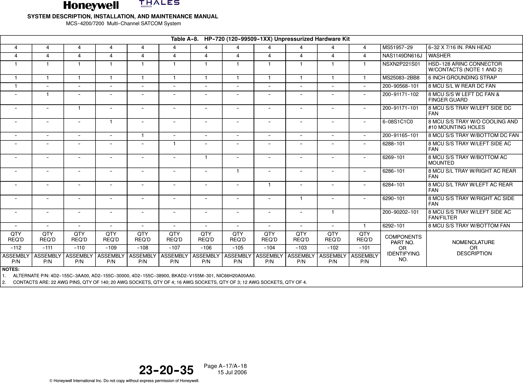
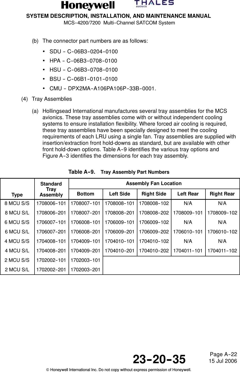
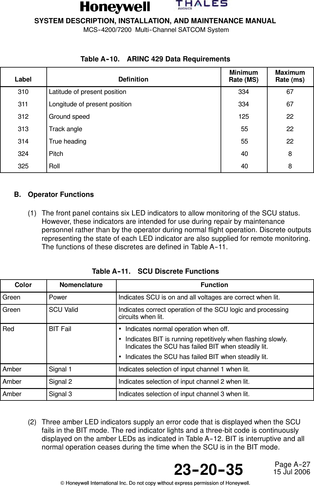
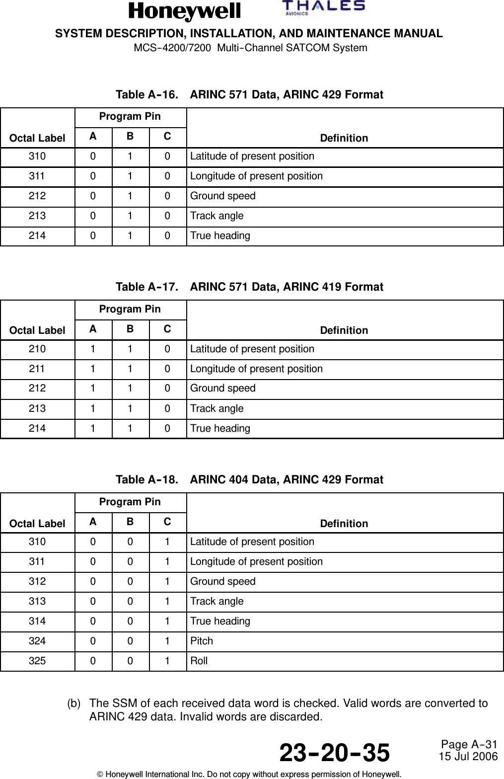
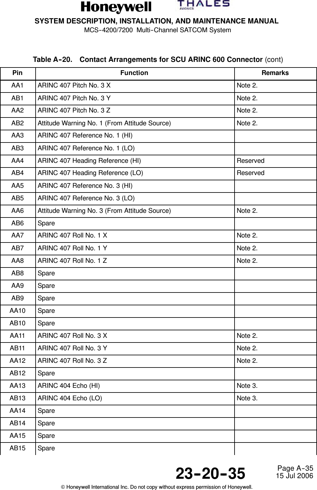
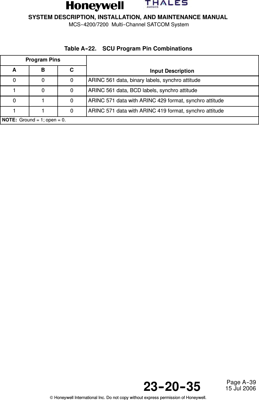
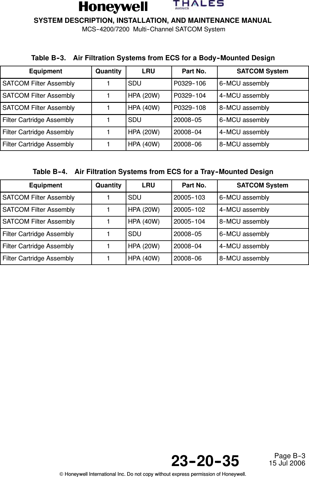
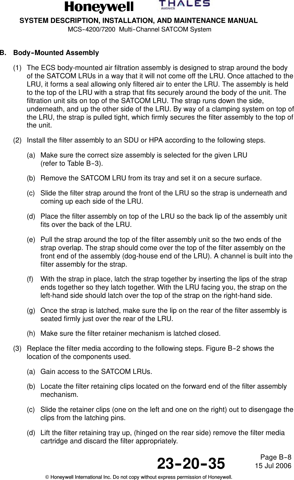
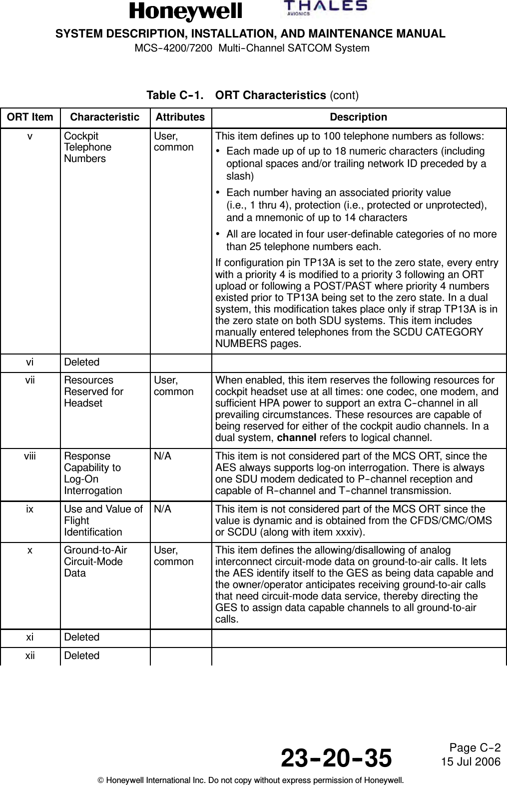
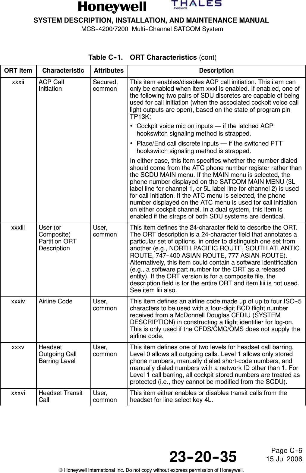
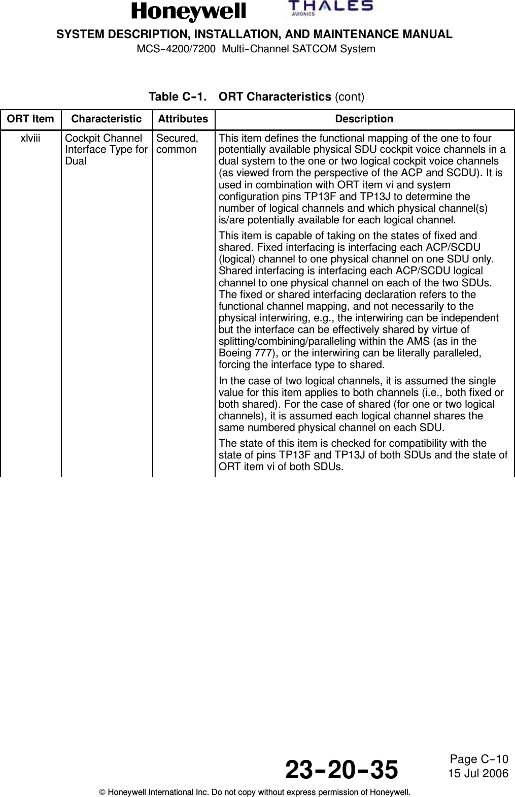
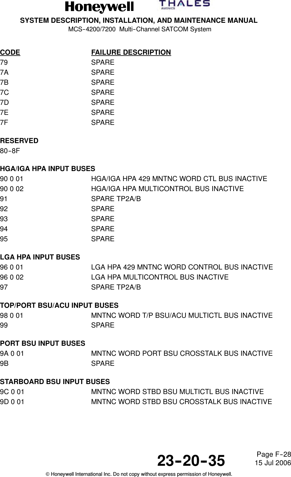
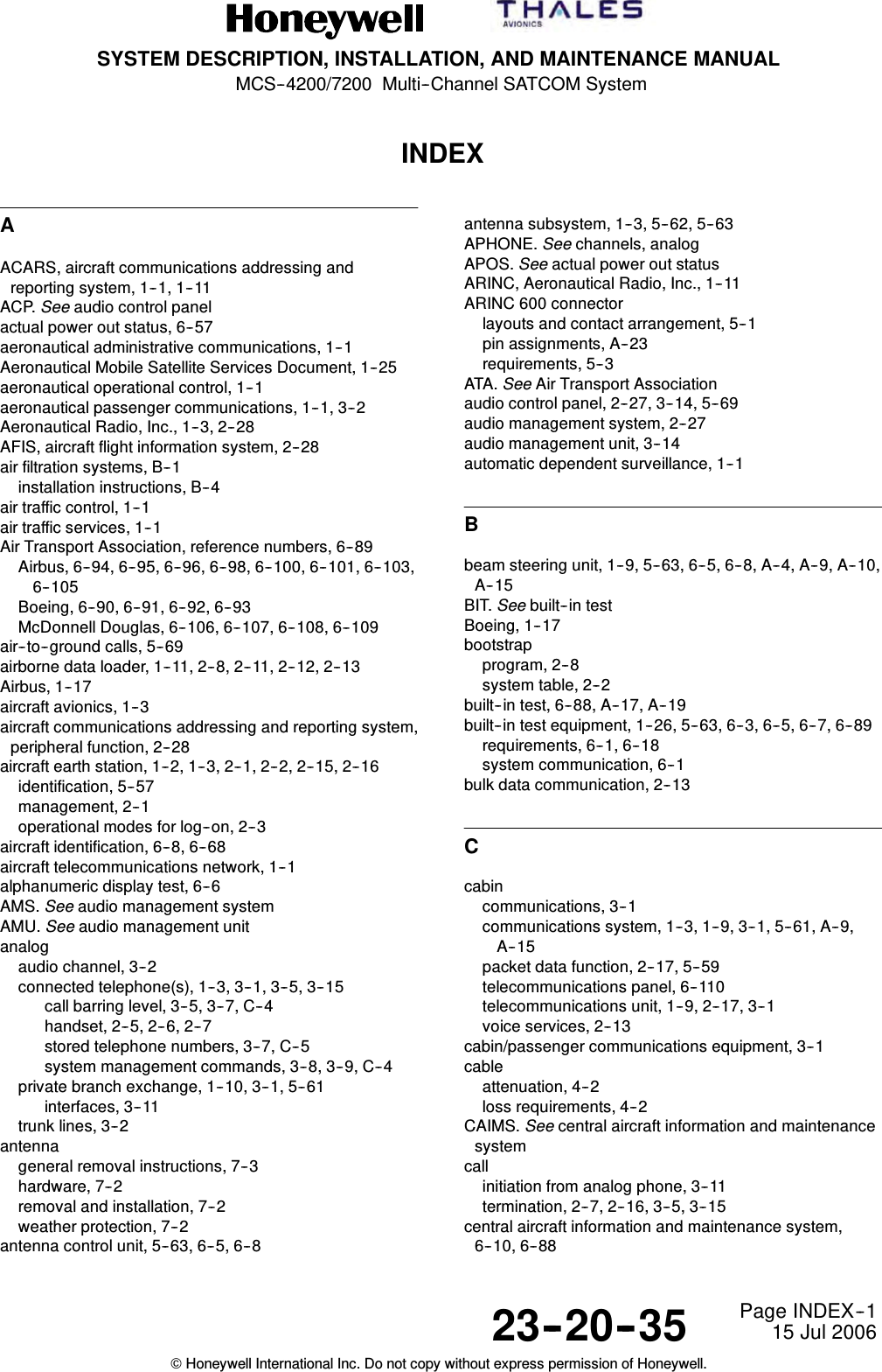
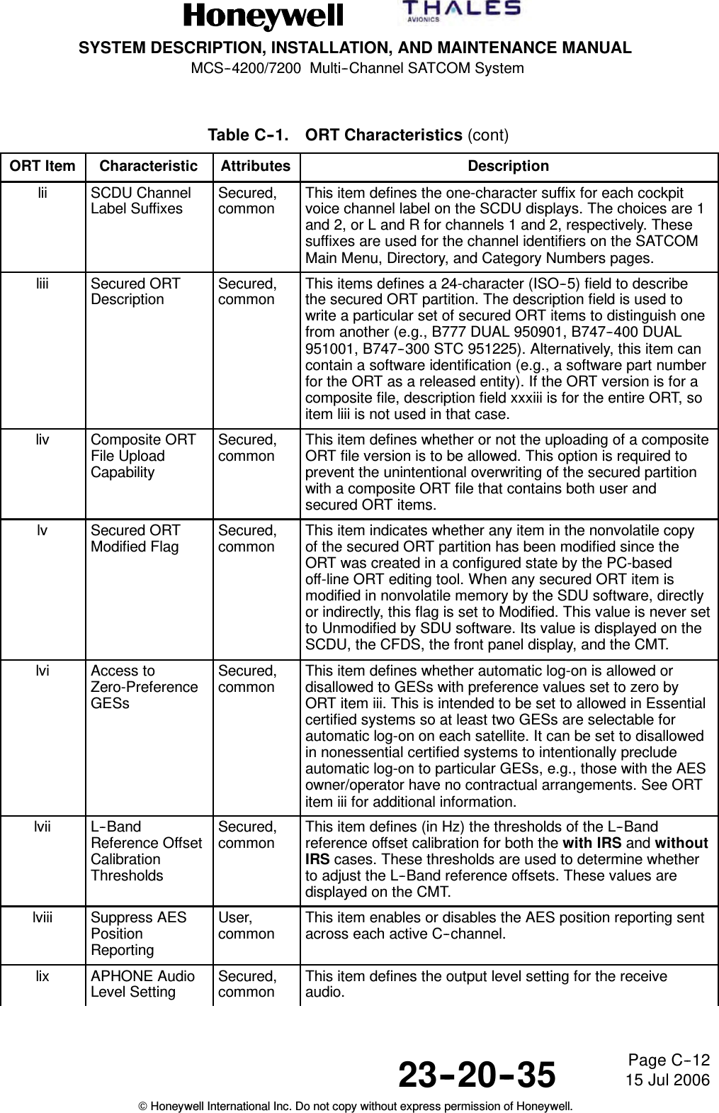
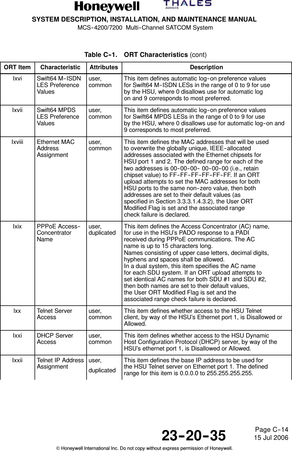
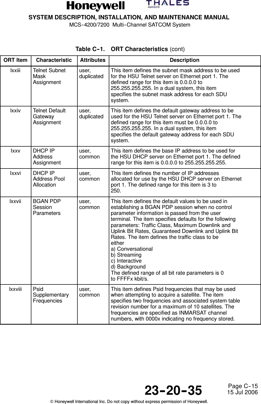
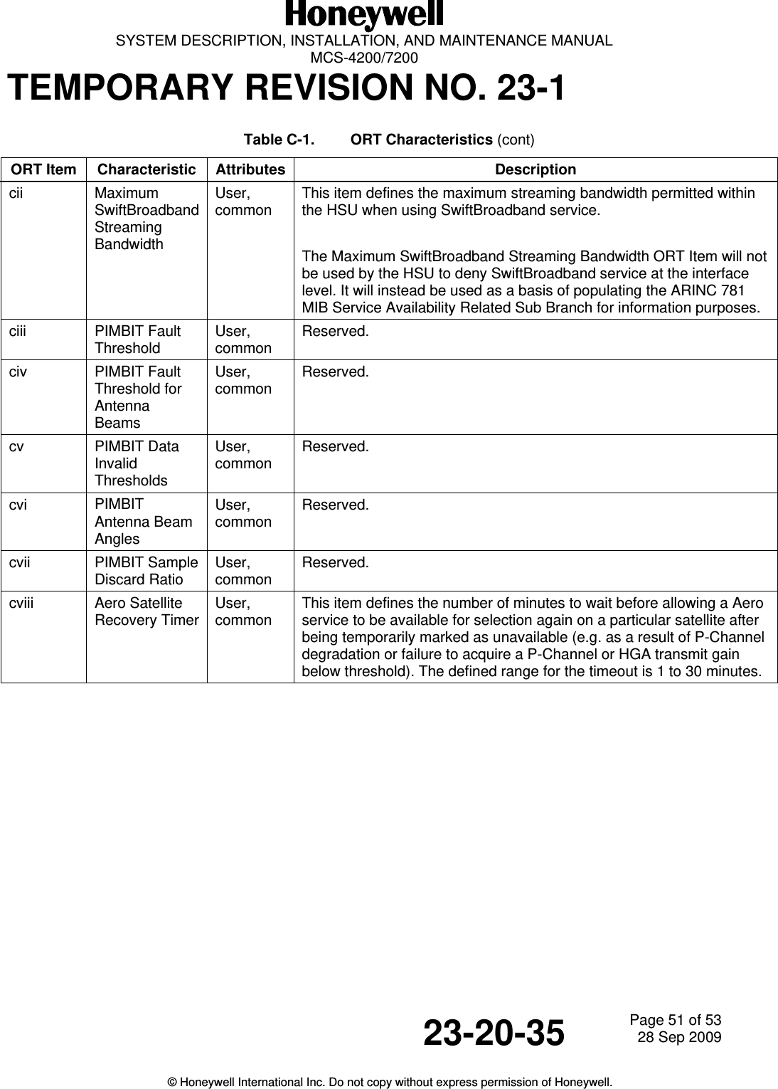
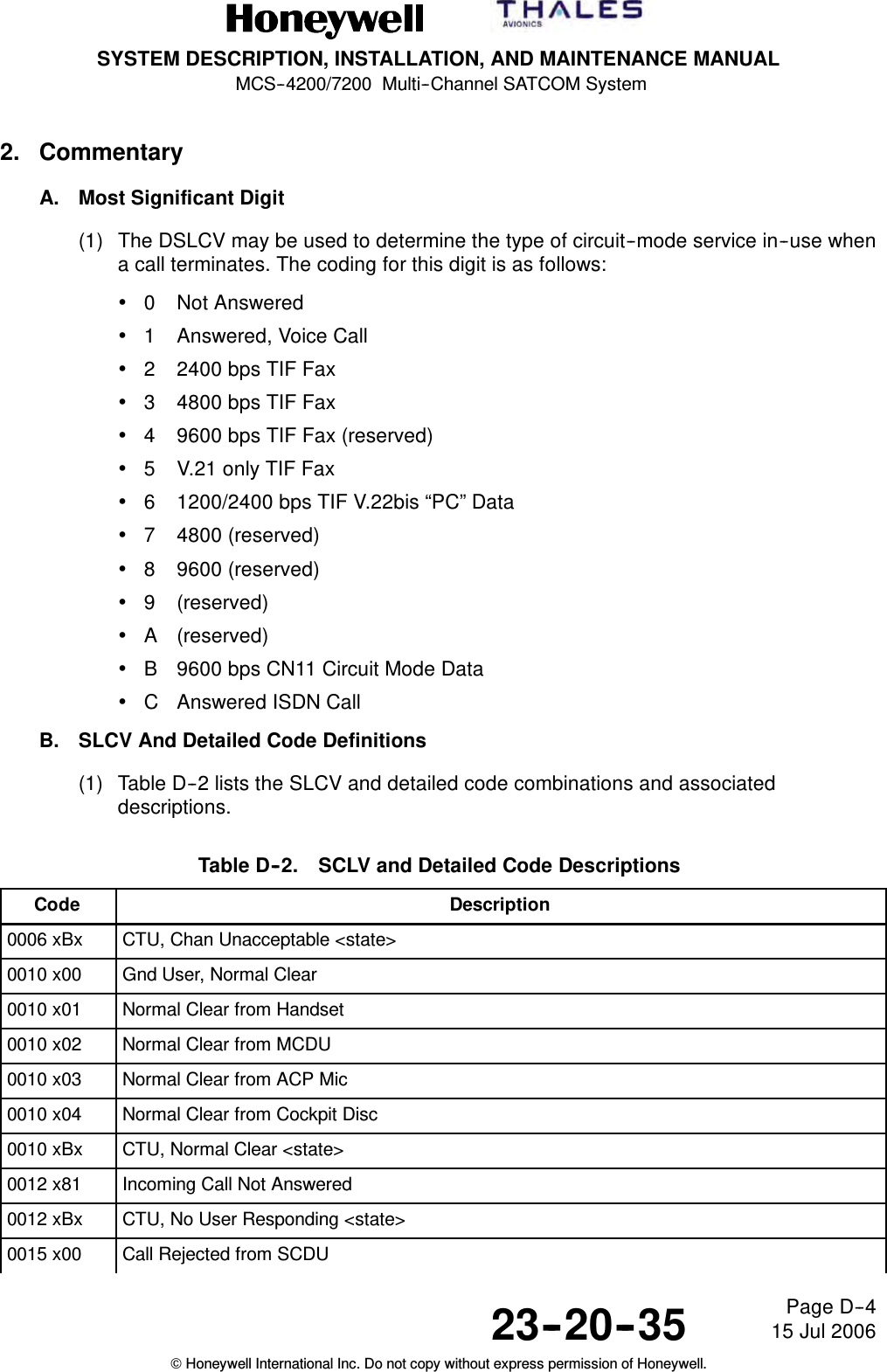
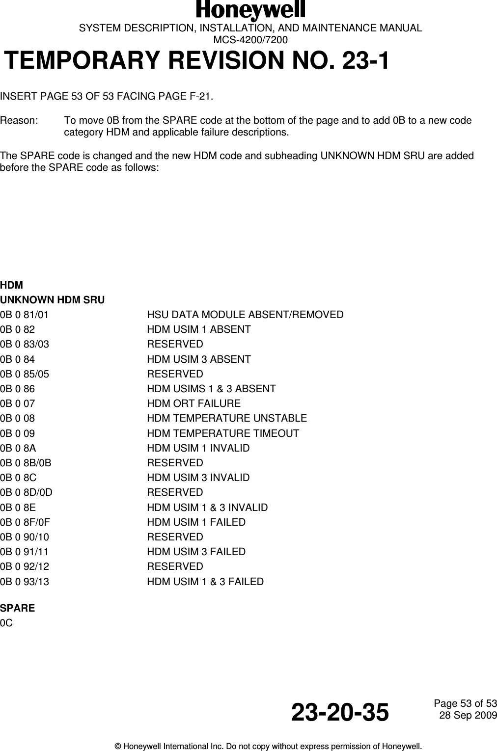
![SYSTEM DESCRIPTION, INSTALLATION, AND MAINTENANCE MANUALMCS--4200/7200 Multi--Channel SATCOM System23--20--35 15 Jul 2006Honeywell International Inc. Do not copy without express permission of Honeywell.Page C--11Table C--1. ORT Characteristics (cont)ORT Item DescriptionAttributesCharacteristicil MasteryHandoverAlgorithmWeightingUser,commonThis item stores the relative weighting factors for each of thesix functional capability items that form the criteria fordetermining which system should automatically become themaster in a dual system. Each of the six weighting factors is anon-negative integer ranging from 0 to 99. Higher factorsindicate more important criteria; however, only the relativevalues of the factors is significant. Zero is used to indicate acapability factor not installed, not used, or is a don’t care. Thefunctional capability items are as follows:•CoV -- Cockpit voice (for any number of channels).•CaV -- Cabin circuit-mode voice/fax/data(any number of channels, any cabin interface).•CoL -- Cockpit packet-mode data(through [C]MU) at low-rate only.•CoH -- Cockpit packet-mode data(through [C]MU) at (potentially) high-rate.•CaL -- Cabin packet-mode data(through CPDF or CTU) at low rate only.•CaH -- Cabin packet-mode data (through CPDF or CTU) at(potentially) high-rate.CoL and CoH are mutually exclusive, as are CaL andCaH — i.e., regardless of the weighting factors assigned, nomore than one of the cockpit data (or cabin data) capabilitiescanbetrueatatime.The primary practical use of this ORT item is for determiningwhich SDU in a dual system should be the master when thechoice is down to one system which only has voice capabilityvs one which only has data capability, or one with only cockpitservices capabilities vs one with only cabin servicescapabilities.lDisable/ReenableOther SATCOMSCDU PromptsSecured,commonThis item determines if the disable other SATCOM andre--enable other SATCOM toggling SCDU prompts arepresented or suppressed. The SCDU prompts are usuallysuppressed if the optional external manual switch (thatcontrols the dual system select and disable discretes) issupplied so there is only one means of performing anyfunction at a time and the possibility of inadvertently disablingboth systems is avoided.li SCDU SATCOMSubsystemPromptsSecured,duplicatedThis item defines up to six ISO--5 characters used for theSCDU main menu SATCOM subsystem selection LSKprompts. The owner/operator is able to select any ISO--5characters and any length up to six characters. Examplecharacter strings would be SAT L and SAT R, or <SDU--1 and<SDU--2.](https://usermanual.wiki/Honeywell/HS-720.HS-720-User-Manual-Part3/User-Guide-1350372-Page-48.png)
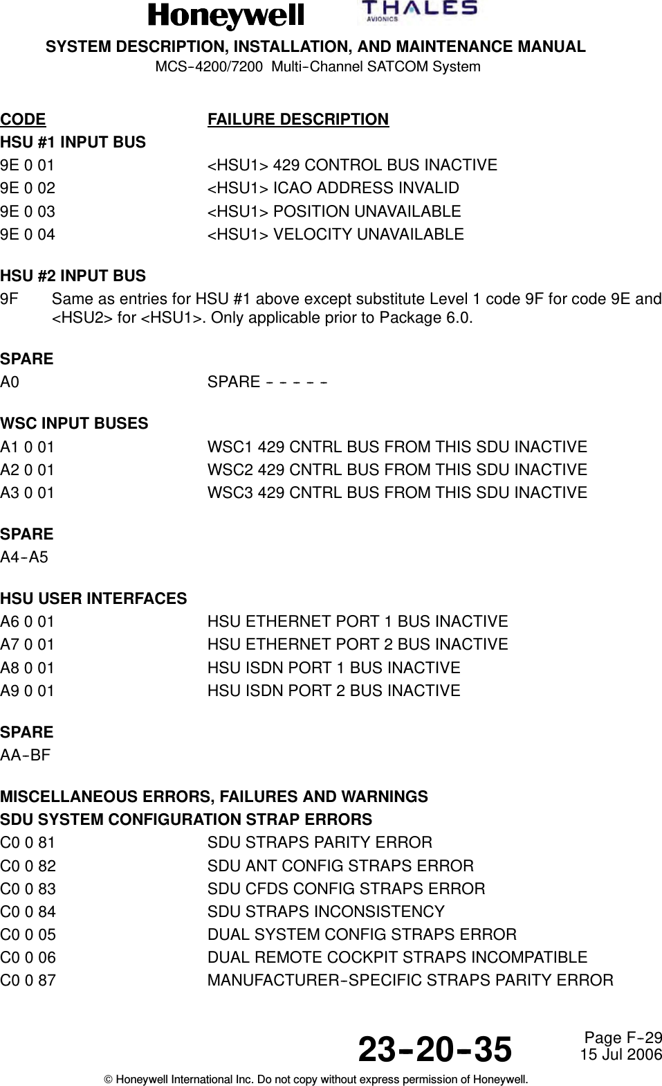
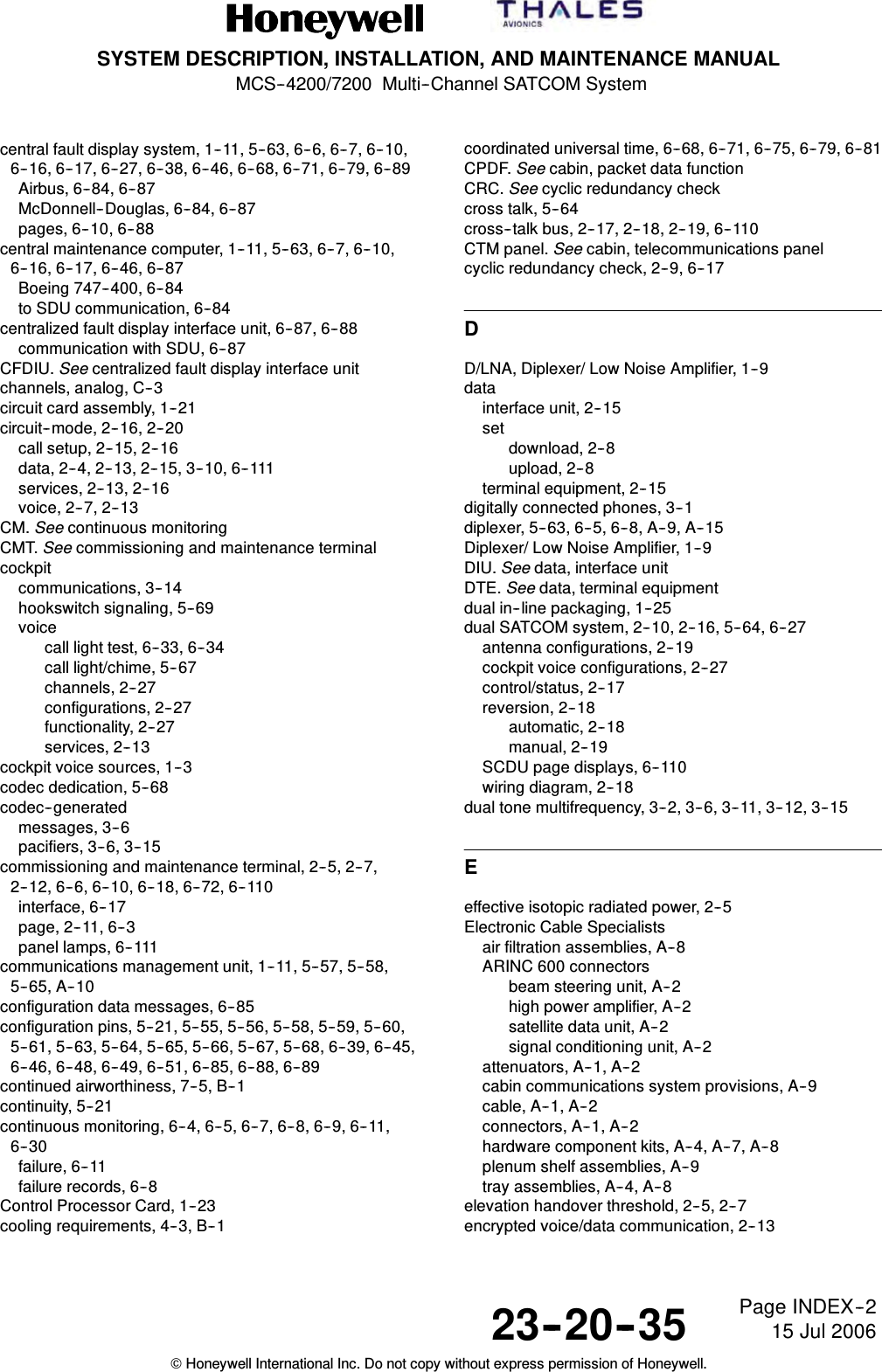
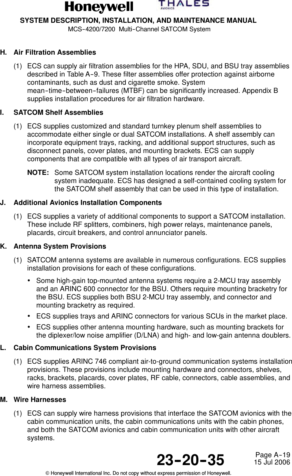
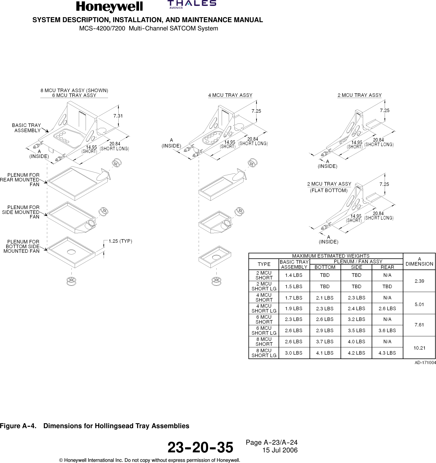
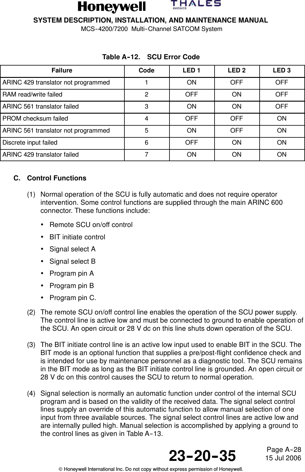
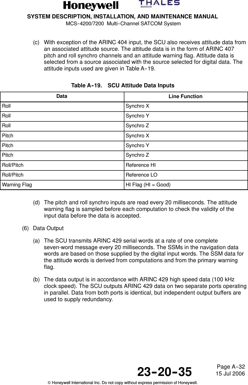
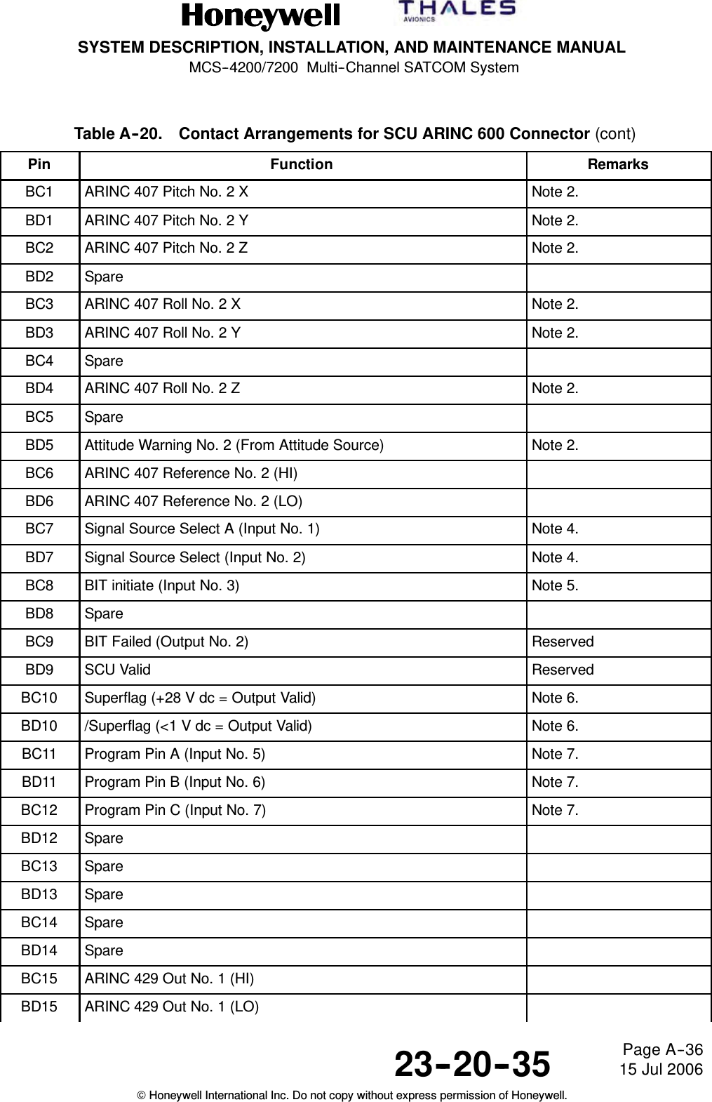
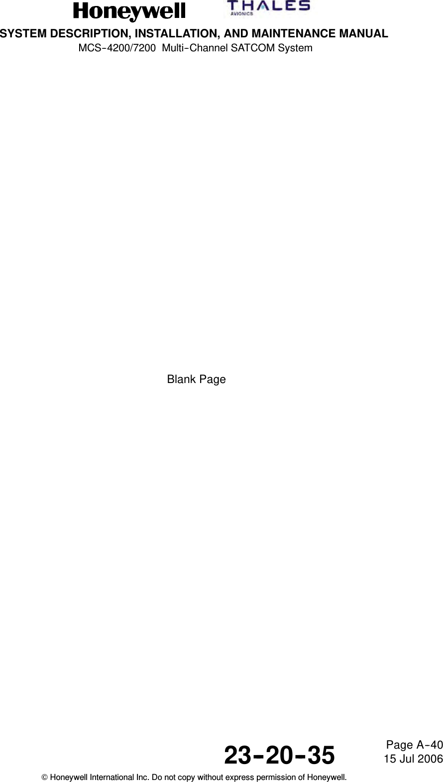
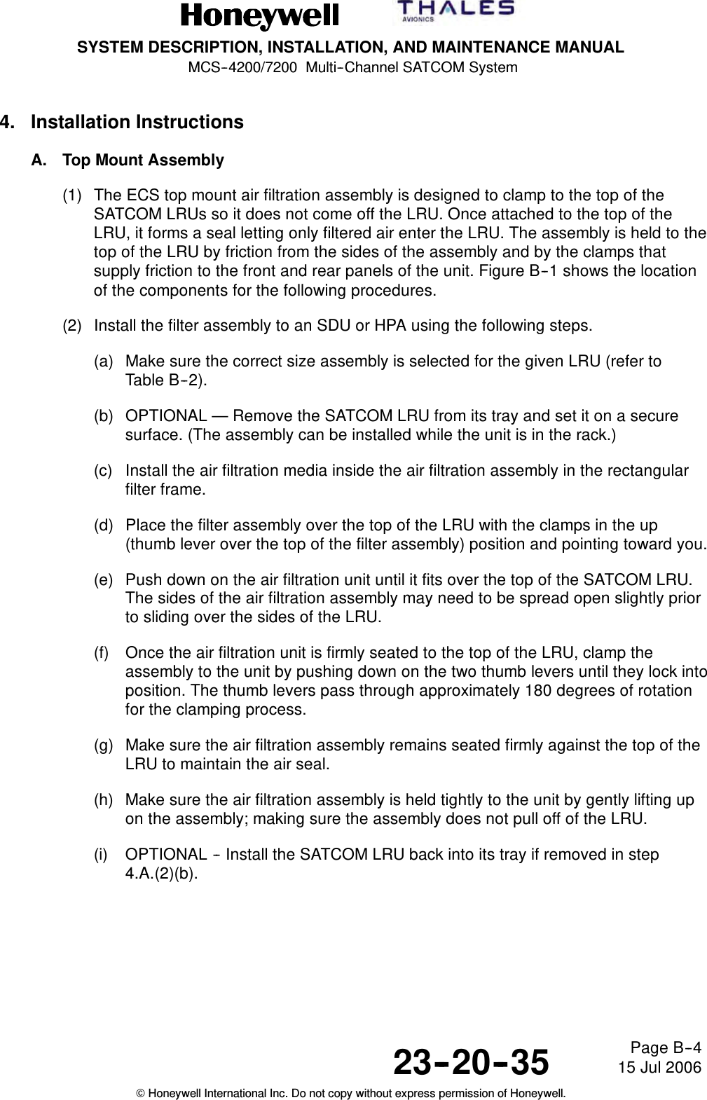
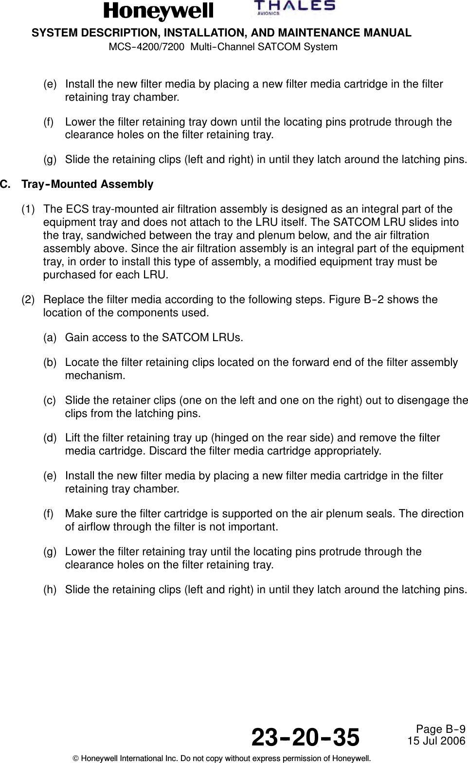
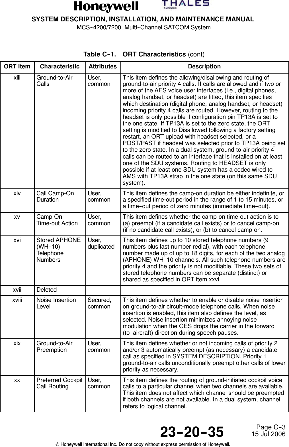
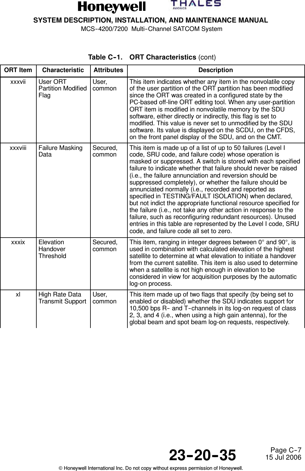
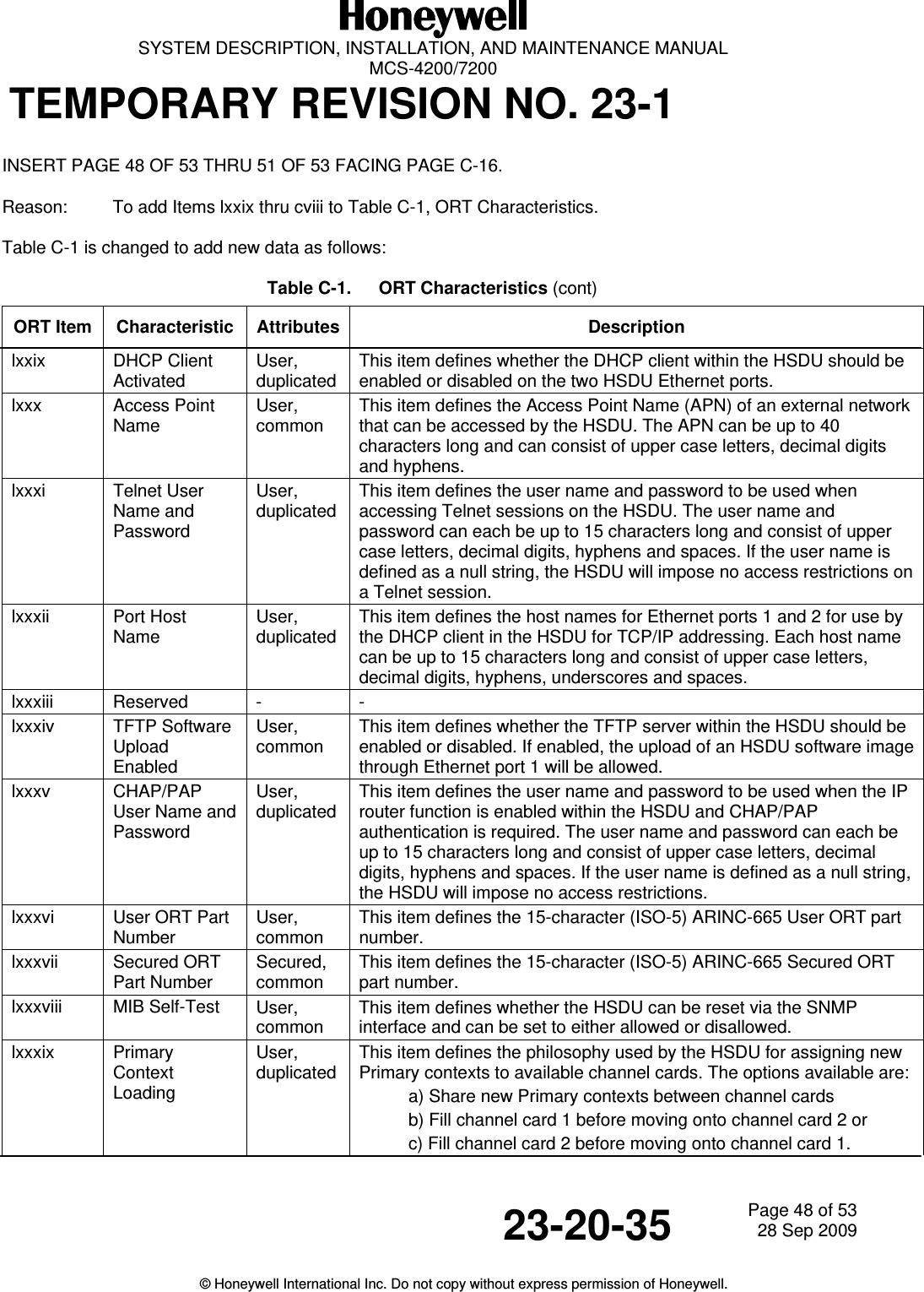
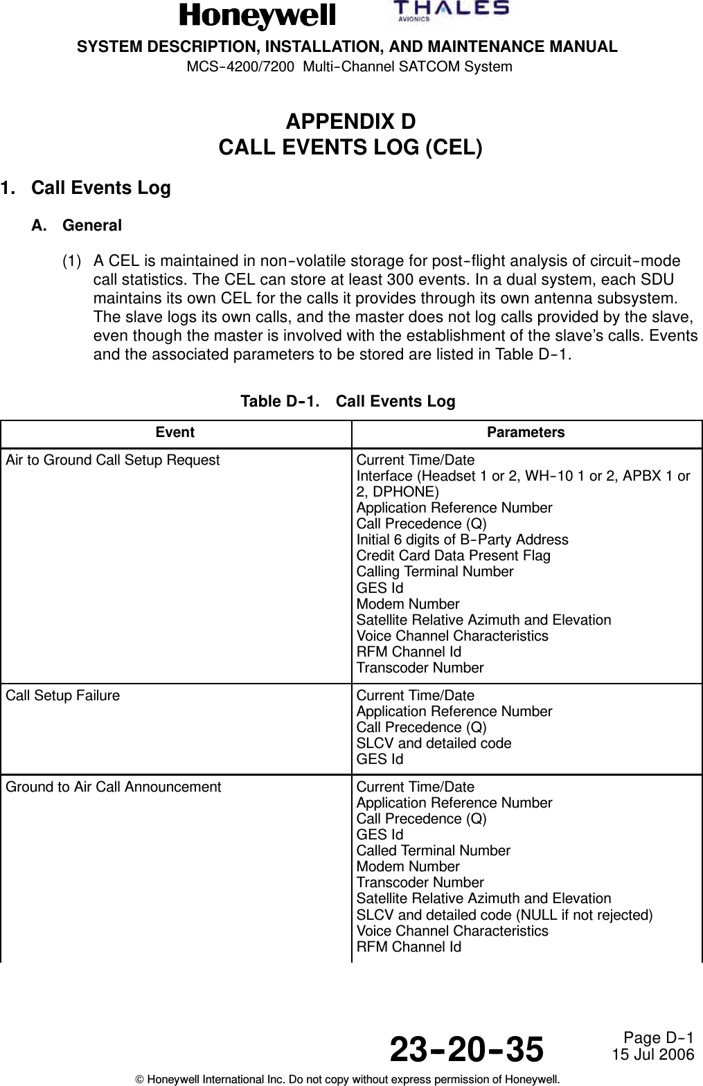
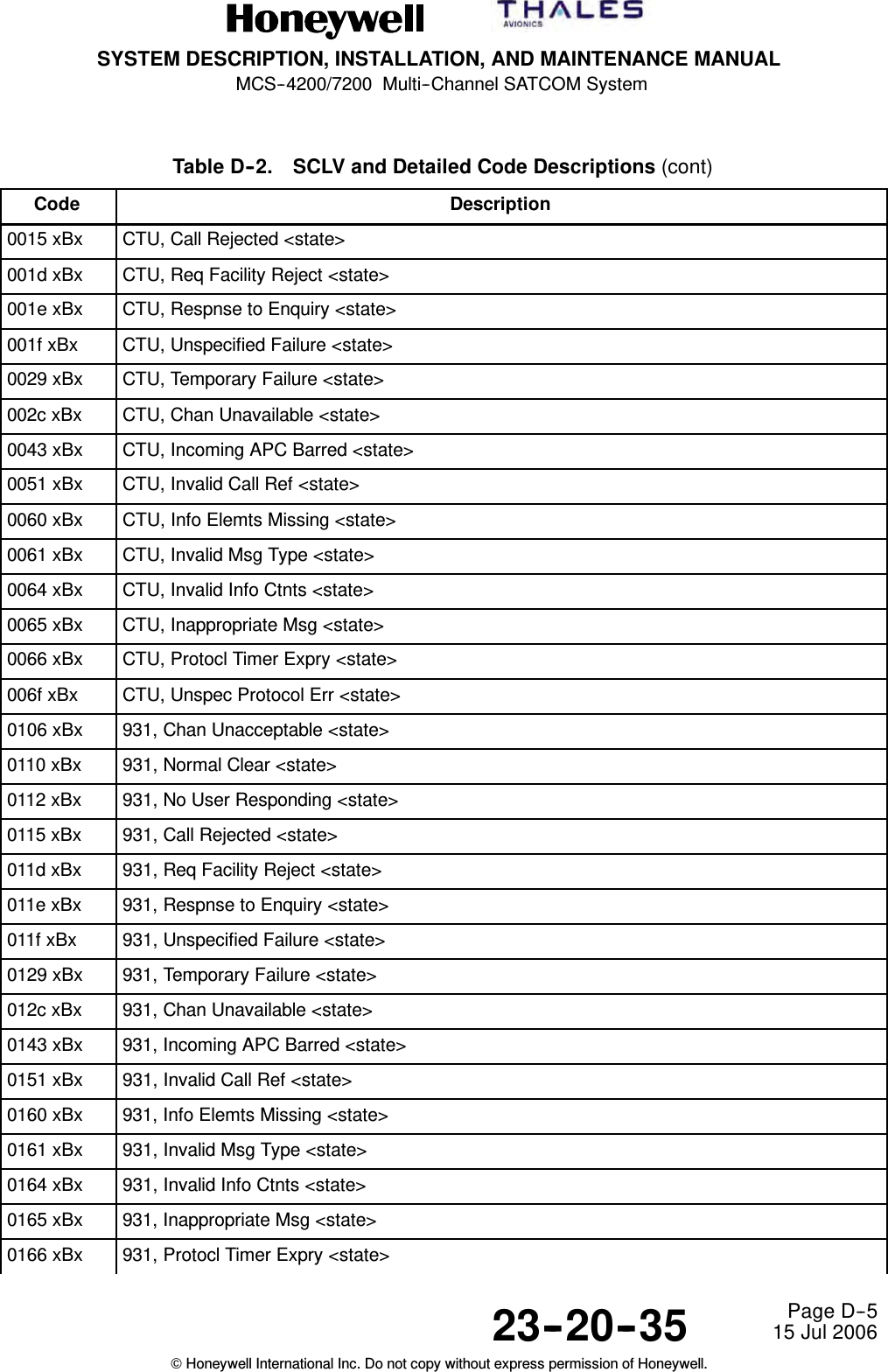
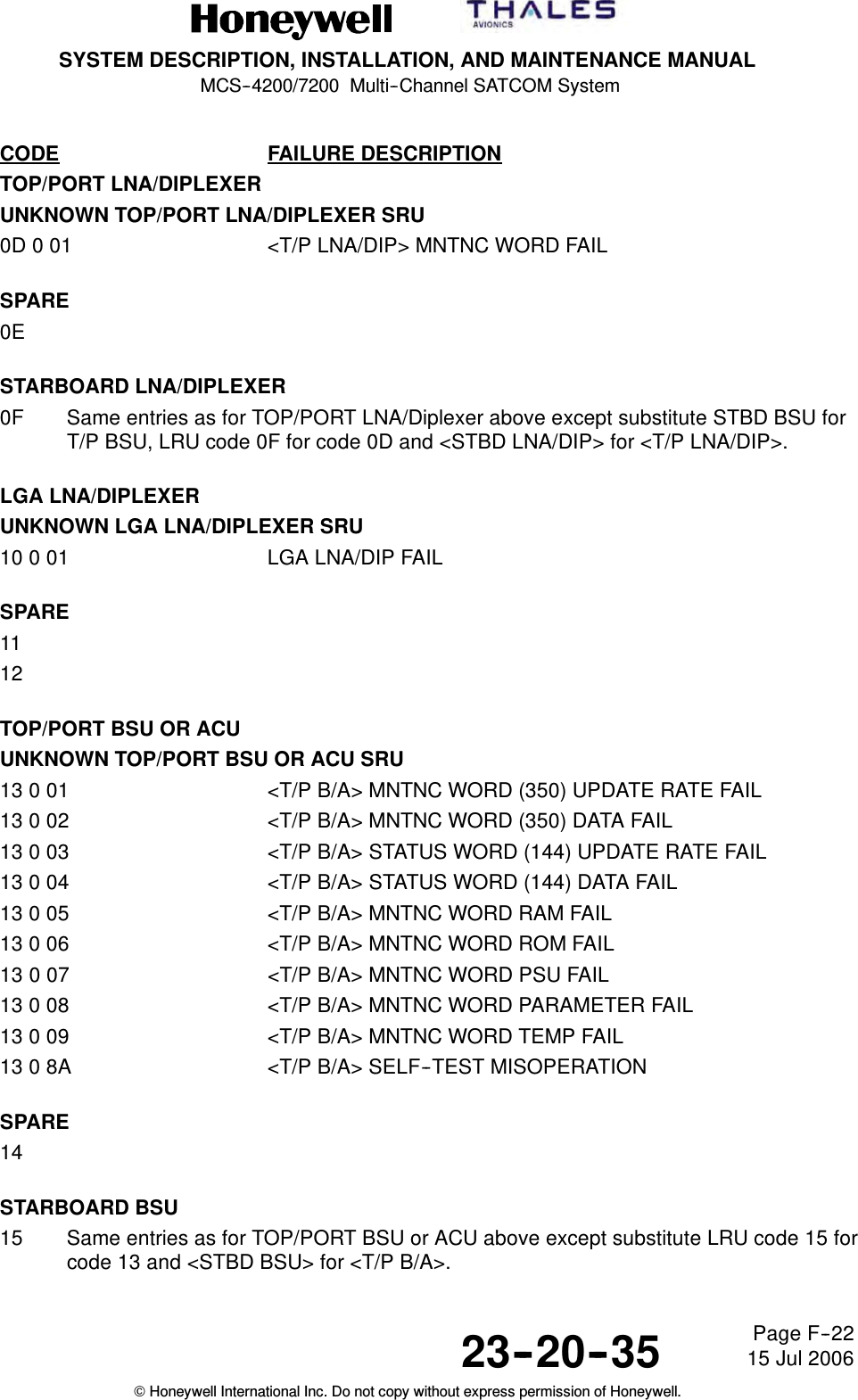
![SYSTEM DESCRIPTION, INSTALLATION, AND MAINTENANCE MANUALMCS--4200/7200 Multi--Channel SATCOM System23--20--35 15 Jul 2006Honeywell International Inc. Do not copy without express permission of Honeywell.Page C--13Table C--1. ORT Characteristics (cont)ORT Item DescriptionAttributesCharacteristiclx AERO H OnlyOperationSecured,commonThis item defines the service mode when an HGA is installed.lxi HSD PreemptionPreferencesuser,commonThis ORT item defines the preferences to be used indetermining which channel(s)/call(s) will be preemptedwhen one or more HSD channels are among thepreemption candidates. The following preference sets areselectable:Level Retention Preferences0 C--P4 > MPDS/BGAN > ISDN1 C--P4 > ISDN > MPDS/BGAN2 MPDS/BGAN > C--P4 > ISDN3 MPDS/BGAN > ISDN > C--P44ISDN>C--P4>MPDS/BGAN5 ISDN > MPDS/BGAN > C--P4Ixii Ongoing HSDCall EIRPuser,commonThis item defines the minimum level of power that theSDU reserves for an ongoing Swift64 M--ISDN HSDcall. If the HSU requested EIRP falls below thisreserved EIRP level, then power reserved for the HSUwill freeze at this level even though the actual powerwill track the EIRP requested by the HSU. The definedrange of this item is 0.0 to 25.0 dBW.Ixiii WSC ManualDialinguser,commonThis item defines parameter options to be passed toany connected and active Williamsburg SDUcontroller(s) (WSCs), for the WSC’s own optionalusage. It has no other direct functionality within theSDU. It shall be capable of taking on the values“Disabled” and “Enabled”, and for the latter case, itspecifies the priority level (1 through 4, [for ManualDial Enable and Priority for Manual Dial] ) to be usedfor such calls.Ixiv Minimum HSDCall EIRPuser,commonThis item defines the minimum permissible level ofpower that the SDU deems adequate for an ongoingSwift64 M--ISDN HSD call. If the HSU requested EIRPfalls below this level, then the SDU terminates thecall. The defined range of this item is 0.0 to 30.0dBW.Ixv HSD RegistrationPreferenceuser,commonThis item specifies the type of HSD service(Swift64 or BGAN) which the HSU shall provide by way of thechosen satellite when in a region of both Swift64 andBGAN service coverage. The item defines theregistration preference to be eithera) automatic (i.e. BGAN when in BGAN coverage,otherwise Swift64 if in Swift64 coverage)b) Swift64 onlyc) BGAN only.](https://usermanual.wiki/Honeywell/HS-720.HS-720-User-Manual-Part3/User-Guide-1350372-Page-50.png)
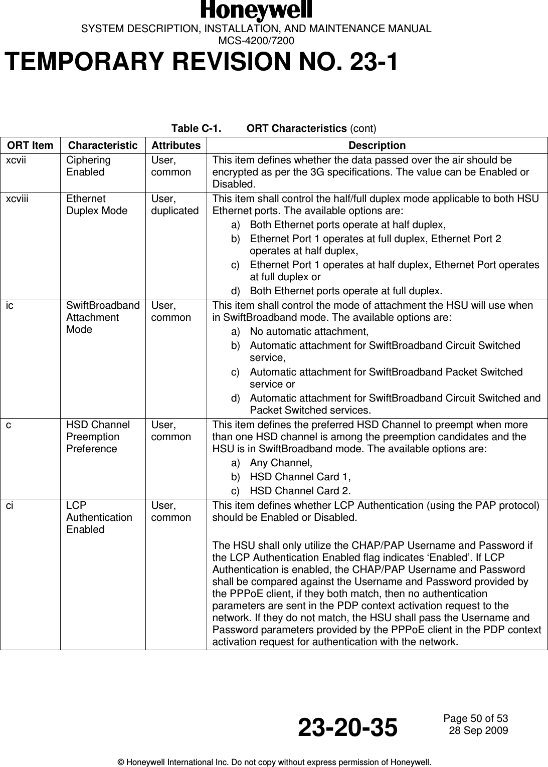

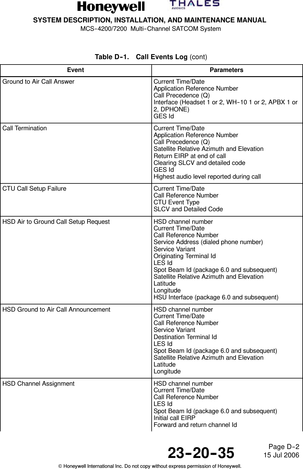
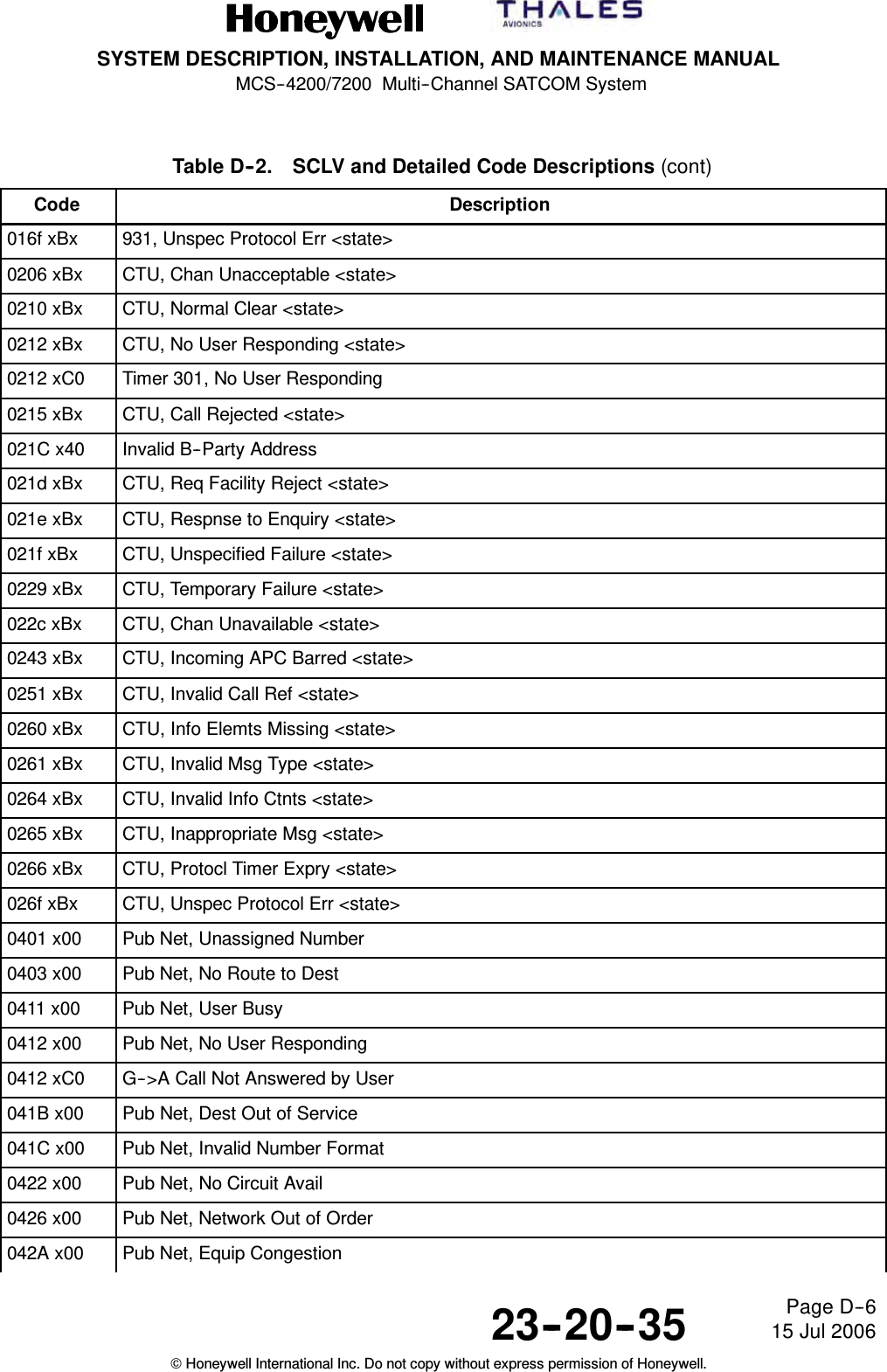
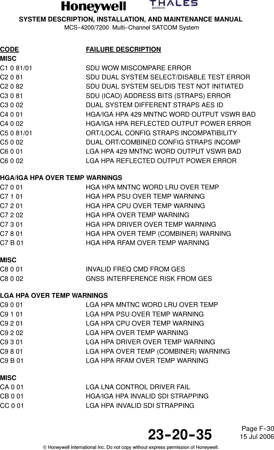
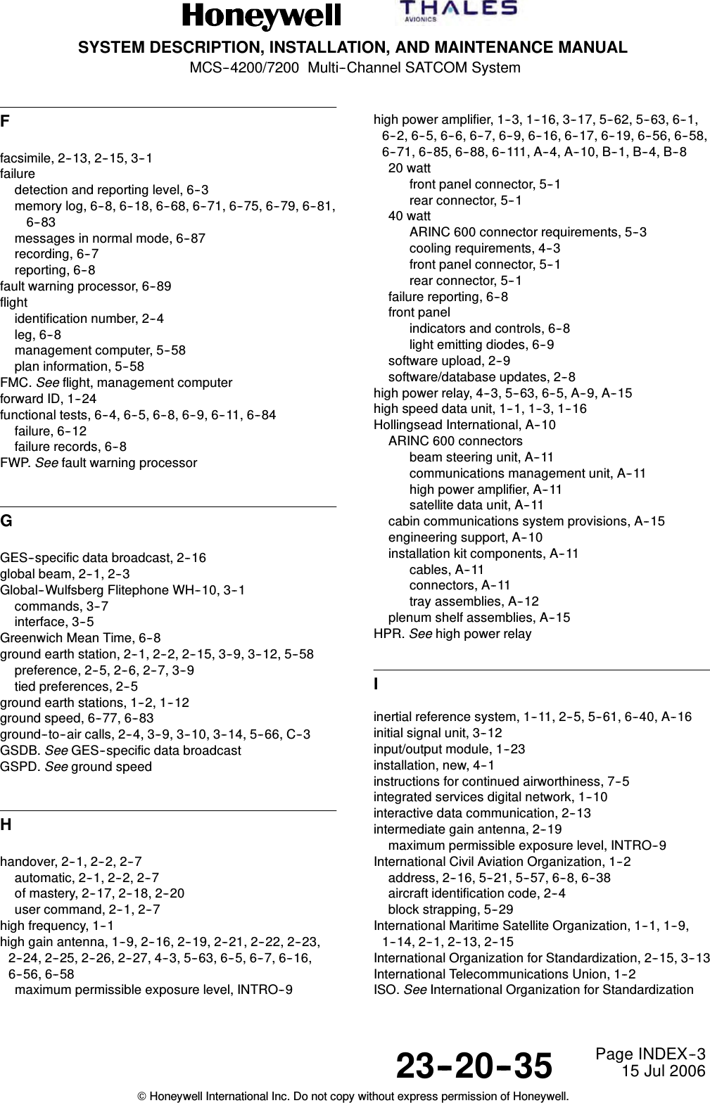
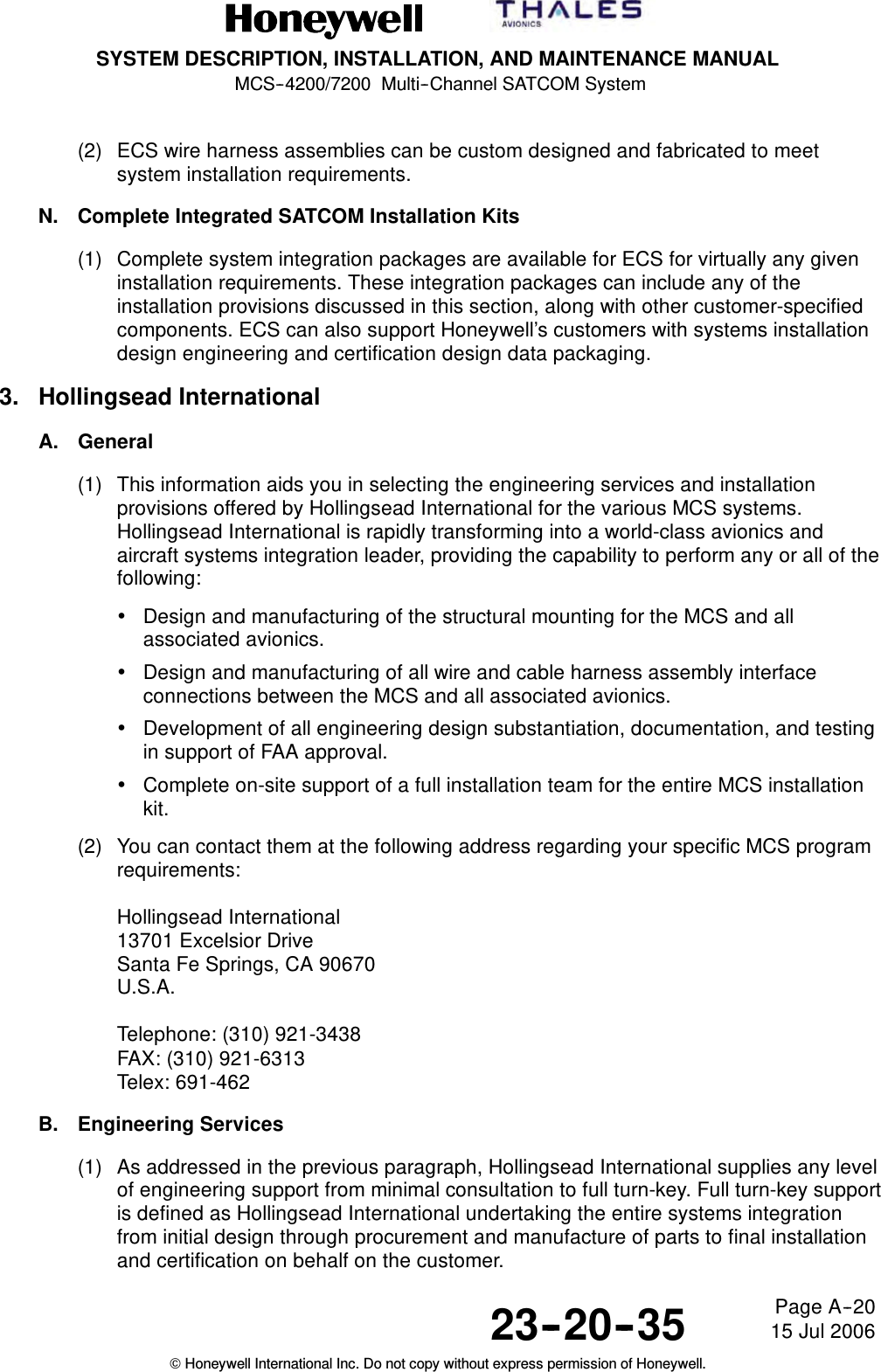
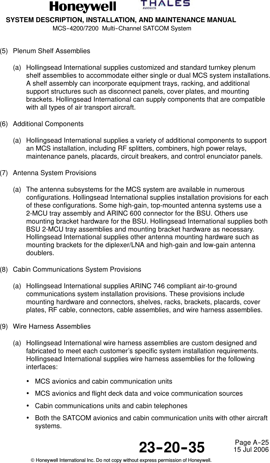
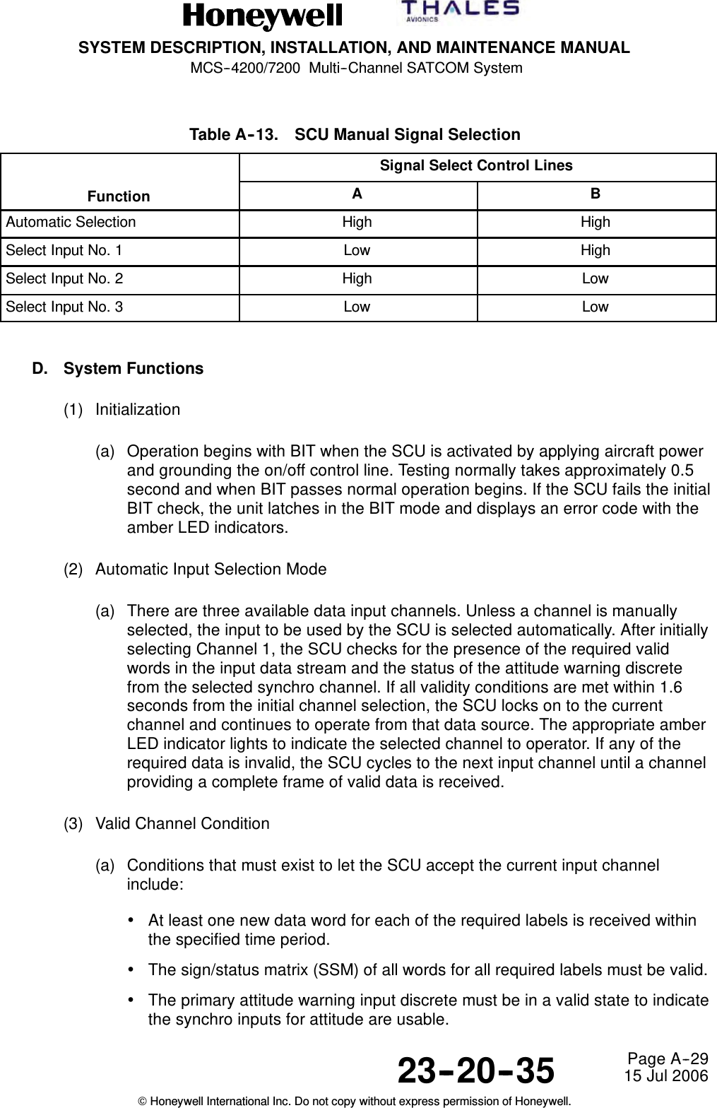
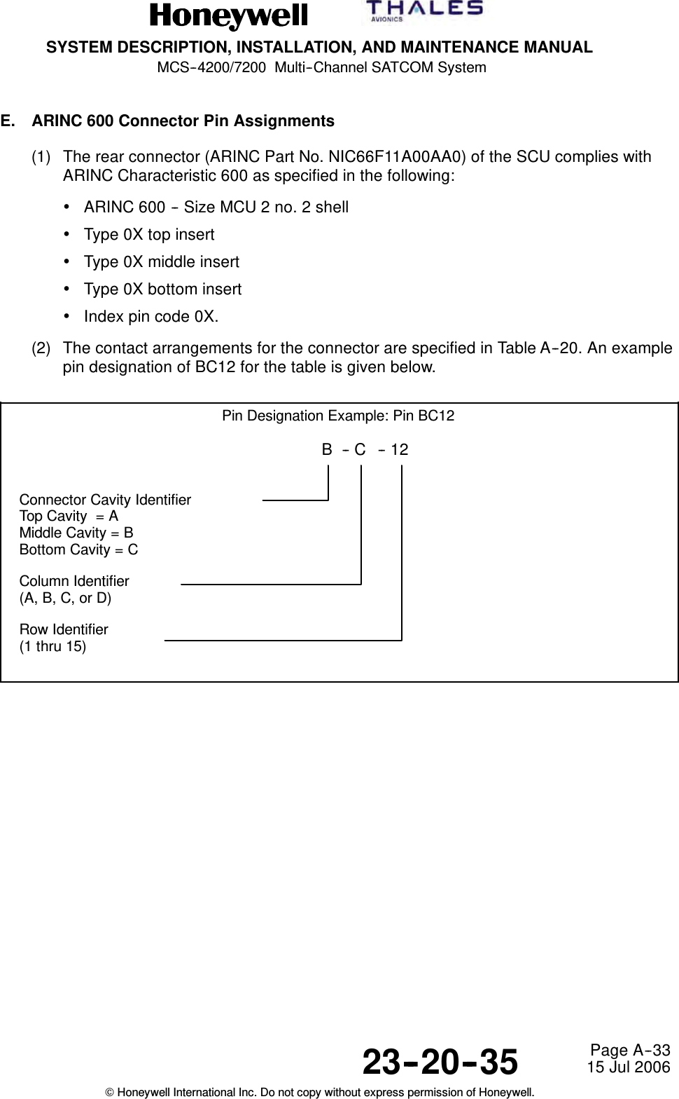
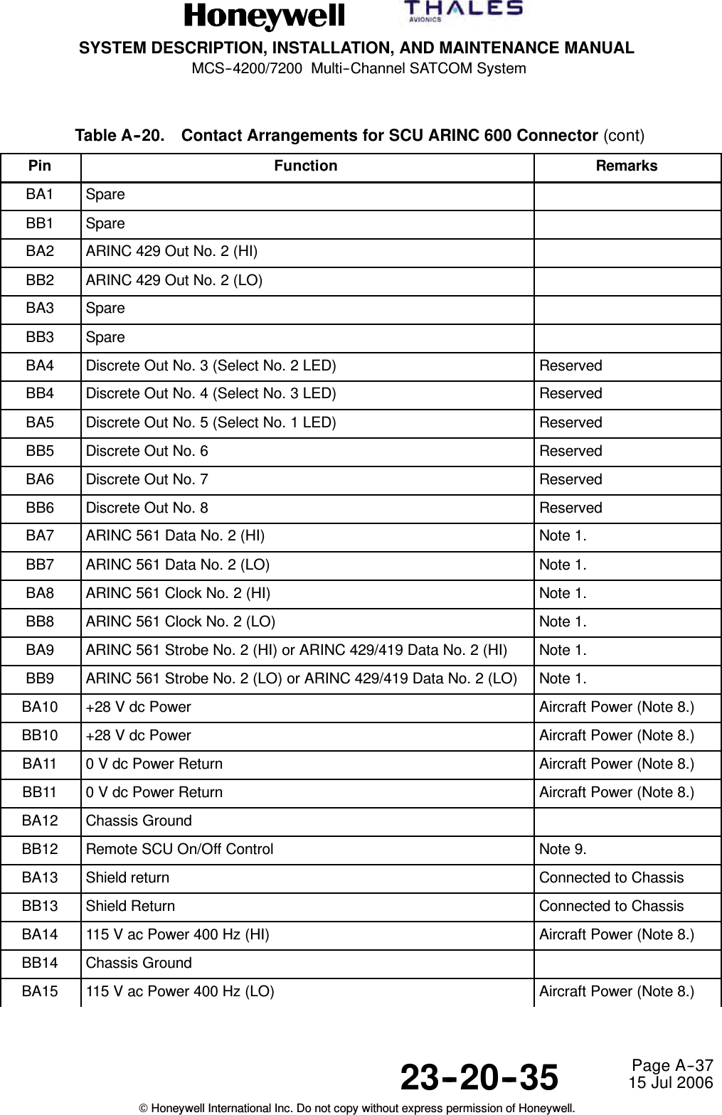
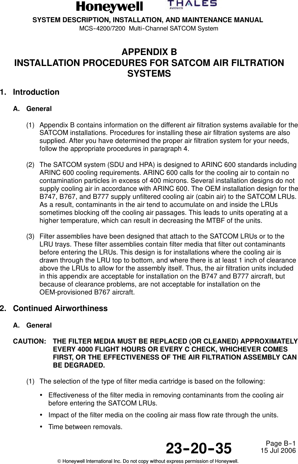
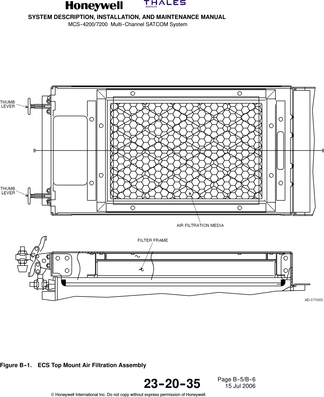
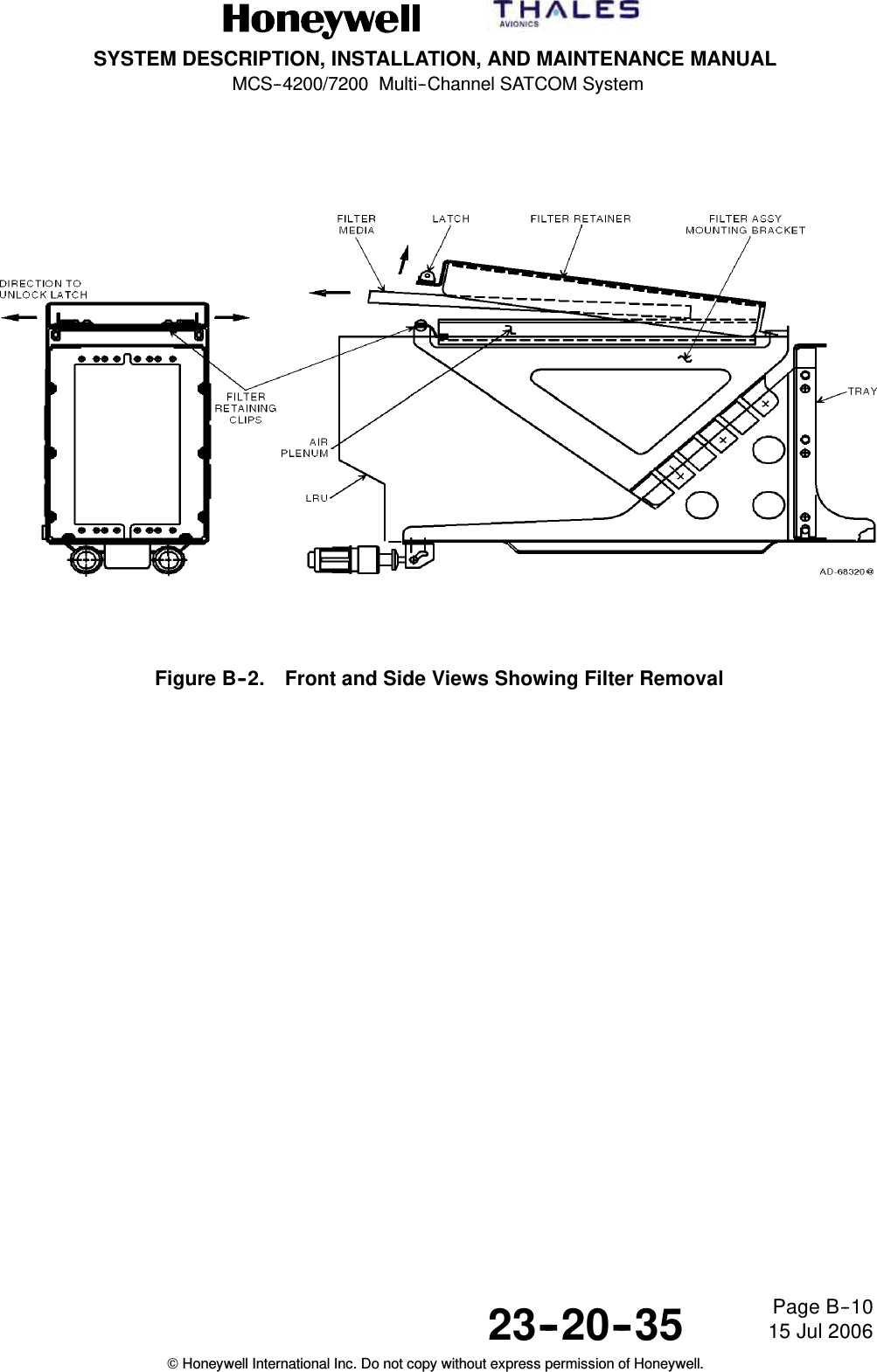
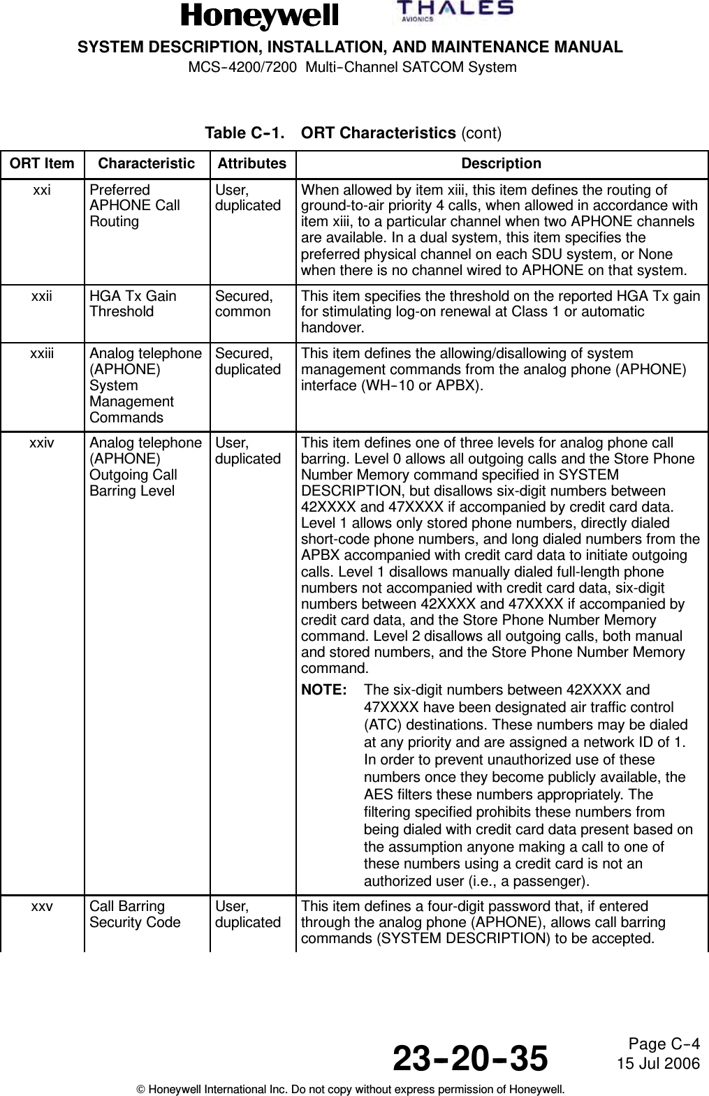
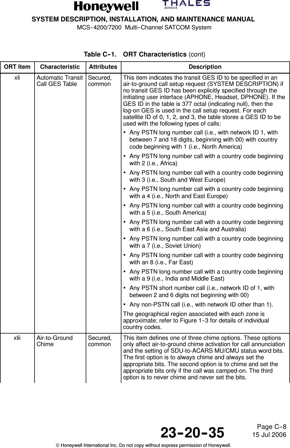
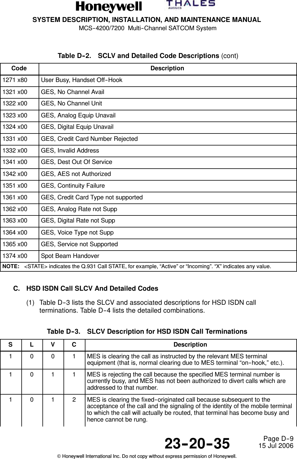
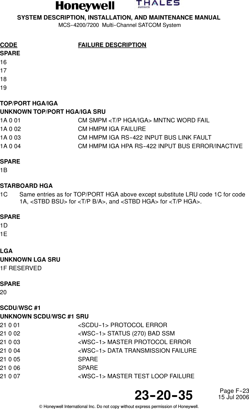
![SYSTEM DESCRIPTION, INSTALLATION, AND MAINTENANCE MANUALMCS--4200/7200 Multi--Channel SATCOM System23--20--35 15 Jul 2006Honeywell International Inc. Do not copy without express permission of Honeywell.Page D--8Table D--2. SCLV and Detailed Code Descriptions (cont)Code Description1221 x28 Transcoder Revoked1221 x29 This SDU Disabled1221 x2A Cross--Talk Bus Failure1221 x41 Analog Audio Interface revoked from call1222 x32 Outgoing call -- Insufficient Power for Setup1222 x33 Outgoing call -- No Modem for Setup1222 x34 Outgoing call -- No Transcoder for Setup1222 x35 Not Logged On1222 x36 Outgoing call -- Cockpit Camp--On Cancel1222 x37 Outgoing call -- Call Failed to Preempt1222 x38 Missing Resource for Setup1222 x39 Incoming call -- Destination I/F Not Wired1222 x3A Incoming call -- Internal Equipment Failure1222 x3B Incoming call -- External Equipment Failure1222 x3C Incoming call -- Invalid DDI Called Term Id1222 x3D Incoming call -- No Channel Available1222 x3E Incoming call -- Master [other_satcom] Not OK1222 x3F Incoming call -- Cannot Reach CTId on Other SATCOM (e.g., XTB failure)1222 x40 Outgoing call -- No available analog interface1242 x90 Outgoing Calls Disallowed (ORT item xxvi)1243 x50 Incoming Public Calls Barred (ORT item xiii)1251 x61 C’ty Fail (C--Chan not Received)1251 x63 C’ty Fail (No C--Chan Assignmnt)1251 x64 C’ty Fail (No Test SU Received)1251 x65 C’ty Fail (No S4 or S7 SU Rxed)1251 x66 C’ty Fail (No Ack to Connect)1251 x67 C--channel Bit Error Rate Degradation (CN59)1251 x68 C--channel Inhibited, AES ID or ARN mismatch (CN59)1264 x91 Incoming call -- Voice Channel Type Not Supported1265 x70 Not Logged On for Voice](https://usermanual.wiki/Honeywell/HS-720.HS-720-User-Manual-Part3/User-Guide-1350372-Page-67.png)
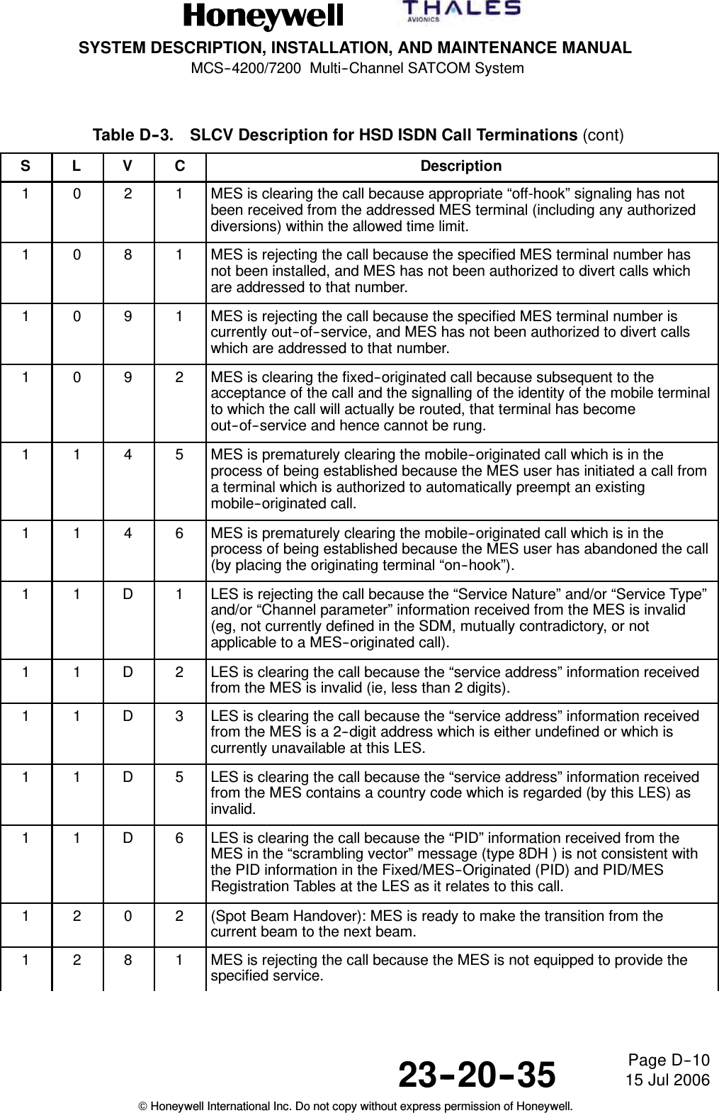
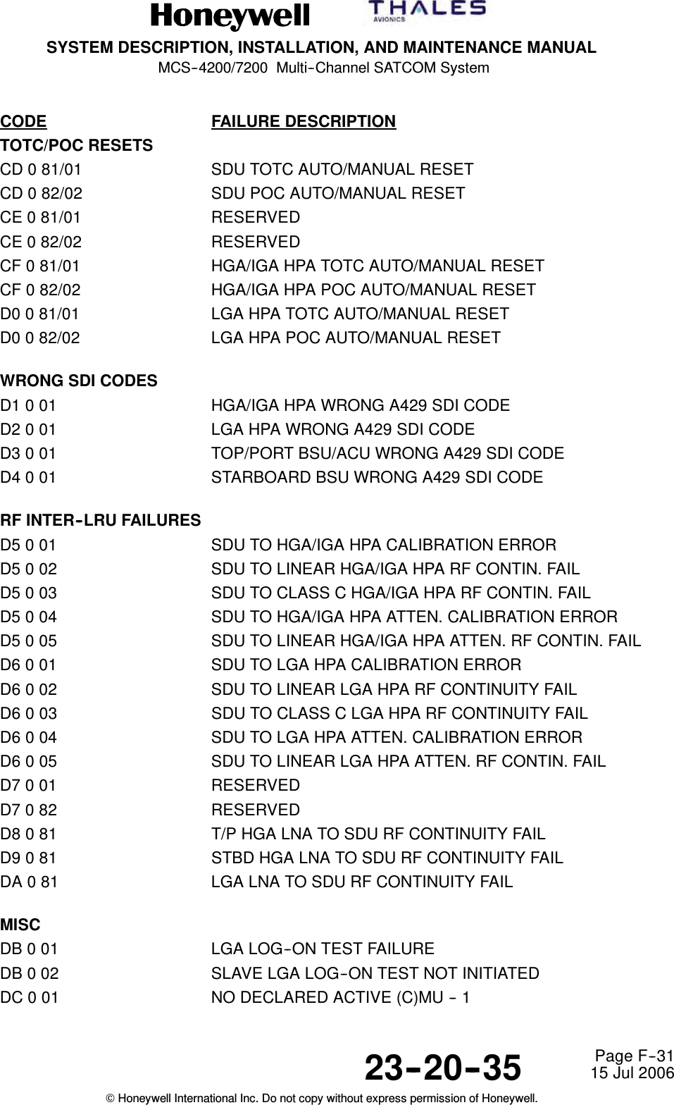
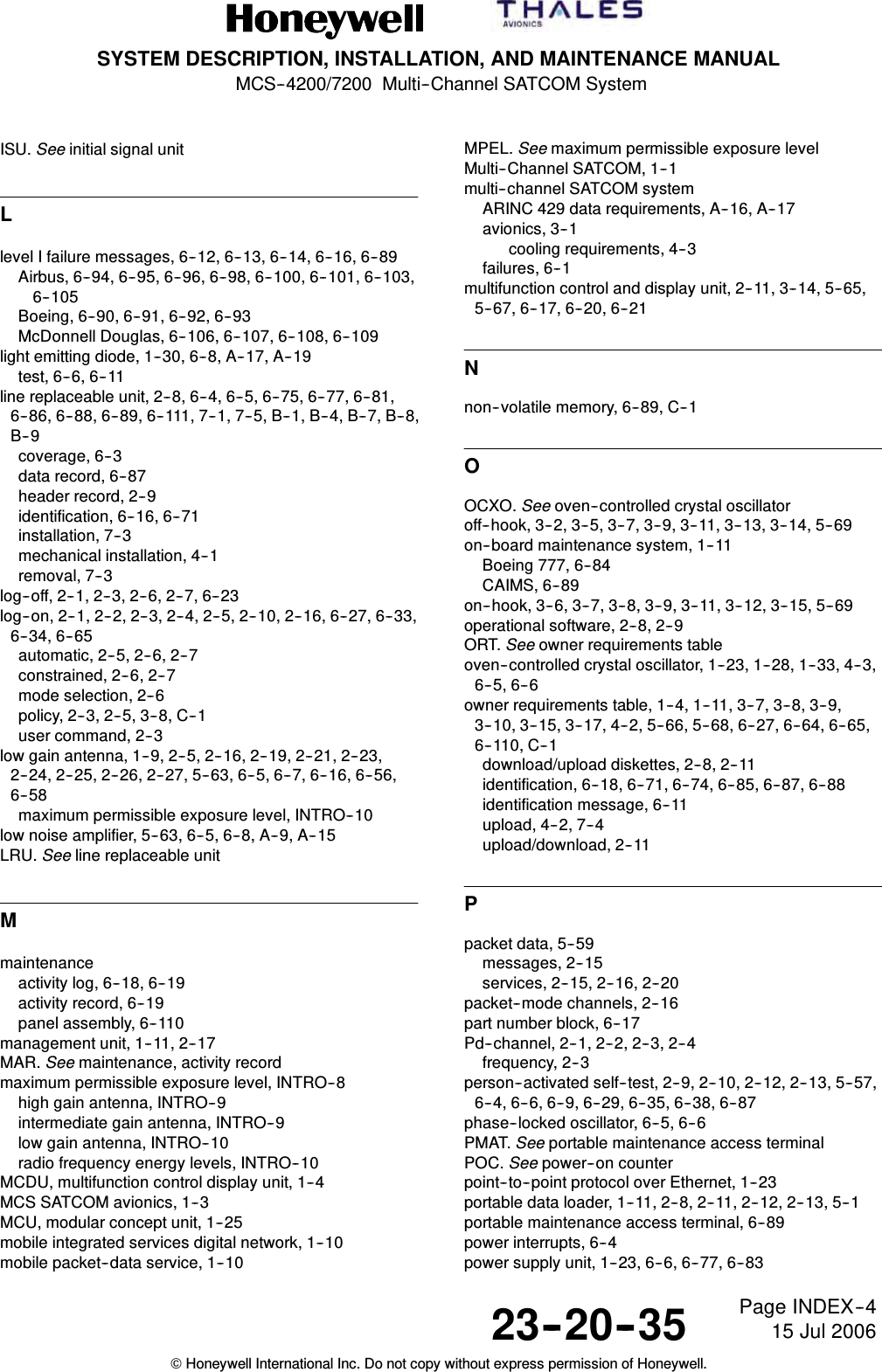
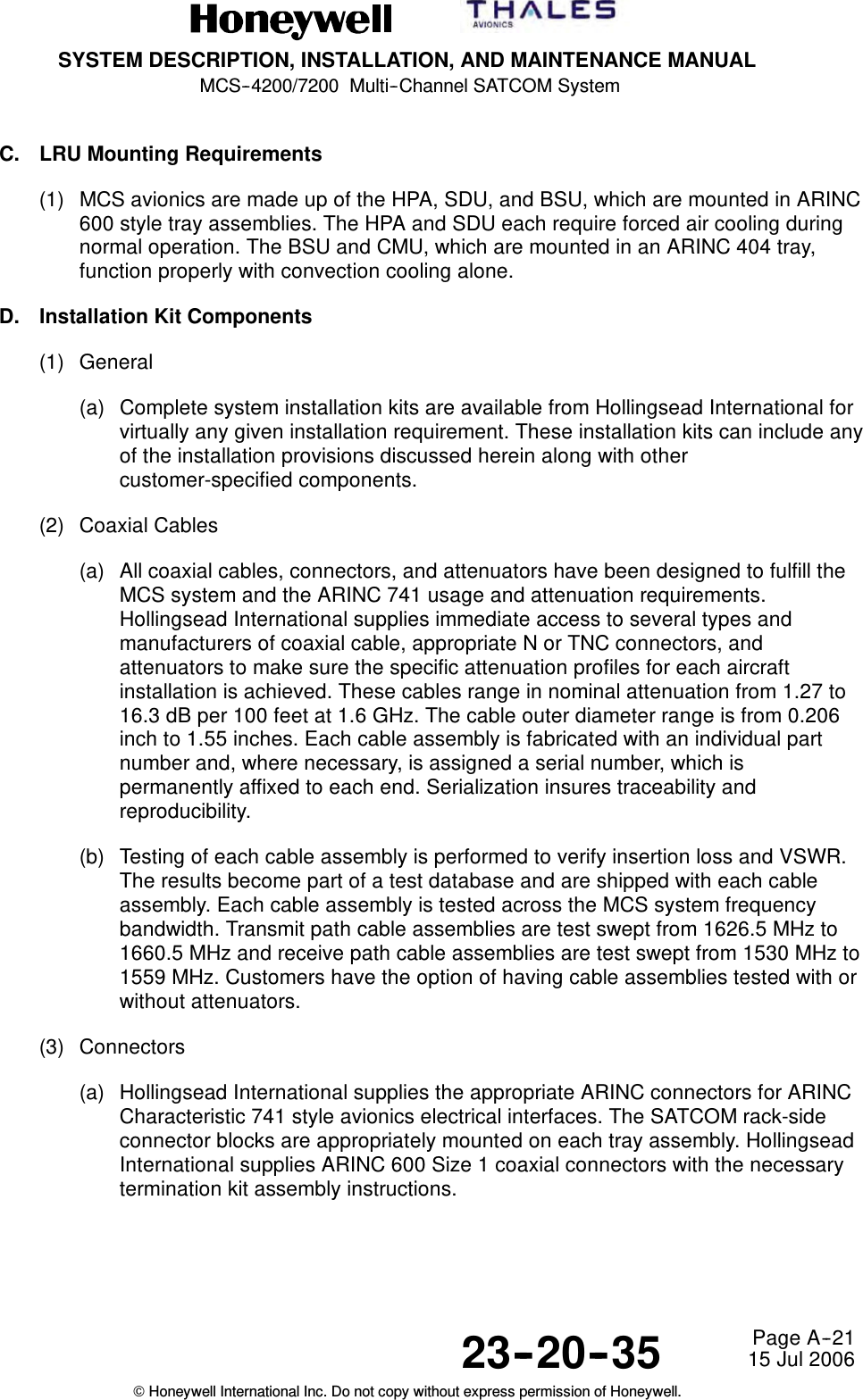
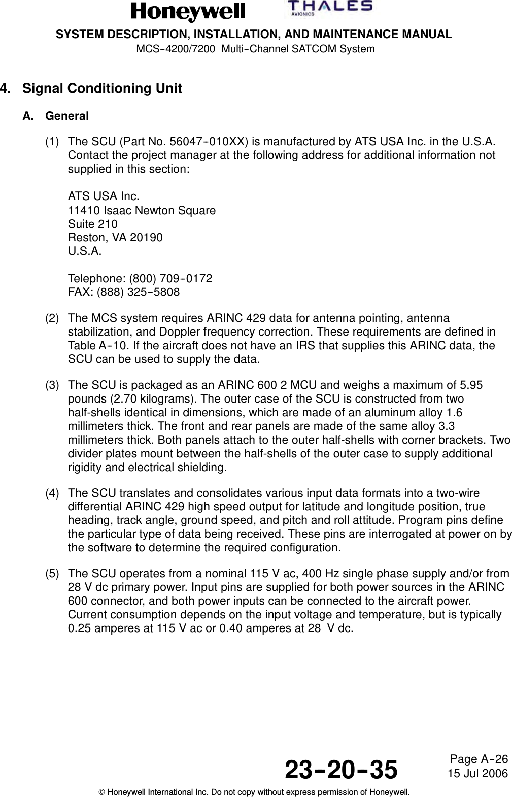
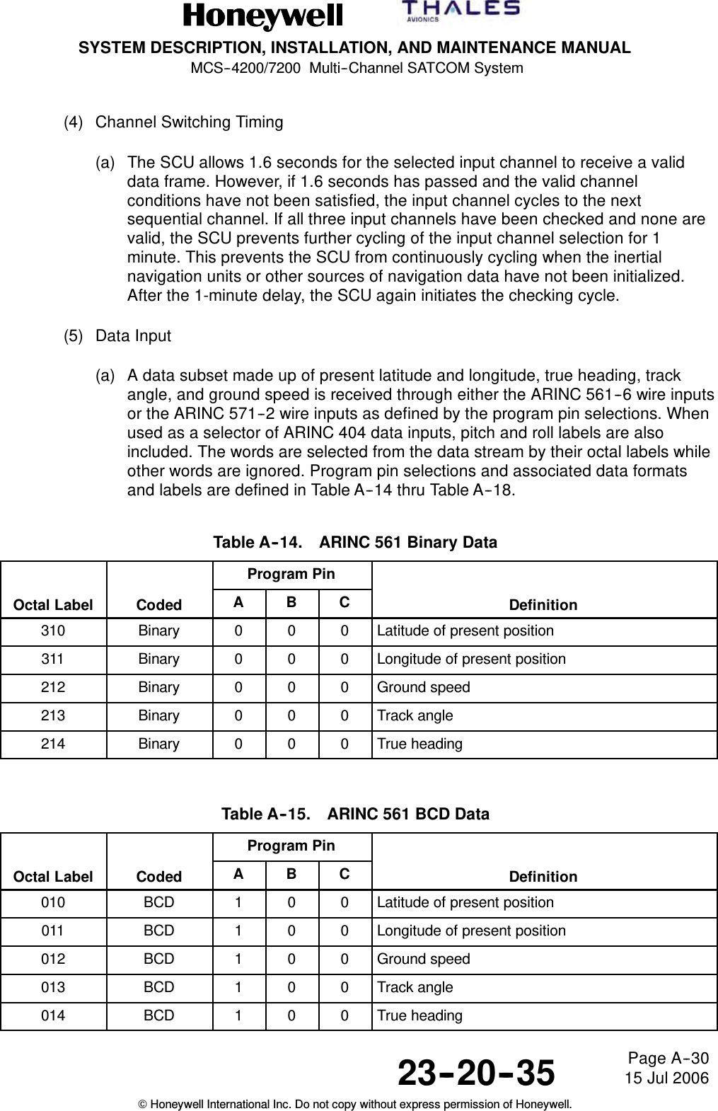
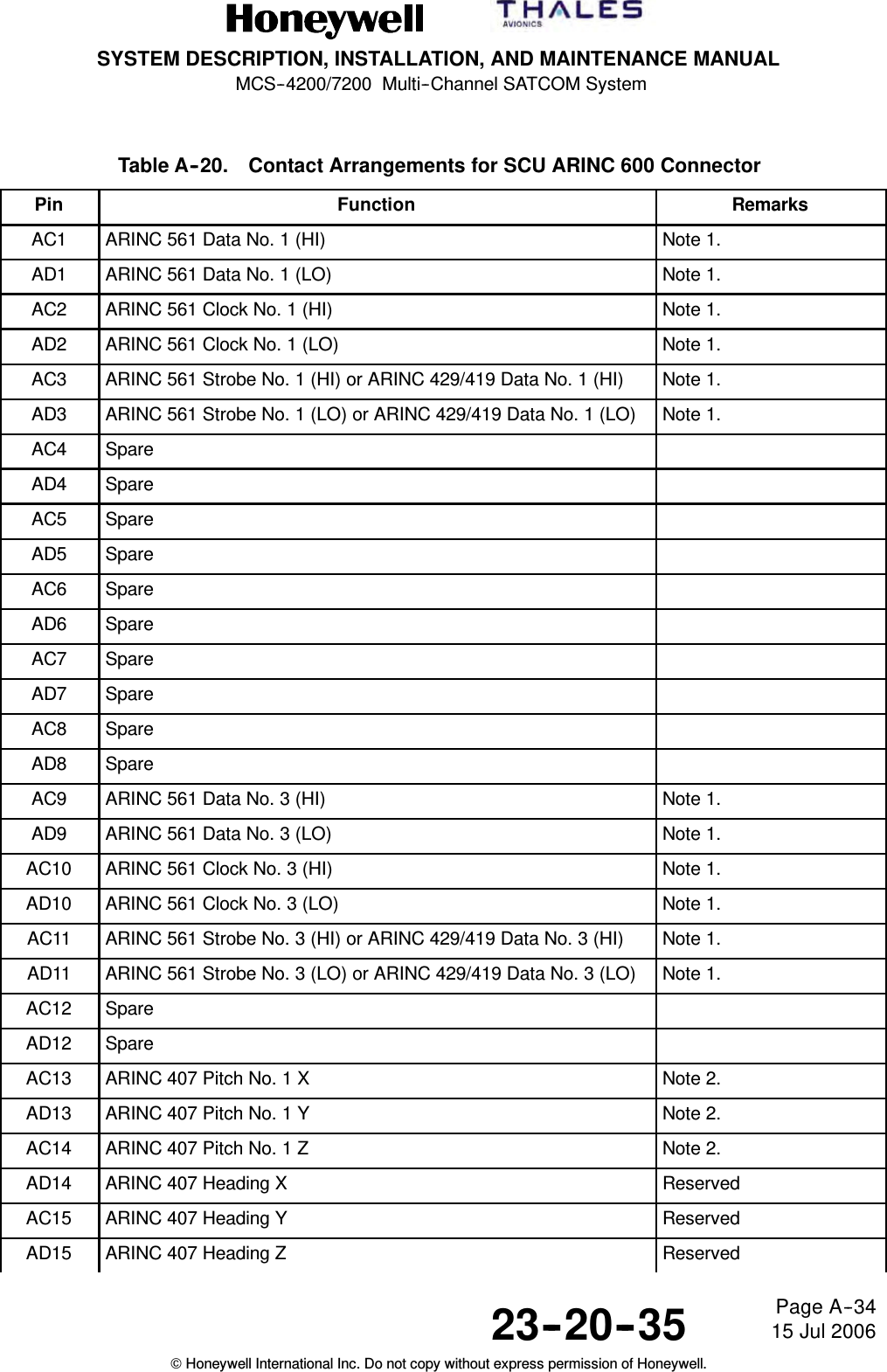
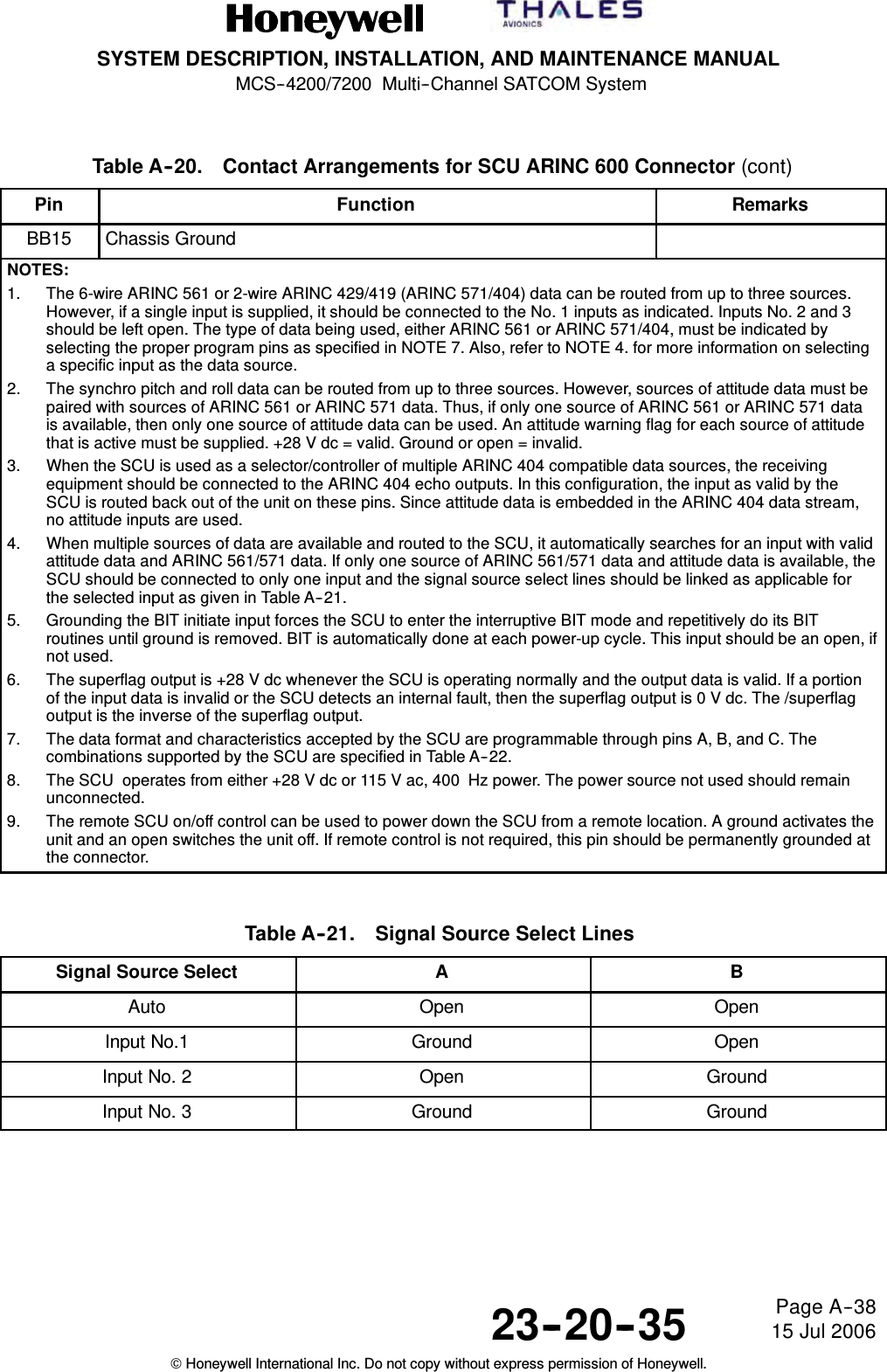
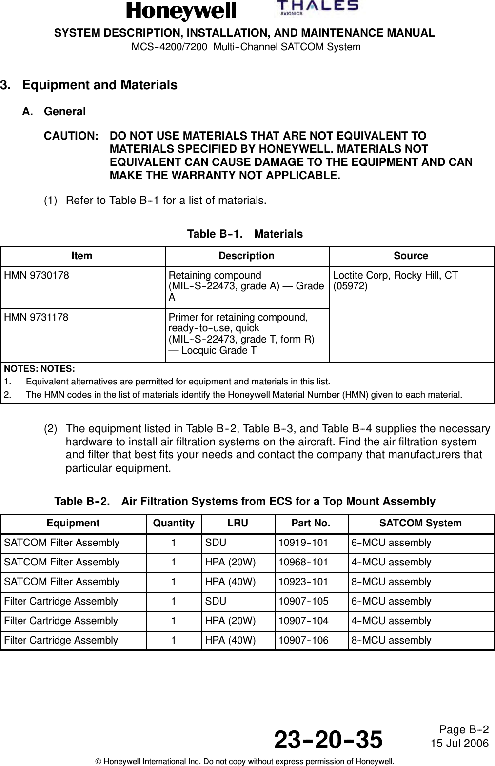
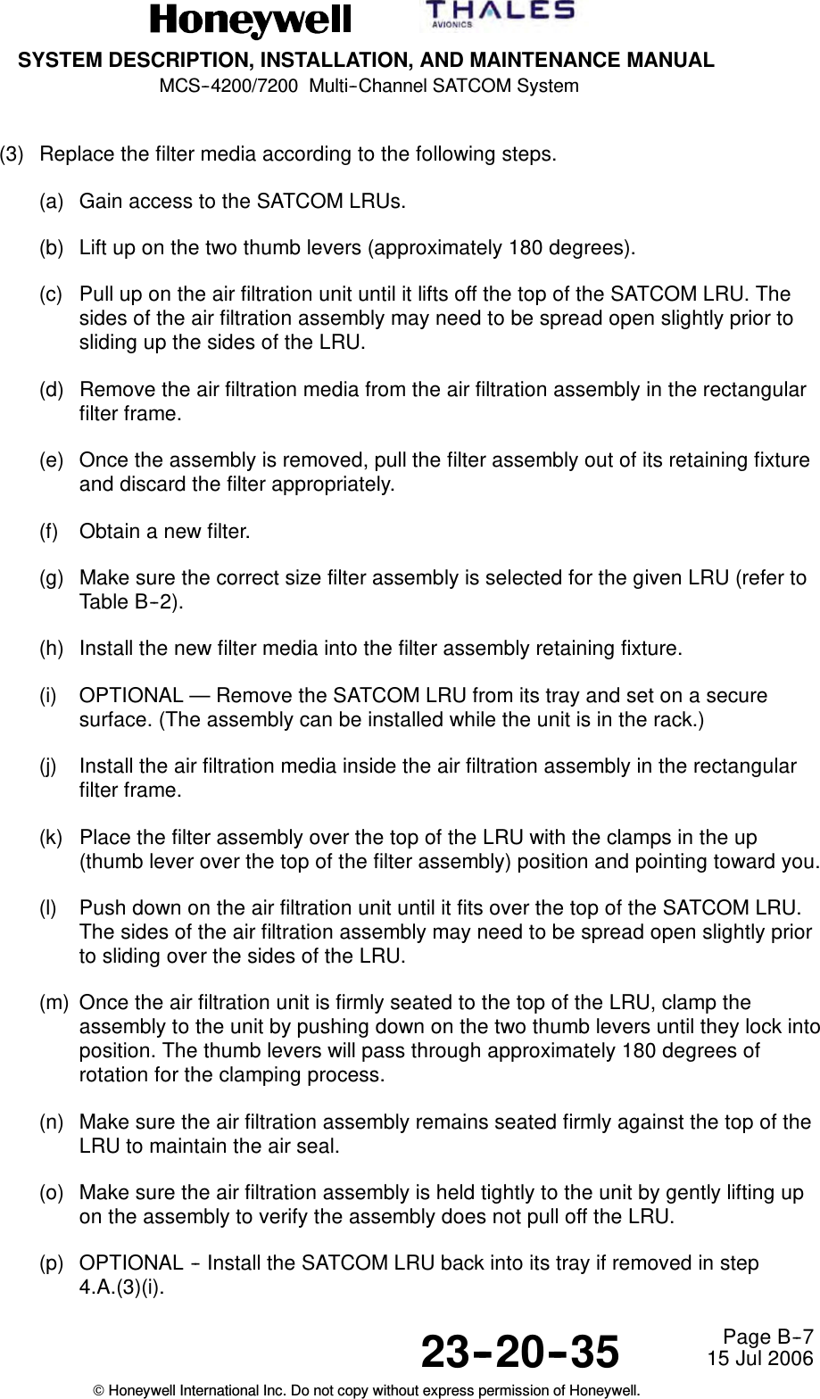
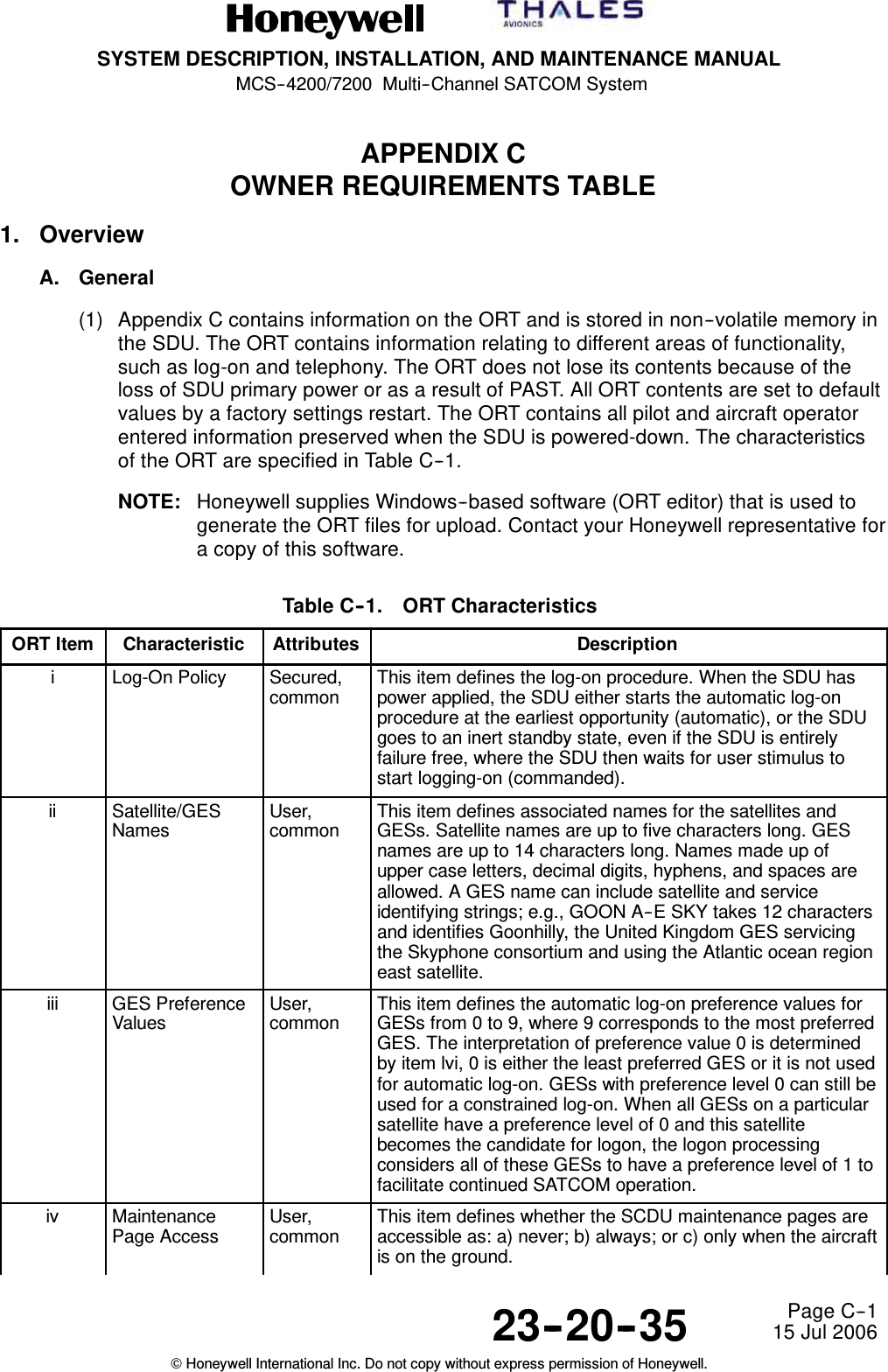
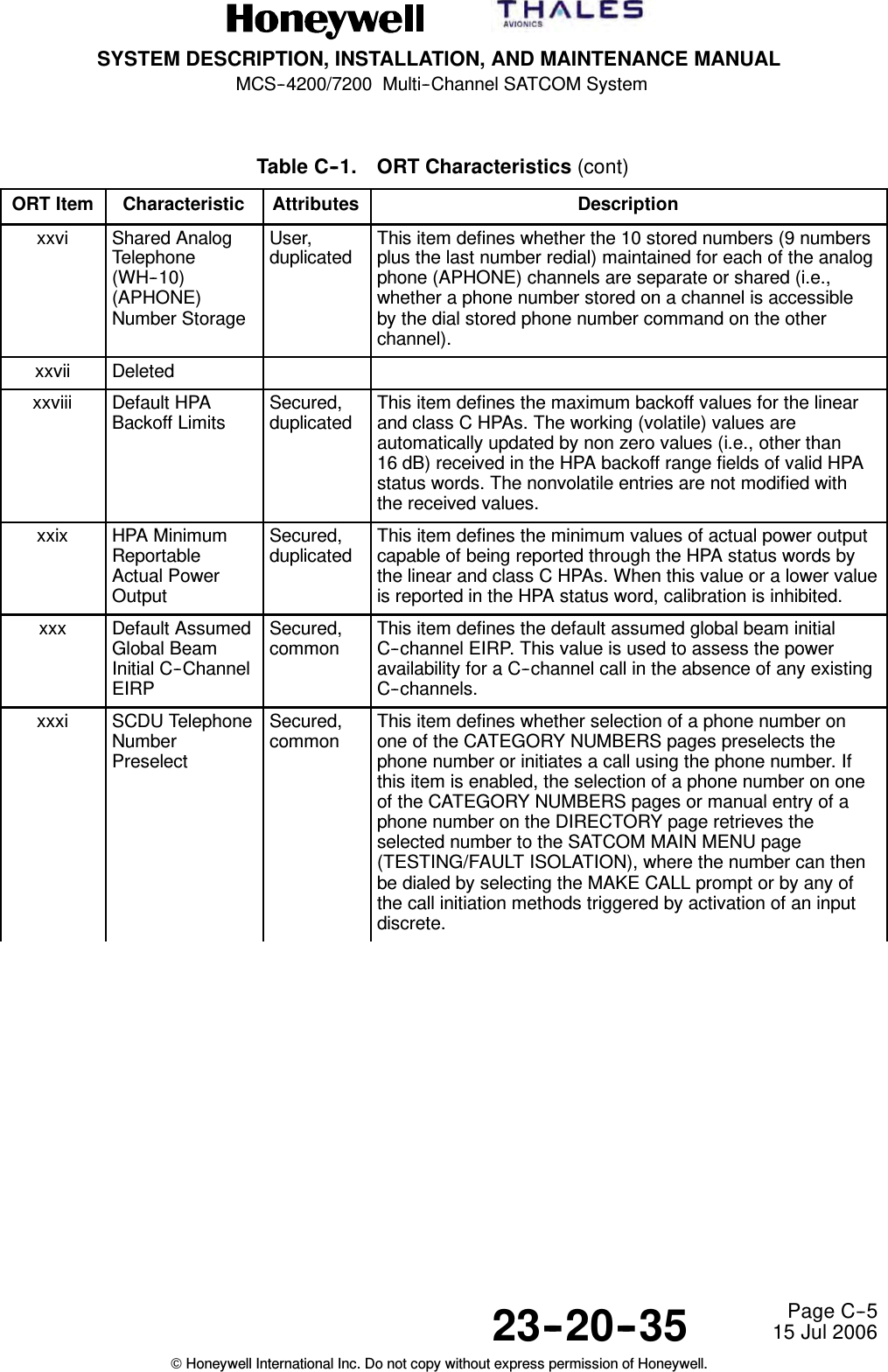
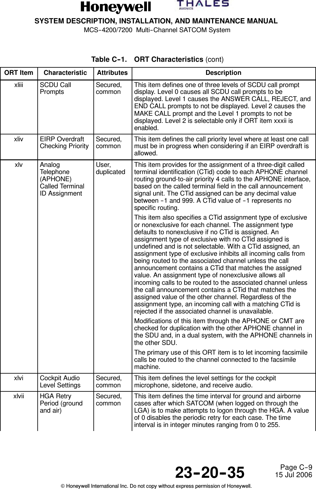
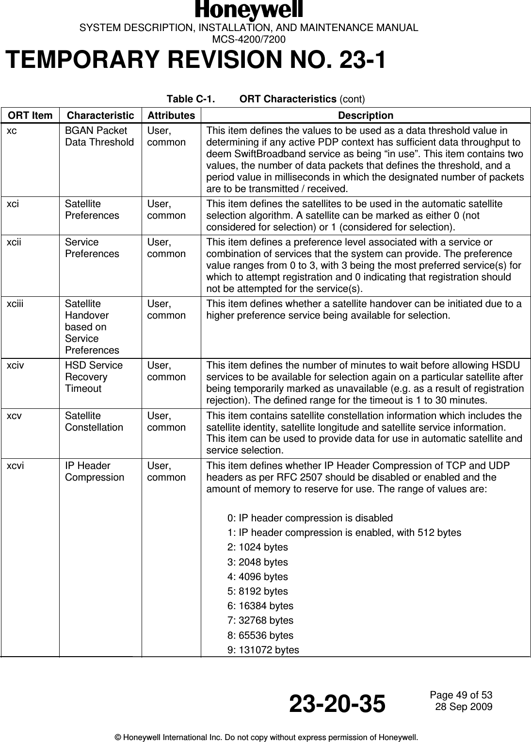
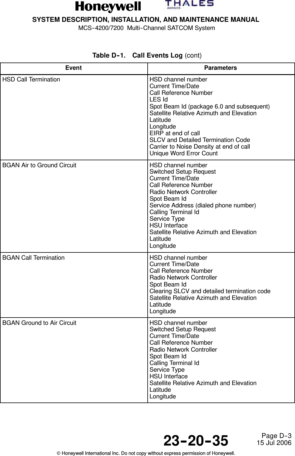
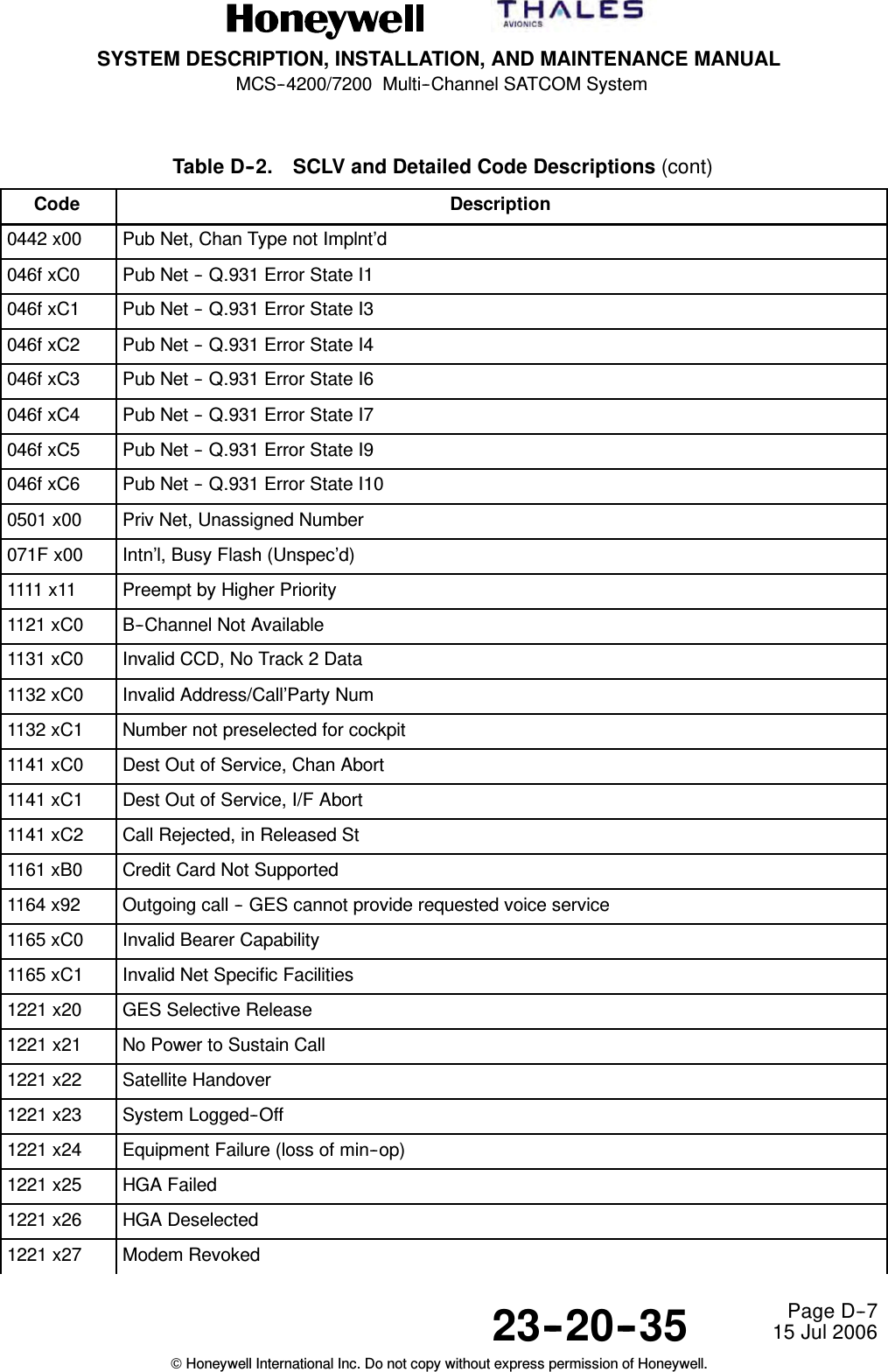
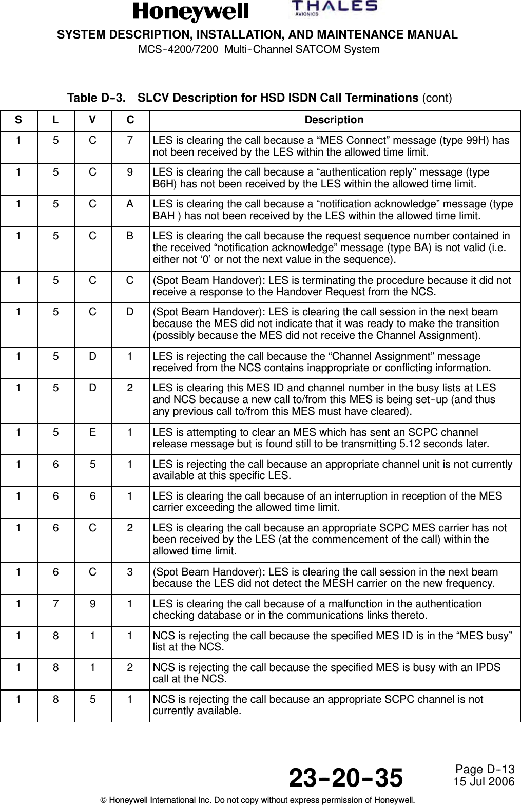
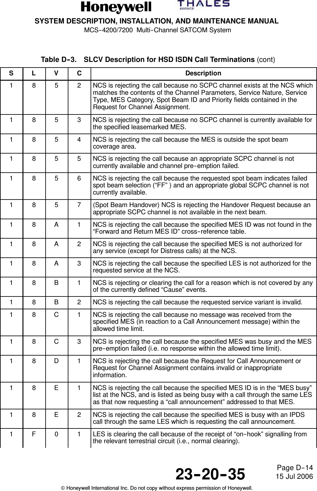
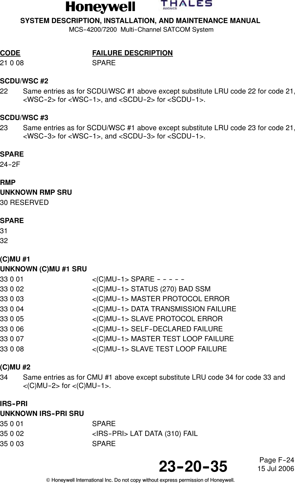
![SYSTEM DESCRIPTION, INSTALLATION, AND MAINTENANCE MANUALMCS--4200/7200 Multi--Channel SATCOM System23--20--35 15 Jul 2006Honeywell International Inc. Do not copy without express permission of Honeywell.Page D--12Table D--3. SLCV Description for HSD ISDN Call Terminations (cont)S DescriptionCVL1 4 5 1 LES is rejecting the call because an appropriate terrestrial circuit is notcurrently available at this specific LES.1 4 5 2 LES is rejecting the call because an appropriate channel unit and associatedterrestrial circuit are not currently available at this LES. [This “cause” is onlyutilized when there is a permanent “one--to--one” connection betweenappropriate channel units and their terrestrial circuits].1 5 0 2 (Spot Beam Handover): LES is ready to make the transition from the currentbeam to the next beam and is clearing the call session in the current beam(normal clear).1 5 5 1 LES is rejecting the call because an appropriate satellite channel is notcurrently available at this specific LES.1 5 8 1 LES is rejecting the call because the requested service is not provided bythis specific LES.1 5 9 1 LES is rejecting the call because the requested service is temporarily notavailable at this specific LES.1 5 A 1 LES is rejecting the call because the specified MES is not authorized for anyservice at this specific LES.1 5 A 2 LES is rejecting the call because the specified MES is not authorized to usespecific requested service via this specific LES.1 5 A 4 LES is clearing the call because the data received from the MES in the“authentication reply” message (type B6H) has been declared “invalid” bythe LES authentication process.1 5 A 5 LES is rejecting the call because the specified PID is not authorized for anyservice at this specific LES.1 5 A 6 LES is rejecting the call because the specified PID is not authorized to usespecific requested service via this specific LES.1 5 A 7 LES is clearing the call because the service address received from the MESis not authorized for the requested priority.1 5 B 1 LES is rejecting or clearing the call for a reason which is not covered by anyof the currently defined “Cause” events.1 5 C 1 LES is rejecting the call because an appropriate “Channel Assignment”message has not been received by the LES within the allowed time limit.1 5 C 2 LES is clearing the call because the “service address” information has notbeen received by the LES within the allowed time limit.1 5 C 3 LES is clearing the call because a “Scrambling Vector” message (type 8DH)has not been received by the LES within the allowed time limit.1 5 C 4 LES is clearing the call because neither the “service address” informationnor a “Scrambling Vector” message (type 8DH ) has been received by theLES within the allowed time limit.](https://usermanual.wiki/Honeywell/HS-720.HS-720-User-Manual-Part3/User-Guide-1350372-Page-73.png)

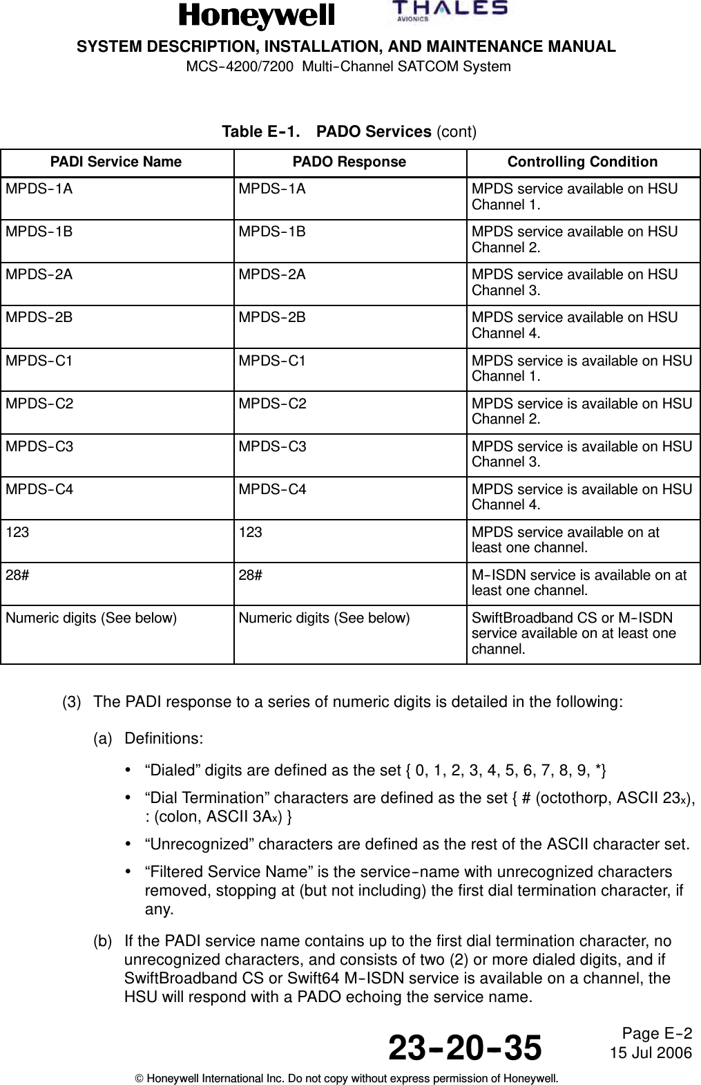

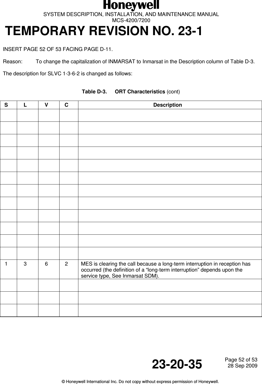
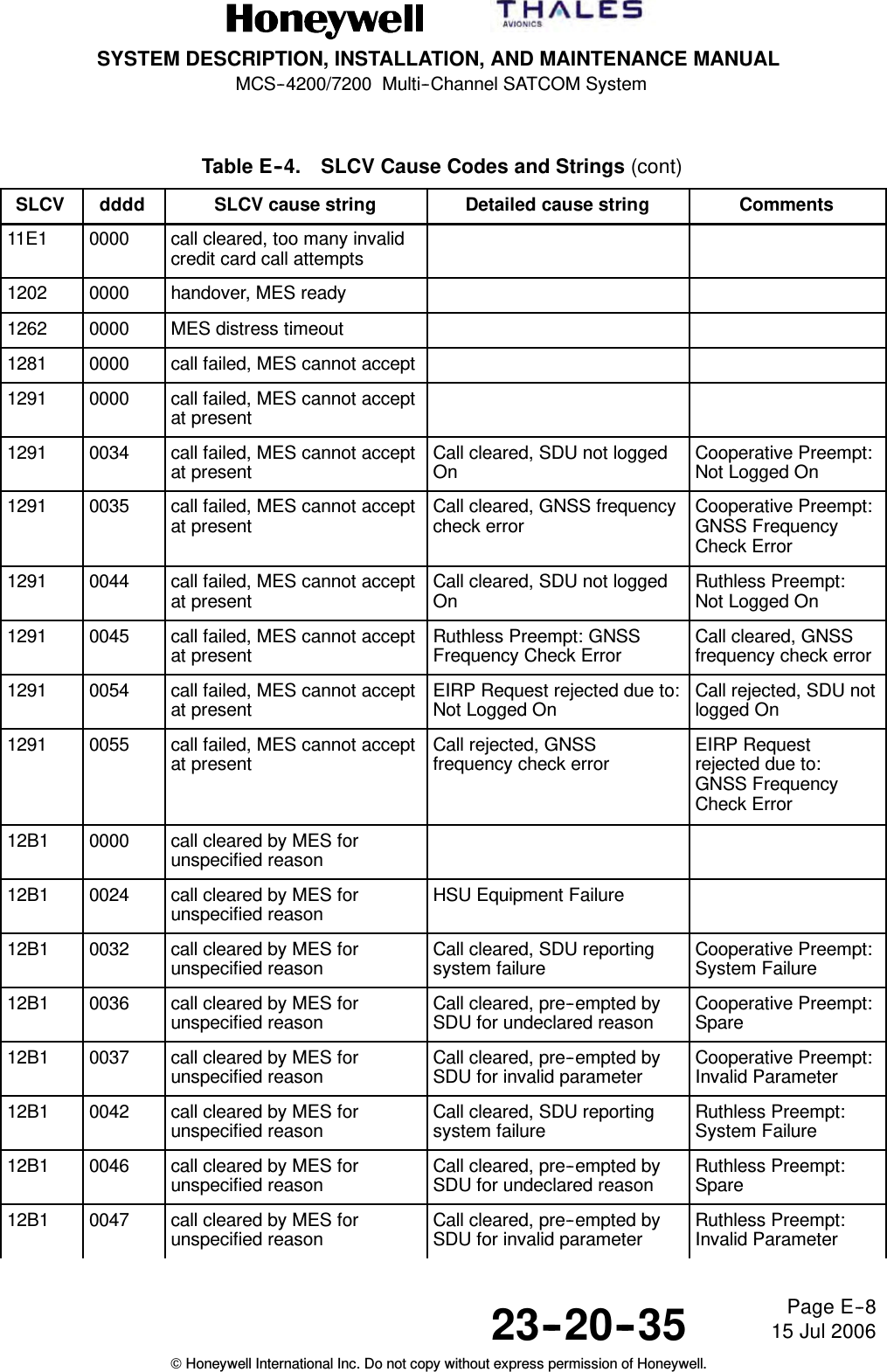
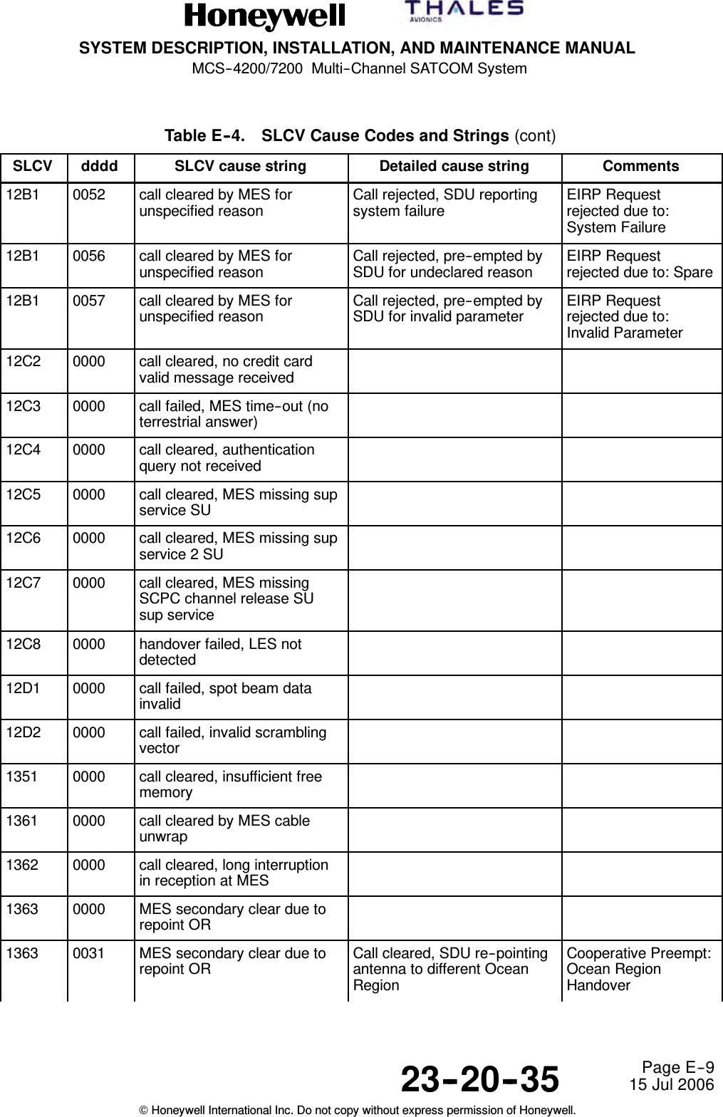
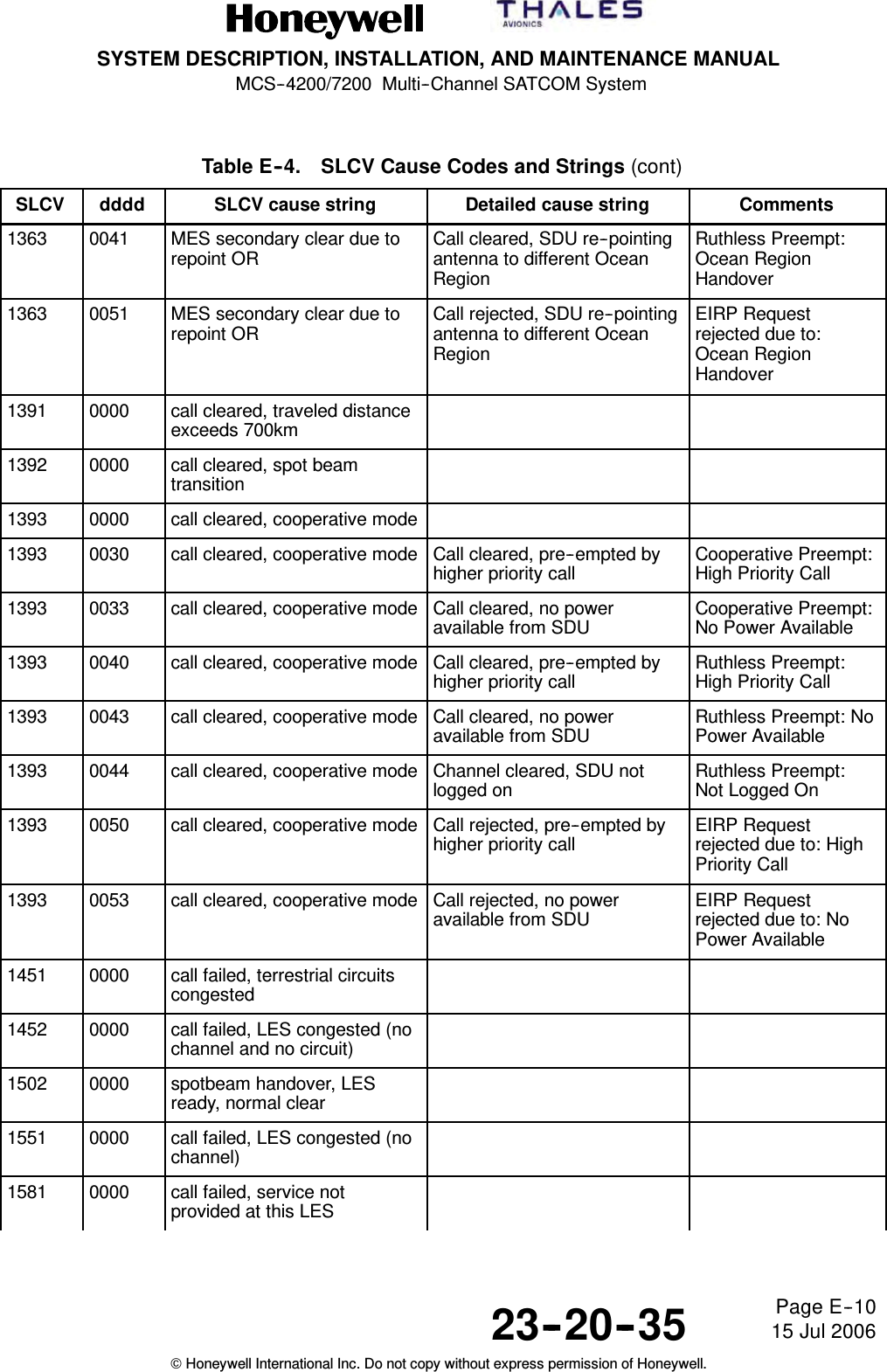
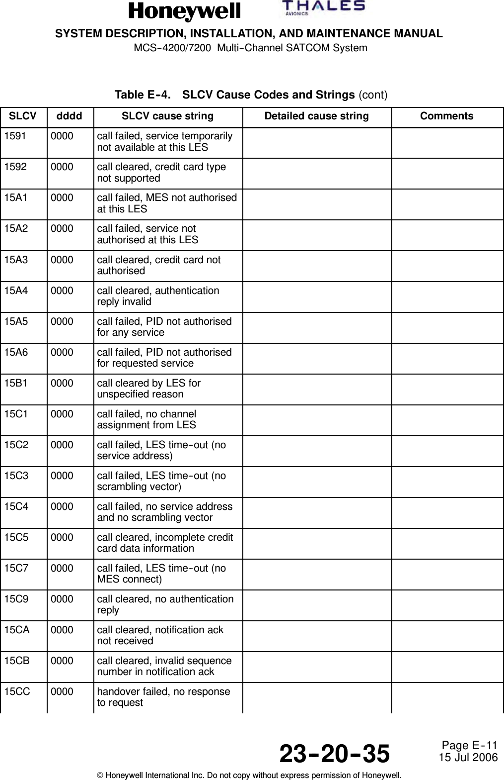
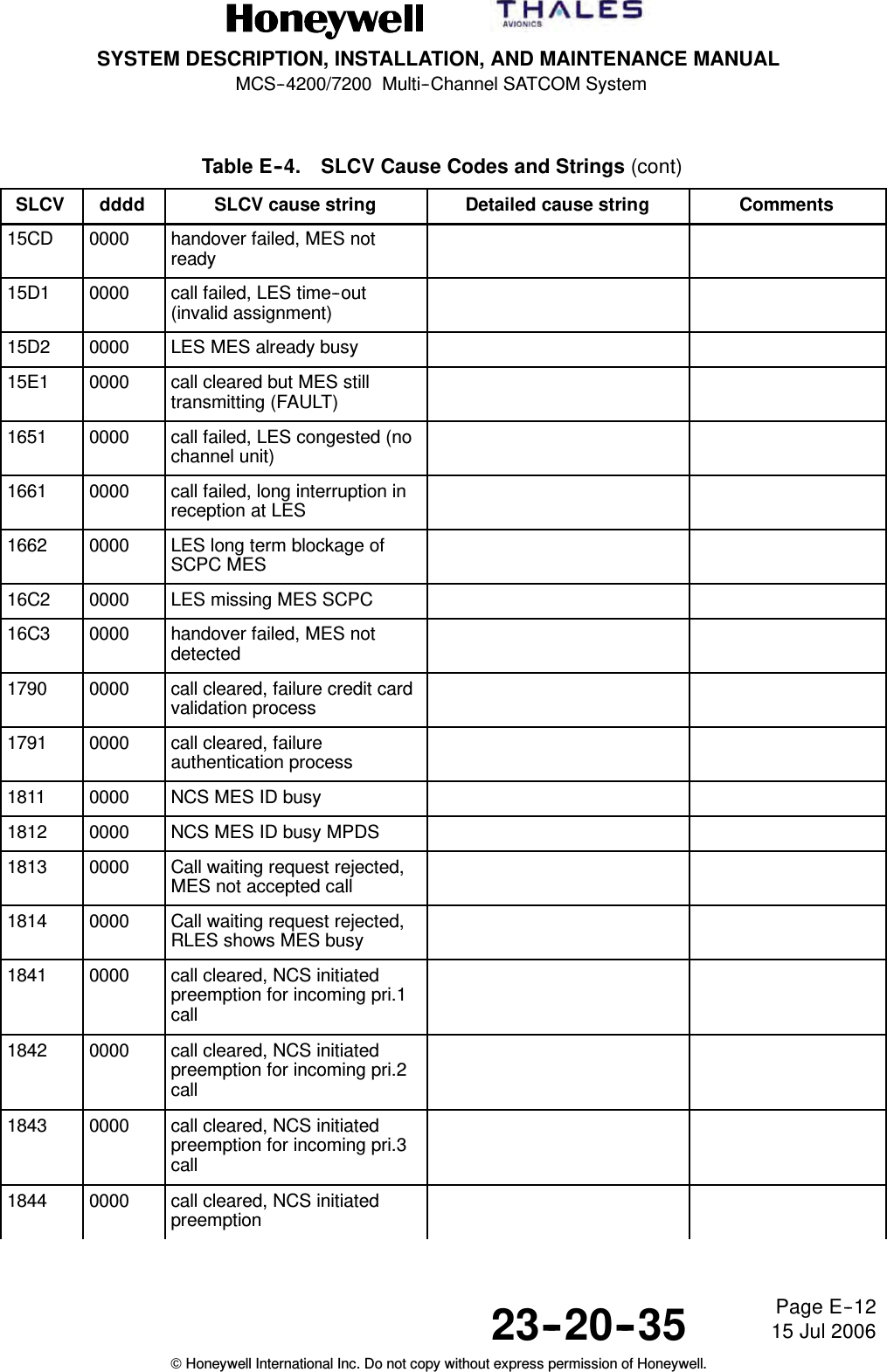
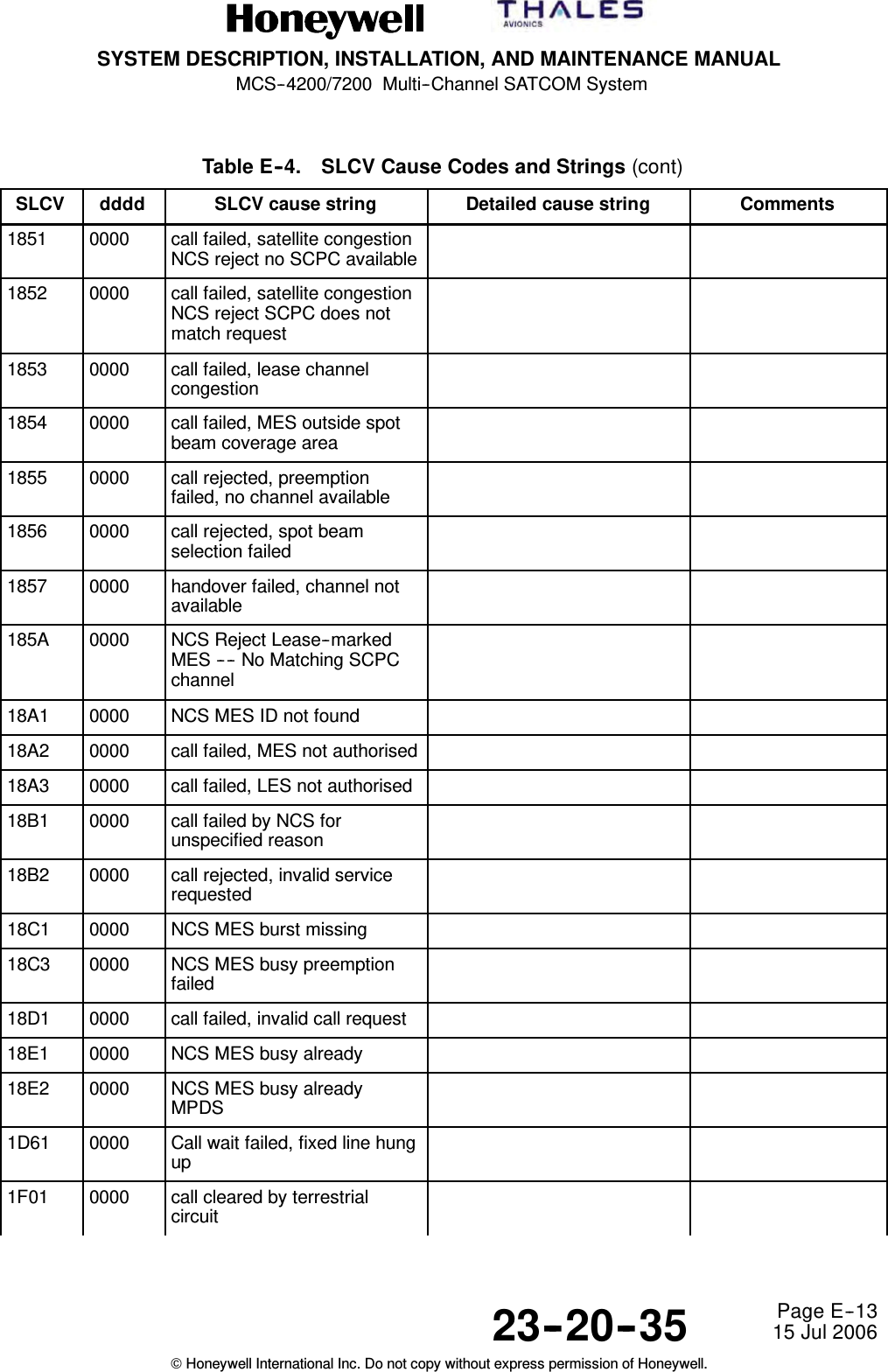
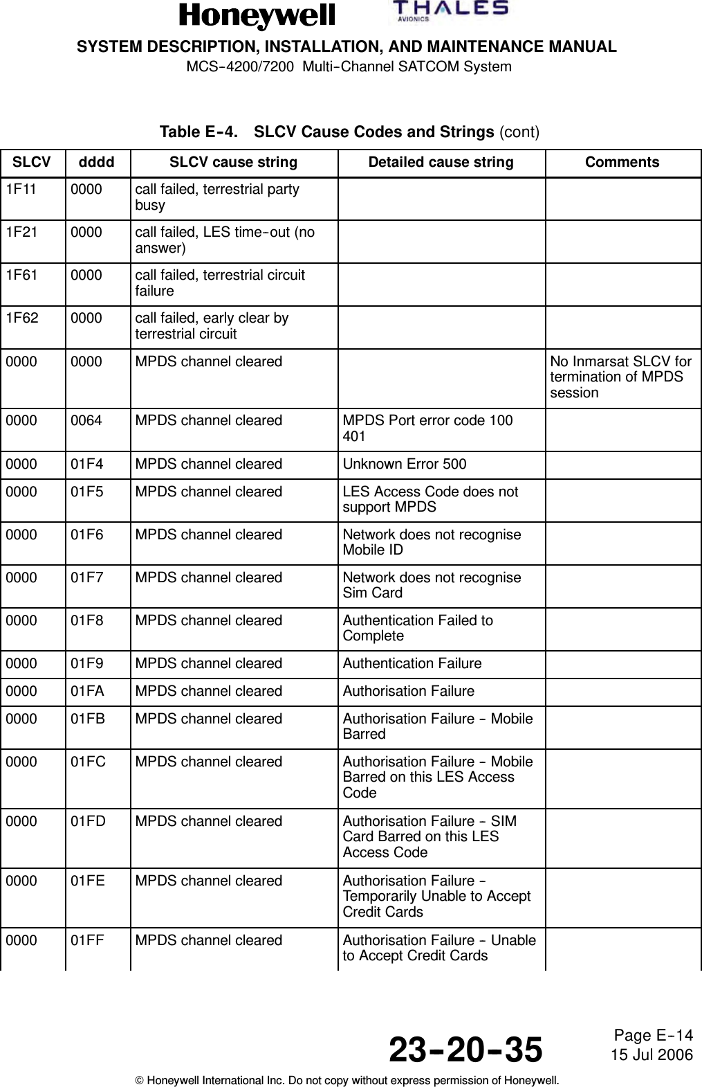
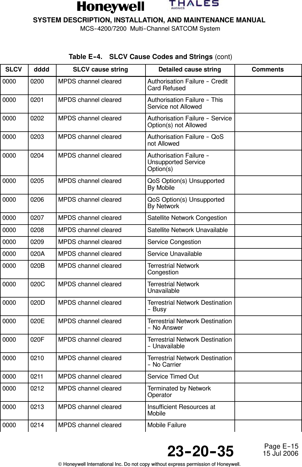
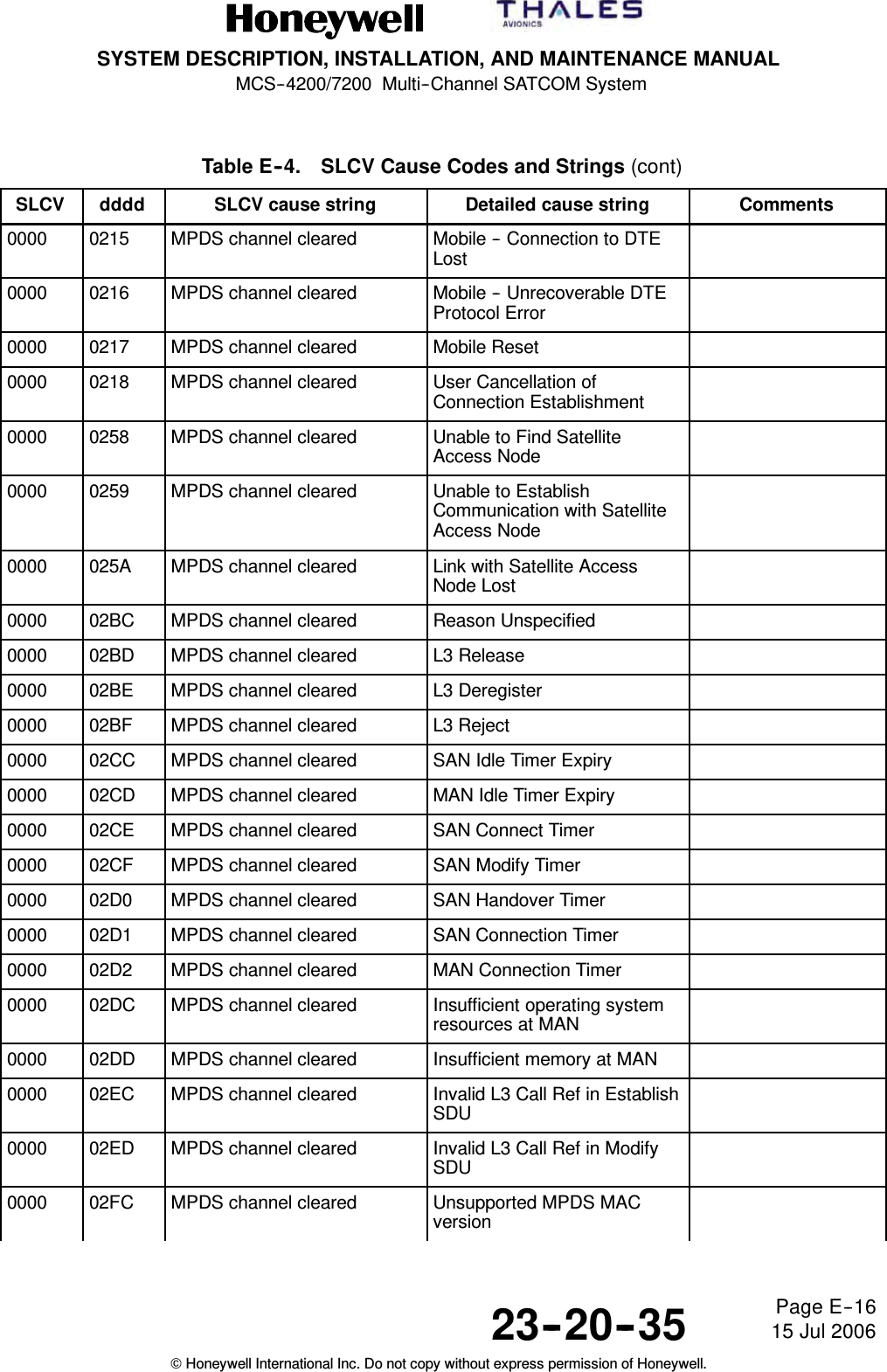
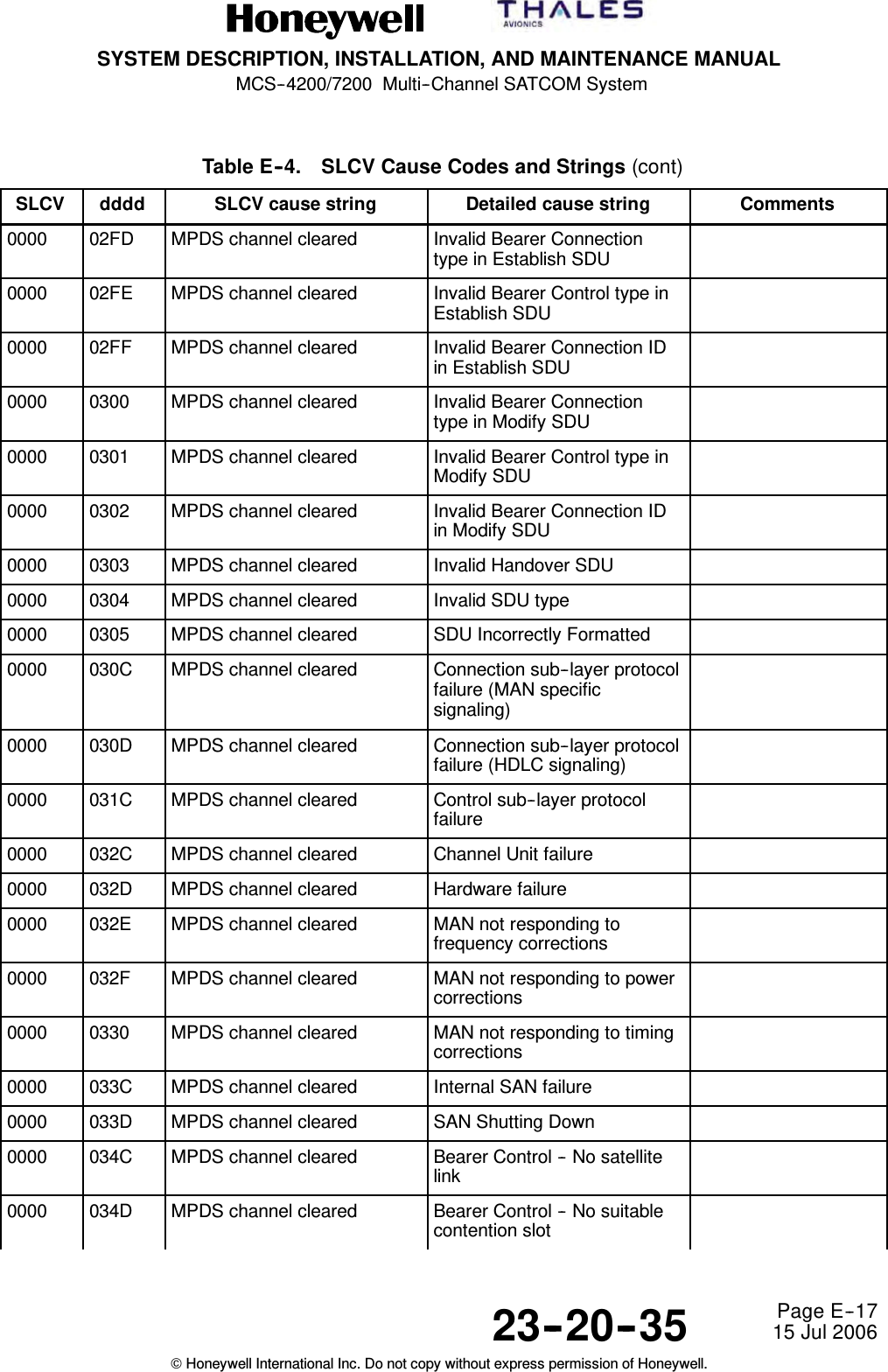
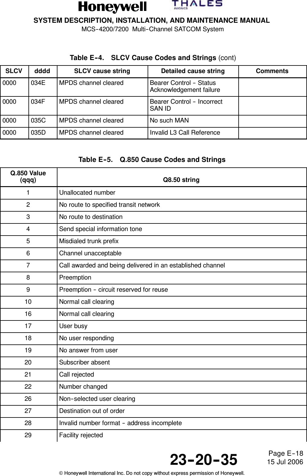
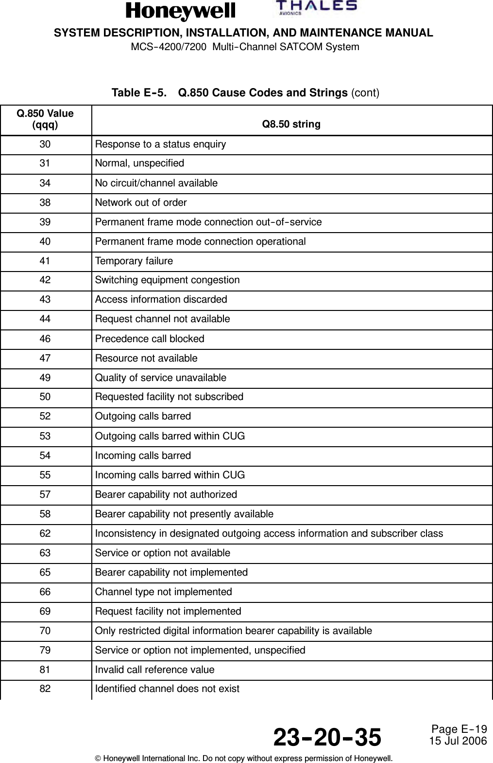
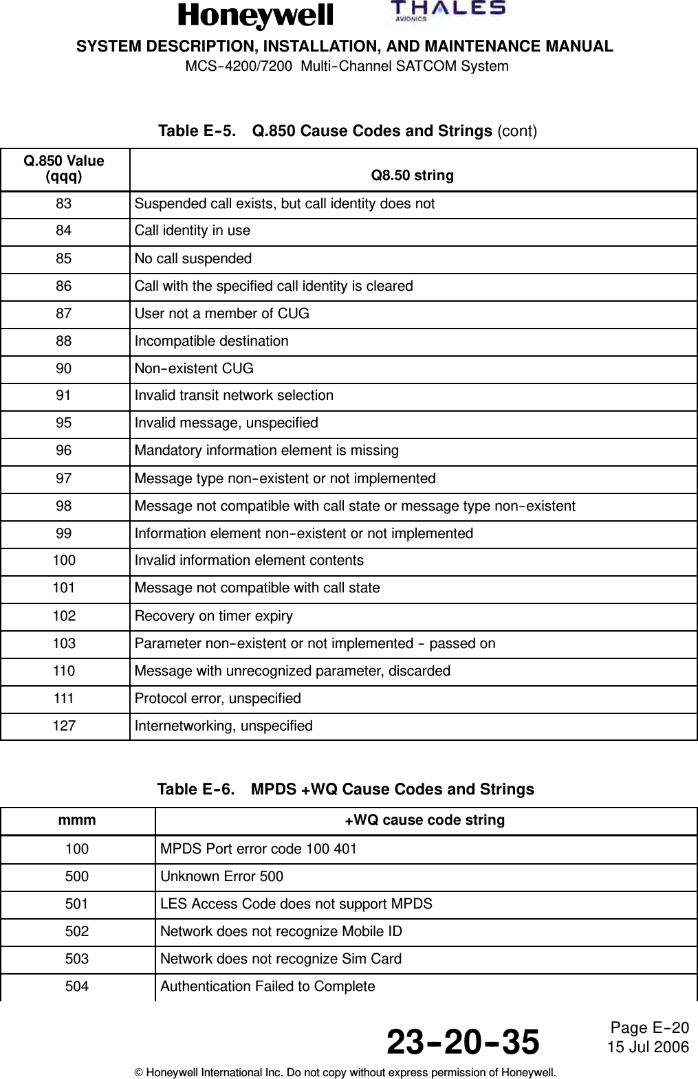
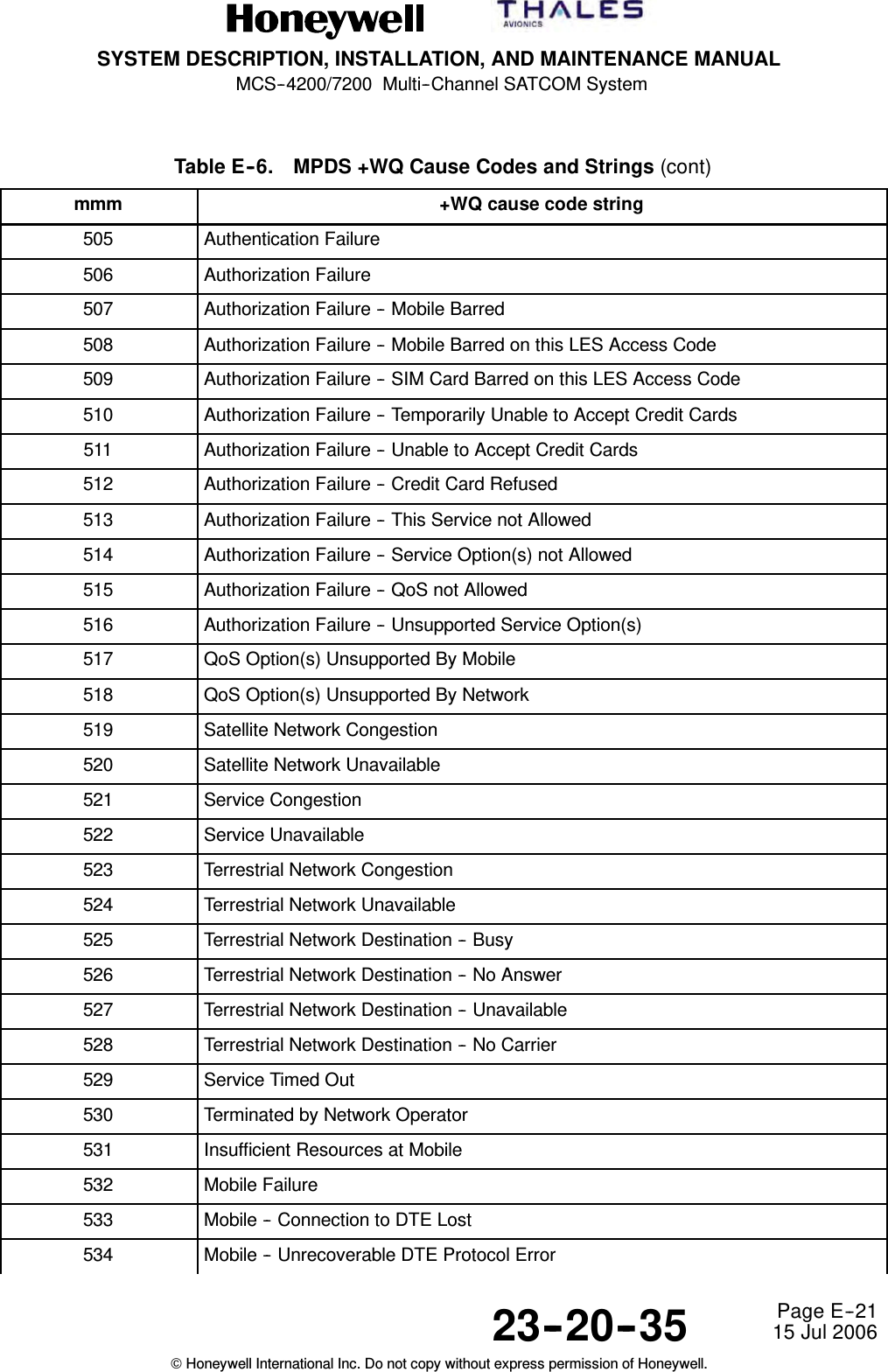
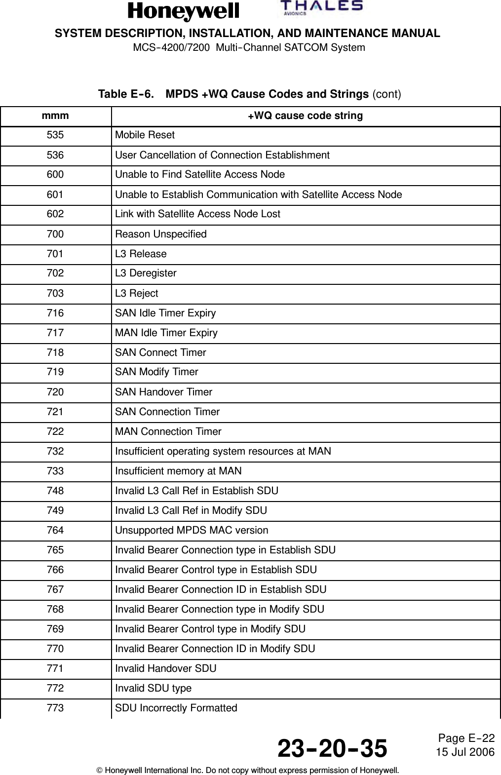
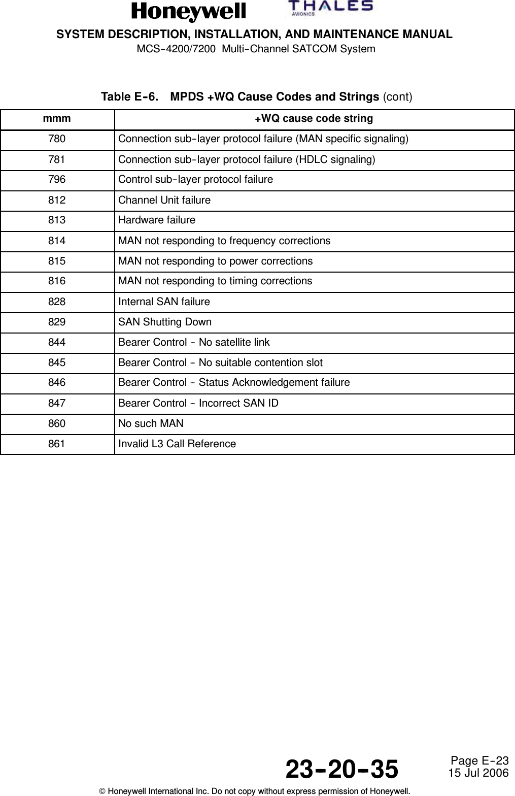
![SYSTEM DESCRIPTION, INSTALLATION, AND MAINTENANCE MANUALMCS--4200/7200 Multi--Channel SATCOM System23--20--35 15 Jul 2006Honeywell International Inc. Do not copy without express permission of Honeywell.Page E--6(a) SLCV – nnnn/dddd: SLCV_cause_string [detailed_cause_string] Where:•nnnn is the Inmarsat SLCV termination code as defined in Table E--4.•dddd is the detailed cause code defined in Table E--4.•SLCV_cause_string is the (modified) Inmarsat standard cause codewording defined in Table E--4.•detailed_cause_string is extended cause description as defined inTable E--4.(5) The HSU will generate an AC--System--Error tag upon termination of every session,including those that terminate normally. The AC--System--Error tag is as definedbelow.(a) If the PPPoE session was a Swift64 64k UDI session, the AC--System--Error tagwill be of the following format:1Q850 – qqq: Q.850_string Where:•qqq is the ISDN Q.850 cause code defined in Table E--5.•Q.850_string is the Q.850 cause string defined in Table E--5.(b) If the PPPoE session was a Swift64 MPDS session, the AC--System--Error tagwill be of the following format:1MPDS – mmm: +WQ_cause_string defined in Table E--6. Where:•qqq is the MPDS AT +WQ cause number defined in Table E--6.•+WQ_cause_string is the MPDS AT +WQ cause string defined inTable E--6.(c) If the PPPoE session was a SwiftBroadband PS session, the AC--System--Errortag will be of the following format:1BGAN – bbb: TBD Where:•bbb and TBD are not specified.Table E--4. SLCV Cause Codes and StringsSLCV dddd SLCV cause string Detailed cause string Comments1001 0000 call cleared by MES terminal1011 0000 call failed, MES terminal busy1012 0000 call cleared, MES terminalbusy1021 0000 call failed, MES time--out (noanswer)1081 0000 call failed, MES terminal notinstalled](https://usermanual.wiki/Honeywell/HS-720.HS-720-User-Manual-Part3/User-Guide-1350372-Page-83.png)

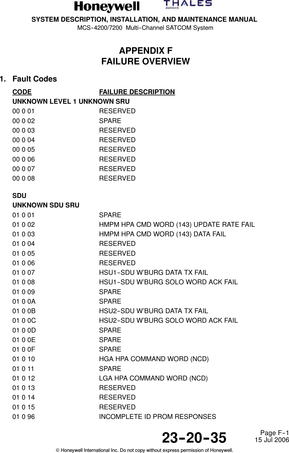
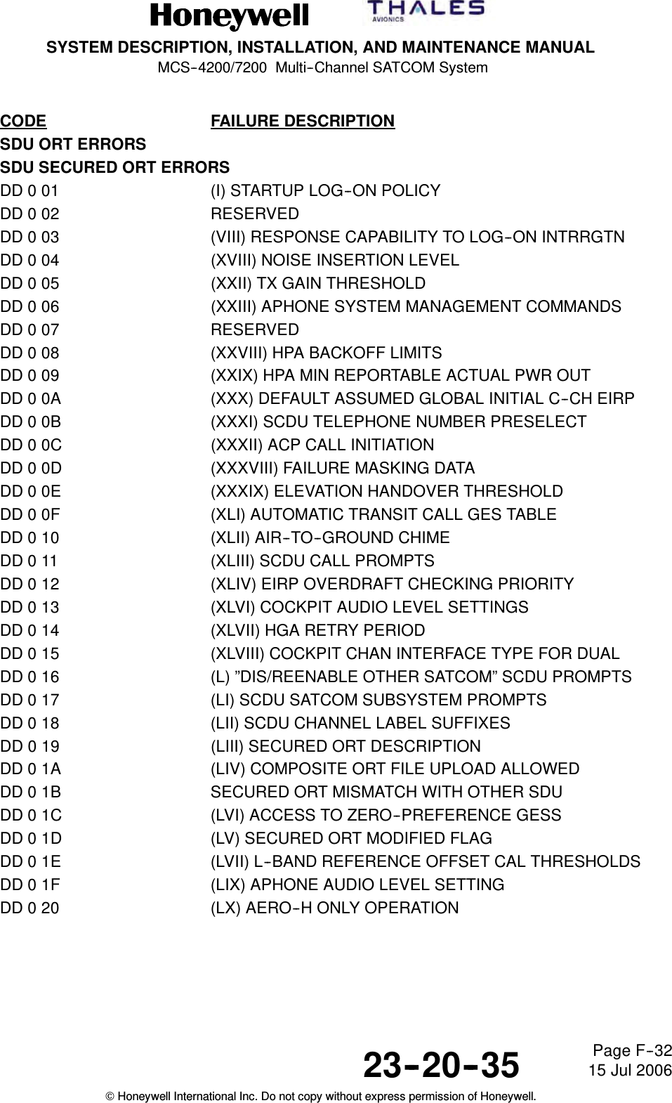
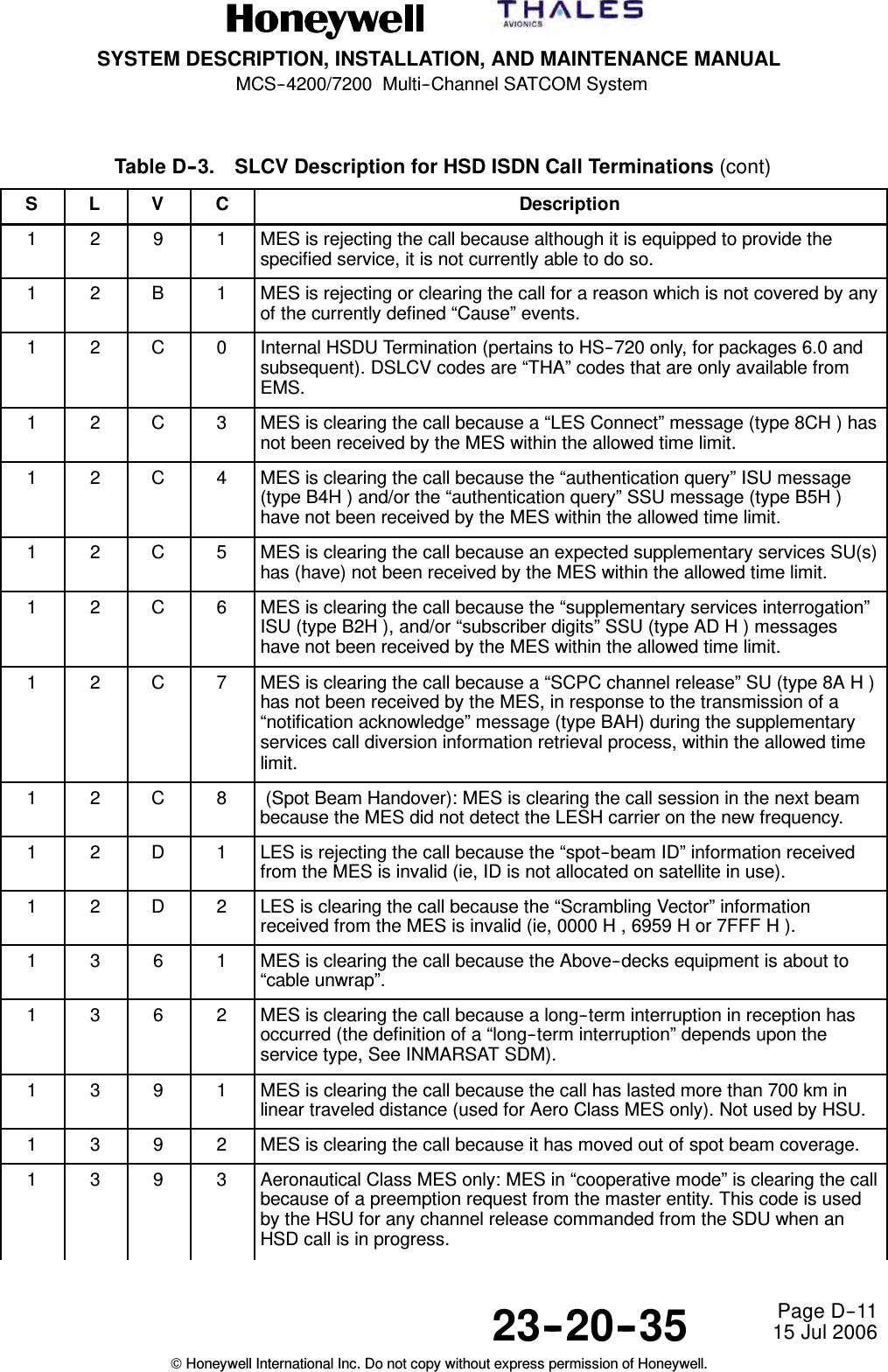
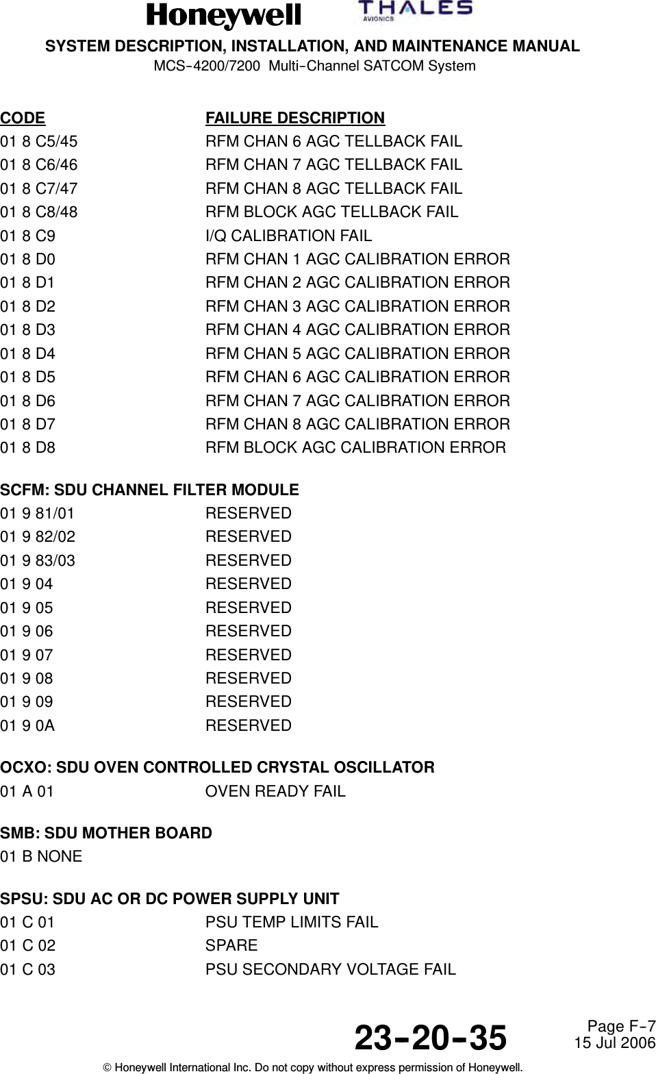
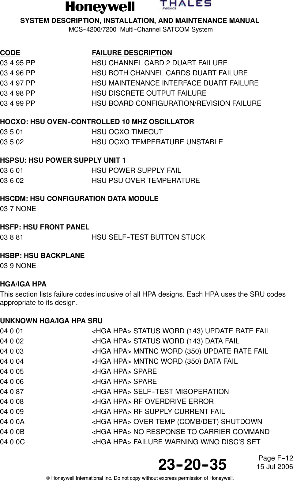
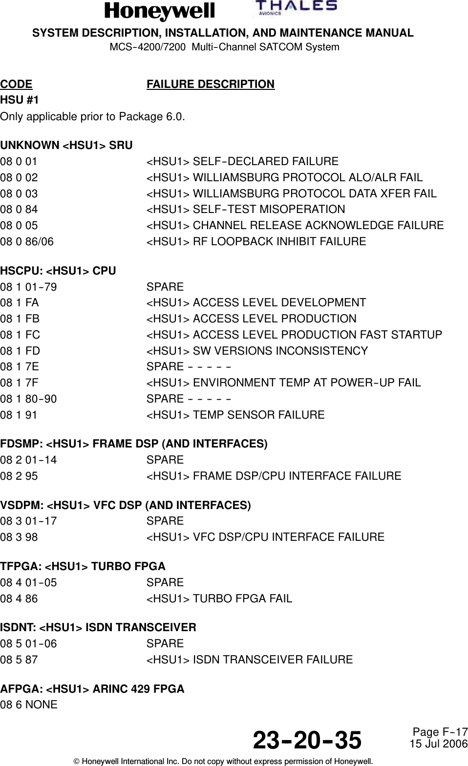
![SYSTEM DESCRIPTION, INSTALLATION, AND MAINTENANCE MANUALMCS--4200/7200 Multi--Channel SATCOM System23--20--35 15 Jul 2006Honeywell International Inc. Do not copy without express permission of Honeywell.Page F--3CODE FAILURE DESCRIPTIONCODB: SDU VOICE CODEC MODULE B01 3 Same entries as for CODA above except substitute CODB for CODA, SRU code 3 forcode 2, [CODEC_B] for [CODEC_A] and <CODEC--B> for <CODEC--A>.Fault codes for codecs C--F have Level 2 (SRU) codes E--H. They are listed in the appropriatesection of this table for those SRU codes.SIOM: SDU INPUT/OUTPUT MODULE (EXCLUSIVE TO SIOM)01 4 81 A429 XMTR LOOP--BACK TO OTHER SDU FAIL01 4 82 A429 XMTR LOOP--BACK TO CFDS FAIL01 4 83 A429 XMTR LOOP--BACK TO ADL FAIL01 4 84 A429 XMTR LOOP--BACK TO PDL FAIL01 4 85 A429 XMTR LOOP--BACK TO (C)MUs FAIL01 4 86 A429 XMTR LOOP--BACK TO SCDUs FAIL01 4 87 A429 XMTR LOOP--BACK TO MULTI--CNTRL FAIL01 4 88 RESERVED01 4 89 A429 XMTR LOOP--BACK TO RMP/CAP FAIL01 4 8A A429 XMTR LOOP--BACK TO SNU/CPDF FAIL01 4 8B A429 XMTR LOOP--BACK TO HSU1 FAIL01 4 8C A429 XMTR LOOP--BACK TO HSU2 FAIL01 4 8D A429 XMTR LOOP--BACK SPARE01 4 8E A429 XMTR LOOP--BACK SPARE01 4 8F A429 XMTR LOOP--BACK SPARE01 4 90 A429 XMTR LOOP--BACK SPARE01 4 91 RESERVED014AB SIOMBUSERROR01 4 2C A429 TX TO OTHER SDU BUFFER FULL01 4 2D A429 TX TO CFDS BUFFER FULL0142E A429TXTOADLBUFFERFULL0142F A429TXTOPDLBUFFERFULL01 4 30 A429 TX TO (C)MUs BUFFER FULL01 4 31 A429 TX TO SCDUs BUFFER FULL01 4 32 A429 TX TO MULTI--CTRL BUFFER FULL01 4 33 RESERVED01 4 34 A429 TX TO RMP/CAP BUFFER FULL01 4 35 A429 TX TO SNU/CPDF BUFFER FULL01 4 36 A429 TX TO HSU1 BUFFER FULL01 4 37 A429 TX TO HSU2 BUFFER FULL01 4 38 A429 TX BUFFER FULL SPARE01 4 39 A429 TX BUFFER FULL SPARE](https://usermanual.wiki/Honeywell/HS-720.HS-720-User-Manual-Part3/User-Guide-1350372-Page-104.png)
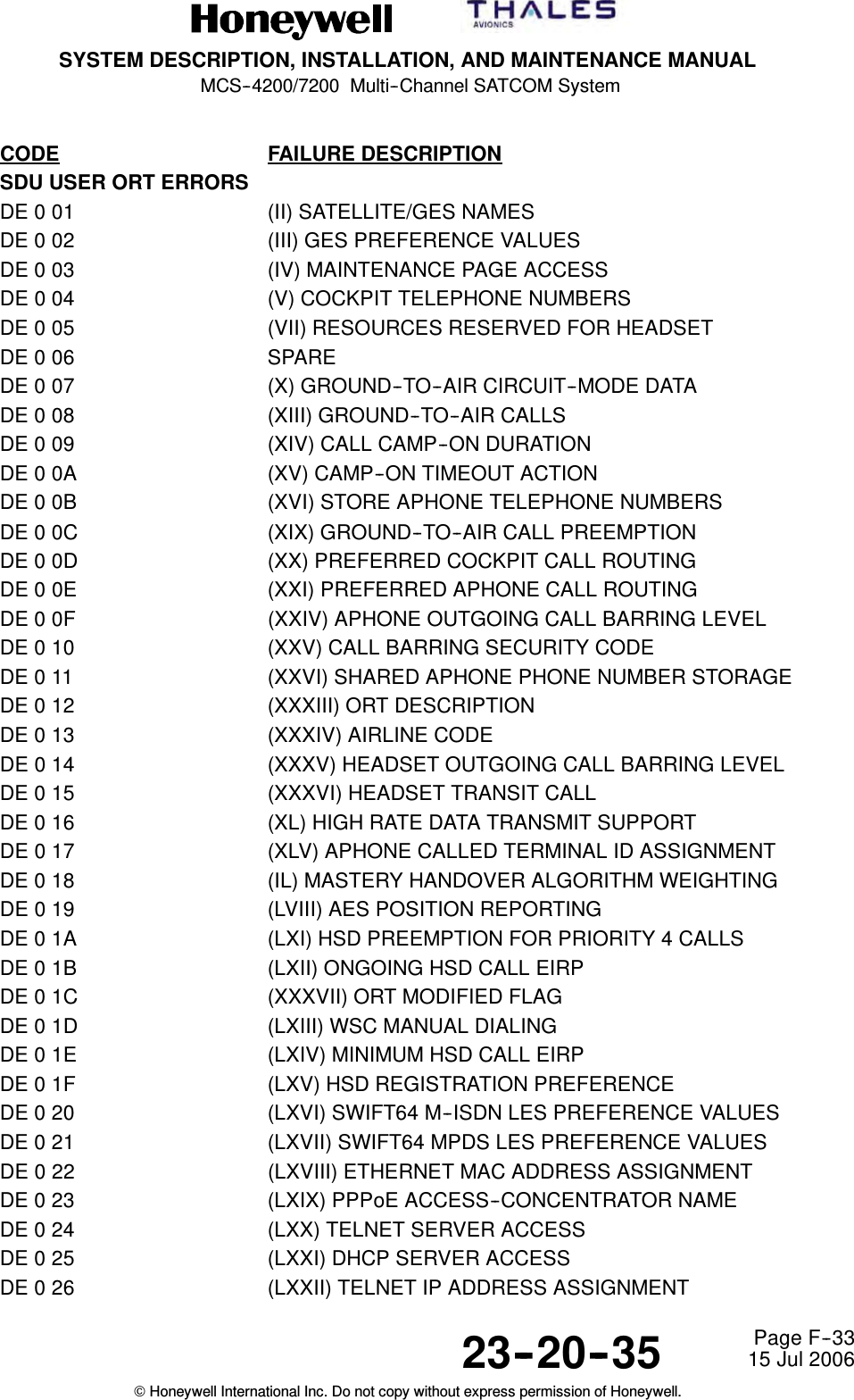
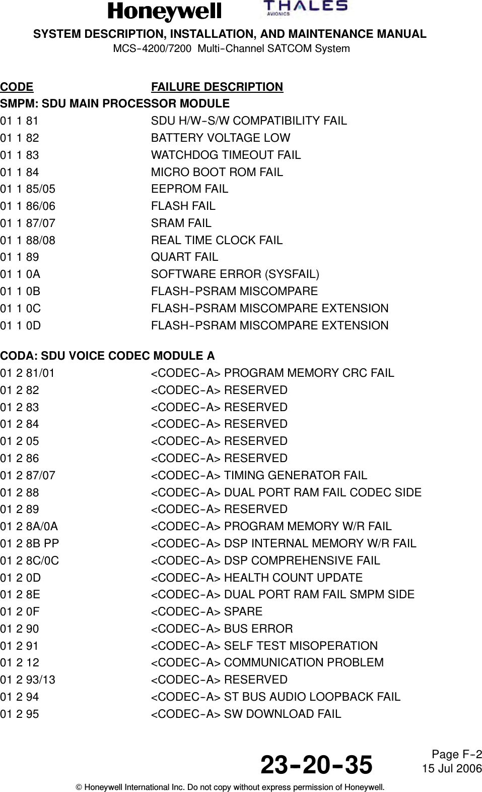
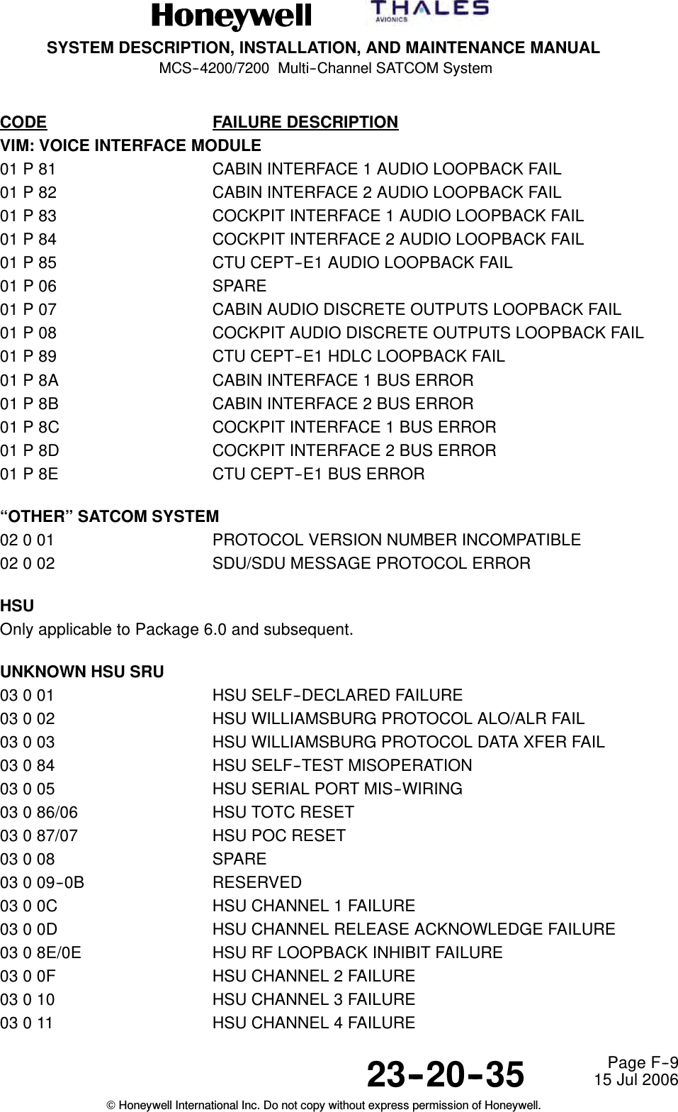
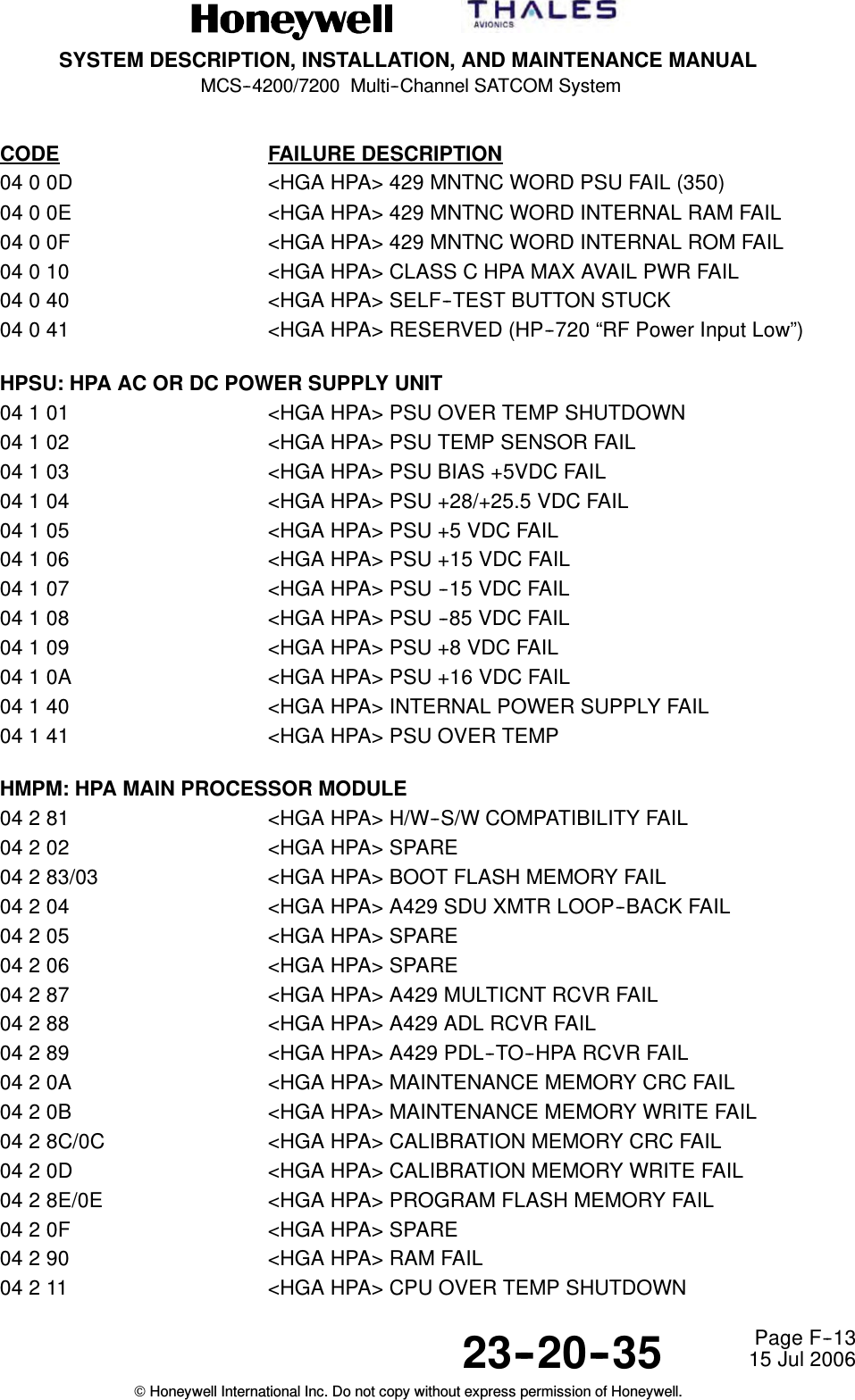
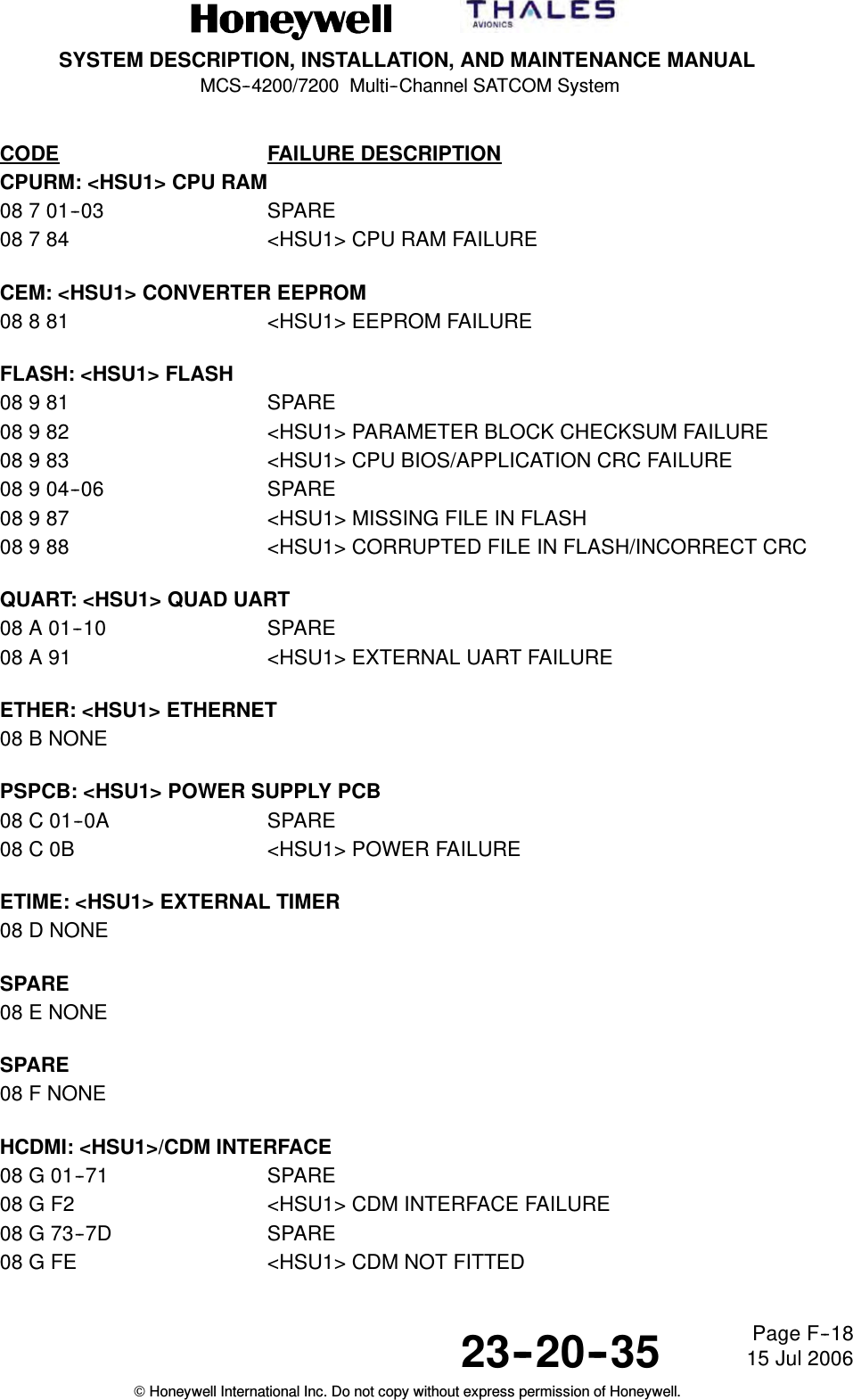
![SYSTEM DESCRIPTION, INSTALLATION, AND MAINTENANCE MANUALMCS--4200/7200 Multi--Channel SATCOM System23--20--35 15 Jul 2006Honeywell International Inc. Do not copy without express permission of Honeywell.Page F--5CODE FAILURE DESCRIPTIONSMDM2: SDU MODEM MODULE #201 6 Same entries as for SMDM1 above except substitute SMDM2 for SMDM1, SRU code 6for code 5, [MODEM_2] for [MODEM_1] and <MODEM-- 2> for <MODEM--1>.SMDM3: SDU MODEM MODULE #301 7 Same entries as for SMDM1 above except substitute SMDM3 for SMDM1, SRU code 7for code 5, [MODEM_3] for [MODEM_1] and <MODEM-- 3> for <MODEM--1>.Fault codes for modems 4--7 have Level 2 (SRU) codes J, L, M and N. They are listed in thistable in the appropriate section for those SRU codes.SRFM: SDU RADIO FREQUENCY MODULE01 8 81 RESERVED01 8 82 RESERVED01 8 83 RESERVED01 8 84 RESERVED01 8 85 RESERVED01 8 86 RESERVED01 8 87 RESERVED01 8 88 RESERVED01 8 89 RESERVED0180A SPARE0180B SPARE0180C SPARE0180D SPARE01 8 8E/0E RF SYNTH CHAN1 LOCK DETECT FAIL01 8 8F/0F RESERVED01 8 90/10 RF SYNTH CHAN2 LOCK DETECT FAIL01 8 91/11 RESERVED01 8 92/12 RF SYNTH CHAN3 LOCK DETECT FAIL01 8 93/13 RESERVED01 8 94/14 RESERVED01 8 95/15 RESERVED01 8 96/16 RF SYNTH CHAN4 LOCK DETECT FAIL01 8 97/17 RF SYNTH CHAN5 LOCK DETECT FAIL01 8 98/18 RF SYNTH CHAN6 LOCK DETECT FAIL01 8 99/19 RF SYNTH CHAN7 LOCK DETECT FAIL01 8 9A/1A RF SYNTH CHAN8 LOCK DETECT FAIL01 8 9B/1B RF SYNTH TX BLOCK PLO LOCK DETECT FAIL01 8 9C/1C RF SYNTH RX BLOCK PLO LOCK DETECT FAIL](https://usermanual.wiki/Honeywell/HS-720.HS-720-User-Manual-Part3/User-Guide-1350372-Page-106.png)
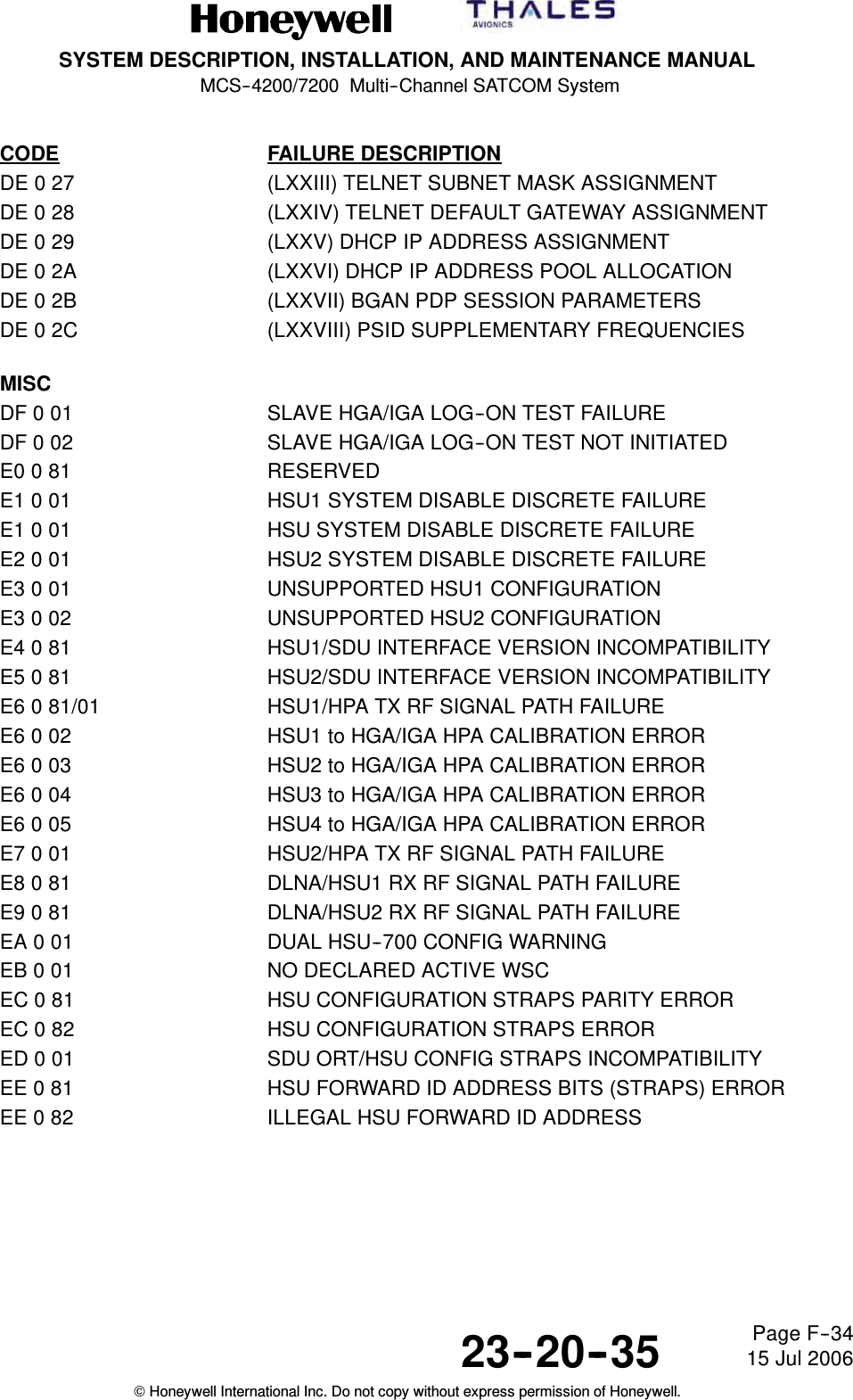
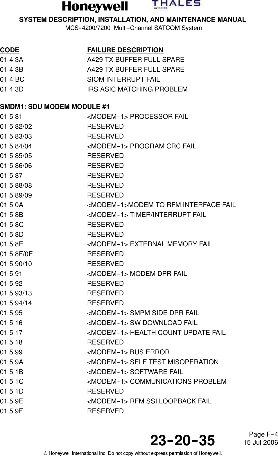
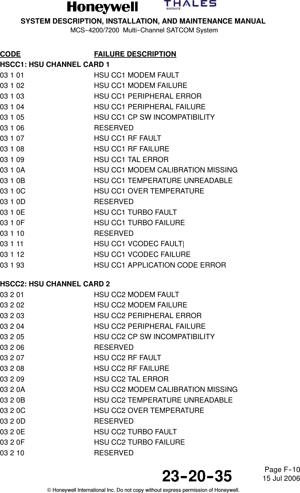
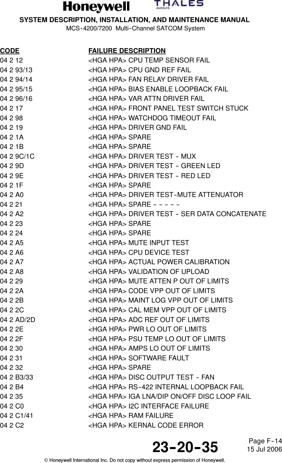
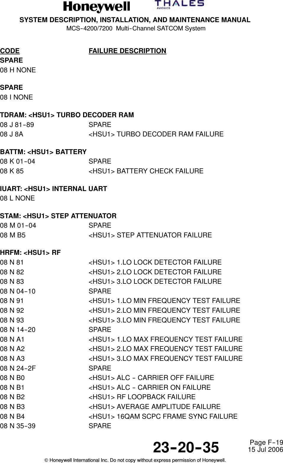
![SYSTEM DESCRIPTION, INSTALLATION, AND MAINTENANCE MANUALMCS--4200/7200 Multi--Channel SATCOM System23--20--35 15 Jul 2006Honeywell International Inc. Do not copy without express permission of Honeywell.Page F--8CODE FAILURE DESCRIPTIONSFPDM: SDU FRONT PANEL DISPLAY MODULE01 D 01 TEST (PAST) SWITCH STUCK01 D 02 MANUAL SCROLL SWITCH STUCKCODC: SDU VOICE CODEC MODULE C01 E Same entries as for CODA (01 2 xx) above except substitute CODC for CODA, SRUcode E for code 2, [CODEC_C] for [CODEC_A] and <CODEC--C> for <CODEC--A>.CODD: SDU VOICE CODEC MODULE D01 F Same entries as for CODA (01 2 xx) above except substitute CODD for CODA, SRUcode F for code 2, [CODEC_D] for [CODEC_A] and <CODEC--D> for <CODEC--A>.CODE: SDU VOICE CODEC MODULE E01 G Same entries as for CODA (01 2 xx) above except substitute CODE for CODA, SRUcode G for code 2, [CODEC_E] for [CODEC_A] and <CODEC--E> for <CODEC--A>.CODF: SDU VOICE CODEC MODULE F01 H Same entries as for CODA (01 2 xx) above except substitute CODF for CODA, SRUcode H for code 2, [CODEC_F] for [CODEC_A] and <CODEC--F> for <CODEC--A>.01 I Not used.SMDM4: SDU MODEM MODULE #401 J Same entries as for SMDM1 (01 5 xx) above except substitute SMDM4 for SMDM1,SRU code J for code 5, [MODEM_4] for [MODEM_1] and <MODEM--4> for<MODEM--1>.01 K Not used.SMDM5: SDU MODEM MODULE #501 L Same entries as for SMDM1 (01 5 xx) above except substitute SMDM5 for SMDM1,SRU code L for code 5, [MODEM_5] for [MODEM_1] and <MODEM--5> for<MODEM--1>.SMDM6: SDU MODEM MODULE #601 M Same entries as for SMDM1 (01 5 xx) above except substitute SMDM6 for SMDM1,SRU code M for code 5, [MODEM_6] for [MODEM_1] and <MODEM--6> for<MODEM--1>.SMDM7: SDU MODEM MODULE #701 N Same entries as for SMDM1 (01 5 xx) above except substitute SMDM7 for SMDM1,SRU code N for code 5, [MODEM_7] for [MODEM_1] and <MODEM--7> for<MODEM--1>.](https://usermanual.wiki/Honeywell/HS-720.HS-720-User-Manual-Part3/User-Guide-1350372-Page-109.png)
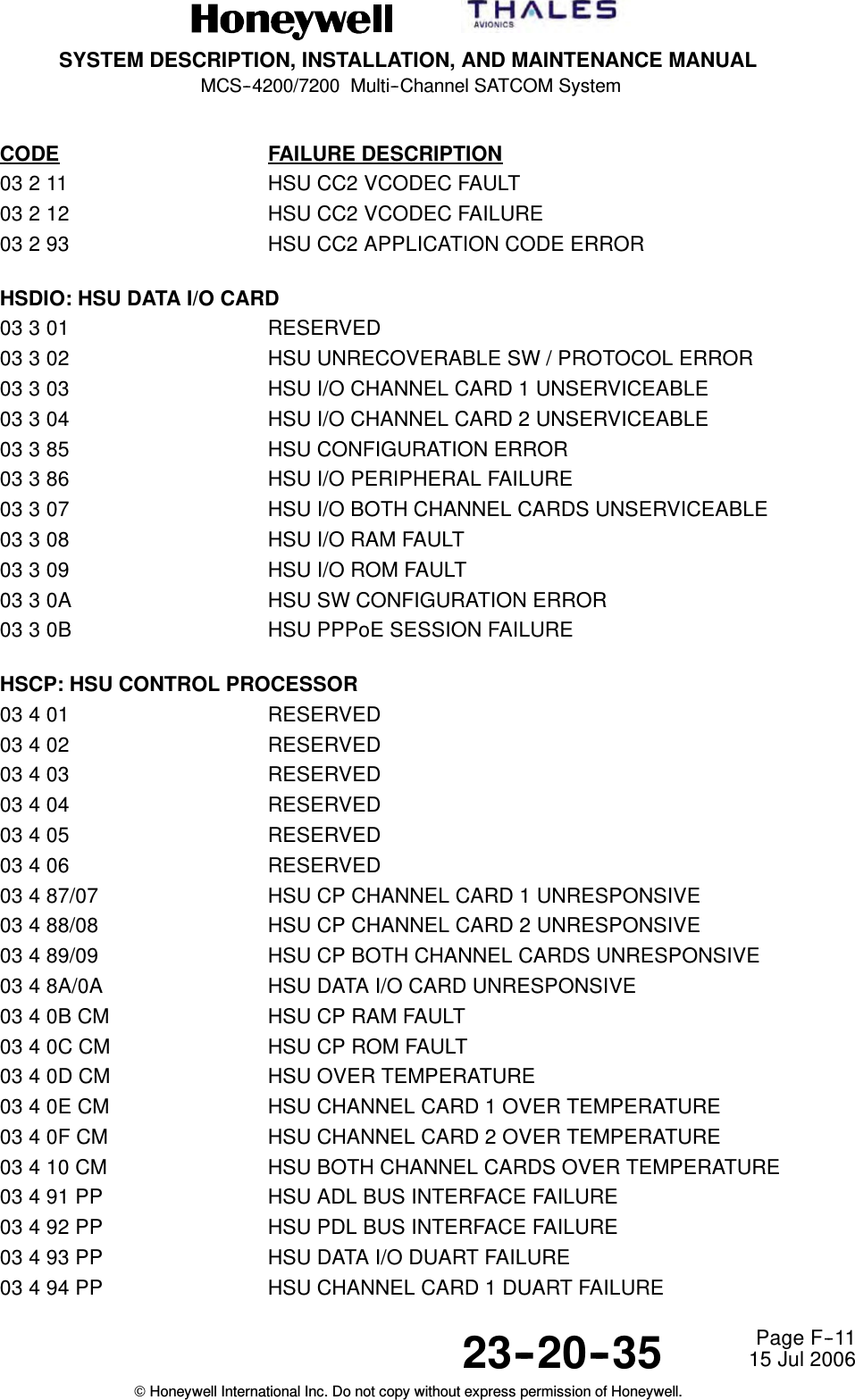
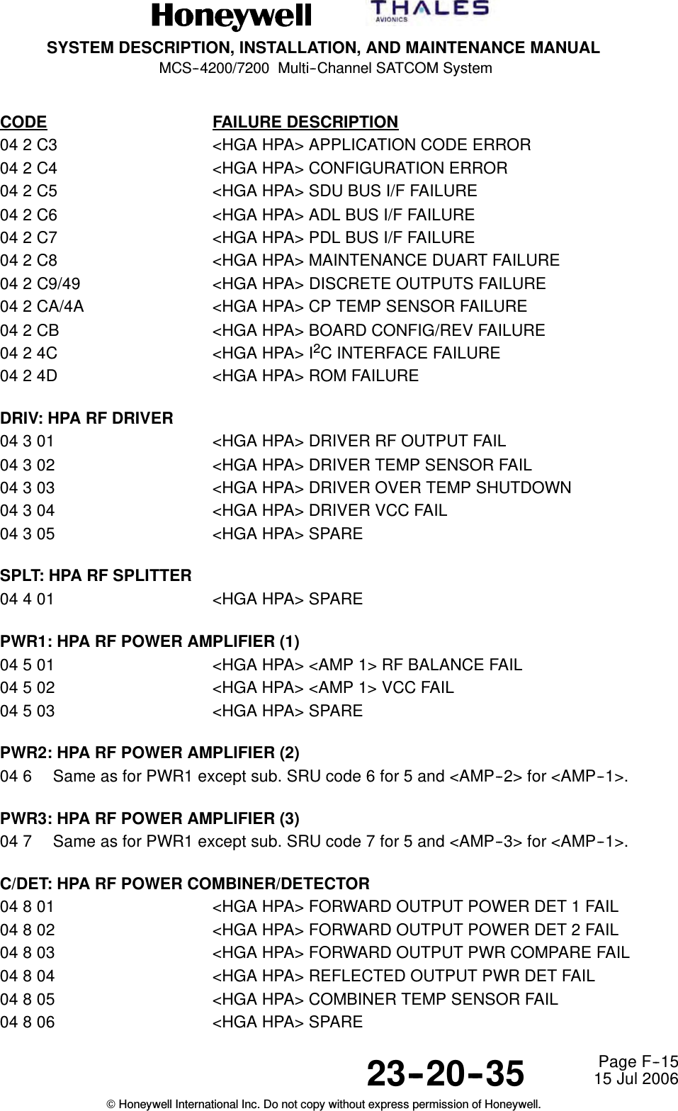
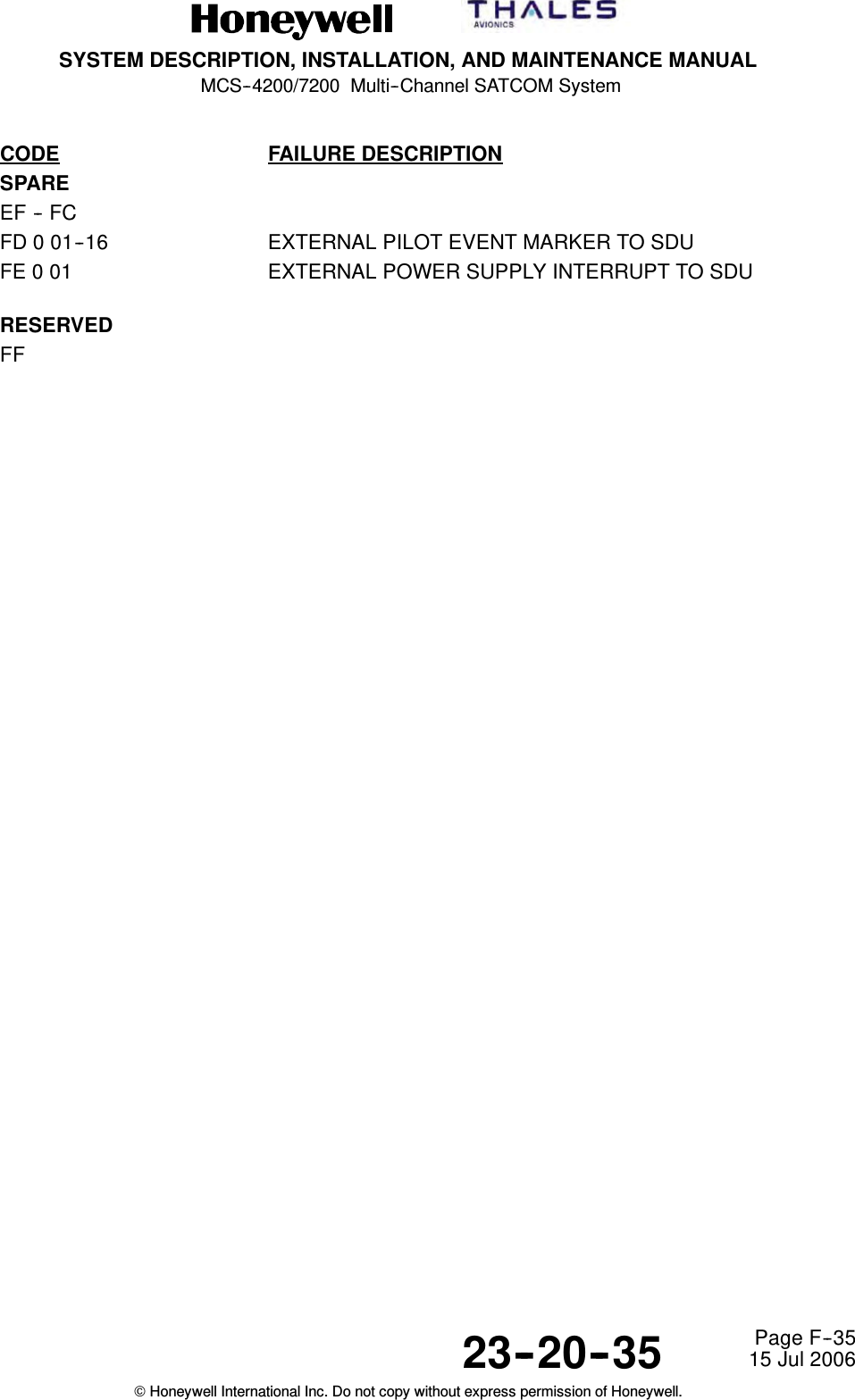
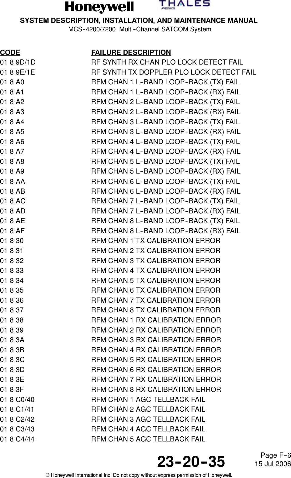
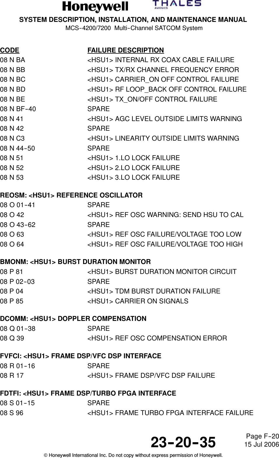
![SYSTEM DESCRIPTION, INSTALLATION, AND MAINTENANCE MANUALMCS--4200/7200 Multi--Channel SATCOM System23--20--35 15 Jul 2006Honeywell International Inc. Do not copy without express permission of Honeywell.Page F--16CODE FAILURE DESCRIPTIONFPAMP: HPA RF FINAL POWER AMPLIFIER04 9 01 <HGA HPA> FINAL AMP 1 RF BALANCE FAIL04 9 02 <HGA HPA> FINAL AMP 1 VCC FAIL04 9 03 <HGA HPA> SPARE04 9 04 <HGA HPA> FINAL AMP 2 RF BALANCE FAIL04 9 05 <HGA HPA> FINAL AMP 2 VCC FAIL04 9 06 <HGA HPA> SPARE04 9 C0/40 <HGA HPA> PA UNRESPONSIVE04 9 41 <HGA HPA> SPARE04 9 42 <HGA HPA> OVER CURRENT FAILURE04 9 43 <HGA HPA> DRIVER AMPLIFIER DC VOLTAGE FAILURE04 9 44 <HGA HPA> DRIVER AMPLIFIER CURRENT FAILURE04 9 45 <HGA HPA> 12 VDC FAILURE04 9 46 <HGA HPA> PA MUTE FAILURE04947 <HGAHPA>PAOVERTEMP04948 <HGAHPA>PASTATUSFAILURE04 9 49 <HGA HPA> PA TEMP SENSOR FAILUREHMB: HPA MOTHER BOARD04 A 40 <HGA HPA> BP TEMP SENSOR FAILURERFAM: 20W HPA RF AMPLIFIER MODULE04 B 01 <HGA HPA> OVER TEMP SHUTDOWN04B02 <HGAHPA>RFAMVCCFAIL04B03 <HGAHPA>AMP1VCCFAIL04 B 04 <HGA HPA> FORWARD OUTPUT POWER DET 1 FAIL04 B 05 <HGA HPA> FORWARD OUTPUT POWER DET 2 FAIL04 B 06 <HGA HPA> REFLECTED OUTPUT PWR DET FAIL04 B 07 <HGA HPA> TEMP SENSOR FAIL04 B 08 <HGA HPA> FORWARD OUTPUT POWER FAIL04 B 09 <HGA HPA> AMP 2 RF BALANCE FAIL04B0A <HGAHPA>AMP2VCCFAILSPARE Level 1 Codes0506LGA HPA07 Same entries as for HGA/IGA HPA above except substitute LRU code 7 for code 4,<LGA HPA> for <HGA HPA>, and [LGA_SUBSYS] for [HGA_SUBSYS]. For the casesof conditional HGA subsystem indictments ([cond_HGA_SUBSYS]), the equivalentLGA HPA failures shall UNconditionally indict [LGA_SUBSYS].](https://usermanual.wiki/Honeywell/HS-720.HS-720-User-Manual-Part3/User-Guide-1350372-Page-117.png)
![SYSTEM DESCRIPTION, INSTALLATION, AND MAINTENANCE MANUALMCS--4200/7200 Multi--Channel SATCOM System23--20--35 15 Jul 2006Honeywell International Inc. Do not copy without express permission of Honeywell.Page F--21CODE FAILURE DESCRIPTIONVDTFI: <HSU1> VFC DSP/TURBO FPGA INTERFACE08 T NONEVDITI: <HSU1> VFC DSP/ISDN TRANSCEIVER INTERFACE08 U NONETFTDR: <HSU1> TURBO FPGA/TURBO DECODER RAM INTERFACE08 V NONEPSIPI: <HSU1> POWER SUPPLY PCB/ISDN PHONE INTERFACE08 W 01--07 SPARE08 W 88 <HSU1> ISDN SUPPLY VOLTAGE FAILURECDM: <HSU1> CONFIGURATION DATA MODULE08 X 01--70 SPARE08 X F1 <HSU1> INVALID SERIAL NUMBER08 X 72 SPARE08 X F3 <HSU1> CDM ESSENTIAL DATA FAILURE08 X F4 <HSU1> CDM DATA ACCESS ERROR08 X F5 <HSU1> CDM MISSING WRITE PROTECTION08 X F6 <HSU1> CDM INCORRECT VERSIONSPARE08 Y NONEITPSI: <HSU1> ISDN TRANSCEIVER/POWER SUPPLY PCB INTERFACE08 Z 01--08 SPARE08 Z 89 <HSU1> ISDN RX VOLTAGEHSU #209 Same entries as for HSU #1 above except substitute LRU code 09 for code 08,<HSU2> for <HSU1>, and [HSU2] for [HSU1]. Only applicable prior to Package 6.0.HIGH POWER RELAYUNKNOWN HPR SRU0A 0 01 (PORT) MNTNC WORD HPR FAIL0A 0 02 (STBD) MNTNC WORD HPR FAILSPARE0B0C](https://usermanual.wiki/Honeywell/HS-720.HS-720-User-Manual-Part3/User-Guide-1350372-Page-124.png)
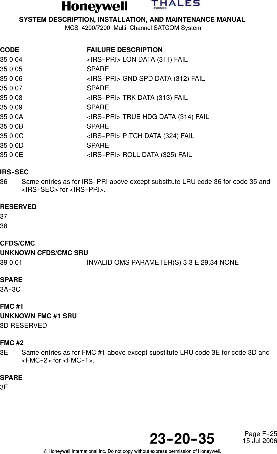
![SYSTEM DESCRIPTION, INSTALLATION, AND MAINTENANCE MANUALMCS--4200/7200 Multi--Channel SATCOM System23--20--35 15 Jul 2006Honeywell International Inc. Do not copy without express permission of Honeywell.Page F--27CODE FAILURE DESCRIPTION58001 SPAREMP4A/B59 0 01 SDU CFDS BUS INACTIVE59 0 02 INVALID OMS PARAMETER(S)5A 0 01 SDU PRI IRS BUS INACTIVE5B 0 01 SDU SEC IRS BUS INACTIVE5C 0 01 SDU HGA/IGA HPA BITE BUS INACTIVE5C 0 02 HGA/IGA HPA SELF--TEST MISOPERATION5D SPARE5E SPARE MP6G/H5F 0 01 SDU LGA HPA BITE BUS INACTIVE5F 0 02 LGA HPA SELF--TEST MISOPERATION60 SPARE MP7A/B61 SPARE62 0 01 SDU TOP/PORT BSU/ACU BITE BUS INACTIVE62 0 02 TOP/PORT BSU/ACU SELF--TEST MISOPERATION63 SPARE64 0 01 SDU STBD BSU BITE BUS INACTIVE64 0 02 STBD BSU/ACU SELF--TEST MISOPERATION65 0 01 SDU RMP BUS INACTIVE66 0 01 SDU SCDU/WSC--3 BUS INACTIVE67 0 01 RESERVED68 0 01 RESERVED69 SPARE6A 0 81 RESERVED6B 0 01 SPARE6C 0 81 RESERVED6D 0 81 RESERVED6E 0 81 RESERVED6F 0 81 RESERVED70 SPARE71 0 01 SDU CROSS--TALK BUS INACTIVE 3 2 I -- [OTHER_SATCOM]72 SPARE MP12E/F73 0 01 SDU FMC--1 BUS INACTIVE74 0 01 SDU FMC--2 BUS INACTIVE75 SPARE76 SPARE77 SPARE78 SPARE](https://usermanual.wiki/Honeywell/HS-720.HS-720-User-Manual-Part3/User-Guide-1350372-Page-130.png)