Honeywell Bc7000L1000 Users Manual 66 6002 Conversion Wiring Diagrams For BC7000L 1000
2014-12-11
: Honeywell Honeywell-Bc7000L1000-Users-Manual-120153 honeywell-bc7000l1000-users-manual-120153 honeywell pdf
Open the PDF directly: View PDF ![]() .
.
Page Count: 33

CONVERSION WIRING DIAGRAMS
FOR BC7000L1000
The diagrams and instructions contained in this booklet are for converting the following model
programmers to BC7000 Microcomputer Based Burner Control System.
TABLE OF CONTENTS Page
Section l . . . . . . . . . . . . . . . . . . . . . . . . . . . . . . . . . . . . . . . . . . . . . . . . . . . . . . . . . . . . . . . . . . . . . . . . . . . . . . . . . . . . . . . . . . . . . . . . . . . . . . . . ...2
Fireye C, D, and E-Series
Section II . . . . . . . . . . . . . . . . . . . . . . . . . . . . . . . . . . . . . . . . . . . . . . . . . . . . . . . . . . . . . . . . . . . . . . . . . . . . . . . . . . . . . . . . . . . . . . . . . . . . . . . . ...6
Fireye P-Series
Section III . . . . . . . . . . . . . . . . . . . . . . . . . . . . . . . . . . . . . . . . . . . . . . . . . . . . . . . . . . . . . . . . . . . . . . . . . . . . . . . . . . . . . . . . . . . . . . . . . . . . . . . . 13
Honeywell R4126, R4127, R4181
Section lV . . . . . . . . . . . . . . . . . . . . . . . . . . . . . . . . . . . . . . . . . . . . . . . . . . . . . . . . . . . . . . . . . . . . . . . . . . . . . . . . . . . . . . . . . . . . . . . . . . . . . . . . 23
Honeywell R4140, R4150 with 20 Terminal Subbase (120 V only)
Section V . . . . . . . . . . . . . . . . . . . . . . . . . . . . . . . . . . . . . . . . . . . . . . . . . . . . . . . . . . . . . . . . . . . . . . . . . . . . . . . . . . . . . . . . . . . . . . . . . . . . . ...29
Honeywell R4150 with 13 or 15 Terminal Subbase
1. Installer must be a trained, experienced, flame safeguard control service technician.
2. Disconnect power supply before beginning installation to prevent electrical shock and
equipment damage.
3. All wiring must comply with applicable local electrical codes, ordinances, and regulations.
4. Voltage and frequency of the power supply and flame detector(s) connected to this control
must agree with those marked on the device.
5. Loads connected to the control terminals must not exceed those listed in the SPECIFI-
CATIONS section.
6. All external timers must be listed or component recognized by authorities having
jurisdiction, for the specific purpose for which they are used.
7. Perform all required checkout tests after installation is complete.
IMPORTANT
For on-off, gas-fired systems, some authorities having jurisdiction prohibit the wiring of any
limit or operating contacts in series with the main fuel valve(s).
P.G.
Rev. 6/89
Form Number 66-6002—4
©Honeywell Inc. 1989

SECTION I
FIREYE C, D, E-SERIES CONTROL
120 V ONLY
DIRECTIONS:
1. Disconnect all power to programmer.
2. Remove old programmer from subbase (trade-in to Honeywell Authorized Flame Safeguard
Distributor).
3. Mark all wires on subbase; i.e., wires connected to terminal “D” should be marked “D.”
Disconnect wires as they are marked.
4. Remove old subbase.
5. Mount Q520A subbase.
6. Connect wires to subbase per attached cross reference. Pay close attention to footnotes. For
example: To convert a Fireye 70D10 to a BC7000, the wire marked “P” would connect to
terminal #3 on the Q520. The wire marked “8” would connect to Q520 terminal #15.
7. The symbol “ “ designates a footnote. Study these footnotes carefully.
8. Plug in the BC7000. Make sure you select the proper amplifier, detector and program module
for the application.
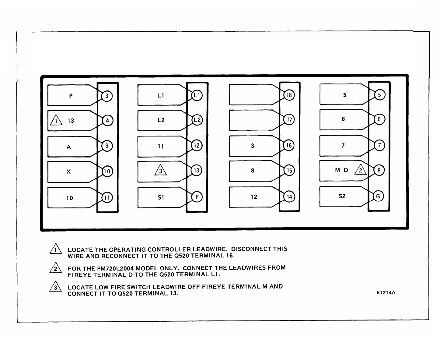
E1214A
FIREYE 70D10/26CF6-5022/26 CU6-5065
EP160/EP161/EP170
TO
BC7000L/PM720L2004 or 1030
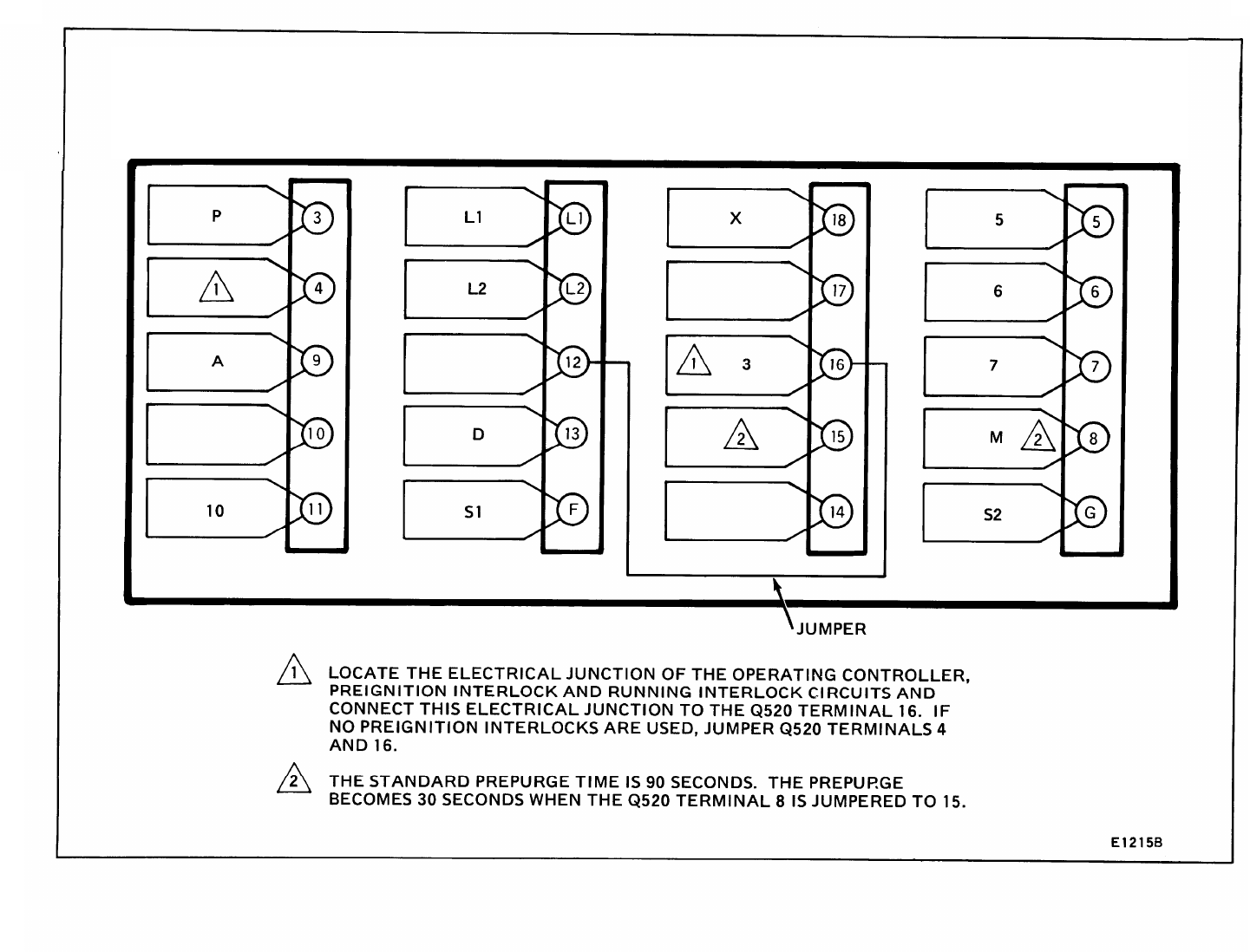
E1215B
FIREYE 24CJ5 - 5010/5011/3010/3011
25CU6 5062/5063/RS-2E
70D30/26CF6 5020/5021/1010/1011
EP380/EP381/EP390
TO
BC7000L/PM720M2002
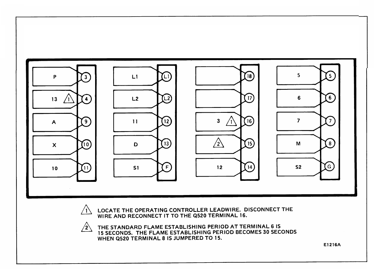
E1216E
FIREYE 24CJ5 5015
70D20/26CF6 5023/25 CU65055
EP260/EP261/EP270
TO
BC7000L/PM720G2005

SECTION II
FIREYE P-SERIES CONTROLS
120 V ONLY
DIRECTIONS:
1.
2.
3.
4.
5.
6.
7.
8.
Disconnect all power to programmer.
Remove old programmer from subbase (trade-in to Honeywell Authorized Flame Safeguard
Distributor).
Mark all wires on subbase; i.e., wires connected to terminal “D” should be marked “D.”
Disconnect wires as they are marked.
Remove old subbase.
Mount Q520A subbase.
Connect wires to subbase per attached cross reference. Pay close attention to footnotes. For
example: To convert a Fireye 26RJ81016 to a BC7000, the wire marked “B” would connect to
terminal #10 on the Q520. The wire marked “W” would connect to Q520 terminal #14.
The symbol “ “ designates a footnote. Study these footnotes carefully.
Plug in the BC7000. Make sure you select the proper amplifier, detector and program module
for the application.
6
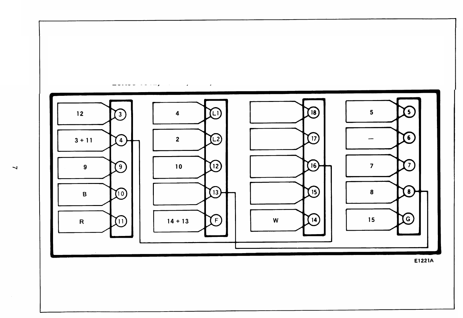
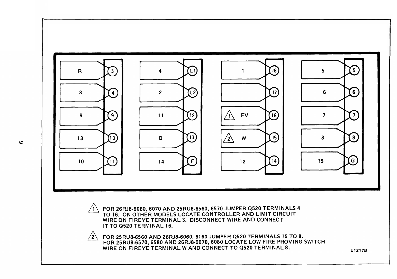
E1221A
FIREYE 26RJ8 1016, 1016T
26RJ8 1012, 1012T, 6012, 6012T
TO
BC7000L + PM720G2005
E1693
FIREYE 25RLJ84580
TO
BC700L + PM720L1030
E1217B
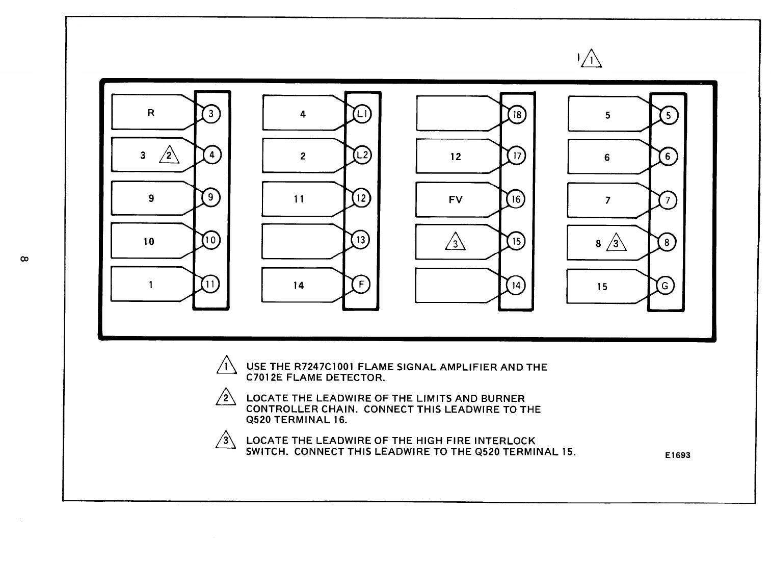
FIREYE 25RU8 6560, 6570,6580
26RJ8 6060, 6070,6080, 6160 TO
BC7000L + PM720L1030
E1218A
FIREYE 29RF5 1001, 1009, 6009 TO BC7000L + PM720G2013
E1219A
26RJ8 6058, 6066, 6068
25RU8 6558, 6566
TO
BC7000L + PM720G2005
E1220A
FIREYE 26RJ8 1002, 1003, 1008, 1011, 1018, 6008, 6018
29RF5 1000, 1002, 1005, 1015, 1104
29RF5 6015 TO BC7000L + PM720G2005

SECTION Ill
HONEYWELL R4126, R4127, R4181 CONTROLS
120 V ONLY
DIRECTIONS:
1.
2.
3.
4.
5.
6.
7.
8.
Disconnect all power to programmer.
Remove old programmer from subbase (trade-in to Honeywell Authorized Flame Safeguard
Distributor).
Mark all wires on subbase; i.e., wires connected to terminal “D” should be marked “D.”
Disconnect wires as they are marked.
Remove old subbase.
Mount Q520A subbase.
Connect wires to subbase per attached cross reference. Pay close attention to footnotes. For
example: To convert an R4126A1172 to a BC7000, the wire marked “F2” would connect to
terminal #3 on the Q520. The wire marked “3” would connect to Q520 terminal #14.
The symbol “ ” designates a footnote. Study these footnotes carefully.
Plug in the BC7000. Make sure you select the proper amplifier, detector and program module
for the application.
13
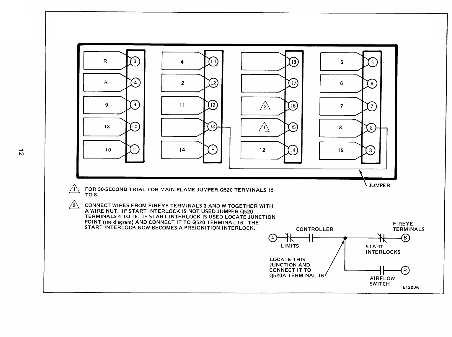
E1222A
R4126A1172, 1180,1198 TO BC7000L + PM720L2004
E1223A
R4126A1008, 1016, 1024, 1032, 1040, 1057, 1081, 1149
R4126B1006, 1014, 1022
TO
BC7000L + PM720G2005
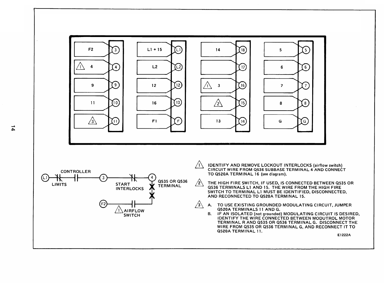
E1224A
R4126A1073,1164 TO BC7000L + PM720L2004
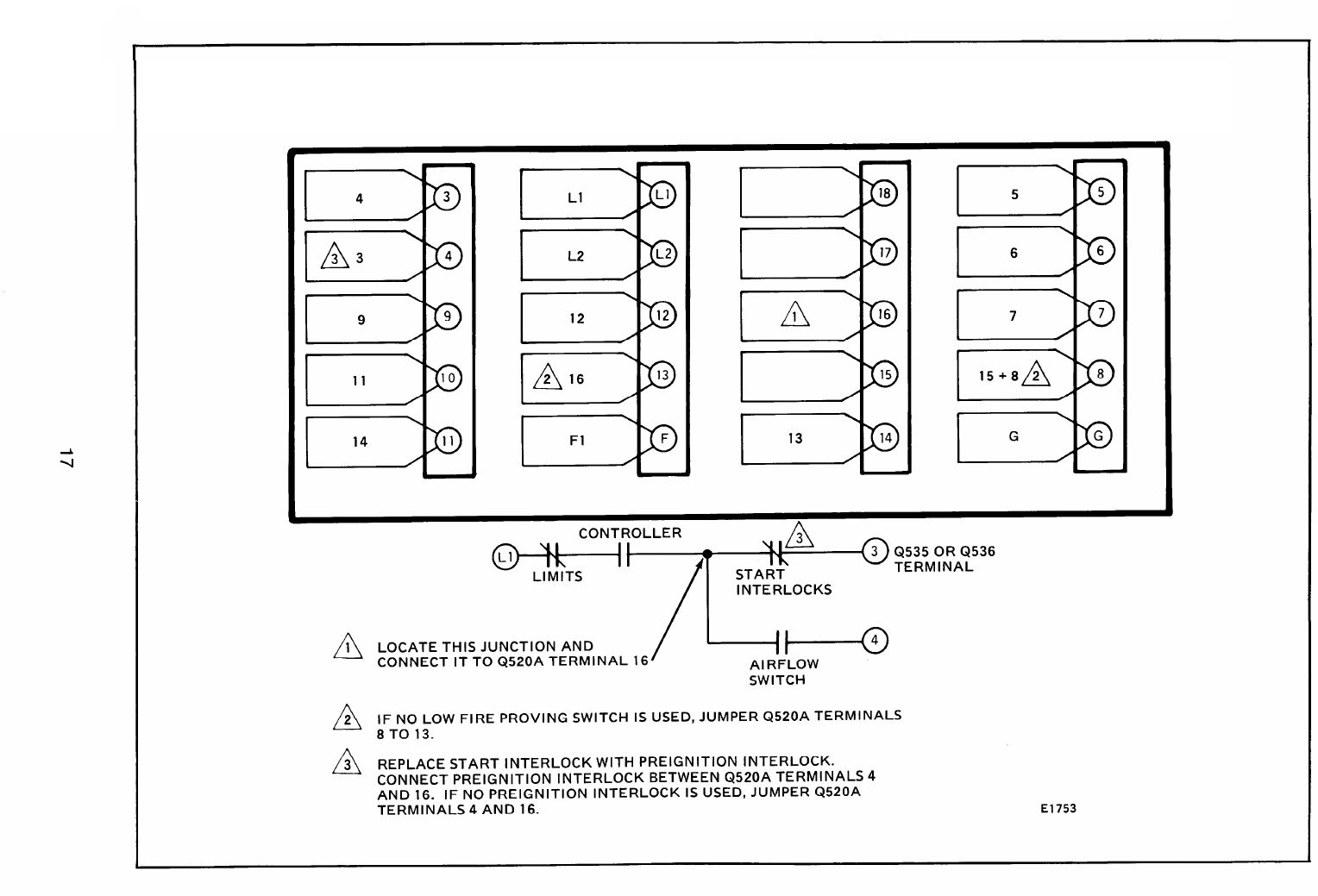
E1753
R4127A1155 AND R4127A1197 TO BC7000L + PM720G2005
E1225A
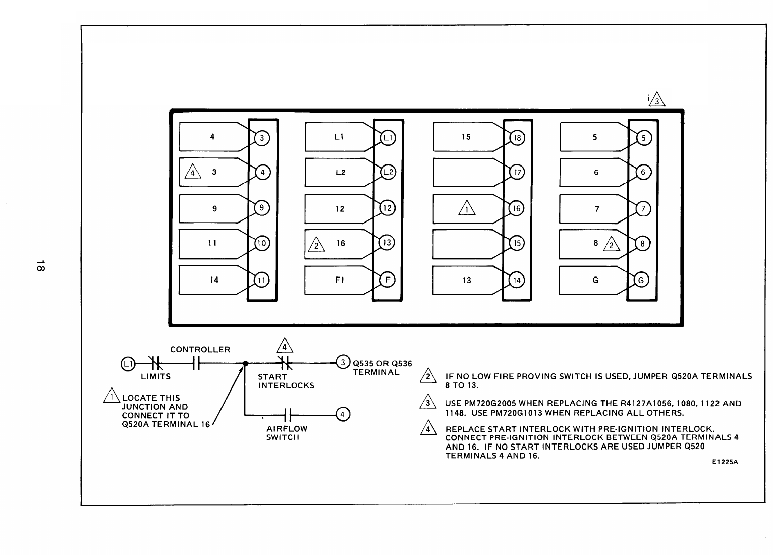
R4127 (ALL MODELS) EXCEPT R4127A1171,
R4127A1155, R4127A1197,
R4127B1039, AND R4127B1047
TO
BC7000L + PM720G
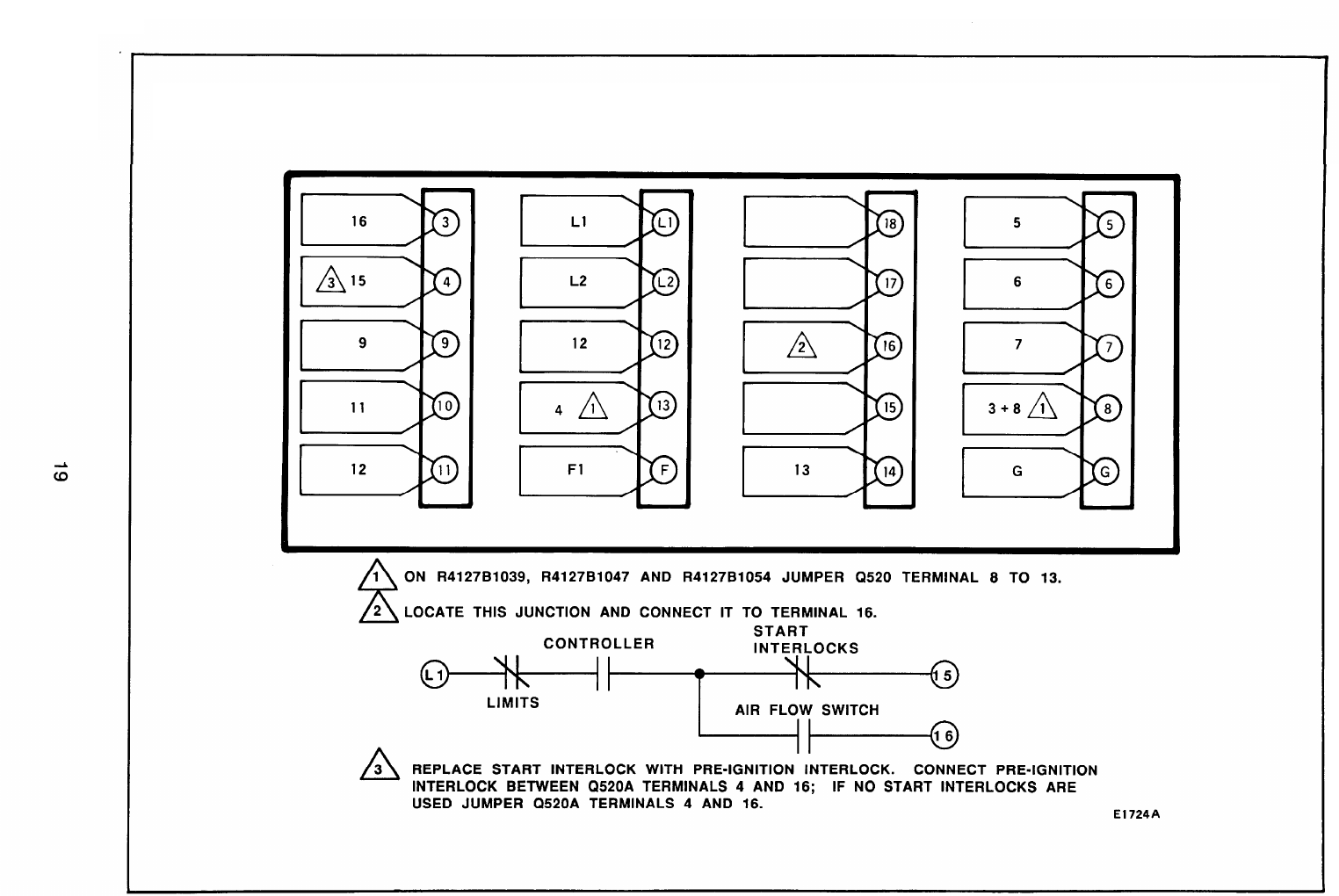
E1724A
R4127A1171/R4127B1039/R4127B1047
TO
BC7000L+PM720G2005
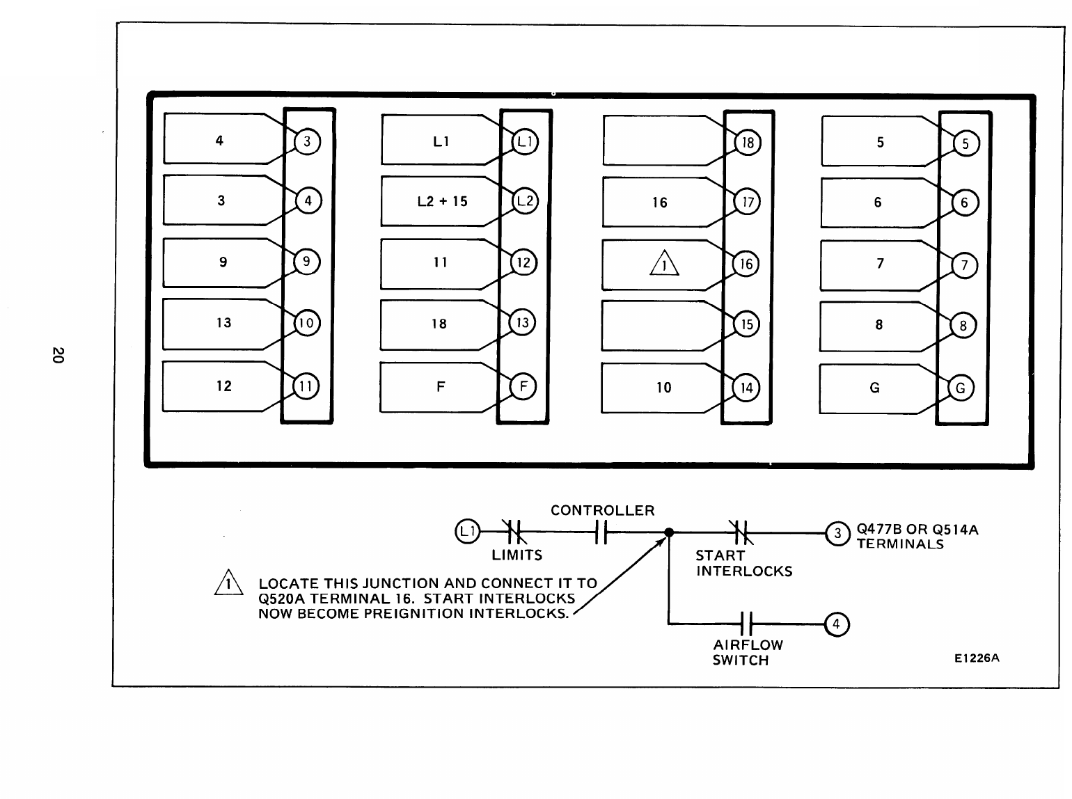
E1226A
R4181A1000, R4181A1026 TO
BC7000L + PM720G2005
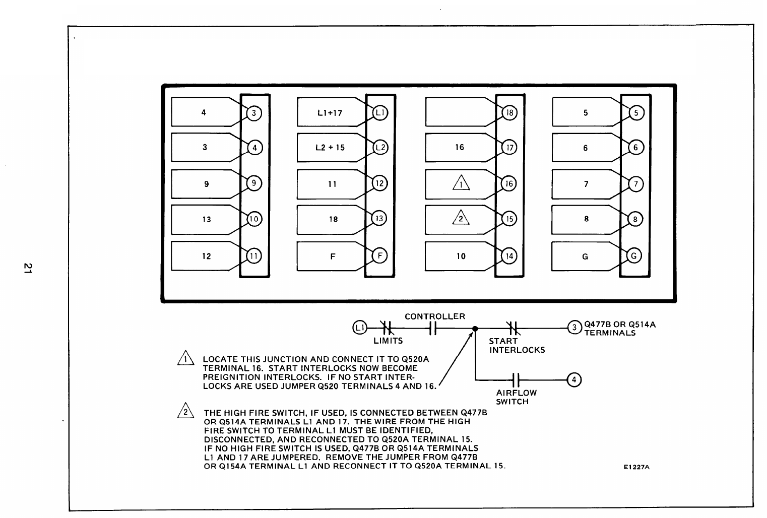
E1227A
R4181A1018, R4181A1034 TO BC7000L + PM720L2004
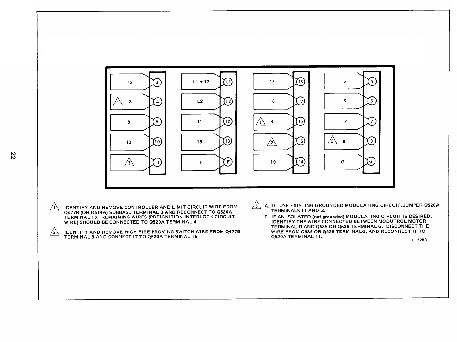
E1228A
R4181A1042, R4181A1059 TO BC7000L + PM720L2004
SECTION IV
HONEYWELL R4140 AND R4150, 20 TERMINAL SUBBASE
120 V ONLY
NOTE: This cross reference does not include conversions for proprietary controls such as
Cleaver Brooks, Vapor or Peabody Gordon Piatt models.
Preignition Interlock Models:
R4140G1007
R4140G1015
R4140G1106
R4140G1130
R4140G1148
R4140L All Models
R4140M1145
R4140M1152
R4140M1160
R4140M1 178
R4150G1186
R4150L All Models
All others have start interlocks.
If existing R4150 has 13- or 15-terminal subbase, the subbase must be replaced with a 20
terminal Q520A. See Section V.
23
REPLACING AN R4140M OR R4150M WITH START
INTERLOCKS WITH A BC7000L/PM720M2002
*-X
x
x
;.-”
.“.
STEPS FOR CONVERSION
1. START INTERLOCKS BECOME PREIGNITION INTERLOCKS.
2. DISCONNECT DAMPER CONTROL WIRE FROM TERMINAL 10
CONNECT IT TO TERMINAL 11.
3. REMOVE JUMPER FROM TERMINAL BETWEEN TERMINAL 11
AND 12 (on some models).
4. IF LOW FIRE SWITCH IS NOT USED, CONNECT JUMPER WIRE
BETWEEN TERMINALS 8 AND 13.
5. JUMPER 8 TO
15
FOR 30-SECOND PREPURGE.
6. IF OLD CONTROL HAD 12 TO 11 JUMPERED, ADD A JUMPER
FROM 12 TO 16.
E1235B
E1237
REPLACING AN R4140M OR R4150M WITH
PREIGNITION INTERLOCKS WITH A
BC7000L/PM720M2002
2. DISCONNECT DAMPER CONTROL WIRE FROM TERMINAL 10
AND CONNECT IT TO TERMINAL 11.
3.
4.
5.
REMOVE JUMPER FROM TERMINAL BETWEEN TERMINAL 11
AND 12 (on some models).
IF LOW FIRE SWITCH IS NOT USED, CONNECT JUMPER WIRE
BETWEEN TERMINALS 8 AND 13.
JUMPER TERMINALS 8 TO 15 FOR 30-SECOND PURGE.
E1237
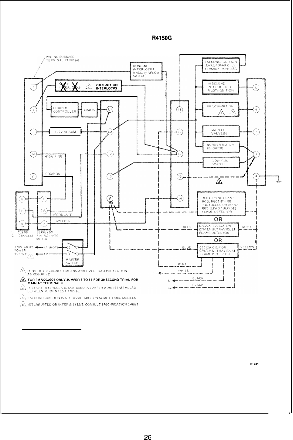
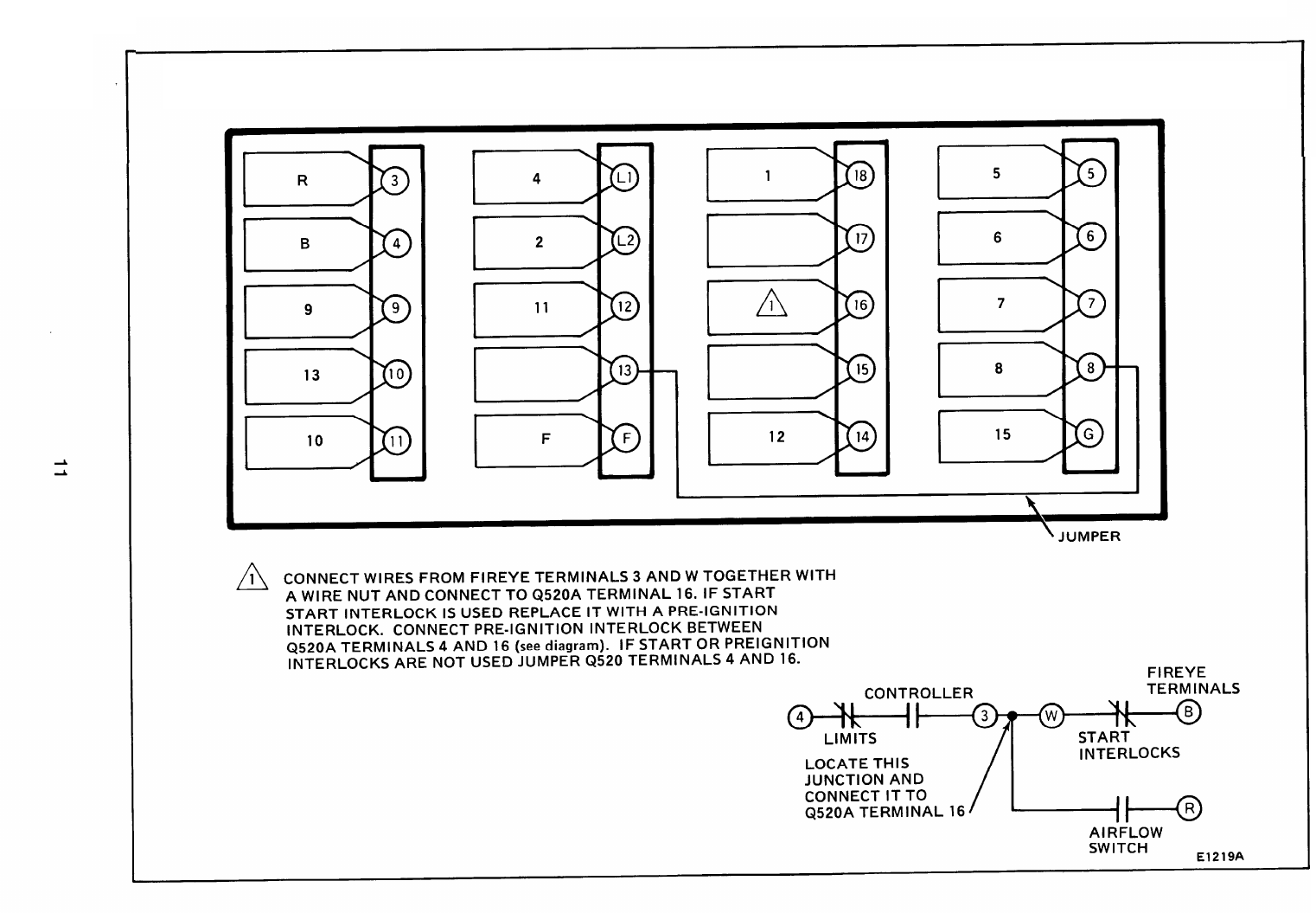
REPLACING AN R4140G OR
R4150G
WITH START
INTERLOCKS WITH A
BC7000L/PM720G2005 /PM720G2013
t
*
BC7000L/PM720G2005 /PM720G2013
STEPS FOR CONVERSION
1. START INTERLOCKS BECOME PREIGNITION INTERLOCKS.
2.
3.
4.
FOR PM720G2005 ONLY JUMPER 15 TO 8 FOR 30-SECOND
TRIAL FOR MAIN FLAME AT TERMINAL NO. 6.
TERMINAL 16 MUST BE USED ON THE BC7000. IF AN
EXTERNAL TIE POINT WAS PREVIOUSLY USED ON THE R4140G
OR R4150G TO BE REPLACED, IT MUST BE LOCATED AND
WIRED TO TERMINAL NO. 16.
FOR INTERMITTENT PILOT USE PM720G2013.
E1234
----1.
.-“
26
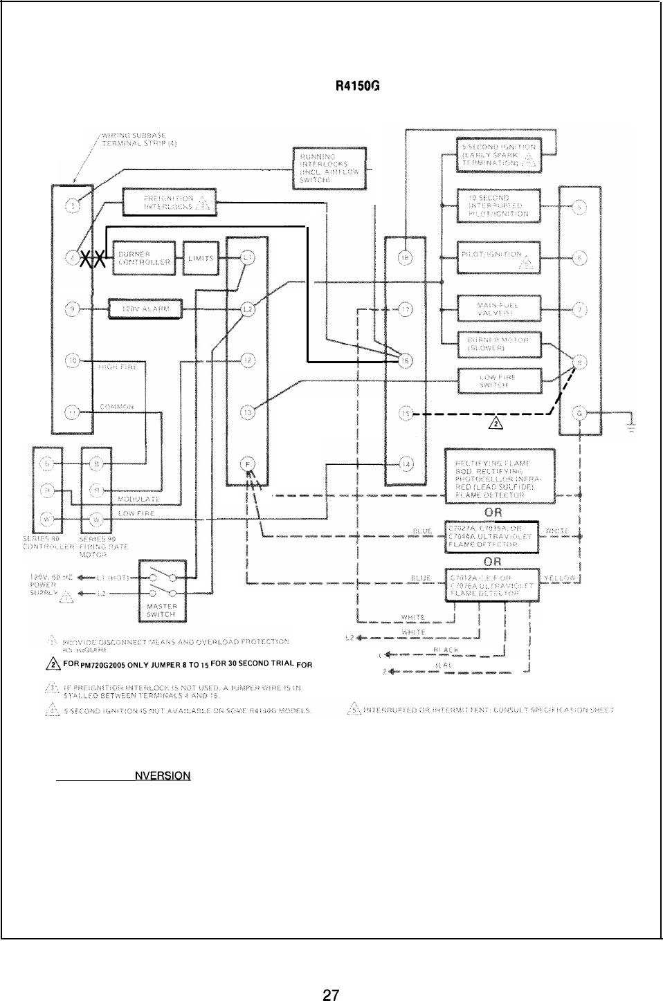
REPLACING AN R4140G OR
R4150G
WITH PREIGNITION
INTERLOCKS WITH A
BC7000L/PM720G2005 /PM720G2013
#f-----+---
-.,
,,,
,):.>
?>.,
E.,li:,.
~
FOR
PM720G20050NLYJ”MPER8T0
15
FOR3CISECCZNDTRIAL FOR
(
+-
————=—=—
—$==$
—
Ji
>:
c, .
MAIN AT TERMINAL 6.
/+—’———
———=—
.
J
BC7000L/PM720G2005 /PM720G2013
STEPS FOR CONVERSIO~
1. IDENTIFY AND REMOVE BURNER CONTROLLER AND LIMITS
CIRCUIT WIRE FROM TERMINAL NO. 4 ON THE Q520A
SUBBASE AND CONNECT TO TERMINAL NO. 16.
2. FOR PM720G2005 ONLY, JUMPER 8 TO 15 FOR 30-SECOND
TRIAL FOR MAIN FLAME AT TERMINAL 6.
3. FOR INTERMITTENT PILOT USE PM720G2013.
El 233
27
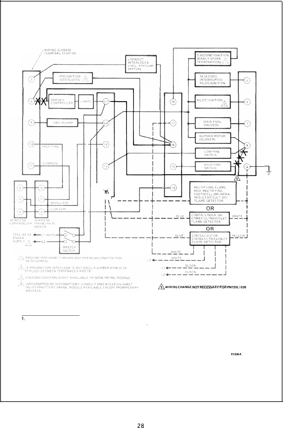
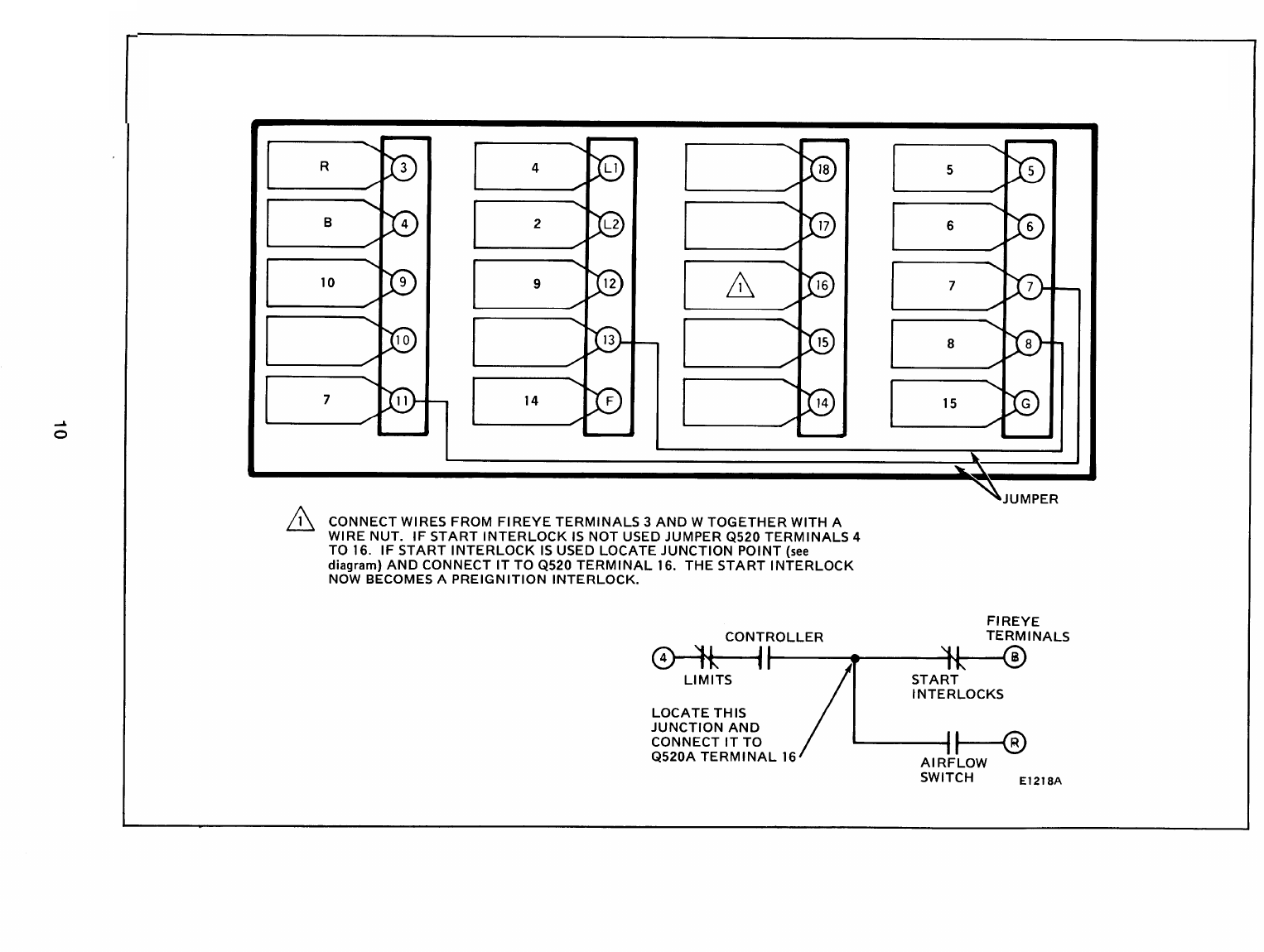
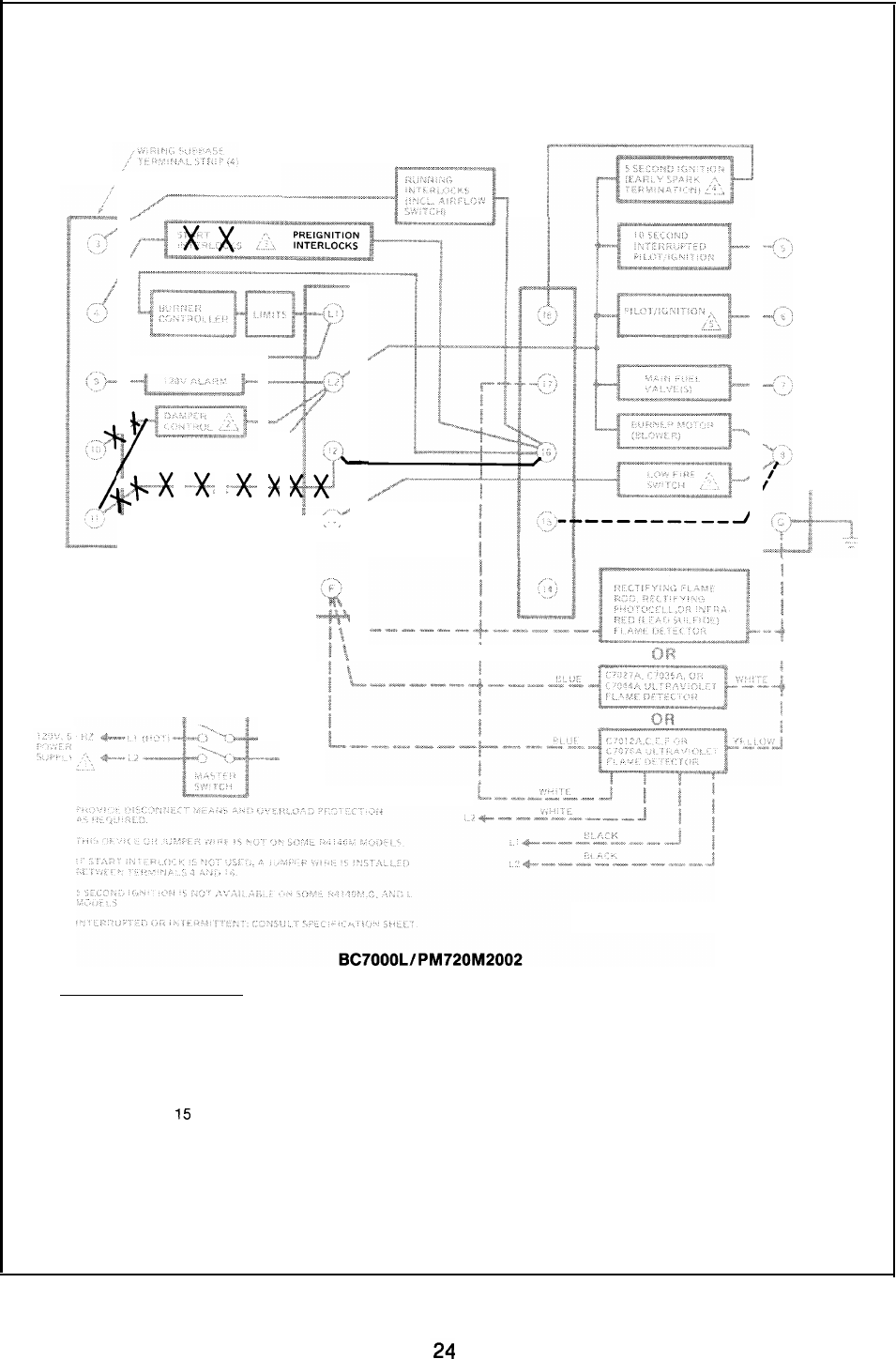
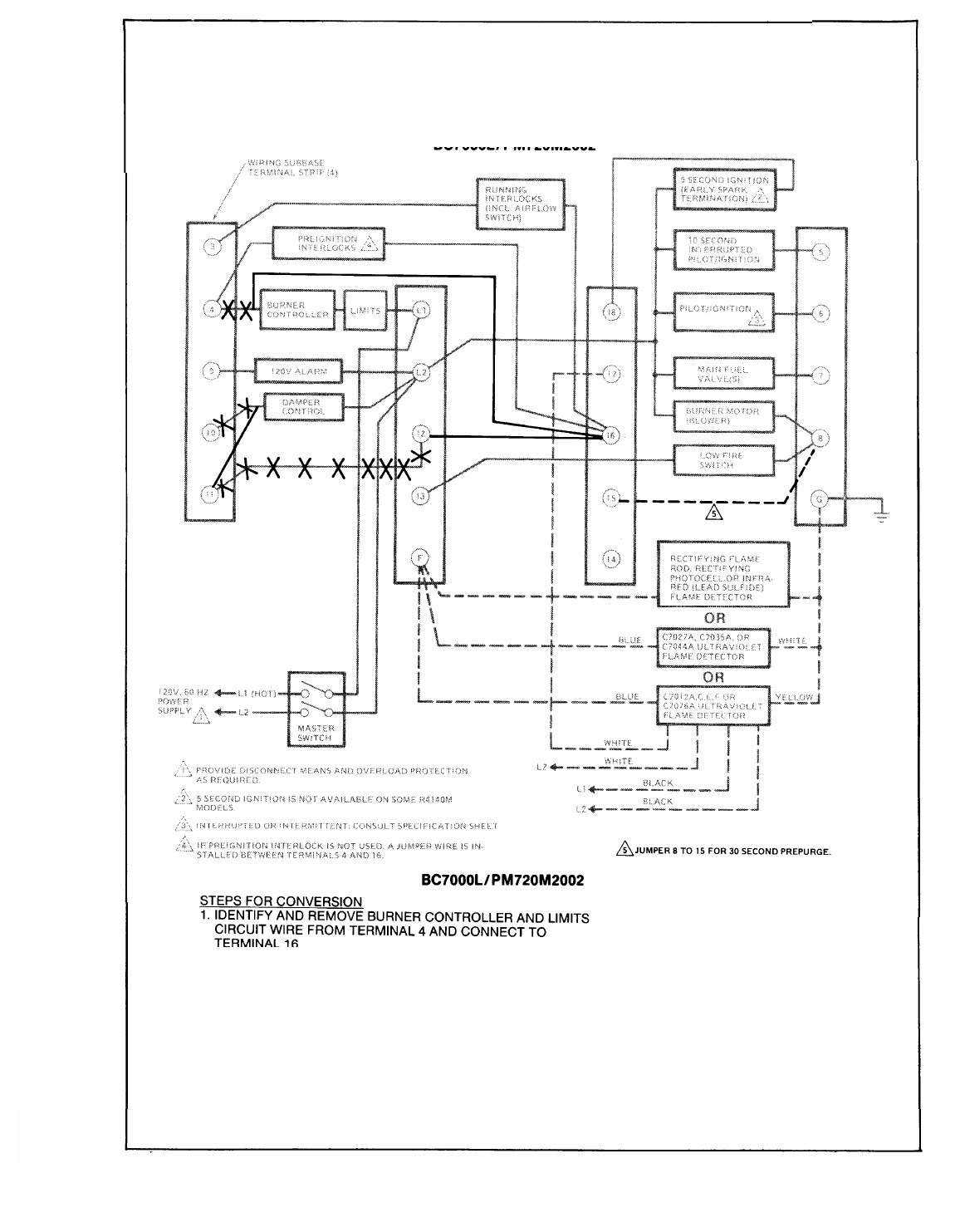
REPLACING AN R4140L OR R4150L WITH A
BC7000L/PM720L1030 /PM720L2004
L
/-..,
‘-4
~VJIRllUG
CHANGE NOT NECESSARY FOR PM720LI030
BC7000L/PM720L1030 /PM720L2004
1.
2.
3.
STEPS FOR CONVERSION
IDENTIFY AND REMOVE BURNER CONTROLLER AND LIMITS
CIRCUIT WIRE FROM TERMINAL NO. 4 ON THE Q520A
~
SUBBASE AND CONNECT TO TERMINAL NO. 16.
IDENTIFY AND REMOVE HIGH FIRE PROVING SWITCH WIRES
FROM TERMINAL NO, 8 AND CONNECT THEM TO TERMINAL L1 .
(THE LOW FIRE SWITCH WIRE MAY BE CONNECTED TO
TERMINAL NO. 15. REMOVE FROM TERMINAL NO. 15 AND
CONNECT TO 8.)
E1236A
FOR ENERGY SAVING PREPURGE USE PM720L2004.
2-
-T
28

SECTION V
1.
2.
3.
4.
5.
6.
7,
REPLACING R4150 MODELS WITH 13- OR
15-TERMINAL SUBBASES
Disconnect all power to programmer.
Remove R4150 from subbase (trade-in to Authorized Distributor).
Mark all wires on subbase; i.e., wires connected to terminal “9” should be marked “9”.
Disconnect wires as they are marked.
Remove old subbase.
Install 20-terminal Q520A subbase.
Connect wires to subbase per attached cross reference. Pay close attention to footnotes.
Plug in the BC7000. Make sure you select the proper amplifier detector and program module
for the application.
29
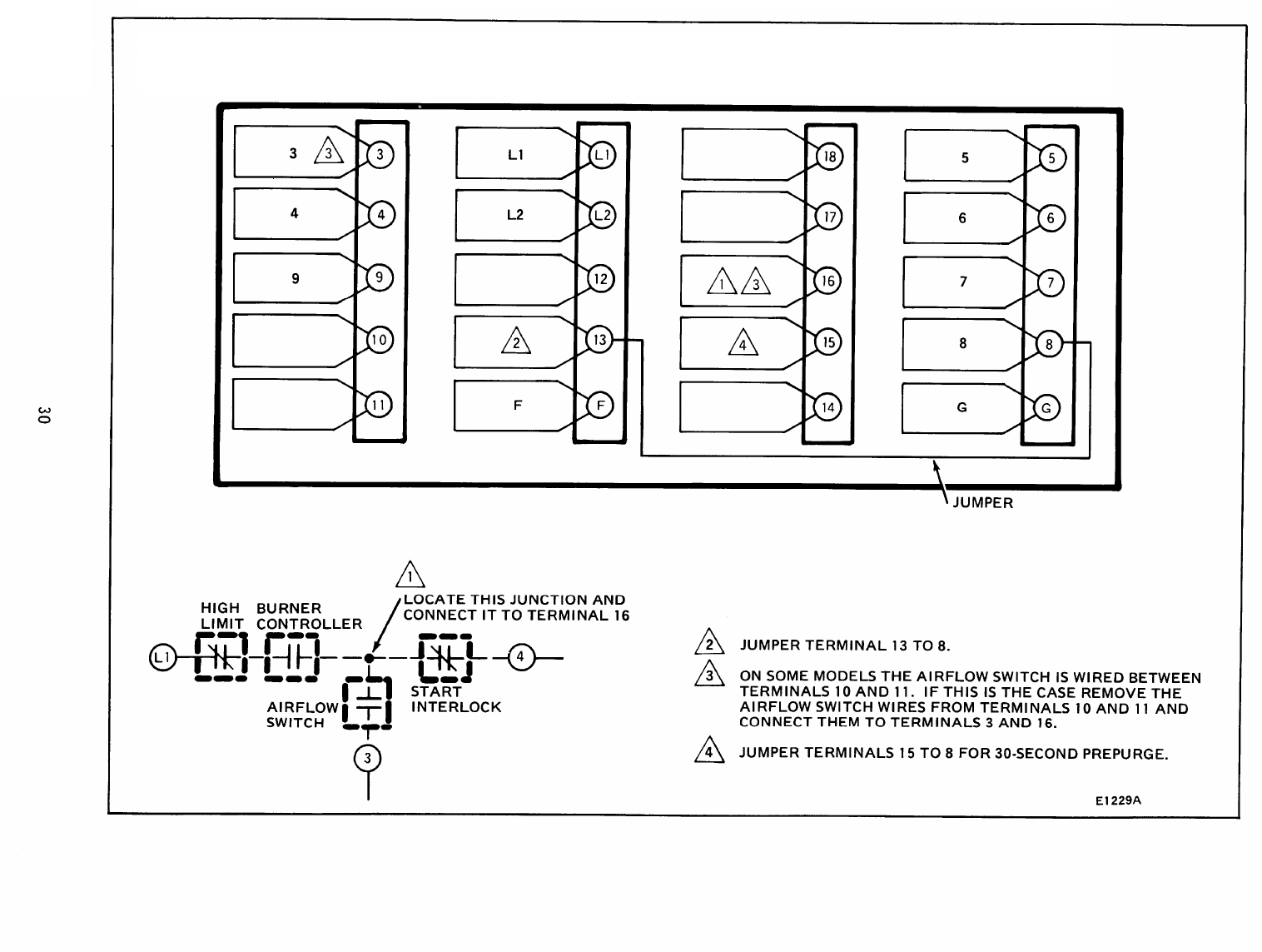
E1229A
CONVERSION FOR R4150A, B, AND C MODELS
120 VOLT ONLY
USE BC7000L/PM720M2002
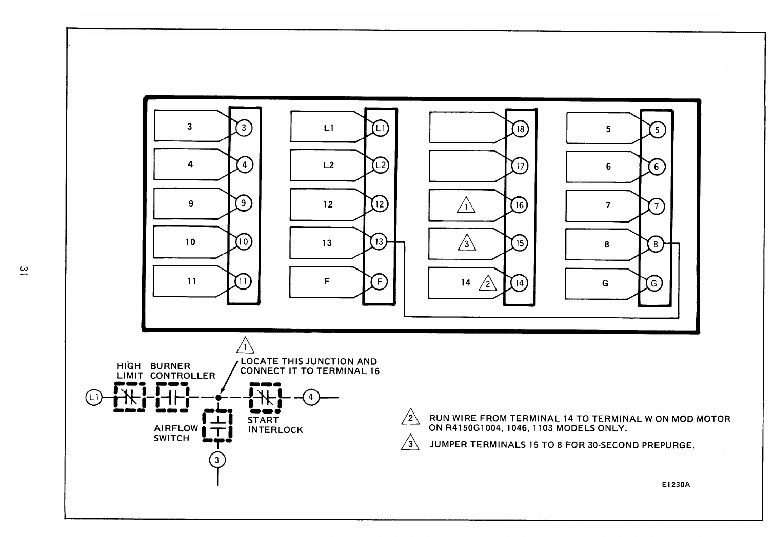
E1230A
CONVERSION FOR R4150G1004, G1020, G1046, G1103, G1111, G1145, G1178 MODELS
120 VOLT ONLY
USE BC7000L/PM720G2013
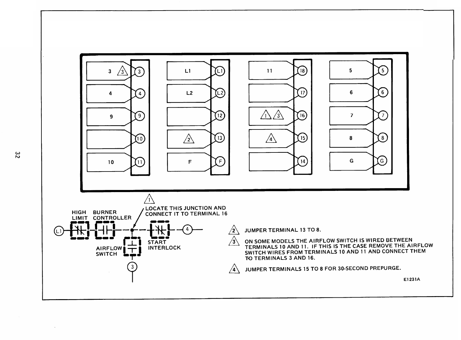
E1231A
CONVERSION FOR R4150G1012 AND G1079 MODELS
120 VOLT ONLY
USE BC7000L/PM720M2002
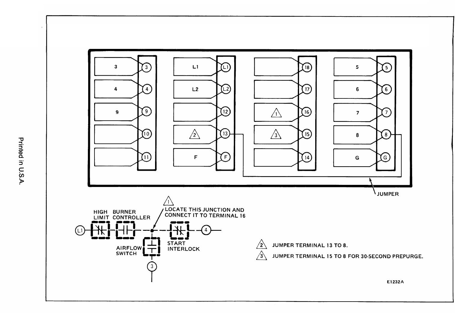
E1232A
CONVERSION FOR R4150M
USE BC7000L/PM720M2002
