Honeywell Chronotherm Iii T8611G Users Manual 69 0348 T8611G,R Fuel Saver Thermostats
2014-12-11
: Honeywell Honeywell-Chronotherm-Iii-T8611G-Users-Manual-120101 honeywell-chronotherm-iii-t8611g-users-manual-120101 honeywell pdf
Open the PDF directly: View PDF ![]() .
.
Page Count: 8
J.H. • 3-92 • © Honeywell Inc. 1992 • Form Number 69-0348—1
T8611G,R
Chronotherm III
Fuel Saver Thermostats
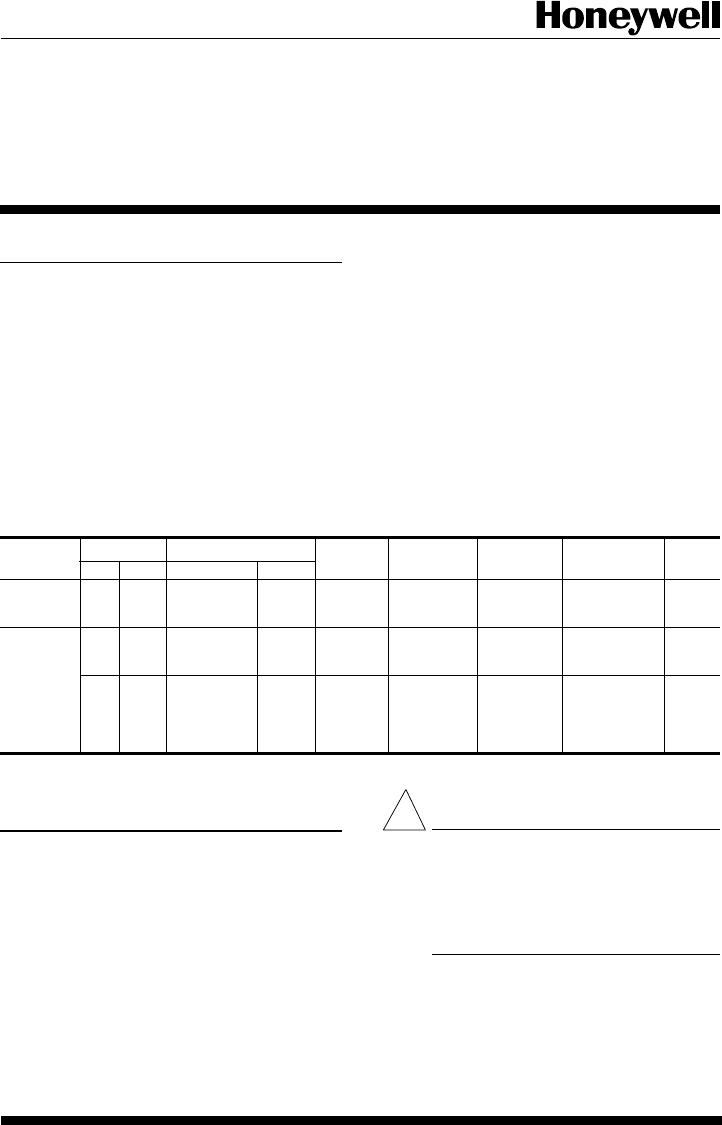
TABLE 1—Thermostat Models.
Thermostat Stages Switching LEDs Changeover Terminals Comments See Fig.
Heat Cool System Fan
T8611G 2 1 EM.HEAT- ON- EM.HT, Auto R, C/X, L, — 4
HEAT-OFF- AUTO AUX.HT. W2,E,G,O,
AUTO-COOL B,Y,X2,X1
T8611R 2 1 EM.HEAT- ON- EM.HT., Manual R,C/X,L, — 5
HEAT-OFF- AUTO AUX.HT. W2,E,W1,G,
COOL O,B,Y,P
21EM.HEAT- ON- EM.HT. Manual R,B,X,W2,Exact 6
HEAT-OFF- AUTO E,W1,G,O, replacement
COOL H,Y1for York
model no.
2ET11700224.
Installation
WHEN INSTALLING THIS PRODUCT...
1. Read these instructions carefully. Failure to allow
them could damage the product or cause a hazardous condi-
tion.
2. Check the ratings on the product to make sure the
product is suitable for your application.
3. Installer must be a trained, experienced service techni-
cian.
4. Allow thermostat to warm to room temperature before
operating.
5. After installation is complete, check out product op-
eration as provided in these instructions.
CAUTION
1. Disconnect power supply to prevent electri-
cal shock or equipment damage.
2. After wiring is complete, push excess wire
back into the hole, and plug hole with
nonhardening caulk, putty or insulation to
prevent drafts from affecting thermostat op-
eration.
LOCATION
Install thermostat and subbase about 5 ft. [1.5m] above the
floor in an area with good air circulation at room temperature.
Do not install the thermostat where it may be affected
!
Application
These thermostats provide energy saving control for a 24
Vac multistage heat pump heating/cooling system as indi-
cated in Table 1 and are powered directly from the control
transformer. All models have 5-1-1 programming.
As long as AC power is continuously available to trans-
former, the thermostat will be compatible with most control
systems.
The T8611G,R models include SYSTEM and ENRG
SAV LEDs near the top front of the thermostat. The SYS-
TEM LED lights when the thermostat is signaling for heating
or air conditioning. The ENGR SAV LED lights during the
LEAVE and SLEEP periods.
The AUX. HT., EM. HT., and CHECK LEDS are located
near the bottom center of the subbase. See Table 1. The AUX.
HT. LED lights whenever the thermostat is calling for
operation of the backup or auxiliary heater. Backup (auxil-
iary) heat is more expensive to operate than the heat pump and
typically is used only when the heat pump is unable to handle
the load. The EM. HT. LED lights whenever the thermostat
system switch is in the EM. HT. position. The CHECK LED
lights when something needs to be checked to maintain
efficient operation of the system. Consult heat pump equip-
ment literature to determine specific meaning of this LED.
Heat and cool anticipation is fixed in all models; no
adjustment is necessary. Cycle rates are adjustable for auxil-
iary heating stage.
TRADELINE

2
by—
—drafts or dead spots behind doors, in corners or under
cabinets.
—hot or cold air from ducts.
—radiant heat from sun or appliances
—concealed pipes and chimneys.
—unheated (uncooled) areas behind the thermostat, such
as an outside wall.
IF REPLACING AN EXISTING THERMOSTAT
Turn off power to thermostat at furnace or heat pump. A
two-transformer system may require turning off two switches
or disconnects. Remove any existing wallplate or subbase
from the wall. Label or write down each wire color with the
letter or number on the wiring terminal as the wire is removed,
to avoid miswiring later.
IF NEW INSTALLATION
Run a cable to a hole at the selected wall location, and pull
about 3 in. [76 mm] of wire through the opening. Color-
coded, 8-gauge thermostat cable with one conductor for each
wiring terminal is recommended. Good service practice
recommends selecting cable with one or two more conduc-
tors than the immediate application requires.
MOUNTING SUBBASE
The subbase does not require leveling for proper opera-
tion, but for appearance only.
Remove thermostat from subbase, see Fig. 1.
The subbase mounts directly onto the wall with the screws
included in the package. Use the subbase as a template, and
with a pencil, mark the two mounting screw positions, see
Fig. 2. Use 3/16 in. bit to drill holes for anchors. Gently tap
anchors into holes until they are flush with the wall surface.
Thread wires through the center opening of the subbase. Then
mount the subbase using two screws provided. Gently tighten
screws level top surface of subbase, then securely tighten
screws.
Fig. 1—Removing thermostat from subbase.
WIRING
All wiring must comply with local electrical codes and
ordinances.
Disconnect power before wiring to prevent electrical
shock or equipment damage.
The shape of the terminal barrier permits insertion of
straight or conventional wraparound wiring connections.
Either method is acceptable.
Refer to Figs. 4-6 for typical hookups of subbase and
thermostat.
NOTE: Keep all wiring restricted to ribbed area surround-
ing terminals to assure thermostat/subbase contact, see
Fig. 3.
Fig. 3—Keep wiring restricted to ribbed area
surrounding terminals.
Fig. 2—Mounting subbase on wall.
AUX. HEAT
EM. HT.
ONAUTO
FAN
M5179A
CHECK
HEAT OFF AUTO COOL
SYSTEM
WIRES THROUGH
WALL OPENING
WALL
WALL
ANCHORS
(2)
SUBBASE
MOUNTING
HOLES
MOUNTING
SCREWS (2)
M5175
FOR STRAIGHT INSERTION –
STRIP 5/16 in. [8 mm]
FOR WRAPAROUND –
STRIP 7/16 in. [11 mm]
RESTRICT
WIRING TO
THIS AREA
WIRING TO BE BELOW
THIS SURFACE
TOP SURFACE
OF SUBBASE
FRONT VIEW OF
TERMINAL AREA
CROSS-SECTIONAL VIEW OF
TERMINAL AREA
M3062
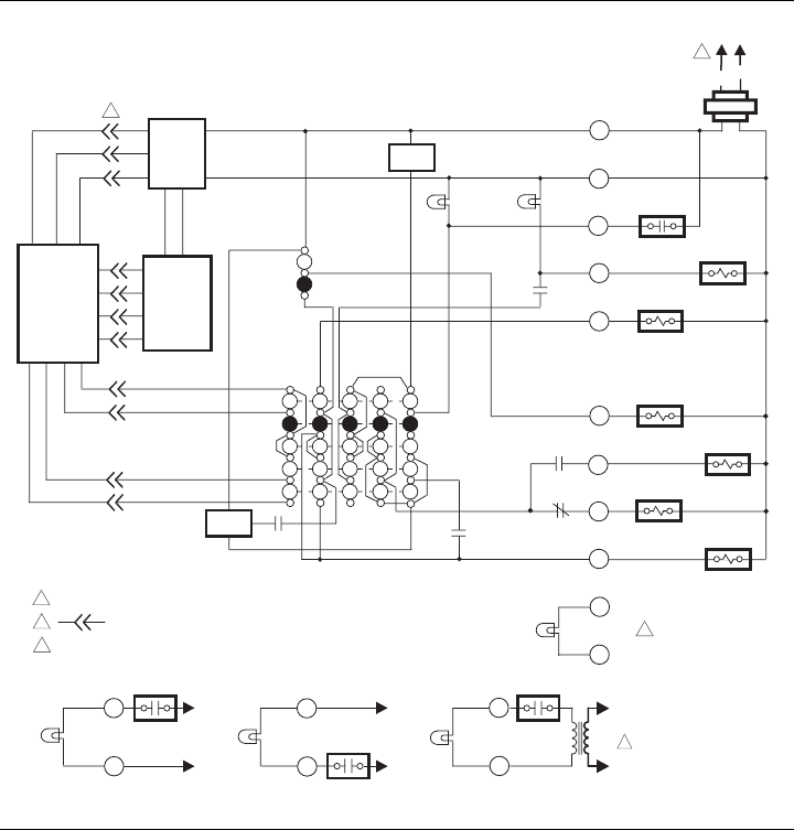
Fig. 4—T8611G 2-stage heat/1-stage cool thermostat.
POWER SUPPLY. PROVIDE DISCONNECT MEANS AND OVERLOAD PROTECTION AS REQUIRED.
DENOTES THERMOSTAT TO SUBBASE INTERCONNECT.
POSSIBLE CHECK LED CIRCUITS:
M 6020
MONITOR
AUXILIARY
HEAT RELAY
HEAT 2
L1
(HOT) L2
HEAT
OFF
AUTO
SYSTEM
SWITCH
AUTO
ON
FAN
SWITCH
1
EMERGENCY
HEAT RELAY
FAN RELAY
CHANGEOVER
RELAY (HEAT)
COMPRESSOR
CONTACTOR
EM. HT.
CHANGEOVER
RELAY (COOL)
AUX. HEAT
LED (GRN)
EM. HEAT
LED (RED)
HEAT 1
THERMOSTAT
LOGIC
CIRCUIT
SUBBASE
LOGIC/
CONTROL
CIRCUIT
R
C/X
L
W2
E
X2
G
O
B
Y
POWER
SUPPLY HIGH
LIMIT
HIGH
LIMIT
X1
2
1
2
3
COOL
C.O.
C.O.
COOL
CHECK LED
(YELLOW)
CHECK
LED
(YELLOW)
FAULT DETECTION
SWITCH
SWITCH TO R (POWER) SIDE OF
SYSTEM TRANSFORMER
TO R
TO C/X
CHECK
LED
(YELLOW)
FAULT DETECTION
SWITCH
SWITCH TO C (COMMON) SIDE
OF SYSTEM TRANSFORMER
TO R
TO C/X
CHECK
LED
(YELLOW)
SWITCHING
DEVICE
SWITCH IN SECONDARY OF
SEPARATE TRANSFORMER
L1
(HOT)
L2
24 Vac
1
X1
X2
X1
X2
X1
X2
3
369-0348—1
4
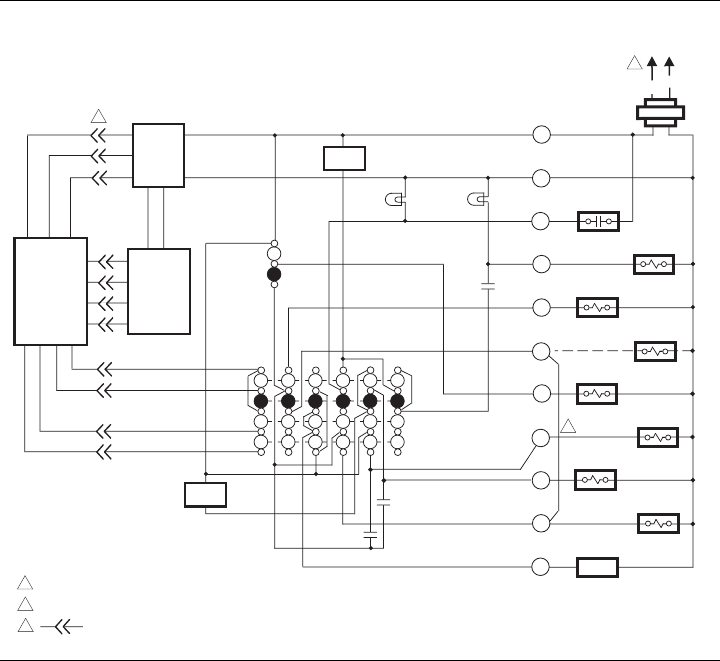
Fig. 5—T8611R 2-stage heat/1-stage cool thermostat.
M 6019
MONITOR
AUXILIARY
HEAT RELAY
HEAT 2
L1
(HOT) L2
HEAT
OFF
COOL
SYSTEM
SWITCH
AUTO
ON
FAN
SWITCH
1
STAGE 1
HEAT RELAY
EMERGENCY
HEAT RELAY
FAN RELAY
CHANGEOVER
RELAY (HEAT)
COMPRESSOR
CONTACTOR
DEFROST
CONTROL
EM. HT.
COOL
CHANGEOVER
RELAY (COOL)
AUX. HEAT
LED (GRN)
EM. HEAT
LED (RED)
HEAT 1
THERMOSTAT
LOGIC
CIRCUIT
POWER SUPPLY. PROVIDE DISCONNECT MEANS AND OVERLOAD PROTECTION AS REQUIRED.
REMOVE JUMPER FOR SYSTEM WITH ISOLATED STAGE 1 HEATING AND COOLING CONNECTIONS.
DENOTES THERMOSTAT TO SUBBASE INTERCONNECT.
SUBBASE
LOGIC/
CONTROL
CIRCUIT
R
C/X
L
W2
E
W1
G
O
B
Y1
POWER
SUPPLY HIGH
LIMIT
HIGH
LIMIT
P
2
3
1
2
3
569-0348—1
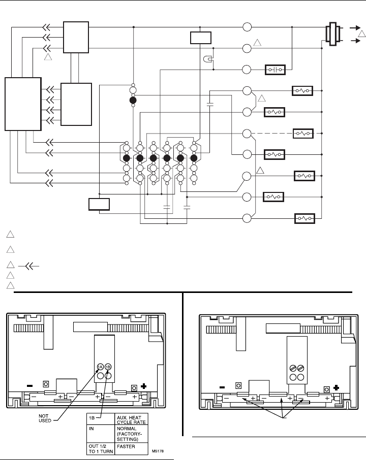
Fig. 6—T8611R 2-stage heat/1-stage cool thermostat. Exact replacement for York model no. 2ET11700224.
MONITOR
AUXILIARY
HEAT RELAY
HEAT 2
L1
(HOT)
L2
HEAT
OFF
AUTO
SYSTEM
SWITCH
AUTO
ON
FAN
SWITCH
1
STAGE 1
HEAT RELAY
EMERGENCY
HEAT RELAY
FAN RELAY
CHANGEOVER
RELAY (HEAT)
COMPRESSOR
CONTACTOR
EM. HT.
COOL
CHANGEOVER
RELAY (COOL)
EM. HEAT
LED (RED)
HEAT 1
THERMOSTAT
LOGIC
CIRCUIT
SUBBASE
LOGIC/
CONTROL
CIRCUIT
R
B
X
W2
E
W1
G
O
H
Y1
TRANSFORMER
POWER
SUPPLY HIGH
LIMIT
HIGH
LIMIT
2
3
POWER SUPPLY. PROVIDE DISCONNECT MEANS AND OVERLOAD
PROTECTION AS REQUIRED.
REMOVE JUMPER FOR SYSTEM WITH ISOLATED STAGE 1 HEATING
AND COOLING CONNECTIONS.
DENOTES THERMOSTAT TO SUBBASE INTERCONNECT.
REMOVE JUMPER FOR SYSTEM WITH ISOLATED EMERGENCY HEAT.
TRANSFORMER COMMON IS CONNECTED TO B TERMINAL.
1
2
3
4
5
4
5
M3206
NOTE: THIS DIAGRAM IS FOR USE WHEN REPLACING ONLY YORK
THERMOSTAT MODEL NO. 2ET11700224. USING THIS
DRAWING FOR OTHER INSTALLATIONS CAN RESULT IN
DAMAGE TO THERMOSTAT.
Fig. 8—Battery placement.Fig. 7—Cycle rate adjustment.
CYCLE RATE ADJUSTMENT
To custom-tailor the thermostat’s cycling performance to
different types of heating equipment, a cycle rate adjustment
screw is provided on the back of the thermostat. Correct
setting of this screw will provide optimum savings.
NOTE: Most applications will not require a change in
cycle rate.
The room air temperature will normally vary slightly from
the comfort temperature setting with the cycling of the heat
pump or auxiliary heater.
The cycle rate of this thermostat is factory-set for heat
pumps. The heat pump compressor cycle rate can be adjusted
by turning the cycle rate adjustment screw located on the back
of the thermostat, see Fig. 7.
INSTALLING BATTERIES
Three AAA alkaline batteries are provided as backup to
prevent program loss in event of power outage. Batteries are
included with thermostat. Install batteries in back of thermo-
stat as shown in Fig. 8.
Without battery backup, the program will remain about 20
seconds in event of power loss. When batteries are first
installed, the display will flash 1:00 PM and 32°.
BATTERY PLACEMENT
(NOTE CORRECT PLUS
AND MINUS DIRECTION)
M372A
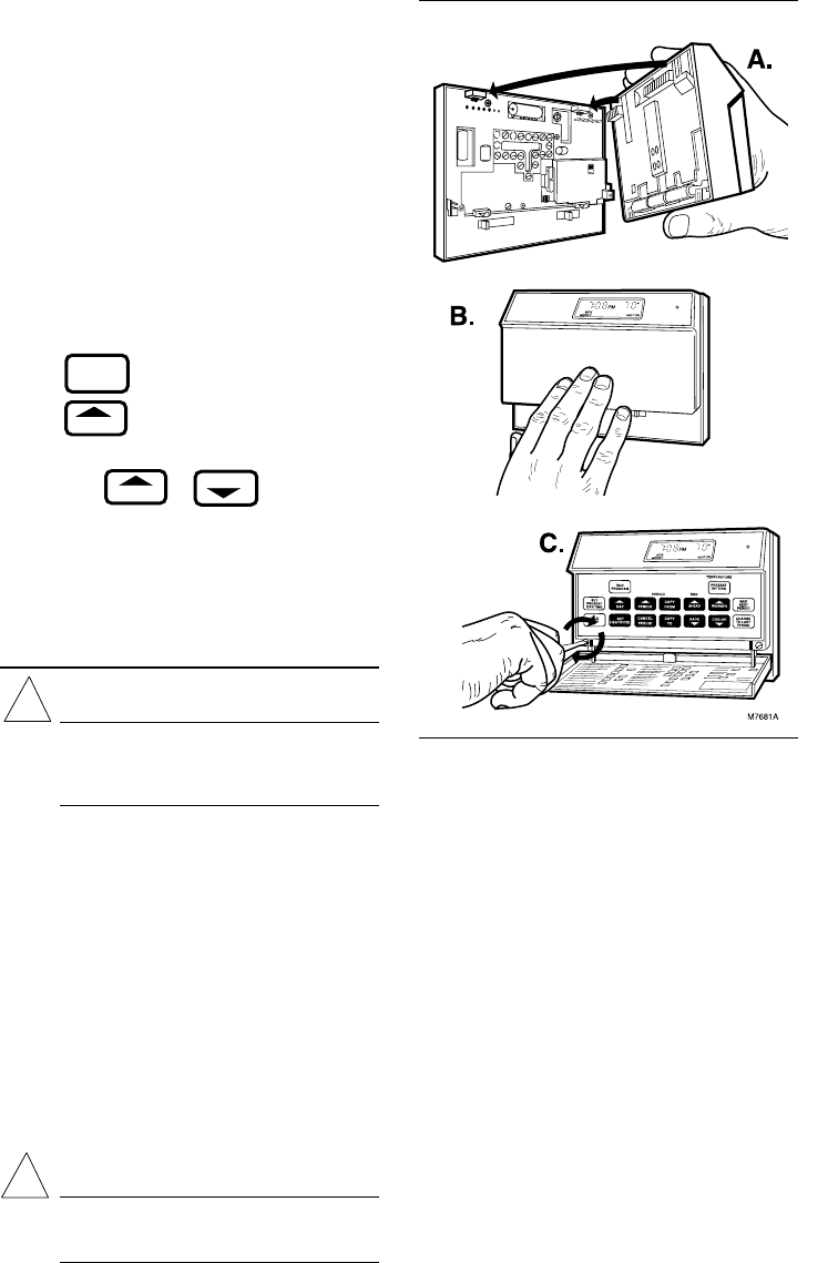
Fig. 9—Mounting the thermostat on subbase.
When the batteries are low, the display will flash REPL
BAT. Homeowner will have 20-30 seconds to replace batter-
ies after removing batteries from thermostat. After 20-30
seconds, it will be necessary to reprogram. REPL BAT
indication will be disappear when thermostat is mounted
back on the powered subbase.
MOUNTING THE THERMOSTAT
With system switch set to OFF, hang the thermostat on the
tabs at the top of the subbase (Fig. 9A). Swing down and press
on lower edge until thermostat snaps in place
(Fig. 9B). Open cover and tighten the captive mounting
screws (Fig. 9C).
SETTING DAY AND TIME
Restore 24V power to the thermostat. When power is
applied to the thermostat, the display will read 1:00 PM and
room temperature. It will go off for a few seconds, then begin
to flash on and off. Set present day and time.
6
AHEAD
BACK
SET
PRESENT
DAY/TIME
DAY
Press .
Press to set the current day. Each press of the
DAY key advances the display one day.
Press TIME or to set the current time.
If the display will not come on.
—check mounting of thermostat to subbase. If loose or
misaligned, remove thermostat and reinstall on the
subbase, making sure it is firmly attached.
—check to see that system power is on.
—check voltage between R and C/X; it should be 20 to 30
Vac. Checkout
CAUTION
During cold weather, some heat pumps will require
that crankcase heater be energized several hours
before operating heat pump. Refer to manufacturer’s
recommendations.
HEATING
When heating setting is changed, thermostat will wait up
to 5 minutes before turning on the heating equipment. This
delay protects the compressor.
Move the system switch to HEAT and the fan switch to
AUTO. Press WARMER key until the setting is about
10° F [6° C] above room temperature. Heating should start
and the fan should run (there may be a delay of
5-10 minutes before heat turns on). Press COOLER key until
the setting is about 10° F [6° C] below room temperature. The
heating equipment and fan should shut off.
NOTE: On an AUTO changeover thermostat, the cooling
temperature must be set at least 3° F [1.7° C] above the
heating temperature, or display will flash.
COOLING
CAUTION
Do not operate cooling if outdoor temperature is
below 50° F [10° C]. Refer to manufacturer’s
recommendations.
!
!
NOTE: When cooling setting is changed, thermostat will
wait up to 5 minutes before turning on the cooling equip-
ment. This delay protects the compressor.
Move the system switch to COOL and the fan switch to
AUTO. Press COOLER key until the setting is about
10° F [6° C] below room temperature. The cooling equip-
ment and fan should start. Press WARMER key until the
setting is about 10° F [6° C] above room temperature. The
cooling equipment and fan should stop.
NOTE: On an AUTO changeover thermostat, the heating
temperature must be set at least 3° F [1.7° C] below the
cooling temperature, or display will flash.
FAN
Move the system switch to OFF, and the fan switch to ON.
The fan should run continuously. When the fan switch is in
the AUTO position, fan cycles with the heating or cooling
system.
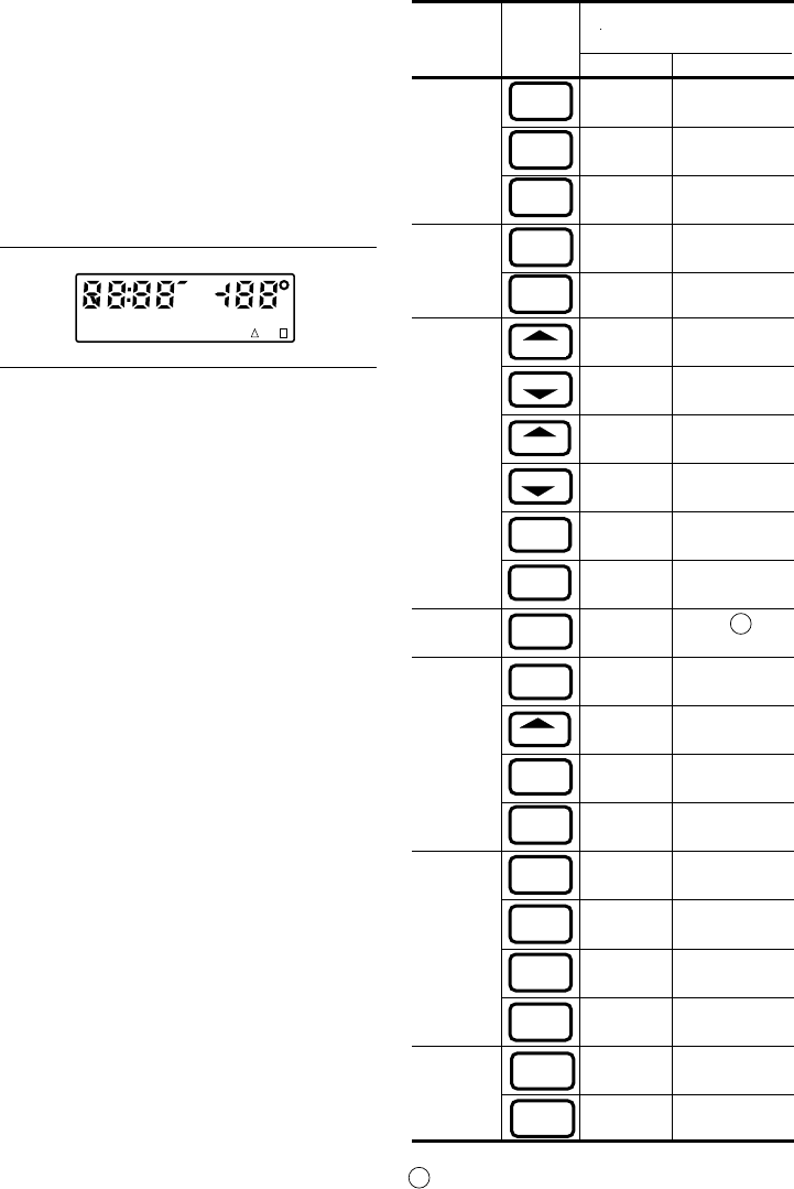
INSTALLER SELF-TEST (OPTIONAL)
NOTE: Thermostat must have AC power to perform self-
test.
769-0348—1
mask no. and
System Press Look for this
Switch This Response
Position Key Key Down Key Released
OFF 03 Blank
07 Blank
15 Blank
COOL or 15 Cooling, fan and
15 Cooling, fan and
OFF 06 Blank
02 Blank
05 Blank
04 Blank
01 Blank
00 Blank
12 See note A
OFF 08 Blank
13 Microprocessor
09 Blank
14 Blank
HEAT or 14
14
14
14
OFF 10 Blank
11
END SELF-TEST
AHEAT displayed when system switch is in HEAT, COOL
when in COOL, HEAT or COOL when in AUTO, neither
when in OFF. Also, a four-digit code is displayed, with each
digit explained on the next page.
AUTO (with
fan in AUTO)
CHANGE
TO LAST
PERIOD
SKIP
NEXT
PERIOD
PRESENT
SETTING
PRESENT
SETTING
PRESENT
SETTING
WARMER
COOLER
AHEAD
BACK
LEAVE
RETURN
WAKE
SLEEP
DAY
SET
HEAT/COOL
SET
PRESENT
DAY/TIME
SYSTEM LED on.
SYSTEM LED off.
revision no.
1st stage heating,
fan and SYSTEM
LED on.
AUTO
(with fan
in AUTO) 2nd stage heating
and AUX. HEAT
LED also on.
2nd stage heating
and AUX. HEAT
LED off.
1st stage heating,
fan and SYSTEM
LED off.
Normal operating
display.
SET
PRESENT
DAY/TIME
SET
PRESENT
DAY/TIME
HOLD
TEMP
SET
PRESENT
DAY/TIME
SET
PRESENT
DAY/TIME
RUN
PROGRAM
(CHECK
EACH
POSITION)
Perform the following test as a check of all thermostat
functions. If thermostat does not respond as indicated, ther-
mostat must be replaced.
1. Press AHEAD and BACK keys at the same time.
While holding keys down, all segments of the display should
be on, see Fig. 10.
2. Set system switch to OFF. Press AHEAD and BACK
and PRESENT SETTING keys at the same time to enter
self-test.
Fig. 10—All segments on display.
M410C
SUN MON TUE WED THU FRI SAT COOL ON HEAT ON
WAKE LEAVE RETURN SLEEP TEMPORARY
REPL
BAT
AM
PM
SET
PT
3. Press each key as listed below, and look for response
listed, as key is held down and released.
Home and Building Control Home and Building Control Helping You Control Your World
Honeywell Inc. Honeywell Limited—Honeywell Limitée
1985 Douglas Drive North 740 Ellesmere Road
Golden Valley, Minnesota 55422 Scarborough, Ontario
M1P 2V9 QUALITY IS KEY
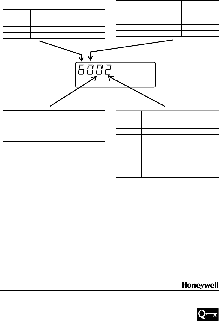
Second Clock
Digit (Hrs.) Degrees
012F
112C
424F
524C
4-DIGIT CODE EXPLANATION
Printed in TAIWAN, R.O.C.
Cycle Rate Setting
First (CPH at 50% on time,
Digit 2nd stage heat)
0 or 2 6
4 or 6 3
M 524
System
Fourth Thermostat Switch
Digit Type No. Position
0RCOOL, OFF
1GCOOL,
AUTO or
OFF
2REM.HT.
or HEAT
3GAUTO,
EM.HT. or
HEAT
Refer to Owner’s Manual for programming instructions and
homeowner troubleshooting.
Third System
Digit Switch Position
0HEAT, EM.HT, or OFF
2AUTO
4COOL
This equipment is a Class B digital apparatus which complies with Canadian Radio Interference Regulations, CRCc. 1374.
