Honeywell Ct50 Owners Manual 69 2040EFS 01 Series
Honeywell-Ct50-Ct51-Ct53-Ct54-Ct55-Ct50K-Ct51N-Ct53K-Ct54K-Ct55N-Yct50-Yct51-Yct53-Yct54-Yct55-Yct50K-Yct51N-Yct53K-Yct54K-Yct55 honeywell-ct50-ct51-ct53-ct54-ct55-ct50k-ct51n-ct53k-ct54k-ct55n-yct50-yct51-yct53-yct54-yct55-yct50k-yct51n-yct53k-yct54k-yct55
CT55 to the manual 80365ca0-422d-4c24-ac56-8ab5e8791ad4
2015-08-26
: Honeywell Honeywell-Ct50-Owners-Manual-803293 honeywell-ct50-owners-manual-803293 honeywell pdf
Open the PDF directly: View PDF ![]() .
.
Page Count: 16
Owner’s Manual
English: Page 1
Mode d’emploi
Français : Page 6
Manual de Uso
Español: Página 11
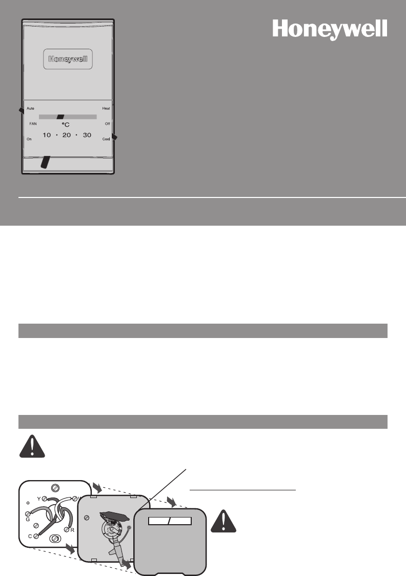
CT50 Series
Thermostat
® U.S. Registered Trademark. Patents pending.
Copyright © 2009 Honeywell International Inc.
All rights reserved.
M23785
69-2040EFS-01
M23786
MERCURY NOTICE
If your old thermostat contains
mercury, contact your local waste
management authority for proper
disposal instructions.
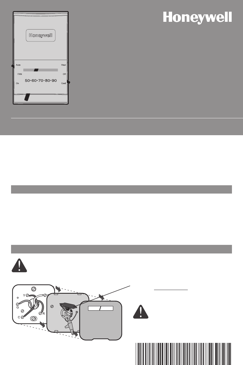
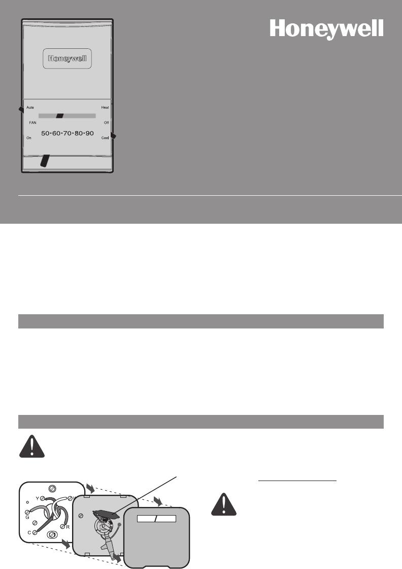
TURN OFF POWER at heating/cooling system (or fuse/circuit-breaker panel).
Remove cover and thermostat, but leave wallplate with wires attached.
Temperature Control Range
• 45°–95°F(7°–35°C)
• 35°–85°F(2°–29°C);selectmodels;forgaragesorotheroutbuildings.
Is there a sealed tube containing mercury?
If so, see mercury notice below.
Leave wallplate in place.
Old thermostat Cover
Check package contents:
• Thermostat
• Wallanchors&screws(2each)
• Wirelabels
Before you begin, make sure you have:
• No.2Phillips&smallpocketscrewdrivers
• Hammer
• Level(optional)
• Pencil
• Drillandbit(3/16”fordrywall,7/32”for
plaster)
Getting started
Remove your old thermostat
Vertical Mount:
CT50(24Vacheatingsystems)
CT51(24Vacheatingandcoolingsystems)
CT53(750mVor12Vdcheatingsystems)
Horizontal Mount:
CT54(24Vacheatingsystems)
CT55(24Vacheatingandcoolingsystems)
CT50 Series • Owner's Manual
69-2040EFS—01 2
M23789
M23787
M23790
M23788
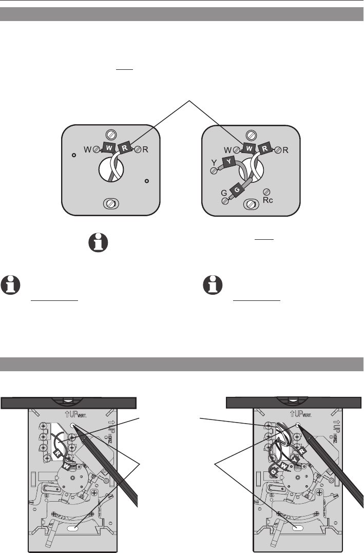
Wrapsuppliedlabelssecurelyaroundeachwire.Do not let wires fall into wall opening!
IGNORE WIRE COLORS: Use only letter
designations to identify wire types.
ForCT51/CT55: If your old
thermostathas7ormorewires
(not counting terminals C or C1),
you may have purchased the
wrong replacement thermostat.
Stopnowandcall1-800-468-1502
for advice.
CT50/CT53/CT54
1. Pullwires
through base.
2. Level base if
desired.
3. Markpositions
of both screw
holes.
ForCT50/CT53/CT54: If your old
thermostathas3ormorewires
(not counting terminals C or C1),
you may have purchased the
wrong replacement thermostat.
Stopnowandcall1-800-468-1502
for advice.
Use a screwdriver to disconnect wires one by one. As you disconnect each wire, wrap it with
the label matching the letter on your old thermostat. (Adhesive labels are supplied in your
thermostat package.)
Remove the old wallplate only after all wires are labeled. Be careful not to let loose wires fall
into the wall opening.
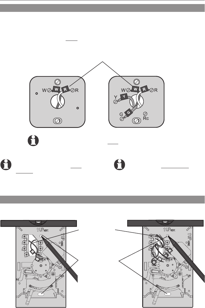
Label wires and remove old wallplate
Mark mounting position
CT51/CT55
CT50/CT53/CT54 CT51/CT55
English: Page 1 • Français : Page 6 • Español: Página 11
3 69-2040EFS—01
M23793
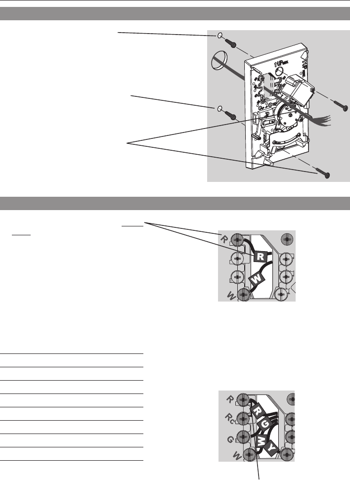
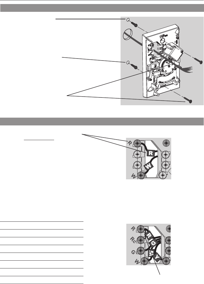
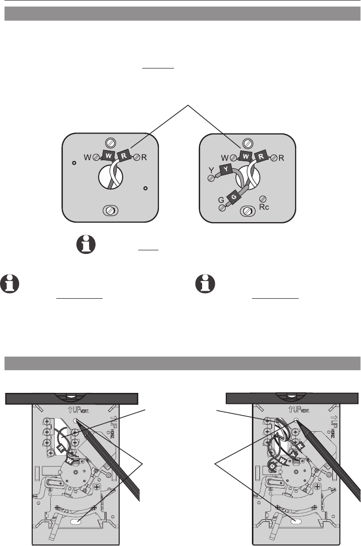
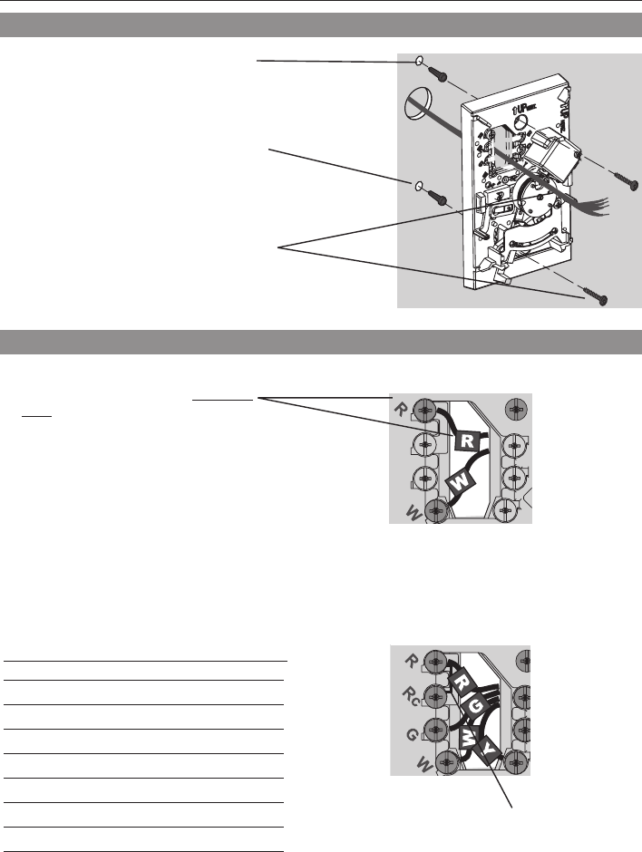
Wiring CT50/CT53/CT54
• 2-wire heat-only system: Connect one
wire to R terminal, one wire to W terminal.
M23791
Wiring CT51/CT55
[1]IfwireswillbeconnectedtobothR and Rc
terminals, remove the metal jumper.
[2]DonotconnectbothO and B if you have a
heat pump. Connect only the Owire.WrapB
wire with electrical tape and do not use.
[3]DonotuseC, X or B.Wrapbareendofwire
with electrical tape.
M23792
1. Drillholesatpencil-marked
locations(3/16”holesfor
drywall,7/32”holesfor
plaster).
2. Use hammer to tap anchors
intoholesuntilushwithwall.
3. Pullwiresthroughthermostat
base and insert screws.
Check level if desired, then
tighten screws.
Mount thermostat base
1. Matcheachlabeledwirewithsame
letter on terminal.
2. Use a screwdriver to loosen screw
terminals, insert bare wires beneath
screws, then tighten screws.
3. Pushanyexcesswirebackintothe
wall opening.
Labels don't match?
If labels do not match letters on
thermostat, see table below.
Existing wires Connect to:
R• RH•4• V Terminal “R” [1]
Rc Terminal “Rc” [1]
O Terminal “O” [2]
B Terminal “B” [2]
G•F Terminal “G”
W•W1•H Terminal “W”
Y •Y1•M Terminal “Y”
C•X •B Do not use [3]
CT51/CT55
CT50/CT53/CT54
Connect wires
CT50 Series • Owner's Manual
69-2040EFS—01 4
M23794
1. Aligntheslotsonthecoverwithtabson
the sides of the base, then push gently
until the cover snaps into place.
2. Restore power at the heating/cooling sys-
tem, or at the fuse/circuit-breaker panel.
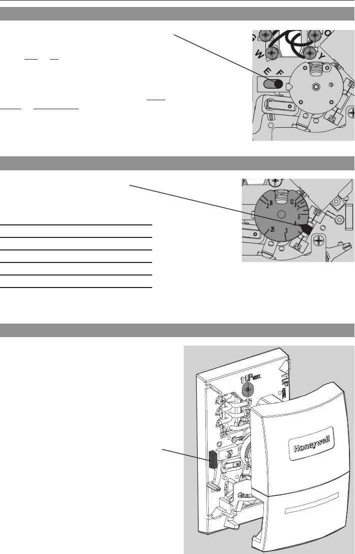
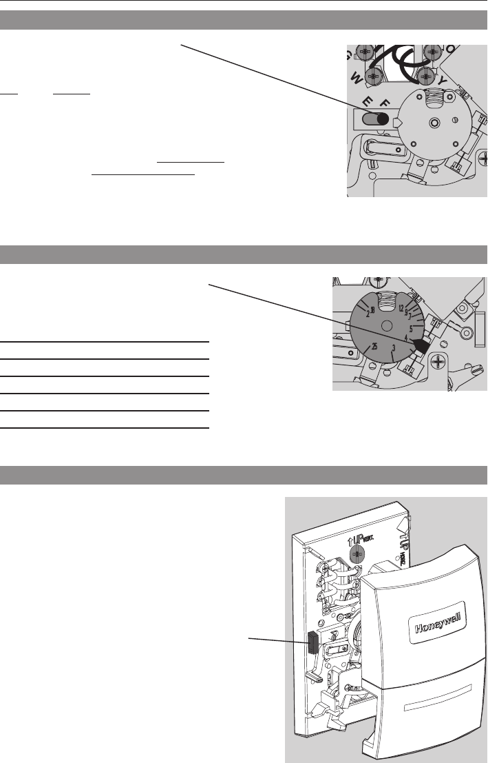
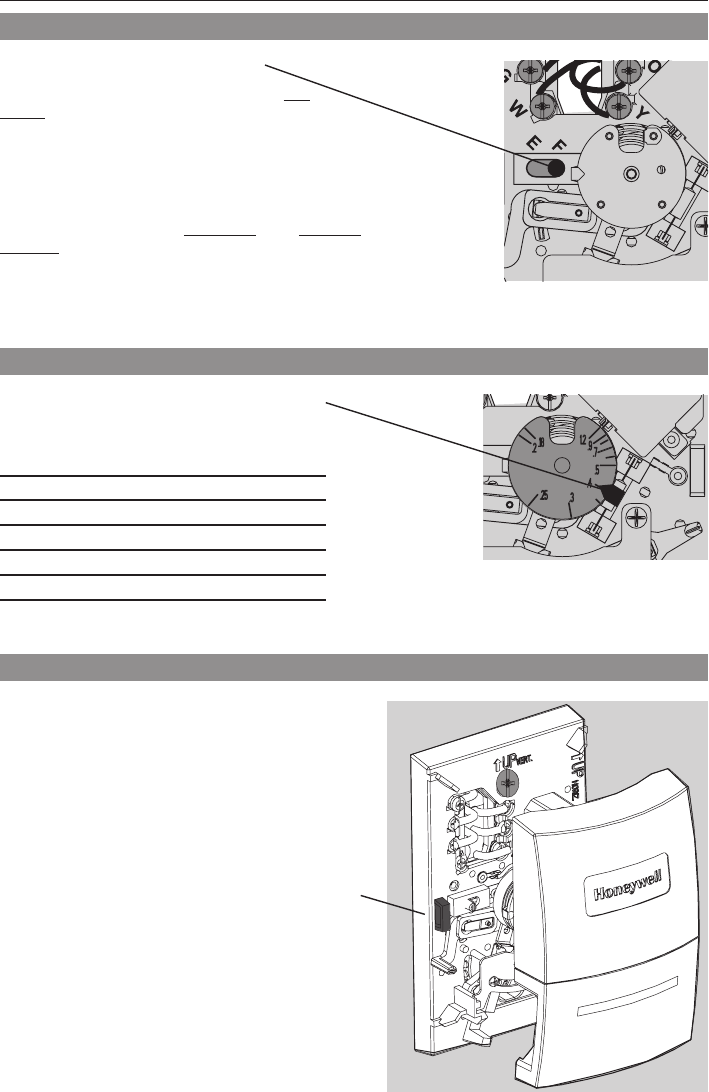
Movetheswitchtothepropersettingforyour
system:
F:Forgas or oil heating systems, leave the
fan operation switch in this factory-set position
(for systems that control the fan in a call for
heat).
E: Change the switch to this setting for heat
pump or electric heat systems. (This setting
is for systems that allow the thermostat to
control the fan in a call for heat, if a fan wire is
connected to the G terminal.)
Set fan operation switch (CT51/CT55)
Finish installation
M23796
Tab
Movetheadjustmentarrowtothe
proper setting for your system
(see table below).
Your system Setting
Steam 1.2
Hotwaterheat 0.8
Warmair(highefciency) 0.8
Warmair(standard) 0.4
Electricheat 0.3
M23795
Set heat anticipator (select models)
English: Page 1 • Français : Page 6 • Español: Página 11
5 69-2040EFS—01
Operation
Honeywell warrants this product to be free from defects in
the workmanship or materials, under normal use and service,
foraperiodofone(1)yearfromthedateofpurchasebythe
consumer. If at any time during the warranty period the prod-
uct is determined to be defective or malfunctions, Honeywell
shall repair or replace it (at Honeywell's option).
If the product is defective,
(i) return it, with a bill of sale or other dated proof of pur-
chase,totheplacefromwhichyoupurchasedit;or
(ii)callHoneywellCustomerCareat1-800-468-1502.
Customer Care will make the determination whether the
product should be returned to the following address:
HoneywellReturnGoods,Dock4MN10-3860,1885Douglas
Dr.N.,GoldenValley,MN55422,orwhetherareplacement
product can be sent to you.
This warranty does not cover removal or reinstallation
costs. This warranty shall not apply if it is shown by Honey-
well that the defect or malfunction was caused by damage
which occurred while the product was in the possession of
a consumer.
Honeywell's sole responsibility shall be to repair or
replace the product within the terms stated above.
HONEYWELLSHALLNOTBELIABLEFORANYLOSSOR
DAMAGEOFANYKIND,INCLUDINGANYINCIDENTALOR
CONSEQUENTIALDAMAGESRESULTING,DIRECTLYOR
INDIRECTLY,FROMANYBREACHOFANYWARRANTY,
EXPRESSORIMPLIED,ORANYOTHERFAILUREOFTHIS
PRODUCT.Somestatesdonotallowtheexclusionorlimita-
tion of incidental or consequential damages, so this limitation
may not apply to you.
THISWARRANTYISTHEONLYEXPRESSWARRANTY
HONEYWELLMAKESONTHISPRODUCT.THEDURA-
TIONOFANYIMPLIEDWARRANTIES,INCLUDINGTHE
WARRANTIESOFMERCHANTABILITYANDFITNESSFORA
PARTICULARPURPOSE,ISHEREBYLIMITEDTOTHEONE-
YEARDURATIONOFTHISWARRANTY.Somestatesdonot
allow limitations on how long an implied warranty lasts, so
the above limitation may not apply to you.
Thiswarrantygivesyouspeciclegalrights,andyoumay
have other rights which vary from state to state.
If you have warranty questions, please write Honeywell
CustomerRelations,1985DouglasDr.,GoldenValley,MN
55422orcall1-800-468-1502.InCanada,writeRetailProd-
uctsON15-02H,HoneywellLimited/HoneywellLimitée,
35DynamicDrive,Toronto,OntarioM1V4Z9.
1-year limited warranty
M23785
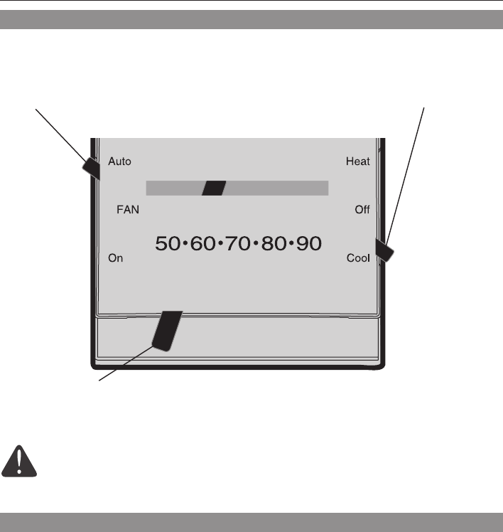
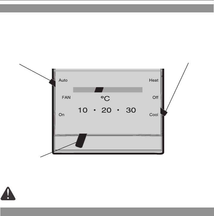
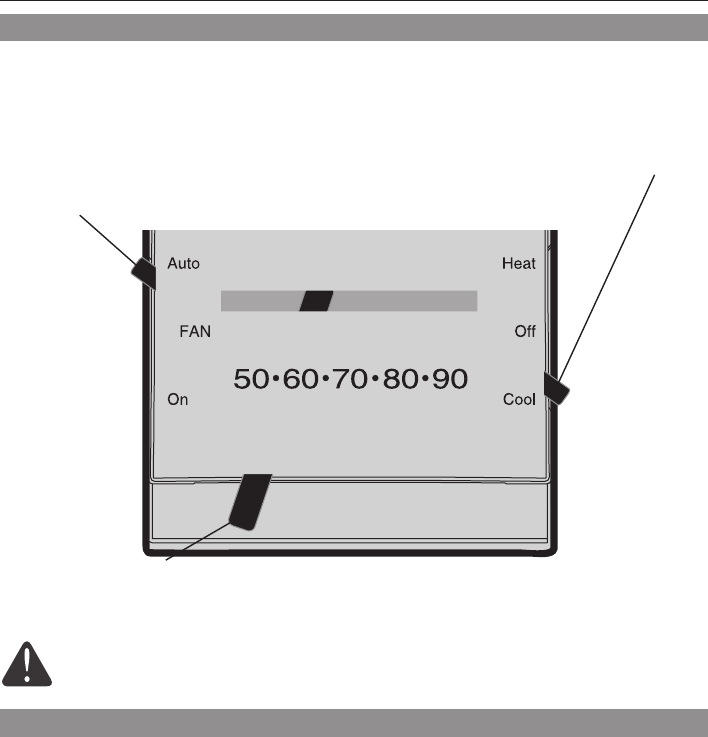
Fan switch (CT51/CT55)
• Auto:Fanrunsonlywhenheating
or cooling system is on.
• On:Fanrunscontinuously.
System switch (select models)
• Heat: Controls the heating system.
• Off: All systems are off.
• Cool:Controlsthecoolingsystem(CT51/
CT55).
Temperature setting
Adjust to set desired indoor temperature.
CAUTION: EQUIPMENT DAMAGE HAZARD (CT51/CT55).
Donotoperatecoolingsystemwhenoutdoortemperatureisbelow50°F(10°C).
M23785
Série CT50
Thermostat
Owner’s Manual
English: Page 1
Mode d’emploi
Français : Page 6
Manual de Uso
Español: Página 11
M23786
Ancien
thermostat
Laisser la plaque de montage en place. Lethermostatcomporte-t-iluntubescellé
contenant du mercure? Si c’est le cas, se reporter à
l’avis concernant le mercure ci-dessous.
Couvercle
COUPER LE COURANT au niveau du système de chauffage/de refroidissement (ou
du panneau de fusibles ou de disjoncteurs). Retirer le boîtier et le thermostat. Laisser
laplaquemontageetlesfilsquiysontfixés.
Retrait de l’ancien thermostat
Éléments nécessaires à l’installation
®MarquedéposéeauxÉ.-U.Brevetseninstance.
© 2009 Honeywell International Inc.
Tousdroitsréservés.
M23797
AVIS SUR LE MERCURE
Nepasplacerl'ancienthermostatdans
les ordures s’il contient une ampoule
de mercure. Contacter l'agence de
gestiondesdéchetsdelalocalitépour
connaître les règlements concernant le
recyclage et la mise au rebut.
Vérifierlecontenudepaquet:
•Thermostat
•Chevillesetvisdemontage(2dechaque)
•Étiquettesdefils
Outillageetmatérielnécessaires:
•Deuxtournevis(unpetit,uncruciformen°2)
•Marteau
•Niveau(facultatif)
•Crayon
•Mèche(3/16popourcloisonssèches,
7/32popourcloisonsplâtre)
Installation à la verticale :
CT50(systèmesdechauffageà24Vc.a.)
CT51 (systèmes de chauffage-refroidissement
à24Vc.a.)
CT53 (systèmesdechauffage750mVou
12Vc.c.)
Installation à l’horizontale :
CT54 (systèmesdechauffageà24Vc.a.)
CT55 (systèmes de chauffage-refroidissement
à24Vc.a.)
Gamme de réglage de la température
• 7–35°C(45–95°F)
• 2–29°C(35–85°F);certainsmodèles;pourlesgaragesouautresannexes.
English: Page 1 • Français : Page 6 • Español: Página 11
7 69-2040EFS—01
Étiquetage des fils et retrait de la plaque de montage
Fixersoigneusementlesétiquettesfourniesàchaquefil.Ne pas laisser les fils tomber dans
l’ouverture du mur!
Repérage de la position de montage
Débrancherlesfilsunparunàl’aided’untournevis.Àmesurequelesfilssontdébranchés,fixer
lesétiquettesci-jointesportantlalettrecorrespondantàl’ancienneborne.(Desétiquettesadhé-
sives sont fournies dans l'emballage du thermostat.)
Neretirerl’ancienneplaquequ’aprèsavoirétiquetétouslesfils.Veillerànepaslaisserdesfils
détachéstomberdansl’ouverturedumur.
NE PAS TENIR COMPTE DE LA COULEUR DES FILS :
Tenir compte seulement de la lettre qui identifie le type de fil.
CT51/CT55 : Si l'ancien thermostat
a7filsouplus(sans compter C ou
C1), le thermostat de rechange ne
convient peu-être pas à l'application.
Arrêter l'installation et demander
conseilau1800468-1502.
CT50/CT53/CT54 : Si l'ancien
thermostata3filsouplus(sans
compter C ou C1), le thermostat de
rechange ne convient peu-être pas à
l'application. Arrêter l'installation et
demanderconseilau1800468-1502.
1. Tirerlesfils
par la base.
2. Mettrelabase
de niveau
(facultatif).
3. Marquerla
position des
deuxtrousdevis.
M23787
M23788
M23789
M23790
CT50/CT53/CT54 CT51/CT55
CT50/CT53/CT54 CT51/CT55
Série CT50 • Mode d’emploi
69-2040EFS—01 8
Câblage CT51/CT55
[1]SidesfilsserontraccordésauxbornesR et
Rc,enleverlecavalierenmétal.
[2]NepasraccorderàlafoislesbornesO et
B à une pompe à chaleur. Raccorder le fil O
seulement. Enrouler le bout du fil B de ruban
isolant.
[3]NepasutiliserlesfilsC, X ou B. Enrouler les
bouts de fil de ruban isolant.
Câblage CT50/CT53/CT54
• Système de chauffage à 2 fils : Raccorder
un fil à la borne R, un fil à la borne W.
1. Fairecorrespondrefiletborne
portant la même lettre.
2. Desserrerlesbornesàvisàl’aide
d’untournevis,insérerlesfilsnus
sous des vis et serrer les vis.
3. Repousserlefilentropdans
l'ouverture du mur.
Les étiquettes ne
correspondent pas?
Silesétiquettesnecorrespondentpas
auxlettresmarquéessurlethermostat,
voir le tableau ci-dessous.
Fils existants Raccorder à :
R• RH•4• V Borne R [1]
Rc Borne Rc [1]
O Borne O [2]
B Borne B [2]
G•F Borne G
W•W1•H Borne W
Y •Y1•M Borne Y
C•X •B Ne pas utiliser [3]
M23791
1. Percerdestrousaux
emplacementsrepérés
aucrayon(3/16popourles
cloisonssèches,7/32po
pourleplâtre).
2. Entrer les chevilles dans
les trous avec un marteau
jusqu’à ce qu’elles soient
de niveau avec le mur.
3. Tirerleslsparlabasedu
thermostatetinsérerles
vis.Vérierleniveauau
besoin et serrer les vis.
Installation du thermostat
M23793
M23792
CT51/CT55
CT50/CT53/CT54
Raccordement des fils
English: Page 1 • Français : Page 6 • Español: Página 11
9 69-2040EFS—01
Placerlesélecteuràlapositionqui
correspond au système :
F : S’il s’agit d’un système de chauffage au
gaz ou au mazout,laisserlesélecteuràla
positionrégléeenusine(pourlessystèmes
qui commandent la mise en marche du
ventilateur lors d’une demande de chaleur).
E : Déplacerlecommutateuràcette
position si le système est une thermopompe
ou un appareil de chauffageélectrique.(À
cette position, le thermostat commande la
mise en marche du ventilateur lors d’une
demande de chaleur si un fil du ventilateur
estraccordéàlaborneG.)
Réglages du ventilateur (CT51/CT55)
M23794
M23796
M23795
Déplacerlaècheauréglageapproprié
pour votre système (voir le tableau
ci-dessous).
Votre système Réglage
Vapeur 1,2
Chauffaged'eauchaude 0,8
Airchaud(àhauteefcacité) 0,8
Airchaud(standard) 0,4
Airchaudélectrique 0,3
1. Alignerlesfentesducouvercleavecles
languettes du thermostat, puis pousser
doucement jusqu’à ce que le couvercle
s’emboîte en place.
2. Rétablirlecourantélectriqueau
niveau de l’installation de chauffage/
refroidissement ou du panneau de
fusible ou du disjoncteur.
Languette
Réglage de l'anticipateur de chaleur (certains modèles)
Fin de l'installation
Série CT50 • Mode d’emploi
69-2040EFS—01 10
Honeywell garantit ce produit contre tout vis de fabrication
ou de matière dans des conditions d’utilisation et de service
normales,pendantuneduréedeun(1)anàcompterde
la date d’achat par le consommateur. Si à un moment
quelconquependantladuréedelagarantie,leproduitest
jugédéfectueuxoutombeenpanne,Honeywellleréparera
ouleremplacera(auchoixdeHoneywell).
Sileproduitestdéfectueux,
(i) retournez-le avec un reçu ou une autre preuve d’achat
aulieuoùvousl’avezacheté,ou
(ii) appelez Les Services à la clientèle de Honeywell au
1800468-1502.LesServicesàlaclientèledéciderontsile
produitdoitêtrerenvoyéàl’adressesuivante:Honeywell
ReturnGoods,Dock4MN10-3860,1885DouglasDr.N.,
GoldenValley,MN55422,ousiunproduitderemplacement
peutvousêtreenvoyé.
Cettegarantienecouvrepaslesfraisdedémontageou
deréinstallation.Ellenes’appliquepassiHoneywellprouve
queledéfautouladéfaillanceprovientdedommagesquise
sontproduitspendantqueleproduitétaitdanslapossession
d’unacquéreur.
LaresponsabilitédeHoneywellselimiteàlaréparationou
auremplacementduproduitdanslesconditionsénoncées
cidessus.HONEYWELLNESAURAITÊTRERESPONSABLE
D'UNEPERTEOUDEDOMMAGESQUELSQU'ILS
SOIENT,YCOMPRISLESDOMMAGESCONSÉCUTIFS
OUACCESSOIRESPROVENANTDIRECTEMENTOU
INDIRECTEMENTD'UNEINFRACTIONÀLAGARANTIE,
EXPLICITEOUIMPLICITEOUDETOUTEAUTRE
DÉFAILLANCEDECEPRODUIT.Certainsétatsnepermettent
pasdelimitessurladuréed’unegarantieimplicite,ilsepeut
donc que les limites ci-dessus ne s’appliquent pas à vous.
CETTEGARANTIEESTLASEULEGARANTIEEXPLICITE
QUEFAITHONEYWELLSURCEPRODUIT.LADURÉEDE
TOUTESLESGARANTIESIMPLICITES,YCOMPRISCELLES
DEQUALITÉMARCHANDEETD’ADAPTATIONÀUNUSAGE
PARTICULIERESTLIMITÉEPARLADURÉED’UNANDE
CETTEGARANTIE.Certainsétatsnepermettentpasde
limitessurladuréed’unegarantieimplicite,ilsepeutdonc
que les limites ci-dessus ne s’appliquent pas à vous.
Cettegarantievousdonnedesdroitsspéciquesfaceà
laloietvouspouvezenavoird’autres,variablesd’unétatà
un autre.
Si vous avez des questions concernant cette garantie,
écrivezàHoneywellCustomerRelations,1985DouglasDr.,
GoldenValley,MN55422ouappelez1800468-1502.Au
Canada,écrivezàRetailProductsON15-02H,Honeywell
Limited/HoneywellLimitée,35DynamicDrive,Toronto,
OntarioM1V4Z9.
Garantie limitée de un an
MISE EN GARDE : RISQUE DE DOMMAGES MATÉRIELS (CT51/CT55).
Nepasfairefonctionnerlesystèmederefroidissementlorsquelatempératureextérieure
estinférieureà10°C(50°F).
Sélecteur du ventilateur
(CT51/CT55)
• Auto : Le ventilateur ne fonctionne
que lorsque le chauffage ou le
refroidissement est en marche.
• On : Le ventilateur fonctionne en
permanence.
Réglage de la température
Ajusterleréglagepourobtenirlatempératureintérieuredésirée.
Sélecteur du système
(certains modèles)
• Heat : Commande le système de
chauffage seulement.
• Off : Tous les systèmes sont hors tension.
• Cool : Commande le système de
refroidissementseulement(CT51/CT55).
Fonctionnement
M23797
M23785
Compruebe el contenido del paquete:
• Termostato
• Placadecubierta
• Soportesdeparedytornillosdemontaje
(2 cada uno)
• Rótulosparaloscables
Herramientas y materiales necesarios:
• DestornilladorPhillipsN.º2
• Destornilladorpequeñodebolsillo
• Martillo
• Nivel(optativo)
• Lápiz
• Mechadetaladro(3/16"para
mamposteríaenseco,7/32"parayeso)
Lista de comprobación previa a la instalación
AVISO DE MERCURIO
Noarrojesuviejotermostatoala
basura si contiene mercurio en un
tubo sellado. Comuníquese con la
autoridadlocaldedisposiciónde
desechos para recibir instrucciones
sobrerecicladoyeliminación
correcta.
CT50 Serie
Termostato
Owner’s Manual
English: Page 1
Mode d’emploi
Français : Page 6
Manual de Uso
Español: Página 11
M23786
Termostato
viejo
Dejelaplacademontajeensulugar. ¿Existealgúntuboselladoquecontengamercurio?
Si es así, consulte el aviso sobre mercurio que figura
abajo.
Cubierta
®MarcaregistradadelosEE.UU.Patentesentrámite.
© 2009, Honeywell International Inc.
Todos los derechos reservados.
M23785
Montaje vertical:
CT50 (sistemasdecalefacciónde24VCA)
CT51 (sistemasdecalefacciónyrefrigeración
de24VCA)
CT53 (sistemasdecalefacciónde750mVo
12VCC)
Montaje horizontal:
CT54 (sistemasdecalefacciónde24VCA)
CT55 (sistemasdecalefacciónyrefrigeración
de24VCA)
DESCONECTE LA ALIMENTACIÓNenelsistemadecalefacción/refrigeración(oen
el panel de fusibles/disyuntor). Retire la cubierta y el termostato, pero deje los cables
unidos a la placa de montaje.
Remueva su viejo termostato
Rango de control de temperatura
• 45°–95°F(7°–35°C)
• 35°–85°F(2°–29°C);modelosseleccionados;paragarajesuotrasconstruccionesanexas.
CT50 Serie • Manual de Uso
69-2040EFS—01 12
Rotule los cables y retire la vieja placa de montaje
Use un destornillador para desconectar los cables uno a uno. A medida que desconecte cada
cable,péguelealrededorelrótuloconlamismaletraquefiguraensuviejotermostato.(Enel
paquetedesutermostatoseincluyenrótulosautoadhesivos).
Retirelaviejaplacademontajesólodespués de haber rotulado todos los cables. Tenga cui-
dado de no dejar que los cables sueltos caigan en el hueco de la pared.
Envuelvafirmementelosrótulosprovistosalrededordecadacable¡No permita que los cables
caigan en el hueco de la pared!
IGNORE LOS COLORES DE LOS CABLES:
Usesóloletras para identificar los tipos de cable.
Para el modelo CT51/CT55: Si
suviejotermóstatotiene7omás
cables (no contando los terminales
C o C1), usted pudo haber
compradoeltermóstatoincorrecto
del reemplazo. Interrumpa la
instalaciónyllameal
1-800-468-1502parapedirconsejo.
Marque la posición para el montaje
Para el modelo CT50/CT53/CT54:
Sisuviejotermóstatotiene3omás
cables (no contando los terminales C
o C1), usted pudo haber comprado el
termóstatoincorrectodelreemplazo.
Interrumpalainstalaciónyllameal
1-800-468-1502parapedirconsejo.
1. Tiredelos
cablesatravés
de la base.
2. Nivelelabase
si lo desea.
3. Marquelas
posiciones de
ambos orificios.
M23787
M23788
M23789
M23790
CT50/CT53/CT54 CT51/CT55
CT50/CT53/CT54 CT51/CT55
English: Page 1 • Français : Page 6 • Español: Página 11
13 69-2040EFS—01
M23791
Cableado CT51/CT55
[1]Siloscablessonconectadosconlos
terminales de R y de Rc, retire el empalme
de metal.
[2]NoconecteloscablesdeO y de B si
usted tiene una bomba de calor. Conecte
solamente el cable de O. Envuelva el cable
de Bconlacintaeléctrica.
[3]NoutiliceloscablesdeC, de X o de B.
Envuelvaelextremodecablesconlacinta
eléctrica.
Cableado CT50/CT53/CT54
• Sistema de calefacción de dos cables:
Conecte un cable con el terminal de R, un
cable al terminal de W.
1. Hagacoincidircadacablerotulado
con el terminal que tiene la misma
letra.
2. Utilice un destornillador para aflojar
los terminales atornillados, inserte
los alambres pelados debajo de los
tornillos, luego ajuste los tornillos.
3. Empujeelcablesobrantedentrodel
orificio de la pared.
¿Los rótulos no coinciden?
Silosrótulosnocoincidenconlasletras
de los terminales en el termostato,
consulte la tabla abajo.
Cables existentes Conecte a:
R • RH • 4 • V Terminal “R” [1]
Rc Terminal “Rc” [1]
O Terminal “O” [2]
B Terminal “B” [2]
G • F Terminal “G”
W • W1 • H Terminal “W”
Y • Y1 • M Terminal “Y”
C • X • B Para no utilizar[3]
1. Taladreoriciosenlasposiciones
marcadas.Oriciosde3/16”para
mamposteríaenseco.Oriciosde
7/32”parayeso.
2. Con un martillo golpee suavemente
lossoportesdeparedeintrodúz-
calosenlosoricioshastaque
queden al ras de la pared.
3. Tiredeloscablesatravésdelabase
del termostato e inserte los tornillos.
Nivélelasilodeseayluegoajustelos
tornillos.
Instalación de placa de montaje
CT51/CT55
CT50/CT53/CT54
Conecte los cables
M23793
M23792
CT50 Serie • Manual de Uso
69-2040EFS—01 14
1. Alineelasranurasdelacubiertaconlas
lengüetas del termostato, luego empuje con
suavidad hasta que la cubierta calce en su
lugar.
2. Vuelvaaconectarlacorrienteeléctricaenel
sistemadecalefacción/refrigeración,oenel
panel de fusibles/disyuntor.
Fijeelinterruptorparasusistema:
F: Paralossistemasdecalefacciónagas o
aceite, deje el interruptor de fun-cionamiento
delventiladorenlaposiciónoriginaldefábrica
(estaposiciónesparalossistemasquecon-
trolan el ventilador cuando hay demanda de
calefacción).
E: Cambieelinterruptoraestaposiciónparalos
sistemasdecalefaccióneléctricos o de bombeo
de calor.(Estaposiciónesparalossistemas
que permiten que el termostato controle el
ventiladorcuandohaydemandadecalefacción,
si hay conectado un cable del ventilador al
terminal G).
Ajuste de funcionamiento del ventilador (CT51/CT55)
Finalice la instalación
M23794
M23796
M23795
Muevalaechaalajusteapropiadoparasu
sistema(véaselatablaabajo).
Su sistema Ajuste
Sistemadevapor 1,2
Aguacaliente 0,8
Airecaliente(dealtaeciencia) 0,8
Airecaliente(normal) 0,4
Caloreléctrico 0,3
Ajuste el anticipador del calor (algunos modelos)
Lengüeta
English: Page 1 • Français : Page 6 • Español: Página 11
15 69-2040EFS—01
Honeywellgarantizaque,aexcepcióndelabateríayen
condiciones de uso y servicio normales, este producto no
tendrádefectosdefabricaciónnidematerialesduranteun(1)
añoapartirdelafechadecompraporpartedelconsumi-
dor. Si durante ese período de garantía, el producto resulta
defectuoso o tiene problemas de funcionamiento, Honeywell
lorepararáoreemplazará(acriteriodeHoneywell).
Si el producto es defectuoso:
(i)devuélvalo,acompañadodelafacturauotrapruebade
compraconfecha,allugardondeloadquirió;o
(ii)llamealnumérodeatenciónalclientedeHoneywell
al1-800-468-1502.Atenciónalclientedeterminarásielpro-
ductosedebedevolveralasiguientedirección:Honeywell
ReturnGoods,Dock4MN10-3860,1885DouglasDr.N.,
GoldenValley,MN55422obien,siselepuedeenviarun
producto de reemplazo.
Estagarantíanocubreloscostosderemociónoreinsta-
lación.EstagarantíanocorrespondesiHoneywellprueba
que el defecto o mal funcionamiento ha sido ocasionado por
dañoproducidomientraselproductoestabaenmanosdeun
consumidor.
LaúnicaresponsabilidaddeHoneywellseráreparar
oreemplazarelproductoenelmarcodelostérminos
precedentementemencionados.HONEYWELLNOSERÁ
RESPONSABLEPORNINGUNAPÉRDIDANIDAÑOS
DENINGÚNTIPO,INCLUSODAÑOSINCIDENTALESO
CONSECUENTESQUERESULTEN,DIRECTAOINDIRECTA-
MENTEDELINCUMPLIMIENTODECUALQUIERGARANTÍA,
EXPRESAOIMPLÍCITA,ODENINGUNAOTRAFALLADE
ESTEPRODUCTO.Algunosestadosnoadmitenlaexclusión
olimitacióndelosdañosincidentalesoconsecuentes,de
maneraquetalvezestalimitaciónnoseapliqueensucaso.
ÉSTAESLAÚNICAGARANTÍAEXPRESADEHONEY-
WELLRESPECTODEESTEPRODUCTO.LADURACIÓNDE
LASGARANTÍASIMPLÍCITAS,INCLUSOLADECOMERCIA-
BILIDADYDEAPTITUDPARAUNUSOPARTICULAR,SE
LIMITAPORELLOALADURACIÓNDEUNAÑODEESTA
GARANTÍA.Algunosestadosnoadmitenlimitacionesencu-
antoaladuracióndelasgarantíasimplícitas,demaneraque
talvezlalimitaciónprecedentenoseapliqueensucaso.
Estagarantíaleotorgaderechoslegalesespecícosypu-
ede gozar de otros derechos que varían de un estado al otro.
Si desea consultar acerca de esta garantía, escriba a
HoneywellCustomerRelations,1985DouglasDr.,GoldenVal-
ley,MN55422ollamea1-800-468-1502.EnCanadá,escriba
aRetailProductsON15-02HHoneywellLimited/Honeywell
Limitée,35DynamicDrive,Toronto,OntarioM1V4Z9.
Interruptor del ventilador
(CT51/CT55)
• Auto:Funcionasólocuandoestá
encendidoelsistemaderefrigeración
ocalefacción.
• On: El ventilador funciona
continuamente.
Interruptor del sistema
(algunos modelos)
• Heat:Controlaelsistemadecalefacción.
• Off:Todoslossistemasestánapagados.
• Cool:Controlaelsistemaderefrigeración
(CT51/CT55).
Instrucciones de manejo
Ajuste de temperatura
Resbaleparajartemperaturadeseada.
Garantía limitada de un año
PRECAUCIÓN: PELIGRO DE DAÑO AL EQUIPO (CT51/CT55).
Nohagafuncionarelsistemaderefrigeracióncuandolatemperaturaexteriorsea
inferiora50°F(10°C).
M23785

CT50 Series • Owner's Manual
Honeywell International Inc.
1985DouglasDriveNorth
GoldenValley,MN55422
http://DIYthermostats.honeywell.com
Automation and Control Solutions
® U.S. Registered Trademark.
© 2009 Honeywell International Inc.
69-2040EFS—01M.S.Rev.08-09
HoneywellLimited-HoneywellLimitée
35DynamicDrive
Toronto,OntarioM1V4Z9
Printed in U.S.A. on recycled
papercontainingatleast10%
post-consumer paper fibers.
Need Help?
Forassistancewiththisproductpleasevisit
http://DIYthermostats.honeywell.com
or call Honeywell Customer Care toll-free at 1-800-468-1502
Besoin d’aide?
Pourobtenirdel’aideconcernantleproduit,veuillezconsulterlesiteWeb
http://DIYthermostats.honeywell.comouvousadresserauxServicesàla
clientèle de Honeywell en composant le 1 800 468-1502
¿Necesita ayuda?
Consulte sobre este producto en http://DIYthermostats.honeywell.com
ollamandosincargoaatenciónalclientedeHoneywell1-800-468-1502
