Honeywell Hcd484L Users Manual L Series Color Day/Night Camera User Guide
HCD484L to the manual 9140bd16-590c-459c-8d0b-b111ae0fd34a
2015-01-23
: Honeywell Honeywell-Hcd484L-Users-Manual-261281 honeywell-hcd484l-users-manual-261281 honeywell pdf
Open the PDF directly: View PDF ![]() .
.
Page Count: 144 [warning: Documents this large are best viewed by clicking the View PDF Link!]
- Introduction
- Camera Functions
- Installation
- Programming
- Warranty and Service
- Specifications
- Introduction
- Branchement de la caméra
- Installation
- Programmation
- Garantie et service après-vente
- Caractéristiques
- Introducción
- Funciones de la cámara
- Instalación
- Programación
- Garantía y servicio
- Especificaciones
- Introduzione
- Impostazioni della telecamera
- Installazione
- Programmazione
- Garanzia e assistenza
- Specifiche
- Einführung
- Funktionen der Kamera
- Installation
- Programmierung
- Gewährleistung und Kundendienst
- Technische Daten
- Inleiding
- Camerafuncties
- Installatie
- Programmeren
- Garantie en service
- Specificaties

Document G-113079-002 – 02/07 – Rev 2
L-Series Color
Day/Night Camera
HCD484L HCD484LX
HCD485LX
User Guide
NTSC PAL
FrançaisDeutsch Italiano
Nederland Español English

Revisions
Issue Date Revisions
1.00 10/06 New document
2 02/07 Updated document part no.; added
warning to p. iii.
Rev 2 ii G-113079-002
02/07
Rev 2 iii G-113079-002
02/07
Warnings
Installation and servicing should be performed only by
qualified and experienced personnel to conform to all local
codes and to maintain your warranty.
WARNING! 12 VDC/24 VAC models require the use
of CSA Certified/UL Listed Class 2
power adapters to ensure compliance
with electrical safety standards.
Where the MAINS plug or an appliance coupler is used as
the disconnect device, the disconnect device shall remain
readily operable.
WEEE (Waste Electrical and Electronic Equipment).
Correct disposal of this product (applicable in the
European Union and other European countries with
separate collection systems). This product should be
disposed of, at the end of its useful life, as per applicable
local laws, regulations, and procedures.
Explanation of Graphical
Symbols
RISK OF ELECTRIC
SHOCK
DO NOT OPEN
CAUTION: TO REDUCE THE RISK OF ELECTRIC
SHOCK, DO NOT REMOVE THE COVER.
NO USER-SERVICEABLE PARTS INSIDE
REFER SERVICING TO QUALIFIED
SERVICE PERSONNEL
THIS SYMBOL INDICATES THAT
DANGEROUS VOLTAGE
CONSTITUTING A RISK OF
ELECTRIC SHOCK IS PRESENT
WITHIN THE UNIT.
THIS SYMBOL INDICATES THAT
IMPORTANT OPERATING AND
MAINTENANCE INSTRUCTIONS
ACCOMPANY THIS UNIT.
CAUTION
English

Rev 2 iv G-113079-002
02/07
FCC Compliance Statement
Information to the User: This equipment has been tested
and found to comply with the limits for a Class A digital
device. Pursuant to Part 15 of the FCC Rules, these limits
are designed to provide reasonable protection against
harmful interference when the equipment is operated in a
commercial environment. This equipment generates, uses,
and can radiate radio frequency energy and, if not installed
and used in accordance with the instruction manual, may
cause harmful interference to radio communications.
Operation of this equipment in a residential area is likely to
cause harmful interference in which case the user will be
required to correct the interference at his own expense.
Caution Changes or modifications not expressly
approved by the party responsible for
compliance could void the user’s authority to
operate the equipment.
Manufacturer’s Declaration of
Conformance
The manufacturer declares that the equipment supplied
with this guide is compliant with the essential protection
requirements of the EMC directive 89/336/EEC and the Low
Voltage Directive LVD 73/23 EEC, conforming to the
requirements of standards EN 55013 for emissions.

Rev 2 G-113079-002
02/07
English
Contents
Introduction . . . . . . . . . . . . . . . . . . . . . . . . . . . . . . . 1
Features . . . . . . . . . . . . . . . . . . . . . . . . . . . . . . . . . 1
Before You Begin . . . . . . . . . . . . . . . . . . . . . . . . . 2
Unpack Everything. . . . . . . . . . . . . . . . . . . . . . . . 2
Camera Functions . . . . . . . . . . . . . . . . . . . . . . . . . . 3
Installation . . . . . . . . . . . . . . . . . . . . . . . . . . . . . . . . 4
Selecting the Lens . . . . . . . . . . . . . . . . . . . . . . . . 4
Adjusting the Back Focus . . . . . . . . . . . . . . . . . . . 5
Mounting the Camera. . . . . . . . . . . . . . . . . . . . . . . 6
Connecting the Camera . . . . . . . . . . . . . . . . . . . . 6
Remote Control Connections . . . . . . . . . . . . . 7
Programming . . . . . . . . . . . . . . . . . . . . . . . . . . . . . . 8
On-Screen Display (OSD) . . . . . . . . . . . . . . . . . . 8
OSD Menu Functions . . . . . . . . . . . . . . . . . . . . 9
Saving your Settings . . . . . . . . . . . . . . . . . . . . 9
Setting Up Your Camera . . . . . . . . . . . . . . . . . . . 10
OSD Menu Structure . . . . . . . . . . . . . . . . . . . 10
Adding a Camera ID Or Title . . . . . . . . . . . . . 12
Setting the Camera Lighting Optimization . . 13
ELC / ALC Mode . . . . . . . . . . . . . . . . . . . . 13
White Balance Control Setup . . . . . . . . . . 14
Nightshot Control Setup . . . . . . . . . . . . . . . . . 15
Sync Control Setup . . . . . . . . . . . . . . . . . . . . . 16
Exit Setup Menu . . . . . . . . . . . . . . . . . . . . . . . 16
Warranty and Service . . . . . . . . . . . . . . . . . . . . . . . 17
Specifications . . . . . . . . . . . . . . . . . . . . . . . . . . . . . 17
Rev 2 1 G-113079-002
02/07
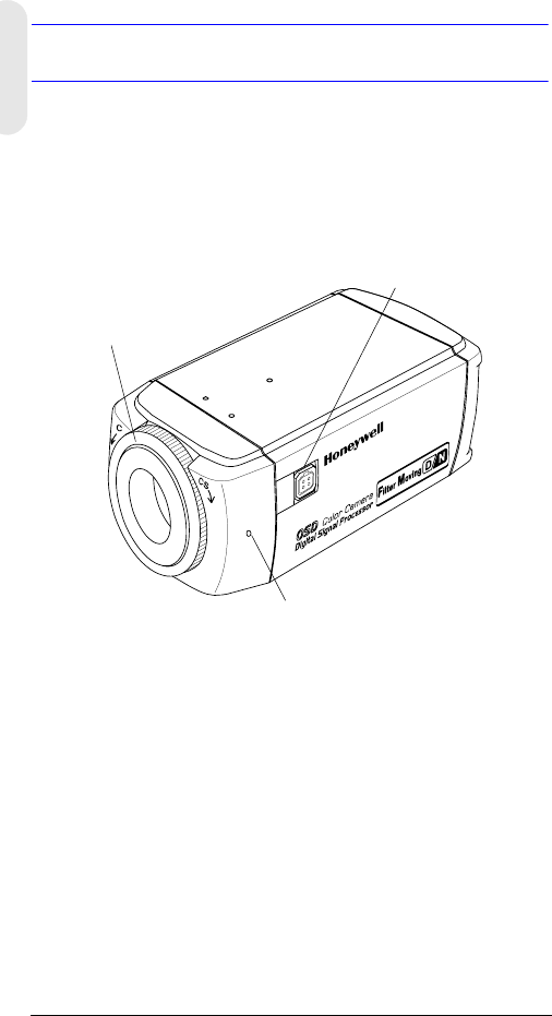
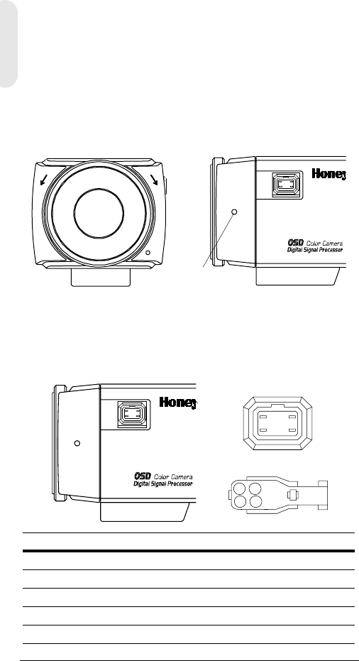
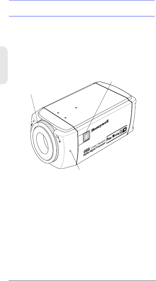
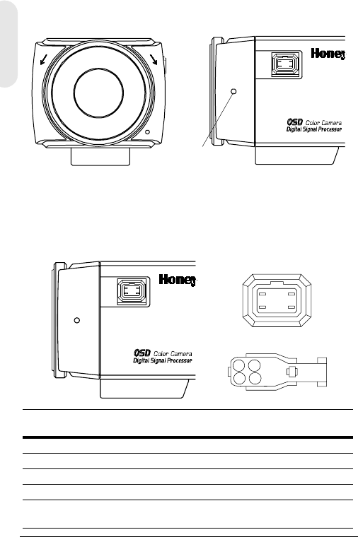
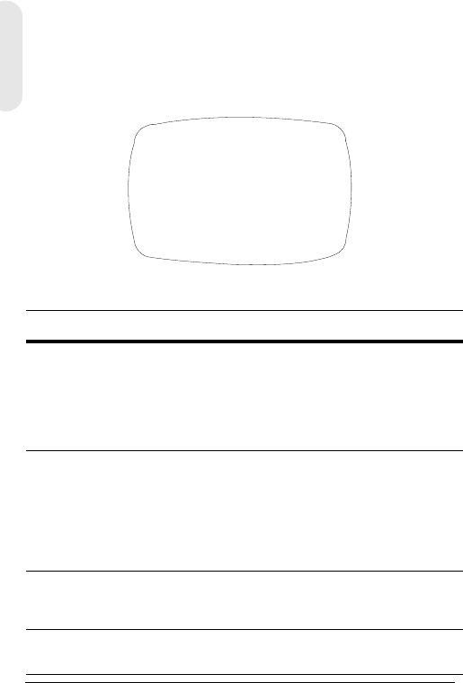
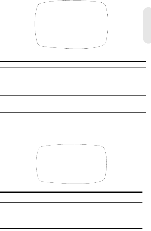
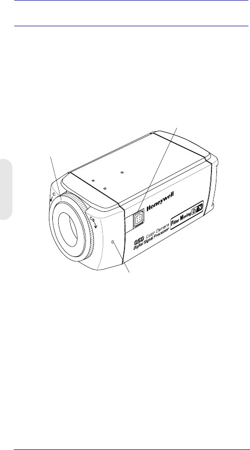
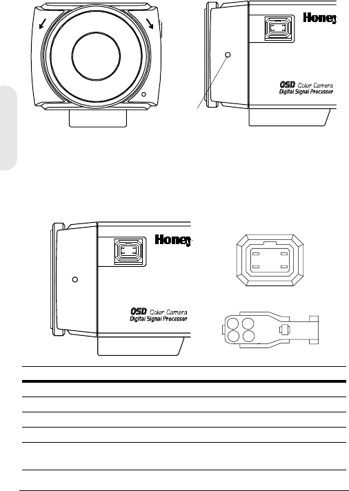
Introduction
The Honeywell L-Series Day/Night Color cameras provide
high picture quality and resolution with a highly sensitive
1/3 inch interline transfer CCD image sensor.
Figure 1 Camera Overview
Features
• 1/3” IT Super HAD CCD
• C/CS adjustable lens mount adapter
• Excellent signal-to-noise ratio of more than 50 dB
• Minimum illumination of 0.1 lux (F1.2, 50 IRE, IR Filter
Off, B/W)
• Compatible with Video Iris (VSD) or Direct Drive (DC)
Auto Iris lens
• OSD menu control
• True color reproduction from various light sources
• Remote control with RS485 connection
Lens connector for
Auto Iris lens plug
Setscrew: loosen locking ring with a Phillips
screwdriver to adjust mounting ring.
C/CS mount adapter:
C mount: turn counterclockwise
CS mount: turn clockwise

Rev 2 2 G-113079-002
02/07
English
Before You Begin
Unpack Everything
Check that the items received match those listed on the
order form and packing slip. The L-Series Day/Night
packing box should include, in addition to this User Guide:
• One L-Series Day/Night Color camera
• One 4-pin connection cable
• One Auto Iris lens plug
If any parts are missing or damaged, contact the dealer you
purchased the camera from or call Honeywell Customer
Service (see Contact Information on the back of this
manual).
Note You will also require a Phillips screwdriver to
complete the installation.
Please read this guide carefully
before you install the L-Series Day/
Night Color camera.
Keep this guide for future reference.
Rev 2 3 G-113079-002
02/07
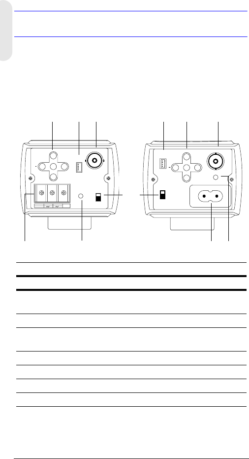
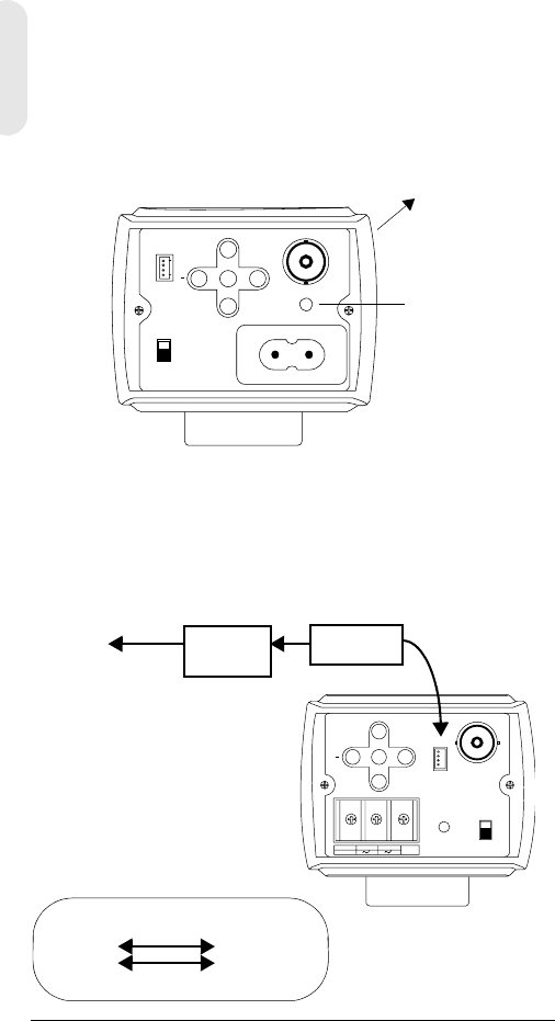
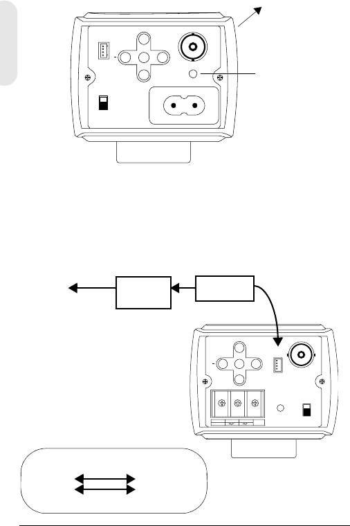
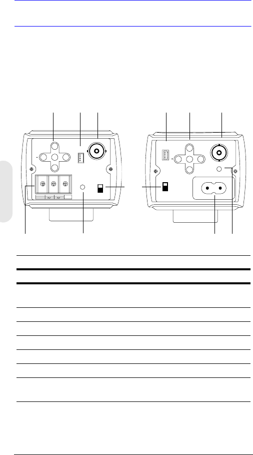
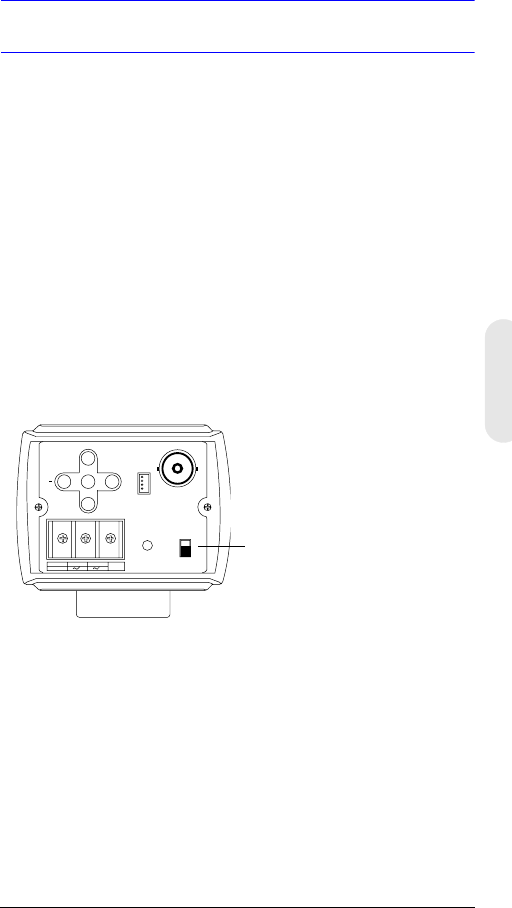
Camera Functions
Figure 2 Camera Rear View
PWR
VSD
DC
VIDEO
~207-253VAC 50HZ
REMOTE UP
DOWN
MENU
+
-+
GND
DC 12V
AC 24V
PWR VSD
DC
VIDEO
+
UP
DOWN
MENU REMOTE
Legend
#Description
1Auto Iris Lens select switch, VSD for Video or DC for
Directive Drive
2Video output connector
3Power input connector (24 VAC: 3 terminals)—Low Voltage
model only
4Power LED indicator
5Remote RS485 connector
6Menu control (see ”Programming” on page 8)
7Mains 230V Line Voltage power connector
Mains 230V—Line Voltage
(HCD485LX)
Low Voltage
(HCD484L, HCD484LX
2
4
1
5
3
62
4
56
7
Rev 2 4 G-113079-002
02/07
English
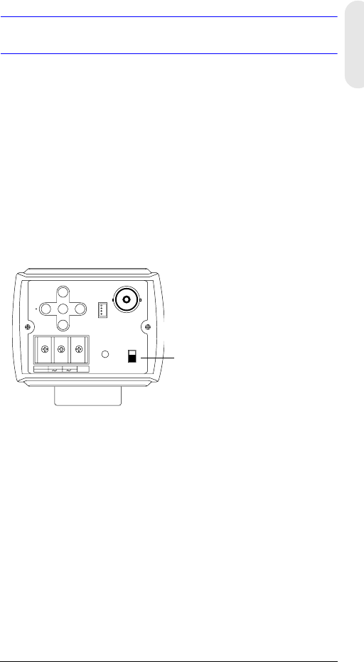
Installation
Selecting the Lens
Vari-focal Auto Iris lenses (Direct Drive or Video Drive) are
connected to the camera via a 4-pin square socket located
at the side of the camera.
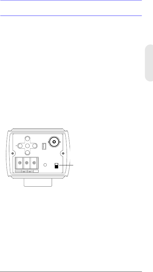
1. Set the VSD/DC switch on the rear of the camera.
For Video Drive lens, set the switch to VSD.
For Direct Drive lens, set the switch to DC.
2. Set the EE MODE to ALC MODE on the OSD menu
(see ALC MODE).
Auto iris lens with amplifier: Set the VSD LENS on the
OSD menu.
Auto iris lens with no amplifier: Set the DC LENS on the
OSD menu. Adjust to the LEVEL carefully to avoid
hunting.
-+
GND
DC 12V
AC 24V
PWR VSD
DC
VIDEO
+
UP
DOWN
MENU REMOTE
Low Voltage model shown
(HCD484L, HCD484LX)
VSD = Auto iris lens with a built-in
amplifier (video-type lens)
DC = Auto iris lens with no amplifier
(DC-type lens)
Rev 2 5 G-113079-002
02/07
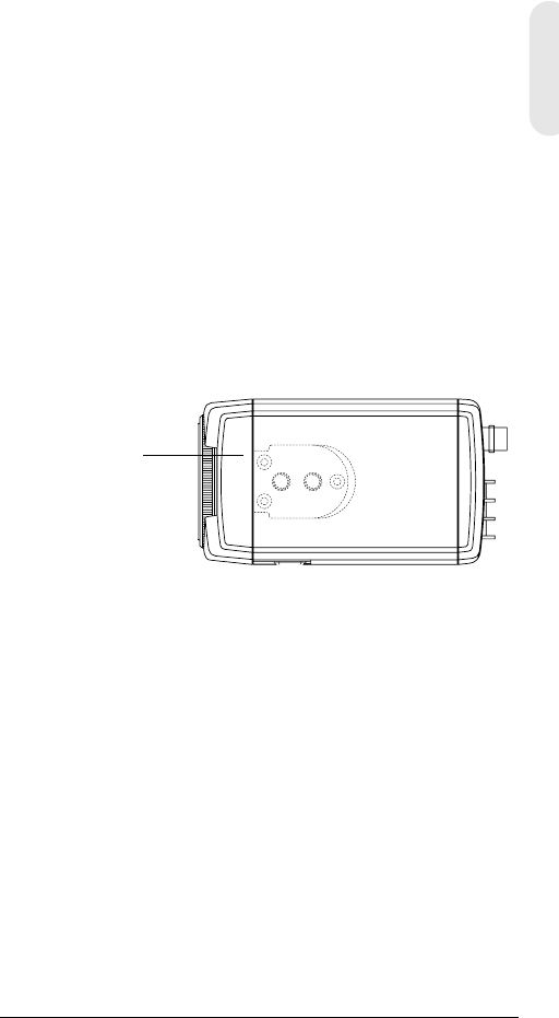
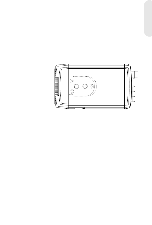
Adjusting the Back Focus
The back focus adjustment is accessible at the front end of
the camera housing to adjust the back focal length or
picture focus.
The range of adjustment allows both C- and CS-mount
lenses to be used without the need for a spacer ring.
Figure 3 C/CS Mount
1. Loosen the setscrew with a Phillips screwdriver.
2. Adjust the focus ring to focus the picture.
3. Retighten the setscrew.
Figure 4 Auto Iris Lens Pin Definition
CCS
Setscrew
1
23
4
21
43
Pin DC (Direct Drive) lens Video (VSD) lens
1 CTRL- Power (+ 12V)
2CTRL+ NC
3DRV+ Video Signal
4DRV- GND
Set the select switch to DC. Set the select switch to VSD.
Rev 2 6 G-113079-002
02/07
English
Mounting the Camera
Mounting points are provided on the top of the camera for
mounting the camera on a bracket or tripod. They are
designed to accept standard sized 1/4 x 20 mounting
screws. This bracket can be unscrewed and mounted onto
the opposite side of the camera, depending on your
application. The mounting bracket must be capable of
supporting the weight of the camera and its lens.
Note Some installation codes dictate that the
mounting bracket must be capable of
supporting up to four times the combined
weight of the camera and lens.
Figure 5 Camera Mount
Connecting the Camera
Note Check the power source from the external
power supply before applying power to the
camera.
1. Connect the VIDEO connector on the rear of the
camera to the video-in connector on your monitor.
2. Connect the camera to a power supply appropriate for
your installation.
HCD484L, HCD484LX:12 VDC or 24 VAC power
supply
HCD485LX: 230V power supply
Unscrew 3 bracket
securing screws and
then resecure the
bracket on the other
side of the camera.
Rev 2 7 G-113079-002
02/07
3. Plug in the power supply. The power (PWR) LED
illuminates to show that the camera is receiving power.
If it does not illuminate, check the connections and the
power source.
Figure 6 Camera Connections
Remote Control Connections
The L-Series Day/Night Color camera can be controlled
remotely using an RS485 connection.
Figure 7 RS485 Camera Connection
PWR
VSD
DC
VIDEO
~207-253VAC 50HZ
REMOT E UP
DOWN
MENU
+
Connect to
Monitor
Power LED
Mains (230V) version shown
(HCD485L)
-+
GND
DC 12V
AC 24V
PWR VSD
DC
VIDEO
+
UP
DOWN
MENU REMOTE
RS485 Converter
TRx+
TRx-
4P Cable
3TRx+
2TRx-
4P CableConnect to
Serial Port
(COM1 or
COM2)
Serial
cable
4-Pin Cable Legend
1. Red Not used
2. Blue TRx-
3. Yellow TRx+
4. Black Not used
RS485
converter

Rev 2 8 G-113079-002
02/07
English
Programming
On-Screen Display (OSD)
Press MENU briefly to confirm the current operation setup.
The information (see Figure 8) disappears after a few
seconds if there is no button action.
Even though the OSD message disappears, the Camera ID
or Title continues to display, if selected in the CAMERA ID
sub-menu. To turn off the Camera ID or Title, either:
• With external communication, change the display
position. Options are
Bottom right, bottom left, top left, top right, non-display
• If you do not need to display the Operating OSD (for
example, for an external text overlay board), set it to
OFF at all times through a remote control using an
RS485 connection.
Figure 8 OSD Information Display
CAMERA ID/TITLE
Back Light WB Mode
Back Light displays if BLC is enabled (see BLC MODE
(Backlight Compensation).
Shutter Speed displays if the default shutter speed is
changed.
WB Mode always displays.
Shutter Speed

Rev 2 9 G-113079-002
02/07
OSD Menu Functions
Use the OSD menu controls to program the camera.
1. Press and hold the MENU (center) button for 2
seconds to display the Setup menu.
2. Press the UP or DOWN buttons to select a menu item.
3. Press the MENU button to enter the selected
submenu.
4. Press the + or – buttons to increase/decrease the
value of the selected item.
Figure 9 OSD Menu Controls
Saving your Settings
First Method: When you are satisfied with your settings:
1. Press MENU for two seconds. The SETUP MENU is
replaced by one of two messages:
SAVE? displays when values have been changed.
Selecting SAVE exits Setup mode and saves your
changes.
QUIT? displays when you have not changed any
settings. Selecting QUIT exits Setup mode without
saving any changed values.
2. Press + or – to select SAVE or QUIT and then press
MENU to exit the Setup mode. Press UP or DOWN to
cancel the SAVE/QUIT and return to the SETUP
MENU.
Second Method: Select EXIT MENU on the SETUP MENU,
press MENU, and then select SAVE AND EXIT to save the
changed settings and exit the menu. Select EXIT to exit
without saving the settings.
UP
DOWN
MENU
+
Rev 2 10 G-113079-002
02/07
English
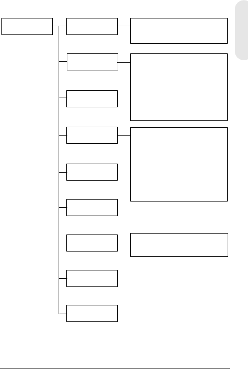
Setting Up Your Camera
OSD Menu Structure
The L-Series Day/Night Color camera menu system
consists of one main setup menu for easy programming.
SETUP MENU CAMERA ID
ELC/ALC Mode
Shutter Speed
White Balance
AGC Control
Nightshot
Sync Control
Restore Default
Exit Menu
Camera ID, Title
Display Position
ELC Mode: AUTO, MANUAL
ALC Mode: VSD LENS
DC LENS (LEVEL)
ATW, Outdoor, Indoor, User,
Fluorescent,
AWC (Auto, Manual, Push&Lock)
MWB (RED, BLUE)
AUTO, INTERNAL,
LineLock (V.PH)
Main MENU Sub-Menus Options
1
2
3
4
5
6
7
8

Rev 2 11 G-113079-002
02/07
Menu Item Option Description
1 CAMERA
ID
000 (off), 001 … 255 0: Turns ID display off. See
Sync Control Setup for more
information.
2ELC / ALC
Mode
ELC …
ALC …
See ELC / ALC Mode for
more information.
3 Shutter
Speed
1/60 NTSC (1/50
PAL)
FL
1/250
1/500
1/1000
1/2000
1/4000
1/10000
1/30000
1/50000
Adjust brightness with high
shutter speed.
FL: Removes flicker in a
picture.
This field is not adjustable
when the camera is set to
ELC MODE. Auto is
selected by default.
4White
Balance
ATW (Auto Trace
White Balance)
AWC (Auto White
Balance Control)
MWB (Manual White
Balance)
Preset white balance modes
include Outdoor, Indoor,
User, Fluorescent. See White
Balance Control Setup for
more information.
5AGC
Control
OFF
10 dB
12 dB … 38 dB
Adjust maximum value of
AGC gain. When AGC is set
to OFF, Nightshot is not
available.
6 Nightshot Set how the camera reacts
to low light illumination.
7Sync.
Control
AUTO
INTERNAL
LineLock (V.Phase)
See Sync Control Setup for
more information.
8Restore
Default
Reload the factory default
settings. If you have not
made any changes, you will
not be able to select this
setting.

Rev 2 12 G-113079-002
02/07
English
Adding a Camera ID Or Title
Adding a camera ID is useful when there are a number of
cameras in your network. To add a camera ID or title, enter
the SETUP MENU, select CAMERA ID and press MENU.
Figure 10 Adding Camera ID Or Title
Entering a Camera Title
1. Move to the first character of the TITLE: using the + or
– menu controls on the rear of the camera.
2. Use the UP, DOWN, +, – menu controls to select the
first character in the title, then press the MENU key to
set the character.
Menu Item Option Description
CAM ID 0
001 …
255
The number assigned each camera in
your network, from 000 to 255.
0: The ID is not displayed on the screen.
DISPLAY TITLE
ID
OFF
Select what is displayed on the screen
(Camera TITLE, ID or nothing).
POSITION T.R.
B.R.
B.L.
T.L.
NO DISP
Select where you want the Camera ID or
Title to appear on the display (Top Right,
Bottom Right, Top Left, Bottom Left, and
No Display).
TITLE Enter a name for the camera. Maximum
10 characters, including spaces.
RETURN Press MENU to return to the main
SETUP MENU.
CAM ID: 002
DISPLAY: TITLE
POSITION: T.R.
1 2 3 4 5 6 7 8 9 A B C D E F
G H I J K L M N P Q R S T U V W
X Y Z a b c d e f g h i j k l m
n o p q r s t u v w x y z , . :
; ~ ! ? $ % * & / < > + - = ■
TITLE: HCD484■■
RETURN

Rev 2 13 G-113079-002
02/07
3. Select the next position of the title character using the
+ or – menu controls, then repeat steps 2 and 3 until
your camera title is complete.
4. Select RETURN and press MENU to accept your
changes and return to the main SETUP MENU.
Setting the Camera Lighting Optimization
ELC / ALC Mode
Figure 11 Setting Camera Lighting
To set the lens mode, back light compensation and black
mask:
Menu Item Option Description
EE MODE:
ELC MODE
AUTO
MANUAL
For a manual (fixed) lens:
AUTO: Iris operates electronic
exposure automatically.
MANUAL: Adjust the iris by
changing the high shutter speed
manually.
EE MODE:
ALC MODE
VSD
LENS
DC LENS
For an automatic iris lens:
VSD: Select for video-type lens.
DC LENS: Select for direct drive-
type lens. Adjust the LEVEL until the
image is neither too bright nor too
dark.
BLC MODE
(Backlight
Compensation)
OFF
LOW BL
MID. BL
HIGH BL
Prevents the object in the center of
the image from darkening (silhouette
effect) when there is excessive light
from behind.
RETURN Press MENU to return to the SETUP
MENU.
<ELC / ALC MODE>
EE MODE: ALC MODE
DC LENS
LEVEL 04
BLC MODE: OFF
RETURN

Rev 2 14 G-113079-002
02/07
English
White Balance Control Setup
Auto white balance ensures that color integrity is
maintained within the color range of 2800°K to 8000°K:
Figure 12 White Balance Control
Menu Item Description
ATW (Auto Trace
White Balance
Mode)
Feedback system that automatically aligns the
white balance (2800°K to 8000°K).
AWC (Auto White
Balance Control
Mode)
Performs at a faster operating speed than
ATW. Typically used for outdoor applications
or where variable lighting conditions exist.
Options are:
AUTO: AWC operates all the time
MANUAL: PUSH Press MENU to start the
AWC operation
MANUAL: LOCK Release MENU to fit the
present shooting scene’s white balance
INDOOR General indoor scenes preset (3200°K).
FLUORESCENT Office environments with fluorescent or
tungsten lighting. Provides lowest dynamic
range of all presets (4200°K).
USER FIXED Preset (4700°K)
OUTDOOR Preset for outside environments and high-
contrast scenes where the camera is focused
on the darker (6300°K).
MWB
(Manual Mode)
RED: 0 to 20
BLUE: 0 to 20
RETURN Press MENU to return to the SETUP MENU.
<WHITE BALANCE>
WB MODE: MWB
WB CONT: R=00
B=00
RETURN

Rev 2 15 G-113079-002
02/07
Nightshot Control Setup
The Nightshot menu allows you to set how the camera
reacts to changes in low light illumination and to set when
the camera switches between Night and Day modes. AGC
must be on for Nightshot to be active.
Figure 13 White Balance Control
Menu Item Description
MODE AUTO: The camera removes or inserts IR cut
filter by auto detecting luminance.
ON: IR cut filter is removed (Night mode)
OFF: IR cut filter is inserted (Day mode)
DET.TIME Sets the time—5 to 60 seconds—before the
camera switches to Day or Night mode after
detecting a low light condition.
MODE must be set to AUTO.
D->N THD
(Threshold)
Determines the low light detection level—1 to
9—when the camera switches to Night mode.
The lower the value, the darker the lighting
conditions before the camera switches.
MODE must be set to AUTO.
Note D-> THD must be set at least 2 less
than the N->D THD setting.
N->D THD
(Threshold)
Determines the low light detection level —1 to
9—when the camera switches to Day mode.
The higher the value, the brighter the lighting
conditions before the camera switches.
MODE must be set to AUTO.
DN COLOR Sets the color mode as B/W (monochrome) or
COLOR in Night mode.
MODE must be set to AUTO or ON.
RETURN Press MENU to return to the SETUP MENU.
<NIGHTSHOT>
MODE: AUTO
DET.TIME: 10 sec
D->N THD 2
N->D THD 5
DN COLOR BW
RETURN

Rev 2 16 G-113079-002
02/07
English
Sync Control Setup
To synchronize the vertical interval sync pulse of your
camera with other equipment to reduce the effect of picture
roll on the monitor.
Figure 14 Sync Control Setup
Exit Setup Menu
To exit the SETUP menu.
Figure 15 Exit Menu
Menu Item Description
INTERNAL When line lock is not required.
LINELOCK Adjust the proper phase:
V.PH: 000 to 300 (factory default is 0)
Note Line lock is not available in 12 VDC power.
AUTO Camera automatically detects synchronization.
RETURN Press MENU to return to the SETUP MENU.
Menu Item Description
SAVE AND EXIT Press MENU to save your changes and exit.
EXIT Press MENU to quit without saving your
changes.
RETURN Press MENU to return to the SETUP MENU.
<SYNC. CONTROL>
SYNC MODE: LINELOCK
V.PH 000
STEP=10
RETURN
<EXIT MENU>
SAVE AND EXIT
EXIT
RETURN

Rev 2 17 G-113079-002
02/07
Warranty and Service
Subject to the terms and conditions listed on the Product warranty,
during the warranty period Honeywell will repair or replace, at its
sole option, free of charge, any defective product returned prepaid.
In the event you have a problem with any Honeywell product,
please call Customer Service at 1.800.796.CCTV (North America
only) for assistance or to request a Return Merchandise
Authorization (RMA) number. For Europe and the United
Kingdom, please contact your Honeywell dealer.
Be sure to have the model number, serial number, and the nature
of the problem available for the technical service representative.
Prior authorization must be obtained for all returns, exchanges, or
credits. Items shipped to Honeywell without a clearly identified
Return Merchandise Authorization (RMA) number may be
refused.
Specifications
Note These specifications refer to all models,
except where otherwise noted.
HCD484L HCD484LX
HCD485LX
Operational
Image Sensor: 1/3” Super HAD CCD
Video
Standard:
NTSC PAL
Scanning
System:
525 lines, 2:1 interlace 625 lines, 2:1 interlace
Number of
Pixels (H x V):
768 x 494 752 x 582
Minimum
Illumination:
< 0.1 lux @ F1.2
(50 IRE, AGC ON, IR Filter Off, B/W)
Horizontal
Resolution:
480 TVL 480 TVL

Rev 2 18 G-113079-002
02/07
English
Video Output: 1 Vp-p @ 75 Ohms
Sync System: Internal/Line lock/Auto
S/N Ratio: > 50 dB
Auto Gain
Control (AGC):
Off, 10 dB to 38 dB
ALC: EE/VSD/DC
Automatic
Electronic
Shutter (AES):
1/60 - 1/100,000 sec 1/50 - 1/100,000 sec
Lens Mount: C/CS mount (adjustable)
White Balance
(AWB):
ATW, AWC, Indoor, Outdoor, Fluorescent,
User, MWB
BLC: Off, Low, Middle, High
Electrical
Input Voltage: HCD484L, HCD484LX: 12 VDC/24 VAC
HCD485LX: 230 VAC
Input Voltage
Range:
HCD484L, HCD484LX: 11-16 VDC/17-28 VAC
HCD485LX: 230 VAC ± 10%
Power
Consumption:
HCD484L, HCD484LX: 3.5 W (max)
HCD485LX: 4.5 W (max)
Mechanical
Dimension:
(W x H x D)
HCD484L, HCD484LX: 2.68 x 2.2 x 4.72 in.
(68 x 56 x 120 mm)
HCD485LX: 2.68 x 2.2 x 5.51 in.
(68 x 56 x 140 mm)
Weight: HCD484L, HCD484LX: 0.84 lb (.380 kg)
HCD485LX: 0.90 lb(.410 kg)
Environmental
Temperature: Operating: 14°F to 122°F (-10°C to +50°C)
Storage: -4°F to158°F (-20°C to +70°C)
Regulatory
Emissions: FCC, CE (EN55013)
Immunity: CE (EN50130-4)
Safety: EU: 73/23/EEC LVD
HCD484L HCD484LX
HCD485LX

© 2007 Honeywell International Inc. All rights reserved. No part of this publication
may be reproduced by any means without written permission from Honeywell Video
Systems. The information in this publication is believed to be accurate in all respects.
However, Honeywell Video Systems cannot assume responsibility for any
consequences resulting from the use thereof. The information contained herein is
subject to change without notice. Revisions or new editions to this publication may
be issued to incorporate such changes.
www.honeywellvideo.com
+1.800.796.CCTV (North America only)
HVSsupport@honeywell.com
Document G-113079-002 02/07 Rev 2
Honeywell Video Systems (Head office)
2700 Blankenbaker Pkwy, Suite 150
Louisville, KY 40299, USA
www.honeywellvideo.com
℡ +1.800.796.2288
Honeywell Security Australia Pty Ltd.
Unit 5, Riverside Centre
24-28 River Road West
Parramatta, NSW 2150, Australia
www.ademco.com.au
℡ +61.2.8837.9300
Honeywell Security Asia Pacific
33/F Tower A, City Center, 100 Zun Yi
Road
Shanghai 200051, China
www.security.honeywell.com/cn
℡ +86 21.2527.4568
Honeywell Security Asia
Flat A, 16/F, CDW Building
388 Castle Peak Road
Tsuen Wan, N.T., Hong Kong
www.security.honeywell.com/hk
℡ +852.2405.2323
Honeywell Security France
Parc Gutenberg, 8, Voie La Cardon
91120, Palaiseau, France
www.honeywell.com/security/fr
℡ +33.01.64.53.80.40
Honeywell Security Italia SpA
Via Treviso 2 / 4
31020 San Vendemiano
Treviso, Italy
www.honeywell.com/security/it
℡ +39.04.38.36.51
Honeywell Security España
Mijancas 1. 3a Planta
P.Ind. Las Mercedes
28022 Madrid, Spain
www.honeywell.com/security/es
℡ +34.902.667.800
Honeywell Video Systems
Northern Europe
Netwerk 121
1446 WV Purmerend, The Netherlands
www.SecurityHouse.nl
℡ +31.299.410.200
Honeywell Video Systems UK Ltd.
Aston Fields Road, Whitehouse Ind Est
Runcorn, Cheshire, WA7 3DL, UK
www.honeywellvideo.com
℡ +0844 8000 235
Honeywell Security South Africa
Unit 6 Galaxy Park, 17 Galaxy Avenue
Linbro Park, P.O. Box 59904
2100 Kengray, Johannesburg
South Africa
www.honeywell.co.za
℡ +27.11.574.2500
Honeywell Security Deutschland
Johannes-Mauthe-Straße 14
D-72458 Albstadt, Germany
www.honeywell.com/security/de
℡ +49.74 31.8 01.0
Honeywell Security Poland
Chmielewskiego 22a, 70-028
Szczecin, Polska
www.ultrak.pl
℡ +48.91.485.40.60
Honeywell Security Czech Republic
Havránkova 33, Brno
Dolní Heršpice, 619 00
Czech Republic
www.olympo.cz
℡ +420.543.558.111
Honeywell Security Slovakia Republic
Vajnorská 142, 83104 Bratislava
Slovakia
www.olympo.sk
℡ +421.2.444.54.660

Document G-113079-002 – 02/07 – Rév 2
Caméra Jour/Nuit
Série L
HCD484L HCD484LX
HCD485LX
Guide d'utilisation
NTSC PAL
Français

Révisions
Édition Date Révisions
1.00 10/06 Nouveau document
2 02/07 Mis à jour 900.0842 document
numéro de la pièce; Avertissement
supplémentaire à la page iii.
Rév 2 ii G-113079-002
02/07
Rév 2 iii G-113079-002
02/07
Avertissements
L’installation et l’entretien ne doivent être effectués que par
du personnel qualifié et expérimenté, afin de respecter
toutes les normes locales et de maintenir votre garantie.
DANGER ! Les modèles 12 VDC/24 VAC requièrent
l’utilisation d’adaptateurs d’alimentation
certifiés CSA/inscrits sur la liste UL, de
classe 2, afin d’être en conformité avec
les normes de sécurité électrique.
Lorsque la prise du RÉSEAU D’ALIMENTATION ou une
prise placée sur l’appareil est utilisée comme dispositif de
déconnexion, ce dispositif doit demeuré aisément
accessible.
Déchets d'Équipements Électroniques et Électriques
(DEEE). Élimination appropriée du produit (applicable en
Union Européenne et dans d’autres pays européens
pratiquant le tri sélectif). Ce produit doit être éliminé, à la
fin de sa durée de vie utile, dans le respect des lois,
réglementations et procédures locales applicables.
Explication des symboles
graphiques
RISQUE DE CHOC
ELECTRIQUE
NE PAS OUVRIR
ATTENTION : POUR REDUIRE LE RISQUE DE CHOC
ELECTRIQUE, NE PAS OTER LE CAPOT.
AUCUNE PIECE N'EST REPARABLE PAR
L'UTILISATEUR. LA MAINTENANCE NE DOIT ETRE
EFFECTUEE QUE PAR UN PERSONNEL QUALIFIE.
CE SYMBOLE SIGNALE LA
PRÉSENCE DANS L’UNITÉ D’UNE
TENSION DANGEREUSE
CONSTITUANT UN RISQUE
DE CHOC ÉLECTRIQUE.
CE SYMBOLE INDIQUE QUE DES
INSTRUCTIONS D'UTILISATION
ET DE MAINTENANCE
IMPORTANTES SONT FOURNIES
AVEC CETTE UNITÉ.
ATTENTION
Français

Rév 2 iv G-113079-002
02/07
Déclaration de conformité FCC
Informations à l’attention de l’utilisateur :
Cet équipement a été testé et déclaré conforme aux
normes définies pour un dispositif numérique de classe A.
Conformément à l’article 15 de la Réglementation FCC, ces
normes sont conçues pour fournir une protection suffisante
contre le brouillage nuisible, lorsque l’équipement est
utilisé dans un environnement commercial. Cet appareil
génère, utilise et peut émettre de l'énergie de fréquence
radio, et peut, en cas d'installation ou d'utilisation non
conforme au manuel d'instructions, générer des
interférences nuisibles aux communications radio.
L'utilisation de ce produit dans une zone résidentielle peut
provoquer des interférences nuisibles. Le cas échéant,
l'utilisateur devra remédier à ces interférences à ses
propres frais.
Attention Tout changement ou toute modification non
expressément approuvée par la partie
responsable de la conformité peut annuler
le droit de l'utilisateur à utiliser l'appareil.
Déclaration de conformité
du fabricant
Le fabricant déclare que l’équipement fourni avec le
présent guide est conforme aux exigences essentielles de
sécurité de la directive de comptabilité électromagnétique
EMC 89/336/EEC et de la directive de basse tension
LVD 73/23 EEC, conformément aux exigences des normes
EN 55013 sur les émissions.

Rev 2 G-113079-002
02/07
Français
Sommaire
Introduction . . . . . . . . . . . . . . . . . . . . . . . . . . . . . . . 1
Caractéristiques . . . . . . . . . . . . . . . . . . . . . . . . . . 1
Avant de commencer . . . . . . . . . . . . . . . . . . . . . . 2
Déballage . . . . . . . . . . . . . . . . . . . . . . . . . . . . . . . 2
Branchement de la caméra . . . . . . . . . . . . . . . . . . . 3
Installation . . . . . . . . . . . . . . . . . . . . . . . . . . . . . . . . 4
Choix de l’objectif. . . . . . . . . . . . . . . . . . . . . . . . . 4
Réglage du tirage optique . . . . . . . . . . . . . . . . . . 5
Montage de la caméra . . . . . . . . . . . . . . . . . . . . . . 6
Branchement de la caméra . . . . . . . . . . . . . . . . . 6
Connexions pour le contrôle à distance . . . . . 7
Programmation. . . . . . . . . . . . . . . . . . . . . . . . . . . . . 8
Comprendre l’affichage à l’écran. . . . . . . . . . . . . 8
Affichage à l’écran . . . . . . . . . . . . . . . . . . . . . . 9
Enregistrement de vos paramètres. . . . . . . . . 9
Configuration de votre caméra . . . . . . . . . . . . . 10
Structure du menu d’affichage à l’écran . . . . 10
Ajout d’un affichage de titre de caméra . . . . . 12
Réglage de l’optimisation d’éclairage
de la caméra . . . . . . . . . . . . . . . . . . . . . . . . . . 13
Mode de contrôle de lumière (ELC/ALC) 13
Configuration de la balance des blancs 14
Réglage des commandes de prise
de vue nocturne . . . . . . . . . . . . . . . . . . . . . . . 15
Configuration du contrôle de la
synchronisation . . . . . . . . . . . . . . . . . . . . . . . 16
Quitter le Menu Setup (Configuration) . . . . . . 16
Garantie et service après-vente. . . . . . . . . . . . . . . 17
Caractéristiques . . . . . . . . . . . . . . . . . . . . . . . . . . 17
Rév 2 1 G-113079-002
02/07
Introduction
Les caméras Jour/Nuit Série L Honeywell offrent une
qualité d’image et une résolution élevées grâce à un
capteur d’image CCD de transfert d’interligne 1/3 po
extrêmement sensible.
Figure 1 Vue d’ensemble de la caméra
Caractéristiques
• Capteur 1/3 pouces IT-CCD Super HAD
• Adaptateur de monture de l’objectif réglable C/CS
• Excellent rapport signal-bruit supérieur à 50 dB
• Luminosité minimale de 0,1 lux (F1.2, 50 IRE,
IR Filter Off, B/W)
• Objectif à diaphragme à commande vidéo (VSD)
ou à diaphragme à commande directe (DC)
• Menu OSD d’affichage à l’écran
• Reproduction couleurs vraies à partir de plusieurs
sources lumineuses
• Commande à distance via RS485
Connecteur d’objectif
pour fiche d’objectif à
diaphragme automatique
Vis de serrage : desserrez la bague de
verrouillage à l’aide d’un tournevis cruciforme
afin de régler la bague de montage.
Adaptateur de monture C/CS :
Monture C : tournez vers la gauche
Monture CS : tournez vers la droite

Rév 2 2 G-113079-002
02/07
Français
Avant de commencer
Déballage
Vérifiez que les éléments reçus correspondent bien à ceux
inscrits sur le bon de commande et sur le bordereau de
livraison. La boîte d’emballage de la caméra Jour/Nuit
Série L doit contenir, en plus du présent Guide
d'utilisation :
• Une caméra Jour/Nuit Série L
• Un câble de branchement à 4 broches
• Une fiche d’objectif à diaphragme automatique
Si l’une de ces pièces est manquante ou endommagée,
contactez le vendeur de la caméra ou contactez le Service
client Honeywell (voir la section Coordonnées au dos du
présent manuel).
Remarque Un tournevis cruciforme sera également
nécessaire lors de l’installation.
Lire attentivement le présent guide
avant d’installer la caméra Jour/Nuit
Série L.
Conservez ce guide pour un usage
ultérieur.
Rév 2 3 G-113079-002
02/07
Branchement de la caméra
Fonctions de la caméra
Figure 2 Vue arrière de la caméra
PWR
VSD
DC
VIDEO
~207-253VAC 50HZ
REMOTE UP
DOWN
MENU
+
-+
GND
DC 12V
AC 24V
PWR VSD
DC
VIDEO
+
UP
DOWN
MENU REMOTE
Légende
#Description
1Sélecteur d’objectif à diaphragme automatique, VSD pour
Vidéo ou DC pour Commande directe
2Connecteur de sortie vidéo
3Connecteur de courant d’entrée (24 V CA : 3 terminaux)—
Modèle faible tension uniquement
4Témoin d’alimentation
5Connecteur RS485 distant
6Commande Menu (voir « Programmation » à la page 8)
7Connecteur d’alimentation 230V
Secteur 230V—Tension d’alimentation
(HCD485LX)
Faible tension
(HCD484L, HCD484LX
2
4
1
5
3
62
4
56
7
Rév 2 4 G-113079-002
02/07
Français
Installation
Choix de l’objectif
Les objectifs à diaphragme automatique et à focale
variable (à commande directe ou à commande vidéo)
sont raccordés à la caméra à l'aide d’une douille 4 pans
à 4 broches située sur le côté de la caméra.
1. Positionnez le commutateur VSD/DC à l'arrière de la
caméra sur DC.
Pour les objectifs à commande vidéo, positionnez le
commutateur sur VSD.
Pour les objectifs à commande directe, positionnez le
commutateur sur DC.
2. Réglez le MODE EE (exposition automatique) sur le
MODE ALC (contrôle de lumière automatique) dans le
menu d’affichage à l’écran OSD (voir Mode de
contrôle de lumière (ELC / ALC)).
Objectif à diaphragme automatique avec
amplificateur : Réglez sur VSD LENS dans le menu
d’affichage à l’écran OSD.
Objectif à diaphragme automatique sans
amplificateur : Réglez sur DC LENS dans le menu
d’affichage à l’écran OSD. Réglez avec précaution le
niveau (LEVEL) afin d’éviter tout balayage intempestif.
-+
GND
DC 12V
AC 24V
PWR VSD
DC
VIDEO
+
UP
DOWN
MENU REMOTE
Modèle illustré : faible tension
(HCD484L, HCD484LX
Réglez sur VSD pour un objectif
à diaphragme automatique avec
amplificateur intégré (objectif vidéo).
Réglez sur DC pour un objectif
à diaphragme automatique sans
amplificateur (objectif DC).
Rév 2 5 G-113079-002
02/07
Réglage du tirage optique
Le réglage du tirage optique est accessible sur l’extrémité
avant du boîtier de la caméra et permet de régler la longueur
focale arrière ou de procéder à la mise au point de l’image.
La portée de réglage permet l’utilisation des deux supports
d’objectifs C et CS sans avoir recours à une bague
d’espacement.
Figure 3 Support C/CS
1. Desserrez la vis de serrage à l’aide d’un tournevis cruciforme.
2. Réglez la bague de variation de la focale afin d’effectuer
la mise au point l’image.
3. Serrez à nouveau la vis de serrage.
Figure 4 Définition des broches d'objectifs à iris automatique
CCS
Vis de serrage
1
23
4
21
43
Broche Objectif à commande
directe (DC) Objectif à commande
vidéo (VSD)
1 CTRL - Alimentation (+ 12V)
2CTRL+ NC
3DRV+ Signal vidéo
4 DRV- Masse
Positionnez le sélecteur
sur DC Positionnez le sélecteur
sur VSD
Rév 2 6 G-113079-002
02/07
Français
Montage de la caméra
Les points de montage se trouvent sur la partie supérieure
de la caméra dans le but de monter celle-ci sur un support
ou un trépied. Ils sont conçus pour supporter des vis de
fixation de taille standardisée 1/4 x 20. Ce support peut être
dévissé et fixé de l’autre côté de la caméra, selon les
besoins de votre application. Le support de montage
doit être capable de supporter le poids de la caméra et
de son objectif.
Remarque Certains codes d’installation imposent que
le support de montage soit en mesure de
supporter jusqu’à quatre fois le poids
combiné de la caméra et de l’objectif.
Figure 5 Montage de la caméra
Branchement de la caméra
Remarque Vérifiez l’alimentation de la source externe
avant de mettre la caméra sous tension.
1. Branchez le connecteur VIDEO à l’arrière de la caméra
dans le connecteur d’entrée vidéo de votre moniteur.
2. Branchez la caméra à une alimentation appropriée
(selon votre installation).
Alimentation HCD484L, HCD484LX:12 VDC ou 24 VAC
HCD485LX : Alimentation 230V
Dévissez les trois vis
de fixation du support,
puis refixez ce dernier
de l’autre côté de
la caméra.
Rév 2 7 G-113079-002
02/07
3. Mettez sous tension. Le témoin d’alimentation (PWR)
s’allume pour indiquer que la caméra est alimentée.
Si le voyant ne s’allume pas, vérifiez les branchements
et la source d’alimentation.
Figure 6 Branchements de la caméra
Connexions pour le contrôle à distance
La caméra Jour/Nuit Série L peut être contrôlée à distance
via RS485.
Figure 7 Connexion caméra via RS485
PWR
VSD
DC
VIDEO
~207-253VAC 50HZ
REMOT E UP
DOWN
MENU
+
Connexion
au moniteur
Témoin
d’alimentation
Version illustrée : secteur (230V)
(HCD485L)
-+
GND
DC 12V
AC 24V
PWR VSD
DC
VIDEO
+
UP
DOWN
MENU REMOTE
Convertisseur RS485
TRx+
TRx-
Câble 4P
3TRx+
2TRx-
Câble 4PConnexion
au port série
(COM1 ou
COM2)
Câble
série
Légende du câble à 4 broches
1. Rouge Non utilisé
2. Bleu TRx-
3. Jaune TRx+
4. Noir Non utilisé
Convertisseur
RS485

Rév 2 8 G-113079-002
02/07
Français
Programmation
Comprendre l’affichage à l’écran
Appuyez rapidement sur MENU afin de confirmer la
configuration actuelle. Les informations (voir Figure 8)
s’afficheront au bout de quelques secondes si aucun
bouton n’a été actionné.
Après disparition du message d’affichage à l’écran,
le numéro d’identification de la caméra ou le titre
continueront de s’afficher. Pour désactiver cet affichage,
vous pouvez :
• Par le biais d’une communication externe, modifier la
position d’affichage. Les options possibles sont :
Bottom right (en bas à droite), bottom left (en bas
à gauche), top left (en haut à gauche), top right
(en haut à droite), non-display (pas d’affichage)
• Si vous n’avez pas besoin d’afficher l’écran d’affichage
d’exploitation (par exemple, pour carte de
surimpression textuelle), vous pouvez le configurer
sur OFF (DÉSACTIVÉ) à tout moment via un contrôle
à distance passant par la connexion RS485.
Figure 8 Affichage des informations de
l’affichage à l’écran
CAMERA ID/TITLE (ID CAMÉRA/TITRE)
Back Light
(Rétro-
éclairage)
WB Mode
(Mode WB)
Back Light s’affiche si BLC est activé (voir BLC MODE
(Compensation de contre-jour).
Shutter Speed s’affiche si la vitesse d’obturation par
défaut est modifiée.
WB Mode est toujours affiché.
Shutter Speed
(Vitesse
d’obturation)

Rév 2 9 G-113079-002
02/07
Affichage à l’écran
Utilisez l’affichage à l’écran pour programmer la caméra.
1. Appuyez sur le bouton MENU (centre) et maintenez-le
enfoncé pendant 2 secondes afin d’afficher le menu
Setup.
2. Appuyez sur le bouton UP (haut) ou DOWN (bas) afin
de sélectionner un élément du menu.
3. Appuyez sur le bouton MENU pour entrer dans le
sous-menu sélectionné.
4. Appuyez sur les boutons + or – pour augmenter /
diminuer la valeur de l’élément sélectionné.
Figure 9 Contrôles du menu d’affichage à l’écran
Enregistrement de vos paramètres
Première méthode : Lorsque vous êtes satisfait des
paramètres définis :
1. Appuyez sur MENU pendant deux secondes. Le menu
SETUP (MENU CONFIGURATION) est remplacé par
l’un des deux messages suivants :
SAVE? (ENREGISTRER ?) s’affiche lorsque des valeurs
ont été modifiées. Si vous sélectionnez SAVE
(ENREGISTRER), vous quittez le mode de configuration
Setup après enregistrement de vos modifications.
QUIT?
(QUITTER ?) s’affiche si vous n’avez modifié
aucun paramètre. Si vous sélectionnez
QUIT
(QUITTER), vous quittez le mode de configuration Setup
sans enregistrer les éventuelles modifications.
2. Appuyez sur + ou – afin de sélectionner SAVE
(ENREGISTRER) ou QUIT (QUITTER), puis appuyez
sur MENU pour sortir du mode de configuration Setup.
Appuyez sur UP (HAUT) ou DOWN (BAS) afin
d’annuler le choix SAVE/QUIT (ENREGISTRER /
QUITTER) et retourner au MENU SETUP (MENU
CONFIGURATION).
Deuxième méthode : Sélectionnez EXIT MENU (QUITTER
LE MENU) dans le MENU SETUP, appuyez sur MENU, puis
sélectionnez SAVE AND EXIT (ENREGISTRER ET
QUITTER) afin d’enregistrer les paramètres modifiés et
quitter le menu. Sélectionnez EXIT (QUITTER) afin de
quitter sans enregistrer les paramètres.
UP
DOWN
MENU
+
Rév 2 10 G-113079-002
02/07
Français
Configuration de votre caméra
Structure du menu d’affichage à l’écran
Le menu de la caméra Jour / Nuit Série L se compose d’un
menu principal pour une programmation facile.
SETUP MENU CAMERA ID
ELC/ALC Mode
Shutter Speed
White Balance
AGC Control
Nightshot
Sync Control
Restore Default
Exit Menu
Numéro d’identification de
la caméra, titre et position
de l’affichage
Mode de contrôle de lumière
électronique :
AUTO (AUTOMATIQUE),
MANUAL (MANUEL)
Mode de contrôle de lumière
automatique :
VSD LENS (OBJECTIF VSD)
DC LENS (OBJECTIF DC)
(Level [Niveau])
Ajustement automatique de la
balance des blancs, extérieur,
intérieur, utilisateur, fluorescent
AWC (Contrôle automatique de
la balance des blancs) (Auto,
Manual; Push and Lock [Auto,
Manuel ; Pousser et verrouiller])
MWB (Balance des blancs
manuelle) (RED [ROUGE],
BLUE [BLEU])
AUTO, INTERNE,
Verrouillage de ligne [phase V]
MENU
principal Sous-menus Options
1
2
3
4
5
6
7
8

Rév 2 11 G-113079-002
02/07
Élément
de menu Option Description
1 CAMERA
ID 000 (off),
001 … 255 Si le numéro d’identification est
défini sur 0, il ne sera pas affiché.
Voir Configuration du contrôle de
la synchronisation pour plus
d’informations.
2ELC / ALC
Mode ELC …
ALC … Voir Mode de contrôle de lumière
(ELC / ALC) pour plus
d’informations.
3 Shutter
Speed 1/60 NTSC
(1/50 PAL) FL
1/250
1/500
1/1000
1/2000
1/4000
1/10000
1/30000
1/50000
Pour régler la luminance avec une
vitesse d’obturation élevée.
Clignotement Il est impossible de
régler ce champ lorsque la caméra
est configurée sur ELC MODE
(MODE ELC). Auto est sélectionné
par défaut.
4White
Balance ATW (Auto
Trace White
Balance)
AWC (Auto
White Balance
Control)
MWB (Manual
White Balance)
Mode de balance des blancs, auto
et manuel. Les modes prédéfinis
de balance des blancs sont les
suivants : INDOOR (INTÉRIEUR),
FLUORESCENT, USER
(UTILISATEUR) et OUTDOOR
(EXTÉRIEUR). Voir Configuration
de la balance des blancs pour plus
d’informations.
5AGC
Control OFF
10 dB
12 dB … 38 dB
Pour ajuster la valeur minimale du
gain AGC (contrôle de gain
automatique). Lorsque AGC est
réglé sur OFF, la fonction
Nightshot n’est pas disponible.
6 Nightshot Définition du comportement de la
caméra en environnement peu
éclairé.
7Sync.
Control AUTO
INTERNAL
LineLock
(V.Phase)
Voir Configuration du contrôle de
la synchronisation pour plus
d’informations.
8Restore
Default Pour rétablir les paramètres
d’usine par défaut. Si vous n’avez
effectué aucune modification, vous
ne pouvez pas sélectionner ce
paramètre.

Rév 2 12 G-113079-002
02/07
Français
Ajout d’un affichage de titre de caméra
L’ajout d’un numéro d’identification de caméra peut être
utile si votre réseau comporte plusieurs caméras. Pour
ajouter un numéro d’identification de caméra ou un titre,
affichez SETUP MENU (CONFIGURATION), sélectionnez
CAMERA ID et appuyez sur MENU.
Figure 10 Ajout d’un titre de caméra (Title)
Entrée d’un titre de caméra
1. Placez-vous sur le premier caractère du titre (TITLE :)
à l’aide des commandes de menu + ou – situées
à l’arrière de la caméra.
2. Utilisez les boutons
UP
,
DOWN
,
+
,
–
pour sélectionner
le premier caractère du titre, et appuyez sur la touche
MENU afin de définir le caractère.
Élément
de menu Option Description
CAM ID 0
001 …
255
Le numéro affecté à chaque caméra de
votre réseau peut aller de 000 à 255.
Lorsque le numéro est défini sur 000,
l’identifiant n’est pas affiché à l’écran.
DISPLAY TITLE
ID
OFF
Sélection de ce qui doit s’afficher à l’écran
(Camera TITLE, (TITRE de la caméra) ID
(numéro d’identification) ou rien).
POSITION T.R.
B.R.
B.L.
T.L.
NO DISP
Sélectionnez l’emplacement d’affichage
du numéro d’identification de la caméra ou
du titre (en haut à droite, en bas à droite,
en bas à gauche, en haut à gauche et
aucun affichage).
TITLE Entrée d’un nom pour la caméra.
10 caractères maximum, espaces compris.
RETURN Appuyez sur MENU afin de revenir au
menu principal SETUP MENU (MENU DE
CONFIGURATION).
CAM ID: 002
DISPLAY: TITLE
POSITION: T.R.
1 2 3 4 5 6 7 8 9 A B C D E F
G H I J K L M N P Q R S T U V W
X Y Z a b c d e f g h i j k l m
n o p q r s t u v w x y z , . :
; ~ ! ? $ % * & / < > + - = ■
TITLE: HCD484■■
RETURN
Rév 2 13 G-113079-002
02/07
3. Une fois la position établie, utilisez les boutons
UP (HAUT), DOWN (BAS), +, – pour vous déplacer
d’un caractère alphanumérique à l’autre. Lorsque le
caractère souhaité clignote, appuyez sur MENU pour
l’accepter. Répétez les étapes 2 et 3 jusqu’au dernier
caractère du titre.
4. Sélectionnez RETURN et appuyez sur MENU pour
accepter vos modifications et revenir au menu
principal SETUP MENU (MENU CONFIGURATION).
Réglage de l’optimisation d’éclairage de
la caméra
Mode de contrôle de lumière (ELC / ALC)
Figure 11 Réglage de l’éclairage de la caméra
Pour régler le mode de l’objectif, la compensation de
contre-jour et le BMB :
Élément de
menu Option Description
EE MODE:
ELC MODE
AUTO
MANUAL Pour un objectif manuel (fixe) :
AUTO : L’objectif effectue
automatiquement une mesure
d’exposition électronique.
MANUAL (MANUEL) : Réglez l’objectif
en modifiant manuellement la vitesse
d’obturation élevée.
EE MODE:
ALC MODE
VSD
LENS
DC
LENS
Pour un objectif à diaphragme
automatique :
VSD
: Sélectionnez pour un objectif vidéo.
DC LENS (OBJECTIF DC) :
Sélectionnez pour un objectif DC
(« direct drive »). Ajustez le LEVEL
(NIVEAU) jusqu’à ce que l’image ne
soit ni trop claire ni trop sombre.
BLC MODE
(Compensation
de contre-jour)
OFF
LOW BL
MID. BL
HIGH BL
Prévient l’obscurcissement de l’objet
situé au centre de l’image en cas de
lumière excessive venant de derrière.
RETURN Appuyez sur MENU afin de revenir au
menu principal SETUP MENU
(MENU CONFIGURATION).
<ELC / ALC MODE>
EE MODE: ALC MODE
DC LENS
LEVEL 04
BLC MODE: OFF
RETURN

Rév 2 14 G-113079-002
02/07
Français
Configuration de la balance des blancs
Une balance de blancs matique permet d’assurer le
maintien de l’intégrité des couleurs dans la gamme
couleur 2800°K à 8000°K :
Figure 12 Contrôle de la balance des blancs
Élément de
menu Description
ATW (Suivi
automatique de
la balance des
blancs)
Système de retour qui aligne automatiquement la
balance des blancs (2800°K à 8000°K).
AWC (Contrôle
automatique de
la balance des
blancs)
Effectue une action plus rapide que le mode ATW
(AJUSTEMENT AUTOMATIQUE DE LA BALANCE
DES BLANCS) sans plage de fonctionnement.
Vous avez le choix entre les options suivantes :
AUTO: Le contrôle automatique de la balance
des blancs fonctionne tout le temps
MANUAL (MANUEL) : PUSH (POUSSER) =
Appuyez sur la touche MENU pour lancer le
contrôle automatique de la balance des blancs
MANUAL (MANUEL) : LOCK (VERROUILLER) =
Relâchez la touche MENU pour appliquer la
balance des blancs en cours
INDOOR Pré-réglage général pour les scènes en intérieure
(3200°K).
FLUORESCENT Environnements de bureau avec un éclairage
fluorescent ou à incadescence. Fournit une
gamme dynamique plus faible que toutes celles
prédéfinies (4200°K).
USER FIXED Pré-réglage (4700°K)
OUTDOOR Pré-réglage pour les environnements extérieurs
et les scènes à fort contraste où la mise au point
de la caméra est faite sur le point le plus sombre
(6300°K).
MWB
(Mode manuel) ROUGE : 0 à 20
BLEU : 0 à 20
RETURN Appuyez sur MENU afin de revenir au menu prin-
cipal SETUP MENU (MENU CONFIGURATION).
<WHITE BALANCE>
WB MODE: MWB
WB CONT: R=00
B=00
RETURN

Rév 2 15 G-113079-002
02/07
Réglage des commandes de prise de vue
nocturne
Le menu Nightshot vous permet de définir le
fonctionnement de la caméra en environnement faiblement
éclairé et le basculement entre les modes Night (Nuit) et
Day (Jour). AGC (Contrôle de gain automatique) doit être
actif pour que le fonction Nightshot fonctionne.
Figure 13 Réglage de la balance des blancs
Élément
de menu Description
MODE AUTO : La caméra retire ou insère un filtre de coupe
IR par détection automatique de luminance.
ON : Le filtre de coupe IR est retiré (mode Nuit)
OFF : Le filtre de coupe IR est inséré (mode Jour)
DET.TIME Définition du délai (5 à 60 secondes) au terme
duquel la caméra passe en mode Jour ou Nuit après
détection d’une condition de faible luminosité.
MODE doit être réglé sur AUTO.
D->N THD
(Seuil)
Détermination du niveau de détection de faible
luminosité (1 à 9) lorsque la caméra passe en mode
Nuit. Plus la valeur est faible, plus les conditions de
luminosité sont faibles avant que la caméra ne passe
en mode Nuit.
MODE doit être réglé sur AUTO.
Remarque D-> THD doit être réglé sur au moins 2
de moins que le paramètre N->D THD.
N->D THD
(Seuil)
Détermination du niveau de détection de faible
luminosité (1 à 9) lorsque la caméra passe en mode
Jour. Plus la valeur est faible, plus les conditions de
luminosité sont faibles avant que la caméra ne passe
en mode Jour.
MODE doit être réglé sur AUTO.
DN COLOR Définition du mode couleur en B.W N/B (mono-
chrome) ou COLOR (COULEUR) en mode Nuit.
MODE doit être réglé sur AUTO ou ON.
RETURN Appuyez sur MENU afin de revenir au menu
principal SETUP MENU.
<NIGHTSHOT>
MODE: AUTO
DET.TIME: 10 sec
D->N THD 2
N->D THD 5
DN COLOR BW
RETURN
Rév 2 16 G-113079-002
02/07
Français
Configuration du contrôle de la
synchronisation
Permet de synchroniser l’impulsion de synchronisation
verticale de votre caméra avec un autre matériel afin de
réduire l’effet de décrochage de synchro sur le moniteur.
Figure 14 Configuration du contrôle de la synchronisation
Quitter le Menu Setup (Configuration)
Permet de quitter le menu SETUP (MENU
CONFIGURATION).
Figure 15 Quitter le menu
Élément
de menu Description
INTERNAL Lorsque le verrouillage de ligne n’est pas nécessaire.
LINELOCK Ajustez la phase correcte :
V.PH (PHASE V) : 000 – 300 (le paramètre d’usine par
défaut est 0)
Remarque Le verrouillage de ligne n’est pas
disponible sur une alimentation 12 VDC.
AUTO La caméra détecte automatiquement la synchronisation.
RETURN Appuyez sur MENU afin de revenir au menu principal
SETUP MENU (MENU CONFIGURATION).
Élément de menu Description
SAVE AND EXIT Appuyez sur MENU afin d’enregistrer vos
modifications et quitter.
EXIT Appuyez sur MENU pour quitter sans
enregistrement de vos modifications.
RETURN Appuyez sur MENU afin de revenir au menu
principal SETUP MENU (MENU
CONFIGURATION).
<SYNC. CONTROL>
SYNC MODE: LINELOCK
V.PH 000
STEP=10
RETURN
<EXIT MENU>
SAVE AND EXIT
EXIT
RETURN

Rév 2 17 G-113079-002
02/07
Garantie et service
après-vente
Soumise aux termes et conditions énumérées sur la garantie du
produit, Honeywell réparera ou remplacera, pendant la période de
garantie, selon son propre choix, sans frais supplémentaire, tout
produit défectueux prépayé et retourné.
En cas de problème avec un produit Honeywell, veuillez contacter
le Service client au 1 800 796 CCTV (Amérique du Nord
uniquement) pour recevoir une assistance ou demander un
numéro d’Autorisation de Retour de Marchandise (ARM). Pour
l’Europe et le Royaume Uni, veuillez contacter votre distributeur
Honeywell.
Veuillez vous assurer de disposer du numéro de modèle, du
numéro de série et de la nature du problème afin de les fournir au
représentant du service technique.
Vous devez vous procurer une autorisation préalable pour tout
retour, échange ou crédit. Les articles expédiés à Honeywell
sans numéro d’Autorisation de Retour de Marchandise
pourront être refusés.
Caractéristiques
Remarque Ces caractéristiques font référence à tous
les modèles, sauf mention contraire.
HCD484L HCD484LX/HCD485LX
Opérationnel
Type de capteur : 1/3 pouces Super HAD CCD
Standard vidéo : NTSC PAL
Système de
balayage :
525 lignes,
2:1 entrelacé
625 lignes, 2:1 entrelacé
Nombre de pixels
(H x V) :
768 x 494 752 x 582
Luminosité
minimale :
< 0,1 lux @ F1.2
(50 IRE, contrôle de gain automatique activé,
Filtre IR Off, N/B)

Rév 2 18 G-113079-002
02/07
Français
Résolution
horizontale :
480 TVL 480 TVL
Sortie vidéo : 1 Vp-p @ 75 Ohms
Système de
synchronisation :
Interne/Blocage de ligne/Auto
Rapport son/bruit : > 50 dB
Contrôle
automatique de
gain (AGC) :
Désactivé, 10 à 38 dB
ALC: EE/VSD/DC
Obturation
électronique
automatique
(AES) :
1/60 - 1/100 000 sec 1/50 - 1/100 000 sec
Monture de
l’objectif :
Monture (réglable) C/CS :
Balance des
blancs (AWB) :
Ajustement automatique de la balance des
blancs/contrôle automatique de la balance des
blancs/Intérieur/Extérieur/Fluorescent/Manuel/
Balance des blancs par une pression
BLC: Désactivé, Faible, Moyen, Élevé
Branchement électrique
Tension d’entrée : HCD484L, HCD484LX : 12 VDC/24 VAC
HCD485LX : 230 VAC
Plage des
tensions d’entrée :
HCD484L, HCD484LX : 11-16 VDC/17-28 VAC
HCD485LX : 230 VAC ± 10%
Consommation : HCD484L, HCD484LX : 3.5 W (max)
HCD485LX : 4.5 W (max)
Boîtier
Dimensions :
(L x H x P)
HCD484L, HCD484LX : 68 x 56 x 120 mm
HCD485LX : 68 x 56 x 140 mm
Poids : HCD484L, HCD484LX : 0,380 kg
HCD485LX : 0,410 kg
Environnement
Température : Fonctionnement : -10°C à +50°C
Stockage : -20°C à +70°C
Réglementation
Émissions : FCC, CE (EN55013)
Immunité : CE (EN50130-4)
Sécurité : EU : 73/23/EEC LVD
HCD484L HCD484LX/HCD485LX

© 2007 Honeywell International Inc. Tous droits réservés. Aucune partie de cette
publication ne peut être reproduite par quelque moyen que ce soit sans l’autorisation
écrite de Honeywell Video Systems. Les informations contenues dans cette
publication sont tenues pour exactes à tout point de vue. Cependant, Honeywell
Video Systems ne peut être tenu pour responsable de toute conséquence résultant
de son utilisation. Les informations ci-contenues peuvent être modifiées sans
avertissement préalable. Des révisions ou nouvelles éditions de cette publication
peuvent être publiées afin d’incorporer de telles modifications.
www.honeywellvideo.com
+1.800.796.CCTV (Amérique du Nord uniquement)
HVSsupport@honeywell.com
Document G-113079-002 02/07 Rév 2
Honeywell Video Systems (Siège)
2700 Blankenbaker Pkwy, Suite 150
Louisville, KY 40299, États-Unis
www.honeywellvideo.com
℡ +1.800.796.2288
Honeywell Security Australia Pty Ltd.
Unit 5, Riverside Centre
24-28 River Road West
Parramatta, NSW 2150, Australie
www.ademco.com.au
℡ +61.2.8837.9300
Honeywell Security Asia Pacific
33/F Tower A, City Center, 100 Zun Yi
Road
Shanghai 200051, Chine
www.security.honeywell.com/cn
℡ +86 21.2527.4568
Honeywell Security Asia
Flat A, 16/F, CDW Building
388 Castle Peak Road
Tsuen Wan, N.T., Hong Kong
www.security.honeywell.com/hk
℡ +852.2405.2323
Honeywell Security France
Parc Gutenberg, 8, Voie La Cardon
91120, Palaiseau, France
www.honeywell.com/security/fr
℡ +33.01.64.53.80.40
Honeywell Security Italia SpA
Via Treviso 2 / 4
31020 San Vendemiano
Treviso, Italie
www.honeywell.com/security/it
℡ +39.04.38.36.51
Honeywell Security España
Mijancas 1. 3a Planta
P.Ind. Las Mercedes
28022 Madrid, Espagne
www.honeywell.com/security/es
℡ +34.902.667.800
Honeywell Video Systems
Northern Europe
Netwerk 121
1446 WV Purmerend, Pays Bas
www.SecurityHouse.nl
℡ +31.299.410.200
Honeywell Video Systems UK Ltd.
Aston Fields Road, Whitehouse Ind Est
Runcorn, Cheshire, WA7 3DL,
Royaume-Uni
www.honeywellvideo.com
℡ +0844 8000 235
Honeywell Security South Africa
Unit 6 Galaxy Park, 17 Galaxy Avenue
Linbro Park, P.O. Box 59904
2100 Kengray, Johannesburg
Afrique du Sud
www.honeywell.co.za
℡ +27.11.574.2500
Honeywell Security Deutschland
Johannes-Mauthe-Straße 14
D-72458 Albstadt, Allemagne
www.honeywell.com/security/de
℡ +49.74 31.8 01.0
Honeywell Security Poland
Chmielewskiego 22a, 70-028
Szczecin, Pologne
www.ultrak.pl
℡ +48.91.485.40.60
Honeywell Security Czech Republic
Havránkova 33, Brno
Dolní Heršpice, 619 00
République Tchèque
www.olympo.cz
℡ +420.543.558.111
Honeywell Security Slovakia Republic
Vajnorská 142, 83104 Bratislava
Slovaquie
www.olympo.sk
℡ +421.2.444.54.660

Documento G-113079-002 – 02/07 – Rev. 2
Cámara día/noche
en color L-Series
HCD484L HCD484LX
HCD485LX
Guía del usuario
NTSC PAL
Español

Revisiones
Número Fecha Revisiones
1.00 10/06 Nuevo documento
2 02/07 Documento actualizado número de
pieza; Advertencia agregada a la
página iii.
Rev. 2 ii G-113079-002
02/07
Rev. 2 iii G-113079-002
02/07
Advertencias
La instalación y el mantenimiento deben ser realizados por
personal experimentado y especializado para cumplir con
las normas locales y mantener la cobertura de la garantía.
ADVERTENCIA Es obligatorio que los modelos de
12 V CC/24 V CA utilicen adaptadores
de corriente de Clase 2 reconocidos
por UL o aprobados por CSA, para
garantizar el cumplimiento de las
normas de seguridad eléctrica.
Aunque se utilice el enchufe o clema de conexión a red
como dispositivo de desconexión, debe instalarse un
dispositivo de desconexión que permita cortar la
alimentación.
WEEE (Residuos de equipos eléctricos y electrónicos).
Eliminación correcta de este producto (aplicable en la
Unión Europea y otros países europeos con diferentes
sistemas de recogida). Se debe eliminar este producto al
final de su vida útil conforme a las normas, normativas
y procedimientos locales aplicables.
Explicación de los símbolos
gráficos
RIESGO DE DESCARGA
ELÉCTRICA.
NO ABRIR
PRECAUCIÓN: PARA REDUCIR EL RIESGO DE
DESCARGAS ELÉCTRICAS, NO RETIRE LA CUBIERTA. NO
HAY PIEZAS EN EL INTERIOR QUE PUEDA MANIPULAR EL
USUARIO. ES CONVENIENTE DEJAR LAS FUNCIONES DE
MANTENIMIENTO AL PERSONAL ESPECIALIZADO
ESTE SÍMBOLO INDICA LA
EXISTENCIA DE TENSIÓN
PELIGROSA EN LA UNIDAD
Y PODRÍA SUPONER UN RIESGO
DE DESCARGA ELÉCTRICA.
ESTE SÍMBOLO INDICA QUE SE
INCLUYEN INSTRUCCIONES DE
FUNCIONAMIENTO Y
MANTENIMIENTO IMPORTANTES
CON ESTA UNIDAD.
PRECAUCIÓN
Español

Rev. 2 iv G-113079-002
02/07
Declaración de conformidad con
las Normas FCC
Información dirigida al usuario: Este dispositivo ha sido
sometido a pruebas y ha demostrado cumplir con los
límites establecidos para un dispositivo digital de clase A.
Conforme al Apartado 15 de las Normas FCC, estos límites
han sido diseñados para proporcionar una protección
razonable frente a las interferencias perjudiciales durante
su uso en un entorno comercial. Este equipo genera, utiliza
y puede emitir energía de radiofrecuencia y, si no se instala
y utiliza acorde al manual de instrucciones, podría
provocar interferencias en las comunicaciones por radio.
Es probable que el uso de este dispositivo en una zona
residencial provoque interferencias perjudiciales. En este
caso, el usuario deberá corregir dicha interferencia
y asumir los costes.
Precaución Cualquier modificación realizada sin la
aprobación expresa de la parte responsable
del cumplimiento de las normas, podría anular
el derecho del usuario a utilizar el equipo.
Declaración de conformidad del
fabricante
El fabricante declara que el equipo suministrado con esta
guía cumple con los requisitos básicos de protección, con
arreglo a la Directiva 89/336/CEE sobre compatibilidad
electromagnética y la Directiva 73/23/CEE sobre baja
tensión, conforme a los requisitos de los estándares EN
55013 para emisiones.

Rev. 2 G-113079-002
02/07
Español
Contenido
Introducción . . . . . . . . . . . . . . . . . . . . . . . . . . . . . . . 1
Características . . . . . . . . . . . . . . . . . . . . . . . . . . . . 1
Antes de comenzar . . . . . . . . . . . . . . . . . . . . . . . 2
Desembalaje de todo . . . . . . . . . . . . . . . . . . . . . . 2
Funciones de la cámara. . . . . . . . . . . . . . . . . . . . . . 3
Instalación . . . . . . . . . . . . . . . . . . . . . . . . . . . . . . . . 4
Selección de la lente . . . . . . . . . . . . . . . . . . . . . . . 4
Ajuste del enfoque posterior . . . . . . . . . . . . . . . . . 5
Montaje de la cámara . . . . . . . . . . . . . . . . . . . . . . 6
Conexión de la cámara . . . . . . . . . . . . . . . . . . . . . 6
Conexiones del control remoto. . . . . . . . . . . . 7
Programación . . . . . . . . . . . . . . . . . . . . . . . . . . . . . . 8
Menú en pantalla (OSD) . . . . . . . . . . . . . . . . . . . . 8
Funciones del menú en pantalla. . . . . . . . . . . 9
Almacenamiento de la configuración . . . . . . . 9
Configuración de la cámara . . . . . . . . . . . . . . . . 10
Estructura del menú en pantalla (OSD) . . . . . 10
Añadir un ID o título de cámara . . . . . . . . . . . 12
Configuración de la optimización de luz
de la cámara . . . . . . . . . . . . . . . . . . . . . . . . . . 13
Modo de control de luz ELC / ALC . . . . . . 13
Configuración del control del balance
de blancos . . . . . . . . . . . . . . . . . . . . . . . . 14
Configuración del control de
grabación nocturna . . . . . . . . . . . . . . . . . . . . 15
Configuración del control de la sincronización 16
Cierre del menú de configuración . . . . . . . . 16
Garantía y servicio . . . . . . . . . . . . . . . . . . . . . . . . . 17
Especificaciones . . . . . . . . . . . . . . . . . . . . . . . . . . 17
Rev. 2 1 G-113079-002
02/07
Introducción
Las cámaras día/noche en color Honeywell L-Series
ofrecen imágenes de elevada calidad y resolución con un
sensor de imágenes CCD con transferencia interlinear de
1/3 pulgadas muy sensible.
Figura 1 Descripción general de la cámara
Características
• CCD Super HAD IT de tipo 1/3"
• Adaptador para el montaje de la lente ajustable C/CS
• Excelente relación señal/ruido superior a 50 dB
• Iluminación mínima de 0,1 lux (F1.2, 50 IRE, filtro IR
desactivado, B/N)
• Compatible con lentes autoiris tipo vídeo (VSD) o de
control directo (DC)
• Control del menú en pantalla
• Reproducción de color auténtico de varias fuentes de
iluminación
• Control remoto con conexión RS485
Conector de lente para
conectar una lente autoiris
Tornillo de fijación: afloje el anillo de fijación
con un destornillador Phillips para ajustar la
rosca de montaje.
Adaptador de montaje C/CS
Montaje C: girar en el sentido
contrario a las agujas del reloj
Montaje CS: girar en el sentido
de las agujas del reloj

Rev. 2 2 G-113079-002
02/07
Español
Antes de comenzar
Desembalaje de todo
Compruebe que los artículos recibidos coinciden con los
que figuran en el pedido y el comprobante de la caja.
La caja de la cámara día/noche L-Series debería incluir
además de esta Guía del usuario:
• Cámara día/noche en color L-Series
• Un cable de conexión de 4 patillas
• Un conector para la lente autoiris
Si faltara algún componente o estuviera dañado, póngase
en contacto con el distribuidor donde adquirió la cámara
o llame al servicio de atención al cliente de Honeywell
(consulte el apartado Información de contacto al final de
este manual).
Nota Necesitará también un destornillador Phillips
para completar la instalación.
Lea atentamente esta guía antes de
instalar la cámara día/noche en
color L-Series.
Guarde esta guía para futuras
consultas.
Rev. 2 3 G-113079-002
02/07
Funciones de la cámara
Figura 2 Vista posterior de la cámara
PWR
VSD
DC
VIDEO
~207-253VAC 50HZ
REMOTE UP
DOWN
MENU
+
-+
GND
DC 12V
AC 24V
PWR VSD
DC
VIDEO
+
UP
DOWN
MENU REMOTE
Leyenda
# Descripción
1Conmutador de selección de lentes autoiris, VSD para
vídeo o DC para control directo
2Conector de salida de vídeo
3(12 VCC / 24 VCA: 3Terminales)
4Indicador luminoso (LED) de alimentación
5Conector RS485 remoto
6Control de menú (consulte “Programación” en la página 8)
7Conector de alimentación de tensión de línea de red
de 230 V
Red 230 V—Tensión de línea
(HCD485LX)
Baja tensión
(HCD484L, HCD484LX
2
4
1
5
3
62
4
56
7
Rev. 2 4 G-113079-002
02/07
Español
Instalación
Selección de la lente
Las lentes autoiris varifocales (Control directo o Tipo vídeo)
se conectan a la cámara mediante un conector cuadrado
de 4 patillas situado en el lateral de la cámara.
1. Cambie el interruptor VSD/DC situado en la parte
posterior de la cámara.
Para lentes de tipo vídeo, coloque el conmutador
en VSD.
Para lentes de control directo, coloque el conmutador
en DC.
2. Configure la opción EE MODE como ALC MODE en el
menú en pantalla (consulte ALC MODE).
Lente autoiris con amplificador: configure la opción
VSD LENS en el menú en pantalla.
Lente autoiris sin amplificador: configure la opción
DC LENS en el menú en pantalla. Ajuste el nivel en
LEVEL con cuidado para evitar la búsqueda del sujeto.
-+
GND
DC 12V
AC 24V
PWR VSD
DC
VIDEO
+
UP
DOWN
MENU REMOTE
Se muestra el modelo de baja tensión
(HCD484L, HCD484LX)
VSD = lente autoiris con amplificador
integrado (lente de tipo vídeo)
DC = lente autoiris sin amplificador
(lente de tipo control directo)
Rev. 2 5 G-113079-002
02/07
Ajuste del enfoque posterior
Se puede acceder al ajuste del enfoque posterior en el
extremo frontal de la carcasa de la cámara para ajustar la
longitud focal posterior o el enfoque de la imagen.
El rango de ajuste permite que se utilicen lentes de
montaje C y CS sin necesidad de un anillo espaciador.
Figura 3 Montaje C/CS
1. Afloje el tornillo de fijación con un destornillador Phillips.
2. Ajuste el anillo de enfoque para enfocar la imagen.
3. Vuelva a apretar el tornillo de fijación.
Figura 4 Definición de las 4 patillas de la lente autoiris
CCS
Tornillo de fijación
1
23
4
21
43
Patilla Lente de control directo (DC) Lente de tipo vídeo (VSD)
1 CTRL - Alimentación (+12 V)
2CTRL + NC
3 DRV + Señal de vídeo
4DRV - GND
Cambie el conmutador de
selección a DC.Cambie el conmutador
de selección a VSD.
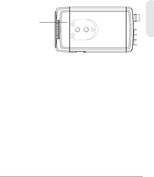
Rev. 2 6 G-113079-002
02/07
Español
Montaje de la cámara
Aparecen unos puntos de montaje marcados en la parte
superior de la cámara para montarla sobre un soporte
o trípode. Están diseñados para admitir tornillos de
montaje de tamaño ¼ x 20 estándar. Se puede
desatornillar este soporte y montarlo en el lateral opuesto
de la cámara, según el uso que se vaya a dar. El soporte
debe aguantar el peso de la cámara y su lente.
Nota Algunas normas de instalación establecen
que el soporte debe poder soportar hasta
cuatro veces el peso combinado de la
cámara y su lente.
Figura 5 Montaje de la cámara
Conexión de la cámara
Nota Compruebe la fuente de alimentación de la
toma externa antes de conectar la corriente a
la cámara.
1. Conecte el conector de VIDEO situado en la parte
posterior de la cámara al conector de entrada de vídeo
de su monitor.
2. Conecte la cámara a una fuente de alimentación
adecuada para su instalación.
HCD484L, HCD484LX: fuente de alimentación de
12 V CC o 24 V CA
HCD485LX: fuente de alimentación de 230 V
Desatornille los tres
tornillos de seguridad
del soporte y fíjelo
firmemente al otro
lateral de la cámara.
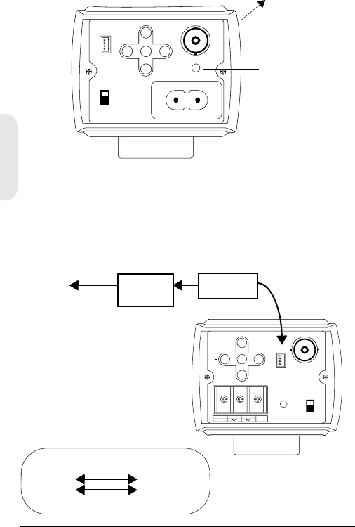
Rev. 2 7 G-113079-002
02/07
3. Conecte la fuente de alimentación. Se encenderá el
indicador luminoso de alimentación (PWR) para indicar
que la cámara recibe corriente. Si no se enciende,
compruebe las conexiones y la fuente de alimentación.
Figura 6 Conexiones de la cámara
Conexiones del control remoto
La cámara día/noche en color L-Series puede controlarse
de forma remota mediante una conexión RS485.
Figura 7 Conexión de cámara RS485
PWR
VSD
DC
VIDEO
~207-253VAC 50HZ
REMOT E UP
DOWN
MENU
+
Conexión
al monitor
Indicador luminoso
de alimentación
Versión mostrada, red (230 V)
(HCD485L)
-+
GND
DC 12V
AC 24V
PWR VSD
DC
VIDEO
+
UP
DOWN
MENU REMOTE
Conversor RS485
TRx+
TRx-
Cable de 4
patillas
3TRx+
2TRx-
Cable de
4patillas
Conectar al
puerto serie
(COM1 o
COM2)
Cable
serie
Convenciones del cable
de 4 patillas
1. Rojo No utilizado
2. Azul TRx-
3. Amarillo TRx+
4. Negro No utilizado
Conversor
RS485

Rev. 2 8 G-113079-002
02/07
Español
Programación
Menú en pantalla (OSD)
Pulse MENU brevemente para confirmar la configuración
de funcionamiento actual. La información (consulte la
Figura 8) desaparecerá tras unos segundos si no se pulsa
ningún botón.
Aunque el mensaje desaparezca, el título o ID de la cámara
seguirá en pantalla si se selecciona en el submenú
CAMERA ID. Para desactivar el título o ID de la cámara:
• Con la comunicación externa, cambie la posición en la
pantalla. Las opciones son
Bottom right, Bottom left, Top left, Top right,
Non display
• Si no necesita ver el menú en pantalla operativo
(por ejemplo, para un panel de superposición de texto
externo), se puede configurar como OFF
(desactivado) en cualquier momento, utilizando el
control remoto con conexión RS485.
Figura 8 Visualización de la información del menú en pantalla
CAMERA ID/TITLE
Back Light WB Mode
Back Light se muestra si se activa BLC (consulte BLC
MODE (Compensación de contraluz)..
Shutter Speed se muestra si se modifica la velocidad
predeterminada del obturador.
WB Mode siempre se muestra.
Shutter Speed
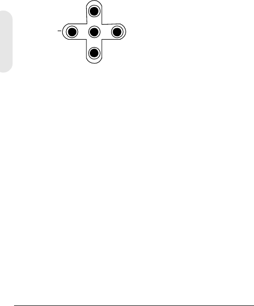
Rev. 2 9 G-113079-002
02/07
Funciones del menú en pantalla
Utilice los controles del menú en pantalla (OSD) para
programar la cámara.
1. Mantenga pulsado el botón central MENU durante dos
segundos para mostrar el menú de configuración.
2. Pulse los botones UP o DOWN para seleccionar
una opción.
3. Pulse el botón MENU para acceder al submenú
seleccionado.
4. Pulse los botones + o – para aumentar/disminuir el
valor del elemento seleccionado.
Figura 9 Controles del menú en pantalla
Almacenamiento de la configuración
Primer método: Una vez configurados los ajustes deseados:
1. Pulse MENU durante dos segundos. Aparecen dos
mensajes en lugar del menú SETUP:
SAVE? si se han cambiado los ajustes. Si selecciona
SAVE se cerrará el modo de configuración y se
guardarán los cambios.
QUIT? si no se han cambiado los ajustes.
Al seleccionar QUIT se cierra el modo de
configuración sin guardar los valores.
2. Pulse + o – para seleccionar SAVE o QUIT y pulse
después MENU para salir del modo de configuración.
Pulse UP o DOWN para cancelar SAVE/QUIT y volver
al menú de configuración SETUP.
Segundo método: Seleccione EXIT MENU en SETUP
MENU, pulse MENU, y seleccione después SAVE AND
EXIT para guardar los ajustes cambiados y cerrar el menú.
Seleccione EXIT para salir sin guardar los ajustes.
UP
DOWN
MENU
+
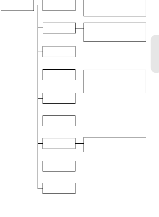
Rev. 2 10 G-113079-002
02/07
Español
Configuración de la cámara
Estructura del menú en pantalla (OSD)
El sistema de menús de la cámara día/noche en color
L-Series consta de un menú de configuración principal
para una programación sencilla.
SETUP MENU CAMERA ID
ELC/ALC Mode
Shutter Speed
White Balance
AGC Control
Nightshot
Sync Control
Restore Default
Exit Menu
Camera ID, Title
Display Position
ELC Mode: AUTO, MANUAL
ALC Mode: VSD LENS
DC LENS (LEVEL)
ATW, Outdoor, Indoor, User,
Fluorescent
AWC (Auto, Manual, Push&Lock)
MWB (RED, BLUE)
AUTO, INTERNAL,
LineLock (V.PH)
Menú principal Submenús Opciones
1
2
3
4
5
6
7
8

Rev. 2 11 G-113079-002
02/07
Elemento
de menú Opción Descripción
1CAMERA
ID 000 (desact.),
001 … 255 0: Desactiva la pantalla de ID.
Consulte Configuración del
control de la sincronización
para obtener más información.
2 ELC/ALC
Mode ELC …
ALC … Consulte Modo de control de
luz ELC / ALC para obtener
más información.
3Shutter
Speed 1/60 NTSC
(1/50 PAL) FL
1/250
1/500
1/1000
1/2000
1/4000
1/10000
1/30000
1/50000
Ajusta la intensidad de luz con
una alta velocidad de
obturador.
FL: Elimina el parpadeo de
una imagen.
Este campo no admite ajuste
cuando la cámara está en
ELC MODE. El valor
predeterminado es Auto.
4White
Balance ATW (Modo de detec-
ción automática del
balance de blancos)
AWC (Modo de con-
trol automático del
balance de blancos)
MWB (Balance de
blancos automático)
Los modos del balance de
blancos predefinidos son
Outdoor, Indoor, User,
Fluorescent Consulte
Configuración del control del
balance de blancos para
obtener más información.
5AGC
Control OFF
10 dB
12 dB … 38 dB
Ajusta el valor máximo del
control automático de
ganancia (AGC). Si el AGC se
configura como OFF, la
opción Nightshot no está
disponible.
6 Nightshot Establece el comportamiento
de la cámara en condiciones
de poca iluminación.
7Sync.
Control AUTO
INTERNAL
LineLock (V.Phase)
Consulte Configuración del
control de la sincronización
para obtener más información.
8Restore
Default Vuelve a cargar la
configuración predeterminada
de fábrica. Si no ha realizado
ningún cambio, no podrá
seleccionar este ajuste.

Rev. 2 12 G-113079-002
02/07
Español
Añadir un ID o título de cámara
Los ID de cámara resultan muy útiles cuando hay varias
cámaras en la red. Para añadir un ID o título de cámara,
entre en el SETUP MENU, seleccione CAMERA ID y pulse
MENU.
Figura 10 Añadir un ID o título de cámara
Introducción de un título de cámara
1. Vaya al primer carácter de TITLE: utilizando los contro-
les de menú + o – de la parte posterior de la cámara.
2. Utilice los controles de menú UP, DOWN, +, – para
seleccionar el primer carácter del título y pulse
después la tecla MENU para establecer el carácter.
Elemento
de menú
Opción Descripción
CAM ID 0
001 …
255
El número asignado a cada cámara de la
red, de 000 a 255.
0: El ID no aparece en la pantalla.
DISPLAY TITLE
ID
OFF
Seleccione qué elemento desea que
aparezca en pantalla (TITLE, ID o nada).
POSITION T.R.
B.R.
B.L.
T.L.
NO DISP
Seleccione dónde desea que aparezca el ID
o el título de la cámara en pantalla (superior
derecha (T.R.), inferior derecha (B.R.),
superior izquierda (T.L.), inferior izquierda
(B.L.) o que no aparezca (NO DISP).
TITLE Introduzca un nombre para la cámara con
un máximo de 10 caracteres, incluidos
espacios.
RETURN Pulse MENU para volver a la pantalla
principal SETUP MENU.
CAM ID: 002
DISPLAY: TITLE
POSITION: T.R.
1 2 3 4 5 6 7 8 9 A B C D E F
G H I J K L M N P Q R S T U V W
X Y Z a b c d e f g h i j k l m
n o p q r s t u v w x y z , . :
; ~ ! ? $ % * & / < > + - = ■
TITLE: HCD484■■
RETURN

Rev. 2 13 G-113079-002
02/07
3. Seleccione la siguiente posición del carácter del título
con los controles de menú + o – y repita después los
pasos 2 y 3 hasta completar el título de la cámara.
4. Seleccione RETURN y pulse MENU para aceptar los
cambios y volver a la pantalla principal SETUP MENU.
Configuración de la optimización de luz
de la cámara
Modo de control de luz ELC / ALC
Figura 11 Configuración de la iluminación de la cámara
Para configurar el modo de la lente, la compensación de
contraluz y la máscara negra:
Elemento de
menú Opción Descripción
EE MODE:
ELC MODE
AUTO
MANUA
L
Para una lente manual (fija):
AUTO: la lente iris utiliza la exposición
electrónica automáticamente:
MANUAL: ajuste la lente iris cambiando
manualmente la alta velocidad del
obturador.
EE MODE:
ALC MODE
VSD
LENS
DC
LENS
Para una lente autoiris automática:
VSD: seleccione esta opción para una
lente de tipo vídeo.
DC LENS: seleccione esta opción para
una lente de tipo control directo. Ajuste
el nivel con LEVEL hasta que la imagen
deje de estar demasiado oscura
odemasiado luminosa.
BLC MODE
(Com-
pensación de
contraluz).
OFF
LOW BL
MID. BL
HIGH BL
Evita que el objeto situado en el
centro de la imagen se oscurezca
(efecto silueta) cuando hay demasiada
luz detrás.
RETURN Pulse MENU para volver a SETUP MENU.
<ELC/ALC MODE>
EE MODE: ALC MODE
DC LENS
LEVEL 04
BLC MODE: OFF
RETURN

Rev. 2 14 G-113079-002
02/07
Español
Configuración del control del balance de blancos
El balance automático de blancos garantiza que la
integridad del color se mantiene dentro del rango de
colores de 2.800° a 8.000°K:
Figura 12 Control del balance de blancos
Elemento
de menú Descripción
ATW (Modo de
detección
automática del
balance de
blancos)
Sistema de retroalimentación que alinea
automáticamente el balance de blancos
(de 2.800 a 8.000 K).
AWC (Modo de
control
automático del
balance de
blancos)
Tiene una velocidad de funcionamiento más
alta que ATW. Normalmente se utiliza en
exteriores o en zonas con condiciones de
iluminación variables. Las opciones son:
AUTO: AWC funciona todo el tiempo
MANUAL: PUSH Pulse MENU para iniciar el
funcionamiento en modo AWC
MANUAL: LOCK Suelte MENU para ajustar el
balance de blancos de la escena que va
a grabar
INDOOR Valor predefinido para escenas en interiores en
general (3.200 K)
FLUORESCENT Entornos de oficina con luz fluorescente o de
tungsteno. Proporciona el rango dinámico más
bajo de todos los valores predefinidos (4.200 K)
USER FIXED Valor predefinido (4.700 K)
OUTDOOR Valor predefinido para escenas en exteriores y
con un alto grado de contraste, donde la
cámara enfoca la parte más oscura (6.300 K).
MWB
(Modo manual) RED: 0 a 20
BLUE: 0 a 20
RETURN Pulse MENU para volver a SETUP MENU.
<WHITE BALANCE>
WB MODE: MWB
WB CONT: R=00
B=00
RETURN

Rev. 2 15 G-113079-002
02/07
Configuración del control de grabación
nocturna
El menú Nightshot le permite establecer la reacción de la
cámara a los cambios en las condiciones de iluminación,
menos luz, y cuándo la cámara cambia entre los modos
Night y Day. AGC debe estar activado para que se active
Nightshot.
Figura 13 Control del balance de blancos
Elemento
de menú Descripción
MODE AUTO: La cámara suprime o inserta el filtro “de corte”
IR mediante la detección automática de la luminancia.
ON: el filtro “de corte IR” se suprime (modo Night)
OFF: se inserta el filtro “de corte” IR (modo Day)
DET.TIME Establece el tiempo—5 a 60 segundos—antes de
que la cámara cambie a modo Day o Night tras
detectar una situación de poca iluminación.
MODE debe establecerse en AUTO.
D->N THD
(Umbral)
Determina el nivel de detección de poca
iluminación—1 a 9—cuando la cámara cambia
a modo Night. Cuanto más bajo sea el valor, menos
luz tendrá que haber para que la cámara cambie.
MODE debe establecerse en AUTO.
Nota El valor de D-> THD debe establecerse
como mínimo en 2 unidades menos que el
de N->D THD.
N->D THD
(Umbral)
Determina el nivel de detección de poca
iluminación —1 a 9—cuando la cámara cambia
a modo Day. Cuanto más alto sea el valor, más
brillantes tendrán que ser las condiciones de
iluminación para que la cámara cambie de modo.
MODE debe establecerse en AUTO.
DN COLOR Establece el modo de color como B/W (monocromo)
o COLOR en modo Night.
MODE debe establecerse en AUTO u ON.
RETURN Pulse MENU para volver a SETUP MENU.
<NIGHTSHOT>
MODE: AUTO
DET.TIME: 10 s
D->N THD 2
N->D THD 5
DN COLOR BW
RETURN
Rev. 2 16 G-113079-002
02/07
Español
Configuración del control de la
sincronización
Para sincronizar el impulso de la sincronización del
intervalo vertical de la cámara con otros dispositivos a fin
de reducir el efecto de líneas horizontales que se
desplazan en el monitor.
Figura 14 Configuración del control de la sincronización
Cierre del menú de configuración
Para cerrar el menú SETUP
Figura 15 Exit Menu
Elemento
de menú
Descripción
INTERNAL Cuando no se requiere la sincronización por fase
de red (line lock).
LINELOCK Ajuste la fase adecuada:
V.PH: 000 a 300 (el valor predeterminado es 0)
Nota La opción Line lock no está disponible con
alimentación de 12 V CC.
AUTO La cámara detecta automáticamente la sincronización.
RETURN Pulse MENU para volver a SETUP MENU.
Elemento
de menú Descripción
SAVE AND EXIT Pulse MENU para guardar los cambios y salir.
EXIT Pulse MENU para salir sin guardar los cambios.
RETURN Pulse MENU para volver a SETUP MENU.
<SYNC. CONTROL>
SYNC MODE: LINELOCK
V.PH 000
STEP=10
RETURN
<EXIT MENU>
SAVE AND EXIT
EXIT
RETURN

Rev. 2 17 G-113079-002
02/07
Garantía y servicio
Conforme a todos los términos dispuestos en la garantía del
producto, durante el período de garantía, Honeywell reparará
o sustituirá gratuitamente a su entera discreción, cualquier
producto defectuoso que se haya devuelto previo pago del envío.
Si surgiera un problema con un producto Honeywell, llame al
servicio de atención al cliente al 1.800.796.CCTV (sólo en
Norteamérica) para obtener ayuda o para solicitar un número de
autorización de devolución de mercancía (RMA). En Europa
y Reino Unido, póngase en contacto con su distribuidor Honeywell.
Asegúrese de que tiene a mano el número de modelo, número
de serie y la naturaleza del problema para el representante del
servicio técnico.
Debe disponer de la autorización previa para cualquier devolución,
sustitución o reembolso. Los artículos enviados a Honeywell sin
un número de autorización de devolución de mercancía (RMA)
claramente indicado pueden ser rechazados.
Especificaciones
Nota Estas especificaciones se aplican a todos los
modelos, a menos que se indique otra cosa.
HCD484L HCD484LX
HCD485LX
Funcionamiento
Sensor de
imagen:
CCD Super HAD de tipo 1/3"
Estándar de
vídeo:
NTSC PAL
Sistema de
barrido:
525 líneas, 2:1
entrelazado
625 líneas, 2:1
entrelazado
Número de
píxeles (H x V):
768 x 494 752 x 582
Iluminación
mínima:
< 0,1 lux @ F1.2
(50 IRE, AGC ON, filtro IR desactivado, B/N)
Resolución
horizontal:
480 TVL 480 TVL

Rev. 2 18 G-113079-002
02/07
Español
Salida de vídeo: 1 Vp-p @ 75 Ohmios
Sistema de
sincronización:
Interno, por fase de red, automático
Relación Señal/
Ruido:
> 50 dB
Control
automático de
ganancia (AGC):
Desactivado, 10 a 38 dB
ALC: EE/VSD/DC
Obturador
electrónico
automático (AES):
1/60 - 1/100.000 s 1/50 - 1/100.000 s
Montaje de lente: Montaje C/CS (ajustable)
Balance de
blancos (AWB):
ATW, AWC, Indoor, Outdoor, Fluorescent,
User, MWB
Compensación de
contraluz:
Desactivada, baja, media, alta
Instalación eléctrica
Tensión de
entrada
HCD484L, HCD484LX: 12 V CC/24 V CA
HCD485LX: 230 V CA
Rango de tensión
de entrada:
HCD484L, HCD484LX: 11-16 V CC/17-28 V CA
HCD485LX: 230 V CA ± 10%
Consumo de
energía:
HCD484L, HCD484LX: 3,5 W (máx.)
HCD485LX: 4.5 W (máx.)
Mecánica
Dimensiones:
(An x Al x F)
HCD484L, HCD484LX: 68 x 56 x 120 mm
(2,68 x 2,2 x 4,72 pulgadas)
HCD485LX: 68 x 56 x 140 mm
(2,68 x 2,2 x 5,51 pulgadas)
Peso: HCD484L, HCD484LX: 0,38 kg (0,84 libras)
HCD485LX: 0,41 kg (0,90 libras)
Tempera tura
Temperatura
medioambiental:
En funcionamiento: entre -10 y 50°C
(entre 14 y 122°F)
Almacenamiento: entre -20 y 70°C
(entre -4 y 158°F)
Reglamentación
Emisiones: FCC, CE (EN55013)
Inmunidad: CE (EN50130-4)
Seguridad: UE: Directiva 73/23/CEE sobre baja tensión
HCD484L HCD484LX
HCD485LX

© 2007 Honeywell International Inc. Todos los derechos reservados. No se permite
la reproducción de este documento, ya sea parcial o total, sin autorización previa por
escrito de Honeywell Video Systems. Se estima que la información contenida en
esta publicación es precisa en todos los aspectos. Ahora bien, Honeywell Video
Systems no se responsabiliza de las consecuencias derivadas del uso de la misma.
La información contenida en este documento está sujeta a cambios sin previo aviso.
Se contempla la posibilidad de publicar revisiones o nuevas versiones de esta
publicación para incorporar dichos cambios.
www.honeywellvideo.com
+1.800.796.CCTV (sólo Norteamérica)
HVSsupport@honeywell.com
Documento G-113079-002 02/07 Rev. 2
Honeywell Video Systems
(Oficina Central)
2700 Blankenbaker Pkwy, Suite 150
Louisville, KY 40299, EE.UU.
www.honeywellvideo.com
℡ +1.800.796.2288
Honeywell Security Australia Pty Ltd.
Unit 5, Riverside Centre
24-28 River Road West
Parramatta, NSW 2150, Australia
www.ademco.com.au
℡ +61.2.8837.9300
Honeywell Security Asia Pacific
33/F Tower A, City Center, 100 Zun Yi
Road
Shanghai 200051, China
www.security.honeywell.com/cn
℡ +86 21.2527.4568
Honeywell Security Asia
Flat A, 16/F, CDW Building
388 Castle Peak Road
Tsuen Wan, N.T., Hong Kong
www.security.honeywell.com/hk
℡ +852.2405.2323
Honeywell Security France
Parc Gutenberg, 8, Voie La Cardon
91120, Palaiseau, Francia
www.honeywell.com/security/fr
℡ +33.01.64.53.80.40
Honeywell Security Italia SpA
Via Treviso 2 / 4
31020 San Vendemiano
Treviso, Italia
www.honeywell.com/security/it
℡ +39.04.38.36.51
Honeywell Security España
Mijancas 1. 3a Planta
P.Ind. Las Mercedes
28022 Madrid, España
www.honeywell.com/security/es
℡ +34.902.667.800
Honeywell Video Systems
Northern Europe
Netwerk 121
1446 WV Purmerend, Países Bajos
www.SecurityHouse.nl
℡ +31.299.410.200
Honeywell Video Systems UK Ltd.
Aston Fields Road, Whitehouse Ind Est
Runcorn, Cheshire, WA7 3DL, UK
www.honeywellvideo.com
℡ +0844 8000 235
Honeywell Security South Africa
Unit 6 Galaxy Park, 17 Galaxy Avenue
Linbro Park, P.O. Box 59904
2100 Kengray, Johannesburgo
Sudáfrica
www.honeywell.co.za
℡ +27.11.574.2500
Honeywell Security Deutschland
Johannes-Mauthe-Straße 14
D-72458 Albstadt, Alemania
www.honeywell.com/security/de
℡ +49.74 31.8 01.0
Honeywell Security Poland
Chmielewskiego 22a, 70-028
Szczecin, Polonia
www.ultrak.pl
℡ +48.91.485.40.60
Honeywell Security Czech Republic
Havránkova 33, Brno
Dolní Heršpice, 619 00
República Checa
www.olympo.cz
℡ +420.543.558.111
Honeywell Security Slovakia Republic
Vajnorská 142, 83104 Bratislava
Eslovaquia
www.olympo.sk
℡ +421.2.444.54.660

Documento G-113079-002 – 02/07 – Rev 2
Telecamera
L-Series Color
Day/Night
HCD484L HCD484LX
HCD485LX
Guida per l'utente
NTSC PAL
Italiano

Revisioni
Edizione Data Revisioni
1.00 10/06 Nuovo documento
2 02/07 Modificato 900.0842 documento
numero del pezzo; Avvertimento
aggiunto alla pagina iii.
Rev 2 ii G-113079-002
02/07
Rev 2 iii G-113079-002
02/07
Avvertenze
Le operazioni di installazione e assistenza dovranno
essere effettuate solo da personale esperto e qualificato, al
fine di rispettare la conformità con tutte le normative locali
e mantenere la validità della garanzia.
ATTENZIONE! I modelli a 12 VCC/24 VCA richiedono
l'utilizzo di un adattatore di
alimentazione di Classe 2 in elenco
UL o certificato CSA per la conformità
agli standard di sicurezza elettrica.
Dove viene usato come dispositivo di scollegamento una
spina della RETE ELETTRICA o un apparecchio
accoppiatore, tale dispositivo dovrà rimanere prontamente
operativo.
Direttiva WEEE (Waste Electrical and Electronic
Equipment, Smaltimento di apparecchiature elettriche
ed elettroniche). Corretto smaltimento del prodotto
(applicabile nell'Unione Europea e in altri paesi europei
con sistemi di raccolta diversificata dei rifiuti).
Lo smaltimento di questo prodotto, al termine della sua
vita utile, è soggetto alle leggi, alle normative e alle
procedure applicabili localmente.
Spiegazione dei simboli grafici
RISCHIO DI SCOSSA
ELETTRICA
NON APRIRE
ATTENZIONE: PER RIDURRE IL RISCHIO DI SCOSSA
ELETTRICA, NON RIMUOVERE IL COPERCHIO.
ALL'INTERNO DELL'UNITÀ NON SONO PRESENTI
PARTI LA CUI MANUTENZIONE POSSA ESSERE
ESEGUITA DALL'UTENTE. PER ASSISTENZA
RIVOLGERSI AL PERSONALE QUALIFICATO.
QUESTO SIMBOLO INDICA CHE
ALL'INTERNO DELL'UNITÀ
È PRESENTE UN LIVELLO DI
TENSIONE PERICOLOSA CHE
COSTITUISCE RISCHI DI SCOSSA
ELETTRICA.
QUESTO SIMBOLO INDICA CHE
L'UNITÀ È ACCOMPAGNATA DA
IMPORTANTI ISTRUZIONI
OPERATIVE E DI GESTIONE.
ATTENZIONE
Italiano

Rev 2 iv G-113079-002
02/07
Dichiarazione di conformità alle
norme FCC
Informazioni per l'utente: questa apparecchiatura è stata
sottoposta a test ed è risultata conforme ai limiti previsti per
i dispositivi digitali della Classe A. In base alla Parte 15
della normativa FCC, questi limiti sono stati fissati per
fornire un'adeguata protezione contro interferenze dannose
nelle installazioni commerciali. Questa apparecchiatura
genera, utilizza e può emettere radiofrequenze e, se non
viene installata e utilizzata in conformità alle istruzioni,
può causare interferenze alle comunicazioni radio.
Il funzionamento di questa apparecchiatura nelle
installazioni residenziali potrebbe provocare interferenze
dannose. In tal caso, l'eliminazione delle interferenze
è a carico dell'utente.
Attenzione Cambiamenti o modifiche non
espressamente approvate dalla parte
responsabile per la conformità potrebbero
invalidare l'autorizzazione dell'utente
all'utilizzo dell'apparecchiatura.
Dichiarazione di conformità del
produttore
Il produttore dichiara che l'apparecchiatura fornita con
la presente Guida è conforme ai requisiti di protezione
essenziali definiti dalla normativa EMC (Electromagnetic
Compatibility, Compatibilità elettromagnetica) 89/336/EEC
e dalla normativa LVD (Low Voltage Directive, Direttiva
Bassa Tensione) 73/23 EEC, in conformità con i requisiti
degli standard EN 55013 relativi alle emissioni.

Rev 2 G-113079-002
02/07
Italiano
Sommario
Introduzione . . . . . . . . . . . . . . . . . . . . . . . . . . . . . . . 1
Caratteristiche . . . . . . . . . . . . . . . . . . . . . . . . . . . . 1
Prima di iniziare . . . . . . . . . . . . . . . . . . . . . . . . . . . 2
Aprire la confezione . . . . . . . . . . . . . . . . . . . . . . . . 2
Funzioni della telecamera . . . . . . . . . . . . . . . . . . . . 3
Installazione . . . . . . . . . . . . . . . . . . . . . . . . . . . . . . . 4
Selezione dell'obiettivo . . . . . . . . . . . . . . . . . . . . . 4
Regolazione della messa a fuoco posteriore . . . . 5
Montaggio della telecamera. . . . . . . . . . . . . . . . . 6
Collegamento della telecamera . . . . . . . . . . . . . . 6
Connessioni telecomando . . . . . . . . . . . . . . . 7
Programmazione . . . . . . . . . . . . . . . . . . . . . . . . . . . 8
Menu OSD (On-Screen Display) . . . . . . . . . . . . . 8
Funzioni del menu OSD . . . . . . . . . . . . . . . . . . 9
Salvataggio delle impostazioni . . . . . . . . . . . . 9
Impostazione della telecamera . . . . . . . . . . . . . . 10
Struttura del menu OSD . . . . . . . . . . . . . . . . . 10
Aggiunta di un ID telecamera o di un titolo . . 12
Impostazione dell'ottimizzazione
illuminazione telecamera . . . . . . . . . . . . . . . . 13
Modalità ELC / ALC . . . . . . . . . . . . . . . . . 13
Impostazione del controllo del
bilanciamento del bianco . . . . . . . . . . . . . 14
Impostazione del controllo Nightshot . . . . . . 15
Impostazione del controllo Sync . . . . . . . . . . 16
Chiusura del menu Setup . . . . . . . . . . . . . . . 16
Garanzia e assistenza . . . . . . . . . . . . . . . . . . . . . . 17
Specifiche . . . . . . . . . . . . . . . . . . . . . . . . . . . . . . . . 17
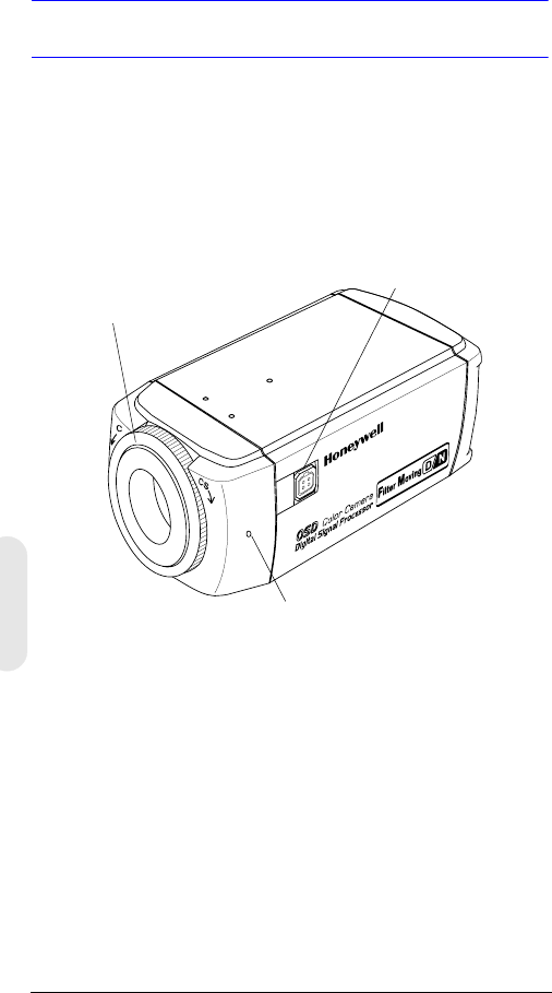
Rev 2 1 G-113079-002
02/07
Introduzione
Le telecamere Honeywell L-Series Day/Night Color offrono
elevata qualità delle immagini e risoluzione grazie
all'utilizzo di un sensore immagini CCD interline transfer
da 1/3 pollice altamente sensibile.
Immagine 1 Panoramica della telecamera
Caratteristiche
• CCD Super HAD 1/3"
• Adattatore dell'attacco dell'obiettivo regolabile C/CS
• Eccellente rapporto segnale/disturbo, superiore a 50 dB
• Illuminazione minima pari a 0,1 lux (F1.2, 50 IRE,
Filtro IR Off, B/N)
• Compatibile con obiettivo Video Iris (VSD) o Auto Iris
Direct Drive (DC)
• Controllo menu OSD
• Riproduzione true color da diverse sorgenti luminose
• Telecomando programmabile con connessione RS485
Connettore per l'attacco
dell'obiettivo Auto Iris
Vite di fermo: allentare l'anello di bloccaggio
con un cacciavite Phillips per regolare
l'anello di montaggio.
Adattatore attacco C/CS:
Attacco C: ruotare in senso antiorario
Attacco CS: ruotare in senso orario

Rev 2 2 G-113079-002
02/07
Italiano
Prima di iniziare
Aprire la confezione
Verificare che la confezione contenga tutti gli articoli
elencati nel modulo d'ordine e nella ricevuta. La confezione
del modello L-Series Day/Night contiene, oltre a questa
Guida per l'utente:
• Una telecamera L-Series Day/Night Color
• Un cavo di connessione a 4 pin
• Un attacco per l'obiettivo Auto Iris
In caso di parti mancanti o danneggiate, contattare il
rivenditore o l'Assistenza Clienti Honeywell (vedere la
sezione Contatti sul retro del manuale).
Nota Per completare l'installazione sarà inoltre
necessario un cacciavite Phillips.
Prima di procedere al montaggio della
telecamera L-Series Day/Night Color,
leggere la guida con attenzione.
Conservare la guida per riferimento
futuro.
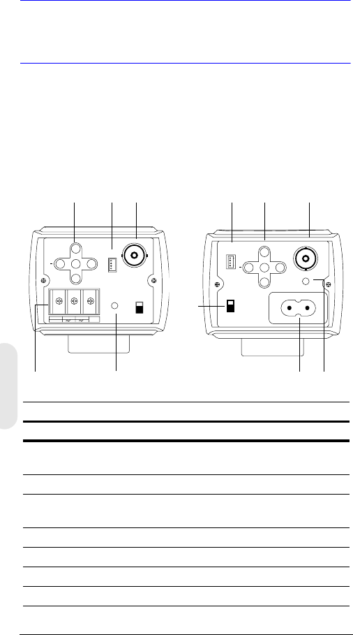
Rev 2 3 G-113079-002
02/07
Impostazioni della
telecamera
Funzioni della telecamera
Immagine 2 Vista posteriore della telecamera
PWR
VSD
DC
VIDEO
~207-253VAC 50HZ
REMOTE UP
DOWN
MENU
+
-+
GND
DC 12V
AC 24V
PWR VSD
DC
VIDEO
+
UP
DOWN
MENU REMOTE
Legenda
#Descrizione
1Interruttore di selezione per l'obiettivo Auto Iris, VSD per
Video o DC per Direct Drive
2Connettore per l'uscita Video
3Connettore per l'alimentazione (24 VCA: 3 terminali) - Solo
modello a bassa tensione
4Indicatore LED alimentazione
5Connettore RS485 per telecomando
6Controllo menu (vedere “Programmazione” a pagina 8)
7Connettore alimentazione di rete 230 V
Alimentazione di rete 230 V -
Tensione di alimentazione
(HCD485LX)
Bassa tensione
(HCD484L, HCD484LX)
2
4
1
5
3
62
4
56
7
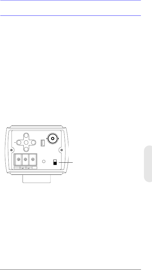
Rev 2 4 G-113079-002
02/07
Italiano
Installazione
Selezione dell'obiettivo
Gli obiettivi Varifocal Auto Iris (Direct Drive o Video Drive)
sono collegati alla telecamera tramite una presa quadrata
a 4 pin posizionata sul lato della telecamera.
1. Impostare l'interruttore VSD/DC sul retro della
telecamera.
Nel caso di obiettivo Video Drive, impostare
l'interruttore su VSD.
Nel caso di obiettivo Direct Drive, impostare
l'interruttore su DC.
2. Impostare EE MODE su ALC MODE nel menu OSD
(vedere ALC MODE).
Obiettivo Auto Iris con amplificatore: impostare
VSD LENS nel menu OSD.
Obiettivo Auto Iris senza amplificatore: impostare
DC LENS nel menu OSD. Regolare LEVEL per evitare
oscillazioni.
-+
GND
DC 12V
AC 24V
PWR VSD
DC
VIDEO
+
UP
DOWN
MENU REMOTE
Modello a bassa tensione
(HCD484L, HCD484LX)
VSD = Obiettivo Auto Iris con
amplificatore incorporato
(obiettivo tipo video)
DC = Obiettivo Auto Iris senza
amplificatore (obiettivo tipo DC)
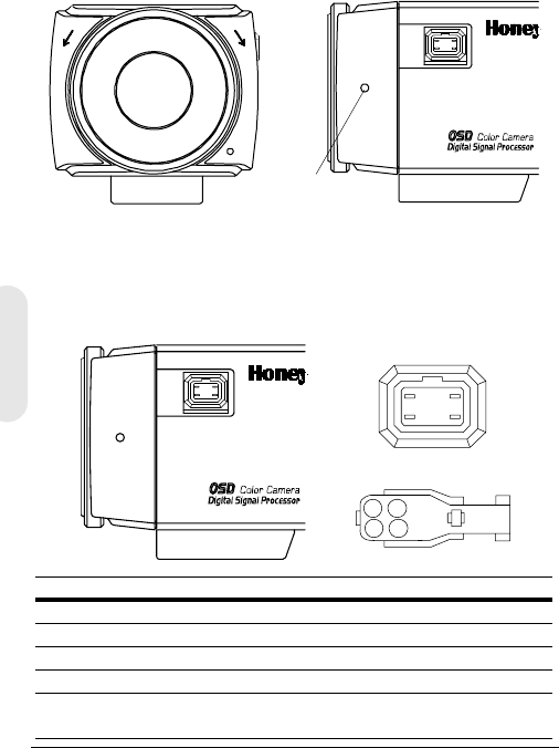
Rev 2 5 G-113079-002
02/07
Regolazione della messa a fuoco
posteriore
La regolazione della messa a fuoco posteriore si trova
sul lato anteriore dell'alloggiamento della telecamera
e consente di regolare la distanza focale posteriore o la
messa a fuoco dell'immagine.
La gamma di regolazione consente di utilizzare attacchi C o
CS dell'obiettivo senza la necessità di un anello distanziatore.
Immagine 3 Attacco C/CS
1. Allentare la vite di fermo con un cacciavite Phillips.
2. Regolare l'anello di messa a fuoco per mettere a fuoco
l'immagine.
3. Serrare nuovamente la vite di fermo.
Immagine 4 Definizione di pin dell'obiettivo Auto Iris
CCS
Vite di fermo
1
23
4
21
43
Pin Obiettivo DC (Direct Drive) Obiettivo Video (VSD)
1 CTRL - Alimentazione (+12 V)
2CTRL + NC
3 DRV + Segnale video
4DRV - GND
Impostare l'interruttore di
selezione su DC.
Impostare l'interruttore di
selezione su VSD.
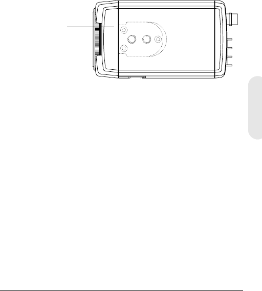
Rev 2 6 G-113079-002
02/07
Italiano
Montaggio della telecamera
I punti di innesto si trovano nella parte superiore della
telecamera per il montaggio su staffa o treppiede. Sono
adatti a viti di montaggio di dimensioni standard 1/4 x 20.
Questa staffa può essere svitata e montata sul lato opposto
della telecamera, in base alle esigenze. La staffa di
montaggio deve essere in grado di sopportare il peso della
telecamera e dell'obiettivo.
Nota Alcuni codici di installazione stabiliscono che
la staffa di montaggio deve essere in grado di
supportare un peso pari a quattro volte il
peso totale di telecamera e obiettivo.
Immagine 5 Montaggio della telecamera
Collegamento della telecamera
Nota Prima di alimentare la telecamera, verificare
che la fonte di alimentazione esterna sia
adeguata.
1. Collegare il connettore VIDEO sul retro della
telecamera al connettore ingresso video del monitor.
2. Collegare la telecamera a un alimentatore adatto per
l'installazione.
HCD484L, HCD484LX: alimentatore da 12 VCC
o24VCA
HCD485LX: alimentatore da 230 V
Svitare le tre viti di
fissaggio della staffa
e montare la staffa
sull'altro lato della
telecamera.
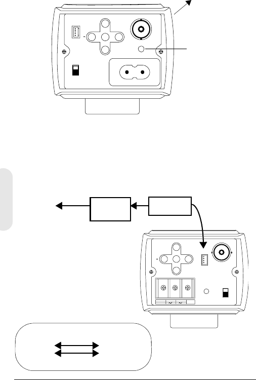
Rev 2 7 G-113079-002
02/07
3. Inserire la spina nella presa. Il LED di alimentazione
(PWR) si accende, segnalando che la telecamera
è alimentata. In caso contrario, verificare le
connessioni e la fonte di alimentazione.
Immagine 6 Connessioni della telecamera
Connessioni telecomando
La telecamera L-Series Day/Night Color può essere
utilizzata con il telecomando, tramite connessione RS485.
Immagine 7 Connessione telecamera tramite RS485
PWR
VSD
DC
VIDEO
~207-253VAC 50HZ
REMOT E UP
DOWN
MENU
+
Collegamento
al monitor
LED alimentazione
Versione alimentazione di rete (230 V)
(HCD485L)
-+
GND
DC 12V
AC 24V
PWR VSD
DC
VIDEO
+
UP
DOWN
MENU REMOTE
Convertitore RS485
TRx+
TRx-
Cavo a 4 pin
3TRx+
2TRx-
Cavo a 4 pinCollegamento
alla porta
seriale (COM1
o COM2)
Cavo
seriale
Legenda cavo a 4 pin
1. Rosso Non utilizzato
2. Blu TRx-
3. Giallo TRx+
4. Nero Non utilizzato
Convertitore
RS485

Rev 2 8 G-113079-002
02/07
Italiano
Programmazione
Menu OSD (On-Screen Display)
Premere brevemente MENU per confermare l'impostazione
dell'operazione corrente. Le informazioni (vedere
Immagine 8) scompaiono dopo alcuni secondi se non
viene premuto nessuno dei pulsanti.
Anche se il messaggio OSD scompare, l'ID telecamera
o il titolo rimane visualizzato, se è stato selezionato nel
sottomenu CAMERA ID. Per disattivare la visualizzazione
dell'ID telecamera o del titolo, eseguire una delle
operazioni sottostanti.
• Utilizzando la comunicazione esterna, cambiare la po-
sizione di visualizzazione. Le opzioni disponibili sono:
In basso a destra, in basso a sinistra, in alto a sinistra,
in alto a destra, nessuna visualizzazione.
• Se non è necessario visualizzare l'OSD di
funzionamento (ad esempio, in presenza di una
scheda overlay esterna), impostarlo sempre su OFF
utilizzando un telecomando e una connessione RS485.
Immagine 8 Visualizzazione informazioni OSD
CAMERA ID/TITLE
Back Light WB Mode
Back Light viene visualizzata se è abilitata la compensazione
di retroilluminazione (BLC, Backlight Compensation)
(vedere BLC MODE (Backlight Compensation).
Shutter Speed viene visualizzata se si modifica la velocità
otturatore predefinita.
WB Mode viene sempre visualizzata.
Shutter Speed

Rev 2 9 G-113079-002
02/07
Funzioni del menu OSD
Utilizzare i controlli del menu OSD per programmare la
telecamera.
1. Premere e tenere premuto il pulsante MENU (al centro)
per due secondi per visualizzare il menu Setup.
2. Premere il pulsante UP o DOWN per selezionare una
voce di menu.
3. Premere il pulsante MENU per accedere al sottomenu
selezionato.
4. Premere il pulsante + o – per aumentare/ridurre il
valore dell'elemento selezionato.
Immagine 9 Controlli menu OSD
Salvataggio delle impostazioni
Primo metodo: Al termine delle impostazioni:
1. Premere MENU per due secondi. La schermata
SETUP MENU viene sostituita da uno dei due
messaggi seguenti:
SAVE? viene visualizzato quando i valori sono stati
modificati. Se si seleziona SAVE si esce dalla modalità
Setup e le modifiche apportate vengono salvate.
QUIT? viene visualizzato quando non viene apportata
alcuna modifica alle impostazioni. Se si seleziona
QUIT si esce dalla modalità Setup senza salvare
i valori modificati.
2. Premere + o – per selezionare SAVE o QUIT e quindi
premere MENU per uscire dalla modalità Setup.
Premere UP o DOWN per annullare la scelta SAVE/
QUIT e tornare alla schermata SETUP MENU.
Secondo metodo: Selezionare EXIT MENU nella schermata
SETUP MENU, premere MENU e quindi scegliere SAVE
AND EXIT per salvare le impostazioni modificate e uscire
dal menu. Selezionare EXIT per uscire senza salvare le
impostazioni.
UP
DOWN
MENU
+
Rev 2 10 G-113079-002
02/07
Italiano
Impostazione della telecamera
Struttura del menu OSD
Il sistema di menu della telecamera L-Series Day/Night
Color è composto da un menu di impostazione principale
per semplificare la programmazione.
SETUP MENU CAMERA ID
ELC/ALC Mode
Shutter Speed
White Balance
AGC Control
Nightshot
Sync Control
Restore Default
Exit Menu
ID telecamera, titolo
posizione di visualizzazione
Modalità ELC: AUTO, MANUAL
Modalità ALC: VSD LENS
DC LENS (LEVEL)
ATW, Outdoor, Indoor, User,
Fluorescent,
AWC (Auto, Manual, Push&Lock)
MWB (RED, BLUE)
AUTO, INTERNAL,
LineLock (V.PH)
Menu
principale Sottomenu Opzioni
1
2
3
4
5
6
7
8

Rev 2 11 G-113079-002
02/07
Voce di
menu
Opzione Descrizione
1 CAMERA
ID
000 (off),
001 … 255
0: disattiva la visualizzazione
dell'ID. Per ulteriori informazioni,
vedere Impostazione del
controllo Sync.
2ELC/ALC
Mode
ELC …
ALC …
Per ulteriori informazioni, vedere
Modalità ELC / ALC.
3 Shutter
Speed
1/60 NTSC
(1/50 PAL) FL
1/250
1/500
1/1000
1/2000
1/4000
1/10000
1/30000
1/50000
Consente di regolare la
luminosità con velocità
otturatore elevata.
FL: elimina lo sfarfallio in
un'immagine.
Questo campo non è regolabile
quando la telecamera
èimpostata su ELC MODE.
L'impostazione predefinita
èAuto.
4White
Balance
ATW (Auto Trace
White Balance)
AWC (Auto White
Balance Control)
MWB (Manual
White Balance)
Le modalità di bilanciamento del
bianco preimpostate includono
Outdoor, Indoor, User,
Fluorescent. Per ulteriori
informazioni, vedere
Impostazione del controllo del
bilanciamento del bianco.
5AGC
Control
OFF
10 dB
12 dB … 38 dB
Consente di regolare il valore
massimo del guadagno AGC.
Quando il controllo AGC è
impostato su OFF, la funzione
Nightshot non è disponibile.
6 Nightshot Consente di impostare il
funzionamento della
telecamera in condizioni
di bassa illuminazione.
7Sync.
Control
AUTO
INTERNAL
LineLock (V.Phase)
Per ulteriori informazioni, vedere
Impostazione del controllo Sync.
8Restore
Default
Consente di ripristinare le
impostazioni predefinite di
fabbrica. Questa impostazione
non è disponibile se non è stata
apportata alcuna modifica.

Rev 2 12 G-113079-002
02/07
Italiano
Aggiunta di un ID telecamera o di un titolo
L'aggiunta di un ID telecamera è utile quando sono presenti
più telecamere collegate in rete. Per aggiungere un ID
telecamera o un titolo, accedere alla schermata SETUP
MENU, selezionare CAMERA ID e premere MENU.
Immagine 10 Aggiunta di un ID telecamera o di un titolo
Immissione di un titolo telecamera
1. Spostarsi nella posizione del primo carattere di TITLE:
utilizzando i controlli di menu + o – che si trovano sul
retro della telecamera.
2. Utilizzare i controlli di menu UP, DOWN, +, – per
selezionare il primo carattere nel titolo, quindi premere
il tasto MENU per impostare il carattere.
Voce di menu Opzione Descrizione
CAM ID 0
001 …
255
Il numero assegnato a ciascuna
telecamera della rete, da 000 a 255.
0
: l'ID non viene visualizzato sullo schermo.
DISPLAY TITLE
ID
OFF
Consente di selezionare l'informazione
visualizzata sullo schermo (TITOLO o ID
telecamera oppure nessuna
informazione).
POSITION T.R.
B.R.
B.L.
T.L.
NO DISP
Consente di scegliere la posizione in cui
visualizzare l'ID telecamera o il titolo
(in alto a destra, in basso a destra, in alto
a sinistra, in basso a sinistra e nessuna
visualizzazione).
TITLE Assegnare un nome alla telecamera.
Sono consentiti fino a 10 caratteri,
compresi gli spazi.
RETURN Premere MENU per tornare alla
schermata SETUP MENU principale.
CAM ID: 002
DISPLAY: TITLE
POSITION: T.R.
1 2 3 4 5 6 7 8 9 A B C D E F
G H I J K L M N P Q R S T U V W
X Y Z a b c d e f g h i j k l m
n o p q r s t u v w x y z , . :
; ~ ! ? $ % * & / < > + - = ■
TITLE: HCD484■■
RETURN

Rev 2 13 G-113079-002
02/07
3. Selezionare la posizione successiva del carattere del
titolo utilizzando i controlli di menu + o –, quindi
ripetere i passi 2 e 3 fino a quando il titolo della
telecamera non è stato completato.
4. Selezionare RETURN e premere MENU per accettare
le modifiche e tornare alla schermata SETUP MENU
principale.
Impostazione dell'ottimizzazione
illuminazione telecamera
Modalità ELC / ALC
Immagine 11 Impostazione illuminazione telecamera
Per impostare la modalità obiettivo, la compensazione di
retroilluminazione (BLC, Back Light Compensation) e la
Black Mask:
Voce di menu Opzione Descrizione
EE MODE:
ELC MODE
AUTO
MANUAL Per un obiettivo (fisso) manuale:
AUTO: l'obiettivo iris esegue
l'esposizione elettronica automatica.
MANUAL: consente di regolare
l'obiettivo iris modificando manual-
mente l'alta velocità otturatore.
EE MODE:
ALC MODE
VSD
LENS
DC LENS
Nel caso un obiettivo iris automatico:
VSD: selezionare nel caso di
obiettivo tipo video.
DC LENS: selezionare nel caso di
obiettivo tipo direct drive. Regolare
LEVEL fino a ottenere un'immagine
né troppo chiara né troppo scura.
BLC MODE
(Backlight
Compensation)
OFF
LOW BL
MID. BL
HIGH BL
Impedisce che l'oggetto al centro
dell'immagine appaia troppo scuro
(effetto contorno) nel caso di
eccessiva illuminazione posteriore.
RETURN Premere MENU per tornare alla
schermata SETUP MENU.
<ELC / ALC MODE>
EE MODE: ALC MODE
DC LENS
LEVEL 04
BLC MODE: OFF
RETURN

Rev 2 14 G-113079-002
02/07
Italiano
Impostazione del controllo del bilanciamento
del bianco
Il bilanciamento del bianco automatico garantisce l'integrità
dei colori nell'intervallo da 2800°K a 8000°K:
Immagine 12 Controllo del bilanciamento del bianco
Voce di menu Descrizione
ATW (Auto Trace
White Balance
Mode)
Sistema di retroazione che allinea
automaticamente il bilanciamento del bianco
(da 2800°K a 8000°K).
AWC (Auto White
Balance Control
Mode)
Eseguita a una velocità di funzionamento
superiore ad ATW. Utilizzata in genere per
applicazioni in esterni o in presenza di
condizioni di luce variabili. Le opzioni
disponibili sono:
AUTO: AWC sempre attivo
MANUAL: PUSH Premere MENU per avviare
il funzionamento AWC
MANUAL: LOCK Rilasciare MENU per
adeguare il bilanciamento del bianco della
scena di ripresa corrente.
INDOOR Preimpostazione generale scene per interni
(3200°K).
FLUORESCENT Ambienti di ufficio con luci fluorescenti o al
tungsteno. Offre l'intervallo dinamico più
basso di tutte le preimpostazioni (4200°K).
USER FIXED Preimpostazione (4700°K)
OUTDOOR Preimpostazione per ambienti esterni e scene
ad alto contrasto in cui la telecamera
è puntata verso l'area più scura (6300°K).
MWB
(Manual Mode)
RED: da 0 a 20
BLUE: da 0 a 20
RETURN Premere MENU per tornare alla schermata
SETUP MENU.
<WHITE BALANCE>
WB MODE: MWB
WB CONT: R=00
B=00
RETURN

Rev 2 15 G-113079-002
02/07
Impostazione del controllo Nightshot
Il menu Nightshot consente di impostare il funzionamento
della telecamera in condizioni di bassa illuminazione e di
stabilire quando passare alle modalità Night e Day. Per attiva-
re il controllo Nightshot è necessario impostare AGC su
ON
.
Immagine 13 Controllo del bilanciamento del bianco
Voce di menu Descrizione
MODE AUTO: la telecamera rimuove o inserisce il filtro IR
cut attraverso la rilevazione automatica della
luminanza.
ON: il filtro IR cut viene rimosso (modalità Night)
OFF: il filtro IR cut viene inserito (modalità Day)
DET.TIME Consente di impostare il tempo - da 5 a 60
secondi - che deve trascorrere prima che venga
eseguita la commutazione alla modalità Day o
Night dopo che è stata rilevata una situazione di
bassa luminosità.
Impostare MODE su AUTO.
D->N THD
(Threshold)
Consente di determinare il livello di rilevazione di
bassa illuminazione - da 1 a 9 - in corrispondenza
del quale viene eseguita la commutazione alla
modalità Night. Più piccolo è il valore, più basse
sono le condizioni di illuminazione prima che
venga eseguita la commutazione.
Impostare MODE su AUTO.
Nota Impostare D-> THD su un valore inferiore di
almeno 2 unità rispetto all'impostazione
N->D THD.
N->D THD
(Threshold)
Consente di determinare il livello di rilevazione di
bassa illuminazione - da 1 a 9 - in corrispondenza
del quale viene eseguita la commutazione alla
modalità Day. Più grande è il valore, più alte sono
le condizioni di illuminazione prima che venga
eseguita la commutazione.
Impostare MODE su AUTO.
DN COLOR Consente di impostare la modalità colore su B/W
(monochrome) o COLOR nella modalità Night.
Impostare MODE su AUTO o ON.
RETURN Premere MENU per tornare alla schermata
SETUP MENU.
<NIGHTSHOT>
MODE: AUTO
DET.TIME: 10 sec
D->N THD 2
N->D THD 5
DN COLOR BW
RETURN

Rev 2 16 G-113079-002
02/07
Italiano
Impostazione del controllo Sync
Consente di sincronizzare l'impulso di sincronismo
dell'intervallo verticale della telecamera con un'altra
apparecchiatura per ridurre l'effetto di cambiamento
dell'immagine (picture roll) sul monitor.
Immagine 14 Impostazione del controllo Sync
Chiusura del menu Setup
Per uscire dal menu SETUP, procedere come indicato di seguito.
Immagine 15 Menu Exit
Voce di menu Descrizione
INTERNAL Quando non è richiesto l’aggancio in fase.
LINELOCK Consente di impostare il valore di fase corretto:
V.PH: da 000 a 300 (l'impostazione predefinita è 0)
Nota L’aggancio in fase non è disponibile con
l'alimentazione a 12 VCC.
AUTO Viene eseguita la rilevazione automatica della
sincronizzazione.
RETURN Premere MENU per tornare alla schermata
SETUP MENU.
Voce di menu Descrizione
SAVE AND EXIT Premere MENU per salvare le modifiche e uscire.
EXIT Premere MENU per uscire senza salvare le
modifiche.
RETURN Premere MENU per tornare alla schermata
SETUP MENU.
<SYNC. CONTROL>
SYNC MODE: LINELOCK
V.PH 000
STEP=10
RETURN
<EXIT MENU>
SAVE AND EXIT
EXIT
RETURN

Rev 2 17 G-113079-002
02/07
Garanzia e assistenza
In base ai termini e alle condizioni elencati nella garanzia del
prodotto, durante il periodo di garanzia Honeywell provvederà
a sostituire, come unica opzione, gratuitamente, qualsiasi prodotto
difettoso restituito prepagato.
Nel caso in cui si verificasse un problema con un prodotto
Honeywell, contattare l'Assistenza Clienti al numero
1.800.796.CCTV (solo Nord America) per ottenere supporto o per
richiedere un numero di autorizzazione per la restituzione del
prodotto (RMA, Return Merchandise Authorization). Per Europa
e Regno Unito, contattare il proprio rivenditore Honeywell.
Assicurarsi di avere a portata di mano il numero del modello e il
numero di serie, e di essere a conoscenza della natura del
problema da comunicare al rappresentante del servizio tecnico.
Per tutte le restituzioni, i cambi o i crediti è necessaria la previa
autorizzazione. Gli articoli inviati a Honeywell senza un numero
di autorizzazione per la restituzione del prodotto (RMA, Return
Merchandise Authorization) potrebbero essere respinti.
Specifiche
Nota Queste specifiche si riferiscono a tutti
i modelli, se non diversamente specificato.
HCD484L HCD484LX/CD485LX
Modalità operativa
Sensore immagini: CCD Super HAD 1/3"
Standard video: NTSC PAL
Sistema di scansione: 525 linee,
interlacciamento 2:1
625 linee,
interlacciamento 2:1
Numero di pixel
(Orizz. x Vert.):
768 x 494 752 x 582
Illuminazione minima: < 0,1 lux @ F1.2
(50 IRE, AGC ON, Filtro IR Off, B/N)
Risoluzione
orizzontale:
480 TVL 480 TVL
Uscita video: 1 Vp-p a 75 Ohm
Sistema di
sincronizzazione
Automatico/aggancio in fase/interno

Rev 2 18 G-113079-002
02/07
Italiano
Rapporto S/N: > 50 dB
Controllo del
guadagno automatico
(AGC, Automatic Gain
Control):
Off, da 10 dB a 38 dB
ALC: EE/VSD/DC
Otturatore elettronico
automatico (AES,
Automatic Electronic
Shutter):
1/60 - 1/100.000 sec 1/50 - 1/100.000 sec
Attacco obiettivo: Attacco C/CS (regolabile):
Bilanciamento del
bianco automatico
(AWB, Auto White
Balance):
ATW, AWC, Indoor, Outdoor, Fluorescent,
User, MWB
BLC: Off, Low, Middle, High
Specifiche elettriche
Tensione in ingresso: HCD484L, HCD484LX: 12 VCC/24 VCA
HCD485LX: 230 VCA
Intervallo di tensione
in ingresso:
HCD484L, HCD484LX: 11-16 VCC/17-28 VCA
HCD485LX: 230 VCA ± 10%
Consumo di energia: HCD434L, HCD484LX: 3.5 W (massimo)
HCD485LX: 4.5 W (massimo)
Specifiche
meccaniche
Dimensioni:
(L x A x P)
HCD484L, HCD484LX: 2,68 x 2,2 x 4,72 poll.
(68 x 56 x 120 mm)
HCD485LX: 2,68 x 2,2 x 5,51 poll.
(68 x 56 x 140 mm)
Peso: HCD484L, HCD484LX: 0,84 lb (0,380 kg)
HCD485LX: 0,90 lb (0,410 kg)
Condizioni
ambientali
Temperatura: Operativa: da 14°F a 122°F (da -10°C
a +50°C)
Immagazzinaggio: da -4°F a 158°F (da -20°C
a +70°C)
Normative
Emissioni: FCC, CE (EN55013)
Immunità: CE (EN50130-4)
Sicurezza: UE: 73/23/EEC LVD
HCD484L HCD484LX/CD485LX

© 2007 Honeywell International Inc.Tutti i diritti riservati. È vietata la riproduzione
anche parziale e con qualsiasi mezzo della presente pubblicazione senza
autorizzazione scritta di Honeywell Video Systems. Le informazioni contenute in
questa pubblicazione sono da ritenersi accurate. Tuttavia, Honeywell Video System
non si assume la responsabilità per qualsiasi conseguenza derivante dall'utilizzo
delle suddette informazioni. Le informazioni contenute nella presente pubblicazione
sono soggette a modifiche senza preavviso. È prevista la possibilità di revisioni
o nuove edizioni della presente pubblicazione al fine di incorporare tali modifiche.
www.honeywellvideo.com
+1.800.796.CCTV (Solo Nord America)
HVSsupport@honeywell.com
Documento G-113079-002 02/07 Rev 2
Honeywell Video Systems
(Sede centrale)
2700 Blankenbaker Pkwy, Suite 150
Louisville, KY 40299, Stati Uniti
www.honeywellvideo.com
℡ +1.800.796.2288
Honeywell Security Australia Pty Ltd.
Unit 5, Riverside Centre
24-28 River Road West
Parramatta, NSW 2150, Australia
www.ademco.com.au
℡ +61.2.8837.9300
Honeywell Security Asia Pacific
33/F Tower A, City Center, 100 Zun Yi
Road
Shanghai 200051, Cina
www.security.honeywell.com/cn
℡ +86 21.2527.4568
Honeywell Security Asia
Flat A, 16/F, CDW Building
388 Castle Peak Road
Tsuen Wan, N.T., Hong Kong
www.security.honeywell.com/hk
℡ +852.2405.2323
Honeywell Security France
Parc Gutenberg, 8, Voie La Cardon
91120, Palaiseau, Francia
www.honeywell.com/security/fr
℡ +33.01.64.53.80.40
Honeywell Security Italia SpA
Via Treviso 2 / 4
31020 San Vendemiano
Treviso, Italia
www.honeywell.com/security/it
℡ +39.04.38.36.51
Honeywell Security España
Mijancas 1. 3a Planta
P.Ind. Las Mercedes
28022 Madrid, Spagna
www.honeywell.com/security/es
℡ +34.902.667.800
Honeywell Video Systems
Northern Europe
Netwerk 121
1446 WV Purmerend, Paesi Bassi
www.SecurityHouse.nl
℡ +31.299.410.200
Honeywell Video Systems UK Ltd.
Aston Fields Road, Whitehouse Ind Est
Runcorn, Cheshire, WA7 3DL, Regno
Unito
www.honeywellvideo.com
℡ +0844 8000 235
Honeywell Security South Africa
Unit 6 Galaxy Park, 17 Galaxy Avenue
Linbro Park, P.O. Box 59904
2100 Kengray, Johannesburg
Sudafrica
www.honeywell.co.za
℡ +27.11.574.2500
Honeywell Security Deutschland
Johannes-Mauthe-Straße 14
D-72458 Albstadt, Germania
www.honeywell.com/security/de
℡ +49.74 31.8 01.0
Honeywell Security Poland
Chmielewskiego 22a, 70-028
Szczecin, Polonia
www.ultrak.pl
℡ +48.91.485.40.60
Honeywell Security Czech Republic
Havránkova 33, Brno
Dolní Heršpice, 619 00
Repubblica Ceca
www.olympo.cz
℡ +420.543.558.111
Honeywell Security Slovakia Republic
Vajnorská 142, 83104 Bratislava
Slovacchia
www.olympo.sk
℡ +421.2.444.54.660

Dokument G-113079-002 – 02/07 – Version 2
Tages-/Nachtlicht-
Farbkamera Serie L
HCD484L HCD484LX
HCD485LX
Bedienungsanleitung
NTSC PAL
Deutsch

Versionsübersicht
Ausgab
e
Datum Versionsübersicht
1.00 10/06 Neues Dokument
301/07
Aktualisierte Dokument Zahl des Teils;
Zusätzliche Warnung zu Seite iii.
Version 2 ii G-113079-002
02/07
Version 2 iii G-113079-002
02/07
Vorsichtshinweise
Installations- und Wartungsarbeiten dürfen nur von
qualifizierten und erfahrenen Technikern ausgeführt
werden. Dabei ist auf die Einhaltung aller am
Installationsort geltenden rechtlichen Bestimmungen zu
achten. Andernfalls erlischt der Gewährleistungsanspruch.
VORSICHT! Modelle mit 12-VDC- und 24-VAC-
Versorgung: Die elektrischen
Sicherheitsvorschriften erfordern die
Verwendung von Netzgeräten mit
Prüfzeichen CSA Certified bzw. UL
Listed Class 2.
Dort wo ein Netz- oder der Kaltgerätestecker zur
Netztrennung verwendet wird, sollte das Gerät in
betriebsbereitem Zustand verbleiben.
WEEE (Waste Electrical and Electronic Equipment,
Entsorgung von elektrischen und elektronischen
Altgeräten). Umweltgerechte Entsorgung des Geräts
(gilt in den Ländern der Europäischen Union und in
anderen Ländern mit Mülltrennsystemen). Dieses Gerät ist
nach Ablauf der nutzbaren Betriebsdauer entsprechend
den vor Ort gültigen Gesetzen, Richtlinien und Verfahren
zu entsorgen.
Bedeutung der grafischen
Symbole
STROMSCHLAG-
GEFAHR
NICHT ÖFFNEN
ACHTUNG: ZUM SCHUTZ VOR STROMSCHLAG
DARF DIE ABDECKUNG NICHT ABGENOMMEN
WERDEN. DAS GERÄT ENTHÄLT KEINE VOM
ANWENDER ZU REPARIERENDEN TEILE. WARTUNG
UND REPARATUR NUR DURCH FACHPERSONAL.
DIESES SYMBOL SIGNALISIERT,
DASS IM GERÄT GEFÄHRLICHE
ELEKTRISCHE SPANNUNGEN
ANLIEGEN. ES BESTEHT
STROMSCHLAGGEFAHR.
DIESES SYMBOL SIGNALISIERT,
DASS DAS GERÄT MIT
WICHTIGEN HINWEISEN ZU
BETRIEB UND WARTUNG
AUSGELIEFERT WURDE.
ACHTUNG
Deutsch

Version 2 iv G-113079-002
02/07
FCC-Konformitätserklärung
Informationen für den Anwender: Bei der Prüfung dieses
Geräts wurde festgestellt, dass die Grenzwerte für digitale
Geräte der Klasse nicht überschritten werden. Gemäß Teil
15 der FCC-Bestimmungen bedeutet die Einhaltung dieser
Grenzwerte einen angemessenen Schutz vor schädlicher
Störstrahlung bei Betrieb in gewerblichen Umgebungen.
Dieses Gerät erzeugt und verwendet Hochfrequenzenergie
und kann solche Energie abstrahlen. Wenn das Gerät nicht
in Übereinstimmung mit der Gebrauchsanweisung
installiert oder betrieben wird, kann die
Funksignalübertragung in der Umgebung des Geräts
gestört werden. Bei Betrieb des Geräts in Wohnbereichen
ist anzunehmen, dass schädliche Störstrahlung erzeugt
wird. Diese Störung ist vom Anwender auf eigene Kosten
zu beseitigen.
Achtung Änderungen und Modifikationen, die nicht
ausdrücklich von der für Konformität
zuständigen Instanz genehmigt wurden,
können zum Erlöschen der Betriebserlaubnis
für das Gerät führen.
Konformitätserklärung des
Herstellers
Der Hersteller erklärt, dass das mit dieser Anleitung
gelieferte Gerät den einschlägigen Anforderungen der
EU-Richtlinie 89/336/EWG sowie der
Niederspannungsrichtlinie LVD 73/23 EWG entspricht.
Außerdem werden die Anforderungen der Norm EN 55013
in Bezug auf die Funkstöreigenschaften erfüllt.

Version 2 G-113079-002
02/07
Deutsch
Inhalt
Einführung . . . . . . . . . . . . . . . . . . . . . . . . . . . . . . . . 1
Merkmale und Funktionen . . . . . . . . . . . . . . . . . . 1
Vorbereitungen . . . . . . . . . . . . . . . . . . . . . . . . . . . 2
Auspacken . . . . . . . . . . . . . . . . . . . . . . . . . . . . . . 2
Funktionen der Kamera . . . . . . . . . . . . . . . . . . . . . . 3
Installation . . . . . . . . . . . . . . . . . . . . . . . . . . . . . . . . 4
Auswählen des Objektivs . . . . . . . . . . . . . . . . . . . 4
Einstellen der bildseitigen Schnittweite . . . . . . . . 5
Montage der Kamera . . . . . . . . . . . . . . . . . . . . . . 6
Anschließen der Kamera . . . . . . . . . . . . . . . . . . . . 6
Fernbedienungsanschlüsse . . . . . . . . . . . . . . 7
Programmierung . . . . . . . . . . . . . . . . . . . . . . . . . . . 8
On-Screen Display (OSD) . . . . . . . . . . . . . . . . . . 8
OSD-Menüfunktionen . . . . . . . . . . . . . . . . . . . 9
Speichern der Einstellungen. . . . . . . . . . . . . . 9
Einrichten der Kamera . . . . . . . . . . . . . . . . . . . . . 10
OSD-Menüstruktur. . . . . . . . . . . . . . . . . . . . . 10
Festlegen einer Kamerakennung oder
Kamerabezeichnung . . . . . . . . . . . . . . . . . . . 12
Einstellen der Kamera-Beleuchtungsoptimierung 13
ELC/ALC-Modus . . . . . . . . . . . . . . . . . . . . 13
Einstellen des Weißabgleichs . . . . . . . . . . 14
Einstellen des Nachtaufnahmemodus . . . . . . 15
Einstellen der Synchronisation . . . . . . . . . . . 16
Verlassen des Einstellungsmenüs . . . . . . . . 16
Gewährleistung und Kundendienst. . . . . . . . . . . . 17
Technische Daten. . . . . . . . . . . . . . . . . . . . . . . . . . 17
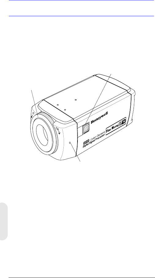
Version 2 1 G-113079-002
02/07
Einführung
Die Tages- und Nachtlicht-Farbkameras der Serie
Honeywell L erreichen mit einem hochempfindlichen 8,5-
mm-CCD-Interline-Sensor hohe Bildqualität und Auflösung.
Abbildung 1 Die Kamera im Überblick
Merkmale und Funktionen
• IT Super HAD CCD-Sensor 1/3 Zoll (8,5 mm)
• Einstellbarer C/CS-Objektivmontageadapter
• Exzellenter Signal-Rausch-Abstand von über 50 dB
• Minimale Umgebungshelligkeit 0,1 lux (F 1,2; 50 IRE,
IR-Filter aus, S/W)
• Kompatibel zu Objektiv mit Videoblende (VSD) oder
direkt angetriebener Blende (DC)
• Steuerung über Bildschirmmenü (OSD)
• Exakte Farbwiedergabe auch unter verschiedenen
Beleuchtungsbedingungen
• Fernbedienung mit RS485-Anschluss
Objektivanschluss für
Stecker des Objektivs mit
automatischer Blende
Madenschraube: Arretierungsring mit
einem Kreuzschlitzschraubendreher lösen,
dann Montagering einstellen
C/CS-Montageadapter:
C-Montage: gegen den
Uhrzeigersinn drehen
CS-Montage: im Uhrzeigersinn
drehen

Version 2 2 G-113079-002
02/07
Deutsch
Vorbereitungen
Auspacken
Kontrollieren Sie, ob der tatsächliche Lieferumfang mit den
Angaben auf dem Auftragsformular und dem Packzettel
übereinstimmt. Zusätzlich zu dieser Bedienungsanleitung
sollte die Produktverpackung der Tages-/Nachtlicht-
Farbkamera die folgenden Teile enthalten:
• 1 Tages-/Nachtlicht-Farbkamera der Serie L
• 1 Anschlusskabel (vierpolig)
• 1 Stecker für Objektiv mit automatischer Blende
Wenn Teile fehlen sollten, wenden Sie sich an den Händler,
bei dem Sie die Kamera erworben haben, oder an den
Honeywell Kundenservice (siehe Kontakt auf der Rückseite
dieser Anleitung).
Hinweis Für die Installation benötigen Sie außerdem
einen Kreuzschlitzschraubendreher.
Bitte lesen Sie diese Anleitung
sorgfältig durch, bevor Sie die
Tages-/Nachtlicht-Farbkamera der
Serie L installieren.
Bewahren Sie die Anleitung auf.
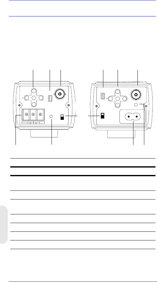
Version 2 3 G-113079-002
02/07
Funktionen der Kamera
Abbildung 2 Rückansicht der Kamera
PWR
VSD
DC
VIDEO
~207-253VAC 50HZ
REMOTE UP
DOWN
MENU
+
-+
GND
DC 12V
AC 24V
PWR VSD
DC
VIDEO
+
UP
DOWN
MENU REMOTE
Legende
Nr. Beschreibung
1Auswahlschalter für Objektiv mit automatischer Blende
(VSD für Video und DC für Direktantrieb)
2Video-Ausgangsanschluss
3Stromversorgungseingang (24 VAC, 3 Anschlüsse), nur bei
Ausführung mit Kleinspannungsversorgung
4Betriebsanzeige-LED
5RS485-Anschluss für Fernbedienung
6Menüsteuerung (siehe „Programmierung“ auf Seite 8)
7Netzkabelbuchse 230 V
Netzspannung 230V
(HCD485LX)
Kleinspannung
(HCD484L, HCD484LX)
2
4
1
5
3
62
4
56
7
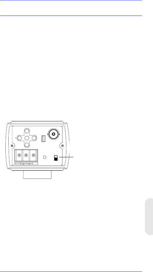
Version 2 4 G-113079-002
02/07
Deutsch
Installation
Auswählen des Objektivs
Objektive mit einstellbarer Brennweite und automatischer
Blende (Direktantrieb oder Videoantrieb) werden an die
4-polige Würfelbuchse an der Seite der Kamera
angeschlossen.
1. Stellen Sie den Schalter VSD/DC an der Rückseite der
Kamera ein.
Objektiv mit Videoantrieb: VSD.
Objektiv mit Direktantrieb: DC.
2. Stellen Sie die Option EE MODE im OSD-Menü auf
ALC MODE (siehe ALC MODE).
Objektiv mit automatischer Blende und Verstärker:
Wählen Sie im OSD-Menü die Option VSD LENS.
Objektiv mit automatischer Blende ohne Verstärker:
Wählen Sie im OSD-Menü die Option DC LENS.
Stellen Sie den Wert von LEVEL vorsichtig ein, damit
keine Phasenverschiebung auftritt.
-+
GND
DC 12V
AC 24V
PWR VSD
DC
VIDEO
+
UP
DOWN
MENU REMOTE
Abgebildet ist ein Modell mit
Kleinspannungsversorgung
(HCD484L, HCD484LX)
VSD = Objektiv mit automatischer
Blende und integriertem Verstärker
(Objektiv mit Videoantrieb)
DC = Objektiv mit automatischer
Blende ohne Verstärker (Objektiv mit
Direktantrieb)
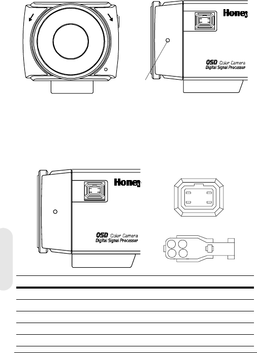
Version 2 5 G-113079-002
02/07
Einstellen der bildseitigen
Schnittweite
Die Einstellung der bildseitigen Schnittweite erfolgt an der
Vorderseite der Kamera. Damit kann die Bildschärfe
korrigiert werden.
Der Einstellbereich ermöglicht die Verwendung von
Objektiven mit C- und CS-Montage ohne Distanzring.
Abbildung 3 C/CS-Montage
1. Lösen Sie die Madenschraube mit einem
Kreuzschlitzschraubendreher.
2. Stellen Sie das Bild mit dem Einstellring scharf.
3. Ziehen Sie die Schraube wieder an.
Abbildung 4 Anschlussbelegung für Objektiv mit
automatischer Blende
CCS
Madenschraube
1
23
4
21
43
Pin
Objektiv mit Direktantrieb (DC) Objektiv mit Videoantrieb (VSD)
1 CTRL – Stromversorgung (+12 V)
2CTRL + nicht belegt
3DRV + Videosignal
4 DRV – Masse
Stellen Sie den Schalter auf
DC
. Stellen Sie den Schalter auf
VSD
.
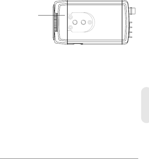
Version 2 6 G-113079-002
02/07
Deutsch
Montage der Kamera
An der Oberseite der Kamera sind Montagepunkte
vorgesehen, so dass die Kamera an einer Halterung oder
auf einem Stativ befestigt werden kann. Die Bohrungen
sind für handelsübliche Schrauben der Größe 1/4 x 20
vorgesehen. Je nach Anwendung kann diese Halterung
abgeschraubt und an der gegenüberliegenden Seite der
Kamera angebracht werden. Die Montagehalterung muss
das Gewicht der Kamera und des Objektivs tragen können.
Hinweis Einige Sicherheitsvorschriften besagen,
dass die Montagehalterung sogar für das
vierfache Gesamtgewicht von Kamera und
Objektiv ausgelegt sein muss.
Abbildung 5 Montage der Kamera
Anschließen der Kamera
Hinweis Prüfen Sie die Spannung der externen
Stromversorgung, bevor Sie die Kamera
anschließen.
1. Verbinden Sie den Anschluss VIDEO an der Rückseite
der Kamera mit dem Video-Eingangsanschluss des
Monitors.
2. Schließen Sie die Kamera an die passende
Stromversorgung an.
HCD484L, HCD484LX: 12 VDC oder 24 VAC
HCD485LX: 230 V
Lösen Sie die drei
Schrauben der
Halterung, und
bringen Sie die
Halterung an der
anderen Seite der
Kamera an.
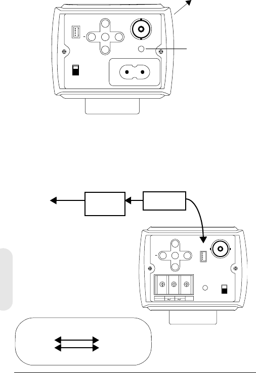
Version 2 7 G-113079-002
02/07
3. Verbinden Sie das Netzteil mit dem Stromnetz. Die
Betriebsanzeige-LED (PWR) leuchtet und signalisiert
damit, dass die Kamera Stromversorgung erhält.
Wenn diese LED nicht leuchtet, überprüfen Sie alle
Verbindungen und die Stromversorgung.
Abbildung 6 Anschlüsse an der Kamera
Fernbedienungsanschlüsse
Die Tages-/Nachtlicht-Farbkamera der Serie L kann über
einen RS485-Anschluss ferngesteuert werden.
Abbildung 7 RS485-Anschluss
PWR
VSD
DC
VIDEO
~207-253VAC 50HZ
REMOT E UP
DOWN
MENU
+
Zum
Monitor
Betriebsanzeige-
LED
Abgebildet ist die Netzspannungsversion (230 V)
(HCD485L)
-+
GND
DC 12V
AC 24V
PWR VSD
DC
VIDEO
+
UP
DOWN
MENU REMOTE
RS485-Wandler
TRx+
TRx-
4-poliges
Kabel
3TRx+
2TRx-
4-poliges
Kabel
Verbindung
zur seriellen
Schnittstelle
(COM1 oder
COM2)
Ser.
Kabel
Anschlussbelegung des 4-poligen
Kabels
1. Rot nicht belegt
2. Blau TRx-
3. Gelb TRx+
4. Schwarz nicht belegt
RS485-
Wandler

Version 2 8 G-113079-002
02/07
Deutsch
Programmierung
On-Screen Display (OSD)
Drücken Sie kurz die Taste MENU, um die aktuelle
Einstellung abzurufen. Die Informationen (siehe
Abbildung 8) werden nach einigen Sekunden wieder
ausgeblendet, sofern keine Tastenbetätigung erfolgt.
Selbst wenn die OSD-Meldung nicht mehr zu sehen ist,
werden die Kamerakennung oder die Kamerabezeichnung
weiterhin angezeigt, wenn dies im Untermenü CAMERA ID
festgelegt wurde. So schalten Sie die Anzeige der
Kamerakennung bzw. der Kamerabezeichnung aus:
• Ändern Sie mit externer Kommunikation die
Anzeigeposition. Verfügbare Optionen:
unten rechts, unten links, oben links, oben rechts,
keine Anzeige.
• Wenn Sie die Anzeige des OSDs nicht benötigen
(beispielsweise für ein externes Text-Overlay-System),
deaktivieren Sie die Anzeige über eine RS485-Verbin-
dung mithilfe der Fernbedienungsfunktion vollständig.
Abbildung 8 OSD-Anzeige
CAMERA ID/TITLE
Back Light WB Mode
Back Light (Gegenlicht) wird angezeigt, wenn BLC
aktiviert ist (siehe BLC MODE (Backlight Compensation,
Gegenlicht-kompensation).
Shutter Speed (Belichtungszeit) wird angezeigt, wenn die
voreingestellte Belichtungszeit verändert wird.
WB Mode (Weißabgleich-Modus) wird immer angezeigt.
Shutter Speed

Version 2 9 G-113079-002
02/07
OSD-Menüfunktionen
Mit den Funktionen des OSD-Menüs programmieren Sie
die Kamera.
1. Halten Sie die Taste
MENU
(in der Mitte) zwei Sekunden
lang gedrückt, um das Einstellungsmenü zu öffnen.
2. Wählen Sie mit den Tasten UP und DOWN eine
Menüoption aus.
3. Drücken Sie die Taste MENU, um das gewählte
Untermenü zu öffnen.
4. Erhöhen oder verringern Sie mit den Tasten + und –
den Wert der ausgewählten Option.
Abbildung 9 Steuerelemente für das OSD-Menü
Speichern der Einstellungen
Erste Methode: Wenn Sie eine Einstellung übernehmen
möchten:
1. Drücken Sie zwei Sekunden lang die Taste MENU.
Das SETUP MENU wird durch eine der folgenden
Meldungen ersetzt:
Wenn Werte verändert wurden, wird
SAVE?
angezeigt.
Wenn Sie
SAVE
auswählen, wird der Einstellungsmodus
verlassen, und Ihre Einstellungen werden gespeichert.
Wenn keine Werte verändert wurden, wird QUIT?
angezeigt. Wenn Sie QUIT auswählen, wird der
Einstellungsmodus verlassen, ohne dass Änderungen
gespeichert werden.
2. Drücken Sie + oder –, um SAVE oder QUIT
auszuwählen, und drücken Sie MENU, um den
Einstellungsmodus zu verlassen. Drücken Sie UP oder
DOWN, um die Abfrage SAVE/QUIT zu verlassen und
zum SETUP MENU zurückzukehren.
Zweite Methode:
Wählen Sie im SETUP MENU die Option
EXIT MENU
, drücken Sie
MENU
, und wählen Sie
SAVE AND
EXIT
, um die geänderten Einstellungen zu speichern und das
Menü zu verlassen. Wählen Sie
EXIT
, wenn Sie das Menü
verlassen möchten, ohne die Einstellungen zu speichern.
UP
DOWN
MENU
+
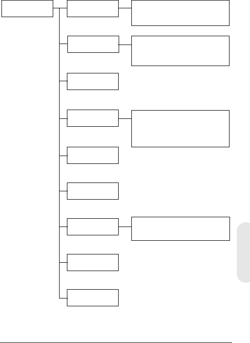
Version 2 10 G-113079-002
02/07
Deutsch
Einrichten der Kamera
OSD-Menüstruktur
Das Menüsystem der Tages-/Nachtlicht-Farbkamera
besteht aus einem Hauptmenü für die einfache
Programmierung.
SETUP MENU CAMERA ID
ELC/ALC Mode
Shutter Speed
White Balance
AGC Control
Nightshot
Sync Control
Restore Default
Exit Menu
Kamerakennung/
Kamerabezeichnung
Anzeigeposition
ELC Mode: AUTO, MANUAL
ALC Mode: VSD LENS
DC LENS (LEVEL)
ATW, Outdoor, Indoor, User,
Fluorescent,
AWC (Auto, Manual, Push&Lock)
MWB (RED, BLUE)
AUTO, INTERNAL,
LineLock (V.PH)
Hauptmenü Untermenüs Optionen
1
2
3
4
5
6
7
8

Version 2 11 G-113079-002
02/07
Menüoption Option Beschreibung
1 CAMERA ID 000 (aus), 001 …
255
0: Kamerakennung wird
ausgeblendet. Siehe
Einstellen der Synchronisation.
2 ELC/ALC
Mode ELC …
ALC …
Siehe ELC/ALC-Modus.
3 Shutter
Speed
1/60 NTSC
(1/50 PAL) FL
1/250
1/500
1/1000
1/2000
1/4000
1/10000
1/30000
1/50000
Mit hoher Belichtungszeit lässt
sich die Helligkeit anpassen.
FL: Bildflimmern wird
unterdrückt.
Im Modus ELC MODE kann
dieses Feld nicht verändert
werden. Standardeinstellung
ist Auto.
4 White
Balance
ATW (Auto Trace
White Balance,
automatische
Weißabgleich-
Nachführung)
AWC (Auto White
Balance Control,
automatischer
Weißabgleich mit
Voreinstellung)
MWB (Manual White
Balance, manueller
Weißabgleich)
Zu den voreingestellten
Weißabgleichmodi gehören
Outdoor, Indoor, User,
Fluorescent. Siehe Einstellen
des Weißabgleichs.
5 AGC Control OFF
10 dB
12 dB … 38 dB
Stellen Sie für die dynamische
Verstärkungsregelung den
maximalen Wert ein. Wenn
AGC auf OFF gestellt ist, steht
der Nachtmodus (Nightshot)
nicht zur Verfügung.
6 Nightshot Mit dieser Einstellung legen
Sie fest, wie die Kamera auf
schwache Beleuchtung
reagiert.
7 Sync. Control AUTO
INTERNAL
LineLock (V.Phase)
Siehe Einstellen der
Synchronisation.
8Restore
Default
Die werkseitigen Standard-
einstellungen werden wieder-
hergestellt. Wenn Sie keine
Änderungen vorgenommen
haben, können Sie diese
Einstellung nicht auswählen.

Version 2 12 G-113079-002
02/07
Deutsch
Festlegen einer Kamerakennung oder
Kamerabezeichnung
Wenn mehrere Kameras in einem Netzwerk verbunden
sind, kann die Vergabe einer Kamerakennung sinnvoll sein.
Wenn Sie eine Kamerakennung oder -bezeichnung
festlegen möchten, öffnen Sie das SETUP MENU, wählen
CAMERA ID und drücken MENU.
Abbildung 10 Festlegen einer Kamerakennung oder
Kamerabezeichnung
Eingeben einer Kamerabezeichnung
1. Steuern Sie mit den Tasten + und – auf der Rückseite
der Kamera das erste Zeichen im Feld TITLE an.
2. Drücken Sie UP, DOWN, +, –, um das erste Zeichen
des Titels auszuwählen. Drücken Sie dann die Taste
MENU, um dieses Zeichen zu übernehmen.
Menüoption Option Beschreibung
CAM ID 0
001 …
255
Diese Nummer wird fortlaufend an die
Kameras im Netz vergeben (000 bis 255).
0: Die Kennung wird auf dem Bildschirm
nicht angezeigt.
DISPLAY TITLE
ID
OFF
Wählen Sie, was auf dem Bildschirm
angezeigt werden soll (TITLE, ID oder
nichts).
POSITION T.R.
B.R.
B.L.
T.L.
NO DISP
Wählen Sie aus, wo die Kamerakennung
oder -bezeichnung angezeigt werden
soll: Top Right (Oben rechts), Bottom
Right (Unten rechts), Top Left (Oben
links), Bottom Left (Unten links) oder
NoDisplay (Keine Anzeige).
TITLE Geben Sie eine Bezeichnung für die
Kamera ein. Maximal 10 Zeichen (eins-
chließlich Leerzeichen) sind möglich.
RETURN Drücken Sie die Taste MENU, um zum
SETUP MENU zurückzukehren.
CAM ID: 002
DISPLAY: TITLE
POSITION: T.R.
1 2 3 4 5 6 7 8 9 A B C D E F
G H I J K L M N P Q R S T U V W
X Y Z a b c d e f g h i j k l m
n o p q r s t u v w x y z , . :
; ~ ! ? $ % * & / < > + - = ■
TITLE: HCD484■■
RETURN

Version 2 13 G-113079-002
02/07
3. Wählen Sie mit + oder – die nächste Zeichenposition.
Wiederholen Sie dann Schritt 2 und 3, bis die
Kamerabezeichnung vollständig ist.
4. Wählen Sie RETURN, und drücken Sie MENU, um die
Änderungen zu bestätigen und zum SETUP MENU
zurückzukehren.
Einstellen der Kamera-
Beleuchtungsoptimierung
ELC/ALC-Modus
Abbildung 11 Einstellen der Beleuchtungsoptimierung
So stellen Sie den Objektivmodus, die
Gegenlichtkompensation und die Schwarzmaske ein:
Menüoption Option Beschreibung
EE MODE:
ELC MODE
AUTO
MANUAL Für manuelle (feste) Objektive:
AUTO: Die Blende steuert die
Belichtung automatisch.
MANUAL: Stellen Sie die Blende ein,
indem Sie die Belichtungszeit
manuell verändern.
EE MODE:
ALC MODE
VSD
LENS
DC LENS
Objektiv mit automatischer Blende:
VSD: Wählen Sie diese Option für
Objektive mit Videoantrieb.
DC LENS: Wählen Sie diese Option
für Objektive mit Direktantrieb.
Stellen Sie den Wert LEVEL so ein,
dass das Bild nicht zu hell und nicht
zu dunkel ist.
BLC MODE
(Backlight
Compensation,
Gegenlicht-
kompensation)
OFF
LOW BL
MID. BL
HIGH BL
Diese Einstellung verhindert, dass
Objekte in Bildmitte zu dunkel
werden (Silhouetten-Effekt), wenn
der Hintergrund sehr hell ist.
RETURN Drücken Sie die Taste MENU, um
zum SETUP MENU zurückzukehren.
<ELC / ALC MODE>
EE MODE: ALC MODE
DC LENS
LEVEL 04
BLC MODE: OFF
RETURN

Version 2 14 G-113079-002
02/07
Deutsch
Einstellen des Weißabgleichs
Der automatische Weißabgleich sorgt für möglichst original-
getreue Farbwiedergabe im Bereich von 2800 °K bis 8000 °K:
Abbildung 12 Weißabgleich-Einstellung
Menüoption Beschreibung
ATW (Auto
Trace White
Balance Mode,
automatische
Weißabgleich-
Nachführung)
Ein Regelkreis passt automatisch den
Weißabgleich an (2800 °K bis 8000 °K).
AWC (Auto
White Balance
Control,
automatischer
Weißabgleich
mit
Voreinstellung)
Schnellere Variante als ATW. Dieser Modus wird
vorzugsweise im Außenbereich oder in
Umgebungen mit schwankenden Lichtver-
hältnissen eingesetzt. Verfügbare Optionen:
AUTO: AWC ist immer aktiv
MANUAL: PUSH Drücken Sie MENU, um AWC
zu aktivieren
MANUAL: LOCK Lassen Sie die Taste MENU
los, um den Weißabgleich an die aktuellen
Verhältnisse anzupassen.
INDOOR Universelle Voreinstellung für Innenräume
(3200 °K)
FLUORESCENT Für Büroumgebungen mit Leuchtstoff- oder
Glühlampenlicht. Geringster Dynamikbereich
aller Voreinstellungen (4200 °K).
USER FIXED Voreinstellung (4700 °K)
OUTDOOR Voreinstellung für Außenbereiche und für Orte
mit starken Kontrasten, während die Kamera auf
die dunkleren Bereiche fokussiert ist (6300 °K).
MWB
(manuell) RED: 0 bis 20
BLUE: 0 bis 20
RETURN Drücken Sie die Taste MENU, um zum SETUP
MENU zurückzukehren.
<WHITE BALANCE>
WB MODE: MWB
WB CONT: R=00
B=00
RETURN

Version 2 15 G-113079-002
02/07
Einstellen des Nachtaufnahmemodus
Im Menü NIGHTSHOT legen Sie fest, wie die Kamera auf
schlechte Lichtverhältnisse reagiert und wann zwischen
Tag- und Nachtmodus umgeschaltet wird. Der Nachtmo-
dus ist nur dann verfügbar, wenn AGC auf ON gestellt ist.
Abbildung 13 Weißabgleich-Einstellung
Menüoption Beschreibung
MODE AUTO: Die Kamera ermittelt automatisch die
Luminanz und aktiviert oder deaktiviert
entsprechend den IR-Filter.
ON: Der IR-Filter wird entfernt (Nachtmodus).
OFF: Der IR-Filter wird aktiviert (Tagmodus).
DET.TIME Dieses Zeitintervall von 5 bis 60 Sekunden
bestimmt, wie lange es dauert, bis die Kamera nach
Erkennung von schlechten Lichtverhältnissen vom
Tagmodus in den Nachtmodus wechselt.
MODE muss auf AUTO gestellt sein.
D->N THD
(Threshold,
Schwellen-
wert)
Schwellenwert zur Klassifizierung von schwacher
Umgebungshelligkeit (1 bis 9) für den Wechsel in
den Nachtmodus. Je niedriger der Wert, desto
schwächer ist das Licht, bei dem die Kamera
umschaltet.
MODE muss auf AUTO gestellt sein.
Hinweis D-> THD muss um mindestens 2 kleiner
sein als die Einstellung N->D THD.
N->D THD
(Threshold,
Schwellen-
wert)
Schwellenwert zur Klassifizierung von schwacher
Umgebungshelligkeit (1 bis 9) für den Wechsel in
den Tagmodus. Je höher der Wert, desto heller ist
das Licht, bei dem die Kamera umschaltet.
MODE muss auf AUTO gestellt sein.
DN COLOR Der Farbmodus für den Kamerabetrieb im
Nachtmodus: B/W (Schwarzweiß) oder COLOR.
MODE muss auf AUTO oder ON gestellt sein.
RETURN Drücken Sie die Taste MENU, um zum SETUP
MENU zurückzukehren.
<NIGHTSHOT>
MODE: AUTO
DET.TIME: 10 sec
D->N THD 2
N->D THD 5
DN COLOR BW
RETURN

Version 2 16 G-113079-002
02/07
Deutsch
Einstellen der Synchronisation
Mit dieser Option synchronisieren Sie das vertikale
Synchronisierungssignal mit anderen Geräten, so dass ein
Bildlaufeffekt auf dem Monitor vermieden wird.
Abbildung 14 Einstellen der Synchronisation
Verlassen des Einstellungsmenüs
So verlassen Sie das Menü SETUP:
Abbildung 15 Menü verlassen
Menüoption Beschreibung
INTERNAL Geeignet, wenn keine Synchronisierung mit
Netzfrequenz erforderlich ist.
LINELOCK Stellen Sie die Phase ein:
V.PH: 000 bis 300 (Werkseinstellung ist 0)
Hinweis Die Synchronisierung mit der
Netzfrequenz steht bei 12-VDC-
Stromversorgung nicht zur Verfügung.
AUTO
Die Kamera erkennt die Synchronisierung automatisch.
RETURN Drücken Sie die Taste MENU, um zum SETUP
MENU zurückzukehren.
Menüoption Beschreibung
SAVE AND
EXIT Drücken Sie die Taste MENU, um Ihre Änderungen
zu speichern und das Menü zu verlassen.
EXIT
Drücken Sie die Taste
MENÜ
, wenn Sie das Menü ver-
lassen möchten, ohne die Änderungen zu speichern.
RETURN Drücken Sie die Taste MENU, um zum SETUP
MENU zurückzukehren.
<SYNC. CONTROL>
SYNC MODE: LINELOCK
V.PH 000
STEP=10
RETURN
<EXIT MENU>
SAVE AND EXIT
EXIT
RETURN

Version 2 17 G-113079-002
02/07
Gewährleistung und
Kundendienst
Gemäß den Bedingungen der Gewährleistungserklärung zu diesem
Gerät übernimmt Honeywell während des Gewährleistungszeit-
raums nach eigenem Ermessen den kostenlosen Austausch oder
die kostenlose Reparatur defekter Geräte, die mit vorausbezahlten
Frachtkosten an Honeywell zurückgesendet werden.
Wenn in Verbindung mit einem Honeywell gerät ein Problem
auftritt, wenden Sie sich bitte an den Kundenservice
(in Nordamerika: 1.800.796.CCTV) und lassen sich einen
Rücksendecode zuteilen (Return Merchandise Authorization
(RMA)). Informationen zur Gewährleistung in Europa erhalten Sie
bei einem Honeywell Vertriebspartner.
Halten Sie bitte die Modellnummer, die Seriennummer und eine
Beschreibung des Problems bereit.
Rücksendungen, Ersatzlieferungen und Gutschriften müssen
vorher autorisiert werden. Sendungen an Honeywell, die ohne
Rücksendecode (Return Merchandise Authorization)
eintreffen, müssen von Honeywell nicht angenommen werden.
Technische Daten
Hinweis Sofern nichts anderes vermerkt ist, gelten
diese Daten für alle Modelle.
HCD484L HCD484LX
HCD485LX
Betrieb
Bildsensor: Super-HAD-CCD-Sensor 1/3 Zoll (8,5 mm)
Bildnorm: NTSC PAL
Bilderfassung: 525 Zeilen,
Zeilensprungfaktor 2:1 625 Zeilen,
Zeilensprungfaktor 2:1
Anzahl Pixel
(H x V): 768 x 494 752 x 582
Minimale
Umgebungs-
helligkeit:
< 0,1 lux bei F 1,2
(50 IRE, AGC ein, IR-Filter aus, S/W)

Version 2 18 G-113079-002
02/07
Deutsch
Horizontale
Auflösung: 480 TVL 480 TVL
Videoausgang: 1 Vss an 75 Ohm
Synchronisation: Intern/Netzfrequenz/Automatisch
Signal-Rausch-
Abstand: > 50 dB
Dynamische
Verstärkungsrege
lung (Auto Gain
Control, AGC):
Aus, 10 dB bis 38 dB
ALC: EE/VSD/DC
Automatische
elektronische
Blende
(Automatic
Electronic
Shutter, AES):
1/60 bis 1/100.000 s 1/50 bis 1/100.000 s
Objektivmontage: C/CS-Montage (einstellbar)
Weißabgleich: ATW, AWC, Indoor, Outdoor, Fluorescent, User, MWB
BLC (Gegenlicht-
kompensation): Off, Low, Middle, High
Elektrische Kenndaten
Eingangs-
spannung: HCD484L, HCD484LX: 12 VDC/24 VAC
HCD485LX: 230 VAC
Eingangsspan-
nungsbereich: HCD484L, HCD484LX: 11bis 16 VDC/17 bis 28 VAC
HCD485LX: 230 VAC ± 10 %
Leistungs-
aufnahme: HCD484L, HCD484LX: 3.5 W (max)
HCD485LX: 4.5 W (max)
Mechanische Daten
Maße:
(B x H x T) HCD484L, HCD484LX: 68 x 56 x 120 mm
HCD485LX: 68 x 56 x 140 mm
Gewicht: HCD484L, HCD484LX: 0,380 kg
HCD485LX: 410 g
Umgebungsbedingungen
Temperatur: Betrieb: –10 °C bis +50 °C
Lagerung: –20 °C bis +70 °C
Normen
Emissionen: FCC, CE (EN55013)
Störfestigkeit: CE (EN50130-4)
Sicherheit: EU: 73/23/EWG LVD
HCD484L HCD484LX
HCD485LX

© 2007 Honeywell International Inc. Alle Rechte vorbehalten. Kein Teil dieser Ver-
öffentlichung darf ohne schriftliche Genehmigung durch Honeywell Video Systems
reproduziert werden. Die Informationen in dieser Veröffentlichung wurden mit größter
Sorgfalt zusammengestellt. Honeywell Video Systems kann jedoch keinerlei Haftung
für die Folgen übernehmen, die sich aus der Nutzung dieser Informationen ergeben
könnten. Die in diesem Dokument enthaltenen Informationen können jederzeit und
ohne vorherige Ankündigung geändert werden. Zur Umsetzung solcher Änderungen
können überarbeitete Versionen dieser Veröffentlichung herausgegeben werden.
www.honeywellvideo.com
+1.800.796.CCTV (nur Nordamerika)
HVSsupport@honeywell.com
Dokument G-113079-002 02/07 Version 2
Honeywell Video Systems
(Hauptniederlassung)
2700 Blankenbaker Pkwy, Suite 150
Louisville, KY 40299, USA
www.honeywellvideo.com
℡ +1.800.796.2288
Honeywell Security Australia Pty Ltd.
Unit 5, Riverside Centre
24–28 River Road West
Parramatta, NSW 2150, Australien
www.ademco.com.au
℡ +61.2.8837.9300
Honeywell Security Asia Pacific
33/F Tower A, City Center, 100 Zun Yi
Road
Shanghai 200051, China
www.security.honeywell.com/cn
℡ +86 21.2527.4568
Honeywell Security Asia
Flat A, 16/F, CDW Building
388 Castle Peak Road
Tsuen Wan, N.T., Hongkong
www.security.honeywell.com/hk
℡ +852.2405.2323
Honeywell Security France
Parc Gutenberg, 8, Voie La Cardon
91120, Palaiseau, Frankreich
www.honeywell.com/security/fr
℡ +33.01.64.53.80.40
Honeywell Security Italia SpA
Via Treviso 2 / 4
31020 San Vendemiano
Treviso, Italien
www.honeywell.com/security/it
℡ +39.04.38.36.51
Honeywell Security España
Mijancas 1. 3a Planta
P.Ind. Las Mercedes
28022 Madrid, Spanien
www.honeywell.com/security/es
℡ +34.902.667.800
Honeywell Video Systems
Nordeuropa
Netwerk 121
1446 WV Purmerend, Niederlande
www.SecurityHouse.nl
℡ +31.299.410.200
Honeywell Video Systems UK Ltd.
Aston Fields Road, Whitehouse Ind Est
Runcorn, Cheshire, WA7 3DL, GB
www.honeywellvideo.com
℡ +0844 8000 235
Honeywell Security South Africa
Unit 6 Galaxy Park, 17 Galaxy Avenue
Linbro Park, P.O. Box 59904
2100 Kengray, Johannesburg
Südafrika
www.honeywell.co.za
℡ +27.11.574.2500
Honeywell Security Deutschland
Johannes-Mauthe-Straße 14
D-72458 Albstadt, Deutschland
www.honeywell.com/security/de
℡ +49.74 31.8 01.0
Honeywell Security Poland
Chmielewskiego 22a, 70-028
Szczecin, Polen
www.ultrak.pl
℡ +48.91.485.40.60
Honeywell Security Czech Republic
Havránkova 33, Brno
Dolní Heršpice, 619 00
Tschechische Republik
www.olympo.cz
℡ +420.543.558.111
Honeywell Security Slovakia Republic
Vajnorská 142, 83104 Bratislava
Slowakei
www.olympo.sk
℡ +421.2.444.54.660

Document G-113079-002 – 02/07 – Rev 2
L-serie dag/nacht-
kleurencamera
HCD484L HCD484LX
HCD485LX
Gebruikers-
handleiding
NTSC PAL
Nederland

Revisies
Publicatie Datum Revisies
1.00 10/06 Nieuw document
2 02/07 bijgewerkt 900.0842 document
aantal deel; Toegevoegde
waarschuwing aan pagina iii.
Rev 2 ii G-113079-002
02/07
Rev 2 iii G-113079-002
02/07
Waarschuwingen
Installatie en onderhoud mogen alleen uitgevoerd worden
door gekwalificeerd en ervaren personeel om te voldoen
aan alle plaatselijke codes en om uw garantie te
behouden.
WAARSCHUWING! De 12 VDC/24 VAC-modellen
vereisen het gebruik van CSA-
gecertificeerd/UL-opgenomen
klasse 2-stroomadapters om
naleving van elektrische
veiligheidsstandaards te
garanderen.
Wanneer een STEKKER of een ander stroomverbinding
wordt gebruikt om het apparaat van het stroomnet te
ontkoppelen, dient deze ten alle tijden bedienbaar te zijn.
Aparte afvalinzameling voor elektrische en
elektronische apparatuur (AEEA). Juiste
afvalverwijdering van dit product (van toepassing in de
Europese Unie en andere Europese landen met
gescheiden afvalverwijderingssystemen). Dit product dient
aan het einde van het gebruiksleven volgens de van
toepassing zijnde plaatselijke wetgeving en procedures
vernietigd te worden.
Verklaring van de grafische
symbolen
RISICO VAN
ELEKTRISCHE SCHOK
NIET OPENEN
LET OP: OM HET RISICO OP EEN ELEKTRISCHE SCHOK
TE VERMINDEREN MAG DE BEHUIZING NIET
VERWIJDERD WORDEN. IN HET INSTRUMENT
BEVINDEN ZICH GEEN ONDERDELEN DIE DOOR DE
GEBRUIKER KUNNEN WORDEN ONDERHOUDEN.
RAADPLEEG VOOR SERVICE GEKWALIFICEERD
ONDERHOUDSPERSONEEL
DIT SYMBOOL GEEFT AAN DAT
ZICH BINNEN HET APPARAAT
GEVAARLIJKE VOLTAGE
BEVINDT DIE EEN RISICO VORMT
OP EEN ELEKTRISCHE SCHOK.
DIT SYMBOOL GEEFT AAN DAT
BELANGRIJKE BEDIENINGS- EN
ONDERHOUDSINSTRUCTIES BIJ
DIT APPARAAT GELEVERD
WORDEN.
WAARSCHUWING
Nederland

Rev 2 iv G-113079-002
02/07
FCC-verklaring van naleving
Informatie voor de gebruiker: Deze apparatuur is getest
op en voldoet aan de limieten voor een klasse A-digitaal
apparaat. Ingevolge deel 15 van de FCC-regels zijn deze
begrenzingen ontwikkeld om redelijke bescherming te
bieden tegen schadelijke interferentie wanneer de
apparatuur gebruikt wordt in een commerciële omgeving.
Dit apparaat genereert en gebruikt radiofrequentie-energie
en kan deze uitstralen. Indien niet geïnstalleerd en gebruikt
volgens de instructies, kan dit apparaat schadelijke
interferentie van radiocommunicatie veroorzaken. Gebruik
van dit apparaat in een woonomgeving zal waarschijnlijk
schadelijke interferentie veroorzaken en in dit geval zal
de gebruiker de interferentie op eigen kosten dienen aan
te passen.
Let op Veranderingen of modificaties die niet
uitdrukkelijk goedgekeurd zijn door de partij
die verantwoordelijk is voor naleving, kunnen
uw recht op bediening van het apparaat
doen vervallen.
Conformiteitsverklaring van de
fabrikant
De fabrikant verklaart dat de apparatuur die bij deze
handleiding geleverd wordt, conform de essentiële
beschermingsbepalingen van de EMC-richtlijn 89/336/EEC
en de Low Voltage Directive LVD 73/23 EEC is, waarmee
voldaan wordt aan de bepalingen van standaards
EN 55013 voor emissies.

Rev 2 G-113079-002
02/07
Nederland
Inhoud
Inleiding . . . . . . . . . . . . . . . . . . . . . . . . . . . . . . . . . . 1
Eigenschappen . . . . . . . . . . . . . . . . . . . . . . . . . . 1
Voor u begint . . . . . . . . . . . . . . . . . . . . . . . . . . . . . 2
Alles uitpakken . . . . . . . . . . . . . . . . . . . . . . . . . . . 2
Camerafuncties. . . . . . . . . . . . . . . . . . . . . . . . . . . . . 3
Installatie . . . . . . . . . . . . . . . . . . . . . . . . . . . . . . . . . 4
Het kiezen van de lens . . . . . . . . . . . . . . . . . . . . . 4
Aanpassen van de backfocus . . . . . . . . . . . . . . . . 5
Monteren van de camera . . . . . . . . . . . . . . . . . . . 6
Aansluiten van de camera . . . . . . . . . . . . . . . . . . . 6
Aansluitingen van de afstandsbediening . . . . . 7
Programmeren . . . . . . . . . . . . . . . . . . . . . . . . . . . . . 8
On-Screen Display (OSD) . . . . . . . . . . . . . . . . . . . 8
OSD-menufuncties . . . . . . . . . . . . . . . . . . . . . 9
Opslaan van uw instellingen . . . . . . . . . . . . . . 9
Instellen van uw camera . . . . . . . . . . . . . . . . . . . 10
OSD-menustructuur . . . . . . . . . . . . . . . . . . . 10
Het toevoegen van een camera-ID of -titel . .12
Instellen van belichtingsoptimalisatie
van de camera . . . . . . . . . . . . . . . . . . . . . . . . 13
ELC/ALC-modus . . . . . . . . . . . . . . . . . . . . 13
Instellen witbalanscontrole . . . . . . . . . . . . 14
Nightshot Control Setup . . . . . . . . . . . . . . . . . 15
Instellen sync-control . . . . . . . . . . . . . . . . . . 16
Afsluiten van het instelmenu . . . . . . . . . . . . . 16
Garantie en service . . . . . . . . . . . . . . . . . . . . . . . . 17
Specificaties . . . . . . . . . . . . . . . . . . . . . . . . . . . . . 17
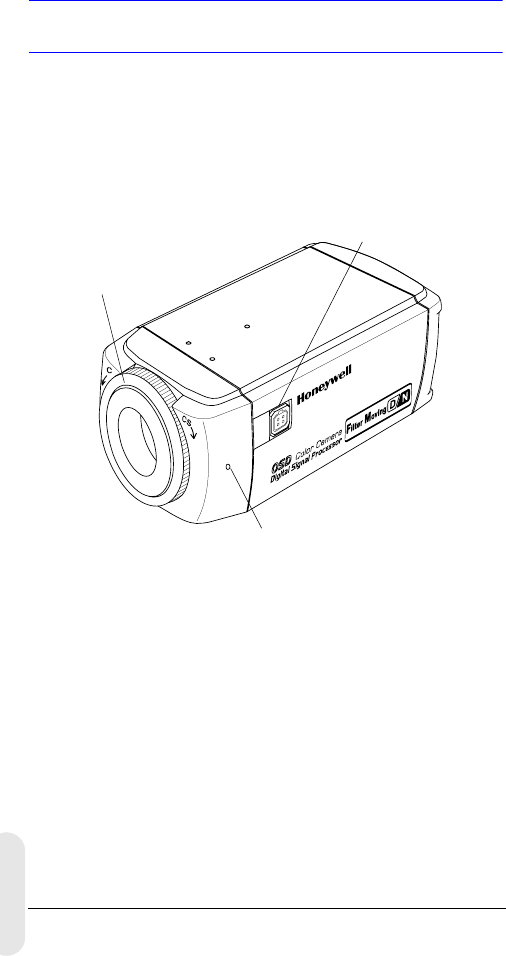
Rev 2 1 G-113079-002
02/07
Inleiding
De Honeywell L-serie-dag/nacht-kleurencamera's geven
een hoge afbeeldingskwaliteit en -resolutie met een zeer
gevoelige 11/3 inch interlinetransfer CCD-beeldsensor.
Figuur 1 Overzicht van de camera
Eigenschappen
• 1/3" IT Super HAD CCD
• C/CS-regelbare lensmountadapter
• Uitstekende signaal-tot-ruisverhouding van meer
dan 50 dB
• Minimale belichting van 0,1 lux (F1.2, 50 IRE, IR Filter
Off, B/W)
• Compatibel met Video Iris (VSD) of Direct Drive (DC)
Auto irislens
• OSD-menubediening
• True-colorweergave van verschillende lichtbronnen
• Afstandsbediening met RS485-aansluiting
Lensconnector voor
Auto irislensplug
Stelschroef: draai de sluitring los met een
kruiskopschroevendraaier om de mounting
ring aan te passen.
C/CS-mountadapter:
C-mount: draai tegen de wijzers
van de klok in
CS-mount: draai met de wijzers
van de klok mee

Rev 2 2 G-113079-002
02/07
Nederland
Voor u begint
Alles uitpakken
Controleer of de items die u ontvangen hebt,
overeenkomen met de items die vermeld staan op het
bestelformulier en de pakbon. De L-serie dag/nacht-doos
dient, naast deze gebruikershandleiding, het volgende
te bevatten:
• Een L-serie dag/nacht-kleurencamera
• Een 4 pinsverbindingskabel
• Een Auto irislensplug
Als er onderdelen ontbreken of beschadigd zijn, dient u
contact op te nemen met de dealer bij wie u de camera
gekocht hebt of bel de Honeywell Klantenservice (zie
Contactinformatie op de achterkant van deze handleiding).
Opmerking U hebt ook een kruiskopschroevendraaier
nodig om de installatie te voltooien.
Lees deze handleiding zorgvuldig
door voor u de L-serie dag/nacht-
kleurencamera installeert.
Bewaar deze handleiding. U kunt
hem in de toekomst nodig hebben.
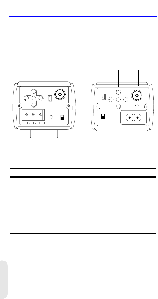
Rev 2 3 G-113079-002
02/07
Camerafuncties
Figuur 2 Achteraanzicht van de camera
PWR
VSD
DC
VIDEO
~207-253VAC 50HZ
REMOTE UP
DOWN
MENU
+
-+
GND
DC 12V
AC 24V
PWR VSD
DC
VIDEO
+
UP
DOWN
MENU REMOTE
Legenda
#Beschrijving
1Selectieschakelaar voor Auto irislens, VSD voor Video of
DC voor Direct Drive
2Video-outputconnector
3Stroom-inputconnector (24 VAC: 3 terminals)—Alleen laag
voltagemodel
4Stroom LED-indicator
5Afstandsbediening RS485-connector
6Menubediening (zie “Programmeren” op pagina 8)
7Netaansluiting 230V lijnvoltage-voedingsaansluiting
Netaansluiting 230V—-lijnvoltage
(HCD485LX)
Laag voltage
(HCD484L, HCD484LX
2
4
1
5
3
62
4
56
7
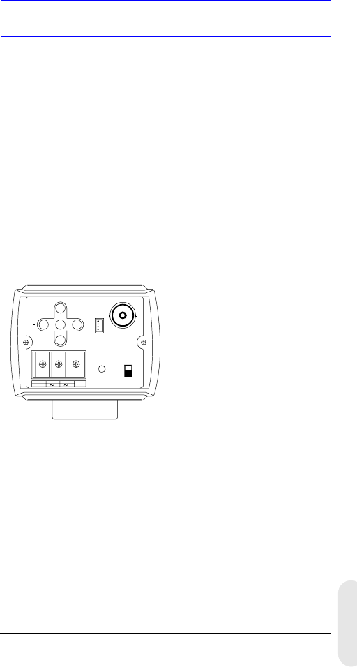
Rev 2 4 G-113079-002
02/07
Nederland
Installatie
Het kiezen van de lens
Varifocale Auto irislenzen (Direct Drive of Video Drive)
worden aangesloten op de camera door middel van een
4-pins vierkante aansluiting die zich aan de zijkant van de
camera bevindt.
1. Stel de VSD/DC-schakelaar aan de achterkant van de
camera in.
Voor Video Drive-lens stelt u de schakelaar in op VSD.
Voor Direct Drive stelt u de schakelaar in op DC.
2. Stel de EE MODE in op ALC MODE op het OSD-menu
(zie ALC MODE).
Auto irislens met versterker: Stel de VSD LENS in op
het OSD-menu.
Auto irislens zonder versterker: Stel de DC LENS in op
het OSD-menu. Pas het LEVEL zorgvuldig aan om
hunting te vermijden.
-+
GND
DC 12V
AC 24V
PWR VSD
DC
VIDEO
+
UP
DOWN
MENU REMOTE
Hier afgebeeld is het laag voltagemodel
(HCD484L, HCD484LX)
VSD = Auto irislens met een
ingebouwde versterker (video-type lens)
DC = Auto irislens zonder versterker
(DC-type lens)
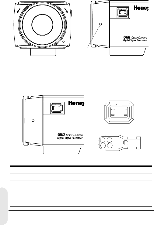
Rev 2 5 G-113079-002
02/07
Aanpassen van de backfocus
De aanpassing van de backfocus is toegankelijk aan de
voorzijde van de camerabehuizing om de lengte van de
backfocus of beeldfocus aan te passen.
Het aanpassingsbereik zorgt ervoor dat zowel C- als
CS-mountlenzen gebruikt kunnen worden zonder dat er
een afstandsring gebruikt hoeft te worden.
Figuur 3 C/CS-mount
1. Draai de stelschroef los met een kruiskopschroevendraaier.
2. Pas de focusring aan om het beeld te focussen.
3. Draai de stelschroef weer vast.
Figuur 4 Pinbeschrijving van de Auto irislens
CCS
Stelschroef:
1
23
4
21
43
Pin DC (directe aandrijving) lens Video (VSD) lens
1 CTRL- Stroom (+ 12V)
2CTRL+ NC
3DRV+ Videosignaal
4DRV- GND
Stel de selecteerschakelaar
in op DC.Stel de selecteerschakelaar
in op VSD.
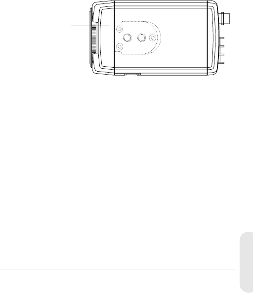
Rev 2 6 G-113079-002
02/07
Nederland
Monteren van de camera
Er zijn montagepunten aan de bovenzijde van de camera
om de camera op een beugel of statief te plaatsen. Ze zijn
geschikt voor bevestigingsschroeven met een
standaardmaat van 1/4 x 20. Deze beugel kan
losgeschroefd en gemonteerd worden aan de andere kant
van de camera, afhankelijk van uw toepassing.
De bevestigingsbeugel moet sterk genoeg zijn om het
gewicht van de camera en de lens te kunnen dragen.
Opmerking Sommige installatiecodes schrijven voor dat
de bevestigingsbeugel in staat moet zijn om
tot vier keer het gecombineerde gewicht van
camera en lens te dragen.
Figuur 5 Bevestiging van de camera
Aansluiten van de camera
Opmerking Controleer de voedingspanning van de
externe voedingseenheid voordat u stroom
zet op de camera.
1. Sluit de VIDEO-connector aan de achterkant van de
camera aan op de video-in-connector op uw monitor.
2. Sluit de camera aan op een voedingsbron die van
toepassing is op uw installatie.
HCD484L, HCD484LX: 12 VDC- of 24 VAC-stroombron
HCD485LX: 230V-stroomvoorziening
Schroef 3
bevestigingsschroeven
van de beugel los en
bevestig de beugel
daarna aan de andere
kant van de camera.
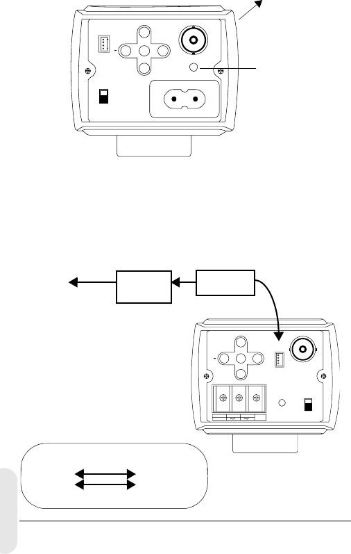
Rev 2 7 G-113079-002
02/07
3. Steek de stekker in het stopcontact. De stroom
(PWR)-LED licht op om te tonen dat de camera stroom
krijgt. Als die niet brandt, controleer dan de
aansluiting en de stroomvoorziening.
Figuur 6 Camera-aansluitingen
Aansluitingen van de afstandsbediening
De L-serie dag/nacht-kleurencamera kan op afstand
bediend worden door middel van een RS485-aansluiting.
Figuur 7 RS485-camera-aansluiting
PWR
VSD
DC
VIDEO
~207-253VAC 50HZ
REMOT E UP
DOWN
MENU
+
Aansluiting op
de monitor
Stroom-LED
Hier is de netaansluiting (230V)-versie afgebeeld
(HCD485L)
-+
GND
DC 12V
AC 24V
PWR VSD
DC
VIDEO
+
UP
DOWN
MENU REMOTE
RS485-converter
TRx+
TRx-
4P-kabel
3TRx+
2TRx-
4P-kabelAansluiting
op seriële
poort (COM1
of COM2)
Seriële
kabel
Legenda van de 4 pinskabel
1. Rood Niet gebruikt
2. Blauw TRx-
3. Geel TRx+
4. Zwart Niet gebruikt
RS485-
converter

Rev 2 8 G-113079-002
02/07
Nederland
Programmeren
On-Screen Display (OSD)
Druk kort op MENU om de huidige bedieningsset-up te
bevestigen. De informatie (zie Figuur 8) verdwijnt na een
paar seconden als er geen knop ingedrukt wordt.
Hoewel de OSD-boodschap verdwijnt, blijft de camera-ID
of -titel op het scherm te zien, als die geselecteerd is in het
CAMERA ID-submenu. Om de camera-ID of -titel uit te
schakelen:
• met externe communicatie, verander de
schermpositie. Opties zijn
onderkant rechts, onderkant links, bovenkant links,
bovenkant rechts, niet op het scherm
• als u de OSD-bediening niet nodig hebt (bijvoorbeeld
als u een extern tekstscherm gebruikt), kunt u die op
elk gewenst moment door middel van een
afstandsbediening met een RS485-aansluiting op OFF
instellen.
Figuur 8 OSD-informatiedisplay
CAMERA-ID/-TITEL
Back Light WB Mode
Back Light wordt getoond als BLC ingeschakeld is
(zie BLC MODE (voor het compenseren van achtergrond-
verlichting)).
Shutter Speed wordt getoond als de
standaardsluitersnelheid gewijzigd is.
WB Mode wordt altijd getoond.
Shutter Speed

Rev 2 9 G-113079-002
02/07
OSD-menufuncties
Gebruik de OSD-menubediening om de camera te
programmeren.
1. Druk op de (middelste) knop MENU en houdt deze
gedurende 2 seconden ingedrukt om het instelmenu
te tonen.
2. Druk op de knoppen UP of DOWN om een
menuonderdeel te selecteren.
3. Druk op de knop MENU om terug te keren naar het
geselecteerde submenu.
4. Druk op de knoppen + of – om de waarde van het
geselecteerde onderdeel te verhogen of te verlagen.
Figuur 9 OSD-menubediening
Opslaan van uw instellingen
Eerste methode: Wanneer u tevreden bent met uw
instellingen:
1. Druk de knop MENU gedurende 2 seconden in. Het
SETUP MENU wordt vervangen door een van twee
boodschappen:
SAVE? wordt getoond wanneer waarden gewijzigd
zijn. Als u SAVE selecteert, verlaat u de instelmodus
en slaat u uw veranderingen op.
QUIT? wordt getoond wanneer u geen instellingen
hebt gewijzigd. Als u QUIT selecteert, verlaat u de
instelmodus zonder gewijzigde waarden op te slaan.
2. Druk op + of – om SAVE of QUIT te selecteren en
druk daarna op MENU om de instelmodus te verlaten.
Druk op UP of DOWN om de SAVE/QUIT te annuleren
en terug te keren naar het instelmenu.
Tweede methode:
Selecteer
EXIT MENU
op het instelmenu,
druk op
MENU
en selecteer daarna
SAVE AND EXIT
om de
gewijzigde instellingen op te slaan en het menu te verlaten. Se-
lecteer
EXIT
om af te sluiten zonder de instellingen op te slaan.
UP
DOWN
MENU
+
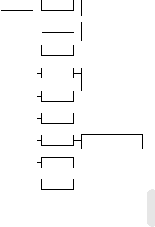
Rev 2 10 G-113079-002
02/07
Nederland
Instellen van uw camera
OSD-menustructuur
Het menusysteem van de L-serie dag/nacht-kleurencamera
bestaat uit een hoofdinstelmenu voor eenvoudig
programmeren.
SETUP MENU CAMERA ID
ELC / ALC Mode
Shutter Speed
White Balance
AGC Control
Nightshot
Sync Control
Restore Default
Het afsluiten van
het menu
Camera-ID, -titel
Displaypositie
ELC Mode: AUTO, MANUAL
ALC Mode: VSD LENS
DC LENS (LEVEL)
ATW, Outdoor, Indoor, User,
Fluorescent,
AWC (Auto, Manual, Push&Lock)
MWB (RED, BLUE)
AUTO, INTERNAL,
LineLock (V.PH)
Hoofdmenu Submenu's Opties
1
2
3
4
5
6
7
8

Rev 2 11 G-113079-002
02/07
Menuon-
derdeel
Optie Beschrijving
1 CAMERA
ID
000 (off), 001 … 255 0: Schakelt ID-scherm uit.
Zie Instellen sync-control
voor meer informatie.
2ELC / ALC
Mode
ELC …
ALC …
Zie ELC/ALC-modus voor
meer informatie.
3 Shutter
Speed
1/60 NTSC (1/50
PAL)
FL
1/250
1/500
1/1000
1/2000
1/4000
1/10000
1/30000
1/50000
Aanpassen helderheid met
hoge sluitersnelheid.
FL: Verwijdert trillingen in
een beeld.
Dit veld is niet regelbaar
wanneer de camera
ingesteld is op ELC MODE.
Auto is standaard
geselecteerd.
4White
Balance
ATW (Auto Trace
White Balance)
AWC (Auto White
Balance Control)
MWB (Manual White
Balance)
Vooringestelde
witbalansfuncties waaronder
buiten, binnen, gebruiker, tl-
licht. Zie Instellen
witbalanscontrole voor
meer informatie.
5AGC
Control
OFF
10 dB
12 dB … 38 dB
Voor het aanpassen van de
maximumwaarde van AGC-
versterking. Wanneer AGC is
ingesteld op OFF, is
Nightshot niet beschikbaar.
6 Nightshot Stel in hoe de camera
reageert op lage belichting.
7Sync.
Control
AUTO
INTERNAL
LineLock (V.Phase)
Zie Instellen sync-control
voor meer informatie.
8Restore
Default
Laad de standaardfabrieks-
instellingen opnieuw.
Als u geen wijzigingen hebt
aangebracht, zult u deze
instelling niet kunnen
selecteren.

Rev 2 12 G-113079-002
02/07
Nederland
Het toevoegen van een camera-ID of -titel
Het toevoegen van een camera-ID is nuttig als u een aantal
camera's in uw netwerk hebt. Om een camera-ID of -titel
toe te voegen, gaat u naar het SETUP MENU, selecteer
CAMERA ID en druk op MENU.
Figuur 10 Toevoegen van een camera-ID of -titel
Voer een cameratitel in
1. Ga naar het eerste karakter van de TITLE: door de +
of – menubediening aan de achterkant van de camera
te gebruiken.
2. Gebruik de menubediening UP, DOWN, +, – om het
eerste karakter in de titel te selecteren, druk daarna op
de MENU-toets om het karakter op te slaan.
Menuon-
derdeel Optie Beschrijving
CAM ID 0
001 …
255
Het nummer dat aan elke camera in uw
netwerk is toegewezen, van 000 tot 255.
0: De ID wordt niet op het scherm getoond.
DISPLAY TITLE
ID
OFF
Selecteer wat op het scherm wordt
getoond (Camera TITLE, ID of niets).
POSITION T.R.
B.R.
B.L.
T.L.
NO DISP
Selecteer waar u de camera-ID of -titel op
het scherm wilt laten verschijnen
(bovenkant rechts, onderkant rechts,
bovenkant links, onderkant links en niet op
het scherm).
TITLE Voer een naam in voor de camera.
Maximum 10 karakters, inclusief spaties.
RETURN Druk op MENU om terug te keren naar het
hoofd-SETUP MENU.
CAM ID: 002
DISPLAY: TITLE
POSITION: T.R.
1 2 3 4 5 6 7 8 9 A B C D E F
G H I J K L M N P Q R S T U V W
X Y Z a b c d e f g h i j k l m
n o p q r s t u v w x y z , . :
; ~ ! ? $ % * & / < > + - = ■
TITLE: HCD484■■
RETURN

Rev 2 13 G-113079-002
02/07
3. Selecteer het volgende karakter van de titel met de +
of – menubediening, herhaal daarna de stappen 2 en
3 tot uw cameratitel klaar is.
4. Selecteer RETURN en druk op MENU om uw
wijzigingen op te slaan en terug te keren naar het
hoofd-SETUP MENU.
Instellen van belichtingsoptimalisatie van
de camera
ELC/ALC-modus
Figuur 11 Instellen van de camerabelichting
Voor het instellen van de lensmodus, compensatie van
achtergrondlicht en zwart masker:
Menuon-
derdeel Optie Beschrijving
EE MODE:
ELC MODE
AUTO
MANUAL Voor een handmatige (vaste) lens:
AUTO: Iris bedient de elektronische
belichting automatisch.
MANUAL: Pas de iris aan door het
handmatig veranderen van de hoge
sluitersnelheid.
EE MODE:
ALC MODE
VSD
LENS
DC
LENS
Voor een automatische irislens:
VSD: Selecteer voor video-type lens.
DC LENS: Selecteer voor direct-
drivetype lens. Pas het LEVEL aan
tot het beeld niet te helder en ook
niet te donker is.
BLC MODE
(voor het
compenseren
van achtergrond-
verlichting)
OFF
LOW BL
MID. BL
HIGH BL
Voorkomt dat het object in het
midden van het beeld donker wordt
(silhoueteffect) wanneer er te veel
licht van achteren komt.
RETURN Druk op MENU om terug te keren
naar het SETUP MENU.
<ELC / ALC MODE>
EE MODE: ALC MODE
DC LENS
LEVEL 04
BLC MODE: OFF
RETURN

Rev 2 14 G-113079-002
02/07
Nederland
Instellen witbalanscontrole
Auto-witbalans zorgt ervoor dat de kleurintegriteit behouden
blijft binnen het kleurbereik van 2800 °K tot 8000 °K:
Figuur 12 Witbalanscontrole
Menuonderdeel Beschrijving
ATW (Auto Trace
White Balance
Mode)
Feedbacksysteem dat automatisch de
witbalans aanpast (2800 °K tot 8000 °K).
AWC (Auto White
Balance Control
Mode)
Functioneert met een snellere
bedieningssnelheid dan ATW. Wordt over het
algemeen gebruikt voor buitentoepassingen
of daar waar variabele belichtingscondities
heersen. De opties zijn:
AUTO: AWC functioneert de hele tijd
MANUAL: PUSH Druk op MENU om de AWC-
functie te starten
MANUAL: LOCK Laat de knop MENU los
om aan te sluiten bij de witbalans van de
huidige opname
INDOOR Voorinstelling voor algemene binnenopnamen
(3200 °K).
FLUORESCENT Kantooromgevingen met tl- of
tungstenverlichting. Geeft het laagste
dynamische bereik van alle voorinstellingen
(4200 °K).
USER FIXED Voorinstelling (4700 °K)
OUTDOOR Voorinstelling voor buitenomgevingen en
scènes met hoog contrast waar de camera
gefocust is op donkerder (6300 °K).
MWB
(Manual Mode)
RED: 0 to 20
BLUE: 0 to 20
RETURN Druk op MENU om terug te keren naar het
SETUP MENU.
<WHITE BALANCE>
WB MODE: MWB
WB CONT: R=00
B=00
RETURN

Rev 2 15 G-113079-002
02/07
Nightshot Control Setup
Het Nightshot-menu biedt u de mogelijkheid in te stellen
hoe de camera reageert op veranderingen in lage
verlichting en in te stellen wanneer de camera overschakelt
tussen nacht- en dagmodus. AGC moet aan staan om
Nightshot actief te laten zijn.
Figuur 13 Witbalanscontrole
Menuonderdeel Beschrijving
MODE AUTO: De camera verwijdert of voegt de IR-
cutfilter in door autodetectie van de helderheid.
ON: IR-cutfilter is verwijderd (nachtmodus)
OFF: IR-cutfilter is ingevoegd (dagmodus)
DET.TIME Stelt de tijd in—5 tot 60 seconden—voordat de
camera overschakelt naar dag- of nachtmodus
nadat een lage lichttoestand gedetecteerd is.
MODE moet ingesteld worden op AUTO.
D->N THD
(drempel)
Bepaalt het detectieniveau voor weinig licht—1
tot 9—wanneer de camera overschakelt naar
de nachtmodus. Hoe lager de waarde, hoe
donkerder de belichtingscondities voordat de
camera overschakelt.
MODE moet ingesteld worden op AUTO.
Opmerking D-> THD moet ingesteld worden
op ten minste 2 minder dan de
N->D THD-instelling.
N->D THD
(drempel)
Bepaalt het detectieniveau voor weinig licht —
1 tot 9—wanneer de camera overschakelt naar
de dagmodus. Hoe hoger de waarde, hoe
helderder de belichtingscondities voordat de
camera overschakelt.
MODE moet ingesteld worden op AUTO.
DN COLOR Stelt de kleurmodus in op B/W (monochroom)
of COLOR in de nachtmodus.
MODE moet ingesteld worden op AUTO of ON.
RETURN Druk op MENU om terug te keren naar het
SETUP MENU.
<NIGHTSHOT>
MODE: AUTO
DET.TIME: 10 sec
D->N THD 2
N->D THD 5
DN COLOR BW
RETURN

Rev 2 16 G-113079-002
02/07
Nederland
Instellen sync-control
Om de verticale intervalsync-puls van uw camera te
synchroniseren met andere apparatuur om het effect van
rollen van het beeld op de monitor te verminderen.
Figuur 14 Instellen sync-control
Afsluiten van het instelmenu
Om het SETUP-menu te verlaten.
Figuur 15 Het afsluiten van het menu
Menuonderdeel Beschrijving
INTERNAL Wanneer linelock niet nodig is.
LINELOCK Aanpassen van de juiste fase:
V.PH: 000 tot 300 (fabrieksinstelling is 0)
Opmerking Linelock is niet beschikbaar
in 12 VDC-vermogen.
AUTO Camera detecteert automatisch de synchronisatie.
RETURN Druk op MENU om terug te keren naar het
SETUP MENU.
Menuonderdeel Beschrijving
SAVE AND EXIT Druk op MENU om uw wijzigingen op te slaan
en af te sluiten.
EXIT Druk op MENU om te stoppen zonder uw
wijzigingen op te slaan.
RETURN Druk op MENU om terug te keren naar het
SETUP MENU.
<SYNC. CONTROL>
SYNC MODE: LINELOCK
V.PH 000
STEP=10
RETURN
<EXIT MENU>
SAVE AND EXIT
EXIT
RETURN

Rev 2 17 G-113079-002
02/07
Garantie en service
Ingevolge de algemene voorwaarden die u vindt bij Productgarantie,
zal Honeywell tijdens de garantieperiode elk product dat gebreken
vertoont en waarvan de koper de verzendkosten heeft betaald,
zonder kosten repareren of vervangen, naar eigen keuze.
Als u een probleem hebt met een Honeywell-product, neemt u dan
contact op met de Klantenservice op het telefoonnummer
1.800.796.CCTV (alleen voor Noord-Amerika) voor hulp of om een
Return Merchandise Authorization (RMA)-nummer te vragen. ln
Europa en het Verenigd Koninkrijk kunt u contact opnemen met uw
Honeywell-dealer.
Zorg dat u het modelnummer, serienummer en de aard van het
probleem bij de hand hebt voor de vertegenwoordiger van de
Technische Dienst.
Voordat u het apparaat terugstuurt, omwisselt of uw geld
terugkrijgt, moet u hiervoor eerst autorisatie gekregen hebben.
Apparaten die naar Honeywell gestuurd worden zonder een
herkenbaar Return Merchandise Autorization (RMA)-nummer
kunnen geweigerd worden.
Specificaties
Opmerking Deze specificaties hebben betrekking op alle
modellen, behalve waar anderszins vermeld.
HCD484L HCD484LX
HCD485LX
Werking
Beeldsensor: 1/3” Super HAD CCD
Videostandaard: NTSC PAL
Scansysteem: 525 beeldlijnen,
2:1 interlace
625 beeldlijnen,
2:1 interlace
Aantal pixels (H x
V):
768 x 494 752 x 582
Minimale
belichting:
< 0,1 lux @ F1.2
(50 IRE, AGC ON, IR Filter Off, B/W)
Horizontale
resolutie:
480 TVL 480 TVL

Rev 2 18 G-113079-002
02/07
Nederland
Video-output: 1 Vp-p @ 75 Ohm
Sync-systeem: Intern/Linelock/Auto
S/R-verhouding: > 50 dB
Automatische
Versterkingsrege-
ling (Auto Gain
Control, of AGC):
Off, 10 dB to 38 dB
ALC: EE/VSD/DC
Automatische
Elektronische
Sluiter (AES):
1/60 - 1/100 000 sec 1/50 - 1/100 000 sec
Lens Mount: C/CS-mount (regelbaar)
Witbalans (AWB): ATW, AWC, binnen, buiten, tl, gebruiker, MWB
BLC: Uit, laag, gemiddeld, hoog
Elektrisch
Inputvoltage: HCD484L, HCD484LX: 12 VDC/24 VAC
HCD485LX: 230 VAC
Inputvoltage-
bereik:
HCD484L, HCD484LX: 11-16 VDC/17-28 VAC
HCD485LX: 230 VAC ± 10%
Stroomverbruik: HCD484L, HCD484LX: 3,5 W (max)
HCD485LX: 4.5 W (max)
Mechanisch
Afmetingen:
(B x H x D)
HCD484L, HCD484LX: 2,68 x 2,2 x 4,72 in.
(68 x 56 x 120 mm)
HCD485LX: 2,68 x 2,2 x 5,51 in.
(68 x 56 x 140 mm)
Gewicht: HCD484L, HCD484LX: 0,84 lb (0,38 kg)
HCD485LX: 0,90 lb(0,41 kg)
Omgeving
Temperatuur: Bij functioneren: 14°F tot 122°F (-10°C tot +50°C)
Opslag: -4°F tot158°F (-20°C tot +70°C)
Gereguleerd
Emissies: FCC, CE (EN55013)
Immuniteit: CE (EN50130-4)
Veiligheid: EU: 73/23/EEC LVD
HCD484L HCD484LX
HCD485LX

© 2007 Honeywell International Inc. Alle rechten voorbehouden. Geen enkel deel
van deze publicatie mag op enige manier gereproduceerd worden zonder
schriftelijke toestemming van Honeywell Video Systems. De informatie in deze
publicatie wordt geacht in alle opzichten accuraat te zijn. Honeywell Video Systems
kan echter geen verantwoordelijkheid aanvaarden voor eventuele gevolgen als
gevolg van het gebruik hiervan. De informatie die hierin is opgenomen kan zonder
kennisgeving gewijzigd worden. Revisies of nieuwe edities van deze publicatie
kunnen uitgegeven worden om dergelijke veranderingen op te nemen.
www.honeywellvideo.com
+1.800.796.CCTV (alleen voor Noord-Amerika)
HVSsupport@honeywell.com
Document G-113079-002 02/07 Rev 2
Honeywell Video Systems
(Hoofdkantoor)
2700 Blankenbaker Pkwy, Suite 150
Louisville, KY 40299, Verenigde Staten
www.honeywellvideo.com
℡ +1.800.796.2288
Honeywell Security Australia Pty Ltd.
Unit 5, Riverside Centre
24-28 River Road West
Parramatta, NSW 2150, Australië
www.ademco.com.au
℡ +61.2.8837.9300
Honeywell Security Asia Pacific
33/F Tower A, City Center, 100 Zun Yi
Shanghai 200051, China
www.security.honeywell.com/cn
℡ +86 21.2527.4568
Honeywell Security Asia
Flat A, 16/F, CDW Building
388 Castle Peak Road
Tsuen Wan, N.T., Hongkong
www.security.honeywell.com/hk
℡ +852.2405.2323
Honeywell Security France
Parc Gutenberg, 8, Voie La Cardon
91120, Palaiseau, Frankrijk
www.honeywell.com/security/fr
℡ +33.01.64.53.80.40
Honeywell Security Italia SpA
Via Treviso 2 / 4
31020 San Vendemiano
Treviso, Italië
www.honeywell.com/security/it
℡ +39.04.38.36.51
Honeywell Security España
Mijancas 1. 3a Planta
P.Ind. Las Mercedes
28022 Madrid, Spanje
www.honeywell.com/security/es
℡ +34.902.667.800
Honeywell Video Systems
Northern Europe
Netwerk 121
1446 WV Purmerend, Nederland
www.SecurityHouse.nl
℡ +31.299.410.200
Honeywell Video Systems UK Ltd.
Aston Fields Road, Whitehouse Ind Est
Runcorn, Cheshire, WA7 3DL, Verenigd
Koninkrijk
www.honeywellvideo.com
℡ +0844 8000 235
Honeywell Security South Africa
Unit 6 Galaxy Park, 17 Galaxy Avenue
Linbro Park, P.O. Box 59904
2100 Kengray, Johannesburg
Zuid-Afrika
www.honeywell.co.za
℡ +27.11.574.2500
Honeywell Security Deutschland
Johannes-Mauthe-Straße 14
D-72458 Albstadt, Duitsland
www.honeywell.com/security/de
℡ +49.74 31.8 01.0
Honeywell Security Poland
Chmielewskiego 22a, 70-028
Szczecin, Polen
www.ultrak.pl
℡ +48.91.485.40.60
Honeywell Security Czech Republic
Havránkova 33, Brno
Dolní Heršpice, 619 00
Tsjechië
www.olympo.cz
℡ +420.543.558.111
Honeywell Security Slovakia Republic
Vajnorská 142, 83104 Bratislava
Slovakije
www.olympo.sk
℡ +421.2.444.54.660
