Honeywell Satellite Radio St 3000 Users Manual .
ST 3000 to the manual 8a05c09e-2577-46e3-bdc8-63caffbb8472
2015-01-23
: Honeywell Honeywell-Honeywell-Satellite-Radio-St-3000-Users-Manual-261740 honeywell-honeywell-satellite-radio-st-3000-users-manual-261740 honeywell pdf
Open the PDF directly: View PDF ![]() .
.
Page Count: 316 [warning: Documents this large are best viewed by clicking the View PDF Link!]

Honeywell Process Solutions
ST 3000 Smart Transmitter
Release 300 and Smart Field
Communicator Model STS103
User’s Manual
34-ST-25-14
6/08

ii ST 3000 Release 300 and SFC Model STS103 User’s Manual 6/08
Copyright, Notices, and Trademarks
© Copyright 2008 by Honeywell Inc.
June 2008
While this information is presented in good faith and believed to be accurate,
Honeywell disclaims the implied warranties of merchantability and fitness for a
particular purpose and makes no express warranties except as may be stated in
its written agreement with and for its customer.
In no event is Honeywell liable to anyone for any indirect, special or consequential
damages. The information and specifications in this document are subject to
change without notice.
This document was prepared using Information Mapping® methodologies and
formatting principles.
TDC 3000, SFC, Smartline and ST 3000 are U.S. registered trademarks of
Honeywell Inc.
Information Mapping is a trademark of Information Mapping Inc.
Honeywell Process Solutions
512 Virginia Drive
Fort Washington, PA 19034

6/08 ST 3000 Release 300 and SFC Model STS103 User’s Manual iii
About This Publication
This manual is intended as a detailed “how to” reference for installing, piping, wiring, configuring,
starting up, operating, maintaining, calibrating, and servicing Honeywell’s family of Release 300
Series 100 and Series 900 ST 3000® Smart Transmitters. It is based on using a model STS103
Smart Field Communicator (SFC®) as the operator interface for the ST 3000 transmitter. Be aware
that data in this manual overlaps information in the ST 3000 Smart Transmitter Installation Guide
and the Smart Field Communicator Model STS103 Operating Guide to minimize cross reference.
While this manual provides detailed procedures to assist first time users, it also includes keystroke
summaries for most procedures as a quick reference for experienced users.
If you will be digitally integrating the ST 3000 transmitter with our TotalPlant® Solution (TPS)
system, you will need to supplement this information with data in the PM/APM Smartline®
Transmitter Integration Manual which is supplied with the TDC 3000®X bookset. TPS is the
evolution of TDC 3000X.
This manual does not apply for non Release 300 Series 100, Series 600, Series 100e and non
Release 300 Series 900 transmitter models. If you have a non Release 300 Series 100 or Series
600 ST 3000 Smart Transmitter, refer to the Installation Guide 34-ST-33-28 and User’s Manual
34-ST-25-09 supplied with the transmitter for information. If you have a non Release 300 Series
900 or Series 100e Smart Transmitter, refer to the Installation Guide 34-ST-33-31 and User’s
Manual 34-ST-25-11 supplied with the transmitter for information.
Patent Notice
This product is covered by one or more of the following U.S. Patents: 4,520,488; 4,567,466;
4,494,183; 4,502,335; 4,592,002; 4,553,104; 4,541,282; 4,806,905; 4,797,669; 4,735,090;
4,768,382; 4,787,250; 4,888,992; 5,811,690; 5,875,150; 5,765,436; 4,734,873; 6,041,659 and
other patents pending.
iv ST 3000 Release 300 and SFC Model STS103 User’s Manual 6/08
References
Publication
Title
Publication
Number
Binder
Title
Binder
Number
Smart Field Communicator
Model STS103
Operating Guide
34-ST-11-14
ST 3000 Smart Transmitter
Series 100 and Series 900
Release 300
Installation Guide
34-ST-33-39
For R400 and later:
PM/APM Smartline Transmitter
Integration Manual
PM12-410 Implementation/
PM/APM Optional Devices
TDC 2045
Symbol Definitions
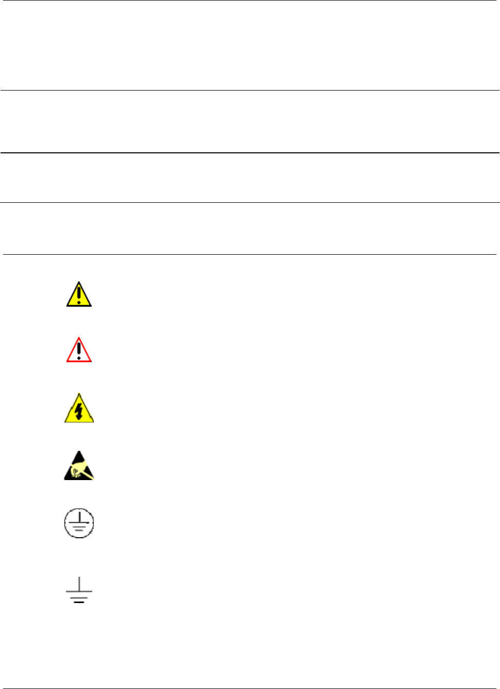
This CAUTION symbol on the equipment refers the user to the Product
Manual for additional information. This symbol appears next to required
information in the manual.
This WARNING symbol on the equipment refers the user to the Product
Manual for additional information. This symbol appears next to required
information in the manual.
WARNING: risk of electrical shock. This symbol warns the user of a potential
shock hazard where HAZARDOUS LIVE voltages greater than 30 Vrms, 42.4
Vpeak, or 60 VDC may be accessible.
ATTENTION, Electrostatic Discharge (ESD) hazards. Observe precautions for
handling electrostatic sensitive devices
Protective Earth (PE) terminal. Provided for connection of the protective earth
(green or green/yellow) supply system conductor.
Earth Ground. Functional earth connection. NOTE: This connection shall be
bonded to Protective earth at the source of supply in accordance with national
and local electrical code requirements.

6/08 ST 3000 Release 300 and SFC Model STS103 User’s Manual v
Table of Contents
References.................................................................................................................................................. iv
Technical Assistance.................................................................................................................................xiii
SECTION 1 —OVERVIEW - FIRST TIME USERS ONLY.................................................1
1.1 Introduction........................................................................................................................................1
1.2 ST 3000 Smart Transmitters .............................................................................................................2
1.3 Smart Field Communicator................................................................................................................8
1.4 Transmitter/SFC Order....................................................................................................................11
1.5 Local Smart Meter Options..............................................................................................................13
SECTION 2 —QUICK START REFERENCE.................................................................. 15
2.1 Introduction......................................................................................................................................15
2.2 Getting ST 3000 Transmitter On-Line Quickly ................................................................................16
SECTION 3 —PREINSTALLATION CONSIDERATIONS .............................................. 17
3.1 Introduction......................................................................................................................................17
3.2 CE Conformity (Europe) Notice.......................................................................................................18
3.3 Considerations for ST 3000 Transmitter .........................................................................................19
3.4 Considerations for SFC ...................................................................................................................22
3.5 Considerations for Local Smart Meter Option .................................................................................24
SECTION 4 —INSTALLATION....................................................................................... 25
4.1 Introduction......................................................................................................................................25
4.2 Mounting ST 3000 Transmitter........................................................................................................26
4.3 Piping ST 3000 Transmitter.............................................................................................................38
4.4 Wiring ST 3000 Transmitter.............................................................................................................43
SECTION 5 —GETTING STARTED ...............................................................................49
5.1 Introduction......................................................................................................................................49
5.2 Establishing Communications .........................................................................................................50
5.3 Making Initial Checks.......................................................................................................................54
5.4 Changing Mode of Operation ..........................................................................................................57

vi ST 3000 Release 300 and SFC Model STS103 User’s Manual 6/08
Table of Contents
SECTION 6 —CONFIGURATION ...................................................................................59
6.1 Introduction ..................................................................................................................................... 59
6.2 Overview ......................................................................................................................................... 60
6.3 Entering a Tag Number................................................................................................................... 71
6.4 Selecting Output Form .................................................................................................................... 73
6.5 Adjusting Damping Time................................................................................................................. 76
6.6 Selecting Unit of Measurement....................................................................................................... 78
6.7 Setting Range Values Using SFC................................................................................................... 80
6.8 Setting Range Values Using Local Adjustments ............................................................................ 84
6.9 Selecting Output Signal Mode (DE Mode Only) ............................................................................. 91
6.10 Selecting Message Format (DE Mode Only) .................................................................................. 94
6.11 Configuring Smart Meter Using SFC .............................................................................................. 96
6.12 Configuring Smart Meter Using Pushbuttons ............................................................................... 103
6.13 Disconnecting SFC ....................................................................................................................... 122
SECTION 7 —STARTUP...............................................................................................123
7.1 Introduction ................................................................................................................................... 123
7.2 Startup Tasks ................................................................................................................................ 124
7.3 Running Analog Output Check ..................................................................................................... 125
7.4 Flow Measurement with DP Transmitter....................................................................................... 128
7.5 Pressure Measurement with DP Transmitter................................................................................ 131
7.6 Liquid Level Measurement - Vented Tank .................................................................................... 133
7.7 Liquid Level Measurement - Pressurized Tank ............................................................................ 136
7.8 Pressure or Liquid Level Measurement with GP Transmitter....................................................... 140
7.9 Pressure or Liquid Level Measurement with Flush Mount Transmitter ........................................ 144
7.10 Pressure Measurement with AP Transmitter ................................................................................ 145
7.11 Liquid Level Measurement with DP Transmitter with Remote Seals............................................ 147
SECTION 8 —OPERATION ..........................................................................................151
8.1 Introduction ................................................................................................................................... 151
8.2 Accessing Operation Data ............................................................................................................ 152
8.3 Changing Default Failsafe Direction ............................................................................................. 155
8.4 Writing Data in Scratch Pad Area ................................................................................................. 157
8.5 Saving and Restoring a Database ................................................................................................ 159
8.6 Monitoring Local Smart Meter Display.......................................................................................... 163
SECTION 9 —MAINTENANCE .....................................................................................169
9.1 Introduction ................................................................................................................................... 169
9.2 Preventive Maintenance................................................................................................................ 170
9.3 Inspecting and Cleaning Barrier Diaphragms............................................................................... 171
9.4 Replacing PWA............................................................................................................................. 175
9.5 Replacing Meter Body................................................................................................................... 178

6/08 ST 3000 Release 300 and SFC Model STS103 User’s Manual vii
Table of Contents
SECTION 10 —CALIBRATION..................................................................................... 183
10.1 Introduction....................................................................................................................................183
10.2 Overview........................................................................................................................................184
10.3 Calibrating Analog Output Signal ..................................................................................................185
10.4 Calibrating Range with SFC ..........................................................................................................189
10.5 Resetting Calibration .....................................................................................................................192
SECTION 11 —TROUBLESHOOTING......................................................................... 195
11.1 Introduction....................................................................................................................................195
11.2 Overview........................................................................................................................................196
11.3 Clearing the “#” Symbol From SFC Display ..................................................................................197
11.4 Diagnostic Messages ....................................................................................................................199
11.5 Running Status Check...................................................................................................................202
11.6 Interpreting Messages...................................................................................................................203
11.7 Checking SFC Display and Keyboard...........................................................................................207
SECTION 12 —PARTS LIST ........................................................................................ 209
12.1 Replacement Parts........................................................................................................................209
SECTION 13 —REFERENCE DRAWINGS .................................................................. 231
13.1 Wiring Diagrams ............................................................................................................................231
APPENDIX A – TABLE III OPTIONS IN MODEL NUMBER......................................... 233
A.1 Table III Options Reference...........................................................................................................233
APPENDIX B – FREEZE PROTECTION OF TRANSMITTERS ................................... 237
B.1 Possible Solutions/Methods ..........................................................................................................237
APPENDIX C – CONFIGURATION RECORD SHEET ................................................. 251
APPENDIX D – HAZARDOUS LOCATIONS REFERENCE......................................... 253
D.1 North American Classification of Hazardous Locations ................................................................253
D.2 International Electrotechnical Commission (IEC) Classification of Hazardous Locations ............259
D.3 Enclosure Ratings .........................................................................................................................263
INDEX............................................................................................................................ 266

viii ST 3000 Release 300 and SFC Model STS103 User’s Manual 6/08
Figures
Figure 1 Typical ST 3000 Differential Pressure Transmitter................................................................................2
Figure 2 Functional Block Diagram for Transmitter in Analog Mode of Operation............................................3
Figure 3 Functional Block Diagram for Transmitter in Digital DE Mode of Operation. .....................................4
Figure 4 Typical SFC Communication Interface..................................................................................................8
Figure 5 Typical ST 3000 Transmitter and SFC Order Components. ................................................................11
Figure 6 ST 3000 with Local Smart Meter Option.............................................................................................14
Figure 7 Typical Mounting Area Considerations Prior to Installation ...............................................................19
Figure 8 Typical Bracket Mounted and Flange Mounted Installations...............................................................26
Figure 9 Leveling a Model STA122 or 922 Absolute Pressure Transmitter. .....................................................30
Figure 10 Typical Flange Mounted Transmitter Installation ................................................................................33
Figure 11 Typical Flush Mounted Transmitter Installation ..................................................................................34
Figure 12 Typical Pipe and Flange Mounted Installations ...................................................................................35
Figure 13 Typical Remote Diaphragm Seal Transmitter Installation. ..................................................................37
Figure 14 Typical 3-Valve Manifold and Blow-Down Piping Arrangement. ......................................................38
Figure 15 Typical Piping Arrangement for ½” NPT Process Connection............................................................39
Figure 16 Operating Range for ST 3000 Transmitters. ........................................................................................43
Figure 17 ST 3000 Transmitter Terminal Block...................................................................................................44
Figure 18 Ground Connection for Lightning Protection.......................................................................................46
Figure 19 Typical SFC Connections.....................................................................................................................50
Figure 20 Write Protect Jumper Location and Selections.....................................................................................55
Figure 21 Display With All Indicators Lit............................................................................................................56
Figure 22 Keystroke Summary for Changing Mode of Operation. ......................................................................58
Figure 23 Summary of Configuration Process......................................................................................................60
Figure 24 SFC and ST 3000 Transmitter Memories.............................................................................................61
Figure 25 Flowchart — ST 3000 Pressure Transmitter Configuration.................................................................66
Figure 26 Keystroke Summary for Entering Tag Number....................................................................................72
Figure 27 Keystroke Summary for Selecting Output Conformity........................................................................74
Figure 28 Square Root Dropout Points.................................................................................................................75
Figure 29 Keystroke Summary for Adjusting Damping Time..............................................................................77
Figure 30 Keystroke Summary for Keying in LRV and URV..............................................................................81
Figure 31 Keystroke Summary for Setting LRV and URV to Applied Pressures. ...............................................83
Figure 32 Typical Setup for Setting Range Values Using Local Zero and Span Adjustments.............................90
Figure 33 Keystroke Summary for Selecting Mode of Output Signal Indication.................................................93
Figure 34 Keystroke Summary for Selecting Message Format. ...........................................................................95
Figure 35 Keystroke Summary for Configuring Local Smart Meter..................................................................102
Figure 36 Button Pushing Summary for Selecting Engineering Units. ..............................................................120
Figure 37 Button Pushing Summary for Setting Lower and Upper Display Limits...........................................121
Figure 38 Typical SFC and Meter Connections for Constant-Current Source Mode.........................................127
Figure 39 Typical Piping Arrangement for Flow Measurement with DP Type Transmitter..............................128
Figure 40 Typical Piping Arrangement for Pressure Measurement with DP Type Transmitter.........................131
Figure 41 Typical Piping Arrangement for Liquid Level Measurement with
DP Type Transmitter and Vented Tank..............................................................................................133
Figure 42 Typical Piping Arrangement for Liquid Level Measurement with
DP Type Transmitter and Pressurized Tank.......................................................................................136
Figure 43 Typical Piping Arrangement for Pressure Measurement with GP Type Transmitter.........................140
Figure 44 Typical Piping Arrangement for Liquid Level Measurement with GP TypeTransmitter...................140
Figure 45 Typical Arrangement for Pressure Measurement with Flush Mount Transmitter..............................144
Figure 46 Typical Arrangement for Liquid Level Measurement with Flush Mount Transmitter.......................144
Figure 47 Typical Piping Arrangement for Pressure Measurement with AP Type Transmitter.........................145

6/08 ST 3000 Release 300 and SFC Model STS103 User’s Manual ix
Figures
Figure 48 Typical Piping Arrangement for Liquid Level Measurement with
DP Type Transmitter with Remote Seals ...........................................................................................147
Figure 49 Location of Failsafe Direction Jumper on PWA................................................................................156
Figure 50 Summary of Save and Restore Database Function.............................................................................159
Figure 51 Display With All Indicators Lit..........................................................................................................163
Figure 52 Typical Calibration Hookup...............................................................................................................191
Figure 53 Major ST 3000 Smart Transmitter Parts Reference. ..........................................................................210
Figure 54 ST 3000 Transmitter Mounting Bracket Parts Reference. .................................................................211
Figure 55 Series 100/900 Electronics Housing - Electronics/Meter End. ..........................................................212
Figure 56 Series 100/900 Electronics Housing - Terminal Block End...............................................................212
Figure 57 Series 100 and Series 900 DP Meter Body for Models STD924 & STD930 C, D, G,
H, K, and L and STD974 ...................................................................................................................214
Figure 58 Series 900 DP Meter Body for Models Models STD924 & STD930 A, B, E, F, and J.....................217
Figure 59 Series 100 GP and AP Meter Bodies and Series 900 AP Meter Body...............................................219
Figure 60 Series 900 Dual-Head GP Meter Bodies............................................................................................221
Figure 61 Series 100 and Series 900 LGP Meter Body......................................................................................222
Figure 62 Series 900 Flush Mount Meter Body. ................................................................................................223
Figure 63 Series 100 and Series 900 Flange Mounted Meter Body. ..................................................................224
Figure 64 High Temperature Meter Body. .........................................................................................................226
Figure 65 SFC Smart Field Communicator and Accessories. ............................................................................228
Figure B-1 Piping Installation for Sealing Liquid With Specific Gravity Heavier Than Process Fluid...............238
Figure B-2 Piping Installation for Sealing Liquid with Specific Gravity Lighter Than Process Fluid.................239
Figure B-3 Piping Installation for Gas Flow. .......................................................................................................240
Figure B-4 Piping Installation for Differential Pressure Transmitter with Metal Diaphragm Seals.....................241
Figure B-5 Piping Installation for Process Pressure Transmitter with Metal Diaphragm Seal.............................242
Figure B-6 Piping Installation for Differential Pressure Transmitter and
Impulse Piping with Electric Heating and Control.............................................................................243
Figure B-7 Piping Installation for Process Pressure Transmitter and
Impulse Piping with Electric Heating Control. ..................................................................................244
Figure B-8 Piping Installation for Differential Pressure Transmitter and Impulse Piping with Steam Heating...247
Figure B-9 Piping Installation for Process Pressure Transmitter and Impulse Piping with Steam Heating.........248

x ST 3000 Release 300 and SFC Model STS103 User’s Manual 6/08
Tables
Table 1 ST 3000 Pressure Transmitter Family..................................................................................................6
Table 2 SFC Model Differences........................................................................................................................9
Table 3 Local Smart Meter Available Options................................................................................................13
Table 4 Start-up Tasks Reference....................................................................................................................16
Table 5 Operating Temperature Limits (Transmitters with Silicone Fill Fluids)............................................20
Table 6 Transmitter Overpressure Ratings......................................................................................................21
Table 7 Installing and Charging SFC Battery Pack.........................................................................................22
Table 8 Local Smart Meter Specifications. .....................................................................................................24
Table 9 Mounting ST 3000 Transmitter to a Bracket......................................................................................27
Table 10 Zero Corrects Procedure for STD110.................................................................................................32
Table 11 Mounting Remote Diaphragm Seal Transmitter.................................................................................36
Table 12 Suggested Transmitter Location for Given Process ...........................................................................39
Table 13 Process Connections...........................................................................................................................40
Table 14 Flange Description .............................................................................................................................41
Table 15 Installing Flange Adapter ...................................................................................................................42
Table 16 Wiring the Transmitter .......................................................................................................................45
Table 17 Starting Communications with Transmitter........................................................................................51
Table 18 Confirming Mode of Operation and Identifying Software Versions..................................................54
Table 19 Changing Mode of Operation.............................................................................................................57
Table 20 Summary of Pressure Transmitter Configuration Parameters............................................................63
Table 21 Entering Tag Number.........................................................................................................................71
Table 22 Selecting Output Conformity .............................................................................................................73
Table 23 Adjusting Damping Time...................................................................................................................76
Table 24 Pre-Programmed Engineering Units for Selection .............................................................................78
Table 25 Keying in LRV and URV...................................................................................................................80
Table 26 Setting LRV and URV to Applied Pressures......................................................................................82
Table 27 Setting Range Values Using Local Zero and Span Adjustments .......................................................84
Table 28 Selecting Mode of Output Signal Indication......................................................................................91
Table 29 Selecting Message Format..................................................................................................................94
Table 30 Setting Up Local Smart Meter Configuration Using an SFC.............................................................97
Table 31 Smart Meter Pushbutton Description ...............................................................................................103
Table 32 Smart Meter Engineering Units Code ..............................................................................................105
Table 33 Selecting Engineering Units.............................................................................................................106
Table 34 Smart Meter Restrictions for Setting Display Values.......................................................................109
Table 35 Setting Lower Display Values for Smart Meter Display..................................................................110
Table 36 Setting Upper Display Value for Smart Meter Display....................................................................114
Table 37 Startup Procedure Reference............................................................................................................124
Table 38 Using Transmitter in Constant-Current Source Mode......................................................................125
Table 39 Starting Up DP Transmitter for Flow Measurement With SFC .......................................................128
Table 40 Starting Up DP Transmitter for Pressure Measurement With SFC..................................................131
Table 41 Starting Up DP Transmitter for Liquid Level Measurement in Vented Tank..................................134
Table 42 Starting Up DP Transmitter for Liquid Level Measurement in Pressurized Tank ...........................137
Table 43 Starting Up GP Transmitter for Pressure or Liquid Level Measurement With SFC........................141
Table 44 Starting Up AP Transmitter for Pressure Measurement With SFC..................................................145
Table 45 Starting Up DP Transmitter with Remote Seals for Liquid Level Measurement with SFC.............148
Table 46 Summary of Keystrokes for Operation Data Access........................................................................152
Table 47 Cutting Failsafe Direction Jumper....................................................................................................156
Table 48 Writing Data in Scratch Pad Area ....................................................................................................157
Table 49 Saving and Restoring a Database .....................................................................................................160

6/08 ST 3000 Release 300 and SFC Model STS103 User’s Manual xi
Tables
Table 50 Description of Display Indicators Shown in Figure 51....................................................................163
Table 51 Summary of Typical Local Smart Meter Indications. ......................................................................165
Table 52 Possible Smart Meter Error Codes...................................................................................................166
Table 53 Inspecting and Cleaning Barrier Diaphragms ..................................................................................171
Table 54 Process Head Bolt Torque Ratings...................................................................................................174
Table 55 Replacing PWA................................................................................................................................175
Table 56 Replacing Meter Body Only.............................................................................................................178
Table 57 Calibrating Output Signal for Transmitter in Analog Mode ............................................................185
Table 58 Calibrating Measurement Range With SFC.....................................................................................189
Table 59 Resetting Calibration Data With SFC ..............................................................................................193
Table 60 Clearing the # Symbol from the SFC Display..................................................................................197
Table 61 Summary of Diagnostic Messages for Non-Critical Failures...........................................................199
Table 62 Summary of Diagnostic Messages for Critical Failures...................................................................200
Table 63 Summary of Diagnostic Messages for Communication Errors ........................................................200
Table 64 Summary of Diagnostic Messages for Invalid Key Entry Errors.....................................................201
Table 65 Summary of Interrupt Messages For SFC Display...........................................................................201
Table 66 Running a Status Check With SFC ..................................................................................................202
Table 67 Diagnostic Message Interpretation Table.........................................................................................203
Table 68 Running SFC Display and Keyboard Test .......................................................................................207
Table 69 Major ST 3000 Smart Transmitter Parts Reference. ........................................................................211
Table 70 Parts Identification for Callouts in Figures 55 and 56......................................................................213
Table 71 Parts Identification for Callouts in Figure 57...................................................................................215
Table 72 Parts Identification for Callouts in Figure 58...................................................................................218
Table 73 Parts Identification for Callouts in Figure 59...................................................................................219
Table 74 Replacement GP and AP Process Head Part Numbers for Narrow Profile Meter Body..................220
Table 75 Parts Identification for Callouts in Figure 60...................................................................................221
Table 76 Parts Identification for Callouts in Figure 61...................................................................................222
Table 77 Parts Identification for Callouts in Figure 62...................................................................................223
Table 78 Parts Identification for Callouts in Figure 63...................................................................................225
Table 79 Parts Identification for Callouts in Figure 64...................................................................................226
Table 80 Parts Identification for Callouts in Figure 65...................................................................................229
Table 81 Summary of Recommended Spare Parts..........................................................................................230
Table B-1 Temperature Range of Freeze Protection Systems...........................................................................246
Table B-2 Steam Pressure Versus Steam Temperature Values.........................................................................250
Table D-1 Factory Mutual (FM) Entity Parameters ..........................................................................................257
Table D-2 CSA Entity Parameters.....................................................................................................................258
Table D-3 CENELEC / LCIE Certification.......................................................................................................261
Table D-4 Standards Australia (LOSC) Certification........................................................................................262
Table D-5 Zone 2 (Europe) Declaration of Conformity....................................................................................262
Table D-6 NEMA Enclosure Type Numbers and Comparable IEC Enclosure Classification..........................264

xii ST 3000 Release 300 and SFC Model STS103 User’s Manual 6/08
Acronyms
AP.......................................................................................................................... Absolute Pressure
APM .......................................................................................................Advanced Process Manager
AWG .............................................................................................................. American Wire Gauge
DE .................................................................................... Digital Enhanced Communications Mode
DP...................................................................................................................... Differential Pressure
EMI....................................................................................................... Electromagnetic Interference
GP.............................................................................................................................. Gauge Pressure
HP.................................................................................................................................High Pressure
HP.............................................................................................High Pressure Side (DP Transmitter)
inH2O ........................................................................................................................Inches of Water
LGP ...............................................................................................................In-Line Gauge Pressure
LP ..................................................................................................................................Low Pressure
LP ............................................................................................. Low Pressure Side (DP Transmitter)
LRV.................................................................................................................... Lower Range Value
mA................................................................................................................................. Milliamperes
mmHg............................................................................................................Millimeters of Mercury
NPT .................................................................................................................. National Pipe Thread
PCB .................................................................................................................. Printed Circuit Board
PM.............................................................................................................................Process Manger
PROM......................................................................................... Programmable Read Only Memory
PSI................................................................................................................ Pounds per Square Inch
PSIA ..............................................................................................Pounds per Square Inch Absolute
RFI.......................................................................................................Radio Frequency Interference
SFC..........................................................................................................Smart Field Communicator
TPS.....................................................................................................................TotalPlant Solution
URL..................................................................................................................... Upper Range Limit
URV ....................................................................................................................Upper Range Value
Vdc .....................................................................................................................Volts Direct Current
XMTR ..............................................................................................................................Transmitter

6/08 ST 3000 Release 300 and SFC Model STS103 User’s Manual xiii
Technical Assistance
If you encounter a problem with your ST 3000 Smart Transmitter, check to see how your
transmitter is currently configured to verify that all selections are consistent with your application.
If the problem persists, you can reach Honeywell’s Solution Support Center for technical support
by telephone during normal business hours. An engineer will discuss your problem with you.
Please have your complete model number, serial number, and software revision number on hand
for reference. You can find the model and serial numbers on the transmitter nameplates. You can
also view the software version number using the SFC or SCT 3000 software application.
By Telephone Honeywell Solution Support Center Phone:
1-800-423-9883 (U.S. only)
Outside the U.S. call: 1-602-313-6510
Additional Help You may also seek additional help by contacting the Honeywell
distributor who supplied your ST 3000 transmitter.
By E-mail You can also e-mail your technical questions or comments about this
product to:
Honeywell Solution Support Center e-mail: ace@honeywell.com
Problem Resolution If it is determined that a hardware problem exists, a replacement
transmitter or part will be shipped with instructions for returning the
defective unit. Please do not return your transmitter without
authorization from Honeywell’s Solution Support Center or until the
replacement has been received.

6/08 ST 3000 Release 300 and SFC Model STS103 User’s Manual 1
Section 1 —Overview - First Time Users Only
1.1 Introduction
Section contents This section includes these topics:
Section Topic See Page
1.1 Introduction ....................................................................................1
1.2 ST 3000 Transmitters.....................................................................2
1.3 Smart Field Communicator.............................................................8
1.4 Transmitter/SFC Order.................................................................11
1.5 Local Smart Meter Options...........................................................13
About this section This section is intended for users who have never worked with our
ST 3000 Smart Transmitter and its companion operator interface device
the hand-held Smart Field Communicator (SFC®) before. It provides
some general information to acquaint you with the ST 3000 transmitter
and the SFC.
ATTENTION Honeywell also offers the SCT 3000 Smartline Configuration Toolkit
that runs on a variety of Personal Computer (PC) platforms using MS-
DOS 5.0 or higher and Windows 3.1 or higher. It is a bundled Microsoft
Windows software and PC-interface hardware solution that allows
quick, error-free configuration of Honeywell Smartline field
instruments. Some SCT 3000 features include:
• Preconfigured templates that simplify configuration and allow rapid
development of configuration databases.
• Context-sensitive help and an on-line user manual.
• Extensive menus and prompts that minimize the need for prior
training or experience.
• The ability to load previously configured databases at time of
installation.
• Automatic verification of device identification and database
configuration menus and prompts for bench set up and calibration.
• The ability to save unlimited transmitter databases on the PC.
SCT 3000 Release 3.12.2 or greater is compatible with our latest Series
100 and 900, Release 300, ST 3000 transmitters. Please contact your
Honeywell representative for more information.
2 ST 3000 Release 300 and SFC Model STS103 User’s Manual 6/08
1.2 ST 3000 Smart Transmitters
About the transmitter The ST 3000 Smart Transmitter comes in a variety of models for
measurement applications involving one of these basic types of
pressure:
• Differential Pressure
• Gauge Pressure
• Absolute Pressure
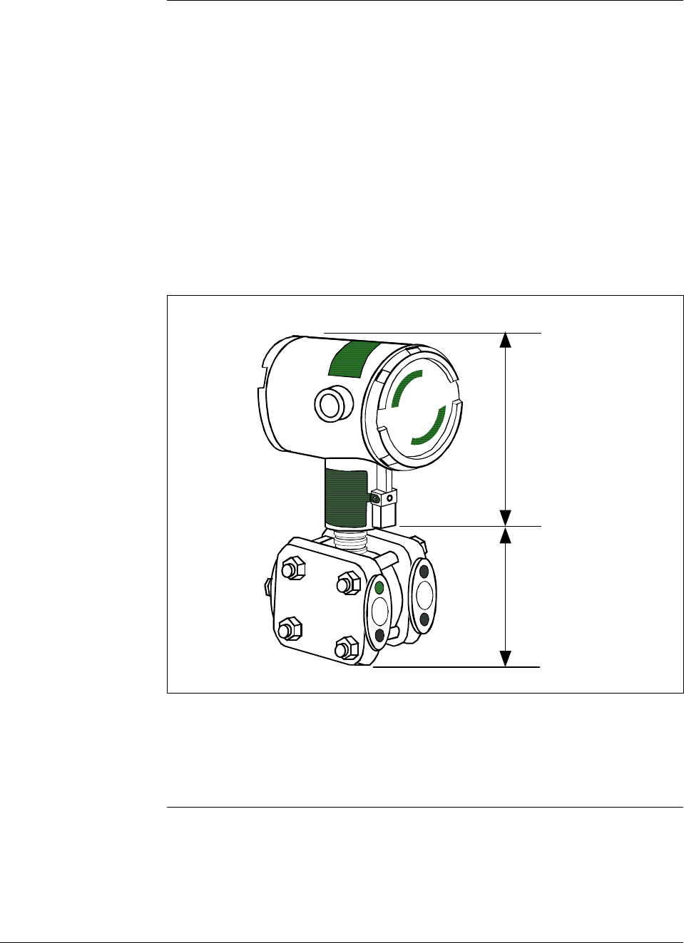
The transmitter measures the process pressure and transmits an output
signal proportional to the measured variable over a 4 to 20 milliampere,
two-wire loop. Its major components are an electronics housing and a
meter body as shown in Figure 1 for a typical differential pressure
model transmitter.
Figure 1 Typical ST 3000 Differential Pressure Transmitter.
Electronics
Housing
Meter Body
The ST 3000 can transmit its output in either an analog 4 to 20
milliampere format or a digital DE protocol format for direct digital
communications with our TPS system, Allen-Bradley PLCs and other
control systems.
Continued on next page
6/08 ST 3000 Release 300 and SFC Model STS103 User’s Manual 3
1.2 ST 3000 Smart Transmitters, Continued
About the transmitter,
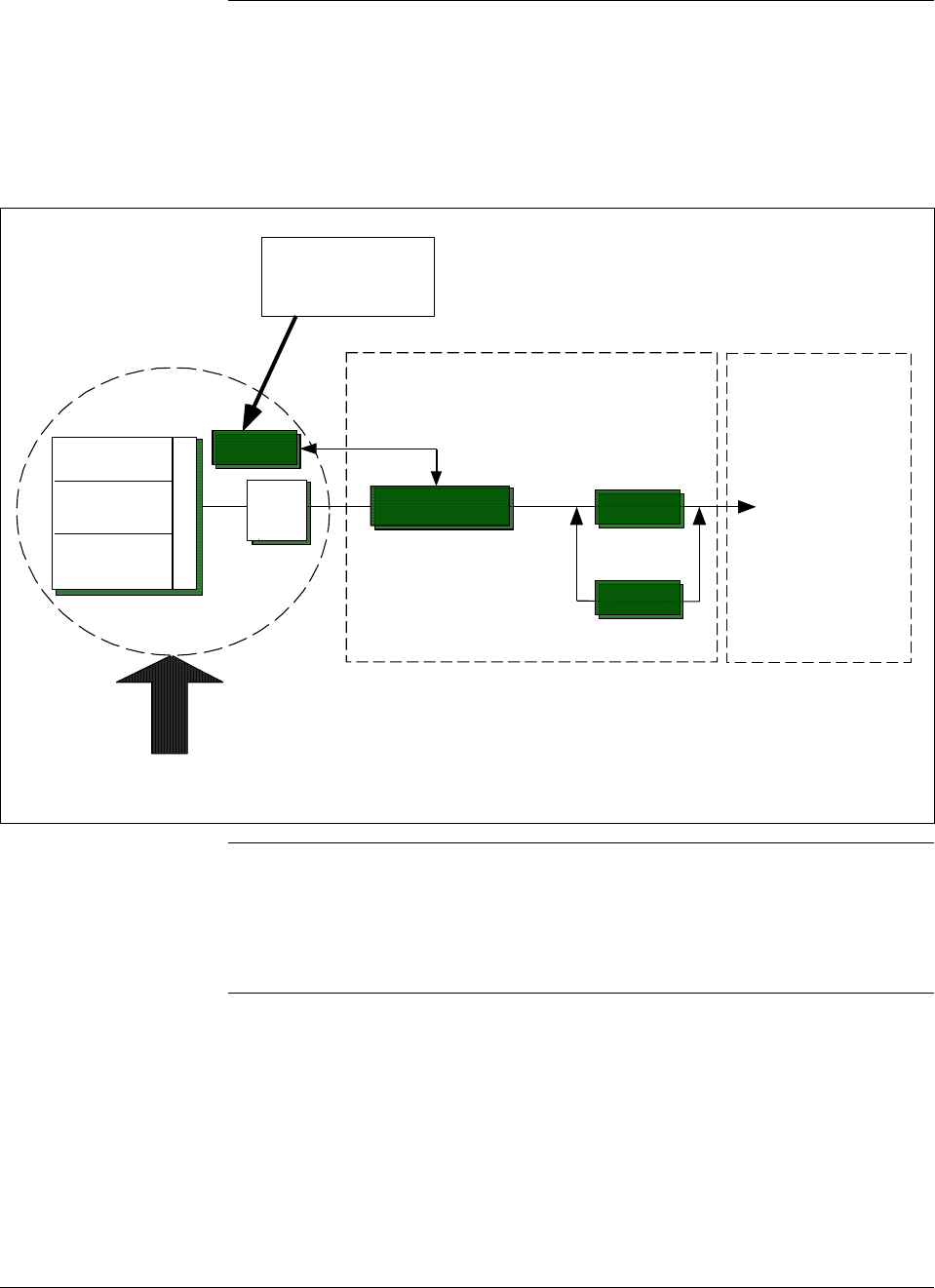
continued Besides the process variable (PV) output, the transmitter also provides
its meter body temperature as a secondary variable which is only
available as a read-only parameter through the SFC when the transmitter
is in its analog mode. See Figure 2.
Figure 2 Functional Block Diagram for Transmitter in Analog Mode of Operation.
A/D
DP or PP
Sensor
Temperature
Sensor
Static Pressure
Sensor
Meter Body Electronics Housing
Pressure
Factory
Characterization
Data
Modular Electronics Terminal Block
Proportional 4 to
20 mA PV output.
(Digital signal
imposed during
SFC
communications)
D/A
PROM
Multiplexer
Microprocessor
Digital I/O
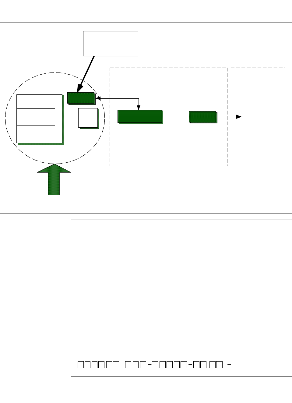
When the transmitter is in its DE mode, the process variable is available
for monitoring and control purposes; and the meter body temperature is
also available as a secondary variable for monitoring purposes only.
See Figure 3.
Continued on next page
4 ST 3000 Release 300 and SFC Model STS103 User’s Manual 6/08
1.2 ST 3000 Smart Transmitters, Continued
Figure 3 Functional Block Diagram for Transmitter in Digital DE Mode of Operation.
A/D
DP or PP
Sensor
Temperature
Sensor
Static Pressure
Sensor
Meter Body Electronics Housing
Pressure
Factory
Characterization
Data
Modular Electronics Terminal Block
Digital signal
broadcasts PV
in floating point
format over
20 mA loop.
Digital I/O
PROM
Multiplexer
Microprocessor
Series and model
number data Honeywell’s line of ST 3000 Smart Transmitters includes these two
series designations:
• Series 100
• Series 900
Each series includes several models to meet various process pressure
measurement and interface requirements. Each transmitter comes with a
nameplate located on the top of the electronics housing that lists its given
“model number”. The model number format consists of a Key Number
with several Table selections as shown below.
Key Number
Meter Body
Flange Assembly
Options
Factory Identification
Table I Table II Table III Table IV
Basic Type
,
STD1 20 E1H 00000 S 1CBXXXX
Continued on next page

6/08 ST 3000 Release 300 and SFC Model STS103 User’s Manual 5
1.2 ST 3000 Smart Transmitters, Continued
Series and model
number data,
continued
You can quickly identify what series and basic type of transmitter you
have from the third and fourth digits in the key number. The letter in the
third digit represents one of these basic transmitter types:
A = Absolute Pressure
D = Differential Pressure
F = Flange Mounted
G = Gauge Pressure
R = Remote Seals
The number in the fourth digit matches the first digit in the transmitter
Series. Thus, a “1” means the transmitter is a Series 100 and a “9” is a
Series 900.
For a complete breakdown of the Table selections in your model
number, please refer to the appropriate Specification and Model
Selection Guide that is provided as a separate document. However, a
description of the available Table III options is given in Appendix A of
this manual for handy reference.
ATTENTION Previous models of the ST 3000 transmitter with designations of Series
100, Series 100e, Series 600, and Series 900 have been supplied at
various times since the ST 3000 was introduced in 1983. While all these
transmitters are functionally alike, there are differences in housing and
electronics design. This manual only applies for Release 300, Series 100
transmitters with software version 3.0 or greater and Release 300, Series
900 transmitters with software version b.0 or greater. See the procedure
on page 50 to use the SFC to check your transmitter’s software version.
Release 300 transmitters can be identified by the “R300” designation on
the nameplate.
Transmitter
adjustments Except for optional zero and span adjustments, the ST 3000 has no
physical adjustments. You need an SFC to make any adjustments in an
ST 3000 transmitter. Alternately, certain adjustments can be made
through the Universal Station if the transmitter is digitally integrated
with a Honeywell TPS system; or through a PC running Honeywell
SCT 3000 software.
ST 3000 Transmitters
presently available Table 1 illustrates the present ST 3000 pressure transmitter family.
Continued on next page
6 ST 3000 Release 300 and SFC Model STS103 User’s Manual 6/08
1.2 ST 3000 Smart Transmitters, Continued
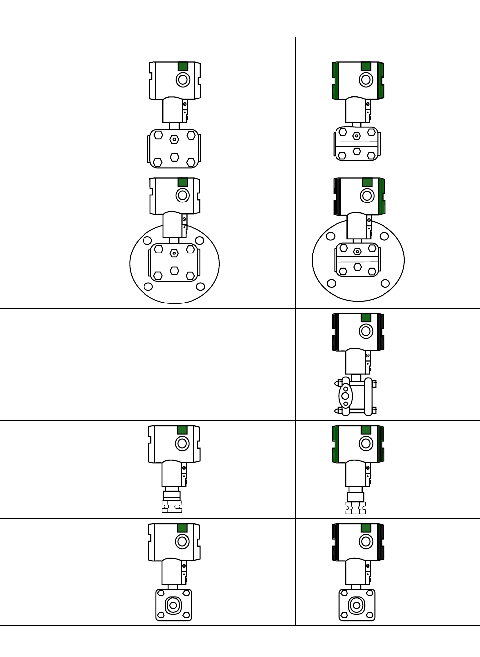
Table 1 ST 3000 Pressure Transmitter Family.
Transmitter Type Series 100 Model Series 900 Model
Differential
Pressure
STD1xx
STD9xx
Differential Pressure
with Flange on One
Side
STF1xx
STF9xx
Dual-Head Gauge
Pressure Not Available
STG9xx
In-Line Gauge and
Absolute Pressure
STG1xL
STA1xL
STG9xL
STA9xL
Gauge and Absolute
Pressure
STG1xx
STA1xx
STG9xx
STA9xx
Continued on next page
6/08 ST 3000 Release 300 and SFC Model STS103 User’s Manual 7
1.2 ST 3000 Smart Transmitters, Continued
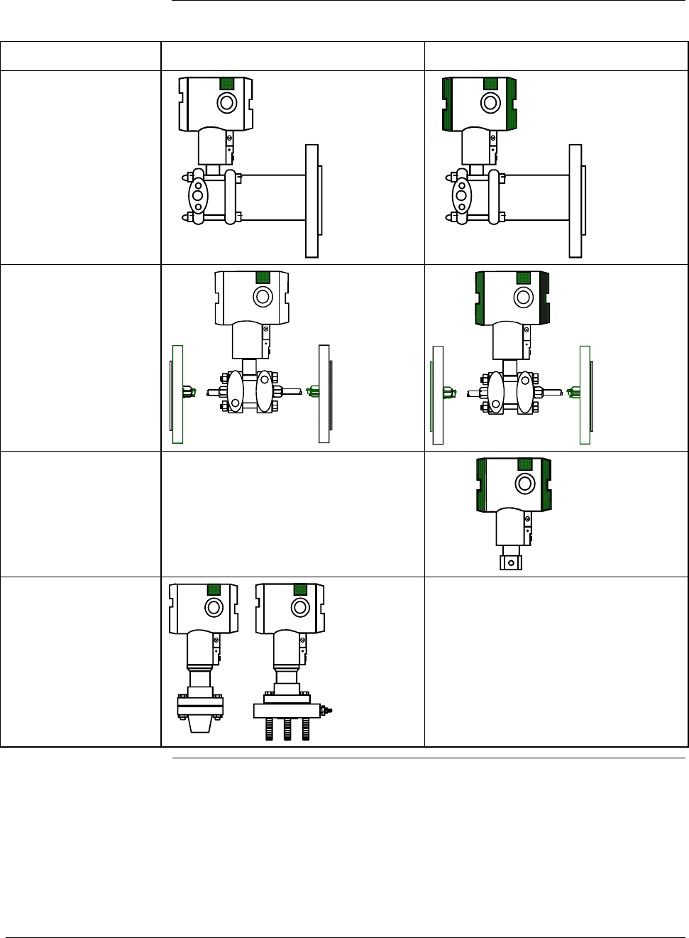
Table 1 ST 3000 Pressure Transmitter Family, continued.
Transmitter Type Series 100 Model Series 900 Model
Flange-Mount
Liquid Level
STF1xx
STF9xx
Differential Pressure
with Remote
Diaphragm Seals
STR1xx
STR9xx
Flush Mount
Not Available
STG93P
High Temperature
STG14T
STF14T
Not Available
8 ST 3000 Release 300 and SFC Model STS103 User’s Manual 6/08
1.3 Smart Field Communicator
About SFC
communications The portable, battery-powered SFC serves as the common communication
interface device for Honeywell’s family of Smartline Transmitters. It
communicates with a transmitter through serial digital signals over the 4
to 20 milliampere line used to power the transmitter. A request/response
format is the basis for the communication operation. The transmitter’s
microprocessor receives a communication signal from the SFC, identifies
the request, and sends a response message.
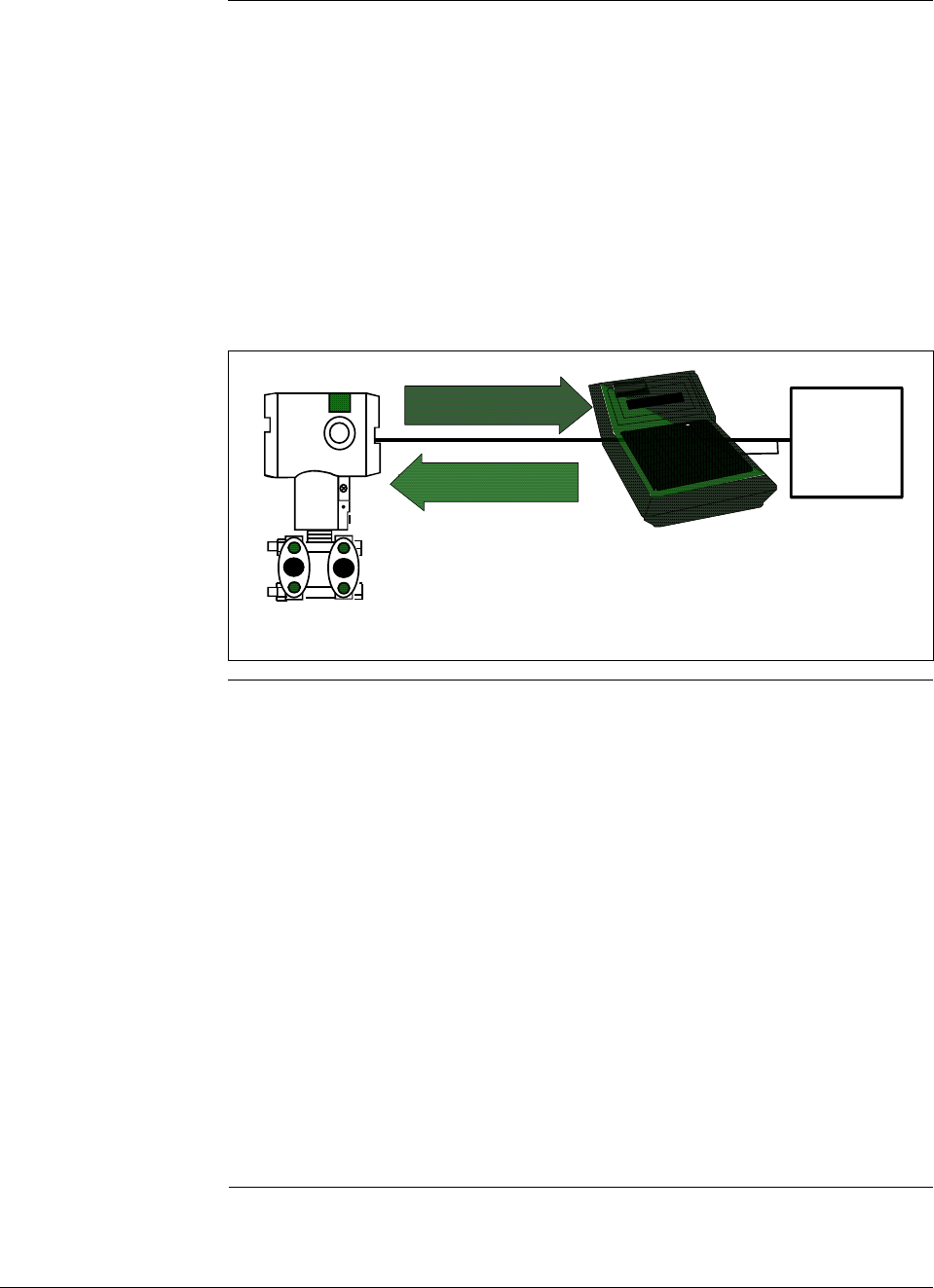
Figure 4 shows a simplified view of the communication interface provided
by an SFC.
Figure 4 Typical SFC Communication Interface.
SFC
Response
STR3001
4 to 20 mA line
Request
ST 3000
Power
Supply and
Receiver
Purpose of SFC The SFC allows you to adjust transmitter values, or diagnose potential
problems from a remote location such as the control room. You can use
the SFC to:
• Configure: Define and enter the transmitter’s operating parameters
including
– range values,
– output conformity,
– damping time,
– tag number (ID), and more
• Monitor: Read the input pressure to the transmitter in
engineering units and the transmitter’s output in
percent.
• Display: Retrieve and display data from the transmitter or SFC
memory.
• Change Mode
of Operation: Tell transmitter to operate in either its analog (4-20
mA) mode or its digital enhanced (DE) mode.
Continued on next page

6/08 ST 3000 Release 300 and SFC Model STS103 User’s Manual 9
1.3 Smart Field Communicator, Continued
Purpose of SFC,
continued • Check Current
Output: Use the transmitter to supply the output current
desired for verifying analog loop operation, troubleshooting,
or calibrating other components in the analog loop.
• Troubleshoot: Check status of transmitter operation and display
diagnostic messages to identify transmitter,
communication, or operator error problems.
SFC model
differences As Honeywell’s family of Smartline Transmitters has evolved, the SFC
has been changed to meet new model and functionality requirements.
Besides different software versions, some major differences exist
between these four SFC model designations.
• STS100
• STS101
• STS102
• STS103
Table 2 summarizes the differences between the four SFC models for
reference.
Table 2 SFC Model Differences
If SFC
model is. . . Then it is compatible
with. . . And additional functions
include . . .
STS100 Analog only ST 3000 smart
pressure transmitters Not applicable
STS101 Analog only ST 3000 smart
pressure transmitters, if
SFC software version is less
than 5.0.
Analog and Digital (DE)
mode ST 3000 pressure
transmitters and STT 3000
temperature transmitters, if
SFC software version is 5.0
or greater.
Corrects Reset, Failsafe Direction
and Sensor Temperature
indication.
Changing the mode from analog
to digital or digital to analog,
configuration parameters for STT
3000 and scratch pad
configuration area for ST 3000.
Continued on next page

10 ST 3000 Release 300 and SFC Model STS103 User’s Manual 6/08
1.3 Smart Field Communicator, Continued
SFC model
differences, continued
Table 2 SFC Model Differences, continued
If SFC
model is. . . Then it is compatible
with. . . And additional functions
include . . .
STS102 Analog and Digital (DE)
mode ST 3000 pressure
transmitters, STT 3000
temperature transmitters,
and MagneW 3000
electromagnetic flowmeters.
Changing the mode from analog
to digital or digital to analog.
Configuration parameters for
Magnew 3000 as well as scratch
pad configuration area.
STS103 Same as STS102 plus new
multivariable transmitters -
SCM 3000 Smart Coriolis
Flowmeter and SGC 3000
Smart Gas Chromatograph.
SMV 3000 Smart
Multivariable Transmitters, if
SFC software version is 4.2
or greater.
SMV 3000 with superheated
steam algorithm and
thermocouple input, if SFC
software version is 4.4 or
greater.
Release 300 Series 100 and
900 ST 3000 pressure
transmitters, if SFC software
version is 5.0 or greater.
Two-line, 16-character per line
display. Made “SAVE” and
“RESTORE” functions part of
configuration menu instead of
dedicated keys. Configuration
parameters for SCM 3000 and
SGC 3000.
Configuration parameters for
SMV 3000
SMV 3000 configuration
parameters for superheated steam
algorithm and thermocouple
inputs.
Local Smart Meter configuration
parameters.
ATTENTION The keystroke actions and prompt displays referenced in this manual are
for the SFC model STS103. While the SFC model STS103 does have a
two-line instead of a one-line display, many of the basic keystrokes and
configuration parameter prompts for ST 3000 pressure transmitters are
identical to those in the model STS102.
If you will be using a model STS102 SFC, you must refer to the SFC
Smart Field Communicator Operating Guide 34-ST-11-10 for keystroke
details. But, be aware that transmitter functions will be limited to only
those that are supported by the Model STS102 SFC.
6/08 ST 3000 Release 300 and SFC Model STS103 User’s Manual 11
1.4 Transmitter/SFC Order
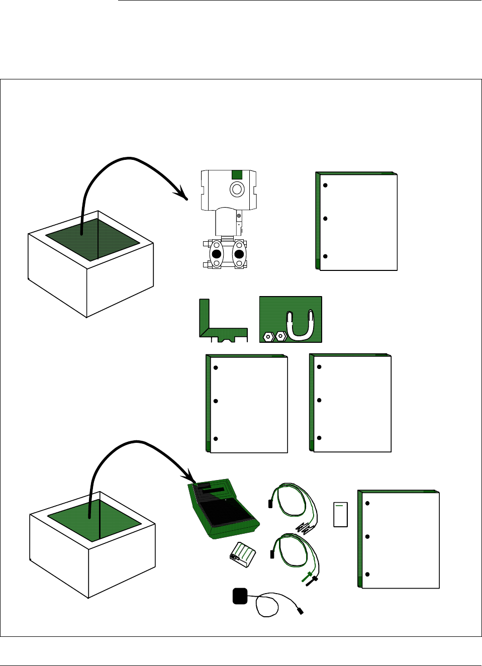
Order components Figure 5 shows the components that would be shipped and received for
a typical ST 3000 transmitter and SFC order.
Figure 5 Typical ST 3000 Transmitter and SFC Order Components.
ST 3000
Installation
Guide
Mounting Bracket (Optional)
ST 3000
Series 100 ST 3000 Differential pressure transmitter with optional mounting bracket
Smart Field Communicator with optional battery charger
Ordered
Shipped Received
ST 3000
User'sManual Quick
Reference
Guide
Leads
Battery
Pack
Pocket
Card
Battery
Charger
(optional)
SFC SFC
Operating
Guide
Shipped
separately,
if ordered
Continued on next page

12 ST 3000 Release 300 and SFC Model STS103 User’s Manual 6/08
1.4 Transmitter/SFC Order, Continued
About documentation Various documents are available for reference describing how to install,
configure and operate the ST 3000 transmitter:
• ST 3000 Smart Transmitter Installation Guide Using SFC Model
STS103 34-ST-33-39: One copy is shipped with every transmitter.
This document provides information for checking, installing, and
wiring the ST 3000 transmitter for operation.
• ST 3000 Smart Transmitter and SFC Smart Field Communicator
Model STS 103 User’s Manual 34-ST-25-14: One or more copies are
sent to the address designated on the order when specified. This
document provides detailed information for installing, wiring,
configuring, starting up, operating, maintaining, and servicing the ST
3000 transmitter. This is the main reference manual for the ST 3000
transmitter and it overlaps some data in the previously listed
Installation Guide 34-ST-33-39 and in the following Operating Guide
34-ST-11-14 to minimize cross reference.
• ST 3000 Smart Transmitter Quick Reference Guide 34-ST-09-06:
Shipped with User’s Manual. This document provides abbreviated
versions of procedures for installing, wiring, configuring, calibrating
and troubleshooting the ST 3000 transmitter for quick reference.
• Smart Field Communicator Model STS103 Pocket Card 34-ST-11-15:
One card is shipped with every SFC. This card provides quick
reference of keystroke actions for selected transmitter interface tasks.
• Smart Field Communicator Model STS103 Operating Guide 34-ST-
11-14: One copy is shipped with every SFC. This document provides
detailed SFC information and keystroke actions for interfacing with
these Honeywell Smartline Transmitters.
– ST 3000 Smart Pressure Transmitter (Non Release 300 models)
– STT 3000 Smart Temperature Transmitter
– MagneW 3000 Smart Electromagnetic Flowmeter
– SMV 3000 Smart Multivariable Transmitter
• Smartline Configuration Toolkit SCT 3000 Installation and Start-up
Guide 34-ST-10-08: One copy is shipped when the SCT 3000
software application is ordered.
6/08 ST 3000 Release 300 and SFC Model STS103 User’s Manual 13
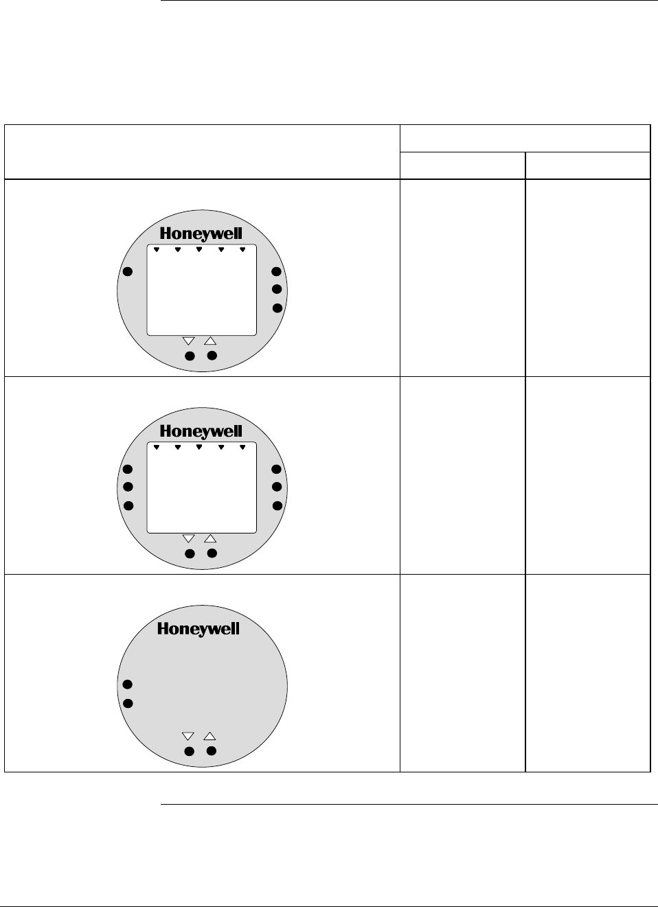
1.5 Local Smart Meter Options
Option availability Depending upon your transmitter model, it can be equipped with one of
the available Local Smart Meter and/or Zero and Span Adjust options as
shown in Table 3.
Table 3 Local Smart Meter Available Options
Option Description Available with Transmitter Series
100 900
Local Smart Meter only
%
1000
UPPER
VALUE
UNITS
LOWER
VALUE
SET
VAR
SEL.
Yes
Yes
Local Smart Meter with Zero and Span Adjustments
%1000
UPPER
VALUE
UNITS
LOWER
VALUE
SET
VAR
SEL.
SPAN
ZERO
Yes *
Yes
Local Zero and Span Adjustments only
SPAN
ZERO
Yes *
Yes
* Except draft range, model STD110
Continued on next page
14 ST 3000 Release 300 and SFC Model STS103 User’s Manual 6/08
1.5 Local Smart Meter Options, Continued
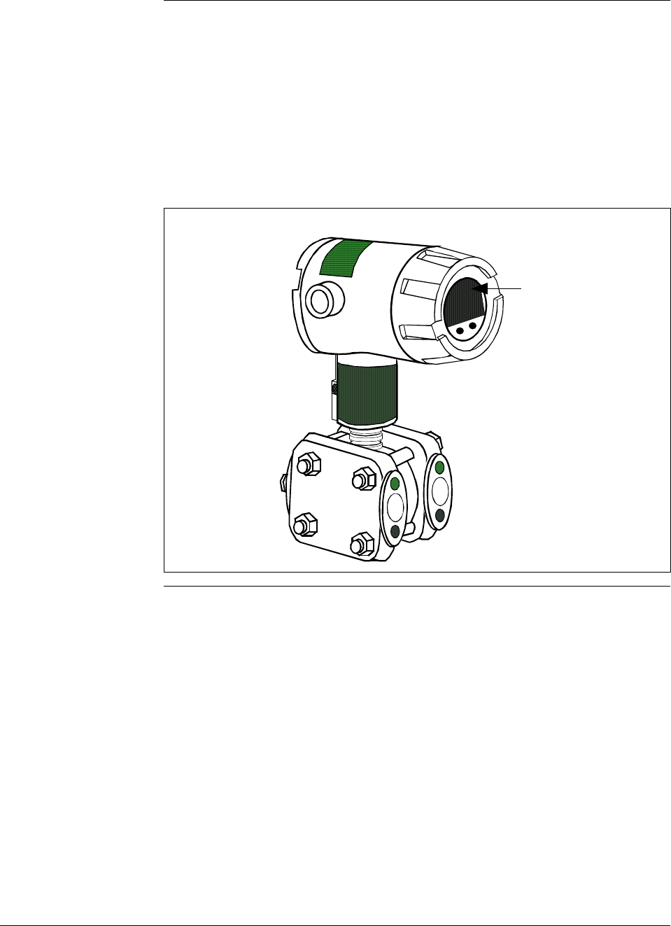
About the options Each Local Smart Meter and/or Zero and Span Adjust option comes as a
separate assembly mounted on the transmitter’s Printed Wiring
Assembly (PWA) mounting bracket. The meter option assembly
includes a cable and plug assembly for mating with a connector on the
transmitter’s PWA. A meter end-cap which includes a window is
supplied on the electronics side of the transmitter’s housing so you can
view the meter display with the end cap installed. See Figure 6.
Figure 6 ST 3000 with Local Smart Meter Option.
Electronics
Housing Local Smart
Meter Option

6/08 ST 3000 Release 300 and SFC Model STS103 User’s Manual 15
Section 2 —Quick Start Reference
2.1 Introduction
Section Contents This section includes these topics:
Section Topic See Page
2.1 Introduction ..................................................................................15
2.2 Getting ST 3000 Transmitter On-Line Quickly .............................16
About this section This section assumes that the ST 3000 transmitter has been installed and
wired correctly, and is ready to be put into operation. It also assumes
that you are somewhat familiar with using the SFC and that the
transmitter has been configured correctly for your application. If the
transmitter has not been installed and wired, you are not familiar with
SFC operation, and/or you do not know if the transmitter is configured
correctly, please read the other sections of this manual before starting up
your transmitter.
This section provides a list of typical start-up tasks and tells you where
you can find detailed information about performing the task.

16 ST 3000 Release 300 and SFC Model STS103 User’s Manual 6/08
2.2 Getting ST 3000 Transmitter On-Line Quickly
Quick start-up tasks Table 4 lists common start-up tasks for an ST 3000 transmitter using an
SFC and gives an appropriate section in this manual to reference for
more information about how to do the task. The start-up tasks are listed
in the order they are commonly completed.
Table 4 Start-up Tasks Reference
Task Description Reference Section
1 Put analog loop into manual
mode. Appropriate vendor documentation
for controller or recorder used as a
receiver in analog loop with
ST 3000 transmitter.
2 Connect SFC to transmitter and
establish communications. 5.2
3 Check or set tag ID. 6.3
4 Identify transmitter’s mode of
operation. 5.3
5 Change mode of operation, if
required. 5.4
6 Check/set output form
(Linear/Square Root). 6.4
7 Check/set damping time. 6.5
8 Check/set Lower Range Value
and Upper Range Value. 6.7 (See 6.8 for local zero and
span adjustments)
9 Run optional output check for
analog loop. 7.3
10 Check zero input and set, if
required. 7.4 - See Step 9 in Table 39.
7.8 - See Step 9 in Table 43.
11 Check transmitter status. 8.2
12 Setup local Smart Meter, if
applicable. 6.11 or 6.12
13 Write data in scratch pad
memory, if desired. 8.4
14 Store all changes in the
transmitter's non-volatile
memory by pressing [SHIFT] and
[ENTER].
6.13

6/08 ST 3000 Release 300 and SFC Model STS103 User’s Manual 17
Section 3 —Preinstallation Considerations
3.1 Introduction
Section Contents This section includes these topics:
Section Topic See Page
3.1 Introduction ..................................................................................17
3.2 CE Conformity (Europe) Notice....................................................18
3.3 Considerations for ST 3000 Transmitter ......................................19
3.4 Considerations for SFC................................................................22
3.5 Considerations for Local Smart Meter Option ..............................24
About this section This section reviews things you should take into consideration before
you install the transmitter and start using the SFC. Of course, if you are
replacing an existing ST 3000 transmitter and you did not order a new
SFC; you can skip this section.

18 ST 3000 Release 300 and SFC Model STS103 User’s Manual 6/08
3.2 CE Conformity (Europe) Notice
About conformity and
special conditions This product is in conformity with the protection requirements of
89/336/EEC, the EMC Directive. Conformity of this product with any
other “CE Mark” Directive(s) shall not be assumed.
Deviation from the installation conditions specified in this manual, and
the following special conditions, may invalidate this product’s
conformity with the EMC Directive.
• You must use shielded, twisted-pair cable such as Belden 9318 for all
signal/power wiring.
• You must connect the shield to ground at the power supply side of the
wiring only and leave it insulated at the transmitter side.
ATTENTION ATTENTION
The emission limits of EN 50081-2 are designed to provide reasonable
protection against harmful interference when this equipment is operated
in an industrial environment. Operation of this equipment in a residential
area may cause harmful interference. This equipment generates, uses,
and can radiate radio frequency energy and may cause interference to
radio and television reception when the equipment is used closer than 30
meters (98 feet) to the antenna(e). In special cases, when highly
susceptible apparatus is used in close proximity, the user may have to
employ additional mitigating measures to further reduce the
electromagnetic emissions of this equipment.
6/08 ST 3000 Release 300 and SFC Model STS103 User’s Manual 19
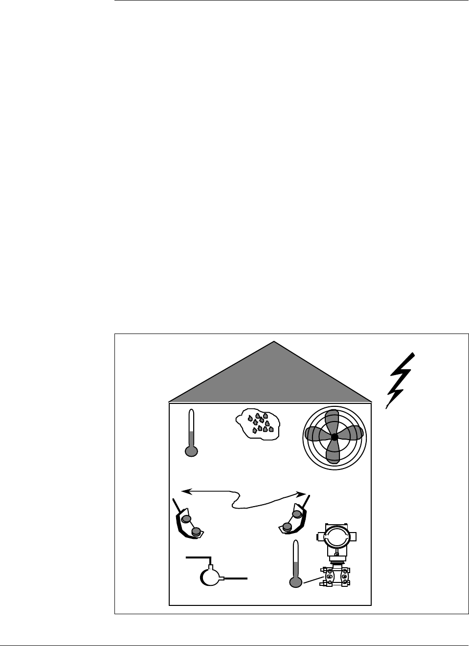
3.3 Considerations for ST 3000 Transmitter
Evaluate conditions The ST 3000 transmitter is designed to operate in common indoor
industrial environments as well as outdoors. To assure optimum
performance, evaluate these conditions at the mounting area relative to
published transmitter specifications and accepted installation practices
for electronic pressure transmitters.
• Environmental Conditions
– Ambient Temperature
– Relative Humidity
• Potential Noise Sources
– Radio Frequency Interference (RFI)
– Electromagnetic Interference (EMI)
• Vibration Sources
– Pumps
– Motorized Valves
– Valve Cavitation
• Process Characteristics
– Temperature
– Maximum Pressure Rating
Figure 7 illustrates typical mounting area considerations to make before
installing a transmitter.
Figure 7 Typical Mounting Area Considerations Prior to Installation
Ambient
Temperature
Relative
Humidity
Large Fan Motors
(EMI)
Transceivers
(RFI)
Pump
(vibration)
Meter Body
Temperature
Lightning
(EMI)
21003
Continued on next page

20 ST 3000 Release 300 and SFC Model STS103 User’s Manual 6/08
3.3 Considerations for ST 3000 Transmitter, Continued
Temperature limits Table 5 lists the operating temperature limits for the various types of
transmitters with silicone fill fluids. See transmitter specifications for
temperature limits of ST 3000 transmitters with alternative fill fluids.
Table 5 Operating Temperature Limits (Transmitters with Silicone Fill Fluids)
Transmitter Type and Model Ambient Temperature Process Interface Temperature
°C °F °C °F
Draft Range STD110 -40 to 70 -40 to 158 -40 to 70 -40 to 158
Differential Pressure STD125
STD120, STD130, STD170
STD904, STD924,
STD930, STD974
-40 to 85
-40 to 93
-40 to 85
-40 to 185
-40 to 200
-40 to 185
-40 to 85
-40 to 125
-40 to 125
-40 to 185
-40 to 257
-40 to 257
Gauge Pressure
STG140, STG170, STG180,
STG14L, STG17L, STG18L
STG14T
STG93P
STG944, STG974
STG90L, STG94L,
STG97L, STG98L
-40 to 93
-40 to 93
-15 to 65
-40 to 85
-40 to 85
-40 to 200
-40 to 200
5 to 149
-40 to 185
-40 to 185
-40 to 125
-40 to 150 †
-15 to 95 ††
-40 to 125
-40 to 110
-40 to 257
-40 to 302 †
5 to 203 ††
-40 to 257
-40 to 230
Absolute PressureSTA122/12L -40 to 93 -40 to 200 See Specification Sheet
STA140/14L -40 to 93 -40 to 200 -40 to 80 -40 to 176
STA922/92L -40 to 85 -40 to 185 See Specification Sheet
STA940/94L -40 to 85 -40 to 185 -40 to 80 -40 to 176
Flange Mounted
STF128, STF132, STF924,
STF932
Pseudo-Flanged Head
STF12F, STF13F, STF92F,
STF93F
STF14F
Gauge Pressure Flange Mount
STF14T
-40 to 93
-40 to 93
-40 to 85
-40 to 93
-40 to 200
-40 to 200
-40 to 185
-40 to 200
-40 to 175
-40 to 93
-40 to 85
-40 to 150 †
-40 to 350
-40 to 200
-40 to 185
-40 to 302 †
Remote Diaphragm Seals
STR12D, STR13D, STR14G,
STR17G, STR14A
See Specification Sheet
See Specification Sheet
STR93D, STR94G -40 to 85 -40 to 185 See Specification Sheet
† Process temperatures above 125 °C (257 °F) require a reduction in the maximum ambient temperature as follows:
Process Temperature Ambient Temperature Limit
150 °C (302 °F) 50 °C (122 °F)
140 °C (284 °F) 60 °C (140 °F)
125 °C (257 °F) 85 °C (185 °F)
†† Process temperatures above 65 °C (149 °F) require a 1:1 reduction in maximum ambient temperature.
NOTE: For transmitters with local meter option see Table 8.
NOTE: Transmitters with other fill fluids (CTFE, Neobee, Etc.) have different Operating Temperature Limits. For
more specific information, refer to the appropriate Specification and Model Selection Guide or transmitter nameplate

6/08 ST 3000 Release 300 and SFC Model STS103 User’s Manual 21
3.3 Considerations for ST 3000 Transmitter, Continued
Pressure ratings Table 6 lists maximum working pressure for a given transmitter Upper
Range Limit (URL).
The maximum allowable working pressure (MAWP) is the pressure
used for the approval body safety calculations.
Table 6 Transmitter Maximum Allowable Working Pressure (MAWP) Ratings
Transmitter Type Upper Range Limit
(URL) MAWP
Draft Range 10 inches H2O (25
mbar)
50 psi (3.5 bar)
Differential Pressure 400 inches H2O (1 bar) 3000 psi (210 bar)
100 psi (7 bar) 3000 psi (210 bar)
3000 psi (210 bar) 3000 psi (210 bar)
Gauge Pressure 100 psi (7 bar) 100 psi (7 bar)
300 psi (21 bar) 300 psi (21 bar)
500 psi (35 bar) 500 psi (35 bar)
3000 psi (210 bar) 3000 psi (210 bar)
6000 psi (415 bar) 6000 psi (415 bar)
10000 psi (690 bar) 10000 psi (690 bar)
400 inches H2O (1 bar)
Flange Mount
100 psi (7 bar)
Per selected flange
and material
(ANSI/ASME 150#,
300#, DN PN40)
400 inches H2O (1 bar)
Remote Seal
100 psi (7 bar)
Lesser MAWP of
either Remote Seal
selected or transmitter
pressure rating
Absolute Pressure 780 mmHg Absolute
(1 bar) 780 mmHg Absolute
(1 bar)
500 psia (35 bar) 500 psia (35 bar)
Note: Maximum Allowable Working Pressure (MAWP) may vary with materials of construction and process
temperature. For more specific information, refer to the appropriate Specification and Model Selection
Guide or transmitter nameplate
NOTE: To convert bar values to kilopascals (kPa), multiply by 100.
For example, 3.5 bar equals 350 kPa.
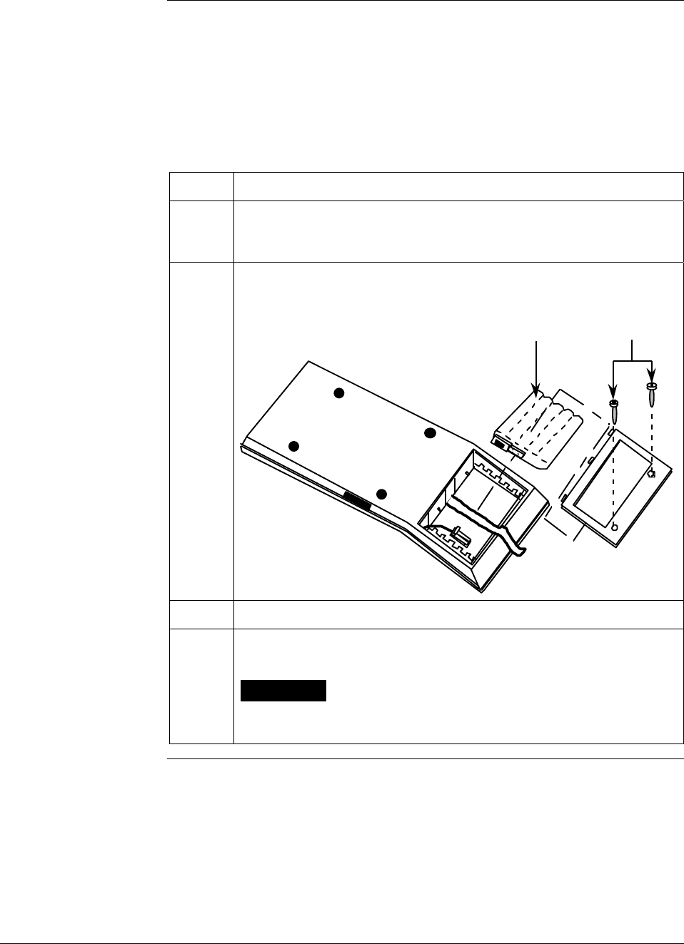
22 ST 3000 Release 300 and SFC Model STS103 User’s Manual 6/08
3.4 Considerations for SFC
Install SFC battery
pack If the SFC battery pack was removed for shipping and/or storage, you
will have to install the battery pack and charge the batteries before you
can operate the SFC.
The procedure in Table 7 outlines the steps for the battery pack.
Table 7 Installing and Charging SFC Battery Pack
Step Action
1 Turn SFC face down on working surface. Use metric hex wrench
(2.5 mm) to remove screws in battery compartment cover and
remove cover.
2 Insert battery pack in compartment and connect plug in compartment
to pin on battery back
Example - Battery pack installation.
Battery Pack Hex Screws
21004
3 Replace cover and tighten hex screws
4 Connect lead from battery charger to recessed connector on left side
of SFC.
WARNING The SFC battery charger is not intrinsically safe.
Always recharge the SFC battery pack in a nonhazardous location.
The SFC itself is an intrinsically safe device.
Continued on next page

6/08 ST 3000 Release 300 and SFC Model STS103 User’s Manual 23
3.4 Considerations for SFC, Continued
Install SFC battery
pack, continued
Table 7 Installing and Charging SFC Battery Pack, continued
Step Action
5 Plug battery charger into any standard 120 Vac outlet or universal-
European 240 Vac outlet as applicable for charger power rating. If
240 Vac charger is supplied with stripped leads instead of universal-
European plug, lead identification for 240 Vac charger is as follows.
Lead Color… Function…
Blue Neutral
Brown Hot
Green/Yellow Ground
ATTENTION It takes up to 16 hours to fully recharge the battery
pack and you can use the SFC continuously for up to 24 hours
before the battery pack needs recharging.
Temperature Limits The ambient operating temperature limits for the SFC are –10 to 50°C
(14 to 122°F) with relative humidity in the range of 10 to 90% RH.
Usage guidelines • For transmitters operating in the Analog Mode, be sure to put an
analog control loop into its manual mode before initiating SFC
communications with the transmitter. Also, be sure any switches that
may trip alarms or interlocks associated with the analog loop are
secured or turned OFF. Communication superimposes digital signals
on the loop wiring that could affect the analog control signal.
• Be sure the power supply voltage does not exceed 45Vdc.
The ST 3000 transmitter and SFC were designed to operate with
voltages below 45Vdc.
• Be sure there is at least 250 ohms of resistance between the SFC and
the power supply for proper communications.

24 ST 3000 Release 300 and SFC Model STS103 User’s Manual 6/08
3.5 Considerations for Local Smart Meter Option
Reference
specifications Table 8 lists pertinent Smart Meter specifications for reference.
Table 8 Local Smart Meter Specifications.
Operating Conditions —————
Parameter Rated Extreme, Transportation and
Storage
Ambient Temperature °F
°C
–40 to 176
–40 to 80
–58 to 194
–50 to 90
Relative Humidity %RH 10 to 90 0 to 100
Design ———————————
Accuracy No error. Reproduces transmitter signal exactly within its resolution.
Display Resolution Bargraph
Digital Readout
±3% of reading
±0.005 for ±19.99 reading range,
±0.05 for ±199.9 reading range,
±0.5 for ±1999 reading range,
±5 for ±19990 reading range,
±50 for ±199900 reading range,
±500 for ±1999000 reading range,
±5000 for ±19990000 reading range.
Shown as:
19.99
199.9
1999
19.99 K
199.9 K
1999 K
19990 K
Display Update Rate Above 32°F (0°C): ½ second
@ or below 32°F (0°C): 1½ seconds
Meter Display at High
and Low Temperature
Extremes
The rated temperature limits for the local meter are listed above and are
true in that no damage to the meter will occur over these temperatures,
however the readability of the LCD is affected if taken to these
temperature extremes:
• The LCD will turn black at some temperature between 80 to 90 °C
(176 and 194 °F), rendering the display unreadable. This effect is
only temporary, and normally occurs at 90 °C (194 °F).
• At low temperatures, the update rate of the display is lengthened to
1.5 seconds due to the slower response time of the display. At -20
°C (-4 °F) the display becomes unreadable due to slow response of
the LCD. This is also only temporary and normal readability will
return when temperature returns above -20 °C (-4 °F).

6/08 ST 3000 Release 300 and SFC Model STS103 User’s Manual 25
Section 4 —Installation
4.1 Introduction
Section Contents This section includes these topics:
Section Topic See Page
4.1 Introduction ..................................................................................25
4.2 Mounting ST 3000 Transmitter.....................................................26
4.3 Piping ST 3000 Transmitter..........................................................36
4.4 Wiring ST 3000 Transmitter .........................................................41
About this section This section provides information about installing the ST 3000
transmitter. It includes procedures for mounting, piping and wiring the
transmitter for operation.
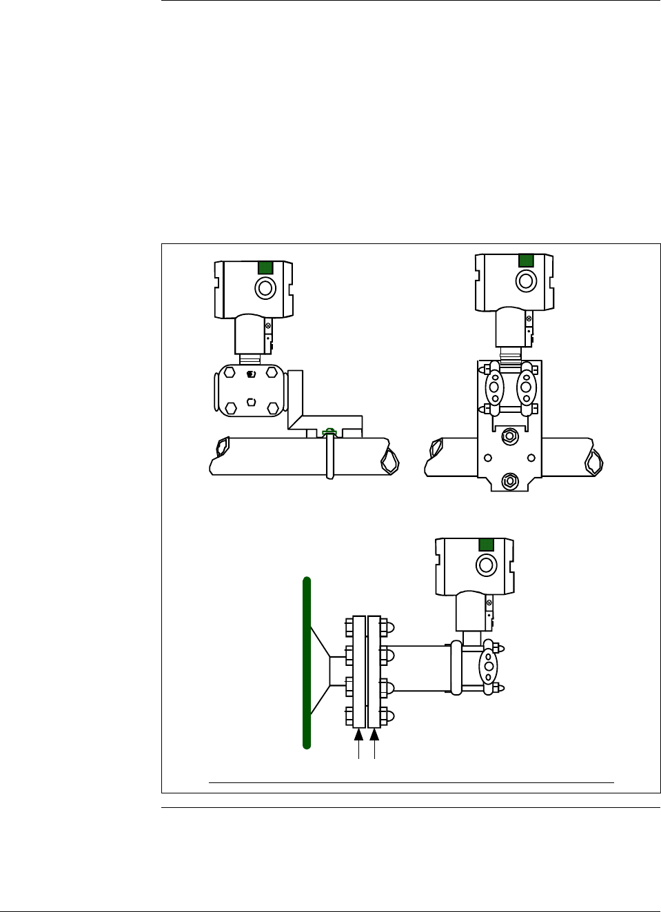
26 ST 3000 Release 300 and SFC Model STS103 User’s Manual 6/08
4.2 Mounting ST 3000 Transmitter
Summary You can mount all transmitter models (except flush mount models and
those with integral flanges) to a 2-inch (50 millimeter) vertical or
horizontal pipe using our optional angle or flat mounting bracket, or a
bracket of your own. Flush mount models are mounted directly to the
process pipe or tank by a 1” weld nipple. Those models with integral
flanges are supported by the flange connection.
Figure 8 shows typical bracket mounted and flange mounted transmitter
installations for comparison.
Figure 8 Typical Bracket Mounted and Flange Mounted Installations
Angle
Mounting
Bracket Flat
Mounting
Bracket
Horizontal Pipe
24118
Tank
Wall
Flange
Connection Transmitter
Flange
Continued on next page
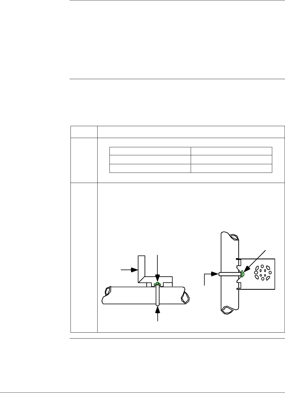
6/08 ST 3000 Release 300 and SFC Model STS103 User’s Manual 27
4.2 Mounting ST 3000 Transmitter, Continued
Dimensions Detailed dimension drawings for given transmitter series and types are
listed in the back of the Installation Guide (Part number 34-ST-33-39)
for reference. Note that abbreviated overall dimensions are also shown
in the Specification Sheets for the given transmitter models.
This section assumes that the mounting dimensions have already been
taken into account and the mounting area can accommodate the
transmitter.
Bracket mounting Table 9 summarizes typical steps for mounting a transmitter to a
bracket.
Table 9 Mounting ST 3000 Transmitter to a Bracket
Step Action
1
If you are using an… Then…
optional mounting bracket go to Step 2.
existing mounting bracket go to Step 3.
2 Position bracket on 2-inch (50.8 mm) horizontal or vertical pipe, and
install “U” bolt around pipe and through holes in bracket. Secure with
nuts and lockwashers provided.
Example - Angle mounting bracket secured to horizontal or vertical
pipe.
Horizontal Pipe
Mounting
Bracket
Nuts and
Lockwashers
Nuts and
Lockwashers
U-Bolt
U-Bolt
Mounting
Bracket
Vertical Pipe
Continued on next page
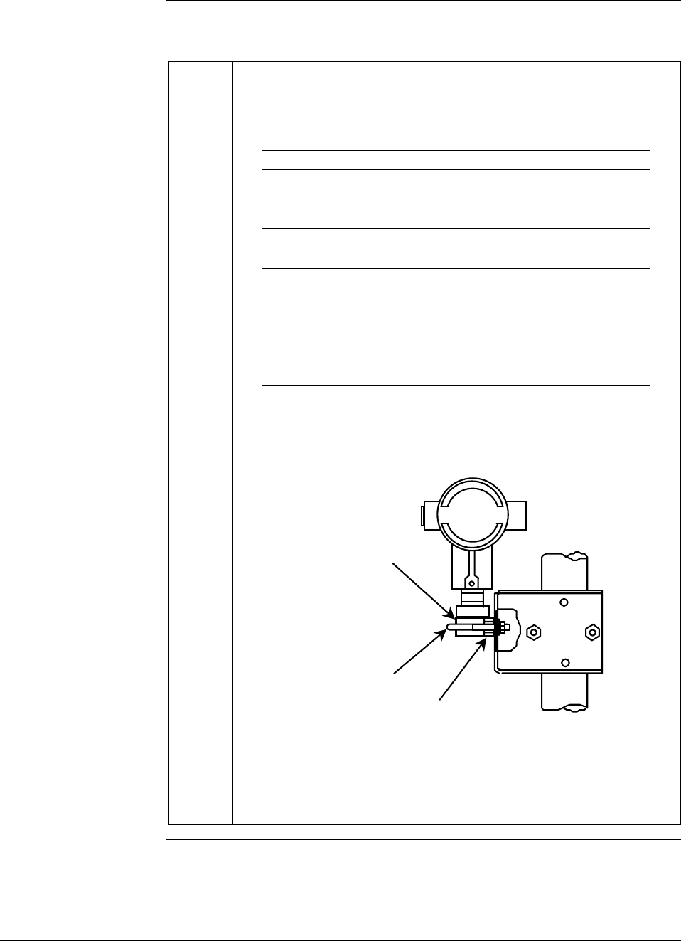
28 ST 3000 Release 300 and SFC Model STS103 User’s Manual 6/08
4.2 Mounting ST 3000 Transmitter, Continued
Bracket mounting,
continued
Table 9 Mounting ST 3000 Transmitter to a Bracket, continued
Step Action
3 Align appropriate mounting holes in transmitter with holes in bracket
and secure with bolts and washers provided.
If transmitter is … Then …
DP type with double ended use alternate mounting
process heads and/or holes in end of heads.
remote seals
GP and AP with single- use mounting holes in side
ended head of meter body.
In-line GP and AP use smaller “U” bolt
(STGxxL and STAxxL) provided to attach meter
body to bracket.
See figure below.
Dual-head GP and AP use mounting holes in end
of process head.
Example – Inline model transmitter mounted to optional angle
mounting bracket.
Inline models
Meter Body
Smaller
“U” bolt Use bracket for
hexagonal meter body
NOTE: If the meter body is hexagonal, you must use the additional
bracket supplied. If meter body is round, discard the
bracket.
Continued on next page
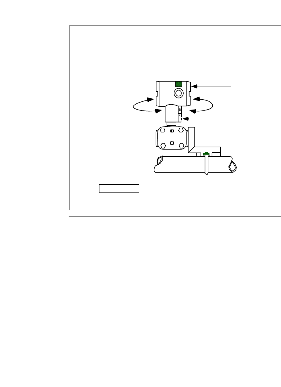
6/08 ST 3000 Release 300 and SFC Model STS103 User’s Manual 29
4.2 Mounting ST 3000 Transmitter, Continued
Bracket mounting,
continued
Table 9 Mounting ST 3000 Transmitter to a Bracket, continued
4 Loosen set screw on outside neck of transmitter one full turn. Rotate
electronics housing a maximum of 180 degrees in left or right
direction from center to the position you require and tighten set screw
(13 to 15 lb-in/1.46 to 1.68 N.m).
Example - Rotating electronics housing.
Set Screw
Electronics
Housing
180 degrees
max.
180 degrees
max.
ATTENTION The metric socket head wrench kit supplied with the
SFC includes 2.5, 3, and 4mm size wrenches. You will need the
4mm size wrench for the outside set screw.
Continued on next page
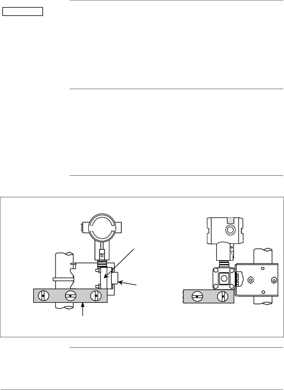
30 ST 3000 Release 300 and SFC Model STS103 User’s Manual 6/08
4.2 Mounting ST 3000 Transmitter, Continued
ATTENTION The mounting position of a model STA122, STA922, STA12L, or
STA92L Absolute Pressure Transmitter or a model STD110 Draft
Range Differential Pressure Transmitter is critical as the transmitter
spans become smaller. A maximum zero shift of 2.5 mm Hg for an
absolute transmitter or
1.5 inH2O for a draft range transmitter can result from a mounting
position which is rotated 90 degrees from vertical. A typical zero shift of
0.12 mm Hg or 0.20 in H2O can occur for a 5 degree rotation from
vertical.
Precautions for
Mounting
Transmitters with
Small Absolute or
Differential Pressure
Spans
To minimize these positional effects on calibration (zero shift), take the
appropriate mounting precautions that follow for the given transmitter
model.
For a model STA122, STA922, STA12L, or STA92L transmitter, you
must ensure that the transmitter is vertical when mounting it. You do
this by leveling the transmitter side-to-side and front-to-back. See
Figure 9 for suggestions on how to level the transmitter using a spirit
balance.
Figure 9 Leveling an Absolute Pressure Transmitter.
Leveling Absolute Pressure models
Center
Section
Process
Head
Position spirit balance on
center section of meter
body only.
Cont’d
Continued on next page
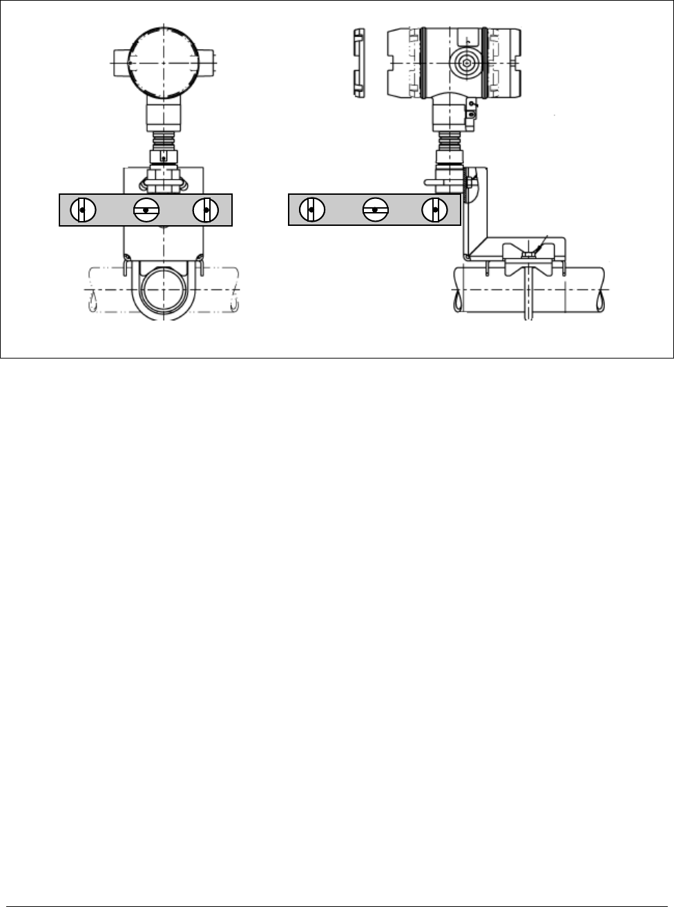
6/08 ST 3000 Release 300 and SFC Model STS103 User’s Manual 31
4.2 Mounting ST 3000 Transmitter Continued
Figure 9 Leveling an Absolute Pressure Transmitter (cont’d)
Leveling Inline models
Mount transmitter vertically to assure best accuracy. Position spirit balance on pressure connection surface
of AP body.
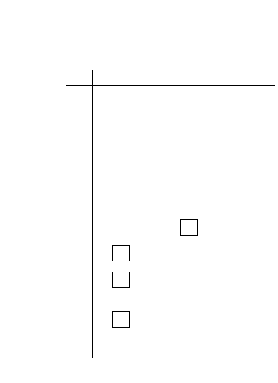
32 ST 3000 Release 300 and SFC Model STS103 User’s Manual 6/08
4.2 Mounting ST 3000 Transmitter, Continued
Precautions for
Mounting
Transmitters with
Small Absolute or
Differential Pressure
Spans, continued
For a transmitter with a small differential pressure span, you must
ensure that the transmitter is vertical when mounting it. You do this by
leveling the transmitter side-to-side and front-to-back. See Figure 9 for
suggestions on how to level the transmitter using a spirit balance. You
must also zero the transmitter by following the steps in Table 10 below.
Table 10 Zero Corrects Procedure for STD110
Step Action
1 Attach the transmitter to the mounting bracket but do not completely
tighten the mounting bolts
2 Connect a tube between the input connections in the high pressure
(HP) and low pressure (LP) heads to eliminate the affects of any
surrounding air currents.
3 Connect 24 Vdc power to the transmitter and connect a digital
voltmeter or SFC to read the transmitter’s output. See Figures 18
and 38 for typical SFC connection or connect a voltmeter across the
250 ohm resistor, if desired.
4 Use the SFC and establish communications with the transmitter.
Follow the steps in Table 17, if needed.
5 While reading the transmitter’s output on an SFC or a voltmeter,
position the transmitter so the output reading is at or near zero and
then completely tighten the mounting bolts.
6 Perform an input zero correct function using the SFC and following
the steps below. This corrects the transmitter for any minor error that
may occur after the mounting bolts are tightened.
7
Initiate shift key selection. Press
^
SHIFT key
Press
INPUT
J
OUT-
PUT key. Read applied input pressure.
Press
RESET
K
COR-
RECT key. Prompt asks if the applied input pressure equals
zero input. If it is zero input, go to next keystroke. If it is not, press
[CLR] key to exit function and repeat keystrokes.
Press
NON-VOL
ENTER
(Yes) key. Zero input is set equal to applied input pressure.
8 Remove the tube from between the input connections, the power,
and the digital voltmeter or SFC.
9 Continue with the remaining installation tasks.
Continued on next page
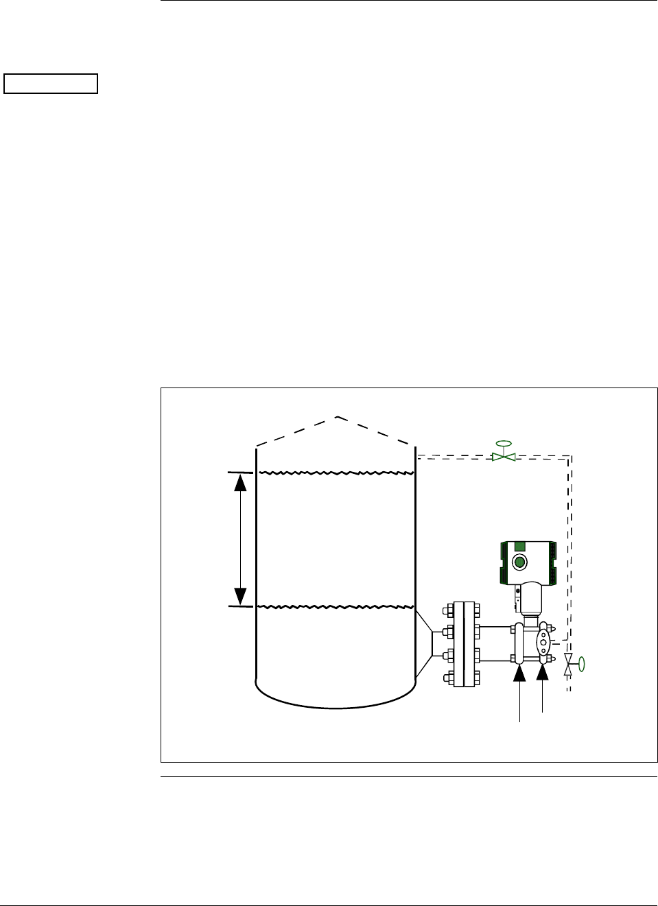
6/08 ST 3000 Release 300 and SFC Model STS103 User’s Manual 33
4.2 Mounting ST 3000 Transmitter, Continued
Flange mounting To mount a flange mounted transmitter model, bolt the transmitter’s
flange to the flange pipe on the wall of the tank.
ATTENTION On insulated tanks, remove enough insulation to accommodate the
flange extension.
Figure 10 shows a typical installation for a transmitter with the flange
on the high pressure (HP) side so the HP diaphragm is in direct contact
with the process fluid. The low pressure (LP) side of the transmitter is
vented to atmosphere (no connection).
It is the End User’s responsibility to provide a flange gasket and mounting hardware that are suitable for the
transmitter’s service condition.
To prevent degradation of performance in Flush-Mounted Flanged Transmitters, exercise care to ensure
that the internal diameter of the flange gasket does not obstruct the sensing diaphragm.
To prevent degradation of performance in Extended Mount Flanged Transmitters, ensure that there
is sufficient clearance in front of the sensing diaphragm body.
Figure 10 Typical Flange Mounted Transmitter Installation
Variable
Head H1 Reference
Leg
Attention: Dotted area indicates use
with closed tank with reference leg.
LP Side vented
to atmosphere
HP Side
mounted
to tank
Minimum Level
Maximum Level
Continued on next page
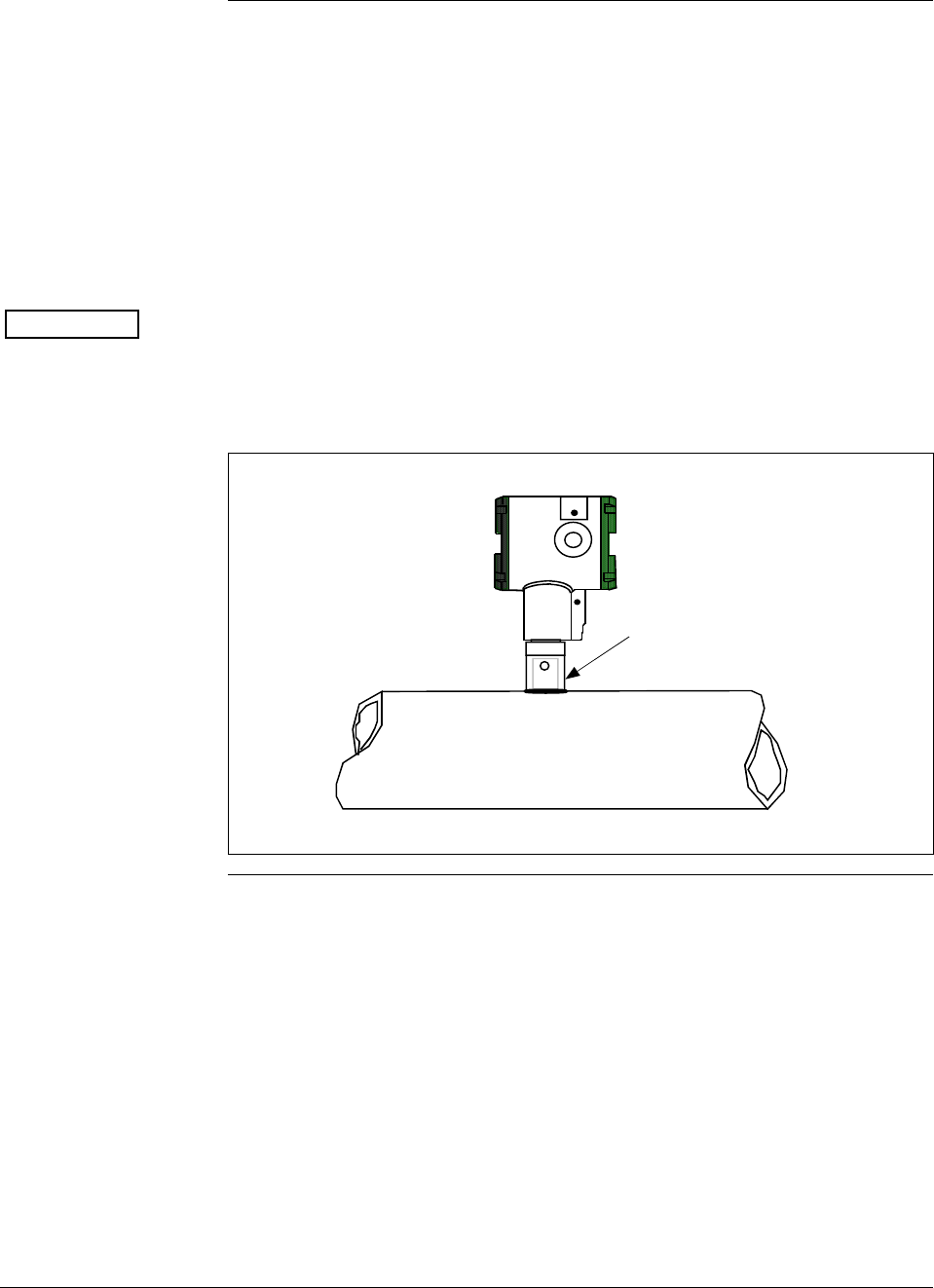
34 ST 3000 Release 300 and SFC Model STS103 User’s Manual 6/08
4.2 Mounting ST 3000 Transmitter, Continued
Flush mounting To mount a flush mounted model, cut a hole for a 1” standard pipe in
the tank or pipe where the transmitter is to be mounted. Weld the 1”
mounting sleeve to the wall of the tank or to the hole cut on the pipe.
Insert the meter body of the transmitter into the mounting sleeve and
secure with the locking bolt. Tighten the bolt to a torque of 6,4 Nm +/-
0,30 Nm (4.7 ft-lbs +/- 0.2 ft.-lbs.). Figure 11 shows a typical
installation for a transmitter with a flush mount on a pipe.
ATTENTION
Once the transmitter is mounted, the electronics housing can be rotated
to the desired position. See Table 9, Step 4 for details.
On insulated tanks, remove enough insulation to accommodate the
mounting sleeve.
Figure 11 Typical Flush Mounted Transmitter Installation
1” Pipe Mount -
316 SS Weld Nipple
(standard option)
Continued on next page
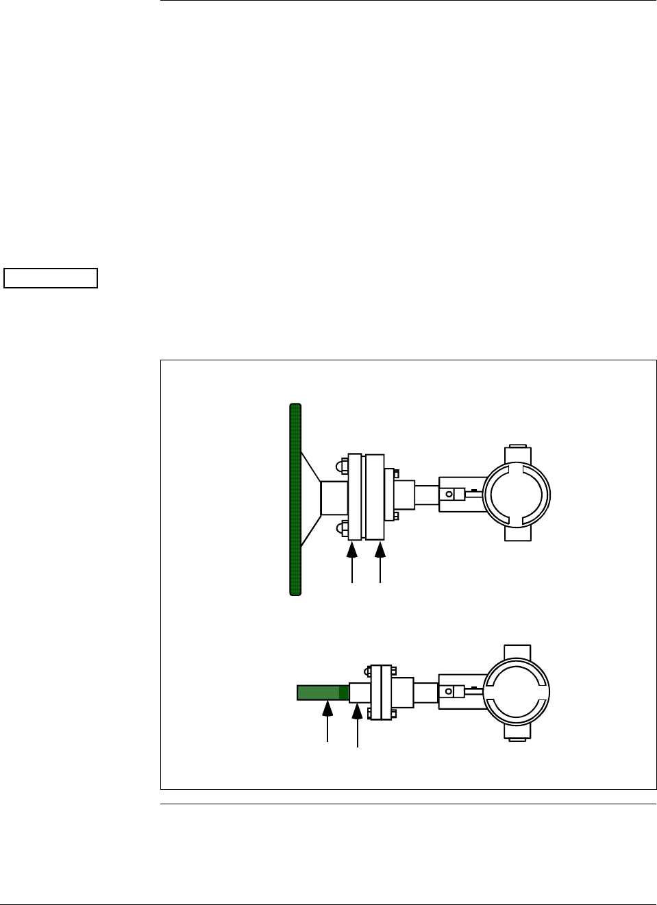
6/08 ST 3000 Release 300 and SFC Model STS103 User’s Manual 35
4.2 Mounting ST 3000 Transmitter, Continued
High Temperature
Transmitter Mounting You can mount the High Temperature transmitter directly to the process
flange connection or the process piping. Figure 12 shows typical pipe
and flange mounted transmitter installations for comparison.
To mount a flange mounted transmitter model, bolt the transmitter’s
flange to the flange on the wall of the tank or process pipe.
It is the End User’s responsibility to provide a flange gasket and
mounting hardware that are suitable for the transmitter’s service
condition.
Once the transmitter is mounted, the electronics housing can be rotated
to the desired position. See Table 9, step 4.
ATTENTION On insulated tanks, remove enough insulation to accommodate the
flange extension.
Figure 12 Typical Pipe and Flange Mounted Installations
1/2" NPT
Connection
Process Pipe
Tank
Wall
Flange
Connection Transmitter
Flange
Continued on next page

36 ST 3000 Release 300 and SFC Model STS103 User’s Manual 6/08
4.2 Mounting ST 3000 Transmitter, Continued
Remote seal
mounting Use the procedure in Table 11 to mount a remote diaphragm seal
transmitter model. Figure 13 shows a typical installation for a remote
diaphragm seal transmitter for reference.
WARNING Mount the transmitter flanges within the limits stated here for the given
fill-fluid in the capillary tubes with a tank at one atmosphere.
IF the fill fluid is… THEN mount the flange…
Silicone DC 200 Oil no greater than 22 feet (6.7 meters)
below the transmitter
Silicone DC 704 Oil no greater than 19 feet (5.8 meters)
below the transmitter
Chlorotrifluorethylene no greater than 11 feet (3.4 meters)
below the transmitter.
NOTE: The combination of tank vacuum and high pressure capillary
head effect should not exceed 9 psi (300 mm Hg) absolute.
Table 11 Mounting Remote Diaphragm Seal Transmitter
Step Action
1 Mount transmitter at a remote distance determined by length of
capillary tubing.
2 If Transmitter Model Then Connect Remote
Number is… Seal on…
STR93D or STR12D high pressure (HP) side of
transmitter to lower flange
mounting on tank wall for
variable head H1.
STR13D low pressure (LP) side of
transmitter to lower flange
mounting on tank wall for
variable head H1.
ATTENTION On insulated tanks, remove enough insulation to
accommodate the flange extension.
Continued on next page
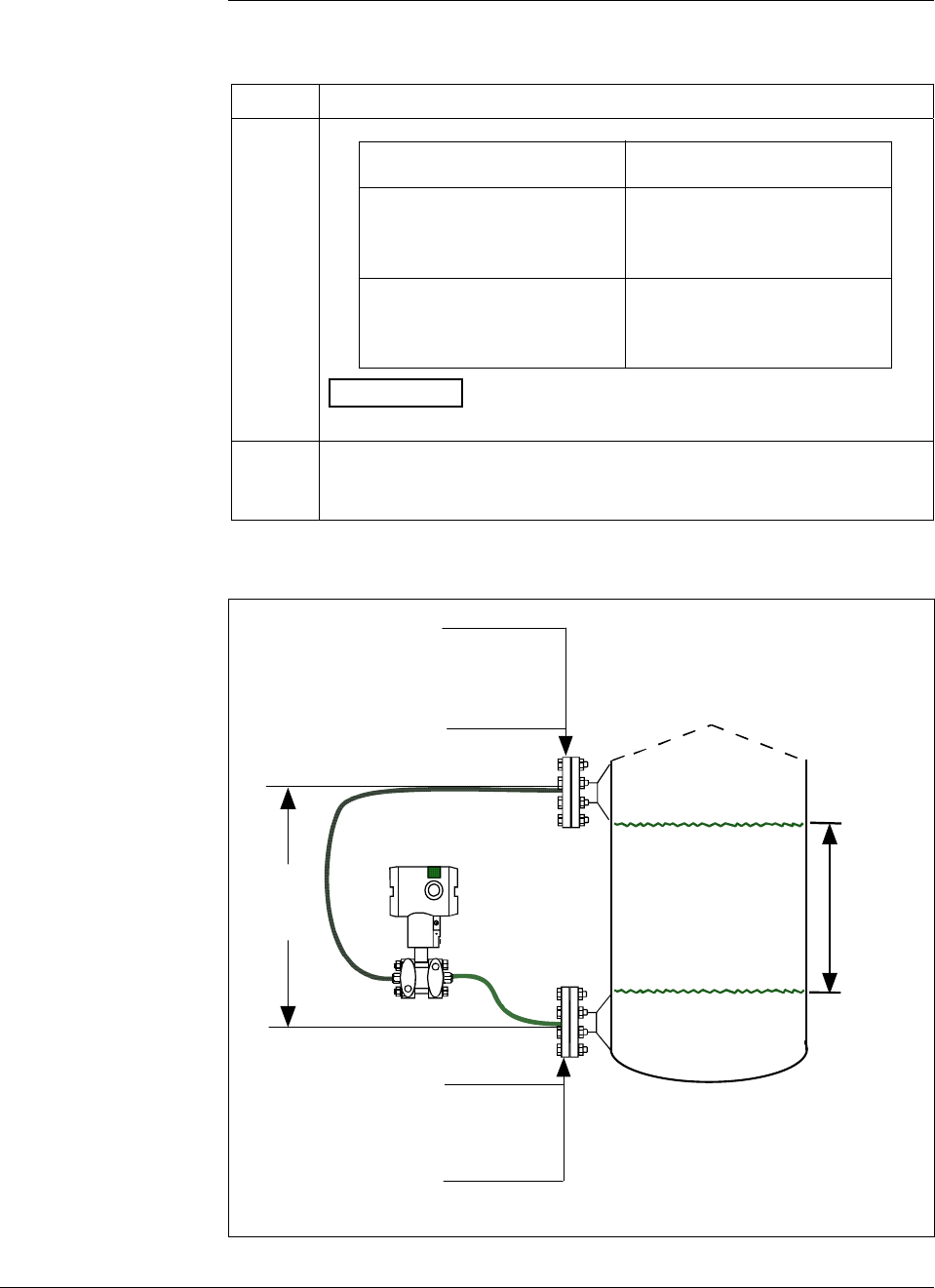
6/08 ST 3000 Release 300 and SFC Model STS103 User’s Manual 37
4.2 Mounting ST 3000 Transmitter, Continued
Remote seal
mounting, continued
Table 11 Mounting Remote Diaphragm Seal Transmitter, continued
Step Action
3 If Transmitter Model Then Connect Remote
Number is… Seal on…
STR93D or STR12D low pressure (LP) side of
transmitter to upper flange
mounting on tank wall for
fixed or constant head H2.
STR13D high pressure (HP) side of
transmitter to upper flange
mounting on tank wall for
fixed or constant head H2.
ATTENTION On insulated tanks, remove enough insulation to
accommodate the flange extension.
4 It is the End User’s responsibility to provide a flange gasket and
mounting hardware that are suitable for the transmitter’s service
condition
Figure 13 Typical Remote Diaphragm Seal Transmitter Installation.
Variable
Head H1
HP Side
- Model STR93D
- Model STR12D
LP Side
- Model STR13D
Minimum Level
Maximum Level
LP Side
- Model STR93D
- Model STR12D
HP Side
- Model STR13D
H2
Fixed
Ref. Leg
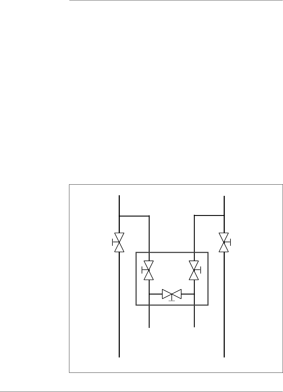
38 ST 3000 Release 300 and SFC Model STS103 User’s Manual 6/08
4.3 Piping ST 3000 Transmitter
Piping arrangements The actual piping arrangement will vary depending upon the process
measurement requirements and the transmitter model. Except for
flanged and remote diaphragm seal connections, process connections are
made to ¼ inch or ½ inch NPT female connections in the process head
of the transmitter’s meter body. For example, a differential pressure
transmitter comes with double-ended process heads with ¼ inch NPT
connections but they can be modified to accept ½ inch NPT through
optional flange adapters. Some gauge pressure transmitters may have a
½ inch NPT connection which mounts directly to a process pipe.
The most common type of pipe used is ½ inch schedule 80 steel pipe.
Many piping arrangements use a three-valve manifold to connect the
process piping to the transmitter. A manifold makes it easy to install
and remove or rezero a transmitter without interrupting the process. It
also accommodates the installation of blow-down valves to clear debris
from pressure lines to the transmitter.
Figure 14 shows a diagram of a typical piping arrangement using a
three-valve manifold and blow-down lines for a differential pressure
transmitter being used to measure flow.
Figure 14 Typical 3-Valve Manifold and Blow-Down Piping
Arrangement.
Blow-Down
Valve 3-Valve
Manifold
To Upstream TapTo Downstream Tap
To Low Pressure
Side of Transmitter To High Pressure
Side of Transmitter
Blow-Down
Valve
Blow-Down
Piping
To WasteTo Waste
Blow-Down
Piping
21010
Continued on next page
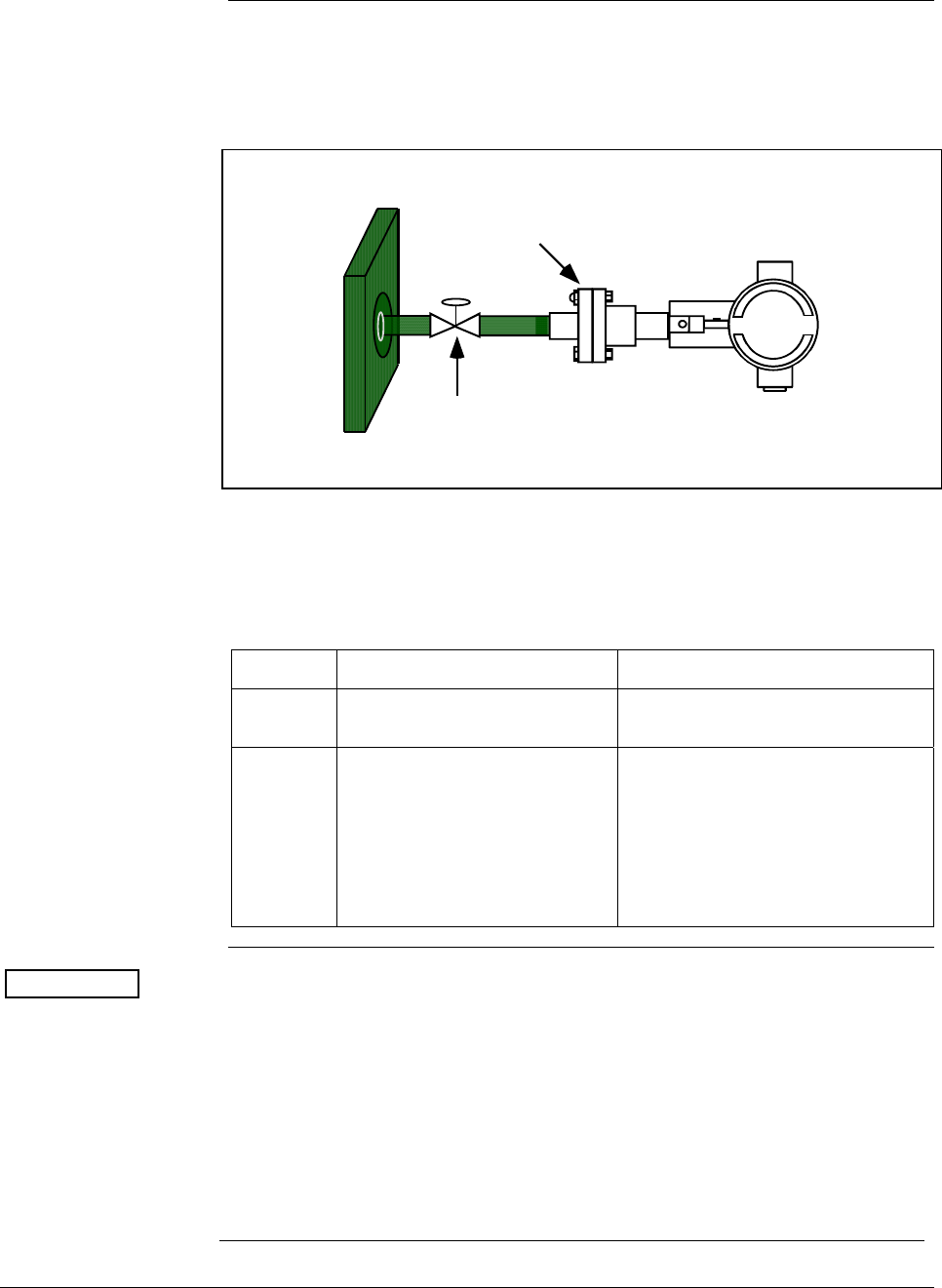
6/08 ST 3000 Release 300 and SFC Model STS103 User’s Manual 39
4.3 Piping ST 3000 Transmitter, Continued
Piping arrangements,
continued Another piping arrangement uses a block-off valve and a tee connector in
the process piping to the transmitter as shown in Figure 15.
Figure 15 Typical Piping Arrangement for ½” NPT Process Connection
Block-off Valve
1/2" NPT
Connection
Tank Wall
Transmitter location Table 12 lists the mounting location for the transmitter depending on the
process.
Table 12 Suggested Transmitter Location for Given Process
Process Suggested Location Explanation
Gases Above the gas line The condensate drains away from
the transmitter.
Liquids 1. Below but close to the
elevation of the process
connection.
2. Level with or above the
process connection.
1. This minimizes the static head
effect of the condensate.
2. This requires a siphon to
protect the transmitter from
process steam. The siphon
retains water as a “fill fluid.”
ATTENTION For liquid or steam, the piping should slope a minimum of 25.4 mm
(1 inch) per 305 mm (1 foot). Slope the piping down towards the
transmitter if the transmitter is below the process connection so the
bubbles may rise back into the piping through the liquid. If the
transmitter is located above the process connection, the piping should rise
vertically above the transmitter; then slope down towards the flowline
with a vent valve at the high point. For gas measurement, use a
condensate leg and drain at the low point (freeze protection may be
required here).
See Appendix B for some suggested freeze protection solutions.

40 ST 3000 Release 300 and SFC Model STS103 User’s Manual 6/08
Continued on next page
4.3 Piping ST 3000 Transmitter, Continued
ATTENTION Care must be taken when installing transmitters on hot processes. The
operating temperature limits for the device (as outlined in Table 5) must
not be exceeded. Impulse piping may be used to reduce the temperature
of the process that comes into contact with the transmitter meter body.
As a general rule there is a 56 degree C drop (100 degree F) in the
temperature of the process for every foot of ½ inch uninsulated piping.
Process connections Table 13 describes typical process connections for a given type of
transmitter.
Table 13 Process Connections
Transmitter Type Process Connection
Differential
Pressure • Process heads with 1/4-inch NPT female connection.
• Flange adapters and manifolds with 1/2-inch female
connection are optional.
• Models with pseudo flange on one side include 2- or 3-
inch ANSI class 150 flange.
Gauge Pressure • Process head with 1/2-inch NPT female connection
(Series 100).
• In-line 1/2-inch NPT female connection (STGxxL).
• In-line ½ inch NPT male
• 9/16 AMINCO
• DIN 19213
• Process heads with 1/4-inch NPT female connection
(STG9x4).
• Flange adapters and manifolds with 1/2-inch female
connections are optional (STG9x4).
• 2-inch Sanitary Tri-Clamp (STGxxT)
• Flush mount in 1-inch weld sleeve, with O-ring and
locking bolt (STGxxP).
Absolute Pressure • Process head with 1/2-inch NPT female connection.
(STAx22, x40).
• In-line ½ inch NPT male
• 9/16 AMINCO
• DIN 19213
Flange Mounted
Liquid Level • Small flange 1/2-inch, 1-, 1 ½ - and 2-inch (STFxxT)
• 2, 3- or 4-inch flange with flush or 2-, 4- or 6-inch
extended diaphragm (See Table 14) on high pressure
side.*
• DN 50, 80, or 100 PN 40 flange with flush or 2, 4 or 6
inch extended diaphragm (See Table 14) on High
Pressure Side*.
Remote
Diaphragm Seals See Model Selection Guide for description of available
Flanged, Threaded, Chemical Tee, Saddle, and Sanitary
process connections.
* Reference side has standard differential pressure process head.
Continued on next page

6/08 ST 3000 Release 300 and SFC Model STS103 User’s Manual 41
4.3 Piping ST 3000 Transmitter, Continued
Flange descriptions Table 14 describes the available flange connections for flange mounted
liquid level transmitters.
Table 14 Flange Description
Transmitter Type Description
Flush or Extended
Diaphragm 2-inch 150# serrated–face flange with 4 holes 19 mm (3/4 in) diameter on 120.7
mm (4.75 in) diameter bolt circle and an outside diameter of 150 mm (5.91 in).
2-inch 150# serrated–face flange with 8 holes 19 mm (3/4 in) diameter on 127 mm
(5.00 in) diameter bolt circle and an outside diameter of 165 mm (6.50 in).
3-inch 150# serrated–face flange with 4 holes 19 mm (3/4 in) diameter on 152.4
mm (6.00 in) diameter bolt circle and an outside diameter of 190 mm (7.48 in).
3-inch 300# serrated–face flange with 8 holes 22.2 mm (7/8 in) diameter on 168.3
mm (6.62 in) diameter bolt circle and an outside diameter of 210 mm (8.27 in).
4-inch 150# serrated–face flange with 4 holes 19 mm (3/4 in) diameter on 190.5
mm (7.50 in) diameter bolt circle and an outside diameter of 230 mm (9.05 in).
4-inch 300# serrated–face flange with 8 holes 22.2 mm (7/8 in) diameter on 255
mm (10.04 in) diameter bolt circle and an outside diameter of 200 mm (7.87 in).
DN 50 PN 40 serrated–face flange with 4 holes 18 mm (0.71 in) diameter on 125
mm (4.92 in) diameter bolt circle and an outside diameter of 165 mm (6.50 in).
DN 80 PN 40 serrated–face flange with 8 holes 18 mm (0.71 in) diameter on 160
mm (6.30 in) diameter bolt circle and an outside diameter of 200 mm (7.87 in).
DN 100 PN 40 serrated–face flange with 8 holes 22 mm (0.87 in) diameter on 190
mm (7.48 in) diameter bolt circle and an outside diameter of 235 mm (9.25 in).
Pseudo Flange Head 2-inch, 150 lbs serrated-face flange with 4 holes 15.9 mm (5/8 in) diameter on
120.6 mm (4-3/4 in) diameter bolt circle and an outside diameter of 152.4 mm (6
in).
3-inch, 150 lbs serrated-face flange with 4 holes 19 mm (3/4 in) diameter on 152
mm (6 in) diameter bolt circle and an outside diameter of 190 mm (7-1/2 in).
Flush Mount
Gauge STG93P
25.4 mm (1” pipe mount) (316L SS standard option.)
General piping
guidelines • When measuring fluids containing suspended solids, install
permanent valves at regular intervals to blow-down piping.
• Blow-down all lines on new installations with compressed air or
steam and flush them with process fluids (where possible) before
connecting these lines to the transmitter’s meter body.
• Be sure all the valves in the blow-down lines are closed tight after the
initial blow-down procedure and each maintenance procedure after
that.
Continued on next page
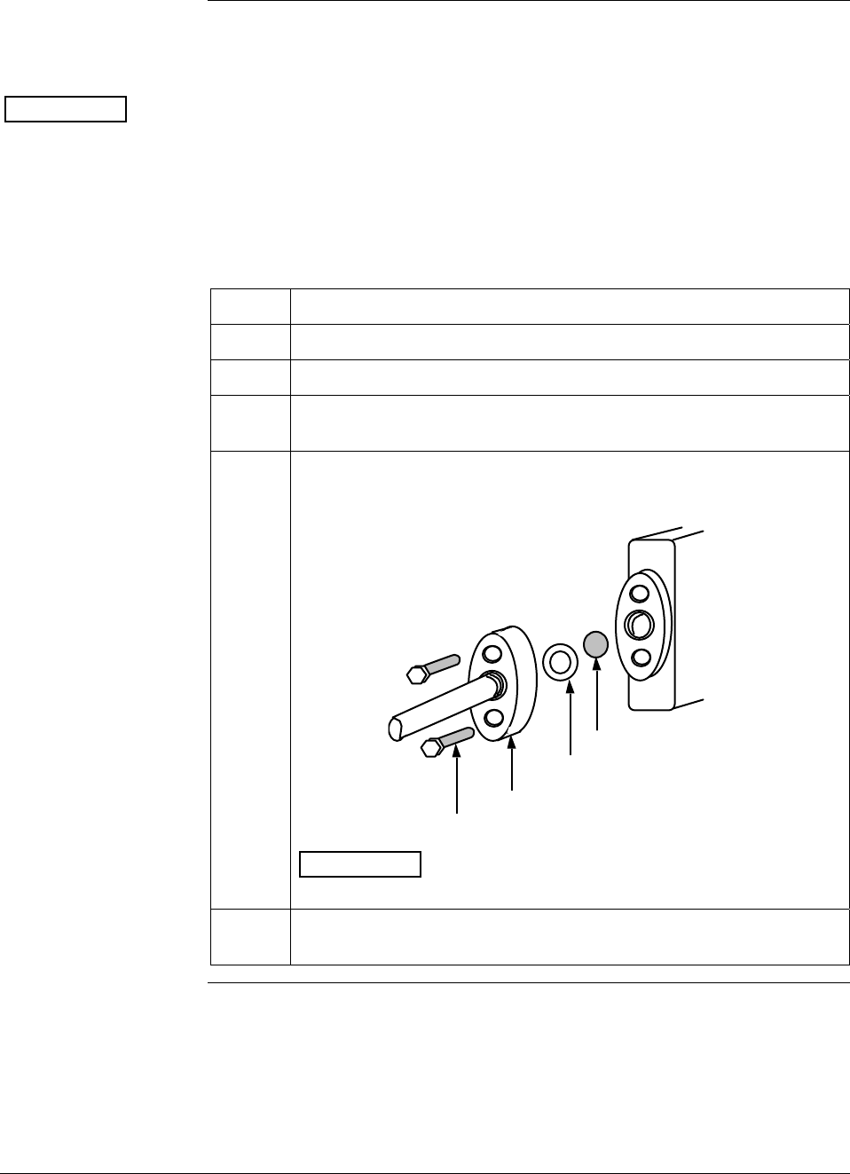
42 ST 3000 Release 300 and SFC Model STS103 User’s Manual 6/08
4.3 Piping ST 3000 Transmitter, Continued
Installing flange
adapter Table 15 gives the steps for an optional flange adapter on the process
head.
ATTENTION Slightly deforming the gasket supplied with the adapter before you
insert it into the adapter may aid in retaining the gasket in the groove
while you align the adapter to the process head. To deform the gasket,
submerse it in hot water for a few minutes then firmly press it into its
recessed mounting groove in the adapter.
Table 15 Installing Flange Adapter
Step Action
1 Insert filter screen (if supplied) into inlet cavity of process head.
2 Carefully seat Teflon (white) gasket into adapter groove.
3 Thread adapter onto 1/2-inch process pipe and align mounting holes
in adapter with holes in end of process head as required.
4 Secure adapter to process head by hand tightening 7/16-20 hex-
head bolts.
Example – Installing adapter on process head.
Process
Head
Filter Screen
Teflon Gasket
Flange Adapter
7/16 x 20 Bolts 21011
ATTENTION Apply an anti-seize compound on the stainless steel
bolts prior to threading them into the process head.
5 Evenly torque flange adapter bolts to a torque of 27,1 Nm +/- 1,4 Nm
(20 ft lbs +/- 1.0 ft lbs)
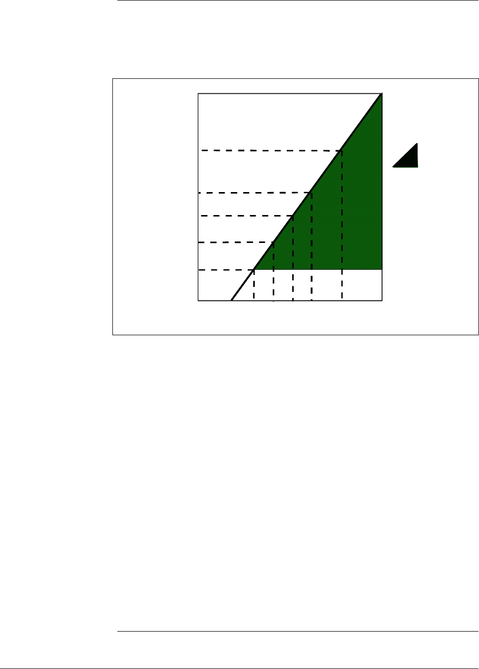
6/08 ST 3000 Release 300 and SFC Model STS103 User’s Manual 43
4.4 Wiring ST 3000 Transmitter
Summary The transmitter is designed to operate in a two-wire power/current loop
with loop resistance and power supply voltage within the operating
range shown in Figure 16.
Figure 16 Operating Range for ST 3000 Transmitters.
0 10.8 16.28 20.63 25 28.3 37.0 42.4
250
450
650
800
1200
1440
Operating Voltage (Vdc)
= Operating
Area
NOTE: A minimum of
250 0hms of loop
resistance is
necessary to support
communications. Loop
resistance equals
barrier resistance plus
wire resistance plus
receiver resistance.
Also 45 volt operation
is permitted if not an
intrinsically safe
installation.
Loop
Resistance
(ohms)
21012
Loop wiring is connected to the transmitter by simply attaching the
positive (+) and negative (–) loop wires to the positive (+) and negative
(–) SIGNAL screw terminals on the terminal block in the transmitter’s
electronics housing shown in Figure 17.
Each transmitter includes an internal ground terminal to connect the
transmitter to earth ground. A ground terminal can be optionally added
to the outside of the electronics housing. While it is not necessary to
ground the transmitter for proper operation, we suggest that you do so to
minimize the possible effects of “noise” on the output signal and
provide additional protection against lightning and static discharge
damage.
Note that grounding may be required to meet optional approval body
certification. Refer to section 3.2 CE Conformity (Europe) Notice for
special conditions.
Optional lightning protection (option LP) can be ordered for transmitters
that will be installed in areas highly susceptible to lightning strikes.
Figure 17 shows the 5-screw terminal block used when the lightning
protection option is ordered.
Continued on next page
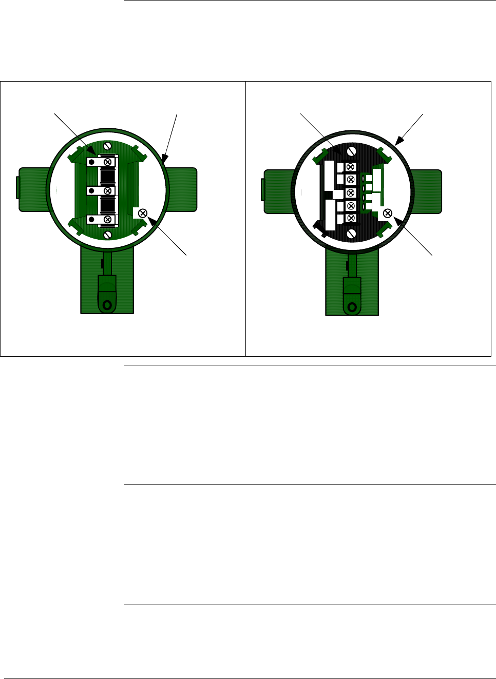
44 ST 3000 Release 300 and SFC Model STS103 User’s Manual 6/08
4.4 Wiring ST 3000 Transmitter, Continued
Summary, continued Barriers can be installed per manufacturer’s instructions for transmitters
to be used in intrinsically safe applications.
Figure 17 ST 3000 Transmitter Terminal Block
- SIGNAL +
+ -
TEST
Terminal
Block
Electronics
Housing
Internal
Ground
Terminal
3-Screw Terminal Block
+
+
-
-
L-
SIGNAL
METER
TESTSIGNAL
-
+
+
-
Terminal
Block
Electronics
Housing
Internal
Ground
Terminal
5-Screw Terminal Block
Lightning Protection Option (LP)
TPS reference Transmitters that are to be digitally integrated to Honeywell’s TPS
system will be connected to the Smart Transmitter Interface Module in
the Process Manager, Advanced Process Manager or High Performance
Process Manager through a Field Termination Assembly. Details about
the TPS system connections are given in the PM/APM Smartline
Transmitter Integration Manual PM12-410 which is part of the TDC
3000X system bookset.
Allen-Bradley PLC If you are digitally integrating the ST 3000 to an Allen Bradley PLC, the
same FTA and wiring procedures used with Honeywell’s TPS system
are also used with the Allen-Bradley 1771 and 1746 platforms.
For more information, contact:
ProSoft Technology, Inc.
(800) 326-7066 or
http://www.psft.com
Continued on next page
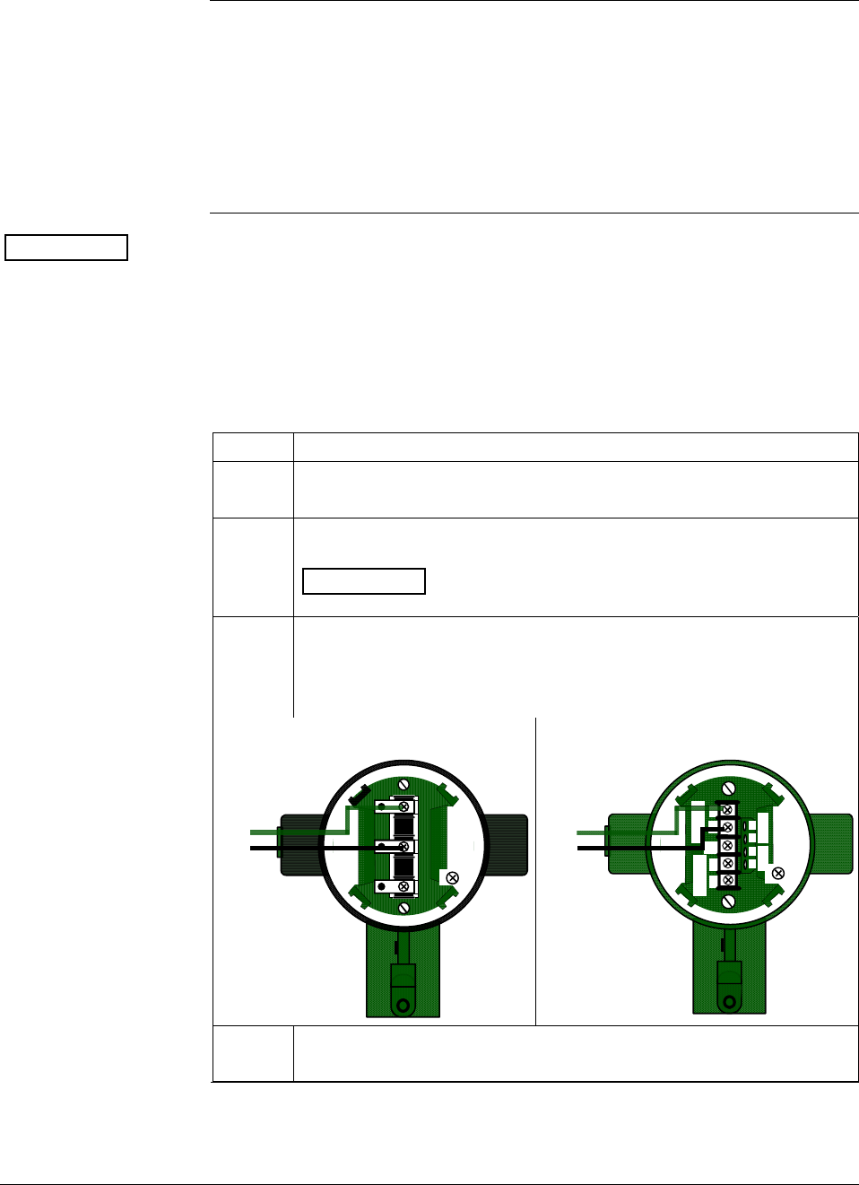
6/08 ST 3000 Release 300 and SFC Model STS103 User’s Manual 45
4.4 Wiring ST 3000 Transmitter, Continued
Wiring connections
and installation
drawings
The procedure in Table 16 shows the steps for connecting power to the
transmitter. For loop wiring and external wiring diagrams, refer to the
installation drawings presented in Section 13. Detailed drawings are
provided for transmitter installation in non-intrinsically safe areas and
for intrinsically safe loops in hazardous area locations. If you are using
the transmitter with Honeywell’s TPS system, see the previous TPS
reference.
ATTENTION • All wiring must comply with local codes, regulations, and
ordinances.
• If you will be using the transmitter in a hazardous area, be sure to
review the hazardous location reference data included in Appendix
D of this manual before operating the transmitter.
Table 16 Wiring the Transmitter
Step Action
1
Loosen end-cap lock using a 1.5 mm allen wrench and remove end-
cap cover from terminal block end of electronics housing.
2
Feed loop power leads through one of conduit entrances on either
side of electronics housing. Plug whichever entrance you do not use.
ATTENTION The transmitter accepts up to 16 AWG wire.
3 Observing polarity, connect positive loop power lead to SIGNAL +
terminal and negative loop power lead to SIGNAL – terminal.
Example – Connecting loop power to transmitter.
3-screw terminal block
- SIGNAL +
+ -
TEST
+
-
Loop
Power
5-screw terminal (option LP)
+
+
-
-
L
-
SIGNAL
METER
TESTSIGNAL
-
+
+
-
+
-
Loop
Power
4 Replace end-cap, and tighten end-cap lock.
Continued on next page
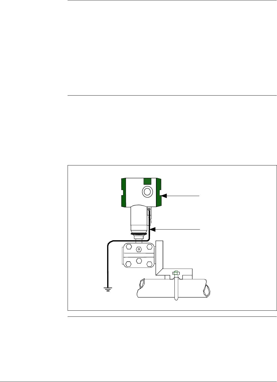
46 ST 3000 Release 300 and SFC Model STS103 User’s Manual 6/08
4.4 Wiring ST 3000 Transmitter, Continued
Approval body
requirements If your transmitter was ordered with Table III option 3N for self-
declared approval per 94/9/EC (ATEX4), you must use a power supply
that includes a voltage limiting device that will keep the voltage to the
transmitter from exceeding 42 Vdc. You can achieve this by using a
battery as the supply or one of these voltage limiting means.
• Double wound mains transformer per BS 3535 or equivalent.
• An adequately rated zener diode whose voltage is not significantly
higher than the rated voltage.
• An adequately rated semiconductor voltage regulator.
Lightning protection When your transmitter is equipped with optional lightning protection,
you must connect a wire from the transmitter to ground as shown in
Figure 18 to make the protection effective. We recommend that you use
a size 8 AWG (American Wire Gage) or (8.37mm2) bare or green
covered wire.
Figure 18 Ground Connection for Lightning Protection.
Electronics
Housing
Connect to
Earth Ground
Continued on next page

6/08 ST 3000 Release 300 and SFC Model STS103 User’s Manual 47
4.4 Wiring ST 3000 Transmitter, Continued
Process Sealing
Explosionproof
Conduit seal
The ST 3000, Series 100, 100e, 600, and 900, Smart Pressure
Transmitters are CSA certified as “Dual Seal” devices in accordance
with ANSI/ISA–12.27.01–2003, Requirements for Process Sealing
between Electrical Systems and Flammable or Combustible Process
Fluids.
Transmitters installed as explosionproof in a Class I, Division 1, Group
A Hazardous (Classified) Location in accordance with ANSI/NFPA 70,
the US National Electrical Code (NEC), require a “LISTED”
explosionproof seal to be installed in the conduit, within 18 inches of
the transmitter. Crouse-Hinds® type EYS/EYD or EYSX/EYDX are
examples of “LISTED” explosionproof seals that meets this
requirement.
Transmitters installed as explosionproof in a Class I, Division 1, Group
B, C or D Hazardous (Classified) Locations do not require an
explosionproof seal to be installed in the conduit.
NOTE: Installation should conform to all national and local electrical
code requirements.
WARNING When installed as explosionproof in a Division 1 Hazardous Location,
keep covers tight while the transmitter is energized. Disconnect power
to the transmitter in the non-hazardous area prior to removing end caps
for service.
When installed as nonincendive equipment in a Division 2 Hazardous
Location, disconnect power to the transmitter in the non-hazardous area,
or determine that the location is non-hazardous prior to disconnecting or
connecting the transmitter wires.
Continued on next page
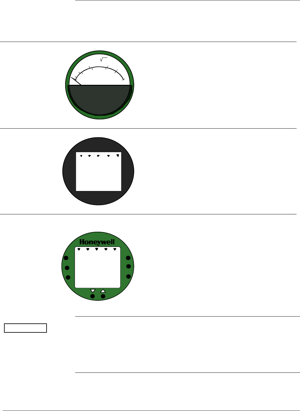
48 ST 3000 Release 300 and SFC Model STS103 User’s Manual 6/08
4.4 Wiring ST 3000 Transmitter, Continued
Existing meter
connections Existing analog meters and SM 3000 Smart Meters can be connected to
Release 300 transmitters. Examples of each meter type are shown
below.
Analog Meter
80
100
60
40
20
0
%
10
2
4
6
8
10
Analog Meter Connections —You can connect the
analog meter (2-wires) integrally to Release 300
transmitter’s terminal block inside the electronics
housing. However, there are alternate wiring
methods for connecting an analog meter remotely
with the loop wiring. Section 13 in this manual
illustrates alternate wiring methods for connecting
an analog meter to Release 300 transmitters.
Smart Meter
0100
%
SM 3000 Smart Meter Connections —The smart
meter (3-wires) can be connected remotely to a
Release 300 transmitter. Section 13 in this manual
illustrates alternate wiring methods for connecting
this smart meter to Release 300 transmitters.
New Smart Meter with Local Zero and Span
UPPE R
VALUE
UNITS
LOWER
VALUE
SET
VAR
SEL.
0
-
SPAN
ZERO
%100
0
New Smart Meter Connections – The new integral
smart meter (8-wires) is connected directly to the
transmitter’s PWA and is mounted to the
electronics module assembly inside the electronics
housing. The new integral smart meter is designed
for the ST 3000 Release 300 transmitter and
provides functionality not available with other
smart meter designs.
NOTE: Only one smart meter should be installed
integrally to the transmitter.
ATTENTION Be aware that the RMA 300 remote meter does not have custom and
flow units capability like the new smart meter. Therefore, if you use a
local smart meter that is configured to display readings in custom or
flow units in conjunction with an RMA 300 remote meter, the readings
of the two meters will be in different units.

6/08 ST 3000 Release 300 and SFC Model STS103 User’s Manual 49
Section 5 —Getting Started
5.1 Introduction
Section Contents This section includes these topics:
Section Topic See Page
5.1 Introduction ..................................................................................49
5.2 Establishing Communications ......................................................50
5.3 Making Initial Checks ...................................................................54
5.4 Changing Mode of Operation .......................................................57
About this section If you have never used an SFC to “talk” to an ST 3000 transmitter, this
section tells you how to establish communications, make initial checks,
and change the transmitter’s mode of operation.
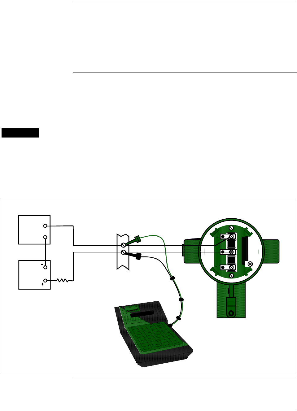
50 ST 3000 Release 300 and SFC Model STS103 User’s Manual 6/08
5.2 Establishing Communications
SFC connection rules • Always plug the SFC leads into the jack on the SFC before you
connect them to the transmitter.
• Use this formula to find the maximum filter capacitance allowed
across the sense resistor (250 ohm minimum) for SFC
communications to work.
C (µF) = 1000 / Rsense
Connecting SFC Using either leads with alligator clips or easy-hooks supplied with the
SFC, you connect the SFC directly to signal terminals on the
transmitter’s terminal block or at any convenient location in the 4 to 20
milliampere line. Observing polarity, connect the red lead to positive (+)
and the black lead to negative (–).
WARNING When the transmitter’s end-cap is removed, the housing is not
explosionproof.
Figure 19 shows typical SFC connections across loop wiring to the
ST 3000 transmitter. (Non-lightning protection terminal connections
shown.)
Figure 19 Typical SFC Connections.
+ Red
- Black
+
-
Field
Terminals
- SIGNAL +
+ -
TEST
STR3012
Power
Supply
+
-
Receiver
SFC
ST 3000
250
Ω
Continued on next page
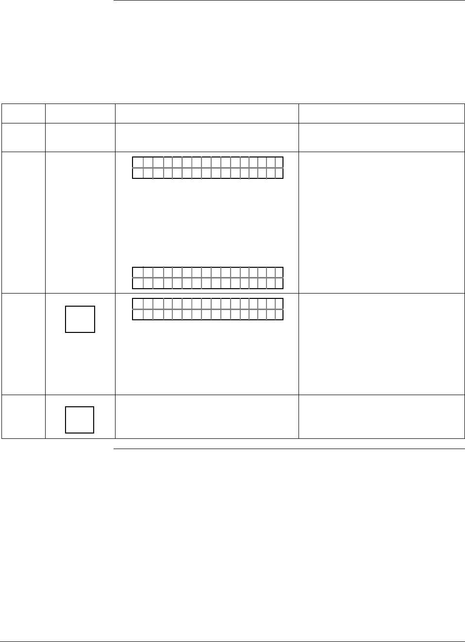
6/08 ST 3000 Release 300 and SFC Model STS103 User’s Manual 51
5.2 Establishing Communications, Continued
Starting
communications Once you connect the SFC to the transmitter or loop wiring, you are
ready to start communicating with the transmitter. The procedure in
Table 17 outlines the steps for communications with an ST 3000
transmitter without an assigned tag number.
Table 17 Starting Communications with Transmitter.
Step Press Key Read Display or Action Description
1 Slide power switch on left side of SFC to
ON position. SFC runs its self check and displays
initial prompt.
2 PUT IN MANLOOP
OR
DE X TMR RE S ISDP–
If this prompt appears, transmitter is
in Analog mode of operation. This is
the factory default mode of
operation setting. Put your control
loop in the manual mode of
operation before initiating SFC
communications. Note that you must
do this separately through the
receiving device in the loop.
If this prompt appears, transmitter is
in Digital (DE) mode of operation.
3 DE READ
A
ID
TA ON.G
?TRIPS SECURED?
OR
Go to Step 5
Be sure any switches that may trip
alarms or interlocks associated with
analog loop are secured or turned
off. Go to Step 4.
This prompt does not appear for
transmitters operating in DE mode.
See DE transmitter display response
in Step 5.
4 NON-VOL
ENTER
(Yes)
Confirms that “TRIPS” are secured. Go
to Step 5 for display response. Required for transmitters operating
in analog mode only.
Continued on next page
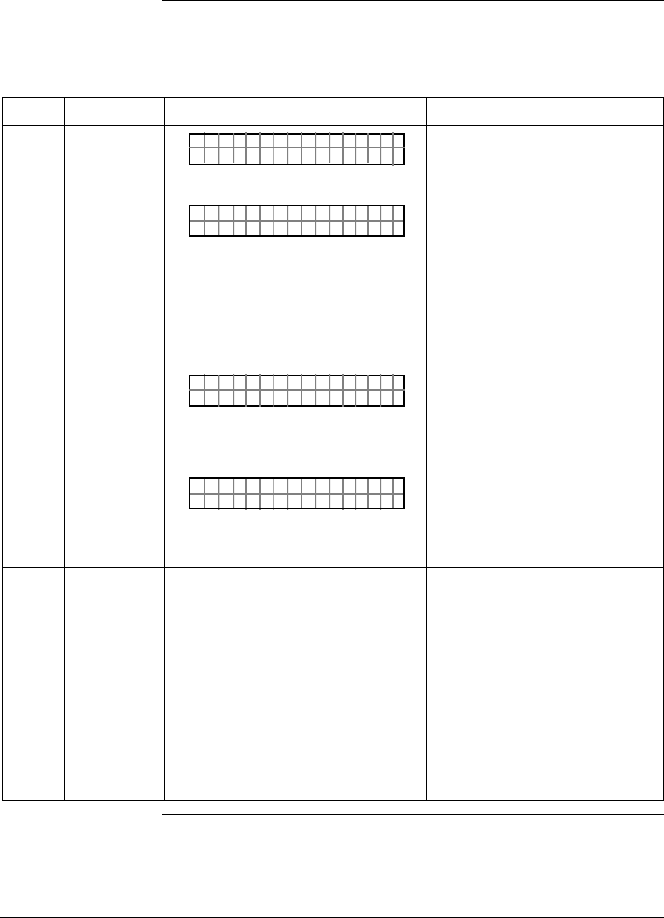
52 ST 3000 Release 300 and SFC Model STS103 User’s Manual 6/08
5.2 Establishing Communications, Continued
Starting
communications,
continued
Table 17 Starting Communications with Transmitter, continued
Step Press Key Read Display or Action Description
5 TA ON.G
SFC WORK ING.. .
LIN AG NO.DP T
_
OR
DE X TMTA OG.RN
_
–
OR
TAG O
ORXT ONM ES
N.
NSRPE
Message exchange is taking place
Note that communications with
transmitter are blocked until [ID] key
is pressed.
Transmitter is in analog
transmission mode. “LIN” means
transmitter is set for linear output
instead of square root (SQRT). “DP”
means transmitter is differential
pressure type instead of gauge
pressure (GP) or absolute pressure
(AP). Last eight columns in bottom
row are blank when no tag number
has been assigned to this
transmitter. Go to Step 8.
Transmitter is in digital (DE)
transmission mode. Last eight
columns in bottom row are blank
when no tag number has been
assigned to this transmitter. Go to
Step 7.
Communication error messages are
cycled at two second intervals and
display returns to initial prompt. Go
to Step 6.
6 There is a communication problem,
check the
• power and SFC connections - Is the
polarity correct; red to positive and
black to negative?
• loop resistance - Is there a minimum
of 250 ohms resistance between the
SFC and the power supply?
• power supply - Is power applied, is
there greater than 11 volts at the
transmitter, and are you within the
operating area on the curve in Figure
16?
Correct any wiring, resistance, or
power supply problems, and try
communicating again - Press [ID]
key.
If you are still not getting the
correct display, note error
messages and refer to
Troubleshooting section in this
manual for probable cause.
Continued on next page
6/08 ST 3000 Release 300 and SFC Model STS103 User’s Manual 53
5.2 Establishing Communications, Continued
Starting
communications,
continued
Table 17 Starting Communications with Transmitter, continued
Step Press Key Read Display or Action Description
7 ^
SHIFT
DE READ
A
ID
DE X TMTA OG.RN
F
–
SHI T–
TA ON.G
S FC WORK I NG–. 33%
LIN AG NO.DP T
_
Initiates shift key selection.
Begins upload of configuration
database from transmitter.
Operation completion rate is shown
in percent. Note that display for ID
response reverts to style used for
transmitter in analog mode when
upload is completed.
8 F/S DIR
U
STAT
ST A ST
FC WOSING.RK . .
U
ST A ST
TA USSHECKC=O
U
TK
LIN DP
.Y. .RE AD
Initiates status check.
If messages other than this one are
cycled in display, refer to the
Troubleshooting section in this
manual for an explanation of the
message, the probable cause, and
any corrective action.
Signals end of status messages for
display.
ATTENTION When assigned,
the transmitter’s tag number also
appears in the top row of the
display.
9 You have established
communications with transmitter and
are ready to initiate other SFC
operations.
54 ST 3000 Release 300 and SFC Model STS103 User’s Manual 6/08
5.3 Making Initial Checks
Checking mode and
software Before doing anything else, it is a good idea to confirm the transmitter’s
mode of operation and identify the version of software being used in the
SFC and the transmitter. Table 18 outlines the steps for quickly
checking the transmitter’s mode of operation and software versions of
the SFC and the transmitter.
Table 18 Confirming Mode of Operation and Identifying Software Versions.
Step Press Key Read Display or Action Description
1 ^
SHIFT
A <–>DE
Q
LIN T ØØØDP S
FT–SHI
3
?
A/ DE
HN T OCG DE
ST 3ØØØ
OR
?
A/ DE
HN T OCG AN
ST 3ØØØ
ALOG
Initiates shift key selection. Note that
transmitter tag number ST 3000 in
top row is used for example
purposes only.
Asks if you want to change to DE
(digital) mode. This means
transmitter is in analog mode of
operation.
Asks if you want to change to
analog mode. This means
transmitter is in DE (digital) mode of
operation.
2 CLR
(No)
LIN DP
.Y. .RE AD
T ØØØS3
Exits analog to DE change function.
3 ^
SHIFT
X
3
SW VER
LIN T ØØØDP S
FT–SHI
3
S/ ON.
W
SFC 4. 5 XMTR
=3
=.Ø
S T 3 ØØØ
Initiates shift key selection.
Both SFC and XMTR software
versions appear in display. Note that
only SFC version appears when
SFC is not connected to transmitter
or [SHIFT] and [ID] keys have not yet
been pressed for transmitter in DE
mode.
4 CLR
(NO)
LIN DP
.Y. .RE AD
T ØØØS3
Exit function. SFC is “READY” for
next operation.
Analog and DE
modes In the analog transmission mode, the transmitter sends a proportional 4
to 20 milliampere output signal that can be used as a compatible analog
input signal to a controller or a recorder in the control room
Continued on next page
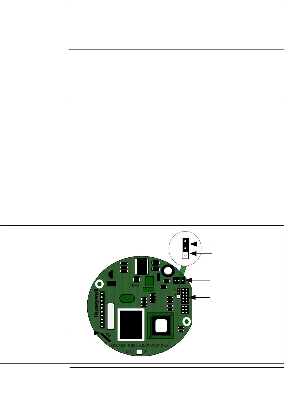
6/08 ST 3000 Release 300 and SFC Model STS103 User’s Manual 55
5.3 Making Initial Checks, Continued
Analog and DE
modes, continued A transmitter in the digital (DE) mode can communicate in a direct
digital fashion with Honeywell’s TPS system and Allen-Bradley PLCs.
The digital signal can include process variable as well as configuration
database data depending upon the broadcast format selected during
configuration.
Software version
compatibility The SFC model STS103 with software version 5.0 or greater is fully
compatible with all Series 100 and Series 900 Release 300 transmitters.
The SFC will operate with transmitters that have older software
versions, but functions will be limited to those applicable for the
transmitter software.
Write protect option The ST 3000 transmitters are available with what is called a “write
protect option”. It consists of a jumper located on the transmitter’s PWA
that you can position to allow read and write access or read only access
to the transmitter’s configuration database. When the write protect
option is ordered, transmitters are shipped with a default jumper position
for read-only. This means that the transmitter’s configuration database
can not be overwritten. To allow read/write access, the jumper can be
moved to the read/write position. When the write protect option is not
ordered access is read/write.
Figure 20 shows the location of the write protect jumper on the PWA for
Release 300 transmitters.
Figure 20 Write Protect Jumper Location and Selections.
Failsafe
Direction
Jumper
Meter
Connector
Power
Connector
W
R
Read and
Write
Read Only
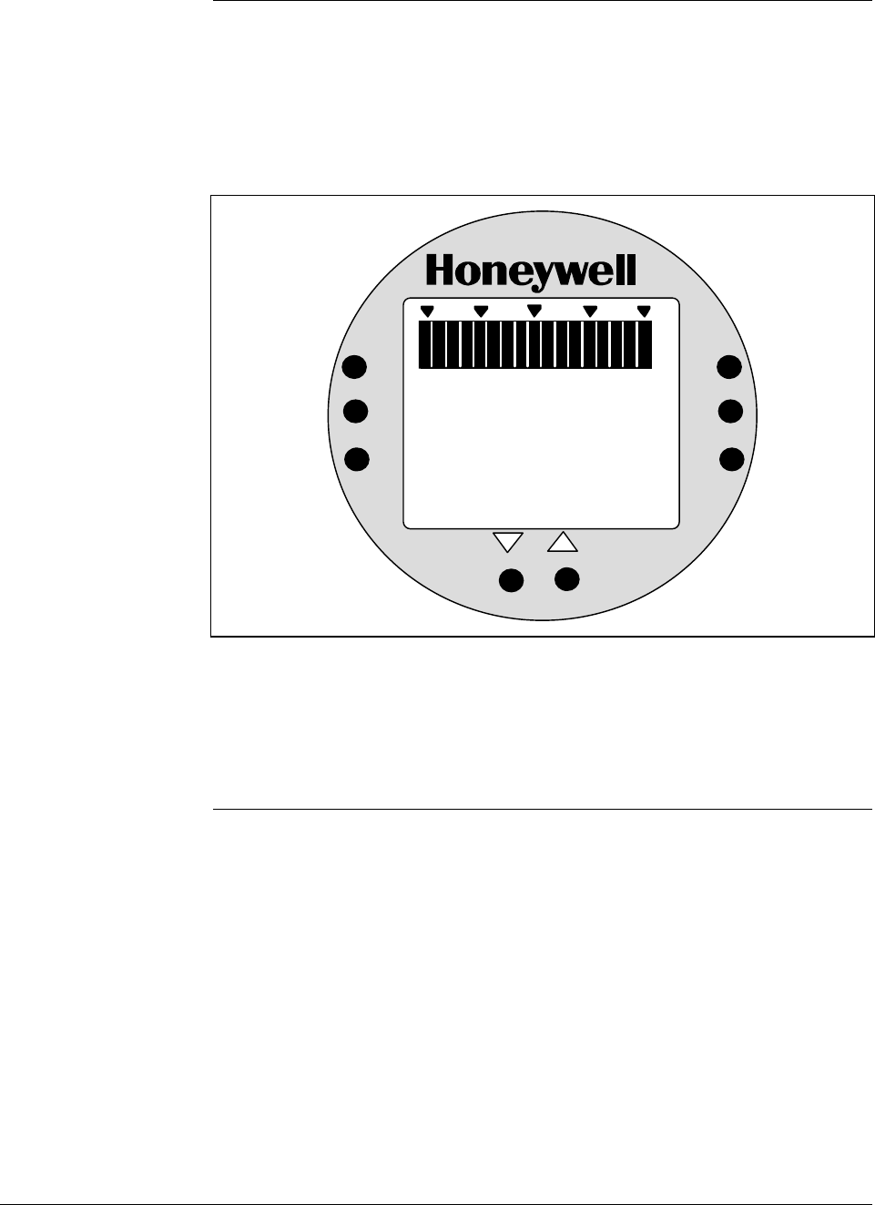
56 ST 3000 Release 300 and SFC Model STS103 User’s Manual 6/08
5.3 Making Initial Checks, Continued
Local smart meter
display indications You can check the status of all the indicators on the Local Smart Meter
LCD display by cycling power to the transmitter. The meter runs a brief
self-test whenever power is applied to the transmitter. All the display
indicators are lit during the self-test as shown in Figure 21.
Figure 21 Display With All Indicators Lit.
%
100
0
18 8
.
8
ANALOG
%
FLOW
In H O
2
K
GPH mmHg
GPM PSI
A
OUTPUT MODE
CHECK STATUS
0
-
UPPER
VALUE
UNITS
LOWER
VALUE
SET
VAR
SEL.
SPAN
ZERO
.
KNOWN VALUE
Please refer to Table 31 in this manual for a description of the pushbuttons
on the meter face. See Section 8.6 for a description of the indicators with
examples of typical display indications and error codes. (Note that the
display may revert to dashes (– – –) after the self-test until the transmitter
initializes all its functions.) Use the SFC to check the transmitter’s status.
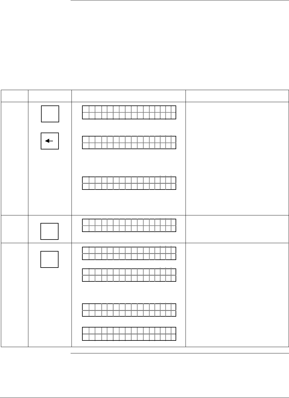
6/08 ST 3000 Release 300 and SFC Model STS103 User’s Manual 57
5.4 Changing Mode of Operation
Procedure If you need to change your transmitter’s mode of operation, use the
steps in Table 19 to change the mode from analog to digital or digital to
analog. If you have an optional Local Smart Meter, you can readily tell
your transmitter’s present mode of operation by checking whether the
ANALOG indicator on the meter display is lit or not.
Attention: Only transmitters with Option DE can be set to DE Mode.
Table 19 Changing Mode of Operation.
Step Press Key Read Display or Action Description
1 ^
SHIFT
A <–>DE
Q
LIN T ØØØDP S
FT–SHI
3
?
A/ DE
HN T OCG DE
ST 3ØØØ
OR
?
A/ DE
HN T OCG AN
ST 3ØØØ
ALOG
Initiates shift key selection. Note that
transmitter tag number ST 3000 in
top row is used for example
purposes only.
Asks if you want to change to DE
(digital) mode. If you want to change
mode, go to Step 2. If you do not
want to change mode, press [CLR]
key to exit function.
Asks if you want to change to
analog mode. If you want to change
mode, go to Step 2. If you do not
want to change mode, press [CLR]
key to exit function.
2 NON-VOL
ENTER
(Yes)
?
A/ DE
RE YOASU
ST 3ØØØ
REU
Prompt asks for confirmation of
mode change.
3 NON-VOL
ENTER
(Yes)
A/ DE
FC WOSIN
ST 3ØØØ
G.
RK ..
R
A/ DE
X
ST 3ØØØ
MTDE
OR
A/ DE
NA G
ST 3ØØØ
XMLO TRA
LIN DP
.Y. .RE AD
T ØØØS3
Message exchange is working.
Mode of operation is now DE
(digital).
Mode of operation is now analog.
Ready for next function.
Continued on next page
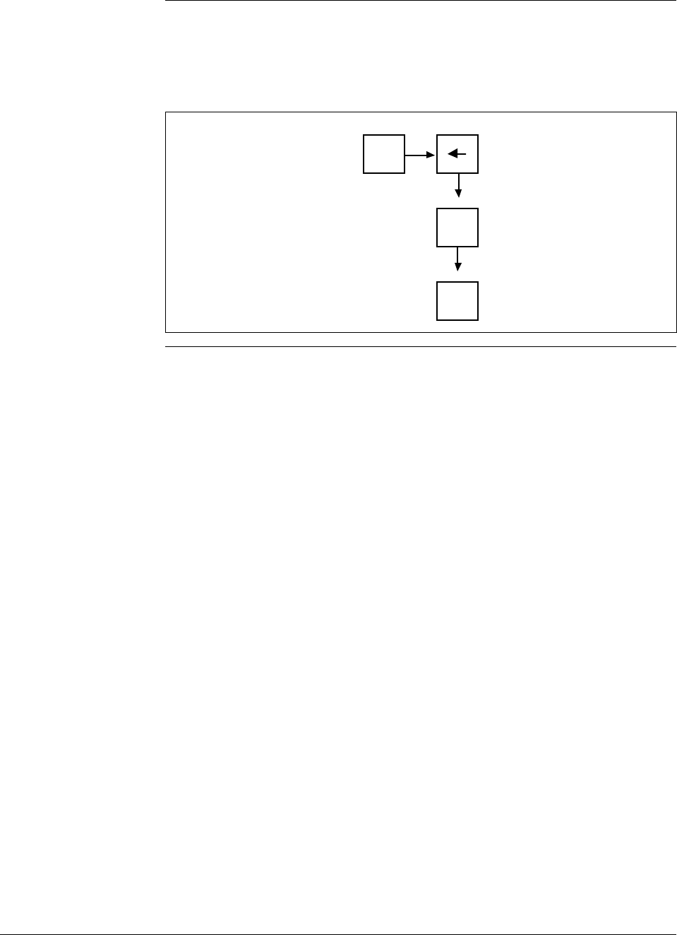
58 ST 3000 Release 300 and SFC Model STS103 User’s Manual 6/08
5.4 Changing Mode of Operation, Continued
Keystroke summary Figure 22 shows keystroke summary for changing mode of
operation for quick reference.
Figure 22 Keystroke Summary for Changing Mode of Operation.
^
SHIFT
NON-VOL
ENTER
(Yes)
A <–>DE
Q
NON-VOL
ENTER
(Yes)

6/08 ST 3000 Release 300 and SFC Model STS103 User’s Manual 59
Section 6 —Configuration
6.1 Introduction
Section Contents This section includes these topics:
Section Topic See Page
6.1 Introduction ..................................................................................59
6.2 Overview ......................................................................................60
6.3 Entering a Tag Number................................................................71
6.4 Selecting Output Form .................................................................73
6.5 Adjusting Damping Time ..............................................................76
6.6 Selecting Unit of Measurement ....................................................78
6.7 Setting Range Values Using SFC ................................................80
6.8 Setting Range Values Using Local Adjustments..........................84
6.9 Selecting Output Signal Mode (DE Mode Only)...........................91
6.10 Selecting Message Format (DE Mode Only).................................94
6.11 Configuring Smart Meter Using SFC............................................96
6.12 Configuring Smart Meter Using Pushbuttons.............................103
6.13 Disconnecting SFC ....................................................................122
About this section This section introduces you to ST 3000 transmitter configuration. It
identifies the parameters that make up the transmitter’s configuration
database and provides procedures for entering values/selections for the
given configuration parameters.
ATTENTION If you will be using the SCT 3000 software Release 3.12.2 or greater
instead of an SFC to configure the transmitter, follow the SCT 3000 on-
line help and on-line documentation to configure the transmitter’s
database.
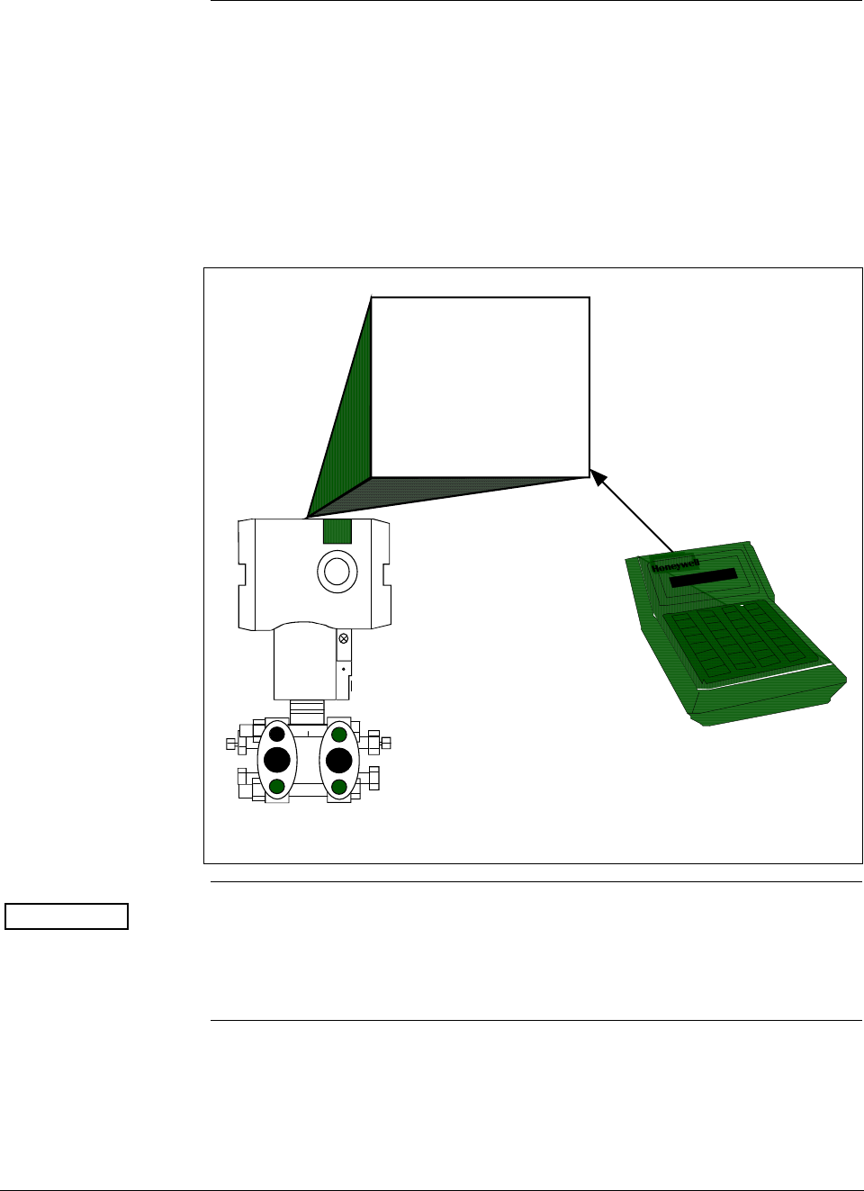
ST 3000 Release 300 and SFC Model STS103 User’s Manual 6/08
60
6.2 Overview
About configuration Each ST 3000 Transmitter includes a configuration database which
defines its particular operating characteristics. You can use an SFC to
change selected parameters within a given transmitter’s database to alter
its operating characteristics. We call this process of viewing and/or
changing database parameters “configuration”.
Figure 23 shows a graphic summation of the configuration process.
Figure 23 Summary of Configuration Process
ST 3000
Configuration Database
Transmitter's
Operating
Characteristics
View and/or
change
database
parameters
SFC
ATTENTION If the transmitter is operating in the DE mode, you can also configure
the transmitter’s configuration database through displays at the
Universal Station or GUS. See the PM/APM Smartline Integration
Manual PM12-410 for details.
Continued on next page
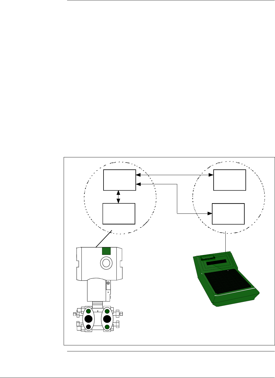
6/08 ST 3000 Release 300 and SFC Model STS103 User’s Manual 61
6.2 Overview, Continued
SFC and ST 3000
transmitter memories Both the SFC and the ST 3000 transmitter have working memories as
shown in Figure 24. They serve as temporary storage areas for data
exchanged between the SFC and the transmitter during communications.
The transmitter also has a non-volatile memory as the permanent storage
area for a backup copy of all the data held in the working memory. This
memory retains its data even if the transmitter loses power.
The SFC has a second temporary storage area called the hold memory.
This memory supports the SFC’s save and restore functions. It serves as
the temporary storage area for a configuration database saved from a
transmitter until it can be restored in a transmitter. Data in this memory
can not be displayed or altered, and it will be lost if the SFC is turned off.
Figure 24 shows the working relationship between SFC and transmitter
memories during communications.
Figure 24 SFC and ST 3000 Transmitter Memories.
Working
Memory
Working
Memory
Non/Volatile
Memory
Hold
Memory
ST 3000
SFC
Continued on next page

ST 3000 Release 300 and SFC Model STS103 User’s Manual 6/08
62
6.2 Overview, Continued
Copying data into
non-volatile memory
ATTENTION
When setting-up or configuring a ST 3000, whether you are changing one
element or a full database, all configuration data must be copied into the
transmitter’s non-volatile memory.
Normally, thirty seconds after a value is changed the transmitter
automatically copies it into the non-volatile memory. But, if you change
an element and power goes down before the change is copied to non-
volatile memory, you will lose the data in the working memory.
Therefore, whenever you make any changes in the transmitter using the
SFC, always end your procedure by pressing SHIFT and ENTER. This
action immediately copies the changes from working memory to non-
volatile memory.
Continued on next page

6/08 ST 3000 Release 300 and SFC Model STS103 User’s Manual 63
6.2 Overview, Continued
What to configure Table 20 summarizes the parameters that are included in the
configuration database for an ST 3000 pressure transmitter in either the
analog or DE mode of operation.
Be aware that configuration data for the transmitter as well as for the
Local Smart Meter is stored in a non-volatile memory on the
transmitter’s PWA and make up the transmitter’s configuration
database. Therefore, the transmitter and meter configuration are lost if
the PWA is replaced. Performing a save and restore function using the
SFC will preserve the transmitter’s configuration database. See Section
8.5 for the steps to perform save and restore functions using the SFC.
ATTENTION Since the SFC is compatible with other Honeywell Smartline
transmitters, be sure all configuration data applies to a pressure
transmitter.
Table 20 Summary of Pressure Transmitter Configuration Parameters
Configuration Data Setting or Selection
Transmitter Tag Number Up to eight characters
Damping Time Constant Any one of these value selections in seconds:
0.00 0.5 4.0 32.0
0.2 1.0 8.0
0.3 2.0 16.0
Type of Output Conformity LIN (Linear)
SQRT (Square Root)
Unit of Measurement ATTENTION Note that ST 3000 transmitters with inches of water
ranges are factory calibrated using pressure referenced to a temperature
of 39.2°F (4°C).
Pressure readings can be displayed in any one of these pre-programmed
engineering units:
“H2O_39F PSI MPa bar KG/cm^2 mmH2O_4C
mmHg_0C KPa mbar G/cm^2 inHg_32F mH2O_4C
“H2O_68F ATM “H2O_60F
LRV (Lower Range Value)
(Process input for 4 mAdc
(0%) output)
Key in desired value through SFC keyboard or set LRV to applied
pressure.
URV (Upper Range Value)
(Process input for 20 mAdc
(100%) output)
Key in desired value through SFC keyboard or set URV to applied
pressure.
Continued on next page
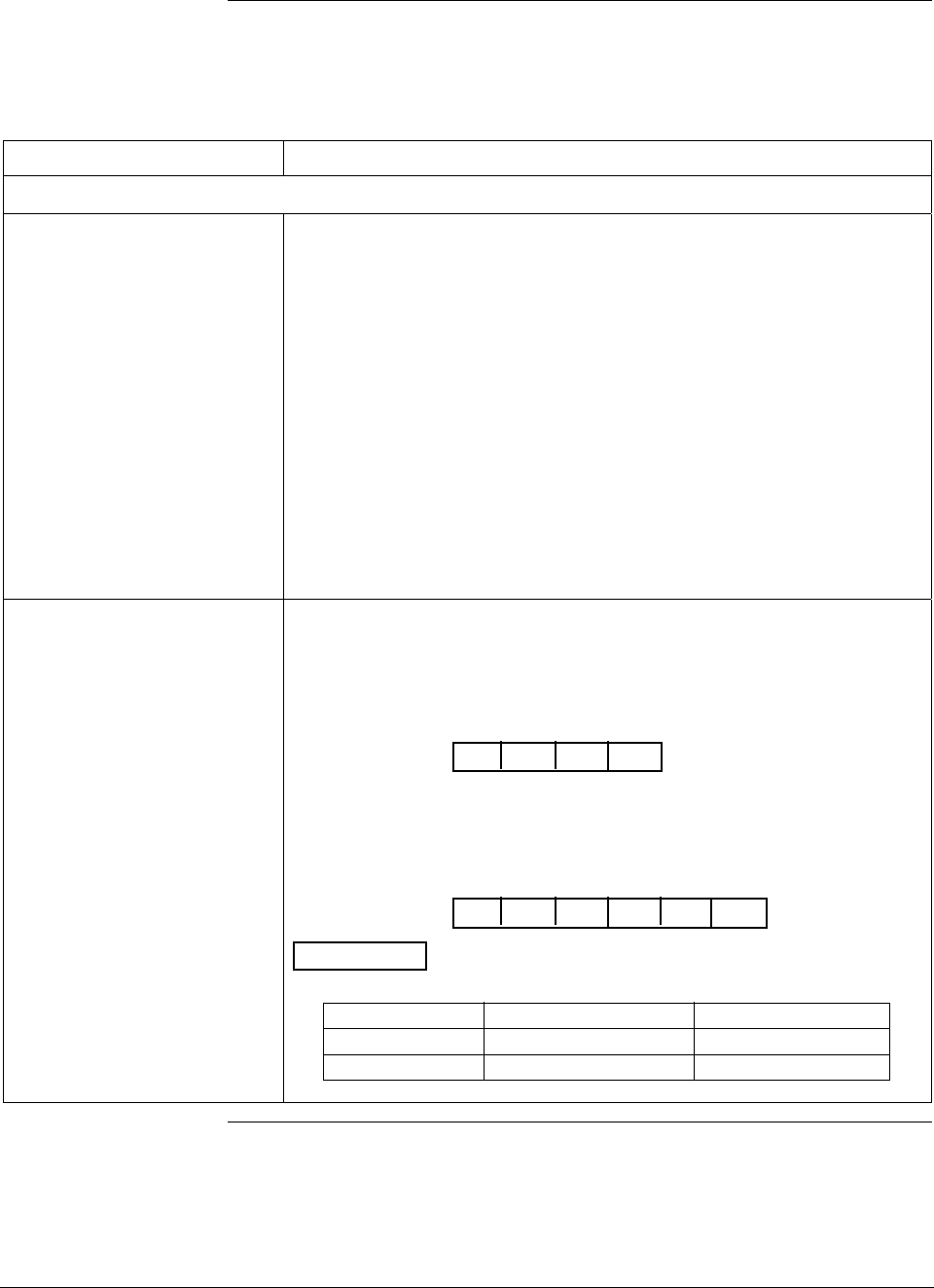
ST 3000 Release 300 and SFC Model STS103 User’s Manual 6/08
64
6.2 Overview, Continued
What to configure,
continued
Table 20 Summary of Pressure Transmitter Configuration Parameters, continued
Configuration Data Setting or Selection
The following parameters are for transmitters in DE mode of operation only.
Mode of Output Signal
Indication Any one of these selections based on control system information needs:
Single Range Sends the PV value corresponding to the
transmitter’s working range (PVw) to the
control system for display. For systems using
STDC card or STIMV IOP module (also called
STIM Smart Transmitter Interface Module).
Dual Range (STDC) Sends the PV values corresponding to the
transmitter’s full range (PVt) and working range
(PVw) measurements to the control system
for display. For systems using STDC card only.
Single Rng W/SV Sends PV value corresponding to the
transmitter’s working range (PVw) and
temperature value from the transmitter’s sensor
to the control system for display. For systems
using STDC card or STIMV IOP module.
Message Format Choose one of these broadcast types for data transmission to the digital
control system: Note that “DB” in following selection prompt stands for
“database”.
w/oDB (4 Byte) Byte 1 is output signal mode
Bytes 2 to 4 are PV value
FLAG PV PV PV
1234
w/DB (6 Byte) Byte 1 is output signal mode
Bytes 2 to 4 are PV value
Byte 5 is data type identifier (LRV, URV span, etc.)
Byte 6 is data being sent
FLAG PV PV PV
1234
ID DB
56
ATTENTION The approximate rates of transmission in repeats per
second are:
Data 4 - Byte 6 - Byte
PV value 3 rpts/sec 2.5 rpts/sec
Temperature 1 rpt/2.5 sec 1 rpt/3 sec
Continued on next page

6/08 ST 3000 Release 300 and SFC Model STS103 User’s Manual 65
6.2 Overview, Continued
What to configure,
continued
Table 20 Summary of Pressure Transmitter Configuration Parameters, continued
Configuration Data Setting or Selection
Failsafe Mode NOTE: This parameter is valid only to select the failsafe action for the
STDC card in a controller - not the transmitter. If you are using
the STDC card to interface with the ST 3000 transmitter, contact
Honeywell Technical Assistance in using this parameter.
ATTENTION An STIMV IOP module has built-in failsafe capabilities
and ignores this parameter.
The following parameters are only for transmitters with optional Local Smart Meter.
Meter Engineering Units If the transmitter is set for LINEAR output conformity, you can choose to
have the Local Smart Meter display pressure readings in one of these
engineering units:
“H2O_39F PSI MPa BAR Kg/cm^2 inHg_32F
mmHg_0C KPa mBAR g/cm^2 mmH2O_4C mH2O_4C
Custom %
If the transmitter is set for SQUARE ROOT output conformity, you can
choose to have the Local Smart Meter display flow readings in one of
these engineering units:
GPM GPH Custom %
Engineering Units High and
Low You can enter desired lower and upper (high) display limits to scale flow
(GPM, GPH) or Custom engineering units to represent the transmitter’s
0 to 100% output within the meter’s display range of ±19,990,000.
ATTENTION When the transmitter is set to SQUARE ROOT output
conformity, the lower display limit for flow units (GPM, GPH) and Custom
unit must equal zero (0).
Continued on next page
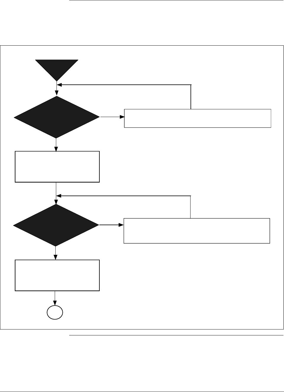
ST 3000 Release 300 and SFC Model STS103 User’s Manual 6/08
66
6.2 Overview, Continued
Configuration
decision summary The flowchart in Figure 25 summarizes the typical entries/selections
decisions associated with configuring an ST 3000 pressure transmitter.
Figure 25 Flowchart — ST 3000 Pressure Transmitter Configuration.
Have you
assigned a unique
"tag number" for
the transmitter?
Start
NO
YES
Assign a unique tag number consisting of up to 8
alphanumeric characters to identify this transmitter.
Establish communications and
enter assigned Tag Number at
SFC configuration prompt TAG
NO.
See procedure in Table 21 for entry details.
Press [ID] key and acknowledge TRIPS SECURED prompt, if
required, to call up SFC prompt TAG NO. Use [NUM/ALPHA]
key to toggle between Alpha mode and Numeric mode to
enter alphabetic characters and numbers, respectively,
through SFC keys.
Do you know if
output is to represent
linear or square root
calculation?
NO
YES
Determine if transmitter's output is to represent a
straight linear calculation or a square root calculation
for flow measurements.
Select LINEAR or SQUARE ROOT
through SFC configuration
prompt CONFORMITY.
See procedure in Table 22 for selection details.
Call up SFC configuration prompt CONFORMITY and select
menu item LINEAR or SQUARE ROOT.
A
Continued on next page
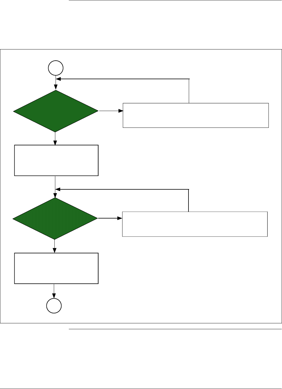
6/08 ST 3000 Release 300 and SFC Model STS103 User’s Manual 67
6.2 Overview, Continued
Configuration
decision summary,
continued
Figure 25 Flowchart — ST 3000 Pressure Transmitter Configuration, continued.
B
Do you know how
much damping time
is needed?
NO
YES
Determine appropriate damping time value for your
process. We suggest that you set the damping to the
largest value that is reasonable for your process.
Select desired damping time
value in seconds through the
SFC prompt DAMP.
See procedure in Table 23 for selection details.
Press [DAMP] key and use [NEXT] or [PREV] key to select
stored damping time value through SFC prompt DAMP 1.
Do you know what
engineering units to
use for pressure
readings?
NO
YES
See Unit of Measurement in Table 24 for list of available
pre-programmed engineering units in the SFC.
Select desired pre-programmed
engineering units through SFC
prompt UNITS.
See procedure in Table 24 for selection details.
Call up a pressure value on the SFC display and repeatedly
press [UNITS] key to select desired pre-programmed
engineering units through the SFC prompt UNITS 1.
A
Continued on next page
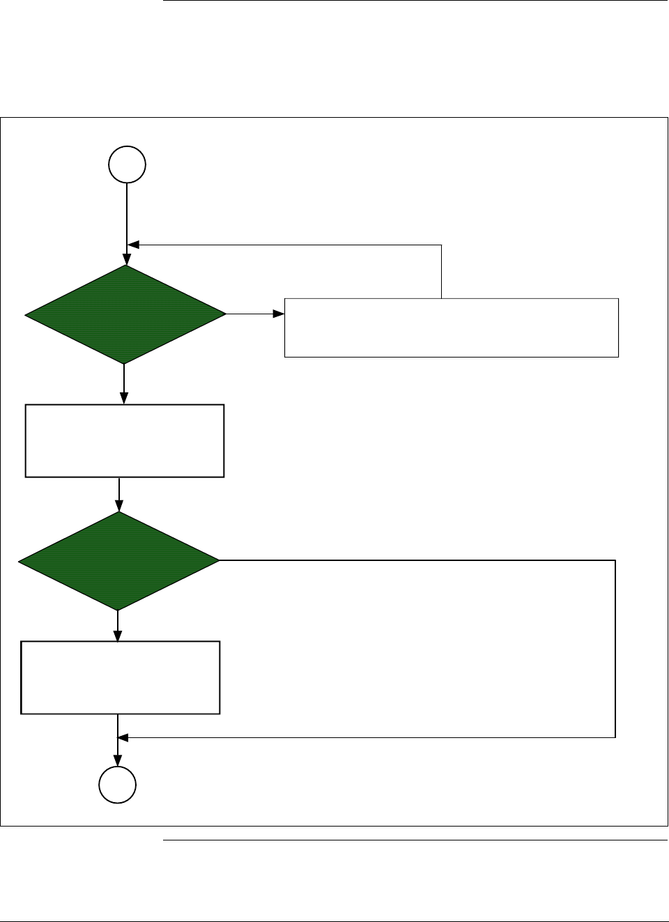
ST 3000 Release 300 and SFC Model STS103 User’s Manual 6/08
68
6.2 Overview, Continued
Configuration
decision summary,
continued
Figure 25 Flowchart — ST 3000 Pressure Transmitter Configuration, continued.
Do you know what
range values to use
?
NO
YES
Determine Lower Range Value (LRV) and Upper Range
Value (URV) to be used for setting range values.
Set LRV and URV to desired
values through SFC prompts
LRV 1 and URV 1.
See procedure in Table 25 or 26 for range setting details.
Use [LRV] and [URV] keys to call up respective SFC prompts
for keying in range values or setting range values to applied
pressures.
Will transmitter be
operating in DE
mode?
NO
YES
Select appropriate DE
configuration parameters
through SFC prompt DE CONF.
See procedures in Tables 28 and 29 for DE
parameter selections.
Press [SHIFT] and [MENU ITEM] keys to call up
DE configuration menu.
C
B
continued on next page
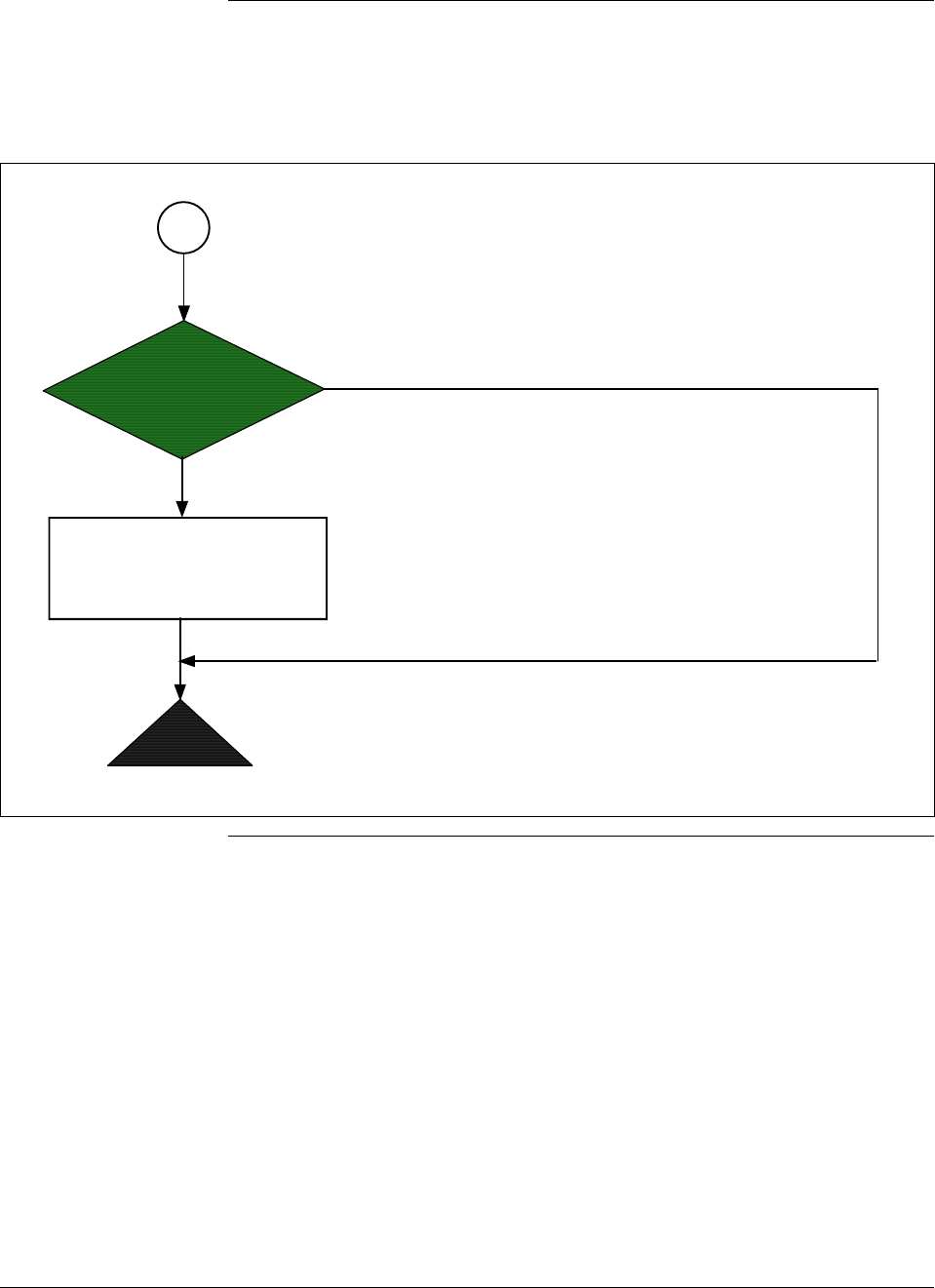
6/08 ST 3000 Release 300 and SFC Model STS103 User’s Manual 69
6.2 Overview, Continued
Configuration
decision summary,
continued
Figure 25 Flowchart — ST 3000 Pressure Transmitter Configuration, Continued.
Does transmitter
have Local Smart
Meter option?
NO
YES
Use buttons on face of Local
Smart Meter or SFC to select
engineering units and range
values as applicable.
See procedures in Tables 33 to 36 for configuring Local
Smart Meter for operation.
End
C
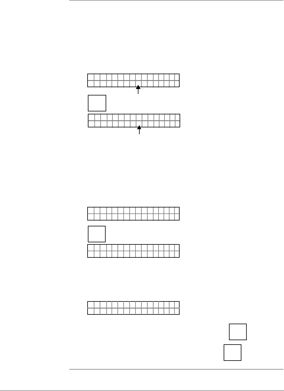
ST 3000 Release 300 and SFC Model STS103 User’s Manual 6/08
70
6.2 Overview, Continued
SFC interface
characteristics Keep these three basic interface characteristics in mind when you use
the SFC to configure a transmitter.
• If the displayed prompt contains a cursor, you can key in a number or
an alphabetic character in that space. However, to key in an alphabetic
character, you must first press the [NUM/ALPHA] key to initiate the
alphabet selection or alpha mode.
• Example:
LIN AG NO.DP T
_
Cursor
LIN AG NO.DP T
_
Alpha Mode
*
NUM/
ALPHA
• If the displayed prompt includes an equal sign (=), you can make
another selection after the equal sign by pressing the [MENU ITEM] key to
call up the next selection Note that you can use the [s NEXT ] key to call
up the next parameter or the [t PREV] key to return to the previous
parameter.
• Example:
DE T ØØØON S
OLoB/
3CF
F/S=
DE T ØØØON S
OHiB/
3CF
F/S=
MENU
ITEM
DE CONF
I
• If the displayed prompt contains a question mark (?), you can initiate
the action in question by pressing the [ENTER] key to answer yes or
abort it by pressing the [CLR] key to answer no.
• Example:
LRV
T
PT 3Ø11
ELRV?S
1
To initiate setting of LRV to applied pressure, press
NON-VOL
ENTER
(Yes)
To abort setting of LRV to applied pressure, press CLR
(NO)
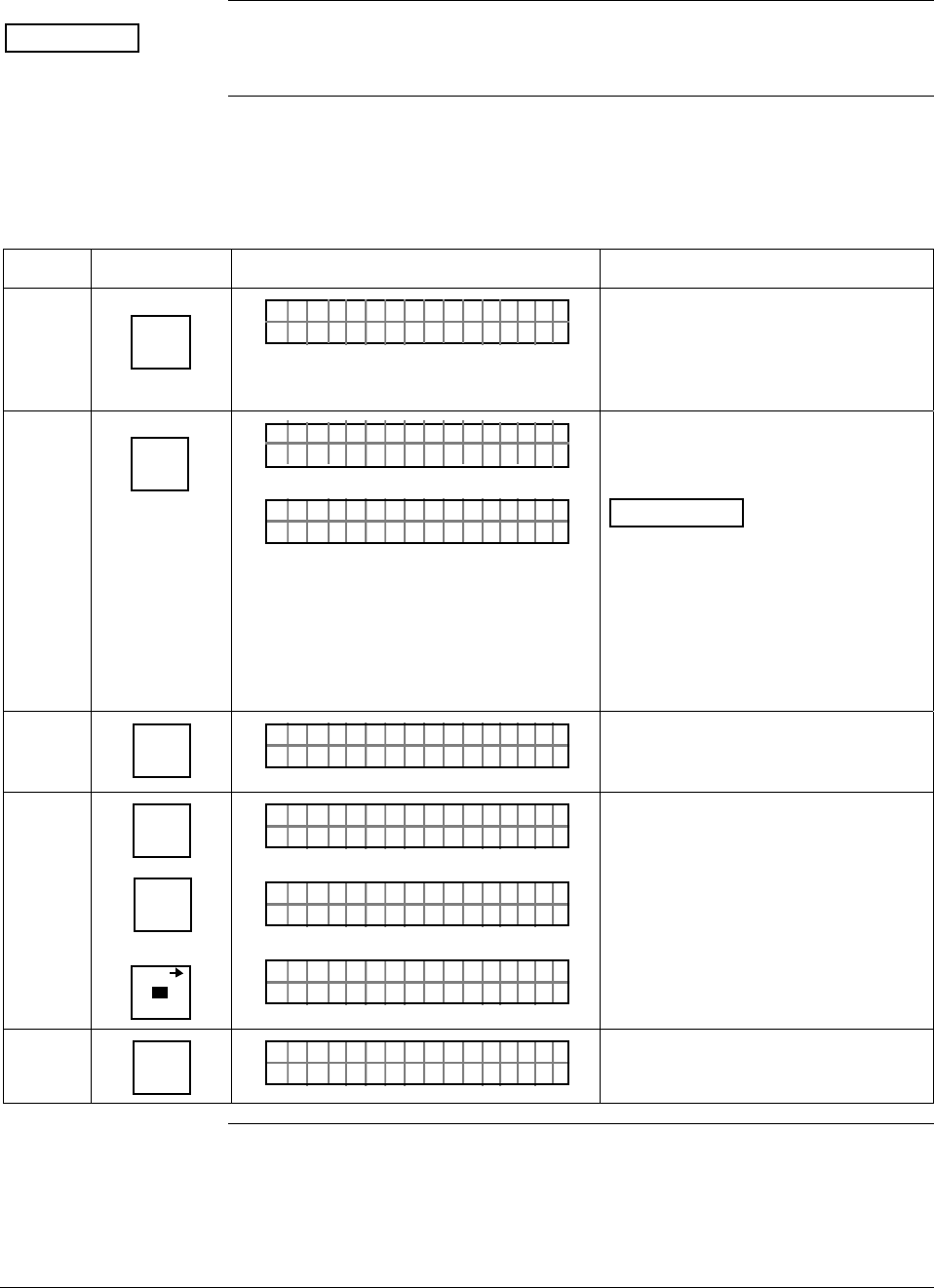
6/08 ST 3000 Release 300 and SFC Model STS103 User’s Manual 71
6.3 Entering a Tag Number
ATTENTION There is a Configuration Record Sheet provided in Appendix C, if you
want to record the configuration data for your transmitter.
Procedure The procedure in Table 21 shows how to enter a sample tag number of
PT 3011 into the transmitter’s configuration database.
Table 21 Entering Tag Number
Step Press Key Read Display or Action Description
1 DE READ
A
ID
TA ON.G
?TRIPS SECURED?
Be sure any switches that may trip
alarms or interlocks associated with
analog loop are secured or turned
off. This prompt only appears for
transmitters in analog mode
2 NON-VOL
ENTER
(Yes)
TA ON.G
SFC WORK ING.. .
LIN AG NO.DP T
_
Confirm that “TRIPS” are secured
and establish transmitter
communications
ATTENTION This procedure
also applies for transmitters in DE
mode. The prompt may show DE -
XMTR instead of output form and
transmitter type in top row, if you
have not established
communications as previously
described in Section 5.2 of this
manual.
2 NUM/
ALPHA
LIN AG NO.DP T
_
*
Put SFC keyboard into alpha mode.
Activates alphabetic characters in
upper right hand corner of keys.
3 9
P
6
T
SCR PAD
LIN AG NO.DP T
_
*
P
LIN AG NO.DP T
_
*
PT
LIN AG NO.DP T
_
*
PT
Key in P, T, and space as first
characters in tag number.
4 NUM/
ALPHA
LIN AG NO.DP T
_
PT
Take SFC keyboard out of alpha
mode and put it into numeric mode.
Continued on next page
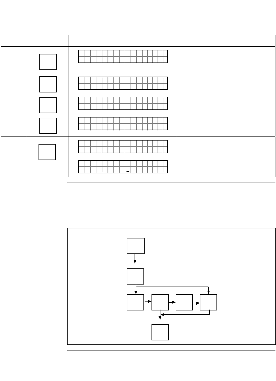
ST 3000 Release 300 and SFC Model STS103 User’s Manual 6/08
72
6.3 Entering a Tag Number, Continued
Procedure, continued
Table 21 Entering Tag Number, continued
Step Press Key Read Display or Action Description
5 X
3
SW VER
Z
0
1
V
1
V
LIN AG NO.DP T
_
PT 3
LIN AG NO.DP T
_
PT 3Ø
LIN AG NO.DP T
_
PT 3Ø1
LIN AG NO.DP T
_
PT 3Ø11
Key in “3011” as numbers in Tag
number.
6 NON-VOL
ENTER
(Yes)
LIN AG NO.DP T
INGOR KSFC W ...
LIN AG NO.DP T
PT3Ø11
Message exchange is working.
Loads tag number into transmitter’s
working memory.
Keystroke summary Figure 26 shows keystroke summary for entering tag number for quick
reference.
Figure 26 Keystroke Summary for Entering Tag Number
NON-VOL
ENTER
(Yes)
NUM/
ALPHA
Alpha
DE READ
A
ID
Number
NUM/
ALPHA
NON-VOL
ENTER
(Yes)
( analog mode only)
22506
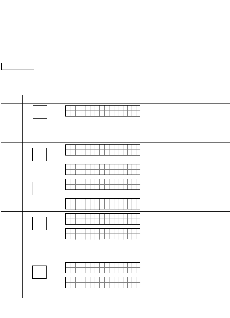
6/08 ST 3000 Release 300 and SFC Model STS103 User’s Manual 73
6.4 Selecting Output Form
Background You can select the transmitter’s output to represent a straight linear
calculation or a square root calculation for flow measurement
applications using a differential pressure type transmitter. Thus, we refer
to the linear or the square root selection as the output conformity or the
output form.
Procedure The procedure in Table 22 shows how to select the desired output
conformity.
ATTENTION If the transmitter is equipped with a local smart meter, you must
reconfigure the smart meter as described in Section 6.11 or 6.12 of this
manual whenever you change the transmitter’s output conformity.
Table 22 Selecting Output Conformity
Step Press Key Read Display or Action Description
1 B
CONF
NGO
ITYORM
IST C F
CON F ?
Prompt asks if you want to access
configuration parameter called
conformity. if you want to access it,
go to Step 2. If you do not want to
access it, press [CLR] key to exit
function or [s NEXT] key to call up
next configuration parameter.
2 NON-VOL
ENTER
(Yes)
ITYORMCONF
LINEAR
OR
ITYORMCONF
ARE ROSQU OT
Present output conformity is linear.
Present output conformity is square
root.
3
MENU
ITEM
DE CONF
I
ITYORMCONF
ARE ROSQU OT
OR
ITYORMCONF
LINEAR
Change output conformity to square
root.
Change output conformity to linear.
4 NON-VOL
ENTER
(Yes)
ITYORMCONF
RE D I NNTE SEFC
ITYORMCONF
OAD CHWNL NOGEDA?
Conformity change is entered in
SFC.
Prompt asks if you want to
download change to transmitter. If
you want to download change, go to
Step 5. If you do not want to
download change, press [CLR] key to
return to initial prompt in Step 1.
5 NON-VOL
ENTER
(Yes)
ITYORMCONF
OR K NGCW .F.S.I
NGO IST C F
ITYORMCONF ?
Message exchange is working.
Output conformity is changed in
transmitter. Press [s NEXT] key to
call up next parameter or [CLR] key
to exit function. Continued on next page
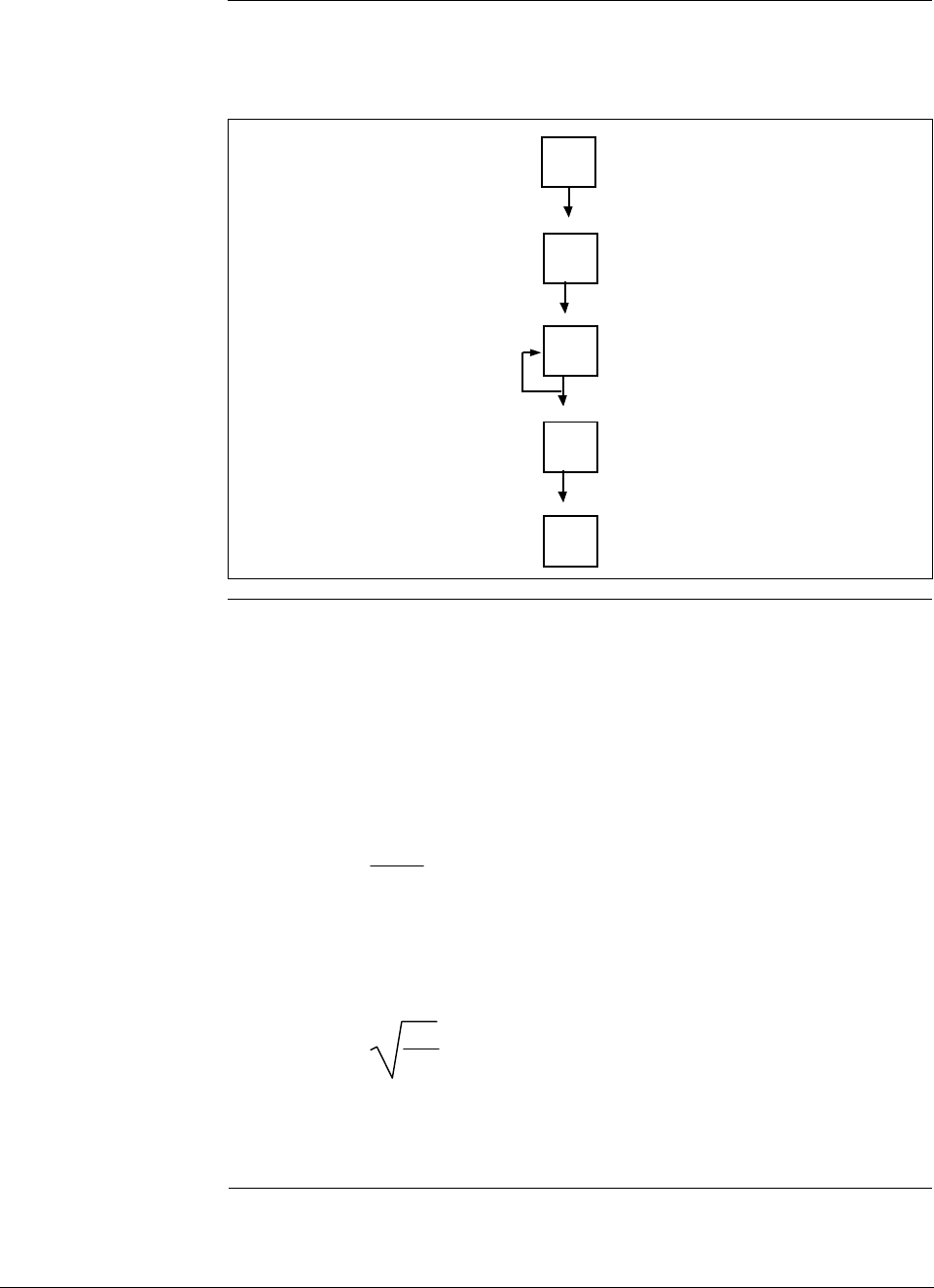
ST 3000 Release 300 and SFC Model STS103 User’s Manual 6/08
74
6.4 Selecting Output Form, Continued
Keystroke summary Figure 27 shows keystroke summary for selecting output conformity for
quick reference.
Figure 27 Keystroke Summary for Selecting Output Conformity.
B
CONF
NON-VOL
ENTER
(Yes)
MENU
ITEM
DE CONF
I
NON-VOL
ENTER
(Yes)
NON-VOL
ENTER
(Yes) 22507
About square root
output For differential pressure transmitters measuring the pressure drop across
a primary element, the flow rate is directly proportional to the square
root of the differential or pressure drop. The ST 3000 transmitter’s
output is automatically converted to equal percent of flow when its
output conformity is configured as square root.
You can use these formulas to manually calculate the percent of flow for
comparison purposes.
ΔP
Span • 100 = % P
Where, ΔP = Differential pressure input in engineering units
Span = Transmitter’s measurement span (URV – LRV)
% P = Pressure input in percent of span
Therefore, %P
100 • 100 = % Flow
And, you can use the following formula to determine the corresponding
current output in milliamperes direct current.
(% Flow • 16) + 4 = mA dc Output
Continued on next page
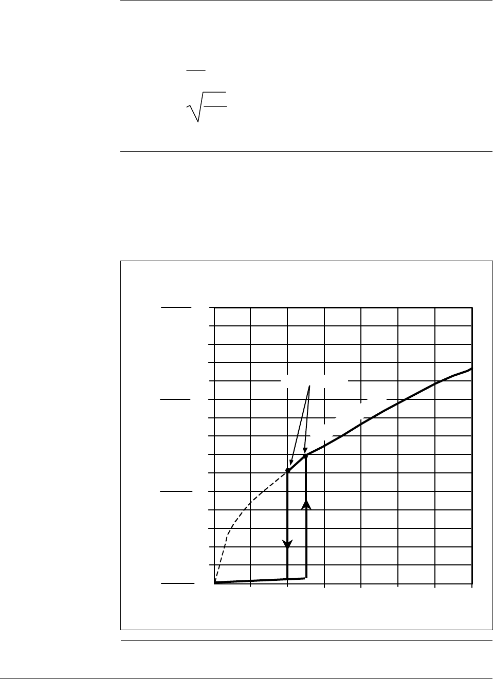
6/08 ST 3000 Release 300 and SFC Model STS103 User’s Manual 75
6.4 Selecting Output Form, Continued
About square root
output, continued Example: If you have a differential pressure transmitter with a range of
0 to 100 inches of water with an input of 49 inches of water,
substituting into the above formulas yields:
49
100 • 100 = 49%
49%
100 • 100 = 70% Flow, and
70% • 16 + 4 = 15.2 mA dc Output
Square root dropout To avoid unstable output at readings near zero, the ST 3000 transmitter
automatically drops square root conformity and changes to linear
conformity for low differential pressure readings. As shown in Figure
28, the dropout point is between 0.4 and 0.5 % of differential pressure
input depending on direction.
Figure 28 Square Root Dropout Points.
0 0.2 0.4 0.8 10.6 1.2 1.4
1
2
3
4
5
6
7
8
9
10
11
12
13
14
15
0
Differential Pressure (% Full Scale)
Flow
(% of Span)
0utput
(mA dc)
4
4.8
5.6
6.4
Dropout Points
22508
Square Root Curve
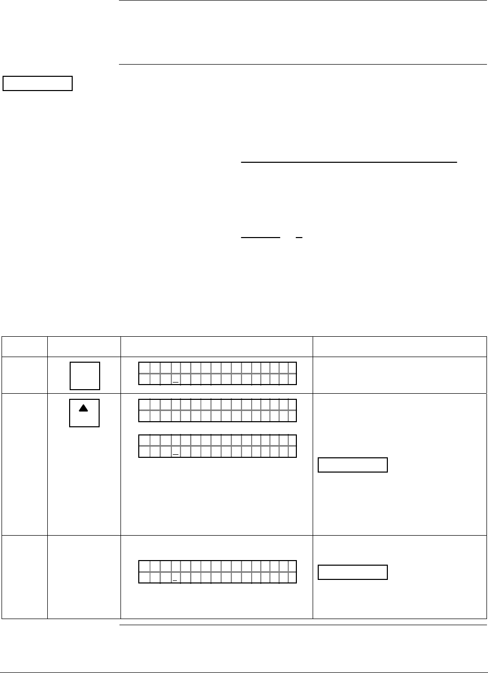
ST 3000 Release 300 and SFC Model STS103 User’s Manual 6/08
76
6.5 Adjusting Damping Time
Background You can adjust the damping time to reduce the output noise. We suggest
that you set the damping to the smallest value that is reasonable for your
process.
ATTENTION The electrical noise effect on the output signal is partially related to the
turndown ratio of the transmitter. As the turndown ratio increases, the
peak-to-peak noise on the output signal increases. You can use this
formula to find the turndown ratio using the range information for your
transmitter.
Turndown Ratio = Upper Range Limit
(Upper Range Value – Lower Range Value)
Example: The turndown ratio for a 400 inH2O transmitter with a range of
0 to 50 inH2O would be:
Turndown Ratio = 400
(50 – 0) = 8
1 or 8:1
Procedure The procedure in Table 23 outlines the keystrokes used to adjust the
damping time to two seconds as an example.
Table 23 Adjusting Damping Time
Step Press Key Read Display or Action Description
1 C
DAMP
PT1DAMP
3ECØ.ON
3011
SDS
Present damping time in seconds
2
NEXT
H
PT1DAMP 301 1
OR K NGCW .F.S.I
PT1DAMP
5ECØ.ON
3011
SDS
Message exchange is working.
Next highest damping time value in
seconds.
ATTENTION The [s NEXT] key
raises the setting while the
[t PREV] key lowers the setting. Or,
you can key in a number that will be
converted to closest damping value
listed in Table 20.
3 Repeat Step 2 until display shows
PT1DAMP
ØEC2.ON
3011
SDS
Transmitter’s damping time is now
set to two seconds.
ATTENTION You do not need to
press the [ENTER] key to store the
damping time in the transmitter’s
memory.
Continued on next page
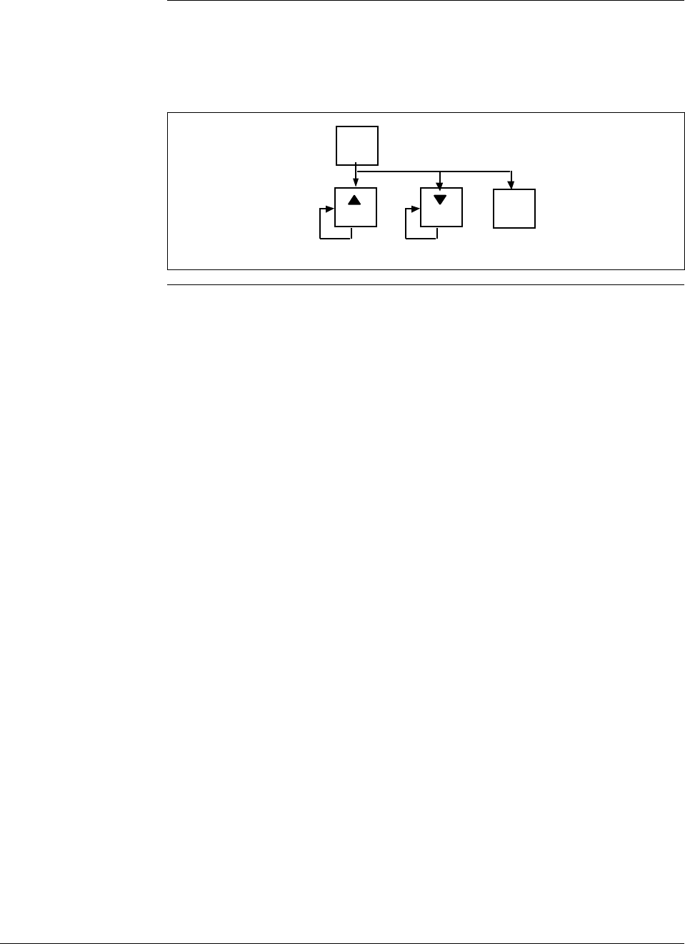
6/08 ST 3000 Release 300 and SFC Model STS103 User’s Manual 77
6.5 Adjusting Damping Time, Continued
Keystroke summary Figure 29 shows keystroke summary for adjusting damping time for
quick reference.
Figure 29 Keystroke Summary for Adjusting Damping Time
C
DAMP
NEXT
H
PREV
L
Number
22509
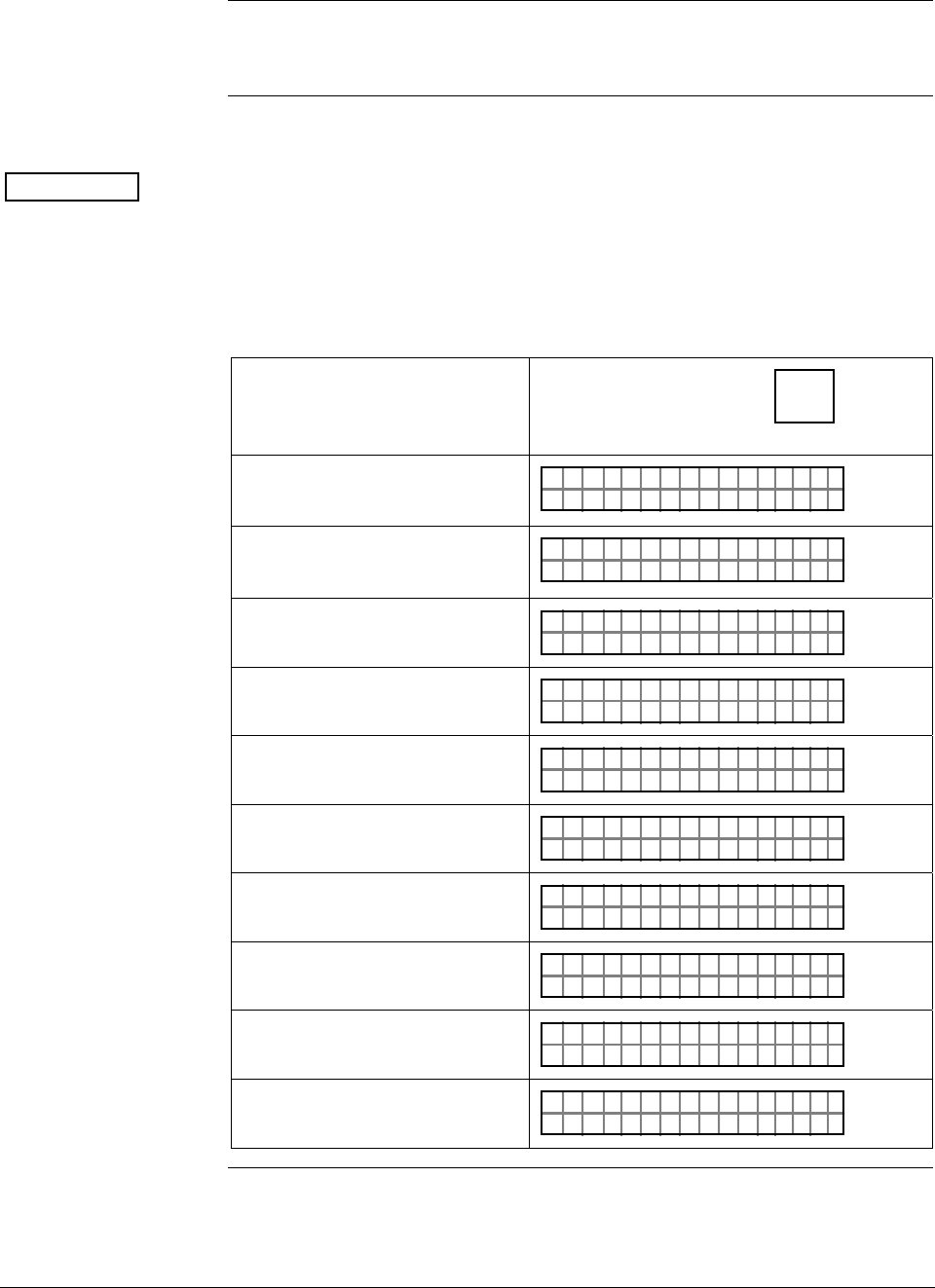
ST 3000 Release 300 and SFC Model STS103 User’s Manual 6/08
78
6.6 Selecting Unit of Measurement
Background You can choose to have the pressure measurements displayed in one of
the preprogrammed engineering units in the SFC.
Procedure Table 24 lists the pre-programmed units and shows how to select them.
ATTENTION The engineering units shown in Table 23 are only available in an SFC
with software version 3.2 or greater. The selections are similar in other
software versions but without temperature references and minus the
inches of water at 68°F (20°C) engineering units.
Table 24 Pre-Programmed Engineering Units for Selection
IF you want URV, LRV, etc.
displayed in …
THEN sequentially press
D
UNITS key until
display shows…
inches of water at 39.2°F (4°C)
"
PT1UN I T
H2O
3011S
_39F
inches of water at 68°F (20°C) PT1UN I T
H2O
3011
"
S
_68F
millimeters of mercury at 0°C
(32°F) PT1UN I T
mHg
3011
m
S
_ØC
pounds per square inch PT1UN I T
SI
3011
P
S
kilopascals PT1UN I T
Pa
3011
K
S
megapascals PT1UN I T
Pa
3011
M
S
millibar PT1UN I T
BA
3011
m
S
R
bar PT1UN I T
BA
3011S
R
grams per square centimeter PT1UN I T
g/
3011S
cm^2
kilograms per square centimeter PT1UN I T
G/
3011S
cm ^ 2K
Continued on next page
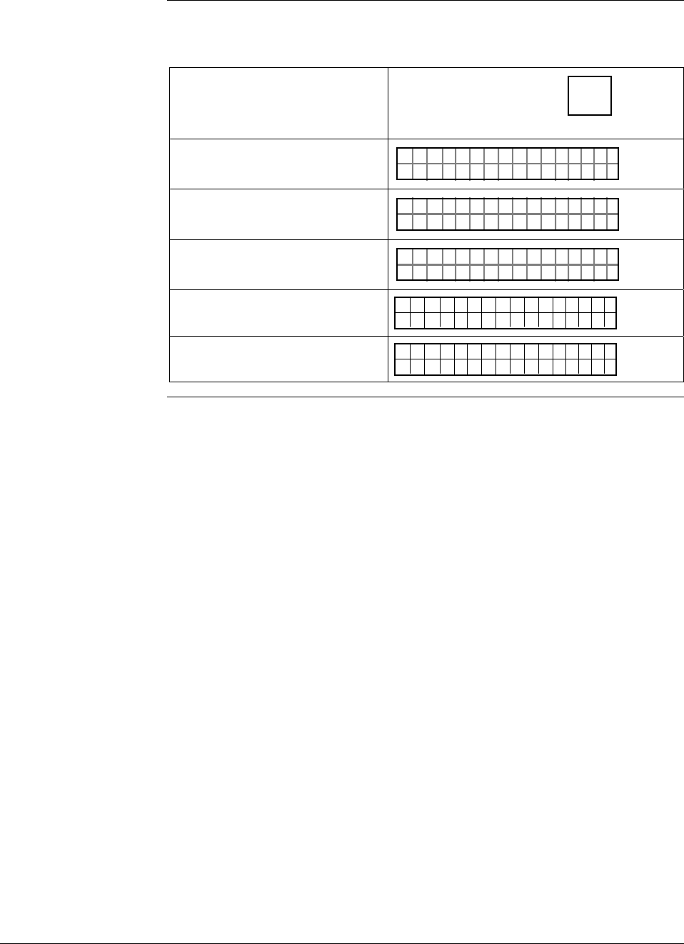
6/08 ST 3000 Release 300 and SFC Model STS103 User’s Manual 79
6.6 Selecting Unit of Measurement, Continued
Procedure, continued
Table 24 Pre-Programmed Engineering Units for Selection, continued
IF you want URV, LRV, etc.
displayed in …
THEN sequentially press
D
UNITS key until
display shows…
inches of mercury at 32°F (0°C) PT1UN I T
nH
3011S
gi _32F
millimeters of water at 4°C
(39.2°F) PT1UN I T
mH
3011S
2mO
_4C
meters of water at 4°C (39.2°F) PT1UN I T
H
3011S
2mO
_4C
normal atmoshperes
ATM
1UN TIS PT3
011
inches of water at 60°F (15.6°C) 1UN TIS PT3
011
"2H0O_6F
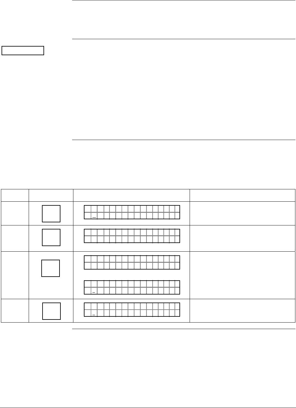
ST 3000 Release 300 and SFC Model STS103 User’s Manual 6/08
80
6.7 Setting Range Values Using SFC
Background You can set the LRV and URV by either keying in the desired values
through the SFC keyboard or applying the corresponding LRV and
URV pressures directly to the transmitter.
ATTENTION • We factory calibrate ST 3000 Smart Transmitters with inches of
water ranges using inches of water pressure referenced to a
temperature of 39.2°F (4°C).
• For a reverse range, enter the upper range value as the LRV and the
lower range value as the URV. For example, to make a 0 to 50 psi
range a reverse range, enter 50 as the LRV and 0 as the URV.
• The URV changes automatically to compensate for any changes in
the LRV and maintain the present span (URV – LRV).
• If you must change both the LRV and URV, always change the LRV
first.
Procedure 1 Table 25 gives the procedure for the range values for a sample 5 to 45
inH2O at 39.2°F (4°C) range.
Table 25 Keying in LRV and URV
Step Press Key Read Display or Action Description
1 E
LRV
0%
PTLRV 3Ø111
Ø. ØØØØ "H2O_39F
Present LRV setting. (Pressure for 4
mAdc (0%) output.)
2 5
S
PTLRV 3Ø111
5_"H2 O
_39F
Key in desired LRV setting. (It is not
necessary to key in a decimal point
and zeros for a whole number.)
3 NON-VOL
ENTER
(Yes)
ORK NGCW .F.S.I
PTLRV 3Ø111
PTLRV 3Ø111
5. ØØØØ "H2 O
_39F
Message exchange is working.
New LRV setting stored in
transmitter’s working memory.
4 URV
100%
F
PTUR V 3Ø1 11
1.Ø5 ØØ "H2 O
_39F
Present URV setting. (Pressure for
20 mAdc (100%) output.)
Continued on next page
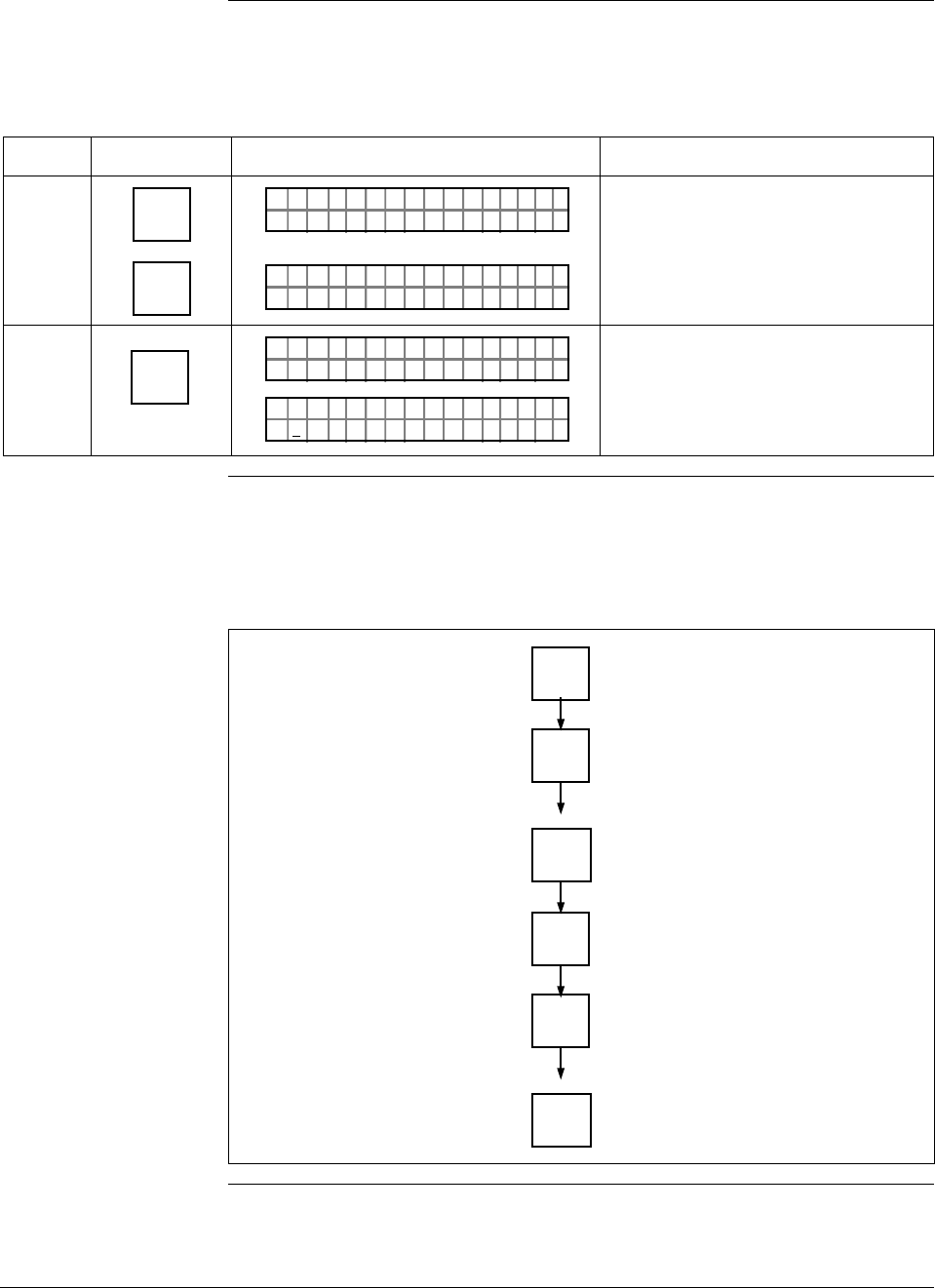
6/08 ST 3000 Release 300 and SFC Model STS103 User’s Manual 81
6.7 Setting Range Values Using SFC, Continued
Procedure 1,
continued
Table 25 Keying in LRV and URV, continued
Step Press Key Read Display or Action Description
5 R
4
5
S
PTUR V 3Ø1 11
4_"H2 O
_39F
PTUR V 3Ø1 11
4_
5"H2 O
_39F
Key in 45 as desired URV setting.
6 NON-VOL
ENTER
(Yes)
ORK NGCW .F.S.I
PTUR V 3Ø1 11
PTUR V 3Ø1 11
4.5 ØØØ "H2 O
_39F
Message exchange is working.
New URV setting stored in
transmitter’s working memory.
Keystroke 1 summary Figure 30 shows keystroke summary for keying in LRV and URV for
quick reference.
Figure 30 Keystroke Summary for Keying in LRV and URV.
E
LRV
0%
Number
NON-VOL
ENTER
(Yes)
URV
100%
F
Number
NON-VOL
ENTER
(Yes) 22510
Continued on next page
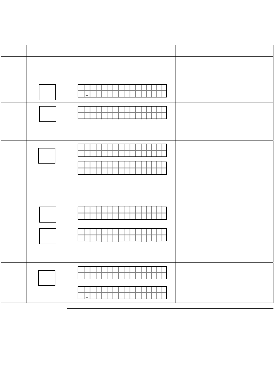
ST 3000 Release 300 and SFC Model STS103 User’s Manual 6/08
82
6.7 Setting Range Values Using SFC, Continued
Procedure 2 Table 26 gives the procedure for setting range values to sample applied
pressures.
Table 26 Setting LRV and URV to Applied Pressures
Step Press Key Read Display or Action Description
1 Apply known input pressure to
transmitter that represents LRV for 0%
(4 mAdc) output.
2 E
LRV
0%
PTLRV 3Ø111
5. ØØØØ "H2 O
_39F
Present LRV setting. (Pressure for 4
mAdc (0%) output.)
3 SET
G
PTLRV
RV
3Ø1 1
L
1
?SET
Prompt asks if you want to set LRV
to applied pressure. If you don’t
want to set LRV, press [CLR] key to
exit function. Otherwise, go to Step
4.
4 NON-VOL
ENTER
(Yes)
ORK NGCW .F.S.I
PTLRV 3Ø111
PTLRV 3Ø111
7. 8377 "H2 O
_39F
Message exchange is working.
Applied LRV setting stored in
transmitter's working memory.
5 Apply known input pressure to
transmitter that represents URV for
100% (20 mAdc) output.
6 URV
100%
F
PTUR V 3Ø1 11
4.7 837 "H2 O
_39F
Present URV setting. (Pressure for
20 mAdc (100%) output.)
7 SET
G
PTUR V
RV
3Ø1 1
U
1
?SET
Prompt asks if you want to set URV
to applied pressure. If you don’t
want to set URV, press [CLR] key to
exit function. Otherwise, go to Step
8.
8 NON-VOL
ENTER
(Yes)
ORK NGCW .F.S.I
PTUR V 3Ø1 11
PTUR V 3Ø1 11
5.5 482
Message exchange is working.
Applied URV setting stored in
transmitter’s working memory.
Continued on next page
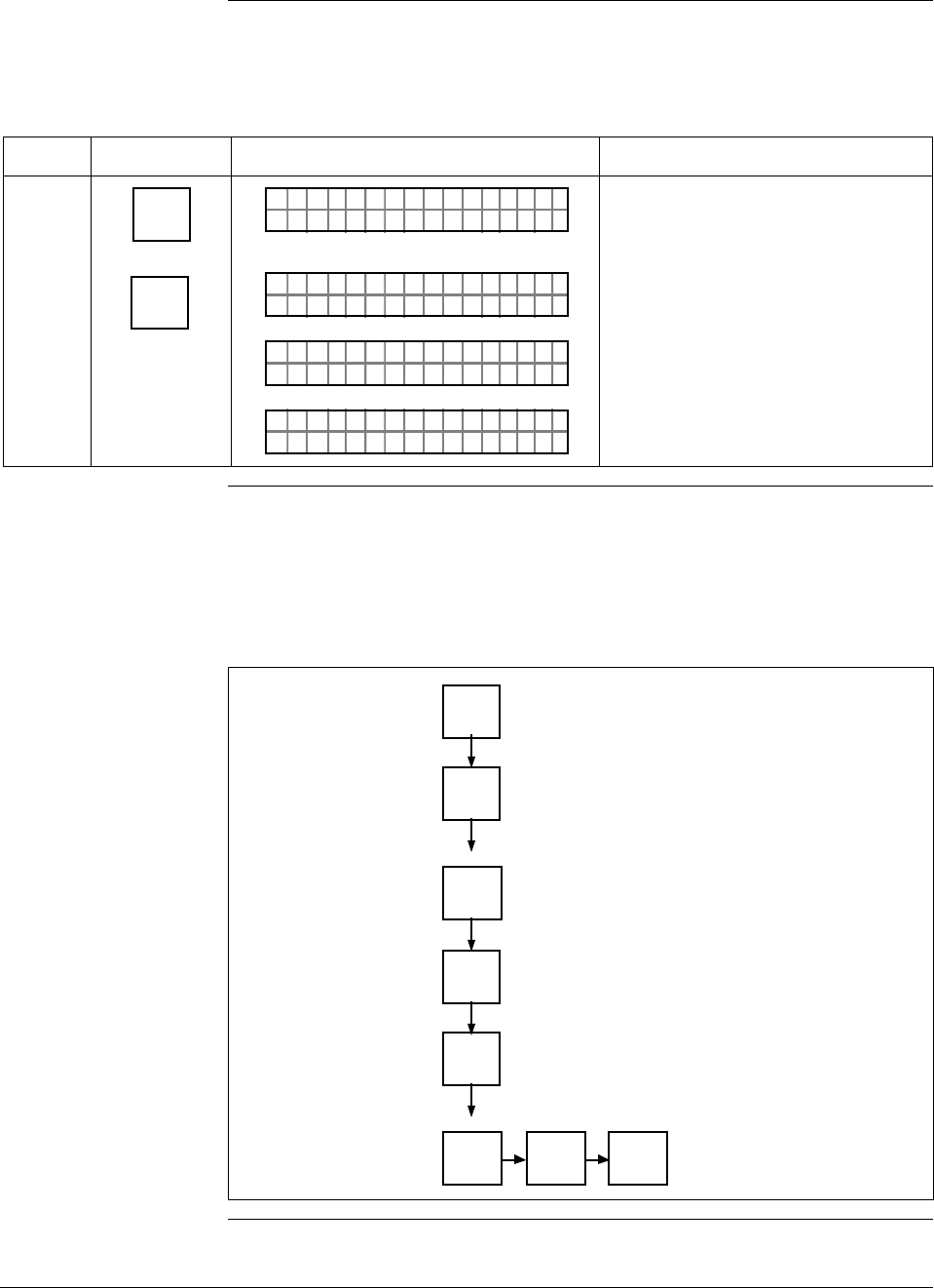
6/08 ST 3000 Release 300 and SFC Model STS103 User’s Manual 83
6.7 Setting Range Values Using SFC, Continued
Procedure 2,
continued
Table 26 Setting LRV and URV to Applied Pressures, continued
Step Press Key Read Display or Action Description
9 ^
SHIFT
NON-VOL
ENTER
(Yes)
PTUR V 3Ø1 11
SH I T– . ..F
PTUR V 3Ø1 11
ORK NGCW .F.S.I
PTUR V 3Ø1 11
NO VO ATLNDA TA ILE
LIN DP
.Y. .RE AD
TØ11P3
Initiates shift key selection.
Saves data in transmitter’s non-
volatile memory. This takes
approximately 8 seconds.
Keystroke 2 summary Figure 31 shows keystroke summary for setting LRV and URV to
applied pressures for quick reference.
Figure 31 Keystroke Summary for Setting LRV and URV to Applied
Pressures.
E
LRV
0%
NON-VOL
ENTER
(Yes)
URV
100%
F
NON-VOL
ENTER
(Yes)
SET
G
SET
G
NON-VOL
ENTER
(Yes)
^
SHIFT 22511

ST 3000 Release 300 and SFC Model STS103 User’s Manual 6/08
84
6.8 Setting Range Values Using Local Adjustments
Local zero and span
option ST 3000 Release 300 transmitters are available with optional local zero
and span adjustments. This option is for applications that do not require
an SFC nor digital integration with our TPS system.
About local
adjustments You must apply equivalent zero and span pressures to make the local
zero and span adjustments. This is similar to setting the LRV and URV
to applied pressures using the SFC.
ATTENTION After making any adjustments to the Smart Meter, keep the transmitter
powered for at least 30 seconds so that the new meter configuration is
written to non-volatile memory. If power is turned off before 30
seconds, the changes may not be saved so that when the transmitter
power is restored, the meter configuration will revert to the previous
settings.
Procedure The procedure in Table 27 shows the steps for setting the range values
to applied pressures using local zero and span adjustments. See Figure
32 for typical local adjustment connections and setup details.
Table 27 Setting Range Values Using Local Zero and Span
Adjustments
Step Action
1 Turn OFF transmitter power. Loosen end-cap lock and remove end-
cap from terminal block side of electronics housing.
2 Observing polarity, connect a milliammeter across positive (+) and
negative (–) TEST terminals.
ATTENTION If you have the Local Smart Meter with Zero and
Span adjustment option, you may use the Local Smart Meter in place
of the milliammeter.
Continued on next page
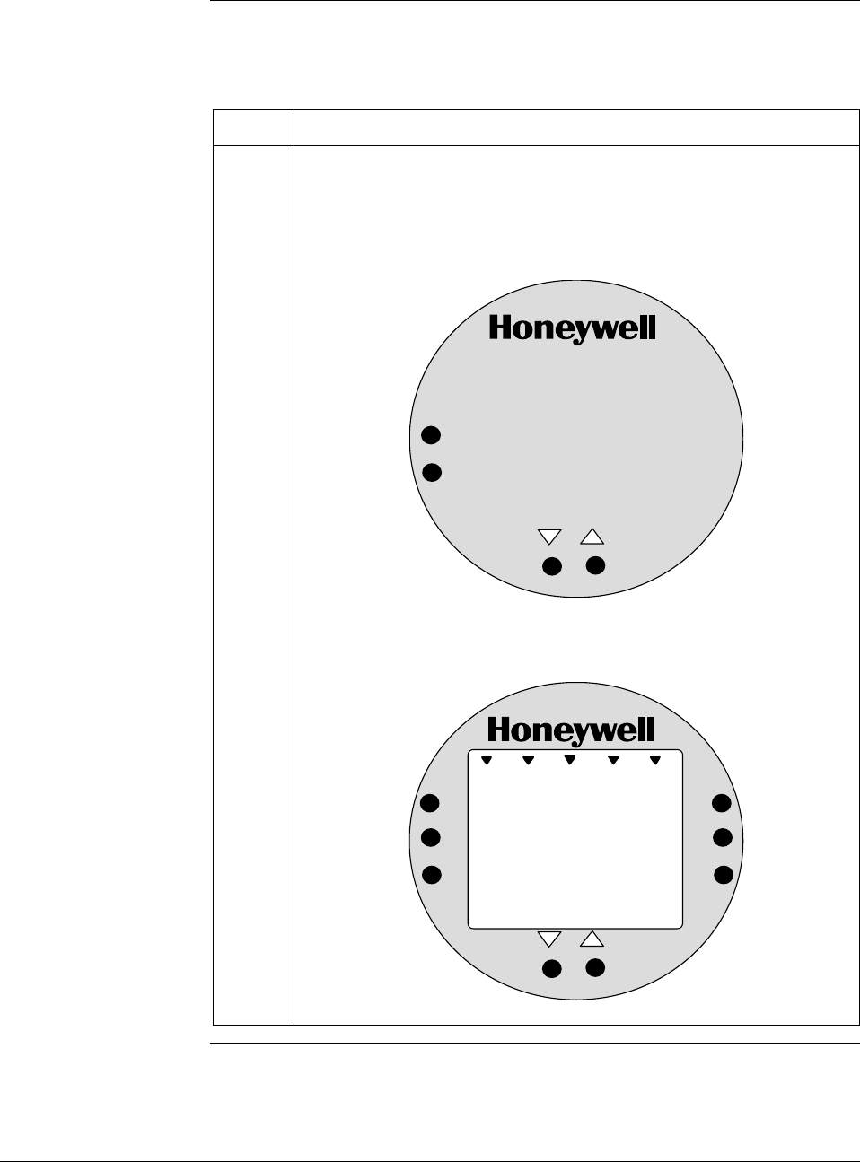
6/08 ST 3000 Release 300 and SFC Model STS103 User’s Manual 85
6.8 Setting Range Values Using Local Adjustments,
Continued
Procedure, continued
Table 27 Setting Range Values Using Local Zero and Span
Adjustments, continued
Step Action
3 Loosen end-cap lock and remove end-cap from PWA side of
electronics housing to expose Local Zero and Span assembly or
Local Smart meter with Zero and Span adjustments.
Example – Local Zero and Span Assembly.
SPAN
ZERO
Example –Local Smart Meter with Zero and Span adjustments.
%
1000
UPPER
VALUE
UNITS
LOWER
VALUE
SET
VAR
SEL.
SPAN
ZERO
Continued on next page
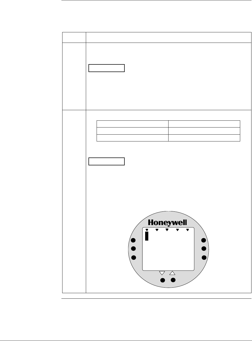
ST 3000 Release 300 and SFC Model STS103 User’s Manual 6/08
86
6.8 Setting Range Values Using Local Adjustments,
Continued
Procedure, continued
Table 27 Setting Range Values Using Local Zero and Span
Adjustments, continued
Step Action
4 Turn ON transmitter power and let it warm up for a few minutes.
Using an accurate pressure source, apply desired zero equivalent
pressure to transmitter.
ATTENTION For differential pressure transmitters, apply pressure
to the high pressure head for positive range values or vent both
heads to atmosphere for zero. If zero is to equal a negative value,
apply the equivalent pressure to the low pressure head. For
example, if zero is to equal –10 inH2O, you would apply 10 inH2O to
the low pressure head and vent the high pressure head for the zero
adjustment.
5 Check that milliammeter reading is 4 mA.
If reading … Then…
is less or greater than 4 mA go to Step 6.
is correct go to Step 7.
ATTENTION If you have the Local Smart Meter with Zero and
Span adjustment option, you may substitute the Local Smart Meter
readings for the milliammeter readings. For example, with zero input
pressure applied assume that the meter reads 4 inH2O instead of 0
inH2O. In this case, the meter reading is greater than 0 (or 4 mA).
Example – Local Smart Meter displaying transmitter output in inches
of water.
%
1000
4
.
0
ANALOG In H O
2
0
UPPER
VALUE
UNITS
LOWER
VALUE
SET
VAR
SEL.
SPAN
ZERO
Continued on next page
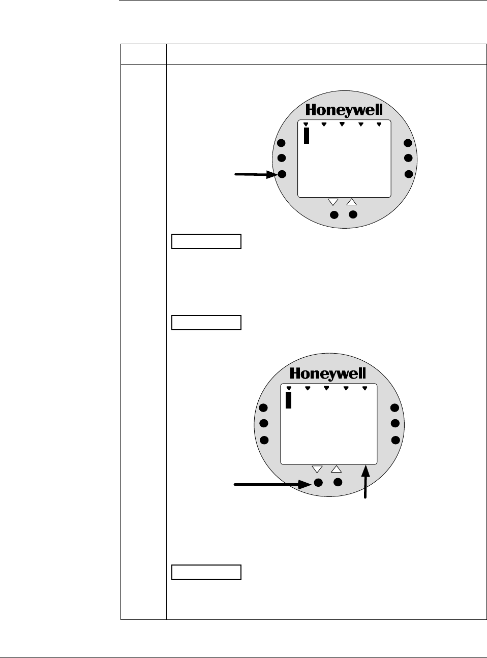
6/08 ST 3000 Release 300 and SFC Model STS103 User’s Manual 87
6.8 Setting Range Values Using Local Adjustments,
Continued
Procedure, continued Table 27 Setting Range Values Using Local Zero and Span
Adjustments, continued
Step Action
6 a. Press and hold ZERO button on Local Zero and Span assembly
or Local Smart Meter.
%
1000
1
.
0
%
0
UPPER
VALUE
UNITS
LOWER
VALUE
SET
VAR
SEL.
SPAN
ZERO
Press &
Hold
ANALOG
ATTENTION The Local Smart Meter readings revert to the default
unit of percent (%) during this operation. If the error code Er0
appears on the display, you are working with a model STD110
transmitter that does not support the Local Zero and Span
adjustments.
b. Press Decrease τ button once to complete this function.
ATTENTION The Local Smart Meter display goes blank for a 1/2
second and then returns reading 0%.
%
1000
0
.
0
ANALOG
%
0
UPPER
VALUE
UNITS
LOWER
VALUE
SET
VAR
SEL.
SPAN
ZERO
Press once
Display goes
blank for 1/2
second and
returns with
zero reading
c. Check that milliammeter reading equals 4 mA and release ZERO
button.
ATTENTION If milliammeter reading doesn’t change, be sure you
are not working with a model STD110 transmitter that ignores local
adjustments. The Local Smart Meter readings return to the set
engineering units after you release the ZERO button.
Continued on next page
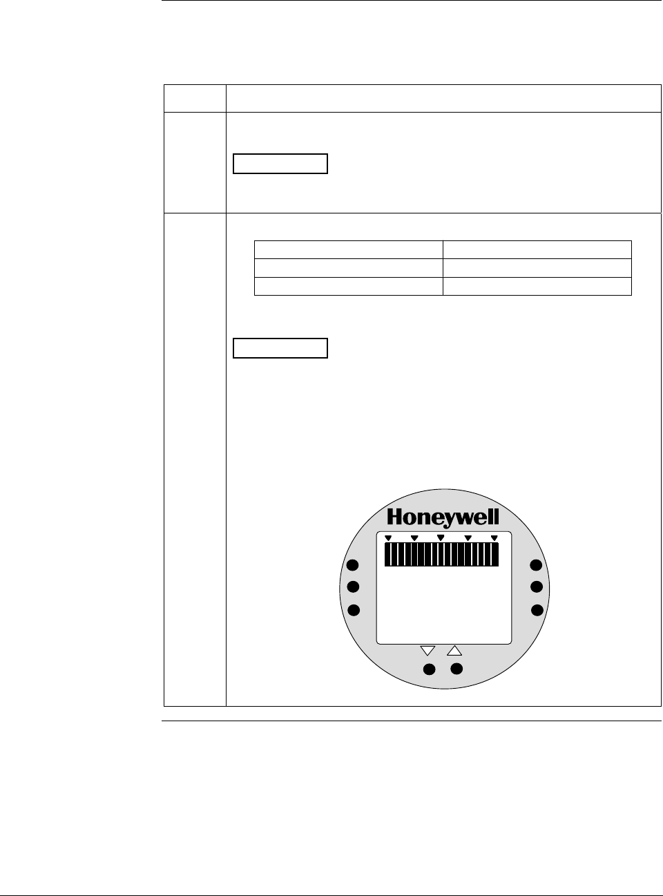
ST 3000 Release 300 and SFC Model STS103 User’s Manual 6/08
88
6.8 Setting Range Values Using Local Adjustments,
Continued
Procedure, continued
Table 27 Setting Range Values Using Local Zero and Span
Adjustments, continued
Step Action
7 Using an accurate pressure source, apply pressure equivalent to
desired upper range value to transmitter.
ATTENTION For differential pressure transmitters, apply pressure
to the high pressure head and be sure that the pressure to the low
pressure head is at its reference value.
8 Check that milliammeter reading is 20 mA.
If reading … Then…
is not exactly 20 mA go to Step 9.
is correct go to Step 10.
ATTENTION If you have the Local Smart Meter with Zero and
Span adjustment option, you may substitute the Local Smart Meter
readings for the milliammeter readings. For example, with URV input
pressure applied assume that the meter reads 396 inH2O instead of
400 inH2O. In this case, the meter reading is less than 100% (or 20
mA).
Example – Local Smart Meter displaying transmitter output in inches
of water.
%
100
0
39
ANALOG In H O
2
6
UPPER
VALUE
UNITS
LOWER
VALUE
SET
VAR
SEL.
SPAN
ZERO
Continued on next page
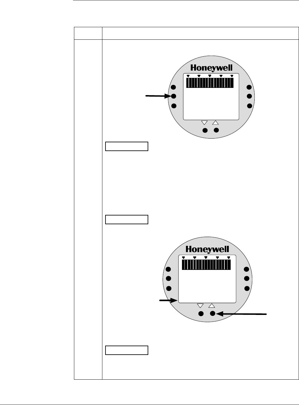
6/08 ST 3000 Release 300 and SFC Model STS103 User’s Manual 89
6.8 Setting Range Values Using Local Adjustments,
Continued
Procedure, continued Table 27 Setting Range Values Using Local Zero and Span
Adjustments, continued
Step Action
9 a. Press and hold SPAN button on Local Zero and Span assembly or
Local Smart Meter.
%
1000
9
.
9
%
0
UPPER
VALUE
UNITS
LOWER
VALUE
SET
VAR
SEL.
SPAN
ZERO
Press &
Hold
ANALOG
ATTENTION The Local Smart Meter readings revert to the default
unit of percent (%) during this operation. If the error code Er0
appears on the display, you are working with a model STD110
transmitter that does not support the Local Zero and Span
adjustments. If the error code Er4 appears, you are trying to set a
SPAN value that is outside acceptable limits for your transmitter.
Readjust applied pressure to be within acceptable range limits and
repeat this procedure.
b. Press Increase σ button once to complete this function.
ATTENTION The Local Smart Meter display goes blank for a 1/2
second and then returns reading 100%.
%
1000
1
.
0
%
0
UPPER
VALUE
UNITS
LOWER
VALUE
SET
VAR
SEL.
SPAN
ZERO
Press once
ANALOG
Display goes
blank for 1/2
second and
returns with
100% reading
0
c. Check that milliammeter reading equals 20 mA and release SPAN
button.
ATTENTION If milliammeter reading doesn’t change, be sure you
are not working with a model STD110 transmitter that ignores local
adjustments. The Local Smart Meter readings return to the set
engineering units after you release the SPAN button.
Continued on next page
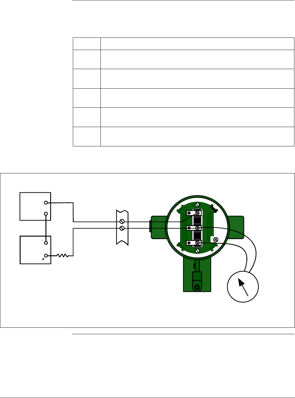
ST 3000 Release 300 and SFC Model STS103 User’s Manual 6/08
90
6.8 Setting Range Values Using Local Adjustments,
Continued
Procedure, continued
Table 27 Setting Range Values Using Local Zero and Span
Adjustments, continued
Step Action
10 Wait 30 seconds so that changes have been copied to the
transmitter’s non-volatile memory.
11
Remove applied pressure and turn OFF transmitter power.
12 Replace end-cap on PWA side of electronics housing and tighten
lock.
13 Remove milliammeter from TEST terminals and replace end-cap and
tighten lock.
14 Turn ON transmitter power and check Local Smart Meter reading, if
applicable.
Figure 32 Typical Setup for Setting Range Values Using Local Zero and Span Adjustments.
+
-
Field
Terminals
- SIGNAL +
+ -
TEST
Power
Supply
+
-
Receiver
ST 3000
250
Ω
STR3015
Milliammeter
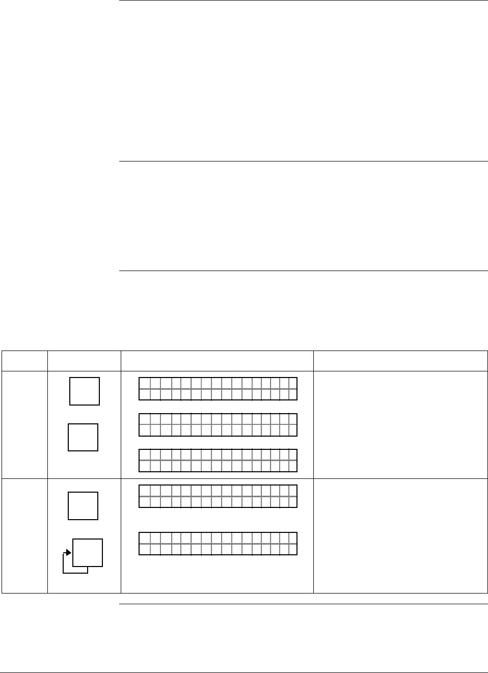
6/08 ST 3000 Release 300 and SFC Model STS103 User’s Manual 91
6.9 Selecting Output Signal Mode (DE Mode Only)
DE configuration
parameters You must configure these additional parameters for a transmitter in the
DE mode of operation.
• Mode of Output Signal Indication
• Message Format
This section and the next section cover how to configure these
parameters individually. However, once you enter the DE configuration
function, you can access all DE configuration parameters serially
without exiting the function. Just use the [s NEXT ] and [t PREV] keys to
step through the parameter selections.
Background You can select the output signal mode for digital transmission to be one
of these three modes as described in Table 20.
• Single Range
• Dual Range (STDC)
• Single Range W/SV
Procedure The procedure in Table 28 outlines the steps for selecting a Single
Range W/SV mode for example purposes only.
Table 28 Selecting Mode of Output Signal Indication
Step Press Key Read Display or Action Description
1 ^
SHIFT
DE CONF
MENU
ITEM
I
LIN DP
FT–SHI
TØ11P3
ORK NGCW .F.S.I
PTDE 3011OCNF
eRngnliSea
PTDE 3011OCNF
g
Initiate shift key selection.
Calls up DE CONFIG menu. Output
signal mode selection appears.
2 DE CONF
MENU
ITEM
I
DE CONF
MENU
ITEM
I
eRgnliSn
PTDE 3011OCNF
gw/SV
RngauDea
PTDE 3011OCNF
l(
ST DC)
Calls up next output signal mode
selection.
Repeatedly press [MENU ITEM] key to
step through all output signal mode
selections listed in Table 20 in
sequence. Stop when “Single Range
W/SV” mode is on display.
Continued on next page
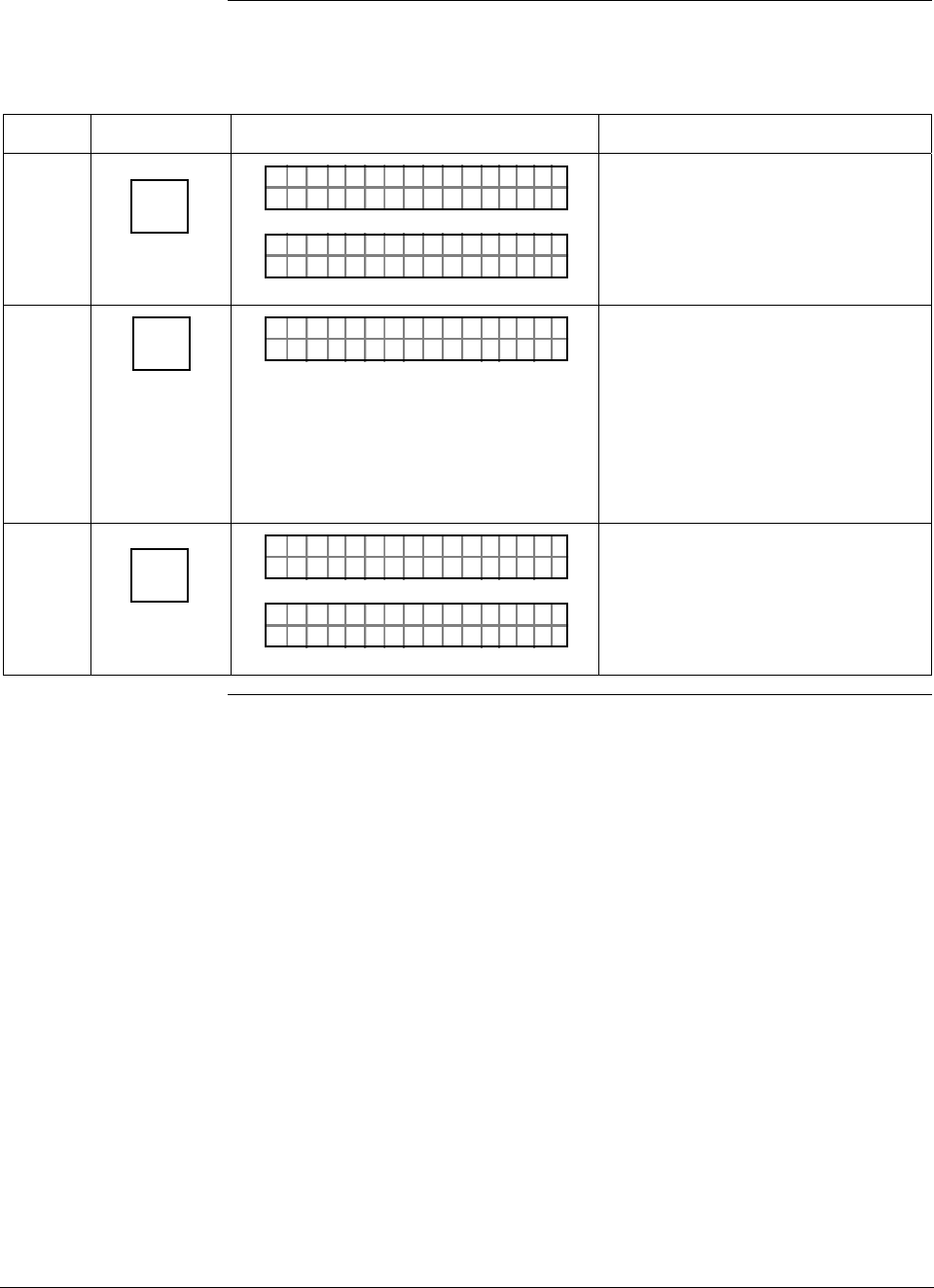
ST 3000 Release 300 and SFC Model STS103 User’s Manual 6/08
92
6.9 Selecting Output Signal Mode (DE Mode Only), Continued
Procedure , continued
Table 28 Selecting Mode of Output Signal Indication, continued
Step Press Key Read Display or Action Description
3 NON-VOL
ENTER
(Yes)
RD INEE
PTDE 3011OCNF
TSFCEN
4BoB/
PTDE 3011OCNF
De
)( ywt
Enters change in SFC and calls up
next DE configuration parameter.
This action only applies if selection
is changed. Otherwise, must press
[CLR] key to exit function or [s NEXT]
key to call up next parameter.
4 CLR
(NO) DCWLO
PTDE 3011OCNF
NNGAHDAOE?
Prompt asks if change entered in
SFC is to be downloaded to
transmitter. If you want to download
change, go to Step 5. If you do not
want to download change, press
[CLR] key to exit function. This action
only applies when Step 3 is valid.
Otherwise, this keystroke exits DE
CONF function.
5 NON-VOL
ENTER
(Yes)
PTDE 3011OCNF
OR K NGCW .F.S.I
LIN DP
.Y. .RE AD
TØ11P3
Message exchange is working.
Parameter change is loaded in
transmitter. SFC is ready for next
function.
Continued on next page
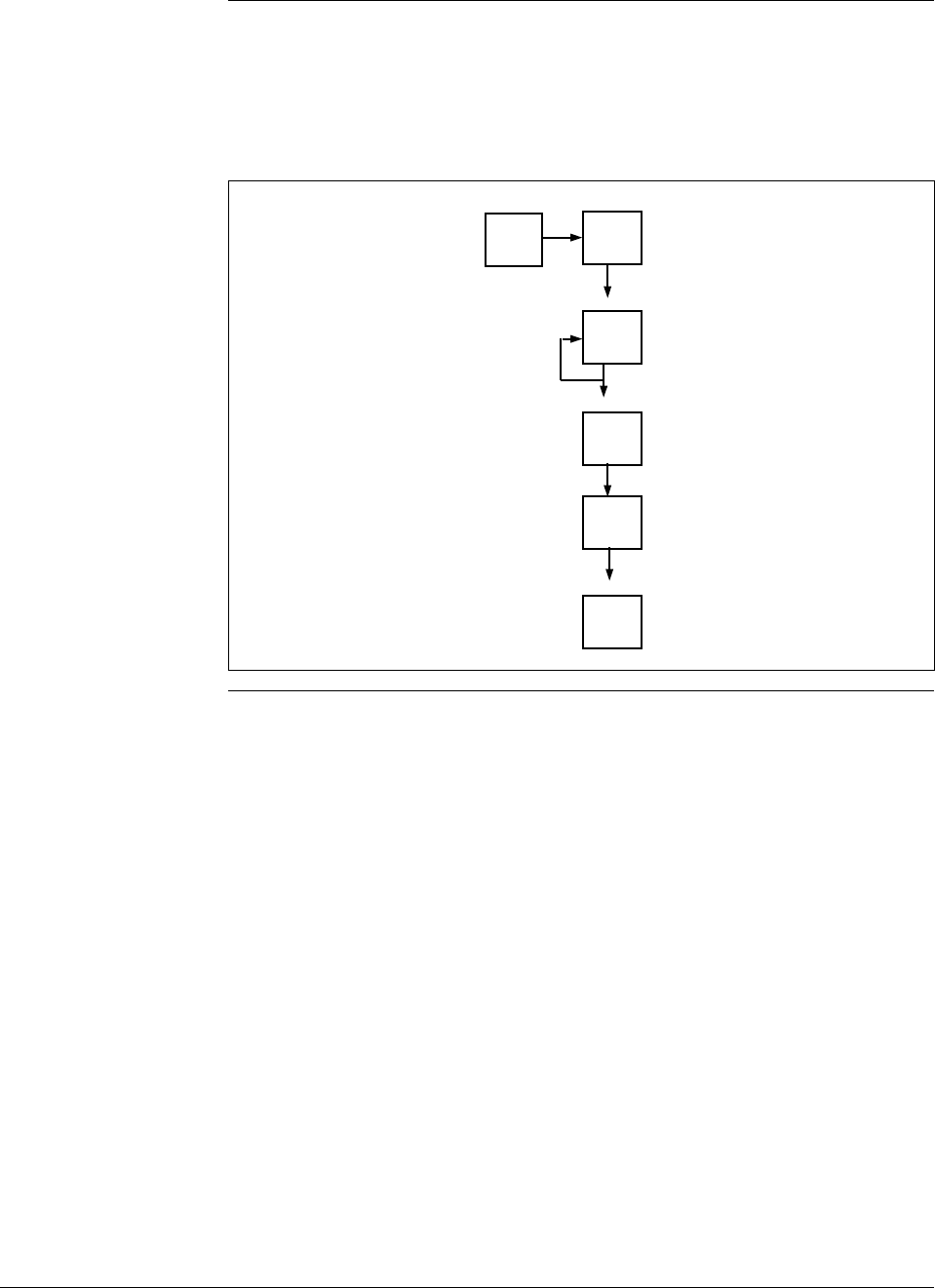
6/08 ST 3000 Release 300 and SFC Model STS103 User’s Manual 93
6.9 Selecting Output Signal Mode (DE Mode Only), Continued
Keystroke summary Figure 33 shows keystroke summary for selecting the mode of output
signal indication for transmitter in DE mode for quick reference.
Figure 33 Keystroke Summary for Selecting Mode of Output Signal
Indication.
^
SHIFT MENU
ITEM
DE CONF
I
MENU
ITEM
DE CONF
I
NON-VOL
ENTER
(Yes)
CLR
(No)
NON-VOL
ENTER
(Yes) 22513
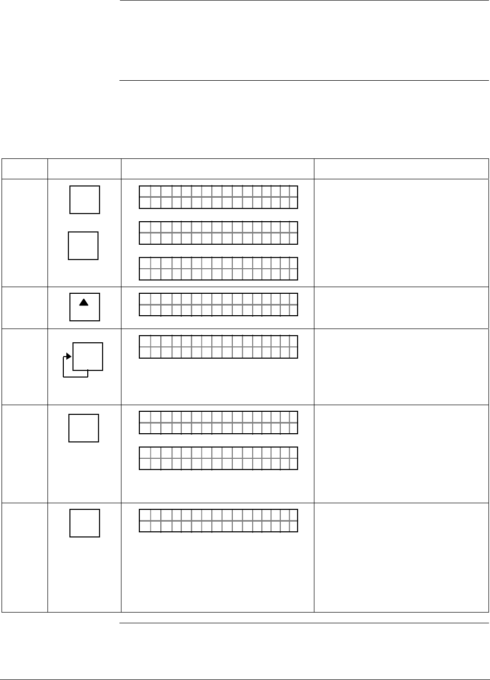
ST 3000 Release 300 and SFC Model STS103 User’s Manual 6/08
94
6.10 Selecting Message Format (DE Mode Only)
Background You can select one of these broadcast formats for the digital signal
transmission as described in Table 20.
• 4-Byte type
• 6-Byte type
Procedure The procedure in Table 29 outlines the steps for selecting a 6-Byte type
format for example purposes only.
Table 29 Selecting Message Format
Step Press Key Read Display or Action Description
1 ^
SHIFT
DE CONF
MENU
ITEM
I
LIN DP
FT–SHI
TØ11P3
ORK NGCW .F.S.I
PTDE 3011OCNF
eRgnliSn
PTDE 3011OCNF
gw/SV
Initiate shift key selection.
Calls up DE CONFIG menu. Output
signal mode selection appears.
2
NEXT
H
4BoB/
PTDE 3011OCNF
De
)( ywt
Calls up next DE CONFIG menu
item - Message format selection
appears.
3 DE CONF
MENU
ITEM
I
6B/Bw
PTDE 3011OCNF
De
)( yt
Calls up next message format
selection. Repeatedly press [MENU
ITEM] key to cycle between two
format selections. See Table 19 for
details. Stop when “w/DB (6 Byte)”
selection is on display.
4 NON-VOL
ENTER
(Yes) RD INEE
PTDE 3011OCNF
TSFCEN
/S=/
PTDE 3011OCNF
BLoFO
Enters change in SFC and calls up
next DE configuration parameter.
This action only applies if selection
is changed. Otherwise, must press
[CLR] key to exit function, [s NEXT]
key to call up next parameter, or
[t PREV] key to call up previous
parameter.
5 CLR
(NO) DCWLO
PTDE 3011OCNF
NNGAHDAOE?
Prompt asks if change entered in
SFC is to be downloaded to
transmitter. If you want to download
change, go to Step 6. If you do not
want to download change, press
[CLR] key to exit function. This action
only applies when Step 4 is valid.
Otherwise, this keystroke exits DE
CONF function.
Continued on next page
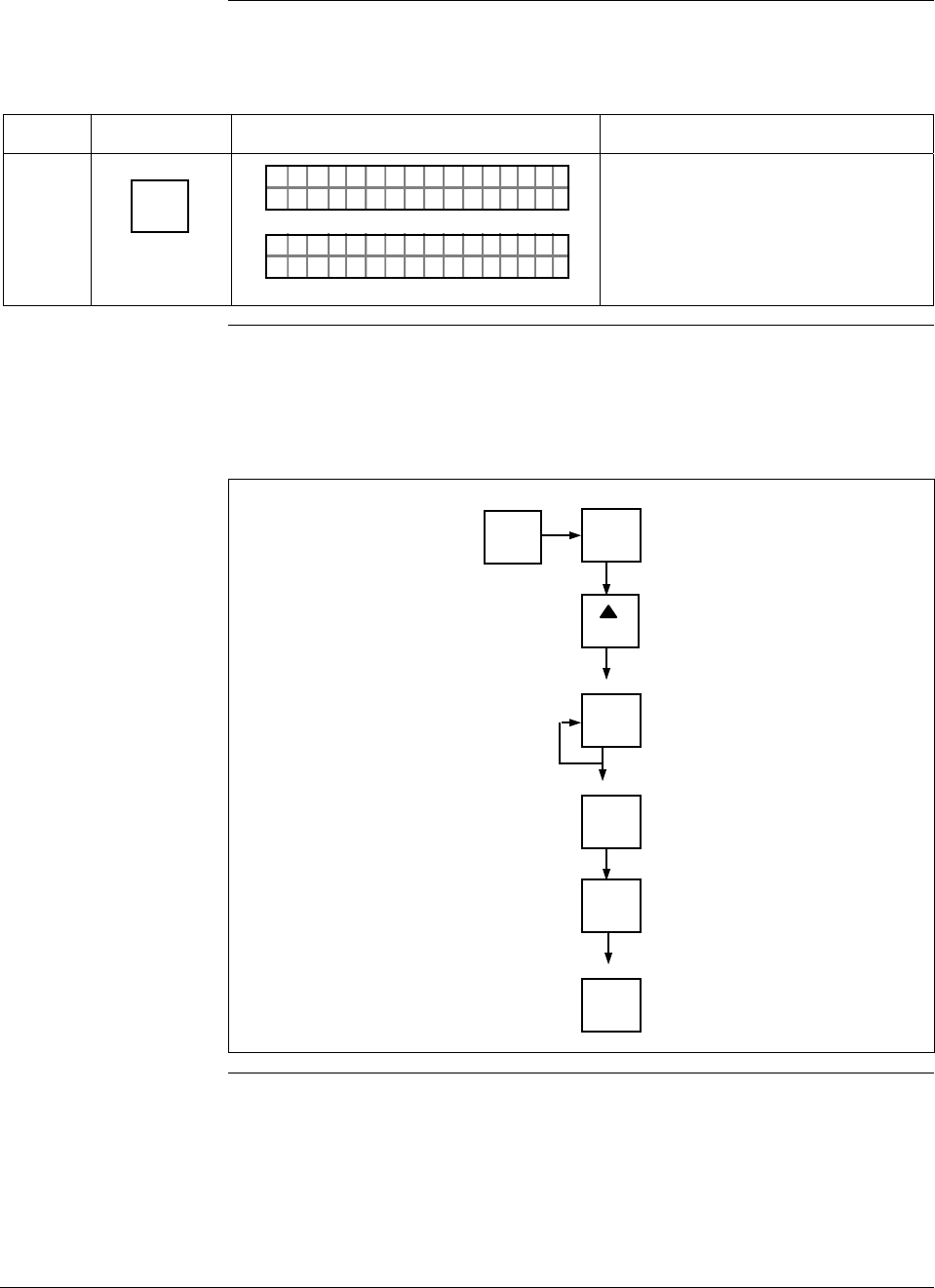
6/08 ST 3000 Release 300 and SFC Model STS103 User’s Manual 95
6.10 Selecting Message Format (DE Mode Only), Continued
Procedure , continued
Table 29 Selecting Message Format, continued
Step Press Key Read Display or Action Description
6 NON-VOL
ENTER
(Yes)
PTDE 3011OCNF
OR K NGCW .F.S.I
LIN DP
.Y. .RE AD
TØ11P3
Message exchange is working.
Parameter change is loaded in
transmitter. SFC is ready for next
function.
Keystroke summary Figure 34 shows keystroke summary for selecting the message format for
transmitter in DE mode for quick reference.
Figure 34 Keystroke Summary for Selecting Message Format.
^
SHIFT MENU
ITEM
DE CONF
I
MENU
ITEM
DE CONF
I
NON-VOL
ENTER
(Yes)
CLR
(No)
NON-VOL
ENTER
(Yes)
NEXT
H
22514

ST 3000 Release 300 and SFC Model STS103 User’s Manual 6/08
96
6.11 Configuring Smart Meter Using SFC
Background You can select an available engineering unit or enter a custom one
including upper and lower limit settings for the Local Smart Meter’s
digital readout through the SFC.
Configuring the Smart
Meter • If you initiate an SFC command at the same time a button is pressed
on the Local Smart Meter, the Local Smart Meter will respond to the
command it receives last. In other words, the last command wins.
• The Local Smart Meter does not have to be installed for you to
configure it through the SFC. The meter’s configuration data is stored
in memory on the transmitter’s PWA rather than in the meter itself.
Transmitter Output
Conformity and Smart
Meter Configuration
Normally when using a differential type transmitter, you can select the
transmitter’s output to represent a straight linear calculation or a square
root calculation for flow measurement applications. This linear or
square root output parameter selection is called output conformity or
output form. (See Subsection 6.4 for more details.)
When configuring the smart meter to display the transmitter output
measurement, there are certain rules to keep in mind which are
dependent on the output conformity selection. These rules are described
in the following paragraphs.
1. The output conformity setting of the transmitter restricts the
engineering units you can select for the smart meter display.
• When the transmitter is configured for an output conformity of
LINEAR, you can select only pressure type engineering units.
(See Table 31.)
• When the transmitter is configured for an output conformity of
SQUARE ROOT, you can select only flow type engineering
units GPM and GPH.
• The percent and custom engineering units can be selected
regardless of output conformity configuration.
2. Additionally, the output conformity setting restricts the setting of the
lower and upper display limits to represent transmitter’s 0 to 100%
output.
• If you select pressure type engineering units, you cannot set the
lower or upper display limits. These values are automatically set
when you select the engineering units.
• You can set only the upper display limit when the transmitter is
configured for SQUARE ROOT output conformity. The lower
display limit is fixed at zero (0) for a transmitter in square root
mode and cannot be changed.
Continued on next page
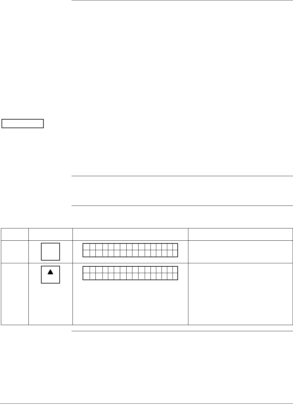
6/08 ST 3000 Release 300 and SFC Model STS103 User’s Manual 97
6.11 Configuring Smart Meter Using SFC, Continued
Transmitter Output
Conformity and Smart
Meter Configuration,
continued
• You can set both the lower and upper display limits when you
have selected custom engineering units (Custom) and the
transmitter output conformity is set to LINEAR.
When setting the lower and upper display limits, if you let either
the lower or upper display limit setting time out (after thirty
seconds), the meter will discard the newly set values and will
revert to its previous settings. The meter forces you to set both
limits by automatically initiating the next limit setting, either
lower or upper, depending upon which limit you set first.
3. If you change the transmitter’s output conformity, you must
reconfigure the local smart meter as outlined in Table 30.
ATTENTION After making any adjustments to the smart meter, keep the transmitter
powered for at least 30 seconds so that the new meter configuration is
written to non-volatile memory. If power is turned off before 30
seconds, the changes may not be saved so that when the transmitter
power is restored, the meter configuration will revert to the previous
settings.
Procedure The procedure in Table 30 outlines the steps for setting up the
configuration for a Local Smart Meter using an SFC.
Table 30 Setting Up Local Smart Meter Configuration Using an SFC
Step Press Key Read Display or Action Description
1 CONF
B
CONF I G
MON TFR IC?OY
ST
Calls up first configuration prompt.
2
NEXT
H
CONF I G
CMe ntr o ?ef
ST
ig
Calls up next configuration prompt.
Prompt asks if you want to access
meter configuration function. If you
want to access it, go to Step 3. If
you do not want to access it, press
[CLR] key to exit function or [s NEXT]
key to call up next configuration
parameter.
Continued on next page
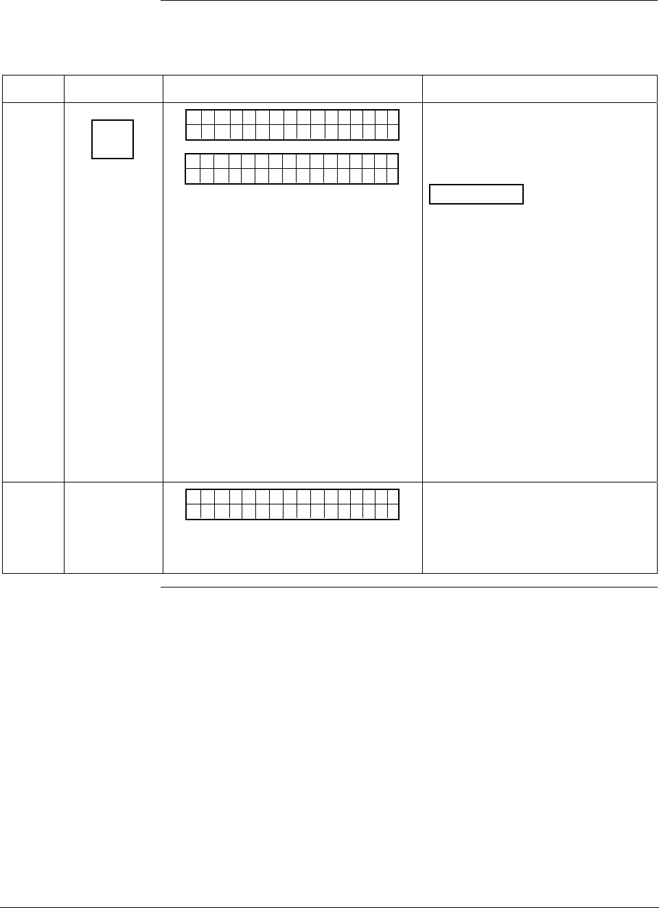
ST 3000 Release 300 and SFC Model STS103 User’s Manual 6/08
98
6.11 Configuring Smart Meter Using SFC, Continued
Procedure, continued
Table 30 Setting Up Local Smart Meter Configuration Using an SFC, continued
Step Press Key Read Display or Action Description
3
ENTER
(YES)
NON-VOL
SCFO
WRK NI.G..
CMe ntr oef
ig
Pertsen
Met re
CMe ntr oef
ig
Bd
Enters meter configuration function
and confirms that Local Smart Meter
is present. Timed prompt - Proceed
to Step 4.
ATTENTION If prompt “No Meter
Present” appears, prompt times out
in a few seconds, as described
above, and calls up the Configure
Meter? prompt. This means that
you can access the meter
configuration function without the
Local Smart Meter installed.
Proceed to Step 4. If prompt “Mtr
not Supportd” appears, prompt
times out and returns to previous ST
CONFIG prompt (See Step 2.). This
means that you are working with a
pre-release 300 transmitter that
does not support the Local Smart
Meter option and, therefore, can not
access the meter configuration
function.
4
Cnoufig Me t re
CMe ntr oef
ig
re ?
Prompt asks if you want to configure
Local Smart Meter. If you want to
configure it, go to Step 5. If you do
not want to configure it, press [CLR]
key to exit function.
Continued on next page
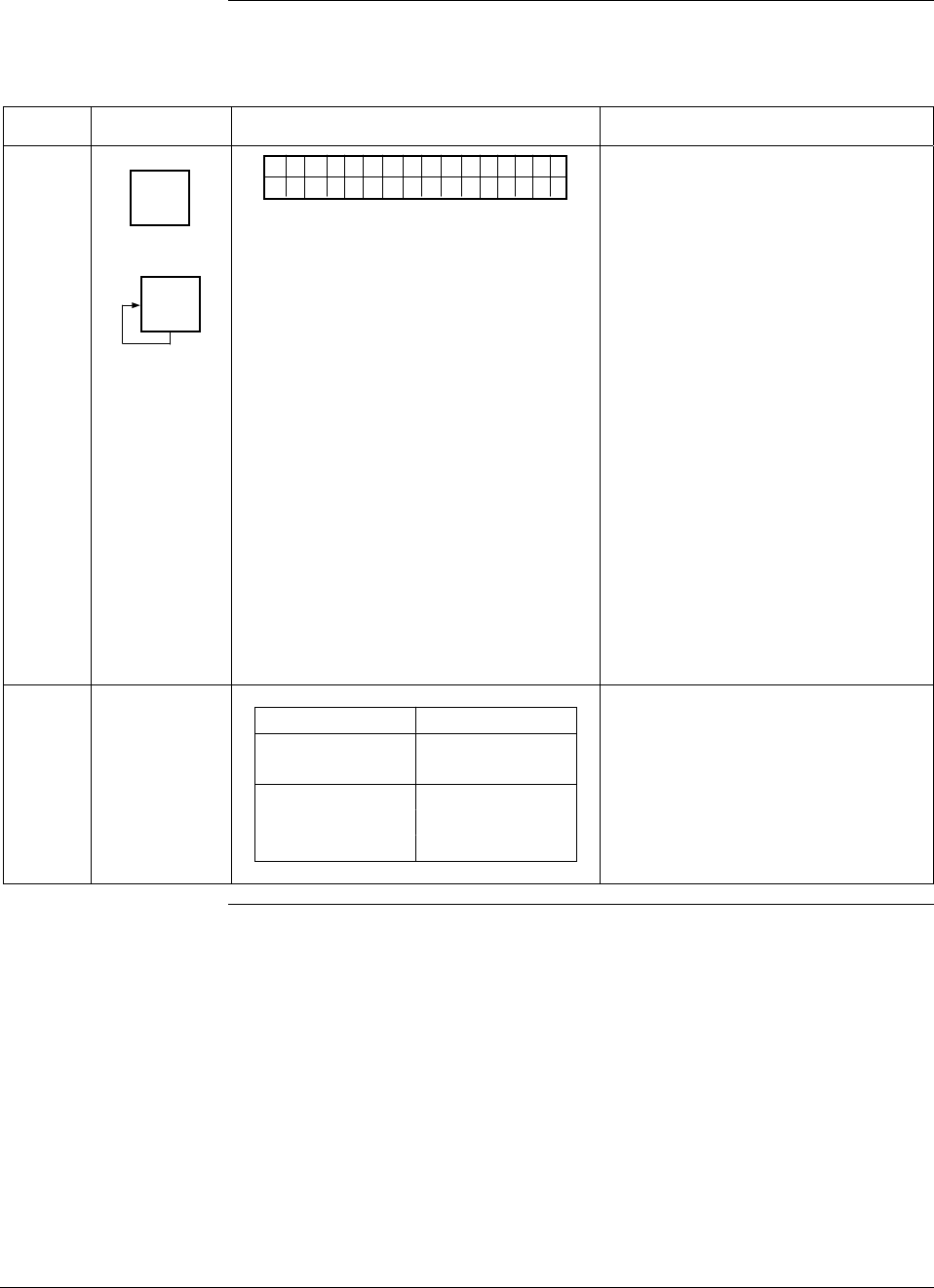
6/08 ST 3000 Release 300 and SFC Model STS103 User’s Manual 99
6.11 Configuring Smart Meter Using SFC, Continued
Procedure, continued
Table 30 Setting Up Local Smart Meter Configuration Using an SFC, continued
Step Press Key Read Display or Action Description
5
ENTER
(YES)
NON-VOL
MENU
ITEM
I
DECONF
"2H9O_3
EMe gtr neU
ni
F
ts
MmHg_0C
PSI
KPa
MPa
mBAR
BAR
g/cm^2
Kg/cm^2
mmH2O_4C
inHg_32F
mH2O_4C
GPM
GPH
Custom
%
Calls up present meter Engineering
Unit selection. (Note that unit
“H2O_39F is shown for example
purposes only.)
Repeatedly press [MENU ITEM] key to
step through other selections. For
example purposes, stop when PSI
unit is on display.
6
If EU is … Then…
Custom, GPM, go to Step 7.
or GPH
other than go to Step 13.
Custom, GPM,
or GPH
Continued on next page
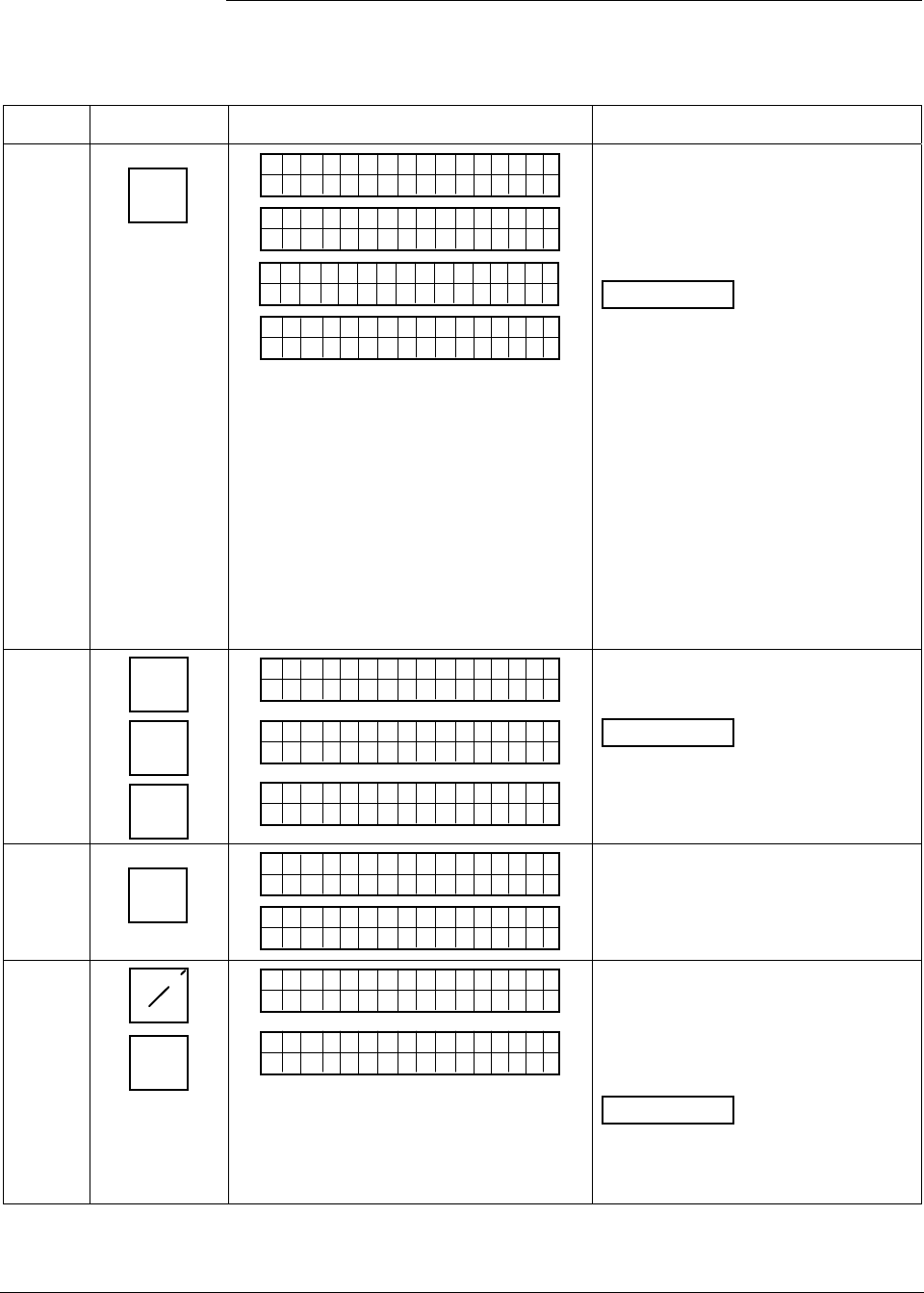
ST 3000 Release 300 and SFC Model STS103 User’s Manual 6/08
100
6.11 Configuring Smart Meter Using SFC, Continued
Procedure, continued
Table 30 Setting Up Local Smart Meter Configuration Using an SFC, continued
Step Press Key Read Display or Action Description
7
ENTER
(YES)
NON-VOL
SCFO
W
EMe gtr neU
ni
R
ts
KNI.G..
Dtao
D
EMe gtr neU
ni ts
wn oleadd
a
SCFO
W
EH
i-oLgnU
ni
R
ts
KNI.G..
R>N
A
EHi CUu
st
G
om
E
Selected engineering unit is
downloaded to transmitter and
high/low display limit setting function
is initiated. (Note that Custom unit is
shown for example purposes only.)
ATTENTION If you select GPM
or GPH unit with the transmitter in its
LINEAR mode, the prompts
“INVALID REQUEST”, “Download
Error”, and “MtrNotInFlowMode” are
sequentially displayed after the SFC
WORKING. . . prompt and display
returns to the Configure Meter
prompt. Transmitter must be in its
SQUARE ROOT (Flow) mode for
GPM or GPH to be a valid unit
selection.
Press [τ PREV] key , if you want to
view present high and low display
limits loaded in the transmitter.
8 5S
2W
5S
_
5
EHi CUu
stom
25
EH
iCUu
stom
_
25
EHi CUu
stom
5_
Key in 525 as upper display limit for
Custom unit.
ATTENTION The display range
of the meter is ±19,990,000. If you
enter larger values, they will not be
displayed.
9
ENTER
(YES)
NON-VOL
EHi CUu
stom
ETNR
EED NIFCS
R>N
A
ELo CUu
st
G
om
E
Enters upper display limit in SFC
and calls up lower display limit
setting.
10 +_
5S
-
ELo CUu
stom
_
-
ELo CUu
stom
5_
Key in –5 as lower display limit for
Custom unit in transmitter
configured for LINEAR output mode.
(Note that lower limit value is
referenced to configured LRV.)
ATTENTION Zero (0) is only
valid entry for GPM or GPH unit, or
CUSTOM unit with transmitter in
SQUARE ROOT output mode.
Continued on next page
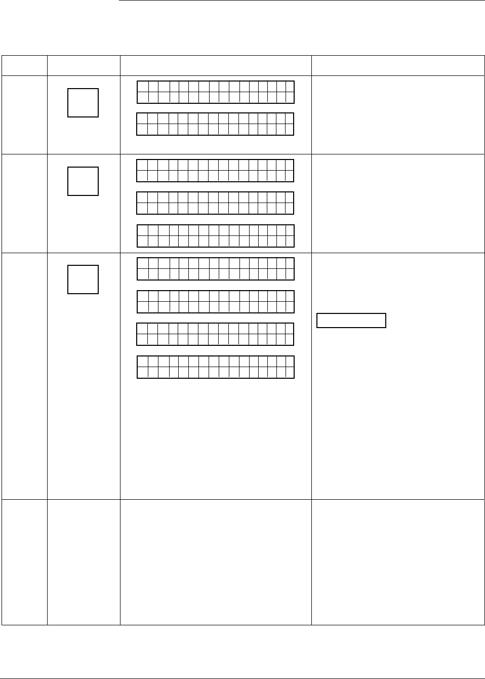
6/08 ST 3000 Release 300 and SFC Model STS103 User’s Manual 101
6.11 Configuring Smart Meter Using SFC, Continued
Procedure, continued
Table 30 Setting Up Local Smart Meter Configuration Using an SFC, continued
Step Press Key Read Display or Action Description
11
ENTER
(YES)
NON-VOL
ELo CUu
stom
ETNR
EED NIFCS
ETNR
E
EHi-oLgnU
ni ts
CH NASG?E
Enters lower display limit in SFC
and prompt asks if you want to enter
changes in transmitter. If you want
to enter changes, go to Step 12. If
you do not want to enter changes,
press [CLR] key to exit function.
12
ENTER
(YES)
NON-VOL
SCFO
W
EH
i-oLgnU
ni
R
ts
KNI.G..
Dtao
Dwn oleadd
a
EHi-oLgnU
ni ts
Cnoufig Met re
CMe ntr oef
ig
re ?
Downloads changes to transmitter
and returns to Configure Meter?
prompt. Press [CLR] key to return to
ST CONFIG menu. Skip Step 13.
13
ENTER
(YES)
NON-VOL
SCFO
W
EMe gtr neU
ni
R
ts
KNI.G..
Dtao
D
EMe gtr neU
ni ts
wn oleadd
a
MrtI
t
EMe gtr neU
ni
n
ts
FolowdM
No e
Cnoufig Met re
CMe ntr oef
ig
re ?
Downloads selected pressure
engineering unit to transmitter.
Press [CLR] key to return to ST
CONFIG menu.
ATTENTION If you select a
pressure unit with the transmitter in
its SQUARE ROOT (Flow) mode,
the prompts “INVALID REQUEST”
and “Download Error” are
sequentially displayed after the SFC
WORKING. . . prompt and the EU Hi
prompt is called up for display. At
this point, you can change the upper
display limit as shown in Step 8 or
press the [σ NEXT] key to call up the
EU Lo prompt. See Step 10 to
change the lower display limit or
press the [σ NEXT] key and then the
[CLR] key to exit the function.
14 If you selected one of these engineering
units: %,
inH2O,
mmHg,
PSI,
GPM, or
GPH;
verify that corresponding unit indicator is
lit on Local Smart Meter display.
If selected engineering unit does not
match one of six unit indicators on
meter, you can use a stick-on label
from Honeywell drawing 30756918-
001. Just peel off matching
engineering unit label from drawing
and carefully paste it in lower right
hand corner of display.
Continued on next page
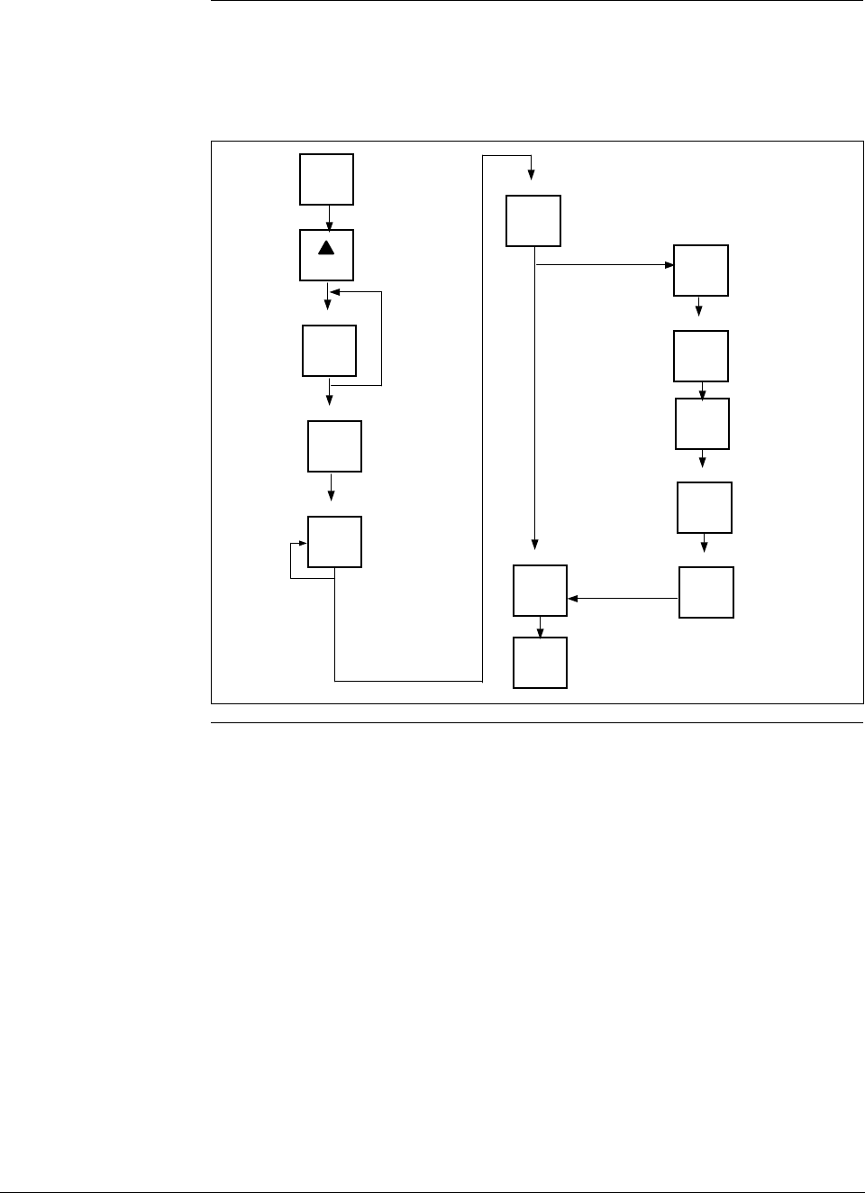
ST 3000 Release 300 and SFC Model STS103 User’s Manual 6/08
102
6.11 Configuring Smart Meter Using SFC, Continued
Keystroke summary Figure 35 shows the keystroke summary for configuring the Local Smart
Meter using the SFC for quick reference.
Figure 35 Keystroke Summary for Configuring Local Smart Meter.
CONF
B
ENTER
(YES)
NON-VOL
NEXT
H
Meter Not
Supported
ENTER
(YES)
NON-VOL
MENU
ITEM
I
DECONF
ENTER
(YES)
NON-VOL
Number
ENTER
(YES)
NON-VOL
Number
ENTER
(YES)
NON-VOL
ENTER
(YES)
NON-VOL
CLR
(NO)
Custom, GPM,
or GPH unit only Hi Limit
Lo Limit
ENTER
(YES)
NON-VOL
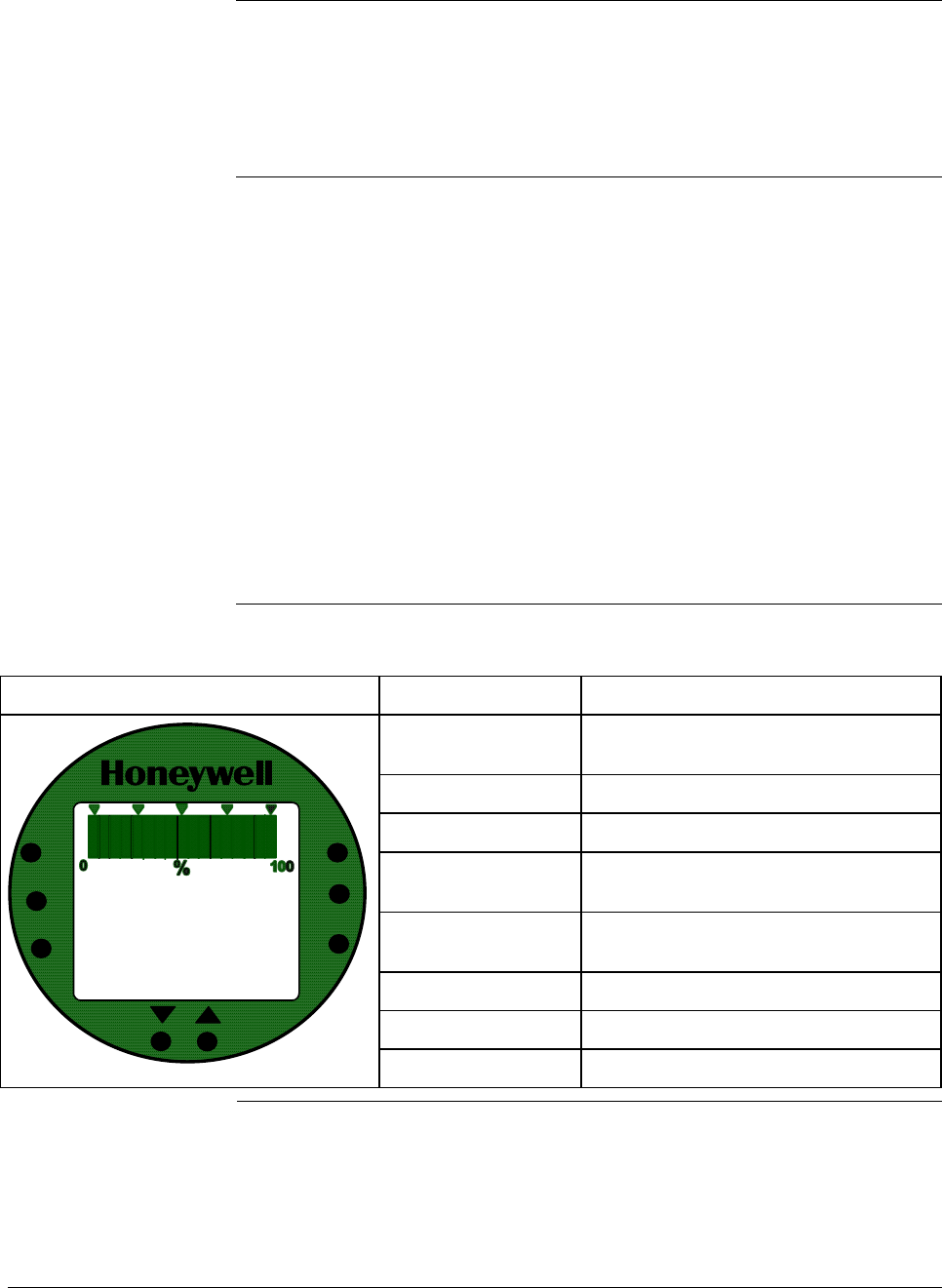
6/08 ST 3000 Release 300 and SFC Model STS103 User’s Manual 103
6.12 Configuring Smart Meter Using Pushbuttons
Background The local smart meter can be set to show the PV out in engineering units
that are appropriate for your process application. You can select an
available engineering unit or enter a custom one including upper and
lower display limit settings for the local smart meter’s digital readout
using buttons on the face of the meter.
Using the Smart
Meter Follow these guidelines when configuring the local smart meter:
• If you initiate an SFC command at the same time a button is pressed
on the local smart meter, the local smart meter will respond to the
command it receives last. In other words, the last command wins.
• In most cases, you can press and release a button for one-shot
operation, or press and hold a button for continuous, 1/2 second,
repetitive operation.
• Active setup field will begin to flash at one second rate if next action
is not initiated within one second. And, if no action is taken within
30 seconds, the setup function will time out and the meter will return
to its previous state.
Table 31 shows an illustration of the local smart meter and a description
of the pushbuttons on the meter face.
Table 31 Smart Meter Pushbutton Description
Smart Meter Pushbuttons Pushbutton Function
VAR SEL. Not functional when installed with
ST 3000 transmitters.
SPAN Selects Span range setting (URV).
ZERO Selects Zero range setting (LRV).
UPPER VALUE Selects Upper Range Value setting
(URV).
UNITS SET Selects engineering units for meter
display.
LOWER VALUE Selects Lower Range Value (LRV).
τ Decrease pushbutton
UPPER
VALUE
UNITS
LOWER
VALUE
SET
18.808
-
ANALOG In H O
2
KGPH mmHg
GPM PSI A
OUTPUT MODE
CHECK STATUS
FAULT - LAST
KNOWN VALUE
%
FLOW
oFoC
VAR
SEL.
SPAN
ZERO
σ Increase pushbutton
Continued on next page

ST 3000 Release 300 and SFC Model STS103 User’s Manual 6/08
104
6.12 Configuring Smart Meter Using Pushbuttons, Continued
Transmitter Output
Conformity and Smart
Meter Configuration
Normally when using a differential type transmitter, you can select the
transmitter’s output to represent a straight linear calculation or a square
root calculation for flow measurement applications. This linear or
square root output parameter selection is called output conformity or
output form. (See Subsection 6.4 for more details.)
When configuring the smart meter to display the transmitter output
measurement, there are certain rules to keep in mind which are
dependent on the output conformity selection. These rules are described
in the following paragraphs.
1. The output conformity setting of the transmitter restricts the
engineering units you can select for the smart meter display.
• When the transmitter is configured for an output conformity of
LINEAR, you can select only pressure type engineering units.
(See Table 32.)
• When the transmitter is configured for an output conformity of
SQUARE ROOT, you can select only flow type engineering
units GPM and GPH.
• The percent and custom engineering units can be selected
regardless of output conformity configuration.
2. Additionally, the output conformity setting restricts the setting of the
lower and upper display limits to represent transmitter’s 0 to 100%
output.
• If you select pressure type engineering units, you cannot set the
lower or upper display limits. These values are automatically set
when you select the engineering units.
• You can set only the upper display limit when the transmitter is
configured for SQUARE ROOT output conformity. The lower
display limit is fixed at zero (0) for a transmitter in square root
mode and cannot be changed.
• You can set both the lower and upper display limits when you
have selected custom engineering units (EUF) and the
transmitter output conformity is set to LINEAR.
When setting the lower and upper display limits, if you let either the
lower or upper display limit setting time out (after thirty seconds), the
meter will discard the newly set values and will revert to its previous
settings. The meter forces you to set both limits by automatically
initiating the next limit setting, either lower or upper, depending upon
which limit you set first.
3. If you change the transmitter’s output conformity, you must
reconfigure the Local Smart meter as outlined in Tables 33 to 36.
Continued on next page

6/08 ST 3000 Release 300 and SFC Model STS103 User’s Manual 105
6.12 Configuring Smart Meter Using Pushbuttons, Continued
Transmitter Output
Conformity and Smart
Meter Configuration,
continued
Table 32 Smart Meter Engineering Units Code
Smart Meter Code Engineering Unit Transmitter Output
Conformity
EU0
% * Linear or Square Root
EU1
in H2O *
EU2 mmHg *
EU3 PSI *
EU4 kPa †
EU5 MPa †
EU6 mbar † Linear
EU7 bar †
EU8 g/cm2 †
EU9 kg/cm2 †
EUA mmH2O †
EUB inHg †
EUC mH2O †
EUD GPM * Square Root
EUE GPH * Square Root
EUF Custom † Linear or Square Root
* These selections have indicators on smart meter display.
† Use stick-on labels provided for other engineering units.
Selecting Engineering
Units The procedure in Table 33 outlines the steps for selecting the desired
engineering units for a Local Smart Meter using its local adjustments on
the face of the meter. You will be selecting the unit of measurement
that you want the smart meter to indicate during normal operation.
WARNING When the transmitter’s end-cap is removed, the housing is not
explosionproof.
Continued on next page
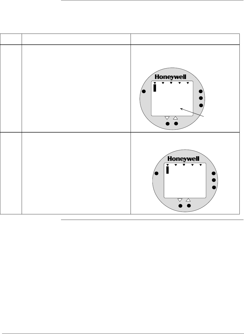
ST 3000 Release 300 and SFC Model STS103 User’s Manual 6/08
106
6.12 Configuring Smart Meter Using Pushbuttons, Continued
Selecting Engineering
Units, continued
Table 33 Selecting Engineering Units
Step Action Meter Display
1 Loosen lock on meter end-cap and unscrew
cap from housing. Be sure transmitter power
is ON.
Typical display for meter in transmitter that
has no previous meter configuration stored in
its memory.
%
1000
0
.
0
ANALOG
%
0
UPPER
VALUE
UNITS
LOWER
VALUE
SET
VAR
SEL.
Appears when
transmitter is in
its Analog mode.
2 Press UNITS SET button. Display shows code for current engineering
units setting.
%
1000
EU
ANALOG
%
0
UPPER
VALUE
UNITS
LOWER
VALUE
SET
VAR
SEL.
Continued on next page
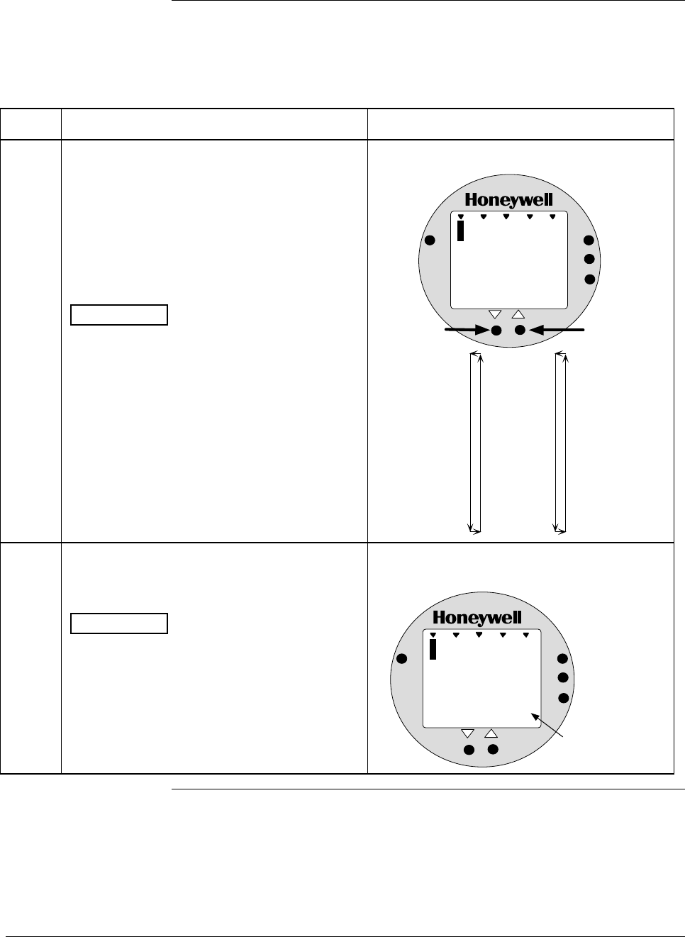
6/08 ST 3000 Release 300 and SFC Model STS103 User’s Manual 107
6.12 Configuring Smart Meter Using Pushbuttons, Continued
Selecting Engineering
Units, continued
Table 33 Selecting Engineering Units, continued
Step Action Meter Display
3 Press Increase σ key to call up next code or
Decrease τ button call up previous code.
Repeat this action until desired code is on
display.
You can hold down the Increase or Decrease
key to scroll forward or backward through the
codes.
ATTENTION Remember that if transmitter
is configured for SQUARE ROOT output
conformity the only valid code selections are
EU0 (%)
EUD (GPM)
EUE (GPH)
EUF (Custom)
If transmitter is configured for LINEAR output
conformity EU0 (%) to EUC and EUF
(CUSTOM) are valid code selections.
Selection codes for engineering units
%
1000
EU
ANALOG
1
UPPER
VALUE
UNITS
LOWER
VALUE
SET
VAR
SEL.
In H O
2
EU0 = %*
EU1 = inH2O*
EU2 = mmHg*
EU3 = PSI*
EU4 = KPa
EU5 = MPa
EU6 = mbar
EU7 = bar
EU8 = g/cm2
EU9 = Kg/cm2
EUA = mmH2O
EUB = inHg
EUC = mH2O
EUD = GPM*
EUE = GPH*
EUF = Custom
Press and hold to
scroll forward
through selections
Press and hold to
scroll backward
through selections
*These selections
have indicators on
the display.
4 Press UNITS SET button to lock in selected
code.
ATTENTION If you select an invalid code
according to the selections in Step 3, the
meter display will show an error code Er1 for
one second and then return to the previous
engineering units selection.
Goes blank for 1/2 second and returns with
reading in engineering units
%
1000
0
.
1
ANALOG
8
UPPER
VALUE
UNITS
LOWER
VALUE
SET
VAR
SEL.
In H O
2
Digital reading now
in engineering units
of inches of water
Continued on next page
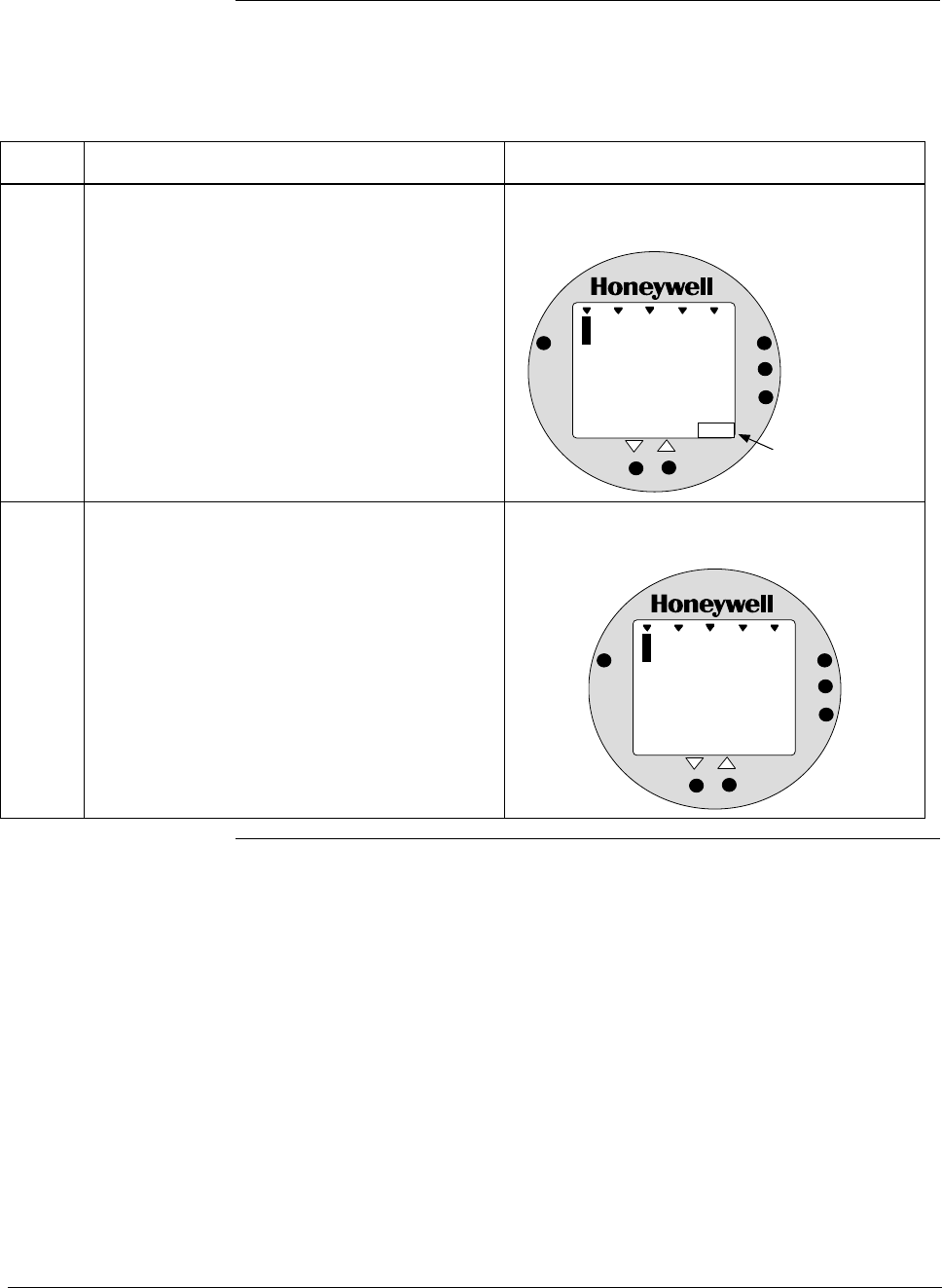
ST 3000 Release 300 and SFC Model STS103 User’s Manual 6/08
108
6.12 Configuring Smart Meter Using Pushbuttons, Continued
Selecting Engineering
Units, continued
Table 33 Selecting Engineering Units, continued
Step Action Meter Display
5 If selected engineering unit does not match
one of six unit indicators on meter, peel off
matching stick-on unit label from sheet
(drawing number 30756918-001) and paste it
in lower right hand corner of meter.
Use stick-on label for engineering units
without indicators on display.
%
1000
1
.
0
ANALOG
2
UPPER
VALUE
UNITS
LOWER
VALUE
SET
VAR
SEL.
Kg/cm2
Stick-on label
identifies selected
engineering units
6 If you selected Custom or Flow engineering
units, go to Tables 35 and 36 to set lower and
upper display limits for smart meter display.
Lower and upper display limits have not been
set for Custom or Flow engineering units.
%
1000
U
-
ANALOG
L
UPPER
VALUE
UNITS
LOWER
VALUE
SET
VAR
SEL.
FLOW
GPM

6/08 ST 3000 Release 300 and SFC Model STS103 User’s Manual 109
6.12 Configuring Smart Meter Using Pushbuttons, Continued
Setting Lower and
Upper Display Values The Table 34 shows the restrictions on setting the display values for
given engineering units and output conformity selections.
Table 34 Smart Meter Restrictions for Setting Display Values
Engineering Output Set
Units code Conformity Lower Display Value? Upper Display Value?
EU0 through EUC
(Pressure type units)
Linear No (set automatically) No (set automatically)
EU0, EUD, EUE,and EUF
(%, GPM, GPH, or Custom)
Square root No (fixed at zero) Yes
Use Table 36
EUF
(Custom)
Linear Yes
Use Table 35
Yes
Use Table 36
Setting Lower and
Upper Display Values To set the lower and upper display limit values for the meter display
perform the procedures in Tables 35 and 36. Also note that in each
procedure you must:
• First set the magnitude range for each display value. This enables
the multiplier (K) on the display for indicating larger ranges (greater
than 19999 and shifts the decimal point of the digital display left or
right depending on the precision you want to show for that value).
• Next set the display value. This procedure sets the display limit of
the meter to represent minimum and maximim transmitter output
(0% and 100 % output).
Note: Magnitude range and display values are set for both upper and
lower (if applicable) display limits.
During normal operation, the display range of the meter digital readout
is ±19,990,000 and is automatically ranged to provide the best precision
possible for the digits available up to 1/100th of a unit.
Setting Lower Display
Values The procedure in Table 35 outlines the steps for setting the lower
display limit to represent the 0 percent (LRV) output of the transmitter.
ATTENTION For example purposes, the procedures in Tables 35 and 36 assume that
the lower value is to be set at 0 and the upper value is to be set at
19,990,000 for a CUSTOM unit in a transmitter with a LINEAR output,
and the transmitter’s present output is exactly 50 percent.
Continued on next page
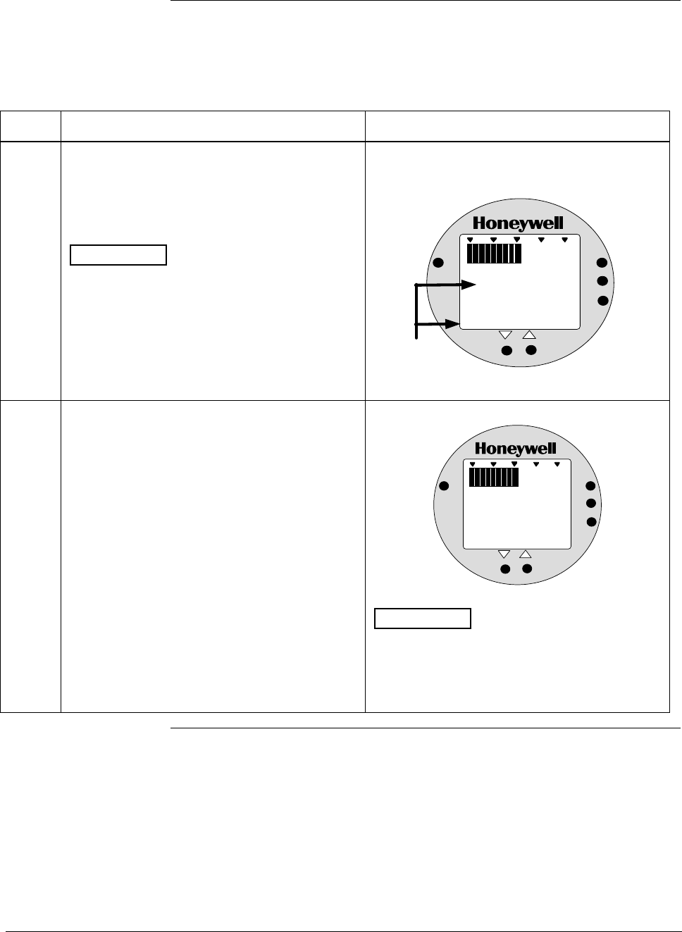
ST 3000 Release 300 and SFC Model STS103 User’s Manual 6/08
110
6.12 Configuring Smart Meter Using Pushbuttons, Continued
Setting Lower Display
Values, continued
Table 35 Setting Lower Display Values for Smart Meter Display
Step Action Meter Display
1 You have completed units selection in Table
33 and U-L appears on the display. Press
LOWER VALUE button to initiate lower
display limit setting function.
ATTENTION This procedure is only
applicable for Custom (EUF) engineering unit
selection in a transmitter configured for
LINEAR output conformity.
The lower display value for transmitters
configured for SQUARE ROOT output
conformity is fixed at zero (0.00) and cannot
be changed.
If lower limit display value was previously set,
KNOWN VALUE indicator lights and set value
flashes in display.
%
1000
ANALOG
UPPER
VALUE
UNITS
LOWER
VALUE
SET
VAR
SEL.
0. 00
Previously set
value flashes in
display and
indicator lights
KNOWN VALUE
2 Press LOWER VALUE button again within 5
seconds. Otherwise, meter exits limit setting
function.
Display shows magnitude range selection.
%
1000
ANALOG
UPPER
VALUE
UNITS
LOWER
VALUE
SET
VAR
SEL.
19 .99
ATTENTION The magnitude range
selection only applies for setting the display
limits. This selection does not affect the
normal operation of the meter. During normal
operation, the display is automatically ranged
to provide the best precision possible.
Continued on next page
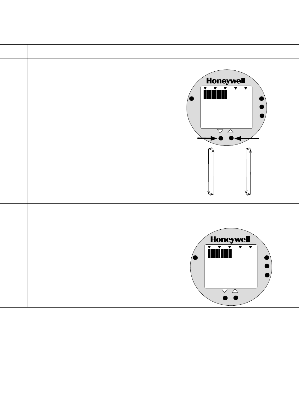
6/08 ST 3000 Release 300 and SFC Model STS103 User’s Manual 111
6.12 Configuring Smart Meter Using Pushbuttons, Continued
Setting Lower Display
Values, continued
Table 35 Setting Lower Display Values for Smart Meter Display, continued
Step Action Meter Display
3 Press Increase σ button to call up next
available magnitude range selection or
Decrease τ button to call up previous
magnitude range selection.
NOTE: This action enables the multiplier (K)
for indicating larger ranges and shifts
the decimal point of the digital display
left or right depending on which button
is pushed. The display shows largest
positive number for given range
selection so you can select a range
that is just larger than the range to be
set for best display precision. Hold
respective key to scroll forward or
backward through the selections.
Repeat this action until desired selection is on
display.
Magnitude range selections.
%
1000
ANALOG
UPPER
VALUE
UNITS
LOWER
VALUE
SET
VAR
SEL.
19 . 99
19.99
199.9
1999
19.99K*
199.9K*
1999K*
19990K*
Press and hold to
scroll forward
through selections
Press and hold to
scroll backward
through selections
*The "K" multiplier
indicator appears
below the digital
reading on the display.
4 Press LOWER VALUE button to initiate lower
value setting. Readout goes blank except for first active digit
which will be 0 unless lower value was set
before.
%
1000
ANALOG
UPPER
VALUE
UNITS
LOWER
VALUE
SET
VAR
SEL.
0
Continued on next page
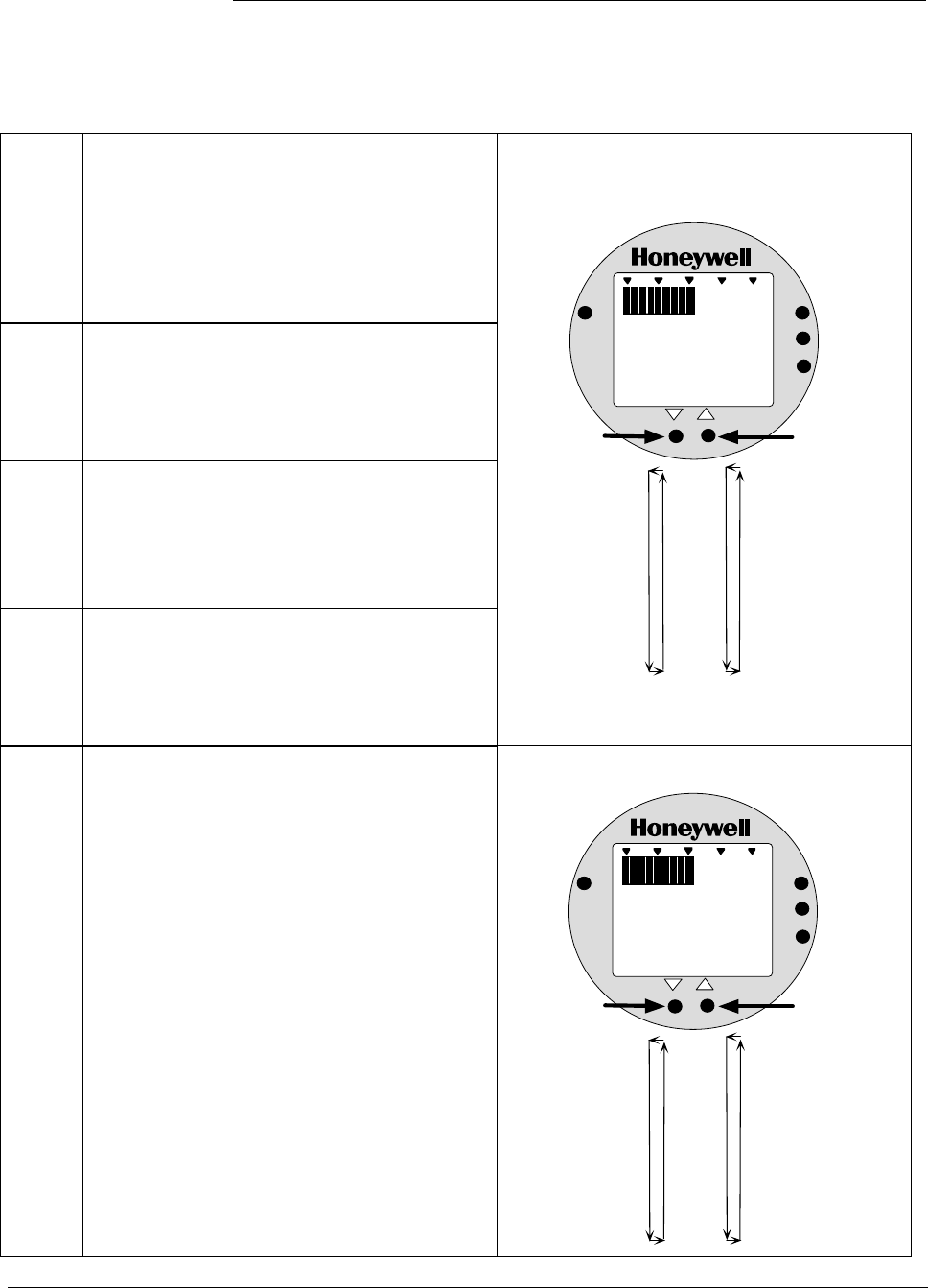
ST 3000 Release 300 and SFC Model STS103 User’s Manual 6/08
112
6.12 Configuring Smart Meter Using Pushbuttons, Continued
Setting Lower Display
Values, continued
Table 35 Setting Lower Display Values for Smart Meter Display, continued
Step Action Meter Display
5
Press Increase σ button to select the next
available digit value or Decrease τ button to
select the previous digit value.
Repeat this action until desired value is on
display.
6
Press LOWER VALUE button to lock-in first
digit and activate next active digit.
Readout now displays next active digit which
will be zero unless lower value was set
before.
7
Press Increase σ button to select the next
available digit value or Decrease τ button to
select the previous digit value.
Repeat this action until desired value is on
display.
8
Press LOWER VALUE button to lock-in
second digit and activate next active digit.
Readout now displays next active digit which
will be zero unless lower value was set
before.
First digit value setting.
%
1000
ANALOG
UPPER
VALUE
UNITS
LOWER
VALUE
SET
VAR
SEL.
0
0
1
2
3
4
5
6
7
8
9
Press and hold to
scroll forward
through values
Press and hold to
scroll backward
through values
9 Press Increase σ button to select the next
available digit value or Decrease τ button to
select the previous digit value.
Repeat this action until desired value is on
display.
Third digit value setting.
%
1000
ANALOG
UPPER
VALUE
UNITS
LOWER
VALUE
SET
VAR
SEL.
000.
0
1
2
3
4
5
6
7
8
9
Press and hold to
scroll forward
through values
Press and hold to
scroll backward
through values
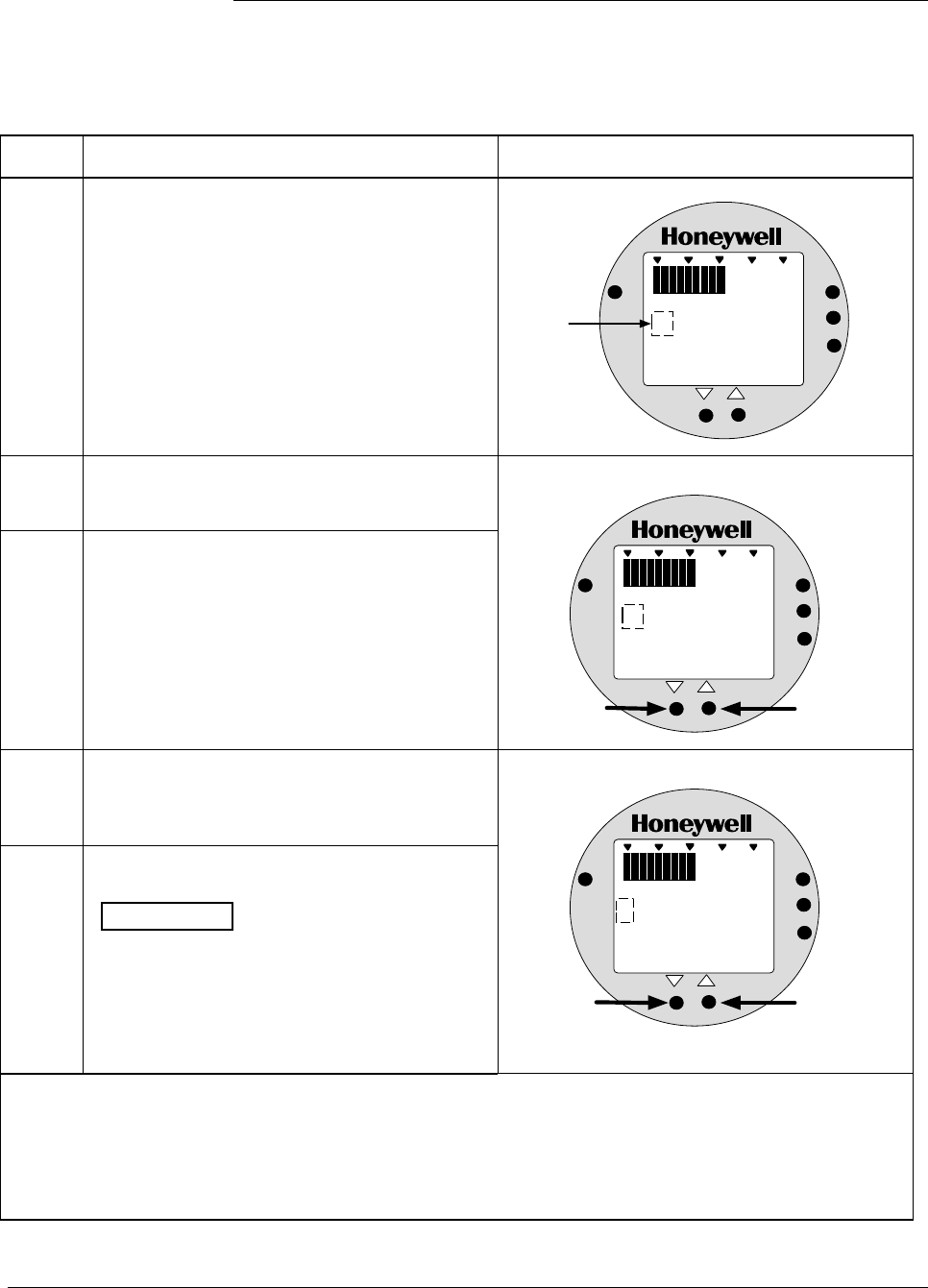
6/08 ST 3000 Release 300 and SFC Model STS103 User’s Manual 113
6.12 Configuring Smart Meter Using Pushbuttons, Continued
Setting Lower Display
Values, continued
Table 35 Setting Lower Display Values for Smart Meter Display, continued
Step Action Meter Display
10 Press LOWER VALUE button to lock-in third
digit and activate next active digit.
Readout now displays next active digit which
will be BLANK unless lower value was set to 1
before.
%
1000
ANALOG
UPPER
VALUE
UNITS
LOWER
VALUE
SET
VAR
SEL.
000.
"1" digit is
BLANK or 1
11
Press Increase σ button to set digit to 1 or
Decrease τ button to set it to BLANK.
12 Press LOWER VALUE button to lock-in “1”
digit and activate sign segment.
Readout now displays sign segment which
will be BLANK for positive values unless lower
value was set for negative (–) values before.
“1” digit value setting.
%
1000
ANALOG
UPPER
VALUE
UNITS
LOWER
VALUE
SET
VAR
SEL.
000.
Press to set "1"
digit as 1
Press to set "1"
digit as BLANK
13
Press Increase σ button to set sign segment
to minus sign for negative values or Decrease
τ button to set it to BLANK for positive values.
14 Press LOWER VALUE button to lock in
current settings as lower display value limit.
ATTENTION For CUSTOM unit in
transmitter with LINEAR output, you must set
both lower and upper display limits for values
to take effect. If you let either the lower or
upper display limit time out (after 30 seconds),
the meter discards both newly set values and
reverts back to the previously set values.
Sign segment setting.
%
1000
ANALOG
UPPER
VALUE
UNITS
LOWER
VALUE
SET
VAR
SEL.
000.
Press to set sign
segment as minus
sign (-) for negative
values
Press to set sign
segment as
BLANK for
positive values
• If you have not yet set the upper display limit value, the meter automatically enters the upper display
setting function after it displays previously set value, if applicable. Go to Table 36.
• If you have already set the upper display limit value, this completes the lower and upper display
limits setting function for Custom engineering units in the transmitter. Meter returns to normal
operation.
Continued on next page
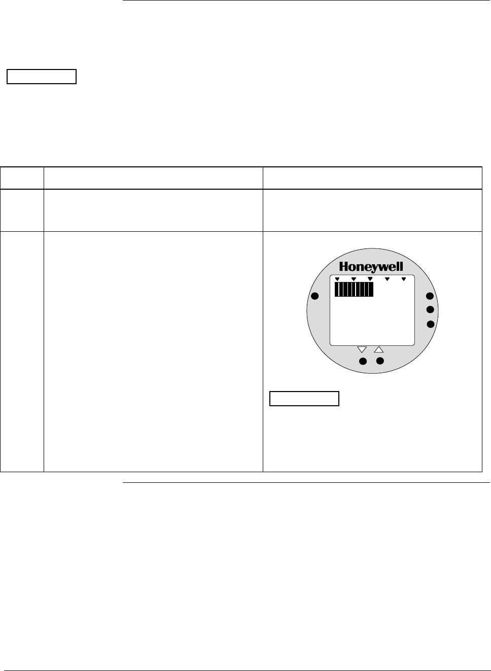
ST 3000 Release 300 and SFC Model STS103 User’s Manual 6/08
114
6.12 Configuring Smart Meter Using Pushbuttons, Continued
Setting Upper Display
Values The procedure in Table 36 outlines the steps for setting the upper
display limit to represent the 100 percent (URV) output of the
transmitter.
ATTENTION This procedure applies only for Flow units (GPM or GPH) in a
transmitter configured for SQUARE ROOT output conformity, or
CUSTOM unit in a transmitter configured for linear or square root
output conformity.
Table 36 Setting Upper Display Value for Smart Meter Display
Step Action Meter Display
1 Press UPPER VALUE button to initiate upper
display limit setting function. If upper limit display value was previously set,
KNOWN VALUE indicator lights and set value
flashes in display.
2 Press UPPER VALUE button again within 5
seconds. Otherwise, meter exits limit setting
function.
Display shows magnitude range selection.
%
1000
ANALOG
UPPER
VALUE
UNITS
LOWER
VALUE
SET
VAR
SEL.
19 .99
ATTENTION The magnitude range
selection only applies for setting the display
limits. This selection does not affect the
normal operation of the meter. During normal
operation, the display is automatically ranged
to provide the best precision possible.
Continued on next page
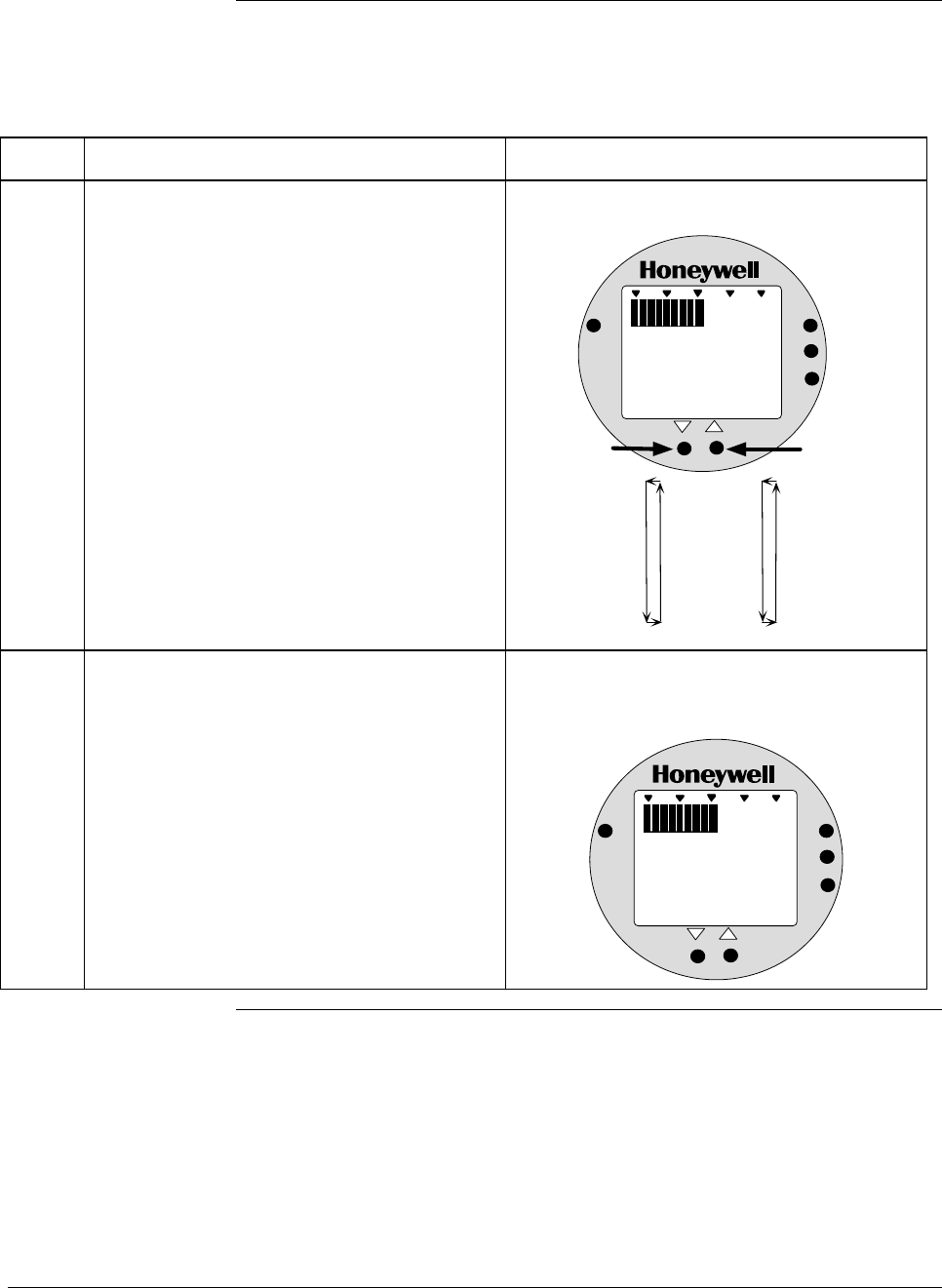
6/08 ST 3000 Release 300 and SFC Model STS103 User’s Manual 115
6.12 Configuring Smart Meter Using Pushbuttons, Continued
Setting Upper Display
Values, continued
Table 36 Setting Upper Display Value for Smart Meter Display, continued
Step Action Meter Display
3 Press Increase σ button to call up next
available magnitude range selection or
Decrease τ button to call up previous
magnitude range selection.
NOTE: This action enables the multiplier (K)
for indicating larger ranges and shifts
the decimal point of the digital display
left or right depending on which button
is pushed. The display shows largest
positive number for given range
selection so you can select a range
that is just larger than the range to be
set for best display precision. Hold
respective key to scroll forward or
backward through the selections.
Repeat this action until desired selection is on
display. For example purposes only, largest
range 19990K is selected in this procedure.
Magnitude range selections with largest range
selected.
%
1000
ANALOG
UPPER
VALUE
UNITS
LOWER
VALUE
SET
VAR
SEL.
19.99
199.9
1999
19.99K*
199.9K*
1999K*
19990K*
Press and hold to
scroll forward
through selections
Press and hold to
scroll backward
through selections
*The "K" multiplier
indicator appears
below the digital
reading on the display.
K
19 990
4 Press UPPER VALUE button to initiate upper
value setting. Readout goes blank except for first active digit
which will be 0 unless upper value was set
before.
%
1000
ANALOG
UPPER
VALUE
UNITS
LOWER
VALUE
SET
VAR
SEL.
K
00
Continued on next page
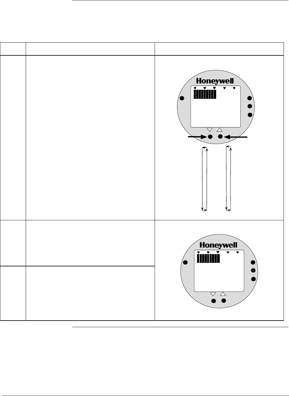
ST 3000 Release 300 and SFC Model STS103 User’s Manual 6/08
116
6.12 Configuring Smart Meter Using Pushbuttons, Continued
Setting Upper Display
Values, continued
Table 36 Setting Upper Display Value for Smart Meter Display, continued
Step Action Meter Display
5 Press Increase σ button to select the next
available digit value or Decrease τ button to
select the previous digit value.
Repeat this action until desired value is on
display – use 9 for example purposes.
First digit value setting is set to 9.
%
1000
ANALOG
UPPER
VALUE
UNITS
LOWER
VALUE
SET
VAR
SEL.
K
90
0
1
2
3
4
5
6
7
8
9
Press and hold to
scroll forward
through values
Press and hold to
scroll backward
through values
6
Press UPPER VALUE button to lock-in first
digit and activate next active digit.
Readout now displays next active digit which
will be zero unless upper value was set
before.
7 Press Increase σ button to select the next
available digit value or Decrease τ button to
select the previous digit value.
Repeat this action until desired value is on
display – use 9 for example purposes.
%
1000
ANALOG
UPPER
VALUE
UNITS
LOWER
VALUE
SET
VAR
SEL.
K
090
Continued on next page
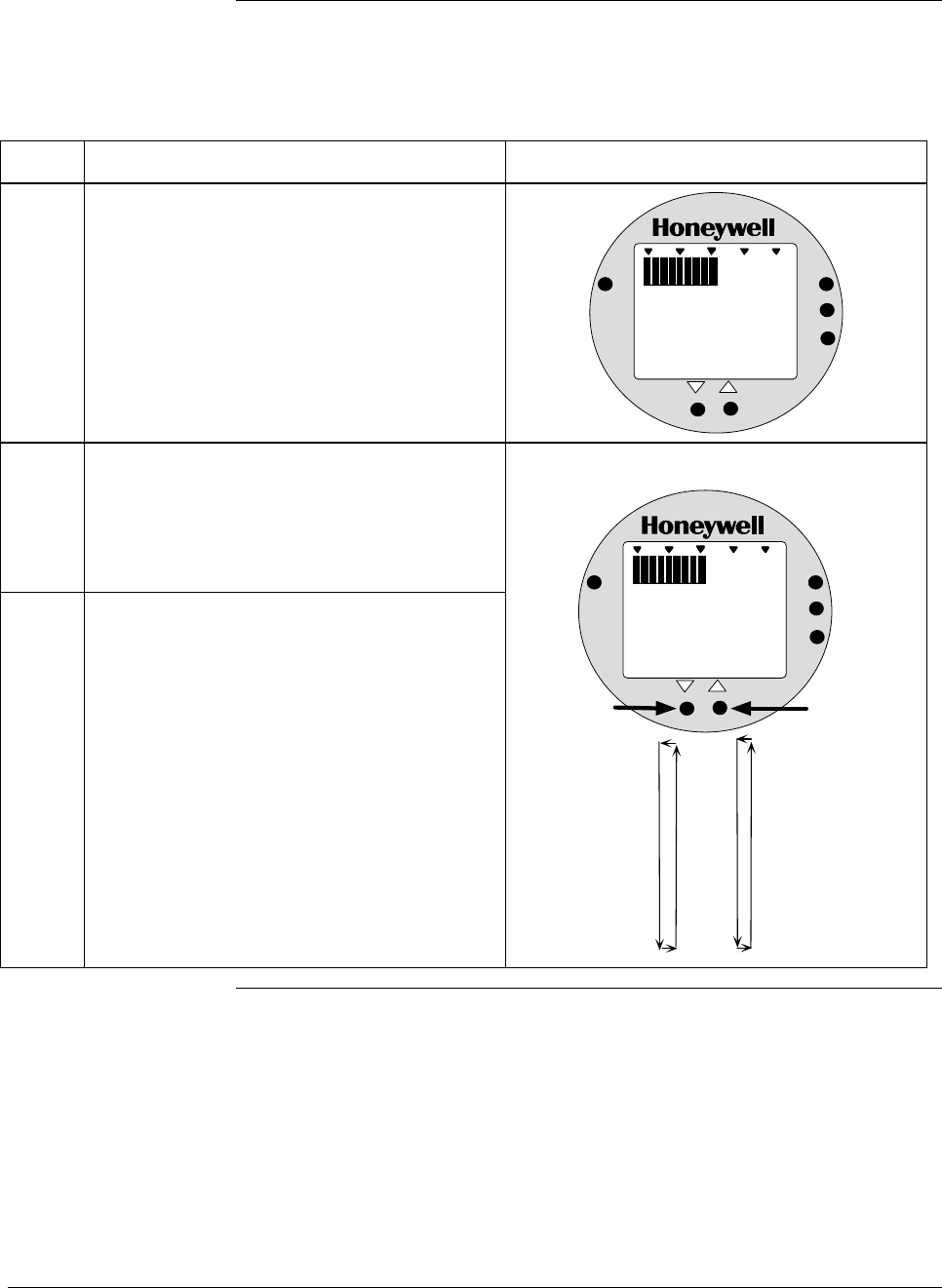
6/08 ST 3000 Release 300 and SFC Model STS103 User’s Manual 117
6.12 Configuring Smart Meter Using Pushbuttons, Continued
Setting Upper Display
Values, continued
Table 36 Setting Upper Display Value for Smart Meter Display, continued
Step Action Meter Display
8 Press UPPER VALUE button to lock-in
second digit and activate next active digit.
Readout now displays next active digit which
will be zero unless upper value was set
before.
%
1000
ANALOG
UPPER
VALUE
UNITS
LOWER
VALUE
SET
VAR
SEL.
K
0990
9
Press Increase σ button to select the next
available digit value or Decrease τ button to
select the previous digit value.
Repeat this action until desired value is on
display – use 9 for example purposes.
10 Press UPPER VALUE button to lock-in third
digit and activate next active digit.
Readout now displays next active digit which
will be BLANK unless upper value was set to
1 before.
Next digit value setting is set to 9.
%
1000
ANALOG
UPPER
VALUE
UNITS
LOWER
VALUE
SET
VAR
SEL.
K
9990
0
1
2
3
4
5
6
7
8
9
Press and hold to
scroll forward
through values
Press and hold to
scroll backward
through values
Continued on next page
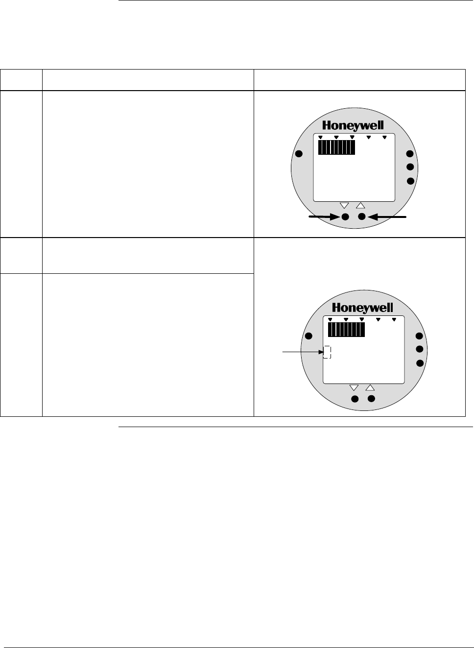
ST 3000 Release 300 and SFC Model STS103 User’s Manual 6/08
118
6.12 Configuring Smart Meter Using Pushbuttons, Continued
Setting Upper Display
Values, continued
Table 36 Setting Upper Display Value for Smart Meter Display, continued
Step Action Meter Display
11 Press Increase σ button to set digit to 1 or
Decrease τ button to set it to BLANK. “1” digit value setting is set to 1.
%
1000
ANALOG
UPPER
VALUE
UNITS
LOWER
VALUE
SET
VAR
SEL.
K
9990
Press to set "1"
digit as 1
Press to set "1"
digit as BLANK
1
12
Press UPPER VALUE button to lock-in “1”
digit and activate sign segment.
13 Press Increase σ button to set sign segment
to minus sign for negative values or Decrease
τ button to set it to BLANK. for positive values.
Readout now displays sign segment which
will be BLANK for positive values unless
upper value was set for negative (–) values
before.
%
1000
ANALOG
UPPER
VALUE
UNITS
LOWER
VALUE
SET
VAR
SEL.
K
99901
Sign segment
is BLANK for
positive values
and minus sign
for negative
values
Continued on next page
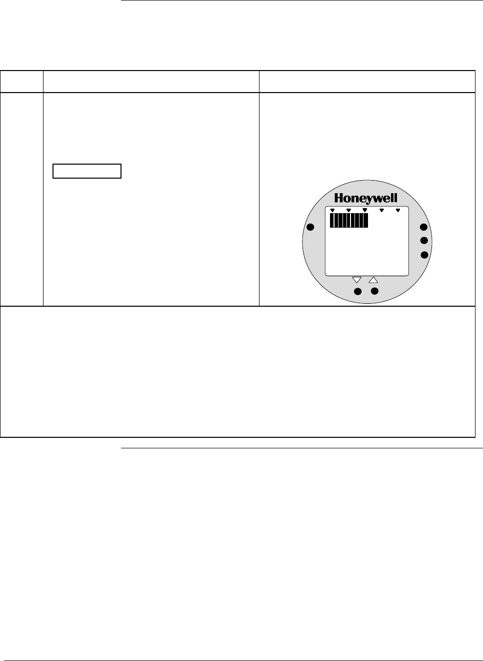
6/08 ST 3000 Release 300 and SFC Model STS103 User’s Manual 119
6.12 Configuring Smart Meter Using Pushbuttons, Continued
Setting Upper Display
Values, continued
Table 36 Setting Upper Display Value for Smart Meter Display, continued
Step Action Meter Display
14 Press UPPER VALUE button to lock in
current settings as upper display value and
return to previous display. Upper display limit
setting is now complete.
ATTENTION For CUSTOM unit in
transmitter with LINEAR output, you must set
both lower and upper display limits for values
to take effect. If you let either the lower or
upper display limit time out (after 30 seconds),
the meter discards both newly set values and
reverts back to the previously set values.
Display goes blank for a 1/2 second and
returns to display readout equal to 50%
output.
In this example, readout is 9, 990,000
CUSTOM unit for 50% display range of 0 to
19,990,000 CUSTOM for transmitter with
LINEAR output.
%
1000
ANALOG
UPPER
VALUE
UNITS
LOWER
VALUE
SET
VAR
SEL.
K
9990
• If you have not yet set the lower display limit value for CUSTOM unit in a transmitter configured for
LINEAR output mode, the meter automatically enters the lower display setting function after it
displays previously set value, if applicable. Go to Table 35, Step 3.
• If you have already set the lower display limit value, this completes the lower and upper display limits
setting function for CUSTOM unit in transmitter configured for LINEAR output mode. Meter returns to
normal operation as shown in example display below.
• If you have just set the upper display limit for Flow unit or CUSTOM unit in transmitter configured for
SQUARE ROOT output mode, this completes the limit setting function. Meter returns to normal
operation as shown in example display below.
Continued on next page
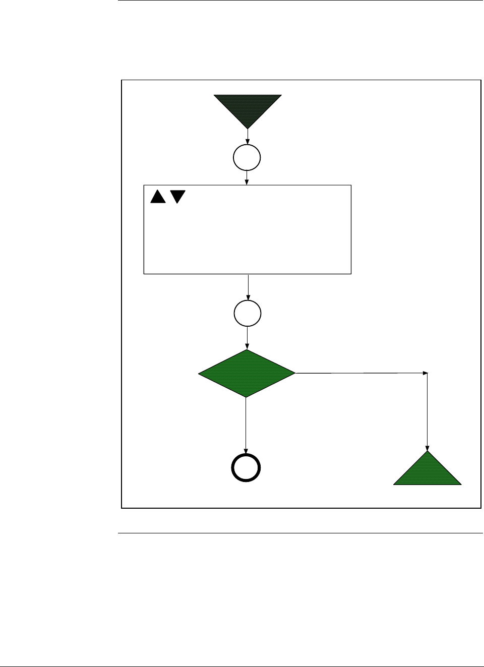
ST 3000 Release 300 and SFC Model STS103 User’s Manual 6/08
120
6.12 Configuring Smart Meter Using Pushbuttons, Continued
Button Pushing
Summary Figure 36 shows button pushing summary for the smart meter display to
select the engineering units.
Figure 36 Button Pushing Summary for Selecting Engineering Units.
Units
Set
Select Unit: EU0 = %
EU1 = inH
2
O
EU2 = mmHg
EU3 = PSI
EU4 = KPa
EU5 = MPa
EU6 = mbar
EU7 = bar
EU8 = g/cm
2
EU9 = Kg/cm
2
EUA = mmH
2
O
EUB = inHg
EUC = mH
2
O
EUD = GPM
EUE = GPH
EUF = Custom
Is
EUD, EUE or EUF
selected?
Start
NO
YES
End
Units
Set
A
Continued on next page
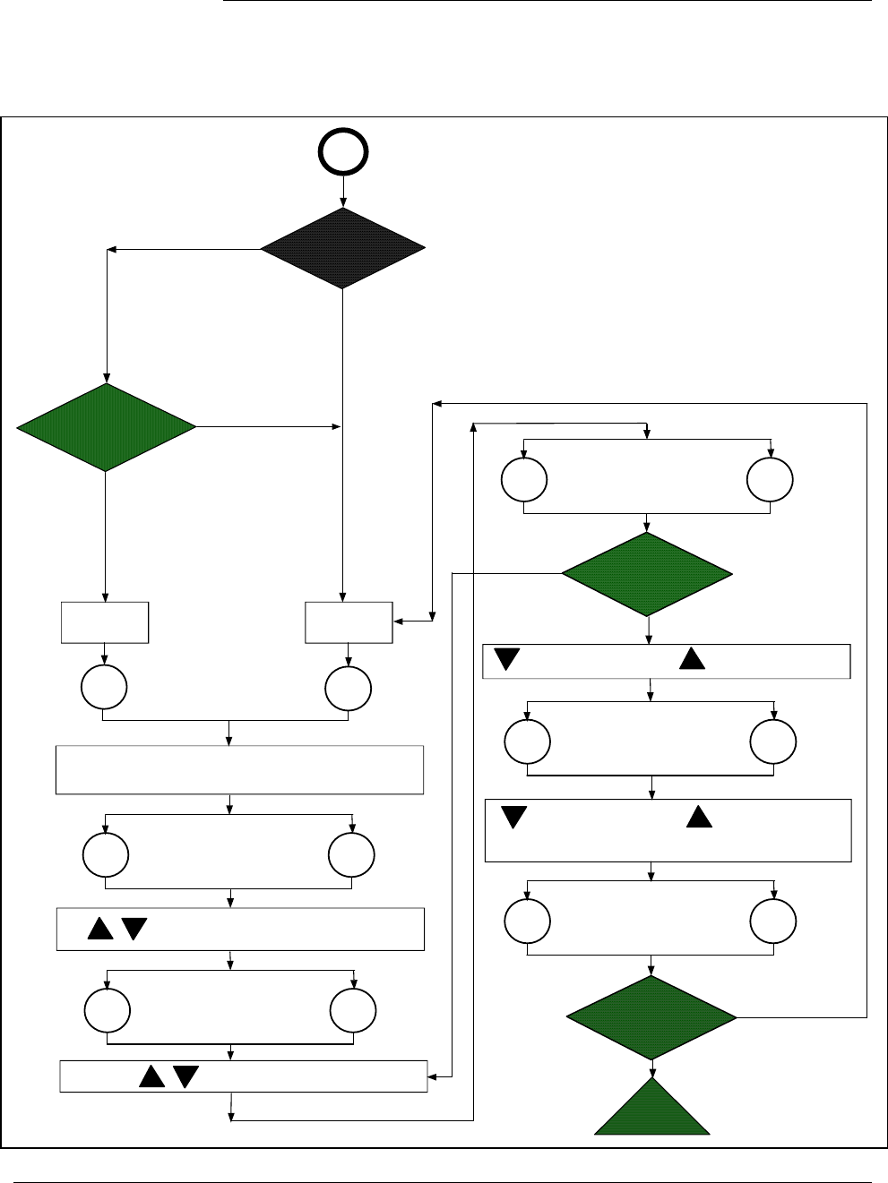
6/08 ST 3000 Release 300 and SFC Model STS103 User’s Manual 121
6.12 Configuring Smart Meter Using Pushbuttons, Continued
Button Pushing
Summary Figure 37 shows button pushing summary for the smart meter display to
set the lower and upper display limits.
Figure 37 Button Pushing Summary for Setting Lower and Upper Display Limits.
Is
EUF in
LINEAR
or
SQUARE ROOT
mode?
Is
EUD or EUE
selected?
YES
NO
LINEAR
Mode
SQUARE ROOT
Mode
Set active digit value 0 to 9
Lower
Value Upper
Value
Set magnitude range: 19.99, 199.9, 1999,
19.99K, 199.9K, 1999K, 19990K
If display limit was previously set, KNOWN VALUE indicator lights
and set value flashes in display.(Note that lower display limit is
fixed at zero (0.00) for units in SQUARE ROOT mode.)
Lower
Value Upper
Value
Set 1 digit to BLANK Set 1 digit to 1
Set sign segment
BLANK for positive
values
Set sign segment
to minus sign (-) for
negative values
Are both lower and
upper display limit
values set?
Yes
No
Is "1" digit active?
Yes
No
Set Lower
Range Value
Set Upper
Range Value
Lower
Value Upper
Value
Lower
Value Upper
Value
Lower
Value Upper
Value
Lower
Value Upper
Value
End
A
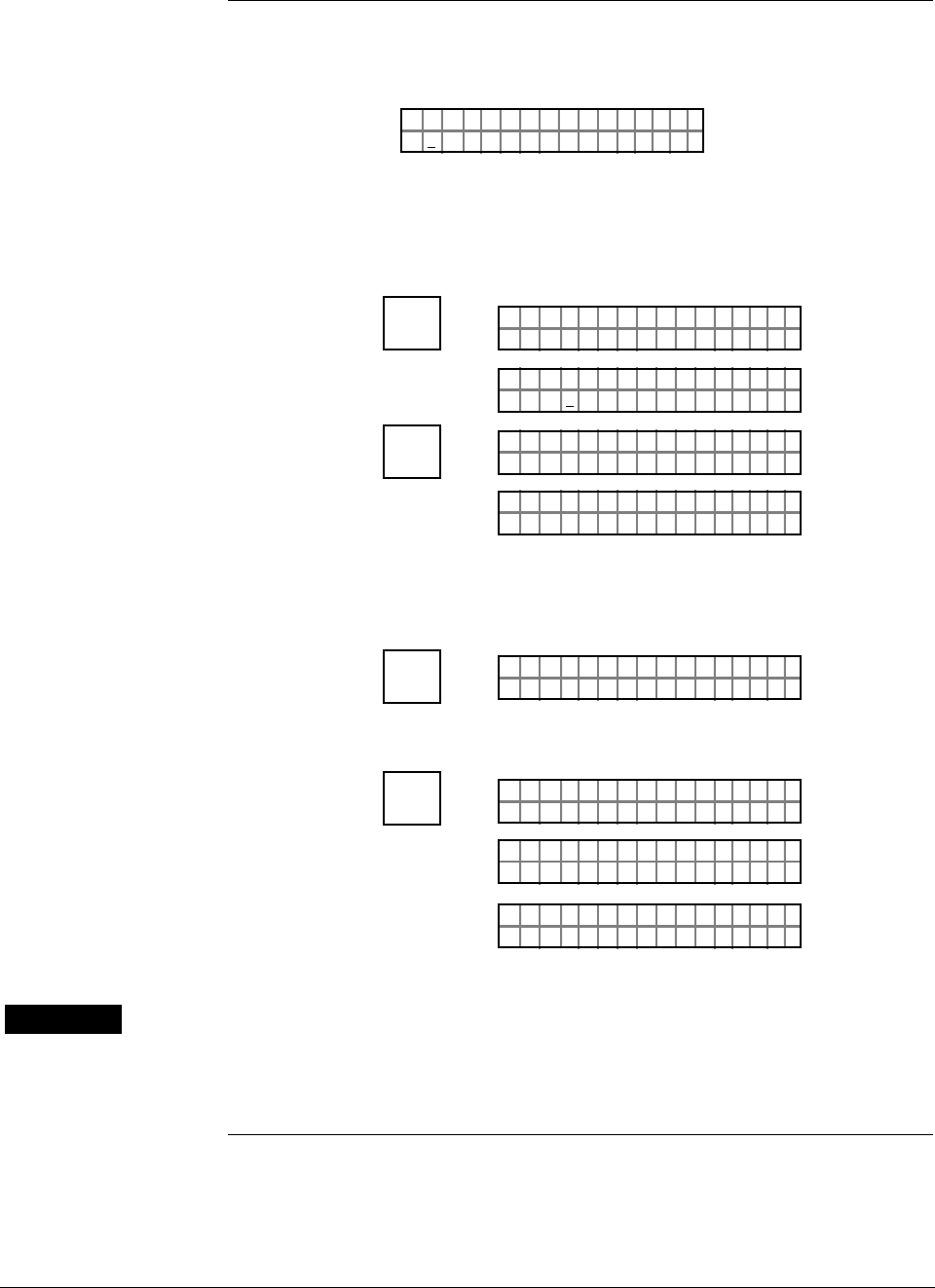
ST 3000 Release 300 and SFC Model STS103 User’s Manual 6/08
122
6.13 Disconnecting SFC
Considerations • Be sure a “#” character does not appear on the right side of the SFC
display indicating that the transmitter may be in its current output
mode, or the SFC has detected a non-critical status condition.
– Example:
PTLRV
nH
3011
i
1
25 .ØØØØ O
#
If the # character is on the display, press the [OUTPUT] key and then the
[CLR] key to remove the transmitter from the current output mode, or
press the [STAT] key to check the operating status of the transmitter.
– Example:
INPUT
J
OUT-
PUT
PTOUT 301 11P#
FC WOSING.RK . .
PTOU T
%
30111
5.ØØØ
P#
CLR
(NO)
PTOUT 301 11P#
FC WOSING.RK . .
LIN DP
.Y. .RE AD
T 011P3
• Be sure to store all changes in the transmitters non-volatile memory by
pressing the [SHIFT] key and then the [ENTER] key.
– Example:
^
SHIFT
LIN DP
FT–SHI
T 011P3
NON-VOL
ENTER
(Yes)
PTL I N 3011DP
FC WOSING.RK . .
PTL I N 301 1
NO VO ATLNDA TA ILE
DP
LIN DP
.Y. .RE AD
T 011P3
WARNING • Be sure to disconnect the SFC leads from the transmitter before
unplugging them from the SFC.
• Be sure the SFC is disconnected from a transmitter in the analog
mode before returning the loop to the automatic operating mode.

6/08 ST 3000 Release 300 and SFC Model STS103 User’s Manual 123
Section 7 —Startup
7.1 Introduction
Section Contents This section includes these topics
Section Topic See Page
7.1 Introduction ................................................................................123
7.2 Startup Tasks .............................................................................124
7.3 Running Analog Output Check...................................................125
7.4 Flow Measurement with DP Transmitter ....................................128
7.5 Pressure Measurement with DP Transmitter .............................131
7.6 Liquid Level Measurement - Vented Tank..................................133
7.7 Liquid Level Measurement - Pressurized Tank..........................136
7.8 Pressure or Liquid Level Measurement with GP Transmitter.....140
7.9 Pressure or Liquid Level Measurement with
Flush Mount Transmitter ............................................................144
7.10 Pressure Measurement with AP Transmitter..............................145
7.11 Liquid Level Measurement with DP Transmitter with
Remote Seals.............................................................................147
About this section This section identifies typical startup tasks associated with several
generic pressure measurement applications. It also includes the
procedure for running an optional analog output check.

ST 3000 Release 300 and SFC Model STS103 User’s Manual 6/08
124
7.2 Startup Tasks
About startup Once you have installed and configured a transmitter, you are ready to
start up the process loop. Startup usually includes
• Applying process pressure to the transmitter,
• Checking zero input, and
• Reading input and output.
You can also run an optional output check to “ring out” an analog loop
prior to startup.
Procedure reference The actual steps in a startup procedure will vary based on the type of
transmitter and the measurement application. In general, we use the SFC
to check the transmitter’s input and output under static process
conditions, and make adjustments as required before putting the
transmitter into full operation with the running process.
Choose the applicable procedure to reference in this section from Table
37 based on your type of transmitter and the measurement application.
The reference procedure will give you some idea of the typical tasks
associated with starting up a transmitter in a given application.
Table 37 Startup Procedure Reference
IF transmitter type
is . . . AND application is . . . THEN reference
procedure in section . . .
Differential
Pressure (DP) Flow Measurement 7.4
Pressure Measurement 7.5
Liquid Level Measurement
for Vented Tank with Dry
Reference Leg*
7.6
Liquid Level Measurement
for Pressurized Tank with
Liquid-Filled Reference Leg*
7.7
Gauge Pressure
(GP) Pressure or Liquid Level
Measurement** 7.8
Flush Mount Pressure or Liquid Level
Measurement 7.9
Absolute Pressure
(AP) Pressure Measurement** 7.10
DP with Remote
Seals Liquid Level Measurement 7.11
* These applications also apply for flange-mounted liquid level type transmitters that
are usually mounted directly to a flange at the zero level of the tank.
** These applications also apply for GP and AP type transmitters equipped with remote
seals. However, you can only confirm that input pressure correlates with transmitter
output in processes using remote seal connections.
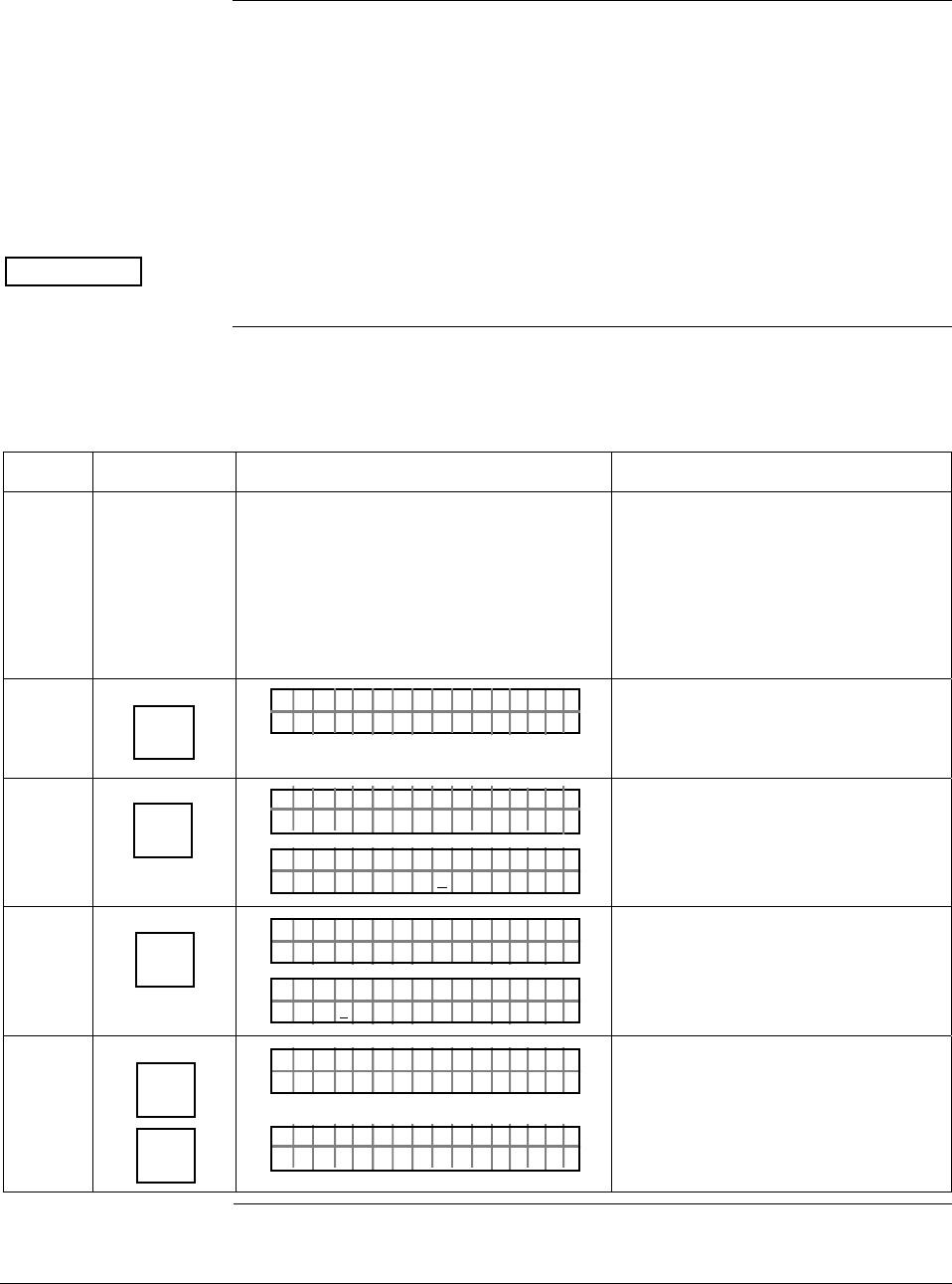
6/08 ST 3000 Release 300 and SFC Model STS103 User’s Manual 125
7.3 Running Analog Output Check
Background You can put the transmitter into a constant-current source mode to
checkout other instruments in the loop such as recorders, controllers,
and positioners. Using the SFC, you can tell the transmitter to change its
output to any value between 0 (4mA) and 100 (20mA) percent and
maintain that output. This makes it easy to verify loop operation through
the accurate simulation of transmitter output signals before bringing the
loop on line. Note that the constant-current source mode is also referred
to as the output mode.
ATTENTION The transmitter does not measure the input or update the output while it
is in the constant-current source mode.
Procedure The procedure in Table 38 outlines the steps for using a transmitter in its
output mode and clearing the output mode.
Table 38 Using Transmitter in Constant-Current Source Mode
Step Press Key Read Display or Action Description
1 Connect SFC across loop wiring and
turn it on. If possible, locate SFC where
you can also view receiver instrument in
loop. If you want to verify loop
calibration, connect a precision
milliammeter or a voltmeter across a 250
ohm resistor in loop to compare
readings.
See Figure 38 for sample SFC and
meter connections in a typical
analog loop with a differential
pressure type transmitter.
2 DE READ
A
ID
TA ON.G
?TRIPS SECURED?
Be sure any switches that may trip
alarms or interlocks associated with
analog loop are secured or turned
off.
3 NON-VOL
ENTER
(Yes)
TA ON.G
SFC WORK ING.. .
LIN AG NO.DP T
PT3Ø11
Confirm that “TRIPS” are secured
and establish communications with
sample transmitter PT 3011
4 INPUT
J
OUT-
PUT
PTL I N 3011DP
FC WOSING.RK . .
PTOU T
%
30111
3.24
P
Display shows current transmitter
output level and it will update every
six seconds. Be sure to time your
next key press with an updated
display.
5 X
3
SW VER
Z
0
PTOU T
%
30111
3_
P
PTOU T
%
30111
3_Ø
P
Key in 30% for desired output signal
level of 8.8 mA (2.2V).
Continued on next page
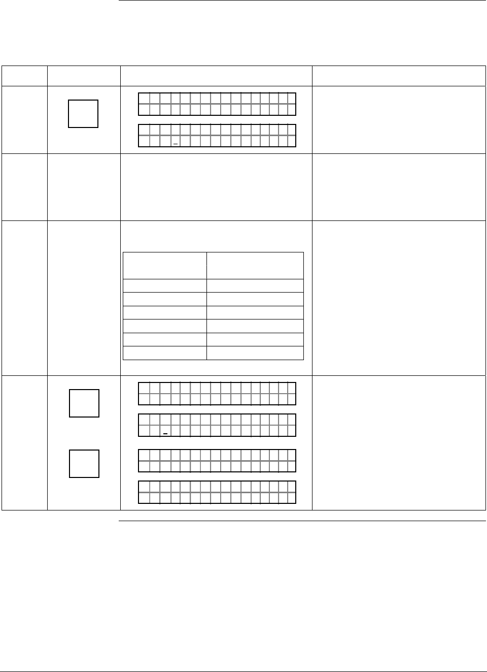
ST 3000 Release 300 and SFC Model STS103 User’s Manual 6/08
126
7.3 Running Analog Output Check, Continued
Procedure, continued
Table 38 Using Transmitter in Constant-Current Source Mode, continued
Step Press Key Read Display or Action Description
6 NON-VOL
ENTER
(Yes)
PTOUT 301 11P#
FC WOSING.RK . .
PTOU T
%
30111
3.ØØØ
P#
Output signal is set at 30% (8.8
mA/2.2 V). A “#” character appears
on right side of display to remind
you that transmitter is in its output
mode.
7 Check that receiving device indication is
at its 30% point. If applicable, check that
milliammeter reading is 8.8 mA or
voltmeter reading is 2.2 V across 250
ohm resistor.
If indication is inaccurate, check
calibration of receiving device.
8 Repeat Steps 5 and 6 to check
indications at these output percentages.
If output is … Then meter
reads…
0% 4.0mA/1.0V
25% 8.0mA/2V
50% 12.0mA/3V
60% 13.6mA/3.4V
80% 16.8mA/4.2V
100% 20.0mA/5.0V
Use transmitter output as a
calibration input source for
instruments in loop.
9 INPUT
J
OUT-
PUT
CLR
(NO)
PTOUT 301 11P#
FC WOSING.RK . .
%Ø.ØØ
PTOUT 301 11P#
1
PTOUT 301 11P#
FC WOSING.RK . .
LIN DP
.Y. .RE AD
T 011P3
Exit constant-current source mode.
Check that # character disappears
from right side of display since
transmitter is no longer in output
mode.
Continued on next page
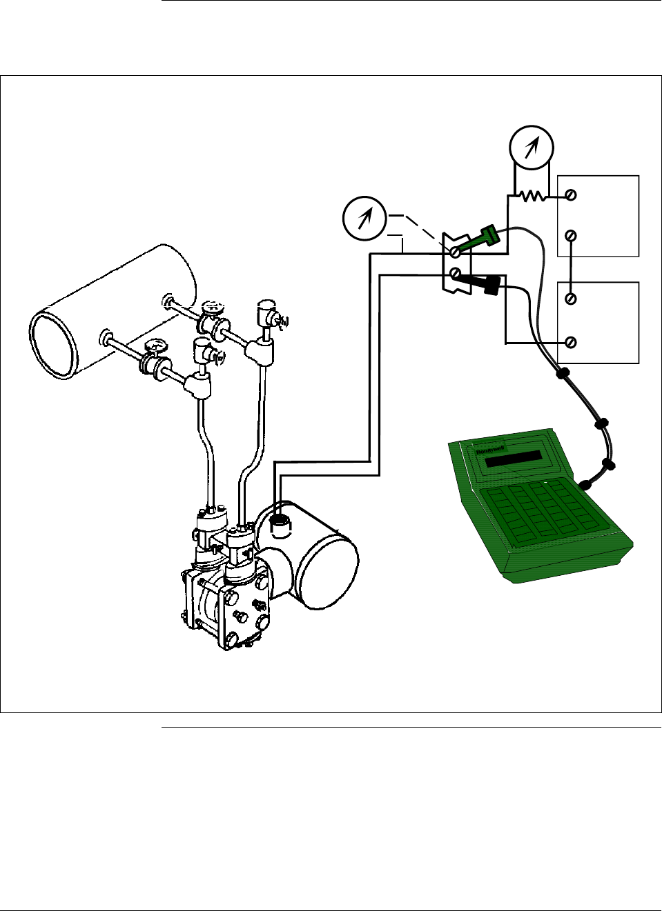
6/08 ST 3000 Release 300 and SFC Model STS103 User’s Manual 127
7.3 Running Analog Output Check, Continued
Procedure, continued
Figure 38 Typical SFC and Meter Connections for Constant-Current Source Mode.
-
+
-
+
+
-
250 Ω
Voltmeter
SFC
Power
Supply
Field
Terminals
Receiver
Red +
Black -
Precision
Milliammeter
Differential Pressure
Type Transmitter
HP
LP
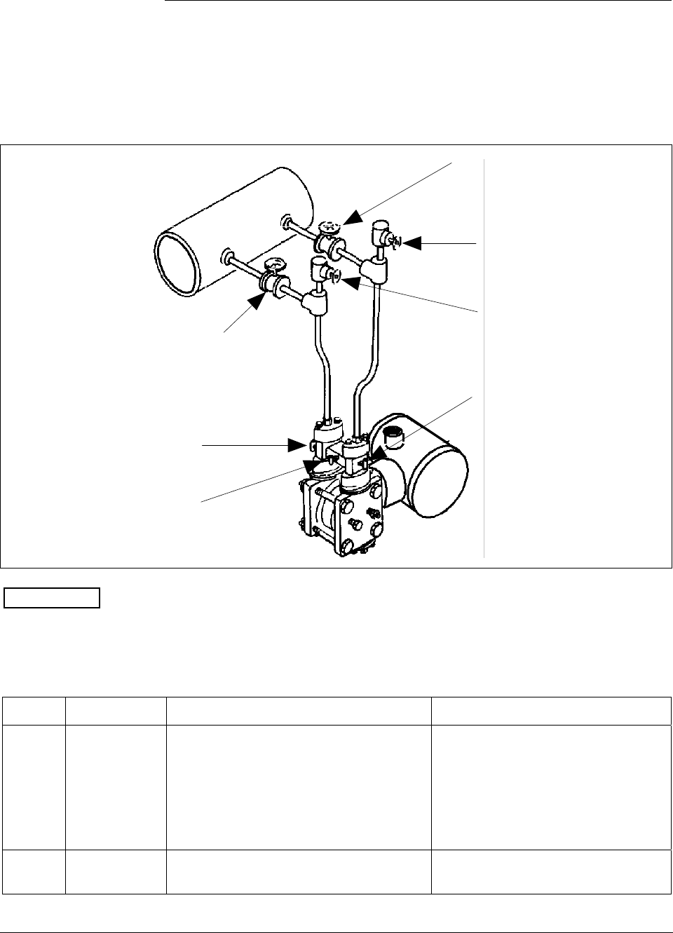
ST 3000 Release 300 and SFC Model STS103 User’s Manual 6/08
128
7.4 Flow Measurement with DP Transmitter
Procedure The procedure in Table 39 outlines the steps for starting up a differential
pressure (DP) type transmitter in a flow measurement application. Refer
to Figure 39 for the piping arrangement identification and Figure 38 for
typical SFC and meter connections.
Figure 39 Typical Piping Arrangement for Flow Measurement with DP Type Transmitter
HP
LP
LP Blockoff
Plug G
Plug F
Valve A
Valve B
Valve C
HP Blockoff
Differential
Pressure
Transmitter
ATTENTION For the procedure in Table 39, we are assuming that all the valves on the
three-valve manifold and the block-off valves were closed at
installation.
Table 39 Starting Up DP Transmitter for Flow Measurement With SFC
Step Press Key Read Display or Action Description
1 Connect SFC across loop wiring and
turn it on. If possible, locate SFC where
you can also view receiver instrument in
loop. If you want to verify transmitter
output, connect a precision milliammeter
or voltmeter in loop to compare
readings.
See Figure 38 for sample SFC and
meter connections in a typical
analog loop with a differential
pressure type transmitter.
2 Open equalizer valve C. See Figure 39 for sample piping
arrangement.
Continued on next page
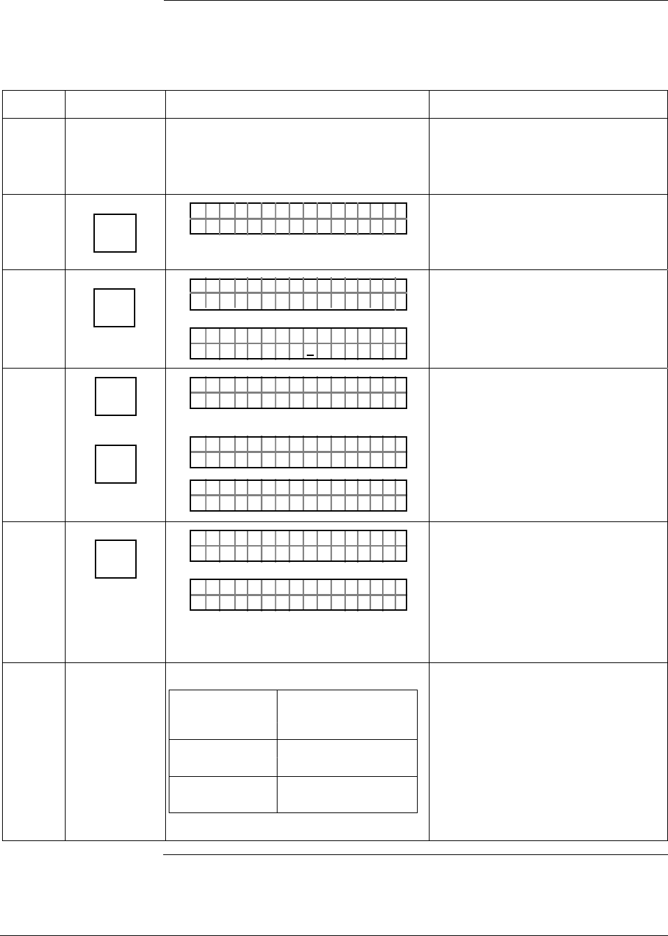
6/08 ST 3000 Release 300 and SFC Model STS103 User’s Manual 129
7.4 Flow Measurement with DP Transmitter, Continued
Procedure, continued
Table 39 Starting Up DP Transmitter for Flow Measurement With SFC, continued
Step Press Key Read Display or Action Description
3 Open valves A and HP block-off to make
differential pressure zero (0) by applying
same pressure to both sides of meter
body.
Allow system to stabilize at full static
pressure - zero differential.
4 DE READ
A
ID
TA ON.G
?TRIPS SECURED?
Be sure any switches that may trip
alarms or interlocks associated with
analog loop are secured or turned
off.
5 NON-VOL
ENTER
(Yes)
TA ON.G
SFC WORK ING.. .
LIN AG NO.DP T
PT3Ø11
Confirm that “TRIPS” are secured
and establish communications with
sample transmitter PT 3011
6 ^
SHIFT
INPUT
J
OUT-
PUT
LIN AG NO.DP T
FT–SHI
PTINP 3Ø111UT
FC WOSING
.
RK . .
PTINP 3Ø111UT
.9 351Ø"H2O_39F
Initiate shift key selection.
Read applied input pressure.
Reading is updated every six
seconds.
7 INPUT
J
OUT-
PUT
PTOU T 3Ø1 11P
FC WOSING.RK . .
%Ø. Ø
PTOU T 3Ø1 11P
Call up output for display.
Read 0% output on display for
corresponding zero input pressure.
For analog transmission, check that
milliammeter reading is 4 mA (0%)
output.
8
If SFC and Then…
milliammeter
readings…
are exactly go to Step 11.
zero (4mA)
are not exactly go to Step 9.
zero (4mA)
Continued on next page
ST 3000 Release 300 and SFC Model STS103 User’s Manual 6/08
130
7.4 Flow Measurement with DP Transmitter, Continued
Procedure, continued
Table 39 Starting Up DP Transmitter for Flow Measurement With SFC, continued
Step Press Key Read Display or Action Description
9 ^
SHIFT
INPUT
J
OUT-
PUT
RESET
K
COR-
RECT
NON-VOL
ENTER
(Yes)
PTOU T 3Ø1 11P
FT–SH I
PTINP 3Ø111UT
FC WOSING
.
RK . .
PTINP 3Ø111UT
.9 351Ø"H2O_39F
PTINP 3Ø111UT
ZRO NPUTEI ?
PTINP 3Ø111UT
FC WOSING
.
RK . .
PTINP 3Ø111UT
ZROENPUTIED
PTINP 3Ø111UT
.Ø Ø42Ø"H2O_39F
Initiate shift key selection.
Read applied input pressure.
Prompt asks if the applied input
pressure equals zero input. If it is
zero input, go to next keystroke. If it
is not, press [CLR] key to exit
function and try again.
Zero input is set equal to applied
input pressure.
10 Repeat Steps 6 to 8.
11 Close equalizer valve C.
12 Open valve B and LP block-off valve to
begin measuring process differential
pressure.
13 Take SFC and milliammeter readings to
check that output signal does
correspond to applied input pressure. If
readings don’t correspond, check that
transmitter has been installed correctly.
If applicable, blow down piping to be
sure no foreign matter is entrapped in it.
Check SFC and milliammeter readings
again. If readings are still not correct,
verify transmitter’s configuration data
and change its range setting if needed.
14 Remove SFC and milliammeter from
loop.
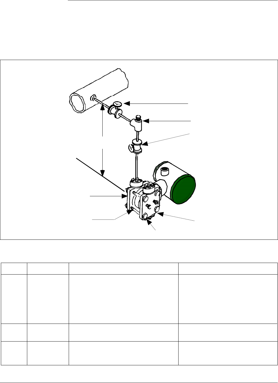
6/08 ST 3000 Release 300 and SFC Model STS103 User’s Manual 131
7.5 Pressure Measurement with DP Transmitter
Procedure The procedure in Table 40outlines the steps for starting up a differential
pressure (DP) type transmitter in a pressure measurement application.
Refer to Figure 40 for the piping arrangement identification and Figure
38 for typical SFC and meter connections.
Figure 40 Typical Piping Arrangement for Pressure Measurement with DP Type Transmitter.
Valve D
Valve A
Plug C
LP Vent
HP Vent
HP side
Differential
Pressure
Transmitter
LP side
H
Table 40 Starting Up DP Transmitter for Pressure Measurement With SFC
Step Press Key Read Display or Action Description
1 Connect SFC across loop wiring and
turn it on. If possible, locate SFC where
you can also view receiver instrument in
loop. If you want to verify transmitter
output, connect a precision milliammeter
or voltmeter in loop to compare
readings.
See Figure 38 for sample SFC and
meter connections in a typical
analog loop with a differential
pressure type transmitter.
2 Close valve D. See Figure 40 for sample piping
arrangement.
3 Open plug C and valve A to apply head
pressure H to meter body. Then, open
LP vent.
Allow system to stabilize at head
pressure.
Continued on next page
ST 3000 Release 300 and SFC Model STS103 User’s Manual 6/08
132
7.5 Pressure Measurement with DP Transmitter, Continued
Procedure, continued
Table 40 Starting Up DP Transmitter for Pressure Measurement With SFC, continued
Step Press Key Read Display or Action Description
4 DE READ
A
ID
TA ON.G
?TRIPS SECURED?
Be sure any switches that may trip
alarms or interlocks associated with
analog loop are secured or turned
off.
5 NON-VOL
ENTER
(Yes)
TA ON.G
SFC WORK ING.. .
LIN AG NO.DP T
PT3Ø11
Confirm that “TRIPS” are secured
and establish communications with
sample transmitter PT 3011
6 E
LRV
0%
SET
G
NON-VOL
ENTER
(Yes)
PTLRV 3Ø111
Ø. ØØØØ PS I
PTLRV
RV
3Ø1 1
L
1
?SET
PTLRV 3Ø111
1. 8315 PS I
Read present LRV setting.
Prompt asks if you want to set LRV
to applied pressure.
LRV is set to applied head pressure.
7 INPUT
J
OUT-
PUT
PTOU T 3Ø1 11P
FC WOSING.RK . .
%.Ø
PTOU T 3Ø1 11P
ØØØ
Call up output for display.
Read 0% output on display for
corresponding zero line pressure
plus head pressure H. For analog
transmission, check that
milliammeter reading is 4 mA (0%)
output.
8 Close plug C
9 Open valve D to begin measuring
process line pressure.
10 Take SFC and milliammeter readings to
check that output signal does
correspond to applied line pressure. If
readings don’t correspond, check that
transmitter has been installed correctly.
If applicable, blow down piping to be
sure no foreign matter is entrapped in it.
Check SFC and milliammeter readings
again. If readings are still not correct,
verify transmitter’s configuration data
and change its range setting if needed.
11 Remove SFC and milliammeter from
loop.
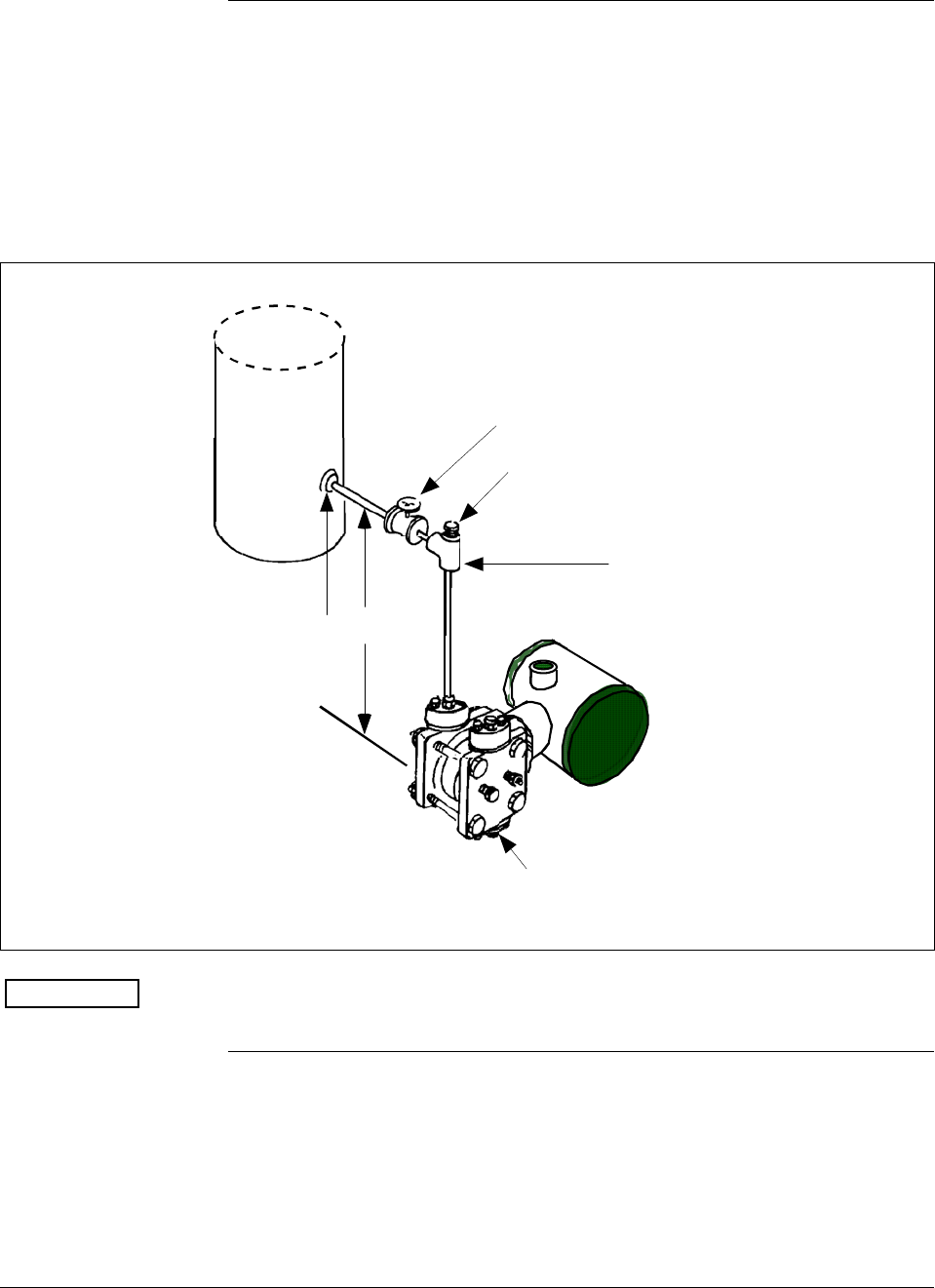
6/08 ST 3000 Release 300 and SFC Model STS103 User’s Manual 133
7.6 Liquid Level Measurement - Vented Tank
Procedure The procedure in Table 41 outlines the steps for starting up a differential
pressure (DP) type transmitter in a liquid level measurement application
for a vented tank with a dry reference leg. Refer to Figure 41 for the
piping arrangement identification and Figure 38 for typical SFC and
meter connections.
Figure 41 Typical Piping Arrangement for Liquid Level Measurement with DP Type
Transmitter and Vented Tank
Valve A
Plug C
LP Vent
Tap location at
the minimum level
to be measured
To HP connection
on meter body
Differential
Pressure
Transmitter
H
ATTENTION For the procedure in Table 41, we are assuming that the tank is empty
and the piping arrangement includes a block-off valve.
Continued on next page

ST 3000 Release 300 and SFC Model STS103 User’s Manual 6/08
134
7.6 Liquid Level Measurement - Vented Tank, Continued
Procedure, continued
Table 41 Starting Up DP Transmitter for Liquid Level Measurement in Vented Tank
Step Press Key Read Display or Action Description
1 Connect SFC across loop wiring and
turn it on. If possible, locate SFC where
you can also view receiver instrument in
loop. If you want to verify transmitter
output, connect a precision milliammeter
or voltmeter in loop to compare
readings.
See Figure 38 for sample SFC and
meter connections in a typical
analog loop with a differential
pressure type transmitter.
2 Close block-off valve A. See Figure 41 for sample piping
arrangement.
3 Open plug C. Allow system to stabilize at head
pressure.
4 DE READ
A
ID
TA ON.G
?TRIPS SECURED?
Be sure any switches that may trip
alarms or interlocks associated with
analog loop are secured or turned
off.
5 NON-VOL
ENTER
(Yes)
TA ON.G
SFC WORK ING.. .
LIN AG NO.DP T
PT3Ø11
Confirm that “TRIPS” are secured
and establish communications with
sample transmitter PT 3011
6 E
LRV
0%
SET
G
NON-VOL
ENTER
(Yes)
PTLRV 3Ø111
Ø. ØØØØ "H2O
_39F
PTLRV
RV
3Ø1 1
L
1
?SET
PTLRV 3Ø111
1.Ø 624 "H2O
_39F
Read present LRV setting.
Prompt asks if you want to set LRV
to applied pressure.
LRV is set to applied head pressure.
7 INPUT
J
OUT-
PUT
PTOU T 3Ø1 11P
FC WOSING.RK . .
%.Ø
PTOU T 3Ø1 11P
ØØØ
Call up output for display.
Read 0% output on display for
corresponding empty tank pressure
plus head pressure H. For analog
transmission, check that
milliammeter reading is 4 mA (0%)
output.
8 Close plug C
Continued on next page

6/08 ST 3000 Release 300 and SFC Model STS103 User’s Manual 135
7.6 Liquid Level Measurement - Vented Tank, Continued
Procedure, continued
Table 38 Starting Up DP Transmitter for Liquid Level Measurement in Vented Tank,
Continued
Step Press Key Read Display or Action Description
9 Open valve A to begin measuring tank
pressure. Leave LP side vented to
atmosphere.
ATTENTION If the URV was
calculated on the approximate
density of the liquid and/or tank
height, the exact URV can be set by
filling the tank to the desired full
scale level and then setting the URV
through the SFC. See section 6.7 in
this manual for details.
10 Take SFC and milliammeter readings to
check that output signal does
correspond to applied tank level
pressure. If readings don’t correspond,
check that transmitter has been installed
correctly. If applicable, blow down piping
to be sure no foreign matter is entrapped
in it. Check SFC and milliammeter
readings again. If readings are still not
correct, verify transmitter’s configuration
data and change its range setting if
needed.
11 Remove SFC and milliammeter from
loop.
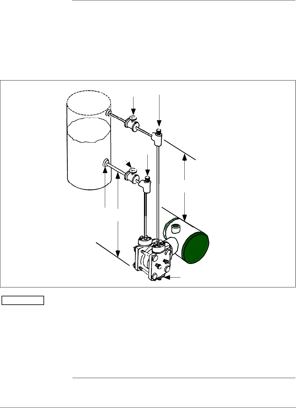
ST 3000 Release 300 and SFC Model STS103 User’s Manual 6/08
136
7.7 Liquid Level Measurement - Pressurized Tank
Procedure The procedure in Table 42 outlines the steps for starting up a differential
pressure (DP) type transmitter in a liquid level measurement application
for a pressurized tank with a liquid-filled (wet) reference leg. Refer to
Figure 42 for the piping arrangement identification and Figure 38 for
typical SFC and meter connections.
Figure 42 Typical Piping Arrangement for Liquid Level Measurement with DP Type
Transmitter and Pressurized Tank
Valve A
Plug C at
zero level
Tap location at the
minimum level to be
measured
HP side of transmitter
Differential
Pressure
Transmitter
h
H1
Valve B Plug D
ATTENTION For the procedure in Table 42, we are assuming that:
• The tank is empty and the reference leg is filled.
• The high pressure (HP) side of the transmitter is connected to the
wet reference leg. Note that the transmitter will work if the HP side
is connected to the bottom of the tank, but not within the guaranteed
accuracy specifications.
• The transmitter is mounted below the zero level of the tank, so “h” is
greater than zero. If h equals zero, plug C is eliminated from the
piping and the LP vent is opened instead.
Continued on next page
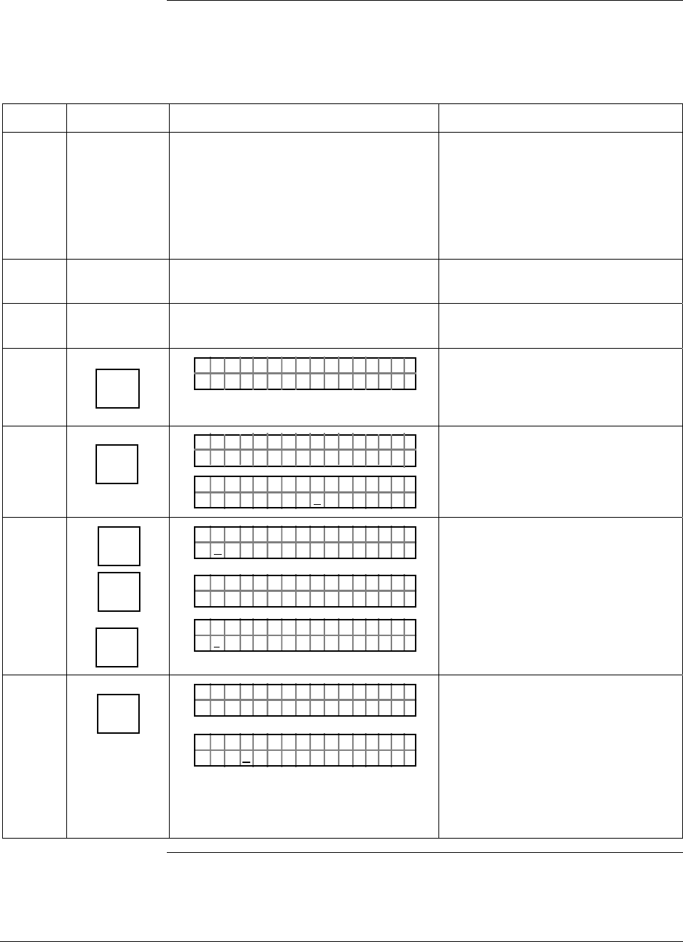
6/08 ST 3000 Release 300 and SFC Model STS103 User’s Manual 137
7.7 Liquid Level Measurement - Pressurized Tank, Continued
Procedure, continued
Table 42 Starting Up DP Transmitter for Liquid Level Measurement in Pressurized Tank
Step Press Key Read Display or Action Description
1 Connect SFC across loop wiring and
turn it on. If possible, locate SFC where
you can also view receiver instrument in
loop. If you want to verify transmitter
output, connect a precision milliammeter
or voltmeter in loop to compare
readings.
See Figure 38 for sample SFC and
meter connections in a typical
analog loop with a differential
pressure type transmitter.
2 Close block-off valves A and B. See Figure 42 for sample piping
arrangement.
3 Open plugs C and D. Allow system to stabilize at head
pressure.
4 DE READ
A
ID
TA ON.G
?TRIPS SECURED?
Be sure any switches that may trip
alarms or interlocks associated with
analog loop are secured or turned
off.
5 NON-VOL
ENTER
(Yes)
TA ON.G
SFC WORK ING.. .
LIN AG NO.DP T
PT3Ø11
Confirm that “TRIPS” are secured
and establish communications with
sample transmitter PT 3011
6 E
LRV
0%
SET
G
NON-VOL
ENTER
(Yes)
PTLRV 3Ø111
Ø. ØØØØ "H2O
_39F
PTLRV
RV
3Ø1 1
L
1
?SET
PTLRV 3Ø111
1.Ø5 32 "H2O
_39F
Read present LRV setting.
Prompt asks if you want to set LRV
to applied pressure.
LRV is set to applied head pressure
H1 times density of liquid in
reference leg.
7 INPUT
J
OUT-
PUT
PTOU T 3Ø1 11P
FC WOSING.RK . .
%.Ø
PTOU T 3Ø1 11P
ØØØ
Call up output for display.
Read 0% output on display for
corresponding empty tank pressure
plus head pressure H1. For analog
transmission, check that
milliammeter reading is 4 mA (0%)
output.
Continued on next page
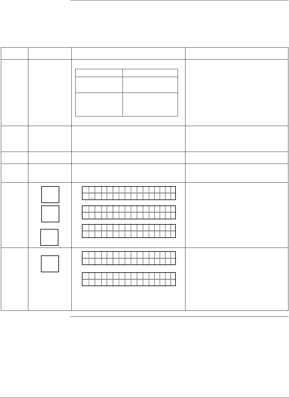
ST 3000 Release 300 and SFC Model STS103 User’s Manual 6/08
138
7.7 Liquid Level Measurement - Pressurized Tank, Continued
Procedure, continued
Table 42 Starting Up DP Transmitter for Liquid Level Measurement in Pressurized Tank,
continued
Step Press Key Read Display or Action Description
8
If you … Then…
can not fill tank go to Step 9.
can fill tank to go to Step 10.
desired full-
scale level
9 Key in URV that is equal to full tank
pressure. See section 6.7 in this manual
for details on keying in a range value.
Go to Step 14.
10 Close plugs C and D.
11 Open valves A and B. Fill tank to desired
full scale level.
12 URV
100%
F
SET
G
NON-VOL
ENTER
(Yes)
PTUR V 3Ø1 11
5.Ø ØØØ "H2 O
_39F
PTUR V
RV
3Ø1 1
U
1
?SET
PTUR V 3Ø1 11
.5 32Ø "H2 O
_39FØ
Read present URV setting.
Prompt asks if you want to set URV
to applied pressure.
URV is set to full tank pressure.
13 INPUT
J
OUT-
PUT
PTOU T 3Ø1 11P
FC WOSING.RK . .
%1Ø
.PTOU T 3Ø1 11P
.ØØØ
Call up output for display, with full
tank pressure applied.
Read 100% output on display for
corresponding full tank pressure.
For analog transmission, check that
milliammeter reading is 20 mA
(100%) output.
Continued on next page

6/08 ST 3000 Release 300 and SFC Model STS103 User’s Manual 139
7.7 Liquid Level Measurement - Pressurized Tank, Continued
Procedure, continued
Table 42 Starting Up DP Transmitter for Liquid Level Measurement in Pressurized Tank,
continued
Step Press Key Read Display or Action Description
14 Take SFC and milliammeter readings to
check that output signal does
correspond to empty and full tank
pressures. If readings don’t correspond,
check that transmitter has been installed
correctly. If applicable, blow down piping
to be sure no foreign matter is entrapped
in it. Check SFC and milliammeter
readings again. If readings are still not
correct, verify transmitter’s configuration
data and change its range setting if
needed.
ATTENTION Ranging the
transmitter in this way makes it
reverse acting.
15 Remove SFC and milliammeter from
loop.
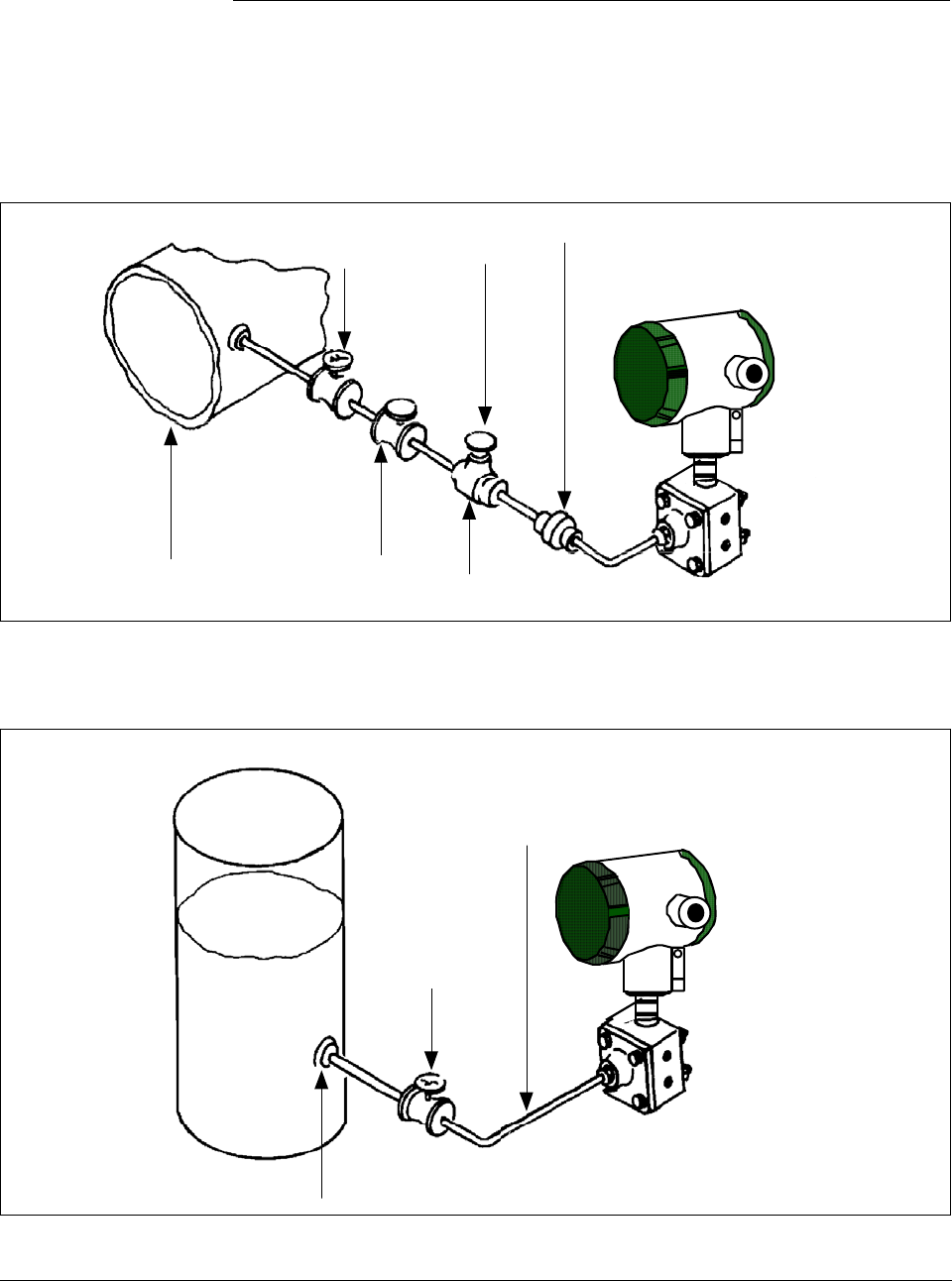
ST 3000 Release 300 and SFC Model STS103 User’s Manual 6/08
140
7.8 Pressure or Liquid Level Measurement with GP
Transmitter
Procedure The procedure in Table 43 outlines the steps for starting up a gauge
pressure (GP) type transmitter in a pressure or liquid level measurement
application. Refer to Figures 43 and 44 for the piping arrangement
identification and Figure 38 for typical SFC and meter connections.
Figure 43 Typical Piping Arrangement for Pressure Measurement with GP Type Transmitter
Block-off
valve no.2
Gauge
Pressure
Transmitter
Union
Block-off
valve no.1 Pipe
Plug
Process Tee connector
Figure 44 Typical Piping Arrangement for Liquid Level Measurement with GP Type
Transmitter
Tap location at the minimum
level to be measured
Gauge
Pressure
Transmitter
Block-off
valve
To Process Head
connection on
meter body
Continued on next page
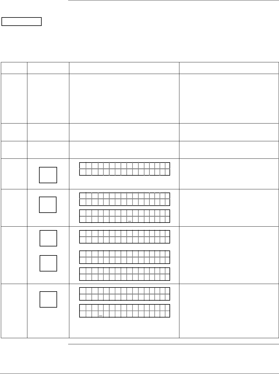
6/08 ST 3000 Release 300 and SFC Model STS103 User’s Manual 141
7.8 Pressure or Liquid Level Measurement with GP
Transmitter, Continued
Procedure, continued
ATTENTION For the procedure in Table 43, we are assuming that piping arrangement
includes a block-off valve and a Tee-connector. If your piping does not
include a Tee-connector, you can only verify that the input and output
readings correlate.
Table 43 Starting Up GP Transmitter for Pressure or Liquid Level Measurement With SFC
Step Press Key Read Display or Action Description
1 Connect SFC across loop wiring and
turn it on. If possible, locate SFC where
you can also view receiver instrument in
loop. If you want to verify transmitter
output, connect a precision milliammeter
or voltmeter in loop to compare
readings.
See Figure 38 for sample SFC and
meter connections in a typical
analog loop with a differential
pressure type transmitter.
2 Close block-off valve. See Figure 43 or 44 for sample
piping arrangement.
3 Remove plug from Tee-connector to
vent it to atmosphere, if applicable. Allow system to stabilize at static
pressure.
4 DE READ
A
ID
TA ON.G
?TRIPS SECURED?
Be sure any switches that may trip
alarms or interlocks associated with
analog loop are secured or turned
off.
5 NON-VOL
ENTER
(Yes)
TA ON.G
SFC WORK ING.. .
LIN AG NO.DP T
PT3Ø11
Confirm that “TRIPS” are secured
and establish communications with
sample transmitter PT 3011
6 ^
SHIFT
INPUT
J
OUT-
PUT
PTOU T 3Ø1 11P
FT–SH I
PTINP 3Ø111UT
FC WOSING
.
RK . .
PTINP 3Ø111UT
.Ø Ø42Ø PSI
Initiate shift key selection.
Read applied input pressure which
should be zero.
7 INPUT
J
OUT-
PUT
PTOU T 3Ø1 11P
FC WOSING.RK . .
%.Ø
PTOU T 3Ø1 11P
ØØØ
Call up output for display.
Read 0% output on display for
corresponding input pressure. For
analog transmission, check that
milliammeter reading is 4 mA (0%)
output.
Continued on next page
ST 3000 Release 300 and SFC Model STS103 User’s Manual 6/08
142
7.8 Pressure or Liquid Level Measurement with GP
Transmitter, Continued
Procedure, continued
Table 43 Starting Up GP Transmitter for Pressure or Liquid Level Measurement With SFC,
continued
Step Press Key Read Display or Action Description
8
If SFC and Then…
milliammeter
readings…
are zero (4mA) go to Step 11.
are not zero go to Step 9.
(4mA) and Tee
-connector is
level with
transmitter
are not zero go to Step 10.
(4mA) and Tee
-connector is
above
transmitter
9 ^
SHIFT
INPUT
J
OUT-
PUT
RESET
K
COR-
RECT
NON-VOL
ENTER
(Yes)
PTOU T 3Ø1 11P
FT–SH I
PTINP 3Ø111UT
FC WOSING
.
RK . .
PTINP 3Ø111UT
.8 54 73PSI
PTINP 3Ø111UT
ZRO NPUTEI ?
PTINP 3Ø111UT
FC WOSING
.
RK . .
PTINP 3Ø111UT
ZROENPUTIED
PTINP 3Ø111UT
.Ø Ø29ØPSI
Initiate shift key selection.
Read applied input pressure.
Prompt asks if the applied input
pressure equals zero input. If it is
zero input, go to next keystroke. If it
is not, press [CLR] key to exit
function and try again.
Zero input is set equal to applied
input pressure. Go to Step 11.
Continued on next page
6/08 ST 3000 Release 300 and SFC Model STS103 User’s Manual 143
7.8 Pressure or Liquid Level Measurement with GP
Transmitter, Continued
Procedure, continued
Table 43 Starting Up GP Transmitter for Pressure or Liquid Level Measurement With SFC,
continued
Step Press Key Read Display or Action Description
10 E
LRV
0%
SET
G
NON-VOL
ENTER
(Yes)
PTLRV 3Ø111
Ø. ØØØØ PS I
PTLRV
RV
3Ø1 1
L
1
?SET
PTLRV 3Ø111
1.Ø ØØ5 PS I
Read present LRV setting.
Prompt asks if you want to set LRV
to applied pressure.
LRV is set to applied pressure.
11 Close Tee-connector and slowly open
block-off valve to apply process
pressure to transmitter.
12 Take SFC and milliammeter readings to
check that output signal does
correspond to zero and full-scale
pressures. If readings don’t correspond,
check that transmitter has been installed
correctly. If applicable, blow down piping
to be sure no foreign matter is entrapped
in it. Check SFC and milliammeter
readings again. If readings are still not
correct, verify transmitter’s configuration
data and change its range setting if
needed.
13 Remove SFC and milliammeter from
loop.
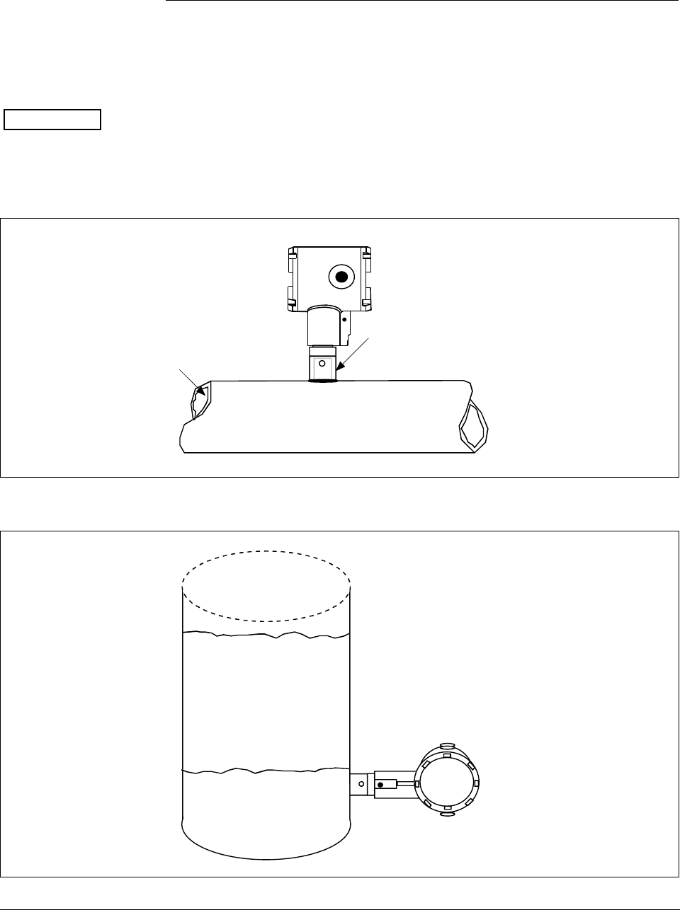
ST 3000 Release 300 and SFC Model STS103 User’s Manual 6/08
144
7.9 Pressure or Liquid Level Measurement with Flush
Mount Transmitter
Procedure The procedure in Table 43 outlines the steps for starting up a gauge
pressure (GP) type transmitter in a pressure or liquid level measurement
application. Refer to Figures 45 and 46 for the flush mount transmitter
arrangement and Figure 38 for typical SFC and meter connections.
ATTENTION For the procedure in Table 43, we are assuming that piping arrangement
includes a block-off valve and a Tee-connector. If your piping does not
include a Tee-connector, you can only verify that the input and output
readings correlate.
Figure 45 Typical Arrangement for Pressure Measurement with Flush Mount Transmitter
Process
Flush Mount
Transmitter
1" Pipe Mount -
316 SS Weld Nipple
(standard option)
Figure 46 Typical Arrangement for Liquid Level Measurement with Flush Mount Transmitter
Flush Mount
Transmitter
Maximum Level
Minimum Level
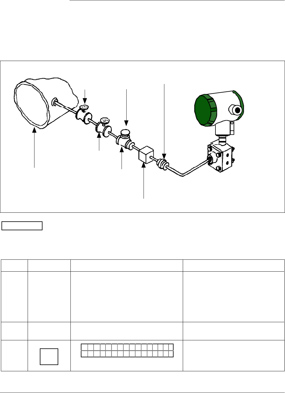
6/08 ST 3000 Release 300 and SFC Model STS103 User’s Manual 145
7.10 Pressure Measurement with AP Transmitter
Procedure The procedure in Table 44 outlines the steps for starting up an absolute
pressure (AP) type transmitter in a pressure measurement application.
Refer to Figure 47 for the piping arrangement identification and Figure
38 for typical SFC and meter connections.
Figure 47 Typical Piping Arrangement for Pressure Measurement with AP Type Transmitter.
Shut-off
valve no.2
Absolute
Pressure
Transmitter
Union
Shut-off
valve no.1 Pipe
Plug
Process Tee connector
For additional overrrange protection, use
Sprague engineering type gauge saver or
Fairchild model 95 gauge guard (style 1)
ATTENTION For AP transmitters, you can only verify that the input and output
readings correlate.
Table 44 Starting Up AP Transmitter for Pressure Measurement With SFC
Step Press Key Read Display or Action Description
1 Connect SFC across loop wiring and
turn it on. If possible, locate SFC where
you can also view receiver instrument in
loop. If you want to verify transmitter
output, connect a precision milliammeter
or voltmeter in loop to compare
readings.
See Figure 38 for sample SFC and
meter connections in a typical
analog loop with a differential
pressure type transmitter.
2 Set process pressure to zero level Allow system to stabilize at zero
pressure.
3 DE READ
A
ID
TA ON.G
?TRIPS SECURED?
Be sure any switches that may trip
alarms or interlocks associated with
analog loop are secured or turned
off.
Continued on next page
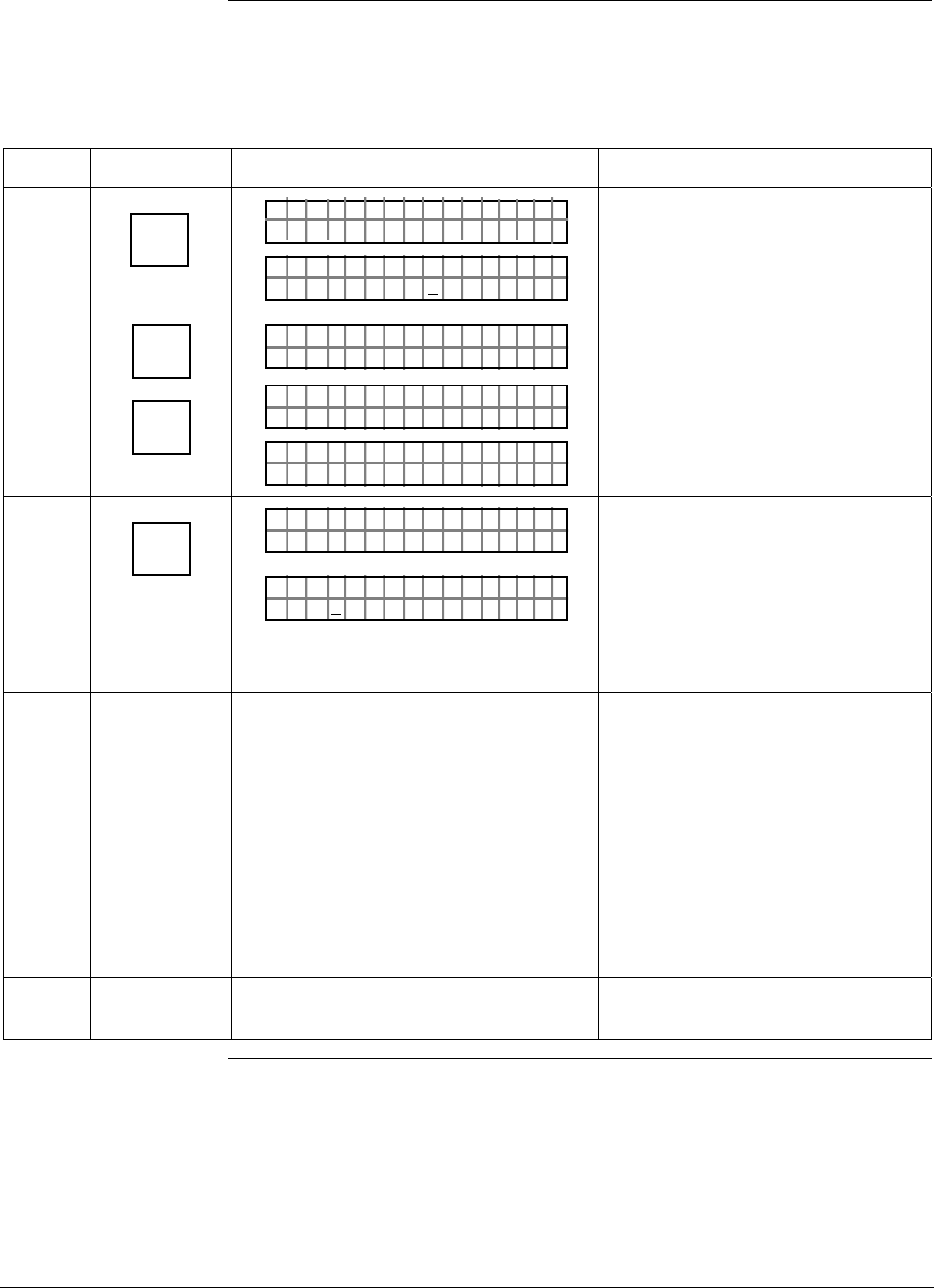
ST 3000 Release 300 and SFC Model STS103 User’s Manual 6/08
146
7.10 Pressure Measurement with AP Transmitter, Continued
Procedure,
continued
Table 44 Starting Up AP Transmitter for Pressure Measurement With SFC, continued
Step Press Key Read Display or Action Description
4 NON-VOL
ENTER
(Yes)
TA ON.G
SFC WORK ING.. .
LIN AG NO.DP T
PT3Ø11
Confirm that “TRIPS” are secured
and establish communications with
sample transmitter PT 3011
5 ^
SHIFT
INPUT
J
OUT-
PUT
PTOU T 3Ø1 11P
FT–SH I
PTINP 3Ø111UT
FC WOSING
.
RK . .
PTINP 3Ø111UT
.Ø Ø42Ø PSI
Initiate shift key selection.
Read applied input pressure which
should be zero.
6 INPUT
J
OUT-
PUT
PTOU T 3Ø1 11P
FC WOSING.RK . .
%.Ø
PTOU T 3Ø1 11P
ØØØ
Call up output for display.
Read 0% output on display for
corresponding input pressure. For
analog transmission, check that
milliammeter reading is 4 mA (0%)
output.
7 Take SFC and milliammeter readings to
check that output signal does
correspond to zero and full-scale
pressures. If readings don’t correspond,
check that transmitter has been installed
correctly. If applicable, blow down piping
to be sure no foreign matter is entrapped
in it. Check SFC and milliammeter
readings again. If readings are still not
correct, verify transmitter’s configuration
data and change its range setting if
needed.
8 Remove SFC and milliammeter from
loop.
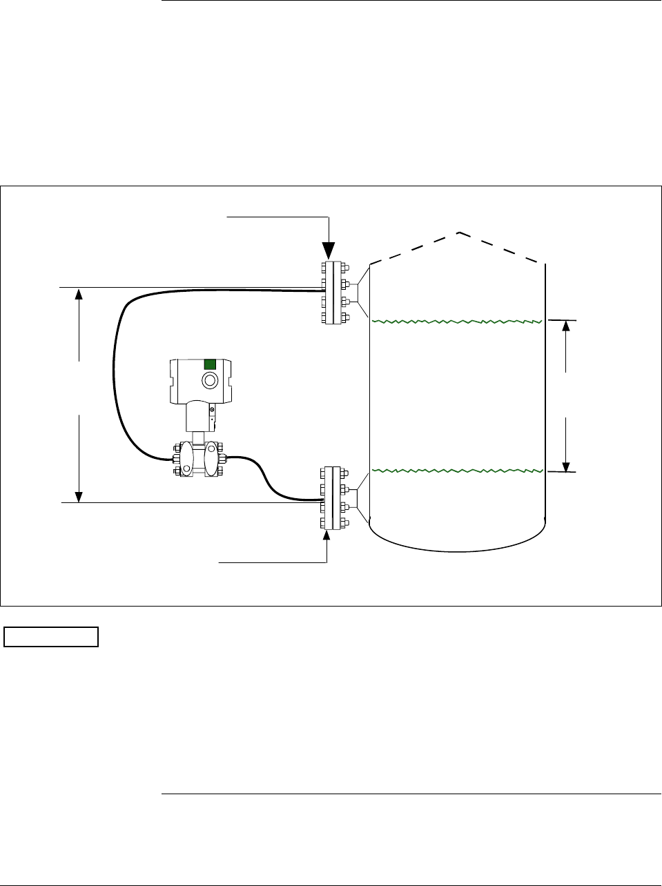
6/08 ST 3000 Release 300 and SFC Model STS103 User’s Manual 147
7.11 Liquid Level Measurement with DP Transmitter with
Remote Seals
Procedure The procedure in Table 45 outlines the steps for starting up a differential
pressure (DP) type transmitter with remote diaphragm seals in a liquid
level measurement application. Refer to Figure 48 for the piping
arrangement identification and Figure 38 for typical SFC and meter
connections.
Figure 48 Typical Piping Arrangement for Liquid Level Measurement with DP Type
Transmitter with Remote Seals
HP Side
Zero Level (empty)
Full Level
LP Side
H2
Fixed
Ref. Leg
Differential
Pressure
Transmitter with
remote seals
Variable
Head H1
ATTENTION For the procedure in Table 45, we are assuming that the tank is empty
and the remote seal flanges are installed at their final positions. The
transmitter is a model STR93D or STR12D with a compound
characterized meter body. The DP transmitter has its high pressure (HP)
side connected to the tank’s lower flange and low pressure (LP) side
connected to the upper flange. (Note that connections would be reversed
for a model STR13D transmitter or a model STR12D transmitter
without a compound characterized meter body.)
Continued on next page
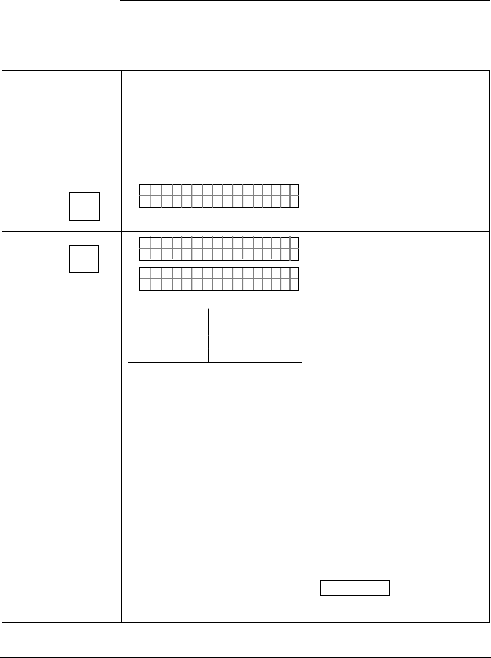
ST 3000 Release 300 and SFC Model STS103 User’s Manual 6/08
148
7.11 Liquid Level Measurement with DP Transmitter with
Remote Seals, Continued
Procedure, continued
Table 45 Starting Up DP Transmitter with Remote Seals for Liquid Level Measurement with
SFC
Step Press Key Read Display or Action Description
1 Connect SFC across loop wiring and
turn it on. If possible, locate SFC where
you can also view receiver instrument in
loop. If you want to verify transmitter
output, connect a precision milliammeter
or voltmeter in loop to compare
readings.
See Figure 38 for sample SFC and
meter connections in a typical
analog loop with a differential
pressure type transmitter.
2 DE READ
A
ID
TA ON.G
?TRIPS SECURED?
Be sure any switches that may trip
alarms or interlocks associated with
analog loop are secured or turned
off.
3 NON-VOL
ENTER
(Yes)
TA ON.G
SFC WORK ING.. .
LIN AG NO.DP T
PT3Ø11
Confirm that “TRIPS” are secured
and establish communications with
sample transmitter PT 3011
4
If you … Then…
can not empty go to Step 5.
tank
can empty tank go to Step 6.
See Figure 48 for sample piping
arrangement.
5 Key in LRV that is equal to empty tank
pressure. See section 6.7 in this manual
for details on keying in a range value.
Go to Step 8.
You can use this formula to
calculate LRV in inH2O.
LRV = H2 x Sf x –1
H2 = Height of fixed reference leg
in inches.
Sf = Specific gravity of remote
seal fill fluid.
–1 = Required for LRV
calculation since pressure is on
low side of meter body.
Example: If H2 equaled 12 feet and
the fill fluid was silicone oil,
substituting into the formula yields.
LRV = 12 ft x 12 in x 0.94 x –1
LRV = –135.36 inH2O
ATTENTION The specific gravity
of silicone oil fill fluid is 0.94 and
florolube fill fluid is 1.84.
Continued on next page
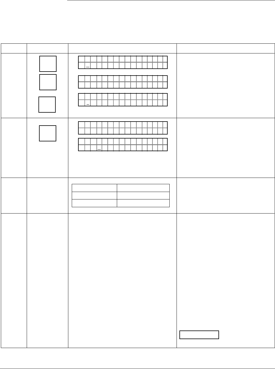
6/08 ST 3000 Release 300 and SFC Model STS103 User’s Manual 149
7.11 Liquid Level Measurement with DP Transmitter with
Remote Seals, Continued
Procedure, continued
Table 45 Starting Up DP Transmitter with Remote Seals for Liquid Level Measurement with
SFC, continued
Step Press Key Read Display or Action Description
6 E
LRV
0%
SET
G
NON-VOL
ENTER
(Yes)
PTLRV 3Ø111
Ø. ØØØØ "H2O
_39F
PTLRV
RV
3Ø1 1
L
1
?SET
PTLRV 3Ø111
1.35 36 "H2O
_39F–
Read present LRV setting.
Prompt asks if you want to set LRV
to applied pressure.
LRV is set to fixed reference leg
pressure H2 times specific gravity of
remote seal fill fluid and –1 for
pressure on low side of meter body.
7 INPUT
J
OUT-
PUT
PTOU T 3Ø1 11P
FC WOSING.RK . .
%.Ø
PTOU T 3Ø1 11P
ØØØ
Call up output for display.
Read 0% output on display for
corresponding empty tank pressure
plus reference pressure H2. For
analog transmission, check that
milliammeter reading is 4 mA (0%)
output.
8
If you … Then…
can not fill tank go to Step 9.
can fill tank go to Step 10.
9 Key in URV that is equal to full tank
pressure. See section 6.7 in this manual
for details on keying in a range value.
Go to Step 12.
You can use these formulas to
calculate URV in inH2O.
Span = H1 x SL
H1 = Height of variable head
in inches.
SL = Specific gravity of
measured liquid.
URV = Span + LRV
Example: If H1 equaled 10 feet, the
measured liquid was water, and the
LRV equaled –135.36 inH2O;
substituting into the formulas yields.
Span = 10 ft x 12 in x 1.00
Span = 120 inH2O
URV = 120 inH2O + –135.36 inH2O
URV = –15.36 inH2O
ATTENTION The specific gravity
of water at 60 °F (15.6 °C) is 1.00.
Continued on next page
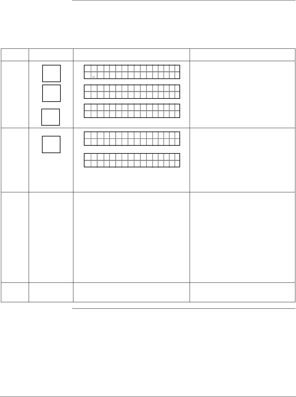
ST 3000 Release 300 and SFC Model STS103 User’s Manual 6/08
150
7.11 Liquid Level Measurement with DP Transmitter with
Remote Seals, Continued
Procedure, continued
Table 45 Starting Up DP Transmitter with Remote Seals for Liquid Level Measurement with
SFC, continued
Step Press Key Read Display or Action Description
10 URV
100%
F
SET
G
NON-VOL
ENTER
(Yes)
PTUR V 3Ø1 11
5.Ø ØØØ "H2 O
_39F
PTUR V
RV
3Ø1 1
U
1
?SET
PTURV 3Ø1 11
.536Ø1"H2O
_39F–
Read present URV setting.
Prompt asks if you want to set URV
to applied pressure.
URV is set to full tank pressure.
11 INPUT
J
OUT-
PUT
PTOU T 3Ø1 11P
FC WOSING.RK . .
%1Ø
.PTOU T 3Ø1 11P
.ØØØ
Call up output for display, with full
tank pressure applied.
Read 100% output on display for
corresponding full tank pressure.
For analog transmission, check that
milliammeter reading is 20 mA
(100%) output.
12 Take SFC and milliammeter readings to
check that output signal does
correspond to empty and full tank
pressures. If readings don’t correspond,
check that transmitter has been installed
correctly. If applicable, blow down piping
to be sure no foreign matter is entrapped
in it. Check SFC and milliammeter
readings again. If readings are still not
correct, verify transmitter’s configuration
data and change its range setting if
needed.
13 Remove SFC and milliammeter from
loop.

6/08 ST 3000 Release 300 and SFC Model STS103 User’s Manual 151
Section 8 —Operation
8.1 Introduction
Section Contents This section includes these topics:
Section Topic See Page
8.1 Introduction ................................................................................151
8.2 Accessing Operation Data .........................................................152
8.3 Changing Default Failsafe Direction...........................................155
8.4 Writing Data in Scratch Pad Area...............................................157
8.5 Saving and Restoring a Database..............................................159
8.6 Monitoring Local Smart Meter Display .......................................163
About this section This section identifies how to access typical data associated with the
operation of an ST 3000 transmitter. It also includes procedures for:
• Changing the default failsafe direction,
• Writing data in the scratch pad area,
• Saving and Restoring a database, and
• Monitoring optional Local Smart Meter display.
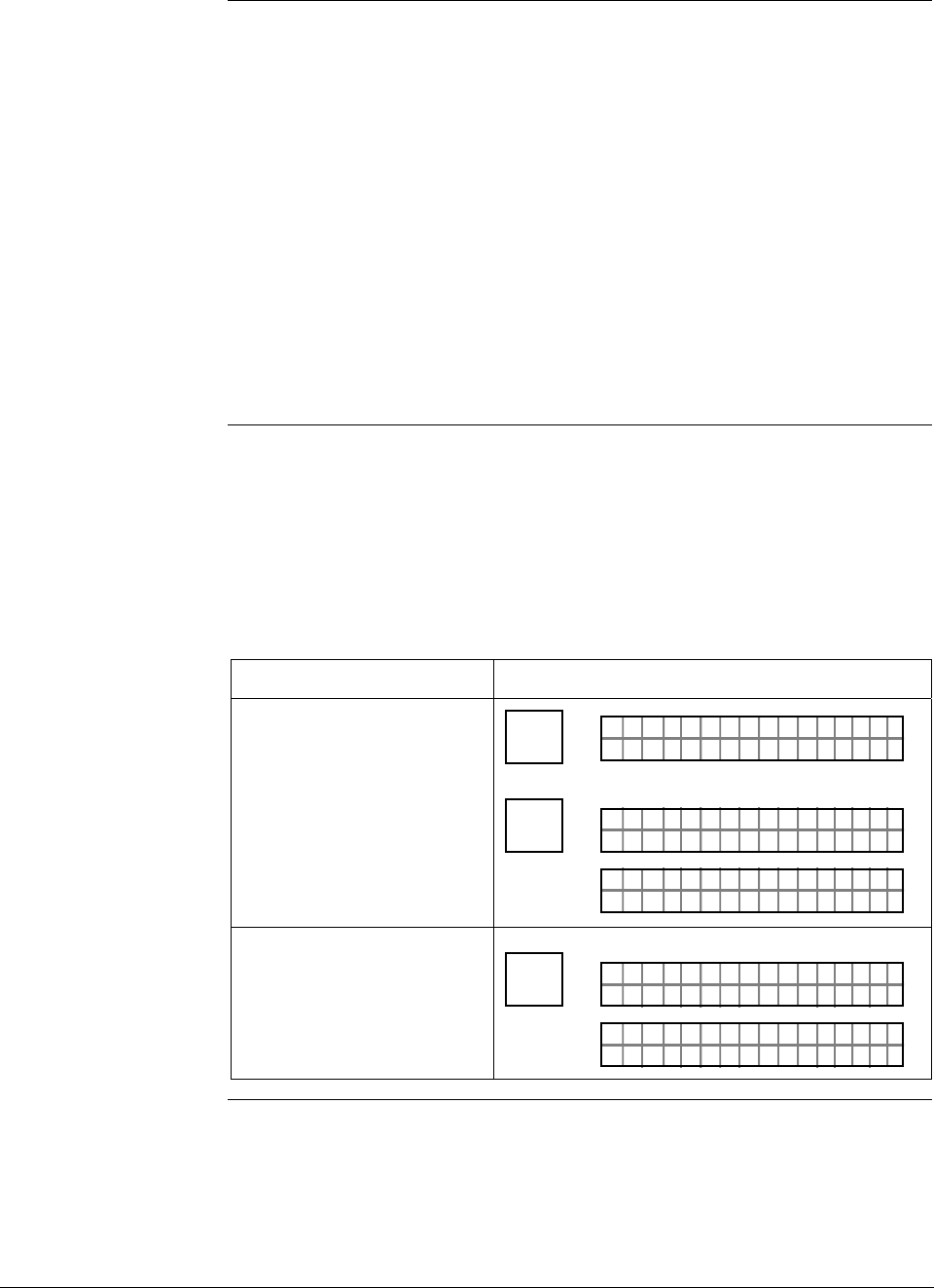
ST 3000 Release 300 and SFC Model STS103 User’s Manual 6/08
152
8.2 Accessing Operation Data
Summary You can access this data relevant to the operation of the transmitter
using an SFC.
• Input
• Output
• Span
• Upper Range Limit
• Status
• Failsafe Output Direction
• Sensor Temperature
• Scratch Pad Messages
• PROM Serial Number
Procedure Table 46 summarizes the keystrokes required to access given operation
data from the transmitter using an SFC. These keystrokes assume that
SFC communications have been established with the transmitter by
pressing the [ID] key. The values shown in displays are for example
purposes only.
Table 46 Summary of Keystrokes for Operation Data Access
IF you want to view… THEN use these keystrokes…
the present input pressure,
which is updated every six
seconds
^
SHIFT FT–SHI
LIN DP T 011P3
INPUT
J
OUT-
PUT
PTIN P 301 11UT
FC WOSING
.
RK . .
PTINP 3Ø111UT
.37Ø21 "H2O_39F
the present transmitter
output in percent, which is
updated every six seconds
INPUT
J
OUT-
PUT
PTOUT 301 11P
FC WOSING.RK . .
%5. 7
PTOUT 301 11P
64
Continued on next page
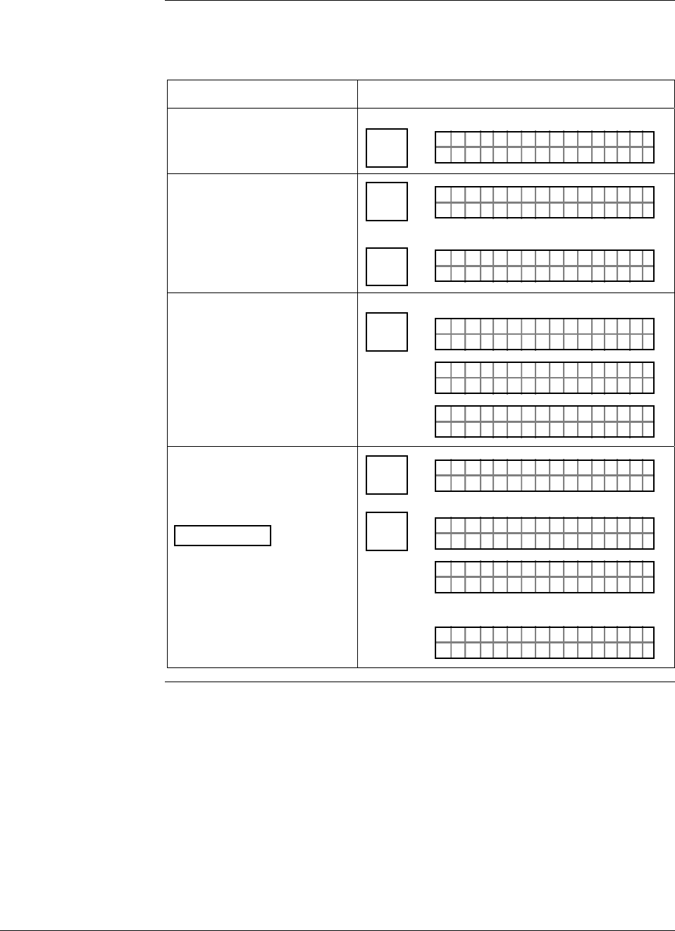
6/08 ST 3000 Release 300 and SFC Model STS103 User’s Manual 153
8.2 Accessing Operation Data, Continued
Procedure, continued
Table 46 Summary of Keystrokes for Operation Data Access,
continued
IF you want to view… THEN use these keystrokes…
the span, which is the URV
minus the LRV SPAN
Y
URL
Ø. Ø
PTSPA 3Ø111N
ØØ2"H2O_39F
the Upper Range Limit of
the transmitter ^
SHIFT FT–SHI
LIN DP T 011P3
SPAN
Y
URL
PTUR L 3Ø1 11
4.ØØ ØØ "H2O_39F
the status of transmitter
operation at the present
time
U
STAT
F/S DIR
PTST A 301 1ST
FC WOSING.RK . .
U
PTST A 301 1ST
TA USSHECKC=O
U
TK
LIN DP
.Y. .RE AD
T 011P3
the present failsafe output
direction for the transmitter
ATTENTION You can
change the default failsafe
direction from upscale to
downscale. See Changing
default failsafe direction in
this section.
^
SHIFT FT–SHI
LIN DP T 011P3
U
STAT
F/S DIR
PTF / S 301 1I
FC WOSING.RK . .
DR
PTF / S 301 1I
/S FEFPSCAULE
DR
A
OR
PTF / S 301 1I
/S FEFOSCADLE
DR
AWN
Continued on next page
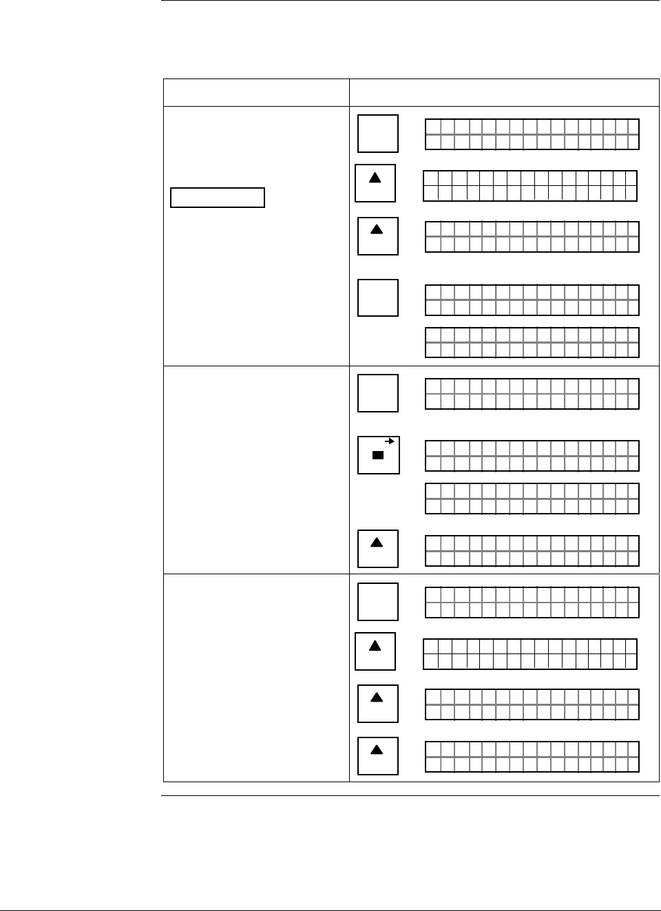
ST 3000 Release 300 and SFC Model STS103 User’s Manual 6/08
154
8.2 Accessing Operation Data, Continued
Procedure, continued
Table 46 Summary of Keystrokes for Operation Data Access,
continued
IF you want to view… THEN use these keystrokes…
the present temperature
(±5 °C) measured by
circuitry in the transmitter’s
sensor
ATTENTION You can
change the temperature
engineering units to °F, °R
or °K by pressing the [UNITS]
key to select and then the
[CONF] key to return to the
temperature display.
B
CONF
NGO IST C F
ITYORMCONF ?
NEXT
H
CONF I G
CMe ntr o ?ef
ST
ig
NEXT
H
NGO IST C F
TEMORSENS ?P
NON-VOL
ENTER
(Yes)
NGO IST C F
FC WOSING
.
RK . .
E.
T PSO M
16 29 ÞC6.
SEN R
the present message in the
scratch pad area of memory ^
SHIFT FT–SHI
LIN DP T 011P3
SCR PAD
P3PD T
FC WOSING
.
RK . .
SCR A 011
PTH A
AL BC3/2ON 2 /
SCR C 1AD
I93
NEXT
H
PTH A
YOBndNSH
SCR C 2AD
JFTH2
the PROM serial number B
CONF
NGO IST C F
ITYORMCONF ?
NEXT
H
CONF I G
CMe ntr o ?ef
ST
ig
NEXT
H
NGO IST C F
TEMORSENS ?P
NEXT
H
NGO IST C F
7751SER# 21ØØØ

6/08 ST 3000 Release 300 and SFC Model STS103 User’s Manual 155
8.3 Changing Default Failsafe Direction
Background Transmitters are shipped with a default failsafe direction of upscale.
This means that the transmitter’s output will be driven upscale
(maximum output) when the transmitter detects a critical status.
You can change the direction from upscale to downscale (minimum
output) by cutting jumper W1 on the Printed Wiring Assembly (PWA)
Analog and DE mode
differences If your transmitter is operating in the analog mode, an upscale failsafe
action will drive the transmitter’s output to greater than 21 mA or a
downscale action will drive its output to less than 3.8 mA.
If your transmitter is operating in the DE mode, an upscale failsafe
action will cause the transmitter to generate a “+ infinity” digital signal,
or a downscale failsafe action will cause it to generate a “– infinity”
digital signal. The STIMV IOP module interprets either signal as “not a
number” and initiates its own configured failsafe action for the control
system. The STDC card initiates the failsafe mode configured through
the transmitter when either signal is generated.
ATTENTION The failsafe direction display that you can access through the SFC only
shows the state of the failsafe jumper in the transmitter as it correlates to
analog transmitter operation. The failsafe action of the digital control
system may be configured to operate differently than indicated by the
state of the jumper in the transmitter.
Procedure The procedure in Table 47 outlines the steps for cutting the failsafe
direction jumper on the transmitter’s PWA. Figure 49 shows the
location of the failsafe direction jumper on the PWA of, Release 300
transmitters.
The nature of the integrated circuitry used in the transmitter’s PWA
makes it susceptible to damage by stray static discharges when it is
removed from the transmitter. Follow these tips to minimize chances of
static electricity damage when handling the PWA.
• Never touch terminals, connectors, component leads, or circuits when
handling the PWA.
• When removing or installing the PWA, hold it by its edges or bracket
section only. If you must touch the PWA circuits, be sure you are
grounded by staying in contact with a grounded surface or wearing a
grounded wrist strap.
• As soon as the PWA is removed from the transmitter, put it in an
electrically conductive bag or wrap it in aluminum foil to protect it.
Continued on next page
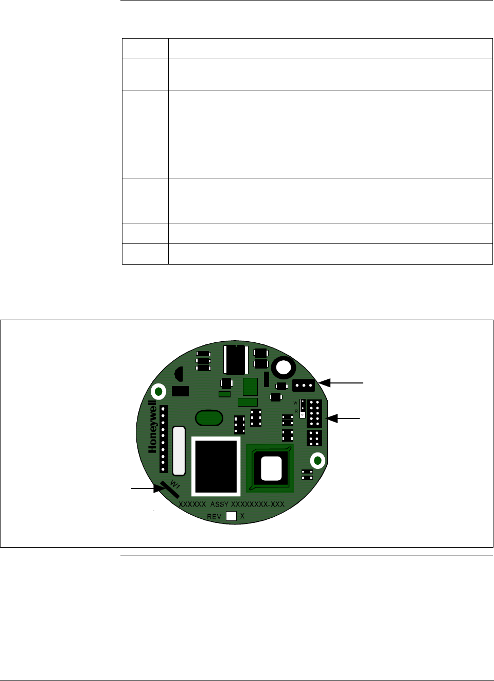
ST 3000 Release 300 and SFC Model STS103 User’s Manual 6/08
156
8.3 Changing Default Failsafe Direction, Continued
Procedure, continued Table 47 Cutting Failsafe Direction Jumper
Step Action
1 Turn OFF transmitter power. Loosen end-cap lock and unscrew end
cap from electronics side of transmitter housing.
2 If applicable, carefully turn Local Smart Meter counterclockwise to
remove it from PWA mounting bracket and unplug cable from
connector on back of meter assembly.
Loosen two retaining screws and carefully pull mounting bracket and
PWA from housing. Unplug flex tape and power connectors from
component side of PWA, and remove PWA.
3 With component side of PWA facing you, locate failsafe direction
jumper W1 and cut it in half with small wire cutter such as dykes. See
Figure 48. This changes failsafe action from upscale to downscale.
4 Reverse applicable previous steps to replace PWA.
5 Turn ON transmitter power.
Figure 49 Location of Failsafe Direction Jumper on PWA.
Failsafe
Direction
Jumper
Power
Connector
Meter
Connector
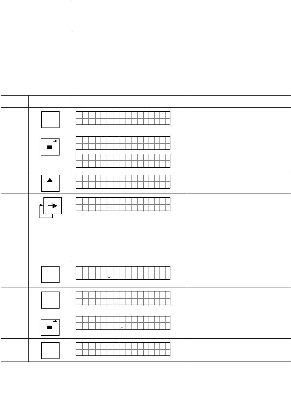
6/08 ST 3000 Release 300 and SFC Model STS103 User’s Manual 157
8.4 Writing Data in Scratch Pad Area
Background You can enter or edit a message in the scratch pad area of memory
consisting of two groups of 16 characters each through the SFC.
Procedure The procedure in Table 48 outlines the steps for editing a sample
message in the scratch pad area. This procedure assumes that SFC
communications have been established with the transmitter by pressing
the [ID] key
Table 48 Writing Data in Scratch Pad Area
Step Press Key Read Display or Action Description
1 ^
SHIFT
SCR PAD
FT–SHI
LIN DP T 011P3
P3PD T
FC WOSING
.
RK ..
SCR A 011
PTH A
AL BC3/2ON 2 /
SCR C 1AD
I93
Initiate shift key selection.
Call up first group of 16 characters.
2
NEXT
H
PTH A
YOBndNSH
SCR C 2AD
JFTH2
Call up second group of 16
characters
3 M
PTH A
YOBndNSH
SCR C 2AD
JFTH2
Move cursor to 6th character “H”.
Cursor moves one character space
to right with each press. Use [←]
key to move cursor one character
space to left with each press. Note
that cursor keys will automatically
toggle between pad 1 and 2 when
moving forward or backward through
message as applicable.
4 NUM/
ALPHA
PTH A
YOBndNSH
SCR C 2AD
JFT*2
Enter alpha mode so you can use
SFC keyboard to enter alphabetic
characters.
5 E
LRV
0%
SCR PAD
PTH A
YOBndESH
SCR C 2AD
JFT*2
PTH A
YOBndESH
SCR C 2AD
JFT*2
Key in “E” and “space” to change
name from JOHN to JOE
6 NUM/
ALPHA
PTH A
YOBndESH
SCR C 2AD
JFT
_2
Exit alpha mode.
Continued on next page
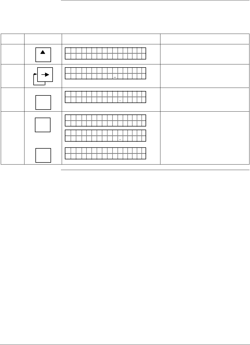
ST 3000 Release 300 and SFC Model STS103 User’s Manual 6/08
158
8.4 Writing Data in Scratch Pad Area, Continued
Procedure, continued
Table 48 Writing Data in Scratch Pad Area, continued
Step Press Key Read Display or Action Description
7
NEXT
H
PTH A
AL BC3/2ON 2 /
SCR C 1AD
I93
Return to first group of 16
characters.
8 M
PTH A
AL BC3
/2ON 2 /
SCR C 1AD
I93
Move cursor to 10th character “3”.
9
6
T
SEC VAR
PTH A
AL BC6/
2ON 2 /
SCR C 1AD
I93
Change “3” to “6” to reflect revised
calibration date.
10 NON-VOL
ENTER
(Yes)
OR
CLR
(NO)
PD
FC WOSING
.
RK ..
SCR A
PTH A
AL BC6/
2ON 2 /
SCR C 1AD
I93
LIN DP
.Y. .RE AD
T 011P3
Save changes in message.
Exit scratch pad without saving
changes in message.
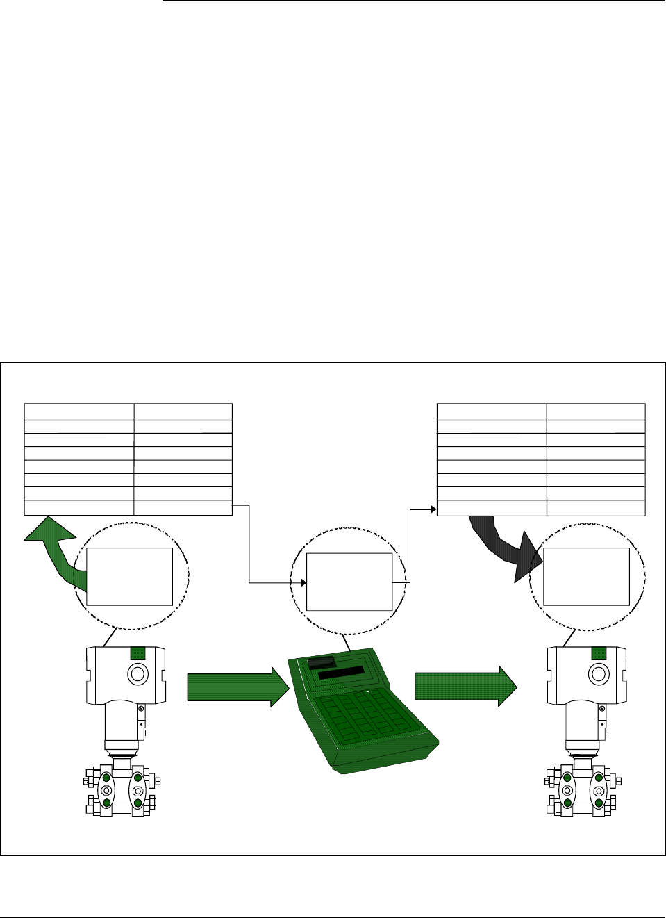
6/08 ST 3000 Release 300 and SFC Model STS103 User’s Manual 159
8.5 Saving and Restoring a Database
Background If it ever became necessary to replace a damaged transmitter with a
spare, you could save the configuration database from the damaged
transmitter to the HOLD memory in the SFC and then restore the saved
configuration database from the HOLD memory in the spare transmitter.
In fact, you could restore the saved configuration database in any
number of transmitters as long as you change the tag number (ID) in the
restored database.
NOTE: The configuration data for the optional Local Smart Meter is
stored in a memory located on the transmitter’s PWA. If a database
save and restore is done with the SFC, then the meter configuration is
restored along with the transmitter configuration.
Figure 50 shows a graphical summation of the save and restore database
function.
Figure 50 Summary of Save and Restore Database Function.
RESTORE
SFC
Hold
Memory
ST 3000
ID
Output Form
Damping Time
LRV
URV
Output Signal Mode
Message Format
Failsafe Mode
PT 3011
LINEAR
2.0 sec.
35.0 psi
200.0 psi
SINGLE RNG
6-BYTE
Read only
Saved Configuration Database
ST 3000
Working
Memory
ID
Output Form
Damping Time
LRV
URV
Output Signal Mode
Message Format
Failsafe Mode
PT 3011
LINEAR
2.0 sec.
35.0 psi
200.0 psi
SINGLE RNG
6-BYTE
Read Only
Restored Configuration Database
SAVE
Working
Memory
Continued on next page
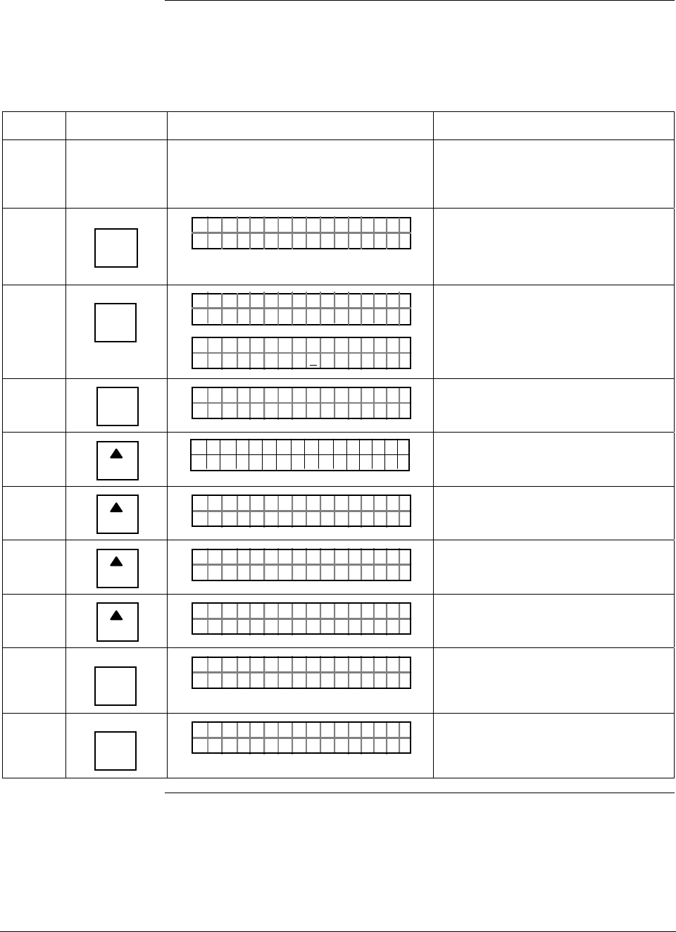
ST 3000 Release 300 and SFC Model STS103 User’s Manual 6/08
160
8.5 Saving and Restoring a Database, Continued
Procedure The procedure in Table 49 outlines the steps for saving a database from
one transmitter and restoring it in another.
Table 49 Saving and Restoring a Database
Step Press Key Read Display or Action Description
1 Connect SFC across loop wiring for
transmitter with database to be saved
and turn it on.
Be sure to put analog loop into
manual mode.
2 DE READ
A
ID
TA ON.G
?TRIPS SECURED?
Be sure any switches that may trip
alarms or interlocks associated with
analog loop are secured or turned
off.
3 NON-VOL
ENTER
(Yes)
TA ON.G
SFC WORK ING.. .
LIN AG NO.DP T
PT3Ø11
Confirm that “TRIPS” are secured
and establish communications with
sample transmitter PT 3011
4 B
CONF
NGO IST C F
ITYORMCONF ?
Call up first configuration parameter.
5
NEXT
H
CONF I G
CMe ntr o ?ef
ST
ig
Call up next configuration
parameter.
6
NEXT
H
NGO IST C F
TEMORSENS ?P
Call up next configuration
parameter.
7
NEXT
H
NGO IST C F
7751SER# 21ØØØ
Call up next configuration
parameter.
8
NEXT
H
NGO IST C F
STORSAVE ?REE
Call up save/restore function.
9 NON-VOL
ENTER
(Yes)
TES RE/ E O
TADSAVE ?A
SAV R
Prompt asks if you want to save
database from this transmitter.
10 NON-VOL
ENTER
(Yes)
ATEA
SOARE ?U
SAV D
YURE
Prompt asks for confirmation of
database save function.
Continued on next page
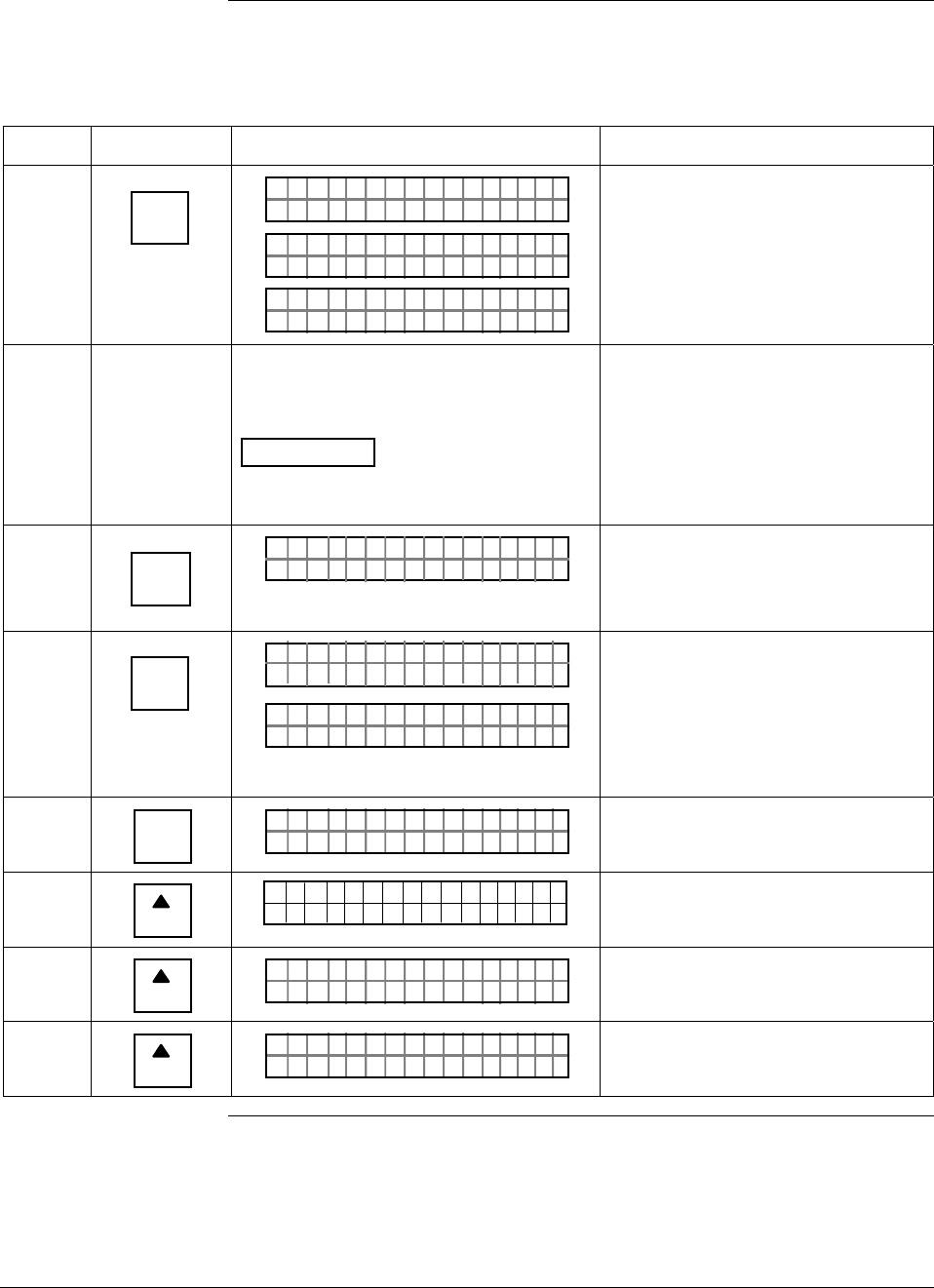
6/08 ST 3000 Release 300 and SFC Model STS103 User’s Manual 161
8.5 Saving and Restoring a Database, Continued
Procedure, continued
Table 49 Saving and Restoring a Database, continued
Step Press Key Read Display or Action Description
11 NON-VOL
ENTER
(Yes)
ATEASAV D
FC WOSING
.
RK . .
ATEASAV D
AT SDEDAVA
TES RE/ E O
TADSAVE ?A
SAV R
Answer yes to prompt and initiate
database save function.
Database saved to SFC HOLD
memory.
12 Disconnect SFC and connect it to loop
wiring for transmitter whose database is
to be restored.
ATTENTION Be sure to leave SFC
power on. The saved database will be
lost if the SFC power is turned off.
Be sure to put analog loop into
manual mode.
13 DE READ
A
ID
TA ON.G
?TRIPS SECURED?
Be sure any switches that may trip
alarms or interlocks associated with
analog loop are secured or turned
off.
14 NON-VOL
ENTER
(Yes)
TA ON.G
SFC WORK ING.. .
LIN AG NO.DP T
_
Confirm that “TRIPS” are secured
and establish communications with
sample transmitter without a tag
number (ID) whose database is to
be restored.
15 B
CONF
NGO IST C F
ITYORMCONF ?
Call up first configuration parameter.
16
NEXT
H
CONF I G
CMe ntr o ?ef
ST
ig
Call up next configuration
parameter.
17
NEXT
H
NGO IST C F
TEMORSENS ?P
Call up next configuration
parameter.
18
NEXT
H
NGO IST C F
7751SER# 21ØØØ
Call up next configuration
parameter.
Continued on next page
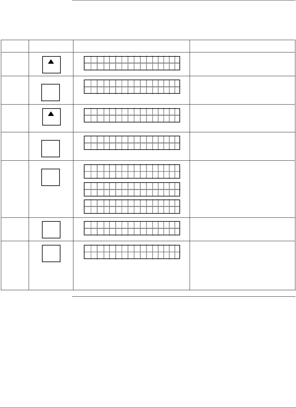
ST 3000 Release 300 and SFC Model STS103 User’s Manual 6/08
162
8.5 Saving and Restoring a Database, Continued
Procedure, continued
Table 49 Saving and Restoring a Database, continued
Step Press Key Read Display or Action Description
19
NEXT
H
NGO IST C F
STORSAVE ?REE
Call up save/restore function.
20 NON-VOL
ENTER
(Yes)
TES RE/ E O
TADSAVE ?A
SAV R
Prompt asks if you want to save
database from this transmitter.
21
NEXT
H
TES RE/ E O
TADRES T ?A
SAV R
ORE
Call up prompt for restore function. It
asks if you want to restore saved
database in this transmitter.
22 NON-VOL
ENTER
(Yes)
TADRES T AORE
SOARE ?UYURE
Prompt asks for confirmation of
database restore function.
23 NON-VOL
ENTER
(Yes)
TADRES T AORE
FC WOSING
.
RK . .
TADRES T AORE
AT RDTOREES DA
TES RE/ E O
TADRES T ?A
SAV R
ORE
Answer yes to prompt and initiate
database restore function.
Saved database has been restored
(written) to transmitter’s memory.
24 CLR
(No)
NGO IST C F
STORSAVE ?REE/
Return to configuration parameter
menu selection.
25 CLR
(No)
LIN DP
.Y. .RE AD
T 011P3
Exit configuration and verify that
transmitter’s ID now reflects ID from
restored database. Tag number PT
3011 is used for example purposes
only. Change tag number and other
configuration data as required.
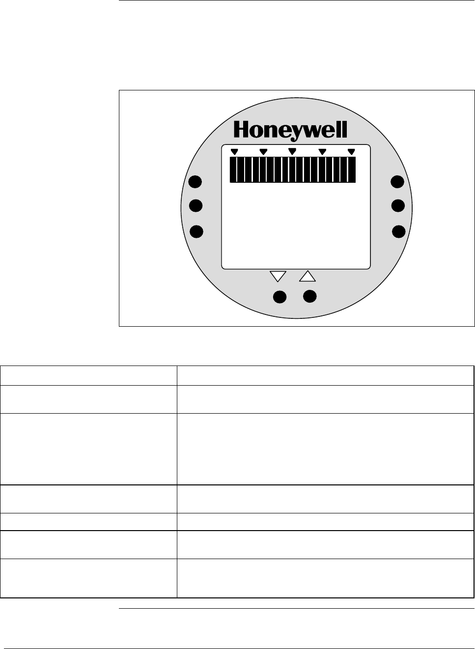
6/08 ST 3000 Release 300 and SFC Model STS103 User’s Manual 163
8.6 Monitoring Local Smart Meter Display
Display description Figure 51 shows a Local Smart Meter display with all its indicators and
segments lit for reference and Table 50 gives a brief description of what
the indications mean.
Figure 51 Display With All Indicators Lit.
%
100
0
18 8
.
8
ANALOG
%
FLOW
In H O
2
K
GPH mmHg
GPM PSI
A
OUTPUT MODE
CHECK STATUS
0
-
UPPER
VALUE
UNITS
LOWER
VALUE
SET
VAR
SEL.
SPAN
ZERO
.
KNOWN VALUE
Table 50 Description of Display Indicators Shown in Figure 51
Display Indicator What It Means When Lit
17-Segment Bargraph Gives a gross indication of the transmitter’s PV output from 0 to
100%.
Digital Readout Gives an indication of the transmitter’s PV output in either percent
of span or actual engineering units. The display range is
±19,990,000 and it is automatically ranged to provide the best
precision possible within the limits of the display. A second
decimal place expands the precision of range values within
±19.99 to 1/100th of a unit.
% Digital readout represents output in percent of span. This is the
default engineering units selection.
FLOW Transmitter is configured for Square Root output conformity.
OUTPUT MODE Transmitter is in its output mode and it is not sending a real PV
signal.
CHECK STATUS Transmitter in DE mode is broadcasting a critical status or
transmitter in Analog mode has an output that is less than –2.0%
or greater than 106%. Use the SFC to check transmitter’s status.
Continued on next page

ST 3000 Release 300 and SFC Model STS103 User’s Manual 6/08
164
8.6 Monitoring Local Smart Meter Display, Continued
Display description,
continued
Table 50 Description of Display Indicators Shown in Figure 51, continued
Display Indicator What It Means When Lit
KNOWN VALUE The Upper Value or Lower Value being displayed has previously
been configured to the value shown.
ANALOG Transmitter is in its Analog mode. (When indicator is OFF,
transmitter is in its DE mode)
inH2O Inches of Water is selected engineering units for digital readout
K Multiplies digital reading by 1,000. Turns on automatically when
reading exceeds 1999.
GPH Gallons per hour is selected engineering units for digital readout.
(Note that the FLOW indicator must also be lit to allow this
selection.)
GPM Gallons per minute is selected engineering units for digital
readout. (Note that the FLOW indicator must also be lit to allow
this selection.)
mmHg Millimeters of Mercury is selected engineering units for digital
readout.
PSI Pounds per Square Inch is selected engineering units for digital
readout.
A Transmitter is absolute pressure type. Digital readout represents
absolute values.
Stick-On Label (not shown) Selected engineering unit equals one of these units which is
available as a stick-on label from Honeywell drawing number
30756918-001.
Kpa = Kilopascals
Mpa = Megapascals
mbar = Millibar
bar = Bar
g/cm2 = Grams per Square Centimeter
Kg/cm2 = Kilograms per Square Centimeter
mmH2O = Millimeters of Water
inHg = Inches of Mercury
mH2O = Meters of Water
Typical operation
indications Table 51 summarizes typical Local Smart Meter indications. Note that
other combinations of status messages are possible.
Continued on next page
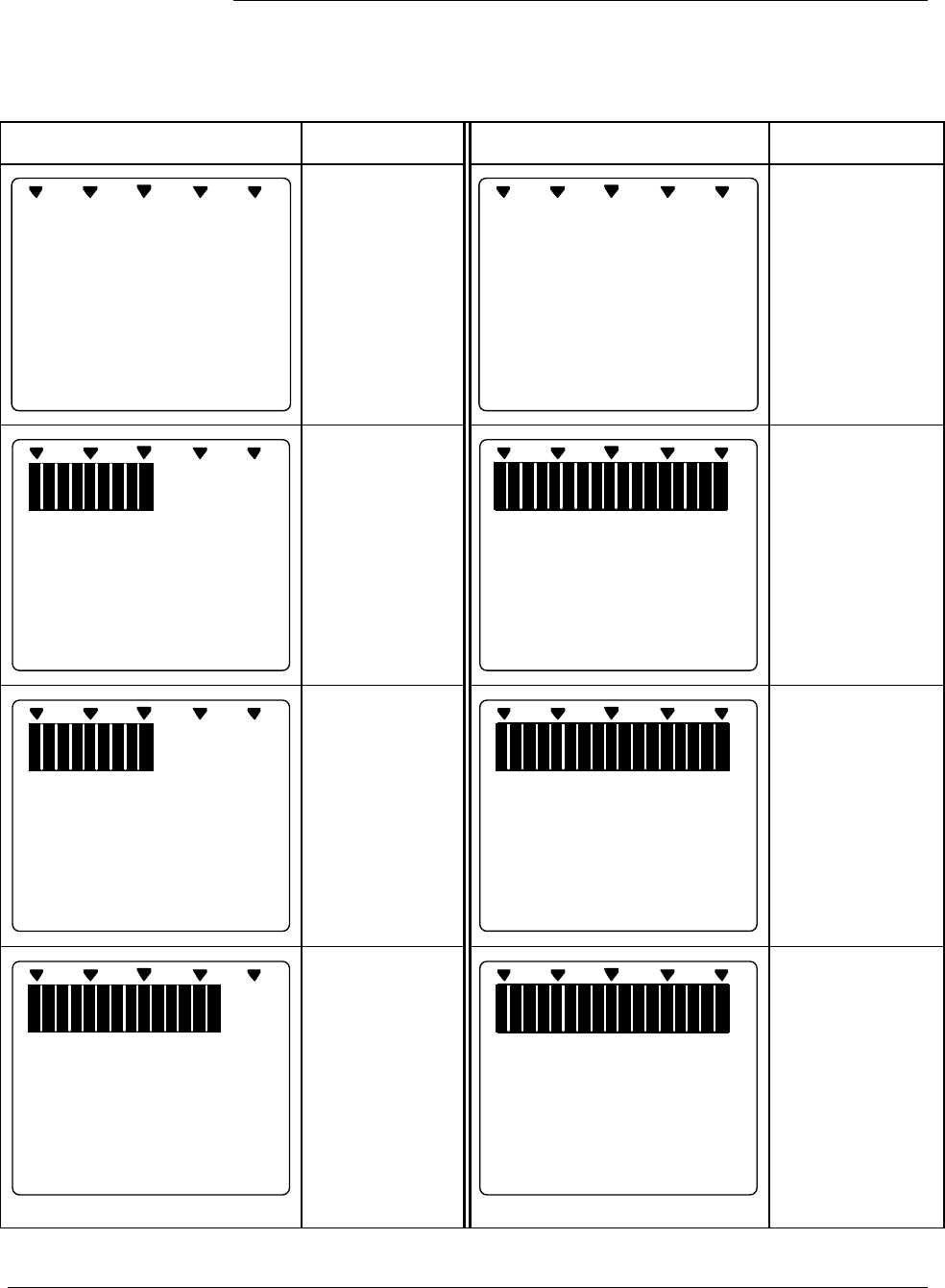
6/08 ST 3000 Release 300 and SFC Model STS103 User’s Manual 165
8.6 Monitoring Local Smart Meter Display, Continued
Typical operation
indications, continued
Table 51 Summary of Typical Local Smart Meter Indications.
Meter Indication What It Means Meter Indication What It Means
%
100
0
No power
applied.
%
100
0
---
Meter has
detected
transmitter output
that is not-a-
number.
%
100
0
20
ANALOG In H O
2
0
Normal display
for transmitter in
Analog mode
with digital
readout in
inches of water.
%
100
0
O
-
L
K
GPM
Display range is
Over Limit. Upper
value is
19,990,000 and
transmitter output
is over 100%.
%
1000
FLOW
GPM
K
9990
Normal display
for transmitter in
DE mode and
square root
output. Digital
readout is
gallons per
minute with
1000 multiplier.
%
100
0
100
.
0
%
OUTPUT MODE
Transmitter is in
output mode.
Bargraph and
readout show
value that was
entered through
SFC.
%
100
0
77
.
9
%
CHECK STATUS
Transmitter in
DE mode is in
non-critical
status.
Displayed value
may not be valid.
If display is “- - -”
instead of a
value,
transmitter is in
critical status.
%
100
0
200
.
0
%
Input pressure
equal to or
greater than
200%. Display
flashes between
200% (or twice
current URV in
EU) and O-L.
Transmitter locks
output at 200%
and will go no
higher regardless
of input.
Continued on next page
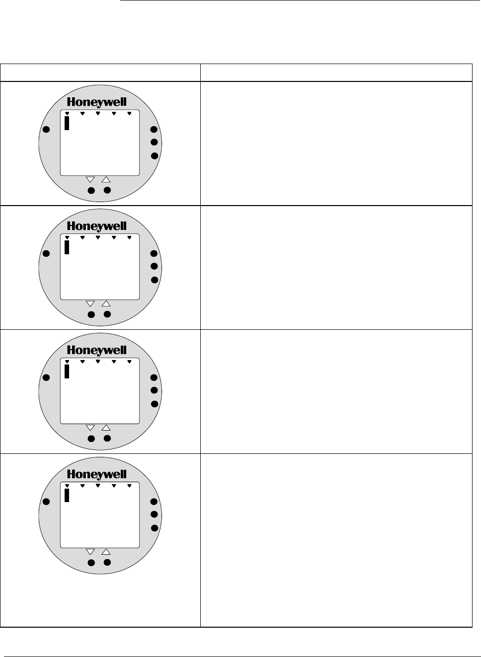
ST 3000 Release 300 and SFC Model STS103 User’s Manual 6/08
166
8.6 Monitoring Local Smart Meter Display, Continued
Operation error codes Table 52 identifies possible meter error codes and what they mean.
Table 52 Possible Smart Meter Error Codes.
If error indication is . . . Then, it means
%
1000
Er
ANALOG
%
0
UPPER
VALUE
UNITS
LOWER
VALUE
SET
VAR
SEL.
You have tried to set local Zero or Span adjustment in a
Series 100 transmitter which does not support this option.
%
1000
Er
ANALOG
%
1
UPPER
VALUE
UNITS
LOWER
VALUE
SET
VAR
SEL.
You have tried to set a pressure type engineering unit for a
transmitter in SQUARE ROOT mode (FLOW) or have tried
to set a flow type engineering unit for a transmitter in
LINEAR mode (pressure). After this error is displayed, the
meter will return to the unit # (EU#) of the Engineering Unit
it was displaying before the set function was invoked. You
may then select another unit or exit in the normal fashion.
%
1000
Er
ANALOG
%
2
UPPER
VALUE
UNITS
LOWER
VALUE
SET
VAR
SEL.
You have tried to select a process variable for the
transmitter using the VAR SEL. button. The Variable Select
button is non-functioning on the ST 3000 R300 transmitter.
%
1000
Er
ANALOG
%
3
UPPER
VALUE
UNITS
LOWER
VALUE
SET
VAR
SEL.
You have tried to set Lower or Upper display limit for
pressure type engineering units (EU1 to EUC), or Lower
display limit for flow type engineering units (EUD,EUE) or
CUSTOM unit (EUF) in transmitter configured for SQUARE
ROOT output. Or, you have tried to set upper display limit
for flow or Custom unit in transmitter with SQUARE ROOT
output and URV set to zero (0). In SQUARE ROOT mode,
the transmitter’s URV cannot equal zero. The Lower and
Upper display limits only apply for CUSTOM (EUF) unit in
transmitter configured for LINEAR output. The Upper
display limit also applies for FLOW (EUD,EUE) and
CUSTOM (EUF) units with transmitter in SQUARE ROOT
mode , but the Lower display limit is fixed at zero (0) and
cannot be changed.
Continued on next page
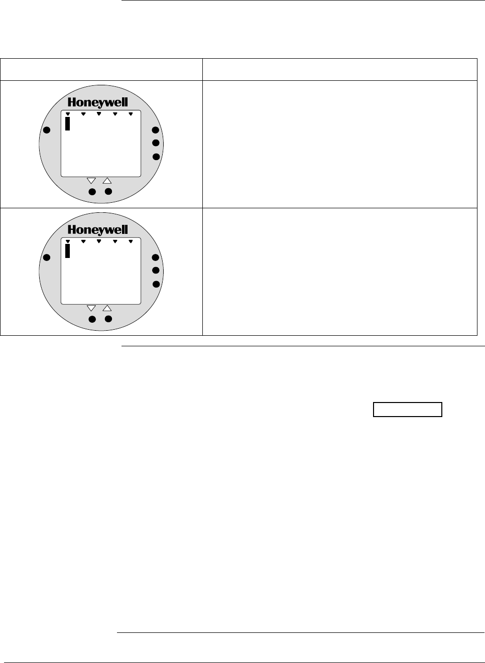
6/08 ST 3000 Release 300 and SFC Model STS103 User’s Manual 167
8.6 Monitoring Local Smart Meter Display, Continued
Operation error codes,
continued
Table 52 Possible Smart Meter Error Codes, continued.
If error indication is . . . Then, it means
%
1000
Er
ANALOG
%
4
UPPER
VALUE
UNITS
LOWER
VALUE
SET
VAR
SEL.
You have tried to set a span value that is outside
acceptable limits for your transmitter.
%
1000
Er
ANALOG
%
5
UPPER
VALUE
UNITS
LOWER
VALUE
SET
VAR
SEL.
You have tried to invoke a Local Smart Meter set function
with the transmitter’s Write Protect jumper in its Read Only
position. You cannot make changes in the Local Smart
Meter settings when the transmitter’s configuration is write
protected.
Meter/transmitter
interaction • Cycling transmitter power OFF/ON will have no affect on meter
configuration. The meter digital readout will be in the previously set
engineering units and applicable upper and lower display limits will be
intact when transmitter power is restored. (See ATTENTION in
Section 6.8 when setting range values and configuring the meter
display.)
• If you switch the transmitter mode from Analog to DE, the ANALOG
indicator on the meter will go out. If you switch from DE to Analog
mode, the ANALOG indicator will light.
• If you reconfigure the transmitter output conformity from SQUARE
ROOT to LINEAR, the meter’s digital readout will automatically
revert to the default engineering unit of percent and the FLOW
indicator will go out when the change is downloaded to the
transmitter. Likewise, if you reconfigure the transmitter output
conformity from LINEAR to SQUARE ROOT, the meter’s digital
readout will automatically revert to the default engineering unit of
percent and the FLOW indicator will light when the change is
downloaded to the transmitter. In either case, you must reconfigure the
transmitter as outlined in Section 6.11 or 6.12 of this manual.

ST 3000 Release 300 and SFC Model STS103 User’s Manual 6/08
168

6/08 ST 3000 Release 300 and SFC Model STS103 User’s Manual 169
Section 9 —Maintenance
9.1 Introduction
Section Contents This section includes these topics
Section Topic See Page
9.1 Introduction ................................................................................169
9.2 Preventive Maintenance.............................................................170
9.3 Inspecting and Cleaning Barrier Diaphragms.............................171
9.4 Replacing PWA ..........................................................................175
9.5 Replacing Meter Body................................................................178
About this section This section provides information about preventive maintenance
routines, cleaning barrier diaphragms, and replacing damaged parts.

ST 3000 Release 300 and SFC Model STS103 User’s Manual 6/08
170
9.2 Preventive Maintenance
Maintenance routines
and schedules The ST 3000 transmitter itself does not require any specific maintenance
routine at regularly scheduled intervals. However, you should consider
carrying out these typical inspection and maintenance routines on a
schedule that is dictated by the characteristics of the process medium
being measured and whether blow-down facilities or purge systems are
being used.
• Check piping for leaks
• Clear the piping of sediment or other foreign matter
• Clean the transmitter’s pressure chambers including the barrier
diaphragms
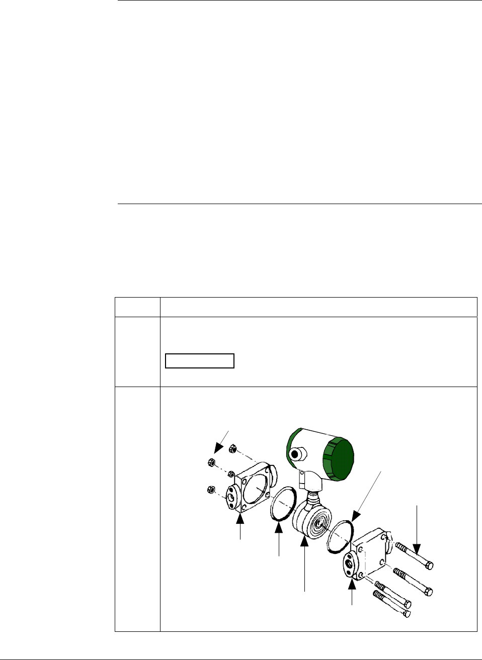
6/08 ST 3000 Release 300 and SFC Model STS103 User’s Manual 171
9.3 Inspecting and Cleaning Barrier Diaphragms
Background Depending on the characteristics of the process medium being
measured, sediment or other foreign particles may collect in the process
head cavity/chamber and cause faulty measurement. In addition, the
barrier diaphragm or diaphragms in the transmitter’s meter body may
become coated with a residue from the process medium. The latter is
also true for external diaphragms on flange mount and remote seal type
transmitters.
In most cases, you can readily remove the process head or heads from
the transmitter’s meter body to clean the process head cavity and inspect
the barrier diaphragm or diaphragms. For flange mount and remote seal
diaphragms, you may only need to run a purge line in the tank to rinse
off the face of the diaphragm.
Procedure The procedure in Table 53 outlines the general steps for inspecting and
cleaning barrier diaphragms. You may have to modify the steps to meet
your particular process or transmitter model requirements.
Table 53 Inspecting and Cleaning Barrier Diaphragms
Step Action
1 Close all valves and isolate transmitter from process. Open vent in
process head to drain fluid from transmitter’s meter body, if required.
ATTENTION We recommend that you remove the transmitter
from service and move it to a clean area before taking it apart.
2 Remove nuts from bolts that hold process head or heads to meter
body. Remove process heads and bolts.
Nuts
Process
head O-ring
Center
section Process
head
O-ring
Bolts
Continued on next page
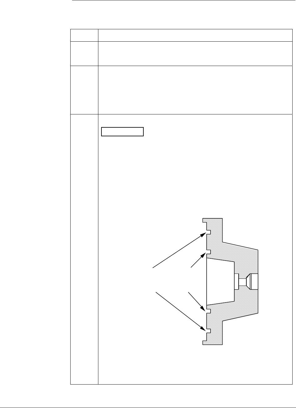
ST 3000 Release 300 and SFC Model STS103 User’s Manual 6/08
172
9.3 Inspecting and Cleaning Barrier Diaphragms, Continued
Procedure, continued
Table 53 Inspecting and Cleaning Barrier Diaphragms, continued
Step Action
3
Remove O-ring and clean interior of process head using soft bristle
brush and suitable solvent.
4
Inspect barrier diaphragm for any signs of deterioration or corrosion.
Look for possible residue and clean if necessary.
NOTE: If diaphragm is dented, has distorted convolutions or radial
wrinkles, performance may be affected. Contact TAC for
assistance.
5
Replace O-ring.
ATTENTION
• We recommend that you install a new O-ring whenever a process
head is removed for cleaning.
• The process head for a GP or an AP transmitter with single-head
design has two O-ring grooves. A large one which is 2 in (50.8
mm) in diameter and a small one which is 1.3 in (33 mm) in
diameter as shown in the following illustration. On high-pressure,
model STG180, GP transmitters, be sure to use a small O-ring in
the smaller/inner groove. On other models of GP and AP
transmitters, use a large O-ring in the larger/outer groove. Never
use both O-rings together.
Larger O-ring
groove for
lower pressure
applications
Smaller O-ring
groove for
high pressure
applications
22518
GP/AP Process Head
• For process heads of a GP or AP transmitter with dual-head
design, see detail illustration for differential pressure transmitters
in Step 2.
Continued on next page
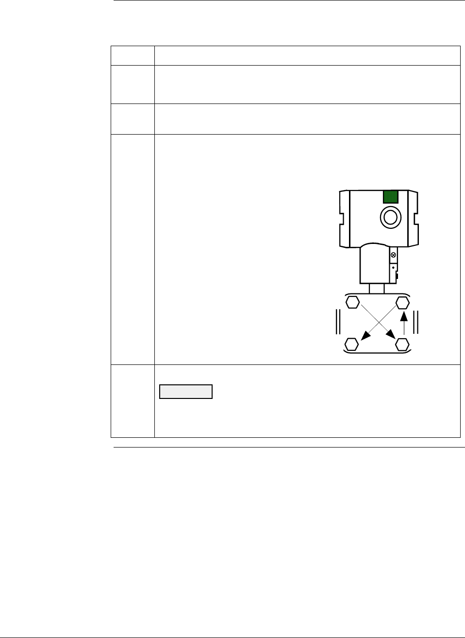
6/08 ST 3000 Release 300 and SFC Model STS103 User’s Manual 173
9.3 Inspecting and Cleaning Barrier Diaphragms, Continued
Procedure, continued
Table 53 Inspecting and Cleaning Barrier Diaphragms, continued
Step Action
6
Coat threads on process head bolts with anti-seize compound such
as “Neverseize” or equivalent.
7 Replace process head or heads and bolts. Finger tighten nuts.
8
Use a torque wrench to gradually tighten nuts to torque rating shown
in Table 48 in sequence shown in following illustration. Tighten head
bolts in stages of 1/3 full torque, 2/3 full torque, and then full torque.
1
2
4
3
Always tighten head bolts in
sequence shown and in these
stages:
1. 1/3 full torque
2. 2/3 full torque
3. Full torque
9
Return transmitter to service.
CAUTION Do not exceed the overload rating when placing the
transmitter back into service or during cleaning operations. See
Overpressure ratings in Section 3 of this manual.
Continued on next page

ST 3000 Release 300 and SFC Model STS103 User’s Manual 6/08
174
9.3 Inspecting and Cleaning Barrier Diaphragms, Continued
Torque ratings Table 54 lists process head bolt torque ratings for given transmitter type.
Table 54 Process Head Bolt Torque Ratings
Bolting Type Meter Body
Type
Process Head
Bolting Size Carbon Steel –
Standard; no option
specified
B7M Bolting
[“B7” Option]
Stainless Steel NACE
[“CR” Option] 316 Stainless Steel
Non-NACE [“SS”
Option]
7/16 x 14 UNC 20,3 N-m +/- 1,0 N-m
[15.0 Lb-Ft +/- 0.8 Lb-Ft]
20,3 N-m +/- 1,0 N-m
[15.0 Lb-Ft +/- 0.8 Lb-Ft]
20,3 N-m +/- 1,0 N-m
[15.0 Lb-Ft +/- 0.8 Lb-Ft]
20,3 N-m +/- 1,0 N-m
[15.0 Lb-Ft +/- 0.8 Lb-Ft]
7/16 x 20 UNF NA NA 25,8 N-m +/- 1,3 N-m
[19.0 Lb-Ft +/- 1.0 Lb-Ft]
NA
Draft Range
Transmitter
M12 x 1.75 25,8 N-m +/- 1,3 N-m
[19.0 Lb-Ft +/- 1.0 Lb-Ft]
NA NA NA
M12 x 1.75 63,7 N-m +/- 3,2 N-m
[47.0 Lb-Ft +/- 2.4 Lb-Ft]
NA NA NA
7/16 x 20 UNF NA NA 63,7 N-m +/- 3,2 N-m
[47.0 Lb-Ft +/- 2.4 Lb-Ft]
NA
7/16 x 14 UNC 67,8 N-m +/- 3,4 N-m
[50.0 Lb-Ft +/- 2.5 Lb-Ft]
48,8 N-m +/- 2,4 N-m
[36.0 Lb-Ft +/- 1.8 Lb-Ft]
56,9 N-m +/- 2,8 N-m
[42.0 Lb-Ft +/- 2.1 Lb-Ft]
56,9 N-m +/- 2,8 N-m
[42.0 Lb-Ft +/- 2.1 Lb-Ft]
3/8 x 16 UNC 39,3 N-m +/- 2,0 N-m
[29 Lb-Ft +/- 1.5 Lb-Ft]
NA 39,3 N-m +/- 2,0 N-m
[29 Lb-Ft +/- 1.5 Lb-Ft]
39,3 N-m +/- 2,0 N-m
[29 Lb-Ft +/- 1.5 Lb-Ft]
M8 x 1.25 27,1 N-m +/- 1,4 N-m
[20.0 Lb-Ft +/- 1.0 Lb-Ft]
NA NA NA
All Other DP,
GP and AP
Transmitters
5/16 x 18 UNC NA NA 20,3 N-m +/- 1,0 N-m
[15.0 Lb-Ft +/- 0.8 Lb-Ft]
20,3 N-m +/- 1,0 N-m
[15.0 Lb-Ft +/- 0.8 Lb-Ft]
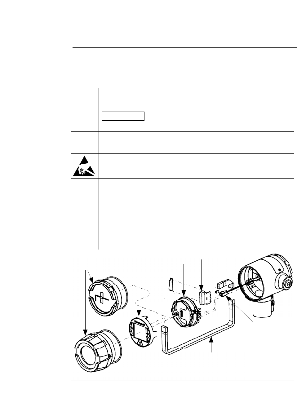
6/08 ST 3000 Release 300 and SFC Model STS103 User’s Manual 175
9.4 Replacing PWA
About the PWA
Electronics Board The circuitry in the ST 3000 Release 300 transmitters is of the single
PWA design. The PWA contains connectors for the flex-tape conductor
from the sensor, the loop power wires and a connector for the optional
smart meter cable.
Procedure The procedure in Table 55 outlines the steps for replacing the PWA.
Table 55 Replacing PWA.
Step Action
1
Turn OFF transmitter power.
ATTENTION We recommend that you remove the transmitter
from service and move it to a clean area before taking it apart.
2
Loosen end cap lock and unscrew end cap from electronics side of
transmitter housing.
We recommend that you use a ground strap or ionizer when handling
the PWA, since electrostatic discharges can damage certain circuit
components.
3
• If equipped with a Local Smart Meter, carefully turn Smart Meter
counterclockwise to remove it from PWA mounting bracket and
unplug cable from connector on back of meter assembly.
• Loosen two retaining screws and carefully pull mounting bracket
and PWA from housing.
• Using the retaining clip, unplug flex tape connector and 2-wire
power connector from PWA, and remove PWA.
Flex-Tape Connector
Local Smart
Meter
Meter
Cable
PWA and
Mounting Bracket
Transmitter
End Caps
Power
Connector
Continued on next page
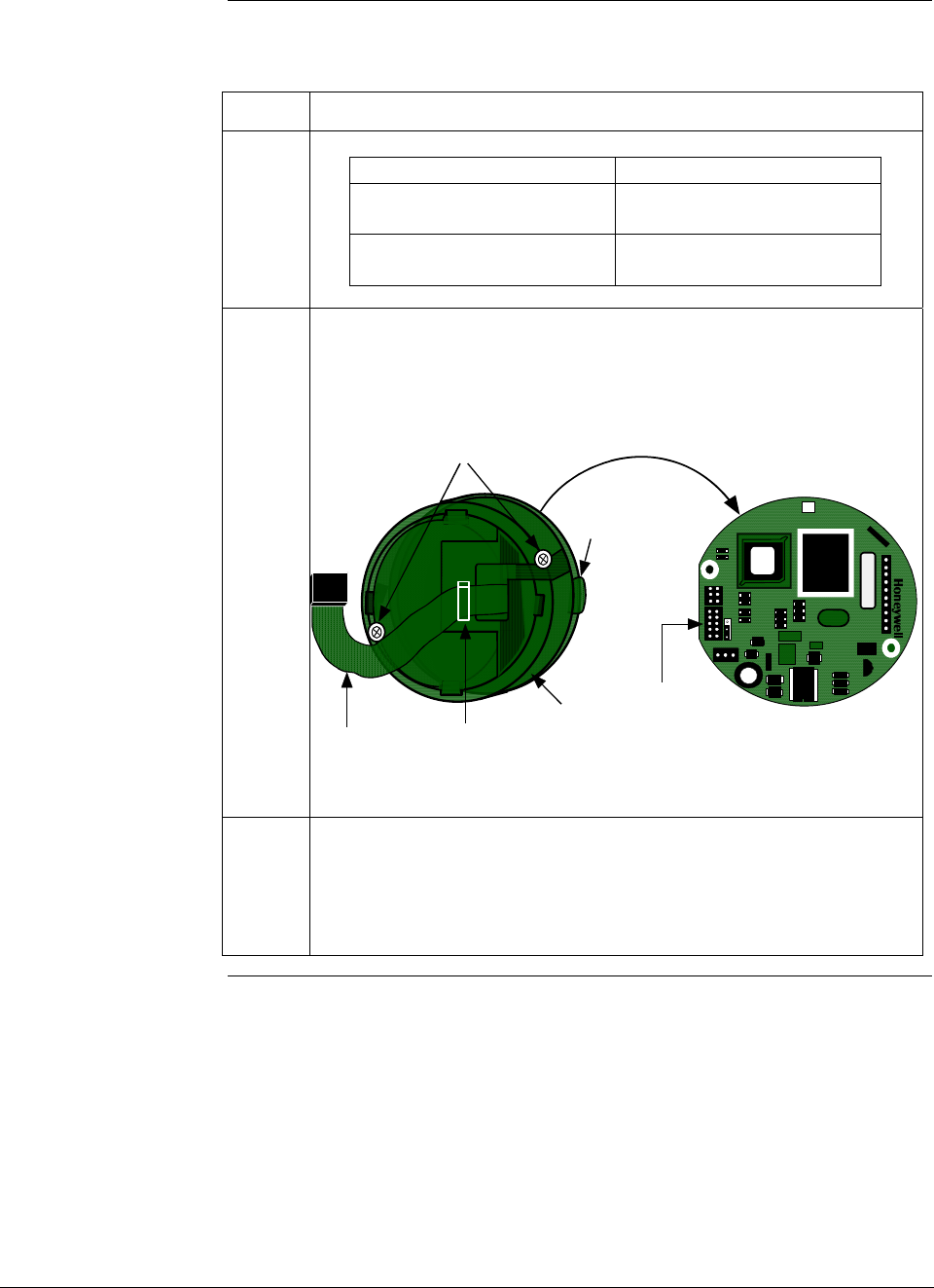
ST 3000 Release 300 and SFC Model STS103 User’s Manual 6/08
176
9.4 Replacing PWA, Continued
Procedure, continued
Table 55 Replacing PWA, continued
Step Action
4
If your transmitter… Then…
has Local Smart Meter go to Step 5
Option
does not have Local Smart go to Step 7
Meter Option
5
Note orientation of mounting bracket on PWA (side without cable
connectors). Unplug meter cable from connector on PWA. Remove
screw retainers from other side of mounting screws so you can
remove screws and mounting bracket from PWA. Set PWA aside.
Restraining
Clip
Mounting
Bracket
Meter Cable
Mounting Screws
Meter cable is installed
between PWA and
mounting bracket.
J4 Meter
Connector
PWA Connector Side
W
R
W
1
XXXXXX ASSY XXXXXXXX-XXX
REV X
6
Orient mounting bracket as noted above with meter cable still located
in slot on its right-hand side, install mounting screws through bracket
and replacement PWA, and install retainers to hold screws in place.
Plug meter cable into connector J4 on PWA and be sure cable is still
under restraining clip on front of bracket. Go to Step 9.
Continued on next page
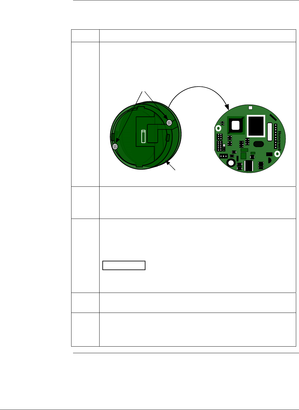
6/08 ST 3000 Release 300 and SFC Model STS103 User’s Manual 177
9.4 Replacing PWA, Continued
Procedure, continued
Table 55 Replacing PWA, continued
Step Action
7 Note orientation of mounting bracket on PWA (side without cable
connectors). Remove screw retainers from other side of mounting
screws so you can remove screws and mounting bracket from PWA.
Set PWA aside.
PWA Connector Side
Mounting
Bracket
Mounting Screws
W
R
W
1
XXXXXX ASSY XXXXXXXX-XXX
REV X
8
Orient mounting bracket as noted above, install mounting screws
through bracket and replacement PWA, and install retainers to hold
screws in place.
9
Reverse actions in Steps 2 and 3, as applicable, to install PWA and
bracket to transmitter housing.
We recommend that you lubricate end-cap O-ring with silicon grease
such as Dow Corning #33 or equivalent before you replace end cap.
ATTENTION Be sure to orient Local Smart Meter for proper
viewing through end-cap window. You can rotate the meter mounting
orientation in 90 degree increments.
10
Return transmitter to service and turn ON power.
11
If applicable, verify Local Smart Meter configuration data.
Reconfigure selected engineering units and lower and upper display
range values as required. (See Subsections 6.11 and/or 6.12 for
details.)
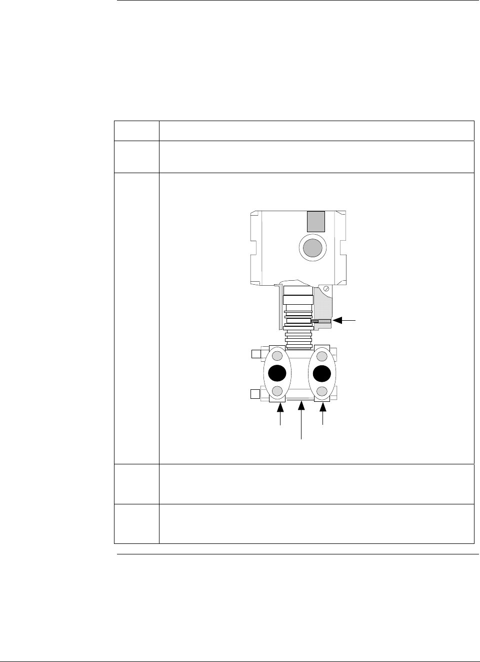
ST 3000 Release 300 and SFC Model STS103 User’s Manual 6/08
178
9.5 Replacing Meter Body
Procedure You can replace the complete meter body including process heads or
only the meter body on selected DP, GP and AP transmitters by using
the existing process head(s).
Use the procedure in Table 56 to install a meter body only.
Table 56 Replacing Meter Body Only
Step Action
1
Complete first 3 Steps in Table 55, as applicable, to remove PWA.
2 Use 4 mm size hex wrench to completely loosen set screw outside
housing.
Process Head Process Head
Meter Body
Set Screw
3
Carefully turn complete meter body counterclockwise to unscrew it
from electronics housing.
4
Remove nuts from bolts that hold process head or heads to center
section. Remove process heads and bolts
Continued on next page
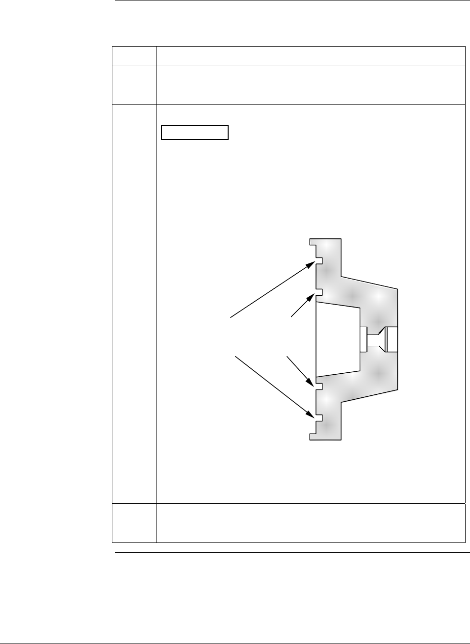
6/08 ST 3000 Release 300 and SFC Model STS103 User’s Manual 179
9.5 Replacing Meter Body, Continued
Procedure, continued
Table 56 Replacing Meter Body Only, continued
Step Action
5
Remove O-ring and clean interior of process head using soft bristle
brush and suitable solvent.
6
Replace O-ring.
ATTENTION The process head for a GP or an AP transmitter with
single-head design has two O-ring grooves. A large one which is 2 in
(50.8 mm) in diameter and a small one which is 1.3 in (33 mm) in
diameter as shown in the following illustration. On high-pressure,
model STG180, GP transmitters, be sure to use a small O-ring in the
smaller/inner groove. On other models of GP and AP transmitters,
use a large O-ring in the larger/outer groove. Never use both O-rings
together.
Larger O-ring
groove for
lower pressure
applications
Smaller O-ring
groove for
high pressure
applications
22518
GP/AP Process Head
• For process heads of a GP or AP transmitter with dual-head
design, see detail illustration for differential pressure transmitters
in Step 8.
7
Coat threads on process head bolts with anti-seize compound such
as “Neverseize” or equivalent.
Continued on next page
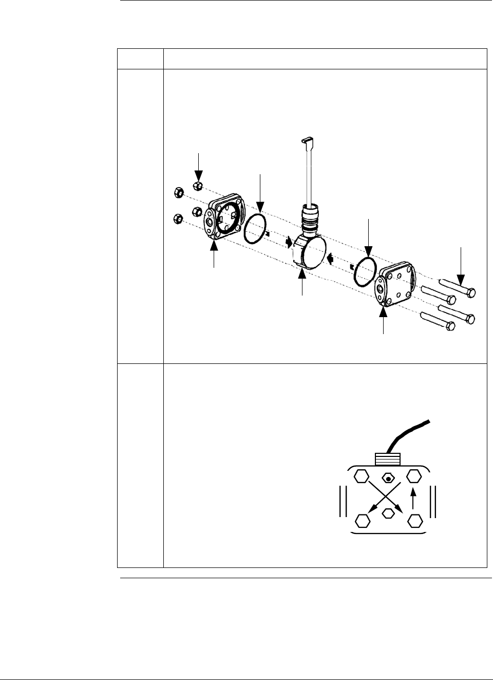
ST 3000 Release 300 and SFC Model STS103 User’s Manual 6/08
180
9.5 Replacing Meter Body, Continued
Procedure, continued
Table 56 Replacing Meter Body Only, continued
Step Action
8 Carefully assemble process head or heads and bolts to new meter
body. Finger tighten nuts.
Typical Series 100 DP Transmitter Meter Body
HP SIDE
LP
SIDE
Process
head
Process
head
Meter
Body
O-ring
O-ring
Bolts
Nuts Flex Tape
9 Use a torque wrench to gradually tighten nuts to torque rating shown
in Table 48 in sequence shown in following illustration. Tighten head
bolts in stages of 1/3 full torque, 2/3 full torque, and then full torque.
22519
A
lways tighten head bolts in
sequence shown and in these
stages:
1. 1/3 full torque
2. 2/3 full torque
3. Full torque 4
13
2
Continued on next page

6/08 ST 3000 Release 300 and SFC Model STS103 User’s Manual 181
9.5 Replacing Meter Body, Continued
Procedure, continued
Table 56 Replacing Meter Body Only, continued
Step Action
10
Feed flex tape on new meter body through neck of housing and
screw new meter body into housing until bottom of header portion of
center section is approximately flush with neck of electronics
housing.
11
Tighten outside set screw to be sure it is fully seated in slot in
header. Loosen set screw half turn, rotate housing to desired position
and tighten set screw.
12
Reverse actions in Steps 2 and 3 in Table 52, as applicable, to return
PWA and bracket to transmitter housing.
We recommend that you lubricate end-cap O-ring with silicon grease
such as Dow Corning #33 or equivalent before you replace end cap.
ATTENTION Be sure to orient Local Smart Meter for proper
viewing through end-cap window. You can rotate the meter mounting
orientation in 90 degree increments.
13
Return transmitter to service and turn ON power.
14
Verify transmitter’s configuration data. Restore saved database, if
applicable.

ST 3000 Release 300 and SFC Model STS103 User’s Manual 6/08
182

6/08 ST 3000 Release 300 and SFC Model STS103 User’s Manual 183
Section 10 —Calibration
10.1 Introduction
Section Contents This section includes these topics
Section Topic See Page
10.1 Introduction ................................................................................183
10.2 Overview ....................................................................................184
10.3 Calibrating Analog Output Signal ...............................................185
10.4 Calibrating Range with SFC.......................................................189
10.5 Resetting Calibration..................................................................192
About this section This section provides information about calibrating the transmitter’s
analog output and measurement range. It also covers the procedure for
resetting calibration to default values as a quick alternative to
measurement range calibration.

ST 3000 Release 300 and SFC Model STS103 User’s Manual 6/08
184
10.2 Overview
About calibration The ST 3000 Smart Transmitter does not require recalibration at
periodic intervals to maintain accuracy. If a recalibration is required, we
recommend that you do a bench calibration with the transmitter
removed from the process and located in a controlled environment to get
the best accuracy.
If the transmitter will be operating in the analog mode, you must
calibrate its output signal before you calibrate the transmitter’s
measurement range using the SFC. While it is not required to calibrate
the output signal first for transmitter's operating in the DE mode, you
can do it by using the SFC to read the output in percent.
You can also use the SFC to reset the calibration data to default values,
if it is corrupted, until the transmitter can be recalibrated. See Table 59
in this section for details.
ATTENTION If the transmitter is digitally integrated with our TPS system, you can
initiate range calibration and calibration reset functions through displays
at the Universal Station, GUS and Allen-Bradley PLCs. However, we
still recommend that you do a range calibration using an SFC with the
transmitter removed from service and moved to a controlled
environment. Details about doing a calibration reset through the
Universal Station are given in the PM/APM Smartline Transmitter
Integration Manual PM12-410 which is part of the TDC 3000X system
bookset.
Test Equipment
Required Depending upon the type of calibration you choose, you may need any
of the following test equipment to accurately calibrate the transmitter:
• Digital Voltmeter or milliammeter with 0.02% accuracy or better
• SFC Smart Field Communicator
• Calibration-standard input source with a 0.02% accuracy
• 250 ohm resistor with 0.01% tolerance or better.
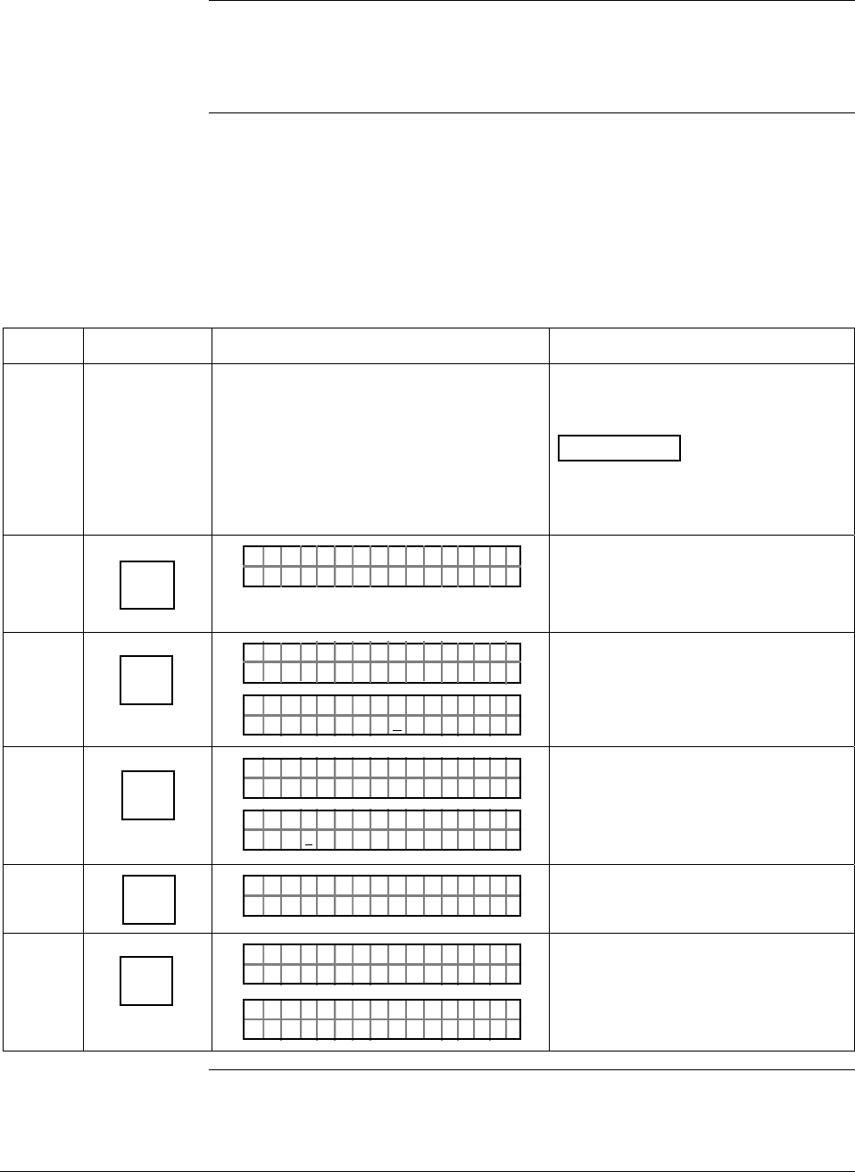
6/08 ST 3000 Release 300 and SFC Model STS103 User’s Manual 185
10.3 Calibrating Analog Output Signal
Background You can calibrate the transmitter’s analog output circuit at its 0 and
100% levels by using the transmitter in its constant-current source
mode. It is not necessary to remove the transmitter from service.
Procedure The procedure in Table 57 shows the steps for calibrating the output
signal for a transmitter in the analog mode. Note that the procedure is
similar for a transmitter in the DE mode, but the SFC must be used to
read the output in percent in place of the milliammeter or voltmeter
readings.
Table 57 Calibrating Output Signal for Transmitter in Analog Mode
Step Press Key Read Display or Action Description
1 Connect SFC across loop wiring and
turn it on. Connect a precision
milliammeter or voltmeter ( 0.02%
accuracy or better) in loop to check
readings.
See Figure 38 for sample test
equipment hookup.
ATTENTION Be sure the
accuracy of the resistor is 0.01% or
better for current measurements
made by voltage drop.
2 DE READ
A
ID
TA ON.G
?TRIPS SECURED?
Be sure any switches that may trip
alarms or interlocks associated with
analog loop are secured or turned
off.
3 NON-VOL
ENTER
(Yes)
TA ON.G
SFC WORK ING.. .
LIN AG NO.DP T
PT3Ø11
Confirm that “TRIPS” are secured
and establish communications with
sample transmitter PT 3011
4 INPUT
J
OUT-
PUT
PTOUT 301 11P
FC WOSING.RK . .
PTOU T
%
30111
3.24
P
Ø
Display shows current transmitter
output level and it will update every
six seconds. Be sure to time your
next key press with an updated
display.
5 Z
0
PTOU T
%
30111
Ø_
P
Key in 0 (zero) as desired output
signal level in percent.
6 NON-VOL
ENTER
(Yes)
PTOUT 301 11P
FC WOSING.RK . .
%.Ø
PTOUT 301 11P
ØØ
#
Put transmitter into constant-current
source mode as noted by “#” sign in
display and set output to 0%.
Continued on next page
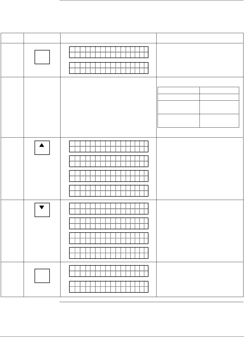
ST 3000 Release 300 and SFC Model STS103 User’s Manual 6/08
186
10.3 Calibrating Analog Output Signal, Continued
Procedure, continued
Table 57 Calibrating Output Signal for Transmitter in Analog Mode, continued
Step Press Key Read Display or Action Description
7 RESET
K
COR-
RECT
PTOUT 301 11P
FC WOSING.RK . .
ACE
PTOUT 301 11P
T
#
CORR D C ZERO
Calibrate output signal to 0%.
8 Check that milliammeter or voltmeter
reading is 4mA or 1V.
If reading is … Then…
correct go to Step 11.
lower than 4mA go to Step 9.
or 1V
higher than go to Step 10.
4mA or 1V
9
NEXT
H
O
PTOUT 301 11P
1
#
INC C U TSN
PTOUT 301 11P#
FC WOSING.RK . .
D
PTOUT 301 11P
A
#
IN E mA4CRE S
ACE
PTOUT 301 11P
T
#
CORR D C ZERO
Gradually raise output to 4mA or 1V
reading. Repeat this Step as
required.
10
PREV
L
O
PTOUT 301 11P
1
#
DEC C U TSN
PTOUT 301 11P#
FC WOSING.RK . .
D
PTOUT 301 11P
A
#
DE E mA4CRE S
ACE
PTOUT 301 11P
T
#
CORR D C ZERO
Gradually decrease output to 4mA
or 1V reading. Repeat this Step as
required.
11 INPUT
J
OUT-
PUT
PTOUT 301 11P#
FC WOSING.RK . .
%.Ø
PTOUT 301 11P
ØØ
#
Call up output for display.
Present output signal level in
percent.
Continued on next page
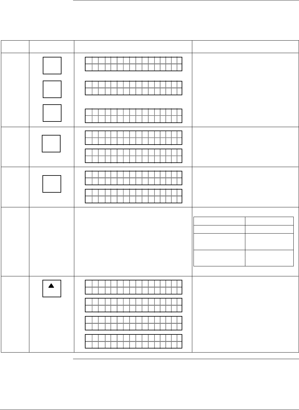
6/08 ST 3000 Release 300 and SFC Model STS103 User’s Manual 187
10.3 Calibrating Analog Output Signal, Continued
Procedure, continued
Table 57 Calibrating Output Signal for Transmitter in Analog Mode, continued
Step Press Key Read Display or Action Description
12
1
V
Z
0
Z
0
PTOU T
%
30111
1_
P#
PTOU T
%
30111
1Ø
P
_
#
%1Ø
.PTOUT 301 11P
_
Ø
#
Key in 100 as desired output level in
percent.
13 NON-VOL
ENTER
(Yes)
PTOUT 301 11P#
FC WOSING.RK . .
%1Ø
.PTOUT 301 11P
.Ø
#
ØØ
Set output to 100%.
14 RESET
K
COR-
RECT
PTOUT 301 11P#
FC WOSING.RK . .
ACE
PTOUT 301 11P
T
#
CORR D C SPAN
Calibrate output to 100%.
15 Check that milliammeter or voltmeter
reading is 20mA or 5V.
If reading is … Then…
correct go to Step 18.
lower than go to Step 16.
20mA or 5V
higher than go to Step 17.
20mA or 5V
16
NEXT
H
O
PTOUT 301 11P
1
#
INC C U TSN
PTOUT 301 11P#
FC WOSING.RK . .
D
PTOUT 301 11P
A
#
IN E mAØCRE S 2
ACE
PTOUT 301 11P
T
#
CORR D C SPAN
Gradually raise output to 20mA or
5V reading. Repeat this Step as
required.
Continued on next page
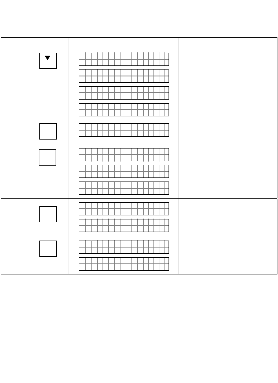
ST 3000 Release 300 and SFC Model STS103 User’s Manual 6/08
188
10.3 Calibrating Analog Output Signal, Continued
Procedure, continued
Table 57 Calibrating Output Signal for Transmitter in Analog Mode, continued
Step Press Key Read Display or Action Description
17
PREV
L
O
PTOUT 301 11P
1
#
DEC C U TSN
PTOUT 301 11P#
FC WOSING.RK . .
D
PTOUT 301 11P
A
#
DE E mAØCRE S 2
ACE
PTOUT 301 11P
T
#
CORR D C SPAN
Gradually decrease output to 20mA
or 5V reading. Repeat this Step as
required.
18 ^
SHIFT
NON-VOL
ENTER
(Yes)
PTOUT 301 11P
FT–SH I
#
PTOUT 301 11P#
FC WOSING.RK . .
ON
PTOUT 301 11P
O
#
DATA V L TILENA
LIN DP
.Y. .RE AD
T 011P3 #
Initiate shift key selection
Saves data in transmitter’s
nonvolatile memory. This takes
approximately 8 seconds.
19 INPUT
J
OUT-
PUT
PTOUT 301 11P#
FC WOSING.RK . .
%1Ø
.PTOUT 301 11P
.Ø
#
ØØ
Call up output for display.
Present output signal level in
percent.
20 CLR
(NO)
PTOUT 301 11P#
FC WOSING.RK . .
LIN DP
.Y. .RE AD
T 011P3
Exit constant-current source mode.
6/08 ST 3000 Release 300 and SFC Model STS103 User’s Manual 189
10.4 Calibrating Range with SFC
Background The ST 3000 Smart Transmitter has two-point calibration. This means
when you calibrate two points in the calibration range all the points in
that range adjust to that calibration.
Procedure The procedure in Table 58 shows the steps for calibrating a differential
pressure (DP) type transmitter to a range of 0 to 200 inH2O for example
purposes. This procedure assumes that the transmitter is removed from
the process and located in a controlled environment.
ATTENTION You must have a precision pressure source with an accuracy of 0.04% or
better to do a range calibration. Note that we factory calibrate ST 3000
Smart Transmitters with inches of water ranges using inches of water
pressure referenced to a temperature of 39.2 °F (4°C).
Table 58 Calibrating Measurement Range With SFC
Step Press Key Read Display or Action Description
1 Connect power supply and SFC to
signal terminals on transmitter’s terminal
block. Connect a calibration-standard
pressure source to high pressure side of
DP type transmitter.
See Figure 52 for typical SFC,
power supply, and pressure source
hookup for calibration.
2 Turn on power supply and allow
transmitter to stabilize its operation for
approximately 30 minutes.
3 Turn on SFC.
4 DE READ
A
ID
TA ON.G
?TRIPS SECURED?
Does not apply for bench calibration.
5 NON-VOL
ENTER
(Yes)
TA ON.G
SFC WORK ING.. .
LIN AG NO.DP T
PT3Ø11
Acknowledge prompt and establish
communications with sample
transmitter PT 3011 to be calibrated.
6 Adjust pressure source to apply
pressure equal to LRV (0%)
7 E
LRV
0%
PTLRV 3Ø111
ØØØ
.
ØØ "H2O_39F
Present LRV setting. If displayed
value does not match applied
pressure, key in matching LRV
value or adjust pressure
accordingly.
8 RESET
K
COR-
RECT
PTLRV
L
3Ø1 1
T
1
RRRECO VC?
Prompt asks if LRV is to be
calibrated to applied reference
pressure. If it is to be calibrated, go
to next Step. If it isn’t, press [CLR]
key and try again.
Continued on next page
ST 3000 Release 300 and SFC Model STS103 User’s Manual 6/08
190
10.4 Calibrating Range with SFC, Continued
Procedure, continued
Table 58 Calibrating Measurement Range With SFC, continued
Step Press Key Read Display or Action Description
9 NON-VOL
ENTER
(Yes)
ORK NGCW .F.S.I
PTLRV 3Ø111
PTLRV 3Ø111
LRV TRRECO C DE
PTLRV 3Ø111
ØØØ
.
ØØ "H2O_39F
Calibrates LRV to reference input
pressure for zero calibration.
10 Adjust pressure source to apply
pressure equal to URV (100%)
11 URV
100%
F
PTUR V 3Ø1 11
ØØØ
.
2Ø "H2O_39F
Present URV setting. If displayed
value does not match applied
pressure, key in matching URV
value or adjust pressure accordingly
before you press [CORRECT] key in
next step.
12 RESET
K
COR-
RECT
PTUR V
U
3Ø11
T
1
RRRECO VC?
Prompt asks if URV is to be
calibrated to applied reference
pressure. If it is to be calibrated, go
to next Step. If it isn’t, press [CLR]
key and try again.
13 NON-VOL
ENTER
(Yes)
ORK NGCW .F.S.I
PTUR V 3Ø1 11
PTUR V 3Ø111
UR V TRRECO C DE
PTUR V 3Ø1 11
ØØØ
.
2Ø "H2O_39F
Calibrates URV to reference input
pressure for span (100%)
calibration.
14 ^
SHIFT
NON-VOL
ENTER
(Yes)
FT–SH I
PTUR V 3Ø1 11
ORK NGCW .F.S.I
PTUR V 3Ø1 11
PTUR V 3Ø1 11
NO VO ATLNDA TA I LE
LIN DP
.Y. .RE AD
Initiate shift key selection
Saves data in transmitter’s
nonvolatile memory. This takes
approximately 8 seconds.
Continued on next page
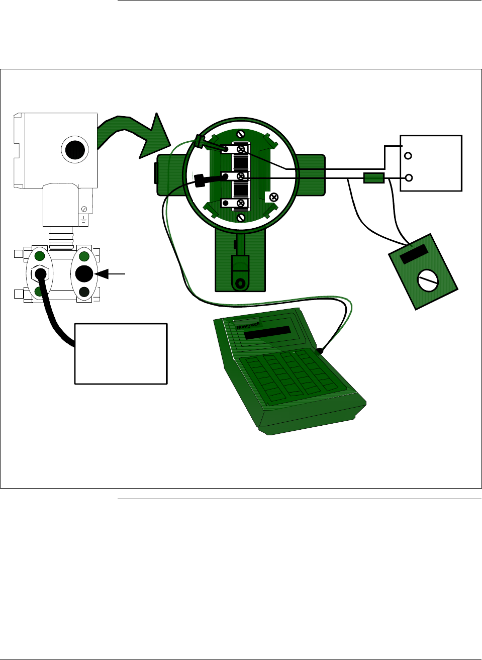
6/08 ST 3000 Release 300 and SFC Model STS103 User’s Manual 191
10.4 Calibrating Range with SFC, Continued
Procedure, continued
Figure 52 Typical Calibration Hookup.
- SIGNAL +
+ -
TEST
24Vdc
Power
Supply
+
-
DVM
(See NOTES)
+ Red
- Black
ST 3000
Low
Pressure
Head
SFC
Dead Weight
Tester
(See NOTES)
250
Ω
NOTES: The digital voltmeter must have a 0.02% accuracy or better.
The calibration-standard input source must have a 0.02% accuracy.
The 250 ohm resistor must have a 0.01% tolerance or better.

ST 3000 Release 300 and SFC Model STS103 User’s Manual 6/08
192
10.5 Resetting Calibration
Background You can erase incorrect calibration data by resetting the data to default
values through the SFC. The default values return the transmitter
calibration to the original factory “characterization” values.
Characterization calculates a mathematical model of the performance of
the transmitter’s sensors and then stores that data in the transmitter’s
memory. Note that this is not the “final calibration” which is done at the
end of the process against the ordered range.
While resetting the calibration will return the transmitter to a close
approximation of the previous calibration using its stored
characterization data, the accuracy of the “reset” transmitter will be
lower than the specified final calibrated accuracy. The calibration is not
exact since the transmitter mounting angle may be different than the
factory mounting angle. This means that the transmitter is calculating its
output based on the characterization equation alone without any
compensation for the small residual errors of zero offset and span
correction.
For example, a typical zero offset correction is less than 0.1 inH2O for a
400 inH2O range and a typical span correction is less than 0.2%
regardless of the range (down to the point where specification turndown
begins). The typical performance of a 400 inH2O transmitter after a
calibration reset (or a “Corrects Reset” as it is often called) can be
expressed as:
Accuracy = 0.2% +
0.1 inH2O
Span inH2O
⎛
⎝
⎜ ⎞
⎠
⎟
• 100%
By correcting the zero input, the typical performance will be 0.2% or
better.
For other transmitter ranges, the initial zero offset will be scaled by the
ratio of the Upper Range Limit (URL) to 400 inH2O at 39.2°F (4°C).
Thus, for a 100 psi range, the initial zero offset can be expressed by:
0.1inH2O•2768inH2O
400inH2O=0.7inH2O or 0.025psi
Note that these are typical values and they may vary. However, our
patented characterization method includes several techniques which
help to ensure that this level of performance can be achieved.
Continued on next page
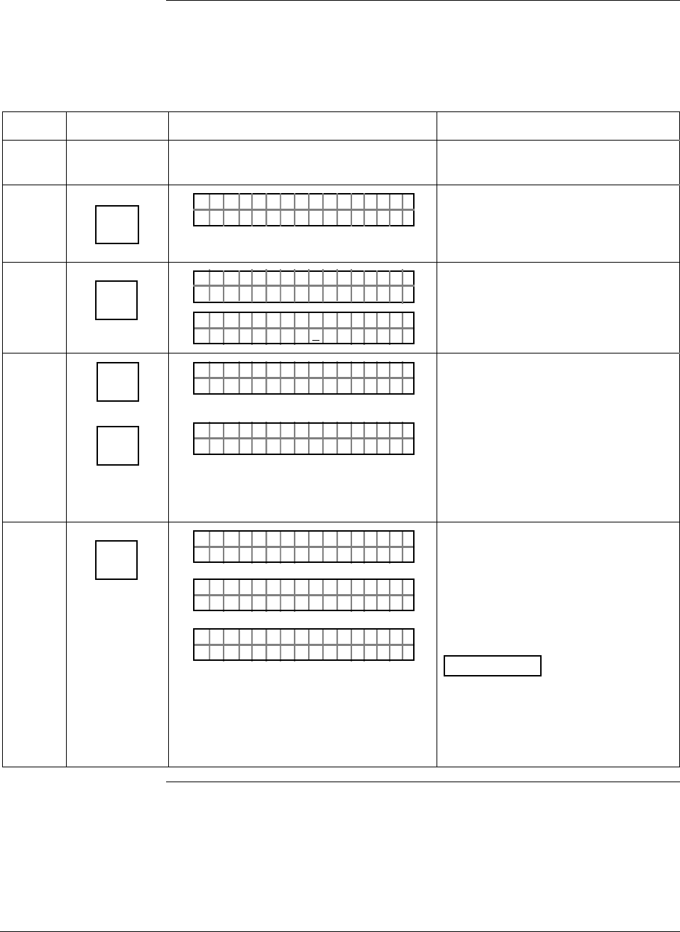
6/08 ST 3000 Release 300 and SFC Model STS103 User’s Manual 193
10.5 Resetting Calibration, Continued
Procedure The procedure in Table 59 shows how to reset calibration data in a
transmitter with an SFC.
Table 59 Resetting Calibration Data With SFC
Step Press Key Read Display or Action Description
1 Connect SFC across loop wiring and
turn it on.
2 DE READ
A
ID
TA ON.G
?TRIPS SECURED?
Be sure any switches that may trip
alarms or interlocks associated with
analog loop are secured or turned
off.
3 NON-VOL
ENTER
(Yes)
TA ON.G
SFC WORK ING.. .
LIN AG NO.DP T
PT3Ø11
Confirm that “TRIPS” are secured
and establish communications with
sample transmitter PT 3011
4 ^
SHIFT
RESET
K
COR-
RECT
FT–SHI
LIN DP T 011P3
RECCOR
T 011P3
RE SET ST?
Initiate shift key selection
Prompt asks if you want to correct
calibration data by resetting it to
default values. If you do want to
reset data, go to next Step. If you
don’t, press [CLR] key to exit
function.
5 NON-VOL
ENTER
(Yes)
#T 011P3
OR K NGCW .F.S.I
#T 011P3
R ESETRECCOR ST
LIN DP
.Y. .RE AD
T 011P3 #
Previous calibration “CORRECTS”
are removed and calibration is reset
to default characterization values as
indicated by non-critical status
symbol “#” on right-hand side of
display. Symbol remains on display
until transmitter is recalibrated.
ATTENTION The accuracy of the
reset transmitter will be
approximately 0.2% at reference
conditions – See the Background
paragraph in this section for more
details. .

ST 3000 Release 300 and SFC Model STS103 User’s Manual 6/08
194

6/08 ST 3000 Release 300 and SFC Model STS103 User’s Manual 195
Section 11 —Troubleshooting
11.1 Introduction
Section Contents This section includes these topics
Section Topic See Page
11.1 Introduction ................................................................................195
11.2 Overview ....................................................................................196
11.3 Clearing the “#” Symbol From SFC Display ...............................197
11.4 Diagnostic Messages .................................................................199
11.5 Running Status Check ...............................................................202
11.6 Interpreting Messages................................................................203
11.7 Checking SFC Display and Keyboard........................................207
About this section This section identifies diagnostic messages that may appear in the SFC
and describes what they mean. An interpretation of diagnostic messages
is given which suggests possible cause and corrective action for each
message. Procedures are provided for running a status check and testing
the SFC keyboard.

ST 3000 Release 300 and SFC Model STS103 User’s Manual 6/08
196
11.2 Overview
Diagnostics The SFC and ST 3000 transmitter are constantly running internal
diagnostics to monitor the functions and status of the control loop and
their communications link.
When a diagnostic failure is detected, a corresponding message is
generated for the SFC display. See Section 11.4 Diagnostic Messages
for details.
ATTENTION There are additional diagnostics provided by the STIMV IOP for
transmitters integrated with the TPS system and any message will
appear in the TRANSMITTER STATUS field of the Detail Display in
the Universal Station. Details about the STIMV IOP diagnostic
messages are given in the PM/APM Smartline Transmitter Integration
Manual PM12-410 which is part of the TDC 3000X system bookset.
Troubleshooting tool Your primary troubleshooting tool is using the SFC to run a status
check, recording displayed diagnostic messages, and then interpreting
the diagnostic messages. See Table 66 to run a status check using an
SFC.
You should also use the SFC to verify the transmitter’s configuration
data and check to be sure your process is operating correctly.
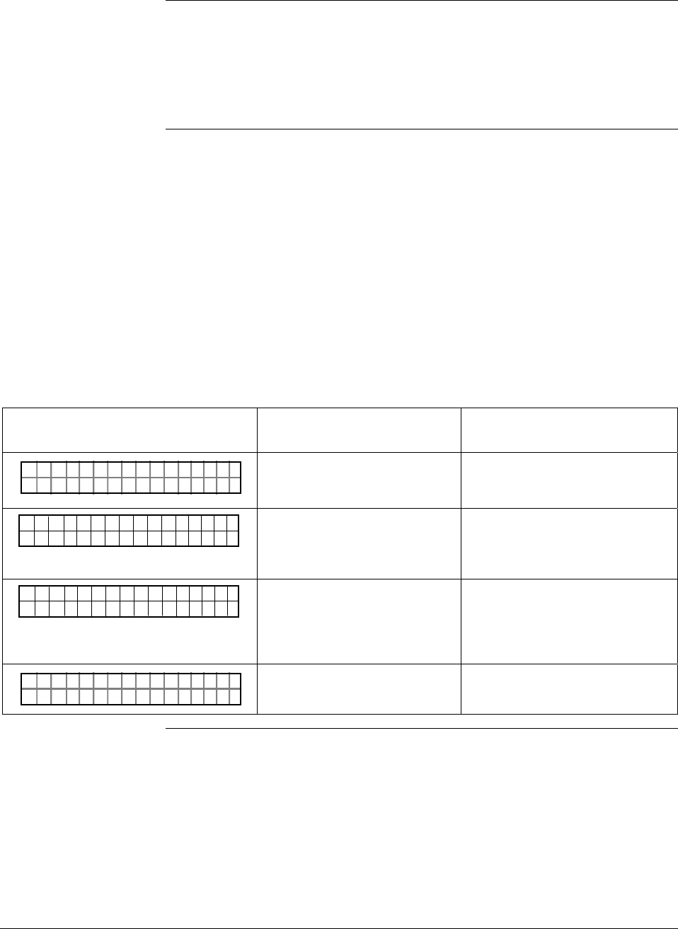
6/08 ST 3000 Release 300 and SFC Model STS103 User’s Manual 197
11.3 Clearing the “#” Symbol From SFC Display
About the “#” symbol When transmitter diagnostics detect a non-critical status condition, the
number symbol “#” appears as the last character in the top row of the
SFC display along with whatever you are displaying at the time. Thus,
the purpose of the # symbol is simply to let you know that a non-critical
status condition exists.
Procedure To clear the # symbol from the SFC display, you must first determine
what non-critical status condition exists and then correct it. The general
procedure would be:
• Press [STAT] key on SFC and record diagnostic messages that appear in
bottom row of display.
• Use Table 60 as an aid in determining the possible cause of the
diagnostic message and the suggested corrective action to take to clear
the # symbol.
• The # symbol will disappear from the display when the diagnostic
condition is corrected.
Table 60 Clearing the # Symbol from the SFC Display
If Message is. . . Then, Possible Cause is. . . And, Suggested Corrective
Action is. . .
#T 011P3
R ESETRECCOR ST
ST ATUS
All calibration “CORRECTS” were
deleted and data was reset to
default characterization values.
Recalibrate transmitter.
#
T 0 1 1 P 3
N C O R R E S S E X C S
S T A T U S
P A
SPAN correction factor is outside
acceptable limits. Could be that
transmitter was in output mode.
Check input pressure and be sure it
matches calibrated range value.
Check meter body. Do a URV
CORRECT procedure.
#
T 0 1 1 P 3
O C O R R E S S E X C Z
S T A T U S
E R
ZERO correction factor is outside
acceptable limits. Could be that
either INPUT was zero or
transmitter was in output mode
during a CORRECT procedure.
Check input pressure and be sure it
matches calibrated range value.
Check meter body. Do a LRV
CORRECT procedure.
#T 011P3
MODEOUTIN U
ST ATUS
TP
Transmitter is operating as a
current source. Press [OUTPUT] and [CLR] keys to tell
transmitter to exit output mode.
Continued on next page
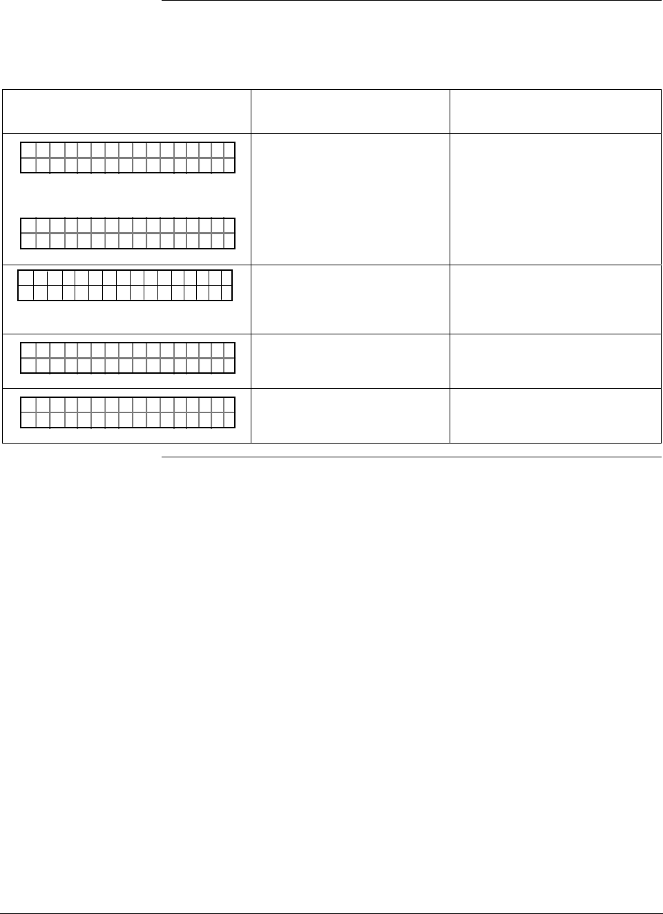
ST 3000 Release 300 and SFC Model STS103 User’s Manual 6/08
198
11.3 Clearing the “#” Symbol From SFC Display, Continued
Procedure, continued
Table 60 Clearing the # Symbol from the SFC Display, continued
If Message is. . . Then, Possible Cause is. . . And, Suggested Corrective
Action is. . .
#T 011P3
OAD.OM. E
ST ATUS
RVBL
OR
#T 011P3
AULROET Y
ST ATUS
DEFMB T
Pressure input is two times
greater than URL of transmitter. • Check range and, if required,
replace transmitter with one that
has a wider range.
• Meter body may have been
damaged. Check the transmitter
for accuracy and linearity
Replace meter body and
recalibrate, if needed.
#
T 0 1 1 P 3
C O M A O E
S T A T U S
T D P N C P M
No temperature compensation
data exists for D/A converter. Effect will be minor degradation of
ambient temperature influence
specifications. Replace electronics
module
#T 011P3
TEMOEV
ST ATUS
OSRSR PEN
Meter body temperature is too
high. Accuracy and life span may
decrease if it remains high.
Take steps to insulate meter body
from temperature source.
#T 011P3
ON
ST ATUS
NUWKN
Selection is unknown Be sure SFC software is latest
version. Press SHIFT and 3 to view
SFC software version.
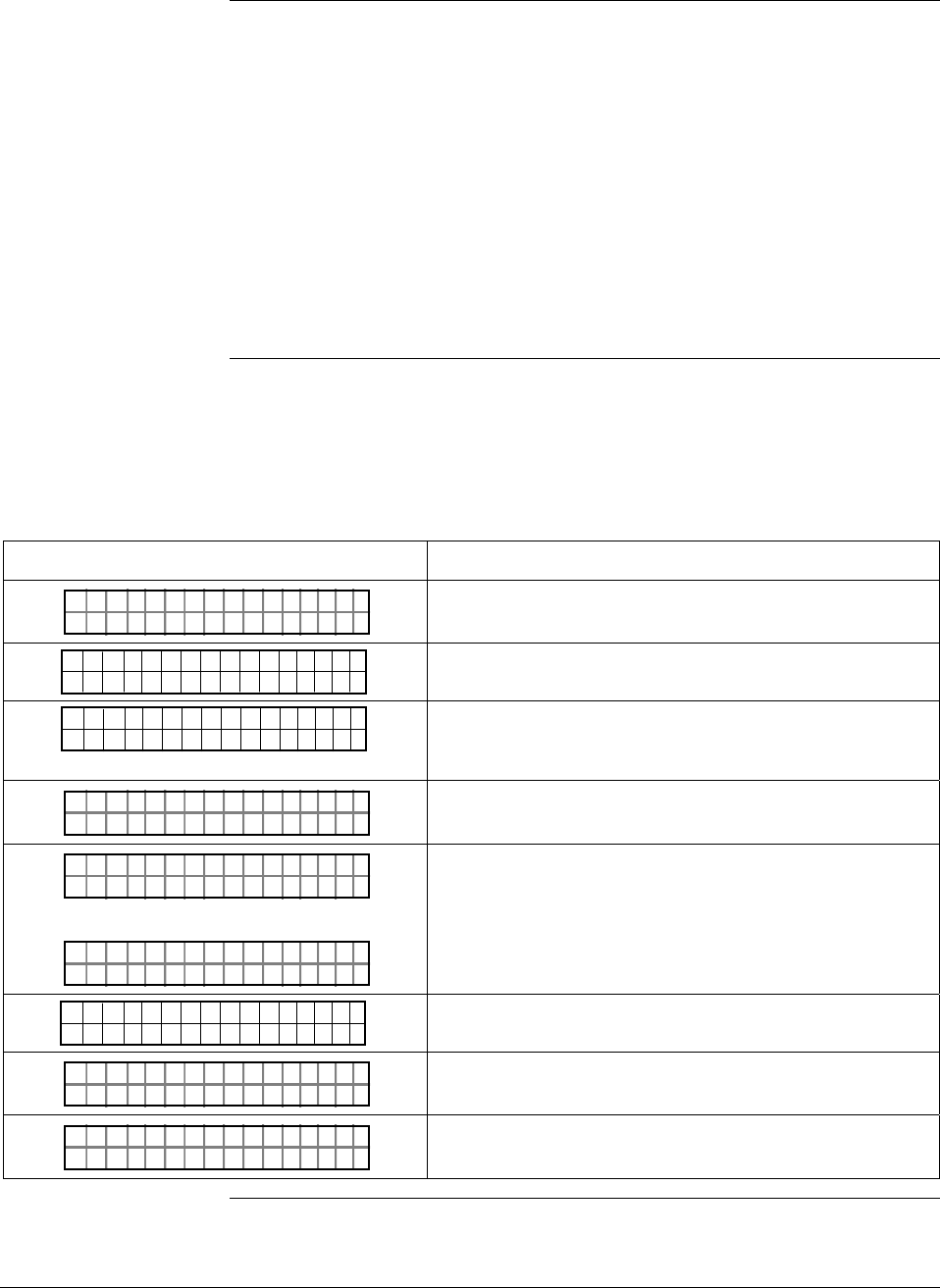
6/08 ST 3000 Release 300 and SFC Model STS103 User’s Manual 199
11.4 Diagnostic Messages
Summary The diagnostic messages can be grouped into one of these five
categories.
• Non-Critical Failures — Transmitter continues to calculate PV output.
• Critical Failures — Transmitter drives PV output to failsafe state.
• Communications Errors
• Invalid Key Entry Errors
• Interrupt Messages
A description of the messages in each category is given in the following
paragraphs. Note that there also a few messages that we have grouped as
general interrupt messages at the end of this section.
Non-critical failures Table 61 summarizes the non-critical SFC status message displays. All
SFC functions remain operational during a non-critical failure and the
“#” sign appears on the right hand side of the display.
Table 61 Summary of Diagnostic Messages for Non-Critical Failures
Message Description
#T 011P3
R ESETRECCOR ST
ST ATUS
Must recalibrate transmitter to attain required accuracy.
#
T 0 1 1 P 3
N C O R R E S S E X C S
S T A T U S
P A
SPAN correction factor is outside the acceptable limits
for accurate operation.
#
T 0 1 1 P 3
O C O R R E S S E X C Z
S T A T U S
E R
Zero calibration value is too large. Excess zero
correction may be an indication of a problem with the
process or installation.
#T 011P3
MODEOUTIN U
ST ATUS
TP
Transmitter is operating as current source.
#T 011P3
OAD.OM. E
ST ATUS
RVBL
OR
#T 011P3
AULROET Y
ST ATUS
DEFMB T
Input pressure is more that 2 times greater than the
Upper Range Limit of the transmitter.
#
T 0 1 1 P 3
C O M A O E
S T A T U S
T D P N C P M
No temperature compensation data exists for D/A
converter.
#T 011P3
TEMOEV
ST ATUS
OSRSR PEN
Meter body temperature is too high.
#T 011P3
ON
ST ATUS
NUWKN
Status is unknown.
Continued on next page
ST 3000 Release 300 and SFC Model STS103 User’s Manual 6/08
200
11.4 Diagnostic Messages, Continued
Critical failures Table 62 summarizes the critical SFC status message displays. A critical
failure has these effects on SFC operation.
• Only ID, OUTPUT, and STATUS functions remain operational.
• The critical status message is displayed for three seconds followed by
the applicable status message. Run the status check to view messages
again.
• The transmitter’s output is driven to its failsafe direction - upscale or
downscale.
Table 62 Summary of Diagnostic Messages for Critical Failures
Message Description
PTOUT 301 11P
RHA M LTURPO ACF
Characterization PROM failure.
PT 3011
OLE I >ACRN <ESTC
OUT 1P
No temperature compensation data exists for
calculations.
PT 3011
OLE I >BCRN <ESTC
OUT 1P
Transmitter’s nonvolatile memory (NVM) fault.
PT 3011
OLE I >CCRN <ESTC
OUT 1P
Transmitter’s random access memory (RAM) fault.
PT 3011
OLE I >DCRN <ESTC
OUT 1P
Transmitter’s programmable read only memory (PROM)
fault.
T 0 1 1 P 3
FAULTE R BME T O
S T A T U S
DY
Electronics (PWA) and meter body are incompatible.
PTOUT 301 11P
TUS IPC TSUENP
Possible meter body or electronics based problem.
Communication
errors Table 63 summarizes the message displays associated with
communication errors. A communication error has these effects on SFC
operation.
• All the SFC functions are disabled.
• Communication error messages are cycled in the display at two second
intervals. Press [ID] and then [ENTER] to view messages again.
Table 63 Summary of Diagnostic Messages for Communication Errors
Message Description
TAG O
ND NRREA D
N.
UROE
Communications is unsuccessful.
TAG O
AI OLD CFE MM
N.
CHK
SFC failed a communication diagnostic test.
TAG O
HI LEORO
N.
/LTSV
Loop resistance is too large or supply voltage is too low.
TAG O
LL RAOGE
N.
NSLPIE S E
Illegal response from transmitter.
Continued on next page
6/08 ST 3000 Release 300 and SFC Model STS103 User’s Manual 201
11.4 Diagnostic Messages, Continued
Communication
errors, continued
Table 63 Summary of Diagnostic Messages for Communication Errors, continued
Message Description
TAG O
NV DIBLA
N.
ASDAIA T E
Transmitter database was incorrect at powerup.
TAG O
NV RIELE
N.
STDUIA Q
Request is invalid.
TAG O
LO PLS
N.
OEWRO
Loop resistance is too low.
TAG O
ORXT ONM ES
N.
NSRPE
No response from transmitter.
TAG O
FTASF
N.
UCL
SFC is not operating properly.
Invalid key entry
errors Table 64 summarizes the message displays for possible invalid key
entry errors.
Table 64 Summary of Diagnostic Messages for Invalid Key Entry Errors
Message Description
None - Keystroke makes display blink Invalid keystroke
URV
>GN
1.
ER
PT 3011
A"H2 O
_39F
The computed SFC value is outside the display range.
Interrupt messages Table 65 summarizes messages that may interrupt the SFC display.
Table 65 Summary of Interrupt Messages For SFC Display
Message Meaning Remedy
PTOU T 30111P
ARI STC UCTITALS
Diagnostics has detected a
critical failure. Press [STAT] key to retrieve
messages.
LIN AG NO.DP :
P T3Ø11
Colon
The SFC battery is low. Recharge the battery.
LIN DP
.Y. .RE AD
T 011P3 #
Number Symbol
Diagnostics has detected a
non-critical failure. Or, the
transmitter is in its output
mode.
Press [STAT] key to retrieve
messages or exit the output
mode.
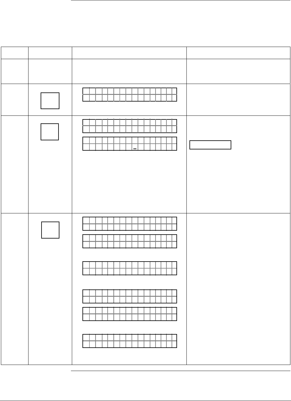
ST 3000 Release 300 and SFC Model STS103 User’s Manual 6/08
202
11.5 Running Status Check
Procedure The procedure in Table 66 shows how to run a status check using the
SFC.
Table 66 Running a Status Check With SFC
Step Press Key Read Display or Action Description
1 Connect SFC across loop wiring for
transmitter whose status is to be
checked
Be sure to put analog loop into
manual mode.
2 DE READ
A
ID
TA ON.G
?TRIPS SECURED?
Be sure any switches that may trip
alarms or interlocks associated with
analog loop are secured or turned
off.
3 NON-VOL
ENTER
(Yes)
TA ON.G
SFC WORK ING.. .
LIN AG NO.DP T
PT3Ø11
Confirm that “TRIPS” are secured
and establish communications with
sample transmitter PT 3011
ATTENTION If a communications
error is detected, applicable
diagnostic messages will cycle at
two-second intervals in the display
and then display returns to the
prompt PUT LOOP IN MAN. Repeat
Steps 2 and 3 to view messages
again. Communications is not
established and all SFC functions
are disabled.
4 U
STAT
F/S DIR
T 011P3ST ATUS
OR K NGCW .F.S.I
PTST A 3011ST
TA USSHECKC=O
U
TK
OR
#T 011P3
TEMOEV
ST ATUS
OSRSR PEN
OR
PTST A 3011ST
ARI STC UCTITALS
U
PTST A 3011ST
CSU ISE TUPNPT
U
THEN
LIN DP
.Y. .RE AD
T 011P3
Initiate status check.
Transmitter and SFC are operating
normally.
Diagnostic message appears for
detected fault.
Critical status appears followed by
applicable diagnostic messages.
Signals end of status messages for
display. Press [STAT] key to display
messages again. When there are two
or more messages, they are cycled in
display at 5-second intervals.
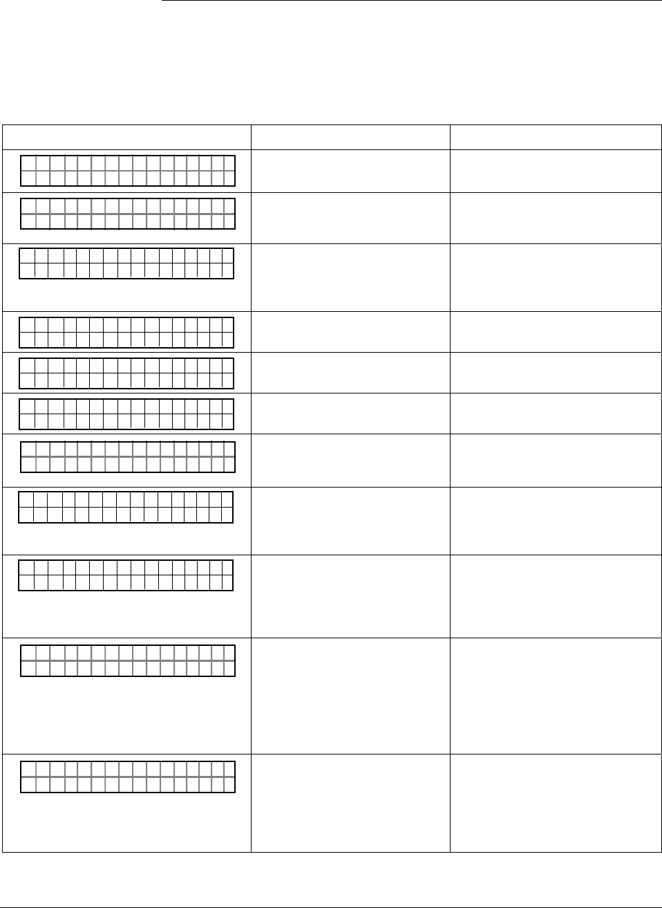
6/08 ST 3000 Release 300 and SFC Model STS103 User’s Manual 203
11.6 Interpreting Messages
Interpretation table Most of the diagnostic messages that can be displayed on the SFC are
listed in alphabetical order in Table 67 along with a description and
suggested action to be taken.
Table 67 Diagnostic Message Interpretation Table
Message Possible Cause What to Do
PT 301 1
RHA M LTURPO ACF
STA STU
Characterization PROM is not
functioning correctly. Replace meter body.
#T 011P3
R ESETRECCOR ST
ST ATUS
All calibration “CORRECTS” were
deleted and data was reset to
default values.
Recalibrate transmitter.
PT 3011
OLE I >ACRN <ESTC
OUT 1P
No temperature compensation
data exists for calculations.
Effect will be minor degradation of
ambient temperature influence
specifications. Replace electronics
module (PWA).
PT 3011
OLE I >BCRN <ESTC
OUT 1P
Transmitter’s nonvolatile memory
fault. Replace electronics module (PWA).
PT 3011
OLE I >CCRN <ESTC
OUT 1P
Transmitter’s random access
memory (RAM) fault. Replace electronics module (PWA).
PT 3011
OLE I >DCRN <ESTC
OUT 1P
Transmitter’s programmable read
only memory (PROM) fault. Replace electronics module (PWA).
TAG O
ND NRREA D
N.
UROE
Communications unsuccessful. Check loop wiring and SFC
connections. If error persists,
replace transmitter.
#
T 0 1 1 P 3
N C O R R E S S E X C S
S T A T U S
P A
SPAN correction factor is outside
acceptable limits. Could be that
transmitter was in output mode.
Check input pressure and be sure it
matches calibrated range value.
Check meter body. Do a URV
CORRECT procedure.
#
T 0 1 1 P 3
O C O R R E S S E X C Z
S T A T U S
E R
ZERO correction factor is outside
acceptable limits. Could be that
either INPUT was incorrect or
transmitter was in output mode
during a CORRECT procedure.
Check input pressure and be sure it
matches calibrated range value.
Check meter body. Do an LRV
CORRECT procedure.
TAG O
AI OLD CFE MM
N.
CHK
SFC failed a communications
diagnostic check. Could be an
SFC electronic problem or a faulty
or dead communication loop.
• Check polarity and try again.
• Press [STAT] and do any
corrective action required and try
again.
• Check communication loop.
• Replace SFC.
TAG O
HI LEORO
N.
/LTSV
Either there is too much
resistance in loop (open circuit),
voltage is too low, or both.
Check polarity, wiring, and power
supply. There must be 11 volts
minimum at transmitter to permit
operation. Check for defective or
misapplied capacitive or inductive
devices (I/Ps) on the loop wiring.
Continued on next page
ST 3000 Release 300 and SFC Model STS103 User’s Manual 6/08
204
11.6 Interpreting Messages, Continued
Interpretation table,
continued
Table 67 Diagnostic Message Interpretation Table, continued
Message Possible Cause What to Do
OTE
.H
SAVE / R
W.M
ES R
ISMATCH
Hardware mismatch. Part of
Save/Restore function. Nothing – SFC tried to restore as
much of database as possible.
#T 011P3
MODEOUTIN U
ST ATUS
TP
Transmitter is operating as a
current source. Press [OUTPUT] and [CLR] keys to tell
transmitter to exit output mode.
TAG O
LL RAOGE
N.
NSLPIE S E
Transmitter sent illegal response
to SFC Try communicating again.
TAG O
NV DIBLA
N.
ASDAIA T E
Transmitter database was
incorrect at powerup. • Try communicating again.
• Verify database configuration.
Manually update non-volatile
memory with each parameter.
URV
ILA
1.
IN
PT 3011
VREQUDEST
• Requesting transmitter to
correct or set its URV to a
value which results in too
small a span, or correct its
LRV or URV while in output
mode.
• Keystroke is not valid for given
transmitter.
• Check that correct URV
calibration pressure is being
applied to transmitter, or that
transmitter is not in output mode.
• Check that keystroke is
applicable for given transmitter.
TAG O
LO PLS
N.
OEWRO
Not enough resistance in series
with communication loop. Check sensing resistor and increase
resistance to at least 250Ω.
#T 011P3
OAD.OM. E
ST ATUS
RVBL
OR
#T 011P3
AULROET Y
ST ATUS
DEFMB T
Pressure input is two times
greater than URL of transmitter. • Check range and, if required,
replace transmitter with one that
has a wider range.
• Meter body may have been
damaged. Check the transmitter
for accuracy and linearity
Replace meter body and
recalibrate, if needed.
T 0 1 1 P 3
FAULTE R BME T O
S T A T U S
DY
Electronics (PWA) and meter
body are incompatible. Obtain matching meter body for
given transmitter model and series.
Check transmitter nameplate for
model number data.
T 011P3
ONSAE
ST ATUS
RKPNESC
Transmitter sent a negative
response because it could not
process one or more commands.
Check configuration and try again.
Continued on next page
6/08 ST 3000 Release 300 and SFC Model STS103 User’s Manual 205
11.6 Interpreting Messages, Continued
Interpretation table,
continued
Table 67 Diagnostic Message Interpretation Table, continued
Message Possible Cause What to Do
TAG O
ORXT ONM ES
N.
NSRPE
No response from transmitter.
Could be transmitter or loop
failure.
• Try communicating again.
• Press [ID] key and do any
corrective action required and try
again.
• Check that transmitter’s loop
integrity has been maintained,
that SFC is connected properly,
and that loop resistance is at
least 250 Ω.
T 011P3
MS
ST ATUS
OEENV N MAN
SFC’s CPU is misconfigured. Replace SFC.
OTE
OP
SAVE / R
ITM
ES R
ISMATCHON
On a database restore, one or
more options do not match. Nothing - SFC tried to restore as
much of database as possible.
OTE
TR
SAVE / R
SEE
ES R
FAILEDOR
Database restore function failed. Check transmitter and try again.
#T 011P3
TEMOEV
ST ATUS
OSRSR PEN
Meter body temperature is too
high. Accuracy and life span may
decrease if it remains high.
Take steps to insulate meter body
from temperature source.
#T 011P3
FAOEE
ST ATUS
TSPSR IMNL
Transmitter’s temperature sensor
has failed. Replace transmitter.
TAG O
FTASF
N.
UCL
SFC is operating incorrectly. Try communicating again. If error
still exists, replace SFC.
PTOUT 301 11P
TUS IPC TSUENP
Input data seems wrong. Could
be a process problem, but it could
also be a meter body or PWA
problem.
Put transmitter in output mode and
press [STAT] key. Diagnostic
messages should identify where
problem is. If no other diagnostic
message is given, condition is most
likely meter body related. Check
installation and replace meter body
if condition persists.
OTE
P
SAVE / R
YTM
ES R
ISMATCHE
On database restore, transmitter
types do not match. Nothing - SFC tried to restore as
much of database as possible.
Continued on next page
ST 3000 Release 300 and SFC Model STS103 User’s Manual 6/08
206
11.6 Interpreting Messages, Continued
Interpretation table,
continued
Table 67 Diagnostic Message Interpretation Table, continued
Message Possible Cause What to Do
#T 011P3
ON
ST ATUS
NUWKN
Selection is unknown. Be sure SFC software is latest
version. Press SHIFT and 3 to view
SFC software version.
URV
WRET
1.
R
PT 3011
IOTECPTED
Transmitter’s write protect jumper
is in its read only position. If authorized, move W/R jumper on
PWA, make configuration change,
then move back W/R jumper on
PWA.
URV
>GN
1.
ER
PT 3011
A"H2 O
_39F
Value calculation is greater than
display range. Press [CLR] key and start again. Be
sure special units conversion factor
is not greater than display range.
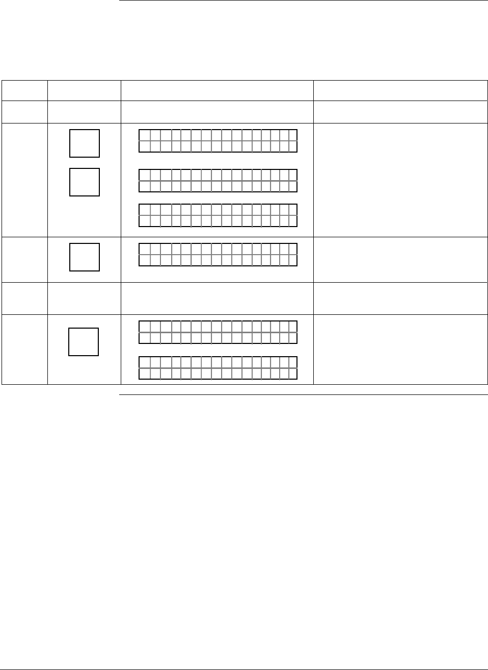
6/08 ST 3000 Release 300 and SFC Model STS103 User’s Manual 207
11.7 Checking SFC Display and Keyboard
Procedure The procedure in Table 68 shows how to run an SFC display and
keyboard test.
Table 68 Running SFC Display and Keyboard Test
Step Press Key Read Display or Action Description
1 Turn on SFC
2 ^
SHIFT
2
W
PUT IN MANLOOP
FT–SH I
DI TE TPLAY
YOPLA
SS
**DIS KAY
**
KE TE TBOAR
ouc
YS
*
rw mn
*
D
ol
Initiate shift key selection.
All display segments are working.
Ready to check operation of
individual keys.
3 E
LRV
0%
KE TE TBOAR
ouc
YS
2rw mn1
D
ol
Confirm key operation by verifying
that its row and column location on
keyboard are displayed
4 Repeat Step 3 as required to check all
keys or go to Step 5 to exit test.
5 NON-VOL
ENTER
(Yes)
KE TE TBOAR
ouc
YS
8rw mn4
D
ol
PUT IN MANLOOP
Check [ENTER] key location.
Ready for operation.

ST 3000 Release 300 and SFC Model STS103 User’s Manual 6/08
208

6/08 ST 3000 Release 300 and SFC Model STS103 User’s Manual 209
Section 12 —Parts List
12.1 Replacement Parts
Part identification • All individually salable parts are indicated in each figure by key
number callout. For example, 1, 2, 3, and so on.
• All parts that are supplied in kits are indicated in each Figure by key
number callout with the letter “K” prefix. For example, K1, K2, K3,
and so on.
• Parts denoted with a “†” are recommended spares. See Table 81 for
summary list of recommended spare parts.
Figure 53 shows major parts for given model with parts list Figure
references.
Continued on next page
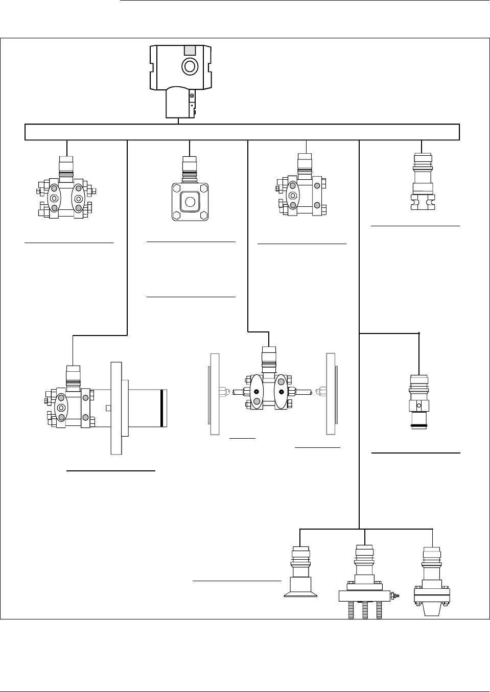
210 ST 3000 Release 300 and SFC Model STS103 User’s Manual 6/08
12.1 Replacement Parts, Continued
Figure 53 Major ST 3000 Smart Transmitter Parts Reference.
ST 3000 Release 300
Electronic Housing Assembly
See Figures 55 and 56
Single Head See
GP Models Figure
STG140 59
STG170 59
STG180 59
Single Head See
AP Models Figure
STA122 59
STA140 59
STA922 59
STA940 59
DP See
Models Figure
STD110 57
STD120 57
STD125 57
STD130 57
STD170 57
STD904 57,58
STD924 57,58
STD930 57,58
STD974 57,58
Dual Head See
GP Models Figure
STG944 60
STG974 60
LGP/LAP See
Models Figure
STG14L 61
STG17L 61
STG18L 61
STG90L 61
STG94L 61
STG97L 61
STG98L 61
STA12L 61
STA92L 61
STA14L 61
STA94L 61
Flush Mount See
GP Models Figure
STG93P 62
Flange
Mounted See
Models Figure
STF128 63
STF132 63
STF12F 63
STF13F 63
STF14F 63
STF924 63
STF932 63
STF92F 63
STF93F 63
Remote Diaphragm Seal
Models
STR12D LGP Models
STR13D STR14G
STR14A STR17G
STR93D STR94G
Attention: No replacement meter body is
available for Remote Diaphragm Seal Models.
Meter Bodies
High
Temperature See
Models Figure
STG14T 64
STF14T 64
Continued on next page
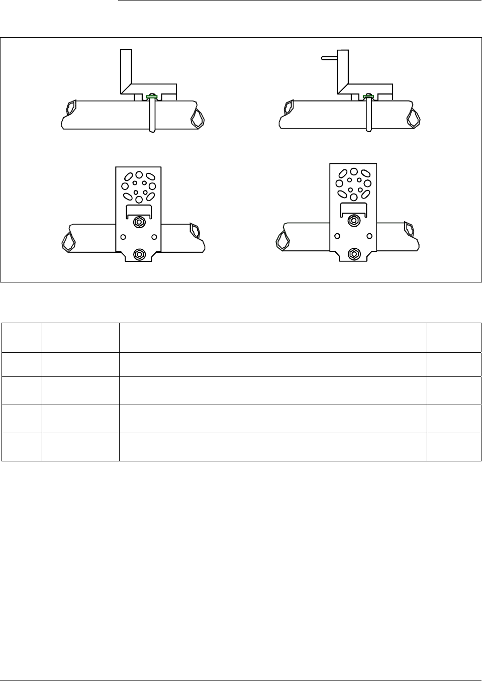
6/08 ST 3000 Release 300 and SFC Model STS103 User’s Manual 211
12.1 Replacement Parts, Continued
Figure 54 ST 3000 Transmitter Mounting Bracket Parts Reference.
2
Angle
Mounting
Bracket
Flat
Mounting
Bracket
4
3
1
Table 69 Major ST 3000 Smart Transmitter Parts Reference.
Key
No. Part Number Description Quantity
Per Unit
1 30752770-003
Angle Bracket Mounting Kit for all models except LGP and Flush mount
2 30752770-004
Angle Bracket Mounting Kit for models LGP, Flush mount, STR14G,
STR17G, and STR94G
3 51196557-001 Flat Bracket Mounting Kit for all models except LGP and Flush Mount
4 51196557-002 Flat Bracket Mounting Kit for all models LGP, Flush mount, STR14G,
STR17G, and STR94G
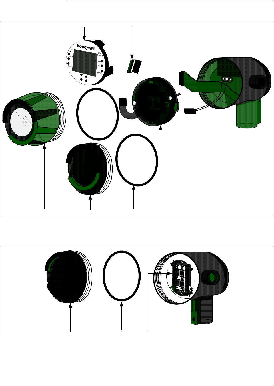
212 ST 3000 Release 300 and SFC Model STS103 User’s Manual 6/08
12.1 Replacement Parts, Continued
Figure 55 Series 100/900 Electronics Housing - Electronics/Meter End.
46
5
12 K1
Figure 56 Series 100/900 Electronics Housing - Terminal Block End
K1
13/K2
Continued on next page

6/08 ST 3000 Release 300 and SFC Model STS103 User’s Manual 213
12.1 Replacement Parts, Continued
Table 70 Parts Identification for Callouts in Figures 55 and 56
Key
No. Part Number Description Quantity
Per Unit
1 30756961-501
30756961-502 Cap for Series 900 only
Cap for Series 100 only 1
2 30756996-501
30756996-502 Cap, meter for Series 900 only
Cap, meter for Series 100 only 1
3 51205897-501†
51404078-502† Terminal assembly without lightning protection
Terminal assembly with lightning protection 1
4 51309389-501
51309389-502
51309389-503
Local Zero and Span Adjust Only
Local Smart Meter Only
Local Smart Meter With Zero and Span Adjust
1
5 51309397-501
51309397-504
51309397-511
51309397-514
51309397-506
51309397-507
51309397-516
51309397-517
Analog Only Electronics, Transmitter Option AN
Analog Only Electronics, Options AN,4G
Analog Only Electronics, Options AN,NE
Analog Only Electronics, Options AN,NE,4G
DE/Analog Electronics, Option DE
DE/Analog Electronics, Options DE,4G
DE/Analog Electronics, Options DE,NE
DE/Analog Electronics, Options DE,NE,4G
1
6 51204038-001 Retaining Clip 1
7 30756997-501 Analog meter 1
K1 30757503-001† Electronics housing seals kit (includes O-rings)
K2 51197425-001
51197425-002
Terminal assembly without lightning protection conversion kit (includes
screws, cover, and terminal block)
Terminal assembly with lightning protection conversion kit (includes
screws, cover, and terminal block)
Not
Shown 30757504-001 Electronics housing hardware kit, DP/I, GP/I, LGP/I (includes screws,
gasket, plate, washers, cover terminal, and spacers)
Continued on next page
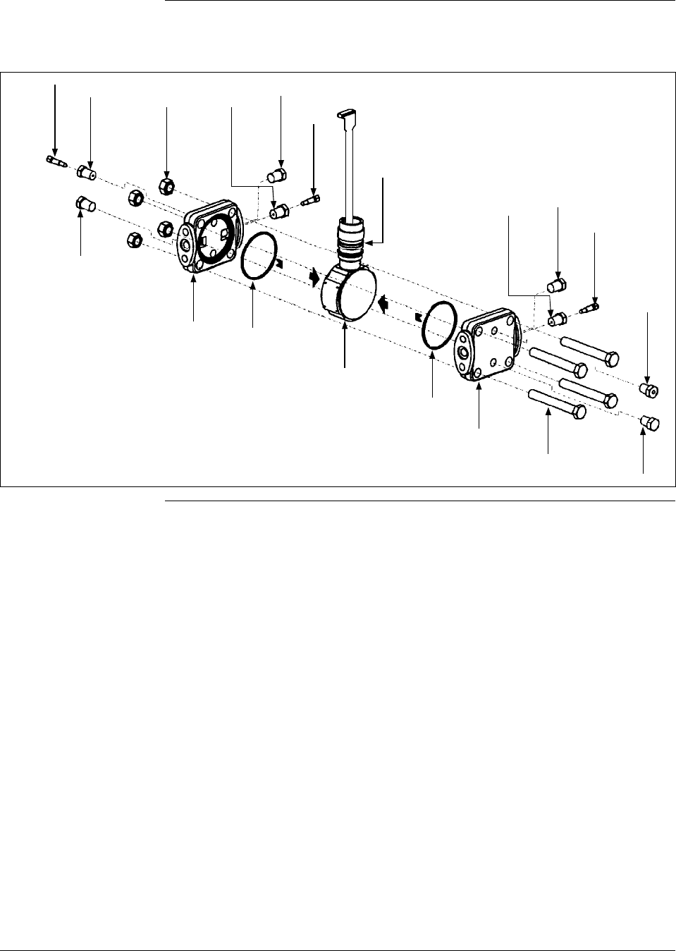
214 ST 3000 Release 300 and SFC Model STS103 User’s Manual 6/08
12.1 Replacement Parts, Continued
Figure 57 Series 100 and Series 900 DP Meter Body for Models STD924 & STD930 C, D, G,
H, K, and L and STD974
K1
K2 K3 K4
K5 K6
1
K7
K8
K1
K2
K3
K1
K2
K3
K3
K1
K6
K5
Continued on next page

6/08 ST 3000 Release 300 and SFC Model STS103 User’s Manual 215
12.1 Replacement Parts, Continued
Table 71 Parts Identification for Callouts in Figure 57.
Key
No. Part Number Description Quantity
Per Unit
1 Specify complete
model number
from nameplate
plus R300
Series 100 replacement meter body without heads 1
Specify complete
model number
from nameplate
plus R300
Series 900 replacement meter body without heads 1
2 30757104-001 Adapter, meter body to electronics housing 1
30753790-001 Carbon steel bolts and nuts kit
Not Shown Bolt, hex head, 7/16-20 UNF, 1.375 inches lg., flange adapter 4
K4 Nut, hex, metric, M12, process heads 4
K8 Bolt, hex head, metric, M12, 90mm lg., process heads 4
30753791-002 A286 SS (NACE) bolts and 302/304 SS (NACE) nuts kit
Not Shown Bolt, hex head, 7/16-20 UNF, 1.375 inches lg., flange adapter 4
K4 Nut, hex, metric, M12, process heads 4
K8 Bolt, hex head, metric, M12, 90mm lg., process heads 4
30753785-001 St. steel vent/drain and plug kit
K1 Pipe plug 4
K2 Vent plug (all except model STD110) 2
K3 Vent bushing (all except model STD110) 2
30753787-001 Monel vent/drain and plug kit
K1 Pipe plug 4
K2 Vent plug (all except model STD110) 2
K3 Vent bushing (all except model STD110) 2
30753786-001 Hastelloy C vent/drain and plug kit
K1 Pipe plug 4
K2 Vent plug (all except model STD110) 2
K3 Vent bushing (all except model STD110) 2
30753788-003† Process head gasket kit (PTFE material)
30753788-004† Process head gasket kit for (Viton material)
K6 Head gasket [For gasket only: 30756445-501 (PTFE, quantity 12) or
30749274-501 (6 Viton head O-rings and 6 Vition flange adapter O-
rings)]
6
K7 O-ring 3
K9 Not Shown Gasket, flange adapter (for gasket only: 30679622-501, 6 Teflon; or
30749274-002, 6 Viton) 6
Continued on next page

216 ST 3000 Release 300 and SFC Model STS103 User’s Manual 6/08
12.1 Replacement Parts, Continued
Table 71 Parts Identification for Callouts in Figure 57, continued
Key
No. Part Number Description Quantity
Per Unit
Optional Flange Adapter Kits (two heads) - Not Shown
30754419-002 Flange adapter kit (st. steel flange adapters with carbon steel bolts)
30754419-004 Flange adapter kit (Monel flange adapters with carbon steel bolts)
30754419-018 Flange adapter kit (st. steel flange adapters with 316 st. steel NACE bolts)
30754419-020 Flange adapter kit (Monel flange adapters with 316 st. steel NACE bolts)
K9 Not Shown Bolt, hex head, 7/16-20 UNF, 1.375 inches lg., flange adapter 4
K11 Not Shown Gasket, flange adapter 2
K10 Not Shown Flange adapter 2
K12 Not Shown Filter screen 2
30754419-003 Flange adapter kit (Hastelloy C flange adapters with carbon steel bolts)
30754419-019 Flange adapter kit (Hastelloy C flange adapters with 316 st. steel NACE bolts)
K9 Not Shown Bolt, hex head, 7/16-20 UNF, 1.375 inches lg., optional flange adapter 4
K11 Not Shown Gasket, flange adapter 2
K10 Not Shown Flange adapter 2
Process Head Kits (one head with PTFE head gasket)
30753908-001 Process head assembly kit (Hastelloy C head)
30753908-002 Process head assembly kit (Hastelloy C DIN head)
30753908-003 Process head assembly kit (carbon steel head with side vent/drain)
30753908-004 Process head assembly kit (st. steel head with side vent/drain)
30753908-005 Process head assembly kit (Monel head)
30753908-009 Process head assembly kit (carbon steel head without side vent/drain)
30753908-010 Process head assembly kit (stainless steel head without side vent/drain)
30753908-011 Process head assembly kit (stainless steel DIN head without side
vent/drain)
30753908-012 Process head assembly kit (carbon steel head - model STD110 only)
30753908-013 Process head assembly kit (st. steel head - model STD110 only)
30753908-014 Process head assembly kit (carbon steel DIN head - model STD110 only)
30753908-015 Process head assembly kit (st. steel DIN head - model STD110 only)
K1 Pipe plug 2
K2 Vent plug 1
K3 Vent bushing 1
K5 Process head 1
K6 Gasket (PTFE), process head 1
K11 Gasket (PTFE), optional flange adapter 1
Continued on next page
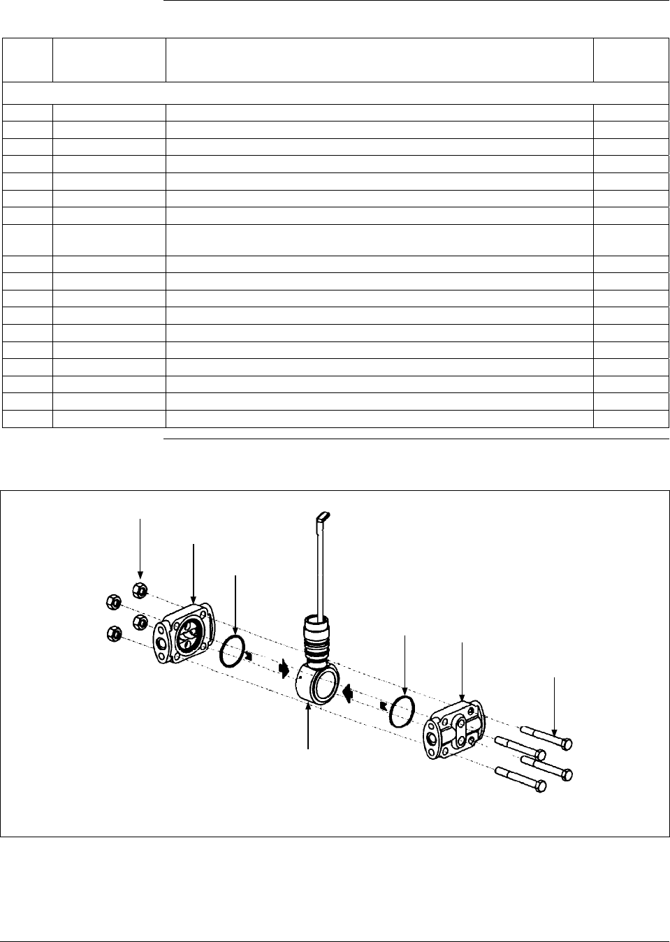
6/08 ST 3000 Release 300 and SFC Model STS103 User’s Manual 217
12.1 Replacement Parts, Continued
Table 71 Parts Identification for Callouts in Figure 57, continued
Key
No. Part Number Description Quantity
Per Unit
Process Head Kits (one head with Viton head gasket)
30753908-101 Process head assembly kit (Hastelloy C head)
30753908-102 Process head assembly kit (Hastelloy C DIN head)
30753908-103 Process head assembly kit (carbon steel head with side vent/drain)
30753908-104 Process head assembly kit (st. steel head with side vent/drain)
30753908-105 Process head assembly kit (Monel head)
30753908-109 Process head assembly kit (carbon steel head without side vent/drain)
30753908-110 Process head assembly kit (stainless steel head without side vent/drain)
30753908-111 Process head assembly kit (stainless steel DIN head without side
vent/drain)
30753908-112 Process head assembly kit (carbon steel head - model STD110 only)
30753908-113 Process head assembly kit (st. steel head - model STD110 only)
30753908-114 Process head assembly kit (carbon steel DIN head - model STD110 only)
30753908-115 Process head assembly kit (st. steel DIN head - model STD110 only)
K1 Pipe plug 2
K2 Vent plug 1
K3 Vent bushing 1
K6 Gasket (Viton), process head 1
K11 Gasket (PTFE), flange adapter 1
K5 Process head 1
Figure 58 Series 900 DP Meter Body for Models Models STD924 & STD930 A, B, E, F, and J
K1
K2
K3
K3 K2
K1
1
Continued on next page

218 ST 3000 Release 300 and SFC Model STS103 User’s Manual 6/08
12.1 Replacement Parts, Continued
Table 72 Parts Identification for Callouts in Figure 58
Key
No. Part Number Description Quantity
Per Unit
1 Specify complete
model number
from nameplate
plus R300
Series 900 replacement meter body without heads 1
K1 30757506-001 Head bolts carbon steel
Kit includes: Bolts, Nuts 4
30757507-001 Head bolts stainless steel/NACE
Kit includes: Bolts, Nuts 4
30757507-002 Process Head Bolting 3/8 UNC 316 SS Non-NACE Kit
Includes: Process Head Bolts and Nuts 4
K2 30757147-001† Replacement heads carbon steel
Kit includes: Heads with side vents, Head gaskets Teflon, head gaskets
Viton, Plugs, Bushings, Vent plugs, Gaskets
30757147-002 Replacement heads carbon steel
Kit includes: Heads without side vents, Head gaskets Teflon, head
gaskets Viton, Bushings, Vent plugs, Gaskets
30757148-001 Replacement heads stainless steel
Kit includes: Heads with side vents, Head gaskets Teflon, Head gaskets
Viton, Plugs, Bushings, Vent Plugs, Gaskets
30757148-002 Replacement heads stainless steel
Kit includes: Heads without side vents, Head gaskets Teflon, Head
gaskets Viton, Bushings, Vent Plugs, Gaskets
30757149-001 Replacement heads Hastelloy
Kit includes: Heads with side vents, Head gaskets Teflon, Head gaskets
Viton, Plugs, Bushings, Vent plugs, Gaskets
30757500-001 Replacement heads Monel
Kit includes: Head with side vents, Head gasket Teflon, Head gasket
Viton, Plugs, Bushings, Vent plugs, Gaskets
K3 30757505-001† Process Head Gasket Kit
Kit includes: 6 Teflon head gaskets (30757100-001), 6 Viton head
gaskets (30749274-004), and 6 Teflon flange adapter gaskets
(30679622-501)
Optional Flange Adapter and Flange Adapter Gaskets - Not Shown
30679622-501 Flange adapter gaskets Teflon 6
30749274-502 Flange adapter gaskets Viton 6
30754419-002 Flange adapter kit (st. steel flange adapters with carbon steel bolts)
30754419-018 Flange adapter kit (st. steel flange adapters with 316 st. steel NACE bolts)
K9 Not Shown Bolt, hex head, 7/16-20 UNF, 1.375 inches lg., flange adapter 4
K11 Not Shown Gasket, flange adapter 2
K10 Not Shown Flange adapter 2
K12 Not Shown Filter screen 2
30754419-003 Flange adapter kit (Hastelloy C flange adapters with carbon steel bolts)
30754419-019 Flange adapter kit (Hastelloy C flange adapters with 316 st. steel NACE bolts)
K9 Not Shown Bolt, hex head, 7/16-20 UNF, 1.375 inches lg., optional flange adapter 4
K11 Not Shown Gasket, flange adapter 2
K10 Not Shown Flange adapter 2
Continued on next page
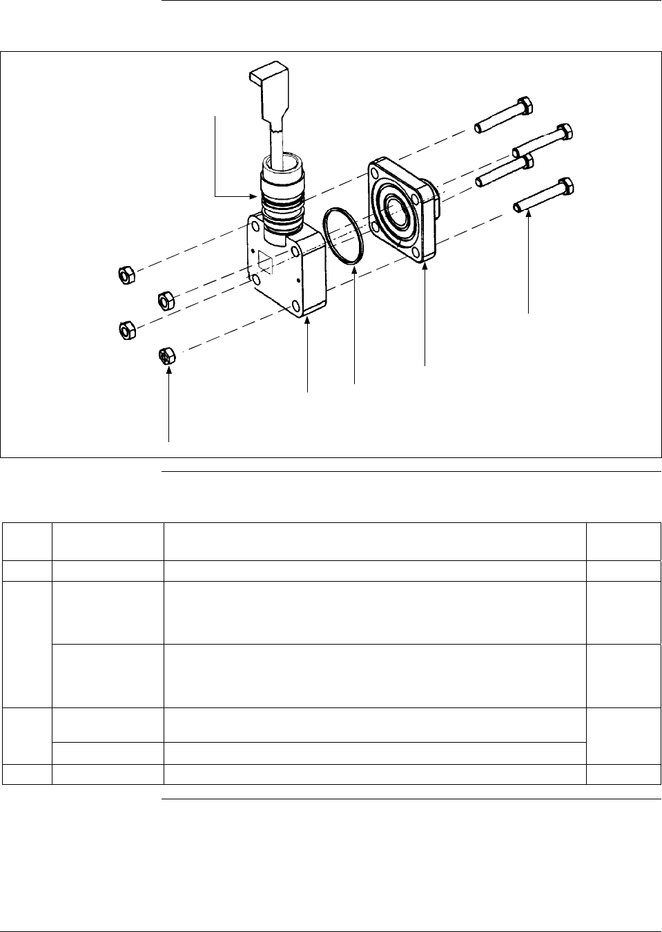
6/08 ST 3000 Release 300 and SFC Model STS103 User’s Manual 219
12.1 Replacement Parts, Continued
Figure 59 Series 100 GP and AP Meter Bodies and Series 900 AP Meter Body
K1
1
K2
K3 2
K4
Table 73 Parts Identification for Callouts in Figure 59
Key
No. Part Number Description Quantity
Per Unit
2 See Table 74 Process head (GP/AP models) 1
1 Specify complete
model number
from nameplate
plus R300
Series 100 replacement meter body without head (GP/AP Models) 1
Specify complete
model number
from nameplate
plus R300
Series 900 replacement meter body without head (GP/AP Models) 1
30754154-002† Head gasket kit for all models with narrow profile meter body except
STG180 (3 sets)
30754154-003† Head gasket kit for model STG180 with narrow profile meter body (3 sets)
K2 O-ring 3
Continued on next page

220 ST 3000 Release 300 and SFC Model STS103 User’s Manual 6/08
12.1 Replacement Parts, Continued
Table 73 Parts Identification for Callouts in Figure 59, continued
Key
No. Part Number Description Quantity
Per Unit
K3 Gasket, Teflon [for gasket only - 30756445-502 (narrow profile L.P), or
30756445-503 (STG180) 6
Gasket, Viton [for gasket only - 30756445-504 (narrow profile L.P), or
30756445-505 (STG180) 6
30756445-509 Gasket, Graphite (for replacement on existing STG/A X22/X40 Transmitter
with Graphite Gasket only) 6
30753792-001 Bolts & nuts kit, all models - narrow profile (carbon steel). Contains:
K1 Nut, hex, metric, M8 carbon steel 4
K4 Bolt, hex head, metric, M8, 50 mm long 4
30753793-002 A286 SS (NACE) Bolts & 304 SS (NACE) nuts kit, all models - narrow
profile. Contains:
K1 Nut, hex, 5/16 (304 stainless steel) 4
K4 Bolt, hex head, 5/16-18 4
30753793-003 Process Head Bolting 316 SS Non-NACE
Kit Includes: Process Head Bolts and Nuts. Contains:
K1 5/16 –18 UNC 316 SS Non-NACE Heavy Hex Nuts 4
K4 5/16 –18 UNC 316 SS Non-NACE Hex Cap Screw 4
Table 74 Replacement GP and AP Process Head Part Numbers for Narrow Profile Meter
Body
Material Fitting Size Models: STA122, STA140,
STG140, STG170, STG180,
STA922, STA940
Carbon steel (Series 100) 9/16 - 18UNF-2B 30755124-001
Stainless steel (Series 100) 9/16 - 18UNF-2B 30755124-002
Carbon steel 1/2 in NPT 30755124-005
Stainless steel 1/2 in NPT 30755124-006
Monel 1/2 in NPT 30755124-008
Hastelloy C 1/2 in NPT 30755124-007
Continued on next page
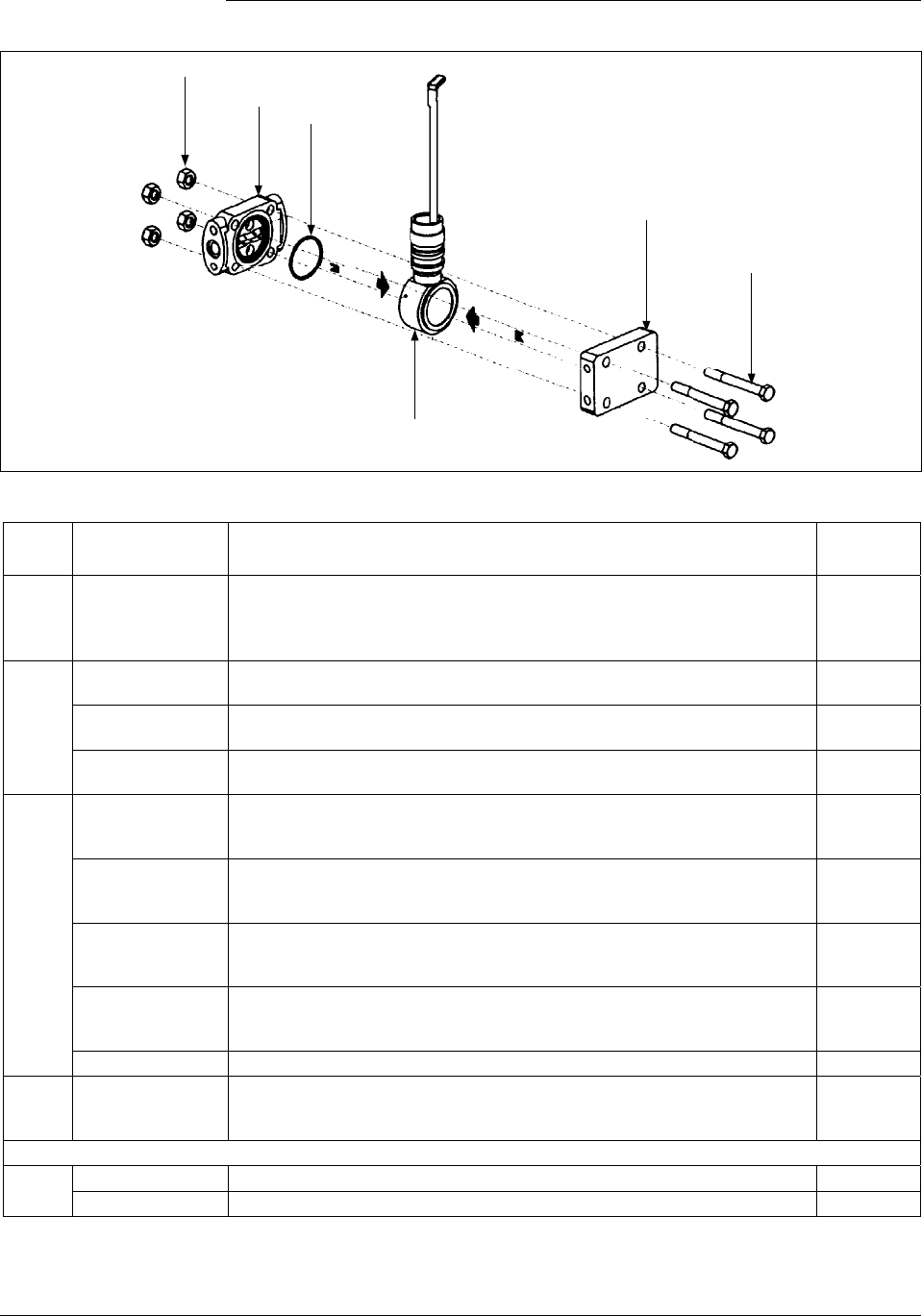
6/08 ST 3000 Release 300 and SFC Model STS103 User’s Manual 221
12.1 Replacement Parts, Continued
Figure 60 Series 900 Dual-Head GP Meter Bodies.
K1
K2 K3
1
K2
K1
Table 75 Parts Identification for Callouts in Figure 60
Key
No. Part Number Description Quantity
Per Unit
1 Specify complete
model number
from nameplate
plus R300
Series 900 replacement meter body without heads (GP models) 1
K1 30757506-001 Head bolts carbon steel, 3/8-inch
Kit includes: Bolts, Nuts 4
30757507-001 Head bolts stainless steel/NACE, 3/8-inch
Kit includes: Bolts, Nuts 4
30757507-002 Process Head Bolting 3/8 UNC 316 SS Non-NACE
Kit Includes: Process Head Bolts and Nuts 4
K2 30757501-001 Replacement heads carbon steel
Kit includes: Head with side vents, Head dummy CS, Head gaskets
Teflon, Head gaskets Viton, Plugs, Bushings, Vent Plug, Gasket
30757501-002 Replacement heads carbon steel
Kit includes: Head without side vents, Head dummy CS, Head gaskets
Teflon, Head gaskets Viton, Bushings, Vent Plug, Gasket
30757502-001 Replacement heads stainless steel
Kit includes: Heads with side vents, Head dummy SS, Head gaskets
Teflon, head gaskets Viton, Plugs, Bushings, Vent plugs, Gaskets
30757502-002 Replacement heads stainless steel
Kit includes: Heads without side vents, Head dummy SS, Head gaskets
Teflon, head gaskets Viton, Bushings, Vent plugs, Gaskets
30756941-005 Stainless steel blind reference head (HR option)
K3 30757505-001† Process head gasket kit
Kit includes: 6 Teflon head gaskets (30757100-001), 6 Teflon flange
adapter gaskets (30679622-001), 6 Viton head gaskets (30749274-004)
Optional Flange Adapter - Not Shown
K4 30679622-501 Flange adapter gaskets Teflon 6
30749274-502 Flange adapter gaskets Viton 6
Continued on next page
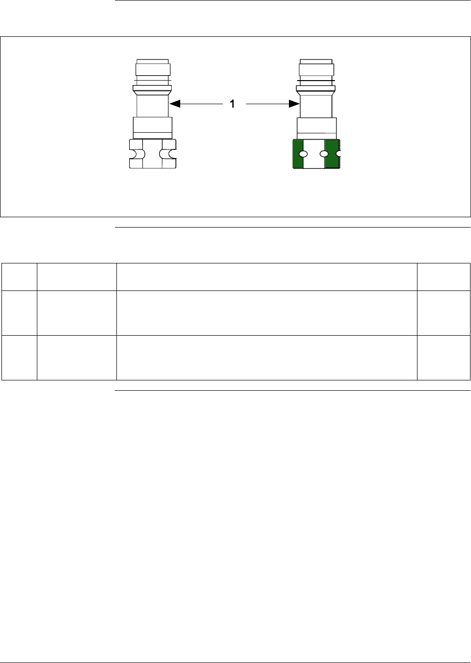
222 ST 3000 Release 300 and SFC Model STS103 User’s Manual 6/08
12.1 Replacement Parts, Continued
Figure 61 Series 100 and Series 900 LGP Meter Body.
Hexagonal Body
Round Body
Table 76 Parts Identification for Callouts in Figure 61
Key
No. Part Number Description Quantity
Per Unit
1 Specify complete
model number
from nameplate
plus R300
Series 100 replacement meter body (LGP and LAP model) 1
Specify complete
model number
from nameplate
plus R300
Series 900 replacement meter body (LGP and LAP model) 1
Continued on next page
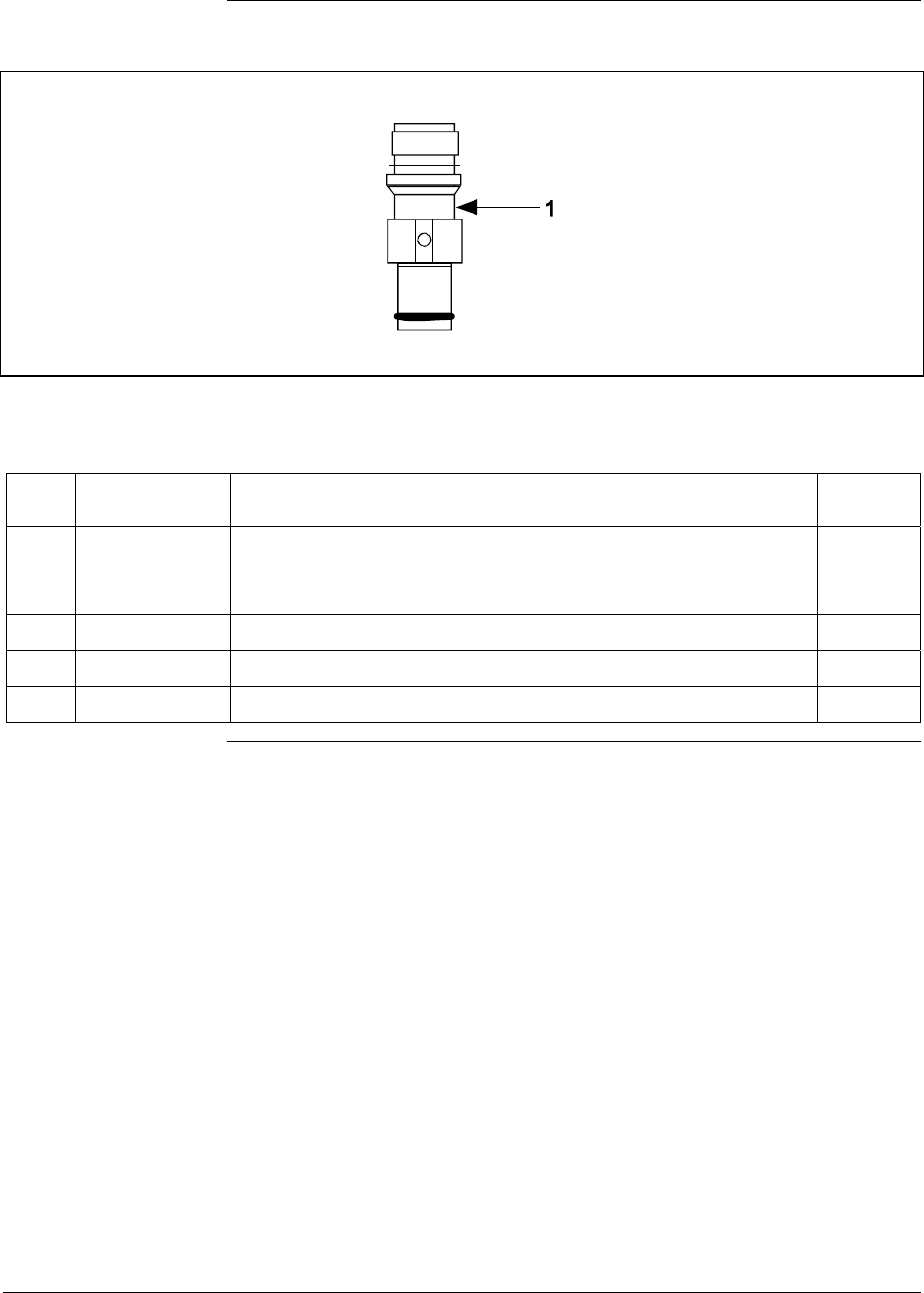
6/08 ST 3000 Release 300 and SFC Model STS103 User’s Manual 223
12.1 Replacement Parts, Continued
Figure 62 Series 900 Flush Mount Meter Body.
Table 77 Parts Identification for Callouts in Figure 62
Key
No. Part Number Description Quantity
Per Unit
1 Specify complete
model number
from nameplate
plus R300
Series 900 replacement meter body (Flush Mount model) 1
30756445-508 Gasket Kit (0-rings)
51204496-001 316L SS Mounting Sleeve Kit
51204497-001 Calibration Sleeve Kit
Continued on next page
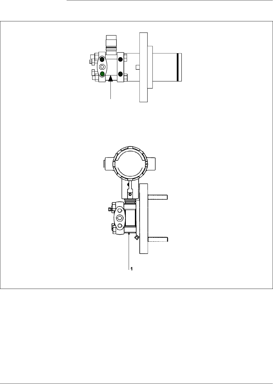
224 ST 3000 Release 300 and SFC Model STS103 User’s Manual 6/08
12.1 Replacement Parts, Continued
Figure 63 Series 100 and Series 900 Flange Mounted Meter Body.
1
Extended Flange Design
Pseudo Flange Design
Continued on next page

6/08 ST 3000 Release 300 and SFC Model STS103 User’s Manual 225
12.1 Replacement Parts, Continued
Table 78 Parts Identification for Callouts in Figure 63
Key
No. Part Number Description Quantity
Per Unit
1 Specify complete
model number
from nameplate
plus R300
Series 100 replacement meter body 1
Specify complete
model number
from nameplate
plus R300
Series 900 replacement meter body 1
30749372-005 O-ring seal 1
30749372-001 O-ring seal 1
Optional Flange Adapter - Not Shown
30754419-006 Flange adapter kit (st. steel flange adapter with carbon steel bolts)
30754419-008 Flange adapter kit (Monel flange adapter with carbon steel bolts)
30754419-022 Flange adapter kit (st. steel flange adapter with 316 st. steel NACE bolts)
30754419-024 Flange adapter kit (Monel flange adapter with 316 st. steel NACE bolts)
K1 Bolt, hex head, 7/16-20 UNF, 1.375 inches lg. 2
K2 Flange adapter 1
K3 Gasket 1
K4 Filter screen 1
30754419-007 Flange adapter kit (Hastelloy C flange adapter with carbon steel bolts)
30754419-023 Flange adapter kit (Hastelloy C flange adapter with 316 st. steel NACE
bolts)
K1 Bolt, hex head, 7/16-20 UNF, 1.375 inches lg. 2
K2 Flange adapter 1
K3 Gasket 1
K5 30757503-001 Housing seal kit 1
Continued on next page
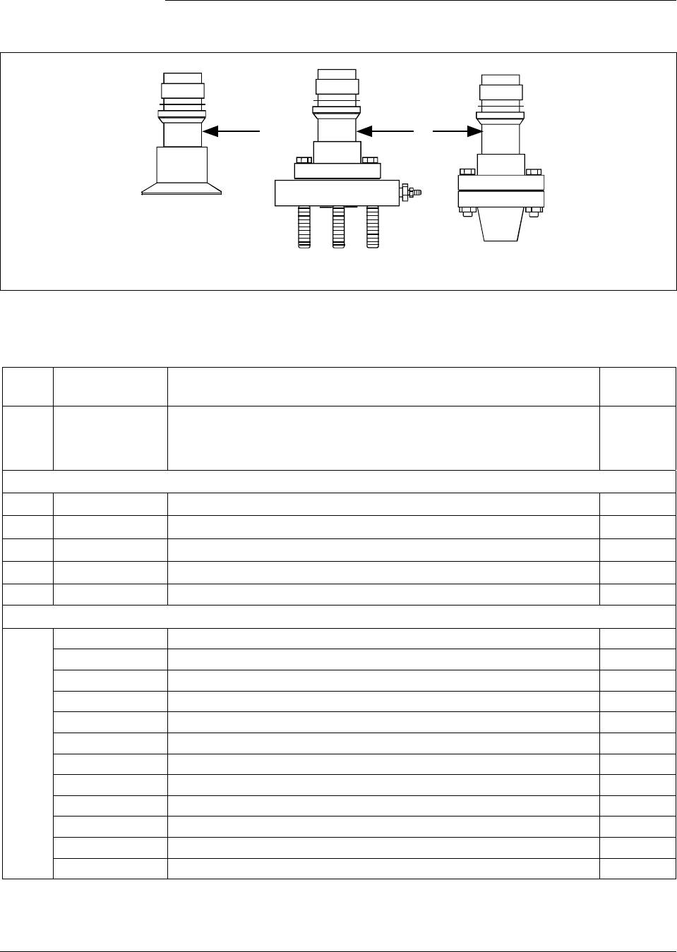
226 ST 3000 Release 300 and SFC Model STS103 User’s Manual 6/08
12.1 Replacement Parts, Continued
Figure 64 High Temperature Meter Body.
1
1
Sanitary Seal Small Flange NPT
Table 79 Parts Identification for Callouts in Figure 64
Key
No. Part Number Description Quantity
Per Unit
1 Specify complete
model number
from nameplate
plus R300
Series 100 replacement meter body 1
Sanitary Seal Head and Gasket
51204982-001 Sanitary Seal Head GP/I (Stainless Steel Head w/ st.stl. hardware)
51204982-003 Sanitary Seal Head GP/I (Stainless Steel Head w/ SS NACE. hardware)
51204982-002 Sanitary Seal Head GP/I (Hastelloy Head w/ st.stl. hardware)
51204984-001 Gasket GP/I (includes Teflon gasket and Viton O-ring)
Flange Adapter - Not Shown
51204983-001 Flange adapter kit (½” NPT st. stl. 150# w/ st. stl bolts)
51204983-002 Flange adapter kit (½” NPT st. stl. 150# w/ st. stl bolts w/ vent/drain)
51204983-017 Flange adapter kit (½” NPT st. stl. 150# w/ SS NACE bolts)
51204983-018 Flange adapter kit (½” NPT st. stl. 150# w/ SS NACE bolts w/ vent/drain)
51204983-003 Flange adapter kit (½” NPT Hastelloy 150# w/ st. stl bolts)
51204983-004 Flange adapter kit (½” NPT Hastelloy 150# w/ st. stl bolts w/ vent/drain)
51204983-005 Flange adapter kit (1” NPT st. stl. 150# w/ st. stl bolts)
51204983-006 Flange adapter kit (1” NPT st. stl. 150# w/ st. stl bolts w/ vent/drain)
51204983-019 Flange adapter kit (1” NPT st. stl. 150# w/ SS NACE bolts)
51204983-020 Flange adapter kit (1” NPT st. stl. 150# w/ SS NACE bolts w/ vent/drain)
51204983-007 Flange adapter kit (1” NPT Hastelloy 150# w/ st. stl bolts)
51204983-008 Flange adapter kit (1” NPT Hastelloy 150# w/ st. stl bolts w/ vent/drain)
Continued on next page

6/08 ST 3000 Release 300 and SFC Model STS103 User’s Manual 227
12.1 Replacement Parts, Continued
Table 79 Parts Identification for Callouts in Figure 64, continued
Key
No. Part Number Description Quantity
Per Unit
51204983-013 Flange adapter kit (1” NPT st. stl. 300# w/ st. stl bolts)
51204983-014 Flange adapter kit (1” NPT st. stl. 300# w/ st. stl bolts w/ vent/drain)
51204983-023 Flange adapter kit (1” NPT st. stl. 300# w/ SS NACE bolts)
51204983-024 Flange adapter kit (1” NPT st. stl. 300# w/ SS NACE bolts w/ vent/drain)
51204983-015 Flange adapter kit (1” NPT Hastelloy 300# w/ st. stl bolts)
51204983-016 Flange adapter kit (1” NPT Hastelloy 300# w/ st. stl bolts w/ vent/drain)
51204983-009 Flange adapter kit (1½” NPT st. stl. 150# w/ st. stl bolts)
51204983-010 Flange adapter kit (1½” NPT st. stl. 150# w/ st. stl bolts w/ vent/drain)
51204983-021 Flange adapter kit (1½” NPT st. stl. 150# w/ SS NACE bolts)
51204983-022 Flange adapter kit (1½” NPT st. stl. 150# w/ SS NACE bolts w/ vent/drain)
51204983-011 Flange adapter kit (1½” NPT Hastelloy 150# w/ st. stl bolts)
51204983-012 Flange adapter kit (1½” NPT Hastelloy 150# w/ st. stl bolts w/ vent/drain)
51204983-025 Flange adapter kit (2” st. stl. 150# w/ st. stl bolts)
51204983-026 Flange adapter kit (2” st. stl. 150# w/ st. stl bolts w/ vent/drain)
51204983-037 Flange adapter kit (2” st. stl. 150# w/ SS NACE bolts)
51204983-038 Flange adapter kit (2” st. stl. 150# w/ SS NACE bolts w/ vent/drain)
51204983-027 Flange adapter kit (2” Hastelloy 150# w/ st. stl bolts)
51204983-028 Flange adapter kit (2” Hastelloy 150# w/ st. stl bolts w/ vent/drain)
51204983-029 Flange adapter kit (1½” st. stl. 300# w/ st. stl bolts)
51204983-030 Flange adapter kit (1½” st. stl. 300# w/ st. stl bolts w/ vent/drain)
51204983-039 Flange adapter kit (1½” st. stl. 300# w/ SS NACE bolts)
51204983-040 Flange adapter kit (1½” st. stl. 300# w/ SS NACE bolts w/ vent/drain)
51204983-031 Flange adapter kit (1½” Hastelloy 300# w/ st. stl bolts)
51204983-032 Flange adapter kit (1½” Hastelloy 300# w/ st. stl bolts w/ vent/drain)
51204983-033 Flange adapter kit (2” st. stl. 300# w/ st. stl bolts)
51204983-034 Flange adapter kit (2” st. stl. 300# w/ st. stl bolts w/ vent/drain)
51204983-041 Flange adapter kit (2” st. stl. 300# w/ SS NACE bolts)
51204983-042 Flange adapter kit (2” st. stl. 300# w/ SS NACE bolts w/ vent/drain)
51204983-035 Flange adapter kit (2” Hastelloy 300# w/ st. stl bolts)
51204983-036 Flange adapter kit (2” Hastelloy 300# w/ st. stl bolts w/ vent/drain)
Continued on next page
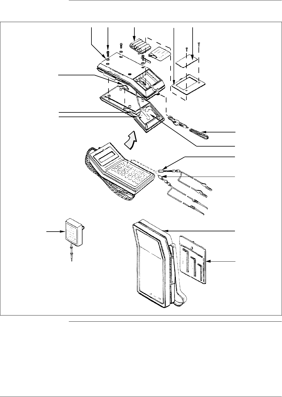
228 ST 3000 Release 300 and SFC Model STS103 User’s Manual 6/08
12.1 Replacement Parts, Continued
Figure 65 SFC Smart Field Communicator and Accessories.
22378
Style
A
Style
B
K1 K2 1K4
K3
K10
K8
K7
5/6
K12
7
4
3
2
K6
Continued on next page

6/08 ST 3000 Release 300 and SFC Model STS103 User’s Manual 229
12.1 Replacement Parts, Continued
Table 80 Parts Identification for Callouts in Figure 65.
Key
No. Part Number Description Quantity
Per Unit
1 Battery pack assembly 1
See Figure 62 Style A – No longer available. Order conversion kit 30755131-001
30755080-501 Style B
2 30753046-501 LCD assembly 1
3
30752453-501
30752453-503
30752453-505
Interface cable assembly (with alligator clips)
6 feet (1.8 meters) long
12 feet (3.6 meters) long
20 feet (6 meters) long
1
4
30752453-502
30752453-504
30752453-506
Interface cable assembly (with EZ hooks)
6 feet (1.8 meters) long
12 feet (3.6 meters) long
20 feet (6 meters) long
1
5 30752438-501 DC battery charger, AA Nicad cell , 120 Vac 1
6 30753739-501 DC battery charger, AA Nicad cell, 240 Vac (Universal-European plug) 1
7 30752834-501 Carrying case, vinyl 1
Key
No. Part Number Description Quantity
Per Kit
30753194-001 Replacement hardware kit
K1 Bumper, recess 4
K2 Screw, metric, M3, socket head 6
K3 Cover, battery compartment 1
K4 Label, battery cover 1
K6 Carry strap 1
K7 Harness assembly, power/charger 1
K10 Actuator 1
K12 Socket head wrench kit, metric
Contents:
(1) Hex head socket wrench, size 2.5 mm
(1) Hex head socket wrench, size 3 mm
(1) Hex head socket wrench, size 4 mm
1
Continued on next page

230 ST 3000 Release 300 and SFC Model STS103 User’s Manual 6/08
12.1 Replacement Parts, Continued
Table 81 Summary of Recommended Spare Parts
Reference Spares for
Part Number Description Figure
Nmbr. Key
Nmbr. 1-10
Units 10-100
Units 100-
1000
Units
Electronics Housing Assembly Figs. 55 and 56
51309397-501
51309397-504
51309397-511
51309397-514
51309397-506
51309397-507
51309397-516
51309397-517
Analog Only Electronics, Transmitter Option AN
Analog Only Electronics, Options AN,4G
Analog Only Electronics, Options AN,NE
Analog Only Electronics, Options AN,NE,4G
DE/Analog Electronics, Option DE
DE/Analog Electronics, Options DE,4G
DE/Analog Electronics, Options DE,NE
DE/Analog Electronics, Options DE,NE,4G
55 5 1 1-2 2-4
30757503-001
Series 100/900 housing seal kit 55 & 56 K1 1 1-2 2-4
51205897-501
51404078-502
Series 100/900 terminal assembly without lightning
protection
Series 100/900 terminal assembly with lightning
protection
56 3/K2 1 1 1-2
Process head gasket kit 1 1-4 4-10
30757505-001
For STD924-A, B, E, F, and J; STD930-A, B, E, F, and
J; STG944; STG974 models
Teflon and Viton
58,60 K3
30753788-003
30753788-004
For all other Series 100 DP and STD924-C, D, G, H, K,
and L; STD930-C, D, G, H, K, and L; and STD974
models
Teflon
Viton
57 K6
30754154-002
For STA122, STA140, STA922, STA940, STG140, and
STG170
Teflon and Viton
59 K3
30754154-003 For STG180 59 K3
Meter Body 1 1-2 2-4
Specify complete Series 100/900 DP Models 57 1
model number from Series 900 DP Models 57,58 1
nameplate plus R300 Series 100/900 GP/AP Models 59 1
Series 900 GP Dual Head Model 60 1
Series 100/900 Inline and Series 900 AP Models 61 1
Series 900 Flush Mount Models 62 1
Series 100/900 Flange Mount Models 63 1
Series 100 High Temperature Models 64 1

6/08 ST 3000 Release 300 and SFC Model STS103 User’s Manual 231

232 ST 3000 Release 300 and SFC Model STS103 User’s Manual 6/08
Section 13 —Reference Drawings
13.1 Wiring Diagrams
External Wiring
Diagrams Wiring diagram drawing numbers are listed here for ST 3000 Release
300, Series 100 and 900 Transmitters. These wiring diagrams are
included in numerical order behind this page for wiring reference.
ST 3000 Description Drawing Number
Release 300 For non-intrinsically safe application 30753607
Series 100, 900 For intrinsically safe application (FM) 51204241
Transmitters For intrinsically safe application (CSA) 51204242
For intrinsically safe application (CENELEC) 51204243
Transmitter
Dimension Drawings Dimension drawings for individual transmitter models are available and
are listed in the ST 3000 Release 300 installation guide document
supplied with your transmitter. If you need a copy of a drawing, please
determine the appropriate drawing number and contact your Honeywell
representative to obtain a copy.

6/08 ST 3000 Release 300 and SFC Model STS103 User’s Manual 233

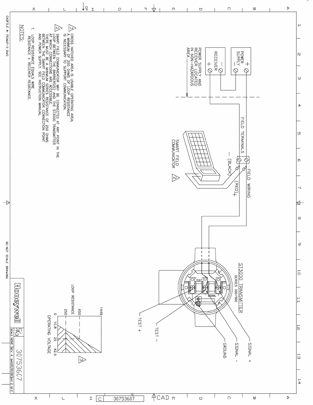
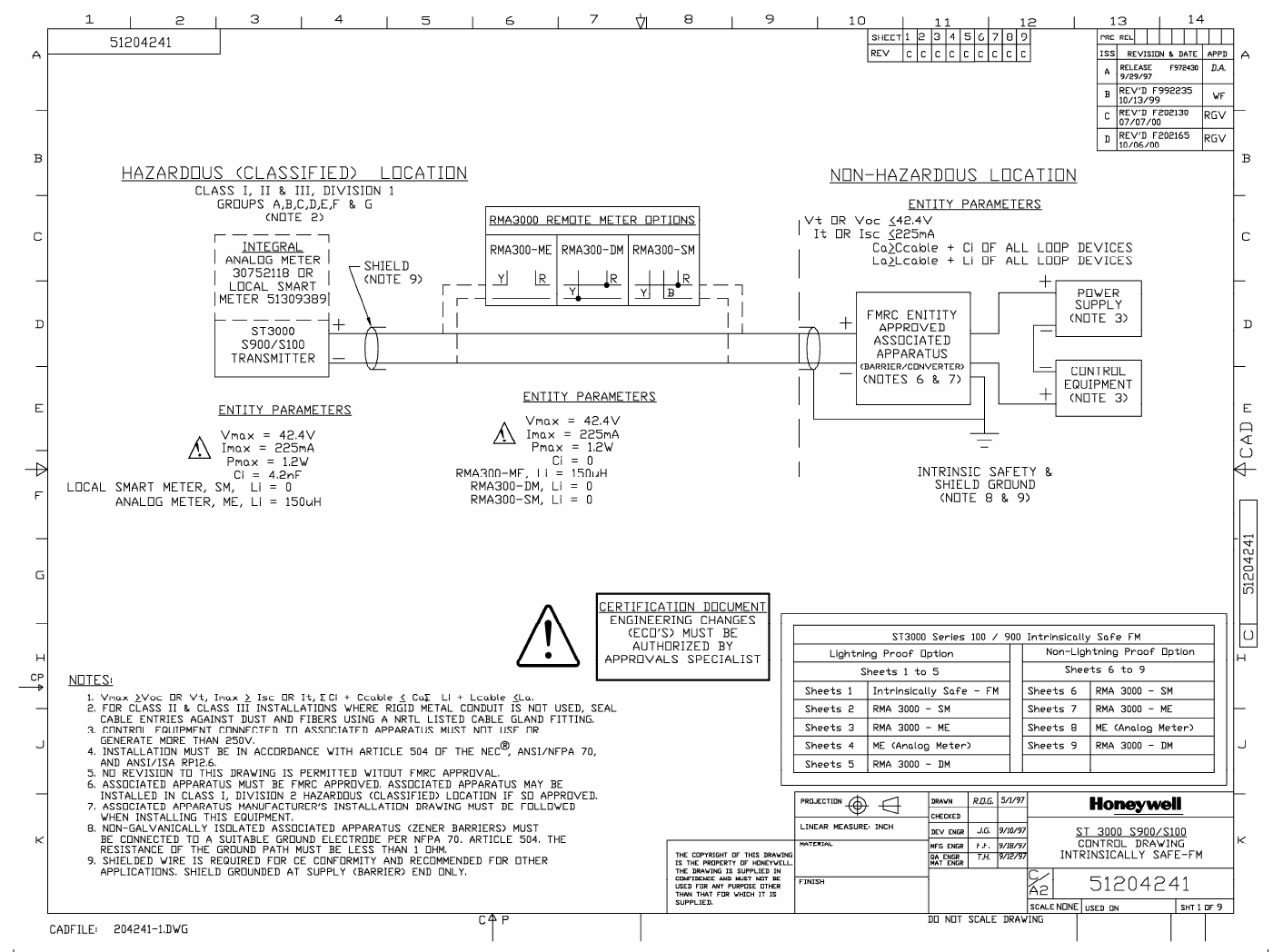
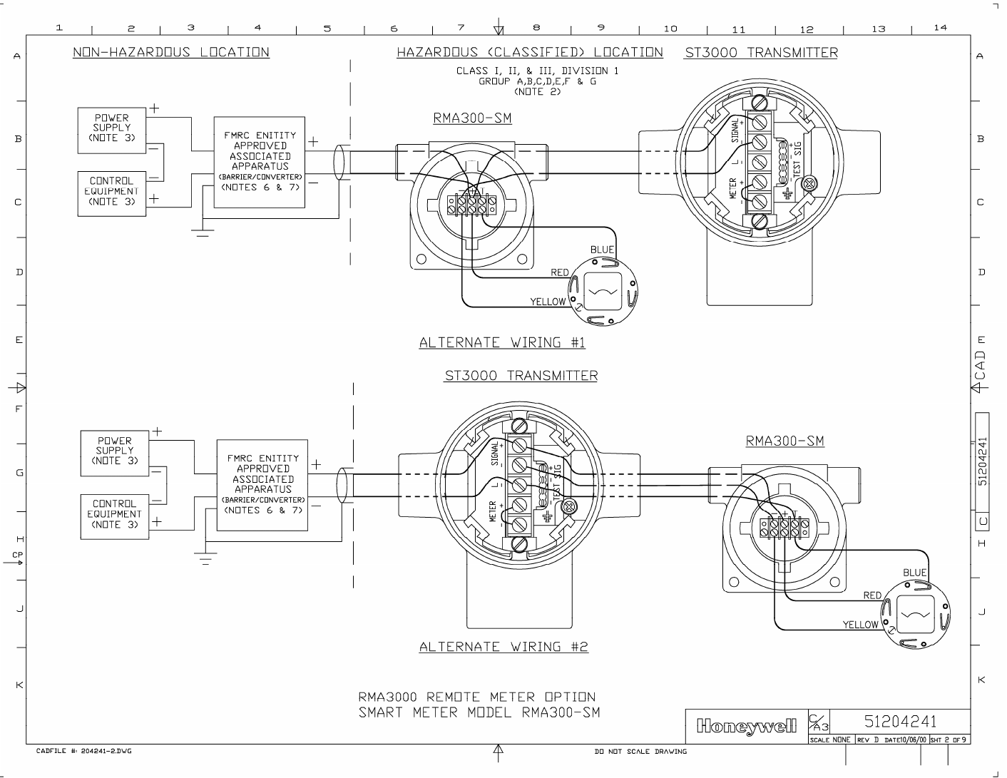
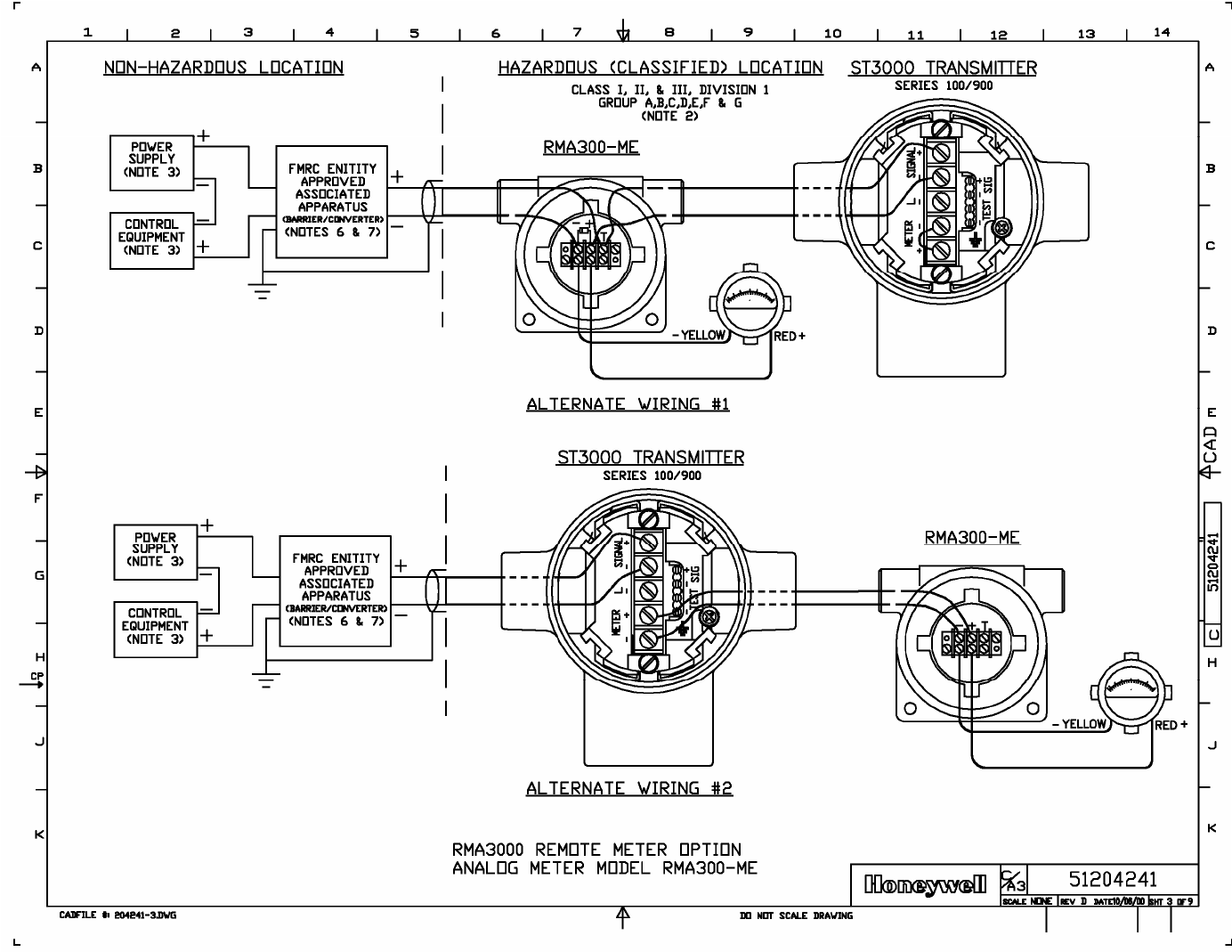
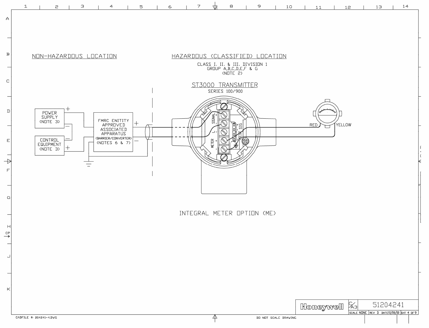
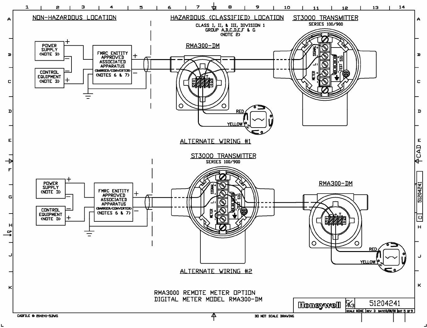
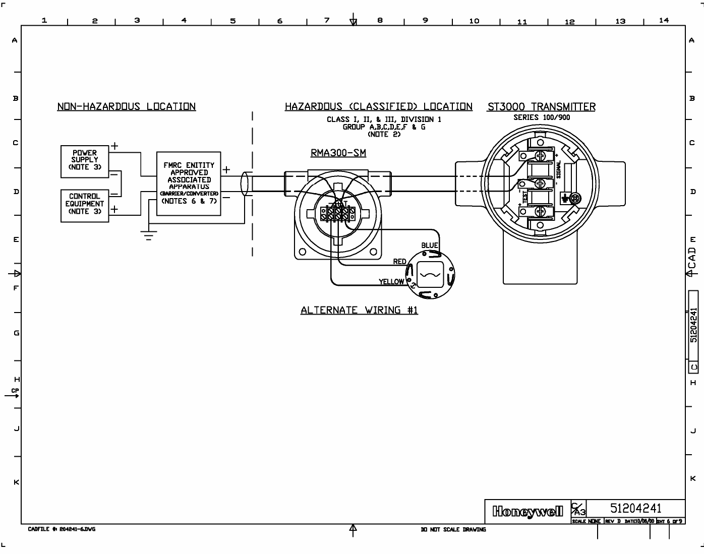
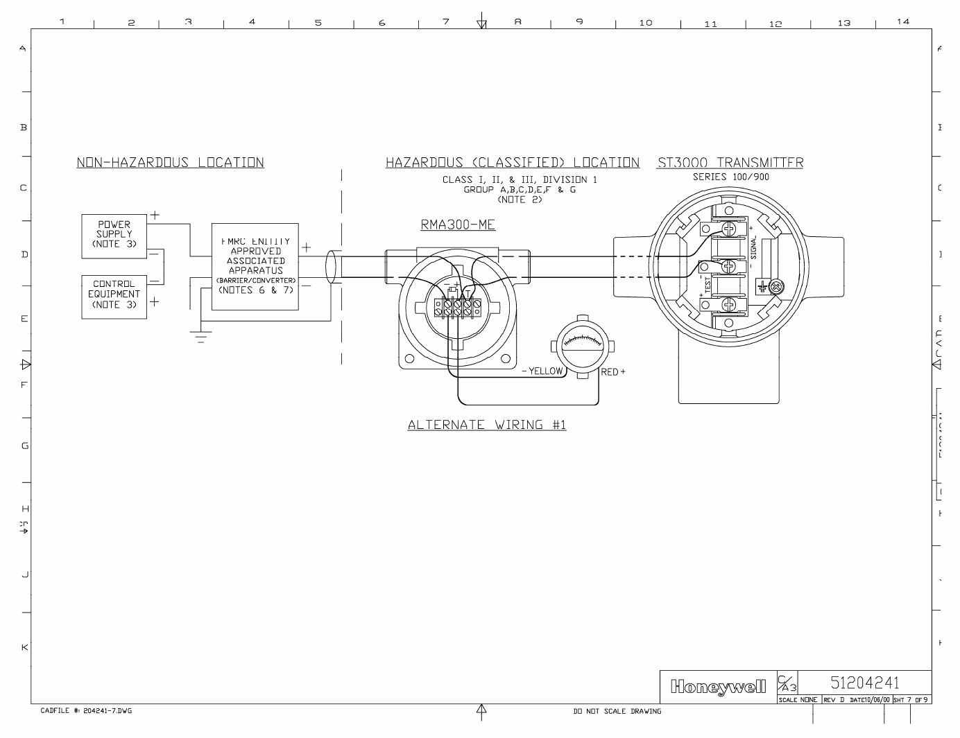
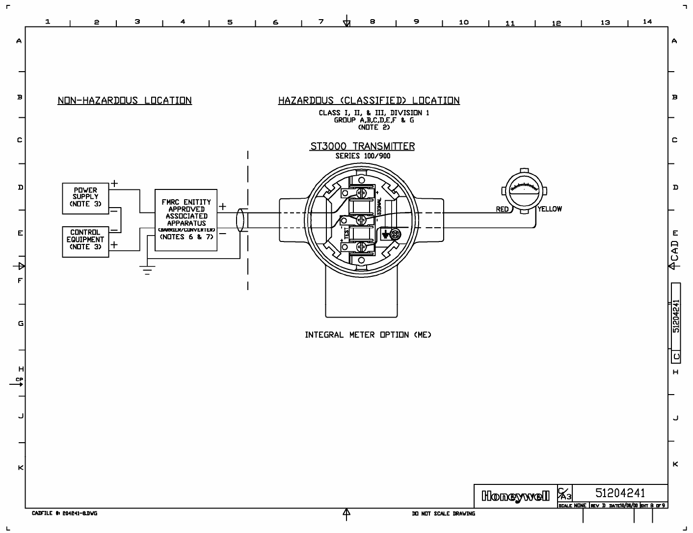
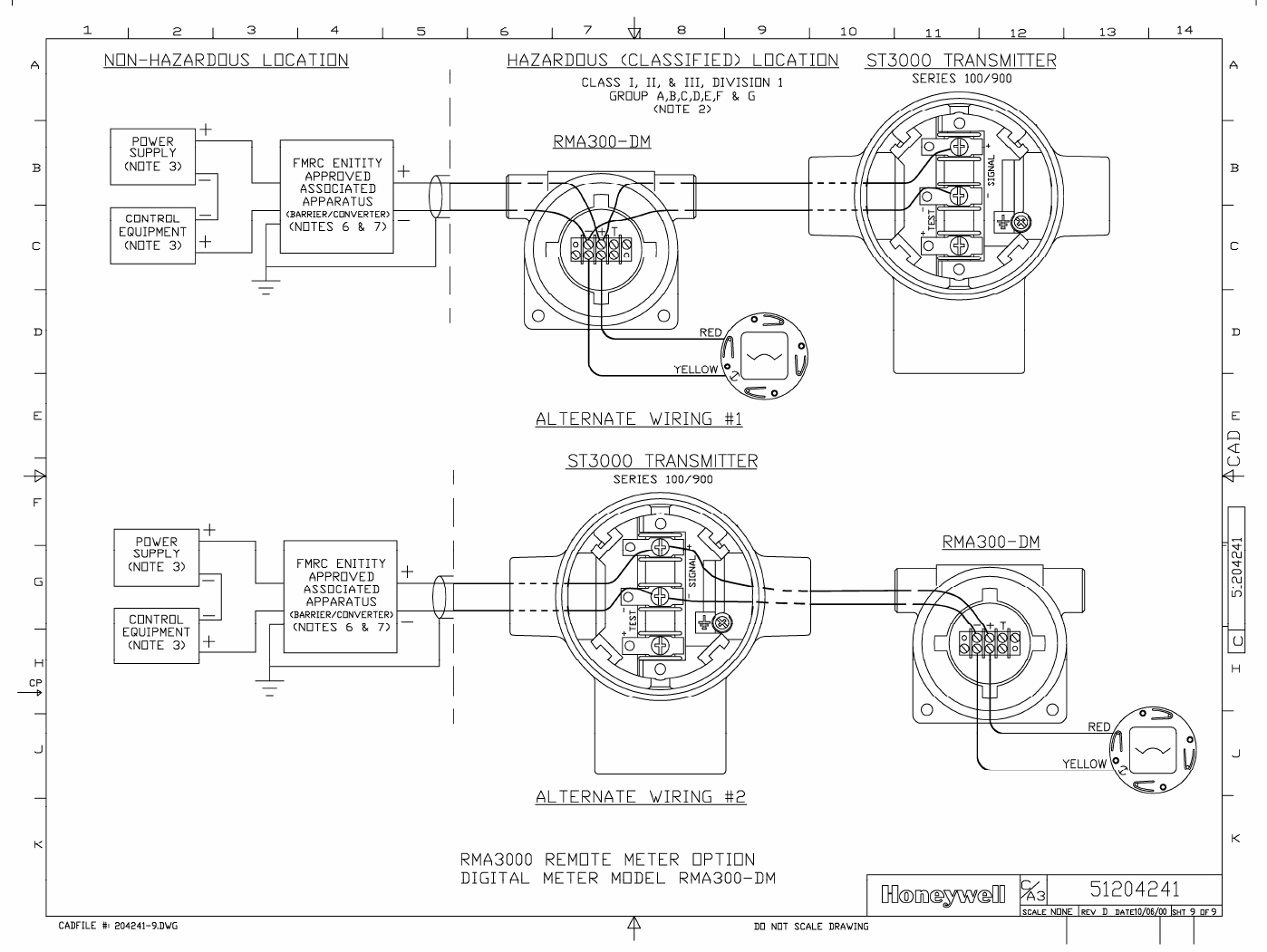
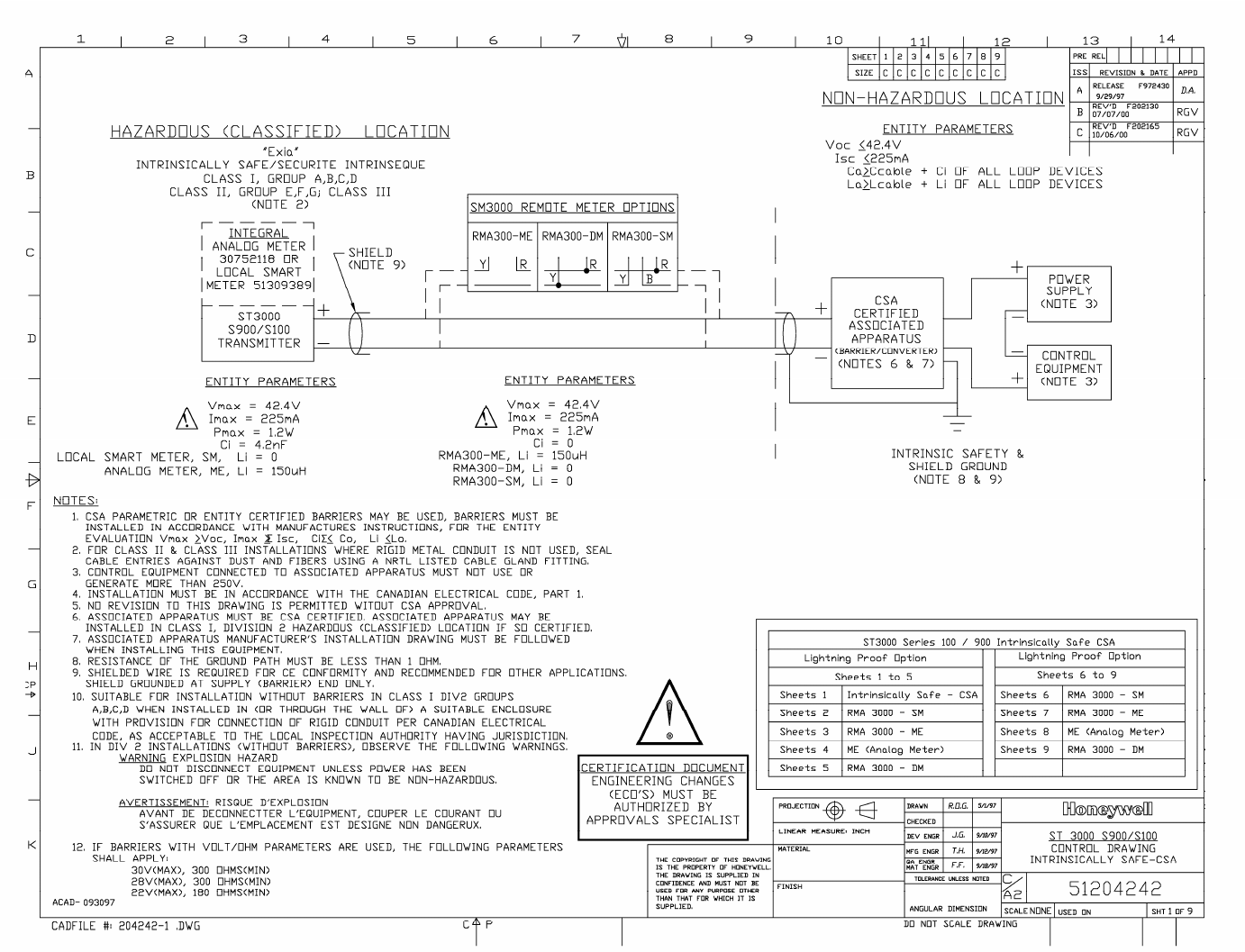
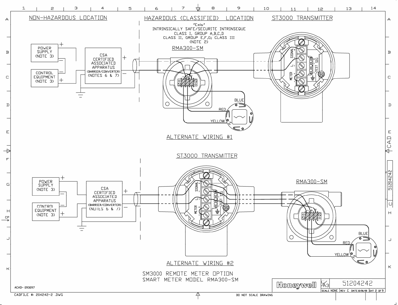
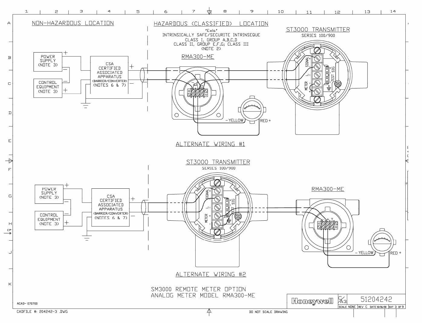
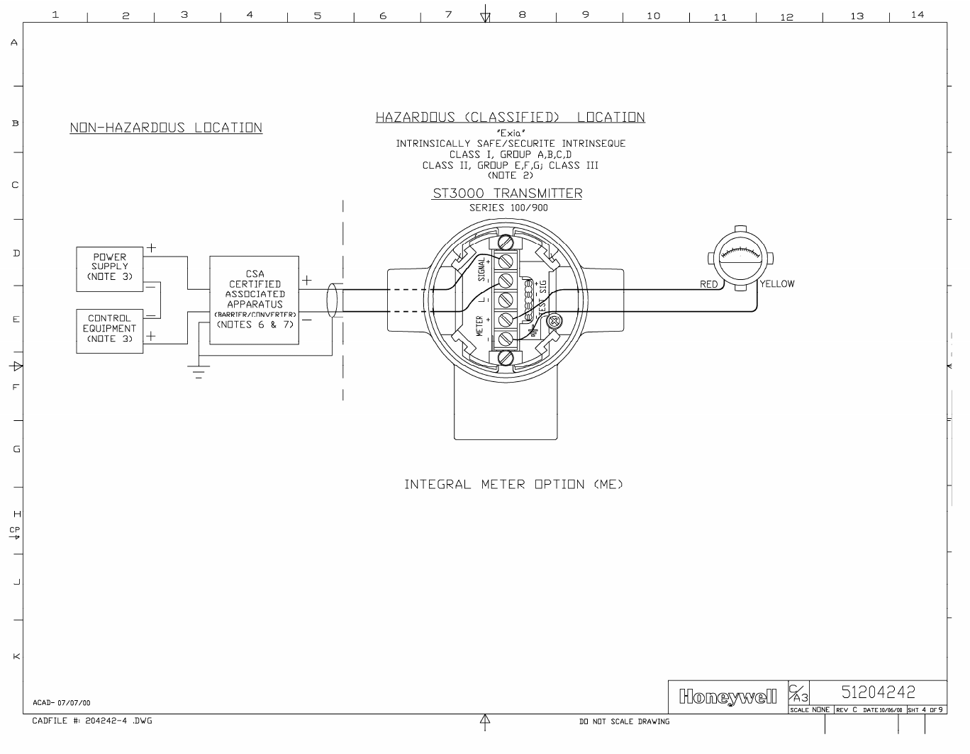
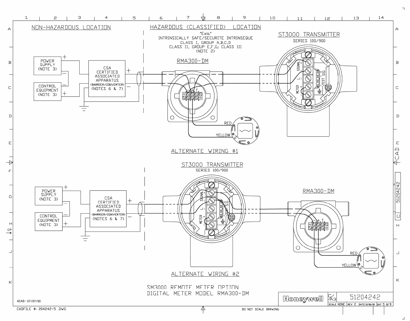

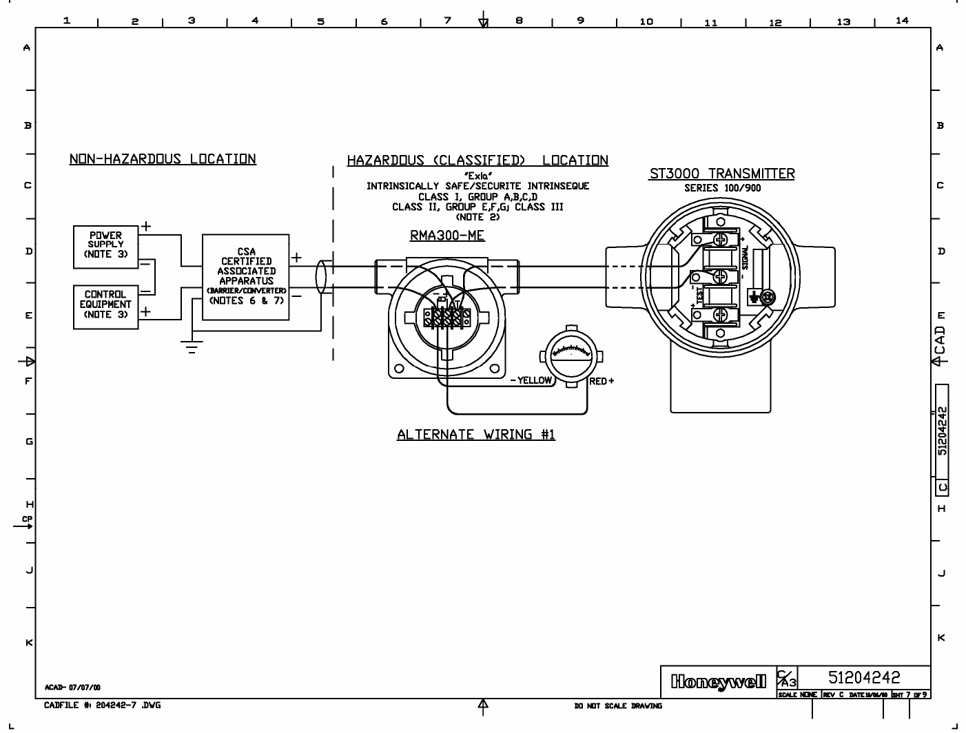
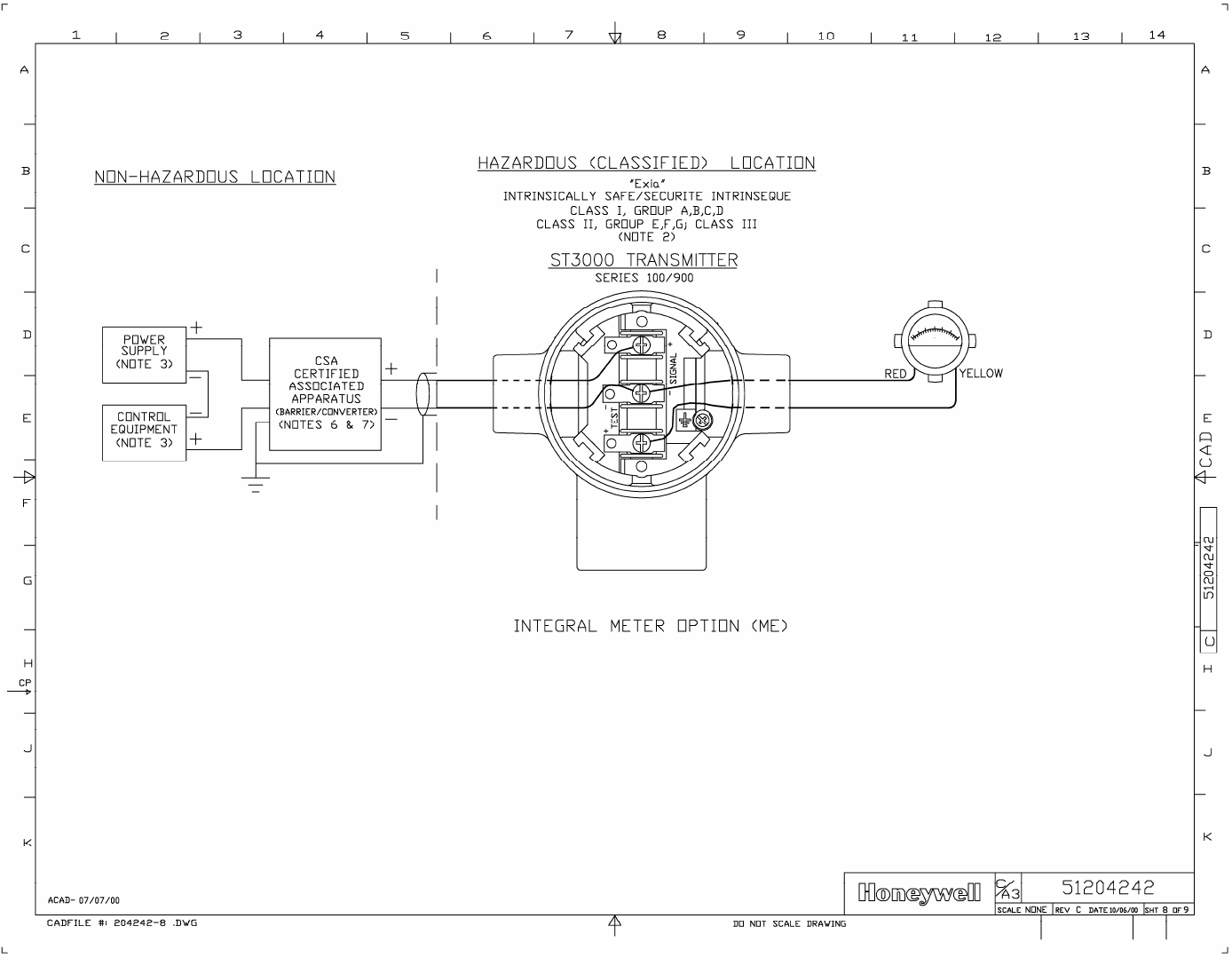
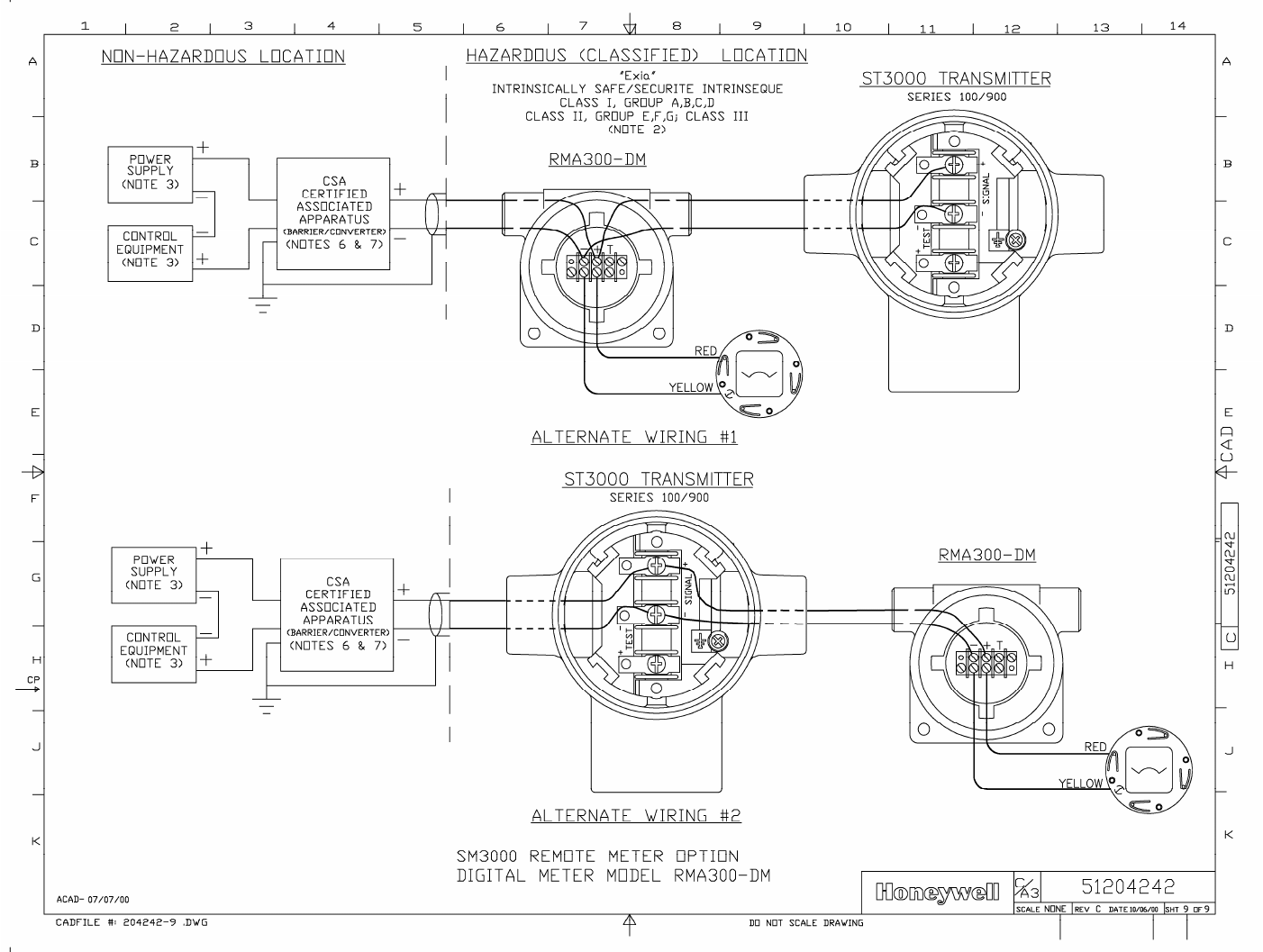
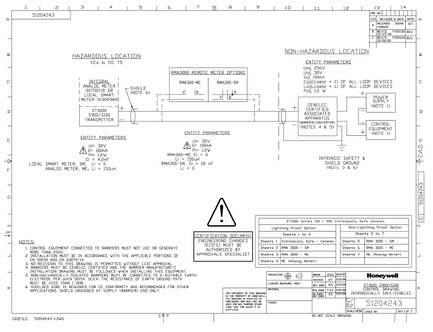
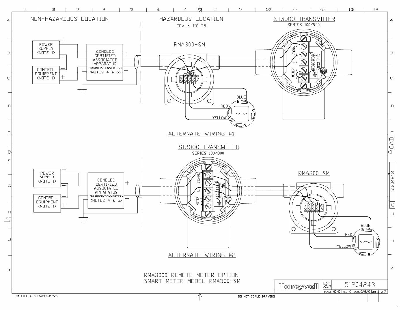
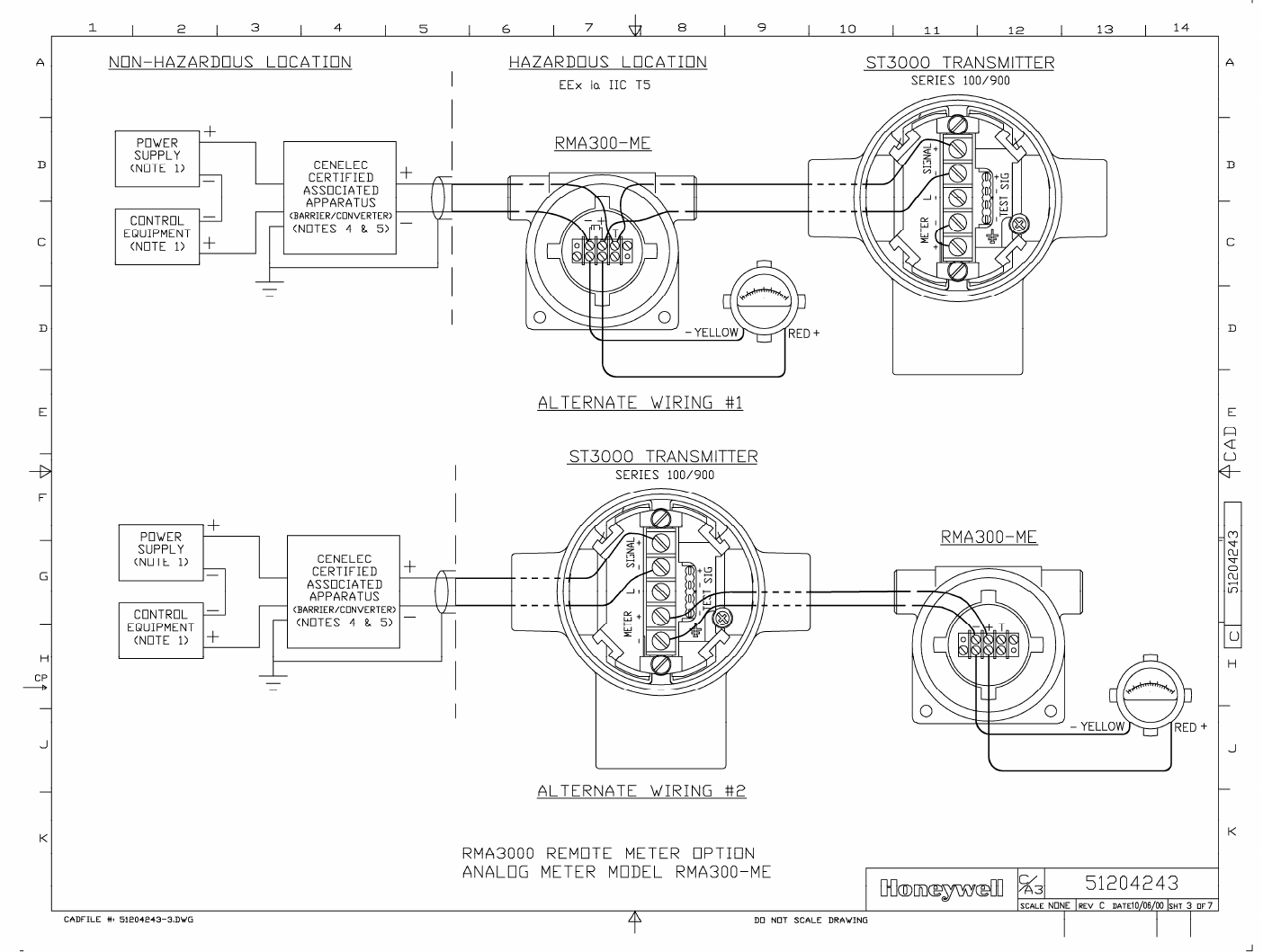
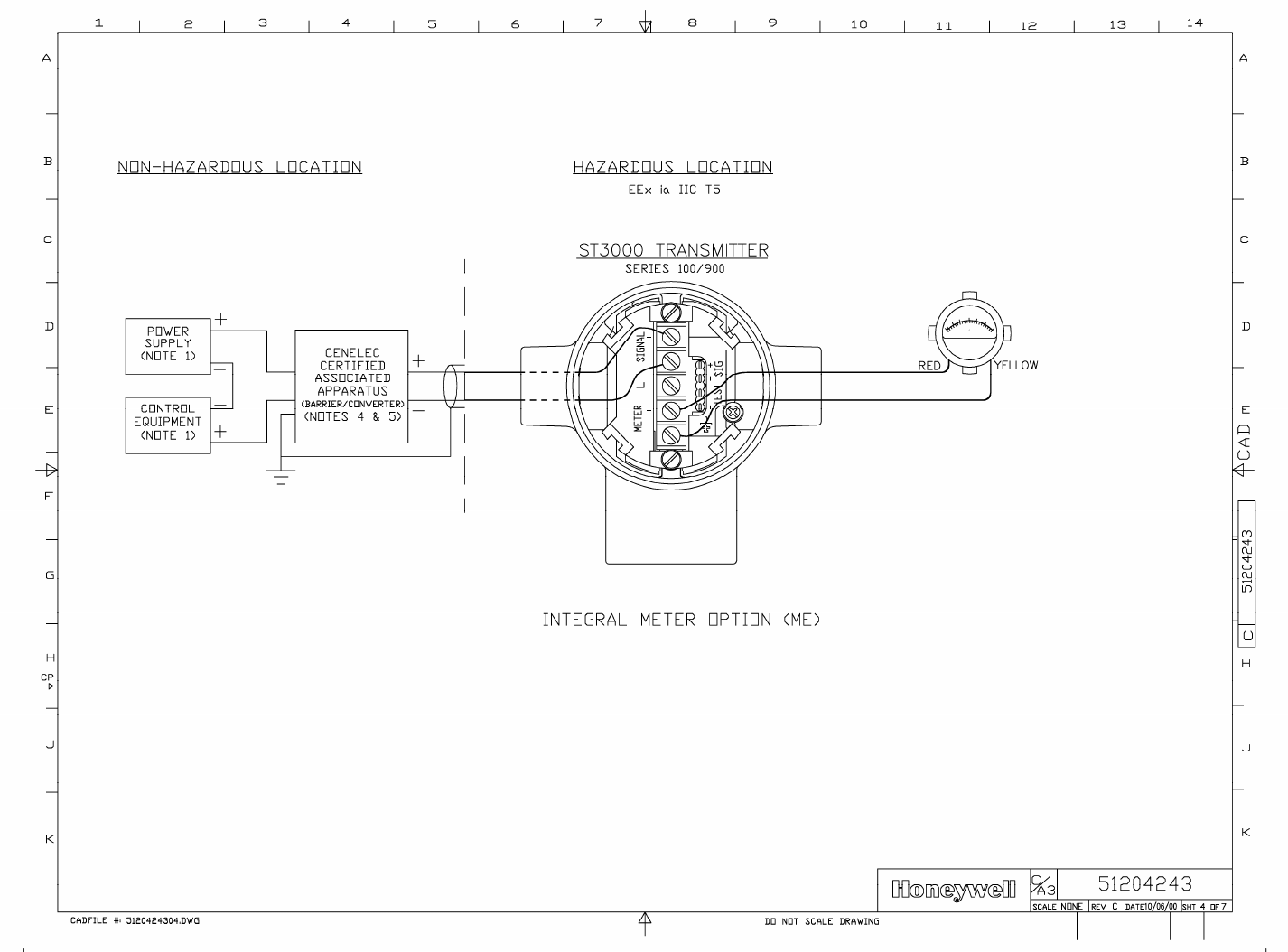
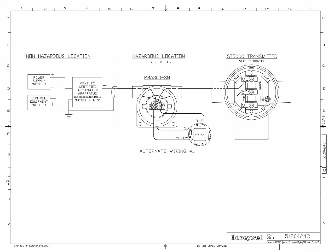
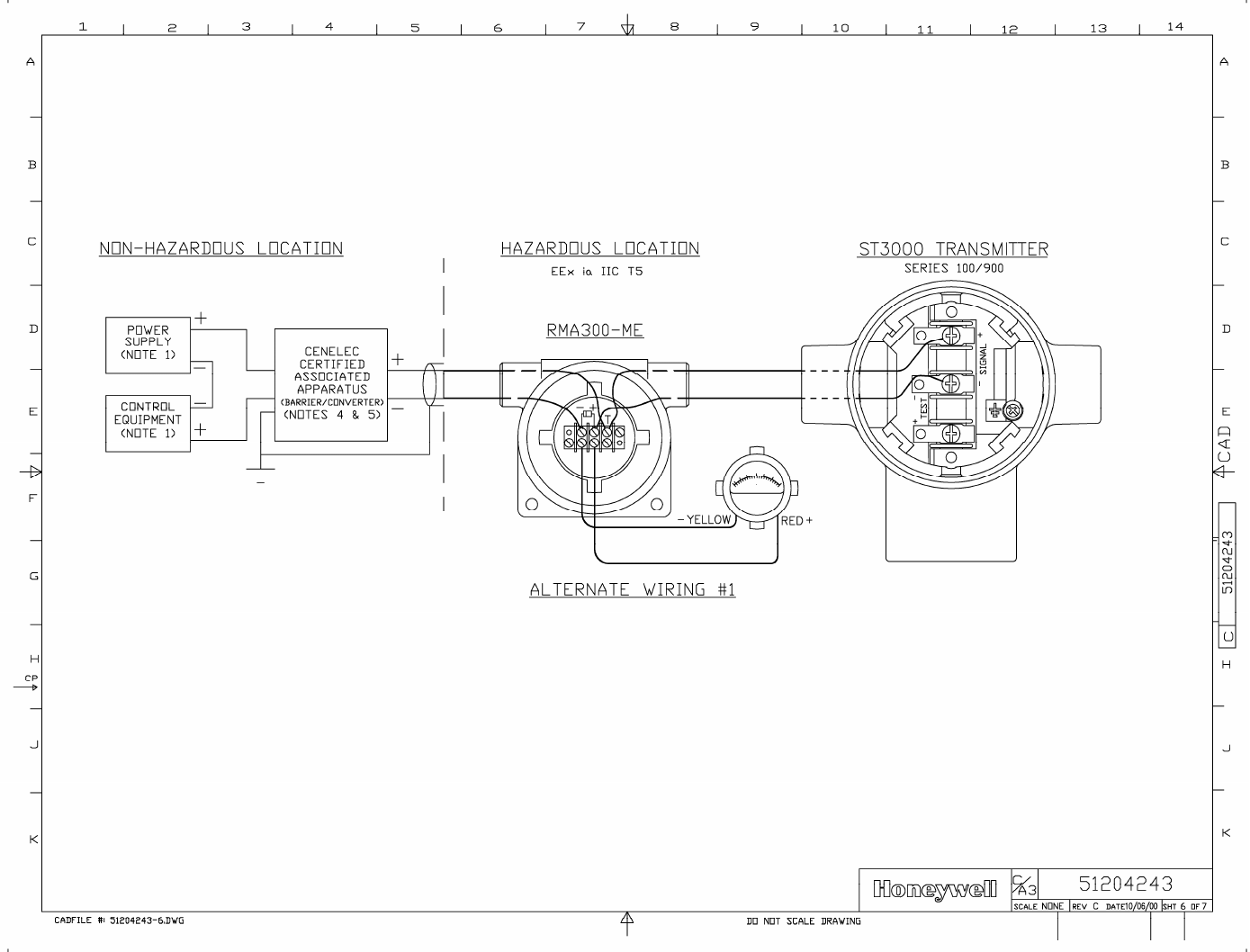
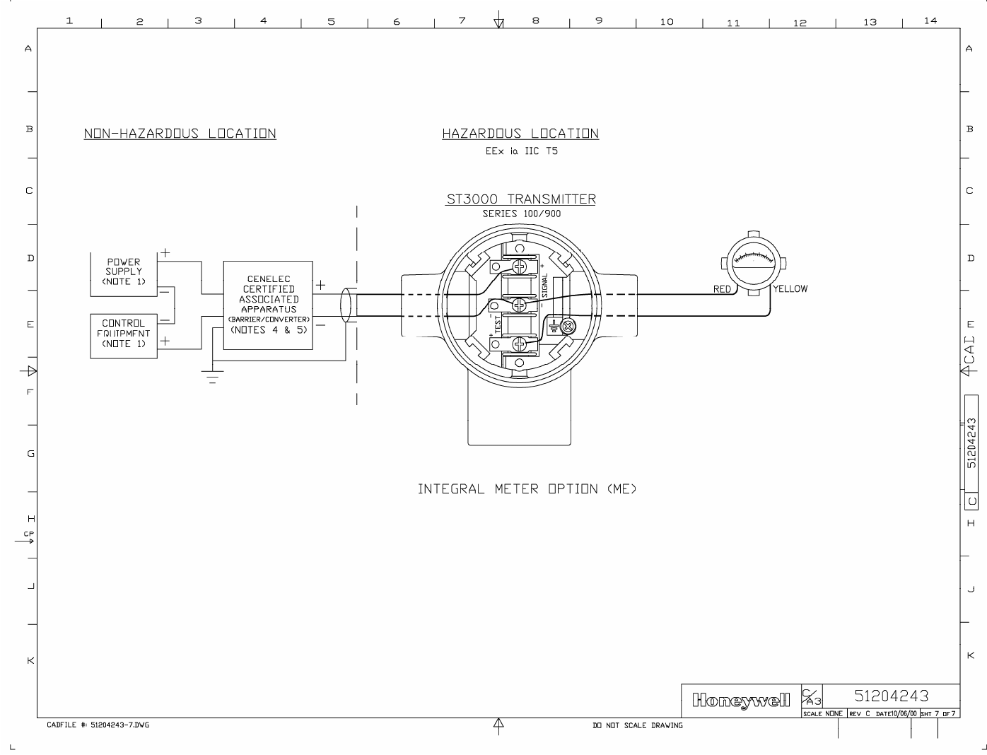

6/08 ST 3000 Release 300 and SFC Model STS103 User’s Manual 233
Appendix A – Table III Options in Model Number
A.1 Table III Options Reference
Codes and
descriptions The following table lists available Table III options alphabetically and
numerically by their codes and gives a brief description of the options.
Note that restrictions do apply based on other as-built transmitter
characteristics and some options are mutually exclusive.
If Code is. . . Then, transmitter option is . . .
A1 1/2-inch NPT to M20 316 stainless steel conduit adapter.
A2 1/2-inch NPT to 3/4-inch NPT 316 stainless steel conduit adapter.
B1 or B2 Blind DIN stainless steel adapter flanges mounted with NACE bolts on process head.
CC Custom calibration to user specified range and user specified transmitter tag number
entered and stored in memory.
CF Calibration Fixture (with ¼” NPT Port for pressure source) for STG93P only.
CM Compound characterized meter body.
CV Stainless steel center vent drain and bushing.
CR A286 stainless steel and 302/304 stainless steel (NACE) nuts for process heads and
316 stainless steel (NACE) bolts for mounting flange adapter to process head.
DN 316 stainless steel modified DIN process heads.
FB Flat mounting bracket (carbon steel).
F1 Calibration test report and certificate of conformance (F3399).
F3 Certificate of conformance (F3391).
F5 Certificate of Origin (F0195).
F7 NACE certificate (F0198).
HR Stainless steel reference head (carbon steel is standard).
LP Lightning protection.
LT Low temperature (–50°C) ambient limit.
MB Angle mounting bracket (carbon steel).
ME Analog meter (0 to 100% linear, 0 to 10 square root).
Continued on next page

234 ST 3000 Release 300 and SFC Model STS103 User’s Manual 6/08
A.1 Table III Options Reference, Continued
Codes and descriptions,
continued
If Code is. . . Then, transmitter option is . . .
MS 316LSS Mounting Sleeve (requires customer installation to process) for STG93P
only.
OX Clean transmitter for Oxygen or Chlorine service with certificate.
SB Angle mounting bracket (stainless steel).
SH 316 stainless steel electronics housing with M20 conduit connections.
SM Local Smart Meter
SV Side vent/drain in process head (end vent/drain is standard).
S1 or S2 1/2-inch, NPT, stainless steel, adapter flange for process head.
TB Stainless steel customer wired -on tag (blank).
TC Factory configured per user supplied data.
TF Teflon process head gasket (Viton is standard).
TG Wired-on, stainless steel customer tag (4-lines, 28 characters per line; customer
supplied information).
TP Over-pressure leak test with F3392 certificate.
T1 or T2 1/2-inch, NPT, Hastelloy C, adapter flange for process head.
VT Viton head gaskets (1/2-inch adapter gaskets are special).
V1 or V2 1/2-inch, NPT, Monel, adapter flange for process head.
WP Write protection.
W1 Additional warranty for 1 year.
W2 Additional warranty for 2 years.
W3 Additional warranty for 3 years.
W4 Additional warranty for 4 years.
ZS Local Zero and Span adjustments.
00 None.
Continued on next page

6/08 ST 3000 Release 300 and SFC Model STS103 User’s Manual 235
A.1 Table III Options Reference, Continued
Codes and descriptions,
continued
If Code is. . . Then, transmitter option is . . .
1C FM approval body certification for:
• Explosionproof/Flameproof Class I, Division 1, Groups A, B, C, D
• Dust Ignition Proof Class II, III, Division 1, Groups E, F, G
• Non-Incendive Class I, Division 2, Groups A, B, C, D
• Intrinsically Safe Class I, II, III, Division 1, Groups A, B, C, D, E, F, G
1S FM approval body certification for:
• Intrinsically Safe Class I, II, III, Division 1, Groups A, B, C, D, E, F, G
2J CSA approval body certification for :
• Explosionproof Class I, Division 1, Groups B, C, D
• Dust Ignition Proof Class II, III, Division 1, Groups E, F, G
• Non-Incendive Class I, Division 2, Groups A, B, C, D
• Intrinsically Safe Class I, II, III, Division 1, Groups A, B, C, D, E, F, G
2S CSA approval body certification for :
• Intrinsically Safe Class I, II, III, Division 1, Groups A, B, C, D, E, F, G
3A LCIE approval body certification for:
• Flame Proof/ CENELEC EEx d IIC T6
• Intrinsically Safe/CENELEC EEx ia IIC T5
3D LCIE approval body certification for:
• Flame Proof/ CENELEC EEx d IIC T6
3N Zone 2 (Europe) certification for:
• Self-Declared per 94/4/EC (ATEX4)
Ex II 3 GD T6 X
Ui ≤ 42V ≤ (Zone 2)
–40 ≤ Ta ≤ 93°C
IP66/67
3S Approval body certification for:
• Intrinsically Safe/CENELEC EEx ia IIC T5
4G or 4H SA approval body certification for:
• Intrinsically Safe Ex ia IIC T4
• Non-Incendive Ex n IIC T6 (T4 with Local Smart Meter option)
5A VNIIVE approval body certification for:
• Intrinsically Safe OEx ia IIC T6 X
9X No certification

236 ST 3000 Release 300 and SFC Model STS103 User’s Manual 6/08

6/08 ST 3000 Release 300 and SFC Model STS103 User’s Manual 237
Appendix B – Freeze Protection of Transmitters
B.1 Possible Solutions/Methods
Problem When water is present in the process fluid and ambient temperatures can
fall below the freezing point (32°F/0°C), pressure transmitters and their
piping require freeze protection. Transmitters may also require
continuous heating, if the process fluid is tar, wax, or other medium
which will solidify at normal ambient. However, uncontrolled steam or
electric heating, in addition to wasting energy, can cause errors and
accidentally destroy the transmitter.
Solution These two basic solutions are possible:
• Eliminate the need for heating the transmitter by keeping the
freezable process fluid out of direct contact with transmitter.
• Control the steam or electric heat to prevent overheating on warm
days while protecting against freeze-ups under the coldest
conditions.
The other paragraphs in this section review a number of methods for
implementing both solutions.
Sealing liquid method The simplest and least costly method is to use a sealing liquid in the
transmitter meter body and its impulse piping to the process. The small
contact (interface) area between the sealing liquid and the process fluid
reduces the mixing of the two fluids.
You should select a sealing liquid that has a greater specific gravity than
the process fluid to inhibit mixing. It also must have freezing and
boiling temperatures compatible with the range of temperatures existing
at the site, including the heated interface.
WARNING WARNING — The user must verify the compatibility of any sealing
liquid with their process fluid.
A reliable sealing liquid is a 50/50 percent (by volume) solution of
ethylene-glycol and water. This solution has a specific gravity of 1.070 at
60°F (15°C), a freezing temperature of –34°F (–36°C), and a boiling
temperature of +225°F (+106°C) at atmospheric pressure. Conventional
antifreeze liquids for automobile coolant systems such as Prestone and
Continued on next page
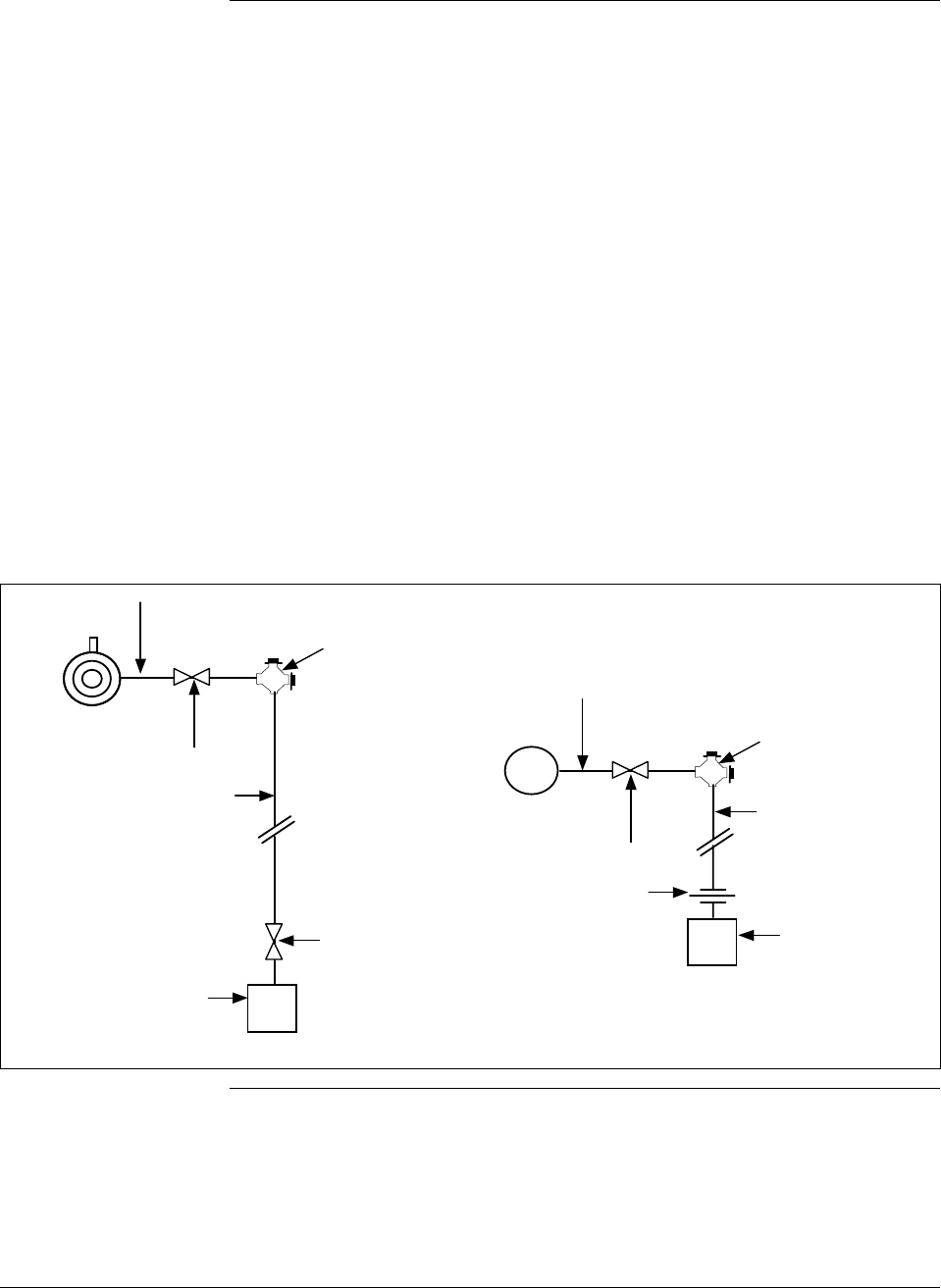
238 ST 3000 Release 300 and SFC Model STS103 User’s Manual 6/08
B.1 Possible Solutions/Methods, Continued
Sealing liquid method,
continued Zerex are solutions of ethylene-glycol with some rust inhibitors and
possibly leak sealants added; they may be used in place of pure ethylene-
glycol.
Another sealing liquid, used in many chemical plants, is dibutylphalate an
oily-type liquid with a specific gravity of 1.045 at 70°F (21°C). It has a
boiling point 645°F (340°C) and does not freeze so it can be used down to
about –20°F (–30°C).
Figures B-1 and B-2 show typical piping installations for this method. The
process fluid must be heated above its freezing point. This is frequently
done by lagging in (insulating) the connecting nipple, shut-off valve and
“T” connector with the process piping. Where the process piping itself
requires heating, a steam or electric trace is run around their components
with consideration given to the boiling point of the sealing liquid.
Figure B-1 Piping Installation for Sealing Liquid With Specific Gravity Heavier Than
Process Fluid.
1/2" seamless pipe nipple 6" long
1/2" shut-off valve (thru
port type desirable)
1/2" pipe cross
with 2 pipe plugs
1/2" seamless pipe
(slope at least 1"
per foot downward
1/2" 3-valve
manifold,
standard type
1/2" seamless pipe
(short as possible to
reduce head effect)
Differential
pressure
transmitter
Process pressure
transmitter
1/2" pipe union
or coupling
1/2" pipe cross
with 2 pipe plugs
1/2" shut-off valve (thru
port type desirable)
1/2" seamless pipe nipple 6" long
Continued on next page
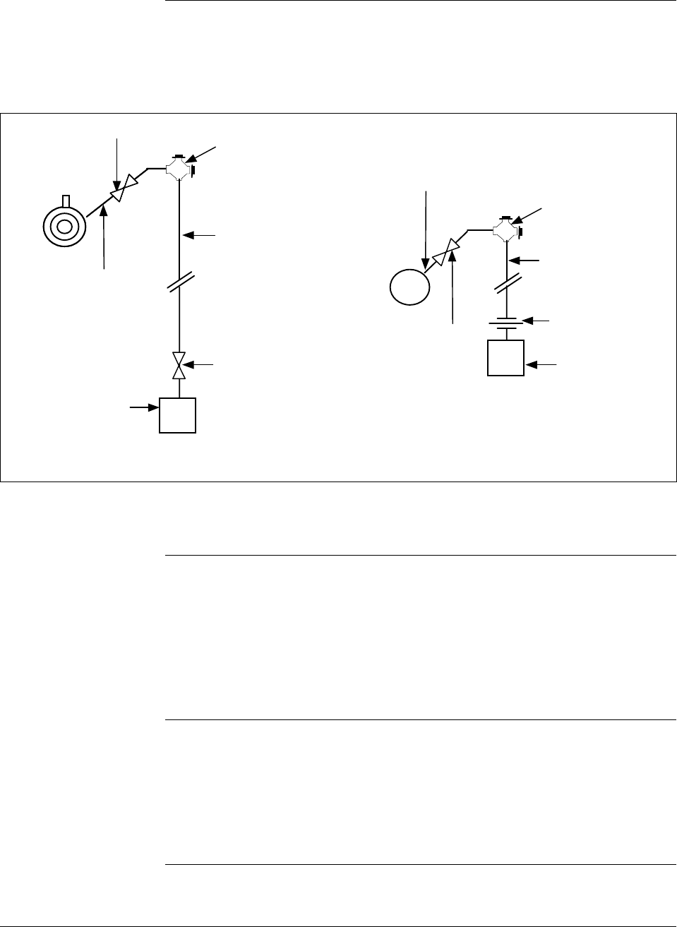
6/08 ST 3000 Release 300 and SFC Model STS103 User’s Manual 239
B.1 Possible Solutions/Methods, Continued
Sealing liquid
method, continued
Figure B-2 Piping Installation for Sealing Liquid with Specific Gravity Lighter Than
Process Fluid.
1/2" seamless
pipe nipple 6" long
1/2" shut-off valve (thru
port type desirable)
1/2" seamless pipe
(short as possible to
reduce head effect)
Process pressure
transmitter
1/2" pipe union
or coupling
1/2" pipe cross
with 2 pipe plugs
1/2" shut-off
valve (thru port
type desirable)
1/2" seamless
pipe nipple 6"
long
1/2" pipe cross
with 2 pipe plugs
1/2" 3-valve
manifold,
standard type
Differential
pressure
transmitter
1/2" seamless pipe
(slope at least 1"
per foot downward
Make both HP and LP
connections as shown.
The installation should be checked every 6 to 12 months to verify that the
sealing liquid is at its required specific gravity.
Purging Purging air or water purges are commonly used to prevent viscous
materials from clogging the impulse lines to pressure, level, or flow
transmitters. The bubbler system, using a constant-air flow regulator, is
particularly common on open tank liquid level applications. No heating of
impulse lines or transmitter is required, but normal precautions are
required to keep water out of the air supply system.
Gas applications We must not overlook the possibility of condensate freezing in impulse
lines to transmitters measuring gas flow or pressure. Although these
components could be heated similar to water and steam applications, the
simplest and best approach is to install transmitters so that they are self
draining. This means that the impulse lines are connected to the lowest
Continued on next page
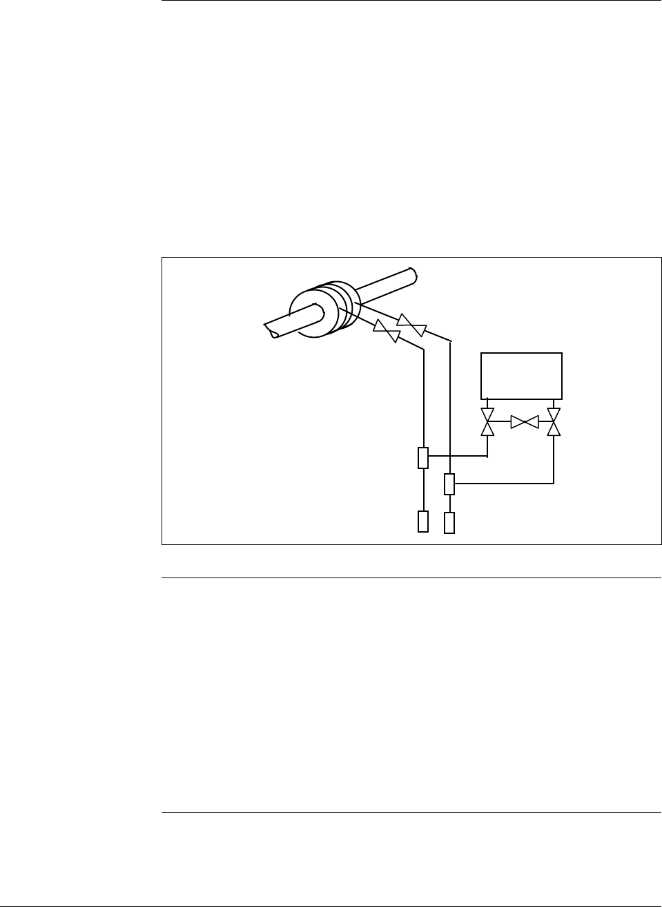
240 ST 3000 Release 300 and SFC Model STS103 User’s Manual 6/08
B.1 Possible Solutions/Methods, Continued
Gas applications,
continued point in the transmitter meter body and the piping is sloped downward at
least one inch per foot. (Side-connected transmitters with vent-drains at a
lower point in the meter body must be regularly checked to assure
condensate removal.) If the transmitter is located below the process taps
(not recommended), piping must still run downward from the transmitter
to the drain point and then up to the process as shown in Figure B-3.
Steam or electric heating of the drain point will prevent pipe rupture due
to freezing.
Figure B-3 Piping Installation for Gas Flow.
Transmitter
Mechanical
(diaphragm) seals Diaphragm seals on the impulse lines provide the most expensive, yet
broadest application of all the methods. Similar in principle to the liquid
seals, diaphragm seals eliminate the possibility of seal liquid carry-over
into the process fluid. This eliminates the need for periodic maintenance
checks to assure full and equal liquid seal legs. Welded diaphragm seals
with special fills permit temperatures from –34° to 600°F (–36° to 315°C)
at the process interface which can therefore be steam or electrically heated
to assure viscosity of tars and similar high-freezing point fluids under the
coldest conditions.
Continued on next page
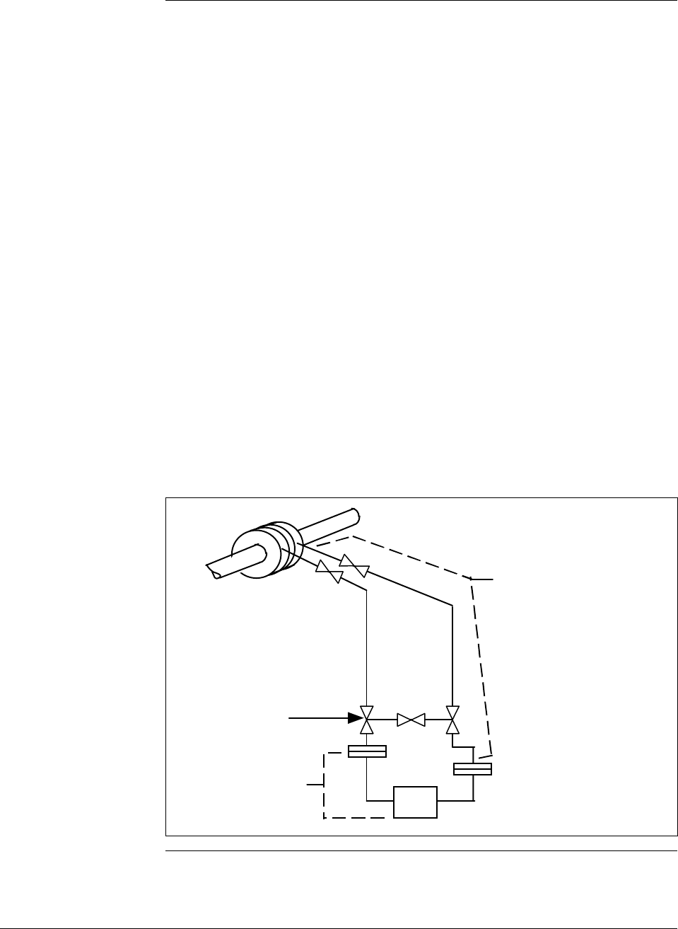
6/08 ST 3000 Release 300 and SFC Model STS103 User’s Manual 241
B.1 Possible Solutions/Methods, Continued
Mechanical
(diaphragm) seals,
continued You must be careful to specify large enough diaphragms to accommodate
expansion and contraction of the fill fluid under varying temperatures
without overextending the diaphragm into its stiff area. In general,
conventional diaphragm seals are satisfactory for pressure ranges above
approximately 75 psig with special large diameter elements required for
low pressure or differential pressure measurements.
You can lag (insulate) impulse lines and diaphragm seals with the process
piping, but this practice is only common with liquid level applications
involving highly viscous materials unsuitable for 1/2-inch impulse lines.
Use a tank-mounted flanged seal in such installations. Otherwise, it is
more desirable to keep the capillary lengths short, the transmitter
accessible for maintenance, and (for flow applications) the normal 3-valve
manifold assembly close to the transmitter for normal service checks.
Thus, the impulse lines, valving and diaphragm seals with 1/2-inch
connections would be electrically or steam traced, with high temperature
steam permitted without damage to the transmitter. See Figures B-4 and
B-5 for typical piping layouts.
Figure B-4 Piping Installation for Differential Pressure Transmitter with
Metal Diaphragm Seals.
The impulse piping, 3-valve
manifold, and upper flanges
of the metal diaphragm seals
must be insulated and, where
required, also heated by
electric or steam.
1/2" , 3-valve manifold
(standard type with
suitable temperature rating)
Differential pressure
transmitter with metal
diaphragm seals
Continued on next page
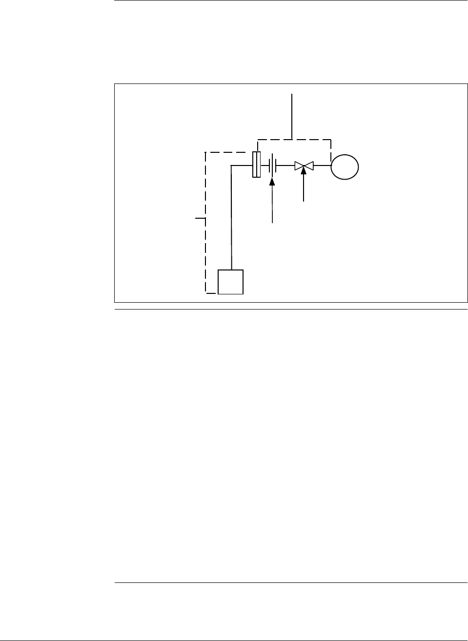
242 ST 3000 Release 300 and SFC Model STS103 User’s Manual 6/08
B.1 Possible Solutions/Methods, Continued
Mechanical
(diaphragm) seals,
continued
Figure B-5 Piping Installation for Process Pressure Transmitter with
Metal Diaphragm Seal.
Process pressure
transmitter with
metal diaphragm
seal
Pipe union or
coupling
Shut-off valve
Impulse piping, shut-off valve, and
diaphragm seal distance must be as
short as possible and insulated along
with the process pipe or vessel
Electric heating Most transmitters will withstand higher temperatures at their process
interfaces (bodies) than at their electronics. Normally, it is impractical to
heat transmitter bodies above 225 to 250°F (107 to 121°C) without radiant
and conducted heat exceeding the rating at the electronics (normally
200°F/93°C). Prefabricated insulated enclosures with integral heating
coils and thermostats set at 200°F (93°C) can assure viscosity of fluids
which freeze below 180°F (82°C) while assuring safe transmitter
operation. For water or similar lower-temperature mediums, the control
can be set at 50°F (10°C) to save energy and call for heat only when
temperature and wind conditions require.
Systems can be engineered for uncontrolled, continuous electric heating to
prevent water freezing at 0°F (–18°C) and 20 mph wind velocity, while
not exceeding 225°F (107°C) at the transmitter body at 90°F (32°C)
ambient and zero wind velocity. The operating costs in energy for these
systems usually exceed the high initial cost of the thermostat systems.
Never attempt to maintain freeze points above 100°F (38°C) without
thermostat controls since the Btu required to prevent freezing will
normally exceed the body temperature rating under opposite extremes.
Continued on next page
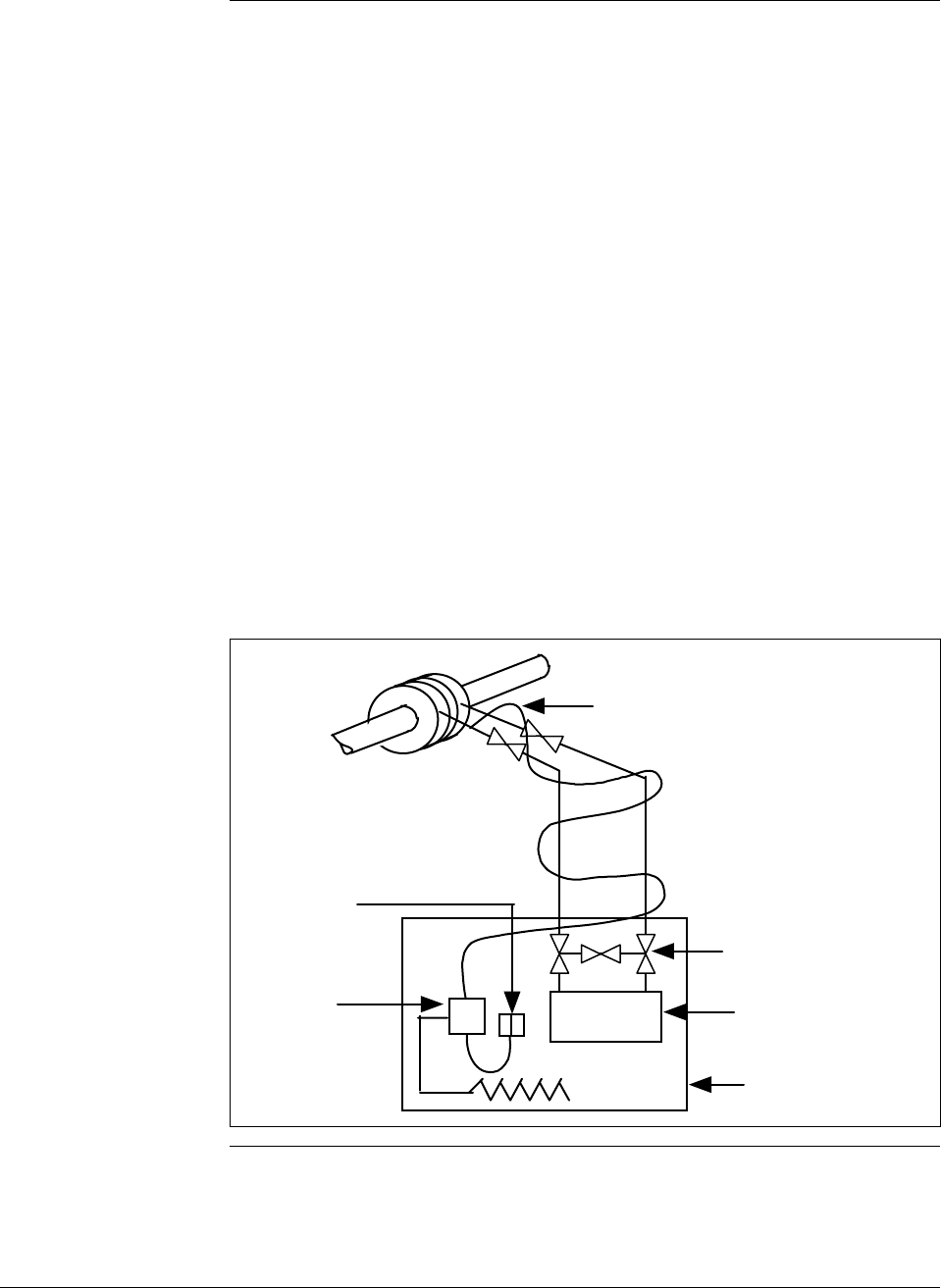
6/08 ST 3000 Release 300 and SFC Model STS103 User’s Manual 243
B.1 Possible Solutions/Methods, Continued
Electric heating,
continued Although systems are available with hollow bolts replacing the normal
transmitter body bolts and containing electrical heating elements and
thermostats, certain precautions are required with such arrangements.
Some transmitter meter body bolts are too small to accept the available
thermostats. Also thermostat settings should not approach the body
temperature limit because the heat gradient across the meter body can be
such that limits are exceeded adjacent to the heating elements even when
the thermostat setting is lower.
Electrical heating systems are available in explosionproof ratings for
Class I, Group D, Division I and II installations.
The possibility of electric supply failure must be considered. For this
reason, we recommend using alarm devices with manual acknowledgment
and reset.
See Figures B-6 and B-7 for typical piping installations.
Figure B-6 Piping Installation for Differential Pressure Transmitter and
Impulse Piping with Electric Heating and Control.
Electric heating cable
1/2" , 3-valve manifold
(standard type )
Differential pressure
transmitter
Temperature
controller
(thermostat)
Temperature
sensor
Insulated enclosure
Continued on next page
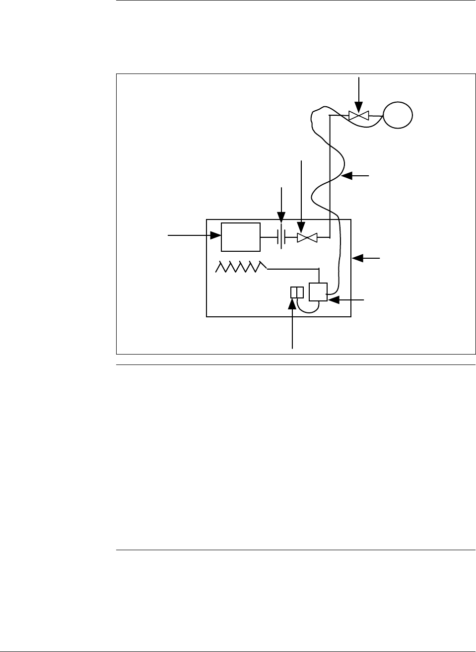
244 ST 3000 Release 300 and SFC Model STS103 User’s Manual 6/08
B.1 Possible Solutions/Methods, Continued
Electric heating,
continued
Figure B-7 Piping Installation for Process Pressure Transmitter and
Impulse Piping with Electric Heating Control.
Union or coupling
Process pressure
transmitter
Temperature
controller
(thermostat)
Temperature
sensor
Insulated
enclosure
Shut-off valve
Shut-off valve Electric heating
cable
Steam heating Steam heating is perhaps the most common, yet potentially the most
damaging method of protecting transmitters from freeze-ups. Since steam
is generated for use in the overall process operation, it is considered an
available by-product. The most important point to remember when steam
heating transmitter meter bodies is the temperature of the steam that will
be used and its pressure. We recommend that you review the next
paragraph Superheated steam considerations to get a better understanding
of the temperature problem with steam heating. In brief, do not assume
that 30 psig steam is 274°F (134°C) and cannot damage a transmitter rated
for 250°F (121°C). With steam heating, as with electrical, you should use
insulated transmitter body housing, impulse piping and valves.
Continued on next page

6/08 ST 3000 Release 300 and SFC Model STS103 User’s Manual 245
B.1 Possible Solutions/Methods, Continued
Steam heating,
continued It is common practice to use conventional steam traps on all steam heating
systems. They permit live, superheated steam to enter the heating coils
and piping down to the trap. You should also use conventional steam traps
with lower pressure desuperheated steam which cannot overheat the
transmitter under warm-day conditions. If the heating pipes are not
carefully installed to eliminate low spots and trapped condensate in the
piping, they could freeze at low temperatures.
All steam traps require a periodic maintenance program. Dirt, scale, and
water softeners will cause traps to stick or jam which result in their either
blowing steam continuously or not blowing steam, allowing condensate
freeze-up in cold weather. When steam traps are used for cold-weather
freeze protection of water lines, a thermostat controlled steam supply
valve, which will shut off the steam at ambient temperatures higher than
50°F (10°C), will save steam and prevent overheating.
A more general solution is offered by a specialized type of trap which
throttles condensate flow based on its temperature. This backs up hot
water in the radiator within the insulated transmitter enclosure, assuring
temperatures no higher than the saturated steam at the reduced pressure.
Models are available to set the condensate temperature from about 70° to
200°F (21° to 93°C). They must be located within 6 to 12 inches (15 to 30
cm) of the transmitter body and , like all steam traps, they also require
periodic maintenance. The engineering of this type system is more
complex than electric systems since the amount of heat loss upstream of
the CTV valve under varying conditions will determine the location of the
steam/water interface. It could occur within the heater coil or further up
the steam line, thus affecting the heating efficiency within the insulated
enclosure. Therefore, steam control of materials which freeze or become
too viscous above 100°F (38°C) should probably not be attempted without
some experimenting with the specific piping layout used.
Uncontrolled steam heating, even with the best pressure regulation and
desuperheating of steam, should not be used to maintain transmitter
temperatures above 100°F (38°C), since this type of fixed Btu input must
either over or under-heat under normal ambient swings.
As with electric heating, there are many types of commercial steam
heating units available such as radiant heaters, hollow meter body studs or
just tubing lagged to the impulse piping and transmitter body. The same
precaution applies to the use of hollow studs as on the electrical versions.
Continued on next page
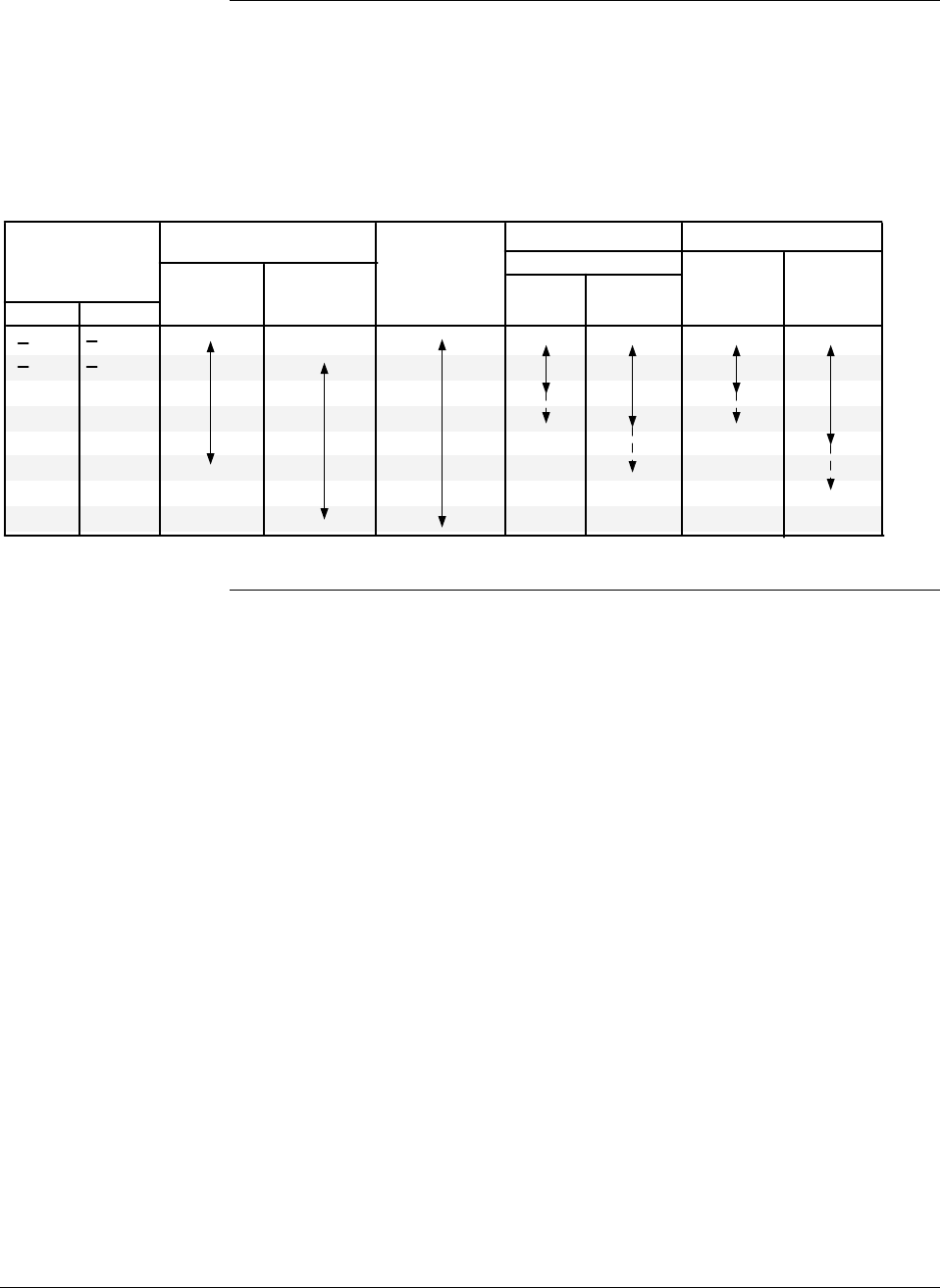
246 ST 3000 Release 300 and SFC Model STS103 User’s Manual 6/08
B.1 Possible Solutions/Methods, Continued
Steam heating,
continued See Figure B-8 and B-9 for typical piping installations. Table B-1
summarizes the temperature ranges for the various freeze protection
systems.
Table B-1 Temperature Range of Freeze Protection Systems
Operating
Temperature
Range
Liquid Seals
Ethylene
Glycol
Dibutyl-
Phthalate
Steam Heating
No Seals
Trap CTV
Valve
Electric Heat
No
Control
Thermo-
stated
ο Fο
C
34
20
50
100
200
225
325
600
36
30
10
38
93
106
163
315
Note: Broken lines indicate areas of caution.
Diaphragm
Seals
Continued on next page
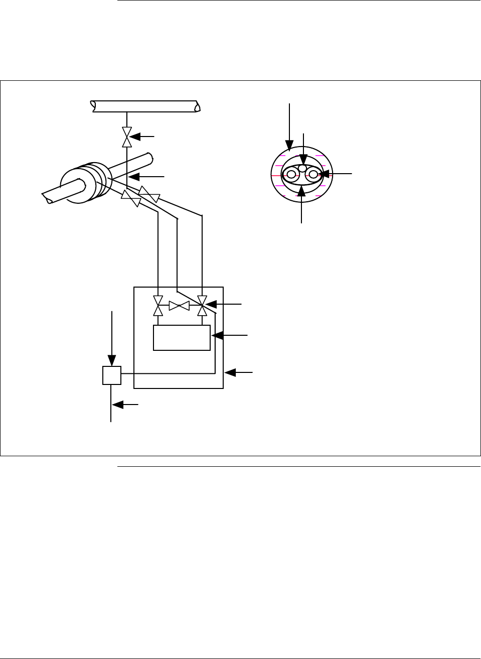
6/08 ST 3000 Release 300 and SFC Model STS103 User’s Manual 247
B.1 Possible Solutions/Methods, Continued
Steam heating,
continued
Figure B-8 Piping Installation for Differential Pressure Transmitter and Impulse Piping with
Steam Heating.
Steam heat
tracer line
1/2" , 3-valve manifold
(standard type )
Differential pressure
transmitter
Condensate return from steam trap. All steam and
condensate lines must always slope downward at least 1"
per foot to prevent low spots which will trap condensate.
All condensate lines must be protected from freezing.
Steam trap or
condensate
temperature
valvle
Insulated enclosure
1/4" OD steam tracer line
Impulse piping with
1/4" thick insulation
Pipe insulated with
waterproof outer cover
Pipe strap about
every 15"
Detail of Transmitter Impulse Piping
Shut-off valve
Steam Supply (low pressure)
Continued on next page
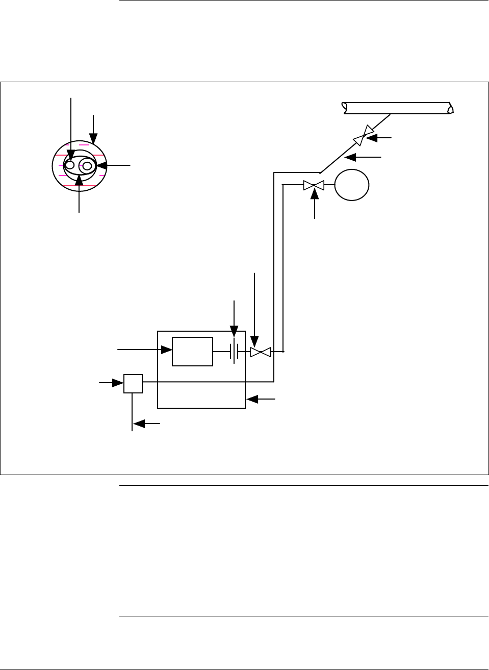
248 ST 3000 Release 300 and SFC Model STS103 User’s Manual 6/08
B.1 Possible Solutions/Methods, Continued
Steam heating,
continued
Figure B-9 Piping Installation for Process Pressure Transmitter and Impulse Piping with
Steam Heating.
1/4" OD steam tracer line
Impulse piping with
1/4" thick insulation
Pipe insulated with
waterproof outer cover
Pipe strap about
every 15"
Detail of Transmitter Impulse Piping
Condensate return from steam trap. All steam and
condensate lines must always slope downward at least 1"
per foot to prevent low spots which will trap condensate.
All condensate lines must be protected from freezing.
Steam trap or
condensate
temperature
valvle
Insulated enclosure
Shut-off valve
Steam Supply (low pressure)
Union or coupling
Process pressure
transmitter
Shut-off valve
Shut-off valve
Steam heat
tracer line
Superheated steam
considerations We must remember that the temperature of steam is 212°F (100°C) only at
the normal atmospheric pressure of about 14.7 pounds per square inch
absolute (psia). If the pressure of steam is increased above 14.7 psia, the
temperature of the steam is also increased. For example, if we have steam
at 30 pounds per square inch gage (psig), the steam temperature is 274°F
(134°C).
Continued on next page

6/08 ST 3000 Release 300 and SFC Model STS103 User’s Manual 249
B.1 Possible Solutions/Methods, Continued
Superheated steam
considerations,
continued On industrial flow and pressure measurement applications, we may be
required to use steam to heat the impulse piping to the flow or pressure
transmitter, as well as the transmitter itself. For these applications, we
must verify the temperature of the heating steam used. As an example,
assume that steam at 100 psig saturated (338°F/170°C) is to be reduced to
30 psig pressure for the heating system. Too frequently, it is assumed that
this pressure reduction will result in steam at 274°F (134°C), the
temperature of saturated steam at 30 psig. Wrong! A reduction of the
steam pressure will not appreciably decrease the initial steam temperature.
In our example, we were talking about saturated steam in the main header
from the boiler. But modern industrial boilers cannot afford to let waste
heat go up the stack. After reaching the boiling point in the drum, the
steam flows through a series of pipes in the second pass of the flue gas
exit, extracting additional heat energy and being raised to a temperature
higher than the saturation temperature at the same pressure. This is
superheat and, depending on boiler design, it may amount to 50 to 300°F
(10 to 149°C) above the saturated steam temperature. It also permits
packing more heat energy in a given size pipe for transmission from the
process. Thus, in the typical application, the problem of steam heating is
compounded by the additional superheat in the main header.
Specifically, when steam is reduced in pressure, it retains about the same
latent heat or the same Btu’s/pound at the reduced pressure. Therefore, in
our example, steam at 100 psig and 338°F (170°C) when reduced to 30
psig steam will have a temperature of 306°F (152°C) or a loss of only
32°F (18°C).
This steam temperature can only be reduced by using a desuperheater.
This device mixes cold water with the superheated steam to reduce its
temperature by removing Btu’s per pound of water (steam). It is also
possible to use temperature controlled steam traps, which actually allow
the steam to condense to water and therefore reduce its temperature to a
pre-set value.
Continued on next page

250 ST 3000 Release 300 and SFC Model STS103 User’s Manual 6/08
B.1 Possible Solutions/Methods, Continued
Superheated steam
considerations,
continued Table B-2 lists the various values of steam pressure, saturated steam
temperatures at these pressures, degrees of superheat added to the
saturated steam and finally the actual temperature of each when it is
reduced to 30 psig steam.
Table B-2 Steam Pressure Versus Steam Temperature Values
Pressure
(1) Saturated
Temperature
(2)
Superheat Added
(3) Final Steam
Temperature
(2) + (3)
Actual Temperature
of Steam When
Reduced From (1)*
to 30 psig
psig °F °C °F °C °F °C °F °C
50 298 147 None None 298 147 290 143
100 338 170 100 55 438 225 420 215
150 366 185 120 66 486 251 460 234
200 387 198 150 83 537 281 500 260
400 448 231 200 111 648 342 600 316
600 489 254 250 139 739 393 660 349
*(1) equals pressure in column one with superheat added.
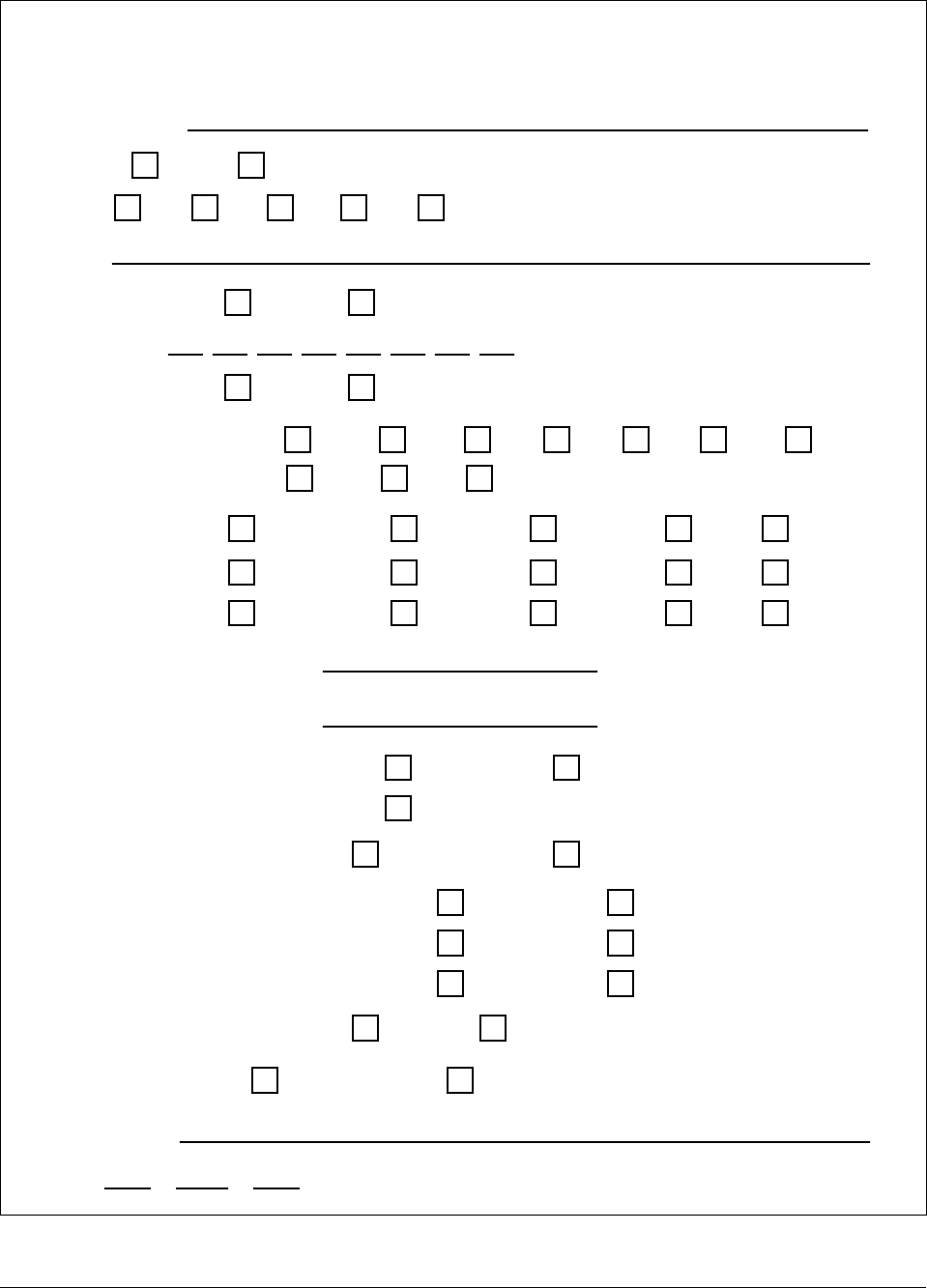
6/08 ST 3000 Release 300 and SFC Model STS103 User’s Manual 251
Appendix C – Configuration Record Sheet
ST 3000 Smart Transmitter
Configuration Record Sheet
Series: 100 900
Type: DP GP AP RS FM
Model Number:
Range:
Tag Number:
Output Conformity: Linear Square Root
Engineering Units : "H2O_39F
mmHg_0C
PSI
KPa
MPa
mbar
bar
G/cm^2
KG/cm^2
inHg_32F mH2O_4C "H2O_68F
mmH2O_4C
Lower Range Value: 4 mAdc =
Upper Range Value: 20 mAdc =
Output Signal Mode (DE Mode Only): Single Range Dual Range (STDC)
Single Range W/SV
Message Format (DE Mode Only): W/O DB (4 Byte) W/DB (6 Byte)
Failsafe Mode STDC Card (DE Mode Only): F/S = B/O Lo
F/S = B/O Hi
F/S = LKG
F/S = FSO, B/O Lo
F/S = FSO, B/O Hi
F/S = FSO, LKG
Failsafe Direction (Analog Mode): Upscale Downscale
Write Protect Option: Read and Write Read Only
Configured By:
Date: //
Damping Time (Seconds): 0.00 0.2 0.3 0.5 1.0 2.0 4.0
8.0 16.0 32.0
Mode of Operation: Analog DE
ATM "H2O_60F

252 ST 3000 Release 300 and SFC Model STS103 User’s Manual 6/08

6/08 ST 3000 Release 300 and SFC Model STS103 User’s Manual 253
Appendix D – Hazardous Locations Reference
Reference
Information Information is provided to clarify the hazardous location installation
requirements in North America and internationally. An explanation of
the applicable enclosure classification systems is also provided.
D.1 North American Classification of Hazardous Locations
Electrical Codes Installation of electrical apparatus within hazardous (classified)
locations of the United States is conducted under the provisions of the
National Electrical Code (NEC), ANSI/NFPA 70, Article 500; and
within Canada, under the provisions of the Canadian Electrical Code
(CEC) C22.1, Part 1, Section 18.
Classes Hazardous (classified) locations, in both the United States and Canada,
are categorized into one of these three classes.
Class Description of Hazardous Location
I Presence of flammable gases or vapors may be present in
quantities sufficient to produce explosive or ignitable mixtures.
II Presence of combustible dusts, powders or grains.
III Presence of easily ignitable fibers or flyings.
Divisions The classes listed above are further categorized based upon the level of
risk present.
Division Description of Risk
1 Locations in which hazardous concentrations of flammable gases
or vapors, or combustible dust in suspension are continuously,
intermittently or periodically present under normal operating
conditions.
2 Locations in which flammable gases or vapors are present, but
normally confined within closed containers or systems from which
they can escape only under abnormal or fault conditions.
Combustible dusts are not normally in suspension nor likely to be
thrown into suspension.
Continued on next page

254 ST 3000 Release 300 and SFC Model STS103 User’s Manual 6/08
D.1 North American Classification of Hazardous
Locations, Continued
Examples Given the criteria above, the following examples are made:
A Class III, Division 1 location is a location in which easily ignitable
fibers or material processing combustible flyings are
handled, manufactured or used.
A Class III, Division 2 location is a location in which easily ignitable
fibers are stored or handled.
Groups Flammable gases, vapors and ignitable dusts, fibers and flyings are
classified into groups according to the energy required to ignite the most
easily-ignitable mixture within air. Group classifications are as follows:
Class I
Group Description of Atmosphere
A Atmospheres containing acetylene.
B Atmospheres containing hydrogen, fuel and combustible
process gases containing more than 30 percent hydrogen by
volume, or gases or vapors of equivalent hazard.
C Atmospheres such as ethyl ether, ethylene, or gasses or vapors
of equivalent hazard.
D Atmospheres such as acetone, ammonia, benzene, butane,
cyclopropane, ethanol, gasoline, hexane, methanol, methane,
natural gas, naphtha, propane or gases or vapors of equivalent
hazard.
Class II
Group Description
E Atmospheres containing combustible metal dusts including
aluminum, magnesium, and their commercial alloys, and other
metals of similarly hazardous characteristics.
F Atmospheres containing combustible carbonaceous dusts
including carbon black, charcoal, coal or other dusts that have
been sensitized by other materials so that they present an
explosion hazard.
G Atmospheres containing combustible dusts not included in
Group E or F, including flour wood, grain, and other dusts of
similarly hazardous characteristics.
Continued on next page
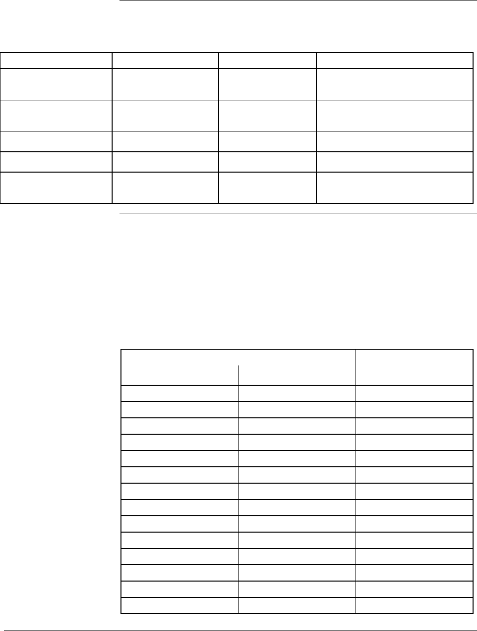
6/08 ST 3000 Release 300 and SFC Model STS103 User’s Manual 255
D.1 North American Classification of Hazardous
Locations, Continued
Methods of Protection The following table summarizes available methods of protection for use
in given locations.
Protection Concept Designation Permitted Use Principle
Explosionproof XP Division 1 & 2 Contains explosion and
quenches flame.
Intrinsic Safety IS Division 1 & 2 Limit energy of sparks under
normal and fault conditions.
Pressurized Type X and Y Division 1 Keeps flammable gas out.
Pressurized Type Z Division 2 Keeps flammable gas out.
Nonincendive NI Division 2 No arcs, sparks or hot surfaces
under normal conditions
Temperature
Classification Equipment intended for installation directly within the hazardous
(classified) location must also be classified for the maximum surface
temperature that can be generated under normal or fault conditions as
referenced to either 40°C (104°F) or the maximum operating ambient of
the equipment (whichever is greater). The maximum surface
temperature must be less than the minimum autoignition temperature of
the hazardous atmosphere present. The temperature shall be indicated in
identification numbers as listed in the following table.
Maximum Temperature Temperature
Degrees C Degrees F Identification Number
450 842 T1
300 572 T2
280 536 T2A
260 500 T2B
230 446 T2C
215 419 T2D
200 392 T3
180 356 T3A
165 329 T3B
160 320 T3C
135 275 T4
120 248 T4A
100 212 T5
85 185 T6

256 ST 3000 Release 300 and SFC Model STS103 User’s Manual 6/08
D.1 North American Classification of Hazardous
Locations, Continued
Intrinsically Safe
Apparatus
Parameters
The Apparatus Parameters are defined as follows.
Parameter Description
Vmax Maximum safe voltage that can be applied to the apparatus
terminals.
Imax Maximum safe current that can be applied to the apparatus
terminals.
Ci Unprotected capacitance in the apparatus that can be
considered present at the terminals.
Li Unprotected inductance in the apparatus that can be
considered present at the terminals.
Associated Apparatus
Parameters The Associated Apparatus Parameters are defined as follows.
Parameter Description
Voc Maximum output voltage that can be delivered to the
hazardous (classified) location. This voltage is the maximum
from a single channel.
Isc Maximum output current that can be delivered to the
hazardous (classified) location. This current is the maximum
from a single channel.
*Vt Maximum output voltage that can be delivered to the
hazardous (classified) location. This voltage is the maximum
across any combination of terminals of a multiple channel
configuration.
*It Maximum output current that can be delivered to the
hazardous (classified) location. This current is the maximum
through any combination of terminals of a multiple channel
configuration.
Ca Maximum capacitance that can be connected to the
apparatus.
La Maximum inductance that can be connected to the apparatus.
*CSA does not recognize these parameters at this time.
Continued on next page

6/08 ST 3000 Release 300 and SFC Model STS103 User’s Manual 257
D.1 North American Classification of Hazardous
Locations, Continued
Entity Concept Under entity requirements, the concept allows interconnection of
intrinsically safe apparatus to associated apparatus, not specifically
examined in such combination. The criteria for interconnection is that the
voltage (Vmax ) and current (Imax ), which intrinsically safe apparatus
can receive and remain intrinsically safe, considering faults, must be
equal to or greater than the voltage (Voc or Vt ) and current (Isc or It )
levels which can be delivered by the associated apparatus, considering
faults and applicable factors. In addition, the maximum unprotected
capacitance (Ci ) and inductance (Li ) of the intrinsically safe apparatus,
including interconnecting wiring, must be less than or equal to the
capacitance (Ca ) and inductance (La ) which can be safely connected to
the associated apparatus. If these criteria are met, then the combination
may be connected and remain intrinsically safe. Both FMRC and CSA
define the entity parameters in Tables D-1 and D-2.
Table D-1 Factory Mutual (FM) Entity Parameters
Code Description
1C Factory Mutual (FM) Approval
• Explosionproof for Class I, Division 1, Groups A, B, C & D. Dust-
Ignitionproof for Class II, Division 1, Groups E, F & G. Suitable
for Class III, Division 1. Conduit seals required within 18” of
enclosure, Group A only.
• Intrinsically Safe for use in Class I, Division 1, Groups A, B, C &
D; Class II, Division 1, Groups E, F & G; Class III, Division 1, T4
at 40°C, T3A at 93°C maximum ambient, when connected in
accordance with Honeywell drawing 51204241.
• Nonincendive for use in Class I, Division 2, Groups A, B, C & D;
Suitable for Classes II & III, Division 2, Groups F & G, T4 at 93°C
maximum ambient, hazardous locations. 42 Vdc max.
• Environmental: Indoor & outdoor hazardous locations (NEMA 4X).
Intrinsic Safety
Entity Parameters (1) Class I, II, III, Divisions 1 and
2, Groups A - G
VMax ≤42.4 V
IMax = 225 mA
PMax = 1.2 W
Ci = 4.2 nF
Li = 0 With no integral indicator, or
with integral Smart Meter,
option SM.
Li = 150 μH With Analog Meter, option ME.
(1) Install in accordance with Honeywell drawing 51204241.

258 ST 3000 Release 300 and SFC Model STS103 User’s Manual 6/08
D.1 North American Classification of Hazardous
Locations, Continued
Table D-2 CSA Entity Parameters
Code Description
2j Canadian Standards Association (CSA)
• Explosion Proof for Class I, Division 1, Groups B, C & D. Dust-
Ignition-Proof for Class II, Division 1, Groups E, F & G; Class III,
Division 1. Conduit seals not required. 42 Vdc max.
• Intrinsically Safe for Class I, Groups A, B, C & D; Class II,
Groups E, F & G; Class III, Divisions 1, T4 at 40°C, T3A at 93°C
maximum ambient. Install per Honeywell drawing 51204242.
• Suitable for Class I, II & III, Division 2, Groups A, B, C, D, E, F &
G hazardous locations, T4 at 93°C. 42 Vdc max.
• Environmental: Indoor and outdoor hazardous locations
(Encl 4X).
CSA Certified Barriers (1) Class I, II, III, Division 1 and 2,
Groups
28V / 200 Ω A - G
20V / 150 Ω C - G
(1) Install in accordance with Honeywell drawing 51204242.

6/08 ST 3000 Release 300 and SFC Model STS103 User’s Manual 259
D.2 International Electrotechnical Commission (IEC)
Classification of Hazardous Locations
About IEC The IEC has established a number of recommendations applying to the
construction of explosion protected electrical apparatus identified.
These recommendations are found within IEC 79-0 through
79-15 and 79-28.
For all EC countries as well as various neighboring countries
(CENELEC member states), the European Standards EN 50 014 to EN
50 020 and EN 50 039 apply for the construction of explosion protected
electrical apparatus. They were established on the basis of the IEC.
However these recommendations are much more detailed by
comparison.
Zones Within IEC7-10, hazardous locations are categorized into one of these
three zones.
ZONE Description of Hazardous Location
0 Explosive gas atmosphere is present continuously, or is
present for long periods.
1 Explosive gas atmosphere is likely to occur in normal operation.
2 Explosive gas atmosphere is not likely to occur in normal
operation and, if it does occur, it will exist for a short period
only.
IEC Groups Flammable gases, vapors and mists are further classified into groups
according to the energy required to ignite the most easily-ignitable
mixture within air. Apparatus is grouped according to the atmospheres
it may be used within as follows:
Group Description of Atmosphere
IIC Atmospheres containing acetylene, hydrogen, fuel and
combustible process gases or vapors of equivalent hazard.
IIB Atmospheres such as ethyl ether, ethylene, or gasses or
vapors of equivalent hazard.
IIA Atmospheres such as acetone, benzene, butane,
cyclopropane, ethanol, gasoline, hexane, methanol, methane,
natural gas, naphtha, propane or gases or vapors of
equivalent hazard.
Continued on next page

260 ST 3000 Release 300 and SFC Model STS103 User’s Manual 6/08
D.2 International Electrotechnical Commission (IEC)
Classification of Hazardous Locations, Continued
IEC Methods of
Protection The following table summarizes available methods of protection for use
in given locations.
Protection Concept Designation Permitted Use Principle
Flameproof d Zone 1 & 2 Contains explosion and
quenches flame.
Intrinsic Safety ia Zone 0, 1 & 2 Limits energy of sparks under
2 faults.
Intrinsic Safety ib Zone 1 & 2 Limits energy of sparks under
1 fault
Pressurized p Zone 1 Keeps flammable gases out.
Encapsulation m Zone 1 & 2 Keeps flammable gases out.
Increased Safety e Zone 1 & 2 No arcs, sparks or hot
surface.
Powder Filled q Zone 1 & 2 Contains explosion and
quenches flame.
Oil Immersion o Zone 1 & 2 Keeps flammable gases out.
Non-sparking nA Zone 2 No arcs, sparks or hot
surfaces under normal
conditions.
Enclosed Break nC Zone 2 Contains explosion and
quenches flame.
Limited Energy nA Zone 2 Limits energy of sparks and
surface temperature under
normal conditions.
Restricted Breathing nR Zone 2 Keeps flammable gases out.
Continued on next page
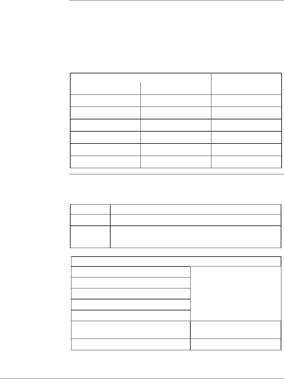
6/08 ST 3000 Release 300 and SFC Model STS103 User’s Manual 261
D.2 International Electrotechnical Commission (IEC)
Classification of Hazardous Locations, Continued
IEC Temperature
Classification Equipment intended for installation directly within the hazardous
location must also be classified for the maximum surface temperature
that can be generated under normal or fault conditions as referenced to
the maximum operating ambient of the equipment. The maximum
surface temperature must be less than the minimum autoignition
temperature of the hazardous atmosphere present. The temperature shall
be indicated in identification numbers as listed in the following table.
Maximum Temperature Temperature
Degrees C Degrees F Identification Number
450 842 T1
300 572 T2
200 392 T3
135 275 T4
100 212 T5
85 185 T6
Certification and
Conformity Details
Table D-3 CENELEC / LCIE Certification
Code Description
3D Flameproof, Supply ≤ 45 Vdc, IP 66/67EEx d IIC T6.
3A Intrinsically Safe EEx ia IIC T5, −40 ≤ Ta ≤ 93°C.
Flameproof, Supply ≤ 45 Vdc, IP 66/67 EEx d IIC T6.
LCIE Intrinsic Safety Parameters (1)
Ui = 30 V
Ii = 100 mA
Pi = 1.2 W
Ci = 4.2 nF
Ri = 0
Li = 0 With no integral indicator, or with
integral Smart Meter, option SM.
Li = 150 μH With Analog Meter, option ME.
(1) Install in accordance with Honeywell drawing 51204243.
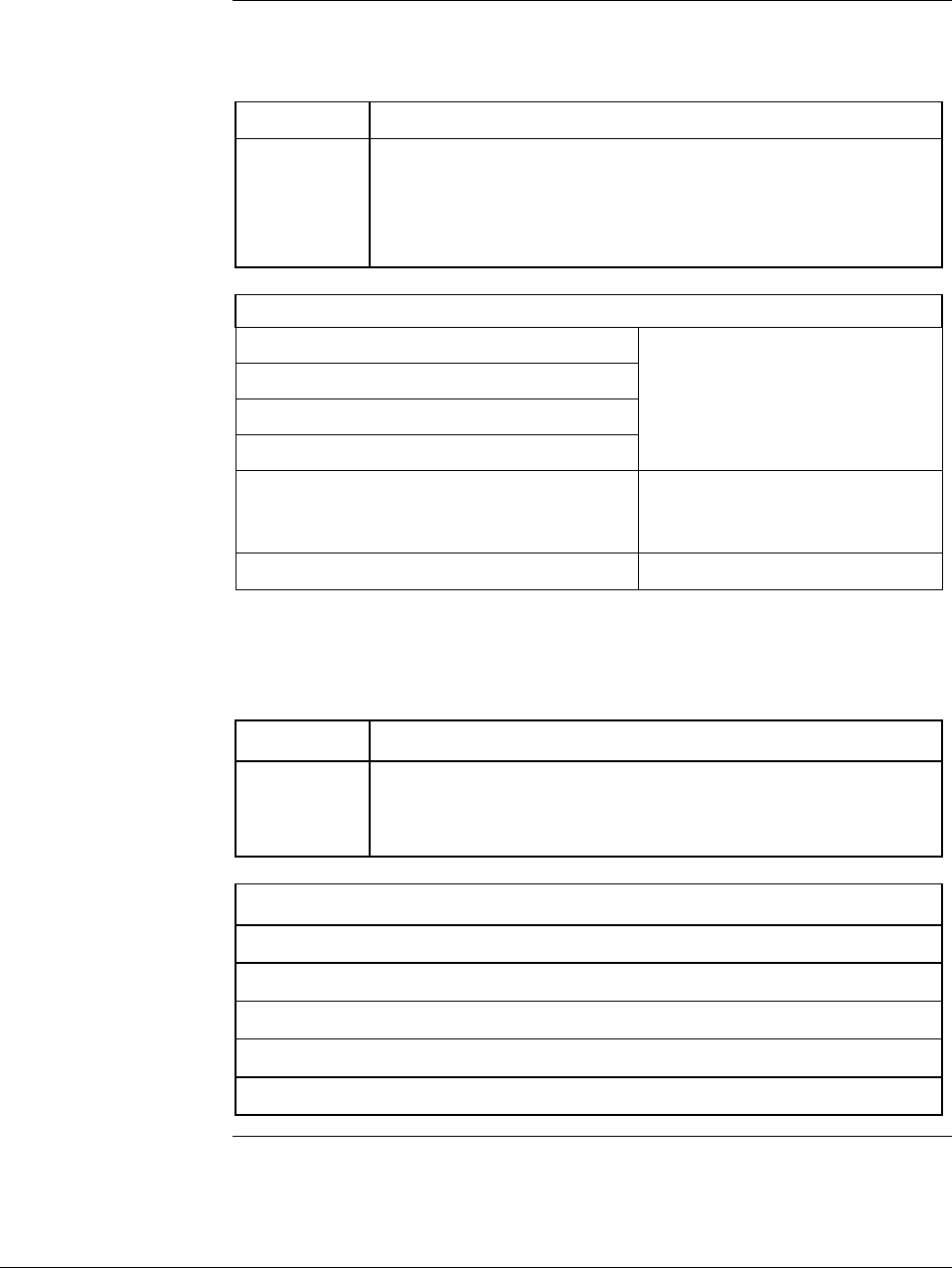
262 ST 3000 Release 300 and SFC Model STS103 User’s Manual 6/08
D.2 International Electrotechnical Commission (IEC)
Classification of Hazardous Locations, Continued
Certification and
Conformity Details,
continued
Table D-4 Standards Australia (LOSC) Certification
Code Description
4H Intrinsically Safe Ex ia IIC T4 Class I Zone 0.
Flameproof Ex d IIC T6 Class I Zone 1
Non-Sparking Apparatus - Type of Protection ‘n’ Ex n IIC T6
Class I Zone 2
LOSC Intrinsic Safety Parameters (1)
Ui = 42.4 V
Ii = 225 mA
Pi = 1.2 W
Ci = 4.2 nF
Li = 0 With no integral indicator, or
with integral Smart Meter,
option SM.
Li = 150 μH With Analog Meter, option ME.
(1) Install in accordance with Honeywell drawing 51204309.
Table D-5 Zone 2 (Europe) Declaration of Conformity
Code Description
3N Electrical Apparatus With Type of Protection “n” per IEC 79-
15. IP 66/67.
Ex II 3 GD T(1) X (Council Directive 94/9/EC) −40 ≤ Ta ≤ 93°C.
Zone 2 Parameters
Ui ≤42 V
Ii ≤22 mA
Temp. Code (1) T4 at Ta 93°C Maximum Ambient
Temp. Code (1) T5 at Ta 80°C Maximum Ambient
Temp. Code (1) T6 at Ta 65°C Maximum Ambient
Continued on next page

6/08 ST 3000 Release 300 and SFC Model STS103 User’s Manual 263
D.3 Enclosure Ratings
NEMA and IEC
Recognition The NEMA (National Electrical Manufacturer’s Association) enclosure
classifications are recognized in the US. The IEC Publication 529
Classifications are recognized throughout Europe and those parts of the
world that use the IEC standards as a basis for product certifications.
The following paragraphs provide a discussion of the Comparison
Between NEMA Enclosure Type Numbers and IEC Enclosure
Classification Designations.
IEC Classifications IEC Publication 529, Classification of Degrees of Protection Provided
by Enclosures, provides a system for specifying the enclosures of
electrical equipment on the basis of the degree of protection provided by
the enclosure. IEC 529 does not specify degrees of protection against
mechanical damage of equipment, risk of explosion, or conditions such
as moisture (produced for example by condensation), corrosive vapors,
fungus, or vermin.
NEMA Standards NEMA Standards Publication 250, Enclosures for Electrical Equipment
(1000 Volts Maximum), does test for environmental conditions such as
corrosion, rust, icing, oil, and coolants. For this reason, and because the
tests and evaluations for other characteristics are not identical, the IEC
enclosure classification designations cannot be exactly equated with
NEMA enclosure type numbers.
IEC Designations Basically, the IEC designation consists of the letters IP followed by two
numerals. The first characteristic numeral indicates the degree of
protection provided by the enclosure with respect to persons and solid
foreign objects entering the enclosure. The second characteristic
numeral indicates the degree of protection provided by the enclosure
with respect to the harmful ingress of water.
Continued on next page

264 ST 3000 Release 300 and SFC Model STS103 User’s Manual 6/08
D.3 Enclosure Ratings, Continued
IEC Designations,
continued Table D-6 provides an approximate conversion from NEMA enclosure
type numbers to IEC enclosure classification designations. The NEMA
types meet or exceed the test requirements for the associated IEC
classifications; for this reason the Table cannot be used to convert
from IEC classifications to NEMA types.
Table D-6 NEMA Enclosure Type Numbers and Comparable IEC
Enclosure Classification
NEMA Enclosure
Type Number IEC Enclosure
Classification Designation
1 IP 10
2 IP 11
3 IP 54
3R IP 14
3S IP 54
4 and 4X IP 56
5 IP 52
6 and 6P IP 67
12 and 12K IP 52
13 IP 54
NOTE: This comparison is based on tests specified in IEC Publication 529
Process Sealing Process Sealing for Classes I, II, and III, Divisions 1 and 2 and Class
I, Zone 0, 1, and 2, Explosionproof Electrical Systems
ST 3000, Smart Pressure Transmitters
The ST 3000, Series 100, 100e, 600, and 900, Smart Pressure
Transmitters are CSA certified as “Dual Seal” devices in accordance
with ANSI/ISA–12.27.01–2003, Requirements for Process Sealing
between Electrical Systems and Flammable or Combustible Process
Fluids.
Accordingly, the ST 3000, Series 100, 100e, 600, and 900, Smart
Pressure Transmitters comply with the sealing requirements of NEC
Chapter 5. Special Occupancies, Article 500 — Hazardous (Classified)
Locations, Classes I, II, and III, Divisions 1 and 2, Article 501 — Class
I Locations, Article 501-15, Sealing and Drainage, (f) Drainage, (3)
Canned Pumps, Process or Service Connections, Etc., Article 505 —
Class I, Zone 0, 1, and 2 Locations, Article 505-16, Sealing and
Drainage, (E) Drainage, (3) Canned Pumps, Process, or Service
Connections, and So Forth., and the Canadian Electrical Code rules 18-

6/08 ST 3000 Release 300 and SFC Model STS103 User’s Manual 265
092, 18-108, 18-158, J18-108 and J18-158.
Annunciation of a primary seal failure per ANSI/ISA–12.27.01 is
electronic and is displayed in various forms based on the type of
communication used for the particular transmitter. Failure of the
primary seal is considered a Critical Failure. Based on testing
annunciation of primary seal failure will occur in 7 hours or less.
The transmitter’s 4-20 mA output will be driven to the selected failsafe
direction – upscale or downscale.
The transmitter’s digital output (DE, HART, Fieldbus) will display any
of the following responses which could indicate a primary seal failure as
well as other meter body faults.
METER BODY FAULT, MB OVERLOAD, SUSPECT INPUT,
SENSOR FAILURE, DEVICE FAILURE.

Index
A
Analog and DE Modes, 56
Analog meter connections, 48
Analog Mode, 2
B
Barrier Diaphragms
Cleaning and Inspecting, 171
Battery Pack
Installing and Charging, 22
Bracket
Mounting Transmitter, 27
C
Calibration
Calibrating Analog Output Signal, 185
Calibrating Range with SFC, 189
Equipment Required, 184
Resetting, 192
Typical Equipment Connections, 191
Communications
Starting, 52
Configuration Database, 61
Configuration Decisions
Summary, 67
Configuration Parameters, 64
D
Damping, 64
Damping Time
Adjusting, 77
Keystroke Summary, 78
DE Mode, 3
DE protocol format, 2
Diagnostic Messages, 196
Communication Errors, 200
Critical Failures, 200
Interpreting, 203
Interrupt Messages, 201
Invalid Key Entry, 201
Non-Critical Failures, 199
Diaphragm Seals, 240
Display and Keyboard Test
Running, 207
Dropout
Square Root, 76
E
Electric Heating, 242
EMC Directive, 18
Enclosure ratings, 264
Engineering Units
Selecting, 79
Engineering Units High and Low, 66
Environmental Conditions, 19
F
Failsafe Direction
Changing, 156
Flange Adapter
Installing, 42
Flange Connections
Description, 41
Flange mounted transmitter, 35
Mounting, 35
Flow Measurement (DP)
Starting Up, 129
Flush Mounted Transmitter
Mounting, 34
Freeze Protection, 237
H
Hazardous locations reference
IEC Classifications, 259
North American Classifications, 253
Hold Memory
SFC, 62
L
Lightning Protection, 46
Linear Output
Selecting, 74
Liquid Level Measurement (DP with Remote Seals)
Starting Up, 148
Liquid Level Measurement (DP)
Starting Up Pressurized Tank, 137
Starting Up Vented Tank, 134
Local Smart Meter
Set Up Summary (Using Meter Pushbuttons), 121

6/08 ST 3000 Release 300 and SFC Model STS103 User’s Manual 267
Local Smart Meter
Keystroke Summary (Using SFC), 103
Meter/Transmitter Interaction, 168
Options, 13
Output Conformity, 105
Pushbuttons, 104
Reference Specifications, 24
Set Up Using Meter Psuhbuttons, 104
Set Up Using SFC, 97
Setting display of LRV (using meter pushbuttons), 110
Local Smart Meter Display
Description, 164
Error Codes, 167
Typical Indications, 165
Local Zero and Span
Adjusting (Procedure), 85
Loop wiring, 48
LRV (Lower Range Value), 64
LRV and URV
Keying in Values, 81
Keystroke Summary (Applied Pressures), 84
Keystroke Summary (Keying in Values), 82
Setting to Applied Pressures, 83
M
Maintenance
Routine, 170
Memories
Non-volatile, 62
SFC and ST 3000, 62
Message Format
(DE Only) Selecting \i, 95
DE Mode Only, 65
Keystroke Summary, 96
Meter Body
Replacing, 178
Meter Engineering Units, 66
Mode and Software
Checking, 55
Mode of Operation
Changing, 58
Keystroke Summary, 59
Model Number
Format, 4
Mounting Area
Considerations, 19
Mounting Location
Suggested, 39
Mounting Precautions
Model STD110, 32
Models STA122 and STA922, 30
N
Non-volatile Memory
Copying data into non-volatile memory, 63
ST 3000, 62
Number Symbol “#”
Clearing, 197
O
Operation Data
Accessing, 153
Output Conformity, 64
Keystroke Summary, 75
Selecting, 74
Smart Meter setup, 98
Output Mode
Running Analog Output Check, 126
Output Signal Indication
DE Mode Only, 65
Output Signal Mode
(DE Only) Selecting, 92
Keystroke Summary, 94
Ranges, 92
P
Parameters
Configuration, 64
Piping, 38
Potential Noise Sources, 19
Power Supply Voltage
Operating Range, 43
Pressure Measurement (AP)
Starting Up, 146
Pressure Measurement (DP)
Starting Up, 132
Pressure or Liquid Level Measurement (GP)
Starting Up, 141, 145
Pressure Ratings, 21
Process Connections
Summary, 40
Process Sealing, 47, 264
PWA
Replacing, 175
R
Remote Diaphragm Seal Transmitter
Mounting, 36
Replacement parts, 209

S
Save and Restore Database, 160
Procedure, 161
Scratch Pad Area
Writing Data, 158
Sealing Liquid, 237
SFC
Connecting to Transmitter, 51
Disconnecting, 123
Display Characteristics, 71
Model Designations, 9
Purpose, 8
SM 3000 Smart Meter connections, 48
Smart Meter. See Local Smart Meter
Smartline Configuration Toolkit, 1
Solution Support Center, xiii
Square Root Output, 75
Dropout, 76
Selecting, 74
ST 3000 Smart Transmitter, 2
Startup Procedure
Reference, 125
Start-Up Tasks
Reference, 16
Status Check
Running, 202
Steam Heating, 244
Superheated Steam, 249
T
Tag Number, 64
Entering (Procedure), 72
Keystroke Summary, 73
Temperature Limits
Operating, 20
Transmitter mounting
Models STA122, STA922, 30
Transmitter options
Options, 233
Transmitter Types, 5
Tthree-Valve Manifold
Piping, 38
Turndown Ratio, 77
U
Unit of Measurement, 64
URV (Upper Range Value), 64
V
Vibration Sources, 19
W
Wiring Connections, 45
Write Protect Jumper
Location and Selections, 56
Z
Zero and Span Adjust
Options, 13
Zero corrects, 32
Zero shift, 30

6/08 ST 3000 Release 300 and SFC Model STS103 User’s Manual 269


Honeywell Process Solutions
512 Virginia Drive
Fort Washington, PA 19034
