Honeywell Thermostat T7350 Users Manual 63 2605 Commercial Programmable
2015-01-23
: Honeywell Honeywell-Honeywell-Thermostat-T7350-Users-Manual-262218 honeywell-honeywell-thermostat-t7350-users-manual-262218 honeywell pdf
Open the PDF directly: View PDF ![]() .
.
Page Count: 40
PRODUCT DATA
Put Bar Code Here
63-2605—5
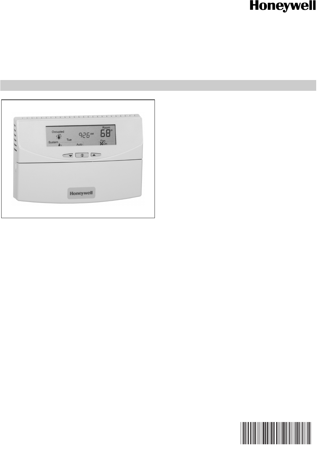
T7350 Commercial Programmable Thermostat
FOR SINGLE- OR MTG512ULTI-STAGE CONVENTIONAL/HEAT PUMP
SYSTEMS
APPLICATION
The T7350 Commercial Programmable Thermostat controls
24 Vac commercial single zone heating, ventilating and air
conditioning (HVAC) equipment. The T7350 consists of a
thermostat and subbase. The thermostat includes the keypad
and display for 7-day programming. The subbase includes
equipment control connections. The subbase mounts on the
wall and the thermostat mounts to the subbase.
FEATURES
• Typically used in buildings (including: restaurants,
shopping malls, office buildings and banks) under
55,000 square feet.
• For single zone rooftop units, split systems, heat
pumps or hot/chilled water systems.
• 7-day programming.
• Two Occupied and two Not Occupied periods per day.
• Thermostat Interface Module (TIM) connections to
thermostat from PDA for advanced configuration,
programming, keypad lockout, etc. changes can be
made with thermostat mounted.
• Individual heat and cool setpoints available for
Occupied and Not Occupied periods.
• P+I+D control minimizes temperature fluctuations.
• Recovery ramp control automatically optimizes
equipment start times based on building load.
• Convenient overrides allow temporary setpoint
changes.
• Keypad multi-level lockout available with all models.
• Remote sensor capability for temperature (including
outdoor air and discharge air) and humidity sensors.
• Auxiliary subbase contact typically interface with a
Honeywell Economizer System (for total rooftop
control integration) or act as dehumidification output.
• Universal Versaguard™ Thermostat guards available.
• T7350H provides networking capability on LonWorks®
Bus using a Free Topology Transceiver (FTT).
• T7350H Conforms to LonMark® Space Comfort Profile
for rooftop applications.
continued
Contents
Specifications ................................................................... 3
Installation ........................................................................ 6
Settings ............................................................................ 11
Installer Setup .................................................................. 12
Programming .................................................................... 15
Operation .......................................................................... 18
Troubleshooting Guide (Table 19) .................................... 23
Wiring Diagrams (Fig. 17-25) ........................................... 25
Appendix - PDA Usage .................................................... 30
T7350 COMMERCIAL PROGRAMMABLE THERMOSTAT
63-2548—5 2
ORDERING INFORMATION
When purchasing replacement and modernization products from your TRADELINE® wholesaler or distributor, refer to the
TRADELINE® Catalog or price sheets for complete ordering number.
If you have additional questions, need further information, or would like to comment on our products or services, please write or
phone:
1. Your local Honeywell Automation and Control Products Sales Office (check white pages of your phone directory).
2. Honeywell Customer Care
1885 Douglas Drive North
Minneapolis, Minnesota 55422-4386
In Canada—Honeywell Limited/Honeywell Limitée, 35 Dynamic Drive, Toronto, Ontario M1V 4Z9.
International Sales and Service Offices in all principal cities of the world. Manufacturing in Australia, Canada, Finland, France,
Germany, Japan, Mexico, Netherlands, Spain, Taiwan, United Kingdom, U.S.A.
FEATURES (continued from page 1)
Features Available via PDA Configuration
• 365 day clock with holiday programming.
• Automatic Daylight Saving Time adjustments.
• Selectable dehumidification limit control.
• Modulating output configuration.
• Occupancy input to control standby setpoint.
• Additional standby period used in low traffic areas.
• Sequential start option.
• Discharge air high/low limits.
• Selectable recovery ramp.
• Ambient lockout (with outdoor sensor).
• System monitoring.
• Application database with download and storing.
Features via Optional Network Model-H
• Communications on LonTalk® network.
• Network Tools (LonSpec, CARE) have ability to
configure all PDA available features.
• T7350 Network data inputs including outdoor air
temperature, Occupancy Sensor, Electric Demand
Shed/Restore, room temperature and humidity.
• Use T7350H to time-schedule up to 119 network
connected XL10 + XL15c devices.
• Time synchronization with a network master clock or
the T7350H configured as the network master clock.
• Remote manual occupancy changes to the T7350 via
Command Display (S7760).
• View and modify weekly schedules and holidays via
Command Display (S7760).
• Remote changes to the T7350 occupancy override,
schedules, fan operation (on auto), system mode (off,
auto, heat, cool) and room temperature setpoints via
Workstation.
• Remote unoccupied bypass controlled from another
device.
• Remote T7350 data and alarm monitoring via
Command Display or Workstation.
• Network Manual Mode allows a remote user to turn on/
off or modulate each output via a network connection.
• LonMark plugin software to facilitate third party
configuration tools and workstations.

T7350 COMMERCIAL PROGRAMMABLE THERMOSTAT
363-2605—5
SPECIFICATIONS
IMPORTANT
The specifications given in this publication do not
include normal manufacturing tolerances. Therefore,
this unit might not exactly match listed specifications.
This product is tested and calibrated under closely
controlled conditions; minor performance differences
can be expected if those conditions are changed.
Models: See Table 1.
Dimensions: See Fig. 1.
Finish (color): Trident White.
Batteries: No batteries required.
Table 1. T7350 Thermostat Features.
aAll models are down-selectable and can be configured to control fewer stages than the maximum allowed.
bOne extra stage (of either heat or cool) can be configured using the auxiliary relay.
cHeat pump applications for these models have a maximum of two heat stages and two cool stages.
Mounting Means:
Mounts on subbase.
Subbase Mounts On:
Wall: Using two 5/8 in. long #6-32 screws (included).
Outlet Box: Using sheet metal screws.
Throttling Range for Modulating Outputs:
Automatically adjusts based on heat/cool stages. Manually
adjustable with PDA.
Clock Accuracy (at 77° F [25° C]): ±1 min./month (30 days).
Minimum Stage Operation Time (fixed):
Minimum On
Heat: 1 minutes.
Cool: 3 minutes.
Minimum Off (Cool and Heat Pump): 1 minute.
Electrical Ratings:
Power: 24 Vac, 50/60 Hz.; 20 to 30 Vac, 50/60 Hz.
Input:
Temperature: 20K ohms.
Humidity: 0-10 Vdc.
Outdoor: 3000 PTC.
Discharge Air: 20K ohms.
Occupancy Sensor: Dry contact switching 30 Vdc at 1 mA.
All Relay Outputs (at 30 Vac):
Running: 1.5A maximum.
Inrush: 7.5A maximum.
Modulating Output: 4 to 20 mA with 510 ohm maximum
terminating resistance.
System Current Draw (without load):
5 VA maximum at 30 Vac, 50/60 Hz.
NOTE: Relays are N.O. Single-Pole, Single-Throw (SPST).
Outdoor Sensor Wiring: Requires 18 gauge wire.
Humidity Ratings: 5% to 90% RH, noncondensing.
Emergency Heat Indication:
Display indicates when Emergency Heat is activated (Em).
Temperature:
Ratings:
Operating Ambient: 30°F to 110°F (-1°C to 43°C).
Shipping: -30°F to +150°F (-34°C to +66°C).
Display Accuracy: ±1°F (±1°C).
Setpoint:
Range:
Heating: 40°F to 90°F (4°C to 32°C).
Cooling: 45°F to 99°F (7°C to 37°C).
Deadband: 2°F (1°C).
Default Settings: See Table 2.
Loss of Power: The thermostat maintains programmed times
and temperatures for the life of the product. Clock and day
information is retained for a minimum of 48 hours.
NOTE: To achieve the 48-hour power-loss clock retention,
the T7350 must be powered for at least 5 minutes.
Communicating Model T7350H:
Connection Terminals for the LonWorks Bus.
Network jack for quick access by personal computer based
tools.
Communications service-pin pushbutton to simplify startup.
LonMark Functional Profile: 8500_20 Space Comfort
Controller.
LonMark SCC Object Type: 8504 Rooftop See Fig. 2.
LonMark Program Identifier: 80:00:0C:55:04:03:04:2E.
LonMark Application Interoperability: version 3.3
Honeywell LonMark Plug-In file downloads:
http://plugin.ge51.honeywell.de/index.htm#
Model Applications
Maximum Stagesa
Features
Auxiliary
Relay
LONWORKS®
Capability?Heat Cool
T7350A Conventional
or
Heat Pump
1b1bYes No
T7350B 2b2bOutdoor, Discharge Air Capability Yes
T7350D 3 (2)c3 (4)cHumidity, Occupancy,
Outdoor, Discharge Air Capability
Yes
T7350H1009 Isolated
Normally
Open
Yes
T7350H1017 Modulating 2 modulating, 2b relay Humidity, Occupancy,
Outdoor, Discharge Air Capability,
4-20 mA output (2-10 Vdc with 500 ohm resistor)
Yes
T7350M Yes No

T7350 COMMERCIAL PROGRAMMABLE THERMOSTAT
63-2605—5 4
PDA System Requirements:
Palm OS®: 3.5.x to 5.2.1
Dynamic Heap: 256K bytes.
Free RAM Space: 1000K bytes.
Serial Communications: RS-232.
Approvals:
European Community Mark (CE) Listed.
UL 873 Recognized, NEC Class 2.
FCC Part 15 subpart J Class A.
cUL.
Table 2. Default Setpoints.
Fig. 1. Thermostat and subbase dimensions in inches
(mm).
Accessories:
Duct Discharge Air Sensors:
C7041B (6 or 12 in. [152 or 305 mm]),
C7041C (18 in. [457 mm]),
C7041J (12 ft. [3.66 m] averaging),
C7770A (8 in. [203 mm] probe).
Outdoor Air Sensors: C7089A, C7170A,
C7031G2014 (weatherproof).
Temperature Sensors (Remote): C7772A, T7770A1006,
T7770B1046, T7770C1044, T7770D1000, T7771.
Economizer Logic Modules: W6210, W6215, W7210, W7212,
W7215, W7459.
Humidity Sensors: H7625, H7635.
PDA Units: Palm® V, M125, and i705 handhelds;
TRGPro handheld; ZIRE™ 71 handheld;
TUNGSTEN™ T handheld.
Others:
209541B FTT network termination module.
209651A Vertical Mounting Hardware Wallplate Adapter
(Trident white).
50000083-001 Thermostat Interface Module (TIM).
50014064-001 Infra-Red TIM.
50000452-001 Troubleshooting Cable.
AK3797 Single pair network cable plenum rated,
U.L. Type CMP.
AK3798 Single pair network cable, U.L. Type CMR.
AK3799 Double pair network cable plenum rated,
U.L. Type CMP.
Q7740A FTT network 2-way repeater.
Q7740B FTT network 4-way repeater.
TG512 Universal Versaguard™ Thermostat guards.
Control Occupied
Not
Occupied Standby
Heating 70° F (21° C) 55° F (13° C) 67° F (19° C)
Cooling 75° F (24° C) 85° F (29° C) 78° F (26° C)
6-3/4 (171)
2-3/16 (56)
1-9/16
(40)
4-1/2
(114)
2-1/32
(52)
2-1/32
(52)
4-1/16
(104)
1-5/8
(42)
2-3/8 (60)
3-1/4 (83)
6-9/16 (166) M22432
1-5/8
(42)
SUBBASE
T7350 COMMERCIAL PROGRAMMABLE THERMOSTAT
563-2605—5
Fig. 2. T7350H LonMark Space Comfort Controller Rooftop Object (8504) with Node Object.
nv28
nv26 nvoSpaceTemp
SNVT_ temp_p
nv27 nvoUnitStatus
SNVT_hvac_status
nvoEffectSetpt
SNVT_temp_p
Hardware OutputHardware Output
Hardware Input
Hardware Input
SCC-Rooftop
Object Number 8504.
Mandatory
Network
Variables
Manufacturer
Defined
Section
Optional
Network
Variables
Configuration Properties
nv45 nvoOutdoorTemp
SNVT_temp_p
nv29 nvoEffectOccup
SNVT_occupancy
nv30 nvoHeatCool
SNVT_hvac_mode
nv34 nvoDischAirTemp
SNVT_temp_p
nv37 nvoTerminalLoad
SNVT_lev_percent
nv43 nvoSpaceRH
SNVT_lev_percent
nv7 nviOccSensor
SNVT_occupancy
nv2 nviSetpoint
SNVT_ temp_p
nv6 nviOccManCmd
SNVT_occupancy
nv5 nviOccSchedule
SNVT_tod_event
nviSpaceTemp
SNVT_temp_p
nv1
nv8 nviApplicMode
SNVT_hvacMode
nv19 nviOutdoorTemp
SNVT_Temp_p
nv20 nviSpaceRH
SNVT_lev_percent
nv43 nvoBypass
SNVT_switch
nv44 nvoOccSchedule
SNVT_tod_event
nv45 nvoOccSensor
SNVT_occupancy
nv46 nvoData1
UNVT_data1
nv47 nvoData2
UNVT_data2
nv30 nviBypass
SNVT_switch
nv31 nviFanAuto
SNVT_switch
nv32 nviManValue
UNVT_manValue
nv34 nviDlcShed
UNVT_dlcShed
M22431
SNVT_time_sec
SNVT_time_sec
SNVT_temp_setpt
SNVT_time_min
UCPTconfig
UCPTconfigPts
UCPTdaylightSav
UCPTschedule0
UCPTschedule1
UCPTschedule2
UCPTschedule3
UCPTschedule4
UCPTschedule5
UCPTschedule6
UCPTschedule7
UCPTholSched
(mandatory)
(optional)
(mandatory)
(optional)
(manf specific)
(manf specific)
(manf specific)
(manf specific)
(manf specific)
(manf specific)
(manf specific)
(manf specific)
(manf specific)
(manf specific)
(manf specific)
(manf specific)
nc1 - nciSndHrtBt
nc4 - nciRevHrtBt
nc2 - nciSetpoints
nc6 - nciBypassTime
nciConfig
nciConfigPts
nciDayLghtSav
nciDaySchedule0
nciDaySchedule1
nciDaySchedule2
nciDaySchedule3
nciDaySchedule4
nciDaySchedule5
nciDaySchedule6
nciDaySchedule7
nciHolSched
nv6
nv2 nvoStatus
SNVT_ obj_status
nvoFileStat
SNVT_file_status
Node
Object
Mandatory
Network
Variables
Manufacturer
Defined
Section
Optional
Network
Variables
Configuration Properties
nv3 nviTimeSet
SNVT_ time_stamp
nv7 nviFilePos
SNVT_file_pos
nv5 nviFileReq
SNVT_file_req
nviRequest
SNVT_obj_request
nv1
nv11 nroT7350Ver
UNVT_version
nv12 nroPgmVer
UNVT_pgmId
nv13 nvoPgm
UNVT_pgmOut
nv14 nvoTime
SNVT_time_stamp
nv15 nvoAlarmH
UNVT_alarm
nv16 nvoAlarmStatus
UNVT_alarmStatus
nv17 nvoAlarmLog
UNVT_alarmLog
nv18 nvoError
UNVT_error
nv9 nviInUse
UNVT_inUse
nv10 nviPgm
UNVT_pgmIn
UCPTdevName
UCPTapplVer
(manf specific)
(manf specific)
nc1 - nciDeviceName
nc2 - nciApplVer
T7350 COMMERCIAL PROGRAMMABLE THERMOSTAT
63-2605—5 6
INSTALLATION
When Installing this Product...
1. Read these instructions carefully. Failure to follow them
could damage the product or cause a hazardous
condition.
2. Check ratings given in instructions and on the product to
ensure the product is suitable for your application.
3. Installer must be a trained, experienced service
technician.
4. After installation is complete, check out product
operation as provided in these instructions.
CAUTION
Electrical Shock or Equipment Damage Hazard.
Can shock individuals or short equipment
circuitry.
Disconnect power supply before installation.
IMPORTANT
All wiring must agree with applicable codes,
ordinances and regulations.
MERCURY NOTICE
If this control is replacing a control that contains
mercury in a sealed tube, do not place your old
control in the trash. Dispose of properly.
Contact your local waste management authority for
instructions regarding recycling and the proper
disposal of an old control. If you have questions, call
Honeywell Customer Care Center at 1-800-468-1502.
Location
Do not install the thermostat where it can be affected by:
— drafts, or dead spots behind doors and in corners.
— hot or cold air from ducts.
— radiant heat from sun or appliances.
— concealed pipes and chimneys.
— unheated (uncooled) areas such as an outside wall behind
the thermostat.
Subbase
WHEN USED TO SENSE ROOM TEMPERATURE
Install the thermostat about 5 ft (1.5m) above the floor in an
area with good air circulation at average temperature. (See
Fig. 3.)
WHEN NOT USED TO SENSE ROOM TEMPERATURE
When using the remote-mounted temperature (and humidity)
sensor(s) to sense ambient conditions, install the thermostat
in an area that is accessible for setting and adjusting the
temperature and settings.
CAUTION
Equipment Damage Hazard.
Can damage the TIM connection beyond repair.
Disconnect the TIM cable prior to opening or closing
the thermostat cover.
NOTE: Allow sufficient clearance below the thermostat to
plug in the TIM cable.
Install the remote-mounted sensor(s) about 5 ft (1.5m) above
the floor in an area with good air circulation at average
temperature. (See Fig. 3.)
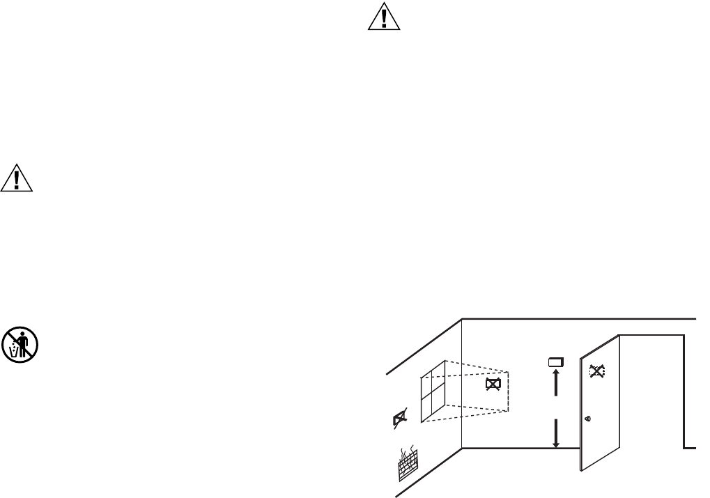
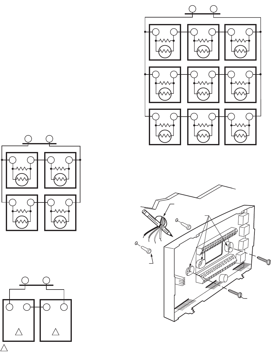
If multiple remote sensors are required, they must be
arranged in a temperature averaging network consisting of
four or nine sensors. (See Fig. 4 and 6.)
NOTE: Only T7770 models with neither setpoint adjustment
nor bypass can be used for temperature averaging.
Fig. 3. Typical location of thermostat
or remote-mounted sensor.
IMPORTANT
To avoid electrical interference, which can cause
erratic performances, keep wiring runs as short as
possible and do not run thermostat wires adjacent to
the line voltage electrical distribution systems. Use
shielded cable (Belden type 8762 or equivalent for
2-wire). The cable shield must be grounded only at
the controlled equipment case.
Mounting Subbase
The subbase mounts horizontally or vertically.
IMPORTANT
• When using the internal temperature sensor, the
device must be mounted horizontally (with the LCD
facing upwards). Precise leveling is not needed.
• When using remote sensors, thermostat mounting
orientation does not matter.
Wall mounting (using standard drywall screws) is standard.
Mounting to a 2 in.(50.8 mm) by 4 in. (101.6 mm) wiring box
can be accomplished:
— for a horizontal box, no extra hardware is required.
5 FEET
(1.5 METERS)
YES NO
NO NO
M4823A
T7350 COMMERCIAL PROGRAMMABLE THERMOSTAT
763-2605—5
— for a vertical box, part 209651A is required.
— Mount to European standard wall box (having 60.3 mm
[2.4 in.] between mounting screws in a horizontal line) with
or without adaptive hardware.
1. Position and level the subbase.
NOTE: A level wallplate is only for appearance. The
thermostat functions properly when not level.
2. Use a pencil to mark the mounting holes. (See Fig. 7.)
3. Remove the subbase from the wall and drill two 3/16 in.
(4.76 mm) holes in the wall (if drywall) as marked. For
firmer material such as plaster or wood, drill two 7/32 in.
(5.56 mm) holes.
4. Gently tap anchors (provided) into the drilled holes until
flush with the wall.
5. Position the subbase over the holes, pulling wires
through the wiring opening.
6. Loosely insert the mounting screws into the holes.
7. Tighten mounting screws.
Fig. 4. Four T7770A Sensors providing a temperature
averaging network for T7350 Thermostat.
Fig. 5. Two T7770A3002 Sensors providing a temperature
averaging network for T7350 Thermostat.
Fig. 6. Nine T7770A Sensors providing a temperature
averaging network for T7350 Thermostat.
Fig. 7. Mounting the subbase.
M19606A
T4 T3
TT
SUBBASE
T7770A
TT
T7770A
TT
T7770A
TT
T7770A
M22408
T4 T3
T7350 SUBBASE
T7770A3002
T4 T3
T7770A3002
T4 T3
1
11
THE T7771A3002 IS A 10K OHM SENSOR.
M19607A
T T
T7770A
TT
T7770A
TT
T7770A
TT
T7770A
TT
T7770A
TT
T7770A
TT
T7770A
TT
T7770A
TT
T77770A
T4 T3
SUBBASE
WIRES THROUGH WALL
WALL
ANCHORS
(2)
M19608
MOUNTING
HOLES
MOUNTING
SCREWS
T7350 COMMERCIAL PROGRAMMABLE THERMOSTAT
63-2605—5 8
Wiring
CAUTION
Electrical Shock or Equipment Damage Hazard.
Can shock individuals or short equipment
circuitry.
Disconnect power supply before installation.
IMPORTANT
All wiring must comply with local electrical codes
and ordinances.
NOTE: Maximum (and recommended) wire size is
18-gauge (ø 1.02 mm). Do not use wire smaller than
22-gauge (ø 0.644 mm).
Follow equipment manufacturer wiring instructions when
available. Refer to the Wiring Diagram section for typical
hookups. A letter code is located near each terminal for
identification. Refer to Tables 3 through 8 for terminal
designations.
1. Loosen subbase terminal screws and connect system
wires.
2. Securely tighten each terminal screw.
3. Push excess wire back into the hole in the wall.
4. Plug the hole with nonflammable insulation to prevent
drafts from affecting the thermostat.
Table 3. T7350A Subbase for Single-stage Heat,
Single-stage Cool Systems.
aFactory jumper between RC and RH for systems with one
transformer.
bFor changeover functional details, see Operation section.
Table 4. T7350B Subbase for Two-stage Heat,
Two-stage Cool Systems.
aFactory jumper between RC and RH for systems with one
transformer.
bFor changeover functional details, see Operation section.
Terminal
Description
Conventional
Heat Pump
RCaRCa24 VAC Cooling transformer.
RHaRHa24 VAC Heating transformer.
X X Common.
GGFan relay.
aux aux Conventional: Auxiliary relay or 2nd Stage of
heating or cooling relay.
Heat Pump: Auxiliary relay or 1st Stage auxiliary
heat relay.
W1 O/B Conventional: Stage 1 heating relay.
Heat Pump: Changeover relay for heating (B) or
cooling (O)b.
Y1 Y1 Conventional: Stage 1 cooling relay.
Heat Pump: Stage 1 compressor relay.
Terminal
Description
Conventional
Heat Pump
RCaRCa24 VAC Cooling transformer.
RHaRHa24 VAC Heating transformer.
X X Common.
aux aux Conventional: Auxiliary relay or 3rd stage of
heating or cooling.
Heat Pump: Auxiliary relay or 2nd stage auxiliary.
W1 O/B Conventional: Stage 1 heating relay.
Heat Pump: Changeover relay for heating (B) or
cooling (O)b.
W2 W1 Conventional: Stage 2 heating relay.
Heat Pump: 1st Stage auxiliary heat relay.
Y1 Y1 Conventional: Stage 1 cooling relay.
Heat Pump: Stage 1 compressor relay.
Y2 Y2 Conventional: Stage 2 cooling relay.
Heat Pump: Stage 2 compressor relay.
AS AS Discharge Air Sensor connection (1).
AS AS Discharge Air Sensor connection (2).
OS OS Outdoor Air Sensor connection (1).
OS OS Outdoor Air Sensor connection (2).
GGFan relay.
T3 T3 T7770 Remote Sensor connection (3).
T4 T4 T7770 Remote Sensor connection (4).
T5 T5 T7770 Remote Sensor connection (5).
T6 T6 T7770 Remote Sensor connection (6).
T7 T7 T7770 Remote Sensor connection (7).
T7350 COMMERCIAL PROGRAMMABLE THERMOSTAT
963-2605—5
Table 5. T7350D Subbase for Three-stage Heat,
Three-stage Cool Systems.
aFactory jumper between RC and RH for systems with one
transformer.
bFor changeover functional details, see Operation section.
Table 6. T7350H Subbase for Three-stage Heat, Three-
stage Cool Systems with Network Communications
aFactory jumper between RC and RH for systems with one
transformer.
bFloating auxiliary contact (not connected to transformer hot
or common).
cFor changeover functional details, see Operation section.
Terminal
Description
Conventional
Heat Pump
RCaRCa24 VAC Cooling transformer.
RHaRHa24 VAC Heating transformer.
X X Common.
aux aux Auxiliary relay.
W1 O/B Conventional: Stage 1 heating relay.
Heat Pump: Changeover relay for heating (B) or
cooling (O)b.
W2 W1 Conventional: Stage 2 heating relay.
Heat Pump: 1st Stage auxiliary heat relay.
Y1 Y1 Conventional: Stage 1 cooling relay.
Heat Pump: Stage 1 compressor relay.
Y2 Y2 Conventional: Stage 2 cooling relay.
Heat Pump: Stage 2 compressor relay.
AS AS Discharge Air Sensor connection (1).
AS AS Discharge Air Sensor connection (2).
OS OS Outdoor Air Sensor connection (1).
OS OS Outdoor Air Sensor connection (2).
GGFan relay.
T3 T3 T7770 Remote Sensor connection (3).
T4 T4 T7770 Remote Sensor connection (4).
T5 T5 T7770 Remote Sensor connection (5).
T6 T6 T7770 Remote Sensor connection (6).
T7 T7 T7770 Remote Sensor connection (7).
W3 W2 Conventional: Stage 3 heat or stage 4 cool relay.
Heat Pump: 2nd Stage auxiliary heat relay.
Y3 — Conventional: Stage 3 cooling relay.
HS HS Humidity Sensor connection (signal: 0-10 Vdc).
HC HC Humidity Sensor connection (common).
HP HP Humidity Sensor connection (power).
M M Motion Sensor connection (1).
M M Motion Sensor connection (2).
Terminal
Description
Conventional
Heat Pump
RCaRCa24 VAC Cooling transformer.
RHaRHa24 VAC Heating transformer.
XXCommon.
auxbauxbAuxiliary relay connection (normally open).
auxbauxbAuxiliary relay connection (common).
W1 O/B Conventional: Stage 1 heating relay.
Heat Pump: Changeover relay for heating (B) or
cooling (O)c.
W2 W1 Conventional: Stage 2 heating relay.
Heat Pump: 1st Stage auxiliary heat relay.
Y1 Y1 Conventional: Stage 1 cooling relay.
Heat Pump: Stage 1 compressor relay.
Y2 Y2 Conventional: Stage 2 cooling relay.
Heat Pump: Stage 2 compressor relay.
AS AS Discharge Air Sensor connection (1).
AS AS Discharge Air Sensor connection (2).
OS OS Outdoor Air Sensor connection (1).
OS OS Outdoor Air Sensor connection (2).
G G Fan relay.
T3 T3 T7770 Remote Sensor connection (3).
T4 T4 T7770 Remote Sensor connection (4).
T5 T5 T7770 Remote Sensor connection (5).
T6 T6 T7770 Remote Sensor connection (6).
T7 T7 T7770 Remote Sensor connection (7).
W3 W2 Conventional: Stage 3 heat or stage 4 cool relay.
Heat Pump: 2nd Stage auxiliary heat relay.
Y3 — Conventional: Stage 3 cooling relay.
HS HS Humidity Sensor connection (signal: 0-10 Vdc).
HC HC Humidity Sensor connection (common).
HP HP Humidity Sensor connection (power).
M M Motion Sensor connection (1).
M M Motion Sensor connection (2).
ebus ebus LonWorks Bus (1).
ebus ebus LonWorks Bus (2).
T7350 COMMERCIAL PROGRAMMABLE THERMOSTAT
63-2605—5 10
Table 7. T7350H Subbase for Modulating Systems with
Network Communications.
aFactory jumper between RC and RH for systems with one
transformer.
bFloating auxiliary contact (not connected to transformer hot
or common).
Table 8. T7350M Subbase for Modulating Systems.
aFactory jumper between RC and RH for systems with one
transformer.
Mounting Thermostat on Subbase (Fig. 8)
With the subbase installed, mount the thermostat:
1. Engage the tabs at the top of the thermostat and
subbase.
2. Swing the thermostat down.
3. Press the lower edge of the case to latch.
NOTE: To remove the thermostat from the wall, first
pull out at the bottom of the thermostat; then
remove the top.
Terminal
Description
Conventional
Heat Pump
RCa— 24 VAC Cooling transformer.
RHa— 24 VAC Heating transformer.
X—Common.
auxbauxbAuxiliary relay connection (normally open).
auxbauxbAuxiliary relay connection (common).
W1 — Stage 1 heating relay.
Y1 — Stage 1 cooling relay.
MX — Modulating common.
MH — Modulating heating signal (4-20 mA).
MC — Modulating cooling signal (4-20 mA).
AS — Discharge Air Sensor connection (1).
AS — Discharge Air Sensor connection (2).
OS — Outdoor Air Sensor connection (1).
OS — Outdoor Air Sensor connection (2).
G—Fan relay.
T3 — T7770 Remote Sensor connection (3).
T4 — T7770 Remote Sensor connection (4).
T5 — T7770 Remote Sensor connection (5).
T6 — T7770 Remote Sensor connection (6).
T7 — T7770 Remote Sensor connection (7).
HS — Humidity Sensor connection (signal: 0-10 Vdc).
HC — Humidity Sensor connection (common).
HP — Humidity Sensor connection (power).
M — Motion Sensor connection (1).
M — Motion Sensor connection (2).
ebus ebus LonWorks Bus (1).
ebus ebus LonWorks Bus (2).
Terminal
Description
Conventional
Heat Pump
RCa— 24 VAC Cooling transformer.
RHa— 24 VAC Heating transformer.
X — Common.
aux — Auxiliary relay or 2nd stage of heating or cooling.
W1 — Stage 1 heating relay.
Y1 — Stage 1 cooling relay.
MX — Modulating common.
MH — Modulating heating signal (4-20 mA).
MC — Modulating cooling signal (4-20 mA).
AS — Discharge Air Sensor connection (1).
AS — Discharge Air Sensor connection (2).
OS — Outdoor Air Sensor connection (1).
OS — Outdoor Air Sensor connection (2).
G—Fan relay.
T3 — T7770 Remote Sensor connection (3).
T4 — T7770 Remote Sensor connection (4).
T5 — T7770 Remote Sensor connection (5).
T6 — T7770 Remote Sensor connection (6).
T7 — T7770 Remote Sensor connection (7).
HS — Humidity Sensor connection (signal: 0-10 Vdc).
HC — Humidity Sensor connection (common).
HP — Humidity Sensor connection (power).
M — Motion Sensor connection (1).
M — Motion Sensor connection (2).

T7350 COMMERCIAL PROGRAMMABLE THERMOSTAT
11 63-2605—5
Fig. 8. Mounting thermostat on subbase.
SETTINGS
Using Thermostat Keys
The thermostat keys are used to:
• set current time and day,
• program times and setpoints for heating and cooling,
• override the program temperatures,
• display present setting,
• set system and fan operation,
• perform simple configuration.
NOTE: See Fig. 9 for keypad information.
Setting Temperature
Refer to Table 2 for the default temperature setpoints. See
Programming section for complete instructions on changing
the setpoints.
Setting System and Fan
System default setting is Auto. Fan default setting is On.
NOTE: Use System and Fan keys to change settings.
System Settings
— Auto: Thermostat automatically changes between heating
and cooling based on indoor temperature.
— Cool: Thermostat controls only cooling.
— Off: Heating, cooling, and fan are all off.
— Heat: Thermostat controls only heating.
— Em Heat: Auxiliary heat serves as first stage. Compressor
stages are locked off.
Fan Settings
— On: See Table 9.
— Auto: Fan always cycles with call for heating or cooling.
— Conventional: The equipment (i.e. plenum switch)
controls fan operation in heat mode. The thermostat
controls fan operation in cool mode.
— Electric Heat: The thermostat controls fan operation
in both heat and cool modes.
NOTE: Fan operation can extend (delay Off) after the
heating/cooling turns off:
— Heating choices are 0 or 90 seconds.
— Cooling choices are 0 or 40 seconds.
Table 9. Fan On Control Logic.
aIn heat mode, when set for conventional heat, the equip-
ment (i.e. plenum switch) could power the fan despite the
T7350.
Fig. 9. Thermostat key locations.
M19609
B. PRESS LOWER EDGE OF CASE TO LATCH.
A. ENGAGE TABS AT TOP OF THERMOSTAT AND SUBBASE OR WALLPLATE.
Occupancy Call for Heat/Cool
Scheduled Sensor Signal Yes No
Occupied Occupied On On
Occupied Standby On Off a
Standby — On On
Not Occupied — On Off a
System Fan Run
Schedule
CopyNot OccupiedOccupiedDay
Clear
Start Time
Day Time
Temperature
Temporary
Occupied
Override
HEAT HEATCOOL COOL
HEAT COOL ON AUTO
Schedule
Set Day/Time
Occupied
Not Occupied
Temporary
Not Occupied
M19610
T7350 COMMERCIAL PROGRAMMABLE THERMOSTAT
63-2605—5 12
INSTALLER SETUP
For most applications, the thermostat factory settings do not
need to be changed. Review the factory settings in Table 10.
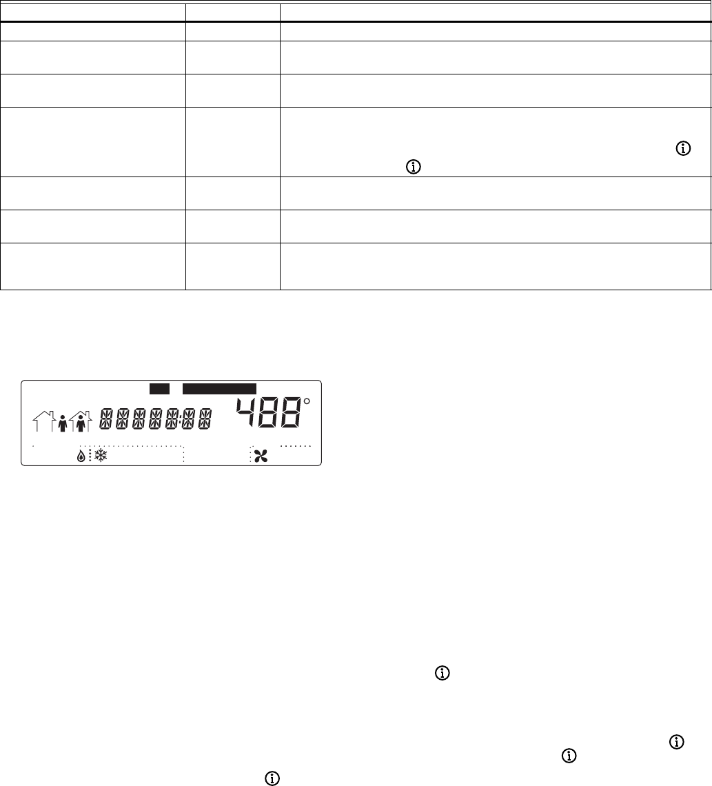
NOTE: When power is first applied to the thermostat, the
display will show all segments (see Fig. 10).
Table 10. Keypad Configurable Installer Setup Optionsa.
aWith the exception of Temporary Not Occupied, functions not keypad configurable require a Palm OS Configuration Tool.
bLockouts do not allow adjustments on dehumidification high limit. Special keypresses are never locked out.
cDisplays only when heat pump is selected.
dValues vary depending on the model.
Fig. 10. LCD display of all segments.
Setup Using Keypad
The installer uses the Installer Setup to customize the
thermostat to specific systems. (See Table 10.) The table
includes all the configuration options available. For basic
setup functions, the thermostat can be configured using the
keypad.
NOTE: The T7350 has serial communications to facilitate
use of an installer configuration tool. More advanced
features are available using this tool. (See the
Appendix for details.)
A combination of key presses are required to use the Installer
Setup feature:
1. To enter the Installer Setup, press and hold both the
Run Schedule and the Copy keys until DEG F (or
DEG C) displays.
2. To advance to the next Setup item, press .
NOTE: Pressing Run/Copy again while in this mode
displays the T7350 firmware version number.
3. To return to a Setup item, cycle through the options.
4. To change a setting, use the up S or down T key.
5. To exit the Installer Setup, press Run Schedule.
6. The display prompts SAV CFG (save configuration).
a. If you want to save the new configuration, use the
up S or down T key to change NO to YES before
pressing Run Schedule.
b. If you want the configuration to remain as it was
before starting this change, ensure the display
indicates SAV CFG NO and press Run Schedule.
NOTE: Installer Setup is automatically exited after five
minutes with no key pressed. Upon this auto-
matic exit, all changes are lost.
Setting Keypad Lockout
Proper keypad sequences activate the lockout features. To
change the keypad lockout state:
1. Enter the Installer Setup: press and hold both the Run
Schedule and the Copy keys until DEG F (or DEG C)
displays.
2. Press until KYLCK displays.
3. Use the up S or down T key to change the setting.
Options are:
• 0: No lockout.
• 1: Lockout all keys except Temporary Occupied,
Temporary Not Occupied, up S, down T and .
• 2: Lockout all keys except .
NOTES:
— Options 1 and 2 do not allow adjustments on
dehumidification high limit.
Configuration Option Factory Default Description
Degree temperature display DEG F Temperature display: °F or °C
Remote room temperature sensor LOC SEN LOC: Use Local temperature sensor.
REM: Use Remote temperature sensor.
Clock format 12HRCLK 12HR: 12-hour clock format
24HR: 24-hour clock format
Keypad lockout level KYLCK 0 Keypad lockout enable/disable through special keypad sequence.
0: No lockout.
1: Lockout all keys except Temporary Occupied, Temporary Not Occupied, S, T and b.
2: Lockout all keys except b.
Conventional / heat pump selection CONV CONV: Conventional equipment.
HT PUMP: Heat Pump.
Heat Pump Reversing ValvecRVON HT RVON HT: Heat pump, energize O/B on call for heat.
RVON CL: Heat pump, energize O/B on call for cool.
Configuration Variables
(C1,C2,C3,C4,C5,C6,C7,C8)
dHexadecimal configuration code values.
The code defines only Installer Configuration.
It sets neither Parameters (gains and setpoints) nor Schedules.
Temporary Standby
StartTime
M19611
Not Occupied12
System
EmHeat Off CoolAuto
MonTueWedThuFri
AM
PM
SatSunHol
Dehumid OnAuto
MinsDays
Room
Fan
%
Set ScheduleSet

T7350 COMMERCIAL PROGRAMMABLE THERMOSTAT
13 63-2605—5
— No options lockout special keypresses. See
the Special Functions section for details.
4. Once the proper option is chosen, exit Installer Setup by
pressing Run Schedule.
5. The display prompts SAV CFG (save configuration). If
you want to save it, use the up S or down T key to
change NO to YES before pressing Run Schedule
again.
Configuration
CAUTION
Possible Equipment Damage.
Fan must be running when system is operating.
Heat pump and electric heat systems must be
configured correctly to prevent equipment damage
caused by the system running without the fan.
Limited configuration can be done with the keypad. In order to
determine the proper codes to use for the Configuration
Variables (CnfgID), a PDA is required:
1. Open the PDA Config Tool Application.
2. Select the desired configuration.
3. On the summary screen, tap CnfgID.
4. The PDA determines the proper CnfgID.
5. Make note of the values.
6. Press both Copy and Run Schedule.
7. Tap until C1 appears on the right end of the display.
8. Adjust each variable to match the PDA indication:
a. Hold down the up S or down T key to adjust the
value quickly.
b. Tap the up S or down T key for fine control.
9. Press to switch to another variable.
10. Return to step 8 and repeat the process until all digits
are set properly.
11. To exit the Installer Setup, press Run Schedule.
12. The display prompts SAV CFG (save configuration).
a. If you want to save the new configuration, use the
up S or down T key to change NO to YES before
pressing Run Schedule.
b. If you want the configuration to remain as it was
before starting this change, ensure the display
indicates SAV CFG NO and press Run Schedule.
IMPORTANT
1. Review the settings to confirm that they are correct
for the system.
2. Press Run Schedule to exit the Installer Setup.
3. The thermostat prompts you to save configuration
changes. Default is NO.
4. Be sure to set the current day and time immediately.
Special Functions
Restore Factory Configuration (Run/Clear)
IMPORTANT
This operation erases the current configuration and
restores the factory defaults for all configuration,
parameters, setpoints and schedules. To regain the
old requires device reconfiguration.
1. Press both Run Schedule and Clear Start Time.
2. The display gives the option to restore the FAC CFG.
a. To restore the factory defaults, press up S or
down T until the display indicates YES.
b. To cancel this option, ensure display indicates NO.
3. Press Run Schedule.
Get Factory Schedule (Info/Clear)
Performing this operation reverts the schedules to the factory
defaults:
1. Press both Info and Clear Start Time.
2. The display gives the option to restore the FAC SCH.
a. To restore the factory schedule, press up S or
down T until the display indicates YES.
b. To cancel this option, ensure display indicates NO.
3. Press Run Schedule.
Test Mode (Occupied/Not Occupied/Schedule Day)
CAUTION
Possible Equipment Damage.
Equipment damage can result if compressor is
cycled too quickly.
The minimum off time for compressors is bypassed
during Test Mode. Equipment damage can occur if the
compressor is cycled too quickly.
Use the Test Mode to check the thermostat configurations and
operation. To start the system test:
1. Press Schedule Day, Occupied and Not Occupied
simultaneously.
2. The display gives the option to TEST.
a. To enter test mode, press up S or down T until the
display indicates IN TEST.
b. To cancel this option, ensure the display indicates
NO TEST.
3. Press Run Schedule.
NOTES:
— To verify whether or not the system test is still
active, repeat the above process.
— The system test times out after ten minutes with
no key pressed.
Save User Schedule (Info/Copy)
Performing this operation saves the current schedule
(including holidays) to memory, overwriting the old saved
schedule:
1. Press both Info and Copy.
2. The display gives the option to SAV SHD.
a. To save the current schedule, press up S or down
T until the display indicates YES.
b. To cancel this option, ensure display indicates NO.
3. Press Run Schedule.
Get User Schedule (Info/Run)
Getting the user schedule restores the schedule (including
holidays) from saved memory, overwriting the schedule
currently in use:
1. Press both Run Schedule and Info.
2. The display gives the option to GET SHD.
a. To retrieve the saved schedule, press up S or
down T until the display indicates YES.
b. To cancel this option, ensure display indicates NO.
3. Press Run Schedule.
T7350 COMMERCIAL PROGRAMMABLE THERMOSTAT
63-2605—5 14
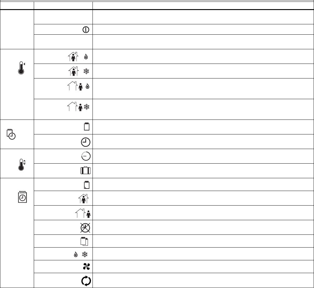
Table 11. T7350 Key Function Summary.
aFan On: Continuous fan operation (occupied and standby). During not occupied periods, fan cycles with call for heat or cool.
Fan Auto: Fan cycles with call for heat or cool during all periods. (See Fan Settings section for more details.)
NOTE: The display returns to the default screen after pressing Run Schedule (or after a period of time without keypress):
— ten seconds: when returning from temporary setpoint changes, info screen, temp occ, and temp not occ.
— one minute: when returning from setting clock/day.
— ten minutes: when returning from System Checkout.
— five minutes: when returning from all other modes.
Grouping Button Definition
Information Down Arrow Lowers setpoint, day, or time. When setting times or temperatures, hold key down to
continuously decrease value. Also can make temporary change in temperature setpoint.
Information Obtains information (where humidity “high-limit” can be set), cycles through setup options.
Up Arrow Raises setpoint, day, or time. When setting times or temperatures, hold key down to
continuously increase value. Also can make temporary change in temperature setpoint.
Temperature Occupied
Heat
Sets Occupied Heat setpoint.
Occupied
Cool
Sets Occupied Cool setpoint.
Not
Occupied
Heat
Sets Not Occupied Heat setpoint.
Not
Occupied
Cool
Sets Not Occupied Cool setpoint.
Set Day Sets day of week. Tapping key with 'Set Value' segment on increases current day (same
effect as Up Arrow key).
Time Sets time.
Tapping key with “Set Value” segment on increases time in one hour increments.
Override Temporary
Occupied
Temporary occupied setting for length of time defined by installer.
User can modify setpoints.
Temporary Not
Occupied
Sets holiday length.
User selects number of days (“0”-”99”), or “---” for continuous override.
Schedule Day Selects day schedule to modify. (Used also with copy key.)
Occupied Selects occupied event start times for specified day.
Repeatedly press this key to toggle between two occupied events.
Not Occupied Selects not occupied event start times for specified day.
Repeatedly press this key to toggle between two not occupied events.
Clear
Start Time
Clears start time for specified period and day.
Copy Copies schedule from one day to another.
System Selects System Mode. Toggles through Em Heat, Heat, Off, Cool, and Auto modes.
Fan Selects fan operation mode. Toggles between On and Auto.a
Run Schedule Resumes running schedule.
Cancels Temporary (Not) Occupied action, and/or Temporary setpoint changes.
T
S
T7350 COMMERCIAL PROGRAMMABLE THERMOSTAT
15 63-2605—5
PROGRAMMING
The thermostat operates at the Occupied temperature setting
until the thermostat is programmed. Table 12 shows the
default temperature settings. (The program has four):
— Occupied heat.
— Occupied cool.
— Not Occupied heat.
— Not Occupied cool.
Table 12. Occupied and Not Occupied
Default Temperature Settings.
The thermostat can be set for two Occupied and two Not
Occupied times for each day of the week (28 independent
time settings). Programming Holidays provides a total of 32
independent time settings.
The Temporary Occupied key provides quick temporary
temperature changes for increased occupant comfort. The
Temporary Not Occupied key provides energy efficient
operation for extended periods of time.
IMPORTANT
• Programming the thermostat with the keypad
requires 24 Vac (turn on system power).
• Keyboard lockout must be disabled.
NOTE: Before starting the program procedure, use
Table 13 to organize the program schedule.
Table 13. Occupied and Not Occupied Period Start Times.
aOnly applies to holidays programmed with 365-day calen-
dar
NOTE: 12:00 PM is Noon, and 12:00 AM is Midnight.
Setting Current Day/Time
This can be done using the keypad or a PDA interface.
IMPORTANT
• Once you set the day/time once, you should not
need to set it again. As a result, once a PDA sets the
day using calendar mode (MM/DD/YYYY), keypad
changes to the day are not allowed.
NOTES: To allow keypad day changes, use a PDA as follows:
1. Go to the “Set Clock” function.
2. Change the “Date Mode” from “MM/DD/YYYY” to
“Day of Week”.
3. Press Set.
When using the keypad to change the day/time:
1. Press Set Day until the current day is displayed.
NOTE: Sun = Sunday, Mon = Monday, Tue = Tuesday,
Wed = Wednesday, Thu = Thursday,
Fri = Friday, Sat = Saturday.
2. Press Set Time.
3. Press up S or down T until the current time is
displayed.
NOTE: Tapping Set Time changes the time in one
hour increments.
4. Press Run Schedule.
Setting Schedule Times
Use the PDA or the keys in the “Schedule” area of the keypad
for this procedure.
1. Press Occupied.
NOTE: Anytime a start time is not required, press
Clear Start Time.
2. Press Day until the desired day is displayed.
3. Press Occupied or Not Occupied until the proper period
is displayed.
4. Press up S or down T until the desired start time is
displayed.
5. Repeat steps 3 and 4 for a given day.
6. Repeat steps 2 through 5 until finished.
Program Holidays
IMPORTANT
— Holidays must be first programmed with a PDA.
— Day-of-Week mode forces the T7350 to ignore
holidays.
With holidays set, holiday schedule times can be changed
using the keypad:
1. Use the Schedule Day key to select “Hol” for Holiday
schedule times.
2. Press Occupied or Not Occupied to switch to the proper
time period within the holiday.
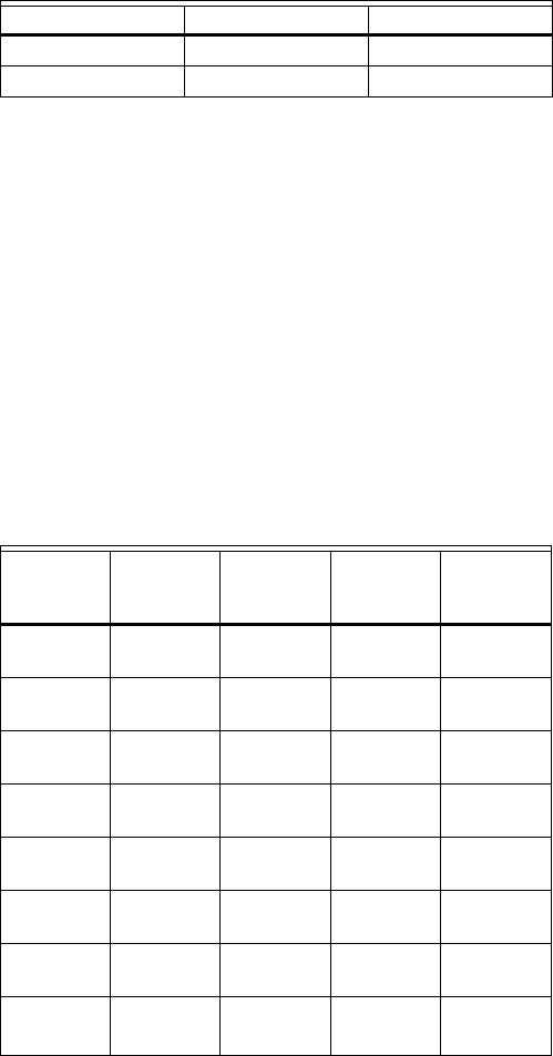
Control Occupied Not Occupied
Heating 70° F (21° C) 55° F (13° C)
Cooling 75° F (24° C) 85° F (29° C)
Day
Occupied
Period 1
Not
Occupied
Period 1
Occupied
Period 2
Not
Occupied
Period 2
Monday
Tuesday
Wednesday
Thursday
Friday
Saturday
Sunday
Holidaya
T7350 COMMERCIAL PROGRAMMABLE THERMOSTAT
63-2605—5 16
3. Press up S or down T until the desired time is
displayed.
4. Press Run Schedule.
IMPORTANT
— Invalid holidays are ignored.
— Valid holidays require valid: month, day and duration.
— Holidays such as the fifth Tuesday of a month with
only four Tuesdays are also invalid.
Copying a Day
Use the PDA or almost exclusively keys in the “Schedule”
area of the keypad for this procedure:
1. Press Occupied.
2. Press Day to select the day to be copied.
3. Press Copy.
4. Press Copy again. The following day is automatically
selected. (For example: If the day to be copied is Mon-
day, Tuesday will automatically be selected.)
5. If necessary, press Day until the day to receive the copy
is displayed.
NOTE: To cancel the copy press Run Schedule before
step 6.
6. Press Copy.
NOTE: DONE displays for two seconds then the
program display reappears.
7. Repeat steps 2 through 6 for all the days desired.
8. Press Run Schedule.
Clearing Program Start Times
1. Press Occupied or Not Occupied until the start period to
be cleared is displayed.
2. Press Day until desired day is displayed.
3. Press Clear Start Time.
4. Repeat steps 1 through 3 for all the start times to be
cleared.
5. Press Run Schedule.
Temperature Setpoints
Setpoint Limits
The setpoint temperature range is 40°F to 90°F (4°C to 32°C)
for heating and 45°F to 99°F (7°C to 37°C) for cooling.
NOTES: The ranges mentioned can be limited based upon
setpoints and stops:
1. The greater of the Minimum Heat Stop and the
Not Occupied Heat setpoints determines the
lowest setting to which the occupied heat setpoint
can be adjusted:
°F: Stop/NotOcc ≤ OccHeat ≤ (OccCool - 2).
°C: Stop/NotOcc ≤ OccHeat ≤ (OccCool - 1).
2. The lesser of the Maximum Cool Stop and Not
Occupied Cool setpoints determines the highest
setting to which the occupied cool setpoint can be
adjusted:
°F: Stop/NotOcc ≥ OccCool ≥ (OccHeat + 2).
°C: Stop/NotOcc ≥ OccCool ≥ (OccHeat + 1).
3. The Maximum Occupied Heat Setpoint is limited
by Occupied Cool Setpoint – 2° F (1° C).
4. The Minimum Occupied Cool Setpoint is limited
by the Occupied Heat Setpoint + 2° F (1° C).
Programming Temperature Setpoints
1. Press Occupied Heat.
2. Press up S or down T until the desired
temperature is displayed.
3. Press Occupied Cool.
4. Press up S or down T until the desired
temperature is displayed.
5. Press Not Occupied Heat.
6. Press up S or down T until the desired
temperature is displayed.
7. Press Not Occupied Cool.
8. Press up S or down T until the desired
temperature is displayed.
9. Press Run Schedule.
Temperature Setpoint Overrides
IMPORTANT
— The setup determines the duration of Occupied
overrides.
— Default duration is three hours.
NOTE: To cancel the Override and immediately return to the
program, press Run Schedule.
T7770 Setpoint Knob
A T7770 setpoint knob can remotely adjust the T7350 setpoint.
Adjustment can be made with the sensor in override.
NOTES:
— During override, only occupied and standby heat
setpoints, and cool setpoints are adjusted.
— The maximum adjustment is ±5° F (3° C).
— With a disconnected or failed T7770, or a T7350
not set for remote+setpoint, offset is zero.
T7771 Setpoint Button
A T7770 setpoint button can remotely adjust the T7350
setpoint. Adjustment can be made with the sensor in override.
NOTES:
— During override, only occupied and standby heat
setpoints, and cool setpoints are adjusted.
— The maximum adjustment is ±3° F (2° C).
— With a disconnected or failed T7771, or a T7350
not set for remote+setpoint, offset is zero.
Changing Temperature Setpoint Until Next Program
Period
This is a simple change to perform even with the door closed:
1. Press up S or down T until the desired
temperature is displayed.
NOTE: If done while in Standby or Not Occupied
mode, Temporary Occupied override engages
2. The temporary temperature appears for approximately
ten seconds, then the room temperature is displayed.

T7350 COMMERCIAL PROGRAMMABLE THERMOSTAT
17 63-2605—5
Using Temporary Occupied Override
The Temporary Occupied Override can be used when the
T7350 is in Not Occupied or Standby mode. It switches to the
Occupied mode for a fixed number of hours.
1. To use the default occupied override, press Temporary
Occupied.
NOTE: The default temperature setting is the
Occupied setpoint.
2. To select a temperature setting other than the default,
press up S or down T until the desired temperature off-
set is displayed (range is 0° F to 3° F [0° TO 2° C]).
NOTE: This offset can be restricted by the limits
detailed in the Setpoint Limits section.
Using Temporary Not Occupied Override
The Temporary Not Occupied Override fixes the device to
operate in Not Occupied mode for a number of days (between
1 and 99) without changing programming saved in memory.
NOTES:
— If the number of days is set to zero, no temporary
change takes effect.
— If the number of days is set just below zero, the
display for days is “---” (an indefinite override).
— To turn off this override, you must press Run
Schedule.
1. Press Temporary Not Occupied.
2. Press up S or down T to change the duration of the
Not Occupied period (in days).
NOTE: The default temperature setting is the
Not Occupied setpoint.
3. Press to display the default setpoint.
NOTE: The only way to change this setpoint is to
change the Not Occupied setpoint.

T7350 COMMERCIAL PROGRAMMABLE THERMOSTAT
63-2605—5 18
OPERATION
Startup Operation
Upon initial thermostat powerup, a startup and initialization
program begins. This startup occurs only on initial powerup.
After total loss of power for an extended period, the current
time and day can be lost (requiring reset). However, the
thermostat retains the user program.
NOTE: With no program set, the thermostat controls to the
Occupied default setpoints of 70°F (21°C) for heat
and 75°F (24°C) for cool.
T7350 Relay Logic
All T7350 model thermostats contain four switching relays. In
conventional applications, the relays control first stage cooling,
first stage heating, fan, and auxiliary. In heat pump
applications, the relays control the heat pump compressor,
changeover, fan, and emergency heat.
NOTE: Models T7350B,D, T7350H1009 have subbases with
more relays to accommodate extra stages.
Logic with Modulating Outputs (T7350H1017, M, only)
The specific relay logic depends on whether or not staging is
employed. See Table 14.
NOTE: The modulating outputs always provide a signal.
Table 14. T7350 Modulating Relay Logic Exceptions.
aSee Table 15 for modulating output signal details.
To display the status of the modulating outputs:
1. Cycle through information displays using the info key.
2. The device displays a percentage value for each output:
a. MODHEAT on one screen.
b. MODCOOL on another screen.
Table 15. Modulating Output Signal.
O/B Terminal for Heat or Cool Changeover
The O/B terminal controls heat pump changeover. The default
operation is for the terminal to be powered when calling for
heat (or while the most recent call was for heat). This
corresponds to a typical O terminal.
NOTE: The O/B terminal can be configured to operate as a
typical B terminal (powered on call for cool).
Emergency Heat
(select T7350 Thermostats only)
With the system set for Em Heat, auxiliary heat serves as
stage one; compressor stages are locked off. The fan cycles
with the auxiliary heat.
Equipment Protection
As part of the operational sequence, the T7350
microprocessor incorporates cycle rate, and minimum on and
off times for all heating and cooling stages. This extends
equipment life as it prevents rapid cycling of equipment.
NOTE: Minimum on and off times are fixed.
Cycle Rates
The thermostat control algorithm maintains the temperature by
cycling stages of heating or cooling to meet setpoint. Cycle
rates, in cycles per hour (cph) are set using a PDA.
NOTE: Defaults are: heat: 6cph, cool: 3cph.
P+I+D Control
The T7350 microprocessor-based control requires that the
user understands temperature control and thermostat
performance. A conventional electromechanical or electronic
thermostat does not control temperature precisely at setpoint.
Typically, there is an offset (droop) in the control point as the
system load changes. This is a phenomenon that most people
in the industry know and accept.
IMPORTANT
• P+I+D (Loop Tuning) parameters are optimized for
proper operation of a vast majority of HVAC systems.
Only when completely certain of necessary and
proper changes should you alter these values.
• Improper changes result in poor system performance
and equipment problems such as compressor short
cycling. Other problems include wide swings in space
temperature and excessive overdriving of modulating
outputs.
All adjustments to Loop Tuning parameters should be gradual.
After each change, allow the system to stabilize to accurately
observe the effects of the change. Then, as needed, make
further refinements until the system operates as desired.
If adjustment of PID parameters is required, use the following:
NOTE: In the items that follow, the term “error” refers to the
difference between the measured space temperature
and the current actual space temperature setpoint:
—The Throttling Range (TR), also called Proportional Gain,
determines the impact of the error on the output signal.
Decreasing TR amplifies the error effect; that is, for a given
error, smaller TR causes higher output signal.
—The Integral Time (IT), also called Integral Gain,
determines the impact of the error-over-time on the output
signal. Error-over-time has two components making up its
value: amount of time the error exists; and size of the error.
The higher the IT, the slower the control response. In other
words, a decrease in IT causes a more rapid change to the
output signal.
Modulating
OutputaStages
Relay Action
Heat/
Cool Fan
On
(1 to 100
percent)
0 On Output reaches 10%: On
Output falls below 5%: Off
1 or 2 Staged
Cycling
On/Off matches equipment
stage operation
Off
(0 percent)
0,1, or 2 Off Off
Action 0 percent 100 percent
Direct 4 mA 20 mA
Reverse 20 mA 4 mA
T7350 COMMERCIAL PROGRAMMABLE THERMOSTAT
19 63-2605—5
—The Derivative Time (DT), also called Derivative Gain,
determines the impact of the error rate on the output signal.
The error rate is how fast the error value changes. It can
also be the direction the space temperature is going, either
toward or away from the setpoint, and its speed—rapid or
slow. A decrease in DT causes, for a given error rate, a
greater effect on output signal.
Recovery Ramping Logic
The T7350 incorporates a ramping feature that gradually
changes the space setpoints. During recovery operation, the
setpoint changes at a rate in degrees per hour depending on
the outdoor air temperature. If there is no outdoor air
temperature sensor available, the minimum ramp rate is used.
When recovering in heating, the control point raises gradually,
maximizing the use of the more economical first stage heat to
bring the sensed temperature to the desired comfort setpoint.
This minimizes using the typically more expensive later
stage(s) of heat.
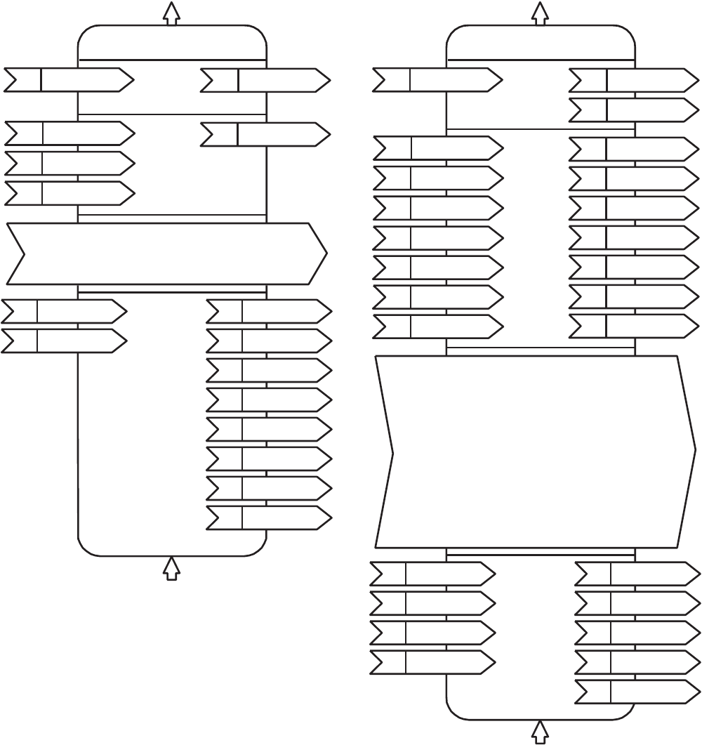
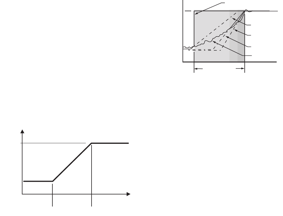
NOTE: See Fig. 11 for a pictorial representation of the heat
ramp rate determination.
Recovery Ramping for Conventional Systems
Fig. 11. Heat setpoint ramping for conventional systems.
NOTES:
— Recovery ramping applies between scheduled
heat or cool setpoint changes from not occupied
to standby and not occupied to occupied.
— Other setpoint changes use a setpoint step
change.
Recovery Ramping for Heat Pump Systems
During recovery with heat pump equipment, the heating
setpoint is split into a heat pump setpoint for compressors,
and two auxiliary heat setpoints for the auxiliary heat stages.
(See Fig. 12 for the various setpoints.)
Fig. 12. Heat setpoint ramping for heat pump systems.
Heat pump ramping for heating proceeds as follows:
1. The heat pump setpoint begins to ramp until the room
temperature and the compressor ramp intersect.
2. At this point, the heat pump setpoint performs a step
change to the Occupied (or Standby) setpoint and all
auxiliary heat stages are disabled.
NOTE: The heat pump setpoint remains here for the
rest of the Not Occupied period.
3. The stage one auxiliary heat ramp is calculated based
on a steeper slope starting 1° F (0.5° C) below the not
occupied setpoint.
4. When the room temperature intersects this auxiliary
heat ramp, the first stage of auxiliary heat is enabled.
5. The stage two auxiliary heat ramp is calculated based
on an even steeper slope starting 2° F (1° C) below the
not occupied setpoint.
6. When the room temperature intersects this auxiliary
heat ramp, the second stage of auxiliary heat is
enabled.
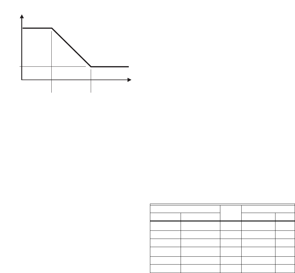
During the cool recovery period, the setpoint changes at a
rate in degrees per hour relative to the outdoor air
temperature. If there is no outdoor air temperature sensor
available, the minimum ramp rate is used.
See Fig. 13 for the various setpoints.
NOTE: For cooling, the same method is used in both
conventional and heat pump systems.
HEAT RECOVERY
RAMP RATE
(DEGREES/HOUR)
MaxHtRamp
MinHtRamp
OaTempMinHtRamp OaTempMaxHtRamp
OUTDOOR AIR
TEMPERATURE
M10109A
AUX HEAT
STAGE 1 RAMP
NORMAL
RECOVERY RAMP
OCCUPIED
SETPOINT
NOT OCCUPIED
SETPOINT
M19877
RECOVERY TIME
OCCUPIED
TIME
AUX HEAT
STAGE 2 RAMP
HEAT PUMP SETPOINT
(FOR COMPRESSORS)
SPACE
TEMPERATURE
T7350 COMMERCIAL PROGRAMMABLE THERMOSTAT
63-2605—5 20
Fig. 13. Setpoint ramping parameters with ramp rate
calculation.
NOTE: The setpoint used during the cool recovery period is
similar to the heat mode in Fig. 11, except the slope
of the line reverses for cooling.
Advantages:
• Comfort setting is achieved at the programmed time and
maintained regardless of weather conditions; occupants
are comfortable.
• Drafts from low-temperature discharge air are minimized
during Occupied periods.
• Use of the more economical first stage of heat is
maximized during recovery, minimizing use of the
expensive later heat stage(s).
• Comfort and energy savings can be achieved in both
heating and cooling.
• Heat cycling reduced, extending equipment life.
Auxiliary Relay
The auxiliary relay can be used with a variety of controls:
• Time-of-day (TOD).
• Economizer minimum position control.
• Dehumidification (see Dehumidification section).
Relay for Time-Of-Day (Table 16)
Time-of-day (TOD) is the Auxiliary Relay default configuration.
TOD logic operates strictly according to programming:
— Occupied: Relay contacts closed.
— Not Occupied: Relay contacts open.
— Standby (Scheduled): Relay contacts closed.
Relay for Economizers
Mechanical cooling is often used with outside temperatures in
the 50°F (10°C) to 60°F (16°C) range and humidity below 50
percent. In central and northern climates, hundreds of hours
fall into this temperature category. By permitting 80 to 100
percent outside air into the system, mechanical cooling may
not be needed at all, particularly during Spring and Fall.
Economizers take advantage of outside air. The typical
economizer consists of an outside air damper, motor, outdoor
air changeover control and a minimum position potentiometer.
The motor controls the dampers. Suitability of the outside air
for cooling is determined by the outdoor air changeover
control. The potentiometer adjusts the minimum position of
the economizer dampers, which provide a minimum amount
of fresh air for ventilation.
The economizer reduces compressor run time, thereby saving
energy and extending compressor life. The drawback to using
the economizer is that during the Not Occupied period, if there
is no call for cool or outdoor air is not suitable for free cooling,
the economizer is controlled to minimum position. This
position allows some percentage of outdoor air to enter the
building, regardless of air suitability. The situation can cause
the heating or cooling to run more often than when only
suitable air is permitted to enter the building.
The T7350 can take advantage of an economizer by closing
the auxiliary relay contacts to control the economizer
minimum position potentiometer. (See Table 16 for details.)
— Powered: Allows normal economizer operation.
— Unpowered: Disables the economizer minimum position.
The lack of power causes the economizer to drive dampers
fully closed instead of staying at minimum open position.
This reduces the possibility of unsuitable outdoor air
entering the building, which lowers the internal load on the
HVAC system and saves additional energy.
Table 16. Auxiliary Relay Logic (Economizer and TOD).
aUnless otherwise noted, Economizer logic ignores calls for
heat. TOD logic always observes calls for heat.
bWith fan set to AUTO and call for neither heat nor cool, the
relay is open in order to disable damper minimum position.
Other Uses for the Auxiliary Relay
Examples of other uses of the auxiliary relay are hot water
heaters, lighting, or baseboard heat. The additional loads are
connected to the auxiliary relay contacts on the subbase. The
contacts are rated for 1.5A at 30 Vac, but can be adapted to
higher current applications using an external relay.
(See Fig. 14 through 16.)
COOL RECOVERY
RAMP RATE
(DEGREES/HOUR)
MaxClRamp
MinClRamp
OaTempMinClRamp OaTempMaxClRamp
OUTDOOR AIR
TEMPERATURE
M10111A
Occupancy Call for
Coola
Auxiliary Contacts
Scheduled Sensor Signal Economizer TOD
—Occupied —ClosedbClosed
Occupied Standby Yes Closed Open
Occupied Standby No Open Open
Standby Standby —ClosedbClosed
— Not Occupied Yes Closed Open
— Not Occupied No Open Open

T7350 COMMERCIAL PROGRAMMABLE THERMOSTAT
21 63-2605—5
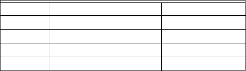
Fig. 14. Using T7350A,B,D,M models with an external
relay (with loads greater than 1.5A).
Fig. 15. Using T7350H models with an external relay
powered from thermostat transformer.
Fig. 16. Using T7350H models with an external relay
powered from an auxiliary transformer.
Default Auxiliary Relay Operations
(T7350D, T7350H1009 only)
Unless configured as a stage of heating or cooling, terminals
W2, W3, and Y3 operate for specific auxiliary functions. Each
output takes on different auxiliary functions depending on
configuration for Conventional or Heat Pump operation. See
Table 17 for details.
NOTE: The default functions cannot be modified. They are
limited to firmware version 1.3.0 or higher.
M19613
1
1
RELAY REQUIRED (R8222 OR SIMILAR).
T7350A,B,D,M SUBBASE
TO
LOAD
AUXILIARY
RELAY
CONTACT
AUX
RH
X
M22487
1
1
RELAY REQUIRED (R8222 OR SIMILAR).
T7350H SUBBASE
TO
LOAD
AUXILIARY
RELAY
CONTACT
AUX
RH
AUX
X
M22488
1
2
1
RELAY REQUIRED (R8222 OR SIMILAR).
POWER SUPPLY. PROVIDE DISCONNECT MEANS
AND OVERLOAD PROTECTION AS REQUIRED.
T7350H SUBBASE
TO
LOAD
AUXILIARY
RELAY
CONTACT
AUX
AUX
2
L1
(HOT)
L2
AUXILIARY
TRANSFORMER
Table 17. Default Auxiliary Relay Operations.
aSimple dehumidification uses a normally closed contact. The relay is closed when humidity is below the high limit. When the
humidity is above the high limit, the contact is open.
bThe PDA configuration tool output screen displays available Auxiliary Relay functions based on this configuration.
Heat Pump or
Conventional
Contact Not Used
as Heat or Cool Stage Contact Configuration of Contact Not Used as Stage
Heat Pump Y3 not Simple
Dehumidificationa
Simple
Dehumidificationa
Time of Day Time of Day
W2 not aux heat Economizer Time of Day Economizer Economizer
Conventional W3 not Simple
Dehumidificationa
Simple
Dehumidificationa
Simple
Dehumidificationa
Time of Day
Y3 not (W3 not) Economizer Time of Day Time of Day Economizer
Y3 not (W3 used) Simple
Dehumidificationa
Simple
Dehumidificationa
Simple
Dehumidificationa
Time of Day
Auxiliary Contact Configurationb:Time of Day Economizer Hot Gas Bypass
Dehumidification
Simple
Dehumidificationa
T7350 COMMERCIAL PROGRAMMABLE THERMOSTAT
63-2605—5 22
Dehumidification (T7350D,M,H only)
There are five methods through which the T7350 can control
for dehumidification. Three of them modify the control
algorithm, thus providing limited dehumidification through
cooling. The other two use the auxiliary output to control
another device.
IMPORTANT
Configurable only with a PDA or a network tool such
as LonSpec or CARE.
NOTE: The dehumidification high limit can be set within the
range of 10 to 90 percent relative humidity.
Control Through Cooling
Configure using some combination of the following:
— Minimum On.
— Reheat.
— Reset.
NOTES:
— These methods operate only during cooling.
— Selecting both Reheat and Reset can cause
frequent setpoint adjustments. This selection
is not recommended.
MIN ON TIME
Dehumidifies by increasing the compressor minimum on time
(normally 3 minutes) by a programmable amount. This is
useful with oversized systems in that it forces the coils to cool
to a point where dehumidification can occur.
NOTES:
— Can force wider temperature swings by cooling
when setpoint control does not require it.
— The minimum on time can be set within the range
of 5 to 15 minutes.
— Hysteresis and a minimum timer are used to
ensure this behavior does not change with every
equipment cycle.
REHEAT
Dehumidifies by operating cooling during typical off time. The
T7350 maintains the proper setpoint by running the heat at the
same time.
IMPORTANT
At times during Reheat dehumidification, the T7350
operates heating and the cooling simultaneously.
This is normal.
NOTES:
— The heat stage never energizes during Reheat if
more than one cool stage is on.
— Reheat mode cannot occur during heating.
— The T7350H1017, T7350M do not support the
Reheat method.
RESET TEMP SETPT
The room temperature set point resets to a specified number
of degrees below the actual set point when room relative
humidity (RH) rises above humidity high limit.
Though this may not technically reduce RH, it reduces the
dew point to provide the customer with a sense of comfort due
to a lower temperature setting in the room.
As long as RH stays above humidity high limit, this set point is
maintained.
NOTE: Hysteresis and a minimum timer prevent the set
point from short interval alternation (between stan-
dard and reset set points).
Options Utilizing Auxiliary Output
There are two dehumidification options that utilize the
auxiliary output. They are:
— Simple Dehumidification.
— Hot Gas Bypass Dehumidification.
SIMPLE DEHUMID(IFICATION)
The auxiliary output:
— Energizes when RH rises above humidity high limit.
— De-energizes when RH drops below humidity high limit.
NOTES:
— Hysteresis and a minimum timer prevent short
cycling of this output.
— Unlike Dehumid Hot Gas BP the relay remains
energized during calls for multiple cooling stages.
DEHUMID HOT GAS BP
The auxiliary output operates as shown in Table 18.
Table 18. Hot Gas Bypass Dehumidification Logic.
Auxiliary output during call for multiple cooling stages for two
reasons:
1. This method assumes that the cooling provides dehu-
midification.
2. Multiple cooling stages probably provide necessary
dehumidification.
NOTE: Hysteresis and a minimum timer prevent short
cycling of this output.
Humidity Cooling Stages Active Auxiliary Output
High more than one De-energized
High one or less Energized
Low more than one De-energized
Low one or less De-energized

T7350 COMMERCIAL PROGRAMMABLE THERMOSTAT
23 63-2605—5
TROUBLESHOOTING GUIDE (TABLE 19)
Table 19. Troubleshooting Information.
Symptom Possible Cause Action
Display will not come on. Thermostat is not being powered. Check that X terminal is connected to the system
transformer.
Check for 24 Vac between X and RH or RC terminals.
If missing 24 Vac:
•Check if circuit breaker is tripped; if so, reset circuit
breaker.
•Check if system fuse is blown; if so, replace fuse.
•Check if the HVAC equipment power switch is in the Off
position; if so, set to the On position.
•Check wiring between thermostat and HVAC
equipment. Replace broken wires and tighten loose
connections.
If 24 Vac is present, proceed with troubleshooting.
Temperature display is
incorrect.
Room temperature display has been
recalibrated.
Use PDA configuration software to recalibrate as desired.
Thermostat is configured for °F or °C
display.
Press both Run Schedule and Copy, then reconfigure the
display.
Bad thermostat location. Relocate the thermostat.
Display shows three dashes and a degree
sign (all systems shut down).
T7350 is set for remote sensing and sensor is missing or
circuit is either open or shorted.
Temperature settings will
not change.
(Example: Cannot set
heating higher or cooling
lower.)
Upper or lower temperature limits were
reached.
Check the temperature setpoints:
•Heating limits are 40° to 90° F (7° to 31° C)
•Cooling limits are 45° to 99° F (9° to 37° C)
Occupied setpoint temperature range
stops were configured.
Using a PDA, check setpoint stops. If necessary,
reconfigure the stop(s).
Keypad is locked. When a locked key is
pressed, LOCKED appears momentarily
on the LCD.
•Use PDA (Set, Display) to unlock keypad.
•Press both Run Schedule and Copy, then change
keypad lock level.
Room temperature is out
of control.
Remote temperature sensing is not
working.
Check all remote sensors.
Heat will not come on. No power to the thermostat. Check that X terminal is connected to the system
transformer.
Check for 24 Vac between X and RH terminals.
If missing 24 Vac:
•Check if circuit breaker is tripped; if so, reset circuit
breaker.
•Check if system fuse is blown; if so, replace fuse.
•Check if the HVAC equipment power switch is in the Off
position; if so, set to the On position.
•Check wiring between thermostat and HVAC
equipment. Replace broken wires and tighten loose
connections.
If 24 Vac is present, proceed with troubleshooting.
Thermostat minimum off time is activated. •Wait up to five minutes for the system to respond.
•Use PDA to configure heating response.
System selection is set to Off or Cool. Set system selection to Heat or Auto.
DAT high limit has been reached, or
OAT lockout is engaged.
•If the setpoints are correct, do nothing.
•Use PDA (Heating Config) to adjust or disable DAT
high limit and/or OAT lockout.
•Check HVAC equipment to ensure proper operation.

T7350 COMMERCIAL PROGRAMMABLE THERMOSTAT
63-2605—5 24
Cooling will not come on. No power to the thermostat. Check that X terminal is connected to the system
transformer.
Check for 24 Vac between X and RC terminals.
If missing 24 Vac:
•Check if circuit breaker is tripped; if so, reset circuit
breaker.
•Check if system fuse is blown; if so, replace fuse.
•Check if the HVAC equipment power switch is in the Off
position; if so, set to the On position.
•Check wiring between thermostat and HVAC
equipment. Replace broken wires and tighten loose
connections.
If 24 Vac is present, proceed with troubleshooting.
Thermostat minimum off time is activated. •Wait up to five minutes for the system to respond.
•Use PDA to configure cooling response.
System selection is set to Off or Heat. Set system selection to Cool or Auto.
DAT low limit has been reached, or
OAT lockout is engaged.
•If the setpoints are correct, do nothing.
•Use PDA (Cooling Config) to adjust or disable DAT low
limit and/or OAT lockout.
•Check HVAC equipment to ensure proper operation.
System indicator (flame:
heat, snowflake: cool) is
displayed, but no warm or
cool air is coming from
the registers.
The call for heat or cool is not yet given. Check if any stage indicators (dots next to the system
indicator) are displayed. With no display of stage
indicators, no call for cool/heat via relay is yet given.
For T7350M models only: Check the information screens.
MODHEAT or MODCOOL percentages of zero and 100
indicate an extreme signal from the given terminal. See
Table 15 for details.
Conventional heating equipment turns the
fan on only after the furnace has warmed
to a setpoint.
Wait one minute after seeing the on indicator and then
check the registers.
Heating or cooling equipment is not
operating.
Verify operation of heating or cooling equipment in Test
Mode.
Table 19. Troubleshooting Information. (Continued)
Symptom Possible Cause Action
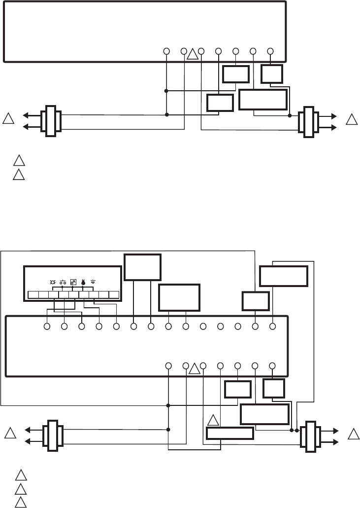
T7350 COMMERCIAL PROGRAMMABLE THERMOSTAT
25 63-2605—5
WIRING DIAGRAMS (FIG. 17-25)
Fig. 17. Typical hookup of T7350A in two-stage heat and one-stage cool conventional system
with two transformers.
Fig. 18. Typical hookup of T7350B in two-stage heat and two-stage cool conventional system
with two transformers.
POWER SUPPLY. PROVIDE DISCONNECT MEANS AND OVERLOAD PROTECTION AS REQUIRED.
WHEN INSTALLED ON A SYSTEM WITH TWO TRANSFORMERS, REMOVE THE FACTORY-INSTALLED JUMPER.
1
M19764A
2
2
RCX
SUBBASE
W1 GY1AUXRH
1
L1
(HOT)
L2 1
L1
(HOT)
L2
COMPRESSOR
CONTACTOR 1
HEATING
TRANSFORMER
COOLING
TRANSFORMER
FAN
RELAY
HEAT
RELAY 2
HEAT
RELAY 1
POWER SUPPLY. PROVIDE DISCONNECT MEANS AND OVERLOAD PROTECTION AS REQUIRED.
WHEN INSTALLED ON A SYSTEM WITH TWO TRANSFORMERS, REMOVE THE FACTORY-INSTALLED JUMPER.
USE ECONOMIZER INSTRUCTIONS FOR INSTALLATION DIRECTIONS.
1
M19765A
2
2
3
RCX
SUBBASE
W1 G
T7770 REMOTE SENSOR
Y1
W2 Y2
AUXRH
T5 T6 T7 T4 T3
DISCHARGE
AIR
SENSOR
OUTDOOR
AIR
SENSOR
OSOS ASAS
1
3
L1
(HOT)
L2 1
L1
(HOT)
L2
COMPRESSOR
CONTACTOR 1
COMPRESSOR
CONTACTOR 2
HEATING
TRANSFORMER
COOLING
TRANSFORMER
HEAT
RELAY 1
123456789
FAN
RELAY
ECONOMIZER
HEAT
RELAY 2
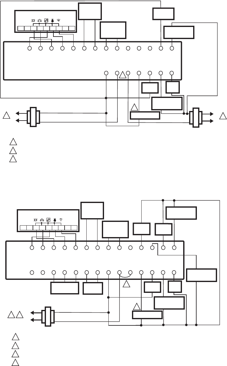
T7350 COMMERCIAL PROGRAMMABLE THERMOSTAT
63-2605—5 26
Fig. 19. Typical hookup of T7350B in three-stage heat and two-stage cool heat pump system
with two transformers.
Fig. 20. Typical hookup of T7350D in three-stage heat and three-stage cool conventional system with one transformer.
POWER SUPPLY. PROVIDE DISCONNECT MEANS AND OVERLOAD PROTECTION AS REQUIRED.
WHEN INSTALLED ON A SYSTEM WITH TWO TRANSFORMERS, REMOVE THE FACTORY-INSTALLED JUMPER.
USE ECONOMIZER INSTRUCTIONS FOR INSTALLATION DIRECTIONS.
1
M19767A
2
2
3
RCX
SUBBASE
O/B G
T7770 REMOTE SENSOR
Y1
W2 Y2
AUXRH
T5 T6 T7 T4 T3
DISCHARGE
AIR
SENSOR
OUTDOOR
AIR
SENSOR
OSOS AS
AS
1
3
L1
(HOT)
L2 1
L1
(HOT)
L2
COMPRESSOR
CONTACTOR 1
COMPRESSOR
CONTACTOR 2
HEATING
TRANSFORMER
COOLING
TRANSFORMER
CHANGE
OVER
123456789
FAN
RELAY
ECONOMIZER
AUX HEAT
STAGE 1
POWER SUPPLY. PROVIDE DISCONNECT MEANS AND OVERLOAD PROTECTION AS REQUIRED.
ENSURE TRANSFORMER IS SIZED TO HANDLE THE LOAD.
HEAT/COOL SYSTEMS WITH ONE TRANSFORMER REQUIRE THE FACTORY-INSTALLED JUMPER.
USE ECONOMIZER INSTRUCTIONS FOR INSTALLATION DIRECTIONS.
1
M19766A
2
3
2
3
4
RCX
SUBBASE
W1 G
T7770 REMOTE SENSOR
Y1
W3/Y4 Y3 W2 Y2
AUXRH
T5 T6 T7 T4 T3
DISCHARGE
AIR
SENSOR
OUTDOOR
AIR
SENSOR
MOTION
SENSOR
HUMIDITY
SENSOR
M
OSOS ASAS
MHC HP
HS
1
4
L1
(HOT)
L2
COMPRESSOR
CONTACTOR 1
COMPRESSOR
CONTACTOR 2
HEAT
RELAY 1
123456789
FAN
RELAY
ECONOMIZER
HEAT
RELAY 2
COMPRESSOR
CONTACTOR 3
HEAT
RELAY 3
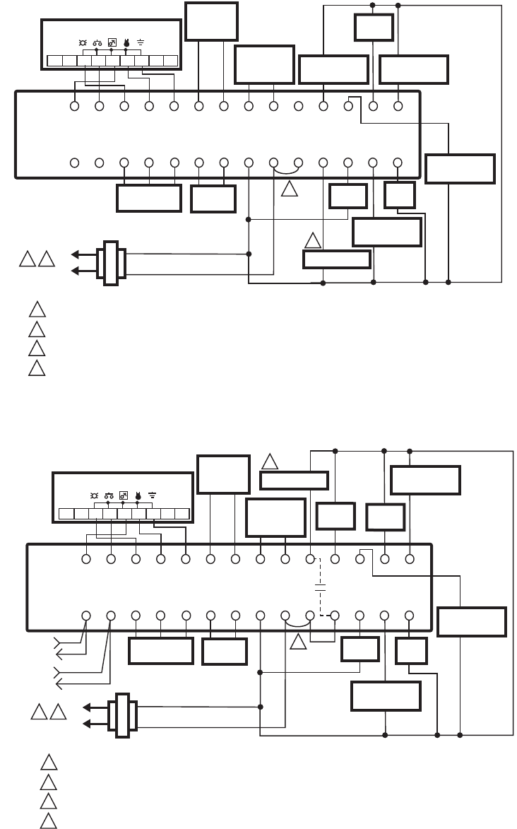
T7350 COMMERCIAL PROGRAMMABLE THERMOSTAT
27 63-2605—5
Fig. 21. Typical hookup of T7350D in two-stage heat and four-stage cool conventional system.
Fig. 22. Typical hookup of T7350H1009 in three-stage heat and three-stage cool conventional system with one
transformer.
POWER SUPPLY. PROVIDE DISCONNECT MEANS AND OVERLOAD PROTECTION AS REQUIRED.
ENSURE TRANSFORMER IS SIZED TO HANDLE THE LOAD.
HEAT/COOL SYSTEMS WITH ONE TRANSFORMER REQUIRE THE FACTORY-INSTALLED JUMPER.
USE ECONOMIZER INSTRUCTIONS FOR INSTALLATION DIRECTIONS.
1
M19768
A
2
3
2
3
4
RCX
SUBBASE
W1 G
T7770 REMOTE SENSOR
Y1
W3/Y4 Y3 W2 Y2
AUXRH
T5 T6 T7 T4 T3
DISCHARGE
AIR
SENSOR
OUTDOOR
AIR
SENSOR
MOTION
SENSOR
HUMIDITY
SENSOR
M
OSOS ASAS
MHC HP
HS
1
4
L1
(HOT)
L2
COMPRESSOR
CONTACTOR 1
COMPRESSOR
CONTACTOR 2
HEAT
RELAY 1
123456789
FAN
RELAY
ECONOMIZER
HEAT
RELAY 2
COMPRESSOR
CONTACTOR 3
COMPRESSOR
CONTACTOR 4
POWER SUPPLY. PROVIDE DISCONNECT MEANS AND OVERLOAD PROTECTION AS REQUIRED.
ENSURE TRANSFORMER IS SIZED TO HANDLE THE LOAD.
HEAT/COOL SYSTEMS WITH ONE TRANSFORMER REQUIRE THE FACTORY-INSTALLED JUMPER.
USE ECONOMIZER INSTRUCTIONS FOR INSTALLATION DIRECTIONS.
1
M22489
2
3
2
3
4
RC
AUX
X
SUBBASE
W1 G
T7770 REMOTE SENSOR
Y1
W3/Y4 Y3 W2 Y2
AUXRH
T5 T6 T7 T4 T3
DISCHARGE
AIR
SENSOR
OUTDOOR
AIR
SENSOR
MOTION
SENSOR
HUMIDITY
SENSOR
M
OSOS ASAS
MHC HPHSEB
EB
1
4
L1
(HOT)
L2
LONWORKS®
BUS
COMPRESSOR
CONTACTOR 1
COMPRESSOR
CONTACTOR 2
HEAT
RELAY 1
123456789
FAN
RELAY
ECONOMIZER
HEAT
RELAY 2
COMPRESSOR
CONTACTOR 3
HEAT
RELAY 3
LONWORKS®
BUS
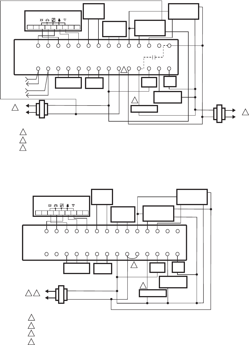
T7350 COMMERCIAL PROGRAMMABLE THERMOSTAT
63-2605—5 28
Fig. 23. Typical hookup of T7350H1017 for system with two independent heat stages (one modulating),
two independent cool stages (one modulating), and two transformers.
Fig. 24. Typical hookup of T7350M for system with two independent heat stages (one modulating),
two independent cool stages (one modulating), and one transformer.
POWER SUPPLY. PROVIDE DISCONNECT MEANS AND OVERLOAD PROTECTION AS REQUIRED.
WHEN INSTALLED ON A SYSTEM WITH TWO TRANSFORMERS, REMOVE THE FACTORY-INSTALLED JUMPER.
USE ECONOMIZER INSTRUCTIONS FOR INSTALLATION DIRECTIONS.
1
M22006
2
2
3
RCX
SUBBASE
W1 G
AUX
T7770 REMOTE SENSOR
Y1
AH AC
AUXRH
T5 T6 T7 T4 T3
DISCHARGE
AIR
SENSOR
OUTDOOR
AIR
SENSOR
MOTION
SENSOR
HUMIDITY
SENSOR
M
OSOS AS AXAS
MHC HPHSEB
EB
1
3
L1
(HOT)
HEATING
TRANSFORMER COOLING
TRANSFORMER
L2
1
L1
(HOT)
L2
COMPRESSOR
CONTACTOR 1
HEAT
RELAY 1
123456789
FAN
RELAY
ECONOMIZER
MODULATING
HEAT
(4-20 mA)
–
+
MODULATING
COOL
(4-20 mA)
–
+
R
X
R
X
LONWORKS®
BUS
LONWORKS®
BUS
POWER SUPPLY. PROVIDE DISCONNECT MEANS AND OVERLOAD PROTECTION AS REQUIRED.
ENSURE TRANSFORMER IS SIZED TO HANDLE THE LOAD.
HEAT/COOL SYSTEMS WITH ONE TRANSFORMER REQUIRE THE FACTORY-INSTALLED JUMPER.
USE ECONOMIZER INSTRUCTIONS FOR INSTALLATION DIRECTIONS.
1
M19769
A
2
3
3
4
RCX
SUBBASE
W1 G
T7770 REMOTE SENSOR
Y1
MH MC
AUXRH
T5 T6 T7 T4 T3
DISCHARGE
AIR
SENSOR
OUTDOOR
AIR
SENSOR
MOTION
SENSOR
HUMIDITY
SENSOR
M
OSOS AS MXAS
MHC HP
HS
21
4
L1
(HOT)
L2
COMPRESSOR
CONTACTOR 1
HEAT
RELAY 1
123456789
FAN
RELAY
ECONOMIZER
MODULATING
HEAT
(4-20 mA)
–
+
MODULATING
COOL
(4-20 mA)
–
+
R
X
R
X
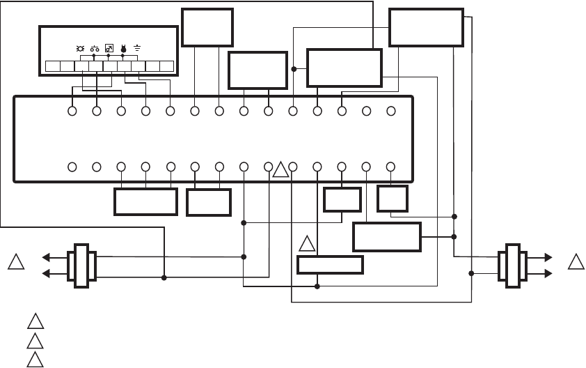
T7350 COMMERCIAL PROGRAMMABLE THERMOSTAT
29 63-2605—5
Fig. 25. Typical hookup of T7350M for system with two independent heat stages (one modulating),
two independent cool stages (one modulating), and two transformers.
POWER SUPPLY. PROVIDE DISCONNECT MEANS AND OVERLOAD PROTECTION AS REQUIRED.
WHEN INSTALLED ON A SYSTEM WITH TWO TRANSFORMERS, REMOVE THE FACTORY-INSTALLED JUMPER.
USE ECONOMIZER INSTRUCTIONS FOR INSTALLATION DIRECTIONS.
1
M22006
2
2
3
RCX
SUBBASE
W1 G
T7770 REMOTE SENSOR
Y1
MH MC
AUXRH
T5 T6 T7 T4 T3
DISCHARGE
AIR
SENSOR
OUTDOOR
AIR
SENSOR
MOTION
SENSOR
HUMIDITY
SENSOR
M
OSOS AS MXAS
MHC HP
HS
1
3
L1
(HOT)
HEATING
TRANSFORMER
COOLING
TRANSFORMER
L2 1
L1
(HOT)
L2
COMPRESSOR
CONTACTOR 1
HEAT
RELAY 1
123456789
FAN
RELAY
ECONOMIZER
MODULATING
HEAT
(4-20 mA)
–
+
MODULATING
COOL
(4-20 mA)
–
+
R
X
R
X
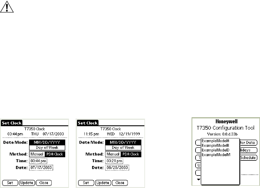
T7350 COMMERCIAL PROGRAMMABLE THERMOSTAT
63-2605—5 30
APPENDIX - PDA USAGE
See Table 20 for the advanced setup options available
through a PDA.
NOTE: Upon initial thermostat power-up, wait at least 30
seconds before connecting the TIM.
Hardware Requirements
The Thermostat Configuration Tool has the following
configuration:
• PDA hardware platform supporting application software.
• Serial Connection Cable with TIM. The interface plug
connects to the thermostat socket.
CAUTION
Equipment Damage Hazard
Can damage the TIM connection beyond repair.
Disconnect the TIM cable prior to opening or closing
the thermostat cover.
Setting Clock
It is best to set the clock before downloading anything else to
the thermostat. Connect to the thermostat and set the clock.
See Fig. 26.
NOTES:
— When setting the clock the first time, the PDA
displays an incorrect T7350 Clock time, day, and
date.
— Day-of-Week mode forces the T7350 to ignore
holidays.
Fig. 26. Set Clock menu.
PDA Programming
The PDA Configuration Tool can perform a variety of tasks:
• Configure the thermostat.
• Calibrate the thermostat.
• Perform diagnostics.
NOTE: To install the configuration tool on a second PDA:
1. Power up both PDAs.
2. Execute the following command sequence from
the source PDA: Menu, Beam, T7350, Beam.
Configuration
Whether the configuration is performed offline or while
connected, the procedure is the same.
OFFLINE CONFIGURATION
While disconnected from the thermostat, you can arrange and
save named configurations.
NOTE: The user can note the Configuration ID and manually
set the code using the T7350 user interface.
CONNECT AND CONFIGURE
Connect to a thermostat and:
— configure device with existing named parameter
arrangement,
— configure device by changing all parameters
— read the existing configuration parameter values and
— change one or more configuration parameters
— save new configuration file.
NOTE: The configuration tool verifies that the subbase
supports the existing arrangement.
CONFIGURATION PROCEDURE
1. Enter the T7350 PDA application. (See Fig. 27.)
2. If disconnected, the only usable functions are:
a. New Config:
(1) Enter a name for the configuration.
(2) Tap New Config.
(3) Proceed to Select Existing Config(uration)
section.
b. Select Existing Config: See below.
Fig. 27. PDA configuration tool main menu.
Select Existing Config(uration)
This function is used to select a programmed configuration
when setting up/programming a T7350. This can be useful
when you use any given configuration more than once.
NOTES:
— You can modify details of a given configuration
prior to downloading it into any particular T7350.
— The PDA tool will notify you when a selected
configuration requires more stages/features than
the T7350 into which you are downloading it.
— Configuration screens will vary depending on the
T7350 model selected.
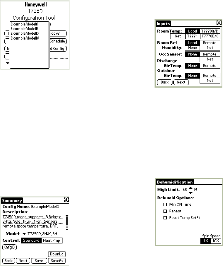
T7350 COMMERCIAL PROGRAMMABLE THERMOSTAT
31 63-2605—5
To configure a T7350:
1. From the opening screen, tap Select Existing Config.
(See Fig. 28.)
2. Select the desired configuration.
Fig. 28. Select Existing Config.
3. This brings up the Summary screen. From here, you
can make changes using the:
a. Novice navigation screens (that appear), or
b. Advanced navigation screens, using the hidden
menus. (These are designed for expert users.)
(1) Access to the Advanced Navigation mode is
obtained using one of the following methods:
(a)Tap the lower left “Menu” silk screen icon.
(b)Tap the Title Tab of any screen.
RESULT: The Config Tool replaces the existing Screen
Title Tab with the Advanced Navigation menu
displayed across the top of the screen.
4. Tap “SaveAs” to save the changes under a new name.
5. The Summary screen facilitates changes to:
a. Description.
b. Model.
c. Control (Standard or Heat Pump).
Fig. 29. Configuration Summary screen.
6. Make changes and tap “Next” to proceed to the Inputs
screen.
7. The Inputs screen facilitates changes to:
a. RoomTemp(erature).
b. Room Rel(ative) Humidity.
c. Occ(upancy) Sensor.
d. Discharge Air Temp(erature).
e. Outdoor Air Temp(erature).
NOTE: Some selections only appear for the models
that support them.
Fig. 30. Inputs screen.
8. Make changes and tap “Next”.
NOTE: Novice navigation to the Dehumidification
screen is controlled based on the T7350 model
and configured room humidity sensor status.
So, step 9 and Fig. 31 may not apply.
9. The Dehumidification screen facilitates changes to:
a. Room humidity high limit.
b. Dehumidification options.
Fig. 31. Dehumidification screen.
10. Make changes and tap “Next” to proceed to the Cooling
Config(uration) screen.
11. The Cooling Config screen facilitates changes to:
a. Number of Stages.
b. Cooling Response.
c. OAT Lockout and DAT Low Limit Setpoints (for
some models).
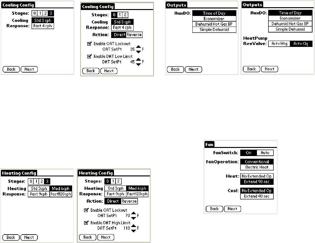
T7350 COMMERCIAL PROGRAMMABLE THERMOSTAT
63-2605—5 32
Fig. 32. Cooling Config(uration) screen.
12. Make changes and tap “Next” to proceed to the Heating
Config(uration) screen.
13. The Heating Config(uration) screen facilitates changes
to:
a. Number of Stages.
b. Heating Response.
c. OAT Lockout and DAT High Limit Setpoints (for
some models).
Fig. 33. Heating Config(uration) screen.
14. Make changes and tap “Next” to proceed to the Outputs
screen.
15. The Outputs screen facilitates changes to output
type(s).
NOTE: When configured with an extra stage of heat or
cool (using the auxiliary stage) the Outputs
screen shows nothing but this indication.
Fig. 34. Outputs screen.
16. Make changes and tap “Next” to proceed to the Fan
screen.
17. The Fan screen facilitates changes to:
a. Fan Switch (On or Auto).
b. Fan Operation (Conventional or Electric Heat).
c. Heat and cool extended operation.
Fig. 35. Fan screen.
18. Make changes and tap “Next” to proceed to the Weekly
Schedule screen.
NOTE: The only schedule days/times displayed are
those in the program. It is possible to have as
many as 4 event times per day for each day
(including holiday) programmed into each set.
19. The Weekly Schedule screen facilitates changes to the
program schedule:
a. Tap Modify. (See Fig. 37.)
b. Select a day to modify.
c. Make changes to:
(1) Mode (see Fig. 38).
NOTE: To remove a given event, change Mode
to “None”.
(2) Time (see Fig. 39).
d. Repeat step c for all events until changes are
complete for the given day.
NOTE: To copy a day schedule, check the appropriate
boxes, and click CopyDayTo. (See Fig. 40.)
e. Tap OK.
f. Type in a name for the new schedule.
g. Tap SaveAs.
T7350MT7350D
T7350MT7350D

T7350 COMMERCIAL PROGRAMMABLE THERMOSTAT
33 63-2605—5
Fig. 36. Weekly Schedule screen.
Fig. 37. Weekly Schedule modification screen.
Fig. 38. Weekly Schedule Mode modification.
Fig. 39. Weekly Schedule Time modification.
Fig. 40. Weekly Schedule Mode CopyDayTo.
20. Tap “Next” to proceed to the SetPoints screen.
21. The SetPoints screen facilitates changes to the:
a. Default setpoints.
b. Occupied Setpoint stops.
c. Temporary Override duration.
Fig. 41. SetPoints screen.
22. Make changes and tap “Next” to return to the Summary
screen.
23. Tap “Save” to save changes under the existing name.
24. Tap “DownLd” to download changes to a connected
T7350.
25. Tap “CnfgID” to have the device calculate configuration
number(s).
26. The configuration numbers represent the C numbers
(C1.C2.C3.C4.C5.C6.C7.C8) that can be input using
the T7350 keypad.
NOTE: The configuration numbers determine all but
the schedule and setpoints.
27. To return to the Home Screen, tap the Menu icon (lower
left hand corner silk screen) and tap Set / Home.
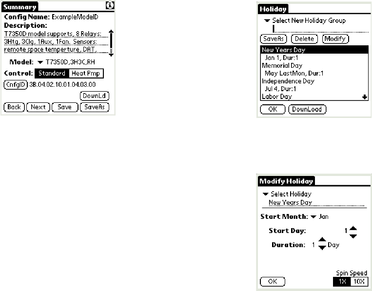
T7350 COMMERCIAL PROGRAMMABLE THERMOSTAT
63-2605—5 34
Fig. 42. Summary screen with configuration numbers.
Deleting Configurations
1. Make certain you are in a configuration other than the
one you plan to delete.
2. Tap the Summary tab in the upper left corner.
3. Select File / Delete.
4. Select the configuration to delete.
5. Tap DELETE.
6. A prompt appears allowing you to cancel the deletion.
7. To delete more configurations, return to step 4.
8. When finished with deletions, tap DONE.
Weekly (Wkly) Schedule
This function is used to upload/modify/download schedule
sets for programming a T7350. This can be useful if you want
to change only schedule settings.
NOTE: The schedule can also be modified from within a
given configuration.
Holidays
This function is used to upload/modify/download holiday sets
for programming a T7350. This can be useful if you want to
change only holiday settings. It is especially useful if you use
any group of holidays more than once.
NOTE: The holidays can be modified from within a given
configuration.
To create a new holiday group:
1. From the main menu, tap Holidays. (See Fig. 43.)
NOTE: The only holidays displayed are those
contained in a program set. It is possible to
have as many as 10 holidays programmed into
each set.
Fig. 43. Holiday screen.
2. Tap Modify. (See Fig. 44.)
Fig. 44. Holiday modification screen.
3. Select a holiday slot to modify or create.
4. Make changes to:
a. Holiday title.
b. Start Month.
NOTE: To remove a given holiday, change the Start
Month to “None” and tap “OK”. The title will
remain, but the holiday will not operate.
c. Start Day.
d. Duration.
NOTE: To remove all evidence of a given holiday,
change Title to “Hol ##”, Start Month and Start
Day to “None”, Duration to “0” and tap “OK”.
e. Spin Speed.
NOTE: Spin Speed determines the increment change
(1X or 10X) for Start Day and Duration. The
spin speed setting is local for each screen.
5. Repeat steps 2 through 4 until changes are complete for
the given holiday set.
6. Type in a name for the new holiday set.
7. Tap SaveAs.
8. Repeat steps 2 through 8 for all desired holiday sets.
9. To return to the main menu, tap the Holiday screen OK.
Calibration
Connect to a thermostat and calibrate the temperature
display.

T7350 COMMERCIAL PROGRAMMABLE THERMOSTAT
35 63-2605—5
Online Diagnostics
Connect to a thermostat and, using the “Monitor Data”
function, read diagnostic information including:
• Thermostat firmware version.
• Thermostat hardware version.
• Subbase hardware version.
• Run time error messages.
Table 20. Thermostat Setup Options Through PDA.
Configuration Option Factory DefaultaPDA
Tool CnfgID Description
Fan Operation Conventional X X Conventional: Applications where equipment controls fan operation in heat mode.
Electric Heat: Applications where thermostat controls fan operation in heat mode.
The thermostat always controls the fan in cool mode.
Extended Heat Fan Extend 90 sec X X No Extended Op: No extended fan operation after call for heat ends.
Extend 90 sec: Fan operation extended 90 seconds after call for heat ends.
Extended Cool Fan No Extended Op X X No Extended Op: No extended fan operation after call for cool ends.
Extend 40 sec: Fan operation extended 40 seconds after call for cool ends.
Control Standard X X Standard: Conventional equipment; Heat Pmp: Heat Pump.
HeatPump RevValve ActvClg X X ActvClg: Energize O/B on call for cool.
ActvHtg: Energize O/B on call for heat.
Heat Output Stages aX X Stages of heat (conventional HVAC equipment). Set to zero for heat pump.
Three heat stages not available if configured for four stages of cooling.
AuxStg 1 X X Auxiliary Heat Stages (for heat pump applications): Number of stages (0,1, or 2).
Heating Response 6 cph X X 3 cph: Standard response for heating system;
6 cph: Medium response for heating system; 9 cph: Fast response for heating system;
20 cph: Super fast response for heating systems.
Heat Lockout None X X None: No outdoor air temperature (OAT) lockout for heat.
Enable: Heat locked out when OAT is greater than Heat Lockout Setpoint.
Heat Lockout Setpoint 70° F X Heat is locked out when OAT is greater than this setpoint.
Range: -40 to 120° F
Cool Output stages aX X Stages of cool (conventional), or number of compressor stages (heat pump).
Cooling Response 3 cph X X 3 cph: Standard response for cooling system.
4 cph: Fast response for cooling system.
Cooling response applies to compressors in heat pump applications.
Cooling Lockout None X X None: No OAT lockout for cool.
Enable: Cool locked out when OAT is less than Cool Lockout Setpoint.
Cool Lockout Setpoint 35° F X Cooling is locked out if the outdoor temperature is less than this setpoint.
Range: -40 to 120° F
Cooling Valve Direct X X Modulating Cooling Valve Action: Direct or Reverse. (T7350M only.)
Heating Valve Direct X X Modulating Heating Valve Action: Direct or Reverse. (T7350M only.)
Anticipator Authority
Application
Htg X X Htg: Authority applies to heating only.
Htg&Clg: Authority applies to both heating and cooling. (Found in Loop Tuning.)
Anticipator Authority 4° F X X Thermostat Anticipator Authority. Range: 2 to 15° F.
Cooling TR aX Cooling Throttling Range. Range: 1 to 30° F. (Found in Loop Tuning.)
Cooling IT aX Cooling Integral Time. Options: 0, 100 to 5000 sec. (0: disable.)
Cooling DT 0 sec X Cooling Derivative Time. Options: 0, 10 to 3000 sec. (0: disable.)
Heating TR aX Heating Throttling Range. Range: 1 to 30° F. (Found in Loop Tuning.)
Heating IT aX Heating Integral Time. Options: 0, 100 to 5000 sec. (0: disable.)
Heating DT 0 sec X Heating Derivative Time. Options: 0, 10 to 3000 sec. (0: disable.)
Display Units °F X X Temperature Display: °F or °C.
Clock Format AM/PM X X AM/PM: 12-hour clock format. 24 hr: 24-hour clock format.
aThe Factory defaults listed here apply to all subbase models with the exceptions of the items listed in Table 21.
b12:00 Noon is the default start point when time is unknown.
cOnly Available if user selected one or more of following: Dehumidification Reset, Dehumidification Minimum On, or Dehumidification Reheat.
dConfig ID cannot handle Standby setpoints. Keypad users cannot set Occupied setpoints that violate Not Occupied setpoint relationship. The T7350 algo-
rithm never allows the effective setpoint outside Not Occupied setpoints.

T7350 COMMERCIAL PROGRAMMABLE THERMOSTAT
63-2605—5 36
Temperature Display
Calibration
No Change X No Change: Displayed temperature is actual room temperature.
Can adjust to display up to 3° F (1.7° C) higher or down to 4° F (2.2° C) lower than
room temperature.
TempOverride 3 X X Temporary Occupied Override duration. Range: 1 to 8 hours.
RoomTemp Local X X Room Temperature Input
Local: Use internal sensor; T7770A/D: Use remote sensor.
T7770B/C: Use remote sensor with setpoint adjustment capability (requires PDA).
T7771: Use remote sensor with setpoint adjustment capability (requires PDA); changes
T7771 LED and bypass button operation: LED on means either occupied or bypass,
pushing bypass can cancel bypass.
RoomRelHumidity aX X Room Relative Humidity Input.
None: No humidity sensor; Local: Use internal humidity sensor;
Remote: Use remote humidity sensor (0-10 Vdc signal).
Discharge AirTemp None X X Discharge Air Temperature Input.
None: No discharge air sensor; or Remote: Remote discharge air sensor.
Outdoor AirTemp None X X Outdoor Air Temperature Input.
None: No outdoor air sensor; or Remote: Remote outdoor air sensor.
OccSensor 0 X X None: No occupancy sensor; or Remote: Remote occupancy sensor.
AuxDO Time of Day X X Auxiliary Contact Operation:
Time of Day, Economizer, Dehumid Hot Gas BP, or Simple Dehumid.
Auxiliary contact not available if heat pump selected with T7350A.
Key Pad (Lockout) Enable All X X Keypad lockout enable/disable through special keypad sequence.
Enable All (0): No lockout.
SetPts & Ovrrd (1): Lockout all keys except: Temporary (Not) Occupied, S, T and
.
Info Only (2): Lockout all keys except .
The special keypress features are never locked out.
Recovery Heat RampMin 5° F/hr X Minimum heating recovery ramp rate. Range: 0 to 20° F/hr.
Recovery Heat RampMax 8° F/hr X Maximum heating recovery ramp rate. Range: 0 to 20° F/hr.
Recovery Cool RampMin 3° F/hr X Minimum cooling recovery ramp rate. Range: 0 to 20° F/hr.
Recovery Cool RampMax 6° F/hr X Maximum heating recovery ramp rate. Range: 0 to 20° F/hr.
Recovery Heat OAT@Min 0° F X Minimum heating outdoor air temperature. Range: -20 to 100° F.
Recovery Heat OAT@Max 40° F X Maximum heating outdoor air temperature. Range: -20 to 100° F.
Recovery Cool OAT@Min 90° F X Minimum cooling outdoor air temperature. Range: -20 to 100° F.
Recovery Cool OAT@Max 70° F X Maximum cooling outdoor air temperature. Range: -20 to 100° F.
Demand Limit Control Bump 3° F X Demand limit control set point bump. Range: 0 to 10° F.
Power Failure Seq Start 0 (x10 sec) X X Delays start of equipment (fan, heat, cool) after power restored to thermostat.
Range: 0 to 150 seconds (in 10-second increments).
Enable DAT High Limit None X X None: No Discharge Air Temperature (DAT) high limit; Enable: Use DAT High Limit.
Enable DAT Low Limit None X X None: No Discharge Air Temperature (DAT) low limit; Enable: Use DAT Low Limit.
High Limit DAT Setpoint 110° F X Discharge Air Temperature High Limit Setpoint. Range: 65 to 140° F.
Low Limit DAT Setpoint 45° F X Discharge Air Temperature Low Limit Setpoint. Range: 35 to 60° F.
Dehumidification Min On None X X None: No Minimum On Time dehumidification;
Enable: Dehumidification using Minimum On Time.
Dehumidification Min On Time 5 X Minimum on time used with “Dehumidify Minimum On”. Range: 5 to 15 minutes.
Dehumidification Reset Temp None X X None: No Reset dehumidification; Enable: Dehumidification using Reset.
Table 20. Thermostat Setup Options Through PDA. (Continued)
Configuration Option Factory DefaultaPDA
Tool CnfgID Description
aThe Factory defaults listed here apply to all subbase models with the exceptions of the items listed in Table 21.
b12:00 Noon is the default start point when time is unknown.
cOnly Available if user selected one or more of following: Dehumidification Reset, Dehumidification Minimum On, or Dehumidification Reheat.
dConfig ID cannot handle Standby setpoints. Keypad users cannot set Occupied setpoints that violate Not Occupied setpoint relationship. The T7350 algo-
rithm never allows the effective setpoint outside Not Occupied setpoints.

T7350 COMMERCIAL PROGRAMMABLE THERMOSTAT
37 63-2605—5
Dehumidification Reset Temp
Setpt
2° F X Amount of reset used with “Dehumidify Reset”. Range: 1 to 5° F.
Must be smaller than occupied zero energy band (ZEB) or standby ZEB.
Dehumidification Reheat None X X None: No Reheat dehumidification; Enable: Dehumidification using Reheat.
Dehumidification High Limit 65% X XcDehumidification High Limit. Range: 10 to 90%.
Clock Year 1999 X Range: 2000 to 2035.
Clock Month 12 X 1: January… 12: December.
Clock Day Wed X Day of the Week: Sun, Mon, Tue, Wed, Thu, Fri, Sat
Clock Minutes 11:15 p.m.bX X 12:00 a.m.: Midnight (first minute of the day); 12:00 p.m.: Noon.
Holiday Month 0 X Unprogrammed; January…December.
Holiday Day 0 X Unprogrammed; 1; 2…31; LASTDAYOFMONTH…LAST_SAT
Holiday Duration 0 days X Duration of given Holiday (in days). Range: 0 to 99 days.
Delays On X X On: Delays (on relays, sequential start, etc.) are active.
Off: Delays disabled (also called Test Mode).
System Switch Auto X X System settings: Auto; Cool; Off; Heat; Emergency Heat (valid if Heat Pump)
Fan Switch On X X Fan setting: On; Auto
Occupied Heat Setpt Stop 55° F X Occupied Minimum Heat Setpoint: Lowest the programmed occupied heating setpoint
can be adjusted. Range: 40 to 90° F; Value ≤ OccHt ≤ OccCl - 2° F.
Occupied Cool Setpt Stop 85° F X Occupied Maximum Cool Setpoint: Highest the programmed occupied cooling setpoint
can be adjusted. Range: 45 to 99° F. Value ≥ OccCl ≥ OccHt + 2° F.
Not Occupied Heat Setpoint 55° F X X Not Occupied heating setpoint. Range: 40 to 90° F.
UnoccHt ≤ OccHt ≤ OccCl - 2° F; UnoccHt ≤ StdByHt ≤ StdByCl - 2° F
Standby Heat Setpoint 67° F X dStandby heating setpoint. Range: 40 to 90° F.
Occupied Heat Setpoint 70° F X X Occupied heating setpoint. Range: 40 to 90° F.
Occupied Cool Setpoint 75° F X X Occupied cooling setpoint. Range: 45 to 99° F.
Standby Cool Setpoint 78° F X dStandby cooling setpoint. Range: 45 to 99° F.
Not Occupied Cool Setpoint 85° F X X Not Occupied cooling setpoint. Range: 45 to 99° F.
UnoccCl ≥ OccCl ≥ OccHt + 2° F; UnoccCl ≥ StdByCl ≥ StdByHt + 2° F.
Event 1 State Occupied X X Day Schedule is a structure of 8 days of 4 events each day. Defaults listed are for
Monday through Friday. Saturday/Sunday/Holiday default to Unprogrammed (None /
12:00 a.m.). All Events can be set for: Standby or None.
Only Events 1 and 3 can be set for Occupied.
Only Events 2 and 4 can be set for Not Occupied.
Note: The Config ID cannot set an event to Standby, but it can change the time.
Event 2 State Not Occupied X X
Event 3 State None X X
Event 4 State None X X
Event 1 Time 8:00 a.m. X X Scheduled time for event change.
12:00 p.m.: Noon
12:00 a.m.: Midnight
Event 2 Time 10:00 p.m. X X
Event 3 Time 12:00 a.m
(midnight)
XX
Event 4 Time X X
Table 20. Thermostat Setup Options Through PDA. (Continued)
Configuration Option Factory DefaultaPDA
Tool CnfgID Description
aThe Factory defaults listed here apply to all subbase models with the exceptions of the items listed in Table 21.
b12:00 Noon is the default start point when time is unknown.
cOnly Available if user selected one or more of following: Dehumidification Reset, Dehumidification Minimum On, or Dehumidification Reheat.
dConfig ID cannot handle Standby setpoints. Keypad users cannot set Occupied setpoints that violate Not Occupied setpoint relationship. The T7350 algo-
rithm never allows the effective setpoint outside Not Occupied setpoints.

T7350 COMMERCIAL PROGRAMMABLE THERMOSTAT
63-2605—5 38
Table 21. Exceptions to Factory Defaults.
ZIRE and TUNGSTEN are trademarks of palmOne, Inc.
LonMark®, LonTalk®, Echelon® and LonWorks® are registered trademarks of Echelon Corporation.
Palm OS® is a registered trademark of Palm Computing, Inc.
Palm® is a registered trademark of PalmSource, Inc.
Configuration Option T7350A T7350B
T7350D
T7350H1009
T7350M
T7350H1017
Heat Output Stages 1 2 3 0
Cool Output Stages 1 2 3 0
Room Humidity Sensor None None Local Local
Heat Throttling Range 3 4 7 5
Cool Throttling Range 3 4 7 5
Heat Integral Time 3100 2500 1650 1250
Cool Integral Time 3100 2500 1650 1250
T7350 COMMERCIAL PROGRAMMABLE THERMOSTAT
39 63-2605—5

T7350 COMMERCIAL PROGRAMMABLE THERMOSTAT
Automation and Control Solutions
Honeywell International Inc. Honeywell Limited-Honeywell Limitée
1985 Douglas Drive North 35 Dynamic Drive
Golden Valley, MN 55422 Toronto, Ontario M1V 4Z9
customer.honeywell.com
® U.S. Registered Trademark
© 2007 Honeywell International Inc.
63-2605—5 J.Z. Rev. 07-07
