Honeywell Video Gaming Accessories Ms4103 Users Manual
MS4103 to the manual b077fa6a-efd0-41e7-9326-e17ad80f84c6
2015-01-23
: Honeywell Honeywell-Honeywell-Video-Gaming-Accessories-Ms4103-Users-Manual-262649 honeywell-honeywell-video-gaming-accessories-ms4103-users-manual-262649 honeywell pdf
Open the PDF directly: View PDF ![]() .
.
Page Count: 268 [warning: Documents this large are best viewed by clicking the View PDF Link!]

Dampers, Actuators and Valves
Application And Selection Guide
control your environment with honeywell
DAmPerS, vAlveS AnD ActuAtorS

SUPPORT
Contact Information Phone Fax
Commercial Components
Technical Hotline 888-516-9347
Customer Care
Order Entry 888-793-8193 800-356-0149
Product Drop-Ship Team 763-954-4140 800-356-0149
Butterfly & Flanged Control Ball Valve Ordering
Take-Off Service 888-664-4092 877-880-3386
Let Honeywell Take-Off Service provide a complete
job schedule for your projects for dampers, actuators,
valves and VFDs.
Online Resources
Honeywell Customer Web Site http://customer.honeywell.com
A web site with a large amount of information,
literature, pricing, and product selection tools
that is available to you at any time.
Honeywell Consulting Engineer Web Site http://specifyhoneywell.com
A website developed for consulting engineers. Get
product guide specs, wiring diagrams and more.
Honeywell eLearning http://customer.honeywell.com/learning
A convenient and smart way of learning about our
products with 10 to 20 minute training modules.
Register at the Honeywell customer website above for access.
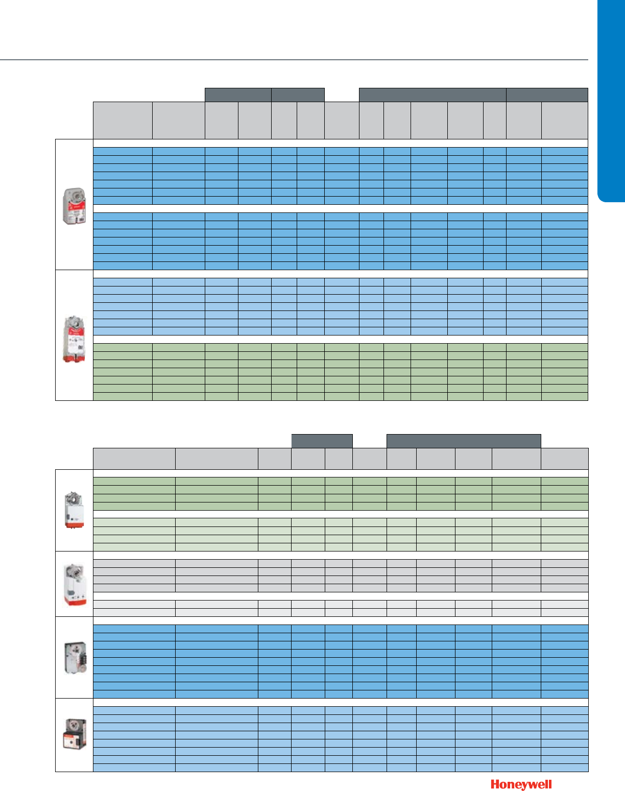
How to use this guide
All pages in this literature are constructed in one of two ways:
For unassembled product:
As a reference, pictures will represent the valves and actuators
separately; and part numbers are highlighted in blue. To order a
complete product one OS# must be chosen from each blue box.
For factory assembled product:
The complete assembled OS# will be displayed in the body of
the chart (except for cartridge cage valves, both an actuator and
valve must be chosen). Pictures will also reference the factory
assembled configuration.
Additional product information
To find more detailed information on the individual products
included in this document, go to: http://customer.honeywell.com
and use the search text box to quickly locate product specific
content.

3
TABLE OF CONTENTS
Section 1: DCA & Damper Selection
Dampers ......................................................................................8
DCA ...........................................................................................12
Fire and Smoke ..........................................................................14
Section 2: Valve Selection
Control Valve Applications .........................................................17
Control Valve Selection Criteria ..................................................18
2-Way ...................................................................................18
3-Way ...................................................................................20
Fan Coil and Zone Valves .......................................................... 22
Cartridge Cage Valves ................................................................24
Cartridge Globe Valves ...............................................................26
Control Ball Valves ½ - 3”
2-Way NPT NEMA 2 .............................................................28
2-Way NPT NEMA 3R ...........................................................30
Control Ball Valves ½ - 2 ½”
3-Way NPT NEMA 2 .............................................................32
3-Way NPT NEMA 3R .......................................................... 33
Flanged Control Ball Valves 4”- 6”
2-Way Flanged NEMA 2+3R .................................................34
3-Way Flanged NEMA 2+3R .................................................35
NPT Globe Valves ½-3”
With Dedicated Valve Actuators ............................................36
With Direct Coupled Actuators..... .........................................38
Flanged Globe Valves 2 ½ -3”
With Direct Coupled Actuators ..............................................42
Threaded and Flanged Globe Valves 2”-3”
With Tandem Linked Direct Coupled Actuators ....................46
Flanged Globe Valves 2 ½ - 3”
With Dedicated Valve Actuators ............................................48
Flanged Globe Valves 4”-6”
With Tandem Linked Direct Coupled Actuators .....................52
With Dedicated Valve Actuators ............................................54
Flanged Cage Valves 2 ½ - 6” ....................................................55
NPT Globe Valves ½ -3”
With Pneumatic Actuators .....................................................56
Flanged Globe Valves 2 ½ - 3”
With Pneumatic Actuators .....................................................60
Flanged Globe Valves 4”- 6”
With Pneumatic Actuators .....................................................64
Resilient Seat Butterfly Valves
2-Way Electrically-Actuated Control ......................................66
3-Way Electrically-Actuated Control ......................................68
2-Way Pneumatically-Actuated Control .................................72
3-Way Pneumatically-Actuated Control .................................74
Section 3: Submittal Sheets
Rectangular Volume Control Dampers
D1 Series ............................................................................. 78
D2 and D3 Series ..................................................................79
Round Volume Control Dampers
D690 .....................................................................................80
DM7600 ................................................................................81
Spring Return Direct Coupled Actuator
S03 Series (MS4103; MS4603; MS7403; MS7503; MS8103) ...82
S05 Series (MS4105; MS4605; MS7105; MS7405; MS7505;
MS8105) ..................................................................83
S05 Series (MS4105; MS7505; MS8105) ..................................84
S10 Series (MS4110; MS7510; MS8110) ..................................85
S20 Series (MS4120; MS7520; MS8120) .................................86
ML4125; ML8125 ................................................................87
Non-Spring Return Direct Coupled Actuator
ML6161; ML7161 .................................................................88
ML6174; ML7174 .................................................................89
N05 Series (MN6105; MN7505) ............................................90
N10 Series (MN6110; MN7510) ............................................91
N20 Series (MN6120; MN7220) ............................................92
N34 Series (MN6134; MN7234) .................................................93
Fire And Smoke Actuators
ML4115; ML8115 ................................................................94
MS4209F; MS4309F; MS4709F; MS4809F; MS8209F;
MS8309F ..............................................................................95
MS4120F; MS4620F; MS8120F ...........................................96
Pneumatic Damper Actuator
MP909D ................................................................................97
MP909E, H ...........................................................................98
MP913 ..................................................................................99
MP918A, B .........................................................................100
MP920 ................................................................................101
Pneumatic Valve Actuator
MP953C, D .........................................................................102
MP953E, F ..........................................................................103

4
Section 3: Submittal Sheets (CONT.)
MP958 ................................................................................104
Modutrol IV Motor
M4185; M8185 ...................................................................105
M6184; M6194 ...................................................................106
M6285 for slaving applications ............................................107
M6284; M6294 for slaving applications ...............................108
M6274; M6284; M6285; M6294 Motors with
Linear 10K Feedback ..........................................................109
M7164 ...............................................................................110
M7274; M7284; M7285; M7286; M7294 ................................111
M9164; M9174; M9182; M9184; M9194 ...........................112
M9175; M9185; M9186 ......................................................113
Q7130; Q7230; Q7330 .......................................................114
Unitary Valve Actuator
VU443; VU444; VU843; VU844 ..........................................115
VC Series Two-position .......................................................116
VC Series Proportional ........................................................117
VC Series Fail Safe Proportional ..........................................118
M6410; M7410 ...................................................................119
M6435; M7435 ...................................................................120
Direct Coupled Valve Actuator
ML6420; ML7420 ...............................................................121
ML6421; ML7421 ...............................................................122
ML6425; ML7425 ...............................................................123
ML6984 .............................................................................124
ML7984 ..............................................................................125
Unitary Valve
VU52; VU53 ........................................................................126
VU54 ...................................................................................127
VCZA; VCZB .......................................................................128
VCZM; VCZN ......................................................................129
V5852; V5862 .....................................................................130
V5853; V5863 .....................................................................131
Control Ball Valve
VBN2 ..................................................................................132
VBN3 ..................................................................................133
VBF2 ...................................................................................134
VBF3 ...................................................................................135
NPT Globe Valve
V5011F, G ...........................................................................136
V5011N ...............................................................................137
V5013N ...............................................................................138
Flanged Cage Valve
V5051A ...............................................................................139
Flanged Globe Valve
V5011A, B ..........................................................................140
V5013B, C ..........................................................................141
VGF2 ...................................................................................142
VGF2 Pressure Balanced ....................................................143
VGF3 ...................................................................................144
Resilient Seat Butterfly Valves
VFF1 ...................................................................................145
VFF2 ...................................................................................146
VFF3 ...................................................................................147
VFF6 ...................................................................................148
Damper Linkage
Q605 ...................................................................................149
Valve Linkage
Q5001 .................................................................................150
Q5020 .................................................................................151
Q5022 .................................................................................152
Section 4: Wiring Diagrams
Actuator Wiring Diagrams .......................................................154
Section 5: Guide Specifications
Guide Specifications ..............................................................170
Section 6: Accessories
Ball Joints, Push Rod Accessories ...........................................186
Control, Positioning, Feedback Accessories ............................186
Mounting Accessories ..............................................................187
Rotational Limiters, Position Indicators .....................................188
Crankarms ...............................................................................189
Shaft Adaptor Accessories .......................................................189
Enclosure Accessories .............................................................190
Q7002 Interface Modules .........................................................190
Miscellaneous Accessories ......................................................190
Accessories for Obsolete Actuators .........................................191
Valve Actuator Accessories ......................................................192
VU Series Fan Coil Actuator Accessories .................................192
Pneumatic Damper Actuator Parts and Accessories ................193
TABLE OF CONTENTS

5
Pneumatic Valve Actuator Parts and Accessories ....................196
Foot Mounted Motor Accessories ............................................198
Damper and Valve Linkage Accessories ...................................200
Section 8: Competitive Cross Reference
Direct Coupled Actuator ...........................................................202
Control Ball Valve
2-Way Valve .......................................................................220
2-Way Valve + Non-Spring Return Floating Actuator ...........221
2-Way Valve + Non-Spring Return Modulating Actuator......222
2-Way Valve + Spring Return, 2-Position Actuator ..............223
2-Way Valve + Spring Return Floating Actuator ...................224
2-Way Valve + Spring Return Modulating Actuator .............225
Threaded Globe Valves ............................................................226
Flanged Globe Valves ...............................................................227
Pneumatics ..............................................................................228
Modutrol IV Motor ....................................................................231
Section 8:
APPENDIX A:
Valve Selection & Sizing ...........................................................244
APPENDIX B:
NEMA Standard Classification Code for Enclosures ................263
APPENDIX C:
Best Practices for Low Power Control Signal Wiring ................264
Notes .......................................................................................265
Warranty...................................................................................267
TABLE OF CONTENTS

6

7
Section 1: DCA & Damper Selection
Dampers ......................................................................................8
DCA ...........................................................................................12
Fire and Smoke ..........................................................................14
SELECTION GUIDE
8
Use the following guidelines to determine the actuator quantity and
torque requirements for your damper configuration.
Determine Damper Actuator Locations
Use the following configuration to determine the amount of
actuator locations your damper will require.
Single Section ≤ 48 x 74 D2, D3
≤ 60 x 74 D1
Dampers will never ship more than 2 sections wide and one
section high.
Configuration
A single section damper will have one actuator location.
A damper that is ≥ 48 x 74 ≤ 96 x 74 will have one actuator
location. This is a two section damper jackshafted together.
A damper that is ≥ 96 x 74 ≤ 144 x 74 will have two actuator
locations. This is a two section damper jackshafted together and a
single section damper.
Exception: 3 section wide ≤ 42 SFT damper will have one actuator
location.
If damper exceeds 74” height a second row is necessary. Apply
same logic above to each row of dampers.
For dampers larger than 144 x 144, please contact the Take-Off
Service (takeoff.service@honeywell.com) for a quote and actuator
location.
Mounting
Internal Mount: Blade drive lever bracket provided only. Customer
is responsible for providing mounting hardware.
External Mount: Actuator shaft will be provided as extension pin kit
to be mounted on side or with jackshaft pre-mounted on damper.
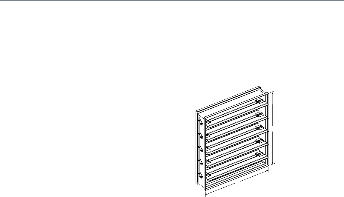
Damper And Actuator Sizing
Determining Damper Actuator Torque
Requirements
Use the following procedure to determine the required torque for
your damper.
NOTE: Damper area is measured using the H and W dimensions.
H
W
M20587
Measuring Damper Area
1. Calculate the damper area in square feet by multiplying the H
dimension by the W dimension.
2. Multiply the damper area by the lb-in. per square foot value
from Table 2 on page 9.
NOTE: The minimum lb-in. per square foot value that can
accommodate tight closeoff and no leakage applications is 5,
regardless of the value shown in the table.
3. Select the highest actuator torque value than the calculated
value.
EXAMPLE:
Low leakage, parallel blade damper:
H dimension = 48 in.
W dimension = 96 in.
Static pressure (in. w.c.) = 2 in. w.c.
Face Velocity = 1000 fpm
48 in. x 96 in. ÷ 144 = 32 sq. ft.
32 sq. ft. x 7 lb-in./sq. ft. = 244 lb-in.
where 7 lb-in./sq. ft = value from Table 2.
In this case you would need an actuator with a minimum nominal
torque of 224 lb-in.

9
DCA & DAMPER SELECTION
Damper Sizing
Dampers can be sized using two different methods; actual sizing
and nominal sizing. When actual sizing is used the damper
dimensions will be the same as the sizes ordered. For example,
when a 24 inch x 24 inch D640 damper is ordered, it will be made
such that the height is 24 inches and the width is 24 inches. When
nominal sizing is used, the damper dimensions will be ¼ inch
smaller than the sizes ordered. For example, when a 24 inch x 24
inch D640 is ordered, it will be made such that the height is 23.75
inches and the width is 23.75 inches. No special allowances are
required for dampers that are constructed of multiple sections. For
example, a damper that is 24 inch x 60 inch will be constructed of
two sections. When ordered using nominal sizing, the damper size
will be 23.75 inches high by 59.75 inches wide.
Actual sizing is commonly used when the exact size of the
opening is known or if the damper is not meant to be installed
inside an opening or duct. Nominal sizing, with its ¼ inch
undersizing is commonly used when the damper will be installed
inside an opening or duct and space is needed for positioning or
seal material.
Honeywell’s sizing default is nominal sizing. If actual sizing is
required, please make sure this is specified on the order. For more
information on ordering Honeywell dampers, please contact your
local Honeywell distributor or sales representative.
Damper And Actuator Sizing
Table 2. Approximate industry standard damper lb-in.
per sq ft value.
Face Velocity (fpm)/
Static Pressure (in. wc
Leakage Damper
Blades
500/
1
1000/
2
1500/
3
2000/
4
2500/
5
Low Parallel 4 7 10.5 12 14
Low Opposed 3 5 7.5 8.5 10
Standard Parallel 3 4.5 6.5 7 8
Standard Opposed 2 3 4.5 5 6
10
Damper And Actuator Sizing
3-V Blades - D2 and D3 Dampers
Honeywell Volume Control Dampers
feature a 3-V design that’s proven to
meet higher-level system requirements
while minimizing flow-through system loss. Blades are fabricated from
a single thickness of 16-gauge galvanized steel with three horizontal
structural V-grooves running the length of the blade.
Applications And Operation
Honeywell Volume Control Dampers are designed to control airflow
volume in medium- to high-pressure and velocity HVAC systems.
Typical applications include volume control of airflow in zoning, air
handler unit or economizer applications. Dampers are designed
to operate with a wide range of Honeywell electric and pneumatic
actuators. Operating range is from 2000 to 4000 fpm, and 2.5 to 6
inch wg. Spring return and non-spring return actuators are available
with a wide range of output torque ratings to deliver the precise
power needed for your damper application.
Certified Performance
Honeywell certifies that models D2 and D3 are licensed to bear the
AMCA Seal. The ratings shown are based on tests and procedures
performed in accordance with AMCA Publication 511 and comply with
the requirements of the AMCA Certified Ratings Programs. The AMCA
Certified Ratings Seal applies to air performance ratings only.
Durable construction details are the
cornerstone of Honeywell D1, D2 and D3
Volume Control Dampers. They feature
heavy-duty hat channel frames for
dependable operation inside ductwork.
And all models have low-profile top and
bottom frames, creating more free area
while reducing pressure loss and reducing
actuator torque.
The Right Choice
There’s a Honeywell Volume Control Damper that’s just right for your
application. The D1 airfoil extremely low leakage damper presents a
lower resistance to airflow typically used in high pressure systems.
The D2 ultra-low leakage damper keeps leakage to a minimum with
blade and jamb seals, and is designed for medium- to high-pressure
and velocity systems. The D3 low leakage damper is ruggedly built for
applications in medium pressure and velocity systems.
Blade Design
Airfoil Blades - D1 Dampers
Honeywell Airfoil Volume Control Dampers feature blades constructed
of double skin galvanized steel. This design presents a lower resistance
to airflow and has strength that is typically used in high pressure systems.
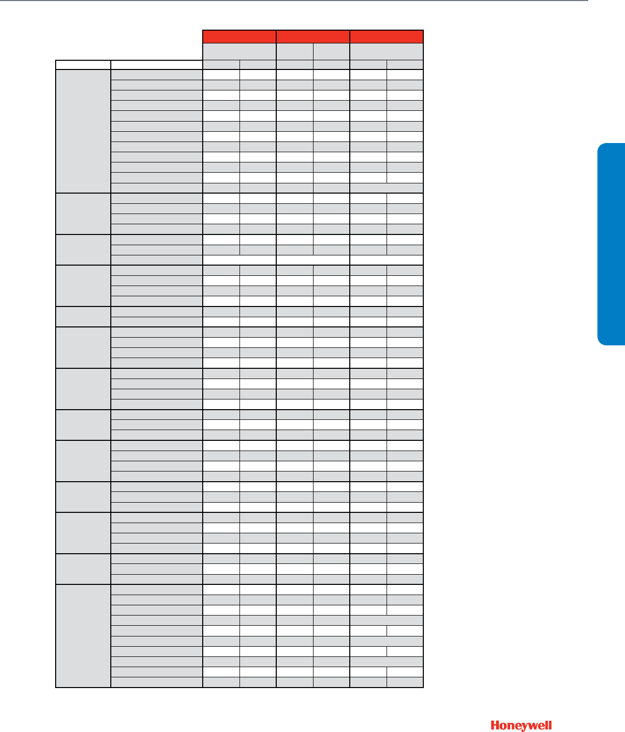
Material Frame
Gauge
Blade
Seals Bearings Axles
Linkage
Material
Flange
S — Standard
O — Optional
Galvanized
Stainless
Aluminum
16
14
12
Vinyl
Silicone
Synthetic
Bronze
Stainless
Steel
Stainless
Steel
Stainless
None
Single
Double
Reverse
D1 Airfoil Extremely Low Leakage
Volume Control Damper S O
n/a
S O O
n/a
SSOOSOSOSOOO
D2 Ultra-Low Leakage
Volume Control Damper SOOSOOSOSOOSOSOSOOO
D3 Low Leakage Volume
Control Damper S O O S O O
n/a n/a
SOOSOSOSOOO
HVAC performance depends largely upon airflow, and Honeywell Volume Control Dampers are built
for both improved airflow and heavy-duty use. Honeywell has long been the leading source for airflow
control, with Volume Control Dampers that meet AMCA-certified Air Performance Standards, the highest
established standards for commercial control dampers. Designed to minimize leakage, Honeywell
dampers will give you efficient, trouble-free operation for years to come.
For a copy of the specification sheet the D1 (63-2671) or D2 and D3 (63-2398), visit customer.honeywell.com.
Standard Rectangular Dampers
11
DCA & DAMPER SELECTION
Damper And Actuator Sizing
Standard Round Dampers Custom Dampers
Need a custom damper? Contact the Take-Off Service. Below is a
sample list of the products we frequently quote.
Custom Rectangular Dampers
Number Description
VCD34 Galvanized Insulated Airfoil Damper
VCD40 Aluminum Narrow Frame Airfoil Damper
VCD42 Aluminum Airfoil Damper (Galvanized Frame)
VCD43 Aluminum Airfoil Damper
VCD45 Aluminum thermally broken insulated Damper
Custom Round Dampers
Number Description
VCDR53 Galvanized Round Damper – to 24 inches
VCDRM53 Galvanized Round Multi-Blade Damper –
to 36 inches
Specification Take-Off Service
1. Submit your information in one of the following ways:
a) Email to takeoff.service@honeywell.com (preferred)
b) Fax toll-free to 1-877-880-3386 (local: 1-612-951-1238)
2. Include your desired turn-around time.
3. Take-Off Service staff will send you a confirmation that your email or fax was
received.
We always attempt to have your request finished as soon as possible. Please
note, however, that the quality of the submitted information largely determines the
turn-around time. We will work closely with you to ensure that we have enough
information to move forward as quickly as possible.
4. A final product schedule document will be returned to you following take-off
completion.
Included In the Final Take-Off Document
We send a comprehensive spreadsheet, which contains:
• Acompleteproductschedule
• Baseprice
• DirectionsonhowtoorderHoneywellproducts
• Linkstoproductsubmittals
• Quoteidentificationnumber
Questions
If you have questions about the Honeywell Take-Off Service, please call the dedicated
Take-Off Service phone number or email us at takeoff.service@honeywell.com.
Don’t see what you need?
Take-Off Service Contact Information:
Toll-free: 1-888-664-4092
Local: 1-612-951-1027
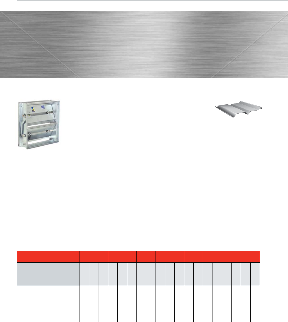
D690 and DM7600 Round Dampers. The 6” to 16” round dampers
are used in zoning systems to control airflow in a round duct. These
dampers come with neoprene and silicone seals for tight close off
and low leakage. The DM7600 includes an actuator that is already
attached to the round damper.
12
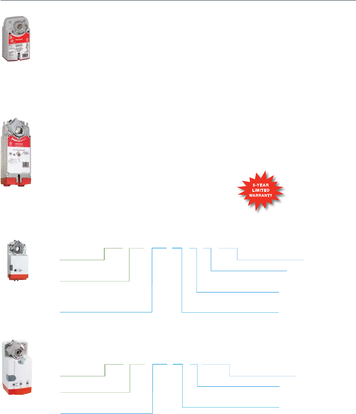
Direct Coupled Actuators
• ML Non-Spring Return
• 61 Floating, 24 Vac
• 71 Modulating, 24 Vac
Input Signal Type
Fail Safe Mode
ML 61 61
System Controlled Numbers
XXX2B
• 1 Standard
• 2 Includes Declutch Function
Declutch
• A Feedback w/Accessory
• B Standard
• D Cover w/Conduit Connections
• C Feedback w/Accessory and
Cover w/Conduit Connections
Feedback & Conduit
• 61 (4 Nm) = 35 in-lb
• 74 (8 Nm) = 70 in-lb
To rque
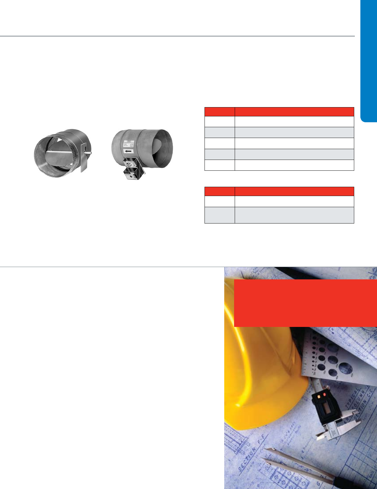
• MS Spring Return
• MN Non-Spring Return
• 41 Tw o-Position, 100-250 Vac
• 61 Floating, 24 Vac/dc
• 75 Modulating/Floating, 24 Vac/dc
• 81 Tw o-Position, 24 Vac/dc
Input Signal Type
Fail Safe Mode
MS 75 10
System Controlled Numbers
XX 2 2 A
• 0 No Internal Switches
• 2 Tw o Internal Switches
Auxiliary Switches
• 1 No Feedback
• 2 Voltage Feedback
Feedback
• A Standard Model
• H Enhanced Model
Application Type
• 03 Nm = 27 in-lb
• 05 Nm = 44 in-lb
• 10 Nm = 88 in-lb
• 20 Nm = 175 in-lb
• 34 Nm = 300 in-lb
To rque
EASY-TO-SELECT MODEL NUMBERS
MS and MN Families
Precise, reliable performance. Lasting value. Ease
of installation. Everything you look for in direct-
coupled actuators hinges on quality. And quality
engineering is what makes Honeywell’s complete
line of actuators the top performers in the industry.
Our global engineering team designs and tests
our direct-coupled actuators to exceed rigorous
global standards — and to meet Honeywell’s own
demanding life testing.
But we don’t stop there. Thanks to our continuous
improvement process, Honeywell actuators are now
easier than ever to install. You’ll also benefit from
consistent wiring regardless of signal type, common
accessories and a simplified selection process.
Honeywell’s complete line of building control
products, including valves and actuators, are
already proven in more than three million buildings
worldwide. So when you need spring or non-
spring return actuators for your damper and valve
applications, specify Honeywell. We make precision
easy.
Improve Installation Time
• Self-centeringshaftadapterprovidesmounting
flexibility and greater clamping force.
• Commonwiringamongfamiliesforeverysignal
saves installation time.
Decrease Material Cost
• Detachableaccesscoverallowsdirectwiring
without a junction box.
Reduce Inventory
• Signalmodeswitchadaptsmodelstotwo-
position, floating (tri-state), or modulating
(proportional) applications.
Increase Control and Accuracy
• Morethan200repositionstepsformodulating
models provide precise control.
DIRECT COUPLED ACTUATORS QUICK SELECTION GUIDE
Spring Return,
High Torque
Non-Spring Return,
High Torque
Non-Spring Return,
Low Torque
ML Family
Spring Return,
Low Torque
13
Power Supply Control Input/Output
Order Specification
Number
Approximate Area of
Damper (4.5 lb-in/sq. ft.)
Running
Time 24 Vac/dc 24 Vac
VA Rating
(Running)
On/Off,
Floating 0/2-10 Vdc 2-10 Vdc
Feedback
(0/2-10 Vdc)
SPDT Auxiliary
Switches
N05 Series (5 Nm, 44 lb-in)
MN6105A1011 10 90 • • 0
MN6105A1201 10 90 • • 2
MN7505A2001 10 90 • • 0
MN7505A2209 10 90 • • 2
N10 Series (10 Nm, 88 lb-in)
MN6110A1003 20 90 • • 0
MN6110A1201 20 90 • • 2
MN7510A2001 20 90 • • • • 0
MN7510A2209 20 90 • • • • 2
N20 Series (20 Nm, 175 lb-in)
MN6120A1002 39 90 • • 0
MN6120A1200 39 90 • • 2
MN7220A2007 39 90 • • • 0
MN7220A2205 39 90 • • • 2
N34 Series (34 Nm, 300 lb-in)
MN6134A1003 67 90 • • 0
MN7234A2008 67 90 • • 2
ML6161/7161 (4 Nm, 35 lb-in)
ML6161A2009 8 90 •1.8 •w/ accessory 0
ML6161A2017 8 420 •1.8 •w/ accessory 0
ML6161A2025 8 180 •1.8 •w/ accessory 0
ML6161B2024 8 90 •1.8 •0
MS6161B2032 8 420 •1.8 •0
ML6161B2073 8 180 •1.8 •0
ML6161C2007 8 90 •1.8 •w/ accessory 0
ML6161D2006 8 90 •1.8 •0
MS7161A2008 8 90 •5.4 •0
ML6174/7174 (8 Nm, 70 lb-in)
ML6174A2002 16 90 •2.4 •w/ accessory 0
ML6174A2010 16 180 •2.4 •w/ accessory 0
ML6174B2019 16 90 •2.4 •0
ML6174B2035 16 420 •2.4 •0
ML6174D2009 16 90 •2.4 •0
ML6174E2008 16 90 •2.4 •0
ML7174A2001 16 90 •5.4 •0
ML7174E2007 16 90 •5.4 •0
DCA SELECTION
1 Consult Tradeline catalog for additional models.
2 Assumes standard 1000 fpm system with parallel blade damper. Approximate square foot.
Direct Coupled Actuators
NON-SPRING RETURN
Running Time Power Supply Control Input/Output Auxiliary Knob
Order
Specification
Number
Approximate
Area of Damper
(4.5 lb-in/sq. ft.)
Drive
(seconds)
Spring
Return
(seconds)
24
Vac/dc
120-230
Vac
VA Rating
(Running) On/Off
0/2-10
Vdc,
Floating
3 kOhm
NTC,
3-Position
Feedback
(0/2-10
Vdc)
Adj.
Zero
and
Span
SPDT
Auxiliary
Switches
Internal
Minimum
Position
Potentiometer
S03 Series (3 Nm, 27 lb-in)
MS8103A1030 6 45 <25 • • 0
MS8103A1130 6 45 <25 • • 1
MS4103A1030 6 45 <25 • • 0
MS4103A1130 6 45 <25 • • 1
MS7503A2030 6 90 <25 • • • 0
MS7503A2130 6 90 <25 • • • 1
MS7403A2030 6 90 <25 • • • • 0•
S05 Series (5 Nm, 44 lb-in)
MS8105A1030 10 45 <25 • • 0
MS8105A1130 10 45 <25 • • 1
MS4105A1030 10 45 <25 • • 0
MS4105A1130 10 45 <25 • • 1
MS7505A2030 10 90 <25 • • • 0
MS7505A2130 10 90 <25 • • • 1
MS7405A2030 10 90 <25 • • • 0•
S10 Series (10 Nm, 88 lb-in)
MS8110A1008 20 45 <25 • • 0
MS8110A1206 20 45 <25 • • 2
MS4110A1002 20 45 <25 • • 0
MS4110A1200 20 45 <25 • • 2
MS7510A2008 20 90 <25 • • • 0
MS7510A2206 20 90 <25 • • • 2
MS7510H2209 20 90 <25 • • • 2
S20 Series (20 Nm, 175 lb-in)
MS8120A1007 39 45 <25 • • 0
MS8120A1205 39 45 <25 • • 2
MS4120A1001 39 45 <25 • • 0
MS4120A1209 39 45 <25 • • 2
MS7520A2007 39 90 <25 • • • 0
MS7520A2205 39 90 <25 • • • 2
MS7520H2208 39 90 <25 • • • 2
SPRING RETURN
14
Fire & Smoke Actuators
Honeywell’s complete line of two-position, fast-acting spring-
return actuators meet all of your needs for fire and smoke control
applications. All models are designed to meet the UL-555 and
UL-555S high temperature requirements for fire dampers and
combined fire and smoke dampers.
Safety First
As a life safety system component Honeywell is dedicated to
meeting the UL-555 and UL-555S requirements. The elevated
temperature test can be performed at the temperature ratings
of 250ºF or 350ºF. Honeywell only offers models at 350ºF to
meet UL-555 and UL-555S for fire and combined fire and smoke
applications to support the highest level of safety for building
occupants.
Largest Torque Range in the Industry
Honeywell’s fire and smoke actuators are available in 30, 80 and
175 lb-in with the 175 lb-in being the highest torque commercial
fire and smoke actuator available on the market today.
Key Features and Benefits
• Integralspringreturnthatensurestheproperleveloftorque
• Patenteddesignthateliminatedlimitswitches,reducingpower
consumption
• Reliableserviceinsmokecontrolsystemsrequiring
Underwriter’s Laboratories Inc. UL-555 and UL-555S
• Robustdie-castaluminumhousingensures
• Fulllifeoftwo-positionspringreturnreandsmokeactuators
rated up to 350ºF for all critical applications
• Fastactingwithamaximumspringreturntimingof15seconds
• Noaudiblenoiseduringholding
Torque Voltage Spring Direction Description Number of internal
Auxiliary Switch Model Number
30 lb-in (3.4 Nm)
120 Vac CCW
Fire and smoke, fast acting,
two position spring return, UL-555
and UL-555S ratings up to 350ºF
External* ML4115A1009
CW External* ML4115B1008
230 Vac CCW External* ML4115C1007
CW External* ML4115D1006
24 Vac CCW External* ML8115A1005
CW External* ML8115B1004
80 lb-in (9 Nm)
120 Vac CW
Fire and smoke, fast acting,
two position spring return, UL-555
and UL555S ratings up to 350ºF
External* MS4209F1007
CCW External* MS4309F1005
230 Vac CW External* MS4709F1014
CCW External* MS4809F1012
24 Vac CW External* MS8209F1003
CCW External* MS8309F1001
175 lb-in (20 Nm)
120 Vac
Reversible Design
Fire and smoke, fast acting,
two position spring return, UL-555 and
UL-555S ratings up to 350ºF
0 MS4120F1006
2 SPST MS4120F1204
230 Vac 0 MS4620F1005
2 SPST MS4620F1203
24 Vac 0 MS8120F1002
2 SPST MS8120F1200
Note: Honeywell's spring return fire and smoke actuators are designed to pass UL-555 and UL-555S 350ºF requirements. They are not designed for HVAC applications. UL-555
and UL-555S requires that all new construction fire and smoke damper jobs have the actuator assembled and tested at the damper manufacturer. A like for like retrofit replacement
or technically equal UL-555 and UL-555S approved device is recommended.

15
VALVE SELECTION
Section 2: Valve Selection
Control Valve Applications .........................................................17
Control Valve Selection Criteria ..................................................18
2-Way ...................................................................................18
3-Way ...................................................................................20
Fan Coil and Zone Valves .......................................................... 22
Cartridge Cage Valves ................................................................24
Cartridge Globe Valves ...............................................................26
Control Ball Valves ½ - 3”
2-Way NPT NEMA 2 .............................................................28
2-Way NPT NEMA 3R ...........................................................30
Control Ball Valves ½ - 2 ½”
3-Way NPT NEMA 2 .............................................................32
3-Way NPT NEMA 3R .......................................................... 33
Flanged Control Ball Valves 4”- 6”
2-Way Flanged NEMA 2+3R .................................................34
3-Way Flanged NEMA 2+3R .................................................35
NPT Globe Valves ½-3”
With Dedicated Valve Actuators ............................................36
With Direct Coupled Actuators..... .........................................38
Flanged Globe Valves 2 ½ -3”
With Direct Coupled Actuators ..............................................42
Threaded and Flanged Globe Valves 2”-3”
With Tandem Linked Direct Coupled Actuators ....................46
Flanged Globe Valves 2 ½ - 3”
With Dedicated Valve Actuators ............................................48
Flanged Globe Valves 4”-6”
With Tandem Linked Direct Coupled Actuators .....................52
With Dedicated Valve Actuators ............................................54
Flanged Cage Valves 2 ½ - 6” ....................................................55
NPT Globe Valves ½ -3”
With Pneumatic Actuators .....................................................56
Flanged Globe Valves 2 ½ - 3”
With Pneumatic Actuators .....................................................60
Flanged Globe Valves 4”- 6”
With Pneumatic Actuators .....................................................64
Resilient Seat Butterfly Valves
2-Way Electrically-Actuated Control ......................................66
3-Way Electrically-Actuated Control ......................................68
2-Way Pneumatically-Actuated Control .................................72
3-Way Pneumatically-Actuated Control .................................74

16
17
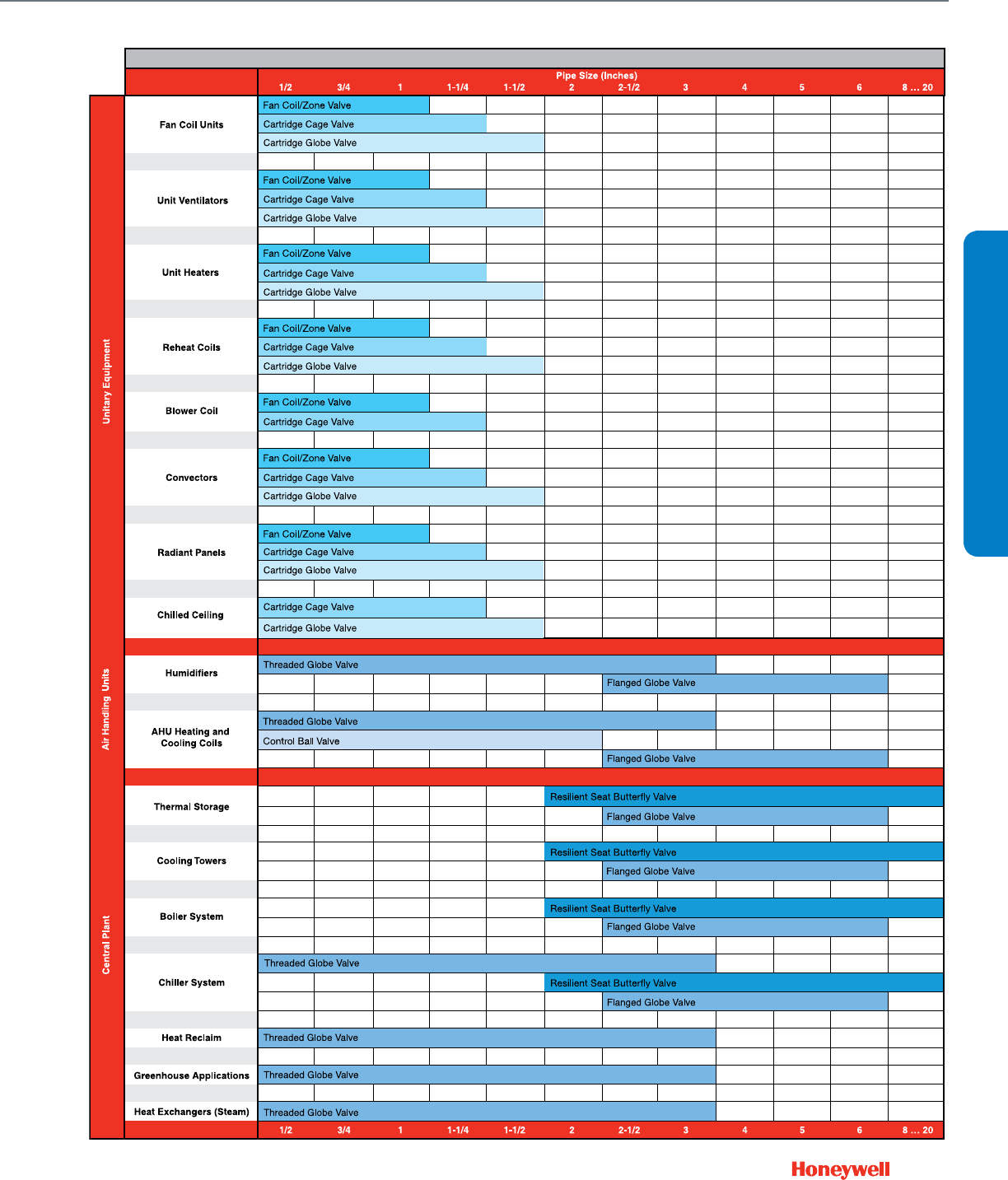
Control Valve Applications
Fan Coil/Zone Valve
Control Valve Applications
VALVE SELECTION
18
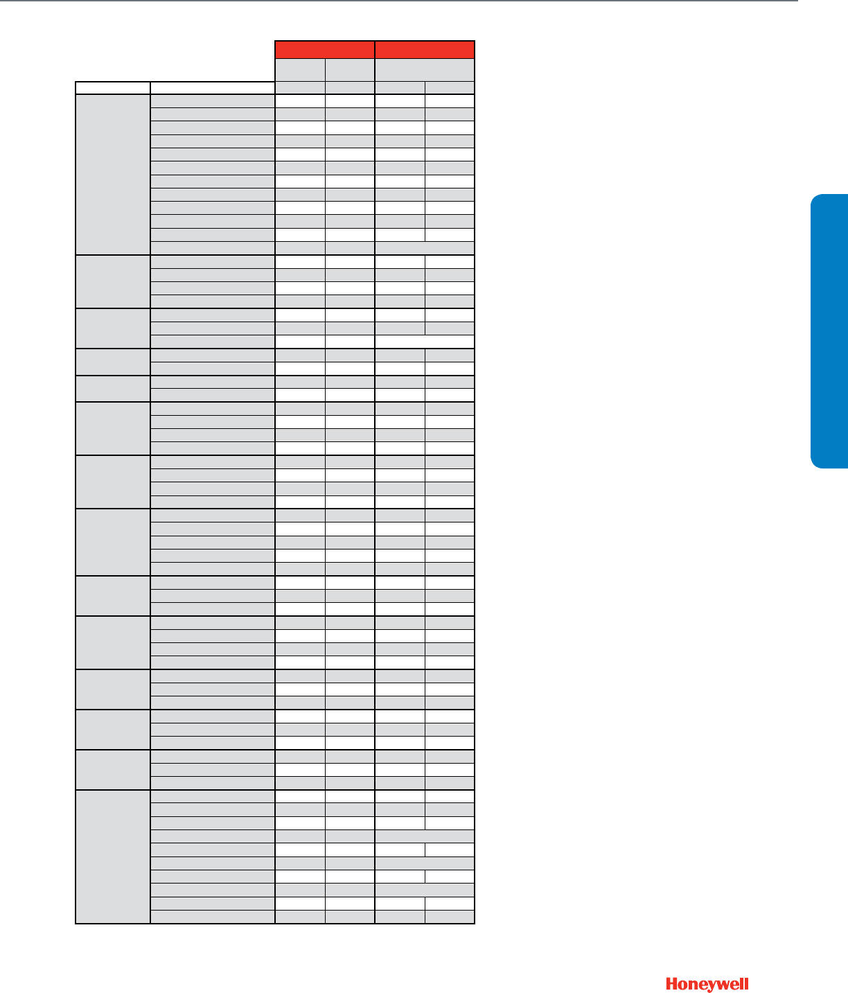
Control Valve Selection Criteria
2-Way
Unitary Globe
Fan Coil Cartridge
Cage
Cartridge
Globe Threaded Flanged
Attribute Specification VU52 VU53 VCzA/B
V58x2
V5011N... V5011F V5011G V5011A V5011B VGF2xS
Pipe Size
1/2"
[DN15]
• • • • •
3/4" [DN20] • • • • •
1"
[DN25]
• • • •
1 1/4" [DN32] • •
1 1/2" [DN40] •
2" [DN50] •
2 1/2"
[DN65]
••• •
3" [DN80] ••• •
4"
[DN100]
•••
5" [DN125] •••
6" [DN150] •••
Other (maximum size)
Pipe Fittings
Sweat • • • •
NPT Internal Thread •••••••
Inverted Flare • • •
ANSI Flange •••
Static Pressure
ANSI 125/150
•
•••••
ANSI 250/300 •
Other 300 psi 300 psi 230 psi
Media
Chilled Water ••••••••••
Hot Water • • • •
•
•••••
Low Pressure Steam N1, N3 •••••
High Pressure Steam
N2
••
Flow Capacity, Cv Multiple ratings per pipe size • • • •
•
••
One rating/size above 1/2"
•
•••••
Valve Action
Direct Acting ****
N1, N2
••• •
Reverse Acting ***** • •
N3
•
Rotary N.O. •
Rotary N.C. •
Flow Characteristic
Equal Percentage •
•
• • • •
Modified Equal Percentage •
Linear •
•
••
Quick Open • • •
Close-off
pressure***
High** (100 psid minimum) •
Medium (40 psid minimum) • •
Varies with actuator • •
•
•••••
Maximum Seat
Leakage
ANSI Class III (0.10% Cv max.) 0.02%
0.05%
•
ANSI Class IV (0.01% Cv max.) • •
Bubble-tight design •
Other (see product data literature) 33 mL/m 0.5% 0.5%
Rangeability
High (50:1 minimum)
N/A
•
•
•••••
Medium* (15~50:1) •
Low (under 15:1)
Trim
Brass, plated brass, bronze
N3
• • •
Brass plug /Stainless seat
N1
Stainless Steel
N2
••
Resilient materials • • • •
In-line
Serviceability
Cartridge • • • •
Packing
•
•••••
Rebuild
•
••• •
Actuation Options
Electronic Modulating • •
•
•••••
Tri-state floating • •
•
•••••
Pulse Width Modulation •
2-position low voltage • • • o
•
•••••
2-position line voltage • • •
•
•••••
Electric Spring Return • • •
•
•••••
Electronic Fail Safe •
Pneumatic, low pressure •
•
•••••
Pnuematic bidirectional (Hi-Pr)
Pnuematic spring return (Hi-Pr)
Notes * Best used with supply water reset from outdoor air temperature.
** Can dead-head pumps. Use with VFD-controlled pumps with maximum pressure cut-out
*** Maximum operating differential pressure. Static close-off pressure may be higher. Maximum pressure for quiet service may be less.
**** Stem down to close
***** Stem up to close
19
VALVE SELECTION
Globe Control Ball Butterfly
Pressure-Balanced Threaded Flanged Resilient Seat
Attribute Specification V5862A3 VGF2xP VBN2 VBF2 VFF1 VFF2
Pipe Size
1/2"
[DN15]
•
3/4" [DN20] •
1"
[DN25]
• •
1 1/4" [DN32] • •
1 1/2" [DN40] • •
2" [DN50] • • •
2 1/2"
[DN65]
• • • •
3" [DN80] • • • •
4"
[DN100]
• • • •
5" [DN125] • • • •
6" [DN150] • • • •
Other (maximum size) 20" [DN500]
Pipe Fittings
Sweat
NPT Internal Thread • •
Inverted Flare
ANSI Flange • • • •
Static Pressure
ANSI 125/150 • •
ANSI 250/300
Other 230 psi 360 psi 250 psi
Media
Chilled Water • • • • • •
Hot Water • • • • • •
Low Pressure Steam •
High Pressure Steam •
Flow Capacity, Cv Multiple ratings per pipe size • • •
One rating/size above 1/2" • • •
Valve Action
Direct Acting **** • •
Reverse Acting *****
Rotary N.O. o o •o
Rotary N.C. • • •
Flow Characteristic
Equal Percentage •
Modified Equal Percentage • • • •
Linear • •
Quick Open
Close-off
pressure***
High** (100 psid minimum) • • • • • •
Medium (40 psid minimum) • •
Varies with actuator
Maximum Seat
Leakage
ANSI Class III (0.10% Cv max.)
ANSI Class IV (0.01% Cv max.) • • • • • •
Bubble-tight design • •
Other (see product data literature)
Rangeability
High (50:1 minimum) • • • •
Medium* (15~50:1) o
Low (under 15:1) • •
Trim
Brass, plated brass, bronze •
Brass plug /Stainless seat
Stainless Steel • • • •
Resilient materials • •
In-line
Serviceability
Cartridge
Packing • • • •
Rebuild •
Actuation Options
Electronic Modulating • • • • • •
Tri-state floating • • • • • •
Pulse Width Modulation
2-position low voltage • • • Limited
2-position line voltage •o o • •
Electric Spring Return • • • • Limited
Electronic Fail Safe
Pneumatic, low pressure •Limited
Pnuematic bidirectional (Hi-Pr) • •
Pnuematic spring return (Hi-Pr) • •
Notes * Best used with supply water reset from outdoor air temperature.
** Can dead-head pumps. Use with VFD-controlled pumps with maximum pressure cut-out
*** Maximum operating differential pressure. Static close-off pressure may be higher. Maximum pressure for quiet service may be less.
**** Stem down to close
***** Stem up to close
Control Valve Selection Criteria
2-Way

20
Control Valve Selection Criteria
3-Way
Unitary Globe
Fan Coil Cartridge
Cage Cartridge Globe Threaded Flanged
Attribute Specification VU54 VCzM/N V58x3
V5863A3
V5013N... V5013B V5013C VGF3xLD VGF3xEM
Pipe Size
1/2"
[DN15]
• • • •
3/4" [DN20] • • • •
1"
[DN25]
• • • •
1 1/4" [DN32] • • •
1 1/2" [DN40] • •
2" [DN50] •
2 1/2"
[DN65]
• • •
3" [DN80] • • •
4"
[DN100]
• • • •
5" [DN125] • • • •
6" [DN150] • • • •
Other (maximum size)
Pipe Fittings
Sweat • • •
NPT Internal Thread • • • • •
Inverted Flare • •
ANSI Flange • • • •
Static Pressure
ANSI 125/150 • • • • •
ANSI 250/300 • •
Other 300 psi 300 psi 230 psi 230 psi
Media Chilled Water • • • • • • • • •
Hot Water • • • • • • • • •
Flow Capacity, Cv Multiple ratings per pipe size • • • • •
One rating/size above 1/2" • • • • •
Valve Action
Mixing A-B-AB porting • • • • •
Mixing A-AB-B porting • •
Diverting AB-B-A porting • •
Diverting A-AB-B porting •
A-port Flow
Characteristic
Equal Percentage • • •
Modified Equal Percentage •
Linear • • • • •
Quick Open • •
B-port Flow
Characteristic
Modified Equal Percentage
Linear •
•
• • • •
Linear, Reduced Cv • •
Total Constant Flow • • • • • •
Quick Open •
Close-off
pressure***
High (60 psid minimum) • • •
Medium (30 psid minimum) •
Varies with actuator • • • • • •
Maximum
Seat
Leakage**
ANSI Class III (0.10% Cv max.) • •
•
•
ANSI Class IV (0.01% Cv max.) • •
Bubble-tight design •
Other (see product data literature) 33 mL/m A = 0.5%
Rangeability
High (50:1 minimum)
N/A
• • • • • • •
Medium* (15~50:1) •
Low (under 15:1)
Trim
Brass, plated brass, bronze • • • •
Stainless Steel o • •
Resilient materials • • •
In-line
Serviceability
Cartridge • • •
Packing •
•
• • • •
Rebuild • • •
Actuation Options
Electronic Modulating • • • • • • • •
Tri-state floating • • • • • • • •
Pulse Width Modulation •
2-position low voltage • • o o • • • • •
2-position line voltage • •
•
• • • •
Electric Spring Return • • •
•
• • • •
Electronic Fail Safe •
Pneumatic, low pressure •
•
• • • •
Pnuematic bidirectional (Hi-Pr)
Pnuematic spring return (Hi-Pr)
Notes * Best used with supply water reset from outdoor air temperature.
** A port specification
*** A-port maximum operating differential pressure. Static close-off pressure may be higher. Maximum pressure for quiet service may be less.
**** Stem down to close
***** Stem up to close
"Limited" = not available in large sizes
21
Control Ball Butterfly
Threaded Flanged Resilient Seat
Attribute Specification VBN3 VBF3 VFF3
VFF6
Pipe Size
1/2"
[DN15]
•
3/4" [DN20] •
1"
[DN25]
•
1 1/4" [DN32] •
1 1/2" [DN40] •
2" [DN50] • •
•
2 1/2"
[DN65]
• • •
3" [DN80] • •
4"
[DN100]
• • •
5" [DN125] • • •
6" [DN150] • • •
Other (maximum size) 20" [DN500]
Pipe Fittings
Sweat
NPT Internal Thread •
Inverted Flare
ANSI Flange • • •
Static Pressure
ANSI 125/150 •
ANSI 250/300
Other 360 psi 250 psi
Media Chilled Water • • • •
Hot Water • • • •
Flow Capacity, Cv Multiple ratings per pipe size • •
One rating/size above 1/2" • •
Valve Action
Mixing A-B-AB porting • • •
Mixing A-AB-B porting •
Diverting AB-B-A porting •o•
Diverting A-AB-B porting •
A-port Flow
Characteristic
Equal Percentage
Modified Equal Percentage • • • •
Linear
Quick Open
B-port Flow
Characteristic
Modified Equal Percentage • •
Linear
Linear, Reduced Cv • •
Total Constant Flow
Quick Open
Close-off
pressure***
High (60 psid minimum) • • •
Medium (30 psid minimum) • • •
Varies with actuator
Maximum
Seat
Leakage**
ANSI Class III (0.10% Cv max.)
ANSI Class IV (0.01% Cv max.) •A-port • •
Bubble-tight design • •
Other (see product data literature) B-port
Rangeability
High (50:1 minimum) • •
Medium* (15~50:1) o
Low (under 15:1) • •
Trim
Brass, plated brass, bronze •
Stainless Steel •
Resilient materials • •
In-line
Serviceability
Cartridge
Packing • •
Rebuild •
Actuation Options
Electronic Modulating • • • •
Tri-state floating • • • •
Pulse Width Modulation
2-position low voltage • • Limited
2-position line voltage o o • •
Electric Spring Return • • Limited
Electronic Fail Safe
Pneumatic, low pressure Limited
Pnuematic bidirectional (Hi-Pr) • •
Pnuematic spring return (Hi-Pr) • •
Notes * Best used with supply water reset from outdoor air temperature.
** A port specification
*** A-port maximum operating differential pressure. Static close-off pressure may be higher. Maximum pressure for quiet service may be less.
**** Stem down to close
***** Stem up to close
"Limited" = not available in large sizes
VALVE SELECTION
Control Valve Selection Criteria
3-Way
22
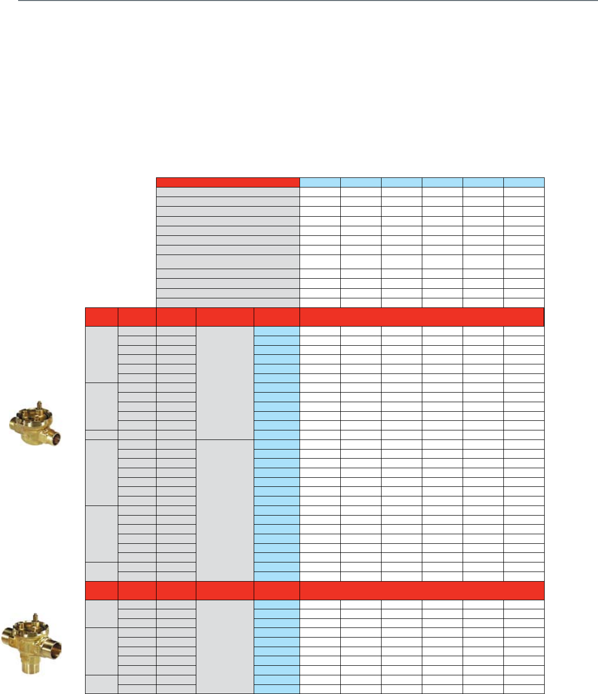
Actuator O.S. Number VU443A1008 VU443A1024 VU443A1115 VU443A1180 VU443E1009 VU444A1007
Power Supply Voltage 120 Vac 208 Vac 230 Vac 120 Vac 120 Vac 120 Vac
Frequency 60 Hz 60 Hz 50 / 60 Hz 60 Hz 60 Hz 60 Hz
Power (60 Hz) 5 VA 5 VA 5 VA 5 VA 5 VA 5 VA
Control 2-Position SPST ••••••
Aux Switch SPST 2.2 A/120 Vac
Maximum Timing Seconds @ 60 Hz, Driving 15 15 15 15 15 15
Fail Safe 666666
Fail Safe Action N.C. N.C. N.C. N.C. N.C. 2-way N.O.
3-way N.O./N.C.
Electrical Connections Leadwire Length, in. 618 6 6 18 6
1/2 in. flexible conduit hole ••••••
Manual Override (on power failure, auto reset) ••••••
Nickel plated motors Condensing Atmosphere •
Valve Size
(inches)
Connection
Type
Flow Capacity
(Cv)
Valve
Action
Valve O.S.
Number 2-way Valves Close-off
2-Way
1/2"
f NPT 1.0 Cv
Normally Open
VU52N1027 50
Sweat 1.0 Cv VU52S2002 50
f NPT 2.5 Cv VU52N1035 30
Sweat 2.5 Cv VU52S2010 30
f NPT 3.5 Cv VU52N1019 20
Sweat 3.5 Cv VU52S2028 20
3/4"
f NPT 3.5 Cv VU52SN1076 20
Sweat 3.5 Cv VU52S2036 20
Sweat 5.0 Cv VU52S2044 15
f NPT 8.0 Cv VU52N1001 10
Sweat 8.0 Cv VU52S2051 10
1'' f NPT 8.0 Cv VU52N1068 10
1/2"
f NPT 1.0 Cv
Normally Closed
VU53N1041 50 50 50 50 50
Sweat 1.0 Cv VU53S2018 50 50 50 50 50
f NPT 2.5 Cv VU53N1058 30 30 30 30 30
Sweat 2.5 Cv VU53S2026 30 30 30 30 30
Inverted Flare 3.5 Cv VU53F1024 20 20 20 20 20
f NPT 3.5 Cv VU53N1009 20 20 20 20 20
Sweat 3.5 Cv VU53S2034 20 20 20 20 20
3/4"
f NPT 3.5 Cv VU53N1033 20 20 20 20 20
Sweat 3.5 Cv VU53S2042 20 20 20 20 20
f NPT 5.0 Cv VU53N1066 15 15 15 15 15
Sweat 5.0 Cv VU53S2075 15 15 15 15 15
f NPT 8.0 Cv VU53N1017 10 10 10 10 10
Sweat 8.0 Cv VU53S2059 10 10 10 10 10
1" f NPT 8.0 Cv VU53N1026 10 10 10 10 10
Sweat 8.0 Cv VU53S2000 10 10 10 10 10
Valve Size
(inches)
Flow Capacity
(Cv)
Valve
Action
Connection
Type
Valve O.S.
Number 3-way Valves Close-off
3-Way
1/2"
Inverted Flare 4.0 Cv
Mixing
VU54F1022 20
f NPT 4.0 Cv VU54N1007 20
Sweat 4.0 Cv VU54S2008 10
3/4"
f NPT 4.0 Cv VU54N1031 20
f NPT 5.0 Cv VU54N1049 15
Sweat 5.0 Cv VU54S2057 15
f NPT 7.0 Cv VU54N1015 10
Sweat 7.0 Cv VU54S2016 10
1" f NPT 7.0 Cv VU54N1023 10
Sweat 7.0 Cv VU54S2024 10
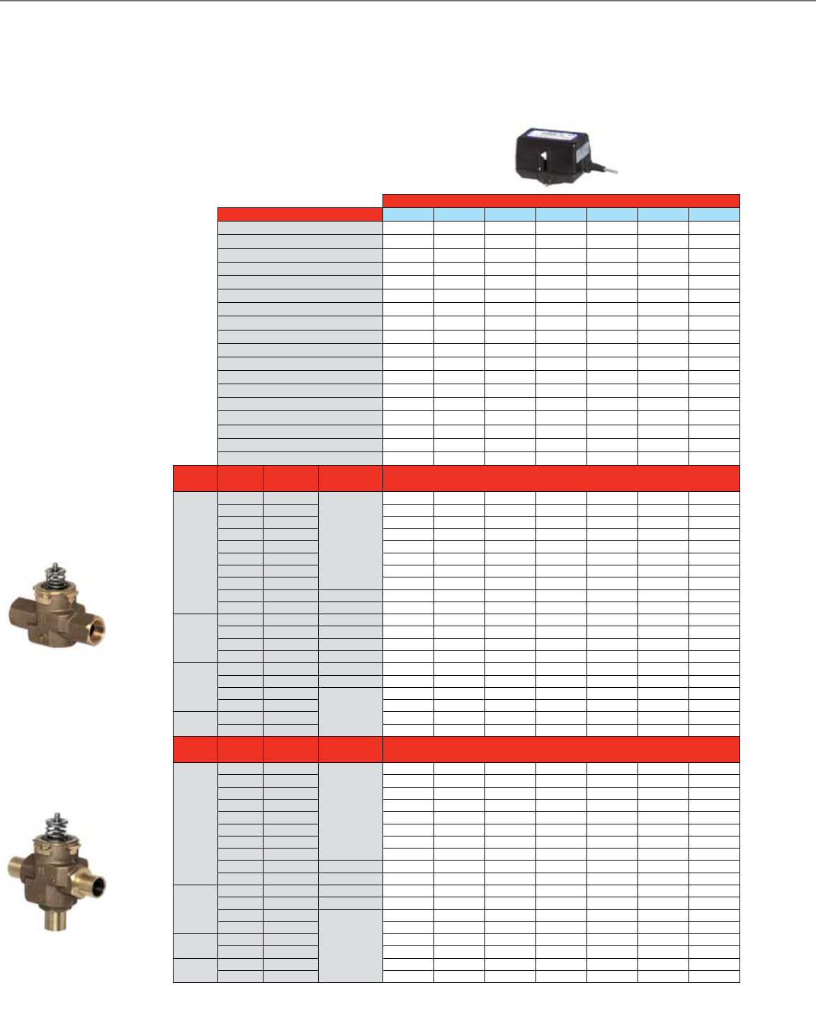
Fan Coil and Zone Valves
Honeywell Fan Coil and Zone Valves family (VU Series) have
withstood the test of time as a reliable and dependable product.
With a Cv range suitable for anything from radiator panels to fan
coil units and both normally open and normally closed spring
return functions, it’s easy to select a model that fits your needs.
Additionally you can choose between line voltage or low voltage
actuators as well as three different types of pipe fittings: Female
NPT, Sweat, and Inverted flare.
Common Features
• Maximum static water pressure: 300 psig
• Ambient temp range: 34-104°F
(at 34-200°F medium temperature)
• 3-way valve is diverting type
• Long service life with patented ball seal
• Quick opening / soft closing for optimal
2-position control
• Manual opener
23
Actuator O.S. Number VU444A1098 VU444A1106 VU444A1155 VU843A1004 VU843A1087 VU844A1003 VU844A1060
Power Supply Voltage 227 Vac 230 Vac 120 Vac 24 Vac 24 Vac 24 Vac 24 Vac
Frequency 60 Hz 50 / 60 Hz 60 Hz 50 / 60 Hz 50 / 60 Hz 50 / 60 Hz 50 / 60 Hz
Power (60 Hz) 5 VA 5 VA 5 VA 0.32 A 0.32 A 0.32 A 0.32 A
Control 2-Position SPST •••••••
Aux Switch SPST
Maximum Timing Seconds @ 60 Hz, Driving 15 15 15 15 15 15 15
Fail Safe 6666666
Fail Safe Action 2-way N.O.
3-way N.O./N.C.
2-way N.O.
3-way N.O./N.C.
2-way N.O.
3-way N.O./N.C. N.C. N.C. 2-way N.O.
3-way N.O./N.C.
2-way N.O.
3-way N.O./N.C.
Electrical Connections Leadwire Length, in. 18666666
1/2 in. flexible conduit hole •••••••
Manual Override (on power failure, auto reset) •••••••
Nickel plated motors Condensing Atmosphere •••
Valve Size
(inches)
Connection
Type
Flow Capacity
(Cv)
Valve
Action
Valve O.S.
Number 2-way Valves Close-off
2-Way
1/2"
f NPT 1.0 Cv
Normally Open
VU52N1027 50 50 50 50 50
Sweat 1.0 Cv VU52S2002 50 50 50 50 50
f NPT 2.5 Cv VU52N1035 30 30 30 30 30
Sweat 2.5 Cv VU52S2010 30 30 30 30 30
f NPT 3.5 Cv VU52N1019 20 20 20 20 20
Sweat 3.5 Cv VU52S2028 20 20 20 20 20
3/4"
f NPT 3.5 Cv VU52SN1076 20 20 20 20 20
Sweat 3.5 Cv VU52S2036 20 20 20 20 20
Sweat 5.0 Cv VU52S2044 15 15 15 15 15
f NPT 8.0 Cv VU52N1001 10 10 10 10 10
Sweat 8.0 Cv VU52S2051 10 10 10 10 10
1" f NPT 8.0 Cv VU52N1068 10 10 10 10 10
1/2"
f NPT 1.0 Cv
Normally Closed
VU53N1041 50 50
Sweat 1.0 Cv VU53S2018 50 50
f NPT 2.5 Cv VU53N1058 30 30
Sweat 2.5 Cv VU53S2026 30 30
Inverted Flare 3.5 Cv VU53F1024 20 20
f NPT 3.5 Cv VU53N1009 20 20
Sweat 3.5 Cv VU53S2034 20 20
3/4"
f NPT 3.5 Cv VU53N1033 20 20
Sweat 3.5 Cv VU53S2042 20 20
f NPT 5.0 Cv VU53N1066 15 15
Sweat 5.0 Cv VU53S2075 15 15
f NPT 8.0 Cv VU53N1017 10 10
Sweat 8.0 Cv VU53S2059 10 10
1" f NPT 8.0 Cv VU53N1026 10 10
Sweat 8.0 Cv VU53S2000 10 10
Valve Size
(inches)
Flow Capacity
(Cv)
Valve
Action
Connection
Type
Valve O.S.
Number 3-way Valves Close-off
3-Way
1/2"
Inverted Flare 4.0 Cv
Mixing
VU54F1022 20 20 20 20 20
f NPT 4.0 Cv VU54N1007 20 20 20 20 20
Sweat 4.0 Cv VU54S2008 10 10 10 10 10
3/4"
f NPT 4.0 Cv VU54N1031 20 20 20 20 20
f NPT 5.0 Cv VU54N1049 15 15 15 15 15
Sweat 5.0 Cv VU54S2057 15 15 15 15 15
f NPT 7.0 Cv VU54N1015 10 10 10 10 10
Sweat 7.0 Cv VU54S2016 10 10 10 10 10
1" f NPT 7.0 Cv VU54N1023 10 10 10 10 10
Sweat 7.0 Cv VU54S2024 10 10 10 10 10
ValVe Selection
Fan Coil and Zone Valves
24
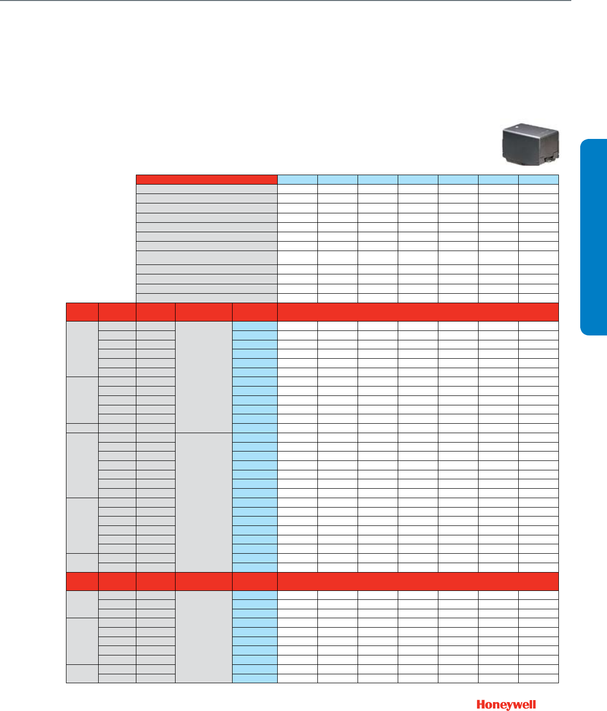
Cartridge Cage Valves
Non-Fail Safe
Actuator O.S. Number VC6834ZZ11 VC6934ZZ11 VC7934ZZ11 VC4011ZZ11 VC4013ZZ11 VC8114ZZ11 VC8714ZZ11
Power Supply Voltage 24 Vac 24 Vac 24 Vac 100-130 Vac 200-240 Vac 24 Vac 24 Vac
Frequency 50/60 Hz 50/60 Hz 50/60 Hz 50/60 Hz 50/60 Hz 60 Hz 60 Hz
Power 6 VA 6 VA 6 VA 6 VA 6 VA 6 VA 6 VA
Control 2-10 Vdc •
4-20 mA (external 500 Ohm resistor) •
Floating • •
2-Position SPDT • •
2-Position SPST ••••
Pulse Width Modulation
Aux Switch SPDT Class II 2.2 A 2.2 A
Fail Safe Action Stay in Place Stay in Place Stay in Place Stay in Place Stay in Place Stay in Place Stay in Place
Reversible Operation Wiring Change • •
DIP Switch
Stroke Timing Seconds @ 60 Hz (Drive) 120 120 120 6 6 6 6
Fail Safe
Electrical Connection Cable length, in. 60 60 60 39.4 39.4 60 60
Plenum-rated cable ••• ••
1/2 in. flexible conduit adapter ••• ••
Valve Size
(inches)
Connection
Type
Flow Capacity
(Cv)
Flow
Characteristic Valve O.S. Number
2-Way
1/2"
f NPT 0.7
Modified Equal %
VCZBB3500 VCZBB3500 VCZBB3500
Sweat 0.7 VCZAA3500 VCZAA3500 VCZAA3500
f NPT 1.3 VCZBB3600 VCZBB3600 VCZBB3600
Sweat 1.3 VCZAA3600 VCZAA3600 VCZAA3600
Sweat 1.9 VCZAA3800 VCZAA3800 VCZAA3800
f NPT 1.9 VCZBB3800 VCZBB3800 VCZBB3800
Sweat 2.3 VCZAA3400 VCZAA3400 VCZAA3400
f NPT 2.3 VCZBB3400 VCZBB3400 VCZBB3400
f NPT 3.5 Linear VCZBB3100 VCZBB3100 VCZBB3100 VCZBB1100 VCZBB1100 VCZBB1100 VCZBB1100
Sweat 3.5 Linear VCZAA3100 VCZAA3100 VCZAA3100 VCZAA1100 VCZAA1100 VCZAA1100 VCZAA1100
3/4"
f NPT 3.9 Modified Equal % VCZAL3400 VCZAL3400 VCZAL3400
Sweat 3.9 Modified Equal % VCZAM3400 VCZAM3400 VCZAM3400
f NPT 4.7 Linear VCZAL3100 VCZAL3100 VCZAL3100 VCZAL1100 VCZAL1100 VCZAL1100 VCZAL1100
Sweat 4.7 Linear VCZAM3100 VCZAM3100 VCZAM3100 VCZAM1100 VCZAM1100 VCZAM1100 VCZAM1100
1"
f NPT 4.2 Modified Equal % VCZAR3400 VCZAR3400 VCZAR3400
Sweat 4.2 Modified Equal % VCZAS3400 VCZAS3400 VCZAS3400
f NPT 6.6
Linear
VCZAR3100 VCZAR3100 VCZAR3100 VCZAR1100 VCZAR1100 VCZAR1100 VCZAR1100
Sweat 6.6 VCZAS3100 VCZAS3100 VCZAS3100 VCZAS1100 VCZAS1100 VCZAS1100 VCZAS1100
1-1/4" f NPT 7VCZBD3100 VCZBD3100 VCZBD3100 VCZBD1100 VCZBD1100 VCZBD1100 VCZBD1100
Sweat 7VCZBE3100 VCZBE3100 VCZBE3100 VCZBE1100 VCZBE1100 VCZBE1100 VCZBE1100
Valve Size
(inches)
Connection
Type
Flow Capacity
(Cv)
Flow
Characteristic Valve O.S. Number
3-Way Mixing/ Diverting
1/2"
f NPT 0.7
Modified Equal %
VCZNB7500 VCZNB7500 VCZNB7500
Sweat 0.7 VCZMA7500 VCZMA7500 VCZMA7500
f NPT 1.5 VCZNB7600 VCZNB7600 VCZNB7600
Sweat 1.5 VCZMA7600 VCZMA7600 VCZMA7600
f NPT 1.5 VCZNB7800 VCZNB7800 VCZNB7800
Sweat 1.5 VCZMA7800 VCZMA7800 VCZMA7800
f NPT 2.7 VCZNB7400 VCZNB7400 VCZNB7400
Sweat 2.7 VCZMA7400 VCZMA7400 VCZMA7400
f NPT 3.7 Linear VCZNB7100 VCZNB7100 VCZNB7100 VCZNB6100 VCZNB6100 VCZNB6100 VCZNB6100
Sweat 3.7 Linear VCZMA7100 VCZMA7100 VCZMA7100 VCZMA6100 VCZMA6100 VCZMA6100 VCZMA6100
3/4"
f NPT 4.2 Modified Equal % VCZMK7400 VCZMK7400 VCZMK7400
Sweat 4.2 Modified Equal % VCZML7400 VCZML7400 VCZML7400
f NPT 6.6
Linear
VCZMK7100 VCZMK7100 VCZMK7100 VCZMK6100 VCZMK6100 VCZMK6100 VCZMK6100
Sweat 6.6 VCZML7100 VCZML7100 VCZML7100 VCZML6100 VCZML6100 VCZML6100 VCZML6100
1" f NPT 8.3 VCZMR7100 VCZMR7100 VCZMR7100 VCZMR6100 VCZMR6100 VCZMR6100 VCZMR6100
Sweat 8.3 VCZMS7100 VCZMS7100 VCZMS7100 VCZMS6100 VCZMS6100 VCZMS6100 VCZMS6100
1-1/4" f NPT 9VCZND7100 VCZND7100 VCZND7100 VCZND6100 VCZND6100 VCZND6100 VCZND6100
Sweat 9VCZNE7100 VCZNE7100 VCZNE7100 VCZNE6100 VCZNE6100 VCZNE6100 VCZNE6100
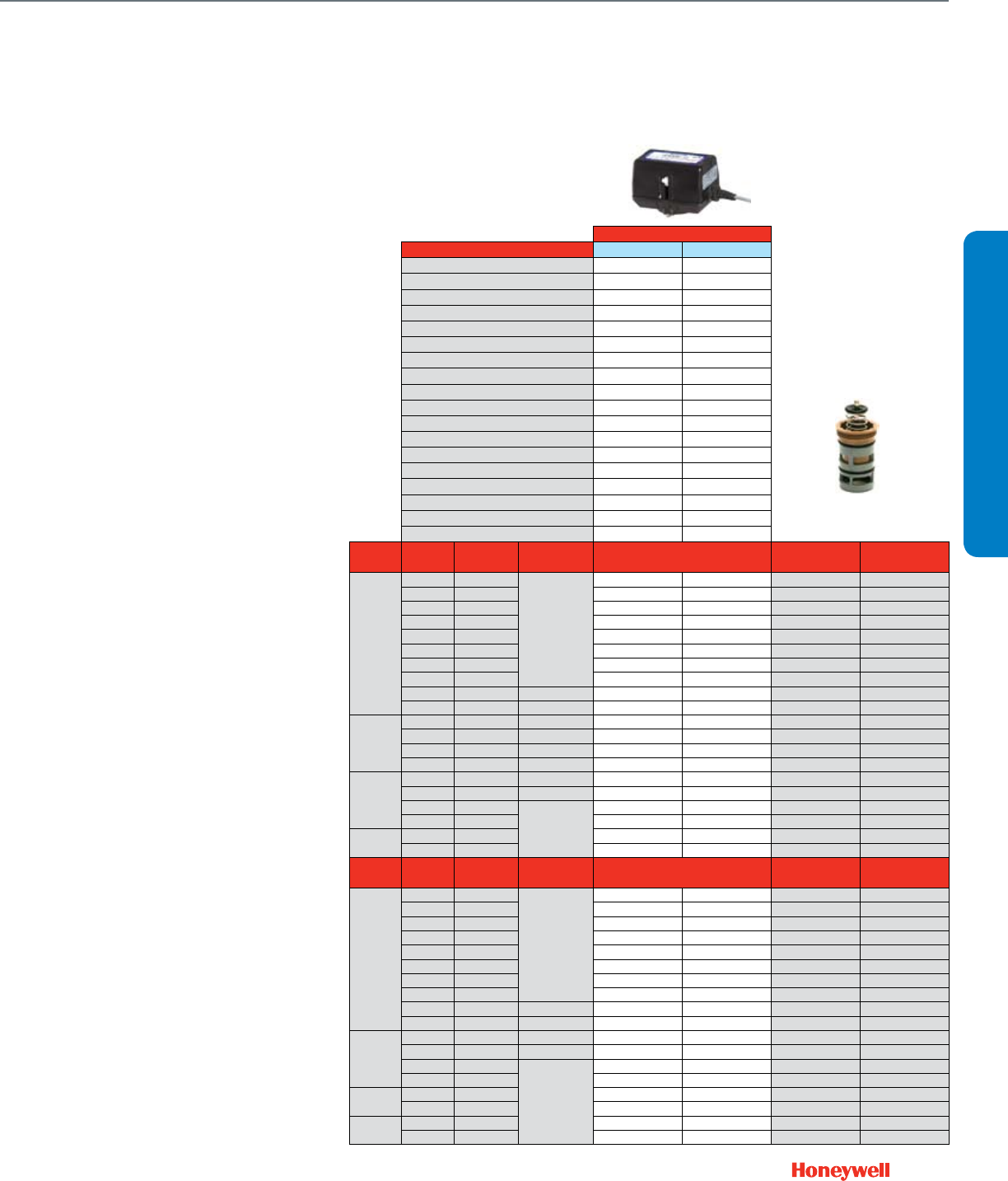
Honeywell Cartridge Cage Valves family (VC Series) are highly serviceable
and completely rebuildable.
Select from 2-position (both low and line voltage), oating, and modulating
actuators, and fail-safe actuators with congurable open/closed
functionality on power failure depending on the application. Since these
valves are not sensitive to ow direction; they can do both mixing and
diverting without changing anything except the piping.
25
Fail Safe
Actuator O.S. Number VC6936ZZ11-530 VC7936ZZ11-529
Power Supply Voltage 24 Vac 24 Vac
Frequency 50/60 Hz 50/60 Hz
Power 12 VA 12 VA
Control 2-10 Vdc •
4-20 mA (external 500 Ohm resistor) •
Floating • •
2-Position SPDT • •
2-Position SPST •
Pulse Width Modulation • •
Aux Switch SPDT Class II
Fail Safe Action Electronic NO/NC Electronic NO/NC
Reversible Operation Wiring Change • •
DIP Switch •
Stroke Timing Seconds @ 60 Hz (Drive) 120 60 / 120
Fail Safe 12 12
Electrical Connection Cable length, in. 60 60
Plenum-rated cable • •
1/2 in. flexible conduit adapter • •
Valve Size
(inches)
Connection
Type
Flow Capacity
(Cv)
Flow
Characteristic Y-pack O.S. Number Replacement Cartridge
Floating / Modulating
Replacement Cartridge
Electronic Fail Safe
2-Way
1/2"
f NPT 0.7
Modified Equal %
VC6936BB1500 VC7936BB1500 VCZZ3500 VCZZ1500
Sweat 0.7 VC6936AA1500 VC7936AA1500 VCZZ3500 VCZZ1500
f NPT 1.3 VC6936BB1600 VC7936BB1600 VCZZ3600 VCZZ1600
Sweat 1.3 VC6936AA1600 VC7936AA1600 VCZZ3600 VCZZ1600
Sweat 1.9 VC6936AA1800 VC7936AA1800 VCZZ3800 VCZZ1800
f NPT 1.9 VC6936BB1800 VC7936BB1800 VCZZ3800 VCZZ1800
Sweat 2.3 VC6936AA1400 VC7936AA1400 VCZZ3400 VCZZ1400
f NPT 2.3 VC6936BB1400 VC7936BB1400 VCZZ3400 VCZZ1400
f NPT 3.5 Linear VC6936BB1100 VC7936BB1100 VCZZ3100 VCZZ1100*
Sweat 3.5 Linear VC6936AA1100 VC7936AA1100 VCZZ3100 VCZZ1100*
3/4"
f NPT 3.9 Modified Equal % VC6936AL1400 VC7936AL1400 VCZZ3400 VCZZ1400
Sweat 3.9 Modified Equal % VC6936AM1400 VC7936AM1400 VCZZ3400 VCZZ1400
f NPT 4.7 Linear VC6936AL1100 VC7936AL1100 VCZZ3100 VCZZ1100*
Sweat 4.7 Linear VC6936AM1100 VC7936AM1100 VCZZ3100 VCZZ1100*
1"
f NPT 4.2 Modified Equal % VC6936AR1400 VC7936AR1400 VCZZ3400 VCZZ1400
Sweat 4.2 Modified Equal % VC6936AS1400 VC7936AS1400 VCZZ3400 VCZZ1400
f NPT 6.6
Linear
VC6936AR1100 VC7936AR1100 VCZZ3100 VCZZ1100*
Sweat 6.6 VC6936AS1100 VC7936AS1100 VCZZ3100 VCZZ1100*
1-1/4" f NPT 7VC6936BD1100 VC7936BD1100 VCZZ3100 VCZZ1100*
Sweat 7VC6936BE1100 VC7936BE1100 VCZZ3100 VCZZ1100*
Valve Size
(inches)
Connection
Type
Flow Capacity
(Cv)
Flow
Characteristic Y-pack O.S. Number Replacement Cartridge
Floating / Modulating
Replacement Cartridge
Electronic Fail Safe
3-Way Mixing/ Diverting
1/2"
f NPT 0.7
Modified Equal %
VC6936NB6500 VC7936NB6500 VCZZ7500 VCZZ6500
Sweat 0.7 VC6936MA6500 VC7936MA6500 VCZZ7500 VCZZ6500
f NPT 1.5 VC6936NB6600 VC7936NB6600 VCZZ7600 VCZZ6600
Sweat 1.5 VC6936MA6600 VC7936MA6600 VCZZ7600 VCZZ6600
f NPT 1.5 VC6936NB6800 VC7936NB6800 VCZZ7800 VCZZ6800
Sweat 1.5 VC6936MA6800 VC7936MA6800 VCZZ7800 VCZZ6800
f NPT 2.7 VC6936NB6400 VC7936NB6400 VCZZ7400 VCZZ6400
Sweat 2.7 VC6936MA6400 VC7936MA6400 VCZZ7400 VCZZ6400
f NPT 3.7 Linear VC6936NB6100 VC7936NB6100 VCZZ7100 VCZZ6100*
Sweat 3.7 Linear VC6936MA6100 VC7936MA6100 VCZZ7100 VCZZ6100*
3/4"
f NPT 4.2 Modified Equal % VC6936MK6400 VC7936MK6400 VCZZ7400 VCZZ6400
Sweat 4.2 Modified Equal % VC6936ML6400 VC7936ML6400 VCZZ7400 VCZZ6400
f NPT 6.6
Linear
VC6936MK6100 VC7936MK6100 VCZZ7100 VCZZ6100*
Sweat 6.6 VC6936ML6100 VC7936ML6100 VCZZ7100 VCZZ6100*
1" f NPT 8.3 VC6936MR6100 VC7936MR6100 VCZZ7100 VCZZ6100*
Sweat 8.3 VC6936MS6100 VC7936MS6100 VCZZ7100 VCZZ6100*
1-1/4" f NPT 9VC6936ND6100 VC7936ND6100 VCZZ7100 VCZZ6100*
Sweat 9VC6936NE6100 VC7936NE6100 VCZZ7100 VCZZ6100*
Honeywell’s Cartridge Cage Valves
feature a field replaceable cartridge
for all working parts
* Also applies to 2-position valve-actuator applications
Common Features
• 2-way straight-through or 3-way mixing/diverting body congurations
• Corrosion resistant, engineered plastic actuator housing
• 60 psid close-off on all models
• Fast acting 2-position actuator with soft close technology
• Position indicator/manual override lever standard
• Replaceable cartridge rebuilds valve to factory specications without
removing valve body from piping
• 300 psi operating pressure
• Combination position indicator/manual
ush-and-ll manual lever on all actuators
ValVe Selection
Cartridge Cage Valves
26
Cartridge Globe Valves
Non-Fail Safe
Actuator O.S. Number M6410A1029 M6410A3017 M7410F1000 M7410F3006
Power Supply Voltage 24 Vac 24 Vac 24 Vac 24 Vac
Frequency 50/60 Hz 50/60 Hz 50/60 Hz 50/60 Hz
Power 0.7 VA 0.7 VA 1.4 VA 1.4 VA
Stem Force (lb.) 40.5 67.5 40.5 67.5
Control 2-Position SPDT • •
Floating • •
0(2)-10 Vdc DIP Switch DIP Switch
4-20 mA (external 500 Ohm resistor) • •
Pneumatic Spring Range
Fail Safe Action Stay in Place Stay in Place Stay in Place Stay in Place
Reversible Operation Wiring Change • •
DIP Switch • •
Stroke Timing Seconds @ 60 Hz (Drive) 125 125 125 125
Fail Safe
Manual Override (Use valve dust cap) ••••
Position Indicator ••••
Electrical Connection Cable length, in. 36 36 36 36
Plenum-rated Cable ••••
Screw terminals
1/2 in. flexible conduit hub ••••
Valve Size
(inches)
Pipe
Connection Type
Flow
Capacity (Cv)
Flow
Characteristic
Valve
Closes
Valve O.S.
Number Close-off Pressure, psid
2-Way
1/2"
f NPT 0.19
Equal% Stem Down2
V5862A2005 232 232
Sweat 0.19 V5852A2007 232 232
f NPT 0.29 V5862A2013 232 232
Sweat 0.29 V5852A2015 232 232
f NPT 0.47 V5862A2021 232 232
Sweat 0.47 V5852A2023 232 232
f NPT 0.74 V5862A2039 232 232
Sweat 0.74 V5852A2031 232 232
f NPT 1.2 V5862A2047 174 174
Sweat 1.2 V5852A2049 174 174
f NPT 1.9 V5862A2054 174 174
Sweat 1.9 V5852A2056 174 174
3/4"
f NPT 2.9 V5862A2062 58 58
Sweat 2.9 V5852A2064 58 58
f NPT 4.9 V5862A2070 58 58
Sweat 4.9 V5852A2072 58 58
1"
f NPT 5.5
Linear Stem Up
V5862A3003 232 232
f NPT 7.8 V5862A3011 232 232
f NPT 11 V5862A3029 232 232
1-1/4" f NPT 18 V5862A3037 174 174
1-1/2" f NPT 25 V5862A3045 145 145
Valve Size
(inches)
Pipe
Connection Type
Flow
Capacity (Cv)
Flow
Characteristic
Valve
Closes
Valve O.S.
Number Close-off Pressure, psid
3-Way
1/2"
f NPT 0.29
A-AB Equal%,
B-AB Linear
Stem Up
V5863A2004 116 116
Sweat 0.29 V5853A2006 116 116
f NPT 0.47 V5863A2012 116 116
Sweat 0.47 V5853A2014 116 116
f NPT 0.74 V5863A2020 36 36
Sweat 0.74 V5853A2022 36 36
f NPT 1.2 V5863A2038 36 36
Sweat 1.2 V5853A2030 36 36
f NPT 1.9 V5863A2046 34 34
Sweat 1.9 V5853A2048 34 34
3/4"
f NPT 2.9 V5863A1006 34 34
Sweat 2.9 V5853A1008 34 34
f NPT 4.9 V5863A1014 34 34
Sweat 4.9 V5853A1016 34 34
f NPT 2.9 V5863A2053 7.25 7.25
Sweat 2.9 V5853A2055 7.25 7.25
f NPT 4.9 V5863A2061 7.25 7.25
Sweat 4.9 V5853A2063 7.25 7.25
1"
f NPT 5.5
Linear
V5863A3002 232 232
f NPT 7.8 V5863A3010 232 232
f NPT 11 V5863A3028 232 232
1-1/4" f NPT 18 V5863A3036 174 174
1-1/2" f NPT 25 V5863A3044 145 145
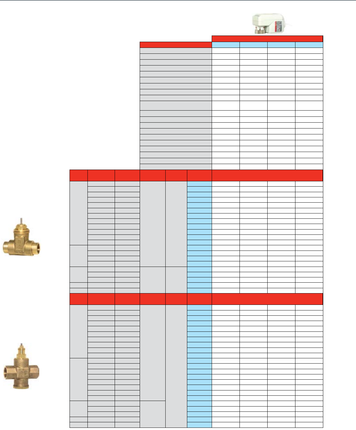
For more than 50 years, Honeywell has manufactured
the V58 series of premium Cartridge Globe Valves. The
compact size and replacement capabilities make it a great
choice for controlling modulating unitary equipment.
Valves 1" and larger feature a pressure balanced design
with enhanced close-off (levels).
Common Features
• Maximum static pressure 235 psi
• Long stroke allows for a wide range of control
• Leakage rate: 0.02% of Cv
• Insert replacement tool allows for the valve cartridge
to be replaced or changed without draining the system
(½" and ¾" models only)
• Brass body and stainless steel stem
• Threaded plastic valve cover/manual handle allows
for manual operation
• Corrosion resistant
Notes: Maximum coil-bypass pressure difference is 7 psi when used with electric actuators.
1 B port Cv is 20% less
2 Fail safe position for 1/2" and 3/4" 2-way is Normally Open with Mx435 and MP958 spring return actuators. All other valves fail safe closed.
27
Fail Safe Pneumatic
Actuator O.S. Number M6435A1004 M6435A3000 M7435F1001 M7435F3007 MP958A1009 MP958A1017 MP958A1025
Power Supply Voltage 24 Vac 24 Vac 24 Vac 24 Vac
Frequency 50/60 Hz 50/60 Hz 50/60 Hz 50/60 Hz
Power 10 VA 10 VA 5 VA 5 VA
Stem Force (lb.) 40.5 90 40.5 90
Control 2-Position SPDT • •
Floating • •
0(2)-10 Vdc DIP Switch DIP Switch
4-20 mA (external 500 Ohm resistor) • •
Pneumatic Spring Range 2-5 psi 3-10 psi 8-11 psi
Fail Safe Action 2-way N.O.
3-way N.C. N.C. 2-way N.O.
3-way N.C. N.C. 2-way N.O.
3-way N.C.
2-way N.O.
3-way N.C.
2-way N.O.
3-way N.C.
Reversible Operation Wiring Change • •
DIP Switch • •
Stroke Timing Seconds @ 60 Hz (Drive) 50 50 50 50
Fail Safe 10 10 10 10
Manual Override (Use valve dust cap) • • • • • • •
Position Indicator • • • •
Electrical Connection Cable length, in.
Plenum-rated Cable
Screw terminals • • • •
1/2 in. flexible conduit hub • • • •
Valve Size
(inches)
Pipe
Connection Type
Flow
Capacity (Cv)
Flow
Characteristic
Valve
Closes
Valve O.S.
Number Close-off Pressure, psid A-port Close-off Pressure, psid
Full air pressure*
Replacement
Insert3
2-Way
1/2"
f NPT 0.19
Equal% Stem Down2
V5862A2005 232 232 232 232 232 0902812
Sweat 0.19 V5852A2007 232 232 232 232 232 0902812
f NPT 0.29 V5862A2013 232 232 232 232 232 0902811
Sweat 0.29 V5852A2015 232 232 232 232 232 0902811
f NPT 0.47 V5862A2021 232 232 232 232 232 0902810
Sweat 0.47 V5852A2023 232 232 232 232 232 0902810
f NPT 0.74 V5862A2039 232 232 232 232 232 0902809
Sweat 0.74 V5852A2031 232 232 232 232 232 0902809
f NPT 1.2 V5862A2047 174 174 232 140 120 0902808
Sweat 1.2 V5852A2049 174 174 232 140 120 0902808
f NPT 1.9 V5862A2054 174 174 232 140 120 0902807
Sweat 1.9 V5852A2056 174 174 232 140 120 0902807
3/4"
f NPT 2.9 V5862A2062 58 58 90 50 40 0902814
Sweat 2.9 V5852A2064 58 58 90 50 40 0902814
f NPT 4.9 V5862A2070 58 58 90 50 40 0902815
Sweat 4.9 V5852A2072 58 58 90 50 40 0902815
1"
f NPT 5.5
Linear Stem Up
V5862A3003 232 232 0903827
f NPT 7.8 V5862A3011 232 232 0903827
f NPT 11 V5862A3029 232 232 0903827
1-1/4" f NPT 18 V5862A3037 174 174 0903828
1-1/2" f NPT 25 V5862A3045 145 145 0903829
Valve Size
(inches)
Pipe
Connection Type
Flow
Capacity (Cv)
Flow
Characteristic
Valve
Closes
Valve O.S.
Number Close-off Pressure, psid A-port Close-off Pressure, psid
Full air pressure*
Replacement
Insert3
3-Way
1/2"
f NPT 0.29
A-AB Equal%,
B-AB Linear
Stem Up
V5863A2004 116 116 20 80 232 0902821
Sweat 0.29 V5853A2006 116 116 20 80 232 0902821
f NPT 0.47 V5863A2012 116 116 20 80 232 0902822
Sweat 0.47 V5853A2014 116 116 20 80 232 0902822
f NPT 0.74 V5863A2020 36 36 20 80 232 0902823
Sweat 0.74 V5853A2022 36 36 20 80 232 0902823
f NPT 1.2 V5863A2038 36 36 N / A 10 100 0902824
Sweat 1.2 V5853A2030 36 36 N / A 10 100 0902824
f NPT 1.9 V5863A2046 34 34 N / A 10 100 0902825
Sweat 1.9 V5853A2048 34 34 N / A 10 100 0902825
3/4"
f NPT 2.9 V5863A1006 34 34 0902826
Sweat 2.9 V5853A1008 34 34 0902826
f NPT 4.9 V5863A1014 34 34 0902827
Sweat 4.9 V5853A1016 34 34 0902827
f NPT 2.9 V5863A2053 7.25 7.25 N / A N / A 35 0902818
Sweat 2.9 V5853A2055 7.25 7.25 N / A N / A 35 0902818
f NPT 4.9 V5863A2061 7.25 7.25 N / A N / A 35 0902819
Sweat 4.9 V5853A2063 7.25 7.25 N / A N / A 35 0902819
1"
f NPT 5.5
Linear
V5863A3002 232 232 0903827
f NPT 7.8 V5863A3010 232 232 0903827
f NPT 11 V5863A3028 232 232 0903827
1-1/4" f NPT 18 V5863A3036 174 174 0903828
1-1/2" f NPT 25 V5863A3044 145 145 0903829
Notes: *20 psi for 2-way; 0 psi for 3-way
B-port Close-off of 3-way valves is the same as A-port in 2-way valves
3 Insert determines Cv for 1/2” and 3/4" bodies. Grouped inserts are interchangeable.
ValVe Selection
Cartridge Globe Valves
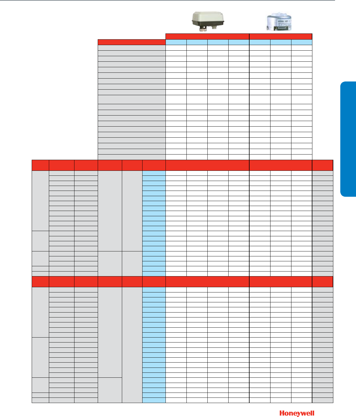
28
Control Ball Valves ½- 3"
2-Way NPT NEMA 2
Actuator Features Non-fail Safe
Actuator O.S. Number MN6105A1011 MN6105A1011 MN7505A2001 MN7505A2001
Power Supply Voltage 24 Vac 24 Vac 24 Vac 24 Vac
Frequency 50 / 60 Hz 50 / 60 Hz 50 / 60 Hz 50 / 60 Hz
Power 5 VA 5 VA 5 VA 5 VA
Actuator Torque (lb.-in.) 44 44 44 44
Control (0)2-10 Vdc • •
4-20 mA (external 500 Ohm Resistor) • •
Floating ••••
Two-Position SPDT ••••
Two-Position SPST • •
Fail Safe Action Stay in Place Stay in Place Stay in Place Stay in Place
Normal Position (no signal)
Closed Closed Closed Closed
Actuator Stroke (degrees) 95° ± 3° 95° ± 3° 95° ± 3° 95° ± 3°
Timing (seconds) 90 90 90 90
Aux Switch 2 x SPDT Add-on SSW2 SSW2 SW2-US SW2-US
Feedback 2-10 Vdc Built In - - • •
Valve Features Trim Nickel-Plated Brass Stainless Steel Nickel-Plated Brass Stainless Steel
Valve Size
(inches) Cv Close-off
Differential Pressure (psi) Valve O.S. Number
2-Way
1/2"
0.38
130
VBN2AB3P0A VBN2AB3S0A VBN2AB3P0B VBN2AB3S0B
0.68 VBN2AD3P0A VBN2AD3S0A VBN2AD3P0B VBN2AD3S0B
1.3 VBN2AE3P0A VBN2AE3S0A VBN2AE3P0B VBN2AE3S0B
2VBN2AF3P0A VBN2AF3S0A VBN2AF3P0B VBN2AF3S0B
2.6 VBN2AG3P0A VBN2AG3S0A VBN2AG3P0B VBN2AG3S0B
4.7 VBN2AH3P0A VBN2AH3S0A VBN2AH3P0B VBN2AH3S0B
8VBN2AJ3P0A VBN2AJ3S0A VBN2AJ3P0B VBN2AJ3S0B
11.7* VBN2AK3P0A VBN2AK3S0A VBN2AK3P0B VBN2AK3S0B
3/4"
0.31 VBN2BB3P0A VBN2BB3S0A VBN2BB3P0B VBN2BB3S0B
0.63 VBN2BD3P0A VBN2BD3S0A VBN2BD3P0B VBN2BD3S0B
1.2 VBN2BE3P0A VBN2BE3S0A VBN2BE3P0B VBN2BE3S0B
2.5 VBN2BG3P0A VBN2BG3S0A VBN2BG3P0B VBN2BG3S0B
4.3 VBN2BH3P0A VBN2BH3S0A VBN2BH3P0B VBN2BH3S0B
7.4 VBN2BJ3P0A VBN2BJ3S0A VBN2BJ3P0B VBN2BJ3S0B
10.1 VBN2BK3P0A VBN2BK3S0A VBN2BK3P0B VBN2BK3S0B
14.7* VBN2BL3P0A VBN2BL3S0A VBN2BL3P0B VBN2BL3S0B
29* VBN2BM3P0A VBN2BM3S0A VBN2BM3P0B VBN2BM3S0B
1
"
4.4
100
VBN2CH3P0A VBN2CH3S0A VBN2CH3P0B VBN2CH3S0B
9VBN2CJ3P0A VBN2CJ3S0A VBN2CJ3P0B VBN2CJ3S0B
15.3 VBN2CL3P0A VBN2CL3S0A VBN2CL3P0B VBN2CL3S0B
26 VBN2CM3P0A VBN2CM3S0A VBN2CM3P0B VBN2CM3S0B
44* VBN2CN3P0A VBN2CN3S0A VBN2CN3P0B VBN2CN3S0B
54* VBN2CP3P0A VBN2CP3S0A VBN2CP3P0B VBN2CP3S0B
1-1/4
"
4.4 VBN2DH3P0A VBN2DH3S0A VBN2DH3P0B VBN2DH3S0B
8.3 VBN2DJ3P0A VBN2DJ3S0A VBN2DJ3P0B VBN2DJ3S0B
14.9 VBN2DK3P0A VBN2DK3S0A VBN2DK3P0B VBN2DK3S0B
25 VBN2DL3P0A VBN2DL3S0A VBN2DL3P0B VBN2DL3S0B
37 VBN2DM3P0A VBN2DM3S0A VBN2DM3P0B VBN2DM3S0B
41* VBN2DN3P0A VBN2DN3S0A VBN2DN3P0B VBN2DN3S0B
102* VBN2DS3P0A VBN2DS3S0A VBN2DS3P0B VBN2DS3S0B
1-1/2
"
23 VBN2EL3P0A VBN2EL3S0A VBN2EL3P0B VBN2EL3S0B
30 VBN2EM3P0A VBN2EM3S0A VBN2EM3P0B VBN2EM3S0B
41 VBN2EN3P0A VBN2EN3S0A VBN2EN3P0B VBN2EN3S0B
74* VBN2ER3P0A VBN2ER3S0A VBN2ER3P0B VBN2ER3S0B
172* VBN2E13P0A VBN2E13S0A VBN2E13P0B VBN2E13S0B
2
"
42 VBN2FN3P0A VBN2FN3S0A VBN2FN3P0B VBN2FN3S0B
57 VBN2FP3P0A VBN2FP3S0A VBN2FP3P0B VBN2FP3S0B
71 VBN2FR3P0A VBN2FR3S0A VBN2FR3P0B VBN2FR3S0B
100 VBN2FS3P0A VBN2FS3S0A VBN2FS3P0B VBN2FS3S0B
108* VBN2FT3P0A VBN2FT3S0A VBN2FT3P0B VBN2FT3S0B
210 VBN2F13P0A VBN2F13S0A VBN2F13P0B VBN2F13S0B
266* VBN2F23P0A VBN2F23S0A VBN2F23P0B VBN2F23S0B
2-1/2
"
45 VBN2GN3P0A VBN2GN3S0A VBN2GN3P0B VBN2GN3S0B
55 VBN2GP3P0A VBN2GP3S0A VBN2GP3P0B VBN2GP3S0B
72 VBN2GR3P0A VBN2GR3S0A VBN2GR3P0B VBN2GR3S0B
101 VBN2GS3P0A VBN2GS3S0A VBN2GS3P0B VBN2GS3S0B
162 VBN2GU3P0A VBN2GU3S0A VBN2GU3P0B VBN2GU3S0B
202* VBN2G13P0A VBN2G13S0A VBN2G13P0B VBN2G13S0B
3
"
49 VBN2HN3P0A VBN2HN3S0A VBN2HN3P0B VBN2HN3S0B
63 VBN2HP3P0A VBN2HP3S0A VBN2HP3P0B VBN2HP3S0B
82 VBN2HR3P0A VBN2HR3S0A VBN2HR3P0B VBN2HR3S0B
124 VBN2HT3P0A VBN2HT3S0A VBN2HT3P0B VBN2HT3S0B
145* VBN2HU3P0A VBN2HU3S0A VBN2HU3P0B VBN2HU3S0B
Full port ball. No flow characterizing insert.
Honeywell's Control Ball Valve product lines
(VBN and VBF) feature the largest Cv range in
the industry. A patented seat design allows for
lower torque actuators, while a single spring
return actuator may be used for up to a 70
psid differential pressure close-off on up to a
6" connection size.
The VBN family features a unique field
replaceable stem assembly.
Common Features
• Max static pressure 360 psi (250°F)
• Medium: Water/glycol solutions up to 50%.
• Temperature range: -22 to +250°F
• Field congurable open or closed fail-safe
position
• ANSI class IV leakage (0.01% of Cv)
VBN2 (Two-way)
• Equal % ow insert. Linear with full port.
(Largest Cv valve in each valve size is full
port), as noted
• Nickel-chrome plated brass or 316 stainless
steel ball and stem
NEED TO
PHOTOSHOP

29
Actuator Features Fail Safe
Actuator O.S. Number MS8105A1030 MS8105A1030 MS7505A2030 MS7505A2030 Valve Only Valve Only
Power Supply Voltage 24 Vac 24 Vac 24 Vac 24 Vac
Frequency 50 / 60 Hz 50 / 60 Hz 50 / 60 Hz 50 / 60 Hz
Power 8VA 8VA 7.5 VA 7.5 VA
Actuator Torque (lb.-in.) 44 44 44 44
Control (0)2-10 Vdc • •
4-20 mA (external 500 Ohm Resistor) • •
Floating • •
Two-Position SPDT • •
Two-Position SPST • • • •
Fail Safe Action Closed* Closed* Closed* Closed*
Normal Position (no signal)
Closed* Closed* Closed* Closed*
Actuator Stroke (degrees) 95° ± 3° 95° ± 3° 95° ± 3° 95° ± 3°
Timing (seconds) 45 45 90 90
Aux Switch 2 x SPDT Add-on
Feedback 2-10 Vdc Built In • •
Valve Features Trim Nickel-Plated Brass Stainless Steel Nickel-Plated Brass Stainless Steel Nickel-Plated Brass Stainless Steel
Valve Size
(inches) Cv Close-off
Differential Pressure (psi) Valve O.S. Number
2-Way
1/2"
0.38
130
VBN2AB3P0C VBN2AB3S0C VBN2AB3P0D VBN2AB3S0D VBN2AB3P0X VBN2AB3S0X
0.68 VBN2AD3P0C VBN2AD3S0C VBN2AD3P0D VBN2AD3S0D VBN2AD3P0X VBN2AD3S0X
1.3 VBN2AE3P0C VBN2AE3S0C VBN2AE3P0D VBN2AE3S0D VBN2AE3P0X VBN2AE3S0X
2VBN2AF3P0C VBN2AF3S0C VBN2AF3P0D VBN2AF3S0D VBN2AF3P0X VBN2AF3S0X
2.6 VBN2AG3P0C VBN2AG3S0C VBN2AG3P0D VBN2AG3S0D VBN2AG3P0X VBN2AG3S0X
4.7 VBN2AH3P0C VBN2AH3S0C VBN2AH3P0D VBN2AH3S0D VBN2AH3P0X VBN2AH3S0X
8VBN2AJ3P0C VBN2AJ3S0C VBN2AJ3P0D VBN2AJ3S0D VBN2AJ3P0X VBN2AJ3S0X
11.7* VBN2AK3P0C VBN2AK3S0C VBN2AK3P0D VBN2AK3S0D VBN2AK3P0X VBN2AK3S0X
3/4"
0.31 VBN2BB3P0C VBN2BB3S0C VBN2BB3P0D VBN2BB3S0D VBN2BB3P0X VBN2BB3S0X
0.63 VBN2BD3P0C VBN2BD3S0C VBN2BD3P0D VBN2BD3S0D VBN2BD3P0X VBN2BD3S0X
1.2 VBN2BE3P0C VBN2BE3S0C VBN2BE3P0D VBN2BE3S0D VBN2BE3P0X VBN2BE3S0X
2.5 VBN2BG3P0C VBN2BG3S0C VBN2BG3P0D VBN2BG3S0D VBN2BG3P0X VBN2BG3S0X
4.3 VBN2BH3P0C VBN2BH3S0C VBN2BH3P0D VBN2BH3S0D VBN2BH3P0X VBN2BH3S0X
7.4 VBN2BJ3P0C VBN2BJ3S0C VBN2BJ3P0D VBN2BJ3S0D VBN2BJ3P0X VBN2BJ3S0X
10.1 VBN2BK3P0C VBN2BK3S0C VBN2BK3P0D VBN2BK3S0D VBN2BK3P0X VBN2BK3S0X
14.7* VBN2BL3P0C VBN2BL3S0C VBN2BL3P0D VBN2BL3S0D VBN2BL3P0X VBN2BL3S0X
29* VBN2BM3P0C VBN2BM3S0C VBN2BM3P0D VBN2BM3S0D VBN2BM3P0X VBN2BM3S0X
1
"
4.4
100
VBN2CH3P0C VBN2CH3S0C VBN2CH3P0D VBN2CH3S0D VBN2CH3P0X VBN2CH3S0X
9VBN2CJ3P0C VBN2CJ3S0C VBN2CJ3P0D VBN2CJ3S0D VBN2CJ3P0X VBN2CJ3S0X
15.3 VBN2CL3P0C VBN2CL3S0C VBN2CL3P0D VBN2CL3S0D VBN2CL3P0X VBN2CL3S0X
26 VBN2CM3P0C VBN2CM3S0C VBN2CM3P0D VBN2CM3S0D VBN2CM3P0X VBN2CM3S0X
44* VBN2CN3P0C VBN2CN3S0C VBN2CN3P0D VBN2CN3S0D VBN2CN3P0X VBN2CN3S0X
54* VBN2CP3P0C VBN2CP3S0C VBN2CP3P0D VBN2CP3S0D VBN2CP3P0X VBN2CP3S0X
1-1/4
"
4.4 VBN2DH3P0C VBN2DH3S0C VBN2DH3P0D VBN2DH3S0D VBN2DH3P0X VBN2DH3S0X
8.3 VBN2DJ3P0C VBN2DJ3S0C VBN2DJ3P0D VBN2DJ3S0D VBN2DJ3P0X VBN2DJ3S0X
14.9 VBN2DK3P0C VBN2DK3S0C VBN2DK3P0D VBN2DK3S0D VBN2DK3P0X VBN2DK3S0X
25 VBN2DL3P0C VBN2DL3S0C VBN2DL3P0D VBN2DL3S0D VBN2DL3P0X VBN2DL3S0X
37 VBN2DM3P0C VBN2DM3S0C VBN2DM3P0D VBN2DM3S0D VBN2DM3P0X VBN2DM3S0X
41* VBN2DN3P0C VBN2DN3S0C VBN2DN3P0D VBN2DN3S0D VBN2DN3P0X VBN2DN3S0X
102* VBN2DS3P0C VBN2DS3S0C VBN2DS3P0D VBN2DS3S0D VBN2DS3P0X VBN2DS3S0X
1-1/2
"
23 VBN2EL3P0C VBN2EL3S0C VBN2EL3P0D VBN2EL3S0D VBN2EL3P0X VBN2EL3S0X
30 VBN2EM3P0C VBN2EM3S0C VBN2EM3P0D VBN2EM3S0D VBN2EM3P0X VBN2EM3S0X
41 VBN2EN3P0C VBN2EN3S0C VBN2EN3P0D VBN2EN3S0D VBN2EN3P0X VBN2EN3S0X
74* VBN2ER3P0C VBN2ER3S0C VBN2ER3P0D VBN2ER3S0D VBN2ER3P0X VBN2ER3S0X
172* VBN2E13P0C VBN2E13S0C VBN2E13P0D VBN2E13S0D VBN2E13P0X VBN2E13S0X
2
"
42 VBN2FN3P0C VBN2FN3S0C VBN2FN3P0D VBN2FN3S0D VBN2FN3P0X VBN2FN3S0X
57 VBN2FP3P0C VBN2FP3S0C VBN2FP3P0D VBN2FP3S0D VBN2FP3P0X VBN2FP3S0X
71 VBN2FR3P0C VBN2FR3S0C VBN2FR3P0D VBN2FR3S0D VBN2FR3P0X VBN2FR3S0X
100 VBN2FS3P0C VBN2FS3S0C VBN2FS3P0D VBN2FS3S0D VBN2FS3P0X VBN2FS3S0X
108* VBN2FT3P0C VBN2FT3S0C VBN2FT3P0D VBN2FT3S0D VBN2FT3P0X VBN2FT3S0X
210 VBN2F13P0C VBN2F13S0C VBN2F13P0D VBN2F13S0D VBN2F13P0X VBN2F13S0X
266* VBN2F23P0C VBN2F23S0C VBN2F23P0D VBN2F23S0D VBN2F23P0X VBN2F23S0X
2-1/2
"
45 VBN2GN3P0C VBN2GN3S0C VBN2GN3P0D VBN2GN3S0D VBN2GN3P0X VBN2GN3S0X
55 VBN2GP3P0C VBN2GP3S0C VBN2GP3P0D VBN2GP3S0D VBN2GP3P0X VBN2GP3S0X
72 VBN2GR3P0C VBN2GR3S0C VBN2GR3P0D VBN2GR3S0D VBN2GR3P0X VBN2GR3S0X
101 VBN2GS3P0C VBN2GS3S0C VBN2GS3P0D VBN2GS3S0D VBN2GS3P0X VBN2GS3S0X
162 VBN2GU3P0C VBN2GU3S0C VBN2GU3P0D VBN2GU3S0D VBN2GU3P0X VBN2GU3S0X
202* VBN2G13P0C VBN2G13S0C VBN2G13P0D VBN2G13S0D VBN2G13P0X VBN2G13S0X
3
"
49 VBN2HN3P0C VBN2HN3S0C VBN2HN3P0D VBN2HN3S0D VBN2HN3P0X VBN2HN3S0X
63 VBN2HP3P0C VBN2HP3S0C VBN2HP3P0D VBN2HP3S0D VBN2HP3P0X VBN2HP3S0X
82 VBN2HR3P0C VBN2HR3S0C VBN2HR3P0D VBN2HR3S0D VBN2HR3P0X VBN2HR3S0X
124 VBN2HT3P0C VBN2HT3S0C VBN2HT3P0D VBN2HT3S0D VBN2HT3P0X VBN2HT3S0X
145* VBN2HU3P0C VBN2HU3S0C VBN2HU3P0D VBN2HU3S0D VBN2HU3P0X VBN2HU3S0X
Full port ball. No flow characterizing insert.
VALVE SELECTION
Control Ball Valves ½- 3"
2-Way NPT NEMA 2
30
Control Ball Valves ½- 3"
2-Way NPT NEMA 3R
Common Features
• Max static pressure 360 psi (250°F)
• Medium: Water/glycol solutions up to 50%.
• Temperature range: -22 to +250°F
• Field congurable open or closed fail-safe position
• Removable handle for manual operation
• ANSI class IV leakage (0.01% of Cv)
VBN2 (Two-way):
• Equal % ow insert. Linear with full port.
(Largest Cv valve in each valve size is full port)
• Nickel-chrome plated brass or 316 stainless
steel ball and stem
Optional NEMA 3R enclosure
Actuator Features Non-fail Safe
Actuator O.S. Number MN6105A1011 MN6105A1011 MN7505A2001 MN7505A2001
Power Supply Voltage 24 Vac 24 Vac 24 Vac 24 Vac
Frequency 50 / 60 Hz 50 / 60 Hz 50 / 60 Hz 50 / 60 Hz
Power 5 VA 5 VA 5 VA 5 VA
Actuator Torque (lb.-in.) 44 44 44 44
Control (0)2-10 Vdc • •
4-20 mA (external 500 Ohm Resistor) • •
Floating • • • •
Two-Position SPDT • • • •
Two-Position SPST • •
Fail Safe Action
Stay in Place Stay in Place Stay in Place Stay in Place
Normal Position (no signal)
Closed Closed Closed Closed
Actuator Stroke (degrees) 95° ± 3° 95° ± 3° 95° ± 3° 95° ± 3°
Timing (seconds) 90 90 90 90
Aux Switch 2 x SPDT Add-on SSW2 SSW2 SW2-US SW2-US
Feedback 2-10 Vdc Built In • •
Valve Features Trim Nickel-Plated Brass Stainless Steel Nickel-Plated Brass Stainless Steel
Valve Size
(inches) Cv Close-off
Differential Pressure (psi) Valve O.S. Number
2-Way
1/2"
0.38
130
VBN2AB3PRA VBN2AB3SRA VBN2AB3PRB VBN2AB3SRB
0.68 VBN2AD3PRA VBN2AD3SRA VBN2AD3PRB VBN2AD3SRB
1.3 VBN2AE3PRA VBN2AE3SRA VBN2AE3PRB VBN2AE3SRB
2VBN2AF3PRA VBN2AF3SRA VBN2AF3PRB VBN2AF3SRB
2.6 VBN2AG3PRA VBN2AG3SRA VBN2AG3PRB VBN2AG3SRB
4.7 VBN2AH3PRA VBN2AH3SRA VBN2AH3PRB VBN2AH3SRB
8VBN2AJ3PRA VBN2AJ3SRA VBN2AJ3PRB VBN2AJ3SRB
11.7* VBN2AK3PRA VBN2AK3SRA VBN2AK3PRB VBN2AK3SRB
3/4"
0.31 VBN2BB3PRA VBN2BB3SRA VBN2BB3PRB VBN2BB3SRB
0.63 VBN2BD3PRA VBN2BD3SRA VBN2BD3PRB VBN2BD3SRB
1.2 VBN2BE3PRA VBN2BE3SRA VBN2BE3PRB VBN2BE3SRB
2.5 VBN2BG3PRA VBN2BG3SRA VBN2BG3PRB VBN2BG3SRB
4.3 VBN2BH3PRA VBN2BH3SRA VBN2BH3PRB VBN2BH3SRB
7.4 VBN2BJ3PRA VBN2BJ3SRA VBN2BJ3PRB VBN2BJ3SRB
10.1 VBN2BK3PRA VBN2BK3SRA VBN2BK3PRB VBN2BK3SRB
14.7* VBN2BL3PRA VBN2BL3SRA VBN2BL3PRB VBN2BL3SRB
29* VBN2BM3PRA VBN2BM3SRA VBN2BM3PRB VBN2BM3SRB
1
"
4.4
100
VBN2CH3PRA VBN2CH3SRA VBN2CH3PRB VBN2CH3SRB
9VBN2CJ3PRA VBN2CJ3SRA VBN2CJ3PRB VBN2CJ3SRB
15.3 VBN2CL3PRA VBN2CL3SRA VBN2CL3PRB VBN2CL3SRB
26 VBN2CM3PRA VBN2CM3SRA VBN2CM3PRB VBN2CM3SRB
44* VBN2CN3PRA VBN2CN3SRA VBN2CN3PRB VBN2CN3SRB
54* VBN2CP3PRA VBN2CP3SRA VBN2CP3PRB VBN2CP3SRB
1-1/4
"
4.4 VBN2DH3PRA VBN2DH3SRA VBN2DH3PRB VBN2DH3SRB
8.3 VBN2DJ3PRA VBN2DJ3SRA VBN2DJ3PRB VBN2DJ3SRB
14.9 VBN2DK3PRA VBN2DK3SRA VBN2DK3PRB VBN2DK3SRB
25 VBN2DL3PRA VBN2DL3SRA VBN2DL3PRB VBN2DL3SRB
37 VBN2DM3PRA VBN2DM3SRA VBN2DM3PRB VBN2DM3SRB
41* VBN2DN3PRA VBN2DN3SRA VBN2DN3PRB VBN2DN3SRB
102* VBN2DS3PRA VBN2DS3SRA VBN2DS3PRB VBN2DS3SRB
1-1/2
"
23 VBN2EL3PRA VBN2EL3SRA VBN2EL3PRB VBN2EL3SRB
30 VBN2EM3PRA VBN2EM3SRA VBN2EM3PRB VBN2EM3SRB
41 VBN2EN3PRA VBN2EN3SRA VBN2EN3PRB VBN2EN3SRB
74* VBN2ER3PRA VBN2ER3SRA VBN2ER3PRB VBN2ER3SRB
172* VBN2E13PRA VBN2E13SRA VBN2E13PRB VBN2E13SRB
2
"
42 VBN2FN3PRA VBN2FN3SRA VBN2FN3PRB VBN2FN3SRB
57 VBN2FP3PRA VBN2FP3SRA VBN2FP3PRB VBN2FP3SRB
71 VBN2FR3PRA VBN2FR3SRA VBN2FR3PRB VBN2FR3SRB
100 VBN2FS3PRA VBN2FS3SRA VBN2FS3PRB VBN2FS3SRB
108* VBN2FT3PRA VBN2FT3SRA VBN2FT3PRB VBN2FT3SRB
210 VBN2F13PRA VBN2F13SRA VBN2F13PRB VBN2F13SRB
266* VBN2F23PRA VBN2F23SRA VBN2F23PRB VBN2F23SRB
2-1/2
"
45 VBN2GN3PRA VBN2GN3SRA VBN2GN3PRB VBN2GN3SRB
55 VBN2GP3PRA VBN2GP3SRA VBN2GP3PRB VBN2GP3SRB
72 VBN2GR3PRA VBN2GR3SRA VBN2GR3PRB VBN2GR3SRB
101 VBN2GS3PRA VBN2GS3SRA VBN2GS3PRB VBN2GS3SRB
162 VBN2GU3PRA VBN2GU3SRA VBN2GU3PRB VBN2GU3SRB
202* VBN2G13PRA VBN2G13SRA VBN2G13PRB VBN2G13SRB
3
"
49 VBN2HN3PRA VBN2HN3SRA VBN2HN3PRB VBN2HN3SRB
63 VBN2HP3PRA VBN2HP3SRA VBN2HP3PRB VBN2HP3SRB
82 VBN2HR3PRA VBN2HR3SRA VBN2HR3PRB VBN2HR3SRB
124 VBN2HT3PRA VBN2HT3SRA VBN2HT3PRB VBN2HT3SRB
145* VBN2HU3PRA VBN2HU3SRA VBN2HU3PRB VBN2HU3SRB
Full port ball. No flow characterizing insert.
31
Actuator Features Fail Safe
Actuator O.S. Number MS8105A1030 MS8105A1030 MS7505A2030 MS7505A2030 Valve Only Valve Only
Power Supply Voltage 24 Vac 24 Vac 24 Vac 24 Vac
Frequency 50 / 60 Hz 50 / 60 Hz 50 / 60 Hz 50 / 60 Hz
Power 8VA 8VA 7.5 VA 7.5 VA
Actuator Torque (lb.-in.) 44 44 44 44
Control (0)2-10 Vdc • •
4-20 mA (external 500 Ohm Resistor) • •
Floating • •
Two-Position SPDT • •
Two-Position SPST • • • •
Fail Safe Action Closed* Closed* Closed* Closed*
Normal Position (no signal)
Closed Closed Closed Closed
Actuator Stroke (degrees) 95° ± 3° 95° ± 3° 95° ± 3° 95° ± 3°
Timing (seconds) 45 45 90 90
Aux Switch 2 x SPDT Add-on
Feedback 2-10 Vdc Built In • •
Valve Features Trim Nickel-Plated Brass Stainless Steel Nickel-Plated Brass Stainless Steel Nickel-Plated Brass Stainless Steel
Valve Size
(inches) Cv Close-off
Differential Pressure (psi) Valve O.S. Number
2-Way
1/2"
0.38
130
VBN2AB3PRC VBN2AB3SRC VBN2AB3PRD VBN2AB3SRD — —
0.68 VBN2AD3PRC VBN2AD3SRC VBN2AD3PRD VBN2AD3SRD — —
1.3 VBN2AE3PRC VBN2AE3SRC VBN2AE3PRD VBN2AE3SRD — —
2VBN2AF3PRC VBN2AF3SRC VBN2AF3PRD VBN2AF3SRD — —
2.6 VBN2AG3PRC VBN2AG3SRC VBN2AG3PRD VBN2AG3SRD — —
4.7 VBN2AH3PRC VBN2AH3SRC VBN2AH3PRD VBN2AH3SRD — —
8VBN2AJ3PRC VBN2AJ3SRC VBN2AJ3PRD VBN2AJ3SRD — —
11.7* VBN2AK3PRC VBN2AK3SRC VBN2AK3PRD VBN2AK3SRD — —
3/4"
0.31 VBN2BB3PRC VBN2BB3SRC VBN2BB3PRD VBN2BB3SRD — —
0.63 VBN2BD3PRC VBN2BD3SRC VBN2BD3PRD VBN2BD3SRD — —
1.2 VBN2BE3PRC VBN2BE3SRC VBN2BE3PRD VBN2BE3SRD — —
2.5 VBN2BG3PRC VBN2BG3SRC VBN2BG3PRD VBN2BG3SRD — —
4.3 VBN2BH3PRC VBN2BH3SRC VBN2BH3PRD VBN2BH3SRD — —
7.4 VBN2BJ3PRC VBN2BJ3SRC VBN2BJ3PRD VBN2BJ3SRD — —
10.1 VBN2BK3PRC VBN2BK3SRC VBN2BK3PRD VBN2BK3SRD — —
14.7* VBN2BL3PRC VBN2BL3SRC VBN2BL3PRD VBN2BL3SRD — —
29* VBN2BM3PRC VBN2BM3SRC VBN2BM3PRD VBN2BM3SRD — —
1
"
4.4
100
VBN2CH3PRC VBN2CH3SRC VBN2CH3PRD VBN2CH3SRD — —
9VBN2CJ3PRC VBN2CJ3SRC VBN2CJ3PRD VBN2CJ3SRD — —
15.3 VBN2CL3PRC VBN2CL3SRC VBN2CL3PRD VBN2CL3SRD — —
26 VBN2CM3PRC VBN2CM3SRC VBN2CM3PRD VBN2CM3SRD — —
44* VBN2CN3PRC VBN2CN3SRC VBN2CN3PRD VBN2CN3SRD — —
54* VBN2CP3PRC VBN2CP3SRC VBN2CP3PRD VBN2CP3SRD — —
1-1/4
"
4.4 VBN2DH3PRC VBN2DH3SRC VBN2DH3PRD VBN2DH3SRD — —
8.3 VBN2DJ3PRC VBN2DJ3SRC VBN2DJ3PRD VBN2DJ3SRD — —
14.9 VBN2DK3PRC VBN2DK3SRC VBN2DK3PRD VBN2DK3SRD — —
25 VBN2DL3PRC VBN2DL3SRC VBN2DL3PRD VBN2DL3SRD — —
37 VBN2DM3PRC VBN2DM3SRC VBN2DM3PRD VBN2DM3SRD — —
41* VBN2DN3PRC VBN2DN3SRC VBN2DN3PRD VBN2DN3SRD — —
102* VBN2DS3PRC VBN2DS3SRC VBN2DS3PRD VBN2DS3SRD — —
1-1/2
"
23 VBN2EL3PRC VBN2EL3SRC VBN2EL3PRD VBN2EL3SRD — —
30 VBN2EM3PRC VBN2EM3SRC VBN2EM3PRD VBN2EM3SRD — —
41 VBN2EN3PRC VBN2EN3SRC VBN2EN3PRD VBN2EN3SRD — —
74* VBN2ER3PRC VBN2ER3SRC VBN2ER3PRD VBN2ER3SRD — —
172* VBN2E13PRC VBN2E13SRC VBN2E13PRD VBN2E13SRD — —
2
"
42 VBN2FN3PRC VBN2FN3SRC VBN2FN3PRD VBN2FN3SRD — —
57 VBN2FP3PRC VBN2FP3SRC VBN2FP3PRD VBN2FP3SRD — —
71 VBN2FR3PRC VBN2FR3SRC VBN2FR3PRD VBN2FR3SRD — —
100 VBN2FS3PRC VBN2FS3SRC VBN2FS3PRD VBN2FS3SRD — —
108* VBN2FT3PRC VBN2FT3SRC VBN2FT3PRD VBN2FT3SRD — —
210 VBN2F13PRC VBN2F13SRC VBN2F13PRD VBN2F13SRD — —
266* VBN2F23PRC VBN2F23SRC VBN2F23PRD VBN2F23SRD — —
2-1/2
"
45 VBN2GN3PRC VBN2GN3SRC VBN2GN3PRD VBN2GN3SRD — —
55 VBN2GP3PRC VBN2GP3SRC VBN2GP3PRD VBN2GP3SRD — —
72 VBN2GR3PRC VBN2GR3SRC VBN2GR3PRD VBN2GR3SRD — —
101 VBN2GS3PRC VBN2GS3SRC VBN2GS3PRD VBN2GS3SRD — —
162 VBN2GU3PRC VBN2GU3SRC VBN2GU3PRD VBN2GU3SRD — —
202* VBN2G13PRC VBN2G13SRC VBN2G13PRD VBN2G13SRD — —
3
"
49 VBN2HN3PRC VBN2HN3SRC VBN2HN3PRD VBN2HN3SRD — —
63 VBN2HP3PRC VBN2HP3SRC VBN2HP3PRD VBN2HP3SRD — —
82 VBN2HR3PRC VBN2HR3SRC VBN2HR3PRD VBN2HR3SRD — —
124 VBN2HT3PRC VBN2HT3SRC VBN2HT3PRD VBN2HT3SRD — —
145* VBN2HU3PRC VBN2HU3SRC VBN2HU3PRD VBN2HU3SRD — —
VALVE SELECTION
Control Ball Valves ½- 3"
2-Way NPT NEMA 3R
Full port ball. No flow characterizing insert.
32
Control Ball Valves ½- 2½"
3-Way NPT NEMA 2
Actuator Features Non-fail Safe Fail Safe
Actuator O.S. Number MN6105A1011 MN7505A2001 MS8105A1030 MS7505A2030 Valve Only
Power Supply Voltage 24 Vac 24 Vac 24 Vac 24 Vac
Frequency 50 / 60 Hz 50 / 60 Hz 50 / 60 Hz 50 / 60 Hz
Power 5 VA 5 VA 8 VA 7.5 VA
Actuator Torque (lb.-in.) 44 44 44 44
Control (0)2-10 Vdc • •
4-20 mA (external 500 Ohm Resistor) • •
Floating • • •
Two-Position SPDT • • •
Two-Position SPST • • •
Fail Safe Action
(field configurable)
Stay in Place Stay in Place A-AB Closed A-AB Closed
Normal Position (no signal) (field configurable)
Closed Closed A-AB Closed A-AB Closed
Actuator Stroke (degrees) 95° ± 3° 95° ± 3° 95° ± 3° 95° ± 3°
Timing (seconds) 90 90 45 90
Aux Switch 2 x SPDT Add-on SSW2 SSW2
Feedback 2-10 Vdc Built In • •
Valve Features Trim Nickel-Plated Brass Nickel-Plated Brass Nickel-Plated Brass Nickel-Plated Brass Nickel-Plated Brass
Valve Size
(inches) Cv Close-off
Differential Pressure (psi) Valve O.S. Number
3-Way
1/2"
0.33
50
VBN3AB3P0A VBN3AB3P0B VBN3AB3P0C VBN3AB3P0D VBN3AB3P0X
0.59 VBN3AC3P0A VBN3AC3P0B VBN3AC3P0C VBN3AC3P0D VBN3AC3P0X
1VBN3AE3P0A VBN3AE3P0B VBN3AE3P0C VBN3AE3P0D VBN3AE3P0X
2.4 VBN3AF3P0A VBN3AF3P0B VBN3AF3P0C VBN3AF3P0D VBN3AF3P0X
4.3 VBN3AH3P0A VBN3AH3P0B VBN3AH3P0C VBN3AH3P0D VBN3AH3P0X
8* VBN3AJ3P0A VBN3AJ3P0B VBN3AJ3P0C VBN3AJ3P0D VBN3AJ3P0X
3/4"
0.4 VBN3BC3P0A VBN3BC3P0B VBN3BC3P0C VBN3BC3P0D VBN3BC3P0X
0.66 VBN3BD3P0A VBN3BD3P0B VBN3BD3P0C VBN3BD3P0D VBN3BD3P0X
1.3 VBN3BE3P0A VBN3BE3P0B VBN3BE3P0C VBN3BE3P0D VBN3BE3P0X
2.4 VBN3BF3P0A VBN3BF3P0B VBN3BF3P0C VBN3BF3P0D VBN3BF3P0X
3.8 VBN3BG3P0A VBN3BG3P0B VBN3BG3P0C VBN3BG3P0D VBN3BG3P0X
7VBN3BJ3POA VBN3BJ3POB VBN3BJ3POC VBN3BJ3POD VBN3BJ3POX
11* VBN3BK3P0A VBN3BK3P0B VBN3BK3P0C VBN3BK3P0D VBN3BK3P0X
1"
0.4 VBN3CC3P0A VBN3CC3P0B VBN3CC3P0C VBN3CC3P0D VBN3CC3P0X
0.65 VBN3CD3P0A VBN3CD3P0B VBN3CD3P0C VBN3CD3P0D VBN3CD3P0X
1.3 VBN3CE3P0A VBN3CE3P0B VBN3CE3P0C VBN3CE3P0D VBN3CE3P0X
2.3 VBN3CF3P0A VBN3CF3P0B VBN3CF3P0C VBN3CF3P0D VBN3CF3P0X
3.5 VBN3CG3P0A VBN3CG3P0B VBN3CG3P0C VBN3CG3P0D VBN3CG3P0X
4.5 VBN3CH3P0A VBN3CH3P0B VBN3CH3P0C VBN3CH3P0D VBN3CH3P0X
8.6 VBN3CJ3P0A VBN3CJ3P0B VBN3CJ3P0C VBN3CJ3P0D VBN3CJ3P0X
14.9 VBN3CK3P0A VBN3CK3P0B VBN3CK3P0C VBN3CK3P0D VBN3CK3P0X
22* VBN3CL3P0A VBN3CL3P0B VBN3CL3P0C VBN3CL3P0D VBN3CL3P0X
31* VBN3CM3P0A VBN3CM3P0B VBN3CM3P0C VBN3CM3P0D VBN3CM3P0X
1-1/4"
4.1
40
VBN3DH3P0A VBN3DH3P0B VBN3DH3P0C VBN3DH3P0D VBN3DH3P0X
8.7 VBN3DJ3P0A VBN3DJ3P0B VBN3DJ3P0C VBN3DJ3P0D VBN3DJ3P0X
12.7 VBN3DK3P0A VBN3DK3P0B VBN3DK3P0C VBN3DK3P0D VBN3DK3P0X
19.4* VBN3DL3P0A VBN3DL3P0B VBN3DL3P0C VBN3DL3P0D VBN3DL3P0X
27 VBN3DM3P0A VBN3DM3P0B VBN3DM3P0C VBN3DM3P0D VBN3DM3P0X
34* VBN3DN3P0A VBN3DN3P0B VBN3DN3P0C VBN3DN3P0D VBN3DN3P0X
1-1/2"
4VBN3EH3P0A VBN3EH3P0B VBN3EH3P0C VBN3EH3P0D VBN3EH3P0X
8.3 VBN3EJ3P0A VBN3EJ3P0B VBN3EJ3P0C VBN3EJ3P0D VBN3EJ3P0X
13.4 VBN3EK3P0A VBN3EK3P0B VBN3EK3P0C VBN3EK3P0D VBN3EK3P0X
24 VBN3EL3P0A VBN3EL3P0B VBN3EL3P0C VBN3EL3P0D VBN3EL3P0X
32* VBN3EM3P0A VBN3EM3P0B VBN3EM3P0C VBN3EM3P0D VBN3EM3P0X
61* VBN3EP3P0A VBN3EP3P0B VBN3EP3P0C VBN3EP3P0D VBN3EP3P0X
2"
24 VBN3FL3P0A VBN3FL3P0B VBN3FL3P0C VBN3FL3P0D VBN3FL3P0X
38 VBN3FN3P0A VBN3FN3P0B VBN3FN3P0C VBN3FN3P0D VBN3FN3P0X
57* VBN3FP3P0A VBN3FP3P0B VBN3FP3P0C VBN3FP3P0D VBN3FP3P0X
83 VBN3FR3P0A VBN3FR3P0B VBN3FR3P0C VBN3FR3P0D VBN3FR3P0X
109* VBN3FT3P0A VBN3FT3P0B VBN3FT3P0C VBN3FT3P0D VBN3FT3P0X
2-1/2"
38 VBN3GN3P0A VBN3GN3P0B VBN3GN3P0C VBN3GN3P0D VBN3GN3P0X
74 VBN3GR3P0A VBN3GR3P0B VBN3GR3P0C VBN3GR3P0D VBN3GR3P0X
100* VBN3GS3P0A VBN3GS3P0B VBN3GS3P0C VBN3GS3P0D VBN3GS3P0X
Common Features
VBN3 (Three-way):
• Equal % A to AB, linear B to AB
• Nickel-chrome plated brass
ball and stem
• Convert to 2-way by plugging
B port (plug not provided)
• Mixing or diverting control
with the same valve
* Full port ball. No flow characterizing insert.
NEED TO
PHOTOSHOP
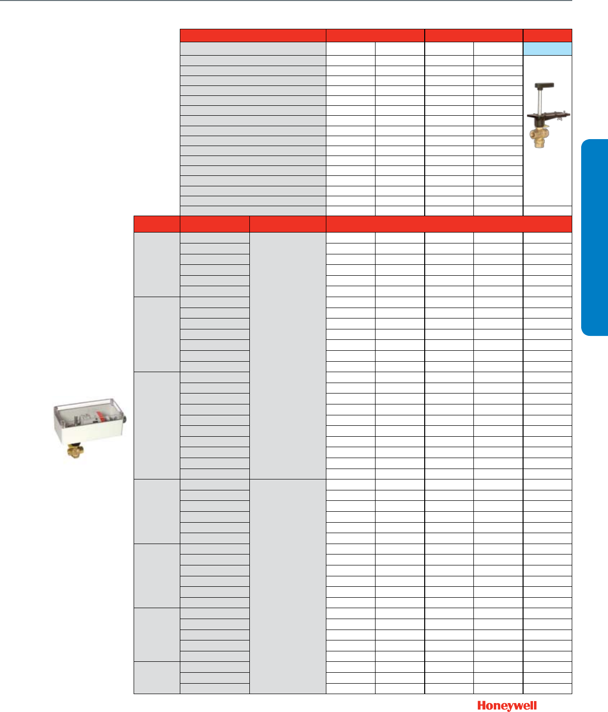
33
Actuator Features Non-fail Safe Fail Safe
Actuator O.S. Number MN6105A1011 MN7505A2001 MS8105A1030 MS7505A2030 Valve Only
Power Supply Voltage 24 Vac 24 Vac 24 Vac 24 Vac
Frequency 50 / 60 Hz 50 / 60 Hz 50 / 60 Hz 50 / 60 Hz
Power 5 VA 5 VA 8 VA 7.5 VA
Actuator Torque (lb.-in.) 44 44 44 44
Control (0)2-10 Vdc • •
4-20 mA (external 500 Ohm Resistor) • •
Floating • • •
Two-Position SPDT • • •
Two-Position SPST • • •
Fail Safe Action
(field configurable)
Stay in Place Stay in Place A-AB Closed A-AB Closed
Normal Position (no signal) (field configurable)
Closed Closed A-AB Closed A-AB Closed
Actuator Stroke (degrees) 95° ± 3° 95° ± 3° 95° ± 3° 95° ± 3°
Timing (seconds) 90 90 45 90
Aux Switch 2 x SPDT Add-on SSW2 SSW2
Feedback 2-10 Vdc Built In • •
Valve Features Trim Nickel-Plated Brass Nickel-Plated Brass Nickel-Plated Brass Nickel-Plated Brass Nickel-Plated Brass
Valve Size
(inches) Cv Close-off
Differential Pressure (psi) Valve O.S. Number
3-Way
1/2"
0.33
50
VBN3AB3PRA VBN3AB3PRB VBN3AB3PRC VBN3AB3PRD —
0.59 VBN3AC3PRA VBN3AC3PRB VBN3AC3PRC VBN3AC3PRD —
1VBN3AE3PRA VBN3AE3PRB VBN3AE3PRC VBN3AE3PRD —
2.4 VBN3AF3PRA VBN3AF3PRB VBN3AF3PRC VBN3AF3PRD —
4.3 VBN3AH3PRA VBN3AH3PRB VBN3AH3PRC VBN3AH3PRD —
8* VBN3AJ3PRA VBN3AJ3PRB VBN3AJ3PRC VBN3AJ3PRD —
3/4"
0.4 VBN3BC3PRA VBN3BC3PRB VBN3BC3PRC VBN3BC3PRD —
0.66 VBN3BD3PRA VBN3BD3PRB VBN3BD3PRC VBN3BD3PRD —
1.3 VBN3BE3PRA VBN3BE3PRB VBN3BE3PRC VBN3BE3PRD —
2.4 VBN3BF3PRA VBN3BF3PRB VBN3BF3PRC VBN3BF3PRD —
3.8 VBN3BG3PRA VBN3BG3PRB VBN3BG3PRC VBN3BG3PRD —
7VBN3BJ3PRA VBN3BJ3PRB VBN3BJ3PRC VBN3BJ3PRD —
11* VBN3BK3PRA VBN3BK3PRB VBN3BK3PRC VBN3BK3PRD —
1"
0.4 VBN3CC3PRA VBN3CC3PRB VBN3CC3PRC VBN3CC3PRD —
0.65 VBN3CD3PRA VBN3CD3PRB VBN3CD3PRC VBN3CD3PRD —
1.3 VBN3CE3PRA VBN3CE3PRB VBN3CE3PRC VBN3CE3PRD —
2.3 VBN3CF3PRA VBN3CF3PRB VBN3CF3PRC VBN3CF3PRD —
3.5 VBN3CG3PRA VBN3CG3PRB VBN3CG3PRC VBN3CG3PRD —
4.5 VBN3CH3PRA VBN3CH3PRB VBN3CH3PRC VBN3CH3PRD —
8.6 VBN3CJ3PRA VBN3CJ3PRB VBN3CJ3PRC VBN3CJ3PRD —
14.9 VBN3CK3PRA VBN3CK3PRB VBN3CK3PRC VBN3CK3PRD —
22* VBN3CL3PRA VBN3CL3PRB VBN3CL3PRC VBN3CL3PRD —
31* VBN3CM3PRA VBN3CM3PRB VBN3CM3PRC VBN3CM3PRD —
1-1/4"
4.1
40
VBN3DH3PRA VBN3DH3PRB VBN3DH3PRC VBN3DH3PRD —
8.7 VBN3DJ3PRA VBN3DJ3PRB VBN3DJ3PRC VBN3DJ3PRD —
12.7 VBN3DK3PRA VBN3DK3PRB VBN3DK3PRC VBN3DK3PRD —
19.4* VBN3DL3PRA VBN3DL3PRB VBN3DL3PRC VBN3DL3PRD —
27 VBN3DM3PRA VBN3DM3PRB VBN3DM3PRC VBN3DM3PRD —
34* VBN3DN3PRA VBN3DN3PRB VBN3DN3PRC VBN3DN3PRD —
1-1/2"
4VBN3EH3PRA VBN3EH3PRB VBN3EH3PRC VBN3EH3PRD —
8.3 VBN3EJ3PRA VBN3EJ3PRB VBN3EJ3PRC VBN3EJ3PRD —
13.4 VBN3EK3PRA VBN3EK3PRB VBN3EK3PRC VBN3EK3PRD —
24 VBN3EL3PRA VBN3EL3PRB VBN3EL3PRC VBN3EL3PRD —
32* VBN3EM3PRA VBN3EM3PRB VBN3EM3PRC VBN3EM3PRD —
61* VBN3EP3PRA VBN3EP3PRB VBN3EP3PRC VBN3EP3PRD —
2"
24 VBN3FL3PRA VBN3FL3PRB VBN3FL3PRC VBN3FL3PRD —
38 VBN3FN3PRA VBN3FN3PRB VBN3FN3PRC VBN3FN3PRD —
57* VBN3FP3PRA VBN3FP3PRB VBN3FP3PRC VBN3FP3PRD —
83 VBN3FR3PRA VBN3FR3PRB VBN3FR3PRC VBN3FR3PRD —
109* VBN3FT3PRA VBN3FT3PRB VBN3FT3PRC VBN3FT3PRD —
2-1/2"
38 VBN3GN3PRA VBN3GN3PRB VBN3GN3PRC VBN3GN3PRD —
74 VBN3GR3PRA VBN3GR3PRB VBN3GR3PRC VBN3GR3PRD —
100* VBN3GS3PRA VBN3GS3PRB VBN3GS3PRC VBN3GS3PRD —
VALVE SELECTION
Control Ball Valves ½- 2½"
3-Way NPT NEMA 3R
Full port ball. No flow characterizing insert.
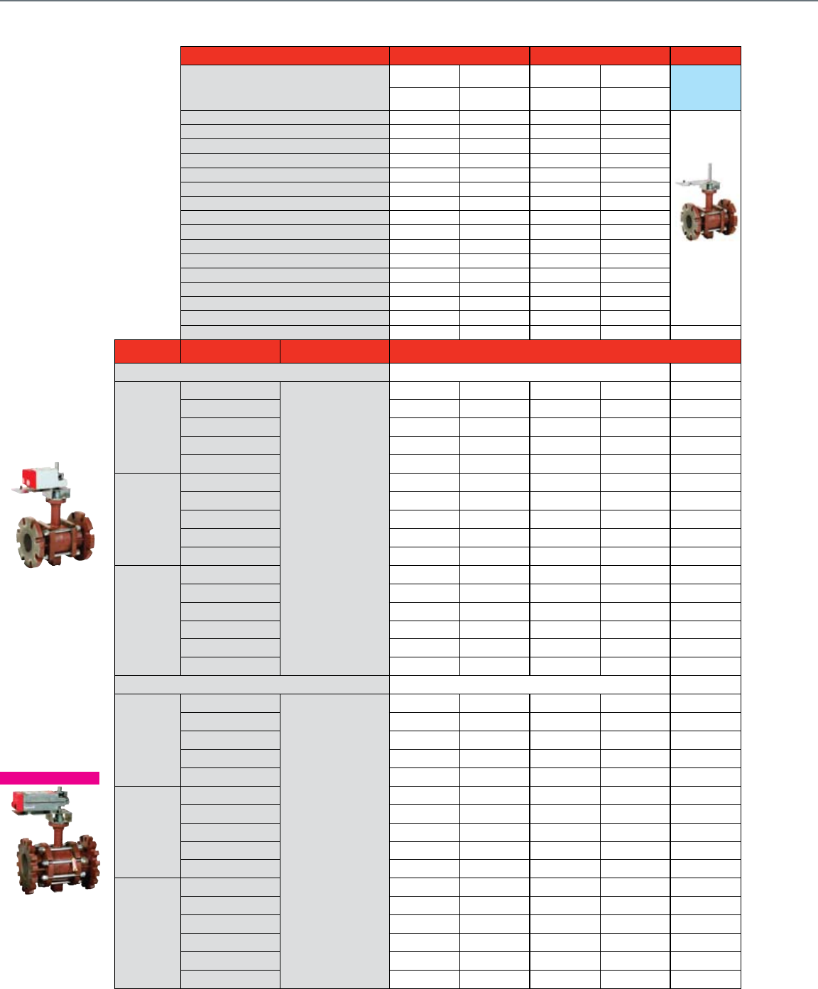
34
Flanged Control Ball Valves 4"- 6"
2-Way Flanged NEMA 2+3R
Actuator Features Non-fail Safe Fail Safe Valve Only
Actuator O.S. Number
MN6110A1003
4 to 5 in.
MN7510A2001
4 to 5 in.
MS8110A1008
4 to 5 in.
MS7510A2008
4 to 5 in. Valve Only
MN6134A1003
6 in.
MN7234A2008
6 in.
MS8120A1007
6 in.
MS7520A2007
6 in.
Power Supply Voltage 24 Vac 24 Vac 24 Vac 24 Vac
Frequency 50 / 60 Hz 50 / 60 Hz 50 / 60 Hz 50 / 60 Hz
Power 5 / 9 VA 5 / 9 VA 30 / 40 VA 14 / 16 VA
Actuator Torque (lb.-in.) 88/300 88/300 88/175 88/175
Control (0)2-10 Vdc • •
4-20 mA (external 500 Ohm Resistor) • •
Floating • • •
Two-Position SPDT • • •
Two-Position SPST • • • •
Fail Safe Action
(field configurable)
Stay in Place Stay in Place A-AB Closed A-AB Closed
Normal Position (no signal) (field configurable)
Closed Closed Closed Closed
Actuator Stroke (degrees) 95° 95° 95° 95°
Timing (seconds) 90 90 90 90
Aux Switch 2 x SPDT Add-on SW2-US SW2-US SW2-US SW2-US
Feedback 2-10 Vdc Built In • •
Valve Features Trim Stainless Steel Stainless Steel Stainless Steel Stainless Steel Stainless Steel
Valve Size
(inches) Cv Close-off
Differential Pressure (psi) Valve O.S. Number
2-Way
NEMA 2 Actuator
4"
91
70
VBF2JC1S0A VBF2JC1S0B VBF2JC1S0C VBF2JC1S0D VBF2JC1S0X
118 VBF2JT1S0A VBF2JT1S0B VBF2JT1S0C VBF2JT1S0D VBF2JT1S0X
152 VBF2JU1S0A VBF2JU1S0B VBF2JU1S0C VBF2JU1S0D VBF2JU1S0X
197 VBF2J11S0A VBF2J11S0B VBF2J11S0C VBF2J11S0D VBF2J11S0X
254 VBF2J21S0A VBF2J21S0B VBF2J21S0C VBF2J21S0D VBF2J21S0X
5"
144 VBF2KU1S0A VBF2KU1S0B VBF2KU1S0C VBF2KU1S0D VBF2KU1S0X
185 VBF2K11S0A VBF2K11S0B VBF2K11S0C VBF2K11S0D VBF2K11S0X
240 VBF2K21S0A VBF2K21S0B VBF2K21S0C VBF2K21S0D VBF2K21S0X
309 VBF2K31S0A VBF2K31S0B VBF2K31S0C VBF2K31S0D VBF2K31S0X
400 VBF2K41S0A VBF2K41S0B VBF2K41S0C — VBF2K41S0X
6"
208 VBF2L11S0A VBF2L11S0B VBF2L11S0C VBF2L11S0D VBF2L11S0X
268 VBF2L21S0A VBF2L21S0B VBF2L21S0C VBF2L21S0D VBF2L21S0X
346 VBF2L41S0A VBF2L41S0B VBF2L41S0C — VBF2L41S0X
441 VBF2L51S0A VBF2L51S0B VBF2L51S0C — VBF2L51S0X
577 VBF2L61S0A VBF2L61S0B VBF2L61S0C — VBF2L61S0X
650 VBF2L71S0A VBF2L71S0B VBF2L71S0C — VBF2L71S0X
NEMA 3R Actuator
4"
91
70
VBF2JC1SRA VBF2JC1SRB VBF2JC1SRC VBF2JC1SRD —
118 VBF2JT1SRA VBF2JT1SRB VBF2JT1SRC VBF2JT1SRD —
152 VBF2JU1SRA VBF2JU1SRB VBF2JU1SRC VBF2JU1SRD —
197 VBF2J11SRA VBF2J11SRB VBF2J11SRC VBF2J11SRD —
254 VBF2J21SRA VBF2J21SRB VBF2J21SRC VBF2J21SRD —
5"
144 VBF2KU1SRA VBF2KU1SRB VBF2KU1SRC VBF2KU1SRD —
185 VBF2K11SRA VBF2K11SRB VBF2K11SRC VBF2K11SRD —
240 VBF2K21SRA VBF2K21SRB VBF2K21SRC VBF2K21SRD —
309 VBF2K31SRA VBF2K31SRB VBF2K31SRC VBF2K31SRD —
400 VBF2K41SRA VBF2K41SRB VBF2K41SRC — —
6"
208 VBF2L11SRA VBF2L11SRB VBF2L11SRC VBF2L11SRD —
268 VBF2L21SRA VBF2L21SRB VBF2L21SRC VBF2L21SRD —
346 VBF2L41SRA VBF2L41SRB VBF2L41SRC — —
441 VBF2L51SRA VBF2L51SRB VBF2L51SRC — —
577 VBF2L61SRA VBF2L61SRB VBF2L61SRC — —
650 VBF2L71SRA VBF2L71SRB VBF2L71SRC — —
Common Features
• Maximum static pressure
240 psi (-22°F to 250°F)
• Medium: Water/glycol
solutions up to 50%
• ANSI class 125 anged
connections
• ANSI class IV leakage
(0.01% of Cv)
• Valve ball and stem 316
stainless steel
• Equal percentage ow
(linear full port)
NEW PHOTO
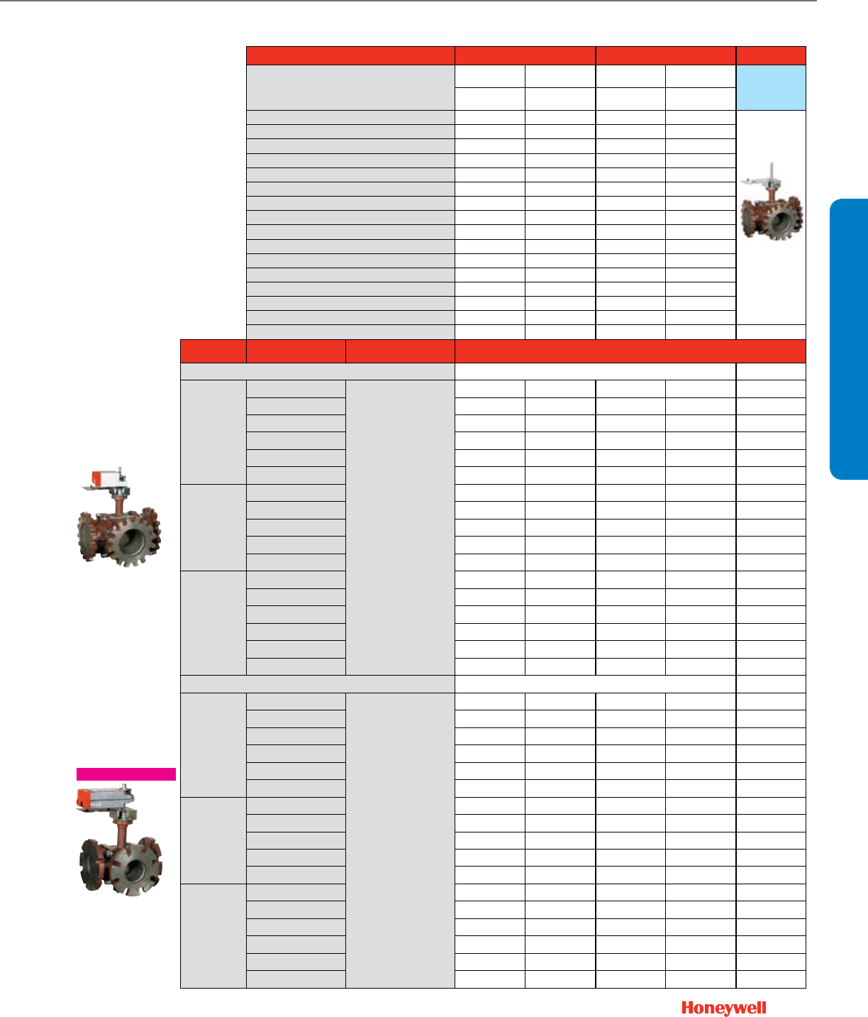
35
Actuator Features Non-fail Safe Fail Safe Valve Only
Actuator O.S. Number
MN6110A1003
4 to 5 in.
MN7510A2001
4 to 5 in.
MS8110A1008
4 to 5 in.
MS7510A2008
4 to 5 in. Valve Only
MN6134A1003
6 in.
MN7234A2008
6 in.
MS8120A1007
6 in.
MS7520A2007
6 in.
Power Supply Voltage 24 Vac 24 Vac 24 Vac 24 Vac
Frequency 50 / 60 Hz 50 / 60 Hz 50 / 60 Hz 50 / 60 Hz
Power 5 / 9 VA 5 / 9 VA 30 / 40 VA 14 / 16 VA
Actuator Torque (lb.-in.) 88/300 88/300 88/175 88/175
Control (0)2-10 Vdc • •
4-20 mA (external 500 Ohm Resistor) • •
Floating • • •
Two-Position SPDT • • •
Two-Position SPST • • • •
Fail Safe Action
(field configurable)
Stay in Place Stay in Place A-AB Closed A-AB Closed
Normal Position (no signal) (field configurable)
A-AB Closed A-AB Closed A-AB Closed A-AB Closed
Actuator Stroke (degrees) 95° 95° 95° 95°
Timing (seconds) 90 90 90 90
Aux Switch 2 x SPDT Add-on SW2-US SW2-US SW2-US SW2-US
Feedback 2-10 Vdc Built In • •
Valve Features Trim Stainless Steel Stainless Steel Stainless Steel Stainless Steel Stainless Steel
Valve Size
(inches) Cv Close-off
Differential Pressure (psi) Valve O.S. Number
3-Way
NEMA 2 Actuator
4"
91
70
VBF3JS1S0A VBF3JS1S0B VBF3JS1S0C VBF3JS1S0D VBF3JS1S0X
118 VBF3JT1S0A VBF3JT1S0B VBF3JT1S0C VBF3JT1S0D VBF3JT1S0X
152 VBF3JU1S0A VBF3JU1S0B VBF3JU1S0C VBF3JU1S0D VBF3JU1S0X
197 VBF3J11S0A VBF3J11S0B VBF3J11S0C VBF3J11S0D VBF3J11S0X
254 VBF3J21S0A VBF3J21S0B VBF3J21S0C VBF3J21S0D VBF3J21S0X
327 VBF3J31S0A VBF3J31S0B VBF3J31S0C VBF3J31S0D VBF3J31S0X
5"
144 VBF3KU1S0A VBF3KU1S0B VBF3KU1S0C VBF3KU1S0D VBF3KU1S0X
185 VBF3K11S0A VBF3K11S0B VBF3K11S0C VBF3K11S0D VBF3K11S0
240 VBF3K21S0A VBF3K21S0B VBF3K21S0C VBF3K21S0D VBF3K21S0X
309 VBF3K31S0A VBF3K31S0B VBF3K31S0C VBF3K31S0D VBF3K31S0X
400 VBF3K41S0A VBF3K41S0B VBF3K41S0C — VBF3K41S0X
6"
208 VBF3L11S0A VBF3L11S0B VBF3L11S0C VBF3L11S0D VBF3L11S0X
268 VBF3L21S0A VBF3L21S0B VBF3L21S0C VBF3L21S0D VBF3L21S0X
346 VBF3L41S0A VBF3L41S0B VBF3L41S0C — VBF3L41S0X
441 VBF3L51S0A VBF3L51S0B VBF3L51S0C — VBF3L51S0X
577 VBF3L61S0A VBF3L61S0B VBF3L61S0C — VBF3L61S0X
650 VBF3L71S0A VBF3L71S0B VBF3L71S0C — VBF3L71S0X
NEMA 3R Actuator —
4"
91
70
VBF3JS1SRA VBF3JS1SRB VBF3JS1SRC VBF3JS1SRD —
118 VBF3JT1SRA VBF3JT1SRB VBF3JT1SRC VBF3JT1SRD —
152 VBF3JU1SRA VBF3JU1SRB VBF3JU1SRC VBF3JU1SRD —
197 VBF3J11SRA VBF3J11SRB VBF3J11SRC VBF3J11SRD —
254 VBF3J21SRA VBF3J21SRB VBF3J21SRC VBF3J21SRD —
327 VBF3J31SRA VBF3J31SRB VBF3J31SRC VBF3J31SRD —
5"
144 VBF3KU1SRA VBF3KU1SRB VBF3KU1SRC VBF3KU1SRD —
185 VBF3K11SRA VBF3K11SRB VBF3K11SRC VBF3K11SRD —
240 VBF3K21SRA VBF3K21SRB VBF3K21SRC VBF3K21SRD —
309 VBF3K31SRA VBF3K31SRB VBF3K31SRC VBF3K31SRD —
400 VBF3K41SRA VBF3K41SRB VBF3K41SRC — —
6"
208 VBF3L11SRA VBF3L11SRB VBF3L11SRC VBF3L11SRD —
268 VBF3L21SRA VBF3L21SRB VBF3L21SRC VBF3L21SRD —
346 VBF3L41SRA VBF3L41SRB VBF3L41SRC — —
441 VBF3L51SRA VBF3L51SRB VBF3L51SRC — —
577 VBF3L61SRA VBF3L61SRB VBF3L61SRC — —
650 VBF3L71SRA VBF3L71SRB VBF3L71SRC — —
Common Features
• Mixing or diverting with the
same 3-way valve
• Globe valve A-B-AB ow
pattern (side B port)
• Three-way: A-AB equal
percentage, B-AB linear
(80% of Cv on B-port)
VALVE SELECTION
Flanged Control Ball Valves 4"- 6"
3-Way Flanged NEMA 2+3R
NEW PHOTO
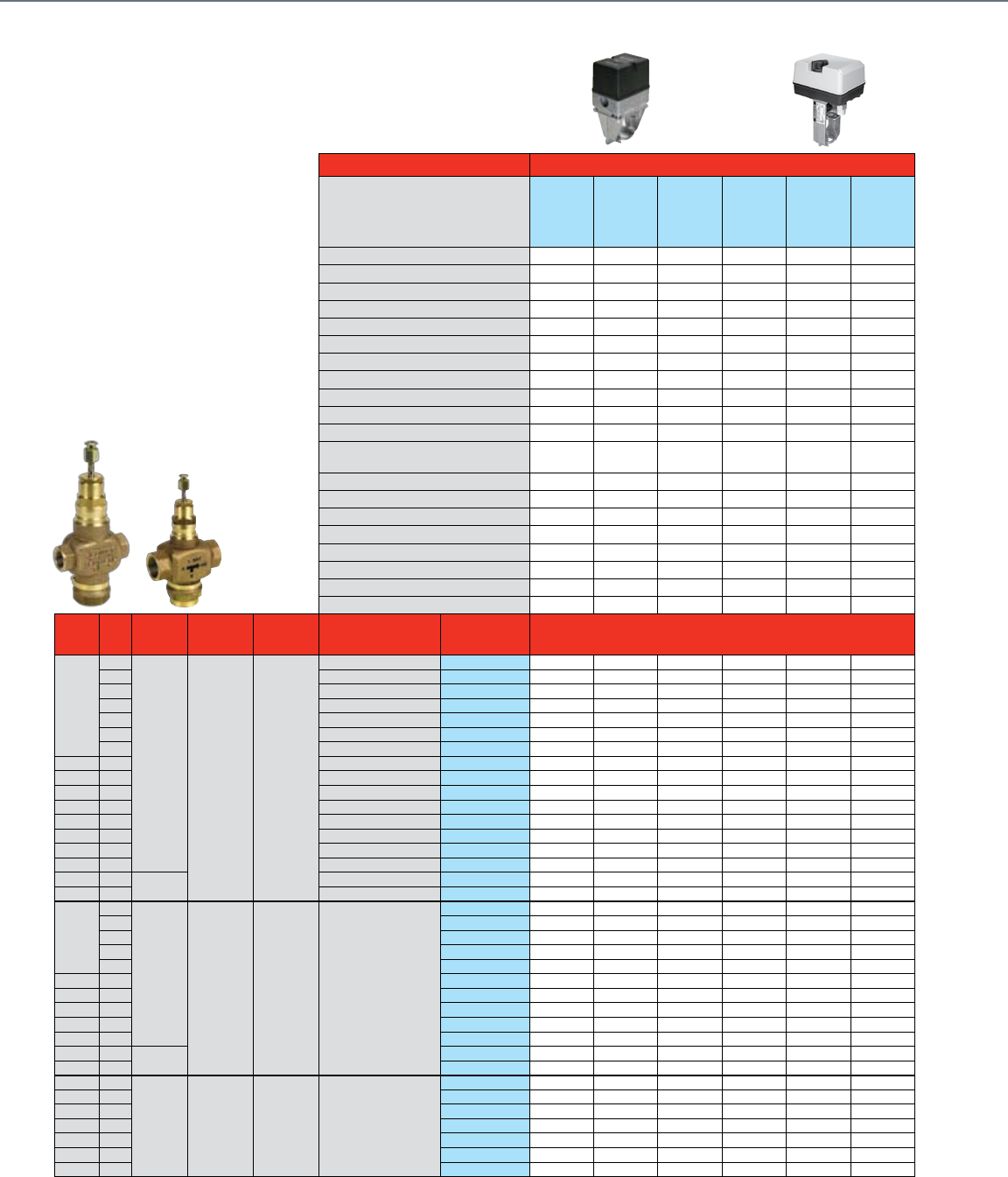
36
NPT Globe Valves ½- 3"
With Dedicated Valve Actuators
For more than 50 years, Honeywell Globe
Valves (V5011/13, VGF) have provided
precise control for most applications.
Globe valves provide the rangeability and
close-off needed to keep tight control
of the environment.
Actuator Features Non-Fail Safe
Actuator O.S. Number
ML7984A4009
ML6984A4000
ML7420A3055
ML7420A3063
ML6420A3049
ML6420A3056
Power Supply Voltage
24 Vac / 28 Vdc 24 Vac / 28 Vdc
24 Vac 24 Vac 24 Vac 24 Vac
Frequency
0 / 50 / 60 Hz 0 / 50 / 60 Hz
50 / 60 Hz 50 / 60 Hz 50 / 60 Hz 50 / 60 Hz
Power 12 VA 12 VA 7 VA 7 VA 6 VA 6 VA
Actuator Stem Force (lbs.) 160 160 135 135 135 135
Control (0)2-10 Vdc Built-in •* •*
4-20 mA (external 500 Ohm Resistor) • • •
Floating • • •
Two-Position SPDT
Two-Position SPST •
135 Ohm Stay in place Stay in place Stay in place Stay in place Stay in place Stay in place
Fail Safe Action Stem Up Stem Up Stem Up Stem Up Stem Up Stem Up
Normal Position (no signal) (field configurable)
0.5 - 1 self adj 0.5 - 1 self adj 0.75 0.75 0.75 0.75
Actuator Stroke (inches) 63 63 60 30 60 30
Timing (seconds at 0.75" stroke)
43196000-001 43196000-001 43196000-001 43196000-001
Aux Switch 1 x SPDT Add-On
43191680-105 43191680-105 43191680-105 43191680-105
2 x SPDT Add-On • •
Feedback 2-10 Vdc Built-in 272630D 272630D
2-10 Vdc Add-On
43191679-111 43191679-111
220 Ohm Add-On
43191679-112 43191679-111
10 kOhm Add-On 200976B 200976B 200976B 200976B
Valve
Size
(inches)
Cv
Max Static
Water
Pressure
Max Steam
Pressure /
Temperature
Flow
Characteristic
Valve
Action
Valve OS
Number Close-off Pressure, psid
2-Way
Water Valves
Straight Through
1/2"
0.73
217 psi
@ 248 F 15 psi
(2-position) Equal %
Stem down to close V5011N1008 230 230 230 230 230 230
1.16 Stem down to close V5011N1016 230 230 230 230 230 230
1.85 Stem down to close V5011N1024 230 230 230 230 230 230
2.9 Stem down to close V5011N1032 230 230 230 230 230 230
2.9 Stem up to close V5011N3004 230 230 230 230 230 230
4.7 Stem down to close V5011N1040 230 230 230 230 230 230
4.7 Stem up to close V5011N3012 230 230 230 230 230 230
3/4" 7.3 Stem down to close V5011N1057 230 230 230 230 230 230
3/4" 7.3 Stem up to close V5011N3020 230 230 230 230 230 230
1" 11.7 Stem down to close V5011N1065 193 193 163 163 163 163
1" 11.7 Stem up to close V5011N3038 193 193 163 163 163 163
1-1/4" 18.7 Stem down to close V5011N1073 123 123 104 104 104 104
1-1/4" 18.7 Stem up to close V5011N3046 123 123 104 104 104 104
1-1/2" 29.3 Stem down to close V5011N1081 79 79 67 67 67 67
2" 46.8 Stem down to close V5011N1099 44 44 37 37 37 37
2-1/2" 63 250 psi
@ 100F
Stem down to close V5011F1105 33 33 28 28 28 28
3" 100 Stem down to close V5011F1113 19 19 16 16 16 16
2-Way
Steam Valves
Straight Through
1/2"
0.73
217 psi
@ 248 F 100 psig /
337 F Linear Stem down to close
V5011N2006 100 100 100 100 100 100
1.16 V5011N2014 100 100 100 100 100 100
1.85 V5011N2022 100 100 100 100 100 100
2.9 V5011N2030 100 100 100 100 100 100
4.7 V5011N2048 100 100 100 100 100 100
3/4" 7.3 V5011N2055 100 100 100 100 100 100
1" 11.7 V5011N2063 100 100 100 100 100 100
1-1/4" 18.7 V5011N2071 100 100 100 100 100 100
1-1/2" 29.3 V5011N2089 79 79 67 67 67 67
2" 46.8 V5011N2097 44 44 37 37 37 37
2-1/2" 63 250 psi
@ 100F
V5011G1111 33 33 28 28 28 28
3" 100 V5011G1129 19 19 16 16 16 16
3-Way
Water Valves
Mixing
1/2" 2.9
217 psi
@ 248 F N / A Linear B-AB /
Equal % A-AB Stem up closes A-AB
V5013N1030 230 230 230 230 230 230
1/2" 4.7 V5013N1048 230 230 230 230 230 230
3/4" 7.3 V5013N1055 230 230 230 230 230 230
1" 11.7 V5013N1063 193 193 163 163 163 163
1-1/4" 18.7 V5013N1071 123 123 104 104 104 104
1-1/2" 29.3 V5013N1089 79 79 67 67 67 67
2" 46.8 V5013N1097 44 44 37 37 37 37
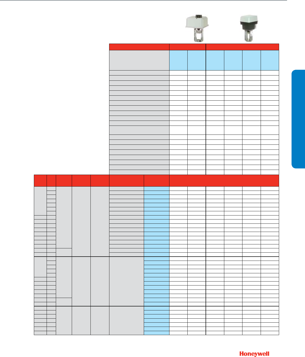
37
Actuator Features Non-Fail Safe Fail Safe
Actuator O.S. Number
ML7421A1032
ML6421A1017
ML7425A3013
ML7425B3012
ML6425A3022
ML6425B3013
Power Supply Voltage 24 Vac 24 Vac 24 Vac 24 Vac 24 Vac 24 Vac
Frequency 50 / 60 Hz 50 / 60 Hz 50 / 60 Hz 50 / 60 Hz 50 / 60 Hz 50 / 60 Hz
Power 12 VA 11 VA 12 VA 12 VA 11 VA 11 VA
Actuator Stem Force (lbs.) 404 404 135 135 135 135
Control (0)2-10 Vdc •* •* •*
4-20 mA (external 500 Ohm Resistor) • • •
Floating • • •
Two-Position SPDT • •
Two-Position SPST
135 Ohm Stay in place Stay in place Stem Down Stem Up Stem Down Stem Up
Fail Safe Action Stem Up Stem Up Stem Up Stem Up Stem Up Stem Up
Normal Position (no signal) (field configurable)
0.75 0.75 0.75 0.75 0.75 0.75
Actuator Stroke (inches) 90 90 90 90 90 90
Timing (seconds at 0.75" stroke)
43196000-001 43196000-001 43196000-001 43196000-001 43196000-001 43196000-001
Aux Switch 1 x SPDT Add-On
43191680-102 43191680-102 43191680-105 43191680-105 43191680-105 43191680-105
2 x SPDT Add-On • • •
Feedback 2-10 Vdc Built-in
2-10 Vdc Add-On
43191679-101 43191679-111
220 Ohm Add-On
43191679-112
10 kOhm Add-On 200976B 200976B 200976B 200976B
Valve
Size
(inches)
Cv
Max Static
Water
Pressure
Max Steam
Pressure /
Temperature
Flow
Characteristic
Valve
Action
Valve OS
Number Close-off Pressure, psid
2-Way
Water Valves
Straight Through
1/2"
0.73
217 psi
@ 248 F 15 psi
(2-position) Equal %
Stem down to close V5011N1008 230* 230** 230* 230**
1.16 Stem down to close V5011N1016 230* 230** 230* 230**
1.85 Stem down to close V5011N1024 230* 230** 230* 230**
2.9 Stem down to close V5011N1032 230* 230** 230* 230**
2.9 Stem up to close V5011N3004 230** 230* 230** 230*
4.7 Stem down to close V5011N1040 230* 230** 230* 230**
4.7 Stem up to close V5011N3012 230* 230** 230* 230**
3/4" 7.3 Stem down to close V5011N1057 230* 230** 230* 230**
3/4" 7.3 Stem up to close V5011N3020 230** 230* 230** 230*
1" 11.7 Stem down to close V5011N1065 230 230 163* 163** 163* 163**
1" 11.7 Stem up to close V5011N3038 230 230 163** 163* 163** 163*
1-1/4" 18.7 Stem down to close V5011N1073 230 230 104* 104** 104* 104**
1-1/4" 18.7 Stem up to close V5011N3046 230 230 104** 104* 104** 104*
1-1/2" 29.3 Stem down to close V5011N1081 221 221 67* 67** 67* 67**
2" 46.8 Stem down to close V5011N1099 126 126 37* 37** 37* 37**
2-1/2" 63 250 psi
@ 100F
Stem down to close V5011F1105 100 100 28* 28** 28* 28**
3" 100 Stem down to close V5011F1113 61 61 16* 16** 16* 16**
2-Way
Steam Valves
Straight Through
1/2"
0.73
217 psi
@ 248 F 100 psig /
337 F Linear Stem down to close
V5011N2006 100* 100** 100* 100**
1.16 V5011N2014 100* 100** 100* 100**
1.85 V5011N2022 100* 100** 100* 100**
2.9 V5011N2030 100* 100** 100* 100**
4.7 V5011N2048 100* 100** 100* 100**
3/4" 7.3 V5011N2055 100* 100** 100* 100**
1" 11.7 V5011N2063 100 100 100* 100** 100* 100**
1-1/4" 18.7 V5011N2071 100 100 100* 100** 100* 100**
1-1/2" 29.3 V5011N2089 100 100 67* 67** 67* 67**
2" 46.8 V5011N2097 100 100 37* 37** 37* 37**
2-1/2" 63 250 psi
@ 100F
V5011G1111 100 100 28* 28** 28* 28**
3" 100 V5011G1129 61 61 16* 16** 16* 16**
3-Way
Water Valves
Mixing
1/2" 2.9
217 psi
@ 248 F N / A Linear B-AB /
Equal % A-AB Stem up closes A-AB
V5013N1030 230 230 230 230
1/2" 4.7 V5013N1048 230 230 230 230
3/4" 7.3 V5013N1055 230 230 230 230
1" 11.7 V5013N1063 230 230 163 163 163 163
1-1/4" 18.7 V5013N1071 230 230 104 104 104 104
1-1/2" 29.3 V5013N1089 221 221 67 67 67 67
2" 46.8 V5013N1097 126 126 37 37 37 37
* valve is Normally Closed on loss of power
** valve is Normally Open on loss of power.
VALVE SELECTION
Common Features
• ANSI body class 150
• Close-off pressure = maximum
differential pressure
• Maximum static water pressure (250°F):
240 psi
• Maximum steam pressure
2-way steam valves, 337°F: 100 psi
2-way water valves: 15 psi
• Stem travel: 0.75"
• Rangeability: 50:1
• Leakage < 0.05% of Cv
• Body material: Red brass, stainless
steel stem (steam valve has stainless
steel trim)
NPT Globe Valves ½- 3"
With Dedicated Valve Actuators
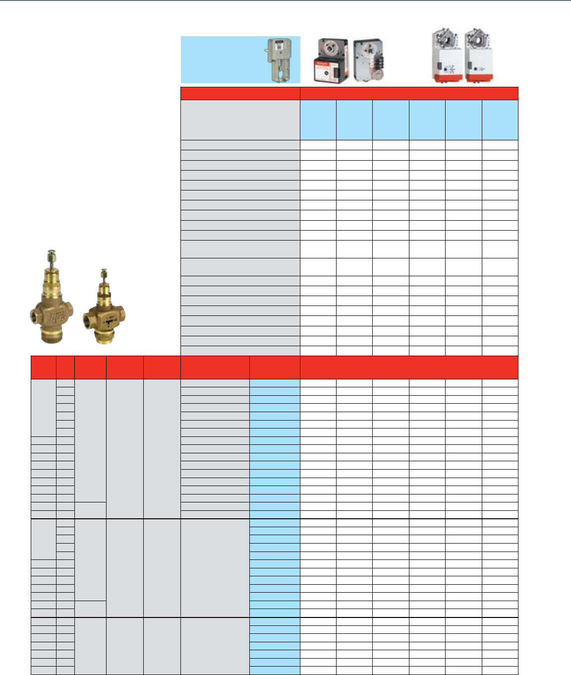
38
Common Features
• ANSI body class 150
• Close-Off pressure = maximum
differential pressure
• Maximum static water pressure (250°F):
240 psi
• Maximum steam pressure
2-way steam valves, 337°F: 100 psi
2-way water valves: 15 psi
• Stem travel: 0.75"
• Rangeability: 50:1
• Leakage < 0.05% of Cv
• Body material: Red brass, stainless steel
stem (steam valve has stainless steel
trim)
Actuator Features Non-Fail Safe
Actuator O.S. Number
ML7161A2008
ML6161B2024
ML7174A2001
ML6174B2019
MN7505A2001
MN7505A2209
MN6105A1011
MN6105A1201
Power Supply Voltage 24 Vac 24 Vac 24 Vac 24 Vac 24 Vac 24 Vac
Frequency 50 / 60 Hz 50 / 60 Hz 50 / 60 Hz 50 / 60 Hz 50 / 60 Hz 50 / 60 Hz
Power 5.4 VA 1.8 VA 5.4 VA 2.4 VA 5 VA 5 VA
Actuator Torque (lb.-in.) 35 35 70 70 44 44
Linkage Stem Force (lbs.) 46 46 93 93 58 58
Control (0)2-10 Vdc •••
4-20 mA (external 500 Ohm Resistor) •••
Floating • • • •
Two-Position SPDT • • • •
Two-Position SPST • •
Fail Safe Action Stay in Place Stay in Place Stay in Place Stay in Place Stay in Place Stay in Place
Normal Position (no signal) (field configurable)
Stem Up/DownStem Up/Down Stem Up/Down Stem Up/Down Stem Up/Down Stem Up/Down
Actuator Stroke (inches) 90° 90° 90° 90° 95° 95°
Timing (seconds at 0.75" stroke) 90 90 90 90 95 95
Aux Switch 2 x SPDT Built In 0 / 2 0 / 2
1 x SPDT Add-On 201052A 201052A 201052A 201052A
2 x SPDT Add-On 201052B 201052B 201052B 201052B SSW2 SSW2
Feedback (0)2-10 Vdc Built In •
500 Ohm Add-On 200976A 200976A 200976A 200976A
2 kOhm Add-On 200976B 200976B 200976B 200976B
Valve
Size
(inches)
Cv
Max Static
Water
Pressure
Max Steam
Pressure /
Temperature
Flow
Characteristic
Valve
Action
Valve OS
Number Close-off Pressure, psid
2-Way
Water Valves
Straight Through
1/2"
0.73
217 psi
@ 248 F 15 psi
(2-position) Equal %
Stem down to close V5011N1008 230 230 230 230 230 230
1.16 Stem down to close V5011N1016 230 230 230 230 230 230
1.85 Stem down to close V5011N1024 230 230 230 230 230 230
2.9 Stem down to close V5011N1032 230 230 230 230 230 230
2.9 Stem up to close V5011N3004 230 230 230 230 230 230
4.7 Stem down to close V5011N1040 143 143 230 230 188 188
4.7 Stem up to close V5011N3012 143 143 230 230 188 188
3/4" 7.3 Stem down to close V5011N1057 69 69 156 156 91 91
3/4" 7.3 Stem up to close V5011N3020 69 69 156 156 91 91
1" 11.7 Stem down to close V5011N1065 47 47 109 109 63 63
1" 11.7 Stem up to close V5011N3038 47 47 109 109 63 63
1-1/4" 18.7 Stem down to close V5011N1073 29 29 69 69 39 39
1-1/4" 18.7 Stem up to close V5011N3046 29 29 69 69 39 39
1-1/2" 29.3 Stem down to close V5011N1081 17 17 44 44 24 24
2" 46.8 Stem down to close V5011N1099 8 8 24 24 12 12
2-1/2" 63 250 psi
@ 100F
Stem down to close V5011F1105 5 5 16 16 7 7
3" 100 Stem down to close V5011F1113 229933
2-Way
Steam Valves
Straight Through
1/2"
0.73
217 psi
@ 248 F 100 psig /
337 F Linear Stem down to close
V5011N2006 100 100 100 100 100 100
1.16 V5011N2014 100 100 100 100 100 100
1.85 V5011N2022 100 100 100 100 100 100
2.9 V5011N2030 100 100 100 100 100 100
4.7 V5011N2048 100 100 100 100 100 100
3/4" 7.3 V5011N2055 69 69 100 100 91 91
1" 11.7 V5011N2063 47 47 100 100 63 63
1-1/4" 18.7 V5011N2071 29 29 69 69 39 39
1-1/2" 29.3 V5011N2089 17 17 44 44 24 24
2" 46.8 V5011N2097 8 8 24 24 12 12
2-1/2" 63 250 psi
@ 100F
V5011G1111 5 5 16 16 7 7
3" 100 V5011G1129 229933
3-Way
Water Valves
Mixing
1/2" 2.9
217 psi
@ 248 F N / A Linear B-AB /
Equal % A-AB Stem up closes A-AB
V5013N1030 230 230 230 230 230 230
1/2" 4.7 V5013N1048 143 143 230 230 188 188
3/4" 7.3 V5013N1055 69 69 156 156 91 91
1" 11.7 V5013N1063 47 47 109 109 63 63
1-1/4" 18.7 V5013N1071 29 29 69 69 39 39
1-1/2" 29.3 V5013N1089 17 17 44 44 24 24
2" 46.8 V5013N1097 8 8 24 24 12 12
Q5020A1003
Required
NPT Globe Valves ½- 3"
With Direct Coupled Actuators and Valve Linkage
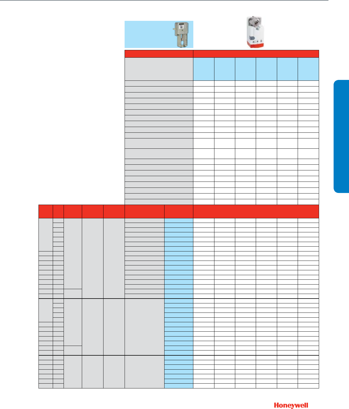
39
Actuator Features Non-Fail Safe
Actuator O.S. Number
MN7510A2001
MN7510A2209
MN6110A1003
MN6110A1201
MN7220A2007
MN7220A2205
MN6120A1002
MN6120A1200
MN7234A2008
MN6134A1003
Power Supply Voltage 24 Vac 24 Vac 24 Vac 24 Vac 24 Vac 24 Vac
Frequency 50 / 60 Hz 50 / 60 Hz 50 / 60 Hz 50 / 60 Hz 50 / 60 Hz 50 / 60 Hz
Power 5 VA 5 VA 6 VA 6 VA 9 VA 9 VA
Actuator Torque (lb.-in.) 88 88 175 175 300 300
Linkage Stem Force (lbs.) 117 117 234 234 402 402
Control (0)2-10 Vdc •••
4-20 mA (external 500 Ohm Resistor) •••
Floating •••• •
Two-Position SPDT •••• •
Two-Position SPST ••••••
Fail Safe Action Stay in Place Stay in Place Stay in Place Stay in Place Stay in Place Stay in Place
Normal Position (no signal) (field configurable)
Stem Up/DownStem Up/Down Stem Up/Down Stem Up/Down Stem Up/Down Stem Up/Down
Actuator Stroke (inches) 95° 95° 95° 95° 95° 95°
Timing (seconds at 0.75" stroke) 95 95 95 95 95 95
Aux Switch 2 x SPDT Built In 0 / 2 0 / 2 0 / 2 0 / 2
1 x SPDT Add-On
2 x SPDT Add-On SSW2 SSW2 SW2-US SW2-US SW2-US SW2-US
Feedback (0)2-10 Vdc Built In •••
500 Ohm Add-On
2 kOhm Add-On
Valve
Size
(inches)
Cv
Max Static
Water
Pressure
Max Steam
Pressure /
Temperature
Flow
Characteristic
Valve
Action
Valve OS
Number Close-off Pressure, psid
2-Way
Water Valves
Straight Through
1/2"
0.73
217 psi
@ 248 F 15 psi
(2-position) Equal %
Stem down to close V5011N1008 230 230 230 230 230 230
1.16 Stem down to close V5011N1016 230 230 230 230 230 230
1.85 Stem down to close V5011N1024 230 230 230 230 230 230
2.9 Stem down to close V5011N1032 230 230 230 230 230 230
2.9 Stem up to close V5011N3004 230 230 230 230 230 230
4.7 Stem down to close V5011N1040 230 230 230 230 230 230
4.7 Stem up to close V5011N3012 230 230 230 230 230 230
3/4" 7.3 Stem down to close V5011N1057 192 192 230 230 230 230
3/4" 7.3 Stem up to close V5011N3020 192 192 230 230 230 230
1" 11.7 Stem down to close V5011N1065 135 135 230 230 230 230
1" 11.7 Stem up to close V5011N3038 135 135 230 230 230 230
1-1/4" 18.7 Stem down to close V5011N1073 85 85 168 168 230 230
1-1/4" 18.7 Stem up to close V5011N3046 85 85 168 168 230 230
1-1/2" 29.3 Stem down to close V5011N1081 55 55 113 113 180 180
2" 46.8 Stem down to close V5011N1099 30 30 63 63 103 103
2-1/2" 63 250 psi
@ 100F
Stem down to close V5011F1105 19 19 42 42 74 74
3" 100 Stem down to close V5011F1113 11 11 26 26 45 45
2-Way
Steam Valves
Straight Through
1/2"
0.73
217 psi
@ 248 F 100 psig /
337 F Linear Stem down to close
V5011N2006 100 100 100 100 100 100
1.16 V5011N2014 100 100 100 100 100 100
1.85 V5011N2022 100 100 100 100 100 100
2.9 V5011N2030 100 100 100 100 100 100
4.7 V5011N2048 100 100 100 100 100 100
3/4" 7.3 V5011N2055 100 100 100 100 100 100
1" 11.7 V5011N2063 100 100 100 100 100 100
1-1/4" 18.7 V5011N2071 85 85 100 100 100 100
1-1/2" 29.3 V5011N2089 55 55 100 100 100 100
2" 46.8 V5011N2097 30 30 58 58 100 100
2-1/2" 63 250 psi
@ 100F
V5011G1111 19 19 42 42 74 74
3" 100 V5011G1129 11 11 26 26 45 45
3-Way
Water Valves
Mixing
1/2" 2.9
217 psi
@ 248 F N / A Linear B-AB /
Equal % A-AB Stem up closes A-AB
V5013N1030 230 230 230 230 230 230
1/2" 4.7 V5013N1048 230 230 230 230 230 230
3/4" 7.3 V5013N1055 192 192 230 230 230 230
1" 11.7 V5013N1063 135 135 230 230 230 230
1-1/4" 18.7 V5013N1071 85 85 168 168 230 230
1-1/2" 29.3 V5013N1089 55 55 105 105 180 180
2" 46.8 V5013N1097 30 30 103 103 103 103
VALVE SELECTION
NPT Globe Valves ½- 3"
With Direct Coupled Actuators and Valve Linkage
Q5020A1003
Required
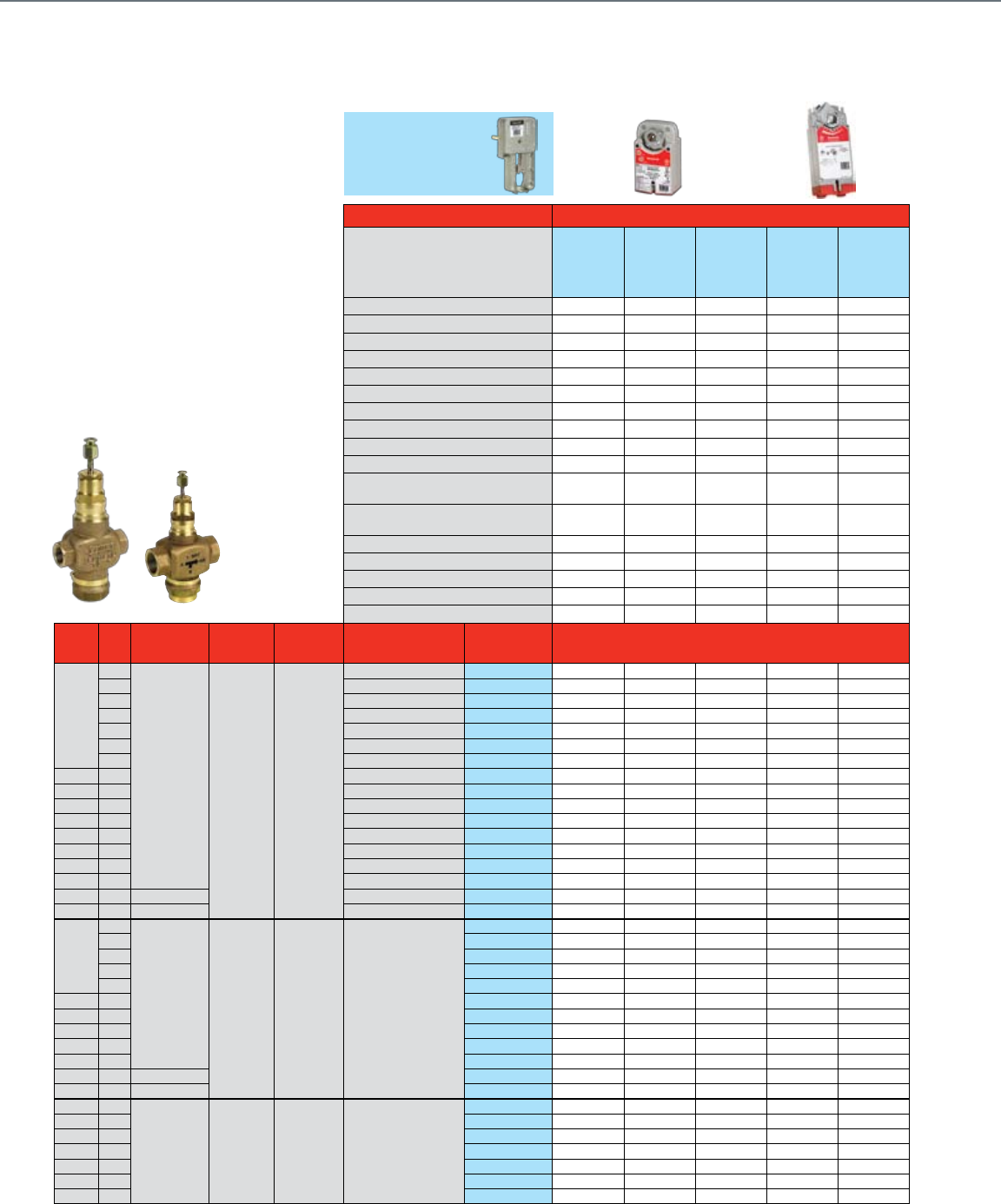
40
Actuator Features Fail Safe
Actuator O.S. Number
MS7505A2030
MS7505A2130
MS8105A1030
MS8105A1130
MS4105A1030
MS4105A1130
MS7510A2008
MS7510A2206
MS7510H2209
MS8110A1008
MS8110A1206
Power Supply Voltage 24 Vac 24 Vac 100-250 Vac 24 Vac 24 Vac
Frequency 50 / 60 Hz 50 / 60 Hz 60 Hz 50 / 60 Hz 50 / 60 Hz
Power 7.5VA 8 VA 11VA 14 VA 30 VA
Actuator Torque (lb.-in.) 44 44 44 88 88
Linkage Stem Force (lbs.) 58 58 58 117 117
Control (0)2-10 Vdc • •
4-20 mA (external 500 Ohm Resistor) • •
Floating • •
Two-Position SPDT • •
Two-Position SPST •••••
Fail Safe Action Congurable
Open/Closed
Congurable
Open/Closed
Congurable
Open/Closed
Congurable
Open/Closed
Congurable
Open/Closed
Normal Position (no signal) (field configurable)
Stem Up/Down Stem Up/Down Stem Up/Down Stem Up/Down Stem Up/Down
Actuator Stroke (inches) 95° 95° 95° 95° 95°
Timing (seconds at 0.75" stroke) 90 90 90 90 90
Aux Switch SPDT Built In 0 / 1 0 / 1 0 / 1 0 / 2 / 2 0 / 2
2 x SPDT Add-On SW2-US SW2-US
Feedback 2-10 Vdc Built In • •
Valve
Size
(inches)
Cv Max Static
Water Pressure
Max Steam
Pressure /
Temperature
Flow
Characteristic
Valve
Action
Valve OS
Number Close-off Pressure, psid
2-Way
Water Valves
Straight Through
1/2"
0.73
217 psi @ 248 F 15 psi
(2-position) Equal %
Stem down to close V5011N1008 230 230 230 230 230
1.16 Stem down to close V5011N1016 230 230 230 230 230
1.85 Stem down to close V5011N1024 230 230 230 230 230
2.9 Stem down to close V5011N1032 230 230 230 230 230
2.9 Stem up to close V5011N3004 230 230 230 230 230
4.7 Stem down to close V5011N1040 184 184 184 230 230
4.7 Stem up to close V5011N3012 184 184 184 230 230
3/4" 7.3 Stem down to close V5011N1057 79 79 79 150 150
3/4" 7.3 Stem up to close V5011N3020 79 79 79 150 150
1" 11.7 Stem down to close V5011N1065 66 66 66 136 136
1" 11.7 Stem up to close V5011N3038 66 66 66 136 136
1-1/4" 18.7 Stem down to close V5011N1073 40 40 40 84 84
1-1/4" 18.7 Stem up to close V5011N3046 40 40 40 84 84
1-1/2" 29.3 Stem down to close V5011N1081 26 26 26 55 55
2" 46.8 Stem down to close V5011N1099 13 13 13 30 30
2-1/2" 63 250 psi @ 100F Stem down to close V5011F1105 9 9 9 21 21
3" 100 250 psi @ 100F Stem down to close V5011F1113 6 6 6 13 13
2-Way
Steam Valves
Straight Through
1/2"
0.73
217 psi @ 248 F 100 psig /
337 F Linear Stem down to close
V5011N2006 100 100 100 100 100
1.16 V5011N2014 100 100 100 100 100
1.85 V5011N2022 100 100 100 100 100
2.9 V5011N2030 100 100 100 100 100
4.7 V5011N2048 100 100 100 100 100
3/4" 7.3 V5011N2055 79 79 79 100 100
1" 11.7 V5011N2063 66 66 66 100 100
1-1/4" 18.7 V5011N2071 40 40 40 84 84
1-1/2" 29.3 V5011N2089 26 26 26 55 55
2" 46.8 V5011N2097 13 13 13 30 30
2-1/2" 63 250 psi @ 100F V5011G1111 9 9 9 21 21
3" 100 250 psi @ 100F V5011G1129 6 6 6 13 13
3-Way
Water Valves
Mixing
1/2" 2.9
217 psi @ 248 F N / A Linear B-AB /
Equal % A-AB Stem up closes A-AB
V5013N1030 230 230 230 230 230
1/2" 4.7 V5013N1048 184 184 184 230 230
3/4" 7.3 V5013N1055 79 79 79 150 150
1" 11.7 V5013N1063 66 66 66 136 136
1-1/4" 18.7 V5013N1071 40 40 40 84 84
1-1/2" 29.3 V5013N1089 26 26 26 55 55
2" 46.8 V5013N1097 13 13 13 30 30
Common Features
• ANSI body class 150
• Close-Off pressure = maximum
differential pressure
• Maximum static water pressure (250°F):
240 psi
• Maximum steam pressure
2-way steam valves, 337°F: 100 psi
2-way water valves: 15 psi
• Stem travel: 0.75"
• Rangeability: 50:1
• Leakage < 0.05% of Cv
• Body material: Red brass, stainless steel
stem (steam valve has stainless steel
trim)
NPT Globe Valves ½- 3"
With Direct Coupled Spring Return Actuators and Valve Linkage
Q5020A1003
Required
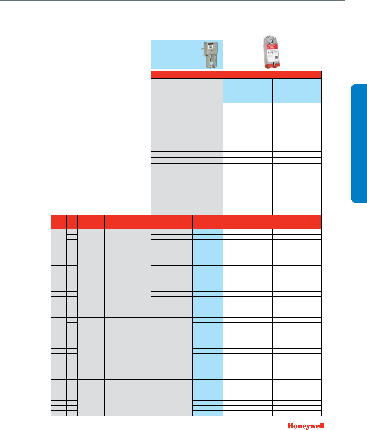
41
Actuator Features Fail Safe
Actuator O.S. Number
MS4110A1002
MS4110A1200
MS7520A2007
MS7520A2205
MS7520H2208
MS8120A1007
MS8120A1205
MS4120A1001
MS4120A1209
Power Supply Voltage 100-250 Vac 24 Vac 24 Vac 100-250 Vac
Frequency 60 Hz 50 / 60 Hz 50 / 60 Hz 60 Hz
Power 45 VA 16 VA 40 VA 60 VA
Actuator Torque (lb.-in.) 88 175 175 175
Linkage Stem Force (lbs.) 117 234 234 234
Control (0)2-10 Vdc •
4-20 mA (external 500 Ohm Resistor) •
Floating •
Two-Position SPDT •
Two-Position SPST ••••
Fail Safe Action Congurable
Open/Closed
Congurable
Open/Closed
Congurable
Open/Closed
Congurable
Open/Closed
Normal Position (no signal) (field configurable)
Stem Up/Down Stem Up/Down Stem Up/Down Stem Up/Down
Actuator Stroke (inches) 95° 95° 95° 95°
Timing (seconds at 0.75" stroke) 90 90 90 90
Aux Switch SPDT Built In 0 / 2 0 / 2 / 2 0 / 2 0 / 2
2 x SPDT Add-On SW2-US SW2-US SW2-US SW2-US
Feedback 2-10 Vdc Built In •
Valve
Size
(inches)
Cv Max Static
Water Pressure
Max Steam
Pressure /
Temperature
Flow
Characteristic
Valve
Action
Valve OS
Number Close-off Pressure, psid
2-Way
Water Valves
Straight Through
1/2"
0.73
217 psi @ 248 F 15 psi
(2-position) Equal %
Stem down to close V5011N1008 230 230 230 230
1.16 Stem down to close V5011N1016 230 230 230 230
1.85 Stem down to close V5011N1024 230 230 230 230
2.9 Stem down to close V5011N1032 230 230 230 230
2.9 Stem up to close V5011N3004 230 230 230 230
4.7 Stem down to close V5011N1040 230 230 230 230
4.7 Stem up to close V5011N3012 230 230 230 230
3/4" 7.3 Stem down to close V5011N1057 150 230 230 230
3/4" 7.3 Stem up to close V5011N3020 150 230 230 230
1" 11.7 Stem down to close V5011N1065 136 230 230 230
1" 11.7 Stem up to close V5011N3038 136 230 230 230
1-1/4" 18.7 Stem down to close V5011N1073 84 171 171 171
1-1/4" 18.7 Stem up to close V5011N3046 84 171 171 171
1-1/2" 29.3 Stem down to close V5011N1081 55 113 113 113
2" 46.8 Stem down to close V5011N1099 30 63 63 63
2-1/2" 63 250 psi @ 100F Stem down to close V5011F1105 21 45 45 45
3" 100 250 psi @ 100F Stem down to close V5011F1113 13 27 27 27
2-Way
Steam Valves
Straight Through
1/2"
0.73
217 psi @ 248 F 100 psig /
337 F Linear Stem down to close
V5011N2006 100 100 100 100
1.16 V5011N2014 100 100 100 100
1.85 V5011N2022 100 100 100 100
2.9 V5011N2030 100 100 100 100
4.7 V5011N2048 100 100 100 100
3/4" 7.3 V5011N2055 100 100 100 100
1" 11.7 V5011N2063 100 100 100 100
1-1/4" 18.7 V5011N2071 84 100 100 100
1-1/2" 29.3 V5011N2089 55 100 100 100
2" 46.8 V5011N2097 30 63 63 63
2-1/2" 63 250 psi @ 100F V5011G1111 21 45 45 45
3" 100 250 psi @ 100F V5011G1129 13 27 27 27
3-Way
Water Valves
Mixing
1/2" 2.9
217 psi @ 248 F N / A Linear B-AB /
Equal % A-AB Stem up closes A-AB
V5013N1030 230 230 230 230
1/2" 4.7 V5013N1048 230 230 230 230
3/4" 7.3 V5013N1055 150 230 230 230
1" 11.7 V5013N1063 136 230 230 230
1-1/4" 18.7 V5013N1071 84 171 171 171
1-1/2" 29.3 V5013N1089 55 113 113 113
2" 46.8 V5013N1097 30 63 63 63
VALVE SELECTION
NPT Globe Valves ½- 3"
With Direct Coupled Spring Return Actuators and Valve Linkage
Q5020A1003
Required
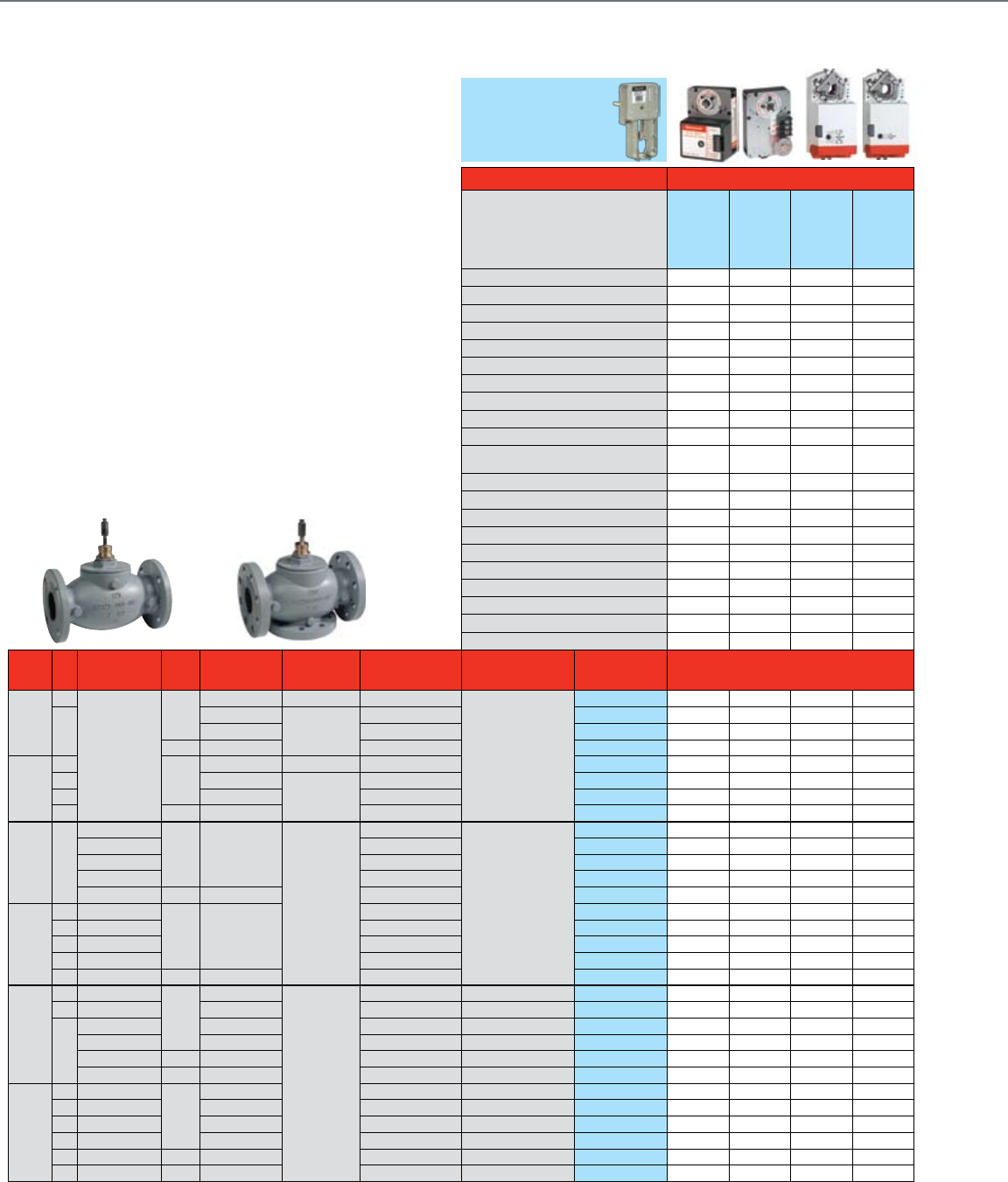
42
Flanged Globe Valves 2½- 3"
With Direct Coupled Actuators and Valve Linkage
Common Features
• ANSI body class 125 or 250
• Close-off pressure = Maximum differential pressure
• Maximum static water pressure: Up to 400 psi
• Maximum steam pressure
(VGF, 2-pos or modulating): 100 psi
• Maximum steam pressure (V5011, 2-pos): 15 psi
• Stem travel: 0.75"
• Rangeability: 50:1
• Body material: Cast iron
• Body trim: Stainless steel stem, brass seat (V5011/13),
stainless steel (VGF)
Q5020A1003
Required
Actuator Features Non-fail Safe
Actuator O.S. Number
ML7174A2001
ML6174B2019
MN7510A2001
MN7505A2209
MN6110A1003
MN6110A1201
Power Supply Voltage 24 Vac 24 Vac 24 Vac 24 Vac
Frequency 50 / 60 Hz 50 / 60 Hz 50 / 60 Hz 50 / 60 Hz
Power 5.4 VA 2.4 VA 5 VA 5 VA
Actuator Torque (lb.-in.) 70 70 88 88
Linkage Stem Force (lbs.) 93 93 117 117
Control (0)2-10 Vdc • •
4-20 mA (external 500 Ohm Resistor) • •
Floating •••
Two-Position SPDT •••
Two-Position SPST • •
Fail Safe Action Stay in Place Stay in Place Stay in Place Stay in Place
Normal Position (no signal) (field configurable)
Stem Up/Down Stem Up/Down Stem Up/Down Stem Up/Down
Actuator Stroke (degrees) 90° 90° 95° 95°
Timing (seconds) 90 90 95 95
High Temperature Kit Steam Application 43196000-001 43196000-001 43196000-001 43196000-001
Aux Switch SPDT Built In 0 / 2 0 / 2
1 x SPDT Add-On 201052A 201052A
2 x SPDT Add-On 201052B 201052B SSW2 SSW2
Feedback (0)2-10 Vdc Built In •
500 Ohm Add-On 200976A 200976A
2 kOhm Add-On 200976B 200976B
Valve
Size
(inches)
Cv Valve
Type
ANSI
Class
Max Static
Water Pressure
Max Steam
Pressure /
Temperature
Flow
Characteristic
Valve
Action
Valve OS
Number Close-off Pressure, psid
2-Way Water & Steam
Valves ANSI Class III (<
0.05% Cv) Seat Leakage
2 1/2"
63
Standard
125
150 psi @ 240 F 15 psi (2-position) Equal %
Stem down to close
V5011A1734 21 21 27 27
70
175 psi @ 130 F
125 psig / 353 F
Equal % VGF21ES25 18 18 34 34
175 psi @ 130 F Linear VGF21LS25 18 18 34 34
250 400 psi @ 130 F Equal % VGF22ES25 18 18 34 34
3"
100
125
150 psi @ 240 F 15 psi (2-position) Equal % V5011A1767 9 9 11 11
115 175 psi @ 130 F
125 psig / 353 F
Equal % VGF21ES30 9 9 16 16
125 175 psi @ 130 F Linear VGF21LS30 9 9 16 16
120 250 400 psi @ 130 F Equal % VGF22ES30 9 9 16 16
2-Way Water & Steam Valves
ANSI Class IV (< 0.01% Cv)
Seat Leakage
2 1/2" 70
Pressure Balanced
125 175 psi @ 130 F
125 psig / 353 F
Equal %
Stem down to close
VGF21EP25 100 100 100 100
Standard Equal % VGF21ES25
Pressure Balanced Linear VGF21LP25 100 100 100 100
Standard Linear VGF21LS25
Standard 250 400 psi @ 130 F Equal % VGF22ES25
3"
115 Pressure Balanced
125 175 psi @ 130 F
Equal % VGF21EP30
115 Standard Equal % VGF21ES30
120 Pressure Balanced Linear VGF21LP30
125 Standard Linear VGF21LS30
120 Standard 250 400 psi @ 130 F Equal % VGF22ES30
3-Way Water Valves
2 1/2"
63 Mixing
125
150 psi @ 240 F
N / A
Constant Total Stem up closes A-AB V5013B1003 21 21 27 27
63 Diverting 150 psi @ 240 F Constant Total Stem up closes B-AB V5013C1001 21 21 27 27
70
Mixing 175 psi @ 130 F Equal % A-AB Stem up closes A-AB VGF31EM25 23 23 44 44
Diverting 175 psi @ 130 F Linear, Constant Total Stem up closes B-AB VGF31LD25 18 18 34 34
Mixing 250 400 psi @ 130 F Equal % A-AB Stem up closes A-AB VGF32EM25 23 23 44 44
Diverting 250 400 psi @ 130 F Linear, Constant Total Stem up closes B-AB VGF32LD25 18 18 34 34
3"
100 Mixing
125
150 psi @ 240 F Constant Total Stem up closes A-AB V5013B1011 9 9 11 11
100 Diverting 150 psi @ 240 F Constant Total Stem up closes B-AB V5013C1019 9 9 11 11
120 Mixing 175 psi @ 130 F Equal % A-AB Stem up closes A-AB VGF31EM30 15 15 29 29
120 Diverting 175 psi @ 130 F Linear, Constant Total Stem up closes B-AB VGF31LD30 9 9 16 16
115 Mixing 250 400 psi @ 130 F Equal % A-AB Stem up closes A-AB VGF32EM30 15 15 29 29
120 Diverting 250 400 psi @ 130 F Linear, Constant Total Stem up closes B-AB VGF32LD30 9 9 16 16
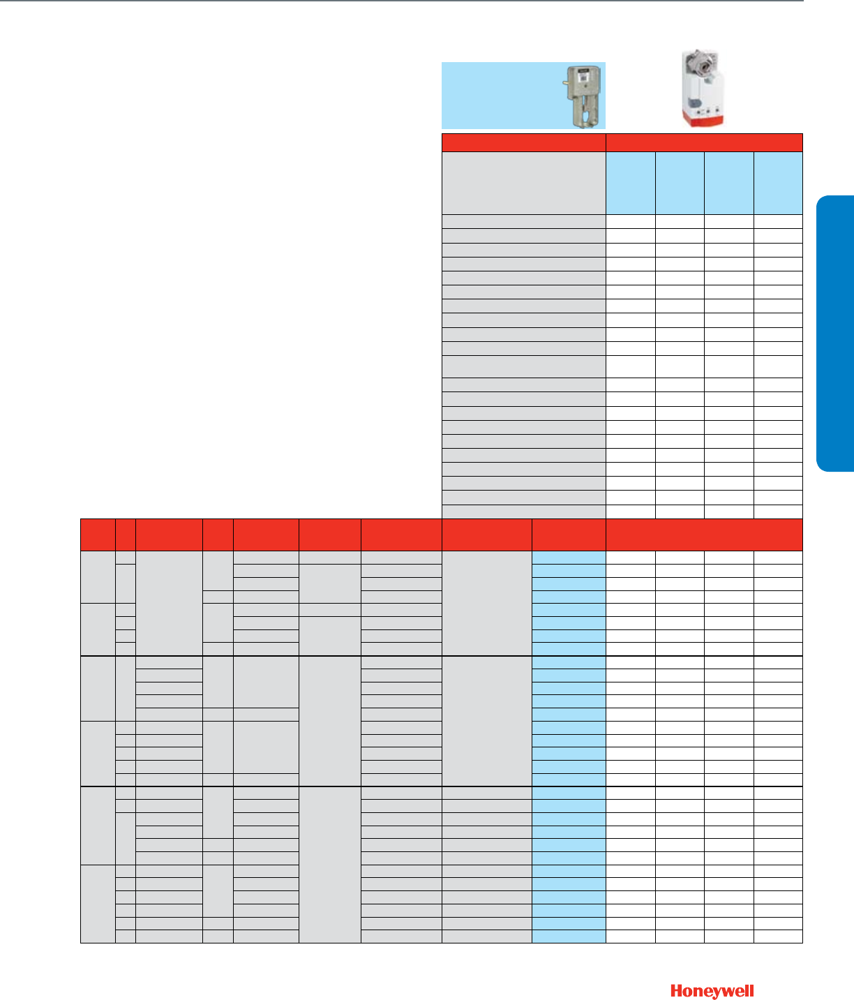
43
Q5020A1003
Required
Actuator Features Non-fail Safe
Actuator O.S. Number
MN7220A2007
MN6120A1002
MN7234A2008
MN6134A1003
Power Supply Voltage 24 Vac 24 Vac 24 Vac 24 Vac
Frequency 50 / 60 Hz 50 / 60 Hz 50 / 60 Hz 50 / 60 Hz
Power 6 VA 6 VA 9 VA 9 VA
Actuator Torque (lb.-in.) 175 175 300 300
Linkage Stem Force (lbs.) 234 234 402 402
Control (0)2-10 Vdc • •
4-20 mA (external 500 Ohm Resistor) • •
Floating • • •
Two-Position SPDT • • •
Two-Position SPST ••••
Fail Safe Action Stay in Place Stay in Place Stay in Place Stay in Place
Normal Position (no signal) (field configurable)
Stem Up/Down Stem Up/Down Stem Up/Down Stem Up/Down
Actuator Stroke (degrees) 95° 95° 95° 95°
Timing (seconds) 95 95 95 95
High Temperature Kit Steam Application 43196000-001 43196000-001 43196000-001 43196000-001
Aux Switch SPDT Built In 0 / 2 0 / 2
1 x SPDT Add-On
2 x SPDT Add-On SW2-US SW2-US SW2-US SW2-US
Feedback (0)2-10 Vdc Built In • •
500 Ohm Add-On
2 kOhm Add-On
Valve
Size
(inches)
Cv Valve
Type
ANSI
Class
Max Static
Water Pressure
Max Steam
Pressure /
Temperature
Flow
Characteristic
Valve
Action
Valve OS
Number Close-off Pressure, psid
2-Way Water & Steam
Valves ANSI Class III (<
0.05% Cv) Seat Leakage
2 1/2"
63
Standard
125
150 psi @ 240 F 15 psi (2-position) Equal %
Stem down to close
V5011A1734 52 52 88 88
70
175 psi @ 130 F
125 psig / 353 F
Equal % VGF21ES25 52 52
175 psi @ 130 F Linear VGF21LS25 52 52
250 400 psi @ 130 F Equal % VGF22ES25 52 52
3"
100
125
150 psi @ 240 F 15 psi (2-position) Equal % V5011A1767 24 24 42 42
115 175 psi @ 130 F
125 psig / 353 F
Equal % VGF21ES30 26 26
125 175 psi @ 130 F Linear VGF21LS30 26 26
120 250 400 psi @ 130 F Equal % VGF22ES30 26 26
2-Way Water & Steam Valves
ANSI Class IV (< 0.01% Cv)
Seat Leakage
2 1/2" 70
Pressure Balanced
125 175 psi @ 130 F
125 psig / 353 F
Equal %
Stem down to close
VGF21EP25 175 175 175 175
Standard Equal % VGF21ES25 77 77
Pressure Balanced Linear VGF21LP25 175 175 175 175
Standard Linear VGF21LS25 77 77
Standard 250 400 psi @ 130 F Equal % VGF22ES25 77 77
3"
115 Pressure Balanced
125 175 psi @ 130 F
Equal % VGF21EP30 175 175 175 175
115 Standard Equal % VGF21ES30 38 38
120 Pressure Balanced Linear VGF21LP30 175 175 175 175
125 Standard Linear VGF21LS30 38 38
120 Standard 250 400 psi @ 130 F Equal % VGF22ES30 38 38
3-Way Water Valves
2 1/2"
63 Mixing
125
150 psi @ 240 F
N / A
Constant Total Stem up closes A-AB V5013B1003 52 52 88 88
63 Diverting 150 psi @ 240 F Constant Total Stem up closes B-AB V5013C1001 52 52 88 88
70
Mixing 175 psi @ 130 F Equal % A-AB Stem up closes A-AB VGF31EM25 66 66 97 97
Diverting 175 psi @ 130 F Linear, Constant Total Stem up closes B-AB VGF31LD25 52 52 97 97
Mixing 250 400 psi @ 130 F Equal % A-AB Stem up closes A-AB VGF32EM25 66 66 97 97
Diverting 250 400 psi @ 130 F Linear, Constant Total Stem up closes B-AB VGF32LD25 52 52 97 97
3"
100 Mixing
125
150 psi @ 240 F Constant Total Stem up closes A-AB V5013B1011 24 24 42 42
100 Diverting 150 psi @ 240 F Constant Total Stem up closes B-AB V5013C1019 24 24 42 42
120 Mixing 175 psi @ 130 F Equal % A-AB Stem up closes A-AB VGF31EM30 44 44 65 65
120 Diverting 175 psi @ 130 F Linear, Constant Total Stem up closes B-AB VGF31LD30 26 26 65 65
115 Mixing 250 400 psi @ 130 F Equal % A-AB Stem up closes A-AB VGF32EM30 44 44 65 65
120 Diverting 250 400 psi @ 130 F Linear, Constant Total Stem up closes B-AB VGF32LD30 26 26 65 65
VALVE SELECTION
Flanged Globe Valves 2½- 3"
With Direct Coupled Actuators and Valve Linkage
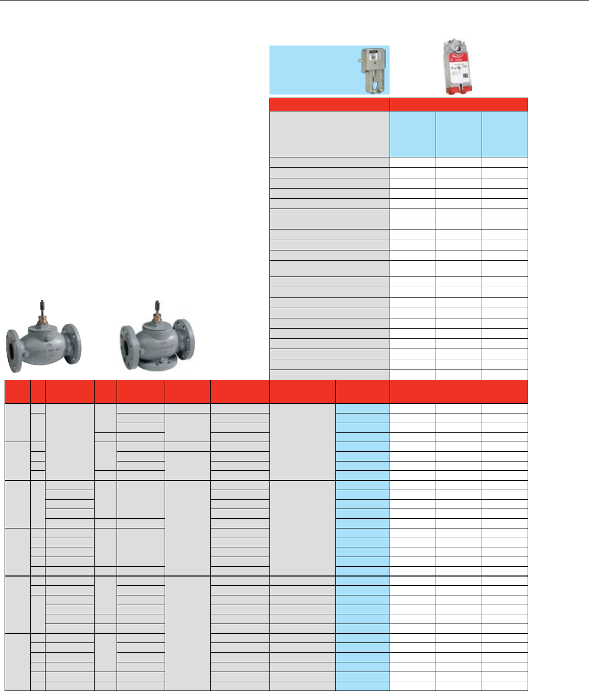
44
Flanged Globe Valves 2½- 3"
With Direct Coupled Spring Return Actuators and Valve Linkage
Common Features
• ANSI body class 125 or 250
• Close-off pressure = Maximum differential pressure
• Maximum static water pressure: Up to 400 psi
• Maximum steam pressure
(VGF, 2-pos or modulating): 100 psi
• Maximum steam pressure (V5011, 2-pos): 15 psi
• Stem travel: 0.75"
• Rangeability: 50:1
• Body material: Cast iron
• Body trim: Stainless steel stem, brass seat (V5011/13),
stainless steel (VGF)
Q5020A1003
Required
Actuator Features Fail Safe
Actuator O.S. Number
MS7510A2008
MS7510A2206
MS7510H2209
MS8110A1008
MS4110A1002
Power Supply Voltage 24 Vac 24 Vac 100-250 Vac
Frequency 50 / 60 Hz 50 / 60 Hz 60 Hz
Power 14 VA 30 VA 45VA
Actuator Torque (lb.-in.) 88 88 88
Linkage Stem Force (lbs.) 117 117 117
Control (0)2-10 Vdc •
4-20 mA (external 500 Ohm Resistor) •
Floating •
Two-Position SPDT •
Two-Position SPST •••
Fail Safe Action Congurable
Open/Closed
Congurable
Open/Closed
Congurable
Open/Closed
Normal Position (no signal) (field configurable)
Stem Up/Down Stem Up/Down Stem Up/Down
Actuator Stroke (degrees) 95° 95° 95°
Timing (seconds) 90 90 90
High Temperature Kit Steam Application 43196000-001 43196000-001 43196000-001
Aux Switch SPDT Built In 0 / 2 / 2 0 / 2 0 / 2
1 x SPDT Add-On
2 x SPDT Add-On SW2-US SW2-US SW2-US
Feedback (0)2-10 Vdc Built In •
500 Ohm Add-On
2 kOhm Add-On
Valve
Size
(inches)
Cv Valve
Type
ANSI
Class
Max Static
Water Pressure
Max Steam
Pressure /
Temperature
Flow
Characteristic
Valve
Action
Valve OS
Number Close-off Pressure, psid
2-Way Water & Steam
Valves ANSI Class III (<
0.05% Cv) Seat Leakage
2 1/2"
63
Standard
125
150 psi @ 240 F 15 psi (2-position) Equal %
Stem down to close
V5011A1734 27 27 27
70
175 psi @ 130 F
125 psig / 353 F
Equal % VGF21ES25 33 33 33
175 psi @ 130 F Linear VGF21LS25 33 33 33
250 400 psi @ 130 F Equal % VGF22ES25 33 33 33
3"
100
125
150 psi @ 240 F 15 psi (2-position) Equal % V5011A1767 11 11 11
115 175 psi @ 130 F
125 psig / 353 F
Equal % VGF21ES30 15 15 15
125 175 psi @ 130 F Linear VGF21LS30 15 15 15
120 250 400 psi @ 130 F Equal % VGF22ES30 15 15 15
2-Way Water & Steam Valves
ANSI Class IV (< 0.01% Cv)
Seat Leakage
2 1/2" 70
Pressure Balanced
125 175 psi @ 130 F
125 psig / 353 F
Equal %
Stem down to close
VGF21EP25 100 100 100
Standard Equal % VGF21ES25
Pressure Balanced Linear VGF21LP25 100 100 100
Standard Linear VGF21LS25
Standard 250 400 psi @ 130 F Equal % VGF22ES25
3"
115 Pressure Balanced
125 175 psi @ 130 F
Equal % VGF21EP30
115 Standard Equal % VGF21ES30
120 Pressure Balanced Linear VGF21LP30
125 Standard Linear VGF21LS30
120 Standard 250 400 psi @ 130 F Equal % VGF22ES30
3-Way Water Valves
2 1/2"
63 Mixing
125
150 psi @ 240 F
N / A
Constant Total Stem up closes A-AB V5013B1003 27 27 27
63 Diverting 150 psi @ 240 F Constant Total Stem up closes B-AB V5013C1001 27 27 27
70
Mixing 175 psi @ 130 F Equal % A-AB Stem up closes A-AB VGF31EM25 43 43 43
Diverting 175 psi @ 130 F Linear, Constant Total Stem up closes B-AB VGF31LD25 33 33 33
Mixing 250 400 psi @ 130 F Equal % A-AB Stem up closes A-AB VGF32EM25 43 43 43
Diverting 250 400 psi @ 130 F Linear, Constant Total Stem up closes B-AB VGF32LD25 33 33 33
3"
100 Mixing
125
150 psi @ 240 F Constant Total Stem up closes A-AB V5013B1011 11 11 11
100 Diverting 150 psi @ 240 F Constant Total Stem up closes B-AB V5013C1019 11 11 11
120 Mixing 175 psi @ 130 F Equal % A-AB Stem up closes A-AB VGF31EM30 28 28 28
120 Diverting 175 psi @ 130 F Linear, Constant Total Stem up closes B-AB VGF31LD30 15 15 15
115 Mixing 250 400 psi @ 130 F Equal % A-AB Stem up closes A-AB VGF32EM30 28 28 28
120 Diverting 250 400 psi @ 130 F Linear, Constant Total Stem up closes B-AB VGF32LD30 15 15 15

45
Q5020A1003
Required
Actuator Features Fail Safe
Actuator O.S. Number
MS7520A2007
MS7520A2205
MS7520H2208
MS8120A1007
MS4120A1001
Power Supply Voltage 24 Vac 24 Vac 100-250 Vac
Frequency 50 / 60 Hz 50 / 60 Hz 60 Hz
Power 16 VA 40 VA 60 VA
Actuator Torque (lb.-in.) 175 175 175
Linkage Stem Force (lbs.) 234 234 234
Control (0)2-10 Vdc •
4-20 mA (external 500 Ohm Resistor) •
Floating •
Two-Position SPDT •
Two-Position SPST •••
Fail Safe Action Congurable
Open/Closed
Congurable
Open/Closed
Congurable
Open/Closed
Normal Position (no signal) (field configurable)
Stem Up/Down Stem Up/Down Stem Up/Down
Actuator Stroke (degrees) 95° 95° 95°
Timing (seconds) 90 90 90
High Temperature Kit Steam Application 43196000-001 43196000-001 43196000-001
Aux Switch SPDT Built In 0 / 2 / 2 0 / 2 0 / 2
1 x SPDT Add-On
2 x SPDT Add-On SW2-US SW2-US SW2-US
Feedback (0)2-10 Vdc Built In •
500 Ohm Add-On
2 kOhm Add-On
Valve
Size
(inches)
Cv Valve
Type
ANSI
Class
Max Static
Water Pressure
Max Steam
Pressure /
Temperature
Flow
Characteristic
Valve
Action
Valve OS
Number Close-off Pressure, psid
2-Way Water & Steam
Valves ANSI Class III (<
0.05% Cv) Seat Leakage
2 1/2"
63
Standard
125
150 psi @ 240 F 15 psi (2-position) Equal %
Stem down to close
V5011A1734 56 56 56
70
175 psi @ 130 F
125 psig / 353 F
Equal % VGF21ES25 71 71 71
175 psi @ 130 F Linear VGF21LS25 71 71 71
250 400 psi @ 130 F Equal % VGF22ES25 71 71 71
3"
100
125
150 psi @ 240 F 15 psi (2-position) Equal % V5011A1767 25 25 25
115 175 psi @ 130 F
125 psig / 353 F
Equal % VGF21ES30 35 35 35
125 175 psi @ 130 F Linear VGF21LS30 35 35 35
120 250 400 psi @ 130 F Equal % VGF22ES30 35 35 35
2-Way Water & Steam Valves
ANSI Class IV (< 0.01% Cv)
Seat Leakage
2 1/2" 70
Pressure Balanced
125 175 psi @ 130 F
125 psig / 353 F
Equal %
Stem down to close
VGF21EP25 175 175 175
Standard Equal % VGF21ES25
Pressure Balanced Linear VGF21LP25 175 175 175
Standard Linear VGF21LS25
Standard 250 400 psi @ 130 F Equal % VGF22ES25
3"
115 Pressure Balanced
125 175 psi @ 130 F
Equal % VGF21EP30 175 175 175
115 Standard Equal % VGF21ES30
120 Pressure Balanced Linear VGF21LP30 175 175 175
125 Standard Linear VGF21LS30
120 Standard 250 400 psi @ 130 F Equal % VGF22ES30
3-Way Water Valves
2 1/2"
63 Mixing
125
150 psi @ 240 F
N / A
Constant Total Stem up closes A-AB V5013B1003 56 56 56
63 Diverting 150 psi @ 240 F Constant Total Stem up closes B-AB V5013C1001 56 56 56
70
Mixing 175 psi @ 130 F Equal % A-AB Stem up closes A-AB VGF31EM25 89 89 89
Diverting 175 psi @ 130 F Linear, Constant Total Stem up closes B-AB VGF31LD25 71 71 71
Mixing 250 400 psi @ 130 F Equal % A-AB Stem up closes A-AB VGF32EM25 89 89 89
Diverting 250 400 psi @ 130 F Linear, Constant Total Stem up closes B-AB VGF32LD25 71 71 71
3"
100 Mixing
125
150 psi @ 240 F Constant Total Stem up closes A-AB V5013B1011 25 25 25
100 Diverting 150 psi @ 240 F Constant Total Stem up closes B-AB V5013C1019 25 25 25
120 Mixing 175 psi @ 130 F Equal % A-AB Stem up closes A-AB VGF31EM30 59 59 59
120 Diverting 175 psi @ 130 F Linear, Constant Total Stem up closes B-AB VGF31LD30 35 35 35
115 Mixing 250 400 psi @ 130 F Equal % A-AB Stem up closes A-AB VGF32EM30 59 59 59
120 Diverting 250 400 psi @ 130 F Linear, Constant Total Stem up closes B-AB VGF32LD30 35 35 35
VALVE SELECTION
Flanged Globe Valves 2½- 3"
With Direct Coupled Spring Return Actuators and Valve Linkage
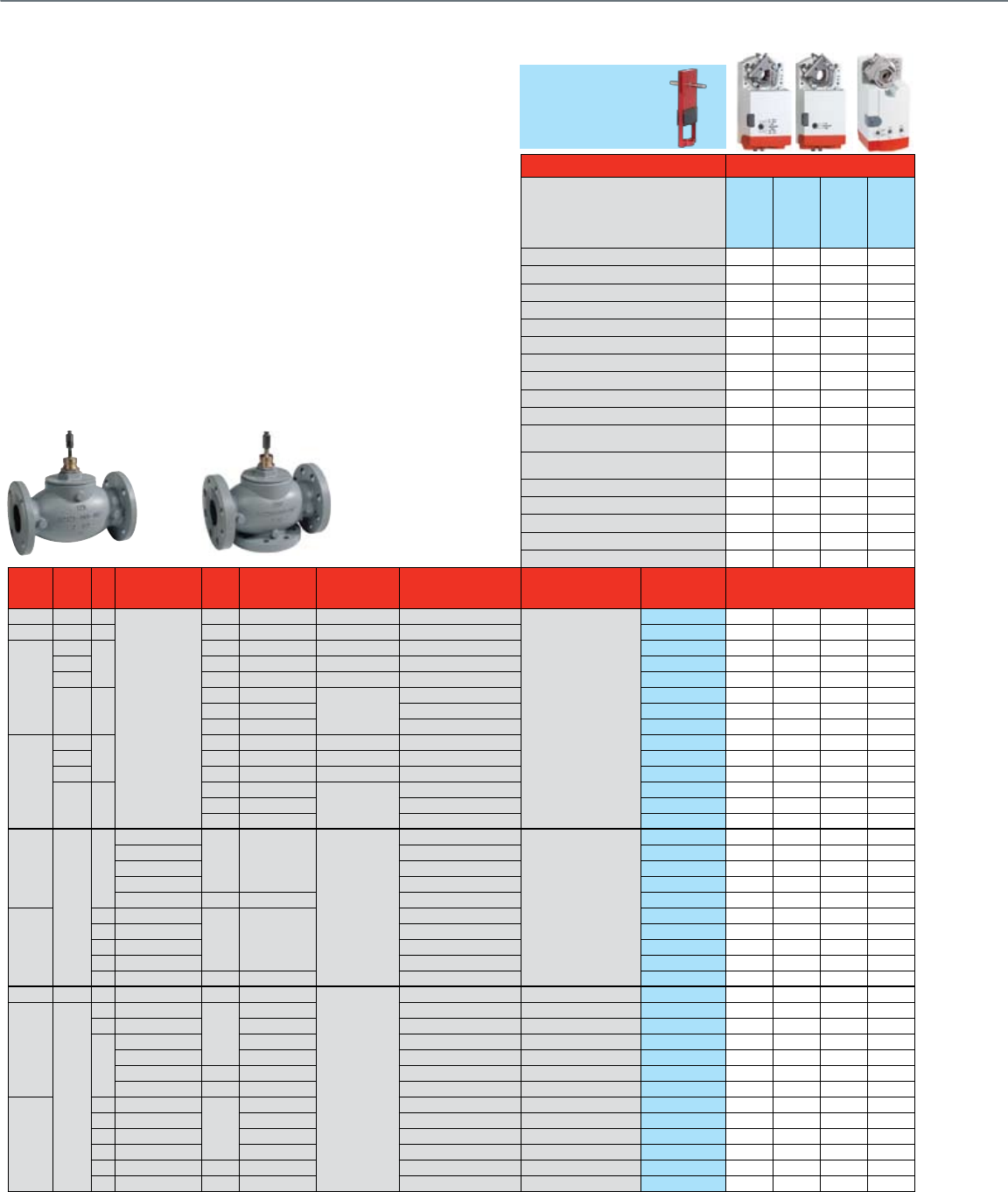
46
Threaded and Flanged Globe Valves 2"- 3"
With Tandem Direct Coupled Actuators and Valve Linkage
Common Features
• Stem travel: 0.75"
• Rangeability: 50:1
• Body material: Bronze (V5011/13N), Cast iron
• Seat Material: Bronze (V5011/13), Stainless Steel (VGF2),
Cast Iron (VGF3)
• Stem Material: Stainless Steel
Actuator Features Non-fail Safe
Actuator O.S. Number
(Two required per linkage/valve)
MN7220A2007
MN6120A1002
MN72342008
MN6134A1003
Power Supply Voltage 24 Vac 24 Vac 24 Vac 24 Vac
Frequency 60 Hz 60 Hz 60 Hz 60 Hz
Power 6 VA 6 VA 9 VA 9 VA
Actuator Torque (lb.-in.) 175 175 300 300
Linkage Stem Force, Two Actuators (lbs.) 655 655 1115 1115
Control (0)2-10 Vdc • •
4-20 mA (external 500 Ohm Resistor) • •
Floating ••••
Two-Position SPDT ••••
Two-Position SPST •••
Fail Safe Action
Stay in
Place
Stay in
Place
Stay in
Place
Stay in
Place
Normal Position (no signal) (field configurable)
Stem Up/
Down
Stem Up/
Down
Stem Up/
Down
Stem Up/
Down
Actuator Stroke (inches) 0.75 0.75 0.75 0.75
Timing (seconds) 95 95 95 95
Aux Switch 2 x SPDT Add-On SW2-US SW2-US SW2-US SW2-US
2 x SPDT Built In
Feedback (0)2-10 Vdc Built In • •
Valve
Size
(inches)
Pipe
Fitting Cv Valve
Type
ANSI
Class
Max Static
Water Pressure
Max Steam
Pressure /
Temperature
Flow
Characteristic
Valve
Action
Valve OS
Number Close-off Pressure, psid
2-Way Water & Steam Valves
ANSI Class III (< 0.05% Cv) Seat Leakage
2" f NPT 47
Standard
150 217 psi @ 248 F 15 psi (2-position) Equal %
Stem down to close
V5011N1099 162 162 240 240
2" f NPT 47 150 217 psi @ 248 F 100 psig / 337 F Equal % V5011N2097 100 100 100 100
2 1/2"
Flanged
63
125 150 psi @ 240 F 15 psi (2-position) Equal % V5011A1734 130 130 225 225
f NPT 150 250 psi @ 100F 15 psi (2-position) Equal % V5011F1105 130 130 225 225
f NPT 150 250 psi @ 100F 100 psig / 337 F Linear V5011G1111 100 100 100 100
Flanged 70
125 175 psi @ 130 F
125 psig / 353 F
Equal % VGF21ES25 110 110 190 190
125 175 psi @ 130 F Linear VGF21LS25 110 110 190 190
250 400 psi @ 130 F Equal % VGF22ES25 110 110 190 190
3"
Flanged
100
125 150 psi @ 250 F 15 psi (2-position) Equal % V5011A1767 66 66 115 115
f NPT 150 250 psi @ 100F 15 psi (2-position) Equal % V5011F1113 65 65 115 115
f NPT 150 250 psi @ 100F 100 psig / 337 F Linear V5011G1129 65 65 100 100
Flanged 120
125 175 psi @ 130 F
125 psig / 353 F
Equal % VGF21ES30 55 55 94 94
125 175 psi @ 130 F Linear VGF21LS30 55 55 94 94
250 400 psi @ 130 F Equal % VGF22ES30 55 55 94 94
2-Way Water & Steam Valves
ANSI Class IV
(< 0.01% Cv) Seat Leakage
2 1/2"
Flanged
70
Pressure Balanced
125 175 psi @ 130 F
125 psig / 353 F
Equal %
Stem down to close
VGF21EP25 175* 175* 175* 175*
Standard Equal % VGF21ES25 74 74 152 152
Pressure Balanced Linear VGF21LP25 175* 175* 175* 175*
Standard Linear VGF21LS25 74 74 152 152
Standard 250 400 psi @ 130 F Equal % VGF22ES25 74 74 152 152
3"
115 Pressure Balanced
125 175 psi @ 130 F
Equal % VGF21EP30 175* 175* 175* 175*
120 Standard Equal % VGF21ES30 36 36 75 75
115 Pressure Balanced Linear VGF21LP30 175* 175* 175* 175*
120 Standard Linear VGF21LS30 36 36 75 75
120 Standard 250 400 psi @ 130 F Equal % VGF22ES30 36 36 75 75
3-Way Water Valves
2" f NPT 47 Mixing 150 217 psi @ 248 F
N / A
Linear B-AB / Equal % A-AB Stem up closes A-AB V5013N1097 162 162 240 240
2 1/2"
Flanged
63 Mixing
125
150 psi @ 240 F Constant Total Stem up closes A-AB V5013B1003 130 130 225 225
63 Diverting 150 psi @ 240 F Constant Total Stem up closes B-AB V5013C1001 130 130 225 225
70
Mixing 175 psi @ 130 F Linear B-AB / Equal % A-AB Stem up closes A-AB VGF31EM50 141 141 240 240
Diverting 175 psi @ 130 F Linear, Constant Total Stem up closes B-AB VGF31LD50 110 110 190 190
Mixing 250 400 psi @ 130 F Linear B-AB / Equal % A-AB Stem up closes A-AB VGF32EM50 141 141 240 240
Diverting 250 400 psi @ 130 F Linear, Constant Total Stem up closes B-AB VGF32LD50 110 110 190 190
3"
100 Mixing
125
150 psi @ 240 F Constant Total Stem up closes A-AB V5013B1011 65 65 115 115
100 Diverting 150 psi @ 240 F Constant Total Stem up closes B-AB V5013C1019 65 65 115 115
115 Mixing 175 psi @ 130 F Linear B-AB / Equal % A-AB Stem up closes A-AB VGF31EM60 94 94 160 160
120 Diverting 175 psi @ 130 F Linear, Constant Total Stem up closes B-AB VGF31LD60 110 110 190 190
115 Mixing 250 400 psi @ 130 F Linear B-AB / Equal % A-AB Stem up closes A-AB VGF32EM60 94 94 160 160
120 Diverting 250 400 psi @ 130 F Linear, Constant Total Stem up closes B-AB VGF32LD60 110 110 190 190
*Only requires single actuator
** For high pressure steam-rated valves, close-off is the lesser of Maximum Steam Pressure or water close-off rating
Q5022A1001
Required
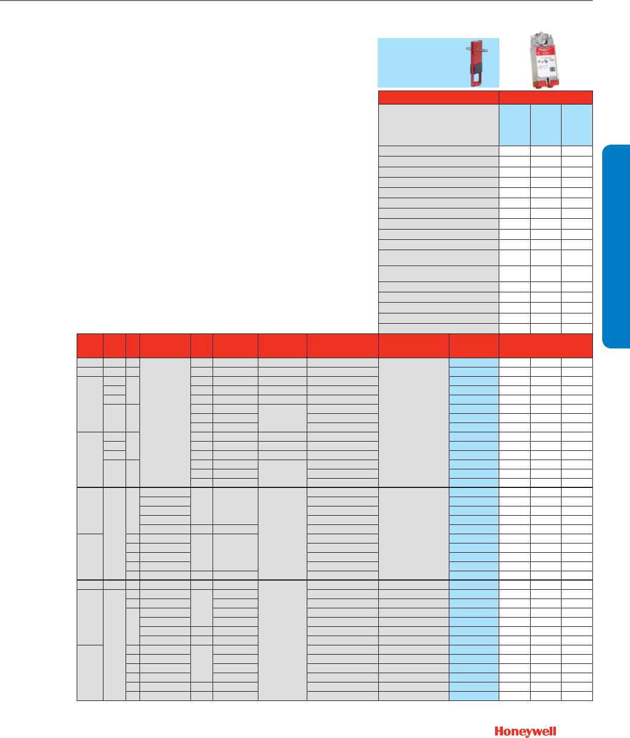
47
Actuator Features Fail Safe
Actuator O.S. Number
(Two required per linkage/valve)
MS7520A2007
MS7520A2205
MS8120A1007
MS4120A1001
Power Supply Voltage 24 Vac 24 Vac 100-250 Vac
Frequency 60 Hz 60 Hz 60 Hz
Power 16 VA 40 VA 60 VA
Actuator Torque (lb.-in.) 175 175 175
Linkage Stem Force, Two Actuators (lbs.) 655 655 655
Control (0)2-10 Vdc •
4-20 mA (external 500 Ohm Resistor) •
Floating •
Two-Position SPDT •
Two-Position SPST •••
Fail Safe Action
Congurable
Open/Closed
Congurable
Open/Closed
Congurable
Open/Closed
Normal Position (no signal) (field configurable)
Stem Up/
Down
Stem Up/
Down
Stem Up/
Down
Actuator Stroke (inches) 0.75 0.75 0.75
Timing (seconds) 90 90 90
Aux Switch 2 x SPDT Add-On SW2-US SW2-US SW2-US
2 x SPDT Built In 0 / 2
Feedback (0)2-10 Vdc Built In •
Valve
Size
(inches)
Pipe
Fitting Cv Valve
Type
ANSI
Class
Max Static
Water Pressure
Max Steam
Pressure /
Temperature
Flow
Characteristic
Valve
Action
Valve OS
Number Close-off Pressure, psid
2-Way Water & Steam Valves
ANSI Class III (< 0.05% Cv) Seat Leakage
2" f NPT 47
Standard
150 217 psi @ 248 F 15 psi (2-position) Equal %
Stem down to close
V5011N1099 162 162 162
2" f NPT 47 150 217 psi @ 248 F 100 psig / 337 F Equal % V5011N2097 100 100 20
2 1/2"
Flanged
63
125 150 psi @ 240 F 15 psi (2-position) Equal % V5011A1734 130 130 130
f NPT 150 250 psi @ 100F 15 psi (2-position) Equal % V5011F1105 130 130 130
f NPT 150 250 psi @ 100F 100 psig / 337 F Linear V5011G1111 100 100 100
Flanged 70
125 175 psi @ 130 F
125 psig / 353 F
Equal % VGF21ES25 110 110 110
125 175 psi @ 130 F Linear VGF21LS25 110 110 110
250 400 psi @ 130 F Equal % VGF22ES25 110 110 110
3"
Flanged
100
125 150 psi @ 250 F 15 psi (2-position) Equal % V5011A1767 66 66 66
f NPT 150 250 psi @ 100F 15 psi (2-position) Equal % V5011F1113 65 65 65
f NPT 150 250 psi @ 100F 100 psig / 337 F Linear V5011G1129 65 65 65
Flanged 120
125 175 psi @ 130 F
125 psig / 353 F
Equal % VGF21ES30 55 55 55
125 175 psi @ 130 F Linear VGF21LS30 55 55 55
250 400 psi @ 130 F Equal % VGF22ES30 55 55 55
2-Way Water & Steam Valves
ANSI Class IV
(< 0.01% Cv) Seat Leakage
2 1/2"
Flanged
70
Pressure Balanced
125 175 psi @ 130 F
125 psig / 353 F
Equal %
Stem down to close
VGF21EP25 175* 175* 175*
Standard Equal % VGF21ES25 74 74 74
Pressure Balanced Linear VGF21LP25 175* 175* 175*
Standard Linear VGF21LS25 74 74 74
Standard 250 400 psi @ 130 F Equal % VGF22ES25 74 74 74
3"
115 Pressure Balanced
125 175 psi @ 130 F
Equal % VGF21EP30 175* 175* 175*
120 Standard Equal % VGF21ES30 36 36 36
115 Pressure Balanced Linear VGF21LP30 175* 175* 175*
120 Standard Linear VGF21LS30 36 36 36
120 Standard 250 400 psi @ 130 F Equal % VGF22ES30 36 36 36
3-Way Water Valves
2" f NPT 47 Mixing 150 217 psi @ 248 F
N / A
Linear B-AB / Equal % A-AB Stem up closes A-AB V5013N1097 162 162 162
2 1/2"
Flanged
63 Mixing
125
150 psi @ 240 F Constant Total Stem up closes A-AB V5013B1003 130 130 130
63 Diverting 150 psi @ 240 F Constant Total Stem up closes B-AB V5013C1001 130 130 130
70
Mixing 175 psi @ 130 F Linear B-AB / Equal % A-AB Stem up closes A-AB VGF31EM50 141 141 141
Diverting 175 psi @ 130 F Linear, Constant Total Stem up closes B-AB VGF31LD50 110 110 110
Mixing 250 400 psi @ 130 F Linear B-AB / Equal % A-AB Stem up closes A-AB VGF32EM50 141 141 141
Diverting 250 400 psi @ 130 F Linear, Constant Total Stem up closes B-AB VGF32LD50 110 110 110
3"
100 Mixing
125
150 psi @ 240 F Constant Total Stem up closes A-AB V5013B1011 65 65 65
100 Diverting 150 psi @ 240 F Constant Total Stem up closes B-AB V5013C1019 65 65 65
115 Mixing 175 psi @ 130 F Linear B-AB / Equal % A-AB Stem up closes A-AB VGF31EM60 94 94 94
120 Diverting 175 psi @ 130 F Linear, Constant Total Stem up closes B-AB VGF31LD60 110 110 110
115 Mixing 250 400 psi @ 130 F Linear B-AB / Equal % A-AB Stem up closes A-AB VGF32EM60 94 94 94
120 Diverting 250 400 psi @ 130 F Linear, Constant Total Stem up closes B-AB VGF32LD60 110 110 110
*Only requires single actuator
** For high pressure steam-rated valves, close-off is the lesser of Maximum Steam Pressure or water close-off rating
***Q5022A linkage compatible with VGF valves with 1/4-28UNF stem thread (Manufactured after June, 2005)
Q5022A1001
Required***
VALVE SELECTION
Threaded and Flanged Globe Valves 2"- 3"
With Tandem Direct Coupled Actuators and Valve Linkage
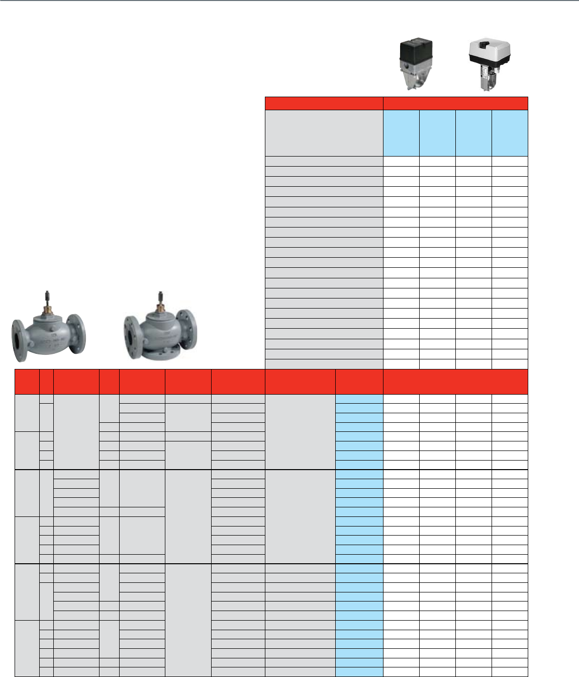
48
Flanged Globe Valves 2½- 3"
With Dedicated Valve Actuators
Common Features
• ANSI body class 125 or 250
• Close-off pressure = Maximum differential pressure
• Maximum static water pressure: Up to 400 psi
• Maximum steam pressure (VGF, 2-pos or modulating): 100 psi
• Maximum steam pressure (V5011, 2-pos): 15 psi
• Stem travel: 0.75"
• Rangeability: 50:1
• Body material: Cast iron
• Body trim: Stainless steel stem, brass seat (V5011/13),
stainless steel (VGF)
Actuator Features Non-fail Safe
Actuator O.S. Number
ML7984A4009**
ML6984A4000**
ML7420A3055
ML7420A3063
Power Supply Voltage 24 Vac / 28 Vdc 24 Vac / 28 Vdc 24 Vac 24 Vac
Frequency 0 / 50 / 60 Hz 0 / 50 / 60 Hz 50 / 60 Hz 50 / 60 Hz
Power 12 VA 12 VA 7 VA 7 VA
Actuator Torque (lb.-in.) 160 160 135 135
Control (0)2-10 Vdc • • •
4-20 mA (external 500 Ohm Resistor) Built-in • •
Floating •
Two-Position SPDT •
Two-Position SPST
135 Ohm •
Fail Safe Action Stay in place Stay in place Stay in place Stay in place
Normal Position (no signal) (field co nfigurable)
Stem Up Stem Up Stem Up Stem Up
Actuator Stroke (inches)
0.5 - 1 self adj 0.5 - 1 self adj
0.75 0.75
Timing (seconds at 0.75" stroke) 63 63 60 30
High Temperature Kit Steam Application 43196000-001 43196000-001
Aux Switch 1 x SPDT Add-On 272630D 272630D
2 x SPDT Add-On 43191680-105 43191680-105
Feedback 2-10 Vdc Built In • •
2-10 Vdc Add-On 272630D 272630D
220 Ohm Add-On
10 kOhm Add-On
Valve
Size
(inches)
Cv Valve
Type
ANSI
Class
Max Static
Water Pressure
Max Steam
Pressure /
Temperature
Flow
Characteristic
Valve
Action
Valve OS
Number Close-off Pressure, psid
2-Way
Water & Steam Valves
ANSI Class III (< 0.05%
Cv) Seat Leakage
2 1/2"
63
Standard
125
150 psi @ 240 F 15 psi (2-position) Equal %
Stem down to close
V5011A1734 33 33 28 28
70
175 psi @ 130 F
125 psig / 353 F
Equal % VGF21ES25 27* 27* 23 23
175 psi @ 130 F Linear VGF21LS25 27* 27* 23 23
250 400 psi @ 130 F Equal % VGF22ES25 27* 27* 23 23
3"
100 125 150 psi @ 240 F 15 psi (2-position) Equal % V5011A1767 19 19 16 16
115 125 175 psi @ 130 F
125 psig / 353 F
Equal % VGF21ES30 13* 13* 11 11
125 125 175 psi @ 130 F Linear VGF21LS30 13* 13* 11 11
120 250 400 psi @ 130 F Equal % VGF22ES30 13* 13* 11 11
2-Way Water & Steam Valves
ANSI Class IV (< 0.01% Cv)
Seat Leakage
2 1/2" 70
Pressure Balanced
125 175 psi @ 130 F
125 psig / 353 F
Equal %
Stem down to close
VGF21EP25 175 175 175 175
Standard Equal % VGF21ES25
Pressure Balanced
Linear VGF21LP25 175 175 175 175
Standard Linear VGF21LS25
Standard 250 400 psi @ 130 F Equal % VGF22ES25
3"
115
Pressure Balanced
125 175 psi @ 130 F
Equal % VGF21EP30 175 175 175 175
115 Standard Equal % VGF21ES30
120
Pressure Balanced
Linear VGF21LP30 175 175 175 175
125 Standard Linear VGF21LS30
120 Standard 250 400 psi @ 130 F Equal % VGF22ES30
3-Way Water Valves
2 1/2"
63 Mixing
125
150 psi @ 240 F
N / A
Constant Total Stem up closes A-AB V5013B1003 27 27 23 23
63 Diverting 150 psi @ 240 F Constant Total Stem up closes B-AB V5013C1001 25 25 21 21
70
Mixing 175 psi @ 130 F Equal % A-AB Stem up closes A-AB VGF31EM25 34 34 29 29
Diverting 175 psi @ 130 F Linear, Constant Total Stem up closes B-AB VGF31LD25 27 27 23 23
Mixing 250 400 psi @ 130 F Equal % A-AB Stem up closes A-AB VGF32EM25 34 34 29 29
Diverting 250 400 psi @ 130 F Linear, Constant Total Stem up closes B-AB VGF32LD25 27 27 23 23
3"
100 Mixing
125
150 psi @ 240 F Constant Total Stem up closes A-AB V5013B1011 13 13 11 11
100 Diverting 150 psi @ 240 F Constant Total Stem up closes B-AB V5013C1019 17 17 14 14
120 Mixing 175 psi @ 130 F Equal % A-AB Stem up closes A-AB VGF31EM30 22 22 19 19
120 Diverting 175 psi @ 130 F Linear, Constant Total Stem up closes B-AB VGF31LD30 13 13 11 11
115 Mixing 250 400 psi @ 130 F Equal % A-AB Stem up closes A-AB VGF32EM30 22 22 19 19
120 Diverting 250 400 psi @ 130 F Linear, Constant Total Stem up closes B-AB VGF32LD30 13 13 11 11
*Requires 272629A adpater kit to provide upper stop for actuator torque switch
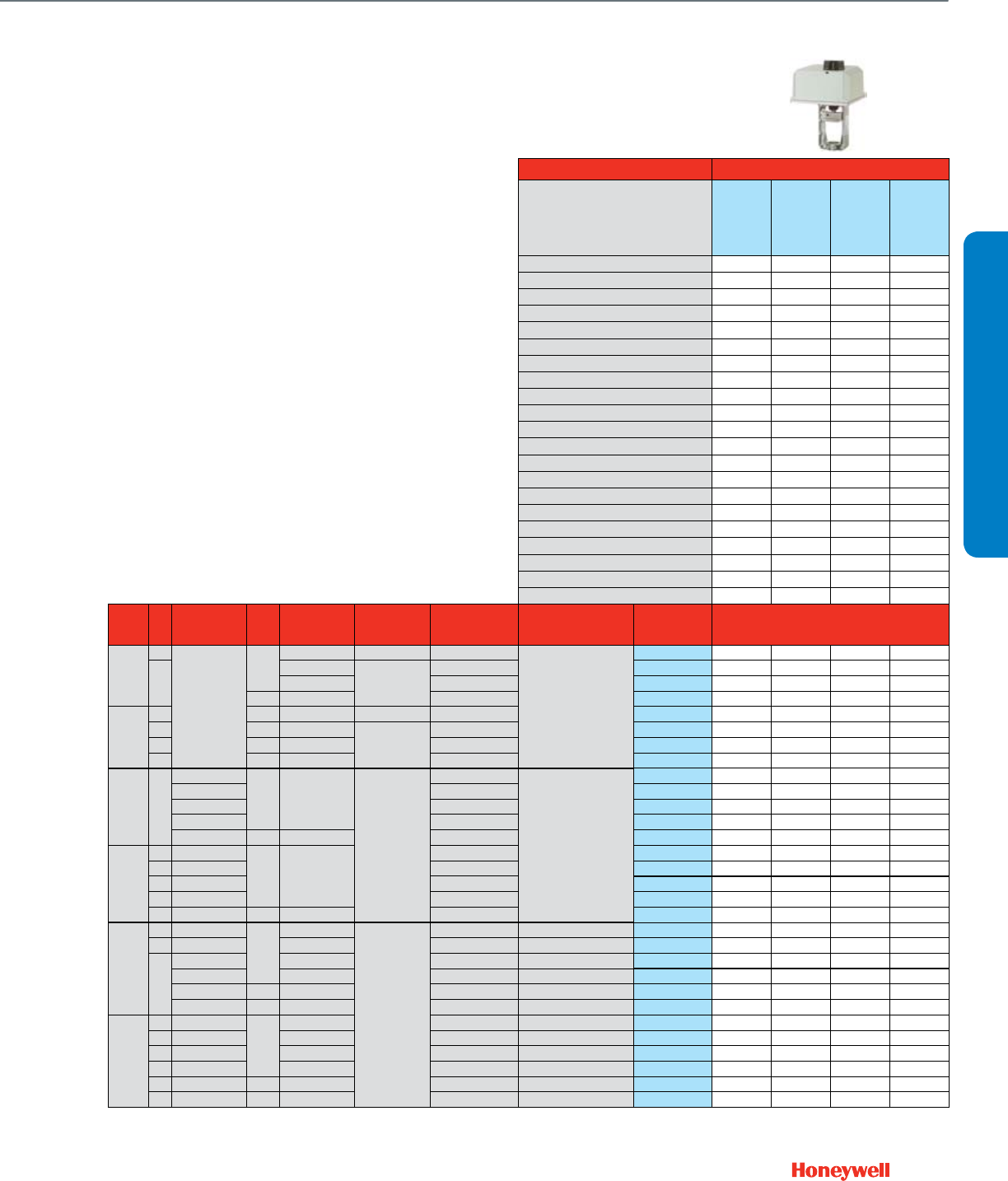
49
Actuator Features Non-fail Safe
Actuator O.S. Number
ML6420A3049
ML6420A3056
ML7421A1032
ML6421A1017
Power Supply Voltage 24 Vac 24 Vac 24 Vac 24 Vac
Frequency 50 / 60 Hz 50 / 60 Hz 50 / 60 Hz 50 / 60 Hz
Power 6 VA 6 VA 12 VA 11 VA
Actuator Torque (lb.-in.) 135 135 404 404
Control (0)2-10 Vdc •
4-20 mA (external 500 Ohm Resistor) •
Floating • • •
Two-Position SPDT • • •
Two-Position SPST
135 Ohm
Fail Safe Action Stay in place Stay in place Stay in place Stay in place
Normal Position (no signal) (field co nfigurable)
Stem Up Stem Up Stem Up Stem Up
Actuator Stroke (inches) 0.75 0.75 0.75 0.75
Timing (seconds at 0.75" stroke) 60 30 90 90
High Temperature Kit Steam Application 43196000-001 43196000-001 43196000-001 43196000-001
Aux Switch 1 x SPDT Add-On
2 x SPDT Add-On 43191680-105 43191680-105 43191680-102 43191680-102
Feedback 2-10 Vdc Built In •
2-10 Vdc Add-On
220 Ohm Add-On 43191679-111 43191679-111 43191679-101
10 kOhm Add-On 43191679-112 43191679-111
Valve
Size
(inches)
Cv Valve
Type
ANSI
Class
Max Static
Water Pressure
Max Steam
Pressure /
Temperature
Flow
Characteristic
Valve
Action
Valve OS
Number Close-off Pressure, psid
2-Way
Water & Steam Valves
ANSI Class III (< 0.05%
Cv) Seat Leakage
2 1/2"
63
Standard
125
150 psi @ 240 F 15 psi (2-position) Equal %
Stem down to close
V5011A1734 28 28 77 77
70
175 psi @ 130 F
125 psig / 353 F
Equal % VGF21ES25 23 23
175 psi @ 130 F Linear VGF21LS25 23 23
250 400 psi @ 130 F Equal % VGF22ES25 23 23
3"
100 125 150 psi @ 240 F 15 psi (2-position) Equal % V5011A1767 16 16 53 53
115 125 175 psi @ 130 F
125 psig / 353 F
Equal % VGF21ES30 11 11
125 125 175 psi @ 130 F Linear VGF21LS30 11 11
120 250 400 psi @ 130 F Equal % VGF22ES30 11 11
2-Way Water & Steam Valves
ANSI Class IV (< 0.01% Cv)
Seat Leakage
2 1/2" 70
Pressure Balanced
125 175 psi @ 130 F
125 psig / 353 F
Equal %
Stem down to close
VGF21EP25 175 175 175 175
Standard Equal % VGF21ES25 69 69
Pressure Balanced
Linear VGF21LP25 175 175 175 175
Standard Linear VGF21LS25 69 69
Standard 250 400 psi @ 130 F Equal % VGF22ES25 69 69
3"
115
Pressure Balanced
125 175 psi @ 130 F
Equal % VGF21EP30 175 175 175 175
115 Standard Equal % VGF21ES30 34 34
120
Pressure Balanced
Linear VGF21LP30 175 175 175 175
125 Standard Linear VGF21LS30 34 34
120 Standard 250 400 psi @ 130 F Equal % VGF22ES30 34 34
3-Way Water Valves
2 1/2"
63 Mixing
125
150 psi @ 240 F
N / A
Constant Total Stem up closes A-AB V5013B1003 23 23 77 77
63 Diverting 150 psi @ 240 F Constant Total Stem up closes B-AB V5013C1001 21 21 77 77
70
Mixing 175 psi @ 130 F Equal % A-AB Stem up closes A-AB VGF31EM25 29 29 87 87
Diverting 175 psi @ 130 F Linear, Constant Total Stem up closes B-AB VGF31LD25 23 23 69 69
Mixing 250 400 psi @ 130 F Equal % A-AB Stem up closes A-AB VGF32EM25 29 29 87 87
Diverting 250 400 psi @ 130 F Linear, Constant Total Stem up closes B-AB VGF32LD25 23 23 69 69
3"
100 Mixing
125
150 psi @ 240 F Constant Total Stem up closes A-AB V5013B1011 11 11 53 53
100 Diverting 150 psi @ 240 F Constant Total Stem up closes B-AB V5013C1019 14 14 53 53
120 Mixing 175 psi @ 130 F Equal % A-AB Stem up closes A-AB VGF31EM30 19 19 58 58
120 Diverting 175 psi @ 130 F Linear, Constant Total Stem up closes B-AB VGF31LD30 11 11 34 34
115 Mixing 250 400 psi @ 130 F Equal % A-AB Stem up closes A-AB VGF32EM30 19 19 58 58
120 Diverting 250 400 psi @ 130 F Linear, Constant Total Stem up closes B-AB VGF32LD30 11 11 34 34
VALVE SELECTION
Flanged Globe Valves 2½- 3"
With Dedicated Valve Actuators
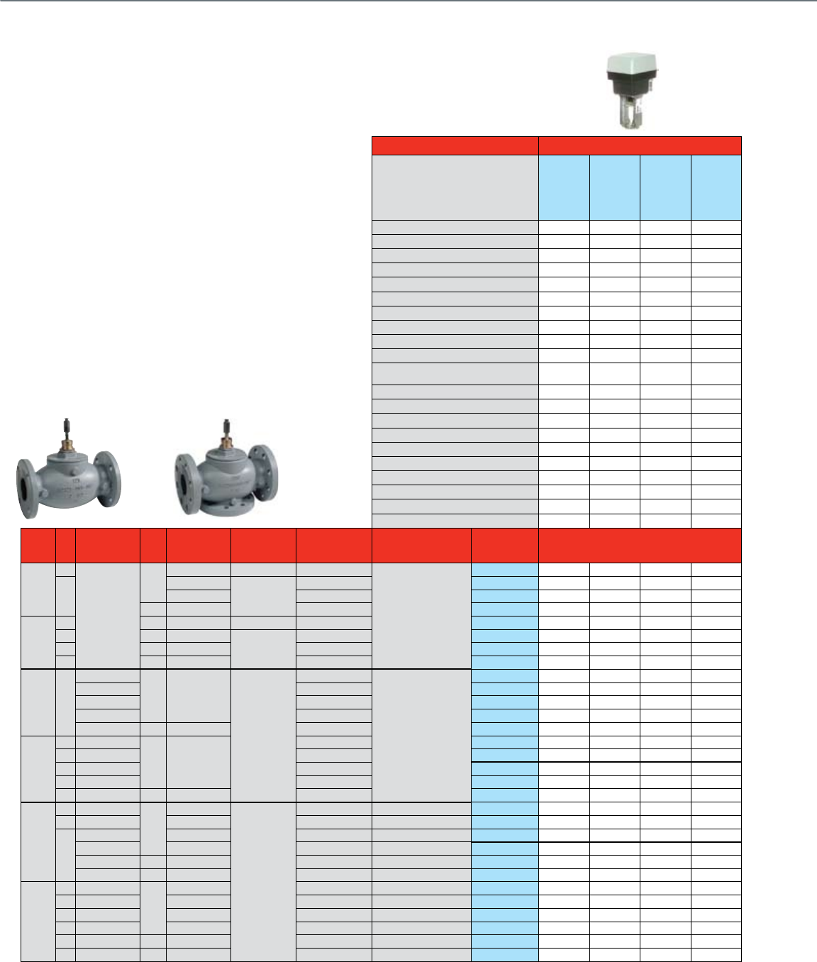
50
Flanged Globe Valves 2½- 3"
With Dedicated Valve Actuators
Common Features
• ANSI body class 125 or 250
• Close-off pressure = Maximum differential pressure
• Maximum static water pressure: Up to 400 psi
• Maximum steam pressure (VGF, 2-pos or modulating): 100 psi
• Maximum steam pressure (V5011, 2-pos): 15 psi
• Stem travel: 0.75"
• Rangeability: 50:1
• Body material: Cast iron
• Body trim: Stainless steel stem, brass seat (V5011/13),
stainless steel (VGF)
Actuator Features Fail Safe
Actuator O.S. Number
ML7425A3013
ML7425B3012
ML6425A3022
ML6425B3013
Power Supply Voltage 24 Vac 24 Vac 24 Vac 24 Vac
Frequency 50 / 60 Hz 50 / 60 Hz 50 / 60 Hz 50 / 60 Hz
Power 12 VA 12 VA 11 VA 11 VA
Actuator Torque (lb.-in.) 135 135 135 135
Control (0)2-10 Vdc • •
4-20 mA (external 500 Ohm Resistor) • •
Floating • •
Two-Position SPDT • •
Two-Position SPST • •
135 Ohm
Fail Safe Action Stem Down
(2-way N.C.)
Stem Up
(2-way N.O.)
Stem Down
(2-way N.C.)
Stem Up
(2-way N.O.)
Normal Position (no signal) (field configurable)
Stem Up Stem Up Stem Up Stem Up
Actuator Stroke (inches) 0.75 0.75 0.75 0.75
Timing (seconds at 0.75" stroke) 90 90 90 90
High Temperature Kit Steam Application 43196000-001 43196000-001 43196000-001 43196000-001
Aux Switch 1 x SPDT Add-On
2 x SPDT Add-On 43191680-105 43191680-105 43191680-105 43191680-105
Feedback 2-10 Vdc Built In • •
2-10 Vdc Add-On
220 Ohm Add-On 43191679-111
10 kOhm Add-On 43191679-112
Valve
Size
(inches)
Cv Valve
Type
ANSI
Class
Max Static
Water Pressure
Max Steam
Pressure /
Temperature
Flow
Characteristic
Valve
Action
Valve OS
Number Close-off Pressure, psid
2-Way
Water & Steam Valves
ANSI Class III (< 0.05%
Cv) Seat Leakage
2 1/2"
63
Standard
125
150 psi @ 240 F 15 psi (2-position) Equal %
Stem down to close
V5011A1734 28 28 28 28
70
175 psi @ 130 F
125 psig / 353 F
Equal % VGF21ES25 23 23 23 23
175 psi @ 130 F Linear VGF21LS25 23 23 23 23
250 400 psi @ 130 F Equal % VGF22ES25 23 23 23 23
3"
100 125 150 psi @ 240 F 15 psi (2-position) Equal % V5011A1767 16 16 16 16
115 125 175 psi @ 130 F
125 psig / 353 F
Equal % VGF21ES30 11 11 11 11
125 125 175 psi @ 130 F Linear VGF21LS30 11 11 11 11
120 250 400 psi @ 130 F Equal % VGF22ES30 11 11 11 11
2-Way Water & Steam Valves
ANSI Class IV (< 0.01% Cv)
Seat Leakage
2 1/2" 70
Pressure Balanced
125 175 psi @ 130 F
125 psig / 353 F
Equal %
Stem down to close
VGF21EP25 175 175 175 175
Standard Equal % VGF21ES25
Pressure Balanced
Linear VGF21LP25 175 175 175 175
Standard Linear VGF21LS25
Standard 250 400 psi @ 130 F Equal % VGF22ES25 23 23 23 23
3"
115
Pressure Balanced
125 175 psi @ 130 F
Equal % VGF21EP30 175 175 175 175
115 Standard Equal % VGF21ES30
120
Pressure Balanced
Linear VGF21LP30 175 175 175 175
125 Standard Linear VGF21LS30
120 Standard 250 400 psi @ 130 F Equal % VGF22ES30
3-Way Water Valves
2 1/2"
63 Mixing
125
150 psi @ 240 F
N / A
Constant Total Stem up closes A-AB V5013B1003 21 21 21 21
63 Diverting 150 psi @ 240 F Constant Total Stem up closes B-AB V5013C1001 21 21 21 21
70
Mixing 175 psi @ 130 F Equal % A-AB Stem up closes A-AB VGF31EM25 29 29 29 29
Diverting 175 psi @ 130 F Linear, Constant Total Stem up closes B-AB VGF31LD25 23 23 23 23
Mixing 250 400 psi @ 130 F Equal % A-AB Stem up closes A-AB VGF32EM25 29 29 29 29
Diverting 250 400 psi @ 130 F Linear, Constant Total Stem up closes B-AB VGF32LD25 23 23 23 23
3"
100 Mixing
125
150 psi @ 240 F Constant Total Stem up closes A-AB V5013B1011 14 14 14 14
100 Diverting 150 psi @ 240 F Constant Total Stem up closes B-AB V5013C1019 14 14 14 14
120 Mixing 175 psi @ 130 F Equal % A-AB Stem up closes A-AB VGF31EM30 19 19 19 19
120 Diverting 175 psi @ 130 F Linear, Constant Total Stem up closes B-AB VGF31LD30 11 11 11 11
115 Mixing 250 400 psi @ 130 F Equal % A-AB Stem up closes A-AB VGF32EM30 19 19 19 19
120 Diverting 250 400 psi @ 130 F Linear, Constant Total Stem up closes B-AB VGF32LD30 11 11 11 11

51
VALVE SELECTION
Notes & Numbers
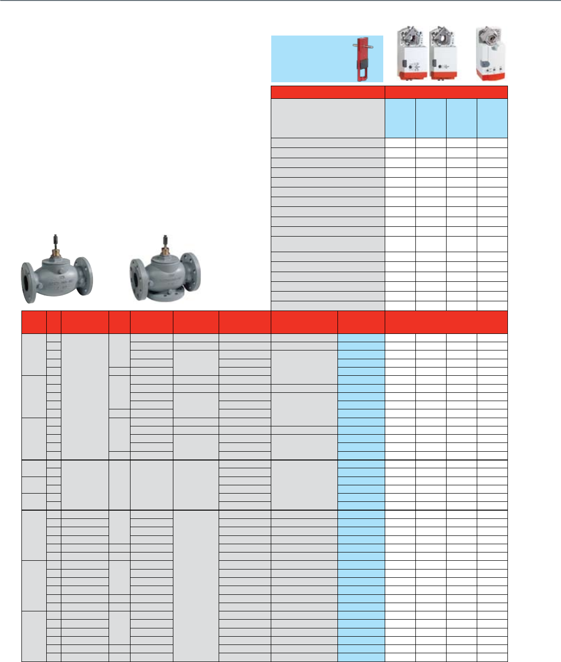
52
Flanged Globe Valves 4"- 6"
With Tandem Direct Coupled Actuators and Valve Linkage
Common Features
• Stem travel: 1.5"
• Rangeability: 50:1
• Body material: Cast iron
• Seat Material: Bronze (V5011/13), Stainless Steel (VGF)
• Stem Material: Stainless Steel
• Normal position eld congurable to stem up or stem down
Actuator Features Non-fail Safe
Actuator O.S. Number
(Two Actuators per valve/linkage)
MN7220A2007
MN6120A1002
MN72342008
MN6134A1003
Power Supply Voltage 24 Vac 24 Vac 24 Vac 24 Vac
Frequency 60 Hz 60 Hz 60 Hz 60 Hz
Power 6 VA 6 VA 9 VA 9 VA
Actuator Torque (lb.-in.) 175 175 300 300
Linkage Stem Force, Two Actuators (lbs.) 325 325 555 555
Control (0)2-10 Vdc • •
4-20 mA (external 500 Ohm Resistor) • •
Floating ••••
Two-Position SPDT ••••
Two-Position SPST •••
Fail Safe Action
Stay in Place Stay in Place Stay in Place Stay in Place
Normal Position (no signal) (field configurable)
Stem Up/Down Stem Up/Down Stem Up/Down Stem Up/Down
Actuator Stroke (inches) 1.5 1.5 1.5 1.5
Timing (seconds) 95 95 95 95
Aux Switch 2 x SPDT Add-On SW2-US SW2-US SW2-US SW2-US
2 x SPDT Built In
Feedback (0)2-10 Vdc Built In • •
Valve
Size
(inches)
Cv Valve
Type
ANSI
Class
Max Static
Water Pressure
Max Steam
Pressure /
Temperature
Flow
Characteristic
Valve
Action
Valve OS
Number Close-off Pressure, psid
2-Way Water & Steam Valves ANSI Class
III (< 0.05% Cv) Seat Leakage
4"
160
Standard
125
150 psi @ 240 F 15 psi (2-position) Equal % Stem down to close V5011A1858 20 20 34 34
160 150 psi @ 240 F 15 psi (2-position) Equal % Stem up to close V5011B1013 20 20 34 34
150 175 psi @ 130 F
125 psig / 353 F
Equal %
Stem down to close
VGF21ES40 27 27 47 47
155 175 psi @ 130 F Linear VGF21LS40 27 27 47 47
150 250 400 psi @ 130 F Equal % VGF22ES40 27 27 47 47
5"
250
125
150 psi @ 240 F 15 psi (2-position) Equal % V5011A1882 16 16 28 28
250 150 psi @ 240 F 15 psi (2-position) Equal % Stem up to close V5011B1047 16 16 28 28
285 175 psi @ 130 F
125 psig / 353 F
Equal %
Stem down to close
VGF21ES50 11 11 18 18
320 175 psi @ 130 F Linear VGF21LS50 11 11 18 18
320 250 400 psi @ 130 F Equal % VGF22ES50 11 11 18 18
6"
360
125
150 psi @ 240 F 15 psi (2-position) Equal % V5011A1916 11 11 19 19
360 150 psi @ 240 F 15 psi (2-position) Equal % Stem up to close V5011B1070 11 11 19 19
365 175 psi @ 130 F
125 psig / 353 F
Equal %
Stem down to close
VGF21ES60 11 11 18 18
370 175 psi @ 130 F Linear VGF21LS60 11 11 18 18
370 250 400 psi @ 130 F Equal % VGF22ES60 11 11 18 18
2-Way Water &
Steam Valves
ANSI Class IV
(< 0.01% Cv)
Seat Leakage
4" 150
Pressure Balanced 125 175 psi @ 130 F 125 psig / 353 F
Equal %
Stem down to close
VGF21EP40 175 175 175** 175**
150 Linear VGF21LP40 175 175 175** 175**
5" 285 Equal % VGF21EP50 175 175 175** 175**
320 Linear VGF21LP50 175 175 175** 175**
6" 365 Equal % VGF21EP60 175 175 175** 175**
370 Linear VGF21LP60 175 175 175** 175**
3-Way Water Valves
4"
160 Mixing
125
150 psi @ 240 F
N / A
Constant Total Stem up closes A-AB V5013B1029 20 20 34 34
160 Diverting 150 psi @ 240 F Constant Total Stem up closes B-AB V5013C1027 20 20 34 34
150 Mixing 175 psi @ 130 F Equal % A-AB Stem up closes A-AB VGF31EM40 27 27 47 47
160 Diverting 175 psi @ 130 F Linear, Constant Total Stem up closes B-AB VGF31LD40 27 27 47 47
170 Mixing 250 400 psi @ 130 F Equal % A-AB Stem up closes A-AB VGF32EM40 27 27 47 47
160 Diverting 250 400 psi @ 130 F Linear, Constant Total Stem up closes B-AB VGF32LD40 27 27 47 47
5"
250 Mixing
125
150 psi @ 240 F Constant Total Stem up closes A-AB V5013B1037 16 16 28 28
250 Diverting 150 psi @ 240 F Constant Total Stem up closes B-AB V5013C1035 16 16 28 28
320 Mixing 175 psi @ 130 F Equal % A-AB Stem up closes A-AB VGF31EM50 11 11 18 18
285 Diverting 175 psi @ 130 F Linear, Constant Total Stem up closes B-AB VGF31LD50 11 11 18 18
320 Mixing 250 400 psi @ 130 F Equal % A-AB Stem up closes A-AB VGF32EM50 11 11 18 18
285 Diverting 250 400 psi @ 130 F Linear, Constant Total Stem up closes B-AB VGF32LD50 11 11 18 18
6"
360 Mixing
125
150 psi @ 240 F Constant Total Stem up closes A-AB V5013B1045 11 11 19 19
360 Diverting 150 psi @ 240 F Constant Total Stem up closes B-AB V5013C1043 11 11 19 19
370 Mixing 175 psi @ 130 F Equal % A-AB Stem up closes A-AB VGF31EM60 11 11 18 18
380 Diverting 175 psi @ 130 F Linear, Constant Total Stem up closes B-AB VGF31LD60 11 11 18 18
370 Mixing 250 400 psi @ 130 F Equal % A-AB Stem up closes A-AB VGF32EM60 11 11 18 18
380 Diverting 250 400 psi @ 130 F Linear, Constant Total Stem up closes B-AB VGF32LD60 11 11 18 18
**Only requires single actuator
***Q5022B linkage compatible with VGF valves with 7/16-20UNF stem thread (Manufactured after June, 2005)
Q5022B1009
Required***
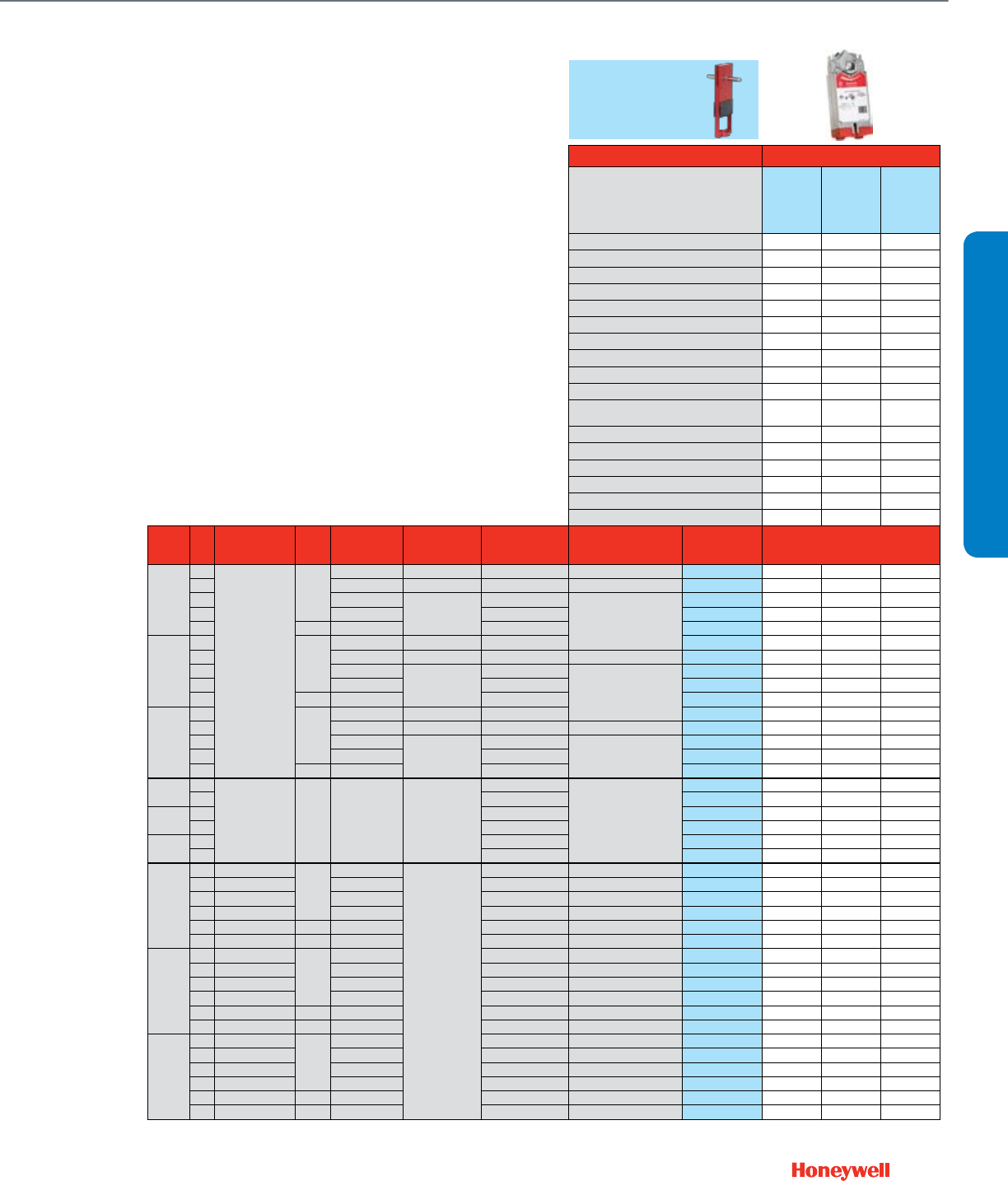
53
Actuator Features Fail Safe
Actuator O.S. Number
(Two Actuators per valve/linkage)
MS7520A2007
MS7520A2205
MS8120A1007
MS4120A1001
Power Supply Voltage 24 Vac 24 Vac 100-250 Vac
Frequency 60 Hz 60 Hz 60 Hz
Power 16 VA 40 VA 60 VA
Actuator Torque (lb.-in.) 175 175 175
Linkage Stem Force, Two Actuators (lbs.) 325 325 325
Control (0)2-10 Vdc •
4-20 mA (external 500 Ohm Resistor) •
Floating •
Two-Position SPDT •
Two-Position SPST •••
Fail Safe Action
Congurable
Open/Closed
Congurable
Open/Closed
Congurable
Open/Closed
Normal Position (no signal) (field configurable)
Stem Up/Down Stem Up/Down Stem Up/Down
Actuator Stroke (inches) 1.5 1.5 1.5
Timing (seconds) 90 90 90
Aux Switch 2 x SPDT Add-On SW2-US SW2-US SW2-US
2 x SPDT Built In 0 / 2
Feedback (0)2-10 Vdc Built In •
Valve
Size
(inches)
Cv Valve
Type
ANSI
Class
Max Static
Water Pressure
Max Steam
Pressure /
Temperature
Flow
Characteristic
Valve
Action
Valve OS
Number Close-off Pressure, psid
2-Way Water & Steam Valves ANSI Class
III (< 0.05% Cv) Seat Leakage
4"
160
Standard
125
150 psi @ 240 F 15 psi (2-position) Equal % Stem down to close V5011A1858 20 20 20
160 150 psi @ 240 F 15 psi (2-position) Equal % Stem up to close V5011B1013 20 20 20
150 175 psi @ 130 F
125 psig / 353 F
Equal %
Stem down to close
VGF21ES40 27 27 27
155 175 psi @ 130 F Linear VGF21LS40 27 27 27
150 250 400 psi @ 130 F Equal % VGF22ES40 27 27 27
5"
250
125
150 psi @ 240 F 15 psi (2-position) Equal % V5011A1882 16 16 16
250 150 psi @ 240 F 15 psi (2-position) Equal % Stem up to close V5011B1047 16 16 16
285 175 psi @ 130 F
125 psig / 353 F
Equal %
Stem down to close
VGF21ES50 11 11 11
320 175 psi @ 130 F Linear VGF21LS50 11 11 11
320 250 400 psi @ 130 F Equal % VGF22ES50 11 11 11
6"
360
125
150 psi @ 240 F 15 psi (2-position) Equal % V5011A1916 11 11 11
360 150 psi @ 240 F 15 psi (2-position) Equal % Stem up to close V5011B1070 11 11 11
365 175 psi @ 130 F
125 psig / 353 F
Equal %
Stem down to close
VGF21ES60 11 11 11
370 175 psi @ 130 F Linear VGF21LS60 11 11 11
370 250 400 psi @ 130 F Equal % VGF22ES60 11 11 11
2-Way Water &
Steam Valves
ANSI Class IV
(< 0.01% Cv)
Seat Leakage
4" 150
Pressure Balanced 125 175 psi @ 130 F 125 psig / 353 F
Equal %
Stem down to close
VGF21EP40 175 175 175
150 Linear VGF21LP40 175 175 175
5" 285 Equal % VGF21EP50 175 175 175
320 Linear VGF21LP50 175 175 175
6" 365 Equal % VGF21EP60 175 175 175
370 Linear VGF21LP60 175 175 175
3-Way Water Valves
4"
160 Mixing
125
150 psi @ 240 F
N / A
Constant Total Stem up closes A-AB V5013B1029 20 20 20
160 Diverting 150 psi @ 240 F Constant Total Stem up closes B-AB V5013C1027 20 20 20
150 Mixing 175 psi @ 130 F Equal % A-AB Stem up closes A-AB VGF31EM40 27 27 27
160 Diverting 175 psi @ 130 F Linear, Constant Total Stem up closes B-AB VGF31LD40 27 27 27
170 Mixing 250 400 psi @ 130 F Equal % A-AB Stem up closes A-AB VGF32EM40 27 27 27
160 Diverting 250 400 psi @ 130 F Linear, Constant Total Stem up closes B-AB VGF32LD40 27 27 27
5"
250 Mixing
125
150 psi @ 240 F Constant Total Stem up closes A-AB V5013B1037 16 16 16
250 Diverting 150 psi @ 240 F Constant Total Stem up closes B-AB V5013C1035 16 16 16
320 Mixing 175 psi @ 130 F Equal % A-AB Stem up closes A-AB VGF31EM50 11 11 11
285 Diverting 175 psi @ 130 F Linear, Constant Total Stem up closes B-AB VGF31LD50 11 11 11
320 Mixing 250 400 psi @ 130 F Equal % A-AB Stem up closes A-AB VGF32EM50 11 11 11
285 Diverting 250 400 psi @ 130 F Linear, Constant Total Stem up closes B-AB VGF32LD50 11 11 11
6"
360 Mixing
125
150 psi @ 240 F Constant Total Stem up closes A-AB V5013B1045 11 11 11
360 Diverting 150 psi @ 240 F Constant Total Stem up closes B-AB V5013C1043 11 11 11
370 Mixing 175 psi @ 130 F Equal % A-AB Stem up closes A-AB VGF31EM60 11 11 11
380 Diverting 175 psi @ 130 F Linear, Constant Total Stem up closes B-AB VGF31LD60 11 11 11
370 Mixing 250 400 psi @ 130 F Equal % A-AB Stem up closes A-AB VGF32EM60 11 11 11
380 Diverting 250 400 psi @ 130 F Linear, Constant Total Stem up closes B-AB VGF32LD60 11 11 11
***Q5022B linkage compatible with VGF valves with 7/16-20UNF stem thread (Manufactured after June, 2005)
Q5022B1009
Required***
VALVE SELECTION
Flanged Globe Valves 4"- 6"
With Tandem Direct Coupled Actuators and Valve Linkage
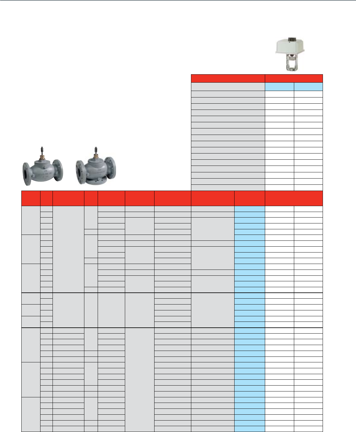
54
Actuator Features Non-fail Safe
Actuator O.S. Number ML7421B1023 ML6421B1040
Power Supply Voltage 24 Vac 24 Vac
Frequency 50 / 60 Hz 50 / 60 Hz
Power 12 VA 11 VA
Actuator Torque (lb.-in.) 404 404
Control (0)2-10 Vdc •
4-20 mA (external 500 Ohm Resistor) •
Floating •
Two-Position SPDT •
Fail Safe Action Stay in Place Stay in Place
Normal Position (no signal) (field configurable)
Stem Up Stay in Place
Actuator Stroke (inches) 1.5 1.5
Stroke Timing (seconds) 175 175
High Temperature Kit Steam Application 43196000-038 43196000-038
Aux Switch 2 x SPDT (24 Vac) (add-on) 43191680-102 43191680-102
Feedback
1 x 220 Ohm Potentiometer (add-on)
43191679-102
2-10 Vdc (built in) •
Valve Size
(inches) Cv Valve
Type
ANSI
Class
Max Static
Water Pressure
Max Steam
Pressure /
Temperature
Flow
Characteristic
Valve
Action
Valve OS
Number Close-off Pressure, psid
2-Way Water & Steam Valves ANSI Class III
(< 0.05% Cv) Seat Leakage
4"
160
Standard
125
150 psi @ 240 F
15 psi (2-position)
Equal % Stem down to close V5011A1858 29 29
160 150 psi @ 240 F
15 psi (2-position)
Equal % Stem up to close V5011B1013 29 29
150 175 psi @ 130 F
125 psig / 353 F
Equal %
Stem down to close
VGF21ES40 34 34
155 175 psi @ 130 F Linear VGF21LS40 34 34
150 250 400 psi @ 130 F Equal % VGF22ES40 34 34
5"
250
125
150 psi @ 240 F 15 psi (2-position) Equal % V5011A1882 18 18
250 150 psi @ 240 F 15 psi (2-position) Equal % Stem up to close V5011B1047 18 18
285 175 psi @ 130 F
125 psig / 353 F
Equal %
Stem down to close
VGF21ES50 13 13
320 175 psi @ 130 F Linear VGF21LS50 13 13
320 250 400 psi @ 130 F Equal % VGF22ES50 13 13
6"
360
125
150 psi @ 240 F 15 psi (2-position) Equal % V5011A1916 12 12
360 150 psi @ 240 F 15 psi (2-position) Equal % Stem up to close V5011B1070 12 12
365 175 psi @ 130 F
125 psig / 353 F
Equal %
Stem down to close
VGF21ES60 13 13
370 175 psi @ 130 F Linear VGF21LS60 13 13
370 250 400 psi @ 130 F Equal % VGF22ES60 13 13
2-Way Water &
Steam Valves
ANSI Class IV
(< 0.01% Cv)
Seat Leakage
4" 150
Pressure Balanced 125 175 psi @ 130 F 125 psig / 353 F
Equal %
Stem down to close
VGF21EP40 175 175
150 Linear VGF21LP40 175 175
5" 285 Equal % VGF21EP50 175 175
320 Linear VGF21LP50 175 175
6" 365 Equal % VGF21EP60 175 175
370 Linear VGF21LP60 175 175
3-Way Water Valves
4"
160 Mixing
125
150 psi @ 240 F
N/A
Constant Total Stem up closes A-AB V5013B1029 29 29
160 Diverting 150 psi @ 240 F Constant Total Stem up closes B-AB V5013C1027 29 29
150 Mixing 175 psi @ 130 F Equal % A-AB Stem up closes A-AB VGF31EM40 34 34
160 Diverting 175 psi @ 130 F
Linear, Constant Total
Stem up closes B-AB VGF31LD40 34 34
170 Mixing 250 400 psi @ 130 F Equal % A-AB Stem up closes A-AB VGF32EM40 34 34
160 Diverting 250 400 psi @ 130 F
Linear, Constant Total
Stem up closes B-AB VGF32LD40 34 34
5"
250 Mixing
125
150 psi @ 240 F Constant Total Stem up closes A-AB V5013B1037 18 18
250 Diverting 150 psi @ 240 F Constant Total Stem up closes B-AB V5013C1035 18 18
320 Mixing 175 psi @ 130 F Equal % A-AB Stem up closes A-AB VGF31EM50 13 13
285 Diverting 175 psi @ 130 F
Linear, Constant Total
Stem up closes B-AB VGF31LD50 13 13
320 Mixing 250 400 psi @ 130 F Equal % A-AB Stem up closes A-AB VGF32EM50 13 13
285 Diverting 250 400 psi @ 130 F
Linear, Constant Total
Stem up closes B-AB VGF32LD50 13 13
6"
360 Mixing
125
150 psi @ 240 F Constant Total Stem up closes A-AB V5013B1045 12 12
360 Diverting 150 psi @ 240 F Constant Total Stem up closes B-AB V5013C1043 12 12
370 Mixing 175 psi @ 130 F Equal % A-AB Stem up closes A-AB VGF31EM60 13 13
380 Diverting 175 psi @ 130 F
Linear, Constant Total
Stem up closes B-AB VGF31LD60 13 13
370 Mixing 250 400 psi @ 130 F Equal % A-AB Stem up closes A-AB VGF32EM60 13 13
380 Diverting 250 400 psi @ 130 F
Linear, Constant Total
Stem up closes B-AB VGF32LD60 13 13
Flanged Globe Valves 4"- 6"
With Dedicated Valve Actuators
Common Features
• ANSI body class 125 or 250
• Close-off pressure = Maximum differential pressure
• Maximum static water pressure: Up to 400 psi
• Maximum steam pressure (VGF, 2-pos or modulating): 100 psi
• Maximum steam pressure (V5011, 2-pos): 15 psi
• Stem travel: 1.5"
• Rangeability: 50:1
• Leakage < 0.05% of Cv
• Body material: Cast iron
• Body trim: Stainless steel stem, brass seat (V5011/13),
stainless steel seat (VGF)
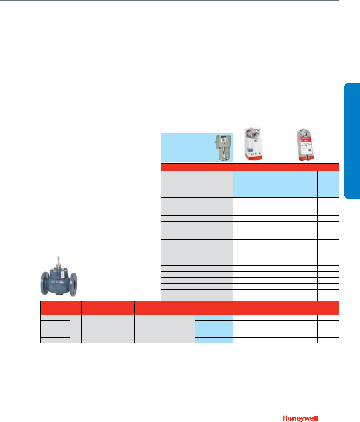
55
Q5020C1009
Required
Actuator Features Non-fail Safe Fail Safe
Actuator O.S. Number
MN6120A1002
MN6120A1200
MN7220A2007
MN7220A2205
MS7520A2007
MS7520A2205
MS7520H2208
MS8120A1007
MS8120A1205
MN4120A1001
MS4120A1209
Power Supply Voltage 24 Vac 24 Vac 24 Vac 24 Vac 100-250 Vac
Frequency 50 / 60 Hz 50 / 60 Hz 50 / 60 Hz 50 / 60 Hz 60 Hz
Power 6 VA 6 VA 16 VA 40 VA 60 VA
Actuator Torque (lbs.) 175 175 175 175 175
Control (0)2-10 Vdc • •
4-20 mA (external 500 Ohm Resistor) • •
Floating • • •
Two-Position SPDT • • •
Two-Position SPST • • • •
Fail Safe Action Stay-in-Place Stay-in-Place Congurable
Open/Closed
Congurable
Open/Closed
Congurable
Open/Closed
Normal Position (no signal) (field configurable)
Stem Up Stem Up Stem Up Stem Up Stem Up
Linkage Stroke (inches) 1.5 1.5 1.5 1.5 1.5
Stroke Timing (seconds) 95 95 90 90 90
High Temperature Kit Steam Application
Aux Switch 2 x SPDT (built in) 0 / 2 0 / 2 0 / 2 / 2 0 / 2 0 / 2
2 x SPDT (add-on) SW2-US SW2-US SW2-US SW2-US SW2-US
Feedback 2-10 Vdc (built in) • •
2-Way Water &
Steam Valves
Valve Size
(inches) Cv ANSI
Class
Max Static Wa-
ter Pressure
Max Steam
Pressure /
Temperature
Flow
Characteristic
Valve
Action
Valve OS
Number Close-off Pressure, psid
2 1/2" 75
125 150 psi @ 100 F 55 psig / 300 F Modified Linear Stem down to close
V5051A3004 150 150 150 150 150
3" 116 V5051A3012 150 150 150 150 150
4" 178 V5051A3020 150 150 150 150 150
5" 318 V5051A3038 150 150 150 150 150
6" 390 V5051A3046 150 150 150 150 150
Flanged Cage Valves 2½- 6"
The V5051 series advantage lies in its ability to
perform like a globe valve while achieving high close-
off pressures with a single spring return actuator. This
premium valve delivers a high close-off using a single
spring return actuator on all valves up to 6". It is highly
suitable for medium-pressure steam applications.
Common Features
• Pressure balanced design for high close-off
• Close-off pressure = Maximum differential pressure
• ANSI body class 125
• Stem travel 1.5”
• Body material: Cast iron
• Body valve trim: Stainless steel
• Leakage: 0.01% Cv 2.5”-4” and 0.03% Cv 5”-6”
• Max static water pressure: 150 psi
• Max static steam pressure: 55 psi
• Flow characteristic: Modied linear
VALVE SELECTION
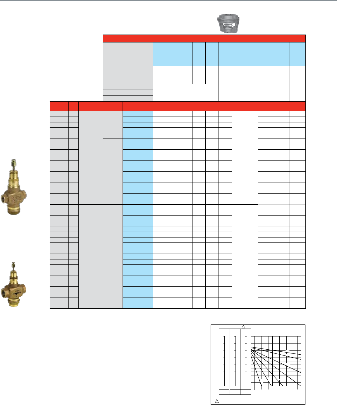
56
NPT Globe Valves ½- 3"
With Pneumatic Actuators
Common Features
• Rolling diaphragm for long life and
low hysteresis
• Easily installation and attachment
to the valve
• Direct or reverse acting
• No positive positioner
Actuator Features Without Positive Positioner
Actuator O.S. Number
MP953C1000
MP953C1018
MP953C1026
MP953C1067
MP953C1075
MP953C1083
MP953C1554
MP953C1562
MP953D1107
MP953D1131
MP953D1172
Direct / Reverse Acting DA / RA DA DA DA DA DA DA DA DA RA RA RA
Diaphragm Size 5" 5" 5" 8" 8" 8" 13" 13" 7-1/8" 7-1/8" 7-1/8"
Fail Safe Action
Stem Up Stem Up Stem Up Stem Up Stem Up Stem Up Stem Up Stem Up Stem Down Stem Down Stem Down
Positioner 10psi span
N/A5psi span
3psi span
Valve Size
(inches) Cv Flow
Characteristic
Valve
Action
Valve OS
Number Close-off Pressure - See Charts On Page 51
2-Way
Water Valves
Straight Through
2.9
Equal %
Stem up to
close
V5011N3004 A-NC A-NC A-NC B-NC B-NC B-NC
N/A
C-NO C-NO C-NO
1/2" 4.7 V5011N3012 A-NC A-NC A-NC B-NC B-NC B-NC C-NO C-NO C-NO
3/4" 7.3 V5011N3020 A-NC A-NC A-NC B-NC B-NC B-NC C-NO C-NO C-NO
1" 11.7 V5011N3038 A-NC A-NC A-NC B-NC B-NC B-NC C-NO C-NO C-NO
1-1/4" 18.7 V5011N3046 A-NC A-NC A-NC B-NC B-NC B-NC C-NO C-NO C-NO
1/2" 0.73
Stem down
to close
V5011N1008 F-NO F-NO F-NO E-NO E-NO E-NO D-NC D-NC D-NC
1/2" 1.16 V5011N1016 F-NO F-NO F-NO E-NO E-NO E-NO D-NC D-NC D-NC
1/2" 1.85 V5011N1024 F-NO F-NO F-NO E-NO E-NO E-NO D-NC D-NC D-NC
1/2" 2.9 V5011N1032 F-NO F-NO F-NO E-NO E-NO E-NO D-NC D-NC D-NC
1/2" 4.7 V5011N1040 F-NO F-NO F-NO E-NO E-NO E-NO D-NC D-NC D-NC
3/4" 7.3 V5011N1057 F-NO F-NO F-NO E-NO E-NO E-NO D-NC D-NC D-NC
1" 11.7 V5011N1065 F-NO F-NO F-NO E-NO E-NO E-NO D-NC D-NC D-NC
1-1/4" 18.7 V5011N1073 F-NO F-NO F-NO E-NO E-NO E-NO D-NC D-NC D-NC
1-1/2" 29.3 V5011N1081 F-NO F-NO F-NO E-NO E-NO E-NO D-NC D-NC D-NC
2" 46.8 V5011N1099 F-NO F-NO F-NO E-NO E-NO E-NO D-NC D-NC D-NC
2-1/2" 63 V5011F1105 L-NO L-NO L-NO L-NO L-NO L-NO G-NC G-NC G-NC
3" 100 V5011F1113 L-NO L-NO L-NO L-NO L-NO L-NO G-NC G-NC G-NC
2-Way
Steam Valves
Straight Through
1/2" 0.73
Linear Stem down
to close
V5011N2006 F*-NO F*-NO F*-NO E*-NO E*-NO E*-NO
N/A
D*-NC D*-NC D*-NC
1/2" 1.16 V5011N2014 F*-NO F*-NO F*-NO E*-NO E*-NO E*-NO D*-NC D*-NC D*-NC
1/2" 1.85 V5011N2022 F*-NO F*-NO F*-NO E*-NO E*-NO E*-NO D*-NC D*-NC D*-NC
1/2" 2.9 V5011N2030 F*-NO F*-NO F*-NO E*-NO E*-NO E*-NO D*-NC D*-NC D*-NC
1/2" 4.7 V5011N2048 F*-NO F*-NO F*-NO E*-NO E*-NO E*-NO D*-NC D*-NC D*-NC
3/4" 7.3 V5011N2055 F*-NO F*-NO F*-NO E*-NO E*-NO E*-NO D*-NC D*-NC D*-NC
1" 11.7 V5011N2063 F*-NO F*-NO F*-NO E*-NO E*-NO E*-NO D*-NC D*-NC D*-NC
1-1/4" 18.7 V5011N2071 F*-NO F*-NO F*-NO E*-NO E*-NO E*-NO D*-NC D*-NC D*-NC
1-1/2" 29.3 V5011N2089 F*-NO F*-NO F*-NO E*-NO E*-NO E*-NO D*-NC D*-NC D*-NC
2" 46.8 V5011N2097 F*-NO F*-NO F*-NO E*-NO E*-NO E*-NO D*-NC D*-NC D*-NC
2-1/2" 63 V5011G1111 L*-NO L*-NO L*-NO L*-NO L*-NO L*-NO G*-NC G*-NC G*-NC
3" 100 V5011G1129 L*-NO L*-NO L*-NO L*-NO L*-NO L*-NO G*-NC G*-NC G*-NC
3-Way
Water Valves
Mixing
1/2" 2.9
Linear B-AB /
Equal % A-AB
Stem up
closes A-AB
V5013N1030 H-NC H-NC H-NC J-NC J-NC J-NC
N/A
K-NC K-NC K-NC
1/2" 4.7 V5013N1048 H-NC H-NC H-NC J-NC J-NC J-NC K-NC K-NC K-NC
3/4" 7.3 V5013N1055 H-NC H-NC H-NC J-NC J-NC J-NC K-NC K-NC K-NC
1" 11.7 V5013N1063 H-NC H-NC H-NC J-NC J-NC J-NC K-NC K-NC K-NC
1-1/4" 18.7 V5013N1071 H-NC H-NC H-NC J-NC J-NC J-NC K-NC K-NC K-NC
1-1/2" 29.3 V5013N1089 H-NC H-NC H-NC J-NC J-NC J-NC K-NC K-NC K-NC
2" 46.8 V5013N1097 H-NC H-NC H-NC J-NC J-NC J-NC K-NC K-NC K-NC
*The close-off pressure not to exceed rated pressure of steam valve
NC = Normally Closed
NO = Normally Open
SPRING RANGE PSI (kPa)
L - LOWER SEAT
U - UPPER SEAT
ACTUATOR AIR PRESSURE IN PSI (kPa)
4-11
(30-75)
11
(75)
12
(85)
13
(90)
14
(95)
15
(105)
16
(110)
17
(115)
18
(125)
4
(30)
3
(20)
2
(15)
1
(5)
0
(0)
LU
V5013N: 1/2-INCH TO 2-INCH VALVE BODIES WITH
5-INCH DIRECT ACTING PNEUMATIC ACTUATOR
5
(35)
10
(70)
15
(105)
20
(140)
25
(170)
30
(205)
35
(240)
40
(275)
CLOSEOFF PRESSURE RATING - PSI (kPa)
2-7
(15-50)
7
(50)
8
(55)
9
(60)
10
(70)
11
(75)
12
(85)
13
(90)
14
(95)
2
(15)
1
(5)
0
(0)
LU
MIXING
1
1
USE 4-11 PSI (30-75 kPa) RANGE FOR DETERMINING CLOSEOFF OF VALVES WITH
MP953E ACTUATORS. M12909
8-12
(55-85)
12
(85)
13
(90)
14
(95)
15
(105)
16
(110)
17
(115)
18
(125)
1
(5)
8
(55)
7
(50)
6
(40)
LU
5
(35)
4
(30)
3
(20)
2
(15)
45
(310)
55
(380)
65
(450)
50
(345)
60
(415)
70
(485)
Cv 2.9
Cv 4.7
Cv7.3
Cv 11.7
Cv18.7
Cv 29.3
Cv 46.8
Chart H
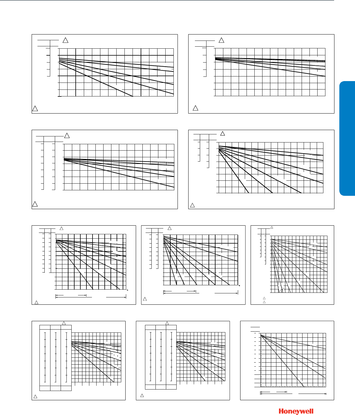
57
SPRING RANGE PSI (kPa)
L - LOWER SEAT
U - UPPER SEAT
ACTUATOR AIR PRESSURE IN PSI (kPa)
4-11
(30-75)
11
(75)
12
(85)
13
(90)
14
(95)
15
(105)
16
(110)
17
(115)
18
(125)
4
(30)
3
(20)
2
(15)
1
(5)
0
(0)
LU
V5013N: 1/2-INCH TO 2-INCH VALVE BODIES WITH
8-INCH DIRECT ACTING PNEUMATIC ACTUATOR
5
(35)
10
(70)
15
(105)
20
(140)
25
(170)
30
(205)
35
(240)
40
(275)
CLOSEOFF PRESSURE RATING - PSI (kPa)
2-7
(15-50)
7
(50)
8
(55)
9
(60)
10
(70)
11
(75)
12
(85)
13
(90)
14
(95)
2
(15)
1
(5)
0
(0)
LU
MIXING
1
1
USE 4-11 PSI (30-75 kPa) RANGE FOR DETERMINING CLOSEOFF OF VALVES WITH MP953E
ACTUATORS.
M12908
8-12
(55-85)
12
(85)
13
(90)
14
(95)
15
(105)
16
(110)
17
(115)
18
(125)
1
(5)
8
(55)
7
(50)
6
(40)
LU
5
(35)
4
(30)
3
(20)
2
(15)
45
(310)
55
(380)
65
(450)
50
(345)
60
(415)
70
(485)
Cv 2.9
Cv7.3
Cv 11.7
Cv 29.3
Cv 46.8
Cv18.7
Cv 4.7
Chart J
SPRING RANGE PSI (kPa)
L - LOWER SEAT
U - UPPER SEAT
4-11
(30-75)
11
(75)
12
(85)
13
(90)
14
(95)
15
(105)
16
(110)
17
(115)
18
(125)
4
(30)
3
(20)
2
(15)
1
(5)
0
(0)
UL
V5013N: 1/2-INCH TO 2-INCH VALVE BODIES
WITH7-1/8 INCH REVERSE ACTING
PNEUMATIC ACTUATOR
5
(35)
10
(70)
15
(105)
20
(140)
25
(170)
30
(205)
35
(240)
40
(275)
CLOSEOFF PRESSURE RATING - PSI (kPa)
3-7
(15-50)
7
(50)
8
(55)
9
(60)
10
(70)
11
(75)
12
(85)
13
(90)
14
(95)
3
(20)
2
(15)
1
(5)
ULMIXING
USE 8-13 PSI (55-90 kPa) RANGE FOR DETERMINING CLOSEOFF OF VALVES WITH
MP953F ACTUATORS. M12907
8-13
(55-90)
13
(90)
14
(95)
15
(105)
16
(110)
17
(115)
18
(125)
19
(130)
1
(5)
8
(55)
7
(50)
6
(40)
UL
5
(35)
4
(30)
3
(20)
2
(15)
45
(310)
55
(380)
65
(450)
50
(345)
60
(415)
70
(485)
0
(0)
Cv 2.9
Cv 4.7
Cv 11.7
Cv7.3
Cv18.7
Cv 29.3
Cv 46.8
ACTUATOR AIR PRESSURE IN PSI (kPa)
1
1
Chart K
Chart C
8
(55)
7
(50)
6
(40)
5
(35)
4
(30)
3
(20)
2
(15)
1
(10)
0
(0)
4
(30)
3
(20)
2
(15)
1
(10)
0
(0)
3
(20)
2
(15)
1
(10)
0
(0)
0
(0)
10
(70)
20
(140)
30
(205)
40
(275)
60
(515)
70
(480)
50
(345)
80
(550)
90
(620)
100
(690)
110
(760)
120
(825)
130
(895)
140
(965)
150
(1035) 160
(1100)
2-7
(15-50)
4-11
(30-75)
8-13
(55-90)
SPRING RANGE PSI (kPa)
AIR PRESSURE IN ACTUATOR PSI (kPa)
CLOSEOFF PRESSURE RATINGS PSI (kPa)
1
M16051
USE 4-11 PSI SPRING FOR POSITIONER MODEL (MP953E).
1
V5011N — 1/2 THROUGH 2 IN. DIRECT ACTING
THREADED BODIES WITH 7-1/8 REVERSE ACTING
PNEUMATIC ACTUATOR (NORMALLY CLOSED)
CV .73 TO 2.9
CV 4.7
CV 7.3
CV 11.7
CV 18.7
CV 29.3
CV 46.8
Chart D
SPRING RANGE PS (kPa) V5011N — 1/2 THROUGH 1-1/4 IN. REVERSE ACTING
THREADED BODIES WITH 5 IN. DIRECT ACTING
PNEUMATIC ACTUATOR (NORMALLY CLOSED)
4-11
(30-75)
8-12
(55-85)
5
(35)
4
(30)
3
(20)
8
(55)
7
(50)
6
(40)
5
(35)
15
(105)
25
(170)
35
(240)
45
(310)
55
(380)
65
(450)
0
(0)
10
(70)
20
(140)
30
(205)
40
(275)
50
(345)
60
(415)
70
(480)
CLOSEOFF PRESSURE RATINGS PSI (kPa)
AIR PRESSURE IN ACTUATOR PSI (kPa)
1
1
0
(0)
1
(10)
M16052
2
(15)
3
(20)
4
(30)
1
(10)
2
(15)
USE 4-11 PSI SPRING FOR POSITIONER MODEL (MP953E).
CV .73 TO 2.9
CV 4.7
CV 7.3
CV 11.7
CV 18.7
Chart A
M16053
SPRING RANGE PSI (kPa) V5011N — 1/2 THROUGH 1-1/4 IN. REVERSE ACTING
THREADED BODIES WITH 8 IN. DIRECT ACTING
PNEUMATIC ACTUATOR (NORMALLY CLOSED)
4-11
(30-75) 8-12
(55-85)
5
(35)
4
(30)
3
(20)
8
(55)
7
(50)
6
(40)
5
(35)
15
(105)
25
(170)
35
(240)
45
(310)
55
(380)
65
(450)
0
(0)
10
(70)
20
(140)
30
(205)
40
(275)
50
(345)
60
(415)
70
(480)
CLOSEOFF PRESSURE RATINGS PSI (kPa)
0
(0)
1
(10)
2
(15)
3
(20)
4
(30)
1
(10)
2
(15)
USE 4-11 PSI SPRING FOR POSITIONER MODEL (MP953E).
1
1
CV .73 TO 2.9
CV 4.7
CV 7.3
CV 11.7
CV 18.7
AIR PRESSURE IN ACTUATOR PSI (kPa)
Chart B
M16054
SPRING RANGE PSI (kPa) V5011N — 1/2 THROUGH 1-1/4 IN. REVERSE ACTING THREADED
BODIES WITH 7 IN. REVERSE ACTING PNEUMATIC ACTUATOR
(NORMALLY OPEN)
4-11
(30-75)
3-7
(20-50)
8-13
(55-90)
7
(50)
14
(95)
17
(120)
18
(125)
15
(105)
16
(110)
17
(120)
18
(125)
12
(85)
13
(90)
14
(95)
5
(35)
15
(105)
25
(170)
35
(240)
45
(310)
55
(380)
65
(450)
0
(0)
10
(70)
20
(140)
30
(205)
40
(275)
50
(345)
60
(415)
70
(480)
CLOSEOFF PRESSURE RATINGS PSI (kPa)
AIR PRESSURE IN ACTUATOR PSI (kPa)
1
16
(110)
12
(85)
13
(90)
15
(105)
11
(75)
14
(95)
10
(70)
9
(60)
8
(55)
13
(90)
12
(85)
11
(75)
1 USE 4-11 PSI SPRING FOR POSITIONER MODEL (MP953E).
CV .73 TO 2.9
CV 4.7
CV 7.3
CV 11.7
CV 18.7
V5011N — 1/2 THROUGH 2 IN., DIRECT ACTING,
THREADED BODIES WITH 5 IN. DIA.
PNEUMATIC ACTUATOR (NORMALLY OPEN)
4-11
(30-75)
2-7
(15-50)
8-12
(55-90)
14
(97)
15
(103)
16
(110)
17
(117)
18
(124)
19
(131)
20
(138)
17
(117)
18
(124)
19
(131)
20
(138)
19
(131)
20
(138)
15
(103)
16
(110)
17
(117)
18
(124)
13
(90)
14
(97)
AIR PRESSURE IN ACTUATOR PSI (kPa)
16
(110)
12
(83)
13
(90)
15
(103)
11
(26)
14
(97)
10
(69)
9
(62)
8
(55)
13
(90)
12
(83)
SPRING RANGE PSI (kPa)
0
(0)
20
(138)
40
(276)
60
(414)
80
(552)
100
(699)
CLOSE OFF PRESSURE RATINGS PSI (kPa)
120
(827)
140
(965)
160
(1103)
180
(1241)
200
(1379)
220
(1517)
230
(1595)
USE 4-11 PSI SPRING FOR POSITIONER MODEL (MP953E). M16049
V5011N1XXX
V5011N2XXX
CV .73 TO 2.9
CV 4.7
CV 7.3
CV 11.7
CV 18.7
CV 29.3
CV 46.8
1
1
Chart F
V5011N — 1/2 THROUGH 2 IN., DIRECT ACTING,
THREADED BODIES WITH 8 IN. DIA.
PNEUMATIC ACTUATOR (NORMALLY OPEN)
14
(97)
15
(103)
16
(110)
17
(117)
18
(124)
19
(131)
20
(138)
17
(117)
18
(124)
19
(131)
20
(138)
19
(131)
20
(138)
15
(103)
16
(110)
17
(117)
18
(124)
13
(90)
14
(97)
AIR PRESSURE IN ACTUATOR PSI (kPa)
16
(110)
12
(83)
13
(90)
15
(103)
11
(26)
14
(97)
10
(69)
9
(62)
8
(55)
7
(48)
13
(90)
12
(83)
11
(75)
12
(83)
0
(0)
20
(138)
40
(276)
60
(414)
80
(552)
100
(699)
CLOSE OFF PRESSURE RATINGS PSI (kPa)
120
(827)
140
(965)
160
(1103)
180
(1241)
200
(1379)
220
(1517)
USE 4-11 PSI SPRING FOR POSITIONER MODEL (MP953E). M16050
V5011N1XXX
V5011N2XXX
230
(1595)
CV .73 TO 2.9
CV 4.7
CV 7.3
CV 11.7
CV 18.7
CV 29.3
CV 46.8
4-11
(30-75)
2-7
(15-50)
8-12
(55-90)
SPRING RANGE PSI (kPa) 1
1
Chart E
8
(55)
7
(50)
6
(40)
5
(35)
4
(30)
3
(20)
2
(15)
1
(10)
0
(0)
4
(30)
3
(20)
2
(15)
1
(10)
0
(0)
3
(20)
2
(15)
1
(10)
0
(0)
0
(0)
10
(70)
20
(140)
30
(205)
40
(275)
60
(515)
70
(480)
50
(345)
80
(550)
90
(620)
100
(690)
1 1 0
(760)
120
(825)
130
(895)
140
(965)
150
(1035)
160
(1100)
2-7
(15-50)
4-11
(30-75)
8-13
(55-90)
SPRING RANGE
PSI (kPa)
AIR PRESSURE IN ACTUATOR PSI (kPa)
CLOSEOFF PRESSURE RATINGS PSI (kPa)
1
C3125-1
USE 8-13 PSI (55-90 KPA) RANGE FOR DETERMINING CLOSEOFF OF VA LVES USED WITH
MP953F ACTUATORS.
DUE TO DIFFERENCES IN V A LVE BODY CONSTRUCTION, SCREWED AND FLANGED PA TTERNS
HAVE DIFFERENT CLOSEOFF RATINGS. THIS APPLIES TO 2-1/2 AND 3 IN. VA LVE SIZES.
1
2
Cv = 0.63 TO 2.5
Cv = 4.0
Cv = 6.3
Cv = 10
Cv = 16
Cv = 25
Cv = 40
Cv = 63
Cv = 100
2
2
V5011F&G — 1/2 THROUGH 3 IN. D.A. SCREWED BODIES
WITH R.A. PNEUMATIC ACTUATOR
(NORMALLY CLOSED)
Chart G
15
(103)
16
(110)
17
(117)
18
(124)
19
(131)
20
(138)
V5011F,G 1-1/2 THROUGH 3 INCH DIRECT ACTING,
SCREWED BODIES WITH 13 INCH DIAMETER
PNEUMATIC ACTUA T OR (NORMALLY OPEN)
ACTUAT OR
SPRING RANGE
psi (kPa)
2-7
4-11
7
(48)
8
(55)
9
(62)
10
(69)
11
(75)
12
(83)
13
(90)
14
(97)
11
(75)
12
(83)
13
(90)
14
(97)
15
(103)
16
(110)
17
(117)
18
(124)
19
(131)
20
(138)
USE 4-11 PSI SPRING RANGE FOR POSITIONER MODEL (MP953E)
CLOSE OFF PRESSURE RATINGS PSI (kPa)
V5011F
V5011G
20
(138)
0
(0)
40
(276)
60
(414)
80
(552)
100
(699)
120
(827)
140
(965)
160
(1103)
180
(1241)
200
(1379)
220
(1517)
240
(1655)
C7977A
Cv=25
Cv=100
Cv=63
Cv=40
AIR PRESSURE IN ACTUATOR PSI (kPa)
Chart L
VALVE SELECTION
NPT Globe Valves ½- 3"
With Pneumatic Actuators
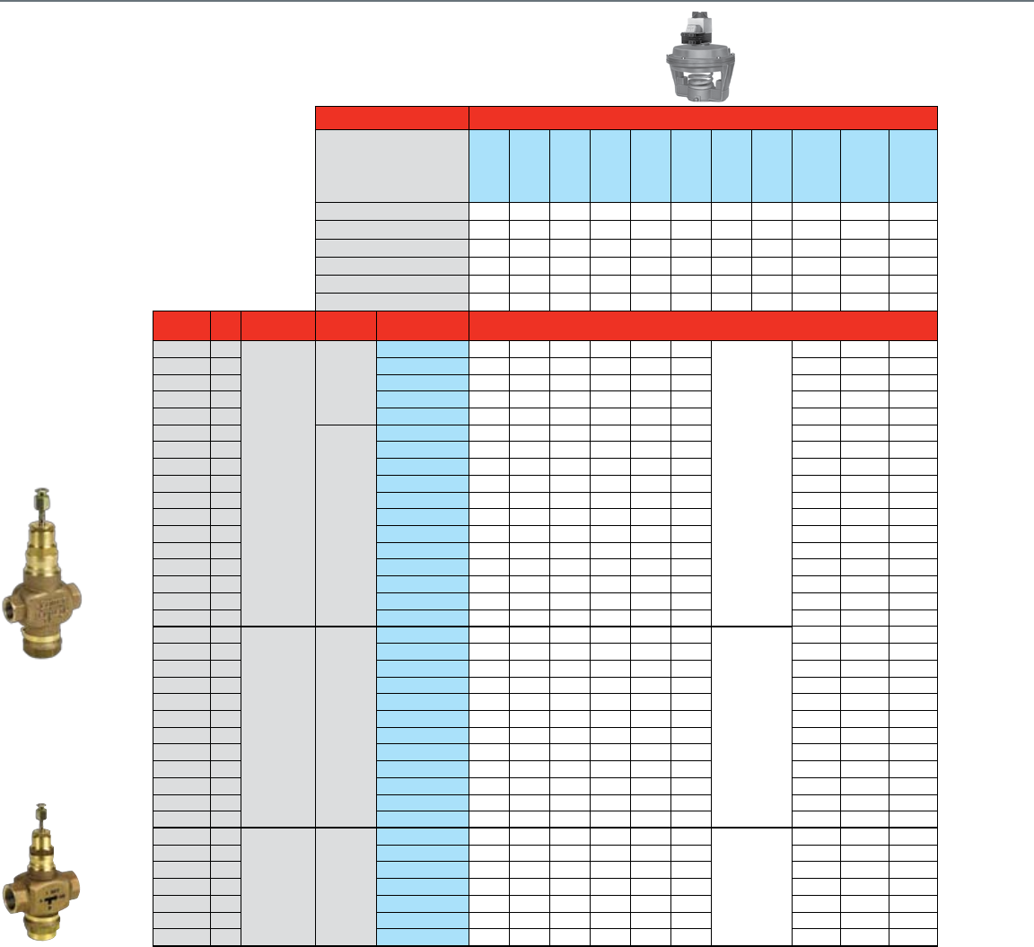
58
NPT Globe Valves ½- 3"
With Pneumatic Actuators
Common Features
• Rolling diaphragm for long life and
low hysteresis
• Easily installation and attachment
to the valve
• Direct or reverse acting
• Integrated positive positioner
Actuator Features With Positive Positioner
Actuator O.S. Number
MP953E1301
MP953E1319
MP953E1327
MP953E1368
MP953E1376
MP953E1384
MP953E1435
MP953E1443
MP953F1093
MP953F1101
MP953F1119
Direct / Reverse Acting DA / RA DA DA DA DA DA DA DA DA RA RA RA\
Diaphragm Size 5" 5" 5" 8" 8" 8" 13" 13" 7-1/8" 7-1/8" 7-1/8"
Fail Safe Action
Stem Up Stem Up Stem Up Stem Up Stem Up Stem Up Stem Up Stem Up Stem Down Stem Down Stem Down
Positioner 10psi span • • • •
5psi span • • • •
3psi span • • •
Valve Size
(inches) Cv Flow
Characteristic
Valve
Action
Valve OS
Number Close-off Pressure - See Charts On Page 53
2-Way
Water Valves
Straight Through
2.9
Equal %
Stem up to
close
V5011N3004 A-NC A-NC A-NC B-NC B-NC B-NC
N/A
C-NO C-NO C-NO
1/2" 4.7 V5011N3012 A-NC A-NC A-NC B-NC B-NC B-NC C-NO C-NO C-NO
3/4" 7.3 V5011N3020 A-NC A-NC A-NC B-NC B-NC B-NC C-NO C-NO C-NO
1" 11.7 V5011N3038 A-NC A-NC A-NC B-NC B-NC B-NC C-NO C-NO C-NO
1-1/4" 18.7 V5011N3046 A-NC A-NC A-NC B-NC B-NC B-NC C-NO C-NO C-NO
1/2" 0.73
Stem down
to close
V5011N1008 F-NO F-NO F-NO E-NO E-NO E-NO D-NC D-NC D-NC
1/2" 1.16 V5011N1016 F-NO F-NO F-NO E-NO E-NO E-NO D-NC D-NC D-NC
1/2" 1.85 V5011N1024 F-NO F-NO F-NO E-NO E-NO E-NO D-NC D-NC D-NC
1/2" 2.9 V5011N1032 F-NO F-NO F-NO E-NO E-NO E-NO D-NC D-NC D-NC
1/2" 4.7 V5011N1040 F-NO F-NO F-NO E-NO E-NO E-NO D-NC D-NC D-NC
3/4" 7.3 V5011N1057 F-NO F-NO F-NO E-NO E-NO E-NO D-NC D-NC D-NC
1" 11.7 V5011N1065 F-NO F-NO F-NO E-NO E-NO E-NO D-NC D-NC D-NC
1-1/4" 18.7 V5011N1073 F-NO F-NO F-NO E-NO E-NO E-NO D-NC D-NC D-NC
1-1/2" 29.3 V5011N1081 F-NO F-NO F-NO E-NO E-NO E-NO D-NC D-NC D-NC
2" 46.8 V5011N1099 F-NO F-NO F-NO E-NO E-NO E-NO D-NC D-NC D-NC
2-1/2" 63 V5011F1105 G-NC G-NC G-NC
3" 100 V5011F1113 G-NC G-NC G-NC
2-Way
Steam Valves
Straight Through
1/2" 0.73
Linear Stem down
to close
V5011N2006 F**-NO F**-NO F**-NO E**-NO E**-NO E**-NO
N/A
D*-NC D*-NC D*-NC
1/2" 1.16 V5011N2014 F**-NO F**-NO F**-NO E**-NO E**-NO E**-NO D*-NC D*-NC D*-NC
1/2" 1.85 V5011N2022 F**-NO F**-NO F**-NO E**-NO E**-NO E**-NO D*-NC D*-NC D*-NC
1/2" 2.9 V5011N2030 F**-NO F**-NO F**-NO E**-NO E**-NO E**-NO D*-NC D*-NC D*-NC
1/2" 4.7 V5011N2048 F**-NO F**-NO F**-NO E**-NO E**-NO E**-NO D*-NC D*-NC D*-NC
3/4" 7.3 V5011N2055 F**-NO F**-NO F**-NO E**-NO E**-NO E**-NO D*-NC D*-NC D*-NC
1" 11.7 V5011N2063 F**-NO F**-NO F**-NO E**-NO E**-NO E**-NO D*-NC D*-NC D*-NC
1-1/4" 18.7 V5011N2071 F**-NO F**-NO F**-NO E**-NO E**-NO E**-NO D*-NC D*-NC D*-NC
1-1/2" 29.3 V5011N2089 F**-NO F**-NO F**-NO E**-NO E**-NO E**-NO D*-NC D*-NC D*-NC
2" 46.8 V5011N2097 F**-NO F**-NO F**-NO E**-NO E**-NO E**-NO D*-NC D*-NC D*-NC
2-1/2" 63 V5011G1111 G*-NC G*-NC G*-NC
3" 100 V5011G1129 G*-NC G*-NC G*-NC
3-Way
Water Valves
Mixing
1/2" 2.9
Linear B-AB /
Equal % A-AB
Stem up
closes A-AB
V5013N1030 H-NC H-NC H-NC J-NC J-NC J-NC
N/A
K-NC K-NC K-NC
1/2" 4.7 V5013N1048 H-NC H-NC H-NC J-NC J-NC J-NC K-NC K-NC K-NC
3/4" 7.3 V5013N1055 H-NC H-NC H-NC J-NC J-NC J-NC K-NC K-NC K-NC
1" 11.7 V5013N1063 H-NC H-NC H-NC J-NC J-NC J-NC K-NC K-NC K-NC
1-1/4" 18.7 V5013N1071 H-NC H-NC H-NC J-NC J-NC J-NC K-NC K-NC K-NC
1-1/2" 29.3 V5013N1089 H-NC H-NC H-NC J-NC J-NC J-NC K-NC K-NC K-NC
2" 46.8 V5013N1097 H-NC H-NC H-NC J-NC J-NC J-NC K-NC K-NC K-NC
*The close-off pressure not to exceed rated pressure of steam valve
**The close-off pressure not to exceed rated pressure of steam valve. Use 4-11 spring range for positive positioner models.
NC = Normally Closed
NO = Normally Open
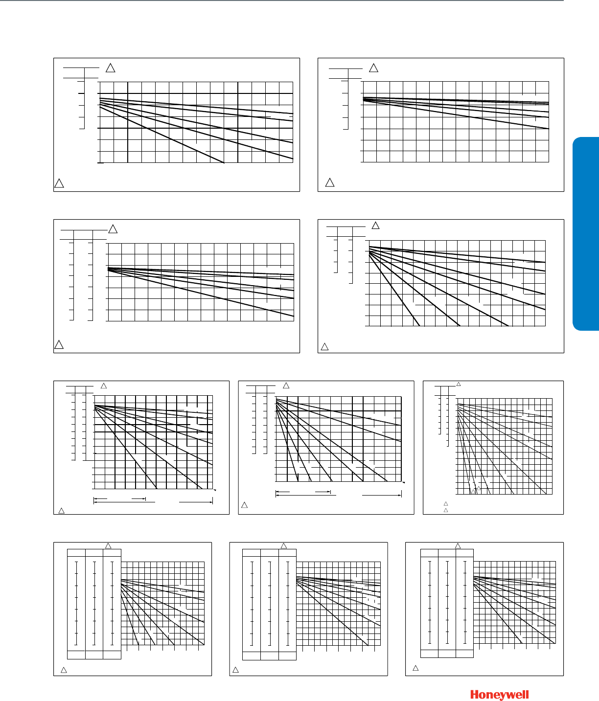
59
Chart C
8
(55)
7
(50)
6
(40)
5
(35)
4
(30)
3
(20)
2
(15)
1
(10)
0
(0)
4
(30)
3
(20)
2
(15)
1
(10)
0
(0)
3
(20)
2
(15)
1
(10)
0
(0)
0
(0)
10
(70)
20
(140)
30
(205)
40
(275)
60
(515)
70
(480)
50
(345)
80
(550)
90
(620)
100
(690)
110
(760)
120
(825)
130
(895)
140
(965)
150
(1035) 160
(1100)
2-7
(15-50)
4-11
(30-75)
8-13
(55-90)
SPRING RANGE PSI (kPa)
AIR PRESSURE IN ACTUATOR PSI (kPa)
CLOSEOFF PRESSURE RATINGS PSI (kPa)
1
M16051
USE 4-11 PSI SPRING FOR POSITIONER MODEL (MP953E).
1
V5011N — 1/2 THROUGH 2 IN. DIRECT ACTING
THREADED BODIES WITH 7-1/8 REVERSE ACTING
PNEUMATIC ACTUATOR (NORMALLY CLOSED)
CV .73 TO 2.9
CV 4.7
CV 7.3
CV 11.7
CV 18.7
CV 29.3
CV 46.8
Chart D
SPRING RANGE PS (kPa) V5011N — 1/2 THROUGH 1-1/4 IN. REVERSE ACTING
THREADED BODIES WITH 5 IN. DIRECT ACTING
PNEUMATIC ACTUATOR (NORMALLY CLOSED)
4-11
(30-75)
8-12
(55-85)
5
(35)
4
(30)
3
(20)
8
(55)
7
(50)
6
(40)
5
(35)
15
(105)
25
(170)
35
(240)
45
(310)
55
(380)
65
(450)
0
(0)
10
(70)
20
(140)
30
(205)
40
(275)
50
(345)
60
(415)
70
(480)
CLOSEOFF PRESSURE RATINGS PSI (kPa)
AIR PRESSURE IN ACTUATOR PSI (kPa)
1
1
0
(0)
1
(10)
M16052
2
(15)
3
(20)
4
(30)
1
(10)
2
(15)
USE 4-11 PSI SPRING FOR POSITIONER MODEL (MP953E).
CV .73 TO 2.9
CV 4.7
CV 7.3
CV 11.7
CV 18.7
Chart A
M16053
SPRING RANGE PSI (kPa) V5011N — 1/2 THROUGH 1-1/4 IN. REVERSE ACTING
THREADED BODIES WITH 8 IN. DIRECT ACTING
PNEUMATIC ACTUATOR (NORMALLY CLOSED)
4-11
(30-75) 8-12
(55-85)
5
(35)
4
(30)
3
(20)
8
(55)
7
(50)
6
(40)
5
(35)
15
(105)
25
(170)
35
(240)
45
(310)
55
(380)
65
(450)
0
(0)
10
(70)
20
(140)
30
(205)
40
(275)
50
(345)
60
(415)
70
(480)
CLOSEOFF PRESSURE RATINGS PSI (kPa)
0
(0)
1
(10)
2
(15)
3
(20)
4
(30)
1
(10)
2
(15)
USE 4-11 PSI SPRING FOR POSITIONER MODEL (MP953E).
1
1
CV .73 TO 2.9
CV 4.7
CV 7.3
CV 11.7
CV 18.7
AIR PRESSURE IN ACTUATOR PSI (kPa)
Chart B
M16054
SPRING RANGE PSI (kPa) V5011N — 1/2 THROUGH 1-1/4 IN. REVERSE ACTING THREADED
BODIES WITH 7 IN. REVERSE ACTING PNEUMATIC ACTUATOR
(NORMALLY OPEN)
4-11
(30-75)
3-7
(20-50)
8-13
(55-90)
7
(50)
14
(95)
17
(120)
18
(125)
15
(105)
16
(110)
17
(120)
18
(125)
12
(85)
13
(90)
14
(95)
5
(35)
15
(105)
25
(170)
35
(240)
45
(310)
55
(380)
65
(450)
0
(0)
10
(70)
20
(140)
30
(205)
40
(275)
50
(345)
60
(415)
70
(480)
CLOSEOFF PRESSURE RATINGS PSI (kPa)
AIR PRESSURE IN ACTUATOR PSI (kPa)
1
16
(110)
12
(85)
13
(90)
15
(105)
11
(75)
14
(95)
10
(70)
9
(60)
8
(55)
13
(90)
12
(85)
11
(75)
1 USE 4-11 PSI SPRING FOR POSITIONER MODEL (MP953E).
CV .73 TO 2.9
CV 4.7
CV 7.3
CV 11.7
CV 18.7
V5011N — 1/2 THROUGH 2 IN., DIRECT ACTING,
THREADED BODIES WITH 5 IN. DIA.
PNEUMATIC ACTUATOR (NORMALLY OPEN)
4-11
(30-75)
2-7
(15-50)
8-12
(55-90)
14
(97)
15
(103)
16
(110)
17
(117)
18
(124)
19
(131)
20
(138)
17
(117)
18
(124)
19
(131)
20
(138)
19
(131)
20
(138)
15
(103)
16
(110)
17
(117)
18
(124)
13
(90)
14
(97)
AIR PRESSURE IN ACTUATOR PSI (kPa)
16
(110)
12
(83)
13
(90)
15
(103)
11
(26)
14
(97)
10
(69)
9
(62)
8
(55)
13
(90)
12
(83)
SPRING RANGE PSI (kPa)
0
(0)
20
(138)
40
(276)
60
(414)
80
(552)
100
(699)
CLOSE OFF PRESSURE RATINGS PSI (kPa)
120
(827)
140
(965)
160
(1103)
180
(1241)
200
(1379)
220
(1517)
230
(1595)
USE 4-11 PSI SPRING FOR POSITIONER MODEL (MP953E). M16049
V5011N1XXX
V5011N2XXX
CV .73 TO 2.9
CV 4.7
CV 7.3
CV 11.7
CV 18.7
CV 29.3
CV 46.8
1
1
Chart F
V5011N — 1/2 THROUGH 2 IN., DIRECT ACTING,
THREADED BODIES WITH 8 IN. DIA.
PNEUMATIC ACTUATOR (NORMALLY OPEN)
14
(97)
15
(103)
16
(110)
17
(117)
18
(124)
19
(131)
20
(138)
17
(117)
18
(124)
19
(131)
20
(138)
19
(131)
20
(138)
15
(103)
16
(110)
17
(117)
18
(124)
13
(90)
14
(97)
AIR PRESSURE IN ACTUATOR PSI (kPa)
16
(110)
12
(83)
13
(90)
15
(103)
11
(26)
14
(97)
10
(69)
9
(62)
8
(55)
7
(48)
13
(90)
12
(83)
11
(75)
12
(83)
0
(0)
20
(138)
40
(276)
60
(414)
80
(552)
100
(699)
CLOSE OFF PRESSURE RATINGS PSI (kPa)
120
(827)
140
(965)
160
(1103)
180
(1241)
200
(1379)
220
(1517)
USE 4-11 PSI SPRING FOR POSITIONER MODEL (MP953E). M16050
V5011N1XXX
V5011N2XXX
230
(1595)
CV .73 TO 2.9
CV 4.7
CV 7.3
CV 11.7
CV 18.7
CV 29.3
CV 46.8
4-11
(30-75)
2-7
(15-50)
8-12
(55-90)
SPRING RANGE PSI (kPa) 1
1
Chart E
8
(55)
7
(50)
6
(40)
5
(35)
4
(30)
3
(20)
2
(15)
1
(10)
0
(0)
4
(30)
3
(20)
2
(15)
1
(10)
0
(0)
3
(20)
2
(15)
1
(10)
0
(0)
0
(0)
10
(70)
20
(140)
30
(205)
40
(275)
60
(515)
70
(480)
50
(345)
80
(550)
90
(620)
100
(690)
1 1 0
(760)
120
(825)
130
(895)
140
(965)
150
(1035)
160
(1100)
2-7
(15-50)
4-11
(30-75)
8-13
(55-90)
SPRING RANGE
PSI (kPa)
AIR PRESSURE IN ACTUATOR PSI (kPa)
CLOSEOFF PRESSURE RATINGS PSI (kPa)
1
C3125-1
USE 8-13 PSI (55-90 KPA) RANGE FOR DETERMINING CLOSEOFF OF VA LVES USED WITH
MP953F ACTUATORS.
DUE TO DIFFERENCES IN V A LVE BODY CONSTRUCTION, SCREWED AND FLANGED PA TTERNS
HAVE DIFFERENT CLOSEOFF RATINGS. THIS APPLIES TO 2-1/2 AND 3 IN. VA LVE SIZES.
1
2
Cv = 0.63 TO 2.5
Cv = 4.0
Cv = 6.3
Cv = 10
Cv = 16
Cv = 25
Cv = 40
Cv = 63
Cv = 100
2
2
V5011F&G — 1/2 THROUGH 3 IN. D.A. SCREWED BODIES
WITH R.A. PNEUMATIC ACTUATOR
(NORMALLY CLOSED)
Chart G
SPRING RANGE PSI (kPa)
L - LOWER SEAT
U - UPPER SEAT
ACTUATOR AIR PRESSURE IN PSI (kPa)
4-11
(30-75)
11
(75)
12
(85)
13
(90)
14
(95)
15
(105)
16
(110)
17
(115)
18
(125)
4
(30)
3
(20)
2
(15)
1
(5)
0
(0)
LU
V5013N: 1/2-INCH TO 2-INCH VALVE BODIES WITH
5-INCH DIRECT ACTING PNEUMATIC ACTUATOR
5
(35)
10
(70)
15
(105)
20
(140)
25
(170)
30
(205)
35
(240)
40
(275)
CLOSEOFF PRESSURE RATING - PSI (kPa)
2-7
(15-50)
7
(50)
8
(55)
9
(60)
10
(70)
11
(75)
12
(85)
13
(90)
14
(95)
2
(15)
1
(5)
0
(0)
LU
MIXING
1
1
USE 4-11 PSI (30-75 kPa) RANGE FOR DETERMINING CLOSEOFF OF VALVES WITH
MP953E ACTUATORS. M12909
8-12
(55-85)
12
(85)
13
(90)
14
(95)
15
(105)
16
(110)
17
(115)
18
(125)
1
(5)
8
(55)
7
(50)
6
(40)
LU
5
(35)
4
(30)
3
(20)
2
(15)
45
(310)
55
(380)
65
(450)
50
(345)
60
(415)
70
(485)
Cv 2.9
Cv 4.7
Cv7.3
Cv 11.7
Cv18.7
Cv 29.3
Cv 46.8
Chart H
SPRING RANGE PSI (kPa)
L - LOWER SEAT
U - UPPER SEAT
ACTUATOR AIR PRESSURE IN PSI (kPa)
4-11
(30-75)
11
(75)
12
(85)
13
(90)
14
(95)
15
(105)
16
(110)
17
(115)
18
(125)
4
(30)
3
(20)
2
(15)
1
(5)
0
(0)
LU
V5013N: 1/2-INCH TO 2-INCH VALVE BODIES WITH
8-INCH DIRECT ACTING PNEUMATIC ACTUATOR
5
(35)
10
(70)
15
(105)
20
(140)
25
(170)
30
(205)
35
(240)
40
(275)
CLOSEOFF PRESSURE RATING - PSI (kPa)
2-7
(15-50)
7
(50)
8
(55)
9
(60)
10
(70)
11
(75)
12
(85)
13
(90)
14
(95)
2
(15)
1
(5)
0
(0)
LU
MIXING
1
1
USE 4-11 PSI (30-75 kPa) RANGE FOR DETERMINING CLOSEOFF OF VALVES WITH MP953E
ACTUATORS.
M12908
8-12
(55-85)
12
(85)
13
(90)
14
(95)
15
(105)
16
(110)
17
(115)
18
(125)
1
(5)
8
(55)
7
(50)
6
(40)
LU
5
(35)
4
(30)
3
(20)
2
(15)
45
(310)
55
(380)
65
(450)
50
(345)
60
(415)
70
(485)
Cv 2.9
Cv7.3
Cv 11.7
Cv 29.3
Cv 46.8
Cv18.7
Cv 4.7
Chart J
SPRING RANGE PSI (kPa)
L - LOWER SEAT
U - UPPER SEAT
4-11
(30-75)
11
(75)
12
(85)
13
(90)
14
(95)
15
(105)
16
(110)
17
(115)
18
(125)
4
(30)
3
(20)
2
(15)
1
(5)
0
(0)
UL
V5013N: 1/2-INCH TO 2-INCH VALVE BODIES
WITH7-1/8 INCH REVERSE ACTING
PNEUMATIC ACTUATOR
5
(35)
10
(70)
15
(105)
20
(140)
25
(170)
30
(205)
35
(240)
40
(275)
CLOSEOFF PRESSURE RATING - PSI (kPa)
3-7
(15-50)
7
(50)
8
(55)
9
(60)
10
(70)
11
(75)
12
(85)
13
(90)
14
(95)
3
(20)
2
(15)
1
(5)
ULMIXING
USE 8-13 PSI (55-90 kPa) RANGE FOR DETERMINING CLOSEOFF OF VALVES WITH
MP953F ACTUATORS. M12907
8-13
(55-90)
13
(90)
14
(95)
15
(105)
16
(110)
17
(115)
18
(125)
19
(130)
1
(5)
8
(55)
7
(50)
6
(40)
UL
5
(35)
4
(30)
3
(20)
2
(15)
45
(310)
55
(380)
65
(450)
50
(345)
60
(415)
70
(485)
0
(0)
Cv 2.9
Cv 4.7
Cv 11.7
Cv7.3
Cv18.7
Cv 29.3
Cv 46.8
ACTUATOR AIR PRESSURE IN PSI (kPa)
1
1
Chart K
VALVE SELECTION
NPT Globe Valves ½- 3"
With Pneumatic Actuators

60
Flanged Globe Valves 2½- 3"
With Pneumatic Actuators
Common Features
• Rolling diaphragm for long life and low hysteresis
• Easily installation and attachment to the valve
• Direct or reverse acting
• No positive positioner
Actuator Features Without Positive Positioner
Actuator O.S. Number
MP953C1067
MP953C1075
MP953C1083
MP953C1554
MP953C1562
MP953D1107
MP953D1131
MP953D1172
Direct / Reverse Acting DA / RA DA DA DA DA DA RA RA RA
Diaphragm Size 8" 8" 8" 13" 13" 7-1/8" 7-1/8" 7-1/8"
Fail Safe Action
Stem Up Stem Up Stem Up Stem Up Stem Up Stem
Down
Stem
Down
Stem
Down
Positioner 10psi span
5psi span
3psi span
Valve Size
(inches) Cv Valve
Type
Max Static
Water Pressure
ANSI
Class
Max Steam
Pressure
Flow
Characteristic
Valve
Action
Valve OS
Number Close-off Pressure - See Charts On Page 55
2-Way Water & Steam
Valves
2-1/2"
63 Standard 250 psi
125
15 psi (2-position)
Equal %
Stem down to close
V5011A1734 M*-NO M*-NO M*-NO P*-NO P*-NO N*-NC N*-NC N*-NC
70
Pressure Balanced
175 psi 125 psig / 353 F
Equal % VGF21EP25 L*-NO L*-NO L*-NO O*-NO O*-NO R*-NC R*-NC R*-NC
70 Standard Equal % VGF21ES25 L*-NO L*-NO L*-NO O*-NO O*-NO R*-NC R*-NC R*-NC
72
Pressure Balanced
Linear VGF21LP25 L*-NO L*-NO L*-NO O*-NO O*-NO R*-NC R*-NC R*-NC
70 Standard Linear VGF21LS25 L*-NO L*-NO L*-NO O*-NO O*-NO R*-NC R*-NC R*-NC
70 Standard 400 psi 250 Equal % VGF22ES25 L*-NO L*-NO L*-NO O*-NO O*-NO R*-NC R*-NC R*-NC
3"
100 Standard 250 psi
125
15 psi (2-position)
Equal % V5011A1767 M*-NO M*-NO M*-NO P*-NO P*-NO N*-NC N*-NC N*-NC
115
Pressure Balanced
175 psi 125 psig / 353 F
Equal % VGF21EP30 L*-NO L*-NO L*-NO O*-NO O*-NO R*-NC R*-NC R*-NC
115 Standard Equal % VGF21ES30 L*-NO L*-NO L*-NO O*-NO O*-NO R*-NC R*-NC R*-NC
120
Pressure Balanced
Linear VGF21LP30 L*-NO L*-NO L*-NO O*-NO O*-NO R*-NC R*-NC R*-NC
125 Standard Linear VGF21LS30 L*-NO L*-NO L*-NO O*-NO O*-NO R*-NC R*-NC R*-NC
120 Standard 400 psi 250 Equal % VGF22ES30 L*-NO L*-NO L*-NO O*-NO O*-NO R*-NC R*-NC R*-NC
3-Way Water
Valves
2-1/2"
63 Mixing 250 psi
125
N/A
Constant Total Stem up closes A-AB V5013B1003 S-NC S-NC S-NC T-NC T-NC U-NO U-NO U-NO
63 Diverting 250 psi Constant Total Stem up closes B-AB V5013C1001 S-NC S-NC S-NC T-NC T-NC U-NO U-NO U-NO
70 Mixing 175 psi Equal % A-AB Stem up closes A-AB VGF31EM25 L-NC L-NC L-NC O-NC O-NC R-NO R-NO R-NO
70 Diverting 175 psi
Linear, Constant Total
Stem up closes B-AB VGF31LD25 L-NC L-NC L-NC O-NC O-NC R-NO R-NO R-NO
70 Mixing 400 psi 250 Equal % A-AB Stem up closes A-AB VGF32EM25 L-NC L-NC L-NC O-NC O-NC R-NO R-NO R-NO
70 Diverting 400 psi 250
Linear, Constant Total
Stem up closes B-AB VGF32LD25 L-NC L-NC L-NC O-NC O-NC R-NO R-NO R-NO
3"
100 Mixing 250 psi
125
Constant Total Stem up closes A-AB V5013B1011 S-NC S-NC S-NC T-NC T-NC U-NO U-NO U-NO
100 Diverting 250 psi Constant Total Stem up closes B-AB V5013C1019 S-NC S-NC S-NC T-NC T-NC U-NO U-NO U-NO
120 Mixing 175 psi Equal % A-AB Stem up closes A-AB VGF31EM30 L-NC L-NC L-NC O-NC O-NC R-NO R-NO R-NO
120 Diverting 175 psi
Linear, Constant Total
Stem up closes B-AB VGF31LD30 L-NC L-NC L-NC O-NC O-NC R-NO R-NO R-NO
115 Mixing 400 psi 250 Equal % A-AB Stem up closes A-AB VGF32EM30 L-NC L-NC L-NC O-NC O-NC R-NO R-NO R-NO
120 Diverting 400 psi 250
Linear, Constant Total
Stem up closes B-AB VGF32LD30 L-NC L-NC L-NC O-NC O-NC R-NO R-NO R-NO
*The close-off pressure not to exceed rated pressure of steam valve
NC = Normally Closed
NO = Normally Open
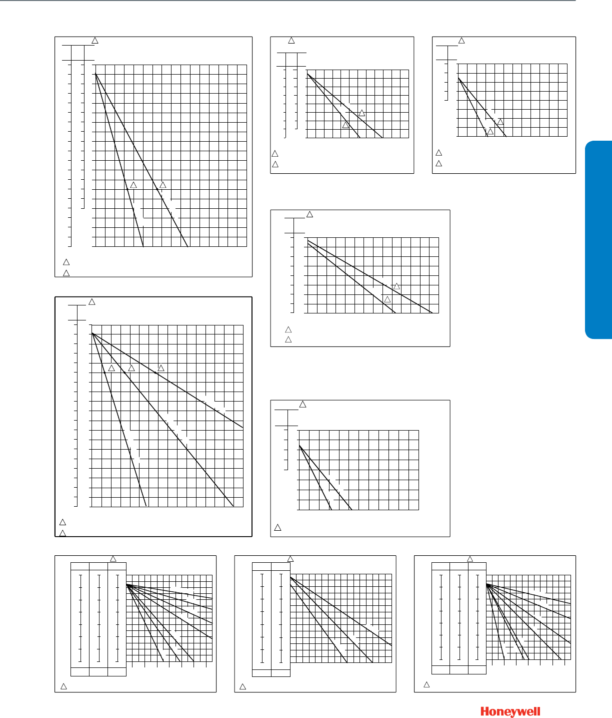
61
Chart L
12
(83)
13
(90)
14
(96)
15
(103)
16
(110)
17
(117)
18
(124)
19
(131)
20
(138)
21
(144)
22
(152)
23
(159)
24
(165)
25
(172)
12
(83)
11
(76)
13
(90)
14
(96)
15
(103)
16
(110)
17
(117)
18
(124)
12
(83)
11
(76)
13
(90)
14
(96)
15
(103)
16
(110)
17
(117)
18
(124)
19
(131)
20
(138)
21
(144)
22
(152)
23
(159)
24
(165)
25
(172)
19
(131)
20
(138)
21
(144)
22
(152)
23
(159)
24
(165)
25
(172)
7
(48)
8
(55)
9
(62)
10
(69)
0
(0)
10
(69)
20
(138)
30
(207)
40
(276)
60
(414)
70
(483)
50
(345)
80
(552)
90
(621)
100
(690)
11 0
(759)
120
(828)
130
(897)
140
(966)
150
(1035)
160
(1104)
2-7
(15-50)
4-11
(30-75)
8-12
(55-85)
SPRING RANGE
PSI (kPa)
SIZE 2-1/2 IN. AND 3 IN.
WITH 8 IN. D.A. PNEUMATIC ACTUATOR
(NORMALLY OPEN PORTS B TO AB)
AIR PRESSURE IN ACTUATOR PSI (kPa)
CLOSEOFF PRESSURE RATINGS PSI (kPa)
CLOSEOFF PRESSURE AT VARIOUS CONTROL AIR PRESSURES FOR VGF FLANGED VA LVES
AND MP953 PNEUMATIC ACTUATORS.
AIR PRESSURE REQUIRED TO OPERATE PRESSURE-BALANCED VGF FLANGED VA LVES.
1
2
1
SIZE 2-1/2 INCH
SIZE 3 INCH
M22594
2 2
12
(83)
11
(76)
13
(90)
14
(96)
15
(103)
16
(110)
17
(117)
18
(124)
12
(83)
11
(76)
13
(90)
14
(96)
15
(103)
16
(110)
17
(117)
18
(125)
19
(131)
20
(138)
21
(144)
22
(152)
23
(159)
24
(165)
25
(172)
19
(131)
20
(138)
21
(144)
22
(152)
23
(159)
24
(165)
25
(172)
7
(48)
8
(55)
9
(62)
10
(69)
2-7
(15-50)
4-11
(30-75)
SPRING RANGE
PSI (kPa)
SIZE 2-1/2 IN., 3 IN., 4 IN., 5 IN., 6 IN.
WITH 13 IN. D.A. PNEUMATIC ACTUATOR
(NORMALLY OPEN PORTS B TO AB)
AIR PRESSURE IN ACTUATOR PSI (kPa)
CLOSEOFF PRESSURE RATINGS PSI (kPa)
1
SIZE 2-1/2 INCH
SIZE 3- AND 4-INCH
M22595
SIZE 5- AND 6-INCH
CLOSEOFF PRESSURE AT VARIOUS CONTROL AIR PRESSURES FOR
VGF FLANGED VA LVES AND MP953 PNEUMATIC ACTUATORS.
AIR PRESSURE REQUIRED TO OPERATE PRESSURE-BALANCED VGF VA LVES.
1
2
0
(0)
10
(69)
20
(138)
30
(207)
40
(276)
60
(414)
70
(483)
50
(345)
80
(552)
90
(621)
100
(690)
11 0
(759)
120
(828)
130
(897)
140
(966)
150
(1035)
160
(1104)
2 2 2
Chart O
SPRING RANGE
PSI (kPa)
V5011A — 2-1/2 THROUGH 3 IN. D.A. FLANGED BODIES
WITH 8 IN. D.A. PNEUMATIC ACTUATOR
(NORMALLY OPEN)
4-11
(30-75)
2-7
(15-50)
8-12
(55-85)
7
(50)
14
(95)
17
(120)
18
(125)
15
(105)
16
(110)
17
(120)
18
(125)
12
(85)
13
(90)
14
(95)
AIR PRESSURE IN ACTUATOR PSI (kPa)
1
16
(110)
12
(85)
13
(90)
15
(105)
11
(75)
14
(95)
10
(70)
9
(60)
8
(55)
13
(90)
12
(85)
11
(75)
0
(0)
30
(205)
50
(345)
20
(140)
40
(275)
60
(415)
CLOSEOFF PRESSURE RATINGS PSI (kPa)
10
(70)
USE 4-11 PSI (30-75 kPa) RANGE FOR DETERMINING CLOSEOFF OF VALVES USED WITH
MP953E ACTUATORS.
1
C3123
15
(105)
DUE TO DIFFERENCES IN VALVE BODY CONSTRUCTION, SCREWED AND FLANGED
PATTERNS HAVE DIFFERENT CLOSEOFF RATINGS. THIS APPLIES TO 2-1/2 AND 3 IN.
VALVE SIZES.
2
5
(35)
15
(105)
25
(170)
35
(240)
45
(310)
55
(380)
Cv = 100
2
Cv = 63
2
Chart M
M22869
SPRING RANGE
PSI (kPa)
SIZE 2-1/2 AND 3 IN. D.A. FLANGED BODIES
WITH 7 IN. R.A. PNEUMATIC ACTUATOR
(NORMALLY CLOSED)
4-11
(30-75)
8-13
(55-90)
1
(7)
5
(35)
4
(30)
3
(20)
8
(55)
7
(50)
6
(40)
AIR PRESSURE IN ACTUATOR PSI (kPa)
0
(0)
1
(7)
2
(15)
3
(20)
4
(30)
0
(0)
30
(207)
50
(345)
20
(138)
40
(276)
60
(414)
CLOSEOFF PRESSURE RATINGS PSI (kPa)
10
(69)
5
(35)
15
(104)
25
(172)
35
(241)
45
(310)
55
(379)
0
(0)
2
(15)
USE 8-13 PSI (55-90 kPa) RANGE FOR DETERMINING CLOSEOFF OF VA L V ES
USED WITH MP953F ACTUAT ORS.
SIZE 2-1/2 INCH
SIZE 3 INCH
1
1
Chart R
SPRING RANGE PSI (kPa)
L - LOWER SEAT
U - UPPER SEAT
ACTUATOR AIR PRESSURE IN PSI (kPa)
4-11
(30-75)
11
(75)
12
(85)
13
(90)
14
(95)
15
(105)
16
(110)
17
(115)
18
(125)
4
(30)
3
(20)
2
(15)
1
(5)
0
(0)
L
U
U
L
V5013B-F: 1/2-INCH TO 3-INCH VALVE BODIES WITH
8-INCH D.A. PNEUMATIC ACTUATOR
5
(35)
10
(70)
15
(105)
20
(140)
25
(170)
30
(205)
35
(240)
40
(275)
CLOSEOFF PRESSURE RATING - PSI (kPa)
2-7
(15-50)
7
(50)
8
(55)
9
(60)
10
(70)
11
(75)
12
(85)
13
(90)
14
(95)
2
(15)
1
(5)
0
(0)
L
U
U
L
MIXING
DIVERTING
1
1
USE 4-11 PSI (30-75 kPa) RANGE FOR DETERMINING CLOSEOFF OF VALVES WITH MP953E
ACTUATORS.
C1988-1
8-12
(55-85)
12
(85)
13
(90)
14
(95)
15
(105)
16
(110)
17
(115)
18
(125)
1
(5)
8
(55)
7
(50)
6
(40)
L
U
U
L
5
(35)
4
(30)
3
(20)
2
(15)
45
(310)
55
(380)
65
(450)
50
(345)
60
(415)
70
(485)
Cv = 2.5, 4.0, 6.3
Cv = 16
Cv = 25
Cv = 63
Cv = 100
Cv = 40
Cv = 10
Chart S
SPRING RANGE PSI (kPa)
L - LOWER SEAT
U - UPPER SEAT
ACTUATOR AIR PRESSURE IN PSI (kPa)
V5013B, C:
4-INCH, 5-INCH, AND 6-INCH VALVE BODIES WITH
13-INCH D.A. PNEUMATIC ACTUATOR
4-11
(30-75)
11
(75)
12
(85)
13
(90)
14
(95)
15
(105)
16
(110)
17
(115)
18
(125)
4
(30)
3
(20)
2
(15)
1
(5)
0
(0)
L
U
U
L
5
(35)
10
(70)
15
(105)
20
(140)
25
(170)
30
(205)
35
(240)
40
(275)
CLOSEOFF PRESSURE RATING - PSI (kPa)
Cv = 160
Cv = 250
Cv = 360
2-7
(15-50)
7
(50)
8
(55)
14
(95)
2
(15)
1
(5)
L
U
U
L
MIXING
DIVERTING
1
1
USE 4-11 PSI (30-75 kPa) RANGE FOR DETERMINING CLOSEOFF OF VALVES WITH
MP953E ACTUATORS.
C1986-1
9
(60)
10
(70)
11
(75)
12
(85)
13
(90)
0
(0)
ACTUATOR AIR PRESSURE IN PSI (kPa)
Chart T
SPRING RANGE PSI (kPa)
L - LOWER SEAT
U - UPPER SEAT
4-11
(30-75)
11
(75)
12
(85)
13
(90)
14
(95)
15
(105)
16
(110)
17
(115)
18
(125)
4
(30)
3
(20)
2
(15)
1
(5)
0
(0)
U
L
L
U
V5013B-F: 1/2-INCH TO 3-INCH VALVE BODIES WITH
7-INCH R.A. PNEUMATIC ACTUATOR
5
(35)
10
(70)
15
(105)
20
(140)
25
(170)
30
(205)
35
(240)
40
(275)
CLOSEOFF PRESSURE RATING - PSI (kPa)
3-7
(15-50)
7
(50)
8
(55)
9
(60)
10
(70)
11
(75)
12
(85)
13
(90)
14
(95)
3
(20)
2
(15)
1
(5)
U
L
L
U
MIXING
DIVERTING
USE 8-12 PSI (55-85 kPa) RANGE FOR DETERMINING CLOSEOFF OF VALVES WITH
MP953F ACTUATORS. C1987-1
8-12
(55-85)
12
(85)
13
(90)
14
(95)
15
(105)
16
(110)
17
(115)
18
(125)
1
(5)
8
(55)
7
(50)
6
(40)
U
L
L
U
5
(35)
4
(30)
3
(20)
2
(15)
45
(310)
55
(380)
65
(450)
50
(345)
60
(415)
70
(485)
0
(0)
Cv = 2.5, 4.0, 6.0
Cv = 10
Cv = 16
Cv = 25
Cv = 40
Cv = 63
Cv = 100
ACTUATOR AIR PRESSURE IN PSI (kPa)
1
1
Chart U
12
(85)
11
(75)
13
(90)
14
(95)
15
(105)
16
(110)
17
(120)
18
(125)
12
(85)
11
(75)
13
(90)
14
(95)
15
(105)
7
(50)
8
(55)
9
(60)
10
(70)
0
(0)
10
(70)
20
(140)
30
(205)
40
(275)
60
(515)
70
(480)
50
(345)
80
(550)
90
(620)
100
(690)
11 0
(760)
120
(825)
130
(895)
140
(965)
2-7
(15-50)
4-11
(30-75)
SPRING RANGE
PSI (kPa)
V5011A — 2-1/2 AND 3 IN. DA FLANGED BODIES
WITH 13 IN. D.A. PNEUMATIC ACTUATOR
(NORMALLY OPEN)
AIR PRESSURE IN ACTUATOR PSI (kPa)
CLOSEOFF PRESSURE RATINGS PSI (kPa)
USE 4-11 PSI (30-75 kPa) RANGE FOR DETERMINING CLOSEOFF OF VA LVES USED WITH
MP953E ACTUATORS.
DUE TO DIFFERENCES IN V A LVE BODY CONSTRUCTION, SCREWED AND FLANGED PATTERNS
HAVE DIFFERENT CLOSEOFF RATINGS. THIS APPLIES TO 2-1/2 AND 3 IN. VA LVE SIZES.
1
2
2
2
1
C3118
Cv = 100
Cv = 63
Chart P
C3124-2
SPRING RANGE
PSI (kPa)
V5011A — 2-1/2 AND 3 IN. D.A. FLANGED BODIES
WITH R.A. PNEUMATIC ACTUATOR
(NORMALLY CLOSED)
4-11
(30-75)
8-13
(55-90)
1
(10)
5
(35)
4
(30)
3
(20)
8
(55)
7
(50)
6
(40)
AIR PRESSURE IN ACTUATOR PSI (kPa)
0
(0)
1
(10)
2
(15)
3
(20)
4
(30)
0
(0)
30
(205)
50
(345)
20
(140)
40
(275)
60
(415)
CLOSEOFF PRESSURE RATINGS PSI (kPa)
10
(70)
DUE TO DIFFERENCES IN V A LVE BODY CONSTRUCTION, SCREWED AND
FLANGED PA TTERNS HAVE DIFFERENT CLOSEOFF RATINGS. THIS APPLIES
TO 2-1/2 AND 3 IN. V A LVE SIZES.
5
(35)
15
(105)
25
(170)
35
(240)
45
(310)
55
(380)
0
(0)
2
(15)
USE 8-13 PSI (55-90 kPa) RANGE FOR DETERMINING CLOSEOFF OF VA LVES
USED WITH MP953F ACTUATORS.
Cv = 63
Cv = 100
1
1
2
2
2
Chart N
VALVE SELECTION
Flanged Globe Valves 2½- 3"
With Pneumatic Actuators
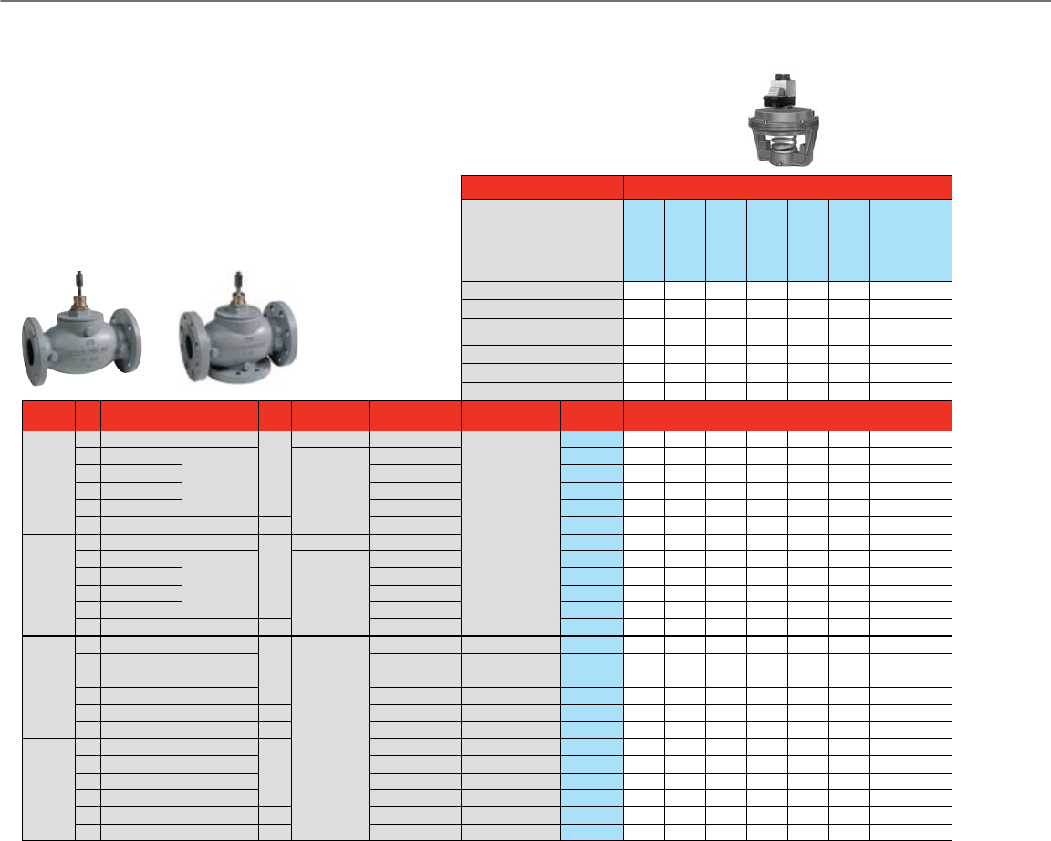
62
Flanged Globe Valves 2½- 3"
With Pneumatic Actuators
Common Features
• Rolling diaphragm for long life and low hysteresis
• Easily installation and attachment to the valve
• Direct or reverse acting
• Integrated positive positioner
Actuator Features With Positive Positioner
Actuator O.S. Number
MP953E1368
MP953E1376
MP953E1384
MP953E1435
MP953E1443
MP953F1093
MP953F1101
MP953F1119
Direct / Reverse Acting DA / RA DA DA DA DA DA RA RA RA\
Diaphragm Size 8" 8" 8" 13" 13" 7-1/8" 7-1/8" 7-1/8"
Fail Safe Action
Stem Up Stem Up Stem Up Stem Up Stem Up Stem
Down
Stem
Down
Stem
Down
Positioner 10psi span • • •
5psi span • • •
3psi span • •
Valve Size
(inches) Cv Valve
Type
Max Static
Water Pressure
ANSI
Class
Max Steam
Pressure
Flow
Characteristic
Valve
Action
Valve OS
Number Close-off Pressure - See Charts On Page 57
2-Way Water & Steam
Valves
2-1/2"
63 Standard 250 psi
125
15 psi (2-position)
Equal %
Stem down to close
V5011A1734 M**-NO M**-NO M**-NO P**-NO P**-NO N**-NC N**-NC N**-NC
70
Pressure Balanced
175 psi 125 psig / 353 F
Equal % VGF21EP25 L**-NO L**-NO L**-NO O**-NO O**-NO R**-NC R**-NC R**-NC
70 Standard Equal % VGF21ES25 L**-NO L**-NO L**-NO O**-NO O**-NO R**-NC R**-NC R**-NC
72
Pressure Balanced
Linear VGF21LP25 L**-NO L**-NO L**-NO O**-NO O**-NO R**-NC R**-NC R**-NC
70 Standard Linear VGF21LS25 L**-NO L**-NO L**-NO O**-NO O**-NO R**-NC R**-NC R**-NC
70 Standard 400 psi 250 Equal % VGF22ES25 L**-NO L**-NO L**-NO O**-NO O**-NO R**-NC R**-NC R**-NC
3"
100 Standard 250 psi
125
15 psi (2-position)
Equal % V5011A1767 M**-NO M**-NO M**-NO P**-NO P**-NO N**-NC N**-NC N**-NC
115
Pressure Balanced
175 psi 125 psig / 353 F
Equal % VGF21EP30 L**-NO L**-NO L**-NO O**-NO O**-NO R**-NC R**-NC R**-NC
115 Standard Equal % VGF21ES30 L**-NO L**-NO L**-NO O**-NO O**-NO R**-NC R**-NC R**-NC
120
Pressure Balanced
Linear VGF21LP30 L**-NO L**-NO L**-NO O**-NO O**-NO R**-NC R**-NC R**-NC
125 Standard Linear VGF21LS30 L**-NO L**-NO L**-NO O**-NO O**-NO R**-NC R**-NC R**-NC
120 Standard 400 psi 250 Equal % VGF22ES30 L**-NO L**-NO L**-NO O**-NO O**-NO R**-NC R**-NC R**-NC
3-Way Water
Valves
2-1/2"
63 Mixing 250 psi
125
N/A
Constant Total Stem up closes A-AB V5013B1003 S-NC S-NC S-NC T-NC T-NC U-NO U-NO U-NO
63 Diverting 250 psi Constant Total Stem up closes B-AB V5013C1001 S-NC S-NC S-NC T-NC T-NC U-NO U-NO U-NO
70 Mixing 175 psi Equal % A-AB Stem up closes A-AB VGF31EM25 L-NC L-NC L-NC O-NC O-NC R-NO R-NO R-NO
70 Diverting 175 psi
Linear, Constant Total
Stem up closes B-AB VGF31LD25 L-NC L-NC L-NC O-NC O-NC R-NO R-NO R-NO
70 Mixing 400 psi 250 Equal % A-AB Stem up closes A-AB VGF32EM25 L-NC L-NC L-NC O-NC O-NC R-NO R-NO R-NO
70 Diverting 400 psi 250
Linear, Constant Total
Stem up closes B-AB VGF32LD25 L-NC L-NC L-NC O-NC O-NC R-NO R-NO R-NO
3"
100 Mixing 250 psi
125
Constant Total Stem up closes A-AB V5013B1011 S-NC S-NC S-NC T-NC T-NC U-NO U-NO U-NO
100 Diverting 250 psi Constant Total Stem up closes B-AB V5013C1019 S-NC S-NC S-NC T-NC T-NC U-NO U-NO U-NO
120 Mixing 175 psi Equal % A-AB Stem up closes A-AB VGF31EM30 L-NC L-NC L-NC O-NC O-NC R-NO R-NO R-NO
120 Diverting 175 psi
Linear, Constant Total
Stem up closes B-AB VGF31LD30 L-NC L-NC L-NC O-NC O-NC R-NO R-NO R-NO
115 Mixing 400 psi 250 Equal % A-AB Stem up closes A-AB VGF32EM30 L-NC L-NC L-NC O-NC O-NC R-NO R-NO R-NO
120 Diverting 400 psi 250
Linear, Constant Total
Stem up closes B-AB VGF32LD30 L-NC L-NC L-NC O-NC O-NC R-NO R-NO R-NO
*The close-off pressure not to exceed rated pressure of steam valve
**The close-off pressure not to exceed rated pressure of steam valve. Use 4-11 spring range for positive positioner models.
NC = Normally Closed
NO = Normally Open

63
Chart L
12
(83)
13
(90)
14
(96)
15
(103)
16
(110)
17
(117)
18
(124)
19
(131)
20
(138)
21
(144)
22
(152)
23
(159)
24
(165)
25
(172)
12
(83)
11
(76)
13
(90)
14
(96)
15
(103)
16
(110)
17
(117)
18
(124)
12
(83)
11
(76)
13
(90)
14
(96)
15
(103)
16
(110)
17
(117)
18
(124)
19
(131)
20
(138)
21
(144)
22
(152)
23
(159)
24
(165)
25
(172)
19
(131)
20
(138)
21
(144)
22
(152)
23
(159)
24
(165)
25
(172)
7
(48)
8
(55)
9
(62)
10
(69)
0
(0)
10
(69)
20
(138)
30
(207)
40
(276)
60
(414)
70
(483)
50
(345)
80
(552)
90
(621)
100
(690)
11 0
(759)
120
(828)
130
(897)
140
(966)
150
(1035)
160
(1104)
2-7
(15-50)
4-11
(30-75)
8-12
(55-85)
SPRING RANGE
PSI (kPa)
SIZE 2-1/2 IN. AND 3 IN.
WITH 8 IN. D.A. PNEUMATIC ACTUATOR
(NORMALLY OPEN PORTS B TO AB)
AIR PRESSURE IN ACTUATOR PSI (kPa)
CLOSEOFF PRESSURE RATINGS PSI (kPa)
CLOSEOFF PRESSURE AT VARIOUS CONTROL AIR PRESSURES FOR VGF FLANGED VA LVES
AND MP953 PNEUMATIC ACTUATORS.
AIR PRESSURE REQUIRED TO OPERATE PRESSURE-BALANCED VGF FLANGED VA LVES.
1
2
1
SIZE 2-1/2 INCH
SIZE 3 INCH
M22594
2 2
12
(83)
11
(76)
13
(90)
14
(96)
15
(103)
16
(110)
17
(117)
18
(124)
12
(83)
11
(76)
13
(90)
14
(96)
15
(103)
16
(110)
17
(117)
18
(125)
19
(131)
20
(138)
21
(144)
22
(152)
23
(159)
24
(165)
25
(172)
19
(131)
20
(138)
21
(144)
22
(152)
23
(159)
24
(165)
25
(172)
7
(48)
8
(55)
9
(62)
10
(69)
2-7
(15-50)
4-11
(30-75)
SPRING RANGE
PSI (kPa)
SIZE 2-1/2 IN., 3 IN., 4 IN., 5 IN., 6 IN.
WITH 13 IN. D.A. PNEUMATIC ACTUATOR
(NORMALLY OPEN PORTS B TO AB)
AIR PRESSURE IN ACTUATOR PSI (kPa)
CLOSEOFF PRESSURE RATINGS PSI (kPa)
1
SIZE 2-1/2 INCH
SIZE 3- AND 4-INCH
M22595
SIZE 5- AND 6-INCH
CLOSEOFF PRESSURE AT VARIOUS CONTROL AIR PRESSURES FOR
VGF FLANGED VA LVES AND MP953 PNEUMATIC ACTUATORS.
AIR PRESSURE REQUIRED TO OPERATE PRESSURE-BALANCED VGF VA LVES.
1
2
0
(0)
10
(69)
20
(138)
30
(207)
40
(276)
60
(414)
70
(483)
50
(345)
80
(552)
90
(621)
100
(690)
11 0
(759)
120
(828)
130
(897)
140
(966)
150
(1035)
160
(1104)
2 2 2
Chart O
SPRING RANGE
PSI (kPa)
V5011A — 2-1/2 THROUGH 3 IN. D.A. FLANGED BODIES
WITH 8 IN. D.A. PNEUMATIC ACTUATOR
(NORMALLY OPEN)
4-11
(30-75)
2-7
(15-50)
8-12
(55-85)
7
(50)
14
(95)
17
(120)
18
(125)
15
(105)
16
(110)
17
(120)
18
(125)
12
(85)
13
(90)
14
(95)
AIR PRESSURE IN ACTUATOR PSI (kPa)
1
16
(110)
12
(85)
13
(90)
15
(105)
11
(75)
14
(95)
10
(70)
9
(60)
8
(55)
13
(90)
12
(85)
11
(75)
0
(0)
30
(205)
50
(345)
20
(140)
40
(275)
60
(415)
CLOSEOFF PRESSURE RATINGS PSI (kPa)
10
(70)
USE 4-11 PSI (30-75 kPa) RANGE FOR DETERMINING CLOSEOFF OF VALVES USED WITH
MP953E ACTUATORS.
1
C3123
15
(105)
DUE TO DIFFERENCES IN VALVE BODY CONSTRUCTION, SCREWED AND FLANGED
PATTERNS HAVE DIFFERENT CLOSEOFF RATINGS. THIS APPLIES TO 2-1/2 AND 3 IN.
VALVE SIZES.
2
5
(35)
15
(105)
25
(170)
35
(240)
45
(310)
55
(380)
Cv = 100
2
Cv = 63
2
Chart M
M22869
SPRING RANGE
PSI (kPa)
SIZE 2-1/2 AND 3 IN. D.A. FLANGED BODIES
WITH 7 IN. R.A. PNEUMATIC ACTUATOR
(NORMALLY CLOSED)
4-11
(30-75)
8-13
(55-90)
1
(7)
5
(35)
4
(30)
3
(20)
8
(55)
7
(50)
6
(40)
AIR PRESSURE IN ACTUATOR PSI (kPa)
0
(0)
1
(7)
2
(15)
3
(20)
4
(30)
0
(0)
30
(207)
50
(345)
20
(138)
40
(276)
60
(414)
CLOSEOFF PRESSURE RATINGS PSI (kPa)
10
(69)
5
(35)
15
(104)
25
(172)
35
(241)
45
(310)
55
(379)
0
(0)
2
(15)
USE 8-13 PSI (55-90 kPa) RANGE FOR DETERMINING CLOSEOFF OF VA L V ES
USED WITH MP953F ACTUAT ORS.
SIZE 2-1/2 INCH
SIZE 3 INCH
1
1
Chart R
SPRING RANGE PSI (kPa)
L - LOWER SEAT
U - UPPER SEAT
ACTUATOR AIR PRESSURE IN PSI (kPa)
4-11
(30-75)
11
(75)
12
(85)
13
(90)
14
(95)
15
(105)
16
(110)
17
(115)
18
(125)
4
(30)
3
(20)
2
(15)
1
(5)
0
(0)
L
U
U
L
V5013B-F: 1/2-INCH TO 3-INCH VALVE BODIES WITH
8-INCH D.A. PNEUMATIC ACTUATOR
5
(35)
10
(70)
15
(105)
20
(140)
25
(170)
30
(205)
35
(240)
40
(275)
CLOSEOFF PRESSURE RATING - PSI (kPa)
2-7
(15-50)
7
(50)
8
(55)
9
(60)
10
(70)
11
(75)
12
(85)
13
(90)
14
(95)
2
(15)
1
(5)
0
(0)
L
U
U
L
MIXING
DIVERTING
1
1
USE 4-11 PSI (30-75 kPa) RANGE FOR DETERMINING CLOSEOFF OF VALVES WITH MP953E
ACTUATORS.
C1988-1
8-12
(55-85)
12
(85)
13
(90)
14
(95)
15
(105)
16
(110)
17
(115)
18
(125)
1
(5)
8
(55)
7
(50)
6
(40)
L
U
U
L
5
(35)
4
(30)
3
(20)
2
(15)
45
(310)
55
(380)
65
(450)
50
(345)
60
(415)
70
(485)
Cv = 2.5, 4.0, 6.3
Cv = 16
Cv = 25
Cv = 63
Cv = 100
Cv = 40
Cv = 10
Chart S
SPRING RANGE PSI (kPa)
L - LOWER SEAT
U - UPPER SEAT
ACTUATOR AIR PRESSURE IN PSI (kPa)
V5013B, C:
4-INCH, 5-INCH, AND 6-INCH VALVE BODIES WITH
13-INCH D.A. PNEUMATIC ACTUATOR
4-11
(30-75)
11
(75)
12
(85)
13
(90)
14
(95)
15
(105)
16
(110)
17
(115)
18
(125)
4
(30)
3
(20)
2
(15)
1
(5)
0
(0)
L
U
U
L
5
(35)
10
(70)
15
(105)
20
(140)
25
(170)
30
(205)
35
(240)
40
(275)
CLOSEOFF PRESSURE RATING - PSI (kPa)
Cv = 160
Cv = 250
Cv = 360
2-7
(15-50)
7
(50)
8
(55)
14
(95)
2
(15)
1
(5)
L
U
U
L
MIXING
DIVERTING
1
1
USE 4-11 PSI (30-75 kPa) RANGE FOR DETERMINING CLOSEOFF OF VALVES WITH
MP953E ACTUATORS.
C1986-1
9
(60)
10
(70)
11
(75)
12
(85)
13
(90)
0
(0)
ACTUATOR AIR PRESSURE IN PSI (kPa)
Chart T
SPRING RANGE PSI (kPa)
L - LOWER SEAT
U - UPPER SEAT
4-11
(30-75)
11
(75)
12
(85)
13
(90)
14
(95)
15
(105)
16
(110)
17
(115)
18
(125)
4
(30)
3
(20)
2
(15)
1
(5)
0
(0)
U
L
L
U
V5013B-F: 1/2-INCH TO 3-INCH VALVE BODIES WITH
7-INCH R.A. PNEUMATIC ACTUATOR
5
(35)
10
(70)
15
(105)
20
(140)
25
(170)
30
(205)
35
(240)
40
(275)
CLOSEOFF PRESSURE RATING - PSI (kPa)
3-7
(15-50)
7
(50)
8
(55)
9
(60)
10
(70)
11
(75)
12
(85)
13
(90)
14
(95)
3
(20)
2
(15)
1
(5)
U
L
L
U
MIXING
DIVERTING
USE 8-12 PSI (55-85 kPa) RANGE FOR DETERMINING CLOSEOFF OF VALVES WITH
MP953F ACTUATORS. C1987-1
8-12
(55-85)
12
(85)
13
(90)
14
(95)
15
(105)
16
(110)
17
(115)
18
(125)
1
(5)
8
(55)
7
(50)
6
(40)
U
L
L
U
5
(35)
4
(30)
3
(20)
2
(15)
45
(310)
55
(380)
65
(450)
50
(345)
60
(415)
70
(485)
0
(0)
Cv = 2.5, 4.0, 6.0
Cv = 10
Cv = 16
Cv = 25
Cv = 40
Cv = 63
Cv = 100
ACTUATOR AIR PRESSURE IN PSI (kPa)
1
1
Chart U
12
(85)
11
(75)
13
(90)
14
(95)
15
(105)
16
(110)
17
(120)
18
(125)
12
(85)
11
(75)
13
(90)
14
(95)
15
(105)
7
(50)
8
(55)
9
(60)
10
(70)
0
(0)
10
(70)
20
(140)
30
(205)
40
(275)
60
(515)
70
(480)
50
(345)
80
(550)
90
(620)
100
(690)
11 0
(760)
120
(825)
130
(895)
140
(965)
2-7
(15-50)
4-11
(30-75)
SPRING RANGE
PSI (kPa)
V5011A — 2-1/2 AND 3 IN. DA FLANGED BODIES
WITH 13 IN. D.A. PNEUMATIC ACTUATOR
(NORMALLY OPEN)
AIR PRESSURE IN ACTUATOR PSI (kPa)
CLOSEOFF PRESSURE RATINGS PSI (kPa)
USE 4-11 PSI (30-75 kPa) RANGE FOR DETERMINING CLOSEOFF OF VA LVES USED WITH
MP953E ACTUATORS.
DUE TO DIFFERENCES IN V A LVE BODY CONSTRUCTION, SCREWED AND FLANGED PATTERNS
HAVE DIFFERENT CLOSEOFF RATINGS. THIS APPLIES TO 2-1/2 AND 3 IN. VA LVE SIZES.
1
2
2
2
1
C3118
Cv = 100
Cv = 63
Chart P
C3124-2
SPRING RANGE
PSI (kPa)
V5011A — 2-1/2 AND 3 IN. D.A. FLANGED BODIES
WITH R.A. PNEUMATIC ACTUATOR
(NORMALLY CLOSED)
4-11
(30-75)
8-13
(55-90)
1
(10)
5
(35)
4
(30)
3
(20)
8
(55)
7
(50)
6
(40)
AIR PRESSURE IN ACTUATOR PSI (kPa)
0
(0)
1
(10)
2
(15)
3
(20)
4
(30)
0
(0)
30
(205)
50
(345)
20
(140)
40
(275)
60
(415)
CLOSEOFF PRESSURE RATINGS PSI (kPa)
10
(70)
DUE TO DIFFERENCES IN V A LVE BODY CONSTRUCTION, SCREWED AND
FLANGED PA TTERNS HAVE DIFFERENT CLOSEOFF RATINGS. THIS APPLIES
TO 2-1/2 AND 3 IN. V A LVE SIZES.
5
(35)
15
(105)
25
(170)
35
(240)
45
(310)
55
(380)
0
(0)
2
(15)
USE 8-13 PSI (55-90 kPa) RANGE FOR DETERMINING CLOSEOFF OF VA LVES
USED WITH MP953F ACTUATORS.
Cv = 63
Cv = 100
1
1
2
2
2
Chart N
VALVE SELECTION
Flanged Globe Valves 2½- 3"
With Pneumatic Actuators
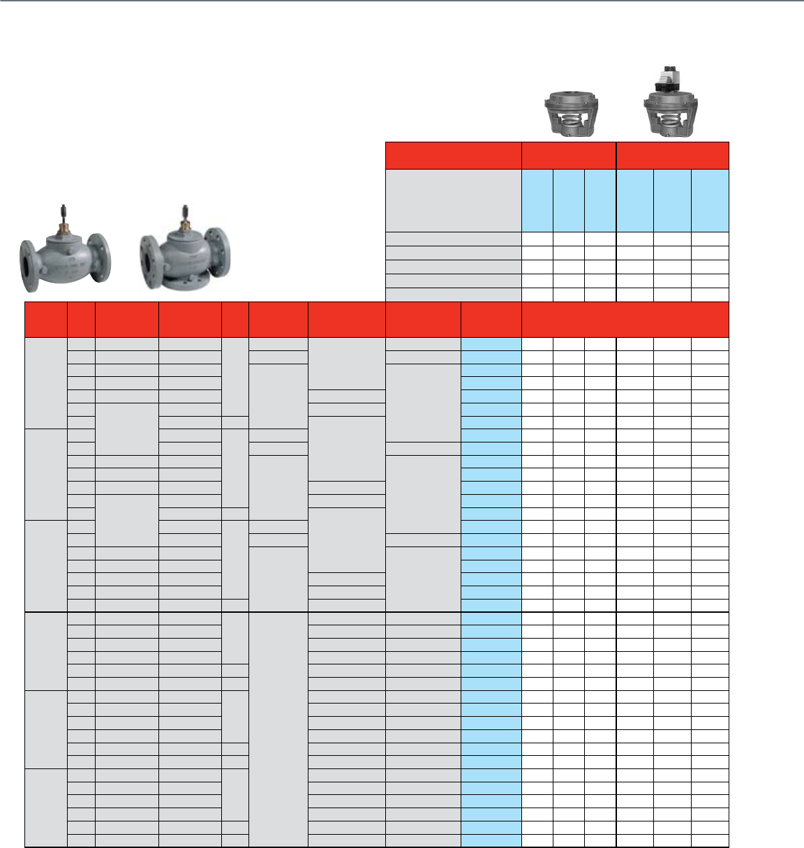
64
Actuator Features Without Positive
Positioner
With Positive
Positioner
Actuator .S. Number
MP953C1471
MP953C1489
MP953C1547
MP953E1285
MP953E1400
MP953E1418
Diaphragm 13" 13" 8" 8" 13" 13"
Action DA DA DA DA DA DA
Spring Range 2-7psi 4-11psi 3-15psi 4-11psi 4-11psi 4-11psi
Positioner Span n/a n/a n/a 5psi range 5psi range 10psi range
Stroke 1-1/2" 1-1/2" 1-1/2" 1-1/2" 1-1/2" 1-1/2"
Valve Size
(inches) Cv Valve
Type
Max Static
Water Pressure
ANSI
Class
Max Steam
Pressure
Flow
Characteristic
Valve
Action
Valve OS
Number
Close-off Pressure -
See Charts On Page 57
2-Way Water & Steam Valves
4"
160 Standard 250 psi
125
15 psi (2-position)
Equal %
Stem down to close V5011A1858 V*-NO V*-NO V*-NO V**-NO V**-NO V**-NO
160
Standard
250 psi
15 psi (2-position)
Stem up to close V5011B1013 W*-NO W*-NO W*-NO W**-NO W**-NO W**-NO
150
Pressure Balanced
175 psi
125 psig / 353 F Stem down to close
VGF21EP40 O*-NO O*-NO O*-NO O**-NO O**-NO O**-NO
150
Standard
175 psi VGF21ES40 O*-NO O*-NO O*-NO O**-NO O**-NO O**-NO
150
Pressure Balanced
175 psi Linear VGF21LP40 O*-NO O*-NO O*-NO O**-NO O**-NO O**-NO
155
Standard
175 psi Linear VGF21LS40 O*-NO O*-NO O*-NO O**-NO O**-NO O**-NO
150 400 psi 250
Equal %
VGF22ES40 O*-NO O*-NO O*-NO O**-NO O**-NO O**-NO
5"
250 250 psi
125
15 psi (2-position)
V5011A1882 V*-NO V*-NO V*-NO V**-NO V**-NO V**-NO
250 250 psi
15 psi (2-position)
Stem up to close V5011B1047 W*-NO W*-NO W*-NO W**-NO W**-NO W**-NO
285
Pressure Balanced
175 psi
125 psig / 353 F Stem down to close
VGF21EP50 O*-NO O*-NO O*-NO O**-NO O**-NO O**-NO
285 Standard 175 psi VGF21ES50 O*-NO O*-NO O*-NO O**-NO O**-NO O**-NO
320
Pressure Balanced
175 psi Linear VGF21LP50 O*-NO O*-NO O*-NO O**-NO O**-NO O**-NO
320
Standard
175 psi Linear VGF21LS50 O*-NO O*-NO O*-NO O**-NO O**-NO O**-NO
320 400 psi 250
Equal %
VGF22ES50 O*-NO O*-NO O*-NO O**-NO O**-NO O**-NO
6"
360 250 psi
125
15 psi (2-position)
V5011A1916 V*-NO V*-NO V*-NO V**-NO V**-NO V**-NO
360 250 psi
15 psi (2-position)
Stem up to close V5011B1070 W*-NO W*-NO W*-NO W**-NO W**-NO W**-NO
365
Pressure Balanced
175 psi
125 psig / 353 F Stem down to close
VGF21EP60 O*-NO O*-NO O*-NO O**-NO O**-NO O**-NO
365 Standard 175 psi VGF21ES60 O*-NO O*-NO O*-NO O**-NO O**-NO O**-NO
370
Pressure Balanced
175 psi Linear VGF21LP60 O*-NO O*-NO O*-NO O**-NO O**-NO O**-NO
370 Standard 175 psi Linear VGF21LS60 O*-NO O*-NO O*-NO O**-NO O**-NO O**-NO
370 Standard 400 psi 250 Equal % VGF22ES60 O*-NO O*-NO O*-NO O**-NO O**-NO O**-NO
3-Way Water Valves
4"
160 Mixing 250 psi
125
N/A
Constant Total Stem up closes A-AB V5013B1029 T-NC T-NC T-NC T-NC T-NC T-NC
160 Diverting 250 psi Constant Total Stem up closes B-AB V5013C1027 T-NC T-NC T-NC T-NC T-NC T-NC
150 Mixing 175 psi Equal % A-AB Stem up closes A-AB VGF31EM40 O-NC O-NC O-NC O-NC O-NC O-NC
160 Diverting 175 psi
Linear, Constant Total
Stem up closes B-AB VGF31LD40 O-NC O-NC O-NC O-NC O-NC O-NC
170 Mixing 400 psi 250 Equal % A-AB Stem up closes A-AB VGF32EM40 O-NC O-NC O-NC O-NC O-NC O-NC
160 Diverting 400 psi 250
Linear, Constant Total
Stem up closes B-AB VGF32LD40 O-NC O-NC O-NC O-NC O-NC O-NC
5"
250 Mixing 250 psi
125
Constant Total Stem up closes A-AB V5013B1037 T-NC T-NC T-NC T-NC T-NC T-NC
250 Diverting 250 psi Constant Total Stem up closes B-AB V5013C1035 T-NC T-NC T-NC T-NC T-NC T-NC
320 Mixing 175 psi Equal % A-AB Stem up closes A-AB VGF31EM50 O-NC O-NC O-NC O-NC O-NC O-NC
285 Diverting 175 psi
Linear, Constant Total
Stem up closes B-AB VGF31LD50 O-NC O-NC O-NC O-NC O-NC O-NC
320 Mixing 400 psi 250 Equal % A-AB Stem up closes A-AB VGF32EM50 O-NC O-NC O-NC O-NC O-NC O-NC
285 Diverting 400 psi 250
Linear, Constant Total
Stem up closes B-AB VGF32LD50 O-NC O-NC O-NC O-NC O-NC O-NC
6"
360 Mixing 250 psi
125
Constant Total Stem up closes A-AB V5013B1045 T-NC T-NC T-NC T-NC T-NC T-NC
360 Diverting 250 psi Constant Total Stem up closes B-AB V5013C1043 T-NC T-NC T-NC T-NC T-NC T-NC
370 Mixing 175 psi Equal % A-AB Stem up closes A-AB VGF31EM60 O-NC O-NC O-NC O-NC O-NC O-NC
380 Diverting 175 psi
Linear, Constant Total
Stem up closes B-AB VGF31LD60 O-NC O-NC O-NC O-NC O-NC O-NC
370 Mixing 400 psi 250 Equal % A-AB Stem up closes A-AB VGF32EM60 O-NC O-NC O-NC O-NC O-NC O-NC
380 Diverting 400 psi 250
Linear, Constant Total
Stem up closes B-AB VGF32LD60 O-NC O-NC O-NC O-NC O-NC O-NC
*The close-off pressure not to exceed rated pressure of steam valve
**The close-off pressure not to exceed rated pressure of steam valve. Use 4-11 spring range for positive positioner models.
NC = Normally Closed
NO = Normally Open
Flanged Globe Valves 4"- 6"
With Pneumatic Actuators
Common Features
• Rolling diaphragm for long life and low hysteresis
• Easily installation and attachment to the valve
• Direct or reverse acting
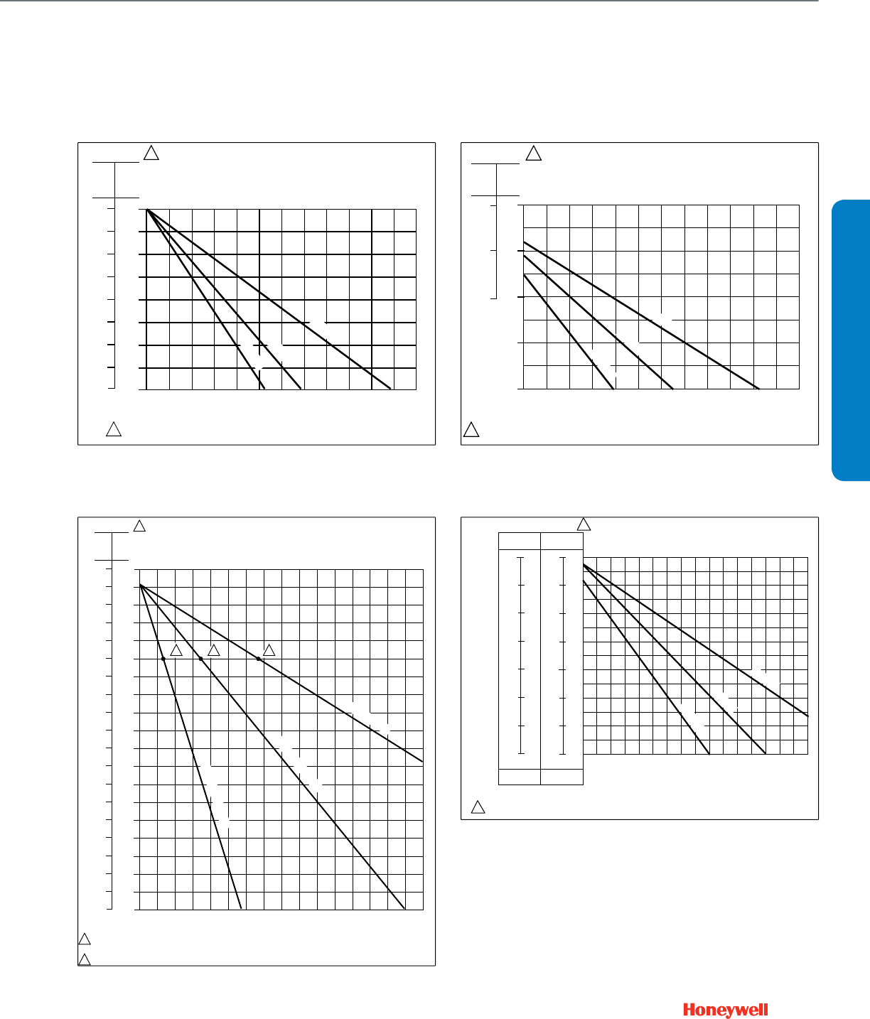
65
12
(85)
11
(75)
13
(90)
14
(95)
15
(105)
16
(110)
17
(120)
18
(125)
12
(85)
11
(75)
13
(90)
14
(95)
15
(105)
7
(50)
8
(55)
9
(60)
10
(70)
0
(0)
10
(70)
20
(140)
30
(205)
40
(275)
60
(515)
50
(345)
2-7
(15-50)
4-11
(30-75)
SPRING RANGE
PSI (kPa)
V5011A — 4, 5 AND 6 IN. D.A. FLANGED BODIES
WITH 13 IN. D.A. PNEUMATIC ACTUATOR
(NORMALLY OPEN)
AIR PRESSURE IN ACTUATOR PSI (kPa)
CLOSEOFF PRESSURE RATINGS PSI (kPa)
USE 4-11 PSI (30-75 kPa) RANGE FOR DETERMINING CLOSEOFF OF VALVES
USED WITH MP953E ACTUATORS.
1
1
C3120
Cv = 250
Cv = 160
Cv = 360
15
(105)
25
(170)
35
(240)
45
(310)
5
(35)
55
(380)
Chart V
C3126
V5011B — 4,5, AND 6 IN. R.A. FLANGED BODIES
WITH 13 IN. D.A. PNEUMATIC ACTUATOR
(NORMALLY CLOSED)
10
(70)
5
(35)
15
(105)
CLOSEOFF PRESSURE RATINGS PSI (kPa)
20
(140)
25
(175)
30
(205)
USE 4-11 PSI (30-75 kPa) RANGE FOR DETERMINING CLOSEOFF OF VALVES
USED WITH MP953E ACTUATORS.
4-11
(30-75)
2-7
(15-50)
2
(15)
1
(10)
AIR PRESSURE IN ACTUATOR PSI (kPa)
SPRING RANGE
PSI (kPa)
2
(15)
0
(0)
1
(10)
3
(20)
4
(30)
0
(0)
CV = 160
CV = 360
CV = 250
1
1
Chart W
12
(83)
11
(76)
13
(90)
14
(96)
15
(103)
16
(110)
17
(117)
18
(124)
12
(83)
11
(76)
13
(90)
14
(96)
15
(103)
16
(110)
17
(117)
18
(125)
19
(131)
20
(138)
21
(144)
22
(152)
23
(159)
24
(165)
25
(172)
19
(131)
20
(138)
21
(144)
22
(152)
23
(159)
24
(165)
25
(172)
7
(48)
8
(55)
9
(62)
10
(69)
2-7
(15-50)
4-11
(30-75)
SPRING RANGE
PSI (kPa)
SIZE 2-1/2 IN., 3 IN., 4 IN., 5 IN., 6 IN.
WITH 13 IN. D.A. PNEUMATIC ACTUATOR
(NORMALLY OPEN PORTS B TO AB)
AIR PRESSURE IN ACTUATOR PSI (kPa)
CLOSEOFF PRESSURE RATINGS PSI (kPa)
1
SIZE 2-1/2 INCH
SIZE 3- AND 4-INCH
M22595
SIZE 5- AND 6-INCH
CLOSEOFF PRESSURE AT VARIOUS CONTROL AIR PRESSURES FOR
VGF FLANGED VA LVES AND MP953 PNEUMATIC ACTUATORS.
AIR PRESSURE REQUIRED TO OPERATE PRESSURE-BALANCED VGF VALVES.
1
2
0
(0)
10
(69)
20
(138)
30
(207)
40
(276)
60
(414)
70
(483)
50
(345)
80
(552)
90
(621)
100
(690)
11 0
(759)
120
(828)
130
(897)
140
(966)
150
(1035)
160
(1104)
2 2 2
Chart O
SPRING RANGE PSI (kPa)
L - LOWER SEAT
U - UPPER SEAT
ACTUATOR AIR PRESSURE IN PSI (kPa)
V5013B, C:
4-INCH, 5-INCH, AND 6-INCH VALVE BODIES WITH
13-INCH D.A. PNEUMATIC ACTUATOR
4-11
(30-75)
11
(75)
12
(85)
13
(90)
14
(95)
15
(105)
16
(110)
17
(115)
18
(125)
4
(30)
3
(20)
2
(15)
1
(5)
0
(0)
L
U
U
L
5
(35)
10
(70)
15
(105)
20
(140)
25
(170)
30
(205)
35
(240)
40
(275)
CLOSEOFF PRESSURE RATING - PSI (kPa)
Cv = 160
Cv = 250
Cv = 360
2-7
(15-50)
7
(50)
8
(55)
14
(95)
2
(15)
1
(5)
L
U
U
L
MIXING
DIVERTING
1
1
USE 4-11 PSI (30-75 kPa) RANGE FOR DETERMINING CLOSEOFF OF VALVES WITH
MP953E ACTUATORS.
C1986-1
9
(60)
10
(70)
11
(75)
12
(85)
13
(90)
0
(0)
ACTUATOR AIR PRESSURE IN PSI (kPa)
Chart T
VALVE SELECTION
Flanged Globe Valves 4"- 6"
With Pneumatic Actuators
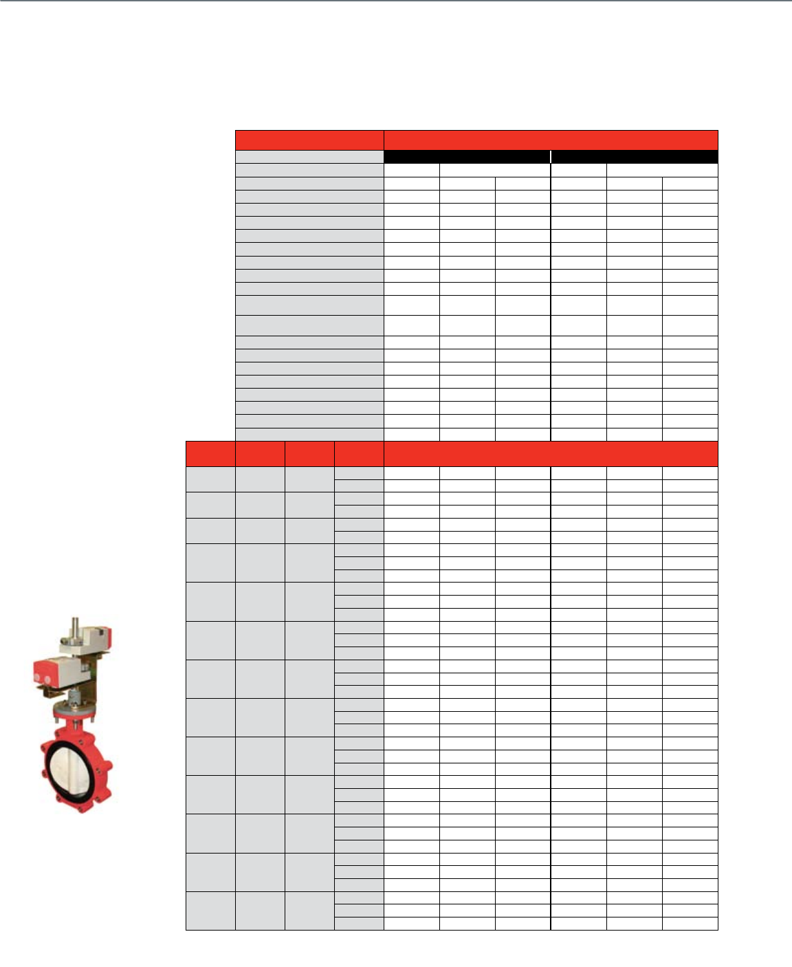
66
Honeywell Resilient Seat Butterfly Valves family (VFF) offers options in sizes
2" to 20", highlighted with an industry unique tandem mount using Honeywell
direct coupled actuators on valves up to 8" size.
Resilient Seat Butterfly Valves
2-Way Electrically-Actuated Control
Actuator Features Non-fail Safe
Floating Modulating
Actuator O.S. Number MN6134A1003 Industrial Actuators MN7234A2008 Industrial Actuators
NEMA 2 NEMA 4X NEMA 4 NEMA 2 NEMA 4X NEMA 4
Power Supply Voltage 24 Vac 120 Vac 120 Vac 24 Vac 120 Vac 120 Vac
Frequency 50 / 60 Hz 50 / 60 Hz 50 / 60 Hz 50 / 60 Hz 50 / 60 Hz 50 / 60 Hz
Power (* tandem mount) 9 / 18* VA 1.4 - 3.0 ALR 3.2 - 4.0 ALR 9 / 18* VA 1.4 - 3.0 ALR 3.2 - 4.0 ALR
Actuator Torque lb.-in. 300 / 600* 300 - 6,500 8,850 - 31,000 300 / 600* 300 - 6,500 8,850 - 31,000
Control (0)2-10 Vdc • • •
4-20 mA (external 500 ohm resistor) •In-built In-built
Floating 24 Vac 120 Vac 120 Vac 24 Vac
2-Position • • • •
Fail Safe Action Stay in Place Stay in Place Stay in Place Stay in Place Stay in Place Stay in Place
Normal Position Configurable
Open / Closed
Configurable
Open / Closed
Configurable
Open / Closed
Configurable
Open / Closed
Configurable
Open / Closed
Configurable
Open / Closed
Aux Switch Built in 2 x SPDT 2 x SPDT 2 x SPDT 2 x SPDT
Add-On SW2-US SW2-US
Feedback Built in 2-10 Vdc
4-20mA / 2-10Vdc 4-20mA / 2-10Vdc
Manual Override • • • •
Conduit Connection • • • • • •
Waterproof • • • •
Corrosion-resistant • • • •
Anti-condensate heater • • • •
Valve Size
(inches) Cv @ 60° Cv @ 90° Close-off
(psid) Valve O.S. Number
2-Way Normally Closed (Field-Configurable Normally Open)
2" 61 144 175 VFF2FW1Y2A VFF2FW1YXA VFF2FW1Y2B VFF2FW1YXB
250
2 1/2" 107 282 175 VFF2GW1Y2A VFF2GW1YXA VFF2GW1Y2B VFF2GW1YXB
250
3" 154 461 175 VFF2HW1Y2A VFF2HW1YXA VFF2HW1Y2B VFF2HW1YXB
250
4" 274 841
50 VFF2JV1Y2A VFF2JV1YXA VFF2JV1Y2B VFF2JV1YXB
175 VFF2JW1Y2A VFF2JW1YXA VFF2JW1Y2B VFF2JW1YXB
250
5" 428 1376
50 VFF2KV1Y2A* VFF2KV1YXA VFF2KV1Y2B* VFF2KV1YXB
175 VFF2KW1Y2A VFF2KW1YXA VFF2KW1Y2B VFF2KW1YXB
250
6" 567 1850
50 VFF2LW1Y2A** VFF2LV1YXA VFF2LW1Y2B** VFF2LV1YXB
175 VFF2LW1Y2A VFF2LW1YXA VFF2LW1Y2B VFF2LW1YXB
250
8" 1081 3316
50 VFF2MV1Y2A VFF2MV1YXA VFF2MV1Y2B VFF2MV1YXB
175 VFF2MW1YXA VFF2MW1YXB
250
10" 1710 5430
50 VFF2NV1YXA VFF2NV1YXB
175 VFF2NW1YXA VFF2NW1YXB
250
12" 2563 8077
50 VFF2PV1YXA VFF2PV1YXB
175 VFF2PW1YXA VFF2PW1YXB
250
14" 3384 10538
50 VFF2RV1YXA VFF2RV1YXB
150 VFF2RW1YXA VFF2RW1YXB
250
16" 4483 13966
50 VFF2SV1YXA VFF2SV1YXB
150 VFF2SW1Y4A VFF2SW1Y4B
250
18" 5736 17214
50 VFF2TV1YXA VFF2TV1YXB
150 VFF2TW1Y4A VFF2TW1Y4B
250
20" 7144 22339
50 VFF2UV1Y4A VFF2UV1Y4B
150 VFF2UW1Y4A VFF2UW1Y4B
250
*Chilled water service only.
**Use full cut valves – requires same actuator torque.
Common Features
• Honeywell direct coupled actuators
up to 8" size
• Maximum static pressure 175 psi
at 250°F
• Body style: lugged buttery valve,
full-cut (150-175 psid close-off) or
under-cut disc (50 psid close-off)
• ANSI 125/150 anged connections
• Bubble-tight ANSI class VI seat
leakage at rated close-off
• Heaters built into NEMA 4X and
NEMA 6 actuators
• Controlled media: Water or glycol
solutions up to 50% concentration
• Flow characteristics: Equal percentage
from 20°-60° stem rotation, modied
linear over full stroke
• Normally closed conguration
(eld congurable)
• Resilient Seat Buttery Valves
come with factory-tted
actuators
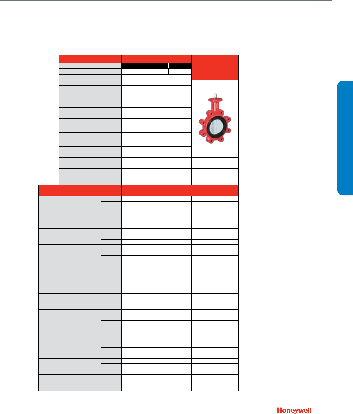
67
Actuator Features Fail Safe
Valve Only
End-of-line Service
2-Position Modulating
Actuator O.S. Number MS8120A1007 MS4120A1001 MS7520A2007
NEMA 2 NEMA 4X NEMA 6
Power Supply Voltage 24 Vac 100-250 Vac 24 Vac
Frequency 60 Hz 60 Hz 50 / 60 Hz
Power (* tandem mount) 40 / 80* VA 60 / 120* VA 16 / 32* VA
Actuator Torque lb.-in. 175 / 350* 175 / 350* 175 / 350*
Control (0)2-10 Vdc •
4-20 mA (external 500 ohm resistor) •
Floating 24 Vac
2-Position • • •
Fail Safe Action Configurable
Open / Closed
Configurable
Open / Closed
Configurable
Open / Closed
Normal Position Configurable
Open / Closed
Configurable
Open / Closed
Configurable
Open / Closed
Aux Switch Built in
Add-On SW2-US SW2-US SW2-US
Feedback Built in 2-10 Vdc
Manual Override Lever Lever
Conduit Connection • • •
Waterproof
Corrosion-resistant
Anti-condensate heater
Valve Size
(inches) Cv @ 60° Cv @ 90° Close-off
(psid) Valve O.S. Number
2-Way Normally Closed (Field-Configurable Normally Open)
2" 61 144 175 VFF2FW1Y2C VFF2FW1Y2E VFF2FW1Y2D
250 VFF2FW2YLX VFF2FW2YGX
2 1/2" 107 282 175 VFF2GW1Y2C VFF2GW1Y2E VFF2GW1Y2D
250 VFF2GW2YLX VFF2GW2YGX
3" 154 461 175 VFF2HW1Y2C VFF2HW1Y2E VFF2HW1Y2D
250 VFF2HW2YLX VFF2HW2YGX
4" 274 841
50 VFF2JV1Y2C VFF2JV1Y2E VFF2JV1Y2D
175
250 VFF2JW2YLX VFF2JW2YGX
5" 428 1376
50 VFF2KV1Y2C* VFF2KV1Y2E* VFF2KV1Y2D*
175
250 VFF2KW2YLX VFF2KW2YGX
6" 567 1850
50
175
250 VFF2LW2YLX VFF2LW2YGX
8" 1081 3316
50
175
250 VFF2MW2YLX VFF2MW2YGX
10" 1710 5430
50
175
250 VFF2NW2YLX VFF2NW2YGX
12" 2563 8077
50
175
250 VFF2PW2YLX VFF2PW2YGX
14" 3384 10538
50
150
250 VFF2RW2YGX
16" 4483 13966
50
150
250 VFF2SW2YGX
18" 5736 17214
50
150
250 VFF2TW2YGX
20" 7144 22339
50
150
250 VFF2UW2YGX
*Chilled water service only.
VALVE SELECTION
Resilient Seat Butterfly Valves
2-Way Electrically-Actuated Control
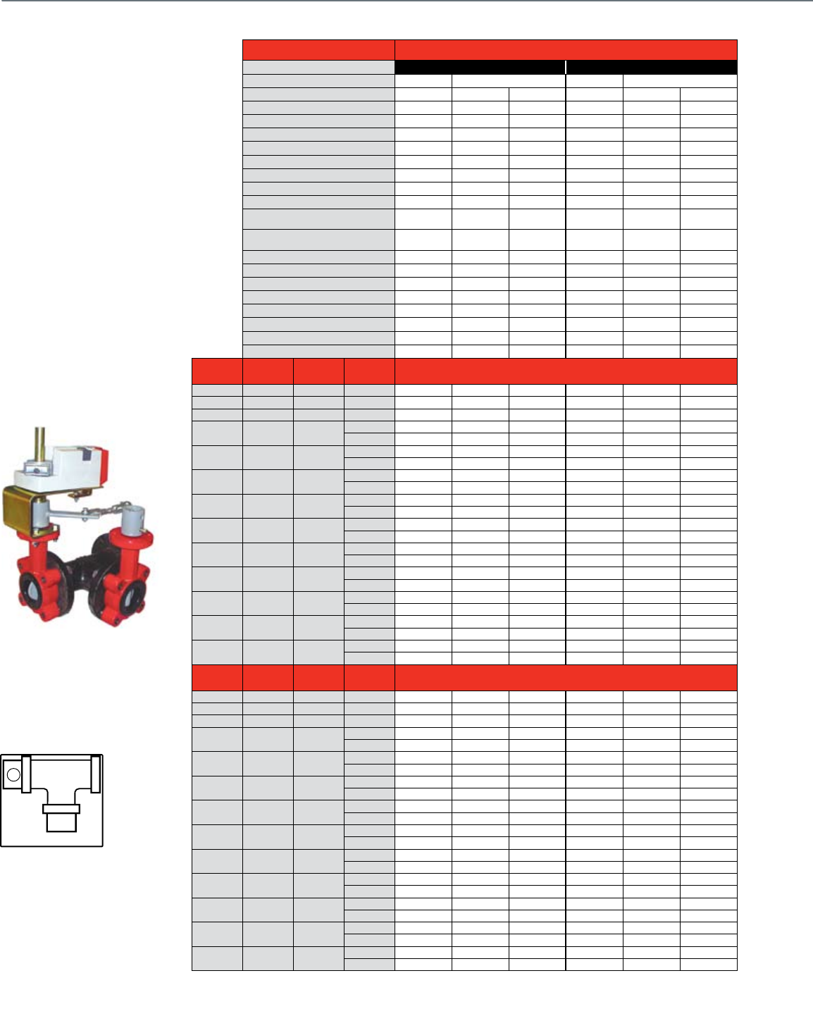
68
Actuator Features Non-fail Safe
Floating Modulating
Actuator O.S. Number MN6134A1003 Industrial Actuators MN7234A2008 Industrial Actuators
NEMA 2 NEMA 4X NEMA 4 NEMA 2 NEMA 4X NEMA 4
Power Supply Voltage 24 Vac 120 Vac 120 Vac 24 Vac 120 Vac 120 Vac
Frequency 50 / 60 Hz 50 / 60 Hz 50 / 60 Hz 50 / 60 Hz 50 / 60 Hz 50 / 60 Hz
Power (* tandem mount) 9 / 18* VA 1.4 - 3.0 ALR 3.2 - 4.0 ALR 9 / 18* VA 1.4 - 3.0 ALR 3.2 - 4.0 ALR
Actuator Torque lb.-in. 300 / 600* 300 - 6,500 8,850 - 31,000 300 / 600* 300 - 6,500 8,850 - 31,000
Control (0)2-10 Vdc • • •
4-20 mA (external 500 ohm resistor) •In-built In-built
Floating 24 Vac 120 Vac 120 Vac 24 Vac
2-Position • • • •
Fail Safe Action Stay in Place Stay in Place Stay in Place Stay in Place Stay in Place Stay in Place
Normal Position Configurable
Open / Closed
Configurable
Open / Closed
Configurable
Open / Closed
Configurable
Open / Closed
Configurable
Open / Closed
Configurable
Open / Closed
Aux Switch Built in 2 x SPDT 2 x SPDT 2 x SPDT 2 x SPDT
Add-On SW2-US SW2-US
Feedback Built in 2-10 Vdc
4-20mA / 2-10Vdc 4-20mA / 2-10Vdc
Manual Override • • • •
Conduit Connection • • • • • •
Waterproof • • • •
Corrosion-resistant • • • •
Anti-condensate heater • • • •
Valve Size
(inches) Cv @ 60° Cv @ 90° Close-off
(psid) Valve O.S. Number
3-Way Mixing / Diverting Globe Valve Porting
2" 61 144 175 VFF3FW1Y2A VFF3FW1YXA VFF3FW1Y2B VFF3FW1YXB
2 1/2" 107 282 175 VFF3GW1Y2A VFF3GW1YXA VFF3GW1Y2B VFF3GW1YXB
3" 154 461 175 VFF3HW1Y2A VFF3HW1YXA VFF3HW1Y2B VFF3HW1YXB
4" 274 841 50 VFF3JV1Y2A VFF3JV1YXA VFF3JV1Y2B VFF3JV1YXB
175 VFF3JW1Y2A VFF3JW1YXA VFF3JW1Y2B VFF3JW1YXB
5" 428 1376 50 VFF3KW1Y2A* VFF3KV1YXA VFF3KW1Y2B* VFF3KV1YXB
175 VFF3KW1Y2A VFF3KW1YXA VFF3KW1Y2B VFF3KW1YXB
6" 567 1850 50 VFF3LV1Y2A VFF3LV1YXA VFF3LV1Y2B VFF3LV1YXB
175 VFF3LW1YXA VFF3LW1YXB
8" 1081 3316 50 VFF3MV1YXA VFF3MV1YXB
175 VFF3MW1YXA VFF3MW1YXB
10" 1710 5430 50 VFF3NV1YXA VFF3NV1YXB
175 VFF3NW1YXA VFF3NW1YXB
12" 2563 8077 50 VFF3PV1YXA VFF3PV1YXB
175 VFF3PW1YXA VFF3PW1YXB
14" 3384 10538 50 VFF3RV1YXA VFF3RV1Y4A VFF3RV1YXB VFF3RV1Y4B
150 VFF3RW1Y4A VFF3RW1Y4B
16" 4483 13966 50 VFF3SV1YXA VFF3SV1Y4A VFF3SV1YXB VFF3SV1Y4B
150 VFF3SW1Y4A VFF3SW1Y4B
18" 5736 17214 50 VFF3TV1Y4A VFF3TV1Y4B
150 VFF3TW1Y4A VFF3TW1Y4B
20" 7144 22339 50 VFF3UV1Y4A VFF3UV1Y4B
150 VFF3UW1Y4A VFF3UW1Y4B
Valve Size
(inches) Cv @ 60° Cv @ 90° Close-off
(psid) Valve O.S. Number
3-Way Mixing / Diverting Center Common Port
2" 61 144 175 VFF6FW1Y2A VFF6FW1YXA VFF6FW1Y2B VFF6FW1YXB
2 1/2" 107 282 175 VFF6GW1Y2A VFF6GW1YXA VFF6GW1Y2B VFF6GW1YXB
3" 154 461 175 VFF6HW1Y2A VFF6HW1YXA VFF6HW1Y2B VFF6HW1YXB
4" 274 841 50 VFF6JV1Y2A VFF6JV1YXA VFF6JV1Y2B VFF6JV1YXB
175 VFF6JW1Y2A VFF6JW1YXA VFF6JW1Y2B VFF6JW1YXB
5" 428 1376 50 VFF6KW1Y2A* VFF6KV1YXA VFF6KW1Y2B* VFF6KV1YXB
175 VFF6KW1Y2A VFF6KW1YXA VFF6KW1Y2B VFF6KW1YXB
6" 567 1850 50 VFF6LV1Y2A VFF6LV1YXA VFF6LV1Y2B VFF6LV1YXB
175 VFF6LW1YXA VFF6LW1YXB
8" 1081 3316 50 VFF6MV1YXA VFF6MV1YXB
175 VFF6MW1YXA VFF6MW1YXB
10" 1710 5430 50 VFF6NV1YXA VFF6NV1YXB
175 VFF6NW1YXA VFF6NW1YXB
12" 2563 8077 50 VFF6PV1YXA VFF6PV1YXB
175 VFF6PW1YXA VFF6PW1YXB
14" 3384 10538 50 VFF6RV1YXA VFF6RV1Y4A VFF6RV1YXB VFF6RV1Y4B
150 VFF6RW1Y4A VFF6RW1Y4B
16" 4483 13966 50 VFF6SV1YXA VFF6SV1Y4A VFF6SV1YXB VFF6SV1Y4B
150 VFF6SW1Y4A VFF6SW1Y4B
18" 5736 17214 50 VFF6TV1Y4A VFF6TV1Y4B
150 VFF6TW1Y4A VFF6TW1Y4B
20" 7144 22339 50 VFF6UV1Y4A VFF6UV1Y4B
150 VFF6UW1Y4A VFF6UW1Y4B
*Chilled water service only.
Resilient Seat Butterfly Valves
3-Way Electrically-Actuated Control
Common Features
• VFF3 – A-B-AB porting, full-cut (150-
175 psid close-off) or under-cut disc
(50 psid close-off)
• Honeywell direct coupled actuators
up to 6" size
• Mixing or diverting control
• Standard right-angle cast-iron T-pipe
• A-port congured to closed position
at factory
• Porting pattern eld-congurable with
valve linkage adjustment
• Resilient Seat Buttery Valves come
with factory-tted actuators
A AB
B
S
P
N.C.
N.O.
A
AB
BSP
N.C. N.O.
VFF3 Default Configuration
Notes:
Viewed from above
P = Actuator and Primary Valve
S = Slave Valve
VFF3 valve action is mixing for uid
flow from left to right.
VFF3 valve action is diverting for uid
flow from right to left
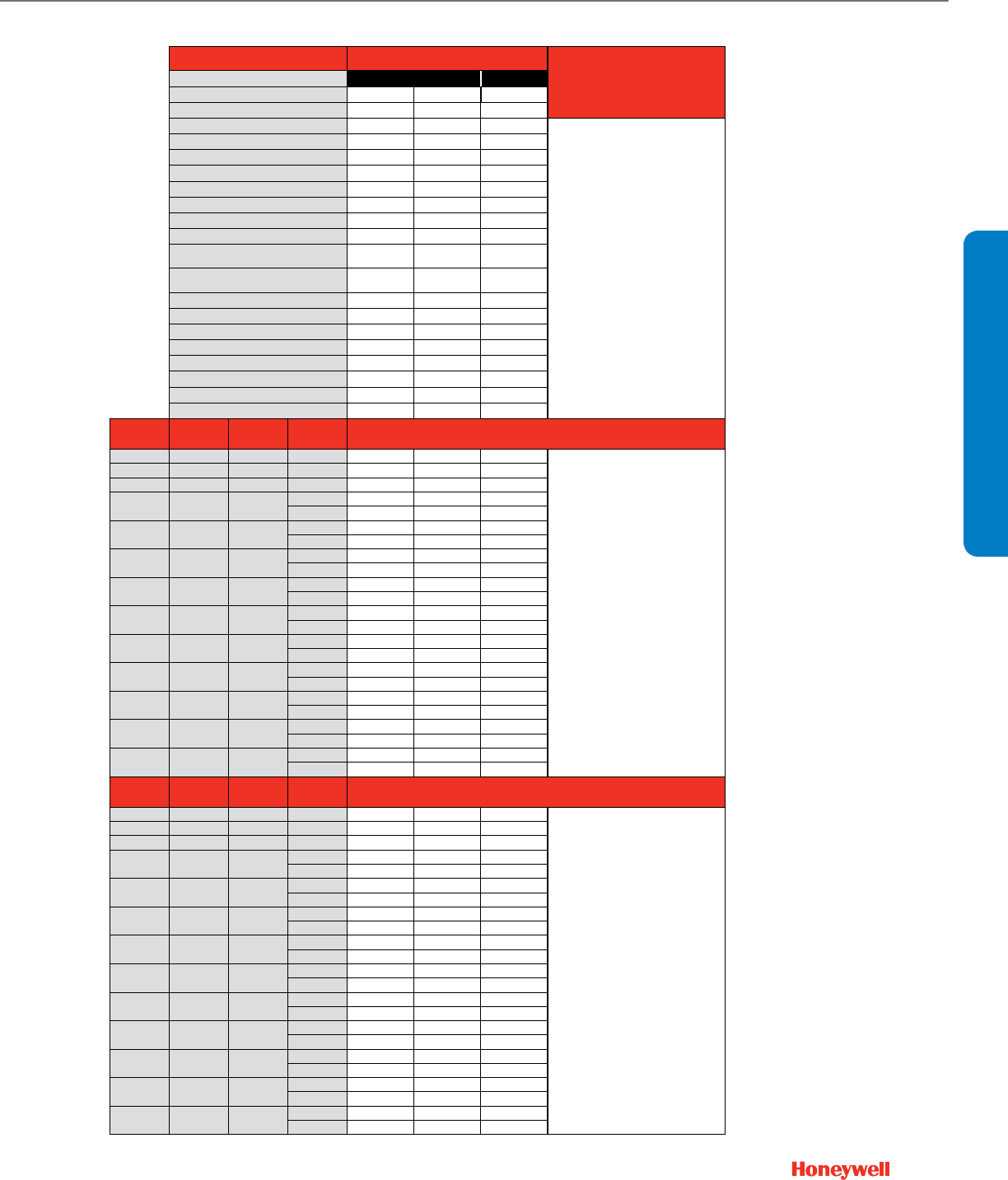
69
Actuator Features Fail Safe
Valve Only
End-of-line Service
2-Position Modulating
Actuator O.S. Number MS8120A1007 MS4120A1001 MS7520A2007
NEMA 2 NEMA 2 NEMA 2
Power Supply Voltage 24 Vac 100-250 Vac 24 Vac
Frequency 60 Hz 60 Hz 50 / 60 Hz
Power (* tandem mount) 40 / 80* VA 60 / 120* VA 16 / 32* VA
Actuator Torque lb.-in. 175 / 350* 175 / 350* 175 / 350*
Control (0)2-10 Vdc •
4-20 mA (external 500 ohm resistor) •
Floating 24 Vac
2-Position • • •
Fail Safe Action Configurable
Open / Closed
Configurable
Open / Closed
Configurable
Open / Closed
Normal Position Configurable
Open / Closed
Configurable
Open / Closed
Configurable
Open / Closed
Aux Switch Built in
Add-On SW2-US SW2-US SW2-US
Feedback Built in 2-10 Vdc
Manual Override
Conduit Connection • • •
Waterproof
Corrosion-resistant
Anti-condensate heater
Valve Size
(inches) Cv @ 60° Cv @ 90° Close-off
(psid) Valve O.S. Number
3-Way Mixing / Diverting Globe Valve Porting
2" 61 144 175 VFF3FW1Y2C VFF3FW1Y2E VFF3FW1Y2D
Use a pair of
2-way valves
with standard
flanged Tee
2 1/2" 107 282 175 VFF3GW1Y2C VFF3GW1Y2E VFF3GW1Y2D
3" 154 461 175 VFF3HW1Y2C VFF3HW1Y2E VFF3HW1Y2D
4" 274 841 50 VFF3JV1Y2C VFF3JV1Y2E VFF3JV1Y2D
175
5" 428 1376 50 VFF3KV1Y2C* VFF3KV1Y2E* VFF3KV1Y2D*
175
6" 567 1850 50
175
8" 1081 3316 50
175
10" 1710 5430 50
175
12" 2563 8077 50
175
14" 3384 10538 50
150
16" 4483 13966 50
150
18" 5736 17214 50
150
20" 7144 22339 50
150
Valve Size
(inches) Cv @ 60° Cv @ 90° Close-off
(psid) Valve O.S. Number
3-Way Mixing / Diverting Center Common Port
2" 61 144 175 VFF6FW1Y2C VFF6FW1Y2E VFF6FW1Y2D
Use a pair of
2-way valves
with standard
flanged Tee
2 1/2" 107 282 175 VFF6GW1Y2C VFF6GW1Y2E VFF6GW1Y2D
3" 154 461 175 VFF6HW1Y2C VFF6HW1Y2E VFF6HW1Y2D
4" 274 841 50 VFF6JV1Y2C VFF6JV1Y2E VFF6JV1Y2D
175
5" 428 1376 50 VFF6KV1Y2C* VFF6KV1Y2E* VFF6KV1Y2D*
175
6" 567 1850 50
175
8" 1081 3316 50
175
10" 1710 5430 50
175
12" 2563 8077 50
175
14" 3384 10538 50
150
16" 4483 13966 50
150
18" 5736 17214 50
150
20" 7144 22339 50
150
*Chilled water service only.
VALVE SELECTION
Resilient Seat Butterfly Valves
3-Way Electrically-Actuated Control
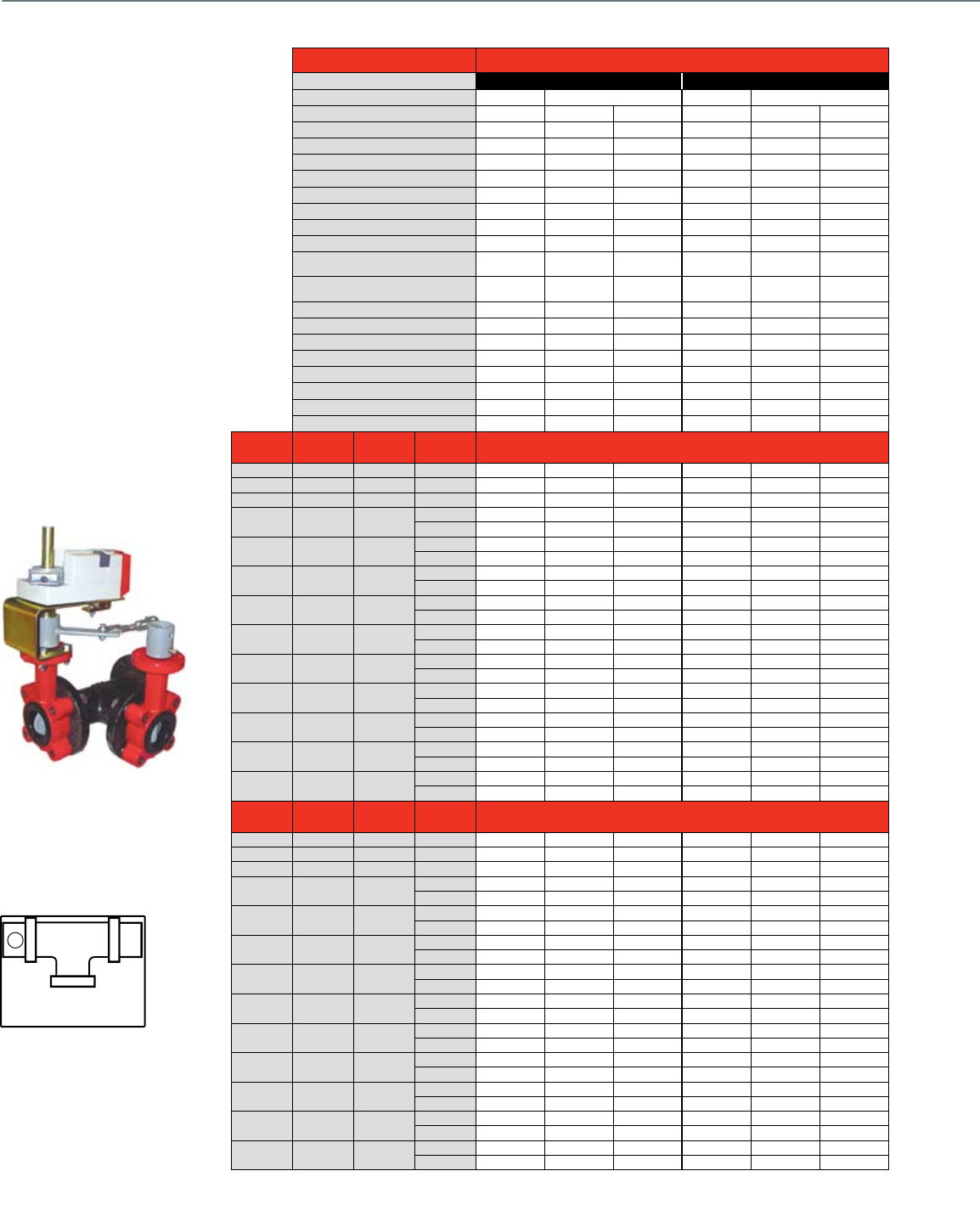
70
Actuator Features Non-fail Safe
Floating Modulating
Actuator O.S. Number MN6134A1003 Industrial Actuators MN7234A2008 Industrial Actuators
NEMA 2 NEMA 4X NEMA 4 NEMA 2 NEMA 4X NEMA 4
Power Supply Voltage 24 Vac 120 Vac 120 Vac 24 Vac 120 Vac 120 Vac
Frequency 50 / 60 Hz 50 / 60 Hz 50 / 60 Hz 50 / 60 Hz 50 / 60 Hz 50 / 60 Hz
Power (* tandem mount) 9 / 18* VA 1.4 - 3.0 ALR 3.2 - 4.0 ALR 9 / 18* VA 1.4 - 3.0 ALR 3.2 - 4.0 ALR
Actuator Torque lb.-in. 300 / 600* 300 - 6,500 8,850 - 31,000 300 / 600* 300 - 6,500 8,850 - 31,000
Control (0)2-10 Vdc • • •
4-20 mA (external 500 ohm resistor) • • •
Floating 24 Vac 120 Vac 120 Vac 24 Vac
2-Position • • • •
Fail Safe Action Stay in Place Stay in Place Stay in Place Stay in Place Stay in Place Stay in Place
Normal Position Configurable
Open / Closed
Configurable
Open / Closed
Configurable
Open / Closed
Configurable
Open / Closed
Configurable
Open / Closed
Configurable
Open / Closed
Aux Switch Built in 2 x SPDT 2 x SPDT 2 x SPDT 2 x SPDT
Add-On SW2-US SW2-US
Feedback Built in 2-10 Vdc
4-20mA / 2-10Vdc 4-20mA / 2-10Vdc
Manual Override • • • •
Conduit Connection • • • • • •
Waterproof • • • •
Corrosion-resistant • • • •
Anti-condensate heater • • • •
Valve Size
(inches) Cv @ 60° Cv @ 90° Close-off
(psid) Valve O.S. Number
3-Way Mixing / Diverting Globe Valve Porting
2" 61 144 175 VFF3FW1Y2A VFF3FW1YXA VFF3FW1Y2B VFF3FW1YXB
2 1/2" 107 282 175 VFF3GW1Y2A VFF3GW1YXA VFF3GW1Y2B VFF3GW1YXB
3" 154 461 175 VFF3HW1Y2A VFF3HW1YXA VFF3HW1Y2B VFF3HW1YXB
4" 274 841 50 VFF3JV1Y2A VFF3JV1YXA VFF3JV1Y2B VFF3JV1YXB
175 VFF3JW1Y2A VFF3JW1YXA VFF3JW1Y2B VFF3JW1YXB
5" 428 1376 50 VFF3KW1Y2A* VFF3KV1YXA VFF3KW1Y2B* VFF3KV1YXB
175 VFF3KW1Y2A VFF3KW1YXA VFF3KW1Y2B VFF3KW1YXB
6" 567 1850 50 VFF3LV1Y2A VFF3LV1YXA VFF3LV1Y2B VFF3LV1YXB
175 VFF3LW1YXA VFF3LW1YXB
8" 1081 3316 50 VFF3MV1YXA VFF3MV1YXB
175 VFF3MW1YXA VFF3MW1YXB
10" 1710 5430 50 VFF3NV1YXA VFF3NV1YXB
175 VFF3NW1YXA VFF3NW1YXB
12" 2563 8077 50 VFF3PV1YXA VFF3PV1YXB
175 VFF3PW1YXA VFF3PW1YXB
14" 3384 10538 50 VFF3RV1YXA VFF3RV1Y4A VFF3RV1YXB VFF3RV1Y4B
150 VFF3RW1Y4A VFF3RW1Y4B
16" 4483 13966 50 VFF3SV1YXA VFF3SV1Y4A VFF3SV1YXB VFF3SV1Y4B
150 VFF3SW1Y4A VFF3SW1Y4B
18" 5736 17214 50 VFF3TV1Y4A VFF3TV1Y4B
150 VFF3TW1Y4A VFF3TW1Y4B
20" 7144 22339 50 VFF3UV1Y4A VFF3UV1Y4B
150 VFF3UW1Y4A VFF3UW1Y4B
Valve Size
(inches) Cv @ 60° Cv @ 90° Close-off
(psid) Valve O.S. Number
3-Way Mixing / Diverting Center Common Port
2" 61 144 175 VFF6FW1Y2A VFF6FW1YXA VFF6FW1Y2B VFF6FW1YXB
2 1/2" 107 282 175 VFF6GW1Y2A VFF6GW1YXA VFF6GW1Y2B VFF6GW1YXB
3" 154 461 175 VFF6HW1Y2A VFF6HW1YXA VFF6HW1Y2B VFF6HW1YXB
4" 274 841 50 VFF6JV1Y2A VFF6JV1YXA VFF6JV1Y2B VFF6JV1YXB
175 VFF6JW1Y2A VFF6JW1YXA VFF6JW1Y2B VFF6JW1YXB
5" 428 1376 50 VFF6KW1Y2A* VFF6KV1YXA VFF6KW1Y2B* VFF6KV1YXB
175 VFF6KW1Y2A VFF6KW1YXA VFF6KW1Y2B VFF6KW1YXB
6" 567 1850 50 VFF6LV1Y2A VFF6LV1YXA VFF6LV1Y2B VFF6LV1YXB
175 VFF6LW1YXA VFF6LW1YXB
8" 1081 3316 50 VFF6MV1YXA VFF6MV1YXB
175 VFF6MW1YXA VFF6MW1YXB
10" 1710 5430 50 VFF6NV1YXA VFF6NV1YXB
175 VFF6NW1YXA VFF6NW1YXB
12" 2563 8077 50 VFF6PV1YXA VFF6PV1YXB
175 VFF6PW1YXA VFF6PW1YXB
14" 3384 10538 50 VFF6RV1YXA VFF6RV1Y4A VFF6RV1YXB VFF6RV1Y4B
150 VFF6RW1Y4A VFF6RW1Y4B
16" 4483 13966 50 VFF6SV1YXA VFF6SV1Y4A VFF6SV1YXB VFF6SV1Y4B
150 VFF6SW1Y4A VFF6SW1Y4B
18" 5736 17214 50 VFF6TV1Y4A VFF6TV1Y4B
150 VFF6TW1Y4A VFF6TW1Y4B
20" 7144 22339 50 VFF6UV1Y4A VFF6UV1Y4B
150 VFF6UW1Y4A VFF6UW1Y4B
*Chilled water service only.
Resilient Seat Butterfly Valves
3-Way Electrically-Actuated Control
Common Features
• VFF6 – A-AB-B porting, full-cut (150-
175 psid close-off) or under-cut disc
(50 psid close-off)
• Honeywell direct coupled actuators
up to 6" size
• Mixing or diverting control
• Standard right-angle cast-iron T-pipe
• A-port congured to closed position
at factory
• Porting pattern eld-congurable with
valve linkage adjustment
• Resilient Seat Buttery Valves come
with factory-tted actuators
VFF6 Default Configuration
Notes:
Viewed from above
P = Actuator and Primary Valve
S = Slave Valve
VFF6 may be piped for mixing
control with water exiting port AB,
or for diverting control with water
entering port AB
A AB
B
S
P
N.C.
N.O.
A
AB
BSP
N.C. N.O.

71
Actuator Features Fail Safe
Valve Only
End-of-line Service
2-Position Modulating
Actuator O.S. Number MS8120A1007 MS4120A1001 MS7520A2007
NEMA 2 NEMA 2 NEMA 2
Power Supply Voltage 24 Vac 100-250 Vac 24 Vac
Frequency 60 Hz 60 Hz 50 / 60 Hz
Power (* tandem mount) 40 / 80* VA 60 / 120* VA 16 / 32* VA
Actuator Torque lb.-in. 175 / 350* 175 / 350* 175 / 350*
Control (0)2-10 Vdc •
4-20 mA (external 500 ohm resistor) •
Floating 24 Vac
2-Position • • •
Fail Safe Action Configurable
Open / Closed
Configurable
Open / Closed
Configurable
Open / Closed
Normal Position Configurable
Open / Closed
Configurable
Open / Closed
Configurable
Open / Closed
Aux Switch Built in
Add-On SW2-US SW2-US SW2-US
Feedback Built in 2-10 Vdc
Manual Override
Conduit Connection • • •
Waterproof
Corrosion-resistant
Anti-condensate heater
Valve Size
(inches) Cv @ 60° Cv @ 90° Close-off
(psid) Valve O.S. Number
3-Way Mixing / Diverting Globe Valve Porting
2" 61 144 175 VFF3FW1Y2C VFF3FW1Y2E VFF3FW1Y2D
Use a pair of
2-way valves
with standard
flanged Tee
2 1/2" 107 282 175 VFF3GW1Y2C VFF3GW1Y2E VFF3GW1Y2D
3" 154 461 175 VFF3HW1Y2C VFF3HW1Y2E VFF3HW1Y2D
4" 274 841 50 VFF3JV1Y2C VFF3JV1Y2E VFF3JV1Y2D
175
5" 428 1376 50 VFF3KV1Y2C* VFF3KV1Y2E* VFF3KV1Y2D*
175
6" 567 1850 50
175
8" 1081 3316 50
175
10" 1710 5430 50
175
12" 2563 8077 50
175
14" 3384 10538 50
150
16" 4483 13966 50
150
18" 5736 17214 50
150
20" 7144 22339 50
150
Valve Size
(inches) Cv @ 60° Cv @ 90° Close-off
(psid) Valve O.S. Number
3-Way Mixing / Diverting Center Common Port
2" 61 144 175 VFF6FW1Y2C VFF6FW1Y2E VFF6FW1Y2D
Use a pair of
2-way valves
with standard
flanged Tee
2 1/2" 107 282 175 VFF6GW1Y2C VFF6GW1Y2E VFF6GW1Y2D
3" 154 461 175 VFF6HW1Y2C VFF6HW1Y2E VFF6HW1Y2D
4" 274 841 50 VFF6JV1Y2C VFF6JV1Y2E VFF6JV1Y2D
175
5" 428 1376 50 VFF6KV1Y2C* VFF6KV1Y2E* VFF6KV1Y2D*
175
6" 567 1850 50
175
8" 1081 3316 50
175
10" 1710 5430 50
175
12" 2563 8077 50
175
14" 3384 10538 50
150
16" 4483 13966 50
150
18" 5736 17214 50
150
20" 7144 22339 50
150
*Chilled water service only.
VALVE SELECTION
Resilient Seat Butterfly Valves
3-Way Electrically-Actuated Control
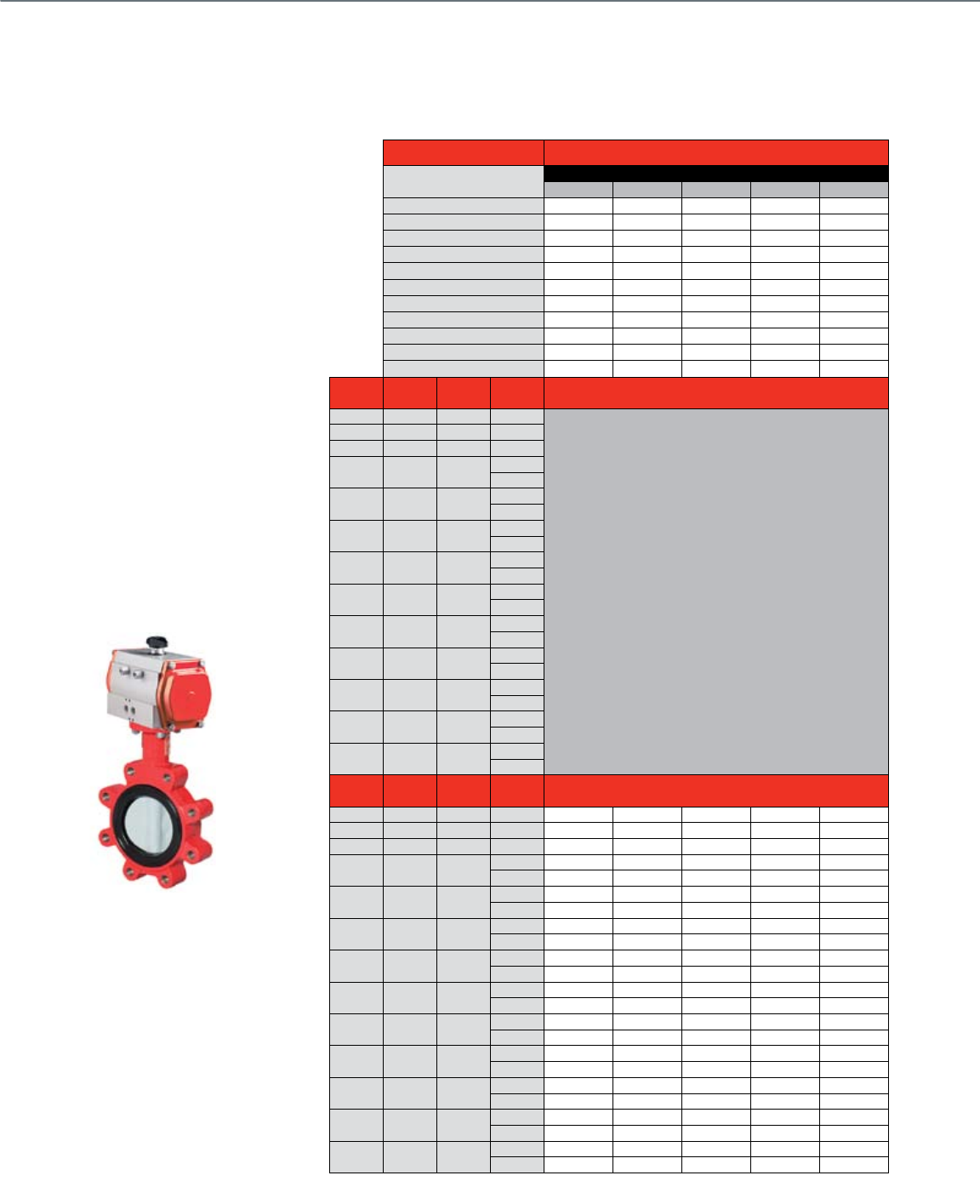
72
Common Features
Honeywell offers a wide selection of pneumatic actuators:
• 20 psi spring return (up to 10" size)
• 80 psi spring return
• 80 psi double acting bi-directional
Resilient Seat Butterfly Valves
2-Way Pneumatically-Actuated Control
Actuator Features Non-fail Safe (Bidirectional)
Actuator 80 psi Actuator
Standard E-P Solenoid E-P Solenoid Positioner E-P Positioner
Power Supply Voltage 24 Vac 120 VAc 24 Vac
Frequency 50 / 60 Hz 50 / 60 Hz 50 / 60 Hz
Power 6 W 6 W
Control Modulating Pneumatic • •
2-Position • •
4-20 mA •
Auxiliary Switch Add-On VFF50-0400 VFF50-0400 VFF50-0400
Manual Override •
Conduit Connection • • •
Waterproof •
Fail Safe
Valve Size
(inches) Cv @ 60° Cv @ 90° Close-off
(psid) Valve O.S. Number
2-Way Normally Open
2" 61 144 175
Use VFF2 models for Bi-directional pneumatic operation
2 1/2" 107 282 175
3" 154 461 175
4" 274 841 50
175
5" 428 1376 50
175
6" 567 1850 50
175
8" 1081 3316 50
175
10" 1710 5430 50
175
12" 2563 8077 50
175
14" 3384 10538 50
150*
16" 4483 13966 50
150*
18" 5736 17214 50
150*
20" 7144 22339 50
150*
Valve Size
(inches) Cv @ 60° Cv @ 90° Close-off
(psid) Valve O.S. Number
2-Way Normally Closed
2" 61 144 175 VFF2FW1YXR VFF2FW1YCR VFF2FW1YER VFF2FW1YPR VFF2FW1YDR
2 1/2" 107 282 175 VFF2GW1YXR VFF2GW1YCR VFF2GW1YER VFF2GW1YPR VFF2GW1YDR
3" 154 461 175 VFF2HW1YXR VFF2HW1YCR VFF2HW1YER VFF2HW1YPR VFF2HW1YDR
4" 274 841 50 VFF2JV1YXR VFF2JV1YCR VFF2JV1YER VFF2JV1YPR VFF2JV1YDR
175 VFF2JW1YXR VFF2JW1YCR VFF2JW1YER VFF2JW1YPR VFF2JW1YDR
5" 428 1376 50 VFF2KV1YXR VFF2KV1YCR VFF2KV1YER VFF2KV1YPR VFF2KV1YDR
175 VFF2KW1YXR VFF2KW1YCR VFF2KW1YER VFF2KW1YPR VFF2KW1YDR
6" 567 1850 50 VFF2LV1YXR VFF2LV1YCR VFF2LV1YER VFF2LV1YPR VFF2LV1YDR
175 VFF2LW1YXR VFF2LW1YCR VFF2LW1YER VFF2LW1YPR VFF2LW1YDR
8" 1081 3316 50 VFF2MV1YXR VFF2MV1YCR VFF2MV1YER VFF2MV1YPR VFF2MV1YDR
175 VFF2MW1YXR VFF2MW1YCR VFF2MW1YER VFF2MW1YPR VFF2MW1YDR
10" 1710 5430 50 VFF2NV1YXR VFF2NV1YCR VFF2NV1YER VFF2NV1YPR VFF2NV1YDR
175 VFF2NW1YXR VFF2NW1YCR VFF2NW1YER VFF2NW1YPR VFF2NW1YDR
12" 2563 8077 50 VFF2PV1YXR VFF2PV1YCR VFF2PV1YER VFF2PV1YPR VFF2PV1YDR
175 VFF2PW1YXR VFF2PW1YCR VFF2PW1YER VFF2PW1YPR VFF2PW1YDR
14" 3384 10538 50 VFF2RV1YXR VFF2RV1YCR VFF2RV1YER VFF2RV1YPR VFF2RV1YDR
175* VFF2RW1YXR VFF2RW1YCR VFF2RW1YER VFF2RW1YPR VFF2RW1YDR
16" 4483 13966 50 VFF2SV1YXR VFF2SV1YCR VFF2SV1YER VFF2SV1YPR VFF2SV1YDR
175* VFF2SW1YXR VFF2SW1YCR VFF2SW1YER VFF2SW1YPR VFF2SW1YDR
18" 5736 17214 50 VFF2TV1YXR VFF2TV1YCR VFF2TV1YER VFF2TV1YPR VFF2TV1YDR
175* VFF2TW1YXR VFF2TW1YCR VFF2TW1YER VFF2TW1YPR VFF2TW1YDR
20" 7144 22339 50 VFF2UV1YXR VFF2UV1YCR VFF2UV1YER VFF2UV1YPR VFF2UV1YDR
175* VFF2UW1YXR VFF2UW1YCR VFF2UW1YER VFF2UW1YPR VFF2UW1YDR
* Full cut valves with bi-directional pneumatic actuators feature 175 psi close-off in all body sizes
Configurable with accessories:
• Positioner
• Electro-pneumatic positioner (80 psi only)
• Electro-pneumatic solenoid (80 psi only)
• VFF1 congured normally open and VFF2
normally closed at factory for spring
return actuators
• Body style: lugged buttery valve with
full-cut (150-175 psid close-off) or
under-cut disc (50 psid close-off)
• Bi-directional actuator 175 psid
close-off on all sizes with
full cut disc (2-way only)
• Normally-open conguration
(VFF1 spring return)
• Normally-closed conguration
(VFF2 spring return)
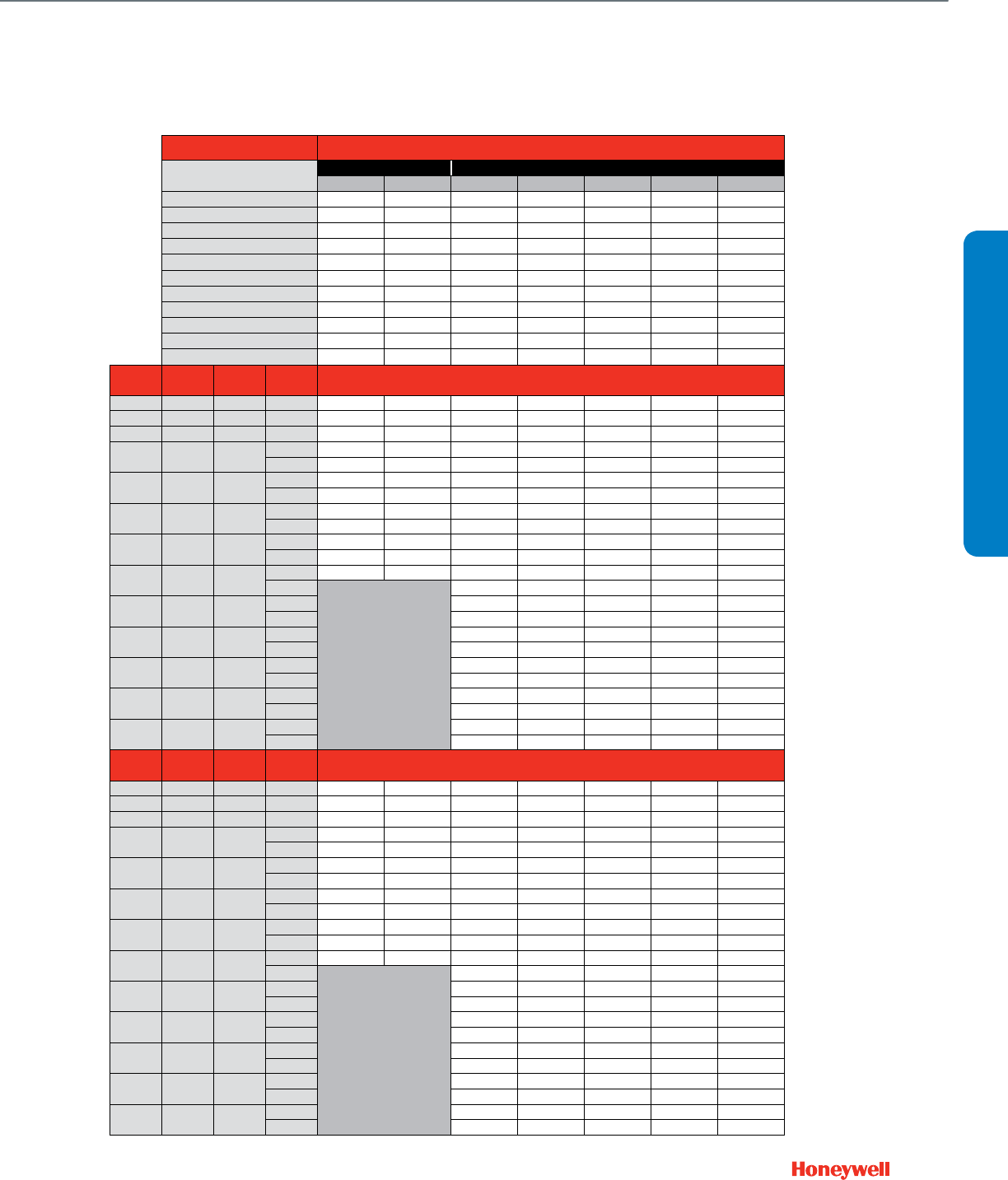
73
Actuator Features Fail Safe
Actuator 20 psi Actuator 80 psi Actuator
8-13 spring Positioner Standard E-P Solenoid E-P Solenoid Positioner E-P Positioner
Power Supply Voltage 24 Vac 120 Vac 24 Vac
Frequency 50 / 60 Hz 50 / 60 Hz 50 / 60 Hz
Power 6 W 6 W
Control Modulating Pneumatic • • • •
2-Position • •
4-20 mA •
Auxiliary Switch Add-On VFF50-0400 VFF50-0400 VFF50-0400
Manual Override •
Conduit Connection • • •
Waterproof •
Fail Safe •••••••
Valve Size
(inches) Cv @ 60° Cv @ 90° Close-off
(psid) Valve O.S. Number
2-Way Normally Open
2" 61 144 175 VFF1FW1Y8P VFF1FW1YPP VFF1FW1YXS VFF1FW1YCS VFF1FW1YES VFF1FW1YPS VFF1FW1YDS
2 1/2" 107 282 175 VFF1GW1Y8P VFF1GW1YPP VFF1GW1YXS VFF1GW1YCS VFF1GW1YES VFF1GW1YPS VFF1GW1YDS
3" 154 461 175 VFF1HW1Y8P VFF1HW1YPP VFF1HW1YXS VFF1HW1YCS VFF1HW1YES VFF1HW1YPS VFF1HW1YDS
4" 274 841 50 VFF1JV1Y8P VFF1JV1YPP VFF1JV1YXS VFF1JV1YCS VFF1JV1YES VFF1JV1YPS VFF1JV1YDS
175 VFF1JW1Y8P VFF1JW1YPP VFF1JW1YXS VFF1JW1YCS VFF1JW1YES VFF1JW1YPS VFF1JW1YDS
5" 428 1376 50 VFF1KV1Y8P VFF1KV1YPP VFF1KV1YXS VFF1KV1YCS VFF1KV1YES VFF1KV1YPS VFF1KV1YDS
175 VFF1KW1Y8P VFF1KW1YPP VFF1KW1YXS VFF1KW1YCS VFF1KW1YES VFF1KW1YPS VFF1KW1YDS
6" 567 1850 50 VFF1LW1Y8P* VFF1LW1YPP* VFF1LV1YXS VFF1LV1YCS VFF1LV1YES VFF1LV1YPS VFF1LV1YDS
175 VFF1LW1Y8P VFF1LW1YPP VFF1LW1YXS VFF1LW1YCS VFF1LW1YES VFF1LW1YPS VFF1LW1YDS
8" 1081 3316 50 VFF1MV1Y8P VFF1MV1YPP VFF1MV1YXS VFF1MV1YCS VFF1MV1YES VFF1MV1YPS VFF1MV1YDS
175 VFF1MW1Y8P VFF1MW1YPP VFF1MW1YXS VFF1MW1YCS VFF1MW1YES VFF1MW1YPS VFF1MW1YDS
10" 1710 5430 50 VFF1NV1Y8P VFF1NV1YPP VFF1NV1YXS VFF1NV1YCS VFF1NV1YES VFF1NV1YPS VFF1NV1YDS
175 VFF1NW1YXS VFF1NW1YCS VFF1NW1YES VFF1NW1YPS VFF1NW1YDS
12" 2563 8077 50 VFF1PV1YXS VFF1PV1YCS VFF1PV1YES VFF1PV1YPS VFF1PV1YDS
175 VFF1PW1YXS VFF1PW1YCS VFF1PW1YES VFF1PW1YPS VFF1PW1YDS
14" 3384 10538 50 VFF1RV1YXS VFF1RW1YCS VFF1RV1YES VFF1RV1YPS VFF1RV1YDS
150 VFF1RW1YXS VFF1RW1YCS VFF1RW1YES VFF1RW1YPS VFF1RW1YDS
16" 4483 13966 50 VFF1SV1YXS VFF1SV1YCS VFF1SV1YES VFF1SV1YPS VFF1SV1YDS
150 VFF1SW1YXS VFF1SW1YCS VFF1SW1YES VFF1SW1YPS VFF1SW1YDS
18" 5736 17214 50 VFF1TV1YXS VFF1TV1YCS VFF1TV1YES VFF1TV1YPS VFF1TV1YDS
150 VFF1TW1YXS VFF1TW1YCS VFF1TW1YES VFF1TW1YPS VFF1TW1YDS
20" 7144 22339 50 VFF1UV1YXS VFF1UV1YCS VFF1UV1YES VFF1UV1YPS VFF1UV1YDS
150 VFF1UW1YXS VFF1UW1YCS VFF1UW1YES VFF1UW1YPS VFF1UW1YDS
Valve Size
(inches) Cv @ 60° Cv @ 90° Close-off
(psid) Valve O.S. Number
2-Way Normally Closed
2" 61 144 175 VFF2FW1Y8P VFF2FW1YPP VFF2FW1YXS VFF2FW1YCS VFF2FW1YES VFF2FW1YPS VFF2FW1YDS
2 1/2" 107 282 175 VFF2GW1Y8P VFF2GW1YPP VFF2GW1YXS VFF2GW1YCS VFF2GW1YES VFF2GW1YPS VFF2GW1YDS
3" 154 461 175 VFF2HW1Y8P VFF2HW1YPP VFF2HW1YXS VFF2HW1YCS VFF2HW1YES VFF2HW1YPS VFF2HW1YDS
4" 274 841 50 VFF2JV1Y8P VFF2JV1YPP VFF2JV1YXS VFF2JV1YCS VFF2JV1YES VFF2JV1YPS VFF2JV1YDS
175 VFF2JW1Y8P VFF2JW1YPP VFF2JW1YXS VFF2JW1YCS VFF2JW1YES VFF2JW1YPS VFF2JW1YDS
5" 428 1376 50 VFF2KV1Y8P VFF2KV1YPP VFF2KV1YXS VFF2KV1YCS VFF2KV1YES VFF2KV1YPS VFF2KV1YDS
175 VFF2KW1Y8P VFF2KW1YPP VFF2KW1YXS VFF2KW1YCS VFF2KW1YES VFF2KW1YPS VFF2KW1YDS
6" 567 1850 50 VFF2LW1Y8P* VFF2LW1YPP* VFF2LV1YXS VFF2LV1YCS VFF2LV1YES VFF2LV1YPS VFF2LV1YDS
175 VFF2LW1Y8P VFF2LW1YPP VFF2LW1YXS VFF2LW1YCS VFF2LW1YES VFF2LW1YPS VFF2LW1YDS
8" 1081 3316 50 VFF2MV1Y8P VFF2MV1YPP VFF2MV1YXS VFF2MV1YCS VFF2MV1YES VFF2MV1YPS VFF2MV1YDS
175 VFF2MW1Y8P VFF2MW1YPP VFF2MW1YXS VFF2MW1YCS VFF2MW1YES VFF2MW1YPS VFF2MW1YDS
10" 1710 5430 50 VFF2NV1Y8P VFF2NV1YPP VFF2NV1YXS VFF2NV1YCS VFF2NV1YES VFF2NV1YPS VFF2NV1YDS
175 VFF2NW1YXS VFF2NW1YCS VFF2NW1YES VFF2NW1YPS VFF2NW1YDS
12" 2563 8077 50 VFF2PV1YXS VFF2PV1YCS VFF2PV1YES VFF2PV1YPS VFF2PV1YDS
175 VFF2PW1YXS VFF2PW1YCS VFF2PW1YES VFF2PW1YPS VFF2PW1YDS
14" 3384 10538 50 VFF2RV1YXS VFF2RW1YCS VFF2RV1YES VFF2RV1YPS VFF2RV1YDS
150 VFF2RW1YXS VFF2RW1YCS VFF2RW1YES VFF2RW1YPS VFF2RW1YDS
16" 4483 13966 50 VFF2SV1YXS VFF2SV1YCS VFF2SV1YES VFF2SV1YPS VFF2SV1YDS
150 VFF2SW1YXS VFF2SW1YCS VFF2SW1YES VFF2SW1YPS VFF2SW1YDS
18" 5736 17214 50 VFF2TV1YXS VFF2TV1YCS VFF2TV1YES VFF2TV1YPS VFF2TV1YDS
150 VFF2TW1YXS VFF2TW1YCS VFF2TW1YES VFF2TW1YPS VFF2TW1YDS
20" 7144 22339 50 VFF2UV1YXS VFF2UV1YCS VFF2UV1YES VFF2UV1YPS VFF2UV1YDS
150 VFF2UW1YXS VFF2UW1YCS VFF2UW1YES VFF2UW1YPS VFF2UW1YDS
*Use full cut, 175psid close-off valves - No under-cut, 50psid close-off valve available
VALVE SELECTION
Resilient Seat Butterfly Valves
2-Way Pneumatically-Actuated Control
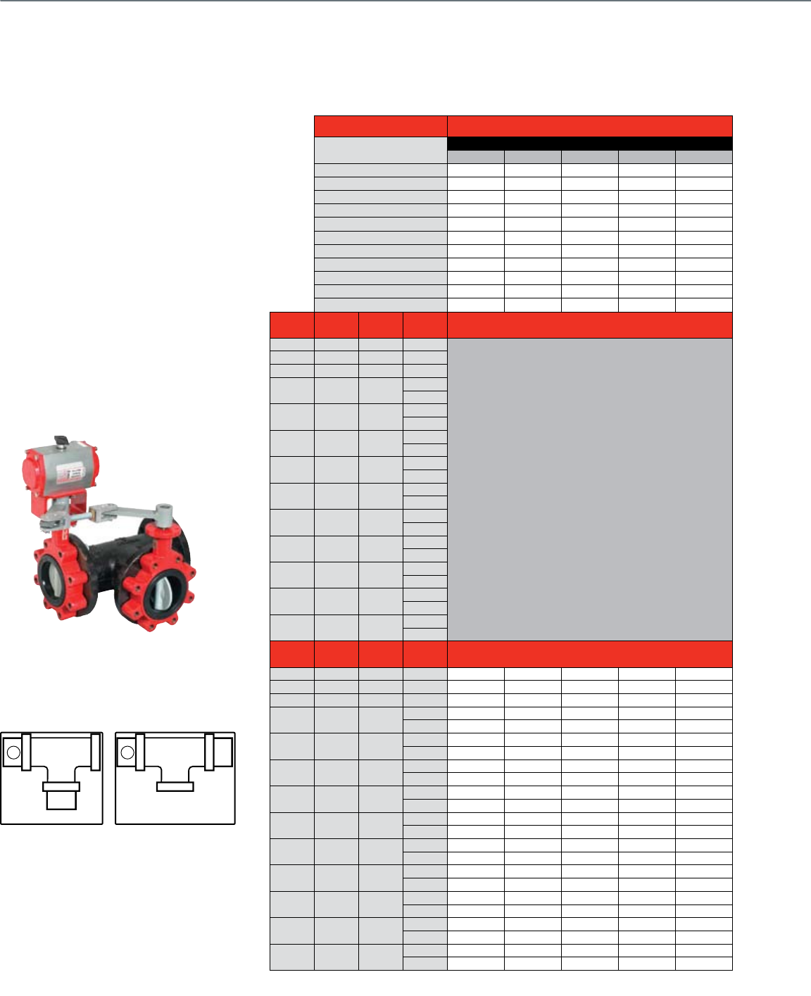
74
Actuator Features Non-fail Safe (Bidirectional)
Actuator 80 psi Actuator
Standard E-P Solenoid E-P Solenoid Positioner E-P Positioner
Power Supply Voltage 24 Vac 120 VAc 24 Vac
Frequency 50 / 60 Hz 50 / 60 Hz 50 / 60 Hz
Power 6 W 6 W
Control Modulating Pneumatic • •
2-Position • •
4-20 mA •
Auxiliary Switch Add-On VFF50-0400 VFF50-0400 VFF50-0400
Manual Override •
Conduit Connection • • •
Waterproof •
Fail Safe
Valve Size
(inches) Cv @ 60° Cv @ 90° Close-off
(psid) Valve O.S. Number
3-Way Mixing / Diverting Globe Valve Porting
2" 61 144 175
Use VFF2 models for Bi-directional pneumatic operation
2 1/2" 107 282 175
3" 154 461 175
4" 274 841 50
175
5" 428 1376 50
175
6" 567 1850 50
175
8" 1081 3316 50
175
10" 1710 5430 50
175
12" 2563 8077 50
175
14" 3384 10538 50
150
16" 4483 13966 50
150
18" 5736 17214 50
150
20" 7144 22339 50
150
Valve Size
(inches) Cv @ 60° Cv @ 90° Close-off
(psid) Valve O.S. Number
3-Way Mixing / Diverting Center Common Port
2" 61 144 175 VFF2FW1YXR VFF2FW1YCR VFF2FW1YER VFF2FW1YPR VFF2FW1YDR
2 1/2" 107 282 175 VFF2GW1YXR VFF2GW1YCR VFF2GW1YER VFF2GW1YPR VFF2GW1YDR
3" 154 461 175 VFF2HW1YXR VFF2HW1YCR VFF2HW1YER VFF2HW1YPR VFF2HW1YDR
4" 274 841 50 VFF2JV1YXR VFF2JV1YCR VFF2JV1YER VFF2JV1YPR VFF2JV1YDR
175 VFF2JW1YXR VFF2JW1YCR VFF2JW1YER VFF2JW1YPR VFF2JW1YDR
5" 428 1376 50 VFF2KV1YXR VFF2KV1YCR VFF2KV1YER VFF2KV1YPR VFF2KV1YDR
175 VFF2KW1YXR VFF2KW1YCR VFF2KW1YER VFF2KW1YPR VFF2KW1YDR
6" 567 1850 50 VFF2LV1YXR VFF2LV1YCR VFF2LV1YER VFF2LV1YPR VFF2LV1YDR
175 VFF2LW1YXR VFF2LW1YCR VFF2LW1YER VFF2LW1YPR VFF2LW1YDR
8" 1081 3316 50 VFF2MV1YXR VFF2MV1YCR VFF2MV1YER VFF2MV1YPR VFF2MV1YDR
175 VFF2MW1YXR VFF2MW1YCR VFF2MW1YER VFF2MW1YPR VFF2MW1YDR
10" 1710 5430 50 VFF2NV1YXR VFF2NV1YCR VFF2NV1YER VFF2NV1YPR VFF2NV1YDR
175 VFF2NW1YXR VFF2NW1YCR VFF2NW1YER VFF2NW1YPR VFF2NW1YDR
12" 2563 8077 50 VFF2PV1YXR VFF2PV1YCR VFF2PV1YER VFF2PV1YPR VFF2PV1YDR
175 VFF2PW1YXR VFF2PW1YCR VFF2PW1YER VFF2PW1YPR VFF2PW1YDR
14" 3384 10538 50 VFF2RV1YXR VFF2RV1YCR VFF2RV1YER VFF2RV1YPR VFF2RV1YDR
175* VFF2RW1YXR VFF2RW1YCR VFF2RW1YER VFF2RW1YPR VFF2RW1YDR
16" 4483 13966 50 VFF2SV1YXR VFF2SV1YCR VFF2SV1YER VFF2SV1YPR VFF2SV1YDR
175* VFF2SW1YXR VFF2SW1YCR VFF2SW1YER VFF2SW1YPR VFF2SW1YDR
18" 5736 17214 50 VFF2TV1YXR VFF2TV1YCR VFF2TV1YER VFF2TV1YPR VFF2TV1YDR
175* VFF2TW1YXR VFF2TW1YCR VFF2TW1YER VFF2TW1YPR VFF2TW1YDR
20" 7144 22339 50 VFF2UV1YXR VFF2UV1YCR VFF2UV1YER VFF2UV1YPR VFF2UV1YDR
175* VFF2UW1YXR VFF2UW1YCR VFF2UW1YER VFF2UW1YPR VFF2UW1YDR
* Full cut valves with bi-directional pneumatic actuators feature 175 psi close-off in all body sizes
Resilient Seat Butterfly Valves
3-Way Pneumatically-Actuated Control
Common Features
Honeywell offers a wide selection of
pneumatic actuators:
• VFF3 – A-B-AB porting, full-cut (150-175 psid
close-off) or under-cut disc (50 psid close-off)
(Figure 1 - from 63-2661-02 g. 12)
• VFF6 – A-AB-B porting, full-cut (150-175 psid
close-off) or under-cut disc (50 psid close-off)
(Figure 2 - from 63-2661-02 g. 12)
• 20 psi spring return (up to 8" size)
• 80 psi spring return
• 80 psi double acting bi-directional
• Mixing or diverting control
• Standard right-angle cast-iron T-pipe
• A-port congured to closed position at factory
• Porting pattern eld-congurable with valve
linkage adjustment
Notes:
Viewed from above
P = Actuator and Primary Valve
S = Slave Valve
VFF3 valve action is mixing for uid ow from
left to right.
VFF3 valve action is diverting for uid ow from
right to left
VFF6 may be piped for mixing control with water
exiting port AB, or for diverting control with
water entering port AB
Figure 1 (VFF3) Figure 2 (VFF6)
A AB
B
S
P
N.C.
N.O.
A
AB
BSP
N.C. N.O.
A AB
B
S
P
N.C.
N.O.
A
AB
BSP
N.C. N.O.

75
Actuator Features Fail Safe
Actuator 20 psi Actuator 80 psi Actuator
8-13 spring Positioner Standard E-P Solenoid E-P Solenoid Positioner E-P Positioner
Power Supply Voltage 24 Vac 120 Vac 24 Vac
Frequency 50 / 60 Hz 50 / 60 Hz 50 / 60 Hz
Power 6 W 6 W
Control Modulating Pneumatic • • • •
2-Position • •
4-20 mA •
Auxiliary Switch Add-On VFF50-0400 VFF50-0400 VFF50-0400
Manual Override •
Conduit Connection • • •
Waterproof •
Fail Safe •••••••
Valve Size
(inches) Cv @ 60° Cv @ 90° Close-off
(psid) Valve O.S. Number
3-Way Mixing / Diverting Globe Valve Porting
2" 61 144 175 VFF1FW1Y8P VFF1FW1YPP VFF1FW1YXS VFF1FW1YCS VFF1FW1YES VFF1FW1YPS VFF1FW1YDS
2 1/2" 107 282 175 VFF1GW1Y8P VFF1GW1YPP VFF1GW1YXS VFF1GW1YCS VFF1GW1YES VFF1GW1YPS VFF1GW1YDS
3" 154 461 175 VFF1HW1Y8P VFF1HW1YPP VFF1HW1YXS VFF1HW1YCS VFF1HW1YES VFF1HW1YPS VFF1HW1YDS
4" 274 841 50 VFF1JV1Y8P VFF1JV1YPP VFF1JV1YXS VFF1JV1YCS VFF1JV1YES VFF1JV1YPS VFF1JV1YDS
175 VFF1JW1Y8P VFF1JW1YPP VFF1JW1YXS VFF1JW1YCS VFF1JW1YES VFF1JW1YPS VFF1JW1YDS
5" 428 1376 50 VFF1KV1Y8P VFF1KV1YPP VFF1KV1YXS VFF1KV1YCS VFF1KV1YES VFF1KV1YPS VFF1KV1YDS
175 VFF1KW1Y8P VFF1KW1YPP VFF1KW1YXS VFF1KW1YCS VFF1KW1YES VFF1KW1YPS VFF1KW1YDS
6" 567 1850 50 VFF1LW1Y8P* VFF1LW1YPP* VFF1LV1YXS VFF1LV1YCS VFF1LV1YES VFF1LV1YPS VFF1LV1YDS
175 VFF1LW1Y8P VFF1LW1YPP VFF1LW1YXS VFF1LW1YCS VFF1LW1YES VFF1LW1YPS VFF1LW1YDS
8" 1081 3316 50 VFF1MV1Y8P VFF1MV1YPP VFF1MV1YXS VFF1MV1YCS VFF1MV1YES VFF1MV1YPS VFF1MV1YDS
175 VFF1MW1Y8P VFF1MW1YPP VFF1MW1YXS VFF1MW1YCS VFF1MW1YES VFF1MW1YPS VFF1MW1YDS
10" 1710 5430 50 VFF1NV1Y8P VFF1NV1YPP VFF1NV1YXS VFF1NV1YCS VFF1NV1YES VFF1NV1YPS VFF1NV1YDS
175 VFF1NW1YXS VFF1NW1YCS VFF1NW1YES VFF1NW1YPS VFF1NW1YDS
12" 2563 8077 50 VFF1PV1YXS VFF1PV1YCS VFF1PV1YES VFF1PV1YPS VFF1PV1YDS
175 VFF1PW1YXS VFF1PW1YCS VFF1PW1YES VFF1PW1YPS VFF1PW1YDS
14" 3384 10538 50 VFF1RV1YXS VFF1RW1YCS VFF1RV1YES VFF1RV1YPS VFF1RV1YDS
150 VFF1RW1YXS VFF1RW1YCS VFF1RW1YES VFF1RW1YPS VFF1RW1YDS
16" 4483 13966 50 VFF1SV1YXS VFF1SV1YCS VFF1SV1YES VFF1SV1YPS VFF1SV1YDS
150 VFF1SW1YXS VFF1SW1YCS VFF1SW1YES VFF1SW1YPS VFF1SW1YDS
18" 5736 17214 50 VFF1TV1YXS VFF1TV1YCS VFF1TV1YES VFF1TV1YPS VFF1TV1YDS
150 VFF1TW1YXS VFF1TW1YCS VFF1TW1YES VFF1TW1YPS VFF1TW1YDS
20" 7144 22339 50 VFF1UV1YXS VFF1UV1YCS VFF1UV1YES VFF1UV1YPS VFF1UV1YDS
150 VFF1UW1YXS VFF1UW1YCS VFF1UW1YES VFF1UW1YPS VFF1UW1YDS
Valve Size
(inches) Cv @ 60° Cv @ 90° Close-off
(psid) Valve O.S. Number
3-Way Mixing / Diverting Center Common Port
2" 61 144 175 VFF2FW1Y8P VFF2FW1YPP VFF2FW1YXS VFF2FW1YCS VFF2FW1YES VFF2FW1YPS VFF2FW1YDS
2 1/2" 107 282 175 VFF2GW1Y8P VFF2GW1YPP VFF2GW1YXS VFF2GW1YCS VFF2GW1YES VFF2GW1YPS VFF2GW1YDS
3" 154 461 175 VFF2HW1Y8P VFF2HW1YPP VFF2HW1YXS VFF2HW1YCS VFF2HW1YES VFF2HW1YPS VFF2HW1YDS
4" 274 841 50 VFF2JV1Y8P VFF2JV1YPP VFF2JV1YXS VFF2JV1YCS VFF2JV1YES VFF2JV1YPS VFF2JV1YDS
175 VFF2JW1Y8P VFF2JW1YPP VFF2JW1YXS VFF2JW1YCS VFF2JW1YES VFF2JW1YPS VFF2JW1YDS
5" 428 1376 50 VFF2KV1Y8P VFF2KV1YPP VFF2KV1YXS VFF2KV1YCS VFF2KV1YES VFF2KV1YPS VFF2KV1YDS
175 VFF2KW1Y8P VFF2KW1YPP VFF2KW1YXS VFF2KW1YCS VFF2KW1YES VFF2KW1YPS VFF2KW1YDS
6" 567 1850 50 VFF2LW1Y8P* VFF2LW1YPP* VFF2LV1YXS VFF2LV1YCS VFF2LV1YES VFF2LV1YPS VFF2LV1YDS
175 VFF2LW1Y8P VFF2LW1YPP VFF2LW1YXS VFF2LW1YCS VFF2LW1YES VFF2LW1YPS VFF2LW1YDS
8" 1081 3316 50 VFF2MV1Y8P VFF2MV1YPP VFF2MV1YXS VFF2MV1YCS VFF2MV1YES VFF2MV1YPS VFF2MV1YDS
175 VFF2MW1Y8P VFF2MW1YPP VFF2MW1YXS VFF2MW1YCS VFF2MW1YES VFF2MW1YPS VFF2MW1YDS
10" 1710 5430 50 VFF2NV1Y8P VFF2NV1YPP VFF2NV1YXS VFF2NV1YCS VFF2NV1YES VFF2NV1YPS VFF2NV1YDS
175 VFF2NW1YXS VFF2NW1YCS VFF2NW1YES VFF2NW1YPS VFF2NW1YDS
12" 2563 8077 50 VFF2PV1YXS VFF2PV1YCS VFF2PV1YES VFF2PV1YPS VFF2PV1YDS
175 VFF2PW1YXS VFF2PW1YCS VFF2PW1YES VFF2PW1YPS VFF2PW1YDS
14" 3384 10538 50 VFF2RV1YXS VFF2RW1YCS VFF2RV1YES VFF2RV1YPS VFF2RV1YDS
150 VFF2RW1YXS VFF2RW1YCS VFF2RW1YES VFF2RW1YPS VFF2RW1YDS
16" 4483 13966 50 VFF2SV1YXS VFF2SV1YCS VFF2SV1YES VFF2SV1YPS VFF2SV1YDS
150 VFF2SW1YXS VFF2SW1YCS VFF2SW1YES VFF2SW1YPS VFF2SW1YDS
18" 5736 17214 50 VFF2TV1YXS VFF2TV1YCS VFF2TV1YES VFF2TV1YPS VFF2TV1YDS
150 VFF2TW1YXS VFF2TW1YCS VFF2TW1YES VFF2TW1YPS VFF2TW1YDS
20" 7144 22339 50 VFF2UV1YXS VFF2UV1YCS VFF2UV1YES VFF2UV1YPS VFF2UV1YDS
150 VFF2UW1YXS VFF2UW1YCS VFF2UW1YES VFF2UW1YPS VFF2UW1YDS
*Use full cut, 175psid close-off valves - No under-cut, 50psid close-off valve available
VALVE SELECTION
Resilient Seat Butterfly Valves
3-Way Pneumatically-Actuated Control

76

77
Section 3: Submittal Sheets
Rectangular Volume Control Dampers
D1 Series ............................................................................. 78
D2 and D3 Series ..................................................................79
Round Volume Control Dampers
D690 .....................................................................................80
DM7600 ................................................................................81
Spring Return Direct Coupled Actuator
S03 Series (MS4103; MS4603; MS7403; MS7503; MS8103) ...82
S05 Series (MS4105; MS4605; MS7105; MS7405; MS7505;
MS8105) ..................................................................83
S05 Series (MS4105; MS7505; MS8105) ..................................84
S10 Series (MS4110; MS7510; MS8110) ..................................85
S20 Series (MS4120; MS7520; MS8120) .................................86
ML4125; ML8125 ................................................................87
Non-Spring Return Direct Coupled Actuator
ML6161; ML7161 .................................................................88
ML6174; ML7174 .................................................................89
N05 Series (MN6105; MN7505) ............................................90
N10 Series (MN6110; MN7510) ............................................91
N20 Series (MN6120; MN7220) ............................................92
N34 Series (MN6134; MN7234) .................................................93
Fire And Smoke Actuators
ML4115; ML8115 ................................................................94
MS4209F; MS4309F; MS4709F; MS4809F; MS8209F;
MS8309F ..............................................................................95
MS4120F; MS4620F; MS8120F ...........................................96
Pneumatic Damper Actuator
MP909D ................................................................................97
MP909E, H ...........................................................................98
MP913 ..................................................................................99
MP918A, B .........................................................................100
MP920 ................................................................................101
Pneumatic Valve Actuator
MP953C, D .........................................................................102
MP953E, F ..........................................................................103
MP958 ................................................................................104
Modutrol IV Motor
M4185; M8185 ...................................................................105
M6184; M6194 ...................................................................106
M6285 for slaving applications ............................................107
M6284; M6294 for slaving applications ...............................108
M6274; M6284; M6285; M6294 Motors with
Linear 10K Feedback ..........................................................109
M7164 ...............................................................................110
M7274; M7284; M7285; M7286; M7294 ...........................111
M9164; M9174; M9182; M9184; M9194 ...........................112
M9175; M9185; M9186 ......................................................113
Q7130; Q7230; Q7330 .......................................................114
Unitary Valve Actuator
VU443; VU444; VU843; VU844 ..........................................115
VC Series Two-position .......................................................116
VC Series Proportional ........................................................117
VC Series Fail Safe Proportional ..........................................118
M6410; M7410 ...................................................................119
M6435; M7435 ...................................................................120
Direct Coupled Valve Actuator
ML6420; ML7420 ...............................................................121
ML6421; ML7421 ...............................................................122
ML6425; ML7425 ...............................................................123
ML6984 .............................................................................124
ML7984 ..............................................................................125
Unitary Valve
VU52; VU53 ........................................................................126
VU54 ...................................................................................127
VCZA; VCZB .......................................................................128
VCZM; VCZN ......................................................................129
V5852; V5862 .....................................................................130
V5853; V5863 .....................................................................131
Control Ball Valve
VBN2 ..................................................................................132
VBN3 ..................................................................................133
VBF2 ...................................................................................134
VBF3 ...................................................................................135
NPT Globe Valve
V5011F, G ...........................................................................136
V5011N ...............................................................................137
V5013N ...............................................................................138
Flanged Cage Valve
V5051A ...............................................................................139
Flanged Globe Valve
V5011A, B ..........................................................................140
V5013B, C ..........................................................................141
VGF2 ...................................................................................142
VGF2 Pressure Balanced ....................................................143
VGF3 ...................................................................................144
Resilient Seat Butterfly Valves
VFF1 ...................................................................................145
VFF2 ...................................................................................146
VFF3 ...................................................................................147
VFF6 ...................................................................................148
Damper Linkage
Q605 ...................................................................................149
Valve Linkage
Q5001 .................................................................................150
Q5020 .................................................................................151
Q5022 .................................................................................152
SUBMITTAL SHEETS
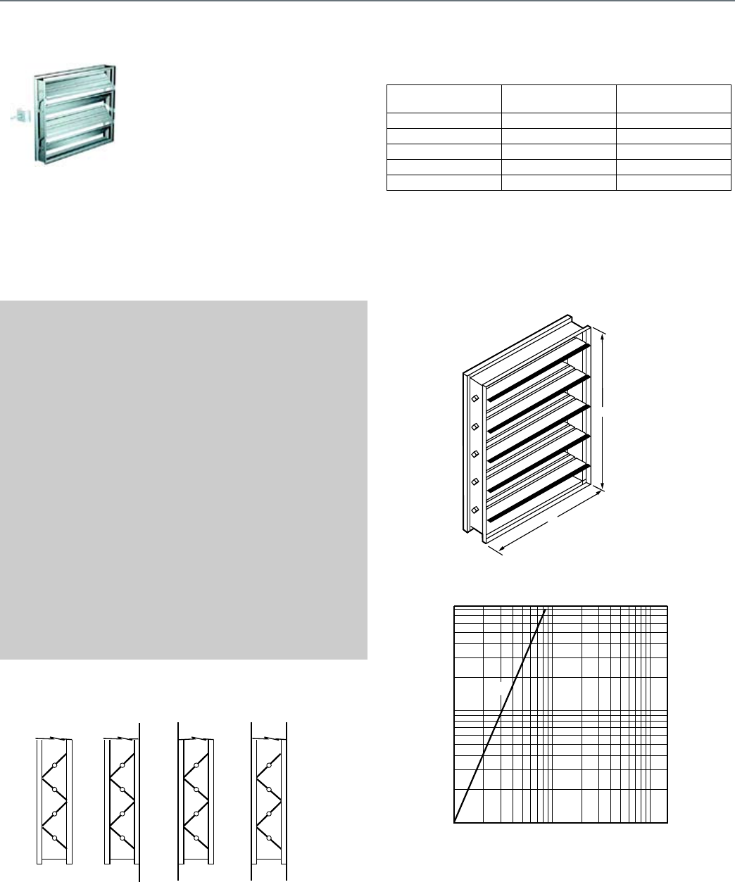
78
Rectangular Volume Control Dampers
D1 Series
D1 Series
The D1 series is an extremely low
leakage damper with rugged steel
airfoil blades designed to meet the
highest standards established. It is
intended for application in medium
to high pressure and velocity
ratings.
SPECIFICATIONS
Size Range1
Minimum Size
One Blade ..........................................6 in. wide by 6 in. high
Two Blade ...........................................6 in. wide by 10 in. high
Maximum Size
Single Section ....................................60 in. wide by 74 in. high
Multiple Section ..................................unlimited
Temperature Rating ............................180 F (82 C) maximum2
Standard Construction3
Blade: .................................................14 gauge galvanized steel,
airfoil shaped
Action: ................................................Parallel or Opposed
Frame3: ..............................................16 gauge galvanized steel
Hat-channel
Bearings3 ...........................................Synthetic (Acetal)
Linkage3 .............................................Steel Side linkage out of
airstream (concealed in frame)
Axles3 .................................................1/2 in. diameter plated steel
Jamb Seals3 .......................................304 Stainless Steel
Blade Edge Seals3 .............................Silicone
1Width and height dimensions furnished 1/4 in. undersized - standard
2Temperature rating can higher with a different
3See table for customized options
FLANGE OPTIONS
Performance Data
D1 Pressure and Velocity Limits.
DIMENSIONS DIAGRAM
LEAKAGE RATE
M18986
STANDARD
(NO FLANGE)
ACTUATOR SIDE FOR
INTERNAL MOUNTING
SINGLE
FLANGE
SINGLE
REVERSE
FLANGE
ACTUATOR SIDE FOR
INTERNAL MOUNTING
DOUBLE
FLANGE
Damper Size
in in.
Maximum
System Pressure
Maximum
System Velocity
12 x 12 8.0 in. wg 4000 fpm
24 x 24 8.0 in. wg 4000 fpm
36 x 36 6.3 in. wg 3500 fpm
48 x 48 4.7 in. wg 3000 fpm
60 x 60 2.0 in. wg 2500 fpm
H
W
M13905
1 2 3 4 5 6 7 8 9 10 20 30 40
50
60
70
80
90
100 150
AIR LEAKAGE (CFM/FT
2
)
STATIC PRESSURE DIFFERENCE (IN. WG)
0.2
0.3
0.4
0.5
0.6
0.7
0.8
0.9
1.0
2.0
3.0
4.0
5.0
6.0
7.0
8.0
8.5
M13906
D1
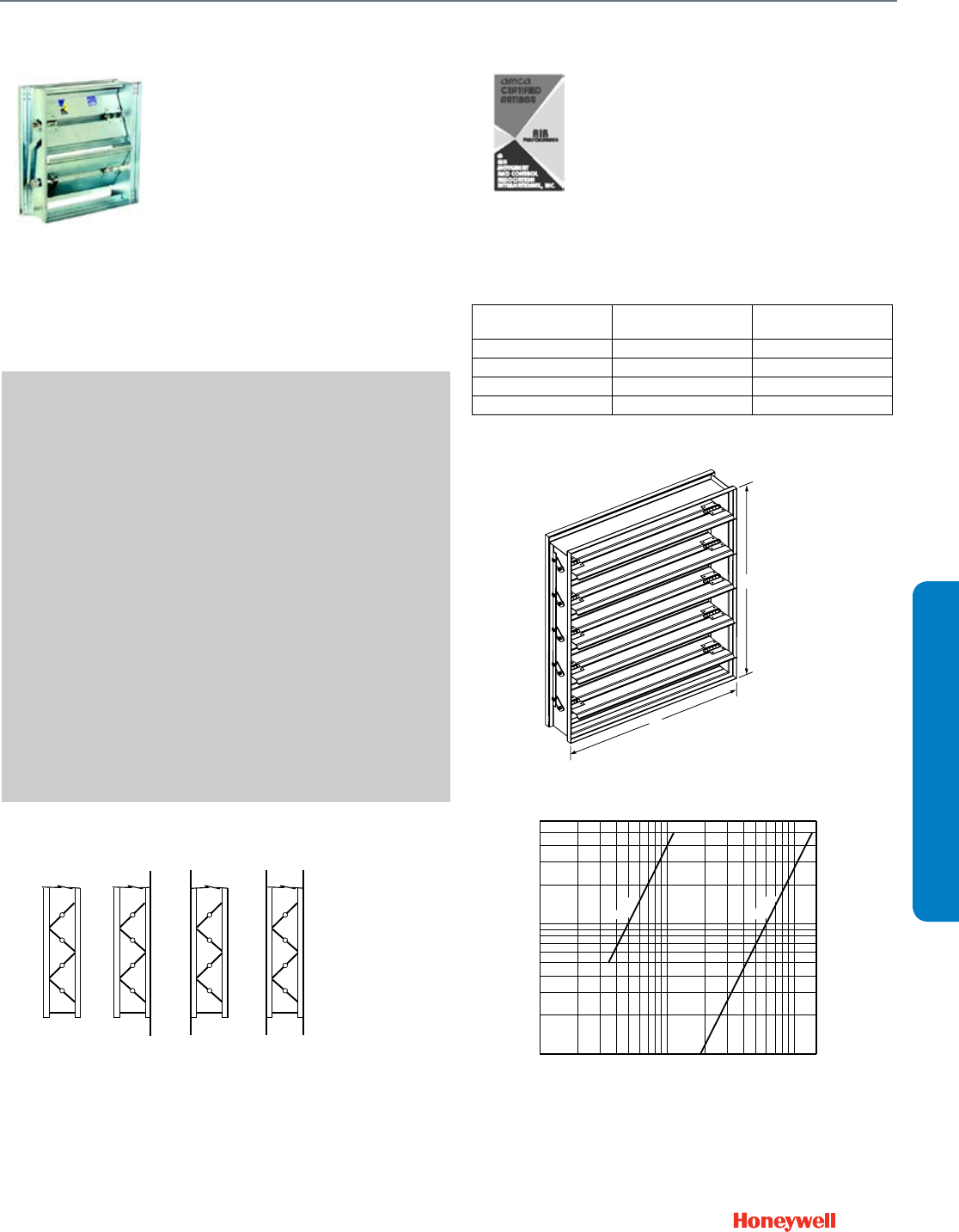
79
D2 and D3 Series
D2 series is an ultra-low leakage
control damper which includes
blade and jamb seals. The D3
series is a general purpose damper
intended for applications where low
leakage performance is not
necessary.
SPECIFICATIONS
Size Range1
Minimum Size
One Blade ......................................... 6 in. wide by 6 in. high
Two Blade .......................................... 6 in. wide by 10 in. high
Maximum Size
Single Section ................................... 48 in. wide by 72 in. high
Multiple Section ................................. unlimited
Temperature Rating ........................... 180 F (82 C) maximum
Standard Construction2
Blade: ................................................ 16 gauge galvanized steel 3-V
Action: ............................................... Parallel or Opposed
Frame2: .............................................. 16 gauge galvanized steel
Hat-channel
Bearings2 .......................................... Synthetic (Acetal)
Linkage .............................................. Side linkage out of airstream
(concealed in frame)
Axles .................................................. 1/2 in. square plated steel
Jamb Seals3 ...................................... Compression-type Stainless
Steel
Blade Edge Seals2 ............................ Extruded Vinyl
1Width and height dimensions furnished 1/4 in. undersized - standard
2See table for customized options
3D2 Dampers only
FLANGE OPTIONS
Honeywell International, Inc. certifies that the
models D2, and D3 shown herein are licensed
to bear the AMCA Seal. The ratings shown are
based on tests and procedures performed in
accordance with AMCA Publication 511 and
comply with the requirements of the AMCA
Certified Ratings Programs. The AMCA
Certified Ratings Seal applies to air
performance ratings only. March 2008.
Performance Data
D2, D3 Pressure and Velocity Limits.
DIMENSIONS DIAGRAM
LEAKAGE RATE
NOTE: D2 and D3 will withstand higher pressures and velocities. Displayed
ratings are conservative to prevent misapplication. Consult Honeywell
if you have an application outside these limitations.
M18986
STANDARD
(NO FLANGE)
ACTUATOR SIDE FOR
INTERNAL MOUNTING
SINGLE
FLANGE
SINGLE
REVERSE
FLANGE
ACTUATOR SIDE FOR
INTERNAL MOUNTING
DOUBLE
FLANGE
Damper Size
in in.
Maximum
System Pressure
Maximum
System Velocity
12 x 12 5.0 in. wg 3000 fpm
24 x 24 5.0 in. wg 3000 fpm
36 x 36 4.0 in. wg 2500 fpm
48 x 48 2.5 in. wg 2000 fpm
H
W
M20587
1.0
.8
.6
.5
.4
.3
.2
6.0
5.0
4.0
3.0
2.0
1
M23317A
2 3 5 6 8 10 20 30 50
60
80
100
AIR LEAKAGE (CFM/FT
2
)
STATIC PRESSURE DIFFERENCE (IN. WG)
40
4 150
D3
D2
Rectangular Volume Control Dampers
D2 and D3 Series
SUBMITTAL SHEETS
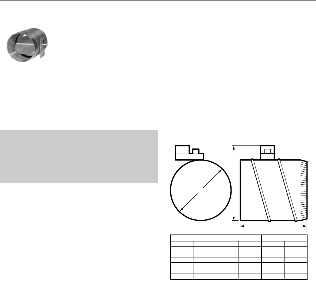
80
Round Volume Control Dampers
D690
D690
The D690 Round Damper is used in
conventional air handling systems
to control airflow in a round duct.
The damper is designed for use
with Honeywell ML6161 and
ML7161 Direct Coupled Actuators.
SPECIFICATIONS
Application .........................................heating, cooling, ventilating
Type of Blade .....................................Single-blade, round
Temperature Range ...........................32 F to 130 F (0 C to 54 C)
Integral Actuator ................................None
Input Signal ........................................none
Used With ...........................................ML6161; ML7161; W7751 VAV
Controller
FEATURES
• Neoprene seal for tight closing and low leakage
• Oilite™ bearings for long life
• 90 degree damper travel for a variety of applications
DIMENSIONS DIAGRAM
D
W
L
DAMPER DIAMETER (D)
6
8
10
12
14
16
WIDTH (W) LENGTH (L)
in.
152
203
254
305
356
406
mm
9-1/2
11-1/2
13-1/2
15-1/2
17-1/2
19-1/2
in.
241
292
343
394
445
495
mm
12
12
12
13
15
17
in.
305
305
305
330
381
432
mm
M17412
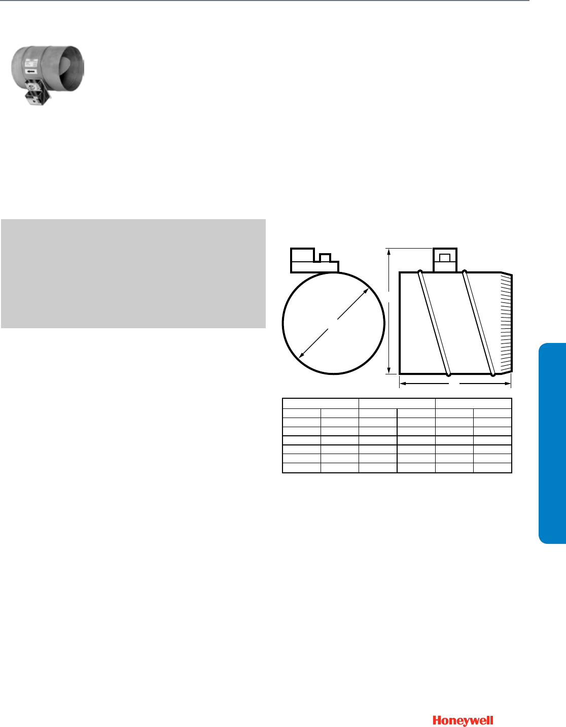
81
SUBMITTAL SHEETS
DM7600
The DM7600 Commercial Zone
Damper is used in zoning systems
to control airflow in a round duct. A
Honeywell ML6161 or ML7161
Direct Coupled Actuator is factory
mounted to the damper to simplify
field installation.
SPECIFICATIONS
Application ........................................ heating, cooling, ventilating
Type of Blade .................................... Single-blade, round
Temperature Range ........................... 32 F to 130 F (0 C to 54 C)
Integral Actuator ................................ 2 to 10 Vdc or 4 to 20 mA,
ML7161A2008
Input Signal ....................................... 2 to 10 Vdc or 4 to 20 mA
Maximum Approach Velocity (ft/ min) 2500 ft/min
Voltage .............................................. 24 Vac
Frequency ......................................... 50 Hz; 60 Hz
FEATURES
• Neoprene seal for tight closing and low leakage
• Oilite bearings for long life
• 90 degree damper travel for a variety of applications
• Magnetic coupling requires no limit switches or mechanical
stops
DIMENSIONS DIAGRAM
D
W
L
DAMPER DIAMETER (D)
6
8
10
12
14
16
WIDTH (W) LENGTH (L)
in.
152
203
254
305
356
406
mm
9-1/2
11-1/2
13-1/2
15-1/2
17-1/2
19-1/2
in.
241
292
343
394
445
495
mm
12
12
12
13
15
17
in.
305
305
305
330
381
432
mm
M17412
Round Volume Control Dampers
DM7600
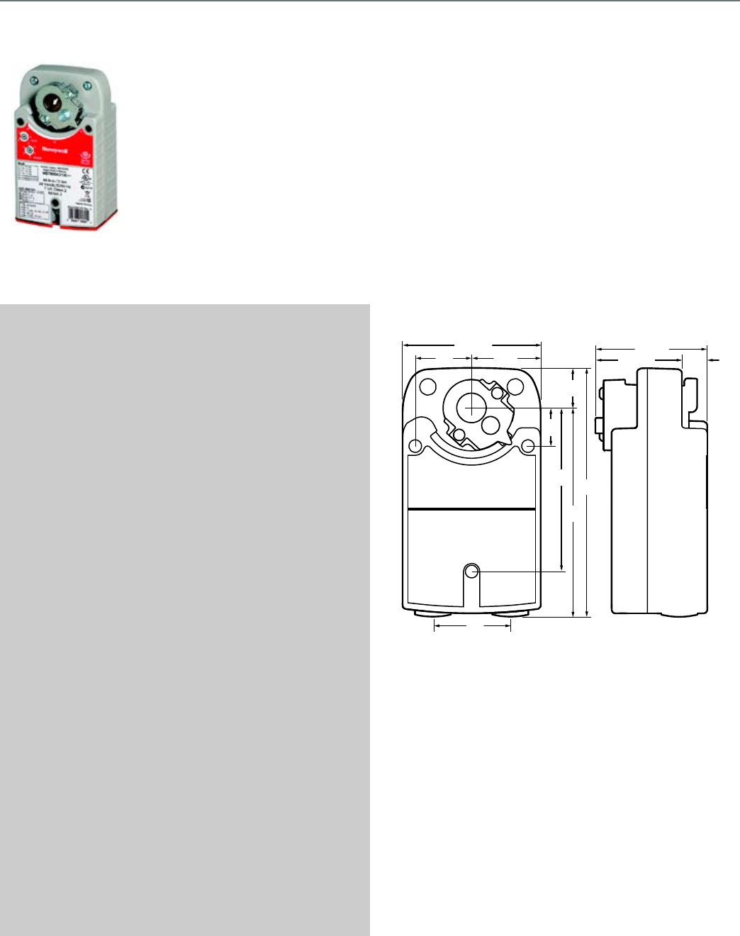
82
S03 Series (MS4103; MS7403; MS7503; MS8103)
MS4103, MS7403, MS7503,
MS8103 Spring Return Direct
Coupled Actuators (DCA) are used
within heating, ventilating, and air-
conditioning (HVAC) systems. They
can drive a variety of quarter-turn,
final control elements requiring
spring return fail-safe operation.
SPECIFICATIONS
Actuator Type ....................................... Damper, Valve
Rotational Stroke .................................. 95 ±3 degrees
Fail Safe Mode ..................................... Spring Return
Rated Torque ........................................ 27 lb-in. (3 Nm)
External Auxiliary Switches Available .. No
Electrical Connections ......................... Enclosed screw terminal strip
(22 to 14 AWG)
Environmental Rating ........................... NEMA2
Frequency ............................................ 50 Hz; 60 Hz
Mounting .............................................. Direct Coupled
Maximum Noise Rating,
Holding (dBA @ 1m) ............................ 20 (no audible noise)
Maximum Noise Rating,
Driving (dBA @ 1m) .............................. 50
Timing, Nominal Driving at 60 Hz ........ 45 sec. or 90 sec.
Power Consumption, Driving ............... 6.5 VA, 7 VA, or 10 VA
Rotation to Open .................................. By switch
Rotational Stroke Adjustment ............... Mechanically limited 5 degree
increments
Compatible Damper Shafts .................. 3/8 to 5/8 round or 1/4 to 1/2
square
(9 to 16 round or 6 to 13
square)
Shaft Adapter Type .............................. Self-centering clamping
Materials ............................................... Plenum rated plastic housing
Ingress Protection Rating ..................... IP54
Operating Humidity Range (% RH) ...... 5 to 95% RH, non-condensing
Ambient Temperature Range ............... -40 F to 150 F (-40 C to 65 C)
-22 F to 150 F (-30 C to 65 C)
Two-position models only
Temperature Ratings (Shipping) .......... -40 F to 150F (-40 C to 65 C)
Storage Temperature Range ................ -40 F to 150F (-40 C to 65 C)
Weight .................................................. 3.5 lb (1.6 kg)
Includes ............................................... Mounting bracket, self-
centering shaft adapter
APPROVALS
CE ........................................................ 2006/95/EC
(Low Voltage Directive )
EMC 2004/108/EC
C-Tick ................................................... N314
International Electrotechnical Commission IEC 60730-1 and Part 2—14
Underwriters Laboratories, Inc. ........... UL 873
UL1097 for Double Insulation
FEATURES
• Volume control dampers, mounted directly to the drive shaft
or remotely (with the use of accessory hardware).
• Quarter-turn rotary valves, such as ball or butterfly valves
mounted directly to the drive shaft.
• Linear stroke globe or cage valves mounted with linkages to
provide linear actuation.
DIMENSIONS DIAGRAM
M27712A
3-55/64 (98)
6-61/64
(177)
1-1/8
(29)
5-27/32
(148)
1-9/16
(40)
3-5/32 (80)
4-9/16
(116)
1-15/16
(49)
1-1/16
(27)
2-1/64
(55)
47/64
(19)
2-27/64 (61)
Spring Return Direct Coupled Actuator
S03 Series (MS4103; MS7403; MS7503; MS8103)
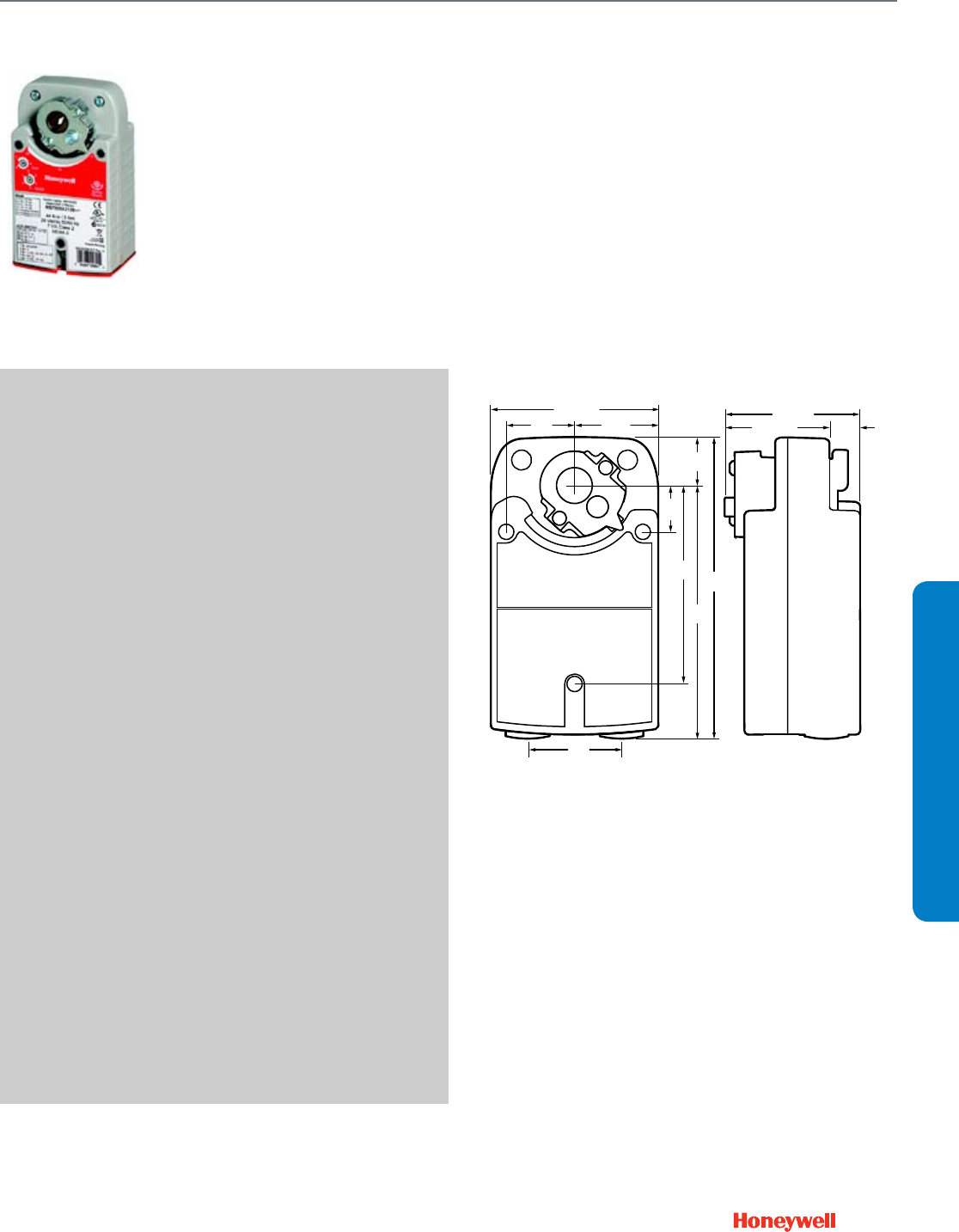
83
S05 Series (MS4105; MS7105; MS7405; MS7505; MS8105)
MS4105, MS7405, MS7505,
MS8105 Spring Return Direct
Coupled Actuators (DCA) are used
within heating, ventilating, and air-
conditioning (HVAC) systems. They
can drive a variety of quarter-turn,
final control elements requiring
spring return fail-safe operation.
SPECIFICATIONS
Actuator Type ....................................... Damper, Valve
Rotational Stroke .................................. 95 ±3 degrees
Fail Safe Mode ..................................... Spring Return
Rated Torque ........................................ 44 lb-in. (5 Nm)
External Auxiliary Switches Available .. No
Electrical Connections ......................... Enclosed screw terminal strip
(22 to 14 AWG)
Environmental Rating ........................... NEMA2
Frequency ............................................ 50 Hz, 60 Hz
Mounting .............................................. Direct Coupled
Maximum Noise Rating, Holding (dBA @ 1m) 20 (no audible noise)
Maximum Noise Rating, Driving (dBA @ 1m) 50
Timing, Nominal Driving at 60 Hz ......... 45 sec. or 90 sec.
Power Consumption, Driving ................ 7.5 VA, 8 VA, or 11 VA
Rotation to Open .................................. By switch
Rotational Stroke Adjustment ............... Mechanically limited 5 degree
increments
Compatible Damper Shafts .................. 3/8 to 5/8 round or 1/4 to 1/2
square
(9 to 16 round or 6 to 13
square)
Shaft Adapter Type .............................. Self-centering clamping
Materials ............................................... Plenum rated plastic housing
Ingress Protection Rating ..................... IP54
Operating Humidity Range (% RH) ...... 5 to 95% RH, non-condensing
Ambient Temperature Range ............... -40 F to 149F (-40 C to 65 C)
-22 F to 150 F (-30 C to 65 C)
Two-position models only
Temperature Ratings (Shipping) .......... -40 F to 150F (-40 C to 65 C)
Storage Temperature Range ................ -40 F to 150F (-40 C to 65 C)
Weight .................................................. 3.5 lb (1.6 kg)
Includes ................................................ Mounting bracket, self-
centering shaft adapter
APPROVALS
CE ......................................................... 2006/95/EC
(Low Voltage Directive )
EMC 2004/108/EC
C-Tick ................................................... N314
International Electrotechnical Commission IEC 60730-1 and Part 2—14
Underwriters Laboratories, Inc. ............ UL 873
UL1097 for Double Insulation
FEATURES
• Volume control dampers, mounted directly to the drive shaft
or remotely (with the use of accessory hardware).
• Quarter-turn rotary valves, such as ball or butterfly valves
mounted directly to the drive shaft.
• Linear stroke globe or cage valves mounted with linkages to
provide linear actuation.
DIMENSIONS DIAGRAM
M27712A
3-55/64 (98)
6-61/64
(177)
1-1/8
(29)
5-27/32
(148)
1-9/16
(40)
3-5/32 (80)
4-9/16
(116)
1-15/16
(49)
1-1/16
(27)
2-1/64
(55)
47/64
(19)
2-27/64 (61)
Spring Return Direct Coupled Actuator
S05 Series (MS4105; MS7105; MS7405; MS7505; MS8105)
SUBMITTAL SHEETS
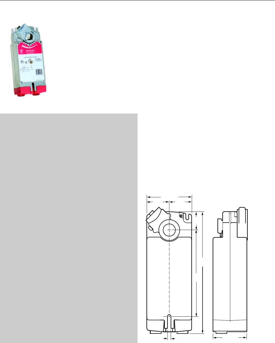
84
S10 Series (MS4110; MS7510; MS8110)
MS4110, MS7510, MS8110 S10
Series Spring Return Direct
Coupled Actuators (DCA) are used
within heating, ventilating, and air-
conditioning (HVAC) systems. They
can drive a variety of quarter-turn,
final control elements requiring
spring return fail-safe operation.
SPECIFICATIONS
Actuator Type ....................................... Damper, Valve
Rotational Stroke .................................. 95 ±3 degrees
Fail Safe Mode ..................................... Spring Return
Rated Torque ........................................ 88 lb-in. (10 Nm)
External Auxiliary Switches Available .. Yes, SW2-US
Electrical Connections ......................... Enclosed screw terminal strip
(22 to 14 AWG)
Environmental Rating ........................... NEMA2
Frequency ............................................ 60 Hz
Manual operation ................................. Manual crank
Mounting .............................................. Direct Coupled
Maximum Noise Rating,
Holding (dBA @ 1m) ............................ 20 (no audible noise)
Maximum Noise Rating,
Driving (dBA @ 1m) .............................. 40
Timing, Nominal Driving at 60 Hz ........ 45 sec. or 90 sec.
Power Consumption, Driving ............... 14 VA, 30 VA, or 45 VA
Rotational Stroke Adjustment ............... Mechanically limited 5 degree
increments
Compatible Damper Shafts .................. 3/8 to 1.06 round or 3/8 to
11/16 square
(10 to 27 round or 10 to 18
square)
Shaft Adapter Type .............................. Self-centering clamping
Supply Voltage ..................................... 100 to 250 Vac
Materials ............................................... Aluminum housing, Plenum
rated plastic access cover
Operating Humidity Range (% RH) ...... 5 to 95% RH, non-condensing
Ambient Temperature Range ............... -40 F to 140 F (-40 C to 60 C)
Storage Temperature Range ................ -40 F to 158 F (-40 C to 70 C)
Weight .................................................. 6 lb (2.72 kg)
Includes ............................................... Mounting bracket, self-
centering shaft adapter, 3mm
crank
Comments ............................................ Integral 1/2 in. NPSM conduit
connection.
APPROVALS
CE ........................................................ 89/336/ECC, 73/23/EEC
C-Tick ................................................... N314
Underwriters Laboratories, Inc. ........... UL873, Plenum Rated
Canadian Underwriters
Laboratories, Inc. ................................. cUL C22.2 No. 24-93
FEATURES
• Brushless DC sub-motor with electronic stall protection for
floating/modulating models.
• Brush DC sub-motor with electronic stall protection for
2-position models.
• Self-centering shaft adapter (shaft coupling) for wide range
of shaft sizes.
• Models available for use with two-position, single pole
single throw (SPST), line- (Series 40) or low- (Series 80)
voltage controls.
• Models available for use with floating or switched single-
pole, double-throw (SPDT) (Series 60) controls.
• Models available for use with proportional current or voltage
(Series 70) controls.
• Models available with combined floating/modulating control
in a single device.
• Models available with adjustable zero and span.
• Models available with line-voltage internal end switches.
• Access cover to facilitate connectivity.
• Metal housing with built-in mechanical end limits.
• Spring return direction field-selectable.
• Shaft position indicator and scale.
• Manual winding capability with locking function.
• UL (cUL) listed and CE compliant.
• All models are plenum-rated per UL873.
DIMENSIONS DIAGRAMS
9-3/4
(247)
1-9/16
(40)
6-1/8
(156)
1-9/16
(40)
1-9/16
(40)
3-15/16 (100)
2-15/16 (75)
1/4 (6)
M20952
Spring Return Direct Coupled Actuator
S10 Series (MS4110; MS7510; MS8110)
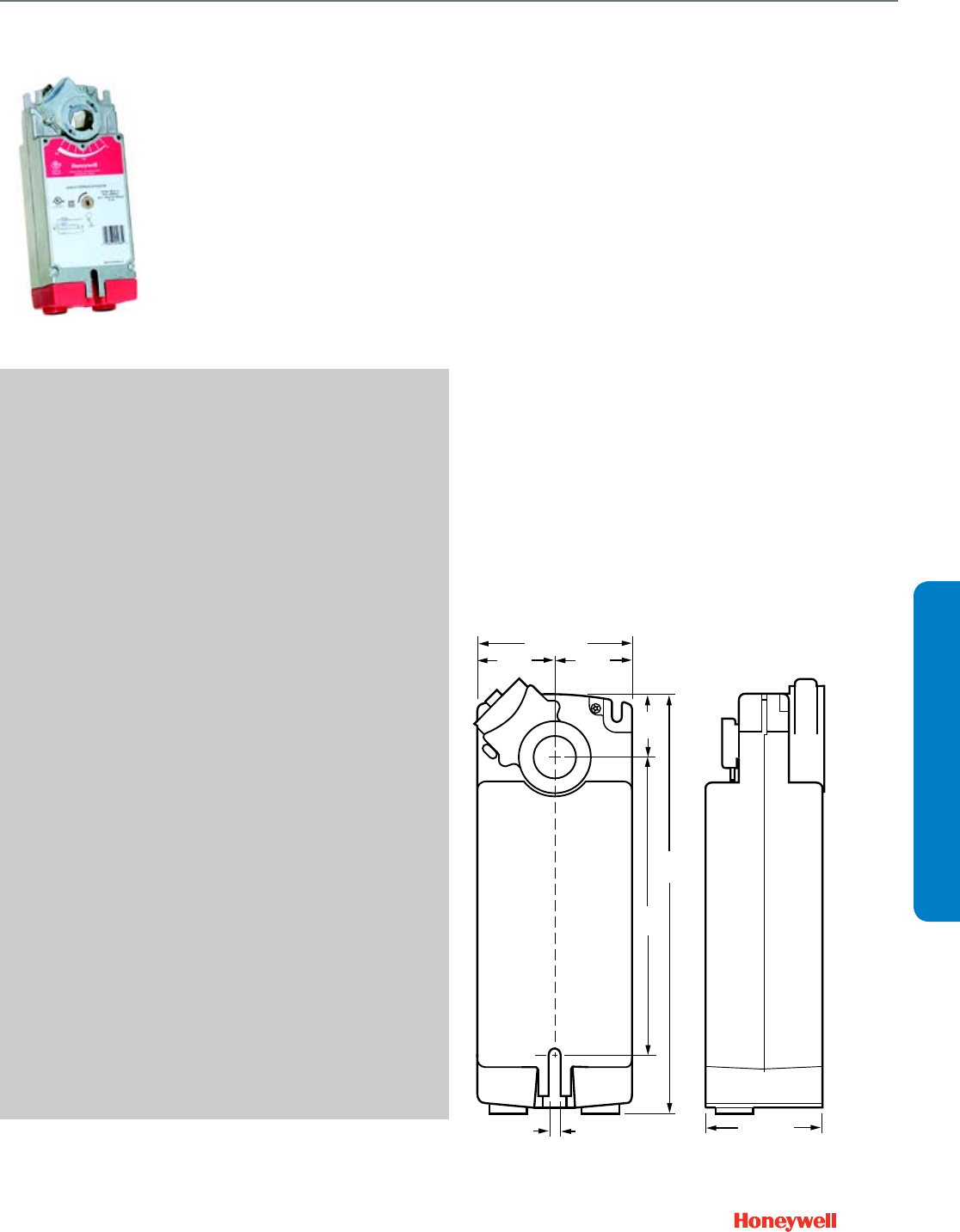
85
S20 Series (MS4120; MS7520; MS8120)
MS4120, MS7520, MS8120 Spring
Return Direct Coupled Actuators (DCA)
are used within heating, ventilating, and
air-conditioning (HVAC) systems. They
can drive a variety of quarter-turn, final
control elements requiring spring return
fail-safe operation.
SPECIFICATIONS
Actuator Type ....................................... Damper, Valve
Rotational Stroke .................................. 95 ±3 degrees
Fail Safe Mode ..................................... Spring Return
Rated Torque ........................................ 175 lb-in. (20 Nm)
External Auxiliary Switches Available .. Yes, SW2-US
Electrical Connections ......................... Enclosed screw terminal strip
(22 to 14 AWG)
Environmental Rating ........................... NEMA2
Frequency ............................................ 60 Hz
Manual operation ................................. Manual crank
Mounting .............................................. Direct Coupled
Maximum Noise Rating,
Holding (dBA @ 1m) ............................ 20 (no audible noise)
Maximum Noise Rating,
Driving (dBA @ 1m) .............................. 40
Timing, Nominal Driving at 60 Hz ......... 45 sec. or 90 sec.
Power Consumption, Driving ................ 16 VA, 40 VA, or 60 VA
Rotational Stroke Adjustment ............... Mechanically limited 5 degree
increments
Compatible Damper Shafts .................. 3/8 to 1.06 round or 3/8 to
11/16 square
(10 to 27 round or 10 to 18
square)
Shaft Adapter Type .............................. Self-centering clamping
Supply Voltage ..................................... 100 to 250 Vac
Materials ............................................... Aluminum housing, Plenum
rated plastic access cover
Operating Humidity Range (% RH) ...... 5 to 95% RH, non-condensing
Ambient Temperature Range ............... -40 F to 140 F (-40 C to 60 C)
Storage Temperature Range ................ -40 F to 158 F (-40 C to 70 C)
Weight .................................................. 6 lb (2.72 kg)
Includes ................................................ Mounting bracket, self-
centering shaft adapter, 3mm
crank
Comments ............................................ Integral 1/2 in. NPSM conduit
connection.
APPROVALS
CE ......................................................... 89/336/ECC, 73/23/EEC
C-Tick ................................................... N314
Underwriters Laboratories, Inc. ............ UL873, Plenum Rated
Canadian Underwriters
Laboratories, Inc. ................................. cUL C22.2 No. 24-93
FEATURES
• Brushless DC sub-motor with electronic stall protection for
floating/modulating models.
• Brush DC sub-motor with electronic stall protection for
2-position models.
• Self-centering shaft adapter (shaft coupling) for wide range
of shaft sizes.
• Models available for use with two-position, single pole
single throw (SPST), line- (Series 40) or low- (Series 80)
voltage controls.
• Models available for use with floating or switched single-
pole, double-throw (SPDT) (Series 60) controls.
• Models available for use with proportional current or voltage
(Series 70) controls.
• Models available with combined floating/modulating control
in a single device.
• Models available with adjustable zero and span.
• Models available with line-voltage internal end switches.
• Access cover to facilitate connectivity.
• Metal housing with built-in mechanical end limits.
• Spring return direction field-selectable.
• Shaft position indicator and scale.
• Manual winding capability with locking function.
• UL (cUL) listed and CE compliant.
• All models are plenum-rated per UL873.
DIMENSIONS DIAGRAMS
9-3/4
(247)
1-9/16
(40)
6-1/8
(156)
1-9/16
(40)
1-9/16
(40)
3-15/16 (100)
2-15/16 (75)
1/4 (6)
M20952
Spring Return Direct Coupled Actuator
S20 Series (MS4120; MS7520; MS8120)
SUBMITTAL SHEETS
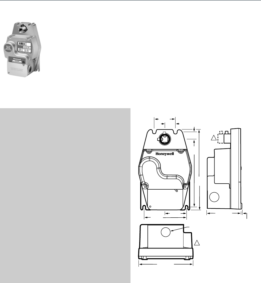
86
ML4125; ML8125
The ML8125 Fast-Acting, Two-
Position Actuators are spring return
direct coupled actuators (DCA)
with an integral junction box for
on/off damper control.
SPECIFICATIONS
Actuator Type ....................................... Damper
Rotational Stroke .................................. 95 ±3 degrees
Fail Safe Mode ..................................... Spring Return
Rated Torque ........................................ 100 lb-in. (11.3 Nm)
External Auxiliary Switches Available .. Yes, 32003532-005
Electrical Connections ......................... Two color-coded leads
Electrical Connection Length ............... 16 in. (406 mm)
Environmental Rating ........................... NEMA1
Frequency ............................................ 60 Hz
Mounting .............................................. Direct Coupled
Maximum Noise Rating,
Holding (dBA @ 1m) ............................ 20 (no audible noise)
Maximum Noise Rating,
Driving (dBA @ 1m) .............................. 65
Timing, Nominal Driving at 60 Hz ........ 20 sec
Power Consumption, Driving ............... 0.18 A/18 W or 18 VA
Compatible Damper Shafts .................. 3/8 to 1/2 in. square or round
(10 to 13 square/round)
Shaft Adapter Type .............................. Aluminum Hub, two set screws
Supply Voltage ..................................... 120 Vac +10%, -15%
Materials ............................................... Aluminum housing
Operating Humidity Range (% RH) ...... 5 to 95% RH, non-condensing
Ambient Temperature Range ............... -40 F to 130 F (-40 C to 55 C)
Storage Temperature Range ................ -40 F to 140 F (-40 C to 60 C)
Weight .................................................. 6 lb (2.72 kg)
Includes ............................................... Ground Screw
Comments ............................................ Integral junction box with three
7/8 in. conduit openings
(fittings not included)
APPROVALS
Underwriters Laboratories, Inc. ........... UL873, Plenum Rated
Canadian Underwriters
Laboratories, Inc. ................................. cUL C22.2 No. 24-93
FEATURES
• Integral spring return.
• -40 C to 130 F (-40 C to 54 C) operating temperature range.
• No audible noise during holding.
• Electronic circuitry provides efficient operation while
eliminating the need for limit switches.
• Ninety-five degree angle of rotation.
• Die-cast aluminum housing. Housing design allows flush
mounting to damper.
• Integral junction box with three conduit openings eliminates
need for separate wiring box.
• Direct mounting to 3/8 or 1/2 in. round or square shaft.
• Not intended for smoke control systems.
DIMENSIONS DIAGRAMS
2 (51)
1 (25)
5/8
(17)
6 3/8
(161)
7 1/2
(192)
4 (102)
7/8 (22)
5 1/8 (129)
2 (51) 3 5/16 (84)
1/16 (2)
M17538
ML4135/ML8135 HAVE SHORTER
HUB WITH TWO SET SCREWS.
ML4125/ML8125 HAVE LONGER
HUB WITH FOUR SET SCREWS.
1
1
Spring Return Direct Coupled Actuator
ML4125; ML8125
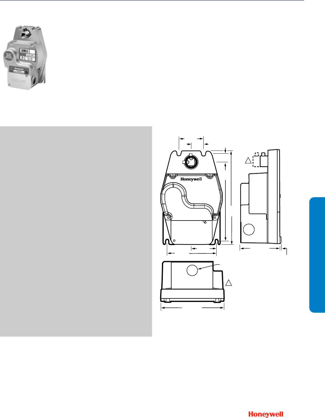
87
ML4135; ML8135
The ML8135 Fast-Acting, Two-
Position Actuators are spring return
direct coupled actuators (DCA)
with an integral junction box for on/
off damper control.
SPECIFICATIONS
Actuator Type ....................................... Damper
Rotational Stroke .................................. 95 ±3 degrees
Fail Safe Mode ..................................... Spring Return
Rated Torque ........................................ 40 lb-in. (4.5 Nm)
External Auxiliary Switches Available .. Yes, 32003532-005
Electrical Connections ......................... Two color-coded leads
Electrical Connection Length ............... 16 in. (406 mm)
Environmental Rating ........................... NEMA1
Frequency ............................................ 60 Hz
Mounting .............................................. Direct Coupled
Maximum Noise Rating,
Holding (dBA @ 1m) ............................ 20 (no audible noise)
Maximum Noise Rating,
Driving (dBA @ 1m) .............................. 65
Timing, Nominal Driving at 60 Hz ......... 25 sec
Power Consumption, Driving ................ 0.12A/18.6W, 0.16A/15W or
15.6VA
Compatible Damper Shafts .................. 3/8 to 1/2 in. square or round
(10 to 13 square/round)
Shaft Adapter Type .............................. Aluminum Hub, four set screws
Supply Voltage ..................................... 120 Vac ±10%
Materials ............................................... Aluminum housing
Operating Humidity Range (% RH) ...... 5 to 95% RH, non-condensing
Ambient Temperature Range ............... -40 F to 130 F (-18 C to 55 C)
Storage Temperature Range ................ -40 F to 140 F (-18 C to 60 C)
Weight .................................................. 6 lb (2.72 kg)
Includes ................................................ Mounting bracket, ground
screw
Comments ............................................ Integral junction box with three
7/8 in. conduit openings
(fittings not included)
APPROVALS
Underwriters Laboratories, Inc. ............ UL873, Plenum Rated
Canadian Underwriters
Laboratories, Inc. ................................. cUL C22.2 No. 24-93
FEATURES
• Integral spring return.
• -40 C to 130 F (-40 C to 54 C) operating temperature range.
• No audible noise during holding.
• Electronic circuitry provides efficient operation while
eliminating the need for limit switches.
• Ninety-five degree angle of rotation.
• Die-cast aluminum housing. Housing design allows flush
mounting to damper.
• Integral junction box with three conduit openings eliminates
need for separate wiring box.
• Direct mounting to 3/8 or 1/2 in. round or square shaft.
• Not intended for smoke control systems.
DIMENSIONS DIAGRAMS
2 (51)
1 (25)
5/8
(17)
6 3/8
(161)
7 1/2
(192)
4 (102)
7/8 (22)
5 1/8 (129)
2 (51) 3 5/16 (84)
1/16 (2)
M17538
ML4135/ML8135 HAVE SHORTER
HUB WITH TWO SET SCREWS.
ML4125/ML8125 HAVE LONGER
HUB WITH FOUR SET SCREWS.
1
1
Spring Return Direct Coupled Actuator
ML4135; ML8135
SUBMITTAL SHEETS
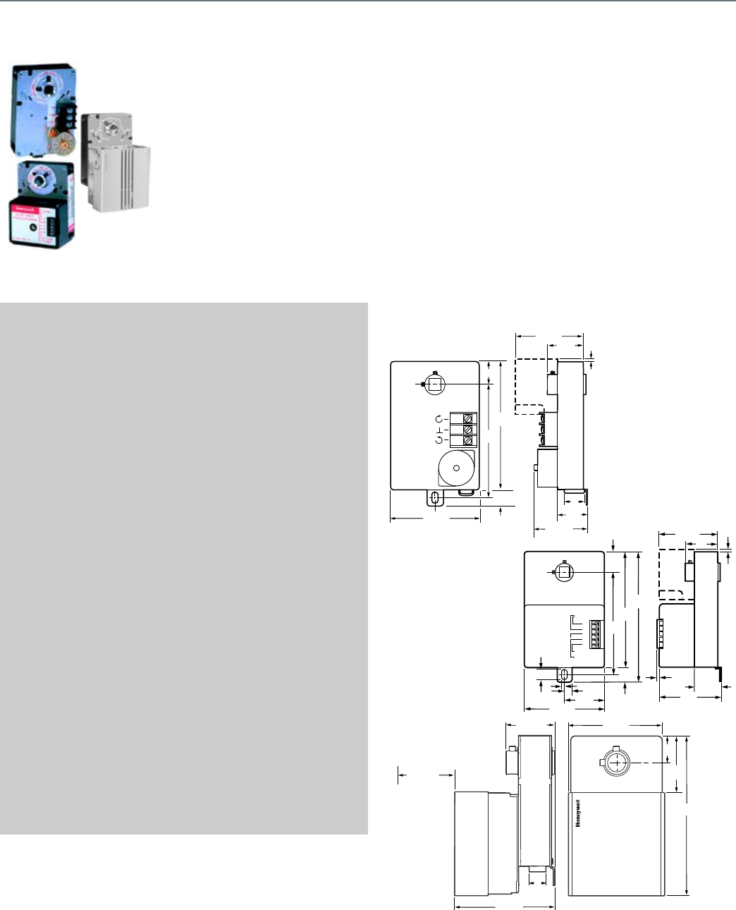
88
ML6161; ML7161
Used to control dampers in
applications such as variable air
volume (VAV) terminal units and for
mounting on ball valves; suitable for
use with SPDT or floating
thermostats or building automation
controls.
SPECIFICATIONS
Actuator Type ....................................... Damper
Rotational Stroke .................................. 90 degrees
Fail Safe Mode ..................................... Non-Spring Return
Rated Torque ........................................ 35 lb-in. (4 Nm)
External Auxiliary Switches Available .. Yes, 201052B
Electrical Connections ......................... Screw terminals
Environmental Rating ........................... NEMA1
Feedback ............................................. With accessory
Frequency ............................................ 50 Hz, 60 Hz
Manual operation ................................. Declutch mechanism
Mounting .............................................. Direct Coupled
Maximum Noise Rating,
Driving (dBA @ 1m) .............................. 45
Timing, Nominal Driving at 60 Hz ........ 90 sec., 180 sec. or 420 sec.
Power Consumption, Driving ............... 1.8 VA or 5.4 VA
Rotation to Open .................................. By wiring
Rotational Stroke Adjustment ............... Mechanically limited at 45 or
60 degrees in cw or ccw
directions
Compatible Damper Shafts .................. 3/8 to 1/2 in. square or round
(10 to 13 square/round)
Shaft Adapter Type .............................. Aluminum Hub, two set screws
Supply Voltage ..................................... 24 Vac ±20%
Materials ............................................... Steel plate and Plenum rated
plastic
Operating Humidity Range (% RH) ...... 5 to 95% RH, non-condensing
Ambient Temperature Range ............... 20 F to 125 F (-18 C to 50 C)
Storage Temperature Range ................ 20 F to 130 F (-18 C to 54 C)
Weight .................................................. 1.5 lb (0.68 kg)
Includes ............................................... 4074ENY Bag Assembly
APPROVALS
CE ........................................................ 89/336/ECC, 73/23/EEC
C-Tick ................................................... N314
Underwriters Laboratories, Inc. ........... UL873, Plenum Rated
Canadian Underwriters
Laboratories, Inc. ................................. cUL C22.2 No. 24-93
FEATURES
• Control for air damper applications with up to 10 sq.ft.
assuming 3.5 lb-in. per sq.ft. of damper area, velocity
independent.
• Superior A/C synchronous sub-motor for consistent timing
and actuator longevity.
• Eliminate need for limit switches or mechanical stops by
providing magnetic coupling.
• All models include manual declutch lever, and bag
assembly with two minimum position setscrews.
• Mount directly on 3/8 in. or 1/2 in. square or round damper
shaft.
• Selectable 45, 60, and 90 degree stroke in either clockwise
or counterclockwise direction.
DIMENSIONS DIAGRAMS
1
(25)
M22990
OPTIONAL
AUXILIARY
SWITCH
T1
T2
-
+
+
24 Vac
2-10 Vdc
4-20 mA
4-7/8
(123)
4-1/4
(108)
5-9/16
(141)
11/16
(18) 1/8
(3)
5/16 (8)
1-11/16
(43)
3-3/8 (86)
1/8
(3)
15/32 (12)
1-5/16
(33)
3 (76)
2-7/8 (73)
1-11/16
(42)
1/8
(3)
1 (25)
M18016
CW
COM
CCW
OPTIONAL
AUXILIARY
SWITCH
11/16
(18)
3-3/8 (86)
4-1/4
(108)
4-7/8
(123)
2-7/8 (73)
1-11/16
(42)
1/8
(3)
1-5/16
(33)
7/8
(22)
2-1/2 (64)
M18018
5-7/8
(149)
1-13/16
(46)
1
(25)
3-5/8 (92)
1-13/16 (46)
3 IN. (76 MM)
MINIMUM SPACING
REQUIRED
FOR REMOVING
CONDUIT COVER
3-3/4 (95)
7/8
(22)
Non-Spring Return Direct Coupled Actuator
ML6161; ML7161
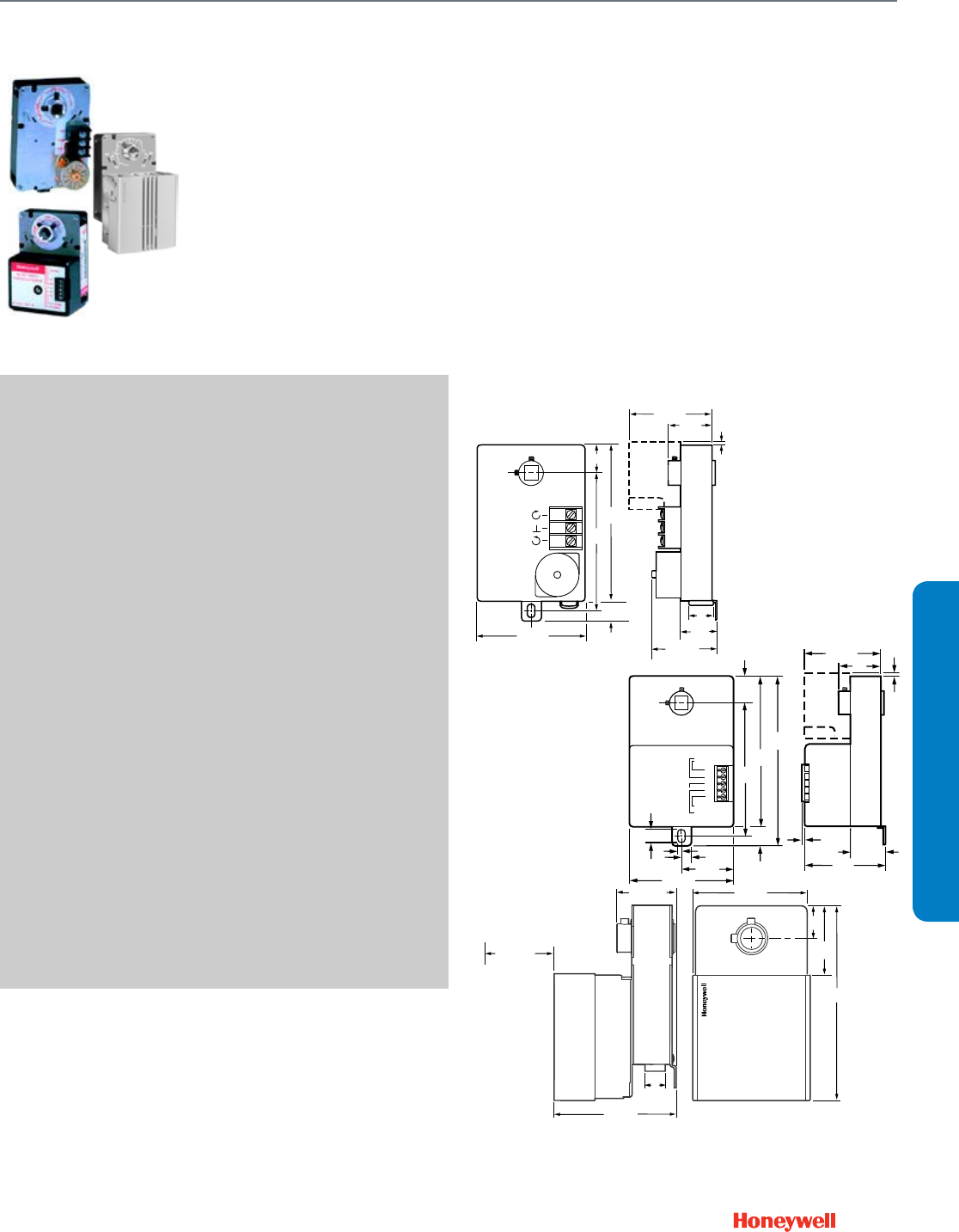
89
Non-Spring Return Direct Coupled Actuator
ML6174; ML7174
SUBMITTAL SHEETS
ML6174; ML7174
Used to control dampers in
applications such as variable air
volume (VAV) terminal units and for
mounting on ball valves; suitable
for use with SPDT or floating
thermostats or building automation
controls.
SPECIFICATIONS
Actuator Type ....................................... Damper
Rotational Stroke .................................. 90 degrees
Fail Safe Mode ..................................... Non-Spring Return
Rated Torque ........................................ 70 lb-in. (8 Nm)
External Auxiliary Switches Available .. Yes, 201052B
Electrical Connections ......................... Screw terminals
Environmental Rating ........................... NEMA1
Feedback ............................................. With accessory
Frequency ............................................ 50 Hz, 60 Hz
Manual operation ................................. Declutch mechanism
Mounting .............................................. Direct Coupled
Maximum Noise Rating,
Driving (dBA @ 1m) .............................. 45
Timing, Nominal Driving at 60 Hz ......... 90 sec., 180 sec. or 420 sec.
Power Consumption, Driving ................ 2.4 VA or 5.4 VA
Rotation to Open .................................. By wiring
Rotational Stroke Adjustment ............... Mechanically limited at 45 or
60 degrees in cw or ccw
directions
Compatible Damper Shafts .................. 3/8 to 1/2 in. square or round
(10 to 13 square/round)
Shaft Adapter Type .............................. Aluminum Hub, two set screws
Supply Voltage ..................................... 24 Vac ±20%
Materials ............................................... Steel plate and Plenum rated
plastic
Operating Humidity Range (% RH) ...... 5 to 95% RH, non-condensing
Ambient Temperature Range ............... 20 F to 125 F (-18 C to 50 C)
Storage Temperature Range ................ 20 F to 130 F (-18 C to 54 C)
Weight .................................................. 1.5 lb (0.68 kg)
Includes ................................................ 4074ENY Bag Assembly
APPROVALS
Underwriters Laboratories, Inc. ............ UL873, Plenum Rated
Canadian Underwriters
Laboratories, Inc. ................................. cUL C22.2 No. 24-93
FEATURES
• Control for air damper applications with up to 20 sq.ft.
assuming 3.5 lb-in. per sq.ft. of damper area, velocity
independent.
• Magnetic coupling eliminates the need for mechanical
stops or limit switch adjustments by limiting stall torque to
130 lb-in. maximum.
• Mount directly on 3/8 to 1/2 in. round and square damper
shafts. All models include manual declutch lever for ease of
mounting, and bag assembly with two minimum position
setscrews. 90 second timing models are suitable for use
with pressure independent VAV systems.
• Selectable 45, 60, and 90 degree stroke in either clockwise
or counterclockwise direction.
DIMENSIONS DIAGRAMS
1
(25)
M22990
OPTIONAL
AUXILIARY
SWITCH
T1
T2
-
+
+
24 Vac
2-10 Vdc
4-20 mA
4-7/8
(123)
4-1/4
(108)
5-9/16
(141)
11/16
(18) 1/8
(3)
5/16 (8)
1-11/16
(43)
3-3/8 (86)
1/8
(3)
15/32 (12)
1-5/16
(33)
3 (76)
2-7/8 (73)
1-11/16
(42)
1/8
(3)
1 (25)
M18016
CW
COM
CCW
OPTIONAL
AUXILIARY
SWITCH
11/16
(18)
3-3/8 (86)
4-1/4
(108)
4-7/8
(123)
2-7/8 (73)
1-11/16
(42)
1/8
(3)
1-5/16
(33)
7/8
(22)
2-1/2 (64)
M18018
5-7/8
(149)
1-13/16
(46)
1
(25)
3-5/8 (92)
1-13/16 (46)
3 IN. (76 MM)
MINIMUM SPACING
REQUIRED
FOR REMOVING
CONDUIT COVER
3-3/4 (95)
7/8
(22)
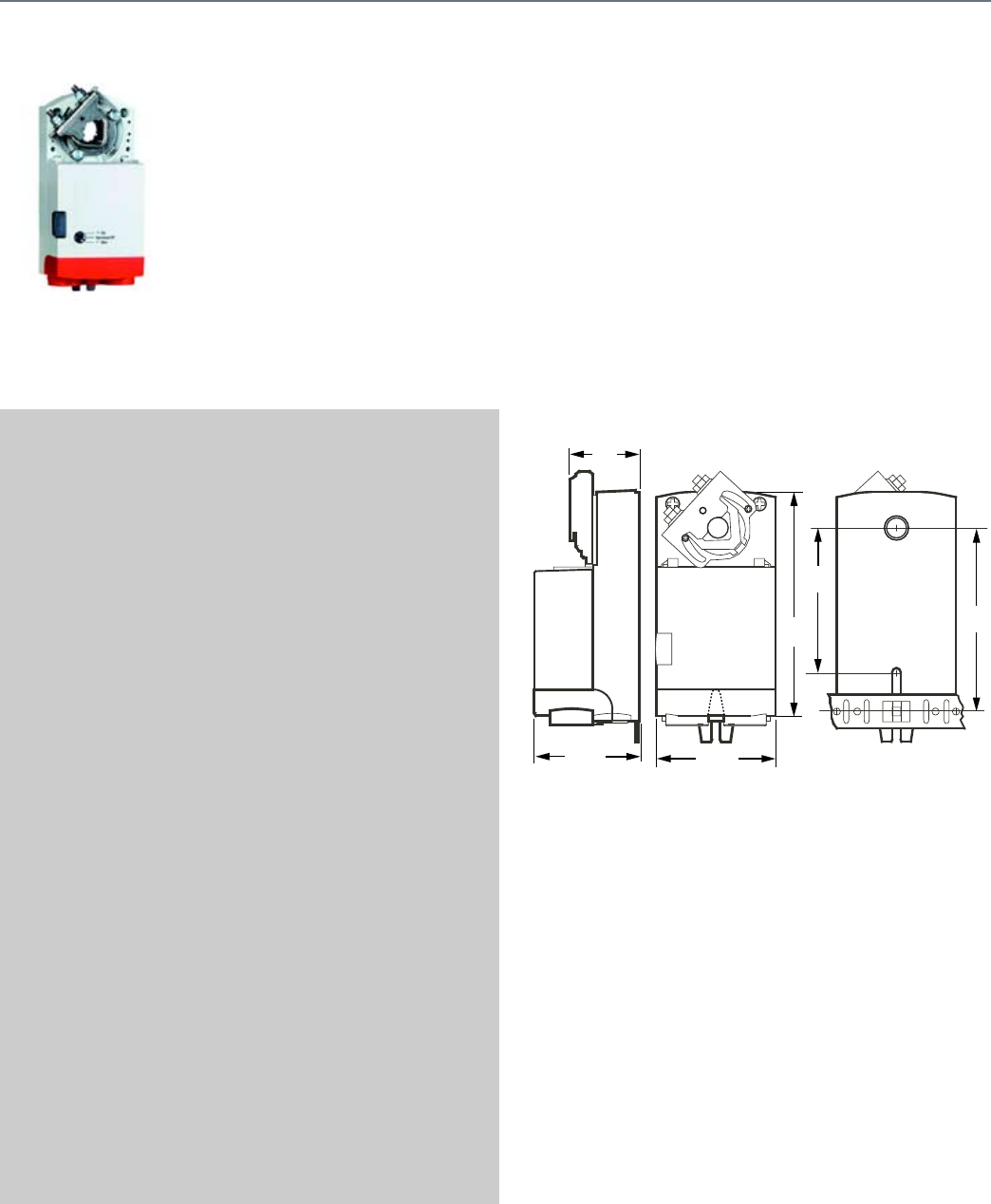
90
N05 Series (MN6105; MN7505)
This non-spring return direct-
coupled damper actuator provides
modulating and floating/2-position
control for: air dampers, VAV units,
air handlers, ventilation flaps,
louvers, and reliable control for air
damper applications with up to
10 sq. ft./ 44lb.-in. (5 Nm) and
20 sq. ft./88 lb.-in. (10 Nm) (seal-
less damper blades; air friction-
dependent).
SPECIFICATIONS
Actuator Type ....................................... Damper, Valve
Rotational Stroke .................................. 95 ±3 degrees
Fail Safe Mode ..................................... Non-Spring Return
Rated Torque ........................................ 44 lb-in. (5 Nm)
External Auxiliary Switches Available .. Yes, SSW2
Electrical Connections ......................... Enclosed screw terminal strip
(22 to 14 AWG)
Environmental Rating ........................... NEMA2
Frequency ............................................ 50 Hz, 60 Hz
Manual operation ................................. Declutch mechanism
Mounting .............................................. Direct Coupled
Maximum Noise Rating,
Driving (dBA @ 1m) .............................. 35
Timing, Nominal Driving at 60 Hz ........ 95 sec.
Power Consumption, Driving ............... 5 VA
Rotation to Open .................................. By switch
Rotational Stroke Adjustment ............... Dual Integral Adj. Stops
(3 degree increments)
Compatible Damper Shafts .................. 1/4 to 1/2 in. square; 3/8 to
5/8 in. round
(6-13 mm square; 8-16 mm
round)
Shaft Adapter Type .............................. U-bolt clamp
Supply Voltage ..................................... 24 Vac +20%, -15%, 24 Vdc
Materials ............................................... Plenum rated plastic housing
Ingress Protection Rating ..................... IP54
Operating Humidity Range (% RH) ...... 5 to 95% RH, non-condensing
Ambient Temperature Range ............... -5 F to 140 F (-20 C to 60 C)
Storage Temperature Range ................ -22 F to 176 F (-30 C to 80 C)
Weight .................................................. 1 lb (0.45 kg)
Includes ............................................... Mounting bracket, screws,
shaft adapter, water-tight
strain-relief cable fittings
Comments ............................................ Integral 1/2 in. NPSM conduit
connection.
APPROVALS
CE ........................................................ 89/336/ECC, 73/23/EEC
C-Tick ................................................... N314
Underwriters Laboratories, Inc. ........... UL873, Plenum Rated
Canadian Underwriters
Laboratories, Inc. ................................. cUL C22.2 No. 24-93
FEATURES
• Declutch for manual adjustment
• Adjustable mechanical end limits
• Removable access cover for direct wiring
• Mountable in any orientation
• Function selection switch for selecting modulating or
floating/2-position control
DIMENSIONS DIAGRAMS
M23103A
5-9/32
(134)
1-5/8
(41)
2-7/16
(62)
2-19/32
(66)
4-1/4
(108)
3-11/32
(85)
Non-Spring Return Direct Coupled Actuator
N05 Series (MN6105; MN7505)
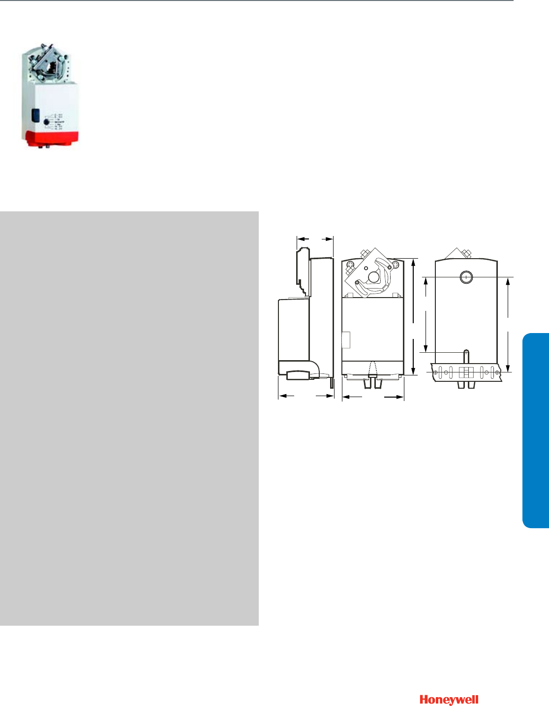
91
Non-Spring Return Direct Coupled Actuator
N10 Series (MN6110; MN7510)
SUBMITTAL SHEETS
N10 Series (MN6110; MN7510)
This non-spring return direct-
coupled damper actuator provides
modulating and floating/2-position
control for air dampers, VAV units,
air handlers, ventilation flaps,
louvers, and reliable control for air
damper applications with up to 20
sq ft/88 lb-in. (10 Nm) (seal-less
damper blades; air friction-
dependent).
SPECIFICATIONS
Actuator Type ....................................... Damper; Valve
Rotational Stroke .................................. 95 ±3 degrees
Fail Safe Mode ..................................... Non-Spring Return
Rated Torque ........................................ 88 lb-in. (10 Nm)
External Auxiliary Switches Available .. Yes, SSW2
Electrical Connections ......................... Enclosed screw terminal strip
(22 to 14 AWG)
Environmental Rating ........................... NEMA2
Frequency ............................................ 50 Hz, 60 Hz
Manual operation ................................. Declutch mechanism
Mounting .............................................. Direct Coupled
Maximum Noise Rating,
Driving (dBA @ 1m) .............................. 35
Timing, Nominal Driving at 60 Hz ......... 95 sec.
Power Consumption, Driving ................ 5 VA
Rotation to Open .................................. By switch
Rotational Stroke Adjustment ............... Dual Integral Adj. Stops
(3 degree increments)
Compatible Damper Shafts .................. 1/4 to 1/2 in. square; 3/8 to
5/8 in. round
(6-13 mm square; 8-16 mm
round)
Shaft Adapter Type .............................. U-bolt clamp
Supply Voltage ..................................... 24 Vac +20%, -15%, 24 Vdc
Materials ............................................... Plenum rated plastic housing
Ingress Protection Rating ..................... IP54
Operating Humidity Range (% RH) ...... 5 to 95% RH, non-condensing
Ambient Temperature Range ............... -5 F to 140 F (-20 C to 60 C)
Storage Temperature Range ................ -22 F to 176 F (-30 C to 80 C)
Weight .................................................. 1 lb (0.45 kg)
Includes ................................................ Mounting bracket, screws,
shaft adapter, water-tight
strain-relief cable fittings
Comments ............................................ Integral 1/2 in. NPSM conduit
connection.
APPROVALS
CE ......................................................... 89/336/ECC, 73/23/EEC
C-Tick ................................................... N314
Underwriters Laboratories, Inc. ............ UL873, Plenum Rated
Canadian Underwriters
Laboratories, Inc. ................................. cUL C22.2 No. 24-93
FEATURES
• Declutch for manual adjustment
• Adjustable mechanical end limits
• Removable access cover for direct wiring
• Mountable in any orientation
• Function selection switch for selecting modulating or
floating/2-position control
DIMENSIONS DIAGRAMS
M23103A
5-9/32
(134)
1-5/8
(41)
2-7/16
(62)
2-19/32
(66)
4-1/4
(108)
3-11/32
(85)
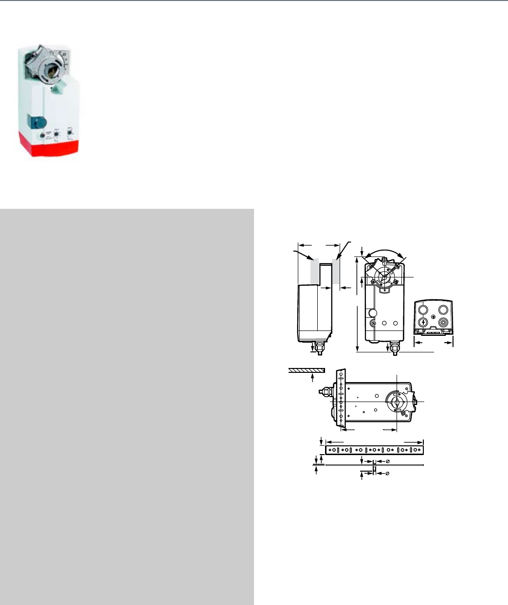
92
N20 Series (MN6120; MN7220)
These direct-coupled damper
actuators provide adjustable
modulating control for: air
dampers, VAV units, air handling
units, ventilation flaps, louvers, and
reliable control for air damper
applications with up to 4.6 m2/50
sq ft (seal-less dampers; air
friction-dependent).
SPECIFICATIONS
Actuator Type ....................................... Damper; Valve
Rotational Stroke .................................. 95 ±3 degrees
Fail Safe Mode ..................................... Non-Spring Return
Rated Torque ........................................ 175 lb-in. (20 Nm)
External Auxiliary Switches Available .. Yes, SW2-US
Electrical Connections ......................... Enclosed screw terminal strip
(22 to 14 AWG)
Environmental Rating ........................... NEMA2; IP54
Frequency ............................................ 50 Hz, 60 Hz
Manual operation ................................. Declutch mechanism
Mounting .............................................. Direct Coupled
Maximum Noise Rating,
Driving (dBA @ 1m) .............................. 40
Timing, Nominal Driving at 60 Hz ........ 95 sec.
Power Consumption, Driving ............... 6 VA/6 W
Rotation to Open .................................. By switch
Rotational Stroke Adjustment ............... Dual Integral Adj. Stops
(3 degree increments)
Compatible Damper Shafts .................. 3/8 to 1.06 round or 3/8 to
11/16 square
(10 to 27 round or 10 to 18
square)
Shaft Adapter Type .............................. Self-centering clamping
Supply Voltage ..................................... 24 Vac ±15%
Materials ............................................... Plenum rated plastic housing
Operating Humidity Range (% RH) ...... 5 to 95% RH, non-condensing
Ambient Temperature Range ............... -5 F to 140 F (-20 C to 60 C)
Storage Temperature Range ................ -40 F to 175 F (-40 C to 80 C)
Weight .................................................. 3.2 lb (1.45 kg)
Includes ............................................... Mounting bracket, self-
centering shaft adapter
Comments ............................................ Integral 1/2 in. NPSM conduit
connection.
APPROVALS
CE ........................................................ 89/336/ECC, 73/23/EEC
C-Tick ................................................... N314
Underwriters Laboratories, Inc. ........... UL873, Plenum Rated
Canadian Underwriters
Laboratories, Inc. ................................. cUL C22.2 No. 24-93
FEATURES
• Control for air damper applications with up to 50 sq ft
assuming 3.5 lb-in. per sq ft of damper area, velocity
independent.
• Patented self-centering shaft adapter.
• Access cover to facilitate connectivity.
• Declutch for manual adjustment.
• Mechanical end limits.
• Field-installable auxiliary switches.
• Rotation direction selectable by switch.
• Mountable in any orientation (no IP54 if upside down).
• Mechanical position indicator.
• CE approved. UL approved.
DIMENSIONS DIAGRAMS
M18923
3-15/16
(100)
SHAFT
A
DAPTER
SHAFT
ADAPTER
(REVERSED)
1-3/16
(20.6)
MIN 2-3/8 (60)
ANTI-ROTATION
BRACKET
9-1/16[+/-1/64] (230 [+/-.5])
25/32 (20)
9/32 (7)
25/128 [+0.002-0.004]
(5) [+0.05-0.10]
1/2 (13)
5/64 (2)
95°
1-7/8 (48)
8-25/32
(223)
5-3/16 (132)
3-5/8 (92)
Non-Spring Return Direct Coupled Actuator
N20 Series (MN6120; MN7220)
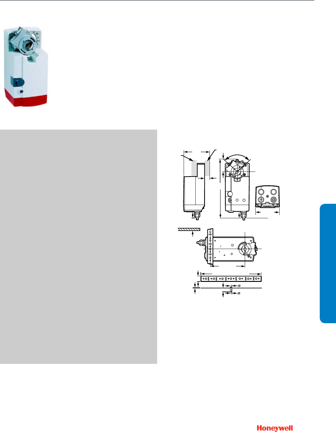
93
Non-Spring Return Direct Coupled Actuator
N34 Series (MN6134; MN7234)
SUBMITTAL SHEETS
N34 Series (MN6134; MN7234)
These direct coupled damper
actuators provide adjustable
modulating control for air dampers,
VAV units, air handling units,
ventilation flaps, louvers, and reliable
control for air damper applications
with up to 7.9 m2/85 sq ft (seal-less
dampers; air friction-dependent).
SPECIFICATIONS
Actuator Type ....................................... Damper; Valve
Rotational Stroke .................................. 95 ±3 degrees
Fail Safe Mode ..................................... Non-Spring Return
Rated Torque ........................................ 300 lb-in. (34 Nm)
External Auxiliary Switches Available .. Yes, SW2-US
Electrical Connections ......................... Enclosed screw terminal strip
(22 to 14 AWG)
Environmental Rating ........................... NEMA2
Frequency ............................................ 50 Hz; 60 Hz
Manual operation ................................. Declutch mechanism
Mounting .............................................. Direct Coupled
Maximum Noise Rating,
Driving (dBA @ 1m) .............................. 40
Timing, Nominal Driving at 60 Hz ......... 95 sec.
Power Consumption, Driving ................ 8 VA/6W or 9 VA/9W
Rotation to Open .................................. By switch
Compatible Damper Shafts .................. 3/8 to 1.06 round or 3/8 to
11/16 square
(10 to 27 round or 10 to 18
square)
Shaft Adapter Type .............................. Self-centering clamping
Supply Voltage ..................................... 24 Vac ±15%, 24 Vdc
Materials ............................................... Plenum rated plastic housing
Operating Humidity Range (% RH) ...... 5 to 95% RH, non-condensing
Ambient Temperature Range ............... -5 F to 140 F (-20 C to 60 C)
Storage Temperature Range ................ -40 F to 175 F (-40 C to 80 C)
Weight .................................................. 3.2 lb (1.45 kg)
Includes ................................................ Mounting bracket, self-
centering shaft adapter
Comments ............................................ Integral 1/2 in. NPSM conduit
connection.
APPROVALS
CE ......................................................... 89/336/ECC, 73/23/EEC
C-Tick ................................................... N314
Underwriters Laboratories, Inc. ............ UL873, Plenum Rated
Canadian Underwriters
Laboratories, Inc. ................................. cUL C22.2 No. 24-93
FEATURES
• Control for air damper applications with up to 85 sq ft
assuming 3.5 lb-in. per sq ft of damper area, velocity
independent.
• Patented self-centering shaft adapter.
• Access cover to facilitate connectivity.
• Declutch for manual adjustment.
• Mechanical end limits.
• Field-installable auxiliary switches.
• Rotation direction selectable by switch.
• Mountable in any orientation (no IP54 if upside down).
• Mechanical position indicator.
• CE approved. UL approved.
DIMENSIONS DIAGRAMS
M18923
3-15/16
(100)
SHAFT
A
DAPTER
SHAFT
ADAPTER
(REVERSED)
1-3/16
(20.6)
MIN 2-3/8 (60)
ANTI-ROTATION
BRACKET
9-1/16[+/-1/64] (230 [+/-.5])
25/32 (20)
9/32 (7)
25/128 [+0.002-0.004]
(5) [+0.05-0.10]
1/2 (13)
5/64 (2)
95°
1-7/8 (48)
8-25/32
(223)
5-3/16 (132)
3-5/8 (92)
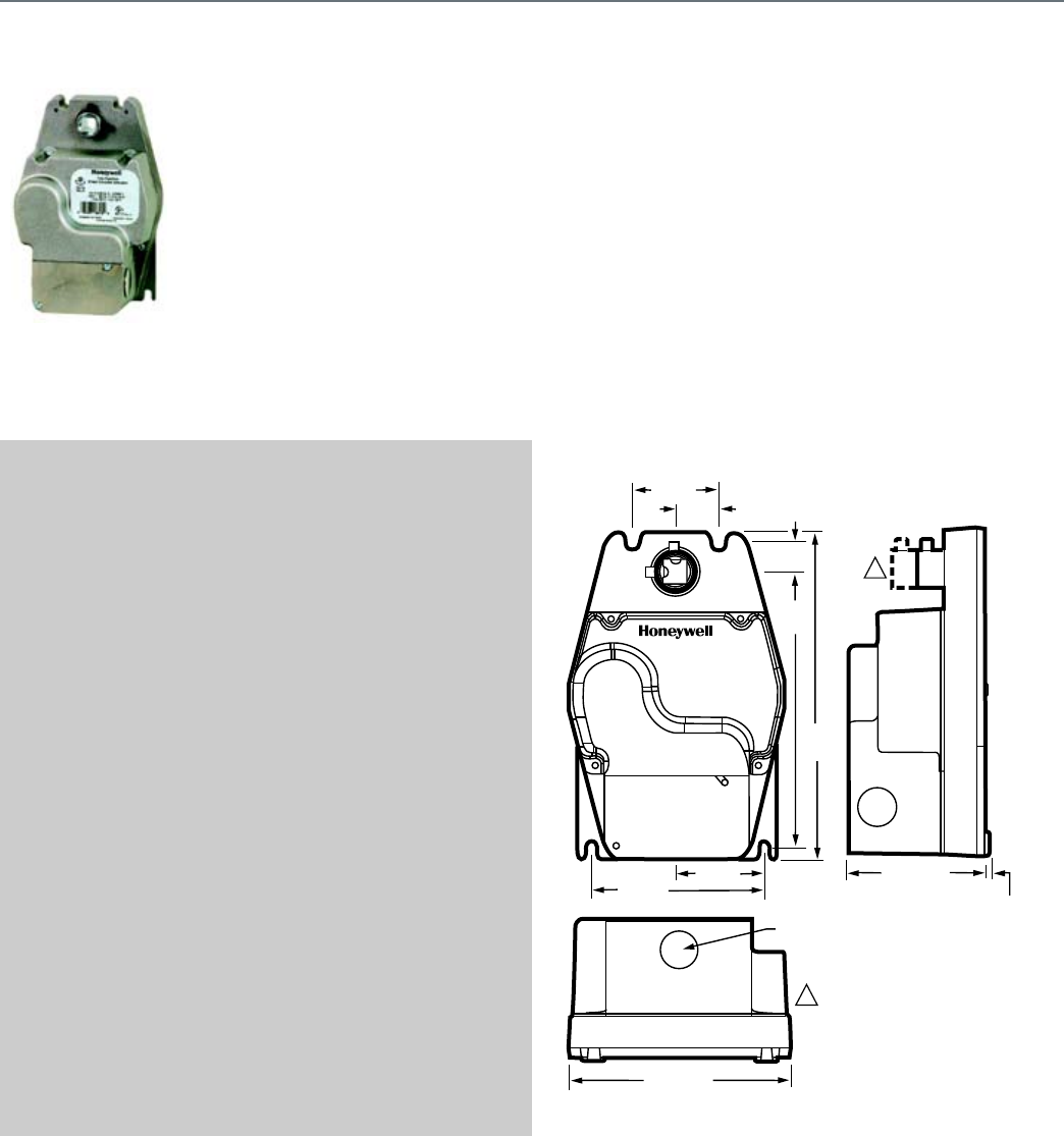
94
ML4115; ML8115
Spring return direct coupled
actuators (DCA) for on/off damper
control with an integral junction box.
The actuator accepts an on/off
signal from a single-pole, single-
throw (SPST) controller. They are
designed to operate reliably in
smoke control systems requiring
Underwriter's Laboratories Inc.
UL555S ratings up to 350 F.
SPECIFICATIONS
Actuator Type ....................................... Damper
Rotational Stroke .................................. 95 ±3 degrees
Fail Safe Mode ..................................... Spring Return
Rated Torque ........................................ 30 lb-in. (3.4 Nm)
Maximum Stall Torque .......................... 150 lb-in. (17 Nm)
Minimum Driving Torque at 350 F ........ 30 lb-in. (3.4 Nm)
Spring Return Torque ........................... 30 lb-in. (3.4 Nm)
External Auxiliary Switches Available .. Yes, 32003532-005
Electrical Connections ......................... Two color-coded leads
Electrical Connection Length ............... 16 in. (406 mm)
Environmental Rating ........................... NEMA1
Frequency ............................................ 60 Hz
Mounting .............................................. Direct Coupled
Maximum Noise Rating,
Holding (dBA @ 1m) ............................ 20 (no audible noise)
Maximum Noise Rating,
Driving (dBA @ 1m) .............................. 65
Compatible Damper Shafts .................. 3/8 to 1/2 in. square or round
(10 to 13 square/round)
Shaft Adapter Type .............................. Aluminum Hub, two set screws
Supply Voltage ..................................... 120 Vac ±10%
Materials ............................................... Aluminum housing
Operating Humidity Range (% RH) ...... 5 to 95% RH, non-condensing
Ambient Temperature Range ............... 0 F to +30 F (-18 C to 55 C)
Storage Temperature Range ................ -40 F to 140 F (-40 C to 60 C)
Weight .................................................. 6 lb (2.72 kg)
Includes ............................................... Ground Screw
Comments ............................................ Integral junction box with three
7/8 in. conduit openings
(fittings not included)
APPROVALS
Underwriters Laboratories, Inc. ........... UL873, Plenum Rated
Canadian Underwriters Laboratories, Inc. cUL C22.2 No. 24-93
FEATURES
• Integral spring return.
• No audible noise during holding.
• Electronic circuitry provides efficient operation while
eliminating the need for limit switches.
• Ninety-five degree angle of rotation for tight damper
closure.
• Die-cast aluminum housing.
• Housing design allows flush mounting to damper.
• Integral junction box with three conduit openings eliminates
need for separate wiring box.
• Mounts to 3/8 or 1/2 in. round or square shaft.
• High-temperature indicator included.
DIMENSIONS DIAGRAMS
2 (51)
1 (25)
5/8
(17)
6 3/8
(161)
7 1/2
(192)
4 (102)
7/8 (22)
5 1/8 (129)
2 (51) 3 5/16 (84)
1/16 (2)
M13053A
ML4115/ML8115 HAVE SMALLER
HUB WITH TWO SET SCREWS.
ML4105/ML8105 HAVE LONGER
HUB WITH FOUR SET SCREWS.
1
1
Fire And Smoke Actuator
ML4115; ML8115
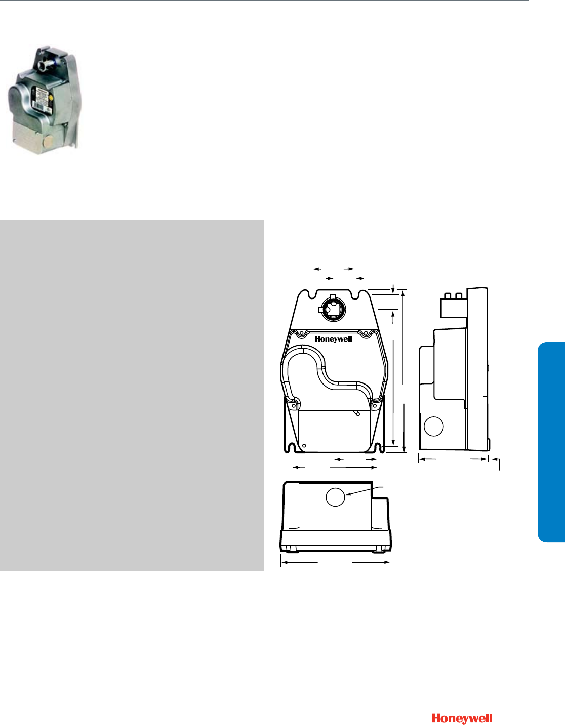
95
Fire And Smoke Actuator
MS4209F; MS4309F; MS4709F; MS4809F; MS8209F; MS8309F
SUBMITTAL SHEETS
MS4209F; MS4309F; MS4709F; MS4809F; MS8209F; MS8309F
Spring return direct coupled
actuators (DCA) for on/off damper
control with an integral junction box.
The actuator accepts an on/off signal
from a single-pole, single-throw
(SPST) controller. They are designed
to operate reliably in smoke control
systems requiring Underwriter's
Laboratories Inc. UL555S ratings up
to 350 F.
SPECIFICATIONS
Actuator Type ....................................... Damper
Rotational Stroke .................................. 95 ±3 degrees
Fail Safe Mode ..................................... Spring Return
Rated Torque ........................................ 80 lb-in. (9 Nm)
Maximum Stall Torque .......................... 240 lb-in. (27 Nm)
Minimum Driving Torque at 350 F ........ 80 lb-in. (9 Nm)
Spring Return Torque ........................... 80 lb-in. (9 Nm)
External Auxiliary Switches Available .. Yes, 32003532-005
Electrical Connections ......................... Two color-coded leads
Electrical Connection Length ............... 16 in. (406 mm)
Environmental Rating ........................... NEMA1
Frequency ............................................ 60 Hz
Mounting .............................................. Direct Coupled
Maximum Noise Rating,
Holding (dBA @ 1m) ............................ 20 (no audible noise)
Maximum Noise Rating,
Driving (dBA @ 1m) .............................. 80
Compatible Damper Shafts .................. 3/8 to 1/2 in. square or round
(10 to 13 square/round)
Shaft Adapter Type .............................. Aluminum Hub, four set screws
Supply Voltage ..................................... 120 Vac +10%, -15%
Materials ............................................... Aluminum housing
Operating Humidity Range (% RH) ...... 5 to 95% RH, non-condensing
Ambient Temperature Range ............... 0 F to 130 F (-18 C to 55 C)
Storage Temperature Range ................ -40 F to 140 F (-40 C to 60 C)
Weight .................................................. 6 lb (2.72 kg)
Comments ............................................ Integral junction box with three
7/8 in. conduit openings
(fittings not included)
APPROVALS
CE ......................................................... 89/336/ECC, 73/23/EEC
C-Tick ................................................... N314
Underwriters Laboratories, Inc. ............ UL873, Plenum Rated
Canadian Underwriters Laboratories, Inc. cUL C22.2 No. 24-93
FEATURES
• Integral spring return ensures level of return torque.
• Fifteen-second spring return timing.
• No special cycling required during long-term holding.
• No audible noise during holding.
• Patent pending design eliminates need for limit switches to
reduce power consumption.
• Models available for 24, 120, and 230 Vac.
• Ninety-five degree angle of rotation for tight damper
closure.
• Actuator holds rated torque at reduced power level.
• Die-cast aluminum housing. Housing design allows flush
mounting to damper.
• Integral junction box with three conduit openings eliminates
need for separate wiring box.
• High-temperature indicator included.
DIMENSIONS DIAGRAM
2 (51)
1 (25)
5/8
(17)
6 3/8
(161)
7 1/2
(192)
4 (102)
7/8 (22)
5 1/8 (129)
2 (51) 3 5/16 (84)
1/16 (2)
M17508
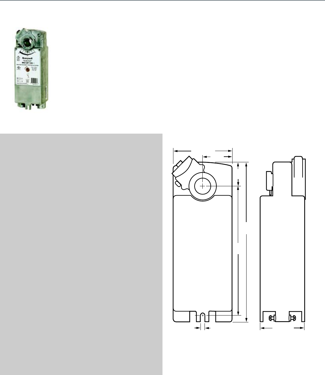
96
MS4120F; MS4620F; MS8120F
Spring return direct coupled
actuators (DCA) for on/off damper
control with an integral junction
box. The actuator accepts an on/off
signal from a single-pole, single-
throw (SPST) controller. They are
designed to operate reliably in
smoke control systems requiring
Underwriter's Laboratories Inc.
UL555S ratings up to 350 F.
SPECIFICATIONS
Actuator Type ....................................... Damper
Rotational Stroke .................................. 95 ±3 degrees
Fail Safe Mode ..................................... Spring Return
Rated Torque ........................................ 175 lb-in. (20 Nm)
Maximum Stall Torque .......................... 425 lb-in. (48 Nm)
Minimum Driving Torque at 350 F ........ 175 lb-in. (20 Nm)
Spring Return Torque ........................... 175 lb-in. (20 Nm)
External Auxiliary Switches Available .. No
Electrical Connections ......................... Teflon-jacketed cable
Electrical Connection Length ............... 40 in. (1 m)
Environmental Rating ........................... NEMA2
Frequency ............................................ 60 Hz
Manual operation ................................. Manual crank
Mounting .............................................. Direct Coupled
Maximum Noise Rating,
Holding (dBA @ 1m) ............................ 20 (no audible noise)
Maximum Noise Rating,
Driving (dBA @ 1m) .............................. 70
Compatible Damper Shafts .................. 3/8 to 1.06 round or 3/8 to
11/16 square (10 to 27 round
or 10 to 18 square)
Shaft Adapter Type .............................. Self-centering clamping
Supply Voltage ..................................... 120 Vac ±10%
Materials ............................................... Aluminum housing
Ingress Protection Rating ..................... IP54
Operating Humidity Range (% RH) ...... 5 to 95% RH, non-condensing
Ambient Temperature Range ............... -40 F to 130 F (-40 C to 55 C)
Storage Temperature Range ................ -40 F to 140 F (-40 C to 60) C
Weight .................................................. 8 lb (3.63 kg)
Includes ............................................... Self-centering shaft adapter,
3mm crank
Comments ............................................ Two integral 3/8 in. flexible
conduit connections
APPROVALS
CE ........................................................ 89/336/ECC, 73/23/EEC
C-Tick ................................................... N314
Underwriters Laboratories, Inc. ........... UL873, Plenum Rated
Canadian Underwriters Laboratories, Inc. cUL C22.2 No. 24-93
FEATURES
• Brush DC sub-motor with electronic stall protection for
2-position models
• Self-centering shaft adapter (shaft coupling) for wide range
of shaft sizes
• Models available for use with two-position, single pole
single throw (SPST), line- (Series 40) or low- (Series 80)
voltage controls
• Metal housing with built-in mechanical end limits
• Spring return direction field-selectable
• Shaft position indicator and scale
• Manual winding capability with locking function
• UL (cUL) listed and CE compliant
• All models are plenum-rated per UL873
DIMENSIONS DIAGRAM
10-11/16
(271)
1-9/16
(40)
8-5/8
(220)
2 (50)
3-15/16 (100)
2-15/16 (75)1/4 (6)
M20051
Fire And Smoke Actuator
MS4120F; MS4620F; MS8120F
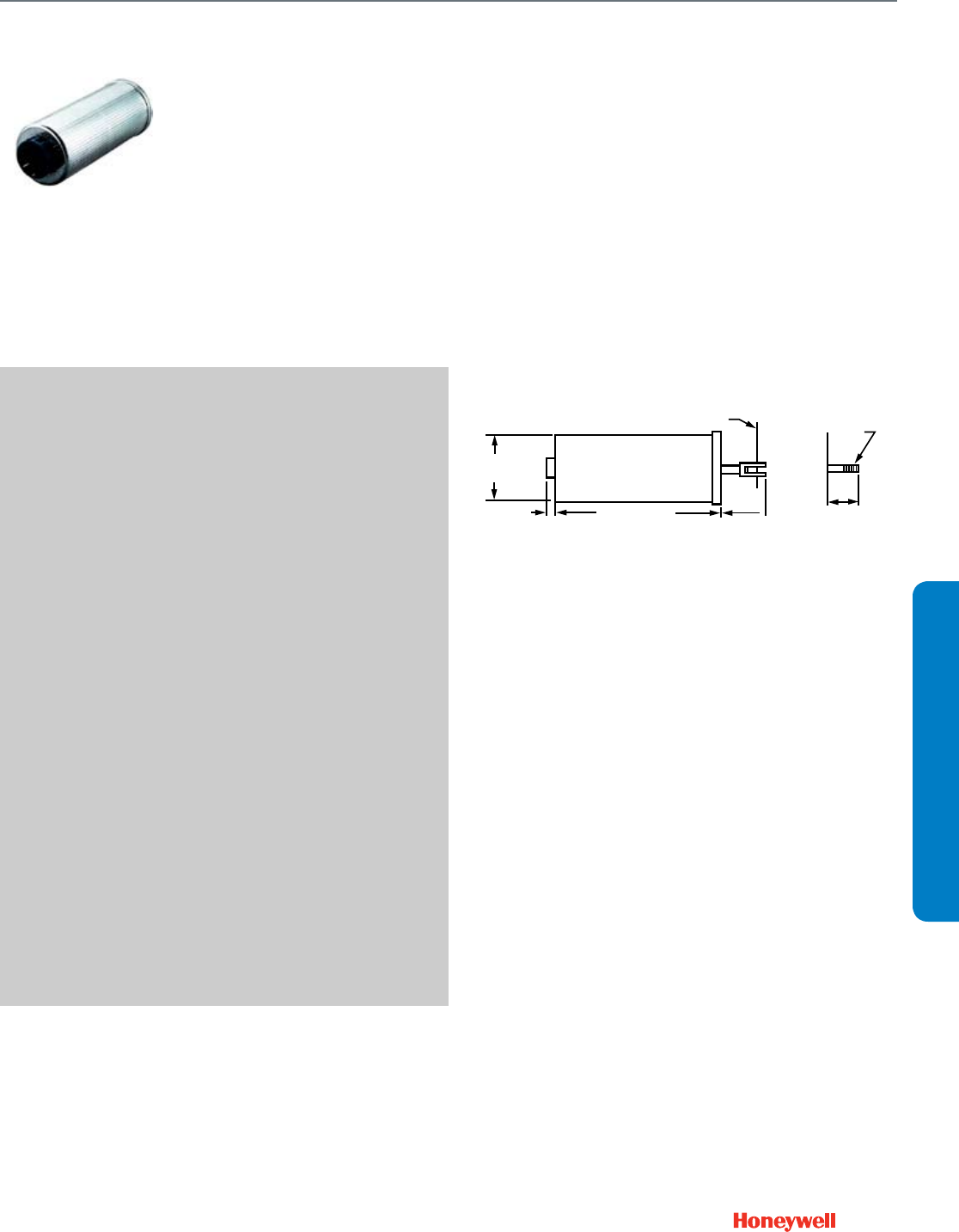
97
Pneumatic Damper Actuator
MP909D
SUBMITTAL SHEETS
MP909D
Used for pneumatic proportional
control of variable volume terminal
units and small dampers. Available
in various operating ranges for
either individual or sequence
operation with other actuators.
Replacement devices are available
for Johnson, Powers, Robertshaw,
and older Honeywell actuator
models.
SPECIFICATIONS
Actuator Type ....................................... Damper
Actuator Force ...................................... Low
Fail Safe Mode ..................................... Spring Return
Air Connections .................................... Barbed fitting for 3/32 in. O.D.
tubing
Stroke ................................................... 2.4 in. (61 mm)
Diaphragm Effective Area .................... 3 sq in. (19.4 sq cm)
Temperature Range .............................. 50 F to 140 F (10 C to 60 C)
Maximum Operating Pressure ............. 30 psi (207 kPa)
Humidity Range .................................... 5 to 95% RH
APPROVALS
Underwriters Laboratories, Inc. ............ Components Recognized:
Report R18118
ACCESSORIES
14002850-001—Angle Bracket 5 3/8 in, 137 mm, long, 5 in, 127 mm,
wide
14003640-001—Angle Bracket 3 in. (76 mm) long, 3 3/4 in. (95 mm)
wide, 2 3/4 in. (70 mm) high
26025B—Damper crank arm for 3/8 in. (9.5 mm) diameter axle.
Elongated slot for linkage connection. Slot scaled for 40-50-60-75-90
degrees.
27174B—Damper crank arm for 7/16 in. (11.1 mm) diameter axle.
Elongated slot for linkage connection. Slot scaled for 40-50-60-75-90
degrees.
27520C—Push Rod (5/16 in. dia., 12 in. length)
27520G—Push Rod (5/16 in. dia., 24 in. length)
27520K—Push Rod (5/16 in. dia., 36 in. length)
27520L—Push Rod (5/16 in. dia., 48 in. length)
312867C—Damper Crank Arm for 1/2 in. (12.7mm) diameter axle.
Elongated slot for linkage connection. Slot scaled for 45-60-75-90
degrees
315321—Crankarm Balljoint (with 1/4 in male threads), fits 5/16 in.
diameter pushrod
315781—Motor shaft balljoint with 3/8 - 16 UNC female threads, fits
5/16 in. diameter pushrods.
FEATURES
• Rugged ribbed aluminum body.
• Low-friction shaft bearing.
• Close tolerance on operating range and stroke.
• Protected barb connector.
• Versatile mounting and connecting hardware options.
• Positive leakproof seal.
DIMENSIONS DIAGRAMS
1/4 DIA (6)
1/2 (13) 1-3/16
(46)
5-11/16 (145)
2-3/8
(61) OR
1-1/16
(27)
3/8-16 UNC-2A
13/16 (20) LONG
MIN.
C484-2
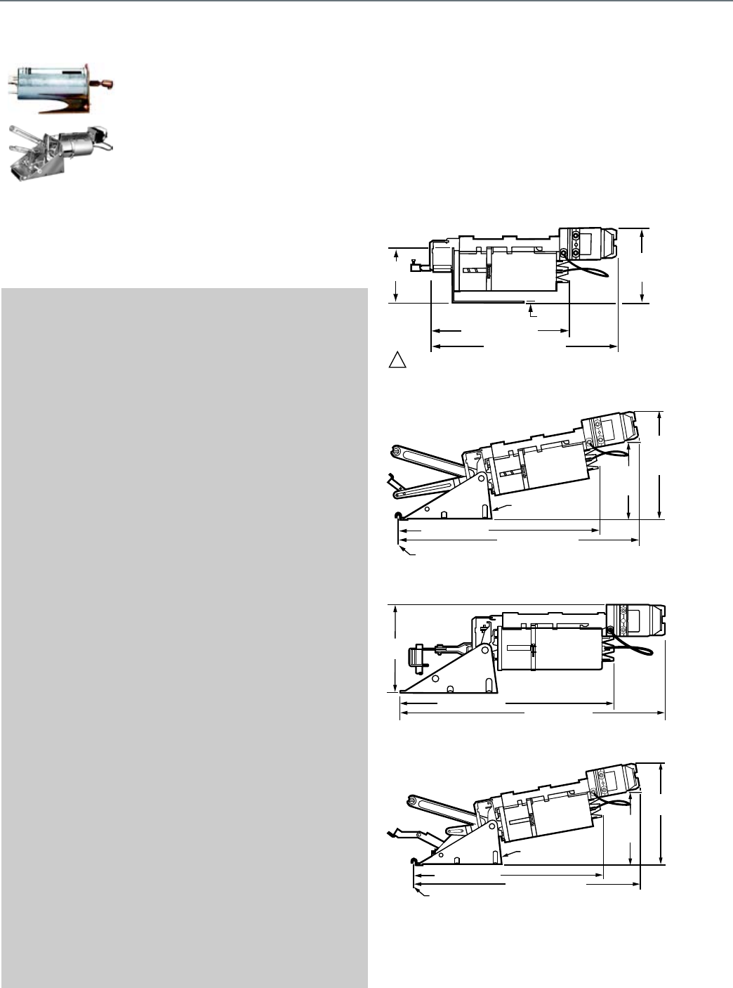
98
MP909E,H
These actuators are used for
proportional control of variable volume
terminal units, mixing boxes, and small
to medium sized dampers. They are
available in various operating ranges
for either independent operation or
sequence operation with other
actuators. The MP909E has an optional
adjustable stroke feature. The MP909H
includes a positive positioner.
Replacement devices are available for
Johnson, Powers, Robertshaw, Barber-
Colman, and older Honeywell actuator
models.
SPECIFICATIONS
Actuator Type ....................................... Damper
Actuator Force ...................................... Medium
Fail Safe Mode ..................................... Spring Return
Air Connections .................................... Dual Barbed fitting for 5/32 in.
or 1/4 in. O.D. tubing
Stroke ................................................... 4 in. (102 mm)
Diaphragm Effective Area .................... 6.6 sq in. (43 sq cm)
Temperature Range .............................. -28 F to 160 F (-33 C to 71 C)
Maximum Operating Pressure ............. 29 psi (200 kPa)
Humidity Range .................................... 5 to 95% RH
APPROVALS
Underwriters Laboratories, Inc. ............ Components Recognized:
Report R18118
ACCESSORIES
14002850-001—Angle Bracket 5 3/8 in, 137 mm, long, 5 in, 127 mm,
wide
14003640-001—Angle Bracket 3 in. (76 mm) long, 3 3/4 in. (95 mm)
wide, 2 3/4 in. (70 mm) high
14004062-001—External Trunnion Mounting Bracket
14004062-002—Internal N.C. Trunnion Mounting Bracket
14004062-003—Internal N.O. Trunnion Mounting Bracket
14004106-001—Actuator pushrod for conversion of internal N.C. to
external
14004107-001—Crankarm Assembly for conversion from internal N.C.
to external Trunnion mounting
14004210-001—Feedback Spring Kit includes orange spring (3 psi
[21kPa]), yellow spring (5 psi [34 kPa]), and blue spring (10 psi
[69 kPa]).
14004236-001—Coupler, actuator shaft to 5/16 in, 8 mm, pushrod
14004241-002—Hitch Pin (Six Sets)
14004242-001—MP918 Top Mount Operator Assembly
14004667-001—Offset Crank arm assembly with 2 screws (304725-
062), nuts (14004102-001), crank arm (14004655-001) for 1/2 in.
Drive Axle
26025B—Damper crank arm for 3/8 in. (9.5 mm) diameter axle.
Elongated slot for linkage connection. Slot scaled for 40-50-60-75-90
degrees.
27518—Crankarm balljoint with 1/4 - 28 UNF male threads, fits 5-16 in.
diameter push rods
312867C—Damper Crank Arm for 1/2 in. (12.7mm) diameter axle.
Elongated slot for linkage connection. Slot scaled for 45-60-75-90
degrees
312867H—Externally mounted Linkage Kit
314440A—MP909 - Clevis, Clevis Pin and Cotter Pin Assembly
315321—Crankarm Balljoint (with 1/4 in male threads), fits 5/16 in.
diameter pushrod
315781—Motor shaft balljoint with 3/8 - 16 UNC female threads, fits
5/16 in. diameter pushrods.
REPLACEMENT PARTS
14004137-001—Retrofit Kit for adding positive positioner to MP909E or
repair of MP909H
FEATURES
• Rolling diaphragm operated.
• Low friction shaft bearing.
• Close tolerance on operating range and stroke.
• Non-overlapping spring ranges for sequencing.
• Corrosion resistant materials.
• Reliable long life.
DIMENSIONS DIAGRAM
Actuator with Fixed External Mounting Bracket
Actuator with Internal N.C. Trunnion Mounting Bracket
Actuator with External Trunnion Mounting Bracket
Actuator with Internal N.O Trunnion Mounting Bracket
13-3/4 (350) MP909H
5 (127)
9-1/4 (235) MP909E
4-1/2
(114)
MP909H
6-1/4
(159)
M27095
1ANGLE BRACKET IS 14002851-001 FOR MP909E1067 AND IS 14002850-001
FOR OTHERS.
17 (430) MP909E
19-3/4 (500) MP909H
MP909E
N.C.
7 (180)
MP909H
N.C.
9-1/2
(240)
EDGE OF
DAMPER
6-7/8 (175) WIDE
M27097
7-1/4
(185)
M27096
17 (430) MP909E
22 (560) MP909H
17 (430) MP909E
19-3/4 (500) MP909H
6-1/2
(169)
MP909E
9 (230)
MP909H
EDGE OF
DAMPER
6-7/8 (175) WIDE
M27098
Pneumatic Damper Actuator
MP909E,H
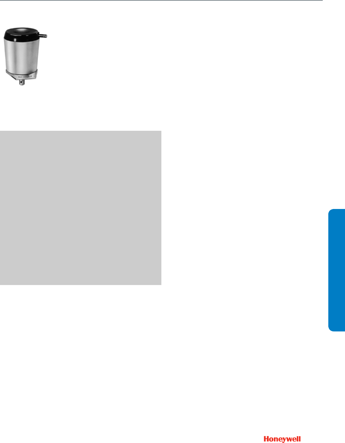
99
SUBMITTAL SHEETS
Pneumatic Damper Actuator
MP913
MP913
Provides proportional control of
variable volume dampers in small
high velocity mixing boxes.
Replacement devices are available
for Johnson and Robertshaw
devices. Suitable for direct
replacement only, do not attempt to
replace larger damper actuators
with this unit.
SPECIFICATIONS
Actuator Type ....................................... Damper
Dimensions, Approximate .................... 2 5/8 in. high (add 3/4 in. for
shaft ) x 2 1/4 in. diameter
(67 mm high (add 19 mm for
shaft) x 57 mm diameter)
Actuator Force ...................................... Low
Fail Safe Mode ..................................... Spring Return
Air Connections .................................... Barbed fitting for 1/4 in. O.D.
plastic tubing
Stroke ................................................... 1 in. (25 mm)
Diaphragm Effective Area .................... 2.2 sq in. (14 sq cm)
Temperature Range .............................. 50 F to 140 F (10 C to 60 C)
Maximum Operating Pressure ............. 30 psi (207 kPa)
Humidity Range .................................... 5 to 95% RH
ACCESSORIES
27520C—Push Rod (5/16 in. dia., 12 in. length)
27520G—Push Rod (5/16 in. dia., 24 in. length)
27520K—Push Rod (5/16 in. dia., 36 in. length)
27520L—Push Rod (5/16 in. dia., 48 in. length)
315321—Crankarm Balljoint (with 1/4 in male threads), fits 5/16 in.
diameter pushrod
315781—Motor shaft balljoint with 3/8 - 16 UNC female threads, fits
5/16 in. diameter pushrods.
FEATURES
• Compact in size.
• Neoprene rolling diaphragm.
• The MP913 Operator can be used with or without a
crankarm.
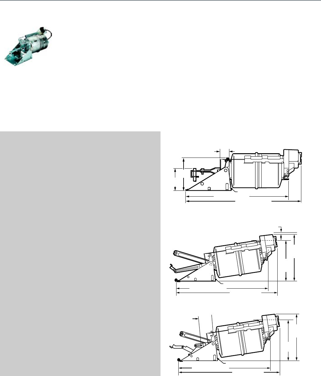
100
MP918A,B
Used for proportional control of
medium- to large-size dampers in
HVAC systems. The MP918A,B are
rolling diaphragm, piston-type
actuators. The MP918A has a
positive positioner. Replacement
devices are available for Johnson,
Powers, Robertshaw, Barber-
Colman, and older Honeywell
actuator models.
SPECIFICATIONS
Actuator Type ....................................... Damper
Actuator Force ..................................... High
Fail Safe Mode ..................................... Spring Return
Air Connections .................................... 5/32 in. push-on barb (Pilot),
1/4 in. push-on barb (main.)
Stroke ................................................... 3 1/2 in. (90 mm)
Diaphragm Effective Area .................... 23.8 sq in. (154 sq cm)
Temperature Range ............................. -20 F to 158 F (-29 C to 70 C)
Maximum Operating Pressure ............. 25 psi (172 kPa)
Humidity Range ................................... 5 to 95% RH
APPROVALS
Underwriters Laboratories, Inc. ........... Components Recognized:
Report R18118
ACCESSORIES
14004062-001—External Trunnion Mounting Bracket
14004062-002—Internal N.C. Trunnion Mounting Bracket
14004062-003—Internal N.O. Trunnion Mounting Bracket
14004106-001—Actuator pushrod for conversion of internal N.C. to
external
14004107-001—Crankarm Assembly for conversion from internal N.C.
to external Trunnion mounting
14004210-001—Feedback Spring Kit includes orange spring (3 psi
[21kPa]), yellow spring (5 psi [34 kPa]), and blue spring (10 psi [69
kPa]).
14004241-002—Hitch Pin (Six Sets)
14004242-001—MP918 Top Mount Operator Assembly
14004667-001—Offset Crank arm assembly with 2 screws
(304725-062), nuts (14004102-001), crank arm (14004655-001) for
1/2 in. Drive Axle
14004236-001—Coupler, actuator shaft to 5/16 in, 8 mm, pushrod
CCT2718—Threaded rod for shaft extension
CCT2725—Rod coupling for shaft extension
REPLACEMENT PARTS
14004264-001—MP918 Repair kit including Positive Positioner,
bracket assembly and fittings
14004264-002—MP918 Positive Positioner Retrofit Kit - includes 10 psi
feedback spring
FEATURES
• Rolling diaphragm operated.
• Low friction shaft bearing.
• Close tolerance on operating range and stroke.
• Versatile mounting and connecting hardware.
• Non-overlapping spring ranges for sequencing.
• Reliable-long life.
DIMENSIONS DIAGRAMS
Actuator with External Trunnion Mounting Bracket
Actuator with Internal N.C. Trunnion Mounting Bracket
Actuator with Internal N.O. Trunnion Mounting Bracket
18-1/4 (465) MP918B
6-7/8
(175)
4 (102)
MIN.
M27099
20-1/2 (520) MP918A
14004062-001
1-7/16
(36)
M27100
8-1/2
(215)
MP918B
10-7/8
(275)
MP918A
3/8 (10) CLEARANCE
18-3/4 (475) MP918B
21 (535) MP918A
14004062-002
M27101
8 (205)
MP918B
10-3/8
(265)
MP918A
18-3/4 (475) MP918B
21 (535) MP918A
14004062-003
3-3/8
(86)
REF.
Pneumatic Damper Actuator
MP918A,B
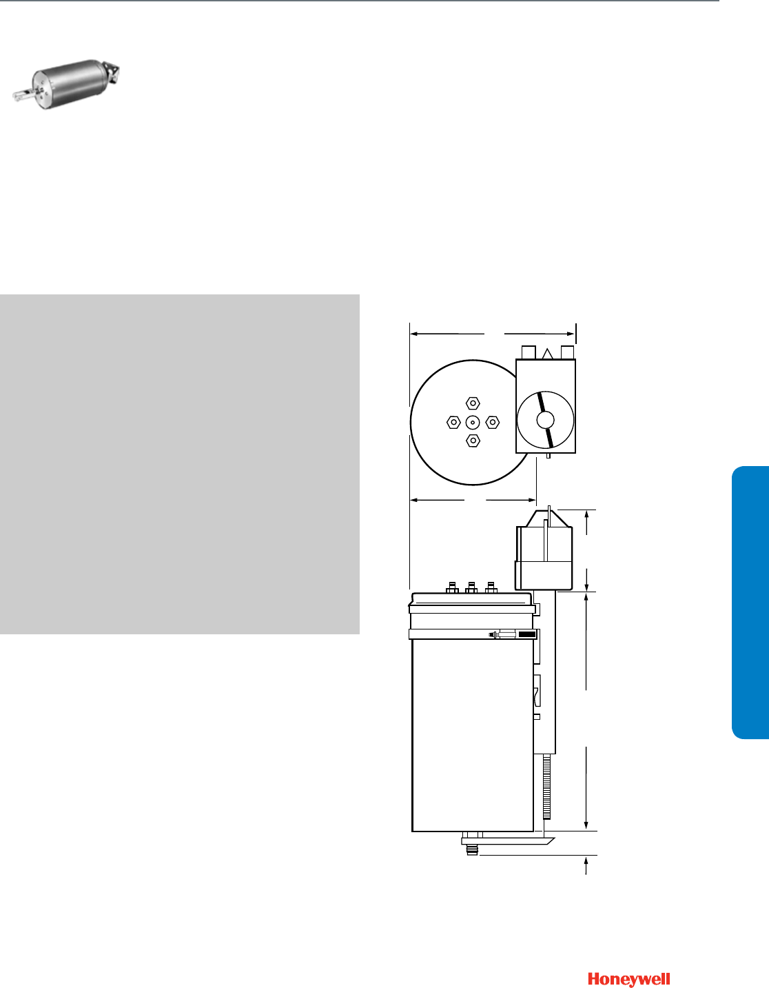
101
SUBMITTAL SHEETS
Pneumatic Damper Actuator
MP920
MP920
Provides proportional control of
large dampers in HVAC systems or
inlet vanes on a VAV fan. Positive
positioner available separately.
Replacement devices are available
for Robertshaw actuator models.
SPECIFICATIONS
Actuator Type ....................................... Damper
Actuator Force ...................................... High
Fail Safe Mode ..................................... Spring Return
Air Connections .................................... Barbed fitting for 1/4 in. O.D.
plastic tubing
Stroke ................................................... 6 in. (150 mm)
Diaphragm Effective Area .................... 24.8 sq in. (160 sq cm)
Temperature Range .............................. -20 F to 158 F (-30 C to 70 C)
Maximum Operating Pressure ............. 29 psi (200 kPa)
Humidity Range .................................... 5 to 95% RH
ACCESSORIES
14004062-001—External Trunnion Mounting Bracket
14004241-002—Hitch Pin (Six Sets)
14004345-001—Positive Positioner Kit, 10 psi feedback spring
AK3556—Pipe Mounting Assembly for 1-1/4 in. pipe
AK3557—Short Clevis Bag Assembly for 3/8-16 threaded rod
AK3558—Swivel Bracket Bag Assembly
AK3559—Long Clevis Bag Assembly with actuator shaft coupling for
5/8-11 threaded rod
AK3560—Balljoint, 3/8-24 threaded stud with couplings for 5/8-11
threaded rod and actuator shaft
AK3561—Balljoint, 3/8-24 threaded stud with couplings for 3/8-16
threaded rod
FEATURES
• Rolling diaphragm operated.
• Fail safe on over pressure.
• Actuator can be swivel mounted from either end to pipe,
floor, or wall surface.
• Optional positive positioner provides accurate positioning
under varying load conditions.
DIMENSIONS DIAGRAMS
1
(30)
11-7/32 (285)
M18809
4 (100)
6-3/16
(157)
8-1/4
(210)
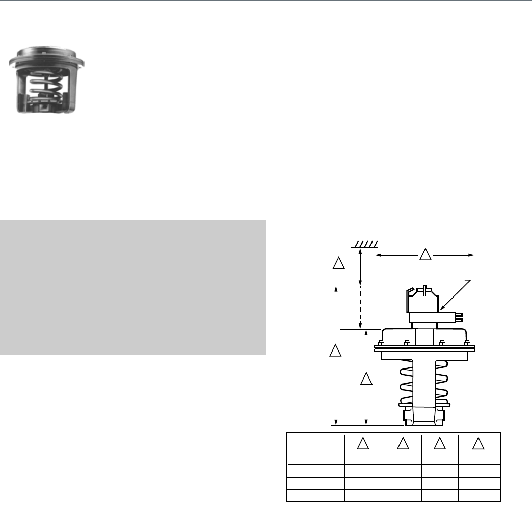
102
MP953C,D
Pneumatic actuators provide
proportional control of steam or hot
or cold liquids in HVAC systems by
operating V5011, V5013, and VGF
valve assemblies. Replacement
devices are available for older
Honeywell actuators.
SPECIFICATIONS
Actuator Type ....................................... Valve
Action ................................................... Direct Acting
Actuator Force ..................................... Medium
Fail Safe Mode ..................................... Spring Return
Air Connections .................................... Main: Barbed fitting for 1/4 in.
O.D. plastic tubing
Pilot: Barbed fitting for 5/32 in.
O.D. plastic tubing
Stroke ................................................... 1 1/2 in. (38 mm)
Temperature Range ............................. 0 F to 140 F (-18 C to 60 C)
Maximum Operating Pressure ............. 25 psi (172 kPa)
Humidity Range ................................... 5 to 95% RH
FEATURES
• Rolling diaphragm for long life and low hysteresis.
• Easily attached to valve.
• Can be installed after piping valve.
• Slide lock feature permits simple engagement to valve
stem.
• Direct- or reverse-action control.
• Does not include positive positioner.
DIMENSIONS DIAGRAMS
2
4
3
MP953E &
MP953F
MP953C &
MP953D
POSITIONER
ON MP953E AND
MP953F ONLY
MINIMUM
CLEARANCE
1 2 3 4
OPERATION SIZE
NOMINAL DIA.
5 INCH
7-1/8 INCH
8 INCH
13 INCH
5-1/8 (130)
7-1/8 (181)
8-1/4 (210)
13-1/2 (343)
9-1/4 (235)
10-1/2 (267)
11-1/8 (283)
18-1/8 (460)
4-5/8 (117)
5-5/8 (143)
6-1/2 (165)
10 (254)
4-3/8 (111)
4-3/8 (111)
5-3/8 (137)
7-11/16 (195)
1
M13903
Pneumatic Valve Actuator
MP953C,D
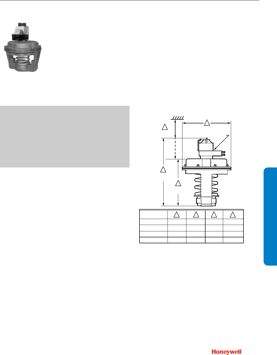
103
SUBMITTAL SHEETS
Pneumatic Valve Actuator
MP953E,F
MP953E,F
Pneumatic actuators provide
proportional control of steam or hot
or cold liquids in HVAC systems by
operating V5011, V5013, and VGF
valve assemblies. Replacement
devices are available for older
Honeywell actuators.
SPECIFICATIONS
Actuator Type ....................................... Valve
Action ................................................... Direct Acting
Actuator Force ...................................... Low
Fail Safe Mode ..................................... Spring Return
Air Connections .................................... Dual barbed fitting for 5/32 in.
O.D. and 1/4 in. O.D. plastic
tubing
Stroke ................................................... 3/4 in. (19 mm)
Temperature Range .............................. 0 F to 140 F (-18 C to 60 C)
Maximum Operating Pressure ............. 25 psi (172 kPa)
Humidity Range .................................... 5 to 95% RH
FEATURES
• Rolling diaphragm for long life and low hysteresis.
• Easily attached to valve.
• Can be installed after piping valve.
• Slide lock feature permits simple engagement to valve
stem.
• Direct- or reverse-action control.
• Integral positive positioner relay provides positive
positioning under varying load conditions.
DIMENSIONS DIAGRAMS
2
4
3
MP953E &
MP953F
MP953C &
MP953D
POSITIONER
ON MP953E AND
MP953F ONLY
MINIMUM
CLEARANCE
1 2 3 4
OPERATION SIZE
NOMINAL DIA.
5 INCH
7-1/8 INCH
8 INCH
13 INCH
5-1/8 (130)
7-1/8 (181)
8-1/4 (210)
13-1/2 (343)
9-1/4 (235)
10-1/2 (267)
11-1/8 (283)
18-1/8 (460)
4-5/8 (117)
5-5/8 (143)
6-1/2 (165)
10 (254)
4-3/8 (111)
4-3/8 (111)
5-3/8 (137)
7-11/16 (195)
1
M13903
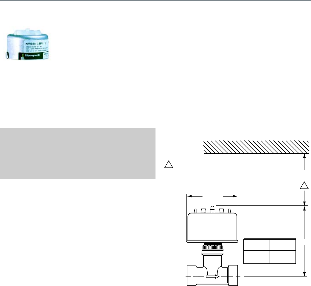
104
MP958
The MP958 Pneumatic Valve
Actuator is direct-acting and used
only with Honeywell V5852A2xx,
V5862A2xx, V5853A2xx, and
V5863A2xx Terminal Unit Valves to
control hot and/or chilled water.
SPECIFICATIONS
Actuator Type ....................................... Valve
Action ................................................... Direct Acting
Actuator Force ..................................... Low
Fail Safe Mode ..................................... Spring Return
Air Connections .................................... Barbed fitting for 1/4 in. O.D.
plastic tubing
Maximum Operating Pressure ............. 30 psi
DIMENSIONS DIAGRAM
1 1/4
(32)
2 1/4 DIA
1
1-1/4 IN. (32 MM) MINIMUM CLEARANCE TO REMOVE
ACTUATOR. 2-1/4 IN. (57 MM) MINIMUM CLEARANCE
TO FACILITATE STRAIGHT ON TUBING CONNECTION.
IF CLEARANCE IS LESS THAN 2-1/4 IN. (57 MM), USE
AN ELBOW.
1
VALVE
SIZE
A
IN. (MM)
1/2 in. NPT
3/4 in. NPT
3-3/16 (81)
3-1/8 (79)
A
C8106A
Pneumatic Valve Actuator
MP958
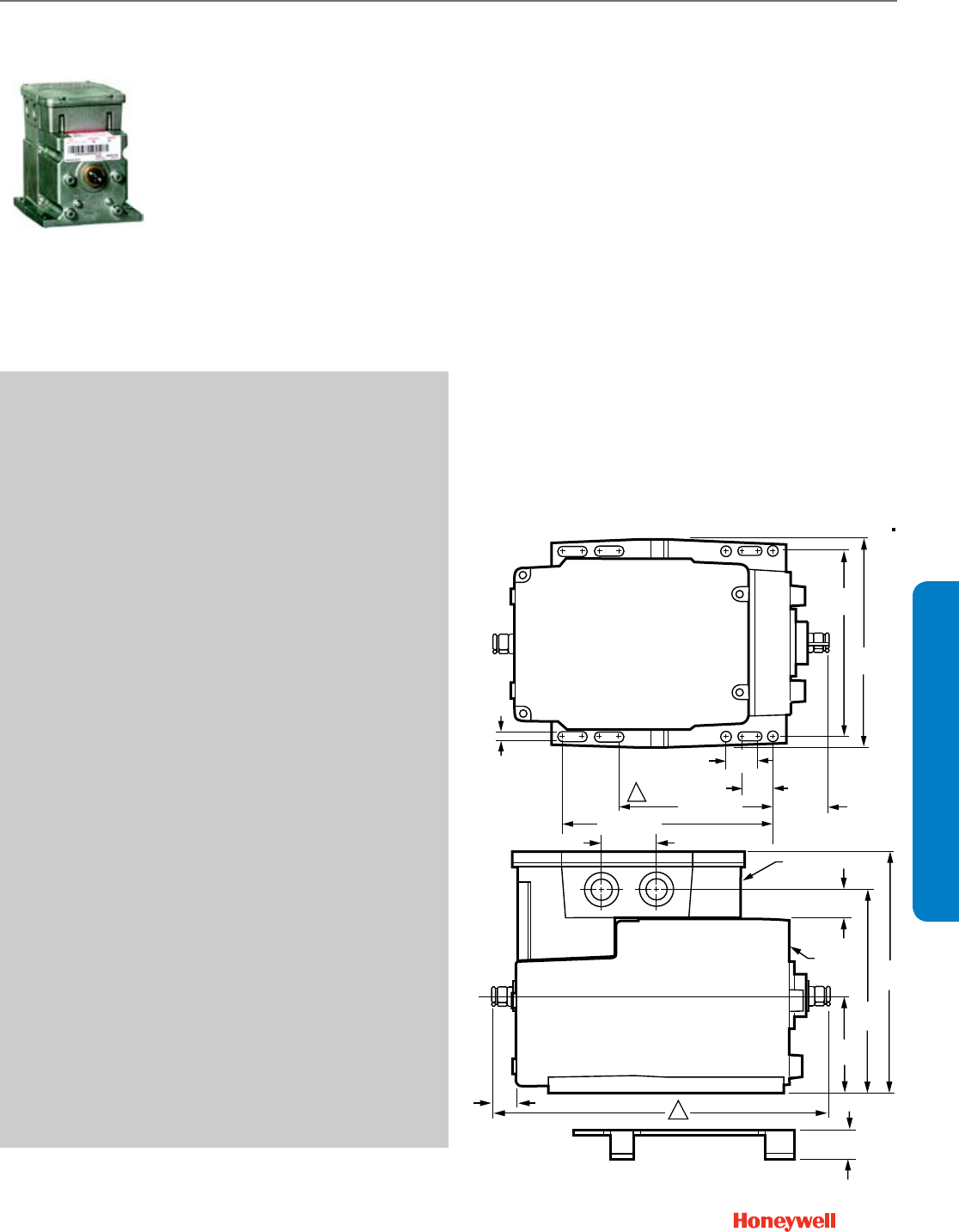
105
SUBMITTAL SHEETS
Modutrol IV Motor
M4185; M8185
M4185; M8185
Series 41 and Series 81 Modutrol IV
motors are 2-position (line- and
low-voltage per motor control)
spring-return motors. They are
used to operate dampers or valves
in applications where it is
necessary or desirable to have the
controlled element return to the
starting position in the event of
power failure or interruption.
SPECIFICATIONS
Application Type .................................. Damper; Valve
Fail Safe Mode ..................................... Spring Return
Control Signal ....................................... Two position, SPST
Torque/Force ........................................ 60 lb-in. (6.8 Nm)
External Auxiliary Switches Available .. Yes
Auxiliary Switch Ratings
AFL - 120 Vac ....................................... 7.2A
Auxiliary Switch Ratings
ALR - 120 Vac ...................................... 43.2A
Auxiliary Switch Ratings
AFL - 240 Vac ....................................... 3.6A
Auxiliary Switch Ratings
ALR - 240 Vac ...................................... 21.6A
Feedback ............................................. No
Electrical Connections ......................... Quick-connect terminals
Frequency ............................................ 50 Hz, 60 Hz
Mounting .............................................. Foot-mounted
Motor Shafts ......................................... Dual-ended shaft
Shaft Shape .......................................... Square
Shaft Dimensions ................................. 0.375 in. (10 mm)
Deadweight Load on Shaft
(Either End) .......................................... 200 lb.
Deadweight Load
(Combined on both Shafts) .................. 300 lb
Ambient Temperature Range ............... -40 F to 150 F (-40 C to 60 C)
Weight .................................................. 9.5 lb
APPROVALS
Canadian Standards Association ......... Certified: File No. LR1620,
Guide No. 400-E
CE ......................................................... EN55011 (Emission) EN50082-
2 (Immunity) 73/23/EEC (LVD)
Underwriters Laboratories, Inc. ............ Listed File: E4436, Guide:
XAPX2
ACCESSORIES
Q7230A1005—Interface module, provides adjustable zero & span,
voltage or current control
220736A—Internal Auxiliary Switch Assembly - 1 Switch
220736B—Internal Auxiliary Switch Assembly - 2 Switches
50017460-001—24/120/230 Vac Internal Transformers for Series 2
Motors
50017460-003—120 Vac Internal Transformers for Series 2 Motors
4074ERU—Weatherproofing kit. Protects motor from driving rain when
mounted in any position
221455A—Infinitely adjustable Motor Crank Arm
FEATURES
• Fixed torque throughout the entire voltage range.
• Integral spring return returns motor to normal position when
power is interrupted.
• Integral junction box provides NEMA 3 weather protection if
motor is mounted in the upright position.
• Motor and circuitry operate from 24 Vac.
• Quick-connect terminals are standard--screw terminal
adapter is available.
• Adapter bracket for matching shaft height of older motors is
available.
• Motors have field adjustable stroke (90 to 160 degrees).
• Motors are designed for either normally open or normally
closed valves and dampers.
• Integral auxiliary switches are available factory mounted, or
can be field added.
• Motors can operate valve linkages from the power end or
auxiliary end shafts for normally closed or normally open
valve applications.
• All models have dual shafts (slotted and tapped on both
ends).
DIMENSIONS DIAGRAM
4-7/8
(124)
5-1/2
(140)
13/16
(20)
4-1/16 (103)
1/4
(7)
1-1/2 (37)
4-1/16 (103)
JUNCTION
BOX
MOTOR
AUXILARY
END
POWER
END
ADAPTER
BRACKET
2-9/16
(66)
5-3/8
(137)
6-7/16
(164)
9/16 (15)
3/4
(19)
TOP VIEW
4
(
1
2
1-1/2 (37)
3/4
(19)
13/16
(20)
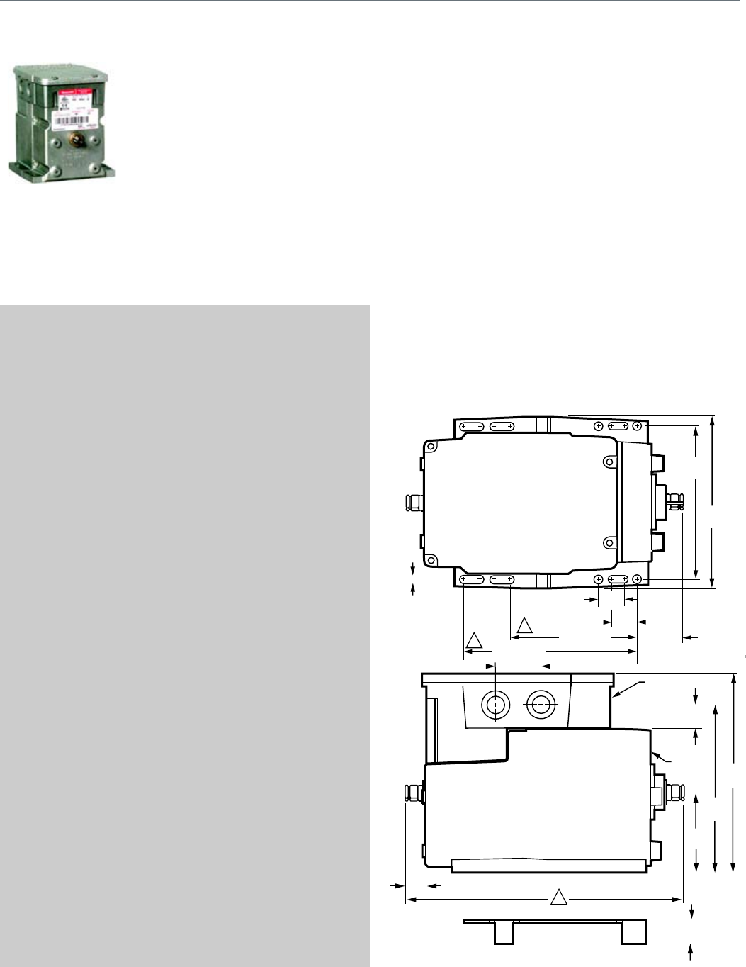
106
M6184; M6194
Series 61 Modutrol IV™ Motors
non-spring return floating control
motors used with controllers that
provide a switched SPDT or floating
output to operate dampers or
valves.
SPECIFICATIONS
Application Type .................................. Damper; Valve
Fail Safe Mode ..................................... Non-Spring Return
Control Signal ....................................... Floating
Torque/Force ........................................ 75 lb-in. (8.5 Nm) or
150 lb-in. (17 Nm) or
300 lb-in. (34 Nm)
External Auxiliary Switches Available .. Yes
Auxiliary Switch Ratings
AFL - 120 Vac ....................................... 7.2A
Auxiliary Switch Ratings
ALR - 120 Vac ...................................... 43.2A
Auxiliary Switch Ratings
AFL - 240 Vac ....................................... 3.6A
Auxiliary Switch Ratings
ALR - 240 Vac ...................................... 21.6A
Feedback ............................................. No
Electrical Connections ......................... Quick-connect terminals
Frequency ............................................ 50 Hz, 60 Hz
Mounting .............................................. Foot-mounted
Motor Shafts ......................................... Dual-ended shaft
Shaft Shape .......................................... Square
Shaft Dimensions ................................. 0.375 in. (10 mm)
Deadweight Load on Shaft
(Either End) .......................................... 200 lb.
Deadweight Load
(Combined on both Shafts) .................. 300 lb.
Ambient Temperature Range ............... -40 F to 150 F (-40 C to 60 C)
Weight .................................................. 6.5 lb
APPROVALS
Canadian Standards Association ........ Certified: File No. LR1620,
Guide No. 400-E
CE ........................................................ EN55011 (Emission) EN50082-
2 (Immunity) 73/23/EEC (LVD)
Underwriters Laboratories, Inc. ........... Listed File: E4436, Guide:
XAPX2
ACCESSORIES
Q7230A1005—Interface module, provides adjustable zero & span,
voltage or current control
220736A—Internal Auxiliary Switch Assembly - 1 Switch
220736B—Internal Auxiliary Switch Assembly - 2 Switches
50017460-001—24/120/230 Vac Internal Transformers for Series 2
Motors
50017460-003—120 Vac Internal Transformers for Series 2 Motors
4074ERU—Weatherproofing kit. Protects motor from driving rain when
mounted in any position
221455A—Infinitely adjustable Motor Crank Arm
FEATURES
• Integral junction box provides NEMA 3 weather protection if
motor is mounted in the upright position.
• Motor and circuitry operate from 24 Vac.
• Quick-connect terminals are standard--screw terminal
adapter is available.
• Adapter bracket for matching shaft height of older motors is
available.
• Motors have field adjustable stroke (90 to 160 degrees).
• Integral auxiliary switches are available factory mounted, or
can be field added.
• All models have dual shafts (slotted and tapped on both
ends).
• All models have auxiliary switch cams.
• Fixed torque throughout the entire voltage range.
• Motors are designed for either normally open or normally
closed valves and dampers.
DIMENSIONS DIAGRAM
4-7/8
(124)
5-1/2
(140)
13/16
(20)
4-1/16 (103)
1/4
(7)
1-1/2 (37)
4-1/16 (103)
JUNCTION
BOX
MOTOR
AUXILARY
END
POWER
END
ADAPTER
BRACKET
2-9/16
(66)
5-3/8
(137)
6-7/16
(164)
9/16 (15)
3/4
(19)
TOP VIEW
4
(
1
2
3
1-1/2 (37)
3/4
(19)
13/16
(20)
Modutrol IV Motor
M6184; M6194
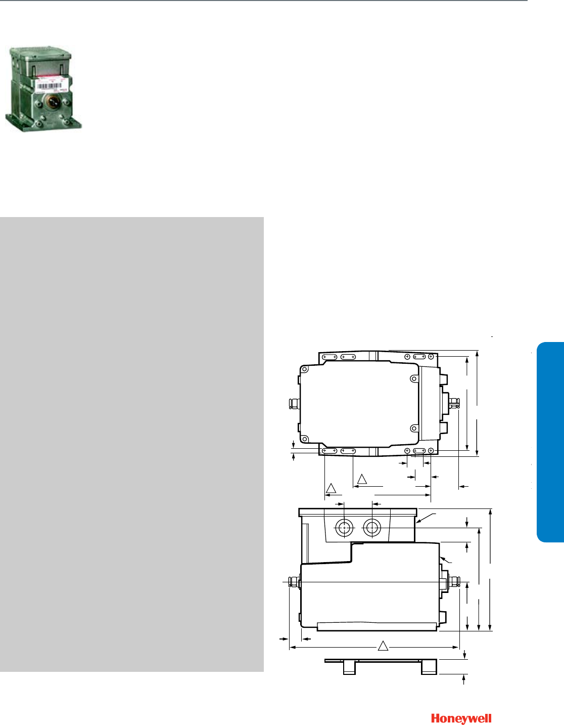
107
SUBMITTAL SHEETS
Modutrol IV Motor
M6285 for slaving applications
M6285 for slaving applications
Series 62 Modutrol IV™ Motors are
spring return floating control motors
used with controllers that provide a
switched SPDT or floating output to
operate dampers or valves. These
motors also have an internal
electrically isolated feedback
potentiometer that provides
indication of the motor shaft
position and can be used for
slaving Series 90 motors or
rebalancing an external control
circuit.
SPECIFICATIONS
Application Type .................................. Damper; Valve
Fail Safe Mode ..................................... Spring Return
Control Signal ....................................... Floating
Torque/Force ........................................ 60 lb-in. (6.8 Nm)
External Auxiliary Switches Available .. Yes
Auxiliary Switch Ratings
AFL - 120 Vac ....................................... 7.2A
Auxiliary Switch Ratings
ALR - 120 Vac ...................................... 43.2A
Auxiliary Switch Ratings
AFL - 240 Vac ....................................... 3.6A
Auxiliary Switch Ratings
ALR - 240 Vac ...................................... 21.6A
Feedback ............................................. Yes
Electrical Connections ......................... Quick-connect terminals
Frequency ............................................ 50 Hz, 60 Hz
Mounting .............................................. Foot-mounted
Motor Shafts ......................................... Dual-ended shaft
Shaft Shape .......................................... Square
Shaft Dimensions ................................. 0.375 in. (10 mm)
Deadweight Load on Shaft
(Either End) .......................................... 200 lb.
Deadweight Load
(Combined on both Shafts) .................. 300 lb.
Ambient Temperature Range ............... -40 F to 150 F (-40 C to 60 C)
Weight .................................................. 8.5 lb
APPROVALS
Canadian Standards Association ......... Certified: File No. LR1620,
Guide No. 400-E
CE ......................................................... EN55011 (Emission) EN50082-
2 (Immunity) 73/23/EEC (LVD)
Underwriters Laboratories, Inc. ............ Listed File: E4436, Guide:
XAPX
ACCESSORIES
Q7230A1005—Interface module, provides adjustable zero & span,
voltage or current control
220736A—Internal Auxiliary Switch Assembly - 1 Switch
220736B—Internal Auxiliary Switch Assembly - 2 Switches
50017460-001—24/120/230 Vac Internal Transformers for Series 2
Motors
50017460-003—120 Vac Internal Transformers for Series 2 Motors
4074ERU—Weatherproofing kit. Protects motor from driving rain when
mounted in any position
221455A—Infinitely adjustable Motor Crank Arm
FEATURES
• Integral junction box provides NEMA 3 weather protection.
• Integral spring return returns motor to normal position when
power is interrupted.
• Motor and circuitry operate from 24 Vac.
• Quick-connect terminals are standard--screw terminal
adapter is available.
• Adapter bracket for matching shaft height of older motors is
available.
• Motors have field adjustable stroke (90 to 160 degrees).
• Integral auxiliary switches are available factory mounted, or
can be field added.
• Spring return motors can operate valve linkages from power
end or auxiliary end shafts for normally closed or normally
open valve applications.
• All models have dual shafts (slotted and tapped on both
ends).
• All models have auxiliary switch cams.
• Fixed torque throughout the entire voltage range.
• Motors are designed for either normally open or normally
closed valves and dampers.
• Include electrically isolated feedback potentiometer that
provides shaft position indication.
• -S models with non-linear feedback are for slaving
applications only.
DIMENSIONS DIAGRAM
4-7/8
(124)
5-1/2
(140)
13/16
(20)
4-1/16 (103)
1/4
(7)
1-1/2 (37)
4-1/16 (103)
JUNCTION
BOX
MOTOR
AUXILARY
END
POWER
END
ADAPTER
BRACKET
2-9/16
(66)
5-3/8
(137)
6-7/16
(164)
9/16 (15)
3/4
(19)
TOTOP VIEW
4-5/8
(116)
1
2
3
1-1/2 (37)
3/4
(19)
SPRING
FOR 60
FOR NO
FOR 60
FOR NO
1
2
3
13/16
(20)
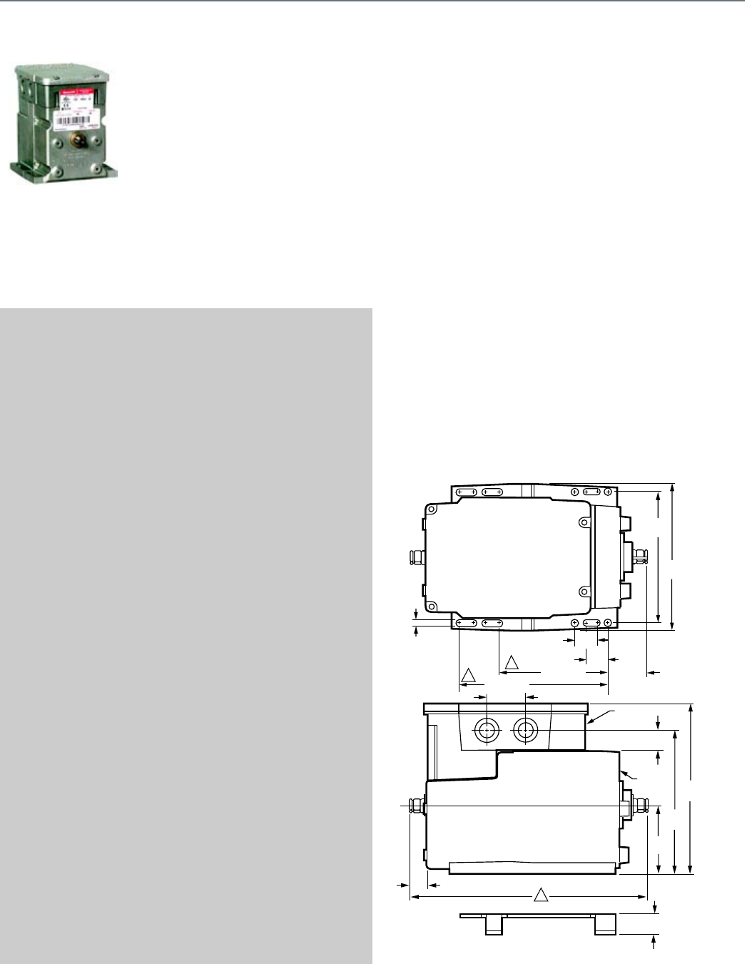
108
M6284; M6294 for slaving applications
These Series 62 Modutrol IV™
Motors non-spring return floating
control motors are used with
controllers that provide a switched
SPDT or floating output to operate
dampers or valves. These motors
also have an internal electrically
isolated feedback potentiometer
that provides indication of the motor
shaft position. Some models can be
used for slaving Series 90 Motors.
SPECIFICATIONS
Application Type .................................. Damper; Valve
Fail Safe Mode ..................................... Non-Spring Return
Control Signal ....................................... Floating
Torque/Force ........................................ 150 lb-in. (17 Nm) or
300 lb-in. (34 Nm)
External Auxiliary Switches Available .. Yes
Auxiliary Switch Ratings
AFL - 120 Vac ....................................... 7.2A
Auxiliary Switch Ratings
ALR - 120 Vac ...................................... 43.2A
Auxiliary Switch Ratings
AFL - 240 Vac ....................................... 3.6A
Auxiliary Switch Ratings
ALR - 240 Vac ...................................... 21.6A
Feedback ............................................. Yes
Electrical Connections ......................... Quick-connect terminals
Frequency ............................................ 50 Hz, 60 Hz
Mounting .............................................. Foot-mounted
Motor Shafts ......................................... Dual-ended shaft
Shaft Shape .......................................... Square
Shaft Dimensions ................................. 0.375 in. (10 mm)
Deadweight Load on Shaft
(Either End) .......................................... 200 lb.
Deadweight Load
(Combined on both Shafts) .................. 300 lb.
Ambient Temperature Range ............... -40 F to 150 F (-40 C to 60 C)
Weight .................................................. 7.5 lb
APPROVALS
Canadian Standards Association ........ Certified: File No. LR1620,
Guide No. 400-E
CE ........................................................ EN55011 (Emission) EN50082-
2 (Immunity) 73/23/EEC (LVD)
Underwriters Laboratories, Inc. ........... Listed File: E4436, Guide:
XAPX
ACCESSORIES
Q7230A1005—Interface module, provides adjustable zero & span,
voltage or current control
220736A—Internal Auxiliary Switch Assembly - 1 Switch
220736B—Internal Auxiliary Switch Assembly - 2 Switches
50017460-001—24/120/230 Vac Internal Transformers for Series 2
Motors
50017460-003—120 Vac Internal Transformers for Series 2 Motors
4074ERU—Weatherproofing kit. Protects motor from driving rain when
mounted in any position
221455A—Infinitely adjustable Motor Crank Arm
FEATURES
• Integral junction box provides NEMA 3 weather protection if
motor is mounted in the upright position.
• Motor and circuitry operate from 24 Vac.
• Quick-connect terminals are standard--screw terminal
adapter is available.
• Adapter bracket for matching shaft height of older motors is
available.
• Motors have field adjustable stroke (90 to 160 degrees).
• Integral auxiliary switches are available factory mounted, or
can be field added.
• All models have dual shafts (slotted and tapped on both
ends).
• All models have auxiliary switch cams.
• Fixed torque throughout the entire voltage range.
• Motors are designed for either normally open or normally
closed valves and dampers.
• Include electrically isolated feedback potentiometer that
provides shaft position indication.
• -S models with non-linear feedback are for slaving
applications only.
DIMENSIONS DIAGRAM
4-7/8
(124)
5-1/2
(140)
13/16
(20)
4-1/16 (103)
1/4
(7)
1-1/2 (37)
4-1/16 (103)
JUNCTION
BOX
MOTOR
AUXILARY
END
POWER
END
ADAPTER
BRACKET
2-9/16
(66)
5-3/8
(137)
6-7/16
(164)
9/16 (15)
3/4
(19)
TOPTOP VIEW
4-5/8
(116)
1
2
3
1-1/2 (37)
3/4
(19)
SPRING
FOR 60 L
FOR NO
FOR 60 L
FOR NO
1
2
3
13/16
(20)
Modutrol IV Motor
M6284; M6294 for slaving applications

109
SUBMITTAL SHEETS
Modutrol IV Motor
M6274; M6284; M6285; M6294 Motors with Linear 10K Feedback
M6274; M6284; M6285; M6294 Motors with Linear 10K Feedback
Series 62 Modutrol IV™ Motors
spring return and non-spring return
floating control motors used with
controllers that provide a switched
SPDT or floating output to operate
dampers or valves. These motors
also have an internal electrically
isolated feedback potentiometer
that provides indication of the
motor shaft position.
SPECIFICATIONS
Application Type .................................. Damper; Valve
Fail Safe Mode ..................................... Spring Return or
Non-Spring Return
Control Signal ....................................... Floating
Torque/Force ........................................ 60 lb-in. (6.8 Nm) or
75 lb-in. (8.5 Nm) or
150 lb-in. (17 Nm) or
300 lb-in. (34 Nm)
External Auxiliary Switches Available .. Yes
Auxiliary Switch Ratings
AFL - 120 Vac ....................................... 7.2A
Auxiliary Switch Ratings
ALR - 120 Vac ...................................... 43.2A
Auxiliary Switch Ratings
AFL - 240 Vac ....................................... 3.6A
Auxiliary Switch Ratings
ALR - 240 Vac ...................................... 21.6A
Feedback ............................................. Yes
Electrical Connections ......................... Screw terminals
Frequency ............................................ 50 Hz; 60 Hz
Mounting .............................................. Foot-mounted
Motor Shafts ......................................... 2; Dual-ended shaft
Shaft Shape .......................................... Square
Shaft Dimensions ................................. 0.375 in. (10 mm)
Deadweight Load on Shaft
(Either End) .......................................... 200 lb.
Deadweight Load
(Combined on both Shafts) .................. 300 lb.
Ambient Temperature Range ............... -40 F to 150 F (-40 C to 60 C)
Weight .................................................. 6.5 lb
APPROVALS
Canadian Standards Association ........ Certified: File No. LR1620,
Guide No. 400-E
CE ........................................................ EN55011 (Emission) EN50082-
2 (Immunity) 73/23/EEC (LVD)
Underwriters Laboratories, Inc. ........... Listed File: E4436, Guide:
XAPX
ACCESSORIES
Q7230A1005—Interface module, provides adjustable zero & span,
voltage or current control
220736A—Internal Auxiliary Switch Assembly - 1 Switch
220736B—Internal Auxiliary Switch Assembly - 2 Switches
50017460-001—24/120/230 Vac Internal Transformers for Series 2
Motors
50017460-003—120 Vac Internal Transformers for Series 2 Motors
4074ERU—Weatherproofing kit. Protects motor from driving rain when
mounted in any position
221455A—Infinitely adjustable Motor Crank Arm
FEATURES
• Integral junction box provides NEMA 3 weather protection if
motor is mounted in the upright position.
• Motor and circuitry operate from 24 Vac.
• Quick-connect terminals are standard--screw terminal
adapter is available.
• Adapter bracket for matching shaft height of older motors is
available.
• Motors have field adjustable stroke (90 to 160 degrees).
• Integral auxiliary switches are available factory mounted, or
can be field added.
• All models have dual shafts (slotted and tapped on both
ends).
• All models have auxiliary switch cams.
• Fixed torque throughout the entire voltage range.
• Motors are designed for either normally open or normally
closed valves and dampers.
• Include electrically isolated feedback potentiometer that
provides shaft position indication.
• -F models have an internal electrically isolated feedback
potentiometer that provides indication of the motor shaft
position.
DIMENSIONS DIAGRAM
4-7/8
(124)
5-1/2
(140)
13/16
(20)
4-1/16 (103)
1/4
(7)
1-1/2 (37)
4-1/16 (103)
JUNCTION
BOX
MOTOR
AUXILARY
END
POWER
END
ADAPTER
BRACKET
2-9/16
(66)
5-3/8
(137)
6-7/16
(164)
9/16 (15)
3/4
(19)
TOP VIEW
4-5/8
(116)
1
2
3
1-1/2 (37)
3/4
(19)
SPR
FO
FO
FO
FO
1
2
3
13/16
(20)
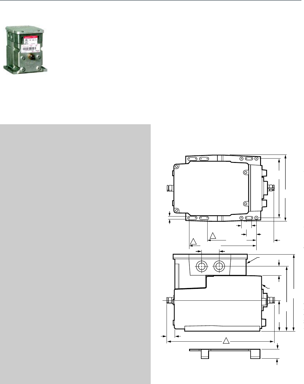
110
M7164
Series 71 Modutrol IV™ Motors
non-spring return motors used to
control dampers and valves. These
motors accept a voltage signal from
an electronic controller to position a
damper or valve at any point
between open and closed.
SPECIFICATIONS
Application Type .................................. Damper; Valve
Fail Safe Mode ..................................... Non-Spring Return
Control Signal ....................................... Modulating, 10.5-13.5 Vdc
Torque/Force ........................................ 60 lb-in. (6.8 Nm)
External Auxiliary Switches Available .. Yes
Auxiliary Switch Ratings
AFL - 120 Vac ....................................... 7.2A
Auxiliary Switch Ratings
ALR - 120 Vac ...................................... 43.2A
Auxiliary Switch Ratings
AFL - 240 Vac ....................................... 3.6A
Auxiliary Switch Ratings
ALR - 240 Vac ...................................... 21.6A
Feedback ............................................. No
Electrical Connections ......................... Quick-connect terminals
Frequency ............................................ 50 Hz, 60 Hz
Mounting .............................................. Foot-mounted
Motor Shafts ......................................... Dual-ended shaft
Shaft Shape .......................................... Square
Shaft Dimensions ................................. 0.375 in. (10 mm)
Deadweight Load on Shaft
(Either End) .......................................... 200 lb.
Deadweight Load
(Combined on both Shafts) .................. 300 lb.
Ambient Temperature Range ............... -40 F to 150 F (-40 C to 60 C)
Weight .................................................. 6.5 lb
APPROVALS
Canadian Standards Association ........ Certified: File No. LR1620,
Guide No. 400-E
CE ........................................................ EN55011 (Emission) EN50082-
2 (Immunity) 73/23/EEC (LVD)
Underwriters Laboratories, Inc. ........... Listed File: E4436, Guide:
XAPX
ACCESSORIES
Q7230A1005—Interface module, provides adjustable zero & span,
voltage or current control
220736A—Internal Auxiliary Switch Assembly - 1 Switch
220736B—Internal Auxiliary Switch Assembly - 2 Switches
50017460-001—24/120/230 Vac Internal Transformers for Series 2
Motors
50017460-003—120 Vac Internal Transformers for Series 2 Motors
4074ERU—Weatherproofing kit. Protects motor from driving rain when
mounted in any position
221455A—Infinitely adjustable Motor Crank Arm
FEATURES
• Integral junction box provides NEMA 3 weather protection if
motor is mounted in the upright position.
• Motor and circuitry operate from 24 Vac.
• Quick-connect terminals are standard--screw terminal
adapter is available.
• Adapter bracket for matching shaft height of older motors is
available.
• Motors have field adjustable stroke (90 to 160 degrees).
• Integral auxiliary switches are available factory mounted, or
can be field added.
• All models have dual shafts (slotted and tapped on both
ends).
• All models have auxiliary switch cams.
• Fixed torque throughout the entire voltage range.
DIMENSIONS DIAGRAM
4-7/8
(124)
5-1/2
(140)
13/16
(20)
4-1/16 (103)
1/4
(7)
1-1/2 (37)
4-1/16 (103)
JUNCTION
BOX
MOTOR
AUXILARY
END
POWER
END
ADAPTER
BRACKET
2-9/16
(66)
5-3/8
(137)
6-7/16
(164)
9/16 (15)
3/4
(19)
TOP VIEW
4-5/
(116
1
2
3
1-1/2 (37)
3/4
(19)
S
1
2
3
13/16
(20)
Modutrol IV Motor
M7164
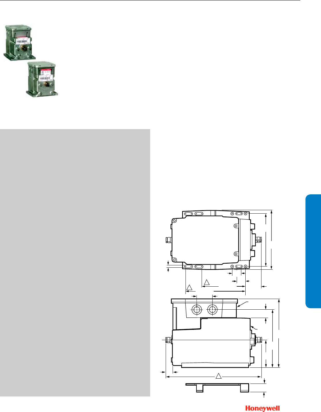
111
SUBMITTAL SHEETS
Modutrol IV Motor
M7274; M7284; M7285; M7286; M7294
M7274; M7284; M7285; M7286; M7294
The Series 72 Modutrol IV Motors
spring return and non-spring return
motors are used to control dampers
and valves. The motors accept a
current or voltage signal from an
electronic controller to position a
damper or valve at any point
between open and closed.
SPECIFICATIONS
Application Type .................................. Damper; Valve
Fail Safe Mode ..................................... Spring Return or
Non-Spring Return
Control Signal ....................................... Modulating, 4-20 mA
Torque/Force ........................................ 60 lb-in. (6.8 Nm) or
75 lb-in. (8.5 Nm) or
150 lb-in. (17 Nm) or
300 lb-in. (34 Nm)
External Auxiliary Switches Available .. Yes
Auxiliary Switch Ratings
AFL - 120 Vac ....................................... 7.2A
Auxiliary Switch Ratings
ALR - 120 Vac ...................................... 43.2A
Auxiliary Switch Ratings
AFL - 240 Vac ....................................... 3.6A
Auxiliary Switch Ratings
ALR - 240 Vac ...................................... 21.6A
Feedback ............................................. No
Electrical Connections ......................... Screw terminals
Frequency ............................................ 50 Hz, 60 Hz
Mounting .............................................. Foot-mounted
Motor Shafts ......................................... Dual-ended shaft
Shaft Shape .......................................... Square
Shaft Dimensions ................................. 0.375 in. (10 mm)
Deadweight Load on Shaft
(Either End) .......................................... 200 lb.
Deadweight Load
(Combined on both Shafts) .................. 300 lb.
Ambient Temperature Range ............... -40 F to 150 F (-40 C to 60 C)
Weight .................................................. 7 lb
APPROVALS
Canadian Standards Association ........ Certified: File No. LR1620,
Guide No. 400-E
Underwriters Laboratories, Inc. ........... Listed File: E4436, Guide:
XAPX
ACCESSORIES
Q7230A1005—Interface module, provides adjustable zero & span,
voltage or current control
220736A—Internal Auxiliary Switch Assembly - 1 Switch
220736B—Internal Auxiliary Switch Assembly - 2 Switches
50017460-001—24/120/230 Vac Internal Transformers for Series 2
Motors
50017460-003—120 Vac Internal Transformers for Series 2 Motors
4074ERU—Weatherproofing kit. Protects motor from driving rain when
mounted in any position
221455A—Infinitely adjustable Motor Crank Arm
FEATURES
• Integral spring return returns motor to normal position when
power is interrupted.
• Integral junction box provides NEMA 3 weather protection if
motor is mounted in the upright position.
• Motor and circuitry operate from 24 Vac.
• Quick-connect terminals are standard--screw terminal
adapter is available.
• Adapter bracket for matching shaft height of older motors is
available.
• Motors have field adjustable stroke (90 to 160 degrees).
• Integral auxiliary switches are available factory mounted, or
can be field added.
• Spring return motors can operate valve linkages from power
end or auxiliary end shafts for normally closed or normally
open valve applications.
• All models have dual shafts (slotted and tapped on both
ends).
• All models have auxiliary switch cams.
• Fixed torque throughout the entire voltage range.
• Motors are designed for either normally open or normally
closed valves and dampers.
• Models available with adjustable start (zero) and span.
• Models available with 4 to 20 mA input signal.
• Models available with 2 to 10 Vdc input signal.
• Die-cast aluminum housing.
DIMENSIONS DIAGRAM
4-7/8
(124)
5-1/2
(140)
13/16
(20)
4-1/16 (103)
1/4
(7)
1-1/2 (37)
4-1/16 (103)
JUNCTION
BOX
MOTOR
AUXILARY
END
POWER
END
ADAPTER
BRACKET
2-9/16
(66)
5-3/8
(137)
6-7/16
(164)
9/16 (15)
3/4
(19)
TOTOP VIEW
4-5/8
(116)
1
2
3
1-1/2 (37)
3/4
(19)
SPRING
FOR 60
FOR NO
FOR 60
FOR NO
1
2
3
13/16
(20)
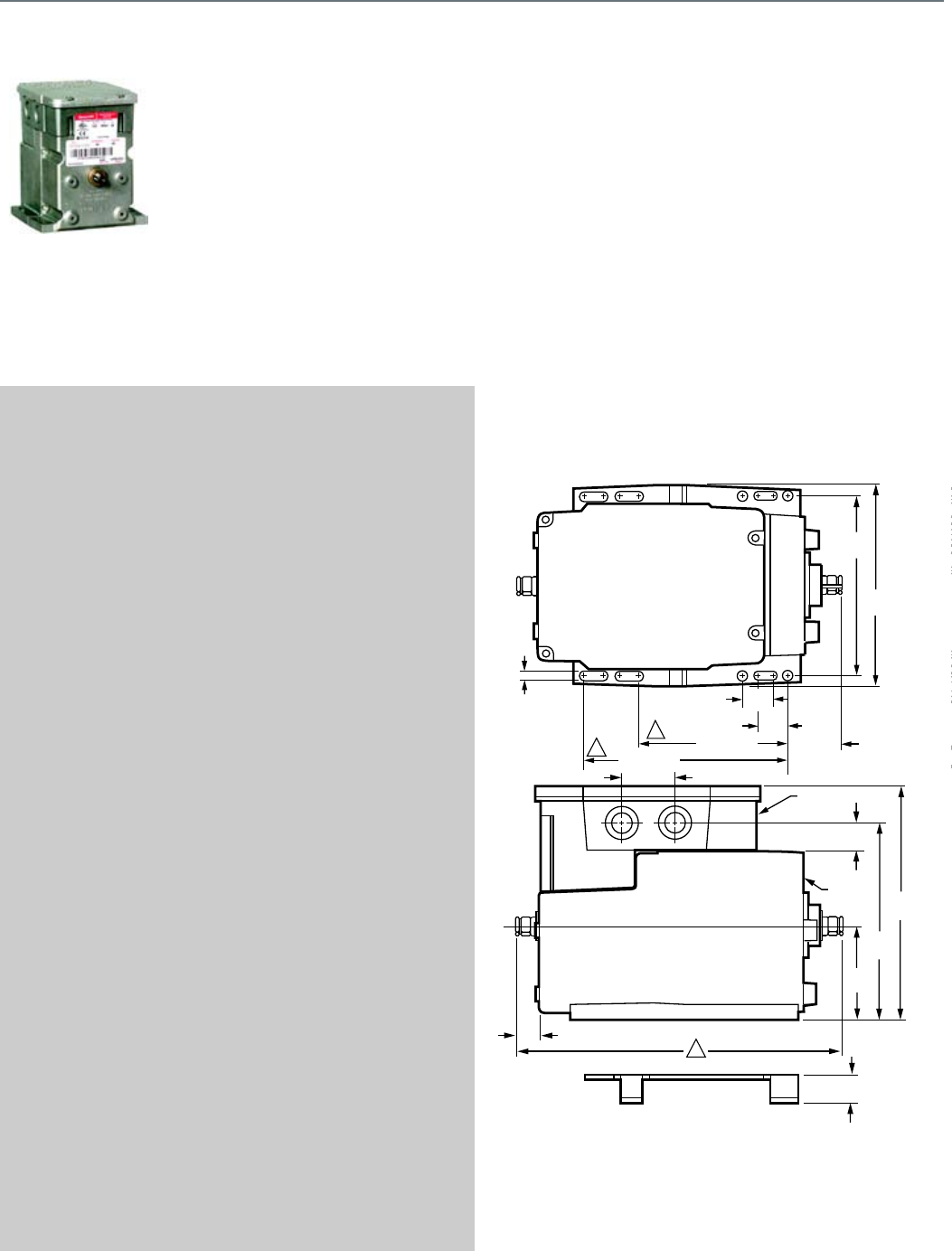
112
M9164; M9174; M9182; M9184; M9194
Series 90 Modutrol IV™ Motors
non-spring return modulating
proportional control motors used
with controllers that provide a
Series 90 output to operate
dampers or valves.
SPECIFICATIONS
Application Type .................................. Damper
Fail Safe Mode ..................................... Non-Spring Return
Control Signal ....................................... Proportional, 135 ohm
Torque/Force ........................................ 60 lb-in. (6.8 Nm) or
75 lb-in. (8.5 Nm) or
150 lb-in. (17 Nm) or
300 lb-in. (34 Nm)
External Auxiliary Switches Available .. Yes
Auxiliary Switch Ratings
AFL - 120 Vac ....................................... 7.2A
Auxiliary Switch Ratings
ALR - 120 Vac ...................................... 43.2A
Auxiliary Switch Ratings
AFL - 240 Vac ....................................... 3.6A
Auxiliary Switch Ratings
ALR - 240 Vac ...................................... 21.6A
Feedback ............................................. No
Electrical Connections ......................... Quick-connect terminals
Frequency ............................................ 50 Hz, 60 Hz
Mounting .............................................. Foot-mounted
Motor Shafts ......................................... Dual-ended shaft
Shaft Shape .......................................... Square
Shaft Dimensions ................................. 0.375 in. (10 mm)
Deadweight Load on Shaft
(Either End) .......................................... 200 lb.
Deadweight Load
(Combined on both Shafts) .................. 300 lb.
Ambient Temperature Range ............... -40 F to 150 F (-40 C to 60 C)
Weight .................................................. 7.5 lb
APPROVALS
Canadian Standards Association ........ Certified: File No. LR1620,
Guide No. 400-E
CE ........................................................ EN55011 (Emission) EN50082-
2 (Immunity) 73/23/EEC (LVD)
Underwriters Laboratories, Inc. ........... Listed File: E4436, Guide:
XAPX
ACCESSORIES
Q7230A1005—Interface module, provides adjustable zero & span,
voltage or current control
220736A—Internal Auxiliary Switch Assembly - 1 Switch
220736B—Internal Auxiliary Switch Assembly - 2 Switches
50017460-001—24/120/230 Vac Internal Transformers for Series 2
Motors
50017460-003—120 Vac Internal Transformers for Series 2 Motors
4074ERU—Weatherproofing kit. Protects motor from driving rain when
mounted in any position
221455A—Infinitely adjustable Motor Crank Arm
FEATURES
• Integral junction box provides NEMA 3 weather protection if
motor is mounted in the upright position.
• Motor and circuitry operate from 24 Vac.
• Quick-connect terminals are standard--screw terminal
adapter is available.
• Adapter bracket for matching shaft height of older motors is
available.
• Motors have field adjustable stroke (90 to 160 degrees).
• Integral auxiliary switches are available factory mounted, or
can be field added.
• All models have dual shafts (slotted and tapped on both
ends).
• All models have auxiliary switch cams.
• Fixed torque throughout the entire voltage range.
DIMENSIONS DIAGRAM
4-7/8
(124)
5-1/2
(140)
13/16
(20)
4-1/16 (103)
1/4
(7)
1-1/2 (37)
4-1/16 (103)
JUNCTION
BOX
MOTOR
AUXILARY
END
POWER
END
ADAPTER
BRACKET
2-9/16
(66)
5-3/8
(137)
6-7/16
(164)
9/16 (15)
3/4
(19)
TOP VIEW
4-5/8
(116)
1
2
3
1-1/2 (37)
3/4
(19)
SPR
F
F
F
F
1
2
3
13/16
(20)
Modutrol IV Motor
M9164; M9174; M9182; M9184; M9194
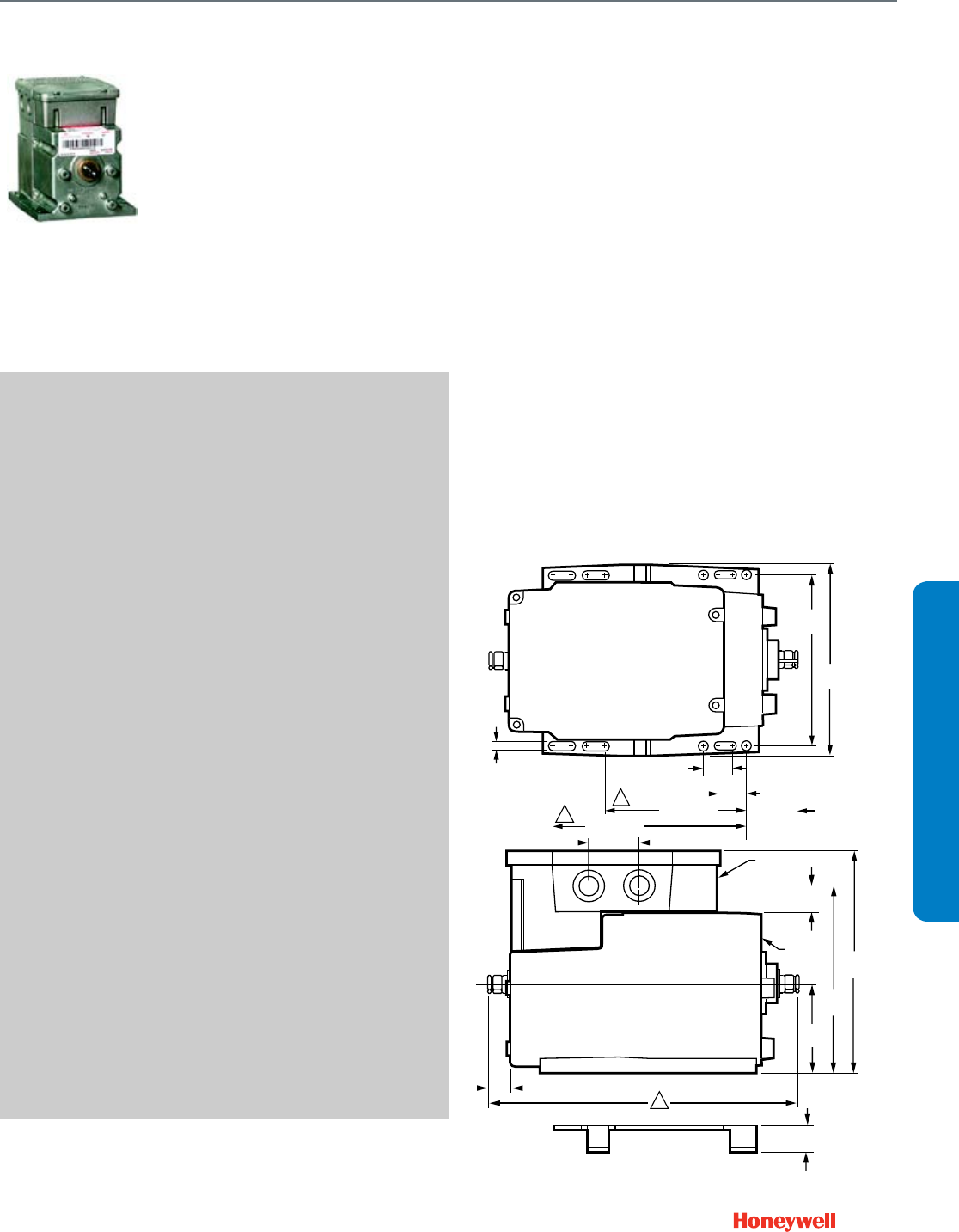
113
SUBMITTAL SHEETS
Modutrol IV Motor
M9175; M9185; M9186
M9175; M9185; M9186
Series 90 Modutrol™ IV Motors
spring return modulating
proportional control motors used
with controllers that provide a
Series 90 output to operate
dampers or valves.
SPECIFICATIONS
Application Type .................................. Damper; Valve
Fail Safe Mode ..................................... Spring Return
Control Signal ....................................... Proportional, 135 ohm
Torque/Force ........................................ 60 lb-in. (6.8 Nm)
External Auxiliary Switches Available .. Yes
Auxiliary Switch Ratings
AFL - 120 Vac ....................................... 7.2A
Auxiliary Switch Ratings
ALR - 120 Vac ...................................... 43.2A
Auxiliary Switch Ratings
AFL - 240 Vac ....................................... 3.6A
Auxiliary Switch Ratings
ALR - 240 Vac ...................................... 21.6A
Feedback ............................................. No
Electrical Connections ......................... Quick-connect terminals
Frequency ............................................ 50 Hz, 60 Hz
Mounting .............................................. Foot-mounted
Motor Shafts ......................................... Dual-ended shaft
Shaft Shape .......................................... Square
Shaft Dimensions ................................. 0.375 in. (10 mm)
Deadweight Load on Shaft
(Either End) .......................................... 200 lb.
Deadweight Load
(Combined on both Shafts) .................. 300 lb.
Ambient Temperature Range ............... -40 F to 150 F (-40 C to 60 C)
Weight .................................................. 8.5 lb
APPROVALS
Canadian Standards Association ......... Certified: File No. LR1620,
Guide No. 400-E
Underwriters Laboratories, Inc. ............ Listed File: E4436, Guide:
XAPX
ACCESSORIES
Q7230A1005—Interface module, provides adjustable zero & span,
voltage or current control
220736A—Internal Auxiliary Switch Assembly - 1 Switch
220736B—Internal Auxiliary Switch Assembly - 2 Switches
50017460-001—24/120/230 Vac Internal Transformers for Series 2
Motors
50017460-003—120 Vac Internal Transformers for Series 2 Motors
4074ERU—Weatherproofing kit. Protects motor from driving rain when
mounted in any position
221455A—Infinitely adjustable Motor Crank Arm
FEATURES
• Integral junction box provides NEMA 3 weather protection if
motor is mounted in the upright position.
• Integral spring return returns motor to normal position when
power is interrupted.
• Motor and circuitry operate from 24 Vac.
• Quick-connect terminals are standard; screw terminal
adapter is available.
• Adapter bracket for matching shaft height of older motors is
available.
• Motors have field adjustable stroke (90 to 160 degrees).
• Integral auxiliary switches are available factory mounted, or
can be field added.
• Spring return motors can operate valve linkages from power
end or auxiliary end shafts for normally closed or normally
open valve applications.
• All models have dual shafts (slotted and tapped on both
ends).
• All models have auxiliary switch cams.
• Fixed torque throughout the entire voltage range.
DIMENSIONS DIAGRAM
4-7/8
(124)
5-1/2
(140)
13/16
(20)
4-1/16 (103)
1/4
(7)
1-1/2 (37)
4-1/16 (103)
JUNCTION
BOX
MOTOR
AUXILARY
END
POWER
END
ADAPTER
BRACKET
2-9/16
(66)
5-3/8
(137)
6-7/16
(164)
9/16 (15)
3/4
(19)
TOP VIEW
4-5/8
(116)
1
2
3
1-1/2 (37)
3/4
(19)
SPR
F
F
F
F
1
2
3
13/16
(20)
114
Q7130; Q7230; Q7330
For converting Series 90
Modutrol IV motors to Series 70
(electronic) control.
SPECIFICATIONS
Application Type .................................. Damper
Dimensions, Approximate .................... Fits inside wiring junction box
of Modutrol IV Motor
Control Signal ....................................... Provides selectable voltage
ranges: 4 to 7, 6 to 9, or 10.5 to
13.5 Vdc. Adapts M91XX to
function as M71XX model
Electrical Connections ......................... Terminal Board
Frequency ............................................ 50 Hz; 60 Hz
Mounting .............................................. Mounts to quick-connects
inside Mod Motor
Ambient Temperature Range ............... -40 F to 150 F (-40 C to 60 C)
Weight .................................................. 0.3 lb
FEATURES
• Mounts and works inside wiring box of any series 90
Modutrol IV Motor.
• Protected from weather by motor's NEMA 3 wiring box.
• Mates to motor's quick-connect terminals and provides
screw terminals for control wiring connections.
• Features solid-state circuitry with surface mount
components.
• Cover holds module in place, screws not required.
• Includes (except Q7330A) reversing switch to allow
replacement of electrically normally open or electrically
normally closed motors.
Modutrol IV Motor
Q7130; Q7230; Q7330
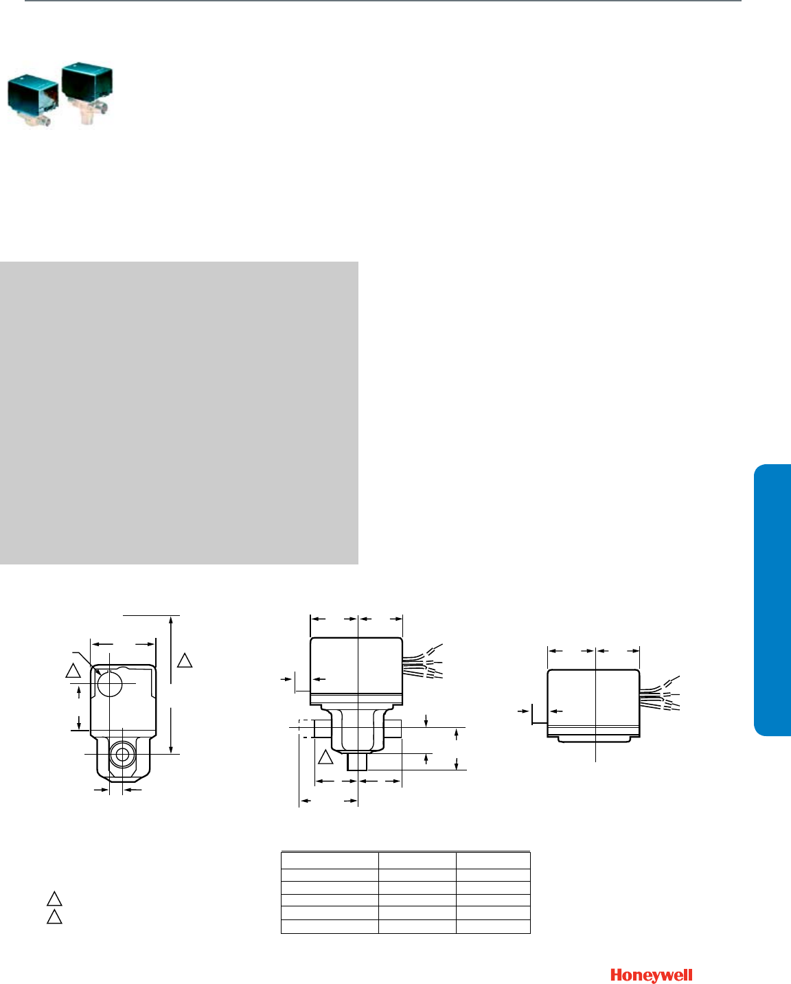
115
SUBMITTAL SHEETS
Unitary Valve Actuator
VU443, VU444; VU843; VU844
VU443, VU444; VU843; VU844
The VU844 Fan Coil Valve
Actuators are used in conjunction
with the VU52, VU53 and VU54
valves for controlling the flow of hot
or chilled water in commercial
HVAC equipment such as fan coil
units, terminal reheat coils and
convectors. These valves are
humidity resistant and are suitable
for use in condensing, non-
corrosive environments.
SPECIFICATIONS
Actuator Type ....................................... Valve
Control Signal ....................................... SPST
Fail Safe Mode ..................................... Spring Return
Electrical Connections ......................... Leads
Electrical Connection Length ............... 6 in.
Frequency ............................................ 60 Hz
Manual operation ................................. Lever
Stroke ................................................... 22 deg. (24 grad.)
Supply Voltage ..................................... 24V, 120V, 208V, 240V, or
277 Vac
Materials ............................................... Stainless Steel Case,
Aluminum Cover,
Nickel-plated motors available
Medium Temperature ........................... 200 F (94 C)
Ambient Temperature Range ............... 34 F to 125 F ambient at
200 F Fluid
(1 C to 52 C ambient at
93 C Fluid)
APPROVALS
Canadian Standards Association ......... Certified C/US
FEATURES
• Compact construction for easy installation.
• Fits under the cover of most baseboard convectors with
actuator fitted to valve body.
• One-button, quick release. Secure 3-point, metal latch to
valve body.
• Spring return operation.
• Stainless steel case and aluminum cover. Rust-proof nickel-
plated motors available.
• Line or low voltage, rust-resistant motors.
• Manual opener for installation and valve operation on power
failure.
• Valve returns to automatic position when power is restored.
• Actuator may be reinstalled or serviced without draining the
system or disassembling the valve.
• Slotted conduit hole for faster wiring.
DIMENSIONS DIAGRAM
2
2
1
1
VU53 VALVE WITH VU448 ACTUATOR
VU53 AND VU54 VALVE WITH ACTUATOR
VU5 ACTUATOR
2-3/8
(60)
7/8 DIA.
(22)
1-1/2
(38)
3-3/4
(133)
15/32
(12)
3/8
(10)
1-3/4
(44)
1-3/4
(44)
A
A
B
AB
7
3/8
(10)
A
2-1/8 (54)
(INVERTED
FLARE)
1-3/4
(44)
1-3/4
(44)
B
3-WAY
7/8 (23)
2-WAY
VALVE BODY SIZE A B
1/2 IN. SWEAT 1-5/6 (33) 1-5/6 (33)
3/4 IN. SWEAT 1-3/8 (35) 1-11/16 (43)
1 IN. SWEAT 1-11/16 (43) 1-11/16 (43)
1/2 IN. NPT 1-3/8 (35) 1-5/16 (33)
3/4 IN. NPT 1-11/16 (43) 1-7/16 (37)
HEIGHT NEEDED TO REMOVE ACTUATOR OR COVER
OPENING FOR 1/2 IN. CONDUIT ON OPPOSITE SITE OF
MANUAL LEVER FOR ALL MODELS. M18261

116
VC Series Two-position Actuators
Control central heating and/or
cooling systems, fan coil systems,
radiators and convectors.
Depending on the model selected,
it can be controlled by either a low
or line voltage SPST controller such
as a room thermostat.
SPECIFICATIONS
Actuator Type ....................................... Valve
Control Signal ....................................... 24 Vac, 100-130 Vac,
or 200-240 Vac
Fail Safe Mode ..................................... Stays in place
Electrical Protection ............................. Double Insulated
Ingress Protection Rating ..................... IP40
Electrical Connections ......................... Plenum-rated cable (24 V);
cable (line voltage)
Frequency ............................................ 60 Hz
Manual operation ................................. Lever
Mounting .............................................. Direct Coupled
Shaft Adapter Type .............................. Self-alignment
Stroke ................................................... 0.4 in. (10 mm)
Supply Voltage ..................................... 24 Vac; 100-130 Vac;
or 200-240 Vac 3-wire.
Timing, Nominal Driving at 60 Hz ........ 6 sec.
Power Consumption, Driving ............... 6 VA
Materials ............................................... Plastic housing
Operating Humidity Range (% RH) ...... 5 to 95% RH, non-condensing
Medium Temperature ........................... 203 F (95 C)
Ambient Temperature Range ............... 32 F to 150 F (0 C to 65 C)
Temperature Ratings (Shipping) .......... -40 F to 150 F (-40 C to 65 C)
Storage Temperature Range ................ -40 F to 150 F (-40 C to 65 C)
Weight .................................................. 0.57 lb (0.26 kg)
Includes ............................................... 3/8 in. flex conduit adapter
(24 V models)
APPROVALS
Canadian Standards Association ........ CSA Certified: LR1322-367
CE ........................................................ 89/336/ECC, 73/23/EEC
Underwriters Laboratories, Inc. ........... UL Recognized, File#
MH11826
FEATURES
• Use with two-way or three-way valves.
• Minimal actuator power consumption.
• Double insulated actuator.
• Quick-connect or one meter cable electrical connections
available.
• Quick and easy replacement of moving parts.
• Actuator head installation does not require draining the
system.
• On/Off models with six second nominal timing
• Use two-position actuators with 1000 Series 2-way and
6000 Series 3-way VC valve bodies only.
• All VC Series actuator-valve combinations provide 60 psi
close-off.
Unitary Valve Actuator
VC Series Two-position Actuators

117
Unitary Valve Actuator
VC Series Proportional Actuators
SUBMITTAL SHEETS
VC Series Proportional Actuators
Control central heating and/or
cooling systems, fan coil systems,
radiators and convectors.
Depending on the model selected,
it can be controlled by either a low
or line voltage SPST or SPDT or
floating controller such as a room
thermostat, Aquastat control, flow
switch or a 0/2 to 10 Vdc controller.
SPECIFICATIONS
Actuator Type ....................................... Valve
Control Signal ....................................... 2-10 Vdc modulating; or
24 Vac floating
Fail Safe Mode ..................................... Stays in place
Cable Entry .......................................... Molded strain relief, conduit
clamp
Electrical Protection ............................. Double Insulated
Ingress Protection Rating ..................... IP40
Electrical Connections ......................... Plenum-rated cable
Electrical Connection Length ............... 5 ft. plenum rated
(1.5 m plenum rated)
Frequency ............................................ 50 Hz, 60 Hz
Manual operation ................................. Lever
Mounting .............................................. Direct Coupled
Shaft Adapter Type .............................. Self-alignment
Stroke ................................................... 0.4 in. (10 mm)
Supply Voltage ..................................... 24 Vac
Timing, Nominal Driving at 60 Hz ......... 120 sec.
Power Consumption, Driving ................ 6 VA
Materials ............................................... Plastic housing
Operating Humidity Range (% RH) ...... 5 to 95% RH, non-condensing
Medium Temperature ........................... 203 F (95 C)
Ambient Temperature Range ............... 32 F to 150 F (0 C to 65 C)
Temperature Ratings (Shipping) .......... -40 F to 150 F (-40 C to 65 C)
Storage Temperature Range ................ -40 F to 150 F (-40 C to 65 C)
Weight .................................................. 0.84 lb (0.38 kg)
Includes ................................................ 3/8 in. flex conduit adapter
Comments ............................................ Use with 3000 Series 2-way
and 7000 Series VC valve
bodies only
APPROVALS
Canadian Standards Association ......... CSA Certified: LR1322-367
Underwriters Laboratories, Inc. ............ Listed 94-5V
FEATURES
• Use with two-way or three-way valves.
• Minimal actuator power consumption.
• Double insulated actuator.
• Quick-connect or one meter cable electrical connections
available.
• Quick and easy replacement of moving parts.
• Actuator head installation does not require draining the
system.
• Use non-fail safe proportional actuators with 3000 Series
2-way and 7000 Series 3-way VC valve bodies only.
• All VC Series actuator-valve combinations provide 60 psi
close-off.

118
VC Series Fail Safe Proportional Actuators
Control central heating and/or
cooling systems, fan coil systems,
radiators and convectors.
Depending on the model selected,
it can be controlled by either a low
or line voltage SPST or SPDT or
floating or modulating controller
such as a room thermostat,
Aquastat control, flow switch or a 0/
2 to 10 Vdc controller.
SPECIFICATIONS
Actuator Type ....................................... Valve
Control Signal ....................................... 2-10 Vdc modulating
24 Vac pulse width modulating
24 Vac floating or
24 Vac on-off
Fail Safe Mode ..................................... N.O. or N.C., switchable
electronic
Cable Entry .......................................... Molded strain relief, conduit
clamp
Electrical Protection ............................. Double Insulated
Ingress Protection Rating ..................... IP40
Electrical Connections ......................... Plenum-rated cable
Electrical Connection Length ............... 5 ft. plenum rated
(1.5 m plenum rated)
Frequency ............................................ 50 Hz; 60 Hz
Manual operation ................................. Lever
Mounting .............................................. Direct Coupled
Shaft Adapter Type .............................. Self-alignment
Stroke ................................................... 0.4 in. (10 mm)
Supply Voltage ..................................... 24 Vac
Timing, Nominal Driving at 60 Hz ........ 60 sec. or 120 sec.
Power Consumption, Driving ............... 12 Watts, 18 VA inrush
Materials ............................................... Plastic housing
Operating Humidity Range (% RH) ...... 5 to 95% RH, non-condensing
Medium Temperature ........................... 203 F (95 C)
Ambient Temperature Range ............... 32 F to 150 F (0 C to 65 C)
Temperature Ratings (Shipping) .......... -40 F to 150 F (-40 C to 65 C)
Storage Temperature Range ................ -40 F to 150 F (-40 C to 65 C)
Weight .................................................. 0.84 lb (0.38 kg)
Includes ............................................... 3/8 in. flex conduit adapter,
valve body
APPROVALS
Canadian Standards Association ........ CSA Certified: LR1322-367
CE ........................................................ 89/336/ECC, 73/23/EEC
Underwriters Laboratories, Inc. ........... Listed 94-5V
FEATURES
• Use with two-way or three-way valves.
• Minimal actuator power consumption.
• Double insulated actuator.
• Five foot plenum-rated cable electrical connections
available.
• Quick and easy replacement of moving parts.
• Actuator head installation does not require draining the
system.
• Selectable/switchable electronic fail safe normally open or
normally closed
• Includes valve bodies.
• All VC Series actuator-valve combinations provide 60 psi
close-off.
Unitary Valve Actuator
VC Series Fail Safe Proportional Actuators
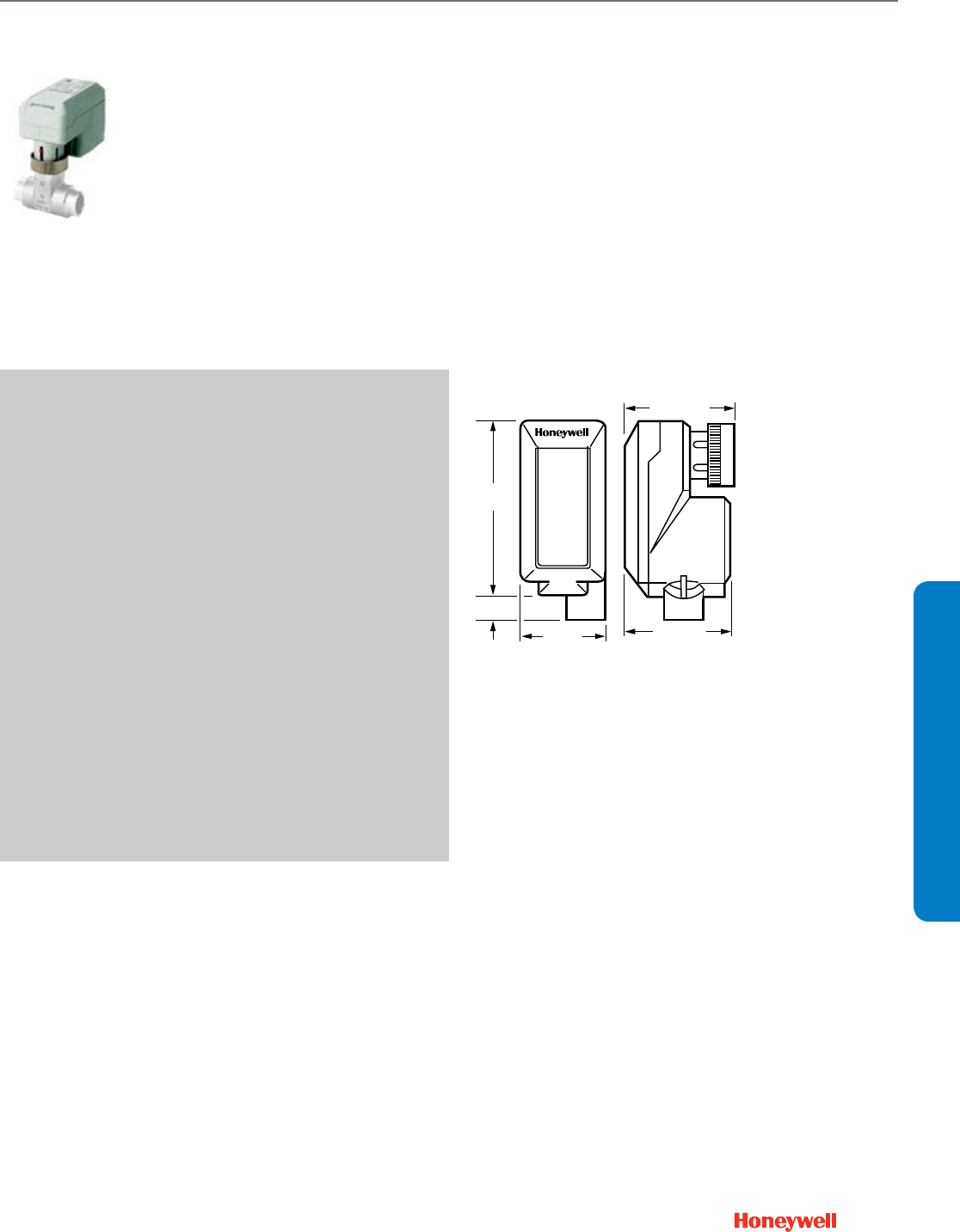
119
Unitary Valve Actuator
M6410; M7410
SUBMITTAL SHEETS
M6410; M7410
Cartridge Globe Valve Actuator are
small electric actuators for
individual room control that provide
floating or modulating control of
V5852, V5862 two-way or V5853,
V5863 three-way valves.
SPECIFICATIONS
Actuator Type ....................................... Valve
Control Signal ....................................... Floating; 0-10Vdc or
2-10Vdc modulating
Fail Safe Mode ..................................... Stays in place
Cable Entry .......................................... Threaded conduit connector
Electrical Protection ............................. Class I Insulation (24 Vac)
Ingress Protection Rating ..................... IP42
Electrical Connections ......................... Plenum-rated cable
Feedback ............................................. No
Frequency ............................................ 50 Hz, 60 Hz
Manual operation ................................. Use valve dust cap
Mounting .............................................. Threads onto V58XX valve
bonnet
Stroke ................................................... 1/4 in. (6 mm)
Supply Voltage ..................................... 20 to 28 Vac
Number of Internal Auxiliary Switch ..... 0
Materials ............................................... Low Maintenance Plastic
Housing
Operating Humidity Range (% RH) ...... 5 to 95% RH
Medium Temperature ........................... 266 F Maximum (130 C
Maximum)
Ambient Temperature Range ............... 32 F to 122 F (0 C to 50 C)
Storage Temperature Range ................ -40 F to 158 F (-40 C to 70 C)
Weight .................................................. 0.3125 lb (0.15 kg)
Includes ................................................ 1/2 in. conduit hub
APPROVALS
Underwriters Laboratories, Inc. ............ UL94-5V
FEATURES
• Suitable for Excel/IRC system or other controllers providing
specified signals.
• Magnetic coupling for torque limitation independent of
voltage supply and self-adjustment of the close-off port.
• No mounting tools required.
• Small size allows installation in limited space of fan coil
units, induction units, and small reheaters or recoolers.
• Visual position indication (red pin).
DIMENSIONS DIAGRAM
M8225A
3-15/16
(100)
1/2 (13)
1-15/16
(49)
2-3/8 (61)
2-5/16 (58)
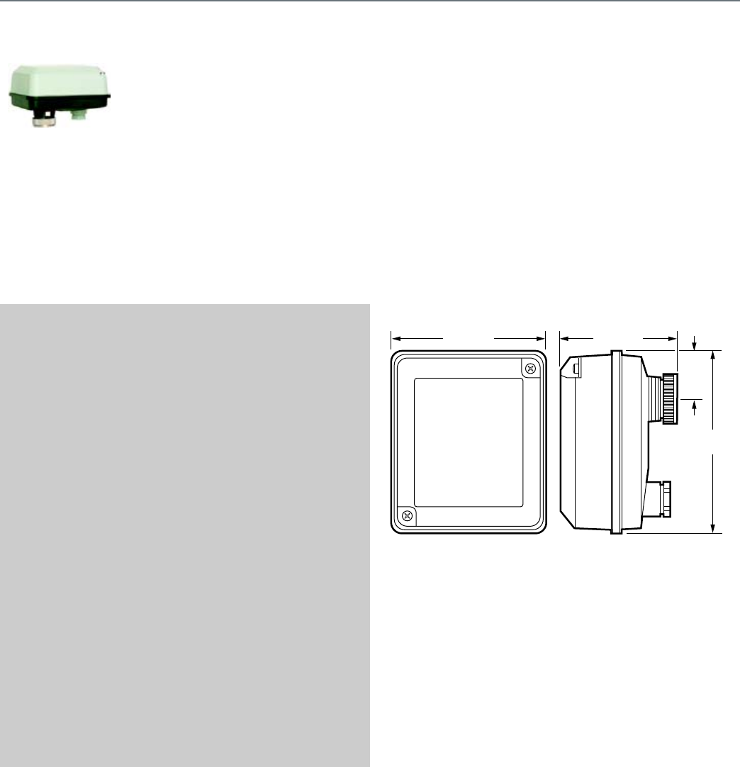
120
M6435; M7435
Cartridge Globe Valve Spring
Return Actuators are small electric
actuators for individual room
control that provide floating or
modulating control of 1/2 and 3/4
in. V5852, V5862 two-way or
V5853, V5863 three-way valves.
SPECIFICATIONS
Actuator Type ....................................... Valve
Control Signal ....................................... Floating; 0-10 Vdc or
2-10 Vdc modulating
Fail Safe Mode ..................................... Spring Return, operator
retracts up (Normally open for
1/2 in. and 3/4 in. V5852 and
V5862. Normally closed for all
other V58XX valves.)
Cable Entry .......................................... Threaded conduit connector
Electrical Protection ............................. Class I Insulation (24 Vac)
Ingress Protection Rating ..................... IP54
Electrical Connections ......................... Screw terminals
Feedback ............................................. No
Frequency ............................................ 50 Hz, 60 Hz
Manual operation ................................. Use valve dust cap
Mounting .............................................. Threads onto V58XX valve
bonnet
Stroke ................................................... 1/4 in. (6 mm)
Supply Voltage ..................................... 24 Vac +20%, -15%
Number of Internal Auxiliary Switch ..... 0
Materials ............................................... Low Maintenance Plastic
Housing
Operating Humidity Range (% RH) ...... 5 to 95% RH
Medium Temperature ........................... 266 F Maximum (130 C
Maximum)
Ambient Temperature Range ............... 32 F to 122 F (0 C to 50 C)
Storage Temperature Range ................ -40 F to 158 F (-40 C to 70 C)
Weight .................................................. 1.1 lb (0.5 kg)
Includes ............................................... 1/2 in. conduit hub
APPROVALS
Underwriters Laboratories, Inc. ........... UL94-5V
FEATURES
• Stem actuator retracts up on power failure. Fail safe mode
depends on valve seat rest position.
• Suitable for Excel/IRC system or other controllers providing
specified signals.
• Magnetic coupling for torque limitation independent of
voltage supply and self-adjustment of the close-off port.
• No mounting tools required.
• Compact size allows installation in limited space of fan coil
units, induction units, and small reheaters or recoolers.
• Visual position indication (red disk).
DIMENSIONS DIAGRAM
5
(126)
1-5/16
(33)
3-3/16 (81)
M19615
4-1/4 (108)
Unitary Valve Actuator
M6435; M7435
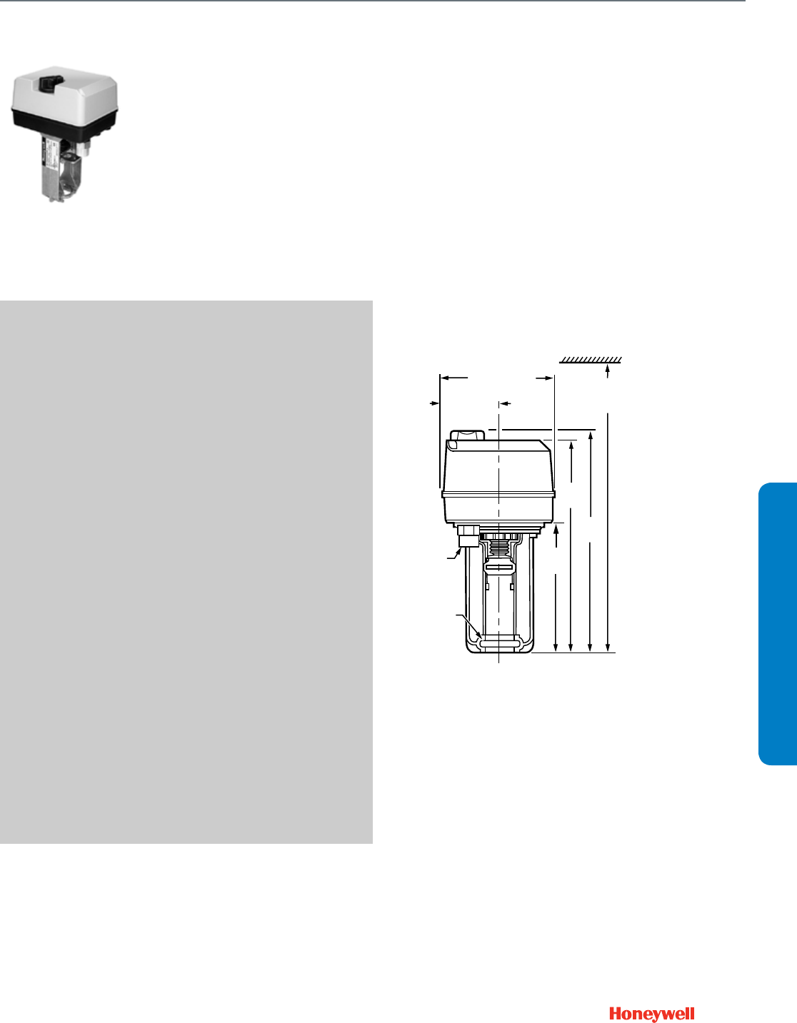
121
Direct Coupled Valve Actuator
ML6420; ML7420
SUBMITTAL SHEETS
ML6420; ML7420
Direct Coupled Globe Valve
Actuators provide floating or
modulating control of chilled water,
hot water, or steam, and mount
directly on VGF series, V5011, and
V5013 globe valves from 1/2 to 3 in.
SPECIFICATIONS
Actuator Type ....................................... Valve
Control Signal ....................................... Floating; 0-10 Vdc or
2-10 Vdc modulating
Fail Safe Mode ..................................... Stays in place
(Rated) Stem Force .............................. 135 lbf (600 N)
Cable Entry .......................................... Conduit connector and one
knockout on actuator case
Electrical Protection ............................. Class I Insulation (24 Vac)
Ingress Protection Rating ..................... IP54
Electrical Connections ......................... Screw terminals
Frequency ............................................ 60 Hz
Manual operation ................................. Knob
Mounting .............................................. Directly on V5011/V5013
Globe Valves and VGF
Flanged Globe Valves
(3/4 in. or 20mm stroke)
Stroke ................................................... 3/4 in. (20 mm)
Supply Voltage ..................................... 24 Vac ±15%
Materials ............................................... ABS-FR Plastic, aluminum
yoke
Operating Humidity Range (% RH) ...... 5 to 95% RH
Medium Temperature ........................... 300 F Maximum (150 C
Maximum)
Ambient Temperature Range ............... 14 F to 122 F (-10 C to +50 C)
Storage Temperature Range ................ -40 F to 158 F (-40 C to 70 C)
Weight .................................................. 2.9 lb (1.3 kg)
Includes ................................................ 1/2 in. conduit hub
APPROVALS
Canadian Standards Association ......... Certified
CE ......................................................... Listed
Underwriters Laboratories, Inc. ............ UL94-5V
ACCESSORIES
43191679-111—Potentiometer, 10 K ohm, for ML6425, ML7425
43191679-112—Potentiometer, 220 ohm for ML6425, ML7425
43191680-105—Dual Auxiliary Switch for CREVAL actuators
43196000-001—High Temperature Kit for actuators with 3/4 in. stroke
FEATURES
• Easy and quick installation on valves with 1 3/8 in. bonnet
and 3/4 in. stroke.
• No separate linkage required.
• Conduit connector standard.
• No adjustments required on linkage.
• Accurate valve positioning.
• Low power consumption.
• High close-off ratings.
• Force limiting end switches.
• Manual operator.
• Synchronous motor.
• Maintenance free.
• ML7420 has an internal selector plug that can be used to
reverse the direction of action.
DIMENSIONS DIAGRAM
5-5/15
(135)
6-5/16
(161)
x
2-11/16 (67)
12-11/16 (322)
MINIMUM
CLEARANCE
9-3/16
(233)
9-9/16
(242)
5-9/16
(141)
M17419
1/2 (13) FPT
YOKE
DIAMETER
1-3/8 (35)
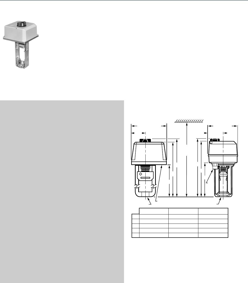
122
ML6421; ML7421
Direct Coupled Globe Valve
Actuators provide floating or
modulating control of chilled water,
hot water, or steam, and mount
directly on VGF series, V5011, and
V5013 valves. These Non-Spring
Return Actuators will operate 1/2 to
6 in. valves.
SPECIFICATIONS
Actuator Type ....................................... Valve
Control Signal ....................................... Floating; 0-10 Vdc or
2-10 Vdc modulating
Fail Safe Mode ..................................... Stays in place
(Rated) Stem Force .............................. 405 lbf (1800 N)
Cable Entry .......................................... Two knockout holes for 1/2 in.
conduit standard on actuator
case
Electrical Protection ............................. Class I Insulation (24 Vac)
Ingress Protection Rating ..................... IP54
Electrical Connections ......................... Screw terminals
Frequency ............................................ 60 Hz
Manual operation ................................. Knob
Mounting .............................................. Directly on V5011/V5013
Globe Valves and VGF
Flanged Globe Valves
Stroke ................................................... 3/4 in. (20 mm); or
1 1/2 in (38 mm)
Materials ............................................... ABS Plastic
Operating Humidity Range (% RH) ...... 5 to 95% RH
Medium Temperature ........................... 300 F Maximum
(150 C Maximum)
Ambient Temperature Range ............... 14 F to 122 F (-10 C to +50 C)
Storage Temperature Range ................ -40 F to 158 F (-40 C to 70 C)
Weight .................................................. 5.1 lb (2.3 kg)
Includes ............................................... 1/2 in. conduit hub
APPROVALS
Canadian Standards Association ........ Certified
CE ........................................................ Recognized
Underwriters Laboratories, Inc. ........... UL94-5V
ACCESSORIES
43191679-101—Auxiliary Potentiometer for ML6421A
43191679-102—Auxiliary Potentiometer for ML6421B
43191680-102—Dual Auxiliary Switch for CREVAL actuators
43196000-001—High Temperature Kit for actuators with 3/4 in. stroke
43196000-038—High Temperature Kit for actuators with 1-1/2 in. stroke
FEATURES
• Easy and quick installation on valves with 1 3/8 in. bonnet
and 3/4 in. stroke, or with 1 7/8 in. bonnet and 1 1/2 in.
stroke.
• High force for VGF Pressure-balanced valves.
• No separate linkage required.
• Conduit connector standard.
• No adjustments required on linkage.
• Accurate valve positioning.
• Low power consumption.
• High close-off ratings.
• Force limiting end switches.
• Manual operator.
• Synchronous motor.
• Maintenance free.
DIMENSIONS DIAGRAM
2-1/2
(64)
7 (178 ) X 7 (178)
A
A
B
C
D
E
5-5/8 (142)
9-3/8 (239)
10-3/8 (264)
14-1/4 (360)
1-3/8 (35)
8 (204)
11-7/8 (301)
12-3/4 (326)
16-7/8 (430)
1-7/8 (48)
5-9/16 (141)
9-3/16 (233)
9-9/16 (242)
12-11/16 (322)
1-3/8 (35)
A
KNOCKOUTS (2)
7/8 (22)
B
B
CC
D
MINIMUM
CLEARANCE
ML6421, ML7421 ML6420, ML7420
ML6421A, ML7421A ML6421B, ML7421B ML6420, ML7420
E (YOKE
DIAMETER)
E (YOKE
DIAMETER)
5-5/15 (135)
x 6-5/16 (161)
2-11/16
(67)
M17463
1/2
(13)
FPT
Direct Coupled Valve Actuator
ML6421; ML7421
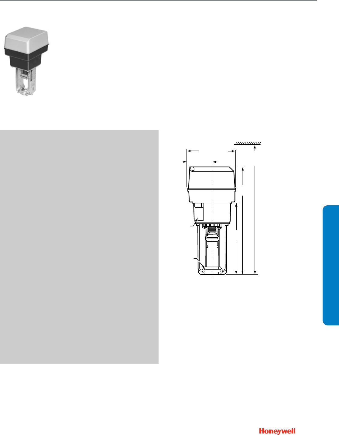
123
SUBMITTAL SHEETS
Direct Coupled Valve Actuator
ML6425; ML7425
ML6425; ML7425
Direct Coupled Globe Valve
Actuators provide floating and
modulating control of chilled water,
hot water, and steam, and mount
directly on VGF series, V5011, and
V5013 globe valves. These Spring
Return Actuators will operate 1/2 to
3 in. valves.
SPECIFICATIONS
Actuator Type ....................................... Valve
Control Signal ....................................... Floating; 0-10 Vdc or
2-10 Vdc modulating
Fail Safe Mode ..................................... Stem down on power failure; or
stem up on power failure
(Rated) Stem Force .............................. 135 lbf (600 N)
Spring Return Torque ........................... 135 lbf (600 N)
Cable Entry .......................................... Conduit connector and one
knockout on actuator case
Electrical Protection ............................. Class I Insulation (24 Vac)
Ingress Protection Rating ..................... IP54
Electrical Connections ......................... Screw terminals
Frequency ............................................ 60 Hz
Manual operation ................................. Manual override winding
Mounting .............................................. Directly on V5011/V5013
Globe Valves and VGF
Flanged Globe Valves (3/4 in.
or 20mm stroke)
Stroke ................................................... 3/4 in. (20 mm)
Materials ............................................... ABS-FR Plastic, aluminum
yoke
Operating Humidity Range (% RH) ...... 5 to 95% RH
Medium Temperature ........................... 300 F Maximum
(150 C Maximum)
Ambient Temperature Range ............... 14 F to 122 F (-10 C to 50 C)
Storage Temperature Range ................ -40 F to 158 F (-40 C to 70 C)
Weight .................................................. 5.1 lb (2.3 kg)
Includes ................................................ 1/2 in. conduit hub
APPROVALS
CE ......................................................... Recognized
Underwriters Laboratories, Inc. ............ UL94-5V
ACCESSORIES
43191679-111—Potentiometer, 10 K ohm, for ML6425, ML7425
43191679-112—Potentiometer, 220 ohm for ML6425, ML7425
43191680-105—Dual Auxiliary Switch for CREVAL actuators
43196000-001—High Temperature Kit for actuators with 3/4 in. stroke
FEATURES
• Easy and quick installation on valves with 1 3/8 in. bonnet
and 3/4 in. stroke.
• No separate linkage required.
• Conduit connector standard.
• No adjustments required on linkage.
• Accurate valve positioning.
• Low power consumption.
• High close-off ratings.
• Force limiting end switches.
• Internal manual operator.
• Synchronous motor.
• Maintenance free.
DIMENSIONS DIAGRAM
5-5/15
(135)
6-5/16
(161)
x
2-11/16 (67)
14-5/16 (364)
MINIMUM
CLEARANCE
11-1/4
(284)
7-5/8
(192)
M7892A
1/2 (13) FPT
YOKE
DIAMETER
1-3/8 (35)
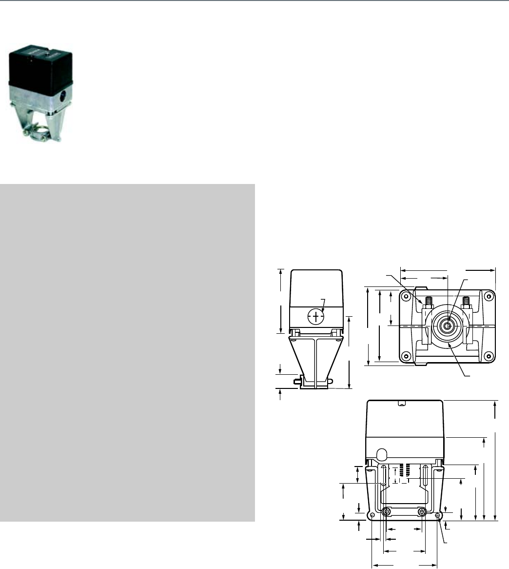
124
ML6984
The ML6984 is a self-contained,
self-adjusting, motorized linkage
that mounts directly onto V5011
two-way or V5013 three-way valves
and provides up to 25 mm (1 in.) of
linear travel (stem lift). For use with
low voltage 3-wire SPDT Series 20
(on-off); Series 60 (floating)
electromechanical (dry contacts);
or electronic (triac output)
controllers.
SPECIFICATIONS
Actuator Type ....................................... Valve
Control Signal ....................................... Floating
Fail Safe Mode ..................................... Stays in place
(Rated) Stem Force .............................. 160 lbf (710 N)
Cable Entry .......................................... 7/8 in. hole for 1/2 in. conduit
External Auxiliary Switches Available .. 272630D
Electrical Protection ............................. NEMA 3R
Ingress Protection Rating ..................... NEMA 3R, IP54 (mounted in
vertical position)
Electrical Connections ......................... Screw terminals
Feedback ............................................. Position feedback available
w/ 272630D; 2-10 Vdc
Frequency ............................................ 50 Hz, 60 Hz
Manual operation ................................. None
Mounting .............................................. Screws onto 1/4-28 UNF
threaded valve stem
Stroke ................................................... 1/2 to 1 in. (13 to 25 mm)
Supply Voltage ..................................... 24 Vac; 28 Vdc
Materials ............................................... UV-stabilized plastic cover,
aluminum base & yoke
Operating Humidity Range (% RH) ...... 15 to 95% RH at 104 F (40 C)
Medium Temperature ........................... 300 F Maximum
(150 C Maximum)
Ambient Temperature Range ............... 32 F to 130 F (0 C to 50 C)
Temperature Ratings (Shipping) .......... -40 F to 150 F (-40 C to 65 C)
Storage Temperature Range ................ -40 F to 150 F (-40 C to 65 C)
Weight .................................................. 2.2 lb (1 kg)
Includes ............................................... Screw terminals
Comments ............................................ 3 or 5-wire operation.
ACCESSORIES
272630D—position feedback and SPDT pilot duty auxiliary switch
(5 wire mode only)
272629A—travel stop for VGF21ES/LS and VGF22ES/LS valves
FEATURES
• Allows the use of one common transformer power supply for
multiple actuators and controllers.
• Self-contained, motorized valve linkage.
• Linkage self-adjusts to valve stroke of 1/2 to 1 in.
(12 to 25 mm).
• Multi-pose mounting.
• Strong valve seat closing force 160 lb-in. (710 Newton).
• Compact size for easy installation in confined area.
• One device for either 24 Vac or 28 Vdc power supply
application.
• Electronic current sensing provides internal protection and
positive full closing force.
• Field-addable position feedback/auxiliary switch module
available.
• Compatible with 3-wire control systems such as Excel 10.
DIMENSIONS DIAGRAM
YELLOW
2-45/64 (69)
4-1/16
(103)
7/8 (22)
KNOCKOUT
25/32
(20)
4
(102)
M16817
1-17/32
(39)
3-1/16
(78)
3-13/64
(82)
4 (102)
2 (51) 1/4 (6)
– 28UNF
1-23/64 (35)
MOUNTING DIA.
1/4 (6) –
20 NUT [2]
2-3/32
(53)
17/64
(7)
51/64
(21)
7/32
(6)
7-3/64
(179)
3-3/32
(78)
1-21/32
(42)
2-13/64
(56)
3-7/32 (82)
4-9/16
(116)
25/64 (10)
3/16 (5) DIA.
SILVER
2-53/64 (72)
3/4 (19)
NOMINAL
STROKE
Direct Coupled Valve Actuator
ML6984
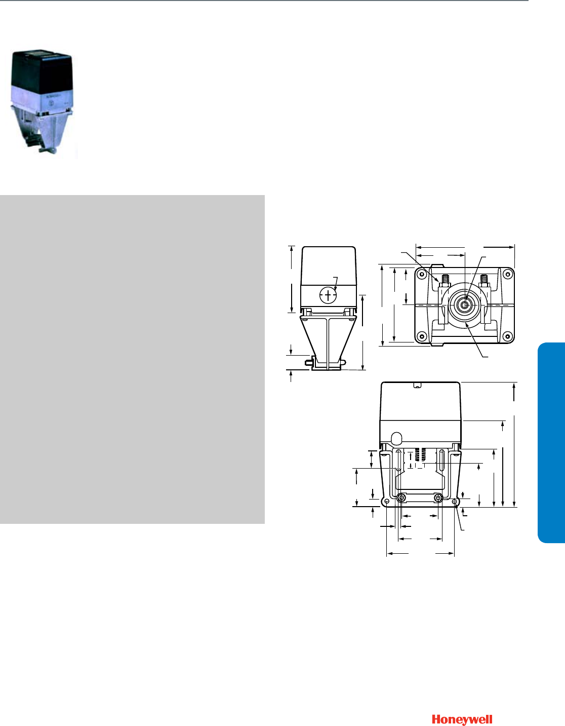
125
SUBMITTAL SHEETS
Direct Coupled Valve Actuator
ML7984
ML7984
The ML7984 is a self-contained, self-
adjusting, motorized linkage that mounts
directly onto V5011 two-way or V5013
three-way valves and provides up to 25
mm (1 in.) of linear stem travel. For use
with Series 70 2-10Vdc, 4-20mA; Series
90 135 ohm; and Electronic (Super Mod)
modulating signals controllers.
SPECIFICATIONS
Actuator Type ....................................... Valve
Control Signal ....................................... 2-10 Vdc, 4-20 mA, 135 ohm
slidewire or SuperMod signal.
Fail Safe Mode ..................................... Stays in place
(Rated) Stem Force .............................. 160 lbf (710 N)
Cable Entry .......................................... 7/8 in. hole for 1/2 in. conduit
External Auxiliary Switches Available .. 272630D
Electrical Protection ............................. NEMA 3R
Ingress Protection Rating ..................... NEMA 3R, IP54 (mounted in
vertical position)
Electrical Connections ......................... Screw terminals
Feedback ............................................. Position feedback available
w/ 272630D; 2-10 Vdc
Frequency ............................................ 50 Hz; 60 Hz
Manual operation ................................. None
Mounting .............................................. Screws onto 1/4-28 UNF
threaded valve stem
Stroke ................................................... 1/2 to 1 in. (13 to 25 mm)
Supply Voltage ..................................... 24 Vac; 28 Vdc
Materials ............................................... UV-stabilized plastic cover,
aluminum base & yoke
Operating Humidity Range (% RH) ...... 15 to 95% RH at 104 F (40 C)
Ambient Temperature Range ............... 32 F to 130 F (0 C to 55 C)
Temperature Ratings (Shipping) .......... -40 F to 150 F (-40 C to 65 C)
Storage Temperature Range ................ -40 F to 150 F (-40 C to 65 C)
Weight .................................................. 2.2 lb (1 kg)
Includes ................................................ Screw terminals
Comments ............................................ Direct/Reverse Acting Switch
ACCESSORIES
272630D—position feedback and SPDT pilot duty auxiliary switch
272629A—travel stop for VGF21ES/LS and VGF22ES/LS valves
FEATURES
• Allows the use of one common transformer power supply for
multiple actuators and controllers.
• Self-contained, motorized valve linkage.
• Linkage self-adjusts to valve stroke from 1/2 to 1 in.
(12 to 25 mm).
• Multi-pose mounting.
• Strong valve seat closing force 710 Newton (160 lb.).
• Compact size for easy installation in confined area.
• One device for either Vac or Vdc power supply application.
• Electronic current sensing provides internal protection and
positive full closing force.
• Field-addable position feedback/auxiliary switch module
available.
DIMENSIONS DIAGRAM
YELLOW
2-45/64 (69)
4-1/16
(103)
7/8 (22)
KNOCKOUT
25/32
(20)
4
(102)
M16817
1-17/32
(39)
3-1/16
(78)
3-13/64
(82)
4 (102)
2 (51) 1/4 (6)
– 28UNF
1-23/64 (35)
MOUNTING DIA.
1/4 (6) –
20 NUT [2]
2-3/32
(53)
17/64
(7)
51/64
(21)
7/32
(6)
7-3/64
(179)
3-3/32
(78)
1-21/32
(42)
2-13/64
(56)
3-7/32 (82)
4-9/16
(116)
25/64 (10)
3/16 (5) DIA.
SILVER
2-53/64 (72)
3/4 (19)
NOMINAL
STROKE
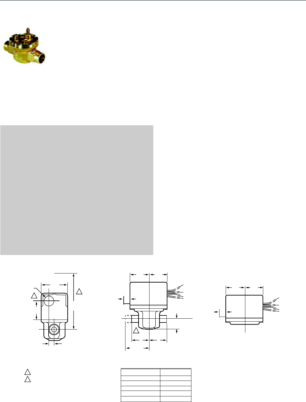
126
Unitary Valve
VU52; VU53
VU52; VU53
Two-way Fan Coil Valves, the VU53
high pressure zone valves are used
to control the flow of hot or chilled
water in commercial HVAC
equipment such as fan coil units,
terminal reheat coils and
convectors.
IMPORTANT: These valves are not
for use in systems containing
dissolved oxygen.
SPECIFICATIONS
Valve Type ............................................ Fan Coil Valve
Valve Size ............................................ 1/2; 3/4; or 1 in.
Connection Type .................................. Sweat; NPT; or
1/2 in. Inverted flare
Body Pattern ........................................ Two-way, Straight-through
Flow Characteristic .............................. Quick Opening
Controlled Medium ............................... Hot/Chilled Water with up to
60% Glycol
Maximum Safe Operating Pressure ..... 300 psig (2068 kPa)
Ambient Temperature Range ............... 34 F to 125 F at 200 F Fluid
(1 to 52 C @ 94 C Fluid)
Actuation .............................................. Must be purchased separately
Materials
(Body) .................................................. Brass
(Stem) ................................................... Brass
(Seat) .................................................... Brass
(Plug/Ball/Disc) .................................... Buna-N rubber
(Packing) .............................................. EPDM rubber
APPROVALS
Canadian Standards Association ........ CSA C/US
FEATURES
• Compact construction for easy installation.
• Fits under the cover of most baseboard convectors with
actuator fitted to valve body.
• VU52 and VU53 provide 2-way, straight-through control of
water.
• Available in normally closed (VU53) or normally open
(VU52) configurations.
• 300 psi (2,000 kPa, PN20) operating pressure rating.
• Patented ball seal provides long service life, soft close off.
• Triple O-ring seal provides three lines of defense against
corrosion and water leakage around drive shaft.
• Quick opening flow curve.
• Available with NPT end connections for iron or steel piping.
DIMENSIONS DIAGRAM
2
2
1
1
VU52 AND VU53 VALVE WITH VU448 ACTUATOR
VU52 AND VU53 VALVE WITH ACTUATOR
VU ACTUATOR
2-3/8
(60)
7/8 DIA.
(22)
1-1/2
(38)
3-3/4
(133)
15/32
(12)
3/8
(10)
1-3/4
(44)
1-3/4
(44)
A
A
B
7
3/8
(10)
A
2-1/8 (54)
(INVERTED
FLARE)
1-3/4
(44)
1-3/4
(44)
7/8 (22)
2-WAY
VALVE BODY SIZE A
1/2 IN. SWEAT 1-5/6 (33)
3/4 IN. SWEAT 1-3/8 (35)
1 IN. SWEAT 1-11/16 (43)
1/2 IN. NPT 1-3/8 (35)
3/4 IN. NPT 1-11/16 (43)
HEIGHT NEEDED TO REMOVE ACTUATOR OR COVER
OPENING FOR 1/2 IN. CONDUIT ON OPPOSITE SITE OF
MANUAL LEVER FOR ALL MODELS.
M16818
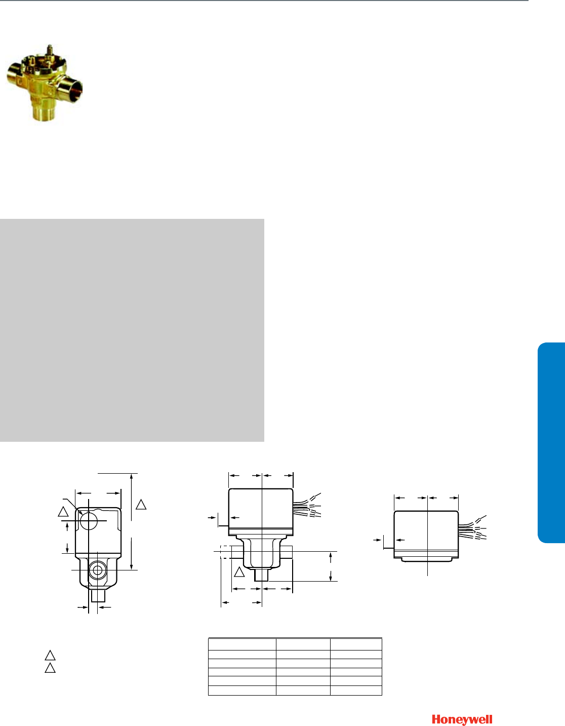
127
SUBMITTAL SHEETS
Unitary Valve
VU54
VU54
Three-way Fan Coil Valve, the VU54
high pressure zone valves are used
to control the flow of hot or chilled
water in commercial HVAC
equipment such as fan coil units,
terminal reheat coils and
convectors.
IMPORTANT: These valves are not
for use in systems containing
dissolved oxygen.
SPECIFICATIONS
Valve Type ............................................ Fan Coil Valve
Valve Size ............................................ 1/2; 3/4; or 1 in.
Connection Type .................................. Sweat; NPT; or
1/2 in. Inverted flare
Body Pattern ........................................ Three-way A-AB-B
Flow Characteristic ............................... Quick Opening
Controlled Medium ............................... Hot Water; Chilled Water with
up to 60% Glycol
Maximum Safe Operating Pressure ..... 300 psig (2068 kPa)
Ambient Temperature Range ............... 34 F to 125 F at 200 F Fluid
(1 to 52 C @ 94 C Fluid )
Actuation .............................................. Must be purchased separately
Materials
(Body) ................................................... Brass
(Stem) ................................................... Brass
(Seat) .................................................... Brass
(Plug/Ball/Disc) ..................................... Buna-N rubber
(Packing) .............................................. EPDM rubber
APPROVALS
Canadian Standards Association ......... CSA C/US
FEATURES
• Compact construction for easy installation.
• Fits under the cover of most baseboard convectors with
actuator fitted to valve body.
• VU54 provides three-way diverting control of water.
• 300 psi (2,000 kPa, PN20) operating pressure rating.
• Patented ball seal provides long service life, soft close off.
• Triple O-ring seal provides three lines of defense against
corrosion and water leakage around drive shaft.
• Quick opening flow curve.
• Choice of NPT end connections for iron or steel piping.
DIMENSIONS DIAGRAM
2
2
1
1
VU54 VALVE WITH VU448 ACTUATOR VU54 VALVE WITH ACTUATOR VU ACTUATOR
2-3/8
(60)
7/8 DIA.
(22)
1-1/2
(38)
3-3/4
(133)
15/32
(12)
3/8
(10)
1-3/4
(44)
1-3/4
(44)
A
A
B
AB
7
3/8
(10)
A
2-1/8 (54)
(INVERTED
FLARE)
1-3/4
(44)
1-3/4
(44)
B
VALVE BODY SIZE A B
1/2 IN. SWEAT 1-5/6 (33) 1-5/6 (33)
3/4 IN. SWEAT 1-3/8 (35) 1-11/16 (43)
1 IN. SWEAT 1-11/16 (43) 1-11/16 (43)
1/2 IN. NPT 1-3/8 (35) 1-5/16 (33)
3/4 IN. NPT 1-11/16 (43) 1-7/16 (37)
HEIGHT NEEDED TO REMOVE ACTUATOR OR COVER
OPENING FOR 1/2 IN. CONDUIT ON OPPOSITE SITE OF
MANUAL LEVER FOR ALL MODELS.
M16819

128
VCZA; VCZB
Two-way Cartridge Cage Valves
are intended for hydronic
applications in a normal indoor
environment to control the flow of
hot water or chilled water glycol
solution to 60% concentration.
These valves are designed for zone
control of heating/cooling systems,
or to control individual fan coil,
baseboard radiator or convector
applications. Depending on the
model selected they can be
controlled by SPST or SPDT two
position controller, tristate (floating), or modulating proportional
controller. For trouble-free operation of the product, good
installation practice must include initial system flushing,
chemical water treatment, and the use of a 50 micron (or finer)
system side stream filter(s). Remove all filters before flushing.
SPECIFICATIONS
Valve Type ............................................ Cartridge Cage Valve
Body Pattern ........................................ Two-way, Straight-through
Connection Type .................................. Sweat or , Female NPT
Controlled Medium ............................... Hot/Chilled Water with up to
60% Glycol
Flow characteristic ............................... Quick open, linear, or equal
percentage
Maximum Safe Operating Pressure ..... 300 psi (2068 kPa (20 Bar))
Close-off pressure ................................ 60 psid (414 kPa [4.1 bar])
Fluid Temperature Range ..................... 34 F to 203 F (1 C to 95 C)
Ambient Temperature Range ............... 32 F to 150 F (0 C to 65 C)
Stem Travel ........................................... 0.4 in. (10 mm)
Materials
(Body) .................................................. Bronze
(Stem) ................................................... Stainless Steel
(Seat) .................................................... EPDM O-ring seals on Noryl
piston
(Cartridge) ............................................ Ryton™, Noryl™ engineering
plastic
(Packing) .............................................. EPDM rubber
APPROVALS
Canadian Standards Association ........ CSA Certified
ACCESSORIES
40007029-002—Wrench for cartridge (included with sweat valves and
all replacement cartridges)
FEATURES
• Quick open, linear, and equal percentage flow
characteristics available.
• Bi-directional installation.
• 3000-series valves for floating and modulating non-fail safe
applications
• 1000-series valves for two-position control
• High close-off rating independent of Cv.
• Available with a variety of North American and international
pipe fittings.
• No tools required for actuator installation or removal.
• Actuator removal does not require draining system.
• Service is by replacement of cartridge, not valve body.
• Cartridge replacement rebuilds valve to factory-new
condition.
Unitary Valve
VCZA; VCZB

129
SUBMITTAL SHEETS
Unitary Valve
VCZM; VCZN
VCZM; VCZN
Three-way Cartridge Cage Valves
are intended for hydronic
applications in a normal indoor
environment to control the flow of
hot water or chilled water glycol
solution to 60% concentration.
These valves are designed for zone
control of heating/cooling systems,
or to control individual fan coil,
baseboard radiator or convector
applications. Depending on the
model selected they can be
controlled by SPST or SPDT two
position controller, tristate (floating), or modulating proportional
controller. For trouble-free operation of the product, good
installation practice must include initial system flushing,
chemical water treatment, and the use of a 50 micron (or finer)
system side stream filter(s). Remove all filters before flushing.
SPECIFICATIONS
Valve Type ............................................ Cartridge Cage Valve
Body Pattern ........................................ Three-way A-AB-B
Connection Type .................................. Sweat, , Female NPT
Controlled Medium ............................... Hot/Chilled Water with up to
60% Glycol
Flow characteristic ............................... Quick open or linear
Maximum Safe Operating Pressure ..... 300 psi (2068 kPa (20 Bar))
Close-off pressure ................................ 60 psid (414 kPa [4.1 bar])
Fluid Temperature Range ..................... 34 F to 203 F (1 C to 95 C)
Ambient Temperature Range ............... 32 F to 150 F (0 C to 65 C)
Stem Travel ........................................... 0.4 in. (10 mm)
Materials
(Body) ................................................... Bronze
(Stem) ................................................... Stainless Steel
(Seat) .................................................... EPDM O-ring seals on Noryl
piston
(Cartridge) ............................................ Ryton™, Noryl™ engineering
plastic
(Packing) .............................................. EPDM rubber
APPROVALS
Canadian Standards Association ......... CSA Certified
ACCESSORIES
40007029-002—Wrench for cartridge (included with sweat valves and
all replacement cartridges)
FEATURES
• Quick open and linear flow characteristics available.
• Mixing or diverting application.
• A-AB-B body pattern.
• 7000-series valves for floating and modulating non-fail safe
applications
• 6000-series valves for two-position control
• High close-off rating independent of Cv.
• Available with a variety of North American and international
pipe fittings.
• No tools required for actuator installation or removal.
• Actuator removal does not require draining system.
• Service is by replacement of cartridge, not valve body.
• Cartridge replacement rebuilds valve to factory-new
condition.
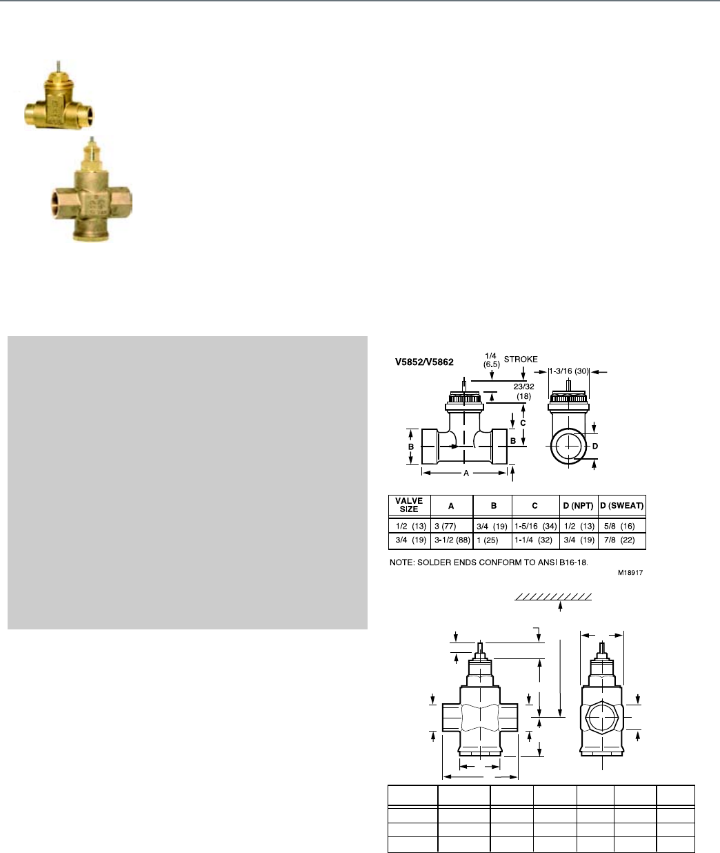
130
V5852; V5862
Two-way Cartridge Globe Valves
control hot and/or chilled water for
VAV terminal units, fan coil units,
small reheaters and recoolers in
electric/electronic temperature
control systems. Used with the
M6410 3-position floating Non-
Spring Return Valve Actuator and
the M7410 selectable 0 to 10 Vdc or
2 to 10 Vdc Non-Spring Return
Actuator. The 1/2 and 3/4 in. valves
are compatible with the M6435
floating Spring Return Actuator, the M7435 selectable 0 to 10
Vdc or 2 to 10 Vdc Spring Return Actuator, and the MP958
Pneumatic Actuator. Larger valves (1 in. through 1-1/2 in.) are
pressure balanced, which results in higher close-off pressures.
SPECIFICATIONS
Valve Type ............................................ Cartridge Globe Valve
Body Pattern ........................................ Two-way
Flow characteristic ............................... Equal percentage for 1/2 and
3/4 in.
Linear for 1 to 1 1/2 in.
Connection Type .................................. Sweat , Female NPT
Controlled Medium ............................... Hot/Chilled Water with up to
50% Glycol
Leakage Rating .................................... less than 0.02% of Cv
Maximum Safe Operating Pressure ..... 235 psi (1620 kPa)
Ambient Temperature Range ............... 36 F to 230 F (2 C to 110 C)
Stem Travel ........................................... 1/4 in. (6.4 mm)
Materials
(Body) .................................................. Brass
(Stem) ................................................... Stainless Steel
(Seat) .................................................... Brass
(Cartridge) ............................................ Brass
(Plug/Ball/Disc) .................................... Brass
Includes ............................................... combination dust cap/manual
operator
FEATURES
• Long stroke allows wider range of control.
• Soft valve seat provides low leakage rate.
• Inserts for 1/2 in. and 3/4 in. valves are changeable without
draining valve when used with an insert replacement tool.
• Brass body and Stainless Steel stem.
• Threaded plastic cover/manual handle allows manual
operation.
• Easily installed in areas where space is limited.
DIMENSIONS DIAGRAM
1 (25)
1-1/4 (32)
1-1/2 (38)
4-1/8 (105)
4-15/16 (125)
5-1/8 (130)
1-5/8 (41)
2 (50)
2-3/16 (55)
2-1/16 (53)
2-7/16 (62)
2-9/16 (65)
3-5/8 (92)
3-5/8 (92)
3-7/8 (98)
B C DE
1-3/4 (44)
2-1/4 (57)
2-5/8 (67)
G
2 (50)
2-3/16 (55)
2-3/8 (60)
F
VALVE SIZE
A (NPT)
E
A
CC
F
B
D
23/32
(18) G
1/4 (6.5)
STROKE
MINIMUM CLEARANCE
9-7/8
(250)
Unitary Valve
V5852; V5862
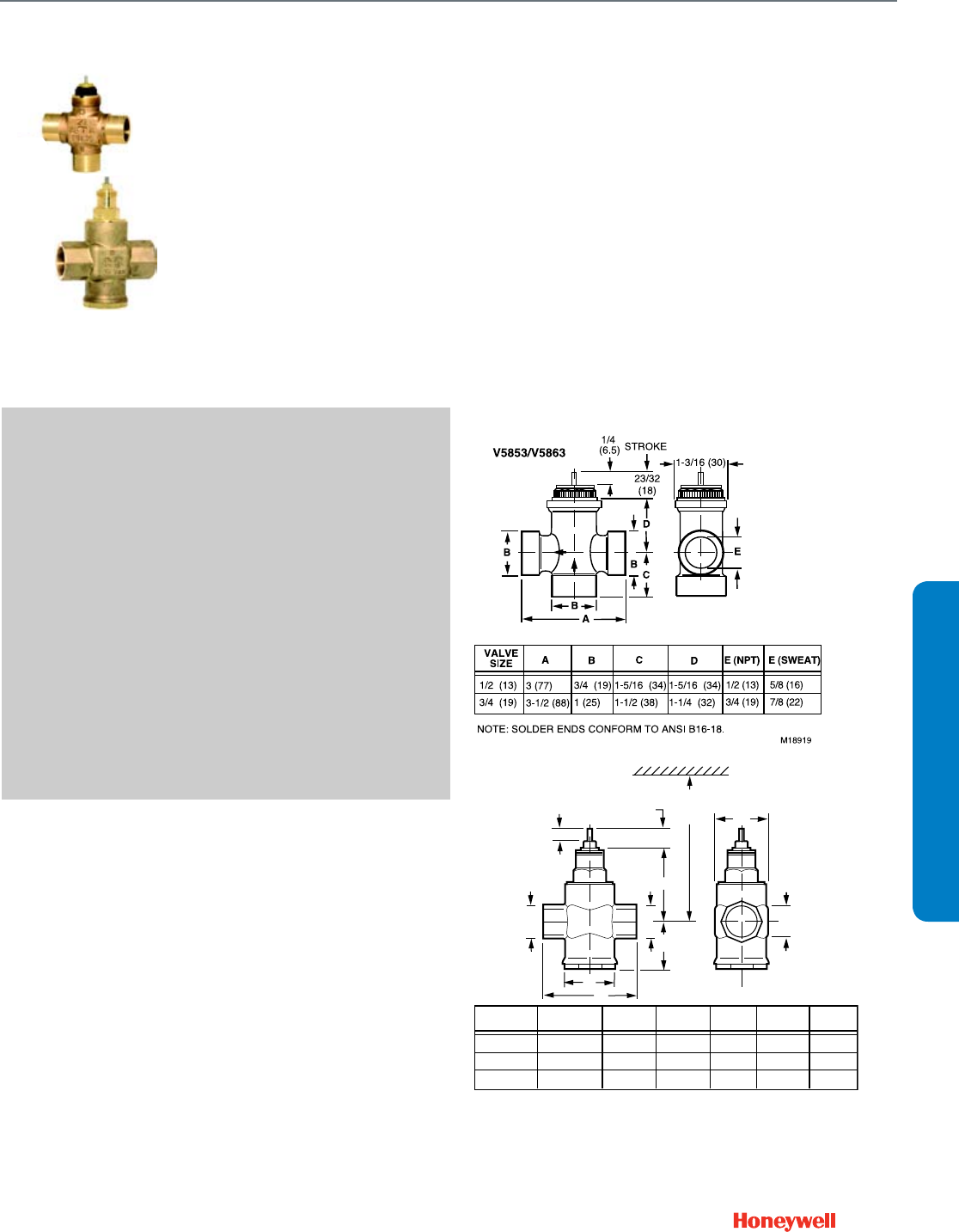
131
SUBMITTAL SHEETS
Unitary Valve
V5853; V5863
V5853; V5863
Three-way Cartridge Globe Valves
control hot and/or chilled water for
VAV terminal units, fan coil units,
small reheaters and recoolers in
electric/ electronic temperature
control systems. Used with the
M6410 3-position floating Non-
Spring Return Valve Actuator and
the M7410 selectable 0 to 10 Vdc
or 2 to 10 Vdc Non-Spring Return
Actuator. The 1/2 in. and 3/4 in.
valves are also compatible with the
M6435 floating Spring Return
Actuator, the M7435 selectable 0 to 10 Vdc or 2 to 10 Vdc
Spring Return Actuator, and the MP958 Pneumatic Actuator.
SPECIFICATIONS
Valve Type ............................................ Cartridge Globe Valve
Body Pattern ........................................ Three-way
Flow Characteristic ............................... A -port - Equal percentage for
1/2 and 3/4 in.
Linear for 1 to 1 1/2 in.
B-port - Linear @ 20% reduced
Cv
Connection Type .................................. Sweat , Female NPT
Controlled Medium ............................... Hot/Chilled Water with up to
50% Glycol
Leakage Rating .................................... less than 0.02% of Cv
Maximum Safe Operating Pressure ..... 235 psi (1620 kPa)
Ambient Temperature Range ............... 36 F to 230 F (2 C to 110 C)
Stem Travel ........................................... 1/4 in. (6.4 mm)
Materials
(Body) ................................................... Brass
(Stem) ................................................... Stainless Steel
(Seat) .................................................... Brass
(Cartridge) ............................................ Brass
(Plug/Ball/Disc) ..................................... Brass
Includes ................................................ Combination manual opener/
dust cap
FEATURES
• Long stroke allows wider range of control.
• Soft valve seat provides low leakage rate.
• Inserts for 1/2 in. and 3/4 in. valves are changeable without
draining valve when used with an insert replacement tool.
• Brass body and stainless steel stem.
• Threaded plastic cover/manual handle allows manual
operation.
• Easily installed in areas where space is limited.
DIMENSIONS DIAGRAM
1 (25)
1-1/4 (32)
1-1/2 (38)
4-1/8 (105)
4-15/16 (125)
5-1/8 (130)
1-5/8 (41)
2 (50)
2-3/16 (55)
2-1/16 (53)
2-7/16 (62)
2-9/16 (65)
3-5/8 (92)
3-5/8 (92)
3-7/8 (98)
B C DE
1-3/4 (44)
2-1/4 (57)
2-5/8 (67)
G
2 (50)
2-3/16 (55)
2-3/8 (60)
F
VALVE SIZE
A (NPT)
E
A
CC
F
B
D
23/32
(18) G
1/4 (6.5)
STROKE
MINIMUM CLEARANCE
9-7/8
(250)
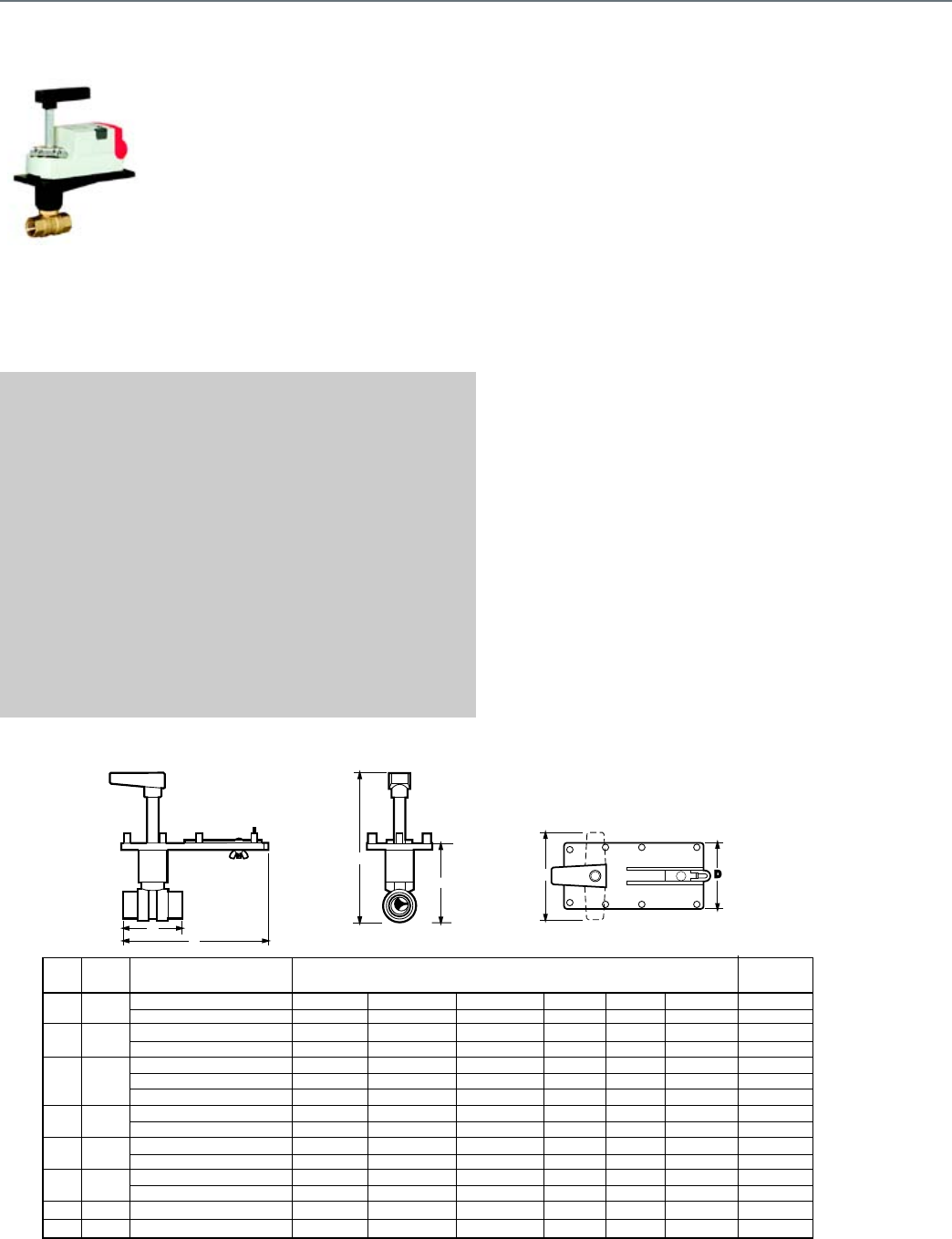
132
VBN2
The VBN2 Two-Way Control Ball
Valves control hot and chilled water
with glycol solutions up to 50% in
heating, ventilating, and air
conditioning (HVAC) systems to
provide two-position or modulating
functions. These valve assemblies
can be ordered with or without
factory-mounted non-spring return
or spring return direct-coupled
actuators (DCA).
SPECIFICATIONS
Valve Type ............................................ Control Ball Valve
Body Pattern ........................................ Two-way
Flow Characteristic .............................. Equal percentage with
patented control insert.
Connection Type .................................. NPT Female
Controlled Medium ............................... Hot/Chilled Water with up to
50% Glycol
Leakage Rating .................................... ANSI Class IV
Maximum Safe Operating Pressure ..... 360 psi (2482 kPa)
Fluid Temperature Range ..................... -22 F to 250 F (-30 C to 121 C)
Materials
(Body) .................................................. Brass
(Stem) ................................................... Brass
(Seat) .................................................... Teflon® seals with EPDM O-
rings
(Plug/Ball/Disc) .................................... Nickel-plated brass ball; or
stainless steel
(Flow optimizer) .................................... Noryl(C)
FEATURES
• Sizes from 1/2 to 2-1/2 in. with internal (female) NPT
connections.
• Equal percentage or linear flow characteristics.
• Choice of four, factory-installed actuation control schemes:
Floating, Modulating (2-10 V), Spring Return 2-Position,
Spring Return Modulating/Floating.
• Field configurable for normally open or normally closed fail-
safe position.
• Removable manual operating handle to control valve during
installation or in an event of power failure.
• ANSI Class IV seat leakage specification (0.01% of Cv).
• Optional NEMA 3R (IP54) rated enclosure for outdoor
applications.
• Actuator can be mounted on the valve in any of four
positions.
• Sizes up to 3 in.
• Wide Cv choices from 0.38 to 266.
• Nickel-chrome plated brass or 316 stainless steel valve ball
and stem.
DIMENSIONS DIAGRAM
A
C
M13729
F
ED
B
Pipe Model CV Dimensions inches (mm) Weight
Size No. A B C D E F lb (kg)
1/2" VBN2A 0.38, 0.68, 1.3, 2.0, 2.6, 4.7, 11.7 2-3/8 (60) 3-7/16 (87) 6-5/8 (168) 3 (76) 4 (102) 8-1/8 (206) 1 (0.5)
8.0 2-5/8 (67) 3-11/16 (94) 6-1/2 (165) 3 (76) 4 (102) 8-5/16 (211) 1 (0.5)
3/4" VBN2B 0.31, 0.63, 1.2, 2.5, 4.3, 7.4, 14.7 2-3/8 (60) 3-7/16 (87) 6-7/16 (164) 3 (76) 4 (102) 8-1/8 (206) 1 (0.5)
10.1, 29 2-5/8 (67) 3-11/16 (94) 6-1/2 (165) 3 (76) 4 (102) 8-5/16 (211) 1 (0.5)
1" VBN2C 9.0 3-3/4 (95) 3-11/16 (94) 7-1/16 (179) 3 (76) 4 (102) 8-5/16 (211) 1 (0.5)
4.4, 15.3, 54 3 (76) 3-15/16 (100) 6-3/4 (171) 3 (76) 4 (102) 8-11/16 (221) 1.4 (0.6)
26, 44 4-3/8 (111) 4-7/16 (113) 7-3/8 (187) 3 (76) 4 (102) 8-7/8 (225) 2.4 (1.1)
1-1/4" VBN2D 4.4, 8.3, 14.9, 25, 41 3 (76) 3-15/16 (100) 6-11/16 (170) 3 (76) 4 (102) 8-11/16 (221) 1.4 (0.6)
37, 102 3-5/8 (92) 4-7/16 (113) 7 (178) 3 (76) 4 (102) 9-1/16 (231) 2.4 (1.1)
1-1/2" VBN2E 23, 30, 74 3-3/8 (86) 3-15/16 (100) 6-15/16 (176) 3 (76) 4 (102) 9-1/16 (231) 2.4 (1.1)
41, 172 3-3/4 (95) 5-3/16 (132) 7-1/16 (179) 3 (76) 4 (102) 8-7/8 (225) 3.2 (1.5)
2" VBN2F 42, 108 4 (102) 5-3/16 (132) 7-3/16 (183) 3 (76) 4 (102) 8-7/8 (225) 3.2 (1.5)
57, 71, 100, 210, 266 4-3/8 (111) 5-3/4 (146) 7-7/16 (189) 3 (76) 4 (102) 10-1/2 (267) 5 (2.3)
2-1/2" VBN2G 45, 55, 72, 101, 162, 202 4-3/4 (121) 5-3/4 (146) 7-9/16 (192) 3 (76) 4 (102) 10-1/2 (267) 5.5 (2.5)
3" VBN2H 49, 63, 82, 124, 145 5 (127) 5-7/8 (149) 7-11/16 (195) 3 (76) 4 (102) 10-11/16 (271) 5.9 (2.7)
Control Ball Valve
VBN2
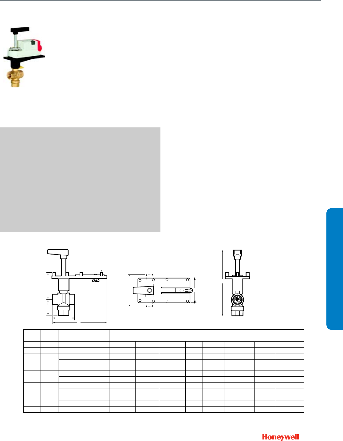
133
SUBMITTAL SHEETS
VBN3
The VBN3 Three-Way Control Ball
Valves control hot and chilled water
with glycol solutions up to 50% in
heating, ventilating, and air
conditioning (HVAC) systems to
provide two-position or modulating
functions. These valve assemblies
can be ordered with or without
factory-mounted non-spring return
or spring return direct-coupled
actuators (DCA).
SPECIFICATIONS
Valve Type ............................................ Control Ball Valve
Body Pattern ........................................ Three-way
Flow Characteristic ............................... Equal percentage with
patented control insert.
Connection Type .................................. NPT Female
Controlled Medium ............................... Hot/Chilled Water with up to
50% Glycol
Leakage Rating .................................... ANSI Class IV
Maximum Safe Operating Pressure ..... 360 psi (2482 kPa)
Fluid Temperature Range ..................... -22 F to 250 F (-30 C to 121 C)
Materials
(Body) ................................................... Brass
(Stem) ................................................... Brass
(Seat) .................................................... Teflon® seals with EPDM
O-rings
(Plug/Ball/Disc) ..................................... Nickel-plated brass ball
FEATURES
• Sizes from 1/2 to 2-1/2 in. with internal (female) NPT
connections.
• Equal percentage or linear flow characteristics.
• Choice of four, factory-installed actuation control schemes:
Floating, Modulating (2-10 V), Spring Return 2-Position,
Spring Return Modulating/Floating.
• Field configurable for normally open or normally closed fail-
safe position.
• Removable manual operating handle to control valve during
installation or in an event of power failure.
• ANSI Class IV seat leakage specification (0.01% of Cv).
• Optional NEMA 3R (IP54) rated enclosure for outdoor
applications.
• Actuator can be mounted on the valve in any of four
positions.
• Wide Cv choices from 0.33 to 109.
• Valve installs in a globe valve "T" pattern, no extra elbows or
piping required.
• Nickel-chrome plated brass valve ball and stem.
• Mixing or Diverting control.
DIMENSIONS DIAGRAM
M13730
ED
B
G
A
C
F
Pipe Model CV Dimensions inches (mm) Weight
Size No. A B C D E F G lb (kg)
1/2" VBN3A 0.33, 0.59, 1.0, 2.4, 4.3, 8.0 3-1/2 (90) 3-5/16 (84) 7 (178) 3 (76) 4 (102) 9-3/8 (238) 2-3/8 (60) 2.4 (1.1)
3/4" VBN3B 0.40, 0.66, 1.3, 2.4, 3.8, 11.0 2-13/16 (71) 3-5/16 (84) 6-1/2 (168) 3 (76) 4 (102) 8-13/16 (224) 2 (51) 2 (0.9)
1" VBN3C 0.40, 0.65, 1.3, 2.3, 3.5 3-13/16 (97) 3-5/16 (84) 7-5/16 (186) 3 (76) 4 (102) 9-1/2 (241) 2-3/4 (70) 2.8 (1.3)
8.6, 22 3 (76) 3-13/16 6-13/16 (173) 3 (76) 4 (102) 9-13/16 (249) 2-5/8 (67) 2.6 (1.2)
4.5, 14.9, 31 4-1/2 (114) 4 (102) 7-13/16 (198) 3 (76) 4 (102) 10-13/16 (275) 3-1/4 (83) 3.3 (1.5)
1-1/4" VBN3D 4.1, 8.7, 19.0 3 (76) 3-13/16 6-13/16 (173) 3 (76) 4 (102) 9-13/16 (249) 2-1/2 (64) 2.5 (1.1)
12.7, 27, 34 3-5/8 (92) 4 (102) 7-5/16 (186) 3 (76) 4 (102) 10-5/16 (262) 2-3/4 (70) 2.8 (1.3)
1-1/2" VBN3E 4.0, 8.3, 13.4, 32 4-1/2 (114) 4 (102) 7-13/16 (198) 3 (76) 4 (102) 10-13/16 (275) 3-1/4 (83) 3.3 (1.5)
24, 61 4 (102) 4-1/2 (114) 7-5/16 (186) 3 (76) 4 (102) 11 (279) 3-1/4 (83) 3.3 (1.5)
2" VBN3F 24, 38, 57 4 (102) 4-1/2 (114) 7-5/16 (186) 3 (76) 4 (102) 11 (279) 3-1/4 (83) 3.3 (1.5)
83, 109 5 (127) 5-13/16 7-13/16 (198) 3 (76) 4 (102) 12-5/16 (313) 3-3/4 (95) 3.8 (1.7)
2-1/2" VBN3G 38, 74, 100 5 (127) 5-13/16 7-13/16 (198) 3 (76) 4 (102) 12-5/16 (313) 3-3/4 (95) 3.8 (1.7)
Control Ball Valve
VBN3
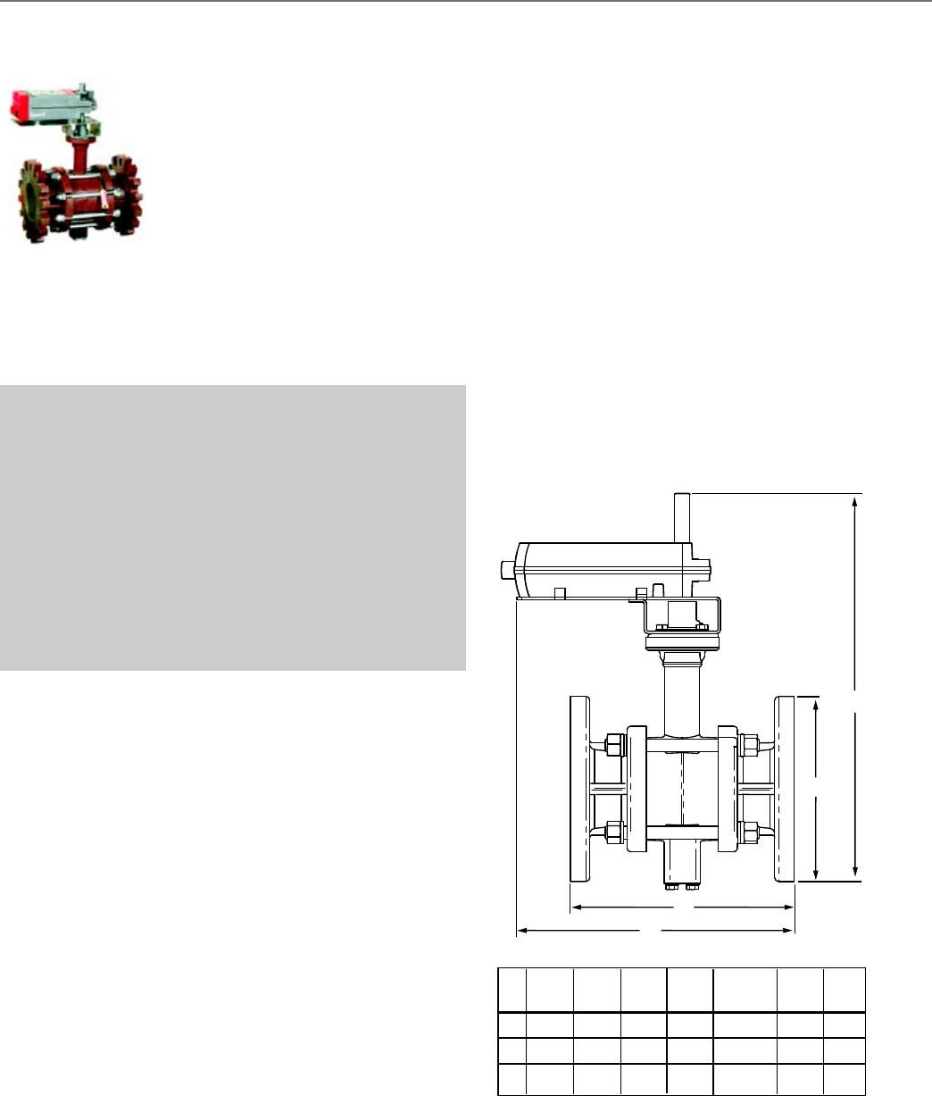
134
VBF2
The VBF2 Two-Way Ball Valve
Assemblies, with and without
actuators, control hot and chilled
water with glycol solutions up to
50% in heating, ventilating, and air
conditioning (HVAC) systems to
provide two-position or modulating
functions. These valve assemblies
can be ordered with or without
factory-mounted non-spring return
or spring return direct-coupled
actuators (DCA).
SPECIFICATIONS
Valve Type ............................................ Control Ball Valve
Body Pattern ........................................ Two-way
Flow Characteristic .............................. Equal percentage with laser-
milled port.
Connection Type .................................. ANSI 125/PN16 Flange
Controlled Medium ............................... Hot/Chilled Water with up to
50% Glycol
Leakage Rating .................................... ANSI Class IV
Maximum Safe Operating Pressure ..... 240 psi (1655 kPa)
Fluid Temperature Range ..................... -22 F to 250 F (-30 C to 121 C)
Materials
(Body) .................................................. Cast Iron
(Stem) ................................................... 316 stainless steel
(Seat) .................................................... Teflon®
(Plug/Ball/Disc) .................................... 316 stainless steel
FEATURES
• Sizes from 4 to 6 in. with ANSI Class 125 flanged
connections.
• Equal percentage flow characteristics.
• Choice of four, factory-installed actuation control schemes:
Floating, Modulating (2-10 V), Spring Return 24V 2-Position,
Spring Return Modulating/Floating.
• Field configurable for normally open or normally closed fail-
safe position.
• Removable manual operating handle to control valve
• during installation or in an event of power failure.
• ANSI Class IV leakage specification (0.01% of Cv).
• Optional NEMA 3R (IP54) rated enclosure for outdoor
applications.
• Option of four actuator mounting positions on the valve.
• Wide range of Cv choices from 91 to 650.
• Valve ball and stem 316 stainless steel.
DIMENSIONS DIAGRAM
A
B
C
E
Size Model A B C D (depth) E Wt.
(in.) Number in. in. in. (not shown) in. lb
(mm) (mm) (mm) in. (mm) (mm) (kg)
4 VBF2J 11 9 13-1/4 9 18-3/4 65
(278) (229) (337) (229) (476) (31)
5 VBF2K 12-3/8 10 14-1/4 10 19 75
(352) (254) (362) (254) (483) (34)
6 VBF2L 13-7/8 11 15-1/8 11 19-7/8 90
(352) (278) (384) (278) (505) (41)
M13732
Control Ball Valve
VBF2
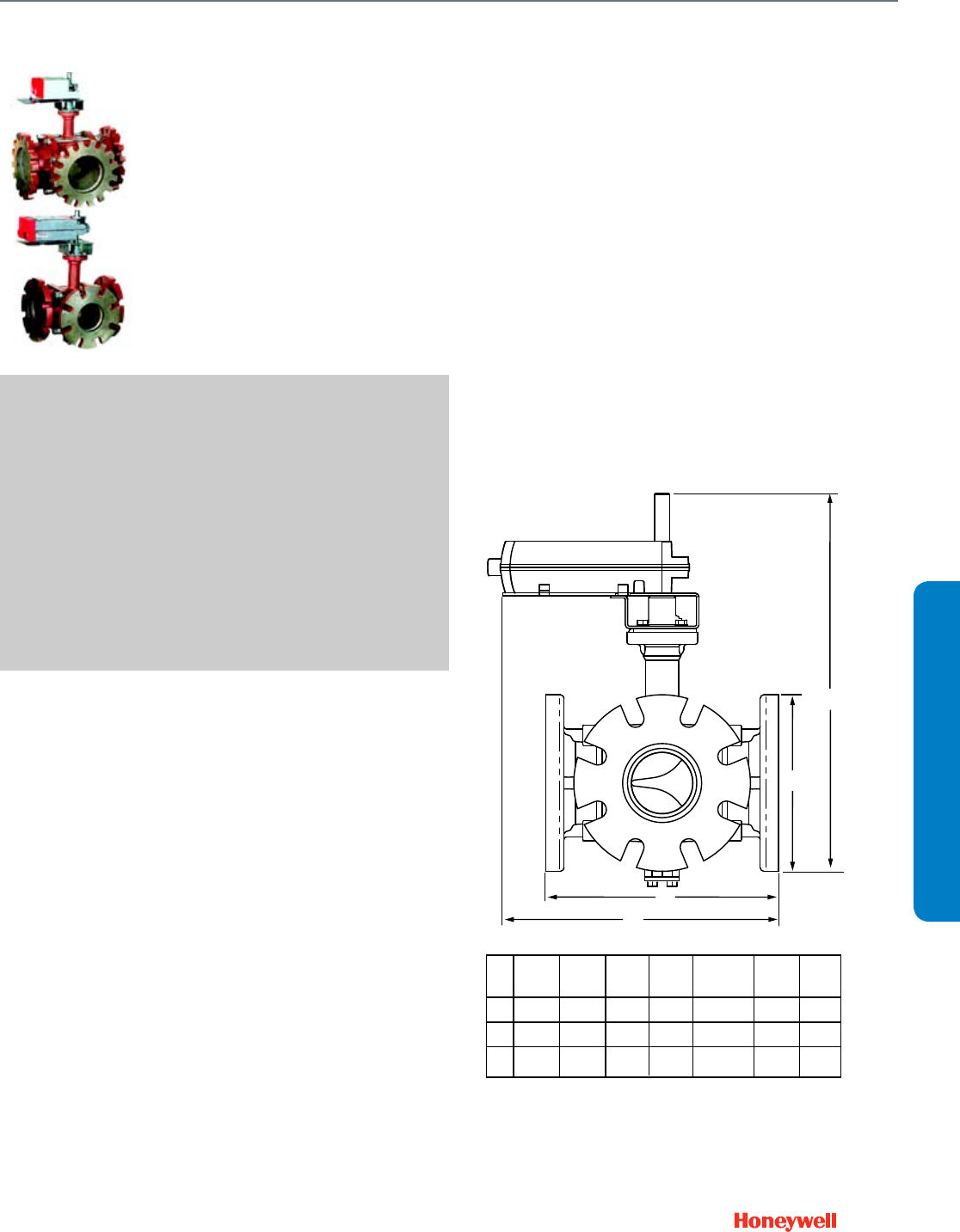
135
SUBMITTAL SHEETS
VBF3
The VBF3 Three-Way Ball Valve
Assemblies, with and without
actuators, control hot and chilled
water with glycol solutions up to
50% in heating, ventilating, and air
conditioning (HVAC) systems to
provide two-position or modulating
functions. These valve assemblies
can be ordered with or without
factory-mounted non-spring return
or spring return direct-coupled
actuators (DCA).
SPECIFICATIONS
Valve Type ............................................ Control Ball Valve
Body Pattern ........................................ Three-way
Flow Characteristic ............................... Equal percentage with laser-
milled port. (A-AB);
Linear (B-AB)
Connection Type .................................. ANSI 125/PN16 Flange
Controlled Medium ............................... Hot/Chilled Water with up to
50% Glycol
Leakage Rating .................................... ANSI Class IV (A port only)
Maximum Safe Operating Pressure ..... 240 psi (1655 kPa)
Fluid Temperature Range ..................... -22 F to 250 F (-30 C to 121 C)
Materials
(Body) ................................................... Cast Iron
(Stem) ................................................... 316 stainless steel
(Seat) .................................................... Teflon®
(Plug/Ball/Disc) ..................................... 316 stainless steel
FEATURES
• Sizes from 4 to 6 in. with ANSI Class 125 flanged
connections.
• Equal percentage or linear flow characteristics.
• Choice of four, factory-installed actuation control schemes:
Floating, Modulating (2-10 V), Spring Return 24V 2-Position,
Spring Return Modulating/Floating.
• Field configurable for normally open or normally closed fail-
safe position.
• Removable manual operating handle to control valve
• during installation or in an event of power failure.
• ANSI Class IV A-port seat leakage (0.01% of Cv).
• Optional NEMA 3R (IP54) rated enclosure for outdoor
applications.
• Option of four actuator mounting positions on the valve.
• Wide range of Cv choices from 91 to 650.
• Valve ball and stem 316 stainless steel.
• Mixing or Diverting control.
DIMENSIONS DIAGRAM
A
B
C
E
Size Model A B C D (depth) E Wt.
(in.) Number in. in. in. (not shown) in. lb
(mm) (mm) (mm) in. (mm) (mm) (kg)
4 VBF3J 11-7/8 9 14-1/8 10-3/8 18-1/2 75
(278) (229) (337) (229) (470) (34)
5 VBF3K 13-7/8 10 15-1/8 12 19-3/8 90
(352) (254) (362) (254) (483) (41)
6 VBF3L 15-7/8 11 16-1/8 13-3/8 20-1/2 105
(403) (278) (410) (521) (521) (48)
M13733A
AB PORT
B PORT
A PORT
Control Ball Valve
VBF3
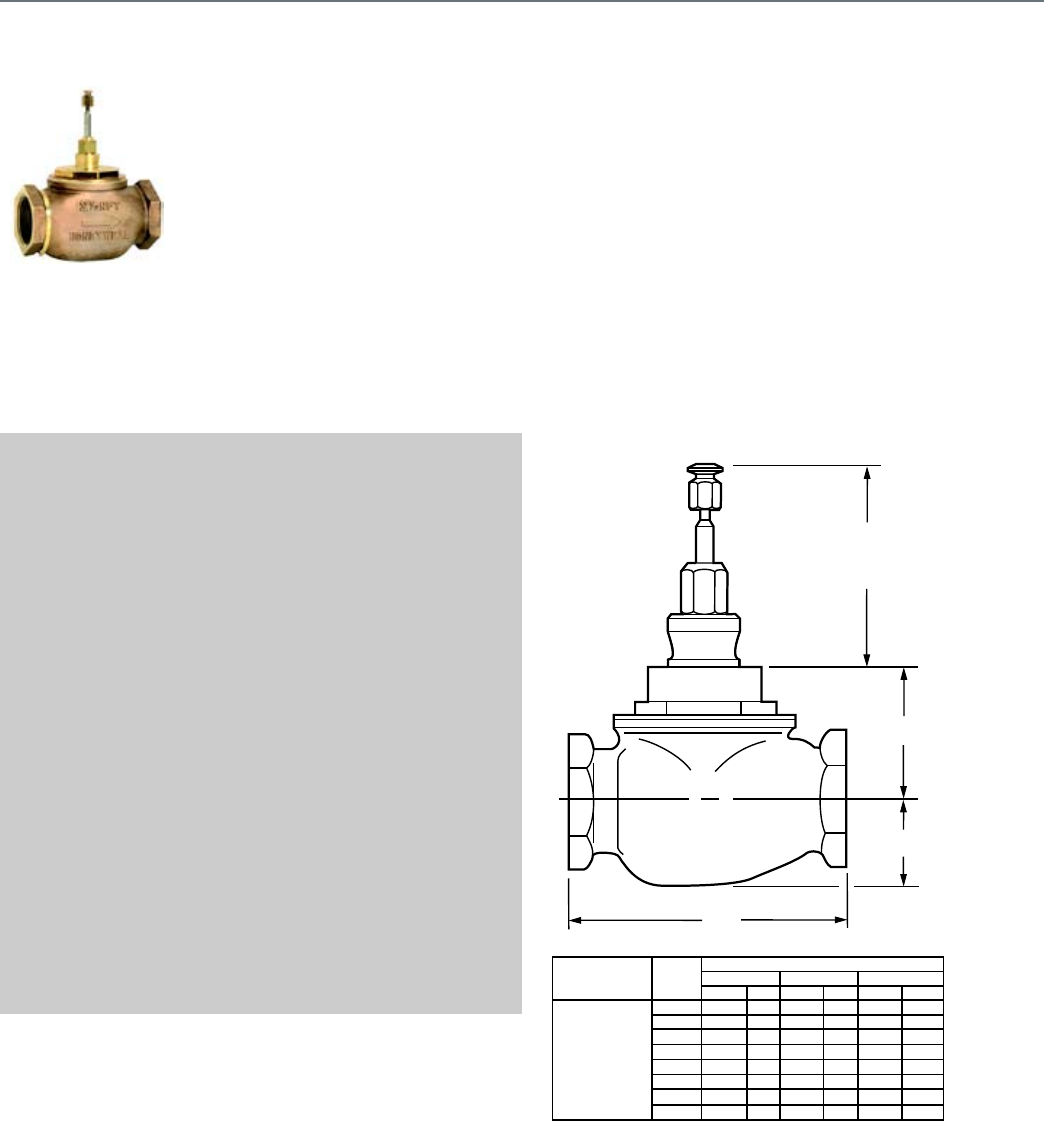
136
V5011F,G
Used for two-position or modulating
control of steam and water and
glycol solutions (to 50 percent
concentration) in heating or cooling
systems.
SPECIFICATIONS
Valve Type ............................................ Globe Valve
Body Pattern ........................................ Two-way
Valve Action ......................................... Stem down to close
Connection Type .................................. NPT Female
Controlled Medium ............................... Hot/Chilled Water with up to
50% Glycol
Flow characteristic ............................... Equal percentage (water);
Linear (steam)
Leakage Rating .................................... 0.5% of Cv
Maximum Safe Operating Pressure ..... 250 psi at 100 F water
(1724 kPa at 38 C water)
15 psi steam (100 kPa steam)
217 psi at 250 F water
V5011G:100 psi (690 kPa)
steam
Maximum Differential for
Quiet Water Service ............................. 20 psid (138 kPa)
Fluid Temperature Range ..................... 40 F to 337 F (4 C to 169 C)
Stem Travel ........................................... 3/4 in. (20 mm)
Materials
(Body) .................................................. Red Brass
(Stem) ................................................... Stainless Steel
(Seat) .................................................... Brass
(Plug/Ball/Disc) .................................... Brass plug with Teflon® disc
(Packing) .............................................. Teflon and Nitrile
APPROVALS
CRN Number ........................................ 0C0861.9087YTN
FEATURES
• Sizes range from 2-1/2 to 3 in.
• Direct and reverse acting
• High pressure steam models with stainless steel trim
• Spring-loaded, self-adjusting packing.
• Stainless steel stem prevents corrosion.
• Valve designs provide equal percentage flow
characteristics for close control of water, and linear flow
characteristic for close control of steam.
• Valves utilize direct mounting valve actuators or Q5020/
Q5022A linkages with Direct Coupled Actuators or
Pneumatic Valve Actuators to operate the valve.
DIMENSIONS DIAGRAM
A
B
C
3-1/2
WITH
STEM
DOWN
DIMENSIONS
1/2
3/4
1
1-1/4
1-1/2
2
2-1/2
3
2
1-3/4
1-7/8
2
2-7/8
3-1/8
2-3/4
3-1/8
51
45
48
51
73
80
70
80
1-3/4
1-3/4
1-3/4
1-5/8
1-5/8
2
2-3/8
2-5/8
45
45
45
42
42
51
61
67
3-3/8
3-3/8
4-1/4
4-7/8
5-5/8
5-5/8
7-1/2
8-7/8
86
86
108
124
143
143
191
226
AB C
mm
in
V5011F,G
THREADED
DIRECT
BODY
inin mmmm
BODY STYLE
PIPE
SIZE
(in.)
M2804A
V5011F,G
NPT Globe Valve
V5011F,G
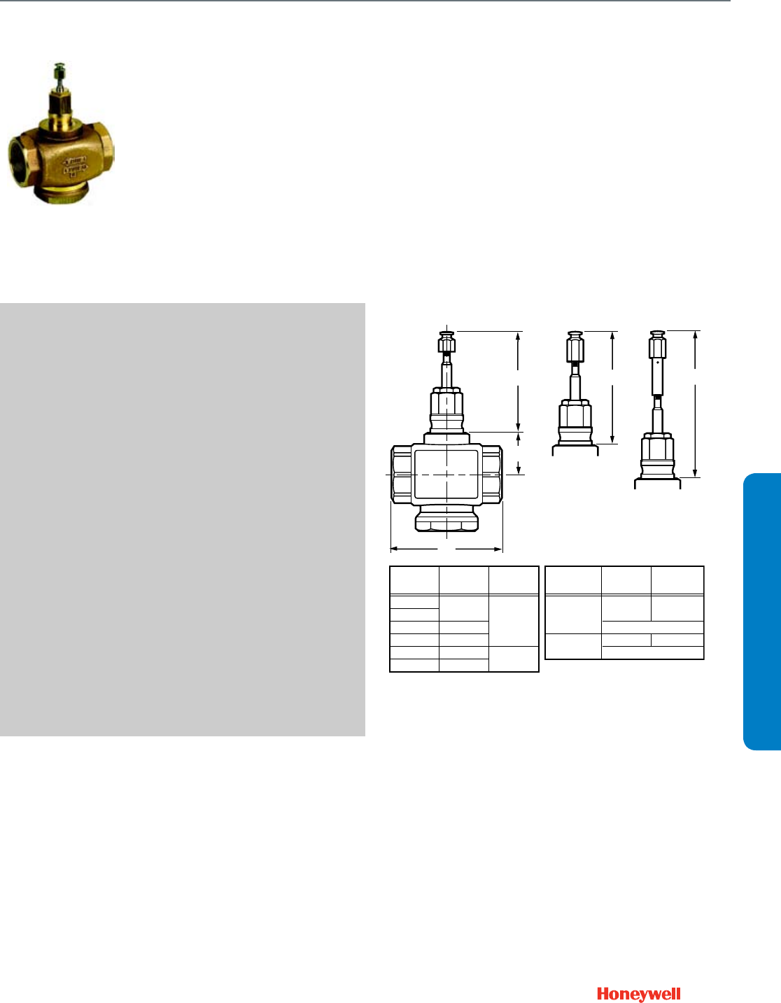
137
V5011N
Used for two-position or modulating
control of steam and water and
glycol solutions (to 50 percent
concentration) in heating or cooling
systems.
SPECIFICATIONS
Valve Type ............................................ Globe Valve
Body Pattern ........................................ Two-way
Connection Type .................................. NPT Female
Controlled Medium ............................... Hot/Chilled Water with up to
50% Glycol
Flow characteristic ............................... Equal percentage (water);
Linear (steam)
Leakage Rating .................................... Seat:- 0.05% of Cv
Maximum Safe Operating Pressure ..... 217 psi at 248 F
(1500 kPa at 120 C)
V5011N2:100 psi (690 kPa)
steam
Maximum Differential for
Quiet Water Service ............................. 20 psid (138 kPa)
Ambient Temperature Range ............... 36 F to 248 F water
(2 C to 120 C water)
337 F (169 C) steam
Stem Travel ........................................... 3/4 in. (20 mm)
Materials
(Body) ................................................... Red Brass
(Stem) ................................................... Stainless Steel
(Seat) .................................................... Stainless Steel;
reverse-acting: Brass
(Cartridge) ............................................ Brass
(Plug/Ball/Disc) ..................................... Teflon or carbon-loaded
Teflon(R)
(Packing) .............................................. Teflon
APPROVALS
CRN Number ........................................ 0C0861.9087YTN/0C0861.99
FEATURES
• Sizes range from 1/2 to 2 in.
• Direct and reverse acting
• High pressure steam models with stainless steel trim
• Spring-loaded, self-adjusting packing.
• Stainless steel stem prevents corrosion.
• Valve designs provide equal percentage flow
characteristics for close control of water, and linear flow
characteristic for close control of steam.
• Valves utilize direct mounting linear valve actuators, Q5020/
Q5022A linkages with direct coupled rotary actuators, or
pneumatic valve actuators to operate the valve.
DIMENSIONS DIAGRAM
A
B
Y1,2
M17378A
A
in. (mm)
B
in. (mm)
1/2
3/4
1
1-1/4
1-1/2
2
3-1/4 (83)
4-1/16 (103)
4-3/16 (106)
4-3/4 (120)
5-1/4 (134)
1-9/16 (40)
1-13/16 (47)
VALVE
SIZE (IN)
Y1
in. (mm)
Y2a
in. (mm)
V5011N1XXX
OR
V5011N2XXX
3-1/2 (89) 5-1/4 (133)
VALVE
aY2 WITH STEM EXTENSION FOR MP953C,E (8 IN. ONLY)
Y1Y2
STEM FULLY DOWN
STEM FULLY UP
5-15/16 (151)4-3/16 (107)
V5011N3XXX
NPT Globe Valve
V5011N
SUBMITTAL SHEETS
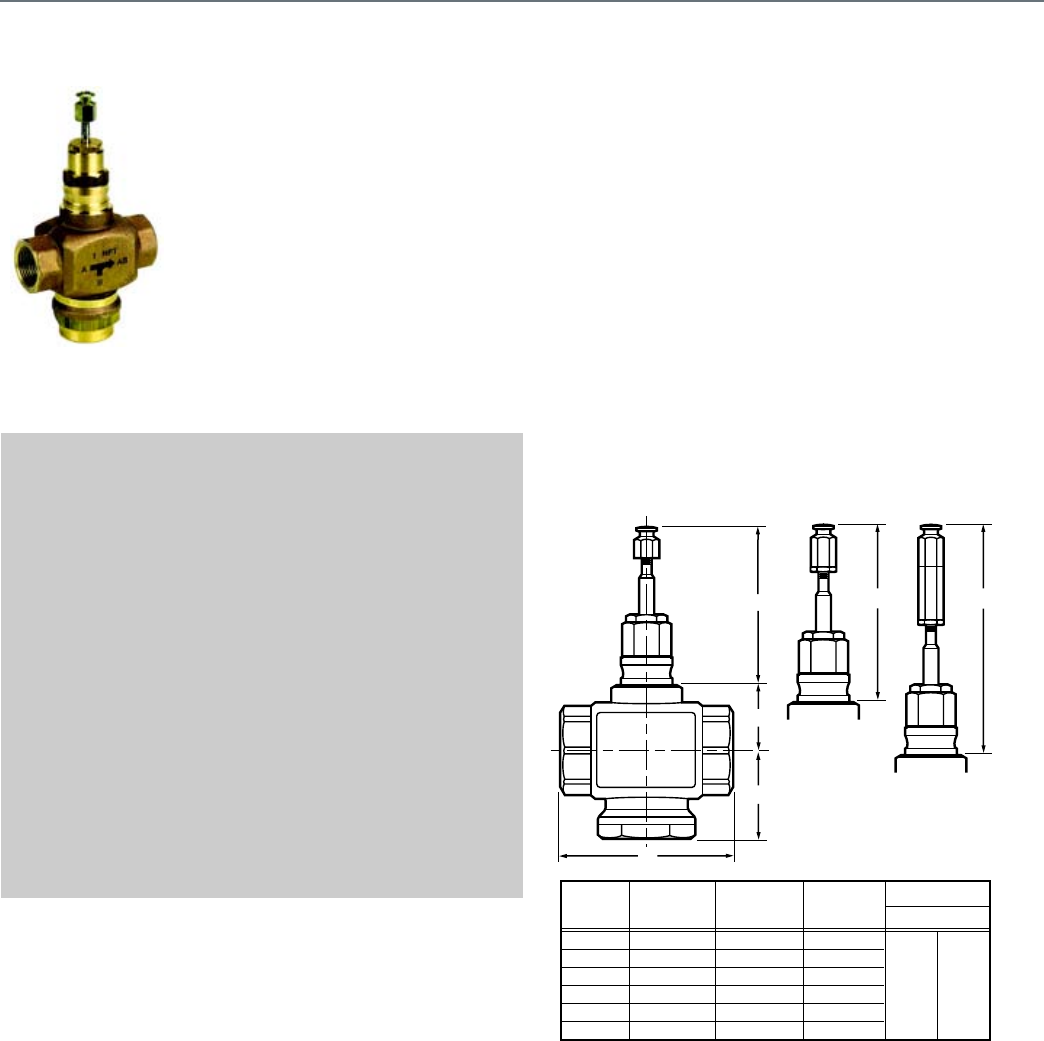
138
V5013N
The V5013N is a three-way threaded
globe valve that controls hot water,
cold water, and glycol solutions (up to
50 percent concentration) in heating
or cooling HVAC applications. The
valves are used for mixing service to
direct flow from one or two inlets to a
common outlet in two-position or
modulating control systems.
SPECIFICATIONS
Valve Type ............................................ Globe Valve
Body Pattern ........................................ Three-way
Connection Type .................................. NPT Female
Controlled Medium ............................... Hot/Chilled Water with up to
50% Glycol
Leakage Rating .................................... 0.05% of Cv
Maximum Safe Operating Pressure ..... 217 psi at 248 F
(1500 kPa at 120 C)
Maximum Differential for
Quiet Water Service ............................. 20 psid (138 kPa)
Ambient Temperature Range ............... 36 F to 248 F water
(2 C to 120 C water)
Stem Travel ........................................... 3/4 in. (20 mm)
Materials
(Body) .................................................. Red Brass
(Stem) ................................................... Stainless Steel
(Seat) .................................................... Brass
(Plug/Ball/Disc) .................................... Brass
(Packing) .............................................. Teflon/EPDM
APPROVALS
CRN Number ........................................ 0C0861.9087YTN/0C0861.123
FEATURES
• Red brass body with NPT-threaded connections.
• Stainless steel stem and brass plug.
• Low seat leakage rating, < 0.05%.
• Spring-loaded, self adjusting packing.
• 50:1 rangeability per VDI/VDE 2173.
• Constant total flow throughout full stem travel.
• Accurate positioning to ensure state-of-the-art temperature
control.
• Sizes range from 1/2 to 2 in.
• Valves utilize direct mounting valve actuators, Q5020/
Q5022 linkages with Direct Coupled Actuators, or
Pneumatic valve actuators to operate the valve.
• Repack and rebuild kits available for field servicing.
DIMENSIONS DIAGRAM
A
A
B
C
BC
Y
1,2 Y1
Y1
Y2
Y2
1/2 (15)
3/4 (20)
1 (25)
1-1/4 (32)
1-1/2 (40)
2 (50)
3-1/4 (83)
3-1/4 (83)
4-1/16 (103)
4-3/16 (106)
4-3/4 (120)
5-1/4 (134)
1-9/16 (39.7)
1-9/16 (39.7)
1-9/16 (39.7)
1-9/16 (39.7)
1-13/16 (46.5)
1-13/16 (46.5)
2-9/16 (65)
2-9/16 (65)
2-5/8 (66.5)
2-7/8 (72.5)
3 (77)
3-5/16 (83.5)
VALVE
SIZE STEM UP
4-3/16
(106)
5-15/16
(151)
M12901A
a
aY2 WITH STEM EXTENSION FOR MP953C,E (8 IN. ONLY)
NOTE: Y DIMENSION IS WITH
STEM FULLY UP, NOT DOWN.
NPT Globe Valve
V5013N
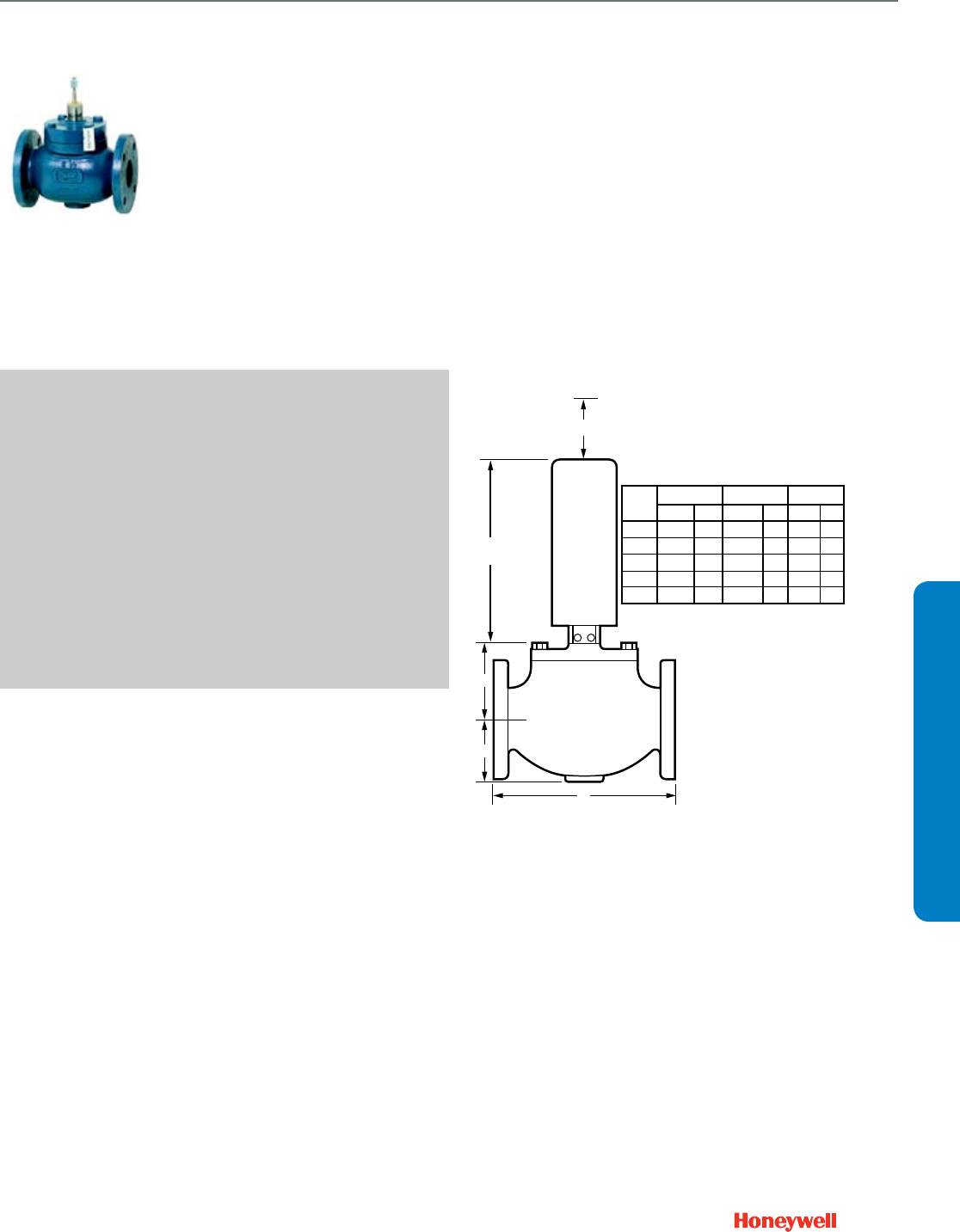
139
V5051A
Single-Seated Cage Valves control
steam, air, liquids, or non-
combustible gases in two-position,
proportional, or floating control
systems where line isolation is not
required.
SPECIFICATIONS
Valve Type ............................................ Cage Valves
Body Pattern ........................................ Two-way, Straight-through
Connection Type .................................. Flanged
Controlled Medium ............................... Steam, Hot/Chilled Water with
up to 50% Glycol
Leakage Rating .................................... 0.01% of Cv,
0.03% of Cv @ 5 & 6 in.
Maximum Safe Operating Pressure ..... 140 psi water (965 kPa water)
55 psi steam (379 kPa steam)
Ambient Temperature Range ............... 35 F to 300 F (2 C to 150 C)
Stem Travel ........................................... 1 1/2 in. (39 mm)
Materials
(Body) ................................................... Cast Iron
(Stem) ................................................... Stainless Steel
(Seat) .................................................... Resilient
(Plug/Ball/Disc) ..................................... Stainless Steel
(Packing) .............................................. Teflon
FEATURES
• Pressure balanced cage type construction.
• Low operating force allows fail safe operation with spring
return actuator.
• Combines 1-3/8 in. bonnet with 1-1/2 in. stroke.
• Sizes range from 2-1/2 to 6 in. (DN65 to DN150).
• Spring-loaded Teflon® V-ring packing.
• Requires Q5020C valve linkage with one rotary, direct
coupled actuator.
DIMENSIONS DIAGRAM
CLEARANCE
TO REMOVE
ACTUATOR
FROM VALVE
4 (102) MINIMUM
VALVE
LINKAGE
15-1/16
(382)
C
B
A
M27552
VALVE
SIZE
A BC
IN.
9-1/2
11
13
15
16-1/2
MM
241
297
330
381
419
IN.
3-1/2
3-15/16
4-1/2
5-1/2
6-3/8
MM
89
100
114
140
162
IN.
4-5/8
4-7/8
5-5/8
7-3/8
7-3/8
MM
117
124
143
187
187
2-1/2
3
4
5
6
Flanged Cage Valve
V5051A
SUBMITTAL SHEETS
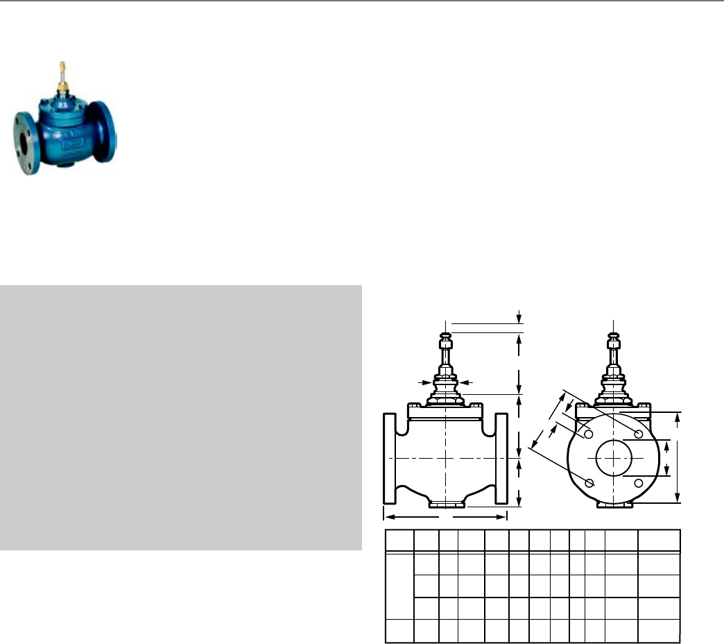
140
V5011A,B
Used for proportional control of hot
or chilled water and glycol
solutions (to 50 percent
concentration) and for two-position
control of low pressure steam.
SPECIFICATIONS
Valve Type ............................................ Globe Valve
Body Pattern ........................................ Two-way
Flow Characteristic .............................. Equal Percentage
Connection Type .................................. Flanged
Controlled Medium ............................... Steam, Hot/Chilled Water with
up to 50% Glycol
Maximum Safe Operating Pressure ..... 15 psi (100 kPa) steam
150 psi at 240 F water
(1034 kPa at 115 C water)
Maximum Differential for
Quiet Water Service ............................. 20 psid (138 kPa)
Ambient Temperature Range ............... 40 F to 250 F (4 C to 121 C)
Stem Travel ........................................... 3/4 in. (20 mm)
Materials
(Body) .................................................. Cast Iron
(Stem) ................................................... Stainless Steel
(Seat) .................................................... Bronze
(Packing) .............................................. Teflon Cone
FEATURES
• Sizes range from 2-1/2 to 6 in.
• Stainless steel stem with removable Teflon disc.
• Valves utilize direct mounting valve actuators, Q5020/
Q5022 linkages with Direct Coupled Actuators, or
Pneumatic Valve Actuators to operate the valve.
• Equal Percentage flow characteristic.
DIMENSIONS DIAGRAM
A
C
D
F
G
H
E
B
I
M27256
J
3-1/2
(89)
3-1/2
(89)
5-1/4
(133)
6-3/4
(171)
2-1/2
(64)
A
a
BCDEF
VALVE
SIZE
3 (76)
4
(102)
4-13/16
(122)
3-1/2
(89)
5-1/4
(133)
6-3/4
(171)
4
(102)
4-5/8
(117)
5-3/16
(132)
8-1/16
(205)
9-1/2
(241)
11
(279)
13
(330)
13
(330)
7
(178)
7-1/2
(191)
9
(229)
9
(229)
2-1/2
(64)
3
(76)
4
(102)
4
(102)
G
3/4
(19)
3/4
(19)
3/4
(19)
3/4
(19)
H
5-1/2
(140)
6
(152)
7-1/2
(191)
7-1/2
(191)
I
(TRAVEL)
3/4
(19)
3/4
(19)
1-1/2
(38)
1-1/2
(38)
J
(DIAMETER)
1-3/8
(35)
1-3/8
(35)
1-7/8
(48)
1-7/8
(48)
MODEL
V5011B
V5011A
4
(102)
Flanged Globe Valve
V5011A,B
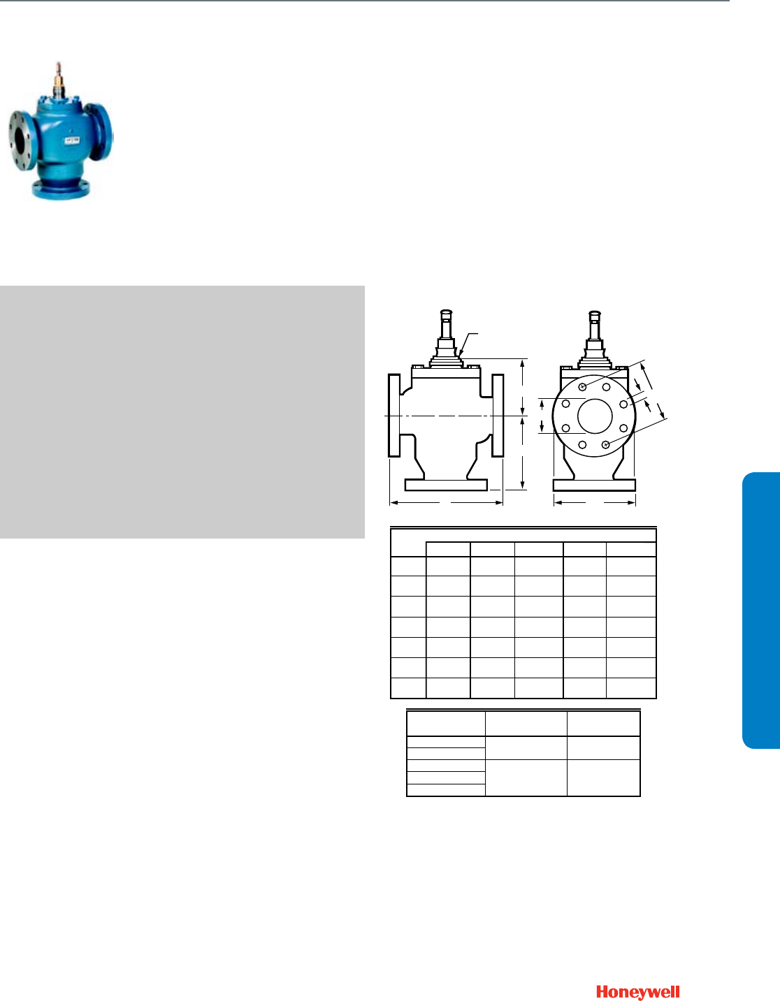
141
V5013B,C
The V5013B are three-way mixing
valves. The V5013C are three-way
diverting valves. These valves provide
proportional or two-position control of
hot or chilled water in heating or
cooling systems. These valves are
offered in sizes 2 1/2 in. through 6 in.
SPECIFICATIONS
Valve Type ............................................ Globe Valve
Body Pattern ........................................ Three-way
Connection Type .................................. Flanged
Controlled Medium ............................... Hot/Chilled Water with up to
50% Glycol
Flow characteristic ............................... Linear (constant total)
Maximum Safe Operating Pressure ..... 150 psi at 240 F water
(1034 kPa at 115 C water)
Maximum Differential for
Quiet Water Service ............................. 20 psid (138 kPa)
Ambient Temperature Range ............... 40 F to 250 F (4 C to 121 C)
Stem Travel ........................................... 3/4 in. (20 mm)
Materials
(Body) ................................................... Cast Iron
(Stem) ................................................... Stainless Steel
(Seat) .................................................... Bronze
(Packing) .............................................. Teflon Cone
FEATURES
• Not suitable for combustible gases.
• Valves utilize direct mounting valve actuators, Q5020/
Q5022 linkages with Direct Coupled Actuators, or
Pneumatic Valve Actuators to operate the valve.
• Constant total flow through full plug travel.
• Stainless steel stem prevents corrosion.
• Class IV (0.01% of Cv) Leakage Rating.
DIMENSIONS DIAGRAM
G
E
F
D
A
C
B
C7959B
VALVE SIZE BONNET SIZE
VALVE SIZE IN INCHES (MM)
V5013B,C DIMENSIONS
2-1/2 (64)
3 (76)
4 (102)
5 (125)
6 (152)
NUMBER OF
BOLT HOLES
1-7/8 (48)
1-3/8 (35)
A
2-1/2 (64)
4-1/2
(114)
3 (76)
5-1/4
(133)
4 (102)
5-7/8
(149)
5 (125)
6-1/4
(159)
6 (152)
7-1/4
(184)
4
8
BONNET
B6-7/17
(164)
6-5/8
(168)
8-11/16
(221)
9-5/8
(244)
10-11/16
(271)
C9-1/2
(241)
11
(279)
13
(330)
15
(381)
16-1/2
(419)
D2-1/2
(64)
3
(76)
4
(102)
5
(127)
6
(152)
E3/4
(19)
3/4
(19)
3/4
(19)
7/8
(22)
7/8
(22)
F5-1/2
(140)
6
(152)
7-1/2
(191)
8-1/2
(216)
9-1/2
(241)
G7
(178)
7-1/2
(191)
9
(229)
10
(254)
11
(279)
Flanged Globe Valve
V5013B,C
SUBMITTAL SHEETS
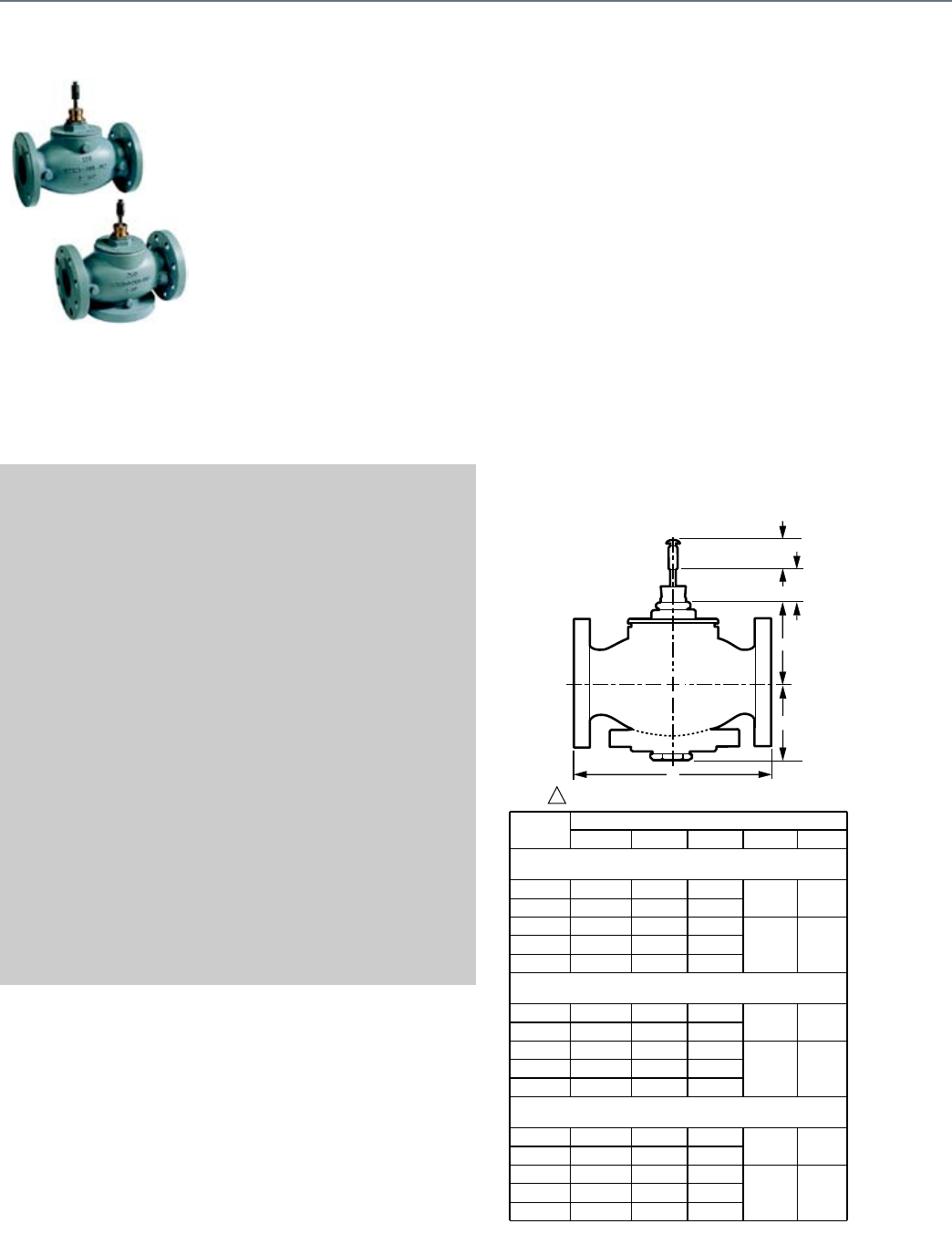
142
VGF2
VGF Flanged Globe Valves are
used for 2-position or modulating
control of steam, hot water, or
chilled water-glycol solutions up to
50 percent concentration in
heating, ventilation and air
conditioning (HVAC) systems. They
can be operated by ML6984/7984,
ML6420/6425, ML6421/7421
Electric Linear Actuators, MP953
Pneumatic Actuators, Modutrol™
Motors with Q5001 valve linkage, or
MN/MS Series Direct Coupled
Actuators with Q5020 valve
linkage.
SPECIFICATIONS
Valve Type ............................................ Globe Valve
Body Pattern ........................................ Two-way
Flow characteristic ............................... Equal percentage or Linear
Connection Type .................................. Flanged
Valve Action ......................................... Step down to close
Controlled Medium ............................... Hot/Chilled Water with up to
50% Glycol; Steam
Leakage Rating .................................... 0.05% of Cv
Maximum Safe Operating Pressure ..... 400 psig (2750 kPa)
Maximum Differential Pressure Ratings
(Close-off) ............................................ Varies with actuator force
Fluid Temperature Range ..................... 20 F to 250 F, steam 335 F
(-7 C to 120 C, steam 180 C)
Actuation .............................................. Must be purchased separately
Stem Travel
2-1/2 and 3 in. valves ........................... 3/4 in. (20 mm)
4 to 6 in. valves .................................... 1-1/2 in. (39 mm)
Bonnet Size
2-1/2 and 3 in. valves ........................... 1-3/8 in. (35 mm)
4 to 6 in. valves .................................... 1-7/8 in. (47.6 mm)
Materials
(Body) .................................................. Cast Iron ASTM A126 Class B
(Stem) ................................................... Stainless Steel
(Seat) .................................................... Stainless Steel
(Cartridge) ............................................ Stainless Steel
(Plug/Ball/Disc) .................................... Stainless Steel
(Packing) .............................................. Spring-loaded PTFE cone
rings
FEATURES
• ANSI Class 125 and Class 250 cast iron bodies with flanged
end connections.
• Equal percentage and linear flow characteristics
• Face-to-face flange dimensions per ANSI/ISA S75.03
standard.
• Sizes from 2-1/2 to 6 in.
• Stainless steel trim standard for long life span.
• ANSI CLass III seat leakage
• Steam inlet pressure up to 125 psig and 353 F maximum
temperature.
• Self-adjusting packing.
• Accurate positioning with equal percentage and linear flow
characteristics to ensure precise temperature control.
• Universal bonnet for direct-coupled electric and pneumatic
actuators for easy mounting, or linkage coupled Modutrol™
Motors and MN/MS Series direct coupled actuators.
• Not suitable for combustible gasses.
DIMENSIONS DIAGRAM
M27603
C
A
B
D
STROKE Y
1DOTTED LINE REPRESENTS ANSI 125 VALVE BONNET.
MODEL
NUMBER
DIMENSIONS, IN. (MM)
A B C E Y
2-WAY VALVES, ANSI CLASS 125. STEM DOWN TO CLOSE. EQUAL
PERCENTAGE OR LINEAR FLOW CHARACTERISTIC
VGF21_S25 10-7/8 (276) 4-3/8 (112) 7 (178) 3-1/2 (89) 13/16 (20)
VGF21_S30 11-3/4 (298) 6-3/8 (161) 7-1/2 (191)
VGF21_S40 13-7/8 (352) 5-7/8 (150) 9 (229) 5-1/4 (133) 1-1/2 (38)
VGF21_S50 15-3/4 (400) 6-3/16 (157) 10 (254)
VGF21_S60 17-3/4 (451) 6-3/16 (157) 11 (279)
2-WAY VALVES, ANSI CLASS 250. STEM DOWN TO CLOSE. EQUAL
PERCENTAGE FLOW CHARACTERISTIC
VGF22ES25 11-1/2 (292) 4-3/8 (112) 7-1/2 (191) 3-1/2 (89) 13/16 (20)
VGF22ES30 12-1/2 (318) 6-3/8 (161) 8-1/4 (210)
VGF22ES40 14-1/2 (368) 5-7/8 (150) 10 (254) 5-1/4 (133) 1-1/2 (38)
VGF22ES50 16-5/8 (422) 6-3/16 (157) 11 (279)
VGF22ES60 18-5/8 (473) 6-3/16 (157) 12-1/2 (318)
2-WAY VALVES, PRESSURE-BALANCED, ANSI CLASS 125. STEM DOWN TO
CLOSE. EQUAL PERCENTAGE OR LINEAR FLOW CHARACTERISTIC
VGF21_P25 10-7/8 (276) 4-3/16 (107) 7 (178) 3-1/2 (89) 13/16 (20)
VGF21_P30 11-3/4 (298) 5-7/8 (150) 7-1/2 (191)
VGF21_P40 13-7/8 (352) 5-7/8 (150) 9 (229) 5-1/4 (133) 1-1/2 (38)
VGF21_P50 15-3/4 (400) 6-1/8 (156) 10 (254)
VGF21_P60 17-3/4 (451) 6-1/8 (156) 11 (279)
Flanged Globe Valve
VGF2
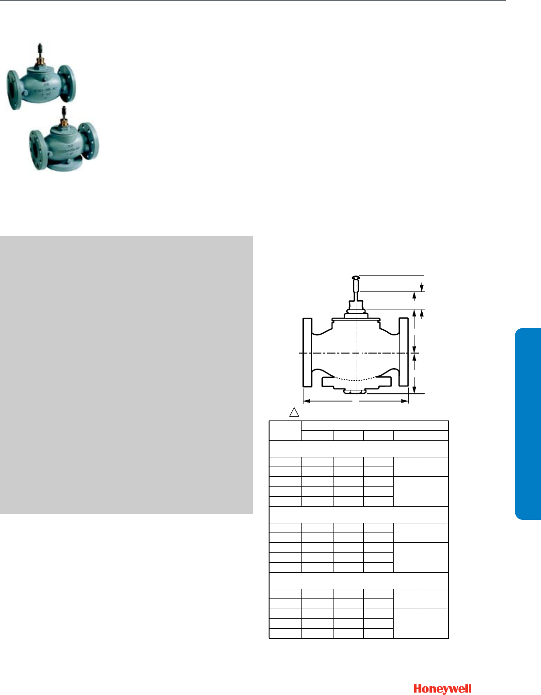
143
VGF2 Pressure Balanced
VGF Flanged Globe Valves are
used for 2-position or modulating
control of steam, hot water, or
chilled water-glycol solutions up to
50 percent concentration in
heating, ventilation and air
conditioning (HVAC) systems. They
can be operated by ML6984/7984,
ML6420/6425, ML6421/7421
Electric Linear Actuators, MP953
Pneumatic Actuators, Modutrol™
Motors with Q5001 valve linkage, or
MN/MS Series Direct Coupled Actuators with Q5020 valve
linkage. Pressure-balanced models feature very high, low
leakage close-off ratings.
SPECIFICATIONS
Valve Type ............................................ Globe Valve
Body Pattern ........................................ Two-way
Flow characteristic ............................... Equal percentage or Linear
Connection Type .................................. Flanged
Valve Action .......................................... Step down to close
Controlled Medium ............................... Hot/Chilled Water with up to
50% Glycol; Steam
Leakage Rating .................................... 0.01% of Cv
Maximum Safe Operating Pressure ..... 175 psig (1206 kPa)
Maximum Differential Pressure Ratings (
Close-off) .............................................. 175 psi (1206 kPa )
Fluid Temperature Range ..................... 20 F to 250 F, steam 335 F
(-7 C to 120 C, steam 180 C)
Actuation .............................................. Must be purchased separately
Stem Travel
2-1/2 and 3 in. valves ........................... 3/4 in. (20 mm)
4 to 6 in. valves .................................... 1-1/2 in. (39 mm)
Bonnet Size
2-1/2 and 3 in. valves ........................... 1-3/8 in. (35 mm)
4 to 6 in. valves .................................... 1-7/8 in. (47.6 mm)
Materials
(Body) ................................................... Cast Iron ASTM A126 Class B
(Stem) ................................................... Stainless Steel
(Seat) .................................................... Stainless Steel
(Cartridge) ............................................ Stainless Steel
(Plug/Ball/Disc) ..................................... Stainless Steel
(Packing) .............................................. Spring-loaded PTFE cone
rings
FEATURES
• ANSI Class 125 cast iron bodies with flanged end
connections.
• Equal percentage and linear flow characteristics
• Face-to-face flange dimensions per ANSI/ISA S75.03
standard.
• Sizes from 2-1/2 to 6 in.
• Stainless steel trim standard for long life span.
• Differential pressure of 175 psi, ANSI Class IV.
• Steam inlet pressure up to 125 psig and 353 F maximum
temperature.
• Self-adjusting packing.
• Accurate positioning with equal percentage and linear flow
characteristics to ensure precise temperature control.
• Universal bonnet for direct-coupled electric and pneumatic
actuators for easy mounting, or linkage coupled Modutrol™
Motors and MN/MS Series direct coupled actuators.
• Not suitable for combustible gasses.
DIMENSIONS DIAGRAM
M27603
C
A
B
D
STROKE Y
1DOTTED LINE REPRESENTS ANSI 125 VALVE BONNET.
MODEL
NUMBER
DIMENSIONS, IN. (MM)
A B C E Y
2-WAY VALVES, ANSI CLASS 125. STEM DOWN TO CLOSE. EQUAL
PERCENTAGE OR LINEAR FLOW CHARACTERISTIC
VGF21_S25 10-7/8 (276) 4-3/8 (112) 7 (178) 3-1/2 (89) 13/16 (20)
VGF21_S30 11-3/4 (298) 6-3/8 (161) 7-1/2 (191)
VGF21_S40 13-7/8 (352) 5-7/8 (150) 9 (229) 5-1/4 (133) 1-1/2 (38)
VGF21_S50 15-3/4 (400) 6-3/16 (157) 10 (254)
VGF21_S60 17-3/4 (451) 6-3/16 (157) 11 (279)
2-WAY VALVES, ANSI CLASS 250. STEM DOWN TO CLOSE. EQUAL
PERCENTAGE FLOW CHARACTERISTIC
VGF22ES25 11-1/2 (292) 4-3/8 (112) 7-1/2 (191) 3-1/2 (89) 13/16 (20)
VGF22ES30 12-1/2 (318) 6-3/8 (161) 8-1/4 (210)
VGF22ES40 14-1/2 (368) 5-7/8 (150) 10 (254) 5-1/4 (133) 1-1/2 (38)
VGF22ES50 16-5/8 (422) 6-3/16 (157) 11 (279)
VGF22ES60 18-5/8 (473) 6-3/16 (157) 12-1/2 (318)
2-WAY VALVES, PRESSURE-BALANCED, ANSI CLASS 125. STEM DOWN TO
CLOSE. EQUAL PERCENTAGE OR LINEAR FLOW CHARACTERISTIC
VGF21_P25 10-7/8 (276) 4-3/16 (107) 7 (178) 3-1/2 (89) 13/16 (20)
VGF21_P30 11-3/4 (298) 5-7/8 (150) 7-1/2 (191)
VGF21_P40 13-7/8 (352) 5-7/8 (150) 9 (229) 5-1/4 (133) 1-1/2 (38)
VGF21_P50 15-3/4 (400) 6-1/8 (156) 10 (254)
VGF21_P60 17-3/4 (451) 6-1/8 (156) 11 (279)
Flanged Globe Valve
VGF2 Pressure Balanced
SUBMITTAL SHEETS
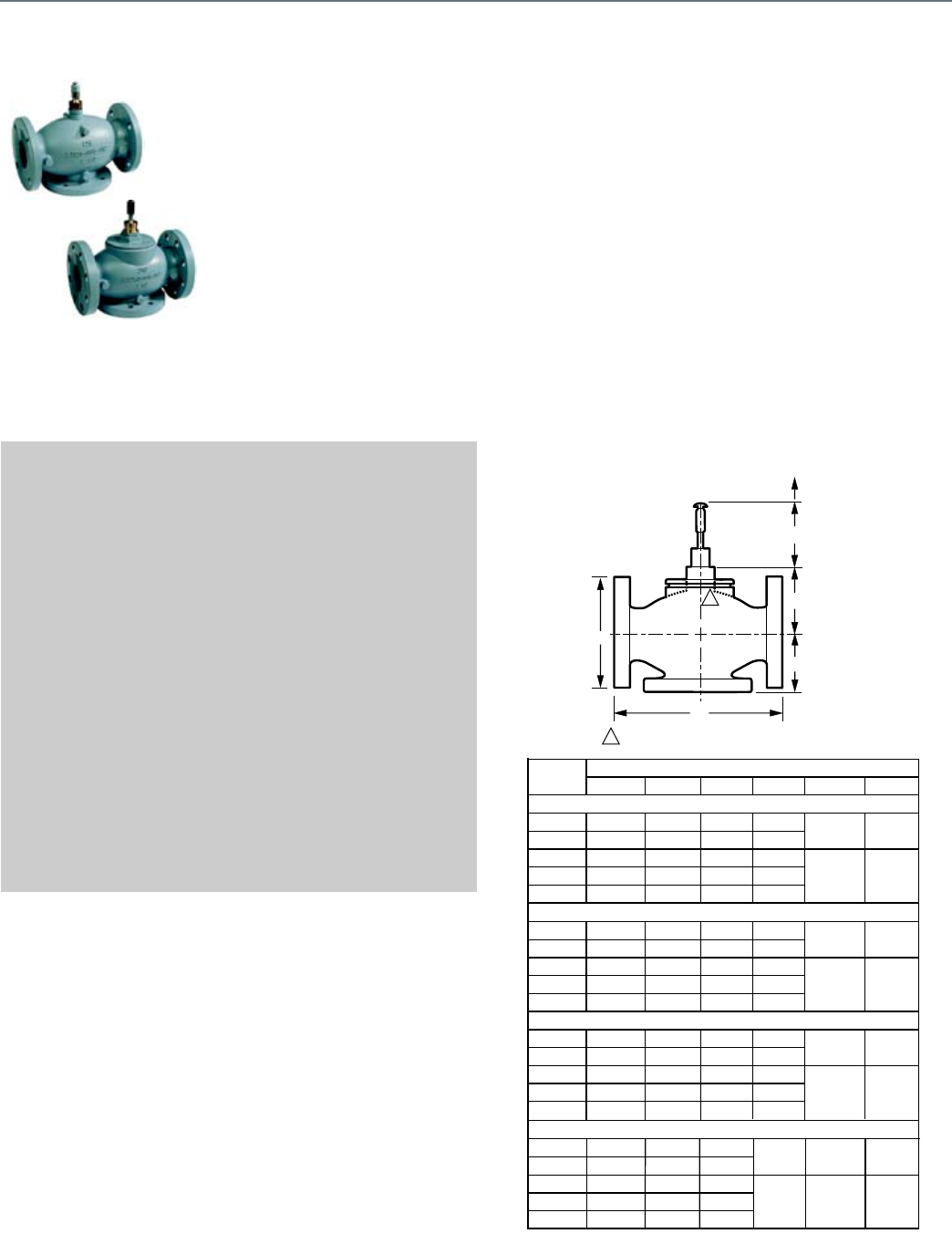
144
VGF3
VGF Flanged Globe Valves are
used for 2-position or modulating
control of hot water or chilled water-
glycol solutions up to 50 percent
concentration in heating, ventilation
and air conditioning (HVAC)
systems. They can be operated by
ML6984/7984, ML6420/6425,
ML6421/7421 Electric Linear
Actuators, MP953 Pneumatic
Actuators, Modutrol™ Motors with
Q5001 valve linkage, or MN/MS
Series Direct Coupled Actuators with Q5020/Q5022 valve
linkages. Three-way bodies are available in mixing or diverting
style with equal percentage and linear flow characteristics,
respectively.
SPECIFICATIONS
Valve Type ............................................ Globe Valve
Body Pattern ........................................ Three-way mixing; diverting
Flow characteristic ............................... A-port - Equal percentage
mixing, Linear Diverting
B-port - Linear
Connection Type .................................. Flanged
Controlled Medium ............................... Hot/Chilled Water with up to
50% Glycol
Fluid Temperature Range ..................... 20 F to 250 F(-7 C to +20 C)
Stem Travel
2-1/2 and 3 in. valves ........................... 3/4 in. (20 mm)
4 to 6 in. valves .................................... 1-1/2 in. (39 mm )
Bonnet Size
2-1/2 and 3 in. valves ........................... 1-3/8. (35 mm )
4 to 6 in. valves .................................... 1-7/8 in. (47.6 mm )
Actuation .............................................. Must be purchased separately
Materials
(Body) .................................................. Cast Iron ASTM A126 Class B
(Stem) ................................................... Stainless Steel
(Seat) .................................................... Stainless Steel
(Cartridge) ............................................ Stainless Steel
(Plug/Ball/Disc) .................................... Stainless Steel
(Packing) .............................................. Spring-loaded PTFE cone
rings
FEATURES
• ANSI Class 125 and Class 250 cast iron bodies with flanged
end connections.
• Face-to-face flange dimensions per ANSI/ISA S75.03
standard.
• Sizes from 2-1/2 to 6 in.
• Stainless steel trim standard for long life span.
• Self-adjusting packing.
• Accurate positioning with equal percentage and linear flow
characteristics to ensure precise temperature control.
• Universal bonnet for direct-coupled electric and pneumatic
actuators for easy mounting, or linkage coupled Modutrol™
Motors and MN/MS Series direct coupled actuators.
• Constant total flow throughout full plug travel (3-way
diverting models).
DIMENSIONS DIAGRAM
D
A
C
B
1DOTTED LINE REPRESENTS ANSI 125
VALVE BONNET.
1
E
STROKE Y MODEL
NUMBER A
3-WAY MIXING VALVES, ANSI CL
VGF31EM25 10-7/8 (276) 3
VGF31EM30 11-3/4 (298) 4-3/
VGF31EM40 13-7/8 (352) 5-8/
VGF31EM50 15-3/4 (400) 5-3/
VGF31EM60 17-3/4 (451) 5-11/
3-WAY MIXING VALVES, ANSI CL
VGF32EM25 11-1/2 (292) 4-3/
VGF32EM30 12-1/2 (318) 6-3/
VGF32EM40 14-1/2 (368) 5-7/
VGF32EM50 16-5/8 (422) 6-3/
VGF32EM60 18-5/8 (473) 6-3/
3-WAY DIVERTING VALVES, ANS
VGF31LD25 10-7/8 (276) 3
VGF31LD30 11-3/4 (298) 4-3/
VGF31LD40 13-7/8 (352) 5-8/
VGF31LD50 15-3/4 (400) 5-3/
VGF31LD60 17-3/4 (451) 5-11/
3-WAY DIVERTING VALVES, ANS
VGF32LD25 11-1/2 (292) 4-3
VGF32LD30 12-1/2 (318) 6-3
VGF32LD40 14-1/2 (368) 5-7
VGF32LD50 16-5/8 (422) 6-3/
VGF32LD60 18-5/8 (473) 6-3/
D
B
5
E
YMODEL
NUMBER
DIMENSIONS, IN. (MM)
A B C D E Y
3-WAY MIXING VALVES, ANSI CLASS 125. STEM UP TO CLOSE A-AB
VGF31EM25 10-7/8 (276) 3 (76) 7 (178) 3-3/4 (95) 4-3/16 (107) 13/16 (20)
VGF31EM30 11-3/4 (298) 4-3/16 (107) 7-1/2 (191) 4-3/8 (111)
VGF31EM40 13-7/8 (352) 5-8/16 (140) 9 (229) 5-1/8 (130) 6-11/16 (170) 1-1/2 (38)
VGF31EM50 15-3/4 (400) 5-3/8 (137) 10 (254) 5-3/4 (146)
VGF31EM60 17-3/4 (451) 5-11/16 (145) 11 (279) 6-5/8 (168)
3-WAY MIXING VALVES, ANSI CLASS 250. STEM UP TO CLOSE A-AB
VGF32EM25 11-1/2 (292) 4-3/8 (112) 7-1/2 (191) 3-3/4 (95) 4-3/16 (107) 13/16 (20)
VGF32EM30 12-1/2 (318) 6-3/8 (161) 8-1/4 (210) 4-3/8 (111)
VGF32EM40 14-1/2 (368) 5-7/8 (150) 10 (254) 5-1/8 (130) 6-11/16 (170) 1-1/2 (38)
VGF32EM50 16-5/8 (422) 6-3/16 (157) 11 (279) 5-3/4 (146)
VGF32EM60 18-5/8 (473) 6-3/16 (157) 12-1/2 (318) 6-5/8 (168)
3-WAY DIVERTING VALVES, ANSI CLASS 125. STEM DOWN TO CLOSE AB-A
VGF31LD25 10-7/8 (276) 3 (76) 7 (178) 3-3/4 (95) 4-3/16 (107) 13/16 (20)
VGF31LD30 11-3/4 (298) 4-3/16 (107) 7-1/2 (191) 4-3/8 (111)
VGF31LD40 13-7/8 (352) 5-8/16 (140) 9 (229) 5-1/8 (130) 6-11/16 (170) 1-1/2 (38)
VGF31LD50 15-3/4 (400) 5-3/8 (137) 10 (254) 5-3/4 (146)
VGF31LD60 17-3/4 (451) 5-11/16 (145) 11 (279) 6-5/8 (168)
M27604
3-WAY DIVERTING VALVES, ANSI CLASS 250. STEM DOWN TO CLOSE AB-A
VGF32LD25 11-1/2 (292) 4-3/8 (112) 7-1/2 (191) 3-3/4 (95) 4-3/16 (107) 13/16 (20)
VGF32LD30 12-1/2 (318) 6-3/8 (161) 8-1/4 (210) 4-3/8 (111)
VGF32LD40 14-1/2 (368) 5-7/8 (150) 10 (254) 5-1/8 (130) 6-11/16 (170) 1-1/2 (38)
VGF32LD50 16-5/8 (422) 6-3/16 (157) 11 (279) 5-3/4 (146)
VGF32LD60 18-5/8 (473) 6-3/16 (157) 12-1/2 (318) 6-5/8 (168)
Flanged Globe Valve
VGF3
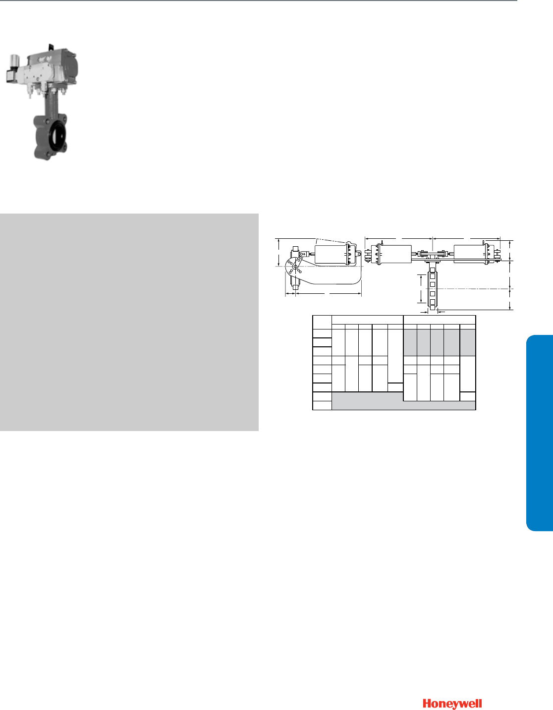
145
VFF1
Resilient seat in two-way valves,
provide control for HVAC system
applications including chilled water,
hot water, cooling tower water,
thermal storage systems, and steam.
SPECIFICATIONS
Body Pattern ........................................ 2 way (S/R NO)
Valve Action .......................................... Normally Open
Connection Type .................................. Lugged
Controlled Medium ............................... Chilled and hot water, up to
50% glycol
Actuator Control Type .......................... Pneumatic, Spring Return
Type of Enclosure ................................. Pneumatic
Flow Characteristic ............................... Modified Equal Percent
Mounting .............................................. ANSI Flanged
Static Pressure Rating (max) ................ 250 psi (1724 kPa)
Maximum Differential Pressure Ratings
(Close-off) ............................................. 175 psi (1206 kPa)
Actuator Ambient Temperature Ratings -20 F to 150 F (-29 C to 66 C)
Temperature Range .............................. -40 F to 250 F (-40 C to 121 C)
Materials
(Body) ................................................... Polyester-coated cast iron
ASTM A126 Class B
(Stem) ................................................... 416 stainless steel
(Seat) .................................................... Peroxide-cured EPDM resilient
seat
(Plug/Ball/Disc) ..................................... Nylon 11-coated ductile iron
DIMENSIONS DIAGRAM
T
L2
G*
L1
M2701
L1 L2
D
F
R
H
PIPE SIZE
IN. [mm] G H HP L1 L2 G H HP L1 L2*
2
[DN50]
2-1/2
[DN65]
3
[DN80]
47-1/4 10 20 5-5/8 3-1/8 6-1/4 16
[DN100] [186] [254] [506] [144] [79] [160] [406]
57-1/4 10 20
[DN125] [186] [254] [506]
6
[DN150]
822-3/4
[DN200] [578]
10 22-3/4
[DN250] [578]
12 LOW PRESSURE ACTUATORS NOT
AVAILABLE IN THESE, AND LARGER BODY SIZES.
[DN300]
VALVE STROKE IS LIMITED TO 70 DEGREES.
3
10-1/8
9
6-7/8
[578]
[257]
[175]
[227]
[175]
22-3/4
[227]
(VFF1/2_V1Y8P/PP)
[257]
[578]
6-1/4
16
5-5/8
3-1/8
(VFF1/2_W1Y8P/PP)
6-7/8
9
[76]
[144]
[79]
[160]
[406]
22-3/4
10-1/8
FULL CUT DISK, 175 PSI CLOSE-OFF
UNDER CUT DISK, 50 PSI CLOSE-OFF**
**NOTE: VALVE SIZES 2 TO 3 INCHES ARE AVAILABLE ONLY WITH FULL CUT DISKS.
[76]
3
Resilient Seat Butterfly Valves
VFF1
SUBMITTAL SHEETS
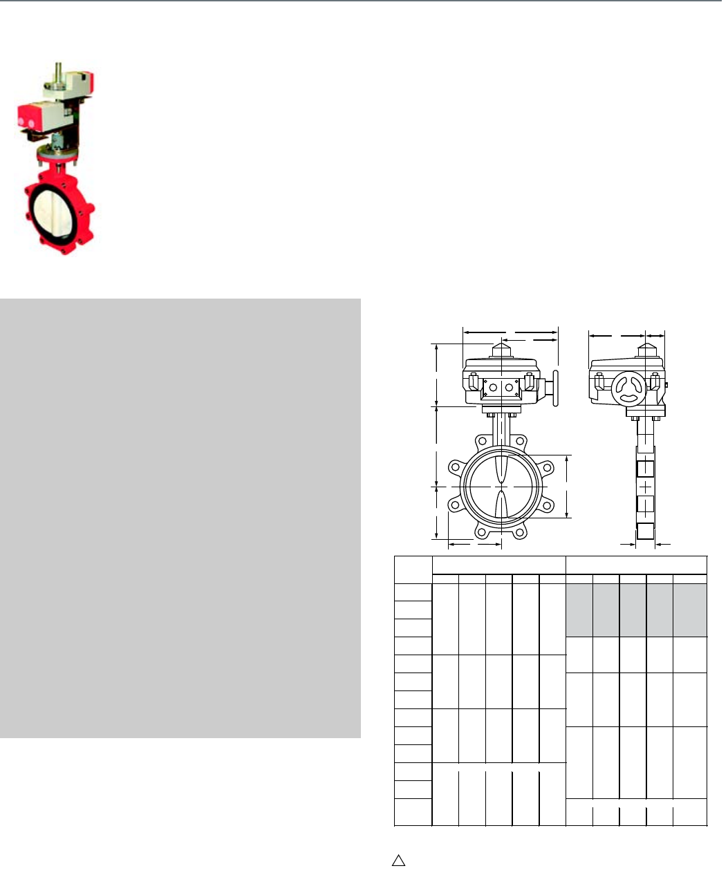
146
VFF2
Resilient seat two-way valves
provide control for HVAC system
applications including chilled
water, hot water, cooling tower
water, thermal storage systems,
and steam.
SPECIFICATIONS
Body Pattern ........................................ 2 way (NC, NC/NO; NSR)
Valve Action ......................................... Normally Closed, convertible
to Normally Open with Spring
Return DCA
Connection Type .................................. Lugged
Controlled Medium ............................... Chilled and hot water, up to
50% glycol
Actuator Control Type .......................... Electric floating, and
modulating; pneumatic spring
and non-spring return
Type of Enclosure ................................. NEMA 2 housing, DCA,
NEMA 4 industrial electric,
pneumatic linear
Flow Characteristic .............................. Modified Equal Percent
Mounting .............................................. ANSI Flanged
Static Pressure Rating (max) ................ 250 psi (1724 kPa)
Maximum Differential Pressure Ratings
(Close-off) ............................................ 175 psi (1206 kPa)
Actuator Ambient Temperature Ratings -5 F to 140 F (-20 C to 60 C)
Temperature Range ............................. -40 F to 250 F (-40 C to 121 C)
Materials
(Body) .................................................. Polyester-coated cast iron
ASTM A126 Class B
(Stem) ................................................... 416 stainless steel
(Seat) .................................................... Peroxide-cured EPDM resilient
seat
(Plug/Ball/Disc) .................................... Nylon 11-coated ductile iron
APPROVALS
CE ........................................................ Compliant
Underwriters Laboratories, Inc. ........... C/US UL873, Plenum Rated
DIMENSIONS DIAGRAM
M27011
D
R
G
T
R
F
L1 L2
W
H
NEMA 4X ACTUATORS ARE WATERPROOF AND CORROSION-RESISTANT.
1
PIPE SIZE
IN. [mm] W H1 L1 L2 G W H1 L1 L2 G
2
[DN50]
2-1/2
[DN65]
3
[DN80]
4
[DN100] 7-1/2 6-3/4 5-1/2 2 5-3/4
5[191] [170] [141] [51] [147]
[DN125]
6
[DN150]
8
[DN200]
10
[DN250]
12
[DN300]
14
[DN350]
16
[DN400]
18
[DN450] 8-1/2 16 8-3/4 4-1/2 12-1/2
20 8-1/2 16 8-3/4 4-1/2 12-1/2
[DN500] [217] [406] [221] [115] [320]
* 175 PSI [1206 KPA] CLOSE-OFF UP TO 12 INCHES [DN 300], 150 PSI [1034 KPA] OTHERWISE
[51]
[147]
7-1/2
[191]
5-3/4
[141]
[81]
[241]
7-3/4
12-1/8
[307]
[217]
[188]
[198]
12-1/8
8-3/4
8-7/8
7-3/8
2-3/4
8-1/8
7-3/8
2-3/4
[68]
[198]
[68]
NEMA 4X (VFF2_W1YXA/B)
5-1/2
6-3/4
[170]
2
10-1/8
[257]
[406]
[224]
8-1/8
[206]
NEMA 4 (VFF2_W1Y4A/4B)
3-1/4
[221]
[115]
[320]
9-1/2
[226]
7-3/4
UNDER CUT DISK, 50 PSI CLOSE-OFF**
**NOTE: VALVE SIZES 2 TO 3 INCHES HAVE 175 PSI [1206 KPA] CLOSE-OFF AND ARE
AVAILABLE ONLY WITH FULL CUT DISKS.
FULL CUT DISK, HIGH CLOSE-OFF*
3-1/4
9-1/2
[257]
[206]
[188]
[307]
[224]
[226]
[81]
[241]
8-7/8
NEMA 4X (VFF2_V1YXA/B)
NEMA 4 (VFF2_V1Y4A/4B)
10-1/8
8-3/4
WITH NEMA 4/4X ACTUATORS
Resilient Seat Butterfly Valves
VFF2
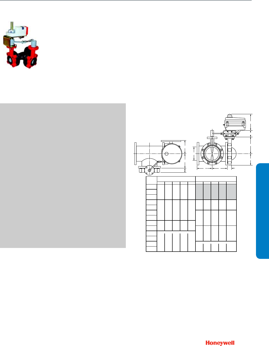
147
VFF3
Resilient seat three-way valves
provide control for HVAC system
applications including chilled
water, hot water, cooling tower
water, thermal storage systems,
and steam.
SPECIFICATIONS
Body Pattern ........................................ 3 way (A-B-AB)
Valve Action .......................................... Normally Closed
Connection Type .................................. Lugged
Controlled Medium ............................... Chilled and hot water, up to
50% glycol
Actuator Control Type .......................... Electric floating, and
modulating; pneumatic spring
and non-spring return
Type of Enclosure ................................. NEMA 2 housing, DCA,
NEMA 4 industrial electric,
pneumatic linear
Flow Characteristic ............................... Modified Equal Percent
Mounting .............................................. ANSI Flanged
Static Pressure Rating (max) ................ 250 psi (1724 kPa)
Maximum Differential Pressure Ratings
(Close-off) ............................................. 175 psi (1206 kPa)
Actuator Ambient Temperature Ratings -5 F to 140 F (-20 C to 60 C)
Temperature Range .............................. -40 F to 250 F (-40 C to 121 C)
Materials
(Body) ................................................... Polyester-coated cast iron
ASTM A126 Class B
(Stem) ................................................... 416 stainless steel
(Seat) .................................................... Peroxide-cured EPDM resilient
seat
(Plug/Ball/Disc) ..................................... Nylon 11-coated ductile iron
APPROVALS
CE ......................................................... Compliant
Underwriters Laboratories, Inc. ............ C/US UL873, Plenum Rated
DIMENSIONS DIAGRAM
M27020
C
T
G
P
T
F
H
R
3 (76)
CC
PIPE SIZE
IN. [mm] W H L1 L2 G W H L1 L2 G
2
[DN50]
2-1/2
[DN65]
3
[DN80]
4
[DN100] 7-1/2 6-3/4 5-1/2 2 5-3/4
5 [191] [170] [141] [49] [147]
[DN125]
6
[DN150]
8
[DN200]
10
[DN250]
12
[DN300]
14
[DN350]
16
[DN400]
18
[DN450] 8-1/2 16 8-3/4 4-1/2 12-1/2
20 [217] [406] [221] [115] [320]
[DN500]
* 175 PSI [1206 KPA] CLOSE-OFF UP TO 12 INCHES [DN 300], 150 PSI [1034 KPA] OTHERWISE
**NOTE: VALVE SIZES 2 TO 3 INCHES HAVE 175 PSI [1206 KPA] CLOSE-OFF AND ARE
AVAILABLE ONLY WITH FULL CUT DISKS.
[170]
NEMA 4X (VFF3/6_W1YXA/B)
12-1/8
[68]
[188]
[198]
9-1/2
3-1/4
[191]
5-1/2
2
5-3/4
7-1/2
[307]
[217]
[406]
[221]
[115]
[320]
12-1/2
4-1/2
NEMA 4 (VFF3/6_V1Y4A/4B)
[241]
[81]
[226]
[224]
8-3/4
[257]
NEMA 4X (VFF3/6_V1YXA/B)
[198]
[68]
9-1/2
3-1/4
8-7/8
[188]
[206]
UNDER CUT DISK, 50 PSI CLOSE-OFF**
10-1/8
7-3/4
2-3/4
7-3/8
8-1/8
[206]
[257]
8-3/4
12-1/8
8-3/4
NEMA 4 (VFF3/6_W1Y4A/4B)
8-7/8
[307]
[224]
[226]
[81]
16
8-1/2
[241]
FULL CUT DISK, 175 PSI CLOSE-OFF
10-1/8
8-1/8
7-3/8
2-3/4
7-3/4
[141]
[49]
[147]
6-3/4
WITH NEMA 4/4X ACTUATORS
Resilient Seat Butterfly Valves
VFF3
SUBMITTAL SHEETS
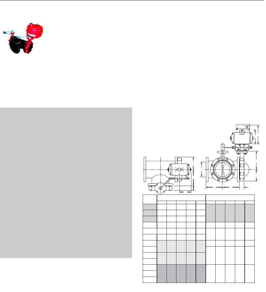
148
VFF6
Resilient seat three-way valves
provide control for HVAC system
applications including chilled
water, hot water, cooling tower
water, thermal storage systems,
and steam.
SPECIFICATIONS
Body Pattern ........................................ 3 way (A-AB-B)
Valve Action ......................................... Normally Closed
Connection Type .................................. Lugged
Controlled Medium ............................... Chilled and hot water, up to
50% glycol
Actuator Control Type .......................... Electric floating, and
modulating; pneumatic spring
and non-spring return
Type of Enclosure ................................. NEMA 2 housing, DCA,
NEMA 4 industrial electric,
pneumatic linear
Flow Characteristic .............................. Modified Equal Percent
Mounting .............................................. ANSI Flanged
Static Pressure Rating (max) ................ 250 psi (1724 kPa)
Maximum Differential Pressure Ratings
(Close-off) ............................................ 175 psi (1206 kPa)
Actuator Ambient Temperature Ratings -5 F to 140 F (-20 C to 60 C)
Temperature Range ............................. -40 F to 250 F (-40 C to 121 C)
Materials
(Body) .................................................. Polyester-coated cast iron
ASTM A126 Class B
(Stem) ................................................... 416 stainless steel
(Seat) .................................................... Peroxide-cured EPDM resilient
seat
(Plug/Ball/Disc) .................................... Nylon 11-coated ductile iron
APPROVALS
CE ........................................................ Compliant
Underwriters Laboratories, Inc. ........... C/US UL873, Plenum Rated
DIMENSIONS DIAGRAM
M27023
T
T
OPTIONAL POSITIONER
A
L2
R
C
CC
R
F
H
Hp
PIPE SIZE
IN. [mm] W H HP L1 L2 W H HP L1 L2
22-3/4 4-1/4 10-1/4 3 3
[DN50] [70] [109] [262] [76] [76]
2-1/2 3-5/8 5-2/8 11-2/8 4 4
[DN65] [91] [132] [284] [100] [100]
34 5-1/2 11-1/2 4-1/2 4-1/2
[DN80] [100] [141] [293] [113] [113]
44-3/4 6-7/8 12-7/8 6 6 4 5-1/2 11-1/2 4-1/2 4-1/2
[DN100] [120] [176] [328] [154] [154] [100] [141] [293] [113] [113]
55-3/8 7-3/4 13-3/4 6-1/8 6-1/8
[DN125] [137] [196] [349] [157] [157]
66-3/4 9-3/8 15-3/8 7-3/4 7-3/4
[DN150] [172] [238] [391] [196] [196]
86-3/4 9-3/8 15-3/8 7-3/4 7-3/4
[DN200] 8-7/8 11-5/8 17-5/8 9-1/2 9-1/2 [172] [238] [391] [196] [196]
10 [224] [295] [447] [240] [240]
[DN250]
12
[DN300]
14 [273] [342] [495] [339] [339]
[DN350]
16
[DN400]
18
[DN450]
20
[DN500]
13-3/8
13-3/8
[273]
[342]
[495]
[339]
[339]
19-1/2
10-3/4
13-1/2
9-1/2
[224]
[295]
[447]
[240]
[240]
8-7/8
11-5/8
17-5/8
9-1/2
[176]
[328]
[154]
[154]
(VFF3/6_W1YCS/DS/ES/PS/XS)
FULL CUT DISK, HIGH CLOSE-OFF*
UNDER CUT DISK, 50 PSI CLOSE-OFF**
(VFF3/6_V1YCS/DS/ES/PS/XS)
13-3/8
4-3/4
6-7/8
12-7/8
6
6
[120]
10-3/4
13-1/2
19-1/2
13-3/8
* 175 PSI [1206 KPA] CLOSE-OFF UP TO 12 INCHES [DN 300], 150 PSI [1034 KPA] AT 14 INCHES
AND NO PRODUCT AVAILABLE GREATER THAN 14 INCHES.
**NOTE: VALVE SIZES 2 TO 3 INCHES ARE AVAILABLE ONLY WITH FULL CUT DISKS.
WITH PNEUMATIC SPRING RETURN ACTUATORS
Resilient Seat Butterfly Valves
VFF6
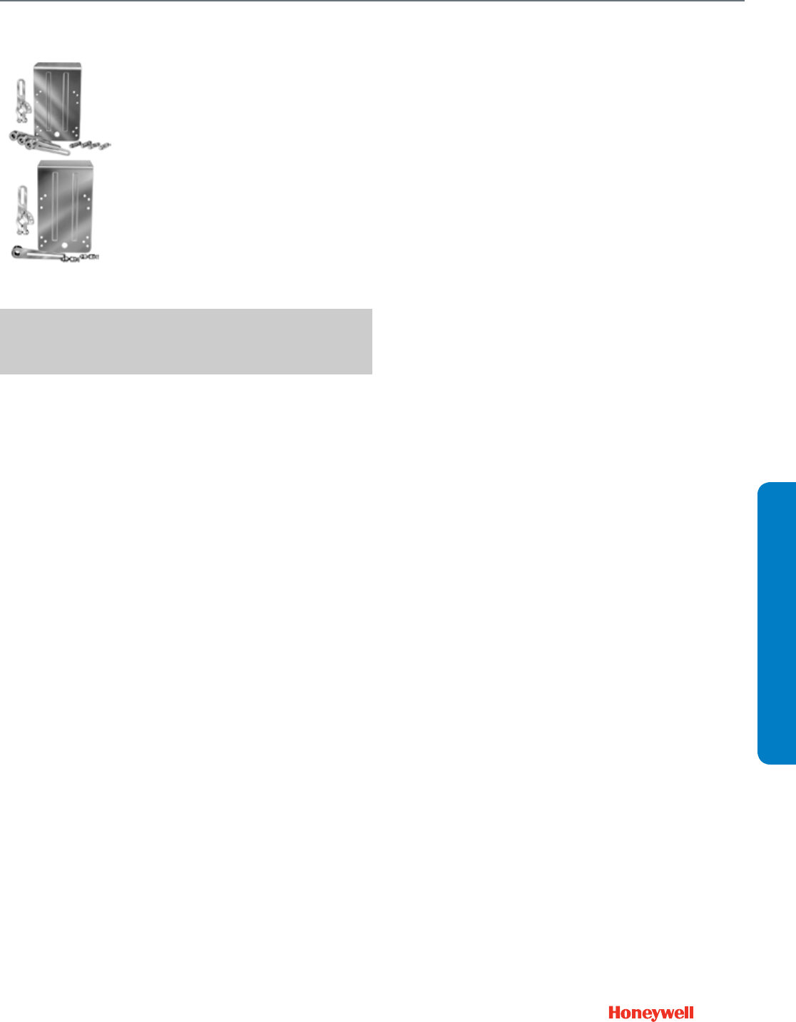
149
SUBMITTAL SHEETS
Q605
Use the Q605 linkage kit to connect
Modutrol® motor to standard
damper or set of dampers to
provide control of duct airflow.
SPECIFICATIONS
Linkage Type ........................................ Damper
Mounting .............................................. Mount motor externally on duct
Used with Actuator ............................... Modutrol Motor
FEATURES
• Adjustable to any degree of damper opening. Include ball
joints, motor crank arm and damper arm for 1/2 in. (13 mm)
diameter shaft.
• 27520 pushrod must be ordered separately.
Damper Linkage
Q605
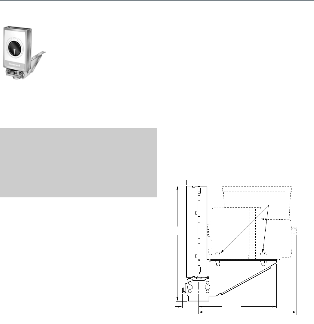
150
Q5001
The Q5001 Valve Linkage connects
a Modutrol® Motor to a 2- or 3-way
valve. It is used primarily on V5011
or V5013 steam and water valves.
SPECIFICATIONS
Linkage Type ........................................ Valve
Mounting .............................................. Linkage mounts directly to the
valve bonnet; motor mounts on
linkage bracket.
Used with Actuator ............................... Modutrol Motor
Stem Force Rating ............................... 80 or 160 lbf (356 N or 712 N)
Ambient Temperature Range ............... -40 F to 150 F (-40 C to 66 C)
REPLACEMENT PARTS
220845/0767—Retainer button for Q5001
FEATURES
• Q5001 Valve Linkage is applicable to 2-Way or 3-Way
valves in modulating or two-position service.
• Linkage requires no adjustment when used with Honeywell
valves and Modutrol IV™ Motors.
• Q5001 Valve Linkage replaces Q601 and Q618 Valve
Linkages.
• Linkage mounts directly to the valve bonnet; motor mounts
to linkage bracket.
• Easy-to-read position indicator.
• Valve stem lift height cam selectable.
• Overtravel permits tight close-off without excessive motor
strain.
• Available brackets make linkages adaptable to many valve
bodies.
• Models available with 80 lb, 160 lb, and 320 lb stem force.
• Reversible cams on the Q5001 allow field selection of
normally open or normally closed valve operation.
• All models have anti-spin clips.
DIMENSIONS DIAGRAM
MOTOR NOT INCLUDED
IN LINKAGE
(POWER END
OF MOTOR)
1/4 X 20 X 1
MOUNTING
BOLTS
M13993
10-1/4 - 10-1/2
(260 - 267)
1-27/64
(36)
6-29/32 (176)
8-25/32 (223)
Valve Linkage
Q5001
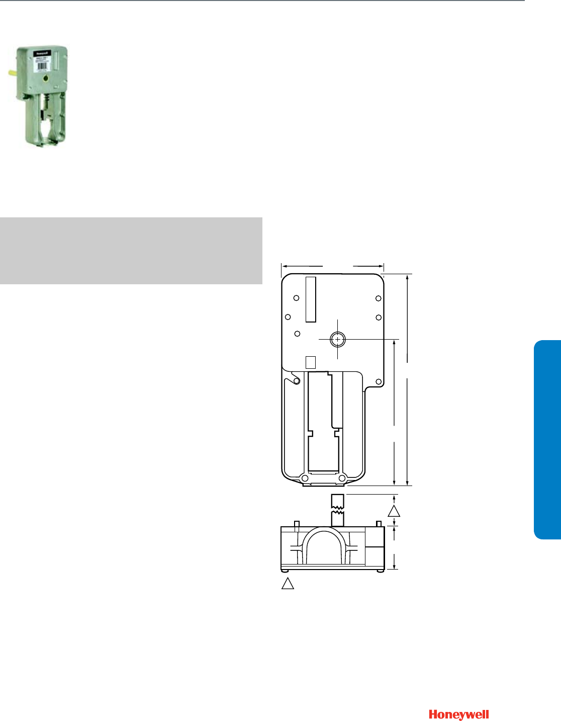
151
SUBMITTAL SHEETS
Q5020
The Q5020 Globe Valve Linkages
connect a Honeywell direct coupled
actuator (DCA) to a steam or water
globe valve. The Q5020 Linkages are
compatible with two-way and three-
way globe valves up to 3 in. (DN80).
SPECIFICATIONS
Linkage Type ........................................ Valve
Mounting .............................................. Linkage mounts directly to the
valve bonnet; motor mounts on
linkage
Used with Actuator ............................... Direct Coupled Actuator
FEATURES
• Used with two-way and three-way globe valves in
modulating or two-position service.
• Used with 25, 50, and 142 lb-in. spring return and 35, 70,
150, and 300 lb-in. non-spring return DCA.
• Quick and simple installation with no disassembly required.
• Heavy-duty Steel rack and pinion construction and
aluminum die-cast housing.
• Maintenance-free construction.
• Precision roller-bearing rack construction prevents
premature valve packing wear and leakage.
• Flexible actuator mounting orientation.
• Adjustable manual override lever and valve position
indicator.
• Can be mounted on specific non-Honeywell valves using a
32004629 Bonnet Adapter Kit.
DIMENSIONS DIAGRAM
4-5/8 (117)
9-1/2
(241)
6-9/16
(166)
1-7/8
(48)
1
1
Q5020A,B,D: 4-7/16 (112)
Q5020C: 3-7/8 (98)
M16346A
Globe Valve Linkage
Q5020
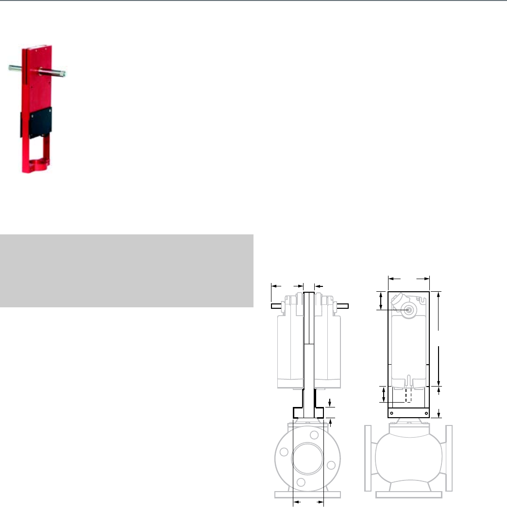
152
Q5022
The Q5022A,B Globe Valve Linkages
connect one or two Honeywell direct
coupled rotary actuators (DCA) to a
globe valve for control of chilled water,
hot water, or steam. The Q5022A,B
Linkages are compatible with 2 and
3-way globe valves up to 6 in. (DN150)
pipe size.
Q5022A is used to provide enhanced
close-off ratings with Honeywell globe
valves up to 3 in. with 1-3/8 in. diameter
bonnet and 3/4 in. stem stroke.
Q5022B is used with Honeywell globe
valves 4 to 6 in. with 1-7/8 in. diameter
bonnet and 1-1/2 in. stem stroke.
SPECIFICATIONS
Linkage Type ........................................ Valve
Mounting .............................................. Linkage mounts directly to the
valve bonnet; motor mounts on
linkage
Used with Actuator ............................... Direct Coupled Actuator
Stem Force Rating ............................... 1117 lbf max. (4969 N max.)
FEATURES
• For use with 2-way and 3-way globe valves in modulating or
two-position service.
• For use with 175 lb.-in. (S20) spring return or 175 and 300
lb.-in. (N20, N34) non-spring return DCAs.
• Accepts single or dual matching actuators for higher close-
off pressures.
• Fail-safe operation with spring return DCAs, field selectable
normally open or normally closed for direct or reverse-
acting valves.
• Linkage threads onto valve stem.
• Oilite™ self-lubricated actuator shaft bearing.
• Anodized extruded aluminum housing.
• Maintenance-free construction.
• Precision roller-bearing rack construction to prevent
premature valve packing wear and leakage.
• Flexible actuator mounting orientation.
DIMENSIONS DIAGRAM
M27644
4-7/8
(124)
8
(203)
3-1/2
(89)
STEM STROKE
5022A 3/4 (19)
5022B 1-1/2 (38)
2-1/2
(64)
1-1/8
(28)
3/4 (19)
2-1/2
(63)
MAX 6-1/4 (159)
MIN 2-15/16 (75)
STROKE “Y”
Globe Valve Linkage
Q5022

153
Direct Coupled Actuators - Spring Return Models
Wiring for (0)2-10 Vdc proportioning controller operating
multiple actuators
Wiring for 3 kOhm Economizer controllers
Wiring for 3 position Economizer controllers
Override to full open
Override to full close
ACTUATOR
0/2 TO 10 VDC
PROPORTIONING
CONTROLLER
24 VAC
1
1
2
3
2
LINE VOLTAGE POWER SUPPLY.
PROVIDE DISCONNECT MEANS AND
OVERLOAD PROTECTION AS REQUIRED.
24 VDC SUPPLY ACCEPTABLE.
SET SWITCH TO MODULATING.
V
FEEDBACK
–
+
FEEDBACK
5
4
3
1
2
M27826
2-10 VDC
10-2 VDC
0-10 VDC
10-0 VDC
Fltg, fwd
Fltg, rev
3
ACTUATOR
V
FEEDBACK
5
4
3
1
2
2-10 VDC
10-2 VDC
0-10 VDC
10-0 VDC
Fltg, fwd
Fltg, rev
3
4
4
ENSURE PROPER GROUNDING OF ACTUATOR CASE.
0°-90°
90°-0°
0°-90°
90°-0°
ACTUATOR
SENSOR
24 VAC V
FEEDBACK
–
+
5
4
3
1
2
M27726
3KΩ
0°-90° OR +
90°-0° OR N/A
1 EXTERNAL MINIMUM POSITION POT CAN BE APPLIED TO 4 90°-0°.
ACTUATOR
SENSOR
24 VAC V
FEEDBACK
–
+
5
4
3
1
2
M27731
0°-90° OR +
90°-0° OR N/A
1 EXTERNAL MINIMUM POSITION POT CAN BE APPLIED TO 4 90°-0°.
ACTUATOR
0/2 TO 10 VDC
PROPORTIONING
CONTROLLER
24 VAC
1
1
2
3
2
LINE VOLTAGE POWER SUPPLY.
PROVIDE DISCONNECT MEANS AND
OVERLOAD PROTECTION AS REQUIRED.
24 VDC SUPPLY ACCEPTABLE.
SET SWITCH TO MODULATING.
V
FEEDBACK
–
+
FEEDBACK
5
4
3
1
2
M27827
2-10 VDC
10-2 VDC
0-10 VDC
10-0 VDC
Fltg, fwd
Fltg, rev
3
SPDT
0°-90° OR +
90°-0° OR N/A
ACTUATOR
0/2 TO 10 VDC
PROPORTIONING
CONTROLLER
24 VAC
1
1
2
3
2
LINE VOLTAGE POWER SUPPLY.
PROVIDE DISCONNECT MEANS AND
OVERLOAD PROTECTION AS REQUIRED.
24 VDC SUPPLY ACCEPTABLE.
SET SWITCH TO MODULATING.
V
FEEDBACK
–
+
FEEDBACK
5
4
3
1
2
2-10 VDC
10-2 VDC
0-10 VDC
10-0 VDC
Fltg, fwd
Fltg, rev
3
SPST
M27828
0°-90° OR +
90°-0° OR N/A
WIRING DIAGRAMS
Section 4: Wiring Diagrams
Actuator Wiring Diagrams .......................................................154
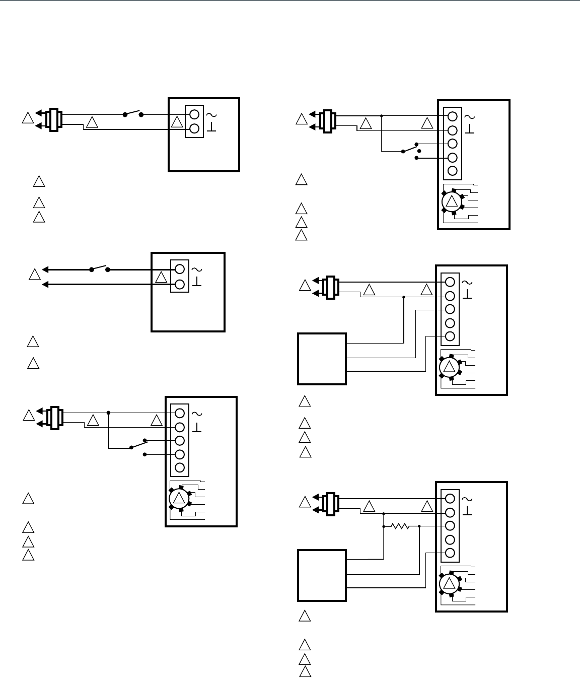
154
Direct Coupled Actuators - Spring Return Models
S03 Series (MS4103, MS7403, MS7503, MS8103) and
S05 Series (MS4105, MS7105, MS7405, MS7505, MS8105)
Wiring for low-voltage two-position control
Wiring for line-voltage two-position control
Wiring for SPDT on/off Control
Wiring for floating control
Wiring for (0)2-10 VDC proportioning controllers
Wiring for 4-20 mA proportioning controllers
ACTUATOR
SPST
24 VAC
1
1
2
2
LINE VOLTAGE POWER SUPPLY. PROVIDE DISCONNECT MEANS
AND OVERLOAD PROTECTION AS REQUIRED.
24 VDC SUPPLY ACCEPTABLE.
ENSURE PROPER GROUNDING OF ACTUATOR CASE.
V
1
2
M19718C
3
3
ACTUATOR
SPST
1
1 LINE VOLTAGE POWER SUPPLY. PROVIDE DISCONNECT MEANS
AND OVERLOAD PROTECTION AS REQUIRED.
ENSURE PROPER GROUNDING OF ACTUATOR CASE.
V
1
2
M22289A
2
2
SPDT
24 VAC
1
1
2
3
2
LINE VOLTAGE POWER SUPPLY.
PROVIDE DISCONNECT MEANS AND
OVERLOAD PROTECTION AS REQUIRED.
24 VDC SUPPLY ACCEPTABLE.
SET SWITCH TO FLOATING.
M27822
ACTUATOR
V
0°-90°
90°-0°
FEEDBACK
5
4
3
1
2
2-10 VDC
10-2 VDC
0-10 VDC
10-0 VDC
Fltg, fwd
Fltg, rev
3
4
ENSURE PROPER GROUNDING OF ACTUATOR CASE.
4
24 VAC
1
1
2
3
2
LINE VOLTAGE POWER SUPPLY.
PROVIDE DISCONNECT MEANS AND
OVERLOAD PROTECTION AS REQUIRED.
24 VDC SUPPLY ACCEPTABLE.
SET SWITCH TO FLOATING.
M27823
ACTUATOR
V
FEEDBACK
5
4
3
1
2
2-10 VDC
10-2 VDC
0-10 VDC
10-0 VDC
Fltg, fwd
Fltg, rev
3
4
4
ENSURE PROPER GROUNDING OF ACTUATOR CASE.
0°-90°
90°-0°
ACTUATOR
0/2 TO 10 VDC
PROPORTIONING
CONTROLLER
24 VAC
1
1
2
3
2
LINE VOLTAGE POWER SUPPLY. PROVIDE DISCONNECT MEANS
AND OVERLOAD PROTECTION AS REQUIRED.
24 VDC SUPPLY ACCEPTABLE.
SET SWITCH TO MODULATING.
V
FEEDBACK
–
+
FEEDBACK
5
4
3
1
2
M27824
2-10 VDC
10-2 VDC
0-10 VDC
10-0 VDC
Fltg, fwd
Fltg, rev
3
4
ENSURE PROPER GROUNDING OF ACTUATOR CASE.
4
0°-90°
90°-0°
ACTUATOR
4 TO 20 mA
PROPORTIONING
CONTROLLER
24 VAC
1
1
2
3
2
490 TO 510
OHMS,
1/2 W
MINIMUM
LINE VOLTAGE POWER SUPPLY.
PROVIDE DISCONNECT MEANS AND
OVERLOAD PROTECTION AS REQUIRED.
24 VDC SUPPLY ACCEPTABLE.
SET SWITCH TO MODULATING.
V
FEEDBACK
–
+
FEEDBACK
5
4
3
1
2
M27825
2-10 VDC
10-2 VDC
0-10 VDC
10-0 VDC
Fltg, fwd
Fltg, rev
3
4
ENSURE PROPER GROUNDING OF ACTUATOR CASE.
4
0°-90°
90°-0°
Actuator Wiring Diagrams
Direct Coupled Actuators - Spring Return Models
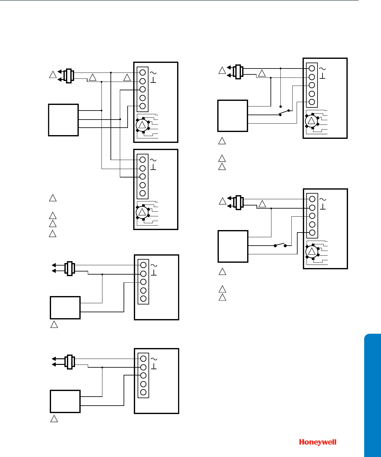
155
Direct Coupled Actuators - Spring Return Models
Wiring for (0)2-10 Vdc proportioning controller operating
multiple actuators
Wiring for 3 kOhm Economizer controllers
Wiring for 3 position Economizer controllers
Override to full open
Override to full close
ACTUATOR
0/2 TO 10 VDC
PROPORTIONING
CONTROLLER
24 VAC
1
1
2
3
2
LINE VOLTAGE POWER SUPPLY.
PROVIDE DISCONNECT MEANS AND
OVERLOAD PROTECTION AS REQUIRED.
24 VDC SUPPLY ACCEPTABLE.
SET SWITCH TO MODULATING.
V
FEEDBACK
–
+
FEEDBACK
5
4
3
1
2
M27826
2-10 VDC
10-2 VDC
0-10 VDC
10-0 VDC
Fltg, fwd
Fltg, rev
3
ACTUATOR
V
FEEDBACK
5
4
3
1
2
2-10 VDC
10-2 VDC
0-10 VDC
10-0 VDC
Fltg, fwd
Fltg, rev
3
4
4
ENSURE PROPER GROUNDING OF ACTUATOR CASE.
0°-90°
90°-0°
0°-90°
90°-0°
ACTUATOR
SENSOR
24 VAC V
FEEDBACK
–
+
5
4
3
1
2
M27726
3KΩ
0°-90° OR +
90°-0° OR N/A
1 EXTERNAL MINIMUM POSITION POT CAN BE APPLIED TO 4 90°-0°.
ACTUATOR
SENSOR
24 VAC V
FEEDBACK
–
+
5
4
3
1
2
M27731
0°-90° OR +
90°-0° OR N/A
1 EXTERNAL MINIMUM POSITION POT CAN BE APPLIED TO 4 90°-0°.
ACTUATOR
0/2 TO 10 VDC
PROPORTIONING
CONTROLLER
24 VAC
1
1
2
3
2
LINE VOLTAGE POWER SUPPLY.
PROVIDE DISCONNECT MEANS AND
OVERLOAD PROTECTION AS REQUIRED.
24 VDC SUPPLY ACCEPTABLE.
SET SWITCH TO MODULATING.
V
FEEDBACK
–
+
FEEDBACK
5
4
3
1
2
M27827
2-10 VDC
10-2 VDC
0-10 VDC
10-0 VDC
Fltg, fwd
Fltg, rev
3
SPDT
0°-90° OR +
90°-0° OR N/A
ACTUATOR
0/2 TO 10 VDC
PROPORTIONING
CONTROLLER
24 VAC
1
1
2
3
2
LINE VOLTAGE POWER SUPPLY.
PROVIDE DISCONNECT MEANS AND
OVERLOAD PROTECTION AS REQUIRED.
24 VDC SUPPLY ACCEPTABLE.
SET SWITCH TO MODULATING.
V
FEEDBACK
–
+
FEEDBACK
5
4
3
1
2
2-10 VDC
10-2 VDC
0-10 VDC
10-0 VDC
Fltg, fwd
Fltg, rev
3
SPST
M27828
0°-90° OR +
90°-0° OR N/A
WIRING DIAGRAMS
Actuator Wiring Diagrams
Direct Coupled Actuators - Spring Return Models
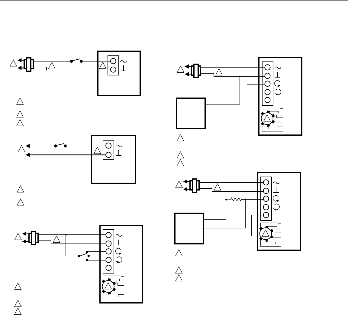
156
Direct Coupled Actuators - Spring Return Models
S10 Series (MS4110, MS7510, MS8110) and S20 Series (MS4120, MS7520, MS8120)
Wiring for On/Off Control
Wiring for Floating Control (Floating mode setting)
Wiring for Proportioning controllers
(Modulating mode setting)
ACTUATOR
SPST
24 VAC
1
1
2
2
LINE VOLTAGE POWER SUPPLY. PROVIDE DISCONNECT MEANS
AND OVERLOAD PROTECTION AS REQUIRED.
24 VDC SUPPLY ACCEPTABLE.
ENSURE PROPER GROUNDING OF ACTUATOR CASE.
V
1
2
M19718C
3
3
ACTUATOR
SPST
1
1 LINE VOLTAGE POWER SUPPLY. PROVIDE DISCONNECT MEANS
AND OVERLOAD PROTECTION AS REQUIRED.
ENSURE PROPER GROUNDING OF ACTUATOR CASE.
V
1
2
M22289A
2
2
24 VAC
1
1
2
3
2
LINE VOLTAGE POWER SUPPLY.
PROVIDE DISCONNECT MEANS AND
OVERLOAD PROTECTION AS REQUIRED.
24 VDC SUPPLY ACCEPTABLE.
SET SWITCH TO FLOATING.
M19573A
ACTUATOR
V
OR +
OR N/A
FEEDBACK
5
4
3
1
2
2-10 VDC
10-2 VDC
0-10 VDC
10-0 VDC
Fltg, fwd
Fltg, rev
3
ACTUATOR
0/2 TO 10 VDC
PROPORTIONING
CONTROLLER
24 VAC
1
1
2
3
2
LINE VOLTAGE POWER SUPPLY.
PROVIDE DISCONNECT MEANS AND
OVERLOAD PROTECTION AS REQUIRED.
24 VDC SUPPLY ACCEPTABLE.
SET SWITCH TO MODULATING.
V
OR +
OR N/A
FEEDBACK
–
+
FEEDBACK
5
4
3
1
2
M19574A
2-10 VDC
10-2 VDC
0-10 VDC
10-0 VDC
Fltg, fwd
Fltg, rev
3
ACTUATOR
4 TO 20 mA
PROPORTIONING
CONTROLLER
24 VAC
1
1
2
3
2
500
OHMS
LINE VOLTAGE POWER SUPPLY.
PROVIDE DISCONNECT MEANS AND
OVERLOAD PROTECTION AS REQUIRED.
24 VDC SUPPLY ACCEPTABLE.
SET SWITCH TO MODULATING.
V
OR +
OR N/A
FEEDBACK
–
+
FEEDBACK
5
4
3
1
2
M22282
2-10 VDC
10-2 VDC
0-10 VDC
10-0 VDC
Fltg, fwd
Fltg, rev
3
Actuator Wiring Diagrams
Direct Coupled Actuators - Spring Return Models
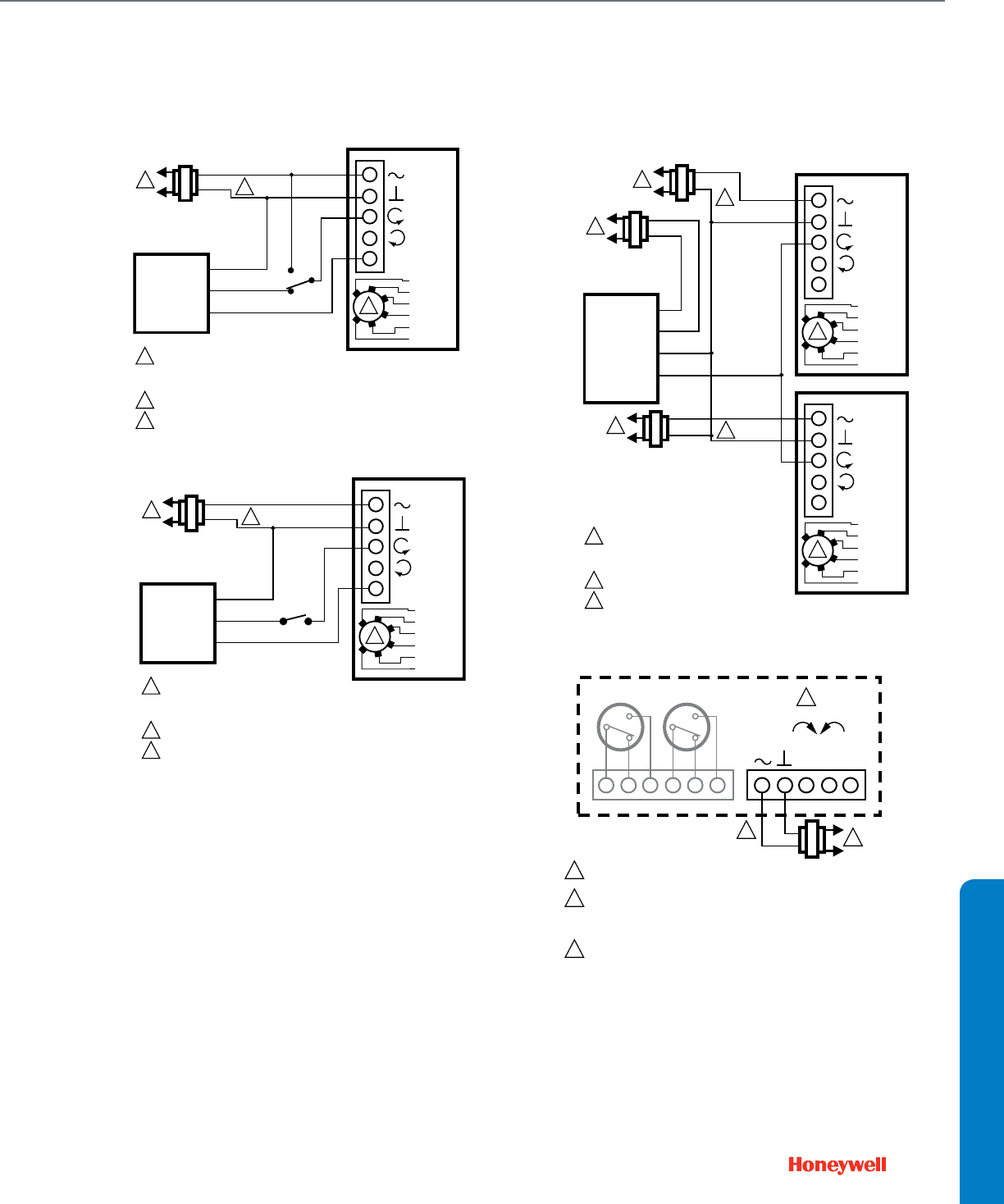
157
Direct Coupled Actuators - Spring Return Models
Override to full open (Modulating mode setting)
Override to full closed (Modulating mode setting)
Wiring for Proportioning controllers operating multiple
actuators (Modulating mode setting)
Terminal Block Details
ACTUATOR
0/2 TO 10 VDC
PROPORTIONING
CONTROLLER
24 VAC
1
1
2
3
2
LINE VOLTAGE POWER SUPPLY.
PROVIDE DISCONNECT MEANS AND
OVERLOAD PROTECTION AS REQUIRED.
24 VDC SUPPLY ACCEPTABLE.
SET SWITCH TO MODULATING.
V
OR +
OR N/A
FEEDBACK
–
+
FEEDBACK
5
4
3
1
2
M19576A
2-10 VDC
10-2 VDC
0-10 VDC
10-0 VDC
Fltg, fwd
Fltg, rev
3
SPDT
ACTUATOR
0/2 TO 10 VDC
PROPORTIONING
CONTROLLER
24 VAC
1
1
2
3
2
LINE VOLTAGE POWER SUPPLY.
PROVIDE DISCONNECT MEANS AND
OVERLOAD PROTECTION AS REQUIRED.
24 VDC SUPPLY ACCEPTABLE.
SET SWITCH TO MODULATING.
V
OR +
OR N/A
FEEDBACK
–
+
FEEDBACK
5
4
3
1
2
M19577A
2-10 VDC
10-2 VDC
0-10 VDC
10-0 VDC
Fltg, fwd
Fltg, rev
3
SPST
ACTUATOR
0/2 TO 10 VDC
PROPORTIONING
CONTROLLER
1
2
3
2
LINE VOLTAGE POWER SUPPLY.
PROVIDE DISCONNECT MEANS AND
OVERLOAD PROTECTION AS REQUIRED.
24 VDC SUPPLY ACCEPTABLE.
SET SWITCH TO MODULATING.
V
OR +
OR N/A
FEEDBACK
5
4
3
1
2
M22288
2-10 VDC
10-2 VDC
0-10 VDC
10-0 VDC
Fltg, fwd
Fltg, rev
3
ACTUATOR
V
OR +
OR N/A
FEEDBACK
5
4
3
1
2
2-10 VDC
10-2 VDC
0-10 VDC
10-0 VDC
Fltg, fwd
Fltg, rev
3
24 VAC
1
24 VAC
1
2
24 VAC
1
HOT
COM
–
+
1 POWER SUPPLY. PROVIDE DISCONNECT MEANS AND OVERLOAD
PROTECTION AS REQUIRED.
3 ENSURE PROPER GROUNDING OF ACTUATOR CASE.
2 THE INTERNAL AUXILIARY SWITCHES MUST BE CONNECTED TO
THE SAME POWER SOURCE; OR THE AUXILIARY SWITCHES SHALL
BE CONNECTED TO THE SAME POLE OF THE SAME SUPPLY CIRCUIT,
CONNECTED IN A SAME POLARITY MANNER.
VOR
+
OR
N/A
FEEDBACK
ACTUATOR
1
2
3
5
4
3
1
7° 85°
S1 S2 S3 S4 S5 S6 2
M19571B
WIRING DIAGRAMS
Actuator Wiring Diagrams
Direct Coupled Actuators - Spring Return Models
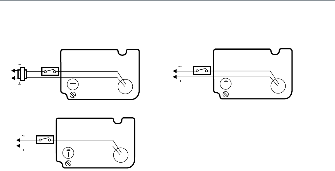
158
Direct Coupled Actuators - Spring Return Models
ML4125, ML8125, ML4135, and ML8135
Typical 24 Vac wiring
Typical 120 Vac Wiring
Typical 230 Vac Wiring
L1
24 VAC
L2
RED
BLACK
M17585A
( )
( )
L1
120 VAC
L2
WHITE
BLACK
M17589A
( )
( )
L1
230 VAC
L2
BLUE
BROWN
M17588A
( )
( )
Actuator Wiring Diagrams
Direct Coupled Actuators - Spring Return Models
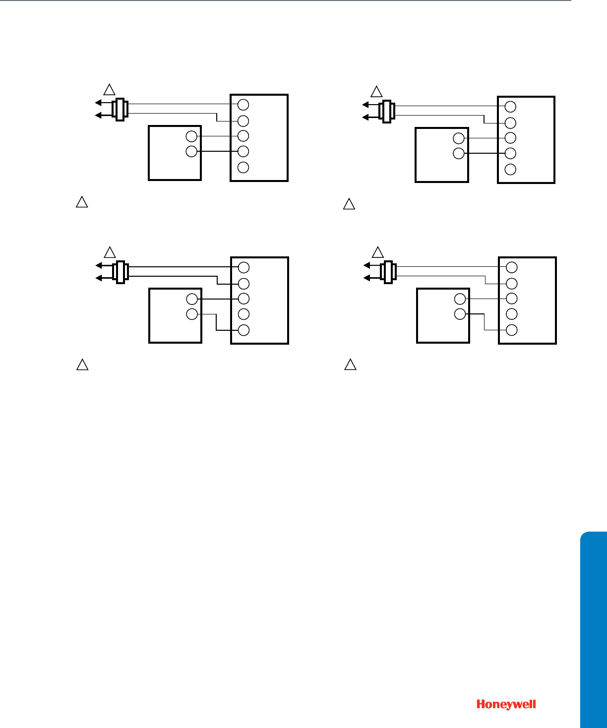
159
Direct Coupled Actuators - Non-Spring Return Models
ML6161 and ML7161
ML7161 used with 4-20 mA control
ML7161 used with 2-10 Vdc control
ML6174 and ML7174
ML7174 used with 4-20 mA control
ML7174 used with 2-10 Vdc control
L1
(HOT)
L2
1
1POWER SUPPLY. PROVIDE DISCONNECT MEANS AND OVERLOAD
PROTECTION AS REQUIRED.
4-20 mA CONTROLLER
ML7161, ML7174
T1
T2
–
–
++ mA
+ V
M18071
L1
(HOT)
L2
1
1POWER SUPPLY. PROVIDE DISCONNECT MEANS AND OVERLOAD
PROTECTION AS REQUIRED.
2-10 Vdc CONTROLLER
ML7161, ML7174
T1
T2
–
–
++ mA
+ V
M18072
L1
(HOT)
L2
1
1POWER SUPPLY. PROVIDE DISCONNECT MEANS AND OVERLOAD
PROTECTION AS REQUIRED.
4-20 mA CONTROLLER
ML7161, ML7174
T1
T2
–
–
++ mA
+ V
M18071
L1
(HOT)
L2
1
1POWER SUPPLY. PROVIDE DISCONNECT MEANS AND OVERLOAD
PROTECTION AS REQUIRED.
2-10 Vdc CONTROLLER
ML7161, ML7174
T1
T2
–
–
++ mA
+ V
M18072
WIRING DIAGRAMS
Actuator Wiring Diagrams
Direct Coupled Actuators - Non-Spring Return Models
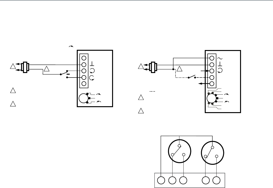
160
Direct Coupled Actuators - Non-Spring Return Models
N05 Series (MN6105, MN7505) and N10 Series (MN6110, MN7510)
Wiring for Floating Control Wiring for Voltage Control
Wiring for Auxiliary Switches
FLOATING: DIR
24 VAC
1
1
2
2
LINE VOLTAGE POWER SUPPLY.
PROVIDE DISCONNECT MEANS AND
OVERLOAD PROTECTION AS REQUIRED.
24 VDC SUPPLY ACCEPTABLE.
M23107
ACTUATOR
V
5
4
3
1
2
Dir
Service/Off
Rev
MN6105, MN6110
MN7505, MN7510
MODULATING: 0[2]... 10 V, 10... 0[2] V
24 VAC
1
1
2
2
LINE VOLTAGE POWER SUPPLY.
PROVIDE DISCONNECT MEANS AND
OVERLOAD PROTECTION AS REQUIRED.
24 VDC SUPPLY ACCEPTABLE.
M23097
ACTUATOR
V
OR +
FEEDBACK
5
4
3
1
2
Dir
Service/Off
Rev
2... 10 V
0... 10 V
10... 0 V
10... 2 V
0[2]... 10 V
= OVERRIDE OPTION
0[2]... 10 V
POS 50%
5° 85°
S1 S2 S3 S5 S6
M23110
END SWITCHES (CLASS II-ONLY)
Actuator Wiring Diagrams
Direct Coupled Actuators - Non-Spring Return Models
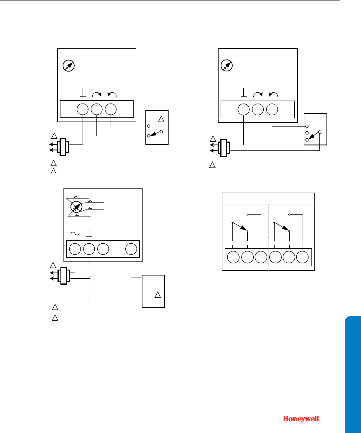
161
Direct Coupled Actuators - Non-Spring Return Models
N20 Series (MN6120, MN7220) and N34 Series (MN6134, MN7234)
Used for On/Off Control
Wiring for Modulating Control
Wiring for Floating Control
Wiring for Auxiliary Switches
432
FLOATING ACTUATOR
24 VAC
1
1POWER SUPPLY. PROVIDE DISCONNECT MEANS
AND OVERLOAD PROTECTION AS REQUIRED.
CONNECTION REQUIRED FOR SPST CONTROL.
2
CONTROLLER
2
Direct
Reverse
Service/Off
M18945A
24 VAC
1
1POWER SUPPLY. PROVIDE DISCONNECT MEANS
AND OVERLOAD PROTECTION AS REQUIRED.
PROPORTIONAL
CONTROLLER
+
-
FEEDBACK
1 32 5
PROPORTIONAL ACTUATOR
FEEDBACK
+
0(2)-10 VDC OF 0(4)-20 mA CONTROL SIGNAL ACCEPTABLE.
SET CONTROL SIGNAL DIP SWITCH TO "OFF" FOR VOLTAGE.
SET TO "ON" FOR CURRENT.
2
2
2 -10 Vdc
2 -10 Vdc
0 -10 Vdc
0 -10 Vdc
M18947A
4
3
2
FLOATING ACTUATOR
24 VAC
Direct
Reverse
Service/Off
1
1POWER SUPPLY. PROVIDE DISCONNECT MEANS
AND OVERLOAD PROTECTION AS REQUIRED.
FLOATING
CONTROLLER
M18946A
AUXILIARY SWITCHES
S1 S2 S3 S4 S5 S6
COM N.O.N.C. COM N.O.N.C.
M18948
WIRING DIAGRAMS
Actuator Wiring Diagrams
Direct Coupled Actuators - Non-Spring Return Models
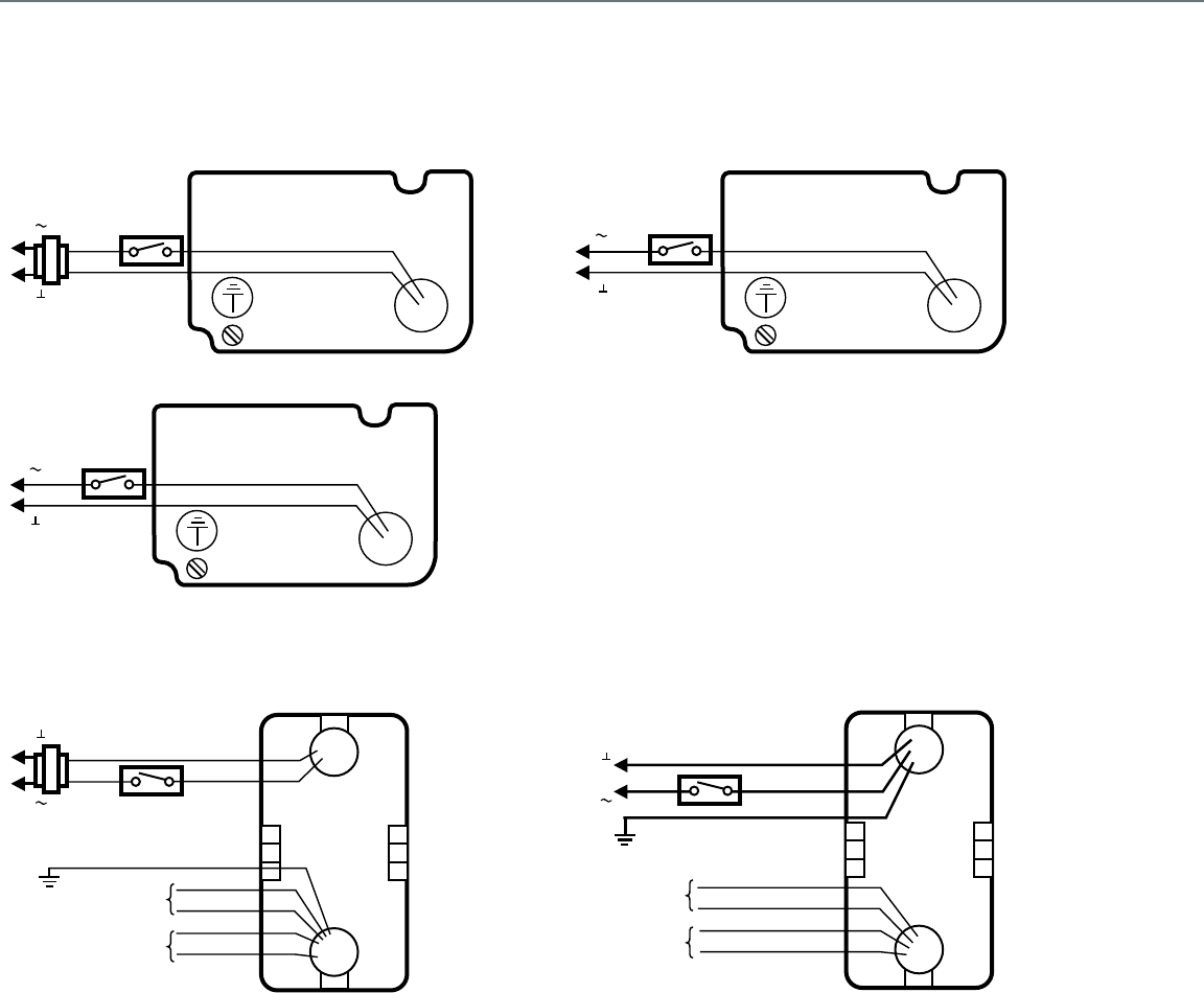
162
Direct Coupled Actuators - Smoke and Fire Actuators
ML4115, ML8115, MS4209F, MS4309F, MS4709F, MS4809F, MS8209F, and MS8309F
Typical 24 Vac wiring
Typical 120 Vac wiring
Typical 230 Vac Wiring
MS4120F, MS4620F, and MS8120F
Wiring for 24V Control Wiring for 120V Control
L1
24 VAC
L2
RED
BLACK
M17585A
( )
( )
L1
120 VAC
L2
WHITE
BLACK
M17589A
( )
( )
L1
230 VAC
L2
BLUE
BROWN
M17588A
( )
( )
M20053A
24 VAC
BLACK
RED
GREEN
MS8120F
L1
( )
L2 ( )
YELLOW
YELLOW
BLUE
7° AUXILIARY
SWITCH
85° AUXILIARY
SWITCH
BLUE
M20056A
WHITE
BLACK
GREEN
MS4120F
L1
( )
L2 ( )
YELLOW
YELLOW
BLUE
BLUE
7° AUXILIARY
SWITCH
85° AUXILIARY
SWITCH
120 VAC
Actuator Wiring Diagrams
Direct Coupled Actuators - Fire and Smoke Actuators
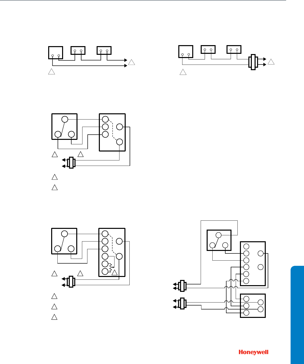
163
Foot Mounted Motors
M4185 and M8185
Typical connections for Series 41 motors Typical connections for Series 81 motors
M6184 and M6194
Typical wiring for Series 61 motors
M6284, M6285, and M6294 for slaving applications
Typical wiring for Series 62 motors Series 60 and Series 90 motors in slaving application
MOTOR
1
1
M806A
THERMOSTAT LIMIT CONTROL
POWER SUPPLY. PROVIDE DISCONNECT MEANS
AND OVERLOAD PROTECTION AS REQUIRED.
MOTOR
1
M807A
THERMOSTAT LIMIT CONTROL
TRANSFORMER
1POWER SUPPLY. PROVIDE DISCONNECT MEANS
AND OVERLOAD PROTECTION AS REQUIRED.
R
BW
R
W
B
T2
T1
L1
(HOT)
L2
POWER SUPPLY. PROVIDE DISCONNECT MEANS
AND OVERLOAD PROTECTION AS REQUIRED.
TRANSFORMER MAY BE INTERNAL OR EXTERNAL
TO MOTOR. M17095A
SERIES 60
CONTROLLER
SERIES 61
MOTOR
1
2
12
R
BW
R
1
2
T
G
Y
4
3
L1
(HOT)
L2
POWER SUPPLY. PROVIDE DISCONNECT MEANS
AND OVERLOAD PROTECTION AS REQUIRED.
TRANSFORMER MAY BE INTERNAL OR EXTERNAL
TO MOTOR.
FEEDBACK POTENTIOMETER. M17096
SERIES 60
CONTROLLER
SERIES 62
MOTOR
1
2
3
123
M27035
R
1
2
T
G
Y
3
4
M6284
W
R
B
T1
T2
M9184
R (HOT)
C
R (HOT)
R
BW
SERIES 60
CONTROLLER
C
WIRING DIAGRAMS
Actuator Wiring Diagrams
Foot Mounted Motors
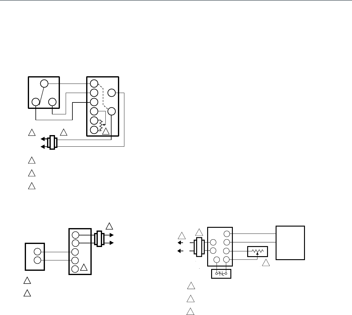
164
Foot Mounted Motors
M6274, M6284, M6285, and M6294 Motors with Linear 10K Feedback
Typical wiring for Series 62 motors
M7164, M7284, M7285, M7286, and M7294
Typical wiring for Series 70 motors
M7685
Typical wiring for M7685 motors
R
BW
R
1
2
T
G
Y
4
3
L1
(HOT)
L2
POWER SUPPLY. PROVIDE DISCONNECT MEANS
AND OVERLOAD PROTECTION AS REQUIRED.
TRANSFORMER MAY BE INTERNAL OR EXTERNAL
TO MOTOR.
FEEDBACK POTENTIOMETER. M17096
SERIES 60
CONTROLLER
SERIES 62
MOTOR
1
2
3
123
CONTROLLER
L1
(HOT)
L2
POWER SUPPLY. PROVIDE DISCONNECT MEANS AND
OVERLOAD PROTECTION AS REQURED.
CONNECTING F TO – WILL DRIVE MOTOR TO FULLY OPEN.
1
M5778
1
-
MOTOR
2
F
T1
T2
2
+
-
+
24V
1
2
3
T1
T2
C
R
4
3
1
L1
L2
( HO T)
+
-
2
2
3
DAMPER MOTORS
WHITE
RED
MODULATING
dc VOLTAGE
SOURCE
MINIMUM
POSITION
POTENTIOMETER
EXTERNAL
CONTROL
POWER SUPPLY. PROVIDE DISCONNECT MEANS AND
OVERLAOD PROTECTION AS REQUIRED.
IF MINIMUM POSITION POTENTIOMENTER IS NOT USED,
JUMPER TERMIALS 3 AND 4.
TRANSFORMER MAY BE INTERNAL OR EXTERNAL. M13727
Actuator Wiring Diagrams
Foot Mounted Motors
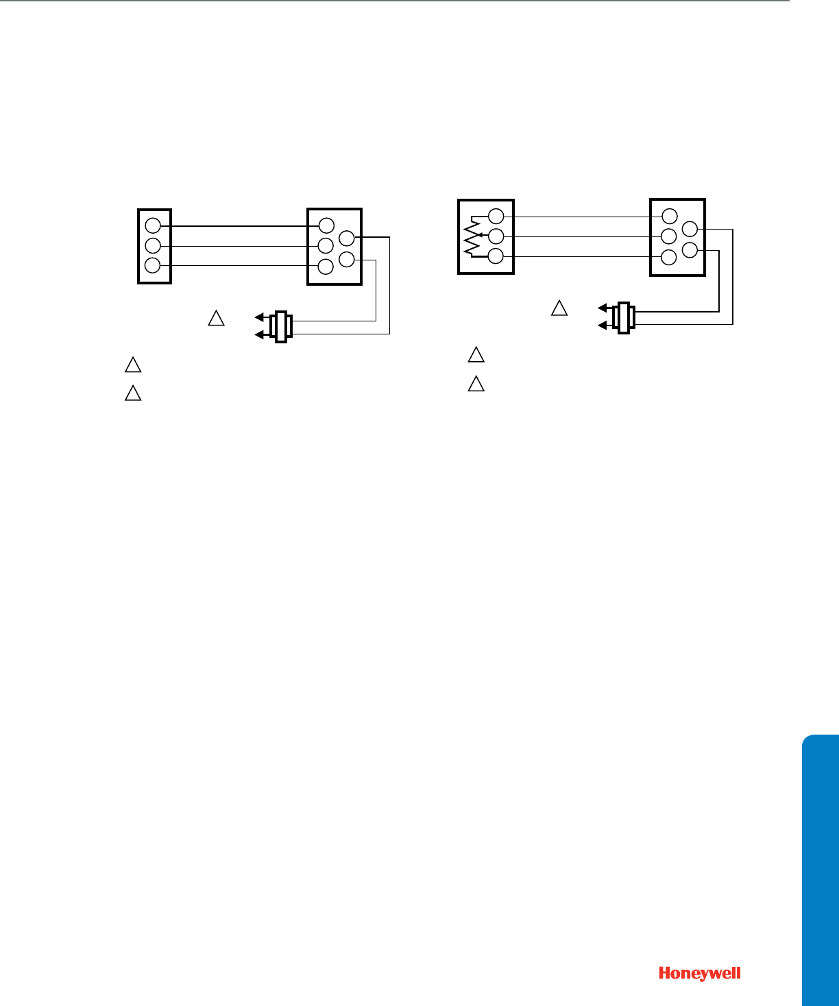
165
Foot Mounted Motors
M9161, M9164, M9171, M9172, M9174, M9175, M9181, M9182, M9184, M9185, M9186, and
M9194
Typical wiring for Series 90 motors Wiring for Potentiometer Control
L1
(HOT)
L2
1
1
2
R
W
B
R
W
B
T1
T2
TRANSFORMER
POWER SUPPLY. PROVIDE DISCONNECT MEANS AND
OVERLOAD PROTECTION AS REQUIRED.
TRANSFORMER MAY BE INTERNAL OR EXTERNAL M770A
SERIES 90
CONTROLLER MOTOR
L1
(HOT)
L2
1
1
2
R
W
B
R
W
B
T1
T2
TRANSFORMER
POWER SUPPLY. PROVIDE DISCONNECT MEANS AND
OVERLOAD PROTECTION AS REQUIRED.
TRANSFORMER MAY BE INTERNAL OR EXTERNAL M13708
135 OHM
POTENTIOMETER MOTOR
WIRING DIAGRAMS
Actuator Wiring Diagrams
Foot Mounted Motors
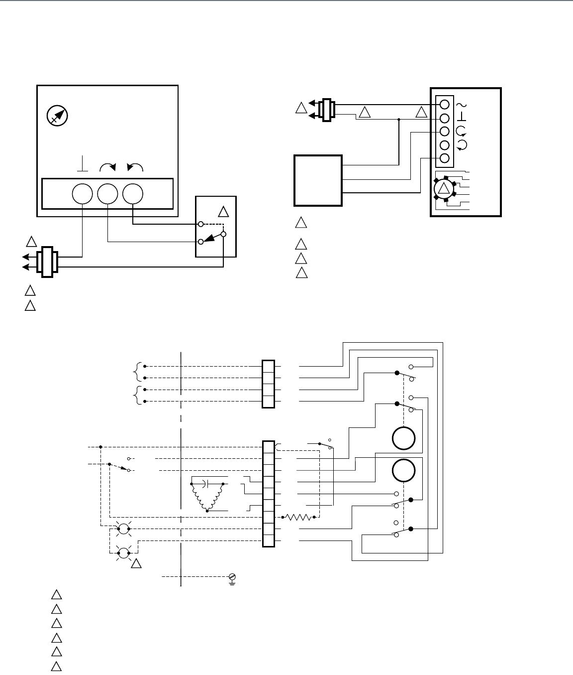
166
Actuators with Butterfly Valves
VFF2, VFF3, and VFF6
Typical Non-Spring Return Floating Control Actuator wiring Typical Spring Return Floating/Modulating control wiring
Typical Non-Spring Return 120 Vac Floating control wiring
432
FLOATING ACTUATOR
24 VAC
1
1POWER SUPPLY. PROVIDE DISCONNECT MEANS
AND OVERLOAD PROTECTION AS REQUIRED.
CONNECTION REQUIRED FOR SPST CONTROL.
2
CONTROLLER
2
Direct
Reverse
Service/Off
M18945A
ACTUATOR
0/2 TO 10 VDC
PROPORTIONING
CONTROLLER
24 VAC
1
1
2
3
2
LINE VOLTAGE POWER SUPPLY. PROVIDE DISCONNECT MEANS
AND OVERLOAD PROTECTION AS REQUIRED.
24 VDC SUPPLY ACCEPTABLE.
SET SWITCH TO MODULATING.
V
OR +
OR N/A
FEEDBACK
–
+
FEEDBACK
5
4
3
1
2
M19574B
2-10 VDC
10-2 VDC
0-10 VDC
10-0 VDC
Fltg, fwd
Fltg, rev
3
4
ENSURE PROPER GROUNDING OF ACTUATOR CASE.
4
ACTUATOR SHOWN IN CLOSED POSITION
MANUAL OVERRIDE NOT ENGAGED
HEATER OPTIONAL
TRAVEL, MANUAL OVERRIDE, AND TORQUE SWITCHES ARE SPDT (FORM C).
DO NOT WIRE ACTUATORS IN PARALLEL.
DO NOT INSTANTANEOUSLY SWITCH DIRECTION OF THE MOTOR WHILE THE ACTUATOR IS MOVING; ALLOW 0.5 TO 1 SECOND BETWEEN COMMAND CHANGES.
LIMIT SWITCH:
125/250 VAC, 10 A, 1/2 HP
125/250 VDC, 0.25 A INDUCTIVE
125/250 VDC, 0.5 A RESISTIVE
TERMINAL STRIP:
14 - 22 AWG
MAX TIGHTENING TORQUE 8 IN-LBS
105°C, 300V MIN RATED WIRE
COM
COM
N.C.
N.O.
N.C.
N.O.
CLOSE
AUX CLOSE
RED
CAM
GREEN
CAM
AUX OPEN
OPEN
COM
N.O.
N.C.
N.O.
N.C.
COM
ACTUATOR
FIELD WIRING
CLOSE N.O.
(VOLTAGE FREE)
OPEN N.O.
(VOLTAGE FREE)
N
SINGLE PHASE
POWER SUPPLY OPEN
CLOSE
L
FOR HEATER
OPTION ONLY
CLOSE
GROUND
OPEN
BLUE
RED
YELLOW OR
BLACK
N
OC
MOTOR
HEATER
(OPTIONAL)
YELLOW
BLUE
RED
BLUE
RED
YELLOW
RED
BLUE
OVERRIDE
SW
2
1
3
4
5
6
7
8
9
ARED
RED
BLUE
BLUE
COM N.C.
N.O.
1
2
3
4
5
6M27038
5
B
C
D
Actuator Wiring Diagrams
Actuators with Butterfly Valves
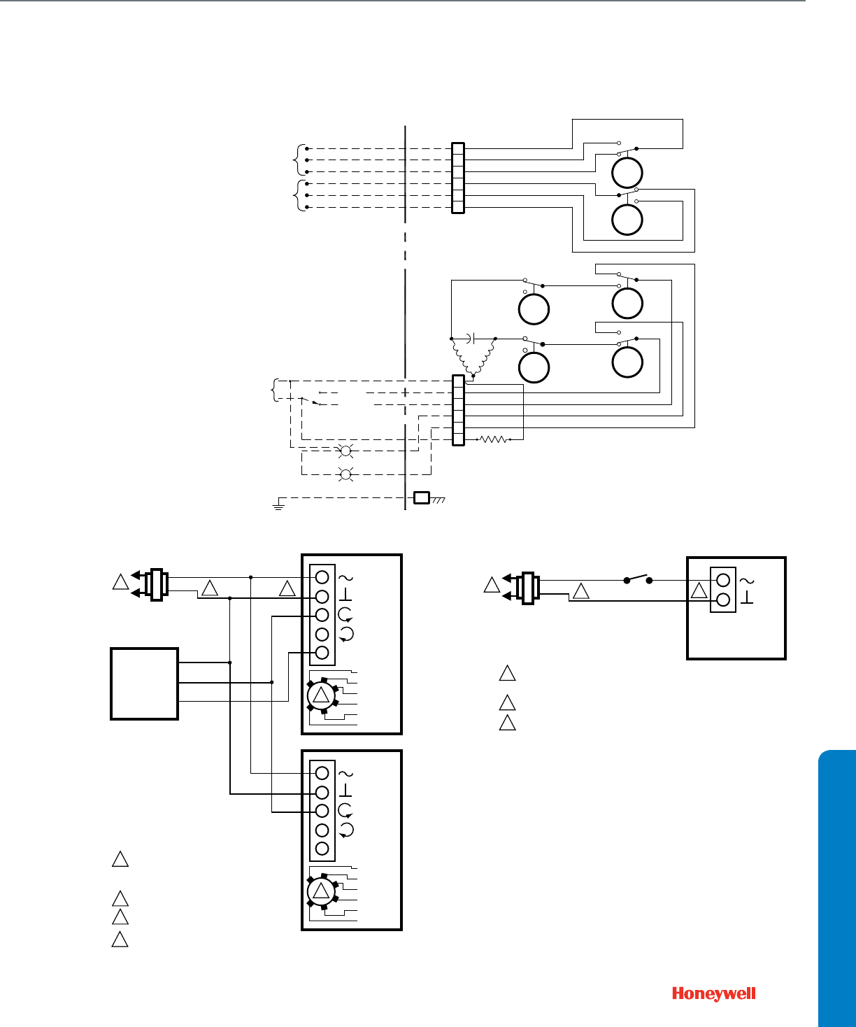
167
Actuators with Butterfly Valves
Typical Non-Spring Return 120 Vac Floating control wiring
Typical Non-Spring Return Modulating control wiring Typical Spring Return 2-Position, 24 Vac wiring
FIELD WIRING
A
UX SPDT SWITCH/LS3
(VOLTAGE FREE)
AUX SPDT SWITCH/LS4
(VOLTAGE FREE)
ACTUATOR
COM
N.O.
N.C.
COM
N.O.
N.C.
A
B
C
D
E
F
N.O.
N.C. COM
TORQUE SWITCHES
(OPTIONAL)
TS2
CLOSE
TS1
OPEN
COM
N.O.
N.C.
N.C.
N.O. COM
LS2
CLOSE
LS1
OPEN
N.C.
N.O. COM
AUXILIARY SWITCHES
COM
COM
LS4
CAM
LS3
CAM N.C.
N.O.
N.O.
N.C.
HEATER
MOTOR
N
0
C
1
7
3
4
5
6
PE
G
OPEN
CLOSE
FOR HEATER OPTION ONLY
SINGLE PHASE
POWER SUPPLY
N
OPEN
CLOSE
L
M27040
ACTUATOR
0/2 TO 10 VDC
PROPORTIONING
CONTROLLER
24 VAC
1
1
2
3
2
LINE VOLTAGE POWER SUPPLY.
PROVIDE DISCONNECT MEANS AND
OVERLOAD PROTECTION AS REQUIRED.
24 VDC SUPPLY ACCEPTABLE.
SET SWITCH TO MODULATING.
V
OR +
OR N/A
FEEDBACK
–
+
FEEDBACK
5
4
3
1
2
M19575B
2-10 VDC
10-2 VDC
0-10 VDC
10-0 VDC
Fltg, fwd
Fltg, rev
3
ACTUATOR
V
OR +
OR N/A
FEEDBACK
5
4
3
1
2
2-10 VDC
10-2 VDC
0-10 VDC
10-0 VDC
Fltg, fwd
Fltg, rev
3
4
4
ENSURE PROPER GROUNDING OF ACTUATOR CASE.
ACTUATOR
SPST
24 VAC
1
1
2
2
LINE VOLTAGE POWER SUPPLY. PROVIDE DISCONNECT MEANS
AND OVERLOAD PROTECTION AS REQUIRED.
24 VDC SUPPLY ACCEPTABLE.
ENSURE PROPER GROUNDING OF ACTUATOR CASE.
V
1
2
M19718C
3
3
WIRING DIAGRAMS
Actuator Wiring Diagrams
Actuators with Butterfly Valves

168

169
GUIDE SPECIFICATIONS
Section 5: Guide Specifications
Guide Specifications ..............................................................170

170
Guide Specifications
Threaded Globe Valves
23 00 00 HEATING, VENTILATING, AND AIR-CONDITIONING (HVAC)
23 09 00 Instrumentation and Control for HVAC
23 09 13 Instrumentation and Control Devices for HVAC
23 09 13.33 Control Valves
Threaded Globe Valves
Mounting
1. Two-way threaded globe valves shall be red brass with female national pipe thread fittings in sizes from ½ up to 3 inches (DN15 to
DN80). Three-way valves shall be up to 2 inches (DN50).
2. Valves sized ½ inch (DN15) shall be available in multiple Cv ratings. Cv ratings shall be a geometric progression.
3. Valves shall offer equal percentage control characteristic on the A port. Valves rated for high pressure steam shall have linear control
characteristic.
4. Two-way, direct acting valves up to 2 inches (DN50) shall have stainless steel seats. Valves rated for high pressure steam shall have
stainless steel plug.
5. Two-way, direct acting valves 2 ½ to 3 inches shall have Teflon or carbon-loaded Teflon discs for water or steam service and brass seats.
6. Three-way and reverse-acting two way valves shall be constructed with brass plugs and seats.
7. Three-way valves shall feature A-B-AB porting for mixing control. Flow capacity of the B port shall have a linear flow characteristic and be
reduced 20% to approximate constant loop flow in coil-bypass applications.
8. Bronze valves bodies shall have static pressure ratings ANSI/ASME Class 150, maximum temperature 337°F (169 C).
9. Valve stroke shall be ¾ inch (20 mm) for precise control.
10. Undercut bonnet of 1 3/8 inch (35 mm) diameter shall allow linkage or direct-coupled actuator attachment by U-bolt, twin set screws, or
mating clamp.
11. Valves shall carry Canadian Registration Numbers.
Control
1. Actuation shall be electric or pneumatic. Actuators may be direct-coupled linear operators, or rotary actuators attached by means of a
linkage. A dual tandem linkage for rotary actuators will provide enhanced close-off ratings.
2. Electric actuators shall provide two-position, floating, or proportional control. Proportional control refers to direct acceptance of 0-10
Vdc, 2-10 Vdc or, with addition of a 500 ohm resistor, a 4-20 mA input signal. Floating control refers to direct acceptance of 24 Vac
pulse-width modulated open and close commands from a tri-state (SP3T) controller. Two-position control of non-fail safe actuators
shall be in the form of 24 Vac power controlled by SPDT switch. Two-position control of fail safe actuators shall be in the form of 24 Vac
power controlled by SPST switch.
3. Globe valves shall have minimum 50:1 rangeability with an equal percentage flow characteristic for water or linear flow characteristic for
steam.
Other
1. Valves shall have spring-loaded, self-adjusting, Teflon® packing.
2. All valves must be field serviceable without the need to remove the valve from the piping, in order to minimize future service costs.
3. Valves may not be installed with stems below the horizontal plane to prevent actuator damage due to stem seal leakage, or accumulation
of particulate in the stem packing.
4. Valves controlling steam should be installed with the actuator beside the valve, not above it.
5. Operating pressure of high pressure steam-rated valves shall not exceed 100 psig (690 kPa). Superheated steam must not exceed the
temperature rating of the valve.
6. A water filtration and treatment system shall be installed and operated according to the requirements of Division 23 25 13, Water
Treatment for Closed-Loop Hydronic Systems. The presence of excess rust in the system will void the manufacturer's warranty.
7. Actuated valves shall be capable of closing off against their maximum operating differential pressure. Seat leakage when closed shall be
ANSI/ASME Class III, 0.05% maximum. Seat leakage for valve with Teflon-based discs shall be 0.5% maximum.
8. Differential pressure for quiet operation shall be at least 20 psid (138 kPa).
9. All valves and actuators shall be manufactured under ISO 9001 International Quality Control Standards.
10. Valves and actuators shall be as manufactured by Honeywell.

171
GUIDE SPECIFICATIONS
23 00 00 HEATING, VENTILATING, AND AIR-CONDITIONING (HVAC)
23 09 00 Instrumentation and Control for HVAC
23 09 13 Instrumentation and Control Devices for HVAC
23 09 13.33 Control Valves
Pressure-Balanced Flanged Globe Valves
Mounting
1. Flanged globe valves shall be cast iron with ANSI/ASME 125 flanges in sizes from 2 ½ up to 6 inches (DN65 to DN150), maximum
temperature 353°F (178 C).
2. Valve dimensions will conform to ANSI/ISA S75.03.
3. Cv ratings shall be a geometric progression.
4. Valves shall offer equal percentage or linear control characteristic.
5. Valves shall have stainless steel stem, plug and seats.
6. Valve stroke, sizes 2 ½ and 3 inches (DN65-80), shall be ¾ inch (20 mm) for precise control. Undercut bonnet of 1 3/8 inch (35 mm)
diameter shall allow linkage or direct-coupled actuator attachment by U-bolt, twin set screws, or mating clamp.
7. Valve stroke, sizes 4 to 6 inches (DN100-150), shall be 1 ½ inch (38 mm) for precise control. Undercut bonnet of 1 7/8 inch (48 mm)
diameter shall allow linkage or direct-coupled actuator attachment by U-bolt, twin set screws, or mating clamp.
Control
1. Actuation shall be electric or pneumatic. Actuators may be direct-coupled linear operators, or rotary actuators attached by means of a
linkage. A dual tandem linkage for rotary actuators will provide enhanced close-off ratings.
2. Electric actuators shall provide two-position, floating, or proportional control. Proportional control refers to direct acceptance of 0-10
Vdc, 2-10 Vdc or, with addition of a 500 ohm resistor, a 4-20 mA input signal. Floating control refers to direct acceptance of 24 Vac
pulse-width modulated open and close commands from a tri-state (SP3T) controller. Two-position control of non-fail safe actuators
shall be in the form of 24 Vac power controlled by SPDT switch. Two-position control of fail safe actuators shall be in the form of 24 Vac
power controlled by SPST switch.
3. Globe valves shall have minimum 50:1 rangeability with an equal percentage flow characteristic for water or linear flow characteristic for
steam or chilled water control.
Other
1. Valves shall have spring-loaded, self-adjusting, Teflon® packing.
2. All valves must be field serviceable without the need to remove the valve from the piping, in order to minimize future service costs.
3. Valves may not be installed with stems below the horizontal plane to prevent actuator damage due to stem seal leakage, or accumulation
of particulate in the stem packing.
4. Valves controlling steam should be installed with the actuator beside the valve, not above it.
5. Operating pressure of high pressure steam-rated valves shall not exceed 125 psig (860 kPa). Superheated steam must not exceed the
temperature rating of the valve.
6. A water filtration and treatment system shall be installed and operated according to the requirements of Division 23 25 13, Water
Treatment for Closed-Loop Hydronic Systems. The presence of excess rust in the system will void the manufacturer's warranty.
7. Actuated valves shall be capable of closing off against 175 psid (1200 kPa). Seat leakage when closed shall be ANSI/ASME Class IV,
0.01% maximum.
8. Differential pressure for quiet operation shall be at least 20 psid (138 kPa).
9. All valves and actuators shall be manufactured under ISO 9001 International Quality Control Standards.
10. Valves and actuators shall be as manufactured by Honeywell.
Guide Specifications
Pressure-Balanced Flanged Globe Valves

172
23 00 00 HEATING, VENTILATING, AND AIR-CONDITIONING (HVAC)
23 09 00 Instrumentation and Control for HVAC
23 09 13 Instrumentation and Control Devices for HVAC
23 09 13.33 Control Valves
Flanged Globe Valves
Mounting
1. Flanged globe valves shall be cast iron with ANSI/ASME 125 and ANSI/ASME250 flanges in sizes from 2 ½ up to 6 inches (DN65 to
DN150), maximum temperature 353°F (178 C).
2. Valve dimensions will conform to ANSI/ISA S75.03.
3. Cv ratings shall be a geometric progression.
4. Valves shall offer equal percentage or linear control characteristic on the A port. Valves rated for high pressure steam shall have linear
control characteristic.
5. Two-way and diverting valves shall have stainless steel stem, plug and seats. Mixing valves shall have seats integral to the body.
6. Three-way valves shall feature A-B-AB porting for mixing or diverting control. The B port shall have a linear flow characteristic.
7. Valve stroke, sizes 2 ½ and 3 inches (DN65-80), shall be ¾ inch (20 mm) for precise control. Undercut bonnet of 1 3/8 inch (35 mm)
diameter shall allow linkage or direct-coupled actuator attachment by U-bolt, twin set screws, or mating clamp.
8. Valve stroke, sizes 4 to 6 inches (DN100-150), shall be 1 ½ inch (38 mm) for precise control. Undercut bonnet of 1 7/8 inch (48 mm)
diameter shall allow linkage or direct-coupled actuator attachment by U-bolt, twin set screws, or mating clamp.
Control
1. Actuation shall be electric or pneumatic. Actuators may be direct-coupled linear operators, or rotary actuators attached by means of a
linkage. A dual tandem linkage for rotary actuators will provide enhanced close-off ratings.
2. Electric actuators shall provide two-position, floating, or proportional control. Proportional control refers to direct acceptance of 0-10
Vdc, 2-10 Vdc or, with addition of a 500 ohm resistor, a 4-20 mA input signal. Floating control refers to direct acceptance of 24 Vac
pulse-width modulated open and close commands from a tri-state (SP3T) controller. Two-position control of non-fail safe actuators
shall be in the form of 24 Vac power controlled by SPDT switch. Two-position control of fail safe actuators shall be in the form of 24 Vac
power controlled by SPST switch.
3. Globe valves shall have minimum 50:1 rangeability with an equal percentage flow characteristic for water or linear flow characteristic for
steam, chilled water, or diverting control.
Other
1. Valves shall have spring-loaded, self-adjusting, Teflon® packing.
2. All valves must be field serviceable without the need to remove the valve from the piping, in order to minimize future service costs.
3. Valves may not be installed with stems below the horizontal plane to prevent actuator damage due to stem seal leakage, or accumulation
of particulate in the stem packing.
4. Valves controlling steam should be installed with the actuator beside the valve, not above it.
5. Operating pressure of high pressure steam-rated valves shall not exceed 125 psig (860 kPa). Superheated steam must not exceed the
temperature rating of the valve.
6. A water filtration and treatment system shall be installed and operated according to the requirements of Division 23 25 13, Water
Treatment for Closed-Loop Hydronic Systems. The presence of excess rust in the system will void the manufacturer's warranty.
7. Actuated valves shall be capable of closing off against their maximum operating differential pressure. Seat leakage when closed shall be
ANSI/ASME Class III, 0.05% maximum.
8. Mixing valve shall rely on hydraulic pressure differences to control flow. A-port seat leakage for mixing valve shall be 0.5% maximum, 1%
maximum on B port.
9. Differential pressure for quiet operation shall be at least 20 psid (138 kPa).
10. All valves and actuators shall be manufactured under ISO 9001 International Quality Control Standards.
11. Valves and actuators shall be as manufactured by Honeywell.
Guide Specifications
Flanged Globe Valves

173
GUIDE SPECIFICATIONS
23 00 00 HEATING, VENTILATING, AND AIR-CONDITIONING (HVAC)
23 09 00 Instrumentation and Control for HVAC
23 09 13 Instrumentation and Control Devices for HVAC
23 09 13.33 Control Valves
Threaded Control Ball Valves and Actuators
Mounting and Wiring
1. Valves shall be forged brass with female national pipe thread pipe fittings from ½ to 2 ½ inches (DN15 to DN65), and 3 inches (DN80) in
two-way.
2. Valves shall provide modified equal percentage, or equal percentage flow control characteristics.
3. Valve ball and stem construction shall be nickel-plated brass. Stainless steel trim shall be optional on 2-way valves.
4. Valve shall have a blow-out proof stem with Teflon® trust bearings, EPDM O-ring, and silicon grease to prevent leakage.
5. Three-way valves shall be used for mixing or diverting control and provide A-B-AB port orientations in a "T" pattern with bottom B port.
The Bypass port shall provide 20% reduced Cv rating using a linear flow characteristic to approximate constant flow through branch
circuits.
6. Threaded valve bodies shall have maximum static pressure rating of 360 psig (2500 kPa) at 250°F (120 C).
7. Actuators shall be direct coupled rotary type requiring neither crank-arm nor linkage and direct mount to the valve actuator bracket. The
bracket shall provide for up to 2 inches (50 mm) of pipe insulation.
8. Actuators shall provide internal wiring terminal connections with threaded holes for flexible conduit strain relief fittings where mechanical
protection is required by local codes.
9. Valve actuator shall be capable of operating on 24 Vac Class II power (Safety Extra-Low Voltage), or be UL Recognized or CSA Certified
to U.S. and Canadian Standards for use with line voltage.
Control
1. The actuator shall provide two-position, floating, or modulating control. Modulating control refers to direct acceptance of 2-10 Vdc or,
with addition of a 500 ohm resistor, a 4-20 mA input signal. Floating control refers to direct acceptance of 24 Vac pulse-width modulated
open and close commands from a tri-state (SP3T) controller. Two-position control of non-fail safe actuators shall be in the form of 24 Vac
power controlled by SPDT switch. Two-position control of fail safe actuators shall be in the form of 24 Vac power controlled by SPST
switch.
2. Threaded control ball valves shall have minimum 50:1 rangeability with an equal percentage flow characteristic provided using a laser-cut
flow control insert within the ball. The insert shall not make contact with valve seals and seats.
3. Multiple Cv ratings will be available in each valve size.
4. Modulating control models shall provide a 2-10 Vdc feedback signal.
5. Modulating actuators shall have a rotation direction control switch accessible on the cover to change between modulating or floating
control.
6. Actuators shall have SPST or SPDT switch for position verification feedback as an available option.
7. Actuation will be available with fail-safe operation.
Other
1. Valve stems must be field serviceable.
2. Valves may not be installed with stems below the horizontal plane to prevent actuator damage due to stem seal leakage, or accumulation
of particulate in the stem packing.
3. A water filtration and treatment system shall be installed and operated according to the requirements of Division 23 25 13, Water
Treatment for Closed-Loop Hydronic Systems. The presence of excess rust in the system will void the manufacturer's warranty.
4. Actuated valves shall be capable of closing off against their maximum operating differential pressure. Seat leakage of the A port when
closed shall be ANSI/ASME Class IV, 0.01% maximum.
5. All spring return actuators must be designed for either normally open or normally closed fail-safe operation with a continuously engaged
mechanical return spring. This spring must return the actuator to a fail-safe position within 20-25 seconds of power loss.
6. All spring return actuators must be able to spring return from -40°F to 189°F
7. All actuators shall be designed for a minimum of 60,000 full-stroke cycles at actuator rated torque and temperature, and 1,500,000
repositions.
8. Run time shall be constant and independent of: load, temperature, and supply voltage (within specifications).
9. All valves and actuators shall be manufactured under ISO 9001 International Quality Control Standards.
10. Actuators shall have a five year warranty.
11. Valves and actuators shall be as manufactured by Honeywell.
Guide Specifications
Threaded Control Ball Valves and Actuators

174
23 00 00 HEATING, VENTILATING, AND AIR-CONDITIONING (HVAC)
23 09 00 Instrumentation and Control for HVAC
23 09 13 Instrumentation and Control Devices for HVAC
23 09 13.33 Control Valves
Control Ball Valves and Actuators
Mounting and Wiring
1. Valves shall be cast iron with ANSI/ASME 125 flange fittings from 4 to 6 inches (DN100 to DN150).
2. Valves shall provide equal percentage flow control characteristics. Valve ball and stem construction shall be stainless steel.
3. Valve shall have a blow-out proof stem.
4. Three-way valves shall be used for mixing control and provide A-B-AB port orientations in a "T" pattern with side B port. The Bypass port
shall provide 20% reduced Cv rating using a linear flow characteristic to approach constant flow through branch circuits.
5. Threaded valve bodies shall have maximum static pressure rating of 240 psig (1650 kPa) at 250°F (120 C).
6. Actuators shall be direct coupled rotary type requiring neither crank-arm nor linkage and direct mount to the valve actuator bracket. The
bracket shall provide for up to 2 inches (50 mm) of pipe insulation.
7. Actuators shall provide internal wiring terminal connections with threaded holes for flexible conduit strain relief fittings where mechanical
protection is required by local codes.
8. Valve actuator shall be capable of operating on 24 Vac Class II power, or be UL Recognized or CSA Certified to U.S. and Canadian
Standards for use with line voltage.
Control
1. The actuator shall provide two-position, floating, or modulating control. Modulating control refers to direct acceptance of 2-10 Vdc or,
with addition of a 500 ohm resistor, a 4-20 mA input signal. Floating control refers to direct acceptance of 24 Vac pulse-width modulated
open and close commands from a tri-state (SP3T) controller. Two-position control of non-fail safe actuators shall be in the form of 24 Vac
power controlled by SPDT switch. Two-position control of fail safe actuators shall be in the form of 24 Vac power controlled by SPST
switch.
2. Flanged control ball valves shall have minimum 100:1 rangeability with an equal percentage flow characteristic provided by a laser-milled
stainless steel ball.
3. Multiple Cv ratings will be available in each valve size.
4. Modulating control models provide a 2-10 Vdc feedback signal.
5. Proportional actuators shall have a rotation direction control switch accessible on the cover to change between proportional or floating
control.
6. Actuators shall have SPST or SPDT switch for position verification feedback as an available option.
7. Actuation will be available with fail-safe operation.
Other
1. Valve stems must be field serviceable.
2. Valves may not be installed with stems below the horizontal plane to prevent actuator damage due to stem seal leakage, or accumulation
of particulate in the stem packing.
3. A water filtration and treatment system shall be installed and operated according to the requirements of Division 23 25 13, Water
Treatment for Closed-Loop Hydronic Systems. The presence of excess rust in the system will void the manufacturer's warranty.
4. Actuated valves shall be capable of closing off against their maximum operating differential pressure. Seat leakage of the A port when
closed shall be ANSI/ASME Class IV, 0.01% maximum.
5. All spring return actuators must be designed for either normally open or normally closed fail-safe operation with a continuously engaged
mechanical return spring. This spring must return the actuator to a fail-safe position within 20-25 seconds of power loss.
6. All 10 and 20 Nm spring return actuators must be able to spring return from -40°F to 189°F
7. All actuators shall be designed for a minimum of 60,000 full-stroke cycles at actuator rated torque and temperature, and 1,500,000
repositions.
8. Run time shall be constant and independent of: load, temperature, and supply voltage (within specifications).
9. All valves and actuators shall be manufactured under ISO 9001 International Quality Control Standards.
10. Actuators shall have a five year warranty.
11. Valves and actuators shall be as manufactured by Honeywell.
Guide Specifications
Control Ball Valves and Actuators

175
GUIDE SPECIFICATIONS
23 00 00 HEATING, VENTILATING, AND AIR-CONDITIONING (HVAC)
23 09 00 Instrumentation and Control for HVAC
23 09 13 Instrumentation and Control Devices for HVAC
23 09 13.33 Control Valves
Flanged Butterfly Valves and Actuators
Mounting and Wiring
1. Valves shall be cast iron with ANSI/ASME 125 flange fittings from 2 to 20 inches (DN50 to DN500). Valve body shall be coated with
polymer resin for corrosion protection.
2. Valves shall provide equal percentage flow control characteristics up to 60° disk rotation.
3. Valve disk construction shall be Nylon 11-coated cast iron. Valve seat shall be peroxide-cured EPDM combination seat and flange
gasket. Valve stem shall be blow-out proof stainless steel.
4. Three-way valve assemblies with cast iron pipe T's shall be used for mixing or diverting control and provide either A-B-AB or A-AB-B
port orientations in a "T" pattern with side port.
5. Valve bodies shall have maximum static pressure rating of 250 psig (1700 kPa) at 250°F (120 C).
6. Actuators shall be direct coupled rotary type requiring neither crank-arm nor linkage with 2-way valve bodies, and direct mount to the
valve actuator bracket. The bracket shall provide for up to 2 inches (50 mm) of pipe insulation.
7. Actuators shall provide internal wiring terminal connections with threaded holes for flexible conduit strain relief fittings for line voltage
wiring or where mechanical protection is required by local codes.
8. Valve actuator shall be capable of operating on 24 Vac Class II power (Safety Extra-Low Voltage), or be UL Recognized or CSA Certified
to U.S. and Canadian Standards for use with line voltage.
Control
1. Electric actuators shall provide two-position, floating, or modulating control. Modulating control refers to direct acceptance of 2-10 Vdc
or, with addition of a 500 ohm resistor, a 4-20 mA input signal. Floating control refers to direct acceptance of 24 or 120 Vac pulse-width
modulated open and close commands from a tri-state (SP3T) controller. Two-position control of non-fail safe actuators shall be in the
form of 24 or 120 Vac power controlled by SPDT switch. Two-position control of fail safe actuators shall be in the form of 24 or 120 Vac
power controlled by SPST switch.
2. High pressure pneumatic actuators shall be rack-and-pinion design, with or without spring return and provide two-position or
proportional control by means of air pressure, electric solenoids, pneumatic positioner, or electro-pneumatic servo controllers.
3. Industrial grade direct-drive actuators shall have polymer-coated, water-tight enclosures rated NEMA 4.
4. Modulating actuators shall provide a 2-10 Vdc feedback signal.
5. Proportional non-industrial grade actuators shall have a rotation direction control switch accessible on the cover to change between
proportional or floating control.
6. Actuators shall have SPST or SPDT auxiliary switch for position verification as an available option.
7. Actuation will be available with fail-safe operation.
Other
1. Valves may not be installed with stems below the horizontal plane to prevent actuator damage due to stem seal leakage, or accumulation
of particulate in the stem packing.
2. A water filtration and treatment system shall be installed and operated according to the requirements of Division 23 25 13, Water
Treatment for Closed-Loop Hydronic Systems. The presence of excess rust in the system will void the manufacturer's warranty.
3. Under-cut disks shall provide 50 psid (345 kPa) close-off. Full cut disks shall provide 150 psid (1034 kPa) minimum close-off. Seat
leakage when closed shall be ANSI/ASME Class IV, maximum 0.01%.
4. All spring return actuators must be designed for either normally open or normally closed fail-safe operation with a continuously engaged
mechanical return spring. This spring must return the actuator to a fail-safe position within 20-25 seconds of power loss.
5. Run time shall be constant and independent of: load, temperature, and supply voltage (within specifications).
6. All valves and actuators shall be manufactured under ISO 9001 International Quality Control Standards.
Guide Specifications
Flanged Butterfly Valves and Actuators

176
23 00 00 HEATING, VENTILATING, AND AIR-CONDITIONING (HVAC)
23 09 00 Instrumentation and Control for HVAC
23 09 13 Instrumentation and Control Devices for HVAC
23 09 13.33 Control Valves
Fan Coil Zone Valves and Dedicated Actuators
Mounting and Wiring
1. Valves shall be forged brass with sweat or female national pipe thread pipe fittings in sizes from ½ up to 1 inches (DN15 to DN25).
Inverted flare pipe fittings shall be available for ½ inch (DN15) size, with sweat adapters for larger pipe sizes.
2. Valves shall be compact size capable of fitting inside terminal equipment such as fan coil units or unit ventilators.
3. Valves shall provide quick open flow control characteristics. Valve plug shall be rotating ball-plug style with brass seat construction.
4. Three-way valves shall have A-AB-B porting and be used for mixing control in coil-bypass applications.
5. Valves bodies shall have static pressure ratings of 300 psig (2000 kPa) at 200°F (93 C) minimum.
6. Actuators shall be direct coupled type requiring neither crank-arm nor linkage and direct mount to the associated Honeywell valve family
using a snap-on engagement, and be removable without the use of tools.
7. Actuators shall provide lead wire connections with knock-out for ½ inch nominal flexible conduit where mechanical protection is required
by local codes.
8. Valve actuator shall be capable of operating on 24 Vac Class II power, or be UL Recognized or CSA Certified to U.S. and Canadian
Standards for use with line voltage.
Control
1. The actuator shall provide two-position control with spring return controlled by SPST switch.
2. Actuators shall have SPST pilot-duty auxiliary switch for position verification feedback as an available option.
3. Actuators will be standard with fail-safe operation.
Other
1. All valves must be field serviceable without the need to remove the valve from the piping, in order to minimize future service costs.
2. Valves may not be installed with stems below the horizontal plane to prevent actuator damage due to stem seal leakage, or accumulation
of particulate in the stem packing.
3. If so rated, valves controlling steam should be installed with the actuator beside the valve, not above it, and use a Class F rated motor.
4. Superheated steam must not exceed the maximum operating temperature of the valve.
5. A water filtration and treatment system shall be installed and operated according to the requirements of Division 23 25 13, Water
Treatment for Closed-Loop Hydronic Systems. The presence of excess rust in the system will void the manufacturer's warranty.
6. Actuated valves shall be capable of closing off against their maximum operating differential pressure. Seat leakage when closed shall not
exceed 0.009 gpm (33 mL/m).
7. All actuators must be able to operate from 32 to 120°F (0 to 50 C) ambient temperature, as measured at the actuator.
8. Actuators shall be constructed of materials resistant to condensation when used to control chilled water. Actuator damage due to
condensation or falling water shall not be cause for warranty replacement.
9. Two-position actuators shall be designed for a minimum of 100,000 full-stroke cycles at rated load and temperature.
10. All valves and actuators shall be manufactured under ISO 9001 International Quality Control Standards.
11. Valves and actuators shall be as manufactured by Honeywell.
Guide Specifications
Fan Coil Zone Valves and Dedicated Actuators

177
GUIDE SPECIFICATIONS
23 00 00 HEATING, VENTILATING, AND AIR-CONDITIONING (HVAC)
23 09 00 Instrumentation and Control for HVAC
23 09 13 Instrumentation and Control Devices for HVAC
23 09 13.33 Control Valves
Cartridge Cage Valves and Dedicated Actuators
Mounting and Wiring
1. Valves shall be cast bronze with sweat or female national pipe thread pipe fittings in sizes from ½ up to 1 ¼ inches (DN15 to DN32). Flare
or inverted flare pipe fittings shall be available for ½ inch (DN15) sizes, with inverted flare-to-sweat adapters for larger pipe sizes.
2. Valves shall be compact size capable of fitting inside terminal equipment such as fan coil units or unit ventilators.
3. Valves shall provide quick open, linear, or modified equal percentage flow control characteristics. Valve plug and seat construction shall
be cage style using resilient seat materials for high differential pressure close-off. Two-way valves shall be capable of being used with flow
in either direction.
4. Three-way valves shall have A-AB-B porting and may be used for mixing or diverting control with tight close-off in coil-bypass
applications.
5. Valves bodies shall have static pressure ratings of 300 psig (2000 kPa) at 200°F (93 C) minimum.
6. Actuators shall be direct coupled type requiring neither crank-arm nor linkage and direct mount to the associated Honeywell valve family
using a snap-on, twist-lock collar, and be removable without the use of tools.
7. Actuators shall provide plenum-rated, lead wire connections with adapter for ½ inch nominal flexible conduit where mechanical
protection is required by local codes.
8. Valve actuator shall be capable of operating on 24 Vac Class II power (Safety Extra-Low Voltage), or be UL Recognized or CSA Certified
to U.S. and Canadian Standards for use with line voltage.
Control
1. The actuator shall provide two-position, floating, or modulating control. Modulating control refers to direct acceptance of 2-10 Vdc or,
with addition of a 500 ohm resistor, a 4-20 mA input signal. Floating control refers to direct acceptance of 24 Vac pulse-width modulated
open and close commands from a tri-state (SP3T) controller. Two-position control shall be in the form of 24 Vac power controlled by
SPST switch.
2. Two-position and floating control models shall be available with optional SPDT pilot-duty auxiliary switch for position verification
feedback.
3. Actuators will be available with electronic fail-safe operation as optional, and shall also accept SPST pulse width modulated control
signals.
Other
1. All valves must be field serviceable without the need to remove the valve from the piping, in order to minimize future service costs.
2. Valves may not be installed with stems below the horizontal plane to prevent actuator damage due to stem seal leakage, or accumulation
of particulate in the stem packing.
3. A water filtration and treatment system shall be installed and operated according to the requirements of Division 23 25 13, Water
Treatment for Closed-Loop Hydronic Systems. The presence of excess rust in the system will void the manufacturer's warranty. A side
stream mechanical filtration system, 50 micron or smaller, filtering no more than 10% of system flow, shall be required for the entire
building.
4. Actuated valves shall be capable of closing off against a maximum operating differential pressure of 60 psid (400 kPa), without cavitation
or water hammer. The valve seat shall be a bubble-tight design.
5. All actuators must be able to operate from 32 to 150°F (0 to 65 C) ambient temperature, as measured at the actuator.
6. Actuators shall be constructed of materials resistant to condensation when used to control chilled water. Actuator damage due to
condensation or falling water shall not be cause for warranty replacement.
7. Proportional actuators shall be designed for a minimum of 50,000 full-stroke cycles, and 1,000,000 repositions at rated load and
temperature.
8. Two-position actuators shall be designed for a minimum of 100,000 full-stroke cycles at rated load and temperature.
9. All valves and actuators shall be manufactured under ISO 9001 International Quality Control Standards.
10. Valves and actuators shall be as manufactured by Honeywell.
Guide Specifications
Cartridge Cage Valves and Dedicated Actuators

178
23 00 00 HEATING, VENTILATING, AND AIR-CONDITIONING (HVAC)
23 09 00 Instrumentation and Control for HVAC
23 09 13 Instrumentation and Control Devices for HVAC
23 09 13.33 Control Valves
Cartridge Globe Valves and Dedicated Actuators
Mounting and Wiring
1. Valves shall be brass with female national pipe thread fittings in sizes from ½ up to 1 ¼ inches (DN15 to DN32) and sweat fittings from ½
to ¾ inches (DN15-20).
2. Valves shall be compact size capable of fitting inside terminal equipment such as fan coil units or unit ventilators.
3. Valves ½ to ¾ inches (DN15-20) shall use resilient seat materials for tight close-off, with equal percentage flow characteristics. Two-way
valves shall be normally open.
4. Valves 1 to 1 ½ inches (DN25-40) shall use a pressure-balanced, metal seat construction for close-off not less than 145 psid (1000 kPa),
with linear flow characteristics.
5. Multiple Cv ratings shall be available in valve sizes ½ to 1 inches (DN15-25).
6. Three-way valves shall feature A-B-AB porting for mixing control in coil-bypass applications. Flow capacity of the B port shall be reduced
20% to more closely balance loop pressure drops in coil-bypass applications.
7. Valves bodies shall have static pressure ratings of 230 psig (1600 kPa) at 230°F (110 C), minimum.
8. Actuators shall be direct coupled type requiring neither crank-arm nor linkage and direct mount to the associated Honeywell valve family
using a threaded collar, and be removable without the use of tools.
9. Actuators shall provide plenum-rated, lead wire connections with threaded fittings for ½ inch nominal flexible conduit where mechanical
protection is required by local codes.
10. Electronic valve actuators shall be capable of operating on 24 Vac, Class II power (Safety Extra-Low Voltage).
Control
1. The actuator shall provide two-position, floating, or modulating control. Modulating control refers to direct acceptance of 0-10 Vdc,
2-10 Vdc or, with addition of a 500 ohm resistor, a 4-20 mA input signal. Floating control refers to direct acceptance of 24 Vac pulse-
width modulated open and close commands from a tri-state (SP3T) controller. Two-position control of non-fail safe actuators shall be
in the form of 24 Vac power controlled by SPDT switch. Two-position control of fail safe actuators shall be in the form of 24 Vac power
controlled by SPST switch.
2. Pneumatic actuators shall be available for ½ and ¾ inch (DN15-20) valves.
3. Globe valves shall have minimum 50:1 rangeability with an equal percentage or linear flow characteristic.
4. Globe valve proportional actuators shall have response range and travel direction selections.
5. Actuators will be available with optional spring return, fail-safe operation.
Other
1. All valves must be field serviceable without the need to remove the valve from the piping, in order to minimize future service costs.
2. Valves may not be installed with stems below the horizontal plane to prevent actuator damage due to stem seal leakage, or accumulation
of particulate in the stem packing.
3. A water filtration and treatment system shall be installed and operated according to the requirements of Division 23 25 13, Water
Treatment for Closed-Loop Hydronic Systems. The presence of excess rust in the system will void the manufacturer's warranty.
4. Actuated valves shall be capable of closing off against their maximum operating differential pressure. Seat leakage when closed shall be
ANSI/ASME Class III, 0.02% maximum.
5. All actuators must be able to operate from 32 to 122°F (0 to 50 C) ambient temperature, as measured at the actuator.
6. Actuators shall be constructed of materials resistant to condensation when used to control chilled water. Actuator damage due to
condensation or falling water shall not be cause for warranty replacement.
7. Proportional actuators shall be designed for a minimum of 50,000 full-stroke cycles, and 1,000,000 repositions at rated load and
temperature.
8. All valves and actuators shall be manufactured under ISO 9001 International Quality Control Standards.
9. Valves and actuators shall be as manufactured by Honeywell.
Guide Specifications
Cartridge Globe Valves and Dedicated Actuators

179
GUIDE SPECIFICATIONS
23 00 00 HEATING, VENTILATING, AND AIR-CONDITIONING (HVAC)
23 09 00 Instrumentation and Control for HVAC
23 09 13 Instrumentation and Control Devices for HVAC
23 09 13.13 Actuators and Operators
Electric Large Linear Globe Valve Actuators
Mounting and Wiring
1. Actuators shall be direct coupled type requiring neither crank-arm nor linkage and be capable of direct mounting to a globe valve.
2. The actuator shall connect to the valve stem using a quick-release engagement.
3. The actuator shall connect to the valve bonnet using set screws or U-bolt. Non-fail safe models shall be available for 1 3/8 inch (35 mm)
or 1 7/8 inch (38 mm) diameter valve bonnets of undercut construction.
4. Actuators shall provide wiring terminals located within an integral access cover with conduit connections.
5. Actuators shall have splash-proof covers rated IP54.
Control
1. The actuator shall provide two-position, floating, or modulating control. Modulating control refers to direct acceptance of 0-10 Vdc, 2-10
Vdc or with addition of a 500 ohm resistor a 4-20 mA input signal. Floating control refers to direct acceptance of 24 Vac pulse-width
modulated open and close commands from a tri-state (SP3T) controller. Two-position control for non-fail safe actuators shall be in the
form of 24 Vac power controlled by an SPDT switch.
2. Modulating actuators shall have a travel direction control switch. Floating actuator travel will be selected by choice of terminal wiring.
3. Modulating control models shall have 0-10 or 2-10 Vdc feedback signal.
4. SPDT switch for position verification feedback shall be an available option.
Other
1. All spring return actuators must be designed for either stem extension or stem retraction fail-safe operation with a continuously engaged
mechanical return spring. This spring must return the actuator to a fail-safe position within 10-15 seconds of power loss.
2. Fail-safe spring return actuators shall be available with force rating of 135 lb (600 N). Valve stroke shall be ¾ inch (20 mm).
3. Non fail safe actuators shall be available with force ratings of 135 or 404 lb (600 or 1800 N), with valve stroke of ¾ or 1 ½ inch (20 or 38
mm).
4. All spring return actuators must be able to spring return from 14°F to 122°F (-10 to 70 C) ambient temperature, as measured at the
actuator.
5. Valves controlling steam should be installed with the actuator beside the valve, not above it, with the actuator mounting yoke oriented to
maximize convective air flow for cooling.
6. A high temperature kit shall be available for further isolation of the actuator from the valve body.
7. All actuators shall be designed for a minimum of 50,000 full-stroke cycles, and 1,000,000 repositions at rated force load and
temperature.
8. All actuators shall be plenum-rated per UL873 and cUL (CSA22.2) Listed, and be manufactured under ISO 9001 International Quality
Control Standards.
9. Actuators shall be as manufactured by Honeywell.
Guide Specifications
Electric Large Linear Globe Valve Actuators

180
23 00 00 HEATING, VENTILATING, AND AIR-CONDITIONING (HVAC)
23 09 00 Instrumentation and Control for HVAC
23 09 13 Instrumentation and Control Devices for HVAC
23 09 13.13 Actuators and Operators
Direct-Coupled Electronic Digital Globe Valve Actuators
Mounting and Wiring
1. Actuators shall be direct coupled type requiring neither crank-arm nor linkage and be capable of direct mounting to a Honeywell globe
valve from ½ to 3 inches in size (DN15 to DN80).
2. The actuator shall connect to the valve stem using an internally-threaded jackshaft.
3. The actuator shall connect to 1 3/8 inch (35 mm) valve bonnet using a U-bolt. Adapters shall be available for globe valves of other
manufacture.
4. Actuators shall provide wiring terminals located within an integral access cover with conduit connections.
5. Actuators shall be available with splash-proof covers rated NEMA 3R for outdoor mounting.
Control
1. The actuator shall provide two-position or floating, or modulating control. Modulating control refers to direct acceptance of 135-270 ohm
slide-wire, 2-10 Vdc or, with addition of a 500 ohm resistor, a 4-20 mA input signal. Floating control refers to direct acceptance of 24 Vac
pulse-width modulated open and close commands from a tri-state (SP3T) controller. Two-position control for non-fail safe actuators shall
be in the form of SPDT 24 Vac power controlled by SPDT switch.
2. Valve actuator shall be capable of operating on 24 Vac or 28 Vdc power supplies.
3. Modulating actuators shall have a travel direction control switch. Floating actuator travel will be selected by choice of terminal wiring.
4. Floating model shall not require continuous power when controlled by triac-based controllers.
5. Continuously-powered models shall have 2-10 Vdc position feedback signal and SPDT pilot duty auxiliary relay as an available option.
Other
1. Non fail safe actuators shall be available with force ratings of 160 lb (710 N) with a self-adjusting, self-calibrating stroke of ½ to 1 inch (12
to 25 mm).
2. Valves controlling steam should be installed with the actuator beside the valve, not above it, with the actuator mounting yoke oriented to
maximize convective air flow for cooling.
3. All actuators must be able to operate from 32 to 130°F (0 to 54 C) ambient temperature, as measured at the actuator.
4. All actuators shall be designed for a minimum of 50,000 full-stroke cycles, and 1,000,000 repositions at rated force load and
temperature.
5. All actuators shall be plenum-rated per UL873 and cUL (CSA22.2) listed, and be manufactured under ISO 9001 International Quality
Control Standards.
6. Actuators shall be as manufactured by Honeywell.
Guide Specifications
Direct-Coupled Electronic Globe Valve Actuators

181
GUIDE SPECIFICATIONS
23 00 00 HEATING, VENTILATING, AND AIR-CONDITIONING (HVAC)
23 09 00 Instrumentation and Control for HVAC
23 09 13 Instrumentation and Control Devices for HVAC
23 09 13.13 Actuators and Operators
Direct-Coupled Rotary Actuator Globe Valve Linkage
Mounting and Wiring
1. Valve linkages shall be direct coupled type capable of adapting Honeywell direct-coupled rotary actuators for direct mounting to a
Honeywell globe valve from ½ to 3 inches in size (DN15 to DN80).
2. The linkage shall connect to the valve stem using a quick release engagement with anti-spin guides.
3. The linkage will mount to the valve bonnet using a U-bolt.
4. The linkage shall accept one spring or non-spring return actuators up to 300 lb-in (34 Nm) torque, for maximum close-off.
5. The actuators shall connect to the linkage shaft using a removable output hub with a self centering shaft coupling if available or u-bolt
hub. This self centering shaft coupling shall provide concentric mounting and include an integral adjustable range-stop mechanism.
6. Actuators shall provide wiring terminals located within an integral access cover with conduit connections.
Control
1. The actuator–linkage combination shall provide two-position or floating, or proportional control. Proportional control refers to direct
acceptance of 0-10 Vdc, 2-10 Vdc or with addition of a 500 ohm resistor a 4-20 mA input signal. Floating control refers to direct
acceptance of 24 Vac pulse-width modulated open and close commands from a tri-state (SP3T) controller. Two-position control for non-
fail safe actuators shall be in the form of SPDT 24 Vac power controlled by SPDT switch.
1. Proportional control models provide a 2-10 Vdc feedback signal.
2. Proportional actuators shall have a rotation direction control switch accessible on the cover to change between proportional or floating
control.
Other
1. All spring return actuator-linkage combinations must be designed for either valve stem extend or retract fail-safe operation with a
continuously engaged mechanical return spring. This spring must return the actuator to a fail-safe position within 20-25 seconds of
power loss.
2. All spring return actuators must be able to spring return from -40 to 189°F (-40 to 87 C).
3. Valves controlling steam should be installed with the linkage beside the valve, not above it, with the actuator mounting yoke oriented to
maximize convective air flow for cooling.
4. A high temperature kit shall be available for further isolation of the linkage and actuator from the valve body.
5. All actuators shall be designed for a minimum of 60,000 full-stroke cycles at actuator rated torque and temperature, and 1,500,000
repositions.
6. Run time shall be constant and independent of: load, temperature, and supply voltage (within specifications).
7. All actuators shall be plenum-rated per UL873 and cUL (CSA22.2) listed, and be manufactured under ISO 9001 International Quality
Control Standards.
8. Actuators shall be as manufactured by Honeywell.
Guide Specifications
Direct-Coupled Rotary Actuator Globe Valve Linkage

182
23 00 00 HEATING, VENTILATING, AND AIR-CONDITIONING (HVAC)
23 09 00 Instrumentation and Control for HVAC
23 09 13 Instrumentation and Control Devices for HVAC
23 09 13.13 Actuators and Operators
Tandem Direct-Coupled Rotary Actuator Globe Valve Linkage
Mounting and Wiring
1. Valve linkages shall be direct coupled type capable of adapting Honeywell direct-coupled rotary actuators for direct mounting to a
Honeywell globe valve from ½ to 3 inches in size (DN15 to DN80), or from 4 to 6 inches (DN100 to DN160).
2. Valve stem stroke will be ¾ or 1 ½ inches.
3. The linkage shall connect to the valve stem using a threaded jackshaft. The valve stem shall be prevented from spinning by use of a jam
nut to lock the valve stem to the jackshaft.
4. The linkage shall mount to the valve bonnet using a full collar.
5. The linkage shall accept one or two, spring or non-spring return actuators up to 300 lb-in (34 Nm) torque each, for maximum close-off.
6. The actuators shall connect to the linkage shaft using a removable output hub with a self centering shaft coupling if available or u-bolt
hub. This self centering shaft coupling shall provide concentric mounting and include an integral adjustable range-stop mechanism.
7. Actuators shall provide wiring terminals located within an integral access cover with conduit connections.
Control
1. The actuator–linkage combination shall provide two-position or floating, or proportional control. Proportional control refers to direct
acceptance of 0-10 Vdc, 2-10 Vdc or with addition of a 500 ohm resistor a 4-20 mA input signal. Floating control refers to direct
acceptance of 24 Vac pulse-width modulated open and close commands from a tri-state (SP3T) controller. Two-position control for non-
fail safe actuators shall be in the form of SPDT 24 Vac power controlled by SPDT switch.
1. Proportional control models provide a 2-10 Vdc feedback signal.
2. Proportional actuators shall have a rotation direction control switch accessible on the cover to change between proportional or floating
control.
Other
1. All spring return actuator-linkage combinations must be designed for either valve stem extend or retract fail-safe operation with a
continuously engaged mechanical return spring. This spring must return the actuator to a fail-safe position within 20-25 seconds of
power loss.
2. All spring return actuators must be able to spring return from -40 to 189°F (-40 to 87 C).
3. Valves controlling steam should be installed with the linkage beside the valve, not above it, with the actuator mounting yoke oriented to
maximize convective air flow for cooling.
4. All actuators shall be designed for a minimum of 60,000 full-stroke cycles at actuator rated torque and temperature, and 1,500,000
repositions.
5. Run time shall be constant and independent of: load, temperature, and supply voltage (within specifications).
6. All actuators shall be plenum-rated per UL873 and cUL (CSA22.2) listed, and be manufactured under ISO 9001 International Quality
Control Standards.
7. Actuators shall be as manufactured by Honeywell.
Guide Specifications
Tandem Direct-Coupled Rotary Actuator Globe Valve Linkage

183
GUIDE SPECIFICATIONS
23 00 00 HEATING, VENTILATING, AND AIR-CONDITIONING (HVAC)
23 09 00 Instrumentation and Control for HVAC
23 09 13 Instrumentation and Control Devices for HVAC
23 09 13.13 Actuators and Operators
Footmount Globe Valve Actuators
Mounting and Wiring
1. Actuators shall be direct coupled type requiring a Q5001 linkage and be capable of direct mounting to a Honeywell globe valve from ½
to 6 inches in size (DN15 to DN80).
2. The actuator shall connect to the valve stem using a stem button and clip retainer with an anti-spin clip to prevent the valve stem from
spinning.
3. The actuator shall connect to the valve bonnet using a Q5001 linkage.
4. Actuators shall provide wiring terminals located within an integral access cover with conduit connections.
5. Actuators shall be available with splash-proof covers rated NEMA 3R for outdoor mounting.
Control
1. The actuator shall provide two-position or floating, or proportional control. Proportional control refers to direct acceptance of 135-270
ohm slide-wire, 2-10 Vdc or, with addition of a 500 ohm resistor, a 4-20 mA input signal. Floating control refers to direct acceptance
of 24 Vac pulse-width modulated open and close commands from a tri-state (SP3T) controller. Two-position control for non-fail safe
actuators shall be in the form of SPDT 24 Vac power controlled by SPDT switch.
2. Valve actuator shall be capable of operating 24 Vac, 120 Vac, or Multi tap (24,120, 230 Vac) power supplies.
3. Proportional actuators shall have a travel direction by turning the motor around and running the linkage from the corresponding shaft.
Floating actuator travel shall have a travel direction by turning the motor around and running the linkage from the corresponding shaft.
4. Proportional control models shall have 2-10 Vdc feedback signal with SPDT switch for position verification feedback as an available
option.
Other
1. Non-Fail safe actuators shall be available with force ratings of 35 lb-in (4.0Nm), 75 lb-in (8.5Nm), 150 lb-in (17Nm), and 300 lb-in (34Nm).
2. Valves controlling steam should be installed with the actuator beside the valve, not above it, with the actuator mounting linkage oriented
to maximize convective air flow for cooling.
3. All actuators must be able to operate from -40 to 150 F (0 to 60 C) ambient temperature, as measured at the actuator.
4. All actuators shall be designed for a minimum of 60,000 full-stroke cycles, and 1,500,000 repositions at rated force load and
temperature.
5. All actuators shall be plenum-rated per cUL 174H listed, CE, and be manufactured under ISO 9001 International Quality Control
Standards.
6. Actuators shall be as manufactured by Honeywell.
Guide Specifications
Footmount Globe Valve Actuators

184
23 00 00 HEATING, VENTILATING, AND AIR-CONDITIONING (HVAC)
23 09 00 Instrumentation and Control for HVAC
23 09 13 Instrumentation and Control Devices for HVAC
23 09 13.13 Actuators and Operators
Footmount Globe Valve Actuators
Mounting and Wiring
1. Actuators shall be direct coupled type requiring a Q5001 linkage and be capable of direct mounting to a Honeywell globe valve from ½
to 6 inches in size (DN15 to DN80).
2. The actuator shall connect to the valve stem using a stem button and clip retainer with an anti-spin clip to prevent the valve stem from
spinning.
3. The actuator shall connect to the valve bonnet using a Q5001 linkage.
4. Actuators shall provide wiring terminals located within an integral access cover with conduit connections.
5. Actuators shall be available with splash-proof covers rated NEMA 3R for outdoor mounting.
Control
1. The actuator shall provide two-position or floating, or proportional control. Proportional control refers to direct acceptance of 135-270
ohm slide-wire, 2-10 Vdc or, with addition of a 500 ohm resistor, a 4-20 mA input signal. Floating control refers to direct acceptance
of 24 Vac pulse-width modulated open and close commands from a tri-state (SP3T) controller. Two-position control for non-fail safe
actuators shall be in the form of SPDT 24 Vac power controlled by SPDT switch.
2. Valve actuator shall be capable of operating 24 Vac, 120 Vac, or Multi tap (24,120, 230 Vac) power supplies.
3. Proportional actuators shall change direction by turning the motor around and running the linkage from the corresponding shaft. Floating
actuator travel shall change direction by turning the motor around and running the linkage from the corresponding shaft.
4. Proportional control models shall have 2-10 Vdc feedback signal with SPDT switch for position verification feedback as an available
option.
Other
1. Fail safe actuators shall be available with force ratings of 60 lb-in (6.8Nm).
2. Valves controlling steam should be installed with the actuator beside the valve, not above it, with the actuator mounting linkage oriented
to maximize convective air flow for cooling.
3. All actuators must be able to operate from -40 to 150 F (0 to 60 C) ambient temperature, as measured at the actuator.
4. All actuators shall be designed for a minimum of 60,000 full-stroke cycles, and 1,500,000 repositions at rated force load and
temperature.
5. All actuators shall be plenum-rated per cUL 174H listed, CE, and be manufactured under ISO 9001 International Quality Control
Standards.
6. Actuators shall be as manufactured by Honeywell.
Guide Specifications
Footmount Globe Valve Actuators

185
ACCESSORIES
Section 6: Accessories
Ball Joints, Push Rod Accessories ...........................................186
Control, Positioning, Feedback Accessories ............................186
Mounting Accessories ..............................................................187
Rotational Limiters, Position Indicators .....................................188
Crankarms ...............................................................................189
Shaft Adaptor Accessories .......................................................189
Enclosure Accessories .............................................................190
Q7002 Interface Modules .........................................................190
Miscellaneous Accessories ......................................................190
Accessories for Obsolete Actuators .........................................191
Valve Actuator Accessories ......................................................192
VU Series Fan Coil Actuator Accessories .................................192
Pneumatic Damper Actuator Parts and Accessories ................193
Pneumatic Valve Actuator Parts and Accessories ....................196
Foot Mounted Motor Accessories ............................................198
Damper and Valve Linkage Accessories ...................................200
186
Ball Joints, Push Rod Accessories
Product Number Description Used With
103598 Ball Joint (1/4 in.) Used With: All
Actuators and Dampers All Actuators and Dampers
27518
Crankarm balljoint with 1/4 - 28 UNF
male threads, fits 5-16 inch diameter
push rods
All Actuators and Dampers
27518
Crankarm balljoint with 1/4 - 28 UNF
male threads, fits 5-16 inch diameter
push rods
All Actuators and Dampers
27520A Push Rod (5/16 in. dia., 5 in. length)
Used With: All Actuators and Dampers All Actuators and Dampers
27520B Push Rod (5/16 in. dia., 10 in. length)
Used With: All Actuators and Dampers All Actuators and Dampers
27520C Push Rod (5/16 in. dia., 12 in. length) All Actuators and Dampers
27520D Push Rod (5/16 in. dia., 15 in. length)
Used With: All Actuators and Dampers All Actuators and Dampers
27520E Push Rod (5/16 in. dia., 18 in. length)
Used With: All Actuators and Dampers All Actuators and Dampers
27520G Push Rod (5/16 in. dia., 24 in. length) All Actuators and Dampers
27520H Push Rod (5/16 in. dia., 28 in. length)
Used With: All Actuators and Dampers All Actuators and Dampers
27520K Push Rod (5/16 in. dia., 36 in. length) All Actuators and Dampers
27520L Push Rod (5/16 in. dia., 48 in. length) All Actuators and Dampers
27520Q Push Rod (5/16 in. dia., 8 in. length)
Used With: All Actuators and Dampers All Actuators and Dampers
Control, Positioning, Feedback Accessories
Product Number Description Used With
200976A
Auxiliary Feedback Potentiometer
(0 to 500 ohm) Used With: ML6161,
ML6174, ML7161, ML7174
ML6161, ML6174, ML7161, ML7174
200976C
Auxiliary Feedback Potentiometer
(0 to 2000 ohm) Used With: ML6161,
ML6174, ML7161, ML7174
ML6161, ML6174, ML7161, ML7174
201052A
Auxiliary Switch Package, Single
Used With: ML6161, ML6174,
ML7161, ML7174
ML6161, ML6174, ML7161, ML7174
201052B
Auxiliary Switch Package, Double
Used With: ML6161, ML6174,
ML7161, ML7174
ML6161, ML6174, ML7161, ML7174
205860
Electronic Remote Minimum Position
Potentiometer Used With:
Proportional Actuators
Proportional Actuators
Damper And Actuator Accessories
187
32003532-005 High Temperature Dual Switch
Assembly
ML4105, ML8105, ML4115, ML8115,
ML4125, ML8125, ML4135, ML8135,
MS4209, MS4309, MS4709, MS4809,
MS8209, MS8309
32006306-001 Resistor Kit (500 ohm, converts
4-20mA to 2-10Vdc) Proportional Actuators
SSW2 Auxiliary Switch Package -
Low Torque Non Spring Return MN Actuator Series (44 in-lb, 88 in-lb)
SW2-US Auxiliary Switch Package
(2 adjustable SPDT switches)
MS and MN High Torque Series
Actuators (MNXX20 and XX34)
Mounting Accessories
Product Number Description Used With
205649
Mounting Bracket Used With: 150
and 300 lb-in NSR and SR (except
25, 53 and 142 lb-in) Actuators
150 and 300 lb-in. NSR and SR
(except 25, 53 and 142 lb-in)
Actuators
32007205-001
Direct Coupled Actuator Mounting
Bracket Used With: Damper with
External Actuator Mounting (
i.e., 32007205-005 Kit)
Damper with External Actuator
Mounting (i.e., 32007205-005 Kit)
32007205-002
Damper Blade Drive Lever (Small)
Used With: All Actuators
and Dampers
All Actuators and Dampers
32007205-003
Damper Blade Drive Lever (Large)
Used With: All Actuators
and Dampers
All Actuators and Dampers
Control, Positioning, Feedback Accessories (cont.)
Product Number Description Used With
M13690
M13691
ACCESSORIES
Damper And Actuator Accessories
188
32007205-004
Retaining Clip, Damper External
Drive Pin Used With: Damper with
External Actuator Mounting
(i.e., 32007205-005 Kit)
Damper with External Actuator
Mounting (i.e., 32007205-005 Kit)
32007205-005
Damper External Drive Pin Kit
Used With: Damper with
External Actuator Mounting
(i.e., 32007205-005 Kit)
Damper with External Actuator
Mounting (i.e., 32007205-005 Kit)
32007205-006 Damper Axle Coupling Used With:
Multi-Section Dampers Multi-Section Dampers
32007205-007 Jumper Bracket Used With:
Multi-Section Dampers Multi-Section Dampers
50000407-001 Actuator Tandem Mounting Kit N20 Actuators; N34 Actuators;
S05, S10, S20 Actuators
50001194-001 Foot Mounting Kit MS and MN High Torque Series
Actuators (MNXX20 and XX34)
50006427-001 Flexible Anti-Rotation Bracket N20 Actuators; N34 Actuators;
S05, S10, S20 Actuators
Rotational Limiters, Position Indicators
Product Number Description Used With
4074ENJ
Minimum Position Kit Used With:
ML6161, ML6174, ML7161,
ML7174
ML6161, ML6174, ML7161, ML7174
Mounting Accessories (cont.)
Product Number Description Used With
Damper And Actuator Accessories
189
Crankarms
Product Number Description Used With
205830A
Rotary-to-Linear Kit Used With:
35 and 70 lb-in NSR and 25, 44,
53, and 88 lb-in SR Actuators
35 and 70 lb-in.NSR
26026G Damper Crank Arm, 1/2 in.
damper shaft All Actuators and Damper
Shaft Adaptor Accessories
Product Number Description Used With
205843B
Hub Insert, 1 in. (25mm) Round
Used With: 300 lb-in NSR Actuators
(ML Series)
300 lb-in.NSR Actuators (ML Series)
32003167-001
3/8 in. Shaft Adapter Used With:
ML6161, ML6174, ML7161,
ML7174, ML7999
ML6161; ML6174; ML7161; ML7174;
ML7999
32003168-001 Short Shaft Adapter (3/4 in. to 1/2 in.)
Used With: All Actuators and Dampers All Actuators and Dampers
32003168-002 Short Shaft Adapter (5/8 in. to 1/2 in.)
Used With: All Actuators and Dampers All Actuators and Dampers
32003168-003 Short Shaft Adapter (9/16 in. to 1/2 in.)
Used With: All Actuators and Dampers All Actuators and Dampers
32004254-001 Self-Centering Shaft Adapter Used
With: N20 Actuators N20 Actuators
32004254-001 Self-Centering Shaft Adapter Used
With: N20 Actuators N20 Actuators
32004254-002 Self-Centering Shaft Adapter Used
With: S05, S10, S20 Actuators S05, S10, S20 Actuators
32004254-003 Self-Centering Shaft Adapter Used
With: N34 Actuators N34 Actuators
4074ENY 3/8 in. Shaft Kit Used With: ML6161,
ML6174, ML7161, ML7174 ML6161, ML6174, ML7161, ML7174
4074EVK Short Shaft Kit Used With: ML6161,
ML6174, ML7161, ML7174 ML6161, ML6174, ML7161, ML7174
M11584
ACCESSORIES
Damper And Actuator Accessories
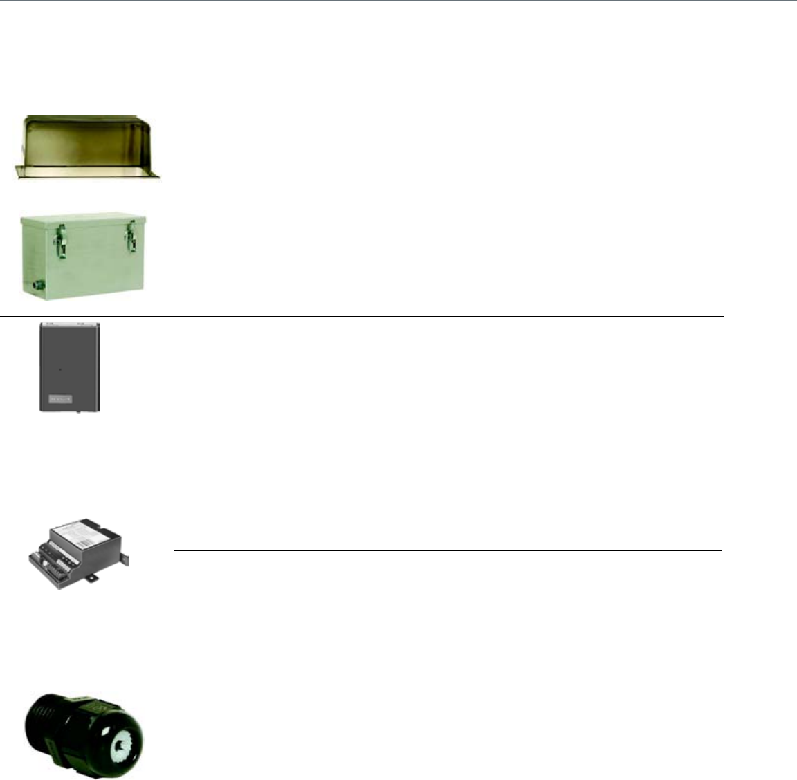
190
Enclosure Accessories
Product Number Description Used With
32003036-001 Weather Enclosure Used With: All
Actuators All Actuators
50005859-001 NEMA 4 Enclosure for Direct
Coupled Actuator
142 lb-in. Spring Return Actuators;
ML6161, ML6174, ML7161, ML7174;
N20 Actuators; N34 Actuators;
150 lb-in. NSR Actuators (ML Series);
25 and 53 lb-in.SR Actuators
(ML Series);
300 lb-in.NSR Actuators (ML Series);
S05, S10, S20 Actuators
7640QW
Enclosure for Conduit Connection
Used With: ML6161, ML6174,
ML7161, ML7174
ML6161, ML6174, ML7161, ML7174
Q7002 Interface Modules
Product Number Description Used With
Q7002B1009
Transducer, Accepts dc voltage,
current, or resistive input and provides
a voltage or current output
Direct-Coupled Proportional Actuators
and Modutrol Motors
Q7002C1007
Transducer, Accepts a pulse-width
modulation (PWM) signal and
provides a voltage output
Direct-Coupled Proportional Actuators
and Modutrol Motors
Miscellaneous Accessories
Product Number Description Used With
32000085-001 Strain Relief Fitting (10 pack) MS and MN Series Actuators
Damper And Actuator Accessories
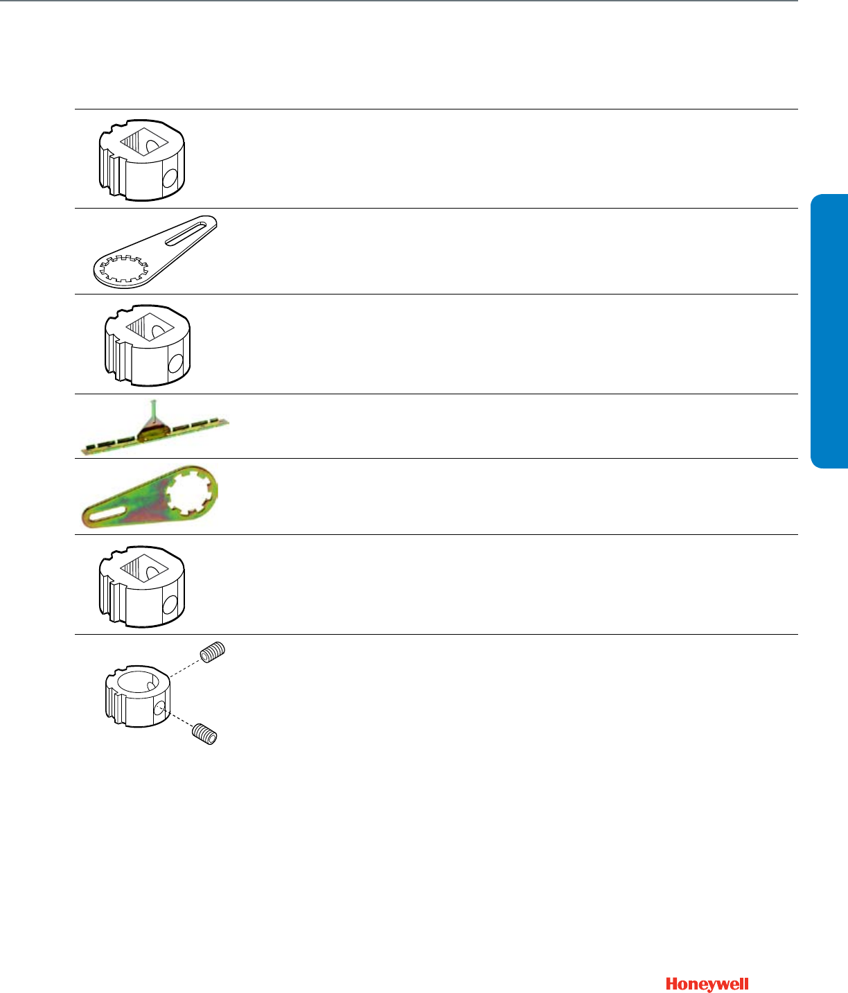
191
Accessories for Obsolete Actuators
Product Number Description Used With
205617 Hub Insert, 3/4 in. (19mm) Used With:
150 lb-in NSR Actuators (ML Series) 150 lb-in. NSR Actuators (ML Series)
205685 Crank Arm Kit Used With: 150 lb-in
NSR Actuators (ML Series) 150 lb-in. NSR Actuators (ML Series)
205753
Hub Insert, 3/8 in. (10mm) Used With:
150 lb-in NSR and 25 and 53 lb-in
Actuators (ML Series)
150 lb-in.NSR and 25 and
53 lb-in.Actuators (ML Series)
205755
Hub Insert, 1/2 in. (13mm) Used With:
150 lb-in NSR and 25 and 53 lb-in
Actuators (ML Series)
150 lb-in.NSR and 25 and
53 lb-in.Actuators (ML Series)
205784 Mounting Bracket Used With: 25 and
53 lb-in SR Actuators (ML Series)
25 and 53 lb-in.SR Actuators
(ML Series)
205846 Crank Arm Kit Used With: 300 lb-in
NSR Actuators (ML Series) 300 lb-in.NSR Actuators (ML Series)
205849A
Hub Insert, 5/8 in. (17mm) Round
Used With: 300 lb-in NSR Actuators
(ML Series)
300 lb-in.NSR Actuators (ML Series)
205856B Hub Insert, 3/4 in. (19mm) Round 300 lb-in.NSR Actuators (ML Series)
M11590
M13687
ACCESSORIES
Damper And Actuator Accessories
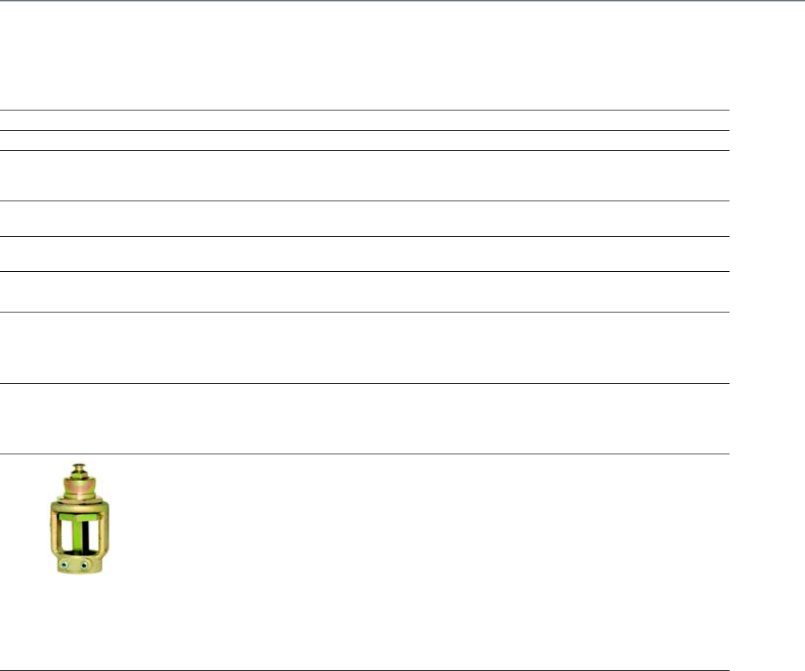
192
Valve Actuator Accessories
Product Number Description Used With
114191A Auxiliary Switch Assembly —
127834A Switch (made) —
272629A
Adapter Kit for mounting ML6984/
ML7984 to V5045 and VGF standard
2-way valves.
ML6984 or ML7984, V5045; VGF21ES;
VGF21LS, VGF22ES; VGF22LS
272630D Position Feedback and Auxiliary
Switch Accessory ML6984/7984 Series 4000 and higher
272775 Replacement Motor Brush Kit for
ML6984/7984 ML6984 or ML7984
43191679-101 Auxiliary Potentiometer for ML6421A ML6421A
43191679-102 Auxiliary Potentiometer for ML6421B ML6421B
43191679-111 Potentiometer, 10k ohm, for ML6425,
ML7425 ML6425 or ML7425
43191679-112 Potentiometer, 220 ohm for ML6425,
ML7425 ML6425 or ML7425
43191680-102 Dual Auxiliary Switch for CREVAL
actuators ML6421, ML7421
43191680-105 Dual Auxiliary Switch for CREVAL
actuators ML6420, ML6425, ML7420, ML7425
43196000-001 High Temperature Kit for actuators
with 3/4" stroke
ML6420, ML6421, ML6425, ML7420,
ML7421, or ML7425
43196000--038 High Temperature Kit for actuators
with 1-1/2" stroke ML6421, ML7421
VU Series Fan Coil Actuator Accessories
Product Number Description Used With
272885C Nickel-plated replacement motor for
24V VU-series valve actuators VU843A, VU844A
272885D Nickel-plated replacement motor for
120 VU-series valve actuators
VU443A1008/A1180/E1009;
VU444A1007/A1155
Valve Accessories
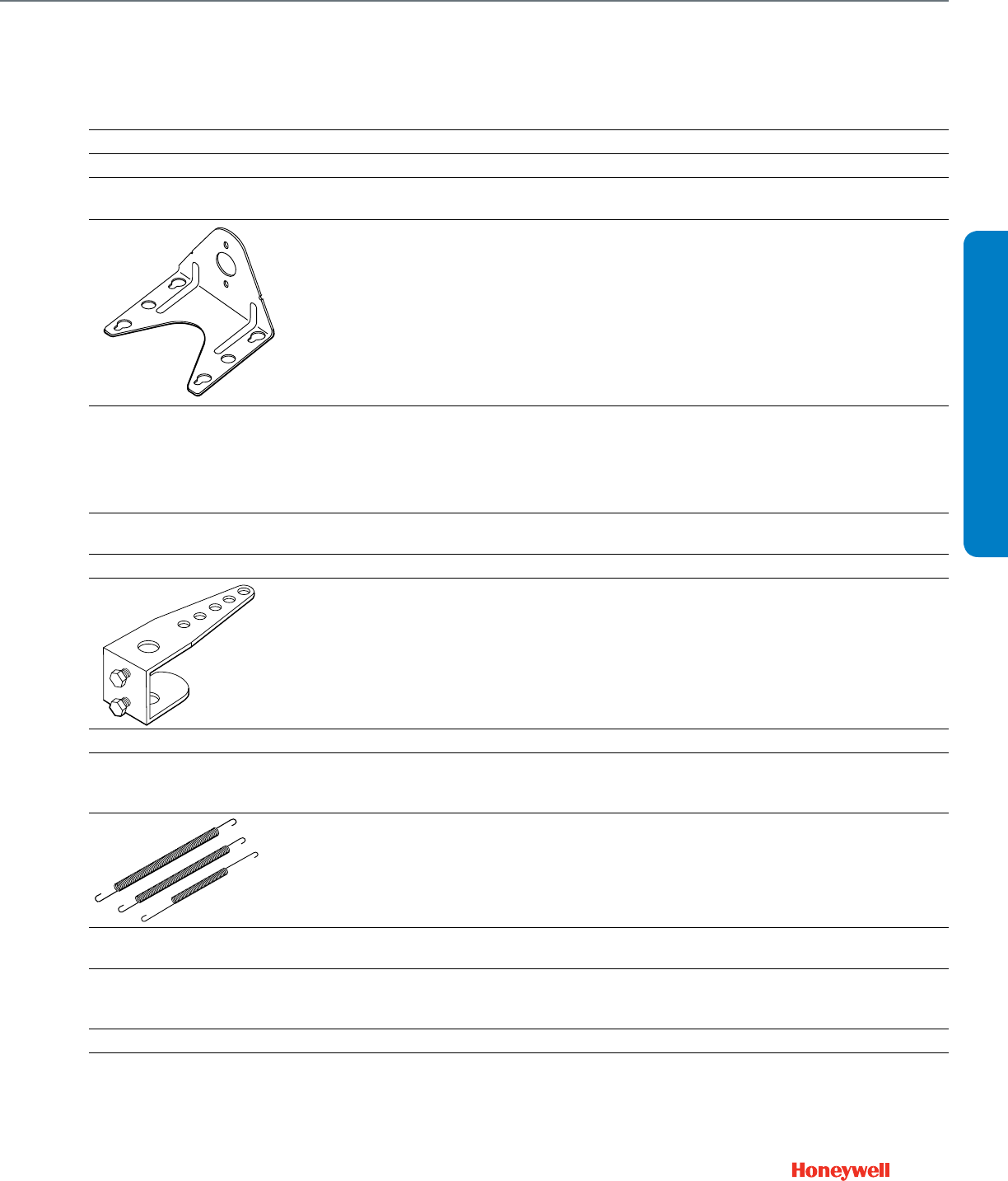
193
Pneumatic Damper Actuator Parts and Accessories
Product Number Description Used With
14001213-001 MP904A and B Diaphragm MP904A,B
14002061-001 Damper Linkage Kit w/ Template MP909E,F
14002850-001 Angle Bracket 5 3/8 in, 137 mm, long,
5 in, 127 mm, wide MP909D,E
14003640-001
Angle Bracket 3 in. (76 mm) long,
3 3/4 in. (95 mm) wide, 2 3/4 in.
(70 mm) high
MP913; MP909D
14004062-001 External Trunnion Mounting Bracket MP918A,B; MP909E,H
14004062-002 Internal N.C. Trunnion Mounting
Bracket MP918A,B; MP909E,H
14004062-003 Internal N.O. Trunnion Mounting
Bracket MP918A,B; MP909E,H
14004106-001 Actuator pushrod for conversion of
internal N.C. to external MP918A,B; MP909E,H
14004106-002 Push rod assembly for internal N.C. MP918A,B; MP909E,H
14004107-001
Crankarm Assembly for conversion
from internal N.C. to external Trunnion
mounting
MP918A,B; MP909E,H
14004136-001 MP904 Positive Positioner Retrofit Kit MP904A
14004137-001
Retrofit Kit for adding positive
positioner to MP909E or repair of
MP909H
MP909E; MP909H
14004210-001
Feedback Spring Kit includes orange
spring (3 psi [21kPa]), yellow spring
(5 psi [34 kPa]), and blue spring (10
psi [69 kPa]).
MP909H; MP918A
14004236-001 Coupler, actuator shaft to 5/16 in,
8 mm, pushrod MP918
14004237-002
Bag assembly including 4 hex head
slotted drill point screws
(14004513-001)
MP918A,B; MP909E,H
14004241-002 Hitch Pin (Six Sets) MP918A,B; MP909E,H
14004242-001 MP918 Top Mount Operator Assembly MP918A,B
14004210
ACCESSORIES
Pneumatic Damper Accessories
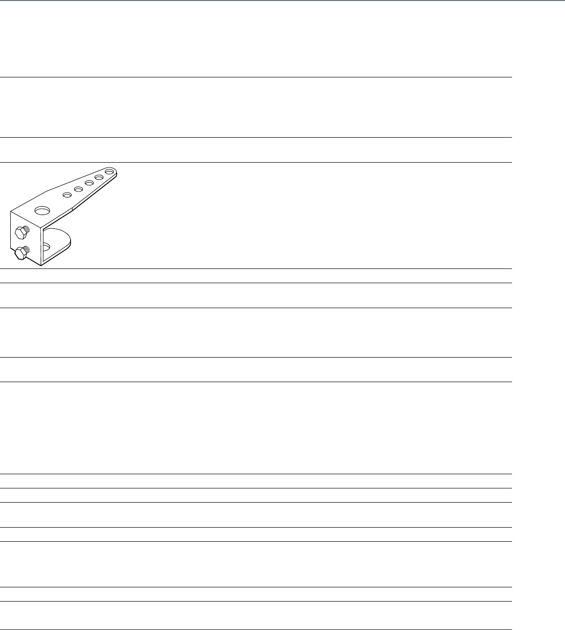
194
14004264-001
MP918 Repair kit including Positive
Positioner, bracket assembly and
fittings
MP918A
14004264-002 MP918 Positive Positioner Retrofit Kit
includes 10 psi feedback spring MP918B
14004324-001 Kit for Alternate External Top-Mount,
MP909E,H MP918A,B MP918A,B; MP909E,H
14004345-001 Positive Positioner Kit, 10 psi
feedback spring MP920B
14004350-001 Steel Clevis Pin (1/4 x 7/8) MP918
14004577-001 MP953 A, C, and E (Direct Acting,
5 in. diameter) Yoke/Base Assembly MP953A,C,E
15753692-001 Modular Kit for Jack Shaft Installation
of MP909E and MP918B Actuators MP909E; MP918B
15753693-001 End kit for Jack Shaft Installation of
MP909E and MP918B Actuators MP909E; MP918B
15753694-001 Operator kit for Jack Shaft Installation
of MP909E and MP918B Actuators MP909E; MP918B
26025B
Damper crank arm for 3/8 in. (9.5 mm)
diameter axle. Elongated slot for
linkage connection. Slot scaled
for 40-50-60-75-90 degrees.
MP516; MP909D; MP909E, H
27174B
Damper crank arm for 7/16 in.
(11.1 mm) diameter axle. Elongated
slot for linkage connection. Slot scaled
for 40-50-60-75-90 degrees.
MP516; MP513
309292 MP516A Diaphragm MP516
309389J Mounting Bracket and Linkage MP516
312809C MP904A and B Tube and Diaphragm
Assembly MP904A,B
312817 MP953C (5 in. diameter) Cover MP953C (5 in.)
312867C
Damper Crank Arm for 1/2 in.
(12.7mm) diameter axle. Elongated
slot for linkage connection. Slot scaled
for 45-60-75-90 degrees
MP516; MP909D; MP909E; MP909H
312867H Externally mounted Linkage Kit MP516; MP909D,E,H
314100 MP909A Replacement Diaphragm MP909A
314231 MP909B Replacement Diaphragm MP909B
314316A Crank Arm Assembly MP516
Pneumatic Damper Actuator Parts and Accessories (cont.)
Product Number Description Used With
Pneumatic Damper Accessories
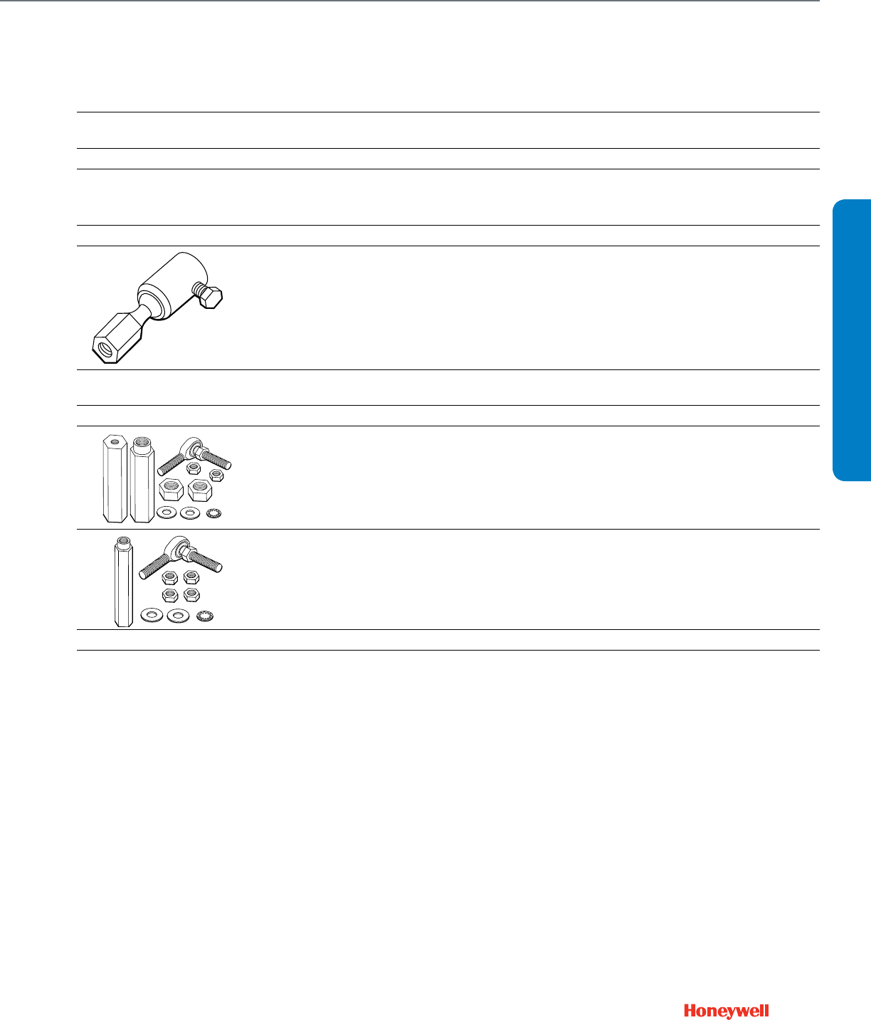
195
314440A MP909 - Clevis, Clevis Pin and Cotter
Pin Assembly MP909
314503 MP909C Replacement Diaphragm MP909C
315321 Crankarm Balljoint (with 1/4 in male
threads), fits 5/16 in. diameter pushrod MP516; MP909D,E,H; MP913
315321G Crankarm and Linkage MP909A,D
315439/0062 Clevis MP909D
315781
Motor shaft balljoint with 3/8 - 16 UNC
female threads, fits 5/16 inch diameter
pushrods.
MP909D,E,H; MP913
315782 Balljoint (9/16 in.-18 UNC) accepts
5/16 in. Pushrod MP920B
AK3558 Swivel Bracket Bag Assembly MP920B
AK3560
Balljoint, 3/8-24 threaded stud with
couplings for 5/8-11 threaded rod
and actuator shaft
MP920B
AK3561 Balljoint, 3/8-24 threaded stud with
couplings for 3/8-16 threaded rod MP920B
CCT2718 Threaded rod for shaft extension MP918
CCT2725 Rod coupling for shaft extension MP918
Pneumatic Damper Actuator Parts and Accessories (cont.)
Product Number Description Used With
AK3560
ACCESSORIES
Pneumatic Damper Accessories

196
Pneumatic Valve Actuator Parts and Accessories
Product Number Description Used With
14002039-001 MP953D Diaphragm Sleeve MP953B,D,F
14002040-002 MP953D Diaphragm MP953B,D,F
14003124-002
MP953B,D,F Diaphragm Repair Kit
(includes 14002039-001 and
14002040-002)
MP953B,D,F
14004138-001 MP953B,F (Reverse Acting) Positive
Positioner Retrofit Kit MP953B,F
14004139-001
MP953A,E (Direct Acting, 8 in. and
13 in. diameter, 3/4 in. stroke) Positive
Positioner Retrofit Kit
MP953A,E
14004140-001
MP953A,E (Direct Acting, 8 in. and
13 in. diameter, 1-1/2 in. stroke) Positive
Positioner Retrofit Kit
MP953A,E
14004211-001 MP953E (8 in. and 13 in. diameter,
3/4 in. stroke) Feedback Spring Kit MP953E
14004212-001 MP953E (8 in. and 13 in. diameter,
1-1/2 in. stroke) Feedback Spring Kit MP953E
14004213-001 MP953F (Reverse Acting) Feedback
Spring Kit MP953F
14004214-001 MP953A,E (5 in. diameter) 3/4 inch stroke
Positive Positioner Retrofit Kit MP953A,E
14004298-001 Thread forming Screw, Size 4-40 MP953D,F
14004298-003
MP953C,E (5 in. dia.) and
MP953B,D,F (7-1/8 in. dia.)
Actuator Base Screw, size 1/4-20
MP953B,D,F; MP953C,E (5 in.)
14004578-001 MP953 B, D, and F (Reverse Acting,
7-1/8 in. diameter) Yoke/Base Assembly MP953B,D,F
14004667-001
Offset Crank arm assembly with 2 screws
(304725-062), nuts (14004102-001),
crank arm (14004655-001) for
1/2 in. Drive Axle
Pneumatic Actuators
14004697-001 Stem extension for 13 in. MP953C,E with
3/4 in. Stroke MP953C,E
310664 MP953A, C and E (5 in. and 8 in. models
only) Tension Spring MP953A,C,E
310665/0062 Spring Support for MP953 MP953A,C,E (5 in.)
310668
MP953A, C and E (5 in. diameter) High
Temperature Silicone Diaphragm
Old Style
MP953A,C,E
311393 White Spring, 4-11 psi MP953C,E
311616 MP953A, C and E (5 in. diameter) Main
Spring (2-7 psi spring range - Brown) MP953A,C,E (5 in.)
311618 MP953A, C and E (5 in. diameter) Main
Spring (8-12 psi spring range - Gray) MP953A,C,E (5 in.)
311749/0605 Cup diaphragm, 8 in. for
MP953A, C, E MP953A,C,E (8 in.)
311750
MP953A, C and E (8 in. diameter)
Regular Temperature Neoprene
Diaphragm - New Style
MP953A,C,E
Pneumatic Valve Accessories
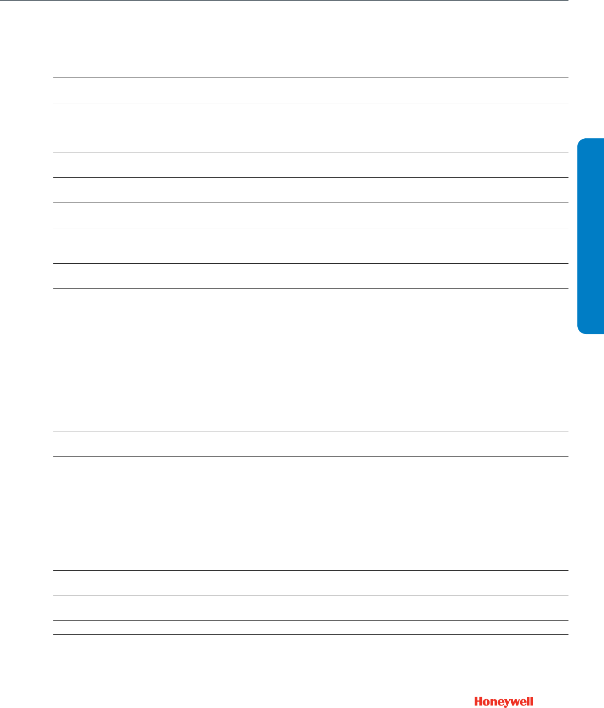
197
311851/0062 Stem extension for 8 in. dia. 3/4 in. stroke
MP953A,C,E MP953A,C,E (8 in.)
311852 Brown Spring for MP953A,C 3/4 inch
stroke (8 inch diameter), 2-7 psi range MP953A,C (8 in., 2-7 psi)
311855 Gray spring for MP953C (8 inch
diameter), 8-12 psi range MP953C
311863 Stem Retainer for the MP953C,E
(8 in. diameter) MP953C,E
312099 1-1/2 in. stroke Spider for 13 in.
MP953C and E MP953C,E
312203 Black Spring for MP953D,F for 8-13 psi
range MP953D,F
312466/0605
Stem Extension for MP953C1489,
MP953C1471, MP953E1392,
MP953E1400, and MP953E1418
MP953C,E
312471 White Spring for MP953C,E (13 in. dia.
1/2 in. stroke) MP953C,E (13 in.)
312505
MP953A,C,E (13 in. diameter) regular
temperature Neoprene diaphragm
New style
MP953A,C,E
312760
MP953A,C,E (5 in. diameter) regular
temperature Neoprene diaphragm
New style
MP953A,C,E
313745
MP953A, C and E (5 in. diameter) High
Temperature Silicone Diaphragm
New Style
MP953A,C,E
314153
MP953A, C and E (8 in. diameter) High
Temperature Silicone Diaphragm
New Style
MP953A,C,E
314646A/0062 Plate, Spring for 13 in. diameter
MP953A,C,E MP953A,C,E
314650A
MP953B, D and F (Reverse Acting)
Support Assembly (for Series-2 actuators
only, use this Support Assembly and
316059A Yoke Assembly to Convert
Series-1 MO/MP953)
MP953B,D,F
314651A
MP953B,D,F (Reverse Acting) yoke
assembly for support assembly- with
nylon insert for use with old style
actuators not made with a Helicoil insert
in yoke
MP953B,D,F
314652 Spring for MP953D,F (used in yoke
assembly) MP953D,F
314683/0062 Stem Retainer for 13 in. diameter
MP953A,C,E (Latches on Stem Button) MP953A,C,E (13 in.)
315020 Cup for MP953C,E (13 inch diameter) MP593C,E (13 in.)
316059A
MP953B, D and F (Reverse Acting) Yoke
Assembly for Support Assembly- with
helicoil insert
MP953B,D,F
Pneumatic Valve Actuator Parts and Accessories (cont.)
Product Number Description Used With
ACCESSORIES
Pneumatic Valve Accessories
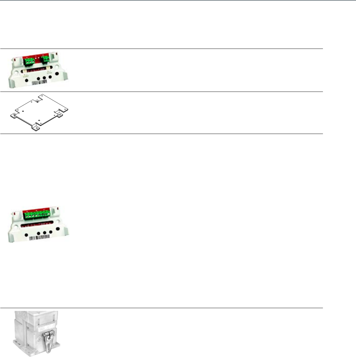
198
Foot Mounted Motor Accessories
Product Number Description Used With
203709D2
Screw Terminal Adapter With Zero and
Span Adjustment for Series 2 and
Series 3 Modutrol IV Motors
Series 2 and Series 3 Modutrol IV™
Motor
220738A Adapter Bracket. Adjusts shaft height
to match Modutrol III Motors
Mod IV Actuator to match shaft height
of Mod III Actuator
220741A2-61
Screw Terminal Adapter Kit for Series
61 Modutrol IV Series 2 motors
Converts quick-connect terminals to
screw terminals
Series 61 Mod IV Motor
220741A2-62
Screw Terminal Adapter Kit for Series
62 Series Modutrol IV Series 2 motors
Converts quick-connect terminals to
screw terminals
Series 62 Mod IV Motor
220741A2-71
Screw Terminal Adapter Kit for Series
71 Modutrol IV Series 2 motors
Converts quick-connect terminals to
screw terminals
Series 71 Mod IV Motor
220741A2-72
Screw Terminal Adapter Kit for Series
72 Modutrol IV Series 2 motors
Converts quick-connect terminals to
screw terminals
Series 72 Mod IV Motor
220741A2-90
Screw Terminal Adapter Kit for Series
90 Modutrol IV Series 2and Series 3
motors. Converts quick-connect
terminals to screw terminals
Series 90 Mod IV Motor
220741A2-TP
Screw Terminal Adapter Kit for
2-position Modutrol IV Series 2 motors
Converts quick-connect terminals to
screw terminals
Two Position for use with M4XXX and
M8XXX Mod IV Motors
221455A Infinitely adjustable Motor Crank Arm Modutrol IV Motors
Foot Mounted Motor Accessories
199
221508A2 Resistor Board Assembly for Series 2
Modutrol IV Motors Series 2 Modutrol IV Motors
4074ERU
Weatherproofing kit. Protects motor
from driving rain when mounted in any
position
Fits all Modutrol IV motors
7617DM Coupling- Must be used with
ES-650-117 explosion-proof housing ES-650-117
ES-650-117
Explosion-Proof Housing encloses
motor for use in explosive
atmospheres. To order, contact: EGS
Enclosures, (281) 774-3763; or write
to: EGS Enclosures in Houston, TX
Karen Barfield 281-774-3763
Karen.barfield@egseg.com part
number ES-650-117
Modutrol IV Motors, not for use with
Q5001 (or any other valve linkages)
Foot Mounted Motor Accessories (cont.)
Product Number Description Used With
M11515
ACCESSORIES
Foot Mounted Motor Accessories

200
Damper and Valve Linkage Accessories
Product Number Description Used With
102546 Ball Joint, 5/16 in. Damper Linkages
101662A/0021 Motor Mounting Bracket Assembly
for Q605 Q605
102931/0021 Adapter arm for less that 90 degree
rotation for the Q605 Q605
104643A Adapter for driving 2 dampers from
1 crank arm Modutrol IV Motors
220828AA Valve bracket assembly, Q5001 Q5001
220845/0767 Retainer button for Q5001 Q5001
220848A Q5001 Cam with 1/2 in. stroke Q5001
220852A Stroke Indicator, Q5001 Q5001
220858A 9/16 inch lift Q5001 linkage cam
assembly with 9/16 in stroke Q5001
220861A 3/4 inch lift Q5001 linkage cam
assembly with 3/4 in stroke Q5001
220863A 1 inch lift Q5001 linkage cam
assembly with 1 inch stroke Q5001
220864A 1 1/8 inch lift Q5001 linkage cam
assembly with 1-1/8 in stroke Q5001
220865A 1 1/4 inch lift Q5001 linkage cam
assembly with 1-1/4 in stroke Q5001
220867A 1 1/2 inch lift Q5001 linkage cam
assembly with 1-1/2 in stroke. Q5001
220874/0767 9/16 inch anti spin clip for Q5001 Q5001
26025F Damper Arm, 3/8 in. shaft —
26026B Damper Arm, 1/2 in. shaft, 3 in. long —
32004629-001
Bonnet adapter kit to adapt Seimens
(Landis/Power) Flowrite 599 1/2 inch
to 3 inch globe valves with Q5020A or
Q5009B
Siemms valves
32004629-002 Bonnet Adapter Kit, Johnson Controls
1/2 to 3/4 in., Q5020 Johnson valves; Q5020
32004629-003 Bonnet Adapter Kit, Johnson Controls
1 to 2 in., Q5020 Johnson valves; Q5020
32004629-004 Bonnet Adapter Kit, Siebe 1/2 to 2 in.,
Q5020 Siebe valves; Q5020
4074ETB Antispin Kit, Q5001 Q5001
7617ACL
Bag Assembly, Q605 includes
Damper arm, motor crankarm, and
2 ball joints
Q605
Damper And Valve Accessories

201
CROSS REFERENCE
Section 8: Competitive Cross Reference
Direct Coupled Actuator ...........................................................202
Control Ball Valve
2-Way Valve .......................................................................220
2-Way Valve + Non-Spring Return Floating Actuator ...........221
2-Way Valve + Non-Spring Return Modulating Actuator......222
2-Way Valve + Spring Return, 2-Position Actuator ..............223
2-Way Valve + Spring Return Floating Actuator ...................224
2-Way Valve + Spring Return Modulating Actuator .............225
Threaded Globe Valves ............................................................226
Flanged Globe Valves ...............................................................227
Pneumatics ..............................................................................228
Modutrol IV Motor ....................................................................231

202
Competitive Cross Reference
Direct Coupled Actuator
Belimo
Model
Torque
(lb-in.)
Control
Signal Power
Feedback
Switches Timing
(sec)
Honeywell
Actuator
Torque
(lb-in.)
Control
SignalaPower
Feedback
a
Switches Timing
(sec)
LMB24-3-P5-T 45 lb-in.
(5 Nm)
On/Off,
Floating 24 Vac/Vdc 0-5 kOhm — 95
ML6174A2002 +
200976A
70 lb-in.
(8 Nm)
On/Off,
Floating
24 Vac
(±20%) 500 Ohm — 95
ML6174A2002 +
200976C
On/Off,
Floating
24 Vac
(±20%) 2 kOhm — 95
LMB24-3-P10-T 45 lb-in.
(5 Nm)
On/Off,
Floating 24 Vac/Vdc 0-10 kOhm — 95
ML6174A2002 +
200976A
70 lb-in. (8
Nm)
On/Off,
Floating
24 Vac
(±20%) 500 Ohm — 95
ML6174A2002 +
200976C
On/Off,
Floating
24 Vac
(±20%) 2 kOhm — 95
LMB24-3 45 lb-in.
(5 Nm)
On/Off,
Floating 24 Vac/Vdc — — 95 MN6105A1011 44 lb-in.
(5 Nm)
On/Off,
Floating
24 Vac/
Vdc (+20 /
-15%)
— — 95
LMB24-3-T 45 lb-in.
(5 Nm)
On/Off,
Floating 24 Vac/Vdc — — 95 MN6105A1011 44 lb-in.
(5 Nm)
On/Off,
Floating
24 Vac/
Vdc (+20 /
-15%)
— — 95
LMB24-3-S 45 lb-in.
(5 Nm)
On/Off,
Floating 24 Vac/Vdc — 1 (0-95) 95 MN6105A1201 44 lb-in.
(5 Nm)
On/Off,
Floating
24 Vac/
Vdc (+20 /
-15%)
— 2 (5, 85) 95
LMB24-SR 45 lb-in.
(5 Nm)
2-10 Vdc
(4-20 mA) 24 Vac/Vdc — — 95 MN7505A2001 44 lb-in.
(5 Nm)
On/Off,
Floating, (0)
2-10 Vdc
24 Vac/
Vdc (+20 /
-15%)
(0) 2-10 Vdc — 95
LMX24-SR 45 lb-in.
(5 Nm)
2-10 Vdc
(4-20 mA) 24 Vac/Vdc 2-10 Vdc —
95
(selectable
35-150)
MN7505A2001 44 lb-in.
(5 Nm)
On/Off,
Floating, (0)
2-10 Vdc
24 Vac/
Vdc (+20 /
-15%)
(0) 2-10 Vdc — 95
LMB24-SR-T 45 lb-in.
(5 Nm)
2-10 Vdc
(4-20 mA) 24 Vac/Vdc — — 95 MN7505A2001 44 lb-in.
(5 Nm)
On/Off,
Floating, (0)
2-10 Vdc
24 Vac/
Vdc (+20 /
-15%)
(0) 2-10 Vdc — 95
LMX24-SR-T 45 lb-in.
(5 Nm)
2-10 Vdc
(4-20 mA) 24 Vac/Vdc — —
95
(selectable
35-150)
MN7505A2001 44 lb-in.
(5 Nm)
On/Off,
Floating, (0)
2-10 Vdc
24 Vac/
Vdc (+20 /
-15%)
(0) 2-10 Vdc — 95
LMX24-MFT 45 lb-in.
(5 Nm) MFT 24 Vac/Vdc Variable
(0-10 Vdc) —
150
(selectable
35-150)
MN7505A2001 44 lb-in.
(5 Nm)
On/Off,
Floating, (0)
2-10 Vdc
24 Vac/
Vdc (+20 /
-15%)
(0) 2-10 Vdc — 95
LMX24-MFT 45 lb-in.
(5 Nm) MFT 24 Vac/Vdc Variable
(0-10 Vdc) Add-On
150
(selectable
35-150)
MN7505A2209 44 lb-in.
(5 Nm)
On/Off,
Floating, (0)
2-10 Vdc
24 Vac/
Vdc (+20 /
-15%)
(0) 2-10 Vdc 2 (5, 85) 95
LMCB24-3 45 lb-in.
(5 Nm)
On/Off,
Floating 24 Vac/Vdc — — 35 MN6105A1011 44 lb-in.
(5 Nm)
On/Off,
Floating
24 Vac/
Vdc (+20 /
-15%)
— — 95
LMCB24-3-T 45 lb-in.
(5 Nm)
On/Off,
Floating 24 Vac/Vdc — — 35 MN6105A1011 44 lb-in.
(5 Nm)
On/Off,
Floating
24 Vac/
Vdc (+20 /
-15%)
— — 95
LMX24-3 45 lb-in.
(5 Nm)
On/Off,
Floating 24 Vac/Vdc — —
95
(selectable
35-150)
MN6105A1011 44 lb-in.
(5 Nm)
On/Off,
Floating
24 Vac/
Vdc (+20 /
-15%)
— — 95
LMX24-3-T 45 lb-in.
(5 Nm)
On/Off,
Floating 24 Vac/Vdc — —
95
(selectable
35-150)
MN6105A1011 44 lb-in.
(5 Nm)
On/Off,
Floating
24 Vac/
Vdc (+20 /
-15%)
— — 95
LMX120-3 45 lb-in.
(5 Nm)
On/Off,
Floating 100-240 Vac — —
95
(selectable
35-150)
— ——————
LMCB24-SR 45 lb-in.
(5 Nm)
2-10 Vdc
(4-20 mA) 24 Vac/Vdc 2-10 Vdc — 35 MN7505A2001 44 lb-in.
(5 Nm)
On/Off,
Floating, (0)
2-10 Vdc
24 Vac/
Vdc (+20 /
-15%)
(0) 2-10 Vdc — 95
LMCB24-SR-T 45 lb-in.
(5 Nm)
2-10 Vdc
(4-20 mA) 24 Vac/Vdc — — 35 MN7505A2001 44 lb-in.
(5 Nm)
On/Off,
Floating, (0)
2-10 Vdc
24 Vac/
Vdc (+20 /
-15%)
(0) 2-10 Vdc — 95
LMX120-SR 45 lb-in.
(5 Nm)
2-10 Vdc
(4-20 mA) 100-240 Vac 2-10 Vdc —
95
(selectable
35-150)
MN7505A2001 44 lb-in.
(5 Nm)
On/Off,
Floating, (0)
2-10 Vdc
24 Vac/
Vdc (+20 /
-15%)
(0) 2-10 Vdc — 95
LMX24-MFT95 45 lb-in.
(5 Nm) 0-135 Ohm 24 Vac/Vdc Variable
(0-10 Vdc) —
150
(selectable
35-150)
MN7505A2001 +
Q7002B1009
44 lb-in.
(5 Nm) 0-135 OHM
24 Vac/
Vdc (+20 /
-15%)
(0) 2-10 Vdc — 95
LMX24-PC 45 lb-in.
(5 Nm)
0-20 V
Phase Cut 24 Vac/Vdc 2-10 Vdc — 95 — — — — — — —
NMB24-3 90 lb-in.
(10 Nm)
On/Off,
Floating 24 Vac/Vdc — — 95 MN6110A1003 88 lb-in.
(10 Nm)
On/Off,
Floating
24 Vac/
Vdc (+20 /
-15%)
— — 95
NMCB24-3 90 lb-in.
(10 Nm)
On/Off,
Floating 24 Vac/Vdc — — 45 MN6110A1003 88 lb-in.
(10 Nm)
On/Off,
Floating
24 Vac/
Vdc (+20 /
-15%)
— — 95
NMX24-3 90 lb-in.
(10 Nm)
On/Off,
Floating 24 Vac/Vdc — —
95
(selectable
35-150)
MN6110A1003 88 lb-in.
(10 Nm)
On/Off,
Floating
24 Vac/
Vdc (+20 /
-15%)
— — 95

203
Belimo
Model
Torque
(lb-in.)
Control
Signal Power
Feedback
Switches Timing
(sec)
Honeywell
Actuator
Torque
(lb-in.)
Control
SignalaPower
Feedback
a
Switches Timing
(sec)
NMCB24-3-T 90 lb-in.
(10 Nm)
On/Off,
Floating 24 Vac/Vdc — — 45 MN6110A1003 88 lb-in.
(10 Nm)
On/Off,
Floating
24 Vac/
Vdc (+20 /
-15%)
— — 95
NMX24-3-T 90 lb-in.
(10 Nm)
On/Off,
Floating 24 Vac/Vdc — —
95
(selectable
35-150)
MN6110A1003 88 lb-in.
(10 Nm)
On/Off,
Floating
24 Vac/
Vdc (+20 /
-15%)
— — 95
NMX120-3 90 lb-in.
(10 Nm)
On/Off,
Floating 100-240 Vac — —
95
(selectable
35-150)
— ——————
NMB24-SR 90 lb-in.
(10 Nm)
2-10 Vdc
(4-20 mA) 24 Vac/Vdc — — 95 MN7510A2001 88 lb-in.
(10 Nm)
On/Off,
Floating, (0)
2-10 Vdc
24 Vac/
Vdc (+20 /
-15%)
(0) 2-10 Vdc — 95
NMCB24-SR 90 lb-in.
(10 Nm)
2-10 Vdc
(4-20 mA) 24 Vac/Vdc 2-10 Vdc — 45 MN7510A2001 88 lb-in.
(10 Nm)
On/Off,
Floating, (0)
2-10 Vdc
24 Vac/
Vdc (+20 /
-15%)
(0) 2-10 Vdc — 95
NMX24-SR 90 lb-in.
(10 Nm)
2-10 Vdc
(4-20 mA) 24 Vac/Vdc 2-10 Vdc —
95
(selectable
35-150)
MN7510A2001 88 lb-in.
(10 Nm)
On/Off,
Floating, (0)
2-10 Vdc
24 Vac/
Vdc (+20 /
-15%)
(0) 2-10 Vdc — 95
NMCB24-SR-T 90 lb-in.
(10 Nm)
2-10 Vdc
(4-20 mA) 24 Vac/Vdc — — 45 MN7510A2001 88 lb-in.
(10 Nm)
On/Off,
Floating, (0)
2-10 Vdc
24 Vac/
Vdc (+20 /
-15%)
(0) 2-10 Vdc — 95
NMX24-SR-T 90 lb-in.
(10 Nm)
2-10 Vdc
(4-20 mA) 24 Vac/Vdc — —
95
(selectable
35-150)
MN7510A2001 88 lb-in.
(10 Nm)
On/Off,
Floating, (0)
2-10 Vdc
24 Vac/
Vdc (+20 /
-15%)
(0) 2-10 Vdc — 95
NMX120-SR 90 lb-in.
(10 Nm)
2-10 Vdc
(4-20 mA) 100-240 Vac 2-10 Vdc —
95
(selectable
35-150)
— ——————
NMX24-MFT 90 lb-in.
(10 Nm) MFT 24 Vac/Vdc Variable
(0-10 Vdc) —
150
(selectable
35-150)
MN7510A2001 88 lb-in.
(10 Nm)
On/Off,
Floating, (0)
2-10 Vdc
24 Vac/
Vdc (+20 /
-15%)
(0) 2-10 Vdc — 95
NMX24-MFT95 90 lb-in.
(10 Nm) 0-135 Ohm 24 Vac/Vdc Variable
(0-10 Vdc) —
150
(selectable
45-170)
MN7510A2001 +
Q7002B1009
88 lb-in.
(10 Nm) 0-135 OHM
24 Vac/
Vdc (+20 /
-15%)
(0) 2-10 Vdc — 95
NMX24-PC 90 lb-in.
(10 Nm)
0-20 Vdc
Phase Cut 24 Vac/Vdc 2-10 Vdc — 95 — — — — — — —
NMQ24-MFT US 90 lb-in.
(10 Nm) MFT 24 Vac/Vdc — — 150 MN7510A2001 88 lb-in.
(10 Nm)
On/Off,
Floating, (0)
2-10 Vdc
24 Vac/
Vdc (+20 /
-15%)
(0) 2-10 Vdc — 95
NMB24-3+S2A 90 lb-in.
(10 Nm)
On/Off,
Floating 24 Vac/Vdc — 2 (adj 0-95) 95 MN6110A1201 88 lb-in.
(10 Nm)
On/Off,
Floating
24 Vac/
Vdc (+20 /
-15%)
— 2 (5, 85) 95
NMB24-SR + S2A 90 lb-in.
(10 Nm)
2-10 Vdc
(4-20 mA) 24 Vac/Vdc — 2 (adj 0-95) 95 MN7510A2209 88 lb-in.
(10 Nm)
On/Off,
Floating, (0)
2-10 Vdc
24 Vac/
Vdc (+20 /
-15%)
(0) 2-10 Vdc 2 (5, 85) 95
AMB24-3 180 lb-in.
(20 Nm)
On/Off,
Floating 24 Vac/Vdc — — 95 MN6120A1002 175 lb-in.
(20 Nm)
On/Off,
Floating
24 Vac
(±15%),
24 Vdc
— — 95
AMX24-3 180 lb-in.
(20 Nm)
On/Off,
Floating 24 Vac/Vdc — —
95
(selectable
95-300)
MN6120A1002 175 lb-in.
(20 Nm)
On/Off,
Floating
24 Vac
(±15%),
24 Vdc
— — 95
AMX24-3-T 180 lb-in.
(20 Nm)
On/Off,
Floating 24 Vac/Vdc — —
95
(selectable
95-300)
MN6120A1002 175 lb-in.
(20 Nm)
On/Off,
Floating
24 Vac
(±15%),
24 Vdc
— — 95
AMB24-3-S 180 lb-in.
(20 Nm)
On/Off,
Floating 24 Vac/Vdc — 1 (adj 0-95) 95 MN6120A1200 175 lb-in.
(20 Nm)
On/Off,
Floating
24 Vac
(±15%),
24 Vdc
— 2 (5, 85) 95
AMX120-3 180 lb-in.
(20 Nm)
On/Off,
Floating 100-240 Vac — —
95
(selectable
95-300)
— ——————
AMB24-SR 180 lb-in.
(20 Nm)
2-10 Vdc
(4-20 mA) 24 Vac/Vdc 2-10 Vdc — 95 MN7220A2007 175 lb-in.
(20 Nm)
(0) 2-10 Vdc,
(0) 4-20 mA
24 Vac
(±20%),
24 Vdc
(0) 2-10 Vdc — 95
AMX24-SR 180 lb-in.
(20 Nm)
2-10 Vdc
(4-20 mA) 24 Vac/Vdc 2-10 Vdc —
95
(selectable
95-300)
MN7220A2007 175 lb-in.
(20 Nm)
(0) 2-10 Vdc,
(0) 4-20 mA
24 Vac
(±20%),
24 Vdc
(0) 2-10 Vdc — 95
AMX24-SR-T 180 lb-in.
(20 Nm)
2-10 Vdc
(4-20 mA) 24 Vac/Vdc — —
95
(selectable
95-300)
MN7220A2007 175 lb-in.
(20 Nm)
(0) 2-10 Vdc,
(0) 4-20 mA
24 Vac
(±20%),
24 Vdc
(0) 2-10 Vdc — 95
AMB24-SR+S2A 180 lb-in.
(20 Nm)
2-10 Vdc
(4-20 mA) 24 Vac/Vdc 2-10 Vdc 2 (adj 0-95) 95 MN7220A2205 175 lb-in.
(20 Nm)
(0) 2-10 Vdc,
(0) 4-20 mA
24 Vac
(±20%),
24 Vdc
(0) 2-10 Vdc 2 (5, 85) 95
AMX120-SR 180 lb-in.
(20 Nm)
2-10 Vdc
(4-20 mA) 100-240 Vac 2-10 Vdc —
95
(selectable
95-300)
— ——————
CROSS REFERENCE
Competitive Cross Reference
Direct Coupled Actuator

204
Belimo
Model
Torque
(lb-in.)
Control
Signal Power
Feedback
Switches Timing
(sec)
Honeywell
Actuator
Torque
(lb-in.)
Control
SignalaPower
Feedback
a
Switches Timing
(sec)
AMX24-MFT 180 lb-in.
(20 Nm) MFT 24 Vac/Vdc Variable
(0-10 Vdc) —
150
(selectable
95-300)
MN7220A2007 175 lb-in.
(20 Nm)
(0) 2-10 Vdc,
(0) 4-20 mA
24 Vac
(±20%),
24 Vdc
(0) 2-10 Vdc — 95
AMX24-MFT95 180 lb-in.
(20 Nm) 0-135 Ohm 24 Vac/Vdc Variable (0-
10 Vdc) —
150
(selectable
95-300)
MN7220A2007+
Q7002B1009
175 lb-in.
(20 Nm) 0-135 OHM
24 Vac
(±20%),
24 Vdc
(0) 2-10 Vdc — 95
AMX24-PC 180 lb-in.
(20 Nm)
0-20 Vdc
Phase Cut 24 Vac/Vdc 2-10 Vdc —
150
(selectable
95-300)
— ——————
GMB24-3 360 lb-in.
(40 Nm)
On/Off,
Floating 24 Vac/Vdc — — 150 MN6134A1003 300 lb-in.
(34 Nm)
On/Off,
Floating
24 Vac
(±15%),
24 Vdc
— — 95
GMX24-3 360 lb-in.
(40 Nm)
On/Off,
Floating 24 Vac/Vdc — — 150 MN6134A1003 300 lb-in.
(34 Nm)
On/Off,
Floating
24 Vac
(±15%),
24 Vdc
— — 95
GMX120-3 360 lb-in.
(40 Nm)
On/Off,
Floating 100-240 Vac — — 150 — — — — — — —
GMB24-SR 360 lb-in.
(40 Nm)
2-10 Vd
(4-20 mA) 24 Vac/Vdc 2-10 Vdc — 150 MN7234A2008 300 lb-in.
(34 Nm)
(0) 2-10 Vdc,
(0) 4-20 mA
24 Vac
(±20%),
24 Vdc
(0) 2-10 Vdc — 95
GMX24-SR 360 lb-in.
(40 Nm)
2-10 Vdc
(4-20 mA) 24 Vac/Vdc 2-10 Vdc — 150 MN7234A2008 300 lb-in.
(34 Nm)
(0) 2-10 Vdc,
(0) 4-20 mA
24 Vac
(±20%),
24 Vdc
(0) 2-10 Vdc — 95
GMX24-MFT 360 lb-in.
(40 Nm) MFT 24 Vac/Vdc Variable
(0-10 Vdc) —
150
(selectable
70-300)
MN7234A2008 300 lb-in.
(34 Nm)
(0) 2-10 Vdc,
(0) 4-20 mA
24 Vac
(±20%),
24 Vdc
(0) 2-10 Vdc — 95
GMX24-MFT95 360 lb-in.
(40 Nm) 0-135 Ohm 24 Vac/Vdc Variable
(0-10 Vdc) —
150
(selectable
70-300)
MN7234A2008 +
Q7002B1009
300 lb-in.
(34 Nm) 0-135 OHM
24 Vac
(±20%),
24 Vdc
(0) 2-10 Vdc — 95
GMX24-PC 360 lb-in.
(40 Nm)
0-20 Vdc
Phase Cut 24 Vac/Vdc 2-10 Vdc —
150
(selectable
70-300)
— ——————
LF24 US 35 lb-in.
(5 Nm) On/Off 24 Vac/Vdc — — 40-75 MS8105A1030 44 lb-in.
(5 Nm) On/Off
24 Vac
(±20%),
24 Vdc
— — 45
LF24-S US 35 lb-in.
(5 Nm) On/Off 24 Vac/Vdc — 1 (adj 0-95) 40-75 MS8105A1130 44 lb-in.
(5 Nm) On/Off
24 Vac
(±20%),
24 Vdc
—1
(Adjustable) 45
LF120 US 35 lb-in.
(5 Nm) On/Off 120 Vac — — 40-75 MS4105A1030 44 lb-in.
(5 Nm) On/Off 100-250 Vac — — 45
LF120-S US 35 lb-in.
(5 Nm) On/Off 120 Vac — 1 (adj 0-95) 40-75 MS4105A1130 44 lb-in.
(5 Nm) On/Off 100-250 Vac — 1
(Adjustable) 45
LF230 US 35 lb-in.
(5 Nm) On/Off 230 Vac — — 40-75 MS4105A1030 44 lb-in.
(5 Nm) On/Off 100-250 Vac — — 45
LF230-S US 35 lb-in.
(5 Nm) On/Off 230 Vac — 1 (adj 0-95) 40-75 MS4105A1130 44 lb-in.
(5 Nm) On/Off 100-250 Vac — 1
(Adjustable) 45
LF24-3 US 35 lb-in.
(5 Nm) Modulating 24 Vac/Vdc — — 150 MS7505A2030 44 lb-in.
(5 Nm)
On/Off,
Floating, (0)
2-10 Vdc
24 Vac
(±20%),
24 Vdc
(0) 2-10 Vdc — 90
LF24-3-S US 35 lb-in.
(5 Nm) Modulating 24 Vac/Vdc — 1 (adj 0-95) 150 MS7505A2130 44 lb-in.
(5 Nm)
On/Off,
Floating, (0)
2-10 Vdc
24 Vac
(±20%),
24 Vdc
(0) 2-10 Vdc 1
(Adjustable) 90
LFC24-3-R US 35 lb-in.
(5 Nm) Floating 24 Vac/Vdc — — 90 MS7505A2030 44 lb-in.
(5 Nm)
On/Off,
Floating, (0)
2-10 Vdc
24 Vac
(±20%),
24 Vdc
(0) 2-10 Vdc — 90
LFC24-3-S US 35 lb-in.
(5 Nm) Floating 24 Vac/Vdc — 1 (adj 0-95) 90 MS7505A2130 44 lb-in.
(5 Nm)
On/Off,
Floating, (0)
2-10 Vdc
24 Vac
(±20%),
24 Vdc
(0) 2-10 Vdc 1
(Adjustable) 90
LF24-SR US 35 lb-in.
(5 Nm)
2-10 Vdc
(4-20 mA) 24 Vac/Vdc 2-10 Vdc — 150 MS7505A2030 44 lb-in.
(5 Nm)
On/Off,
Floating, (0)
2-10 Vdc
24 Vac
(±20%),
24 Vdc
(0) 2-10 Vdc — 90
LF24-SR-S US 35 lb-in.
(5 Nm)
2-10 Vdc
(4-20 mA) 24 Vac/Vdc 2-10 Vdc 1 (adj 0-95) 150 MS7505A2130 44 lb-in.
(5 Nm)
On/Off,
Floating, (0)
2-10 Vdc
24 Vac
(±20%),
24 Vdc
(0) 2-10 Vdc 1
(Adjustable) 90
LF24-SR-E US 35 lb-in.
(5 Nm)
2-10 Vdc,
Built-in.
minimum
position
24 Vac/Vdc 2-10 Vdc — 150 MS7405A2030 44 lb-in.
(5 Nm)
On/Off,
Floating, (0)
2-10 Vdc,
Economizer
(3kOhm,
3-Position)
24 Vac
(±20%),
24 Vdc
(0) 2-10 Vdc 90
Competitive Cross Reference
Direct Coupled Actuator

205
Belimo
Model
Torque
(lb-in.)
Control
Signal Power
Feedback
Switches Timing
(sec)
Honeywell
Actuator
Torque
(lb-in.)
Control
SignalaPower
Feedback
a
Switches Timing
(sec)
LF24-ECON-
R03 US
35 lb-in. (5
Nm)
0-3 kOhm,
type 10
thermistor
24 Vac/Vdc 2-10 Vdc — 95 MS7405A2030 44 lb-in. (5
Nm)
On/Off,
Floating, (0)
2-10 Vdc,
Economizer
(3kOhm,
3-Position)
24 Vac
(±20%),
24 Vdc
(0) 2-10 Vdc 90
LF24-ECON-
R10 US
35 lb-in. (5
Nm)
0-10 kOhm,
type 7
thermistor
24 Vac/Vdc 2-10 Vdc — 95 — — — — — — —
LF24-MFT US 35 lb-in. (5
Nm) MFT 24 Vac/Vdc 2-10 Vdc — 150 MS7505A2030 44 lb-in. (5
Nm)
On/Off,
Floating, (0)
2-10 Vdc
24 Vac
(±20%),
24 Vdc
(0) 2-10 Vdc — 90
LF24-MFT-S US 35 lb-in. (5
Nm) MFT 24 Vac/Vdc 2-10 Vdc 1 (adj 0-95) 150 MS7505A2130 44 lb-in. (5
Nm)
On/Off,
Floating, (0)
2-10 Vdc
24 Vac
(±20%),
24 Vdc
(0) 2-10 Vdc 1
(Adjustable) 90
LF24-MFT-20 US 35 lb-in. (5
Nm) MFT 24 Vac/Vdc 2-10 Vdc — 150 MS7505A2030 44 lb-in. (5
Nm)
On/Off,
Floating, (0)
2-10 Vdc
24 Vac
(±20%),
24 Vdc
(0) 2-10 Vdc — 90
LF24-MFT-20-S
US
35 lb-in. (5
Nm) MFT 24 Vac/Vdc 2-10 Vdc 1 (adj 0-95) 150 MS7505A2130 44 lb-in. (5
Nm)
On/Off,
Floating, (0)
2-10 Vdc
24 Vac
(±20%),
24 Vdc
(0) 2-10 Vdc 1
(Adjustable) 90
NF24 US 60 lb-in. (7
Nm) On/Off 24 Vac/Vdc — — < 75 MS8110A1008 88 lb-in. (10
Nm) On/Off
24 Vac
(±20%),
24 Vdc
— — 45
NF24-S US 60 lb-in. (7
Nm) On/Off 24 Vac/Vdc — 1 (adj 5-85) < 75 MS8110A1206 88 lb-in. (10
Nm) On/Off
24 Vac
(±20%),
24 Vdc
— 2 (7, 85) 45
NF24-S2 US 60 lb-in. (7
Nm) On/Off 24 Vac/Vdc — 2 (5, and adj
25-85) < 75 MS8110A1206 88 lb-in. (10
Nm) On/Off
24 Vac
(±20%),
24 Vdc
— 2 (7, 85) 45
NF120 US 60 lb-in. (7
Nm) On/Off 120 Vac — — < 75 MS4110A1002 88 lb-in. (10
Nm) On/Off 100-250 Vac — — 45
NF120-S US 60 lb-in. (7
Nm) On/Off 120 Vac — 1 (adj 5-85) < 75 MS4110A1200 88 lb-in. (10
Nm) On/Off 100-250 Vac — 2 (7, 85) 45
NF24-SR US 60 lb-in. (7
Nm)
2-10 Vdc
(4-20 mA) 24 Vac/Vdc 2-10 Vdc — 150 MS7510A2008 88 lb-in. (10
Nm)
On/Off,
Floating, (0)
2-10 Vdc
24 Vac
(±20%),
24 Vdc
(0) 2-10 Vdc — 90
NF24-SR-S US 60 lb-in. (7
Nm)
2-10 Vdc
(4-20 mA) 24 Vac/Vdc 2-10 Vdc 1 (adj 5-85) 150 MS7510A2206 88 lb-in. (10
Nm)
On/Off,
Floating, (0)
2-10 Vdc
24 Vac
(±20%),
24 Vdc
(0) 2-10 Vdc 2 (7, 85) 90
NF24-MFT US 60 lb-in. (7
Nm) MFT 24 Vac/Vdc — — 150 MS7510A2008 88 lb-in. (10
Nm)
On/Off,
Floating, (0)
2-10 Vdc
24 Vac
(±20%),
24 Vdc
(0) 2-10 Vdc — 90
AF24 US 133 lb-in.
(15 Nm) On/Off 24 Vac/Vdc — — 150 MS8120A1007 175 lb-in.
(20 Nm) On/Off
24 Vac
(±20%),
24 Vdc
— — 45
AF24-S US 133 lb-in.
(15 Nm) On/Off 24 Vac/Vdc — 2 (5, and adj
25-85) 150 MS8120A1205 175 lb-in.
(20 Nm) On/Off
24 Vac
(±20%),
24 Vdc
— 2 (7, 85) 45
AF120 US 133 lb-in.
(15 Nm) On/Off 120 Vac — — 150 MS4120A1001 175 lb-in.
(20 Nm) On/Off 100-250 Vac — — 45
AF120-S US 133 lb-in.
(15 Nm) On/Off 120 Vac — 2 (5, and adj
25-85) 150 MS4120A1209 175 lb-in.
(20 Nm) On/Off 100-250 Vac — 2 (7, 85) 45
AF230 US 133 lb-in.
(15 Nm) On/Off 230 Vac — — 150 MS4120A1001 175 lb-in.
(20 Nm) On/Off 100-250 Vac — — 45
AF230-S US 133 lb-in.
(15 Nm) On/Off 230 Vac — 2 (5, and adj
25-85) 150 MS4120A1209 175 lb-in.
(20 Nm) On/Off 100-250 Vac — 2 (7, 85) 45
AF24-SR US 133 lb-in.
(15 Nm)
2-10 Vdc
(4-20 mA) 24 Vac/Vdc 2-10 Vdc — 150 MS7520A2007 175 lb-in.
(20 Nm)
On/Off,
Floating, (0)
2-10 Vdc
24 Vac
(±20%),
24 Vdc
(0) 2-10 Vdc — 90
AF24-MFT US 133 lb-in.
(15 Nm) MFT 24 Vac/Vdc 2-10 Vdc — 150 MS7520A2007 175 lb-in.
(20 Nm)
On/Off,
Floating, (0)
2-10 Vdc
24 Vac
(±20%),
24 Vdc
(0) 2-10 Vdc — 90
AF24-MFT-S US 133 lb-in.
(15 Nm) MFT 24 Vac/Vdc 2-10 Vdc 2 (5, and adj
25-85) 150 MS7520A2205 175 lb-in.
(20 Nm)
On/Off,
Floating, (0)
2-10 Vdc
24 Vac
(±20%),
24 Vdc
(0) 2-10 Vdc 2 (7, 85) 90
AF24-MFT-S US 133 lb-in.
(15 Nm) MFT 24 Vac/Vdc 2-10 Vdc 2 (5, and adj
25-85) 150 MS7520H2208 175 lb-in.
(20 Nm)
On/Off,
Floating, (0)
2-10 Vdc
24 Vac
(±20%),
24 Vdc
(0) 2-10 Vdc 2 (7, 85) 90
AF24-MFT95 US 133 lb-in.
(15 Nm) 0-135 Ohm 24 Vac/Vdc — — 150 MS7520A2007 +
Q7002B1009
175 lb-in.
(20 Nm) 0-135 ohm
24 Vac
(±20%),
24 Vdc
(0) 2-10 Vdc — 90
CROSS REFERENCE
Competitive Cross Reference
Direct Coupled Actuator

206
Belimo
Model
Torque
(lb-in.)
Control
Signal Power
Feedback
Switches Timing
(sec)
Honeywell
Actuator
Torque
(lb-in.)
Control
SignalaPower
Feedback
a
Switches Timing
(sec)
TF24 US 18 lb-in.
(2 Nm) On/Off 24 Vac/Vdc — — <75 MS8103A1030 27 lb-in. (3
Nm) On/Off
24 Vac
(±20%),
24 Vdc
— — 45
TF24-S US 18 lb-in.
(2 Nm) On/Off 24 Vac/Vdc — 1 (adj 0-95) <75 MS8103A1130 27 lb-in. (3
Nm) On/Off
24 Vac
(±20%),
24 Vdc
— 1 (Adjustable 45
TF120 US 18 lb-in.
(2 Nm) On/Off 100-240 Vac — — <75 MS4103A1030 27 lb-in. (3
Nm) On/Off 100-250 Vac — — 45
TF120-S US 18 lb-in.
(2 Nm) On/Off 100-240 Vac — 1 (adj 0-95) <75 MS4103A1130 27 lb-in. (3
Nm) On/Off 100-250 Vac — 1 (Adjustable 45
TF24-SR US 18 lb-in.
(2 Nm)
2-10 Vdc
(4-20 mA) 24 Vac/Vdc — — 95 MS7503A2030 27 lb-in. (3
Nm)
On/Off,
Floating, (0)
2-10 Vdc
24 Vac
(±20%),
24 Vdc
(0) 2-10 Vdc — 90
TF24-SR-S US 18 lb-in.
(2 Nm)
2-10 Vdc
(4-20 mA) 24 Vac/Vdc — 1 (adj 0-95) 95 MS7503A2130 27 lb-in. (3
Nm)
On/Off,
Floating, (0)
2-10 Vdc
24 Vac
(±20%)
24 Vdc
(0) 2-10 Vdc 1 (Adjustable 90
TF24-3 US 18 lb-in.
(2 Nm) Floating 24 Vac/Vdc — — 95 MS7503A2030 27 lb-in. (3
Nm)
On/Off,
Floating, (0)
2-10 Vdc
24 Vac
(±20%),
24 Vdc
(0) 2-10 Vdc — 90
TF24-3-S US 18 lb-in.
(2 Nm) Floating 24 Vac/Vdc — 1 (adj 0-95) 95 MS7503A2130 27 lb-in. (3
Nm)
On/Off,
Floating, (0)
2-10 Vdc
24 Vac
(±20%),
24 Vdc
(0) 2-10 Vdc 1 (Adjustable 90
a All models described as (0) 2-10 Vdc can be used with a 4-20 mA control input. Shunt a 500 ohm, 1/2 W resistor across the input at the actuator.
Johnson
Model
Torque
(lb-in.)
Control
Signal Power
Feedback
Switches Timing
(sec)
Honeywell
Actuator
Torque
(lb-in.)
Control
SignalaPower
Feedback
a
Switches Timing
(sec)
M9104-AGA-2N 35 lb-in. (4
Nm) Floating 20 to 30 Vac
at 50/60 Hz — —
90 / 108
(at 60 / 50
Hz)
MN6105A1011 44 lb-in.
(5 Nm)
On/Off,
Floating
24 Vac/
Vdc (+20 /
-15%)
— — 95
M9104-AGS-2N 35 lb-in. (4
Nm) Floating 20 to 30 Vac
at 50/60 Hz — —
90 / 108
(at 60 / 50
Hz)
MN6105A1011 44 lb-in.
(5 Nm)
On/Off,
Floating
24 Vac/
Vdc (+20 /
-15%)
— — 95
M9106-IGA-2
53 lb-in. (6
Nm) and 35
lb-in. (4 Nm)
On/Off,
Floating
20 to 30 Vac
at 50/60 Hz — —
Selectable:
60, 90,
120, 330,
or 660 (at
60 Hz). 72,
108, 144,
396, or
792 (at 50
Hz).
MN6105A1011 44 lb-in. (5
Nm)
On/Off,
Floating
24 Vac/
Vdc (+20 /
-15%)
— — 95
M9106-IGC-2
53 lb-in. (6
Nm) and 35
lb-in. (4 Nm)
On/Off,
Floating
20 to 30 Vac
at 50/60 Hz — 2
Selectable:
60, 90,
120, 330,
or 660 (at
60 Hz). 72,
108, 144,
396, or
792 (at 50
Hz).
MN6105A1201 44 lb-in. (5
Nm)
On/Off,
Floating
24 Vac/
Vdc (+20 /
-15%)
— 2 (5, 85) 95
M9106-AGA-2 53 lb-in. (6
Nm) Floating 20 to 30 Vac
at 50/60 Hz — —
60 / 72
(at 60 / 50
Hz)
MN6110A1003 88 lb-in. (10
Nm)
On/Off,
Floating
24 Vac/Vdc
(+20 /
-15%)
— — 95
M9106-AGA-2N01 53 lb-in. (6
Nm) Floating 20 to 30 Vac
at 50/60 Hz — —
60 / 72
(at 60 / 50
Hz)
MN6110A1003 88 lb-in. (10
Nm)
On/Off,
Floating
24 Vac/Vdc
(+20 /
-15%)
— — 95
M9106-AGA-2N02 53 lb-in. (6
Nm) Floating 20 to 30 Vac
at 50/60 Hz — —
120 / 144
(at 60 / 50
Hz)
MN6110A1003 88 lb-in. (10
Nm)
On/Off,
Floating
24 Vac/Vdc
(+20 /
-15%)
— — 95
M9106-AGC-2 53 lb-in. (6
Nm) Floating 20 to 30 Vac
at 50/60 Hz — 2
60 / 72
(at 60 / 50
Hz)
MN6110A1201 88 lb-in. (10
Nm)
On/Off,
Floating
24 Vac/Vdc
(+20 /
-15%)
— 2 (5, 85) 95
M9106-AGF-2 53 lb-in. (6
Nm) Floating 20 to 30 Vac
at 50/60 Hz 0-10 kOhm —
60 / 72
(at 60 / 50
Hz)
ML6174B2019 +
200976C
70 lb-in.
(8 Nm)
On/Off,
Floating 24 Vac 0-2 kOhm — 95
M9106-AGS-2N02 53 lb-in. (6
Nm) Floating 20 to 30 Vac
at 50/60 Hz — —
120 / 144
(at 60 / 50
Hz)
MN6110A1003 88 lb-in. (10
Nm)
On/Off,
Floating
24 Vac/
Vdc (+20 /
-15%)
— — 95
M9106-GGA-2 53 lb-in. (6
Nm)
(0) 2-10
Vdc, (0)
4 to 20 mA
20 to 30 Vac
at 50/60 Hz
(0) 2-10 Vdc
for 90 (1 mA
at 10 Vdc).
Corresponds
to span
selection.
—
60 / 72
(at 60 / 50
Hz)
MN7510A2001 88 lb-in. (10
Nm)
On/Off,
Floating, (0)
2-10 Vdc
24 Vac/
Vdc (+20 /
-15%)
(0) 2-10 Vdc — 95
Competitive Cross Reference
Direct Coupled Actuator

207
CROSS REFERENCE
Johnson
Model
Torque
(lb-in.)
Control
Signal Power
Feedback
Switches Timing
(sec)
Honeywell
Actuator
Torque
(lb-in.)
Control
SignalaPower
Feedback
a
Switches Timing
(sec)
M9106-GGC-2 53 lb-in. (6
Nm)
(0) 2-10
Vdc, (0)
4 to 20 mA
20 to 30 Vac
at 50/60 Hz
(0) 2-10 Vdc
for 90 (1 mA
at 10 Vdc).
Corresponds
to span
selection.
2
60 / 72
(at 60 / 50
Hz)
MN7510A2209 88 lb-in. (10
Nm)
On/Off,
Floating, (0)
2-10 Vdc
24 Vac/
Vdc (+20 /
-15%)
(0) 2-10 Vdc 2 (5, 85) 95
M9108-AGA-2 70 lb-in. (8
Nm)
On/Off,
Floating
20 to 30 Vac
at 50/60 Hz — —
25-50 for
0-70 lb-in.
(0-8 Nm),
30 at 50%
load.
MN6110A1003 88 lb-in. (10
Nm)
On/Off,
Floating
24 Vac/
Vdc (+20 /
-15%)
— — 95
M9108-AGC-2 70 lb-in. (8
Nm)
On/Off,
Floating
20 to 30 Vac
at 50/60 Hz — 2
25-50 for
0-70 lb-in.
(0-8 Nm),
30 at 50%
load.
MN6110A1201 88 lb-in. (10
Nm)
On/Off,
Floating
24 Vac/
Vdc (+20 /
-15%)
— 2 (5, 85) 95
M9108-AGD-2 70 lb-in. (8
Nm)
On/Off,
Floating
20 to 30 Vac
at 50/60 Hz 0-135 Ohm —
25-50 for
0-70 lb-in.
(0-8 Nm),
30 at 50%
load.
ML6174B2019 +
200976A
70 lb-in.
(8 Nm)
On/Off,
Floating 24 Vac 0-500 Ohm — 95
M9108-AGE-2 70 lb-in. (8
Nm)
On/Off,
Floating
20 to 30 Vac
at 50/60 Hz 0-1 kOhm —
25-50 for
0-70 lb-in.
(0-8 Nm),
30 at 50%
load.
ML6174B2019 +
200976C
70 lb-in.
(8 Nm)
On/Off,
Floating 24 Vac 0-2 kOhm — 95
M9108-GGA-2 70 lb-in. (8
Nm)
0-20 Vdc
(selectable
zero and
span), (0) 4
to 20 mA,
Reversible.
20 to 30 Vac
at 50/60 Hz
(0) 2-10 Vdc
for 90 (1 mA
at 10 Vdc).
Corresponds
to span
selection.
—
25-50 for
0-70 lb-in.
(0-8 Nm),
30 at 50%
load.
MN7510A2001 88 lb-in. (10
Nm)
On/Off,
Floating, (0)
2-10 Vdc
24 Vac/
Vdc (+20 /
-15%)
(0) 2-10 Vdc — 95
M9108-GGC-2 70 lb-in. (8
Nm)
0-20 Vdc
(selectable
zero and
span), (0) 4
to 20 mA,
Reversible.
20 to 30 Vac
at 50/60 Hz
(0) 2-10 Vdc
for 90 (1 mA
at 10 Vdc).
Corresponds
to span
selection.
2
25-50 for
0-70 lb-in.
(0-8 Nm),
30 at 50%
load.
MN7510A2209 88 lb-in. (10
Nm)
On/Off,
Floating, (0)
2-10 Vdc
24 Vac/
Vdc (+20 /
-15%)
(0) 2-10 Vdc 2 (5, 85) 95
M9108-HGA-2 70 lb-in. (8
Nm)
0-20 Vdc
(adjustable
zero and
span), (0) 4
to 20 mA,
Reversible.
20 to 30 Vac
at 50/60 Hz
(0) 2-10 Vdc
for 90 (1 mA
at 10 Vdc).
Corresponds
to span
selection.
—
25-50 for
0-70 lb-in.
(0-8 Nm),
30 at 50%
load.
MN7510A2001 88 lb-in. (10
Nm)
On/Off,
Floating, (0)
2-10 Vdc
24 Vac/
Vdc (+20 /
-15%)
(0) 2-10 Vdc — 95
M9108-HGC-2 70 lb-in. (8
Nm)
0-20 Vdc
(adjustable
zero and
span), (0) 4
to 20 mA,
Reversible.
20 to 30 Vac
at 50/60 Hz
(0) 2-10 Vdc
for 90 (1 mA
at 10 Vdc).
Corresponds
to span
selection.
2
25-50 for
0-70 lb-in.
(0-8 Nm),
30 at 50%
load.
MN7510A2209 88 lb-in. (10
Nm)
On/Off,
Floating, (0)
2-10 Vdc
24 Vac/
Vdc (+20 /
-15%)
(0) 2-10 Vdc 2 (5, 85) 95
M9108-JGA-2 70 lb-in. (8
Nm)
100-10
kOhms.
Reversible.
20 to 30 Vac
at 50/60 Hz 0-10 Vdc —
25-50 for
0-70 lb-in.
(0-8 Nm),
30 at 50%
load.
— ——————
M9108-JGC-2 70 lb-in. (8
Nm)
100-10
kOhms.
Reversible.
20 to 30 Vac
at 50/60 Hz 0-10 Vdc 2
25-50 for
0-70 lb-in
(0-8 Nm),
30 at 50%
load..
— ——————
M9109-AGA-2 80 lb-in. (9
Nm) Floating 20 to 30 Vac
at 50/60 Hz — —
60 / 72
(at 60 / 50
Hz)
MN6110A1003 88 lb-in. (10
Nm)
On/Off,
Floating
24 Vac/
Vdc (+20 /
-15%)
— — 95
M9109-AGC-2 80 lb-in. (9
Nm) Floating 20 to 30 Vac
at 50/60 Hz — 2
60 / 72
(at 60 / 50
Hz)
MN6110A1201 88 lb-in. (10
Nm)
On/Off,
Floating
24 Vac/
Vdc (+20 /
-15%)
— 2 (5, 85) 95
M9109-GGA-2 80 lb-in. (9
Nm)
(0) 2-10 Vdc,
(0) 4-20 mA,
Reversible
20 to 30 Vac
at 50/60 Hz
(0) 2-10 Vdc
for 90 (1 mA
at 10 Vdc).
Corresponds
to span
selection.
—
60 / 72
(at 60 / 50
Hz)
MN7510A2001 88 lb-in. (10
Nm)
On/Off,
Floating, (0)
2-10 Vdc
24 Vac/
Vdc (+20 /
-15%)
(0) 2-10 Vdc — 95
Competitive Cross Reference
Direct Coupled Actuator

208
Johnson
Model
Torque
(lb-in.)
Control
Signal Power
Feedback
Switches Timing
(sec)
Honeywell
Actuator
Torque
(lb-in.)
Control
SignalaPower
Feedback
a
Switches Timing
(sec)
M9109-GGC-2 80 lb-in. (9
Nm)
(0) 2-10 Vdc,
(0) 4-20 mA,
Reversible
20 to 30 Vac
at 50/60 Hz
(0) 2-10 Vdc
for 90 (1 mA
at 10 Vdc).
Corresponds
to span
selection.
2
60 / 72
(at 60 / 50
Hz)
MN7510A2209 88 lb-in. (10
Nm)
On/Off,
Floating, (0)
2-10 Vdc
24 Vac/
Vdc (+20 /
-15%)
(0) 2-10 Vdc 2 (5, 85) 95
M9116-AGA-2 140 lb-in.
(16 Nm)
On/Off,
Floating
20 to 30 Vac
at 50/60 Hz — —
70-115
for 0-140
lb-in. (0-16
Nm). 80 at
50% load.
MN6120A1002 175 lb-in.
(20 Nm)
On/Off,
Floating
24 Vac
(±15%),
24 Vdc
— — 95
M9116-AGC-2 140 lb-in.
(16 Nm)
On/Off,
Floating
20 to 30 Vac
at 50/60 Hz — 2
70-115
for 0-140
lb-in. (0-16
Nm). 80 at
50% load.
MN6120A1200 175 lb-in.
(20 Nm)
On/Off,
Floating
24 Vac
(±15%),
24 Vdc
— 2 (5, 85) 95
M9116-AGD-2 140 lb-in.
(16 Nm)
On/Off,
Floating
20 to 30 Vac
at 50/60 Hz 0-135 Ohm —
70-115
for 0-140
lb-in. (0-16
Nm). 80 at
50% load.
MN6120A1002 175 lb-in.
(20 Nm)
On/Off,
Floating
24 Vac
(±15%),
24 Vdc
— — 95
M9116-AGE-2 140 lb-in.
(16 Nm)
On/Off,
Floating
20 to 30 Vac
at 50/60 Hz 0-1 kOhm —
70-115
for 0-140
lb-in. (0-16
Nm). 80 at
50% load.
MN6120A1002 175 lb-in.
(20 Nm)
On/Off,
Floating
24 Vac
(±15%),
24 Vdc
— — 95
M9116-GGA-2 140 lb-in.
(16 Nm)
(0) 2-10 Vdc,
(0) 4-20 mA,
Reversible
20 to 30 Vac
at 50/60 Hz
(0) 2-10 Vdc
for 90 (1 mA
at 10 Vdc).
Corresponds
to span
selection.
—
70-115
for 0-140
lb-in. (0-16
Nm). 80 at
50% load.
MN7220A2007 175 lb-in.
(20 Nm)
(0) 2-10
Vdc, (0)
4-20 mA
24 Vac
(±20%),
24 Vdc
(0) 2-10 Vdc — 95
M9116-GGC-2 140 lb-in.
(16 Nm)
(0) 2-10 Vdc,
(0) 4-20 mA,
Reversible
20 to 30 Vac
at 50/60 Hz
(0) 2-10 Vdc
for 90 (1 mA
at 10 Vdc).
Corresponds
to span
selection.
2
70-115
for 0-140
lb-in. (0-16
Nm). 80 at
50% load.
MN7220A2205 175 lb-in.
(20 Nm)
(0) 2-10
Vdc, (0)
4-20 mA
24 Vac
(±20%),
24 Vdc
(0) 2-10 Vdc 2 (5, 85) 95
M9116-HGA-2
140 lb-in.
(16 Nm) &
280 lb- in.
(32 Nm)
(0) 2-10 Vdc,
(0) 4-20 mA,
Reversible
20 to 30 Vac
at 50/60 Hz
(0) 2-10 Vdc
for 90 (1 mA
at 10 Vdc).
Corresponds
to span
selection.
—
70-115
for 0-140
lb-in. (0-16
Nm). 80 at
50% load.
MN7220A2007 175 lb-in.
(20 Nm)
(0) 2-10
Vdc, (0)
4-20 mA
24 Vac
(±20%),
24 Vdc
(0) 2-10 Vdc — 95
M9116-HGC-2
140 lb-in.
(16 Nm) &
280 lb- in.
(32 Nm)
(0) 2-10 Vdc,
(0) 4-20 mA,
Reversible
20 to 30 Vac
at 50/60 Hz
(0) 2-10 Vdc
for 90 (1 mA
at 10 Vdc).
Corresponds
to span
selection.
2
70-115
for 0-140
lb-in. (0-16
Nm). 80 at
50% load.
MN7220A2205 175 lb-in.
(20 Nm)
(0) 2-10
Vdc, (0)
4-20 mA
24 Vac
(±20%),
24 Vdc
(0) 2-10 Vdc 2 (5, 85) 95
M9116-JGA-2 140 lb-in.
(16 Nm)
100-10
kOhms,
Reversible
20 to 30 Vac
at 50/60 Hz
0-10 Vdc
for 90 —
70-115
for 0-140
lb-in. (0-16
Nm). 80 at
50% load.
— ——————
M9116-JGC-2 140 lb-in.
(16 Nm)
100-10
kOhms,
Reversible
20 to 30 Vac
at 50/60 Hz
0-10 Vdc
for 90 2
70-115
for 0-140
lb-in. (0-16
Nm). 80 at
50% load.
— ——————
M9124-AGA-2
210 lb-in.
(24 Nm) &
420 lb- in.
(48 Nm)
On/Off,
Floating
20 to 30 Vac
at 50/60 Hz — —
115-175
for 0-210
lb-in. (0-24
Nm). 130
at 50%
load.
MN6134A1003 300 lb-in.
(34 Nm)
On/Off,
Floating
24 Vac
(±15%),
24 Vdc
— — 95
M9124-AGC-2 210 lb-in.
(24 Nm)
On/Off,
Floating
20 to 30 Vac
at 50/60 Hz — 2
115-175
for 0-210
lb-in. (0-24
Nm). 130
at 50%
load.
MN6134A1003
+ SW2
300 lb-in.
(34 Nm)
On/Off,
Floating
24 Vac
(±15%),
24 Vdc
—2
(Adjustable) 95
Competitive Cross Reference
Direct Coupled Actuator
209
Johnson
Model
Torque
(lb-in.)
Control
Signal Power
Feedback
Switches Timing
(sec)
Honeywell
Actuator
Torque
(lb-in.)
Control
SignalaPower
Feedback
a
Switches Timing
(sec)
M9124-AGD-2 210 lb-in.
(24 Nm)
On/Off,
Floating
20 to 30 Vac
at 50/60 Hz 0-1 35 Ohm —
115-175
for 0-210
lb-in. (0-24
Nm). 130
at 50%
load.
MN6134A1003 300 lb-in.
(34 Nm)
On/Off,
Floating
24 Vac
(±15%),
24 Vdc
— — 95
M9124-AGE-2 210 lb-in.
(24 Nm)
On/Off,
Floating
20 to 30 Vac
at 50/60 Hz 0-1 kOhm —
115-175
for 0-210
lb-in. (0-24
Nm). 130
at 50%
load.
MN6134A1003 300 lb-in.
(34 Nm)
On/Off,
Floating
24 Vac
(±15%),
24 Vdc
— — 95
M9124-GGA-2
210 lb-in.
(24 Nm) &
420 lb- in.
(48 Nm)
(0) 2-10 Vdc,
(0) 4-20 mA,
Reversible
20 to 30 Vac
at 50/60 Hz
(0) 2-10 Vdc
for 90 (1 mA
at 10 Vdc)
Corresponds
to span
selection.
—
115-175
for 0-210
lb-in. (0-24
Nm). 130
at 50%
load.
MN7234A2008 300 lb-in.
(34 Nm)
(0) 2-10
Vdc, (0)
4-20 mA
24 Vac
(±20%),
24 Vdc
(0) 2-10 Vdc — 95
M9124-GGC-2
210 lb-in.
(24 Nm) &
420 lb- in.
(48 Nm)
(0) 2-10 Vdc,
(0) 4-20 mA,
Reversible
20 to 30 Vac
at 50/60 Hz
(0) 2-10 Vdc
for 90 (1 mA
at 10 Vdc)
Corresponds
to span
selection.
2
115-175
for 0-210
lb-in. (0-24
Nm). 130
at 50%
load.
MN7234A2008
+ SW2
300 lb-in.
(34 Nm)
(0) 2-10
Vdc, (0)
4-20 mA
24 Vac
(±20%),
24 Vdc
(0) 2-10 Vdc 2
(Adjustable) 95
M9124-HGA-2
210 lb-in.
(24 Nm) &
420 lb- in.
(48 Nm)
(0) 2-10 Vdc,
(0) 4-20 mA,
Reversible
20 to 30 Vac
at 50/60 Hz
(0) 2-10 Vdc
for 90 (1 mA
at 10 Vdc)
Corresponds
to span
selection.
—
115-175
for 0-210
lb-in. (0-24
Nm). 130
at 50%
load.
MN7234A2008 300 lb-in.
(34 Nm)
(0) 2-10
Vdc, (0)
4-20 mA
24 Vac
(±20%),
24 Vdc
(0) 2-10 Vdc — 95
M9206-BGA-2S 53 lb-in. (6
Nm) On/Off 20 to 30 Vac
at 50/60 Hz — —
10-40
for 0-53
lb-in. (0-6
Nm) 25 at
50% load.
Spring
return <
70.
MS8110A1008 88 lb-in. (10
Nm) On/Off
24 Vac
(±20%),
24 Vdc
— — 45
M9206-BGB-2S 53 lb-in. (6
Nm) On/Off 20 to 30 Vac
at 50/60 Hz — 1
10-40
for 0-53
lb-in. (0-6
Nm) 25 at
50% load.
Spring
return <
70.
MS8110A1206 88 lb-in. (10
Nm) On/Off
24 Vac
(±20%),
24 Vdc
— 2 (7, 85) 45
M9206-BAA-2S 53 lb-in. (6
Nm) On/Off 102 to 132
Vac at 60 Hz — —
10-40
for 0-53
lb-in. (0-6
Nm) 25 at
50% load.
Spring
return <
70.
MS4110A1002 88 lb-in. (10
Nm) On/Off 100-250 Vac — — 45
M9206-BAB-2S 53 lb-in. (6
Nm) On/Off 102 to 132
Vac at 60 Hz — 1
10-40
for 0-53
lb-in. (0-6
Nm) 25 at
50% load.
Spring
return <
70.
MS4110A1200 88 lb-in. (10
Nm) On/Off 100-250 Vac — 2 (7, 85) 45
M9206-AGA-2S 53 lb-in. (6
Nm)
On/Off,
Floating
20 to 30 Vac
at 50/60 Hz — — 90 MS7510A2008 88 lb-in. (10
Nm)
On/Off,
Floating, (0)
2-10 Vdc
24 Vac
(±20%),
24 Vdc
(0) 2-10 Vdc — 90
M9206-AGA-2MP 53 lb-in. (6
Nm)
On/Off,
Floating
20 to 30 Vac
at 50/60 Hz — — 90 MS7510A2008 88 lb-in. (10
Nm)
On/Off,
Floating, (0)
2-10 Vdc
24 Vac
(±20%),
24 Vdc
(0) 2-10 Vdc — 90
M9206-AGC-2 53 lb-in. (6
Nm)
On/Off,
Floating
20 to 30 Vac
at 50/60 Hz — 2 90 MS7510A2206 88 lb-in. (10
Nm)
On/Off,
Floating, (0)
2-10 Vdc
24 Vac
(±20%),
24 Vdc
(0) 2-10 Vdc 2 (7, 85) 90
M9206-AGC-2MP 53 lb-in. (6
Nm)
On/Off,
Floating
20 to 30 Vac
at 50/60 Hz — 2 90 MS7510A2206 88 lb-in. (10
Nm)
On/Off,
Floating, (0)
2-10 Vdc
24 Vac
(±20%),
24 Vdc
(0) 2-10 Vdc 2 (7, 85) 90
CROSS REFERENCE
Competitive Cross Reference
Direct Coupled Actuator

210
Johnson
Model
Torque
(lb-in.)
Control
Signal Power
Feedback
Switches Timing
(sec)
Honeywell
Actuator
Torque
(lb-in.)
Control
SignalaPower
Feedback
a
Switches Timing
(sec)
M9124-HGC-2
210 lb-in.
(24 Nm) &
420 lb- in.
(48 Nm)
(0) 2-10 Vdc,
(0) 4-20 mA,
Reversible
20 to 30 Vac
at 50/60 Hz
(0) 2-10 Vdc
for 90 (1 mA
at 10 Vdc)
Corresponds
to span
selection.
2
115-175
for 0-210
lb-in. (0-24
Nm). 130
at 50%
load.
MN7234A2008
+ SW2
300 lb-in.
(34 Nm)
(0) 2-10
Vdc, (0)
4-20 mA
24 Vac
(±20%),
24 Vdc
(0) 2-10 Vdc 2
(Adjustable) 95
M9124-JGA-2 210 lb-in.
(24 Nm)
100-10
kOhms,
Reversible
20 to 30 Vac
at 50/60 Hz
0-10 Vdc for
90 (1 mA at
10 Vdc)
—
115-175
for 0-210
lb-in. (0-24
Nm). 130
at 50%
load.
— ——————
M9124-JGC-2 210 lb-in.
(24 Nm)
100-10
kOhms,
Reversible
20 to 30 Vac
at 50/60 Hz
0-10 Vdc for
90 (1 mA at
10 Vdc)
2
115-175
for 0-210
lb-in. (0-24
Nm). 130
at 50%
load.
— ——————
M9132-AGA-2 280 lb-in.
(32 Nm)
On/Off,
Floating
20 to 30 Vac
at 50/60 Hz — —
115-205
for 0-280
lb-in. (0-32
Nm). 140
at 50%
load.
MN6134A1003 300 lb-in.
(34 Nm)
On/Off,
Floating
24 Vac
(±15%),
24 Vdc
— — 95
M9132-AGC-2 280 lb-in.
(32 Nm)
On/Off,
Floating
20 to 30 Vac
at 50/60 Hz — 2
115-205
for 0-280
lb-in. (0-32
Nm). 140
at 50%
load.
MN6134A1003
+ SW2
300 lb-in.
(34 Nm)
On/Off,
Floating
24 Vac
(±15%),
24 Vdc
—2
(Adjustable) 95
M9132-AGE-2 280 lb-in.
(32 Nm)
On/Off,
Floating
20 to 30 Vac
at 50/60 Hz 0-1 kOhm —
115-205
for 0-280
lb-in. (0-32
Nm). 140
at 50%
load.
MN6134A1003 300 lb-in.
(34 Nm)
On/Off,
Floating
24 Vac
(±15%),
24 Vdc
— — 95
M9132-GGA-2
280 lb-in.
(32 Nm) &
560 lb- in.
(64 Nm)
(0) 2-10
Vdc, (0) 4
to 20 mA,
Reversible
20 to 30 Vac
at 50/60 Hz
(0) 2-10 Vdc
for 90 (1 mA
at 10 Vdc)
Corresponds
to span and
stroke limits
—
115-205
for 0-280
lb-in. (0-32
Nm). 140
at 50%
load.
MN7234A2008 300 lb-in.
(34 Nm)
(0) 2-10
Vdc, (0)
4-20 mA
24 Vac
(±20%),
24 Vdc
(0) 2-10 Vdc — 95
M9132-GGC-2
280 lb-in.
(32 Nm) &
560 lb-in.
(64 Nm)
(0) 2-10
Vdc, (0) 4
to 20 mA,
Reversible
20 to 30 Vac
at 50/60 Hz
(0) 2-10 Vdc
for 90 (1 mA
at 10 Vdc)
Corresponds
to span and
stroke limits
2
115-205
for 0-280
lb-in. (0-32
Nm). 140
at 50%
load.
MN7234A2008
+ SW2
300 lb-in.
(34 Nm)
(0) 2-10
Vdc, (0)
4-20 mA
24 Vac
(±20%),
24 Vdc
(0) 2-10 Vdc 2
(Adjustable) 95
MS4105A1002 44 lb-in.
(5 Nm) On/Off 100-250 Vac — — 45
M9206-GGA-2 53 lb-in. (6
Nm)
(0) 2-10 Vdc,
6-9 Vdc, (0)
4-20 mA,
Reversible
20 to 30 Vac
at 50/60 Hz
(0) 2-10 Vdc
for 90 (1 mA
at 10 Vdc)
Corresponds
to span and
stroke limits
— 90 MS7510A2008 88 lb-in. (10
Nm)
On/Off,
Floating, (0)
2-10 Vdc
24 Vac
(±20%),
24 Vdc
(0) 2-10 Vdc — 90
M9206-GGA-2MP 53 lb-in. (6
Nm)
(0) 2-10 Vdc,
6-9 Vdc, (0)
4-20 mA,
Reversible
20 to 30 Vac
at 50/60 Hz
(0) 2-10 Vdc
for 90 (1 mA
at 10 Vdc)
Corresponds
to span and
stroke limits
— 90 MS7510A2008 88 lb-in. (10
Nm)
On/Off,
Floating, (0)
2-10 Vdc
24 Vac
(±20%),
24 Vdc
(0) 2-10 Vdc — 90
M9206-GGC-2 53 lb-in. (6
Nm)
(0) 2-10 Vdc,
6-9 Vdc, (0)
4-20 mA,
Reversible
20 to 30 Vac
at 50/60 Hz
(0) 2-10 Vdc
for 90 (1 mA
at 10 Vdc)
Corresponds
to span and
stroke limits
2 90 MS7510A2206 88 lb-in. (10
Nm)
On/Off,
Floating, (0)
2-10 Vdc
24 Vac
(±20%),
24 Vdc
(0) 2-10 Vdc 2 (7, 85) 90
M9206-GGC-2MP 53 lb-in. (6
Nm)
(0) 2-10 Vdc,
6-9 Vdc, (0)
4-20 mA,
Reversible
20 to 30 Vac
at 50/60 Hz
(0) 2-10 Vdc
for 90 (1 mA
at 10 Vdc)
Corresponds
to span and
stroke limits
2 90
MS7510A2206 88 lb-in. (10
Nm)
On/Off,
Floating, (0)
2-10 Vdc
24 Vac
(±20%),
24 Vdc
(0) 2-10 Vdc 2 (7, 85) 90
MS7510H2209 88 lb-in. (10
Nm)
On/Off,
Floating, (0)
2-10 Vdc
24 Vac
(±20%),
24 Vdc
(0) 2-10 Vdc 2 (7, 85) 90
Competitive Cross Reference
Direct Coupled Actuator

211
Johnson
Model
Torque
(lb-in.)
Control
Signal Power
Feedback
Switches Timing
(sec)
Honeywell
Actuator
Torque
(lb-in.)
Control
SignalaPower
Feedback
a
Switches Timing
(sec)
M9216-BAA-2
140 lb-in.
(16 Nm) &
280 lb-in.
(32 Nm)
On/Off 120 Vac — — — MS4120A1001 175 lb-in.
(20 Nm) On/Off 100-250 Vac — — 45
M9216-BAC-2
140 lb-in.
(16 Nm) &
280 lb-in.
(32 Nm)
On/Off 120 Vac — 2 — MS4120A1209 175 lb-in.
(20 Nm) On/Off 100-250 Vac — 2 (7, 85) 45
M9216-BGA-2
140 lb-in.
(16 Nm) &
280 lb-in.
(32 Nm)
On/Off
20 to 30 Vac
at 50/60 Hz
or 24 Vdc,
420 mA
— —
70-130
for 0-140
lb-in. (0-16
Nm), 90 at
50% load.
Spring
return <
15.
MS8120A1007 175 lb-in.
(20 Nm) On/Off
24 Vac
(±20%),
24 Vdc
— — 45
M9216-BGC-2
140 lb-in.
(16 Nm) &
280 lb-in.
(32 Nm)
On/Off
20 to 30 Vac
at 50/60 Hz
or 24 Vdc,
420 mA
— 2
70-130
for 0-140
lb-in. (0-16
Nm), 90 at
50% load.
Spring
return <
15.
MS8120A1205 175 lb-in.
(20 Nm) On/Off
24 Vac
(±20%),
24 Vdc
— 2 (7, 85) 45
M9216-AGA-2 140 lb-in.
(16 Nm)
On/Off,
Floating
20 to 30 Vac
at 50/60 Hz
or 24 Vdc,
420 mA
— —
70-130
for 0-140
lb-in. (0-16
Nm), 90 at
50% load.
Spring
return <
15.
MS7520A2007 175 lb-in.
(20 Nm)
On/Off,
Floating, (0)
2-10 Vdc
24 Vac
(±20%),
24 Vdc
(0) 2-10 Vdc — 90
M9216-AGC-2 140 lb-in.
(16 Nm)
On/Off,
Floating
20 to 30 Vac
at 50/60 Hz
or 24 Vdc,
420 mA
— 2
70-130
for 0-140
lb-in. (0-16
Nm), 90 at
50% load.
Spring
return <
15.
MS7520A2205 175 lb-in.
(20 Nm)
On/Off,
Floating, (0)
2-10 Vdc
24 Vac
(±20%),
24 Vdc
(0) 2-10 Vdc 2 (7, 85) 90
M9216-AGD-2 140 lb-in.
(16 Nm)
On/Off,
Floating
20 to 30 Vac
at 50/60 Hz
or 24 Vdc,
420 mA
0-135 Ohms —
70-130
for 0-140
lb-in. (0-16
Nm), 90 at
50% load.
Spring
return <
15.
MS7520A2007 175 lb-in.
(20 Nm)
On/Off,
Floating, (0)
2-10 Vdc
24 Vac
(±20%),
24 Vdc
(0) 2-10 Vdc — 90
M9216-AGE-2 140 lb-in.
(16 Nm)
On/Off,
Floating
20 to 30 Vac
at 50/60 Hz
or 24 Vdc,
420 mA
0-1 kOhms —
70-130
for 0-140
lb-in. (0-16
Nm), 90 at
50% load.
Spring
return <
15.
MS7520A2007 175 lb-in.
(20 Nm)
On/Off,
Floating, (0)
2-10 Vdc
24 Vac
(±20%),
24 Vdc
(0) 2-10 Vdc — 90
M9216-GGA-2
140 lb-in.
(16 Nm) &
280 lb-in.
(32 Nm)
0-10 Vdc,
0-20 mA,
Reversible
20 to 30 Vac
at 50/60 Hz
or 24 Vdc,
420 mA
(0) 2-10 Vdc
for 90 (1 mA
at 10 Vdc)
Corresponds
to span and
stroke limits
—
70-130
for 0-140
lb-in. (0-16
Nm), 90 at
50% load.
Spring
return <
15.
MS7520A2007 175 lb-in.
(20 Nm)
On/Off,
Floating, (0)
2-10 Vdc
24 Vac
(±20%),
24 Vdc
(0) 2-10 Vdc — 90
M9216-GGC-2
140 lb-in.
(16 Nm) &
280 lb-in.
(32 Nm)
0-10 Vdc,
0-20 mA,
Reversible
20 to 30 Vac
at 50/60 Hz
or 24 Vdc,
420 mA
(0) 2-10 Vdc
for 90 (1 mA
at 10 Vdc)
Corresponds
to span and
stroke limits
2
70-130
for 0-140
lb-in. (0-16
Nm), 90 at
50% load.
Spring
return <
15.
MS7520A2205 175 lb-in.
(20 Nm)
On/Off,
Floating, (0)
2-10 Vdc
24 Vac
(±20%),
24 Vdc
(0) 2-10 Vdc 2 (7, 85) 90
CROSS REFERENCE
Competitive Cross Reference
Direct Coupled Actuator

212
Johnson
Model
Torque
(lb-in.)
Control
Signal Power
Feedback
Switches Timing
(sec)
Honeywell
Actuator
Torque
(lb-in.)
Control
SignalaPower
Feedback
a
Switches Timing
(sec)
M9216-HGA-2
140 lb-in.
(16 Nm) &
280 lb-in.
(32 Nm)
0-10 Vdc,
0-20 mA,
Reversible
20 to 30 Vac
at 50/60 Hz
or 24 Vdc,
420 mA
(0) 2-10 Vdc
for 90 (1 mA
at 10 Vdc)
Corresponds
to span and
stroke limits
—
70-130
for 0-140
lb-in. (0-16
Nm), 90 at
50% load.
Spring
return <
15.
MS7520H2208 175 lb-in.
(20 Nm)
On/Off,
Floating, (0)
2-10 Vdc
24 Vac
(±20%),
24 Vdc
(0) 2-10 Vdc 2 (7, 85) 90
M9216-HGC-2
140 lb-in.
(16 Nm) &
280 lb-in.
(32 Nm)
100-10
kOhm
Reversible
20 to 30 Vac
at 50/60 Hz
or 24 Vdc,
420 mA
(0) 2-10 Vdc
for 90 (1 mA
at 10 Vdc)
Corresponds
to span and
stroke limits
2
70-130
for 0-140
lb-in. (0-16
Nm), 90 at
50% load.
Spring
return <
15.
MS7520H2208 175 lb-in.
(20 Nm)
On/Off,
Floating, (0)
2-10 Vdc
24 Vac
(±20%),
24 Vdc
(0) 2-10 Vdc 2 (7, 85) 90
M9216-JGA-2 140 lb-in.
(16 Nm)
100-10
kOhm
Reversible
20 to 30 Vac
at 50/60 Hz
or 24 Vdc,
420 mA
0 -10 Vdc for
90 (1 mA at
10 Vdc)
—
70-130
for 0-140
lb-in. (0-16
Nm), 90 at
50% load.
Spring
return <
15.
— ——————
M9216-JGC-2 140 lb-in.
(16 Nm)
100-10
kOhm
Reversible
20 to 30 Vac
at 50/60 Hz
or 24 Vdc,
420 mA
0 -10 Vdc for
90 (1 mA at
10 Vdc)
2
70-130
for 0-140
lb-in. (0-16
Nm), 90 at
50% load.
Spring
return <
15.
— ——————
a All models described as (0) 2-10 Vdc can be used with a 4-20 mA control input. Shunt a 500 ohm, 1/2 W resistor across the input at the actuator.
Invensys
Model
Torque
(lb-in.)
Control
Signal Power
Feedback
Switches Timing
(sec)
Honeywell
Actuator
Torque
(lb-in.)
Control
SignalaPower
Feedback
a
Switches Timing
(sec)
MA40-7043 35 lb-in. (4
Nm) On/Off
24 Vac
±20% 22-30
Vdc
— - < 50 MS8105A1030 44 lb-in. (5
Nm) On/Off
24 Vac
(±20%),
24 Vdc
— — 45
MA40-7043-501 35 lb-in. (4
Nm) On/Off
24 Vac
±20% 22-30
Vdc
— 1 < 50 MS8105A1130 44 lb-in. (5
Nm) On/Off
24 Vac
(±20%),
24 Vdc
—1
(Adjustable) 45
MF40-7043 35 lb-in. (4
Nm) Floating
24 Vac
±20% 22-30
Vdc
— - < 130 MS7505A2030 44 lb-in. (5
Nm)
On/Off,
Floating,
(0) 2-10 Vdc
24 Vac
(±20%),
24 Vdc
(0) 2-10 Vdc — 90
MF40-7043-501 35 lb-in. (4
Nm) Floating
24 Vac
±20% 22-30
Vdc
— 1 < 130 MS7505A2130 44 lb-in. (5
Nm)
On/Off,
Floating,
(0) 2-10 Vdc
24 Vac
(±20%),
24 Vdc
(0) 2-10 Vdc 1
(Adjustable) 90
MS40-7043 35 lb-in. (4
Nm)
2-10 Vdc
4-20 mA
24 Vac
±20% 22-30
Vdc
2-10 Vdc - < 130 MS7505A2030 44 lb-in. (5
Nm)
On/Off,
Floating,
(0) 2-10 Vdc
24 Vac
(±20%),
24 Vdc
(0) 2-10 Vdc — 90
MS40-7043-501 35 lb-in. (4
Nm)
2-10 Vdc
4-20 mA
24 Vac
±20% 22-30
Vdc
2-10 Vdc 1 < 130 MS7505A2130 44 lb-in. (5
Nm)
On/Off,
Floating,
(0) 2-10 Vdc
24 Vac
(±20%),
24 Vdc
(0) 2-10 Vdc 1
(Adjustable) 90
MA41-7073 60 lb-in. (7
Nm) On/Off
24 Vac
±20% 22-30
Vdc
— - < 80 MS8110A1008 88 lb-in. (10
Nm) On/Off
24 Vac
(±20%),
24 Vdc
— — 45
MA41-7073-502 60 lb-in. (7
Nm) On/Off
24 Vac
±20% 22-30
Vdc
— 2 < 80 MS8110A1206 88 lb-in. (10
Nm) On/Off
24 Vac
(±20%),
24 Vdc
— 2 (7, 85) 45
MF41-7073 60 lb-in. (7
Nm) Floating
24 Vac
±20% 22-30
Vdc
— - < 195 MS7510A2008 88 lb-in. (10
Nm)
On/Off,
Floating,
(0) 2-10 Vdc
24 Vac
(±20%),
24 Vdc
(0) 2-10 Vdc — 90
MF41-7073-502 60 lb-in. (7
Nm) Floating
24 Vac
±20% 22-30
Vdc
— 2 < 195 MS7510A2206 88 lb-in. (10
Nm)
On/Off,
Floating,
(0) 2-10 Vdc
24 Vac
(±20%),
24 Vdc
(0) 2-10 Vdc 2 (7, 85) 90
MS41-7073 60 lb-in. (7
Nm)
2-10 Vdc
4-20 mA
24 Vac
±20% 22-30
Vdc
2-10 Vdc - < 195 MS7510A2008 88 lb-in. (10
Nm)
On/Off,
Floating,
(0) 2-10 Vdc
24 Vac
(±20%),
24 Vdc
(0) 2-10 Vdc — 90
MS41-7073-502 60 lb-in. (7
Nm)
2-10 Vdc
4-20 mA
24 Vac
±20% 22-30
Vdc
2-10 Vdc 2 < 195 MS7510A2206 88 lb-in. (10
Nm)
On/Off,
Floating,
(0) 2-10 Vdc
24 Vac
(±20%),
24 Vdc
(0) 2-10 Vdc 2 (7, 85) 90
Competitive Cross Reference
Direct Coupled Actuator

213
CROSS REFERENCE
Invensys
Model
Torque
(lb-in.)
Control
Signal Power
Feedback
Switches Timing
(sec)
Honeywell
Actuator
Torque
(lb-in.)
Control
SignalaPower
Feedback
a
Switches Timing
(sec)
MA41-7153 133 lb-in.
(15 Nm) On/Off
24 Vac
±20% 22-30
Vdc
— - < 190 MS8120A1007 175 lb-in.
(20 Nm) On/Off
24 Vac
(±20%),
24 Vdc
— — 45
MA41-7153-502 133 lb-in.
(15 Nm) On/Off
24 Vac
±20% 22-30
Vdc
— 2 < 190 MS8120A1205 175 lb-in.
(20 Nm) On/Off
24 Vac
(±20%),
24 Vdc
— 2 (7, 85) 45
MF41-7153 133 lb-in.
(15 Nm) Floating
24 Vac
±20% 22-30
Vdc
— - < 190 MS7520A2007 175 lb-in.
(20 Nm)
On/Off,
Floating,
(0) 2-10 Vdc
24 Vac
(±20%),
24 Vdc
(0) 2-10 Vdc — 90
MF41-7153-502 133 lb-in.
(15 Nm) Floating
24 Vac
±20% 22-30
Vdc
— 2 < 190 MS7520A2205 175 lb-in.
(20 Nm)
On/Off,
Floating,
(0) 2-10 Vdc
24 Vac
(±20%),
24 Vdc
(0) 2-10 Vdc 2 (7, 85) 90
MS41-7153 133 lb-in.
(15 Nm) 2-10 Vdc
24 Vac
±20% 22-30
Vdc
2-10 Vdc - < 190 MS7520A2007 175 lb-in.
(20 Nm)
On/Off,
Floating,
(0) 2-10 Vdc
24 Vac
(±20%),
24 Vdc
(0) 2-10 Vdc — 90
MS41-7153-502 133 lb-in.
(15 Nm) 2-10 Vdc
24 Vac
±20% 22-30
Vdc
2-10 Vdc 2 < 190 MS7520A2205 175 lb-in.
(20 Nm)
On/Off,
Floating,
(0) 2-10 Vdc
24 Vac
(±20%),
24 Vdc
(0) 2-10 Vdc 2 (7, 85) 90
MA40-7170 150 lb-in.
(17 Nm) On/Off 120 Vac
±10% — - < 145 MS4120A1001 175 lb-in.
(20 Nm) On/Off 100-250 Vac — — 45
MA40-7173 150 lb-in.
(17 Nm) On/Off 24 Vac
±20% — - < 145 MS8120A1007 175 lb-in.
(20 Nm) On/Off
24 Vac
(±20%),
24 Vdc
— — 45
MF40-7173 150 lb-in.
(17 Nm) Floating 24 Vac
±20% — - < 145 MS7520A2007 175 lb-in.
(20 Nm)
On/Off,
Floating,
(0) 2-10 Vdc
24 Vac
(±20%),
24 Vdc
(0) 2-10 Vdc — 90
MS40-7170 150 lb-in.
(17 Nm)
2-10 Vdc
4-20 mA
120 Vac
±10% — - < 145 MS7520A2007 175 lb-in.
(20 Nm)
On/Off,
Floating,
(0) 2-10 Vdc
24 Vac
(±20%),
24 Vdc
(0) 2-10 Vdc — 90
MS40-7173 150 lb-in.
(17 Nm)
2-10 Vdc
4-20 mA
24 Vac
±20% — - < 145 MS7520A2007 175 lb-in.
(20 Nm)
On/Off,
Floating,
(0) 2-10 Vdc
24 Vac
(±20%),
24 Vdc
(0) 2-10 Vdc — 90
MA4D-7033-100 30 lb-in. (3.4
Nm) On/Off
24 Vac
±20%
20-30 Vdc
— - < 56 MS8105A1008 44 lb-in. (5
Nm) On/Off
24 Vac
(±20%),
24 Vdc
— — 45
MA4D-8033-100 30 lb-in. (3.4
Nm) On/Off
24 Vac
±20%
20-30 Vdc
— - < 56 MS8105A1008 44 lb-in. (5
Nm) On/Off
24 Vac
(±20%), 24
Vdc
— — 45
MF4D-7033-100 30 lb-in. (3.4
Nm) Floating
24 Vac
±20%
20-30 Vdc
2-10 Vdc - < 85 MS7505A2008 44 lb-in. (5
Nm)
On/Off,
Floating,
(0) 2-10 Vdc
24 Vac
(±20%), 24
Vdc
(0) 2-10 Vdc — 90
MF4D-8033-100 30 lb-in. (3.4
Nm) Floating
24 Vac
±20%
20-30 Vdc
2-10 Vdc - < 85 MS7505A2008 44 lb-in. (5
Nm)
On/Off,
Floating,
(0) 2-10 Vdc
24 Vac
(±20%), 24
Vdc
(0) 2-10 Vdc — 90
MS4D-7033-100 30 lb-in. (3.4
Nm)
(0) 2-10 Vdc,
4-20 mA
24 Vac
±20%
20-30 Vdc
2-10 Vdc - < 85 MS7505A2008 44 lb-in. (5
Nm)
On/Off,
Floating,
(0) 2-10 Vdc
24 Vac
(±20%), 24
Vdc
(0) 2-10 Vdc — 90
MS4D-7033-150 30 lb-in. (3.4
Nm)
(0) 2-10 Vdc,
4-20 mA
24 Vac
±20%
20-30 Vdc
2-10 Vdc - < 85 MS7505A2008 44 lb-in. (5
Nm)
On/Off,
Floating,
(0) 2-10 Vdc
24 Vac
(±20%), 24
Vdc
(0) 2-10 Vdc — 90
MS4D-7033-160 30 lb-in. (3.4
Nm)
(0) 2-10 Vdc,
4-20 mA
24 Vac
±20%
22-30 Vdc
2-10 Vdc — < 85 MS7505A2008 44 lb-in. (5
Nm)
On/Off,
Floating,
(0) 2-10 Vdc
24 Vac
(±20%), 24
Vdc
(0) 2-10 Vdc — 90
MS4D-8033-100 30 lb-in. (3.4
Nm)
(0) 2-10 Vdc,
4-20 mA
24 Vac
±20%
22-30 Vdc
2-10 Vdc — < 85 MS7505A2008 44 lb-in. (5
Nm)
On/Off,
Floating,
(0) 2-10 Vdc
24 Vac
(±20%), 24
Vdc
(0) 2-10 Vdc — 90
MS4D-8033-150 30 lb-in. (3.4
Nm)
(0) 2-10 Vdc,
4-20 mA
24 Vac
±20%
22-30 Vdc
2-10 Vdc — < 85 MS7505A2008 44 lb-in. (5
Nm)
On/Off,
Floating,
(0) 2-10 Vdc
24 Vac
(±20%), 24
Vdc
(0) 2-10 Vdc — 90
MS4D-8033-160 30 lb-in. (3.4
Nm)
(0) 2-10 Vdc,
4-20 mA
24 Vac
±20%
22-30 Vdc
2-10 Vdc — < 85 MS7505A2008 44 lb-in. (5
Nm)
On/Off,
Floating,
(0) 2-10 Vdc
24 Vac
(±20%), 24
Vdc
(0) 2-10 Vdc — 90
MS50-E2301 150 lb-in.
(17 Nm)
1-5 Vdc 4-
20 mA
24 Vac
±10% — — 145 MS7520A2007 175 lb-in.
(20 Nm)
On/Off,
Floating,
(0) 2-10 Vdc
24 Vac
(±20%), 24
Vdc
(0) 2-10 Vdc — 90
MS50-E2001 150 lb-in.
(17 Nm)
1-5 Vdc 4-
20 mA
120 Vac
±10% — — 145 MS7520A2007 175 lb-in.
(20 Nm)
On/Off,
Floating,
(0) 2-10 Vdc
24 Vac
(±20%), 24
Vdc
(0) 2-10 Vdc — 90
MS50-E2101 150 lb-in.
(17 Nm)
1-5 Vdc 4-
20 mA
240 Vac
±10% — — 145 MS7520A2007 175 lb-in.
(20 Nm) On/Off
24 Vac
(±20%), 24
Vdc
(0) 2-10 Vdc — 90
Competitive Cross Reference
Direct Coupled Actuator

214
Invensys
Model
Torque
(lb-in.)
Control
Signal Power
Feedback
Switches Timing
(sec)
Honeywell
Actuator
Torque
(lb-in.)
Control
SignalaPower
Feedback
a
Switches Timing
(sec)
MF41-6043 30 lb-in. (3.4
Nm) Floating 24 Vac 0.05 — — < 90 MN6105A1011 44 lb-in. (5
Nm)
On/Off,
Floating
24 Vac/
Vdc (+20 /
-15%)
— — 95
MF41-6043-510 30 lb-in. (3.4
Nm) Floating 24 Vac 0.05 0-1kOhm — < 90 — — — — — — —
MF41-6043-502 30 lb-in. (3.4
Nm) Floating 24 Vac 0.05 — 2 < 90 MN6105A1201 44 lb-in. (5
Nm)
On/Off,
Floating
24 Vac/
Vdc (+20 /
-15%)
— 2 (7, 85) 95
MS41-6043 30 lb-in. (3.4
Nm) 0-10 Vdc 24 Vac 0.05 0-10 Vdc - < 90 MN7505A2001 44 lb-in. (5
Nm)
On/Off,
Floating,
(0) 2-10 Vdc
24 Vac/
Vdc (+20 /
-15%)
(0) 2-10 Vdc — 95
MS41-6043-520 30 lb-in. (3.4
Nm)
0-10 Vdc
(adjustable) 24 Vac 0.05 0-10 Vdc - < 90 MN7505A2001 44 lb-in. (5
Nm)
On/Off,
Floating,
(0) 2-10 Vdc
24 Vac/
Vdc (+20 /
-15%)
(0) 2-10 Vdc — 95
MS41-6043-522 30 lb-in. (3.4
Nm)
0-10 Vdc
(adjustable) 24 Vac 0.05 0-10 Vdc 2 < 90 MN7505A2209 44 lb-in. (5
Nm)
On/Off,
Floating,
(0) 2-10 Vdc
24 Vac/
Vdc (+20 /
-15%)
(0) 2-10 Vdc 2 (5, 85) 95
MS41-6043-502 30 lb-in. (3.4
Nm) 0-10 Vdc 24 Vac 0.05 0-10 Vdc 2 < 90 MN7505A2209 44 lb-in. (5
Nm)
On/Off,
Floating,
(0) 2-10 Vdc
24 Vac/Vdc
(+20 /
-15%)
(0) 2-10 Vdc 2 (5, 85) 95
MF41-6083 70 lb-in. (8
Nm) Floating 24 Vac 0.05 — - < 125 MN6110A1003 88 lb-in. (10
Nm)
On/Off,
Floating
24 Vac/
Vdc (+20 /
-15%)
— — 95
MF41-6083-510 70 lb-in. (8
Nm) Floating 24 Vac 0.05 0-1kOhm - < 125 — — — — — — —
MF41-6083-502 70 lb-in. (8
Nm) Floating 24 Vac 0.05 — 2 < 125 MN6110A1201 88 lb-in. (10
Nm)
On/Off,
Floating
24 Vac/
Vdc (+20 /
-15%)
— 2 (5, 85) 95
MS41-6083 70 lb-in. (8
Nm) 0-10 Vdc 24 Vac 0.05 0-10 Vdc - < 125 MN7510A2001 88 lb-in. (10
Nm)
On/Off,
Floating,
(0) 2-10 Vdc
24 Vac/
Vdc (+20 /
-15%)
(0) 2-10 Vdc — 95
MS41-6083-520 70 lb-in. (8
Nm)
0-10 Vdc
(adjustable) 24 Vac 0.05 0-10 Vdc - < 125 MN7510A2001 88 lb-in. (10
Nm)
On/Off,
Floating,
(0) 2-10 Vdc
24 Vac/
Vdc (+20 /
-15%)
(0) 2-10 Vdc — 95
MS41-6083-522 70 lb-in. (8
Nm)
0-10 Vdc
(adjustable) 24 Vac 0.05 0-10 Vdc 2 < 125 MN7510A2209 88 lb-in. (10
Nm)
On/Off,
Floating,
(0) 2-10 Vdc
24 Vac/
Vdc (+20 /
-15%)
(0) 2-10 Vdc 2 (5, 85) 95
MS41-6083-502 70 lb-in. (8
Nm) 0-10 Vdc 24 Vac 0.05 0-10 Vdc 2 < 125 MN7510A2209 88 lb-in. (10
Nm)
On/Off,
Floating,
(0) 2-10 Vdc
24 Vac/
Vdc (+20 /
-15%)
(0) 2-10 Vdc 2 (5, 85) 95
MF41-6153 133 lb-in.
(15 Nm) Floating 24 Vac 0.05 — - < 125 MN6120A1002 175 lb-in.
(20 Nm)
On/Off,
Floating
24 Vac/
Vdc (+20 /
-15%)
— — 95
MS41-6153 133 lb-in.
(15 Nm) 0-10 Vdc 24 Vac 0.05 0-10 Vdc - < 125 MN7220A2007 175 lb-in.
(20 Nm)
(0) 2-10 Vdc,
(0) 4-20 mA
24 Vac
(±20%),
24 Vdc
(0) 2-10 Vdc — 95
MS41-6153-502 133 lb-in.
(15 Nm) 0-10 Vdc 24 Vac 0.05 0-10 Vdc 2 < 125 MN7220A2205 175 lb-in.
(20 Nm)
(0) 2-10 Vdc,
(0) 4-20 mA
24 Vac
(±20%),
24 Vdc
(0) 2-10 Vdc 2 (5, 85) 95
MF41-6343 300 lb-in.
(34 Nm) Floating 24 Vac
±20% — - < 145 MN6134A1003 300 lb-in.
(34 Nm)
On/Off,
Floating
24 Vac
(±15%),
24 Vdc
— — 95
MS41-6340 300 lb-in.
(34 Nm)
2-10 Vdc
4-20 mA
120 Vac
±10% — - < 145 MN7234A2008 300 lb-in.
(34 Nm)
(0) 2-10 Vdc,
(0) 4-20 mA
24 Vac
(±20%),
24 Vdc
(0) 2-10 Vdc — 95
MS41-6343 300 lb-in.
(34 Nm)
2-10 Vdc
4-20 mA
24 Vac
±20% — - < 145 MN7234A2008 300 lb-in.
(34 Nm)
(0) 2-10 Vdc,
(0) 4-20 mA
24 Vac
(±20%),
24 Vdc
(0) 2-10 Vdc — 95
MS4D-6043-100 35 lb-in. (4
Nm) 2-10 Vdc
24 Vac
±20%
20-30 Vdc
2-10 Vdc - < 85 MN7505A2001 44 lb-in. (5
Nm)
On/Off,
Floating,
(0) 2-10 Vdc
24 Vac/
Vdc (+20 /
-15%)
(0) 2-10 Vdc — 95
MS4D-6043-150 35 lb-in. (4
Nm) 0-10 Vdc
24 Vac
±20%
20-30 Vdc
2-10 Vdc - < 85 MN7505A2001 44 lb-in. (5
Nm)
On/Off,
Floating,
(0) 2-10 Vdc
24 Vac/
Vdc (+20 /
-15%)
(0) 2-10 Vdc — 95
MS4D-6043-160 35 lb-in. (4
Nm) 4-20 mA
24 Vac
±20%
20-30 Vdc
2-10 Vdc - < 85 MN7505A2001 44 lb-in. (5
Nm)
On/Off,
Floating,
(0) 2-10 Vdc
24 Vac/
Vdc (+20 /
-15%)
(0) 2-10 Vdc — 95
MS4D-6083-100 70 lb-in. (8
Nm) 2-10 Vdc
24 Vac
±20%
20-30 Vdc
2-10 Vdc - < 85 MN7510A2001 88 lb-in. (10
Nm)
On/Off,
Floating,
(0) 2-10 Vdc
24 Vac/
Vdc (+20 /
-15%)
(0) 2-10 Vdc — 95
MS4D-6083-150 70 lb-in. (8
Nm) 0-10 Vdc
24 Vac
±20%
20-30 Vdc
2-10 Vdc - < 85 MN7510A2001 88 lb-in. (10
Nm)
On/Off,
Floating,
(0) 2-10 Vdc
24 Vac/
Vdc (+20 /
-15%)
(0) 2-10 Vdc — 95
Competitive Cross Reference
Direct Coupled Actuator
215
CROSS REFERENCE
Invensys
Model
Torque
(lb-in.)
Control
Signal Power
Feedback
Switches Timing
(sec)
Honeywell
Actuator
Torque
(lb-in.)
Control
SignalaPower
Feedback
a
Switches Timing
(sec)
MS4D-6083-160 70 lb-in. (8
Nm) 4-20 mA
24 Vac
±20% 20-30
Vdc
2-10 Vdc - < 85 MN7510A2001 88 lb-in. (10
Nm)
On/Off,
Floating,
(0) 2-10 Vdc
24 Vac/
Vdc (+20 /
-15%)
(0) 2-10 Vdc — 95
MF4E-60430-100 35 lb-in. (4
Nm) Floating 24 Vac +
20%- 15% — - 90 MN6105A1011 44 lb-in. (5
Nm)
On/Off,
Floating
24 Vac/
Vdc (+20 /
-15%)
— — 95
MF4E-60830-100 70 lb-in. (8
Nm) Floating 24 Vac +
20%- 15% — - 90 MN6110A1003 88 lb-in. (10
Nm)
On/Off,
Floating
24 Vac/
Vdc (+20 /
-15%)
— — 95
MS50-H2301 300 lb-in.
(34 Nm)
1-5 Vdc
4-20 mA
24 Vac
±10% — - 145 MN7234A2008 300 lb-in.
(34 Nm)
(0) 2-10 Vdc,
(0) 4-20 mA
24 Vac
(±20%),
24 Vdc
(0) 2-10 Vdc — 95
MS50-H2001 300 lb-in.
(34 Nm)
1-5 Vdc
4-20 mA
120 Vac
±10% — - 145 MN7234A2008 300 lb-in.
(34 Nm)
(0) 2-10 Vdc,
(0) 4-20 mA
24 Vac
(±20%),
24 Vdc
(0) 2-10 Vdc — 95
MS50-H2101 300 lb-in.
(34 Nm)
1-5 Vdc
4-20 mA
240 Vac
±10% — - 145 MN7234A2008 300 lb-in.
(34 Nm)
(0) 2-10 Vdc,
(0) 4-20 mA
24 Vac
(±20%),
24 Vdc
(0) 2-10 Vdc — 95
— — — — — — — MN6120A1200 175 lb-in.
(20 Nm)
On/Off,
Floating
24 Vac
(±15%),
24 Vdc
— 2 (5, 85) 95
a All models described as (0) 2-10 Vdc can be used with a 4-20 mA control input. Shunt a 500 ohm, 1/2 W resistor across the input at the actuator.
Siemens
Model
Torque
(lb-in.)
Control
Signal Power
Feedback
Switches Timing
(sec)
Honeywell
Actuator
Torque
(lb-in.)
Control
SignalaPower
Feedback
a
Switches Timing
(sec)
— — — — — — — MN7505A2209 44 lb-in. (5
Nm)
On/Off,
Floating, (0)
2-10 Vdc
24 Vac/Vdc -
15%/+20% (0) 2-10 Vdc 2 (5, 85) 95
GDE131.1U 44 lb-in. (5
Nm) Floating 24 Vac — — 90
MN6105A1011 44 lb-in. (5
Nm)
On/Off,
Floating
24 Vac/
Vdc (+20 /
-15%)
— — 95GDE131.1P 44 lb-in. (5
Nm) Floating 24 Vac — — 90
GDE131.1T 44 lb-in. (5
Nm) Floating 24 Vac — — 90
GDE161.1P 44 lb-in. (5
Nm) 0-10 Vdc 24 Vac 0-1kOhm — 90
MN7505A2001 44 lb-in. (5
Nm)
On/Off,
Floating, (0)
2-10 Vdc
24 Vac/
Vdc (+20 /
-15%)
(0) 2-10 Vdc — 95
GDE161.IT 44 lb-in. (5
Nm) 0-10 Vdc 24 Vac 0-1kOhm — 90
GDE132.1P 44 lb-in. (5
Nm) Floating 24 Vac 0-1kOhm — 90 ML6174A2002 +
200976C
70 lb-in. (8
Nm)
On/Off,
Floating 24 Vac 0-2 kOhm — 95
GDE136.1P 44 lb-in. (5
Nm) Floating 24 Vac — 2 90 MN6105A1201 44 lb-in. (5
Nm)
On/Off,
Floating
24 Vac/
Vdc (+20 /
-15%)
— 2 (5, 85) 95
GDE163.1P 44 lb-in. (5
Nm) 0-10 Vdc 24 Vac 0-1kOhm — 90 — — — — — — —
GDE164.1P 44 lb-in. (5
Nm) 0-10 Vdc 24 Vac 0-1kOhm 2 90 — — — — — — —
GDE166.1P 44 lb-in. (5
Nm) 0-10 Vdc 24 Vac 0-1kOhm 2 90 — — — — — — —
GLB131.1P 88 lb-in. (10
Nm) Floating 24 Vac — — 125 MN6110A1003 88 lb-in. (10
Nm)
On/Off,
Floating
24 Vac/
Vdc (+20 /
-15%)
— — 95
GLB161.1P 88 lb-in. (10
Nm) 0-10 Vdc 24 Vac — — 125 MN7510A2001 88 lb-in. (10
Nm)
On/Off,
Floating, (0)
2-10 Vdc
24 Vac/
Vdc (+20 /
-15%)
(0) 2-10 Vdc — 95
GLB132.1P 88 lb-in. (10
Nm) Floating 24 Vac 0-1kOhm — 125 ML6174A2002 +
200976C
70 lb-in. (8
Nm)
On/Off,
Floating 24 Vac 0-2 kOhm — 95
GLB136.1P 88 lb-in. (10
Nm) Floating 24 Vac — 2 125 MN6110A1201 88 lb-in. (10
Nm)
On/Off,
Floating
24 Vac/
Vdc (+20 /
-15%)
— 2 (5, 85) 95
GLB163.1P 88 lb-in. (10
Nm) 0-10 Vdc 24 Vac — — 125 MN7510A2001 88 lb-in. (10
Nm)
On/Off,
Floating, (0)
2-10 Vdc
24 Vac/
Vdc (+20 /
-15%)
(0) 2-10 Vdc — 95
GLB164.1P 88 lb-in. (10
Nm) 0-10 Vdc 24 Vac — 2 125 — — — — — — —
GLB166.1P 88 lb-in. (10
Nm) 0-10 Vdc 24 Vac — 2 125 MN7510A2209 88 lb-in. (10
Nm)
On/Off,
Floating, (0)
2-10 Vdc
24 Vac/
Vdc (+20 /
-15%)
(0) 2-10 Vdc 2 (5, 85) 95
GEB131.1U 132 lb-in.
(15 Nm) Floating 24 Vac — — 125 MN6120A1002 175 lb-in.
(20 Nm)
On/Off,
Floating
24 Vac
(±15%), 24
Vdc
— — 95
Competitive Cross Reference
Direct Coupled Actuator

216
Siemens
Model
Torque
(lb-in.)
Control
Signal Power
Feedback
Switches Timing
(sec)
Honeywell
Actuator
Torque
(lb-in.)
Control
SignalaPower
Feedback
a
Switches Timing
(sec)
GEB161.1U 132 lb-in.
(15 Nm) 0-10 Vdc 24 Vac 0-1kOhm — 125 — — — — — — —
GEB132.1U 132 lb-in.
(15 Nm) Floating 24 Vac 0-1kOhm — 125 — — — — — — —
GEB136.1U 132 lb-in.
(15 Nm) Floating 24 Vac — 2 125 MN6120A1200 175 lb-in.
(20 Nm)
On/Off,
Floating
24 Vac
(±15%), 24
Vdc
— 2 (5, 85) 95
GEB164.1U 132 lb-in.
(15 Nm) 0-10 Vdc 24 Vac 0-1kOhm 2 125 — — — — — — —
GBB171.1U 177 lb-in.
(20 Nm)
On/Off,
Floating 24 Vac — — 150 — — — — — — —
GBB171.1P 177 lb-in.
(20 Nm)
On/Off,
Floating 24 Vac — — 150 MN6120A1002 175 lb-in.
(20 Nm)
On/Off,
Floating
24 Vac
(±15%), 24
Vdc
— — 95
GBB161.1U 177 lb-in.
(20 Nm) 0-10 Vdc 24 Vac — — 150 — — — — — — —
GBB161.1P 177 lb-in.
(20 Nm) 0-10 Vdc 24 Vac — — 150 MN7220A2007 175 lb-in.
(20 Nm)
(0) 2-10 Vdc,
(0) 4-20 mA
24 Vac
(±20%), 24
Vdc
(0) 2-10 Vdc — 95
GBB151.1U 177 lb-in.
(20 Nm) 4-20 mA 24 Vac — — 150 — — — — — — —
GBB151.1P 177 lb-in.
(20 Nm) 4-20 mA 24 Vac — — 150 MN7220A2007 175 lb-in.
(20 Nm)
(0) 2-10 Vdc,
(0) 4-20 mA
24 Vac
(±20%), 24
Vdc
(0) 2-10 Vdc — 95
GBB175.1U 177 lb-in.
(20 Nm)
On/Off,
Floating 24 Vac 0-1kOhm — 150 — — — — — — —
GBB175.1P 177 lb-in.
(20 Nm)
On/Off,
Floating 24 Vac 0-1kOhm — 150 — — — — — — —
GBB166.1U 177 lb-in.
(20 Nm) 0-10 Vdc 24 Vac — 2 150 — — — — — — —
GBB166.1P 177 lb-in.
(20 Nm) 0-10 Vdc 24 Vac — 2 150 MN7220A2205 175 lb-in.
(20 Nm)
(0) 2-10 Vdc,
(0) 4-20 mA
24 Vac
(±20%), 24
Vdc
(0) 2-10 Vdc 2 (5, 85) 95
GBB156.1U 177 lb-in.
(20 Nm) 4-20 mA 24 Vac — 2 150 — — — — — — —
GBB156.1P 177 lb-in.
(20 Nm) 4-20 mA 24 Vac — 2 150 MN7220A2205 175 lb-in.
(20 Nm)
(0) 2-10 Vdc,
(0) 4-20 mA
24 Vac
(±20%), 24
Vdc
(0) 2-10 Vdc 2 (5, 85) 95
GIB131.1U 310 lb-in.
(35 Nm) Floating 24 Vac — — 150
MN6134A1003 300 lb-in.
(34 Nm)
On/Off,
Floating
24 Vac
(±15%), 24
Vdc
— — 95
GIB131.1P 310 lb-in.
(35 Nm) Floating 24 Vac — — 150
GIB132.1U 310 lb-in.
(35 Nm) Floating 24 Vac 0-1kOhm — 150 — — — — — — —
GIB132.1P 310 lb-in.
(35 Nm) Floating 24 Vac 0-1kOhm — 150 — — — — — — —
GIB136.1U 310 lb-in.
(35 Nm) Floating 24 Vac — 2 150 MN6134A1003
+ SW2
300 lb-in.
(34 Nm)
On/Off,
Floating
24 Vac
(±15%),
24 Vdc
—2
(Adjustable) 95
GIB136.1P 310 lb-in.
(35 Nm) Floating 24 Vac — 2 150
GIB163.1U 310 lb-in.
(35 Nm) 0-10 Vdc 24 Vac 0-1kOhm — 150 — — — — — — —
GIB163.1P 310 lb-in.
(35 Nm) 0-10 Vdc 24 Vac 0-1kOhm — 150 — — — — — — —
GIB164.1U 310 lb-in.
(35 Nm) 0-10 Vdc 24 Vac 0-1kOhm 2 150 — — — — — — —
GIB164.1P 310 lb-in.
(35 Nm) 0-10 Vdc 24 Vac 0-1kOhm 2 150 — — — — — — —
GIB171.1U 310 lb-in.
(35 Nm)
On/Off,
Floating 24 Vac — — 150
MN6134A1003 300 lb-in.
(34 Nm)
On/Off,
Floating
24 Vac
(±15%),
24 Vdc
— — 95
GIB171.1P 310 lb-in.
(35 Nm)
On/Off,
Floating 24 Vac — — 150
GIB161.1U 310 lb-in.
(35 Nm) 0-10 Vdc 24 Vac — — 150
MN7234A2008 300 lb-in.
(34 Nm)
(0) 2-10 Vdc,
(0) 4-20 mA
24 Vac
(±20%),
24 Vdc
(0) 2-10 Vdc — 95
GIB161.1P 310 lb-in.
(35 Nm) 0-10 Vdc 24 Vac — — 150
GIB151.1U 310 lb-in.
(35 Nm) 4-20 mA 24 Vac — — 150
MN7234A2008 300 lb-in.
(34 Nm)
(0) 2-10 Vdc,
(0) 4-20 mA
24 Vac
(±20%),
24 Vdc
(0) 2-10 Vdc — 95
GIB151.1P 310 lb-in.
(35 Nm) 4-20 mA 24 Vac — — 150
GIB175.1U 310 lb-in.
(35 Nm)
On/Off,
Floating 24 Vac 0-1kOhm — 150 — — — — — — —
Competitive Cross Reference
Direct Coupled Actuator
217
CROSS REFERENCE
Siemens
Model
Torque
(lb-in.)
Control
Signal Power
Feedback
Switches Timing
(sec)
Honeywell
Actuator
Torque
(lb-in.)
Control
SignalaPower
Feedback
a
Switches Timing
(sec)
GIB175.1P 310 lb-in.
(35 Nm)
On/Off,
Floating 24 Vac 0-1kOhm — 150 — — — — — — —
GIB166.1U 310 lb-in.
(35 Nm) 0-10 Vdc 24 Vac — 2 150 MN7234A2008
+ SW2
300 lb-in.
(34 Nm)
(0) 2-10 Vdc,
(0) 4-20 mA
24 Vac
(±20%),
24 Vdc
(0) 2-10 Vdc 2
(Adjustable) 95
GIB166.1P 310 lb-in.
(35 Nm) 0-10 Vdc 24 Vac — 2 150
GIB156.1U 310 lb-in.
(35 Nm) 4-20 mA 24 Vac — 2 150 MN7234A2008
+ SW2
300 lb-in.
(34 Nm)
(0) 2-10 Vdc,
(0) 4-20 mA
24 Vac
(±20%),
24 Vdc
(0) 2-10 Vdc 2
(Adjustable) 95
GIB156.1P 310 lb-in.
(35 Nm) 4-20 mA 24 Vac — 2 150
GIB161.1P/MAS 310 lb-in.
(35 Nm) 0-10 Vdc 24 Vac 0-1kOhm — 150 — — — — — — —
GIB164.1P/MAS 310 lb-in.
(35 Nm) 0-10 Vdc 24 Vac 0-1kOhm 2 150 — — — — — — —
GIB161.1P/SLA 310 lb-in.
(35 Nm) 0-10 Vdc 24 Vac — — 150 — — — — — — —
— — — — — — — MS4105A1002 44 lb-in.
(5 Nm) On/Off 100-250 Vac — — 45
— — — — — — — MS7505A2008 44 lb-in.
(5 Nm)
On/Off,
Floating, (0)
2-10 Vdc
24 Vac
(±20%),
24 Vdc
(0) 2-10 Vdc — 90
— — — — — — — MS8105A1008 44 lb-in.
(5 Nm) On/Off
24 Vac
(±20%),
24 Vdc
— — 45
— — — — — — — MS7520H2208 175 lb-in.
(20 Nm)
On/Off,
Floating, (0)
2-10 Vdc
24 Vac
(±20%),
24 Vdc
(0) 2-10 Vdc 2 (7, 85) 90
— — — — — — — MS7510H2209 88 lb-in.
(10 Nm)
On/Off,
Floating, (0)
2-10 Vdc
24 Vac
(±20%),
24 Vdc
(0) 2-10 Vdc 2 (7, 85) 90
GMA121.1U 62 lb-in. (7
Nm) On/Off 24 Vac — — 90
MS8110A1008 88 lb-in.
(10 Nm) On/Off
24 Vac
(±20%),
24 Vdc
— — 45GMA121.1P 62 lb-in. (7
Nm) On/Off 24 Vac — — 90
GMA121.1P/B 62 lb-in. (7
Nm) On/Off 24 Vac — — 90
GMA151.1U 62 lb-in. (7
Nm) 2-10 Vdc 24 Vac/ Vdc 0-1kOhm — 90 ML7174A2001 +
200976C
70 lb-in.
(8 Nm)
(0) 2-10 Vdc,
(0) 4-20 mA
24 Vac/Vdc -
15%/+20% 0-2 kOhm — 95
GMA151.1P 62 lb-in. (7
Nm) 2-10 Vdc 24 Vac/ Vdc 0-1kOhm — 90
GMA156.1U 62 lb-in. (7
Nm) 2-10 Vdc 24 Vac/ Vdc 0-1kOhm 2 90 — — — — — — —
GMA156.1P 62 lb-in. (7
Nm) 2-10 Vdc 24 Vac/ Vdc 0-1kOhm 2 90 — — — — — — —
GMA163.1U 62 lb-in. (7
Nm) 0-10 Vdc 24 Vac/ Vdc 0-1kOhm — 90 — — — — — — —
GMA163.1P 62 lb-in. (7
Nm) 0-10 Vdc 24 Vac/ Vdc 0-1kOhm — 90 — — — — — — —
GMA164.1U 62 lb-in. (7
Nm) 0-10 Vdc 24 Vac/ Vdc 0-1kOhm 2 90 — — — — — — —
GMA221.1U 62 lb-in. (7
Nm) On/Off 120 Vac — — 90 MS4110A1002 88 lb-in.
(10 Nm) On/Off 100-250 Vac — — 45
GMA131.1U 62 lb-in. (7
Nm) Floating 24 Vac/ Vdc — — 90 MS7510A2008 88 lb-in.
(10 Nm)
On/Off,
Floating, (0)
2-10 Vdc
24 Vac/Vdc -
15%/+20% (0) 2-10 Vdc — 90
GMA161.1U 62 lb-in. (7
Nm) 0-10 Vdc 24 Vac 0-1kOhm — 90 — — — — — — —
GMA161.1P 62 lb-in. (7
Nm) 0-10 Vdc 24 Vac 0-1kOhm — 90 — — — — — — —
GMA132.1U 62 lb-in. (7
Nm) Floating 24 Vac 0-1kOhm — 90 — — — — — — —
GMA126.1U 62 lb-in. (7
Nm) On/Off 24 Vac — 2 90
MS8110A1206 88 lb-in. (10
Nm) On/Off
24 Vac
(±20%), 24
Vdc
— 2 (7, 85) 45
GMA126.1P 62 lb-in. (7
Nm) On/Off 24 Vac — 2 90
GMA226.1U 62 lb-in. (7
Nm) On/Off 120 Vac — 2 90 MS4110A1200 88 lb-in. (10
Nm) On/Off 100-250 Vac — 2 (7, 85) 45
GMA136.1U 62 lb-in. (7
Nm) Floating 24 Vac — 2 90 MS7510A2206 88 lb-in. (10
Nm)
On/Off,
Floating, (0)
2-10 Vdc
24 Vac/Vdc -
15%/+20% (0) 2-10 Vdc 2 (7, 85) 90
Competitive Cross Reference
Direct Coupled Actuator

218
Siemens
Model
Torque
(lb-in.)
Control
Signal Power
Feedback
Switches Timing
(sec)
Honeywell
Actuator
Torque
(lb-in.)
Control
SignalaPower
Feedback
a
Switches Timing
(sec)
GMA166.1U 62 lb-in. (7
Nm) 0-10 Vdc 24 Vac 0-1kOhm 2 90 — — — — — — —
GMA166.1P 62 lb-in. (7
Nm) 0-10 Vdc 24 Vac 0-1kOhm 2 90 — — — — — — —
GCA121.1U 142 lb-in.
(16 Nm) On/Off 24 Vac — — 90
MS8120A1007 175 lb-in.
(20 Nm) On/Off
24 Vac
(±20%),
24 Vdc
— — 45
GCA121.1P 142 lb-in.
(16 Nm) On/Off 24 Vac — — 90
GCA221.1U 142 lb-in.
(16 Nm) On/Off 120 Vac — — 90 MS4120A1001 175 lb-in.
(20 Nm) On/Off 100-250 Vac — — 45
GCA131.1U 142 lb-in.
(16 Nm) Floating 24 Vac — — 90 — — — — — — —
GCA131.1P 142 lb-in.
(16 Nm) Floating 24 Vac — — 90 — — — — — — —
GCA132.1U 142 lb-in.
(16 Nm) Floating 24 Vac/ Vdc 0-1kOhm — 90 — — — — — — —
GCA132.1P 142 lb-in.
(16 Nm) Floating 24 Vac/ Vdc 0-1kOhm — 90 — — — — — — —
GCA136.1U 142 lb-in.
(16 Nm) Floating 24 Vac/ Vdc — 2 90 — — — — — — —
GCA136.1P 142 lb-in.
(16 Nm) Floating 24 Vac/ Vdc — 2 90 — — — — — — —
GCA161.1U 142 lb-in.
(16 Nm) 0-10 Vdc 24 Vac — — 90 — — — — — — —
GCA161.1P 142 lb-in.
(16 Nm) 0-10 Vdc 24 Vac — — 90 — — — — — — —
GCA163.1U 142 lb-in.
(16 Nm) 0-10 Vdc 24 Vac/ Vdc 0-1kOhm — 90 — — — — — — —
GCA163.1P 142 lb-in.
(16 Nm) 0-10 Vdc 24 Vac/ Vdc 0-1kOhm — 90 — — — — — — —
GCA164.1U 142 lb-in.
(16 Nm) 0-10 Vdc 24 Vac/ Vdc 0-1kOhm 2 90 — — — — — — —
GCA164.1P 142 lb-in.
(16 Nm) 0-10 Vdc 24 Vac/ Vdc 0-1kOhm 2 90 — — — — — — —
GCA151.1U 142 lb-in.
(16 Nm) 4-20 mA 24 Vac — — 90
MS7520A2007 175 lb-in.
(20 Nm)
On/Off,
Floating, (0)
2-10 Vdc
24 Vac
(±20%),
24 Vdc
(0) 2-10 Vdc — 90
GCA151.1P 142 lb-in.
(16 Nm) 4-20 mA 24 Vac — — 90
GCA126.1U 142 lb-in.
(16 Nm) On/Off 24 Vac — 2 90
MS8120A1205 175 lb-in.
(20 Nm) On/Off
24 Vac
(±20%),
24 Vdc
— 2 (7, 85) 45
GCA126.1P 142 lb-in.
(16 Nm) On/Off 24 Vac — 2 90
GCA226.1U 142 lb-in.
(16 Nm) On/Off 120 Vac — 2 90 MS4120A1209 175 lb-in.
(20 Nm) On/Off 100-250 Vac — 2 (7, 85) 45
GCA135.1U 142 lb-in.
(16 Nm) Floating 24 Vac 0-1kOhm 2 90 — — — — — — —
GCA135.1P 142 lb-in.
(16 Nm) Floating 24 Vac 0-1kOhm 2 90 — — — — — — —
GCA166.1U 142 lb-in.
(16 Nm) 0-10 Vdc 24 Vac — 2 90
MS7520A2205 175 lb-in.
(20 Nm)
On/Off,
Floating, (0)
2-10 Vdc
24 Vac
(±20%),
24 Vdc
(0) 2-10 Vdc 2 (7, 85) 90
GCA166.1P 142 lb-in.
(16 Nm) 0-10 Vdc 24 Vac — 2 90
GCA156.1U 142 lb-in.
(16 Nm) 4-20 mA 24 Vac — 2 90 MS7520A2205 175 lb-in.
(20 Nm)
On/Off,
Floating, (0)
2-10 Vdc
24 Vac
(±20%),
24 Vdc
(0) 2-10 Vdc 2 (7, 85) 90
a All models described as (0) 2-10 Vdc can be used with a 4-20 mA control input. Shunt a 500 ohm, 1/2 W resistor across the input at the actuator.
Competitive Cross Reference
Direct Coupled Actuator

219
CROSS REFERENCE
Notes & Numbers
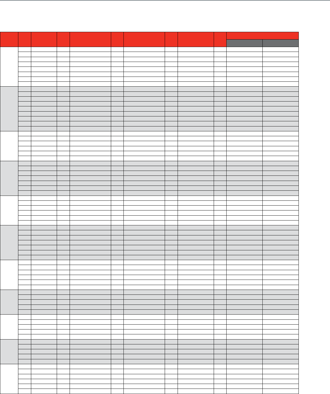
220
Control Ball Valve Cross Reference
2-Way Valve
Pipe
Size Cv Siemens Cv
Belimo
Cv Invensys Cv Johnson
Controls Cv
Honeywell
Ni-Brass
Stainless Steel
1/2 in.
0.4 599-10203 0.38 VB-2213-500-9-01 0.38 VBN2AB3P0X VBN2AB3S0X
0.63 599-10204 0.68 VB-2213-500-9-02 0.68 VBN2AD3P0X VBN2AD3S0X
1.6 599-10205 1.3 VB-2213-500-9-03 1.2 VG1241AD 1.3 VBN2AE3P0X VBN2AE3S0X
1.9 VG1241AE 2 VBN2AF3P0X VBN2AF3S0X
2.5 599-10206 2.6 VB-2213-500-9-04 2.9 VG1241AF 2.6 VBN2AG3P0X VBN2AG3S0X
4 599-10207 4.7 VB-2213-500-9-05 4.7 VG1241AG 4.7 VBN2AH3P0X VBN2AH3S0X
8 VB-2213-500-9-06 7.4 VG1241AL 8 VBN2AJ3P0X VBN2AJ3S0X
10 599-10208 11.7 VB-2213-500-9-07 11.7 VG1241AN 11.7 VBN2AK3P0X VBN2AK3S0X
3/4 in.
0.31 VB-2213-500-9-11 0.31 VBN2BB3P0X VBN2BB3S0X
0.63 VB-2213-500-9-12 0.63 VBN2BD3P0X VBN2BD3S0X
1.2 VB-2213-500-9-13 1.2 VBN2BE3P0X VBN2BE3S0X
2.5 VB-2213-500-9-14 2.5 VBN2BG3P0X VBN2BG3S0X
4.3 VB-2213-500-9-15 4.7 VG1241BG 4.3 VBN2BH3P0X VBN2BH3S0X
7.4 VG1241BL 7.4 VBN2BJ3P0X VBN2BJ3S0X
10 599-10209 10.1 VB-2213-500-9-16 11.7 VG1241BN 10.1 VBN2BK3P0X VBN2BK3S0X
14.7 VB-2213-500-9-17 14.7 VBN2BL3P0X VBN2BL3S0X
25 599-10210 28.6 VB-2213-500-9-18 29 VBN2BM3P0X VBN2BM3S0X
1 in.
4.4 VB-2213-500-9-21 7.4 VG1241CL 4.4 VBN2CH3P0X VBN2CH3S0X
10 599-10211 9.0 VB-2213-500-9-22 11.7 VG1241CN 9.0 VBN2CJ3P0X VBN2CJ3S0X
16 599-10213 15.3 VB-2213-500-9-23 18.7 VG1241CP 15.3 VBN2CL3P0X VBN2CL3S0X
25 599-10212 26.1 VB-2213-500-9-24 26 VBN2CM3P0X VBN2CM3S0X
43.9 VB-2213-500-9-26 44 VBN2CN3P0X VBN2CN3S0X
63 599-10214 54.2 VB-2213-500-9-27 54 VBN2CP3P0X VBN2CP3S0X
1-1/4 in.
4.4 VB-2213-500-9-41 4.4 VBN2DH3P0X VBN2DH3S0X
8.3 VB-2213-500-9-42 11.7 VG1241DN 8.3 VBN2DJ3P0X VBN2DJ3S0X
16 599-10215 14.9 VB-2213-500-9-43 18.7 VG1241DP 14.9 VBN2DK3P0X VBN2DK3S0X
29.2 VG1241DR 25.0 VBN2DL3P0X VBN2DL3S0X
36.5 VB-2213-500-9-44 37 VBN2DM3P0X VBN2DM3S0X
40 599-10216 41.1 VB-2213-500-9-45 41 VBN2DN3P0X VBN2DN3S0X
100 599-10217 102.3 VB-2213-500-9-46 102 VBN2DS3P0X VBN2DS3S0X
1-1/2 in.
25 599-10218 22.8 VB-2213-500-9-51 18.7 VG1241EP 23 VBN2EL3P0X VBN2EL3S0X
29.2 VG1241ER 30.0 VBN2EM3P0X VBN2EM3S0X
40 599-10220 41.3 VB-2213-500-9-52 46.8 VG1241ES 41 VBN2EN3P0X VBN2EN3S0X
63 599-10219 73.9 VB-2213-500-9-53 74 VBN2ER3P0X VBN2ER3S0X
160 599-10221 171.7 VB-2213-500-9-54 172 VBN2E13P0X VBN2E13S0X
29.2 VG1241FR
2 in.
40 599-10222 41.7 VB-2213-500-9-61 46.8 VG1241FS 42 VBN2FN3P0X VBN2FN3S0X
63 599-10224 57.0 VBN2FP3P0X VBN2FP3S0X
71.1 VB-2213-500-9-63 73.7 VG1241FT 71 VBN2FR3P0X VBN2FR3S0X
100 599-10223 100.0 VBN2FS3P0X VBN2FS3S0X
108.0 VB-2213-500-9-65 108.0 VBN2FT3P0X VBN2FT3S0X
210.0 VB-2213-500-9-66 210.0 VBN2F13P0X VBN2F13S0X
250 599-10225 266 VB-2213-500-9-67 266.0 VBN2F23P0X VBN2F23S0X
2-1/2 in.
45.0 VB-2213-500-9-71 45.0 VBN2GN3P0X VBN2GN3S0X
55.0 VB-2213-500-9-72 55.0 VBN2GP3P0X VBN2GP3S0X
72.3 VB-2213-500-9-73 72 VBN2GR3P0X VBN2GR3S0X
101.0 VB-2213-500-9-74 101.0 VBN2GS3P0X VBN2GS3S0X
162.0 VB-2213-500-9-75 162.0 VBN2GU3P0X VBN2GU3S0X
202.0 VB-2213-500-9-76 202.0 VBN2G13P0X VBN2G13S0X
3 in.
49.0 VB-2213-500-9-81 49.0 VBN2HN3P0X VBN2HN3S0X
63.0 VB-2213-500-9-82 63.0 VBN2HP3P0X VBN2HP3S0X
82.0 VB-2213-500-9-83 82.0 VBN2HR3P0X VBN2HR3S0X
124.0 VB-2213-500-9-84 124.0 VBN2HT3P0X VBN2HT3S0X
145.0 VB-2213-500-9-85 145.0 VBN2HU3P0X VBN2HU3S0X
4 in.
91.0 VBF2JS1S0X
118.0 VBF2JT1S0X
152.0 VBF2JU1S0X
197.0 VBF2J11S0X
254.0 VBF2J21S0X
5 in.
144.0 VBF2KU1S0X
185.0 VBF2K11S0X
240.0 VBF2K21S0X
309.0 VBF2K31S0X
400.0 VBF2K41S0X
6'
208.0 VBF2L11S0X
268.0 VBF2L21S0X
346.0 VBF2L41S0X
441.0 VBF2L51S0X
577.0 VBF2L61S0X
650.0 VBF2L71S0X

221
CROSS REFERENCE
Pipe
Size Cv Siemens Cv
Belimo
Cv Invensys Cv Johnson
Controls Cv
Honeywell
Ni-Brass
Stainless Steel
1/2 in.
0.3 B207+LRB24-3
0.4 171A-10203 0.46 B208+LRB24-3 0.38 VF-2213-505-9-01 0.38 VBN2AB3P0A VBN2AB3S0A
0.63 171A-10204 0.8 B209+LRB24-3 0.68 VF-2213-505-9-02 0.68 VBN2AD3P0A VBN2AD3S0A
1.6 171A-10205 1.2 B210+LRB24-3 1.3 VF-2213-505-9-03 1.2 VG1241AD - 9T4AGA 1.3 VBN2AE3P0A VBN2AE3S0A
1.9 B211+LRB24-3 1.9 VG1241AE - 9T4AGA 2 VBN2AF3P0A VBN2AF3S0A
2.5 171A-10206 3 B212+LRB24-3 2.6 VF-2213-505-9-04 2.9 VG1241AF - 9T4AGA 2.6 VBN2AG3P0A VBN2AG3S0A
4 171A-10207 4.7 B213+LRB24-3 4.7 VF-2213-505-9-05 4.7 VG1241AG - 9T4AGA 4.7 VBN2AH3P0A VBN2AH3S0A
7.4 B214+LRB24-3 8 VF-2213-505-9-06 7.4 VG1241AL - 9T4AGA 8 VBN2AJ3P0A VBN2AJ3S0A
10 171A-10208 10 B215+LRB24-3 11.7 VF-2213-505-9-07 11.7 VG1241AN - 9T4AGA 11.7 VBN2AK3P0A VBN2AK3S0A
3/4 in.
0.31 VF-2213-505-9-11 0.31 VBN2BB3P0A VBN2BB3S0A
0.63 VF-2213-505-9-12 0.63 VBN2BD3P0A VBN2BD3S0A
1.2 VF-2213-505-9-13 1.2 VBN2BE3P0A VBN2BE3S0A
2.5 VF-2213-505-9-14 2.5 VBN2BG3P0A VBN2BG3S0A
4.7 B217+LRB24-3 4.3 VF-2213-505-9-15 4.7 VG1241BG - 9T4AGA 4.3 VBN2BH3P0A VBN2BH3S0A
7.4 B218+LRB24-3 7.4 VG1241BL - 9T4AGA 7.4 VBN2BJ3P0A VBN2BJ3S0A
10 171A-10209 10 B219+LRB24-3 10.1 VF-2213-505-9-16 11.7 VG1241BN - 9T4AGA 10.1 VBN2BK3P0A VBN2BK3S0A
14.7 VF-2213-505-9-17 14.7 VBN2BL3P0A VBN2BL3S0A
25 171A-10210 24 B220+LRB24-3 28.6 VF-2213-505-9-18 29 VBN2BM3P0A VBN2BM3S0A
1 in.
7.4 B222+LRB24-3 4.4 VF-2213-505-9-21 7.4 VG1241CL - 9T4AGA 4.4 VBN2CH3P0A VBN2CH3S0A
10 171A-10211 10 B223+LRB24-3 9.0 VF-2213-505-9-22 11.7 VG1241CN - 9T4AGA 9.0 VBN2CJ3P0A VBN2CJ3S0A
16 171A-10213 19 B224+LRB24-3 15.3 VF-2213-505-9-23 18.7 VG1241CP - 9T4AGA 15.3 VBN2CL3P0A VBN2CL3S0A
25 171A-10212 30 B225+LRB24-3 26.1 VF-2213-505-9-24 26 VBN2CM3P0A VBN2CM3S0A
43.9 VF-2213-505-9-26 44 VBN2CN3P0A VBN2CN3S0A
63 171A-10214 54.2 VF-2213-505-9-27 54 VBN2CP3P0A VBN2CP3S0A
1-1/4 in.
4.4 VF-2213-505-9-41 4.4 VBN2DH3P0A VBN2DH3S0A
10 B229+LRB24-3 8.3 VF-2213-505-9-42 11.7 VG1241DN - 906AGA 8.3 VBN2DJ3P0A VBN2DJ3S0A
16 171A-10215 19 B230+LRB24-3 14.9 VF-2213-505-9-43 18.7 VG1241DP - 906AGA 14.9 VBN2DK3P0A VBN2DK3S0A
25 B231+ARB24-3 29.2 VG1241DR - 906AGA 25.0 VBN2DL3P0A VBN2DL3S0A
37 B232+ARB24-3 36.5 VF-2213-505-9-44 37 VBN2DM3P0A VBN2DM3S0A
40 171A-10216 41.1 VF-2213-505-9-45 41 VBN2DN3P0A VBN2DN3S0A
100 171A-10217 102.3 VF-2213-505-9-46 102 VBN2DS3P0A VBN2DS3S0A
1-1/2 in.
25 171B-10218 19 B238+ARB24-3 22.8 VF-2213-505-9-51 18.7 VG1241EP - 906AGA 23 VBN2EL3P0A VBN2EL3S0A
29 B239+ARB24-3 29.2 VG1241ER - 906AGA 30.0 VBN2EM3P0A VBN2EM3S0A
40 171B-10220 37 B240+ARB24-3 41.3 VF-2213-505-9-52 46.8 VG1241ES - 906AGA 41 VBN2EN3P0A VBN2EN3S0A
63 171B-10219 73.9 VF-2213-505-9-53 74 VBN2ER3P0A VBN2ER3S0A
160 171B-10221 171.7 VF-2213-505-9-54 172 VBN2E13P0A VBN2E13S0A
2 in.
29 B248+ARB24-3 29.2 VG1241FR - 909AGA
40 171B-10222 46 B249+ARB24-3 41.7 VF-2213-505-9-61 46.8 VG1241FS - 909AGA 42 VBN2FN3P0A VBN2FN3S0A
63 171B-10224 57 B250+ARB24-3 57.0 VBN2FP3P0A VBN2FP3S0A
65 B251+ARB24-3 71.1 VF-2213-505-9-63 73.7 VG1241FT - 909AGA 71 VBN2FR3P0A VBN2FR3S0A
100 171B-10223 85 B252+ARB24-3 108.0 VF-2213-505-9-65 100.0 VBN2FS3P0A VBN2FS3S0A
120 B253+ARB24-3 108.0 VBN2FT3P0A VBN2FT3S0A
210.0 VF-2213-505-9-66 210.0 VBN2F13P0A VBN2F13S0A
250 171B-10225 240 B254+ARB24-3 266 VF-2213-505-9-67 266.0 VBN2F23P0A VBN2F23S0A
2-1/2 in.
45.0 VF-2213-505-9-71 45.0 VBN2GN3P0A VBN2GN3S0A
60 B261+ARB24-3 55.0 VF-2213-505-9-72 55.0 VBN2GP3P0A VBN2GP3S0A
75 B262+ARB24-3 72.3 VF-2213-505-9-73 72 VBN2GR3P0A VBN2GR3S0A
110 B263+ARB24-3 101.0 VF-2213-505-9-74 101.0 VBN2GS3P0A VBN2GS3S0A
150 B264+ARB24-3 162.0 VF-2213-505-9-75 162.0 VBN2GU3P0A VBN2GU3S0A
210 B265+ARB24-3 202.0 VF-2213-505-9-76 202.0 VBN2G13P0A VBN2G13S0A
3 in.
49.0 VF-2213-505-9-81 49.0 VBN2HN3P0A VBN2HN3S0A
70 B277+ARB24-3 63.0 VF-2213-505-9-82 63.0 VBN2HP3P0A VBN2HP3S0A
82.0 VF-2213-505-9-83 82.0 VBN2HR3P0A VBN2HR3S0A
130 B278+ARB24-3 124.0 VF-2213-505-9-84 124.0 VBN2HT3P0A VBN2HT3S0A
170 B280+ARB24-3 145.0 VF-2213-505-9-85 145.0 VBN2HU3P0A VBN2HU3S0A
4 in.
91.0 VBF2JS1S0A
118.0 VBF2JT1S0A
152.0 VBF2JU1S0A
197.0 VBF2J11S0A
254.0 VBF2J21S0A
5 in.
144.0 VBF2KU1S0A
185.0 VBF2K11S0A
240.0 VBF2K21S0A
309.0 VBF2K31S0A
400.0 VBF2K41S0A
6 in.
208.0 VBF2L11S0A
268.0 VBF2L21S0A
346.0 VBF2L41S0A
441.0 VBF2L51S0A
577.0 VBF2L61S0A
650.0 VBF2L71S0A
Control Ball Valve Cross Reference
2-Way Valve + Non-Spring Return Floating Actuator

222
Pipe
Size Cv Siemens Cv
Belimo
Cv Invensys Cv Johnson
Controls Cv
Honeywell
Ni-Brass
Stainless Steel
1/2 in.
0.3 B207+LRB24-SR
0.4 171C-10203 0.46 B208+LRB24-SR 0.38 VS-2213-505-9-01 0.38 VBN2AB3P0B VBN2AB3S0B
0.63 171C-10204 0.8 B209+LRB24-SR 0.68 VS-2213-505-9-02 0.68 VBN2AD3P0B VBN2AD3S0B
1.6 171C-10205 1.2 B210+LRB24-SR 1.3 VS-2213-505-9-03 1.2 VG1241AD - 9T4GGA 1.3 VBN2AE3P0B VBN2AE3S0B
1.9 B211+LRB24-SR 1.9 VG1241AE - 9T4GGA 2 VBN2AF3P0B VBN2AF3S0B
2.5 171C-10206 3 B212+LRB24-SR 2.6 VS-2213-505-9-04 2.9 VG1241AF - 9T4GGA 2.6 VBN2AG3P0B VBN2AG3S0B
4 171C-10207 4.7 B213+LRB24-SR 4.7 VS-2213-505-9-05 4.7 VG1241AG - 9T4GGA 4.7 VBN2AH3P0B VBN2AH3S0B
7.4 B214+LRB24-SR 8 VS-2213-505-9-06 7.4 VG1241AL - 9T4GGA 8 VBN2AJ3P0B VBN2AJ3S0B
10 171C-10208 10 B215+LRB24-SR 11.7 VS-2213-505-9-07 11.7 VG1241AN - 9T4GGA 11.7 VBN2AK3P0B VBN2AK3S0B
3/4 in.
0.31 VS-2213-505-9-11 0.31 VBN2BB3P0B VBN2BB3S0B
0.63 VS-2213-505-9-12 0.63 VBN2BD3P0B VBN2BD3S0B
1.2 VS-2213-505-9-13 1.2 VBN2BE3P0B VBN2BE3S0B
2.5 VS-2213-505-9-14 2.5 VBN2BG3P0B VBN2BG3S0B
4.7 B217+LRB24-SR 4.3 VS-2213-505-9-15 4.7 VG1241BG - 9T4GGA 4.3 VBN2BH3P0B VBN2BH3S0B
7.4 B218+LRB24-SR 7.4 VG1241BL - 9T4GGA 7.4 VBN2BJ3P0B VBN2BJ3S0B
10 171C-10209 10 B219+LRB24-SR 10.1 VS-2213-505-9-16 11.7 VG1241BN - 9T4GGA 10.1 VBN2BK3P0B VBN2BK3S0B
14.7 VS-2213-505-9-17 14.7 VBN2BL3P0B VBN2BL3S0B
25 171C-10210 24 B220+LRB24-SR 28.6 VS-2213-505-9-18 29 VBN2BM3P0B VBN2BM3S0B
1 in.
7.4 B222+LRB24-SR 4.4 VS-2213-505-9-21 7.4 VG1241CL - 9T4GGA 4.4 VBN2CH3P0B VBN2CH3S0B
10 171C-10211 10 B223+LRB24-SR 9.0 VS-2213-505-9-22 11.7 VG1241CN - 9T4GGA 9.0 VBN2CJ3P0B VBN2CJ3S0B
16 171C-10213 19 B224+LRB24-SR 15.3 VS-2213-505-9-23 18.7 VG1241CP - 9T4GGA 15.3 VBN2CL3P0B VBN2CL3S0B
25 171C-10212 30 B225+LRB24-SR 26.1 VS-2213-505-9-24 26 VBN2CM3P0B VBN2CM3S0B
43.9 VS-2213-505-9-26 44 VBN2CN3P0B VBN2CN3S0B
63 171C-10214 54.2 VS-2213-505-9-27 54 VBN2CP3P0B VBN2CP3S0B
1-1/4 in.
4.4 VS-2213-505-9-41 4.4 VBN2DH3P0B VBN2DH3S0B
10 B229+LRB24-SR 8.3 VS-2213-505-9-42 11.7 VG1241DN - 906GGA 8.3 VBN2DJ3P0B VBN2DJ3S0B
16 171C-10215 19 B230+LRB24-SR 14.9 VS-2213-505-9-43 18.7 VG1241DP - 906GGA 14.9 VBN2DK3P0B VBN2DK3S0B
25 B231+ARB24-SR 29.2 VG1241DR - 906GGA 25.0 VBN2DL3P0B VBN2DL3S0B
40 171C-10216 37 B232+ARB24-SR 36.5 VS-2213-505-9-44 37 VBN2DM3P0B VBN2DM3S0B
41.1 VS-2213-505-9-45 41 VBN2DN3P0B VBN2DN3S0B
100 171C-10217 102.3 VS-2213-505-9-46 102 VBN2DS3P0B VBN2DS3S0B
1-1/2 in.
25 171D-10218 19 B238+ARB24-SR 22.8 VS-2213-505-9-51 18.7 VG1241EP - 906GGA 23 VBN2EL3P0B VBN2EL3S0B
29 B239+ARB24-SR 29.2 VG1241ER - 906GGA 30.0 VBN2EM3P0B VBN2EM3S0B
40 171D-10220 37 B240+ARB24-SR 41.3 VS-2213-505-9-52 46.8 VG1241ES - 906GGA 41 VBN2EN3P0B VBN2EN3S0B
63 171D-10219 73.9 VS-2213-505-9-53 74 VBN2ER3P0B VBN2ER3S0B
160 171D-10221 171.7 VS-2213-505-9-54 172 VBN2E13P0B VBN2E13S0B
2 in.
29 B248+ARB24-SR 29.2 VG1241FR - 909GGA
40 171D-10222 46 B249+ARB24-SR 41.7 VS-2213-505-9-61 46.8 VG1241FS - 909GGA 42 VBN2FN3P0B VBN2FN3S0B
63 171D-10224 57 B250+ARB24-SR 57.0 VBN2FP3P0B VBN2FP3S0B
65 B251+ARX24-MFT 71.1 VS-2213-505-9-63 73.7 VG1241FT - 909GGA 71 VBN2FR3P0B VBN2FR3S0B
100 171D-10223 85 B252+ARX24-MFT 100.0 VBN2FS3P0B VBN2FS3S0B
120 B253+ARX24-MFT 108.0 VS-2213-505-9-65 108.0 VBN2FT3P0B VBN2FT3S0B
210.0 VS-2213-505-9-66 210.0 VBN2F13P0B VBN2F13S0B
250 171D-10225 240 B254+ARX24-MFT 266 VS-2213-505-9-67 266.0 VBN2F23P0B VBN2F23S0B
2-1/2 in.
45.0 VS-2213-505-9-71 45.0 VBN2GN3P0B VBN2GN3S0B
60 B261+ARX24-MFT 55.0 VS-2213-505-9-72 55.0 VBN2GP3P0B VBN2GP3S0B
75 B262+ARX24-MFT 72.3 VS-2213-505-9-73 72 VBN2GR3P0B VBN2GR3S0B
110 B263+ARX24-MFT 101.0 VS-2213-505-9-74 101.0 VBN2GS3P0B VBN2GS3S0B
150 B264+ARX24-MFT 162.0 VS-2213-505-9-75 162.0 VBN2GU3P0B VBN2GU3S0B
210 B265+ARX24-MFT 202.0 VS-2213-505-9-76 202.0 VBN2G13P0B VBN2G13S0B
3 in.
49.0 VS-2213-505-9-81 49.0 VBN2HN3P0B VBN2HN3S0B
70 B277+ARX24-MFT 63.0 VS-2213-505-9-82 63.0 VBN2HP3P0B VBN2HP3S0B
82.0 VS-2213-505-9-83 82.0 VBN2HR3P0B VBN2HR3S0B
130 B278+ARX24-MFT 124.0 VS-2213-505-9-84 124.0 VBN2HT3P0B VBN2HT3S0B
170 B280+ARX24-MFT 145.0 VS-2213-505-9-85 145.0 VBN2HU3P0B VBN2HU3S0B
4 in.
91.0 VBF2JS1S0B
118.0 VBF2JT1S0B
152.0 VBF2JU1S0B
197.0 VBF2J11S0B
254.0 VBF2J21S0B
5 in.
144.0 VBF2KU1S0B
185.0 VBF2K11S0B
240.0 VBF2K21S0B
309.0 VBF2K31S0B
400.0 VBF2K41S0B
6 in.
208.0 VBF2L11S0B
268.0 VBF2L21S0B
346.0 VBF2L41S0B
441.0 VBF2L51S0B
577.0 VBF2L61S0B
650.0 VBF2L71S0B
Control Ball Valve Cross Reference
2-Way Valve + Non-Spring Return Modulating Actuator
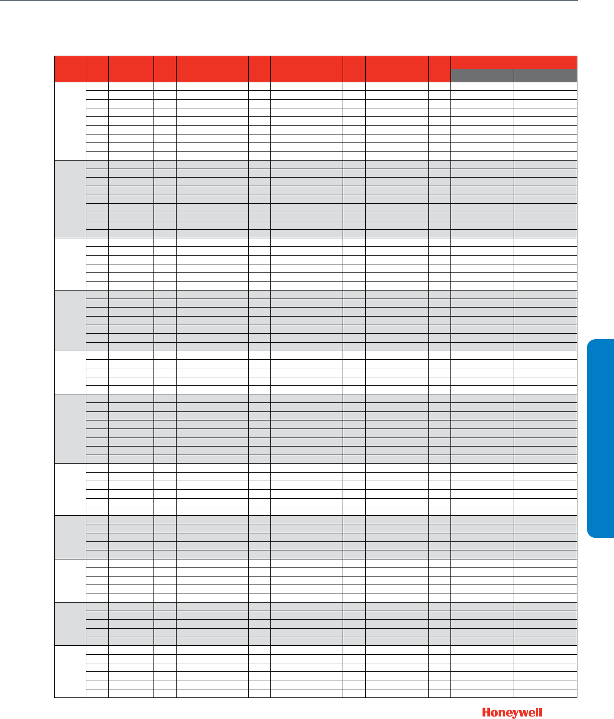
223
CROSS REFERENCE
Pipe
Size Cv Siemens Cv
Belimo
Cv Invensys Cv Johnson
Controls Cv
Honeywell
Ni-Brass
Stainless Steel
1/2 in.
0.3 B207+TFX24 US
0.4 171E-10203 0.46 B208+TFX24 US 0.38 VA-2213-536-9-01 0.38 VBN2AB3P0C VBN2AB3S0C
0.63 171E-10204 0.8 B209+TFX24 US 0.68 VA-2213-536-9-02 0.68 VBN2AD3P0C VBN2AD3S0C
1.6 171E-10205 1.2 B210+TFX24 US 1.3 VA-2213-536-9-03 1.2 VG1241AD - 22TBGA 1.3 VBN2AE3P0C VBN2AE3S0C
1.9 B211+TFX24 US 1.9 VG1241AE - 22TBGA 2 VBN2AF3P0C VBN2AF3S0C
2.5 171E-10206 3 B212+TFX24 US 2.6 VA-2213-536-9-04 2.9 VG1241AF - 22TBGA 2.6 VBN2AG3P0C VBN2AG3S0C
4 171E-10207 4.7 B213+TFX24 US 4.7 VA-2213-536-9-05 4.7 VG1241AG - 22TBGA 4.7 VBN2AH3P0C VBN2AH3S0C
7.4 B214+TFX24 US 8 VA-2213-536-9-06 7.4 VG1241AL - 22TBGA 8 VBN2AJ3P0C VBN2AJ3S0C
10 171E-10208 10 B215+TFX24 US 11.7 VA-2213-536-9-07 11.7 VG1241AN - 22TBGA 11.7 VBN2AK3P0C VBN2AK3S0C
3/4 in.
0.31 VA-2213-536-9-11 0.31 VBN2BB3P0C VBN2BB3S0C
0.63 VA-2213-536-9-12 0.63 VBN2BD3P0C VBN2BD3S0C
1.2 VA-2213-536-9-13 1.2 VBN2BE3P0C VBN2BE3S0C
2.5 VA-2213-536-9-14 2.5 VBN2BG3P0C VBN2BG3S0C
4.7 B217+TFX24 US 4.3 VA-2213-536-9-15 4.7 VG1241BG - 22TBGA 4.3 VBN2BH3P0C VBN2BH3S0C
7.4 B218+TFX24 US 7.4 VG1241BL - 22TBGA 7.4 VBN2BJ3P0C VBN2BJ3S0C
10 171E-10209 10 B219+TFX24 US 10.1 VA-2213-536-9-16 11.7 VG1241BN - 22TBGA 10.1 VBN2BK3P0C VBN2BK3S0C
14.7 VA-2213-536-9-17 14.7 VBN2BL3P0C VBN2BL3S0C
25 171E-10210 24 B220+TFX24 US 28.6 VA-2213-536-9-18 29 VBN2BM3P0C VBN2BM3S0C
1 in.
7.4 B222+LF24 US 4.4 VA-2213-536-9-21 7.4 VG1241CL - 936BGA 4.4 VBN2CH3P0C VBN2CH3S0C
10 171E-10211 10 B223+LF24 US 9.0 VA-2213-536-9-22 11.7 VG1241CN - 936BGA 9.0 VBN2CJ3P0C VBN2CJ3S0C
16 171E-10213 19 B224+LF24 US 15.3 VA-2213-536-9-23 18.7 VG1241CP - 936BGA 15.3 VBN2CL3P0C VBN2CL3S0C
25 171E-10212 30 B225+LF24 US 26.1 VA-2213-536-9-24 26 VBN2CM3P0C VBN2CM3S0C
43.9 VA-2213-536-9-26 44 VBN2CN3P0C VBN2CN3S0C
63 171E-10214 54.2 VA-2213-536-9-27 54 VBN2CP3P0C VBN2CP3S0C
1-1/4 in.
4.4 VA-2213-536-9-41 4.4 VBN2DH3P0C VBN2DH3S0C
10 B229+LF24 US 8.3 VA-2213-536-9-42 11.7 VG1241DN - 936BGA 8.3 VBN2DJ3P0C VBN2DJ3S0C
16 171E-10215 19 B230+LF24 US 14.9 VA-2213-536-9-43 18.7 VG1241DP - 936BGA 14.9 VBN2DK3P0C VBN2DK3S0C
25 B231+AF24 US 29.2 VG1241DR - 936BGA 25.0 VBN2DL3P0C VBN2DL3S0C
37 B232+AF24 US 36.5 VA-2213-536-9-44 37 VBN2DM3P0C VBN2DM3S0C
40 171E-10216 41.1 VA-2213-536-9-45 41 VBN2DN3P0C VBN2DN3S0C
100 171E-10217 102.3 VA-2213-536-9-46 102 VBN2DS3P0C VBN2DS3S0C
1-1/2 in.
25 171E-10218 19 B238+AF24 US 22.8 VA-2213-536-9-51 18.7 VG1241EP - 936BGA 23 VBN2EL3P0C VBN2EL3S0C
29 B239+AF24 US 29.2 VG1241ER - 936BGA 30.0 VBN2EM3P0C VBN2EM3S0C
40 171E-10220 37 B240+AF24 US 41.3 VA-2213-536-9-52 46.8 VG1241ES - 936BGA 41 VBN2EN3P0C VBN2EN3S0C
63 171E-10219 73.9 VA-2213-536-9-53 74 VBN2ER3P0C VBN2ER3S0C
160 171E-10221 171.7 VA-2213-536-9-54 172 VBN2E13P0C VBN2E13S0C
2 in.
29 B248+AF24 US 29.2 VG1241FR - 926BGA
40 171E-10222 46 B249+AF24 US 41.7 VA-2213-536-9-61 46.8 VG1241FS - 926BGA 42 VBN2FN3P0C VBN2FN3S0C
63 171E-10224 57 B250+AF24 US 57.0 VBN2FP3P0C VBN2FP3S0C
65 B251+AF24 US 71.1 VA-2213-536-9-63 73.7 VG1241FT - 926BGA 71 VBN2FR3P0C VBN2FR3S0C
100 171E-10223 85 B252+AF24 US 100.0 VBN2FS3P0C VBN2FS3S0C
120 B253+AF24 US 108.0 VA-2213-536-9-65 108.0 VBN2FT3P0C VBN2FT3S0C
210.0 VA-2213-536-9-66 210.0 VBN2F13P0C VBN2F13S0C
250 171E-10225 240 B254+AF24 US 266 VA-2213-536-9-67 266.0 VBN2F23P0C VBN2F23S0C
2-1/2 in.
45.0 VA-2213-536-9-71 45.0 VBN2GN3P0C VBN2GN3S0C
60 B261+AF24 US 55.0 VA-2213-536-9-72 55.0 VBN2GP3P0C VBN2GP3S0C
75 B262+AF24 US 72.3 VA-2213-536-9-73 72 VBN2GR3P0C VBN2GR3S0C
110 B263+AF24 US 101.0 VA-2213-536-9-74 101.0 VBN2GS3P0C VBN2GS3S0C
150 B264+AF24 US 162.0 VA-2213-536-9-75 162.0 VBN2GU3P0C VBN2GU3S0C
210 B265+AF24 US 202.0 VA-2213-536-9-76 202.0 VBN2G13P0C VBN2G13S0C
3 in.
49.0 VA-2213-536-9-81 49.0 VBN2HN3P0C VBN2HN3S0C
70 B277+AF24 US 63.0 VA-2213-536-9-82 63.0 VBN2HP3P0C VBN2HP3S0C
82.0 VA-2213-536-9-83 82.0 VBN2HR3P0C VBN2HR3S0C
130 B278+AF24 US 124.0 VA-2213-536-9-84 124.0 VBN2HT3P0C VBN2HT3S0C
170 B280+AF24 US 145.0 VA-2213-536-9-85 145.0 VBN2HU3P0C VBN2HU3S0C
4 in.
91.0 VBF2JS1S0C
118.0 VBF2JT1S0C
152.0 VBF2JU1S0C
197.0 VBF2J11S0C
254.0 VBF2J21S0C
5 in.
144.0 VBF2KU1S0C
185.0 VBF2K11S0C
240.0 VBF2K21S0C
309.0 VBF2K31S0C
400.0 VBF2K41S0C
6 in.
208.0 VBF2L11S0C
268.0 VBF2L21S0C
346.0 VBF2L41S0C
441.0 VBF2L51S0C
577.0 VBF2L61S0C
650.0 VBF2L71S0C
Control Ball Valve Cross Reference
2-Way Valve + Spring Return, 2-Position Actuator
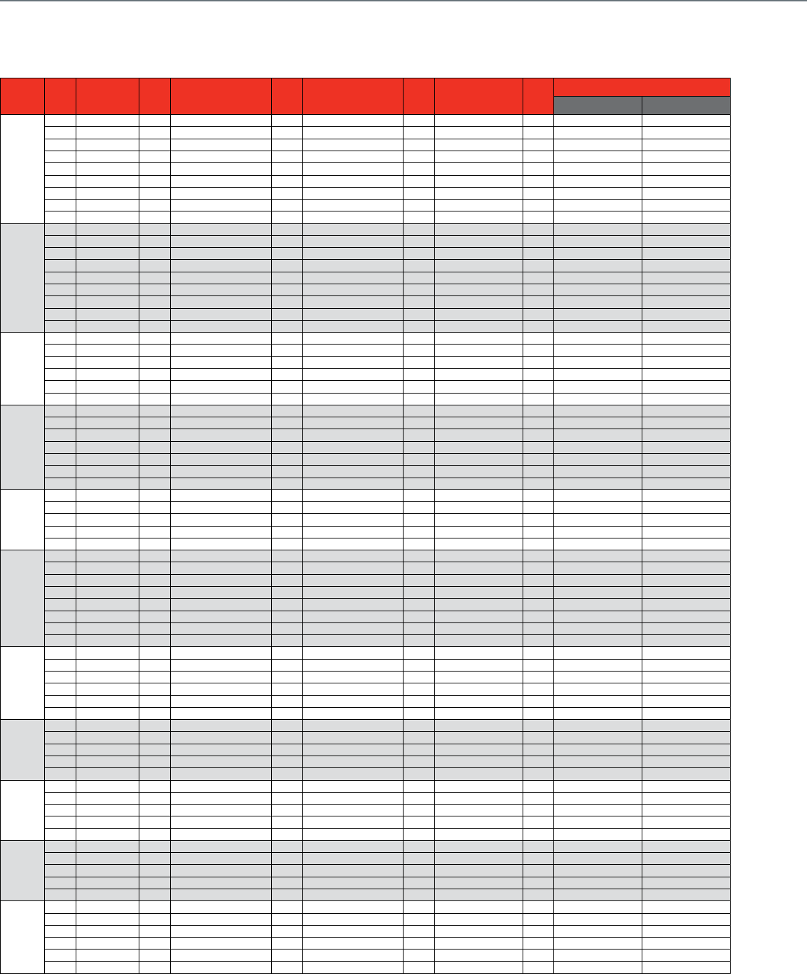
224
Pipe
Size Cv Siemens Cv
Belimo
Cv Invensys Cv Johnson
Controls Cv
Honeywell
Ni-Brass
Stainless Steel
1/2 in.
0.3 B207+TF24-3 US
0.4 171F-10203 0.46 B208+TF24-3 US 0.38 VF-2213-536-9-01 0.38 VBN2AB3P0D VBN2AB3S0D
0.63 171F-10204 0.8 B209+TF24-3 US 0.68 VF-2213-536-9-02 0.68 VBN2AD3P0D VBN2AD3S0D
1.6 171F-10205 1.2 B210+TF24-3 US 1.3 VF-2213-536-9-03 1.2 VG1241AD - 22TAGA 1.3 VBN2AE3P0D VBN2AE3S0D
1.9 B211+TF24-3 US 1.9 VG1241AE - 22TAGA 2 VBN2AF3P0D VBN2AF3S0D
2.5 171F-10206 3 B212+TF24-3 US 2.6 VF-2213-536-9-04 2.9 VG1241AF - 22TAGA 2.6 VBN2AG3P0D VBN2AG3S0D
4 171F-10207 4.7 B213+TF24-3 US 4.7 VF-2213-536-9-05 4.7 VG1241AG - 22TAGA 4.7 VBN2AH3P0D VBN2AH3S0D
7.4 B214+TF24-3 US 8 VF-2213-536-9-06 7.4 VG1241AL - 22TAGA 8 VBN2AJ3P0D VBN2AJ3S0D
10 171F-10208 10 B215+TF24-3 US 11.7 VF-2213-536-9-07 11.7 VG1241AN - 22TAGA 11.7 VBN2AK3P0D VBN2AK3S0D
3/4 in.
0.31 VF-2213-536-9-11 0.31 VBN2BB3P0D VBN2BB3S0D
0.63 VF-2213-536-9-12 0.63 VBN2BD3P0D VBN2BD3S0D
1.2 VF-2213-536-9-13 1.2 VBN2BE3P0D VBN2BE3S0D
2.5 VF-2213-536-9-14 2.5 VBN2BG3P0D VBN2BG3S0D
4.7 B217+TF24-3 US 4.3 VF-2213-536-9-15 4.7 VG1241BG - 22TAGA 4.3 VBN2BH3P0D VBN2BH3S0D
7.4 B218+TF24-3 US 7.4 VG1241BL - 22TAGA 7.4 VBN2BJ3P0D VBN2BJ3S0D
10 171F-10209 10 B219+TF24-3 US 10.1 VF-2213-536-9-16 11.7 VG1241BN - 22TAGA 10.1 VBN2BK3P0D VBN2BK3S0D
14.7 VF-2213-536-9-17 14.7 VBN2BL3P0D VBN2BL3S0D
25 171F-10210 24 2B20+TF24-3 US 28.6 VF-2213-536-9-18 29 VBN2BM3P0D VBN2BM3S0D
1 in.
7.4 B222+LF24-3 US 4.4 VF-2213-536-9-21 7.4 VG1241CL - 936AGA 4.4 VBN2CH3P0D VBN2CH3S0D
10 171F-10211 10 B223+LF24-3 US 9.0 VF-2213-536-9-22 11.7 VG1241CN - 936AGA 9.0 VBN2CJ3P0D VBN2CJ3S0D
16 171F-10213 19 B224+LF24-3 US 15.3 VF-2213-536-9-23 18.7 VG1241CP - 936AGA 15.3 VBN2CL3P0D VBN2CL3S0D
25 171F-10212 30 B225+LF24-3 US 26.1 VF-2213-536-9-24 26 VBN2CM3P0D VBN2CM3S0D
43.9 VF-2213-536-9-26 44 VBN2CN3P0D VBN2CN3S0D
63 171F-10214 54.2 VF-2213-536-9-27 54 VBN2CP3P0D VBN2CP3S0D
1-1/4 in.
4.4 VF-2213-536-9-41 4.4 VBN2DH3P0D VBN2DH3S0D
10 B229+LF24-3 US 8.3 VF-2213-536-9-42 11.7 VG1241DN - 936AGA 8.3 VBN2DJ3P0D VBN2DJ3S0D
16 171F-10215 19 B230+LF24-3 US 14.9 VF-2213-536-9-43 18.7 VG1241DP - 936AGA 14.9 VBN2DK3P0D VBN2DK3S0D
29.2 VG1241DR - 936AGA 25.0 VBN2DL3P0D VBN2DL3S0D
36.5 VF-2213-536-9-44 37 VBN2DM3P0D VBN2DM3S0D
40 171F-10216 41.1 VF-2213-536-9-45 41 VBN2DN3P0D VBN2DN3S0D
100 171F-10217 102.3 VF-2213-536-9-46 102 VBN2DS3P0D VBN2DS3S0D
1-1/2 in.
25 171F-10218 22.8 VF-2213-536-9-51 18.7 VG1241EP - 936AGA 23 VBN2EL3P0D VBN2EL3S0D
29.2 VG1241ER - 936AGA 30.0 VBN2EM3P0D VBN2EM3S0D
40 171F-10220 41.3 VF-2213-536-9-52 46.8 VG1241ES - 936AGA 41 VBN2EN3P0D VBN2EN3S0D
63 171F-10219 73.9 VF-2213-536-9-53 74 VBN2ER3P0D VBN2ER3S0D
160 171F-10221 171.7 VF-2213-536-9-54 172 VBN2E13P0D VBN2E13S0D
2 in.
29.2 VG1241FR - 926AGA
40 171F-10222 41.7 VF-2213-536-9-61 46.8 VG1241FS - 926AGA 42 VBN2FN3P0D VBN2FN3S0D
63 171F-10224 57.0 VBN2FP3P0D VBN2FP3S0D
71.1 VF-2213-536-9-63 73.7 VG1241FT - 926AGA 71 VBN2FR3P0D VBN2FR3S0D
100 171F-10223 100.0 VBN2FS3P0D VBN2FS3S0D
108.0 VF-2213-536-9-65 108.0 VBN2FT3P0D VBN2FT3S0D
210.0 VF-2213-536-9-66 210.0 VBN2F13P0D VBN2F13S0D
250 171F-10225 266 VF-2213-536-9-67 266.0 VBN2F23P0D VBN2F23S0D
2-1/2 in.
45.0 VF-2213-536-9-71 45.0 VBN2GN3P0D VBN2GN3S0D
55.0 VF-2213-536-9-72 55.0 VBN2GP3P0D VBN2GP3S0D
72.3 VF-2213-536-9-73 72 VBN2GR3P0D VBN2GR3S0D
101.0 VF-2213-536-9-74 101.0 VBN2GS3P0D VBN2GS3S0D
162.0 VF-2213-536-9-75 162.0 VBN2GU3P0D VBN2GU3S0D
202.0 VF-2213-536-9-76 202.0 VBN2G13P0D VBN2G13S0D
3 in.
49.0 VF-2213-536-9-81 49.0 VBN2HN3P0D VBN2HN3S0D
63.0 VF-2213-536-9-82 63.0 VBN2HP3P0D VBN2HP3S0D
82.0 VF-2213-536-9-83 82.0 VBN2HR3P0D VBN2HR3S0D
124.0 VF-2213-536-9-84 124.0 VBN2HT3P0D VBN2HT3S0D
145.0 VF-2213-536-9-85 145.0 VBN2HU3P0D VBN2HU3S0D
4 in.
91.0 VBF2JS1S0D
118.0 VBF2JT1S0D
152.0 VBF2JU1S0D
197.0 VBF2J11S0D
254.0 VBF2J21S0D
5 in.
144.0 VBF2KU1S0D
185.0 VBF2K11S0D
240.0 VBF2K21S0D
309.0 VBF2K31S0D
400 VBF2K41S0D
6 in.
208.0 VBF2L11S0D
268.0 VBF2L21S0D
346 VBF2L41S0D
441 VBF2L51S0D
577 VBF2L61S0D
650 VBF2L71S0D
Control Ball Valve Cross Reference
2-Way Valve + Spring Return Floating Actuator
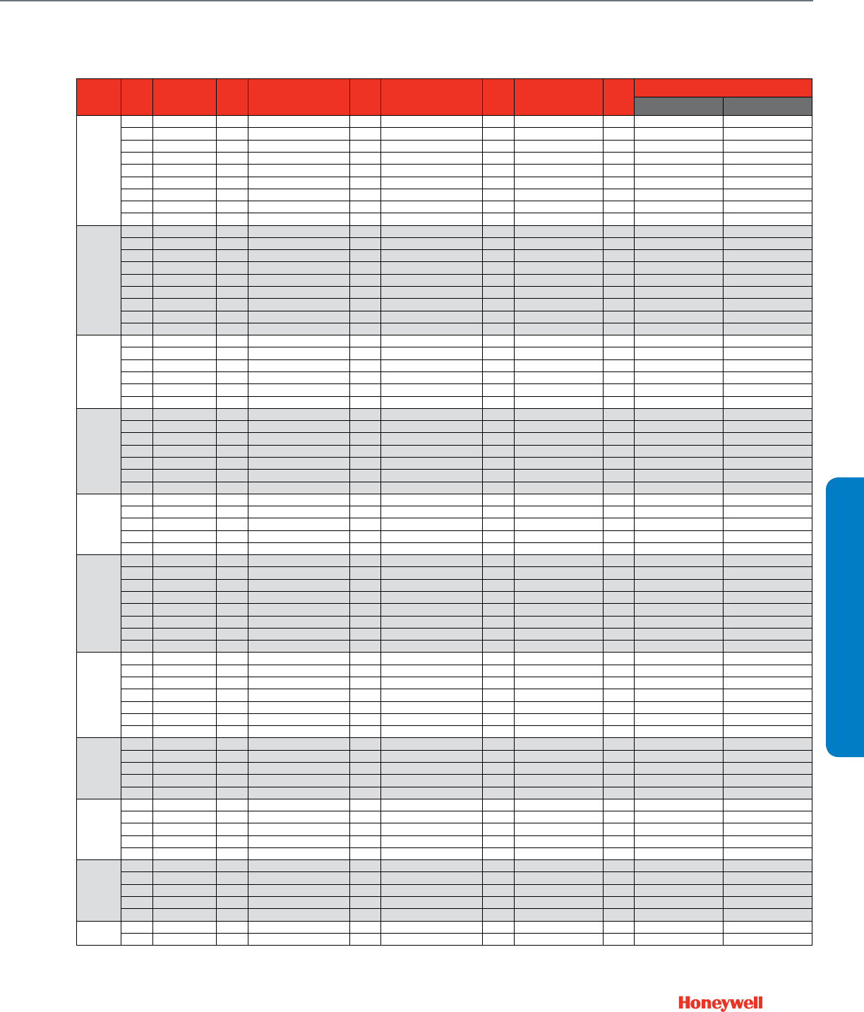
225
CROSS REFERENCE
Pipe
Size Cv Siemens Cv
Belimo
Cv Invensys Cv Johnson
Controls Cv
Honeywell
Ni-Brass
Stainless Steel
1/2 in.
0.3 B207+TF24-SR US
0.4 171G-10203 0.46 B208+TF24-SR US 0.38 VS-2213-536-9-01 0.38 VBN2AB3P0D VBN2AB3S0D
0.63 171G-10204 0.8 B209+TF24-SR US 0.68 VS-2213-536-9-02 0.68 VBN2AD3P0D VBN2AD3S0D
1.6 171G-10205 1.2 B210+TF24-SR US 1.3 VS-2213-536-9-03 1.2 VG1241AD - 22TGGA 1.3 VBN2AE3P0D VBN2AE3S0D
1.9 B211+TF24-SR US 1.9 VG1241AE - 22TBGA 2 VBN2AF3P0D VBN2AF3S0D
2.5 171G-10206 3 B212+TF24-SR US 2.6 VS-2213-536-9-04 2.9 VG1241AF - 22TBGA 2.6 VBN2AG3P0D VBN2AG3S0D
4 171G-10207 4.7 B213+TF24-SR US 4.7 VS-2213-536-9-05 4.7 VG1241AG - 22TBGA 4.7 VBN2AH3P0D VBN2AH3S0D
7.4 B214+TF24-SR US 8 VS-2213-536-9-06 7.4 VG1241AL - 22TBGA 8 VBN2AJ3P0D VBN2AJ3S0D
10 171G-10208 10 B215+TF24-SR US 11.7 VS-2213-536-9-07 11.7 VG1241AN - 22TBGA 11.7 VBN2AK3P0D VBN2AK3S0D
3/4 in.
0.31 VBN2BB3P0D VBN2BB3S0D
0.31 VS-2213-536-9-11 0.63 VBN2BD3P0D VBN2BD3S0D
0.63 VS-2213-536-9-12 1.2 VBN2BE3P0D VBN2BE3S0D
1.2 VS-2213-536-9-13 2.5 VBN2BG3P0D VBN2BG3S0D
4.7 B217+TF24-SR US 2.5 VS-2213-536-9-14 4.7 VG1241BG - 22TBGA 4.3 VBN2BH3P0D VBN2BH3S0D
7.4 B218+TF24-SR US 4.3 VS-2213-536-9-15 7.4 VG1241BL - 22TBGA 7.4 VBN2BJ3P0D VBN2BJ3S0D
10 171G-10209 10 B219+TF24-SR US 10.1 VS-2213-536-9-16 11.7 VG1241BN - 22TBGA 10.1 VBN2BK3P0D VBN2BK3S0D
14.7 VS-2213-536-9-17 14.7 VBN2BL3P0D VBN2BL3S0D
25 171G-10210 24 2B20+TF24-SR US 28.6 VS-2213-536-9-18 29 VBN2BM3P0D VBN2BM3S0D
1 in.
7.4 B222+LF24-SR US 4.4 VS-2213-536-9-21 7.4 VG1241CL - 936GGA 4.4 VBN2CH3P0D VBN2CH3S0D
10 171G-10211 10 B223+LF24-SR US 9.0 VS-2213-536-9-22 11.7 VG1241CN - 22TBGA 9.0 VBN2CJ3P0D VBN2CJ3S0D
16 171G-10213 19 B224+LF24-SR US 15.3 VS-2213-536-9-23 18.7 VG1241CP - 22TBGA 15.3 VBN2CL3P0D VBN2CL3S0D
25 171G-10212 30 B225+LF24-SR US 26.1 VS-2213-536-9-24 26 VBN2CM3P0D VBN2CM3S0D
43.9 VS-2213-536-9-26 44 VBN2CN3P0D VBN2CN3S0D
63 171G-10214 54.2 VS-2213-536-9-27 54 VBN2CP3P0D VBN2CP3S0D
1-1/4 in.
4.4 VS-2213-536-9-41 4.4 VBN2DH3P0D VBN2DH3S0D
10 B229+LF24-SR US 8.3 VS-2213-536-9-42 11.7 VG1241DN - 906GA 8.3 VBN2DJ3P0D VBN2DJ3S0D
16 171G-10215 19 B230+LF24-SR US 14.9 VS-2213-536-9-43 18.7 VG1241DP - 906GA 14.9 VBN2DK3P0D VBN2DK3S0D
25 B231+AF24-SR US 29.2 VG1241DR - 906GA 25.0 VBN2DL3P0D VBN2DL3S0D
37 B232+AF24-SR US 36.5 VS-2213-536-9-44 37 VBN2DM3P0D VBN2DM3S0D
40 171G-10216 41.1 VS-2213-536-9-45 41 VBN2DN3P0D VBN2DN3S0D
100 171G-10217 102.3 VS-2213-536-9-46 102 VBN2DS3P0D VBN2DS3S0D
1-1/2 in.
25 171G-10218 19 B238+AF24-SR US 22.8 VS-2213-536-9-51 18.7 VG1241EP - 906GA 23 VBN2EL3P0D VBN2EL3S0D
29 B239+AF24-SR US 29.2 VG1241ER - 906GA 30.0 VBN2EM3P0D VBN2EM3S0D
40 171G-10220 37 B240+AF24-SR US 41.3 VS-2213-536-9-52 46.8 VG1241ES - 906GA 41 VBN2EN3P0D VBN2EN3S0D
63 171G-10219 73.9 VS-2213-536-9-53 74 VBN2ER3P0D VBN2ER3S0D
160 171G-10221 171.7 VS-2213-536-9-54 172 VBN2E13P0D VBN2E13S0D
2 in.
29 B248+AF24-SR US 29.2 VG1241FR - 926GGA
40 171G-10222 46 B249+AF24-SR US 41.7 VS-2213-536-9-61 46.8 VG1241FS - 926GGA 42 VBN2FN3P0D VBN2FN3S0D
63 171G-10224 57 B250+AF24-SR US 57.0 VBN2FP3P0D VBN2FP3S0D
65 B251+AF24-MFT US 71.1 VS-2213-536-9-63 73.7 VG1241FT - 926GGA 71 VBN2FR3P0D VBN2FR3S0D
100 171G-10223 85 B252+AF24-MFT US 100.0 VBN2FS3P0D VBN2FS3S0D
120 B253+AF24-MFT US 108.0 VS-2213-536-9-65 108.0 VBN2FT3P0D VBN2FT3S0D
210.0 VS-2213-536-9-66 210.0 VBN2F13P0D VBN2F13S0D
250 171G-10225 240 B254+AF24-MFT US 266 VS-2213-536-9-67 266.0 VBN2F23P0D VBN2F23S0D
2-1/2 in.
45.0 VS-2213-536-9-71 45.0 VBN2GN3P0D VBN2GN3S0D
60 B261+AF24-MFT US 55.0 VS-2213-536-9-72 55.0 VBN2GP3P0D VBN2GP3S0D
75 B262+AF24-MFT US 72.3 VS-2213-536-9-73 72 VBN2GR3P0D VBN2GR3S0D
110 B263+AF24-MFT US 101.0 VS-2213-536-9-74 101.0 VBN2GS3P0D VBN2GS3S0D
150 B264+AF24-MFT US 162.0 VS-2213-536-9-75 162.0 VBN2GU3P0D VBN2GU3S0D
210 B265+AF24-MFT US 202.0 VS-2213-536-9-76 202.0 VBN2G13P0D VBN2G13S0D
3 in.
49.0 VS-2213-536-9-81 49.0 VBN2HN3P0D VBN2HN3S0D
70 B277+AF24-MFT US 63.0 VS-2213-536-9-82 63.0 VBN2HP3P0D VBN2HP3S0D
82.0 VS-2213-536-9-83 82.0 VBN2HR3P0D VBN2HR3S0D
130 B278+AF24-MFT US 124.0 VS-2213-536-9-84 124.0 VBN2HT3P0D VBN2HT3S0D
170 B280+AF24-MFT US 145.0 VS-2213-536-9-85 145.0 VBN2HU3P0D VBN2HU3S0D
4 in.
91.0 VBF2JS1S0D
118.0 VBF2JT1S0D
152.0 VBF2JU1S0D
197.0 VBF2J11S0D
254.0 VBF2J21S0D
5 in.
144.0 VBF2KU1S0D
185.0 VBF2K11S0D
240.0 VBF2K21S0D
309.0 VBF2K31S0D
400 VBF2K41S0D
6 in. 208.0 VBF2L11S0D
268.0 VBF2L21S0D
Control Ball Valve Cross Reference
2-Way Valve + Spring Return Modulating Actuator
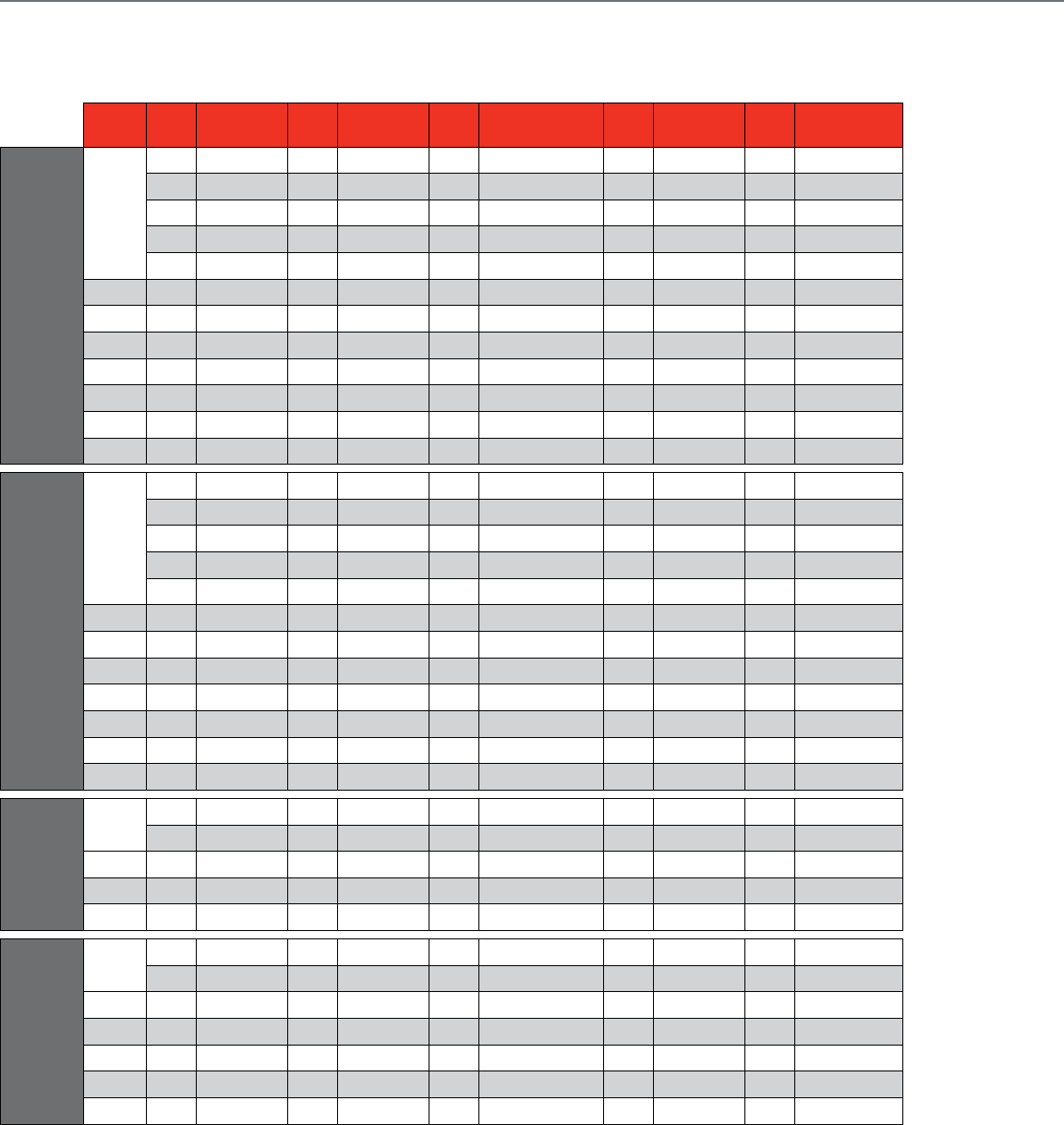
226
Pipe
Size Cv Siemens
Model Cv Belimo
Model Cv Invensys Cv Johnson
Controls Cv Honeywell
Model
Direct-Acting, Brass Trim 2-Way Valves
1/2"
1599-03162 0.4 G212 0.4 VB-7213-0-4-01 0.73 VG7241CT 0.73 V5011N1008
1.6 599-03163 1.3 G213 1.3 VB-7213-0-4-02 1.16 V5011N1016
2.2 G214 2.2 VB-7213-0-4-03 1.8 VG7241ET 1.85 V5011N1024
2.5 599-03164 2.9 V5011N1032
4599-03165 4.4 G215 4.4 VB-7213-0-4-04 4.6 VG7241GT 4.7 V5011N1040
3/4" 6.3 599-03166 7.5 G220 7.5 VB-7213-0-4-06 7.3 VG7241LT 7.3 V5011N1057
1" 10 599-03167 10 G224 10 VB-7213-0-4-07 11.6 VG7241NT 11.7 V5011N1065
1 1/4" 16 599-03168 20 G232 20 VB-7213-0-4-09 18.5 VG7241PT 18.7 V5011N1073
1 1/2" 25 599-03169 28 G240 28 VB-7213-0-4-10 28.9 VG7241RT 29.3 V5011N1081
2" 40 599-03170 40 G250 40 VB-7213-0-4-11 46.2 VG7241ST 46.8 V5011N1099
2 1/2" 65 VB-9213-0-4-12 63 V5011F1105
3" 85 VB-9213-0-4-13 100 V5011F1113
Direct-Acting, SS Trim 2-Way Valves
1/2"
1599-03108 0.73 VG7243CT 0.73 V5011N2006
1.6 599-03109 1.16 V5011N2014
1.8 VG7243ET 1.85 V5011N2022
2.5 599-03110 2.9 V5011N2030
4599-03111 4.6 VG7243GT 4.7 V5011N2048
3/4" 6.3 599-03112 7.3 VG7243LT 7.3 V5011N2055
1" 10 599-03113 11.6 VG7243NT 11.7 V5011N2063
1 1/4" 16 599-03114 18.5 VG7243PT 18.7 V5011N2071
1 1/2" 25 599-03115 28.9 VG7243RT 29.3 V5011N2089
2" 40 599-03116 46.2 VG7243ST 46.8 V5011N2097
2 1/2" 63 V5011G1111
3" 100 V5011G1129
Reverse-Acting
2-Way Valves
1/2" 2.5 599-03182 2.2 VB7223-0-4-03 1.8 VG7441ET 2.9 V5011N3004
4599-03183 4.4 VB7223-0-4-04 4.6 VG7441GT 4.7 V5011N3012
3/4" 6.3 599-03184 7.5 VB7223-0-4-06 7.3 VG7441LT 7.3 V5011N3020
1" 10 599-03185 10 VB7223-0-4-07 11.6 VG7441NT 11.7 V5011N3038
1 1/4" 16 599-03186 20 VB7223-0-4-09 18.5 VG7441PT 18.7 V5011N3046
3-Way Valves
1/2" 2.5 599-03200 2.2 G314 1.3 VB-7313-0-4-02 1.8 VG7842ET 2.9 V5013N1030
4599-03201 4.4 G315 4.4 VB-7313-0-4-04 4.6 VG7842GT 4.7 V5013N1048
3/4" 6.3 599-03202 7.5 G320 7.5 VB-7313-0-4-06 7.3 VG7842LT 7.3 V5013N1055
1" 10 599-03203 14 G325 14 VB-7313-0-4-08 11.6 VG7842NT 11.7 V5013N1063
1 1/4" 16 599-03204 20 G332 20 VB-7313-0-4-09 18.5 VG7842PT 18.7 V5013N1071
1 1/2" 25 599-03205 28 G340 28 VB-7313-0-4-10 28.9 VG7842RT 29.3 V5013N1089
2" 40 599-03206 41 G350 40 VB-7313-0-4-11 46.2 VG7842ST 46.8 V5013N1097
Globe Valve Cross Reference
Threaded Globe Valves
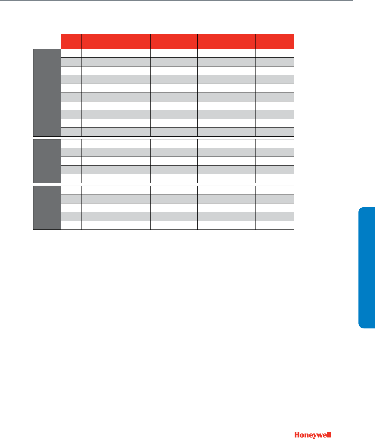
227
Pipe
Size Cv Johnson
Controls Cv Belimo
Model Cv Invensys Cv Honeywell
Model
Bronze Trim, ANSI 125
2-Way Valves
2 1/2" 51 VB-3752-19 65 G665 56 VB-9213-0-5-12 63 V3351A2008
3" 83 VB-3752-22 90 G680 85 VB-9213-0-5-13 100 V3351A3006
4" 150 VB-3752-25 170 G6100 145 VB-9213-0-5-14 160 V3351A4004
5" 240 VB-3752-28 263 G6125 235 VB-9213-0-5-15 250 V3351A5001
6" 350 VB-3752-31 344 G6150 350 VB-9213-0-5-16 400 V3351A6009
2 1/2" 51 VB-3970-11 56 VB-9223-0-5-12 63 V3351C2004
3" 83 VB-3970-14 85 VB-9223-0-5-13 100 V3351C3002
4" 150 VB-3970-17 145 VB-9223-0-5-14 160 V3351C4000
5" 240 VB-3970-20 235 VB-9223-0-5-15 250 V3351C5007
6" 350 VB-3970-23 350 VB-9223-0-5-16 400 V3351C6005
Mixing,
A N S I 1 2 5
3-Way Valves
2 1/2" 54 VB-4322-9 68 G765 56 VB-9313-0-5-12 63 V3360E2008
3" 80 VB-4322-11 91 G780 85 VB-9313-0-5-13 100 V3360E3006
4" 157 VB-4322-13 190 G7100 145 VB-9313-0-5-14 160 V3360E4004
5" 238 VB-4322-19 280 G7125 235 VB-9313-0-5-15 250 V3360E5001
6" 347 VB-4322-18 340 G7150 350 VB-9313-0-5-16 400 V3360E6009
Diverting,
A N S I 1 2 5
3-Way Valves
2 1/2" 38 G765D 56 VB-9323-0-5-12 63 V5013C1001
3" 85 G780D 85 VB-9323-0-5-13 100 V5013C1019
4" 154 G7100D 145 VB-9323-0-5-14 160 V5013C1027
5" 195 G7125D 235 VB-9323-0-5-15 250 V5013C1035
6" 248 G7150D 350 VB-9323-0-5-16 360 V5013C1043
CROSS REFERENCE
Globe Valve Cross Reference
Flanged Globe Valves
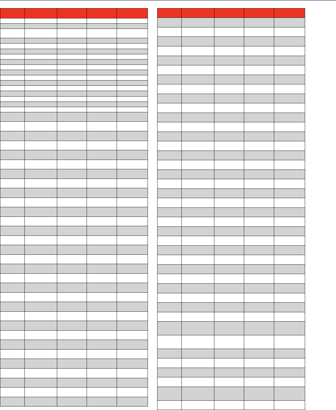
228
Pneumatics Cross Reference
ITEM
NUMBER MANUFACTURER REPLACEMENT
ITEM
TYPE OF
REPLACEMENT REMARKS
2463-863 ROBERTSHAW MP516A1087 FUNCTIONAL
2464-861 ROBERTSHAW MP516A1087 FUNCTIONAL
2466-011 ROBERTSHAW MP920B1002 with
14004345-001 FUNCTIONAL
2466-051 ROBERTSHAW MP920B1002 FUNCTIONAL
2472-020 ROBERTSHAW MP909D1201 FUNCTIONAL
2472-030 ROBERTSHAW MP909D1227 FUNCTIONAL
2472-040 ROBERTSHAW MP909D1219 FUNCTIONAL
2472-050 ROBERTSHAW MP909A1660 FUNCTIONAL
2472-110 ROBERTSHAW MP909A1041 FUNCTIONAL
2472-120 ROBERTSHAW MP909D1201 FUNCTIONAL
2472-140 ROBERTSHAW MP909D1219 FUNCTIONAL
2473-010 ROBERTSHAW MP909E1018 FUNCTIONAL
2473-020 ROBERTSHAW MP909E1083 FUNCTIONAL
2473-030 ROBERTSHAW MP909E1034 FUNCTIONAL
2473-110 ROBERTSHAW MP909E1018 FUNCTIONAL
2473-120 ROBERTSHAW MP909E1083 FUNCTIONAL
2473-140 ROBERTSHAW MP909E1174 FUNCTIONAL
2474-160 ROBERTSHAW MP909H1331 or
MP918A1024 FUNCTIONAL
2566-002 ROBERTSHAW V5013F1004 with
MP953C1000 FUNCTIONAL
2566-004 ROBERTSHAW V5013F1004 with
MP953C1018 FUNCTIONAL
2566-006 ROBERTSHAW V5013F1004 with
MP953E1319 FUNCTIONAL
2566-008 ROBERTSHAW V5013F1020 with
MP953C1000 FUNCTIONAL
2566-010 ROBERTSHAW V5013F1020 with
MP953C1018 FUNCTIONAL
2566-012 ROBERTSHAW V5013F1020 with
MP953E1319 FUNCTIONAL
2566-014 ROBERTSHAW V5013F1038 with
MP953C1000 FUNCTIONAL
2566-016 ROBERTSHAW V5013F1038 with
MP953C1018 FUNCTIONAL
2566-018 ROBERTSHAW V5013F1038 with
MP953E1319 FUNCTIONAL
2566-020 ROBERTSHAW V5013F1046 with
MP953C1000 FUNCTIONAL
2566-022 ROBERTSHAW V5013F1046 with
MP953C1018 FUNCTIONAL
2566-023 ROBERTSHAW V5013F1046 with
MP953C1319 FUNCTIONAL
2566-025 ROBERTSHAW V5013F1053 with
MP953C1000 FUNCTIONAL
2566-027 ROBERTSHAW V5013F1053 with
MP953C1018 FUNCTIONAL
2566-028 ROBERTSHAW V5013F1053 with
MP953E1319 FUNCTIONAL
2566-030 ROBERTSHAW V5013F1061 with
MP953C1000 FUNCTIONAL
2566-032 ROBERTSHAW V5013F1061 with
MP953C1018 FUNCTIONAL
2566-033 ROBERTSHAW V5013F1061 with
MP953E1319 FUNCTIONAL
2566-102 ROBERTSHAW V5013F1004 with
MP958C1000 FUNCTIONAL
2566-104 ROBERTSHAW V5013F1004 with
MP953C1018 FUNCTIONAL
2566-106 ROBERTSHAW V5013F1004 with
MP953E1319 FUNCTIONAL
2566-108 ROBERTSHAW V5013F1004 with
MP953C1000 FUNCTIONAL
2566-110 ROBERTSHAW V5013F1004 with
MP953C1018 FUNCTIONAL
2566-112 ROBERTSHAW V5013F1004 with
MP953E1319 FUNCTIONAL
2567-001 ROBERTSHAW V5011F1006 with
MP953D1172 FUNCTIONAL
2567-003 ROBERTSHAW V5011F1006 with
MP953D1107 FUNCTIONAL
2567-004 ROBERTSHAW V5011F1006 with
MP953F1119 FUNCTIONAL
2567-005 ROBERTSHAW V5011F1022 with
MP953D1172 FUNCTIONAL
2567-007 ROBERTSHAW V5011F1022 with
MP953D1107 FUNCTIONAL
2567-008 ROBERTSHAW V5011F1022 with
MP953F1119 FUNCTIONAL
ITEM
NUMBER MANUFACTURER REPLACEMENT
ITEM
TYPE OF
REPLACEMENT REMARKS
2567-009 ROBERTSHAW V5011H1022 with
MP953C1000 FUNCTIONAL
2567-011 ROBERTSHAW V5011H1022 with
MP953C1018 FUNCTIONAL
2567-012 ROBERTSHAW V5011H1022 with
MP953E1327 FUNCTIONAL
2567-013 ROBERTSHAW V5011H1022 with
MP953C1000 FUNCTIONAL
2567-015 ROBERTSHAW V5011H1022 with
MP953C1018 FUNCTIONAL
2567-016 ROBERTSHAW V5011H1022 with
MP953E1327 FUNCTIONAL
2567-017 ROBERTSHAW V5011H1028 with
MP953C1000 FUNCTIONAL
2567-019 ROBERTSHAW V5011H1028 with
MP953C1018 FUNCTIONAL
2567-020 ROBERTSHAW V5011H1028 with
MP953E1327 FUNCTIONAL
2567-021 ROBERTSHAW V5011H1036 with
MP953C1000 FUNCTIONAL
2567-023 ROBERTSHAW V5011H1036 with
MP953C1018 FUNCTIONAL
2567-024 ROBERTSHAW V5011H1036 with
MP953E1327 FUNCTIONAL
2567-025 ROBERTSHAW V5011H1044 with
MP953C1000 FUNCTIONAL
2567-027 ROBERTSHAW V5011H1044 with
MP953C1018 FUNCTIONAL
2567-028 ROBERTSHAW V5011H1044 with
MP953E1327 FUNCTIONAL
2567-029 ROBERTSHAW V5011H1089 with
MP953D1172 FUNCTIONAL
2567-031 ROBERTSHAW V5011H1089 with
MP953D1107 FUNCTIONAL
2567-032 ROBERTSHAW V5011H1089 with
MP953F1119 FUNCTIONAL
2567-033 ROBERTSHAW V5011H1097 with
MP953D1172 FUNCTIONAL
2567-035 ROBERTSHAW V5011H1097 with
MP953D1107 FUNCTIONAL
2567-036 ROBERTSHAW V5011H1097 with
MP953F1119 FUNCTIONAL
2568-003 ROBERTSHAW V5011F1014 with
MP953C1018 FUNCTIONAL
2568-004 ROBERTSHAW V5011F1014 with
MP953C1000 FUNCTIONAL
2568-005 ROBERTSHAW V5011F1014 with
MP953E1327 FUNCTIONAL
2568-008 ROBERTSHAW V5011F1022 with
MP953C1018 FUNCTIONAL
2568-009 ROBERTSHAW V5011F1022 with
MP953C1000 FUNCTIONAL
2568-010 ROBERTSHAW V5011F1022 with
MP953E1327 FUNCTIONAL
2568-013 ROBERTSHAW V5011F1030 with
MP953C1018 FUNCTIONAL
2568-014 ROBERTSHAW V5011F1030 with
MP953C1000 FUNCTIONAL
2568-015 ROBERTSHAW V5011F1030 with
MP953E1327 FUNCTIONAL
2568-018 ROBERTSHAW V5011F1055 with
MP953C1018 FUNCTIONAL
2568-019 ROBERTSHAW V5011F1055 with
MP953C1000 FUNCTIONAL 3 psi positioner
span
2568-020 ROBERTSHAW V5011F1055 with
MP953E1327 FUNCTIONAL
External Only,
3 psi positioner
span
2568-023 ROBERTSHAW V5011F1063 with
MP953C1018 FUNCTIONAL
External Only,
5 psi positioner
span
2568-024 ROBERTSHAW V5011F1063 with
MP953C1000 FUNCTIONAL
2568-025 ROBERTSHAW V5011F1063 with
MP953E1327 FUNCTIONAL
2568-028 ROBERTSHAW V5011F1071 with
MP953C1018 FUNCTIONAL
2568-029 ROBERTSHAW V5011F1071 with
MP953C1000 FUNCTIONAL
2568-030 ROBERTSHAW V5011F1071 with
MP953E1327 FUNCTIONAL
External Only,
10 psi positioner
span
2568-033 ROBERTSHAW V5011F1089 with
MP953C1018 FUNCTIONAL
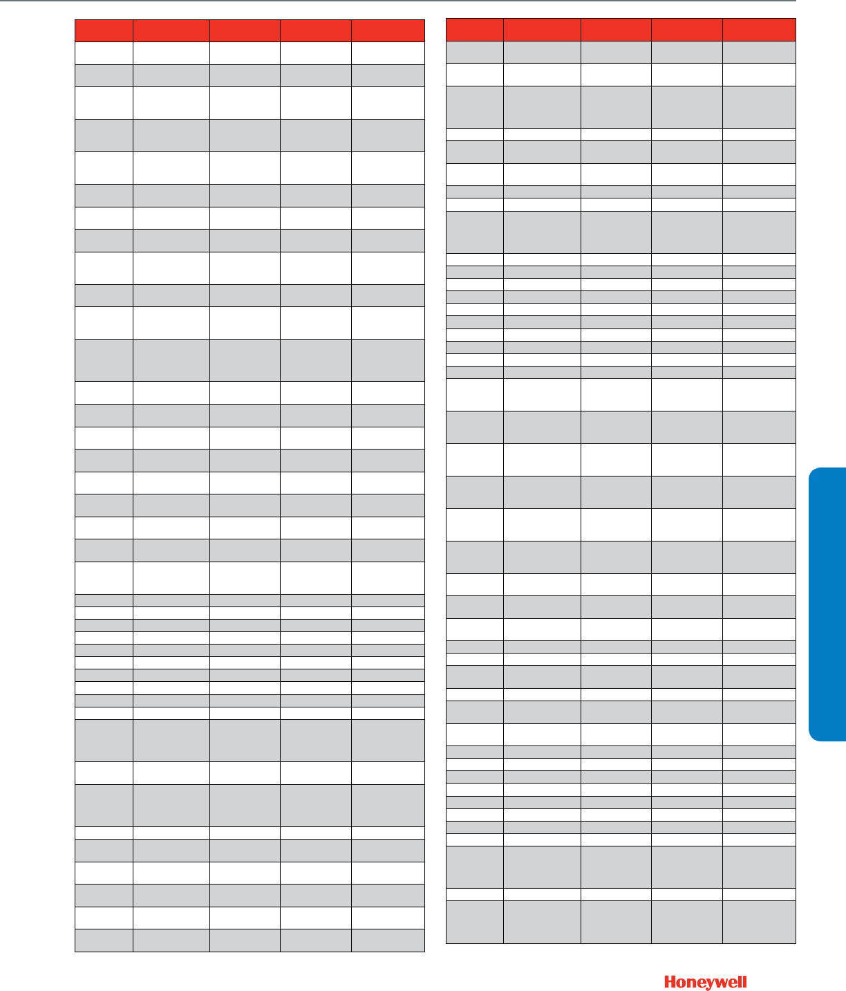
229
CROSS REFERENCE
Pneumatics Cross Reference
ITEM
NUMBER MANUFACTURER REPLACEMENT
ITEM
TYPE OF
REPLACEMENT REMARKS
2568-034 ROBERTSHAW V5011F1089 with
MP953C1000 FUNCTIONAL
2568-035 ROBERTSHAW V5011F1089 with
MP953E1327 FUNCTIONAL
2568-038 ROBERTSHAW V5011F1097 with
MP953C1018 FUNCTIONAL
Internal normally
close only, 3 psi
positioner span
2568-039 ROBERTSHAW V5011F1097 with
MP953C1000 FUNCTIONAL
Internal normally
close only, 5 psi
positioner span
2568-040 ROBERTSHAW V5011F1097 with
MP953E1327 FUNCTIONAL
Internal normally
close only, 10 psi
positioner span
657-8225 POWERS/LANDIS
& GYR
V5013F1020 with
MP953C1018 FUNCTIONAL
658-0026 POWERS/LANDIS
& GYR
V5013F1004 with
MP953C1000 FUNCTIONAL 5 psi positioner
span
658-0028 POWERS/LANDIS
& GYR
V5013F1020 with
MP953C1000 FUNCTIONAL 10 psi positioner
span
D101 JOHNSON
CONTROLS
MP909D1201 or
MP909D1219 or
MP909D1227
FUNCTIONAL
D103 JOHNSON
CONTROLS
MP909E1083 or
MP909E1174 FUNCTIONAL
D251 JOHNSON
CONTROLS
MP909D1201 or
MP909D1219 or
MP909D1227
FUNCTIONAL External Only
D251(4) JOHNSON
CONTROLS
MP918B1030 or
MP918B1113 or
MP918B1139 or
MP918B1147
FUNCTIONAL
D251(6) JOHNSON
CONTROLS MP920B1002 FUNCTIONAL External Only
D3031-3 JOHNSON
CONTROLS MP913A1052 FUNCTIONAL Internal normally
closed only
D3070-1 JOHNSON
CONTROLS MP516A1087 FUNCTIONAL
D3073-2 JOHNSON
CONTROLS MP909E1174 FUNCTIONAL Internal normally
closed only
D3073-3 JOHNSON
CONTROLS MP909E1034 FUNCTIONAL
D3073-7 JOHNSON
CONTROLS MP909E1083 FUNCTIONAL
D3153-2 JOHNSON
CONTROLS MP918B1089 FUNCTIONAL
D3153-3 JOHNSON
CONTROLS MP918B1048 FUNCTIONAL
M556-14 ROBERTSHAW
MP920B1002
with 14004345-
001
FUNCTIONAL
M556-51 ROBERTSHAW MP920B1002 FUNCTIONAL
M572-2311 ROBERTSHAW MP909A1041 FUNCTIONAL
M572-3308 ROBERTSHAW MP909D1227 FUNCTIONAL
M572-5311 ROBERTSHAW MP909D1219 FUNCTIONAL
M572-6308 ROBERTSHAW MP913A1660 FUNCTIONAL
M572-8311 ROBERTSHAW MP909D1201 FUNCTIONAL
M573-2108 ROBERTSHAW MP909E1018 FUNCTIONAL
M573-2111 ROBERTSHAW MP909E1018 FUNCTIONAL
M573-3108 ROBERTSHAW MP909E1034 FUNCTIONAL
M573-5111 ROBERTSHAW MP909E1174 FUNCTIONAL External Only
M573-8111 ROBERTSHAW MP909E1083 FUNCTIONAL
For unitary
applications,
consult technical
support.
M574-1211 ROBERTSHAW MP909H1331 or
MP918A1024 FUNCTIONAL External Only
M583-0520 ROBERTSHAW MP516A1087 FUNCTIONAL
For unitary
applications,
consult technical
support.
M584 ROBERTSHAW MP516A1087 FUNCTIONAL
MK3101 BARBER COLMAN MP909E1083 or
MP918B1063 FUNCTIONAL
MK3111 BARBER COLMAN MP909E1034 or
MP918B1048 FUNCTIONAL Internal normally
closed only
MK3121 BARBER COLMAN MP909E1174 or
MP918B1097 FUNCTIONAL Internal normally
closed only
MK3141 BARBER COLMAN MP909E1018 or
MP918B1006 FUNCTIONAL
MK3201 BARBER COLMAN MP909E1083 or
MP918B1063 FUNCTIONAL
ITEM
NUMBER MANUFACTURER REPLACEMENT
ITEM
TYPE OF
REPLACEMENT REMARKS
MK3211 BARBER COLMAN MP909E1034 or
MP918B1048 FUNCTIONAL External Only
MK3221 BARBER COLMAN MP909E1174 or
MP918B1063 FUNCTIONAL External Only
MK4-3101 BARBER COLMAN MP909H1331 FUNCTIONAL
For unitary
applications,
consult technical
support.
MK4-3111 BARBER COLMAN MP909H1331 FUNCTIONAL
MK4-3121 BARBER COLMAN MP909H1331 FUNCTIONAL Internal normally
closed only
MK4-3141 BARBER COLMAN MP909H1331 FUNCTIONAL Internal normally
closed only
MK4-3801 BARBER COLMAN MP909H1331 FUNCTIONAL
MK4-3811 BARBER COLMAN MP909H1331 FUNCTIONAL
MK4-3821 BARBER COLMAN MP909H1331 FUNCTIONAL
For unitary
applications,
consult technical
support.
MK4-3841 BARBER COLMAN MP909H1331 FUNCTIONAL
MK4401 BARBER COLMAN MP516A1095 FUNCTIONAL
MK4411 BARBER COLMAN MP516A1103 FUNCTIONAL
MK4421 BARBER COLMAN MP909E1158 FUNCTIONAL
MK4451 BARBER COLMAN MP516A1087 FUNCTIONAL
MK4461 BARBER COLMAN MP516A1087 FUNCTIONAL
MK4-7101 BARBER COLMAN MP918A1024 FUNCTIONAL
MK4-7121 BARBER COLMAN MP918A1024 FUNCTIONAL
MK7101 BARBER COLMAN MP918B1063 FUNCTIONAL
MK7121 BARBER COLMAN MP918B1089 FUNCTIONAL
MP904A1145 HONEYWELL MP918A1008 FUNCTIONAL
External Only,
3 psi positioner
span
MP904A1145 HONEYWELL MP918A1016 FUNCTIONAL
External Only,
5 psi positioner
span
MP904A1145 HONEYWELL MP918A1024 FUNCTIONAL
External Only,
10 psi positioner
span
MP904A1145 HONEYWELL MP918A1032 FUNCTIONAL
Internal normally
close only, 3 psi
positioner span
MP904A1145 HONEYWELL MP918A1040 FUNCTIONAL
Internal normally
close only, 5 psi
positioner span
MP904A1145 HONEYWELL MP918A1057 FUNCTIONAL
Internal normally
close only, 10 psi
positioner span
MP904A1152 HONEYWELL MP917A1065 FUNCTIONAL 3 psi positioner
span
MP904A1152 HONEYWELL MP918A1073 FUNCTIONAL 5 psi positioner
span
MP904A1152 HONEYWELL MP918A1081 FUNCTIONAL 10 psi positioner
span
MP904A1186 HONEYWELL MP918A1099 FUNCTIONAL
MP904B1028 HONEYWELL MP918B1006 FUNCTIONAL External Only
MP904B1028 HONEYWELL MP918B1014 FUNCTIONAL Internal normally
closed only
MP904B1093 HONEYWELL MP918B1063 FUNCTIONAL External Only
MP904B1093 HONEYWELL MP918B1071 FUNCTIONAL Internal normally
closed only
MP904B1101 HONEYWELL MP918B1097 FUNCTIONAL Internal normally
closed only
MP904B1101 HONEYWELL MP918B1089 FUNCTIONAL External Only
MP904B1119 HONEYWELL MP918B1014 FUNCTIONAL
MP904B1127 HONEYWELL MP918B1022 FUNCTIONAL
MP904B1135 HONEYWELL MP918B1105 FUNCTIONAL
MP904B1150 HONEYWELL MP918B1030 FUNCTIONAL
MP904C1026 HONEYWELL MP918A1024 FUNCTIONAL
MP904C1328 HONEYWELL MP918B1006 FUNCTIONAL
MP904C1377 HONEYWELL MP918B1030 FUNCTIONAL
MP909A1041 MIRCOSWITCH
MP909D1227
with 14002850-
001 with
312867H
FUNCTIONAL
MP909A1132 HONEYWELL MP909A1652 FUNCTIONAL
MP909A1637 MIRCOSWITCH
MP909D1227
with 14002850-
001 with
312867H
FUNCTIONAL
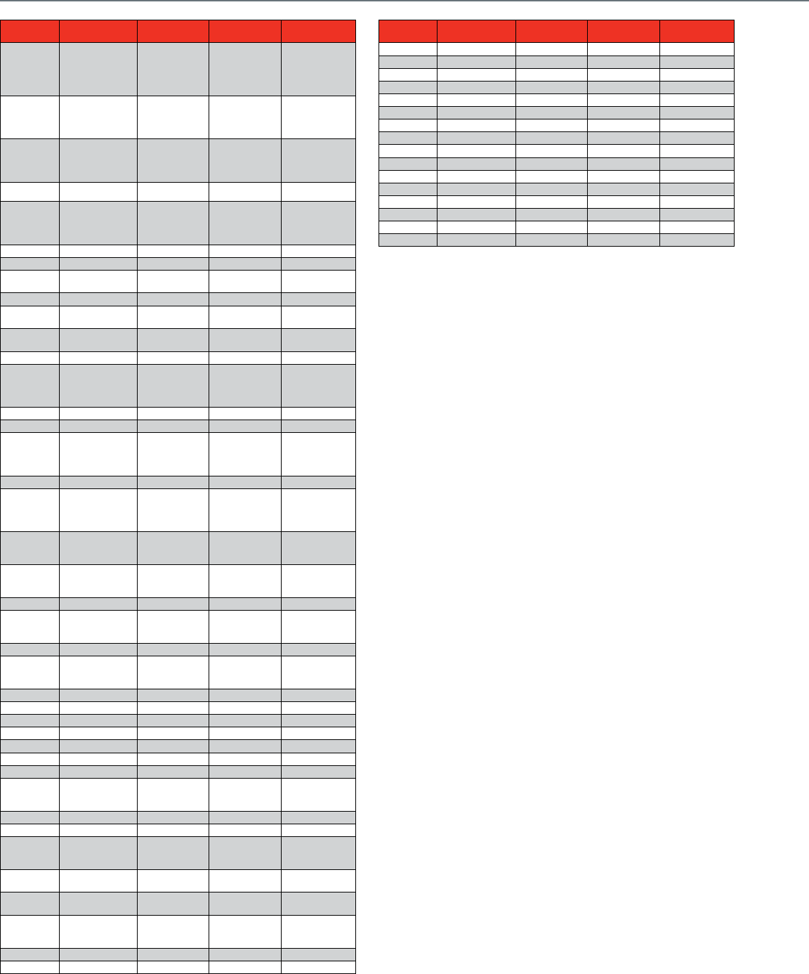
230
Pneumatics Cross Reference
ITEM
NUMBER MANUFACTURER REPLACEMENT
ITEM
TYPE OF
REPLACEMENT REMARKS
MP909A1645 HONEYWELL
MP909D1227
with 14002850-
001 with
312867H with
14002061-001
FUNCTIONAL
MP909A1652 MIRCOSWITCH
MP909D1201
with 14002850-
001 with
312867H
FUNCTIONAL
MP909A1660 MIRCOSWITCH
MP909D1219
with 14002850-
001 with
312867H
FUNCTIONAL
MP909A1744 MP909E1232 FUNCTIONAL
MP909C1021 HONEYWELL MP918B1063 FUNCTIONAL
For unitary
applications,
consult technical
support.
MP909C1047 HONEYWELL MP918B1048 FUNCTIONAL
MP909C1054 HONEYWELL MP918B1006 FUNCTIONAL External Only
MP909C1054 HONEYWELL MP918B1014 FUNCTIONAL Internal normally
closed only
MP909C1161 HONEYWELL MP918B1063 FUNCTIONAL External Only
MP909C1161 HONEYWELL MP918B1071 FUNCTIONAL Internal normally
closed only
MP909C1179 HONEYWELL MP918B1097 FUNCTIONAL Internal normally
closed only
MP909C1179 HONEYWELL MP918B1089 FUNCTIONAL External Only
MP909C1187 HONEYWELL MP918B1113 FUNCTIONAL
For unitary
applications,
consult technical
support.
MP909C1286 HONEYWELL MP918B1048 FUNCTIONAL
MP909C1294 HONEYWELL MP918B1022 FUNCTIONAL
MP909C1310 HONEYWELL MP918B1063 FUNCTIONAL
For unitary
applications,
consult technical
support.
MP909C1336 HONEYWELL MP918B1063 FUNCTIONAL
MP909C1344 HONEYWELL MP918B1089 FUNCTIONAL
For unitary
applications,
consult technical
support.
MP909D1268 MIRCOSWITCH
MP909D1201
with 14003640-
001
DIRECT
MP909D1292 MIRCOSWITCH
MP909D1227
with
315439/00062
FUNCTIONAL
MP909D1300 HONEYWELL MP909D1201 FUNCTIONAL
MP909D1359 MIRCOSWITCH
MP909D1201
with 14003640-
001 with 315781
FUNCTIONAL
MP909E1265 HONEYWELL MP909E1232 FUNCTIONAL
MP909E1497 MIRCOSWITCH
MP909D1201
with 14003640-
001 with 315781
FUNCTIONAL
MP909E1505 HONEYWELL MP909E1034 FUNCTIONAL
MP909H1459 HONEYWELL MP909H1392 FUNCTIONAL
MP913A1045 HONEYWELL MP913A1037 FUNCTIONAL
MP918A1115 HONEYWELL MP918A1024 FUNCTIONAL
MP918A1123 HONEYWELL MP918A1057 FUNCTIONAL
MP918A115 HONEYWELL MP918A1024 FUNCTIONAL
MP918B1220 HONEYWELL MP918B1063 FUNCTIONAL
MP920A1004 HONEYWELL
MP920B1002
with 14004345-
001
DIRECT
MP953D1222 HONEYWELL MP953D1131 FUNCTIONAL
MP953D1255 HONEYWELL MP953D1172 FUNCTIONAL
MP953E1392 MIRCOSWITCH
MP953E1400
with 14004212-
001
DIRECT
PM331 POWERS/LANDIS
& GYR MP920B1002 FUNCTIONAL
PM331-4X3H POWERS/LANDIS
& GYR MP516A1087 FUNCTIONAL
PM331LC POWERS/LANDIS
& GYR
MP920B1002
with 14004345-
001
FUNCTIONAL
2567-016 ROBERTSHAW MP953E1327 FUNCTIONAL
2567-020 ROBERTSHAW MP953E1327 FUNCTIONAL
ITEM
NUMBER MANUFACTURER REPLACEMENT
ITEM
TYPE OF
REPLACEMENT REMARKS
2567-024 ROBERTSHAW MP953E1327 FUNCTIONAL
2567-028 ROBERTSHAW MP953E1327 FUNCTIONAL
2568-005 ROBERTSHAW MP953E1327 FUNCTIONAL
2568-010 ROBERTSHAW MP953E1327 FUNCTIONAL
2568-015 ROBERTSHAW MP953E1327 FUNCTIONAL
2568-020 ROBERTSHAW MP953E1327 FUNCTIONAL
2568-025 ROBERTSHAW MP953E1327 FUNCTIONAL
2568-030 ROBERTSHAW MP953E1327 FUNCTIONAL
2568-035 ROBERTSHAW MP953E1327 FUNCTIONAL
2568-040 ROBERTSHAW MP953E1327 FUNCTIONAL
MP953E1392 MIRCOSWITCH MP953E1400 DIRECT
2567-004 ROBERTSHAW MP953F1119 FUNCTIONAL
2567-008 ROBERTSHAW MP953F1119 FUNCTIONAL
2567-032 ROBERTSHAW MP953F1119 FUNCTIONAL
2567-036 ROBERTSHAW MP953F1119 FUNCTIONAL
2566-102 ROBERTSHAW MP958C1000 FUNCTIONAL
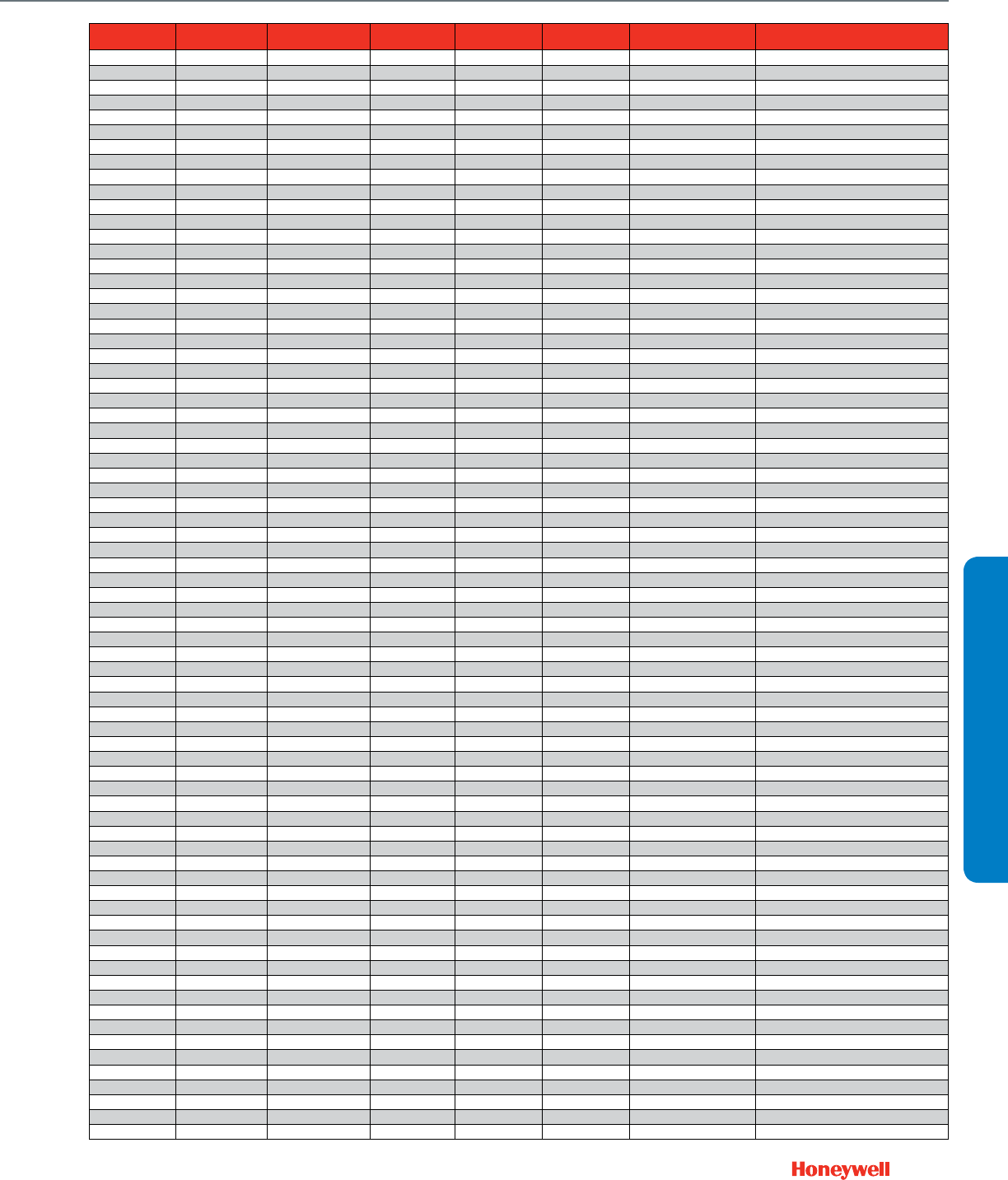
231
CROSS REFERENCE
Modutrol IV Motor Cross Reference
ITEM NUMBER REPL TYPE REPL ITEM MULTI REPL REPL SEQ CHANNEL
(BUSI GROUP) MFG NAME CUSTOMER REMARKS
2005377 FUNCTIONAL M934A1334/U 1TRADE SINGER CO
612804451 FUNCTIONAL M945D1006/U 1 TRADE HARTZELL PROP
203762E/U FUNCTIONAL M8185D1006/U WITH 1 TRADE
2061-1 FUNCTIONAL M835A1051/U 1 TRADE WHITE RODGERS
3402-7 FUNCTIONAL M8415A1004/U 1 TRADE WHITE RODGERS
3402A-7 FUNCTIONAL M8415A1004/U 1 TRADE WHITE RODGERS
3403-4 FUNCTIONAL M8405A1006/U 1 TRADE WHITE RODGERS
3405-11 FUNCTIONAL M836A1042/U 1 TRADE WHITE RODGERS
3405-14 FUNCTIONAL M836A1042/U 1 TRADE WHITE RODGERS
3405-15 FUNCTIONAL M836B1033/U 1 TRADE WHITE RODGERS
3405-2 FUNCTIONAL M836A1042/U 1 TRADE WHITE RODGERS
3405-3 FUNCTIONAL M836A1042/U 1 TRADE WHITE RODGERS
3405A-11 FUNCTIONAL M436A1116/U 1 TRADE WHITE RODGERS
3405A-2 FUNCTIONAL M436A1116/U 1 TRADE WHITE RODGERS
3420-4 FUNCTIONAL M9175D1014/U 1 TRADE WHITE RODGERS
3420A-4 FUNCTIONAL M9175D1014/U WITH 1 TRADE WHITE RODGERS
3430-18 DIRECT M7975E1009/U 1 TRADE WHITE RODGERS
3430-21 DIRECT M7975E1009/U 1 TRADE WHITE RODGERS
3430-7 FUNCTIONAL M7415A1006/U 1 TRADE WHITE RODGERS
3440-4 FUNCTIONAL M9184D1013/U OR 1 TRADE WHITE RODGERS
3440-4 FUNCTIONAL M9184A1019/U 2 TRADE WHITE RODGERS
430-2625 FUNCTIONAL M934A1326/U 1 TRADE ITT GENERAL CONTROLS
430-2630 FUNCTIONAL M934A1334/U 1 TRADE ITT GENERAL CONTROLS
474-4-7914 FUNCTIONAL M934A1318/U 1 TRADE ITT GENERAL CONTROLS
4EQZ-3898 FUNCTIONAL M945D1006/U 1 TRADE AM AIR FILTER
4EZB3762A FUNCTIONAL M945H 1002 1 TRADE AM AIR FILTER
4EZB-3762A FUNCTIONAL M945H 1002 1 TRADE AM AIR FILTER
4EZB-3919A FUNCTIONAL M945D1006/U 1 TRADE AM AIR FILTER
4EZB-4109 FUNCTIONAL M945D1006/U 1 TRADE AM AIR FILTER
8414-00 FUNCTIONAL M644C1006/U 1 TRADE MID-CONT METL
894-1072 FUNCTIONAL M644E 1004 1 TRADE IND COMBUSTION
AE107 FUNCTIONAL M945D1006/U 1 TRADE AM AIR FILTER
AV8050-1008 FUNCTIONAL M6410A1003/U OR 2 TRADE JOHNSON CONTROLS
AV8050-1008 FUNCTIONAL M6410A1011/U 3 TRADE JOHNSON CONTROLS
AV8050-1009 FUNCTIONAL M6410A1003/U OR 2 TRADE JOHNSON CONTROLS
AV8050-1009 FUNCTIONAL M6410A1011/U 3 TRADE JOHNSON CONTROLS
D55759-1 FUNCTIONAL M745A1003/U 1 TRADE AMANA
DM4BB00000000 FUNCTIONAL M944A1010/U OR 1 TRADE ITT GENERAL CONTROLS
DM4BB00000000 FUNCTIONAL M934A1342/U 2 TRADE ITT GENERAL CONTROLS
HF25AA001 FUNCTIONAL M944B1191/U 1 TRADE CARRIER
IR-410-2341 FUNCTIONAL M954A1035/U 1 TRADE NORTH AM MFG
IR-410-2351 FUNCTIONAL M644B1049/U 1 TRADE NORTH AM MFG
M110AAB-1 FUNCTIONAL M8185D1006/U WITH 1 TRADE JOHNSON CONTROLS
M110AGA-1 FUNCTIONAL M8185D1006/U OR 1 TRADE JOHNSON CONTROLS
M110AGA-1 FUNCTIONAL M8175B1002/U 2 TRADE JOHNSON CONTROLS
M110AGB-1 FUNCTIONAL M8185D1006/U WITH 1 TRADE JOHNSON CONTROLS
M110AGB-1 FUNCTIONAL M8175B1002/U 3 TRADE JOHNSON CONTROLS
M110GGA-1 FUNCTIONAL M9175D1014/U WITH 1 TRADE JOHNSON CONTROLS
M110JGA-1 FUNCTIONAL M9175D1014/U 1 TRADE JOHNSON CONTROLS
M110JGB-1 FUNCTIONAL M9175D1014/U WITH 1 TRADE JOHNSON CONTROLS
M120AAA-1 FUNCTIONAL M6184D1035/U WITH 1 TRADE JOHNSON CONTROLS
M120AAC-1 FUNCTIONAL M6184D1035/U WITH 1 TRADE JOHNSON CONTROLS
M120AGA-1 FUNCTIONAL M6184D1035/U OR 1 TRADE JOHNSON CONTROLS
M120AGA-1 FUNCTIONAL M6184F1006/U 2 TRADE JOHNSON CONTROLS
M120GGA-1 FUNCTIONAL M9164D1009/U WITH 1 TRADE JOHNSON CONTROLS
M120JAA-1 FUNCTIONAL M9164D1009/U WITH 1 TRADE JOHNSON CONTROLS
M120JAC-1 FUNCTIONAL M9164D1009/U WITH 1 TRADE JOHNSON CONTROLS
M120JAC-1 FUNCTIONAL M9164C1019/U 3 TRADE JOHNSON CONTROLS
M120JGA-1 FUNCTIONAL M9164D1009/U OR 1 TRADE JOHNSON CONTROLS
M120JGA-1 FUNCTIONAL M9164A1021 2 TRADE JOHNSON CONTROLS
M130AAB-1 FUNCTIONAL M8185D1006/U WITH 1 TRADE JOHNSON CONTROLS
M130AAB-1 FUNCTIONAL M4185B1017/U 4 TRADE JOHNSON CONTROLS
M130AGA-1 FUNCTIONAL M8185D1006/U OR 1 TRADE JOHNSON CONTROLS
M130AGA-1 FUNCTIONAL M8185B1000/U 2 TRADE JOHNSON CONTROLS
M130AGB-1 FUNCTIONAL M8185D1006/U WITH 1 TRADE JOHNSON CONTROLS
M130AGB-1 FUNCTIONAL M8185B1000/U 3 TRADE JOHNSON CONTROLS
M130GGA-1 FUNCTIONAL M9185D1004/U WITH 1 TRADE JOHNSON CONTROLS
M130JGA-1 FUNCTIONAL M9185D1004/U OR 1 TRADE JOHNSON CONTROLS
M130JGA-1 FUNCTIONAL M9185A1018/U 2 TRADE JOHNSON CONTROLS
M130JGB-1 FUNCTIONAL M9185D1004/U WITH 1 TRADE JOHNSON CONTROLS
M130JGB-1 FUNCTIONAL M9185E1019 3 TRADE JOHNSON CONTROLS
M140AAA-1 FUNCTIONAL M6184D1035/U 1 TRADE JOHNSON CONTROLS
M140AGA-1 FUNCTIONAL M6184D1035/U 1 TRADE JOHNSON CONTROLS

232
Modutrol IV Motor Cross Reference
ITEM NUMBER REPL TYPE REPL ITEM MULTI REPL REPL SEQ CHANNEL
(BUSI GROUP) MFG NAME CUSTOMER REMARKS
M140GGA-1 FUNCTIONAL M9174D1007/U WITH 1 TRADE JOHNSON CONTROLS
M140JAA-1 FUNCTIONAL M9174D1007/U WITH 1 TRADE JOHNSON CONTROLS
M140JGA-1 FUNCTIONAL M9174D1007/U 1 TRADE JOHNSON CONTROLS
M150AGA-1 FUNCTIONAL M6184D1035/U 1 TRADE JOHNSON CONTROLS
M150AGB-1 FUNCTIONAL M6184D1035/U WITH 1 TRADE JOHNSON CONTROLS
M150AGB-1 FUNCTIONAL M6184F1017/u 3 TRADE JOHNSON CONTROLS
M150GGA-1 FUNCTIONAL M9184D1013/U WITH 1 TRADE JOHNSON CONTROLS
M150GGA-1 FUNCTIONAL M7284Q1017/U 3 TRADE JOHNSON CONTROLS
M150JGA-1 FUNCTIONAL M9184D1021/u OR 1 TRADE JOHNSON CONTROLS
M150JGA-1 FUNCTIONAL M9184A1019/U 2 TRADE JOHNSON CONTROLS
M150JGB-1 FUNCTIONAL M9184D1021/U WITH 1 TRADE JOHNSON CONTROLS
M150JGB-1 FUNCTIONAL M9184F1034/U 3 TRADE JOHNSON CONTROLS
M150JGC-1 FUNCTIONAL M9184D1021/U WITH 1 TRADE JOHNSON CONTROLS
M150JGC-1 FUNCTIONAL M9184F1034/U 3 TRADE JOHNSON CONTROLS
M150QGA-1 FUNCTIONAL M7284Q1017/u 0 ALL JOHNSON CONTROLS
M40AAA-1 FUNCTIONAL M9164D1009/U WITH 1 TRADE JOHNSON CONTROLS
M40AAA-1 FUNCTIONAL M9164A1005/U 3 TRADE JOHNSON CONTROLS
M40AAC-1 FUNCTIONAL M9164D1009/U WITH 1 TRADE JOHNSON CONTROLS
M40AAC-1 FUNCTIONAL M9164C1068/U 4 TRADE JOHNSON CONTROLS
M40AGA-1 FUNCTIONAL M6184D1035/U OR 1 TRADE JOHNSON CONTROLS
M40AGA-1 FUNCTIONAL M6184A1015/U 2 TRADE JOHNSON CONTROLS
M40AGC-1 FUNCTIONAL M9164D1009/U WITH 1 TRADE JOHNSON CONTROLS
M410GGA-1 FUNCTIONAL M9174D1007/U WITH 1 TRADE JOHNSON CONTROLS
M4175D1015/U DIRECT M4185B1058/U 1 ALL
M4175E1012/U FUNCTIONAL M8185D1006/U WITH 1 ALL HONEYWELL
M4182A1004/P DIRECT M4185A1001/U 1 ALL
M4182A1004/U DIRECT M4185A1001/U WITH 1 ALL
M4182A1004/U FUNCTIONAL M4185A1001/U ALL
M4182B1002/P DIRECT M4185B1009/U WITH 1 ALL
M4182B1002/U DIRECT M4185B1009/U WITH 1 ALL
M4182B1010/U DIRECT M8185D1006/U WITH 1 ALL HONEYWELL
M4182B1028/U FUNCTIONAL M8185D1006/U WITH 1 ALL HONEYWELL
M4182B1036/P DIRECT M4185B1009/U WITH 1 ALL
M4182B1036/U DIRECT M4185B1009/U WITH 1 ALL
M4182B1036/U FUNCTIONAL M4185B1058/U ALL
M4182B1044/U DIRECT M4185B1058/U WITH 1 ALL
M4182B1044/U FUNCTIONAL M4185B1058/U ALL
M4182B1051/U DIRECT M4185B1058/U WITH 1 ALL
M4185A1027/U DIRECT M8185D1006/U WITH 1 ALL HONEYWELL
M4185A1027/U FUNCTIONAL M4185A1001 3 ALL HONEYWELL
M4185B1017/U DIRECT M4185B1058/U 1 ALL
M4185B1025/U DIRECT M4185B 1074 1 ALL HONEYWELL
M4185B1025/U DIRECT M8185D1006/U WITH ALL
M4185B1033/U DIRECT M4185B1009/U WITH 1 ALL
M4185B1041/U DIRECT M8185D1006/U WITH 1 TRADE HONEYWELL
M4185B1041/U FUNCTIONAL M4185B1025/U WITH 4 TRADE HONEYWELL
M4185B1066/U DIRECT M8185D1006/U WITH 1 ALL HONEYWELL
M4185B1066/U FUNCTIONAL M4185B1058 4 ALL HONEYWELL
M4185D1013/U DIRECT M8185D1006/u WITH 1 ALL HONEYWELL
M4185E1010/U DIRECT M8185D1006/u WITH 1 ALL HONEYWELL
M4186H1005/U DIRECT M8185D1006/U WITH 1 ALL HONEYWELL
M4186H1005/U FUNCTIONAL M4185B1009 ALL
M4186L4000/U FUNCTIONAL M8185D1006/U WITH 1 ALL HONEYWELL
M445A1000/U DIRECT M8185D1006/U WITH 1 TRADE HONEYWELL
M445A1000/U FUNCTIONAL M4185B1009/U 4 TRADE HONEYWELL
M445A1042/U DIRECT M8185D1006/U WITH 1 TRADE HONEYWELL
M445A1042/U FUNCTIONAL M4185B1058/U 4 TRADE HONEYWELL
M445A1067/U DIRECT M8185D1006/U WITH 1 TRADE HONEYWELL
M445A1067/U FUNCTIONAL M4185B1058/U WITH 4 TRADE HONEYWELL
M445C1008/U DIRECT M8185D1006/U WITH 1 TRADE HONEYWELL
M445C1008/U FUNCTIONAL M4185B1009/U 4 TRADE HONEYWELL
M445D1007/U DIRECT M8185D1006/U WITH 1 TRADE HONEYWELL
M445D1007/U FUNCTIONAL M4185A1001/U 3 TRADE HONEYWELL
M6161A1004/U TRADE EQUIV M6184A1023/U 1 ALL
M6161A1004/U FUNCTIONAL M6184A1015/U TRADE
M6161B1002/U DIRECT M6184D1035/U WITH 1 ALL HONEYWELL
M6174A1009/U FUNCTIONAL M6184D1035/U 1 ALL HONEYWELL
M6181A1018/U TRADE EQUIV M6184A1015/U 1 ALL
M6181A1026/U DIRECT M6184D1035/U OR 1 TRADE HONEYWELL
M6181A1026/U FUNCTIONAL M6184A1015/U 2 TRADE HONEYWELL
M6181A1034/U TRADE EQUIV M6184A1023/U 1 ALL
M6181A1059/U DIRECT M6184D1035/U 1 ALL
M6181F1009/U TRADE EQUIV M6184F1014/U 1 TRADE
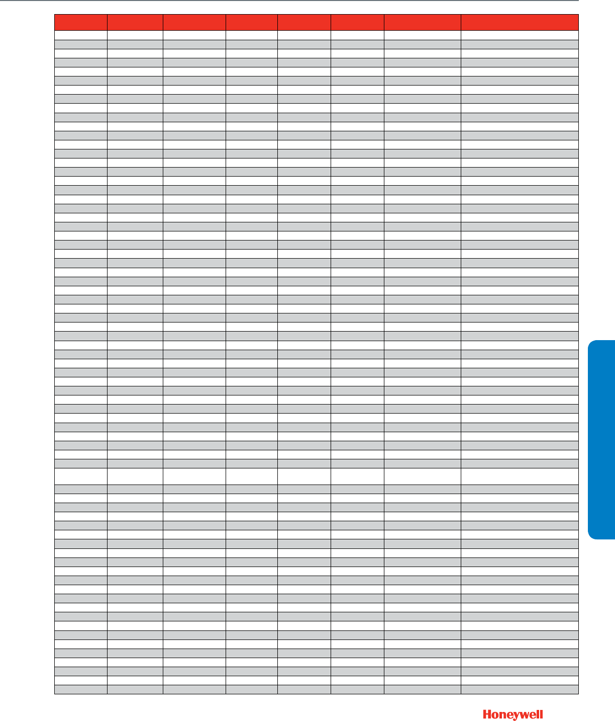
233
CROSS REFERENCE
Modutrol IV Motor Cross Reference
ITEM NUMBER REPL TYPE REPL ITEM MULTI REPL REPL SEQ CHANNEL
(BUSI GROUP) MFG NAME CUSTOMER REMARKS
M6181F1017/U DIRECT M6184D1035/U WITH 1 ALL HONEYWELL
M6181F1017/U FUNCTIONAL M6184F1014/U 1 ALL HONEYWELL
M6182F1016/U FUNCTIONAL M6285A1005-S/U WITH 1 ALL
M6184A1007/U TRADE EQUIV M6184D1035/U 1 ALL
M6184A1049/U DIRECT M6184D1035/U WITH 1 ALL HONEYWELL
M6184A1049/U FUNCTIONAL M6184A1023/U 3 ALL HONEYWELL
M6184B1005/U FUNCTIONAL M6184D1035/U WITH 1 ALL HONEYWELL
M6184B1013/P DIRECT M6184B1013/U 1 ALL
M6184B1021/U DIRECT M6184D1035/U WITH 1 ALL
M6184B1021/U FUNCTIONAL M6184F1014/U ALL
M6184D1050/U DIRECT M6184D1035/u 1 ALL HONEYWELL
M6184D1050/U FUNCTIONAL M6184D1001 2 ALL HONEYWELL
M6184F1006/U FUNCTIONAL M6184F1014/U 1 ALL HONEYWELL
M6184F1006/U DIRECT M6184D1035/U ALL
M6185D1000/U DIRECT M6285A1005/U 1 ALL
M6191A1008/U FUNCTIONAL M6194D1017/U WITH 1 TRADE HONEYWELL
M6191B1006/U DIRECT M6194B1011/U WITH 1 ALL
M6191B1006/U FUNCTIONAL M6194B1011/U ALL
M6191D1002/U FUNCTIONAL M6194D1017/U 1 ALL
M6191D1002/U DIRECT M6294D1008-S/U 1 ALL
M6191D1010/U DIRECT M6194D1017/U WITH 1 ALL HONEYWELL
M6194A1021/U FUNCTIONAL M6194D1017/U 1 TRADE HONEYWELL
M6194B1003/U FUNCTIONAL M6194B1011/U 1 ALL HONEYWELL
M6194B1003/U DIRECT M6194D1017/U WITH ALL HONEYWELL
M6274F1009/U FUNCTIONAL M6274F1009-F/U 1 ALL
M6281F1016/U FUNCTIONAL M6284F1013-S/U 1 ALL
M6282E1009/P DIRECT M6282E1009-F/U 1 ALL
M6282E1009/U FUNCTIONAL M6282E1009-F/U 1 ALL
M6284A1006/U DIRECT M6284D1000-S/U 1 TRADE
M6284A1006/U FUNCTIONAL M6284A1055-S/U 2 TRADE
M6284A1014/U FUNCTIONAL M6284A1055/U 1 ALL HONEYWELL
M6284A1014/U DIRECT M6284D1000/U WITH ALL
M6284A1022/U FUNCTIONAL M6284A1055/U 1 ALL HONEYWELL
M6284A1022/U DIRECT M6284D1000 ALL
M6284A1030/U FUNCTIONAL M6284A1030-S/U 1 ALL
M6284A1048/U DIRECT M6284A1055-S/U 1 ALL
M6284A1055/U FUNCTIONAL M6284A1055-S/U 1 ALL
M6284A1063/U DIRECT M6284D1000-S/U WITH 1 TRADE HONEYWELL
M6284A1071/U FUNCTIONAL M6284A1071-S/U 1 ALL
M6284A1089/U FUNCTIONAL M6284A1089-S/U 1 ALL
M6284A1097/U FUNCTIONAL M6284A1097-S/U 1 ALL
M6284A1113/U DIRECT M6284D1000-S/U WITH 1 ALL
M6284B1004/U FUNCTIONAL M6284B1004-S/U 1 ALL
M6284C1010/U FUNCTIONAL M6284C1010-S/U 1 ALL
M6284C1028/U FUNCTIONAL M6284C1028-S/U 1 ALL
M6284C1036/U FUNCTIONAL M6284D1000-S/U WITH 1 ALL HONEYWELL
M6284C1044/U FUNCTIONAL M6284C1044-S/U 1 ALL
M6284D1000/U FUNCTIONAL M6284D1000-S/U 1 ALL
M6284D1000/U UPGRADE M6284D1032-F/U 1 ALL Same as M6284D1000-s But With Linear
10K Feedback
M6284D1026/U FUNCTIONAL M6284D1026-S/U 1 ALL
M6284D4004/U FUNCTIONAL M6284D4004-S/U 1 ALL
M6284F1005/U DIRECT M6284D1000-S/U WITH 1 TRADE HONEYWELL
M6284F1005/U FUNCTIONAL M6284F1013-S/U 3 TRADE HONEYWELL
M6284F1013/U FUNCTIONAL M6284F1013-S/U 1 ALL
M6284F1021/U DIRECT M6284D1000/U WITH TRADE HONEYWELL
M6284F1021/U FUNCTIONAL M6284F1013/U TRADE HONEYWELL
M6284F1039/U FUNCTIONAL M6284F1039-S/U 1 ALL
M6284F1054/U FUNCTIONAL M6284F1062-S/U WITH 1 ALL
M6284F1062/U FUNCTIONAL M6284F1062-S/U 1 ALL
M6284F1078/U FUNCTIONAL M6284F1078-F/U 1 ALL
M6285A1005/U FUNCTIONAL M6285A1005-S/U 1 ALL
M6285A1013/U DIRECT M6285A1005-S/U 1 ALL
M6285A1039/U FUNCTIONAL M6285A1039-S/U 1 ALL
M6285A1047/U FUNCTIONAL M6285A1047-S/U 1 ALL
M6285A4009/U FUNCTIONAL M6285A4009-S/U 1 ALL
M6285C1001/U FUNCTIONAL M6285C1001-S/U 1 ALL
M6285F1001/U FUNCTIONAL M6285F1001-F/U 1 ALL
M6286G1001/U FUNCTIONAL M6285A1005-S/U 1 ALL
M6286G1019/U FUNCTIONAL M6285A1005/U WITH 1 ALL HONEYWELL
M6294A1004/U DIRECT M6294D1008-S/U WITH 1 ALL HONEYWELL
M6294B1002/U FUNCTIONAL M6294D1008/U WITH 1 ALL HONEYWELL
M6294B1036/U FUNCTIONAL M6294B1036-S/U 1 ALL

234
Modutrol IV Motor Cross Reference
ITEM NUMBER REPL TYPE REPL ITEM MULTI REPL REPL SEQ CHANNEL
(BUSI GROUP) MFG NAME CUSTOMER REMARKS
M6294D1008/U FUNCTIONAL M6294D1008-S/U 1 ALL
M6294F1009/U FUNCTIONAL M6294F1009-F/U 1 ALL
M6294F1017/U FUNCTIONAL M6294F1017-F/U 1 ALL
M640A1006/U FUNCTIONAL M640A1121/U 1 TRADE HONEYWELL
M640B1021/U FUNCTIONAL M640B1062/U 1 TRADE HONEYWELL
M6410A1003/U DIRECT M6410A1029/U 1 TRADE HONEYWELL
M6410A1011/U DIRECT M6410A1029/U 1 TRADE HONEYWELL
M644A1008/U DIRECT M6184D1035/U 1 TRADE HONEYWELL
M644A1016/U DIRECT M6184D1035/U 1 TRADE HONEYWELL
M644A1024/U DIRECT M6184D1035/U OR 1 TRADE HONEYWELL
M644A1024/U FUNCTIONAL M6184A1015/U 2 TRADE HONEYWELL
M644B1007/U DIRECT M6184D1035/U WITH 1 TRADE HONEYWELL
M644B1049/U DIRECT M6184D1035/U WITH 1 TRADE HONEYWELL
M644B1049/U FUNCTIONAL M6184A1023/U 3 TRADE HONEYWELL
M644B1056/U DIRECT M6194D1017/U WITH 1 TRADE HONEYWELL
M644C1006/U DIRECT M6184D1035/U OR 1 TRADE HONEYWELL
M644C1006/U FUNCTIONAL M6184D1001/U 2 TRADE HONEYWELL
M644C1014/U DIRECT M6194D1017/U 1 ALL HONEYWELL
M644D1005/U DIRECT M6184D1035/U WITH 1 TRADE HONEYWELL
M644E1012/U DIRECT M6194D1017/U WITH 1 TRADE HONEYWELL
M6520B1008/U FUNCTIONAL M6410B1001/U 1 ALL HONEYWELL
M6520B1016/U FUNCTIONAL M6410B1001/U 1 ALL HONEYWELL
M7161A1002/U DIRECT M9164D1009/U WITH 1 ALL
M7161G1009/U DIRECT M9164D1009/U WITH 1 ALL HONEYWELL
M7161G1009/U FUNCTIONAL M7164G1030/U ALL HONEYWELL
M7161G1017/U DIRECT M9184D1021/U WITH 1 ALL
M7164A1009/U FUNCTIONAL M9164D1009/U WITH 1 ALL HONEYWELL
M7164B1007/U FUNCTIONAL M9164D1009/U WITH 1 ALL HONEYWELL
M7164G1006/U FUNCTIONAL M7164G1030/U 1 ALL HONEYWELL
M7164G1006/U DIRECT M9164D1009/U WITH ALL HONEYWELL
M7164G1014/U FUNCTIONAL M9164D1009/U WITH 1 ALL HONEYWELL
M7164G1022/U FUNCTIONAL M9164D1009/U WITH 1 ALL HONEYWELL
M7184A1005/U FUNCTIONAL M9184D1021/U WITH 1 ALL HONEYWELL
M7185A1004/U DIRECT M9185D1004/U WITH 1 ALL HONEYWELL
M7186G1000/U FUNCTIONAL M9185D1004/U WITH 1 TRADE HONEYWELL
M7215A1024 TRADE EQUIV M7215A1008 TRADE HONEYWELL
M7272A1008/U FUNCTIONAL M9175D1014/U WITH 1 ALL HONEYWELL
M7274A1006/U DIRECT M9184D1021/U WITH 1 ALL HONEYWELL
M7274G1003/U DIRECT M9184D1021/U WITH 1 ALL HONEYWELL
M7281A1007/U FUNCTIONAL M7284A1004/U 1 ALL HONEYWELL
M7281Q1002/U DIRECT M7284Q1009/U 1 ALL HONEYWELL
M7282A1006/U DIRECT M9185D1004/U WITH 1 ALL HONEYWELL
M7282A1006/U FUNCTIONAL M7285A1003/U ALL HONEYWELL
M7282A1014/P DIRECT M7282A1014/U 1 ALL
M7282C1002/U FUNCTIONAL M9185D1004/U WITH 1 ALL HONEYWELL
M7282D1000/P DIRECT M7282D1000/U 1 ALL
M7284A1020/U FUNCTIONAL M7284A1012/U 1 ALL HONEYWELL
M7284A1020/U DIRECT M9184D1021/U WITH 1 ALL HONEYWELL
M7284A1046/U DIRECT M7284A1004 1 ALL HONEYWELL
M7284C1018/U DIRECT M7284C1000/U 1 ALL
M7284C1026/U FUNCTIONAL M7284C1000/U WITH 1 ALL HONEYWELL Includes 220741A
M7284C1026/U DIRECT M9184D1021/U 1 ALL HONEYWELL
M7284C1059/U DIRECT M7284C1083/U 1 ALL HONEYWELL
M7284C1067/U DIRECT M7284C1091/U 1 ALL HONEYWELL
M7284G1001/U FUNCTIONAL M7284A1079/U ALL HONEYWELL
M7284G1001/U DIRECT M9184D1021/U WITH 1 TRADE HONEYWELL
M7284Q1017/U DIRECT M7284Q1009/U 1 ALL
M7284Q1033/U DIRECT M7284Q1082/U 1 ALL HONEYWELL
M7284Q1041/U DIRECT M7284Q1090/U 1 ALL
M7284Q1074/U DIRECT M7284Q1082/U WITH 1 ALL
M7285A1011/U DIRECT M7285A1003/U 1 ALL
M7285A1029/U DIRECT M9185D1004/U ALL HONEYWELL
M7285A1037/U DIRECT M9185D1004/U 1 ALL HONEYWELL
M7285A1052/U DIRECT M9185D1004/U WITH 1 ALL
M7285B1001/U FUNCTIONAL M9185D1004/U WITH 1 ALL HONEYWELL
M7285C1017/U DIRECT M7285C1009/U 1 ALL
M7285C1025/U DIRECT M9185D1004/U 1 ALL HONEYWELL
M7285C1033/U DIRECT M9185D1004/U 1 TRADE HONEYWELL
M7285Q1016/U DIRECT M7285Q1008/U 1 ALL
M7294G1009/U DIRECT M7294A1010/U 1 ALL
M734A1015/U FUNCTIONAL M7964A1001/U 1 TRADE HONEYWELL
M734B1048/U FUNCTIONAL M7964B1017/U 1 TRADE HONEYWELL
M734D1004/U DIRECT M9164D1009/U WITH 1 TRADE HONEYWELL

235
CROSS REFERENCE
Modutrol IV Motor Cross Reference
ITEM NUMBER REPL TYPE REPL ITEM MULTI REPL REPL SEQ CHANNEL
(BUSI GROUP) MFG NAME CUSTOMER REMARKS
M734D1012/U DIRECT M9164D1009/U WITH 1 TRADE HONEYWELL
M734D1038/U DIRECT M9164D1009/U 0 ALL HONEYWELL
M734H1000/U DIRECT M9164D1009/U WITH 1 TRADE HONEYWELL
M734H1018/U DIRECT M9164D1009/U WITH 1 TRADE HONEYWELL
M734H1026/U FUNCTIONAL M9164D1009/U WITH 1 TRADE HONEYWELL
M734J1015/U FUNCTIONAL M9164D1009/U WITH 1 TRADE HONEYWELL
M734J1023/U DIRECT M9164D1009/U WITH 1 TRADE HONEYWELL
M734J1023/U FUNCTIONAL M7164A1017/U 3 TRADE HONEYWELL
M734J1031/U DIRECT M9164D1009/U WITH 1 TRADE HONEYWELL
M734J1056/U DIRECT M9164D1009/U WITH 1 TRADE HONEYWELL
M734J1056/U FUNCTIONAL M7164A1017/U 3 TRADE HONEYWELL
M734J1072/U DIRECT M9164D1009/U WITH 1 TRADE HONEYWELL
M7364A1007/U DIRECT M9164D1009/U WITH 1 ALL HONEYWELL
M7364A1015/U FUNCTIONAL M9164D1009/U WITH 1 TRADE HONEYWELL
M7364A1023/U FUNCTIONAL M9164D1009/U WITH 1 TRADE HONEYWELL
M7364A1031/U DIRECT M9164A1070/U WITH ALL HONEYWELL
M7384A1003/U FUNCTIONAL M9184D1021/U WITH 1 ALL HONEYWELL
M7384A1011/U FUNCTIONAL M9184D1021/U WITH 1 ALL HONEYWELL
M7385A1002/U FUNCTIONAL M9185D1004/U WITH 1 ALL HONEYWELL
M7385A1010/U FUNCTIONAL M9185D1004/U WITH 1 TRADE HONEYWELL
M7410C1007/U FUNCTIONAL M6410A1029 1 TRADE
M7410C1015/U FUNCTIONAL M6410A3017/U 1 TRADE
M7410E1010/U FUNCTIONAL M7410E1010/U 1 ALL HONEYWELL
M7410E1036/U FUNCTIONAL M7410F1000/U 1 TRADE HONEYWELL
M7415A1022/U FUNCTIONAL M7415A1006/U 1 ALL HONEYWELL
M744A1006/U FUNCTIONAL M9184D1021/U WITH 1 TRADE HONEYWELL
M744A1014/U FUNCTIONAL M9184D1021/U WITH 1 TRADE HONEYWELL
M744D1003/U FUNCTIONAL M9184D1021/U WITH 1 TRADE HONEYWELL
M744S1005/U DIRECT M9184D1021/U WITH 1 TRADE HONEYWELL
M744S1005/U FUNCTIONAL M7284A1004/U 4 TRADE HONEYWELL
M744S1013/U DIRECT M9184D1021/U WITH 1 TRADE HONEYWELL
M744S1013/U FUNCTIONAL M7284A1012/U 4 TRADE HONEYWELL
M744T1004/U DIRECT M9184D1021/U WITH 1 TRADE HONEYWELL
M744T1012/U DIRECT M9184D1021/U WITH 1 TRADE HONEYWELL
M744T1012/U FUNCTIONAL M7284C1018/U 4 TRADE HONEYWELL
M744Y1009/U DIRECT M9184D1021/U WITH 1 TRADE HONEYWELL
M744Y1017/U DIRECT M9184D1021/U WITH 1 TRADE HONEYWELL
M745A1003/U FUNCTIONAL M9185D1004/U WITH 1 TRADE HONEYWELL
M745A1011/U FUNCTIONAL M9185D1004/U WITH 1 TRADE HONEYWELL
M745G1007/U FUNCTIONAL M9185D1004/U WITH 1 TRADE HONEYWELL
M745L1027/U FUNCTIONAL M9185D1004/U WITH 1 TRADE HONEYWELL
M745L1043/U FUNCTIONAL M9185D1004/U WITH 1 TRADE HONEYWELL
M745P1007/U FUNCTIONAL M9185D1004/U WITH 1 TRADE HONEYWELL
M745S1002/U FUNCTIONAL M9185D1004/U WITH 1 TRADE HONEYWELL
M745S1010/U DIRECT M9185D1004/U WITH 1 TRADE HONEYWELL
M745S1010/U FUNCTIONAL M7285A1003/U 4 TRADE HONEYWELL
M745T1019/U FUNCTIONAL M9185D1004/U WITH 1 TRADE HONEYWELL
M745Y1006/U DIRECT M9185D1004/U WITH 1 TRADE HONEYWELL
M745Y1014/U FUNCTIONAL M9185D1004/U WITH 1 TRADE HONEYWELL
M765K1000/U FUNCTIONAL M9175D1014/U WITH 1 TRADE HONEYWELL
M765L1017/U FUNCTIONAL M9175D1014/U WITH 1 TRADE HONEYWELL
M7675A1001/U FUNCTIONAL M9185D1004/U WITH 1 ALL
M7675A1019/U FUNCTIONAL M9185D1004/U WITH 1 TRADE HONEYWELL
M7675G1008/U DIRECT M9185D1004/U WITH 1 ALL
M7682A1010/U DIRECT M9185D1004/U WITH 1 ALL
M7685A1009/U FUNCTIONAL M9185D1004/U WITH 1 TRADE HONEYWELL
M7685A1017/U FUNCTIONAL M9185D1004/U WITH 1 ALL HONEYWELL
M7685A1025/U FUNCTIONAL M9185D1004/U WITH 1 TRADE HONEYWELL
M7964A1001/U FUNCTIONAL M7964A1001/u 1 ALL HONEYWELL
M80AAA-3 FUNCTIONAL M6284D1000/U OR 1 TRADE JOHNSON CONTROLS
M80AAA-3 FUNCTIONAL M6284F1013/U TRADE JOHNSON CONTROLS
M80AAB-1 FUNCTIONAL M6284D1000 WITH TRADE JOHNSON CONTROLS
M80AAB-1 FUNCTIONAL M6284F1013 TRADE JOHNSON CONTROLS
M80ACA-1 FUNCTIONAL M6285A1005/U 1 TRADE JOHNSON CONTROLS
M80ADA-1 FUNCTIONAL M6285A1005/U 1 TRADE JOHNSON CONTROLS
M80BAA-1 FUNCTIONAL M9184D1021/U OR 1 TRADE JOHNSON CONTROLS
M80BAA-1 FUNCTIONAL M9184A1019/U 2 TRADE JOHNSON CONTROLS
M80BAA-4 FUNCTIONAL M9184D1005/U 1 TRADE JOHNSON CONTROLS
M80BCA-1 FUNCTIONAL M9185D1004/U 1 TRADE JOHNSON CONTROLS
M80BDA-1 FUNCTIONAL M9185D1004/U 1 TRADE JOHNSON CONTROLS
M80BEA-1 FUNCTIONAL M9185D1004/U OR 1 TRADE JOHNSON CONTROLS
M80BEA-1 FUNCTIONAL M9185A1018/U 2 TRADE JOHNSON CONTROLS
M80FAA-2 FUNCTIONAL M9184D1021/U OR 1 TRADE JOHNSON CONTROLS

236
Modutrol IV Motor Cross Reference
ITEM NUMBER REPL TYPE REPL ITEM MULTI REPL REPL SEQ CHANNEL
(BUSI GROUP) MFG NAME CUSTOMER REMARKS
M80FAA-2 FUNCTIONAL M9184A1019/U 2 TRADE JOHNSON CONTROLS
M80FCA-2 FUNCTIONAL M9185D1004/U 1 TRADE JOHNSON CONTROLS
M80FDA-1 FUNCTIONAL M9185D1004/U 1 TRADE JOHNSON CONTROLS
M80FEA-1 FUNCTIONAL M9185D1004/U OR 1 TRADE JOHNSON CONTROLS
M80FEA-1 FUNCTIONAL M9185A1018/U 2 TRADE JOHNSON CONTROLS
M80FFA-1 FUNCTIONAL M9185D1004/U OR 1 TRADE JOHNSON CONTROLS
M80FFA-1 FUNCTIONAL M9185A1018/U 2 TRADE JOHNSON CONTROLS
M80HAB-1 FUNCTIONAL M9184D1021/U OR 1 TRADE JOHNSON CONTROLS
M80HAB-1 FUNCTIONAL M9184F1034/U 2 TRADE JOHNSON CONTROLS
M80HAC-1 FUNCTIONAL M9184D1021/U OR 1 TRADE JOHNSON CONTROLS
M80HAC-1 FUNCTIONAL M9184F1034/U 2 TRADE JOHNSON CONTROLS
M80JAA-2 FUNCTIONAL M9184D1021/U OR 1 TRADE JOHNSON CONTROLS
M80JAA-2 FUNCTIONAL M9184A1019/U 2 TRADE JOHNSON CONTROLS
M80JAA--2 FUNCTIONAL M9184A1019/U OR TRADE JOHNSON CONTROLS
M80JAA--2 FUNCTIONAL M9184D1021/U TRADE JOHNSON CONTROLS
M80JAB-1 FUNCTIONAL M9184D1021/U WITH 1 TRADE JOHNSON CONTROLS
M80JAB-1 FUNCTIONAL M9184F1018/U 3 TRADE JOHNSON CONTROLS
M80JAB--1 FUNCTIONAL M9184D1021/U WITH TRADE JOHNSON CONTROLS
M80JAB--1 FUNCTIONAL M9184F1034/U TRADE JOHNSON CONTROLS
M80JAC-1 FUNCTIONAL M9184D1021/U WITH 1 TRADE JOHNSON CONTROLS
M80JAC-1 FUNCTIONAL M9184F1018/U 3 TRADE JOHNSON CONTROLS
M80JAC--1 FUNCTIONAL M9484E1017/U TRADE JOHNSON CONTROLS
M80JCA-2 FUNCTIONAL M9185D1004/U OR 1 TRADE JOHNSON CONTROLS
M80JCA-2 FUNCTIONAL M9185A1018/U 2 TRADE JOHNSON CONTROLS
M80JCA--2 FUNCTIONAL M9185A1018/U OR TRADE JOHNSON CONTROLS
M80JCA--2 FUNCTIONAL M9185D1004U TRADE JOHNSON CONTROLS
M80JCB-1 FUNCTIONAL M9185D1004/U WITH 1 TRADE JOHNSON CONTROLS
M80JCB-1 FUNCTIONAL M9185E1001/U 3 TRADE JOHNSON CONTROLS
M80JCB--1 FUNCTIONAL M9185D1004/U WITH TRADE JOHNSON CONTROLS
M80JCB--1 FUNCTIONAL M9185E1019/U TRADE JOHNSON CONTROLS
M8110AAB-1 FUNCTIONAL M8185D1006/U WITH 1 TRADE JOHNSON CONTROLS
M8175B1002/U FUNCTIONAL M8185D1006/U WITH 1 ALL HONEYWELL
M8182A1005/U DIRECT M8185D1006/U 1 ALL
M8182B1011/U DIRECT M8185D1006/U WITH 1 ALL
M8185A1002/U DIRECT M8185D1006/U 1 ALL
M8185A1010/U DIRECT M8185D1006/U 1 ALL
M8185B1000/U DIRECT M8185D1006/U WITH 1 ALL HONEYWELL
M8185B1018/U FUNCTIONAL M8185D1006/U 1 TRADE HONEYWELL
M8185B1026/U FUNCTIONAL M8185A1028/U 1 TRADE HONEYWELL
M8185B1034/U DIRECT M8185D1006/U WITH 1 ALL
M8186G1008/U DIRECT M8185D1006/U 1 ALL
M81AAA-12 FUNCTIONAL M6184D1035/U OR 1 TRADE JOHNSON CONTROLS
M81AAA-12 FUNCTIONAL M6184F1006/U 2 TRADE JOHNSON CONTROLS
M81AAA--12 DIRECT M6184D1035/U TRADE JOHNSON CONTROLS
M81AAA--12 FUNCTIONAL M6184F1014/U TRADE JOHNSON CONTROLS
M81AAA-13 FUNCTIONAL M6184D1035/U OR 1 TRADE JOHNSON CONTROLS
M81AAA-13 FUNCTIONAL M6184D1001/U 2 TRADE JOHNSON CONTROLS
M81AAA--13 FUNCTIONAL M6184D1001 TRADE JOHNSON CONTROLS
M81AAA--13 DIRECT M6184D1035/U TRADE JOHNSON CONTROLS
M81AAB-5 FUNCTIONAL M6184D1035/U WITH 1 TRADE JOHNSON CONTROLS
M81AAB-5 FUNCTIONAL M6184F1006/U 3 TRADE JOHNSON CONTROLS
M81AAB--5 DIRECT M6184D1035/U WITH TRADE JOHNSON CONTROLS
M81AAB--5 FUNCTIONAL M6184F1015/U TRADE JOHNSON CONTROLS
M81AAC-1 FUNCTIONAL M6184D1035/U WITH 1 TRADE JOHNSON CONTROLS
M81ACA-3 FUNCTIONAL M8185D1006/U OR 1 TRADE JOHNSON CONTROLS
M81ACB-1 FUNCTIONAL M8185D1006/U WITH 1 TRADE JOHNSON CONTROLS
M81ADA-2 DIRECT M8185D1006/U WITH 1 TRADE JOHNSON CONTROLS
M81ADA-2 FUNCTIONAL M4185B1058/U WITH 3 TRADE JOHNSON CONTROLS
M81AEA-2 FUNCTIONAL M8185D1006/U WITH 1 TRADE JOHNSON CONTROLS
M81AEA-2 FUNCTIONAL M4185B1009/U 3 TRADE JOHNSON CONTROLS
M81AFA-2 FUNCTIONAL M8185D1006/U OR 1 TRADE JOHNSON CONTROLS
M81AFB-1 DIRECT M8185D1006/U WITH 1 TRADE JOHNSON CONTROLS
M81AFB-1 FUNCTIONAL M4185B1058/U WITH TRADE JOHNSON CONTROLS
M835A1036/U FUNCTIONAL M835A1051/U 1TRADE HONEYWELL
M836A1034/U FUNCTIONAL M836A1042 TRADE HONEYWELL
M836B1025/U FUNCTIONAL M836B1033/u TRADE HONEYWELL
M836B1041/U FUNCTIONAL M836B1033/U TRADE HONEYWELL
M8414A1005/U FUNCTIONAL M8414A1005/U 1 ALL HONEYWELL
M845A1001/U FUNCTIONAL M8185D1006/U WITH 1 TRADE HONEYWELL
M845A1027/U DIRECT M8185D1006/U WITH 1 TRADE HONEYWELL
M845A1035/U FUNCTIONAL M8185D1006/U WITH 1 TRADE HONEYWELL
M845A1035/U FUNCTIONAL M4185B1058/U 4 TRADE HONEYWELL
M845B1018/U DIRECT m8185D1006 WITH 1 TRADE
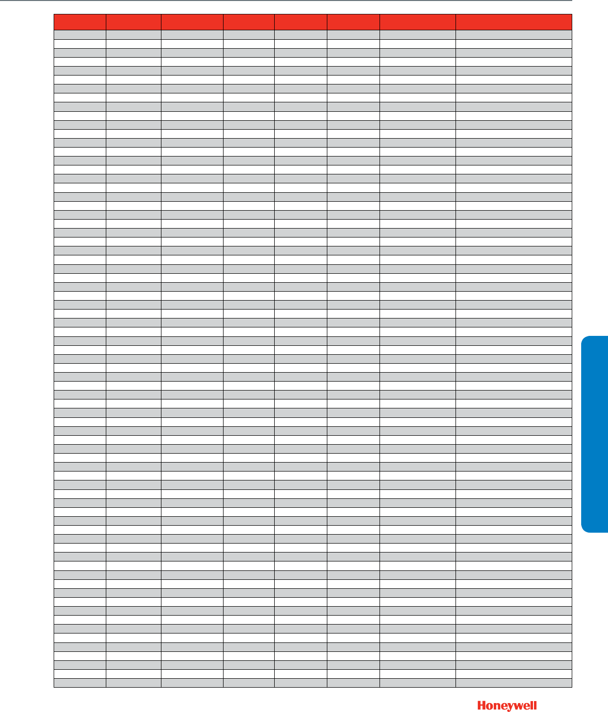
237
CROSS REFERENCE
Modutrol IV Motor Cross Reference
ITEM NUMBER REPL TYPE REPL ITEM MULTI REPL REPL SEQ CHANNEL
(BUSI GROUP) MFG NAME CUSTOMER REMARKS
M845C1009/U FUNCTIONAL M8185D1006/U OR 1 TRADE HONEYWELL
M845D1024/U FUNCTIONAL M8185D1006/U 1 TRADE HONEYWELL
M845E1007/U DIRECT M8185D1006/U WITH 1 TRADE HONEYWELL
M845E1007/U FUNCTIONAL M4185B1009/u 4 TRADE HONEYWELL
M847A1031 FUNCTIONAL M847A1080 TRADE HONEYWELL
M847A1031/U DIRECT M847A1080/U 1 ALL HONEYWELL
M847A1049/U FUNCTIONAL M847A1072/U 1 TRADE HONEYWELL
M847D1004/B FUNCTIONAL M847D1012/U 1 ALL
M847D1004/U FUNCTIONAL M847D1012/U 1 ALL
M886B1004/U FUNCTIONAL M8415A1004/U 1 TRADE
M9161A1016/U DIRECT M9164D1009/U 1 ALL HONEYWELL
M9161A1016/U FUNCTIONAL M9164A1005/U ALL HONEYWELL
M9161A1024/U DIRECT M9164A1005/U 1 ALL
M9161A1032/P DIRECT M9164A1005/U 1 ALL
M9161A1040/U DIRECT M9184D1021/U WITH 1 ALL HONEYWELL
M9161A1040/U FUNCTIONAL M9164A1005 ALL HONEYWELL
M9161C1004/U DIRECT M9164C1001/U WITH 1 ALL
M9161C1004/U FUNCTIONAL M9164C1068/U 1 ALL
M9161C1012/U DIRECT M9164C1068/U 1 ALL
M9164A1021/U DIRECT M9164A1005/U 1 ALL
M9164A1047/U FUNCTIONAL M9164A1088/U 1 ALL HONEYWELL
M9164A1047/U DIRECT M9164D1009/U WITH TRADE HONEYWELL
M9164A1054/U FUNCTIONAL M9164A1005/U 1 ALL HONEYWELL
M9164A1054/U DIRECT M9164D1009/U WITH ALL HONEYWELL
M9164A1062/U FUNCTIONAL M9164A1005/U 1 ALL HONEYWELL
M9164A1062/U DIRECT M9164D1009/U TRADE HONEYWELL
M9164A1088/U DIRECT M9164A1013/U 1 ALL
M9164A1120/U DIRECT M9164D1009/U 1 ALL HONEYWELL
M9164A1120/U FUNCTIONAL M9164A1005/U ALL HONEYWELL
M9164C1019/U FUNCTIONAL M9164C1068/U 1 ALL HONEYWELL
M9164C1019/U DIRECT M9164D1009/U WITH ALL HONEYWELL
M9164C1027/U FUNCTIONAL M9164D1009/U WITH 1 ALL HONEYWELL
M9164C1035/U FUNCTIONAL M9164C1068/U 1 ALL HONEYWELL
M9164C1035/U DIRECT M9164D1009/U WITH ALL HONEYWELL
M9164C1050/U DIRECT M9164C1068/U 1 ALL
M9171A1006/U FUNCTIONAL M9174B1027/U WITH 1 TRADE HONEYWELL
M9171A1006/U FUNCTIONAL M9174B1043/U 3 TRADE HONEYWELL
M9171B1004/U FUNCTIONAL M9174B1027/U 1 ALL
M9171B1004/U DIRECT M9184D1021/U WITH 1 ALL
M9171B1012/U FUNCTIONAL M9174D1007/U WITH 1 TRADE HONEYWELL
M9171C1002/P DIRECT M9174C1025/P 1 ALL
M9171C1002/U DIRECT M9174C1025/U 1 ALL HONEYWELL
M9171C1002/U FUNCTIONAL M9174C1025/u WITH ALL HONEYWELL
M9174B1001/U FUNCTIONAL M9174B1043/U 1 ALL HONEYWELL
M9174B1001/U DIRECT M9174D1007 WITH ALL HONEYWELL
M9174B1019/U FUNCTIONAL M9174B1027/U 1 ALL HONEYWELL
M9174B1019/U DIRECT M9174D1007/U WITH ALL HONEYWELL
M9174B1027/P FUNCTIONAL M9174B1027/U 1 ALL
M9174B1043/U DIRECT M9174B1027/U 1 ALL
M9174C1009/U FUNCTIONAL M9174C1033/U 1 ALL HONEYWELL
M9174C1009/U DIRECT M9174D1007/U WITH ALL HONEYWELL
M9174C1017/U FUNCTIONAL M9174C1025/U 1 ALL HONEYWELL
M9174C1017/U DIRECT M9174D1007/U WITH ALL HONEYWELL
M9174C1033/P FUNCTIONAL M9174C1033/U 1 ALL
M9175A1010/U DIRECT M9185A1018/U 1 ALL HONEYWELL
M9175A1036/U FUNCTIONAL M9185d1004/U WITH 1 ALL HONEYWELL
M9175A1051/P DIRECT M9185A1018/U 1 ALL
M9175A1051/U DIRECT M9185A1018/U 1 ALL
M9175A1077/U FUNCTIONAL M9185D1004/U 1 ALL HONEYWELL
M9175D1006/U FUNCTIONAL M9185D1004/U ALL HONEYWELL
M9175D1006/U FUNCTIONAL M9185A1018/U WITH 1 TRADE
M9175D1014/U TRADE EQUIV M9185D1004/U WITH 1 ALL
M9181A1012/P DIRECT M9184A1019/U 1 ALL
M9181A1012/U DIRECT M9184A1019/U 1 ALL
M9181B1002/U DIRECT M9184D1021/U WITH 1 TRADE HONEYWELL
M9181B1010/U FUNCTIONAL M9184D1021/U WITH 1 TRADE HONEYWELL
M9181D1008/U DIRECT M9184D1021/U OR 1 TRADE HONEYWELL
M9181D1008/U FUNCTIONAL M9184D1005/U 2TRADE HONEYWELL
M9182A1011/P DIRECT M9185A1018/U 1 ALL
M9182A1029/U DIRECT M9185A1018/U 1 ALL
M9182A1052/U DIRECT M9185A1018/U WITH 1 ALL
M9182A1060/U FUNCTIONAL M9185D1004/U WITH 1 ALL HONEYWELL
M9182C1009/U DIRECT M9185C1006/U 1 ALL

238
Modutrol IV Motor Cross Reference
ITEM NUMBER REPL TYPE REPL ITEM MULTI REPL REPL SEQ CHANNEL
(BUSI GROUP) MFG NAME CUSTOMER REMARKS
M9182C1017/U FUNCTIONAL M9185D1004/U WITH 1 ALL HONEYWELL
M9182D1015/U FUNCTIONAL M9185D1004/U 1 ALL HONEYWELL
M9182D1031/U FUNCTIONAL M9185D1004/U WITH 1 ALL HONEYWELL
M9182D4001/U DIRECT M9185D4008/U 1 TRADE HONEYWELL
M9182D4001/U FUNCTIONAL M9185D1004/U TRADE HONEYWELL
M9182W1002/U FUNCTIONAL M9185D1004/U WITH 1 ALL HONEYWELL
M9183G1009/U DIRECT M9185D1004/U OR 1 TRADE HONEYWELL
M9183G1009/U FUNCTIONAL M9185A1018/U 2 TRADE HONEYWELL
M9184A1001/U DIRECT M9184D1021/U 1 ALL HONEYWELL
M9184A1027 DIRECT M9184D1021/U 1 ALL HONEYWELL
M9184A1027 FUNCTIONAL M9184A1035/U ALL HONEYWELL
M9184A1035/U DIRECT M9184D1021/U 1 ALL
M9184A1035/U FUNCTIONAL M9184A1019/U ALL HONEYWELL
M9184B1017/P FUNCTIONAL M9184B1017/U 1 ALL
M9184B1025/P FUNCTIONAL M9184B1025/U 1 ALL
M9184B1033/U FUNCTIONAL M9184D1021/U WITH 1 TRADE HONEYWELL
M9184B1033/U FUNCTIONAL M9184F1034/U 3 TRADE HONEYWELL
M9184B1041/U FUNCTIONAL M9184D1021/U WITH 1 TRADE HONEYWELL
M9184C1007/U DIRECT M9184D1021/U 1 ALL HONEYWELL
M9184C1007/U FUNCTIONAL M9184C1031/U ALL HONEYWELL
M9184C1049/P FUNCTIONAL M9184C1049/U 1 ALL
M9184D1013/U DIRECT M9184D1021/U 1 ALL
M9184F1000/U DIRECT M9184F1034/U 1 ALL
M9184F1018/U DIRECT M9184D1021/U WITH 1 ALL HONEYWELL
M9184F1018/U FUNCTIONAL M9184F1034/U ALL HONEYWELL
M9184F1026/U DIRECT M9184D1021/U WITH 1 ALL
M9184F1026/U FUNCTIONAL M9184F1034/U 1 ALL
M9185A1000/U FUNCTIONAL M9185A1018/U 1 ALL HONEYWELL
M9185A1000/U DIRECT M9185D1004/U OR 1 ALL HONEYWELL
M9185A1026/U DIRECT M9185A1018/U 1 ALL
M9185A1091/U DIRECT M9185D1004/U 1 ALL HONEYWELL
M9185D1012/U FUNCTIONAL M9185D1004/U 1 ALL HONEYWELL
M9185E1001/U FUNCTIONAL M9185E1019/U 1 ALL HONEYWELL
M9185E1001/U DIRECT M9185D1004/u WITH ALL HONEYWELL
M9186G1006/U FUNCTIONAL M9185A1018/U 1 ALL replacement is Normally Closed
M9186G4000/U FUNCTIONAL M9185D1004/U 1 ALL HONEYWELL
M9186G4000/U FUNCTIONAL M9185E4005/U OR 1 ALL HONEYWELL
M934A1201/U FUNCTIONAL M9164D1009/U WITH 1 TRADE HONEYWELL
M934A1201/U FUNCTIONAL M9164A1013/U 3 TRADE HONEYWELL
M934A1219/U FUNCTIONAL M9164D1009/U WITH 1 TRADE HONEYWELL
M934A1219/U FUNCTIONAL M9164A1005/U 3 TRADE HONEYWELL
M934A1227/U FUNCTIONAL M9164D1009/U 1 TRADE HONEYWELL
M934A1235/U FUNCTIONAL M9164D1009/U WITH 1 TRADE HONEYWELL
M934A1235/U FUNCTIONAL M9164A1047/U 3 TRADE HONEYWELL
M934A1243/U FUNCTIONAL M9164D1009/U WITH 1 TRADE HONEYWELL
M934A1243/U FUNCTIONAL M9164C1068/U 3 TRADE HONEYWELL
M934A1250/U FUNCTIONAL M9164D1009/U WITH 1 TRADE HONEYWELL
M934A1268/U FUNCTIONAL M9164D1009/U WITH 1 TRADE HONEYWELL
M934A1284/U FUNCTIONAL M9164D1009/U WITH 1 TRADE HONEYWELL
M934A1284/U FUNCTIONAL M9164A1005/U 3 TRADE HONEYWELL
M934A1292/U FUNCTIONAL M9164D1009/U WITH 1 TRADE HONEYWELL
M934A1292/U FUNCTIONAL M9164C1068/U 4 TRADE HONEYWELL
M934A1300/U FUNCTIONAL M9164D1009/U WITH 1 TRADE HONEYWELL
M934A1318/U FUNCTIONAL M9164D1009/U WITH 1 TRADE HONEYWELL
M934A1318/U FUNCTIONAL M9164C1068/U 4 TRADE HONEYWELL
M934A1326/U FUNCTIONAL M9164D1009/U WITH 1 TRADE HONEYWELL
M934A1326/U FUNCTIONAL M9164A1005/U 3 TRADE HONEYWELL
M934A1334/U FUNCTIONAL M9164D1009/U 1 TRADE HONEYWELL
M934A1342/U FUNCTIONAL M9164D1009/U OR 1 TRADE HONEYWELL
M934A1342/U FUNCTIONAL M9164A1005/U 2 TRADE HONEYWELL
M934A1367/U FUNCTIONAL M9164D1009/U WITH 1 TRADE HONEYWELL
M934A1490/U FUNCTIONAL M9164D1009/U WITH 1 TRADE HONEYWELL
M934A1599/U FUNCTIONAL M9164D1009/U WITH 1 TRADE HONEYWELL
M934D1000/U DIRECT M9174D1007/U WITH 1 TRADE HONEYWELL
M934D1000/U FUNCTIONAL M9174B1043/U 4 TRADE HONEYWELL
M934D1018/U FUNCTIONAL M9174D1007/U WITH 1 TRADE HONEYWELL
M934D1018/U FUNCTIONAL M9174C1033/u 4 TRADE HONEYWELL
M934D1026/U FUNCTIONAL M9174D1007/U WITH 1 TRADE HONEYWELL
M934D1026/U FUNCTIONAL M9174B1027/u 4 TRADE HONEYWELL
M934D1034/U FUNCTIONAL M9174D1007/U WITH 1 TRADE HONEYWELL
M934D1034/U FUNCTIONAL M9174C1025/ 4 TRADE HONEYWELL
M941A1008/U FUNCTIONAL M9484D1010/U 1 TRADE HONEYWELL
M941A1016/U FUNCTIONAL M9484D1010/U 1 TRADE HONEYWELL

239
CROSS REFERENCE
Modutrol IV Motor Cross Reference
ITEM NUMBER REPL TYPE REPL ITEM MULTI REPL REPL SEQ CHANNEL
(BUSI GROUP) MFG NAME CUSTOMER REMARKS
M941A1024/U FUNCTIONAL M9484D1010/U 1 TRADE HONEYWELL
M941A1032/U FUNCTIONAL M9484D1010/U 1 TRADE HONEYWELL
M941A1057/U FUNCTIONAL M9484D1010/U 1 TRADE HONEYWELL
M941B1007/U FUNCTIONAL M6284F1013/U 2 TRADE HONEYWELL
M941C1006/U FUNCTIONAL M9484E1009/U 1 TRADE HONEYWELL
M941C1014/U FUNCTIONAL M9484E1017/U 1 TRADE HONEYWELL
M941C1022/U FUNCTIONAL M9484E1033/u 1 TRADE HONEYWELL
M941C1030/U FUNCTIONAL M9484E1033/U 1 TRADE HONEYWELL
M941C1063/U FUNCTIONAL M9484E1033 1 TRADE HONEYWELL
M941D1005/U FUNCTIONAL M9484F1007/U 1 TRADE HONEYWELL
M941D1021/U FUNCTIONAL M9484F1023/U 1 TRADE HONEYWELL
M941D1039/U FUNCTIONAL M9484F1031/U 1 TRADE HONEYWELL
M941D1047/U FUNCTIONAL M9484F1049/U 1 TRADE HONEYWELL
M944A1002/U DIRECT M9184D1021/U 2 ALL HONEYWELL
M944A1010/U FUNCTIONAL M9184D1021/U OR 1 TRADE HONEYWELL
M944A1010/U FUNCTIONAL M9184A1019/U 2 TRADE HONEYWELL
M944A1028/U FUNCTIONAL M9184D1021/U OR 1 TRADE HONEYWELL
M944A1028/U FUNCTIONAL M9184A1019/U 2 TRADE HONEYWELL
M944B1167/U FUNCTIONAL M6284D1000/U 1 TRADE HONEYWELL
M944B1175/U FUNCTIONAL M6284D1000/U 1 TRADE HONEYWELL
M944B1183/U DIRECT M6284D1000/U 1 TRADE HONEYWELL
M944C1000/U FUNCTIONAL M9184D1021/U OR 1 TRADE HONEYWELL
M944C1000/U FUNCTIONAL M9184D1005/U 2 TRADE HONEYWELL
M944C1018/U FUNCTIONAL M9194D1003/U 1 TRADE HONEYWELL
M944C1042/U FUNCTIONAL M9184D1021/U OR 1 TRADE HONEYWELL
M944D1017/U FUNCTIONAL M9184D1021/U WITH 1 TRADE HONEYWELL
M944D1017/U FUNCTIONAL M9184F1034/U 3 TRADE HONEYWELL
M944E1040/U FUNCTIONAL M6284D1000-S/U WITH 1 TRADE HONEYWELL
M944E1040/U FUNCTIONAL M6284F1013-S/U 3 TRADE HONEYWELL
M944G1089/U FUNCTIONAL M6284D1000/U WITH 1 TRADE HONEYWELL
M944G1097/U FUNCTIONAL M6284D1000/U WITH 1 TRADE HONEYWELL
M944J1051/U FUNCTIONAL M6284D1000/U 1 TRADE HONEYWELL
M944S1027/U FUNCTIONAL M6284D1000/U WITH 1 TRADE HONEYWELL
M945A1009/U FUNCTIONAL M9185D1004/U OR 1 TRADE HONEYWELL
M945A1009/U FUNCTIONAL M9185A1018/U 2 TRADE HONEYWELL
M945A1017/U FUNCTIONAL M9185D1004/U OR 1 TRADE HONEYWELL
M945A1017/U FUNCTIONAL M9185A1018/U 2 TRADE HONEYWELL
M945A1033/U FUNCTIONAL M9185D1004/U OR 1 TRADE HONEYWELL
M945A1033/U FUNCTIONAL M9185A1018/U 2 TRADE HONEYWELL
M945A1082/U FUNCTIONAL M9185D1004/U OR 1 TRADE HONEYWELL
M945A1082/U FUNCTIONAL M9185A1018/U 2 TRADE HONEYWELL
M945A1157/U FUNCTIONAL M9185D1004/U 1 TRADE HONEYWELL
M945B1057/U FUNCTIONAL M6285A1005/U 1 TRADE HONEYWELL
M945B1065/U FUNCTIONAL M6285A1005/U 1 TRADE HONEYWELL
M945B1115/U FUNCTIONAL M6285A1005/U WITH 1 TRADE HONEYWELL
M945C1015/U FUNCTIONAL M6285A1005/U WITH 1 TRADE HONEYWELL
M945C1015/U FUNCTIONAL M6285C1001/U 3 TRADE HONEYWELL
M945D1006/U FUNCTIONAL M9185D1004/U WITH 1 TRADE HONEYWELL
M945D1006/U FUNCTIONAL M9185C1006/U 3 TRADE HONEYWELL
M945F1004/U FUNCTIONAL M9185D1004/U OR 1 TRADE HONEYWELL
M945F1004/U FUNCTIONAL M9185A1018/U 2 TRADE HONEYWELL
M945G1037/U FUNCTIONAL M6285A1005/U OR 1 TRADE HONEYWELL
M945G1037/U FUNCTIONAL M6285A1005/U 2 TRADE HONEYWELL
M945J1025/U FUNCTIONAL M9185D1004/U WITH 1 TRADE HONEYWELL
M945J1025/U FUNCTIONAL M9185C1006/U 3 TRADE HONEYWELL
M945M1006/U FUNCTIONAL M9185D1004/U OR 1 TRADE HONEYWELL
M945M1006/U FUNCTIONAL M9185A1018/U 2 TRADE HONEYWELL
M9481D1005/U DIRECT M9484F1007/U 1 TRADE
M9481D1005/U FUNCTIONAL M9484D1010 TRADE HONEYWELL
M9481E1002/U DIRECT M9484F1007/U 1 ALL HONEYWELL
M9481E1002/U FUNCTIONAL M9484E1017/U 2 ALL HONEYWELL
M9481F1000/U DIRECT M9484F1007/U 1 ALL
M9484D1002/U FUNCTIONAL M9484D1010/U 1 ALL HONEYWELL
M9484D1028/U FUNCTIONAL M9484D1010/U 1 ALL HONEYWELL
M9484D1036/U FUNCTIONAL M9484E1009/U 1 ALL HONEYWELL
M9484E1058/U FUNCTIONAL M9484E1033/U 1 ALL HONEYWELL
M954A1035/U FUNCTIONAL M9184D1021/U 1 TRADE HONEYWELL
M954B1034/U FUNCTIONAL M9184D1021/U WITH 1 TRADE HONEYWELL
M954C1066/U FUNCTIONAL M9184D1021/U WITH 1 TRADE HONEYWELL
M954C1074/U FUNCTIONAL M9184D1021/U WITH 1 TRADE HONEYWELL
M954D1016/U FUNCTIONAL M9184D1021/U WITH 1 TRADE HONEYWELL
M955A1024/U FUNCTIONAL M9185D1004/U 1 TRADE HONEYWELL
M955C1014/U FUNCTIONAL M9185D1004/U WITH 1 TRADE HONEYWELL

240
Modutrol IV Motor Cross Reference
ITEM NUMBER REPL TYPE REPL ITEM MULTI REPL REPL SEQ CHANNEL
(BUSI GROUP) MFG NAME CUSTOMER REMARKS
M955C4000/U FUNCTIONAL M9185D1004/U WITH 1 TRADE HONEYWELL
M955D1005/U FUNCTIONAL M9185D1004/U OR 1 TRADE HONEYWELL
M965A1007/U FUNCTIONAL M9185D1004/U 1 TRADE HONEYWELL
M975A1006/U FUNCTIONAL M9185D1004/U 1 TRADE HONEYWELL
M975A1089/U FUNCTIONAL M9185D1004/U 1 TRADE HONEYWELL
M975A1097/U FUNCTIONAL M9185D1004/U WITH 1 TRADE HONEYWELL
M975A1097/U DIRECT M9185D1004/U 3 TRADE HONEYWELL
M975B1021/U FUNCTIONAL M9185D1004/U WITH 1 TRADE HONEYWELL
MA-12313 FUNCTIONAL M8415A1004/U 1 TRADE BARBER COLMAN
MA-12323 FUNCTIONAL M8415A1004/U 1 TRADE BARBER COLMAN
MA-305 FUNCTIONAL M836A1042/U 1 TRADE BARBER COLMAN
MA-305-500 FUNCTIONAL M836A1042/U 1 TRADE BARBER COLMAN
MA-308 FUNCTIONAL M845A1027/U 1 TRADE BARBER COLMAN
MA-318 FUNCTIONAL M8185D1006/U OR 1 TRADE BARBER COLMAN
MA-318 FUNCTIONAL M8185D1006/U 2 TRADE BARBER COLMAN
MA-318-500 FUNCTIONAL M8185D1006/u WITH ALL BARBER COLMAN TRADE LINE IS 60 SECOND TIMING 160
DEG STROKE SETTING
MA-405 FUNCTIONAL M436A1116/U 1 TRADE BARBER COLMAN
MA-405-500 FUNCTIONAL M436A1116/U 1 TRADE BARBER COLMAN
MA-406 FUNCTIONAL M836A1042/U 1 TRADE BARBER COLMAN
MA-406-500 FUNCTIONAL M836A1042/U 1 TRADE BARBER COLMAN
MA-407 FUNCTIONAL M436A1124/U 1 TRADE BARBER COLMAN
MA-407-500 FUNCTIONAL M436A1124/U 1 TRADE BARBER COLMAN
MA-416 DIRECT M8185D1006/U WITH 1 TRADE BARBER COLMAN
MA-416 DIRECT M4185B1058/U WITH 3 TRADE BARBER COLMAN
MA-416-500 DIRECT M8185D1006/U WITH 1 TRADE BARBER COLMAN
MA-416-500 DIRECT M4185B1058/U 4 TRADE BARBER COLMAN
MA-418 DIRECT M8185D1006/U WITH 1 TRADE BARBER COLMAN
MA-418 DIRECT M4185A1001/U 3 TRADE BARBER COLMAN
MA-418-500 DIRECT M8185D1006/U WITH 1 TRADE BARBER COLMAN
MA-418-500 DIRECT M4185B1009/U 4 TRADE BARBER COLMAN
MA-419 DIRECT M8185D1006/U WITH 1 TRADE BARBER COLMAN
MA-419 FUNCTIONAL M4185B1058/U WITH 3 TRADE BARBER COLMAN
MA-419-500 DIRECT M8185D1006/U WITH 1 TRADE BARBER COLMAN
MA-419-500 DIRECT M4185B1058/U WITH 4 TRADE BARBER COLMAN
MA5213 FUNCTIONAL M6410A1011/U 1 TRADE BARBER COLMAN
MA5-419 FUNCTIONAL M8185D1006/U WITH 1 TRADE BARBER COLMAN
MA5-419 FUNCTIONAL M4185B1058/U WITH 3 TRADE BARBER COLMAN
MA5-419-500 FUNCTIONAL M8185D1006/U WITH 1 TRADE BARBER COLMAN
MA5-419-500 FUNCTIONAL M4185B1058/U 4 TRADE BARBER COLMAN
MC-351 FUNCTIONAL M6194D1017/U WITH 1 TRADE BARBER COLMAN
MC-421 FUNCTIONAL M6184D1035/U WITH 1 TRADE BARBER COLMAN
MC-431 FUNCTIONAL M6194D1017/U WITH 1 TRADE BARBER COLMAN
MC-4311 FUNCTIONAL M6194D1017/U WITH 1 TRADE BARBER COLMAN
MC5-4311 FUNCTIONAL M6194D1017/U WITH 1 TRADE BARBER COLMAN
ME-12313 FUNCTIONAL M8405A1006/U 1 TRADE BARBER COLMAN
ME-12313-102 FUNCTIONAL M8405A1006/U 1 TRADE BARBER COLMAN
MP-2113-500 FUNCTIONAL M6184D1035/U WITH 1 TRADE BARBER COLMAN
MP-2113-500 FUNCTIONAL M6184D1001/U 3 TRADE BARBER COLMAN
MP-2130-500 FUNCTIONAL M6184D1035/U WITH 1 TRADE BARBER COLMAN
MP-2130-500 FUNCTIONAL M6184D1001/U 4 TRADE BARBER COLMAN
MP-2150-500 FUNCTIONAL M6184D1035/U WITH 1 TRADE BARBER COLMAN
MP-2150-500 FUNCTIONAL M6184A1023/U 4 TRADE BARBER COLMAN
MP-2151-500 FUNCTIONAL M6184D1035/U WITH 1 TRADE BARBER COLMAN
MP-371 FUNCTIONAL M6294D1008/U WITH 1 TRADE BARBER COLMAN
MP-381 FUNCTIONAL M6194D1017/U WITH 1 TRADE BARBER COLMAN
MP-481 FUNCTIONAL M9194D1003/U WITH 1 TRADE BARBER COLMAN
MP-483-600 FUNCTIONAL M6294D1008/U WITH 1 TRADE BARBER COLMAN
MP-483-600 FUNCTIONAL M6294D1008/U 4 TRADE BARBER COLMAN
MP-485 FUNCTIONAL M6194D1017/U WITH 1 TRADE BARBER COLMAN
MP-4851 FUNCTIONAL M6294D1008/U WITH 1 TRADE BARBER COLMAN
MP-486 FUNCTIONAL M6294D1008/U WITH 1 TRADE BARBER COLMAN
MP5213 FUNCTIONAL M7410E1010/U OR 1 TRADE BARBER COLMAN
MP5213 FUNCTIONAL M7410E1036/U 2 TRADE BARBER COLMAN
MU-12313 FUNCTIONAL M7415A1006/U 1 TRADE BARBER COLMAN
P-8-11066 FUNCTIONAL M745G1007/U 1 TRADE LENNOX
P-8-11067 FUNCTIONAL M734H1026/U 1 TRADE LENNOX
P-8-11208 FUNCTIONAL M745K1002/U 1 TRADE LENNOX
P-8-8230 FUNCTIONAL M954A1035/U 1 TRADE LENNOX
P-8-8271 FUNCTIONAL M945A1017/U 1 TRADE LENNOX
P-8-8371 FUNCTIONAL M945A1017/U 1 TRADE LENNOX
P-8-8701 FUNCTIONAL M934A1235/U 1 TRADE LENNOX
SQS65 FUNCTIONAL M7410E1010/U OR 1 TRADE POWERS/LANDIS & GYR
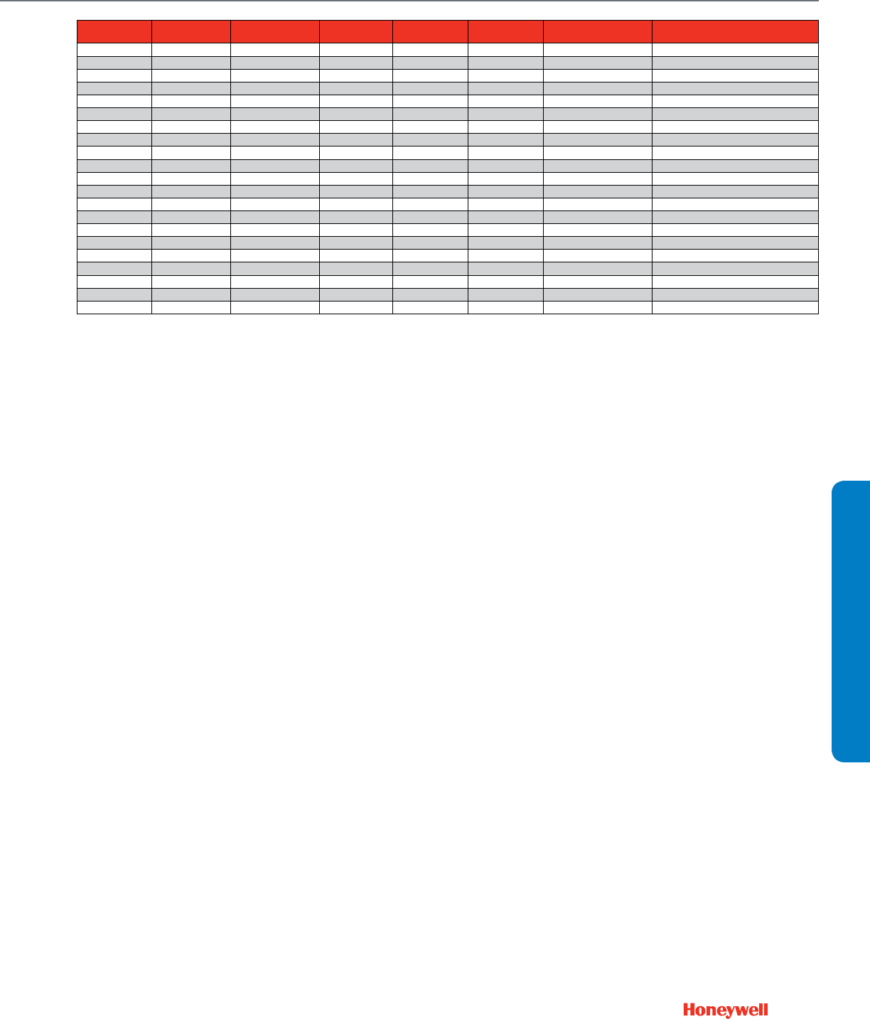
241
CROSS REFERENCE
Modutrol IV Motor Cross Reference
ITEM NUMBER REPL TYPE REPL ITEM MULTI REPL REPL SEQ CHANNEL
(BUSI GROUP) MFG NAME CUSTOMER REMARKS
SQS65 FUNCTIONAL M7410E1036/U 2 TRADE POWERS/LANDIS & GYR
SQS82 FUNCTIONAL M6410A1003/U OR 1 TRADE BARBER COLMAN
SQS82 FUNCTIONAL M6410A1011/U 2 TRADE BARBER COLMAN
SSC61U FUNCTIONAL M7410F1000/U 1 ALL SIEMENS
SSC81U FUNCTIONAL M6410A1029/U 1 ALL SIEMENS
V70DB-6 FUNCTIONAL M945D1006/U 1 TRADE JOHNSON CONTROLS
VA-7450-10011 FUNCTIONAL M6410A1029/U 1 ALL JOHNSON CONTROLS
VA-7452-90011 FUNCTIONAL M7410F1000/U 1 ALL JOHNSON CONTROLS
VA8050-1 FUNCTIONAL M6410A1003/U OR 1 TRADE JOHNSON CONTROLS
VA8050-1 FUNCTIONAL M6410A1011/U 2 TRADE JOHNSON CONTROLS
VA8050-1007 FUNCTIONAL M6410A1003/U OR 2 TRADE JOHNSON CONTROLS
VA8050-1007 FUNCTIONAL M6410A1011/U 3 TRADE JOHNSON CONTROLS
VA8052-1 FUNCTIONAL M7410E1010/U OR 1 TRADE JOHNSON CONTROLS
VA8052-1 FUNCTIONAL M7410E1036/U 2 TRADE JOHNSON CONTROLS
W6210A1003/U FUNCTIONAL M7215A1008/U 1 TRADE
W7395A1008/P DIRECT M7215A1016/U 1 ALL
W7415A1004/B DIRECT M7415A1006/U WITH 1 ALL
W899A1030/U FUNCTIONAL M9164D1009/U 3 TRADE
W899G1000/U DIRECT M9185A1018/U 3 TRADE HONEYWELL
W899G1034/U FUNCTIONAL M9185A1018/U 3 TRADE HONEYWELL
W899G1042/U FUNCTIONAL M9185A1018/U WITH 3 TRADE HONEYWELL

242

243
APPENDIX
Section 8:
APPENDIX A:
Valve Selection & Sizing ...........................................................244
APPENDIX B:
NEMA Standard Classification Code for Enclosures ................263
APPENDIX C:
Best Practices for Low Power Control Signal Wiring ................264
Notes .......................................................................................265
Warranty...................................................................................267
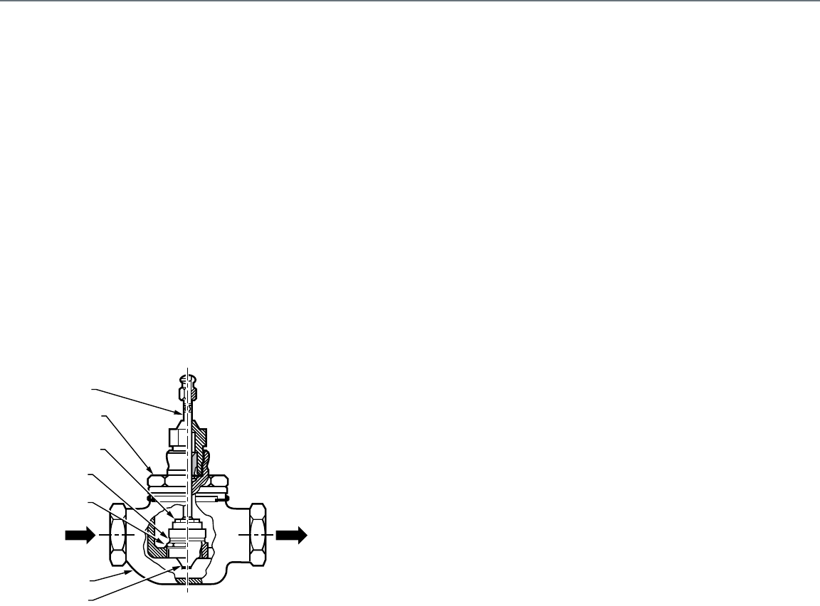
244
Appendix A: Valve Selection and Sizing
Appendix A: Valve Selection and Sizing
Introduction
This section provides information on valve selection and sizing.
Valves must be selected for ability to meet temperature,
pressure, flow control characteristic, and piping connection
requirements of the hydronic system. Valve sizing is critical to
ensure support for heating and cooling loads with adequate
valve capacity, yet able to control system flow to provide stable
building conditions efficiently.
Definitions
Valve Components
Actuator:The part of an automatic control valve that moves the
stem based on an electric, electronic, or pneumatic
signal from a controller. The actuator and valve can be
two separate devices or together they can be one
device.
Body: The valve casting through which the controlled fluid
flows (Fig. 1).
Fig. 1. Globe Valve Components.
Bonnet: The part that screws to the top of the valve body and
contains the packing that seals and guides the valve
stem.
Disc: The part of the valve assembly that contacts the valve
seat to close off flow of the controlled fluid. Some valve
assemblies are built so the disc is replaceable.
Replaceable discs are usually made of a composition
material softer than metal. "Metal trim" valves use
precisely-machined metal plugs and seats operated by
high force actuators instead of a disk.
Plug: The part that varies the opening for the fluid to flow
through the valve body. The following describes the
three most common types of plugs:
— A contoured plug has a shaped end that is usually
end-guided at the top or bottom (or both) of the
valve body. The shaped end controls fluid flow
through the valve with respect to stem travel.
— A V-port plug has a cylinder, called a skirt, that
rides up and down in the valve seat ring. The skirt
guides the plug and varies the flow area with
respect to stem travel via its shaped openings.
— A quick-opening plug is flat and is either end-
guided or guided by wings riding in the valve seat
ring. The flat plug provides maximum flow soon
after it lifts from the valve seat.
Port: The opening in the valve seat.
Seat: The stationary part of the valve body that has a raised
lip to contact the valve disc when closing off flow of the
controlled fluid.
Stem: The shaft that runs through the valve bonnet and
connects an actuator to the valve plug.
Trim: All parts of the valve that contact the controlled fluid.
Trim includes the stem, packing, plug, disc, and seat; it
does not include the valve body.
Valve Flow Characteristics
Direction of Flow: The correct flow of the controlled fluid
through the valve is usually indicated on the valve
body. If the fluid flow through the valve is incorrect, the
disc can slam into the seat as it approaches the closed
position. The result is poor control, excessive valve
wear, and noisy operation. In addition, the actuator
must work harder to reopen the closed valve since it
must overcome the pressure exerted by the fluid on
top of the disc rather than have the fluid assist in
opening the valve by exerting pressure under the disc.
Gate and butterfly valves may offer bi-directional flow.
Equal percentage: A valve which changes flow by an equal
percentage (regardless of flow rate) for similar
movements in stem travel (at any point in the flow
range).
Linear: A valve which provides a flow-to-lift relationship that is
directly proportional. It provides equal flow changes for
equal lift changes, regardless of percentage of valve
opening.
Quick-opening: A valve which provides maximum possible
flow as soon as the stem lifts the disc from the valve
seat.
Valve flow characteristic: The relationship between the stem
travel of a valve, expressed in percent of travel, and
the fluid flow through the valve, expressed in percent
of full flow.
M12225
STEM
BONNET
SEAT
DISC
BODY
PLUG
DISC
HOLDER
OUT
IN

245
APPENDIX
Valve Flow Terms
Rangeability: The ratio of maximum flow to minimum
controllable flow. Approximate rangeability ratios are
50 to 1 for V-port globe valves and 30 to 1 for
contoured plug valves.
EXAMPLE:
A valve with a total flow capacity of 100
gpm full open and a rangeability of 30 to 1,
can accurately controls flow accurately as
low as 3 gpm.
Tight shut-off/close-off: A valve condition in which virtually no
leakage of the controlled fluid occurs in the closed
position. Generally, only single-seated valves provide
tight shut-off. Double-seated valves typically have a
one to three percent leakage in the closed position.
Turndown: The ratio of maximum flow to minimum controllable
flow of a valve installed in a system. Turndown is equal
to or less than rangeability.
EXAMPLE:
For the valve in the rangeability example, if
the system requires a 66 gpm maximum
flow through the valve and since the
minimum accurately controllable flow is
3 gpm, the turndown is 22.
Valve Ratings
Flow coefficient (capacity index): Used to state the flow
capacity of a control valve for specified conditions. In
the control valve industry currently one of three flow
coefficients is used depending upon the location and
system of units; British Av, European kvs, or United
States Cv . The flow coefficients have the following
relationships:
Av= 0.0000278 kvs
Av= 0.0000240 Cv
kvs = 0.865 Cv
The flow coefficient Av is in cubic meters per second
and can be determined from the formula:
Where:
Q = volumetric flow in cubic meters per
second.
ρ=fluid density in kilograms per cubic meter.
∆p = static pressure loss across the valve in
pascals.
The flow coefficient kvs is water flow in cubic meters
per hour with a static pressure loss across the valve of
105 pascals (1 bar) within the temperature range of 5
to 40°C and can be determined from the formula:
Where:
Q = volumetric flow in cubic meters per hour.
ρ=fluid density in kilograms per cubic meter.
ρw=density of water in kilograms per cubic
meter.
∆p kvs= static pressure loss of 105 pascals.
∆p = static pressure loss across the valve in
pascals.
The flow coefficient Cv is water flow in gallons per
minute with a pressure loss across the valve of one
pound per square inch within the temperature range of
40 to 100F and can be determined for other conditions
from the formula:
Where:
Q = volumetric flow in US gallons per minute.
ρ=fluid density in pounds per cubic foot.
ρw=density of water in pounds per cubic foot
within the temperature range of 40
to 100F
∆p = static pressure loss across the valve in
pounds per square inch.
Close-off rating: The maximum pressure drop that a valve can
withstand without leakage while in the full closed
position. The close-off rating is a function of actuator
power to hold the valve closed against pressure drop,
by structural parts such as the stem can be the limiting
factor. The construction of gate-style valves, such as
ball valves, often allows them to hold back high head
pressures in the closed position, although the actuator
may not be powerful enough to operate the valve
against such forces.
EXAMPLE:
A valve with a close-off rating of 10 psi
could have 40 psi upstream pressure and
30 psi downstream pressure. Note that in
applications where failure of the valve to
close is hazardous, the maximum
upstream pressure must not exceed the
valve close-off rating, regardless of the
downstream pressure.
The valve close-off rating is independent of the actual
valve body rating. See definition of BODY RATING
(ACTUAL).
AV
p
∆p
-------
Q
=
kvs Q
∆ρkvs
∆ρ
-----------------ρ
ρw
-------•=
CVQ1
∆ρ
-------ρ
ρw
-------•=
Appendix A: Valve Selection and Sizing
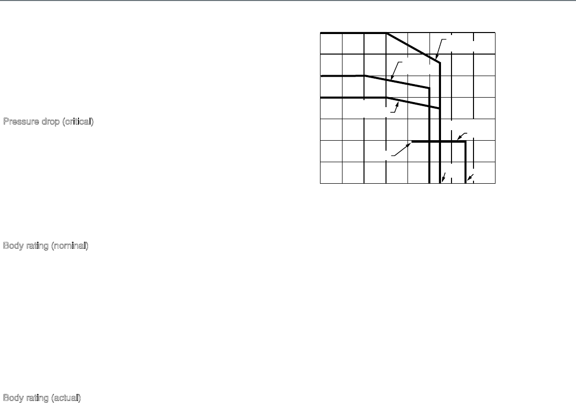
246
Close-off rating of three-way valves: The maximum pressure
difference between either of the two inlet ports and the
outlet port for mixing valves, or the pressure difference
between the inlet port and either of the two outlet ports
for diverting valves.
Pressure drop: The difference in upstream and downstream
pressures of the fluid flowing through the valve.
Pressure drop (critical): The flow of a gaseous controlled fluid
through the valve increases as the pressures drop
increases until reaching a critical point. This is the
critical pressure drop.
Any increase in pressure drop beyond the critical
pressure drop is dissipated as noise and cavitation
rather than increasing flow. The noise and cavitation
can destroy the valve and adjacent piping
components.
Body rating (nominal): The theoretical pressure rating,
expressed in psi, of the valve body exclusive of
packing, disc, etc. The nominal rating is often cast on
the valve body and provides a way to classify the valve
by pressure. A valve of specified body material and
nominal body rating often has characteristics such as
pressure-temperature ratings, wall thickness, and end
connections which are determined by a society such
as ANSI (American National Standards Institute).
Figure 2 shows ANSI pressure-temperature ratings for
valves. Note that the nominal body rating is not the
same as the actual body rating.
Body rating (actual): The correlation between safe, permissible
flowing fluid pressure and flowing fluid temperature of
the valve body (exclusive of the packing, disc, etc.).
The nominal valve body rating is the permissible
pressure at a specific temperature.
EXAMPLE:
From Figure 2, a valve with an ANSI rating
of 150 psi (ANSI Class 150) has an actual
rating of 225 psi at 250F.
Fig. 2. Sample ANSI Pressure-Temperature Ratings
for Valves.
Maximum pressure and temperature: The maximum
pressure and temperature limitations of fluid flow that
a valve can withstand. These ratings may be due to
valve packing, body, or disc material or actuator
limitations. The actual valve body ratings are
exclusively for the valve body and the maximum
pressure and temperature ratings are for the complete
valve (body and trim). Note that the maximum
pressure and temperature ratings may be less that the
actual valve body ratings.
EXAMPLE:
The body of a valve, exclusive of packing,
disc, etc., has a pressure and temperature
rating of 125 psi at 335F. If the valve
contains a composition disc that can
withstand a temperature of only 240F, then
the temperature limit of the disc becomes
the maximum temperature rating for the
valve.
337o F
ANSI CLASS150
(STEAM)
212o F
ANSI
CLASS 125
ANSI
CLASS 150
ANSI
CLASS 250
NOTES:
1. FOR HIGH FLUID TEMPERATURES, THE VALVE AND/OR
PIPING SHOULD BE INSULATED TO PREVENT AMBIENT
TEMPERATURES FROM EXCEEDING ACTURATOR RATINGS.
M12224
275o F
300
300 350
250
250
200
200
150
150
100
100
50
50
0
0
FLUID TEMPERATURE IN oF
LINE PRESSURE IN PSI
400
400
Appendix A: Valve Selection and Sizing
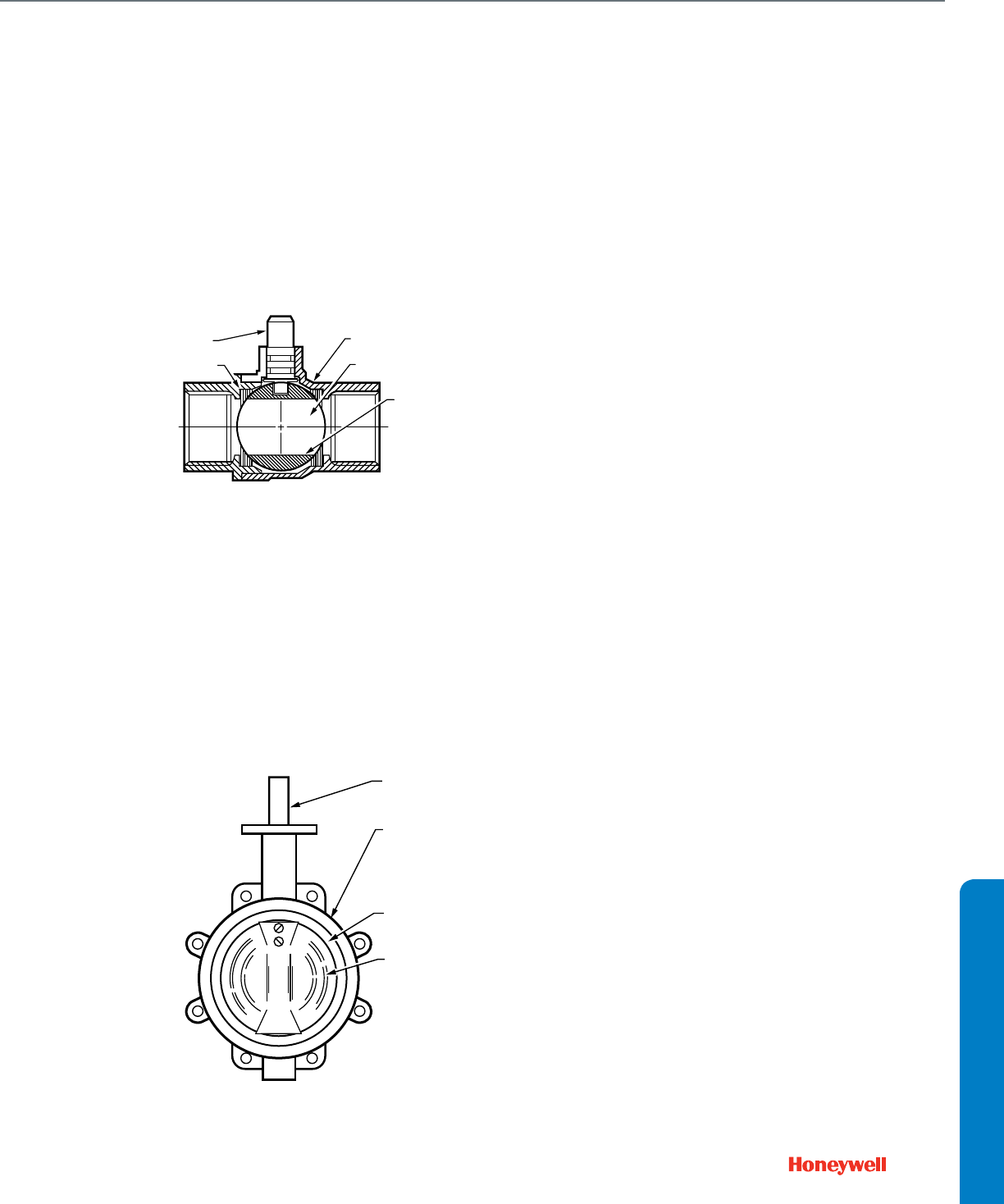
247
APPENDIX
Valve Types
Ball valve:A ball valve has a precision ball between two seats
with a body (Fig. 3). Ball valves have several port sizes
for a give body size and go from closed to open with a
90 degree turn of the stem. They are available in both
two-way and three-way configurations. For HVAC
applications, ball valve construction includes brass
and cast iron bodies; stainless steel, chrome plated
brass, and cast iron balls; resilient seats with various
temperature ratings. Ball valves provide tight shut-off,
while full port models have low flow resistance, and
models with flow characterizing inserts can be
selected for modulating applications.
Fig. 3. Ball Valve.
Butterfly valve: A valve with cylindrical bod, a shaft, and a
rotating disc (Fig. 4). The disc rotates 90 degrees from
open to closed. The disc seats against a resilient body
liner or spring-loaded metal seat and may be
manufactured for tight shut-off or made smaller for
reduced operating torque at lower close-off. Butterfly
valves have limited rangeability for modulating
applications so are used mainly for two-way operation.
For three-way applications, two butterfly valves are
assembled to a pipe tee with linkage for simultaneous
operation.
Fig. 4. Butterfly Valve.
Double-seated valve: A valve with two seats, plugs, and discs.
Double-seated valves are suitable for applications
where fluid pressure is too high to permit a single
seated valve to close. The discs in a double-seated
valve are arranged so that in the closed position there
is minimal fluid pressure forcing the stem toward the
open or closed position; the pressure on the discs is
essentially balanced. For a valve of given size and port
area, the double-seated valve requires less force to
operate than the single-seated valve so the double
seated valve can use a smaller actuator than a single
seated.
Also, double-seated valves often have a larger port
area for a given pipe size. A limitation of double-seated
valves is that they do not provide tight shut-off. Since
both discs rigidly connect together and changes in
fluid temperature can cause either the disc or the valve
body to expand or contract, one disc may seat before
the other and prevent the other disc from seating
tightly.
Flanged-end connections: A valve that connects to a pipe by
bolting a flange on the valve to a flange screwed onto
the pipe. Flanged connections are typically used on
large valves only.
Gate valve: A valve that controls flow using a gating
mechanism, usually a plate, that moves across the
valve seat instead of pushing against the flow. The
actuator works against the friction of the seals rather
than directly against the force of the water. Gate valves
are inherently self-sealing and are often capable of
high close-off pressures without an actuator. Ball
valves are a type of gate valve.
Globe valve: A valve which controls flow by moving a circular
disk against or away from a seat. When used in
throttling control a contoured plug (throttling plug)
extends from the center of circular disk through the
center of the seat for precise control (Fig. 1).
Pressure-balanced valve: A globe valve with a sealed
pressure chamber built into the plug, which equalizes
head pressure across the seat and allows most of the
actuator force to be used to close off the flow, resulting
in very high close-off ratings with very low seat
leakage.
Reduced-port valve: A valve with a capacity less than the
maximum for the valve body. Ball, butterfly, and smaller
globe valves are available with reduced ports to allow
correct sizing for good control.
STEM
BALL
BODY
PORT
SEATS
M12228
M12247
BODY
DISC
RESILIENT
SEAL
STEM
Appendix A: Valve Selection and Sizing

248
Single-seated valve: A valve with one seat, plug, and disc.
Single-seated valves are suitable for applications
requiring tight shut-off. Since a single-seated valve has
nothing to balance the force of the fluid pressure
exerted on the plug, it requires more closing force than
a double-seated valve of the same size and therefore
requires more actuator force than a double-seated
valve.
Threaded-end connection: A valve with threaded pipe
connections. Valve threads are usually tapered female,
to National Pipe Thread standards, but male
connections are available for special applications.
Some valves have an integral union for easier
installation.
Three-way valve: A valve with three ports. The internal design
of a three-way valve classifies it as a mixing or
diverting valve. Three-way valves control liquid in
modulating or two-position applications and do not
provide tight shut-off.
Two-way valve: A valve with one inlet port and one outlet port.
Two-way valves control water or steam in two-position
or modulating applications and provide tight shut-off in
both straight through and angle patterns.
Valve Material and Media
Valves with bronze or cast iron bodies having brass or stainless
steel trim perform satisfactorily in HVAC hydronic systems when
the water is treated properly. Failure of valves in these systems
may be an indication of inadequate water treatment. The
untreated water may contain dissolved minerals (e.g., calcium,
magnesium, or iron compounds) or gases (e.g., carbon dioxide,
oxygen, or ammonia). Inadequate treatment results in corrosion
of the system. Depending on the material of the valve, the color
of the corrosion may indicate the substance causing the failure
(Table 1).
Table 1. Corrosive Elements in Hydronic Systems.
Petroleum products from sources such as cutting oils, solder
flux, etc. can cause some rubber compounds to swell and
interfere with moving parts.
Chloramines, chemical compounds of ammonia and chlorine
used to treat municipal drinking water, are reported to attack
some rubber compounds commonly used in closed loop
hydronic systems.
Particulate present in the system can interfere with, and
sometimes damage moving parts. Examples include: rust
(Fe2O3), magnetite (Fe3O4), sand (quartz granules), silt from
municipal water, iron filings from pipe threads, and scale
precipitated from hard water. Rust, in particular, is highly
abrasive and can rapidly wear out stem seals, causing leaks.
To prevent damage to valves and pumps, a complete flushing
of the system during commissioning, including the existing
structure when building an addition, may be required to remove
physical particulate. Additional components may also be
needed, such as in-line Y-strainers for large objects such as
stones or solder blobs and mechanical filtration, such as a 50
micron 10% side-stream filter piped in parallel with the system
pumps.
Glycol solutions may be used to prevent hydronic systems
freezing. Glycol solutions should be formulated for HVAC
systems. Some available glycol solutions formulated for other
uses contain additives that are injurious to some system seals.
In addition, hydronic seals react differently to water and glycol
such that when a new system is started up with water or glycol
the seals are effective. The hydronic seals are likely to leak if
the system is later restarted with media changed from to water
to glycol or glycol to water. To prevent leakage part of the
process of media changeover should include replacing seals
such as, pump and valve packing. Glycol mixtures are usually
limited to 50% concentration. At 60% concentration, glycol
mixtures have their minimum freezing temperature, but can
have unstable phase changes which may severely damage a
system.
Brass or Bronze Component
Corrosive Substance Corrosion Color
Chloride
Ammonia
Carbonates
Magnesium or Calcium
Oxides
Sulphide (Hydrogen)
Iron
Light Blue-Green
Blue or Dark Blue
Dark Blue-Green
White
Black (water)
Black (Gas)
Rust
Iron or Steel Component
Corrosive Substance Corrosion Color
Magnesium or Calcium
Iron
White
Rust
Appendix A: Valve Selection and Sizing
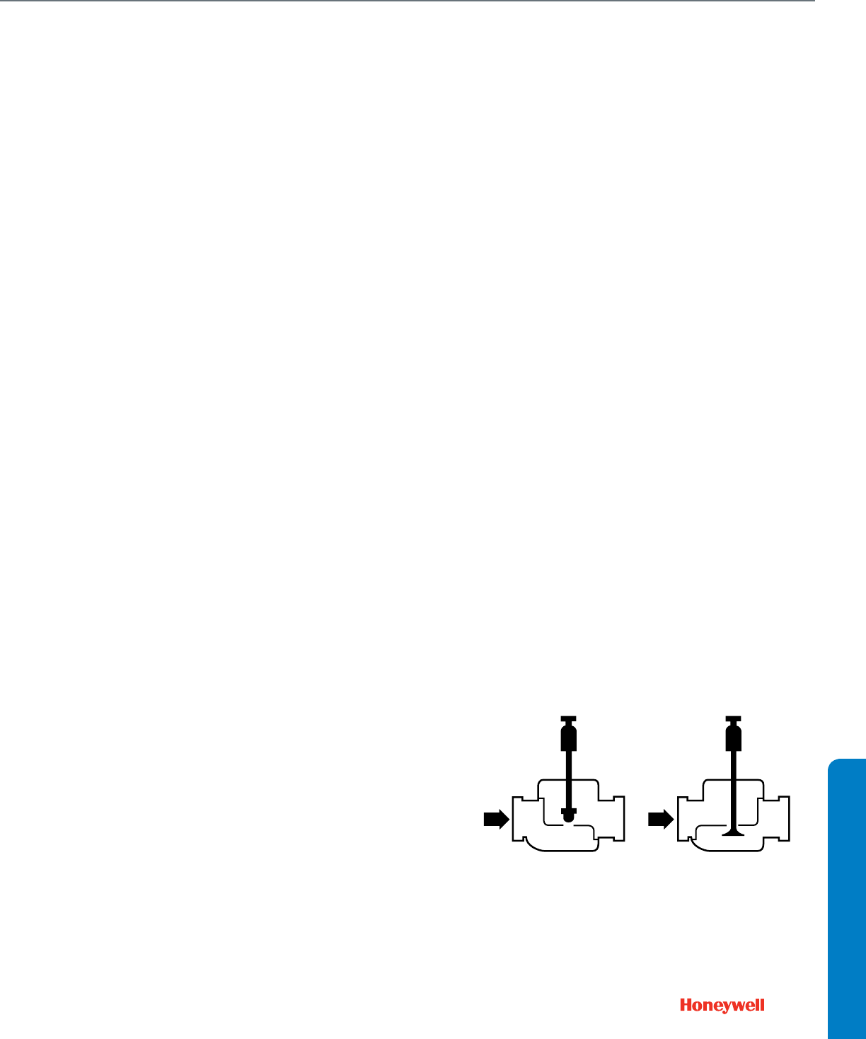
249
APPENDIX
Valve Selection
Proper valve selection matches a valve to the control and
hydronic system physical requirements. First consider the
application requirements and then consider the valve
characteristics necessary to meet those requirements. The
following questions provide a guide to correct valve selection.
— What is the piping arrangement and size?
The piping arrangement indicates whether a two-way or
three-way mixing or diverting valve is needed. The piping
size gives some indication of whether the valve requires a
screwed end or a flanged end connection.
— Does the application require two-position control or
proportional control? Does the application require a normally
open or normally closed valve? Should the actuator be direct
acting or reverse acting?
In its state of rest, the valve is normally open or closed
depending on the load being controlled, the fluid being
controlled, and the system configuration.
For chilled water coils, it is usually preferable to close the
valve on fan shutdown to prevent excessive condensation
around the duct and coil, and to save pumping energy. This
may be accomplished with either normally closed valves or a
variety of other control schemes. Lower cost and more
powerful normally open valve assemblies may be used with
the close-on-shutdown feature and allow, in the case of
pneumatic systems, the capability to provide heating or
cooling in the event of air compressor failure.
Converter control valves should be normally closed and
outdoor air preheat valves should be normally open.
— Is tight shut-off necessary? What differential pressure does
the valve have to close against? How much actuator close-
off force is required?
Valves should never be allowed to "dead head" a pump
unless the pumps are controlled by variable speed drive
systems capable of detecting such conditions and shutting
down the pumps.
Single-seated valves provide tight shut-off, while double-
seated valves do not. Double seated valves are acceptable
for use in pressure bypass or in-line throttling applications.
The design and flow capacity of a valve determine who much
actuator force is required for a given close-off. Therefore, the
valve must first be sized, then, the valve and actuator
selected to provide the required close-off.
— What type of medium is being controlled? What are the
temperature and pressure ranges of the medium?
Valves must be compatible with system media composition,
maximum and minimum temperature, and maximum
pressure. The temperature and pressure of the medium
being controlled should not exceed the maximum
temperature and pressure ratings of the valve.
For applications such as chlorinated water or brine, select
valve materials to avoid corrosion.
— What is the pressure drop across the valve? Is the pressure
drop high enough?
The full open pressure drop across the valve must be high
enough to allow the valve to exercise control over its portion
of the hydronic system. However, the full open pressure drop
must not exceed the valves rating for quiet service and
normal life. Closed pressure drop must not exceed valve and
actuator close-off rating.
Globe Valve
Globe valves are popular for HVAC applications. They are
available in pipe sizes from 1/2 in. to 12 in. and in a large variety
of capacities, flow characteristics, and temperature and
pressure capabilities. They provide wide rangeability and tight
shutoff for excellent control over a broad range of conditions.
Globe valves are made in two-way, straight or angle
configurations and three-way mixing and diverting designs.
Globe valves close against the flow and have arrows on the
body indicating correct flow direction. Incorrect piping can result
in stem oscillations, noise, and high wear.
A two-way globe valve has one inlet port and one outlet port
(Fig. 5) in either a straight through or angle pattern. The valve
can be either push-down-to-close or push-down-to-open.
Pneumatic and electric actuators with linear motion to operate
globe valves are available for operation with many control
signals.
Fig. 5. Two-Way Globe Valves.
IN IN
PUSH-DOWN-TO-CLOSE
(DIRECT ACTING)
PUSH-DOWN-TO-OPEN
(REVERSE ACTING)
C2328A
Appendix A: Valve Selection and Sizing
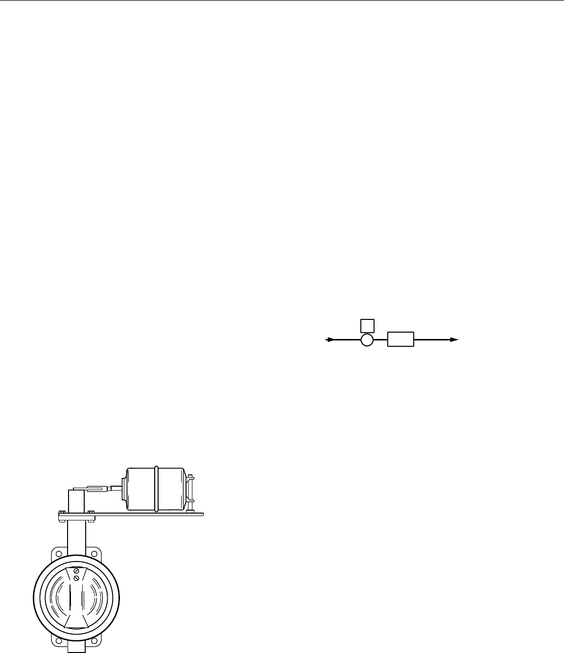
250
Ball Valve
Ball valves are available for two-position applications either
manual (hand) or power operated or for modulating applications
with direct coupled electric actuators. Ball valves are relatively
low cost, provide tight close off, and are available in two-way
and three-way configurations. As with all other valves, ball
valves must be properly sized to provide good flow control.
When used in modulating service, ball valves must be
specifically designed for modulating service as compared to
two-position service. Packing must provide leak-free sealing
through thousands of cycles to ensure trouble-free HVAC
service. The ball, stem and seals should be made of materials
that minimizes sticking and breakaway torque to achieve
smooth operation.
Two-way ball valves have equal percentage flow control
characteristics and flow in full-port models can be in either
direction.
Three-way ball valves can be used in either mixing or diverting
service. Full port models have linear flow control characteristics
for constant total flow. A popular option with 3-way valves is a
20% flow capacity reduction in the B port to equalize pressure
losses in a coil-bypass application.
Butterfly Valve
Butterfly valves (Fig. 6) control the flow of hot, chilled, or
condenser water in two-position or proportional applications.
Butterfly valves are available in two-way or three-way
configurations. Tight shutoff may be achieved by proper
selection of actuator force and body lining. The three-way valve
can be used in mixing or diverting applications with the flow in
any direction. The three-way valve consists of two butterfly
valves that mount on a flanged cast iron tee and are linked to an
actuator which opens one valve as it closes the other. Minimum
combined capacity of both valves occurs at the half-open
position.
Fig. 6. Butterfly Valve.
When butterfly valves are used for proportional control, they
must be applied using conservative pressure drop criteria. If the
pressure drop approaches the critical pressure drop,
unbalanced forces on the disc can cause oscillations, poor
control, and/or damage to the linkage and actuator, even
though the critical flow point is not reached. Modulating control
is usually limited to a range of 15 to 65 degrees of disk rotation.
Butterfly valves are usually found in larger pipe sizes. For
example, two butterfly valves could be piped in a mixing
application to control the temperature of the water going back to
the condenser. The valves proportion the amount of tower water
and condenser water return that is flowing in the condenser
water supply line.
Two-way Valve
Two-way valves are available as globe, ball, or butterfly valves.
The combination of valve body and actuator (called valve
assembly) determines the valve stem position. Two-way valves
control steam or water in two-position or proportional
applications (Fig. 7). They provide tight shutoff and are
available with quick-opening, linear, or equal percentage flow
characteristics. Control valves are typically installed on the
supply side of convectors and radiators, and the return side of
small-bore water coils used in fan-forced equipment.
Fig. 7. Two-Way Valve Application.
Ideally, a control system has a linear response over its entire
operating range. The sensitivity of the control to a change in
temperature is then constant throughout the entire control
range. For example, a small increase in temperature provides a
small increase in cooling. A nonlinear system has varying
sensitivity. For example, a small increase in temperature can
provide a large increase in cooling in one part of the operating
range and a small increase in another part of the operating
range. To achieve linear control, the combined system
performance of the actuator, control valve, and load must be
linear. If the system is linear, a linear control valve is appropriate
(Fig. 8). If the system is not linear, a nonlinear control valve,
such as an equal percentage valve, is appropriate to balance
the system so that resultant performance is linear.
M10403
SUPPLY
LOAD RETURN
C2329
TWO–WAY
VALVE
Appendix A: Valve Selection and Sizing
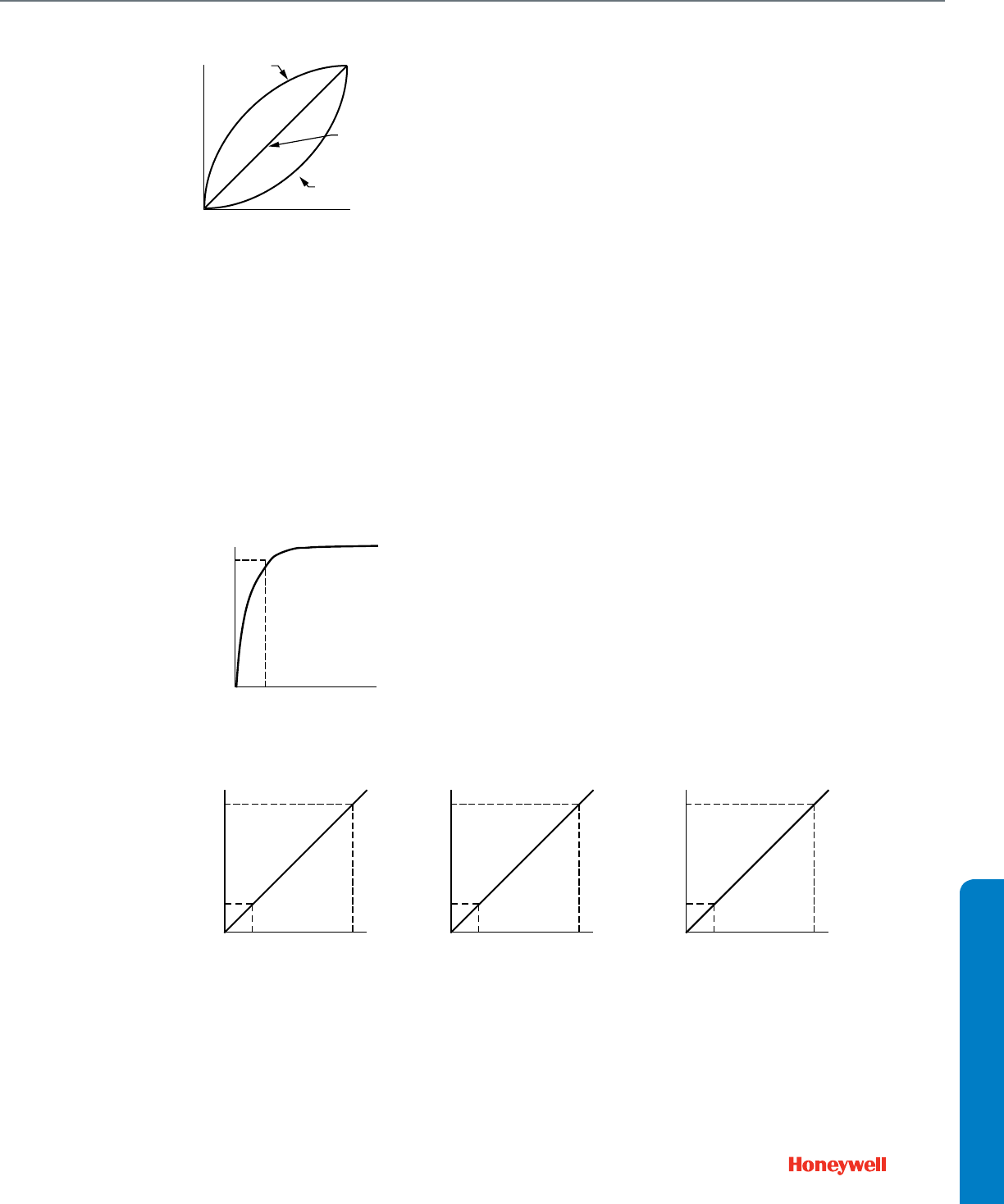
251
APPENDIX
Fig. 8. Linear vs. Nonlinear System Control.
QUICK-OPENING VALVE
A quick-opening two-way valve includes only a disc guide and a
flat or quick-opening plug. This type of valve is used for two
position control of steam. The pressure drop for a quick opening
two-way valve should be 10 to 20 percent of the piping system
pressure differential, leaving the other 80 to 90 percent for the
load and piping connections.Figure 9 shows the relationship of
flow versus stem travel for a quick-opening valve. To achieve 90
percent flow, the stem must open only 20 percent. Linear or
equal percentage valves can be used in lieu of quick-opening
valves in two-position control applications as the only significant
positions are full open and full closed.
Fig. 9. Flow vs. Stem Travel Characteristic of a Quick-
Opening Valve.
Linear Valve
A linear valve may include a V-port plug or a contoured plug.
This type of valve is used for proportional control of steam or
chilled water, or in applications that do not have wide load
variations. Typically in steam or chilled water applications,
changes in flow through the load (e.g., heat exchanger, coil)
cause proportional changes in heat output. For example, Figure
10 shows the relationships between heat output, flow, and stem
travel given a steam heat exchanger and a linear valve as
follows:
— Graph A shows the linear relationship between heat output
and flow for the steam heat exchanger. Changes in heat
output vary directly with changes in the fluid flow.
— Graph B shows the linear relationship between flow and
stem travel for the linear control valve. Changes in stem
travel vary directly with changes in the fluid flow.
NOTE: As a linear valve just starts to open, a minimum
flow occurs due to clearances required to pre-
vent sticking of the valve. Some valves have a
modified linear characteristic to reduce this mini-
mum controllable flow. This modified character-
istic is similar to an equal percentage valve
characteristic for the first 5 to 10 percent of stem
lift and then follows a linear valve characteristic
for the remainder of the stem travel.
— Graph C shows the linear relationship between heat output
and stem travel for the combined heat exchanger and linear
valve. Changes in heat output are directly proportional to
changes in the stem travel.
Thus a linear valve is used in linear applications to provide
linear control.
Fig. 10. Heat Output, Flow, and Stem Travel Characteristics of a Linear Valve.
EQUAL PERCENTAGE VALVE
An equal percentage valve includes a contoured plug or
contoured V-port shaped so that similar movements in stem
travel at any point in the flow range change the existing flow an
equal percentage, regardless of flow rate. In mathematical
terms, this is an exponential response.
100%
0% 100%
NONLINEAR SYSTEM
RESPONSE
RESULTANT
LINEAR SYSTEM
CONTROL
EQUAL PERCENTAGE
CONTROL VALVE
TEMPERATURE
PERCENTAGE OF
FULL COOLING
C2330
100%
0% 100%
STEM TRAVEL
FLOW
C2331
90%
20%
QUICK-OPENING
CONTROL VALVE
C2332
100%
0% 100%
FLOW
HEAT OUTPUT
HEAT OUTPUT
90%
20% 90%
100%
0% 100%
STEM TRAVEL
FLOW
90%
20% 90%
100%
0% 100%
STEM TRAVEL
90%
20% 90%
GRAPH A GRAPH B GRAPH C
20% 20% 20%
Appendix A: Valve Selection and Sizing
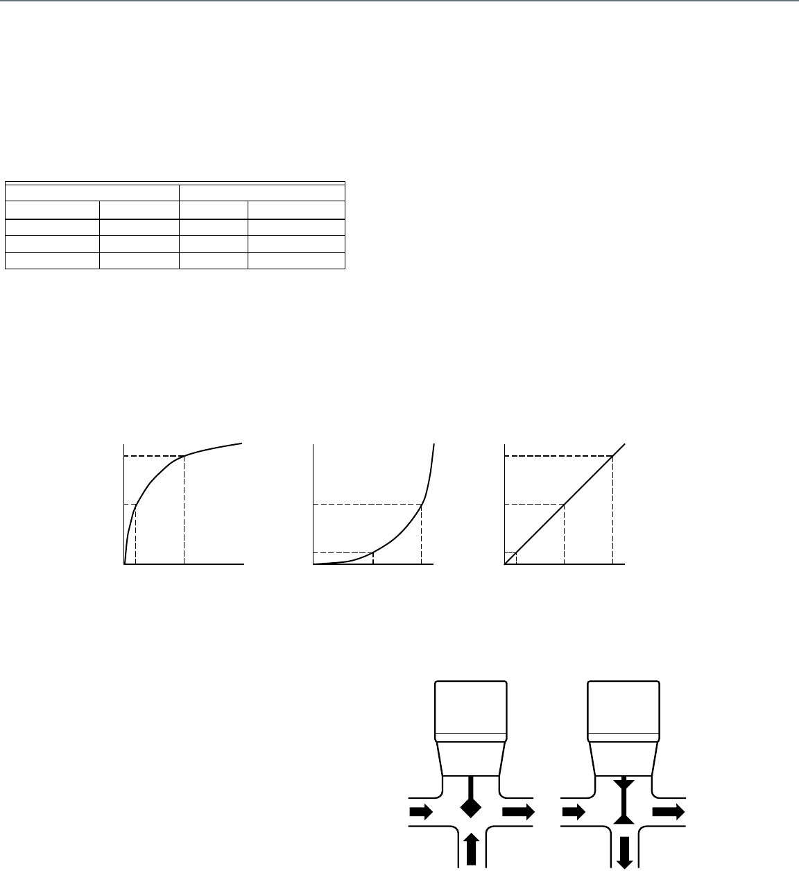
252
EXAMPLE:
When a valve with the stem at 30 percent of its total lift and
existing flow of 3.9 gpm (Table 2) opens an additional 10 per-
cent of its full travel, the flow measures 6.2 gpm or increases
60 percent. If the valve opens an additional 10 percent so
the stem is at 50 percent of its full travel, the flow increases
another 60 percent and is 9.9 gpm.
Table 2. Stem Position vs. Flow for Equal Percentage Valve.
An equal percentage valve is used for proportional control in hot
water applications and is useful in control applications where
wide load variations can occur. Typically in hot water
applications, large reductions in flow through the load (e.g., coil)
cause small reductions in heat output. An equal percentage
valve is used in these applications to achieve linear control. For
example, Figure 11 shows the heat output, flow, and stem travel
relationships for a hot water coil, with 200F, entering water and
50F entering air and an equal percentage valve, as follows:
— Graph A shows the nonlinear relationship between heat
output and flow for the hot water coil. A 50 percent reduction
in flow causes a 10 percent reduction in heat output. To
reduce the heat output by 50 percent, the flow must
decrease 90 percent.
— Graph B shows the nonlinear relationship between flow and
stem travel for the equal percentage control valve. To reduce
the flow 50 percent, the stem must close 10 percent. If the
stem closes 50 percent, the flow reduces 90 percent.
— Graph C shows the relationship between heat output and
stem travel for the combined coil and equal percentage
valve. The combined relationship is close to linear. A 10
percent reduction in heat output requires the stem to close
10 percent, a 50 percent reduction in heat output requires
the stem to close 50 percent, and a 90 percent reduction in
heat output requires the stem to close 90 percent.
The equal percentage valve compensates for the
characteristics of a hot water application to provide a control
that is close to linear.
Fig. 11. Heat Output, Flow, and Stem Travel Characteristics of an Equal Percentage Valve.
Three-way Valves
Three-way valves (Fig. 12) control the flow of liquids in mixing or
diverting valve applications (Fig. 13). The internal design of a
three-way globe valve enables it to seat against the flow of
liquid in the different applications. An arrow cast on the valve
body indicates the proper direction of liquid flow. It is important
to connect three-way valve piping correctly or oscillations,
noise, and excessive valve wear can result. Three-way valves
are typically have linear flow characteristics, although, some are
equal percentage for flow through the coil with linear flow
characteristics for flow through the coil bypass. Ball valves are
also available in a three-way configuration, while two butterfly
valves can be made to act as a three-way valve.
Fig. 12. Three-Way Valves.
Stem Flow
Change Position Rate Change
— 30% open 3.9 gpm —
10% increase 40% open 6.2 gpm 60% increase
10% increase 50% open 9.9 gpm 60% increase
HEAT OUTPUT
HEAT OUTPUT
C2333
100%
0% 100%
FLOW
90%
10%
100%
0% 100%
STEM TRAVEL
FLOW
90%
100%
0% 100%
STEM TRAVEL
90%
10%
GRAPH A GRAPH B GRAPH C
50%
50%
50%
10%
50%
50%
50% 90%
10%
OUT
I
N
MIXING
VALVE
C2334A
DIVERTING
VALVE
IN OUT
IN
O
U
T
Appendix A: Valve Selection and Sizing
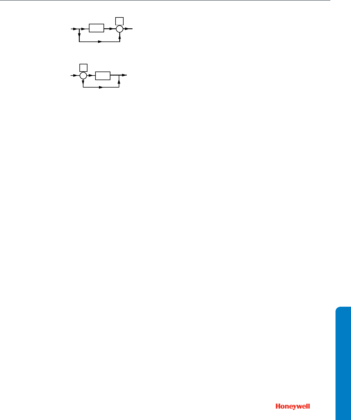
253
APPENDIX
Fig. 13. Three-Way Valve Applications.
MIXING VALVE
A mixing valve provides two inlet ports and one common outlet
port. The valve receives liquids to be mixed from the inlet ports
and discharges the liquid through the outlet port (Fig. 12). The
position of the valve disc determines the mixing proportions of
the liquids from the inlet ports.
The close-off pressure in a mixing valve equals the maximum
value of the greater inlet pressure minus the minimum value of
the downstream pressure.
EXAMPLE:
A mixing valve application has a maximum pressure of
25 psi on one inlet port, maximum pressure of 20 psi on the
other inlet port, and minimum downstream pressure of
10 psi on the outlet port. The close-off pressure is 25 psi –
10 psi = 15 psi. The application requires a mixing valve with
at least a 15 psi close-off rating. The actuator selected must
have a high enough force to operate satisfactorily.
In globe mixing valve applications, the force exerted on the
valve disc due to unbalanced pressure at the inlets usually
remains in the same direction. In cases where there is a
reversal of force, the force changes direction and holds the
valve disc off the seat, cushioning it as it closes. If the pressure
difference for the system is greater than the pressure ratings of
available globe mixing valves, use a ball mixing valve or two
butterfly valves in a tee configuration.
Globe mixing valves are not suitable for modulating diverting
valve applications. If a mixing valve is piped for modulating
diverting service, the inlet pressure slams the disc against the
seat when it nears the closed position. This results in loss of
control, oscillations, and excessive valve wear and noise.
Mixing valves are acceptable using about 80 percent of the
close-off rating, but not recommended, in two-position diverting
valve applications.
DIVERTING VALVE
A globe diverting valve provides one common inlet port and two
outlet ports. The diverting valve uses two V-port plugs which
seat in opposite directions and against the common inlet flow.
The valve receives a liquid from one inlet port and discharges
the liquids through the outlet ports (Fig. 12) depending on the
position of the valve disc. If the valve disc is against the bottom
seat (stem up), all the liquid discharges through the side outlet
port. If the valve disc is against the top seat (stem down), all the
liquid discharges through the bottom outlet port.
The close-off pressure in a diverting valve equals the maximum
value of the inlet pressure minus the minimum value of the
downstream pressure.
Globe diverting valves must not be used for mixing service. As
with mixing valves used for diverting service, media pressure
drop across the valve can cause it to slam shut with resulting
loss of control.
EXAMPLE:
A diverting valve application has 20 psi maximum on the inlet
port, one outlet port discharging to the atmosphere, and the
other outlet port connecting to a tank under 10 psi constant
pressure. The pressure difference between the inlet and the
first outlet port is 20 psi and between the inlet and second
outlet port is 10 psi. The application requires a diverting
valve with at least 20 psi close-off rating.
Valve Sizing
Every valve has a capacity index or flow coefficient (Cv).
Typically determined for the globe and ball valves at full open
and about 60 degrees open for butterfly valves. Cv is the
quantity of water in gpm at 60F that flows through a valve with a
pressure differential of 1 psi. Sizing a valve requires knowing
the medium (liquid or gas) and the required pressure differential
to calculate the required Cv
. When the required Cv is not
available in a standard valve, select the next closest and
calculate the resulting valve pressure differential at the required
flow to verify to verify acceptable performance.
After determination of the valve Cv, calculation of the flow of any
medium through that valve can be found if the characteristics of
the medium and the pressure drop across the valve are known.
C2335A
LOAD
LOAD
SUPPLY
THREE-WAY
DIVERTING VALVE
RETURN
B. LOAD BYPASS IN DIVERTING VALVE APPLICATION
BYPASS
HOT
WATER
SUPPLY
THREE-WAY
MIXING VALVE
BYPASS
HOT
WATER
RETURN
A. LOAD BYPASS IN MIXING VALVE APPLICATION
Appendix A: Valve Selection and Sizing
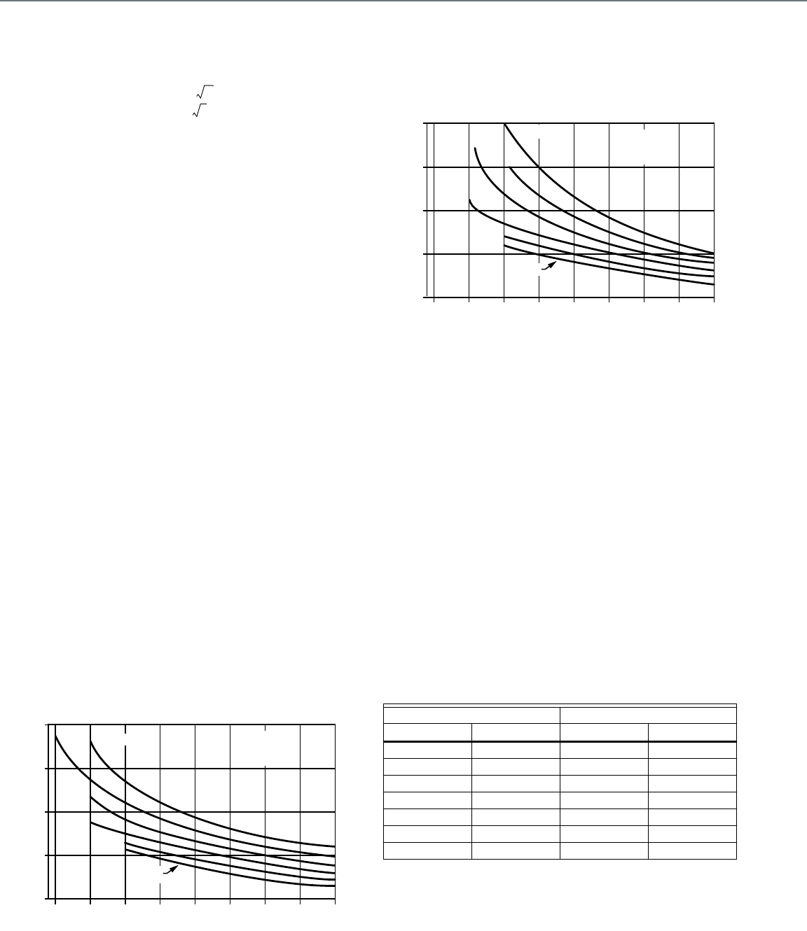
254
Water Valves
Determine the capacity index (Cv) for a valve used in a water
application, using the formula:
Where:
Q = Flow of fluid in gallons per minute required
to pass through the valve.
G = Specific gravity of the fluid (water = 1).
h = Pressure drop in psi. See Figures 14 and
15 for glycol solution correction values.
NOTE: The calculated Cv will rarely match the Cv of an avail-
able valve. For most accurate proportional control,
select the valve with the next lower Cv value, and
increase the pressure drop across the control valve to
achieve the required flow through the coil by reducing
the setting of the balancing valve. Otherwise, turn-
down ratio will be reduced, proportionally.
For example, if the calculated Cv is 87, and the two
closest Cv values are 63 and 100, the best choice for
control precision would be the valve with a Cv of 63,
and increase pressure drop across the valve by 90%.
If increased pressure drop is not possible, use the
valve with Cv of 100, and accept a 13% reduction in
valve rangeability.
For two-position control, always chose the largest Cv
greater than the coil with acceptable close-off pressure
rating.
Determining the Cv of a water valve requires knowing the
quantity of water (gpm) through the valve and the pressure drop
(h) across the valve. If the fluid is a glycol solution, use the
pressure drop multipliers from either Figure 14 or 15. See the
sections on QUANTITY OF WATER and WATER VALVE
PRESSURE DROP. Then select the appropriate valve based on
Cv
, temperature range, action, body ratings, etc., per VALVE
SELECTION guidelines.
REPRINTED BY PERMISSION FROM ASHRAE HANDBOOK—
1996 HVAC SYSTEMS AND EQUIPMENT
Fig. 14. Pressure Drop Correction for
Ethylene Glycol Solutions
REPRINTED BY PERMISSION FROM ASHRAE HANDBOOK—
1996 HVAC SYSTEMS AND EQUIPMENT
Fig. 15. Pressure Drop Correction for Propylene Glycol
Solutions.
Quantity of Water
To find the quantity of water (Q) in gallons per minute use one of
the following formulas:
1. When Btu/hr is known:
Where:
Btu/hr= Heat output.
K = Value from Table 3; based on temperature
of water entering the coil. The value is in
pounds per gallon x 60 minutes per hour.
TDw= Temperature difference of water entering
and leaving the coil.
Table 3. Water Flow Formula Table
CV
QG
h
-------------=
0
0.8
1.0
1.2
1.4
1.6
40 80 120 160
PRESSURE DROP CORRECTION FACTOR
TEMPERATURE, F
ETHYLENE
GLYCOL
SOLUTION
WATER
M12226
10%
20%
30%
40% 50% BY MASS
Water Water
Temp F K Temp F K
40 502 200 484
60 500 225 483
80 498 250 479
100 496 275 478
120 495 300 473
150 490 350 470
180 487 400 465
0
0.8
1.0
1.2
1.4
1.6
40 80 120 160
PRESSURE DROP CORRECTION FACTOR
TEMPERATURE, F
PROPYLENE
GLYCOL
SOLUTION
WATER
M12227
10%
20%
30%
40%
50% BY MASS
QBtu hr⁄
K TDw
×
----------------------=
Appendix A: Valve Selection and Sizing

255
APPENDIX
2. For hot water coil valves:
Where:
cfm = Airflow through the coil.
1.08 = A scaling constant. See Note.
TDa= Temperature difference of air entering and
leaving the coil.
K = Value from Table 3; based on temperature
of water entering the coil (pounds per
gallon x 60 minutes per hour).
TDw= Temperature difference of water entering
and leaving the coil.
NOTE: The scaling constant 1.08 is derived as follows:
Where:
Simplifying the equation:
To find the scaling constant for air conditions other
than standard, divide 14.40 Btu by specific volume of
air at those conditions.
3. For fan system chilled water coil valves:
Where:
cfm = Airflow through the coil.
Btu/lb = Heat per pound of dry air removed.
Includes both sensible and latent heat.
113 = A scaling constant.
TDw= Temperature difference of water entering
and leaving the coil.
WATER VALVE PRESSURE DROP
To determine valve pressure drop:
1. For two-way valves consider the following guidelines for
valve pressure drop:
a. Include the pressure drop in the design of the water
circulating system.
— In systems with two-way valves only, it is often
necessary to provide a pump relief bypass or
some other means of differential pressure control
to limit valve pressure drops to the valve
capabilities. For control stability at light loads,
pressure drop across the fully closed valve should
not exceed triple the pressure drop used for sizing
the valve.
— To avoid high pressure drops near the pump,
reverse returns are recommended in large
systems.
b. The pressure drop across an open valve should be
about half of the pressure difference between system
supply and return, enough so that the valve, not the
friction through the coil or radiator, controls the vol-
ume of water flow or the valve pressure drop should
be equal to or greater than the pressure drop through
the coil or radiator, plus the pipe and fittings connect-
ing them to the supply and return mains.
c. Verify allowable full open and full closed pressure
drops for all proportional and two-position water
valves with appropriate manufacturer literature.
d. Make an analysis of the system at maximum and min-
imum rates of flow to determine whether or not the
pressure difference between the supply and return
mains stays within the limits that are acceptable from
the stand point of control stability and close-off rating.
2. For two- and three-way valves consider the following
guidelines for valve pressure drop:
a. In load bypass applications (Fig. 13) such as radia-
tors, coils, and air conditioning units, the pressure
drop should be 50 to 70 percent of the minimum dif-
ference between the supply and return main pressure
at design operating conditions.
b. A manual balancing valve may be installed in the
bypass to equalize the load drop and the bypass drop.
3. When selecting pressure drops for three-way mixing
valves in boiler bypass applications (Fig. 13), consider the
following:
a. Determine the design pressure drop through the
boiler including all of the piping, valves, and fittings
from the bypass connection through the boiler and up
to the three-way valve input.
b. The valve pressure drop should be equal to or greater
than the drop through the boiler and the fittings. If the
valve drop is much smaller than the boiler pressure
drop at design, effective control is obtained only when
the disc is near one of the two seats. The mid-portion
of the valve lift will be relatively ineffective.
= the specific volume of air at standard
conditions of temperature and
atmospheric pressure.
Q
cfm 1.08 TDa
××
K TDw
×
---------------------------------------------=
1.08 0.24BTU
lbairF
-----------------------60min
1hr
---------------- 1lbair
13.35ft3
--------------------××=
1lbair
13.35ft3
--------------------
1.08 14 40Btumin,
Fhr13.35ft3
-----------------------------------=
Qcfm Btu lb⁄×
113 TDw
×
------------------------------------=
Appendix A: Valve Selection and Sizing

256
c. A manual balancing valve may be installed in the
boiler bypass to equalize the boiler drop and the
bypass drop.
WATER VALVE SIZING EXAMPLES
EXAMPLE 1:
A two-way linear valve is needed to control flow of 45F
chilled water to a cooling coil. The coil manufacturer has
specified an eight-row coil having a water flow pressure drop
of 3.16 psi. Further, specifications say that the coil will pro-
duce 55F leaving air with a water flow of 14.6 gpm. Supply
main is maintained at 40 psig, return is at 30 psig. Select
required capacity index (Cv) of the valve.
Use the water valve Cv formula to determine capacity index
for Valve V1 as follows:
Where:
Q = Flow of fluid in gallons per minute required
is 14.6 gpm.
G = Specific gravity of water is 1.
h = Pressure drop across the valve. The
difference between the supply and return
is 10 psi. 50% to 70% x 10 psi = 5 to 7 psi.
Use 6 psi for the correct valve pressure
drop. Note that 6 psi is also greater than
the coil pressure drop of 3.16 psi.
Substituting:
Select a linear valve providing close control with a capacity
index of 6 and meeting the required pressure and temperature
ratings.
EXAMPLE 2:
A bypass valve is required to prevent flow through the chiller
from dropping below 90 percent of design flow. When sizing
valves for pump or chiller bypass applications (Fig. 16), sys-
tem conditions that cause the valve to open or close com-
pletely must be considered before a pressure drop can be
selected.
Assume the following:
System flow at design, 1000 gpm
Pump head at design, 48 ft
Pump head at 90 percent flow, 50 ft
Pressure across mains at AHU 1 at design flow, 28 ft
Chiller pressure drop, 12 ft
Chiller piping loop design pressure drop, 8 ft
With full system flow, Valve V5 is closed. Pressure drop
across V5 equals the pump head minus the friction drops to
V5. Pressure drop across Valve V5 is then 48 ft – 12 ft
(chiller drop) – 4 ft (supply drop) – 4 ft (return drop) or 28 ft.
With system flow at 90 percent, the pump head rises to
50 ft, while the friction drops fall to the lower values shown in
Figure 16. For additional information on chiller bypass opera-
tion see Chiller, Boiler, and Distribution System Applications
section. Pressure drop across V5 equals the pump head
minus the friction drops to V5. Pressure drop across Valve
V5 is then 50 ft – 9.6 ft (chiller drop) – 3.2 ft (supply drop) –
3.2 ft (return drop) or 34 ft. Converting ft to psi, 34 ft x 0.4335
psi/ft = 14.7 psi.
Substituting the flow of water, specific gravity of water, and
pressure drop in the Cv formula shows that the Valve V5
should have a Cv of 235.
Cv
QG
h
-------------=
Cv
14.6 1
6
------------------6==
Cv
900 1
14.7
---------------- 235==
Appendix A: Valve Selection and Sizing
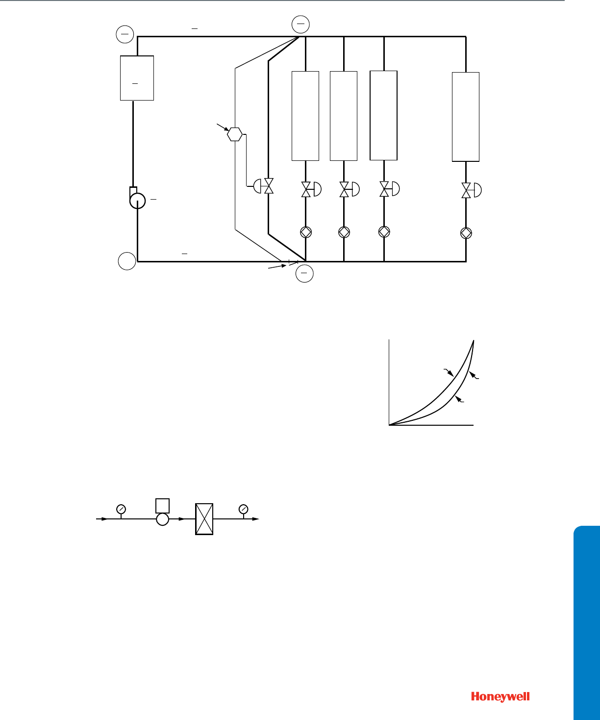
257
APPENDIX
Fig. 16. Chiller Bypass Application.
EXAMPLE 3:
Sizing water valves for heating coils is especially critical. In
Figure 17, a valve with a Cv of 12 will have 30 percent of the
available pressure drop when full open, while a valve with a
Cv of 5 will have 70 percent of the available pressure drop.
As shown in Figure 18, the valve with 70 percent of the avail-
able pressure drop essentially provides the equal percent-
age water flow control, resulting in linear coil heat transfer
and stable temperature control. The valve with only 30 per-
cent of the available pressure drop has a more linear flow
control which results in nonlinear coil heat transfer. See
EQUAL PERCENTAGE VALVE section for further informa-
tion.
Fig. 17. Equal Percentage Valve Hot Water Application.
Fig 18. Effect of Pressure Drop in Hot Water Valve Sizing.
EXAMPLE 4:
A three-way mixing valve is needed for a heat exchanger
application with a bypass line. Water flow is specified at the
rate of 70 gpm. Manufacturer data for the exchanger indi-
cates a pressure drop of 1.41 ft of water through the
exchanger coils.
RETURN
SYSTEM STRAINER
HEAT/
COOL
COIL
1
V1
B1
HEAT/
COOL
COIL
2
V2
B2
HEAT/
COOL
COIL
3
V3
B3
HEAT/
COOL
COIL
4
V4
B4
V5
PUMP
SUPPLY
DP SETPOINT = 34'
180 GPM
PER
AHU COIL
DP
M10605
CHILLER
12
9.6
36
40.4
48
50
PD
4
3.2
4
3.2
PD
4
3.2 PD
ZERO REFERENCE
0
32
37.2
NUMBERS IN CIRCLES = GAGE PRESSURES
PUMP INLET = ZERO FOR SIMPLICITY
TOP NUMBERS = FULL FLOW
BOTTOM NUMBER = 90% FLOW
PD = PRESSURE DROP
VALVE VI
C2339A
180F
HOT WATER
SUPPLY
40 PSI
HOT WATER
RETURN
HEATING
COIL
LOCAL
PIPING
2.2 PSI
DROP
20 GPM AT DESIGN,
4.3 PSI DROP
30% PRESSURE DROP, Cv = 12
70% PRESSURE DROP, Cv = 5
CASE B: 62 PSI
CASE A: 50 PSI
100%
0% 100%
STEM TRAVEL
FLOW AT CONSTANT
PRESSURE DROP
C2340
70%
PRESSURE
DROP
30%
PRESSURE
DROP
IDEAL EQUAL
PERCENTAGE
VALVE
CHARACTERISTIC
Appendix A: Valve Selection and Sizing

258
Use the water valve Cv formula to determine capacity index
for Valve V1 as follows:
Where:
Q = Flow of fluid in gallons per minute required
to pass through the valve is 70 gpm.
G = Specific gravity of water is 1.
h = Pressure drop across the valve. Plans of
the heating system indicate three-inch
supply and return mains. From an elbow
equivalent table and pipe friction chart
found in the ASHRAE Handbook or other
reference manuals, the calculated
pressure drop through a three-inch tee
and the piping from the valve and the tee
to the exchanger is
0.09 psi. Heat exchanger pressure drop is
1.41 ft of water or 1.41 ft x 0.433 psi/ft =
0.61 psi. Total pressure drop from bypass
connection through the heat exchanger
and to the hot-water input of the three-way
valve is 0.61 + 0.09 or 0.70 psi.
Since the valve pressure drop (h) should be equal to or
greater than the drop through the heat exchanger and fit-
tings, 0.70 psi is used as the valve pressure drop.
For optimum control, a manual balancing valve is installed in
the bypass line to equalize the pressure drops in the
exchanger and bypass circuits.
Substituting the flow of water, specific gravity of water, and
pressure drop in the Cv formula shows that the valve should
have a Cv of 83.6 or 84.
Select a linear valve providing close control with a capacity
index of 84 and meeting the required pressure and tempera-
ture ratings.
Steam Valves
Calculate the required capacity index (Cv) for a valve used in a
steam application, using the formula:
Where:
Q = Quantity of steam in pounds per hour
required to pass through the valve.
V = Specific volume of steam, in cubic feet per
pound, at the average pressure in the
valve. For convenience Table 5 at the end
of the STEAM VALVES section lists the
square root of the specific volume of
steam for various steam pressures.
Therefore, use the value in this column of
the table as is; do not take its square root.
63.5 = A scaling constant.
h = Pressure drop in psi.
s = Superheat in degrees F.
Determining the Cv for a steam valve requires knowing, the
quantity of steam (Q) through the valve, the pressure drop (h)
across the valve, and the degrees of superheat. See
QUANTITY OF STEAM and STEAM VALVE PRESSURE
DROP. Then select the appropriate valve based on Cv,
temperature range, action, body ratings, etc., per VALVE
SELECTION guidelines.
NOTE: When the superheat is 0F, then (1 + 0.00075s) equals
1 and may be ignored.
QUANTITY OF STEAM
To find the quantity of steam (Q) in pounds per hour use one of
the following formulas:
1. When Btu/hr (heat output) is known:
Where:
Btu/hr = Heat output.
1000 Btu/lb= A scaling constant representing the
approximate heat of vaporization of
steam.
2. For sizing steam coil valves:
Where:
cfm = Cubic feet per minute (ft3/min) of air from
the fan.
TDa = Temperature difference of air entering and
leaving the coil.
1.08 = A scaling constant. See NOTE.
1000 Btu/lb= A scaling constant representing the
approximate heat of vaporization of
steam.
Cv
QG
h
-------------=
Cv
70 1
0.70
-------------- 83.6 or 84==
Cv
1 0.00075s+()QV
63.5 h
--------------------------------------------------=
QBtu hr⁄
1000Btu lbsteam⁄
-------------------------------------------------=
Q
CFM TDa
×1.08×
1000Btu lbsteam⁄
-------------------------------------------------=
Appendix A: Valve Selection and Sizing

259
APPENDIX
NOTE: The scaling constant 1.08 is derived as follows:
Where:
Simplifying the equation:
To find the scaling constant for air conditions other
than standard, divide 14.40 Btu by specific volume of
air at those conditions.
3. For sizing steam to hot water converter valves:
Where:
gpm = Gallons per minute of water flow through
converter.
TD
w
= Temperature difference of water entering
and leaving the converter.
0.49 = A scaling constant. This value is derived
as follows:
Simplifying the equation:
4. When sizing steam jet humidifier valves:
Where:
W1 = Humidity ratio entering humidifier, pounds
of moisture per pound of dry air.
W2 = Humidity ratio leaving humidifier, pounds
of moisture per pound of dry air.
= The specific volume of air at standard
conditions of temperature and
atmospheric pressure.
= Cubic feet per minute (cfm) of air from the
fan.
= A conversion factor.
Simplifying:
5. When Equivalent Direct Radiation (EDR) is known:
Where:
EDR (Total)=Radiators are sized according to
Equivalent Direct Radiation (EDR). If
controlling several pieces of radiation
equipment with one valve, add the EDR
values for all pieces to obtain the total
EDR for the formula.
0.24 = A scaling constant, lb steam/unit EDR.
See Table 4.
Table 4. Output of Radiators and Convectors.
STEAM VALVE PRESSURE DROP
Proportional Applications
When specified, use that pressure drop (h) across the valve.
When not specified:
1. Calculate the pressure drop (h) across the valve for good
modulating control:
h = 80% x (Pm-Pr)
NOTE: For a zone valve in a system using radiator ori-
fices use:
h = (50 - 75)% x (Pm-Pr)
Where
Pm = Pressure in supply main in psig or psia
(gage or absolute pressure).
Pr = Pressure in return in psig or psia. A
negative value if a vacuum return.
= the specific volume of air at standard
conditions of temperature and
atmospheric pressure.
1.08 0.24BTU
lbairF
-----------------------60min
1hr
----------------×1lbair
13.35ft3
--------------------×=
1lbair
13.35ft3
--------------------
1.08 14.40Btumin
Fhr13.35ft3
----------------------------------=
Q gpm TDw
×0.49×=
0.49 8.33lbwater
1gal
-------------------------------- 60min
1hr
----------------×1lbsteam
1000Btu
--------------------------×1Btu
lb water F
------------------------×=
0.49 0.49minlbsteam
galhrF
---------------------------------------------=
Q
W1W2
–()lbmoisture
lbair
----------------------------------------------------------- 1
13.35ft3
lbair
--------------------
---------------------×ft3
min
----------×60min
hr
----------------×=
13.35ft3
lbair
--------------------
ft3
min
----------
60min
hr
----------------
Average Radiator of
Convector
Temperature, Deg F
Cast Iron Radiator
Btu/Hr/EDR
a
Convector, Btu/
Hr/EDR
b
215 240 240
200 209 205
190 187 183
180 167 162
170 148 140
160 129 120
150 111 102
140 93 85
130 76 69
120 60 53
110 45 39
100 31 27
90 18 16
a At Room Termperature
b At 65 F Inlet Air Temperature
Q4.49
W1W2
–()lbmoisture
hr
-----------------------------------------------------------=
Q EDR Total()0.24×=
Appendix A: Valve Selection and Sizing

260
2. Determine the critical pressure drop:
hcritical = 50% x Pma
Where:
Pma = Pressure in supply main in psia (absolute
pressure)
psia = psig + 14.7
Use the smaller value h or hcritical when calculating Cv.
Two-Position Applications
Use line sized valves whenever possible. If the valve size must
be reduced, use:
h = 20% x (Pm-Pr)
Where
Pm = Pressure in supply main in psig or psia
(gage or absolute pressure).
Pr = Pressure in return in psig or psia. A
negative value if a vacuum return.
STEAM VALVE SIZING EXAMPLES
EXAMPLE 1:
A two-way linear valve (V1) is needed to control high-pres-
sure steam flow to a steam-to-water heat exchanger. An
industrial-type valve is specified. Steam pressure in the sup-
ply main is 80 psig with no superheat, pressure in return is
equal to atmospheric pressure, water flow is 82.5 gpm, and
the water temperature difference is 20F.
Use the steam valve Cv formula to determine capacity index
for Valve V1 as follows:
Where:
Q = The quantity of steam required to pass
through the valve is found using the
converter valve formula:
Where:
gpm = 82.5 gpm water flow through exchanger
TDw= 20F temperature difference
0.49 = A scaling constant
Substituting this data in the formula:
Q = 808.5 pounds per hour
h = The pressure drop across a valve in a
modulating application is:
h = 85% x (Pm-Pr)
Where:
Pm = Upstream pressure in supply main is 80
psig.
Pr = Pressure in return is atmospheric
pressure or 0 psig.
Substituting this data in the pressure drop formula:
h = 0.80 x (80 – 0)
= 0.80 x 80
= 64 psi
The critical pressure drop is found using the following for-
mula:
hcritical = 50% x (psig + 14.7 psi)
hcritical= 0.50 x (80 psig upstream + 14.7 psi)
= 0.50 x 94.7 psi
= 47.4 psi
The critical pressure drop (hcritical) of 47.4 psi is used in cal-
culating Cv, since it is less than the pressure drop (h) of 64
psi. Always, use the smaller of the two calculated values.
V = Specific volume (V) of steam, in cubic
feetper pound at average pressure in
valve (Pavg):
Pavg =
=
The specific volume of steam at 56.4 psig is 6.14 and
the square root is 2.48.
63.5 = A scaling constant.
Substituting the quantity of steam, specific volume of steam,
and pressure drop in the Cv formula shows that the valve
should have a Cv of 4.6.
NOTE: If Pavg is rounded off to the nearest value in
Table 5 (60 psi), the calculated Cv is 4.5 a negli-
gible difference.
Cv
1 0.00075s+()QV
63.5 h
--------------------------------------------------=
Q gpm TDw
×0.49×=
Pm h
2
---–
80 47.4
2
----------– 80 23.6– 56.4psig==
Cv
1 0.00075 0×+()808.5 2.48××
63.5 47.4
-------------------------------------------------------------------------------=
1745.6
63.5 6.88×
--------------------------- 4.6==
Appendix A: Valve Selection and Sizing
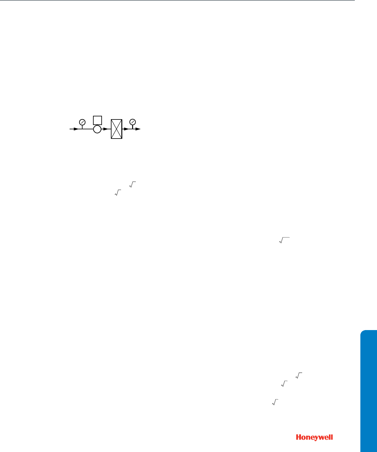
261
APPENDIX
Select a linear valve providing close control with a capacity
index of 4 and meeting the required pressure and tempera-
ture ratings.
NOTE: For steam valves downstream from pressure
reducing stations, the steam will be superheated
in most cases and must be considered.
EXAMPLE 2:
In Figure 19, a linear valve (V1) is needed for accurate flow
control of a steam coil that requires 750 pounds per hour of
steam. Upstream pressure in the supply main is 5 psig and
pressure in the return is 4 in. Hg vacuum minimum.
Fig. 19. Linear Valve Steam Application.
Use the steam valve Cv formula to determine capacity index
for Valve V1 as follows:
Where:
Q = Quantity of steam required to pass
through the valve is 750 pounds per hour.
h = The pressure drop across a valve in a
modulating application is found using:
h = 80% x (Pm – Pr)
and:
Pm = Upstream pressure in supply main is 5
psig.
Pr = Pressure in return is 4 in. Hg vacuum.
NOTE: 1 in. Hg = 0.49 psi and 1 psi = 2.04 in. Hg.
Therefore,
4 in. Hg vacuum = –1.96 psig.
h = 0.80 x [5 – (–1.96)]
= 0.80 x 6.96
= 5.6 psi
The critical pressure drop is found using the following for-
mula:
hcritical = 50% x (psig + 14.7 psi)
hcritical= 0.50 x (5 psig upstream + 14.7 psi)
= 0.50 x 19.7 psia
= 9.9 psi
The pressure drop (h) of 5.6 psi is used in calculating
the Cv, since it is less than the critical pressure drop
(hcritical) of 9.9 psi.
V = Specific volume (V) of steam, in cubic feet
per pound at average pressure in valve
(Pavg):
Pavg =
=
The specific volume of steam at 2.2 psig is 23.54 and
the square root is 4.85.
63.5 = A scaling constant.
s=0
Substituting the quantity of steam, specific volume of steam,
and pressure drop in the Cv formula shows that Valve V1
should have a Cv of 24.17 or the next higher available value
(e.g., 25).
NOTE: If Pavg is rounded off to the nearest value in
Table 5 (2 psi), the calculated Cv is 24.30.
Select a linear valve providing close control with a capacity
index of 25 and meeting the required pressure and tempera-
ture ratings.
EXAMPLE 3:
Figure 20 shows the importance of selecting an 80 percent
pressure drop for sizing the steam valve in Example 2. This
pressure drop (5.6 psi) approximates the linear valve charac-
teristic. If only 30 percent of the available pressure drop is
used (0.30 x 6.96 psi = 2.10 psi or 2 psi), the valve Cv
becomes:
VALVE VI
C2336
5 PSI
SUPPLY
1.96 PSI
(VACUUM)
RETURN
STEAM
COIL
30% PRESSURE DROP, Cv = 41
80% PRESSURE DROP, Cv = 25
Cv
1 0.00075s+()QV
63.5 h
--------------------------------------------------=
Pm h
2
---–
55.6
2
-------– 5 2.8– 2.2psig==
Cv
1 0.00075 0×+()750 4.85××
63.5 5.6
---------------------------------------------------------------------------=
3637.5
63.5 2.37×
--------------------------- 24.17==
Cv
1 0.00075s+()QV
63.5 h
--------------------------------------------------=
Cv
750 4.85×
63.5 2
------------------------- 40.5==
Appendix A: Valve Selection and Sizing
262
This larger valve (2 psi drop) has a steeper curve that is fur-
ther away from the desired linear valve characteristic. See
LINEAR VALVE under VALVE SELECTION for more infor-
mation.
Fig. 20. Effect of Pressure Drop in Steam Valve Sizing.
Table 5. Properties of Saturated Steam.
Vacuum,
Inches of
Mercury
Boiling
Point or
Steam
Temp-
erature
(Deg F)
Specific
Volume (V),
cu. ft/lb
(For valve
sizing)
Maximum
Allowable
Pressure
Drop, psi.
29
25
20
15
14
76.6
133.2
161.2
178.9
181.8
706.00
145.00
75.20
51.30
48.30
26.57
12.04
8.672
7.162
6.950
0.23
1.2
2.4
3.7
3.9
12
10
8
6
4
2
187.2
192.2
196.7
201.0
204.8
208.5
43.27
39.16
35.81
32.99
30.62
28.58
6.576
6.257
5.984
5.744
5.533
5.345
4.4
4.9
5.4
5.9
6.4
6.9
Gage
Pressure,
psig
Boiling
Point or
Steam
Temp-
erature
(Deg F)
Specific
Volume (V),
cu. ft/lb
(For valve
sizing)
Maximum
Allowable
Pressure
Drop, psi.
0
1
2
3
4
212.0
215.3
218.5
221.5
224.4
26.79
25.20
23.78
22.57
21.40
5.175
5.020
4.876
4.751
4.626
7.4
7.8
8.4
8.8
9.4
5
6
7
8
9
227.1
229.8
232.3
234.8
237.1
20.41
19.45
18.64
17.85
17.16
4.518
4.410
4.317
4.225
4.142
9.8
10.4
10.8
11.4
11.8
100%
0% 100%
STEM TRAVEL
VALVE OPENING/
STEAM FLOW
C2337
Cv = 41
Cv = 25
LINEAR VALVE
CHARACTERISTIC
V
V
10
11
12
15
20
239.4
241.6
243.7
249.8
258.8
16.49
15.90
15.35
13.87
12.00
4.061
3.987
3.918
3.724
3.464
12.4
12.8
13.4
14.8
17.4
25
30
35
40
45
266.8
274.0
280.6
286.7
292.4
10.57
9.463
8.56
7.826
7.209
3.251
3.076
2.93
2.797
2.685
19.8
22.4
24.8
27.4
29.8
50
55
60
65
70
297.7
302.6
307.3
311.8
316.0
6.682
6.232
5.836
5.491
5.182
2.585
2.496
2.416
2.343
2.276
32.4
34.8
37.4
39.8
42.4
75
80
85
90
95
320.0
323.9
327.6
331.2
334.6
4.912
4.662
4.445
4.239
4.060
2.216
2.159
2.108
2.059
2.015
44.8
47.4
49.8
52.4
54.8
100
110
120
130
140
337.9
344.1
350.0
355.2
360.9
3.888
3.595
3.337
3.12
2.923
1.972
1.896
1.827
1.766
1.710
57.4
62.3
67.4
72.3
77.4
150
160
170
180
190
366.2
370.6
375.5
379.6
383.9
2.746
2.602
2.462
2.345
2.234
1.657
1.613
1.569
1.531
1.495
82.3
87.4
92.3
97.4
102.3
200
225
250
275
300
387.8
397.4
406.0
414.2
421.8
2.134
1.918
1.742
1.595
1.472
1.461
1.385
1.320
1.263
1.213
107.4
119.8
132.4
145.0
157.4
350
400
450
500
550
435.6
448.1
459.5
470.0
479.7
1.272
1.120
0.998
0.900
0.818
1.128
1.058
0.999
0.949
0.904
182.4
207.4
232.4
257.4
282.4
600
650
700
800
900
1000
488.8
497.3
505.4
520.3
533.9
546.3
0.749
0.690
0.639
0.554
0.488
0.435
0.865
0.831
0.799
0.744
0.699
0.659
307.4
332.4
357.4
407.4
457.4
507.4
Gage
Pressure,
psig
Boiling
Point or
Steam
Temp-
erature
(Deg F)
Specific
Volume (V),
cu. ft/lb
(For valve
sizing)
Maximum
Allowable
Pressure
Drop, psi.
V
Appendix A: Valve Selection and Sizing

263
APPENDIX
Appendix B: NEMA Standard Classification Code for Enclosures
NEMA 1—General purpose. for indoor protection, where condi-
tions are not unusually severe.
NEMA 2—Drip tight. Designed to exclude falling moisture or
dirt. Particularly applicable to cooling rooms, laundries, etc.,
where condensation is prevalent. For indoor use.
NEMA 3—Weather Resistant (weatherproof). For outdoor use;
designed to withstand all normal exposure to natural elements.
Controls mounted on pullout racks for easy access. With rain
hood and weather seals.
NEMA 4—Watertight. Withstands water pressure from 1 in.
hose nozzle, 65 gallons per minute, from distance of not less
than 10 ft for five minutes. Suitable for maritime applications,
breweries, etc.
NEMA 5—Dust-tight. Equipped with dust-tight gaskets. Suitable
for mills and other high-dust atmospheres.
NEMA 6—Submersible. For submerged operation under speci-
fied pressures and time.
NEMA 7—Hazardous Locations, National Electrical Code Class
1 (circuit breaks in air).
NEMA 8—Hazardous Locations, National Electrical Code Class
1 (circuit breaks immersed in oil).
NEMA 9—Hazardous Locations, National Electrical Code Class
2.
NEMA 10—Explosion-proof. Meets U.S. Bureau of Mines
requirements for explosive atmospheres.
NEMA 11—Acid or Fume Resistant. Provides for immersion of
enclosed equipment in oil.
NEMA 12—IIndustrial Use. Excludes oils, dust, moisture, to
satisfy individual requirements.
Appendix B: NEMA Standard Classification Code for Enclosures

264
Appendix C: Best Practices for Low Power Control Signal Wiring
Low power analog signals are commonly used for proportional
control signal wiring in HVAC applications. Following are a
series of best practices for the prevention of corruption of these
signals due to electro-magnetic interference (“EMI”).
EMI is typically caused by coupling of the electro-magnetic field
that surrounds all wires carrying current. It may also be caused
by radio frequency sources such as “walkie talkies” using
amplitude modulated signals. A strong EM field can induce
electrical noise in wires up to 2 V in amplitude. The strongest
coupling comes between closely spaced, parallel wires.
Inductive and high power motor loads are some of the strongest
sources of EMI, along with electronics lighting ballasts,
dimmers, and variable frequency motor drives. More potential
EMI sources in a building mean that greater attention needs to
be paid to effective wiring practices.
All control wiring should consist of twisted pairs of wires, which
resist interference better than straight, non-twisted conductors.
Stranded conductors offer less resistance to current flow than
solid wires, and are more flexible making them easier to install;
however, care must be taken to ensure that all the conductors in
the wire are properly installed and that “whiskers” do not short
out any wiring connections.
Shielded Wiring
Control signals can be protected from EMI using shielded wire. The
more continuous the shield, the more effective it is. Braided shield is
commonly used for microphone cables because of its superior
flexibility. HVAC wiring is fixed, does not require high flexibility during
use, and is better served with lower cost cables using continuous foil
shielding and a “drain wire”.
1. All signal wiring in hospitals should be shielded to prevent the
potential for interference with medical equipment such as high
power MRI and CT scanners.
2. All 0~10 Vdc control signals should be run in shielded cable.
EMI noise can be interpreted as control signaling, depending
on the noise suppression circuitry in the controlled equipment.
3. Long runs of wiring from 24 V power supply transformers
should be shielded in heavy electrical noise environments to
prevent EMI from coupling through the actuator’s power sup-
ply.
4. In typical commercial buildings, 2~10 Vdc signals do not
require shielded wiring.
5. Current flow is much more difficult to induce in wiring than
voltage, and current-based control signals usually do not
require shielded cable except in heavy industrial applica-
tions.
a. If the terminal equipment only accepts voltage input,
install a 500 ohm, ¼ Watt (or larger), 1% resistor across
the control input terminals to convert a 4~20 mA(dc) sig-
nal to 2~10 Vdc.
b. If multiple actuators are connected in parallel, install this
resistor at the first actuator in the group.
c. Any standard resistor (“EIA”) value between 490 and 510
ohms is acceptable, and can be purchased at retail out-
lets that sell electronic components.
6. Floating, pulse-width modulated, and two-position actuators
use switched 24 Vac control or power signals and so rarely
require shielded wiring.
Wiring Techniques
1. No wiring should ever be assumed to be interference-proof.
Never strap signal cables to other conductors or conduit,
especially line voltage.
2. Never run signal wires in raceways or wiring troughs with
other conductors. Keep signal wires at least a yard away from
line voltage wiring. Higher voltage wiring requires greater
separation.
3. When necessary, cross line voltage conductors with signal
wiring at 90° (right angles), to minimize signal coupling.
4. Electromagnetic shielding is a static phenomenon; any cur-
rent running through the shield will negate any protection the
shield may have provided. Only ground (or “earth”) a shield
drain wire at one point, preferably where the signal will be the
weakest, for example: at the actuator.
a. Do not ground the secondary of the 24 V power supply in
the control system. This will create a secondary current
path and negate the protection of any shielding.
b. If there is a burner ignition system, power it with its own
transformer and use an interface relay for isolation, if nec-
essary.
c. Use relays with built-in coil arc suppression, such as a
Honeywell R8229.
5. Insulate all exposed shielding and drain wire joins and splices
so that they cannot contact electrical ground, especially junc-
tion boxes and conduit. Do not use the ground screw of a
junction box as a tie point. Use a separate electrical ground
wire if required for safety extra-low voltage wiring by local
code.
6. Both rigid and flexible conduit are continuously grounded
(“bonded”) for electrical safety, and cannot function as a signal
shield. Where local codes require mechanical protection for
all wiring, shielded signal cable may be run inside conduit, fol-
lowing the practices listed above.
Additional References
Most of these wiring techniques were developed to protect the
very low-strength signals in audio recording. The 20 mA current
loop signal was originally used with teletype (“TWX”) equipment
communicating over telephone lines and adapted for
proportional analog control signaling in industrial process
control. Further information and background theory can be
found in:
1. Audio Engineering Handbook, edited by Blair K. Benson,
McGraw-Hill
2. Handbook for Sound Engineers, by Glen Ballou
3. Standard Handbook of Audio Engineering, by Jerry Whi-
taker and Blair K. Benson, McGraw-Hill.
Appendix C: Best Practices for Low Power Control Signal Wiring

265
APPENDIX
Notes & Numbers

266
Notes & Numbers

70-0568
Rev. 08-08
AUTOMATION AND CONTROL PRODUCTS
WARRANTY POLICY
Honeywell warrants the products in this catalog (except those parts designated on Honeywell's price lists as not covered by this warranty) to be free from
defects due to workmanship or materials, under normal use and service, for the following warranty periods. Honeywell VisionPRO®, Commercial
VisionPRO™, FocusPRO®, PRO 4000, PRO 3000, LineVolt™ PRO, Digital Round™, and Modern Round ™ (T87K, N) Series Thermostats with a date
code of 0501 or later: sixty (60) months from date of installation. CommercialPRO, PRO 2000 and PRO 1000 thermostats: twenty-four (24) months from
date of installation. AUBE branded thermostats, timers, and switches: thirty-six (36) months from date of installation. All other Honeywell thermostats and
thermostats with a date code of 0452 or earlier: twelve (12) months from date of installation, unless specified otherwise. Honeywell Air Cleaners,
Humidifiers, Ventilators, Ultraviolet Treatment and Zoning Products with a date code of 0501 or later, excluding replacement maintenance parts: sixty (60)
months from date of installation. Indoor air quality parts F50, F52, F300, F200, F150, UV100E, HE225, HE265, HE365, with date codes of 0452 or earlier,
excluding replacement maintenance parts: sixty (60) months from date of installation. All other Honeywell indoor air quality and zoning products with a date
code of 0452 or earlier: twenty-four (24) months from date of installation, unless specified otherwise. Variable frequency drive devices (VFD) and
accessories: new products for thirty-six (36) months and factory refurbished drives for twelve (12) months from date of installation when start-up and
commissioning is performed by Honeywell VFD Authorized and trained personnel. All VFD warranty return products must have prior authorization (Form
No. 87-0284) and be returned only to the VFD Service Center in Chattanooga, TN. MS, MN and Fact Acting 2-position Direct Coupled Actuators: sixty (60)
months from date of installation. The warranty period for all other products is twelve (12) months from date of installation.
If a product is defective due to workmanship or materials, is removed within the applicable warranty period, and is returned to Honeywell in accordance
with the procedure described below, Honeywell will, at its option, either repair, replace or credit the customer for the purchase price of the product, in
accordance with the procedure described below. This warranty extends only to persons or organizations who purchase products in this catalog for resale.
The expressed warranty above constitutes the entire warranty of Honeywell with respect to the products in this catalog and IS IN LIEU OF ALL OTHER
WARRANTIES, EXPRESS OR IMPLIED, INCLUDING ANY WARRANTY OF MERCHANTABILITY OR WARRANTY OF FITNESS FOR A PARTICULAR
PURPOSE. IN NO EVENT SHALL HONEYWELL BE RESPONSIBLE FOR ANY CONSEQUENTIAL DAMAGES OF ANY NATURE WHATSOEVER.
INSTRUCTIONS—INSTALLING OR
SERVICING CONTRACTOR OR
DEALER
When replacing a Honeywell product under
warranty, including those products furnished on
original heating and/or cooling equipment, you
should rely on your local Honeywell Wholesaler
or Distributor for prompt and efficient product
replacement service.
A Honeywell Returned Goods Identification Tag
(form 87-0030) or an electronic data notification
system must be completed and approved by the
servicing dealer/contractor prior to submitting the
product to the Honeywell Wholesaler or
Distributor. (Tags may be obtained from the
Wholesaler or Distributor in advance.) No
warranty claim for product replacement or credit
will be honored by the Wholesaler/Distributor
without a completed warranty tag attached or
electronic notification.
INSTRUCTIONS—WHOLESALER OR
DISTRIBUTOR
The following will apply to the return of any
product to Honeywell under this warranty:
Any products which are not variable frequency
drives and are:
(i) identified with Honeywell’s Returned
Goods Identification Tag (form 87-0030),
or electronic notification system;
(ii) are listed individually with Returned
Goods ID Tag numbers and date codes
listed on Honeywell’s Returned Goods
Order (form 71-96024) or a similar form;
(iii) packed separately from other returns
and protected from shipping damage;
(iv) have certification by the installer or
servicing dealer that the product was
removed, due to failure, within the
applicable warranty period;
(v) are received transportation pre-paid at:
Honeywell Return Goods
Dock 4 MN10-3860
1885 Douglas Drive
Golden Valley, MN 55422
(vi) and are found by Honeywell’s inspection
to be defective in workmanship or
materials under normal use and service
will be handled in accordance with one of the two
following procedures, as specified by the
customer making the return:
All VFD warranty return products must have prior
authorization (Form No. 87-0284) and be
returned only to the VFD Service Center in
Chattanooga, TN.
1. CREDIT PROCEDURE. Honeywell will
issue credit, at Honeywell’s lowest
wholesaler net price in effect at the time
of the return (as set forth on
Honeywell’s then current price sheet) or
at the actual invoice amount if a copy of
that invoice is attached to the packing
list. (TRADELINE Replacement
Exchange Products will be at
Honeywell’s lowest replacement
exchange net price in effect at the time
of such return, as shown on
Honeywell’s then current price sheet.)
Honeywell reserves the right to disallow
this credit option in cases of warranty
abuse.
2. REPAIR OR REPLACEMENT
PROCEDURE. Honeywell will, at its
option, either repair or replace the product
free of charge and return it or its
replacement lowest cost transportation
prepaid. The replacement will be a
functionally equivalent new TRADELINE
product. Premium transportation will be
used at customer’s request and expense.
The warranty will not be honored if:
(i) product is damaged or missing parts or
accessory items including batteries.
(ii) product exhibits evidence of field
misapplications.
Final disposition of any warranty claim will be
determined solely by Honeywell. If inspection by
Honeywell does not disclose any defect covered
by the warranty, the product will be returned or
scrapped as instructed by the customer and
Honeywell’s regular service charges will apply.
Products returned to the customer may be sent
shipping charges collect.
If you have any questions relative to product
returns to Honeywell, contact your Customer
Care Representative:
Honeywell International Inc.
Customer Care MN10-1461
1985 Douglas Drive
Golden Valley, MN 55422
(763) 954-5720
SPECIAL MESSAGE TO INDUSTRIAL
USERS AND BUILDING OWNERS
Thank you for using Honeywell products.
As a user, when you purchase a Honeywell
product from this catalog you should expect
performance from the product and, if it fails,
replacement of the product by the installing
dealer.
Typically, you will have purchased a Honeywell
product under the following circumstances:
1. To modernize or refurbish your existing
commercial and/or process control
system.
2. You have purchased new commercial
and/or process heating, cooling, air
cleaning or humidification equipment that
is furnished with Honeywell controls or
components (refer to your owner’s manual
furnished with the equipment).
3. A control has failed on your existing
commercial and/or process heating and/or
cooling equipment and is replaced by a
Honeywell TRADELINE product.
With few exceptions, you utilize the services of a
competent plumbing, heating and/or cooling
dealer/contractor for new or replacement work
performed.
Although our warranty does not extend to you,
Honeywell does extend a warranty to your
supplier.
Your supplier can rely on its local Honeywell
Wholesaler/Distributor or Honeywell for prompt
replacement.
If you have any questions, need additional
information or would like to comment on
Honeywell’s products or services, please write or
phone:
Honeywell International Inc.
Customer Care MN10-1461
1985 Douglas Drive North
Golden Valley, MN 55422-4386
(763) 954-5720
or check your telephone directory (white pages)
for one of many Honeywell field sales offices.

4
Automation and Control Solutions
In the US:
Honeywell
1985 Douglas Drive North
Golden Valley, MN 55422-3992
In Canada:
Honeywell Limited
35 Dynamic Drive
Toronto, Ontario M1V 4Z9
customer.honeywell.com
63-9271 PR
March 2009
© 2009 Honeywell International Inc.
