Honeywell Water Heater Xls 278 Users Manual 0741 And 270 Pull Stations
XLS-278 to the manual 345a5f26-8fa3-4e4c-8995-1a126e7c2e0f
2015-01-23
: Honeywell Honeywell-Honeywell-Water-Heater-Xls-278-Users-Manual-262669 honeywell-honeywell-water-heater-xls-278-users-manual-262669 honeywell pdf
Open the PDF directly: View PDF ![]() .
.
Page Count: 4

EN0C-0741 0599R2-MA
XLS-278 and XLS-270
Manual Pull Stations
SPECIFICATION DATA
DESCRIPTION
The XLS-270 and XLS-278 series Manual Pull Stations are
part of Honeywell's Signature Series system. The XLS-270
Fire Alarm Manual Pull Stations feature a "teardrop" shape.
They are made from die-cast zinc and finished with red epoxy
powder-coat paint complemented by aluminum colored
stripes and markings.
With positive pull- lever operation, one "pull" on the station
handle breaks the glass rod and turns in a positive alarm,
ensuring protection plus fool-proof operation. Pre-signal
models (XLS-270P) are equipped with a general alarm (GA)
key-switch for applications where two-stage operation is
required. The "up-front" highly visible glass rod discourages
tampering.
Honeywell's double action single stage XLS-278 station is a
contemporary style station made from durable red colored
Lexan. To initiate an alarm, first lift the upper door marked
"LIFT THEN PULL HANDLE", then pull the alarm handle.
FEATURES
• Single stage double action XLS-278 features a rugged
Lexan housing
• XLS-270 models have traditional familiar appearance
• XLS-270 models are available for one stage (GA),
two stage (pre-signal), and double action
• Break glass operation on XLS-270 models
• Intelligent device with integral microprocessor
• Non-volatile memory
• Automatic device mapping
• Electronic addressing
• Stand-alone operation
• Diagnostic LEDs
• Designed for high ambient temperature operation
• Designed to ISO 9001 standards
The integral microprocessor built into each Signature Series
station provides four important benefits: Self-diagnostics and
History Log, Automatic Device Mapping, Stand-alone
Operation and Fast, Stable Communication.
Self-Diagnostics and History Log:
Each Signature Series manual station constantly runs self-
checks to provide important maintenance information. The
results of the self-check are automatically updated and
permanently stored in the station's non-volatile memory. This
information is accessible for review any time at the control
panel, PC, or by using the SIGA-PRO Signature
Program/Service Tool.
The information stored in the station's memory includes:
- Station serial number, address, and station type.
- Date of manufacture, hours of operation, and last
maintenance date.
S Y S T E M

XLS-270 AND XLS-278 MANUAL PULL STATIONS
EN0C-0741 0599R2-MA 2
- Number of recorded troubles, alarms, and time and
date of last alarm.
- Up to 24 possible trouble codes which can be used to
specifically diagnose faults.
Automatic Device Mapping:
The loop controller learns where each device's serial number
address is installed relative to other devices on the circuit.
The loop controller keeps a "map" of the Signature Series
devices connected to it.
Signature Series Data Entry Program also uses the mapping
feature. With interactive menus and graphic support, the
wired circuits between each device can be determined.
Layout or "as-built" drawing information showing the
branches (T-taps), device types and their address are stored
on disk for printing hard copy. This takes the mystery" out of
the installation. The preparation of "as-built" drawings is fast
and efficient.
Device mapping allows the Signature loop controller to
discover:
- Unexpected additional device addresses.
- Missing device addresses.
- Changes to the wiring in the circuit.
Stand-alone Operation:
A decentralized alarm decision by the station is guaranteed.
On-board intelligence permits the station to operate in stand-
alone mode. If loop controller CPU communications fail for
more than 4 seconds, all devices on that circuit go into stand-
alone mode. The circuit acts like a conventional alarm
receiving circuit. Each station on the loop will still transmit an
alarm if its operating lever is pulled.
Fast Stable Communication:
Built-in intelligence means less information needs to be sent
between the station and the loop controller. Other than
regular supervisory polling response, the station only needs
to communicate with the loop controller when it has
something new to report. This provides very fast control
panel response time and allows a lower baud rate (speed) to
be used for communication on the loop.
The lower baud rate offers several advantages including:
- Less sensitivity to circuit wire characteristics.
- Less sensitivity to noise glitches on the cable.
- Less emitted noise from the analog wiring.
- Twisted or shielded wiring is not required.
Diagnostic LEDs:
Twin LEDs provide visual indication of normal and
alarm/active conditions. They are visible only when the
station is removed from the mounting box. A flashing GREEN
LED shows normal system polling from the loop controller. A
flashing RED LED means the station is in alarm/active state.
Both LEDs on steady shows alarm state in stand-alone
mode.
Installation:
The Signature Series fire alarm manual pull stations mount to
North American 2-1/2in (64 mm) deep 1-gang boxes and 1-
1/2in (38 mm) deep 4insquare boxes with 1-gang covers. The
terminals are suited for #14 to #18 AWG (1.5 mm2 to 0.75
mm2) wire size.
Honeywell recommends that these stations be installed
according to local codes.
NOTE: This module will not operate without electrical power.
As fires frequently cause power interruption, we
suggest you discuss further safeguards with your
fire protection specialist.
Electronic Addressing:
The loop controller electronically addresses each station,
saving valuable time during system commissioning. Setting
complicated switches or dials is not required. Each station
has its own serial number stored in its "on-board memory".
The loop controller identifies each device on the loop and
assigns a "soft" address to each serial number. If desired, the
stations can be addressed using the SIGA-PRO Signature
Program/ Service Tool.
Application:
The operating characteristics of the fire alarm stations are
determined by their sub-type code or "Personality Code".
NORMALLY-OPEN, ALARM-LATCHING (Personality code 1)
is assigned by the factory; no user configuration is required.
The device is configured for Class B IDC operation. The
ALARM signal is sent to the loop controller when the station's
pull lever is operated. The alarm condition is latched the
station.
Testing and Maintenance:
To test (or reset) the station, simply open the station using a
special tool and operate the exposed switch.
The station's automatic self-diagnosis identifies when it is
defective and causes a trouble message. The user-friendly
maintenance program shows the current state of each
Signature series device and other pertinent messages.
Single devices may be deactivated temporarily, from the
control panel. Availability of maintenance features is
dependent on the fire alarm system used.
Scheduled maintenance should be planned according to
local codes.
XLS-270 AND XLS-278 MANUAL PULL STATIONS
3EN0C-0741 0599R2-MA
SPECIFICATIONS
Models:
XLS-270: One stage fire alarm station; English markings
XLS-270P: Two stage (pre-signal) fire alarm station;
English markings
XLS-278: Double action, one stage fire alarm station;
English markings
Addressing Requirements:
XLS-270/270F/270B: 1 module address
XLS-270P/270PB: 2 module addresses
XLS-278: 1 module address
Operating Current:
XLS-270/270F/270B:
Standby: 250µA
Activated: 400µA
XLS-270P/270PB:
Standby: 396µA
Activated: 680µA
XLS-278:
Standby: 250µA
Activated: 400µA
Construction and Finish:
XLS-270xx:
Die-cast zinc; red epoxy with aluminum markings
XLS-278:
Lexan, red with white markings
Type Code:
Factory set
Operating Voltage:
15.2 to 19.95V dc (19V dc nominal)
Environmental Limits:
Temperature: 32° to 120°F (0° to 49°C)
Humidity: 0 to 93% rh
LED Operation:
On-board green LED: Flashes when polled
On-board red LED: Flashes when in alarm/ active
Both LEDs: on steady when in alarm (stand-alone)
Compatibility:
Use with Signature Loop Controller
Accessories:
276-GLR: 20 glass rods; for XLS-278 only
27193-11: Single Gang Surface mounting box
for XLS-270xx models only
276B-RSB: Surface mounting box, red for XLS-278 only
Figure 1: XLS-270L
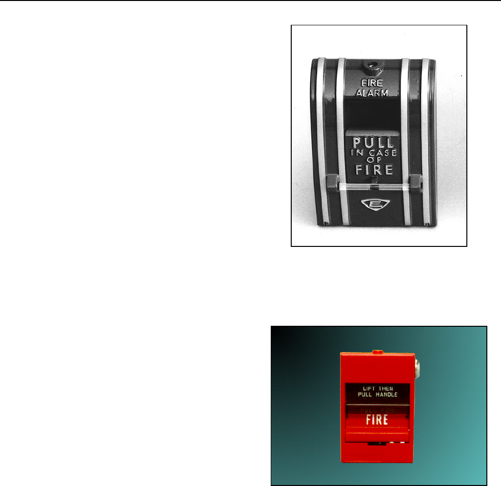
Figure 2: XLS-278

XLS-270 AND XLS-278 MANUAL PULL STATIONS
Comfort from Experience
Home and Building Control Home & Building Control European Centre of Excellence
Honeywell Inc. Honeywell GmbH Fire Solutions
Honeywell Plaza Honeywellstrasse Lovelace Road, Southern Industrial Area
P.O. Box 524 63477 Maintal 1 Bracknell, Berkshire, RG12 8WD
Minneapolis MN 55408-0524 Germany United Kingdom
EN0C-0741 0599R2-MA 4
