Honeywell Local Operator Interface S7999B Users Manual 65 0303—05 S7999C SOLA
S7999B to the manual 456a2910-1b89-498d-8cf2-13e9a7b07b76
2015-01-23
: Honeywell Honeywell-Local-Operator-Interface-S7999B-Users-Manual-261165 honeywell-local-operator-interface-s7999b-users-manual-261165 honeywell pdf
Open the PDF directly: View PDF ![]() .
.
Page Count: 68
- Application
- Features
- Preface
- Software Upgrade
- Specifications
- Safety Features
- Installation Instructions (S7999B OI Display)
- Wiring (S7999B OI Display)
- Building Automation System (BAS) Configuration
- Quick Setup (S7999B OI Display)
- Starting the S7999B OI Display
- Installation Instructions (S7999C OI Display)
- Wiring (S7999C OI Display)
- Starting the S7999C OI Display
- Page Navigation
- R7910A Hydronic Control, R7911 Steam Control Configuration Parameters
- Central Heat Parameters (R7910A Hydronic Control Only)
- Outdoor Reset Parameters (R7910A Hydronic Control Only)
- Domestic Hot Water (DHW) Configuration Parameters (R7910A Hydronic Control Only)
- DHW Storage Configuration
- DHW Plate Heat Exchanger Configuration
- Warm Weather Shutdown Configuration
- Demand Priority Configuration Parameters
- Modulation Configuration Parameters
- Steam Modulation Configuration Parameters
- Pump Configuration Parameters
- Statistics Configuration Parameters
- High Limit Configuration Parameters (R7910A Hydronic Control Only)
- Stack Limit Configuration Parameters
- Delta T Limit Configuration Parameters (R7910A Hydronic Control Only)
- T-Rise Limit Configuration Parameters
- Heat Exchanger High Limit Configuration Parameters
- Anti-Condensation Configuration Parameters (R7910A Hydronic Control Only)
- Frost Protection Parameters (R7910A Hydronic Control Only)
- Annunciation Configuration Parameters
- Safety Configuration Parameters
- Safety Parameter Verification
- Individual R7910A or R7911 Configuration Parameters
- Fan Parameters
- Lead Lag Slave Configuration Parameters (Hydronic Control Only)
- Lead Lag Master Configuration Parameters (Hydronic Control Only)
- Details
- R7910A or R7911 Diagnostics
- Installer Checkout
- S7999B or S7999C Display Setup and Diagnostics
- Advanced Setup
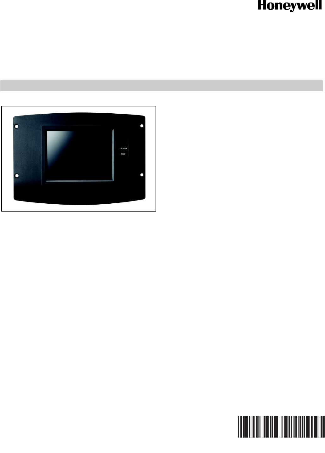
PRODUCT DATA
65-0303-05
S7999B, S7999C SOLA
Local Operator Interface
APPLICATION
The S7999B and S7999C are microprocessor-based touch-
screen Operator Interface (OI) displays that provide an
operator interface for monitoring and configuring parameters
in the Sola Hydronic Control and Sola Steam Control system.
The S7999B can be used to monitor an individual boiler but is
primarily used for multiple boiler applications in a lead/lag
arrangement. COM 2 port is available for Building Automation
applications. The S7999B display is flush mounted into a
panel cutout (8-1/8 in. W x 5-7/8 in. H). Wiring connections to
the S7999B are through a removable 9-pin wiring header.
The S7999C display is used for individual boiler monitoring.
The S7999C is mounted:
• onto a panel using the wallplate provided.
• from the front into a panel cutout (7.6 in. W X 5.4 in. H)
using 4 #6-32 screws and nuts (provided).
• From behind into a panel cutout (5.45 in. W X 4.3 in. H)
using 4 #6-32 screws, nuts and 4 standoffs (provided).
Wiring connections to the S7999C are made via a 4-pin
connector on the back of the display.
NOTE: If display S7999B is used to monitor a lead/lag sys-
tem, display S7999C can NOT be used.
FEATURES
• Individual boiler status, configuration, history, and
diagnostics.
• Allows configuration and monitoring of the Sola
Controls (R7910A Hydronic Controls or R7911 Steam
Control) burner control sequence, flame signal,
diagnostics, historical files, and faults.
• S7999B OI Display only:
— Allows switching view between multiple boilers
— Allows viewing Lead-Lag Master
— Ethernet port for downloading software upgrades
(when required)
— Real-time data trending analysis and transferring
saved trend data to Excel spreadsheet.
— Audible Alarm
— COM 2 Modbus port for Building Automation System
applications.
— LED indicators:
• Power
•Network
•COM 2
•COM 1
— Models available:
• S7999B1026 has Blue Border
• S7999B1067 has Black Border
• S7999C OI Display only:
Contents
Preface ............................................................................. 2
Specifications ................................................................... 3
Installation Instructions (S7999B OI Display) ................... 4
Wiring (S7999B OI Display) ............................................. 4
Starting the S7999B OI Display ........................................ 7
Configuration .................................................................... 20
Details .............................................................................. 38
R7910A or R7911 Diagnostics ......................................... 44
S7999B or S7999C Display Setup and Diagnostics ......... 47
Advanced Setup ............................................................... 48
Table 61 Configurable Parameters. .................................. 53
Table 62 Other Tables. ..................................................... 61
S7999B, S7999C SOLA LOCAL OPERATOR INTERFACE
65-0303—05 2
ORDERING INFORMATION
When purchasing replacement and modernization products from your TRADELINE® wholesaler or distributor, refer to the
TRADELINE® Catalog or price sheets for complete ordering number.
If you have additional questions, need further information, or would like to comment on our products or services, please write or
phone:
1. Your local Honeywell Automation and Control Products Sales Office (check white pages of your phone directory).
2. Honeywell Customer Care
1885 Douglas Drive North
Minneapolis, Minnesota 55422-4386
In Canada—Honeywell Limited/Honeywell Limitée, 35 Dynamic Drive, Toronto, Ontario M1V 4Z9.
International Sales and Service Offices in all principal cities of the world. Manufacturing in Australia, Canada, Finland, France,
Germany, Japan, Mexico, Netherlands, Spain, Taiwan, United Kingdom, U.S.A.
— MMC Port for installing software upgrades (when
required)
— LED indicators:
• Power
•COM
— Models available:
• S7999C1008 has white border
• S7999C1016 has blue border
• S7999C1040 has black border
• Allows for lead/lag commissioning.
• Locates attached boiler(s).
• Allows boiler naming.
• Color 3.5 in. x 4.625 in. (5.7 in. diagonal) user interface
display.
• Graphic user interface.
• Touch screen.
• Communication between the OI Displays and the
SOLA Controls uses Modbus™.
• LED indicators (S7999C):
•Power
•COM
• Flush mounting.
• Touch screen disable for screen cleaning.
• 12 Vdc power supply (included).
• Screen saver.
• Contrast control.
• Volume control.
PREFACE
This User Guide is intended to provide a general overview of
the S7999B or S7999C Operator Interface (OI) Displays. The
general overview goes to page 20 and the actual configuration
begins on page 20.
It is intended to guide you through the features and operation
of the OI Display as you interface with the R7910A or R7911
Sola control and establish the Parameter points of the system.
Note that this sheet shows all parameters. The actual product
may have parameters made invisible or Read Only by
Honeywell as they may not apply to the product.
Use the Product Data Sheet for the Sola Controls (form 65-
0303) as a guide and explanation of the parameters that are
being programmed.
SOFTWARE UPGRADE
S7999B Only
You can download new software for the OI Display through
the Internet. Downloading software should only be done when
recommended by Honeywell. This feature is intended to
permit field upgrades for bug fixes and to install new features.
Requirements for downloading new software:
• Ethernet connection for Internet access (RJ45 male
connector). Carefully insert the RJ45 connector into the
Ethernet jack in the lower right corner on the back of the
display to ensure no damage to the jack.
• Dynamic IP addressing (from DHCP server).
IMPORTANT
If these requirements can’t be met at the location of
the OI Display, this procedure should not be done or
the OI Display should be moved to a location where
these requirements can be met. Failure to satisfy
these requirements can result in the OI Display
becoming inoperable when the upgrade steps are
followed.
The above requirements can be checked prior to execution of
the software upgrade procedure on the Ethernet Setup page
(see Advanced Setup section). On the Ethernet Setup page a
connectivity check can be performed to validate whether
access to the Honeywell server is possible.
The OI Display must be reset to initiate the download
procedure. Initial boot procedure of the device permits the
user to enter into Advanced Startup options within the first five
seconds after power up.
Follow these steps:
1. Select the Advanced Startup Options button. A Warning
message is displayed. If you don’t want to proceed with
the software upgrade, you can cancel the procedure at
this time.
2. Select OK to proceed.
3. Select the “Force Application Update” checkbox.
4. Deselect the “Use Existing Application” checkbox.
5. Select the Continue button.
S7999B, S7999C SOLA LOCAL OPERATOR INTERFACE
365-0303—05
The software upgrade is automatic after the above steps. The
OI Display connects to the Honeywell server, which verifies the
configuration file, erases the old application and downloads the
new one.
The OI Display may have difficulty finding the new
configuration file at first. In this case, the procedure
automatically starts over again until it works.
S7999C Only
Software upgrades for S7999C OI Display (when needed) will
be provided by Honeywell and are accomplished through the
MMC port located on the top back of the device.
SPECIFICATIONS
Electrical Ratings:
+12 Vdc input, maximum of 500 mA current drain.
Included Power Supply for S7999B:
Inputs: 85 to 264 Vac, 47 to 63 Hz; 120 to 370 Vdc.
Output: 12 Vdc; 0 to 2.1 A.
Power: 25 W.
Included Power Supply for S7999C:
Inputs: 100 to 240 Vac.
Output: 12 Vdc; 0.42 A.
Power: 25 W.
Operating Temperature: 32°F to 122°F (0°C to 50°C)
Storage/Shipping Temperature: -40°F to 158°F
(-40°C to 70°C).
Humidity:
85% maximum relative humidity.
Approvals:
FCC Part 15, Class A Digital Device
Underwriter’s Laboratories, Inc. (UL) (cUL) Component
Recognized (for non-continuous operation): File Number
MH20613 (MCCZ)
Canada: ICES-003
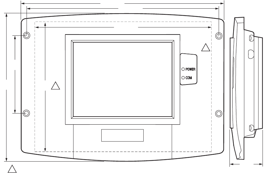
Dimensions: See Fig. 1.
Replacement Parts (S7999B)
• 9-pin connector—50020034-001
• Power Supply—Manufactured by MeanWell,
Model S-25-12 (order from manufacturer).
• #6-32 X1-in. screws(4) with nuts (4)
Supplied Parts (S7999C)
• Mounting Plate - see Fig. 9 for dimensions and hole
locations.
• #6-32 X 1-in. screws (4) with nuts (4)
• Standoffs 5/16-in. dia. X 3/8 in. long (4)
• Power Supply—Manufactured by V-infinity
Model FSC-S5-12U (order from manufacturer).
Fig. 1. OI Display dimensions (S7999C shown) in in. (mm).
NOTE: This equipment has been tested and found to comply with the limits for a Class A digital device, pursuant to part 15 of the
FCC Rules. These limits are designed to provide reasonable protection against harmful interference when the equipment
is operated in a commercial environment. This equipment generates, uses and can radiate radio frequency energy and, if
not installed and used in accordance with the instruction manual, may cause harmful interference to radio communica-
tions. Operation of this equipment in a residential area is likely to cause harmful interference in which case the user will be
6-21/32
(169)
9-7/16 (240)
7-19/32 (193)
1-33/64
(39) M29867A
PANEL HOLE CUTOUT SIZE 7-19/32 (193) WIDE X 5-13/32 (137) HIGH FOR S7999B DISPLAY 7.6 WIDE X 5.4 HIGH..1
1
5-13/32
(137) 1
8-15/16 (227)
3-1/2
(89)
S7999B, S7999C SOLA LOCAL OPERATOR INTERFACE
65-0303—05 4
required to correct the interference at his own expense.
This Class A digital apparatus complies with Canadian ICES-003.
Cet Appareil numérique de la classe A est conforme à la norme NMB-003 du Canada.
SAFETY FEATURES
The OI Displays contain software that incorporates many
features that are designed to guide you safely through the
commissioning process. Safety, however, is your responsibility.
Read all documentation carefully and respond appropriately to
all error messages.
WARNING
Explosion Hazard.
Improper configuration can cause fuel buildup and
explosion.
Improper user operation may result in PROPERTY
LOSS, PHYSICAL INJURY or DEATH.
Using the OI Displays to change parameters, must be
attempted by only experienced and/or licensed
burner/boiler operators and mechanics.
INSTALLATION INSTRUCTIONS
(S7999B OI DISPLAY)
NOTE: For S7999C OI Display installation instructions, see
page 9.
Mounting the S7999B OI Display and
Power Supply
The OI Display can be mounted on the door panel of an
electrical enclosure.
1. Select the location on the door panel to mount the dis-
play; note that the device will extend into the enclosure
at least one inch past the mounting surface.
2. Provide an opening in the panel door 8-1/8 in. wide by 5-
7/8 in. high.
3. Place the OI Display in the opening and use it as a tem-
plate to mark the location of the four mounting screw
holes. Remove the device.
4. Using pilot holes as guides, drill 1/4 in. holes through the
door panel.
5. Place the display in the opening, aligning the mounting
holes in the device with the drilled holes in the panel.
6. Secure the display to the panel with four #6-32 screws
and nuts provided.
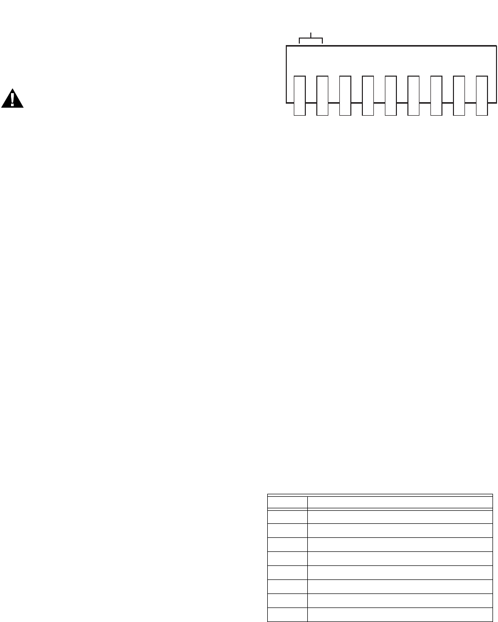
Fig. 2. S7999B OI Display connector terminals.
7. Select a location inside the enclosure for mounting the
power supply.
8. Using the power supply as a template, mark the loca-
tions of the two mounting holes in the enclosure.
9. Remove the power supply.
10. Drill 1/4 in. holes through the panel at the marked loca-
tions and secure the power supply with the two #6-32
screws and nuts provided.
11. Remove the 9-pin connector plug from the back of the OI
Display.
12. Wire the connector to the power supply and the RS-485
cables using the wiring diagram in Fig. 3.
13. Ensure the 9-pin connector plug is aligned with the
header pins when inserting the 9-pin connector plug
back onto the Display. Secure firmly.
WIRING (S7999B OI DISPLAY)
The S7999B OI Display must be appropriately wired for both
power and communications. An external 12V power supply
(provided) with an appropriate power rating is connected to
pins 1, 2 and 3 to power the device.
Communication is done over a RS-485 bus:
• COM1 connected directly to the SOLA Device J3 connector
to either Modbus (MB1 or MB2).
• COM2: A bus to the Building Automation System.
See Fig. 2 for S7999B Display connector terminals. Wiring
connections are listed in Table 1. See Fig. 3 for wiring.
Table 1. 9-pin Connector Terminals
Pin # Function
1 12V input
2 12V input
3 Common (Power, COM 1)
4 COM 1 (b) to MB1 or MB2 terminal
5 COM 1 (a) to MB1 or MB2 terminal
6 Not used
7 Not used
8COM 2 (a)
1 2 3 4 5 6 7 8 9
M28859A
COMMON (c)
COM1 (b)
COM1 (a)
N/C
N/C
COM2 (a)
COM2 (b)
+12V
S7999B, S7999C SOLA LOCAL OPERATOR INTERFACE
565-0303—05
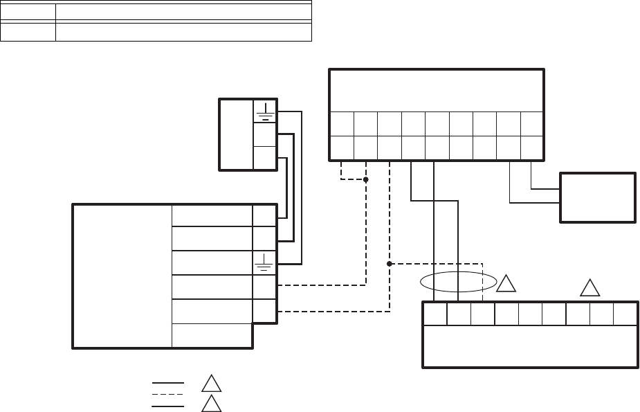
Fig. 3. S7999B wiring diagram.
9 COM 2 (b)
Table 1. 9-pin Connector Terminals
Pin # Function
M32004
214567893
+12 (B) (A) N/C
GND
(C)
+12 N/C (A) (B)
S7999B
AS LOCAL DISPLAY
COM1 COM2
L1
L2
120
VAC
V ADJ
V+
N
L
V-
DC OUT
(COMMON GND)
12 DC OUT +
EARTH
GROUND
120VAC (L1)
NEUTRAL (L2)
MEAN WELL S-25-12
DO NOT CONNECT THE S7999B TO TERMINALS 1 2 3. THIS WILL RENDER THE DISPLAY INOPERABLE.
DISPLAY CAN ALSO BE CONNECTED TO MB2; A, B, C.
POWER SUPPLY
WIRING KEY
LOW VOLTAGE
DATA
LINE VOLTAGE
SOLA CONTROL
23CBACBA1
J3
MB1 ECOMMB2
BAS
1
1
2
2
S7999B, S7999C SOLA LOCAL OPERATOR INTERFACE
65-0303—05 6
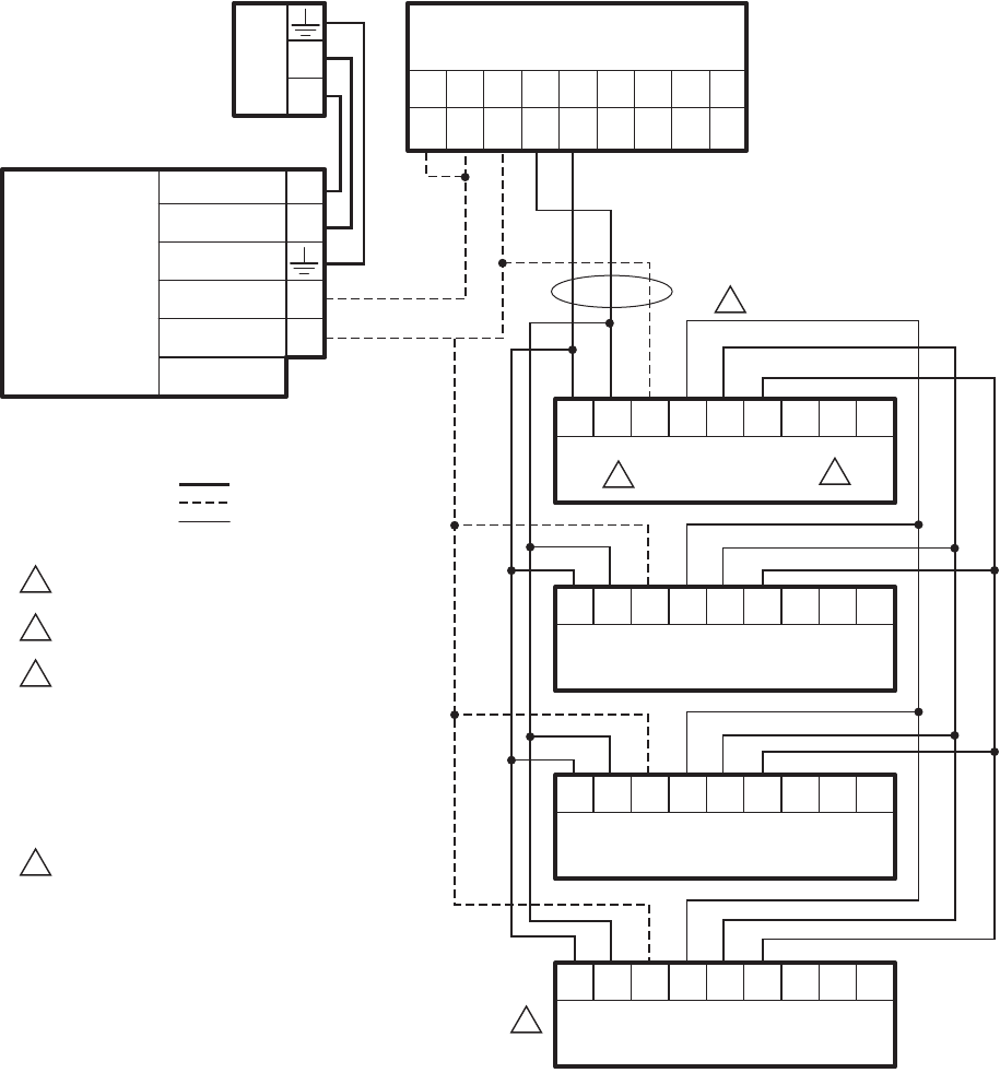
Fig. 4. S7999B wiring diagram for lead lag.
BUILDING AUTOMATION
SYSTEM (BAS)
CONFIGURATION
Connect the BAS Modbus wiring to COM2 of the S7999B as
shown in Fig. 5.
Ensure all S7999B devices have unique Modbus addresses as
defined in Fig. 5.
M32005
2
14567 89
3
+12 (B) (A) N/C
GND
(C)
+12 N/C (A) (B)
S7999B
AS SYSTEM DISPLAY
COM1 COM2
L1
L2
120
VAC
VADJ
V+
N
L
V-
DC OUT
(COMMON GND)
12 DC OUT +
EARTH
GROUND
120VAC (L1)
NEUTRAL (L2)
MEAN WELL S-25-12
DO NOT CONNECT THE S7999B TO TERMINALS 1 2 3.
THIS WILL RENDER THE DISPLAY INOPERABLE.
DISPLAY CAN ALSO BE CONNECTED TO MB2; A, B, C
AND THE SOLA SLAVES NEED TO BE WIRED TO MB1.
CONTROLLER HAS TWO AVAILABLE MODBUS
CONNECTIONS: THIS CONFIGURATION REQUIRES ONE
FOR CONTROL LEAD LAG COMMUNICATION AND ONE
FOR A S7999B SYSTEM DISPLAY.
THERE IS NOT A CONNECTION AVAILABLE FOR A
LOCAL TOUCHSCREEN DISPLAY (S7999C).
THE ECOM CONNECTION IS AVAILABLE FOR
CONNECTIONS OF A LOCAL KEYBOARD
DISPLAY MODULE.
UP TO A MAXIMUM OF 8 SOLA SLAVES IN A
LEAD LAG NETWORK.
POWER SUPPLY
WIRING KEY
LOW VOLTAGE
DATA
LINE VOLTAGE
SOLA LL MASTER
AND SLAVE 1
23CBACBA1
J3
MB1 ECOMMB2
23CBACBA1
SOLA SLAVE 2
J3
MB1 ECOMMB2
23CBACBA1
SOLA SLAVE 3
J3
MB1 ECOMMB2
23CBACBA1
SOLA SLAVE 4
J3
MB1 ECOMMB2
1
1
2
3
3
4
4
2
S7999B, S7999C SOLA LOCAL OPERATOR INTERFACE
765-0303—05
Fig. 5. S7999B in a Building Automation System.
BAS Modbus message timeout should be set to 1.0 seconds or
higher. This means it could take up to 1.0 seconds (max) for
the System Display to reply to a BAS message.
Retries: BAS must setup retries upon timeout to ensure the
Modbus request is accepted.
BAS Modbus poll rate should be set to 1.0 seconds. This
means that the BAS should wait for a minimum of 1.0 seconds
after receiving a Modbus message from Sola before sending a
new Modbus message.
QUICK SETUP (S7999B OI
DISPLAY)
1. Make sure the S7999B 9-pin connector is properly
aligned and pressed firmly in place.
2. Make sure the wires between the 9-pin connector and
the controller are properly wired and secure.
WARNING
Electrical Shock Hazard.
Can cause severe injury, death or equipment
damage.
Line voltage is present at the 120 Vac power supply.
3. Make sure the power supply is connected securely to the
120 Vac power source.
STARTING THE S7999B OI
DISPLAY
Power-up Validation
The Home page will appear and the “Power” LED will be
blinking when the device is properly powered. Select the 1234
Setup button to adjust the contrast and sound as desired.
If the screen is dim, check the pin 1 and 2 wiring connections.
NOTE: An Advanced Startup screen displays for five seconds
after power-up before the Home page displays. This
screen allows the user to upgrade the software in the
System Display (see “Preface” on page 2) and should
normally be bypassed.
Three LEDs exist for I/O traffic: one for the Ethernet network
port and two for Modbus™ ports. The ethernet port should only
be used if instructed by Honeywell that an update is necessary.
Modbus Com Port 2 is not active on this device.
1. Make sure the Power and COM1 LEDs are blinking.
2. If the LEDs are not blinking:
a. Make sure the proper connections have been made
between the Modbus COM1 Port and the first control-
ler device in the Modbus network.
b. See “Wiring (S7999B OI Display)” on page 4 for
proper wiring of the OI Display 9-pin Header
Connections.
3. If connected to a BAS application, COM2 LED will blink
indicating BAS traffic.
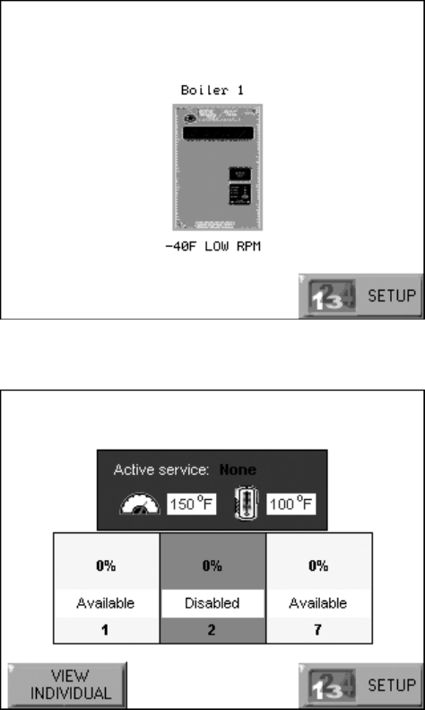
Home Page (S7999B OI Display)
Make sure a screen similar to Fig. 6 appears after the OI
Display has completely powered up.
On System applications, each SOLA Control is represented on
the Home page by an icon and name. Pressing the icon allows
the user to zoom in on that boiler and see its specific details.
These details are provided on a new page, which can include
additional buttons that display additional detail and operation
information, which itself leads to other pages. The pages are
traversed in a tree structure method, as shown in Fig. 8.
The Sola icons will appear in one of four colors indicating the
boiler status.
•Blue: Normal operation
•Red: Lockout condition
•Gray: Standby mode (burner switch off)
M32006
UP TO 8
SOLAS
BAS
S7999B
COM 2
COM 1
S7999B
COM 2
COM 1
S7999B
COM 2
COM 1
EACH SOLA IN THE BAS WILL HAVE A DIFFERENT MODBUS ADDRESS.
1
1
SOLA
1
SOLA
2
SOLA
3
SOLA
4
SOLA
5
S7999B, S7999C SOLA LOCAL OPERATOR INTERFACE
65-0303—05 8
•Gray and crossed out: communication error (disconnected
or powered off)
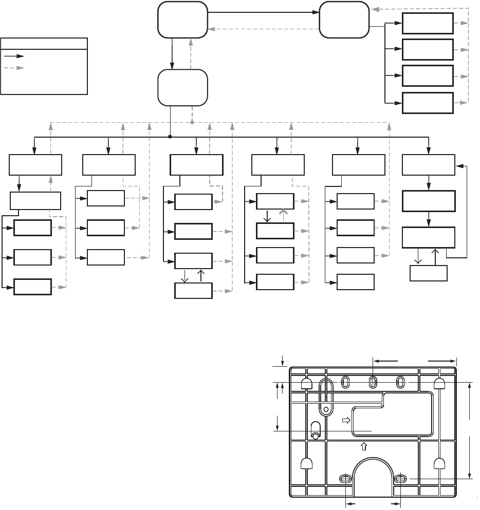
Up to 8 Systems can be displayed on the Home page. The
name of each boiler is displayed next to the Sola icon button.
When Lead Lag is enabled, the system header temperature
and firing rate are displayed for each System. When the burner
is in standby or not firing the firing rate is not displayed.
NOTE: The boiler name may be cut off on the Home page
when all icons are present.
The Home page also includes a System Analysis button that
allows the user to view status information on a system-wide
(that is, multiple boiler) basis. The user can choose which
status information to compare from the SOLA Controls in the
system.
Pressing the 1 2 3 4 Setup button on the Home page displays
miscellaneous setup and diagnostic functions beginning on
page 47 (see also Table 61 on page 53). It also contains the
setup configuration for BAS applications, under the Advanced
Setup button.
Pressing the SOLA icon opens that control’s status page. Go to
“Configure Button” on page 13 to continue.
Fig. 6. S7999B Home page (Boiler 1 in normal operation).
Fig. 7. S7999B Lead Lag Home page.
S7999B, S7999C SOLA LOCAL OPERATOR INTERFACE
965-0303—05
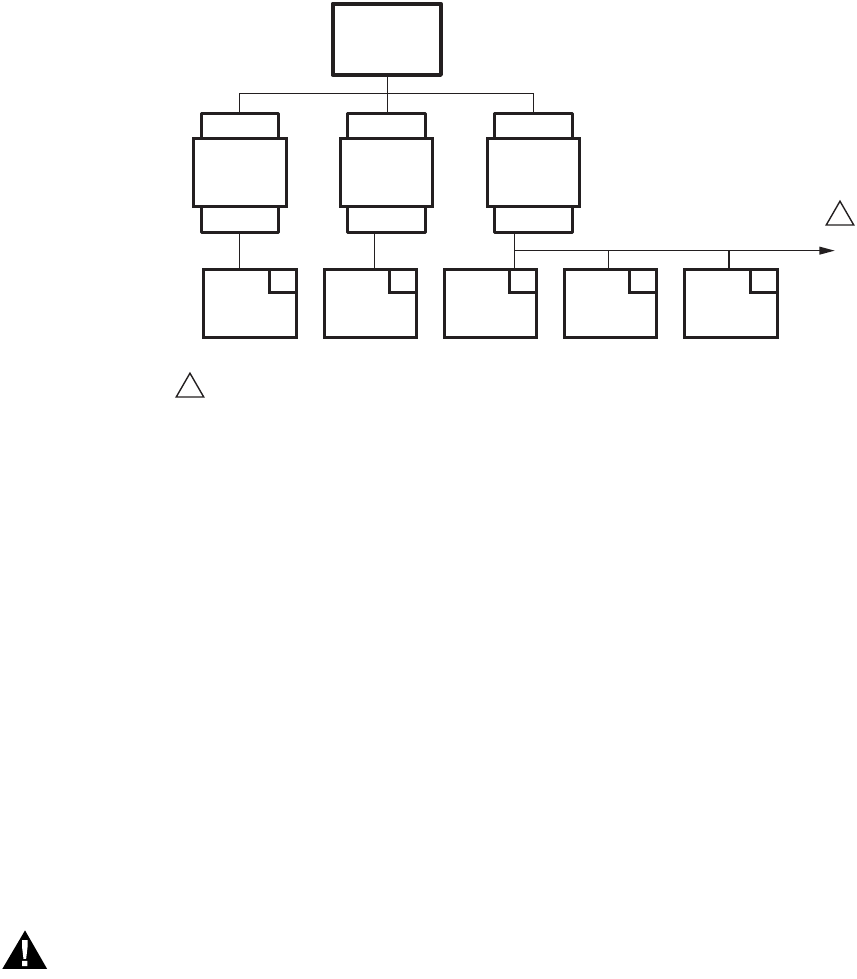
Fig. 8. S7999B display page flow.
INSTALLATION INSTRUCTIONS
(S7999C OI DISPLAY)
NOTE: For S7999B OI Display installation instructions, see
page 4.
The S7999C display is used for individual boiler monitoring.
The S7999C is mounted:
• onto a panel using the wallplate provided.
• from the front into a panel cutout (7.6 in. W X 5.4 in. H)
using 4 #6-32 screws and nuts (provided).
• From behind into a panel cutout (5.45 in. W X 4.3 in. H)
using 4 #6-32 screws, nuts and 4 standoffs (provided).
Mounting the S7999C OI Display
using the wallplate (provided)
1. Select the location to mount the OI display; this could be
a location up to 1000 feet from the SOLA control.
2. Use the device wallplate as a template to mark the loca-
tion of three or four mounting screw holes. See Fig. 9.
3. Drill 3/16 in. holes for mounting the wallplate.
4. Secure the wallplate with three or four #6-32 screws.
5. Bring power and communication wire through the wall
plate and attach to the terminals on the back of the dis-
play before installing the display to the wall plate.
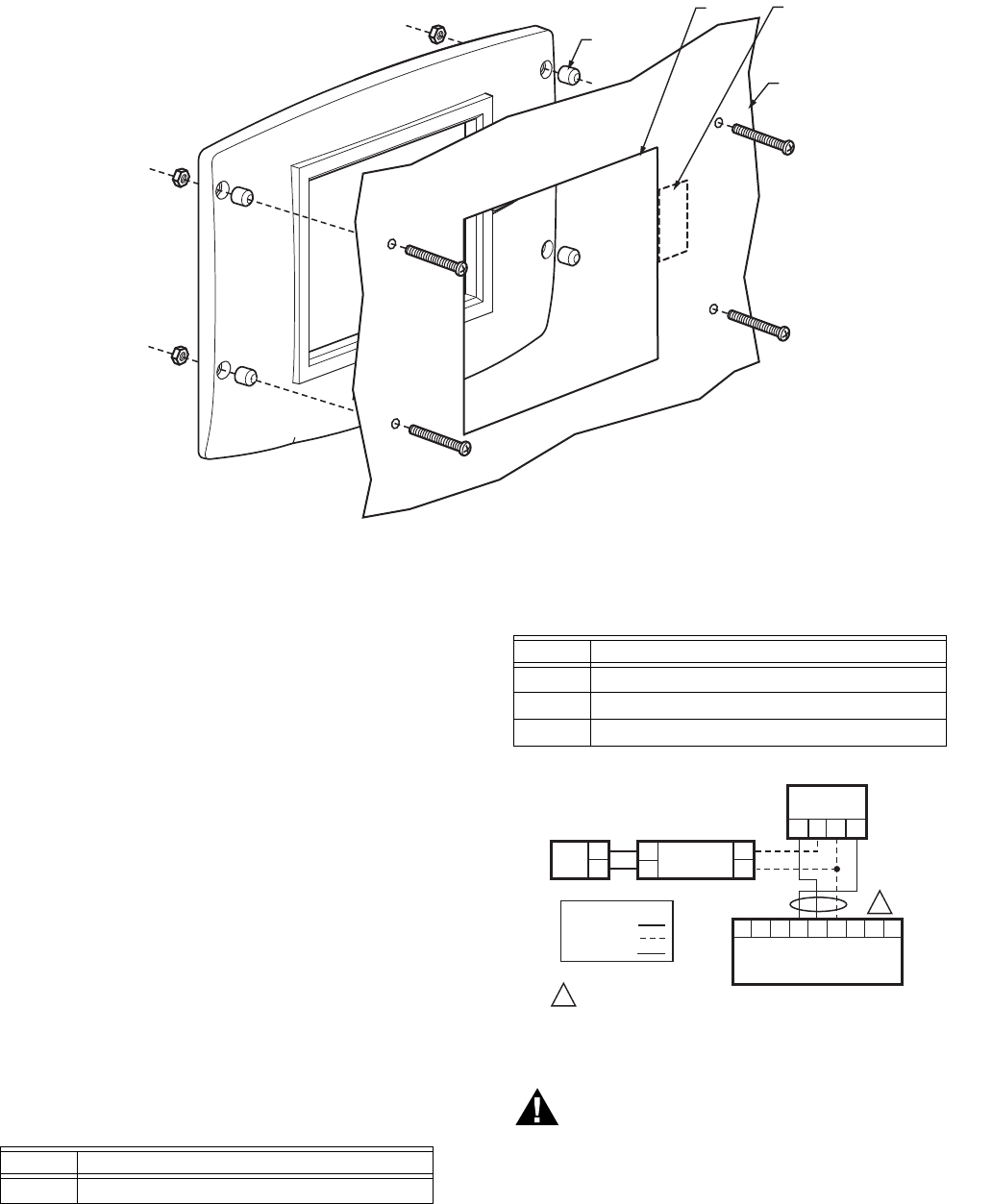
Fig. 9. S7999C wallplate dimensions in in. (mm).
Mounting the S7999C OI Display
directly to the Door Panel
1. Select the location to mount the display.
2. Cut an opening to facilitate mounting the display into the
door panel. See Fig. 1 for the dimensions for mounting
the display from the front of the door. See Fig. 10 for
mounting the display to the back of the door. If desired,
cut a notch so the LEDs will be visible as well. Tear off
templates are also available on the back pages of this
Manual (see Fig. 121 on page 63 and Fig. 122 on page
65).
3. Fit the display into the opening and use the screw holes
in the device as a template to mark the location of the
four mounting screw holes.
HOME
PAGE
SUMMARY
PAGE
M13965
1 2 3 4
SETUP PROGRAM
MODULE
CLEAN
SCREEN
SYSTEM
CONFIG.
ADVANCED
SETUP
CONFIGURE
Configuration
Groups
Login
Logout
Verify
OPERATION
CH
Login
DHW
DIAGNOSTICS
Diagn.
Tes t
Burner
Control
Digital
I/O
Analog
I/O
DETAILS
History
Alerts
Diagn.
Analysis
HISTORY
OK
Lockouts
Alerts
Silence
MODULATION
?
SETPOINTS
PUMPS
KEY
BUTTON FLOW
BACK ICON FLOW
HOME ICON ALWAYS TAKES
YOU TO THE HOME PAGE
1-21/32
(42)
1-13/16 (46)
3-13/64
(81)
2-3/4 (70)
M27606
1/2
(13)
S7999B, S7999C SOLA LOCAL OPERATOR INTERFACE
65-0303—05 10
4. Drill 3/16 in. holes for mounting the display. 5. Secure the OI Display to the panel using the four #6-32
screws and nuts, as shown in Fig. 10. (Standoffs are pro-
vided for mounting the OI Display from the back of the
door.)
Fig. 10. Mounting the S7999C OI Display behind the door panel.
S7999C OI Display Power supply
mounting.
1. Select a location inside the enclosure for mounting the
power supply.
2. Using the power supply as a template, mark the loca-
tions of two mounting holes in the enclosure.
3. Remove the power supply.
4. Drill 1/4 in. holes through the panel at the marked loca-
tions and secure the power supply with the two #6-32
screws and nuts provided.
WIRING (S7999C OI DISPLAY)
The S7999C OI display must be appropriately wired for both
power and communications.
1. Wire the power supply and the RS-485 communication
cables per Table 2 and the wiring diagram in Fig. 11.
• Y and G are connected directly to the display and
either SOLA Control connector J3 Modbus (MB1) or
Modbus (MB2).
2. Make sure the 12 Vdc power supply (supplied with the
S7999C) is connected securely to the 120 Vac power
source.
Fig. 11. S7999C wiring diagram.
WARNING
Electrical Shock Hazard.
Can cause severe injury, death or equipment
damage.
Line voltage is present at the power supply.
M29868
SPACER (4)
WALL
CUTOUT OPTIONAL
CUTOUT
Table 2. 4-pin Connector Terminals (located on the
back of the S7999C OI Display).
Pin # Function
Y Data (-) Output (Modbus b)
+ 12Vdc input
- 12Vdc Input
G Data (+) Output (Modbus a)
Table 2. 4-pin Connector Terminals (located on the
back of the S7999C OI Display).
Pin # Function
M32008
ABCABC123
MB1 MB2 ECOM J3
R7910 HYDRONIC CONTROL OR
R7911 STEAM CONTROL
DO NOT CONNECT S7999C TO TERMINALS 1 2 3 AS THIS WILL RENDER
THE DISPLAY INOPERABLE.
S7999C CAN BE
CONNECTED TO
EITHER MB1 OR
MB2 A, B, C
TERMINALS
S7999C MID-
LEVEL DISPLAY
Y+−G
120
VAC
L2
L1
V-INFINITY
FSC-S5-12U
V+
V–
N
L
WIRING KEY
LINE VOLTAGE
LOW VOLTAGE
DATA
1
1
S7999B, S7999C SOLA LOCAL OPERATOR INTERFACE
11 65-0303—05
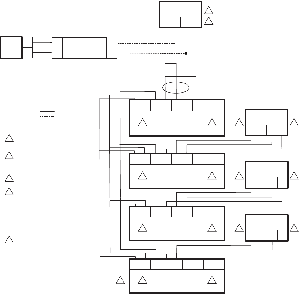
Fig. 12. S7999C wiring diagram for lead lag.
M32007
DO NOT CONNECT THE S7999C TO
TERMINALS 1 2 3. THIS WILL RENDER
THE DISPLAY INOPERABLE.
DISPLAY CAN BE CONNECTED TO MB1
OR MB2; A, B, C AS LONG AS THE
REMAINING MB TERMINAL IS USED
FOR THE SLAVE COMMUNICATIONS.
WIRE V-INFINITY POWER SUPPLY
TO + AND - TERMINALS.
S7999C CONNECTED TO THE MASTER
CAN CONFIGURE THE MASTER.
IT CAN ALSO CONFIGURE THE SLAVE
INFORMATION IN THIS CONTROL AS WELL
AS MONITOR THIS SLAVE’S ACTIVITIES.
S7999C CONNECTED TO EACH SLAVE
CAN ONLY CONFIGURE THAT SLAVE AS
WELL AS MONITOR THAT SLAVE’S ACTIVITY.
UP TO A MAXIMUM OF 8 SOLA SLAVES
IN A LEAD LAG NETWORK.
WIRING KEY
LOW VOLTAGE
DATA
LINE VOLTAGE
1
1 3
3
4
4
5
5
4
4
4
3
3
1
1
1
2
2
2
2
2
3
+YG–
S7999C
MID-LEVEL DISPLAY
23
CBA
C
BA 1
SOLA
LL MASTER AND SLAVE 1
J3
MB1 ECOMMB2
23CBA
C
BA1
SOLA SLAVE 2
J3
MB1 ECOMMB2
23CBA
C
BA1
SOLA SLAVE 4
J3
MB1 ECOMMB2
23CBA
C
BA1
SOLA SLAVE 3
J3
MB1 ECOMMB2
L1
L2
120
VAC
V+
N
LV-
V-INFINITY
FSC-S5-12U
+YG–
S7999C
MID-LEVEL DISPLAY
+Y G
–
S7999C
MID-LEVEL DISPLAY
+YG–
S7999C
MID-LEVEL DISPLAY
S7999B, S7999C SOLA LOCAL OPERATOR INTERFACE
65-0303—05 12
STARTING THE S7999C OI
DISPLAY
Power-up Validation
The Home page will appear and the “Power” LED will be on
continuously and the “COM” LED will be blinking when the
device is properly powered and communicating to the Sola
Control.
The “COM” LED exists for I/O traffic.
1. Make sure the LED is blinking.
2. If the LED is not blinking:
a. Make sure the proper connections have been made
between the display and the Sola Control.
b. See “Wiring (S7999C OI Display)” on page 10 for
proper wiring of the display connections.
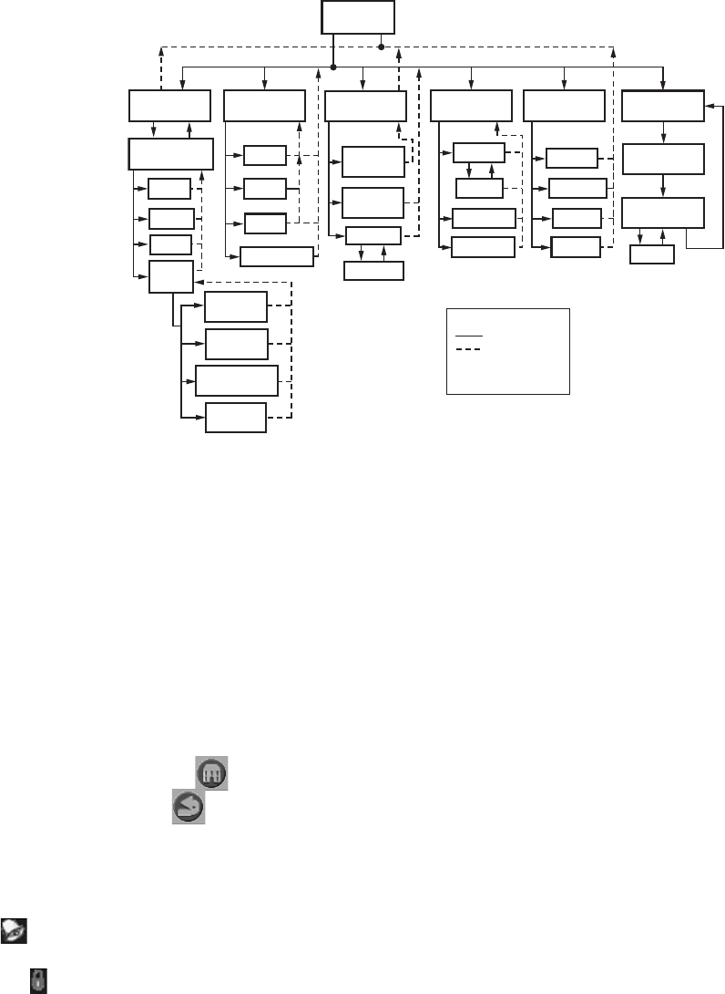
Fig. 13. S7999C display page flow.
PAGE NAVIGATION
The Sola OI Displays present information and options in a
paged manner. Pages are displayed in a tree structure in which
the user navigates up and down to arrive at the desired
Function (see Fig. 8 for S7999B or Fig. 13 for S7999C). The
page descriptions are provided below so that you can
understand the purpose of each and view the selections,
parameters, and information that is available or required on
each.
Common OI Display Page Symbols
Most pages have a Home button in the top-left corner of
the screen and a Back button in the top-right corner of
the screen. The Home button returns the user to the Home
page and terminates any operation in progress. The Back
button returns the user to the previous page.
Two other icons may be noticed near the boiler name.
A bell will be displayed if the system is in Lockout that
reset will be required.
A padlock will be shown on screens that require a password
to change the parameter. An unlocked padlock indicates the
password has been entered to change the parameter.
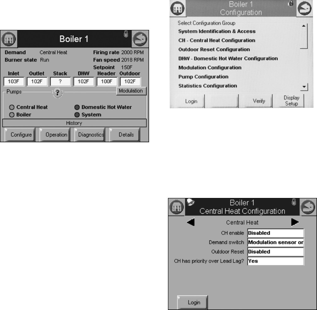
Status or Home Page
A status (summary) page (Fig. 14) is displayed when the
S7999C display is connected. This status page appears on the
S7999B when the Sola control icon is pressed on the “Home”
page. The status page displays the current condition of the
burner control and displays some of the more important
configuration settings.
The boiler name associated with the burner control is
displayed in the title on the status page.
NOTE: When the burner control has no boiler name defined,
Modbus address is used to identify the boiler.
The initial status page displayed contains summary status
information as shown in Fig. 14. Any status information not
applicable for the installation is grayed/blanked out on the
screen.
Buttons on this screen include:
•Configure: used to configure the burner control (see
“Configure Button” on page 13 for more details).
•Operation: used to perform daily or frequent functions with
the burner control, such as setpoint adjustment, etc. See
“Operation Button” on page 18 for details.
•Diagnostic: used to view burner control diagnostic
information (see “Diagnostics Button” on page 19 for more
details).
•Details: used to view burner control detail status
information (see “Details” on page 38).
HOME
PAGE
M29774
LOGIN
CONFIGURE
CONFIGURATION
GROUPS
LOGOUT
VERIFY
DISPLAY
SETUP
OPERATION
CH
LOGIN
DHW
DIAGNOSTICS
DIAGNOSTIC
TEST
BURNER
CONTROL
DIGITAL I/O
ANALOG I/O
PROGRAM
MODULE
CLEAN
SCREEN
SYSTEM
CONFIGURATION
ADVANCED
SETUP
DETAILS
HISTORY
ALERTS
DIAGNOSTIC
ANALYSIS
HISTORY
OK
LOCKOUTS
ALERTS
SILENCE
MODULATION
SETPOINTS
PUMPS
?
KEY
BUTTON FLOW
BACK ICON FLOW
HOME ICON ALWAYS
TAKES YOU TO THE
HOME PAGE
ANNUNCIATION
S7999B, S7999C SOLA LOCAL OPERATOR INTERFACE
13 65-0303—05
•History: used to view burner control history (see “History
Button” on page 16 for more details).
•?: used to expand the pump status information.
•Modulation: used to toggle between status displays: pump,
setpoints, and modulation.
Fig. 14. Summary status page (Hydronic Control shown).
Configure Button
Pressing the Configure button (bottom left) on the Status page
opens the Configuration page. The Configuration page shown
in Fig. 15 is for the S7999C OI display.
The S7999B Configuration page does not have a “Display
Setup” button.
Display Setup (S7999C only): Pressing the Display Setup
button displays miscellaneous S7999C OI Display setup and
diagnostic functions (See page 47 for options). (The same
function as the 1234 Setup on the S7999B home page.)
The configuration page allows the user to view and set
parameters that define how the connected R7910A functions in
the hydronic heating system or the R7911 steam heating
system.
The configuration page contains a menu of parameters
grouped into functional areas that the user selects for
configuration (see Fig. 16). See Table 61 on page 53 for all
parameters available for configuration. If some parameters are
not visible, they have been made invisible by Honeywell.
Fig. 15. Configuration menu page. Shown is the S7999C on
a Hydronic Control.
No specific order for configuration is required. All parameters
are enabled for editing, though some may not be applicable
(e.g., a configuration parameter may disable a control feature).
Selecting a parameter group from the menu displays
parameters exclusively applicable for the functional group on
the page (see Fig. 16). These parameters can be edited, and
when the user is finished, control returns back to the
configuration menu page.
Fig. 16. Sample configuration page for the S7999B
Hydronic Control.
Each parameter is displayed in its group. If there are more
parameters than will fit on the screen, a vertical scroll bar
allows the user to scroll up and down to view all parameters.
The parameter name is displayed on the left and the current
setting is displayed in the text box on the right.
Configuration Password
Some parameters require a valid configuration password be
entered by the user before the parameter can be changed. The
password need only be entered once while the user remains
on the configuration pages. Leaving the configuration pages
ends the scope of the password.
S7999B, S7999C SOLA LOCAL OPERATOR INTERFACE
65-0303—05 14
Three levels of access to Sola Control parameters are
permitted. Each access level has defined rights when
interfacing with configuration and status parameters within the
controls.
•End user: The end user can read or view the control
parameters and be allowed to change some operating
parameters, CH setpoint as an example.
•Installer: The installer can read all control parameters and
change Honeywell's allowed parameters. This access level
is used to customize the control for a particular installation.
•OEM: The OEM can read and change all parameters,
change sensor limits and burner control safety parameters.
Different passwords exist in the Sola Control for each access
level. The end user level requires no password, but the
installer and OEM levels have unique passwords defined for
them.
The installer and OEM passwords can be changed in the Sola
Control after logging in with the current password. When the
password is changed, it is saved for all future logins.
NOTE: For the S7999B System OI display, each boiler in a
multi-boiler configuration has its own set of installer
and OEM passwords. To avoid user confusion, the
passwords should be changed to the same password
in each control, but there is no requirement to do so.
Make sure to record your password.
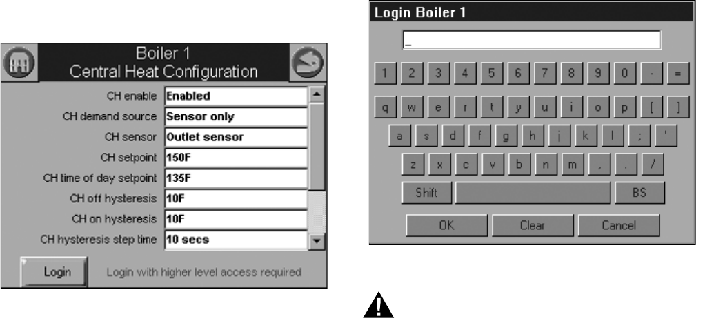
The user is notified that a new password is needed to change a
parameter (or until a password is entered successfully)—see
Fig. 17. The user can continue viewing the configuration
parameters regardless of whether a password is entered
successfully.
Fig. 17. Login required. (S7999B Hydronic Control Shown.)
The Sola Controls maintain a password time-out that limits the
scope of the password entry. Once a password is successfully
entered, the control starts an internal timer that expires after 10
minutes of inactivity. After the timer expires, the user is
required to re-enter a password before a parameter can be
changed.
The user is not required to enter a configuration password for a
parameter that has a lower access level than the access level
achieved by an earlier password entry for any configuration
group (as long as the user stays in the configuration pages).
The user only needs to enter a password once until a
parameter that has a higher access level is selected.
Keyboard
Some pages request user entry of characters. When this type
of input is required, a keyboard page appears, as shown in Fig.
18. The text box at the top of the screen displays the current
(or default) setting of the user input. The user can add to this
text, clear it, or change it.
The Shift key on the left side of the screen shifts between
upper and lowercase characters. Pressing the Shift key
toggles the keyboard from one mode to the other (continuous
pressing of the Shift button is not required). The OK button
should be pressed when the user is done entering the text
input. The Cancel button on the bottom of the screen allows
the user to ignore any text changes that have been made and
keep the original text value. Pressing the OK or Cancel buttons
returns the user to the page displayed prior to the keyboard
page.
Login
Pressing the Login button allows entering the password from a
keyboard as shown in Fig. 18. After the password is entered,
the OK button is selected. The Cancel button aborts the
password login.
Fig. 18. Device login screen.
WARNING
Explosion Hazard.
Improper configuration can cause fuel buildup and
explosion.
Improper user operation may result in PROPERTY
LOSS, PHYSICAL INJURY or DEATH.
Using the OI Displays to change parameters must be
attempted by only experienced and/or licensed
burner/boiler operators and mechanics.
S7999B, S7999C SOLA LOCAL OPERATOR INTERFACE
15 65-0303—05
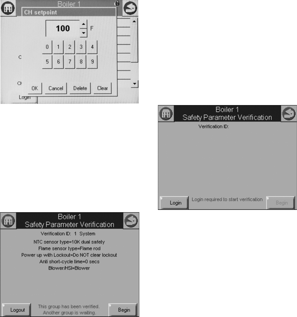
Change Parameter Settings
Change parameter settings by selecting the parameter on the
page. A dialog box displays for the parameter with controls
allowing the user to change the value (see Fig. 19). After
changing the setting to a new value, press the OK button.
Pressing the Cancel button leaves the parameter unchanged.
The changed setting is reflected on the screen and sent to the
control when the OK button is pressed.
Fig. 19. Change configuration parameter page example of
a Hydronic Control.
Verify
Pressing the Verify button displays safety configuration
parameters for an additional verification step to commit the
changes.
Safety parameters are grouped into blocks that include only
safety parameters, not a mixture of safety data and non-safety
data. All parameters within the safety group undergo a
verification process. A safety parameter group is identified on
the display to indicate when the configuration parameters are
safety-related. Each safety parameter group is verified one at a
time until all have been verified. See Fig. 20.
Fig. 20. Safety verification.
Like operating parameters, safety parameters can be viewed
without the need to enter a password.
Safety parameter blocks that have been changed require
verification. The verification steps do not have to be completed
immediately; the installer can move between and change
parameter groups before the verification is done. A Verify
button is enabled that allows the installer to conduct verification
sessions (the example of the Verify button in Fig. 15 is not yet
enabled because the installer hasn’t logged in).
NOTE: When the installer proceeds with the safety parameter
configuration, the control unlocks the safety parame-
ters in this group and marks them unusable. Failure to
complete the entire safety configuration procedure
leaves the control in an un-runnable state (lockout 2).
All safety configuration parameters in the group should have
the same access level. If this condition isn’t so, the user is
asked to enter another password when a higher access level is
needed.
Successful login is noted by the lock icon, which changes to
“unlocked” on the page. The installer may begin to change
safety parameters (or any other parameters) at that time. (See
Fig. 21.) If the Sola Control is in an unconfigured (or new)
state, then this warning doesn’t appear. All parameters that
need changes should be changed during the login.
Fig. 21. Edit safety data.
If the safety configuration session is terminated after it has
started (in the Edit or Verify stages), the Sola Control is left in
an unconfigured (unrunnable) state.
The installer can terminate the session by pressing the Menu
button or by attempting to leave the Verification page with the
Home or Back buttons (top-left and -right screen corners,
respectively). However, leaving the session at this point leaves
the control in an unrunnable state and confirms whether the
installer still wants to do so.
The settings of all parameters in each safety block must be
verified to save them in the control.
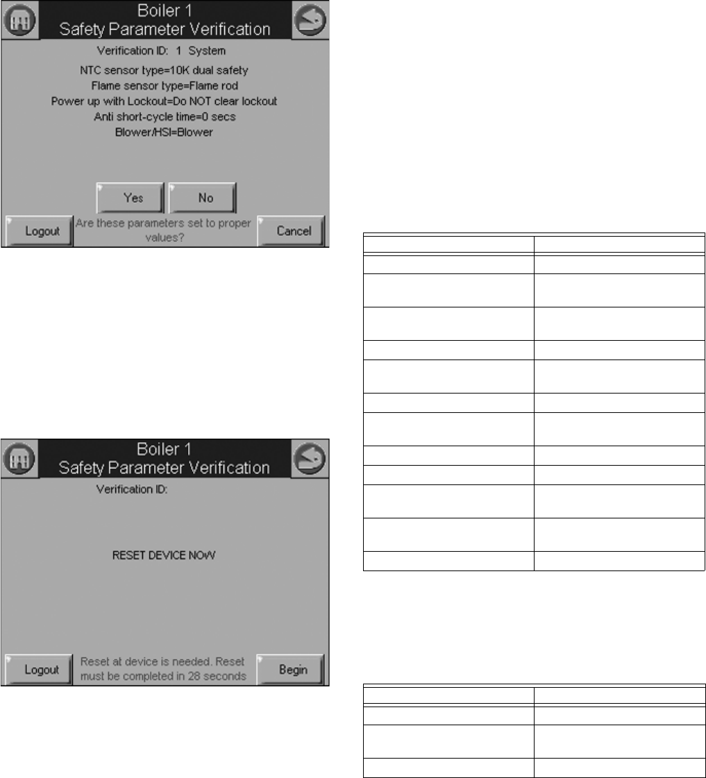
When the installer is done changing safety parameters,
pressing the Verify button on the configuration screen begins
the Verification process. The settings for all safety parameters
in each changed block are presented and Verified by the
installer (see Fig. 22).
S7999B, S7999C SOLA LOCAL OPERATOR INTERFACE
65-0303—05 16
Fig. 22. Safety parameter confirmation.
Press the Yes button to confirm each safety parameter block. If
the No button is selected, the safety parameter block remains
unconfirmed and the Configuration menu page is displayed.
The control remains in an unconfigured state in this case.
After all safety parameter blocks have been confirmed, the
installer is asked to press and hold the Reset button on the
Sola Control to complete the safety verification session (see
Fig. 23).
Fig. 23. Safety parameter reset.
When the Reset button is pressed and held for 3 seconds the
confirmed safety parameters are saved in the control. The
above Reset dialog box automatically closes when this step is
completed.
If this step is not performed, the control remains in a safety
lockout state until the installer resolves the unverified safety
parameters.
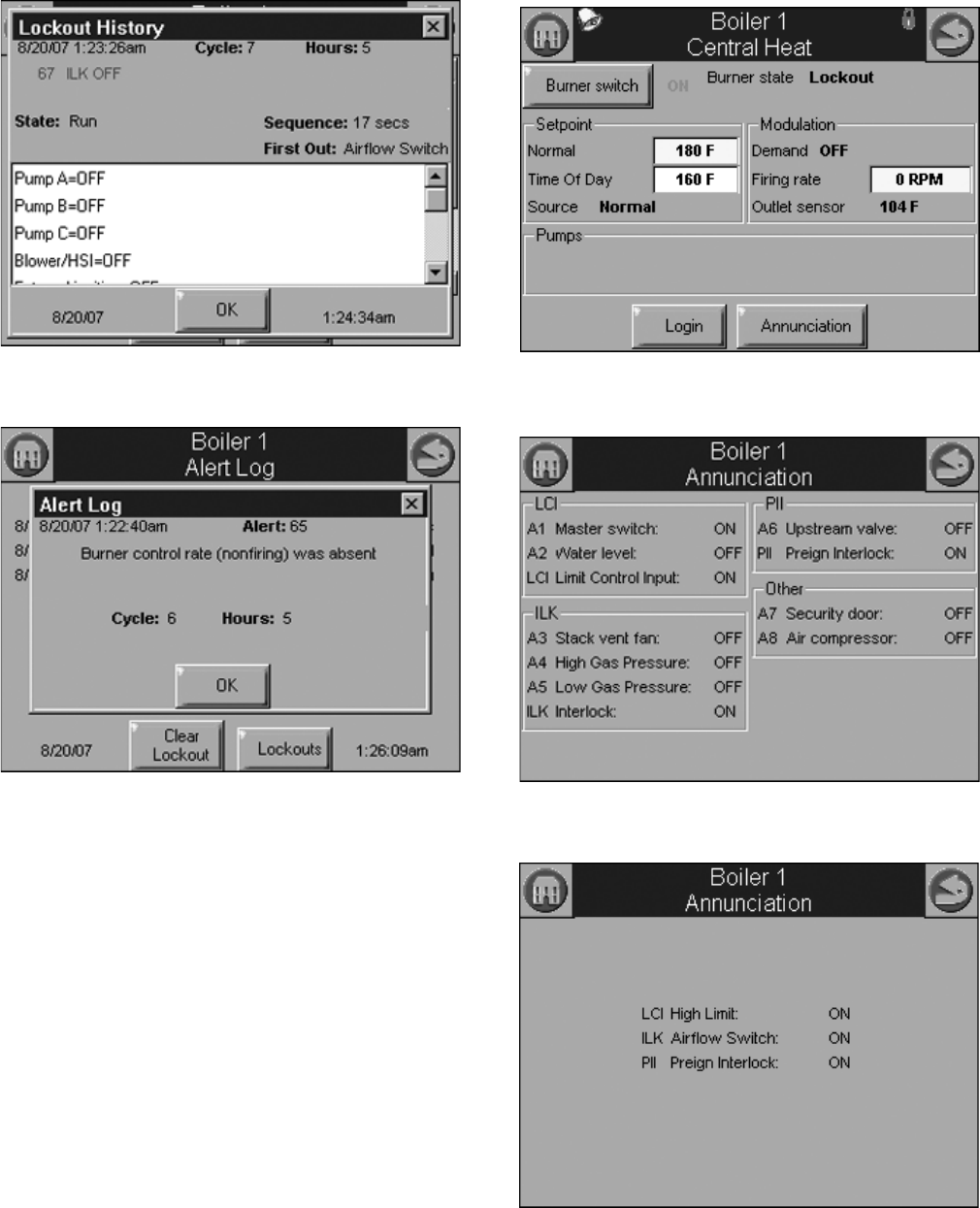
Fault/Alarm Handling
Each Sola Control reports to the OI display when a safety
lockout or an Alert occurs.
Safety lockouts are indicated on each configuration page as an
alarm bell symbol. At the home (for S7999C) or status page
(for S7999B), the History button turns red. If the S7999B is
displaying the system status icons, the control in alarm will turn
red.
The lockout history can be displayed by pressing on the
History button. The state information about each lockout is
displayed along with the date/time that the lockout occurred
(see Table 3). Current date/time stamp is a display setup
feature.
NOTE: In the event of a power interruption, the date/time
must be reset. The OI Display does NOT have a
backup means.
An alert log can be displayed for each control by pressing the
Alert button on the bottom of the history status page. A
description of the alert is displayed along with the time when
the alert occurred (see Table 4).
History Button
The History button on the Home page serves not only as a
button, but also displays Sola Control lockouts, holds, and
alerts as they occur. The History button can be selected at any
time, regardless of which type of information is displayed, to
view history information. Pressing the History button displays a
dialog box (see Fig. 24) that allows the user to select the type
Table 3. Sola Control Lockout History.
Data Comment
Lockout time Set by display
Fault code Unique code defining which
lockout occurred.
Annunciator first out First interlock in limit string
results in a shutdown.
Description Fault description
Burner Lockout/Hold Source/reason for lockout/
hold
Burner control state
Sequence time Burner control state timer at
time of fault
Cycle Burner control cycle
Run Hours Burner control hours
I/O All digital I/O status at time of
fault
Annunciator 1-8 states All annunciator I/O status at
time of fault
Fault data Fault dependent data
Table 4. Sola Control Alert Log.
Data Comment
Alert time Set by display
Alert code Unique code defining which
fault occurred.
Description Alert description
S7999B, S7999C SOLA LOCAL OPERATOR INTERFACE
17 65-0303—05
of history to view. The user can also silence an audible alarm
generated by the control during a lockout or alert by alarm
condition.
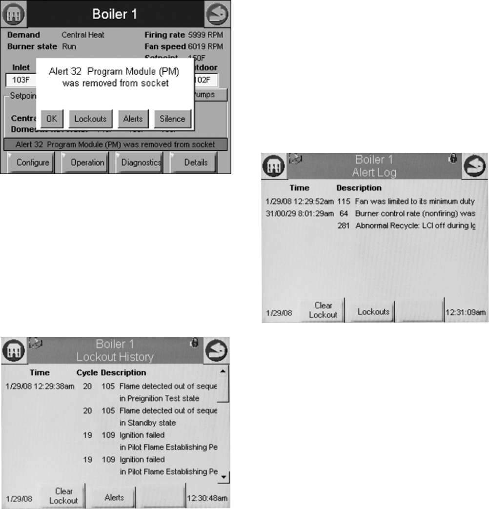
This History dialog box provides an exploded view of the status
information displayed in the History button (the font is larger).
One of the four buttons (OK, Lockouts, Alerts, or Silence) can
be selected. If none of these buttons are selected the dialog
box closes after 30 seconds.
Fig. 24. Hydronic history example shown—exploded view.
Two types of historical data can be displayed on the history
page: lockout history and alert log.
The entire 15 fault code history is displayed in a scrollable list
with the most recent fault displayed first followed by the next
most recent fault. Summary information is displayed for each
fault entry, including the burner cycle count, fault code, and
fault number with description. Detailed information for a
specific fault entry that also includes burner control sequence
state, burner run-time hours, annunciation status, etc., is
viewed by selecting (touching the History line) the lockout entry
in the list (see “Fault/Alarm Handling” on page 16 for details).
Fig. 25. Lockout history example shown.
The date and time that each fault occurred is displayed in the
lockout history. The lockout timestamp displays in both the
lockout summary and detail information.
The Sola Control does not maintain date or time of day
information. The date and time stamp is assigned by the OI
display. When the OI display first obtains the lockout and alert
history from the control (during the display data
synchronization), no timestamps are assigned since the times
that the lockouts occurred are unknown. All new lockouts that
occur after the synchronization are assigned timestamps.
NOTE: The system time can be set in the OI display to
ensure that correct timestamps are given to the con-
trols’ lockouts and alerts. Power interruptions will
require the time to be reset as the display DOES NOT
have a time backup means.
The Clear Lockout button allows the user to acknowledge and
clear (reset) the lockout when in lockout state, much the same
as pressing the reset button on the front of the Sola Control.
The user can toggle between displaying the controls’ lockout
history and alert log by pressing the Alerts or Lockouts button
on the bottom of the pages.
Fig. 26. Alert log example shown.
To see additional detail about a lockout or alert, touching on the
lockout or alert in the list expands the view of that lockout or
alert, as shown in Fig. 27 and 28.
S7999B, S7999C SOLA LOCAL OPERATOR INTERFACE
65-0303—05 18
Fig. 27. Control expanded lockout detail.
Fig. 28. Control expanded alert detail.
Operation Button
The operation button displays the SOLA Control running
operation, including setpoint and firing rate values. From this
page the user can change setpoints, manually control the
boiler’s firing rate, manually turn pumps on, view annunciation
information, and switch between hydronic heating loops
(Central Heat and Domestic Hot Water), as shown in Fig. 22. If
a password is required to change any of the settings on this
page, the user can press the Login button to enter the
password.
Annunciation information is shown in Fig. 23 and Fig 24.
Fig. 29. Hydronic operation page shown.
Fig. 30. Programmable annunciation.
Fig. 31. Fixed annunciation.
S7999B, S7999C SOLA LOCAL OPERATOR INTERFACE
19 65-0303—05
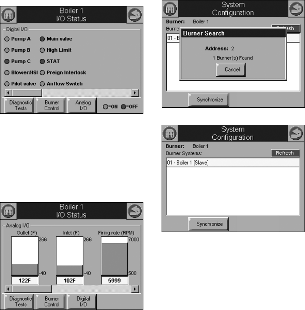
Diagnostics Button
The Diagnostics button displays analog and digital I/O status of
the SOLA Control. A snapshot of the diagnostic status is
displayed and updated once per second as it changes in the
control. See “R7910A or R7911 Diagnostics” on page 44 for
more information about this status.
The digital I/O data is displayed as LEDs that are either on
(green) or off (red) (See Fig. 23). Not all digital I/O can be
displayed at the same time on the page, so a horizontal scroll
bar is used to move the view left and right to show all digital
I/O data.
Fig. 32. Diagnostic page (digital I/O).
The control analog I/O can also be viewed on the OI Display. A
snapshot of the diagnostic status is displayed and updated as
it changes in the control.
The analog I/O data is displayed as bar charts with I/O level
represented in the I/O range (see Figure 24.) Analog I/O that is
not enabled for the installation displays a blank I/O level. Not
all analog I/O can be displayed at the same time on the page,
so a horizontal scroll bar is used to move the view left and right
to show all analog I/O status.
Fig. 33. Diagnostics page (analog I/O).
System Configuration
(S7999B OI DisplayOnly)
The OI Display has some functions related to general
configuration for the control in the end user installation.
Pressing the Display Refresh button invokes a search
procedure (see Fig. 34). A new R7910A Hydronic Control or
R7911 Steam Control is identified by “Unknown” status next to
its name in the boiler system list (see Fig. 35). “Unknown”
indicates that configuration data has not been retrieved from
the control yet.
Fig. 34. System refresh.
Fig. 35. System configuration page.
The control connected to the Modbus network is indicated to
the user after the search procedure has concluded.
Once the control is located it must be synchronized with the OI
Display before it can be displayed. New controls are not
displayed on the Home page until this synchronization (see
below) is performed.
System Synchronization
(S7999B OI Display Only)
The user can manually synchronize configuration data from the
connected controls at any time.
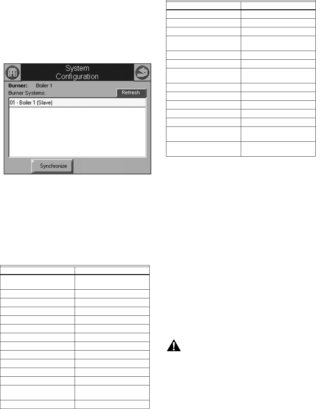
S7999B, S7999C SOLA LOCAL OPERATOR INTERFACE
65-0303—05 20
A new control is visible when configuration and status data is
gathered from it. This collection procedure takes a few
minutes. The control is marked as “Unknown” when no
configuration information exists. Normally, control configuration
data collection only needs to be performed when the control is
initially installed. However, a re synchronization is necessary
after the OI Display is reset. See Fig. 36.
The user presses the Synchronize button to begin
synchronization with the control. See Fig. 36.
Fig. 36. System synchronization.
Status of the synchronization is reflected in the dialog box. The
synchronization can be aborted by selecting the Cancel button.
Configuration
The SOLA Control can be configured from the OI Display. The
control configuration is grouped into the functional groups seen
in Table 5.
Most of this configuration is performed by either the contractor/
installer or at Honeywell. Each functional group is displayed on
the Configuration menu page.
Parameters in functional groups that are not applicable for the
installation can be ignored. In some cases, features in a
functional group are disabled by default and are enabled when
needed for the installation.
R7910A HYDRONIC CONTROL,
R7911 STEAM CONTROL
CONFIGURATION
PARAMETERS
The following pages list the configuration parameters available
for the R7910A or R7911 installed.
NOTE: Individual Configuration pages may differ from this
text as features are added or amended by Honeywell.
A password is required to make changes to the Configuration
Parameters. The SOLA Control will be in a Lockout 2 “waiting
for safety data verification” as received or will go to a Lockout 2
when changes are made to the safety data.
WARNING
Explosion Hazard.
Improper configuration can cause fuel buildup and
explosion.
Improper user operation may result in PROPERTY
LOSS, PHYSICAL INJURY or DEATH.
The OI Display used to change parameters, must be
attempted by only experienced and/or licensed
burner/boiler operators and mechanics.
Table 5. Functional Configuration Groups.
Hydronic Control Steam Control
System Identification and
Access
Steam Identification and
Access
CH - Central Heat Steam Configuration
Outdoor Reset Modulation Configuration
DHW - Domestic Hot Water Pump Configuration
DHW Storage
DHW Plate
Warm Weather Shutdown
Demand Priority
Modulation Configuration Statistics Configuration
Pump Configuration Stack Limit
Statistics Configuration Annunciation Configuration
High Limit Burner Control Interlocks
Stack Limit Burner control Timings and
Rates
Delta T Limits
T-Rise Limit
Heat Exchanger High Limit
Anti-condensation Burner Control Flame Failure
Frost Protection
Configuration
System Configuration
Annunciation Configuration Fan Configuration
Burner Control Interlocks Lead Lag Configuration
Burner Control Timings and
Rates
Burner Control Ignition
Burner Control Flame Failure
System Configuration
Fan Configuration
Sensor Configuration
Lead Lag Slave
Configuration
Lead Lag Master
Configuration
Table 5. Functional Configuration Groups.
Hydronic Control Steam Control
S7999B, S7999C SOLA LOCAL OPERATOR INTERFACE
21 65-0303—05
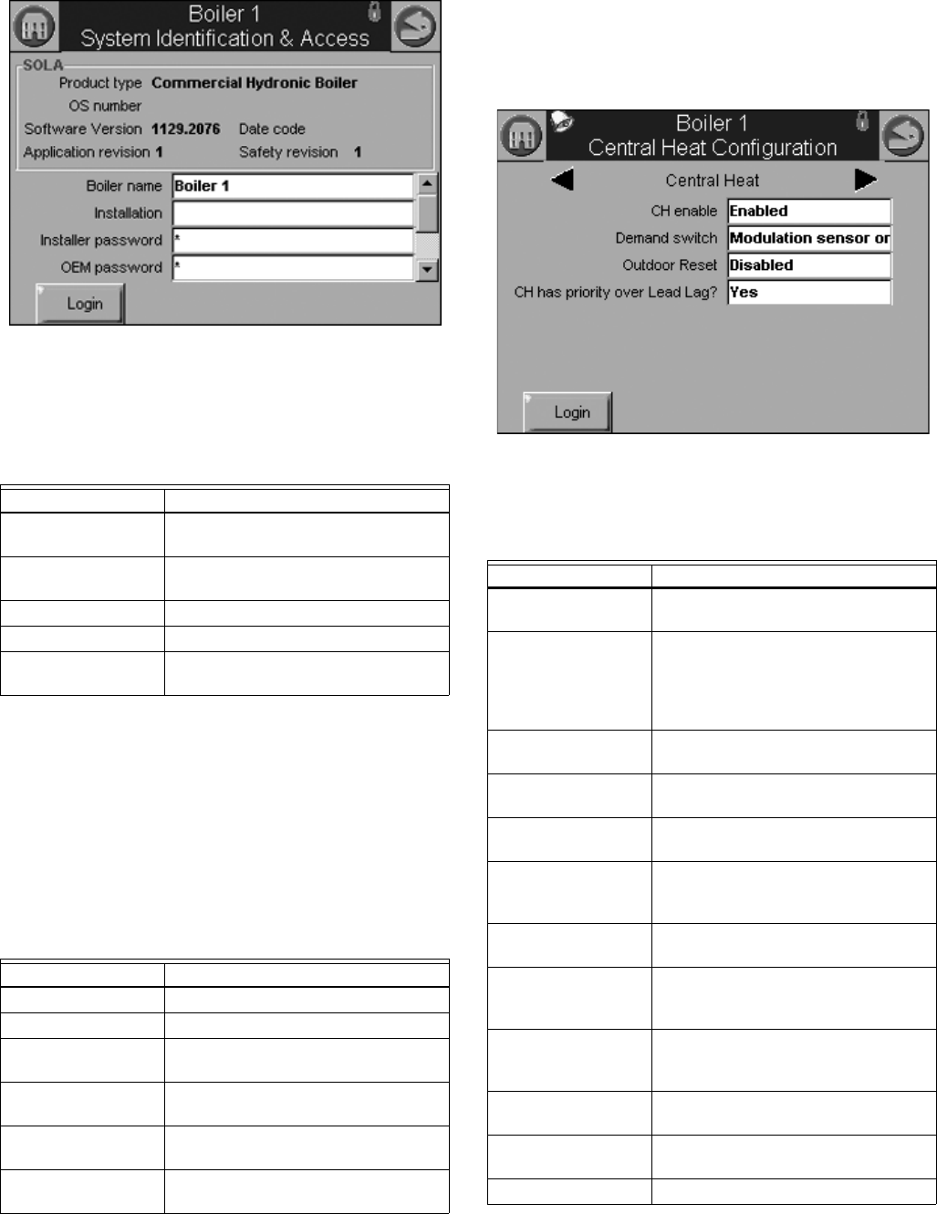
Fig. 37. System identification and access configuration.
(Hydronic Screen Shown.)
Table 6 displays System Identification and Access parameters.
When the burner name is changed, the name is saved in the
R7910A or R7911 and displayed in the title of all pages that
zoom into the control.
Default parameter settings for installer and Honeywell
passwords are “sola” and “solaoem,” respectively. These
passwords most likely have been changed by Honeywell.
Factory Data gives Honeywell an option to display a brand
name other than Sola on this configuration page. Additional
information displayed on this page is listed in Table 7.
Central Heat Parameters
(R7910A Hydronic Control Only)
Table 8 displays Central Heat Hydronic Control configuration
parameters.
Fig. 38. Central Heat hydronic configuration.
Table 6. System Identification and Access Parameters.
Parameter Comment
Boiler Name Name to identify boiler (up to 20
characters)
Installation Notes regarding installation (up to 20
characters)
Installer password Change installer password setting
OEM password Change OEM password setting
Factory Data OEM name to associate with boiler
(up to 20 characters)
Table 7. System Identification Information.
Status Comment
Product Type Type of product that the burner is
OS Number Model number associated with burner
Software Version Version of software running in the
R7910A or R7911
Date Code Date when R7910A or R7911 was
assembled
Application Revision Version of application data in the
R7910A or R7911
Safety Revision Revision of safety data in the R7910A
or R7911
Table 8. Central Heat Hydronic
Configuration Parameters.
Parameter Comment
CH enable Disable or Enable Central Heating
Loop
Demand switch Sensor for Central Heat demand:
Sensor only
Sensor & STAT terminal
Sensor & Remote Stat
LCI & Sensor
Outdoor reset Enabled
Disabled
CH has priority over
Lead Lag
Yes, No, Cancel
Setpoint source Local
S2 (J8-6) 4-20mA
Setpoint Setpoint for normal Central Heat
modulation:
-40 °F to 266 °F (-40 °C to 130 °C)
Time of day setpoint Setpoint when Time Of Day switch is
on. -40 °F to 266 °F (-40 °C to 130 °C)
Off hysteresis Differential above setpoint when boiler
is turned off.
32 °F to 266 °F (0 °C to 130 °C)
On hysteresis Differential from setpoint when boiler
is turned on. 32 °F to 266 °F (0 °C to
130 °C)
4 mA water
temperature
-40 °F to 266 °F (-40 °C to 130 °C)
20 mA water
temperature
-40 °F to 266 °F (-40 °C to 130 °C)
Modulation sensor Outlet sensor, Inlet sensor, S5 (J8-11)
S7999B, S7999C SOLA LOCAL OPERATOR INTERFACE
65-0303—05 22
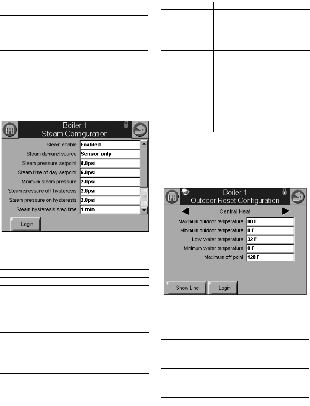
Fig. 39. R7911 Steam Configuration.
Outdoor Reset Parameters
(R7910A Hydronic Control Only)
Table 10 displays Outdoor Reset configuration parameters.
Pressing the left or right arrow displays Lead Lag, which lists
the same parameters.
Fig. 40. Outdoor reset configuration.
Modulation Rate
Sensor
Local
P-gain Gain applied for the P portion of the
PID equation
0-400
I-gain Gain applied for the I portion of the
PID equation
0-400
D-gain Gain applied for the D portion of the
PID equation
0-400
Hysteresis step time Time between hysteresis step
changes: 0-600 seconds (0=Disable
hysteresis stepping)
Table 9. Steam Configuration Parameters
Parameter Comment
Steam enable Disable/enable steam feature
Steam demand
source
Sensor and LCI
Sensor and Remote Stat
Sensor and Stat Terminal
Sensor Only
Steam pressure
setpoint
Setpoint for normal modulation
Adjustable 0 to 15 or 0 to 150 (sensor
dependant)
Steam time of day
setpoint
Setpoint when TOD switch on
Adjustable 0 to 15 or 0 to 150 (sensor
dependant)
Minimum steam
pressure
Establishes setpoint for the 4ma. input.
Adjustable 0 to 15 or 0 to 150 (sensor
dependant)
Steam pressure off
hysteresis
Differential below setpoint when boiler
is turned off
Adjustable 0 to 15 or 0 to 150 (sensor
dependant)
Table 8. Central Heat Hydronic
Configuration Parameters. (Continued)
Parameter Comment Steam pressure on
hysteresis
Differential from setpoint when boiler
is turned on.
Adjustable 0 to 15 or 0 to 150 (sensor
dependant)
Steam hysteresis
step time
Time between hysteresis changes 0 to
600 seconds (0=disable)
Steam P Gain Gain applied for the P portion of the
PID equation
0-400
Steam I Gain Gain applied for the I portion of the PID
Equation - 0-400
Steam D Gain Gain applied for the D portion of the
PID equation
0-400
Steam 4-20 ma
remote control
uses 4-20ma remote control function to
control either the setpoint or
modulation for Steam
Disable, setpoint, modulation
Table 10. Outdoor Reset Configuration Parameters.
Parameter Comment
Maximum outdoor
temperature
-40 °F to 266 °F (-40 °C to 130 °C)
Minimum outdoor
temperature
-40 °F to 266 °F (-40 °C to 130 °C)
Low water
temperature
-40 °F to 266 °F (-40 °C to 130 °C)
Minimum water
temperature
-40 °F to 266 °F (-40 °C to 130 °C)
Maximum off point -40 °F to 266 °F (-40 °C to 130 °C)
Table 9. Steam Configuration Parameters
Parameter Comment
S7999B, S7999C SOLA LOCAL OPERATOR INTERFACE
23 65-0303—05
Domestic Hot Water (DHW)
Configuration Parameters
(R7910A Hydronic Control Only)
Table 11 displays Domestic Hot Water (DHW) configuration
parameters.
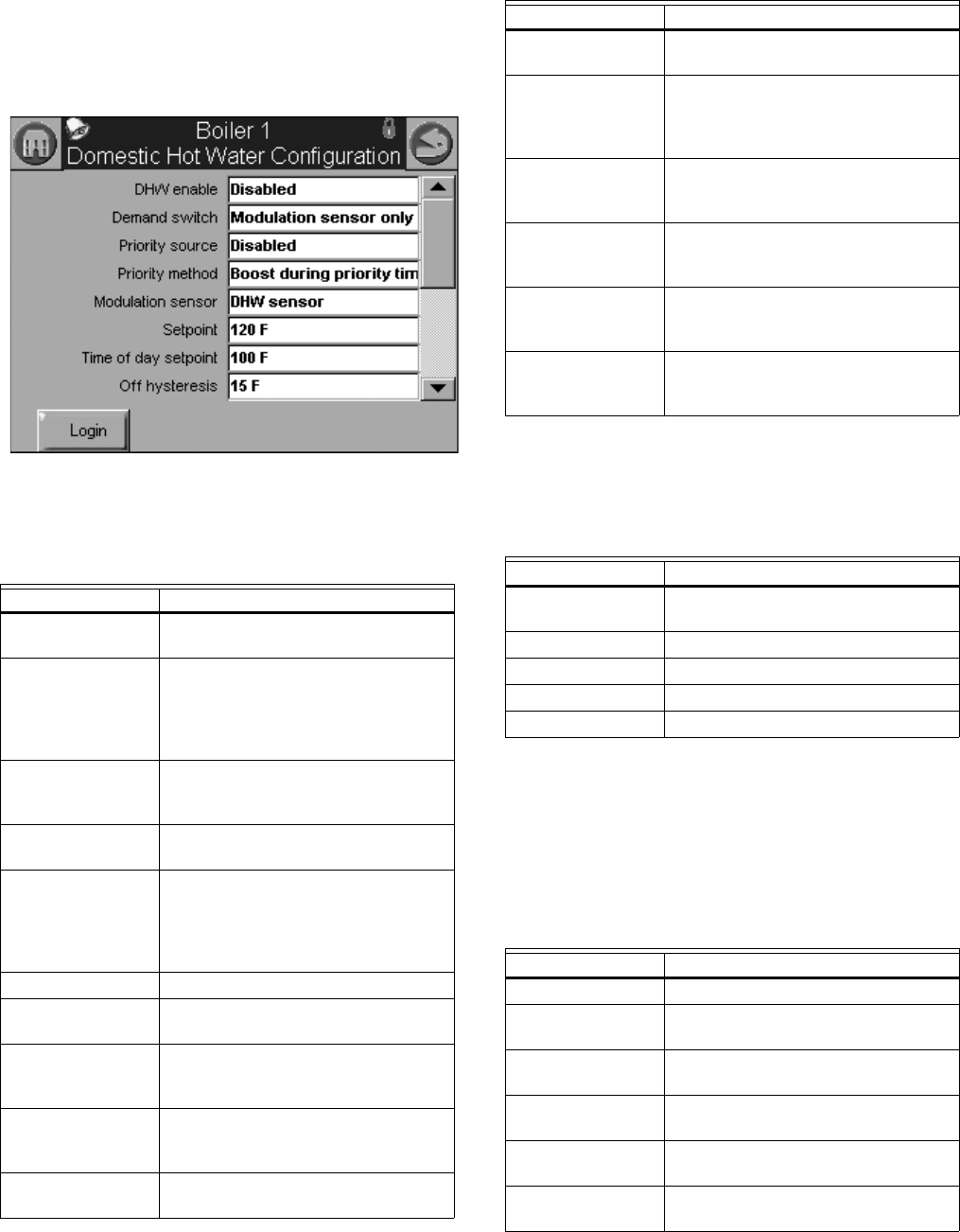
Fig. 41. Domestic Hot Water (DHW) configuration.
DHW Storage Configuration
Table 12 displays DHW Storage configuration parameters.
DHW Plate Heat Exchanger
Configuration
Table 13 displays DHW Plate Heat Exchanger configuration
parameters.
Table 11. Domestic Hot Water (DHW)
Configuration Parameters.
Parameter Comment
Enable Disable or Enable Domestic Hot
Water Loop
Demand switch Sensor for Central Heat demand:
DHW sensor only,
DHW sensor & Remote Stat,
DHW switch & inlet sensor, or
DHW switch & outlet sensor
Priority source Which system has priority:
Disabled or
Heat Demand
Priority method Boost during priority time
Drop after priority time
Modulation sensor DHW Sensor
Outlet Sensor
Inlet Sensor
Auto: DHW (S6) or Inlet Sensor
Auto: DHW (S6) or Outlet Sensor
Setpoint -40 °F to 240 °F (-40 °C to 115 °C)
Time of day setpoint Setpoint when Time Of Day switch is
on. -40 °F to 240 °F (-40 °C to 115 °C)
Off hysteresis Differential above setpoint when boiler
is turned off. -40 °F to 240 °F (-40 °C
to 115 °C)
On hysteresis Differential from setpoint when boiler
is turned on.
2 °F to 234 °F (-16 °C to 112 °C)
DHW priority
override time
___hour ___min ___sec
Hysteresis step
time
___hour ___min ___sec
DHW priority vs CH Which system has priority:
Central Heat over Domestic Hot
Water, or
Domestic Hot Water over Central Heat
DHW priority vs
Lead Lag
Which system has priority:
Lead Lag over Domestic Hot Water,
Domestic Hot Water over Lead Lag
DHW P-gain Gain applied for the P portion of the
PID equation
0-400
DHW I-gain Gain applied for the I portion of the
PID equation
0-400
DHW D-gain Gain applied for the D portion of the
PID equation
0-400
Table 12. DHW Storage Configuration Parameters.
Parameter Comment
DHW storage
enable
Enabled, Disabled
Storage time ___hour ___min ___sec
Setpoint -40 °F to 266 °F (-40 °C to 130 °C)
Off hysteresis -0 °F to 180 °F (-17 °C to 82 °C)
On hysteresis -0 °F to 180 °F (-17 °C to 82 °C)
Table 13. DHW Plate Heat Exchanger
Configuration Parameters.
Parameter Comment
Tap detect degrees -0 °F to 180 °F (-17 °C to 82 °C)
Tap detect on
recognition time
___hour ___min ___sec
Tap detect on
threshold
-0 °F to 180 °F (-17 °C to 82 °C)
Tap detect minimum
on time
___hour ___min ___sec
Tap stop inlet-DHW
degrees
-0 °F to 180 °F (-17 °C to 82 °C)
Tap stop outlet-Inlet
degrees
-0 °F to 180 °F (-17 °C to 82 °C)
Table 11. Domestic Hot Water (DHW)
Configuration Parameters. (Continued)
Parameter Comment
S7999B, S7999C SOLA LOCAL OPERATOR INTERFACE
65-0303—05 24
Warm Weather Shutdown
Configuration
Table 14 displays Warm Weather Setpoint configuration
parameters.
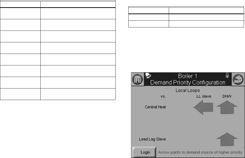
Demand Priority Configuration
Parameters
Fig. 42 displays R7910A Hydronic Control Demand Priority
configuration options. Press the arrows to change the priority
order.
Fig. 42. Demand priority configuration.
Plate preheat
setpoint
-40 °F to 266 °F (-40 °C to 130 °C)
Plate preheat on
recognition time
___hour ___min ___sec
Plate preheat on
hysteresis
-0 °F to 180 °F (-17 °C to 82 °C)
Plate preheat off
hysteresis
-0 °F to 180 °F (-17 °C to 82 °C)
Plate preheat detect
on threshold
-0 °F to 180 °F (-17 °C to 82 °C)
Plate preheat detect
off threshold
-0 °F to 180 °F (-17 °C to 82 °C)
Plate preheat
minimum on time
___hour ___min ___sec
Plate preheat delay
after tap
___hour ___min ___sec
Table 13. DHW Plate Heat Exchanger
Configuration Parameters. (Continued)
Parameter Comment
Table 14. Warm Weather Setpoint
Configuration Parameters.
Parameter Comment
Enable Enabled, disabled
Setpoint -40 °F to 266 °F (-40 °C to 130 °C)
S7999B, S7999C SOLA LOCAL OPERATOR INTERFACE
25 65-0303—05
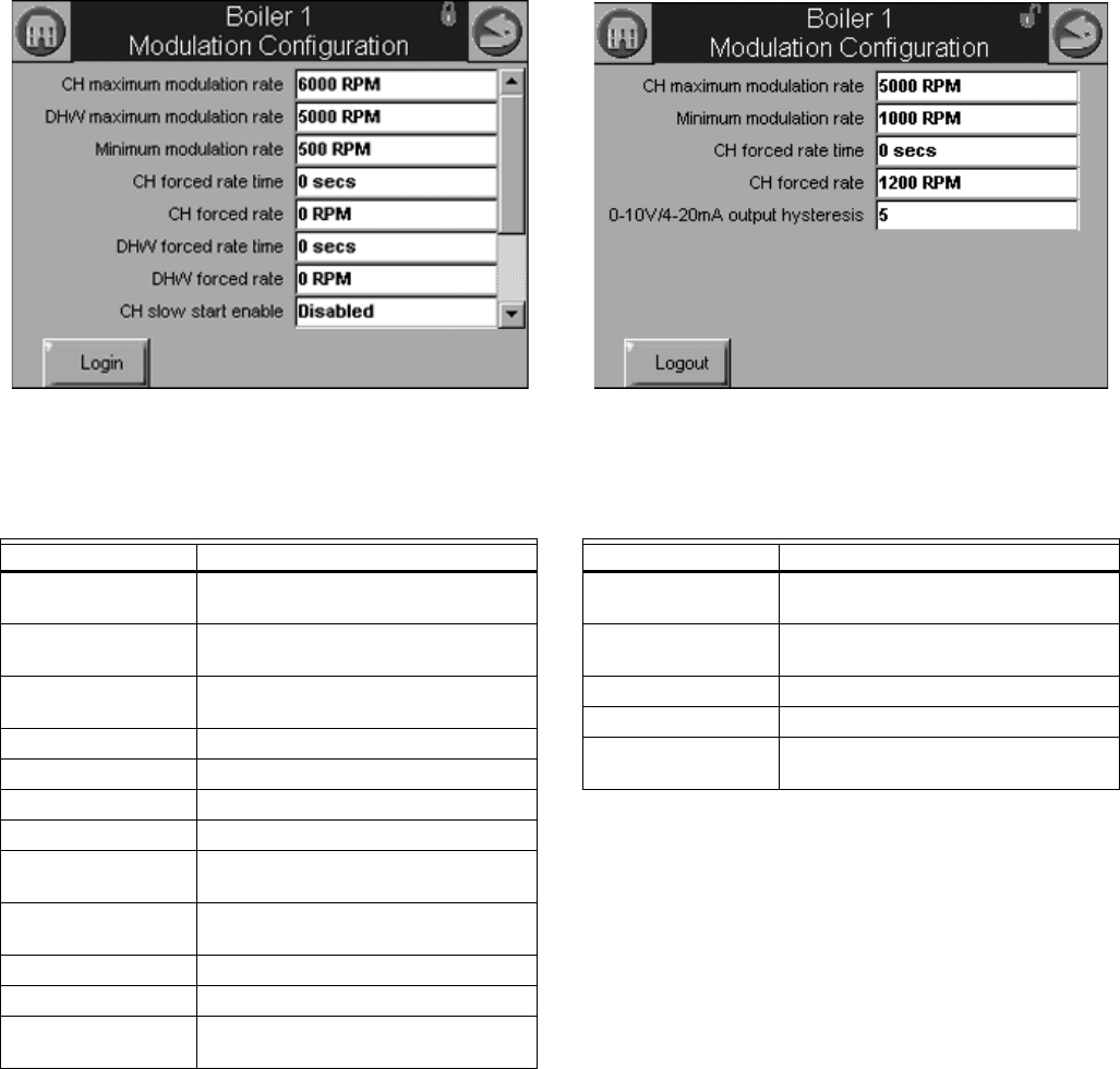
Modulation Configuration
Parameters
Table 15 displays R7910A Hydronic Control Modulation
configuration parameters.
Fig. 43. Modulation configuration.
Steam Modulation Configuration
Parameters
Table 16 displays R7911 Steam Modulation Configuration
parameters.
Fig. 44. Steam modulation configuration.
Table 15. R7910A Hydronic Control Modulation Configura-
tion Parameters.
Parameter Comment
CH maximum
modulation rate
RPM or %
DHW maximum
modulation rate
RPM or %
Minimum modulation
rate
RPM or %
CH forced rate time 0-600 seconds
CH forced rate RPM or %
DHW forced rate time 0-600 seconds
DHW forced rate RPM or %
CH slow start enable Enabled
Disabled
DHW slow start
enable
Enabled
Disabled
Slow start degrees -40 °F to 266 °F (-40 °C to 130 °C)
Slow start ramp RPM /minute or %/minute
0-10/4-20 mA Output
hysteresis
Table 16. R7911 Steam Modulation Configuration
Parameters.
Parameter Comment
CH maximum
modulation rate
RPM or %
Minimum modulation
rate
RPM or %
CH forced rate time 0-600 seconds
CH forced rate RPM or %
0-10/4-20 mA Output
hysteresis
S7999B, S7999C SOLA LOCAL OPERATOR INTERFACE
65-0303—05 26
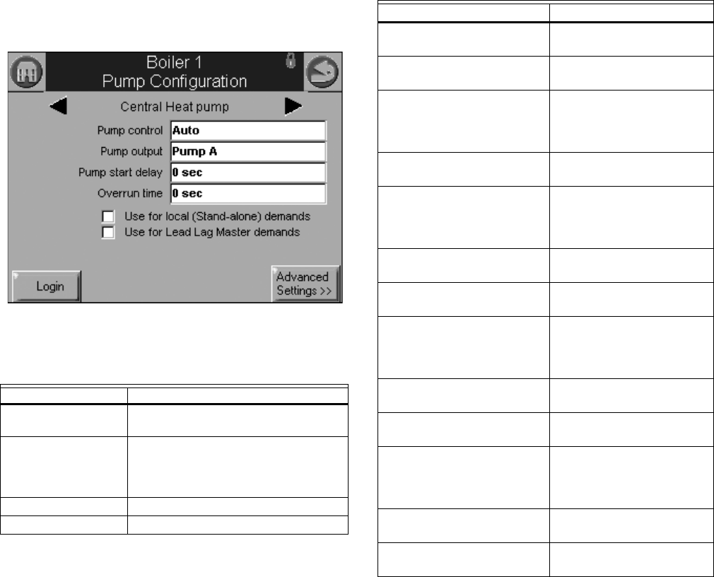
Pump Configuration Parameters
Table 17 displays Pump configuration parameters. Use the left
and right arrows to switch between Central Heat, Boiler, DHW,
System, Auxiliary 1, and Auxiliary 2 pumps. The parameters
are the same for all pumps.
Pressing the Advanced Settings button brings up a number of
other advanced configuration options for each pump. Press the
Control Settings button to return to the screen shown in Fig.
45.
Fig. 45. Pump configuration.
*Table 61 on page 53 has more parameters listed.
NOTE: The R7911 Steam Control does not have pumps, but
the outputs are available to operate air dampers or
accessories. CH Pump, Boiler Pump and System
Pump are used for these output options.
Table 17. Pump Configuration Parameters for
R7910A Hydronic System.
Parameter Comment
Pump control Auto
On
Pump output Pump A
Pump B
Pump C
None
Pump start delay ___hour ___min ___sec
Overrun time ___hour ___min ___sec
Table 17a. Pump Configuration Parameters for R7911
Steam Modulation Configuration Parameters.
Parameter Comment
Auxiliary pump control Auto
On
Auxiliary pump is on when CH pump is ON
Slave command
Auxiliary pump output Pump A
Pump B
Pump C
None
Boiler pump control Auto
On
Boiler pump output Pump A
Pump B
Pump C
None
Boiler pump overrun time 0-600 seconds
0 = Not configured
CH pump control Auto
On
CH pump output Pump A
Pump B
Pump C
None
CH pump overrun time 0-600 seconds
0 = Not configured
System pump control Auto
On
System pump output Pump A
Pump B
Pump C
None
System pump ourrun time 0-600 seconds
0 = Not configured
Pump exercise time 0-600 seconds
0= Not configured
S7999B, S7999C SOLA LOCAL OPERATOR INTERFACE
27 65-0303—05
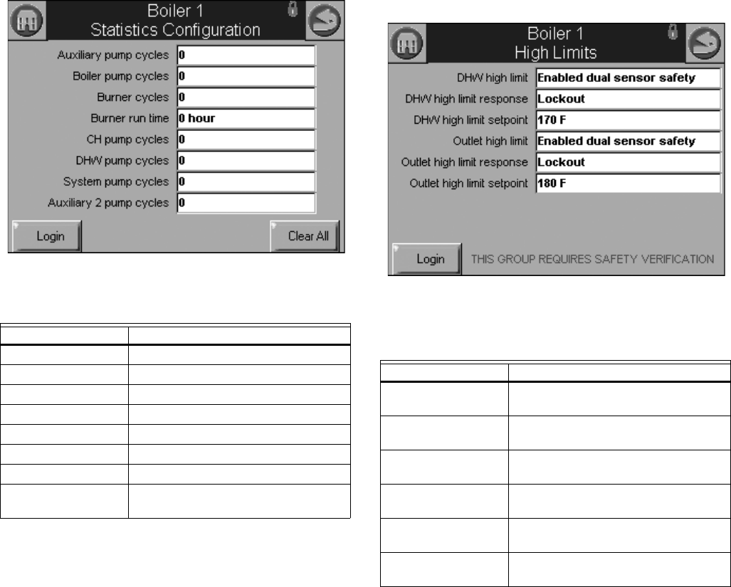
Statistics Configuration Parameters
Table 15 displays Statistics configuration parameters.
Fig. 46. Statistics configuration.
High Limit Configuration Parameters
(R7910A Hydronic Control Only)
Table 19 displays outlet high limit configuration parameters.
Fig. 47. High Limits configuration.
Table 18. Statistics Configuration Parameters.
Parameter Comment
Auxiliary pump cycles 0-999,999
Boiler pump cycles 0-999,999
Burner cycles 0-999,999
Burner run time 0-999,999
CH pump cycles 0-999,999
DHW pump cycles 0-999,999
System pump cycles 0-999,999
Auxiliary 2 pump
cycles
0-999,999
Table 19. High Limit Configuration Parameters.
Parameter Comment
DHW high limit Enabled
Disabled
DHW high limit
response
Recycle & hold
Lockout
DWH high limit
setpoint
-40 °F to 266 °F (-40 °C to 130 °C)
Outlet high limit Enabled
Disabled
Outlet high limit
response
Recycle & hold
Lockout
Outlet high limit
setpoint
-40 °F to 266 °F (-40 °C to 130 °C)
S7999B, S7999C SOLA LOCAL OPERATOR INTERFACE
65-0303—05 28
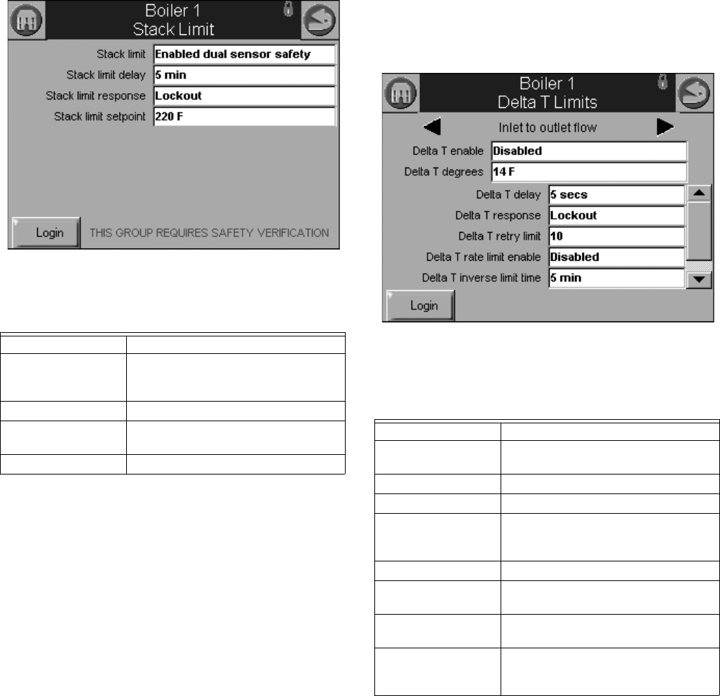
Stack Limit Configuration Parameters
Table 20 displays stack limit configuration parameters.
Fig. 48. Stack Limit configuration.
Delta T Limit Configuration
Parameters
(R7910A Hydronic Control Only)
Table 21 displays other limit parameters. Use the left and right
arrows to switch between Inlet to Outlet Flow and Exchanger to
Outlet Flow. The parameters are the same for all pumps.
Fig. 49. Delta T Limit configuration.
Table 20. Stack Limit Configuration Parameters.
Parameter Comment
Stack limit Enabled dual sensor safety
Enabled single sensor non safety
Disabled
Stack limit delay ___hour ___min ___sec
Stack limit response Lockout
Recycle & delay
Stack limit setpoint 32 °F to 266 °F (0 °C to 130 °C)
Table 21. Delta T Limit
Configuration Parameters.
Parameter Comment
Delta T enable Enabled
Disabled
Delta T degrees 0 °F to 234 °F (-17 °C to 112 °C)
Delta T delay ___hour ___min ___sec
Delta T response Recycle & delay
Recycle & Delay with retry limit
Lockout
Delta T retry limit 0–100
Delta T rate limit
enable
Enabled
Disabled
Delta T inverse limit
time
___hour ___min ___sec
Delta T inverse limit
response
Recycle & delay
Recycle & delay with retry limit
Lockout
S7999B, S7999C SOLA LOCAL OPERATOR INTERFACE
29 65-0303—05
T-Rise Limit Configuration
Parameters
Table 22 displays T-Rise limit parameters.
Heat Exchanger High Limit
Configuration Parameters
Table 23 displays T-Rise limit parameters.
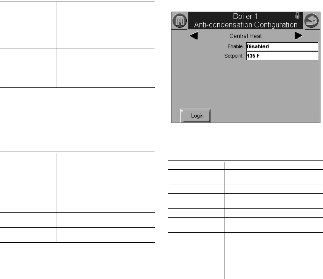
Anti-Condensation Configuration
Parameters (R7910A
Hydronic
Control Only
)
Table 24 displays anti-condensation parameters. Use the left
and right arrows to switch between Central Heat, Domestic Hot
Water, Frost Protection, and Priority parameters.
Fig. 50. Anti-condensation configuration.
Table 22. T-Rise Limit Configuration Parameters.
Parameter Comment
Outlet T-rise enable Enabled
Disabled
Heat exchanger T-
rise enable
Enabled
Disabled
T-rise degrees 0 °F to 234 °F (-17 °C to 112 °C)/sec
T-rise response Recycle & delay
Recycle & delay with retry limit
Lockout
T-rise retry limit 0 to 100
T-rise delay ___hour ___min ___sec
Table 23. Heat Exchanger High Limit
Configuration Parameters.
Parameter Comment
Heat exchanger high
limit enable
Enabled
Disabled
Heat exchanger high
limit setpoint
-40 °F to 266 °F (-40 °C to 130 °C)
Heat exchanger high
limit response
Recycle & delay
Recycle & delay with retry limit
Lockout
Heat exchanger retry
limit
0 to 100
Heat exchanger high
limit delay
___hour ___min ___sec
Table 24. Anti-Condensation Configuration Parameters.
Parameter Comment
CH Enable Enabled
Disabled
CH Setpoint -40 °F to 266 °F (-40 °C to 130 °C)
DHW Enable Enabled
Disabled
DHW Setpoint -40 °F to 266 °F (-40 °C to 130 °C)
Frost Protection
Enable
Enabled
Disabled
Anticondensation
Priority
Anticondensation is more important
than (check those that apply):
Stack limit
Delta T limit
Slow start
Forced rate
Outlet high limit
S7999B, S7999C SOLA LOCAL OPERATOR INTERFACE
65-0303—05 30
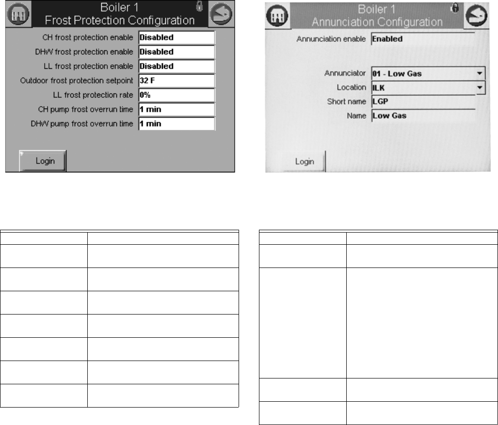
Frost Protection Parameters
(R7910A Hydronic Control Only)
Table 25 displays frost protection parameters.
Fig. 51. Frost Protection configuration.
Annunciation Configuration
Parameters
Table 26 displays annunciation configuration parameters.
Fig. 52. Annunciation configuration example.
Safety Configuration Parameters
Table 27 through 30 display safety parameters.
NOTE: Login is required to change Safety Parameters and
the SOLA Control will go to a Lockout 2 “waiting for
safety data verification” when a change is made.
Table 25. Frost Protection Configuration Parameters.
Parameter Comment
CH frost protection
enable
Enabled
Disabled
DHW frost protection
enable
Enabled
Disabled
Lead Lag frost
protection enable
Enabled
Disabled
Outdoor frost
protection setpoint
-40 °F to 266 °F (-40 °C to 130 °C)
(applicable for CH only)
Lead Lag frost
protection rate
___%
CH pump frost
overrun time
___hour ___min ___sec
DHW pump frost
overrun time
___hour ___min ___sec
Table 26. Annunciation Configuration Parameters.
Parameter Comment
Annunciation enable Enabled
Disabled
Annunciator (1–8)
location
01 - Annunciator 1
02 - Annunciator 2
03 - Annunciator 3
04 - Annunciator 4
05 - Annunciator 5
06 - Annunciator 6
07 - Annunciator 7
08 - Annunciator 8
PII - Pre-Ignition ILK
LCI - Load Control Input
ILK - Interlock
Annunciator (1–8)
short name
Up to 3 characters
Annunciator (1–8)
name
Up to 20 characters
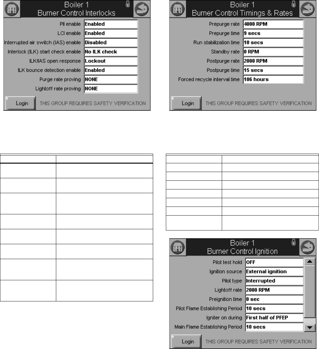
S7999B, S7999C SOLA LOCAL OPERATOR INTERFACE
31 65-0303—05
Fig. 53. Burner Control Interlocks control. Fig. 54. Burner Control Timings and Rates configuration.
Fig. 55. Burner Control Ignition configuration.
Table 27. Burner Control
Interlocks Configuration.
Parameter Comment
PII enable Enabled
Disabled
LCI enable Enabled
Disabled
Interrupted air switch
(IAS) enable
Enable during purge and ignition
Disabled
Enable during purge
Interlock (ILK) start
check enable
No ILK check
ILK check
ILK/IAS open
response
Recycle
Lockout
ILK bounce detection
enable
Enabled
Disabled
Purge rate proving Fan Speed
High Fire Switch
None
Lightoff rate proving Fan Speed
Low Fire Switch
None
Table 28. Burner Control Timings and Rates Configura-
tion.
Parameter Comment
Prepurge rate RPM or %
Prepurge time ___hour ___min ___sec
Run stabilization time ___hour ___min ___sec
Standby Rate RPM or %
Postpurge rate RPM or %
Postpurge time ___hour ___min ___sec
Forced recycle
interval time
___day ___hour ___min
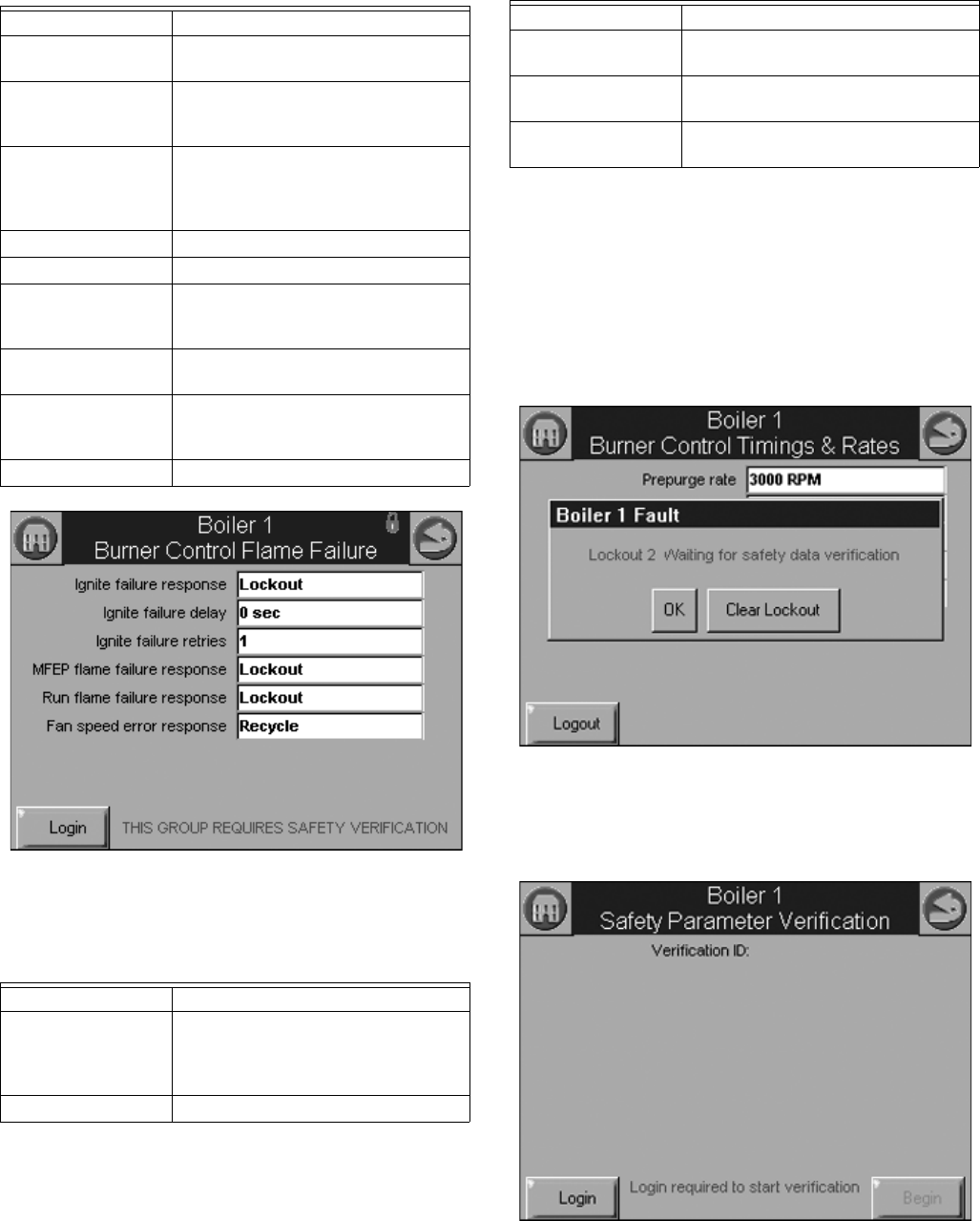
S7999B, S7999C SOLA LOCAL OPERATOR INTERFACE
65-0303—05 32
Fig. 56. Burner Control Flame Failure configuration.
Safety Parameter Verification
When any of the safety configuration parameters are changed,
the safety parameter verification procedure must be performed
before the control will resume burner control. The control
enters a lockout state, if not already in one, and remains locked
out until this verification procedure is performed.
Safety parameter verification lockout occurs when safety
parameter setting is changed. See Fig. 57.
Fig. 57. Safety verification lockout.
The user must log in before verification can be completed, as
shown in Fig. 58.
Fig. 58. Safety verification login.
Table 29. Burner Control Ignition Configuration.
Parameter Comment
Pilot test hold On
Off
Ignition source Hot Surface Igniter
External ignition
Internal ignition
Pilot type Direct burner constant ignition
Direct burner pulsed ignition
Intermittent
Interrupted
Lightoff rate RPM or %
Preignition time ___hour ___min ___sec
Pilot Flame
Establishing Period
15 secs
10 secs
4 secs
Igniter on during 1st half of PFEP
Pilot Flame Establishing Period
Main Flame
Establishing Period
15 secs
10 secs
5 secs
Flame Threshold μA/V
Table 30. Burner Control Flame
Failure Configuration.
Parameter Comment
Ignite failure
response
Lockout
Recycle
Recycle & hold
Recycle & lockout
Ignite failure delay ___hour ___min ___sec
Ignite failure retries 1, 3, or 5
MFEP flame failure
response
Recycle
Lockout
Run flame failure
response
Recycle
Lockout
Fan speed error
response
Recycle
Lockout
Table 30. Burner Control Flame
Failure Configuration. (Continued)
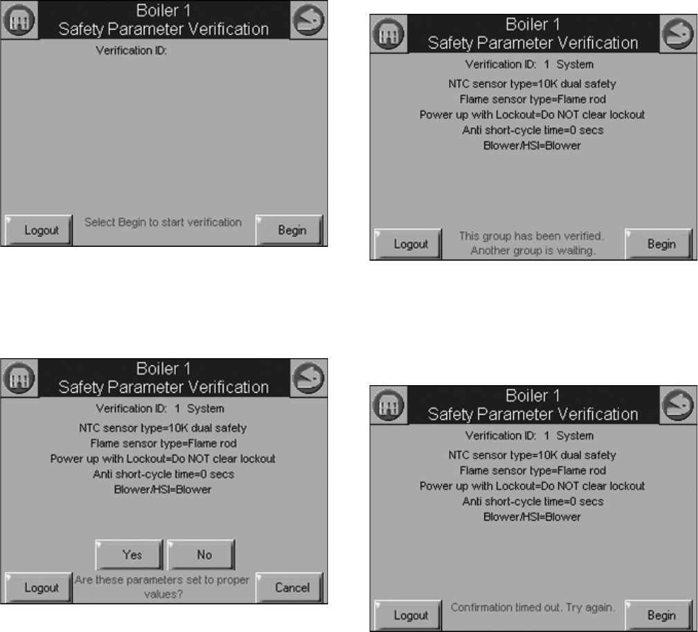
S7999B, S7999C SOLA LOCAL OPERATOR INTERFACE
33 65-0303—05
After successful login, the user presses the Begin button to
start safety parameter verification. See Fig. 59.
Fig. 59. Begin safety verification.
The first group of safety configuration parameters that needs
verification is displayed. The user is asked to confirm that the
settings are correct, as shown in Fig. 60.
Fig. 60. Confirm safety parameter settings.
After the first safety parameter group has been confirmed by
the user (by pressing the Yes button), the next safety
parameter group waits for verification as shown in Fig. 61.
Fig. 61. Safety parameter settings confirmed; next group
waiting for confirmation.
The user has 30 secs to confirm each safety configuration
group’s settings. If the user takes too long to confirm the
settings, an error message is displayed, as shown in Fig. 62.
Fig. 62. Confirmation timed out.
After all safety parameter groups have been verified, the user
must press the Reset button on the control within 30 seconds
to confirm the correct device. See Fig. 63.
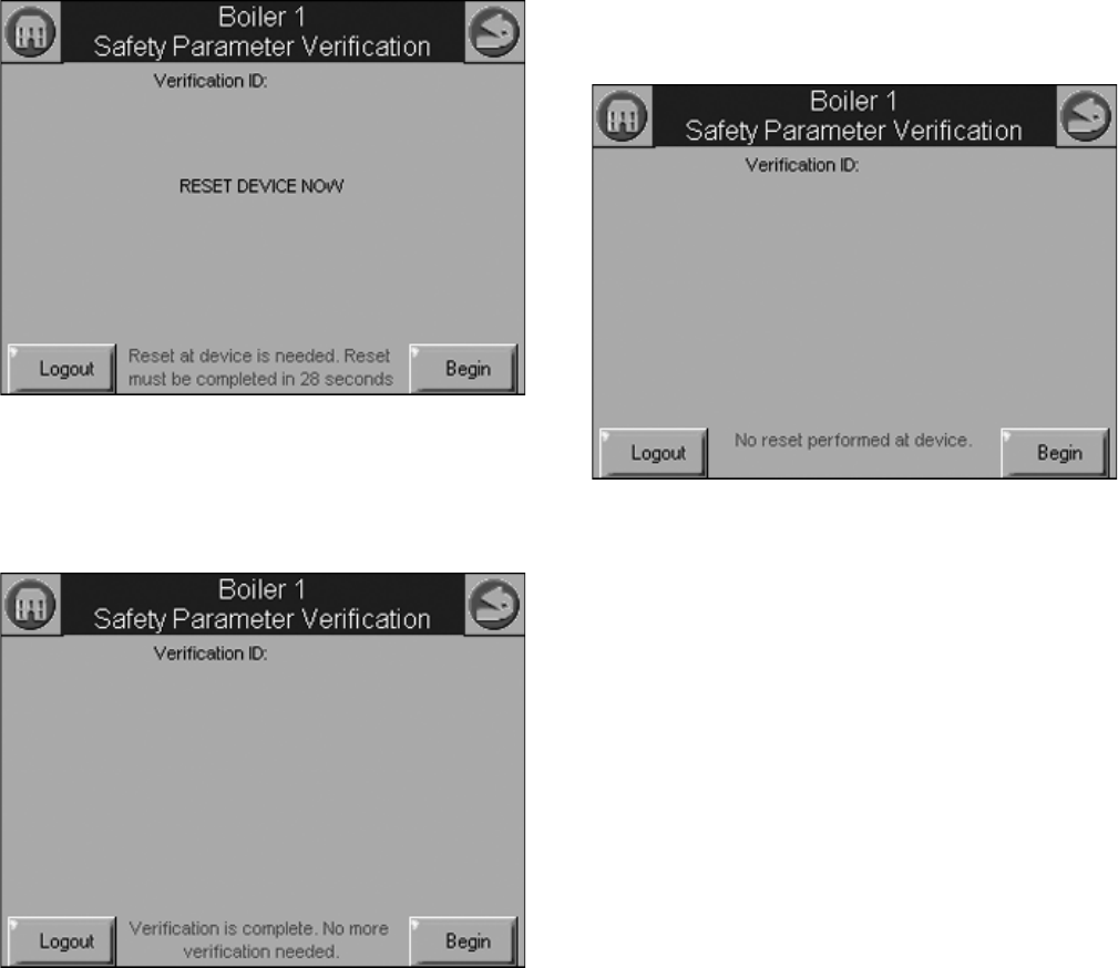
S7999B, S7999C SOLA LOCAL OPERATOR INTERFACE
65-0303—05 34
Fig. 63. Reset R7910A or R7911.
When the user has pressed the Reset button on the control,
completing verification procedure, a Verification Complete
screen is displayed, as shown in as shown in Fig. 64.
Fig. 64. Safety parameter configuration complete.
If for some reason the user does not press the Reset button on
the control within 30 seconds, the configuration is cancelled,
as shown in Fig. 65.
Fig. 65. Control reset timed out.
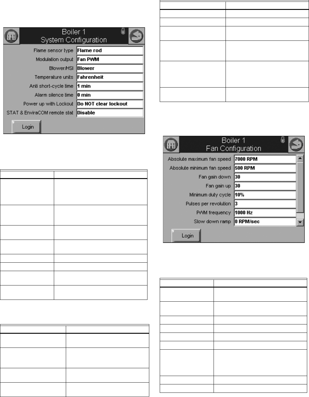
S7999B, S7999C SOLA LOCAL OPERATOR INTERFACE
35 65-0303—05
Individual R7910A or R7911
Configuration Parameters
Table 31 and Table 32 displays system configuration
parameters for individual controls.
Fig. 66. System configuration (R7911 shown).
Fan Parameters
Table 33 displays fan parameters.
Fig. 67. Fan configuration.
Table 31. R7910AHydronic
System Configuration Parameters.
Parameter Comment
Flame sensor type Flame rod
UV power tube
UV power tube with spark interference
None
Modulation output 4-20mA
0-10V
Fan PWM
Blower/HSI Blower
Hot surface ignition
Temperature units Fahrenheit
Celsius
Anti short-cycle time ___hour ___min ___sec
Alarm silence time ___hour ___min ___sec
Power up with
Lockout
Clear lockout
Do NOT clear lockout
STAT & EnviraCOM
remote stat
Enabled
Disabled
Table 32. R7911 System
Configuration Parameters.
Parameter Comment
Flame sensor type Flame rod
UV
Modulation output 4-20ma
0-10V
Fan PWM
Blower/HSI Blower
Hot surface ignitor
Temperature units Fahrenheit
Celsius
Anti short cycle time ___hour ___min ___sec
Alarm silence time ___day ___hour ___min
Power up with lockout Clear lockout
Do NOT clear lockout
Inlet connector type 0-15 psi
0-150 psi
UNCONFIGURED
Stack connector type 10k NTC dual safety
10k NTC single non-safety
12k NTC single non-safety
UNCONFIGURED
Header 4-20ma
UNCONFIGURED
Table 33. Fan Configuration Parameters.
Parameter Comment
Absolute maximum
fan speed
500–12000 RPM
Absolute minimum
fan speed
500–12000 RPM
Fan gain down 0-100
Fan gain up 0-100
Minimum duty cycle 1-100%
Pulses per revolution 1-10
PWM frequency 1000
2000
3000
4000
Slow down ramp 0-12000 RPM/sec
Speed up ramp 0-12000 RPM/sec
Table 32. R7911 System
Configuration Parameters. (Continued)
Parameter Comment
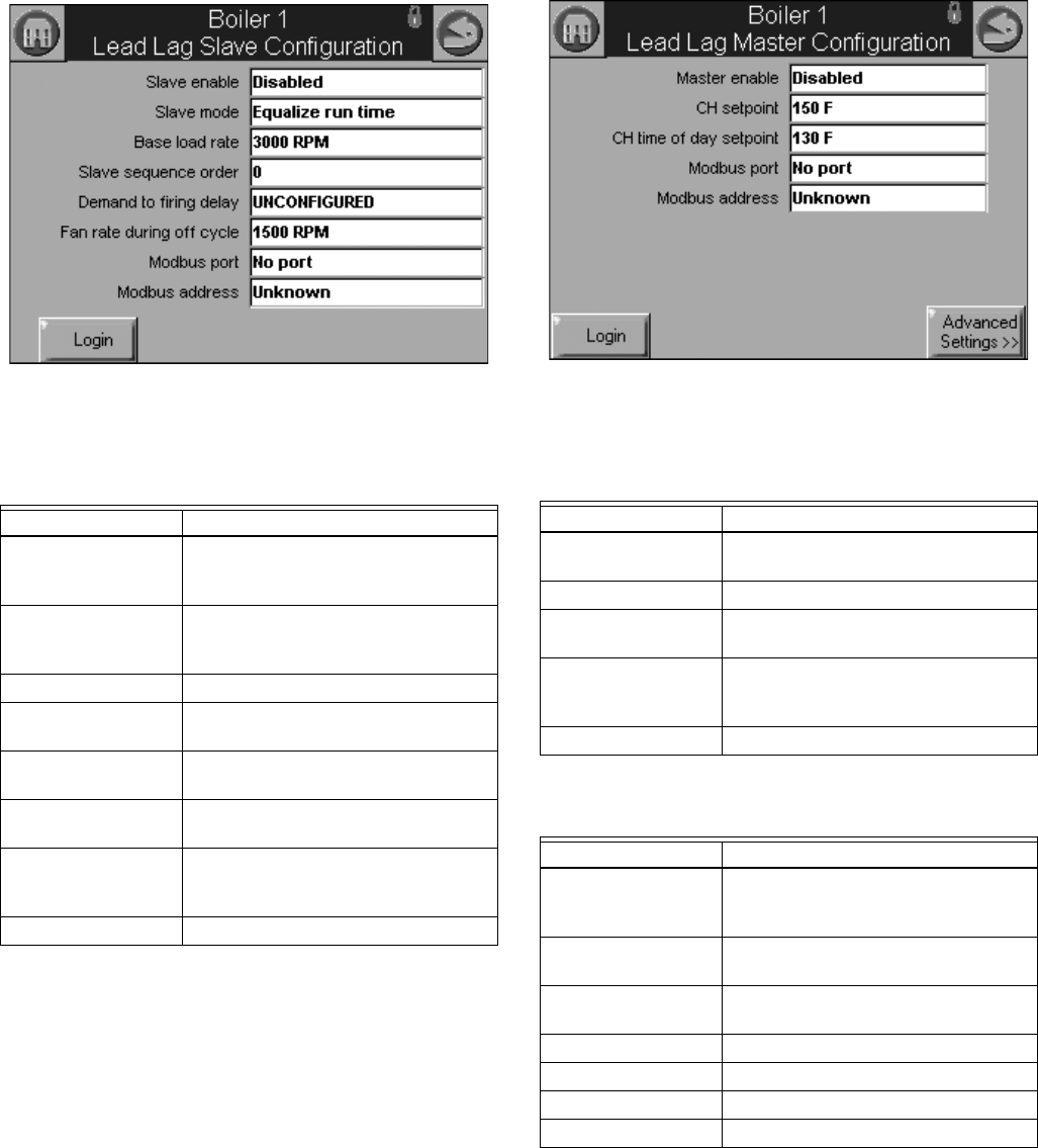
S7999B, S7999C SOLA LOCAL OPERATOR INTERFACE
65-0303—05 36
Lead Lag Slave Configuration
Parameters (Hydronic Control Only)
Table 34 displays Lead Lag Slave Configuration parameters.
Fig. 68. Lead Lag slave configuration.
Lead Lag Master Configuration
Parameters (Hydronic Control Only)
Table 35 displays Lead Lag Master Configuration parameters.
Click the Advanced Settings button to see available advanced
parameters as shown in Table 36–44.
Use the left and right arrows to switch between Modulation,
CH, DHW, Frost Protection, Warm Weather Shutdown,
Algorithms, Rate Allocation, Add stage and Drop stage
parameters.
Fig. 69. Lead Lag master configuration and Advanced
Settings button.
Table 34. Lead Lag Slave
Configuration Parameters.
Parameter Comment
Slave enable Slave
ModBUS slave
Disabled
Slave mode Use first
Use last
Equalize run time
Base load rate 0–6000 rpm
Slave sequence
order
0–8
Demand to firing
delay
___hour ___min ___sec
Fan rate during off
cycle
0–12000 rpm
ModBus port MB1
MB2
No port
ModBus address 0–250
Table 35. Lead Lag Master Configuration Parameters.
Parameter Comment
Master enable Enabled
Disabled
CH setpoint -40 °F to 266 °F (-40 °C to 130 °C)
CH time of day
setpoint
-40 °F to 266 °F (-40 °C to 130 °C)
ModBus port MB1
MB2
No port
ModBus address 1–250
Table 36. Lead Lag Master Configuration
Advanced Settings: Modulation Parameters.
Parameter Comment
Modulation backup
sensor
Lead outlet sensor
Slave outlet sensor average
Disabled
Off hysteresis 0 °F to 234 °F
(-17 °C to 112 °C)
On hysteresis 0 °F to 234 °F
(-17 °C to 112 °C)
Hysteresis step time ___Hour ____Minute _____Second
P gain 0 - 400
I gain 0 - 400
D gain 0 - 400
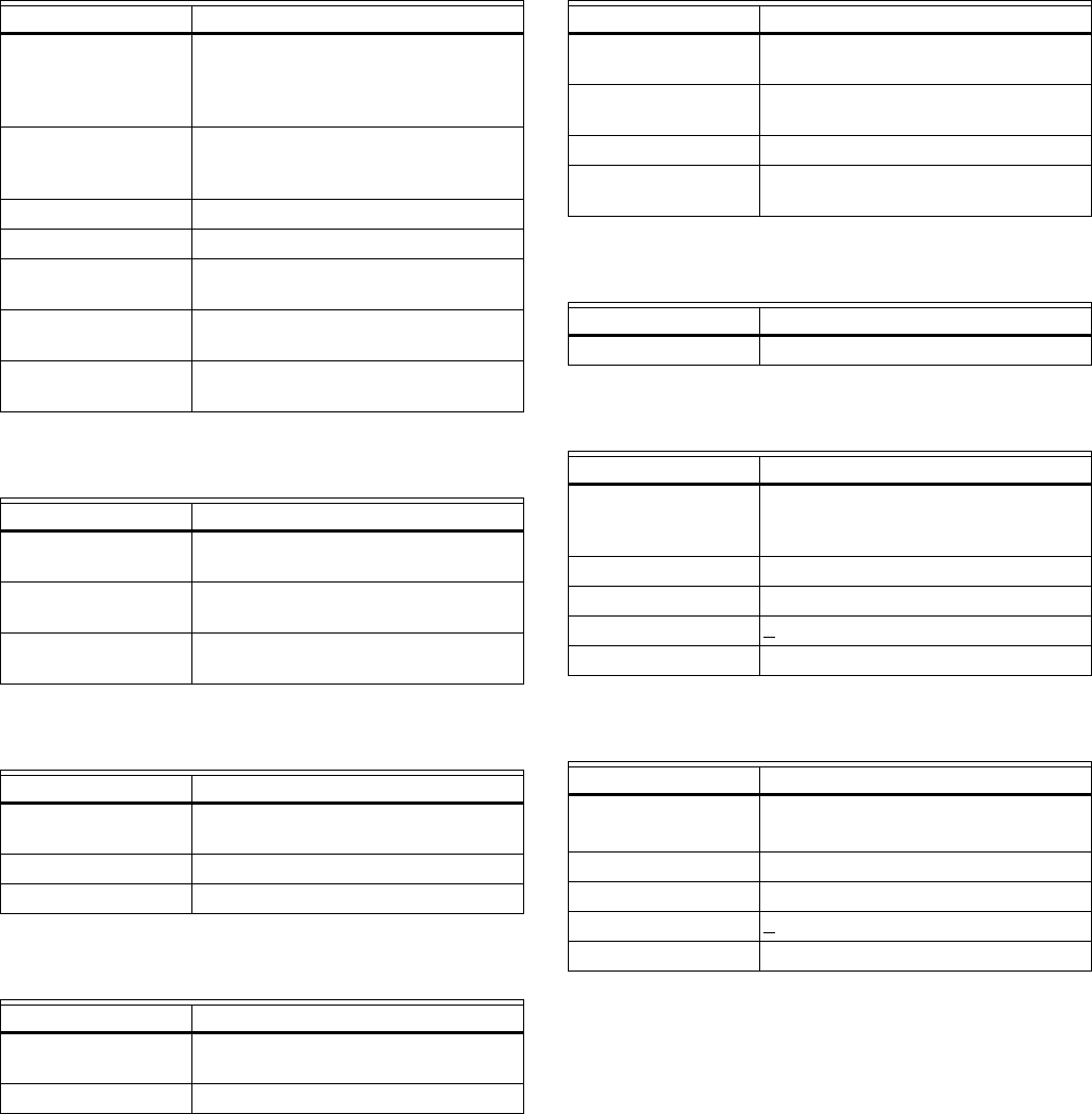
S7999B, S7999C SOLA LOCAL OPERATOR INTERFACE
37 65-0303—05
Table 37. Lead Lag Master Configuration
Advanced Settings: Central Heat Parameters.
Parameter Comment
Demand switch Stat
Remote Stat
ModBus Stat
Disabled
Setpoint source Local
ModBus
4-20 ma
Setpoint -40 °F to 266 °F (-40 °C to 130 °C)
Time of day setpoint -40 °F to 266 °F (-40 °C to 130 °C)
4 ma water
temperature
-40 °F to 266 °F (-40 °C to 130 °C)
20 ma water
temperature
-40 °F to 266 °F (-40 °C to 130 °C)
Outdoor reset Enabled
Disabled
Table 38. Lead Lag Master Configuration
Advanced Settings: DHW Parameters.
Parameter Comment
Priority source DHW heat demand
Disabled
Priority method Boost during priority time
Drop after priority time
DHW priority override
time
___Hour ____Minute _____Second
Table 39. Lead Lag Master Configuration
Advanced Settings: Frost Protection Parameters.
Parameter Comment
Enable Enabled
Disabled
Outdoor setpoint -40 °F to 266 °F (-40 °C to 130 °C)
Frost protection rate ____%
Table 40. Lead Lag Master Configuration Advanced
Settings: Warm Weather Shutdown Parameters.
Parameter Comment
Enable Enabled
Disabled
Setpoint -40 °F to 266 °F (-40 °C to 130 °C)
Table 41. Lead Lag Master Configuration
Advanced Settings: Algorithms Parameters.
Parameter Comment
Lead selection
method
Sequence order
Measured run time
Lag selection method Sequence order
Measured run time
Lead rotation time ___day ____hour _____min
Force lead rotation
time
___day ____hour _____min
Table 42. Lead Lag Master Configuration
Advanced Settings: Rate Allocation Parameters.
Parameter Comment
Base load common ? %
Table 43. Lead Lag Master Configuration
Advanced Settings: Add Stage Parameters.
Parameter Comment
Method Error threshold
Firing rate threshold
Disabled
Detection time ___Hour ____Minute _____Second
Error threshold 0 °F to 234 °F (-17 °C to 112 °C)
Rate offset + ________ %
Interstage delay ___Hour ____Minute _____Second
Table 44. Lead Lag Master Configuration
Advanced Settings: Drop Stage Parameters.
Parameter Comment
Method Error threshold
Firing rate threshold
Detection time ___Hour ____Minute _____Second
Error threshold 0 °F to 234 °F (-17 °C to 112 °C)
Rate offset + ________ %
Interstage delay ___Hour ____Minute _____Second
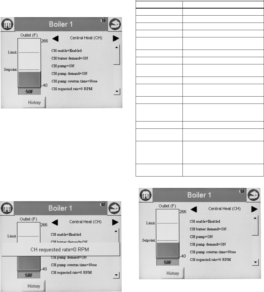
S7999B, S7999C SOLA LOCAL OPERATOR INTERFACE
65-0303—05 38
DETAILS
Details of the hydronic or steam system is accomplished
through the detail status pages. The detail status page is
shown below.
Screens will appear only if they are configured for your system.
Information shown is current status. For example: firing rate is
the current fan speed or motor position; timing shown is current
time Sola is at.
Fig. 70. Hydronic CH detail status page.
Status information on the detail status page is organized into
groups and displayed on the page one group at a time. The
user moves from one group to another using the left and right
arrow buttons.
Status data on the detail status page is displayed in a menu for
the group that is currently displayed. If more status items exist
in the group than will fit on the screen, a vertical scroll bar
allows the user to see all status data. If the user selects a line
of status data in the menu, it will expand in bigger, more easily
readable text, as show in Fig. 71. Additional information about
Status data and groups that are displayed are provided in the
R7910A or R7911 Status section of this document.
Fig. 71. Hydronic “expanded” detail status.
R7910A or R7911 Status
Data in Tables 45–Table 56 are displayed on the R7910A
Hydronic or R7911 Steam status pages. A complete list of
Status tables can be found in Table 60 on page 53.
The CH status data shown in Table 45 displays first when the
CH Hydronic heating loop is selected on the Home page.
Fig. 72. CH Hydronic Status menu (top).
Table 45. CH Hydronic Status.
Data Comment
CH enable Enabled, Disabled
CH burner demand On or Off
CH pump On or Off
CH pump demand On or Off
CH pump overrun
time
Running overtime for CH pump
(seconds)
CH requested rate RPM or %
CH OFF setpoint Setpoint plus hysteresis
CH setpoint Temp setting between -40 °F to 266 °F
(-40 °C to 130 °C)
CH ON setpoint Setpoint minus hysteresis
CH setpoint source Normal, TOD, Outdoor reset, Remote
control
CH status Disabled, Normal, Suspended
Demand source Sensor only, Sensor and Stat terminal,
Sensor and Remote Stat, LCI and
sensor
Outlet high limit Yes or No
Outlet high limit
setpoint
Temp setting between -40 °F to 266 °F
(-40 °C to 130 °C)
Outlet sensor state None, Normal, Open, Shorted,
Outside high range, Outside low
range, Not reliable (None = no outlet
sensor)
Outlet temperature Outlet temperature (same as bar
graph)
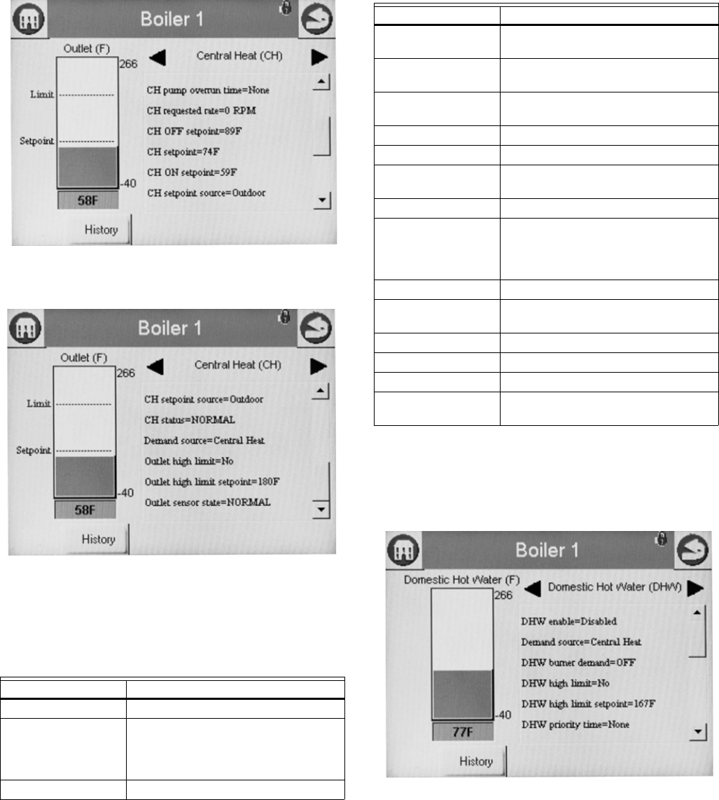
S7999B, S7999C SOLA LOCAL OPERATOR INTERFACE
39 65-0303—05
Fig. 73. CH Hydronic Status menu (middle).
Fig. 74. CH Hydronic Status menu (bottom).
The status data in Table 46 displays first when the DHW
Hydronic heating loop is selected on the Home page. Scrolling
through the status groups eventually shows both.
The bar graph displayed for the CH control loop (hydronic) is
the outlet sensor temperature; for the DHW control loop it is
the DHW sensor temperature. When no analog DHW sensor is
installed (digital switch instead), the inlet sensor temperature is
displayed.
Fig. 75. DHW Hydronic Status menu (top).
Table 46. DHW Hydronic Status.
Data Comment
DHW enable Enabled, Disabled
Demand source Unknown, No source demand, CH,
DHW, Lead Lag, CH frost protection,
DHW frost protection, No demand due
to burner switch
DHW burner demand On or Off
DHW high limit Temp setting between -40 °F to 266 °F
(-40 °C to 130 °C)
DHW high limit
setpoint
Temp setting between -40 °F to 266 °F
(-40 °C to 130 °C)
DHW priority override
time
0-600 seconds
DHW pump On or Off
DHW pump demand On or Off
DHW pump overrun
time
Running overrun time for DHW pump
(seconds)
DHW requested rate RPM or %
DHW sensor state None, Normal, Open, Shorted,
Outside high range, Outside low
range, Not reliable (None = no outlet
sensor)
DHW OFF setpoint Setpoint plus hysteresis
DHW setpoint Temp setting between -40 °F to 266 °F
(-40 °C to 130 °C)
DHW ON setpoint Setpoint minus hysteresis
DHW setpoint source Normal, TOD, Outdoor reset
DHW status Disabled, Normal, Suspended
DHW temperature DHW temperature (same as bar
graph)
Table 46. DHW Hydronic Status. (Continued)
Data Comment
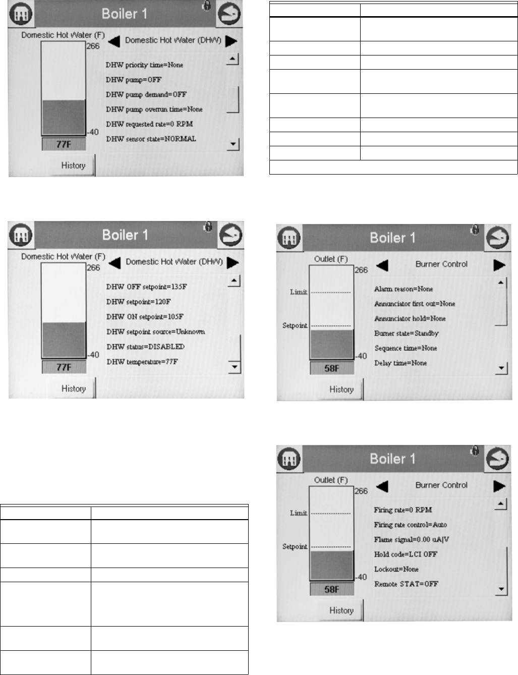
S7999B, S7999C SOLA LOCAL OPERATOR INTERFACE
65-0303—05 40
Fig. 76. DHW Hydronic Status menu (middle).
Fig. 77. DHW Hydronic Status menu (bottom).
Burner Control Status
The Burner Control status page will display the status data
shown in Table 47.
The bar graph displayed for this status is the outlet sensor
temperature.
Fig. 78. Burner Control Status menu (top).
Fig. 79. Burner Control Status menu (bottom).
Burner control can be turned on and off in the R7910A or
R7911 by the user.
Table 47. Burner Control Status.
Data Comment
Alarm reason Description for alarm being on (maybe
lockout or a hold message)
Annunciator first out First annunciator input related to
lockout
Annunciator hold First annunciator input related to hold
Burner state Disabled, Locked out, Anti-short cycle,
Unconfigured safety data, Standby
Hold, Standby, Delay, Normal
Standby, Preparing, Firing, Postpurge
Sequence time Running time for timed burner control
operation (seconds)
Delay time Running display of delay time when
burner control in delay state.
Firing rate % or RPM. Adjustable when firing rate
control set to Manual.
Firing rate control Auto or Manual
Flame signal Flame signal strength
Hold code Description of hold message if locked
out
Lockout Description of lockout message if
locked out
Pilot test hold Off or Hold
Remote STAT On or Off
Note: Steam will show Steam psi as the bar graph
Table 47. Burner Control Status. (Continued)
Data Comment
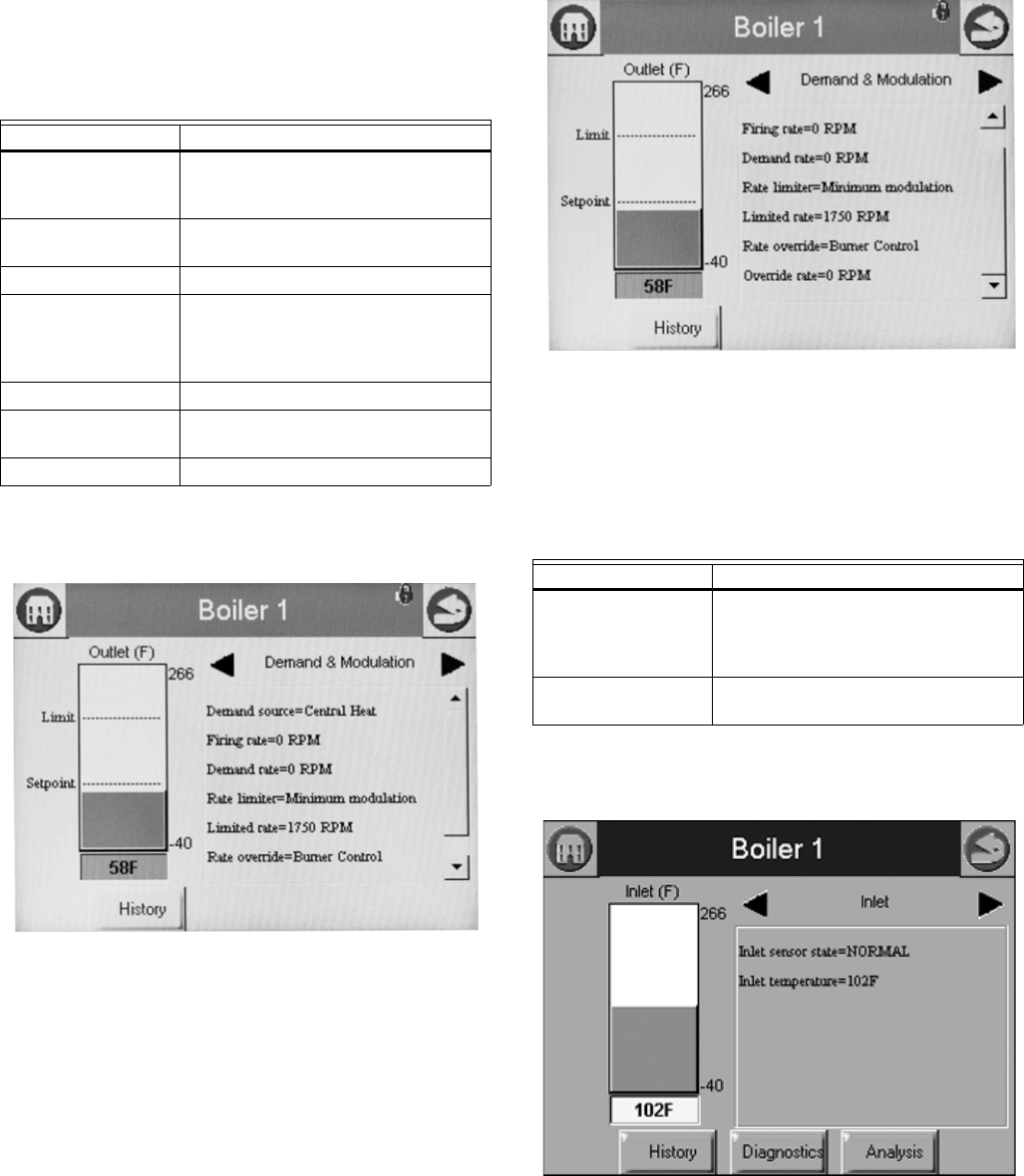
S7999B, S7999C SOLA LOCAL OPERATOR INTERFACE
41 65-0303—05
Hydronic Demand and Modulation
Status
Table 49 displays the status page data for R7910A.
The bar graph displayed for this status is the outlet sensor
temperature.
Fig. 80. Demand and Modulation Status menu (top).
Fig. 81. Demand and Modulation Status menu (bottom).
Inlet Temperature Status
Table 49 displays the status page data for R7910A inlet
temperature.
The bar graph displayed for this status is the inlet sensor
temperature.
Fig. 82. Inlet High Limit Status menu.
Fan Status
Table 50 displays the status page data for the fan in the control.
Table 48. Hydronic Demand and Modulation Status.
Data Comment
Demand source CH, DHW, Lead Lag, or Frost
Protection (parameter that has current
priority)
Firing rate % or RPM. Adjustable when firing rate
control set to Manual.
Demand rate % or RPM.
Rate limiter None, Outlet high limit, Delta T limit,
Stack limit, Slow start limit, Anti-
condensation, Minimum modulation,
Forced rate
Limited rate % or RPM
Rate override Burner control default, Burner control,
manual firing rate off, None
Override rate % or RPM
Table 49. Inlet High Limit Status.
Data Comment
Inlet sensor state None, Normal, Open, Shorted,
Outside high range, Outside low
range, Not reliable (None=no outlet
sensor)
Inlet temperature Inlet sensor temperature (same as bar
graph)
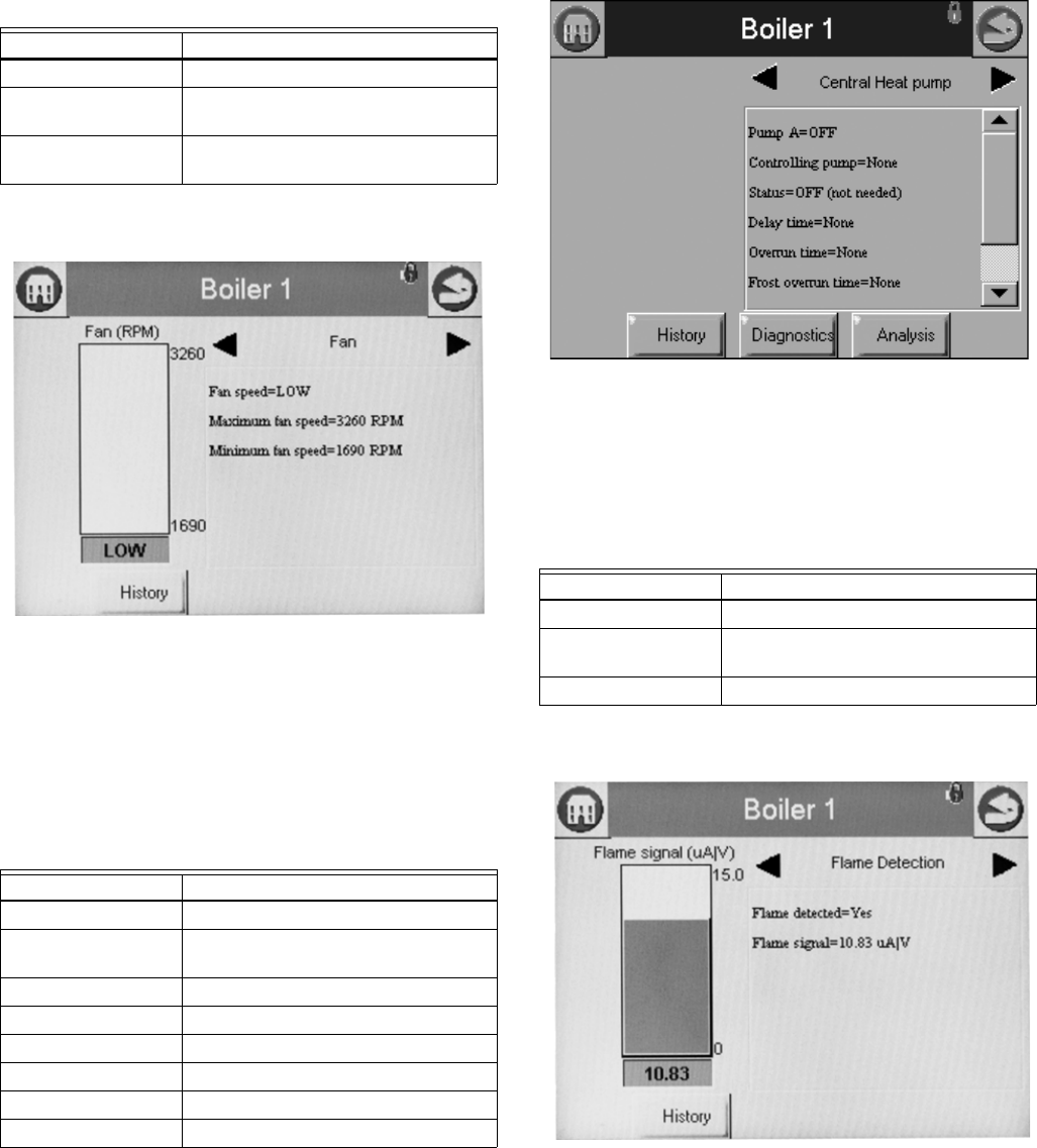
S7999B, S7999C SOLA LOCAL OPERATOR INTERFACE
65-0303—05 42
The bar graph displayed for this status is the fan speed.
Fig. 83. Control Fan Status menu.
Hydronic Pump Status
Table 51 displays the status page data for this example,
Central Heat pump in the R7910A. Screens available for DHW,
Boiler, System, Aux1 and Aux2 will be the same if that pump is
configured.
Fig. 84. Hydronic CH pump status menu.
Flame Detection Status
The status data shown in Table 52 is displayed for flame
detection in the R7910A or R7911.
The bar graph displayed for this status is the flame signal.
Fig. 85. Flame Detection Status menu.
NOTE: This same status is also displayed for burner control
status. A separate status group is defined to provide a
bar graph of the flame signal.
Table 50. Control Fan Status.
Data Comment
Fan speed % or RPM (current fan speed)
Maximum fan speed Setpoint of maximum fan speed (% or
RPM)
Minimum fan speed Setpoint of minimum fan speed (% or
RPM)
Table 51. Hydronic CH Pump Status.
Data Comment
CH Pump On or Off
Controlling Pump
Terminal
Pump A, B, or C
Status On, Off, or Not Used
Delay time Duration of delay time
Overrun time Duration of overrun time
Frost overrun time Duration of frost overrun time
Idle days Number of days idle
Cycle count Number of cycles
Table 52. Flame Detection Status.
Data Comment
Flame detected Yes or No
Flame signal Flame signal strength (same as bar
graph)
Pilot test hold Off or hold
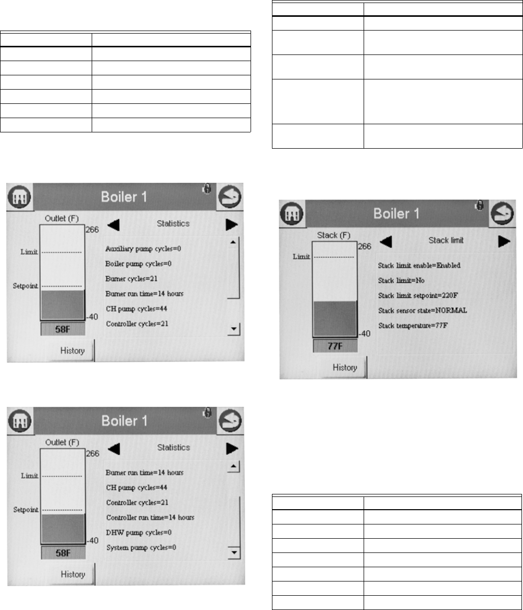
S7999B, S7999C SOLA LOCAL OPERATOR INTERFACE
43 65-0303—05
Statistics Status
Table 53 displays the statistics status page data for the
R7910A or R7911. Though the Steam control will not have a
pump, the output can be used to run some other auxiliary
equipment.
The bar graph displayed for this status is the outlet sensor
temperature.
Fig. 86. Control Statistics Status menu (top).
Fig. 87. Control Statistics Status menu (bottom).
Stack Limit Status
Table 54 shows the status page data for the control Stack Limit.
The bar graph displayed for this status is the stack sensor
temperature.
Fig. 88. Stack Limit Status menu.
Lead Lag Slave Status - Hydronic
Only
Table 55 shows the status page data for Lead Lag Slave.
Table 53. Control Statistics Status.
Data Comment
Burner cycles Number of cycles
Burner run time Duration of run time
CH pump cycles Number of cycles
System pump cycles Number of cycles
Controller cycles Number of cycles
Controller run time Duration of run time
Table 54. Stack Limit Status.
Data Comment
Stack limit enable Enabled or Disabled
Stack limit Temp setting between -40 °F to 266 °F
(-40 °C to 130 °C)
Stack limit setpoint Temp setting between -40 °F to 266 °F
(-40 °C to 130 °C)
Stack sensor state None, Normal, Open, Shorted,
Outside high range, Outside low
range, Not reliable (None=no stack
temp sensor)
Stack temperature Stack sensor temperature (same as
bar graph)
Table 55. Lead Lag Slave.
Data Comment
Type Slave
Command Received Yes/No
Demand Off
Request Rate RPM
Burner Control Standby
Modulating No
Priority
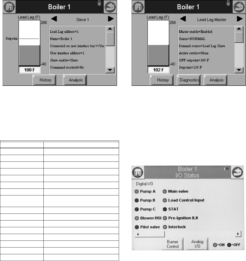
S7999B, S7999C SOLA LOCAL OPERATOR INTERFACE
65-0303—05 44
Fig. 89. Lead Lag Slave Status menu.
Lead Lag Master Status - Hydronic
Only
Table 56 shows the status page data for Lead Lag Master.
Fig. 90. Lead Lag Master Status menu.
R7910A OR R7911
DIAGNOSTICS
The diagnostic page displays analog and digital I/O status of
the control. The digital I/O data is displayed as LEDs that are
either on (green) or off (red) (see Fig. 91–93). Not all digital I/O
can be displayed at the same time on the page, so a horizontal
scroll bar is used to move the view left and right to show all
digital I/O data.
Fig. 91. Diagnostic digital I/O page (left).
Table 56. Lead Lag Master.
Data Comment
Master enabled Enabled
Status normal
Demand source Lead lag slave
Active Service None
Off setpoint 160 °F (71 °C)
Setpoint 150 °F (66 °C)
On setpoint 145 °F (63 °C)
operating
temperature
150 °F (66 °C)
Sensor state normal
Sensor temperature 150 °F (66 °C)
Slave firing no
Stager state idle
Stager timer
CH demand
CH frost demand no
DHW frost demand no
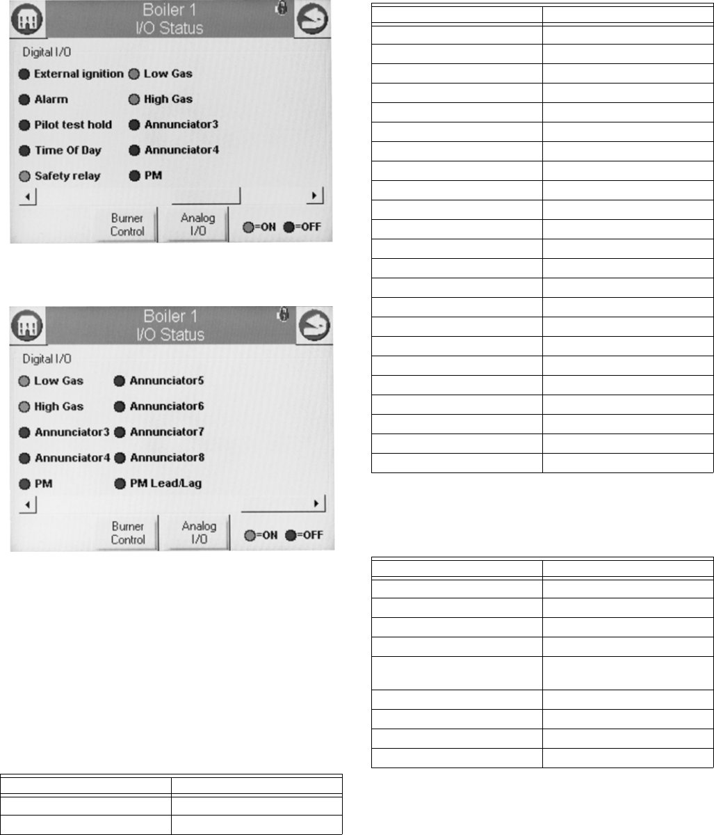
S7999B, S7999C SOLA LOCAL OPERATOR INTERFACE
45 65-0303—05
Fig. 92. Diagnostic digital I/O page (center).
Fig. 93. Diagnostic digital I/O page (right).
Temperature sensors or pressure sensors also display the
current sensor state, (i.e., whether there is a fault condition or
the sensor is in a normal monitoring state). The user can toggle
between displaying the control digital and analog I/O (the initial
display is the digital I/O). The Digital or Analog button on the
bottom of the diagnostic page changes the I/O displayed to the
type indicated by the button.
The following data is displayed on the control diagnostics page
(see Fig. 91–93).
“On” status is indicated by a green LED and “Off” status is
indicated by a red LED.
Analog I/O data is displayed as bar charts depicting the I/O
level (see Fig. 94). Analog I/O that is not enabled for the
installation displays a blank I/O level. To see all analog I/O, use
the horizontal scroll bar to move the view left and right.
Table 57. Control Digital I/O Data.
Data Comment
Pump A On/Off
Pump B On/Off
Pump C On/Off
Blower/HSI On/Off
Pilot valve On/Off
Main valve On/Off
Load Control Input On/Off
STAT On/Off
Pre-ignition interlock On/Off
Interlock On/Off
External ignition On/Off
Alarm On/Off
Pilot test hold On/Off
Time Of Day On/Off
Safety relay On/Off
Low Gas On/Off
High Gas On/Off
Annunciator 3 On/Off
Annunciator 4 On/Off
PM On/Off
Annunciator 5 On/Off
Annunciator 6 On/Off
Annunciator 7 On/Off
Annunciator 8 On/Off
PM Lead/Lag On/Off
Table 58. Control Analog I/O Data.
Data Comment
Outlet
Inlet If enabled
Firing rate % or RPM
Flame signal V
Fan speed RPM (if applicable). Should
match with firing rate.
Domestic Hot Water If enabled
Stack If enabled
Outdoor If enabled
Header If enabled
Table 57. Control Digital I/O Data.
Data Comment
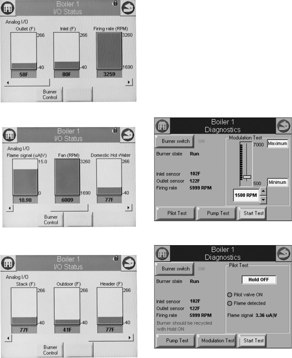
S7999B, S7999C SOLA LOCAL OPERATOR INTERFACE
65-0303—05 46
Fig. 94. Diagnostics analog I/O page (left).
Fig. 95. Diagnostics analog I/O page (center).
Fig. 96. Diagnostics analog I/O page (right).
INSTALLER CHECKOUT
Diagnostics Tests
Pressing the Diagnostics Test button launches the diagnostic
tests. The first test displayed on the right side of the screen is
the last selected test shown, as seen in Fig. 97.
This screen enables the user to perform the following tests:
Modulation Test: enables the user to verify that the burner is
firing at the correct rate. (See Fig. 97.)
Pilot Test: enables the user to verify that the pilot valve is
functioning properly. The user can also perform burner
adjustments for the pilot flame. (See Fig. 98.)
Pump Test: enables the user to verify that the correct pump is
on or off. The Start Test button will test all pumps; pressing an
individual pump tests that pump only. (See Fig. 99.)
Burner Switch: this button turns the burner on or off.
Start Test: runs the test for 5 minutes.
Fig. 97. Modulation test.
Fig. 98. Pilot test.
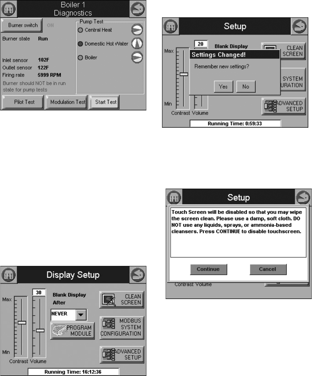
S7999B, S7999C SOLA LOCAL OPERATOR INTERFACE
47 65-0303—05
Fig. 99. Pump test.
S7999B OR S7999C
DISPLAY SETUP AND
DIAGNOSTICS
The following pages apply to display setup and diagnostics for
the S7999B or S7999C OI Displays.
Setup
The Setup button on the Home page (for S7999B OI Display)
or Display Setup Button on the Configuration Screen for the
S7999C OI Display is selected to go to these pages. The Setup
screen (see Fig. 100) is displayed first. It allows for some OI
Display settings. The Advanced Setup button permits the user
to run some diagnostic functions for the display and to set
advanced features for run-time operation. See “Advanced
Setup” on page 48 for these features.
Fig. 100. R7910A setup.
If Contrast or Volume are changed, Fig. 101 displays to allow
saving these changes.
Fig. 101. Setup settings changed.
Cleaning the Screen
When the user wants to clean the touch screen, the CLEAN
SCREEN button is selected to freeze touch input temporarily for
30 seconds to allow the user to clean the screen. (See Fig. 102.)
Fig. 102. Clean screen setup.
A countdown screen (Fig. 103) displays during the screen
disable period. It disappears when the touch screen is
re-enabled.
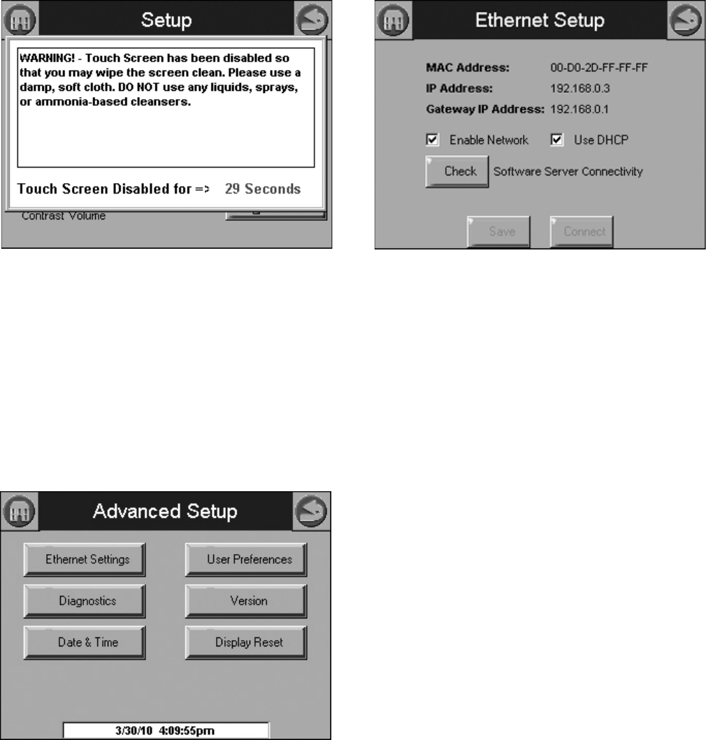
S7999B, S7999C SOLA LOCAL OPERATOR INTERFACE
65-0303—05 48
Fig. 103. Screen disabled for cleaning.
Pressing the SYSTEM CONFIGURATION button starts up the
system configuration. For more information, see “System
Configuration (S7999B OI DisplayOnly)” on page 19.
Pressing the ADVANCED SETUP button starts the Advanced
Setup.
ADVANCED SETUP
Pressing the ADVANCED SETUP button on the Setup page
displays more options that can be set by the user (Fig. 104).
Fig. 104. Advanced Setup.
Ethernet Settings (S7999B Only)
Ethernet Settings is used to enable Ethernet communications
for remote diagnostics, file transfers, and remote support, and
is not typically enabled (Fig. 105). This feature should remain
disabled unless directed to do so for remote troubleshooting.
Once the feature is enabled, the S7999B must be reset to start
it at power-up. The Ethernet interface can also be used to
transfer profile curve files to/from the S7999B over a local
intranet or the Internet.
Fig. 105. Ethernet settings.
A Honeywell software server connectivity check can be
performed by selecting the Check button. This button is only
enabled when the Ethernet interface is enabled and active.
The connectivity check tries for 15 seconds to connect to the
Honeywell software server. Successful connection displays a
“CONNECTED” message on the screen. An unsuccessful
attempt displays “NOT CONNECTED.”
The MAC (Media Access Control) address is a hardware
address that uniquely identifies the S7999B on the network.
This information is likely only of interest to the network
administrator.
The IP (Internet Protocol) address is the address that the
S7999B has been assigned by the DHCP server in the local
network to use for others to access the S7999B. This address
is necessary for the remote user to identify the S7999B in an
FTP (File Transfer Protocol) application for transferring trend
analysis information. Like the MAC address, it is displayed for
informational purposes for the network administrator.
If the IP address has a private network designation (192.x.x.x),
remote access from outside the local network may not be
possible. Contact the network administrator for assistance in
this case. If the IP address is 255.255.255.255, then no IP
assignment has been made, and there is no connection to the
network. This possibility could be due to no physical
connection to an Ethernet network, or there is no DHCP server
present on the Ethernet network. Check with the network
administrator for assistance.
The Gateway IP address is displayed for informational
purposes for the network administrator. The gateway node
provides remote access for devices located off of the local
network to the S7999B.
The Enable Network checkbox specifies that the Ethernet
interface is on or not when the S7999B is powered up. The
selection must be saved to permanent storage (flash) with the
Save button for it take effect at boot time. This checkbox
should normally be disabled, and enabled when Ethernet
access to the S7999B is necessary. This interface must also
be enabled for the Software Server Connectivity check to
function properly (the Check button). If the Ethernet interface is
disabled, the check procedure fails.
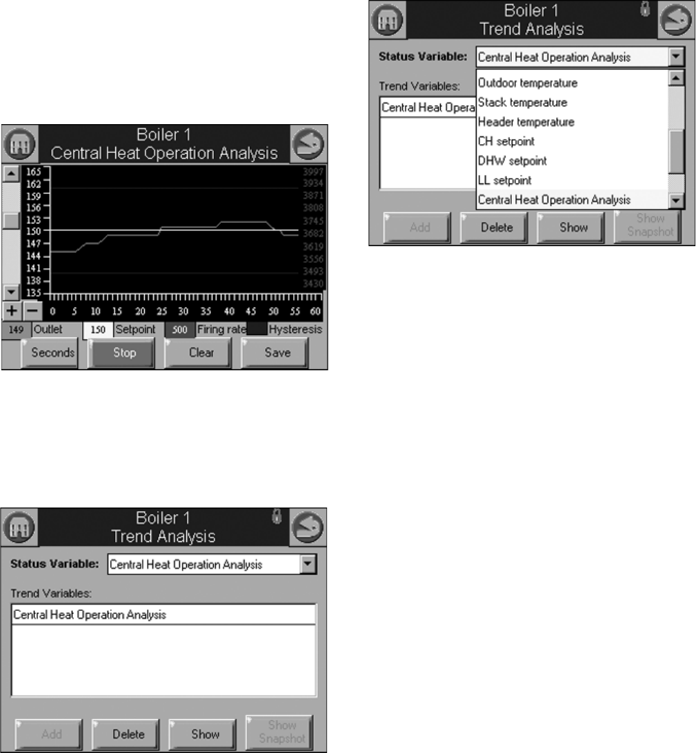
S7999B, S7999C SOLA LOCAL OPERATOR INTERFACE
49 65-0303—05
The S7999B must be assigned an IP address by a DHCP
server for it to operate on the local network, so the Use DHCP
box should be checked. However, because the S7999B
requires this feature, it ignores the checkbox and always
regards it as checked. The checkbox is included for future
purposes when dynamic IP addressing isn’t required.
Trend Analysis Page (S7999B Only)
Trend analysis of R7910 or R7911 status data can be viewed
on the S7999B. A graph displays a historical view of R7910 or
R7911 status data over varying time periods.
A 2-dimensional graph with status data values shown on the Y
axis over time specified on the X axis is displayed. Status for
the most recent time is represented on the left side of the
graph with older status running towards the right side of the
graph.
Fig. 106. Trend analysis page.
Up to 4 R7910 or R7911 status variables can be viewed at the
same time on one trend analysis graph. Select the status
variables for the graph on the menu page (see Fig. 107). This
menu displays when the Trend Analysis button is selected on
the R7910 or R7911 status page.
Fig. 107. Trend analysis menu page.
The status variable with the largest range (minimum to
maximum) is used as the Y-axis range in the graph.
As the status variables are selected they are listed in a trend
variables list box. The user chooses the status variables from a
drop down menu and then presses the Add button to add each
status variable to the trend variable list. See Fig. 108. After all
status variables have been selected press the Show button to
view the trend analysis graph.
Fig. 108. Trend analysis menu page.
Each status variable displayed in the trend analysis is
represented by a different colored line, as follows:
1. First status variable = green
2. Second status variable = yellow
3. Third status variable = red
4. Fourth status variable = blue
No more than two different measurement units (such as
degrees), are allowed for the status variables selected in the
trend analysis graph. Attempts to add a status variable with a
third measurement unit are rejected.
A second Y axis is displayed on the right side of the graph to
represent the scale for the second measurement unit. This can
result in minor clipping of the curves on the right side, as
shown in Fig. 109 and 110.
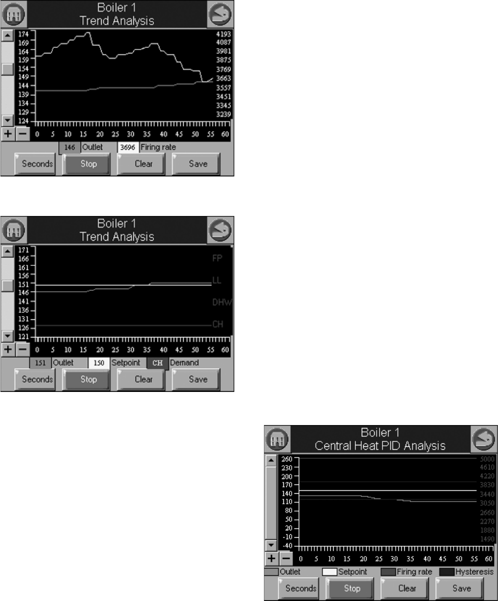
S7999B, S7999C SOLA LOCAL OPERATOR INTERFACE
65-0303—05 50
Fig. 109. Trend analysis page with firing rate.
Fig. 110. Trend analysis page with demand source.
If any of the status variables has degrees as a unit of
measurement, degrees is used for the main Y axis (on the left
of the graph). The status variables selected are saved and are
displayed by default when the trend analysis menu page is first
displayed. Status data is updated on the graph with new status
at the same rate as the sample time period selected. The
current sample time period is displayed in a button on the page
(in Fig. 109 and 110, the button is “Seconds”).
Status older than the sample time period is dropped from the
right end of the curve as newer status appears on the left end
of the curve.
Trend data can be viewed in one-second (most recent 60
second time period), 15-second (most recent 15-minute time
period), and hour (most recent 24 hour time period) intervals.
NOTE: Full graphs require that the S7999B has been moni-
toring the R7910 or R7911 for the complete time
period. Partial graphs display if this is not the case.
The buttons at the bottom can be used to change the view of
the graph. The user can change the sample rates of the
display by pressing the Seconds, Minutes, Hours, or Days
button (the button changes depending on what sample rate is
currently displayed). The + and - buttons zoom in and out of
the graph so the Y axis depicts different degrees of detail for
the data range. The viewing window can be moved up and
down the graph to see the complete range when zoomed in.
The smallest measurement interval is a single whole digit (no
fractional precision) when the entire range exceeds 10 units,
e.g., 20–30 degrees.
Pressing the Stop button will pause trend data updates of the
graph. The graph “freezes” the view when stopped. However,
trend data sampling from the R7910 or R7911 continues
regardless whether the graph update is stopped or not.
Restarting the updates causes the graph to be refreshed with
the latest data samples.
Pressing the Clear button will clear the trend sample data for
an R7910 or R7911. All trend data for the R7910 or R7911 is
cleared including status variables that are not included in the
graph. The user is asked to confirm this action before
proceeding.
NOTE: For system trend analysis graphs the Clear button
isn’t present, so no status variables can be cleared.
A snapshot of the trend analysis graph can be taken and saved
to the S7999B. The user is asked to confirm the save before it
occurs.
NOTE: While this snapshot is saved, trend data sampling for
all R7910s or R7911s is temporarily halted. Gaps or
static level values occur in the trend data as a result.
The date and time that the snapshot is taken is stored with the
snapshot. Only the status variables displayed in the graph are
stored in the snapshot. All raw sample data for the status
variables are stored so that any sample rate can be viewed
offline.
Sample data stored in snapshot is either the real-time status at
the time that the Save button is pressed or it is the sample data
at the time that the graph is stopped.
Special case trend analysis graphs for PID tuning can be
viewed for CH, DHW, and Lead Lag demands.
Fig. 111. PID Trend analysis page.
Data included in the PID analysis graph are:
• Sensor temperature (outlet for CH, DHW for DHW, and
header for Lead Lag)
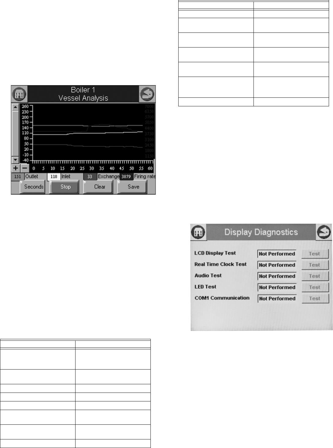
51 65-0303—05
• Setpoint (for corresponding demand source)
• Burner firing rate
• Hysteresis on (for corresponding demand source)
• Hysteresis off (for corresponding demand source)
The Clear button is disabled for the PID analysis (doesn’t apply to
hysteresis).
The default sample rate is 15 sec periods (a tick mark on the X axis
for every 15 second period, with minutes displayed every 4 tick
marks).
Special case trend analysis graph for R7910/R7911 vessel heat
exchange can be selected.
Fig. 112. Vessel analysis page.
Data included in the vessel analysis graph are:
• Outlet temperature
• Inlet temperature
• Heat exchange (outlet – inlet)
• Burner firing rate
Automatic sampling of trend data takes place when the trend
analysis report is displayed. No user intervention is necessary to
invoke sampling.
NOTE: Sample data is collected and stored in the S7999B. The
R7910 or R7911 don’t collect any historical data for trending
purposes. For this reason any S7999B reset causes all
R7910 or R7911 sampling to start over with no data.
Trend analysis of the following data from each R7910/R7911 is
possible:
Trend Analysis Snapshot
The trend analysis snapshot file is stored in Comma Separated Value
(CSV) format in the S7999B so it can be imported into a spreadsheet
program such as Microsoft Excel.
The trend analysis snapshot file can be viewed in graph form on the
S7999B. It is also accessible in an Ethernet FTP session with the
S7999B. This FTP session can be used to export the trend analysis
snapshot file from the S7999B.
Diagnostics
Pressing the Diagnostics button permits some display hardware
diagnostics (see Fig. 104). Normally, these diagnostics are
applicable only for factory testing purposes, but conditions may
arise that warrant this testing.
Fig. 113. Display diagnostics.
NOTE: COM 1 Communication test is a factory-only test. Perform-
ing this text when not connected to a factory test fixture will
always yield a “Failed” result.
Each test is invoked by pressing the Test button next to the
diagnostic. The results of the diagnostic test (“PASS” or “FAIL”)
display in the text box next to the Test button.
Date and Time
Display time can be configured in the S7999B and S7999C OI
Displays and applied to the R7910A or R7911. A date and time is
entered by the user at the display and any data that is timestamped is
marked with the current time and date in the display.
Table 59. R7910/R7911 Trend Analysis Data.
Data Comment
Demand source CH, DHW, LL (Lead Lag), or
FP (Frost Protection) Steam
Sensor
Outlet temperature (R7910
only)
Firing rate % or RPM
Fan speed PWM feedback
Flame signal strength V
Inlet temperature (R7910
only)
If enabled
DHW temperature (R7910
only)
If enabled
Outdoor temperature If enabled
Stack temperature If enabled
Header temperature (R7910
only)
If enabled
CH setpoint Actual CH setpoint based on
time of day (TOD).
DHW setpoint (R7910 only) Actual DHW setpoint based
on TOD.
Central Heat Operation
Analysis
Domestic Hot Water
Operation Analysis (R7910
only)
Vessel Analysis
Table 59. R7910/R7911 Trend Analysis Data. (Continued)
Data Comment
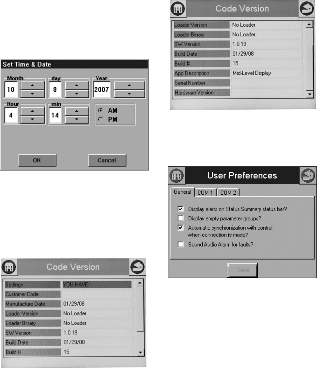
S7999B, S7999C SOLA LOCAL OPERATOR INTERFACE
65-0303—05 52
The Display clock is set by selecting the Date and Time button
on the Advanced Setup page. A screen similar to the following
figure (Fig. 114) displays.
NOTE: It’s important that the time be set in the Display so
correct timestamps are given to the R7910A or
R7911 lockouts. The display’s time and date need
to be set should power be interrupted to the dis-
play.
Fig. 114. Display Date and Time.
Edit the date and time and press the OK button to set the new
settings. Press the Cancel button to exit without changing the
time or date.
Version
Pressing the Version button on the Advanced Setup page
displays manufacturer and software version information (Fig.
115 and 116).
Fig. 115. Code version—top view.
Fig. 116. Code Version—bottom view.
User Preferences
The User Preferences button displays General options as well
as those for for COM1 and COM2.
Fig. 117. General tab.
The General tab (see Fig. 117) contains the following settings:
•Display alerts on Status Summary Bar? This determines
whether non-safety alerts will be shown on the summary bar
of the home page.
•Display empty parameter groups? This cleans up the
home page by hiding unused parameter groups.
•Automatic synchronization with control when
connections is made? This allows automatic display of
new control to update when the connection is identified
instead of manually making the synchronization when the
operator is ready.
•Sound Audio Alarm for faults? This uses the display
speaker to sound an alarm on shutdown for SOLA faults.
The COM1 tab (see Fig. 118) contains the following setting:
•Modbus address range 1-N: Sets the Modbus address for
the connected device (range is 1 to 250).
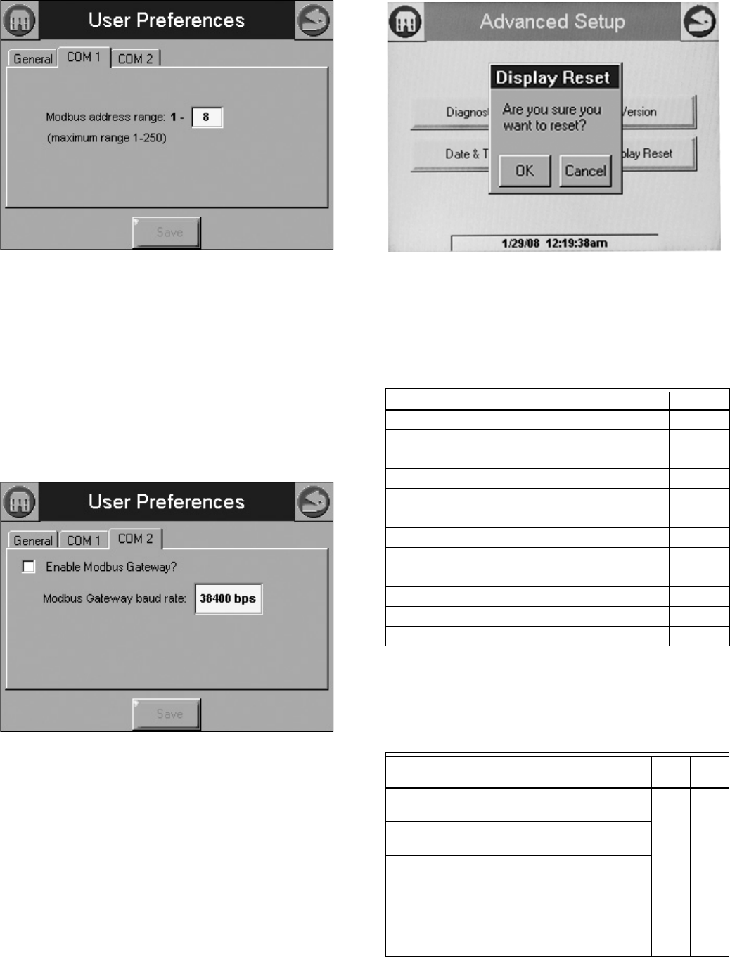
53 65-0303—05
Fig. 118. COM1 tab.
S7999B Only
COM2 is a Modbus gateway for Building Automation System (BAS)
networking.
Press the COM2 tab (see Fig. 119) to define settings:
•Enable Modbus Gateway: This box must be selected to enable
the COM2 BAS interface.
•Modbus Gateway Speed: Select the baud rate (38400, 19, 200,
or 9600 bps)
•Modbus Gateway Timeout: Defines how long the BAS will wait
after sending a Modbus message before timing out and sending
the next modbus message (currently non-functional; leave at 1.0)
Fig. 119. COM 2 tab.
Display Reset
The user can reset the display and force a power-up by pressing the
Display Reset button. A pop-up dialog box confirming the reset
request displays (Fig. 120) before the reset proceeds.
Fig. 120. Processor Reset.
When the Display is reset, the display will reboot and automatically
seek out the Modbus™ device connected to it. When the search is
complete, the display will return to the home page.
Parameters
A complete list of configurable parameters is shown in Table 61.
Table 60. Status Tables.
Name Table # Page #
CH 45 38
DHW 46 39
Burner Control 47 40
Demand and Modulation 48 41
Inlet High Limit 49 41
Fan 50 42
Pump 51 42
Flame Detection 52 42
Statistics 53 43
Stack Limit 54 43
Lead Lag Slave 55 43
Lead Lag Master 56 44
Table 61. Configurable Parameters.
Parameter Comment
Table
#
Page
#
Boiler Name Name to identify boiler (up to 20
characters)
621
Installation Notes regarding installation (up
to 20 characters)
Installer
password
Change installer password
setting
OEM
password
Change OEM password setting
Factory Data OEM name to associate with
boiler (up to 20 characters)
S7999B, S7999C SOLA LOCAL OPERATOR INTERFACE
65-0303—05 54
CH enable Disable or Enable Central
Heating Loop
821
CH demand
switch
Sensor for Central Heat
demand:
Sensor only
Sensor & STAT terminal
Sensor & Remote Stat
LCI & Sensor
CH Outdoor
reset
Enabled
Disabled
CH has
priority over
Lead Lag
Yes, No, Cancel
CH Setpoint
source
Local
S2 (J8-6) 4-20mA
CH Setpoint Setpoint for normal Central
Heat modulation:
-40 °F to 266 °F
(-40 °C to 130 °C)
CH time of
day setpoint
Setpoint when Time Of Day
switch is on. -40 °F to 266 °F
(-40 °C to 130 °C)
CH off
hysteresis
Differential above setpoint
when boiler is turned off. -40 °F
to 266 °F (-40 °C to 130 °C)
CH on
hysteresis
Differential from setpoint when
boiler is turned on.-40 °F to 266
°F (-40 °C to 130 °C)
4 mA water
temperature
-40 °F to 266 °F
(-40 °C to 130 °C)
20 mA water
temperature
-40 °F to 266 °F
(-40 °C to 130 °C)
Modulation
sensor
Outlet sensor, Inlet sensor, S5
(J8-11)
Modulation
Rate Sensor
Local
CH P-gain Time between hysteresis step
changes: 0-400
CH I-gain Time between hysteresis step
changes: 0-400
CH D-gain Time between hysteresis step
changes: 0-400
Hysteresis
step time
Time between hysteresis step
changes: 0-600 seconds
(0=Disable hysteresis stepping)
Table 61. Configurable Parameters. (Continued)
Parameter Comment
Table
#
Page
#
Steam
enable
Disable/enable steam feature 9 22
Steam
demand
source
Sensor and LCI
Sensor and Remote Stat
Sensor and Stat Terminal
Sensor Only
Steam
pressure
setpoint
Setpoint for normal modulation
Adjustable 0 to 15 or 0 to 150
(sensor dependant)
Steam time
of day
setpoint
Setpoint when TOD switch on
Adjustable 0 to 15 or 0 to 150
(sensor dependant)
Minimum
steam
pressure
Establishes setpoint for the
4ma. input.
Adjustable 0 to 15 or 0 to 150
(sensor dependant)
Steam
pressure off
hysteresis
Differential below setpoint when
boiler is turned off
Adjustable 0 to 15 or 0 to 150
(sensor dependant)
Steam
pressure on
hysteresis
Differential from setpoint when
boiler
is turned on.
Adjustable 0 to 15 or 0 to 150
(sensor dependant)
Steam
hysteresis
step time
Time between hysteresis
changes 0 to 600 seconds
(0=disable)
Steam P
Gain
Gain applied for the P portion of
the PID equation
0-400
Steam I Gain Gain applied for the I portion of
the PID Equation - 0-400
Steam D
Gain
Gain applied for the D portion of
the PID equation
0-400
Steam 4-20
ma remote
control
uses 4-20ma remote control
function to control either the
setpoint or modulation for
Steam
Disable, setpoint, modulation
CH maximum
outdoor
temperature
-40 °F to 266 °F
(-40 °C to 130 °C)
10 22
CH minimum
outdoor
temperature
-40 °F to 266 °F
(-40 °C to 130 °C)
Low water
temperature
-40 °F to 266 °F
(-40 °C to 130 °C)
Minimum
water
temperature
-40 °F to 266 °F
(-40 °C to 130 °C)
Maximum off
point
-40 °F to 266 °F
(-40 °C to 130 °C)
Table 61. Configurable Parameters. (Continued)
Parameter Comment
Table
#
Page
#
55 65-0303—05
DHW enable Disable or Enable Domestic Hot
Water Loop
11 23
DHW
demand
switch
Sensor for Central Heat
demand:
DHW sensor only,
DHW sensor & Remote Stat,
DHW switch & inlet sensor, or
DHW switch & outlet sensor
DHW Priority
source
Which system has priority:
Disabled or
Heat Demand
DHW Priority
method
Boost during priority time
Drop after priority time
DHW
Modulation
sensor
DHW Sensor
Outlet Sensor
Inlet Sensor
Auto: DHW (S6) or Inlet Sensor
Auto: DHW (S6) or Outlet
Sensor
DHW
setpoint
-40 °F to 240 °F
(-40 °C to 115 °C)
DHW time of
day setpoint
Setpoint when Time Of Day
switch is on. -40 °F to 240 °F
(-40 °C to 115 °C)
DHW off
hysteresis
Differential above setpoint
when boiler is turned off. -40 °F
to 240 °F (-40 °C to 115 °C)
DHW on
hysteresis
Differential from setpoint when
boiler is turned on. 2 °F to
234 °F (-16 °C to 112 °C)
DHW priority
override time
___hour ___min ___sec
DHW
hysteresis
step time
Time between hysteresis step
changes: 0-600 seconds
(0=Disable hysteresis stepping)
DHW priority
vs CH
Which system has priority:
Central Heat over Domestic Hot
Water, or
Domestic Hot Water over
Central Heat
DHW priority
vs LL
Which system has priority:
Lead Lag over Domestic Hot
Water,
Domestic Hot Water over Lead
Lag
DHW P-gain Time between hysteresis step
changes: 0-400
DHW I-gain Time between hysteresis step
changes: 0-400
DHW D-gain Time between hysteresis step
changes: 0-400
DHW storage
enable
Enabled, Disabled 12 23
Storage time ___hour ___min ___sec
Setpoint -40 °F to 266 °F
(-40 °C to 130 °C)
Off
hysteresis
-0 °F to 180 °F (-17 °C to 82 °C)
On
hysteresis
-0 °F to 180 °F (-17 °C to 82 °C)
Table 61. Configurable Parameters. (Continued)
Parameter Comment
Table
#
Page
#
Tap detect
degrees
-0 °F to 180 °F (-17 °C to 82 °C) 13 23
Tap detect on
recognition
time
___hour ___min ___sec
Tap detect on
threshold
-0 °F to 180 °F (-17 °C to 82 °C)
Tap detect
minimum on
time
___hour ___min ___sec
Tap stop
inlet-DHW
degrees
-0 °F to 180 °F (-17 °C to 82 °C)
Tap stop
outlet-Inlet
degrees
-0 °F to 180 °F (-17 °C to 82 °C)
Plate preheat
setpoint
-40 °F to 266 °F
(-40 °C to 130 °C)
Plate preheat
on
recognition
time
___hour ___min ___sec
Plate preheat
on hysteresis
-0 °F to 180 °F (-17 °C to 82 °C)
Plate preheat
off hysteresis
-0 °F to 180 °F (-17 °C to 82 °C)
Plate preheat
detect on
threshold
-0 °F to 180 °F (-17 °C to 82 °C)
Plate preheat
detect off
threshold
-0 °F to 180 °F (-17 °C to 82 °C)
Plate preheat
minimum on
time
___hour ___min ___sec
Plate preheat
delay after
tap
___hour ___min ___sec
Warm
Weather
Setpoint
Enable
Enabled, disabled 14 24
Warm
Weather
Setpoint
-40 °F to 266 °F
(-40 °C to 130 °C)
Table 61. Configurable Parameters. (Continued)
Parameter Comment
Table
#
Page
#
S7999B, S7999C SOLA LOCAL OPERATOR INTERFACE
65-0303—05 56
CH maximum
modulation
rate
RPM or % 15 25
DHW
maximum
modulation
rate
RPM or %
Minimum
modulation
rate
RPM or %
CH forced
rate time
0-600 seconds
CH forced
rate
RPM or %
DHW forced
rate time
0-600 seconds
DHW forced
rate
RPM or %
CH slow start
enable
Enabled
Disabled
DHW slow
start enable
Enabled
Disabled
Slow start
degrees
-40 °F to 266 °F
(-40 °C to 130 °C)
Slow start
ramp
RPM /minute or %/minute
0-10/4-20 mA Output hysteresis
0-10/4-20 mA
Output
hysteresis
4-20 mA
input
hysteresis
Pump control Auto
On
17 26
Pump output Pump A
Pump B
Pump C
None
Pump start
delay
___hour ___min ___sec
Overrun time ___hour ___min ___sec
Boiler pump
output
Pump A
Pump B
Pump C
None
Table 61. Configurable Parameters. (Continued)
Parameter Comment
Table
#
Page
#
Auxiliary
pump control
Auto
On
17 26
Auxiliary
pump is on
when
CH pump is ON
Slave command
Auxiliary
pump output
Pump A
Pump B
Pump C
None
Boiler pump
control
Auto
On
Boiler pump
output
Pump A
Pump B
Pump C
None
Boiler pump
overrun time
0-600 seconds
0 = Not configured
CH pump
control
Auto
On
CH pump
output
Pump A
Pump B
Pump C
None
CH pump
overrun time
0-600 seconds
0 = Not configured
System
pump control
Auto
On
System
pump output
Pump A
Pump B
Pump C
None
System
pump ourrun
time
0-600 seconds
0 = Not configured
Pump
exercise time
0-600 seconds
0= Not configured
Auxiliary
pump cycles
0-999,999 18 27
Boiler pump
cycles
0-999,999
Burner cycles 0-999,999
Burner run
time
0-999,999
CH pump
cycles
0-999,999
DHW pump
cycles
0-999,999
System
pump cycles
0-999,999
Auxiliary 2
pump cycles
0-999,999
Table 61. Configurable Parameters. (Continued)
Parameter Comment
Table
#
Page
#
S7999B, S7999C SOLA LOCAL OPERATOR INTERFACE
57 65-0303—05
DHW high
limit
Enabled
Disabled
19 27
DHW high
limit
response
Suspend DHW
Recycle & hold
Lockout
DHW high
limit setpoint
-40 °F to 266 °F
(-40 °C to 130 °C)
Outlet high
limit
response
Recycle & hold
Lockout
Outlet high
limit setpoint
-40 °F to 266 °F
(-40 °C to 130 °C)
Stack limit Enabled
Disabled
20 28
Stack limit
delay
0-600 seconds
Stack limit
response
Lockout
Recycle & delay
Stack limit
setpoint
-40 °F to 266 °F
(-40 °C to 130 °C)
Delta T
enable
Enabled
Disabled
21 28
Delta T
degrees
-40 °F to 266 °F
(-40 °C to 130 °C)
Delta T delay 0-600 seconds
Delta T
response
Recycle & delay
Lockout
Delta T retry
limit
Delta T rate
limit enable
Enabled
Disabled
Delta T
inverse limit
time
___hour ___min ___sec
Delta T
inverse limit
response
Recycle & delay
Recycle & delay with retry limit
Lockout
Outlet T-rise
enable
Enabled
Disabled
22 29
Heat
exchanger T-
rise enable
Enabled
Disabled
T-rise
degrees
0 °F to 234 °F
(-17 °C to 112 °C)
T-rise
response
Recycle & delay
Recycle & delay with retry limit
Lockout
T-rise retry
limit
0 to 100
T-rise delay ___hour ___min ___sec
Table 61. Configurable Parameters. (Continued)
Parameter Comment
Table
#
Page
#
Heat
exchanger
high limit
enable
Enabled
Disabled
23 29
Heat
exchanger
high limit
setpoint
-40 °F to 266 °F
(-40 °C to 130 °C)
Heat
exchanger
high limit
response
Recycle & delay
Recycle & delay with retry limit
Lockout
Heat
exchanger
retry limit
0 to 100
Heat
exchanger
high limit
delay
___hour ___min ___sec
CH anticon-
densation
enable
Enabled
Disabled
24 29
CH anticon-
densation
pump
Normal (no change)
CH pump forced off
CH anticon-
densation
setpoint
-40 °F to 266 °F
(-40 °C to 130 °C)
DHW anti-
condensa-
tion enable
Enabled
Disabled
DHW anti-
condensa-
tion pump
Normal (no change)
DHW pump forced off
DHW anti-
condensa-
tion setpoint
-40 °F to 266 °F
(-40 °C to 130 °C)
Anticondensa
tion Priority
Anticondensation is more
important than (check those
that apply):
Stack limit
Delta T limit
Slow start
Forced rate
Outlet high limit
Table 61. Configurable Parameters. (Continued)
Parameter Comment
Table
#
Page
#
S7999B, S7999C SOLA LOCAL OPERATOR INTERFACE
65-0303—05 58
CH frost
protection
enable
Enabled
Disabled
25 30
DHW frost
protection
enable
Enabled
Disabled
Lead Lag
frost
protection
enable
Enabled
Disabled
Outdoor frost
protection
setpoint
-40 °F to 266 °F
(-40 °C to 130 °C)
(applicable for CH only)
Lead Lag
frost
protection
rate
___%
CH pump
frost overrun
time
___hour ___min ___sec
DHW pump
frost overrun
time
___hour ___min ___sec
Annunciation
enable
Enabled
Disabled
26 30
Annunciator
(1–8) location
01 - Annunciator 1
02 - Annunciator 2
03 - Annunciator 3
04 - Annunciator 4
05 - Annunciator 5
06 - Annunciator 6
07 - Annunciator 7
08 - Annunciator 8
PII - Pre-Ignition ILK
LCI - Load Control Input
ILK - Interlock
Annunciator
(1–8) short
name
Up to 3 characters
Annunciator
(1–8) name
Up to 20 characters
Table 61. Configurable Parameters. (Continued)
Parameter Comment
Table
#
Page
#
PII enable Enabled
Disabled
27 31
LCI enable Enabled
Disabled
Interrupted
air switch
(IAS) enable
Enable during purge and
ignition
Disabled
Enable during purge
Interlock
(ILK) start
check enable
No ILK check
ILK check
ILK/IAS open
response
Recycle
Lockout
ILK bounce
detection
enable
Enabled
Disabled
Purge rate
proving
Fan Speed
High Fire Switch
None
Lightoff rate
proving
Fan Speed
Low Fire Switch
None
Prepurge
rate
RPM or % 28 31
Prepurge
time
0-600 seconds
0 = Not configured
Run
stabilization
time
0-600 seconds
0 = Not configured
Standby Rate RPM or %
Postpurge
rate
RPM or %
Postpurge
time
0-600 seconds
0 = Not configured
Forced
recycle
interval time
___hour ___min ___sec
Table 61. Configurable Parameters. (Continued)
Parameter Comment
Table
#
Page
#
S7999B, S7999C SOLA LOCAL OPERATOR INTERFACE
59 65-0303—05
Pilot test hold On
Off
29 32
Ignition
source
Hot Surface Igniter
External ignition
Internal ignition
Pilot type Direct burner constant ignition
Direct burner pulsed ignition
Intermittent
Interrupted
Lightoff rate RPM or %
Preignition
time
0-600 seconds
0 = Not configured
Pilot Flame
Establishing
Period
15 secs
10 secs
4 secs
Igniter on
during
1st half of PFEP
Pilot Flame Establishing Period
Main Flame
Establishing
Period
15 secs
10 secs
5 secs
Flame
Threshold
μA/V
Ignite failure
response
Lockout
Recycle
Recycle & hold
Recycle & lockout
30 32
Ignite failure
delay
0-600 seconds
0 = Not configured
Ignite failure
retries
1, 3, or 5
MFEP flame
failure
response
Recycle
Lockout
Run flame
failure
response
Recycle
Lockout
Fan speed
error
response
Recycle
Lockout
Table 61. Configurable Parameters. (Continued)
Parameter Comment
Table
#
Page
#
Flame sensor
type
Flame rod
UV power tube
UV power tube with spark
interference
None
31 35
Modulation
output
4-20mA
0-10V
Fan PWM*
Blower/HSI Blower
Hot surface ignition
Temperature
units
Fahrenheit
Celsius
Anti short-
cycle time
0-600 seconds
0 = Not configured
Alarm silence
time
0-600 minutes
0 = Not configured
Power up
with Lockout
Clear lockout
Do NOT clear lockout
STAT &
EnviraCOM
remote stat
Enabled
Disabled
Flame sensor
type
Flame rod
UV
32 35
Modulation
output
4-20ma
0-10V
Fan PWM
Blower/HSI Blower
Hot surface ignitor
Temperature
units
Fahrenheit
Celsius
Anti short
cycle time
0-600 minutes
Alarm silence
time
0-600 minutes
Power up
with lockout
Clear lockout
Do NOT clear lockout
Inlet
connector
type
0-15 psi
0-150 psi
UNCONFIGURED
Stack
connector
type
10k NTC dual safety
10k NTC single non-safety
12k NTC single non-safety
UNCONFIGURED
Header 4-20ma
UNCONFIGURED
Table 61. Configurable Parameters. (Continued)
Parameter Comment
Table
#
Page
#
S7999B, S7999C SOLA LOCAL OPERATOR INTERFACE
65-0303—05 60
Absolute
maximum fan
speed
RPM 33 35
Absolute
minimum fan
speed
RPM
Fan gain
down
0-100
Fan gain up 0-100
Minimum
duty cycle
1-100%
Pulses per
revolution
1-10
PWM
frequency
1000
2000
3000
4000
Slow down
ramp
0-12000 RPM/sec
Speed up
ramp
0-12000 RPM/sec
Slave enable Slave
ModBUS slave
Disabled
34 36
Slave mode Use first
Use last
Equalize run time
Base load
rate
0–6000 rpm
Slave
sequence
order
0–8
Demand to
firing delay
___hour ___min ___sec
Fan rate
during off
cycle
0–12000 rpm
ModBus port MB1
MB2
No port
ModBus
address
0–250
Master
enable
Enabled
Disabled
35 36
CH setpoint -40 °F to 266 °F
(-40 °C to 130 °C)
CH time of
day setpoint
-40 °F to 266 °F
(-40 °C to 130 °C)
ModBus port MB1
MB2
No port
ModBus
address
0–250
Table 61. Configurable Parameters. (Continued)
Parameter Comment
Table
#
Page
#
Modulation
backup
sensor
Lead outlet sensor
Slave outlet sensor average
Disabled
36 36
Off
hysteresis
0 °F to 234 °F
(-17 °C to 112 °C)
On
hysteresis
0 °F to 234 °F
(-17 °C to 112 °C)
Hysteresis
step time
___Hour ____Minute
_____Second
P gain 0 - 400
I gain 0 - 400
D gain 0 - 400
Demand
switch
Stat
Remote Stat
ModBus Stat
Disabled
37 37
Setpoint
source
Local
ModBus
4-20 ma
Setpoint -40 °F to 266 °F
(-40 °C to 130 °C)
Time of day
setpoint
-40 °F to 266 °F
(-40 °C to 130 °C)
4 ma water
temperature
-40 °F to 266 °F
(-40 °C to 130 °C)
20 ma water
temperature
-40 °F to 266 °F
(-40 °C to 130 °C)
Outdoor
reset
Enabled
Disabled
Priority
source
DHW heat demand
Disabled
38 37
Priority
method
Boost during priority time
Drop after priority time
DHW priority
override time
___Hour ____Minute
_____Second
Enable Enabled
Disabled
39 37
Outdoor
setpoint
-40 °F to 266 °F
(-40 °C to 130 °C)
Frost
protection
rate
____%
Enable Enabled
Disabled
40 37
Setpoint -40 °F to 266 °F
(-40 °C to 130 °C)
Table 61. Configurable Parameters. (Continued)
Parameter Comment
Table
#
Page
#
S7999B, S7999C SOLA LOCAL OPERATOR INTERFACE
61 65-0303—05
Lead
selection
method
Sequence order
Measured run time
41 37
Lag selection
method
Sequence order
Measured run time
Lead rotation
time
___day ____hour _____min
Force lead
rotation time
___day ____hour _____min
Base load
common
? % 42 37
Method Error threshold
Firing rate threshold
Disabled
43 37
Detection
time
___Hour ____Minute
_____Second
Error
threshold
0 °F to 234 °F
(-17 °C to 112 °C)
Rate offset + ________ %
Interstage
delay
___Hour ____Minute
_____Second
Table 61. Configurable Parameters. (Continued)
Parameter Comment
Table
#
Page
#
Method Error threshold
Firing rate threshold
Disabled
44 37
Detection
time
___Hour ____Minute
_____Second
Error
threshold
0 °F to 234 °F
(-17 °C to 112 °C)
Rate offset + ________ %
Interstage
delay
___Hour ____Minute
_____Second
Table 62. Other Tables.
Name Table # Page #
4-pin Connector Terminals 2 10
Lockout History 3 16
Alert Log 4 16
Digital I/O Data 57 45
Analog I/O Data 58 45
Table 61. Configurable Parameters. (Continued)
Parameter Comment
Table
#
Page
#
S7999B, S7999C SOLA LOCAL OPERATOR INTERFACE
65-0303—05 62
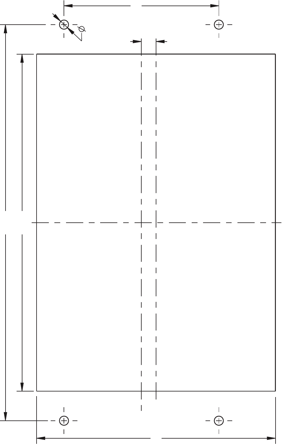
63 65-0303—05
Fig. 121. S7999C front-mount template.
M28852
8.93
(227)
3.50 (89)
5.40 (137)
.330 (8)
.205 (5)
5.45
(138)
S7999B, S7999C SOLA LOCAL OPERATOR INTERFACE
65-0303—05 64
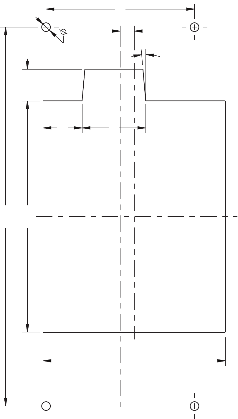
65 65-0303—05
Fig. 122. S7999C rear-mount template.
M28851
8.93
(227)
3.50 (89)
4.30 (109)
1.50 (38)
.92 (23)
.75 (19)
.330 (8)
5°
.205 (5)
5.45
(138)
S7999B, S7999C SOLA LOCAL OPERATOR INTERFACE
65-0303—05 66
S7999B, S7999C SOLA LOCAL OPERATOR INTERFACE
67 65-0303—05

S7999B, S7999C SOLA LOCAL OPERATOR INTERFACE
Automation and Control Solutions
Honeywell International Inc.
1985 Douglas Drive North
Golden Valley, MN 55422
Honeywell Limited-Honeywell Limitée
35 Dynamic Drive
Toronto, Ontario M1V 4Z9
customer.honeywell.com
® U.S. Registered Trademark
© 2010 Honeywell International Inc.
65-0303—05 M.S. Rev. 04-10
Printed in U.S.A.
