Honeywell Mk Vi Users Manual INSTALLATION DESIGN GUIDE 020
MK VI to the manual 16455e12-dbdc-4a58-95f4-56980e94c42e
2015-01-23
: Honeywell Honeywell-Mk-Vi-Users-Manual-261567 honeywell-mk-vi-users-manual-261567 honeywell pdf
Open the PDF directly: View PDF ![]() .
.
Page Count: 326 [warning: Documents this large are best viewed by clicking the View PDF Link!]
- TITLE SHEET
- TABLE OF CONTENTS
- SECTION I
- SECTION II
- SECTION III
- SYSTEM PLANNING
- Introduction
- System Wiring/ Electrical Interfaces
- Category 1 - Aircraft / Mode Type Select
- Category 2 – Air Data Input Select
- Category 3 – Position Input Select
- Category 4 – Altitude Callouts
- Category 5 – Audio Menu Select
- Category 6 – Terrain Display Select
- Category 7 – Options Select Group #1
- Category 8 – Radio Altitude Input Select
- Category 9 – Navigation Inputs Select
- Navigation Inputs Select (Glideslope & Localizer Inputs)
- Glideslope Validity
- Localizer Validity
- ILS Tuned Discrete Input #1 (+28V) and #2 (GND)
- Analog Glideslope Interface (Cat. 9 ID 0,1,5)
- Digital Glideslope / Localizer / ILS Select Interface (Cat. 9 ID 2,3,4)
- Digital – ARINC 429 Dual IOC buses \(Cat. 9 ID 2
- Instructions
- Category 10 – Attitude Input Select
- Category 11 – Heading Input Select
- Category 12 – Windshear Input Select
- Category 13 – Input / Output Discrete Type Select
- Input Discretes
- Glideslope Inhibit Discrete
- Landing Flaps Discrete
- Audio Inhibit Discrete
- Landing Gear Discrete
- Glideslope Cancel Discrete
- Momentary Flap Override Discrete
- Mode 6 Low Volume Discrete
- Autopilot Engaged Discrete
- Terrain Awareness and TCF Inhibit Discrete
- Self Test Discrete
- Steep Approach Discrete #2
- GPWS INHIBIT Discrete (alternate action)
- Output Discretes
- Instructions
- Input Discretes
- Category 14 – Audio Output Level
- Category 15 - 17 – Undefined Input Selects
- SYSTEM PLANNING
- SECTION IV
- SECTION V
- SECTION VI
- APPENDIX A
- APPENDIX B
- APPENDIX C
- APPENDIX D
- APPENDIX E
- Interface Description Document
- INTRODUCTION
- REFERENCES
- MECHANICAL INTERFACE
- ELECTRICAL INTERFACE
- Introduction
- Signal Interfaces
- Front Panel Test Interface
- Front Panel Status Indicators
- AIRCRAFT APPLICATION DATA
- Fault Designation: GPS BUS 2
- Fault Designation: IOC BUS 1
- Category 9, Navigation Input Select
- Category 10, Attitude Input Select
- Category 11, Heading Input Select
- Category 12, Windshear Input Select
- Category 13, Input / Output Discrete Type Select
- Category 14, Audio Output Level
- Category 15, Undefined for this software release
- Category 16, Undefined for this software release
- Category 17, Undefined for this software release
- CONFIGURABLE INPUT DATA DEFINITION
- Analog Input Data
- ARINC 552 Radio Altimeter
- ALT 55 Radio Altimeter
- Uncorrected Barometric Altitude
- Outside Air Temperature (500 ohm probe)
- Outside Air Temperature (Internal Constant)
- ARINC 547/578-4 Low Level Glideslope Deviation with Discrete Valid
- ARINC 547/578-4 Low Level Glideslope Deviation with Low Level Valid
- Roll Attitude, 3 Wire Synchro (11.8 VAC )
- Magnetic Heading, 5 Wire Synchro
- Uncorrected Barometric Altitude (ADS-65)
- RT-221/300 Radio Altimeter
- Pitch Synchro Attitude, 3 Wire Synchro (11.8 VAC )
- Uncorrected Barometric Altitude (CIC 02702)
- ARINC 547/578-4 Low Level Glideslope Deviation Validity
- Roll Attitude, 3 Wire Synchro (11.8 VAC ) with Validity
- Uncorrected Barometric Altitude (AZ-241, AZ-800)
- ARINC 547 Localizer Deviation with Discrete Valid
- Digital Input Data, ARINC 429
- Uncorrected Barometric Altitude (203)
- Static Air Temperature (213)
- Barometric Altitude Rate (212)
- Altitude (076) - GPS (MSL)
- Horizontal Integrity Limit (130) - GPS
- Ground Speed (112) - GPS
- Latitude (110) - GPS
- Longitude (111) - GPS
- Track Angle (103) - GPS
- Horizontal Figure Of Merit \(247\) – GPS \(AR
- Horizontal Figure Of Merit \(247\) – GPS \(AR
- Horizontal Figure Of Merit from HDOP \(101\) –
- Vertical Figure Of Merit \(136\) – GPS \(ARIN
- Vertical Figure Of Merit \(136\) – GPS \(ARIN
- Vertical Figure Of Merit from VDOP \(102\) –
- Sensor Status (273) - GPS
- Universal Time Correlation (125) - GPS
- Date (260) - GPS
- Control Word (154) - MFD
- Control Word 2 (271/273)
- Discrete Word (155 or 176) - MFD
- Hazard Range Output (077)
- Range (050) - Multifunction Signal Generator (MG) or IC600
- Query / Continuous Response (011) - KCPB
- Key Press Data \(012\) – KCPB
- Control Word 1 (270)
- Discrete Word \(273\) – Bendix Weather Radar V
- Discrete Word \(275\) – IC600 only
- Radio Altitude (164)
- Glideslope Deviation (174 or 117)
- Roll Angle (325)
- Magnetic Heading (320)
- Localizer Deviation (173 or 116)
- Pitch Angle (324)
- Range (271) - KCPB
- DSU Status Word (350)
- True Heading (314)
- Corrected Barometric Altitude (204)
- Computed Airspeed (206)
- True Airspeed (210)
- Decision Height \(370\) – IOC Scaling
- Normal Acceleration (333)
- Longitudinal Acceleration (331)
- Left Body Angle of Attack (224)
- Right Body Angle of Attack (225)
- VOR/ILS Frequency (034)
- PFD Mode Select Word (163)
- FWC & GP Discrete Word (171)
- Body Pitch Rate (326)
- Body Roll Rate (327)
- Minimum Descent Altitude \(170\) – IOC Scaling
- Normal Angle of Attack (236)
- North/South Velocity (166) - GPS
- East/West Velocity (174) - GPS
- Discrete Word (017) - KMD 550/850
- Inertial Vertical Speed (365)
- Inertial Altitude (361)
- Vertical Velocity (165) - GPS
- Latitude Fine (120) - GPS
- Longitude Fine (121) - GPS
- Selected Course (100) - IOC
- DH/MDA Selected \(170\) – DAU Scaling
- Digital Data, ARINC 575
- Digital Data, RS-232
- Digital Data, RS-422
- Discrete Inputs
- Analog Radio Altitude Validity Flags
- GND Landing Gear Discrete
- +28V Landing Gear Discrete
- GND Landing Flap Discrete
- +28V Landing Flap Discrete
- Momentary Flap Override Discrete
- Self-Test Discrete
- GND ILS Tuned Discrete #1
- +28V ILS Tuned Discrete #1
- Glideslope Validity Discrete #1
- GND Glideslope Inhibit Discrete
- +28 V Glideslope Inhibit Discrete
- Glideslope Cancel Discrete
- Decision Height Discrete
- Mode 6 Low Volume Discrete
- GND Audio Inhibit Discrete
- +28V Audio Inhibit Discrete
- Display Select Discrete #1
- Display Select Discrete #2
- Terrain Awareness & TCF Inhibit Discrete
- Autopilot Engaged Discrete #1
- Barometric Altitude Validity Discrete
- Magnetic Heading Validity Discrete
- Attitude Validity Discrete
- Steep Approach Discrete #2
- Timed Audio Inhibit Discrete
- GPWS Inhibit Discrete
- Localizer Validity Discrete #1
- Analog Input Data
- OUTPUT DATA DEFINITION
- ARINC 429 Output Data
- Discrete Output Words
- Internal Data Outputs
- Geometric Altitude VFOM (135)
- Terrain Clearance (164)
- Geometric Altitude (261)
- Computed Terrain Clearance (067)
- Latitude – Selected EGPWS \(310\)
- Longitude – Selected EGPWS \(311\)
- Body Angle of Attack—Right \(223\) – MKVIII EG
- Body Angle of Attack—Left \(224\) – MKVIII EGP
- Corrected Airspeed \(242\) – MKVIII EGPWS w/ W
- Windshear Warning Threshold \(331\) – MKVIII E
- Corrected Longitudinal Acceleration \(332\) –
- Raw Total Shear \(362\) – MKVIII EGPWS w/ Wind
- Corrected Normal Acceleration \(364\) – MKVIII
- Computed Flight Path Angle \(375\) – MKVIII EG
- Scaled Total Shear \(376\) – MKVIII EGPWS w/ W
- Terrain Display Outputs
- Equipment Identification
- Fault Summary Words (for Proline 4/21)
- Peak Binary Labels
- ARINC 708A Output
- Audio Output
- Discrete Outputs
- Ground Proximity Alerts Discrete (Lamp) Outputs
- Audio On Discrete
- Monitor Discretes (GPWS INOP & Terrain INOP or Terrain Not Available)
- Terrain Display Switching Discretes (WxR/EGPWS Display Select)
- Flap Override Discrete
- Glideslope Cancel Discrete
- Terrain / Obstacle Awareness Alert Discretes
- Terrain Pop Up
- Windshear INOP Monitor Discretes
- Windshear Warning
- Windshear Caution
- Steep Approach Discrete
- System Configuration Status
- ARINC 429 Output Data
- CONNECTOR INTERFACE
- DEFINITIONS

Proprietary notice on title page applies
CAGE CODE: 97896 SCALE: NONE SIZE: A DWG NO: 060-4314-150 REV: SHEET 1 OF 326
Airlines & Avionics Products
Honeywell Inc.
15001 N.E. 36th Street
Redmond, WA 98052
MK VI
MK VIII
Enhanced Ground Proximity Warning System
(Class A TAWS)
Installation Design Guide
Hardware/Software Part Numbers:
965-1180-020
965-1190-020
965-1210-020
965-1220-020
Release Date: July 14, 2003

Honeywell
MK VI MK VIII EGPWS Installation Design Guide
Proprietary notice on title page applies
CAGE CODE: 97896 SCALE: NONE SIZE: A DWG NO: 060-4314-150 REV: SHEET 2
Copyright 2003 Honeywell, Inc. All rights reserved.
This document and all information and expression contained herein are the property of Honeywell International
Inc., and is provided to the recipient in confidence on a “need to know” basis. Your use of this document is strictly
limited to a legitimate business purpose requiring the information contained therein. Your use of this document
constitutes acceptance of these terms.
Honeywell
MK VI MK VIII EGPWS Installation Design Guide
Proprietary notice on title page applies
CAGE CODE: 97896 SCALE: NONE SIZE: A DWG NO: 060-4314-150 REV: SHEET 3
Typed names constitute approval signatures. Actual signatures are on file at Honeywell in
Redmond, WA.
DRAWN Larry Matter 14-JULY-03
CHECK
ENGR Larry Matter 14-JULY-03
MFG
QA
APVD Jim Mulkins 14-JULY-03
APVD
REVISION STATUS OF SHEETS INDEX
ADDED SHEETS ADDED SHEETS
SHEET
NUMBER
REV
LTR
SHEET
NUMBER
REV
LTR
SHEET
NUMBER
REV
LTR
SHEET
NUMBER
REV
LTR
SHEET
NUMBER
REV
LTR
SHEET
NUMBER
REV
LTR
REVISIONS
SH REV DESCRIPTION DATE APPROVED

Honeywell
MK VI MK VIII EGPWS Installation Design Guide
Proprietary notice on title page applies
CAGE CODE: 97896 SCALE: NONE SIZE: A DWG NO: 060-4314-150 REV: SHEET 4
THIS PAGE INTENTIONALLY LEFT BLANK

Honeywell
MK VI MK VIII EGPWS Installation Design Guide
Proprietary notice on title page applies
CAGE CODE: 97896 SCALE: NONE SIZE: A DWG NO: 060-4314-150 REV: SHEET 5
TABLE OF CONTENTS
SECTION I – GENERAL INFORMATION ..........................................................................................................13
1.1 INTRODUCTION.........................................................................................................................................................13
1.2 APPLICABILITY.........................................................................................................................................................13
1.3 HOW TO USE THIS DOCUMENT ................................................................................................................................13
1.4 REFERENCE DOCUMENTS .........................................................................................................................................14
1.5 DESCRIPTION OF EQUIPMENT ...................................................................................................................................15
1.5.1 MK VI EGPWS Computer ....................................................................................................................................15
1.5.2 MK VIII EGPWS Computer..................................................................................................................................15
1.5.3 MK VI/MK VIII EGPWS Configuration Module ..................................................................................................15
1.5.4 GPS Antenna and Cabling....................................................................................................................................16
1.5.5 OAT Sensor ..........................................................................................................................................................17
1.5.6 Smart Cable (PCMCIA Interface) ........................................................................................................................17
1.6 TECHNICAL CHARACTERISTICS ................................................................................................................................18
1.7 UNITS SUPPLIED.......................................................................................................................................................18
1.7.1 MK VI EGPWS .....................................................................................................................................................18
1.7.2 MK VIII EGPWS.................................................................................................................................................19
1.7.3 Configuration Module ........................................................................................................................................19
1.7.4 Smart Cable (PCMCIA Interface) ......................................................................................................................19
1.8 INSTALLATION KITS AND ACCESSORIES .................................................................................................................19
1.8.1 MK VI/MK VIII EGPWS Installation Kits ..........................................................................................................19
1.8.2 RS-232 Cable......................................................................................................................................................20
1.8.3 Smart Cable........................................................................................................................................................20
1.8.4 Terrain Database Cards.....................................................................................................................................20
1.8.5 Flight History Card ............................................................................................................................................20
1.9 ACCESSORIES NOT SUPPLIED ..................................................................................................................................20
1.9.1 ARINC 453 Terrain Display wiring....................................................................................................................20
1.9.2 GPS Antenna & Cable........................................................................................................................................21
1.9.3 Circuit Breaker...................................................................................................................................................21
1.9.4 Annunciators & Switch/Annunciators ................................................................................................................22
1.9.5 Cockpit Speakers ................................................................................................................................................23
1.9.6 Temperature Probes ...........................................................................................................................................23
1.10 TOOLS REQUIRED .................................................................................................................................................24
1.10.1 Crimping Tool - P1, P2, P3 .............................................................................................................................24
1.10.2 Contact Positioner - P1, P2, P3 ......................................................................................................................24
1.10.3 Insertion/Removal Tool - P1, P2, P3...............................................................................................................24
1.10.4 Spare Connectors and Contacts - P1, P2, P3..................................................................................................25
1.11 LICENSE REQUIREMENTS......................................................................................................................................25
SECTION II - INSTALLATION .............................................................................................................................29

Honeywell
MK VI MK VIII EGPWS Installation Design Guide
Proprietary notice on title page applies
CAGE CODE: 97896 SCALE: NONE SIZE: A DWG NO: 060-4314-150 REV: SHEET 6
2.1 INTRODUCTION.......................................................................................................................................................29
2.2 UNPACKING AND INSPECTING THE EQUIPMENT ......................................................................................................29
2.3 EQUIPMENT INSTALLATION ....................................................................................................................................29
2.3.1 General...............................................................................................................................................................29
2.3.2 MK VI/MK VIII Computer Location...................................................................................................................29
2.3.3 MK VI/ MK VIII Computer Installation..............................................................................................................30
2.3.4 Configuration Module Location .........................................................................................................................31
2.3.5 Configuration Module Installation .....................................................................................................................31
2.3.6 GPS Antenna location.........................................................................................................................................40
2.3.7 GPS Antenna Installation ...................................................................................................................................40
2.3.8 OAT Sensor Location..........................................................................................................................................40
2.3.9 OAT Sensor Installation .....................................................................................................................................40
2.3.10 Cockpit Lights...................................................................................................................................................40
2.3.10.1 Description........................................................................................................................................................................ 41
2.3.10.2 Location ............................................................................................................................................................................ 42
SECTION III – SYSTEM PLANNING ...................................................................................................................51
3.1 INTRODUCTION.......................................................................................................................................................51
3.2 SYSTEM WIRING/ ELECTRICAL INTERFACES ..........................................................................................................51
3.2.1 Primary Power Input ..........................................................................................................................................51
3.2.2 Chassis Ground ..................................................................................................................................................52
3.2.3 GPS Antenna ......................................................................................................................................................52
3.2.4 Analog and Digital Inputs ..................................................................................................................................52
3.2.5 Discrete Inputs....................................................................................................................................................52
3.2.6 Serial Outputs.....................................................................................................................................................52
3.2.7 Audio Output.......................................................................................................................................................53
3.2.8 Discrete Outputs.................................................................................................................................................53
3.2.9 Configuration Module ........................................................................................................................................53
3.3 CATEGORY 1 - AIRCRAFT / MODE TYPE SELECT ...................................................................................................54
3.3.1 Aircraft / Mode Type...........................................................................................................................................54
3.3.2 Mode 1 type ........................................................................................................................................................54
3.3.3 Mode 2 type ........................................................................................................................................................54
3.3.4 Mode 3 type ........................................................................................................................................................55
3.3.5 Mode 4 type ........................................................................................................................................................55
3.3.6 Bank Angle Type.................................................................................................................................................55
3.3.7 Runway Length (MK VIII EGPWS only) ............................................................................................................56
3.3.8 Instructions.........................................................................................................................................................56
3.4 CATEGORY 2 – AIR DATA INPUT SELECT ...............................................................................................................57
3.4.1 Analog (Cat. 2 ID 0, 3, 4, 11, 12) .......................................................................................................................57
3.4.2 Digital – ARINC 429 (Cat. 2 ID 5, 1, 6, 13).......................................................................................................59
3.4.3 Digital –ARINC 575 (Cat. 2 ID 2)......................................................................................................................60
3.4.4 Shadin 2000 (Cat. 2 ID 10).................................................................................................................................61
3.4.5 Digital – ARINC 429 Dual IOC Buses (Cat. 2. ID 255).....................................................................................62

Honeywell
MK VI MK VIII EGPWS Installation Design Guide
Proprietary notice on title page applies
CAGE CODE: 97896 SCALE: NONE SIZE: A DWG NO: 060-4314-150 REV: SHEET 7
3.4.6 Instructions.........................................................................................................................................................62
3.5 CATEGORY 3 – POSITION INPUT SELECT ................................................................................................................63
3.5.1 ARINC 743 Format.............................................................................................................................................63
3.5.2 GPS Altitude (Label 076) Reference...................................................................................................................63
3.5.3 North-South East-West Velocity labels...............................................................................................................63
3.5.4 ARINC 429 BUS (Cat. 3 ID 0,1,4,5,10-13).........................................................................................................64
3.5.5 RS-232 Transmit-Receive, 9600 baud (Cat. 3 ID 3) ...........................................................................................65
3.5.6 Dual ARINC 429 BUS (Cat. 3 ID 253 & 255)....................................................................................................66
3.5.7 Instructions.........................................................................................................................................................66
3.6 CATEGORY 4 – ALTITUDE CALLOUTS ....................................................................................................................67
3.7 CATEGORY 5 – AUDIO MENU SELECT ....................................................................................................................68
3.7.1 Audio Menu Selection.........................................................................................................................................68
3.7.2 Instructions.........................................................................................................................................................68
3.8 CATEGORY 6 – TERRAIN DISPLAY SELECT.............................................................................................................69
3.8.1 TAD & TCF Selection.........................................................................................................................................69
3.8.2 Terrain Display Configuration Group................................................................................................................70
3.8.3 Display Input Control Group..............................................................................................................................70
3.8.4 Output 429 Bus Group........................................................................................................................................71
3.8.5 Instructions.........................................................................................................................................................71
3.8.6 Sample Display Schematics ................................................................................................................................71
3.9 CATEGORY 7 – OPTIONS SELECT GROUP #1...........................................................................................................88
3.9.1 Steep Approach...................................................................................................................................................88
3.9.2 TA&D Alternate Pop-up.....................................................................................................................................88
3.9.3 Peaks Mode ........................................................................................................................................................88
3.9.4 Obstacle Awareness............................................................................................................................................88
3.9.5 Bank Angle Callout Enabling .............................................................................................................................89
3.9.6 Flap Reversal......................................................................................................................................................89
3.9.7 GPS Altitude Reference ......................................................................................................................................89
3.9.8 Instructions.........................................................................................................................................................90
3.10 CATEGORY 8 – RADIO ALTITUDE INPUT SELECT..................................................................................................91
3.10.1 Radio Altitude Input..........................................................................................................................................91
3.10.2 Decision Height Discrete Input ........................................................................................................................91
3.10.3 Digital Radio Altitude Interface (Cat. 8 ID 2)..................................................................................................91
3.10.4 Analog Radio Altitude Interface (Cat. 8 ID 0,1,3,4).........................................................................................92
3.10.5 Digital – ARINC 429 Dual IOC Buses (Cat. 8 ID 251- 255)............................................................................92
3.10.6 Instructions .......................................................................................................................................................93
3.11 CATEGORY 9 – NAVIGATION INPUTS SELECT.......................................................................................................94
3.11.1 Navigation Inputs Select (Glideslope & Localizer Inputs) ...............................................................................94
3.11.2 Glideslope Validity ...........................................................................................................................................94
3.11.3 Localizer Validity .............................................................................................................................................94
3.11.4 ILS Tuned Discrete Input #1 (+28V) and #2 (GND) ........................................................................................94
3.11.5 Analog Glideslope Interface (Cat. 9 ID 0,1,5)..................................................................................................95
3.11.6 Digital Glideslope / Localizer / ILS Select Interface (Cat. 9 ID 2,3,4).............................................................96

Honeywell
MK VI MK VIII EGPWS Installation Design Guide
Proprietary notice on title page applies
CAGE CODE: 97896 SCALE: NONE SIZE: A DWG NO: 060-4314-150 REV: SHEET 8
3.11.7 Digital – ARINC 429 Dual IOC buses (Cat. 9 ID 250 - 255) ...........................................................................96
3.11.8 Instructions .......................................................................................................................................................97
3.12 CATEGORY 10 – ATTITUDE INPUT SELECT ...........................................................................................................98
3.12.1 Roll Angle .........................................................................................................................................................98
3.12.2 Analog Pitch & Roll Angle (Synchro) (Cat. 10 ID 0,2,4) .................................................................................98
3.12.3 Digital Pitch & Roll Angle (ARINC 429 High Speed) (Cat. 10 ID 5 & 6)........................................................99
3.12.4 Digital – ARINC 429 Dual IOC buses (Cat. 10 ID 253 & 255) .......................................................................99
3.12.5 Instructions .......................................................................................................................................................99
3.13 CATEGORY 11 – HEADING INPUT SELECT ..........................................................................................................100
3.13.1 Magnetic Heading ..........................................................................................................................................100
3.13.2 Analog Heading (Synchro) (Cat. 11 ID 0)......................................................................................................100
3.13.3 Digital – ARINC 429 AHRS Input (Cat. 11 ID 2 & 3)....................................................................................101
3.13.4 Digital – ARINC 429 Dual IOC buses (Cat. 11 ID 254 & 255) .....................................................................101
3.13.5 Instructions .....................................................................................................................................................101
3.14 CATEGORY 12 – WINDSHEAR INPUT SELECT .....................................................................................................102
3.14.1 No Windshear .................................................................................................................................................102
3.14.2 Dual ARINC 429 BUS (Cat. 14 ID 253,254,255) ...........................................................................................102
3.14.3 Instructions .....................................................................................................................................................102
3.15 CATEGORY 13 – INPUT / OUTPUT DISCRETE TYPE SELECT ................................................................................103
3.15.1 Input Discretes................................................................................................................................................103
3.15.1.1 Glideslope Inhibit Discrete ............................................................................................................................................. 103
3.15.1.2 Landing Flaps Discrete ................................................................................................................................................... 103
3.15.1.3 Audio Inhibit Discrete..................................................................................................................................................... 104
3.15.1.4 Landing Gear Discrete .................................................................................................................................................... 104
3.15.1.5 Glideslope Cancel Discrete............................................................................................................................................. 106
3.15.1.6 Momentary Flap Override Discrete................................................................................................................................. 106
3.15.1.7 Mode 6 Low Volume Discrete........................................................................................................................................ 106
3.15.1.8 Autopilot Engaged Discrete............................................................................................................................................ 107
3.15.1.9 Terrain Awareness and TCF Inhibit Discrete.................................................................................................................. 107
3.15.1.10 Self Test Discrete.......................................................................................................................................................... 107
3.15.1.11 Steep Approach Discrete #2.......................................................................................................................................... 108
3.15.1.12 GPWS INHIBIT Discrete (alternate action).................................................................................................................. 108
3.15.2 Output Discretes .............................................................................................................................................108
3.15.2.1 Lamp Format................................................................................................................................................................... 109
3.15.2.2 Flashing Lamps............................................................................................................................................................... 109
3.15.2.3 GPWS INOP Discrete..................................................................................................................................................... 109
3.15.2.4 TAD INOP Discrete........................................................................................................................................................ 109
3.15.2.5 GPWS Warning Discrete ................................................................................................................................................ 109
3.15.2.6 GPWS Alert Discrete...................................................................................................................................................... 110
3.15.2.7 Glideslope Cancel’d Discrete.......................................................................................................................................... 110
3.15.2.8 Flap Override Discrete.................................................................................................................................................... 110
3.15.2.9 Steep Approach Discrete................................................................................................................................................. 110
3.15.2.10 Audio On Discrete (TCAS/TAS Inhibit)....................................................................................................................... 110

Honeywell
MK VI MK VIII EGPWS Installation Design Guide
Proprietary notice on title page applies
CAGE CODE: 97896 SCALE: NONE SIZE: A DWG NO: 060-4314-150 REV: SHEET 9
3.15.2.11 Terrain Display Select #1 & #2 Discrete....................................................................................................................... 111
3.15.2.12 Terrain Pop up Discrete ................................................................................................................................................ 112
3.15.3 Instructions .....................................................................................................................................................113
3.16 CATEGORY 14 – AUDIO OUTPUT LEVEL ............................................................................................................113
3.16.1 Instructions .....................................................................................................................................................113
3.17 CATEGORY 15 - 17 – UNDEFINED INPUT SELECTS .............................................................................................114
3.17.1 Undefined Input Select....................................................................................................................................114
3.17.2 Instructions .....................................................................................................................................................114
SECTION IV – CONFIG MODULE PROGRAMMING AND REGIONAL TDB LOADING ......................117
4.1 INTRODUCTION.....................................................................................................................................................117
4.2 HARNESS CHECKOUT AND POWER CHECK ...........................................................................................................117
4.3 UNIT INSTALLATION.............................................................................................................................................117
4.4 EGPWC INITIALIZATION AND CONFIGURATION ..................................................................................................117
4.4.1 RS-232 Communication with the MK VI/VIII EGPWS .....................................................................................117
4.4.2 EGPWC Front Panel Test Connector...............................................................................................................118
4.4.3 WinVIEWS ........................................................................................................................................................119
4.4.4 WinVIEWS Operation.......................................................................................................................................119
4.5 CONFIGURATION MODULE PROGRAMMING..........................................................................................................119
4.5.1 CUW and CMR Commands ..............................................................................................................................121
4.5.2 Configuration Module Reprogramming ...........................................................................................................122
4.6 TERRAIN DATABASE LOADING.............................................................................................................................122
4.6.1 Effectivity..........................................................................................................................................................122
4.6.2 Description .......................................................................................................................................................123
4.6.3 Approval ...........................................................................................................................................................123
4.6.4 Material – Cost and Availability ......................................................................................................................123
4.6.5 Accomplishment Instructions............................................................................................................................123
4.6.6 Verification of the Terrain Database Version ..................................................................................................125
SECTION V – CERTIFICATION......................................................................................................................... 128
5.1 INTRODUCTION.....................................................................................................................................................128
5.2 CERTIFICATION PROCEDURE ................................................................................................................................128
5.2.1 Equipment Compatibility ..................................................................................................................................128
5.2.2 Equipment Location..........................................................................................................................................128
5.2.3 FAA Requirements............................................................................................................................................128
5.2.4 Ground Test ......................................................................................................................................................128
5.2.5 Flight Manual Revision ....................................................................................................................................128
5.2.6 Flight Test.........................................................................................................................................................128
5.2.7 Pilots Guide......................................................................................................................................................129
5.2.8 Failure Modes, Effects, and Safety Analysis.....................................................................................................129
SECTION VI - MK VI GPWS TO MK VI/VIII EGPWS SIGNAL MAPPING ............................................... 131

Honeywell
MK VI MK VIII EGPWS Installation Design Guide
Proprietary notice on title page applies
CAGE CODE: 97896 SCALE: NONE SIZE: A DWG NO: 060-4314-150 REV: SHEET 10
APPENDIX A - CUSTOMER WORKSHEET .....................................................................................................137
APPENDIX B - SAMPLE WIRING DIAGRAMS ............................................................................................... 141
APPENDIX C – WINVIEWS OPERATION INSTRUCTIONS.........................................................................146
APPENDIX D - VENDOR CONTACT INFORMATION................................................................................... 150
APPENDIX E – INTERFACE DESCRIPTION DOCUMENT .......................................................................... 153

Honeywell
MK VI MK VIII EGPWS Installation Design Guide
Proprietary notice on title page applies
CAGE CODE: 97896 SCALE: NONE SIZE: A DWG NO: 060-4314-150 REV: SHEET 11
SECTION I
GENERAL INFORMATION

Honeywell
MK VI MK VIII EGPWS Installation Design Guide
Proprietary notice on title page applies
CAGE CODE: 97896 SCALE: NONE SIZE: A DWG NO: 060-4314-150 REV: SHEET 12
SECTION I – GENERAL INFORMATION
SECTION I – GENERAL INFORMATION ..................................................................................................................... 13
1.1 INTRODUCTION.............................................................................................................................................................. 13
1.2 APPLICABILITY.............................................................................................................................................................. 13
1.3 HOW TO USE THIS DOCUMENT ..................................................................................................................................... 13
1.4 REFERENCE DOCUMENTS .............................................................................................................................................. 14
1.5 DESCRIPTION OF EQUIPMENT ........................................................................................................................................ 15
1.5.1 MK VI EGPWS Computer ..................................................................................................................................... 15
1.5.2 MK VIII EGPWS Computer................................................................................................................................... 15
1.5.3 MK VI/MK VIII EGPWS Configuration Module ................................................................................................... 15
1.5.4 GPS Antenna and Cabling..................................................................................................................................... 16
1.5.5 OAT Sensor ........................................................................................................................................................... 17
1.5.6 Smart Cable (PCMCIA Interface) ......................................................................................................................... 17
1.6 TECHNICAL CHARACTERISTICS ..................................................................................................................................... 18
1.7 UNITS SUPPLIED............................................................................................................................................................ 18
1.7.1 MK VI EGPWS ...................................................................................................................................................... 18
1.7.2 MK VIII EGPWS ................................................................................................................................................... 19
1.7.3 Configuration Module ........................................................................................................................................... 19
1.7.4 Smart Cable (PCMCIA Interface) ......................................................................................................................... 19
1.8 INSTALLATION KITS AND ACCESSORIES........................................................................................................................ 19
1.8.1 MK VI/MK VIII EGPWS Installation Kits ............................................................................................................. 19
1.8.2 RS-232 Cable......................................................................................................................................................... 20
1.8.3 Smart Cable........................................................................................................................................................... 20
1.8.4 Terrain Database Cards........................................................................................................................................ 20
1.8.5 Flight History Card ............................................................................................................................................... 20
1.9 ACCESSORIES NOT SUPPLIED......................................................................................................................................... 20
1.9.1 ARINC 453 Terrain Display wiring....................................................................................................................... 20
1.9.2 GPS Antenna & Cable........................................................................................................................................... 21
1.9.3 Circuit Breaker...................................................................................................................................................... 21
1.9.4 Annunciators & Switch/Annunciators ................................................................................................................... 22
1.9.5 Cockpit Speakers ................................................................................................................................................... 23
1.9.6 Temperature Probes .............................................................................................................................................. 23
1.10 TOOLS REQUIRED........................................................................................................................................................ 24
1.10.1 Crimping Tool - P1, P2, P3................................................................................................................................ 24
1.10.2 Contact Positioner - P1, P2, P3 ......................................................................................................................... 24
1.10.3 Insertion/Removal Tool - P1, P2, P3.................................................................................................................. 24
1.10.4 Spare Connectors and Contacts - P1, P2, P3..................................................................................................... 25
1.11 LICENSE REQUIREMENTS............................................................................................................................................. 25

Honeywell
MK VI MK VIII EGPWS Installation Design Guide
Proprietary notice on title page applies
CAGE CODE: 97896 SCALE: NONE SIZE: A DWG NO: 060-4314-150 REV: SHEET 13
SECTION I – GENERAL INFORMATION
1.1 Introductio n
The Honeywell MK VI/MK VIII Enhanced Ground Proximity Warning System (MK VI/MK VIII EGPWS) provides
alerts and warnings to prevent controlled flight into terrain (CFIT).
This Installation Design Guide must be used in conjunction with the Interface Description Document
(Appendix E) for the MK VI/MK VIII Enhanced Ground Proximity Warning System (MK VI/MK VIII EGPWS)
to select features and design the installation for this system.
It is assumed that the user of this document is familiar with avionics installation practices and aircraft
systems associated with the installation and operation of the MK VI/MK VIII EGPWS. It also assumes
access to pertinent aircraft wiring diagrams, modification records and manuals.
The information contained herein, together with general procedures outlined in FAA AC.43.13 must be followed
carefully to assure a safe, electrically sound, certifiable and operational installation.
The contents of this document are for information and reference only and must not be construed as
formal FAA approved work authorization.
1.2 Applicabilit y
This manual is applicable only to MK VI/MK VIII EGPWS computers with the following part numbers:
MK VI
965-1180-020
965-1190-020
MK VIII
965-1210-020
965-1220-020
Part numbers 965-1190-xxx and 965-1220-xxx include an internal GPS card.
1.3 How To Us e This Document
Section 1 provides a system overview.
Section 2 provides mechanical installation and location information.
Section 3 provides information and instructions for selecting required features of the EGPWS.
Section 4 provides Configuration Module programming instructions.
Section 5 provides certification requirements.
Section 6 provides a pin to pin comparison of the classic MK VI GPWS to the MK VI/MK VIII EGPWS.
Appendix A Customer Worksheet.
Appendix B Sample Wiring Diagrams.
Appendix C provides WinViews operation instructions.
Appendix D provides Vendor Contact Information
Appendix E Interface Description Document

Honeywell
MK VI MK VIII EGPWS Installation Design Guide
Proprietary notice on title page applies
CAGE CODE: 97896 SCALE: NONE SIZE: A DWG NO: 060-4314-150 REV: SHEET 14
1.4 Reference D ocuments
Following is a list of Honeywell reference documents:
965-1180-601 Product Specification for the MK VI and MK VIII Enhanced Ground Proximity Warning
System (EGPWS)
965-1180-201
965-1190-201
965-1210-201
965-1220-201
Outline, MK VI EGPWC (without GPS)
Outline, MK VI EGPWC (with GPS)
Outline, MK VIII EGPWC (without GPS)
Outline, MK VIII EGPWC (with GPS)
060-4199-180
060-4267-000
Line Maintenance Manual
MK VIII EGPWS Terrain Database Airport Coverage List (3500’ Runways)
060-4326-000 MK VI / MK VIII EGPWS Terrain Database Airport Coverage List (2000’ Runways)
060-4199-194 MK VI / MK VIII EGPWS Generic AFM Supplement
060-4314-000 MK VI / MK VIII Enhanced GPWS Pilot’s Guide
060-4188-023 MK VIII Bizjet Flight Test Procedure
060-4188-038 Flight Test Procedure for EGPWS with Internal GPS card
060-4188-041 MK VI / MK VIII GA Fast/GA Slow General Flight Test Procedure
060-4167-158 MK VI / MK VIII Installation Ground Test Procedure
060-4199-190 Trouble Shooting Guide
060-4199-182
076-4610-000
MK VI / MK VIII Failures Modes, Effects, and Safety Analysis
MK VI / MK VIII Failure Modes, Effects, and Criticality Analysis

Honeywell
MK VI MK VIII EGPWS Installation Design Guide
Proprietary notice on title page applies
CAGE CODE: 97896 SCALE: NONE SIZE: A DWG NO: 060-4314-150 REV: SHEET 15
1.5 Description of Equipment
The MK VI/MK VIII EGPWS is a rack mount ground proximity warning (GPWS) and terrain awareness and
warning (Class A TAWS) computer. Some of the system features include:
♦ Basic Ground Proximity Warning Modes 1-5
♦ Mode 6 Altitude Callouts and Bank Angle alert
♦ Terrain Clearance Floor
♦ Terrain and Obstacle Awareness alert and display
♦ Terrain map with runways >= 2000 feet in length (optionally >= 3500 feet in length on the MK VIII EGPWS)
♦ Internal GPS card (MK VI 965-1190-0XX and MK VIII 965-1220-0XX only)
♦ Front loading updateable database (requires Smart cable)
♦ External Configuration Module (with a Real Time Clock for use with Internal GPS)
♦ Internal heater blanket for operation outside of the heated area of the aircraft
♦ Fixed Gear operation
1.5.1 MK VI EGP WS Computer
The MK VI EGPWS computer is available under P/N 965-1180-0XX without internal GPS and P/N 965-1190-
0XX with internal GPS. The MK VI EGPWS computer is intended for small turboprop aircraft that provide a
mixture of analog and digital interfaces. The type of supported displays is limited and does not typically include
EFIS displays (Collins ProLine II and Bendix EFIS 40/50 are supported). The terrain database included with the
MK VI EGPWS computer is regional having three separately defined databases for the AMERICAS (North &
South America), ATLANTIC (Europe/Asia/Africa), and PACIFIC (Asia/Australia).
1.5.2 MK VIII EGP WS Computer
The MK VIII EGPWS computer is available under P/N 965-1210-0XX without internal GPS and P/N 965-1220-
0XX with internal GPS. The MK VIII EGPWS computer is intended for regional turboprop and small turbofan
aircraft that provide a mixture of analog and digital interfaces. The type of supported displays is limited and
includes some EFIS displays. The terrain database included with the MK VIII EGPWS computer is global.
1.5.3 MK VI/MK V III EGPWS Configuration Module
The MK VI/MK VIII EGPWS Configuration Module is available under P/N 700-1710-020. The MK VI/MK VIII
EGPWS use a Configuration Module installed in the aircraft wiring to store aircraft/EGPWS interface
configuration and includes a Real Time Clock for EGPWS installations using internal GPS. The Configuration
Module is read by the EGPWS only during power up. The configuration is copied into Non Volatile Memory
(NVM) of the EGPWS. The Configuration Module is programmable via an RS-232 interface with the EGPWS.
The contents of the Configuration Module can also be read back via the same RS-232 interface. An optional
Configuration Module is available under P/N 700-1710-001 for non-Internal GPS operation only.
The 700-1710-020 Configuration Module includes a GPS Real Time Clock (RTC) counter and position memory
to aid in GPS initialization. A capacitor will keep the position memory retained and clock current for

Honeywell
MK VI MK VIII EGPWS Installation Design Guide
Proprietary notice on title page applies
CAGE CODE: 97896 SCALE: NONE SIZE: A DWG NO: 060-4314-150 REV: SHEET 16
approximately 35 days. GPS initialization time should be less than 3 minutes with active RTC data. If the
capacitor has discharged then GPS initialization time may be as long as 10 minutes.
1.5.4 GPS Anten na and Cabling
EGPWS installations using the internal GPS require a GPS antenna and cabling. The GPS antenna should
meet the following qualifications:
Frequency: 1575.42 MHz
Impedance: 50 ohms
Gain: 33 dB max, 26.5 dB preferred
Power: 5 VDC
Qualification: TSO C129 or C129a or C144
Antenna gain is limited to 33dB gain, maximum. Antennas with 26dB gain are preferred. There are Active GPS
antennas with higher gain. However, as the active antenna amplifiers amplify noise as well as the signal, this
can overdrive the GPS input AGC circuitry and actually reduce performance.
The following GPS antennas are found to be compatible with the EGPWS internal GPS card. Other GPS
antennas may be found compatible, contact EGPWS engineering for assistance. It is the responsibility of the
OEM or owner/operator (and ultimately the regulatory authorities) to assess the antenna acceptance criteria
relative to ARINC, MIL, or other specifications. Boeing has certified the Sensor Systems antenna S67-1575-133
(an ARINC 743A antenna with a 33dB gain) for use on all A/C. This antenna is certified for HIRF/EMI, Class 1
flight critical operation. As a result, it is very expensive (about 3X other versions).
King KA 92 P/N 071-01553-0200 TSO-C129
Sensor Systems P/N S67-1575-52 TSO-C129, ARINC 743A
Sensor Systems P/N S67-1575-133 TSO-C129a, ARINC 743A
The EGPWS requires an input signal of no less than -106 dB (at the EGPWS-GPS coax connector). Installers
need to calculate signal strength, plus antenna gain, minus cable line loss to ensure that the input signal does
not exceed the -106 dB limit. To calculate signal strength at the EGPWS coax connector, assume a received
signal strength of -118 dB at the antenna (this is average signal strength from a GPS satellite at zenith over the
antenna). Add the gain of the antenna, then subtract the line loss of the coax cable, and insertion loss at each
connector, except at the EGPWS. Assume 0.6dB insertion loss per connector.
EXAMPLE: Active GPS Antenna with 26dB gain. A 40 foot coax cable run with 1 coax connector (at the rack
disconnect). The cable has a specified line loss of 0.25dB/foot.
-118dB (received signal)
+ 26dB (antenna gain)
-92dB
-10dB (line loss) (0.25dB/foot x 40 foot run)
- 0.6dB (rack coax connector insertion loss)
= -102.6dB at EGPWS coax connector, better than required -106dB. This is an acceptable installation.
Honeywell
MK VI MK VIII EGPWS Installation Design Guide
Proprietary notice on title page applies
CAGE CODE: 97896 SCALE: NONE SIZE: A DWG NO: 060-4314-150 REV: SHEET 17
1.5.5 OAT Senso r
The EGPWS uses a separate OAT sensor (Outside Air Temperature) to measure outside air temperature on
aircraft that do not have another compatible source of outside air temperature. Outside Air Temperature is used
by the EGPWS along with pressure altitude in the Geometric Altitude computation. If Outside Air Temperature is
not available, Geometric Altitude is computed using pressure altitude and GPS Altitude with a corresponding
reduction in accuracy. Honeywell engineers have determined that the reduction in accuracy is small because
the GPS Altitude is the strongest element in the computation.
Geometric Altitude is computed by the EGPWS to reduce or eliminate errors potentially induced in corrected
barometric altitude by temperature extremes, non-standard altitude conditions, and altimeter miss-sets.
Geometric Altitude also allows continuous EGPWS operation in QFE environments without crew intervention.
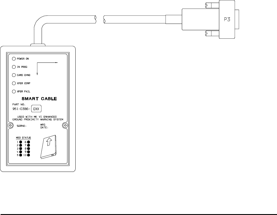
1.5.6 Smart Cabl e (PCMCIA Interface)
The EGPWS Smart Cable (part number 951-0386-001) is a removable PCMCIA card interface. The Smart
Cable is compatible with Honeywell supplied ATA style PCMCIA cards for use with MK VI and MK VIII EGPWS.
The purpose of the Smart Cable in the EGPWS system is for upload of software and databases and also for
download of EGPWS Flight History. The Smart Cable loading operation will closely emulate that of an ARINC
615 Data Loader. (Reference Figure 1-1 MK VI/MK VIII EGPWS SMART CABLE)
FIGURE 1-1 MK VI/MK VIII EGPWS SMART CABLE

Honeywell
MK VI MK VIII EGPWS Installation Design Guide
Proprietary notice on title page applies
CAGE CODE: 97896 SCALE: NONE SIZE: A DWG NO: 060-4314-150 REV: SHEET 18
1.6 Technical C haracteristics
MK VI / VIII EGPWS
TSO Compliance: (MK VI) TSO-C92c, TSO-C151b Class A
(MK VIII) TSO-C92c, TSO-C151b Class A, TSO-C117a
Application for UKCAA Spec 14 is in process
Physical size (HxWxD): 6.20” x 3.04” x 10.30”
Weight: 3.9 pounds maximum
Mounting: Standard 3 inch King Radio rack
Temperature (operational): -55°C to +70°C (F2)
Altitude range: 55,000 feet (F2)
Cooling: No cooling necessary
Shock: No shock mounting required
Power Consumption (28 VDC): 2.5 Amps max
9 watts – no warning
+7 watts – with warning over 8 ohm speaker
+3 watts – with GPS card
+49 watts – with heater blanket on
Configuration Module
TSO Compliance: TSO-C151b
Physical size: 2.68” x 1.51” x 0.32” (fits Positronic connector backshell)
Weight: <1 pound with connector and backshell
Mounting: Mounts to Positronic connector backshell
Temperature (operational): same as MK VI/MK VIII EGPWS
Altitude range: same as MK VI/MK VIII EGPWS
Cooling: No cooling necessary
Shock: No shock mounting required
Power Consumption (5 VDC): from MK VI/MK VIII EGPWS
GPS Antenna Sensor
See Section 1.5.4, ARINC 743A,TSO-C129A and Manufacturer’s specifications.
OAT Sensor
Nominal 500 ohm Temperature probe, resistance at 0°C 500-ohm ± 0.6 ohm, Range -70°C to +60°C (reference
ARINC 575 Section 3.8 or ARINC 706 Section 4.8). See Manufacturer’s specifications.
1.7 Units Supp lied
1.7.1 MK VI EGP WS
The MK VI EGPWS is available in two versions, with internal GPS card or without. The part number for the units
is as follows:
965-1180-XXX without internal GPS card 2
965-1190-XXX with Internal GPS card 2

Honeywell
MK VI MK VIII EGPWS Installation Design Guide
Proprietary notice on title page applies
CAGE CODE: 97896 SCALE: NONE SIZE: A DWG NO: 060-4314-150 REV: SHEET 19
The MK VI EGPWS is normally shipped with an AMERICAS Terrain database. When ordering a MK VI EGPWS that will be
operating in the ATLANTIC or PACIFIC1 region the specific Terrain database must be specified with the order.
NOTE 1: Terrain Database cards for the ATLANTIC or PACIFIC region are no longer required to be ordered separately.
NOTE 2: -XXX defines Application software version.
1.7.2 MK VIII EGP WS
The MK VIII EGPWS is available in two versions, with internal GPS card or without. The part number for the
units is as follows:
965-1210-XXX without internal GPS card 1
965-1220-XXX with Internal GPS card 1
The MK VIII EGPWS is shipped with a world Terrain database.
NOTE 1: -XXX defines Application software version.
1.7.3 Configurati on Module
The MK VI/MK VIII EGPWS Configuration Module is available in two versions. When ordering the Configuration
Module, order part number 700-1710-020 or part number 700-1710-001. The part number 700-1710-020 is
required for installations with internal GPS.
1.7.4 Smart Cabl e (PCMCIA Interface)
The MK VI/MK VIII EGPWS Smart Cable is available in one version. The Smart Cable is used for Line
Maintenance; Application/Configuration code and Terrain Database uploads and Flight History downloads.
Only one Smart Cable is required for an installation house or operator. When ordering the Smart Cable,
order part number 951-0386-001.
1.8 Installation Kits and Accessories
NOTE: Not all installation kits are immediately available, contact Honeywell Order
Administration (425-885-8719) for availability.
1.8.1 MK VI/MK V III EGPWS Installation Kits
Note: For all parts in the Installation kits the weight of each part is less than 0.25 pounds.
(A) Retrofit classic MK VI GPWS installation
The MK VI/MK VIII EGPWS Installation Kit, P/N 755-7013-011, contains the following parts:
Vendor Name Vendor P/N Description QTY UM Honeywell P/N
Positronic Ind. RD50F1OJVLC-15 P2 connector 1 EA 440-1233-001
Honeywell 700-1710-020 Configuration Module 1 EA 700-1710-020
(B) New EGPWS installation
The MK VI/MK VIII EGPWS Installation Kit, P/N 755-7013-010, contains the following parts:
Vendor Name Vendor P/N Description QTY UM Honeywell P/N
Positronic Ind. DD78F1OJVLC-15 P1 connector, female 1 EA 440-1158-009
Positronic Ind. RD50F1OJVLC-15 P2 connector, female 1 EA 440-1233-001
Honeywell 700-1710-020 Configuration Module 1 EA 700-1710-020

Honeywell
MK VI MK VIII EGPWS Installation Design Guide
Proprietary notice on title page applies
CAGE CODE: 97896 SCALE: NONE SIZE: A DWG NO: 060-4314-150 REV: SHEET 20
Bendix/King 071-04003-0002 Computer Mounting Tray 1 EA 405-0383-001
1.8.2 RS-232 Cab le
The MK VI/MK VIII EGPWS RS-232 Cable can be ordered using the following part numbers:
NOTE: The RS-232 Cable can be built by the Installer/Operator per the description in Section 4.4.2.
Vendor Name Vendor P/N Description QTY UM Honeywell P/N
Honeywell 704-2617-001 RS-232 Cable 1 EA 704-2617-001
1.8.3 Smart Cabl e
The MK VI/MK VIII EGPWS Smart Cable can be ordered using the following part numbers:
Vendor Name Vendor P/N Description QTY UM Honeywell P/N
Honeywell 951-0386-001 Smart Cable 1 EA 951-0386-001
1.8.4 Terrain Dat abase Cards
The MK VI EGPWS Terrain Database Cards can be ordered using the following part numbers:
Vendor Name Vendor P/N Description QTY UM Honeywell P/N
Honeywell 718-1391-xxx North & South America 1 EA 718-1391-xxx
Honeywell 718-1392-xxx Europe, Africa, Asia 1 EA 718-1392-xxx
Honeywell 718-1393-xxx Asia, Australia, Pacific 1 EA 718-1393-xxx
Honeywell 402-6075-xxx Label, TDB Front Panel 1 EA 402-6075-xxx
1.8.5 Flight Histo ry Card
The MK VI/MK VIII EGPWS Flight History Card can be ordered using the following part numbers:
Vendor Name Vendor P/N Description QTY UM Honeywell P/N
Honeywell
Honeywell
300-1151-0061
718-1593-0012
Flight History Download
Flight History Download
1
1
EA
EA
300-1151-0061
718-1593-001
Note 1: Unprogrammed (blank) 32 Mb card ATA PCMCIA card.
Note 2: Programmed 32 Mb card ATA PCMCIA card.
1.9 Accessorie s not Supplied
1.9.1 ARINC 453 Terrain Display wiring
The Terrain display wiring (ARINC 453) must meet the display manufacturer’s specifications including
termination method. ARINC 453 bus wiring must meet the following requirements:
• Cable length must be less than 300 feet (91.4 meters).
• Wire to wire capacitance must not exceed 50 pF/foot.
• Shielded twisted pair with not less than one twist per inch.
• Impedance of 78 ohms ±10% at 1 MHz (ARINC 708 WXR).
• Impedance of 70 ohms ±10% at 1 MHz (ARINC 453 bus).
Vendor Name Vendor P/N Description QTY UM
Pic Wire&Cable D620224 ARINC 453 cable A/R EA

Honeywell
MK VI MK VIII EGPWS Installation Design Guide
Proprietary notice on title page applies
CAGE CODE: 97896 SCALE: NONE SIZE: A DWG NO: 060-4314-150 REV: SHEET 21
Pic Wire&Cable D5102QX Hi Temp Quadraxial A/R EA
Pic Wire&Cable D771553 MIL-STD 1553 Data Bus A/R EA
ECS
ECS
4122021
312402
ARINC 453 cable (2 shields)
ARINC 453 cable (3 shields)
A/R
A/R
EA
EA
Emteq D70-022402T-01 ARINC 453 cable A/R EA
M17/176-00002
M83536/6-022M
M12883/44-01
Military Specification
Relay, 4PDT (Note 1)
Relay, Socket (Note 1)
A/R
A/R
A/R
EA
EA
EA
Note 1: Recommended in EFS 40/50 Installation Manual.
1.9.2 GPS Anten na & Cable
The GPS Antenna & cable can be ordered from their manufacturers using the following part numbers:
Vendor Name Vendor P/N Description QTY UM Honeywell P/N
Bendix/King 071-01553-0200 KA 92 GPS Antenna (26dB) 1 EA 300-1147-001
Comant CI 405-2 KA 92 GPS Antenna (26dB) 1 EA 300-1147-001
Bendix/King 050-03318-0000 Antenna Installation Kit OPT EA 405-0432-001
Sensor Systems S67-1575-38 S67 GPS Antenna (29dB) 1 EA
Sensor Systems S67-1575-52 S67 GPS Antenna (26dB) 1 EA
Sensor Systems S67-1575-133 S67 GPS Antenna (33dB) 1 EA
Thermax M17/128-RG400 Coax Cable, RG400/U A/R EA
Coax Cable, RG-142B/U A/R EA
PIC S14293 Coax Cable A/R EA
PIC S44191 Coax Cable A/R EA
ECS 311901 Coax Cable A/R EA
ECS 311601 Coax Cable A/R EA
ECS 311201 Coax Cable A/R EA
Amp 225554-6 TNC Angle Plug, Male 1 EA 440-1239-001
Amphenol 79075 TNC Angle Plug, Male 1 EA 440-1239-001
NOTE: If a satellite communication system is installed in the aircraft, or the GPS cable run is in the vicinity of a
VHF transceiver and/or cable, DO NOT USE R/G 142 or R/G 400 cable.
1.9.3 Circuit Brea ker
The Circuit Breaker needs to be a 3 Amp delayed action circuit breaker.
Vendor Name Vendor P/N Description QTY UM
Klixon (T.I.) 7277-2-3 3 Amp Circuit Breaker,
EGPWS power +28
1EA
Klixon (T.I.) 7277-2-1 1 Amp Circuit Breaker, lamp
power +28
1EA

Honeywell
MK VI MK VIII EGPWS Installation Design Guide
Proprietary notice on title page applies
CAGE CODE: 97896 SCALE: NONE SIZE: A DWG NO: 060-4314-150 REV: SHEET 22
1.9.4 Annunciato rs & Switch/Annunciators
The devices shown below are West Coast Specialties and Staco switch/annunciators and are representative of
those used in some installations. However, there are other comparable devices on the market that may be
substituted at the installer/customers choice. The installer/customer is cautioned to verify regulatory
approval of the annunciation devices installed. See Appendix D for Vendors.
A. GPWS (P/TEST); BELOW G/S (P/CANCEL) switch/annunciator assemblies
The ‘GPWS’ annunciator provides visual indication of an EGPWS warning or alert. The GPWS annunciator
also has a momentary switch that is used to manually initiate EGPWS Self Test. Two GPWS annunciators
are required for each aircraft, one in the direct view of each pilot. If the Lamp Format 2 option is selected
(see 3.15.2.1), this switch/annunciator will be labeled ‘PULL UP’ and annunciated in red.
The ‘BELOW G/S’ annunciator provides visual indication of an EGPWS glideslope caution. The BELOW
G/S annunciator also has a momentary switch that is used to manually inhibit EGPWS Mode 5 glideslope
alerts. Two BELOW G/S annunciators are required for each aircraft, one in the direct view of each pilot. If
the Lamp Format 2 option is selected (see 3.15.2.1), this switch/annunciator will be labeled ‘GPWS’ and
annunciated in amber.
Vendor Name Vendor P/N Description QTY UM
West Coast Spec. 90-81401-001 GPWS BELOW G/S 2 EA
West Coast Spec. 90-81401-003 GPWS BELOW G/S ALT EA
West Coast Spec. 90-81401-008 GPWS BELOW G/S (1) ALT EA
West Coast Spec. 90-81401-009 GPWS BELOW G/S (1) ALT EA
STACO 61406-003 GPWS G/S CANCEL ALT EA
STACO 61406-004 PULL UP GPWS TEST ALT EA
STACO 61406-005 GPWS GPWS TEST ALT EA
STACO 61406-006 BELOW G/S G/S CANCEL ALT EA
(1) GPWS – BELOW G/S – GPWS FLAP OVRD – G/S CANCLD
B. GPWS FLAP OVRD; GPWS INOP; G/S CANCLD switch/annunciator assemblies
The ‘GPWS FLAP OVRD’ annunciator provides visual indication that the EGPWS Flap Override function is
activated. The GPWS FLAP OVRD annunciator also has a momentary switch that is used to manually activate
the Flap Override function.
The ‘GPWS INOP’ annunciator provides visual indication that the EGPWS’ GPWS modes have been disabled
or do not function because of an external or internal fault.
The ‘G/S CANCLD’ annunciator provides visual indication that the EGPWS Mode 5 function is inhibited.
Vendor Name Vendor P/N Description QTY UM
West Coast Spec. 90-81401-008 (1) 1 EA
West Coast Spec. 90-81401-009 (2) 1 EA
West Coast Spec. 90-81401-010 (3) 1 EA

Honeywell
MK VI MK VIII EGPWS Installation Design Guide
Proprietary notice on title page applies
CAGE CODE: 97896 SCALE: NONE SIZE: A DWG NO: 060-4314-150 REV: SHEET 23
West Coast Spec. 90-81401-011 (4) 1 EA
West Coast Spec. 90-81401-012 (5) 1 EA
STACO 61406-007 GPWS FLAP OVERRIDE 1EA
(1) GPWS – BELOW G/S – GPWS FLAP OVRD – G/S CANCLD
(2) GPWS – BELOW G/S – GPWS FLAP OVRD – GPWS INOP
(3) GPWS FLAP OVRD – G/S CANCLD
(4) GPWS INOP – G/S CANCLD – GPWS FLAP OVRD
(5) GPWS FLAP OVRD – GPWS INOP
C. TERR DISPLAY; TERR INHIBIT; GPWS FAIL / TERR FAIL switch/annunciator assemblies
The ‘TERR DISPLAY’ annunciator provides visual indication that the EGPWS Terrain Display has been selected
for the associated display. The TERR DISPLAY annunciator also has a momentary switch that is used to
manually select the Terrain Display.
The ‘TERR INHIBIT’ annunciator provides visual indication that the EGPWS Terrain functions have been
inhibited. The TERR INHIBIT annunciator also has a alternate action switch that is used to manually inhibit the
Terrain functions.
The ‘GPWS FAIL / TERR FAIL’ annunciator provides visual indication that the EGPWS GPWS modes or TA&D
and TCF modes have a disabled function.
Vendor Name Vendor P/N Description QTY UM
STACO 61406-001 TERRAIN DISPLAY ON 1 EA
STACO 61406-002 TERR INHIBIT ON 1 EA
STACO 61406-011 GPWS FAIL TERRAIN FAIL 1EA
1.9.5 Cockpit Sp eakers
The MK VI / MK VIII EGPWS can interface to an 8 ohm audio speaker for cockpit annunciation of aural alerts.
Vendor Name Vendor P/N Description QTY UM
Quam 30A05Z8 Audio Speaker 1 EA
Utah SP-3A Audio Speaker 1 EA
1.9.6 Temperatur e Probes
The MK VI / MK VIII EGPWS may be optionally interfaced to a dedicated 500-ohm temperature probe meeting
the specifications of ARINC 575 Section 3.8. The installer may want to discuss availability of a dual-element
probe compatible with the EGPWS and with other systems on the aircraft with the manufacturers.
Vendor Name Vendor P/N Description QTY UM
CIC
Norwich
Norwich
05257
103-00157-3
103-00034
Single element, unheated
Single element, unheated
Dual element, unheated
1
1
1
EA
EA
EA
Rosemount 102CT2CB 500-ohm 1 EA
Rosemount 102AU1AF Single element, heated 1 EA
Rosemount 102AU1AG Dual element, heated 1 EA

Honeywell
MK VI MK VIII EGPWS Installation Design Guide
Proprietary notice on title page applies
CAGE CODE: 97896 SCALE: NONE SIZE: A DWG NO: 060-4314-150 REV: SHEET 24
Rosemount 102EH2BH Dual element, heated 1 EA
Rosemount 102EH2EB Dual element, heated 1 EA
Rosemount 102JE2FG Triple element, heated 1 EA
Rosemount 129H-500 Single element, unheated 1 EA
Rosemount 129G-500 Dual element, unheated 1 EA
1.10 Tools Requ ired
1.10.1 Crimping T ool - P1, P2, P3
Description UM QTY Vendor Name & Part Number
Hand Crimping Tool EA 1 Positronic Ind. 9507
Hand Crimping Tool EA 1 Daniels AFM8
Hand Crimping Tool EA 1 Military M22520/2-1
Hand Crimping Tool EA 1 Astro 61517
1.10.2 Contact Po sitioner - P1, P2, P3
Description UM QTY Vendor Name & Part Number
Contact Positioner, Socket P1 EA 1 Positronic Ind. 9502-3
Contact Positioner, Socket P1 EA 1 Daniels K41 (for 22 to 28 AWG)
Contact Positioner, Socket P1 EA 1 Military M22520/2-06
Contact Positioner, Socket P2 EA 1 Positronic Ind. 9502-5
Contact Positioner, Socket P2 EA 1 Daniels K13-1 (20-24 AWG)
Contact Positioner, Socket P2 EA 1 Military M22520/2-08
Contact Positioner, Pin P3 EA 1 Positronics 9502-4
Contact Positioner, Pin P3 EA 1 Daniles K42 (22-28 AWG)
Contact Positioner, Pin P3 EA 1 Military M22520/2-09
1.10.3 Insertion/R emoval Tool - P1, P2, P3
Description UM QTY Vendor Name & Part Number
Removal Tool P1, P3 EA 1 Daniels DRK 95-22M
Removal Tool P1, P3 EA 1 Military M81969/8-02
Removal Tool P2 EA 1 Daniels DRK145
Insertion Tool P1, P3 EA 1 Daniels DAK 95-22M
Insertion Tool P1, P3 EA 1 Military M81969/8-01
Insertion Tool P2 EA 1 Daniels DAK145
Insertion/Removal Tool P1, P3 EA 1 Military M81969/1-04
Insertion/Removal Tool P2 EA 1 Military M81969/1-02

Honeywell
MK VI MK VIII EGPWS Installation Design Guide
Proprietary notice on title page applies
CAGE CODE: 97896 SCALE: NONE SIZE: A DWG NO: 060-4314-150 REV: SHEET 25
1.10.4 Spare Conn ectors and Contacts - P1, P2, P3
P/N Description UM QTY Vendor Name & Part Number
440-1223-002 15 pin male with hood EA 1 Positronic Ind. DD15M10YOC-15
440-1223-003 115 pin female EA 1 Positronic Ind. DD15F10OOC-15
440-1223-004 115 pin male EA 1 Positronic Ind. DD15M10OOC-15
400-5163-002 115 pin clamp kit EA 1 AMP 745854-3
male contacts for 15 pin 22-30 AWG EA 1 Positronic Ind. MC8022D
male contacts for 15 pin 22-30 AWG EA 1 M39029/58-360
female contacts for 50 pin 20-24 AWG EA 1 Positronic Ind. FC6020D
female contacts for 50 pin 20-24 AWG EA 1 M39029/63-368
female contacts for 78 pin 22-30 AWG EA 1 Positronic Ind. FC8022D
female contacts for 78 pin 22-30 AWG EA 1 M39029/57-354
1 These parts are available in EGPWS kit PN 755-7013-090.
1.11 License Re quirements
There are no Radio license requirements for the MK VI/MK VIII EGPWS

Honeywell
MK VI MK VIII EGPWS Installation Design Guide
Proprietary notice on title page applies
CAGE CODE: 97896 SCALE: NONE SIZE: A DWG NO: 060-4314-150 REV: SHEET 26
THIS PAGE INTENTIONALLY LEFT BLANK

Honeywell
MK VI MK VIII EGPWS Installation Design Guide
Proprietary notice on title page applies
CAGE CODE: 97896 SCALE: NONE SIZE: A DWG NO: 060-4314-150 REV: SHEET 27
SECTION II
INSTALLATION

Honeywell
MK VI MK VIII EGPWS Installation Design Guide
Proprietary notice on title page applies
CAGE CODE: 97896 SCALE: NONE SIZE: A DWG NO: 060-4314-150 REV: SHEET 28
SECTION II - INSTALLATION
SECTION II - INSTALLATION ........................................................................................................................................ 29
2.1 INTRODUCTION.............................................................................................................................................................. 29
2.2 UNPACKING AND INSPECTING THE EQUIPMENT............................................................................................................. 29
2.3 EQUIPMENT INSTALLATION........................................................................................................................................... 29
2.3.1 General.................................................................................................................................................................. 29
2.3.2 MK VI/MK VIII Computer Location...................................................................................................................... 29
2.3.3 MK VI/ MK VIII Computer Installation................................................................................................................. 30
2.3.4 Configuration Module Location ............................................................................................................................ 31
2.3.5 Configuration Module Installation........................................................................................................................ 31
2.3.6 GPS Antenna location ........................................................................................................................................... 40
2.3.7 GPS Antenna Installation...................................................................................................................................... 40
2.3.8 OAT Sensor Location ............................................................................................................................................ 40
2.3.9 OAT Sensor Installation ........................................................................................................................................ 40
2.3.10 Cockpit Lights...................................................................................................................................................... 40
2.3.10.1 Description........................................................................................................................................................................41
2.3.10.2 Location ............................................................................................................................................................................42

Honeywell
MK VI MK VIII EGPWS Installation Design Guide
Proprietary notice on title page applies
CAGE CODE: 97896 SCALE: NONE SIZE: A DWG NO: 060-4314-150 REV: SHEET 29
SECTION II - INSTALLATION
2.1 Introductio n
This section contains suggestions and factors to consider before installing the Enhanced Ground Proximity
Warning System. Close adherence to these suggestions will assure satisfactory performance from the
equipment.
NOTE
The conditions and tests performed on this article are minimum performance standards. It is
the responsibility of those desiring to install this article either on or within a specific type or
class of aircraft to determine that the aircraft installation conditions are within these
performance standards. The article may be installed only if further evaluation by the
applicant documents an acceptable installation and is approved by the airworthiness
authority.
2.2 Unpacking and Inspecting the Equipment
Exercise extreme caution when unpacking equipment. Perform a visual inspection of the unit for evidence of
damage incurred during shipment. If a damage claim must be filed, save the shipping container and all packing
materials to substantiate your claim. The claim should be filed as soon as possible. The shipping container and
all packing materials should be retained in the event that storage or reshipment of the equipment is necessary.
2.3 Equipment Installation
2.3.1 General
The following paragraphs contain information pertaining to the installation of the MK VI and MK VIII EGPWS,
including instructions concerning the location and mounting of the equipment. The equipment should be
installed in the aircraft in a manner consistent with acceptable workmanship and engineering practices, and in
accordance with the instructions set forth in this publication. To ensure the system has been properly and safely
installed in the aircraft, the installer should make a thorough visual inspection and conduct an overall operational
check of the system, on the ground, prior to flight.
CAUTION
AFTER INSTALLATION OF THE CABLING AND BEFORE INSTALLATION OF THE
EQUIPMENT, A CHECK SHOULD BE MADE WITH THE AIRCRAFT PRIMARY POWER
SUPPLIED TO THE MOUNTING CONNECTOR, TO ENSURE THAT POWER IS APPLIED
ONLY TO THE PINS SPECIFIED IN THE INTERWIRING DIAGRAMS IN SECTION III.
2.3.2 MK VI/MK V III Computer Location
Care should be exercised to avoid mounting components near equipment operating with high pulse current or
high power outputs such as radar and satellite communications equipment. In general, the equipment should be

Honeywell
MK VI MK VIII EGPWS Installation Design Guide
Proprietary notice on title page applies
CAGE CODE: 97896 SCALE: NONE SIZE: A DWG NO: 060-4314-150 REV: SHEET 30
installed in a location convenient for operation, inspection, and maintenance, and in an area free from excessive
vibration, heat, and noise generating sources.
The MK VI and MK VIII EGPWS have an internal heater blanket therefore they can be mounted outside the
heated area of the aircraft. The computers have been qualified for operation up to 50,000 feet and -55°C using
the heater blanket.
All mechanical installation drawings, connector assembly diagrams, interwiring diagrams, and connector pin
assignment tables referenced in this section are located at the end of Section II of this manual. Determine the
mounting location for the system components following the guidelines below.
Prior to installing any equipment, make a continuity check of all wires and cables associated with the system.
Then apply power and check for proper voltages at system connectors, and then remove power before
completing the installation.
To allow for inspection or repair of the wiring of the connector assembly itself, sufficient lead length should be
left so that EGPWS may be moved several inches. A bend should be made in the harness to allow water
droplets that might form on the harness due to condensation, to drip off at the bend and not collect in the
connector.
NOTE
For retrofit installations of classic MK VI GPWS and installing a EGPWS with internal GPS,
the connector backshell of the classic MK VI P1 connector will interfere with the GPS
antenna connector on the front of the EGPWS. The connector backshells chosen for the
EGPWS kits now extends straight out and does not interfere with the GPS antenna
connector.
The length of cables from the EGPWS connectors to other system units is not generally critical because unit
interfaces are designed with high impedance inputs, low impedance outputs, and low noise susceptibility
characteristics. The exception is the wires from the EGPWS Configuration Module, which was designed to be a
part of the EGPWS connector backshell because of the requirement for short lead length. Follow aircraft
manufacturer’s, sub-system manufacturer’s or ARINC specifications for shield grounding.
2.3.3 MK VI/ MK VIII Computer Installation
The MK VI and MK VIII EGPWS installation will conform to standards designated by the customer, installing
agency, and existing conditions as to the unit location and type of installation. However, the following
suggestions will assure a more satisfactory performance from the equipment.
A. Plan a location on the aircraft so that the EGPWS is accessible for front panel maintenance controls. Check
to be sure that there is adequate space in the front of the computer for connectors and cabling.
B. Refer to Figure 2-2 and 2-3 for outline dimensions of the computer and mounting tray.

Honeywell
MK VI MK VIII EGPWS Installation Design Guide
Proprietary notice on title page applies
CAGE CODE: 97896 SCALE: NONE SIZE: A DWG NO: 060-4314-150 REV: SHEET 31
C. Mount the EGPWS mounting tray in the aircraft radio rack or other location using the four screw mounting
holes. Match drill the mounting holes using the Mounting Tray as a template.
D. Ensure that the mounting tray is electrically bonded (less than 10 milli-ohm to aircraft ground).
E. Slide the EGPWS unit in the mounting tray, and secure it using the Hold Down latch.
F. (After Continuity and Power check) Attach the cable harness to the front panel connectors and lock
connectors using the slide lock of the P1 & P2 connectors. The EGPWS should be wired according to the
interconnect diagrams in Section III, of this manual.
2.3.4 Configurati on Module Location
The aircraft configuration is programmed into the EGPWS Configuration Module installed in the aircraft wiring.
The Configuration Module is identified as Honeywell part number 700-1710-020 (optional part number 700-
1710-001). The Configuration Module is installed as one side of the P2 (50 pin) mating connector backshell and
contains electrically reprogrammable memory for configuration storage. The Configuration Module when
installed is wired directly to the appropriate pins in the P2 connector.
2.3.5 Configurati on Module Installation
The purpose of this procedure is to give an assembly sequence for assembly of the Configuration Module with
the P2 connector and backshell.
A. The P2 connector, Honeywell part number 440-1233-001, vendor part number RD50F1OJVLC-15, when
ordered comes with 50 contacts and a plastic backshell (hood).
B. The Configuration Module will replace the Backshell Plate. The Backshell Plate can be discarded.
C. Wire the Configuration Module to the P2 connector using contacts provided with the connector. Wire per the
following wire list:
Wire Color P2 pin #
Violet P2-17
Blue P2-16
Orange P2-33
Black P2-50
White P2-49
Red P2-32

Honeywell
MK VI MK VIII EGPWS Installation Design Guide
Proprietary notice on title page applies
CAGE CODE: 97896 SCALE: NONE SIZE: A DWG NO: 060-4314-150 REV: SHEET 32
D. Position Slide Lock and Spring Clip onto connector.
E. Install Backshell Housing onto connector. The Ground wire (used for ESD discharge) is terminated with
shielded pigtails inside the backshell to the P2 connector.
F. Organize and dress wire exiting from the backshell, route Configuration Module wires in a coil. Install Cable
Clamp, do not tighten Cable Clamp screws.
G. Secure the Configuration Module to the connector using screws provided. Tighten Cable Clamp screws as
required.
CONFIGURATION MODULE ASSEMBLY
REQUIRED: Two items as follows:
1.0 Connector (P2) Positronic Ind. RD50F10JVLC-15 *
2.0 Configuration Module Honeywell 700-1710-020
* This item may be available from Honeywell under Part No. (440-1233-001)
ITEM 2 DESCRIPTION:
Connector P2 (Positronic Ind. PN RD50F10JVLC-15) is a packaged kit consisting of the following parts:
1.1 Connector, 50 socket D-Sub Qty - 1
1.2 Contacts, size 20 crimp Qty - 50
1.3 Backshell housing Qty - 1
1.4 Backshell plate Qty - 1
1.5 Screws, Phillips CSK Qty - 2
1.6 Spring Clip Qty - 1
1.7 Slide Lock Qty - 1
1.8 Screws, Slotted Qty - 2
1.9 Cable Clamp Qty - 1
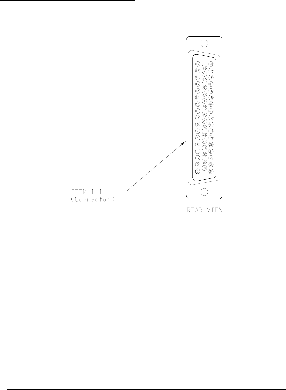
Honeywell
MK VI MK VIII EGPWS Installation Design Guide
Proprietary notice on title page applies
CAGE CODE: 97896 SCALE: NONE SIZE: A DWG NO: 060-4314-150 REV: SHEET 33
INSTALLATION ASSEMBLY SEQUENCE
STEP 1 Install all MK VI/MK VIII system aircraft wiring to this connector using items 1.2 (Crimp
Contacts) and item 1.1 (Connector). See figure 2.1-1 below.
FIGURE 2.1-1 MK VI/MK VIII EGPWS CONFIGURATION MODULE
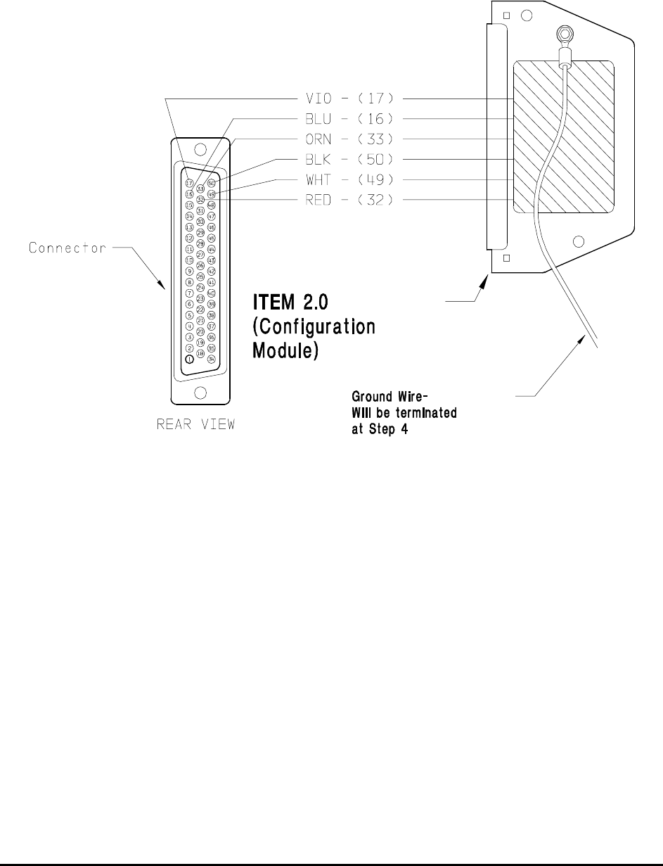
Honeywell
MK VI MK VIII EGPWS Installation Design Guide
Proprietary notice on title page applies
CAGE CODE: 97896 SCALE: NONE SIZE: A DWG NO: 060-4314-150 REV: SHEET 34
STEP 2 Wire item 2.0 (Configuration Module). This part will replace item 1.4 (Backshell plate). Install
the pre-crimped colored wires into item 1.1 (Connector) as shown in figure 2.1-2 below.
FIGURE 2.1-2 MK VI/MK VIII EGPWS CONFIGURATION MODULE

Honeywell
MK VI MK VIII EGPWS Installation Design Guide
Proprietary notice on title page applies
CAGE CODE: 97896 SCALE: NONE SIZE: A DWG NO: 060-4314-150 REV: SHEET 35
STEP 3 Position item 1.7 (Slide lock) onto wired connector as shown in figure 2.1-3 below:
FIGURE 2.1-3 MK VI/MK VIII EGPWS CONFIGURATION MODULE
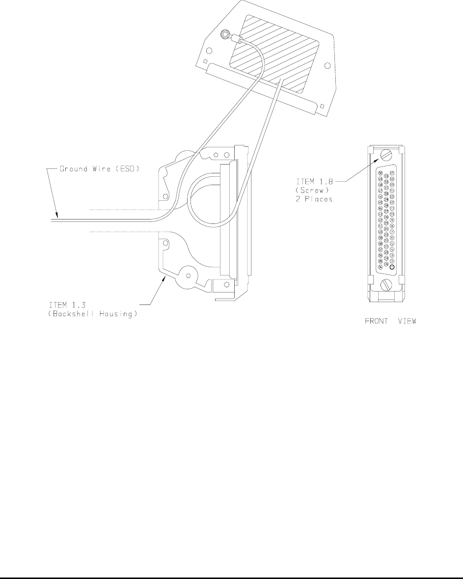
Honeywell
MK VI MK VIII EGPWS Installation Design Guide
Proprietary notice on title page applies
CAGE CODE: 97896 SCALE: NONE SIZE: A DWG NO: 060-4314-150 REV: SHEET 36
STEP 4 Install item 1.3 (Backshell Housing) onto connector using item 1.8 (Screws) as shown in figure
2.1-4 below:
Ground Wire (used for electrostatic discharge {ESD} protection) is terminated with shielded
pigtails of wires at this connector.
FIGURE 2.1-4 MK VI/MK VIII EGPWS CONFIGURATION MODULE

Honeywell
MK VI MK VIII EGPWS Installation Design Guide
Proprietary notice on title page applies
CAGE CODE: 97896 SCALE: NONE SIZE: A DWG NO: 060-4314-150 REV: SHEET 37
STEP 5 Install item 1.6 (Spring Clip) as shown figure 2.1-5 below:
FIGURE 2.1-5 MK VI/MK VIII EGPWS CONFIGURATION MODULE
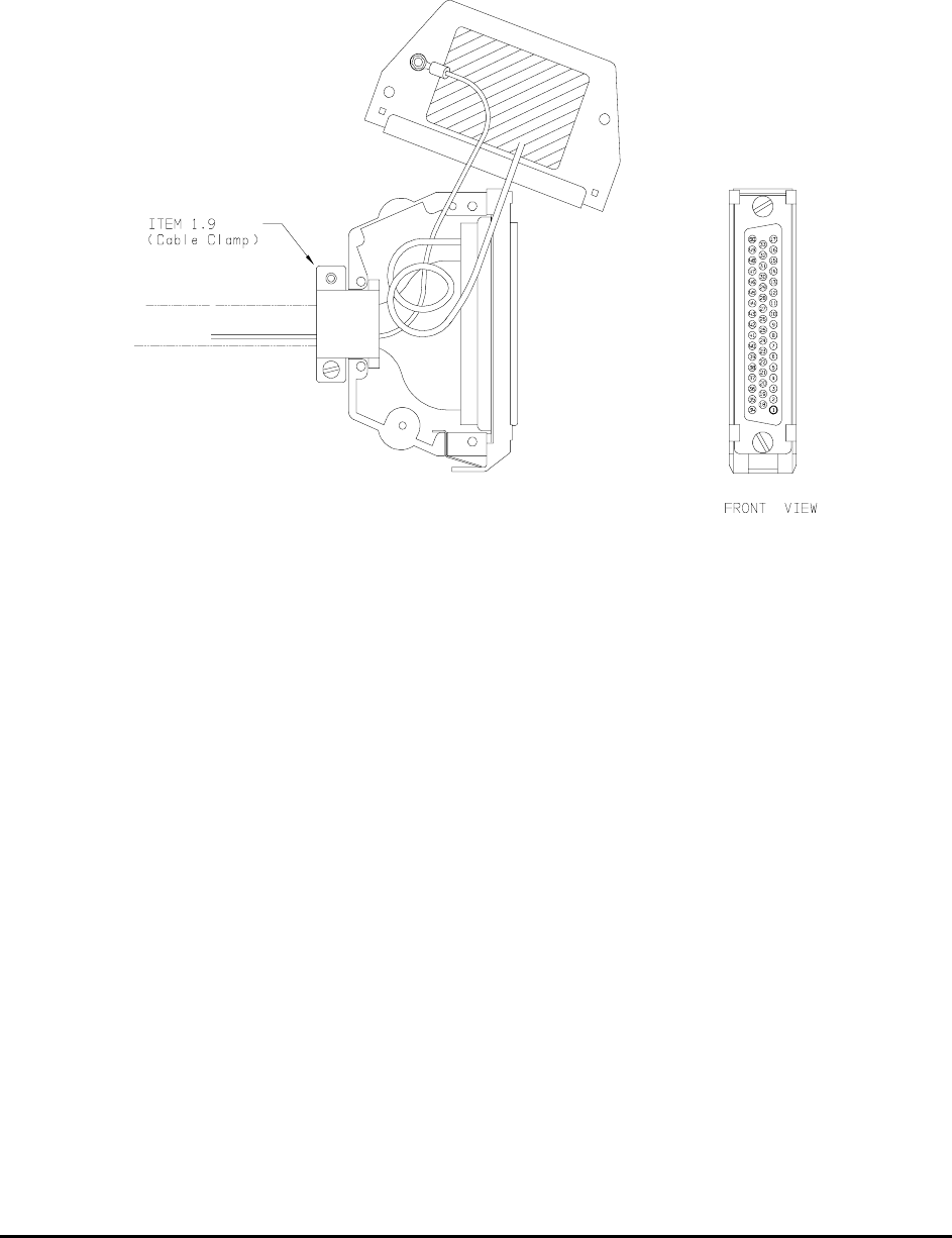
Honeywell
MK VI MK VIII EGPWS Installation Design Guide
Proprietary notice on title page applies
CAGE CODE: 97896 SCALE: NONE SIZE: A DWG NO: 060-4314-150 REV: SHEET 38
STEP 6 Organize and dress wiring exiting from backshell. Route Configuration Module wires exiting
from connector, then coil as shown in figure 2.1-6 below. Install item 1.9 (Cable Clamp) as
shown. Do not tighten screws yet.
FIGURE 2.1-6 MK VI/MK VIII EGPWS CONFIGURATION MODULE

Honeywell
MK VI MK VIII EGPWS Installation Design Guide
Proprietary notice on title page applies
CAGE CODE: 97896 SCALE: NONE SIZE: A DWG NO: 060-4314-150 REV: SHEET 39
STEP 7 Secure Configuration Module to connector assembly using item 1.5 (Screws) as shown in figure
2.1-7 below. Tighten Cable Clamp screws as required.
FIGURE 2.1-7 MK VI/MK VIII EGPWS CONFIGURATION MODULE

Honeywell
MK VI MK VIII EGPWS Installation Design Guide
Proprietary notice on title page applies
CAGE CODE: 97896 SCALE: NONE SIZE: A DWG NO: 060-4314-150 REV: SHEET 40
2.3.6 GPS Anten na location
The GPS antenna should be mounted on top of the fuselage in the centerline of the aircraft. Avoid mounting the
antenna near any projections, the propeller, and the T-tail of the aircraft, where shadows could occur. It is
recommended that there be a separation of at least 3 feet between the GPS antenna and any VHF Comm
antenna on the aircraft. The GPS antenna baseplate must be level within ± 5° in both axis when the aircraft is
level (level is defined as the aircraft attitude required when weighing the aircraft for weight and balance). If the
GPS antenna is tilted more than 5° or is mounted close to other objects that shadow it, loss of some of the
satellites will occur and system performance degraded. See manufacturer for specifications of GPS antennas.
Some GPS Antenna cable and connector information, including vendor information, is listed below.
Cable Length Cable Part
Number (VPN)
EGPWS TNC
Connector (VPN)
Antenna TNC
Connector (VPN)
Max Loss*
0 to 40 ft RG142B/U
RG400/U
TED Mfg. 5-10-30 TED Mfg. 5-30-102-1 8.0
0 to 80 ft ECS 311601 TED Mfg. 5-10-307 TED Mfg. 5-10-307 8.0
0 to 100 ft ECS 311201 TED Mfg. 5-10-306 TED Mfg. 5-10-306 8.0
100 to 165 ft Contact TED, ECS or PIC for complete cable/connector assembly
* Maximum Allowable Loss (dB) @ 1575 MHz for cable and connector using nominal 26.5 dB gain.
TED Manufacturing Corp.
11415 Johnson Drive
Shawnee, Kansas 66203
Tel: (913) 631-6211
Electronic Cable Specialists (ECS)
5300 W. Franklin drive
Franklin, Wisconsin 53132
Tel: (800) 327-9473
PIC Wire & Cable
N63 W 22619 Main Street
Sussex, Wisconsin 53089
Tel: (800) 742-3191
2.3.7 GPS Anten na Installation
Refer to manufacturer’s procedures or applicable STC documentation.
2.3.8 OAT Senso r Location
The OAT sensor should be mounted on the underside (belly) of the aircraft or other convenient location meeting
the following conditions. Avoid mounting the sensor where it can be affected by direct sunlight, or exhaust gases
from engines or heaters. The probe tip should extend beyond the aircraft boundary layer into the turbulent
airflow. See manufacturer for specifications.
2.3.9 OAT Senso r Installation
Refer to manufacturer’s procedures or applicable STC documentation.
2.3.10 Cockpit Lig hts
This section provides information for selecting, locating and mounting of the MK VI and MK VIII EGPWS Cockpit
lights. NOTE: The nomenclature given for each lamp is an example only. Other manufacturers use
nomenclature that is also acceptable.

Honeywell
MK VI MK VIII EGPWS Installation Design Guide
Proprietary notice on title page applies
CAGE CODE: 97896 SCALE: NONE SIZE: A DWG NO: 060-4314-150 REV: SHEET 41
NOTE: All lights
1. Refer to Honeywell Product Specification 965-1176-601 for additional information and for electrical
loads specification.
2. All lights are +28 VDC, dual bulb, sun light readable, non-flashing.
3. In the “OFF” condition, all lights have dark background with visible nomenclature for action.
4. If desired the lights may be put on a “dimmer” circuit for night operation.
2.3.10.1 Description
EGPWS alert/warning (Lamp Format 1) GPWS P/TEST
This assembly is illuminated with red background and activated during any Mode 1 through Mode 4, and Terrain
Awareness alert or warning. This assembly also includes a momentary switch that will activate EGPWS Self
Test.
EGPWS warning (Lamp Format 2) PULLUP P/TEST
This assembly is illuminated with red background and activated during any Mode 1, Mode 2, or Terrain
Awareness PullUp warning. This assembly also includes a momentary switch that will activate EGPWS Self
Test.
GLIDESLOPE alert (Lamp Format 1) BELOW G/S P/CANCEL
This assembly is illuminated with amber background and activated during any Mode 5 alert. This assembly also
includes a momentary switch that will de-activate (cancel) EGPWS Mode 5 alerts during backcourse or low
altitude approaches.
EGPWS caution (Lamp Format 2) GPWS G/S CANCEL
This assembly is illuminated with amber background and activated during any EGPWS alert (non-Pullup). This
assembly also includes a momentary switch that will de-activate (cancel) EGPWS Mode 5 alerts during
backcourse or low altitude approaches.
Glideslope Canceled G/S CANCLD (optional but recommended)
This assembly is illuminated with white, blue or amber background and activated after the flight crew has
initiated the manual cancel of Mode 5 by pressing the BELOW G/S – P/CANCEL light/switch described above.
EGPWS Flap Override GPWS FLAP OVRD (optional but recommended)
This guarded light/switch assembly is illuminated with blue background and activated after the flight crew has
initiated the manual selection of the GPWS Flap Override feature. This assembly also includes a momentary
switch that will activate GPWS Flap Override. Note: the light color may also be white background with black
legend or black background with white legend. Colors are per FAR 23.1322.
GPWS system validity GPWS INOP
This assembly is illuminated with amber background and activated during any detected partial or total failure of
the GPWS modes 1-5.
TERRAIN select TERR DISPLAY ON

Honeywell
MK VI MK VIII EGPWS Installation Design Guide
Proprietary notice on title page applies
CAGE CODE: 97896 SCALE: NONE SIZE: A DWG NO: 060-4314-150 REV: SHEET 42
This assembly is illuminated with white background and activated after the flight crew has initiated the manual
selection of the EGPWS terrain display for the associated cockpit display. This assembly also includes a
momentary switch that will activate EGPWS Terrain display feature.
TERRAIN inhibit TERR INHIBIT ON
This assembly is illuminated with amber background and activated after the flight crew has initiated the manual
inhibit of the EGPWS Terrain Awareness & display and Terrain Clearance Floor functions during an approach to
an airport not in the EGPWS Terrain/Runway database. This assembly also includes a alternate action switch
that will inhibit EGPWS TA&D and TCF functions.
TERRAIN system validity TERR FAIL
This assembly is illuminated with amber background and activated during any detected partial or total failure of
the TA&D or TCF functions.
2.3.10.2 Location
Cockpit layout, size and operator’s preference will determine if only one set of lights is used (i.e., mounted in the
center), or if dual sets of lights are used (one set on each side), or a combination thereof is desired. For a typical
example of cockpit light locations refer to Figure 2-3. For panel cutouts and assembly options see the
manufacturer’s specifications. The following are recommended locations:
GPWS & BELOW G/S or PULLUP & GPWS
These lights should be located together and in the flight crew’s “primary field of view”. This would include either
the instrument panel or the edge of the glareshield.
GPWS FLAP OVRD -Optional-
This light should be located in the flight crew’s “field of view” and within reach of both crew members. This
light/switch may be located in an assembly with the GPWS and BELOW G/S lights and/or other EGPWS
annunciators.
GPWS CANCLD -Optional-
If used, this light should be located within at least one crew member’s “field of view”.
GPWS INOP
This light should be located within at least one crew member’s “field of view” or with other system INOP lights of
similar importance. It is recommended that this light not be located in the flight crew’s “primary field of view”. The
reason being that in the event of a GPWS system failure at the beginning of a flight, this light will remain “ON”
until the problem is fixed. This light may be combined with the TERR FAIL light.
TERR DISPLAY ON
This light should be located near the associated cockpit display, in the flight crew’s “field of view” and within
reach of one or both crew members. This light/switch may be located in an assembly with the TERR INHIBIT
light(s) and/or other EGPWS annunciators.
TERR INHIBIT ON
This light should be located in the flight crew’s “field of view” and within reach of both crew members. This
light/switch may be located in an assembly with the TERR DISPLAY light(s) and/or other EGPWS annunciators.
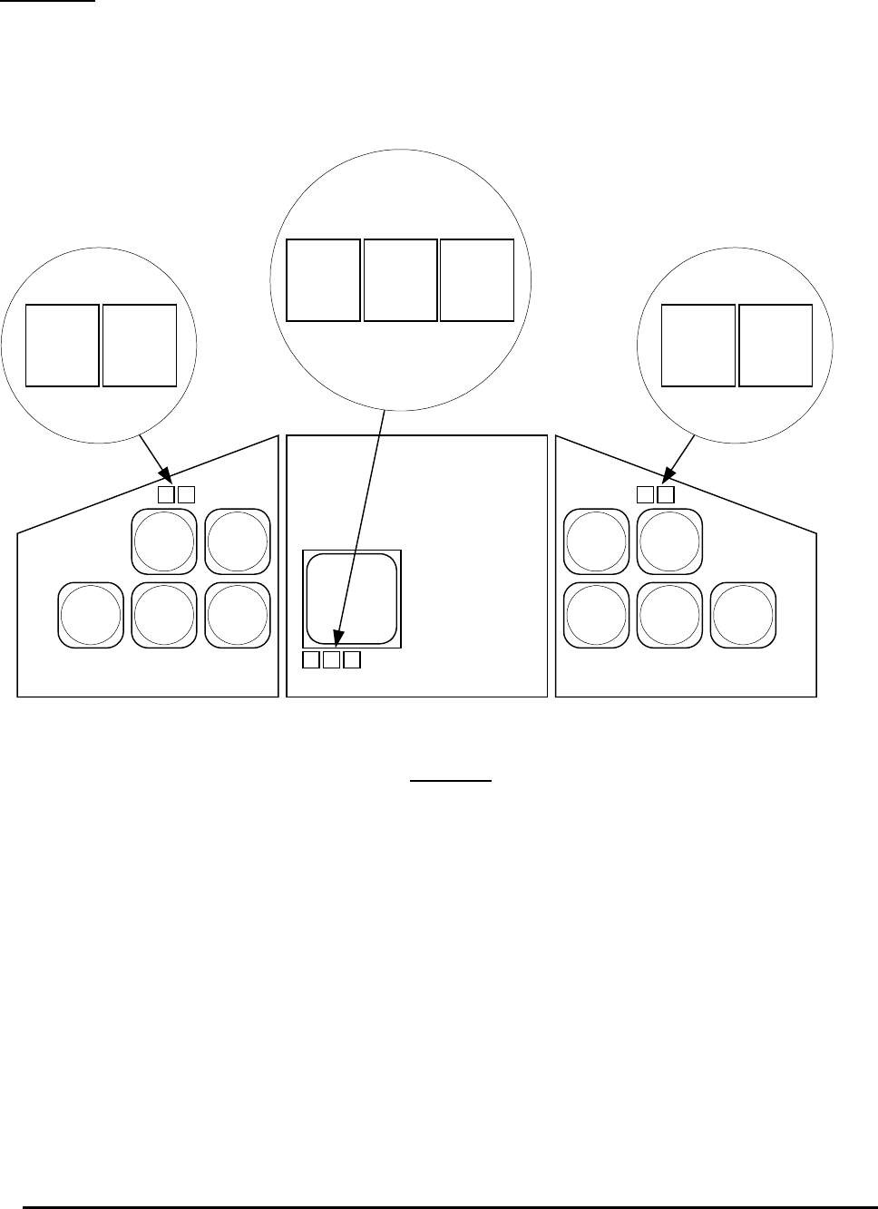
Honeywell
MK VI MK VIII EGPWS Installation Design Guide
Proprietary notice on title page applies
CAGE CODE: 97896 SCALE: NONE SIZE: A DWG NO: 060-4314-150 REV: SHEET 43
TERR FAIL
This light should be located within at least one crew member’s “field of view” or with other system INOP lights of
similar importance. Note: Annunciators are available with split legend GPWS FAIL / TERR FAIL in one
assembly. It is recommended that this light not be located in the flight crew’s “primary field of view”. The reason
being that in the event of a GPWS system failure at the beginning of a flight, this light will remain “ON” until the
problem is fixed.
Figure 2.3
PULLUP
GPWS
PULLUP
GPWS
TERR
ON
TERR
INHB
TERR
FAIL
The above picture is an example of lamp location and
does not restrict lamp location or format
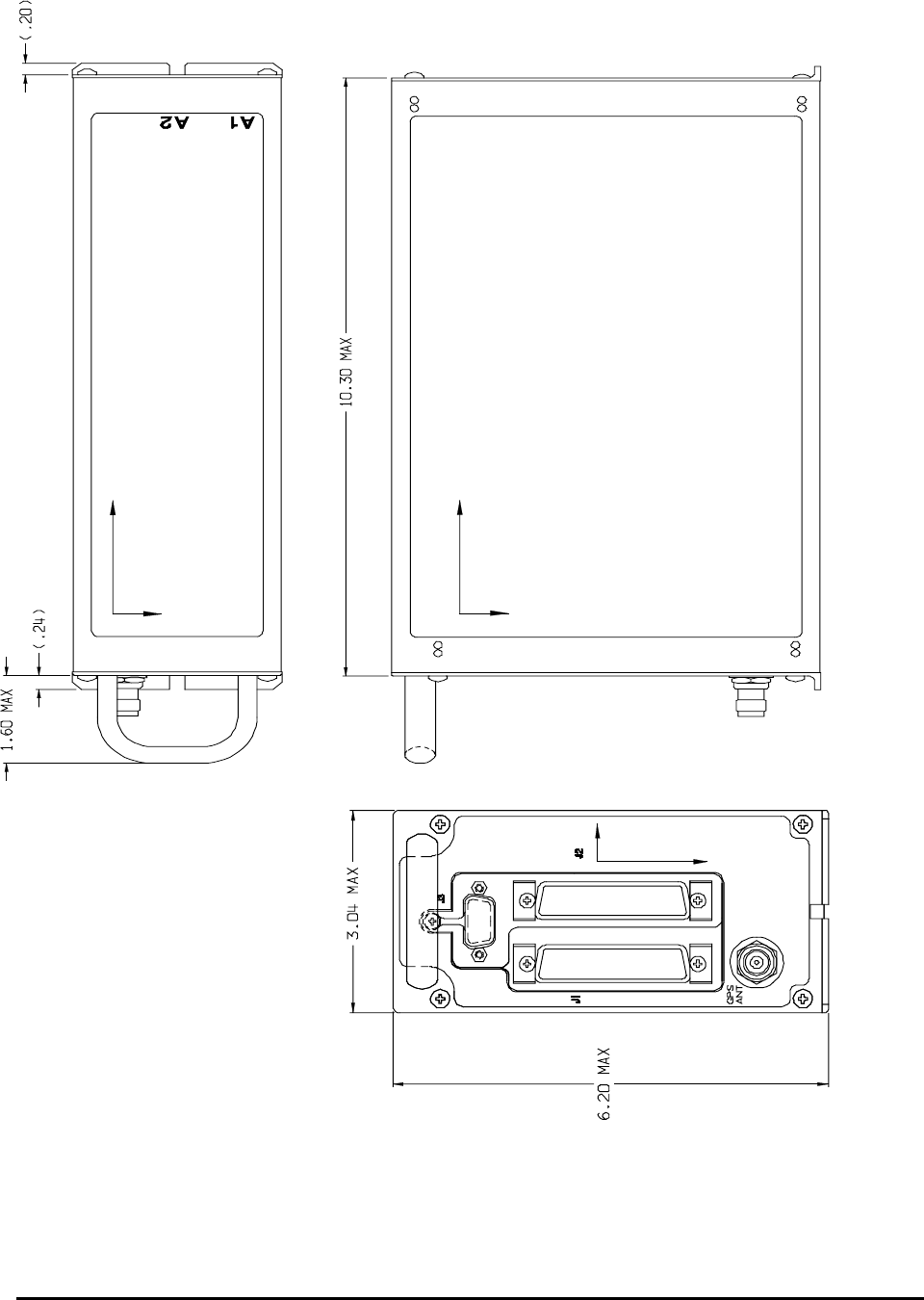
Honeywell
MK VI MK VIII EGPWS Installation Design Guide
Proprietary notice on title page applies
CAGE CODE: 97896 SCALE: NONE SIZE: A DWG NO: 060-4314-150 REV: SHEET 44
FIGURE 2-2 MK VI/MK VIII EGPWS OUTLINE
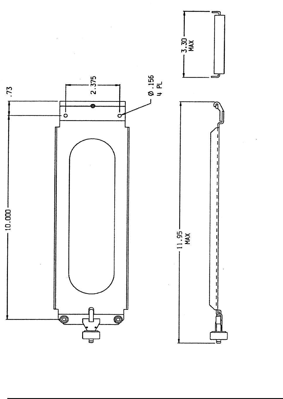
Honeywell
MK VI MK VIII EGPWS Installation Design Guide
Proprietary notice on title page applies
CAGE CODE: 97896 SCALE: NONE SIZE: A DWG NO: 060-4314-150 REV: SHEET 45
FIGURE 2-3 MK VI/MK VIII EGPWS MOUNTING TRAY

Honeywell
MK VI MK VIII EGPWS Installation Design Guide
Proprietary notice on title page applies
CAGE CODE: 97896 SCALE: NONE SIZE: A DWG NO: 060-4314-150 REV: SHEET 46
THIS PAGE INTENTIONALLY LEFT BLANK

Honeywell
MK VI MK VIII EGPWS Installation Design Guide
Proprietary notice on title page applies
CAGE CODE: 97896 SCALE: NONE SIZE: A DWG NO: 060-4314-150 REV: SHEET 47
SECTION III
SYSTEM PLANNING

Honeywell
MK VI MK VIII EGPWS Installation Design Guide
Proprietary notice on title page applies
CAGE CODE: 97896 SCALE: NONE SIZE: A DWG NO: 060-4314-150 REV: SHEET 48
SECTION III – SYSTEM PLANNING
SECTION III – SYSTEM PLANNING..............................................................................................................................51
3.1 INTRODUCTION.............................................................................................................................................................. 51
3.2 SYSTEM WIRING/ ELECTRICAL INTERFACES ................................................................................................................. 51
3.2.1 Primary Power Input.............................................................................................................................................51
3.2.2 Chassis Ground .....................................................................................................................................................52
3.2.3 GPS Antenna .........................................................................................................................................................52
3.2.4 Analog and Digital Inputs .....................................................................................................................................52
3.2.5 Discrete Inputs ......................................................................................................................................................52
3.2.6 Serial Outputs........................................................................................................................................................52
3.2.7 Audio Output .........................................................................................................................................................53
3.2.8 Discrete Outputs....................................................................................................................................................53
3.2.9 Configuration Module ...........................................................................................................................................53
3.3 CATEGORY 1 - AIRCRAFT / MODE TYPE SELECT.......................................................................................................... 54
3.3.1 Aircraft / Mode Type .............................................................................................................................................54
3.3.2 Mode 1 type ...........................................................................................................................................................54
3.3.3 Mode 2 type ...........................................................................................................................................................54
3.3.4 Mode 3 type ...........................................................................................................................................................55
3.3.5 Mode 4 type ...........................................................................................................................................................55
3.3.6 Bank Angle Type....................................................................................................................................................55
3.3.7 Runway Length (MK VIII EGPWS only) ...............................................................................................................56
3.3.8 Instructions............................................................................................................................................................56
3.4 CATEGORY 2 – AIR DATA INPUT SELECT...................................................................................................................... 57
3.4.1 Analog (Cat. 2 ID 0, 3, 4, 11, 12)..........................................................................................................................57
3.4.2 Digital – ARINC 429 (Cat. 2 ID 5, 1, 6, 13)..........................................................................................................59
3.4.3 Digital –ARINC 575 (Cat. 2 ID 2).........................................................................................................................60
3.4.4 Shadin 2000 (Cat. 2 ID 10) ...................................................................................................................................61
3.4.5 Digital – ARINC 429 Dual IOC Buses (Cat. 2. ID 255)........................................................................................62
3.4.6 Instructions............................................................................................................................................................62
3.5 CATEGORY 3 – POSITION INPUT SELECT ....................................................................................................................... 63
3.5.1 ARINC 743 Format ...............................................................................................................................................63
3.5.2 GPS Altitude (Label 076) Reference .....................................................................................................................63
3.5.3 North-South East-West Velocity labels..................................................................................................................63
3.5.4 ARINC 429 BUS (Cat. 3 ID 0,1,4,5,10-13) ...........................................................................................................64
3.5.5 RS-232 Transmit-Receive, 9600 baud (Cat. 3 ID 3)..............................................................................................65
3.5.6 Dual ARINC 429 BUS (Cat. 3 ID 253 & 255).......................................................................................................66
3.5.7 Instructions............................................................................................................................................................66
3.6 CATEGORY 4 – ALTITUDE CALLOUTS ........................................................................................................................... 67
3.7 CATEGORY 5 – AUDIO MENU SELECT........................................................................................................................... 68
3.7.1 Audio Menu Selection............................................................................................................................................68
3.7.2 Instructions............................................................................................................................................................68
3.8 CATEGORY 6 – TERRAIN DISPLAY SELECT ................................................................................................................... 69
3.8.1 TAD & TCF Selection ...........................................................................................................................................69

Honeywell
MK VI MK VIII EGPWS Installation Design Guide
Proprietary notice on title page applies
CAGE CODE: 97896 SCALE: NONE SIZE: A DWG NO: 060-4314-150 REV: SHEET 49
3.8.2 Terrain Display Configuration Group ..................................................................................................................70
3.8.3 Display Input Control Group ................................................................................................................................70
3.8.4 Output 429 Bus Group ..........................................................................................................................................71
3.8.5 Instructions............................................................................................................................................................71
3.8.6 Sample Display Schematics...................................................................................................................................71
3.9 CATEGORY 7 – OPTIONS SELECT GROUP #1 ................................................................................................................. 88
3.9.1 Steep Approach .....................................................................................................................................................88
3.9.2 TA&D Alternate Pop-up........................................................................................................................................88
3.9.3 Peaks Mode ...........................................................................................................................................................88
3.9.4 Obstacle Awareness ..............................................................................................................................................88
3.9.5 Bank Angle Callout Enabling................................................................................................................................89
3.9.6 Flap Reversal ........................................................................................................................................................89
3.9.7 GPS Altitude Reference.........................................................................................................................................89
3.9.8 Instructions............................................................................................................................................................90
3.10 CATEGORY 8 – RADIO ALTITUDE INPUT SELECT ........................................................................................................ 91
3.10.1 Radio Altitude Input ............................................................................................................................................91
3.10.2 Decision Height Discrete Input ...........................................................................................................................91
3.10.3 Digital Radio Altitude Interface (Cat. 8 ID 2).....................................................................................................91
3.10.4 Analog Radio Altitude Interface (Cat. 8 ID 0,1,3,4)............................................................................................92
3.10.5 Digital – ARINC 429 Dual IOC Buses (Cat. 8 ID 251- 255) ..............................................................................92
3.10.6 Instructions..........................................................................................................................................................93
3.11 CATEGORY 9 – NAVIGATION INPUTS SELECT ............................................................................................................. 94
3.11.1 Navigation Inputs Select (Glideslope & Localizer Inputs)..................................................................................94
3.11.2 Glideslope Validity ..............................................................................................................................................94
3.11.3 Localizer Validity ................................................................................................................................................94
3.11.4 ILS Tuned Discrete Input #1 (+28V) and #2 (GND)...........................................................................................94
3.11.5 Analog Glideslope Interface (Cat. 9 ID 0,1,5) ....................................................................................................95
3.11.6 Digital Glideslope / Localizer / ILS Select Interface (Cat. 9 ID 2,3,4) ...............................................................96
3.11.7 Digital – ARINC 429 Dual IOC buses (Cat. 9 ID 250 - 255)..............................................................................96
3.11.8 Instructions..........................................................................................................................................................97
3.12 CATEGORY 10 – ATTITUDE INPUT SELECT.................................................................................................................. 98
3.12.1 Roll Angle............................................................................................................................................................98
3.12.2 Analog Pitch & Roll Angle (Synchro) (Cat. 10 ID 0,2,4)....................................................................................98
3.12.3 Digital Pitch & Roll Angle (ARINC 429 High Speed) (Cat. 10 ID 5 & 6) ..........................................................99
3.12.4 Digital – ARINC 429 Dual IOC buses (Cat. 10 ID 253 & 255) ..........................................................................99
3.12.5 Instructions..........................................................................................................................................................99
3.13 CATEGORY 11 – HEADING INPUT SELECT ................................................................................................................. 100
3.13.1 Magnetic Heading .............................................................................................................................................100
3.13.2 Analog Heading (Synchro) (Cat. 11 ID 0).........................................................................................................100
3.13.3 Digital – ARINC 429 AHRS Input (Cat. 11 ID 2 & 3).......................................................................................101
3.13.4 Digital – ARINC 429 Dual IOC buses (Cat. 11 ID 254 & 255) ........................................................................101
3.13.5 Instructions........................................................................................................................................................101
3.14 CATEGORY 12 – WINDSHEAR INPUT SELECT ............................................................................................................ 102
3.14.1 No Windshear....................................................................................................................................................102

Honeywell
MK VI MK VIII EGPWS Installation Design Guide
Proprietary notice on title page applies
CAGE CODE: 97896 SCALE: NONE SIZE: A DWG NO: 060-4314-150 REV: SHEET 50
3.14.2 Dual ARINC 429 BUS (Cat. 14 ID 253,254,255)..............................................................................................102
3.14.3 Instructions........................................................................................................................................................102
3.15 CATEGORY 13 – INPUT / OUTPUT DISCRETE TYPE SELECT ....................................................................................... 103
3.15.1 Input Discretes ..................................................................................................................................................103
3.15.1.1 Glideslope Inhibit Discrete .............................................................................................................................................103
3.15.1.2 Landing Flaps Discrete ...................................................................................................................................................103
3.15.1.3 Audio Inhibit Discrete.....................................................................................................................................................104
3.15.1.4 Landing Gear Discrete ....................................................................................................................................................104
3.15.1.5 Glideslope Cancel Discrete .............................................................................................................................................106
3.15.1.6 Momentary Flap Override Discrete.................................................................................................................................106
3.15.1.7 Mode 6 Low Volume Discrete........................................................................................................................................106
3.15.1.8 Autopilot Engaged Discrete ............................................................................................................................................107
3.15.1.9 Terrain Awareness and TCF Inhibit Discrete..................................................................................................................107
3.15.1.10 Self Test Discrete ..........................................................................................................................................................107
3.15.1.11 Steep Approach Discrete #2..........................................................................................................................................108
3.15.1.12 GPWS INHIBIT Discrete (alternate action)..................................................................................................................108
3.15.2 Output Discretes................................................................................................................................................108
3.15.2.1 Lamp Format...................................................................................................................................................................109
3.15.2.2 Flashing Lamps...............................................................................................................................................................109
3.15.2.3 GPWS INOP Discrete .....................................................................................................................................................109
3.15.2.4 TAD INOP Discrete........................................................................................................................................................109
3.15.2.5 GPWS Warning Discrete ................................................................................................................................................109
3.15.2.6 GPWS Alert Discrete ......................................................................................................................................................110
3.15.2.7 Glideslope Cancel’d Discrete..........................................................................................................................................110
3.15.2.8 Flap Override Discrete ....................................................................................................................................................110
3.15.2.9 Steep Approach Discrete.................................................................................................................................................110
3.15.2.10 Audio On Discrete (TCAS/TAS Inhibit).......................................................................................................................110
3.15.2.11 Terrain Display Select #1 & #2 Discrete.......................................................................................................................111
3.15.2.12 Terrain Pop up Discrete ................................................................................................................................................112
3.15.3 Instructions........................................................................................................................................................113
3.16 CATEGORY 14 – AUDIO OUTPUT LEVEL ................................................................................................................... 113
3.16.1 Instructions........................................................................................................................................................113
3.17 CATEGORY 15 - 17 – UNDEFINED INPUT SELECTS .................................................................................................... 114
3.17.1 Undefined Input Select ......................................................................................................................................114
3.17.2 Instructions........................................................................................................................................................114
Honeywell
MK VI MK VIII EGPWS Installation Design Guide
Proprietary notice on title page applies
CAGE CODE: 97896 SCALE: NONE SIZE: A DWG NO: 060-4314-150 REV: SHEET 51
SECTION III – SYSTEM PLANNING
3.1 Introductio n
This section provides information for selecting features and wiring the electrical interfaces of the MK VI/MK VIII
EGPWS.
Appendix E Section 5.2 groups features (functions) into sets called Categories. This document follows the
Category structure of the Appendix E. It provides descriptions of the features and instructions for selecting
features and for determining the correct wiring.
Sample wiring diagrams for the most commonly used MK VI/MK VIII EGPWS configurations are provided in
Appendix B.
Make copies of Appendix E Table 5-2 to use for recording feature selections.
Section 6 provides a cross-reference between the MK VI GPWS (Classic) and the MK VI/MK VIII EGPWS
(Enhanced) interfaces.
3.2 System Wir ing/ Electrical Interfaces
System wiring is broken down into the following main components:
- Electrical Interfaces (power and ground)
- GPS Antenna
- Analog and Digital Inputs
- Discrete Inputs
- Serial Outputs
- Audio Outputs
- Discrete Outputs
- Configuration Module
Many of these inputs and outputs will be defined as the Categories are selected for Configuration Module
programming. Appendix E Table 8.1-1 shows the typical usage for each pin on the Left (J1), Right (J2) and
Upper (J3) connectors and provides a place for recording the actual usage for this installation.
3.2.1 Primary Po wer Input
The MK VI/VIII EGPWC requires a primary power input (28 VDC input power) and ground. The Primary power
should be connected as follows for the MK VI/VIII EGPWC.
Pin Signal *Pin pairs J1-40/J1-60 and
J1-40, J1-60 * +28 VDC Input J1-41/J1-61 are internally
J1-41, J1-61 * +28 VDC Return shorted to each other.
Recommended EGPWC Power Control Device: 3 Amp Delayed Action Circuit Breaker

Honeywell
MK VI MK VIII EGPWS Installation Design Guide
Proprietary notice on title page applies
CAGE CODE: 97896 SCALE: NONE SIZE: A DWG NO: 060-4314-150 REV: SHEET 52
3.2.2 Chassis Gr ound
Chassis ground provides a redundant metal connection and should not be used as a normal current carrying
conductor. Chassis ground should be connected as follows:
Pin Signal
J1-42, J1-53 GND
Pins J1-42 and J1-53 are both connected to chassis ground internally. It is not necessary to tie them both to
ground in the aircraft wiring. Pin J1-53 was made available to provide a convenient way to supply a ground to
external equipment. If the OAT probe is not present, nothing needs to be tied to J1-53.
3.2.3 GPS Anten na
A GPS antenna connector is available on the front of the MK VI EGPWS 965-1190-0XX and MK VIII EGPWS
965-1220-0XX. See Appendix E paragraphs 3.2.2 and 4.2.9 for connector details. The J1 connector backshell
supplied with classic MK VI GPWS installation kits can interfere with the GPS antenna connector for this reason
a new J1 backshell is supplied with MK VI-VIII installation kits.
3.2.4 Analog and Digital Inputs
The analog and digital inputs to the MK VI/VIII EGPWS are defined as the Categories are selected. Instructions
for documenting these interfaces are provided with the Category selection instructions.
3.2.5 Discrete Inp uts
The discrete inputs are defined in Appendix E Section 6.6. Additional information for some discretes is provided
within the Category in which they are used.
3.2.6 Serial Outp uts
The EGPWC provides for ARINC 453 and ARINC 429 serial outputs.
Terrain display data is output on two ARINC 453 channels when the Terrain Awareness display function is
enabled.
Low speed ARINC 429 output buses are provided by the EGPWC are described in Appendix E Section 7. The
ARINC 429 output data includes:
1. Internal data (data output for test purposes only such as internal logic booleans, Geometric Altitude, and
Terrain Clearance information).
2. Alert/Warning status (Voice and Lamp activity can be provided to display systems and flight recorders).
3. Internal mode status.
4. Terrain display messages for TAD cockpit integration.
Note: During EGPWS Self Test, the SSM of each output label is set to the Functional Test status code.

Honeywell
MK VI MK VIII EGPWS Installation Design Guide
Proprietary notice on title page applies
CAGE CODE: 97896 SCALE: NONE SIZE: A DWG NO: 060-4314-150 REV: SHEET 53
3.2.7 Audio Outp ut
The audio outputs consist of both an 8-ohm amplifier and a transformer isolated 600-ohm output. Audio output
messages are provided as specified in the selected Audio Menu (Category 5) when inputs are valid and the
audio inhibit discretes are not active.
When audio inhibit is enabled, the output discrete(s) associated with suppressed message(s) are active.
3.2.8 Discrete Ou tputs
The MK VI/MK VIII EGPWS provides for up to twelve 0.5 amp nominal (1 amp maximum) Ground/Open discrete
outputs. The discrete outputs are defined in Appendix E Section 4.2.11 and Category 13.
The discrete outputs are optional if the ARINC 429 output data is used for driving the alert/warning lamps via a
symbol generator. Most Aircraft Types do not use the ARINC 429 output data for lamp control. (This data is
typically sent to the Flight Data Recorder.)
All outputs to lamps are driven by solid state switches to ground. These outputs can also be used as discrete
drivers for other devices (e.g. terrain display switching). Output discretes are intended to operate with +28
VDC lamp sources and will not operate with +5 VDC lamp sources.
3.2.9 Configurati on Module
The EGPWS aircraft configuration is programmed into a configuration module installed in the aircraft wiring. This
Configuration Module is identified as Honeywell part number 700-1710-020. The configuration module is
installed as part of the P2 mating connector backshell and contains electrically reprogrammable memory for
configuration storage. By this method the aircraft configuration is stored in the configuration module on the
aircraft and each newly installed EGPWS computer does not require operator assisted programming before or
during installation. The aircraft configuration in the Configuration Module can be changed at any time by use of
the WinVIEWS software, as explained in Section 4.

Honeywell
MK VI MK VIII EGPWS Installation Design Guide
Proprietary notice on title page applies
CAGE CODE: 97896 SCALE: NONE SIZE: A DWG NO: 060-4314-150 REV: SHEET 54
3.3 Category 1 - Aircraft / Mode Type Select
Category 1 specifies the general aircraft type, warning mode differences, bank angle alert curve, fixed or
retractable gear, and 3500 ft or 2000 ft min runway length (as an option for MK VIII EGPWS only).
Appendix E Tables 5.2 and 5.3.1 include some information required by MK VI/MK VIII EGPWS development
personnel and not pertinent to the installation design process. Only items relevant to the installation design
process are discussed in this document.
3.3.1 Aircraft / M ode Type
The Aircraft Type identifies the aircraft as GA Fast (Turboprop), GA Slow (Turboprop), or Bizjet (Turbofan). The
aircraft category defines configurable airspeed limits for mode expansion and gear and flaps stuck down
conditions (reasonable test) and also define the Mode 1, 2, 3, 4, & Bank Angle warning/alert curve options.
The MK VI EGPWS only supports aircraft types 0,1,2,3,4 that are designed for turboprop aircraft (and emulate
the mode curves of the MK VI GPWS). The MK VIII EGPWS has Aircraft types 254 & 255 that are designed for
turbofan aircraft (and emulate the mode curves of the MK V GPWS), along with aircraft types 0,1,2,3,4. Modes
1,2,3,&4 are different between these aircraft types. For reference compare the mode 1-4 turbofan curves to the
turboprop curves in the MK VI/VIII EGPWS Product Specification 965-1180-601.
Appendix E Table 5.3.1 lists the combinations of Aircraft/Mode Types, identifies the first MK VI/MK VIII EGPWS
version in which the option was available (see the Effectivity entry), and describes the options available with
each Aircraft/Mode type (see Description column).
3.3.2 Mode 1 typ e
Two Mode 1 alert curves are defined, GA (Turboprop) and Bizjet (Turbofan). The lower boundary of the GA
Mode 1 curves is 50 feet, the same lower boundary is extended to 10 feet for Bizjet aircraft.
3.3.3 Mode 2 typ e
Two Mode 2 alert curves are defined, one for GA Fast & Bizjet and one for GA Slow. Mode 2A airspeed
expansion increases the Mode 2 expanded alert area linearly from 1650 feet to 2450 feet for airspeeds of 220
knots to 310 knots in GA Fast and Bizjet defined aircraft (same as MK V and MK VII EGPWS). Mode 2 airspeed
expansion occurs for airspeeds from 190 knots to 280 knots in GA Slow defined aircraft.
MODE 2 AIRSPEED EXPANSION
GA FAST (Turboprop) 220 knots to 310 knots
GA SLOW (Turboprop) 190 knots to 280 knots
BIZJET (Turbofan) 220 knots to 310 knots

Honeywell
MK VI MK VIII EGPWS Installation Design Guide
Proprietary notice on title page applies
CAGE CODE: 97896 SCALE: NONE SIZE: A DWG NO: 060-4314-150 REV: SHEET 55
3.3.4 Mode 3 typ e
Two Mode 3 alert curves are defined, GA (Turboprop) and Bizjet (Turbofan). The GA (Turboprop) Mode 3 curve
is equivalent to the (classic) MK VI Mode 3 curve. The Bizjet (Turbofan) Mode 3 curve is equivalent to the MK V
and MK VII EGPWS Mode 3 curves.
3.3.5 Mode 4 typ e
Mode 4A (Too Low Gear) expanded alert transition occurs at 178 knots for GA Fast aircraft, 148 knots for GA
Slow aircraft, and 190 knots for Bizjet aircraft. Mode 4B (Too Low Flaps) upper boundary has four defined
levels, 245 ft, 200 ft, 170 ft, and 150 ft. The 245 ft boundary is added to emulate the MK V, VII Mode 4B
boundary. The 200 ft boundary is added to emulate the MK II Mode 4B boundary. The 150 ft boundary
(Alternate Mode 4B) is for those aircraft types that routinely delay full flap deployment. All other aircraft types
would use the 170 ft boundary (Normal Mode 4B). For aircraft with previously installed (classic) MK VI GPWS,
the Normal / Alternate Mode 4B correspond to the “Alternate Mode 4B” program pin (J1-25).
The following table compares Mode 4 boundaries for each
Boundaries Mode 4
Aircraft type /
Alternate Mode 4B
Mode 4A Gear Down
at 500 ft, < X knots
Mode 4B Flaps Down
feet / < X knots
Mode 4 A/B
Maximum
A/B
Type
GA Fast, Normal Mode 4B 178 knots 170 ft / 150 knots 750 ft 6
GA Fast, Alternate Mode 4B 178 knots 150 ft / 148 knots 750 ft 8
GA Slow, Normal Mode 4B 148 knots 170 ft / 120 knots 1750 ft 7
GA Slow, Alternate Mode 4B 148 knots 150 ft / 118 knots 1750 ft 9
GA Fast, MK II emulation 178 knots 200 ft / 148 knots 1000 ft 5
Bizjet, MK V, VII emulation 190 knots 245 ft / 159 knots 1000 ft 1
NOTE 1: Some installations that have chosen the GA SLOW aircraft type have found during flight test that the
aircraft can not (or does not) slow to less than 120 knots on normal approach. Thus the installation is
prone to nuisance TOO LOW TERRAIN alerts. These installations should choose the GA FAST
aircraft type.
3.3.6 Bank Angle Type
Two Bank Angle callout curves are defined, GA (Turboprop) and Bizjet (Turbofan). Both Bank Angle callout
curves have an Autopilot Engaged warning area. The Bizjet (Turbofan) Bank Angle callout curve is equivalent to
the MK V and MK VII EGPWS Bank Angle callout curves when the autopilot is not engaged.
Aircraft Type Lower Cutoff Lower Boundary Upper Boundary Slope
GA (Turboprop) 10 ft 10 ft / 15° 210 ft / 50° 2450 ft / 50°
Bizjet (Turbofan) 5 ft 30 ft / 10° 150 ft / 40° 2450 ft / 55°

Honeywell
MK VI MK VIII EGPWS Installation Design Guide
Proprietary notice on title page applies
CAGE CODE: 97896 SCALE: NONE SIZE: A DWG NO: 060-4314-150 REV: SHEET 56
3.3.7 Runway Le ngth (MK VIII EGPWS only)
Two minimum runway length options are defined for Bizjet (Turbofan) aircraft. A 2000 ft minimum runway length
or a 3500 ft minimum runway length may be chosen based on aircraft type as is identified in Appendix E Table
5.3.1. This option does not effect the mode curves as discussed above, and it is only available on MK VIII
EGPWS.
3.3.8 Instruction s
Using Appendix E Tables 5.2 and 5.3.1 as described above, select the Aircraft/Mode Type that
matches the aircraft configuration, feature preferences and version (part number) being installed.
Step 1: Is the aircraft a turbofan? YES, goto Step 2.
NO, goto Step 3.
Step 2: Aircraft can operate from runways less than 3500’? YES, use ID 255
NO, use ID 254
Step 3: Landing speed is typically > 120 knots? YES, goto Step 4.
NO, goto Step 5.
Step 4: 200’ / 170’ / 150’ Flap alert preferred? 200’ use ID 2
170’ use ID 0
150’ use ID 1
Step 5: 170’ / 150’ Flap alert preferred? 170’ use ID 3
150’ use ID 4
Record the ID number for the Aircraft/Mode Type from Appendix E Table 5.3.1 under the Ident No.
heading for Step (Category) 1 in Appendix E Table 5.2.

Honeywell
MK VI MK VIII EGPWS Installation Design Guide
Proprietary notice on title page applies
CAGE CODE: 97896 SCALE: NONE SIZE: A DWG NO: 060-4314-150 REV: SHEET 57
3.4 Category 2 – Air Data Input Select
Category 2 defines the Air Data interface. The Air Data input currently defines 4 analog and 6 digital air data
types.
Appendix E Table 5.3.2 defines the Air Data interface options and identifies the first MK VI/MK VIII EGPWS
version in which the option was available (see the Effectivity entry).
Appendix E Tables 5.3.2-x, where x is the Air Data Type number, define the electrical interfaces required to
support each Air Data Type.
3.4.1 Analog (Ca t. 2 ID 0, 3, 4, 11, 12)
Air Data Type 0 (CIC 04077 or equivalent) uses Uncorrected Barometric Altitude input scaled from –1500 feet
(+5 volts) to +30,000 feet (+15 volts) (see Appendix E section 6.1.3). Baro Altitude Rate and Computed
Airspeed are not required. Baro Altitude Valid is standard +28 volt discrete. Total Air Temperature is from a
dedicated (EGPWS) 500-ohm probe using +5 volt excitation from the MK VI/MK VIII EGPWC.
Air Data Type 3 (ADS-65 or equivalent) uses Uncorrected Barometric Altitude input scaled from -1500 feet (-
0.18 volts) to +46,000 feet (+5.52 volts), zero volts equals zero feet (see Appendix E section 6.1.10). Baro
Altitude Rate and Computed Airspeed are not required. Baro Altitude Valid is standard +28 volt discrete. Total
Air Temperature is from a dedicated (EGPWS) 500-ohm probe using +5 volts excitation from the MK VI/MK VIII
EGPWC.
Air Data Type 4 (CIC 02702 or equivalent) uses Uncorrected Barometric Altitude input scaled from -1000 feet (-
0.244 volts) to +40,000 feet (+9.756 volts) (see Appendix E section 6.1.14). Baro Altitude Rate and Computed
Airspeed are not required. Baro Altitude Valid is standard +28 volt discrete. Total Air Temperature is from a
dedicated (EGPWS) 500-ohm probe using +5 volt excitation from the MK VI/MK VIII EGPWC.
Air Data Types 11 and 12 (AZ-241, AZ-242, AZ-800, AZ-810 or equivalent) uses Uncorrected Barometric
Altitude input scaled from -3750 feet ( 0 volts) to +50,000 feet (+10.75 volts) (see Appendix E section 6.1.16).
Baro Altitude Rate and Computed Airspeed are not required. Baro Altitude Valid is standard +28 volt discrete. ID
11 requires a dedicated (EGPWS) 500-ohm Total Air Temperature probe using +5 volt excitation from the MK
VI/MK VIII EGPWC. ID 12 is configured without a connection to outside air temperature with temperature set not
available. As a result, when using ID 12 the EGPWS calculation of Geometric Altitude will be less accurate than
using ID 11.
NOTE: The analog air data interface for the MK VI / MK VIII EGPWS uses a dedicated 500-ohm temperature
probe. This may be an unused element in a dual element probe but must not be paralleled with any
other system. The EGPWS provides the 5 volt excitation for the element.
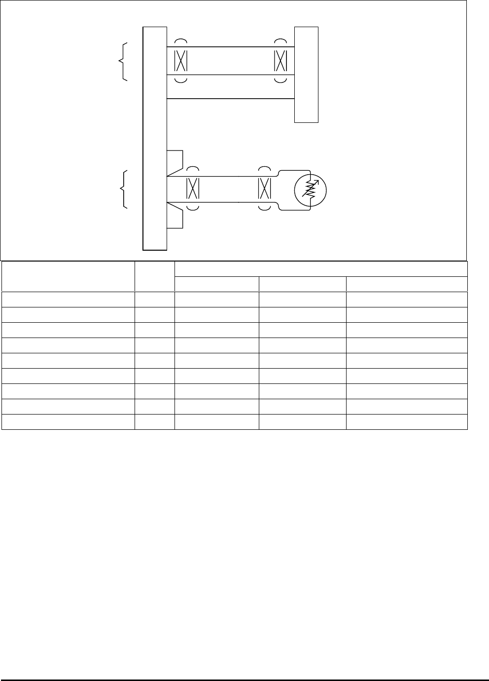
Honeywell
MK VI MK VIII EGPWS Installation Design Guide
Proprietary notice on title page applies
CAGE CODE: 97896 SCALE: NONE SIZE: A DWG NO: 060-4314-150 REV: SHEET 58
62
43
9
25
63
44
53
J1
Altitude Out
Signal Common
BIT Out
Analog Air Data ComputerEGPWS MK VI / MK VIII
(+)
(-)
Uncorrected
Barometric
Altitude
Baro Altitude Valid +28V
(+)
(-)
Temp. Input
Chassis Ground
+5V Excitation
500 ohm
Temperature
Probe
Analog-ADC.vsd
Cat 2 Uncorrected Baro Altitude 1
Vendor Model ID Altitude Out Common BIT Out
CIC 04077 0 J1-F J1-G J1-E
Collins ADS-65 3 J1-12 J1-13 J1-5
CIC 02702 4 J1-A J1-B J1-E
Honeywell AZ-241 11/122J1A-63 J1A-11 (CGND) J1A-12
Honeywell AZ-242 411/122J1B-174J1A-11 (CGND) J1A-12
Honeywell AZ-648 11/122J1-J J1-G J1-U
Honeywell AZ-800311/122J1A-78 J1A-10 (CGND) J1A-34
Honeywell AZ-810311/122J1A-78 J1A-10 (CGND) J1A-34
Honeywell AZ-252 11/122J1A-17 J1A-10 (CGND) J1A-34
NOTES:
1 The connector pin numbers given in the Table above are to the best knowledge of Honeywell EGPWS engineering. Please
contact the manufacturer’s customer service to confirm your installation.
2 ID 12 does not require an OAT input, instead a constant temperature of 25 deg C is assumed.
3 Honeywell AZ-810 should only be used as an analog source if it does not have a digital interface.
4 Honeywell AZ-242 with part numbers 4013242-708, -709, -710, -712, -713 and –742 have DC Altitude out at pin J1B-17. Part
numbers 4013242-709 and -711 have DC Altitude out at pin J1A-40.
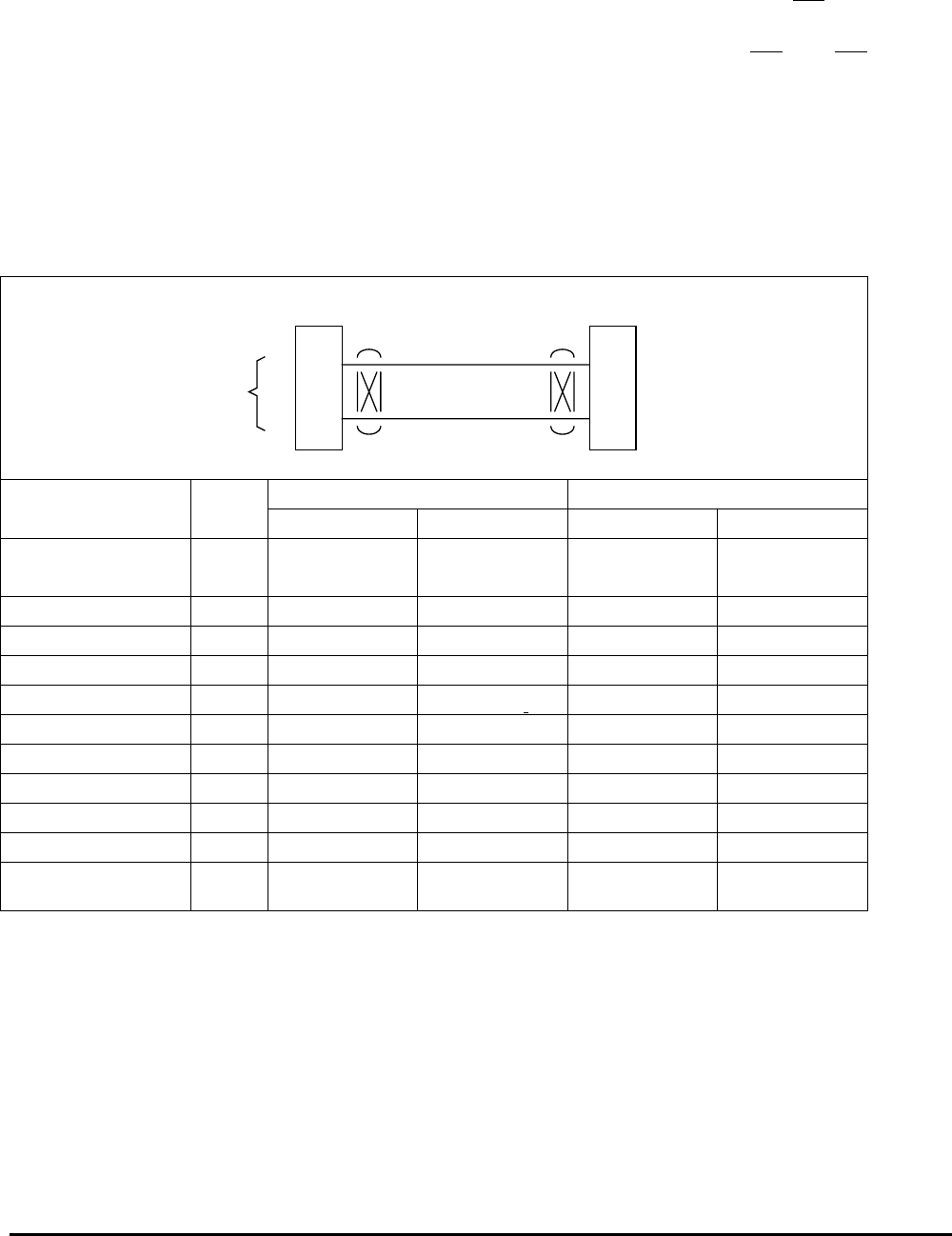
Honeywell
MK VI MK VIII EGPWS Installation Design Guide
Proprietary notice on title page applies
CAGE CODE: 97896 SCALE: NONE SIZE: A DWG NO: 060-4314-150 REV: SHEET 59
3.4.2 Digital – AR INC 429 (Cat. 2 ID 5, 1, 6, 13)
Air Data Type 1 is a low speed, digital ARINC 429 signal having the air data labels 203, 206, 212, and 213.
Air Data Type 5 is a low speed, digital ARINC 429 signal having the air data labels 203, 204, 206, 212, and 213.
Air Data Type 6 is a low speed, digital ARINC 429 signal having the air data labels 203, 206, and 213.
Air Data Type 13 is a low speed, digital ARINC 429 signal having the air data label 203 only.
If the hardware is capable of transmitting all label sets, the preferred Air Data Type is 5. If only label 204 is
missing, use Air Data Type 1, and if both labels 204 and 212 are missing use Air Data Type 6. Some aircraft
have only label 203 available (or no temperature) for those choose Air Data Type 13.
39
38
A
B
J2 ARINC 429 Air Data
ARINC 429 Bus - Hi
ARINC 429 Bus - Lo
EGPWS MK VI / MK VIII
A
B
ARINC 429 Low Speed
Air Data Bus
Digital-ADC.vsd
Cat 2 Bus 1 Bus 2
Vendor Model ID A B A B
Honeywell AZ-6XX,
AZ-8XX
5* J1B-26 J1B-27 J1B-70 J1B-71
CIC 04471 5* J1-12 J1-13
CIC 02702 mod 6 * J2-J J2-K
KDC 281 * P2811-5 P2811-6
KDC 481 * P4811-U P4811- i
B&D 90004 5* J1-27 J1-9
B&D 2600 6** 6 8
B&D 2601 6** 14 13
B&D 2800 * P201-11 P201-28
Collins ADC 85/86 5* P2-9 P2-10 P2-29 P2-30
Shadin ADC-2000
(s/w mod 71.73.01)
5* J1-40 J1-22
NOTE: The connector pin numbers given in the Table above are to the best knowledge of Honeywell EGPWS engineering. Please
contact the manufacturer’s customer service to confirm your installation.
* Category 2, ID 5, 1, 6 or 13 depending on availability of labels 204 and 212. ID 5 is the preferred selection, then ID’s 1, 6, and 13
in order of preference. CIC air data computers installed without Baro Set pots should be configured as Cat 2 ID 1.
** EGPWS installations with the B&D 2600 ADC should be configured for Cat 2 ID 6 because the B&D 2600 Altitude Rate ARINC
429 label 212 has a poor response to altitude changes and causes nuisance alerts.
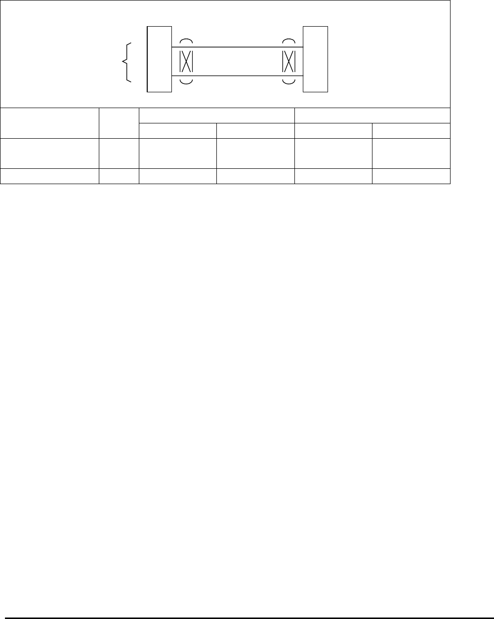
Honeywell
MK VI MK VIII EGPWS Installation Design Guide
Proprietary notice on title page applies
CAGE CODE: 97896 SCALE: NONE SIZE: A DWG NO: 060-4314-150 REV: SHEET 60
3.4.3 Digital –AR INC 575 (Cat. 2 ID 2)
Air Data Type 2 (ADC-80 or equivalent) is a low speed, digital ARINC 575 signal having the air data labels 203,
206, 212, and 213.
39
38
A
B
J2 ARINC 575 Air Data
ARINC 575 Bus - Hi
ARINC 575 Bus - Lo
EGPWS MK VI / MK VIII
A
B
ARINC 575
Air Data Bus
ARINC575-ADC.vsd
Cat 2 Bus 1 Bus 2
Vendor Model ID A B A B
Collins ADC-80( )
Collins ADC-82A
2 P3-35 P3-36
B&D 90004 2 J1-27 J1-9
NOTE: The connector pin numbers given in the Table above are to the best knowledge of Honeywell EGPWS engineering. Please
contact the manufacturer’s customer service to confirm your installation.
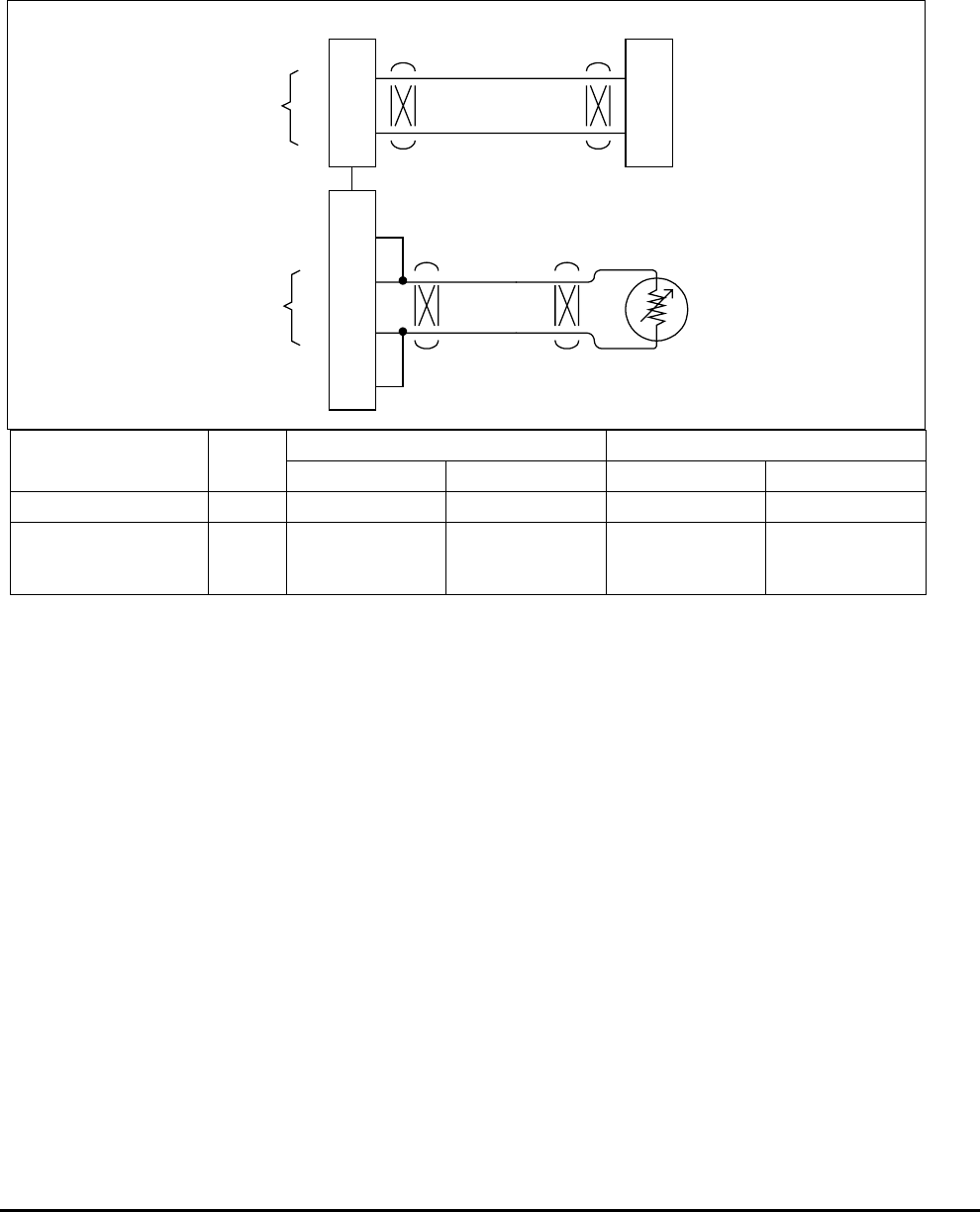
Honeywell
MK VI MK VIII EGPWS Installation Design Guide
Proprietary notice on title page applies
CAGE CODE: 97896 SCALE: NONE SIZE: A DWG NO: 060-4314-150 REV: SHEET 61
3.4.4 Shadin 200 0 (Cat. 2 ID 10)
Air Data Type 10 (Shadin 2000 or equivalent) is a low speed, digital ARINC 429 signal having the air data labels
203, 204, 206, and 212. Total Air Temperature is from a dedicated (EGPWS) 500-ohm probe using +5 volt
excitation from the MK VI/MK VIII EGPWC.
39
38
A
B
J2 ARINC 429 Air Data
ARINC 429 Bus - Hi
ARINC 429 Bus - Lo
EGPWS MK VI / MK VIII
A
B
A
RINC 429 Low Speed
Air Data Bus
(+)
(-)
Temp. Input
Chassis Ground
+5V Excitation
500 ohm
Temperature
Probe
25
63
44
53
J1
Shadin2000.vsd
Cat 2 Bus 1 Bus 2
Vendor PN ID A B A B
962830-1,2,3 10 J2-7 J2-8
962830A-1,2,3
962830A-X-S-4
962830A-X-S-5
10
J1-40 J1-22
NOTE: The connector pin numbers given in the Table above are to the best knowledge of Honeywell EGPWS engineering. Please
contact the manufacturer’s customer service to confirm your installation.
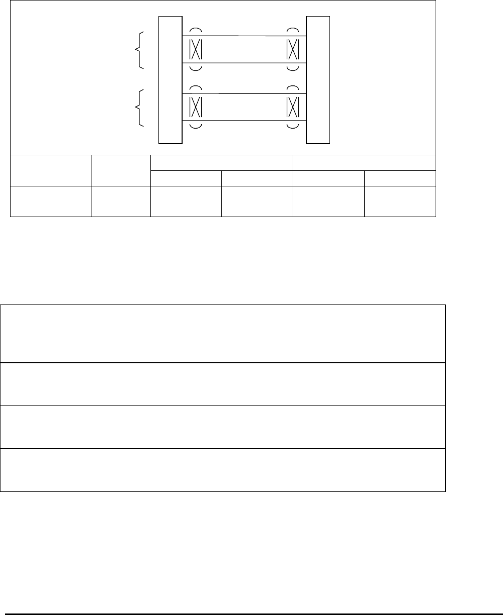
Honeywell
MK VI MK VIII EGPWS Installation Design Guide
Proprietary notice on title page applies
CAGE CODE: 97896 SCALE: NONE SIZE: A DWG NO: 060-4314-150 REV: SHEET 62
3.4.5 Digital – AR INC 429 Dual IOC Buses (Cat. 2. ID 255)
Air Data Type 255 (IOC bus or equivalent) is a dual, high speed, digital ARINC 429 signal having the air data
labels 203, 204, 206, 210, 212, and 213. ID 255 may only be used in conjunction with other IOC bus selections
for categories 6, 8, 9, 10, 11 and 12.
37
36
A
B
J2 IOC Buses
IOC Bus 1
EGPWS MK VI / MK VIII
A
B
ARINC 429
High Speed
41
40
A
B
IOC Bus 2
A
B
ARINC 429
High Speed
ARINC429-IOC.vsd
Cat 2 IOC Bus 1 IOC Bus 2
Vendor Model ID A B A B
BD-100
CJ-1/CJ-2
255
255
A4P1-1
P1-1
A4P1-2
P1-2
A4P101-1
P101-1
A4P101-2
P101-2
NOTE: The connector pin numbers given in the Table above are to the best knowledge of Honeywell EGPWS engineering. Please
contact the manufacturer’s customer service to confirm your installation.
3.4.6 Instruction s
Using Appendix E Tables 5.2, 5.3.2 and 5.3.2-x as described above, select the Air Data Type that
matches the aircraft air data configuration, feature preferences and version (part number) being
installed.
Record the ID number for the Air Data Type from Appendix E Table 5.3.2 under the Ident No.
heading for Step (Category) 2 in Appendix E Table 5.2.
Using the Air Data Type number from Appendix E Table 5.3.2 as “x”, go the Air Data Input Select
x Table.
The electrical interfaces (pin-outs) for the Air Data Input Select are shown in Appendix E Table
5.3.2-x and are used to generate the installation wiring diagrams.

Honeywell
MK VI MK VIII EGPWS Installation Design Guide
Proprietary notice on title page applies
CAGE CODE: 97896 SCALE: NONE SIZE: A DWG NO: 060-4314-150 REV: SHEET 63
3.5 Category 3 – Position Input Select
Category 3 defines the Global Position System bus type and interface. The EGPWS requires a GPS with 8
channels minimum and RAIM capability.
Appendix E Table 5.3.3 defines the Position Input Select options and identifies the first MK VI/VIII EGPWS
version in which the option was available (see the Effectivity entry).
Appendix E Tables 5.3.3-x, where x is the Position Input Type number, define the label set and electrical
interface required to support each Position Input Type.
GPS Input selection is available in the following formats: ARINC 429 low speed, ARINC 429 high speed, RS-
232, and Internal.
The Internal GPS uses ID 2. A unit equipped with an internal GPS (965-1190-XXX and 965-1220-XXX) may
use an external GPS source.
See Category 7 to select GPS Altitude Reference (mean sea level or WGS-84) for ARINC 429 label 076.
3.5.1 ARINC 743 Format
This option provides the ability to specify the GPS input data format as ARINC 743 instead of the ARINC 743A
data format. For ARINC 743A the VFOM is in feet and the HFOM is in nautical miles (nm). For ARINC 743 both
VFOM and HFOM are in meters.
Note: Universal UNS-1 C/D/K/M GPS only, output is in ARINC 743 format.
3.5.2 GPS Altitud e (Label 076) Reference
The GPS Altitude (label 076) may be referenced to mean sea level or WGS-84. Determine which reference your
GPS position uses and program the GPS Altitude Reference accordingly in Category 7.
Note: Universal UNS-1 C/D/K/M GPS only, output the Altitude Label 076 referenced to WGS-84.
3.5.3 North-Sout h East-West Velocity labels
ID’s 10-13 and 253 are provided to support GPS interfaces that do not provide North-South East-West Velocity
labels 166 & 174. ID’s 0,1,4,5, and 255 are preferred.

Honeywell
MK VI MK VIII EGPWS Installation Design Guide
Proprietary notice on title page applies
CAGE CODE: 97896 SCALE: NONE SIZE: A DWG NO: 060-4314-150 REV: SHEET 64
3.5.4 ARINC 429 BUS (Cat. 3 ID 0,1,4,5,10-13)
25
8
A
B
J2 ARINC 429 GPS
ARINC 429 Bus - Hi
ARINC 429 Bus - Lo
EGPWS MK VI / MK VIII
A
B
ARINC 429
GPS Bus
ARINC429-GPS.vsd
Cat 3 429 GPS Alt ARINC Bus 1 Bus 2
Vendor Model ID Speed Ref. 743/743A A B A B
Collins GNLU-910A Note 5 High MSL 743A LMP-2J LMP-2K
Collins GPS-4000 0/42H/L2MSL 743A MP-11A MP-11B
UNS GPS-1000 1 Low WGS-84 743 TP-12A TP-12B TP-11A TP-11B
UNS GPS-1200 0 Low MSL 743A TP-12A TP-12B TP-11A TP-11B
UNS-1C
(1017-3X-XXX) or
(1017-4X-XXX)
1 Low WGS-84 743 P1-a P1-b
UNS-1D
(1192-00-1111XX) or
(1192-30-1111XX)
1 Low WGS-84 743 MP-10J MP-10K
UNS-1F, -1E, -1L
(2192-00-11110X)
0 Low MSL 743A MP-10J MP-10K MP-4J MP-4K
UNS-1K
(1116-3X-111X) or
(1116-4X-111X)
1 Low WGS-84 743 MP-4C MP-4D
UNS-1M
(1013-4X-XXX)
1 Low WGS-84 743 P2-K P2-L
GNS-XLS
(17960-0203-) SM04
(17960-0102-) SM07
0 Low MSL 743A J101-N5 1J101-N6 1
GNS-XL
(18355-) SM06
0 Low MSL 743A J101-N5 1J101-N6 1
GNS-X / CDU-XLS
(14141-0624-) SM04
0 Low MSL 743A JA-A01 JA-A02
HG2021GBXX 1/5 2H/L2MSL 743 J1-38 J1-39 J1-24 J1-25
HG2021GC/GDXX 0/4 2H/L2MSL 743A J1-38 J1-39 J1-24 J1-25
HT1000/HT9100 10/12 H/L WGS-84 743A MP-C02 MP-C01
FreeFlight (Trimble)
2101 I/O Approach Plus
(81440-XX software ver. 241F)
0 Low MSL 743A J1-16 J1-23 J1-58 J1-57
NOTE: The connector pin numbers given in the Table above are to the best knowledge of Honeywell EGPWS engineering. Please
contact the manufacturer’s customer service to confirm your installation.
1 The Enhanced GNS-XLS ARINC 429 bus also contains Range label
2 HG2021G: Pin 21 open = high speed; Pin 21 GND = Low speed; GPS-4000:
3 North/South Velocity (label 166) and East/West Velocity (label 174) are required in MK VI / MK VIII -008 software and on.
4 NOT COMPATIBLE with MK VI / MK VIII EGPWS
Honeywell HT-9000 / KLN-89 / KLN-90 / HG2021AB / GNS-XES
IIMorrow Apollo 2101
Trimble 2100 / 2101 / TNL8100
Universal GPS-950, UNS-1B
5 Check manufacturer for compatibility with North-South, East-West Velocities.
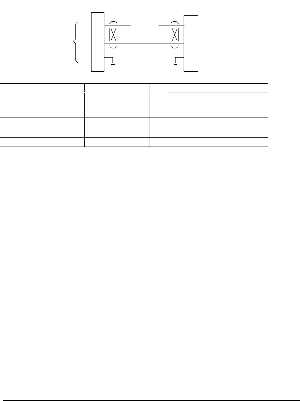
Honeywell
MK VI MK VIII EGPWS Installation Design Guide
Proprietary notice on title page applies
CAGE CODE: 97896 SCALE: NONE SIZE: A DWG NO: 060-4314-150 REV: SHEET 65
3.5.5 RS-232 Tra nsmit-Receive, 9600 baud (Cat. 3 ID 3)
45
29
J2 RS-232 GPS
RX – Receive In
TX – Transmit Out
EGPWS MK VI / MK VIII
TX
RX
RS – 232
GPS Bus
28CM
GND
NC
RS232-GPS.vsd
GPS Alt ARINC NS3RS-232
Vendor Model Ref. 743/743A EW RX TX GND
GARMIN GNS430/5302
Software Version 2.21
MSL N/A Note 3 P4001-56 Chassis
KLN 900
066-04034-0104 or
066-04034-0204
MSL N/A OK P9002-13 Chassis
KLN 94 MSL N/A OK P941-6 Chassis
NOTE: The connector pin numbers given in the Table above are to the best knowledge of Honeywell EGPWS engineering. Please
contact the manufacturer’s customer service to confirm your installation.
1 The KLN 89/89B/90/90A/90B are not compatible.
2 The GNS 430 software mod is also applicable to the GPS 400 and GNC 420 units.
3 Check manufacturer for compatibility with North-South, East-West Velocities.
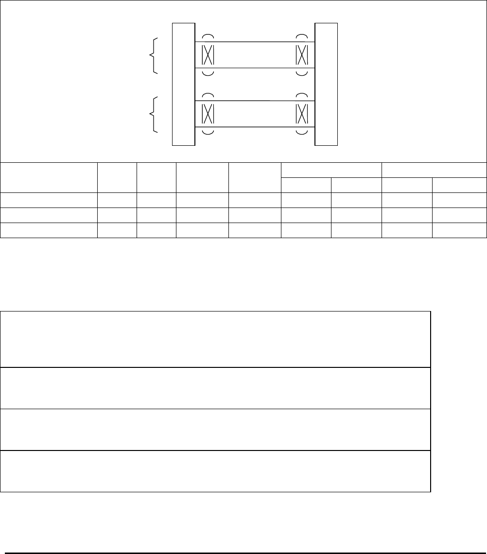
Honeywell
MK VI MK VIII EGPWS Installation Design Guide
Proprietary notice on title page applies
CAGE CODE: 97896 SCALE: NONE SIZE: A DWG NO: 060-4314-150 REV: SHEET 66
3.5.6 Dual ARINC 429 BUS (Cat. 3 ID 253 & 255)
NOTE: If GPS #2 is not installed in the aircraft, then use ID 4 or GPS bus #1 must be connected in parallel to
both EGPWS GPS input ports.
NOTE: Non-IOC aircraft can use ID 253 or 255 to activate dual GPS inputs for redundancy and improved
system availability, but the interface must have dual High Speed 743A GPS, and this cannot be used if
using Category 10 ID 5 or Category 11 ID 2.
25
8
A
B
J2 ARINC 429 GPS
ARINC 429 Bus 1
Lo
EGPWS MK VI / MK VIII
A
B
ARINC 429
GPS Bus
23
6
A
B
A
B
ARINC 429
GPS Bus
Hi
ARINC 429 Bus 2
Lo
Hi
ARINC429-DualGPS.vsd
Cat 3 429 GPS Alt ARINC Bus 1 Bus 2
Aircraft Model ID Speed Ref. 743/743A A B A B
253 1
BD 100 255 High MSL 743A A25BP1-6A A25BP1-6B A24BP1-6A A24BP1-6B
CJ1/CJ2 255 High MSL 743A TBD TBD TBD TBD
NOTE: The connector pin numbers given in the Table above are to the best knowledge of Honeywell EGPWS engineering. Please
contact the manufacturer’s customer service to confirm your installation.
1 ID 253 is a optional configuration for compatibility with IOC that are missing North-South, East-West Velocities labels.
3.5.7 Instruction s
Using Appendix E Tables 5.2, 5.3.3 and 5.3.3-x as described above, select the Position Input
Type that matches the aircraft Position Input configuration, feature preferences and version (part
number) being installed.
Record the ID number for the Position Input Type from Appendix E Table 5.3.3 under the Ident
No. heading for Step (Category) 3 in Appendix E Table 5.2.
Using the Position Input Type number from Appendix E Table 5.3.3 as “x”, go the Position Input
Select x Table.
The electrical interfaces (pin-outs) for the Position Input Select are shown in Appendix E Table
5.3.3-x and are used to generate the installation wiring diagrams.

Honeywell
MK VI MK VIII EGPWS Installation Design Guide
Proprietary notice on title page applies
CAGE CODE: 97896 SCALE: NONE SIZE: A DWG NO: 060-4314-150 REV: SHEET 67
3.6 Category 4 – Altitude Callouts
Category 4 defines the Altitude Callout menu choices and Smart ‘500’ Callout selection.
Appendix E Table 5.3.4 defines the Altitude Callout Menu options and identifies the first MK VI/MK VIII EGPWS
version in which the option was available (see the Effectivity entry).
The Altitude callout menus have selected combinations of “Minimums-Minimums”, “Minimums”, “1000”, Smart
“500”, “500”, “500 Above” Field, “400”, “300”, “200”, “100”, “50”, “40”, “30”, “20”, and “10”. No altitude callouts
may also be selected.
The Altitude Callout menu provides altitude annunciation for descent below predefined altitudes (example: “One
Hundred” is annunciated when descending through 100 feet radio altitude).
A “500” foot callout is available that will issue a “500” callout once during each approach when the aircraft is
500’ AGL.
A “Smart 500” foot callout is available that will issue a “500” callout when the aircraft is 500’ AGL. This callout is
active only during non-precision approaches or when the Glideslope or Localizer deviation is greater than 2
dots.
The “500 Above” Field callout will be annunciated once during each approach when the aircraft is within 5 nm of
a runway in the database and descends through 500 ft above that runway. It compares the GPS-based
geometric altitude with the closest runway field elevation. The callout may be optionally chosen to annunciate
“Five Hundred” or “Five Hundred Above”. This requires Category 6 ID other than 2 (TAD/TCF must be active).
“Minimums-Minimums” callout can be selected or deselected from these combinations by connecting or not
connecting the Decision Height (DH) discrete (J1-33) of Category 8.
Recommendation: Honeywell recommends at least a Smart ‘500’ callout and a “Minimums-Minimums” callout.
FAA and JAA approved installations require a 500 foot callout.
Using Appendix E Table 5.2 and 5.3.4 as described above, select the preferred Altitude Callout
Menu Type (ID) that matches the feature preferences and version (part number) being installed.
Record the ID number for the Altitude Callout Menu Type from Appendix E Table 5.3.4 under the
Ident No. heading for Step (Category) 4 in Appendix E Table 5.2.
If the “Minimums-Minimums” callout will be used, use the electrical interfaces (pin-outs) for Radio
Altitude Input Select Type (Category 8) shown in Appendix E Table 5.3.8-x to generate the
installation wiring diagrams.
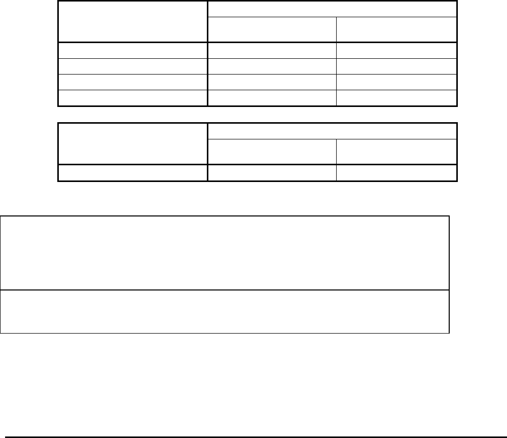
Honeywell
MK VI MK VIII EGPWS Installation Design Guide
Proprietary notice on title page applies
CAGE CODE: 97896 SCALE: NONE SIZE: A DWG NO: 060-4314-150 REV: SHEET 68
3.7 Category 5 – Audio Menu Select
Category 5 defines four Audio Menu options. Retractable Gear aircraft, Type 0 (basic) and Type 1 (alternate)
and Fixed Gear aircraft, Type 2 (basic) and Type 3 (alternate).
Appendix E Table 5.3.5 defines the Audio Menu select options and identifies the first MK VI/MK VIII EGPWS
version in which the option was available (see the Effectivity entry).
Appendix E Tables 5.3.5-x, where X is the Audio Menu Type, defines the voice callouts for each menu. DGAC-
registered aircraft are required to use Alternate Audio Menu.
Recommendation: Honeywell recommends the Basic Audio Menu (except for DGAC-registered aircraft).
3.7.1 Audio Menu Selection
Audio menu must be selected to provide EGPWS callouts. The differences in the Audio Menu Types are shown
in the following comparison tables.
ALERT/WARNING Audio Menu
CONDITION Basic
(Type 0 and 2)
Alternate
(Type 1 and 3)
Terrain Awareness Preface Terrain Terrain Terrain Ahead
Obstacle Awareness Preface Obstacle Obstacle Obstacle Ahead
Terrain Awareness Caution Caution Terrain Terrain Ahead
Obstacle Awareness Caution Caution Obstacle Obstacle Ahead
ALERT/WARNING Audio Menu
CONDITION Retractable Gear
(Type 0 and 1)
Fixed Gear
(Type 2 and 3)
Mode 4 Too Low Gear Too Low Gear Too Low Flaps
3.7.2 Instruction s
Using Appendix E Tables 5.2, 5.3.5 and 5.3.5-x as described above, select the Audio Menu Type
that matches the feature preferences and version (part number) being installed.
• Basic or Alternate menu
• Retractable Gear or Fixed Gear
Record the ID number for the Audio Menu Type from Appendix E Table 5.3.5 under the Ident No.
heading for Step (Category) 5 in Appendix E Table 5.2.

Honeywell
MK VI MK VIII EGPWS Installation Design Guide
Proprietary notice on title page applies
CAGE CODE: 97896 SCALE: NONE SIZE: A DWG NO: 060-4314-150 REV: SHEET 69
3.8 Category 6 – Terrain Display Select
Category 6 defines the Terrain Display options available.
TA&D and TCF mode enabling/disabling is controlled by Category 6.
Peaks mode availability is controlled by Category 6 since its availability is determined by the display
configuration. Peaks mode enabling/disabling is controlled by Category 7. Each of the options controlled by
Category 6 is described below.
Appendix E Table 5.3.6 defines the Terrain Display Select options (Display Configuration Group Tables, Display
Input Control Group Tables and Output 429 Bus Group Tables) and identifies the first MK VI/MK VIII EGPWS
version in which the option was available (see the Effectivity entry). Appendix E Table 5.3.6 also defines the
EGPWS version (MK VI or MK VIII) in which the option is available (see the EGPWS entry).
Appendix E Tables 5.3.6.1-x, where x is the Display Configuration group number, define the display options and
the electrical interface required to support each Display Configuration.
Appendix E Tables 5.3.6.2-x, where x is the Display Input Control group number, define the label set and the
electrical interface required to support each Display Configuration.
Appendix E Tables 5.3.6.3-x, where x is the Output 429 Bus group number, define the label set and the
electrical interface supporting each Display Configuration output requirements.
Figure 3.8-1 is an example of single tube Wx/Terrain display wiring connections.
3.8.1 TAD & TCF Selection
The Terrain Clearance Floor (TCF) algorithm identifies premature descent for approaches regardless of aircraft
configuration. It creates a terrain clearance envelope around the airport to provide protection against controlled
flight into terrain situations beyond that of the basic GPWS.
The Terrain Awareness & Display feature consists of a Terrain Awareness Alerting feature and a Terrain
Awareness Display feature. The Terrain Awareness Alerting feature continuously computes terrain clearance
envelopes ahead of the aircraft and issues alerts if the boundaries of these envelopes conflict with terrain
elevation data in the terrain database. The Terrain Awareness Display feature displays the data terrain relative
to aircraft altitude.
Both TA&D and TCF are Enabled for all ID’s in Appendix E Table 5.3.6 except for “TA&D and TCF Disable” (ID
2).
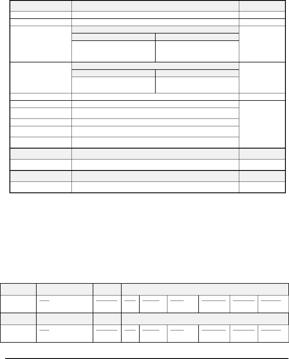
Honeywell
MK VI MK VIII EGPWS Installation Design Guide
Proprietary notice on title page applies
CAGE CODE: 97896 SCALE: NONE SIZE: A DWG NO: 060-4314-150 REV: SHEET 70
3.8.2 Terrain Dis play Configuration Group
This option provides the ability to specify the type of Terrain Display compatible with the aircraft configuration. A
definition of each of the entries in the Display Configuration Group tables is provided in the table below.
Function Value Reference section
Display Type Display manufacturer, model, etc.
Sweep Type The type of sweep used for terrain data (fan, standard, etc.)
Auto Pop Up Category 7, Options Select Group #1
TA&D Alternate Pop Up: False TA&D Alternate Pop Up: True
The TA&D Alternate Pop Up is set to
False or True in Category 7. If False,
Pop Up behavior for the terrain
display is described here.
The TA&D Alternate Pop Up is set to
False or True in Category 7. If True,
Pop Up behavior for the terrain
display is described here.
Peaks Mode Category 7, Options Select Group #1
See Note 1 Peaks Enable: False Peaks Enable: True
Peaks Enable is set to False or True
in Category 7. The effect of setting it
to False is described here.
Peaks Enable is set to False or True
in Category 7. The effect of setting it
to True is described here.
Manual select Describes if/when terrain display(s) can be manually selected
Manual deselect Describes if/when terrain display(s) can be manually deselected
Auto Range Defines if the display data is automatically scaled and, if so, the scale used
(such as 10 nautical miles)
Moving Marker Indicates whether or not a moving marker is provided
Overlay Page Describes where “TERR” and Peaks Elevations overlays will be located on the
display screen.
Display bus type Defines the display bus type ‘KC Picture Bus’ (KCPB was ASPB), ‘Honeywell
Picture Bus’ or ‘ARINC 453’.
CHANNEL
TX453-1 CONNECT TO:
A = J1-58
B = J1-59 Indicates the correct connection for these pins
CHANNEL
TX453-2 CONNECT TO:
A = J1-56
B = J1-57 Indicates the correct connection for these pins
Notes: 1 Peaks Mode “(Not Available)” or “(Elevations via overlay)” shown here. Peaks mode “Not Available” means that this display
type cannot display Peaks Mode.
Table 3.8.2-1 Definition of Display Configuration Group Tables (Appendix E Section 5.3.6)
3.8.3 Display Inp ut Control Group
This input bus is connected to the display (or display controller) and transmits Range settings, Display Mode,
and Display status to the MK VI/MK VIII EGPWC. In some installations where the terrain display(s) is controlled
from one source (controller) the Range inputs to the EGPWS must be paralleled to satisfy dual input
requirements of the EGPWS.
Display Input Control Group
CHANNEL
429_422RX_1
CONNECT TO:
WXR Output 429 bus 1
Fault Designation: DISPLAY BUS 1
Bus Type: Basic
A = J2-37
B = J2-36
Data
Range
Status
Reference Label Sig. Bits Range Signal Type Resolution Rate (ms)
CHANNEL
429RX_3
CONNECT TO:
WXR Output 429 bus 1
Fault Designation: DISPLAY BUS 2
Bus Type: Basic
A = J2-41
B = J2-40
Data
Range
Status
Reference Label Sig. Bits Range Signal Type Resolution Rate (ms)

Honeywell
MK VI MK VIII EGPWS Installation Design Guide
Proprietary notice on title page applies
CAGE CODE: 97896 SCALE: NONE SIZE: A DWG NO: 060-4314-150 REV: SHEET 71
In some installations where the Radar (Terrain) displays are controlled from one source, the Range input buses into the EGPWS must be
paralleled to satisfy EGPWS dual input requirements.
CONN PIN # REFERENCE NAME PIN FUNCTION Polarity/Configuration
J1-32 GND_DISC_12
Reference
6.6.18 Display Select Discrete #1
Type 1 (Momentary)
Gnd = Display Select Toggle
<not> Gnd = Normal
J1-31 GND_DISC_13
Reference
6.6.19 Display Select Discrete #2
Type 1 (Momentary)
Gnd = Display Select Toggle
<not> Gnd = Normal
3.8.4 Output 429 Bus Group
This output bus is commonly connected to EFIS and/or EICAS displays and Flight Recorders. The output
transmits MK VI/MK VIII EGPWC alert, fault, and mode status to other systems.
Output 429 Bus Group
Channel Pins Comments
429TX_1 A = J2-43
B = J2-42
Transmits Label sets: (Section 7)
429TX_2 A = J2-26
B = J2-9
No Connection (No Data Output)
3.8.5 Instruction s
Using Appendix E Tables 5.2, 5.3.6, and 5.3.6.1-x as described above, select the Terrain Display
Select Type (ID) that matches the aircraft configuration, feature preferences and version (part
number) being installed.
Record the ID number for the Terrain Display Select Type from Appendix E Table 5.3.6 under the
Ident No. heading for Step (Category) 6 in Appendix E Table 5.2.
Record the Display Configuration Group number here ! _______________.
Note: This information is used to determine TA&D Alternate Pop Up and Peaks Mode availability
for Category 7.
The electrical interfaces (pin-outs) for the Display Configuration Group, Display Input Control
Group, and Output 429 Bus Group are shown in the Appendix E Table 5.3.6.1-x and are used to
generate the installation wiring diagrams.
3.8.6 Sample Dis play Schematics
Honeywell GNS-XLS
Honeywell KMD 540 / 550 / 850
Honeywell Grimes TRA-45A
Honeywell Primus UDI with Avtech DSU
Honeywell Primus 440/660/880 Integrated
Honeywell Primus 1000
Honeywell Bendix RDR 2000 / IN182A
Honeywell Bendix PPI-4B
Honeywell Bendix EFS-40/50
Collins WXI-701/711
Collins Pro-Line II / IV
Honeywell SPZ8000 / SG-802/803/806
Universal MFD-640
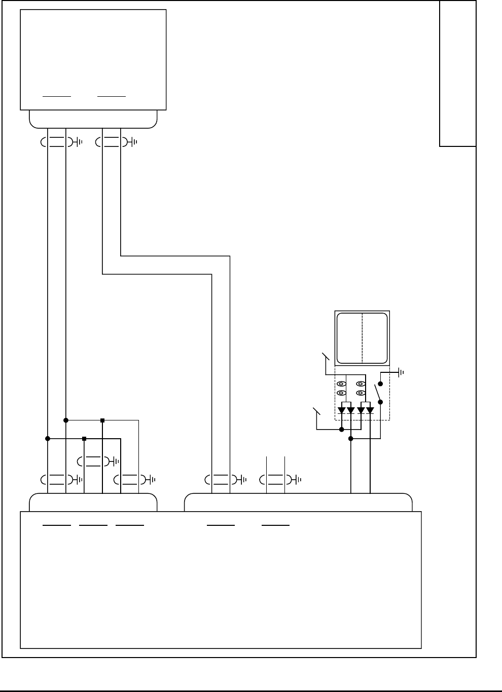
Honeywell
MK VI MK VIII EGPWS Installation Design Guide
Proprietary notice on title page applies
CAGE CODE: 97896 SCALE: NONE SIZE: A DWG NO: 060-4314-150 REV: SHEET 72
Honeywell GNS-XLS
J2
J1
J101
N5
N6
Q4
Q6
37
36
25
8
41
40
58
59
56
57
TERR
INHIB
TERR
INOP
Lamp Test
28V Lamp Dimming Bus
Alternate Action
12
55
EGPWS GNS-XLS
A
B
ARINC 429 Range #1 In
A
B
ARINC 429 GPS In
A
B
ARINC 429 Range #2 In
A
B
KCPB Video #1 Out
A
B
KCPB Video #2 Out
Terrain Inhibit (in)
Terrain INOP (out)
MK VI 965-11X0-020 or later.
MK VIII 965-12X0-020 or later.
A
B
A
B
Range & GPS out
KCPB Video in (H)
17960-0203-XXXX
SM04
Note:
GNS-XLS will not perform auto pop-up during Alert.
For interface and operation of the GNS-XLS see Honeywell
GNS-XLS System Installation Manual 006-10528-0000
GNS-XLS-1.vsd
70-ohm termination
Q5 KCPB Video in (L)
No connection
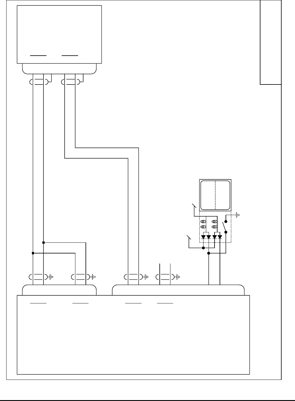
Honeywell
MK VI MK VIII EGPWS Installation Design Guide
Proprietary notice on title page applies
CAGE CODE: 97896 SCALE: NONE SIZE: A DWG NO: 060-4314-150 REV: SHEET 73
Honeywell KMD 540/
550/850
J2
J1
J3001
29
30
11
12
13
31
37
36
41
40
58
59
56
57
TERR
INHIB
TERR
INOP
Lamp Test
28V Lamp Dimming Bus
Alternate Action
12
55
EGPWS KMD 540/550/850
A
B
ARINC 429 Range #1 In
A
B
ARINC 429 Range #2 In
A
B
KCPB Video #1 Out
A
B
KCPB Video #2 Out
Terrain Inhibit (in)
Terrain INOP (out)
A
B
A
B
429 Out
KCPB Video in
(No termination)
Note:
For interface and operation of the Honeywell KMD 540/550/850
see Honeywell Installation Manual P/N 006-10608-0001
KMD540-1.vsd
No connection
MK VI 965-11X0-020 or later.
MK VIII 965-12X0-020 or later.
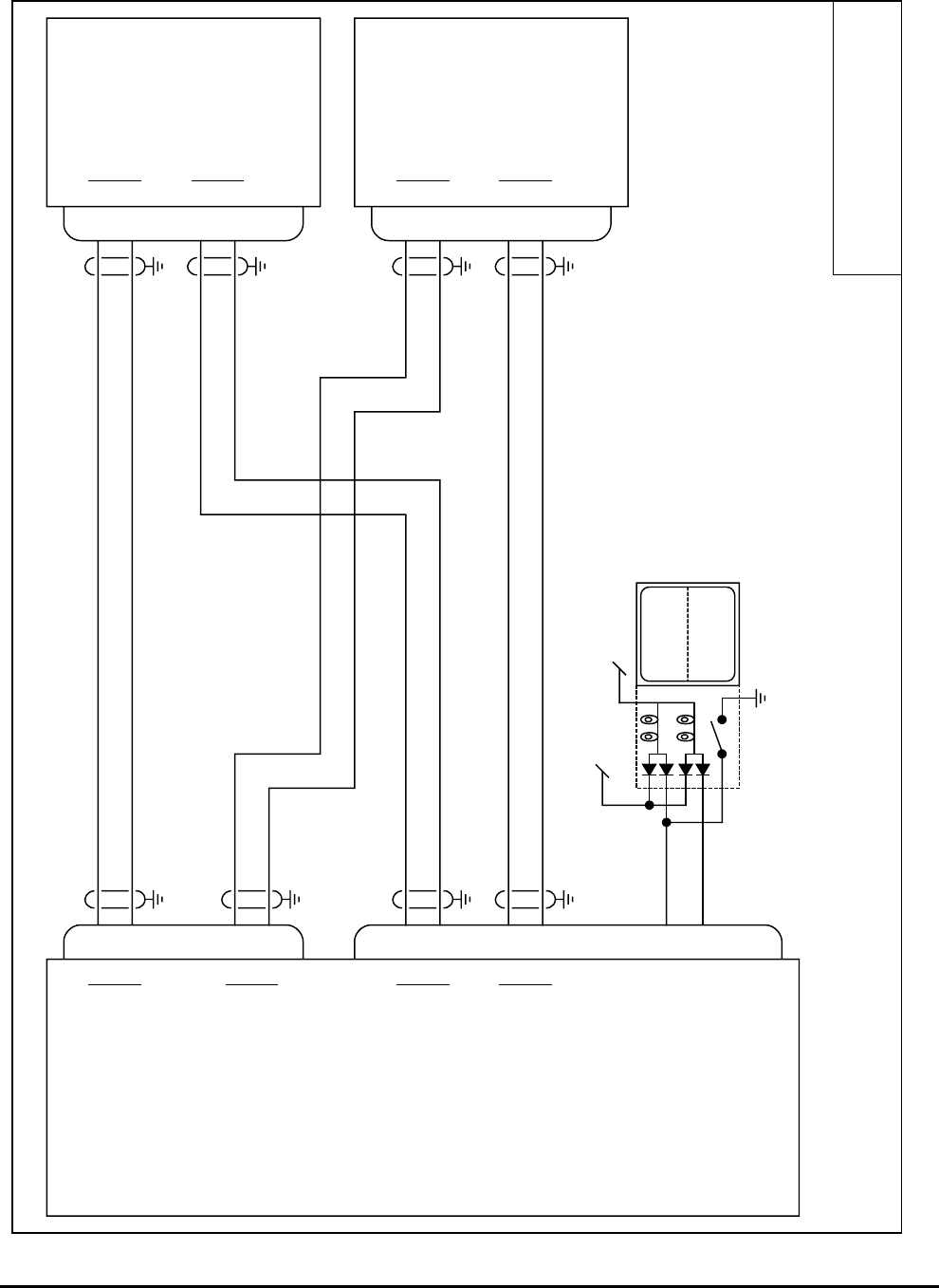
Honeywell
MK VI MK VIII EGPWS Installation Design Guide
Proprietary notice on title page applies
CAGE CODE: 97896 SCALE: NONE SIZE: A DWG NO: 060-4314-150 REV: SHEET 74
Honeywell Grimes
TRA-45A
J2
J1
J1
J1
28
13
1
3
28
13
1
3
37
36
41
40
58
59
56
57
TERR
INHIB
TERR
INOP
Lamp Test
28V Lamp Dimming Bus
Alternate Action
12
55
EGPWS TRA-45A
TRA-45A
A
B
ARINC 429 Range #1 In
A
B
ARINC 429 Range #2 In
A
B
KCPB Video #1 Out
A
B
KCPB Video #2 Out
Terrain Inhibit (in)
Terrain INOP (out)
MK VI 965-11X0-020 or later.
MK VIII 965-12X0-020 or later.
A
B
A
B
A
B
A
B
Range out
KCPB Video in
70-ohm termination
Range out
KCPB Video in
70-ohm termination
80-5145-X-2
Note:
For interface and operation of the Honeywell Grimes TRA-45A see
Honeywell TRA-45A Equipment Installation Manual P/N 34-40-01
80-5145-X-2
TRA45.vsd
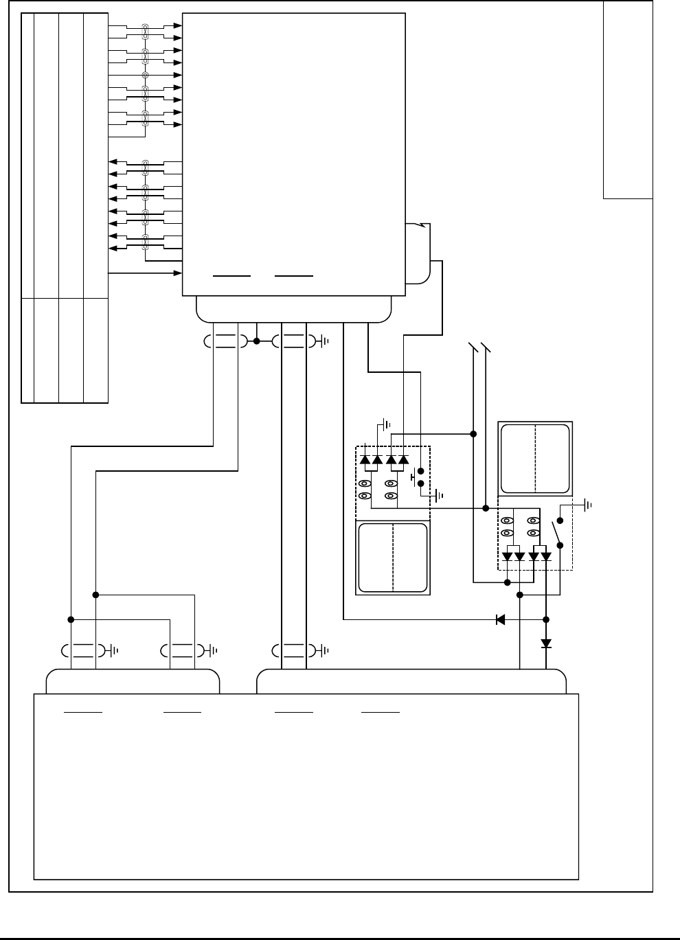
Honeywell
MK VI MK VIII EGPWS Installation Design Guide
Proprietary notice on title page applies
CAGE CODE: 97896 SCALE: NONE SIZE: A DWG NO: 060-4314-150 REV: SHEET 75
AVTECH DSU
Primus WXR UDI
J2
J1
J1
8
9
47
48
37
36
41
40
58
59
56
57
TERR
INHIB
TERR
INOP
Lamp Test
28V Lamp Dimming Bus
Alternate Action
12
55
EGPWS
AVTECH DSU
A
B
ARINC 429 Range #1 In
A
B
ARINC 429 Range #2 In
A
B
KCPB Video #1 Out
A
B
KCPB Video #2 Out
Terrain Inhibit (in)
Terrain INOP (out)
MK VI 965-11X0-020 or later.
MK VIII 965-12X0-020 or later.
A
B
A
B
Range out
KCPB Video in
Note:
For interface and operation of the Avtech 6001 DSU see Avtech
DSU Installation and Operation Procedure P/N 6001-1680
P/N 6001-1
PrimusUDI-1.vsd
PRIMUS SERIES
90, 100, 200, 300,
300SL, 400, 500, AVQ30
450, 650 w/o Lightning,
800
440, 650 w/ Lightning,
660, 700, 870, 880 219
13
6
18
9
3
16
12
10
4
8
15
11
17
14
5
7
219
13
6
18
9
3
16
12
10
4
8
15
11
17
NC
5
7
1
NJESUTDHR MKLA PCVBGF
49
open
7
2
TERR
ON
momentary 32
Display Invalid
Terrain Select
Terrain Status
J2
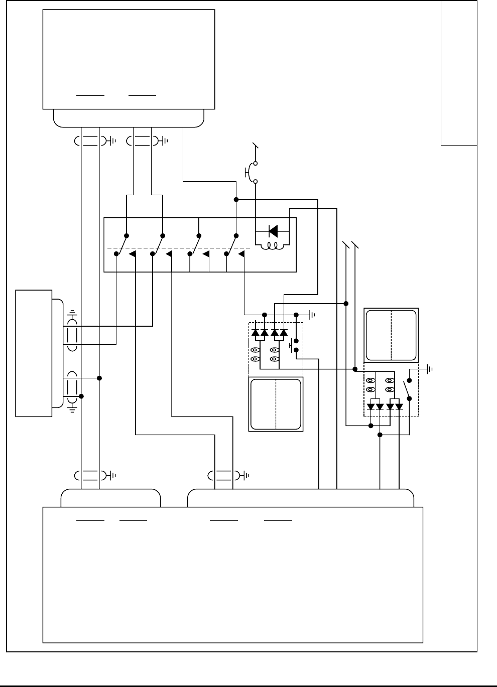
Honeywell
MK VI MK VIII EGPWS Installation Design Guide
Proprietary notice on title page applies
CAGE CODE: 97896 SCALE: NONE SIZE: A DWG NO: 060-4314-150 REV: SHEET 76
Integrated
Primus 440/660/880
J2
J1
F
G
M
L
37
36
41
40
58
59
56
57
TERR
INHIB
TERR
INOP
Lamp Test
28V Lamp Dimming Bus
Alternate Action
12
55
EGPWS
Honeywell
Radar Indicator
A
B
RS-422 Serial Range #1 In
A
B
Range #2 In
A
B
ARINC 453 Video #1 Out
A
B
ARINC 453 Video #2 Out
Terrain Inhibit (in)
Terrain INOP (out)
MK VI 965-11X6-004 or later.
MK VIII 965-12X6-004 or later.
P
N
P
N
SCI Bus
WXPD Bus
Note:
For interface and operation of the Honeywell Weather Radar Indicator
WI-440, 660, 880 see Honeywell Service Bulletin 7007700-34-15
WI-440, 660, 880
7007700-X1X
IntP880.vsd
NC
NC
Honeywell WRX R/T
WU-440, 660, 880
71 72 3 4
TERR
ON
momentary
32
54
Terrain Display Select (in)
Terrain Display Select (out)
28V EGPWS PWR Bus
XEGPWS Selected

Honeywell
MK VI MK VIII EGPWS Installation Design Guide
Proprietary notice on title page applies
CAGE CODE: 97896 SCALE: NONE SIZE: A DWG NO: 060-4314-150 REV: SHEET 77
Honeywell Primus
1000
J2
J1
12
25
41
42
37
36
43
42
58
59
TERR
INHIB
Lamp Test
28V Lamp Dimming Bus
Alternate Action
12
EGPWS Integrated Avionics
Computer IC-600
A
B
ARINC 429 Range #1 In
A
B
ARINC 429 Range #2 In A
B
ARINC 429
Control Bus Out
A
B
ARINC 453 Symbol
Generator Out
Terrain Inhibit (in)
MK VIII 965-12X0-020 or later.
A
B
A
B
429 Out
EGPWS Cont
7017000
Primus1000.vsd
41
40
41
42
12
25
Integrated Avionics
Computer IC-600
A
B
A
B
EGPWS Cont
429 Out
7017000
PILOT
CO-PILOT
Display Unit DU-870
7014300
74
75
A
B453 Bus In
Display Unit DU-870
7014300
74
75
A
B453 Bus In
61
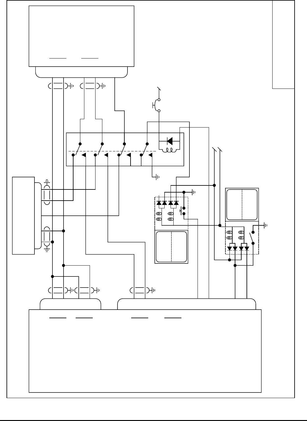
Honeywell
MK VI MK VIII EGPWS Installation Design Guide
Proprietary notice on title page applies
CAGE CODE: 97896 SCALE: NONE SIZE: A DWG NO: 060-4314-150 REV: SHEET 78
Honeywell / Bendix
RDR 2000 / IN182A
J2
J1
27
2
1
20
37
36
41
40
58
59
56
57
TERR
INHIB
TERR
INOP
Lamp Test
28V Lamp Dimming Bus
Alternate Action
12
55
EGPWS
Honeywell
Radar Indicator
A
B
ARINC 429 Range #1 In
A
B
ARINC 429 Range #2 In
A
B
ARINC 453 Video #1 Out
A
B
ARINC 453 Video #2 Out
Terrain Inhibit (in)
Terrain INOP (out)
MK VI 965-11X0-020 or later.
MK VIII 965-12X0-020 or later.
H
C
Control Bus A
T/R Data Bus
Note:
For interface and operation of the Honeywell RDR 2000 Color Weather
Radar system see Honeywell Installation Manual 006-00643-0000
IN182A
066-3084-XX
RDR2000.vsd
NC
Honeywell WRX R/T
ART 2000
2342 43
TERR
ON
momentary
32
54
Terrain Display Select (in)
Terrain Display Select (out)
28V EGPWS PWR Bus
31 RT On/Off 1
31
A
B
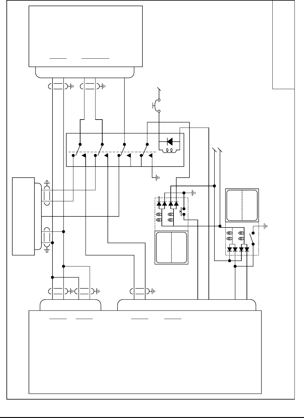
Honeywell
MK VI MK VIII EGPWS Installation Design Guide
Proprietary notice on title page applies
CAGE CODE: 97896 SCALE: NONE SIZE: A DWG NO: 060-4314-150 REV: SHEET 79
Honeywell / Bendix
PPI-4B
J2
J1
10
11
5
12
37
36
41
40
58
59
56
57
TERR
INHIB
TERR
INOP
Lamp Test
28V Lamp Dimming Bus
Alternate Action
12
55
EGPWS
Honeywell
Radar Indicator
A
B
ARINC 429 Range #1 In
A
B
ARINC 429 Range #2 In
A
B
ARINC 453 Video #1 Out
A
B
ARINC 453 Video #2 Out
Terrain Inhibit (in)
Terrain INOP (out)
MK VI 965-11X0-020 or later.
MK VIII 965-12X0-020 or later.
H
C
Control Bus A
T/R Data Bus
PPI-4B
2041222-XXXX
PPI4A4B.vsd
NC
Honeywell WRX R/T
RTA-4B
3B 4B 2D 3D
TERR
ON
momentary
32
54
Terrain Display Select (in)
Terrain Display Select (out)
28V EGPWS PWR Bus
15 RT On/Off 1
6BBP
A
B
5L
T/R Data Bus
70-ohm termination
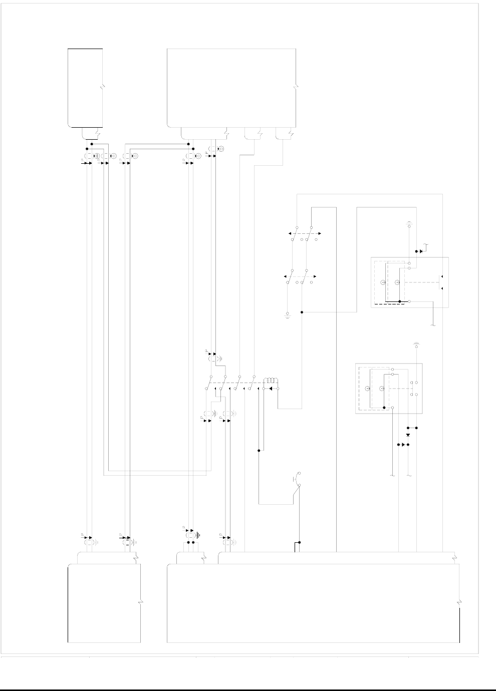
Honeywell
MK VI MK VIII EGPWS Installation Design Guide
Proprietary notice on title page applies
CAGE CODE: 97896 SCALE: NONE SIZE: A DWG NO: 060-4314-150 REV: SHEET 80
453 DATA BUS A OUT
BENDIX/KING
WEATHER RADAR R/T
429 CONTROL BUS 1A IN
453 DATA BUS B OUT
SEE NOTE 2.
429 CONTROL BUS 1B IN
MARK VI/VIII ENHANCED GROUND
PROXIMITY WARNING COMPUTER
NO. 2 DISPLAY RANGE 429 A IN
NO. 1 DISPLAY RANGE 429 A IN
NO. 1 DISPLAY RANGE 429 B IN
NO. 2 DISPLAY RANGE 429 B IN
SEE NOTE 3.
37
J2
41
40
36
KCPB B OUT
KCPB A OUT
TERRAIN POP-UP OUT
58
J1
59
51
SEE NOTE 1.
SEE NOTE 1.
SEE NOTE 1.
SEE NOTE 1.
SEE NOTE 1.
22 R/T TRANSMITTER 429 A OUT
P465
2BBENDIX/KING SG 465
SYMBOL GENERATOR #1
49
SEE NOTE 1.
SEE NOTE 1.
R/T TRANSMITTER 429 B OUT
68
81
P465
22
49
1B
P465
2B
SEE NOTE 1.
R/T TRANSMITTER 429 A OUT
R/T TRANSMITTER 429 B OUT
BENDIX/KING SG 465
MFD SYMBOL GENERATOR
453 DATA BUS B IN
453 DATA BUS A IN
PRESS-TO-TEST
+28VDC POWER IN
+28VDC POWER IN
40
60
TERRAIN SELECT RELAY OUT54
TERRAIN INOP55
TERRAIN SELECT SWITCH IN
TERRAIN INHIBIT SWITCH IN12
32
PRESS-TO-TEST
TERRAIN INHIBIT
POWER
+28VDC AVIONICS
EGPWS
ANNUNCIATOR DIMMER
ANNUNCIATOR
BUS
EGPWS FAIL
NORMAL
NORMAL
STANDBY
DISPLAY DOWN
TERRAIN
ON
ANNUNCIATOR DIMMER
(ALTERNATE ACTION)
(MOMENTARY)
BUS
ANNUNCIATOR
USE M17/176-0002 SHIELDED WIRE OR 024-00064-0000
QUADRAX CABLE FOR THE 453 DATA BUS AND THE KCPB.
(3.13) FOR THE COMPLETE INTERFACE TO THE BENDIX/KING
REFER TO THE WEATHER RADAR SECTION OF THIS MANUAL
THE CATEGORY 6 DISPLAY TYPE ID 10 (INTEGRATED EFIS 40/50)
37
22
P465
1A
TERRAIN POP-UP DISCRETE IN
TERRAIN SELECTED DISCRETE IN
WEATHER RADARS.
IS THE REQUIRED CONFIGURATION.
NOTES:
1.
2.
3.
THIS CONFIGURATION IS NOT SUPPORTED PRIOR TO EGPWS
THE CATEGORY 13 I/O DISCRETE TYPE ID 1 (LAMP FORMAT 2)
COMPUTER PART NUMBERS:
IS THE PREFERRED CONFIGURATION.
4.
965-1180-020 MARK VI EGPWS
965-1190-020 MARK VI EGPWS W/INTERNAL GPS
965-1210-020 MARK VIII EGPWS
965-1220-020 MARK VIII EGPWS W/INTERNAL GPS
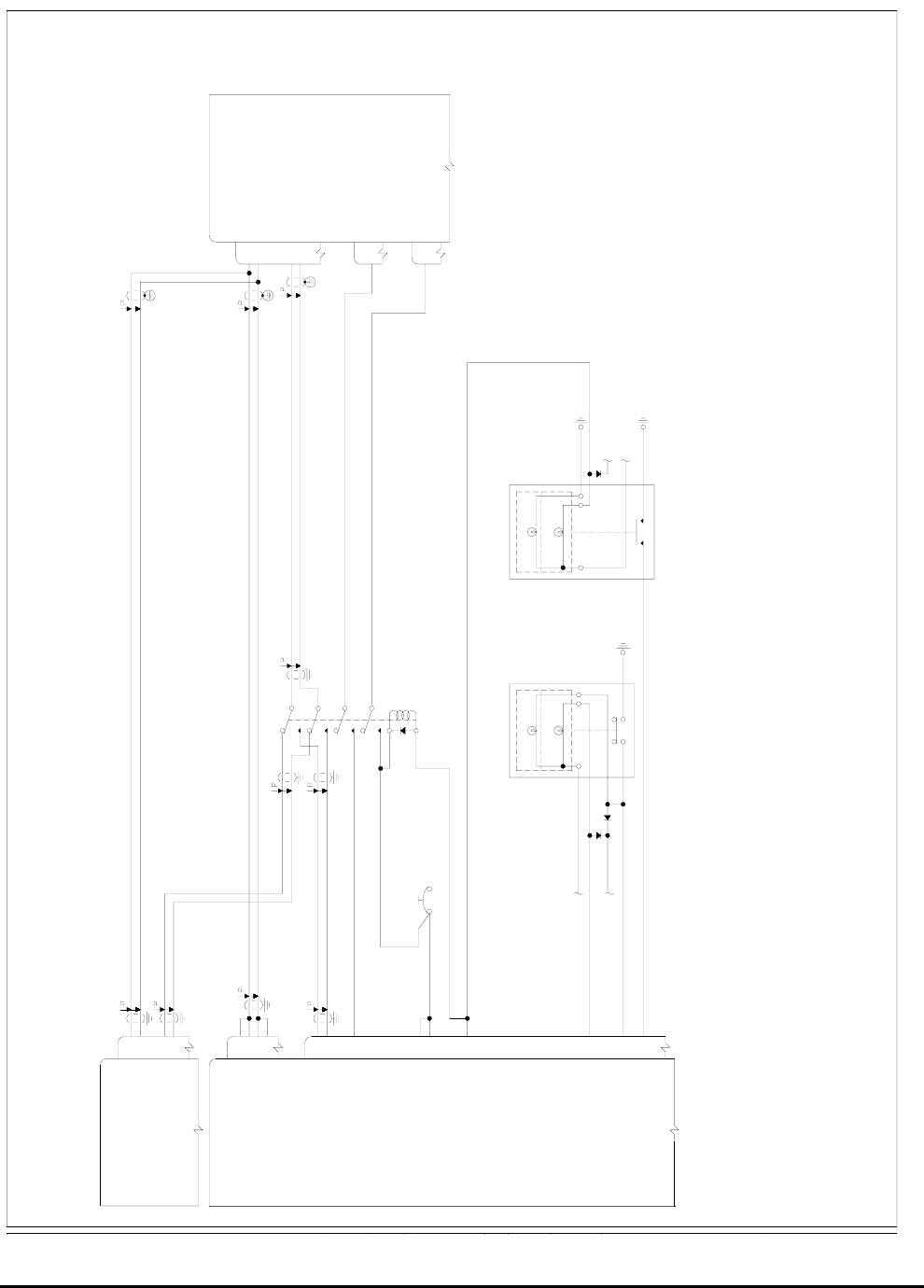
Honeywell
MK VI MK VIII EGPWS Installation Design Guide
Proprietary notice on title page applies
CAGE CODE: 97896 SCALE: NONE SIZE: A DWG NO: 060-4314-150 REV: SHEET 81
54
TERRAIN SELECT RELAY OUT
453 DATA BUS A OUT
BENDIX/KING
WEATHER RADAR R/T
SEE NOTE 2.
429 CONTROL BUS 1A IN
429 CONTROL BUS 1B IN
KCPB A OUT58
MARK VI/VIII ENHANCED GROUND
PROXIMITY WARNING COMPUTER
NO. 2 DISPLAY RANGE 429 A IN
NO. 1 DISPLAY RANGE 429 A IN
NO. 1 DISPLAY RANGE 429 B IN
NO. 2 DISPLAY RANGE 429 B IN
41
453 DATA BUS B OUT
J2
36
37
40
J1
SEE NOTE 3.KCPB B OUT
TERRAIN POP-UP OUT51
59
+28VDC POWER IN
+28VDC POWER IN
40
60
SEE NOTE 1.
SEE NOTE 1.
POWER
+28VDC AVIONICS
SEE NOTE 1.
EGPWS
SEE NOTE 1.
SEE NOTE 1.
68
81
P465
22
49
2B
SEE NOTE 1.
BENDIX/KING SG 465
MFD SYMBOL GENERATOR
R/T TRANSMITTER 429 A OUT
R/T TRANSMITTER 429 B OUT
453 DATA BUS B IN
453 DATA BUS A IN
1B
P465
37
22
P465
1A
TERRAIN POP-UP DISCRETE IN
TERRAIN SELECTED DISCRETE IN
ANNUNCIATOR DIMMER
PRESS-TO-TEST
TERRAIN INOP55
TERRAIN SELECT SWITCH IN
TERRAIN INHIBIT SWITCH IN12
32
TERRAIN INHIBIT
(ALTERNATE ACTION)
PRESS-TO-TEST
ANNUNCIATOR DIMMER
ANNUNCIATOR
BUS
EGPWS FAIL
TERRAIN
ON
ANNUNCIATOR
(MOMENTARY)
BUS
USE M17/176-0002 SHIELDED WIRE OR 024-00064-0000
QUADRAX CABLE FOR THE 453 DATA BUS AND THE KCPB.
REFER TO THE WEATHER RADAR SECTION OF THIS MANUAL
(3.13) FOR THE COMPLETE INTERFACE TO THE BENDIX/KING
THIS CONFIGURATION IS NOT SUPPORTED PRIOR TO EGPWS
THE CATEGORY 6 DISPLAY TYPE ID 10 (INTEGRATED EFIS 40/50)
THE CATEGORY 13 I/O DISCRETE TYPE ID 1 (LAMP FORMAT 2)
COMPUTER PART NUMBERS:
IS THE REQUIRED CONFIGURATION.
IS THE PREFERRED CONFIGURATION.
WEATHER RADARS.
2.
NOTES:
1.
3.
4.
965-1180-020 MARK VI EGPWS
965-1190-020 MARK VI EGPWS W/INTERNAL GPS
965-1210-020 MARK VIII EGPWS
965-1220-020 MARK VIII EGPWS W/INTERNAL GPS
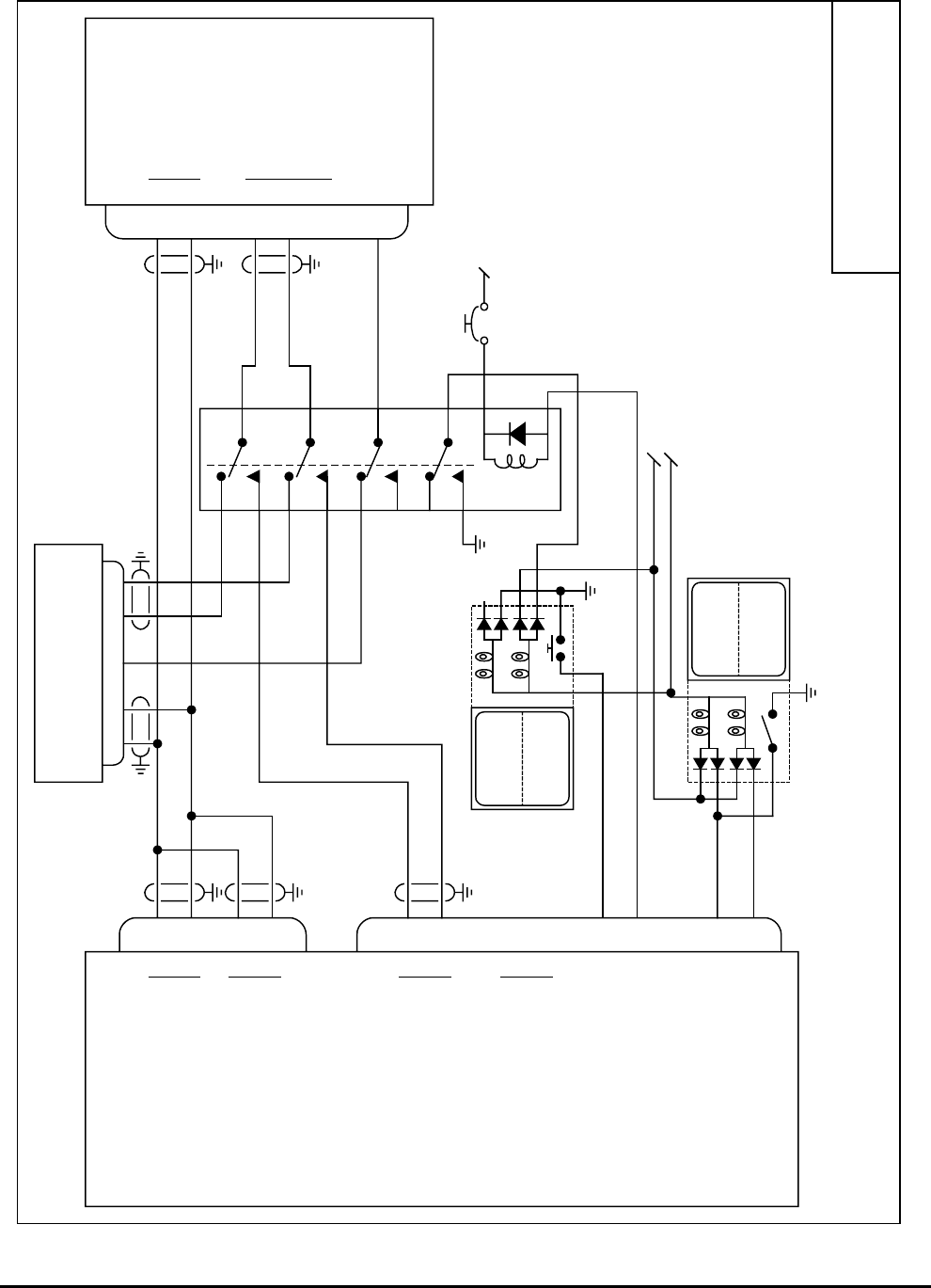
Honeywell
MK VI MK VIII EGPWS Installation Design Guide
Proprietary notice on title page applies
CAGE CODE: 97896 SCALE: NONE SIZE: A DWG NO: 060-4314-150 REV: SHEET 82
Rockwell Collins
WXI-701/711
J2
J1
10
11
5
12
37
36
41
40
58
59
56
57
TERR
INHIB
TERR
INOP
Lamp Test
28V Lamp Dimming Bus
Alternate Action
12
55
EGPWS
Collins WXI-701
Radar Indicator
A
B
ARINC 429 Range #1 In
A
B
ARINC 429 Range #2 In
A
B
ARINC 453 Video #1 Out
A
B
ARINC 453 Video #2 Out
Terrain Inhibit (in)
Terrain INOP (out)
MK VI 965-11X0-020 or later.
MK VIII 965-12X0-020 or later.
H
C
Control Bus A
T/R Data Bus
2041222-XXXX
WXI-701.vsd
NC
Collins WRX R/T
WRT-XXX
?? 8 9
TERR
ON
momentary
32
54
Terrain Display Select (in)
Terrain Display Select (out)
28V EGPWS PWR Bus
15 RT On/Off 1
6BJ1
A
B
6L
T/R Data Bus
70-ohm termination
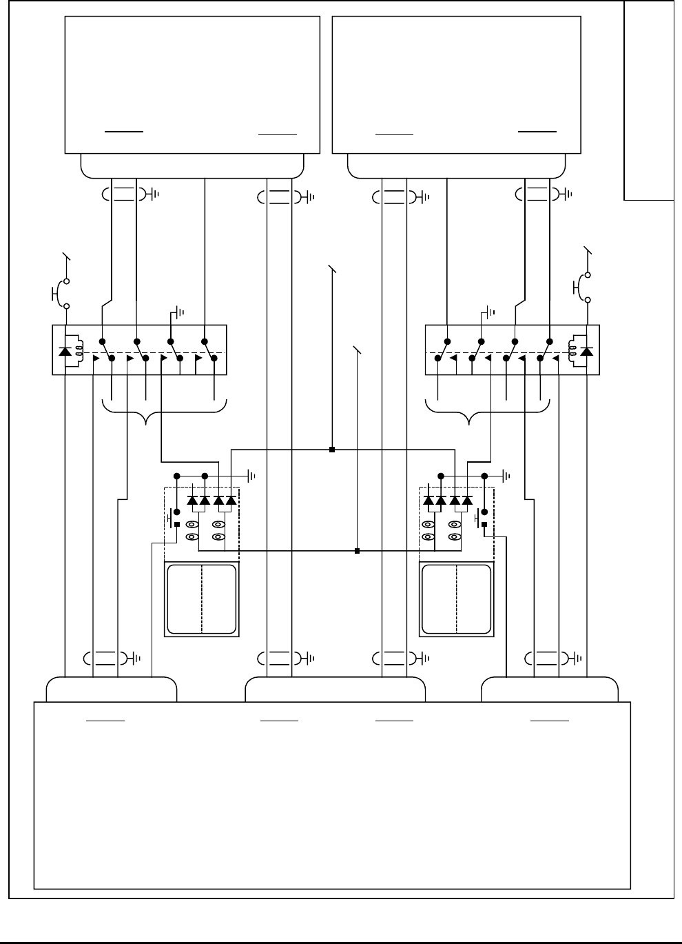
Honeywell
MK VI MK VIII EGPWS Installation Design Guide
Proprietary notice on title page applies
CAGE CODE: 97896 SCALE: NONE SIZE: A DWG NO: 060-4314-150 REV: SHEET 83
Collins ProLine II
with WXP-840/850
J2
15
16
18
19
36
37
58
59
Lamp Test
28V Lamp Dimming Bus
EGPWS
Collins Wx Pnl
WXP-840/850
A
B
ARINC 429 Range #1
A
B
ARINC 453 Video #1
MK VI 965-11X0-020 or later.
MK VIII 965-12X0-020 or later.
A
B
A
B
ARINC 429 Range
ARINC 453 Picture
Note:
For interface and operation of the Collins Proline II displays see Collins
SIL 2-99
CollinsP2.vsd
TERR
ON
momentary
31Terrain Display Select (in)
Terrain Display Select (out)
28V EGPWS
PWR Bus
11 Remote ON
J1
40
41
56
57
A
B
ARINC 429 Range #2
A
B
ARINC 453 Video #2
J1
18
19
Collins Wx Pnl
WXP-840/850
A
B
ARINC 453 Picture
28V EGPWS
PWR Bus
11 Remote ON
15
16
A
B
ARINC 429 Range
54
49
Terrain Display Select (out)
TERR
ON
momentary
31Terrain Display Select (in) To WX R/T
To
WX
R/T
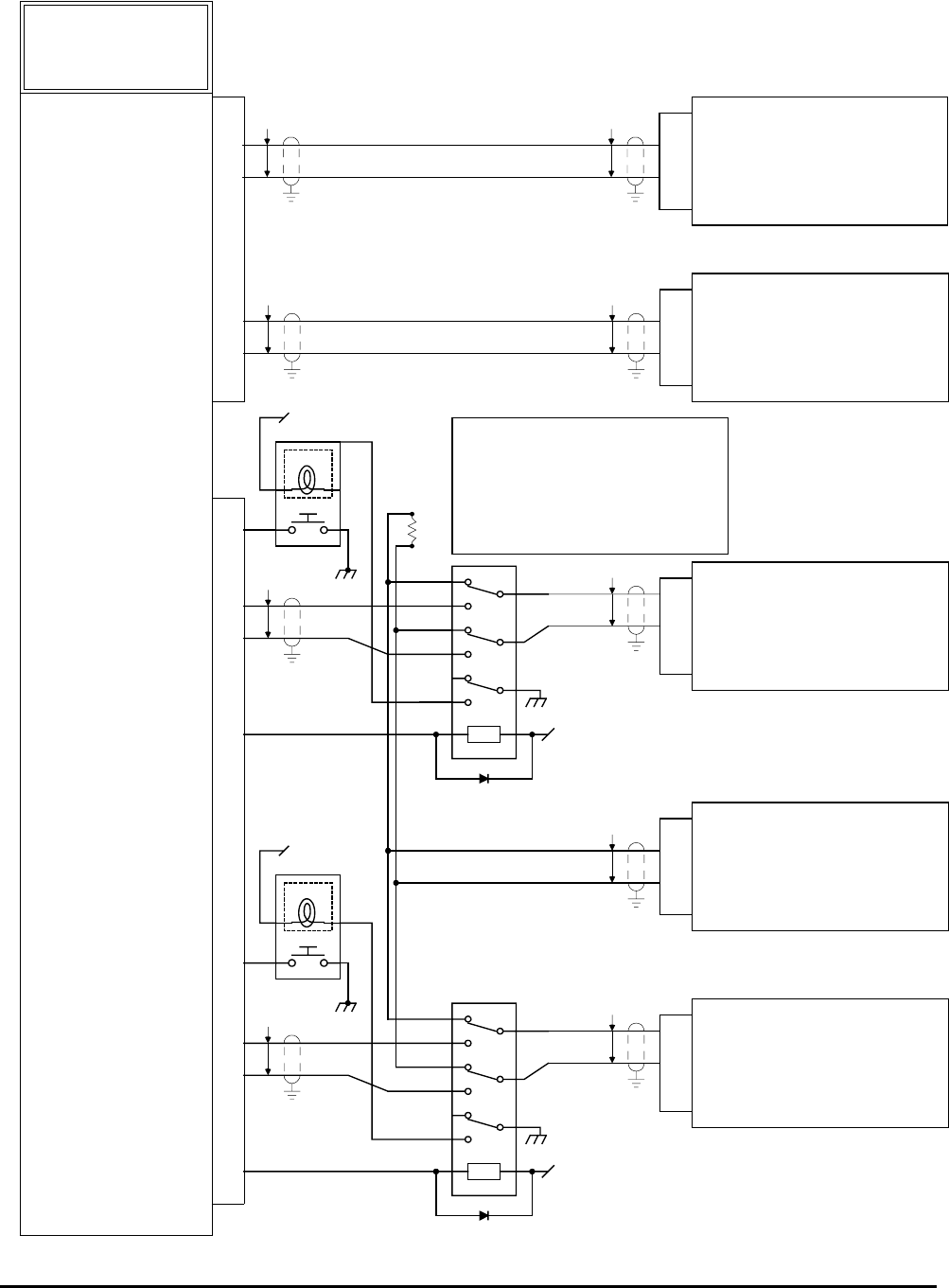
Honeywell
MK VI MK VIII EGPWS Installation Design Guide
Proprietary notice on title page applies
CAGE CODE: 97896 SCALE: NONE SIZE: A DWG NO: 060-4314-150 REV: SHEET 84
HONEYWELL
MK VI-VIII
EGPWS
965-1XXX-0XX
J2
ARINC 453 OUTPUT (A)
ARINC 453 OUTPUT (B)
58
59
P P
RANGE INPUT (A)
RANGE INPUT (B)
37
36
P
P
P1
3*
4*
#1 - IOC (ICC-4000)
PROLINE 4 INTERFACE
MK VI-VIII EGPWS Category 6, ID 5 or 6
P1
8D
10D
#1 - MFD
H - ARINC 453
L - (70 ohm terminated)
4
29
#1 - WXR
H
L
P
P1
P P
RANGE INPUT (A)
RANGE INPUT (B)
41
40
P1
3*
4*
#2 - IOC (ICC-4000)
ARINC 453 OUTPUT (A)
ARINC 453 OUTPUT (B)
56
57
P
PP1
8D
10D
#2 - MFD
H - ARINC 453
J1
LA-GP-5 bus (Label 271)
RA-GP-5 bus (Label 271)
* ICC-851A pins 13 & 14
* ICC-851A pins 13 & 14
11D L - (unterminated)
11D L - (unterminated)
L - (70 ohm terminated)
TERR RLY SELECT #1 54
TERR
+28 VDC
MOM TERR SELECT #1 32
TERR
+28 VDC
TERR RLY SELECT #2 49
MOM TERR SELECT #2 31
ARINC 453 OUT
+28 VDC
+28 VDC
70
!
*
* In the OEM installations a single weather radar 453
bus enters the left MFD, passes through, and is
terminated (70 ohm) at the right MFD. For EGPWS
installations break the 453 radar bus between the
MFDs, install switching relays, and wire one relay to
each MFD. The right MFD connection is moved to
remove the 70 ohm termination at that MFD. To allow
proper radar termination when EGPWS is passing
through the relays, the radar picture bus has a 70 ohm
resistor (added externally).
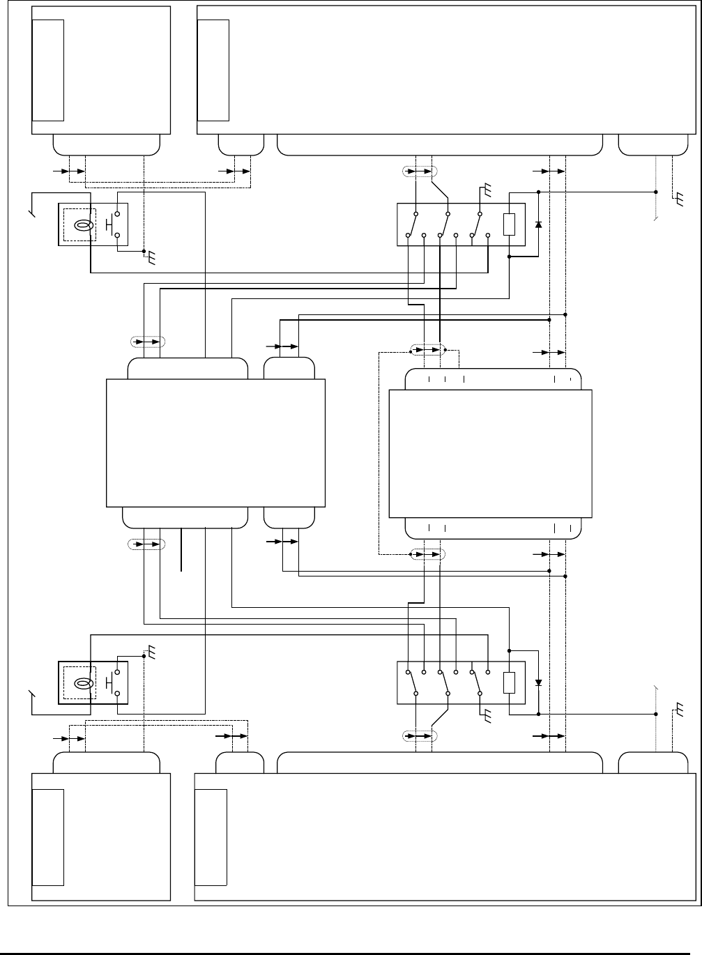
Honeywell
MK VI MK VIII EGPWS Installation Design Guide
Proprietary notice on title page applies
CAGE CODE: 97896 SCALE: NONE SIZE: A DWG NO: 060-4314-150 REV: SHEET 85
34
23
35
1
H
L
J1
LEFT DISPLAY
CONTROLLER
Controller Serial Data
WX pushbutton
GND
DC-810
TERR 34
23
35
1
H
L
J1 RIGHT DISPLAY
CONTROLLER
Controller Serial Data
WX pushbutton
GND
DC-810
TERR
L-EFIS +28 VDC R-EFIS +28 VDC
78
77
Controller Serial Data
J1A
LEFT SYMBOL
GENERATOR
SG-802
H
L78
77
H
L
J1A RIGHT SYMBOL
GENERATOR
Controller Serial Data
SG-802
1
2
J1B
H
L
WX/TERR
PICTURE BUS IN
22
23
H
L
1
2
J1B
H
L
22
23
H
L
J1
H
L
58
59
H
L
H
L
H
L
Radar Serial Data
J2A
3
5
+28V
GND
L-EFIS +28 VDC
J2A
3
5
R-EFIS +28 VDC
Radar Serial Data
+28V
GND
H
L
56
57
H
L
WX/TERR
PICTURE BUS IN
PN 7003400-802 PN 7003400-802
51
J1 J1
J2
H
L
36
37
J1
Radar R/T
MK VIII EGPWS
DISPLAY
BUS #1 DISPLAY
BUS #2
TERRAIN
POP UP
LT SCI
RANGE
g
h
k
s
Left Picture
Bus
Right Picture
Bus
q
Picture Bus Shield
m
n
Left EFIS
Control Bus
e
f
Right EFIS
Control Bus
WU-650
(HPN 7008470-XXX)
(HPN 965-12XX-020)
CAT 6: ID 243
SG-802/803
CAT. 6: ID 243
32 LT DISP
SELECT 31
RT DISP
SELECT
RT SCI
RANGE
J2
H
L
10
11
54 LT RELAY
SELECT 49
RT RELAY
SELECT
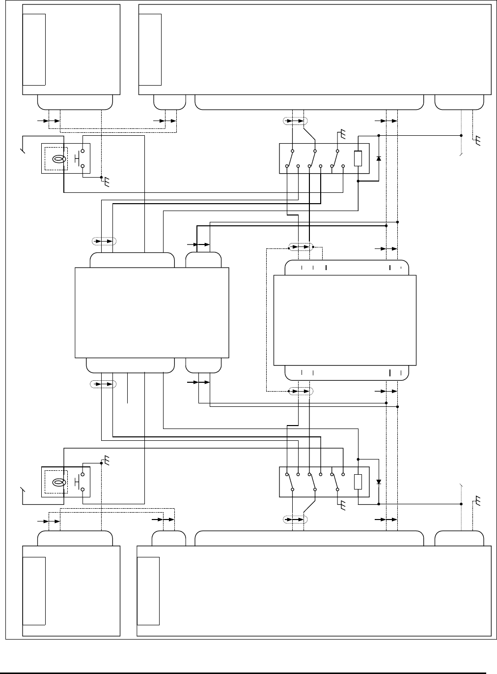
Honeywell
MK VI MK VIII EGPWS Installation Design Guide
Proprietary notice on title page applies
CAGE CODE: 97896 SCALE: NONE SIZE: A DWG NO: 060-4314-150 REV: SHEET 86
34
23
35
1
H
L
J1
LEFT DISPLAY
CONTROLLER
Controller Serial Data
WX pushbutton
GND
DC-811
TERR 34
23
35
1
H
L
J1 RIGHT DISPLAY
CONTROLLER
Controller Serial Data
WX pushbutton
GND
DC-811
TERR
L-EFIS +28 VDC R-EFIS +28 VDC
67
68
Controller Serial Data
J1A
LEFT SYMBOL
GENERATOR
SG-806
H
L67
68
H
L
J1A RIGHT SYMBOL
GENERATOR
Controller Serial Data
SG-806
30
31
J2B
H
L
WX/TERR
PICTURE BUS IN
32
33
H
L
30
31
J1B
H
L
32
33
H
L
J1
H
L
58
59
H
L
H
L
H
L
Radar Serial Data
J2A
1
8
+28V
GND
L-EFIS +28 VDC
J2A
1
8
R-EFIS +28 VDC
Radar Serial Data
+28V
GND
H
L
56
57
H
L
WX/TERR
PICTURE BUS IN
PN 7013788-806 PN 7013788-806
51
J1 J1
J2
H
L
36
37
J1
Radar R/T
MK VIII EGPWS
DISPLAY
BUS #1 DISPLAY
BUS #2
TERRAIN
POP UP
LT SCI
RANGE
g
h
k
s
Left Picture
Bus
Right Picture
Bus
q
Picture Bus Shield
m
n
Left EFIS
Control Bus
e
f
Right EFIS
Control Bus
WU-650
(HPN 7008470-XXX)
(HPN 965-12XX-020)
CAT 6: ID 244
SG-806
32 LT DISP
SELECT 31
RT DISP
SELECT
RT SCI
RANGE
J2
H
L
10
11
54 LT RELAY
SELECT 49
RT RELAY
SELECT
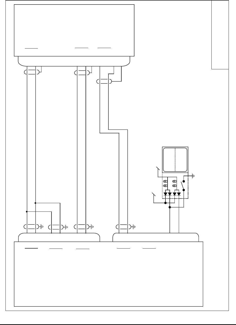
Honeywell
MK VI MK VIII EGPWS Installation Design Guide
Proprietary notice on title page applies
CAGE CODE: 97896 SCALE: NONE SIZE: A DWG NO: 060-4314-150 REV: SHEET 87
Universal MFD-640
J2
J1
P1
105
115
81
80
37
36
41
40
58
59
56
57
TERR
INHIB
TERR
INOP
Lamp Test
28V Lamp Dimming Bus
Alternate Action
12
55
EGPWS MFD-640
A
B
ARINC 429 Range #1 In
A
B
ARINC 429 Range #2 In
A
B
KCPB Video #1 Out
A
B
KCPB Video #2 Out
Terrain Inhibit (in)
Terrain INOP (out)
A
B
A
B
Range out *
Video in *
Note:
For interface and operation of the Universal MFD-640
see Universal Avionics Multi-Function Disaply Installation Manual
34-20-02
6402-1XXX1-0X
106
68
NC
43
42
A
B
ARINC 429 Control Out
94
95
A
B
Display Control In *
96
67
70 ohm termination
* configurable by MFD-640

Honeywell
MK VI MK VIII EGPWS Installation Design Guide
Proprietary notice on title page applies
CAGE CODE: 97896 SCALE: NONE SIZE: A DWG NO: 060-4314-150 REV: SHEET 88
3.9 Category 7 – Options Select Group #1
Category 7 enables/disables the following Options: Steep Approach, TA&D Alternate Pop Up, Peaks Mode,
Obstacle Awareness, Bank Angle, Flap Reversal, and GPS Altitude Reference.
Appendix E Table 5.3.7 defines the Options Select group and identifies the first MK VI/VIII EGPWS version in
which the option was available (see the Effectivity entry).
3.9.1 Steep Appr oach
This feature desensitizes the Mode 1 (Excessive Descent Rate) alert boundaries to permit safe but steeper than
normal instrument precision approaches (e.g. MLS or GPS approaches) without unwanted Mode 1 alerts.
Category 7 enables Steep Approach mode, Category 13 Steep Approach discrete (J2-31) cockpit switch,
activates/deactivates the Steep Approach function during flight.
3.9.2 TA&D Alter nate Pop-up
The Display Configuration Group Type (Category 6) defines default and alternate definitions for EGPWS alert
“Pop-up” behavior, when no terrain displays are active or when a combination of terrain and non-terrain displays
are active. (Some Display Configuration Group Types do not support an Alternate Pop-up definition.) See
Appendix E 5.3.6.1-X for definitions.
Category 7 enables/disables TA&D Alternate Pop Up.
3.9.3 Peaks Mod e
Peaks mode is an alternate means of displaying terrain data. The standard terrain display mode displays terrain
relative to the aircraft altitude that is within the aircraft envelope (the terrain is above or not more than 2000 feet
below the aircraft). The standard terrain display mode is typically blank during the cruise portion of a flight.
Peaks mode provides increased situational awareness by providing the same information as the standard
terrain display mode as well as displaying terrain outside of the aircraft envelope and the highest and lowest
elevations of terrain displayed. Peaks mode displays terrain based on the absolute terrain elevations.
Note: TAD and TCF must be enabled if Peaks mode is enabled. The Display Configuration Group (Category 6)
defines Peaks Mode availability by defining the effects of enabling and disabling the Peaks Mode enable. See
Appendix E 5.3.6.1-X for definitions.
Category 7 enables/disables Peaks Mode.
3.9.4 Obstacle A wareness
The Obstacle Awareness feature adds a database of (man-made) obstacles that are at least 100 feet taller than
the surrounding terrain and continuously computes obstacle clearance envelopes ahead of the aircraft, issuing
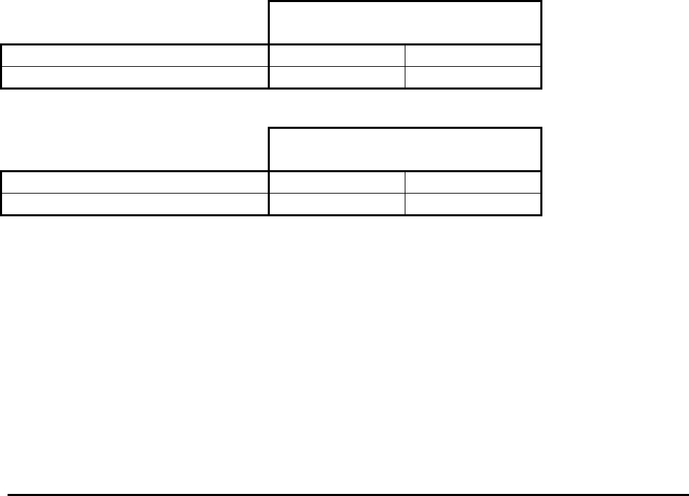
Honeywell
MK VI MK VIII EGPWS Installation Design Guide
Proprietary notice on title page applies
CAGE CODE: 97896 SCALE: NONE SIZE: A DWG NO: 060-4314-150 REV: SHEET 89
alerts if the boundaries of these envelopes conflict with obstacle elevation data in the obstacle database (similar
to the Terrain Awareness function). Obstacle data is currently available for North America and parts of the
Caribbean and Europe. Not all obstacles will be contained in the database.
Category 7 enables Obstacle Awareness if TA&D is not disabled in Category 6.
Note: TAD & TCF must be enabled if Obstacle Awareness is enabled.
3.9.5 Bank Angle Callout Enabling
The Bank Angle feature provides protection for over banking during maneuvering on approach or climb-out and
while at altitude. In addition, it protects against wing or engine strikes close to the runway. For airplanes fitted
with an autopilot, additional protection is provided if the autopilot is engaged by advancing the roll angle limit to
33 degrees. The additional ‘autopilot engaged’ protection applies to all software versions for GA FAST and GA
SLOW aircraft types, whereas it is available in software version –008 or later for Bizjet aircraft types. The Bank
Angle callout can be enabled or disabled as appropriate for this installation.
3.9.6 Flap Revers al
The Landing Flap discrete input is defined in Category 13. The Category 7 control is used to reverse the
defined logic to match aircraft wiring, if necessary.
+28 VDC Landing Flap discrete (J1-37) active position:
Flap Reversal
Flap Discrete (Category 13) False True
Landing Flap discrete = +28V Flaps Up Flaps Down
Landing Flap Discrete = Open (or GND) Flaps Down Flaps Up
Ground seeking Landing Flap discrete (J1-18) active position:
Flap Reversal
Flap Discrete (Category 13) False True
Landing Flap discrete = GND Flaps Up Flaps Down
Landing Flap Discrete = Open (or +28V) Flaps Down Flaps Up
3.9.7 GPS Altitud e Reference
The GPS Altitude (ARINC 429 label 076, Category 3) may be referenced to mean sea level (MSL) or WGS-84.
Determine which reference the GPS position uses and set the GPS Altitude Reference accordingly in this
Category.

Honeywell
MK VI MK VIII EGPWS Installation Design Guide
Proprietary notice on title page applies
CAGE CODE: 97896 SCALE: NONE SIZE: A DWG NO: 060-4314-150 REV: SHEET 90
3.9.8 Instruction s
Review the sections above for information on Steep Approach, TA&D Pop Up, Peaks Mode,
Obstacle Awareness, Bank Angle, Flap Reversal, and GPS Altitude Reference.
Using Appendix E Tables 5.2 and 5.3.7 as described above, select the preferred Category 7
(Options Select Group #1) ID that matches the aircraft configuration, features preferences and
version (part number) being installed.
Record the ID number for the Options Select Group #1 from Appendix E Table 5.3.7 under the
Ident No. heading for Step (Category) 7 in Appendix E Table 5.2.
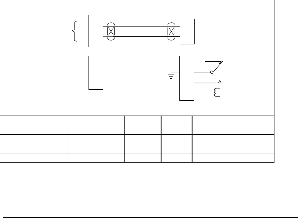
Honeywell
MK VI MK VIII EGPWS Installation Design Guide
Proprietary notice on title page applies
CAGE CODE: 97896 SCALE: NONE SIZE: A DWG NO: 060-4314-150 REV: SHEET 91
3.10 Category 8 – Radio Altitude Input Select
Category 8 defines the Radio Altitude and Decision Height interface.
3.10.1 Radio Altitu de Input
Appendix E Table 5.3.8 defines the Radio Altitude Types and identifies the first MK VI/MK VIII EGPWS version
in which the option was available (see Effectivity entry).
Appendix E Tables 5.3.8-x, where x is the Radio Altitude Type number, define the format and electrical
interfaces required to support each Radio Altitude Type.
3.10.2 Decision H eight Discrete Input
The Decision Height discrete (J1-33, Category 8) indicates to the MK VI/MK VIII EGPWC whether the aircraft is
above or below the selected Decision Height.
This discrete is typically connected to the Decision Height output on the Radio Altimeter indicator. If the
‘Minimums-Minimums’ callout is not wanted the Decision Height discrete should be left open.
3.10.3 Digital Rad io Altitude Interface (Cat. 8 ID 2)
21
4
J2
Radio Altimeter R/T
A
B
EGPWS MK VI / MK VIII
A
B
ARINC 429
Radio Altitude ARINC 429
DH Discrete (Gnd) 33
Radio Altimeter Indicator
DH out
J1
Digital-RA.vsd
DH wiper
Vendor Model Ind. DH R/T
R/T Indicator SCALE wiper/out A B
Collins RAC-870 ALI-55 ARINC 429 P1-R/V P1-2 P1-3
Honeywell ALA-52A/B ARINC 429 MP-B2 MP-B3
Honeywell KRA-405B KNI-415/416 ARINC 429 P1-M/A P4051-B P4051-C
NOTE: The connector pin numbers given in the Table above are to the best knowledge of Honeywell EGPWS engineering. Please
contact the manufacturer’s customer service to confirm your installation.
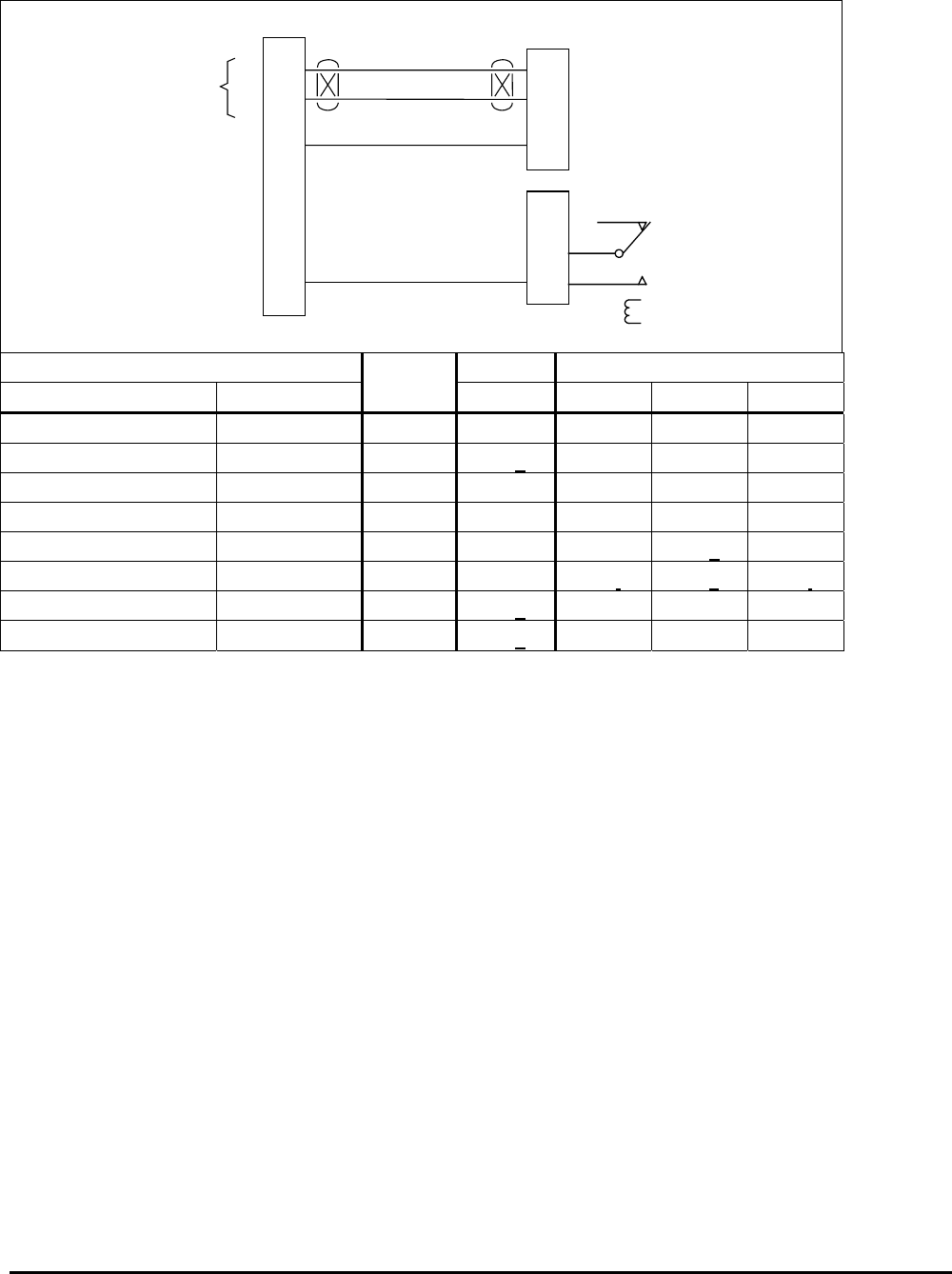
Honeywell
MK VI MK VIII EGPWS Installation Design Guide
Proprietary notice on title page applies
CAGE CODE: 97896 SCALE: NONE SIZE: A DWG NO: 060-4314-150 REV: SHEET 92
3.10.4 Analog Rad io Altitude Interface (Cat. 8 ID 0,1,3,4)
64
45
29
J1
Radio Altimeter R/T
+
-
EGPWS MK VI / MK VIII
(+)
(-)
Analog Radio Altitude ARINC 552, ALT 55,
RT-200/300
Radio Altitude Valid +28V Valid
DH Discrete (Gnd) 33
Radio Altimeter Indicator
DH wiper
DH out
Analog-RA.vsd
Vendor Model Cat. Ind. DH R/T
R/T Indicator ID wiper/out + - Valid
Collins ALT 55 ALI-55 1 P1-R/V P1-57 P1-59 P1-49
Honeywell HG7502(BC) JG1072( ) 0 P1-e P4-47 P4-46 P4-27
Honeywell RT-221/300 (1) RA-315 0 P1-F P1-X P1-N P1-Y
Honeywell RT-220/300 (2) RA-215 3 P1-F P1-N P1-W P1-Y
Honeywell KRA-405 KNI-415/416 4 P1-M/A P1-B P1-g P1-L
Honeywell KRA-405B KNI-415/416 4 P1-M/A P1-i P1-k P1-j
Honeywell ALA-51A INA-51( ) 0 P2-e P1B-47 P1B-46 P1B-27
Collins 860F-1 339H-1/-2 0 P1-e P1B-47 P1B-46 P1B-27
NOTE: The connector pin numbers given in the Table above are to the best knowledge of Honeywell EGPWS engineering. Please
contact the manufacturer’s customer service to confirm your installation.
NOTE 1: The following RT-300 part numbers meet ARINC 552 for the Auxiliary Output: 7001840 -902, -906, -912, -
916, -917, -918, -922, -926, -928, -932, -936, -937, and -938. RT-221’s are also compatible, consult your
Honeywell representative.
NOTE 2: This is the Precision Output from the R/T. Note the + and – signals are swapped to convert the –
4mV to +4mV. RT-300 (-901, -903, -905) should use the Precision Output, same as RT-220.
3.10.5 Digital – AR INC 429 Dual IOC Buses (Cat. 8 ID 251- 255)
Radio Altitude Type 251 (IOC bus or equivalent) is a dual high speed, digital ARINC 429 signal having labels
164 and 170. Radio Altitude Type 252 (IOC bus or equivalent) is a dual high speed, digital ARINC 429 signal
having labels 164 and 370. Radio Altitude Type 253 (IOC bus or equivalent) is a dual high speed, digital ARINC
429 signal having label 164 and a analog discrete DH input. Radio Altitude Type 254 (IOC bus or equivalent) is
a dual high speed, digital ARINC 429 signal having labels 164, 170 and 370. Radio Altitude Type 255 (IOC bus
or equivalent) is a dual high speed, digital ARINC 429 signal having labels 164 and 370. For interface
description see paragraph 3.4.5 Air Data Type 255.

Honeywell
MK VI MK VIII EGPWS Installation Design Guide
Proprietary notice on title page applies
CAGE CODE: 97896 SCALE: NONE SIZE: A DWG NO: 060-4314-150 REV: SHEET 93
3.10.6 Instruction s
Using Appendix E Tables 5.2, 5.3.8 and 5.3.8-x as described above, select the Radio Altitude
Input Type that matches the aircraft configuration, features preferences and version (part
number) being installed.
Record the ID number for the Radio Altitude Type from Appendix E Table 5.3.8 under the Ident
No. heading for Step (Category) 8 in Appendix E Table 5.2.
Using the Radio Altitude Type number from Appendix E Table 5.3.8 as x, go to Appendix E Table
5.3.8-x.
The electrical interfaces (pin-outs) for Radio Altitude Type are shown in Appendix E Table 5.3.8-x
and are used to generate the installation wiring diagrams.

Honeywell
MK VI MK VIII EGPWS Installation Design Guide
Proprietary notice on title page applies
CAGE CODE: 97896 SCALE: NONE SIZE: A DWG NO: 060-4314-150 REV: SHEET 94
3.11 Category 9 – Navigation Inputs Select
Category 9 selects the Glideslope and Localizer Deviation interfaces and Glideslope Validity and ILS Tuned
discretes.
Appendix E Table 5.3.9 defines the Category 9 Navigation Inputs Select options (called Navigation Inputs Select
Types) and identifies the first MK VI/VIII EGPWS version in which the option was available (see the Effectivity
entry).
Appendix E Tables 5.3.9-x, where x is the Navigation Inputs Select Type number, define the format and
electrical interfaces required to support each Navigation Input Select Type.
3.11.1 Navigation Inputs Select (Glideslope & Localizer Inputs)
Glideslope Deviation is basic (required) and is available in analog and digital formats. Localizer Deviation is an
enhancement (not required).
Note: Numerous (but not all) Envelope Modulation cases require a localizer input. Therefore a NAV ID
that supplies both Glideslope and Localizer should be selected in this category if possible.
However, due to hardware limitations, use of localizer for installations that can only provide low
level validity is not supported. In these cases only ID #1 can be selected. Envelope Modulation
will still function for these glideslope only installations, but not for those envelope modulation
areas that require a localizer crosscheck.
3.11.2 Glideslope Validity
Glideslope Validity (+28V Super Flag) is required for Navigation Inputs Select 0 or 5 at pin J1-11.
Glideslope Validity (Low Level) is required for Navigation Inputs Select 1 at pins J1-30 (+) and J1-10 (-).
Digital 429 Glideslope interfaces do not require Glideslope Validity input.
3.11.3 Localizer V alidity
Localizer Validity (+28V Super Flag) is required for Navigation Inputs Select 5 at pin J1-48.
Digital 429 Localizer interfaces do not require Localizer Validity input.
3.11.4 ILS Tuned D iscrete Input #1 (+28V) and #2 (GND)
The ILS Tuned Discretes (+28V and GND) indicate that an Instrument Landing System frequency has been
selected on the Captain’s (or selected) ILS (only one is required). These discretes are used with the analog
Glideslope inputs. When an ILS is tuned, the MK VI/MK VIII EGPWS checks the Glideslope Validity discretes
and monitors the Glideslope inputs.
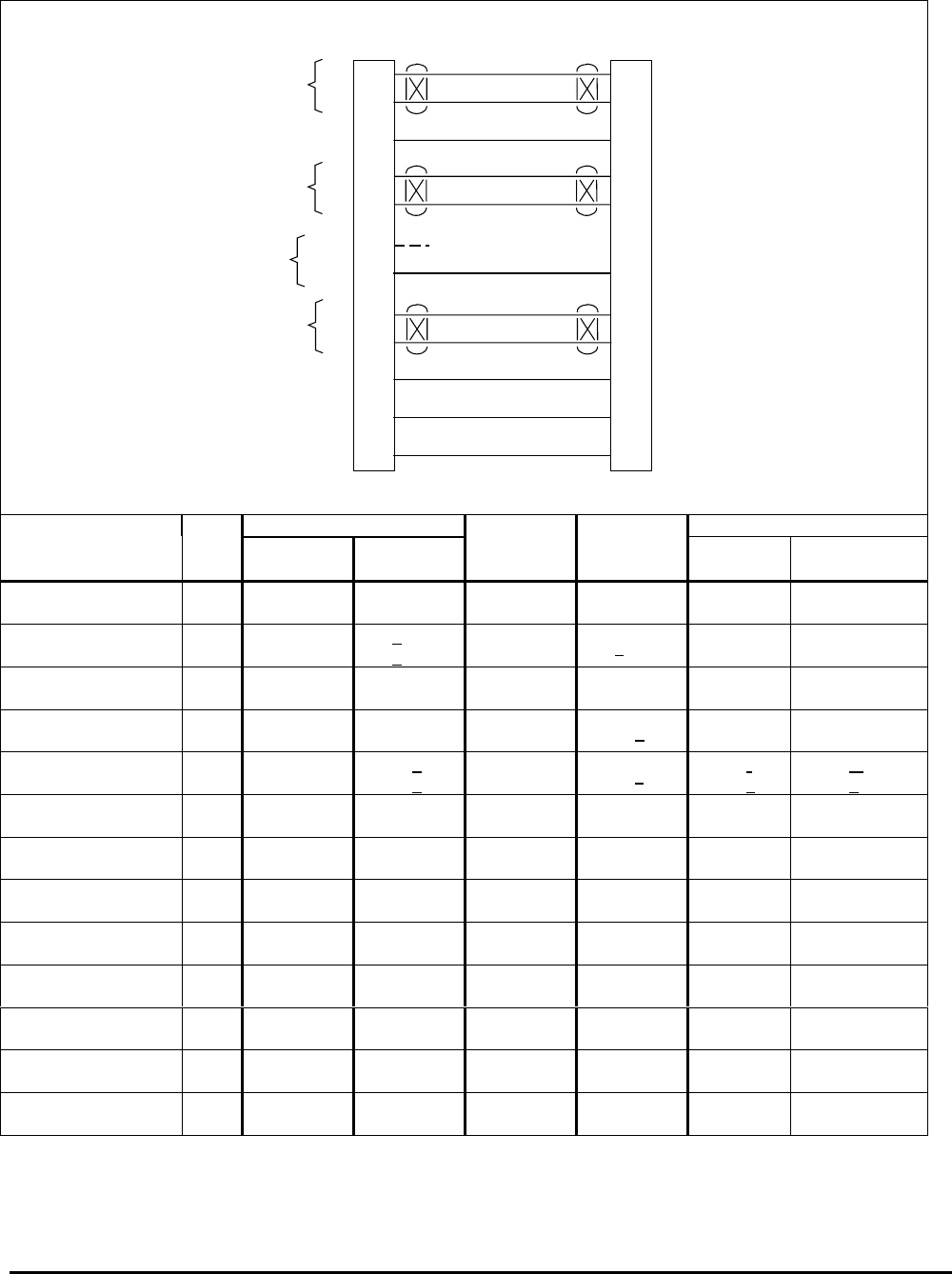
Honeywell
MK VI MK VIII EGPWS Installation Design Guide
Proprietary notice on title page applies
CAGE CODE: 97896 SCALE: NONE SIZE: A DWG NO: 060-4314-150 REV: SHEET 95
3.11.5 Analog Glid eslope Interface (Cat. 9 ID 0,1,5)
J1
ILS Receiver
EGPWS MK VI / MK VIII
GS Valid +28
11
+
-
Low Level
GS Valid
+28
GND
ILS
Tuned
+
-
GS Deviation 65
46
30
10
39
20
Super Flag +28V
+
-
Delayed ILS Mode
ILS Energize
GS Flag
(Low Level)
+Up
+Dn
GS Deviation
Analog-ILS-1.vsd
LOC Valid +28
48
LOC Val +28V
+
-
LOC Deviation 30
10
+L
+R
LOC Deviation
GS Inhibit (BC) +28
38
Backcourse
GS Inhibit (BC) GND
19
Backcourse
GS Valid LOC Valid ILS Tuned Deviation
Vendor Model Cat. 9
ID
SuperFlag
+28V
Low Level
Flag
SuperFlag
+28V GND GS +up
+dn
LOC +R
+L
Honeywell
KNR 6030 5 J1003-27 J1003-21
J1003-22 J1002-50 J1002-18 J1003-8
J1003-9
J1002-39
J1002-40
Honeywell
KNR 660 1P1-e
P1-q P1-k P1-T
P1-V
Honeywell
KNR 634 15 P6342-50 P6342-34
P6342-18 P6342-49 P6341-17 P6342-36
P6342-35
P6342-23
P6342-7
Honeywell
KGM-691 0 P692-W P692-S
P692-T P692-a P692-B
P692-C
Honeywell
KNR 600A 1P601-e
P601-q P601-A P601-k P601-r
P601-s
P601-m
P601-n
Collins
51RV-1, 51RV-4( ) 5 TP-27 2TP-21
TP-22 BP-50 BP-18 TP-8
TP-9
BP-39
BP-40
Collins
VIR-30, -31, -32 5 P1-17 P1-9
P1-13 P2-18 P2-40 P1-5
P1-1
P2-10
P2-13
Honeywell
VNS 41A 5 P1001-60 P1001-101 J1001-56 J1001-90
J1001-23
J1001-38
J1001-92
Honeywell
RNA-34A 5 TP-27 TP-21 BP-50 BP-18 TP-8
TP-9
BP-39
BP-40
Honeywell
KN 53 1P2-13
P2-R P2-12 P2-P
P2-14
Honeywell
KN 72
P1-2
P1-10
Honeywell
RNZ 850 5P1-A74 P1-B60
P1-B106 P1-B91 P1-B64 P1-B79
P1-B75
P1-B78
P1-B75
Honeywell
KX-155/165 1P901-U
P901-R P401-14 P401-8 P901-S
P901-T
P901-s (KX-165)
P901-k (only
NOTE: The connector pin numbers given in the Table above are to the best knowledge of Honeywell EGPWS engineering. ePlease
contact the manufacturer’s customer service to confirm your installation.
1 066-1078-00, -01, -04, -05, -10, -11, -14 and –15 only.
2 51RV-4( ) only.
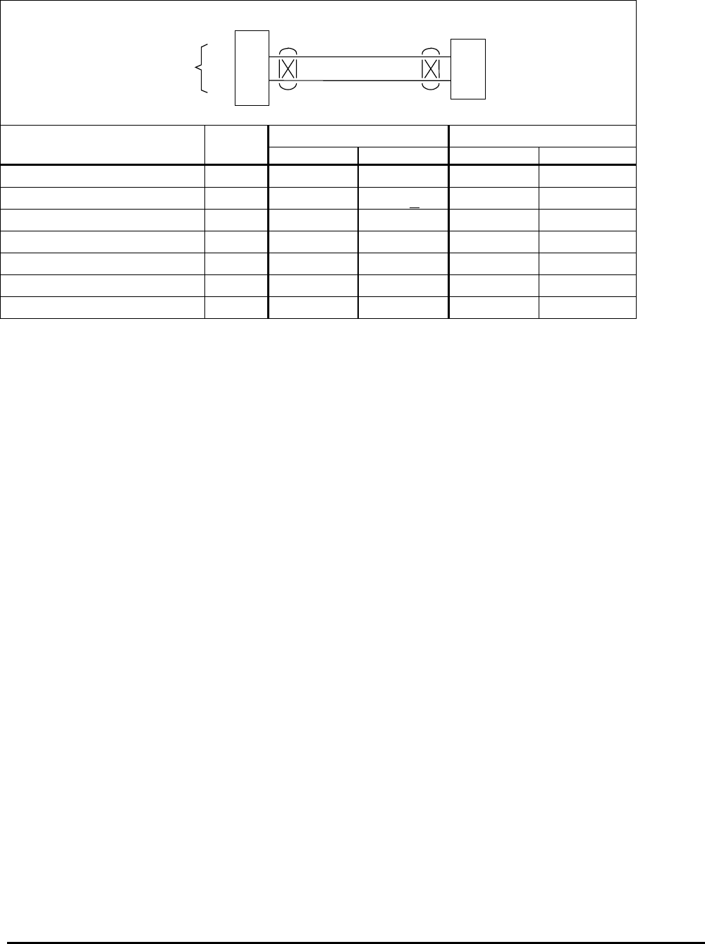
Honeywell
MK VI MK VIII EGPWS Installation Design Guide
Proprietary notice on title page applies
CAGE CODE: 97896 SCALE: NONE SIZE: A DWG NO: 060-4314-150 REV: SHEET 96
3.11.6 Digital Glid eslope / Localizer / ILS Select Interface (Cat. 9 ID 2,3,4)
22
5
J2
ILS 429 Bus
A
B
EGPWS MK VI / MK VIII
A
B
ARINC 429 ILS
ARINC 429
Low Speed
Digital-ILS.vsd
Vendor Model Cat 9 ARINC 429 Bus 1 ARINC 429 Bus 2
IDABA B
Honeywell KNR 634A 2,3 P6342-41 P6342-42 P6342-44 P6342-45
Chelton VNS 411A 2,3 P1-C P1-D
Chelton VNS 411B 2,3 P1001-62 P1001-103
Honeywell RNA-34A 2,3 P1024-24 P1024-28 P1024-21 P1024-25
Honeywell KN 40A(B) 4 P401(403)-41 P401(403)-42 P401(403)-44 P401(403)-45
Collins VIR-432 2,3 P1-35 P1-36 P1-22 P1-23
Garmin GNS-430 2,3 P4006-24 P4006-23
NOTE: The connector pin numbers given in the Table above are to the best knowledge of Honeywell EGPWS engineering. Please
contact the manufacturer’s customer service to confirm your installation.
3.11.7 Digital – AR INC 429 Dual IOC buses (Cat. 9 ID 250 - 255)
Navigation Input Select Type 250 - 255 (IOC bus or equivalent) are dual high speed, digital ARINC 429 buses
having the following labels:
250 100, 163, 173, and 174
251 100, 173, and 174
252 173 and 174 *
253 173 and 174
254 163, 173, and 174
255 117 and 116
For interface description see paragraph 3.4.5 Air Data Type 255. Note * ID 252 uses a special interface to input
channels 2 and 5.

Honeywell
MK VI MK VIII EGPWS Installation Design Guide
Proprietary notice on title page applies
CAGE CODE: 97896 SCALE: NONE SIZE: A DWG NO: 060-4314-150 REV: SHEET 97
3.11.8 Instruction s
Using Appendix E Tables 5.2, 5.3.9 and 5.3.9-x as described above, select the Navigation Input
Select Type that matches the aircraft configuration, feature preferences, and version (part number)
being installed.
Record the ID number for the Navigation Inputs Select Type from Appendix E Table 5.3.9 under the
Ident No. heading for Step (Category) 9 in Appendix E Table 5.2.
Using the Navigation Inputs Select number from Appendix E Table 5.3.9 as “x”, go to Appendix E
Table 5.3.9-x.
The electrical interfaces (pin-outs) for the Navigation Inputs Select Type are shown in Appendix E
Table 5.3.9-x) and are used to generate the installation wiring diagrams.
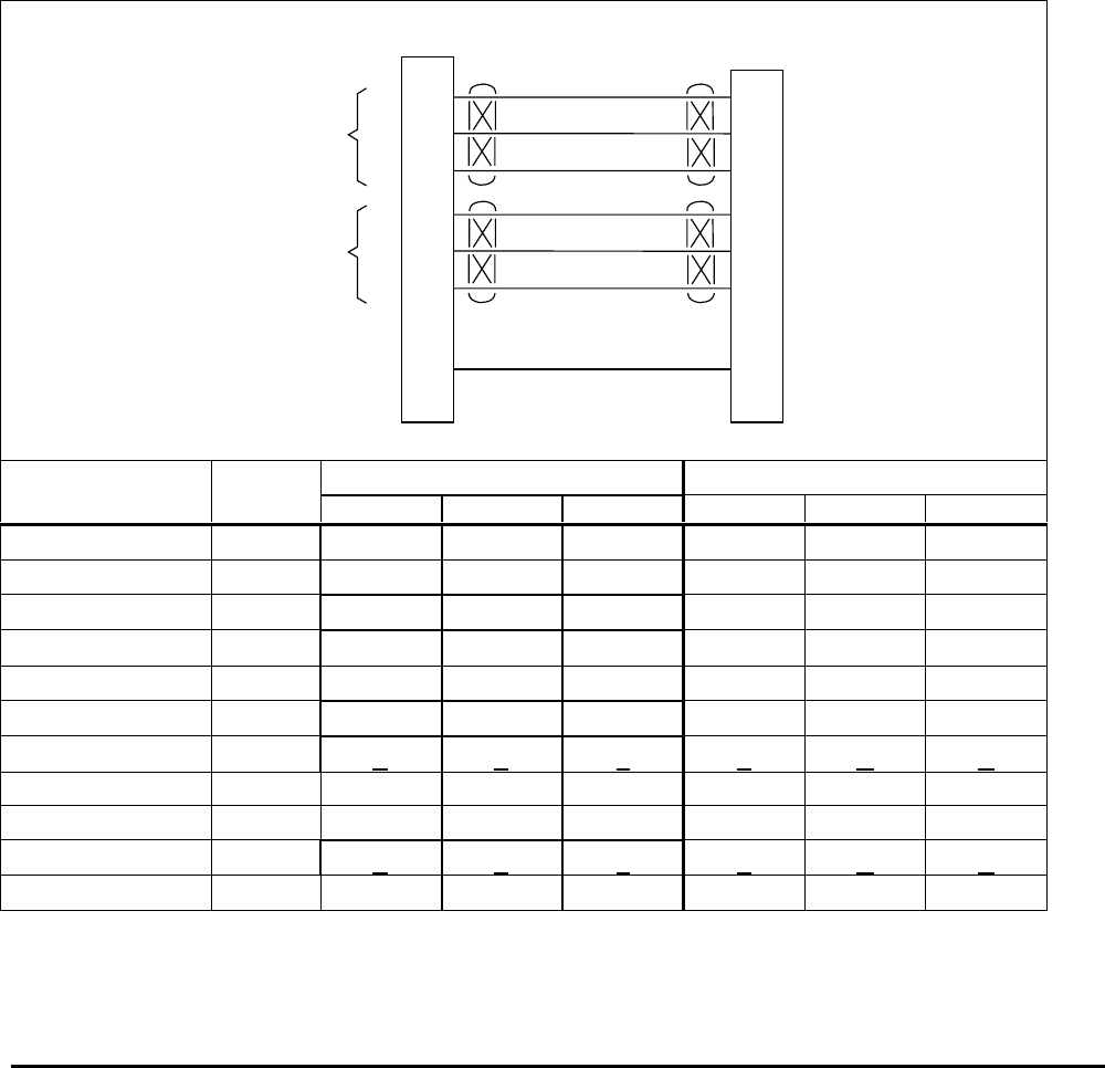
Honeywell
MK VI MK VIII EGPWS Installation Design Guide
Proprietary notice on title page applies
CAGE CODE: 97896 SCALE: NONE SIZE: A DWG NO: 060-4314-150 REV: SHEET 98
3.12 Category 1 0 – Attitude Input Select
Category 10 defines the Roll Angle interface.
Appendix E Table 5.3.10 defines the Attitude Input Select type and identifies the first MK VI/VIII EGPWS version
in which the option was available (see the Effectivity entry).
Appendix E Tables 5.3.10-x, where x is the Attitude Input Select Type number, define the format and electrical
interfaces required to support each Attitude Input Select Type.
3.12.1 Roll Angle
Roll Angle is used for Bank Angle callout and Terrain Awareness display. Each leg of the Roll Synchro is
required. The sign is used to determine left/right wing down. This input improves the TAD look ahead algorithm.
3.12.2 Analog Pitc h & Roll Angle (Synchro) (Cat. 10 ID 0,2,4)
1
21
2
J1
Vertical Gyro
X
Y
X
Y
Roll Synchro Roll Angle
ZZ
Attitude Validity
5
7
6
X
Y
X
Y
Pitch Synchro Pitch Angle
ZZ
68 +28 = Valid
Analog-VG.vsd
EGPWS MK
VI / MK VIII
Vendor Model Attitude Pitch Synchro (Note 1) Roll Synchro (Note 1)
Vertical Gyro Valid +28 XYZXYZ
Aeronetics RVG 801 P1-U P1-A P1-B P1-C P1-D P1-E P1-F
Collins AHC-85( ) P1-13 P2-50 P2-51 P2-52 P2-42 P2-43 P2-44
Collins 332D-11 P1-N P1-A P1-B P1-C P1-D P1-E P1-F
Honeywell HG1075 J1B-G3 J1B-C9 J1B-C10 J1B-C11 J1B-D9 J1B-D10 J1B-D11
Honeywell HG1095 J1B-G3 J1B-C9 J1B-C10 J1B-C11 J1B-D9 J1B-D10 J1B-D11
JET VG-208 P1-U P1-A P1-B P1-C P1-D P1-E P1-F
King KVG-350 GG/FF X Y Z P Q R
Litef LTR-81 MP-A11 MP-B1 MP-B2 MP-B3 MP-B4 MP-B5 MP-B6
Litef LCR-92 & 93 Note 2 J3-11 J3-40 J3-26 J3-16 J3-39 J3-25
Sperry VG-14A GG/FF X Y Z P Q R
Sperry VG-311 P1-45 P1-5 P1-4 P1-6 P1-7 P1-8 P1-9
Note 1: The connector pin numbers given in the Table above are to the best knowledge of Honeywell EGPWS engineering. Please
contact the manufacturer’s customer service to confirm your installation.
Note 2: See LCR installation manual.
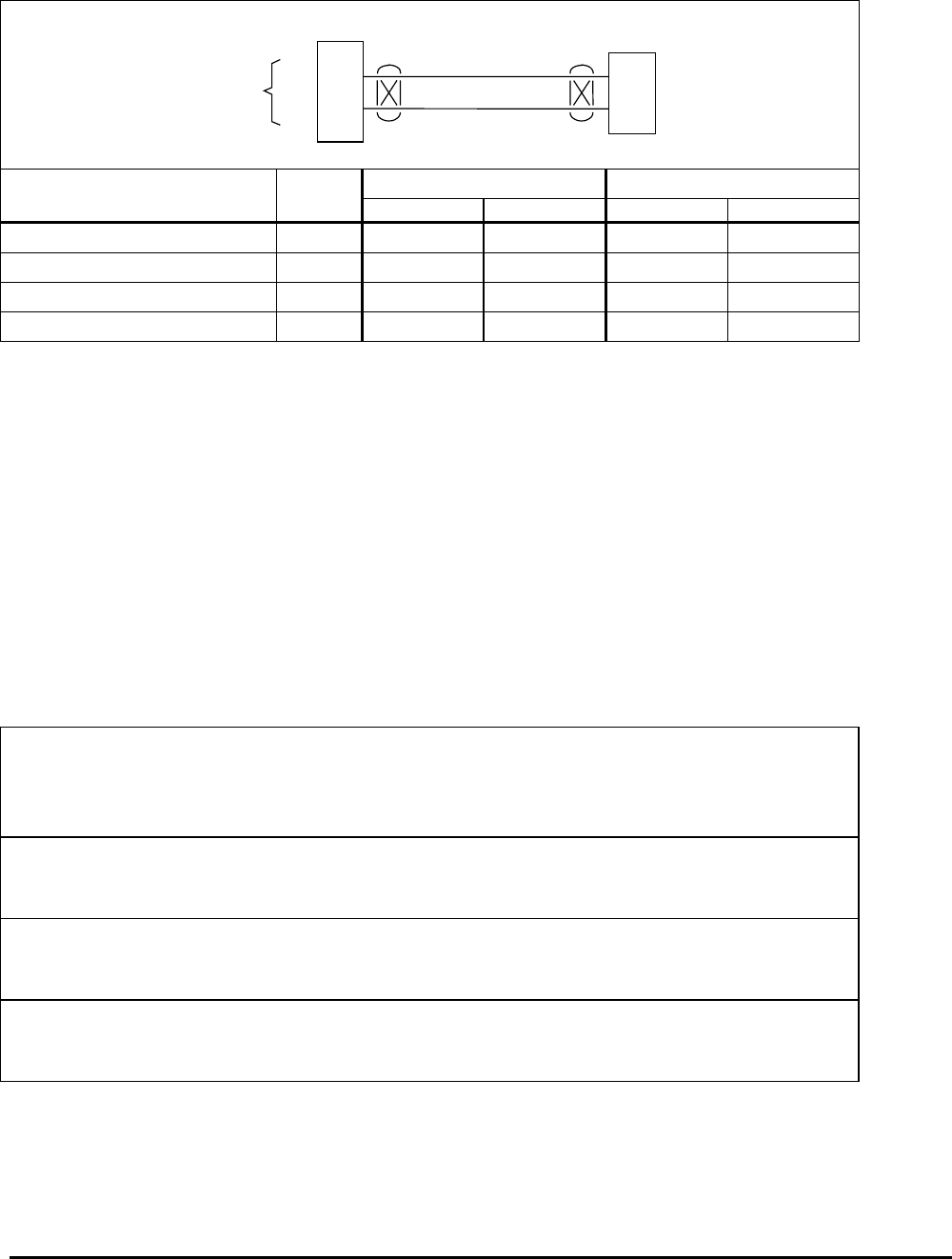
Honeywell
MK VI MK VIII EGPWS Installation Design Guide
Proprietary notice on title page applies
CAGE CODE: 97896 SCALE: NONE SIZE: A DWG NO: 060-4314-150 REV: SHEET 99
3.12.3 Digital Pitc h & Roll Angle (ARINC 429 High Speed) (Cat. 10 ID 5 & 6)
23
6
J2
AHRS 429 Bus
A
B
EGPWS MK VI / MK VIII
A
B
ARINC 429 AHRS
ARINC 429
High Speed
Digital-AHRS.vsd
Vendor Model Cat 10 ARINC 429 Bus 1 ARINC 429 Bus 2
IDABA B
Collins AHC-85(D/E only) 6* P1-16 P1-14 P1-24 P1-22
Litef LTR-81 AHRS 6* MP-G7 MP-G8 MP-E5 MP-E6
Litef LCR-92/LCR-93 AHRS 6* J4-08 J4-29 J4-49 J4-07
Honeywell HG1075/1095 IRU 6* J1B-G7 J1B-G8 J1B-E5 J1B-E6
NOTE: The connector pin numbers given in the Table above are to the best knowledge of Honeywell EGPWS engineering. Please
contact the manufacturer’s customer service to confirm your installation.
* ID 6 is preferred with Category 2 Air Data with ARINC 429 Barometric Altitude Rate (label 212), otherwise ID 5. ID 6 cannot be
used with analog Air Data interfaces.
3.12.4 Digital – AR INC 429 Dual IOC buses (Cat. 10 ID 253 & 255)
Attitude Input Select Type 253 (IOC bus or equivalent) is a dual high speed, digital ARINC 429 signal having
labels 324, 325, 326, 327, 365 and 361. Attitude Input Select Type 255 (IOC bus or equivalent) is a dual high
speed, digital ARINC 429 signal having labels 324, 325, 333 and 331. For interface description see paragraph
3.4.5 Air Data Type 255.
3.12.5 Instruction s
Using Appendix E Tables 5.2, 5.3.10 and 5.3.10-x as described above, select the Attitude Input
Select type that matches the aircraft configuration, feature preferences, and version (part number)
being installed.
Record the ID number for the Attitude Input Select from Appendix E Table 5.3.10 under the Ident
No. heading for Step (Category) 10 in Appendix E Table 5.2.
Using the Attitude Input Select ID number from Appendix E Table 5.3.10 as “x”, go to Appendix E
Table 5.3.10-x.
The electrical interfaces (pin-outs) for the Attitude Input Select Type are shown in Appendix E
Table 5.3.10-x and are used to generate the installation wiring diagrams.
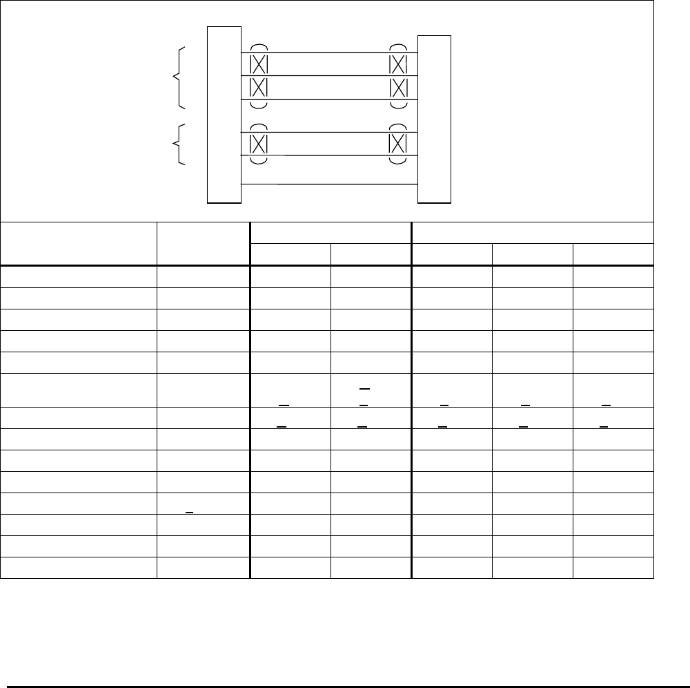
Honeywell
MK VI MK VIII EGPWS Installation Design Guide
Proprietary notice on title page applies
CAGE CODE: 97896 SCALE: NONE SIZE: A DWG NO: 060-4314-150 REV: SHEET 100
3.13 Category 1 1 – Heading Input Select
Category 11 defines the Magnetic Heading interface.
Appendix E Table 5.3.11 defines the Heading Input Select types and identifies the first MK VI/VIII EGPWS
version in which the option was available (see the Effectivity entry).
Appendix E Tables 5.3.11-x, where x is the Heading Input Select number, define the format and electrical
interfaces required to support each Heading Input Select Type.
3.13.1 Magnetic H eading
Magnetic Heading is used for Terrain Awareness alert and display.
3.13.2 Analog Hea ding (Synchro) (Cat. 11 ID 0)
22
23
3
J1
Directional Gyro
X
Y
EGPWS MK VI / MK VIII
X
Y
Heading Synchro
Heading
ZZ
H
C
4
24
26 VAC Reference H
C
Heading Ref
28Mag Hdg Validity
+28V = Valid
Analog-HDG.vsd
Vendor Model Heading Heading Reference Heading Synchro (Note 1)
Directional Gyro Valid H C X Y Z
Aeronetics Model 9100 P1-28 P1-6 P1-7 P1-8 P1-9 P1-10
Collins 332E-4 P1-F P1-D P1-E P1-A P1-B P1-C
Collins AHC-85( ) P1-9 P2-57 P2-58 P2-34 P2-35 P2-36
Collins DGS-65 P1-50 P1-6 P1-3 P1-25 P1-40 P1-24
Honeywell HG1075/1095 J1B-G2 J1B-F13 J1B-G13 J1B-E10 J1B-E11 J1B-E12
Honeywell KSG 105 P1-V P1-P 1
P1-C 2
P1-D 1
P1-F 2
P1-Z 1
P1-T 2
P1-W 1
P1-P 2
P1-T 1
P1-K 2
Honeywell KI-525 3(KG-102) J2-P J2-R J2-U J2-S J2-V J2-T
JET DN-104 P2-31 P2-9 P2-10 P2-1 P2-2 P2-3
Litef LTR-81 MP-E15 MP-B12 MP-B13 MP-B9 MP-B10 MP-B11
Litef LCR-92/LCR-93 Note 2 J3-05 J3-20 J3-13 J3-42 J3-28
Sperry C-14A3P1-e P1-H 1P1-J 1P1-L 1P1-M 1P1-K 1
Sperry C-14D3P1-DD P1-X P1-Y P1-AA P1-BB P1-Z
Sperry DG-234 P2-F P1-L P1-K P1-J
Sperry DG-207 J1-B J1-C(115VAC) J1-M P1-L P1-K P1-J
Note 1: The connector pin numbers given in the Table above are to the best knowledge of Honeywell EGPWS engineering. Please
contact the manufacturer’s customer service to confirm your installation.
Note 2: See LCR installation manual.
1 #1 Heading Output

Honeywell
MK VI MK VIII EGPWS Installation Design Guide
Proprietary notice on title page applies
CAGE CODE: 97896 SCALE: NONE SIZE: A DWG NO: 060-4314-150 REV: SHEET 101
2 #2 Heading Output
3 Do not use #2 output, reserved for autopilot only.
Note 3: The KI-525 must have the proper mod for HEADING TRANSMITTER output. The Heading valid output at J2-P needs to be
converted from ground active output to +28V active output using a external relay for use with EGPWS.
3.13.3 Digital – AR INC 429 AHRS Input (Cat. 11 ID 2 & 3)
Heading Input Select Type 2 (AHRS bus or equivalent) is a high speed, digital ARINC 429 signal having label
320. Heading Input Select Type 3 (AHRS bus or equivalent) is a high speed, digital ARINC 429 signal having
labels 320 and 314. For interface description see paragraph 3.12.3 Attitude Input Type 5.
3.13.4 Digital – AR INC 429 Dual IOC buses (Cat. 11 ID 254 & 255)
Heading Input Select Type 254 (IOC bus or equivalent) is a dual high speed, digital ARINC 429 signal having
label 314. Heading Input Select Type 255 (IOC bus or equivalent) is a dual high speed, digital ARINC 429 signal
having label 320. For interface description see paragraph 3.4.5 Air Data Type 255.
3.13.5 Instruction s
Using Appendix E Tables 5.2, 5.3.11 and 5.3.11-x as described above, select Heading Input Select
type that matches the aircraft configuration, feature preferences, and version (part number) being
installed.
Record the ID number for the Heading Input Select from Appendix E Table 5.3.11 under the Ident
No. heading for Step (Category) 11 in Appendix E Table 5.2.
Using the Heading Input Select number from Appendix E Table 5.3.11 as “x”, go to Appendix E
Table 5.3.11-x.
The electrical interfaces (pin-outs) for the Heading Input Select Type are shown in Appendix E
Table 5.3.11-x and are used to generate the installation wiring diagrams.

Honeywell
MK VI MK VIII EGPWS Installation Design Guide
Proprietary notice on title page applies
CAGE CODE: 97896 SCALE: NONE SIZE: A DWG NO: 060-4314-150 REV: SHEET 102
3.14 Category 1 2 – Windshear Input Select
Category 12 defines the Windshear interface.
Appendix E Table 5.3.12 defines the Windshear Input Select options and identifies the first MK VI/VIII EGPWS
version in which the option was available (see the Effectivity entry).
3.14.1 No Windsh ear
Select ID 0 (No Windshear) for all aircraft configurations without Windshear. Windshear options will be added as
new installations types are propagated.
3.14.2 Dual ARINC 429 BUS (Cat. 14 ID 253,254,255)
Windshear Input Select Types 253, 254 and 255 (IOC bus or equivalent) is a dual high speed, digital ARINC
429 signal having labels 224, 225 and 236. For interface description see paragraph 3.4.5 Air Data Type 255.
NOTE: Windshear is currently available only for Bombardier Challenger 300 airplanes with MK VIII EGPWS
installations.
3.14.3 Instruction s
Using Appendix E Table 5.2 and 5.3.12 as described above, select the Windshear Input Select type
that matches the aircraft configuration, feature preferences and version (part number) being
installed.
Record the ID number for the Windshear Input Select from Appendix E Table 5.3.12 under the
Ident No. heading for Step (Category) 12 in Appendix E Table 5.2.

Honeywell
MK VI MK VIII EGPWS Installation Design Guide
Proprietary notice on title page applies
CAGE CODE: 97896 SCALE: NONE SIZE: A DWG NO: 060-4314-150 REV: SHEET 103
3.15 Category 1 3 – Input / Output Discrete Type Select
Category 13 defines the input and output discretes not defined as part of any of the other Categories.
Appendix E Table 5.3.13 defines the Input/Output discretes options and identifies the first MK VI/VIII EGPWS
version in which the option was available (see the Effectivity entry).
3.15.1 Input Discr etes
The discrete inputs are defined in Appendix E Section 6.6 Additional information for the discretes is provided
below.
Note: When there are two discrete pin choices for the same pin function in Appendix E Table 5.3.13-x, use only
the one that matches the aircraft wiring either +28V or Ground.
3.15.1.1 Glideslope Inhibit Discrete
The Glideslope Inhibit discrete is used for Backcourse Inhibit of Mode 5 Glideslope. Either the +28V (J1-38)
discrete or the ground (J1-19) discrete may be used. If Backcourse is not available these discretes may be left
open.
Discrete Position / Status Connector Pin
Glideslope Inhibit +28 Inhibit = +28V
Not Inhibit = Gnd/Open
J1-38
Glideslope Inhibit Gnd Inhibit = Gnd
Not Inhibit = +28V /Open
J1-19
3.15.1.2 Landing Fla ps Discrete
Landing Flap discrete is supplied by a Flap or Flap handle switch. The active position (+28V or GND) indicates
“Not Landing Flaps” (or Flaps Up) and should be connected to a contact that will indicate Flaps Up until the
Flaps are lowered to landing position prior to landing. The Landing Flap discrete active position can be reversed
by the ‘Flap Reversal Option’ of Appendix E Table 5.3.7 as shown in the following tables. Flap Override for MK
VIII EGPWS can be done by a guarded (or illuminated) cockpit switch that simulates the Flap Down condition.
+28 VDC Landing Flap discrete active position:
Flap Reversal (Category 7)
Flap Discrete (J1-37) False True
Landing Flap discrete = +28V Flaps Up Flaps Down
Landing Flap Discrete = Open (or GND) Flaps Down Flaps
Cat. 13 ID 254/255 only *
Flap Override = OVRD +28V +28V
Flap Override = NORM Open Open
* Category 13 ID 254/255 must use this method for Flap Override.

Honeywell
MK VI MK VIII EGPWS Installation Design Guide
Proprietary notice on title page applies
CAGE CODE: 97896 SCALE: NONE SIZE: A DWG NO: 060-4314-150 REV: SHEET 104
Ground seeking Landing Flap discrete active position:
Flap Reversal (Category 7)
Flap Discrete (J1-18) False True
Landing Flap discrete = GND Flaps Up Flaps Down
Landing Flap Discrete = Open (or +28V) Flaps Down Flaps
Cat. 13 ID 254/255 only *
Flap Override = OVRD GND GND
Flap Override = NORM Open Open
* Category 13 ID 254/255 must use this method for Flap Override.
3.15.1.3 Audio Inhib it Discrete
The Audio Inhibit discrete is an optional input but is strongly recommended to maintain audio and visual
prioritization. When activated, this discrete inhibits all audio (Ground Proximity and Terrain Awareness).
Activation of the Audio Inhibit input for more than 60 seconds will result in the “All Modes Inhibit” fault.
The Audio Inhibit discrete input can be connected to any or all of the following (as applicable to the aircraft
configuration):
- the Stall Warning computers (this is required for CAA-registered aircraft)
- the Predictive Windshear (PWS) Audio Inhibit output discrete
- a separately labeled guarded cockpit switch
- the reactive Windshear system if separate from the EGPWS.
For some existing GPWS installations, this discrete may have been tied to the analog Radio Altimeter Receiver-
Transmitter Self-Test output. This connection is no longer required but may be left intact for retrofit installations.
Discrete Position / Status Connector Pin
Audio Inhibit +28 Inhibit = +28V
Not Inhibit = Gnd/Open
J1-36
Audio Inhibit Gnd Inhibit = Gnd
Not Inhibit = +28V /Open
J1-17
3.15.1.4 Landing Ge ar Discrete
Landing Gear discrete is supplied by the Gear (or Gear handle) switch. The active position (+28V or GND)
indicates “Gear Down” and should be connected to a contact that will indicate Gear Down when the Gear are
lowered prior to 500 feet Radio altitude.
Discrete Position / Status Connector Pin
Landing Gear +28 Down = +28V
Not Down = Gnd/Open
J1-35
Landing Gear Gnd Down = Gnd
Not Down = +28V /Open
J1-16
For Fixed Gear aircraft the Audio Menu in Category 5 should be ID 2 or 3 and one of the following Gear Discrete
arrangements should be used to simulate Gear Down to the EGPWS.

Honeywell
MK VI MK VIII EGPWS Installation Design Guide
Proprietary notice on title page applies
CAGE CODE: 97896 SCALE: NONE SIZE: A DWG NO: 060-4314-150 REV: SHEET 105
MK VI EGPWS
COMPUTER
FIXED LANDING GEAR/FLOAT AIRCRAFT
ALTERNATE AIR SWITCH ARRANGEMENT
(Example Shown: Twin Otter)
W* * KRA 405B Adjustable
Trip pins W,V, & F.
KRA 405B
Adjustable Trip
Landing Flap Discrete (Gnd)
Landing Gear Discrete
(+28)
Power Input: +28VDC
Landing Gear Discrete
On Ground = DC Gnd
16
40
60
35
18
P1 J1
FLAPS UP
APPROACH
FLAPS
APPROACH FLAP
POSITION (5°-7°)
EGPWS
3 AMP
AIRCRAFT +28VDC
Not LANDING
LANDING
FULL LANDING FLAP
POSITION (16°-18°)
The Honeywell KRA 405B provides 3 programmable Adjustable Trip outputs that can be used to supply a
ground to the Landing Gear input discrete when the aircraft is less than 5 to 20 feet Radio Altitude. See the
Honeywell KRA 405B Installation Manual (006-10536-0003) for details of the Adjustable Trip output. Use of
Adjustable Trip outputs of the KRA 405B requires CM2000 Configuration Module along with KPA900
Configuration Module Programmer, PC and software. The Collins ALT-55 (622-2855-001 only) also provides 4
shop adjustable Trip outputs, pins 41,43,46, and 48, contact Collins Avionics for details.
Landing Flap Discrete
(Gnd)
MK VI EGPWS
COMPUTER
FIXED LANDING GEAR/FLOAT AIRCRAFT
ALTERNATE AIR SWITCH ARRANGEMENT
(Example Shown: Twin Otter)
Landing Gear Discrete
(+28)
Power Input: +28VDC
Landing Gear Discrete
On Ground = DC Gnd
16
40
60
35
18
J1P1
Not LANDING
LANDING
FULL LANDING FLAP
POSITION (16°-18°)
APPROACH FLAP
POSITION (5°-7°)
FLAPS UP
APPROACH
FLAPS
EGPWS
3 AMP
AIRCRAFT +28VDC
NC
NO
AIR SWITCH
RELAY
DIODE
AIR SWITCH
(SHOWN AS A/C ON GROUND)
NO
OPTIONAL EQUIPMENT
EXISTING ON AIRCRAFT
HOUR METER
+28VDC
AIR STREAM
~40 KNOTS
~
Some aircraft (ex: Twin Otter) have an air switch (flapper on the wing) that can be used to provide a Landing
Gear discrete ground when the aircraft is less than approximately 40 knots airspeed (approach airspeed varies
by aircraft). Contact Honeywell EGPWS engineering for assistance in adapting this discrete input design to your
aircraft.

Honeywell
MK VI MK VIII EGPWS Installation Design Guide
Proprietary notice on title page applies
CAGE CODE: 97896 SCALE: NONE SIZE: A DWG NO: 060-4314-150 REV: SHEET 106
3.15.1.5 Glideslope Cancel Discrete
The Glideslope Cancel discrete provides the crew with the capability to manually cancel Mode 5 alerts during an
approach. The Glideslope Cancel latch is automatically reset when the aircraft descends below 30 feet or
ascends above 2000 feet or by selecting a non-ILS frequency.
This discrete is typically supplied by a momentary action cockpit Glideslope mode manual inhibit switch,
typically part of the Glideslope Lamp assembly (Below GS).
Discrete Position / Status Connector Pin
Glideslope Cancel Cancel = Gnd
Normal = Open
J1-15
3.15.1.6 Momentary Flap Override Discrete
The Momentary Flap Override discrete provides the crew with the capability to manually desensitize mode 4 of
the EGPWS when the pilot must land with flaps up or partial flaps. For Category 1 GA Fast and GA Slow aircraft
only, the Flap Override will also bias mode 1 by –300 fpm during operations at airports located in terrain where
steep or incompatible terrain clearances are involved. Honeywell recommends the installation of the momentary
Flap Override switch. Category 13 ID’s 254 & 255 do not support this function (see 3.15.1.2).
This feature is activated by momentarily pressing a light switch located in the cockpit within sight of each pilot.
When Flap Override is selected and active, the EGPWS will illuminate a ‘GPWS FLAP OVRD’ light (J1-73) (see
3.14.2.8) to remind the pilots that this feature has been activated. After landing, both the function and the light
will automatically reset to the OFF condition. The Flap Override function and light can also be manually
deactivated in flight by again pressing the light switch. Each pressing of the light switch during flight will alternate
the ON/OFF state of this function (minimum of 5 seconds between presses).
The use of the Flap Override switch will be controlled by the Operator’s (Air Carrier/Airline) Operational
Procedures.
Discrete Position / Status Connector Pin
Flap Override OVRD Toggle = Gnd
Normal = Open
J1-14
3.15.1.7 Mode 6 Low Volume Discrete
The Mode 6 Low Volume discrete permanently or temporarily modifies the volume of the Mode 6 altitude and
bank angle callouts. This discrete operates independent of the Category 14 options.
The Mode 6 Low Volume discrete is used to reduce the Mode 6 volume by 6dB from the volume level select in
Category 14.
This discrete is typically connected to ground to lower the volume an additional 6dB. In some installations, it is
connected to the windshield wiper control to decrease the Mode 6 Volume level under normal conditions and
automatically increase Mode 6 volume 6dB when the cabin noise increases due to the windshield wipers being
on.

Honeywell
MK VI MK VIII EGPWS Installation Design Guide
Proprietary notice on title page applies
CAGE CODE: 97896 SCALE: NONE SIZE: A DWG NO: 060-4314-150 REV: SHEET 107
Discrete Position / Status Connector Pin
Mode 6 Low Volume Low Volume = Gnd
Not Low Volume = Open
J1-13
3.15.1.8 Autopilot E ngaged Discrete
For airplanes fitted with an Autopilot, additional Bank Angle mode protection is provided when the Autopilot is
engaged. If the Autopilot is engaged the Bank Angle roll angle limit advances to 33 degrees from 50 degrees.
This input discrete should be connected to a +28V active (engaged) output discrete from the Autopilot system
that indicates the Autopilot has authority over the controls of the aircraft. For aircraft with Touch Control
Steering, the input should be connected to the clutch engaged output discrete.
Discrete Position / Status Connector Pin
Autopilot Engaged Engaged = +28V
Not Engaged = Open
J1-8
3.15.1.9 Terrain Aw areness and TCF Inhibit Discrete
The Terrain Awareness and TCF Inhibit discrete inhibits the Terrain Awareness and TCF modes of the MK
VI/VIII EGPWS. This discrete is required for all installations that do not disable TA&D and TCF in
Category 6.
This discrete is typically connected to an “alternate action switch” in the cockpit. The recommended label for
this switch is “Terrain Override” although labeling for this switch should be consistent with existing cockpit
nomenclature.
“Terrain Inhibited” will be annunciated during cockpit Self-Test if these functions are inhibited.
Discrete Position / Status Connector Pin
TA & TCF Inhibit Inhibit = Gnd
Not Inhibit = Open
J1-12
3.15.1.10 Self Test D iscrete
The cockpit Self Test discrete is provided to manually initiate test of the EGPWC, EGPWS aircraft interface, and
to enunciate system configuration and status information. This discrete is typically supplied by a momentary
action cockpit ‘push to test’ switch, typically part of the GPWS WARN Lamp assembly.
This discrete must be momentarily connected to ground to activate the Self Test. Activation of this discrete
continuously for more than 60 seconds will result in the ‘Self Test Invalid’ fault which will cause a GPWS INOP
indication.
Discrete Position / Status Connector Pin
Self Test Self Test = Gnd
Normal = Open
J1-34

Honeywell
MK VI MK VIII EGPWS Installation Design Guide
Proprietary notice on title page applies
CAGE CODE: 97896 SCALE: NONE SIZE: A DWG NO: 060-4314-150 REV: SHEET 108
3.15.1.11 Steep Appr oach Discrete #2
For some installations a Steep Approach bias can be optionally applied to the Mode 1 curves. If Steep Approach
is enabled (Category 7) and the Steep Approach discrete is selected (Category 13), then fixed positive biases
are added to both the Sinkrate curve (500 fpm), and the Pull Up curve (200 fpm).
Category 7 enables the Steep Approach function for the installation. Steep Approach is activated using the
Steep Approach discrete. Steep Approach discrete #2 is selected in flight when starting a steep approach.
Steep Approach discrete #2 should not be hardwired. On ground self-test is inhibited if Steep Approach is
active.
Momentary action (Category 13, ID’s 6 and 7 only)
Discrete Position / Status Connector Pin
Steep Approach Steep Approach Toggle = Gnd
Normal (no action) = Open
J2-31
Alternate action (Category 13, all ID’s except ID 6 and 7)
Discrete Position / Status Connector Pin
Steep Approach Selected = Gnd
Not Selected = Open
J2-31
Momentary action (preferred method) enables a (non-latching) cockpit switch. Reference 3.15.2.9 Steep
Approach Discrete for associated lamp output. The Steep Approach output lamp activates when the switch is
pressed or when Envelope Modulation automatically activates steep approach and deactivates on landing.
3.15.1.12 GPWS INHI BIT Discrete (alternate action)
The GPWS INHIBIT discrete inhibits the GPWS modes of the MK VI/VIII EGPWS (all audio and visual except
for WS, TA & TCF). This discrete is typically connected to an “alternate action switch” in the cockpit. The
recommended label for this switch is “GPWS INHIBIT” although labeling for this switch should be consistent with
existing cockpit nomenclature. Activation of this switch for more than 5 seconds will result in a GPWS INOP
indication.
Discrete Position / Status Connector Pin
GPWS INHIBIT Inhibit = Gnd
Normal = Open
J1-67
3.15.2 Output Disc retes
The discrete outputs are defined in Appendix E Section 7.4. The MK VI/VIII EGPWS supports two kinds of
Ground/Open discrete outputs used to indicate various conditions. Monitor outputs are used to indicate failure
conditions for the EGPW system. Monitor outputs default to an active state when there is a failure or if power is
removed from the EGPWS (no connection if the EGPWC is removed from the rack). The Discrete Out Lamp
driver outputs are used to indicate alert modes (GPWS WARN, BELOW GS, etc.) or mode control status (FLAP
OVRD, Terrain Display Select, etc.) of the EGPWS.

Honeywell
MK VI MK VIII EGPWS Installation Design Guide
Proprietary notice on title page applies
CAGE CODE: 97896 SCALE: NONE SIZE: A DWG NO: 060-4314-150 REV: SHEET 109
Short-term current limit protection is provided on all drivers for output shorting conditions. Ground going output
discretes may be connected together to produce a ‘wired OR’ function for the active low state of the outputs. If
output discretes are ‘wire OR’d’ then diodes must be installed for isolation. Output discretes are intended to
operate with +28 VDC lamp sources and will not operate with +5 VDC lamp sources.
3.15.2.1 Lamp Form at
The Lamp Format Type (configuration) is a function of the discrete output pin functions and defines the
operation of the red and amber GPWS cockpit lamps.
For Lamp Format Type 1, the amber “Below G/S” lamp is driven by the GPWS Alert (Glideslope only) discrete
and the red “GPWS” lamp is driven by the remaining alerts and warnings.
For Lamp Format Type 2, the red “GPWS” lamp is driven by the GPWS Warning (Pull Up, Terrain Pull Up, and
Obstacle Pull Up only) discrete and the amber “GPWS” lamp is driven by the remaining alerts and warnings.
Note: Lamp Format 2 is highly recommended by Honeywell. As of April 2002 the FAA position paper
on Lamp Format is in draft form, the FAA may require that all new installation of EGPWS use
Lamp Format 2.
3.15.2.2 Flashing La mps
The Flashing Lamps option is configurable as a function of the discrete output pin functions and defines the
operation of the red and amber GPWS cockpit lamps. If the Flashing Lamps option is selected, both the red and
amber GPWS cockpit lamps will flash when they are illuminated, if Flashing Lamps is not selected, they will be
illuminated as steady lights.
3.15.2.3 GPWS INOP Discrete
The GPWS INOP discrete (J1-72) indicates GPWS modes are inoperative. This feature activates a ‘GPWS
INOP” lamp located in the cockpit within sight of the pilots.
3.15.2.4 TAD INOP D iscrete
The TAD INOP discrete (J1-55) indicates Terrain Clearance Floor (TCF), Terrain Awareness (TA), and Terrain
Display are ‘Not Available’. This feature activates a ‘TERRAIN NOT AVAILABLE” lamp located in the cockpit
within sight of the pilots.
3.15.2.5 GPWS War ning Discrete
(Lamp Format Type 1 definition)
GPWS Warning discrete (J1-78) will activate during any Mode 1 through Mode 4 alert or warning, Terrain
Awareness caution/warning, or Obstacle Awareness caution/warning. This feature activates a ‘GPWS’ lamp
located in the cockpit within sight of each pilot. Note that Mode 6 does not activate any lamp outputs, only
voices.

Honeywell
MK VI MK VIII EGPWS Installation Design Guide
Proprietary notice on title page applies
CAGE CODE: 97896 SCALE: NONE SIZE: A DWG NO: 060-4314-150 REV: SHEET 110
(Lamp Format Type 2 definition)
GPWS Warning discrete (J1-78) will activate during any Mode 1 or 2 Pull Up warning, Terrain Awareness
warning, or Obstacle Awareness warning. This feature activates a ‘GPWS’ lamp located in the cockpit within
sight of each pilot.
3.15.2.6 GPWS Aler t Discrete
(Lamp Format Type 1 definition)
GPWS Alert discrete (J1-77) will activate during Mode 5 Glideslope cautions only. This feature activates a
‘BELOW GS’ amber lamp located in the cockpit within sight of each pilot.
(Lamp Format Type 2 definition)
GPWS Alert discrete (J1-77) will activate during any Mode 1 Sinkrate, Mode 3 Don’t Sink, Mode 4 Too Low
Gear, Too Low Flaps, Too Low Terrain, Mode 5 Glideslope, Terrain Awareness caution, or Obstacle Awareness
caution. This feature activates a ‘GPWS’ amber lamp located in the cockpit within sight of each pilot.
3.15.2.7 Glideslope Cancel’d Discrete
-Optional- Glideslope Cancel’d discrete (J1-76) will activate when the Glideslope Cancel discrete (momentary)
has been pressed any time below 2000 feet Radio Altitude if the ILS is tuned. This feature activates a ‘G/S
CANCLD” amber lamp located in the cockpit within sight of the pilots.
3.15.2.8 Flap Overri de Discrete
-Optional- Flap Override discrete (J1-73) will activate after either pilot has initiated the manual selection of the
Flap Override (momentary) discrete. This feature activates a ‘GPWS FLAP OVRD” blue lamp located in the
cockpit within sight of the pilots. The lamp serves to remind the flight crew that this function is active.
3.15.2.9 Steep Appro ach Discrete
Steep Approach discrete (J1-52) will activate when the Steep Approach discrete (momentary action) has been
pressed. This feature activates a “STP APR” amber lamp located within sight of the pilots.
3.15.2.10 Audio On D iscrete (TCAS/TAS Inhibit)
-Optional- Audio On discrete (J1-69) will activate during any EGPWS voice annunciation. This output is used to
inhibit other systems (such as TCAS or TAS) from talking during EGPWS annunciation. This feature does not
have a lamp associated with it.
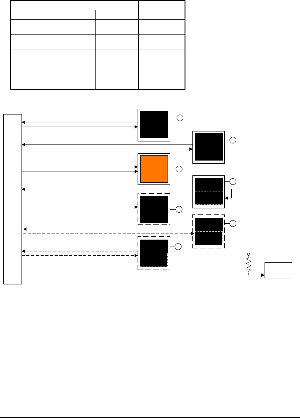
Honeywell
MK VI MK VIII EGPWS Installation Design Guide
Proprietary notice on title page applies
CAGE CODE: 97896 SCALE: NONE SIZE: A DWG NO: 060-4314-150 REV: SHEET 111
TCAS/TAS Connector
Vendor Model Function PIN #
Honeywell CAS-81, TCAS II,
TPA-81A
TA Only
Inhibit Audio
RBP-5C
RBP-5D
Collins TTR-920, TCAS II TA Only
Inhibit Audio
RBP-5C
RBP-5D
CAS 66, 67 Standby
Inhibit Audio
P1A-17
P1A-18
Goodrich*
Skywatch HP (SKY899)
Skywatch (SKY497)
TCAS I (TCAS791/A)
Inhibit Audio P1-34
P1-32
P1-9
* Interface with the Goodrich Skywatch TAS
requires a +28V pullup resistor in the aircraft
wiring as shown in Figure 3.15-1 below.
A
A
A
BRT / DIM / TEST
(7 places)
Self-Test Discrete Input
J1-14
GPWS
INOP
TERR
FAIL
Momentary
J1-34
J1-78
J1-15
J1-77
J1-72
J1-55
J1-12
J1-76
J1-73
J2-31
G/S Cancel Discrete Input
Terrain Inhibit Discrete Input
GPWS Warning Alert Discrete Output
GPWS Caution Alert Discrete Output
GPWS Inoperative Discrete Output
Terrain Not Available Discrete Output
G/S Canceled Discrete Output
G/S
CANCLD
GPWS
FLP OVRD
Momentary
Guarded
ON
Steep Approach Select Discrete Input
Flap Override Discrete Input
Flap Override Discrete Output
A
A
A
TERR
INHIB
ON
Alternate
A
GPWS
P / CANCEL
Momentary
GPWS
STP APR
ON
Guarded
Momentary *
J1-69 Audio On Discrete Output
TCAS
INHIBIT
Note: All EGPWS Outputs are Ground active and are intended to operate
with a +28V lamp source or +28V pullup external to the EGPWS
EGPWS
Lamps2.vsd
J1-52
Steep Approach Select Discrete Output
PULLUP
P / TEST
* Requires -008
software or later
Optional
+28V pullup
100K
ohm
FIGURE 3.15-1 Example of Light/switch Interface (Lamp Format 2)
3.15.2.11 Terrain Dis play Select #1 & #2 Discrete
Terrain Display Select #1 & #2 discrete (J1-54 & J1-49) will activate after the related pilot has initiated manual
selection of the Terrain Display Select (momentary) discrete #1 or #2 (J1-32 & J1-31, Category 6). This feature
activates a ‘TERR” white lamp located in the cockpit within sight of each pilot. The lamp serves to remind the
flight crew that this function is active. The select switches (J1-32 & J1-31) and the indicator lamps (J1-54 & J1-
49) are commonly combined in switch-lamp assemblies mounted near the displays being selected.
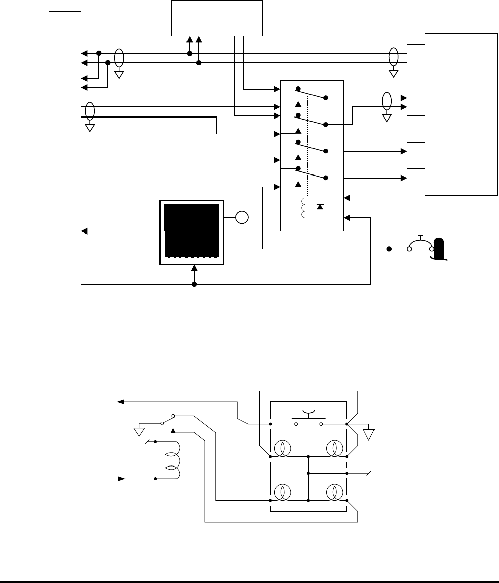
Honeywell
MK VI MK VIII EGPWS Installation Design Guide
Proprietary notice on title page applies
CAGE CODE: 97896 SCALE: NONE SIZE: A DWG NO: 060-4314-150 REV: SHEET 112
3.15.2.12 Terrain Pop up Discrete
Terrain Pop Up discrete (J1-51) will activate when a Terrain/Obstacle Caution or Warning alert event has
occurred. This feature activates the pop up in an integrated display or will switch a relay to pop up Terrain
display over selected weather radar display. The Pop Up discrete can be used by a display system to
differentiate between a manual Terrain display selection or Terrain display selection due to a Terrain/Obstacle
Caution or Warning alert event.
WXR System R/T
J2-37
J2-36
J1-58
J1-59
J1-51
J1-32
A
B
A
BARINC 453 TERRAIN BUS #1
ARINC 429 RANGE BUS
J1-54
Terrain Display Select #1 Discrete Output
Terrain Pop-Up Discrete Output
Display Select
Discrete #1 Input
DSD #1 Gnd
Discrete
Range #1
Discrete
TERR
ON
Momentary
A
* Display relay specifications:
- 4PDT - Continuous Duty Cycle
- Pickup Voltage: 13.5 Vdc Max. - Dropout Voltage: 7.5 - 2.0 Vdc
- Coil Resistance: nominal 500 Ohms (~100mA @ 28 Vdc)
- Coil Rating: 26.0 Vdc (nominal) 34 Vdc (max.)
- Contact V drop: < 125mV @ rated load
- Contact current rating: 2 Amps resistive @ 28 Vdc
28 VDC
DISPLAY RELAY *
429 IN 453 OUT
453 #1
J1-56
J1-57
A
B
453 #2
J2-41
J2-40
A
B
Range #2
J1-31DSD #2 Gnd
453 WX /
TERR BUS
A
B
A
B
TERRAIN
POP-UP
TERRAIN
SELECTED
429 Range
Output Bus
J2-43
J2-42
A
B
429 Tx Spare #2
Spare #2
Spare #2
WXR/TERR
Display
EM6-disp.vsd
FIGURE 3.15-2 Example of Terrain Display Interface
TERR DISPLAY
OFF ON
Amber Green
+28V
+28V
EGPWS
J1-32
EGPWS
J1-54
TerrDisSw.vsd
Figure 3.15-3 Example of Terrain Display switch with relay

Honeywell
MK VI MK VIII EGPWS Installation Design Guide
Proprietary notice on title page applies
CAGE CODE: 97896 SCALE: NONE SIZE: A DWG NO: 060-4314-150 REV: SHEET 113
3.15.3 Instruction s
Using Appendix E Tables 5.2, 5.3.13 and 5.3.13-x as described above, select the Input/Output
Discrete Type number that matches the aircraft configuration, feature preferences and version
(part number) being installed.
Record the ID number for the Input/Output Discrete Select number from Appendix E Table 5.3.13
under the Ident No. heading for Step (Category) 13 in Appendix E Table 5.2.
Using the Input/Output Discrete Type number from Appendix E Table 5.3.13 as “x”, go the
Appendix E Table 5.3.13-x.
The electrical interfaces for the Input/Output Discrete Type are shown in Appendix E Table
5.3.13-x and are used to generate the installation wiring diagrams.
Note: When there are two discrete pin choices for the same pin function in Appendix E Table
5.3.13-x, use only the one that matches the aircraft wiring (use only the +28V and 0V or the
Ground and Open definitions).
3.16 Category 1 4 – Audio Output Level
Category 14 controls the Audio Output level for alert menu callouts (cautions and warnings). Refer to Category
13 for information on the Mode 6 Low Volume discrete.
Appendix E Table 5.3.14 defines the Audio Output Level options and identifies the first MK VI/VIII EGPWS
version in which the option was available (see the Effectivity entry).
The Nominal Volume Select is equivalent to MK VI (classic) MAX volume level. The –6dB through –24 dB are
successively lower volume from Nominal. The Nominal output is 4 watts rms into an 8-ohm load and 100 milli-
watts rms into a 600-ohm load. The audio output level for Mode 6 alerts can be reduced an additional 6 dB by
activating the Mode 6 Low Volume discrete of Category 13.
3.16.1 Instruction s
Using Appendix E Tables 5.2 and 5.3.14 as described above, select the Audio Output Level ID
number that matches the feature preferences and version (part number) being installed.
Record the ID number for the Audio Output Level from Appendix E Table 5.3.14 under the Ident
No. heading for Step (Category) 14 in Appendix E Table 5.2.
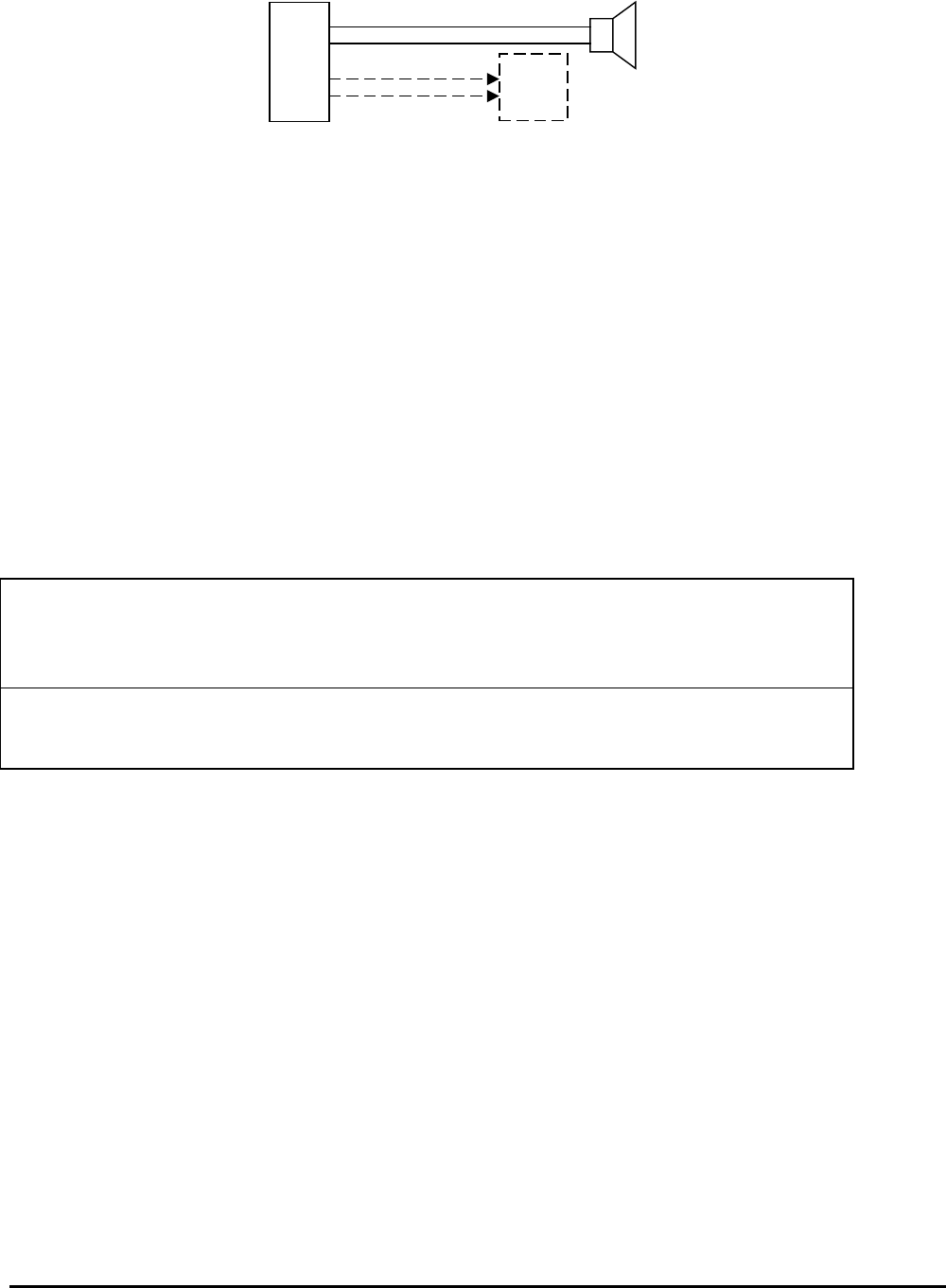
Honeywell
MK VI MK VIII EGPWS Installation Design Guide
Proprietary notice on title page applies
CAGE CODE: 97896 SCALE: NONE SIZE: A DWG NO: 060-4314-150 REV: SHEET 114
High level audio
600 ohm
Audio
Panel
Low level audio
J1-70
H
J1-71
L
J1-75H
J1-74L
8 ohm
FIGURE 3.16-1 Audio Interface
3.17 Category 1 5 - 17 – Undefined Input Selects
Category 15-17 are undefined input selects at this time.
Appendix E Table 5.3.15, 5.3.16, and 5.3.17 define the Select options and identifies the first MK VI/VIII EGPWS
version in which the option was available (see the Effectivity entry).
3.17.1 Undefined Input Select
Select ID 0 for all aircraft configurations. Input Select options will be added as new installations types are
propagated.
3.17.2 Instruction s
Using Appendix E Table 5.2, 5.3.15, 5.3.16, and 5.3.17 as described above, select the Input
Select type that matches the aircraft configuration, feature preferences and version (part number)
being installed.
Record the ID number for the Input Select from Appendix E Table 5.3.15, 5.3.16, and 5.3.17 under
the Ident No. heading for Step (Category) 15, 16, & 17 in Appendix E Table 5.2.

Honeywell
MK VI MK VIII EGPWS Installation Design Guide
Proprietary notice on title page applies
CAGE CODE: 97896 SCALE: NONE SIZE: A DWG NO: 060-4314-150 REV: SHEET 115
SECTION IV
CONFIGURATION MODULE PROGRAMMING
AND
TERRAIN DATABASE LOADING

Honeywell
MK VI MK VIII EGPWS Installation Design Guide
Proprietary notice on title page applies
CAGE CODE: 97896 SCALE: NONE SIZE: A DWG NO: 060-4314-150 REV: SHEET 116
SECTION IV – CONFIGURATION MODULE PROGRAMMING AND
REGIONAL TERRAIN DATABASE LOADING
SECTION IV – CONFIG MODULE PROGRAMMING AND REGIONAL TDB LOADING ................................. 117
4.1 INTRODUCTION............................................................................................................................................................ 117
4.2 HARNESS CHECKOUT AND POWER CHECK .................................................................................................................. 117
4.3 UNIT INSTALLATION ................................................................................................................................................... 117
4.4 EGPWC INITIALIZATION AND CONFIGURATION ......................................................................................................... 117
4.4.1 RS-232 Communication with the MK VI/VIII EGPWS........................................................................................ 117
4.4.2 EGPWC Front Panel Test Connector ................................................................................................................. 118
4.4.3 WinVIEWS........................................................................................................................................................... 119
4.4.4 WinVIEWS Operation.......................................................................................................................................... 119
4.5 CONFIGURATION MODULE PROGRAMMING................................................................................................................. 119
4.5.1 CUW and CMR Commands................................................................................................................................. 121
4.5.2 Configuration Module Reprogramming .............................................................................................................. 122
4.6 TERRAIN DATABASE LOADING ................................................................................................................................... 122
4.6.1 Effectivity............................................................................................................................................................. 122
4.6.2 Description .......................................................................................................................................................... 123
4.6.3 Approval .............................................................................................................................................................. 123
4.6.4 Material – Cost and Availability ......................................................................................................................... 123
4.6.5 Accomplishment Instructions............................................................................................................................... 123
4.6.6 Verification of the Terrain Database Version ..................................................................................................... 125

Honeywell
MK VI MK VIII EGPWS Installation Design Guide
Proprietary notice on title page applies
CAGE CODE: 97896 SCALE: NONE SIZE: A DWG NO: 060-4314-150 REV: SHEET 117
SECTION IV – Config Module Programming And Regional TDB Loading
4.1 Introduction
The following procedures outline the steps necessary to accomplish a complete configuration of the MK VI/MK
VIII EGPWS. This section must be accomplished in the order presented to minimize errors in configuring and
operating the system(s). If problems are encountered in performing these procedures, the installer may refer to
aircraft wiring diagrams for harness troubleshooting or the aircraft maintenance manual to isolate faulty
equipment. All discrepancies should be resolved before proceeding. This section will also load the Regional
Terrain Database in MK VI EGPWS that will be operating outside the AMERICAS region.
4.2 Harness Ch eckout and Power Check
Prior to installing any equipment, it is important to verify that all interfaces have been made, and that power and
ground at each unit connector is correct using the wiring diagrams for the installation. Any discrepancies in the
wiring must be resolved before proceeding.
The wire harness should also be checked for proper clearance near any control cables and other potential areas
that may cause binding and/or chafing.
4.3 Unit Installa tion
After the harness check has been completed and any discrepancies have been resolved, the units should be
installed into their respective racks, and all connections to the wiring harness should be made (connectors
attached). Verify that all of the units are secure in their respective racks, panels, etc., and all harness
connections are secure. Refer to aircraft installation drawings for the unit locations and mounting information.
4.4 EGPWC Ini tialization and Configuration
The first time a MK VI/MK VIII EGPWS is turned on in a new installation, the Configuration Module in the
EGPWS harness must be programmed to the specific interface configuration for the aircraft. This programming
is done via RS-232 cable connection between the EGPWC and a PC running the Honeywell WinViews software.
This interface capability is provided to facilitate diagnostic and configuration functions with the EGPWC during
post installation checkout. Refer to Appendix C for instructions related to using the WinViews software.
4.4.1 RS-232 Com munication with the MK VI/VIII EGPWS
The MK VI/MK VIII EGPWS computer contains software that allows monitoring of its internal
parameters, for testing purposes, without altering its operation. The monitoring of these
parameter values enables the operator to quickly determine if the EGPWC is using the correct signal and
scaling. The communication link utilizes the RS-232 communication protocol configured as follows:
19200 Baud, No Parity, 8 Bits, and 1 Stop Bit
Honeywell
MK VI MK VIII EGPWS Installation Design Guide
Proprietary notice on title page applies
CAGE CODE: 97896 SCALE: NONE SIZE: A DWG NO: 060-4314-150 REV: SHEET 118
4.4.2 EGPWC Fro nt Panel Test Connector
The RS-232 interface with the EGPWC is accomplished via a test connector provided on the EGPWC front
panel (J3). This provides access for a PC test monitor and portable data loading capabilities. The mating
connector for the EGPWC test plug (P3) is a male, 15 pin, double density D-subminiature type (or equivalent).
The connection between the PC serial port connector (with standard DB9) and the EGPWC RS-232 interface is
defined as follows:
RS-232 Receive RS-232 Transmit RS-232 Ground
EGPWS Front Connector (J3) Pin 3 Pin 4 Pin 1
Standard (PC)* DB9 Connector Pin 2 Pin 3 Pin 5
*NOTE: Some PC Comm Ports have Pins 2 & 3 reversed from what is described above.
Connector, AMP 205161-1
Socket Contact, AMP 205090-1, QTY 3
M39029/63-368
PCOM
Connector, AMP 204513-2*
Pin Contact, 204370-2, QTY 4*
M39029/58-360
Backshell, AMP 745854-5
Jackscrew, AMP 747784-3
Grommet Set, AMP 747746-1
P3
2
3
5
3
4
1
Length as required (5' to 50')
* Alternate part number 748364-1 connector and 748333-4 or -7 pin contact.

Honeywell
MK VI MK VIII EGPWS Installation Design Guide
Proprietary notice on title page applies
CAGE CODE: 97896 SCALE: NONE SIZE: A DWG NO: 060-4314-150 REV: SHEET 119
4.4.3 WinVIEWS
(Windows Virtual Interface to the Enhanced Warning System)
WinVIEWS is a software tool developed by Honeywell to communicate with the EGPWS. WinVIEWS provides a
detailed status of the software configuration and input signals, which enables quick identification of system
configuration, and is utilized for programming the system Configuration Module.
To obtain a copy of the WinVIEWS software, contact:
Honeywell
Aerospace Electronic Systems
PO Box 97001
Redmond, WA 98073-9701 USA
Attn: Order Administration M/S 33
Phone: (425) 885-8719
FAX: (425) 885-8988
or Honeywell
Aerospace Electronic Systems
PO Box 97001
Redmond, WA 98073-9701 USA
Attn: EGPWS Applications Engineering
Phone: (425) 885-3711
FAX: (425) 885-2994
GPWS Hotline: (800) 813-2099
WinVIEWS can be sent via e-mail when an e-mail address is provided.
4.4.4 WinVIEWS Operation
1. Connect the PC to the EGPWC using the RS-232 cable as described in section 4.4.2
2. On the PC, start Windows 3.1, or higher.
3. Start the WinVIEWS.EXE program.
4. Use F6 to select the Terminal Mode. Various commands are available in this mode. Type “HELP” or “?” for a
list of the commands available.
4.5 Configurati on Module Programming
The EGPWC reads the aircraft configuration from the Configuration Module, which is installed in the EGPWC
connector. The Configuration Module must have the aircraft specific configuration ID string written to it before
the EGPWS is operational. The ID string is defined by 15 separate categories listed in Appendix E Table 5.2,
Category ID Selection Procedure.
For programming the Configuration Module, the following procedure is used:
1. Verify EGPWC interface to P2 connector (including Configuration Module) and RS-232 interface to PC.
2. Power EGPWC and PC and start WinVIEWS.
3. With WinVIEWS active in the Terminal Mode, configuration sub-mode commands are available for
programming purpose. Type “CFG” at the Terminal Mode prompt (>). At this point, the CFG> prompt is
displayed and the program and EGPWC are ready for entering the program command and data string.
Type “HELP” or “?” to display a list of the Terminal Mode commands and their description. “CUW” is the
preface command for entering the ID string.

Honeywell
MK VI MK VIII EGPWS Installation Design Guide
Proprietary notice on title page applies
CAGE CODE: 97896 SCALE: NONE SIZE: A DWG NO: 060-4314-150 REV: SHEET 120
4. Using the Category ID’s as chosen from the Appendix E (refer to completed Table 5.2), create a command
string with the following structure:
CFG> CUW 0/15 # # # # # # # # # # # # # # #/
- CUW<space>0 is the command and version number. CUW writes the category ID’s defined by version 0
definition (0 is the only version currently available) to the Configuration Module via the EGPWC without a
CRC (checksum) value attached (this is generated by the EGPWC when the data is transmitted).
- /15 indicates the beginning of the data string (/) with 15 being the number of categories to follow.
- <space><Cat 1 ID#><space><Cat 2 ID #>…<Cat 15 ID#>/ each Cat ID# is the chosen ID for the category
from the Appendix E Table 5.2. The ending slash (/) indicates the end of the data string.
Note: If 15 ID’s do not follow “/15”, the error message “Invalid Parameter. Not enough ID’s.
Configuration update failed, please try again.” will be given. The value entered for each category
must be an available ID for the associated category or a similar error message will be given. If the
number of categories provided is less than 15 (e.g., “/8 # … #/” with eight ID’s defined), then the
remaining categories (9 through 15) will be set to 0.
After completing the data string as defined above and pressing ENTER, the following message may appear:
“Confirm this data reflects configuration to be programmed (Y/N)”. If the message does not appear, the
cursor will flash. In either case, it is waiting for an answer “Y” or “N”. Pressing the Y (or y) key confirms the data
and sends the data to the EGPWC to write to the Configuration Module.
Following the writing to the Configuration Module the EGPWC is automatically rebooted in order for the new
configuration to take affect.
Note: If when the ENTER key is pressed the question response is not given (cursor just moves to the next line),
pressing any character key should provide the proper response.
Pressing the N key results in the message “Command aborted – No configuration module change
has been made”. If necessary, revise the data to correct or change as necessary and continue as
above. The backspace key can be used to make corrections.
5. Following the successful writing to the Configuration Module (no error messages) and EGPWC reboot,
pressing Control Z (Ctrl-Z) restarts the WinVIEWS Terminal Mode communication.
6. There are a couple ways to now confirm the Configuration Module programming with the following being the
preferred. As above, type “CFG” to restart the Configuration sub-mode. At the CFG> prompt, type
“CMR<Enter>”. Each category and its associated ID is read from the Configuration Module and listed on the
PC screen. Alternately, when not in the Configuration sub-mode, the command “PS<Enter>” (Present
Status) will display EGPWC and configuration data.
7. Configuration Module programming is complete. If the “CFG >” prompt is still present type “Exit<Enter>” to
exit the Configuration sub-mode.

Honeywell
MK VI MK VIII EGPWS Installation Design Guide
Proprietary notice on title page applies
CAGE CODE: 97896 SCALE: NONE SIZE: A DWG NO: 060-4314-150 REV: SHEET 121
4.5.1 CUW and C MR Commands
An example CUW command/data string, its definition, and the corresponding CMR list is provided below.
CUW command/data string:
CFG > CUW 0/15 2 3 2 0 0 3 93 1 0 0 0 0 0 0 0/
Type “Y” or “y” to confirm the data and send the data to the EGPWC to write to the Configuration Module
Above configuration defined:
Category 1 Aircraft/Mode Type: 2
Category 2 Air Data Type: 3
Category 3 Position Type: 2
Category 4 Altitude Callouts Menu: 0
Category 5 Audio Menu: 0 (Basic menu)
Category 6 Display Type: 3
Category 7 Options Select Group #1: 93 (Steep Approach True)
(TA&D Alternate pop-up False)
(Peaks Mode True)
(Obstacle Awareness True)
(Bank Angle True)
(Flap Reversal False)
(GPS Altitude Ref. MSL)
Category 8 Radio Altitude Type: 1
Category 9 Navigation Type: 0
Category 10 Attitude Type: 0
Category 11 Heading Type: 0
Category 12 Windshear select Type: 0
Category 13 Discrete I/O Type: 0
Category 14 Audio Output Level Type: 0
Category 15 Undefined Type: 0
CMR list: (based on the previous configuration)
CFG > CMR<Enter>
CONFIGURATION MODULE:
Format Version: 0
Category 1 ID: 2
Category 2 ID: 3
Category 3 ID: 2
Category 4 ID: 0
Category 5 ID: 0
Category 6 ID: 3
Category 7 ID: 93
Category 8 ID: 1
Category 9 ID: 0
Category 10 ID: 0
Category 11 ID: 0
Category 12 ID: 0
Category 13 ID: 0
Category 14 ID: 0
Category 15 ID: 0
CRC: 527518533

Honeywell
MK VI MK VIII EGPWS Installation Design Guide
Proprietary notice on title page applies
CAGE CODE: 97896 SCALE: NONE SIZE: A DWG NO: 060-4314-150 REV: SHEET 122
4.5.2 Configurati on Module Reprogramming
Reprogramming the EGPWS Configuration Module is accomplished similar to the programming process above.
Prior to reprogramming, the desired new configuration should be determined based on the MK VI/VIII Interface
Description Document (Appendix E), document number 060-4314-401.
For reprogramming the Configuration Module, the following procedure is used:
1. Verify EGPWC interface to P2 connector (including Configuration Module) and RS-232 interface to PC.
2. Power EGPWC and PC and start WinVIEWS.
3. With WinVIEWS active in the Terminal Mode, start the Configuration sub-mode by typing “CFG” at the
prompt (>). At this point, either all the ID’s can be rewritten using the CUW command as before, or individual
categories can be changed as follows:
4. At the CFG > prompt use the CAT command with the following structure:
- CAT<space><category #><space><ID#><space><T or F><Enter>
- <category #> is the Appendix E Category to change (example 7)
- <ID #> is the new ID to change to (example 92)
- <T or F> is True or False for rebooting the EGPWC. Use “T” if only one category is to be changed and the
EGPWC will reboot following <Enter>. Use “F” if another individual ID is to be changed by another CAT
operation.
Example: CFG > CAT 7 92 T<Enter>
5. After inputting the desired change information, pressing <Enter> will transmit the data to the EGPWC to
write to the Configuration Module. If a reboot is commanded (T), then the EGPWC will reboot at the
completion of the write process. If a reboot is not commanded (F), then a message “Writing to
configuration module … Category 7 ID updated successfully.” is given and the CFG > prompt is again
displayed. At this point the Configuration Module has been changed, but the change will not be effective
until the EGPWC is rebooted. Additional changes can be made with the final change set to command the
EGPWC to reboot (or cycle EGPWC power to reboot).
6. Verification of the changes made is the same as before. As above, type “CFG” to restart the Configuration
sub-mode. At the CFG > prompt, type “CMR<Enter>”. Each category and its associated ID is read from the
Configuration Module and listed on the PC display. Alternately, when not in the Configuration sub-mode, the
command “PS<Enter>” (Present Status) will display the EGPWC and Configuration Module data.
7. Configuration Module reprogramming is complete.
4.6 Terrain Dat abase Loading
4.6.1 Effectivity
The MK VI EGPWS (965-1180-0XX and 965-1190-0XX) are shipped from the factory loaded with the Regional
Terrain Database requested when the purchase order was placed. Use (operation) of a MK VI EGPWS outside
of the loaded Regional Terrain Database will result in the Terrain Awareness function being unavailable. Aircraft
operating outside the loaded Regional Terrain Database region will have to load one of the other two Regional
Terrain Databases before beginning the ground test.

Honeywell
MK VI MK VIII EGPWS Installation Design Guide
Proprietary notice on title page applies
CAGE CODE: 97896 SCALE: NONE SIZE: A DWG NO: 060-4314-150 REV: SHEET 123
The MK VIII EGPWS (965-1210-0XX and 965-1220-0XX) have a Global Terrain Database.
4.6.2 Description
This modification consists of loading the PCMCIA card into the EGPWS either In The Aircraft or On The
Bench. An optional verification procedure is provided.
4.6.3 Approval
This procedure contains no modification information that revises the approved configuration and therefore does
not require FAA or other regulatory agency approval.
4.6.4 Material – C ost and Availability
The AMERICAS, ATLANTIC or PACIFIC region PCMCIA card is available at no charge to Operators. Order part
from:
Honeywell
Airlines & Avionics Products
Order Administration M/S 33
PO Box 97001
Redmond, WA 98073-9701
Phone: 425-885-8719
Fax: 425-885-8988
Honeywell Aerospace
Toulouse Office
Centreda, Avenue Didier Daurat
31700 Blagnac, France
Phone: (33) 5-6171-0079
Fax: (33) 5-6130-0497
Vendor Name Vendor P/N Description QTY UM Honeywell P/N
Honeywell 718-1391-xxx AMERICAS Region Card 1 EA 718-1393-xxx
Honeywell 402-6075-xxx AMERICAS Region Label 1 EA 402-6075-xxx
Honeywell 718-1392-xxx ATLANTIC Region Card 1 EA 718-1392-xxx
Honeywell 402-6075-xxx ATLANTIC Region Label 1 EA 402-6075-xxx
Honeywell 718-1393-xxx PACIFIC Region Card 1 EA 718-1393-xxx
Honeywell 402-6075-xxx PACIFIC Region Label 1 EA 402-6075-xxx
4.6.5 Accomplish ment Instructions
Load the PCMCIA card data as described in paragraphs 4.6.5 A. or 4.6.5 B. below. Loading time will be
approximately 10 minutes.
A. Loading the PCMCIA Card Data with Computer Mounted in the Aircraft.
(1) Connect the Smart Cable (Honeywell PN 951-0386-001) to the EGPWC J3 connector.
(2) Ensure that the 28 VDC circuit breaker to the EGPWC in ON and that the COMPUTER OK LED on
the EGPWC front panel is on.
(3) Insert the PCMCIA card into the Smart Cable PCMCIA card slot.

Honeywell
MK VI MK VIII EGPWS Installation Design Guide
Proprietary notice on title page applies
CAGE CODE: 97896 SCALE: NONE SIZE: A DWG NO: 060-4314-150 REV: SHEET 124
NOTE: Precautionary notes on the PCMCIA card, regarding insertion and/or removal while power is
applied, should be ignored since the EGPWC automatically handles the application and removal
of PCMCIA card power.
(4) While the loading is in progress, the IN PROG LED on the Smart Card remains ON and the
COMPUTER OK LED on the EGPWC is OFF.
(5) When loading is complete the XFER COMP LED on the Smart Card turns ON.
(6) Remove the PCMCIA card from the Smart Card slot.
(7) After approximately 15 seconds the COMPUTER OK LED comes ON to indicate that the contents
of the PCMCIA card were successfully transferred.
(8) Remove the Smart Card connector from the EGPWC front panel J3 connector.
(9) To perform the verification of the Terrain Database version, go to paragraph 4.6.6 below.
B. Loading the PCMCIA Card Data with Computer Mounted on the Bench
(1) Locate a 28 VDC Power Supply with a minimum supply current of 2 amps.
(2) With the Power Supply turned OFF, connect the Power Supply to the J1 connector of the EGPWC
as follows (pin J1-53 is connected to chassis ground internally and does not need to be ground in
aircraft wiring):
J1 connector Pin Pin Nomenclature
J1-40, J1-60 28 VDC (+)
J1-41, J1-61 28 VDC (-)
J1-42, J1-53 Chassis GND
Pins J1-42 and J1-53 are both connected to chassis ground internally. It is not necessary to tie them
both to ground in the aircraft wiring. Pin J1-53 was made available to provide a convenient way to
supply a ground to external equipment. If the OAT probe is not present, nothing needs to be tied to J1-
53.
(3) Connect the Smart Cable (Honeywell PN 951-0386-001) to the EGPWC J3 connector.
(4) Turn the Power Supply ON and that the COMPUTER OK LED on the EGPWC front panel is on.
(5) Insert the PCMCIA card into the Smart Cable PCMCIA card slot.
NOTE: Precautionary notes on the PCMCIA card, regarding insertion and/or removal while power is
applied, should be ignored since the EGPWC automatically handles the application and removal
of PCMCIA card power.
(6) While the loading is in progress, the IN PROG LED on the Smart Card remains ON and the
COMPUTER OK LED on the EGPWC is OFF.

Honeywell
MK VI MK VIII EGPWS Installation Design Guide
Proprietary notice on title page applies
CAGE CODE: 97896 SCALE: NONE SIZE: A DWG NO: 060-4314-150 REV: SHEET 125
(7) When loading is complete the XFER COMP LED on the Smart Card turns ON.
(8) Remove the PCMCIA card from the Smart Card slot.
(9) After approximately 15 seconds the COMPUTER OK LED comes ON to indicate that the contents
of the PCMCIA card were successfully transferred.
(10) Remove the Smart Card connector from the EGPWC front panel J3 connector.
(11) To perform the verification of the Terrain Database version, go to paragraph 4.6.6 below.
4.6.6 Verification of the Terrain Database Version
Since the EGPWC software verifies the PCMCIA card loading process, this verification is to assure the
operator/installer that the correct Regional Terrain Database version is installed.
Terrain Database version verification is accomplished with the EGPWS Self Test (ST) function. The ST function
may be initiated from the aircraft cockpit with the GPWS Test Switch. NOTE: Initiation of the cockpit ST function
may vary from one aircraft to another. For example, the ST function may be initiated by pressing the GPWS
(PULL-UP) light assembly, or by activating a separate ST switch.
The EGPWS ST function has 6 levels that describe the current condition and configuration of the EGPWS, the
fault and warning history, and the condition of the various inputs. To help navigate through the various levels,
there are 2 cancel functions: SHORT CANCEL (press and hold the ST button for more than 0.5 seconds, but
less than 2 seconds) and LONG CANCEL (press and hold the ST button for more than 2 seconds, but less than
8 seconds). The Short Cancel and Long Cancel functions operate differently, depending upon the ST level. To
initiate a ST sequence, or to continue from level-to-level, the ST button must also be ‘pressed and held’ for more
than 0.5 seconds, but less than 2 seconds, which is identical to the Short Cancel function.
Therefore, for simplicity, the phrase “Press ST Button” in the verification procedure means to press and hold the
ST button for more than 0.5 seconds, but less than 2 seconds. The procedure guides the operator directly to ST
Level 3, “System Configuration”, skipping most of ST Level 1 and Level 2.
To verify the Regional Terrain Database that was just loaded into the EGPWC, perform these steps:
NOTE: ‘On the Bench’, this test requires an audio speaker and a self test button. These may not be available
‘On the Bench’ unless when using a Break-Out-Box.
(1) Ensure the EGPWC power is ON
(2) Press ST button to initiate ST Level 1.
(3) After ST Level 1 message starts, Press ST button to cancel Level 1 and start Level 2.
(4) After ST Level 2 message, “Current Faults”, is heard, Press ST button to cancel Level 2.
(5) When the message, “Press to Continue”, is heard, Press ST button to start ST Level 3.
(6) Verify the Terrain Database version annunciated in the following sequence:

Honeywell
MK VI MK VIII EGPWS Installation Design Guide
Proprietary notice on title page applies
CAGE CODE: 97896 SCALE: NONE SIZE: A DWG NO: 060-4314-150 REV: SHEET 126
a) “SYSTEM CONFIGURATION”
b) “PART NUMBER 965-11X0-XXX”
c) “MOD STATUS XX”
d) “SERIAL NUMBER XXXX”
e) “APPLICATION SOFTWARE VERSION XXXXX”
f) “TERRAIN DATABASE VERSION XXXX”
The following example of Terrain Database Version annunciation: “419A” (for ATLANTIC),
“419P” (for PACIFIC), or “419N” (for AMERICAS). Other versions will follow the same pattern
(e.g. “421P”).
(7) Other messages that follow the Terrain Database Version can be ignored. When ST Level 3 finishes,
the message “Press to Continue” is heard. If the ST button is not pressed again the ST sequence
terminates.
NOTE: If power was connected to the EGPWC per steps B1 through B4, perform shut-down per steps (7) and
(8) following.
(8) Turn Power Supply OFF.
(9) Disconnect Power leads from the EGPWC.
END OF TEST

Honeywell
MK VI MK VIII EGPWS Installation Design Guide
Proprietary notice on title page applies
CAGE CODE: 97896 SCALE: NONE SIZE: A DWG NO: 060-4314-150 REV: SHEET 127
SECTION V
CERTIFICATION

Honeywell
MK VI MK VIII EGPWS Installation Design Guide
Proprietary notice on title page applies
CAGE CODE: 97896 SCALE: NONE SIZE: A DWG NO: 060-4314-150 REV: SHEET 128
SECTION V – CERTIFICATION
5.1 Introductio n
This section outlines the procedures required to obtain FAA approval for the MK VI/MK VIII EGPWS installation.
Recommended flight test procedures are also included.
5.2 Certificatio n Procedure
5.2.1 Equipment Compatibility
Careful consideration must be paid to the electrical characteristics of existing equipment or possible additions
that will be interfaced to the MK VI/MK VIII EGPWS, in order to ensure system compatibility. Section III of this
manual provides system planning guidelines, and defines the electrical characteristics of the EGPWS. The
installing agency should contact Honeywell Product Support (800-813-2099), for information regarding the
compatibility of equipment not listed in Section III. Normal business hours are 8:00 AM to 5:00 PM Pacific Time,
Monday through Friday.
5.2.2 Equipment Location
The EGPWS and associated indicators, annunciators, and switches should be clearly visible and within easy
reach of the pilot(s). Refer to Section II of this manual for complete installation information.
5.2.3 FAA Requir ements
The installing agency should contact a local FAA Inspector who will determine whether the installation may be
approved by Supplemental Type Certificate (STC) or by submitting FAA Form 337 with an applicable STC
package.
5.2.4 Ground Tes t
Honeywell has developed a generic Installation Ground Test Procedure for the MK VI/MK VIII EGPWS, drawing
number 060-4167-158.
5.2.5 Flight Manu al Revision
Honeywell has developed a generic Airplane Flight Manual Supplement for the MK VI/MK VIII EGPWS, drawing
number 060-4199-194.
5.2.6 Flight Test
Honeywell has developed a generic Flight Test procedure for the MK VI/MK VIII EGPWS (GA-Fast and GA-
Slow aircraft), drawing number 060-4188-041. A separate generic Flight Test procedure has been developed for
MK VIII EGPWS Bizjet aircraft, drawing number 060-4188-023. The Flight Test procedures were developed for

Honeywell
MK VI MK VIII EGPWS Installation Design Guide
Proprietary notice on title page applies
CAGE CODE: 97896 SCALE: NONE SIZE: A DWG NO: 060-4314-150 REV: SHEET 129
first of type installations, for these installations all sections of the Flight Test procedure shall be performed.
Precedence has been established for testing only the Terrain Awareness functions when replacing an existing
MK VI GPWS. Installers should contact their local FAA office for confirmation of this approach.
For follow on installations of the same aircraft type and interface, the flight test is not required. When updating
an STC to the current part number it is only necessary to flight test significant new features. The notice of
change is available in Honeywell Service Bulletins.
Suggestions for recording of the EGPWS data during a Flight Test for follow on analysis:
• In WinViews change the recording Sample Rate to 1 second intervals (WinViews / Terminal Mode / Options
/ Settings / 1000 ). This sample rate will record adequate data for future analysis.
• Continue recording between tests. Missing data is aggravating. Recording in flight between test sites
(hundreds of miles apart) is not necessary but continuous recording when Mode 1 ends and Mode 4 begins
is helpful. Recording of the take off from brakes locked through climb out also aids later analysis, as does
continuous recording of approach to aircraft off the runway.
• The WinViews software program records in 1.44 megabyte files that can be transferred from Laptop
computer to other computers with ease. Using 1 second sample rate the EGPWS will record approximately
40K bytes per minute of data. 1 hour of recorded time would be approximately 2.4MB, most laptops have
1GB or more free space.
• Use the Event Marker, F9 key, to identify events during tests.
• Use the F10 key to roll (increment) the history file name between test sequences. Rolling adds a number to
the end of the filename (or increments the existing number, if possible.) Example: use tail number (N3GC) in
the file name with a file number (01), this gives a filename N3GC01.hst which will roll to N3GC02.hst when
the F10 key is pressed.
5.2.7 Pilots Guid e
Honeywell has developed a Pilot’s Guide for the MK VI/MK VIII EGPWS, drawing number 060-4314-000 that
provides a description of the modes and the controls of the EGPWS.
5.2.8 Failure Mod es, Effects, and Safety Analysis
Honeywell has developed a Failure Modes, Effects, and Safety Analysis document for the MK VI/MK VIII
EGPWS, drawing number 060-4199-182 that provides an analysis of the failure modes of the EGPWS.

Honeywell
MK VI MK VIII EGPWS Installation Design Guide
Proprietary notice on title page applies
CAGE CODE: 97896 SCALE: NONE SIZE: A DWG NO: 060-4314-150 REV: SHEET 130
SECTION VI
MK VI GPWS (classic) to EGPWS MK VI/VIII
Pin to Pin Comparison

Honeywell
MK VI MK VIII EGPWS Installation Design Guide
Proprietary notice on title page applies
CAGE CODE: 97896 SCALE: NONE SIZE: A DWG NO: 060-4314-150 REV: SHEET 131
SECTION VI - MK VI GPWS to MK VI/VIII EGPWS Signal Mapping
Connector Pin-Out Sorted By Pin Number (USE FOR REFERENCE ONLY)
shaded area indicates function change X=Indicates same function
Signal Name –MK-VI GPWS (965-0686-001, -020) Signal Type Same Conn/Pin Signal Type
< IN Out > Signal Name -MK-VI/MK VIII EGPWS (Enhanced)
Roll Attitude Synchro (X) Synchro XJ1-01 < AC Analog3W1 Roll Attitude Synchro (X)
Chassis Ground GND J1-02 < AC Analog3W3 Roll Attitude Synchro (Z)
Spare #1 Program Pin ProgPin J1-03 < AC Analog3W1 Magnetic Heading Synchro (Z)
Alternate Airspeed Expansion Program Pin ProgPin J1-04 < AC Analog (H) 26 VAC Reference #1 (H)
Fixed Landing Gear Program Pin ProgPin J1-05 < AC Analog3W1 Pitch Synchro (X)
Audio Volume Control #2 Program Pin ProgPin J1-06 < AC Analog3W3 Pitch Synchro (Z)
200’ Altitude Callout Program Pin ProgPin J1-07 < AC Analog3W2 Pitch Synchro (Y)
Radio Altimeter ALT 55 Scale Program Pin ProgPin J1-08 < 28vDisc Autopilot Engaged Discrete (+28VDC)
Barometric Altitude Rate Validity (+28VDC) Discrete XJ1-09 < 28vDisc Barometric Altitude Validity (+28VDC)
Glideslope Deviation Low Level Validity (L) DC-AnalogL XJ1-10 < Analog (-) Glideslope Deviation Low Level Validity (-) and
Localizer Deviation Low Level (-Left)
Glideslope Deviation Validity (+28VDC) Discrete XJ1-11 < 28vDisc Glideslope Deviation Validity (+28VDC)
Spare Reserved XJ1-12 < GDisc Terrain Awareness & TCF Inhibit Discrete (GND)
Altitude Callouts Volume Reduction Discrete (GND) Discrete XJ1-13 < GDisc Mode 6 Low Volume Discrete (GND)
GPWS Flap Override Discrete (GND) Discrete XJ1-14 < GDisc Flap Override Discrete (GND) (from FLAP OVRD SW)
Glideslope Manual Cancel Discrete (GND) Discrete XJ1-15 < GDisc Glideslope Cancel Discrete (Gnd) (from GS Cancel
SW)
Landing Gear Discrete (GND) Discrete XJ1-16 < GDisc Landing Gear Discrete (GND)
External GPWC Audio Suppression Discrete (GND) Discrete XJ1-17 < GDisc Audio Inhibit Discrete (GND)
Landing Flap Discrete (GND) Discrete XJ1-18 < GDisc Landing Flaps Discrete (GND)
ILS Backcourse Approach Selected Discrete (GND) Discrete XJ1-19 < GDisc Glideslope Inhibit Discrete (GND)
ILS Frequency Selected Discrete (GND) Discrete XJ1-20 < GDisc ILS Tuned Discrete (GND)
Roll Attitude Synchro (Y) Synchro XJ1-21 < AC Analog3W2 Roll Attitude Synchro (Y)
Spare Reserved J1-22 < AC Analog3W1 Magnetic Heading Synchro (X)
Spare Reserved J1-23 < AC Analog3W2 Magnetic Heading Synchro (Y)
Landing Flap Logic Inversion Program Pin Progpin J1-24 < AC Analog (L) 26 VAC Reference #1 (L)
Alternate Mode 4B Threshold Program Pin Progpin J1-25 5Vref+ >Air Temperature Reference (+5VDC)

Honeywell
MK VI MK VIII EGPWS Installation Design Guide
Proprietary notice on title page applies
CAGE CODE: 97896 SCALE: NONE SIZE: A DWG NO: 060-4314-150 REV: SHEET 132
Signal Name –MK-VI GPWS (965-0686-001, -020) Signal Type Same Conn/Pin Signal Type
< IN Out > Signal Name -MK-VI/MK VIII EGPWS (Enhanced)
Audio Volume Control #1 Program Pin Progpin J1-26 < Analog (+) Spare
500’ Altitude Callout Program Pin Progpin J1-27 < Analog (-) Spare
Spare Discrete (+28VDC) Discrete J1-28 < 28vDisc Magnetic Heading Validity Discrete (+28VDC)
Radio Altimeter Validity (+28VDC) 28vDisc XJ1-29 < 28vDisc Radio Altitude Validity Discrete (+28VDC)
Glideslope Deviation Low Level Validity (H) DC-AnalogL XJ1-30 < Analog (+) Glideslope Deviation Low Level Validity (+) and
Localizer Deviation Low Level (+Right)
Spare #1 Discrete Discrete J1-31 < GDisc Display Selected Discrete #2 (GND)
Airspeed Expansion Discrete Discrete J1-32 < GDisc Display Selected Discrete #1 (GND)
Decision Height DH Discrete (GND) Discrete XJ1-33 < Gdisc DH Discrete (GND)
GPWS Self Test Discrete (GND) Discrete XJ1-34 < GDisc Self Test Discrete (GND) (from GPWS push to test
Sw)
Landing Gear Discrete (+28VDC) Discrete XJ1-35 < 28vdisc Landing Gear Discrete (+28VDC)
External GPWS Audio Suppress Discrete (+28VDC) Discrete XJ1-36 < 28vdisc Audio Inhibit Discrete (+28VDC)
Landing Flap Discrete (+28VDC) Discrete XJ1-37 < 28vdisc Landing Flaps Discrete (+28VDC)
ILS Backcourse Approach Selectd Discrete (+28V) Discrete XJ1-38 < 28vdisc Glideslope Inhibit Discrete (+28VDC)
ILS Frequency Selected Discrete (+28VDC) Discrete XJ1-39 < 28vdisc ILS 1 Tuned Discrete (+28VDC)
Power Input (+28VDC) PWR/GND XJ1-40 < PWRH Power Input 28VDC (+)
Power Input (GND) PWR/GND XJ1-41 < PWRL Power Input 28VDC (return)
Chassis Ground GND XJ1-42 < GND__C Chassis Ground
Barometric Altitude Rate Input (-) DC-AnalogL J1-43 < Analog (-) Barometric Altitude (-)
Airspeed Input (-) DC-AnalogL J1-44 < Analog (-) Air Temperature (-)
Radio Altimeter Input (-) DC-AnalogL XJ1-45 < Analog (-) Radio Altitude: ARINC 552 or ALT-55 (-)
RT-200/300 Precision (+)
Glideslope Deviation Input (+ down) DC Analog XJ1-46 < Analog (-) Glideslope Deviation Low Level (+down)
Test Point #1 Test point J1-47 < Analog (-) Spare
Test Point #2 Test point J1-48 < 28vdisc Localizer Validity Discrete (+28VDC)
Test Point #3 Test point J1-49 Lampout > (gnd) Terrain Select Relay Output #2 (to TERR lamp and/or
Relay)
Test Point #4 Test point J1-50 Monitor Out > (gnd) Windshear Inop Lamp Output (monitor)
Test Point #5 Test point J1-51 Lampout > (gnd) Terrain Pop Up Discrete Output
Test Point #6 Test point J1-52 Lampout > (gnd) Steep Approach
Windshear Caution
Test Point #7 Test point J1-53 < GND Temperature Probe (GND)
Test Point #8 Test point J1-54 Lampout > (gnd) Terrain Select Relay Output #1 (to TERR lamp and/or
Relay)

Honeywell
MK VI MK VIII EGPWS Installation Design Guide
Proprietary notice on title page applies
CAGE CODE: 97896 SCALE: NONE SIZE: A DWG NO: 060-4314-150 REV: SHEET 133
Signal Name –MK-VI GPWS (965-0686-001, -020) Signal Type Same Conn/Pin Signal Type
< IN Out > Signal Name -MK-VI/MK VIII EGPWS (Enhanced)
Test Point #9 Test point J1-55 Monitor Out > (gnd) TAD / TCF INOP Output (monitor)
Test Point #10 Test point J1-56 453 Out (A) >Terrain Display Output Data #2 (A leg)
Test Point #11 Test point J1-57 453 Out (B) >Terrain Display Output Data #2 (B leg)
Test Point #12 Test point J1-58 453 Out (A) >Terrain Display Output Data #1 (A leg)
Test Point #13 Test point J1-59 453 Out (B) >Terrain Display Output Data #1 (B leg)
Power Input (+28VDC) PWR/GND XJ1-60 < PWRH Power Input 28VDC (+)
Power Input (GND) PWR/GND XJ1-61 < PWRL Power Input 28VDC (return)
Barometric Altitude Rate Input (+) DC-AnalogL J1-62 < Analog (+) Barometric Altitude (+)
Airspeed Input (-) DC-AnalogL J1-63 < Analog (+) Air Temperature (+)
Radio Altimeter Input (+) DC-AnalogL XJ1-64 < Analog (+) Radio Altitude: ARINC 552 or ALT-55 (+)
RT-200/300 Precision (-)
Glideslope Deviation Input (+ Up) DC Analog XJ1-65 < Analog (+) Glideslope Deviation Low Level (+up)
Spare Reserved J1-66 < Analog (+) Spare
Spare Reserved J1-67 < GDisc GPWS Inhibit
Spare Lamp Output Output J1-68 < 28vdisc Attitude Validity Discrete (+28VDC)
TCAS II Inhibit Output Output XJ1-69 Lampout > (gnd) Audio ON Output
Audio Speaker Output – 8-ohm (H) Output XJ1-70 HL Audio Out (H) > High Level Audio Output - 8Ω (+)
Audio Speaker Output – 8-ohm (L) Output XJ1-71 HL Audio Out (L) > High Level Audio Output - 8Ω (-)
GPWS System Status Lamp Output XJ1-72 Monitor Out > (gnd) GPWS INOP (monitor) (to GPWS Fail/Inop lamp)
GPWS Flap OVRD Output XJ1-73 Lampout > (gnd) Flap Override Output (to FLAP OVRD lamp)
Windshear Warning
Audio Low Level (C) Output XJ1-74 LLAud Out (L) > Low Level Audio 600-ohm (C)
Audio Low Level (H) Output XJ1-75 LLAud Out (H) > Low Level Audio 600-ohm (H)
Glideslope Cancelled Lamp Output XJ1-76 Lampout > (gnd) Glideslope Cancel Output (to GS CANCL’D lamp)
Glideslope Alert Lamp Output XJ1-77 Lampout > (gnd) Lamp Format 1: Glideslope Alert Output
Lamp Format 2: GPWS, Terrain or Obstacle Caution
GPWS Alert/Warning Lamp Output XJ1-78 Lampout > (gnd)
GPWS Warning Output (to red GPWS or Pull Lamp)
Terrain Caution or Warning
Obstacle Caution or Warning

Honeywell
MK VI MK VIII EGPWS Installation Design Guide
Proprietary notice on title page applies
CAGE CODE: 97896 SCALE: NONE SIZE: A DWG NO: 060-4314-150 REV: SHEET 134
Signal Name –MK-VI GPWS (965-0686-001, -020) Signal Type Same Conn/Pin Signal Type
< IN Out > Signal Name -MK-VI/MK VIII EGPWS (Enhanced)
NEW CONNECTOR
J2-01 < AC Analog3W1 Configurable Synchro #1 (X leg)
J2-02 < AC Analog3W2 Configurable Synchro #1 (Y leg)
J2-03 < AC Analog3W3 Configurable Synchro #2 (Z leg)
J2-04 < 429 IN (B) Radio Altitude ARINC 429 Input (B leg)
IOC #2 (Nav) ARINC 429 Input (B leg)
J2-05 < 429 IN (B) ILS ARINC 429 Input (B leg)
J2-06 < 429 IN (B) AHRS ARINC 429 Input (B leg)
GPS #2 ARINC 429 Input (B leg)
J2-07 < 429 IN (B) Spare ARINC 429 Input (B leg)
J2-08 < 429 IN (B) GPS ARINC 429 Input (B leg)
J2-09 429 OUT (B) >EGPWS ARINC 429 Output #2 (B leg)
J2-10 < 232 IN (B) Spare RS-422 Input (B leg)
SCI Display Range #2 RS-422 Input (A leg)
J2-11 < 232 IN (A)
Spare RS-232 Input (Rcv)
Spare RS-422 Input (A leg)
SCI Display Range #2 RS-422 Input (B leg)
J2-12 < 232 IN (B) GPS RS-422 Input (B leg)
J2-13
J2-14 < GND Spare RS-232 Common
J2-15 < 28vDisc Spare Discrete (+28VDC)
J2-16 < PWR (L) Configuration Module Power (GND)
J2-17 < PWR (H) Configuration Module Power (+5VDC)
J2-18 < AC Analog3W3 Configurable Synchro #1 (Z leg)
J2-19 < AC Analog3W1 Configurable Synchro #2 (X leg)
J2-20 < AC Analog3W2 Configurable Synchro #2 (Y leg)
J2-21 < 429 IN (A) Radio Altitude ARINC 429 Input (A leg)
IOC #2 (Nav) ARINC 429 Input (A leg)
J2-22 < 429 IN (A) ILS ARINC 429 Input (A leg)
J2-23 < 429 IN (A) AHRS ARINC 429 Input (A leg)
GPS #2 ARINC 429 Input (A leg)
J2-24 < 429 IN (A) Spare ARINC 429 Input (A leg)
J2-25 < 429 IN (A) GPS ARINC 429 Input (A leg)
J2-26 429 OUT (A) >EGPWS ARINC 429 Output #2 (A leg)

Honeywell
MK VI MK VIII EGPWS Installation Design Guide
Proprietary notice on title page applies
CAGE CODE: 97896 SCALE: NONE SIZE: A DWG NO: 060-4314-150 REV: SHEET 135
Signal Name –MK-VI GPWS (965-0686-001, -020) Signal Type Same Conn/Pin Signal Type
< IN Out > Signal Name -MK-VI/MK VIII EGPWS (Enhanced)
J2-27 < 232 IN (A) Spare RS-232 Input (Tx)
Spare RS-422 Input (A leg)
J2-28 < GND GPS/Spare RS-232 Common
J2-29 < 232 IN (A) GPS RS-232 Input (Rcv)
Spare RS-422 Input (A leg)
J2-30
J2-31 < GDisc Steep Approach #2 (GND)
J2-32 Clock >Configuration Module Serial Clock
J2-33 Data >Configuration Module Serial Input
J2-34 < AC Analog (H) 26 VAC Reference #2 (H)
J2-35 < AC Analog (L) 26 VAC Reference #2 (L)
J2-36 < 429 input (B)
Display Range #1 ARINC 429 Input (B leg)
SCI Display Range #1 RS-422 Input (A leg)
IOC #1 ARINC 429 Input (B leg)
J2-37 < 429 input (A)
Display Range #1 ARINC 429 Input (A leg)
SCI Display Range #1 RS-422 Input (B leg)
IOC #1 ARINC 429 Input (A leg)
J2-38 < 429 input (B) Air Data ARINC 429 Input (B leg)
IOC #1 (Nav) ARINC 429 Input (B leg)
J2-39 < 429 input (A) Air Data ARINC 429 Input (A leg)
IOC #1 (Nav) ARINC 429 Input (A leg)
J2-40 < 429 input (B) Display Range #2 ARINC 429 Input (B leg)
IOC #2 ARINC 429 Input (B leg)
J2-41 < 429 input (A) Display Range #2 ARINC 429 Input (A leg)
IOC #2 ARINC 429 Input (A leg)
J2-42 429 Output (B) >EGPWS ARINC 429 Output #1 (B leg)
J2-43 429 Output (A) >EGPWS ARINC 429 Output #1 (A leg)
J2-44 < 232 input (B) Spare RS-422 Input (B leg)
J2-45 < 232 input (A) GPS RS-232 Input (Tx)
Spare RS-422 Input (A leg)
J2-46 < 232 input (B) Spare RS-422 Input (B leg)
J2-47
J2-48
J2-49 < GDisc Configuration Module Serial Select
J2-50 < Data Configuration Module Serial Output
Honeywell
MK VI MK VIII EGPWS Installation Design Guide
Proprietary notice on title page applies
CAGE CODE: 97896 SCALE: NONE SIZE: A DWG NO: 060-4314-150 REV: SHEET 136
Signal Name –MK-VI GPWS (965-0686-001, -020) Signal Type Same Conn/Pin Signal Type
< IN Out > Signal Name -MK-VI/MK VIII EGPWS (Enhanced)
NEW CONNECTOR
J3-01 PWR (L) >SmartCable Power Return (GND)
J3-02 < Gdisc PCMCIA Card Present
J3-03 < Data EGPWS Monitor Port RS-232 (RCV)
J3-04 Data >EGPWS Monitor Port RS-232 (XMT)
J3-05
J3-06 PWR (H) >SmartCable Power (+5VDC)
J3-07 < Clock SmartCable Serial Clock
J3-08 < Data SmartCable Serial Input
J3-09 Data >SmartCable Serial Output
J3-10 < Gdisc SmartCable Serial Select
J3-11 < Gdisc GSE present
J3-12 < GND Ground
J3-13 < GND Ground
J3-14 < GND Ground
J3-15
GPS ANT < RF GPS COAX Connection

Honeywell
MK VI MK VIII EGPWS Installation Design Guide
Proprietary notice on title page applies
CAGE CODE: 97896 SCALE: NONE SIZE: A DWG NO: 060-4314-150 REV: SHEET 137
APPENDIX A - Customer Worksheet

Honeywell
MK VI MK VIII EGPWS Installation Design Guide
Proprietary notice on title page applies
CAGE CODE: 97896 SCALE: NONE SIZE: A DWG NO: 060-4314-150 REV: SHEET 138
MK VI / MK VIII EGPWS
ENHANCED GROUND PROXIMITY WARNING SYSTEM
CUSTOMER INTERFACE WORK SHEET
Proprietary notice on title page applies
CAGE CODE: 97896 SCALE: NONE SIZE: A DWG NO: 060-4314-150 REV: SHEET 139
DATE:
The purpose for this work sheet is to obtain the necessary aircraft data for determining the specific interface configuration for the MK VI or MK VIII
Enhanced Ground Proximity Warning System (EGPWS). For defined MK VI and MK VIII EGPWS interface data, refer to Appendix E, Interface
Description Document (IDD) for the Mark VI and VIII Enhanced Ground Proximity Warning System (MKVI/VIII EGPWS). For product description
information, refer to Honeywell document No. 965-1176-601, Product Specification for the Mark VI and VIII Enhanced Ground Proximity Warning
System. Contact Honeywell EGPWS Applications Engineering for assistance (800-813-2099 or 425-885-8719).
Aircraft Operator:
Contact: Phone:
Installer:
Contact: Phone:
Aircraft Type (be specific): Engine Type (model number):
CURRENT GPWS INSTALLATION:
If GPWS is currently installed in the aircraft, please provide the following information:
Manufacturer: Model No. Part No.
COCKPIT DISPLAYS:
Please provide the following information for intended EGPWS display purposes (include any new displays planned):
SYSTEM QTY MANUFACTURER MODEL NO. PART NO. SOFTWARE NO.
EFIS Symbol Generator
EFIS Display
EFIS Display Control Panel
Multifunction Display (MFD)
Weather Radar Indicator
Weather Radar R/T
Weather Radar Controller
Other (specify)
Honeywell
MK VI MK VIII EGPWS Installation Design Guide
Proprietary notice on title page applies
CAGE CODE: 97896 SCALE: NONE SIZE: A DWG NO: 060-4314-150 REV: SHEET 140
AIRCRAFT SYSTEMS INFORMATION: (Use “N/A” if Not Applicable)
Please provide the manufacturer, model number, part number, software part number, quantity per aircraft, and output data information for:
SYSTEM MFGR. MODEL NO. PART NO. S/W PART NO. QTY
OUTPUT DATA FORMAT – NOTES
(ARINC 429, 547, 552, 575, DC, synchro, potentiometer,
discrete, etc. Identify available ARINC 429 labels)
Air Data
Computers
Radio
Altimeters
ILS
Receivers
AHRS / IRU
/ INU
VG
DG
GPS *
* GPS Altitude Reference: WGS-84 MSL
DISCRETE INPUTS:
Please check applicable boxes for both up and down positions.
PARAMETER GND OPEN +28 VDC
Flaps Down (landing configuration) > ° > °
Flaps Up < ° < °
Landing Gear Down
Landing Gear Up
Notes: ________________________________________________________________________________________________________________________
________________________________________________________________________________________________________________________
______________________________________________________________________________________________________________________________

Honeywell
MK VI MK VIII EGPWS Installation Design Guide
Proprietary notice on title page applies
CAGE CODE: 97896 SCALE: NONE SIZE: A DWG NO: 060-4314-150 REV: SHEET 141
APPENDIX B - Sample Wiring Diagrams
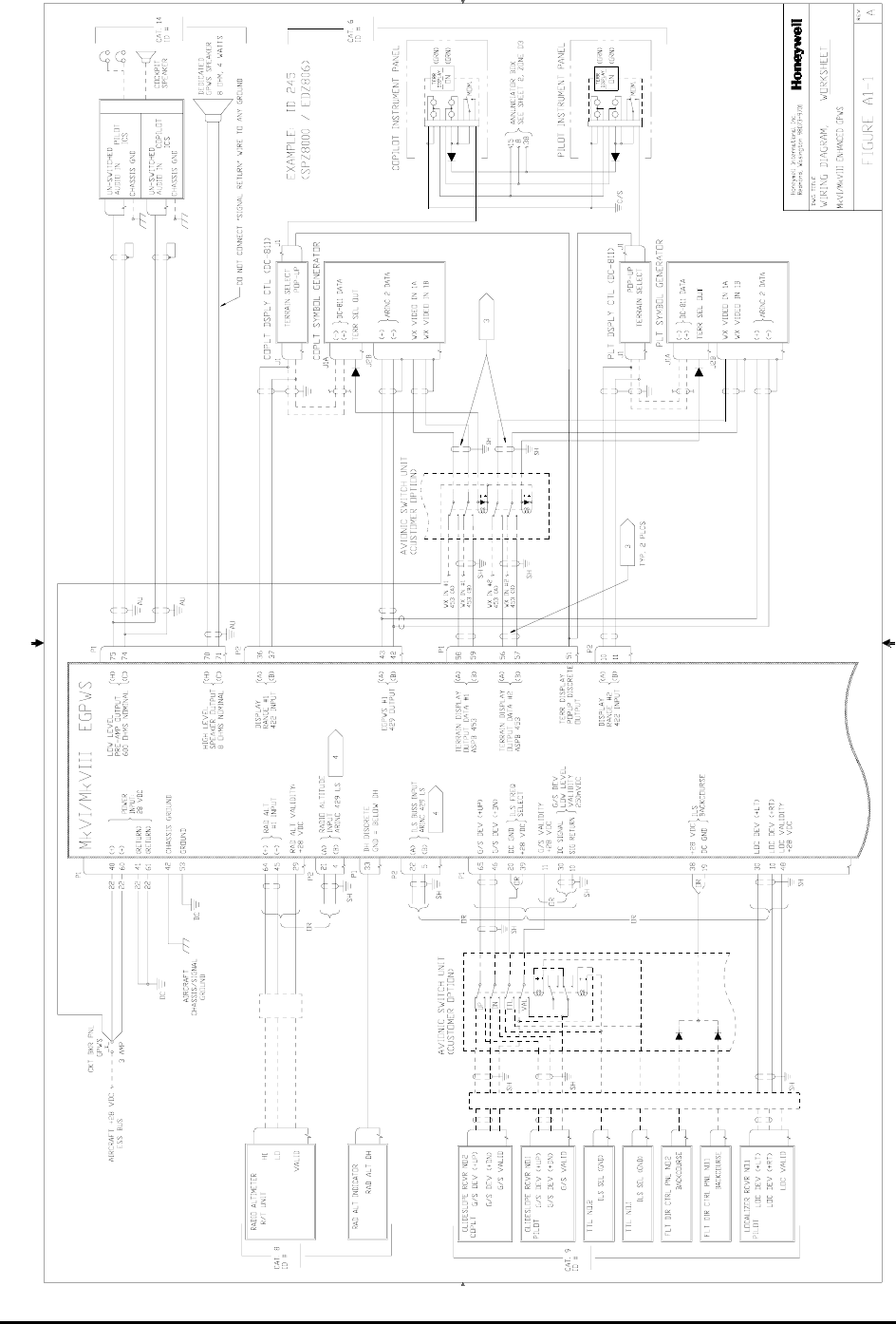
Honeywell
MK VI MK VIII EGPWS Installation Design Guide
Proprietary notice on title page applies
CAGE CODE: 97896 SCALE: NONE SIZE: A DWG NO: 060-4314-150 REV: SHEET 142
DISPLAY CONFIGURATION
AUDIO
GLIDESLOPE
AND/OR
LOCALIZER
RADIO ALTITUDE
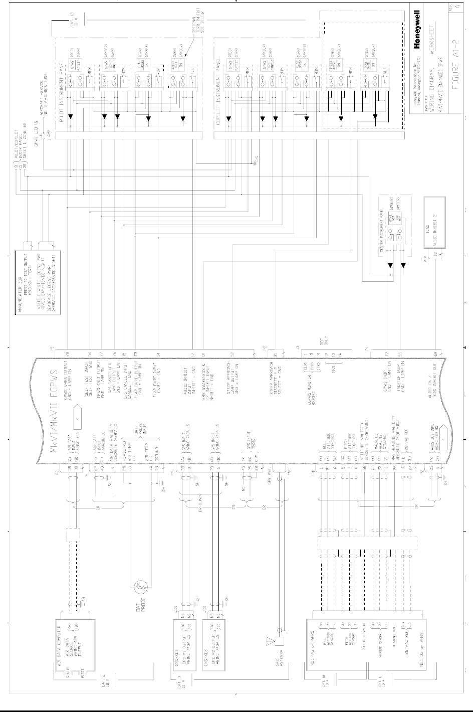
Honeywell
MK VI MK VIII EGPWS Installation Design Guide
Proprietary notice on title page applies
CAGE CODE: 97896 SCALE: NONE SIZE: A DWG NO: 060-4314-150 REV: SHEET 143
AIR DATA
POSITION
ATTITUDE/MAGNETIC HEADING
INPUT/OUTPUT
FUNCTIONS
DISCRETE
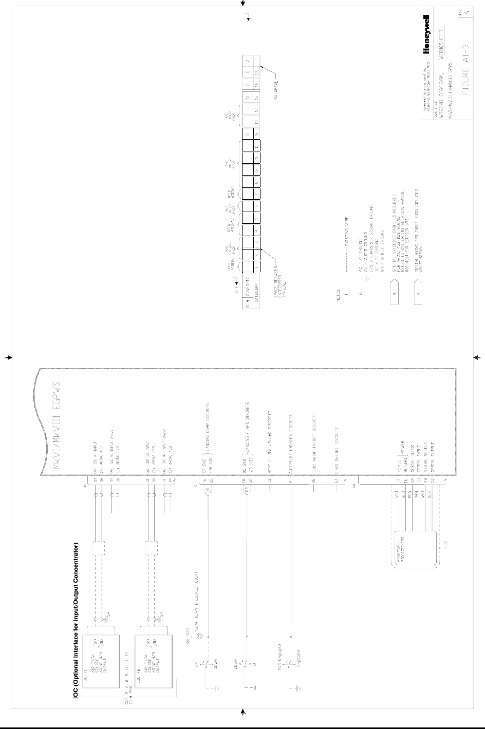
Honeywell
MK VI MK VIII EGPWS Installation Design Guide
Proprietary notice on title page applies
CAGE CODE: 97896 SCALE: NONE SIZE: A DWG NO: 060-4314-150 REV: SHEET 144
AUTOPILOT ENGAGED
FLAP SWITCH
CONFIGURATION MODULE PROGRAMING
GEAR SWITCH
CONFIG MODULE

Honeywell
MK VI MK VIII EGPWS Installation Design Guide
Proprietary notice on title page applies
CAGE CODE: 97896 SCALE: NONE SIZE: A DWG NO: 060-4314-150 REV: SHEET 145
APPENDIX C
WinVIEWS OPERATION INSTRUCTIONS

Honeywell
MK VI MK VIII EGPWS Installation Design Guide
Proprietary notice on title page applies
CAGE CODE: 97896 SCALE: NONE SIZE: A DWG NO: 060-4314-150 REV: SHEET 146
APPENDIX C – WinVIEWS Operation Instructions
RS-232 COMMUNICATION WITH THE EGPWS
The EGPWS contains software that allows monitoring of its internal parameters, for testing purposes, without
altering its operation. The monitoring of these parameter values enables the operator to quickly determine if the
correct signal and scaling is being used by the EGPWS computer. The communication link utilizes the RS-232
Communication Protocol configured as follows:
19200 Baud, No Parity, 8 bits, and 1 stop bit.
The RS-232 interface with the EGPWS is accomplished via the J3 test connector on the front of the EGPWS.
The connection between a PC (with a standard DB9 serial port connector) and the EGPWS RS-232 interface is
defined as follows: (Please note that the EGPWS will activate its RS-232 port only when it receives the
command CONTROL Z after power is applied to the EGPWS. The CONTROL Z command is automatically sent
by WinVIEWS)
RS-232 Receive RS-232 Transmit RS-232 Ground
EGPWS Front Connector Pin 3 Pin 4 Pin 1
Standard DB9 Connector (for a PC)* Pin 2 Pin 3 Pin 5
*NOTE:Some PC Comm Ports have Pins 2 & 3 reversed from what is described above.
The mating connector for the EGPWS J3 test connector is a male (pins) 15 pin double density D-subminiature
type, Positronics Industries (kit) part number ODD15M1OYOZ or the following individual parts:
Nomenclature (AMP) Amp Part Number Military Part Number
Connector Shell (HDP-22 Crimp Snap In Contact) 748364-1 reference MIL-C-24308
Size 22 DM Crimp Snap In Contacts Pin 0.030 748333-4 or -7 M39029/58-360
Backshell (Shielded Cable Clamp Assembly) 745854-5
Jackscrews, 2 required (4-40 Male Jackscrew Kit) 747784-8
Grommet Sets 747746-1
The following tools will work with Positronics, Amp, and Mil Spec Connectors:
Insertion / Extraction Tool 91067-1 M81969/1-04
Hand Crimp Tool M22520/2-01
Positioner M22520/2-09

Honeywell
MK VI MK VIII EGPWS Installation Design Guide
Proprietary notice on title page applies
CAGE CODE: 97896 SCALE: NONE SIZE: A DWG NO: 060-4314-150 REV: SHEET 147
WinVIEWS OPERATION:
Windows Virtual Interface to the Enhanced Warning System
WinVIEWS software is a tool developed by Honeywell to monitor or view values within the EGPWS. The WinVIEWS
software provides a monitor function that does not alter the operation of the EGPWS. The monitoring of values
assists in the installation testing of the EGPWS by allowing the operator to quickly determine if the correct signal and
scaling is being used by the EGPWS. Additionally, WinVIEWS provides a detailed status of the software
configuration and input signals which enables quick identification of system anomalies.
The command file is a simple text file that should include each CVT Item used in this test procedure. A sample
command file for this test procedure is found on the following page. The file must be a ‘Text Only’ type of file, such
as those created in the Microsoft Windows NotePad program. It should have a filename extension of .CMD. Once
this file is loaded, WinVIEWS can automatically display the current value of each parameter listed in the file.
Normal Operation for Ground Testing the EGPWS:
STEP 1 - Connect the PC to the EGPWS via the RS-232 cable as defined above.
STEP 2 - On the PC, start Windows 3.1, or higher.
STEP 3 - Start the WinVIEWS program.
STEP 4 - Under the File Menu select the “Load Command File” option and load the appropriate Command
File.
STEP 5 - Use F6 to select Data Display Mode. Each CVT Item listed in the Command File will be
continuously updated at a rate of greater than once per second. The values shown for the CVT
Items listed will be the test values.

Honeywell
MK VI MK VIII EGPWS Installation Design Guide
Proprietary notice on title page applies
CAGE CODE: 97896 SCALE: NONE SIZE: A DWG NO: 060-4314-150 REV: SHEET 148
Command File: MK68_GTP.CMD The format for the WinVIEWS command file is:
1. ASCII Text Only; no spaces
2. A CVT Item as specified in the test procedure
3. Each CVT Item Name is followed by a <return> or <enter>
RawRA1
ARA1Val
DHDsc
RawBAlt1
RawBCAlt1
RawCAS1
RawBaroRt1
AUBaroVal
RawAACSAT
RawSAT1
ILSTuned1
AGS1Val
RawAACGS1
ALoc1Val
RawAACLoc1
RawGS1
RawLoc1
RawGLat1
GPSLatude1
RawGLng1
GPSLngude1
RawGAlt1
RawHFOM1
RawVFOM1
RawRoll1
RawPitch1
AnAtt1Val
RawAACMHD
AACMHdVal
RawIMHd1
LandFlDsc
MFlpOvrd
LandGrDsc
HiLandGrDsc
GndLandGrDs
GSCan
TerrDis
AudInhDsc
GPWSInhDsc
M6LwVolDsc
APEngDisc1
GSInh
StpAppSel
MomSASel
TAWxRng1
TAWxRng2
DispRngOut1
DispRngOut2
PosUncert
GPWInop
WSInop
TA_NotAvail

Honeywell
MK VI MK VIII EGPWS Installation Design Guide
CAGE CODE: 97896 SCALE: NONE SIZE: A DWG NO: 060-4314-150 REV: SHEET 149
APPENDIX D
VENDOR CONTACT INFORMATION

Honeywell
MK VI MK VIII EGPWS Installation Design Guide
CAGE CODE: 97896 SCALE: NONE SIZE: A DWG NO: 060-4314-150 REV: SHEET 150
APPENDIX D - Vendor Contact Information
Vendor Contact Information
The vendor contact information provided below is current at the time of publication of this document.
AMP 2800 Fulling Mill Road
MS 038-035
Middletown, PA 17507
800 806-0480
http://www.amp.com
Amphenol 20 Melford Drive
Scarborough, Ontario, Canada
M1B 2X6
Ph: 416-291-4401
Fax: 416-292-0647
http://www.amphenol.com
Avidyne Corporation 55 Old Bedford Road
Lincoln, MA 01773
Ph: 888-723-7592
http://www.avidyne.com
Avtech Corporation 3400 Wallingford Ave North
Seattle, WA 98103
Ph: 206-634-2540
http://www.avtcorp.com
Barry Controls Burbank, CA
818 843-1000
Brighton, MA
616 787-1555
United Kingdom:
Surrey, England
44 (0932) 22-4122
Germany:
Raunheim, Germany
49 (6142) 43077/8/9
BF Goodrich Aerospace BF Goodrich Aircraft Sensors
14300 Judicial Road
Burnsville, MN 55306-4898
Ph: 952-892-4000
Fax: 952-892-4800
http://www.bfg-aerospace.com
Computer Instruments Corp. 1000 Shames Drive
Westbury, New York 11590
Ph: 516-876-8400
Fax: 516-876-9153
Email: info@computerinstruments.com
http://www.computerinstruments.com
Comant 12920 Park Street
Sante Fe Springs, CA 90670
Ph: 562-946-6694
Fax: 562-946-5150
Email: sales@comant.com
http://www.comant.com
Dallas Avionics, Inc. 2525 Santa Anna Ave.
Dallas, Texas 75228
Ph: 800-527-2581
distributor for Eaton switches
http://www.dallasavionics.com
Eaton Corporation
(see Dallas Avionics)
Lighted Switches, Displays
1640 Monrovia Avenue
Costa Mesa, CA 92627
Ph: 800-300-9320
http://www.aerospace.eaton.com
EDMO Distributors Inc. 5505 E. Rutter Ave.
Spokane, WA 99212-1333
Ph: 800-235-3300
distributor for STACO switches
http://www.edmo.com

Honeywell
MK VI MK VIII EGPWS Installation Design Guide
CAGE CODE: 97896 SCALE: NONE SIZE: A DWG NO: 060-4314-150 REV: SHEET 151
Electronic Cable Specialists
and Electrical Conservation
Systems, Inc.
5300 W Franklin Drive
Franklin, WI 53132-8642
414 421-5300
http://www.ecsdirect.com
Electrical & Mechanical
Technologies (EMTEQ)
S84 W18693 Enterprise Drive
Muskego, WI 53150
PH: 262 679-6170
Fax: 262 679-6175
888 679-6170
Email: Sales@emteq.com
http://www.emteq.com
Hollingsead International Sante Fe Springs, CA
213 921-3436
http://www.hollingsead.com
IDD Aerospace Redmond, WA
425 885-4353
ITT Cannon Santa Ana, CA
714 557-4700
Korry Electronics 901 Dexter Avenue North
Seattle, WA
Ph: 800 257- 8921
Fax: 206 281-3576
Email: info@korry.com
http://www.korry.com
Master Specialties Co. Costa Mesa, CA
714 642-2427
Mid-Continent Instruments
Norwich Aero Products
PIC Wire & Cable Supply N53 W24747 S. Corporate Circle
P.O. Box 330
Sussex, WI 53089-0330
414 246-0500
Fax: 414 246-0450
http://midcontinentinstruments.com
http://www.norwichaero.com
Email: BHackett@Picwire.com
http://www.picwire.com
Positronic Industries 423 North Campbell Avenue
Springfield, Missouri 65801
Email: info@positronic.com
http://www.positronic.com
Sensor Systems, Inc. 8929 Fullbright Avenue
Chatsworth, CA 91311
818 341-5366
Fax: 818 341-9059
http://www.sensorantennas.com
Shadin Co. 6831 Oxford Street
St. Louis Park, MN 55426
Ph: 800-328-0584
Fax: 612-924-1111
http://www.shadin.com
Email: sales@shadin.com
Spirent Systems
Penny & Giles Aerospace
8710 E. 32nd Street N.
Wichita, KS 67226
Ph: 316-636-2000
Fax: 316-636-9098
http://www.spirent-systems.com
Email: denniss@pgaerospace.com
Staco Switch
(see EDMO Distributors)
1139 Baker Street
Costa Mesa, CA 92626-4191
Ph: 714-549-3041
Fax: 714-549-0930
http://www.stacoswitch.com

Honeywell
MK VI MK VIII EGPWS Installation Design Guide
CAGE CODE: 97896 SCALE: NONE SIZE: A DWG NO: 060-4314-150 REV: SHEET 152
West Coast Specialties P.O. Box 5010
Preston, WA 98050
Ph: 425 222-3118
Fax: 425-222-3119
Contact:
Bruce Maxwell, (Rep)
206-232-2871
Fax: 206-232-3174

Honeywell
MK VI MK VIII EGPWS Installation Design Guide
Proprietary notice on title page applies
CAGE CODE: 97896 SCALE: NONE SIZE: A DWG NO: 060-4314-150 REV: SHEET 153
APPENDIX E
Interface Description Document

Honeywell
MK VI MK VIII EGPWS Installation Design Guide
Proprietary notice on title page applies
CAGE CODE: 97896 SCALE: NONE SIZE: A DWG NO: 060-4314-150 REV: SHEET 154
Table of Contents
APPENDIX E - INTERFACE DESCRIPTION DOCUMENT 159
1 INTRODUCTION 159
1.1 PART NUMBER 159
1.2 PURPOSE 159
1.3 SYSTEM OVERVIEW 159
1.4 DOCUMENT OVERVIEW 159
2 REFERENCES 159
3 MECHANICAL INTERFACE 160
3.1 WEIGHT 160
3.2 SYSTEM INTERFACE COMPONENTS 160
3.2.1 EGPWC Mounting 160
3.2.2 EGPWC Connectors 160
3.2.3 Configuration Module 161
3.3 OUTLINE 162
4 ELECTRICAL INTERFACE 164
4.1 INTRODUCTION 164
4.2 SIGNAL INTERFACES 164
4.2.1 Grounds 164
4.2.1.1 Chassis Ground 164
4.2.1.2 DC Ground 164
4.2.2 Primary Power Input 164
4.2.3 DC Analog Inputs 165
4.2.3.1 Radio Altitude 165
4.2.3.2 Low Level Glideslope 165
4.2.3.3 Localizer Deviation or Low Level Glideslope Validity 165
4.2.3.4 Barometric Altitude 166
4.2.3.5 Outside Air Temperature 166
4.2.3.6 Configuration Defined DC Inputs 166
4.2.4 AC Analog Inputs 166
4.2.4.1 Synchro Roll Attitude 166
4.2.4.2 Synchro Magnetic Heading 167
4.2.4.3 Synchro Pitch Attitude 167
4.2.4.4 Configuration Defined Synchro Inputs 167
4.2.4.5 Signal Timing Reference Inputs 167
4.2.5 ARINC 429/575 Digital Serial Bus Inputs 168
4.2.6 RS-232 / RS-422 Digital Serial Bus Inputs 168
4.2.6.1 GPS RS-232 Digital Serial Bus (serial port 3) 169
4.2.6.2 GPS RS-422 Digital Serial Bus (serial port 3) 169
4.2.6.3 Air Data RS-232 Digital Serial Bus (serial port 2) 169
4.2.6.4 Air Data RS-422 Digital Serial Bus (serial port 2) 169
4.2.6.5 SCI Range RS-422 Digital Serial Bus (serial port 1) 169
4.2.7 Discrete Inputs 170
4.2.8 Configuration Module Interface 170
4.2.9 GPS Antenna Input 170
4.2.10 OAT Voltage Reference Output 171
4.2.11 Lamp Driver Outputs 171
4.2.11.1 Monitor Output Characteristics 171
4.2.11.2 Discrete Output Characteristics 171
4.2.12 Audio Outputs 171
4.2.12.1 High Level (Speaker) Audio Output 171
4.2.12.2 Low Level (Interphone) Audio Output 172
4.2.13 ARINC Digital Serial Output Buses 172
4.2.13.1 ARINC 429 Output Bus 172
4.2.13.2 ARINC 453 Output Bus 172

Honeywell
MK VI MK VIII EGPWS Installation Design Guide
Proprietary notice on title page applies
CAGE CODE: 97896 SCALE: NONE SIZE: A DWG NO: 060-4314-150 REV: SHEET 155
4.3 FRONT PANEL TEST INTERFACE 172
4.3.1 RS-232 Maintenance Port (serial port 4) 173
4.3.2 PCMCIA / SmartCable Port 173
4.3.3 GSE Present Discrete Input 173
4.4 FRONT PANEL STATUS INDICATORS 173
5 AIRCRAFT APPLICATION DATA 174
5.1 CONFIGURATION TYPES 174
5.2 CONFIGURATION SELECTION 174
5.3 CONFIGURATION SELECTION TABLES 177
5.3.1 Category 1, Aircraft / Mode Type Select 177
5.3.2 Category 2, Air Data Input Select 179
5.3.3 Category 3, Position Input Select 187
5.3.4 Category 4, Altitude Callouts 193
5.3.5 Category 5, Audio Menu Select 194
5.3.6 Category 6, Terrain Display Select 198
5.3.7 Category 7, Options Select Group #1 241
5.3.8 Category 8, Radio Altitude Input Select 244
5.3.9 Category 9, Navigation Input Select 248
5.3.10 Category 10, Attitude Input Select 252
5.3.11 Category 11, Heading Input Select 255
5.3.12 Category 12, Windshear Input Select 257
5.3.13 Category 13, Input / Output Discrete Type Select 258
5.3.14 Category 14, Audio Output Level 269
5.3.15 Category 15, Undefined for this software release 269
5.3.16 Category 16, Undefined for this software release 269
5.3.17 Category 17, Undefined for this software release 269
6 CONFIGURABLE INPUT DATA DEFINITION 270
6.1 ANALOG INPUT DATA 270
6.1.1 ARINC 552 Radio Altimeter 270
6.1.2 ALT 55 Radio Altimeter 270
6.1.3 Uncorrected Barometric Altitude 271
6.1.4 Outside Air Temperature (500 ohm probe) 271
6.1.5 Outside Air Temperature (Internal Constant) 271
6.1.6 ARINC 547/578-4 Low Level Glideslope Deviation with Discrete Valid 272
6.1.7 ARINC 547/578-4 Low Level Glideslope Deviation with Low Level Valid 272
6.1.8 Roll Attitude, 3 Wire Synchro (11.8 VAC ) 272
6.1.9 Magnetic Heading, 5 Wire Synchro 273
6.1.10 Uncorrected Barometric Altitude (ADS-65) 273
6.1.11 RT-221/300 Radio Altimeter 273
6.1.12 Pitch Synchro Attitude, 3 Wire Synchro (11.8 VAC ) 274
6.1.13 Uncorrected Barometric Altitude (CIC 02702) 274
6.1.14 ARINC 547/578-4 Low Level Glideslope Deviation Validity 275
6.1.15 Roll Attitude, 3 Wire Synchro (11.8 VAC ) with Validity 275
6.1.16 Uncorrected Barometric Altitude (AZ-241, AZ-800) 275
6.1.17 ARINC 547 Localizer Deviation with Discrete Valid 276
6.2 DIGITAL INPUT DATA, ARINC 429 276
6.2.1 Uncorrected Barometric Altitude (203) 278
6.2.2 Static Air Temperature (213) 278
6.2.3 Barometric Altitude Rate (212) 278
6.2.4 Altitude (076) - GPS (MSL) 278
6.2.5 Horizontal Integrity Limit (130) - GPS 278
6.2.6 Ground Speed (112) - GPS 278
6.2.7 Latitude (110) - GPS 279
6.2.8 Longitude (111) - GPS 279
6.2.9 Track Angle (103) - GPS 279

Honeywell
MK VI MK VIII EGPWS Installation Design Guide
Proprietary notice on title page applies
CAGE CODE: 97896 SCALE: NONE SIZE: A DWG NO: 060-4314-150 REV: SHEET 156
6.2.10 Horizontal Figure Of Merit (247) – GPS (ARINC 743A) 279
6.2.11 Horizontal Figure Of Merit (247) – GPS (ARINC 743) 279
6.2.12 Horizontal Figure Of Merit from HDOP (101) – GPS (ARINC 743) 279
6.2.13 Vertical Figure Of Merit (136) – GPS (ARINC 743A) 279
6.2.14 Vertical Figure Of Merit (136) – GPS (ARINC 743) 279
6.2.15 Vertical Figure Of Merit from VDOP (102) – GPS (ARINC 743) 279
6.2.16 Sensor Status (273) - GPS 280
6.2.17 Universal Time Correlation (125) - GPS 280
6.2.18 Date (260) - GPS 280
6.2.19 Control Word (154) - MFD 281
6.2.20 Control Word 2 (271/273) 281
6.2.20.1 Control Word 2 (271/273) Type 2 281
6.2.21 Discrete Word (155 or 176) - MFD 282
6.2.22 Hazard Range Output (077) 282
6.2.23 Range (050) - Multifunction Signal Generator (MG) or IC600 283
6.2.24 Query / Continuous Response (011) - KCPB 283
6.2.25 Key Press Data (012) – KCPB 284
6.2.26 Control Word 1 (270) 284
6.2.27 Discrete Word (273) – Bendix Weather Radar Vertical Profile Mode 285
6.2.28 Discrete Word (275) – IC600 only 285
6.2.29 Radio Altitude (164) 285
6.2.30 Glideslope Deviation (174 or 117) 285
6.2.31 Roll Angle (325) 286
6.2.32 Magnetic Heading (320) 286
6.2.33 Localizer Deviation (173 or 116) 286
6.2.34 Pitch Angle (324) 286
6.2.35 Range (271) - KCPB 286
6.2.36 DSU Status Word (350) 286
6.2.37 True Heading (314) 287
6.2.38 Corrected Barometric Altitude (204) 287
6.2.39 Computed Airspeed (206) 287
6.2.40 True Airspeed (210) 287
6.2.41 Decision Height (370) – IOC Scaling 287
6.2.42 Normal Acceleration (333) 287
6.2.43 Longitudinal Acceleration (331) 288
6.2.44 Left Body Angle of Attack (224) 288
6.2.45 Right Body Angle of Attack (225) 288
6.2.46 VOR/ILS Frequency (034) 288
6.2.47 PFD Mode Select Word (163) 288
6.2.48 FWC & GP Discrete Word (171) 289
6.2.49 Body Pitch Rate (326) 290
6.2.50 Body Roll Rate (327) 290
6.2.51 Minimum Descent Altitude (170) – IOC Scaling 290
6.2.52 Normal Angle of Attack (236) 290
6.2.53 North/South Velocity (166) - GPS 291
6.2.54 East/West Velocity (174) - GPS 291
6.2.55 Discrete Word (017) - KMD 550/850 291
6.2.56 Inertial Vertical Speed (365) 291
6.2.57 Inertial Altitude (361) 291
6.2.58 Vertical Velocity (165) - GPS 291
6.2.59 Latitude Fine (120) - GPS 292
6.2.60 Longitude Fine (121) - GPS 292
6.2.61 Selected Course (100) - IOC 292
6.2.62 DH/MDA Selected (170) – DAU Scaling 292
6.3 DIGITAL DATA, ARINC 575 292
6.3.1 Static Air Temperature (213) 292
6.3.2 Uncorrected Barometric Altitude (203) 293

Honeywell
MK VI MK VIII EGPWS Installation Design Guide
Proprietary notice on title page applies
CAGE CODE: 97896 SCALE: NONE SIZE: A DWG NO: 060-4314-150 REV: SHEET 157
6.3.3 Barometric Altitude Rate (212) 293
6.3.4 Computed Airspeed (206) 293
6.4 DIGITAL DATA, RS-232 293
6.4.1 Xpress GPS Packets ID 15: Lat/Lon/Estimated Horizontal Position Error 293
6.4.2 Xpress GPS Packets ID 16: Altitude/Estimated Vertical Position Error 293
6.4.3 Xpress GPS Packets ID 17: Ground Speed/Track Angle 293
6.4.4 Xpress GPS Packets ID 18: East/North/Up Velocity 294
6.4.5 Xpress GPS Packets ID 1C: GPS State 294
6.5 DIGITAL DATA, RS-422 295
6.5.1 Honeywell RS-422 Serial Control Interface (SCI) Mode/Range Word 295
6.5.1.1 Serial Control Interface (SCI) Mode/Range Word 1 (80) 295
6.5.1.2 Serial Control Interface (SCI) Status Word 1 (FF) 296
6.5.2 Honeywell RS-232 Serial Control Interface for DC811 Up/Down Range 296
6.6 DISCRETE INPUTS 297
6.6.1 Analog Radio Altitude Validity Flags 297
6.6.2 GND Landing Gear Discrete 297
6.6.3 +28V Landing Gear Discrete 297
6.6.4 GND Landing Flap Discrete 298
6.6.5 +28V Landing Flap Discrete 298
6.6.6 Momentary Flap Override Discrete 298
6.6.7 Self-Test Discrete 298
6.6.8 GND ILS Tuned Discrete #1 298
6.6.9 +28V ILS Tuned Discrete #1 299
6.6.10 Glideslope Validity Discrete #1 299
6.6.11 GND Glideslope Inhibit Discrete 299
6.6.12 +28 V Glideslope Inhibit Discrete 299
6.6.13 Glideslope Cancel Discrete 299
6.6.14 Decision Height Discrete 300
6.6.15 Mode 6 Low Volume Discrete 300
6.6.16 GND Audio Inhibit Discrete 300
6.6.17 +28V Audio Inhibit Discrete 300
6.6.18 Display Select Discrete #1 300
6.6.19 Display Select Discrete #2 301
6.6.20 Terrain Awareness & TCF Inhibit Discrete 301
6.6.21 Autopilot Engaged Discrete #1 301
6.6.22 Barometric Altitude Validity Discrete 301
6.6.23 Magnetic Heading Validity Discrete 301
6.6.24 Attitude Validity Discrete 301
6.6.25 Steep Approach Discrete #2 302
6.6.26 Timed Audio Inhibit Discrete 302
6.6.27 GPWS Inhibit Discrete 302
6.6.28 Localizer Validity Discrete #1 302
7 OUTPUT DATA DEFINITION 303
7.1 ARINC 429 OUTPUT DATA 303
7.1.1 Discrete Output Words 305
7.1.1.1 EGPWS Alert Discrete #1 (270) 305
7.1.1.2 EGPWC Logic Discretes (271) 305
7.1.1.3 Mode 6 Callouts Discrete #1 (272) 306
7.1.1.4 Mode 6 Callouts Discrete #2 (273) 306
7.1.1.5 EGPWS Alert Discrete #2 (274) 307
7.1.1.6 EGPWC Alert Discrete #3 (300) 307
7.1.2 Internal Data Outputs 308
7.1.2.1 Geometric Altitude VFOM (135) 308
7.1.2.2 Terrain Clearance (164) 308
7.1.2.3 Geometric Altitude (261) 308
7.1.2.4 Computed Terrain Clearance (067) 308
7.1.2.5 Latitude – Selected EGPWS (310) 308
7.1.2.6 Longitude – Selected EGPWS (311) 308

Honeywell
MK VI MK VIII EGPWS Installation Design Guide
Proprietary notice on title page applies
CAGE CODE: 97896 SCALE: NONE SIZE: A DWG NO: 060-4314-150 REV: SHEET 158
7.1.2.7 Body Angle of Attack—Right (223) – MKVIII EGPWS w/ Windshear only 308
7.1.2.8 Body Angle of Attack—Left (224) – MKVIII EGPWS w/ Windshear only 309
7.1.2.9 Corrected Airspeed (242) – MKVIII EGPWS w/ Windshear only 309
7.1.2.10 Windshear Warning Threshold (331) – MKVIII EGPWS w/ Windshear only 309
7.1.2.11 Corrected Longitudinal Acceleration (332) – MKVIII EGPWS w/ Windshear only 309
7.1.2.12 Raw Total Shear (362) – MKVIII EGPWS w/ Windshear only 309
7.1.2.13 Corrected Normal Acceleration (364) – MKVIII EGPWS w/ Windshear only 309
7.1.2.14 Computed Flight Path Angle (375) – MKVIII EGPWS w/ Windshear only 309
7.1.2.15 Scaled Total Shear (376) – MKVIII EGPWS w/ Windshear only 309
7.1.3 Terrain Display Outputs 310
7.1.3.1 Displayed Range (050) 310
7.1.3.2 Terrain Display Status Word (051) 310
7.1.3.3 Message Word #1 (052) 311
7.1.3.4 Message Word #2 (053) 311
7.1.3.5 Message Word #3 (054) 312
7.1.3.6 Message Word #4 (055) 312
7.1.4 Equipment Identification 313
7.1.4.1 Equipment Identification Word (377) 313
7.1.5 Fault Summary Words (for Proline 4/21) 313
7.1.5.1 Fault Diagnostic Word #1 (350) 313
7.1.5.2 Fault Diagnostic Word #2 (351) 313
7.1.5.3 Fault Diagnostic Word #3 (355) 314
7.1.6 Peak Binary Labels 314
7.1.6.1 Peaks Upper Elevation (011) 314
7.1.6.2 Peaks Lower Elevation (012) 315
7.2 ARINC 708A OUTPUT 315
7.3 AUDIO OUTPUT 315
7.4 DISCRETE OUTPUTS 315
7.4.1 Ground Proximity Alerts Discrete (Lamp) Outputs 315
7.4.2 Audio On Discrete 316
7.4.3 Monitor Discretes (GPWS INOP & Terrain INOP or Terrain Not Available) 316
7.4.4 Terrain Display Switching Discretes (WxR/EGPWS Display Select) 316
7.4.5 Flap Override Discrete 316
7.4.6 Glideslope Cancel Discrete 316
7.4.7 Terrain / Obstacle Awareness Alert Discretes 316
7.4.7.1 Terrain / Obstacle Caution 316
7.4.7.2 Terrain / Obstacle Warning 316
7.4.8 Terrain Pop Up 316
7.4.9 Windshear INOP Monitor Discretes 316
7.4.10 Windshear Warning 316
7.4.11 Windshear Caution 317
7.4.12 Steep Approach Discrete 317
7.5 SYSTEM CONFIGURATION STATUS 317
7.5.1 System Status Messages 318
8 CONNECTOR INTERFACE 319
8.1 PINOUT FOR FRONT CONNECTORS SORTED BY PIN NUMBER 319
9 DEFINITIONS 324

Honeywell
MK VI MK VIII EGPWS Installation Design Guide
Proprietary notice on title page applies
CAGE CODE: 97896 SCALE: NONE SIZE: A DWG NO: 060-4314-150 REV: SHEET 159
APPENDIX E - Interface Description Document
1 INTRODUCTION
1.1 Part Number
This document is the Interface Description Document for the MK VI and MK VIII Enhanced Ground Proximity Warning
System (EGPWS). The EGPWS computer (EGPWC) for these systems are identified by Honeywell part numbers:
965-1180-0XX MK VI EGPWC With upgraded CPU
965-1190-0XX MK VI EGPWC With upgraded CPU and internal GPS
965-1210-0XX: MK VIII EGPWC With upgraded CPU
965-1220-0XX: MK VIII EGPWC With upgraded CPU and internal GPS
Differences, where they exist, between the different part numbers, are highlighted within this document.
The EGPWC 10 digit part number will identify the configuration of the EGPWC as follows:
965-1ABC-DDD (example 965-1180-020)
A = 1 (MK VI) or 2 (MK VIII)
B = Functionality of hardware (with or without internal GPS or Upgraded CPU). Refer to part number list above for
details.
C = MK VI or MK VIII EGPWC hardware (including boot code). C = 0 as hardware part numbers roll.
DDD = Application Software (including Configuration Software)
The Terrain Database (including the Envelope Modulation Database) Version is not identified in the 10-digit part number
but with a separate identifier on the nameplate.
All modification changes not affecting form, fit or function will be identified via “mod dots”.
The digits identifying the Application software will match the respective version number of the Application software.
1.2 Purpose
The Interface Description Document describes all of the system external interfaces for the MK VI and MK VIII Enhanced
Ground Proximity Warning System (EGPWS).
1.3 System Overview
Refer to the EGPWS Product Specification document referenced in section 2.
1.4 Document Overview
This document is organized as follows.
Section 1 Introduction, identifies this Description Document and describes the content and organization of the document.
Section 2 Referenced Documents.
Section 3 Mechanical Interface, summarizes the outline, mounting tray outline and weight of the EGPWS.
Section 4 Electrical Interface, summarizes the number and type of electrical interfaces available.
Section 5 Aircraft Application Data, specifies the available interfaces as well as specific data provided on each interface
Section 6 Input Data Definition, provides definition of digital and analog input characteristics.
Section 7 Output Data Definition, describes the characteristics of the EGPWC outputs.
Section 8 Connector Interface, describes pin out and function for the front panel connectors.
Section 9 Definitions, provides a list of acronyms.
2 REFERENCES
MK VI/MK VIII EGPWS Product Specification 965-1180-601
MK VI/MK VIII EGPWS Pilot Guide 060-4314-000
MK VI/MK VIII EGPWS Line Maintenance Manual 060-4199-180
MK VI/MK VIII EGPWS Terrain Database 060-4326-000
EGPWS Interface Methodology 060-4303-000
Honeywell
MK VI MK VIII EGPWS Installation Design Guide
Proprietary notice on title page applies
CAGE CODE: 97896 SCALE: NONE SIZE: A DWG NO: 060-4314-150 REV: SHEET 160
3 MECHANICAL INTERFACE
3.1 Weight
The maximum weight for all MK VI and MK VIII EGPWC part numbers is 3.9 pounds.
3.2 System Interface Components
Refer to section 3.3 for outline drawings.
3.2.1 EGPWC Mounting
The mounting rack for the EGPWC is identified as follows:
TRAY
Honeywell P/N Source/Vendor Vendor Part Number
405-0383-001 Bendix/King 071-04003-0002
3.2.2 EGPWC Connectors
There are two connectors that interface the aircraft with the MK VI and MK VIII EGPWC. The 78-pin (J1) and 50 pin
(J2) front panel interface connectors of the MK VI and VIII EGPWC contain all the interfaces for signals and power. The
78 pin is a Subminiature-D, High-Density Series connector conforming to Mil-C-24308. The 50 pin is a Subminiature-D
Connector conforming to Mil-C-24308.
P1 78 pin Connector
Vendor/Supplier Supplier P/N Honeywell P/N
Positronics DD78F10JVLC-15 440-1158-009
P2 50 pin Connector
Vendor/Supplier Supplier P/N Honeywell P/N
Positronics RD50F10JVLC-15 440-1233-001
A GPS Antenna connector is required for Enhanced MK VI and MK VIII units with internal GPS receiver.
GPS Connector
Vendor/Supplier Supplier P/N Honeywell P/N
AMP 225554-6 440-1239-001
For a pictoral of the front panel connectors, see Figure 8.1-1 and 8.1-2. Also, refer to Section 8 for pin-out information.
A test connector (J3) is provided on the EGPWC front panel. This provides access for a PC test monitor and future
portable data loading capabilities. The mating connector for the EGPWC test plug is a male (pins) 15 pin double density
D-subminiature type, Positronics Industries (kit) part number ODD15M1OYOZ or the following individual parts:
Nomenclature (AMP) Amp Part Number Military Part Number
Connector Shell (HDP-22 Crimp Snap In Contact) 748364-1 reference MIL-C-24308
Size 22 DM Crimp Snap In Contacts Pin 0.030 748333-4 or –7 M39029/58-360
Backshell (Shielded Cable Clamp Assembly) 745854-5
Jackscrews (4-40 Male Jackscrew Kit) 747784-8 (specify quantity of 2 per connector)
Grommet Sets 747746-1
The following tools will work with Positronics, Amp, and Mil Spec Connectors:
Insertion / Extraction Tool 91067-1 M81969/1-04
Hand Crimp Tool M22520/2-01
Positioner M22520/2-09

Honeywell
MK VI MK VIII EGPWS Installation Design Guide
Proprietary notice on title page applies
CAGE CODE: 97896 SCALE: NONE SIZE: A DWG NO: 060-4314-150 REV: SHEET 161
3.2.3 Configuration Module
The EGPWS aircraft configuration is programmed into a configuration module installed in the aircraft wiring. This
configuration module is identified as follows:
Vendor/Supplier Supplier P/N
Honeywell 700-1710-001
Honeywell 700-1710-020 *
The configuration module is installed as part of the P2 mating connector backshell and contains reprogrammable memory
for configuration storage.
Configuration module part number 700-1710-020, contains a Real Time Clock (RTC) circuit that supplies the EGPWS
with date and time to allow the internal GPS receiver to determine GPS constellation shift and provide faster satellite
signalacquistion and navigation. The Configuration module, part number 700-1710-020, will only operate with EGPWC
hardware part numbers 965-1180, 965-1190, 965-1210, 965-1220 and software versions -020 or later.
Configuration module, part number 700-1710-001, can be used with all EGPWC hardware part numbers and software
versions.
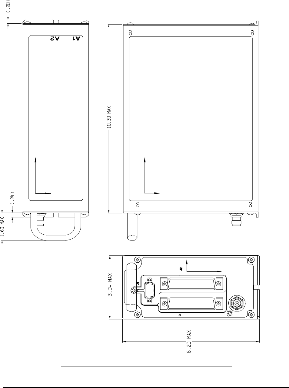
Honeywell
MK VI MK VIII EGPWS Installation Design Guide
Proprietary notice on title page applies
CAGE CODE: 97896 SCALE: NONE SIZE: A DWG NO: 060-4314-150 REV: SHEET 162
3.3 Outline
Dimensions of the MK VI and MK VIII EGPWC hardware and their associated mounting rack are given in this section.
The mounting rack is identical to that of the MK VI GPWC.
FIGURE 3.3-1: OUTLINE DRAWING FOR THE MK VI AND MK VIII EGPWC
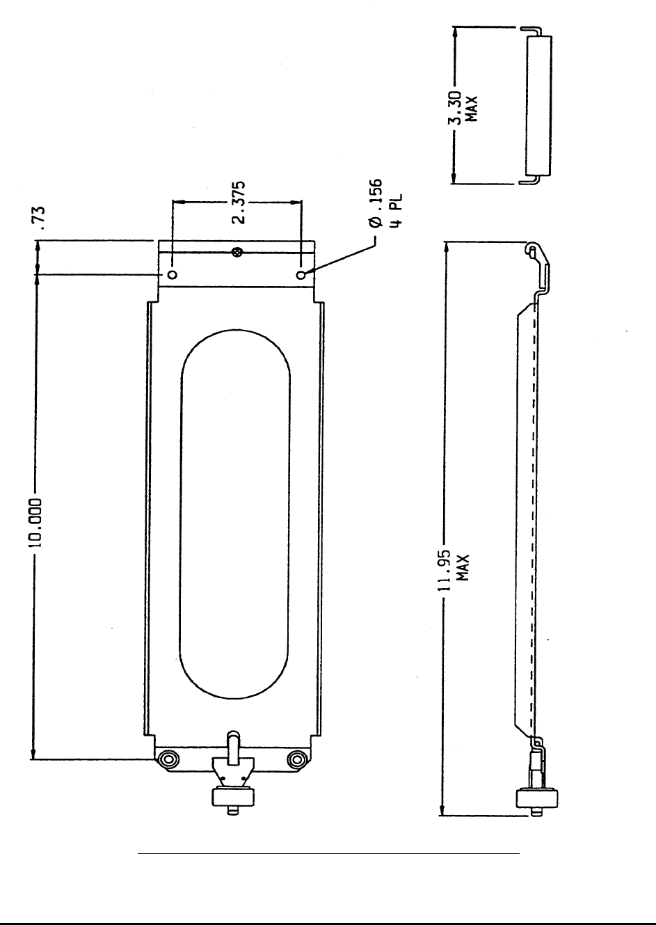
Honeywell
MK VI MK VIII EGPWS Installation Design Guide
Proprietary notice on title page applies
CAGE CODE: 97896 SCALE: NONE SIZE: A DWG NO: 060-4314-150 REV: SHEET 163
FIGURE 3.3-2: MOUNTING RACK FOR THE MK VI AND MK VIII EGPWC

Honeywell
MK VI MK VIII EGPWS Installation Design Guide
Proprietary notice on title page applies
CAGE CODE: 97896 SCALE: NONE SIZE: A DWG NO: 060-4314-150 REV: SHEET 164
4 ELECTRICAL INTERFACE
4.1 Introduction
The MK VI and MK VIII EGPWS provide electrical interfaces for aircraft systems and to support maintenance functions.
The interfaces are made via the front panel aircraft interface connectors, front panel maintenance/test port and front panel
LED’s. A TNC coaxial connector is located on the front panel for internal GPS receivers in the 965-1190-0XX MK VI
EGPWC, and 965-1220-0XX MK VIII EGPWC only. The following sections describe the types of electrical interfaces
provided in the EGPWC. See Section 5 for the specific interface configuration capabilities of the MK VI and MK VIII
EGPWS.
4.2 Signal Interfaces
This section identifies and describes the number and characteristics of each interface type provided in the front panel aircraft
interface connectors. The aircraft interface connectors are defined as P1 (78 pins) and P2 (50 pins). Section 8 identifies the
connector pin assignments. The signal mnemonic for each signal in Section 8 is included in the following sections. All
synchro inputs are brought in as three or five wire devices. No two wire absolute AC signals are available. All analog inputs
provide broken wire detection on all input signal legs. Unless otherwise stated, the “Maximum reverse fault current” is
defined as the current resulting from an internal component failure, with the input signal at zero volts.
4.2.1 Grounds
4.2.1.1 Chassis Ground
Used for redundant metal connection. This pin is internally connected to DC Ground (see section 4.2.1.2).
Pin Assignment (Signal Mnemonic): J1-42, J1-53 (GND)
4.2.1.2 DC Ground
For discrete inputs and lamp driver outputs. These pins are also internally connected to Chassis Ground (see section 4.2.1.1).
Pin Assignment (Signal Mnemonic):
(same as +28 VDC Return) J1-41, J1-61 (PWR_L)
NOTE: All analog signals are differential input.
4.2.2 Primary Power Input
Nominal Input 28 VDC
Normal Voltage Range 22.0 to 30.3 VDC
Normal Surge Voltage Range 15 to 40VDC (30 mSec)
Abnormal Voltage Range 20.5 to 32.2 VDC
Abnormal Surge Voltage Range 37.8 VDC (1sec); 46.3 VDC (100 mSec)
Normal Frequency Range not applicable
Frequency Transients not applicable
Power Requirements 9 Watts - No Warnings
+7 Watts with warning voice over 8 Ω speaker
+3 Watts with Internal GPS (includes antenna power)1
+49 Watts (typical) with heater blanket on2
Recommended Power Control Device 3 Amp delayed action circuit breaker.
Pin Assignment (Signal Mnemonic):
+28 VDC Input
+28 VDC Return
J1-40, J1-60
J1-41, J1-61
(PWR_H3)
(PWR_L3)
1 Based on the Honeywell GPS Pxpress card specification and applies to 965-1190-0XX and 965-1220-0XX only.
2 The heater blanket turns on at temperatures ≤ -23° C and turns off at temperatures ≥ -20° C.
3 Note that this is not a floating input. +28 VDC must be applied to both PWR_H and +28 VDC Return to both PWR_L inputs.

Honeywell
MK VI MK VIII EGPWS Installation Design Guide
Proprietary notice on title page applies
CAGE CODE: 97896 SCALE: NONE SIZE: A DWG NO: 060-4314-150 REV: SHEET 165
4.2.3 DC Analog Inputs
Unless otherwise specified, Input Signal accuracy is 1% linearity +0.1% full scale offset.
4.2.3.1 Radio Altitude
Quantity 1
Input Impedance, each leg > 83 KΩ
Maximum Reverse Fault Current < 200 µA
Signal Range 0 to 2500 feet
Input Voltage Range (VRA)37.7V ≥ VRA ≥ -2.5V
Conversion Range (VC)29.7V ≥ VC ≥ -0.4V
Input Filter 0.1 Second Low Pass, ± 10%
Broken Wire Detect Input will be biased to less than -50 feet
Pin Assignment (Signal Mnemonic):
Signal (+)
Return (-)
J1-64
J1-45
(RALT_H)
(RALT_L)
4.2.3.2 Low Level Glideslope
Quantity 1
Input Impedance, each leg > 2.5 MΩ
Reverse Fault Current < 6.2 µA
Signal Range ±12 Dots
Input Voltage Range ±0.9 VDC
Input Filter 0.1 Second Low Pass, ± 10%
Input Type Differential
Common Mode Voltage Range (VCM)11V ≥ VCM ≥ -2V
Broken Wire Detect Input will be biased less than -15 dots
Pin Assignment (Signal Mnemonic):
+Up, Below Beam, Fly Up
+Down, Above Beam, Fly Down
J1-65
J1-46
(GSDEV_H)
(GSDEV_L)
4.2.3.3 Localizer Deviation or Low Level Glideslope Validity
This input can be configured as either a low level glideslope valid, or as a localizer deviation input. Installations that only
have the low level validity signal for glideslope can not activate the analog localizer input. See section 5.3.9 for more
information.
Quantity 1
Input Impedance, each leg > 2.5 MΩ
Reverse Fault Current < 6.2 µA
Input Filter 0.1 Second Low Pass, ± 10%
Input Type Differential
Common Mode Voltage Range (VCM)11V ≥ VCM ≥ -2V
When used as a validity input:
Pin Assignment (Signal Mnemonic):
+ Flag
– Flag
J1-30
J1-10
(GS_VAL_H)
(GS_VAL_L)
Active Voltage Range (Logic True) +160 to +840 mVDC
Inactive Voltage Range (Logic False) 0 to 50 mVDC
Broken Wire Detect Input will be biased less than –1 VDC
When used as a localizer input:
Pin Assignment (Signal Mnemonic):
CRS DEV + Fly Right
CRS DEV + Fly Left
J1-30
J1-10
(LCDEV_H)
(LCDEV_L)
Signal Range ±12 Dots
Input Voltage Range ±0.9 VDC
Broken Wire Detect Input will be biased less than -15 dots

Honeywell
MK VI MK VIII EGPWS Installation Design Guide
Proprietary notice on title page applies
CAGE CODE: 97896 SCALE: NONE SIZE: A DWG NO: 060-4314-150 REV: SHEET 166
4.2.3.4 Barometric Altitude
Quantity 1
Input Impedance, each leg > 83 KΩ
Reverse Fault Current < 200 µA
Input Voltage Range -0.18 VDC to +15 VDC
Input Filter 0.1 Second Low Pass, ± 10%
Input Type Differential
Broken Wire Detect Input will be biased less than -3000 feet
Pin Assignment (Signal Mnemonic):
Signal (+)
Return (-)
J1-62
J1-43
(ALT_H)
(ALT_L)
4.2.3.5 Outside Air Temperature
Quantity 1
Input Impedance, each leg > 100 KΩ
Reverse Fault Current < 200 µA
Input Voltage Range +0.3 VDC to +0.6 VDC
Input Filter 0.1 Second Low Pass, ± 10%
Input Type Differential
Broken Wire Detect Input will be biased less than -80° C
Pin Assignment (Signal Mnemonic):
Signal (+)
Return (-)
J1-63
J1-44
(OAT_H)
(OAT_L)
NOTE: For temperature probe voltage reference see section 4.2.10.
4.2.3.6 Configuration Defined DC Inputs
Quantity 2
Input Impedance, each leg > 83 KΩ
Reverse Fault Current < 200 µA
Input Voltage Range ±5 VDC
Input Filter 0.1 Second Low Pass, ± 10%
Input Type Differential
Broken Wire Detect Input will be biased less than -6 VDC
Pin Assignment (Signal Mnemonic):
#1 Signal (+)
#1 Return (-)
#2 Signal (+)
#2 Return (-)
J1-26
J1-27
J1-66
J1-47
4.2.4 AC Analog Inputs
Unless otherwise specified
Input Impedance: X leg > 140 KΩ
Input Impedance: Y leg > 140 KΩ
Input Impedance: Z leg > 140 KΩ
Maximum Reverse Fault Current < 200 µA
Input Voltage Range ±11.8 VACRMS ± 20% (leg to leg)
Accuracy 2.5% linearity + 0.1% full scale offset
4.2.4.1 Synchro Roll Attitude
Quantity 1
Synchro Angle Range ±80 deg
Reference Voltages Not Required
Pin Assignment (Signal Mnemonic):
X leg
Y leg
Z leg
J1-1
J1-21
J1-2
(SYN_1X)
(SYN_1Y)
(SYN_1Z)

Honeywell
MK VI MK VIII EGPWS Installation Design Guide
Proprietary notice on title page applies
CAGE CODE: 97896 SCALE: NONE SIZE: A DWG NO: 060-4314-150 REV: SHEET 167
4.2.4.2 Synchro Magnetic Heading
Quantity 1
Synchro Angle Range ±180 deg
Reference Voltages ±26 VACRMS ± 20% (see 4.2.4.4)
Pin Assignment (Signal Mnemonic):
X leg
Y leg
Z leg
J1-22
J1-23
J1-3
(SYN_2X)
(SYN_2Y)
(SYN_2Z)
4.2.4.3 Synchro Pitch Attitude
Quantity 1
Synchro Angle Range ±80 deg
Reference Voltages Not Required
Pin Assignment (Signal Mnemonic):
X leg
Y leg
Z leg
J1-5
J1-7
J1-6
(SYN_3X)
(SYN_3Y)
(SYN_3Z)
4.2.4.4 Configuration Defined Synchro Inputs
Quantity 2
Reference Voltages ±26 VACRMS ± 20%
Pin Assignment (Signal Mnemonic):
#2 X leg
#2 Y leg
#2 Z leg
#3 X leg
#3 Y leg
#3 Z leg
J2-1
J2-2
J2-18
J2-19
J2-20
J2-3
(SYN_4X)
(SYN_4Y)
(SYN_4Z)
(SYN_5X)
(SYN_5Y)
(SYN_5Z)
4.2.4.5 Signal Timing Reference Inputs
These inputs accept 400 Hz AC signals, and detect the “zero crossings” of these signals. These zero crossings are used to
time the conversion and input of AC signals. Absolute voltage level of these signals is not measured, but it must be within
the range specified below. Voltage below the specified minimum value may result in intermittent or “jittery” zero cross
detection.
Timing reference signals are required for input of most AC devices (not required for pitch and roll). These references can be
brought into the appropriate timing reference input, or the system can be configured to derive a reference from the signal.
Timing reference signals are specified for synchro inputs requiring a range greater than ± 80 degrees. Inputs requiring less
(i.e., Roll Attitude) are configured to derive a reference from the synchro input signal and do not require a separate reference
voltage input.
Quantity 2
Input Impedance > 140KΩ each line to signal ground
Maximum Reverse Fault Current < 120 µA
A/C Input Signal Frequency Range 400 Hz, ±10%
Maximum Input Voltage Swing (differential) 50V between input legs
Maximum Input Voltage Swing (ref. to Gnd) 50V from any leg to signal ground
Input Hardware Filtering None
Minimum Input Voltage ± 0.5 VAC
Pin Assignment (Signal Mnemonic):
26VAC Reference #1 H
26VAC Reference #1 C
26VAC Reference #2 H
26VAC Reference #2 C
J1-4
J1-24
J2-34
J2-35
(26REF_1H)
(26REF_1L)
(26REF_2H)
(26REF_2L)

Honeywell
MK VI MK VIII EGPWS Installation Design Guide
Proprietary notice on title page applies
CAGE CODE: 97896 SCALE: NONE SIZE: A DWG NO: 060-4314-150 REV: SHEET 168
4.2.5 ARINC 429/575 Digital Serial Bus Inputs
Quantity 8
Format DITS, ARINC 429/575 Low or high speed 1
Low Speed Data Rate 12.0 KBPS to 14.5 KBPS
High Speed Data Rate 100 KBPS ± 1%
Direction of Information Flow Type ‘A’ broadcast for ARINC 429/575
Word/Frame Structure Type ‘B’ 32 bit words consisting of 8 bits label and 24 bits data/status
Data definition Refer to Section 6 of this document
Channel
Receive #1 A leg
Receive #1 B leg
Receive #2 A leg
Receive #2 B leg
Receive #3 A leg
Receive #3 B leg
Receive #4 A leg
Receive #4 B leg
Receive #5 A leg
Receive #5 B leg
Receive #6 A leg
Receive #6 B leg
Receive #7 A leg
Receive #7 B leg
Receive #8 A leg
Receive #8 B leg
Pin Assignment
J2-37
J2-36
J2-39
J2-38
J2-41
J2-40
J2-25
J2-8
J2-21
J2-4
J2-22
J2-5
J2-23
J2-6
J2-24
J2-7
(Signal Mnemonic):
(429/422RX_1A)
(429/422RX_1B)
(429RX_2A)
(429RX_2B)
(429RX_3A)
(429RX_3B)
(429RX_4A)
(429RX_4B)
(429RX_5A)
(429RX_5B)
(429RX_6A)
(429RX_6B)
(429RX_7A)
(429RX_7B)
(429RX_8A)
(429RX_8B)
SSM/SDI Definition: Refer to Section 6.2 of this document
4.2.6 RS-232 / RS-422 Digital Serial Bus Inputs
Two full duplex RS-232 / RS-422 buses and a third RS-422 receiver are provided at the aircraft interface connectors. The
RS-422 transceivers are electrically multiplexed with the RS-232 transceivers, and are selected through the configuration
process. The third RS-422 receiver is electrically multiplexed with the ARINC 429 channel 1 receiver. The maintenance
RS-232 bus is described in section 4.3.1. The specific characteristics (data rate, parity, data bits, stop bits) is defined in
the configuration selection, see Section 5 and 6 for details. RS-422 cable termination will not be required for typical
applications, see TIA/EIA-422-B Annex A.
The RS-232 bus meets the characteristics specified in RS232C and supports the following characteristics:
Data Rate 1200, 2400, 4800, 9600, 19200 or 38400 bits/Sec
Parity None, Odd or Even
Data bits 7 or 8
Stop bits 1 or 2
Maximum Recommended Cable Length 15 meters
Data definition Refer to Section 6 of this document
The RS-422 bus meets the characteristics of TIA/EIA-422-B and supports the following characteristics:
Data Rate 1200, 2400, 4800, 9600, 12000, 19200 or 38400 bits/Sec
Maximum Transceivers on Bus 20
Receiver Input Impedance 12 KΩ
Word/Frame Structure Refer to Section 6 of this document
Data definition Refer to Section 6 of this document
1 The bus speed is defined in the configuration selection, see Section 5 for details.

Honeywell
MK VI MK VIII EGPWS Installation Design Guide
Proprietary notice on title page applies
CAGE CODE: 97896 SCALE: NONE SIZE: A DWG NO: 060-4314-150 REV: SHEET 169
4.2.6.1 GPS RS-232 Digital Serial Bus (serial port 3)
One port is provided for use with external or internal RS-232 GPS interfaces. This port is common with the GPS RS-422
port described in Section 4.2.6.2 and can only function as a RS-232 interface or a RS-422 interface but not both.
Pin Assignment (Signal Mnemonic):
Transmit
Receive
Common
J2-45
J2-29
J2-28
(GPS_TXA)
(GPS_RXA)
(GND)
NOTE: If an internal GPS configuration is used (965-1190-0XX or 965-1220-0XX) then the receive input will be non-
functional.
4.2.6.2 GPS RS-422 Digital Serial Bus (serial port 3)
One port is provided for use with external GPS interfaces. This port is common with the GPS RS-232 port described in
Section 4.2.6.1 and can only function as a RS-232 interface or a RS-422 interface but not both.
Pin Assignment (Signal Mnemonic):
Transmit A leg
Transmit B leg
Receive A leg
Receive B leg
J2-45
J2-46
J2-29
J2-12
(GPS_TXA)
(GPS_TXB)
(GPS_RXA)
(GPS_RXB)
NOTE: If an internal GPS configuration is used (965-1190-0XX or 965-1220-0XX) then the receive input will be non-
functional.
4.2.6.3 Air Data RS-232 Digital Serial Bus (serial port 2)
One port is provided for use with Air Data computer or Static Pressure Sensor interfaces. This port is common with the
Air Data RS-422 port described in Section 4.2.6.4 and can only function as a RS-232 interface or a RS-422 interface but
not both.
Pin Assignment (Signal Mnemonic):
Transmit
Receive
Common
J2-27
J2-11
J2-28
(ADC_TXA)
(ADC_RXA)
(GND)
4.2.6.4 Air Data RS-422 Digital Serial Bus (serial port 2)
One port is provided for use with Air Data computer or Static Pressure Sensor interfaces. This port is common with the
Air Data RS-232 port described in Section 4.2.6.3 and can only function as a RS-232 interface or a RS-422 interface but
not both.
Pin Assignment (Signal Mnemonic):
Transmit A leg
Transmit B leg
Receive A leg
Receive B leg
J2-27
J2-44
J2-11
J2-10
(ADC_TXA)
(ADC_TXB)
(ADC_RXA)
(ADC_RXB)
4.2.6.5 SCI Range RS-422 Digital Serial Bus (serial port 1)
Two ports are provided for use with the SCI range bus interfaces. Port 1 is common with the ARINC 429 channel 1 port
described in Section 4.2.5 and can only function as a RS-422 interface or an ARINC 429 interface but not both. Port 2 is
common with the RS-232 port described in Section 4.2.6.4 and can only function as a RS-422 interface or an RS-232
interface but not both.
Pin Assignment (Signal Mnemonic):
Receive A leg
Receive B leg
Receive A leg
Receive B leg
J2-36
J2-37
J2-10
J2-11
(429/422RX_1B)
(429/422RX_1A)
(232/422RX_2A)
(232/422RX_2B)
Note: SCI Display Range RS-422 bus A and B legs are reversed from ARINC 429.

Honeywell
MK VI MK VIII EGPWS Installation Design Guide
Proprietary notice on title page applies
CAGE CODE: 97896 SCALE: NONE SIZE: A DWG NO: 060-4314-150 REV: SHEET 170
4.2.7 Discrete Inputs
Discrete signals are intended for remote switching through the aircraft, and are therefore subject to being connected to
other signals, and are also subject to transient voltage conditions. For these reasons, the following rules apply to each
input, unless otherwise stated.
Each input is capable of withstanding voltage transients of ± 600VDC for 10 µs and ± 50VDC continuously, without
damage. The +28 VDC discretes are internally biased via a pull down resistor, and are externally pulled up to +28VDC
when active. The characteristics of each +28 VDC discrete input are as follows:
+28 VDC Discrete Characteristics
Quantity 13
Active Voltage Range (Logic True) > +17 VDC
Inactive Voltage Range (Logic False) < +4.4 VDC
Diode Isolation None
Input Impedance > 95 KΩ
Maximum Fault Current < 60 µA
Pin Assignment (Signal Mnemonic): See specific discrete in Category 13 (28V_DISC_xx)
The Ground discretes are internally biased via a pull up resistor, and are externally pulled down to ground when active.
The characteristics of each Ground discrete input are as follows:
Ground Discrete Characteristics
Quantity 15
Active Voltage Range (Logic True) < +3 VDC
Inactive Voltage Range (Logic False) > 100 KΩ (to ground) or > +3.5 VDC
Diode Isolation Each input is diode isolated to prevent current sinking
Input Impedance > 10 KΩ
Maximum Fault Current < 100 µA (at +28 VDC input)
Pin Assignment (Signal Mnemonic): See specific discrete in Category 13 (GND_DISC_xx)
4.2.8 Configuration Module Interface
System configuration is defined via a Configuration Module, which resides in the MK VI/VIII EGPWS aircraft wiring
harness backshell. The EGPWS Configuration Module contains the aircraft interface and functionality definitions specific
to the installed aircraft. Refer to Section 5 for interface and functional definitions by category. Note that both
configuration module part numbers, 700-1710-003 and 700-1710-020, have identical electrical interfaces.
Electrical Characteristics Refer to the EGPWS Configuration Module specification
Data definition Refer to the EGPWS Configuration Module specification
Pin Assignment (Signal Mnemonic):
Clock
Master Data Out
Master Data In
Configuration Module Select
Configuration Module +5VDC
Configuration Module +5VDC Return
J2-32 (RED)
J2-50 (BLK)
J2-33 (ORN)
J2-49 (WHT)
J2-17 (VIO)
J2-16 (BLU)
(SPICLK)
(SPIMOSI)
(SPIMISO)
(SPISEL_CM#)
(SC_PWR)
(GND)
Output to Config Module Logic Low (nominal) Logic High (nominal)
EMK 6/8 EMK 6/8
Clock Out 0 V 5 V
Master Data Out 0 V 5 V
Config Module Select 0 V 5 V
INTERFACE OF EGPWS OUTPUTS TO CONFIGURATION MODULE
4.2.9 GPS Antenna Input
A GPS input connector is available on the front of the MK VI EGPWS (965-1190-0XX only) and MK VIII EGPWS (965-
1220-0XX) only.
Quantity 1
Cable Length/Allowed Signal Loss Not more than 8 dB, at 1575.42 MHz, for cable and
connector loss from antenna to unit.

Honeywell
MK VI MK VIII EGPWS Installation Design Guide
Proprietary notice on title page applies
CAGE CODE: 97896 SCALE: NONE SIZE: A DWG NO: 060-4314-150 REV: SHEET 171
Connector Type TNC
Low Level DC on RF Output +5 VDC ±5%, 50 mAmps maximum, Shield Ground.
Pin Assignment (Signal Mnemonic): GPS ANT (COAX)
4.2.10 OAT Voltage Reference Output
This output is an accurate voltage source for 500 Ω resistive temperature sensors.
Quantity 1
Output Voltage 5.000 VDC ±10 mVDC (no load)
Nominal Load 500 Ω
Pin Assignment (Signal Mnemonic): J1-25 (OAT_REF)
NOTE: This output has a source impedance of 4.42 KΩ, 0.1%.
4.2.11 Lamp Driver Outputs
The MK VI and MK VIII EGPWC support two kinds of Ground/Open discrete outputs used to signal various discrete
conditions. Monitor outputs are used to signal failure conditions for the MK VI and MK VIII EGPWC. Monitor outputs
default to an active state when there is a failure or if power is removed from the MK VI or MK VIII EGPWC. The other
Lamp Driver outputs are used to signal the alert or mode control status of the MK VI and MK VIII EGPWS.
Short-term current limit protection is provided on all drivers for output shorting conditions. Ground going output discretes
may be connected together to produce a “wired OR” function for the active low state of the signals. If output discretes are
“wired Or’d” then diodes must be installed for isolation.
4.2.11.1 Monitor Output Characteristics
Quantity 3
Type of Output: Switch Closure to Ground
Max. Open Circuit Voltage: 30 VDC
Current Limit 1 A
Potential Across “Closed” Switch: 2.5 VDC Max
Pin Assignment (Signal Mnemonic): See specific output in Category 13 (MON_OUT_xx)
NOTE: Intended to operate with +28VDC lamp sources and will not operate with +5VDC lamp sources.
4.2.11.2 Discrete Output Characteristics
Quantity 9
Type of Output: Switch Closure to Ground
Max. Open Circuit Voltage: 30 VDC
Current Limit 500 mA (typical)
Potential Across “Closed” Switch: 1 VDC Max
Pin Assignment (Signal Mnemonic): See specific output in Category 13 (DISC_OUT_xx)
NOTE: Intended to operate with +28VDC pullup external to the EGPWS.
4.2.12 Audio Outputs
There are two audio outputs provided one 8-ohm output and one 600-ohm output. There are several possible volume levels
available with the MKVI and MK VIII EGPWS as shown below, with maximum output being 4W (8Ω) or 100mW (600Ω).
The actual audio level output by the EGPWS is dependent on several items:
• Selection of nominal alert audio volume level (max, -6, -12, -18 or -24 dB) via Category 14. (Section 5.3.14)
• If a ‘soft’ Glideslope alert is being issued (given 6 dB below nominal alert volume level).
• If a Self Test is in progress, alerts are given 6 dB below nominal alert volume level.
• Selection of Mode 6 Low Volume Discrete (lowers callout volume by 6 dB - See Section 5.3.13).
4.2.12.1 High Level (Speaker) Audio Output
The 8-ohm output is capable of driving a speaker directly but can also be used to drive other devices with equal or higher
impedance.

Honeywell
MK VI MK VIII EGPWS Installation Design Guide
Proprietary notice on title page applies
CAGE CODE: 97896 SCALE: NONE SIZE: A DWG NO: 060-4314-150 REV: SHEET 172
Quantity 1
Maximum Power Output 4 Watts Nominal
Nominal Output Impedance 8Ω
Load Impedance 8Ω or greater
Number of Available Power Output Levels 5 selectable levels excluding the Mode 6 Audio Reduction function
Pin Assignment (Signal Mnemonic):
Signal (+)
Return (-)
J1-70
J1-71
(AUD_HL_H)
(AUD_HL_L)
4.2.12.2 Low Level (Interphone) Audio Output
The 600-ohm output is capable of driving one 600-ohm load at the specified level (or at a reduced level). This output is
primarily designed for headphones and interphone systems.
Quantity 1
Nominal Output Impedance 600Ω ±10%
Maximum Single Channel Power Output 100 mW Nominal
Available Power Output Levels 5 selectable levels excluding the Mode 6 Audio Reduction function
Pin Assignment (Signal Mnemonic):
Signal (+)
Return (-)
J1-75
J1-74
(AUD_LL_H)
(AUD_LL_L)
4.2.13 ARINC Digital Serial Output Buses
4.2.13.1 ARINC 429 Output Bus
The ARINC 429 output buses are defined in the terrain display select Section 5.3.6.3, output 429 bus group.
Quantity 2
Format DITS, ARINC 429
Low Speed Data Rate 12.0 KBPS to 14.5 KBPS
High Speed Data Rate 100 KBPS ± 1%
Direction of Information Flow Type ‘A’ broadcast for ARINC 429
Word/Frame Structure Type ‘B’ 32 bit words consisting of 8 bits label and 24 bits data/status
Data definition Refer to Section 7
Pin Assignment (Signal Mnemonic):
Bus #1 (A leg)
Bus #1 (B leg)
Bus #2 (A leg)
Bus #2 (B leg)
J2-43
J2-42
J2-26
J2-9
(429TX_1A)
(429TX_1B)
(429TX_2A)
(429TX_2B)
4.2.13.2 ARINC 453 Output Bus
Quantity 2
Format 1600 bit Manchester BI-phase per ARINC 708A
Data Rate 1 Mb per second
Word/Frame Structure Refer to Section 7.2
Data definition Refer to Section 7.2
Pin Assignment (Signal Mnemonic):
Bus #1 (A leg)
Bus #1 (B leg)
Bus #2 (A leg)
Bus #2 (B leg)
J1-58
J1-59
J1-56
J1-57
(KCPB_1A)
(KCPB_1B)
(KCPB_2A)
(KCPB_2B)
4.3 Front Panel Test Interface
The MK VI and MK VIII EGPWS provide a 15 pin (double density, D-Sub) test connector on the front panel, which
provides interfaces for various test and maintenance functions. This connector provides the following interfaces.

Honeywell
MK VI MK VIII EGPWS Installation Design Guide
Proprietary notice on title page applies
CAGE CODE: 97896 SCALE: NONE SIZE: A DWG NO: 060-4314-150 REV: SHEET 173
4.3.1 RS-232 Maintenance Port (serial port 4)
One port is provided which meets the characteristics specified in RS232C. This bus can be used to read internal data from
the MK VI or MK VIII EGPWS for both bench, and aircraft testing or transmitting configuration data for selected
EGPWS interfaces and options.
Baud Rate 19,200
Parity None
Data bits 8
Stop bits 1
Maximum Recommended Cable Length 15 meters
Pin Assignment (Signal Mnemonic):
Transmit
Receive
Common
J3-4
J3-3
J3-1
(RS232TXD_MON)
(RS232RXD_MON)
(GND)
4.3.2 PCMCIA / SmartCable Port
One port is provided which meets the Motorola SPI characteristics. The PCMCIA / SmartCable interface allows for both
the uploading, and downloading of internal MK VI and MK VIII EGPWS information. Using this interface system,
software and databases can be updated. Control of the upload/download process is accomplished by connection of the
SmartCable to the MK VI or MK VIII EGPWS front panel test connector and insertion of the PCMCIA card. LEDs are
provided on the SmartCable for PCMCIA interface operation. The PCMCIA / SmartCable is not intended as an on-line/in-
flight storage medium and must be removed after completion of the upload/download operation.
Electrical Characteristics Refer to the Motorola SPI specification
Data definition Refer to the Motorola SPI specification
Maximum Recommended Cable Length 2 meters
Pin Assignment (Signal Mnemonic):
Clock
Master Data Out
Master Data In
SmartCable Select
SmartCable +5VDC
SmartCable +5VDC Return
PCMCIA Card Present
SmartCable Ground
J3-7
J3-9
J3-8
J3-10
J3-6
J3-1
J3-2
J3-12, -13, -14
(SPICLK)
(SPIMOSI)
(SPIMISO)
(SPISEL_SC#)
(SC_PWR)
(GND)
(CARD_PRES#)
(GND)
NOTE: SmartCable +5VDC Return is common with RS-232 Maintenance Port common.
4.3.3 GSE Present Discrete Input
A discrete input for test and Ground Support Equipment is provided. Grounding this pin indicates to the EGPWS that test
or Ground Support Equipment is connected to the computer.
Active Threshold Voltage (Logic True) < 0.8 VDC
Inactive Threshold Voltage (Logic False) > 2.0 VDC
Input Impedance > 20 KΩ
Maximum Fault Current < 500 µA
Pin Assignment (Signal Mnemonic): J3-11 (GSE_PRES#)
4.4 Front Panel Status Indicators
The MK VI and MK VIII EGPWC front panel provides three LEDs for indicating system and LRU status. A yellow LED
labeled “EXTERNAL FAULT” is activated when a signal fault external to the MK VI or MK VIII EGPWC is detected.
A green LED labeled “COMPUTER OK” is activated when the MK VI or MK VIII EGPWC itself is okay. A red LED
labeled “COMPUTER FAIL” is activated when the MK VI or MK VIII EGPWC has detected an internal computer fault.
Refer to Product Specification 965-1180-601 for a detailed discussion of status indications, recommended maintenance
actions, Self Test activation and response.

Honeywell
MK VI MK VIII EGPWS Installation Design Guide
Proprietary notice on title page applies
CAGE CODE: 97896 SCALE: NONE SIZE: A DWG NO: 060-4314-150 REV: SHEET 174
5 AIRCRAFT APPLICATION DATA
This section describes the MK VI and MK VIII EGPWS interfaces for aircraft applications. Section 5.1 is a listing of the
selection categories defining the various aircraft sensor interfaces and EGPWS functional options. Section 5.2 describes
how the Category ID’s are selected and programmed for the interface to aircraft sensors and EGPWS functional options.
Section 5.3 and its sub-sections define the specific aircraft interfaces available for the MK VI and MK VIII EGPWS.
5.1 Configuration Types
The selection of the basic interfaces to the MK VI and MK VIII EGPWS can be found in the following categories:
Aircraft / Mode Type Select Category 1
Air Data Input Select Category 2
Position Input Select Category 3
Altitude Callouts Category 4
Audio Menu Select Category 5
Terrain Display Select Category 6
Options Select Group 1 Category 7
Radio Altitude Input Select Category 8
Navigation Input Select Category 9
Attitude Input Select Category 10
Heading Input Select Category 11
Windshear Input Select Category 12
I / O Discretes Select Category 13
Audio Output Level Category 14
Future Configuration Category Category 15
Future Configuration Category Category 16
Future Configuration Category Category 17
5.2 Configuration Selection
Each category provides information relative to aircraft interfaces or EGPWS functional options required or used for
EGPWS operation. Each category must be defined for the specific aircraft application according to the available aircraft
sensors or equipment and the intended EGPWS function. The choices provided are available in each category identified
by an “ID” number. The ID number is selected for each category and is used to load the selected configuration in a
configuration module installed in the aircraft wiring (physically part of one of the EGPWC mating connectors). For
example, selecting Category 2, ID 1 defines the Air Data Input as ARINC 429 per Table 5.3.2-1 in Category 2. With this
ID programmed into the configuration module the EGPWC will look for and use the interface defined for this ID. Table
5.2 can be used to record the selected ID for each category for later reference when programming the configuration
module. This programming is accomplished using a programming software tool available from Honeywell or generating a
data text string and transferring this data (in either case) via the EGPWC RS-232C (see 4.3.1) to the configuration module.
Once programmed, the configuration is available and read by any installed EGPWC on power up.

Honeywell
MK VI MK VIII EGPWS Installation Design Guide
Proprietary notice on title page applies
CAGE CODE: 97896 SCALE: NONE SIZE: A DWG NO: 060-4314-150 REV: SHEET 175
Table 5.2: Category ID Selection Procedure
Step
(Category) Signal Selection Instruction Ident No.
1
Selects:
a) Aircraft Type
b) Mode Type
Using Table 5.3.1, and any sub-tables
contained within, locate the Aircraft / Mode
Type.
Record the Ident (ID No.) on the space
available on Ident column of this table.
_______
ID #
2
Selects:
a) Air Data Source
Using Table 5.3.2, and any sub-tables
contained within, locate the desired Air Data
signal type.
Record the Ident (ID No.) on the space
available on Ident column of this table.
_______
ID #
3
Selects:
a) Position Source
Using Table 5.3.3, and any sub-tables
contained within, locate the desired Position
signal type.
Record the Ident (ID No.) on the space
available on Ident column of this table.
_______
ID #
4
Selects:
a) Altitude Callouts
Menu
Using Table 5.3.4 and any sub-tables
contained within, locate the desired Altitude
Callout Menu.
Record the Ident (ID No.) on the space
available on Ident column of this table.
_______
ID #
5
Selects:
a) Audio Menu
Using Table 5.3.5 and any sub-tables
contained within, locate the desired Audio
Menu type. Audio Menu types 2 & 3 are
designed for Fixed Gear installations.
Record the Ident (ID No.) on the space
available on Ident column of this table.
_______
ID #
6
Selects:
a) Terrain Display
Config.
Using Table 5.3.6 and any sub-tables
contained within, locate the desired Terrain
Display indicator type and range bus type.
Record the Ident (ID No.) on the space
available on Ident column of this table.
_______
ID #
7
Selects:
a) Steep Approach
Enabled
b) TA&D Alternate
Pop Up
c) Peaks Mode Enable
d) Obstacle Awareness
Enable
e) Bank Angle Enable
f) Flap Position
Polarity
g) GPS Altitude
Reference
Using Table 5.3.7 and any sub-tables
contained within, select the desired True or
False condition for Steep Approach
Enabled, TA&D Alternate Pop Up, Peaks
Mode Enable, Obstacle Awareness Enable,
Bank Angle Enable, Flap Reversal Select
functions and GPS Altitude Reference type.
Record the Ident (ID No.) on the space
available on Ident column of this table.
_______
ID #
8
Selects:
a) Radio Altitude
Source
Using Table 5.3.8, and any sub-tables
contained within, locate the desired Radio
Altitude signal type.
Record the Ident (ID No.) on the space
available on Ident column of this table.
_______
ID #
9
Selects:
a) Glideslope and/or
Localizer Source
Using Table 5.3.9, and any sub-tables
contained within, locate the desired
Navigation signal type.
Record the Ident (ID No.) on the space
available on Ident column of this table.
_______
ID #
10
Selects:
a) Attitude Source
Using Table 5.3.10, and any sub-tables
contained within, locate the desired Attitude
signal type.
Record the Ident (ID No.) on the space
available on Ident column of this table.
_______
ID #
11
Selects:
a) Magnetic Heading
Source
Using Table 5.3.11, and any sub-tables
contained within, locate the desired Magnetic
Heading signal type.
Record the Ident (ID No.) on the space
available on Ident column of this table.
_______
ID #
12
Selects:
a) Windshear Input
Type
Using Table 5.3.12, select “0” NoWindshear
unless you are an OEM with a defined
aircraft windshear type.
Record the Ident “0” (ID No.) on the
space available on Ident column of this
table.
__0__
ID #

Honeywell
MK VI MK VIII EGPWS Installation Design Guide
Proprietary notice on title page applies
CAGE CODE: 97896 SCALE: NONE SIZE: A DWG NO: 060-4314-150 REV: SHEET 176
Step
(Category) Signal Selection Instruction Ident No.
13
Selects:
a) Input Discrete
Functions
b) Output Discrete
Functions
Using Table 5.3.13, and any sub-tables
contained within, locate the desired I / O
Discrete type.
Record the Ident (ID No.) on the space
available on Ident column of this table.
_______
ID #
14
Selects:
a) Audio Output Level
Using Table 5.3.14, and any sub-tables
contained within, locate the desired Volume
type.
Record the Ident (ID No.) on the space
available on Ident column of this table.
_______
ID #
15
Selects:
a) Unused Using Table 5.3.15, select “0” Unused.
Record the Ident “0” (ID No.) on the
space available on Ident column of this
table.
__0__
ID #
16
Selects:
b) Unused Using Table 5.3.16, select “0” Unused.
Record the Ident “0” (ID No.) on the
space available on Ident column of this
table.
__0__
ID #
17
Selects:
c) Unused Using Table 5.3.17, select “0” Unused.
Record the Ident “0” (ID No.) on the
space available on Ident column of this
table.
__0__
ID #
LIMITATIONS: The described use of the configuration module provides for maximum flexibility in selection of input
sensors and output behavior. Every attempt has been made to avoid conflicts arising between categories and to reflect the
known configurations of aircraft. However in the case of input sensors it should not be construed that all combinations are
valid configurations. There may be configurations not supported by the EGPWS software configuration building process
(which will cause the EGPWS to fail in an obvious manner). In general you can not have redundancy through the mixing
of analog and digital sources, however redundant digital signals on different buses are permissable. As it is not practical to
verify all possible sensor combinations, verification of particular sensor combinations is part of the installation
certification process. If you intend to implement a sensor configuration not currently identified in Section 5, please contact
Honeywell or an authorized dealer/installer.

Honeywell
MK VI MK VIII EGPWS Installation Design Guide
Proprietary notice on title page applies
CAGE CODE: 97896 SCALE: NONE SIZE: A DWG NO: 060-4314-150 REV: SHEET 177
5.3 Configuration Selection Tables
Configuration selection is defined by category (or group of functions or inputs). The Category number identifies the
subsection where the details are defined. For example Air Data, Category 2, is defined in Section 5.3.2, and Position
Input Source, Category 3, is defined in Section 5.3.3.
5.3.1 Category 1, Aircraft / Mode Type Select
In this category the following parameters are defined:
• Basic mode alert thresholds
• Selected Mode 4B threshold
• Selected airspeed expansion
• Landing gear type
• Aircraft category (GA Fast, GA Slow, or Bizjet) defines the expected aircraft models, which the Aircraft Type will be
allocated to. It should be noted that the term “GA” when referring to GA Fast and GA Slow refers to Turboprop
aircraft and slower jet aircraft. Some of the differences between aircraft types are listed below to assist the reader.
Bizjet (Turbofan, MK VIII EGPWS only):
• Uses Commercial GPWS modes with Bizjet optimized “Bank-Angle” callout.
• A Gear stuck down fault will be indicated if the Gear are down and Airspeed exceeds 290 knots
• A Flap stuck down fault will be indicated if the Flaps are down and Airspeed exceeds 250 knots
• Uses either a 2000 ft and greater runway database (default) or a 3500 ft and greater runway database
GA Fast (Fast Turboprop):
• Uses classic MK VI GPWS modes.
• A Gear stuck down fault will be indicated if the Gear are down and Airspeed exceeds 290 knots
• A Flap stuck down fault will be indicated if the Flaps are down and Airspeed exceeds 250 knots
GA Slow (Slow Turboprop):
• Uses classic MK VI GPWS modes.
• Allows use of Mode 4 Alternate Airspeed Expansion
• A Gear stuck down fault will be indicated if the Gear are down and Airspeed exceeds 200 knots
• A Flap stuck down fault will be indicated if the Flaps are down and Airspeed exceeds 180 knots
The gear stuck and flap stuck faults activate the “GPWS INOP” and are recorded in fault history.
In addition, the Mode 4 Altitude and Airspeed Expansion variables are defined as follows:
• Mode 4B Altitude are described as follows:
150’ Mode 4B: The voice “Too Low Flaps” is intitiated at 150 feet above the ground.
170’ Mode 4B: The voice “Too Low Flaps” is intitiated at 170 feet above the ground.
200’ Mode 4B: The voice “Too Low Flaps” is intitiated at 200 feet above the ground.
• Normal/Alternate Airspeed Expansion are described as follows:
Normal Airspeed Expansion:
• Above 178 knots, penetration of the Mode 4 envelope will cause a “Too Low Terrain” voice
• Below 178 knots, penetration of the Mode 4 envelope will cause a “Too Low Gear” voice
Alternate Airspeed Expansion:
• Above 148 knots, penetration of the Mode 4 envelope will cause a “Too Low Terrain” voice
• Below 148 knots, penetration of the Mode 4 envelope will cause a “Too Low Gear” voice

Honeywell
MK VI MK VIII EGPWS Installation Design Guide
Proprietary notice on title page applies
CAGE CODE: 97896 SCALE: NONE SIZE: A DWG NO: 060-4314-150 REV: SHEET 178
The following table provides identification of the basic Aircraft/Mode Types and associated parameters. For purposes of
selecting an ID, use the “Description” provided in Table 5.3.1 appropriate to the desired variables as given above.
Table 5.3.1: Aircraft / Mode Type Select
ID Aircraft /
Mode DESCRIPTION Software
Effectivit
y
EGPWS
Type MKVI MKVIII
00
GA Fast (Fast Turboprop, Slow Turbofan),
170’ Mode 4B, Normal Airspeed Expansion -020 X X
11
GA Fast (Fast Turboprop, Slow Turbofan),
150’ Mode 4B, Normal Airspeed Expansion -020 X X
22
GA Fast (Fast Turboprop, Slow Turbofan),
200’ Mode 4B, Normal Airspeed Expansion -020 X X
33
GA Slow (Slow Turboprop),
170’ Mode 4B, Alternate Airspeed Expansion -020 X X
44
GA Slow (Slow Turboprop),
150’ Mode 4B, Alternate Airspeed Expansion -020 X X
254 254
Bizjet (Turbofan), default GPWS modes with Bizjet Bank
Angle Callout and 3500 ft and greater runway database.
(MKVIII Only) (Note 1)
-020 N/A X
255 255
Bizjet (Turbofan), default GPWS modes with Bizjet Bank
Angle Callout and 2000 ft and greater runway database.
(MKVIII Only)
-020 N/A X
Note 1: ID 254 is supported with terrain database 426 and later.
ID
Aircraft
Type
Mode 1
Type
Mode 2
Type
Mode 3
Type
Mode 4
Type
Mode 6
Type
Bank Angle
Type
Runway
Database
0GA Fast44261 42000’
1GA Fast44281 42000’
2GA Fast44251 42000’
3GA Slow45271 42000’
4GA Slow45291 42000’
254Bizjet11111 23500’
255Bizjet11111 22000’
See Product Specification 965-1180-601 for a description of Mode ‘X‘ type number.

Honeywell
MK VI MK VIII EGPWS Installation Design Guide
Proprietary notice on title page applies
CAGE CODE: 97896 SCALE: NONE SIZE: A DWG NO: 060-4314-150 REV: SHEET 179
5.3.2 Category 2, Air Data Input Select
The following table provides identification of the Air Data source type. The entry in the Air Data Type corresponds to a
table that provides detailed information on the configuration. For example, the details for Air Data Type #2 are found in
Table 5.3.2-2. In this category, only the following signals are defined:
• Uncorrected Barometric Altitude in analog, ARINC 575, or ARINC 429 format, and associated validity.
• Temperature (Outside Air or Static Air) in analog, ARINC 575, or ARINC 429 format.
• Corrected Barometric Altitude in ARINC 429 format.
• Barometric Rate in ARINC 575 or ARINC 429 format.
• Computed Airspeed in ARINC 575 or ARINC 429 format.
TABLE 5.3.2: AIR DATA INPUT SELECT
ID Air Data
Type Description Software
Effectivity EGPWS
(Table
5.3.2-x) MKVI MKVIII
00
Analog - Uncorrected Baro altitude and 500Ω OAT
(i.e., CIC 04077) -020 X X
11
Digital - ARINC 429
(i.e., Bendix KDC 281) -020 X X
22
Digital - ARINC 575
(i.e., Collins ADC-80, 81, 82) -020 X X
33
Analog - Uncorrected Baro altitude and 500Ω OAT
(i.e., Collins ADS-65) -020 X X
44
Analog - Uncorrected Baro altitude and 500Ω OAT
(i.e., CIC 02702) -020 X X
55
Digital - ARINC 429 with Corrected Altitude label 204
(i.e., Bendix KDC 481T) -020 X X
66
Digital - ARINC 429 without Baro Rate label 212
(i.e., Honeywell AZ-810) -020 X X
10 10 Digital - ARINC 429 and 500Ω OAT
(i.e. Shadin 2000) -020 X X
11 11
Analog - Uncorrected Baro altitude and 500Ω OAT
(i.e., Honeywell AZ-241, AZ-242, AZ-648, AZ-800,
AZ-810) (Note 2)
-020 X X
12 12
Analog - Uncorrected Baro altitude without temperature
(i.e., Honeywell AZ-241, AZ-242, AZ-648, AZ-800,
AZ-810) (Note 2)
-020 X X
13 13 Digital - ARINC 429 Uncorrected Altitude label 203
without temperature -020 X X
255 255 Digital – ARINC 429 (via dual IOC buses).
(Note 1)-020 N/A X
Note 1: ID 255 may only be used in conjunction with other IOC bus selections for categories 6, 8, 9, 10, 11 and 12.
Note 2: The AZ-800 provides an OAT signal with reference provided by the ADC. This signal is not compatible
with any current EGPWS interface. The AZ-241 does not provide an OAT interface. The installer may either
add an OAT probe (ID 11) or use the internal constant (ID 12). Honeywell recommends ID 11 (added OAT
probe) be used when operating in temperature extremes.
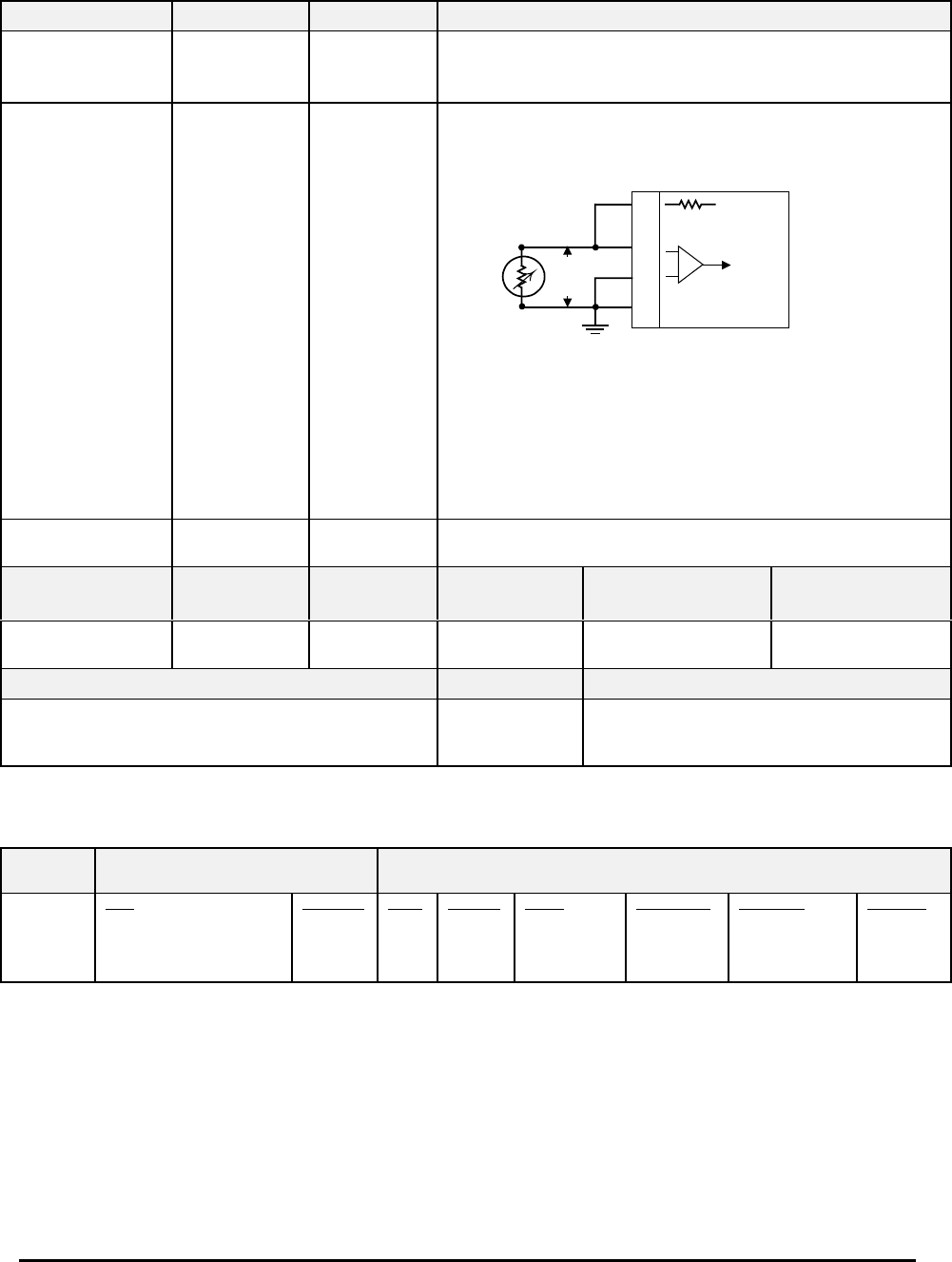
Honeywell
MK VI MK VIII EGPWS Installation Design Guide
Proprietary notice on title page applies
CAGE CODE: 97896 SCALE: NONE SIZE: A DWG NO: 060-4314-150 REV: SHEET 180
TABLE 5.3.2-0: AIR DATA INPUT SELECT #0
SIGNAL CONNECTION REFERENCE SUMMARY DATA
Uncorrected Barometric
Altitude
(+) = J1-62
(–) = J1-43 6.1.3
Format: DC with Validity Flag
Input Type: Basic
Fault Designation: BAROMETRIC ALTITUDE FAULT
Validity: Barometric Alt Valid (+28V)
Outside Air Temp
Total Air Temperature
Probe element
Excitation:
Temp Input
(probe element):
Ground
5 V = J1-25
(+) = J1-63
(–) = J1-44
GND = J1-53
6.1.4
4.2.3.5
4.2.10
Format: DC
Input Type: Basic
Fault Designation: STATIC AIR TEMPERATURE FAULT
OAT PROBE
ELEMENT
25
J1
(5 V Ref)
63
44
Temp In
4.42 K Ohms
53
Voat
Chassis Gnd
-
+
Note: Nominal 500 Ω Temperature Probe only.
Resistance @ 0°C: 500Ω ± 0.6Ω
Connection example:
CIC Temperature Sensor, P/N 05257 (2 wire). Connect positive
lead to both J1-25 and J1-63. Connect negative lead to both J1-
44 and J1-53 (Chassis Ground).
Other probes may have three contacts.
Computed Airspeed No Connection N/A Substitute Ground Speed for Airspeed (airspeed is not available with this air
data input)
PIN FUNCTION CONNECTION PIN TYPE
CHANNEL
DESIGNATION
REFERENCE
Polarity/Configuration References
Barometric Altitude
Validity Discrete (+28V)
J1-9 Input 28V_DISC_08 >+17V = Valid
< +4.4V = Invalid
6.6.22
4.2.7
Configuration Data Type Summary Data
Derive Baro Altitude Rate Analog Baro Altitude Rate is derived using
Uncorrected Barometric Altitude. Baro Rate
is not available with this air data source.
TABLE 5.3.2-1: AIR DATA INPUT SELECT #1
CHANNEL
429RX_2
CONNECT TO: ADC #1
Format: ARINC 429 (Low Speed)
Fault Designation: AIR DATA BUS
Bus Type: Basic
A = J2-39
B = J2-38
Data
Uncorrected Baro. Alt
Computed Airspeed
Barometric Rate
Static Air Temperature
Reference
6.2.1
6.2.39
6.2.3
6.2.2
Label
203
206
212
213
Sig. Bits
17
14
11
11
Range
±131,072 FT
±1024 KTS
±32768 FPM
512 Degrees
Signal Type
Basic
Basic
Basic
Basic
Resolution
1.0
0.0625
16.0
0.25
Rate (ms)
31.3-62.5
62.5-125
31.3-62.5
250-500
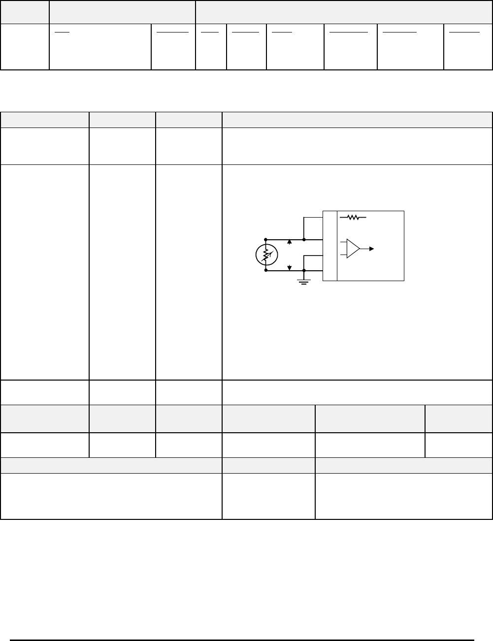
Honeywell
MK VI MK VIII EGPWS Installation Design Guide
Proprietary notice on title page applies
CAGE CODE: 97896 SCALE: NONE SIZE: A DWG NO: 060-4314-150 REV: SHEET 181
TABLE 5.3.2-2: AIR DATA INPUT SELECT #2
CHANNEL
429RX_2
CONNECT TO: ADC #1
Format: ARINC 575 (Low Speed)
Fault Designation: AIR DATA BUS
Bus Type: Basic
A = J2-39
B = J2-38
Data
Uncorrected Baro. Alt
Computed Airspeed
Barometric Rate
Static Air Temperature
Reference
6.3.2
6.3.4
6.3.3
6.3.1
Label
203
206
212
213
Sig. Bits
17
13
11
10
Range
±131,072 FT
±1024 KTS
±20480 FPM
±512 Degrees
Signal Type
Basic
Basic
Basic
Basic
Resolution
1.0
0.125
10.0
0.5
Rate (ms)
31.3-62.5
62.5-125
31.3-62.5
250-500
TABLE 5.3.2-3: AIR DATA INPUT SELECT #3
SIGNAL CONNECTION REFERENCE SUMMARY DATA
Uncorrected Barometric
Altitude
(+) = J1-62
(–) = J1-43 6.1.10
Format: DC with Validity Flag
Input Type: Basic
Fault Designation: BAROMETRIC ALTITUDE FAULT
Validity: Barometric Alt Valid (+28V)
Outside Air Temp
Total Air Temperature
Probe element
Excitation:
Temp Input
(probe element):
Ground
5 V = J1-25
(+) = J1-63
(–) = J1-44
GND = J1-53
6.1.4
4.2.3.5
4.2.10
Format: DC
Input Type: Basic
Fault Designation: STATIC AIR TEMPERATURE FAULT
OAT PROBE
ELEMENT
25
J1
(5 V Ref)
63
44
Temp In
4.42 K Ohms
53
Voat
Chassis Gnd
-
+
Note: Nominal 500 Ω Temperature Probe only.
Resistance @ 0°C: 500Ω ± 0.6Ω
Connection example:
CIC Temperature Sensor, P/N 05257 (2 wire). Connect positive
lead to both J1-25 and J1-63. Connect negative lead to both J1-
44 and J1-53 (Chassis Ground).
Other probes may have three contacts.
Computed Airspeed No Connection N/A Substitute Ground Speed for Airspeed (airspeed is not available with this air data
input)
PIN FUNCTION CONNECTION PIN TYPE
CHANNEL
DESIGNATION
REFERENCE
Polarity/Configuration References
Barometric Altitude
Validity Discrete (+28V)
J1-9 Input 28V_DISC_08 >+17V = Valid
< +4.4V = Invalid
6.6.22
4.2.7
Configuration Data Type Summary Data
Derive Baro Altitude Rate Analog Baro Altitude Rate is derived using
Uncorrected Barometric Altitude. Baro
Rate is not available with this air data
source.
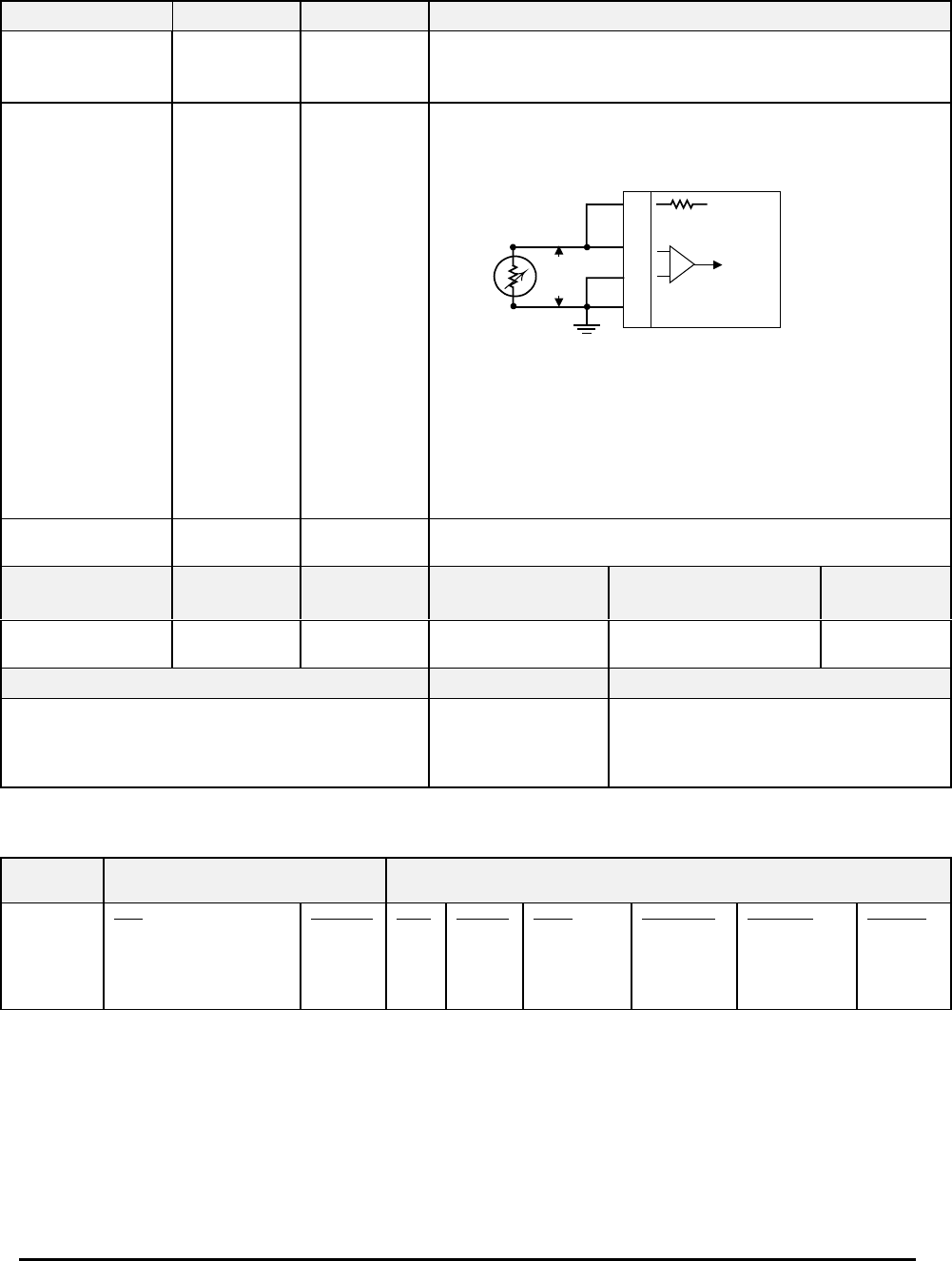
Honeywell
MK VI MK VIII EGPWS Installation Design Guide
Proprietary notice on title page applies
CAGE CODE: 97896 SCALE: NONE SIZE: A DWG NO: 060-4314-150 REV: SHEET 182
TABLE 5.3.2-4: AIR DATA INPUT SELECT #4
SIGNAL CONNECTION REFERENCE SUMMARY DATA
Uncorrected Barometric
Altitude
(+) = J1-62
(–) = J1-43 6.1.13
Format: DC with Validity Flag
Input Type: Basic
Fault Designation: BAROMETRIC ALTITUDE FAULT
Validity: Barometric Alt Valid (+28V)
Outside Air Temp
Total Air Temperature
Probe element
Excitation:
Temp Input
(probe element):
Ground
5 V = J1-25
(+) = J1-63
(–) = J1-44
GND = J1-53
6.1.4
4.2.3.5
4.2.10
Format: DC
Input Type: Basic
Fault Designation: STATIC AIR TEMPERATURE FAULT
OAT PROBE
ELEMENT
25
J1
(5 V Ref)
63
44
Temp In
4.42 K Ohms
53
Voat
Chassis Gnd
-
+
Note: Nominal 500 Ω Temperature Probe only.
Resistance @ 0°C: 500Ω ± 0.6Ω
Connection example:
CIC Temperature Sensor, P/N 05257 (2 wire). Connect positive
lead to both J1-25 and J1-63. Connect negative lead to both J1-
44 and J1-53 (Chassis Ground).
Other probes may have three contacts.
Computed Airspeed No Connection N/A Substitute Ground Speed for Airspeed (airspeed is not available with this air data
input)
PIN FUNCTION CONNECTION PIN TYPE
CHANNEL
DESIGNATION
REFERENCE
Polarity/Configuration References
Barometric Altitude
Validity Discrete (+28V)
J1-9 Input 28V_DISC_08 >+17V = Valid
< +4.4V = Invalid
6.6.22
4.2.7
Configuration Data Type Summary Data
Derive Baro Altitude Rate Analog Baro Altitude Rate is derived using
Uncorrected Barometric Altitude. Baro
Rate is not available with this air data
source.
TABLE 5.3.2-5: AIR DATA INPUT SELECT #5
CHANNEL
429RX_2
CONNECT TO: ADC #1
Format: ARINC 429 (Low Speed)
Fault Designation: AIR DATA BUS
Bus Type: Basic
A = J2-39
B = J2-38
Data
Uncorrected Baro. Alt
Corrected Baro. Alt
Computed Airspeed
Barometric Rate
Static Air Temperature
Reference
6.2.1
6.2.38
6.2.39
6.2.3
6.2.2
Label
203
204
206
212
213
Sig. Bits
17
17
14
11
11
Range
±131,072 FT
±131,072 FT
±1024 KTS
±32678 FPM
±512 Degrees
Signal Type
Basic
Basic
Basic
Basic
Basic
Resolution
1.0
1.0
0.0625
16.0
0.25
Rate (ms)
31.3-62.5
31.3-62.5
62.5-125
31.3-62.5
250-500
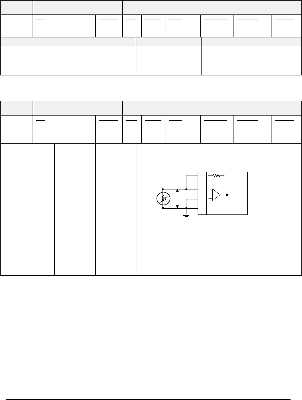
Honeywell
MK VI MK VIII EGPWS Installation Design Guide
Proprietary notice on title page applies
CAGE CODE: 97896 SCALE: NONE SIZE: A DWG NO: 060-4314-150 REV: SHEET 183
TABLE 5.3.2-6: AIR DATA INPUT SELECT #6
CHANNEL
429RX_2
CONNECT TO: ADC #1
Format: ARINC 429 (Low Speed)
Fault Designation: AIR DATA BUS
Bus Type: Basic
A = J2-39
B = J2-38
Data
Uncorrected Baro. Alt
Computed Airspeed
Static Air Temperature
Reference
6.2.1
6.2.39
6.2.2
Label
203
206
213
Sig. Bits
17
14
11
Range
±131,072 FT
±1024 KTS
±512 Degrees
Signal Type
Basic
Basic
Basic
Resolution
1.0
0.0625
0.25
Rate (ms)
31.3-62.5
62.5-125
250-500
Configuration Data Type Summary Data
Derive Baro Altitude Rate Digital Baro Altitude Rate is derived using
Uncorrected Barometric Altitude.
Baro Rate is not available with this air
data source.
TABLE 5.3.2-10: AIR DATA INPUT SELECT #10
CHANNEL
429RX_2
CONNECT TO: ADC #1
Format: ARINC 429 (Low Speed)
Fault Designation: AIR DATA BUS
Bus Type: Basic
A = J2-39
B = J2-38
Data
Uncorrected Baro. Alt
Corrected Baro. Alt
Computed Airspeed
Barometric Rate
Reference
6.2.1
6.2.38
6.2.39
6.2.3
Label
203
204
206
212
Sig. Bits
17
17
14
11
Range
±131,072 FT
±131,072 FT
±1024 KTS
±32678 FPM
Signal Type
Basic
Basic
Basic
Basic
Resolution
1.0
1.0
0.0625
16.0
Rate (ms)
31.3-62.5
31.3-62.5
62.5-125
31.3-62.5
Outside Air Temp
Total Air Temperature
Probe element
Excitation:
Temp Input
(probe element):
Ground
5 V = J1-25
(+) = J1-63
(–) = J1-44
GND = J1-53
6.1.4
4.2.3.5
4.2.10
Format: DC
Input Type: Basic
Fault Designation: STATIC AIR TEMPERATURE FAULT
OAT PROBE
ELEMENT
25
J1
(5 V Ref)
63
44
Temp In
4.42 K Ohms
53
Voat
Chassis Gnd
-
+
Note: Nominal 500 Ω Temperature Probe only.
Resistance @ 0°C: 500Ω ± 0.6Ω
Connection example:
CIC Temperature Sensor, P/N 05257 (2 wire). Connect positive
lead to both J1-25 and J1-63. Connect negative lead to both J1-
44 and J1-53 (Chassis Ground).
Other probes may have three contacts.
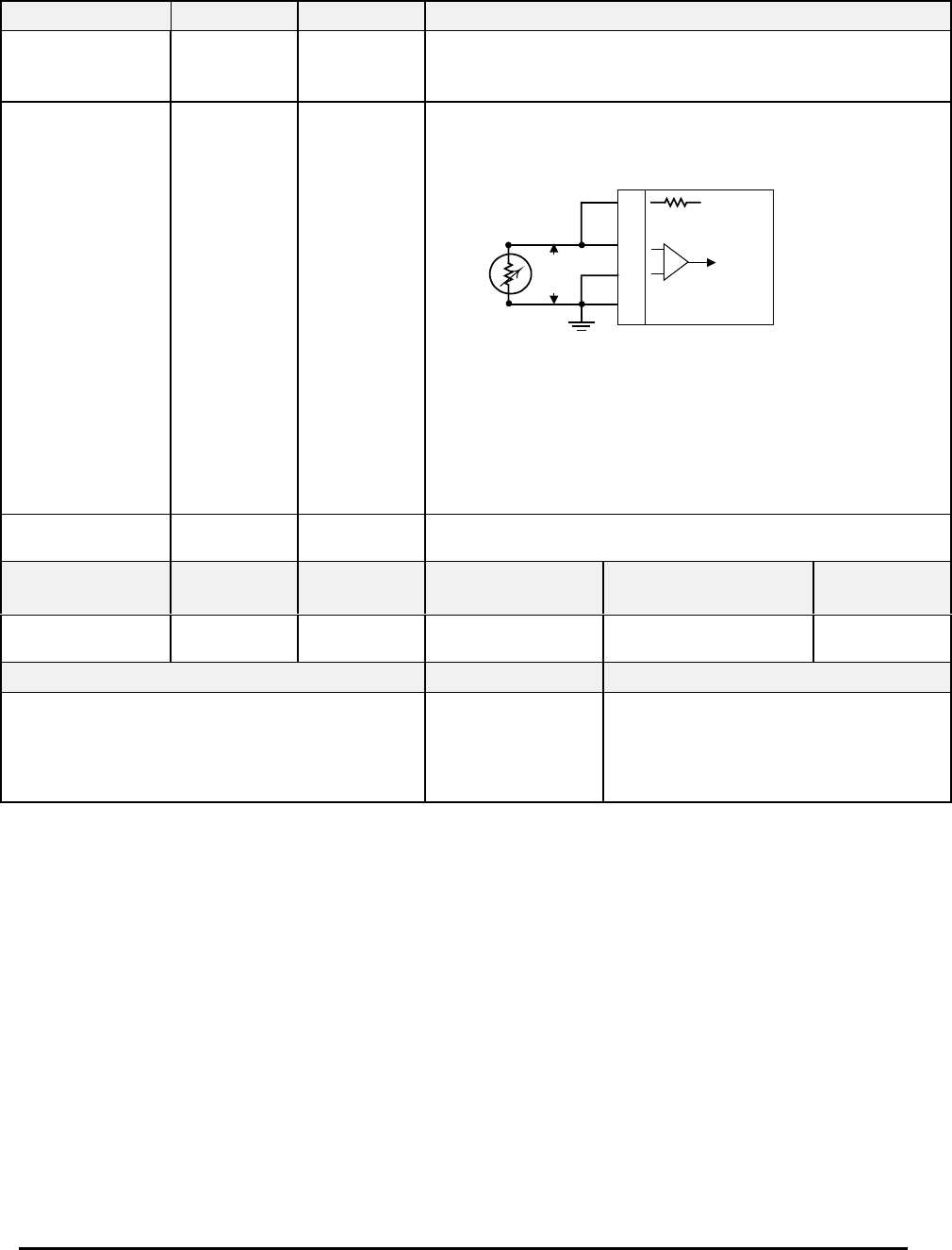
Honeywell
MK VI MK VIII EGPWS Installation Design Guide
Proprietary notice on title page applies
CAGE CODE: 97896 SCALE: NONE SIZE: A DWG NO: 060-4314-150 REV: SHEET 184
TABLE 5.3.2-11: AIR DATA INPUT SELECT #11
SIGNAL CONNECTION REFERENCE SUMMARY DATA
Uncorrected Barometric
Altitude
(+) = J1-62
(–) = J1-43 6.1.16
Format: DC with Validity Flag
Input Type: Basic
Fault Designation: BAROMETRIC ALTITUDE FAULT
Validity: Barometric Alt Valid (+28V)
Outside Air Temp
Total Air Temperature
Probe element
Excitation:
Temp Input
(probe element):
Ground
5 V = J1-25
(+) = J1-63
(–) = J1-44
GND = J1-53
6.1.4
4.2.3.5
4.2.10
Format: DC
Input Type: Basic
Fault Designation: STATIC AIR TEMPERATURE FAULT
OAT PROBE
ELEMENT
25
J1
(5 V Ref)
63
44
Temp In
4.42 K Ohms
53
Voat
Chassis Gnd
-
+
Note: Nominal 500 Ω Temperature Probe only.
Resistance @ 0°C: 500Ω ± 0.6Ω
Connection example:
CIC Temperature Sensor, P/N 05257 (2 wire). Connect positive
lead to both J1-25 and J1-63. Connect negative lead to both J1-44
and J1-53 (Chassis Ground).
Other probes may have three contacts.
Computed Airspeed No Connection N/A Substitute Ground Speed for Airspeed (airspeed is not available with this air data
input)
PIN FUNCTION CONNECTION PIN TYPE
CHANNEL
DESIGNATION
REFERENCE
Polarity/Configuration References
Barometric Altitude
Validity Discrete (+28V)
J1-9 Input 28V_DISC_08 >+17V = Valid
< +4.4V = Invalid
6.6.22
4.2.7
Configuration Data Type Summary Data
Derive Baro Altitude Rate Analog Baro Altitude Rate is derived using
Uncorrected Barometric Altitude.
Although the ADC’s provide Baro Rate,
the EGPWS does not have an analog
connection available.
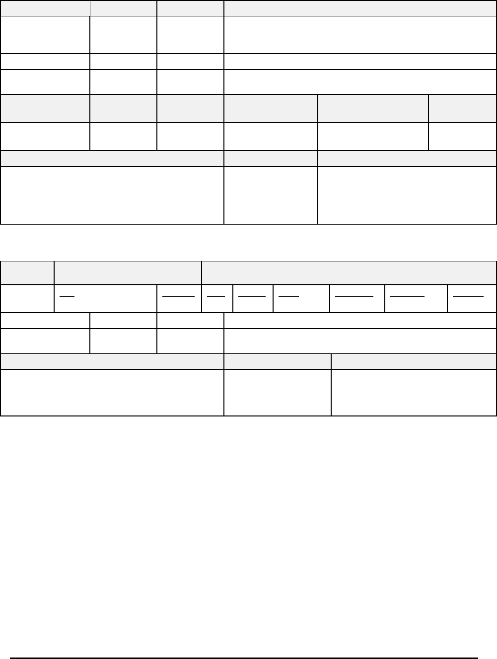
Honeywell
MK VI MK VIII EGPWS Installation Design Guide
Proprietary notice on title page applies
CAGE CODE: 97896 SCALE: NONE SIZE: A DWG NO: 060-4314-150 REV: SHEET 185
TABLE 5.3.2-12: AIR DATA INPUT SELECT #12
SIGNAL CONNECTION REFERENCE SUMMARY DATA
Uncorrected Barometric
Altitude
(+) = J1-62
(–) = J1-43 6.1.16
Format: DC with Validity Flag
Input Type: Basic
Fault Designation: BAROMETRIC ALTITUDE FAULT
Validity: Barometric Alt Valid (+28V)
Outside Air Temp No Connection N/A No temperature
Computed Airspeed No Connection N/A Substitute Ground Speed for Airspeed (airspeed is not available with this air data
input)
PIN FUNCTION CONNECTION PIN TYPE
CHANNEL
DESIGNATION
REFERENCE
Polarity/Configuration References
Barometric Altitude
Validity Discrete (+28V)
J1-9 Input 28V_DISC_08 >+17V = Valid
< +4.4V = Invalid
6.6.22
4.2.7
Configuration Data Type Summary Data
Derive Baro Altitude Rate Analog Baro Altitude Rate is derived using
Uncorrected Barometric Altitude.
Although the ADC’s provide Baro Rate,
the EGPWS does not have an analog
connection available.
TABLE 5.3.2-13: AIR DATA INPUT SELECT #13
CHANNEL
429RX_2
CONNECT TO: ADC #1
Format: ARINC 429 (Low Speed)
Fault Designation: AIR DATA BUS
Bus Type: Basic
A = J2-39
B = J2-38
Data
Uncorrected Baro. Alt
Reference
6.2.1
Label
203
Sig. Bits
17
Range
±131,072 FT
Signal Type
Basic
Resolution
1.0
Rate (ms)
31.3-62.5
Outside Air Temp No Connection N/A No temperature
Computed Airspeed No Connection N/A Substitute Ground Speed for Airspeed (airspeed is not available with this air data
input)
Configuration Data Type Summary Data
Derive Baro Altitude Rate Digital Baro Altitude Rate is derived using
Uncorrected Barometric Altitude.
Baro Rate is not available with this air
data source.

Honeywell
MK VI MK VIII EGPWS Installation Design Guide
Proprietary notice on title page applies
CAGE CODE: 97896 SCALE: NONE SIZE: A DWG NO: 060-4314-150 REV: SHEET 186
TABLE 5.3.2-255: AIR DATA INPUT SELECT #255
CHANNEL
429/422RX_1
CONNECT TO: IOC #1
Format: ARINC 429 (High Speed)
Fault Designation: IOC BUS 1
Bus Type: Basic
A = J2-37
B = J2-36
Data
Uncorrected Baro. Alt
Corrected Baro. Alt
Computed Airspeed
True Airspeed
Barometric Rate
Static Air Temperature
Reference
6.2.1
6.2.38
6.2.39
6.2.40
6.2.3
6.2.2
Label
203
204
206
210
212
213
Sig. Bits
17
17
14
15
11
11
Range
±131,072 FT
±131,072 FT
±1024 KTS
±2048 KTS
±32678 FPM
±512 Degrees
Signal Type
Basic
Basic
Basic
Basic
Basic
Basic
Resolution
1.0
1.0
0.0625
0.0625
16.0
0.25
Rate (ms)
31.3-62.5
31.3-62.5
62.5-125
62.5-125
31.3-62.5
250-500
CHANNEL
429RX_3
CONNECT TO: IOC #2
Format: ARINC 429 (High Speed)
Fault Designation: IOC BUS 2
Bus Type: Basic
A = J2-41
B = J2-40
Data
Uncorrected Baro. Alt
Corrected Baro. Alt
Computed Airspeed
True Airspeed
Barometric Rate
Static Air Temperature
Reference
6.2.1
6.2.38
6.2.39
6.2.40
6.2.3
6.2.2
Label
203
204
206
210
212
213
Sig. Bits
17
17
14
15
11
11
Range
±131,072 FT
±131,072 FT
±1024 KTS
±2048 KTS
±32678 FPM
±512 Degrees
Signal Type
Basic
Basic
Basic
Basic
Basic
Basic
Resolution
1.0
1.0
0.0625
0.0625
16.0
0.25
Rate (ms)
31.3-62.5
31.3-62.5
62.5-125
62.5-125
31.3-62.5
250-500

Honeywell
MK VI MK VIII EGPWS Installation Design Guide
Proprietary notice on title page applies
CAGE CODE: 97896 SCALE: NONE SIZE: A DWG NO: 060-4314-150 REV: SHEET 187
5.3.3 Category 3, Position Input Select
The following table provides identification of the Position source signal. Each entry in the Position Input Type column
has a corresponding table that provides detailed information on the configuration. For example, the details for Position
Input Type #0 are found in Table 5.3.3-0.
In this category, only the following Position signals are defined:
• Altitude
• Date *
• Ground Speed
• Horizontal Figure of Merit (HFOM)
• Horizontal Integrity Limit
• Latitude Position
• Longitude Position
• Sensor Status
• True Track Angle
• Universal Time Correlation *
• Vertical Figure of Merit (VFOM)
• N/S Velocity
• E/W Velocity
• Vertical Velocity
* used if present
Table 5.3.3: Position Input Select
ID Position
Input Type Description Software
Effectivity EGPWS
(Table
5.3.3-x)
MK
VI
MK
VIII
0 0 GPS, ARINC 429 low speed, ARINC 743A format -020 X X
1 1 GPS, ARINC 429 low speed, ARINC 743 format -020 X X
2 2 GPS, Internal -020 X X
3 3 GPS, RS-232 GPS-PXPRESS format -020 X X
4 4 GPS, ARINC 429 high speed, ARINC 743A format -020 X X
5 5 GPS, ARINC 429 high speed, ARINC 743 format -020 X X
10 10 GPS, ARINC 429 low speed, ARINC 743A format
No N/S-E/W velocities Note 2 -020 X X
11 11 GPS, ARINC 429 low speed, ARINC 743 format
No N/S-E/W velocities Note 2 -020 X X
12 12 GPS, ARINC 429 high speed, ARINC 743A format
No N/S-E/W velocities Note 2 -020 X X
13 13 GPS, ARINC 429 high speed, ARINC 743 format
No N/S-E/W velocities Note 2 -020 X X
253 253 Dual IOC GPS, ARINC 429 high speed, ARINC 743A
format, No N/S-E/W velocities Note 2 -020 X X
255 255 Dual GPS, ARINC 429 high speed, ARINC 743A format -020 N/A X
NOTE 1: The GPS Altitude Reference in Category 7, Options Select Group #1 must be properly applied for the
appropriate GPS Position type. At the time of release of this document, all GPS sources except the Universal GPS1000
based systems are of MSL type. The Universal GPS1000 based GPS sources are of WGS-84 type. If the internal GPS
source (ID=2) is defined, the GPS altitude reference in Category 7 must be MSL.
NOTE 2: ID 10, 11, 12, 13 and 253 may only be used when pitch and roll attitude inputs are configured for use in
Category 10 Attitude Input Select.
Honeywell
MK VI MK VIII EGPWS Installation Design Guide
Proprietary notice on title page applies
CAGE CODE: 97896 SCALE: NONE SIZE: A DWG NO: 060-4314-150 REV: SHEET 188
Table 5.3.3-0: Position Input Type 0 (Low Speed ARINC 743A GPS)
CHANNEL
429RX_4
CONNECT TO: GPS (ARINC 743A)
Format: ARINC 429 (Low Speed)
Fault Designation: GPS BUS
Bus Type: Basic
A = J2-25
B = J2-8
Data
Latitude - Normal
Longitude - Normal
GPS Hor. Int. Limit
Altitude
VFOM
HFOM
Ground Speed
True Track Angle
North/South Velocity
East/West Velocity
Vertical Velocity
Sensor Status
**UTC
**Date
Reference
6.2.7
6.2.8
6.2.5
6.2.4
6.2.13
6.2.10
6.2.6
6.2.9
6.2.53
6.2.54
6.2.58
6.2.16
6.2.17
6.2.18
Label
110
111
130
076
136
247
112
103
166
174
165
273
125
260
Sig. Bits
20
20
17
20
18
18
15
15
15
15
15
19
19
19
Range
±180 Degrees
±180 Degrees
16 nm
±131,072 FT
32768 ft
16 nm
±4096 Knots
±180 Degrees
±4096 Knots
±4096 Knots
±32768 fpm
Discrete Wd
Discrete Wd
Discrete Wd
Signal Type
Basic
Basic
Basic
Basic
Basic
Basic
Basic
Basic
Basic
Basic
Basic
Basic
Basic
Basic
Resolution
0.00017166137695
0.00017166137695
0.00012207
0.125
0.125
0.000061035
0.125
0.0054931640625
0.125
0.125
1
n/a
0.1 min
1 day
*Rate (ms)
1000
1000
1000
1000
1000
1000
1000
1000
1000
1000
1000
1000
1000
1000
Notes:
* Slowest acceptable update rate in milliseconds.
** This label is not required. Data used if present
Table 5.3.3-1: Position Input Type 1 (Low Speed ARINC 743 GPS)
CHANNEL
429RX_4
CONNECT TO: GPS (ARINC 743)
Format: ARINC 429 (Low Speed)
Fault Designation: GPS BUS
Bus Type: Basic
A = J2-25
B = J2-8
Data
Latitude - Normal
Longitude - Normal
GPS Hor. Int. Limit
Altitude
VDOP
HDOP
Ground Speed
True Track Angle
North/South Velocity
East/West Velocity
Vertical Velocity
Sensor Status
**UTC
**Date
Reference
6.2.7
6.2.8
6.2.5
6.2.4
6.2.15
6.2.12
6.2.6
6.2.9
6.2.53
6.2.54
6.2.58
6.2.16
6.2.17
6.2.18
Label
110
111
130
076
102
101
112
103
166
174
165
273
125
260
Sig. Bits
20
20
17
20
15
15
15
15
15
15
15
19
19
19
Range
±180 Degrees
±180 Degrees
16 nm
±131,072 FT
1024
1024
±4096 Knots
±180 Degrees
±4096 Knots
±4096 Knots
±32768 fpm
Discrete Wd
Discrete Wd
Discrete Wd
Signal Type
Basic
Basic
Basic
Basic
Basic
Basic
Basic
Basic
Basic
Basic
Basic
Basic
Basic
Basic
Resolution
0.00017166137695
0.00017166137695
0.00012207
0.125
0.03125
0.03125
0.125
0.0054931640625
0.125
0.125
1
n/a
0.1 min
1 day
*Rate (ms)
1000
1000
1000
1000
1000
1000
1000
1000
1000
1000
1000
1000
1000
1000
Notes:
* Slowest acceptable update rate in milliseconds.
** This label is not required. Data used if present
Table 5.3.3-2: Position Input Type 2 (Internal GPS)
CHANNEL Internal GPS Fault Designation: INTERNAL GPS
Bus Type: Basic
Data
Latitude
Longitude
HP Error
Altitude
VP Error
Ground Speed
True Track Angle
East Velocity
North Velocity
Vertical Velocity
GPS State
Integrity State
Error Status
Reference
6.4.1
6.4.1
6.4.1
6.4.2
6.4.2
6.4.3
6.4.3
6.4.4
6.4.4
6.4.4
6.4.5
6.4.5
6.4.5
ID/byte
15/1-4
15/5-8
15/9-12
16/1-4
16/5-8
17/1-4
17/5-8
18/1-4
18/5-8
18/9-12
1C/0
1C/1
1C/6-7
Sig. Bits
32
32
32
32
32
32
32
32
32
32
8
8
8
Range
±180 Degrees
±180 Degrees
meters
meters
meters
meters/sec
360 Degrees
meters/sec
meters/sec
meters/sec
Discrete Wd
Discrete Wd
Discrete Wd
Signal Type
Basic
Basic
Basic
Basic
Basic
Basic
Basic
Basic
Basic
Basic
Basic
Basic
Basic
Resolution
real single-precision
real single-precision
real single-precision
real single-precision
real single-precision
real single-precision
real single-precision
real single-precision
real single-precision
real single-precision
n/a
n/a
n/a
*Rate (ms)
1000
1000
1000
1000
1000
1000
1000
1000
1000
1000
1000
1000
1000
Notes:
* Slowest acceptable update rate in milliseconds.
1. "MSL" reference must be selected when an internal GPS is utilized. Refer to Table 5.3.7
Honeywell
MK VI MK VIII EGPWS Installation Design Guide
Proprietary notice on title page applies
CAGE CODE: 97896 SCALE: NONE SIZE: A DWG NO: 060-4314-150 REV: SHEET 189
Table 5.3.3-3: Position Input Type 3 (RS232 GPS, PXpress format)
CHANNEL
GPS_RXA
GPS_TXA
CONNECT TO: GPS (PXpress format)
Format: RS232 (9600 baud)
Fault Designation: GPS BUS
Bus Type: Basic
J2-28 (cm)
J2-29 (Rx)
Data
Latitude
Longitude
HP Error
Altitude
VP Error
Ground Speed
True Track Angle
East Velocity
North Velocity
Vertical Velocity
GPS State
Integrity State
Error Status
Reference
6.4.1
6.4.1
6.4.1
6.4.2
6.4.2
6.4.3
6.4.3
6.4.4
6.4.4
6.4.4
6.4.5
6.4.5
6.4.5
ID/byte
15/1-4
15/5-8
15/9-12
16/1-4
16/5-8
17/1-4
17/5-8
18/1-4
18/5-8
18/9-12
1C/0
1C/1
1C/6-7
Sig. Bits
32
32
32
32
32
32
32
32
32
32
8
8
8
Range
±180 Degrees
±180 Degrees
meters
meters
meters
meters/sec
360 Degrees
meters/sec
meters/sec
meters/sec
Discrete Wd
Discrete Wd
Discrete Wd
Signal Type
Basic
Basic
Basic
Basic
Basic
Basic
Basic
Basic
Basic
Basic
Basic
Basic
Basic
Resolution
real single-precision
real single-precision
real single-precision
real single-precision
real single-precision
real single-precision
real single-precision
real single-precision
real single-precision
real single-precision
n/a
n/a
n/a
*Rate (ms)
1000
1000
1000
1000
1000
1000
1000
1000
1000
1000
1000
1000
1000
Notes:
* Slowest acceptable update rate in milliseconds.
Table 5.3.3-4: Position Input Type 4 (High Speed ARINC 743A GPS)
CHANNEL
429RX_4
CONNECT TO: GPS (ARINC 743A)
Format: ARINC 429 (High Speed)
Fault Designation: GPS BUS
Bus Type: Basic
A = J2-25
B = J2-8
Data
Latitude - Normal
Longitude - Normal
GPS Hor. Int. Limit
Altitude
VFOM
HFOM
Ground Speed
True Track Angle
North/South Velocity
East/West Velocity
Vertical Velocity
Sensor Status
**UTC
**Date
Reference
6.2.7
6.2.8
6.2.5
6.2.4
6.2.13
6.2.10
6.2.6
6.2.9
6.2.53
6.2.54
6.2.58
6.2.16
6.2.17
6.2.18
Label
110
111
130
076
136
247
112
103
166
174
165
273
125
260
Sig. Bits
20
20
17
20
18
18
15
15
15
15
15
19
19
19
Range
±180 Degrees
±180 Degrees
16 nm
±131,072 FT
32768 ft
16 nm
±4096 Knots
±180 Degrees
±4096 Knots
±4096 Knots
±32768 fpm
Discrete Wd
Discrete Wd
Discrete Wd
Signal Type
Basic
Basic
Basic
Basic
Basic
Basic
Basic
Basic
Basic
Basic
Basic
Basic
Basic
Basic
Resolution
0.00017166137695
0.00017166137695
0.00012207
0.125
0.125
0.000061035
0.125
0.0054931640625
0.125
0.125
1
n/a
0.1 min
1 day
*Rate (ms)
1000
1000
1000
1000
1000
1000
1000
1000
1000
1000
1000
1000
1000
1000
Notes:
* Slowest acceptable update rate in milliseconds.
** This label is not required. Data used if present
Table 5.3.3-5: Position Input Type 5 (High Speed ARINC 743 GPS)
CHANNEL
429RX_4
CONNECT TO: GPS (ARINC 743)
Format: ARINC 429 (High Speed)
Fault Designation: GPS BUS
Bus Type: Basic
A = J2-25
B = J2-8
Data
Latitude - Normal
Longitude - Normal
GPS Hor. Int. Limit
Altitude
VDOP
HDOP
Ground Speed
True Track Angle
North/South Velocity
East/West Velocity
Vertical Velocity
Sensor Status
**UTC
**Date
Reference
6.2.7
6.2.8
6.2.5
6.2.4
6.2.15
6.2.12
6.2.6
6.2.9
6.2.53
6.2.54
6.2.58
6.2.16
6.2.17
6.2.18
Label
110
111
130
076
102
101
112
103
166
174
165
273
125
260
Sig. Bits
20
20
17
20
15
15
15
15
15
15
15
19
19
19
Range
±180 Degrees
±180 Degrees
16 nm
±131,072 FT
1024
1024
±4096 Knots
±180 Degrees
±4096 Knots
±4096 Knots
±32768 fpm
Discrete Wd
Discrete Wd
Discrete Wd
Signal Type
Basic
Basic
Basic
Basic
Basic
Basic
Basic
Basic
Basic
Basic
Basic
Basic
Basic
Basic
Resolution
0.00017166137695
0.00017166137695
0.00012207
0.125
0.03125
0.03125
0.125
0.0054931640625
0.125
0.125
1
n/a
0.1 min
1 day
*Rate (ms)
1000
1000
1000
1000
1000
1000
1000
1000
1000
1000
1000
1000
1000
1000
Notes:
* Slowest acceptable update rate in milliseconds.
** This label is not required. Data used if present
Honeywell
MK VI MK VIII EGPWS Installation Design Guide
Proprietary notice on title page applies
CAGE CODE: 97896 SCALE: NONE SIZE: A DWG NO: 060-4314-150 REV: SHEET 190
Table 5.3.3-10: Position Input Type 10 (Low Speed ARINC 743A GPS, no N/S-E/W Velocities)
CHANNEL
429RX_4
CONNECT TO: GPS (ARINC 743A)
Format: ARINC 429 (Low Speed)
Fault Designation: GPS BUS
Bus Type: Basic
A = J2-25
B = J2-8
Data
Latitude – Normal
Longitude – Normal
GPS Hor. Int. Limit
Altitude
VFOM
HFOM
Ground Speed
True Track Angle
Sensor Status
**UTC
**Date
Reference
6.2.7
6.2.8
6.2.5
6.2.4
6.2.13
6.2.10
6.2.6
6.2.9
6.2.16
6.2.17
6.2.18
Label
110
111
130
076
136
247
112
103
273
125
260
Sig. Bits
20
20
17
20
18
18
15
15
19
19
19
Range
±180 Degrees
±180 Degrees
16 nm
±131,072 FT
32768 ft
16 nm
±4096 Knots
±180 Degrees
Discrete Wd
Discrete Wd
Discrete Wd
Signal Type
Basic
Basic
Basic
Basic
Basic
Basic
Basic
Basic
Basic
Basic
Basic
Resolution
0.00017166137695
0.00017166137695
0.00012207
0.125
0.125
0.000061035
0.125
0.0054931640625
n/a
0.1 min
1 day
*Rate (ms)
1000
1000
1000
1000
1000
1000
1000
1000
1000
1000
1000
Notes:
* Slowest acceptable update rate in milliseconds.
** This label is not required. Data used if present
Table 5.3.3-11: Position Input Type 11 (Low Speed ARINC 743 GPS, no N/S-E/W Velocities)
CHANNEL
429RX_4
CONNECT TO: GPS (ARINC 743)
Format: ARINC 429 (Low Speed)
Fault Designation: GPS BUS
Bus Type: Basic
A = J2-25
B = J2-8
Data
Latitude – Normal
Longitude – Normal
GPS Hor. Int. Limit
Altitude
VFOM
HFOM
Ground Speed
True Track Angle
Sensor Status
**UTC
**Date
Reference
6.2.7
6.2.8
6.2.5
6.2.4
6.2.13
6.2.10
6.2.6
6.2.9
6.2.16
6.2.17
6.2.18
Label
110
111
130
076
136
247
112
103
273
125
260
Sig. Bits
20
20
17
20
15
15
15
15
19
19
19
Range
±180 Degrees
±180 Degrees
16 nm
±131,072 FT
1024 meters
1024 meters
±4096 Knots
±180 Degrees
Discrete Wd
Discrete Wd
Discrete Wd
Signal Type
Basic
Basic
Basic
Basic
Basic
Basic
Basic
Basic
Basic
Basic
Basic
Resolution
0.00017166137695
0.00017166137695
0.00012207
0.125
0.125
0.000061035
0.125
0.0054931640625
n/a
0.1 min
1 day
*Rate (ms)
1000
1000
1000
1000
1000
1000
1000
1000
1000
1000
1000
Notes:
* Slowest acceptable update rate in milliseconds.
** This label is not required. Data used if present
Table 5.3.3-12: Position Input Type 12 (High Speed ARINC 743A GPS, no N/S-E/W Velocities)
CHANNEL
429RX_4
CONNECT TO: GPS (ARINC 743A)
Format: ARINC 429 (High Speed)
Fault Designation: GPS BUS
Bus Type: Basic
A = J2-25
B = J2-8
Data
Latitude – Normal
Longitude – Normal
GPS Hor. Int. Limit
Altitude
VFOM
HFOM
Ground Speed
True Track Angle
Sensor Status
**UTC
**Date
Reference
6.2.7
6.2.8
6.2.5
6.2.4
6.2.13
6.2.10
6.2.6
6.2.9
6.2.16
6.2.17
6.2.18
Label
110
111
130
076
136
247
112
103
273
125
260
Sig. Bits
20
20
17
20
18
18
15
15
19
19
19
Range
±180 Degrees
±180 Degrees
16 nm
±131,072 FT
32768 ft
16 nm
±4096 Knots
±180 Degrees
Discrete Wd
Discrete Wd
Discrete Wd
Signal Type
Basic
Basic
Basic
Basic
Basic
Basic
Basic
Basic
Basic
Basic
Basic
Resolution
0.00017166137695
0.00017166137695
0.00012207
0.125
0.125
0.000061035
0.125
0.0054931640625
n/a
0.1 min
1 day
*Rate (ms)
1000
1000
1000
1000
1000
1000
1000
1000
1000
1000
1000
Notes:
* Slowest acceptable update rate in milliseconds.
** This label is not required. Data used if present
Honeywell
MK VI MK VIII EGPWS Installation Design Guide
Proprietary notice on title page applies
CAGE CODE: 97896 SCALE: NONE SIZE: A DWG NO: 060-4314-150 REV: SHEET 191
Table 5.3.3-13: Position Input Type 13 (High Speed ARINC 743 GPS, no N/S-E/W Velocities)
CHANNEL
429RX_4
CONNECT TO: GPS (ARINC 743)
Format: ARINC 429 (High Speed)
Fault Designation: GPS BUS
Bus Type: Basic
A = J2-25
B = J2-8
Data
Latitude – Normal
Longitude – Normal
GPS Hor. Int. Limit
Altitude
VFOM
HFOM
Ground Speed
True Track Angle
Sensor Status
**UTC
**Date
Reference
6.2.7
6.2.8
6.2.5
6.2.4
6.2.14
6.2.11
6.2.6
6.2.9
6.2.16
6.2.17
6.2.18
Label
110
111
130
076
136
247
112
103
273
125
260
Sig. Bits
20
20
17
20
15
15
15
15
19
19
19
Range
±180 Degrees
±180 Degrees
16 nm
±131,072 FT
1024 meters
1024 meters
±4096 Knots
±180 Degrees
Discrete Wd
Discrete Wd
Discrete Wd
Signal Type
Basic
Basic
Basic
Basic
Basic
Basic
Basic
Basic
Basic
Basic
Basic
Resolution
0.00017166137695
0.00017166137695
0.00012207
0.125
0.03125
0.03125
0.125
0.0054931640625
n/a
0.1 min
1 day
*Rate (ms)
1000
1000
1000
1000
1000
1000
1000
1000
1000
1000
1000
Notes:
* Slowest acceptable update rate in milliseconds.
** This label is not required. Data used if present
Table 5.3.3-253: Position Input Type 253 (Dual High Speed ARINC 743A GPS)
CHANNEL
429RX_1
CONNECT TO: IOC #1 (ARINC 743A-2)
Format: ARINC 429 (High Speed)
Fault Designation: IOC BUS 1
Bus Type: Basic
A = J2-37
B = J2-36
Data
Latitude - Normal
Longitude - Normal
Latitude - Fine
Longitude – Fine
Vertical Velocity
GPS Hor. Int. Limit
Altitude
VFOM
HFOM
Ground Speed
True Track Angle
Sensor Status
**UTC
**Date
Reference
6.2.7
6.2.8
6.2.59
6.2.60
6.2.58
6.2.5
6.2.4
6.2.13
6.2.10
6.2.6
6.2.9
6.2.16
6.2.17
6.2.18
Label
110
111
120
121
165
130
076
136
247
112
103
273
125
260
Sig. Bits
20
20
11
11
15
17
20
18
18
15
15
19
19
19
Range
±180 Degrees
±180 Degrees
±0.000172
±0.000172
±32768 fpm
16 nm
±131,072 ft
32768 ft
16 nm
±4096 Knots
±180 Degrees
Discrete Wd
Discrete Wd
Discrete Wd
Signal Type
Basic
Basic
Basic
Basic
Basic
Basic
Basic
Basic
Basic
Basic
Basic
Basic
Basic
Basic
Resolution
0.00017166137695
0.00017166137695
0.00000008381903
0.00000008381903
1
0.00012207
0.125
0.125
0.000061035
0.125
0.0054931640625
n/a
0.1 min
1 day
*Rate (ms)
1000
1000
1000
1000
1000
1000
1000
1000
1000
1000
1000
1000
1000
1000
CHANNEL
429RX_3
CONNECT TO: IOC #2 (ARINC 743A-2)
Format: ARINC 429 (High Speed) Fault Designation: IOC BUS 2
Bus Type: Basic
A = J2-41
B = J2-40
Data
Latitude - Normal
Longitude - Normal
Latitude - Fine
Longitude – Fine
Vertical Velocity
GPS Hor. Int. Limit
Altitude
VFOM
HFOM
Ground Speed
True Track Angle
Sensor Status
**UTC
**Date
Reference
6.2.7
6.2.8
6.2.59
6.2.60
6.2.58
6.2.5
6.2.4
6.2.13
6.2.10
6.2.6
6.2.9
6.2.16
6.2.17
6.2.18
Label
110
111
120
121
165
130
076
136
247
112
103
273
125
260
Sig. Bits
20
20
11
11
15
17
20
18
18
15
15
19
19
19
Range
±180 Degrees
±180 Degrees
±0.000172
±0.000172
±32768 fpm
16 nm
±131,072 ft
32768 ft
16 nm
±4096 Knots
±180 Degrees
Discrete Wd
Discrete Wd
Discrete Wd
Signal Type
Basic
Basic
Basic
Basic
Basic
Basic
Basic
Basic
Basic
Basic
Basic
Basic
Basic
Basic
Resolution
0.00017166137695
0.00017166137695
0.00000008381903
0.00000008381903
1
0.00012207
0.125
0.125
0.000061035
0.125
0.0054931640625
n/a
0.1 min
1 day
*Rate (ms)
1000
1000
1000
1000
1000
1000
1000
1000
1000
1000
1000
1000
1000
1000
*Slowest acceptable update rate in milliseconds.
**This label is not required. Data used if present
Honeywell
MK VI MK VIII EGPWS Installation Design Guide
Proprietary notice on title page applies
CAGE CODE: 97896 SCALE: NONE SIZE: A DWG NO: 060-4314-150 REV: SHEET 192
Table 5.3.3-255: Position Input Type 255 (Dual High Speed ARINC 743A GPS)
CHANNEL
429RX_4
CONNECT TO: GPS #1 (ARINC 743A)
Format: ARINC 429 (High Speed)
Fault Designation: GPS BUS 1
Bus Type: Basic
A = J2-25
B = J2-8
Data
Latitude - Normal
Longitude - Normal
GPS Hor. Int. Limit
Altitude
VFOM
HFOM
Ground Speed
True Track Angle
Sensor Status
**UTC
**Date
Reference
6.2.7
6.2.8
6.2.5
6.2.4
6.2.13
6.2.10
6.2.6
6.2.9
6.2.16
6.2.17
6.2.18
Label
110
111
130
076
136
247
112
103
273
125
260
Sig. Bits
20
20
17
20
18
18
15
15
19
19
19
Range
±180 Degrees
±180 Degrees
16 nm
±131,072 FT
32768 ft
16 nm
±4096 Knots
±180 Degrees
Discrete Wd
Discrete Wd
Discrete Wd
Signal Type
Basic
Basic
Basic
Basic
Basic
Basic
Basic
Basic
Basic
Basic
Basic
Resolution
0.00017166137695
0.00017166137695
0.00012207
0.125
0.125
0.000061035
0.125
0.0054931640625
n/a
0.1 min
1 day
*Rate (ms)
1000
1000
1000
1000
1000
1000
1000
1000
1000
1000
1000
CHANNEL
429RX_7
CONNECT TO: GPS #2 (ARINC 743A)
Format: ARINC 429 (High Speed) Fault Designation: GPS BUS 2
Bus Type: Basic
A = J2-23
B = J2-6
* NOTE
Data
Latitude - Normal
Longitude - Normal
GPS Hor. Int. Limit
Altitude
VFOM
HFOM
Ground Speed
True Track Angle
Sensor Status
**UTC
**Date
Reference
6.2.7
6.2.8
6.2.5
6.2.4
6.2.13
6.2.10
6.2.6
6.2.9
6.2.16
6.2.17
6.2.18
Label
110
111
130
076
136
247
112
103
273
125
260
Sig. Bits
20
20
17
20
18
18
15
15
19
19
19
Range
±180 Degrees
±180 Degrees
16 nm
±131,072 FT
32768 ft
16 nm
±4096 Knots
±180 Degrees
Discrete Wd
Discrete Wd
Discrete Wd
Signal Type
Basic
Basic
Basic
Basic
Basic
Basic
Basic
Basic
Basic
Basic
Basic
Resolution
0.00017166137695
0.00017166137695
0.00012207
0.125
0.125
0.000061035
0.125
0.0054931640625
n/a
0.1 min
1 day
*Rate (ms)
1000
1000
1000
1000
1000
1000
1000
1000
1000
1000
1000
*Slowest acceptable update rate in milliseconds.
**This label is not required. Data used if present
NOTE: This configuration may not be selected if an AHRS configuration is required for Attitude and Heading information (refer to Category 10 type 1 and
Category 11 type 1), due to the conflict with Channel 429 RX-7.

Honeywell
MK VI MK VIII EGPWS Installation Design Guide
Proprietary notice on title page applies
CAGE CODE: 97896 SCALE: NONE SIZE: A DWG NO: 060-4314-150 REV: SHEET 193
5.3.4 Category 4, Altitude Callouts
The following table provides identification of the Altitude Callouts Menu. Each entry in the ID column corresponds to a
particular menu selection. The Altitude Callouts menu ID’s 0 through 12 consist of standard callouts. Selecting ID 0 – 12
will result in the callouts listed being enunciated.
Smart 500 activation is reflected by a “500” callout being spoken at the end of the selected callout menu sequence in the
Long Level 1 Self-Test. In addition, the Callout menu ID number and the “Smart Callout Selected” configuration
message, will both be given during level 3 Self-Test and in the RS232 Present Status display.
Table 5.3.4: Altitude Callouts
ID MENU Smart
Callout
Software
Effectivity EGPWS
Selected MKVI MK VIII
0 MINIMUMS-MINIMUMS,
“Smart 500”, 200, 100, 50, 40, 30, 20 ,10 True -020 X X
1 MINIMUMS-MINIMUMS,
“Smart 500”, 200 True -020 X X
2 MINIMUMS-MINIMUMS,
“Smart 500”, 100, 50, 40, 30, 20 ,10 True -020 X X
3 MINIMUMS-MINIMUMS,
“Smart 500” True -020 X X
41 MINIMUMS-MINIMUMS,
200, 100, 50, 40, 30, 20 ,10 False -020 X X
51 MINIMUMS-MINIMUMS,
200 False -020 X X
61 MINIMUMS-MINIMUMS,
100, 50, 40, 30, 20 ,10 False -020 X X
71 (no callouts)
False -020 X X
81 MINIMUMS-MINIMUMS
False -020 X X
9 MINIMUMS-MINIMUMS,
500, 200, 100, 50, 40, 30, 20 ,10 False -020 X X
10 MINIMUMS-MINIMUMS,
500, 200 False -020 X X
11 MINIMUMS-MINIMUMS,
500, 100, 50, 40, 30, 20 ,10 False -020 X X
12 MINIMUMS-MINIMUMS,
500 False -020 X X
13 MINIMUMS,
1000, 500, 400, 300, 200, 100, 50, 40, 30, 20, 10 False -020 X X
141 MINIMUMS-MINIMUMS,
100 False -020 X X
151 MINIMUMS-MINIMUMS,
200, 100 False -020 X X
1002 Above Field Callout “500” False -020 X X
1012 Above Field Callout “500 Above” False -020 X X
1 Compliance with TSO-C151a requires a "500" callout. These IDs cannot be used on installations requiring compliance with TSO-C151a unless
there is an alternate source of the "500" callout.
2 This ID provides Above Field Callout. Geometric altitude and runway database are used to calculate the height above field. If this ID is selected
TA&D and TCF must be enabled (MK VI and MK VIII installations cannot select Category 6 ID 2).
Note: Selecting an Altitude Callout ID without a minimums callout can be accomplished by leaving the Decision Height (DH) input discrete open.

Honeywell
MK VI MK VIII EGPWS Installation Design Guide
Proprietary notice on title page applies
CAGE CODE: 97896 SCALE: NONE SIZE: A DWG NO: 060-4314-150 REV: SHEET 194
5.3.5 Category 5, Audio Menu Select
The Audio Menu Select option consists of sets of voices that are mapped to specific warning mode outputs. The Audio
Menu tables list the alert/warning conditions in order of priority.
The following table provides identification of the Audio Menu Type. Each entry in the Audio Menu Type column has a
corresponding table that provides detailed information on the configuration. For example, the details for Audio Menu
Type 0 are found in Table 5.3.5-0.
Table 5.3.5: Audio Menu Type
ID Audio Menu Type Description Software
(Table 5.3.5-x) Effectivity
0 0 Basic (Caution Terrain TAD annunciation) -020
1 1 Alternate (Terrain Ahead TAD annunciation) -020
2 2 Basic (Caution Terrain TAD annunciation) for Fixed Gear aircraft -020
3 3 Alternate (Terrain Ahead TAD annunciation) for Fixed Gear aircraft -020
Table 5.3.5-0: Audio Menu Type 0 (Basic)
ALERT/WARNING CONDITION AUDIO MENU NOTES
MODE 7 WINDSHEAR WARNING (SIREN) WINDSHEAR-WINDSHEAR-WINDSHEAR 6
MODE 1 PULL UP PULL UP 1
MODE 2 PULL UP PREFACE TERRAIN TERRAIN 1, 2
MODE 2 PULL UP PULL UP 1
TERRAIN AWARENESS PREFACE TERRAIN TERRAIN 1, 2
TERRAIN AWARENESS WARNING PULL UP 1, 3
OBSTACLE AWARENESS PREFACE OBSTACLE OBSTACLE 1, 2
OBSTACLE AWARENESS WARNING PULL UP 1, 3
MODE 2 TERRAIN TERRAIN
MODE 6 MINIMUMS SELECTED CALLOUTS
TERRAIN AWARENESS CAUTION CAUTION TERRAIN (PAUSE) CAUTION TERRAIN 4
OBSTACLE AWARENESS CAUTION CAUTION OBSTACLE (PAUSE) CAUTION OBSTACLE 4
MODE 4 TOO LOW TERRAIN TOO LOW TERRAIN
TCF TOO LOW TERRAIN TOO LOW TERRAIN
MODE 6 ALTITUDE CALLOUTS SELECTED CALLOUTS
MODE 4 TOO LOW GEAR TOO LOW GEAR
MODE 4 TOO LOW FLAPS TOO LOW FLAPS
MODE 1 SINKRATE SINKRATE
Note: The basic warning is “SINKRATE (PAUSE) SINKRATE”.
However, if the Mode 1 Pullup curve is violated only a single
“Sinkrate” may occur prior to the pull up voice.
5
MODE 3 DON’T SINK DON’T SINK (PAUSE) DON’T SINK
MODE 5 GLIDESLOPE GLIDESLOPE
MODE 6 BANK ANGLE BANK ANGLE (PAUSE) BANK ANGLE,
BANK ANGLE BANK ANGLE
MODE 7 WINDSHEAR CAUTION (QUIET) (or CAUTION WINDSHEAR if Caution voice Enabled) 6
Note 1: These are the only voices that can interrupt.
Note 2: The preface voices will always be given prior to the warning voice.
Note 3: Voice message is continuous.
Note 4: Voice message will repeat every 10 seconds.
Note 5: Long Self-Test will only issue a single 'Sinkrate".
Note 6: The Windshear Alerts will only be given on a MK VIII EGPWS with Windshear enabled per Category 12.

Honeywell
MK VI MK VIII EGPWS Installation Design Guide
Proprietary notice on title page applies
CAGE CODE: 97896 SCALE: NONE SIZE: A DWG NO: 060-4314-150 REV: SHEET 195
Table 5.3.5-1: Audio Menu Type 1 (Alternate)
ALERT/WARNING CONDITION AUDIO MENU NOTES
MODE 7 WINDSHEAR WARNING (SIREN) WINDSHEAR-WINDSHEAR-WINDSHEAR 6
MODE 1 PULL UP PULL UP 1
MODE 2 PULL UP PREFACE TERRAIN TERRAIN 1, 2
MODE 2 PULL UP PULL UP 1
TERRAIN AWARENESS PREFACE TERRAIN AHEAD 1, 2
TERRAIN AWARENESS WARNING PULL UP 1, 3
OBSTACLE AWARENESS PREFACE OBSTACLE AHEAD 1, 2
OBSTACLE AWARENESS WARNING PULL UP 1, 3
MODE 2 TERRAIN TERRAIN
MODE 6 MINIMUMS SELECTED CALLOUTS
TERRAIN AWARENESS CAUTION TERRAIN AHEAD (PAUSE) TERRAIN AHEAD 4
OBSTACLE AWARENESS CAUTION OBSTACLE AHEAD (PAUSE) OBSTACLE AHEAD 4
MODE 4 TOO LOW TERRAIN TOO LOW TERRAIN
TCF TOO LOW TERRAIN TOO LOW TERRAIN
MODE 6 ALTITUDE CALLOUTS SELECTED CALLOUTS
MODE 4 TOO LOW GEAR TOO LOW GEAR
MODE 4 TOO LOW FLAPS TOO LOW FLAPS
MODE 1 SINKRATE SINKRATE
Note: The basic warning is "SINKRATE (PAUSE) SINKRATE".
However, if the Mode 1 Pullup curve is violated only a single
"Sinkrate" may occur prior to the pull up voice.
5
MODE 3 DON’T SINK DON’T SINK (PAUSE) DON’T SINK
MODE 5 GLIDESLOPE GLIDESLOPE
MODE 6 BANK ANGLE BANK ANGLE (PAUSE) BANK ANGLE,
BANK ANGLE BANK ANGLE (Honeywell Algorithm at low altitudes)
MODE 7 WINDSHEAR CAUTION (QUIET) (or CAUTION WINDSHEAR if Caution voice Enabled) 6
Note 1: These are the only voices that can interrupt.
Note 2: The preface voices will always be given prior to the warning voice.
Note 3: Voice message is continuous.
Note 4: Voice message will repeat every 10 seconds.
Note 5: Long Self-Test will only issue a single 'Sinkrate".
Note 6: The Windshear Alerts will only be given on a MK VIII EGPWS with Windshear enabled per Category 12.

Honeywell
MK VI MK VIII EGPWS Installation Design Guide
Proprietary notice on title page applies
CAGE CODE: 97896 SCALE: NONE SIZE: A DWG NO: 060-4314-150 REV: SHEET 196
Table 5.3.5-2: Audio Menu Type 2 (Basic for Fixed Gear Aircraft)
ALERT/WARNING CONDITION AUDIO MENU NOTES
MODE 7 WINDSHEAR WARNING (SIREN) WINDSHEAR-WINDSHEAR-WINDSHEAR 6
MODE 1 PULL UP PULL UP 1
MODE 2 PULL UP PREFACE TERRAIN TERRAIN 1, 2
MODE 2 PULL UP PULL UP 1
TERRAIN AWARENESS PREFACE TERRAIN TERRAIN 1, 2
TERRAIN AWARENESS WARNING PULL UP 1, 3
OBSTACLE AWARENESS PREFACE OBSTACLE OBSTACLE 1, 2
OBSTACLE AWARENESS WARNING PULL UP 1, 3
MODE 2 TERRAIN TERRAIN
MODE 6 MINIMUMS SELECTED CALLOUTS
TERRAIN AWARENESS CAUTION CAUTION TERRAIN (PAUSE) CAUTION TERRAIN 4
OBSTACLE AWARENESS CAUTION CAUTION OBSTACLE (PAUSE) CAUTION OBSTACLE 4
MODE 4 TOO LOW TERRAIN TOO LOW TERRAIN
TCF TOO LOW TERRAIN TOO LOW TERRAIN
MODE 6 ALTITUDE CALLOUTS SELECTED CALLOUTS
MODE 4 TOO LOW GEAR TOO LOW FLAPS
MODE 4 TOO LOW FLAPS TOO LOW FLAPS
MODE 1 SINKRATE SINKRATE
Note: The basic warning is “SINKRATE (PAUSE) SINKRATE”.
However, if the Mode 1 Pullup curve is violated only a single
“Sinkrate” may occur prior to the pull up voice.
5
MODE 3 DON’T SINK DON’T SINK (PAUSE) DON’T SINK
MODE 5 GLIDESLOPE GLIDESLOPE
MODE 6 BANK ANGLE BANK ANGLE (PAUSE) BANK ANGLE,
BANK ANGLE BANK ANGLE (Honeywell Algorithm at low altitudes)
MODE 7 WINDSHEAR CAUTION (QUIET) (or CAUTION WINDSHEAR if Caution voice Enabled) 6
Note 1: These are the only voices that can interrupt.
Note 2: The preface voices will always be given prior to the warning voice.
Note 3: Voice message is continuous.
Note 4: Voice message will repeat every 10 seconds.
Note 5: Long Self-Test will only issue a single 'Sinkrate".
Note 6: The Windshear Alerts will only be given on a MK VIII EGPWS with Windshear enabled per Category 12.

Honeywell
MK VI MK VIII EGPWS Installation Design Guide
Proprietary notice on title page applies
CAGE CODE: 97896 SCALE: NONE SIZE: A DWG NO: 060-4314-150 REV: SHEET 197
Table 5.3.5-3: Audio Menu Type 3 (Alternate for Fixed Gear Aircraft)
ALERT/WARNING CONDITION AUDIO MENU NOTES
MODE 7 WINDSHEAR WARNING (SIREN) WINDSHEAR-WINDSHEAR-WINDSHEAR 6
MODE 1 PULL UP PULL UP 1
MODE 2 PULL UP PREFACE TERRAIN TERRAIN 1, 2
MODE 2 PULL UP PULL UP 1
TERRAIN AWARENESS PREFACE TERRAIN AHEAD 1, 2
TERRAIN AWARENESS WARNING PULL UP 1, 3
OBSTACLE AWARENESS PREFACE OBSTACLE AHEAD 1, 2
OBSTACLE AWARENESS WARNING PULL UP 1, 3
MODE 2 TERRAIN TERRAIN
MODE 6 MINIMUMS SELECTED CALLOUTS
TERRAIN AWARENESS CAUTION TERRAIN AHEAD (PAUSE) TERRAIN AHEAD 4
OBSTACLE AWARENESS CAUTION OBSTACLE AHEAD (PAUSE) OBSTACLE AHEAD 4
MODE 4 TOO LOW TERRAIN TOO LOW TERRAIN
TCF TOO LOW TERRAIN TOO LOW TERRAIN
MODE 6 ALTITUDE CALLOUTS SELECTED CALLOUTS
MODE 4 TOO LOW GEAR TOO LOW FLAPS
MODE 4 TOO LOW FLAPS TOO LOW FLAPS
MODE 1 SINKRATE SINKRATE
Note: The basic warning is "SINKRATE (PAUSE) SINKRATE".
However, if the Mode 1 Pullup curve is violated only a single
"Sinkrate" may occur prior to the pull up voice.
5
MODE 3 DON’T SINK DON’T SINK (PAUSE) DON’T SINK
MODE 5 GLIDESLOPE GLIDESLOPE
MODE 6 BANK ANGLE BANK ANGLE (PAUSE) BANK ANGLE,
BANK ANGLE BANK ANGLE (Honeywell Algorithm at low altitudes)
MODE 7 WINDSHEAR CAUTION (QUIET) (or CAUTION WINDSHEAR if Caution voice Enabled) 6
Note 1: These are the only voices that can interrupt.
Note 2: The preface voices will always be given prior to the warning voice.
Note 3: Voice message is continuous.
Note 4: Voice message will repeat every 10 seconds.
Note 5: Long Self-Test will only issue a single 'Sinkrate".
Note 6: The Windshear Alerts will only be given on a MK VIII EGPWS with Windshear enabled per Category 12.

Honeywell
MK VI MK VIII EGPWS Installation Design Guide
Proprietary notice on title page applies
CAGE CODE: 97896 SCALE: NONE SIZE: A DWG NO: 060-4314-150 REV: SHEET 198
5.3.6 Category 6, Terrain Display Select
The following table (5.3.6) has an identification number (ID) associated with each Terrain Display configuration. Each of
the ID rows has a group number for the Display Configuration, the Input Control. The TA&D Pop Up Disable function is
defined by a Boolean. The ID groups will completely identify a particular Terrain Display Interface.
Table 5.3.6: Terrain Display Select
ID
Table EGPWS
5.3.6.1
Application Notes Software
Effectivity MKVI MKVIII
0 KC Picture Bus (KCPB) (Note 1) -020 X X
1 No Display (TAD and TCF Enabled) -020 X X
2 TAD / TCF Disabled -020 X X
3 Collins ProLine II (4x4) (Note 2) -020 X X
4 Honeywell/Bendix PPI-4A/4B with Auto Range (Note 3) -020 X X
5 Collins ProLine II (5x6) (Note 2) -020 X X
6 Collins ProLine II (5x4,5x5) (Note 2) -020 X X
7 Honeywell/Bendix IN182A/IN812A (RDR 2000, RDS 81/82) -020 X X
8 Honeywell/Bendix IN842A/IN862A (RDR 2100, RDS 84/86) -020 X X
9 Honeywell/Bendix EFIS 40/50 (non-Integrated) -020 X X
10 Honeywell/Bendix EFIS 40/50 (Integrated) (Note 6, 8) -020 X X
11 Collins WXI-701/711 PPI, with Auto Range -020 X X
12 Collins WXI-701/711 PPI, without Auto Range -020 X X
13 Honeywell P880/660/440, (Integrated) WXPD with SCI range -020 X X
14 Honeywell/Bendix PPI-4A/4B without Auto Range (Note 3) -020 X X
15 Honeywell P880/660/440, (Integrated) WXPD with SCI range, Aircraft symbol -020 X X
18 KC Picture Bus (KCPB) without presentation of Geometric Altitude (Note 1) -020 X X
19 KC Picture Bus (KCPB) with Digital Discrete Word (Note 1, 9) -020 X X
20 KC Picture Bus (KCPB) with Digital Discrete Word without presentation of
Geometric Altitude (Note 1, 9) -020 X X
The following displays are only supported by the MK VIII
235 Collins ProLine 4 (non-Integrated) -020 N/A X
236 Collins ProLine 4 (Integrated) -020 N/A X
237 Honeywell Primus 1000 with binary Peaks Elevations and Cyan ASCII window text -020 N/A X
238 Honeywell Primus 1000 with binary Peaks Elevations -020 N/A X
239 Collins FPI-9XX (Integrated) with binary Peaks -020 N/A X
240 Collins ProLine 21 (Integrated) with overlay Peaks Elevation and Partial Compass
Raster patch (Note 4)-020 N/A X
241 Collins ProLine 21 (Integrated) with binary Peaks Elevation and Full Compass
Raster patch (Note 4)-020 N/A X
243 Honeywell EDZ802, EDZ603, EDZ803 (non-Integrated) with dual SCI range (Note 8)-020 N/A X
244 Honeywell EDZ806 (non-Integrated) with dual SCI range (Note 8) -020 N/A X
245 Honeywell EDZ806, (Integrated) with dual SCI range -020 N/A X
246 Honeywell/Bendix EFIS 10 (non-Integrated) (Note 7) -020 N/A X
247 Collins FDS-255/2000 (EGPWS controls selection) -020 N/A X
248 Honeywell Primus 1000 (Integrated) with overlay Peaks Elevation -020 N/A X
249 Honeywell Primus EPIC CDS/R with overlay Peaks Elevations -020 N/A X
251 Honeywell Primus EPIC CDS/R with binary Peaks Elevations -020 N/A X
252 Honeywell SPZ8000, EDZ605/805 with ARINC 429 range -020 N/A X
253 Collins FDS-255/2000 (Integrated) display controls selection -020 N/A X
Honeywell
MK VI MK VIII EGPWS Installation Design Guide
Proprietary notice on title page applies
CAGE CODE: 97896 SCALE: NONE SIZE: A DWG NO: 060-4314-150 REV: SHEET 199
ID
Table EGPWS
5.3.6.1
Application Notes Software
Effectivity MKVI MKVIII
254 Collins ProLine 21 (Integrated) with binary Peaks Elevations and Partial Compass
Raster patch (Note 4)-020 N/A X
255 Honeywell SPZ8000 (Integrated, older style) WXPD with SCI range (Note 5) -020 N/A X
Note 1: For a description of the KCPB features implemented in a particular software release, see Appendix B: KCPB
Phased Implementation in the EGPWS Interface Methodology document 060-4303-000.
Note 2: Refer to Rockwell Collins Service Information Letter, EFIS 84/85/86 SIL 2-99 Dated March 16/99 or later
revision, for information describing the requirements to interface an EGPWS to the Collins Pro Line II system
equipped with EFIS 84/85/86 Displays and WXR-350/840/700 or TWR-850 Weather Radar systems. This SIL
provides guidance on the type and use of Collins WXA-1000 video converter, required for EGPWS installations
where a WXR-350 radar is installed in the aircraft.
Note 3: This configuration is applicable to RDR-4B with a mod that makes it capable of displaying blue.
Note 4: This ID may only be used in conjunction with other IOC bus selections for categories 2,8,9,10,11 and 12. ID’s
240 and 254 can be selected for Pro Line 21 display configurations that provide a Partial Compass Raster patch
(such as a Citation Jet). ID 241 can be selected for Pro Line 21 display configurations that provide a Full Compass
Raster patch (such as a Challenger 300).
Note 5: This interface only supports the SG-810 and SG-811 SPZ-8000.
Note 6: SG-465 must have software level 01/14.
Note 7: Requires Bendix (Honeywell) 80-series radar (i.e. RDS-86)
Note 8: ID 10, 243, and 244 must have Category 7, Peaks Mode Enabled, option selected.
Note 9: KCPB Digital Discrete Word supports softkey discretes for Flap Desense, Steep Approach, Glideslope Cancel and
Self Test.
In this category the following signals are configured by the ID number:
Signal Name Signal Type Defined By
Terrain Display Bus: KCPB* or ARINC Display Configuration Group
Range Bus: ARINC 429 or RS-422 Display Input Control Group
TA&D Alternate Pop Up Boolean Defined directly in Table
*KCPB is also known as AlliedSignal Picture Bus (ASPB)
Honeywell
MK VI MK VIII EGPWS Installation Design Guide
Proprietary notice on title page applies
CAGE CODE: 97896 SCALE: NONE SIZE: A DWG NO: 060-4314-150 REV: SHEET 200
Table 5.3.6.1-0 KC Picture Bus
Display Configuration Group 0
Function Value Reference section
Display Type KC Picture Bus (KCPB)2
Sweep Type Curtain (Vertical or Horizontal scan)
Category 7, Options Select Group #1
TA&D Alternate Pop Up: False TA&D Alternate Pop Up: True
Auto Pop Up
Pop Up On Caution or Warning Never Pop Up
5.3.7
Category 7, Options Select Group #1
Peaks Enable: False Peaks Enable: True
Peaks Mode
(Elevations via overlay)
Peaks Off Peaks On
5.3.7
Manual select None (Display controls selection)
Manual deselect None (Display controls selection)
Auto Range Controlled by display response (if selected a 10 NM range will be used)
Moving Marker None
Overlay Page Controlled by display
Display bus type KCPB
DISPLAY BUS #1
453TX_1
CONNECT TO:
A = J1-58
B = J1-59
Terrain Display data 4.2.13.2
7.2
DISPLAY BUS #2
453TX_2
CONNECT TO:
A = J1-56
B = J1-57
Terrain Display data 4.2.13.2
7.2
Display Input Control Group 0
CHANNEL
429_422RX_1
CONNECT TO: KCPB-IND Bus 1 out
Format: ARINC 429 (Low Speed) Fault Designation: KCPB BUS 1
Bus Type: Basic
A = J2-37
B = J2-36
Data
Range3
Query/Continuous Response
DSU Status Data (DSU only)
Key Press/Display Mode3
Reference
6.2.35
6.2.24
6.2.36
6.2.25
Label
271
011
350
012
Sig. Bits
11
Discrete
Discrete
Discrete
Range
0.5-1023.5NM
N/A
N/A
N/A
Signal Type
Basic
Basic
Basic
Basic
Resolution
0.5
N/A
N/A
N/A
Rate (ms)
250
1000
1000
250
CHANNEL
429RX_3
CONNECT TO: KCPB-IND Bus 2 out
Format: ARINC 429 (Low Speed) Fault Designation: KCPB BUS 2
Bus Type: Basic
A = J2-41 1
B = J2-40
Data
Range3
Query/Continuous Response
DSU Status Data (DSU only)
Key Press/Display Mode3
Reference
6.2.35
6.2.24
6.2.36
6.2.25
Label
271
011
350
012
Sig. Bits
11
Discrete
Discrete
Discrete
Range
0.5-1023.5NM
N/A
N/A
N/A
Signal Type
Basic
Basic
Basic
Basic
Resolution
0.5
N/A
N/A
N/A
Rate (ms)
250
1000
1000
250
Output 429 Bus Group 0
Channel Pins Comments
429TX_1 (Low Speed) A = J2-43
B = J2-42 Transmits (Section 7) Label sets: 7.1.1.x, 7.1.2.x, 7.1.3.x , and 7.1.4.x
Integration Notes:
1. When interfacing to a single display controller configuration the Display Input bus must be connected to both
EGPWS input channels. This prevents the EGPWS from reporting an external bus fault on the second channel.
2. KCPB (Keyed Component Picture Bus) is also known as ASPB (AlliedSignal Picture Bus)
3. Label 012 is optional. The current fault and fault history message “RANGE” for label 271 (Range) is not shown if
Range Keys are requested on label 012 (Key Press/Display Mode).
4. The Display group is configured by the Display using response labels on its ARINC 429 data bus.
5. KCPB bus types use “Inop & Warning Annunciations in same Window” therefore during EGPWS Self Test the
Fail lights will not remain on throughout the test.

Honeywell
MK VI MK VIII EGPWS Installation Design Guide
Proprietary notice on title page applies
CAGE CODE: 97896 SCALE: NONE SIZE: A DWG NO: 060-4314-150 REV: SHEET 201
Table 5.3.6.1-1 No Display, TAD and TCF enabled
No Table
Table 5.3.6.1-2 No Display, TAD and TCF disabled
No Table

Honeywell
MK VI MK VIII EGPWS Installation Design Guide
Proprietary notice on title page applies
CAGE CODE: 97896 SCALE: NONE SIZE: A DWG NO: 060-4314-150 REV: SHEET 202
Table 5.3.6.1-3 Collins Pro-Line II, 4x4
Display Configuration Group 6
Function Value Reference section
Display Type Collins Pro-Line II (4x4) Display
Sweep Type Standard with +/-60 degree limit
Category 7, Options Select Group #1
TA&D Alternate Pop Up: False TA&D Alternate Pop Up: True
Auto Pop Up
Pop Up On Caution or Warning Never Pop Up
5.3.7
Category 7, Options Select Group #1
Peaks Enabled: False Peaks Enabled: True
Peaks Mode
(Elevations via overlay)
Peaks Off Peaks On
5.3.7
Manual select Anytime
Manual deselect Anytime
Auto Range No
Moving Marker No
Overlay Page Yes, “TERR” located on the left side of display.
Peaks Elevations located on the upper left side of Terrain image.
Display bus type ARINC 453
DISPLAY BUS #1
453TX_1
CONNECT TO:
A = J1-58
B = J1-59
Terrain Display data to switching relay/Symbol Generator 4.2.13.2
7.2
DISPLAY BUS #2
453TX_2
CONNECT TO:
A = J1-56
B = J1-57
Terrain Display data to switching relay/Symbol Generator 4.2.13.2
7.2
Display Input Control Group 1
CHANNEL
429_422RX_1
CONNECT TO: WX-IND Bus 1 out
Format: ARINC 429 (Low Speed) Fault Designation: DISPLAY BUS 1
Bus Type: Basic
A = J2-37
B = J2-36
Data
Range (Display Word 2)
Reference
6.2.20
Label
271
Sig. Bits
Discrete
Range
5-320NM
Signal Type
Basic
Resolution
N/A
Rate (ms)
100
CHANNEL
429RX_3
CONNECT TO: WX-IND Bus 2 out
Format: ARINC 429 (Low Speed) Fault Designation: DISPLAY BUS 2
Bus Type: Basic
A = J2-41 1
B = J2-40
Data
Range (Display Word 2)
Reference
6.2.20
Label
271
Sig. Bits
Discrete
Range
5-320NM
Signal Type
Basic
Resolution
N/A
Rate (ms)
100
CONN PIN # REFERENCE NAME PIN FUNCTION Polarity/Configuration
J1-32 GND_DISC_12 Reference
4.2.7
6.6.18
Display Select Discrete #1 Type 1 (Momentary)
Gnd = Display Select Toggle
<not> Gnd = Normal
J1-31 GND_DISC_13 Reference
4.2.7
6.6.19
Display Select Discrete #2 Type 1 (Momentary)
Gnd = Display Select Toggle
<not> Gnd = Normal
Output 429 Bus Group 0
Channel Pins Comments
429TX_1 (Low Speed) A = J2-43
B = J2-42
Transmits (Section 7) Label sets: 7.1.1.x, 7.1.2.x, 7.1.3.x, and 7.1.4.x
Integration Notes:
1. When interfacing to a single display controller configuration the bus must be connected to both EGPWS input
channels. This prevents the EGPWS from reporting an external bus fault on the second channel.
Honeywell
MK VI MK VIII EGPWS Installation Design Guide
Proprietary notice on title page applies
CAGE CODE: 97896 SCALE: NONE SIZE: A DWG NO: 060-4314-150 REV: SHEET 203
Table 5.3.6.1-4 Honeywell/Bendix PPI-4A/4B with Auto Range
Display Configuration Group 1
Function Value Reference section
Display Type Bendix PPI-4A/4B (MAP-MODE)
Sweep Type Standard
Category 7, Options Select Group #1
TA&D Alternate Pop Up: False TA&D Alternate Pop Up: True
Auto Pop Up
Pop Up On Caution or Warning Never Pop Up
5.3.7
Category 7, Options Select Group #1
Peaks Enable: False Peaks Enable: True
Peaks Mode
(Elevations via overlay)
Peaks Off Peaks On
5.3.7
Manual select Anytime
Manual deselect Anytime
Auto Range Yes 10NM
Moving Marker No
Overlay Page Without Peaks: “TERR” located in the lower right corner.
With Peaks: Peaks numbers located in the lower right corner.
Display bus type ARINC 453
DISPLAY BUS #1
453TX_1
CONNECT TO:
A = J1-58
B = J1-59
Terrain Display data to switching relay/Symbol Generator 4.2.13.2
7.2
DISPLAY BUS #2
453TX_2
CONNECT TO:
A = J1-56
B = J1-57
Terrain Display data to switching relay/Symbol Generator 4.2.13.2
7.2
Display Input Control Group 1
CHANNEL
429_422RX_1
CONNECT TO: WX-IND Bus 1 out
Format: ARINC 429 (Low Speed) Fault Designation: DISPLAY BUS 1
Bus Type: Basic
A = J2-37
B = J2-36
Data
Range (Display Word 2)
Reference
6.2.20
Label
271
Sig. Bits
Discrete
Range
5-320NM
Signal Type
Basic
Resolution
N/A
Rate (ms)
100
CHANNEL
429RX_3
CONNECT TO: WX-IND Bus 2 out
Format: ARINC 429 (Low Speed) Fault Designation: DISPLAY BUS 2
Bus Type: Basic
A = J2-41 1
B = J2-40
Data
Range (Display Word 2)
Reference
6.2.20
Label
271
Sig. Bits
Discrete
Range
5-320NM
Signal Type
Basic
Resolution
N/A
Rate (ms)
100
CONN PIN # REFERENCE NAME PIN FUNCTION Polarity/Configuration
J1-32 GND_DISC_12 Reference
4.2.7
6.6.18
Display Select Discrete #1 Type 1 (Momentary)
Gnd = Display Select Toggle
<not> Gnd = Normal
J1-31 GND_DISC_13 Reference
4.2.7
6.6.19
Display Select Discrete #2 Type 1 (Momentary)
Gnd = Display Select Toggle
<not> Gnd = Normal
Output 429 Bus Group 0
Channel Pins Comments
429TX_1 (Low Speed) A = J2-43
B = J2-42
Transmits (Section 7) Label sets: 7.1.1.x, 7.1.2.x, 7.1.3.x, and 7.1.4.x
Integration Notes:
1. When interfacing to a single display controller configuration the bus must be connected to both EGPWS input
channels. This prevents the EGPWS from reporting an external bus fault on the second channel.
2. Bendix PPI 4B with blue water capability required for Peaks display.

Honeywell
MK VI MK VIII EGPWS Installation Design Guide
Proprietary notice on title page applies
CAGE CODE: 97896 SCALE: NONE SIZE: A DWG NO: 060-4314-150 REV: SHEET 204
Table 5.3.6.1-5 Collins ProLine II, 5x6
Display Configuration Group 2
Function Value Reference section
Display Type Collins ProLine II (5x6)
Sweep Type Standard with +/-60 degree limit
Category 7, Options Select Group #1
TA&D Alternate Pop Up: False TA&D Alternate Pop Up: True
Auto Pop Up
Pop Up On Caution or Warning Never Pop Up
5.3.7
Category 7, Options Select Group #1
Peaks Enabled: False Peaks Enabled: True
Peaks Mode
Peaks Off Peaks On
5.3.7
Manual select Anytime
Manual deselect Anytime
Auto Range No
Moving Marker No
Overlay Page Yes, “TERR” or Peaks Elevations located on upper left side of Terrain
image.
Display bus type ARINC 453
DISPLAY BUS #1
453TX_1
CONNECT TO:
A = J1-58
B = J1-59
Terrain Display data to switching relay/Symbol Generator 4.2.13.2
7.2
DISPLAY BUS #2
453TX_2
CONNECT TO:
A = J1-56
B = J1-57
Terrain Display data to switching relay/Symbol Generator 4.2.13.2
7.2
Display Input Control Group 1
CHANNEL
429_422RX_1
CONNECT TO: WX-IND Bus 1 out
Format: ARINC 429 (Low Speed) Fault Designation: DISPLAY BUS 1
Bus Type: Basic
A = J2-37
B = J2-36
Data
Range (Display Word 2)
Reference
6.2.20
Label
271
Sig. Bits
Discrete
Range
5-320NM
Signal Type
Basic
Resolution
N/A
Rate (ms)
100
CHANNEL
429RX_3
CONNECT TO: WX-IND Bus 2 out
Format: ARINC 429 (Low Speed) Fault Designation: DISPLAY BUS 2
Bus Type: Basic
A = J2-41 1
B = J2-40
Data
Range (Display Word 2)
Reference
6.2.20
Label
271
Sig. Bits
Discrete
Range
5-320NM
Signal Type
Basic
Resolution
N/A
Rate (ms)
100
CONN PIN # REFERENCE NAME PIN FUNCTION Polarity/Configuration
J1-32 GND_DISC_12 Reference
4.2.7
6.6.18
Display Select Discrete #1 Type 1 (Momentary)
Gnd = Display Select Toggle
<not> Gnd = Normal
J1-31 GND_DISC_13 Reference
4.2.7
6.6.19
Display Select Discrete #2 Type 1 (Momentary)
Gnd = Display Select Toggle
<not> Gnd = Normal
Output 429 Bus Group 0
Channel Pins Comments
429TX_1 (Low Speed) A = J2-43
B = J2-42
Transmits (Section 7) Label sets: 7.1.1.x, 7.1.2.x, 7.1.3.x, and 7.1.4.x
Integration Notes:
1. When interfacing to a single display controller configuration the bus must be connected to both EGPWS input
channels. This prevents the EGPWS from reporting an external bus fault on the second channel.

Honeywell
MK VI MK VIII EGPWS Installation Design Guide
Proprietary notice on title page applies
CAGE CODE: 97896 SCALE: NONE SIZE: A DWG NO: 060-4314-150 REV: SHEET 205
Table 5.3.6.1-6 Collins ProLine II, 5x4, 5x5
Display Configuration Group 3
Function Value Reference section
Display Type Collins ProLine II (5x4, 5x5)
Sweep Type Standard with +/-60 degree limit
Category 7, Options Select Group #1
TA&D Alternate Pop Up: False TA&D Alternate Pop Up: True
Auto Pop Up
Pop Up On Caution or Warning Never Pop Up
5.3.7
Category 7, Options Select Group #1
Peaks Enabled: False Peaks Enabled: True
Peaks Mode
Peaks Off Peaks On
5.3.7
Manual select Anytime
Manual deselect Anytime
Auto Range No
Moving Marker No
Overlay Page Yes, “TERR” or Peaks Elevations located on upper left side of
Terrain image.
Display bus type ARINC 453
DISPLAY BUS #1
453TX_1
CONNECT TO:
A = J1-58
B = J1-59
Terrain Display data to switching relay/Symbol Generator 4.2.13.2
7.2
DISPLAY BUS #2
453TX_2
CONNECT TO:
A = J1-56
B = J1-57
Terrain Display data to switching relay/Symbol Generator 4.2.13.2
7.2
Display Input Control Group 1
CHANNEL
429_422RX_1
CONNECT TO: WX-IND Bus 1 out
Format: ARINC 429 (Low Speed) Fault Designation: DISPLAY BUS 1
Bus Type: Basic
A = J2-37
B = J2-36
Data
Range (Display Word 2)
Reference
6.2.20
Label
271
Sig. Bits
Discrete
Range
5-320NM
Signal Type
Basic
Resolution
N/A
Rate (ms)
100
CHANNEL
429RX_3
CONNECT TO: WX-IND Bus 2 out
Format: ARINC 429 (Low Speed) Fault Designation: DISPLAY BUS 2
Bus Type: Basic
A = J2-41 1
B = J2-40
Data
Range (Display Word 2)
Reference
6.2.20
Label
271
Sig. Bits
Discrete
Range
5-320NM
Signal Type
Basic
Resolution
N/A
Rate (ms)
100
CONN PIN # REFERENCE NAME PIN FUNCTION Polarity/Configuration
J1-32 GND_DISC_12 Reference
4.2.7
6.6.18
Display Select Discrete #1 Type 1 (Momentary)
Gnd = Display Select Toggle
<not> Gnd = Normal
J1-31 GND_DISC_13 Reference
4.2.7
6.6.19
Display Select Discrete #2 Type 1 (Momentary)
Gnd = Display Select Toggle
<not> Gnd = Normal
Output 429 Bus Group 0
Channel Pins Comments
429TX_1 (Low Speed) A = J2-43
B = J2-42
Transmits (Section 7) Label sets: 7.1.1.x, 7.1.2.x, 7.1.3.x, and 7.1.4.x
Integration Notes:
1. When interfacing to a single display controller configuration the bus must be connected to both EGPWS input
channels. This prevents the EGPWS from reporting an external bus fault on the second channel.
Honeywell
MK VI MK VIII EGPWS Installation Design Guide
Proprietary notice on title page applies
CAGE CODE: 97896 SCALE: NONE SIZE: A DWG NO: 060-4314-150 REV: SHEET 206
Table 5.3.6.1-7 Honeywell/Bendix IN182A/IN812A (RDR 2000, RDS 81/82)
Display Configuration Group 4
Function Value Reference section
Display Type Bendix IN182A/IN812A color radar display
RDR 2000 and RDS 81/82 radar systems
Sweep Type Sweep range +/- 50 degrees
Category 7, Options Select Group #1
TA&D Alternate Pop Up: False TA&D Alternate Pop Up: True
Auto Pop Up
Pop Up when the display is in the
proper mode.
Never Pop Up
5.3.7
Category 7, Options Select Group #1
Peaks Enabled: False Peaks Enabled: True
Peaks Mode
Peaks Off Peaks On
5.3.7
Manual select Anytime WXR is on and display is in proper Mode
Manual deselect Anytime
Auto Range No
Moving Marker No
Overlay Page Yes, “TERR” or Peaks Elevation located on upper right side of Terrain
image.
Display bus type ARINC 453
DISPLAY BUS #1
453TX_1
CONNECT TO:
A = J1-58
B = J1-59
Terrain Display data to switching relay/Symbol Generator 4.2.13.2
7.2
DISPLAY BUS #2
453TX_2
CONNECT TO:
A = J1-56
B = J1-57
Terrain Display data to switching relay/Symbol Generator 4.2.13.2
7.2
Display Input Control Group 2
CHANNEL
429_422RX_1
CONNECT TO: WX-IND Bus 1 out
Format: ARINC 429 (Low Speed) Fault Designation: DISPLAY BUS 1
Bus Type: Basic
A = J2-37
B = J2-36
Data
Mode (Display Word 1)
Range (Display Word 2)
Discrete Word (Vertical Profile)
Reference
6.2.26
6.2.20
6.2.27
Label
270
271
273
Sig. Bits
Discrete
Discrete
Discrete
Range
Mode, Tilt, Gain
5-320NM
VP Mode, Bit 11
Signal Type
Basic
Basic
Basic
Resolution
N/A
N/A
N/A
Rate
100 ms
100 ms
100 ms
CHANNEL
429RX_3
CONNECT TO: WX-IND Bus 2 out
Format: ARINC 429 (Low Speed) Fault Designation: DISPLAY BUS 2
Bus Type: Basic
A = J2-41 1
B = J2-40
Data
Mode (Display Word 1)
Range (Display Word 2)
Discrete Word (Vertical Profile)
Reference
6.2.26
6.2.20
6.2.27
Label
270
271
273
Sig. Bits
Discrete
Discrete
Discrete
Range
Mode, Tilt, Gain
5-320NM
VP Mode, Bit 11
Signal Type
Basic
Basic
Basic
Resolution
N/A
N/A
N/A
Rate
100 ms
100 ms
100 ms
CONN PIN # REFERENCE NAME PIN FUNCTION Polarity/Configuration
J1-32 GND_DISC_12 Reference
4.2.7
6.6.18
Display Select Discrete #1 Type 1 (Momentary)
Gnd = Display Select Toggle
<not> Gnd = Normal
J1-31 GND_DISC_13 Reference
4.2.7
6.6.19
Display Select Discrete #2 Type 1 (Momentary)
Gnd = Display Select Toggle
<not> Gnd = Normal
Output 429 Bus Group 0
Channel Pins Comments
429TX_1 (Low Speed) A = J2-43
B = J2-42
Transmits (Section 7) Label sets: 7.1.1.x, 7.1.2.x, 7.1.3.x, and 7.1.4.x
Integration Notes:
1. When interfacing to a single display controller configuration the bus must be connected to both EGPWS input
channels. This prevents the EGPWS from reporting an external bus fault on the second channel.
Honeywell
MK VI MK VIII EGPWS Installation Design Guide
Proprietary notice on title page applies
CAGE CODE: 97896 SCALE: NONE SIZE: A DWG NO: 060-4314-150 REV: SHEET 207
Table 5.3.6.1-8 Honeywell/Bendix IN842A/IN862A (RDR 2100, RDS 84/86)
Display Configuration Group 5
Function Value Reference section
Display Type Bendix IN842A/IN862A color radar display
RDR 2100 and RDS 84/86 radar systems
Sweep Type Sweep range +/- 60 degrees
Category 7, Options Select Group #1
TA&D Alternate Pop Up: False TA&D Alternate Pop Up: True
Auto Pop Up
Pop Up when display is in the
proper mode.
Never Pop Up
5.3.7
Category 7, Options Select Group #1
Peaks Enabled: False Peaks Enabled: True
Peaks Mode
Peaks Off Peaks On
5.3.7
Manual select Anytime WXR is on and display is in proper Mode
Manual deselect Anytime
Auto Range No
Moving Marker No
Overlay Page Yes, “TERR” or Peaks Elevation located on upper right side of Terrain
image.
Display bus type ARINC 453
DISPLAY BUS #1
453TX_1
CONNECT TO:
A = J1-58
B = J1-59
Terrain Display data to switching relay/Symbol Generator 4.2.13.2
7.2
DISPLAY BUS #2
453TX_2
CONNECT TO:
A = J1-56
B = J1-57
Terrain Display data to switching relay/Symbol Generator 4.2.13.2
7.2
Display Input Control Group 2
CHANNEL
429_422RX_1
CONNECT TO: WX-IND Bus 1 out
Format: ARINC 429 (Low Speed) Fault Designation: DISPLAY BUS 1
Bus Type: Basic
A = J2-37
B = J2-36
Data
Mode (Display Word 1)
Range (Display Word 2)
Discrete Word (Vertical Profile)
Reference
6.2.26
6.2.20
6.2.27
Label
270
271
273
Sig. Bits
Discrete
Discrete
Discrete
Range
Mode, Tilt, Gain
5-320NM
VP Mode, Bit 11
Signal Type
Basic
Basic
Basic
Resolution
N/A
N/A
N/A
Rate
100 ms
100 ms
100 ms
CHANNEL
429RX_3
CONNECT TO: WX-IND Bus 2 out
Format: ARINC 429 (Low Speed) Fault Designation: DISPLAY BUS 2
Bus Type: Basic
A = J2-41 1
B = J2-40
Data
Mode (Display Word 1)
Range (Display Word 2)
Discrete Word (Vertical Profile)
Reference
6.2.26
6.2.20
6.2.27
Label
270
271
273
Sig. Bits
Discrete
Discrete
Discrete
Range
Mode, Tilt, Gain
5-320NM
VP Mode, Bit 11
Signal Type
Basic
Basic
Basic
Resolution
N/A
N/A
N/A
Rate
100 ms
100 ms
100 ms
CONN PIN # REFERENCE NAME PIN FUNCTION Polarity/Configuration
J1-32 GND_DISC_12 Reference
4.2.7
6.6.18
Display Select Discrete #1 Type 1 (Momentary)
Gnd = Display Select Toggle
<not> Gnd = Normal
J1-31 GND_DISC_13 Reference
4.2.7
6.6.19
Display Select Discrete #2 Type 1 (Momentary)
Gnd = Display Select Toggle
<not> Gnd = Normal
Output 429 Bus Group 0
Channel Pins Comments
429TX_1 (Low Speed) A = J2-43
B = J2-42
Transmits (Section 7) Label sets: 7.1.1.x, 7.1.2.x, 7.1.3.x, and 7.1.4.x
Integration Notes:
1. When interfacing to a single display controller configuration the bus must be connected to both EGPWS input
channels. This prevents the EGPWS from reporting an external bus fault on the second channel.
Honeywell
MK VI MK VIII EGPWS Installation Design Guide
Proprietary notice on title page applies
CAGE CODE: 97896 SCALE: NONE SIZE: A DWG NO: 060-4314-150 REV: SHEET 208
Table 5.3.6.1-9 Honeywell/Bendix EFIS 40/50 (Non-Integrated)
Display Configuration Group 7
Function Value Reference section
Display Type Bendix EFIS 40/50 (Non-Integrated)
Sweep Type Sweep range +/- 60 degrees
Category 7, Options Select Group #1
TA&D Alternate Pop Up: False TA&D Alternate Pop Up: True
Auto Pop Up
Pop Up when display is in the
proper mode.
Never Pop Up
5.3.7
Category 7, Options Select Group #1
Peaks Enabled: False Peaks Enabled: True
Peaks Mode
(Elevations via overlay)
Peaks Off Peaks On
5.3.7
Manual select Anytime WXR is on and display is in proper Mode
Manual deselect Anytime
Auto Range No
Moving Marker No
Overlay Page Yes, “TERR” at middle right of the display. Peaks Elevations located
middle right of display.
Display bus type ARINC 453
DISPLAY BUS #1
453TX_1
CONNECT TO:
A = J1-58
B = J1-59
Terrain Display data to switching relay/Symbol Generator 4.2.13.2
7.2
DISPLAY BUS #2
453TX_2
CONNECT TO:
A = J1-56
B = J1-57
Terrain Display data to switching relay/Symbol Generator 4.2.13.2
7.2
Display Input Control Group 2
CHANNEL
429_422RX_1
CONNECT TO: WX-IND Bus 1 out
Format: ARINC 429 (Low Speed) Fault Designation: DISPLAY BUS 1
Bus Type: Basic
A = J2-37
B = J2-36
Data
Mode (Display Word 1)
Range (Display Word 2)
Discrete Word (Vertical Profile)
Reference
6.2.26
6.2.20
6.2.27
Label
270
271
273
Sig. Bits
Discrete
Discrete
Discrete
Range
Mode, Tilt, Gain
5-320NM
VP Mode, Bit 11
Signal Type
Basic
Basic
Basic
Resolution
N/A
N/A
N/A
Rate
100 ms
100 ms
100 ms
CHANNEL
429RX_3
CONNECT TO: WX-IND Bus 2 out
Format: ARINC 429 (Low Speed) Fault Designation: DISPLAY BUS 2
Bus Type: Basic
A = J2-41 1
B = J2-40
Data
Mode (Display Word 1)
Range (Display Word 2)
Discrete Word (Vertical Profile)
Reference
6.2.26
6.2.20
6.2.27
Label
270
271
273
Sig. Bits
Discrete
Discrete
Discrete
Range
Mode, Tilt, Gain
5-320NM
VP Mode, Bit 11
Signal Type
Basic
Basic
Basic
Resolution
N/A
N/A
N/A
Rate
100 ms
100 ms
100 ms
CONN PIN # REFERENCE NAME PIN FUNCTION Polarity/Configuration
J1-32 GND_DISC_12 Reference
4.2.7
6.6.18
Display Select Discrete #1 Type 1 (Momentary)
Gnd = Display Select Toggle
<not> Gnd = Normal
J1-31 GND_DISC_13 Reference
4.2.7
6.6.19
Display Select Discrete #2 Type 1 (Momentary)
Gnd = Display Select Toggle
<not> Gnd = Normal
Output 429 Bus Group 0
Channel Pins Comments
429TX_1 (Low Speed) A = J2-43
B = J2-42
Transmits (Section 7) Label sets: 7.1.1.x, 7.1.2.x, 7.1.3.x, and 7.1.4.x
Integration Notes:
1. When interfacing to a single display controller configuration the bus must be connected to both EGPWS input
channels. This prevents the EGPWS from reporting an external bus fault on the second channel.
Honeywell
MK VI MK VIII EGPWS Installation Design Guide
Proprietary notice on title page applies
CAGE CODE: 97896 SCALE: NONE SIZE: A DWG NO: 060-4314-150 REV: SHEET 209
Table 5.3.6.1-10 Honeywell/Bendix EFIS 40/50 (Integrated)
Display Configuration Group 8
Function Value Reference section
Display Type Bendix EFIS 40/50 (Integrated)
Sweep Type Sweep range +/- 90 degrees
Category 7, Options Select Group #1
TA&D Alternate Pop Up: False TA&D Alternate Pop Up: True
Auto Pop Up 2
Pop Up on Caution or Warning. Never Pop Up
5.3.7
Category 7, Options Select Group #1
Peaks Mode 1
Peaks Always Enabled (See Note 1)
5.3.7
Manual select Anytime
Manual deselect Anytime
Auto Range Yes 10 NM
Moving Marker No
Overlay Page No, the display supplies a “TERR” mode annunciation.
Display bus type ARINC 453
DISPLAY BUS #1
453TX_1
CONNECT TO:
A = J1-58
B = J1-59
Terrain Display data to switching relay/Symbol Generator 4.2.13.2
7.2
DISPLAY BUS #2
453TX_2
CONNECT TO:
A = J1-56
B = J1-57
Terrain Display data to switching relay/Symbol Generator 4.2.13.2
7.2
Display Input Control Group 2
CHANNEL
429_422RX_1
CONNECT TO: WX-IND Bus 1 out
Format: ARINC 429 (Low Speed) Fault Designation: DISPLAY BUS 1
Bus Type: Basic
A = J2-37
B = J2-36
Data
Mode (Display Word 1)
Range (Display Word 2)
Discrete Word (Vertical Profile)
Reference
6.2.26
6.2.20
6.2.27
Label
270
271
273
Sig. Bits
Discrete
Discrete
Discrete
Range
Mode, Tilt, Gain
5-320NM
VP Mode, Bit 11
Signal Type
Basic
Basic
Basic
Resolution
N/A
N/A
N/A
Rate
100 ms
100 ms
100 ms
CHANNEL
429RX_3
CONNECT TO: WX-IND Bus 2 out
Format: ARINC 429 (Low Speed) Fault Designation: DISPLAY BUS 2
Bus Type: Basic
A = J2-41 3
B = J2-40
Data
Mode (Display Word 1)
Range (Display Word 2)
Discrete Word (Vertical Profile)
Reference
6.2.26
6.2.20
6.2.27
Label
270
271
273
Sig. Bits
Discrete
Discrete
Discrete
Range
Mode, Tilt, Gain
5-320NM
VP Mode, Bit 11
Signal Type
Basic
Basic
Basic
Resolution
N/A
N/A
N/A
Rate
100 ms
100 ms
100 ms
CONN PIN # REFERENCE NAME PIN FUNCTION Polarity/Configuration
J1-32 GND_DISC_12 Reference
4.2.7
6.6.18
Display Select Discrete #1 Type 1 (Momentary)
Gnd = Display Select Toggle
<not> Gnd = Normal
J1-31 GND_DISC_13 Reference
4.2.7
6.6.19
Display Select Discrete #2 Type 1 (Momentary)
Gnd = Display Select Toggle
<not> Gnd = Normal
Output 429 Bus Group 0
Channel Pins Comments
429TX_1 (Low Speed) A = J2-43
B = J2-42
Transmits (Section 7) Label sets: 7.1.1.x, 7.1.2.x, 7.1.3.x, and 7.1.4.x
Integration Notes:
1. Peaks Elevations are transmitted digitally to the display via Label 025 on the ARINC 453 bus. They are then displayed as stroked
characters on the bottom left or right of the display (depending on EFIS strapping).
2. To Pop Up the Terrain display for a Terrain Caution or Warning it is necessary for the EFIS to receive two discrete signals from the
EGPWS (one to indicate that the Terrain display is selected and one to indicate that selection was due to an alert). The EFIS needs to
distinguish between manual selection and alert conditions so it will know when it should autorange. Both EFIS and EGPWS start to
autorange on a Caution or Warning to minimize any latency problem displaying status during an alert.
3. When interfacing to a single display controller configuration the bus must be connected to both EGPWS input channels. This prevents
the EGPWS from reporting an external bus fault on the second channel.
4. Software Level 14 required for integrated display and popup.
Honeywell
MK VI MK VIII EGPWS Installation Design Guide
Proprietary notice on title page applies
CAGE CODE: 97896 SCALE: NONE SIZE: A DWG NO: 060-4314-150 REV: SHEET 210
Table 5.3.6.1-11 Collins WXI-701/711 PPI, with Auto Range
Display Configuration Group 9
Function Value Reference section
Display Type Collins WXI-701/711 PPI
Sweep Type Fan
Category 7, Options Select Group #1
TA&D Alternate Pop Up: False TA&D Alternate Pop Up: True
Auto Pop Up
Pop Up On Caution or Warning Never Pop Up
5.3.7
Category 7, Options Select Group #1
Peaks Enable: False Peaks Enable: True
Peaks Mode
Peaks Off Peaks On
5.3.7
Manual select Anytime
Manual deselect Anytime
Auto Range Yes 10NM
Moving Marker No
Overlay Page Without Peaks: “TERR” located at the bottom left of display.
With Peaks: Peaks numbers located at the bottom left of display.
Display bus type ARINC 453
DISPLAY BUS #1
453TX_1
CONNECT TO:
A = J1-58
B = J1-59
Terrain Display data to switching relay/Symbol Generator 4.2.13.2
7.2
DISPLAY BUS #2
453TX_2
CONNECT TO:
A = J1-56
B = J1-57
Terrain Display data to switching relay/Symbol Generator 4.2.13.2
7.2
Display Input Control Group 1
CHANNEL
429_422RX_1
CONNECT TO: WX-IND Bus 1 out
Format: ARINC 429 (Low Speed) Fault Designation: DISPLAY BUS 1
Bus Type: Basic
A = J2-37
B = J2-36
Data
Range (Display Word 2)
Reference
6.2.20
Label
271
Sig. Bits
Discrete
Range
5-320NM
Signal Type
Basic
Resolution
N/A
Rate (ms)
100
CHANNEL
429RX_3
CONNECT TO: WX-IND Bus 2 out
Format: ARINC 429 (Low Speed) Fault Designation: DISPLAY BUS 2
Bus Type: Basic
A = J2-41 2
B = J2-40
Data
Range (Display Word 2)
Reference
6.2.20
Label
271
Sig. Bits
Discrete
Range
5-320NM
Signal Type
Basic
Resolution
N/A
Rate (ms)
100
CONN PIN # REFERENCE NAME PIN FUNCTION Polarity/Configuration
J1-32 GND_DISC_12 Reference
4.2.7
6.6.18
Display Select Discrete #1 Type 1 (Momentary)
Gnd = Display Select Toggle
<not> Gnd = Normal
J1-31 GND_DISC_13 Reference
4.2.7
6.6.19
Display Select Discrete #2 Type 1 (Momentary)
Gnd = Display Select Toggle
<not> Gnd = Normal
Output 429 Bus Group 0
Channel Pins Comments
429TX_1 (Low Speed) A = J2-43
B = J2-42
Transmits (Section 7) Label sets: 7.1.1.x, 7.1.2.x, 7.1.3.x, and 7.1.4.x
Integration Notes:
1. Left/Right shift keys on the display are not to be used when displaying terrain.
2. When interfacing to a single display controller configuration the bus must be connected to both EGPWS input
channels. This prevents the EGPWS from reporting an external bus fault on the second channel.

Honeywell
MK VI MK VIII EGPWS Installation Design Guide
Proprietary notice on title page applies
CAGE CODE: 97896 SCALE: NONE SIZE: A DWG NO: 060-4314-150 REV: SHEET 211
Table 5.3.6.1-12 Collins WXI-701/711 PPI, without Auto Range
Display Configuration Group 10
Function Value Reference section
Display Type Collins WXI-701/711 PPI
Sweep Type Fan
Category 7, Options Select Group #1
TA&D Alternate Pop Up: False TA&D Alternate Pop Up: True
Auto Pop Up
Pop Up On Caution or Warning Never Pop Up
5.3.7
Category 7, Options Select Group #1
Peaks Enable: False Peaks Enable: True
Peaks Mode
Peaks Off Peaks On
5.3.7
Manual select Anytime
Manual deselect Anytime
Auto Range No
Moving Marker No
Overlay Page Without Peaks: “TERR” located at the bottom left of display.
With Peaks: Peaks numbers located at the bottom left of display.
Display bus type ARINC 453
DISPLAY BUS #1
453TX_1
CONNECT TO:
A = J1-58
B = J1-59
Terrain Display data to switching relay/Symbol Generator 4.2.13.2
7.2
DISPLAY BUS #2
453TX_2
CONNECT TO:
A = J1-56
B = J1-57
Terrain Display data to switching relay/Symbol Generator 4.2.13.2
7.2
Display Input Control Group 1
CHANNEL
429_422RX_1
CONNECT TO: WX-IND Bus 1 out
Format: ARINC 429 (Low Speed) Fault Designation: DISPLAY BUS 1
Bus Type: Basic
A = J2-37
B = J2-36
Data
Range (Display Word 2)
Reference
6.2.20
Label
271
Sig. Bits
Discrete
Range
5-320NM
Signal Type
Basic
Resolution
N/A
Rate (ms)
100
CHANNEL
429RX_3
CONNECT TO: WX-IND Bus 2 out
Format: ARINC 429 (Low Speed) Fault Designation: DISPLAY BUS 2
Bus Type: Basic
A = J2-41 2
B = J2-40
Data
Range (Display Word 2)
Reference
6.2.20
Label
271
Sig. Bits
Discrete
Range
5-320NM
Signal Type
Basic
Resolution
N/A
Rate (ms)
100
CONN PIN # REFERENCE NAME PIN FUNCTION Polarity/Configuration
J1-32 GND_DISC_12 Reference
4.2.7
6.6.18
Display Select Discrete #1 Type 1 (Momentary)
Gnd = Display Select Toggle
<not> Gnd = Normal
J1-31 GND_DISC_13 Reference
4.2.7
6.6.19
Display Select Discrete #2 Type 1 (Momentary)
Gnd = Display Select Toggle
<not> Gnd = Normal
Output 429 Bus Group 0
Channel Pins Comments
429TX_1 (Low Speed) A = J2-43
B = J2-42
Transmits (Section 7) Label sets: 7.1.1.x, 7.1.2.x, 7.1.3.x, and 7.1.4.x
Integration Notes:
1. Left/Right shift keys on the display are not to be used when displaying terrain.
2. When interfacing to a single display controller configuration the bus must be connected to both EGPWS input
channels. This prevents the EGPWS from reporting an external bus fault on the second channel.

Honeywell
MK VI MK VIII EGPWS Installation Design Guide
Proprietary notice on title page applies
CAGE CODE: 97896 SCALE: NONE SIZE: A DWG NO: 060-4314-150 REV: SHEET 212
Table 5.3.6.1-13 Honeywell P880/660/440, WXPD with SCI range (Integrated)
Display Configuration Group 11
Function Value Reference section
Display Type Honeywell P880/660/440 radar displays (Integrated)
Sweep Type Honeywell
Category 7, Options Select Group #1
TA&D Alternate Pop Up: False TA&D Alternate Pop Up: True
Auto Pop Up
Pop Up On Caution or Warning Never Pop Up
5.3.7
Category 7, Options Select Group #1
Peaks Enable: False Peaks Enable: True
Peaks Mode
Peaks Off Peaks On
5.3.7
Manual select Anytime
Manual deselect Anytime
Auto Range No
Moving Marker Yes (across bottom of display)
Overlay Page Yes, for Peaks Elevations located at lower left of display
Display bus type Honeywell picture bus
DISPLAY BUS #1
453TX_1
CONNECT TO:
A = J1-58
B = J1-59
Terrain Display data to switching relay/Symbol Generator 4.2.13.2
7.2
DISPLAY BUS #2
453TX_2
CONNECT TO:
Not supported for this display type
Display Input Control Group 3
CHANNEL
429_422RX_1
CONNECT TO: SCI Bus 1
Format: RS-422 (12K baud) Fault Designation: DISPLAY BUS 1
Bus Type: Basic
A = J2-36
B = J2-37
Data
Range (Mode/Range Word)
Reference
6.5.1.1
Label
80
Sig. Bits
4 Discrete
Range
2000NM
Signal Type
Basic
Resolution
N/A
Rate (ms)
100
CHANNEL
429RX_3
CONNECT TO: Fault Designation:
Bus Type:
No Connection
CONN PIN # REFERENCE NAME PIN FUNCTION Polarity/Configuration
J1-32 GND_DISC_12 Reference
4.2.7
6.6.18
Display Select Discrete #1 Type 1 (Momentary)
Gnd = Display Select Toggle
<not> Gnd = Normal
Output 429 Bus Group 0
Channel Pins Comments
429TX_1 (Low Speed) A = J2-43
B = J2-42
Transmits (Section 7) Label sets: 7.1.1.x, 7.1.2.x, 7.1.3.x, and 7.1.4.x
Integration Notes:
1. Radar Indicator part number must end in –X1X.

Honeywell
MK VI MK VIII EGPWS Installation Design Guide
Proprietary notice on title page applies
CAGE CODE: 97896 SCALE: NONE SIZE: A DWG NO: 060-4314-150 REV: SHEET 213
Table 5.3.6.1-14 Honeywell/Bendix PPI-4A/4B without Auto Range
Display Configuration Group 12
Function Value Reference section
Display Type Bendix PPI-4A/4B (MAP-MODE)
Sweep Type Standard
Category 7, Options Select Group #1
TA&D Alternate Pop Up: False TA&D Alternate Pop Up: True
Auto Pop Up
Pop Up On Caution or Warning Never Pop Up
5.3.7
Category 7, Options Select Group #1
Peaks Enable: False Peaks Enable: True
Peaks Mode
(Elevations via overlay)
Peaks Off Peaks On
5.3.7
Manual select Anytime
Manual deselect Anytime
Auto Range No
Moving Marker No
Overlay Page Without Peaks: “TERR” located in the lower right corner.
With Peaks: Peaks numbers located in the lower right corner.
Display bus type ARINC 453
DISPLAY BUS #1
453TX_1
CONNECT TO:
A = J1-58
B = J1-59
Terrain Display data to switching relay/Symbol Generator 4.2.13.2
7.2
DISPLAY BUS #2
453TX_2
CONNECT TO:
A = J1-56
B = J1-57
Terrain Display data to switching relay/Symbol Generator 4.2.13.2
7.2
Display Input Control Group 1
CHANNEL
429_422RX_1
CONNECT TO: WX-IND Bus 1 out
Format: ARINC 429 (Low Speed) Fault Designation: DISPLAY BUS 1
Bus Type: Basic
A = J2-37
B = J2-36
Data
Range (Display Word 2)
Reference
6.2.20
Label
271
Sig. Bits
Discrete
Range
5-320NM
Signal Type
Basic
Resolution
N/A
Rate (ms)
100
CHANNEL
429RX_3
CONNECT TO: WX-IND Bus 2 out
Format: ARINC 429 (Low Speed) Fault Designation: DISPLAY BUS 2
Bus Type: Basic
A = J2-41 1
B = J2-40
Data
Range (Display Word 2)
Reference
6.2.20
Label
271
Sig. Bits
Discrete
Range
5-320NM
Signal Type
Basic
Resolution
N/A
Rate (ms)
100
CONN PIN # REFERENCE NAME PIN FUNCTION Polarity/Configuration
J1-32 GND_DISC_12 Reference
4.2.7
6.6.18
Display Select Discrete #1 Type 1 (Momentary)
Gnd = Display Select Toggle
<not> Gnd = Normal
J1-31 GND_DISC_13 Reference
4.2.7
6.6.19
Display Select Discrete #2 Type 1 (Momentary)
Gnd = Display Select Toggle
<not> Gnd = Normal
Output 429 Bus Group 0
Channel Pins Comments
429TX_1 (Low Speed) A = J2-43 B = J2-42 Transmits (Section 7) Label sets: 7.1.1.x, 7.1.2.x, 7.1.3.x, and 7.1.4.x
Integration Notes:
1. When interfacing to a single display controller configuration the bus must be connected to both EGPWS input
channels. This prevents the EGPWS from reporting an external bus fault on the second channel.
2. Bendix PPI 4B with blue water capability required for Peaks display.
Honeywell
MK VI MK VIII EGPWS Installation Design Guide
Proprietary notice on title page applies
CAGE CODE: 97896 SCALE: NONE SIZE: A DWG NO: 060-4314-150 REV: SHEET 214
Table 5.3.6.1-15 Honeywell P880/660/440, (Integrated) WXPD with SCI range and A/C symbol
Display Configuration Group 13
Function Value Reference section
Display Type Honeywell P880/660/440 radar displays (Integrated) with A/C symbol
Sweep Type Honeywell
Category 7, Options Select Group #1
TA&D Alternate Pop Up: False TA&D Alternate Pop Up: True
Auto Pop Up
Pop Up On Caution or Warning Never Pop Up
5.3.7
Category 7, Options Select Group #1
Peaks Enable: False Peaks Enable: True
Peaks Mode
Peaks Off Peaks On
5.3.7
Manual select Anytime
Manual deselect Anytime
Auto Range No
Moving Marker Yes (across bottom of display)
Overlay Page Yes, for Peaks Elevations located lower left of the display
Display bus type Honeywell picture bus
DISPLAY BUS #1
453TX_1
CONNECT TO:
A = J1-58
B = J1-59
Terrain Display data to switching relay/Symbol Generator 4.2.13.2
7.2
DISPLAY BUS #2
453TX_2
CONNECT TO:
Not supported for this display type
Display Input Control Group 3
CHANNEL
429_422RX_1
CONNECT TO: SCI Bus 1
Format: RS-422 (12K baud) Fault Designation: DISPLAY BUS 1
Bus Type: Basic
A = J2-36
B = J2-37
Data
Range (Mode/Range Word)
Reference
6.5.1.1
Label
80
Sig. Bits
4 Discrete
Range
2000NM
Signal Type
Basic
Resolution
N/A
Rate (ms)
100
CHANNEL
429RX_3
CONNECT TO: Fault Designation:
Bus Type:
No Connection
CONN PIN # REFERENCE NAME PIN FUNCTION Polarity/Configuration
J1-32 GND_DISC_12 Reference
4.2.7
6.6.18
Display Select Discrete #1 Type 1 (Momentary)
Gnd = Display Select Toggle
<not> Gnd = Normal
Output 429 Bus Group 0
Channel Pins Comments
429TX_1 (Low Speed) A = J2-43 B = J2-42 Transmits (Section 7) Label sets: 7.1.1.x, 7.1.2.x, 7.1.3.x, and 7.1.4.x
Integration Notes:
1. Radar Indicator part number must end in -X1X.
2. This display type overlays an inverted T aircraft symbol.
Honeywell
MK VI MK VIII EGPWS Installation Design Guide
Proprietary notice on title page applies
CAGE CODE: 97896 SCALE: NONE SIZE: A DWG NO: 060-4314-150 REV: SHEET 215
Table 5.3.6.1-18 KC Picture Bus without presentation of Geometric Altitude
Display Configuration Group 17
Function Value Reference section
Display Type KC Picture Bus (KCPB)2
Sweep Type Curtain (Vertical or Horizontal scan)
Category 7, Options Select Group #1
TA&D Alternate Pop Up: False TA&D Alternate Pop Up: True
Auto Pop Up
Pop Up On Caution or Warning Never Pop Up
5.3.7
Category 7, Options Select Group #1
Peaks Enable: False Peaks Enable: True
Peaks Mode
(Elevations via overlay)
Peaks Off Peaks On
5.3.7
Manual select None (Display controls selection)
Manual deselect None (Display controls selection)
Auto Range Controlled by display response (if selected a 10 NM range will be used)
Moving Marker None
Overlay Page Controlled by display
Display bus type KCPB
DISPLAY BUS #1
453TX_1
CONNECT TO:
A = J1-58
B = J1-59
Terrain Display data 4.2.13.2
7.2
DISPLAY BUS #2
453TX_2
CONNECT TO:
A = J1-56
B = J1-57
Terrain Display data 4.2.13.2
7.2
Display Input Control Group 0
CHANNEL
429_422RX_1
CONNECT TO: KCPB-IND Bus 1 out
Format: ARINC 429 (Low Speed) Fault Designation: KCPB BUS 1
Bus Type: Basic
A = J2-37
B = J2-36
Data
*Range
Query/Continuous Response
DSU Status Data (DSU only)
*Key Press/Display Mode
Reference
6.2.35
6.2.24
6.2.36
6.2.25
Label
271
011
350
012
Sig. Bits
11
Discrete
Discrete
Discrete
Range
0.5-1023.5NM
N/A
N/A
N/A
Signal Type
Basic
Basic
Basic
Basic
Resolution
0.5
N/A
N/A
N/A
Rate (ms)
250
1000
1000
250
CHANNEL
429RX_3
CONNECT TO: KCPB-IND Bus 2 out
Format: ARINC 429 (Low Speed) Fault Designation: KCPB BUS 2
Bus Type: Basic
A = J2-41
B = J2-40
Data
*Range
Query/Continuous Response
DSU Status Data (DSU only)
*Key Press/Display Mode
Reference
6.2.35
6.2.24
6.2.36
6.2.25
Label
271
011
350
012
Sig. Bits
11
Discrete
Discrete
Discrete
Range
0.5-1023.5NM
N/A
N/A
N/A
Signal Type
Basic
Basic
Basic
Basic
Resolution
0.5
N/A
N/A
N/A
Rate (ms)
250
1000
1000
250
Output 429 Bus Group 0
Channel Pins Comments
429TX_1 (Low Speed) A = J2-43
B = J2-42
Transmits (Section 7) Label sets: 7.1.1.x, 7.1.2.x, 7.1.3.x , and 7.1.4.x
429TX_2 No Connection (No Data Output)
Integration Notes:
1. When interfacing to a single display controller configuration the Display Input bus must be connected to both
EGPWS input channels. This prevents the EGPWS from reporting an external bus fault on the second channel.
2. KCPB (Keyed Component Picture Bus) is also known as ASPB (AlliedSignal Picture Bus)
3. Label 012 is optional. The current fault and fault history message “RANGE” for label 271 (Range) is not shown if
Range Keys are requested on label 012 (Key Press/Display Mode).
4. The Display group is configured by the Display using response labels on its ARINC 429 data bus.
5. KCPB bus types use “Inop & Warning Annunciations in same Window” therefore during EGPWS Self Test the
Fail lights will not remain on throughout the test.

Honeywell
MK VI MK VIII EGPWS Installation Design Guide
Proprietary notice on title page applies
CAGE CODE: 97896 SCALE: NONE SIZE: A DWG NO: 060-4314-150 REV: SHEET 216
Table 5.3.6.1-19 KC Picture Bus with Soft Keys
Display Configuration Group 0
Function Value Reference section
Display Type KC Picture Bus (KCPB)2
Sweep Type Curtain (Vertical or Horizontal scan)
Category 7, Options Select Group #1
TA&D Alternate Pop Up: False TA&D Alternate Pop Up: True
Auto Pop Up
Pop Up On Caution or Warning Never Pop Up
5.3.7
Category 7, Options Select Group #1
Peaks Enable: False Peaks Enable: True
Peaks Mode
(Elevations via overlay)
Peaks Off Peaks On
5.3.7
Manual select None (Display controls selection)
Manual deselect None (Display controls selection)
Auto Range Controlled by display response (if selected a 10 NM range will be used)
Moving Marker None
Overlay Page Controlled by display
Display bus type KCPB
DISPLAY BUS #1
453TX_1
CONNECT TO:
A = J1-58
B = J1-59
Terrain Display data 4.2.13.2
7.2
DISPLAY BUS #2
453TX_2
CONNECT TO:
A = J1-56
B = J1-57
Terrain Display data 4.2.13.2
7.2
Display Input Control Group 4
CHANNEL
429_422RX_1
CONNECT TO: KCPB-IND Bus 1 out
Format: ARINC 429 (Low Speed) Fault Designation: KCPB BUS 1
Bus Type: Basic
A = J2-37
B = J2-36
Data
Range3
Query/Continuous Response
DSU Status Data (DSU only)
Key Press/Display Mode3
Discrete Word
Reference
6.2.35
6.2.24
6.2.36
6.2.25
6.2.55
Label
271
011
350
012
017
Sig. Bits
11
Discrete
Discrete
Discrete
Discrete
Range
0.5-1023.5NM
N/A
N/A
N/A
N/A
Signal Type
Basic
Basic
Basic
Basic
Basic
Resolution
0.5
N/A
N/A
N/A
N/A
Rate (ms)
250
1000
1000
250
200
CHANNEL
429RX_3
CONNECT TO: KCPB-IND Bus 2 out
Format: ARINC 429 (Low Speed) Fault Designation: KCPB BUS 2
Bus Type: Basic
A = J2-41 1
B = J2-40
Data
Range3
Query/Continuous Response
DSU Status Data (DSU only)
Key Press/Display Mode3
Discrete Word
Reference
6.2.35
6.2.24
6.2.36
6.2.25
6.2.55
Label
271
011
350
012
017
Sig. Bits
11
Discrete
Discrete
Discrete
Discrete
Range
0.5-1023.5NM
N/A
N/A
N/A
N/A
Signal Type
Basic
Basic
Basic
Basic
Basic
Resolution
0.5
N/A
N/A
N/A
N/A
Rate (ms)
250
1000
1000
250
200
Output 429 Bus Group 0
Channel Pins Comments
429TX_1 (Low Speed) A = J2-43
B = J2-42
Transmits (Section 7) Label sets: 7.1.1.x, 7.1.2.x, 7.1.3.x , and 7.1.4.x
Integration Notes:
1. When interfacing to a single display controller configuration the Display Input bus must be connected to both
EGPWS input channels. This prevents the EGPWS from reporting an external bus fault on the second channel.
2. KCPB (Keyed Component Picture Bus) is also known as ASPB (AlliedSignal Picture Bus)
3. Label 012 is optional. The current fault and fault history message “RANGE” for label 271 (Range) is not shown if
Range Keys are requested on label 012 (Key Press/Display Mode).
4. The Display group is configured by the Display using response labels on its ARINC 429 data bus.
5. KCPB bus types use “Inop & Warning Annunciations in same Window” therefore during EGPWS Self Test the
Fail lights will not remain on throughout the test.
Honeywell
MK VI MK VIII EGPWS Installation Design Guide
Proprietary notice on title page applies
CAGE CODE: 97896 SCALE: NONE SIZE: A DWG NO: 060-4314-150 REV: SHEET 217
Table 5.3.6.1-20 KC Picture Bus without presentation of Geometric Altitude
Display Configuration Group 17
Function Value Reference section
Display Type KC Picture Bus (KCPB)2
Sweep Type Curtain (Vertical or Horizontal scan)
Category 7, Options Select Group #1
TA&D Alternate Pop Up: False TA&D Alternate Pop Up: True
Auto Pop Up
Pop Up On Caution or Warning Never Pop Up
5.3.7
Category 7, Options Select Group #1
Peaks Enable: False Peaks Enable: True
Peaks Mode
(Elevations via overlay)
Peaks Off Peaks On
5.3.7
Manual select None (Display controls selection)
Manual deselect None (Display controls selection)
Auto Range Controlled by display response (if selected a 10 NM range will be used)
Moving Marker None
Overlay Page Controlled by display
Display bus type KCPB
DISPLAY BUS #1
453TX_1
CONNECT TO:
A = J1-58
B = J1-59
Terrain Display data 4.2.13.2
7.2
DISPLAY BUS #2
453TX_2
CONNECT TO:
A = J1-56
B = J1-57
Terrain Display data 4.2.13.2
7.2
Display Input Control Group 4
CHANNEL
429_422RX_1
CONNECT TO: KCPB-IND Bus 1 out
Format: ARINC 429 (Low Speed) Fault Designation: KCPB BUS 1
Bus Type: Basic
A = J2-37
B = J2-36
Data
Range3
Query/Continuous Response
DSU Status Data (DSU only)
Key Press/Display Mode3
Discrete Word
Reference
6.2.35
6.2.24
6.2.36
6.2.25
6.2.55
Label
271
011
350
012
017
Sig. Bits
11
Discrete
Discrete
Discrete
Discrete
Range
0.5-1023.5NM
N/A
N/A
N/A
N/A
Signal Type
Basic
Basic
Basic
Basic
Basic
Resolution
0.5
N/A
N/A
N/A
N/A
Rate (ms)
250
1000
1000
250
200
CHANNEL
429RX_3
CONNECT TO: KCPB-IND Bus 2 out
Format: ARINC 429 (Low Speed) Fault Designation: KCPB BUS 2
Bus Type: Basic
A = J2-41 1
B = J2-40
Data
Range3
Query/Continuous Response
DSU Status Data (DSU only)
Key Press/Display Mode3
Discrete Word
Reference
6.2.35
6.2.24
6.2.36
6.2.25
6.2.55
Label
271
011
350
012
017
Sig. Bits
11
Discrete
Discrete
Discrete
Discrete
Range
0.5-1023.5NM
N/A
N/A
N/A
N/A
Signal Type
Basic
Basic
Basic
Basic
Basic
Resolution
0.5
N/A
N/A
N/A
N/A
Rate (ms)
250
1000
1000
250
200
Output 429 Bus Group 0
Channel Pins Comments
429TX_1 (Low Speed) A = J2-43
B = J2-42
Transmits (Section 7) Label sets: 7.1.1.x, 7.1.2.x, 7.1.3.x , and 7.1.4.x
Integration Notes:
1. When interfacing to a single display controller configuration the Display Input bus must be connected to both
EGPWS input channels. This prevents the EGPWS from reporting an external bus fault on the second channel.
2. KCPB (Keyed Component Picture Bus) is also known as ASPB (AlliedSignal Picture Bus)
3. Label 012 is optional. The current fault and fault history message “RANGE” for label 271 (Range) is not shown if
Range Keys are requested on label 012 (Key Press/Display Mode).
4. The Display group is configured by the Display using response labels on its ARINC 429 data bus. KCPB bus types
use “Inop & Warning Annunciations in same Window” therefore during EGPWS Self Test the Fail lights will not
remain on throughout the test.

Honeywell
MK VI MK VIII EGPWS Installation Design Guide
Proprietary notice on title page applies
CAGE CODE: 97896 SCALE: NONE SIZE: A DWG NO: 060-4314-150 REV: SHEET 218
Table 5.3.6.1-235 Collins ProLine 4 (Non-Integrated)
Display Configuration Group 2
Function Value Reference section
Display Type Collins ProLine 4
Sweep Type Standard with +/-60 degree limit
Category 7, Options Select Group #1
TA&D Alternate Pop Up: False TA&D Alternate Pop Up: True
Auto Pop Up
Pop Up On Caution or Warning Never Pop Up
5.3.7
Category 7, Options Select Group #1
Peaks Enabled: False Peaks Enabled: True
Peaks Mode
Peaks Off Peaks On
5.3.7
Manual select Anytime
Manual deselect Anytime
Auto Range No
Moving Marker No
Overlay Page Yes, “TERR” or Peaks Elevations located on upper left side of Terrain
image.
Display bus type ARINC 453
DISPLAY BUS #1
453TX_1
CONNECT TO:
A = J1-58
B = J1-59
Terrain Display data to switching relay/Symbol Generator 4.2.13.2
7.2
DISPLAY BUS #2
453TX_2
CONNECT TO:
A = J1-56
B = J1-57
Terrain Display data to switching relay/Symbol Generator 4.2.13.2
7.2
Display Input Control Group 244
CHANNEL
429_422RX_1
CONNECT TO: IOC #1 Bus
Format: ARINC 429 (High Speed) Fault Designation: IOC BUS 1
Bus Type: Basic
A = J2-37
B = J2-36
Data
Range (Mode/Range Word)
Reference
6.2.21
Label
155
Sig. Bits
Discrete
Range
5-640NM
Signal Type
Basic
Resolution
N/A
Rate (ms)
50
CHANNEL
429RX_3
CONNECT TO: IOC #2 Bus
Format: ARINC 429 (High Speed) Fault Designation: IOC BUS 2
Bus Type: Basic
A = J2-41 1
B = J2-40
Data
Range (Mode/Range Word)
Reference
6.2.21
Label
155
Sig. Bits
Discrete
Range
5-640NM
Signal Type
Basic
Resolution
N/A
Rate (ms)
50
CONN PIN # REFERENCE NAME PIN FUNCTION Polarity/Configuration
J1-32 GND_DISC_12 Reference
4.2.7
6.6.18
Display Select Discrete #1 Type 1 (Momentary)
Gnd = Display Select Toggle
<not> Gnd = Normal
J1-31 GND_DISC_13 Reference
4.2.7
6.6.19
Display Select Discrete #2 Type 1 (Momentary)
Gnd = Display Select Toggle
<not> Gnd = Normal
Output 429 Bus Group 0
Channel Pins Comments
429TX_1 (Low Speed) A = J2-43
B = J2-42
Transmits (Section 7) Label sets: 7.1.1.x, 7.1.2.x, 7.1.3.x, and 7.1.4.x
Integration Notes:
1. When interfacing to a single display controller configuration the bus must be connected to both EGPWS input
channels. This prevents the EGPWS from reporting an external bus fault on the second channel.
Honeywell
MK VI MK VIII EGPWS Installation Design Guide
Proprietary notice on title page applies
CAGE CODE: 97896 SCALE: NONE SIZE: A DWG NO: 060-4314-150 REV: SHEET 219
Table 5.3.6.1-236 Collins ProLine 4 (Integrated)
Display Configuration Group 241
Function Value Reference section
Display Type Collins ProLine 4
Sweep Type Fan Mode with +/-60 degree limit
Category 7, Options Select Group #1
TA&D Alternate Pop Up: False TA&D Alternate Pop Up: True
Auto Pop Up
Pop Up controlled by display Pop Up controlled by display
5.3.7
Category 7, Options Select Group #1
Peaks Enabled: False Peaks Enabled: True
Peaks Mode
Peaks Off Peaks On
5.3.7
Manual select Selection is controlled by display
Manual deselect Deselection is controlled by display
Auto Range Yes (10 NM) controlled by display
Moving Marker No
Overlay Page Yes, “TERR” or Peaks Elevations located on upper left side of Terrain
image. Peaks does not support sea level “blue water”
Display Priority Standard
Display bus type ARINC compatible format – Collins ProLine 4 (label 077)
Terrain Mode Annunciation Standard
DISPLAY BUS #1
453TX_1
CONNECT TO:
A = J1-58
B = J1-59
Terrain Display data to switching relay/Symbol Generator 4.2.13.2
7.2
DISPLAY BUS #2
453TX_2
CONNECT TO:
A = J1-56
B = J1-57
Terrain Display data to switching relay/Symbol Generator 4.2.13.2
7.2
Display Input Control Group 244
CHANNEL
429_422RX_1
CONNECT TO: IOC #1 Bus
Format: ARINC 429 (High Speed) Fault Designation: IOC BUS 1
Bus Type: Basic
A = J2-37
B = J2-36
Data
Range (Mode/Range Word)
Reference
6.2.21
Label
155
Sig. Bits
Discrete
Range
5-640NM
Signal Type
Basic
Resolution
N/A
Rate (ms)
50
CHANNEL
429RX_3
CONNECT TO: IOC #2 Bus
Format: ARINC 429 (High Speed) Fault Designation: IOC BUS 2
Bus Type: Basic
A = J2-41 1
B = J2-40
Data
Range (Mode/Range Word)
Reference
6.2.21
Label
155
Sig. Bits
Discrete
Range
5-640NM
Signal Type
Basic
Resolution
N/A
Rate (ms)
50
Output 429 Bus Group 1
Channel Pins Comments
429TX_1 (Low Speed) A = J2-43
B = J2-42
Transmits (Section 7) Label sets: 7.1.1.x, 7.1.2.x, 7.1.3.x, 7.1.4.x, and 7.1.5.x
429TX_2 (Low Speed) A = J2-26
B = J2-9
Transmits (Section 7) Label sets: 7.1.1.x, 7.1.2.x, 7.1.3.x, 7.1.4.x, and 7.1.5.x
Integration Notes:
When interfacing to a single display controller configuration the bus must be connected to both EGPWS input channels.
This prevents the EGPWS from reporting an external bus fault on the second channel.
Honeywell
MK VI MK VIII EGPWS Installation Design Guide
Proprietary notice on title page applies
CAGE CODE: 97896 SCALE: NONE SIZE: A DWG NO: 060-4314-150 REV: SHEET 220
Table 5.3.6.1-237 Honeywell Primus 1000 with binary Peaks Elevations and Cyan
ASCII window text
MK VIII Only
Display Configuration Group 242
Function Value Reference section
Display Type Honeywell Primus 1000 with binary Peaks Elevations
Sweep Type Honeywell
Category 7, Options Select Group #1
TA&D Alternate Pop Up: False TA&D Alternate Pop Up: True
Auto Pop Up 3
Pop Up On Caution or Warning Never Pop Up
5.3.7
Category 7, Options Select Group #1
Peaks Enable: False Peaks Enable: True
Peaks Mode
Peaks Off Peaks On
5.3.7
Manual select Selection is controlled by display
Manual deselect Deselection is controlled by display
Binary Peaks Elevations Yes - Data passed by ARINC 429, Labels 011 and 012
Auto Range Yes 10NM
Moving Marker Yes (Honeywell type)
Overlay Page Yes, for Peaks Elevations only (located middle right side of display)
Display bus type Honeywell picture bus
DISPLAY BUS #1/#2
453TX_1
CONNECT TO:
A = J1-58
B = J1-59
Terrain Display data to switching relay/Symbol Generator 4.2.13.2
7.2
Display Input Control Group 248
CHANNEL
429_422RX_1
CONNECT TO: IC600 #1 FDR Bus
Format: ARINC 429 (High Speed) Fault Designation: FDR BUS 1
Bus Type: Basic
A = J2-37
B = J2-36
Data
Range
Discrete Word
Reference
6.2.23
6.2.28
Label
050
275
Sig. Bits
Bits 11-14
Bit 17
Range
2000NM
Discrete
Signal Type
Basic
Basic
Resolution
N/A
N/A
Rate (ms)
100 max
500
CHANNEL
429RX_3
CONNECT TO: IC600 #2 FDR Bus
Format: ARINC 429 (High Speed) Fault Designation: FDR BUS 2
Bus Type: Basic
A = J2-41
B = J2-40
Data
Range
Discrete Word
Reference
6.2.23
6.2.28
Label
050
275
Sig. Bits
Bits 11-14
Bit 17
Range
2000NM
Discrete
Signal Type
Basic
Basic
Resolution
N/A
N/A
Rate (ms)
100 max
500
Output 429 Bus Group 0
Channel Pins Comments
429TX_1 (Low Speed) A = J2-43 B = J2-42 Transmits (Section 7) Label sets: 7.1.1.x, 7.1.2.x, 7.1.3.x, 7.1.4.x, and 7.1.6.x
429TX_2 No Connection (No Data Output)
Integration Notes:
1. The EGPWS ARINC 429 Output Bus must be connected to the display.
2. Display channels 1 and 2 are multiplexed on ARINC 453 Bus 1.
3. The Terrain display will Pop-Up in response to EGPWS label 274, bit 28 (Left display) and bit 29 (right display).
4. The system has only one range for terrain display on MFD, therefore the range to use depends on the value of label
275, bit 17.
5. When interfacing to a single display controller configuration the bus must be connected to both EGPWS input
channels. This prevents the EGPWS from reporting an external bus fault on the second channel.
6. This configuration will cause the GPWS INOP, TERRAIN INOP, and WINDSHEAR INOP lamps to turn on only at
the beginning of the EGPWS Self Test.
7. At the time of this printing this configuration is not supported by Primus 1000 hardware (prior to installation contact
Honeywell EGPWS group for applicability).
Honeywell
MK VI MK VIII EGPWS Installation Design Guide
Proprietary notice on title page applies
CAGE CODE: 97896 SCALE: NONE SIZE: A DWG NO: 060-4314-150 REV: SHEET 221
Table 5.3.6.1-238 Honeywell Primus 1000 with binary Peaks Elevations MK VIII Only
Display Configuration Group 243
Function Value Reference section
Display Type Honeywell Primus 1000 with binary Peaks Elevations
Sweep Type Honeywell
Category 7, Options Select Group #1
TA&D Alternate Pop Up: False TA&D Alternate Pop Up: True
Auto Pop Up
Pop Up On Caution or Warning Never Pop Up
5.3.7
Category 7, Options Select Group #1
Peaks Enable: False Peaks Enable: True
Peaks Mode
Peaks Off Peaks On
5.3.7
Manual select Selection is controlled by display
Manual deselect Deselection is controlled by display
Binary Peaks Elevations Yes - Data passed by ARINC 429, Labels 011 and 012
Auto Range Yes 10NM
Moving Marker Yes (Honeywell type)
Overlay Page Yes, for Peaks Elevations only (located middle right side of display)
Display bus type Honeywell picture bus
DISPLAY BUS #1/#2
453TX_1
CONNECT TO:
A = J1-58
B = J1-59
Terrain Display data to switching relay/Symbol Generator 4.2.13.2
7.2
Display Input Control Group 248
CHANNEL
429_422RX_1
CONNECT TO: IC600 #1 FDR Bus
Format: ARINC 429 (High Speed) Fault Designation: FDR BUS 1
Bus Type: Basic
A = J2-37
B = J2-36
Data
Range
Discrete Word
Reference
6.2.23
6.2.28
Label
050
275
Sig. Bits
Bits 11-14
Bit 17
Range
2000NM
Discrete
Signal Type
Basic
Basic
Resolution
N/A
N/A
Rate (ms)
100
500
CHANNEL
429RX_3
CONNECT TO: IC600 #2 FDR Bus
Format: ARINC 429 (High Speed) Fault Designation: FDR BUS 2
Bus Type: Basic
A = J2-41
B = J2-40
Data
Range
Discrete Word
Reference
6.2.23
6.2.28
Label
050
275
Sig. Bits
Bits 11-14
Bit 17
Range
2000NM
Discrete
Signal Type
Basic
Basic
Resolution
N/A
N/A
Rate (ms)
100
500
Output 429 Bus Group 0
Channel Pins Comments
429TX_1 (Low Speed) A = J2-43
B = J2-42
Transmits (Section 7) Label sets: 7.1.1.x, 7.1.2.x, 7.1.3.x, 7.1.4.x, and 7.1.6.x
Integration Notes:
1. The EGPWS ARINC 429 Output Bus must be connected to the display.
2. Display channels 1 and 2 are multiplexed on ARINC 453 Bus 1.
3. The Terrain display will Pop-Up in response to EGPWS label 274, bit 28 (Left display) and bit 29 (right display).
4. The system has only one range for terrain display on MFD, therefore the range to use depends on the value of label
275, bit 17.
5. When interfacing to a single display controller configuration the bus must be connected to both EGPWS input
channels. This prevents the EGPWS from reporting an external bus fault on the second channel.
6. This configuration will cause the GPWS INOP, TERRAIN INOP, and WINDSHEAR INOP lamps to turn on only at
the beginning of the EGPWS Self Test.
7. At the time of this printing this configuration is not supported by Primus 1000 hardware (prior to installation contact
Honeywell EGPWS group for applicability).
Honeywell
MK VI MK VIII EGPWS Installation Design Guide
Proprietary notice on title page applies
CAGE CODE: 97896 SCALE: NONE SIZE: A DWG NO: 060-4314-150 REV: SHEET 222
Table 5.3.6.1-239 Collins FPI-9XX (Integrated) with binary Peaks MK VIII Only
Display Configuration Group 244
Function Value Reference section
Display Type Collins FPI-9xx with binary Peaks Elevations
Sweep Type Fan
Category 7, Options Select Group #1
TA&D Alternate Pop Up: False TA&D Alternate Pop Up: True
Auto Pop Up
Category 7 does not affect pop up logic. The display controls pop up,
therefore enable/disable of pop up is done via the display.
5.3.7
Category 7, Options Select Group #1
Peaks Enable: False Peaks Enable: True
Peaks Mode
Peaks Off Peaks On
5.3.7
Binary Peaks Elevations Yes - Data passed by ARINC 429, Labels 011 and 012
Manual Select Selection is controlled by display
Manual Deselect Deselection is controlled by display
Auto Range Yes (10 NM) controlled by display
Moving Marker No
Overlay Page No
Display bus type ARINC 453
DISPLAY BUS #1
453TX_1
CONNECT TO:
A = J1-58
B = J1-59
Terrain Display data to switching relay/Symbol Generator #1 4.2.13.2
7.2
DISPLAY BUS #2
453TX_2
CONNECT TO:
A = J1-56
B = J1-57
Terrain Display data to switching relay/Symbol Generator #2 4.2.13.2
7.2
Display Input Control Group 253
CHANNEL
429_422RX_1
CONNECT TO: WX-IND Bus 1 out
Format: ARINC 429 (Low Speed) Fault Designation: DISPLAY BUS 1
Bus Type: Basic
A = J2-37
B = J2-36
Data
Range
Reference
6.2.20
Label
273
Sig. Bits
N/A
Range
5-320NM
Signal Type
Basic
Resolution
N/A
Rate (ms)
100
CHANNEL
429RX_3
CONNECT TO: WX-IND Bus 2 out
Format: ARINC 429 (Low Speed) Fault Designation: DISPLAY BUS 2
Bus Type: Basic
A = J2-41
B = J2-40
Data
Range
Reference
6.2.20
Label
273
Sig. Bits
N/A
Range
5-320NM
Signal Type
Basic
Resolution
N/A
Rate (ms)
100
Output 429 Bus Group 1
Channel Pins Comments
429TX_1 (Low Speed) A = J2-43
B = J2-42
Transmits (Section 7) Label sets: 7.1.1.x, 7.1.2.x, 7.1.3.x, 7.1.4.x, 7.1.5.x and 7.1.6.x
429TX_2 (Low Speed) A = J2-26
B = J2-9
Transmits (Section 7) Label sets: 7.1.1.x, 7.1.2.x, 7.1.3.x, 7.1.4.x, 7.1.5.x and 7.1.6.x
Integration Notes:
1. The EGPWS ARINC 429 Output Bus must be connected to the display.
2. The FPI-9xx, when not selected, will command the display range to 10 NM and “Pop Up” to Terrain mode if there is
a Terrain alert. The range does not change if Terrain Mode is already selected when there is a Terrain Alert.
3. When interfacing to a single display controller configuration the bus must be connected to both EGPWS input
channels. This prevents the EGPWS from reporting an external bus fault on the second channel.
Honeywell
MK VI MK VIII EGPWS Installation Design Guide
Proprietary notice on title page applies
CAGE CODE: 97896 SCALE: NONE SIZE: A DWG NO: 060-4314-150 REV: SHEET 223
Table 5.3.6.1-240 Collins Pro Line 21 (Integrated) with overlay Peaks Elevations MK VIII Only
Display Configuration Group 245
Function Value Reference section
Display Type Collins ProLine 21 Integrated, with overlay peaks elevations and partial
compass raster patch
Sweep Type Fan Mode with +/- 90 degree limit
Category 7, Options Select Group #1
TA&D Alternate Pop Up: False TA&D Alternate Pop Up: True
Auto Pop Up
Category 7 does not affect pop up logic. The display controls pop up,
therefore enable/disable of pop up is done via the display.
5.3.7
Category 7, Options Select Group #1
Peaks Enable: False Peaks Enable: True
Peaks Mode
Peaks Off Peaks On
5.3.7
Manual Select Selection is controlled by display
Manual Deselect Deselection is controlled by display
Auto Range Yes (10 NM) controlled by display
Moving Marker No
Overlay Page Yes, for Peaks Elevations only (located upper right side of display)
Display bus type ARINC Compatible Format – Collins ProLine 21 (label 077)
Terrain Mode
Annunciation
ProLine 21 system outputs Terrain Mode annunciation, it does not use
EGPWS ASCII message.
DISPLAY BUS #1
453TX_1
CONNECT TO:
A = J1-58
B = J1-59
Terrain Display data to Primary Flight Display/Multi Function display #1 4.2.13.2
7.2
DISPLAY BUS #2
453TX_2
CONNECT TO:
A = J1-56
B = J1-57
Terrain Display data to Primary Flight Display/Multi Function display #2 4.2.13.2
7.2
Display Input Control Group 254
CHANNEL
429RX_1
CONNECT TO: IOC #1 Bus
Format: ARINC 429 (High Speed) Fault Designation: IOC BUS 1
Bus Type: Basic
A = J2-37
B = J2-36
Data
Range (Mode/Range Word)
Reference
6.2.21
Label
176
Sig. Bits
Discrete
Range
5-640NM
Signal Type
Basic
Resolution
N/A
Rate (ms)
50
CHANNEL
429RX_3
CONNECT TO: IOC #2 Bus
Format: ARINC 429 (High Speed) Fault Designation: IOC BUS 2
Bus Type: Basic
A = J2-41
B = J2-40
Data
Range (Mode/Range Word)
Reference
6.2.21
Label
176
Sig. Bits
Discrete
Range
5-640NM
Signal Type
Basic
Resolution
N/A
Rate (ms)
50
Output 429 Bus Group 1
Channel Pins Comments
429TX_1 (Low Speed) A = J2-43
B = J2-42
Transmits (Section 7) Label sets: 7.1.1.x, 7.1.2.x, 7.1.3.x, 7.1.4.x, and 7.1.6.x
429TX_2 (Low Speed) A = J2-26
B = J2-9
Transmits (Section 7) Label sets: 7.1.1.x, 7.1.2.x, 7.1.3.x, 7.1.4.x, and 7.1.6.x
Integration Notes:
1. The EGPWS ARINC 429 Output Bus must be connected to the display.
2. The Terrain Display will Pop-Up in response to EGPWS label 274, bit 28 (left display) and bit 29 (right display).
3. This configuration will cause the GPWS INOP, TERRAIN INOP, and WINDSHEAR INOP lamps to turn on only at
the beginning of the EGPWS Self Test.
4. When interfacing to a single display controller configuration the bus must be connected to both EGPWS input
channels. This prevents the EGPWS from reporting an external bus fault on the second channel.
Honeywell
MK VI MK VIII EGPWS Installation Design Guide
Proprietary notice on title page applies
CAGE CODE: 97896 SCALE: NONE SIZE: A DWG NO: 060-4314-150 REV: SHEET 224
Table 5.3.6.1-241 Collins Pro Line 21 (Integrated) with binary Peaks Elevations
and Full Compass Raster Patch
MK VIII Only
Display Configuration Group 247
Function Value Reference section
Display Type Collins ProLine 21 Integrated, with binary peaks elevations and full
compass raster patch
Sweep Type Fan Mode with +/- 90 degree limit
Category 7, Options Select Group #1
TA&D Alternate Pop Up: False TA&D Alternate Pop Up: True
Auto Pop Up
Category 7 does not affect pop up logic. The display controls pop up,
therefore enable/disable of pop up is done via the display.
5.3.7
Category 7, Options Select Group #1
Peaks Enable: False Peaks Enable: True
Peaks Mode
Peaks Off Peaks On
5.3.7
Binary Peaks Elevations Yes - Data passed by ARINC 429, Labels 011 and 012
Manual Select Selection is controlled by display
Manual Deselect Deselection is controlled by display
Auto Range Yes (10 NM) controlled by display
Moving Marker No
Overlay Page No
Display bus type ARINC Compatible Format – Collins ProLine 21 (label 077)
Terrain Mode
Annunciation
ProLine 21 system outputs Terrain Mode annunciation, it does not use
EGPWS ASCII message.
DISPLAY BUS #1
453TX_1
CONNECT TO:
A = J1-58
B = J1-59
Terrain Display data to Primary Flight Display/Multi Function display #1 4.2.13.2
7.2
DISPLAY BUS #2
453TX_2
CONNECT TO:
A = J1-56
B = J1-57
Terrain Display data to Primary Flight Display/Multi Function display #2 4.2.13.2
7.2
Display Input Control Group 254
CHANNEL
429RX_1
CONNECT TO: IOC #1 Bus
Format: ARINC 429 (High Speed) Fault Designation: IOC BUS 1
Bus Type: Basic
A = J2-37
B = J2-36
Data
Range (Mode/Range Word)
Reference
6.2.21
Label
176
Sig. Bits
Discrete
Range
5-640NM
Signal Type
Basic
Resolution
N/A
Rate (ms)
50
CHANNEL
429RX_3
CONNECT TO: IOC #2 Bus
Format: ARINC 429 (High Speed) Fault Designation: IOC BUS 2
Bus Type: Basic
A = J2-41
B = J2-40
Data
Range (Mode/Range Word)
Reference
6.2.21
Label
176
Sig. Bits
Discrete
Range
5-640NM
Signal Type
Basic
Resolution
N/A
Rate (ms)
50
Output 429 Bus Group 1
Channel Pins Comments
429TX_1 (Low Speed) A = J2-43
B = J2-42
Transmits (Section 7) Label sets: 7.1.1.x, 7.1.2.x, 7.1.3.x, 7.1.4.x, 7.1.5.x and 7.1.6.x
429TX_2 (Low Speed) A = J2-26
B = J2-9
Transmits (Section 7) Label sets: 7.1.1.x, 7.1.2.x, 7.1.3.x, 7.1.4.x, 7.1.5.x and 7.1.6.x
Integration Notes:
1. The EGPWS ARINC 429 Output Bus must be connected to the display.
2. The Terrain Display will Pop-Up in response to EGPWS label 274, bit 28 (left display) and bit 29 (right display).
3. This configuration will cause the GPWS INOP, TERRAIN INOP, and WINDSHEAR INOP lamps to turn on only at
the beginning of the EGPWS Self Test.
4. When interfacing to a single display controller configuration the bus must be connected to both EGPWS input
channels. This prevents the EGPWS from reporting an external bus fault on the second channel.
Honeywell
MK VI MK VIII EGPWS Installation Design Guide
Proprietary notice on title page applies
CAGE CODE: 97896 SCALE: NONE SIZE: A DWG NO: 060-4314-150 REV: SHEET 225
Table 5.3.6.1-243 Honeywell EDZ802, EDZ603, EDZ803 (non-Integrated) with
dual SCI range
MK VIII Only
Display Configuration Group 238
Function Value Reference section
Display Type Honeywell (Non-Integrated) EDZ802, EDZ603, EDZ803
Sweep Type Honeywell
Category 7, Options Select Group #1
TA&D Alternate Pop Up: False TA&D Alternate Pop Up: True
Auto Pop Up
Pop Up On Caution or Warning Never Pop Up
5.3.7
Category 7, Options Select Group #1
Peaks Enable: False Peaks Enable: True
Peaks Mode
(Elevations via overlay)
Peaks Off Peaks On
5.3.7
Manual select Anytime except when display is in GMAP or Sector Scan mode
Manual deselect Anytime
Auto Range No
Moving Marker Yes – a magenta underline will be alternately placed and removed under
the Peaks Elevations
Overlay Page Yes for Peaks Elevations (located near the vertical center on the right edge
of the Terrain image)
Display bus type Honeywell picture bus
DISPLAY BUS #1
453TX_1
CONNECT TO:
A = J1-58
B = J1-59
Terrain Display data to switching relay/Symbol Generator #1 and MFD left channel 4.2.13.2
7.2
DISPLAY BUS #2
453TX_2
CONNECT TO:
A = J1-56
B = J1-57
Terrain Display data to switching relay/Symbol Generator #2 and MFD right channel 4.2.13.2
7.2
Display Input Control Group 249
CHANNEL
429_422RX_1
CONNECT TO: SCI Bus 1
Format: RS-422 (12.0K baud) Fault Designation: DISPLAY BUS 1
Bus Type: Basic
A = J2-36
B = J2-37
Data
Range (Mode/Range word)
Status
Reference
6.5.1.1
6.5.1.2
Label
80
FF
Sig. Bits
4 discrete
Discrete
Range
2000NM
N/A
Signal Type
Basic
Basic
Resolution
N/A
N/A
Rate (ms)
100
100
CHANNEL
429RX_3
CONNECT TO: SCI Bus 2
Format: RS-422 (12.0K baud) Fault Designation: DISPLAY BUS 2
Bus Type: Basic
A = J2-10
B = J2-11
Data
Range (Mode/Range word)
Status
Reference
6.5.1.1
6.5.1.2
Label
80
FF
Sig. Bits
4 discrete
Discrete
Range
2000NM
N/A
Signal Type
Basic
Basic
Resolution
N/A
N/A
Rate (ms)
100
100
CONN PIN # REFERENCE NAME PIN FUNCTION Polarity/Configuration
J1-32 GND_DISC_12 Reference
4.2.7
6.6.18
Display Select Discrete #1 Type 1 (Momentary)
Gnd = Display Select Toggle
<not> Gnd = Normal
J1-31 GND_DISC_13 Reference
4.2.7
6.6.19
Display Select Discrete #2 Type 1 (Momentary)
Gnd = Display Select Toggle
<not> Gnd = Normal
Output 429 Bus Group 0
Channel Pins Comments
429TX_1 (Low Speed) A = J2-43
B = J2-42
Transmits (Section 7) Label sets: 7.1.1.x, 7.1.2.x, 7.1.3.x, and 7.1.4.x
Integration Notes:
1. The display does not use EGPWS ARINC 429 Output Bus.
2. The display color palette is not compatible with Terrain in the GMAP mode. Peaks Elevations are outside of the scan
area in Sector Scan mode. Terrain will not be allowed to display in these modes.
3. When interfacing to a single display controller configuration the bus must be connected to both EGPWS input
channels. This prevents the EGPWS from reporting an external bus fault on the second channel.
Honeywell
MK VI MK VIII EGPWS Installation Design Guide
Proprietary notice on title page applies
CAGE CODE: 97896 SCALE: NONE SIZE: A DWG NO: 060-4314-150 REV: SHEET 226
Table 5.3.6.1-244 Honeywell EDZ806 (non-Integrated) with dual SCI range MK VIII Only
Display Configuration Group 239
Function Value Reference section
Display Type Honeywell (Non-Integrated) EDZ806
Sweep Type Honeywell
Category 7, Options Select Group #1
TA&D Alternate Pop Up: False TA&D Alternate Pop Up: True
Auto Pop Up
Pop Up On Caution or Warning Never Pop Up
5.3.7
Category 7, Options Select Group #1
Peaks Enable: False Peaks Enable: True
Peaks Mode
(Elevations via overlay)
Peaks Off Peaks On
5.3.7
Manual select Anytime except when display is in GMAP or Sector Scan mode
Manual deselect Anytime
Auto Range No
Moving Marker Yes – a magenta underline will be alternately placed and removed under
the Peaks Elevations
Overlay Page Yes for Peaks Elevations (located near the vertical center on the right edge
of the Terrain image)
Display bus type Honeywell picture bus
DISPLAY BUS #1
453TX_1
CONNECT TO:
A = J1-58
B = J1-59
Terrain Display data to switching relay/Symbol Generator #1 4.2.13.2
7.2
DISPLAY BUS #2
453TX_2
CONNECT TO:
A = J1-56
B = J1-57
Terrain Display data to switching relay/Symbol Generator #2 4.2.13.2
7.2
Display Input Control Group 249
CHANNEL
429_422RX_1
CONNECT TO: SCI Bus 1
Format: RS-422 (12.0K baud) Fault Designation: DISPLAY BUS 1
Bus Type: Basic
A = J2-36
B = J2-37
Data
Range (Mode/Range word)
Status
Reference
6.5.1.1
6.5.1.2
Label
80
FF
Sig. Bits
4 discrete
Discrete
Range
2000NM
N/A
Signal Type
Basic
Basic
Resolution
N/A
N/A
Rate (ms)
100
100
CHANNEL
429RX_3
CONNECT TO: SCI Bus 2
Format: RS-422 (12.0K baud) Fault Designation: DISPLAY BUS 2
Bus Type: Basic
A = J2-10
B = J2-11
Data
Range (Mode/Range word)
Status
Reference
6.5.1.1
6.5.1.2
Label
80
FF
Sig. Bits
4 discrete
Discrete
Range
2000NM
N/A
Signal Type
Basic
Basic
Resolution
N/A
N/A
Rate (ms)
100
100
CONN PIN # REFERENCE NAME PIN FUNCTION Polarity/Configuration
J1-32 GND_DISC_12 Reference
4.2.7
6.6.18
Display Select Discrete #1 Type 1 (Momentary)
Gnd = Display Select Toggle
<not> Gnd = Normal
J1-31 GND_DISC_13 Reference
4.2.7
6.6.19
Display Select Discrete #2 Type 1 (Momentary)
Gnd = Display Select Toggle
<not> Gnd = Normal
Output 429 Bus Group 0
Channel Pins Comments
429TX_1 (Low Speed) A = J2-43
B = J2-42
Transmits (Section 7) Label sets: 7.1.1.x, 7.1.2.x, 7.1.3.x, and 7.1.4.x
Integration Notes:
1. The display does not use EGPWS ARINC 429 Output Bus.
2. The display color palette is not compatible with Terrain in the GMAP mode. Peaks Elevations are outside of the scan
area in Sector Scan mode. Terrain will not be allowed to display in these modes.
3. When interfacing to a single display controller configuration the bus must be connected to both EGPWS input
channels. This prevents the EGPWS from reporting an external bus fault on the second channel.
Honeywell
MK VI MK VIII EGPWS Installation Design Guide
Proprietary notice on title page applies
CAGE CODE: 97896 SCALE: NONE SIZE: A DWG NO: 060-4314-150 REV: SHEET 227
Table 5.3.6.1-245 Honeywell SPZ8000, EDZ806, (Integrated) with dual SCI range MK VIII Only
Display Configuration Group 250
Function Value Reference section
Display Type Honeywell (SPZ8000 new style) every fourth display line is blanked
Sweep Type Honeywell
Category 7, Options Select Group #1
TA&D Alternate Pop Up: False TA&D Alternate Pop Up: True
Auto Pop Up
Pop Up On Caution or Warning Never Pop Up
5.3.7
Category 7, Options Select Group #1
Peaks Enable: False Peaks Enable: True
Peaks Mode
Peaks Off Peaks On
5.3.7
Manual select Selection is controlled by display
Manual deselect Deselection is controlled by display
Auto Range Yes 10NM
Moving Marker Yes (Honeywell type)
Overlay Page Yes for Peaks Elevations only (located middle right of display)
Display bus type Honeywell picture bus
DISPLAY BUS #1
453TX_1
CONNECT TO:
A = J1-58
B = J1-59
Terrain Display data to switching relay/Symbol Generator #1 and MFD left channel 4.2.13.2
7.2
DISPLAY BUS #2
453TX_2
CONNECT TO:
A = J1-56
B = J1-57
Terrain Display data to switching relay/Symbol Generator #1 and MFD right channel 4.2.13.2
7.2
Display Input Control Group 249
CHANNEL
429_422RX_1
CONNECT TO: SCI Bus 1
Format: RS-422 (12.0K baud) Fault Designation: DISPLAY BUS 1
Bus Type: Basic
A = J2-36
B = J2-37
Data
Range (Mode/Range word)
Status
Reference
6.5.1.1
6.5.1.2
Label
80
FF
Sig. Bits
4 discrete
Discrete
Range
2000NM
N/A
Signal Type
Basic
Basic
Resolution
N/A
N/A
Rate (ms)
100
100
CHANNEL
429RX_3
CONNECT TO: SCI Bus 2
Format: RS-422 (12.0K baud) Fault Designation: DISPLAY BUS 2
Bus Type: Basic
A = J2-10
B = J2-11
Data
Range (Mode/Range word)
Status
Reference
6.5.1.1
6.5.1.2
Label
80
FF
Sig. Bits
4 discrete
Discrete
Range
2000NM
N/A
Signal Type
Basic
Basic
Resolution
N/A
N/A
Rate (ms)
100
100
Output 429 Bus Group 0
Channel Pins Comments
429TX_1 (Low Speed) A = J2-43
B = J2-42
Transmits (Section 7) Label sets: 7.1.1.x, 7.1.2.x, 7.1.3.x, and 7.1.4.x
Integration Notes:
1. The EGPWS ARINC 429 Output Bus must be connected to the display.
2. The ‘DISPLAY BUS’ fault will be present only if both MG inputs have failed.
3. The Honeywell EFIS SG & MG provide Terrain display relay control.
4. When interfacing to a single display controller configuration the bus must be connected to both EGPWS input
channels. This prevents the EGPWS from reporting an external bus fault on the second channel.
5. The display uses the following ARINC 429 labels from the EGPWS for annunciations. The Terrain display will
annunciate: “TERR” in green or cyan (depending on the program) when the Terrain is selected and valid.
“TERR” in amber if Terrain is selected and any of the following conditions are TRUE:
• The EGPWS ARINC 429 output bus is missing or labels 050 and 051 are absent or unreadable for 2 seconds.
• EGPWS ARINC label 051 bit 13 = 0 (“Terrain Display Valid” bit FALSE).
• EGPWS ARINC label 050 bit 17 = 1 (“Terrain Inhibit” bit TRUE).
• EGPWS ARINC labels are valid, but the range in label 050 disagrees with the range via SCI bus label 80 (label
050 bit 11-14 contain left display bus range and bits 15-18 are the right display bus range).
The display will be blanked when the amber “TERR” is present.
The display will Pop Up to Terrain mode as follows:

Honeywell
MK VI MK VIII EGPWS Installation Design Guide
Proprietary notice on title page applies
CAGE CODE: 97896 SCALE: NONE SIZE: A DWG NO: 060-4314-150 REV: SHEET 228
• If all the conditions indicated for the amber “TERR” above are FALSE.
• If the display is in normal MFD mode (not HSI backup, or SG backup) AND if label051 bit 11 transitions from
0 to 1 (rising edge), AND Checklist is not selected on the MFD, AND TCAS Auto Pop Up is not occurring.
• The display will change to Map mode.
• The display will energize the Terrain selection relays.
• The display will annunciate “TERR”.
• The display will change to the range indicated by the EGPWS ARINC 429 label 050.
Honeywell
MK VI MK VIII EGPWS Installation Design Guide
Proprietary notice on title page applies
CAGE CODE: 97896 SCALE: NONE SIZE: A DWG NO: 060-4314-150 REV: SHEET 229
Table 5.3.6.1-246 Honeywell/Bendix EFIS 10, EFS 86 Radar system MK VIII Only
Display Configuration Group 246
Function Value Reference section
Display Type Bendix EFIS 10 (Non-Integrated)
Sweep Type Normal, Sweep range +/- 90 degrees
Category 7, Options Select Group #1
TA&D Alternate Pop Up: False TA&D Alternate Pop Up: True
Auto Pop Up
Pop Up on Caution or Warning.1Never Pop Up
5.3.7
Category 7, Options Select Group #1
Peaks Mode
Peaks Off Peaks On
5.3.7
Manual select Anytime1
Manual deselect Anytime1
Auto Range No
Moving Marker No
Overlay Page Yes; Without Peaks: “TERR” is located at the bottom left of the
display. With Peaks: Peaks numbers are located at the bottom left of
the display.
Display bus type ARINC 453
TERRAIN DISPLAY BUS #1
453TX_1
CONNECT TO:
A = J1-58
B = J1-59
Terrain Display data to switching relay/Symbol Generator #1 4.2.13.2
7.2
TERRAIN DISPLAY BUS #2
453TX_2
CONNECT TO:
A = J1-56
B = J1-57
Terrain Display data to switching relay/Symbol Generator #2 4.2.13.2
7.2
Display Input Control Group 246
CHANNEL
429_422RX_1
CONNECT TO: WX-IND 429 Bus 1 out
Format: ARINC 429 (Low Speed) Fault Designation: DISPLAY BUS 1
Bus Type: Basic
A = J2-37
B = J2-36
Data
Mode (Display Word 1)
Range (Display Word 2)
Reference
6.2.26
6.2.20
Label
270
271
Sig. Bits
Discrete
Discrete
Range
Mode, Tilt, Gain
5-320NM
Signal Type
Basic
Basic
Resolution
N/A
N/A
Rate
100 ms
100 ms
CHANNEL
429RX_3
CONNECT TO: WX-IND 429 Bus 2 out
Format: ARINC 429 (Low Speed) Fault Designation: DISPLAY BUS 2
Bus Type: Basic
A = J2-412
B = J2-40
Data
Mode (Display Word 1)
Range (Display Word 2)
Reference
6.2.26
6.2.20
Label
270
271
Sig. Bits
Discrete
Discrete
Range
Mode, Tilt, Gain
5-320NM
Signal Type
Basic
Basic
Resolution
N/A
N/A
Rate
100 ms
100 ms
CONN PIN # REFERENCE NAME PIN FUNCTION Polarity/Configuration
J1-32 GND_DISC_12 Reference
4.2.7
6.6.18
Display Select Discrete #1 Type 1 (Momentary)
Gnd = Display Select Toggle
<not> Gnd = Normal
J1-31 GND_DISC_13 Reference
4.2.7
6.6.19
Display Select Discrete #2 Type 1 (Momentary)
Gnd = Display Select Toggle
<not> Gnd = Normal
Output 429 Bus Group 0
Channel Pins Comments
429TX_1 (Low Speed) A = J2-43
B = J2-42
Transmits (Section 7) Label sets: 7.1.1.x, 7.1.2.x, 7.1.3.x, and 7.1.4.x
Integration Notes:
1. Either Weather (WX) or Weather Test pattern must be displayed before Terrain can be viewed. The white Weather
annunciation “WX” will still be present when Terrain is displayed.
2. When interfacing to a single display controller configuration the bus must be connected to both EGPWS input
channels. This prevents the EGPWS from reporting an external bus fault on the second channel.
Honeywell
MK VI MK VIII EGPWS Installation Design Guide
Proprietary notice on title page applies
CAGE CODE: 97896 SCALE: NONE SIZE: A DWG NO: 060-4314-150 REV: SHEET 230
Table 5.3.6.1-247 Collins FDS 255/2000 with selection controlled by the EGPWS MK VIII Only
Display Configuration Group 252
Function Value Reference section
Display Type Collins FDS 255/2000
Sweep Type Fan
Category 7, Options Select Group #1
TA&D Alternate Pop Up: False TA&D Alternate Pop Up: True
Auto Pop Up
Pop Up On Caution or Warning Never Pop Up
5.3.7
Category 7, Options Select Group #1
Peaks Enable: False Peaks Enable: True
Peaks Mode
Peaks Off Peaks On
5.3.7
Manual select Anytime
Manual deselect Anytime
Auto Range No (see Integration Notes)
Moving Marker No
Overlay Page Yes for Peaks Elevations only (located on lower left of the display)
Display bus type ARINC 453
DISPLAY BUS #1
453TX_1
CONNECT TO:
A = J1-58
B = J1-59
Terrain Display data to switching relay/Symbol Generator #1 4.2.13.2
7.2
DISPLAY BUS #2
453TX_2
CONNECT TO:
A = J1-56
B = J1-57
Terrain Display data to switching relay/Symbol Generator #2 4.2.13.2
7.2
Display Input Control Group 253
CHANNEL
429_422RX_1
CONNECT TO: WX-IND 429 Bus 1 out
Format: ARINC 429 (Low Speed) Fault Designation: DISPLAY BUS 1
Bus Type: Basic
A = J2-37
B = J2-36
Data
Range
Reference
6.2.20
Label
273
Sig. Bits
N/A
Range
5-320NM
Signal Type
Basic
Resolution
N/A
Rate (ms)
100
CHANNEL
429RX_3
CONNECT TO: WX-IND 429 Bus 2 out
Format: ARINC 429 (Low Speed) Fault Designation: DISPLAY BUS 2
Bus Type: Basic
A = J2-41
B = J2-40
Data
Range
Reference
6.2.20
Label
273
Sig. Bits
N/A
Range
5-320NM
Signal Type
Basic
Resolution
N/A
Rate (ms)
100
CONN PIN # REFERENCE NAME PIN FUNCTION Polarity/Configuration
J1-32 GND_DISC_12 Reference
4.2.7
6.6.18
Display Select Discrete #1 Type 1 (Momentary)
Gnd = Display Select Toggle
<not> Gnd = Normal
J1-31 GND_DISC_13 Reference
4.2.7
6.6.19
Display Select Discrete #2 Type 1 (Momentary)
Gnd = Display Select Toggle
<not> Gnd = Normal
Output 429 Bus Group 0
Channel Pins Comments
429TX_1 (Low Speed) A = J2-43
B = J2-42
Transmits (Section 7) Label sets: 7.1.1.x, 7.1.2.x, 7.1.3.x, and 7.1.4.x
Integration Notes:
1. The EGPWS ARINC 429 Output Bus must be connected to the display.
2. When there is a Terrain Alert and the FDS 255/2000 is not currently displaying Terrain it will set its range to 10 NM
and Pop Up to Terrain mode. The range does not change if Terrain mode is already selected when there is a Terrain
Alert.
3. When interfacing to a single display controller configuration the bus must be connected to both EGPWS input
channels. This prevents the EGPWS from reporting an external bus fault on the second channel.
Honeywell
MK VI MK VIII EGPWS Installation Design Guide
Proprietary notice on title page applies
CAGE CODE: 97896 SCALE: NONE SIZE: A DWG NO: 060-4314-150 REV: SHEET 231
Table 5.3.6.1-248 Honeywell Primus 1000 MK VIII Only
Display Configuration Group 248
Function Value Reference section
Display Type Honeywell Primus 1000
Sweep Type Honeywell
Category 7, Options Select Group #1
TA&D Alternate Pop Up: False TA&D Alternate Pop Up: True
Auto Pop Up
Pop Up On Caution or Warning Never Pop Up
5.3.7
Category 7, Options Select Group #1
Peaks Enable: False Peaks Enable: True
Peaks Mode
Peaks Off Peaks On
5.3.7
Manual select Selection is controlled by display
Manual deselect Deselection is controlled by display
Auto Range Yes 10NM
Moving Marker Yes (Honeywell type)
Overlay Page Yes, for Peaks Elevations only (located middle right side of the display)
Display bus type Honeywell picture bus
DISPLAY BUS #1 & #2
453TX_1
CONNECT TO:
A = J1-58
B = J1-59
Terrain Display data to switching relay/Symbol Generator 4.2.13.2
7.2
CONNECT TO:
Not supported for this display type
Display Input Control Group 248
CHANNEL
429_422RX_1
CONNECT TO: IC600 #1 FDR Bus
Format: ARINC 429 (High Speed) Fault Designation: FDR BUS 1
Bus Type: Basic
A = J2-37
B = J2-36
Data
Range
Discrete Word
Reference
6.2.23
6.2.28
Label
050
275
Sig. Bits
Bits 11-14
Bit 17
Range
2000NM
Discrete
Signal Type
Basic
Basic
Resolution
N/A
N/A
Rate (ms)
100
500
CHANNEL
429RX_3
CONNECT TO: IC600 #2 FDR Bus
Format: ARINC 429 (High Speed) Fault Designation: FDR BUS 2
Bus Type: Basic
A = J2-41
B = J2-40
Data
Range
Discrete Word
Reference
6.2.23
6.2.28
Label
050
275
Sig. Bits
Bits 11-14
Bit 17
Range
2000NM
Discrete
Signal Type
Basic
Basic
Resolution
N/A
N/A
Rate (ms)
100
500
Output 429 Bus Group 0
Channel Pins Comments
429TX_1 (Low Speed) A = J2-43
B = J2-42
Transmits (Section 7) Label sets: 7.1.1.x, 7.1.2.x, 7.1.3.x, and 7.1.4.x
Integration Notes:
1. The EGPWS ARINC 429 Output Bus must be connected to the display.
2. Display channels 1 and 2 are multiplexed on ARINC 453 bus 1.
3. The system only has one range for terrain display on MFD, therefore the range to use depends on the value of label
275, bit 17.
8. The Terrain display will Pop-Up in response to EGPWS label 274, bit 28 (Left display) and bit 29 (right display).
9. When interfacing to a single display controller configuration the bus must be connected to both EGPWS input
channels. This prevents the EGPWS from reporting an external bus fault on the second channel.
10. This configuration will cause the GPWS INOP, TERRAIN INOP, and WINDSHEAR INOP lamps to turn on only at
the beginning of the EGPWS Self Test.
Honeywell
MK VI MK VIII EGPWS Installation Design Guide
Proprietary notice on title page applies
CAGE CODE: 97896 SCALE: NONE SIZE: A DWG NO: 060-4314-150 REV: SHEET 232
Table 5.3.6.1-249 Honeywell Primus EPIC CDS/R, (Integrated) with overlay
Peaks Elevations
MK VIII Only
Display Configuration Group 249
Function Value Reference section
Display Type Honeywell Primus EPIC CDS/R (Control Display System/Retrofit) with
overlay Peaks elevation
Sweep Type Honeywell
Category 7, Options Select Group #1
TA&D Alternate Pop Up: False TA&D Alternate Pop Up: True
Auto Pop Up
Category 7 does not affect pop up logic. The display controls pop up,
therefore enable/disable of pop up is done via the display.
5.3.7
Category 7, Options Select Group #1
Peaks Enable: False Peaks Enable: True
Peaks Mode
Peaks Off Peaks On
5.3.7
Manual select Selection is controlled by display
Manual deselect Deselection is controlled by display
Auto Range Yes 10NM
Moving Marker No
Overlay Page Yes, for Peaks Elevations only (located on lower right side of display)
Display Priority Standard
Display bus type Honeywell picture bus
DISPLAY BUS #1 & #2
453TX_1
CONNECT TO:
A = J1-58
B = J1-59
Honeywell left/right interleaved picture bus to MFD and PFD 4.2.13.2
7.2
CONNECT TO:
Not supported for this display type
Display Input Control Group 250
CHANNEL
429_422RX_1
CONNECT TO: IOC #1 Bus
Format: ARINC 429 (High Speed) Fault Designation: IOC BUS 1
Bus Type: Basic
A = J2-37
B = J2-36
Data
FWC & GP discrete word
Reference
6.2.48
Label
171
Sig. Bits
Format 1
Bits 15-18
Bits 25-28
Range
Type 1
2000NM
Discrete
Signal Type
Basic
Resolution
N/A
Rate (ms)
100
CHANNEL
429RX_3
CONNECT TO: IOC #2 Bus
Format: ARINC 429 (High Speed) Fault Designation: IOC BUS 2
Bus Type: Basic
A = J2-41
B = J2-40
Data
FWC & GP discrete word
Reference
6.2.48
Label
171
Sig. Bits
Format 1
Bits 15-18
Bits 25-28
Range
Type 1
2000NM
Discrete
Signal Type
Basic
Resolution
N/A
Rate (ms)
100
Output 429 Bus Group 0
Channel Pins Comments
429TX_1 (Low Speed) A = J2-43
B = J2-42
Transmits (Section 7) Label sets: 7.1.1.x, 7.1.2.x, 7.1.3.x, and 7.1.4.x
Integration Notes:
1. When interfacing to a single display controller configuration the bus must be connected to both EGPWS input
channels. This prevents the EGPWS from reporting an external bus fault on the second channel.
2. The ‘IOC BUS’ fault will be present only if both MG inputs have failed.
3. The Honeywell EFIS SG & MG provide Terrain display relay control.
4. The EGPWS ARINC 429 Output Bus must be connected to the display
5. This configuration will cause the GPWS INOP, TERRAIN INOP, and WINDSHEAR INOP lamps to turn on only at
the beginning of the EGPWS Self Test.
6. Display channels 1 and 2 are multiplexed on ARINC 453 bus 1.
7. This display uses the following ARINC 429 labels from the EGPWS for annunciations:
Label 050 If bits 11-14 left range output from the EGPWS does not match left MFD range (via label 171), then
display white “RANGE MISMATCH” on the left PFD and MFD.

Honeywell
MK VI MK VIII EGPWS Installation Design Guide
Proprietary notice on title page applies
CAGE CODE: 97896 SCALE: NONE SIZE: A DWG NO: 060-4314-150 REV: SHEET 233
If bits 15-18 right range output from the EGPWS does not match right MFD range (via label 171), then
display white “RANGE MISMATCH” on the right PFD and MFD.
Label 051 If bit 17 = 1 then display white “TERRAIN OFF” message on PFD and MFD.
Labels 052-055 EGPWS ASCII characters are not used. Green “TERRAIN” on PFD and MFD by EFIS.
Label 274 If bit 13 or 22 = 1 then display red “PULL UP” on left and right PFD.
If bit 12 or 23 = 1 then display amber “GND PROX” on left and right PFD.
If bit 14 = 1 then display white “GPWS FAIL” message on PFD.
If bit 15 = 1 then display red “WIND SHR” message on PFD.
If bit 17 = 1 then display white WNDSHR FAIL” message on PFD.
If bit 18 = 1 then display amber “WIND SHR” message on PFD.
If bit 24 = 1 then display amber “TERRAIN FAIL” message on PFD and MFD.
If bit 27 = 1 then display amber “TERRAIN NA” message on PFD and MFD.
If bit 28 = 1 and display configured for Pop Up on pilots side, then Pop Up Terrain on left MFD.
If bit 29 = 1 and display configured for Pop Up on copilots side, then Pop Up Terrain on right MFD.
If bit 14, bit 17, and bit 24 = 1 then display amber “EGPWS SYS FAIL” on PFD in lieu of “GPWS
FAIL” and “WNDSHR FAIL” messages on PFD.
If bits 30 and 31 = 01 (Functional Test) then display white “TERRAIN TEST” on PFD and MFD.
8. Terrain can be displayed on the PFD and MFD.
Honeywell
MK VI MK VIII EGPWS Installation Design Guide
Proprietary notice on title page applies
CAGE CODE: 97896 SCALE: NONE SIZE: A DWG NO: 060-4314-150 REV: SHEET 234
Table 5.3.6.1-251 Honeywell Primus EPIC CDS/R, with binary Peaks Elevations MK VIII Only
Display Configuration Group 251
Function Value Reference section
Display Type Honeywell Integrated Primus Epic CDS/R (Control Display
System/Retrofit), with binary peaks elevations
Sweep Type Honeywell
Category 7, Options Select Group #1
TA&D Alternate Pop Up: False TA&D Alternate Pop Up: True
Auto Pop Up
Category 7 does not affect pop up logic. The display controls pop up,
therefore enable/disable of pop up is done via the display.
5.3.7
Category 7, Options Select Group #1
Peaks Enable: False Peaks Enable: True
Peaks Mode
Peaks Off Peaks On
5.3.7
Binary Peaks Elevations Yes - Data passed by ARINC 429, Labels 011 and 012
Manual select Selection is controlled by display
Manual deselect Deselection is controlled by display
Auto Range Yes 10NM
Moving Marker No
Overlay Page No
Display Priority Standard
Display bus type Honeywell picture bus
DISPLAY BUS #1 & #2
453TX_1
CONNECT TO:
A = J1-58
B = J1-59
Honeywell left/right interleaved picture bus to MFD and PFD 4.2.13.2
7.2
CONNECT TO:
Not supported for this display type
Display Input Control Group 250
CHANNEL
429_422RX_1
CONNECT TO: IOC #1 Bus
Format: ARINC 429 (High Speed) Fault Designation: IOC BUS 1
Bus Type: Basic
A = J2-37
B = J2-36
Data
FWC & GP discrete word
Reference
6.2.48
Label
171
Sig. Bits
Format 1
Bits 15-18
Bits 25-28
Range
Type 1
2000NM
Discrete
Signal Type
Basic
Resolution
N/A
Rate (ms)
100
CHANNEL
429RX_3
CONNECT TO: IOC #2 Bus
Format: ARINC 429 (High Speed) Fault Designation: IOC BUS 2
Bus Type: Basic
A = J2-41
B = J2-40
Data
FWC & GP discrete word
Reference
6.2.48
Label
171
Sig. Bits
Format 1
Bits 15-18
Bits 25-28
Range
Type 1
2000NM
Discrete
Signal Type
Basic
Resolution
N/A
Rate (ms)
100
Output 429 Bus Group 0
Channel Pins Comments
429TX_1 (Low Speed) A = J2-43
B = J2-42
Transmits (Section 7) Label sets: 7.1.1.x, 7.1.2.x, 7.1.3.x, 7.1.4.x, 7.1.5.x, and 7.1.6.x
429TX_2 (Low Speed) A = J2-26
B = J2-9
Transmits (Section 7) Label sets: 7.1.1.x, 7.1.2.x, 7.1.3.x, 7.1.4.x, 7.1.5.x, and 7.1.6.x
Integration Notes:
1. The EGPWS ARINC 429 Output Bus must be connected to the display.
2. Display channels 1 and 2 are multiplexed on ARINC 453 Bus 1.
3. This configuration will cause the GPWS INOP, TERRAIN INOP, and WINDSHEAR INOP lamps to turn on only at
the beginning of the EGPWS Self Test.
4. This display uses the following ARINC 429 labels from the EGPWS for annunciation’s:
Label 011/012 Upper/Lower Peaks Elevations – “xxx/xxx” on PFD and MFD.
Label 050 If bits 11-14 left range output from EGPWS does not match left MFD range (via label 171), then display
white “RANGE MISMATCH” on left PFD and MFD.

Honeywell
MK VI MK VIII EGPWS Installation Design Guide
Proprietary notice on title page applies
CAGE CODE: 97896 SCALE: NONE SIZE: A DWG NO: 060-4314-150 REV: SHEET 235
If bits 15-18 right range output from EGPWS does not match right MFD range (via label 171), then
display white “RANGE MISMATCH” on right PFD and MFD.
Label 051 If Bit 17 = 1 then display white “TERRAIN OFF” message on PFD and MFD and Terrain window will be
cleared by EPIC.
Labels 052-055 EGPWS ASCII characters are not used. Green TERRAIN on PFD and MFD by EFIS.
Label 274 If Bit 13 or 22 =1 then display red “PULL UP” on left and right PFD.
If Bit 12 or 23 =1 then display amber “GND PROX” on left and right PFD.
If Bit 14 = 1 then display white “GPWS FAIL” message on PFD.
If Bit 15 = 1 then display red “WIND SHR” message on PFD.
If Bit 17 = 1 then display white “WNDSHR FAIL” message on PFD.
If Bit 18 = 1 then display amber “WIND SHR” message on PFD.
If Bit 24 = 1 then display amber “TERRAIN FAIL” message on PFD and MFD (Terrain window cleared
by Epic).
If Bit 27 = 1 then display amber “TERRAIN NA” message on PFD and MFD (Terrain window cleared by
Epic).
If Bit 28 = 1 and display configured for pop up on Pilots side, then Pop Up Terrain on left MFD.
If Bit 29 = 1 and display configured for pop up on CoPilots side, then Pop Up Terrain on right MFD.
If Bit 14, Bit 17, and Bit 24 = 1 then display amber “EGPWS SYS FAIL” on PFD in lieu of “GPWS
FAIL” and “WNDSHR FAIL” messages on the PFD.
If bits 30 and 31 = 01 (functional test) then display white “TERRAIN TEST” on PFD and MFD.
Honeywell
MK VI MK VIII EGPWS Installation Design Guide
Proprietary notice on title page applies
CAGE CODE: 97896 SCALE: NONE SIZE: A DWG NO: 060-4314-150 REV: SHEET 236
Table 5.3.6.1-252 Honeywell SPZ8000, EDZ605, EDZ805 and EDZ806, with
ARINC 429 Range
MK VIII Only
Display Configuration Group 250
Function Value Reference section
Display Type Honeywell (SPZ8000 new style) dual ARINC 429 Range
Sweep Type Honeywell
Category 7, Options Select Group #1
TA&D Alternate Pop Up: False TA&D Alternate Pop Up: True
Auto Pop Up
Pop Up On Caution or Warning Never Pop Up
5.3.7
Category 7, Options Select Group #1
Peaks Enable: False Peaks Enable: True
Peaks Mode
Peaks Off Peaks On
5.3.7
Manual select Selection is controlled by display
Manual deselect Deselection is controlled by display
Auto Range Yes 10NM
Moving Marker Yes (Honeywell type)
Overlay Page Yes for Peaks Elevations only (located middle right side of display)
Display bus type Honeywell picture bus
DISPLAY BUS #1
453TX_1
CONNECT TO:
A = J1-58
B = J1-59
Terrain Display data to switching relay/Symbol Generator #1 and MFD left channel 4.2.13.2
7.2
DISPLAY BUS #2
453TX_2
CONNECT TO:
A = J1-56
B = J1-57
Terrain Display data to switching relay/Symbol Generator #1 and MFD right channel 4.2.13.2
7.2
Display Input Control Group 252
CHANNEL
429_422RX_1
CONNECT TO: MG/SG Left Bus
Format: ARINC 429 (Low Speed) Fault Designation: EFIS BUS 1
Bus Type: Basic
Note: Provides range unless MG is not backing up right side (see channel 3)
A = J2-37
B = J2-36
Data
Range
(Both ranges on one word)
Reference
6.2.23
Label
050
Sig. Bits
4/4
Range
2000NM discrete
Signal Type
TA&D
Resolution
N/A
Rate (ms)
100
CHANNEL
429RX_3
CONNECT TO: MG/SG Right Bus
Format: ARINC 429 (Low Speed) Fault Designation: EFIS BUS 2
Bus Type: Basic
Note: Only provides range if MG is backing up right side, MG input on channel 1 is
primary input
A = J2-41
B = J2-40
Data
Range
(Both ranges on one word)
Reference
6.2.23
Label
050
Sig. Bits
4/4
Range
2000NM discrete
Signal Type
TA&D
Resolution
N/A
Rate (ms)
100
Output 429 Bus Group 0
Channel Pins Comments
429TX_1 (Low Speed) A = J2-43
B = J2-42
Transmits (Section 7) Label sets: 7.1.1.x, 7.1.2.x, 7.1.3.x, and 7.1.4.x
Integration Notes:
1. The EGPWS ARINC 429 Output Bus must be connected to the display.
2. The ‘EFIS BUS’ fault will be present only if both MG inputs have failed.
3. The Honeywell EFIS SG & MG provide Terrain display relay control.
4. The display uses the following ARINC 429 labels from the EGPWS for annunciations. The Terrain display will
annunciate: “TERR” in green or cyan (depending on the program) when the Terrain is selected and valid.
“TERR” in amber if Terrain is selected and any of the following conditions are TRUE:
• The EGPWS ARINC 429 output bus is missing or labels 050 and 051, or are absent or unreadable for 2 seconds.
• EGPWS ARINC label 051 bit 13 = 0 (“Terrain Display Valid” bit FALSE).
• EGPWS ARINC label 050 bit 17 = 1 (“Terrain Inhibit” bit TRUE).
• EGPWS ARINC labels are valid, but the range in label 050 disagrees with the range via SCI bus label 80 (label
050 bit 11-14 contain left display bus range and bits 15-18 are the right display bus range).

Honeywell
MK VI MK VIII EGPWS Installation Design Guide
Proprietary notice on title page applies
CAGE CODE: 97896 SCALE: NONE SIZE: A DWG NO: 060-4314-150 REV: SHEET 237
The display will be blanked when the amber “TERR” is present.
The display will Pop Up to Terrain mode as follows:
• If all the conditions indicated for the amber “TERR” above are FALSE.
• If the display is in normal MFD mode (not HSI backup, or SG backup) AND if label 051 bit 11 transitions from
0 to 1 (rising edge), AND Checklist is not selected on the MFD, AND TCAS Auto Pop Up is not occurring.
• The display will change to Map mode.
• The display will energize the Terrain selection relays.
• The display will annunciate “TERR”.
• The display will change to the range indicated by the EGPWS ARINC 429 label 050.
Honeywell
MK VI MK VIII EGPWS Installation Design Guide
Proprietary notice on title page applies
CAGE CODE: 97896 SCALE: NONE SIZE: A DWG NO: 060-4314-150 REV: SHEET 238
Table 5.3.6.1-253 Collins FDS 255/2000 with selection controlled by the display MK VIII Only
Display Configuration Group 253
Function Value Reference section
Display Type Collins FDS 255/2000
Sweep Type Fan
Category 7, Options Select Group #1
TA&D Alternate Pop Up: False TA&D Alternate Pop Up: True
Auto Pop Up
Category 7 does not affect pop up logic. The display controls pop up,
therefore enable/disable of pop up is done via the display.
5.3.7
Category 7, Options Select Group #1
Peaks Enable: False Peaks Enable: True
Peaks Mode
Peaks Off Peaks On
5.3.7
Manual select Selection controlled by display
Manual deselect Deselection controlled by display
Auto Range No (see Integration Notes)
Moving Marker No
Overlay Page Yes for Peaks Elevations only (located on lower left of the display)
Display bus type Standard
DISPLAY BUS #1
453TX_1
CONNECT TO:
A = J1-58
B = J1-59
Terrain Display data to switching relay/Symbol Generator #1 4.2.13.2
7.2
DISPLAY BUS #2
453TX_2
CONNECT TO:
A = J1-56
B = J1-57
Terrain Display data to switching relay/Symbol Generator #2 4.2.13.2
7.2
Display Input Control Group 253
CHANNEL
429_422RX_1
CONNECT TO: WX-IND 429 Bus 1 out
Format: ARINC 429 (Low Speed) Fault Designation: DISPLAY BUS 1
Bus Type: Basic
A = J2-37
B = J2-36
Data
Range
Reference
6.2.20
Label
273
Sig. Bits
N/A
Range
5-320NM
Signal Type
Basic
Resolution
N/A
Rate (ms)
100
CHANNEL
429RX_3
CONNECT TO: WX-IND 429 Bus 2 out
Format: ARINC 429 (Low Speed) Fault Designation: DISPLAY BUS 2
Bus Type: Basic
A = J2-41
B = J2-40
Data
Range
Reference
6.2.20
Label
273
Sig. Bits
N/A
Range
5-320NM
Signal Type
Basic
Resolution
N/A
Rate (ms)
100
Output 429 Bus Group 0
Channel Pins Comments
429TX_1 (Low Speed) A = J2-43
B = J2-42
Transmits (Section 7) Label sets: 7.1.1.x, 7.1.2.x, 7.1.3.x, and 7.1.4.x
Integration Notes:
1. The EGPWS ARINC 429 Output Bus must be connected to the display.
2. When there is a Terrain Alert and the FDS 255/2000 is not currently displaying Terrain it will set its range to 10 NM
and Pop Up to Terrain mode. The range does not change if Terrain mode is already selected when there is a Terrain
Alert.
3. When interfacing to a single display controller configuration the bus must be connected to both EGPWS input
channels. This prevents the EGPWS from reporting an external bus fault on the second channel.

Honeywell
MK VI MK VIII EGPWS Installation Design Guide
Proprietary notice on title page applies
CAGE CODE: 97896 SCALE: NONE SIZE: A DWG NO: 060-4314-150 REV: SHEET 239
Table 5.3.6.1-254 Collins ProLine 21 (Integrated) MK VIII Only
Display Configuration Group 254
Function Value Reference section
Display Type Collins ProLine 21, Integrated with binary peaks elevation, with partial
compass raster patch
Sweep Type Fan Mode with +/- 90 degree limit
Category 7, Options Select Group #1
TA&D Alternate Pop Up: False TA&D Alternate Pop Up: True
Auto Pop Up
Category 7 does not affect pop up logic. The display controls pop up,
therefore enable/disable of pop up is done via the display.
5.3.7
Category 7, Options Select Group #1
Peaks Enable: False Peaks Enable: True
Peaks Mode
Peaks Off Peaks On
5.3.7
Manual select Selection is controlled by display
Manual deselect Deselection is controlled by display
Auto Range Yes (10NM) – Controlled by ProLine 21 system
Moving Marker No
Overlay Page No
Display bus type ARINC compatible format – Collins ProLine 21 (label 077)
Terrain Mode
Annunciation
ProLine 21 system outputs Terrain Mode annunciation, it does not use
EGPWS ASCII message.
DISPLAY BUS #1
453TX_1
CONNECT TO:
A = J1-58
B = J1-59
Terrain Display data to Primary Flight Display/Multi Function Display #1 4.2.13.2
7.2
DISPLAY BUS #2
453TX_2
CONNECT TO:
A = J1-56
B = J1-57
Terrain Display data to Primary Flight Display/Multi Function Display #2 4.2.13.2
7.2
Display Input Control Group 254
CHANNEL
429RX_1
CONNECT TO: IOC #1 Bus
Format: ARINC 429 (High Speed) Fault Designation: IOC BUS 1
Bus Type: Basic
A = J2-37
B = J2-36
Data
Range (Mode/Range Word)
Reference
6.2.21
Label
176
Sig. Bits
Discrete
Range
5-640NM
Signal Type
Basic
Resolution
N/A
Rate (ms)
50
CHANNEL
429RX_3
CONNECT TO: IOC #2 Bus
Format: ARINC 429 (High Speed) Fault Designation: IOC BUS 2
Bus Type: Basic
A = J2-41
B = J2-40
Data
Range (Mode/Range Word)
Reference
6.2.21
Label
176
Sig. Bits
Discrete
Range
5-640NM
Signal Type
Basic
Resolution
N/A
Rate (ms)
50
Output 429 Bus Group 1
Channel Pins Comments
429TX_1 (Low Speed) A = J2-43
B = J2-42
Transmits (Section 7) Label sets: 7.1.1.x, 7.1.2.x, 7.1.3.x, 7.1.4.x, 7.1.5.x and 7.1.6.x
429TX_2 (Low Speed) A = J2-26
B = J2-9
Transmits (Section 7) Label sets: 7.1.1.x, 7.1.2.x, 7.1.3.x, 7.1.4.x, 7.1.5.x and 7.1.6.x
Integration Notes:
1. The EGPWS ARINC 429 Output Bus must be connected to the display.
2. When interfacing to a single display controller configuration the bus must be connected to both EGPWS input
channels. This prevents the EGPWS from reporting an external bus fault on the second channel.
3. The Peaks mode will support ‘blue water’ on displays that can support blue.
4. This configuration will cause the GPWS INOP, TERRAIN INOP, and WINDSHEAR INOP lamps to turn on only
at the beginning of the EGPWS Self Test.

Honeywell
MK VI MK VIII EGPWS Installation Design Guide
Proprietary notice on title page applies
CAGE CODE: 97896 SCALE: NONE SIZE: A DWG NO: 060-4314-150 REV: SHEET 240
Table 5.3.6.1-255 Honeywell SPZ8000 older style MK VIII Only
Display Configuration Group 255
Function Value Reference section
Display Type Honeywell (5x6) SPZ8000 older style; does not blank every fourth
weather radar display line.
This interface supports SG-810 and SG-811 SPZ8000 systems only.
Sweep Type Honeywell
Category 7, Options Select Group #1
TA&D Alternate Pop Up: False TA&D Alternate Pop Up: True
Auto Pop Up
Pop Up On Caution or Warning Never Pop Up
5.3.7
Category 7, Options Select Group #1
Peaks Enable: False Peaks Enable: True
Peaks Mode
(Elevations via overlay)
Peaks Off Peaks On
5.3.7
Manual select Selection is controlled by display
Manual deselect Deselection is controlled by display
Auto Range Yes (10 NM)
Moving Marker Yes (Honeywell type)
Overlay Page Yes for Peaks Elevations only (located on lower right side)
Display bus type Honeywell picture bus
DISPLAY BUS #1
453TX_1
CONNECT TO:
A = J1-58
B = J1-59
Terrain Display data to switching relay/Symbol Generator #1 4.2.13.2
7.2
DISPLAY BUS #2
453TX_2
CONNECT TO:
A = J1-56
B = J1-57
Terrain Display data to switching relay/Symbol Generator #2
Note: Range setting always follows Display Bus #1
4.2.13.2
7.2
Display Input Control Group 255
CHANNEL
429_422RX_1
CONNECT TO: SCI Bus 1
Format: RS-422 (12K baud) Fault Designation: DISPLAY BUS 1
Bus Type: Basic
A = J2-36
B = J2-37
Data
Range (Mode/Range Word)
Reference
6.5.1.1
Label
80
Sig. Bits
4 discrete
Range
2000NM
Signal Type
Basic
Resolution
N/A
Rate (ms)
100
Output 429 Bus Group 0
Channel Pins Comments
429TX_1 (Low Speed) A = J2-43
B = J2-42
Transmits (Section 7) Label sets: 7.1.1.x, 7.1.2.x, 7.1.3.x, and 7.1.4.x
Integration Notes:
1. The EGPWS ARINC 429 Output Bus must be connected to the SPZ8000 display.

Honeywell
MK VI MK VIII EGPWS Installation Design Guide
Proprietary notice on title page applies
CAGE CODE: 97896 SCALE: NONE SIZE: A DWG NO: 060-4314-150 REV: SHEET 241
5.3.7 Category 7, Options Select Group #1
The following table provides identification of the Options Select Group #1. Each entry in the ID column corresponds to a
particular combination of TA&D Alternate Pop Up, Obstacle Awareness Enabled, Peaks Mode Enabled, Bank Angle
Enable, Steep Approach Enabled, Flap Reversal and GPS Altitude Reference selection. Refer to section 7.5 for
configuration messages that will be present for each option selected.
Table 5.3.7: Options Select Group #1
ID
Steep
Approach
Enabled 1
TA&D
Alternate
Pop Up
Peaks
Mode
Enabled 2
Obstacle
Awareness
Enabled
Bank Angle
Enable
Flap
Reversal
GPS Altitude
Reference 3Software
Effectivity
0 False False False False False False WGS-84 -020
1 False False False False False False MSL -020
2 False False False False False True WGS-84 -020
3 False False False False False True MSL -020
4 False False False False True False WGS-84 -020
5 False False False False True False MSL -020
6 False False False False True True WGS-84 -020
7 False False False False True True MSL -020
8 False False False True False False WGS-84 -020
9 False False False True False False MSL -020
10 False False False True False True WGS-84 -020
11 False False False True False True MSL -020
12 False False False True True False WGS-84 -020
13 False False False True True False MSL -020
14 False False False True True True WGS-84 -020
15 False False False True True True MSL -020
16 False False True False False False WGS-84 -020
17 False False True False False False MSL -020
18 False False True False False True WGS-84 -020
19 False False True False False True MSL -020
20 False False True False True False WGS-84 -020
21 False False True False True False MSL -020
22 False False True False True True WGS-84 -020
23 False False True False True True MSL -020
24 False False True True False False WGS-84 -020
25 False False True True False False MSL -020
26 False False True True False True WGS-84 -020
27 False False True True False True MSL -020
28 False False True True True False WGS-84 -020
29 False False True True True False MSL -020
30 False False True True True True WGS-84 -020
31 False False True True True True MSL -020
32 False True False False False False WGS-84 -020
33 False True False False False False MSL -020
34 False True False False False True WGS-84 -020
35 False True False False False True MSL -020
1 TRUE enables steep approach selection via Steep Approach Select Discrete (see Section 5.3.13 and 6.6.25).
2 Enables PEAKS mode display if display supports (see display configuration group Section 5.3.6)
3 "MSL" reference must be selected when an internal GPS is utilized (Refer to Table 5.3.3-2).

Honeywell
MK VI MK VIII EGPWS Installation Design Guide
Proprietary notice on title page applies
CAGE CODE: 97896 SCALE: NONE SIZE: A DWG NO: 060-4314-150 REV: SHEET 242
ID
Steep
Approach
Enabled 1
TA&D
Alternate
Pop Up
Peaks
Mode
Enabled 2
Obstacle
Awareness
Enabled
Bank Angle
Enable
Flap
Reversal
GPS Altitude
Reference 3Software
Effectivity
36 False True False False True False WGS-84 -020
37 False True False False True False MSL -020
38 False True False False True True WGS-84 -020
39 False True False False True True MSL -020
40 False True False True False False WGS-84 -020
41 False True False True False False MSL -020
42 False True False True False True WGS-84 -020
43 False True False True False True MSL -020
44 False True False True True False WGS-84 -020
45 False True False True True False MSL -020
46 False True False True True True WGS-84 -020
47 False True False True True True MSL -020
48 False True True False False False WGS-84 -020
49 False True True False False False MSL -020
50 False True True False False True WGS-84 -020
51 False True True False False True MSL -020
52 False True True False True False WGS-84 -020
53 False True True False True False MSL -020
54 False True True False True True WGS-84 -020
55 False True True False True True MSL -020
56 False True True True False False WGS-84 -020
57 False True True True False False MSL -020
58 False True True True False True WGS-84 -020
59 False True True True False True MSL -020
60 False True True True True False WGS-84 -020
61 False True True True True False MSL -020
62 False True True True True True WGS-84 -020
63 False True True True True True MSL -020
64 True False False False False False WGS-84 -020
65 True False False False False False MSL -020
66 True False False False False True WGS-84 -020
67 True False False False False True MSL -020
68 True False False False True False WGS-84 -020
69 True False False False True False MSL -020
70 True False False False True True WGS-84 -020
71 True False False False True True MSL -020
72 True False False True False False WGS-84 -020
73 True False False True False False MSL -020
74 True False False True False True WGS-84 -020
75 True False False True False True MSL -020
76 True False False True True False WGS-84 -020
77 True False False True True False MSL -020
78 True False False True True True WGS-84 -020
79 True False False True True True MSL -020
80 True False True False False False WGS-84 -020
81 True False True False False False MSL -020
82 True False True False False True WGS-84 -020
83 True False True False False True MSL -020
84 True False True False True False WGS-84 -020
85 True False True False True False MSL -020

Honeywell
MK VI MK VIII EGPWS Installation Design Guide
Proprietary notice on title page applies
CAGE CODE: 97896 SCALE: NONE SIZE: A DWG NO: 060-4314-150 REV: SHEET 243
ID
Steep
Approach
Enabled 1
TA&D
Alternate
Pop Up
Peaks
Mode
Enabled 2
Obstacle
Awareness
Enabled
Bank Angle
Enable
Flap
Reversal
GPS Altitude
Reference 3Software
Effectivity
86 True False True False True True WGS-84 -020
87 True False True False True True MSL -020
88 True False True True False False WGS-84 -020
89 True False True True False False MSL -020
90 True False True True False True WGS-84 -020
91 True False True True False True MSL -020
92 True False True True True False WGS-84 -020
93 True False True True True False MSL -020
94 True False True True True True WGS-84 -020
95 True False True True True True MSL -020
96 True True False False False False WGS-84 -020
97 True True False False False False MSL -020
98 True True False False False True WGS-84 -020
99 True True False False False True MSL -020
100 True True False False True False WGS-84 -020
101 True True False False True False MSL -020
102 True True False False True True WGS-84 -020
103 True True False False True True MSL -020
104 True True False True False False WGS-84 -020
105 True True False True False False MSL -020
106 True True False True False True WGS-84 -020
107 True True False True False True MSL -020
108 True True False True True False WGS-84 -020
109 True True False True True False MSL -020
110 True True False True True True WGS-84 -020
111 True True False True True True MSL -020
112 True True True False False False WGS-84 -020
113 True True True False False False MSL -020
114 True True True False False True WGS-84 -020
115 True True True False False True MSL -020
116 True True True False True False WGS-84 -020
117 True True True False True False MSL -020
118 True True True False True True WGS-84 -020
119 True True True False True True MSL -020
120 True True True True False False WGS-84 -020
121 True True True True False False MSL -020
122 True True True True False True WGS-84 -020
123 True True True True False True MSL -020
124 True True True True True False WGS-84 -020
125 True True True True True False MSL -020
126 True True True True True True WGS-84 -020
127 True True True True True True MSL -020
Honeywell
MK VI MK VIII EGPWS Installation Design Guide
Proprietary notice on title page applies
CAGE CODE: 97896 SCALE: NONE SIZE: A DWG NO: 060-4314-150 REV: SHEET 244
5.3.8 Category 8, Radio Altitude Input Select
The following table provides identification of the Radio Altitude type. The entry in the Radio Altitude Type corresponds
to a table that provides detailed information on the configuration. For example, the details for Radio Altitude Type #1 are
found in Table 5.3.8-1. ARINC 552, ALT 55 and digital ARINC 429 compatible Radio Altimeters are supported. ALT50
Radio Altimeters are not recommended due to the maximum 2000-foot operation. GPWS TSO-C92c requires Mode 1
alert thresholds up to 2450 feet radio altitude.
In this category, only the following signals are defined:
• Radio Altitude source selection, input scaling, and associated validities.
Table 5.3.8: Radio Altitude Input Select
ID Radio Altitude
Type Description Software
Effectivity
EGPWS
Effectivity
(Table 5.3.8-x) MKVI MKVIII
0 0 Analog Radio Altitude (ARINC 552) -020 X X
1 1 Analog Radio Altitude (ALT 55) -020 X X
2 2 Digital Radio Altitude (ARINC 429) -020 X X
3 3 Analog Radio Altitude (RT-200/300) -020 X X
4 4 Analog Radio Altitude (KRA 405) -020 X X
251 251 Digital Radio Altitude (ARINC 429 via dual IOC
buses with DH/MDA) (Note 1,3) -020 N/A X
252 252 Digital Radio Altitude (ARINC 429 via dual IOC
buses) (Note 1,3) -020 N/A X
253 253 Digital Radio Altitude (ARINC 429 via dual IOC
buses with DH discrete) (Note 1) -020 N/A X
254 254 Digital Radio Altitude and MDA (ARINC 429
via dual IOC buses) (Notes 1, 2, 3) -020 N/A X
255 255 Digital Radio Altitude (ARINC 429 via dual IOC
buses) (Note 1, 3) -020 N/A X
Note 1: ID 251 - 255 may only be used in conjunction with other IOC bus selections for categories 2,6,9,10,11 and 12.
Note 2: ID 254 must be used in conjunction with Category 9 ID 254, since this provides Label 163 which determines from
bits 19-21 whether MDA or DH is displayed.
Note 3: ID 251, 252, 254 and 255 must not be used in conjunction with Category 4, ID 100 or 101 Altitude Callouts types.
Table 5.3.8-0: Radio Altitude Input Select Type 0 (ARINC 552)
SIGNAL CONNECTION REFERENCE SUMMARY DATA
Radio Altimeter #1 (+) = J1-64
(-) = J1-45
6.1.1
4.2.3.1
Format: ARINC 552 with Validity Flag
Input Type: Basic
Fault Designation: RADIO ALTIMETER FAULT
Validity: Radio Altitude Valid Discrete #1 (+28V)
PIN FUNCTION CONNECTION PIN TYPE CHANNEL DESIGNATION
REFERENCE
Polarity/Configuration References
Radio Altitude Validity
Discrete #1 (+28V)
J1-29 Input 28V_DISC_07 >+17V = Valid
<+4.4V = Invalid
6.6.1
4.2.7
DH Discrete (Gnd) J1-33 Input GND_DISC_11 Gnd = Below DH
<not> Gnd = Above DH
6.6.14
4.2.7
Honeywell
MK VI MK VIII EGPWS Installation Design Guide
Proprietary notice on title page applies
CAGE CODE: 97896 SCALE: NONE SIZE: A DWG NO: 060-4314-150 REV: SHEET 245
Table 5.3.8-1: Radio Altitude Input Select Type 1 (ALT 55)
SIGNAL CONNECTION REFERENCE SUMMARY DATA
Radio Altimeter #1 (+) = J1-64
(-) = J1-45
6.1.2
4.2.3.1
Format: Alt 55 with Validity Flag
Input Type: Basic
Fault Designation: RADIO ALTIMETER FAULT
Validity: Radio Altitude Valid Discrete #1 (+28V)
PIN FUNCTION CONNECTION PIN TYPE CHANNEL DESIGNATION
REFERENCE
Polarity/Configuration References
Radio Altitude Validity
Discrete #1 (+28V)
J1-29 Input 28V_DISC_07 >+17V = Valid
<+4.4V = Invalid
6.6.1
4.2.7
DH Discrete (Gnd) J1-33 Input GND_DISC_11 Gnd = Below DH
<not> Gnd = Above DH
6.6.14
4.2.7
Table 5.3.8-2: Radio Altitude Input Select Type 2 (ARINC 429)
CHANNEL
429RX_5
CONNECT TO: Left LRRA
Format: ARINC 429 (Low Speed)
Fault Designation: RADIO ALTIMETER BUS
Bus Type: Basic
A = J2-21
B = J2-4
Data
Radio Altitude
Reference
6.2.29
Label
164
Sig. Bits
16
Range
±8192 FT
Signal Type
Basic
Resolution
0.125
Rate (ms)
25-50
PIN FUNCTION CONNECTION PIN TYPE CHANNEL DESIGNATION
REFERENCE
Polarity/Configuration References
DH Discrete (Gnd) J1-33 Input GND_DISC_11 Gnd = Below DH
<not> Gnd = Above DH
6.6.14
4.2.7
Table 5.3.8-3: Radio Altitude Input Select Type 3 (RT-200/300)
SIGNAL CONNECTION REFERENCE SUMMARY DATA
Radio Altimeter #1 (+) = J1-64
(-) = J1-45
6.1.11
4.2.3.1
Format: DC with Validity Flag (RT-200/300 Precision Output)
Input Type: Basic
Fault Designation: RADIO ALTIMETER FAULT
Validity: Radio Altitude Valid Discrete #1 (+28V)
PIN FUNCTION CONNECTION PIN TYPE CHANNEL DESIGNATION
REFERENCE
Polarity/Configuration References
Radio Altitude Validity
Discrete #1 (+28V)
J1-29 Input 28V_DISC_07 >+17V = Valid
<+4.4V = Invalid
6.6.1
4.2.7
DH Discrete (Gnd) J1-33 Input GND_DISC_11 Gnd = Below DH
<not> Gnd = Above DH
6.6.14
4.2.7
Table 5.3.8-4: Radio Altitude Input Select Type 4 (KRA 405)
SIGNAL CONNECTION REFERENCE SUMMARY DATA
Radio Altimeter #1 (+) = J1-64
(-) = J1-45
6.1.2
4.2.3.1
Format: Alt 55 with Validity Flag (KRA-405 Auxiliary Output #1)
Input Type: Basic
Fault Designation: RADIO ALTIMETER FAULT
Validity: Radio Altitude Valid Discrete #1 (+28V)
PIN FUNCTION CONNECTION PIN TYPE CHANNEL DESIGNATION
REFERENCE
Polarity/Configuration References
Radio Altitude Validity
Discrete #1 (+28V)
J1-29 Input 28V_DISC_07 >+17V = Valid
<+4.4V = Invalid
6.6.1
4.2.7
DH Discrete (Gnd) J1-33 Input GND_DISC_11 Gnd = Below DH
<not> Gnd = Above DH
6.6.14
4.2.7
Honeywell
MK VI MK VIII EGPWS Installation Design Guide
Proprietary notice on title page applies
CAGE CODE: 97896 SCALE: NONE SIZE: A DWG NO: 060-4314-150 REV: SHEET 246
Table 5.3.8-251: Radio Altitude Input Select Type 251 (ARINC 429 via dual IOC buses with DH/MDA)
CHANNEL
429RX_1
CONNECT TO: IOC #1
Format: ARINC 429 (High Speed)
Fault Designation: IOC BUS 1
Bus Type: Basic
A = J2-37
B = J2-36
Data
Radio Altitude
Decision Height/MDA
Reference
6.2.29
6.2.62
Label
164
170
Sig. Bits
16
12 / 14
Range
±8192 FT
4096/16384
Signal Type
Basic
Basic
Resolution
0.125
1.0
Rate (ms)
25-50
1000
CHANNEL
429RX_3
CONNECT TO: IOC #2
Format: ARINC 429 (High Speed) Fault Designation: IOC BUS 2
Bus Type: Basic
A = J2-41
B = J2-40
Data
Radio Altitude
Decision Height/MDA
Reference
6.2.29
6.2.62
Label
164
170
Sig. Bits
16
12 / 14
Range
±8192 FT
4096/16384
Signal Type
Basic
Basic
Resolution
0.125
1.0
Rate (ms)
25-50
1000
Table 5.3.8-252: Radio Altitude Input Select Type 252 (ARINC 429 via dual IOC buses with DH discrete)
CHANNEL
429RX_1
CONNECT TO: IOC #1
Format: ARINC 429 (High Speed)
Fault Designation: IOC BUS 1
Bus Type: Basic
A = J2-37
B = J2-36
Data
Radio Altitude
Decision Height (format 1)
Reference
6.2.29
6.2.41
Label
164
370
Sig. Bits
16
16
Range
±8192 FT
±8192 FT
Signal Type
Basic
Basic
Resolution
0.125
0.125
Rate (ms)
25-50
100-200
CHANNEL
429RX_3
CONNECT TO: IOC #2
Format: ARINC 429 (High Speed) Fault Designation: IOC BUS 2
Bus Type: Basic
A = J2-41
B = J2-40
Data
Radio Altitude
Decision Height (format 1)
Reference
6.2.29
6.2.41
Label
164
370
Sig. Bits
16
16
Range
±8192 FT
±8192 FT
Signal Type
Basic
Basic
Resolution
0.125
0.125
Rate (ms)
25-50
100-200
Table 5.3.8-253: Radio Altitude Input Select Type 253 (ARINC 429 via dual IOC buses with DH discrete)
CHANNEL
429RX_1
CONNECT TO: IOC #1
Format: ARINC 429 (High Speed)
Fault Designation: IOC BUS 1
Bus Type: Basic
A = J2-37
B = J2-36
Data
Radio Altitude
Reference
6.2.29
Label
164
Sig. Bits
16
Range
±8192 FT
Signal Type
Basic
Resolution
0.125
Rate (ms)
25-50
CHANNEL
429RX_3
CONNECT TO: IOC #2
Format: ARINC 429 (High Speed) Fault Designation: IOC BUS 2
Bus Type: Basic
A = J2-41
B = J2-40
Data
Radio Altitude
Reference
6.2.29
Label
164
Sig. Bits
16
Range
±8192 FT
Signal Type
Basic
Resolution
0.125
Rate (ms)
25-50
PIN FUNCTION CONNECTION PIN TYPE CHANNEL DESIGNATION
REFERENCE
Polarity/Configuration References
DH Discrete (Gnd) J1-33 Input GND_DISC_11 Gnd = Below DH
<not> Gnd = Above DH
6.6.14
4.2.7
Honeywell
MK VI MK VIII EGPWS Installation Design Guide
Proprietary notice on title page applies
CAGE CODE: 97896 SCALE: NONE SIZE: A DWG NO: 060-4314-150 REV: SHEET 247
Table 5.3.8-254: Radio Altitude Input Select Type 254 (ARINC 429 via dual IOC buses)
CHANNEL
429RX_1
CONNECT TO: IOC #1
Format: ARINC 429 (High Speed)
Fault Designation: IOC BUS 1
Bus Type: Basic
A = J2-37
B = J2-36
Data
Radio Altitude
Decision Height (format 3)
MDA (format 3)
Reference
6.2.29
6.2.41
6.2.51
Label
164
370
170
Sig. Bits
16
16
16
Range
±8192 FT
±8192 FT
±65536 FT
Signal Type
Basic
Basic
Basic
Resolution
0.125
0.125
1.0
Rate (ms)
25-50
100-200
200
CHANNEL
429RX_3
CONNECT TO: IOC #2
Format: ARINC 429 (High Speed) Fault Designation: IOC BUS 2
Bus Type: Basic
A = J2-41
B = J2-40
Data
Radio Altitude
Decision Height (format 3)
MDA (format 3)
Reference
6.2.29
6.2.41
6.2.51
Label
164
370
170
Sig. Bits
16
16
16
Range
±8192 FT
±8192 FT
±65536 FT
Signal Type
Basic
Basic
Basic
Resolution
0.125
0.125
1.0
Rate (ms)
25-50
100-200
200
Table 5.3.8-255: Radio Altitude Input Select Type 255 (ARINC 429 via dual IOC buses)
CHANNEL
429RX_1
CONNECT TO: IOC #1
Format: ARINC 429 (High Speed)
Fault Designation: IOC BUS 1
Bus Type: Basic
A = J2-37
B = J2-36
Data
Radio Altitude
Decision Height (format 1)
Reference
6.2.29
6.2.41
Label
164
370
Sig. Bits
16
16
Range
±8192 FT
±8192 FT
Signal Type
Basic
Basic
Resolution
0.125
0.125
Rate (ms)
25-50
100-200
CHANNEL
429RX_3
CONNECT TO: IOC #2
Format: ARINC 429 (High Speed) Fault Designation: IOC BUS 2
Bus Type: Basic
A = J2-41
B = J2-40
Data
Radio Altitude
Decision Height (format 1)
Reference
6.2.29
6.2.41
Label
164
370
Sig. Bits
16
16
Range
±8192 FT
±8192 FT
Signal Type
Basic
Basic
Resolution
0.125
0.125
Rate (ms)
25-50
100-200

Honeywell
MK VI MK VIII EGPWS Installation Design Guide
Proprietary notice on title page applies
CAGE CODE: 97896 SCALE: NONE SIZE: A DWG NO: 060-4314-150 REV: SHEET 248
5.3.9 Category 9, Navigation Input Select
The following table provides identification of the Navigation type. The entry in the Navigation Type corresponds to a
table that provides detailed information on the configuration. For example, the details for Navigation Type #1 are found
in Table 5.3.9-1. In this category, only the following signals are defined:
• Glideslope source selection.
• Localizer source selection.
• PFD Mode Select Word
• Selected Course
Note: Numerous (but not all) Envelope Modulation cases require a localizer input. Therefore, a NAV ID
that supplies both Glideslope and Localizer should be selected in this category, if possible.
However, due to hardware limitations, use of Localizer for installations that can only provide low
level GS validity is not supported. In these cases, only ID #1 can be selected. Envelope
Modulation will still function for those locations which do not require a Localizer input, but not
for those that require Localizer.
TABLE 5.3.9: NAVIGATION INPUT SELECT
ID Navigation
Inputs Select Description Software
Effectivity
EGPWS
Effectivity
(Table 5.3.9-x) MKVI MK VIII
00
Analog Glideslope (ARINC 547) with +28V Validity
Flag -020 X X
11
Analog Glideslope (ARINC 547) with Low Level
Validity -020 X X
2 2 Digital Glideslope (ARINC 429) -020 X X
3 3 Digital Glideslope and Localizer (ARINC 429) -020 X X
4 4 Digital KN40 Glideslope and Localizer (ARINC 429) -020 X X
55
Analog Glideslope/Localizer (ARINC 547) with
+28V Validity Flag -020 X X
250 250 Digital Glideslope, Localizer, PFD Word and Selected
Course (ARINC 429 via dual IOC buses) (Note 1) -020 N/A X
251 251 Digital Glideslope, Localizer and Selected Course
(ARINC 429 via dual IOC buses) (Note 2) -020 N/A X
252 252 Digital Glideslope and Localizer – Alternate Input
Channels (ARINC 429 via dual IOC buses) (Note 2) -020 N/A X
253 253 Digital Glideslope and Localizer (ARINC 429 via
dual IOC buses) (Note 2) -020 N/A X
254 254 Digital Glideslope, Localizer and PFD Word (ARINC
429 via dual IOC buses) (Note 1) -020 N/A X
255 255 Digital Glideslope and Localizer – Alternate Labels
(ARINC 429 via dual IOC buses) (Note 2) -020 N/A X
Note 1: ID 250 and 254 may only be used in conjunction with other IOC bus selections for categories 2,6,8,10,11 and 12.
The use of either the left or right source is based on the displayed source provided on label 163.
Note 2: ID 251, 252, 253, and 255 may only be used in conjunction with other IOC bus selections for categories
2,6,8,10,11 and 12.
Honeywell
MK VI MK VIII EGPWS Installation Design Guide
Proprietary notice on title page applies
CAGE CODE: 97896 SCALE: NONE SIZE: A DWG NO: 060-4314-150 REV: SHEET 249
Table 5.3.9-0: Navigation Inputs Select 0
SIGNAL CONNECTION REFERENCE SUMMARY DATA
Glideslope Deviation (+) = J1-65
(-) = J1-46
6.1.6
4.2.3.2
Format: ARINC 547 with Validity Flag & ILS Select
Input Type: Basic
Fault Designation: GLIDESLOPE FAULT
Validity: Glideslope Validity Discrete #1 (+28V)
PIN FUNCTION CONNECTION PIN TYPE CHANNEL DESIGNATION
REFERENCE
Polarity/Configuration Reference
Glideslope Validity
Discrete #1
J1-11 Input 28V_DISC_06 >+17V = Valid
< +4.4V = Not Valid
6.6.10
4.2.7
+28V ILS Tuned
Discrete #1
J1-39 Input 28V_DISC_01 >+17V = ILS Tuned
< +4.4V = ILS Not Tuned
6.6.9
4.2.7
GND ILS Tuned
Discrete #1
J1-20 Input GND_DISC_01 Gnd = ILS Tuned
<not> Gnd = ILS Not Tuned
6.6.8
4.2.7
Table 5.3.9-1: Navigation Inputs Select 1
SIGNAL CONNECTION REFERENCE SUMMARY DATA
Glideslope Deviation (+) = J1-65
(-) = J1-46
6.1.7
4.2.3.2
Format: ARINC 547 with Low Level Validity & ILS Select
Input Type: Basic
Fault Designation: GLIDESLOPE FAULT
Validity: Low Level Glideslope Deviation Validity
Low Level Glideslope
Deviation Validity
(+) = J1-30
(-) = J1-10
6.1.14
4.2.3.3
Format: DC
Input Type: Basic
Fault Designation: GLIDESLOPE LOW LEVEL VALIDITY FAULT
> 0.145V = Valid (typical active range is 0.16V to 0.84V)
<= 0.145V = Invalid
PIN FUNCTION CONNECTION PIN TYPE CHANNEL DESIGNATION
REFERENCE
Polarity/Configuration Reference
+28V ILS Tuned
Discrete #1
J1-39 Input 28V_DISC_01 >+17V = ILS Tuned
< +4.4V = ILS Not Tuned
6.6.9
4.2.7
GND ILS Tuned
Discrete #1
J1-20 Input GND_DISC_01 Gnd = ILS Tuned
<not> Gnd = ILS Not Tuned
6.6.8
4.2.7
Table 5.3.9-2: Navigation Inputs Select 2
CHANNEL
429RX_6
CONNECT TO: ILS #1
Format: ARINC 429 (Low Speed)
Fault Designation: ILS BUS
Bus Type: Basic
A = J2-22
B = J2-5
Data
Glideslope
Reference
6.2.30
Label
174
Sig. Bits
12
Range
±0.8 DDM
Signal Type
Basic
Resolution
0.0001953125
Rate (ms)
33.3-66.6
Table 5.3.9-3: Navigation Inputs Select 3
CHANNEL
429RX_6
CONNECT TO: ILS #1
Format: ARINC 429 (Low Speed)
Fault Designation: ILS BUS
Bus Type: Basic
A = J2-22
B = J2-5
Data
Glideslope
Localizer
Reference
6.2.30
6.2.33
Label
174
173
Sig. Bits
12
12
Range
±0.8 DDM
±0.4 DDM
Signal Type
Basic
Basic
Resolution
0.0001953125
0.00009765625
Rate (ms)
33.3-66.6
33.3-66.6
Table 5.3.9-4: Navigation Inputs Select 4
CHANNEL
429RX_6
CONNECT TO: ILS #1
Format: ARINC 429 (Low Speed)
Fault Designation: ILS BUS
Bus Type: Basic
A = J2-22
B = J2-5
Data
Glideslope
Localizer
ILS Select (VOR/ILS Freq)
Reference
6.2.30
6.2.33
6.2.46
Label
174
173
034
Sig. Bits
12
12
Discrete
Range
±0.8 DDM
±0.4 DDM
n/a
Signal Type
Basic
Basic
Basic
Resolution
0.0001953125
0.00009765625
Bit 14 = ILS
Rate (ms)
33.3-66.6
33.3-66.6
167-333
Configuration Data Type Reference Section
KN40 Nav Source True
Honeywell
MK VI MK VIII EGPWS Installation Design Guide
Proprietary notice on title page applies
CAGE CODE: 97896 SCALE: NONE SIZE: A DWG NO: 060-4314-150 REV: SHEET 250
Table 5.3.9-5: Navigation Inputs Select 5
SIGNAL CONNECTION REFERENCE SUMMARY DATA
Glideslope Deviation (+) = J1-65
(-) = J1-46
6.1.6
4.2.3.2
Format: ARINC 547 with Validity Flag & ILS Select
Input Type: Basic
Fault Designation: GLIDESLOPE FAULT
Validity: Glideslope Validity Discrete #1 (+28V)
Localizer Deviation (+) = J1-30
(-) = J1-10
6.1.17
4.2.3.3
Format: ARINC 547 with Validity Flag & ILS Select
Input Type: Basic
Fault Designation: LOCALIZER FAULT
Validity: Glideslope Validity Discrete #1 (+28V)
PIN FUNCTION CONNECTION PIN TYPE CHANNEL DESIGNATION
REFERENCE
Polarity/Configuration Reference
Localizer Validity
Discrete #1
J1-48 Input 28V_DISC_11 >+17V = Valid
< +4.4V = Not Valid
6.6.28
4.2.7
Glideslope Validity
Discrete #1
J1-11 Input 28V_DISC_06 >+17V = Valid
< +4.4V = Not Valid
6.6.10
4.2.7
+28V ILS Tuned
Discrete #1
J1-39 Input 28V_DISC_01 >+17V = ILS Tuned
< +4.4V = ILS Not Tuned
6.6.9
4.2.7
GND ILS Tuned
Discrete #1
J1-20 Input GND_DISC_01 Gnd = ILS Tuned
<not> Gnd = ILS Not Tuned
6.6.8
4.2.7
Table 5.3.9-250: Navigation Inputs Select 250
CHANNEL
429/422RX_1
CONNECT TO: IOC #1
Format: ARINC 429 (High Speed)
Fault Designation: IOC BUS 1
Bus Type: Basic
A = J2-37
B = J2-36
Data
Glideslope
Localizer
PFD Mode Select Word
Selected Course
Reference
6.2.30
6.2.33
6.2.44
6.2.61
Label
174
173
163
100
Sig. Bits
12
12
Discrete
11
Range
±0.8 DDM
±0.4 DDM
Type 4
±180 degrees
Signal Type
Basic
Basic
Basic
Basic
Resolution
0.0001953125
0.00009765625
n/a
0.087890625
Rate (ms)
33.3-66.6
33.3-66.6
250
200
CHANNEL
429RX_3
CONNECT TO: IOC #2
Format: ARINC 429 (High Speed) Fault Designation: IOC BUS 2
Bus Type: Basic
A = J2-41
B = J2-40
Data
Glideslope
Localizer
PFD Mode Select Word
Selected Course
Reference
6.2.30
6.2.33
6.2.44
6.2.61
Label
174
173
163
100
Sig. Bits
12
12
Discrete
11
Range
±0.8 DDM
±0.4 DDM
Type 4
±180 degrees
Signal Type
Basic
Basic
Basic
Basic
Resolution
0.0001953125
0.00009765625
n/a
0.087890625
Rate (ms)
33.3-66.6
33.3-66.6
250
200
Table 5.3.9-251: Navigation Inputs Select 251
CHANNEL
429/422RX_1
CONNECT TO: IOC #1
Format: ARINC 429 (High Speed)
Fault Designation: IOC BUS 1
Bus Type: Basic
A = J2-37
B = J2-36
Data
Glideslope
Localizer
Selected Course
Reference
6.2.30
6.2.33
6.2.61
Label
174
173
100
Sig. Bits
12
12
11
Range
±0.8 DDM
±0.4 DDM
±180 degrees
Signal Type
Basic
Basic
Basic
Resolution
0.0001953125
0.00009765625
0.087890625
Rate (ms)
33.3-100
33.3-100
33.3-100
CHANNEL
429RX_3
CONNECT TO: IOC #2
Format: ARINC 429 (High Speed) Fault Designation: IOC BUS 2
Bus Type: Basic
A = J2-41
B = J2-40
Data
Glideslope
Localizer
Selected Course
Reference
6.2.30
6.2.33
6.2.61
Label
174
173
100
Sig. Bits
12
12
11
Range
±0.8 DDM
±0.4 DDM
±180 degrees
Signal Type
Basic
Basic
Basic
Resolution
0.0001953125
0.00009765625
0.087890625
Rate (ms)
33.3-100
33.3-100
33.3-100
Honeywell
MK VI MK VIII EGPWS Installation Design Guide
Proprietary notice on title page applies
CAGE CODE: 97896 SCALE: NONE SIZE: A DWG NO: 060-4314-150 REV: SHEET 251
Table 5.3.9-252: Navigation Inputs Select 252
CHANNEL
429/422RX_1
CONNECT TO: IOC #1
Format: ARINC 429 (High Speed)
Fault Designation: IOC BUS 1
Bus Type: Basic
A = J2-39
B = J2-38
Data
Glideslope
Localizer
Reference
6.2.30
6.2.33
Label
174
173
Sig. Bits
12
12
Range
±0.8 DDM
±0.4 DDM
Signal Type
Basic
Basic
Resolution
0.0001953125
0.00009765625
Rate (ms)
33.3-66.6
33.3-66.6
CHANNEL
429RX_3
CONNECT TO: IOC #2
Format: ARINC 429 (High Speed) Fault Designation: IOC BUS 2
Bus Type: Basic
A = J2-21
B = J2-04
Data
Glideslope
Localizer
Reference
6.2.30
6.2.33
Label
174
173
Sig. Bits
12
12
Range
±0.8 DDM
±0.4 DDM
Signal Type
Basic
Basic
Resolution
0.0001953125
0.00009765625
Rate (ms)
33.3-66.6
33.3-66.6
Table 5.3.9-253: Navigation Inputs Select 253
CHANNEL
429/422RX_1
CONNECT TO: IOC #1
Format: ARINC 429 (High Speed)
Fault Designation: IOC BUS 1
Bus Type: Basic
A = J2-37
B = J2-36
Data
Glideslope
Localizer
Reference
6.2.30
6.2.33
Label
174
173
Sig. Bits
12
12
Range
±0.8 DDM
±0.4 DDM
Signal Type
Basic
Basic
Resolution
0.0001953125
0.00009765625
Rate (ms)
33.3-66.6
33.3-66.6
CHANNEL
429RX_3
CONNECT TO: IOC #2
Format: ARINC 429 (High Speed) Fault Designation: IOC BUS 2
Bus Type: Basic
A = J2-41
B = J2-40
Data
Glideslope
Localizer
Reference
6.2.30
6.2.33
Label
174
173
Sig. Bits
12
12
Range
±0.8 DDM
±0.4 DDM
Signal Type
Basic
Basic
Resolution
0.0001953125
0.00009765625
Rate (ms)
33.3-66.6
33.3-66.6
Table 5.3.9-254: Navigation Inputs Select 254
CHANNEL
429/422RX_1
CONNECT TO: IOC #1
Format: ARINC 429 (High Speed)
Fault Designation: IOC BUS 1
Bus Type: Basic
A = J2-37
B = J2-36
Data
Glideslope
Localizer
PFD Mode Select Word
Reference
6.2.30
6.2.33
6.2.44
Label
174
173
163
Sig. Bits
12
12
Discrete
Range
±0.8 DDM
±0.4 DDM
Type 4
Signal Type
Basic
Basic
Basic
Resolution
0.0001953125
0.00009765625
n/a
Rate (ms)
33.3-66.6
33.3-66.6
250
CHANNEL
429RX_3
CONNECT TO: IOC #2
Format: ARINC 429 (High Speed) Fault Designation: IOC BUS 2
Bus Type: Basic
A = J2-41
B = J2-40
Data
Glideslope
Localizer
PFD Mode Select Word
Reference
6.2.30
6.2.33
6.2.44
Label
174
173
163
Sig. Bits
12
12
Discrete
Range
±0.8 DDM
±0.4 DDM
Type 4
Signal Type
Basic
Basic
Basic
Resolution
0.0001953125
0.00009765625
n/a
Rate (ms)
33.3-66.6
33.3-66.6
250
Table 5.3.9-255: Navigation Inputs Select 255
CHANNEL
429/422RX_1
CONNECT TO: IOC #1
Format: ARINC 429 (High Speed)
Fault Designation: IOC BUS 1
Bus Type: Basic
A = J2-37
B = J2-36
Data
Glideslope
Localizer
Reference
6.2.30
6.2.33
Label
117
116
Sig. Bits
12
12
Range
±0.8 DDM
±0.4 DDM
Signal Type
Basic
Basic
Resolution
0.0001953125
0.00009765625
Rate (ms)
33.3-66.6
33.3-66.6
CHANNEL
429RX_3
CONNECT TO: IOC #2
Format: ARINC 429 (High Speed) Fault Designation: IOC BUS 2
Bus Type: Basic
A = J2-41
B = J2-40
Data
Glideslope
Localizer
Reference
6.2.30
6.2.33
Label
117
116
Sig. Bits
12
12
Range
±0.8 DDM
±0.4 DDM
Signal Type
Basic
Basic
Resolution
0.0001953125
0.00009765625
Rate (ms)
33.3-66.6
33.3-66.6
Honeywell
MK VI MK VIII EGPWS Installation Design Guide
Proprietary notice on title page applies
CAGE CODE: 97896 SCALE: NONE SIZE: A DWG NO: 060-4314-150 REV: SHEET 252
5.3.10 Category 10, Attitude Input Select
The following table provides identification of the Attitude Roll Angle type. The entry in the Attitude Input Select
corresponds to a table that provides detailed information on the configuration. For example, the details for Attitude Input
Select #2 are found in 5.3.10-2.
In this category, only the following signals are defined:
• Roll Attitude.
• Pitch Attitude
• Roll Rate
• Pitch Rate
• Normal Acceleration
• Longitudinal Acceleration
• Inertial Vertical Speed
• Inertial Altitude
Table 5.3.10: Attitude Input Select
ID Attitude Input
Select Description Software
Effectivity
EGPWS
Effectivity
(Table 5.3.10-x) MKVI MKVIII
0 0 Analog Roll without validity (3-Wire Synchro) -020 X X
1
2 2 Analog Pitch and Roll (3-Wire Synchro) -020 X X
3
4 4 Analog Roll with validity (3-Wire Synchro) -020 X X
55
Digital Pitch and Roll
(ARINC 429 High Speed) (Note 2) -020 X X
66
Digital Pitch, Roll, and Vertical Speed
(ARINC 429 High Speed) (Note 2) -020 X X
253 253 Digital Pitch, Roll, Vertical Speed and Altitude
(ARINC 429 via dual IOC buses) (Note 1) -020 N/A X
255 255 Digital Roll and Acceleration
(ARINC 429 via dual IOC buses) (Note 1) -020 N/A X
Note 1: ID 253 and 255 may only be used in conjunction with other IOC bus selections for categories 2,6,8,9,11 and 12.
Note 2: Category 10 and Category 11 use the same ARINC 429 receiver if a digital source is selected.
Table 5.3.10-0: Attitude Input Select Type 0
SIGNAL CONNECTION REFERENCE SUMMARY DATA
Roll Attitude
(X) = J1-1
(Y) = J1-21
(Z) = J1-2
6.1.8
Format: 3 Wire Synchro
Input Type: Basic
Fault Designation: ROLL FAULT
Validity: None
Reference: None
Honeywell
MK VI MK VIII EGPWS Installation Design Guide
Proprietary notice on title page applies
CAGE CODE: 97896 SCALE: NONE SIZE: A DWG NO: 060-4314-150 REV: SHEET 253
Table 5.3.10-2: Attitude Input Select Type 2
SIGNAL CONNECTION REFERENCE SUMMARY DATA
Roll Attitude
(X) = J1-1
(Y) = J1-21
(Z) = J1-2
6.1.15
Format: 3 Wire Synchro with Validity Flag
Input Type: Basic
Fault Designation: ROLL FAULT
Validity: Attitude Validity Discrete #1
Reference: None
Pitch Attitude
(X) = J1-5
(Y) = J1-7
(Z) = J1-6
6.1.12
Format: 3 Wire Synchro with Validity Flag
Input Type: Basic
Fault Designation: PITCH FAULT
Validity: Attitude Validity Discrete #1
Reference: None
PIN FUNCTION CONNECTION PIN TYPE CHANNEL DESIGNATION
REFERENCE
Polarity/
Configuration
References
Attitude Validity
Discrete #1
J1-68 Input 28V_DISC_12 >+17V = Valid
<+4.4V = Invalid
6.6.24
4.2.7
Table 5.3.10-4: Attitude Input Select Type 4
SIGNAL CONNECTION REFERENCE SUMMARY DATA
Roll Attitude
(X) = J1-1
(Y) = J1-21
(Z) = J1-2
6.1.15
Format: 3 Wire Synchro with Validity Flag
Input Type: Basic
Fault Designation: ROLL FAULT
Validity: Attitude Validity Discrete #1
Reference: None
PIN FUNCTION CONNECTION PIN TYPE CHANNEL DESIGNATION
REFERENCE
Polarity/
Configuration
Summary Data
Attitude Validity
Discrete #1
J1-68 Input 28V_DISC_12 >+17V = Valid
<+4.4V = Invalid
6.6.24
4.2.7
Table 5.3.10-5: Attitude Input Select Type 5
CHANNEL
429RX_7
CONNECT TO: AHRS
Format: ARINC 429 (High Speed)
Fault Designation: AHRS BUS
Bus Type: Basic
A = J2-23
B = J2-6
Data
Roll Angle
Pitch Angle
Reference
6.2.31
6.2.34
Label
325
324
Sig. Bits
14
14
Range
±180 degrees
±180 degrees
Signal Type
Basic
Basic
Resolution
0.010986328125
0.010986328125
Rate (ms)
10-20
10-20
Table 5.3.10-6: Attitude Input Select Type 6
CHANNEL
429RX_7
CONNECT TO: AHRS
Format: ARINC 429 (High Speed)
Fault Designation: AHRS BUS
Bus Type: Basic
A = J2-23
B = J2-6
Data
Roll Angle
Pitch Angle
Body Roll Rate
Body Pitch Rate
Inertial Vertical Speed
Reference
6.2.31
6.2.34
6.2.50
6.2.49
6.2.56
Label
325
324
327
326
365
Sig. Bits
14
14
13
13
15
Range
±180 degrees
±180 degrees
±128 deg/sec
±128 deg/sec
±32,768 fpm
Signal Type
Basic
Basic
Basic
Basic
Basic
Resolution
0.010986328125
0.010986328125
0.01562500
0.01562500
1.0
Rate (ms)
10-20
10-20
10-20
10-20
20-40
Honeywell
MK VI MK VIII EGPWS Installation Design Guide
Proprietary notice on title page applies
CAGE CODE: 97896 SCALE: NONE SIZE: A DWG NO: 060-4314-150 REV: SHEET 254
Table 5.3.10-253: Attitude Input Select Type 253
CHANNEL
429RX_7
CONNECT TO: IOC #1
Format: ARINC 429 (High Speed)
Fault Designation: IOC BUS 1
Bus Type: Basic
A = J2-37
B = J2-36
Data
Roll Angle
Pitch Angle
Body Roll Rate
Body Pitch Rate
Inertial Vertical Speed
Inertial Altitude
Reference
6.2.31
6.2.34
6.2.50
6.2.49
6.2.56
6.2.57
Label
325
324
327
326
365
361
Sig. Bits
14
14
13
13
15
20
Range
±180 degrees
±180 degrees
±128 deg/sec
±128 deg/sec
±32,768 fpm
±131,072 ft
Signal Type
Basic
Basic
Basic
Basic
Basic
Basic
Resolution
0.010986328125
0.010986328125
0.01562500
0.01562500
1.0
0.125
Rate (ms)
10-20
10-20
10-20
10-20
20-40
20-40
CHANNEL
429RX_7
CONNECT TO: IOC #2
Format: ARINC 429 (High Speed)
Fault Designation: IOC BUS 2
Bus Type: Basic
A = J2-41
B = J2-40
Data
Roll Angle
Pitch Angle
Body Roll Rate
Body Pitch Rate
Inertial Vertical Speed
Inertial Altitude
Reference
6.2.31
6.2.34
6.2.50
6.2.49
6.2.56
6.2.57
Label
325
324
327
326
365
361
Sig. Bits
14
14
13
13
15
20
Range
±180 degrees
±180 degrees
±128 deg/sec
±128 deg/sec
±32,768 fpm
±131,072 ft
Signal Type
Basic
Basic
Basic
Basic
Basic
Basic
Resolution
0.010986328125
0.010986328125
0.01562500
0.01562500
1.0
0.125
Rate (ms)
10-20
10-20
10-20
10-20
20-40
20-40
Note: ID 253 may only be used with Category 2 ‘digital’ Barometric Altitude Rate sources, analog sources are not
compatible with Inertial Vertical Speed.
Table 5.3.10-255: Attitude Input Select Type 255
CHANNEL
429/422RX_1
CONNECT TO: IOC #1
Format: ARINC 429 (High Speed)
Fault Designation: IOC BUS 1
Bus Type: Basic
A = J2-37
B = J2-36
Data
Roll Angle
Pitch Angle
Normal Acceleration
Longitudinal Acceleration
Reference
6.2.31
6.2.34
6.2.42
6.2.43
Label
325
324
333
331
Sig. Bits
14
14
12
12
Range
±180 degrees
±180 degrees
±4 g’s
±4 g’s
Signal Type
Basic
Basic
Basic
Basic
Resolution
0.010986328125
0.010986328125
0.000977 g’s
0.000977 g’s
Rate (ms)
10-20
10-20
10-20
10-20
CHANNEL
429RX_3
CONNECT TO: IOC #2
Format: ARINC 429 (High Speed) Fault Designation: IOC BUS 2
Bus Type: Basic
A = J2-41
B = J2-40
Data
Roll Angle
Pitch Angle
Normal Acceleration
Longitudinal Acceleration
Reference
6.2.31
6.2.34
6.2.42
6.2.43
Label
325
324
333
331
Sig. Bits
14
14
12
12
Range
±180 degrees
±180 degrees
±4 g’s
±4 g’s
Signal Type
Basic
Basic
Basic
Basic
Resolution
0.010986328125
0.010986328125
0.000977 g’s
0.000977 g’s
Rate (ms)
10-20
10-20
10-20
10-20
Note: The output for Normal Acceleration reads 0 g’s nominal when aircraft is on the ground, or during unaccelerated
level flight.
Honeywell
MK VI MK VIII EGPWS Installation Design Guide
Proprietary notice on title page applies
CAGE CODE: 97896 SCALE: NONE SIZE: A DWG NO: 060-4314-150 REV: SHEET 255
5.3.11 Category 11, Heading Input Select
The following table provides identification of the Heading type. The entry in the Heading Input Select corresponds to a
table that provides detailed information on the configuration. For example, the details for Magnetic Heading Input Select
#0 are found in Table 5.3.11-0.
In this category, only the following signals are defined:
• Magnetic Heading
• True Heading
Table 5.3.11: Heading Input Select
ID Heading Input
Select Description Software
Effectivity
EGPWS
Effectivity
(Table 5.3.11-x) MKVI MK VIII
00
Analog Magnetic Heading
(3-Wire Synchro with reference and validity discrete) -020 X X
1
22
Digital Magnetic Heading
(High Speed ARINC 429) (Note 2) -020 X X
33
Digital Magnetic Heading and True Heading
(High Speed ARINC 429) (Note 2) -020 X X
254 254 Digital True Heading
(ARINC 429 via dual IOC buses) (Note 1) -020 N/A X
255 255 Digital Magnetic Heading
(ARINC 429 via dual IOC buses) (Note 1) -020 N/A X
Note 1: ID 254 and 255 may only be used in conjunction with other IOC bus selections for categories 2,6,8,9,10 and 12.
Note 2: Category 10 and Category 11 use the same ARINC 429 receiver if a digital source is selected.
Table 5.3.11-0: Heading Input Select 0
SIGNAL CONNECTION REFERENCE SUMMARY DATA
Magnetic Heading
(X) = J1-22
(Y) = J1-23
(Z) = J1-3
Reference
(H) = J1-4
(C) = J1-24
6.1.9
4.2.4.2
4.2.4.4
Format: 5 Wire Synchro with Validity Flag
Input Type: Basic
Fault Designation: MAGNETIC HEADING FAULT
Validity: Magnetic Heading Validity Discrete (+28V)
Reference: Nominal 26 VAC
PIN FUNCTION CONNECTION PIN TYPE CHANNEL DESIGNATION
REFERENCE
Polarity/Configuration References
Magnetic Heading
Validity Discrete
J1-28 Input 28V_DISC_10 >+17V = Valid
< +4.4V = Invalid
6.6.23
4.2.7
Table 5.3.11-2: Heading Input Select Type 2
CHANNEL
429RX_7
CONNECT TO: AHRS
Format: ARINC 429 (High Speed)
Fault Designation: AHRS BUS
Bus Type: Basic
A = J2-23
B = J2-6
Data
Magnetic Heading
Reference
6.2.32
Label
320
Sig. Bits
15
Range
±180 degrees
Signal Type
Basic
Resolution
0.0054931640625
Rate (ms)
10-20
Honeywell
MK VI MK VIII EGPWS Installation Design Guide
Proprietary notice on title page applies
CAGE CODE: 97896 SCALE: NONE SIZE: A DWG NO: 060-4314-150 REV: SHEET 256
Table 5.3.11-3: Heading Input Select Type 3
CHANNEL
429RX_7
CONNECT TO: AHRS
Format: ARINC 429 (High Speed)
Fault Designation: AHRS BUS
Bus Type: Basic
A = J2-23
B = J2-6
Data
Magnetic Heading
True Heading
Reference
6.2.32
6.2.37
Label
320
314
Sig. Bits
15
15
Range
±180 degrees
±180 degrees
Signal Type
Basic
Basic
Resolution
0.0054931640625
0.0054931640625
Rate (ms)
10-20
25-50
Table 5.3.11-254: Heading Input Select 254
CHANNEL
429/422RX_1
CONNECT TO: IOC #1
Format: ARINC 429 (High Speed)
Fault Designation: IOC BUS 1
Bus Type: Basic
A = J2-37
B = J2-36
Data
True Heading
Reference
6.2.32
Label
314
Sig. Bits
15
Range
±180 degrees
Signal Type
Basic
Resolution
0.0054931640625
Rate (ms)
25-50
CHANNEL
429RX_3
CONNECT TO: IOC #2
Format: ARINC 429 (High Speed) Fault Designation: IOC BUS 2
Bus Type: Basic
A = J2-41
B = J2-40
Data
True Heading
Reference
6.2.32
Label
314
Sig. Bits
15
Range
±180 degrees
Signal Type
Basic
Resolution
0.0054931640625
Rate (ms)
25-50
Table 5.3.11-255: Heading Input Select 255
CHANNEL
429/422RX_1
CONNECT TO: IOC #1
Format: ARINC 429 (High Speed)
Fault Designation: IOC BUS 1
Bus Type: Basic
A = J2-37
B = J2-36
Data
Magnetic Heading
Reference
6.2.32
Label
320
Sig. Bits
15
Range
±180 degrees
Signal Type
Basic
Resolution
0.0054931640625
Rate (ms)
25-50
CHANNEL
429RX_3
CONNECT TO: IOC #2
Format: ARINC 429 (High Speed) Fault Designation: IOC BUS 2
Bus Type: Basic
A = J2-41
B = J2-40
Data
Magnetic Heading
Reference
6.2.32
Label
320
Sig. Bits
15
Range
±180 degrees
Signal Type
Basic
Resolution
0.0054931640625
Rate (ms)
25-50
Honeywell
MK VI MK VIII EGPWS Installation Design Guide
Proprietary notice on title page applies
CAGE CODE: 97896 SCALE: NONE SIZE: A DWG NO: 060-4314-150 REV: SHEET 257
5.3.12 Category 12, Windshear Input Select
The following table provides identification of the Windshear Input Type. The entry in the Windshear Input Type
corresponds to a table that provides detailed information on the configuration. For example, the details for Windshear
Input Type #255 are found in 5.3.12-255.
In this category, only the following signals are to be defined:
• Body Angle of Attack (AOA) in ARINC 429 format
• Normalized Angle of Attack (AOA) in ARINC 429 format
Table 5.3.12: Windshear Input Select
ID Windshear
Input Type
Description Windshear
Disable
Windshear
INOP
Windshear
Caution
Windshear
Caution Voice
Software
Effectivity
EGPWS
Effectivity
Disable Disable Disable MKVI MKVIII
0 N/A No Windshear TRUE TRUE TRUE TRUE -020 X X
253 255 Digital – ARINC 429
AOA (via Dual IOC
buses). (Note 1)
FALSE FALSE TRUE TRUE -020 N/A X
254 255 Digital – ARINC 429
AOA (via Dual IOC
buses). (Note 1)
FALSE FALSE FALSE TRUE -020 N/A X
255 255 Digital – ARINC 429
AOA (via Dual IOC
buses). (Note 1)
FALSE FALSE FALSE FALSE -020 N/A X
Note 1: IDs 253, 254, and 255 may only be used in conjunction with other IOC bus selections for categories 2, 6, 8, 9, 10,
and 11.
Table 5.3.12-255: Windshear Input Type 255
CHANNEL
429RX_1
CONNECT TO: IOC #1 Bus
Format: ARINC 429 (High Speed)
Fault Designation: IOC BUS 1
Bus Type: Basic
A = J2-37
B = J2-36
Data
Left Angle of Attack Body
Normal Angle of Attack
Reference
6.2.44
6.2.52
Label
224
236
Sig. Bits
12
15
Range
±180 degrees
0 to 1
Signal Type
Basic
Basic
Resolution
0.0439453125 deg
0.00003051757812
Rate (ms)
100
80
CHANNEL
429RX_3
CONNECT TO: IOC #2 Bus
Format: ARINC 429 (High Speed) Fault Designation: IOC BUS 2
Bus Type: Basic
A = J2-41
B = J2-40
Data
Right Angle of Attack Body
Normal Angle of Attack
Reference
6.2.45
6.2.52
Label
225
236
Sig. Bits
12
15
Range
±180 degrees
0 to 1
Signal Type
Basic
Basic
Resolution
0.0439453125 deg
0.00003051757812
Rate (ms)
100
80

Honeywell
MK VI MK VIII EGPWS Installation Design Guide
Proprietary notice on title page applies
CAGE CODE: 97896 SCALE: NONE SIZE: A DWG NO: 060-4314-150 REV: SHEET 258
5.3.13 Category 13, Input / Output Discrete Type Select
The following table provides identification of the Input/Output Discrete Type. Each entry in the Input/Output Discrete
Type column has a corresponding table that provides detailed information on the configuration. For example, the details
for Input/Output Discrete Type #0 are found in Table 5.3.13-0.
Table 5.3.13: Input/Output Discrete Type Select
ID Input/Output
Discrete Type Description Software
Effectivity
EGPWS
Effectivity
(Table 5.3.13-x) MKVI MKVIII
00
Input / Output discrete definitions
(Lamp format 1) -020 X X
11
Input / Output discrete definitions
(Lamp format 2) -020 X X
22
Input / Output discrete definitions
(Lamp format 1) with GPWS Inhibit -020 X X
33
Input / Output discrete definitions
(Lamp format 2) with GPWS Inhibit -020 X X
44
Input / Output discrete definitions
(Lamp format 1, Flashing lamps) with GPWS Inhibit. -020 X X
55
Input / Output discrete definitions
(Lamp format 2, Flashing lamps) with GPWS Inhibit. -020 X X
66
Input / Output discrete definitions (Lamp format 1)
with GPWS Inhibit and Mom. Steep Approach Select. -020 X X
77
Input / Output discrete definitions (Lamp format 2)
with GPWS Inhibit and Mom. Steep Approach Select. -020 X X
254 254 Windshear Input / Output discrete definitions
(Lamp Format 1). -020 N/A X
255 255 Windshear Input / Output discrete definitions
(Lamp Format 2). -020 N/A X

Honeywell
MK VI MK VIII EGPWS Installation Design Guide
Proprietary notice on title page applies
CAGE CODE: 97896 SCALE: NONE SIZE: A DWG NO: 060-4314-150 REV: SHEET 259
Table 5.3.13-0: Input/Output Discrete Type 0
CONN PIN #
CHANNEL
DESIGNATION
REFERENCE
PIN TYPE PIN FUNCTION Ref Polarity/Configuration
J1-38 28V_DISC_02 Input +28V Glideslope Inhibit Discrete 6.6.12 >+17V = Inhibit
<+4.4V = Not Inhibit
J1-19 GND_DISC_02 Input GND Glideslope Inhibit Discrete 6.6.11 Gnd = Inhibit
<not> Gnd = Not Inhibit
J1-37 28V_DISC_03 Input +28V Landing Flaps Discrete 6.6.5 >+17V = Flaps Up
<+4.4V = Not Flaps Up
J1-18 GND_DISC_03 Input GND Landing Flaps Discrete 6.6.4 Gnd = Flaps Up
<not> Gnd = Not Flaps Up
J1-36 28V_DISC_04 Input +28V Audio Inhibit Discrete 6.6.17 >+17V = Inhibit
<+4.4V = Not Inhibit
J1-17 GND_DISC_04 Input GND Audio Inhibit Discrete 6.6.16 Gnd = Inhibit
<not> Gnd = Not Inhibit
J1-35 28V_DISC_05 Input +28V Landing Gear Discrete 6.6.3 >+17V = Gear Down
<+4.4V = Gear Up
J1-16 GND_DISC_05 Input GND Landing Gear Discrete 6.6.2 Gnd = Gear Down
<not> Gnd = Gear Up
J1-15 GND_DISC_06 Input Glideslope Cancel Discrete (Note 1,4) 6.6.13 Gnd = Cancel Toggle
<not> Gnd = Normal
J1-14 GND_DISC_07 Input Momentary Flap Override Discrete (Note 1,4) 6.6.6 Gnd = Flap Override Toggle
<not> Gnd = Normal
J1-13 GND_DISC_08 Input Mode 6 Low Volume Discrete 6.6.15 Gnd = Low Volume
<not> Gnd = Normal
J1-8 28V_DISC_09 Input Autopilot Engaged Discrete #1 6.6.21 >+17V = Engaged
<+4.4V = Not Engaged
J1-12 GND_DISC_09 Input Terrain Awareness & TCF Inhibit Discrete (Note 2,4) 6.6.20 Gnd = Inhibit
<not> Gnd = Not Inhibit
J1-34 GND_DISC_10 Input Self-Test Discrete (Note 1,4) 6.6.7 Gnd = Self-Test Toggle
<not> Gnd = Normal
J2-31 GND_DISC_15 Input Steep Approach Discrete #2 (Note 2)
(alternate action) 6.6.25 Gnd = Selected
<not> Gnd = Not Selected
J1-72 MON_OUT_1 Output GPWS INOP Discrete 7.4.3
J1-55 MON_OUT_2 Output TAD INOP Discrete
Terrain Not Available 7.4.3
J1-78 DISC_OUT_1 Output
GPWS Warning Discrete
Terrain Awareness Caution or Warning
Obstacle Awareness Caution or Warning
7.4.1
7.4.7.1
7.4.7.2
J1-77 DISC_OUT_2 Output GPWS Alert Discrete (Glideslope Only) 7.4.1
J1-76 DISC_OUT_3 Output Glideslope Cancel Discrete 7.4.6
J1-73 DISC_OUT_4 Output Flap Override Discrete 7.4.5
J1-69 DISC_OUT_5 Output Audio On Discrete 7.4.2
J1-54 DISC_OUT_6 Output Terrain Display Select #1 Discrete 7.4.4
J1-51 DISC_OUT_8 Output Terrain Awareness Caution or Warning
Obstacle Awareness Caution or Warning 7.4.7.3 Gnd = Terrain Pop Up
J1-49 DISC_OUT_9 Output Terrain Display Select #2 Discrete 7.4.4
J1-48 28V_DISC_11 Input Not Defined in this ID. (Note 3)
J2-15 28V_DISC_13 Input Not Defined in this ID. (Note 3)
J1-50 MON_OUT_3 Output Not Defined in this ID. (Note 3)
J1-52 DISC_OUT_7 Output Not Defined in this ID. (Note 3)
Configuration Data Possible States State
Lamp Format Type 1,Type 2 Type 1
Flashing Lamps True, False False
Note 1: Provided by Momentary cockpit switch (non-latching)
Note 2: Provided by Alternate cockpit switch (Latching) with guard if inhibiting.
Note 3: This discrete may be used in another category.
Note 4: Function is provided as an OR operation of the physical discrete and the 429 discrete word bit, if configured by the display type.

Honeywell
MK VI MK VIII EGPWS Installation Design Guide
Proprietary notice on title page applies
CAGE CODE: 97896 SCALE: NONE SIZE: A DWG NO: 060-4314-150 REV: SHEET 260
Table 5.3.13-1: Input/Output Discrete Type 1
CONN PIN #
CHANNEL
DESIGNATION
REFERENCE
PIN TYPE PIN FUNCTION Ref Polarity/Configuration
J1-38 28V_DISC_02 Input +28V Glideslope Inhibit Discrete 6.6.12 >+17V = Inhibit
<+4.4V = Not Inhibit
J1-19 GND_DISC_02 Input GND Glideslope Inhibit Discrete 6.6.11 Gnd = Inhibit
<not> Gnd = Not Inhibit
J1-37 28V_DISC_03 Input +28V Landing Flaps Discrete 6.6.5 >+17V = Flaps Up
<+4.4V = Not Flaps Up
J1-18 GND_DISC_03 Input GND Landing Flaps Discrete 6.6.4 Gnd = Flaps Up
<not> Gnd = Not Flaps Up
J1-36 28V_DISC_04 Input +28V Audio Inhibit Discrete 6.6.17 >+17V = Inhibit
<+4.4V = Not Inhibit
J1-17 GND_DISC_04 Input GND Audio Inhibit Discrete 6.6.16 Gnd = Inhibit
<not> Gnd = Not Inhibit
J1-35 28V_DISC_05 Input +28V Landing Gear Discrete 6.6.3 >+17V = Gear Down
<+4.4V = Gear Up
J1-16 GND_DISC_05 Input GND Landing Gear Discrete 6.6.2 Gnd = Gear Down
<not> Gnd = Gear Up
J1-15 GND_DISC_06 Input Glideslope Cancel Discrete (Note 1,4) 6.6.13 Gnd = Cancel Toggle
<not> Gnd = Normal
J1-14 GND_DISC_07 Input Momentary Flap Override Discrete (Note 1,4) 6.6.6 Gnd = Flap Override Toggle
<not> Gnd = Normal
J1-13 GND_DISC_08 Input Mode 6 Low Volume Discrete 6.6.15 Gnd = Low Volume
<not> Gnd = Normal
J1-8 28V_DISC_09 Input Autopilot Engaged Discrete #1 6.6.21 >+17V = Engaged
<+4.4V = Not Engaged
J1-12 GND_DISC_09 Input Terrain Awareness & TCF Inhibit Discrete (Note 2,4) 6.6.20 Gnd = Inhibit
<not> Gnd = Not Inhibit
J1-34 GND_DISC_10 Input Self-Test Discrete (Note 1,4) 6.6.7 Gnd = Self-Test Toggle
<not> Gnd = Normal
J2-31 GND_DISC_15 Input Steep Approach Discrete #2 (Note 2)
(alternate action) 6.6.25 Gnd = Selected
<not> Gnd = Not Selected
J1-72 MON_OUT_1 Output GPWS INOP Discrete 7.4.3
J1-55 MON_OUT_2 Output TAD INOP Discrete
Terrain Not Available 7.4.3
J1-78 DISC_OUT_1 Output
GPWS Warning Discrete
Terrain Awareness Warning
Obstacle Awareness Warning
7.4.1
7.4.7.2
J1-77 DISC_OUT_2 Output
GPWS Alert Discrete
Terrain Awareness Caution
Obstacle Awareness Caution
7.4.1
7.4.7.1
J1-76 DISC_OUT_3 Output Glideslope Cancel Discrete 7.4.6
J1-73 DISC_OUT_4 Output Flap Override Discrete 7.4.5
J1-69 DISC_OUT_5 Output Audio On Discrete 7.4.2
J1-54 DISC_OUT_6 Output Terrain Display Select #1 Discrete 7.4.4
J1-51 DISC_OUT_8 Output Terrain Awareness Caution or Warning
Obstacle Awareness Caution or Warning 7.4.7.3 Gnd = Terrain Pop Up
J1-49 DISC_OUT_9 Output Terrain Display Select #2 Discrete 7.4.4
J1-48 28V_DISC_11 Input Not Defined in this ID (Note 3).
J2-15 28V_DISC_13 Input Not Defined in this ID (Note 3).
J1-50 MON_OUT_3 Output Not Defined in this ID (Note 3).
J1-52 DISC_OUT_7 Output Not Defined in this ID (Note 3).
Configuration Data Possible States State
Lamp Format Type 1,Type 2 Type 2
Flashing Lamps True, False False
Note 1: Provided by Momentary cockpit switch (non-latching)
Note 2: Provided by Alternate cockpit switch (Latching) with guard if inhibiting.
Note 3: This discrete may be used in another category.
Note 4: Function is provided as an OR operation of the physical discrete and the 429 discrete word bit, if configured by the display type.

Honeywell
MK VI MK VIII EGPWS Installation Design Guide
Proprietary notice on title page applies
CAGE CODE: 97896 SCALE: NONE SIZE: A DWG NO: 060-4314-150 REV: SHEET 261
Table 5.3.13-2: Input/Output Discrete Type 2
CONN PIN #
CHANNEL
DESIGNATION
REFERENCE
PIN TYPE PIN FUNCTION Ref Polarity/Configuration
J1-38 28V_DISC_02 Input +28V Glideslope Inhibit Discrete 6.6.12 >+17V = Inhibit
<+4.4V = Not Inhibit
J1-19 GND_DISC_02 Input GND Glideslope Inhibit Discrete 6.6.11 Gnd = Inhibit
<not> Gnd = Not Inhibit
J1-37 28V_DISC_03 Input +28V Landing Flaps Discrete 6.6.5 >+17V = Flaps Up
<+4.4V = Not Flaps Up
J1-18 GND_DISC_03 Input GND Landing Flaps Discrete 6.6.4 Gnd = Flaps Up
<not> Gnd = Not Flaps Up
J1-36 28V_DISC_04 Input +28V Audio Inhibit Discrete 6.6.17 >+17V = Inhibit
<+4.4V = Not Inhibit
J1-17 GND_DISC_04 Input GND Audio Inhibit Discrete 6.6.16 Gnd = Inhibit
<not> Gnd = Not Inhibit
J1-35 28V_DISC_05 Input +28V Landing Gear Discrete 6.6.3 >+17V = Gear Down
<+4.4V = Gear Up
J1-16 GND_DISC_05 Input GND Landing Gear Discrete 6.6.2 Gnd = Gear Down
<not> Gnd = Gear Up
J1-15 GND_DISC_06 Input Glideslope Cancel Discrete (Note 1,4) 6.6.13 Gnd = Cancel Toggle
<not> Gnd = Normal
J1-14 GND_DISC_07 Input Momentary Flap Override Discrete (Note 1,4) 6.6.6 Gnd = Flap Override Toggle
<not> Gnd = Normal
J1-13 GND_DISC_08 Input Mode 6 Low Volume Discrete 6.6.15 Gnd = Low Volume
<not> Gnd = Normal
J1-8 28V_DISC_09 Input Autopilot Engaged Discrete #1 6.6.21 >+17V = Engaged
<+4.4V = Not Engaged
J1-12 GND_DISC_09 Input Terrain Awareness & TCF Inhibit Discrete (Note 2,4) 6.6.20 Gnd = Inhibit
<not> Gnd = Not Inhibit
J1-34 GND_DISC_10 Input Self-Test Discrete (Note 1,4) 6.6.7 Gnd = Self-Test Toggle
<not> Gnd = Normal
J1-67 GND_DISC_14 Input GPWS Inhibit Discrete 6.6.27 Gnd = Inhibit
<not> Gnd = Not Inhibit
J2-31 GND_DISC_15 Input Steep Approach Discrete #2 (Note 2)
(alternate action) 6.6.25 Gnd = Selected
<not> Gnd = Not Selected
J1-72 MON_OUT_1 Output GPWS INOP Discrete 7.4.3
J1-55 MON_OUT_2 Output TAD INOP Discrete
Terrain Not Available 7.4.3
J1-78 DISC_OUT_1 Output
GPWS Warning Discrete
Terrain Awareness Caution or Warning
Obstacle Awareness Caution or Warning
7.4.1
7.4.7.1
7.4.7.2
J1-77 DISC_OUT_2 Output GPWS Alert Discrete (Glideslope Only) 7.4.1
J1-76 DISC_OUT_3 Output Glideslope Cancel Discrete 7.4.6
J1-73 DISC_OUT_4 Output Flap Override Discrete 7.4.5
J1-69 DISC_OUT_5 Output Audio On Discrete 7.4.2
J1-54 DISC_OUT_6 Output Terrain Display Select #1 Discrete 7.4.4
J1-51 DISC_OUT_8 Output Terrain Awareness Caution or Warning
Obstacle Awareness Caution or Warning 7.4.7.3 Gnd = Terrain Pop Up
J1-49 DISC_OUT_9 Output Terrain Display Select #2 Discrete 7.4.4
J1-48 28V_DISC_11 Input Not Defined in this ID (Note 3).
J2-15 28V_DISC_13 Input Not Defined in this ID (Note 3).
J1-50 MON_OUT_3 Output Not Defined in this ID (Note 3).
J1-52 DISC_OUT_7 Output Not Defined in this ID (Note 3).
Configuration Data Possible States State
Lamp Format Type 1,Type 2 Type 1
Flashing Lamps True, False False
Note 1: Provided by Momentary cockpit switch (non-latching)
Note 2: Provided by Alternate cockpit switch (Latching) with guard if inhibiting.
Note 3: This discrete may be used in another category.
Note 4: Function is provided as an OR operation of the physical discrete and the 429 discrete word bit, if configured by the display type.

Honeywell
MK VI MK VIII EGPWS Installation Design Guide
Proprietary notice on title page applies
CAGE CODE: 97896 SCALE: NONE SIZE: A DWG NO: 060-4314-150 REV: SHEET 262
Table 5.3.13-3: Input/Output Discrete Type 3
CONN PIN # CHANNEL
DESIGNATION
REFERENCE
PIN TYPE PIN FUNCTION Ref Polarity/Configuration
J1-38 28V_DISC_02 Input +28V Glideslope Inhibit Discrete 6.6.12 >+17V = Inhibit
<+4.4V = Not Inhibit
J1-19 GND_DISC_02 Input GND Glideslope Inhibit Discrete 6.6.11 Gnd = Inhibit
<not> Gnd = Not Inhibit
J1-37 28V_DISC_03 Input +28V Landing Flaps Discrete 6.6.5 >+17V = Flaps Up
<+4.4V = Not Flaps Up
J1-18 GND_DISC_03 Input GND Landing Flaps Discrete 6.6.4 Gnd = Flaps Up
<not> Gnd = Not Flaps Up
J1-36 28V_DISC_04 Input +28V Audio Inhibit Discrete 6.6.17 >+17V = Inhibit
<+4.4V = Not Inhibit
J1-17 GND_DISC_04 Input GND Audio Inhibit Discrete 6.6.16 Gnd = Inhibit
<not> Gnd = Not Inhibit
J1-35 28V_DISC_05 Input +28V Landing Gear Discrete 6.6.3 >+17V = Gear Down
<+4.4V = Gear Up
J1-16 GND_DISC_05 Input GND Landing Gear Discrete 6.6.2 Gnd = Gear Down
<not> Gnd = Gear Up
J1-15 GND_DISC_06 Input Glideslope Cancel Discrete (Note 1,4) 6.6.13 Gnd = Cancel Toggle
<not> Gnd = Normal
J1-14 GND_DISC_07 Input Momentary Flap Override Discrete (Note 1,4) 6.6.6 Gnd = Flap Override Toggle
<not> Gnd = Normal
J1-13 GND_DISC_08 Input Mode 6 Low Volume Discrete 6.6.15 Gnd = Low Volume
<not> Gnd = Normal
J1-8 28V_DISC_09 Input Autopilot Engaged Discrete #1 6.6.21 >+17V = Engaged
<+4.4V = Not Engaged
J1-12 GND_DISC_09 Input Terrain Awareness & TCF Inhibit Discrete (Note 2) 6.6.20 Gnd = Inhibit
<not> Gnd = Not Inhibit
J1-34 GND_DISC_10 Input Self-Test Discrete (Note 1,4) 6.6.7 Gnd = Self-Test Toggle
<not> Gnd = Normal
J1-67 GND_DISC_14 Input GPWS Inhibit Discrete 6.6.27 Gnd = Inhibit
<not> Gnd = Not Inhibit
J2-31 GND_DISC_15 Input Steep Approach Discrete #2 (Note 2)
(alternate action) 6.6.25 Gnd = Selected
<not> Gnd = Not Selected
J1-72 MON_OUT_1 Output GPWS INOP Discrete 7.4.3
J1-55 MON_OUT_2 Output TAD INOP Discrete
Terrain Not Available 7.4.3
J1-78 DISC_OUT_1 Output
GPWS Warning Discrete
Terrain Awareness Warning
Obstacle Awareness Warning
7.4.1
7.4.7.2
J1-77 DISC_OUT_2 Output
GPWS Alert Discrete
Terrain Awareness Caution
Obstacle Awareness Caution
7.4.1
7.4.7.1
J1-76 DISC_OUT_3 Output Glideslope Cancel Discrete 7.4.6
J1-73 DISC_OUT_4 Output Flap Override Discrete 7.4.5
J1-69 DISC_OUT_5 Output Audio On Discrete 7.4.2
J1-54 DISC_OUT_6 Output Terrain Display Select #1 Discrete 7.4.4
J1-51 DISC_OUT_8 Output Terrain Awareness Caution or Warning
Obstacle Awareness Caution or Warning 7.4.7.3 Gnd = Terrain Pop Up
J1-49 DISC_OUT_9 Output Terrain Display Select #2 Discrete 7.4.4
J1-48 28V_DISC_11 Input Not Defined in this ID (Note 3).
J2-15 28V_DISC_13 Input Not Defined in this ID (Note 3).
J1-50 MON_OUT_3 Output Not Defined in this ID (Note 3).
J1-52 DISC_OUT_7 Output Not Defined in this ID (Note 3).
Configuration Data Possible States State
Lamp Format Type 1,Type 2 Type 2
Flashing Lamps True, False False
Note 1: Provided by Momentary cockpit switch (non-latching)
Note 2: Provided by Alternate cockpit switch (Latching) with guard if inhibiting
Note 3: This discrete may be used in another category.
Note 4: Function is provided as an OR operation of the physical discrete and the 429 discrete word bit, if configured by the display type.

Honeywell
MK VI MK VIII EGPWS Installation Design Guide
Proprietary notice on title page applies
CAGE CODE: 97896 SCALE: NONE SIZE: A DWG NO: 060-4314-150 REV: SHEET 263
Table 5.3.13-4: Input/Output Discrete Type 4
CONN PIN #
CHANNEL
DESIGNATION
REFERENCE
PIN TYPE PIN FUNCTION Ref Polarity/Configuration
J1-38 28V_DISC_02 Input +28V Glideslope Inhibit Discrete 6.6.12 >+17V = Inhibit
<+4.4V = Not Inhibit
J1-19 GND_DISC_02 Input GND Glideslope Inhibit Discrete 6.6.11 Gnd = Inhibit
<not> Gnd = Not Inhibit
J1-37 28V_DISC_03 Input +28V Landing Flaps Discrete 6.6.5 >+17V = Flaps Up
<+4.4V = Not Flaps Up
J1-18 GND_DISC_03 Input GND Landing Flaps Discrete 6.6.4 Gnd = Flaps Up
<not> Gnd = Not Flaps Up
J1-36 28V_DISC_04 Input +28V Audio Inhibit Discrete 6.6.17 >+17V = Inhibit
<+4.4V = Not Inhibit
J1-17 GND_DISC_04 Input GND Audio Inhibit Discrete 6.6.16 Gnd = Inhibit
<not> Gnd = Not Inhibit
J1-35 28V_DISC_05 Input +28V Landing Gear Discrete 6.6.3 >+17V = Gear Down
<+4.4V = Gear Up
J1-16 GND_DISC_05 Input GND Landing Gear Discrete 6.6.2 Gnd = Gear Down
<not> Gnd = Gear Up
J1-15 GND_DISC_06 Input Glideslope Cancel Discrete (Note 1,4) 6.6.13 Gnd = Cancel Toggle
<not> Gnd = Normal
J1-14 GND_DISC_07 Input Momentary Flap Override Discrete (Note 1,4) 6.6.6 Gnd = Flap Override Toggle
<not> Gnd = Normal
J1-13 GND_DISC_08 Input Mode 6 Low Volume Discrete 6.6.15 Gnd = Low Volume
<not> Gnd = Normal
J1-8 28V_DISC_09 Input Autopilot Engaged Discrete #1 6.6.21 >+17V = Engaged
<+4.4V = Not Engaged
J1-12 GND_DISC_09 Input Terrain Awareness & TCF Inhibit Discrete (Note 2,4) 6.6.20 Gnd = Inhibit
<not> Gnd = Not Inhibit
J1-34 GND_DISC_10 Input Self-Test Discrete (Note 1,4) 6.6.7 Gnd = Self-Test Toggle
<not> Gnd = Normal
J1-67 GND_DISC_14 Input GPWS Inhibit Discrete 6.6.27 Gnd = Inhibit
<not> Gnd = Not Inhibit
J2-31 GND_DISC_15 Input Steep Approach Discrete #2 (Note 2)
(alternate action) 6.6.25 Gnd = Selected
<not> Gnd = Not Selected
J1-72 MON_OUT_1 Output GPWS INOP Discrete 7.4.3
J1-55 MON_OUT_2 Output TAD INOP Discrete
Terrain Not Available 7.4.3
J1-76 DISC_OUT_3 Output Glideslope Cancel Discrete 7.4.6
J1-73 DISC_OUT_4 Output Flap Override Discrete 7.4.5
J1-69 DISC_OUT_5 Output Audio On Discrete 7.4.2
J1-54 DISC_OUT_6 Output Terrain Display Select #1 Discrete 7.4.4
J1-51 DISC_OUT_8 Output Terrain Awareness Caution or Warning
Obstacle Awareness Caution or Warning 7.4.7.3 Gnd = Terrain Pop Up
J1-49 DISC_OUT_9 Output Terrain Display Select #2 Discrete 7.4.4
J1-48 28V_DISC_11 Input Not Defined in this ID (Note 3).
J2-15 28V_DISC_13 Input Not Defined in this ID (Note 3).
J1-50 MON_OUT_3 Output Not Defined in this ID (Note 3).
J1-52 DISC_OUT_7 Output Not Defined in this ID (Note 3).
Flashing Lamps
J1-78 DISC_OUT_1 Output
GPWS Warning Discrete (Flashing)
Terrain Awareness Caution or Warning (Flashing)
Obstacle Awareness Caution or Warning (Flashing)
7.4.1
7.4.7.1
7.4.7.2
Yes
Yes
Yes
J1-77 DISC_OUT_2 Output GPWS Alert Discrete (Glideslope Only) (Flashing) 7.4.1 Yes
Configuration Data Possible States State
Lamp Format Type 1,Type 2 Type 1
Flashing Lamps True, False True
Note 1: Provided by Momentary cockpit switch (non-latching)
Note 2: Provided by Alternate cockpit switch (Latching) with guard if inhibiting.
Note 3: This discrete may be used in another category.
Note 4: Function is provided as an OR operation of the physical discrete and the 429 discrete word bit, if configured by the display type.

Honeywell
MK VI MK VIII EGPWS Installation Design Guide
Proprietary notice on title page applies
CAGE CODE: 97896 SCALE: NONE SIZE: A DWG NO: 060-4314-150 REV: SHEET 264
Table 5.3.13-5: Input/Output Discrete Type 5
CONN PIN #
CHANNEL
DESIGNATION
REFERENCE
PIN TYPE PIN FUNCTION Ref Polarity/Configuration
J1-38 28V_DISC_02 Input +28V Glideslope Inhibit Discrete 6.6.12 >+17V = Inhibit
<+4.4V = Not Inhibit
J1-19 GND_DISC_02 Input GND Glideslope Inhibit Discrete 6.6.11 Gnd = Inhibit
<not> Gnd = Not Inhibit
J1-37 28V_DISC_03 Input +28V Landing Flaps Discrete 6.6.5 >+17V = Flaps Up
<+4.4V = Not Flaps Up
J1-18 GND_DISC_03 Input GND Landing Flaps Discrete 6.6.4 Gnd = Flaps Up
<not> Gnd = Not Flaps Up
J1-36 28V_DISC_04 Input +28V Audio Inhibit Discrete 6.6.17 >+17V = Inhibit
<+4.4V = Not Inhibit
J1-17 GND_DISC_04 Input GND Audio Inhibit Discrete 6.6.16 Gnd = Inhibit
<not> Gnd = Not Inhibit
J1-35 28V_DISC_05 Input +28V Landing Gear Discrete 6.6.3 >+17V = Gear Down
<+4.4V = Gear Up
J1-16 GND_DISC_05 Input GND Landing Gear Discrete 6.6.2 Gnd = Gear Down
<not> Gnd = Gear Up
J1-15 GND_DISC_06 Input Glideslope Cancel Discrete (Note 1,4) 6.6.13 Gnd = Cancel Toggle
<not> Gnd = Normal
J1-14 GND_DISC_07 Input Momentary Flap Override Discrete (Note 1,4) 6.6.6 Gnd = Flap Override Toggle
<not> Gnd = Normal
J1-13 GND_DISC_08 Input Mode 6 Low Volume Discrete 6.6.15 Gnd = Low Volume
<not> Gnd = Normal
J1-8 28V_DISC_09 Input Autopilot Engaged Discrete #1 6.6.21 >+17V = Engaged
<+4.4V = Not Engaged
J1-12 GND_DISC_09 Input Terrain Awareness & TCF Inhibit Discrete (Note 2,4) 6.6.20 Gnd = Inhibit
<not> Gnd = Not Inhibit
J1-34 GND_DISC_10 Input Self-Test Discrete (Note 1,4) 6.6.7 Gnd = Self-Test Toggle
<not> Gnd = Normal
J1-67 GND_DISC_14 Input GPWS Inhibit Discrete 6.6.27 Gnd = Inhibit
<not> Gnd = Not Inhibit
J2-31 GND_DISC_15 Input Steep Approach Discrete #2 (Note 2)
(alternate action) 6.6.25 Gnd = Selected
<not> Gnd = Not Selected
J1-72 MON_OUT_1 Output GPWS INOP Discrete 7.4.3
J1-55 MON_OUT_2 Output TAD INOP Discrete
Terrain Not Available 7.4.3
J1-76 DISC_OUT_3 Output Glideslope Cancel Discrete 7.4.6
J1-73 DISC_OUT_4 Output Flap Override Discrete 7.4.5
J1-69 DISC_OUT_5 Output Audio On Discrete 7.4.2
J1-54 DISC_OUT_6 Output Terrain Display Select #1 Discrete 7.4.4
J1-51 DISC_OUT_8 Output Terrain Awareness Caution or Warning
Obstacle Awareness Caution or Warning 7.4.7.3 Gnd = Terrain Pop Up
J1-49 DISC_OUT_9 Output Terrain Display Select #2 Discrete 7.4.4
J1-48 28V_DISC_11 Input Not Defined in this ID (Note 3).
J2-15 28V_DISC_13 Input Not Defined in this ID (Note 3).
J1-50 MON_OUT_3 Output Not Defined in this ID (Note 3).
J1-52 DISC_OUT_7 Output Not Defined in this ID (Note 3).
Flashing Lamps
J1-78 DISC_OUT_1 Output
GPWS Warning Discrete
Terrain Awareness Warning
Obstacle Awareness Warning
7.4.1
7.4.7.2
Yes
Yes
Yes
J1-77 DISC_OUT_2 Output
GPWS Alert Discrete
Terrain Awareness Caution
Obstacle Awareness Caution
7.4.1
7.4.7.1
Yes
Yes
Yes
Configuration Data Possible States State
Lamp Format Type 1,Type 2 Type 2
Flashing Lamps True, False True
Note 1: Provided by Momentary cockpit switch (non-latching)
Note 2: Provided by Alternate cockpit switch (Latching) with guard if inhibiting
Note 3: This discrete may be used in another category.
Note 4: Function is provided as an OR operation of the physical discrete and the 429 discrete word bit, if configured by the display type.

Honeywell
MK VI MK VIII EGPWS Installation Design Guide
Proprietary notice on title page applies
CAGE CODE: 97896 SCALE: NONE SIZE: A DWG NO: 060-4314-150 REV: SHEET 265
Table 5.3.13-6: Input/Output Discrete Type 6
CONN PIN #
CHANNEL
DESIGNATION
REFERENCE
PIN TYPE PIN FUNCTION Ref Polarity/Configuration
J1-38 28V_DISC_02 Input +28V Glideslope Inhibit Discrete 6.6.12 >+17V = Inhibit
<+4.4V = Not Inhibit
J1-19 GND_DISC_02 Input GND Glideslope Inhibit Discrete 6.6.11 Gnd = Inhibit
<not> Gnd = Not Inhibit
J1-37 28V_DISC_03 Input +28V Landing Flaps Discrete 6.6.5 >+17V = Flaps Up
<+4.4V = Not Flaps Up
J1-18 GND_DISC_03 Input GND Landing Flaps Discrete 6.6.4 Gnd = Flaps Up
<not> Gnd = Not Flaps Up
J1-36 28V_DISC_04 Input +28V Audio Inhibit Discrete 6.6.17 >+17V = Inhibit
<+4.4V = Not Inhibit
J1-17 GND_DISC_04 Input GND Audio Inhibit Discrete 6.6.16 Gnd = Inhibit
<not> Gnd = Not Inhibit
J1-35 28V_DISC_05 Input +28V Landing Gear Discrete 6.6.3 >+17V = Gear Down
<+4.4V = Gear Up
J1-16 GND_DISC_05 Input GND Landing Gear Discrete 6.6.2 Gnd = Gear Down
<not> Gnd = Gear Up
J1-15 GND_DISC_06 Input Glideslope Cancel Discrete (Note 1,4) 6.6.13 Gnd = Cancel Toggle
<not> Gnd = Normal
J1-14 GND_DISC_07 Input Momentary Flap Override Discrete (Note 1,4) 6.6.6 Gnd = Flap Override Toggle
<not> Gnd = Normal
J1-13 GND_DISC_08 Input Mode 6 Low Volume Discrete 6.6.15 Gnd = Low Volume
<not> Gnd = Normal
J1-8 28V_DISC_09 Input Autopilot Engaged Discrete #1 6.6.21 >+17V = Engaged
<+4.4V = Not Engaged
J1-12 GND_DISC_09 Input Terrain Awareness & TCF Inhibit Discrete (Note 2,4) 6.6.20 Gnd = Inhibit
<not> Gnd = Not Inhibit
J1-34 GND_DISC_10 Input Self-Test Discrete (Note 1,4) 6.6.7 Gnd = Self-Test Toggle
<not> Gnd = Normal
J1-67 GND_DISC_14 Input GPWS Inhibit Discrete 6.6.27 Gnd = Inhibit
<not> Gnd = Not Inhibit
J2-31 GND_DISC_15 Input Steep Approach Discrete #2 (Note 1,4)
(momentary) 6.6.25 Gnd = Toggle on/off
<not> Gnd = Normal
J1-72 MON_OUT_1 Output GPWS INOP Discrete 7.4.3
J1-55 MON_OUT_2 Output TAD INOP Discrete
Terrain Not Available 7.4.3
J1-78 DISC_OUT_1 Output
GPWS Warning Discrete
Terrain Awareness Caution or Warning
Obstacle Awareness Caution or Warning
7.4.1
7.4.7.1
7.4.7.2
J1-77 DISC_OUT_2 Output GPWS Alert Discrete (Glideslope Only) 7.4.1
J1-76 DISC_OUT_3 Output Glideslope Cancel Discrete 7.4.6
J1-73 DISC_OUT_4 Output Flap Override Discrete 7.4.5
J1-69 DISC_OUT_5 Output Audio On Discrete 7.4.2
J1-54 DISC_OUT_6 Output Terrain Display Select #1 Discrete 7.4.4
J1-51 DISC_OUT_8 Output Terrain Awareness Caution or Warning
Obstacle Awareness Caution or Warning 7.4.7.3 Gnd = Terrain Pop Up
J1-49 DISC_OUT_9 Output Terrain Display Select #2 Discrete 7.4.4
J1-52 DISC_OUT_7 Output Steep Approach Discrete 7.4.14
J1-48 28V_DISC_11 Input Not Defined in this ID (Note 3).
J2-15 28V_DISC_13 Input Not Defined in this ID (Note 3).
J1-50 MON_OUT_3 Output Not Defined in this ID (Note 3).
Configuration Data Possible States State
Lamp Format Type 1,Type 2 Type 1
Flashing Lamps True, False False
Note 1: Provided by Momentary cockpit switch (non-latching)
Note 2: Provided by Alternate cockpit switch (Latching) with guard if inhibiting.
Note 3: This discrete may be used in another category.
Note 4: Function is provided as an OR operation of the physical discrete and the 429 discrete word bit, if configured by the display type.

Honeywell
MK VI MK VIII EGPWS Installation Design Guide
Proprietary notice on title page applies
CAGE CODE: 97896 SCALE: NONE SIZE: A DWG NO: 060-4314-150 REV: SHEET 266
Table 5.3.13-7: Input/Output Discrete Type 7
CONN PIN #
CHANNEL
DESIGNATION
REFERENCE
PIN TYPE PIN FUNCTION Ref Polarity/Configuration
J1-38 28V_DISC_02 Input +28V Glideslope Inhibit Discrete 6.6.12 >+17V = Inhibit
<+4.4V = Not Inhibit
J1-19 GND_DISC_02 Input GND Glideslope Inhibit Discrete 6.6.11 Gnd = Inhibit
<not> Gnd = Not Inhibit
J1-37 28V_DISC_03 Input +28V Landing Flaps Discrete 6.6.5 >+17V = Flaps Up
<+4.4V = Not Flaps Up
J1-18 GND_DISC_03 Input GND Landing Flaps Discrete 6.6.4 Gnd = Flaps Up
<not> Gnd = Not Flaps Up
J1-36 28V_DISC_04 Input +28V Audio Inhibit Discrete 6.6.17 >+17V = Inhibit
<+4.4V = Not Inhibit
J1-17 GND_DISC_04 Input GND Audio Inhibit Discrete 6.6.16 Gnd = Inhibit
<not> Gnd = Not Inhibit
J1-35 28V_DISC_05 Input +28V Landing Gear Discrete 6.6.3 >+17V = Gear Down
<+4.4V = Gear Up
J1-16 GND_DISC_05 Input GND Landing Gear Discrete 6.6.2 Gnd = Gear Down
<not> Gnd = Gear Up
J1-15 GND_DISC_06 Input Glideslope Cancel Discrete (Note 1,4) 6.6.13 Gnd = Cancel Toggle
<not> Gnd = Normal
J1-14 GND_DISC_07 Input Momentary Flap Override Discrete (Note 1,4) 6.6.6 Gnd = Flap Override Toggle
<not> Gnd = Normal
J1-13 GND_DISC_08 Input Mode 6 Low Volume Discrete 6.6.15 Gnd = Low Volume
<not> Gnd = Normal
J1-8 28V_DISC_09 Input Autopilot Engaged Discrete #1 6.6.21 >+17V = Engaged
<+4.4V = Not Engaged
J1-12 GND_DISC_09 Input Terrain Awareness & TCF Inhibit Discrete (Note 2,4) 6.6.20 Gnd = Inhibit
<not> Gnd = Not Inhibit
J1-34 GND_DISC_10 Input Self-Test Discrete (Note 1,4) 6.6.7 Gnd = Self-Test Toggle
<not> Gnd = Normal
J1-67 GND_DISC_14 Input GPWS Inhibit Discrete 6.6.27 Gnd = Inhibit
<not> Gnd = Not Inhibit
J2-31 GND_DISC_15 Input Steep Approach Discrete #2 (Note 1,4)
(momentary) 6.6.25 Gnd = Toggle on/off
<not> Gnd = Normal
J1-72 MON_OUT_1 Output GPWS INOP Discrete 7.4.3
J1-55 MON_OUT_2 Output TAD INOP Discrete
Terrain Not Available 7.4.3
J1-78 DISC_OUT_1 Output
GPWS Warning Discrete
Terrain Awareness Warning
Obstacle Awareness Warning
7.4.1
7.4.7.2
J1-77 DISC_OUT_2 Output
GPWS Alert Discrete
Terrain Awareness Caution
Obstacle Awareness Caution
7.4.1
7.4.7.1
J1-76 DISC_OUT_3 Output Glideslope Cancel Discrete 7.4.6
J1-73 DISC_OUT_4 Output Flap Override Discrete 7.4.5
J1-69 DISC_OUT_5 Output Audio On Discrete 7.4.2
J1-54 DISC_OUT_6 Output Terrain Display Select #1 Discrete 7.4.4
J1-51 DISC_OUT_8 Output Terrain Awareness Caution or Warning
Obstacle Awareness Caution or Warning 7.4.7.3 Gnd = Terrain Pop Up
J1-49 DISC_OUT_9 Output Terrain Display Select #2 Discrete 7.4.4
J1-52 DISC_OUT_7 Output Steep Approach Discrete 7.4.14
J1-48 28V_DISC_11 Input Not Defined in this ID (Note 3).
J2-15 28V_DISC_13 Input Not Defined in this ID (Note 3).
J1-50 MON_OUT_3 Output Not Defined in this ID (Note 3).
Configuration Data Possible States State
Lamp Format Type 1,Type 2 Type 2
Flashing Lamps True, False False
Note 1: Provided by Momentary cockpit switch (non-latching)
Note 2: Provided by Alternate cockpit switch (Latching) with guard if inhibiting
Note 3: This discrete may be used in another category.
Note 4: Function is provided as an OR operation of the physical discrete and the 429 discrete word bit, if configured by the display type.

Honeywell
MK VI MK VIII EGPWS Installation Design Guide
Proprietary notice on title page applies
CAGE CODE: 97896 SCALE: NONE SIZE: A DWG NO: 060-4314-150 REV: SHEET 267
Table 5.3.13-254: Input/Output Discrete Type 254
CONN PIN #
CHANNEL
DESIGNATION
REFERENCE
PIN TYPE PIN FUNCTION Ref Polarity/Configuration
J1-38 28V_DISC_02 Input +28V Glideslope Inhibit Discrete 6.6.12 >+17V = Inhibit
<+4.4V = Not Inhibit
J1-19 GND_DISC_02 Input GND Glideslope Inhibit Discrete 6.6.11 Gnd = Inhibit
<not> Gnd = Not Inhibit
J1-37 28V_DISC_03 Input +28V Landing Flaps Discrete/
Flap Override Switch (non-momentary) 6.6.5 >+17V = Flaps Up
<+4.4V = Not Flaps Up
J1-18 GND_DISC_03 Input GND Landing Flaps Discrete/
Flap Override Switch (non-momentary) 6.6.4 Gnd = Flaps Up
<not> Gnd = Not Flaps Up
J1-36 28V_DISC_04 Input +28V Audio Inhibit Discrete 6.6.17 >+17V = Inhibit
<+4.4V = Not Inhibit
J1-17 GND_DISC_04 Input GND Audio Inhibit Discrete 6.6.16 Gnd = Inhibit
<not> Gnd = Not Inhibit
J1-35 28V_DISC_05 Input +28V Landing Gear Discrete 6.6.3 >+17V = Gear Down
<+4.4V = Gear Up
J1-16 GND_DISC_05 Input GND Landing Gear Discrete 6.6.2 Gnd = Gear Down
<not> Gnd = Gear Up
J1-15 GND_DISC_06 Input Glideslope Cancel Discrete (Note 1) 6.6.13 Gnd = Cancel Toggle
<not> Gnd = Normal
J1-13 GND_DISC_08 Input Mode 6 Low Volume Discrete 6.6.15 Gnd = Low Volume
<not> Gnd = Normal
J1-8 28V_DISC_09 Input Autopilot Engaged Discrete #1 6.6.21 >+17V = Engaged
<+4.4V = Not Engaged
J1-12 GND_DISC_09 Input Terrain Awareness & TCF Inhibit Discrete (Note 2) 6.6.20 Gnd = Inhibit
<not> Gnd = Not Inhibit
J1-34 GND_DISC_10 Input Self-Test Discrete 6.6.7 Gnd = Self-Test Toggle
<not> Gnd = Normal
J1-67 GND_DISC_14 Input GPWS Inhibit Discrete 6.6.27 Gnd = Inhibit
<not> Gnd = Not Inhibit
J2-31 GND_DISC_15 Input Steep Approach Discrete #2 (Note 2)
(alternate action) 6.6.25 Gnd = Selected
<not> Gnd = Not Selected
J1-72 MON_OUT_1 Output GPWS INOP Discrete 7.4.3
J1-55 MON_OUT_2 Output TAD INOP Discrete
Terrain Not Available 7.4.3
J1-50 MON_OUT_3 Output Windshear INOP 7.4.9
J1-78 DISC_OUT_1 Output
GPWS Warning Discrete
Terrain Awareness Caution or Warning
Obstacle Awareness Caution or Warning
7.4.1
7.4.7.1
7.4.7.2
J1-77 DISC_OUT_2 Output GPWS Alert Discrete (Glideslope Only) 7.4.1
J1-76 DISC_OUT_3 Output Glideslope Cancel Discrete 7.4.6
J1-73 DISC_OUT_4 Output Windshear Warning Discrete 7.4.10
J1-52 DISC_OUT_7 Output Windshear Caution Discrete 7.4.11
J1-69 DISC_OUT_5 Output Audio On Discrete 7.4.2
J1-54 DISC_OUT_6 Output Terrain Display Select #1 Discrete 7.4.4
J1-51 DISC_OUT_8 Output Terrain Awareness Caution or Warning
Obstacle Awareness Caution or Warning 7.4.7.3 Gnd = Terrain Pop Up
J1-49 DISC_OUT_9 Output Terrain Display Select #2 Discrete 7.4.4
J1-48 28V_DISC_11 Input Not Defined in this ID (Note 3).
J1-14 GND_DISC_07 Input Not Defined in this ID (Note 3).
J2-15 28V_DISC_13 Input Not Defined in this ID (Note 3).
Configuration Data Possible States State
Lamp Format Type 1,Type 2 Type 1
Flashing Lamps True, False False
Note 1: Provided by Momentary cockpit switch (non-latching)
Note 2: Provided by Alternate cockpit switch (Latching) with guard if inhibiting
Note 3: This discrete may be used in another category.

Honeywell
MK VI MK VIII EGPWS Installation Design Guide
Proprietary notice on title page applies
CAGE CODE: 97896 SCALE: NONE SIZE: A DWG NO: 060-4314-150 REV: SHEET 268
Table 5.3.13-255: Input/Output Discrete Type 255
CONN PIN #
CHANNEL
DESIGNATION
REFERENCE
PIN TYPE PIN FUNCTION Ref Polarity/Configuration
J1-38 28V_DISC_02 Input +28V Glideslope Inhibit Discrete 6.6.12 >+17V = Inhibit
<+4.4V = Not Inhibit
J1-19 GND_DISC_02 Input GND Glideslope Inhibit Discrete 6.6.11 Gnd = Inhibit
<not> Gnd = Not Inhibit
J1-37 28V_DISC_03 Input +28V Landing Flaps Discrete/
Flap Override Switch (non-momentary) 6.6.5 >+17V = Flaps Up
<+4.4V = Not Flaps Up
J1-18 GND_DISC_03 Input GND Landing Flaps Discrete/
Flap Override Switch (non-momentary) 6.6.4 Gnd = Flaps Up
<not> Gnd = Not Flaps Up
J1-36 28V_DISC_04 Input +28V Audio Inhibit Discrete 6.6.17 >+17V = Inhibit
<+4.4V = Not Inhibit
J1-17 GND_DISC_04 Input GND Audio Inhibit Discrete 6.6.16 Gnd = Inhibit
<not> Gnd = Not Inhibit
J1-35 28V_DISC_05 Input +28V Landing Gear Discrete 6.6.3 >+17V = Gear Down
<+4.4V = Gear Up
J1-16 GND_DISC_05 Input GND Landing Gear Discrete 6.6.2 Gnd = Gear Down
<not> Gnd = Gear Up
J1-15 GND_DISC_06 Input Glideslope Cancel Discrete (Note 1) 6.6.13 Gnd = Cancel Toggle
<not> Gnd = Normal
J1-13 GND_DISC_08 Input Mode 6 Low Volume Discrete 6.6.15 Gnd = Low Volume
<not> Gnd = Normal
J1-8 28V_DISC_09 Input Autopilot Engaged Discrete #1 6.6.21 >+17V = Engaged
<+4.4V = Not Engaged
J1-12 GND_DISC_09 Input Terrain Awareness & TCF Inhibit Discrete (Note 2) 6.6.20 Gnd = Inhibit
<not> Gnd = Not Inhibit
J1-34 GND_DISC_10 Input Self-Test Discrete (Note 1) 6.6.7 Gnd = Self-Test Toggle
<not> Gnd = Normal
J1-67 GND_DISC_14 Input GPWS Inhibit Discrete 6.6.27 Gnd = Inhibit
<not> Gnd = Not Inhibit
J2-31 GND_DISC_15 Input Steep Approach Discrete #2 (Note 2) 6.6.25 Gnd = Selected
<not> Gnd = Not Selected
J1-72 MON_OUT_1 Output GPWS INOP Discrete 7.4.3
J1-55 MON_OUT_2 Output TAD INOP Discrete
Terrain Not Available 7.4.3
J1-50 MON_OUT_3 Output Windshear INOP 7.4.9
J1-78 DISC_OUT_1 Output
GPWS Warning Discrete
Terrain Awareness Warning
Obstacle Awareness Warning
7.4.1
7.4.7.2
J1-77 DISC_OUT_2 Output
GPWS Alert Discrete
Terrain Awareness Caution
Obstacle Awareness Caution
7.4.1
7.4.7.1
J1-76 DISC_OUT_3 Output Glideslope Cancel Discrete 7.4.6
J1-73 DISC_OUT_4 Output Windshear Warning Discrete 7.4.10
J1-52 DISC_OUT_7 Output Windshear Caution Discrete 7.4.11
J1-69 DISC_OUT_5 Output Audio On Discrete 7.4.2
J1-54 DISC_OUT_6 Output Terrain Display Select #1 Discrete 7.4.4
J1-51 DISC_OUT_8 Output Terrain Awareness Caution or Warning
Obstacle Awareness Caution or Warning 7.4.7.3 Gnd = Terrain Pop Up
J1-49 DISC_OUT_9 Output Terrain Display Select #2 Discrete 7.4.4
J1-48 28V_DISC_11 Input Not Defined in this ID (Note 3).
J1-14 GND_DISC_07 Input Not Defined in this ID (Note 3).
J2-15 28V_DISC_13 Input Not Defined in this ID (Note 3).
Configuration Data Possible States State
Lamp Format Type 1,Type 2 Type 2
Flashing Lamps True, False False
Note 1: Provided by Momentary cockpit switch (non-latching)
Note 2: Provided by Alternate cockpit switch (Latching) with guard if inhibiting
Note 3: This discrete may be used in another category.
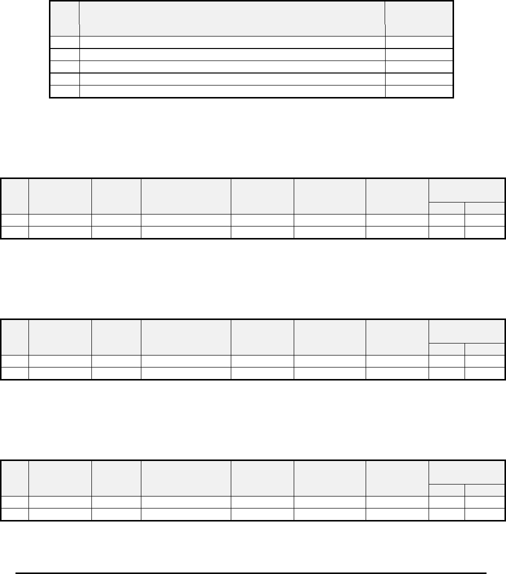
Honeywell
MK VI MK VIII EGPWS Installation Design Guide
Proprietary notice on title page applies
CAGE CODE: 97896 SCALE: NONE SIZE: A DWG NO: 060-4314-150 REV: SHEET 269
5.3.14 Category 14, Audio Output Level
The following table provides identification of the Audio Output Level Select. Each entry in the ID column corresponds to
a particular nominal alert output level selection (Max, -6 dB, -12 dB, -18dB and –24dB). The nominal “Max” output is 4
W(rms) for the 8-ohm output and 100 mW(rms) for the 600-ohm output. The Audio Output Level can be additionally
reduced by 6dB with the Mode 6 Low Volume discrete (see Category 13). The output power level will be the nominal
maximum output (4W or 100mW) reduced by the volume selection from Table 5.3.14 and the Mode 6 Low Volume
discrete.
Table 5.3.14: Audio Output Level
ID Volume Select Software
Effectivity
0Nominal (Equivalent to classic MK VI MAX) -020
1 -6 dB -020
2 -12 dB -020
3 -18 dB -020
4 -24 dB -020
5.3.15 Category 15, Undefined for this software release
The following table provides identification for a future undefined input select category. The entry in the following
undefined Type corresponds to a table that will provide detailed information on the configuration. The details for
Undefined Type #0 are not detailed.
Table 5.3.15: Undefined Type
ID Undefined
Type
Description Software
Effectivity
EGPWS
MKVI MKVIII
0 N/A -020 X X
5.3.16 Category 16, Undefined for this software release
The following table provides identification for a future undefined input select category. The entry in the following
undefined Type corresponds to a table that will provide detailed information on the configuration. The details for
Undefined Type #0 are not detailed.
Table 5.3.16: Undefined Type
ID Undefined
Type
Description Software
Effectivity
EGPWS
MKVI MKVIII
0 N/A -020 X X
5.3.17 Category 17, Undefined for this software release
The following table provides identification for a future undefined input select category. The entry in the following
undefined Type corresponds to a table that will provide detailed information on the configuration. The details for
Undefined Type #0 are not detailed.
Table 5.3.17: Undefined Type
ID Undefined
Type
Description Software
Effectivity
EGPWS
MKVI MKVIII
0 N/A -020 X X

Honeywell
MK VI MK VIII EGPWS Installation Design Guide
Proprietary notice on title page applies
CAGE CODE: 97896 SCALE: NONE SIZE: A DWG NO: 060-4314-150 REV: SHEET 270
6 CONFIGURABLE INPUT DATA DEFINITION
This section defines the EGPWS input signal characteristics or data word formats for input signals commonly used in
MK VI and VIII EGPWS applications. See Section 5 for specific information on signal usage.
6.1 Analog Input Data
6.1.1 ARINC 552 Radio Altimeter
Data Item Value
Signal Name: Radio Altitude, ARINC 552
AIC Algorithm: ARINC 552A Radio Altitude
Signal Dynamic Range: –100 to +3566 Feet
Signal Reasonable Range: –30 to +2800 Feet
Signal Open Wire Threshold –50 Feet
Reference Dynamic Range: None
Reference Reasonable Range: None
Scale: For Radio Altitude ≤ 480 feet:
Voltsin = (0.02 * RALT (ft)) + 0.4
For Radio Altitude > 480 feet:
Voltsin = ))
500
20 + (ft) RALT
(Ln + (110 ×
Input Signal Connection: (+) = J1-64, (–) = J1-45
Input Reference Connection: None
AIC Name: D1 (DC1)
External Validity Flag Connection: J1-29
AIC LSB: 0.25 Feet
AIC Status Mask: 0000200C
External Validity Type: Discrete Validity
6.1.2 ALT 55 Radio Altimeter
Data Item Value
Signal Name: Radio Altitude, ALT 55
AIC Algorithm: DC Absolute
Signal Dynamic Range: –100 to +3200 Feet
Signal Reasonable Range: –30 to +2800 Feet
Signal Open Wire Threshold –50 Feet
Reference Dynamic Range: None
Reference Reasonable Range: None
Scale: For Radio Altitude ≤ 500 Feet (≤ 10.4 VDC):
Voltsin = (0.02 * RALT) + 0.4 or
RALT (ft) = 50 ft/VDC * Voltsin – 20 ft
For Radio Altitude > 500 feet (> 10.4 VDC):
Voltsin = 0.003 * (RALT –500) + 10.4 or
RALT (ft) = 333.3333 ft/VDC * Voltsin – 2966.7
Input Signal Connection: (+) = J1-64, (–) = J1-45
Input Reference Connection: None
AIC Name: D1 (DC1)
External Validity Flag Connection: J1-29
AIC LSB: 0.25 Feet
AIC Status Mask: 0000200C
External Validity Type: Discrete Validity

Honeywell
MK VI MK VIII EGPWS Installation Design Guide
Proprietary notice on title page applies
CAGE CODE: 97896 SCALE: NONE SIZE: A DWG NO: 060-4314-150 REV: SHEET 271
6.1.3 Uncorrected Barometric Altitude
Data Item Value
Signal Name: Uncorrected Baro Altitude, DC Voltage
AIC Algorithm: DC Absolute
Signal Dynamic Range: –19,334 to +31,166 Feet
Signal Reasonable Range: –1500 to +30,000 Feet
Signal Open Wire Threshold –3000 Feet
Reference Dynamic Range: None
Reference Reasonable Range: None
Scale: Altitude (Feet) = 3150 Feet/VDC * Volts – 17250 Feet
Input Signal Connection: (+) = J1-62, (–) = J1-43
Input Reference Connection: None
AIC Name: D2 (DC2)
External Validity Flag Connection: J1-9
AIC LSB: 2 Feet
AIC Status Mask: 0000200F
External Validity Type: Discrete Validity
6.1.4 Outside Air Temperature (500 ohm probe)
Data Item Value
Signal Name: Outside Air Temperature, DC Signal
AIC Algorithm: DC Absolute
Signal Dynamic Range: –85 to +60 °C
Signal Reasonable Range: –70 to +60 °C
Signal Open Wire Threshold –80 °C
Reference Dynamic Range: None
Reference Reasonable Range: None
Scale: VOAT OAT (in °C)
< 0.43448 525.50676* VOAT
– 268.805
>= 0.43448 and < 0.49212 545.64369* VOAT
– 277.560
>= 0.49212 and < 0.54816 566.02357* VOAT
– 287.594
>= 0.54816 581.96990* VOAT
– 296.270
Input Signal Connection: (+) = J1-63, (–) = J1-44 (see section 5.3.2 for hookup)
Input Reference Connection: None
AIC Name: D5 (DC5)
External Validity Flag Connection: None
AIC LSB: 0.03125 °C
AIC Status Mask: 0000200F
External Validity Type: None
6.1.5 Outside Air Temperature (Internal Constant)
Data Item Value
Signal Name: Outside Air Temperature, DC Signal
AIC Algorithm: DC Absolute
Signal Dynamic Range: Constant, no external connection
Signal Reasonable Range: Constant, no external connection
Signal Open Wire Threshold None
Reference Dynamic Range: None
Reference Reasonable Range: None
Scale: OAT (in °C) = 25°C Constant
Input Signal Connection: (no external connection)
Input Reference Connection: None
AIC Name: None

Honeywell
MK VI MK VIII EGPWS Installation Design Guide
Proprietary notice on title page applies
CAGE CODE: 97896 SCALE: NONE SIZE: A DWG NO: 060-4314-150 REV: SHEET 272
External Validity Flag Connection: None
AIC LSB: 0.03125 °C
AIC Status Mask: 00000000
External Validity Type: None
6.1.6 ARINC 547/578-4 Low Level Glideslope Deviation with Discrete Valid
Data Item Value
Signal Name: Low Level Glideslope Deviation, DC Signal
AIC Algorithm: DC Absolute
Signal Dynamic Range: ±16 Dots
Signal Reasonable Range: ±12 Dots
Signal Open Wire Threshold –15 Dots
Reference Dynamic Range: None
Reference Reasonable Range: None
Scale: GS Deviation (Dots) = 13.333333 Dots/VDC * Voltsin – (Positive =
Fly Down) (75 mV per DOT, 0 Volts = 0 DOT)
NOTE: To be consistent with the ARINC 429 definition G/S scaling
inverts sign of input signal such that positive numbers are fly down.
Input Signal Connection: (+) = J1-65 (above beam), (–) = J1-46 (below beam)
Input Reference Connection: None
AIC Name: D3 (DC3)
External Validity Flag Connection: J1-11 (+28 VDC discrete)
AIC LSB: 0.00048828 Dots
AIC Status Mask: 0000200C
External Validity Type: Discrete Validity
6.1.7 ARINC 547/578-4 Low Level Glideslope Deviation with Low Level Valid
Data Item Value
Signal Name: Low Level Glideslope Deviation, DC Signal
AIC Algorithm: DC Absolute
Signal Dynamic Range: ±16 Dots
Signal Reasonable Range: ±12 Dots
Signal Open Wire Threshold –15 Dots
Reference Dynamic Range: None
Reference Reasonable Range: None
Scale: GS Deviation (Dots) = 13.333333 Dots/VDC * Voltsin – (Positive =
Fly Down) (75 mV per DOT, 0 Volts = 0 DOT)
NOTE: To be consistent with the ARINC 429 definition G/S scaling
inverts sign of input signal such that positive numbers are fly down.
Input Signal Connection: (+) = J1-65 (above beam), (–) = J1-46 (below beam)
Input Reference Connection: None
AIC Name: D3 (DC3)
External Validity Flag Connection: (+) = J1-30, (–) = J1-10 (GS low level validity see 6.1.21)
AIC LSB: 0.00048828 Dots
AIC Status Mask: 0000200C
External Validity Type: Low Level Validity
6.1.8 Roll Attitude, 3 Wire Synchro (11.8 VAC )
Data Item Value
Signal Name: Roll Attitude, 3 Wire Synchro
AIC Algorithm: 3 Wire Synchro (11.8 VAC)
Signal Dynamic Range: ±90° Synchro Angle (15.5 VAC max)
Signal Reasonable Range: ±80° Synchro Angle

Honeywell
MK VI MK VIII EGPWS Installation Design Guide
Proprietary notice on title page applies
CAGE CODE: 97896 SCALE: NONE SIZE: A DWG NO: 060-4314-150 REV: SHEET 273
Signal Open Wire Threshold None
Reference Dynamic Range: None
Reference Reasonable Range: None
Scale: Roll Angle (deg) = 1 deg/deg
Input Signal Connection: (X) = J1-1, (Y) = J1-21, (Z) = J1-2
Input Reference Connection: None
AIC Name: S1 (Synchro #1)
External Validity Flag Connection: None
AIC FIFO LSB: 0.00549316°
AIC Status Mask: 0000010F
External Validity Type: None
6.1.9 Magnetic Heading, 5 Wire Synchro
The Magnetic Heading will be corrected with the internal Magnetic Variable Table.
Data Item Value
Signal Name: Magnetic Heading, 5 Wire Synchro
AIC Algorithm: 5 Wire Synchro (11.8V)
Signal Dynamic Range: ±180° Synchro Angle (15.5 VAC max)
Signal Reasonable Range: ±180°
Signal Open Wire Threshold None
Reference Dynamic Range: 17 - 34 VAC
Reference Reasonable Range: None
Scale: Mag Hdg (deg) = 1 deg/deg
Input Signal Connection: (X) = J1-22, (Y) = J1-23, (Z) = J1-3
Input Reference Connection: (H) = J1-4, (C) = J1-24
AIC Name: S2 (Synchro #2)
External Validity Flag Connection: J1-28
AIC FIFO LSB: 0.00549316°
AIC Status Mask: 0000070F
External Validity Type: Discrete Validity, +28VDC
6.1.10 Uncorrected Barometric Altitude (ADS-65)
Data Item Value
Signal Name: Uncorrected Baro Altitude, DC Voltage
AIC Algorithm: DC Absolute
Signal Dynamic Range: –5514 to +128,080 Feet
Signal Reasonable Range: –1500 to +46,000 Feet
Signal Open Wire Threshold –3000 Feet
Reference Dynamic Range: None
Reference Reasonable Range: None
Scale: Altitude (Feet) = 8333.33 Feet/VDC * Volts
Input Signal Connection: (+) = J1-62, (–) = J1-43
Input Reference Connection: None
AIC Name: D2 (DC2)
External Validity Flag Connection: J1-9
AIC LSB: 2 Feet
AIC Status Mask: 0000200F
External Validity Type: Discrete Validity
6.1.11 RT-221/300 Radio Altimeter
Data Item Value
Signal Name: Radio Altitude, RT-221/300
AIC Algorithm: DC Absolute

Honeywell
MK VI MK VIII EGPWS Installation Design Guide
Proprietary notice on title page applies
CAGE CODE: 97896 SCALE: NONE SIZE: A DWG NO: 060-4314-150 REV: SHEET 274
Signal Dynamic Range: –100 to +3200 Feet
Signal Reasonable Range: –30 to +2800 Feet
Signal Open Wire Threshold –50 Feet
Reference Dynamic Range: None
Reference Reasonable Range: None
Scale: RALT (ft) = 250 ft/VDC * Voltsin
Input Signal Connection: (+) = J1-64, (–) = J1-45
Input Reference Connection: None
AIC Name: D1 (DC1)
External Validity Flag Connection: J1-29
AIC LSB: 0.25 Feet
AIC Status Mask: 0000200C
External Validity Type: Discrete Validity
6.1.12 Pitch Synchro Attitude, 3 Wire Synchro (11.8 VAC )
Data Item Value
Signal Name: Pitch Attitude, 3 Wire Synchro
AIC Algorithm: 3 Wire Synchro (11.8 VAC)
Signal Dynamic Range: ±90° Synchro Angle (15.5 VAC max)
Signal Reasonable Range: ±80° Synchro Angle
Signal Open Wire Threshold None
Reference Dynamic Range: None
Reference Reasonable Range: None
Scale: Pitch Angle (deg) = 1 deg/deg
Input Signal Connection: (X) = J1-5, (Y) = J1-7, (Z) = J1-6
Input Reference Connection: None
AIC Name: S3 (Synchro #3)
External Validity Flag Connection: J1-68 (Common Validity with Roll Attitude 6.1.15)
AIC FIFO LSB: 0.00549316°
AIC Status Mask: 0000010F
External Validity Type: Discrete Validity
6.1.13 Uncorrected Barometric Altitude (CIC 02702)
Data Item Value
Signal Name: Uncorrected Baro Altitude, DC Voltage
AIC Algorithm: DC Absolute
Signal Dynamic Range: –3713 to +62,017 Feet
Signal Reasonable Range: –1000 to +40,000 Feet
Signal Open Wire Threshold –3000 Feet
Reference Dynamic Range: None
Reference Reasonable Range: None
Scale: Altitude (Feet) = 4100 Feet/VDC * Volts – 1000 Feet
Input Signal Connection: (+) = J1-62, (–) = J1-43
AIC Name: D2 (DC2)
Input Reference Connection: None
External Validity Flag Connection: J1-9
AIC LSB: 2 Feet
AIC Status Mask: 0000200F
External Validity Type: Discrete Validity

Honeywell
MK VI MK VIII EGPWS Installation Design Guide
Proprietary notice on title page applies
CAGE CODE: 97896 SCALE: NONE SIZE: A DWG NO: 060-4314-150 REV: SHEET 275
6.1.14 ARINC 547/578-4 Low Level Glideslope Deviation Validity
Data Item Value
Signal Name: Low Level Glideslope Validity, DC Signal
AIC Algorithm: DC Absolute
Signal Dynamic Range: –1.1 to +1.5 VDC
Signal Reasonable Range: –0.5 to +1.5 VDC
Signal Open Wire Threshold –1 VDC
Reference Dynamic Range: None
Reference Reasonable Range: None
Scale: GS Validity (VDC) = Voltsin
Input Signal Connection: (+) = J1-30, (–) = J1-10
Input Reference Connection: None
AIC Name: D4 (DC4)
External Validity Flag Connection: None
AIC LSB: 0.0012207 VDC
AIC Status Mask: 0000200C
External Validity Type: None
6.1.15 Roll Attitude, 3 Wire Synchro (11.8 VAC ) with Validity
Data Item Value
Signal Name: Roll Attitude, 3 Wire Synchro
AIC Algorithm: 3 Wire Synchro (11.8 VAC)
Signal Dynamic Range: ±90° Synchro Angle (15.5 VAC max)
Signal Reasonable Range: ±80° Synchro Angle
Signal Open Wire Threshold None
Reference Dynamic Range: None
Reference Reasonable Range: None
Scale: Roll Angle (deg) = 1 deg/deg
Input Signal Connection: (X) = J1-1, (Y) = J1-21, (Z) = J1-2
Input Reference Connection: None
AIC Name: S1 (Synchro #1)
External Validity Flag Connection: J1-68
AIC FIFO LSB: 0.00549316°
AIC Status Mask: 0000010F
External Validity Type: Discrete Validity
6.1.16 Uncorrected Barometric Altitude (AZ-241, AZ-800)
Data Item Value
Signal Name: Uncorrected Baro Altitude, DC Voltage
AIC Algorithm: DC Absolute
Signal Dynamic Range: –3750 to +52,750 Feet (0.0 Vdc to +11.30 Vdc)
Signal Reasonable Range: –1000 to +50,000 Feet (+0.55 Vdc to +10.75 Vdc)
Signal Open Wire Threshold –1950 Feet (+0.36 Vdc)
Reference Dynamic Range: None
Reference Reasonable Range: None
Scale: Altitude (Feet) = 5000 Feet/VDC * Volts – 3750
(0.2 mVdc/foot, 0.75 Vdc = 0 feet)
Input Signal Connection: (+) = J1-62, (–) = J1-43
AIC Name: D2 (DC2)
Input Reference Connection: None
External Validity Flag Connection: J1-9

Honeywell
MK VI MK VIII EGPWS Installation Design Guide
Proprietary notice on title page applies
CAGE CODE: 97896 SCALE: NONE SIZE: A DWG NO: 060-4314-150 REV: SHEET 276
AIC LSB: 2 Feet
AIC Status Mask: 0000200F
External Validity Type: Discrete Validity, 28V
6.1.17 ARINC 547 Localizer Deviation with Discrete Valid
Data Item Value
Signal Name: LocalizerDeviation, DC Signal
AIC Algorithm: DC Absolute
Signal Dynamic Range: ±16 Dots
Signal Reasonable Range: ±12 Dots
Signal Open Wire Threshold –15 Dots
Reference Dynamic Range: None
Reference Reasonable Range: None
Scale: Loc Deviation (Dots) = 13.333333 Dots/VDC * Voltsin
Positive = Fly Right 75 mV per DOT, 0 Volts = 0 DOT
Input Signal Connection: (+) = J1-30 (fly right), (–) = J1-10 (fly left)
Input Reference Connection: None
AIC Name: D4 (DC4)
External Validity Flag Connection: J1-48 (+28 VDC discrete)
AIC LSB: 0.00126 Dots
AIC Status Mask: 0000200C
External Validity Type: Discrete Validity
6.2 Digital Input Data, ARINC 429
The MK VI/VIII EGPWC supports 8 ARINC 429 digital receivers used to monitor broadcast data from other LRUs and to
support interactive protocols. Each receiver channel follows the characteristics of reference document Digital Information
Transfer System (DITS), ARINC Characteristic 429.
Transmission System Interconnect. Each 429 receiver shall be connected to an ARINC 429 transmitter by means of a
single twisted and shielded pair of wires. The shield shall be grounded at both ends and at all production breaks in the
cable to an aircraft ground close to the rack connector.
Receiver Bus Frequency. Receivers are capable of operating at both Low and High speed and are determined by
configuration selection. The following table identifies the bus speed characteristics.
Bus Speed Bus Frequency
High 100 KBPS +/- 1%
Low 12.0 KBPS to 14.5 KBPS
ARINC Receiver Bus Identification. Each ARINC Receiver Channel is identified with two identifiers, one for each leg
of the twisted wire pair. The identifier is formed as follows:
429RX[Channel Id][Leg] where Channel Id ranges [1-8], and Leg is A for the positive leg and B for the negative leg (see
channel 1 exception in following paragraph). An example of a channel identifier would be 429RX-2A, which identifies
leg A of ARINC 429 channel 2.
In addition, one of the ARINC 429 channels is connected to an UART to provision for RS422 operation. In this case the
channel identifier has been defined as 429_422RX_1A and 429_422RX_1B
SIGN/STATUS Matrix The number of BITS, and the meaning of these BITS, varies depending on the type of data in the
ARINC word.
Honeywell
MK VI MK VIII EGPWS Installation Design Guide
Proprietary notice on title page applies
CAGE CODE: 97896 SCALE: NONE SIZE: A DWG NO: 060-4314-150 REV: SHEET 277
BINARY (BNR) DATA
BIT 31 BIT 30 DEFINITION BIT 29 DEFINITION
0 0 Failure Warning Plus, North, East,
0 1 No Computed Data (NCD) 0Right, To, Above
1 0 Functional Test Minus, South, West,
1 1 Normal Operation 1Left, From, Below
BINARY CODED DECIMAL (BCD) DATA
BIT 31 BIT 30 DEFINITION
0 0 Plus, North, East, Right, To, Above
0 1 No Computed Data (NCD)
1 0 Functional Test
1 1 Minus, South, West, Left, From, Below
Unless identified as using the Honeywell Discrete definition all data indicated as ‘Discrete’ uses the following SSM
definition. (Note that PWS uses a non-standard SSM format as described in section 6.2.21)
DISCRETE DATA
BIT 31 BIT 30 DEFINITION
0 0 Normal Operation
0 1 No Computed Data NCD
1 0 Functional Test
1 1 Not Used
Data identified as Honeywell Discrete uses the SSM definition below.
HONEYWELL DISCRETE DATA
BIT 31 BIT 30 DEFINITION
0 0 Normal Operation
0 1 No Computed Data NCD
1 0 Functional Test
1 1 Failure Warning
ISO 5 ALPHABET
Some ARINC 429 labels transmit data using the ISO 5 alphabet as defined in the following table.
B4 B3 B2 B1 0 0 0 0 0 1 0 1 0 0 1 1 1 0 0 1 0 1 1 1 0 1 1 1
0 0 0 0 NUL SP 0 P MCDU
MENU
SEL1
0 0 0 1 CNTRL DC1 ! 1 A Q PROG SEL2
0 0 1 0 STX DC2 “ 2 B R PERF SEL3
0 0 1 1 ETX DC3 # 3 C S INIT SEL4
0 1 0 0 EOT DC4 4 D T DATA SEL5
0 1 0 1 ENQ NAK % 5 E U FPLN SEL6
0110 ACK SYN & 6 F V RAD
NAV
0111 ‘ 7 G W FUEL
PRED
NEXT
PAGE
1 0 0 0 CLEAR LOGOFF ( 8 H X SEL
F-PLN
SER1
1 0 0 1 EVENT ) 9 I Y SPARE SER2
1010 * : J Z SER3
Honeywell
MK VI MK VIII EGPWS Installation Design Guide
Proprietary notice on title page applies
CAGE CODE: 97896 SCALE: NONE SIZE: A DWG NO: 060-4314-150 REV: SHEET 278
B4 B3 B2 B1 0 0 0 0 0 1 0 1 0 0 1 1 1 0 0 1 0 1 1 1 0 1 1 1
1011 + ; K [ SER4
1 1 0 0 DEGREE
SYMBOL
,<L\ SER5
1 1 0 1 <CR> BOX - = M ] SER6
1110 ↓.>N
↑TRI-
ANGLE
1111 →/?O
←DIA-
MOND
6.2.1 Uncorrected Barometric Altitude (203)
UNCORRECTED BAROMETRIC ALTITUDE Source: ARINC 706 DADC or IOC
LABEL (Octal) 203 Units: Feet Max. Range: ± 131,072 Feet Approx. LSB: 1 Foot
Data Bits: 12 to 28 = 17 + = Above Sea Level (ASL) Sign Bit: 29 Pad Bits: 11
Transmit Interval (mSec): 31.3 to 62.5
(50 if DAU)
Data Type: 2’s Complement Binary SDI Bits: 9, 10
6.2.2 Static Air Temperature (213)
STATIC AIR TEMPERATURE Source: ARINC 706 DADC or IOC
LABEL (Octal) 213 Units: Degrees Celsius Max. Range: 512 Degrees C. Approx. LSB: 0.25 Degree
Data Bits: 18 to 28 = 11 + = Above ZERO Sign Bit: 29 Pad Bits: 11 to 17
Transmit Interval (mSec): 250 to 500 Data Type: 2’s Complement Binary SDI Bits: 9, 10
6.2.3 Barometric Altitude Rate (212)
BAROMETRIC ALTITUDE RATE Source: ARINC 706 DADC or IOC
LABEL (Octal) 212 Units: Feet/Minute Max. Range: ± 32,768 Ft/Min Approx. LSB: 16 Ft/Min
Data Bits: 18 to 28 = 11 + = Ascent Sign Bit: 29 Pad Bits: 11 to 17
Transmit Interval (mSec): 31.3 to 62.5 Data Type: 2’s Complement Binary SDI Bits: 9, 10
6.2.4 Altitude (076) - GPS (MSL)
ALTITUDE – GPS (MSL) Source: ARINC 743(A) GPSSU
LABEL (Octal) 076 Units: Feet Max. Range: 131,072 Feet Approx. LSB: 0.125 Foot
Data Bits: 9 to 28 = 20 + = Up Sign Bit: 29 Pad Bits: None
Transmit Interval (mSec): 1000 Maximum Data Type: 2’s Complement Binary SDI Bits: None
6.2.5 Horizontal Integrity Limit (130) - GPS
GPS Horizontal Integrity Limit Source: ARINC 743(A) GPS
LABEL (Octal) 130 Units: Nautical Miles Max. Range: 16 Approx. LSB: 0.00012207
Data Bit: 12 - 28 (see table below) = 17 + = always positive Sign Bit: N/A Pad Bits: N/A
Transmit Interval (mSec): 1000 ms Data Type: BNR + discrete SDI Bits: 9, 10
BIT ASSIGNMENT GPS HIL
Bit Definition
11 Set to 1 whenever the receivers RAIM detects a non-isolatable
satellite failure (NISF), set to 0 otherwise
12 –
28
Integrity limit in nautical miles
6.2.6 Ground Speed (112) - GPS
Ground Speed – GPS Source: ARINC 743(A) GPSSU
LABEL (Octal) 112 Units: Knots Max. Range: 4,096 Knots Approx. LSB: 0.125 Knot
Data Bits: 14 to 28 = 15 + = Forward Sign Bit: 29 Pad Bits: 11 to 13
Transmit Interval (mSec): 1000 Maximum Data Type: 2’s Complement Binary SDI Bits: 9, 10

Honeywell
MK VI MK VIII EGPWS Installation Design Guide
Proprietary notice on title page applies
CAGE CODE: 97896 SCALE: NONE SIZE: A DWG NO: 060-4314-150 REV: SHEET 279
6.2.7 Latitude (110) - GPS
LATITUDE – GPS Source: ARINC 743(A) GPSSU
LABEL (Octal) 110 Units: Degrees Max. Range: ± 180 Degrees Approx. LSB: 0.000172 Deg
Data Bits: 9 to 28 = 20 + = North Sign Bit: 29 Pad Bits: None
Transmit Interval (mSec): 1000 Maximum Data Type: 2’s Complement Binary SDI Bits: 9, 10
6.2.8 Longitude (111) - GPS
LONGITUDE – GPS Source: ARINC 743(A) GPSSU
LABEL (Octal) 111 Units: Degrees Max. Range: ± 180 Degrees Approx. LSB: 0.000172 Deg
Data Bits: 9 to 28 = 20 + = East Sign Bit: 29 Pad Bits: None
Transmit Interval (mSec): 1000 Maximum Data Type: 2’s Complement Binary SDI Bits: 9, 10
6.2.9 Track Angle (103) - GPS
TRACK ANGLE – GPS Source: ARINC 743(A) GPSSU
LABEL (Octal) 103 Units: Degrees Max. Range: ± 180 Degrees Approx. LSB: 0.0055 Deg.
Data Bits: 15 to 29 = 15 + = Clockwise from North Sign Bit: 29 Pad Bits: 11 to 14
Transmit Interval (mSec): 1000 Maximum Data Type: 2’s Complement Binary SDI Bits: 9, 10
6.2.10 Horizontal Figure Of Merit (247) – GPS (ARINC 743A)
HORIZONTAL FIGURE OF MERIT - GPS Source: ARINC 743A GPSSU
LABEL (Octal) 247 Units: Nautical Miles Max. Range: 16 NM’s Approx. LSB: 0.000061035
Data Bits: 11 to 28 = 18 + = N/A Sign Bit: 29 Pad Bits: N/A
Transmit Interval (mSec): 1000 Maximum Data Type: 2’s Complement Binary SDI Bits: 9, 10
6.2.11 Horizontal Figure Of Merit (247) – GPS (ARINC 743)
HORIZONTAL FIGURE OF MERIT - GPS Source: ARINC 743 GPSSU
LABEL (Octal) 247 Units: Meters Max. Range: 1,024 Approx. LSB: 0.03125
Data Bits: 14 to 28 = 15 + = N/A Sign Bit: 29 Pad Bits: 11 to 13
Transmit Interval (mSec): 1000 Maximum Data Type: 2’s Complement Binary SDI Bits: 9, 10
6.2.12 Horizontal Figure Of Merit from HDOP (101) – GPS (ARINC 743)
HORIZONTAL FIGURE OF MERIT – GPS Source: ARINC 743 GPSSU
LABEL (Octal) 101 Units: Meters Max. Range: 16,384* Approx. LSB: 0.5*
Data Bits: 14 to 28 = 15 + = N/A Sign Bit: 29 Pad Bits: 11 to 13
Transmit Interval (mSec): 1000 Maximum Data Type: 2’s Complement Binary SDI Bits: 9, 10
* The HDOP scaling is multiplied by 16 to produce HFOM values required by the EGPWS
6.2.13 Vertical Figure Of Merit (136) – GPS (ARINC 743A)
VERTICAL FIGURE OF MERIT – GPS Source: ARINC 743A GPSSU
LABEL (Octal) 136 Units: Feet Max. Range: 32,768 ft Approx. LSB: 0.125
Data Bits: 11 to 28 = 18 + = N/A Sign Bit: 29 Pad Bits: N/A
Transmit Interval (mSec): 1000 Maximum Data Type: 2’s Complement Binary SDI Bits: 9, 10
6.2.14 Vertical Figure Of Merit (136) – GPS (ARINC 743)
VERTICAL FIGURE OF MERIT – GPS Source: ARINC 743 GPSSU
LABEL (Octal) 136 Units: Meters Max. Range: 1,024 Approx. LSB: 0.03125
Data Bits: 14 to 28 = 15 + = N/A Sign Bit: 29 Pad Bits: 11 to 13
Transmit Interval (mSec): 1000 Maximum Data Type: 2’s Complement Binary SDI Bits: 9, 10
6.2.15 Vertical Figure Of Merit from VDOP (102) – GPS (ARINC 743)
VERTICAL FIGURE OF MERIT – GPS Source: ARINC 743 GPSSU
LABEL (Octal) 102 Units: Meters Max. Range: 16,384* Approx. LSB: 0.5*
Data Bits: 14 to 28 = 15 + = N/A Sign Bit: 29 Pad Bits: 11 to 13
Transmit Interval (mSec): 1000 Maximum Data Type: 2’s Complement Binary SDI Bits: 9, 10
* The VDOP scaling is multiplied by 16 to produce VFOM values required by the EGPWS
Honeywell
MK VI MK VIII EGPWS Installation Design Guide
Proprietary notice on title page applies
CAGE CODE: 97896 SCALE: NONE SIZE: A DWG NO: 060-4314-150 REV: SHEET 280
6.2.16 Sensor Status (273) - GPS
SENSOR STATUS – GPS Source: ARINC 743(A) GPSSU
LABEL (Octal) 273 Units: N/A Max. Range: N/A Approx. LSB: N/A
Data Bits: 11 to 29 = 19 See TABLE + = N/A Sign Bit: N/A Pad Bits: N/A
Transmit Interval (mSec): 1000 Maximum Data Type: Discrete SDI Bits: 9, 10
SENSOR STATUS BIT ASSIGNMENTS
Bit No. DEFINITION
11 MSB of Satellites Visible (16 to 31)
12 DADS Status (*) Present = ‘0’ Not Present = ‘1’
13 DADS Source (*) Primary = ‘0’ Secondary = ‘1’
14 IRS/FMS Status Present = ‘0’ Not Present = ‘1’
15 IRS/FMS Source Primary = ‘0’ Secondary = ‘1’
16 - 19 Number of Satellites Visible (0 to 15)
20 - 23 Number of Satellites Tracked (0 to 15)
24 - 25 Current System in Use 00 = GPS
10 = GLONASS
11 = GPS/GLONASS
01 = Spare
26 - 28 Operational Mode 000 = Self Test Mode
001 = Initialization Mode
010 = Acquisition Mode
011 = Navigation Mode
100 = Altitude/Clock Aiding Mode
101 = Differential Mode
110 = Direction/Speed Aiding Mode
111 = Fault
29 MSB of Satellites Tracked (16 to 31)
(*) = DADS Input is NOT required if ALTITUDE Data to GPSSU Sensor is Received from IRS/FMS Inputs.
6.2.17 Universal Time Correlation (125) - GPS
UNIVERSAL TIME CORRELATION (UTC) (BCD) Source: ARINC 743(A) GPSSU
LABEL (Octal) 125 Units: Hours:Minutes Max. Range: See NOTE 1 Approx. LSB: 0.1 Minute
Data Bits: See NOTE 2 + = N/A Sign Bit: N/A Pad Bits: N/A
Transmit Interval (mSec): 1000 Maximum Data Type: BCD SDI Bits: 9, 10
NOTE 1: Maximum value = 23:59.9
NOTE 2: BCD BIT Assignments per Table below:
UNIVERSAL TIME CORRELATION BIT ASSIGNMENTS
BIT NO. DEFINITION (CFDS/GPS) DEFINITION (CAIMS)
11 - 14 Tenths of Minutes UNITS of Minutes
15 - 18 UNITS of Minutes TENS of Minutes
19 - 22 TENS of Minutes UNITS of Hours
23 - 26 UNITS of Hours TENS of Hours
27 - 29 TENS of Hours N/A
6.2.18 Date (260) - GPS
DATE Source: [AIRBUS] - ARINC 604 CFDS/ CMC/ [GPS] - ARINC 743(A) GPSSU
LABEL (Octal) 260 Units: Day:Month:Year Max. Range: N/A Approx. LSB: 1 Day
Data Bits: 11 to 29 = 19 See NOTE 1 + = N/A Sign Bit: N/A Pad Bits: N/A
Transmit Interval (mSec): 1000 Maximum Data Type: BCD SDI Bits: 9, 10
NOTE 1: BITS 11 to 14 (4) = UNITS of the YEAR (0 to 9)
BITS 15 to 18 (4) = TENS of the YEAR (0 to 9)
BITS 19 to 22 (4) = UNITS of the MONTH (0 to 9)
Honeywell
MK VI MK VIII EGPWS Installation Design Guide
Proprietary notice on title page applies
CAGE CODE: 97896 SCALE: NONE SIZE: A DWG NO: 060-4314-150 REV: SHEET 281
BIT 23 (1) = TENS of the MONTH (0 or 1)
BITS 24 to 27 (4) = UNITS of the DAY (0 to 9)
BITS 28 to 29 (2) = TENS of the DAY (0 to 3)
6.2.19 Control Word (154) - MFD
CONTROL WORD – MFD Source: MFD
LABEL (Octal) 154 Units: N/A Max. Range: N/A Approx. LSB: N/A
Data Bits: Discrete word, see below + = N/A Sign Bit: N/A Pad Bits: 9, 10
Transmit Interval (mSec): 50 ms Data Type: Discrete SDI Bits: N/A
DAU WORD BIT ASSIGNMENTS
Bit No. DEFINITION
11 – 13 Not Used by EGPWC
14 Terrain Display Overlay Active
15 – 29 Not Used by EGPWC
6.2.20 Control Word 2 (271/273)
CONTROL WORD 2 – WXR
DISPLAY WD 1 – NAV DISPLAY BUS
Source: WXR Control Panel/Nav Display
LABEL (Octal) 271
For FDS-255 display the label is 273.
Units: N/A Max. Range: N/A Approx. LSB: N/A
Data Bits: Discrete word, see below + = N/A Sign Bit: N/A Pad Bits: 9, 10
Transmit Interval (mSec): 100 to 120 ms Data Type: Discrete SDI Bits: N/A
CONTROL WORD 2 BIT ASSIGNMENTS
Bit No. DEFINITION
11 Special Function, Not Used by EGPWC
12 Anticlutter, Not Used by EGPWC
13 Windshear, Not Used by EGPWC
14 – 23 Spares
24 – 29 Display Range as specified in the table below
BITS 24 to 29 = Display Range (5 to 320NM, format as follows)
Bit 29 Bit 28 Bit 27 Bit 26 Bit 25 Bit 24 RANGE
00000 0 320 NM
00000 1 5 NM
00001 0 10 NM
00010 0 20 NM
00100 0 40 NM
01000 0 80 NM
10000 0 160 NM
Note: The range bits are additive; e.g., if bits 24 and 26 = 1 then the range would be 25 NM.
6.2.20.1 Control Word 2 (271/273) Type 2
CONTROL WORD 2 – WXR (Type 2)
DISPLAY WD 1 – NAV DISPLAY BUS
Source: IOC Bus
LABEL (Octal) 271
For FDS-255 display the label is 273.
Units: N/A Max. Range: N/A Approx. LSB: N/A
Data Bits: Discrete word, see below + = N/A Sign Bit: N/A Pad Bits: 9, 10
Transmit Interval (mSec): 100 ms Data Type: Discrete SDI Bits: N/A
Honeywell
MK VI MK VIII EGPWS Installation Design Guide
Proprietary notice on title page applies
CAGE CODE: 97896 SCALE: NONE SIZE: A DWG NO: 060-4314-150 REV: SHEET 282
CONTROL WORD 2 BIT ASSIGNMENTS
Bit No. DEFINITION
11–22 Spares
23 Display Range Divide by 20
24 – 29 Display Range as specified in the table below
BITS 24 to 29 = Display Range (5 to 320NM, format as follows)
Bit 29 Bit 28 Bit 27 Bit 26 Bit 25 Bit 24 RANGE
00000 0 320 NM
00000 1 5 NM
00001 0 10 NM
00010 0 20 NM
00100 0 40 NM
01000 0 80 NM
10000 0 160 NM
Note: The range bits are additive; e.g., if bits 24 and 26 = 1 then the range would be 25 NM.
6.2.21 Discrete Word (155 or 176) - MFD
DISCRETE WORD – MFD Source: MFD or IOC #1 & IOC #2
LABEL (Octal) 155 or 176 Units: N/A Max. Range: N/A Approx. LSB: N/A
Data Bits: Discrete word, see below + = N/A Sign Bit: N/A Pad Bits: 9, 10
Transmit Interval (mSec): 50 ms Data Type: Discrete SDI Bits: N/A
DAU WORD BIT ASSIGNMENTS
Bit No. DEFINITION
11 - 17 Not Used by EGPWC
18 - 24 Terrain Display Range as specified in the table below
25 - 29 Not Used by EGPWC
BITS 18 to 24 = Display Range (5 to 640 NM, Format as follows)
DISPLAY RANGE BIT ASSIGNMENTS
Bits 24-18 DEFINITION Bits 24-18 DEFINITION
All 7 bits zero: 640 NM Bit 21 set: 40 NM
Bit 18 set: 5 NM Bit 22 set: 80 NM
Bit 19 set: 10 NM Bit 23 set: 160 NM
Bit 20 set: 20 NM Bit 24 set: 320 NM
6.2.22 Hazard Range Output (077)
Hazard Range Output - Wx RADAR Source: Wx Radar
LABEL (Octal) 077 Units: N/A Max. Range: N/A Approx. LSB: N/A
Data Bits: Discrete word, see below + = N/A Sign Bit: N/A Pad Bits: 9, 10
Transmit Interval (mSec): 20 ms Data Type: Discrete (non-standard SSM, see below) SDI Bits: N/A
HAZARD RANGE OUTPUT BIT ASSIGNMENTS
Bit No. DEFINITION
11 Event Number LSB, Not Used by EGPWC
12 Event Number, Not Used by EGPWC
13 Event Number MSB, Not Used by EGPWC
14 Range (Start), 0.0625 NM, Not Used by EGPWC
15 Range (Start), 0.125 NM, Not Used by EGPWC
Honeywell
MK VI MK VIII EGPWS Installation Design Guide
Proprietary notice on title page applies
CAGE CODE: 97896 SCALE: NONE SIZE: A DWG NO: 060-4314-150 REV: SHEET 283
16 Range (Start), 0.25 NM, Not Used by EGPWC
17 Range (Start), 0.5 NM, Not Used by EGPWC
18 Range (Start), 1 NM, Not Used by EGPWC
19 Range (Start), 2 NM, Not Used by EGPWC
20 Range (Start), 4 NM, Not Used by EGPWC
21 Range (End), 0.0625 NM, Not Used by EGPWC
22 Range (End), 0.125 NM, Not Used by EGPWC
23 Range (End), 0.25 NM, Not Used by EGPWC
24 Range (End), 0.5 NM, Not Used by EGPWC
25 Range (End), 1 NM, Not Used by EGPWC
26 Range (End), 2 NM, Not Used by EGPWC
27 Range (End), 4 NM, Not Used by EGPWC
28 Alert level
29 Alert level
BITS 28 & 29 = Alert Level, format as follows BITS 30 & 31 = SSM as follows
Bit 28 Bits 29 DEFINITION BIT 31 BIT 30 DEFINITION
0 0 No Alert 0 0 Normal Operation
1 0 Level 1 (Advisory) 0 1 Invalid (fault)
0 1 Level 2 (Caution) 1 0 Functional Test
1 1 Level 3 (Warning) 1 1 NCD
6.2.23 Range (050) - Multifunction Signal Generator (MG) or IC600
RANGE – MG Source: MG
LABEL (Octal) 050 Units: N/A Max. Range: N/A Approx. LSB: N/A
Data Bits: Discrete word containing both
left and right ranges, see below
+ = N/A Sign Bit: N/A Pad Bits: 9, 10
Transmit Interval (mSec): 100 ms Data Type: Discrete SDI Bits: N/A
Note: Data format identical to EPGWC output label 050.
BITS 11 to 14 = Left Terrain Display Range (0.5 to 2000NM, Format as follows)
BITS 15 to 18 = Right Terrain Display Range (0.5 to 2000NM, Format as follows)
MG Note: Range is on one of two buses depending on whether MG is backing up right side.
DISPLAY RANGE BIT ASSIGNMENTS
Bits 14-11
Bits 18-15
DEFINITION Bits 14-11
Bits 18-15
DEFINITION
0000 0.5 NM 1000 150 NM
0001 1.0 NM 1001 200 NM
0010 2.5 NM 1010 300 NM
0011 5.0 NM 1011 500 NM
0100 10 NM 1100 1000 NM
0101 25 NM 1101 2000 NM
0110 50 NM 1110 600 NM
0111 100 NM 1111
6.2.24 Query / Continuous Response (011) - KCPB
QUERY / CONTINUOUS RESPONSE Source: KCPB Display
LABEL (Octal) 011 Units: N/A Max. Range: N/A Approx. LSB: N/A
Data Bits: Discrete word + = N/A Sign Bit: N/A Pad Bits: None
Transmit Interval: Prompted Response or
Continuous Response, 2-30 words/sec
Data Type: Discrete SDI Bits: N/A
Honeywell
MK VI MK VIII EGPWS Installation Design Guide
Proprietary notice on title page applies
CAGE CODE: 97896 SCALE: NONE SIZE: A DWG NO: 060-4314-150 REV: SHEET 284
Label 011 communicates the response to the KCPB Query / Setup Label (KCPB Label 027) or on a continuous basis. For
a detailed description of the Query / Continuous Response Label 011 definition see the EGPWS Interface Methodology,
060-4303-000.
6.2.25 Key Press Data (012) – KCPB
KEY PRESS DATA Source: Honeywell TDU/FMS
LABEL (Octal) 012 Units: N/A Max. Range: N/A Approx. LSB: N/A
Data Bits: Discrete word + = N/A Sign Bit: N/A Pad Bits: None
Transmit Interval (mSec): 180 Data Type: Discrete SDI Bits: 0
TDU/FMS key press data will be transmitted using Label 012. The state of the front panel keys will be transmitted
nominally every 180 ms. Keys which are being pressed will be represented as logic “1” in the appropriate bit while non
pressed keys will be registered as logic “0”. For a detailed description of the Key Press / Display Mode Label 012
definition see the EGPWS Interface Methodology, 060-4303-000.
KEY PRESS DATA Source: KCPB Display
LABEL (Octal) 012 Units: N/A Max. Range: N/A Approx. LSB: N/A
Data Bits: Discrete word + = N/A Sign Bit: N/A Pad Bits: None
Transmit Interval (mSec): at least 200 msec Data Type: Discrete SDI Bits: 0
Key press / Display Mode data will be transmitted using Label 012. This is an optional label for KCPB displays. The state
of the front panel keys will be transmitted nominally every 200 ms. Keys which are being pressed will be represented as
logic “1” in the appropriate bit while non pressed keys will be registered as logic “0”. For a detailed description of the Key
Press / Display Mode Label 012 definition see the EGPWS Interface Methodology, 060-4303-000.
6.2.26 Control Word 1 (270)
CONTROL WORD 1 – WXR Source: WXR Control Panel
LABEL (Octal) 270 Units: N/A Max. Range: N/A Approx. LSB: N/A
Data Bits: Discrete word, see below + = N/A Sign Bit: N/A Pad Bits: 9, 10
Transmit Interval (mSec): 100 ms Data Type: Discrete SDI Bits: N/A
CONTROL WORD 1 BIT ASSIGNMENTS
Bit No. DEFINITION
11 Scan, Not Used by EGPWC
12 Anticlutter, Not Used by EGPWC
13 Stabilization, Not Used by EGPWC
14 Mode
15 Mode
16 Mode
17 Tilt, +0.25 degrees
18 Tilt, +0.5 degrees
19 Tilt, +1.0 degrees
20 Tilt, +2.0 degrees
21 Tilt, +4.0 degrees
22 Tilt, +8.0 degrees
23 Tilt, -16.0 degrees (sign)
24 Gain, Bit –1
25 Gain, Bit –2
26 Gain, Bit –4
27 Gain, Bit –8
28 Gain, Bit –16
29 Gain, Bit –32
Honeywell
MK VI MK VIII EGPWS Installation Design Guide
Proprietary notice on title page applies
CAGE CODE: 97896 SCALE: NONE SIZE: A DWG NO: 060-4314-150 REV: SHEET 285
Bits 14 to 16 = Mode, format as follows
Bit 16 Bit 15 Bit 14 MODE
0 0 0 Standby
0 0 1 Weather Only
01 0 Map Only
0 1 1 Windshear Hazard Factor
10 0 Test
1 0 1 Windshear and Turbulence
1 1 0 Weather and Turbulence
1 1 1 Windshear Icon
6.2.27 Discrete Word (273) – Bendix Weather Radar Vertical Profile Mode
Discrete Word Source: EFIS/Weather Radar
LABEL (Octal) 273 Units: N/A Max. Range: N/A Approx. LSB: N/A
Data Bit: 11 + = N/A Sign Bit: N/A Pad Bits: N/A
Transmit Interval (mSec): 100 ms Data Type: Discrete SDI Bits: 9, 10
Some display systems support a vertical profile WXR display where the radar scans up and down. This mode can not
support a terrain display. Therefore when this mode bit is set (indicating that the profile mode is active) the EGPWS is to
treat this as a non-displayable mode.
Mode bit 11 Displayable
Vertical Profile On 1 No
Vertical Profile Off 0 Yes
6.2.28 Discrete Word (275) – IC600 only
Discrete Word - (IC600 Packed Discrete Word 4) Source: IC
LABEL (Octal) 275 Units: N/A Max. Range: N/A Approx. LSB: N/A
Data Bits: Bit 17: See TABLE + = N/A Sign Bit: N/A Pad Bits: N/A
Transmit Interval (mSec): 500 ms Data Type: Discrete SDI Bits: 9, 10
BIT ASSIGNMENTS
Discrete Data Bit Definition
IC outputting MFD format
(its range is displayed)
Bit 17 = 1: IC Driving Display
Bit 17 = 0: IC not Driving Display
6.2.29 Radio Altitude (164)
RADIO ALTITUDE Source: ARINC 707 LRRA or IOC
LABEL (Octal) 164 Units: Feet Max. Range: ± 8,192 Feet Approx. LSB: 0.125 Foot
Data Bits: 13 to 28 = 16 + = Above Ground Level (AGL) Sign Bit: 29 Pad Bits: 11, 12
Transmit Interval (mSec): 25 to 50 Data Type: 2’s Complement Binary SDI Bits: 9, 10
6.2.30 Glideslope Deviation (174 or 117)
GLIDESLOPE DEVIATION Source: ARINC 710 ILS or IOC
LABEL (Octal) 174 or 117 Units: See NOTE Max. Range: ± 0.8 DDM Approx. LSB: 0.000195 DDM
Data Bits: 17 to 28 = 12 + = Fly Down = Above Beam C/L Sign Bit: 29 Pad Bits: 11 to 16
Transmit Interval (mSec): 33.3 to 66.6 Data Type: 2’s Complement Binary SDI Bits: 9, 10
NOTE: Units = Difference in Depth of Modulation (DDM) 0.0875 DDM = 1 ‘Dot’.
Honeywell
MK VI MK VIII EGPWS Installation Design Guide
Proprietary notice on title page applies
CAGE CODE: 97896 SCALE: NONE SIZE: A DWG NO: 060-4314-150 REV: SHEET 286
6.2.31 Roll Angle (325)
ROLL ANGLE Source: ARINC 704 INU / IRS/ AHRS / FMS or IOC
LABEL (Octal) 325 Units: Degrees/180 Max. Range: ± 180 Degrees Approx. LSB: 0.01099 Deg
Data Bits: 15 to 28 = 14 + = Right Wing Down Sign Bit: 29 Pad Bits: 11 to 14
Transmit Interval (mSec): 10 to 36 Data Type: 2’s Complement Binary SDI Bits: 9, 10
6.2.32 Magnetic Heading (320)
MAGNETIC HEADING Source: ARINC 704 INU / IRS / AHRS / FMS or IOC
LABEL (Octal) 320 Units: Degrees/180 Max. Range: ± 180 Degrees Approx. LSB: 0.00549 Degrees
Data Bits: 14 to 28 = 15 + = Clockwise from North Sign Bit: 29 Pad Bits: 11 to 13
Transmit Interval (mSec): 10 to 50 Data Type: 2’s Complement Binary SDI Bits: 9, 10
6.2.33 Localizer Deviation (173 or 116)
LOCALIZER DEVIATION Source: ARINC 710 ILS or IOC
LABEL (Octal) 173 or 116 Units: See NOTE Max. Range: ± 0.4 DDM Approx. LSB: 0.0000977 DDM
Data Bits: 17 to 28 = 12 + = Fly RIGHT = Left of Beam C/L Sign Bit: 29 Pad Bits: 11 to 16
Transmit Interval (mSec): 33.3 to 66.6
115 ms max for IAC
100 ms max for IOC
Data Type: 2’s Complement Binary SDI Bits: 9, 10
NOTE: Units = Difference in Depth of Modulation (DDM) 0.0775 DDM = 1 ‘Dot’.
6.2.34 Pitch Angle (324)
PITCH ANGLE Source: ARINC 704 INU / IRS/ AHRS / FMS or IOC
LABEL (Octal) 324 Units: Degrees/180 Max. Range: ± 180 Degrees Approx. LSB: 0.01099 Deg
Data Bits: 15 to 28 = 14 + = Nose Up Sign Bit: 29 Pad Bits: 11 to 14
Transmit Interval (mSec): 10 to 36 Data Type: 2’s Complement Binary SDI Bits: 9, 10
6.2.35 Range (271) - KCPB
RANGE Source: KCPB Display
LABEL (Octal) 271 Units: NM Max. Range: 1023.5 Approx. LSB: 0.5
Data Bits: 19 to 29 = 11 + = N/A Sign Bit: N/A Pad Bits: 11-18
Transmit Interval (mSec): at least 200 msec. Data Type: Binary SDI Bits: 9,10
6.2.36 DSU Status Word (350)
DSU STATUS WORD Source: DSU
LABEL (Octal) 350 Units: N/A Max. Range: N/A Approx. LSB: N/A
Data Bits: Discrete word, see below + = N/A Sign Bit: N/A Pad Bits: N/A
Transmit Interval (mSec): 1000 maximum Data Type: Discrete SDI Bits: 9,10
DSU STATUS WORD BIT ASSIGNMENTS
Bit No. DEFINITION
11 Power Up Program Memory Test (ROM_FAIL)
12 Power Up External RAM Test (RAM_FAIL)
13 Power Up UDI Video Dual Port RAM Test (UDIVM_FAIL)
15-14 Unused (always 0)
16 Continuous ARINC 453 Inactive Test (A453INACT_FAIL)
17 Continuous Display Range Validity Test (DISPRING_FAIL)
18 Continuous Unused Interrupts Test (UNUSEDINT_FAIL)

Honeywell
MK VI MK VIII EGPWS Installation Design Guide
Proprietary notice on title page applies
CAGE CODE: 97896 SCALE: NONE SIZE: A DWG NO: 060-4314-150 REV: SHEET 287
23-19 Unused (always 0)
24 Program Pin A Status
25 Program Pin B Status
26 Program Pin C Status
27 Program Pin D Status
28 Program Pin E Status
29 Unused (always 0)
6.2.37 True Heading (314)
TRUE HEADING Source: IRS/AHRS/IOC
LABEL (Octal) 314 Units: Degrees/180 Max. Range: +/- 180 Degrees Approx. LSB: 0.00549 Degrees
Data Bits: 14 to 28 = 15 + = Clockwise from North Sign Bit: 29 Pad Bits: 11 to 13
Transmit Interval (mSec): 25 to 50 Data Type: 2’s Complement Binary SDI Bits: 9, 10
6.2.38 Corrected Barometric Altitude (204)
CORRECTED BAROMETRIC ALTITUDE Source: ARINC 706 DADC or IOC
LABEL (Octal) 204 Units: Feet Max. Range: 131,072 Feet Approx. LSB: 1 Foot
Data Bits: 12 to 28 = 17 + = Above Sea Level (ASL) Sign Bit: 29 Pad Bits: 11
Transmit Interval (mSec): 31.3 to 62.5 Data Type: 2’s Complement Binary SDI Bits: 9, 10
6.2.39 Computed Airspeed (206)
COMPUTED AIRSPEED Source: ARINC 706 DADC or IOC
LABEL (Octal) 206 Units: Knots Max. Range: 1,024 Knots Approx. LSB: 0.0625 Knot
Data Bits: 15 to 28 = 14 + = Forward Sign Bit: 29 Pad Bits: 11 to 14
Transmit Interval (mSec): 62.5 to 125(100 if DAU) Data Type: 2’s Complement Binary SDI Bits: 9, 10
6.2.40 True Airspeed (210)
TRUE AIRSPEED Source: IOC
LABEL (Octal) 210 Units: Knots Max. Range: 2,048 Knots Approx. LSB: 0.0625 Knot
Data Bits: 14 to 28 = 15 + = Forward Sign Bit: 29 Pad Bits: 11 to 13
Transmit Interval (mSec): 62.5 to 125 Data Type: 2’s Complement Binary SDI Bits: 9, 10
6.2.41 Decision Height (370) – IOC Scaling
DECISION HEIGHT Source: IOC
LABEL (Octal) 370 Units: Feet Max. Range: ±8192 FT
See NOTE 1
Approx. LSB: 0.125 Foot
Data Bits: 13 to 28 = 16 + = Above Ground Level (AGL) Sign Bit: 29 Pad Bits: 11,12
Transmit Interval (mSec): 100 to 200 Data Type: 2’s Complement Binary SDI Bits: 9, 10
NOTE 1: Some IOC configurations may only provide positive ranges (0 to 8192 Feet), however the EGPWS supports
both positive and negative ranges (+/- 8192 Feet) for all configurations.
NOTE 2: This label may be provided in a configuration with a single DH input or in conjunction with a selected MDA
input. For those configurations which provide DH and MDA on separate labels, Format 3 applies (Format 1 is
0/0 SDI, Format 2 is Left SDI used and Format 3 is No SDI.)
6.2.42 Normal Acceleration (333)
NORMAL ACCELERATION Source: IOC
LABEL (Octal) 333 Units: g’s Max. Range: +/-4.0 g’s Approx. LSB: 0.000977 g’s
Data Bits: 17 to 28 = 12 + = Up See NOTE Sign Bit: 29 Pad Bits: 11 to 16
Transmit Interval (mSec): 10 to 20 Data Type: 2’s Complement Binary SDI Bits: 9, 10
NOTE: Output reads 0 g’s nominal when aircraft is on the ground, or during unaccelerated flight.
Honeywell
MK VI MK VIII EGPWS Installation Design Guide
Proprietary notice on title page applies
CAGE CODE: 97896 SCALE: NONE SIZE: A DWG NO: 060-4314-150 REV: SHEET 288
6.2.43 Longitudinal Acceleration (331)
LONGITUDINAL ACCELERATION Source: IOC
LABEL (Octal) 331 Units: g’s Max. Range: +/-4.0 g’s Approx. LSB: 0.000977 g’s
Data Bits: 17 to 28 = 12 + = Forward Sign Bit: 29 Pad Bits: 11 to 16
Transmit Interval (mSec): 10 to 20 Data Type: 2’s Complement Binary SDI Bits: 9, 10
6.2.44 Left Body Angle of Attack (224)
Body Angle of Attack Source: IOC
LABEL (Octal) 224 Units: degrees Max. Range: +/-180 degrees Approx. LSB: 0.0439 degrees
Data Bits: 17 to 28 = 12 + = Nose Up Sign Bit: 29 Pad Bits: 11 to 16
Transmit Interval (mSec): 50 to 100 Data Type: 2’s Complement Binary SDI Bits: 9, 10
6.2.45 Right Body Angle of Attack (225)
Body Angle of Attack Source: IOC
LABEL (Octal) 225 Units: degrees Max. Range: +/-180 degrees Approx. LSB: 0.0439 degrees
Data Bits: 17 to 28 = 12 + = Nose Up Sign Bit: 29 Pad Bits: 11 to 16
Transmit Interval (mSec): 50 to 100 Data Type: 2’s Complement Binary SDI Bits: 9, 10
6.2.46 VOR/ILS Frequency (034)
VOR/ILS Frequency Source: ARINC 710 ILS
LABEL (Octal) 034 Units: MHz Max. Range: 108 - 117.95MHz Approx. LSB: 10 kHz
Data Bits: See NOTE + = N/A Sign Bit: N/A Pad Bits: N/A
Transmit Interval (mSec): 167 to 333 Data Type: Binary Coded Decimal (BCD) SDI Bits: 9, 10
NOTE: This input is used to indicate if the VOR/ILS receiver is tuned to an ILS frequency, or to a VOR frequency.
BIT #14 will be set to a ‘0’ for all VOR frequencies, and to a ‘1’ for all ILS frequencies, by the tuning information source.
6.2.47 PFD Mode Select Word (163)
PFD MODE SELECT WORD – Type 4 Source: PFD via IOC
LABEL (Octal) 163 Units: N/A Max. Range: N/A Approx. LSB: N/A
Data Bits: See NOTE 2 and 3 + = N/A Sign Bit: N/A Pad Bits: N/A
Transmit Interval (mSec): See NOTE 1 Data Type: Discrete SDI Bits: N/A
NOTE 1: Transmit Interval for data from PFD via IOC is 250 mSec Maximum.
NOTE 2: BITS 25 to 28 contain Binary Code for Displayed Data Source, as listed below.
NOTE 3: BITS 19/20 indicate MDA selection status and BIT 21 indicates DH selection status, as listed below.
PFD Mode Select Word
BIT NO. DEFINITION
19, 20 MDA Display Selection
Bit 19 Bit 20
0 0 MDA not selected
1 0 MDA selected
X1 Not used
21 DH Display Selection
0 DH Not Selected
1 DH Selected
Honeywell
MK VI MK VIII EGPWS Installation Design Guide
Proprietary notice on title page applies
CAGE CODE: 97896 SCALE: NONE SIZE: A DWG NO: 060-4314-150 REV: SHEET 289
25 – 28 Navigation data source currently displayed on the
Primary Flight Display (PFD). The table below
show decimal values with bit 25 the LSB
* = Values currently used by EGPWC
00 = Not Used
01 = Not Used
* 02 = VOR/LOC #1
* 03 = VOR/LOC #2
04 = FMS #1
05 = FMS #2
06 = FMS #3
07 = Not Used
* 08 = MLS #1
* 09 = MLS #2
* 10 = ILS #1
* 11 = ILS #2
12 = NOTE 1
13 = NOTE 1
14 = Not Used
15 = Not Used
NOTE 1: Code 12 and Code 13 are currently assigned to TACAN Data source. Neither of these states are used
by the EGPWC to select or evaluate input data.
6.2.48 FWC & GP Discrete Word (171)
DISCRETE WORD – FWC & GP Source: FWC or GP (#1 & #2)
LABEL (Octal) 171 Units: N/A Max. Range: N/A Approx. LSB: N/A
Data Bits: Discrete word, see below + = N/A Sign Bit: N/A Pad Bits: none
Transmit Interval (mSec): 100 Data Type: Discrete SDI Bits: 9, 10
See below
Note: Several formats exist for this label. Format 1: is the default format. Format 2: will be specified if required in the
Display Input Control Group.
FWC or GP WORD BIT ASSIGNMENTS (Format 1)
Bit No. DEFINITION
Note: Not all of the following bits are necessarily used on a given aircraft, but all will be
processed. The usage depends on the aircraft avionics. For example, Steep
Approach is only supported in a limited number of installations, however, the bits
for Steep Approach are always monitored.
9, 10 SDI: 1/0 = Left Display Range; 0/1 = Right Display Range; 0/0 & 1/1 = No Range
11-14 Self Test command codes
BIT 11 12 13 14
0000= No Test command
0 0 1 0 = Short Level 1 Test command
0 1 0 0 = Long Level 1 Test command
0 1 1 0 = Level 2 Test command
1 0 0 0 = Level 3 Test command
1 0 1 0 = Level 4 Test command
1 1 0 0 = Level 5 Test command
1 1 1 0 = Level 6 Test command
0 0 0 1 = Self Test Cancel command
0011= Skip command
15 Glideslope Cancel (momentary)
16 Flap Override (alternate action)
17 Terrain Awareness & TCF Inhibit
18 Auto Range confirm (alternate action)
19 Landing Gear Down
20 Weight on Wheels
21 Low Altitude (momentary)
Honeywell
MK VI MK VIII EGPWS Installation Design Guide
Proprietary notice on title page applies
CAGE CODE: 97896 SCALE: NONE SIZE: A DWG NO: 060-4314-150 REV: SHEET 290
22 Timed Audio Inhibit (momentary)
23 Reserved for EGPWS Test command Bit
24 Steep Approach activated (alternate action)
25-28 Terrain Display Range (as specified in the table below)
29 Not Used
BITS 25 to 28 = Terrain Display Range (0.5 to 2000 NM) format as follows:
DISPLAY RANGE BIT ASSIGNMENTS
Bits 28-25 DEFINITION Bits 28-25 DEFINITION
0000 0.5 NM 1000 150 NM
0001 1.0 NM 1001 200 NM
0010 2.5 NM 1010 300 NM
0011 5.0 NM 1011 500 NM
0100 10 NM 1100 1000 NM
0101 25 NM 1101 2000 NM
0110 50 NM 1110 600 NM
0111 100 NM 1111 1200 NM
6.2.49 Body Pitch Rate (326)
Body Pitch Rate Source: AHRS / IOC
LABEL (Octal) 326 Units: Deg/Sec Max. Range: +/-128 Degrees/Sec Approx. LSB: 0.0156 Deg/Sec
Data Bits: 16 to 28 = 13 + = Nose Up Sign Bit: 29 Pad Bits: 11 to 15
Transmit Interval (mSec): 10 to 20 Data Type: 2’s Complement Binary SDI Bits: 9, 10
6.2.50 Body Roll Rate (327)
Body Roll Rate Source: AHRS / IOC
LABEL (Octal) 327 Units: Deg/Sec Max. Range: +/-128 Degrees/Sec Approx. LSB: 0.0156 Deg/Sec
Data Bits: 16 to 28 = 13 + = Right Wing Down Sign Bit: 29 Pad Bits: 11 to 15
Transmit Interval (mSec): 10 to 20 Data Type: 2’s Complement Binary SDI Bits: 9, 10
6.2.51 Minimum Descent Altitude (170) – IOC Scaling
Minimum Descent Altitude Source: IOC
LABEL (Octal) 170 Units: Feet Max. Range: ± 65,536 Feet 1Approx. LSB: 1 Foot
Data Bits: 13 to 28 = 16 + = Above Sea Level (ASL) Sign Bit: 29 Pad Bits: 9 to 12
Transmit Interval (mSec): 200 Data Type: 2’s Complement Binary SDI Bits: N/A 2
Note 1: Some IOC configurations may only provide positive ranges (0 to 65536 feet), however the EGPWS supports both
positive and negative ranges (±65,536 feet) for all configurations.
Note 2: This label may be provided in a configuration with a single DH input or in conjunction with a selected MDA
input. For those configurations which provide DH and MDA on separate labels format 3 applies (Format 1 is 0/0
SDI, Format 2 is Left SDI used and Format 3 is no SDI.)
6.2.52 Normal Angle of Attack (236)
Normal Angle of Attack Source: IOC
LABEL (Octal) 236 Units: N/A Max. Range: 0 to 1 Approx. LSB: 0.000031
Data Bits: 14 to 28 = 15 + = N/A Sign Bit: N/A Pad Bits: 11 to 13, 29
Transmit Interval (mSec): 80 Data Type: 2’s Complement Binary SDI Bits: 9, 10
Honeywell
MK VI MK VIII EGPWS Installation Design Guide
Proprietary notice on title page applies
CAGE CODE: 97896 SCALE: NONE SIZE: A DWG NO: 060-4314-150 REV: SHEET 291
6.2.53 North/South Velocity (166) - GPS
NORTH/SOUTH VELOCITY – GPS Source: ARINC 743(A) GPSSU
LABEL (Octal) 166 Units: Knots Max. Range: ± 4,096 Knots Approx. LSB: 0.125 Knots
Data Bits: 14 to 28 = 15 + = North Sign Bit: 29 Pad Bits: 11 to 13
Transmit Interval (mSec): 1000 Maximum Data Type: 2’s Complement Binary SDI Bits: 9, 10
6.2.54 East/West Velocity (174) - GPS
EAST/WEST VELOCITY – GPS Source: ARINC 743(A) GPSSU
LABEL (Octal) 174 Units: Knots Max. Range: ± 4,096 Knots Approx. LSB: 0.125 Knots
Data Bits: 14 to 28 = 15 + = East Sign Bit: 29 Pad Bits: 11 to 13
Transmit Interval (mSec): 1000 Maximum Data Type: 2’s Complement Binary SDI Bits: 9, 10
6.2.55 Discrete Word (017) - KMD 550/850
Discrete Word Source: KMD 550/850 display
LABEL (Octal) 017 Units: N/A Max. Range: N/A Approx. LSB: N/A
Data Bits: 11 + = N/A Sign Bit: N/A Pad Bits: N/A
Transmit Interval (mSec): 200 Data Type: Discrete SDI Bits: 9, 10
DISCRETE WORD BIT ASSIGNMENTS
BIT NO. DEFINITION COMMENTS
11 - 16 Spares
17 Self Test Momentary
18 Terrain Awareness Inhibit Latched
19 Low Altitude Mode Select Momentary
20 Timed Audio Inhibit Momentary
21 G/S Cancel Momentary
22 Steep Approach Momentary
23 Flap Override Momentary
24 - 29 Spares
6.2.56 Inertial Vertical Speed (365)
Inertial Vertical Speed Source: ARINC 704 IRS/AHRS
LABEL (Octal) 365 Units: FPM Max. Range: +/-32768 FPM Approx. LSB: 1 FPM
Data Bits: 14 to 28 = 15 + = Ascent Sign Bit: 29 Pad Bits: 11 to 13
Transmit Interval (mSec): 20 to 40 Data Type: 2’s Complement Binary SDI Bits: 9, 10
6.2.57 Inertial Altitude (361)
Inertial Altitude Source: ARINC 704 IRS/AHRS
LABEL (Octal) 361 Units: Feet Max. Range: +/-131,072 feet Approx. LSB: 0.125 feet
Data Bits: 9 to 28 = 20 + = Above Sea Level (ASL) Sign Bit: 29 Pad Bits: None
Transmit Interval (mSec): 20 to 40 Data Type: 2’s Complement Binary SDI Bits: None
6.2.58 Vertical Velocity (165) - GPS
Vertical Velocity – GPS Source: ARINC 743A GPSSU
LABEL (Octal) 165 Units: FPM Max. Range: +/-32,768 FPM Approx. LSB: 1 FPM
Data Bits: 14 to 28 = 15 + = Ascent Sign Bit: 29 Pad Bits: 11 to 13
Transmit Interval (mSec): 1000 Maximum Data Type: 2’s Complement Binary SDI Bits: 9, 10
Honeywell
MK VI MK VIII EGPWS Installation Design Guide
Proprietary notice on title page applies
CAGE CODE: 97896 SCALE: NONE SIZE: A DWG NO: 060-4314-150 REV: SHEET 292
6.2.59 Latitude Fine (120) - GPS
Latitude Fine - GPS Source: ARINC 743(A) GPSSU
LABEL (Octal) 120 Units: Degrees Max. Range: +/-0.000172 Deg Approx. LSB: 8.38E-8 Deg
Data Bits: 18 to 28 = 11 + = N/A Sign Bit: 29 Pad Bits: 11 to 17
Transmit Interval (mSec): 1000 Maximum Data Type: 2’s Complement Binary SDI Bits: 9, 10
6.2.60 Longitude Fine (121) - GPS
Longitude Fine - GPS Source: ARINC 743(A) GPSSU
LABEL (Octal) 121 Units: Degrees Max. Range: +/-0.000172 Deg Approx. LSB: 8.38E-8 Deg
Data Bits: 18 to 28 = 11 + = N/A Sign Bit: 29 Pad Bits: 11 to 17
Transmit Interval (mSec): 1000 Maximum Data Type: 2’s Complement Binary SDI Bits: 9, 10
6.2.61 Selected Course (100) - IOC
Selected Course (BNR) Source: IOC
LABEL (Octal) 100 Units: Degrees/180 Max. Range: +/-180 Degrees Approx. LSB: 0.8789 Degrees
Data Bits: 18 to 28 = 11 + = Clockwise from North Sign Bit: 29 Pad Bits: 11 to 17
Transmit Interval (mSec): 100 to 500 Data Type: 2’s Complement Binary SDI Bits: 9, 10
6.2.62 DH/MDA Selected (170) – DAU Scaling
DH/MDA Selected Source: DAU
LABEL (Octal) 170 Units: Feet Max. Range (for DH):
+/-4096 feet
Max. Range (for MDA):
+/-16384 feet
Approx. LSB: 1 foot
Data Bits (for DH):
17 to 28 = 12
Data Bits (for MDA):
15 to 28 = 14
+ = Above Ground Level (ASL) Sign Bit: 29 Pad Bits: 11
Transmit Interval (mSec): 1000 Data Type: 2’s Complement Binary / Discrete SDI Bits: 9, 10
Note: If Signal Displayed bit 13=1, MDA Selected is mapped to bit 14. SSM for this word uses the discrete word format.
6.3 Digital Data, ARINC 575
ARINC 575 data is very similar to the low speed ARINC 429 data described in the previous sections, but is one
generation earlier in the aircraft serial data definition. As such, there is NO SDI Field, and the SIGN/STATUS Matrix for
2’s Complement Binary data is different, and is given below for reference.
SIGN/STATUS Matrix: The number of BITS, and the meaning of these BITS, varies depending on the type of data in
the ARINC 575 word.
ARINC 575 BINARY (BNR) DATA
BIT 31 BIT 30 DEFINITION
0 0 Plus, North, East, Right, To, Above
0 1 Failure Warning
1 0 No Computed Data (NCD)
1 1 Minus, South, West, Left, From, Below
6.3.1 Static Air Temperature (213)
STATIC AIR TEMPERATURE Source: ARINC 575 ADC
LABEL (Octal) 213 Units: Degrees Celsius Max. Range: 512 Degrees C. Approx. LSB: 0.5 Degree
Data Bits: 20 to 29 = 10 + = Above ZERO Sign Bit: Part of SSM Pad Bits: 9 to 19
Transmit Interval (mSec): 500 Maximum Data Type: 2’s Complement Binary SDI Bits: N/A
Honeywell
MK VI MK VIII EGPWS Installation Design Guide
Proprietary notice on title page applies
CAGE CODE: 97896 SCALE: NONE SIZE: A DWG NO: 060-4314-150 REV: SHEET 293
6.3.2 Uncorrected Barometric Altitude (203)
UNCORRECTED BAROMETRIC ALTITUDE Source: ARINC 575 ADC
LABEL (Octal) 203 Units: Feet Max. Range: ± 131,072 Feet Approx. LSB: 1 Foot
Data Bits: 13 to 29 = 17 + = Above Sea Level (ASL) Sign Bit: Part of SSM Pad Bits: 9 to 17
Transmit Interval (mSec): 62.5 Maximum Data Type: 2’s Complement Binary SDI Bits: N/A
6.3.3 Barometric Altitude Rate (212)
BAROMETRIC ALTITUDE RATE Source: ARINC 575 ADC
LABEL (Octal) 212 Units: Feet/Minute Max. Range: ± 20,480 Ft/Min Approx. LSB: 10 Ft/Min
Data Bits: 19 to 29 = 11 + = Ascent Sign Bit: Part of SSM Pad Bits: 9 to 18
Transmit Interval (mSec): 62.5 Maximum Data Type: 2’s Complement Binary SDI Bits: N/A
6.3.4 Computed Airspeed (206)
COMPUTED AIRSPEED Source: ARINC 575 ADC
LABEL (Octal) 206 Units: Knots Max. Range: ± 1024 Knots Approx. LSB: 0.125 Knot
Data Bits: 17 to 29 = 13 + = Forward Sign Bit: Part of SSM Pad Bits: 9 to 16
Transmit Interval (mSec): 125 Maximum Data Type: 2’s Complement Binary SDI Bits: N/A
6.4 Digital Data, RS-232
RS-232 data can be received and transmitted from an internal GPS Pxpress card in a TTL voltage level for use as a GPS
source. This data can also be received from a simulator in a TIA/EIA RS-232 format, which will be emulating the GPS
data format of the GPS Pxpress card. The characteristics of the GPS Pxpress data is 9600 baud, 1 stop bit, 8 bit data, odd
parity.
6.4.1 Xpress GPS Packets ID 15: Lat/Lon/Estimated Horizontal Position Error
Byte Data Type Units
0 Valid Flag Byte Valid = 1, Invalid = 0
1-4 Latitude Real Radians (WGS 84)
5-8 Longitude Real Radians (WGS 84)
9-12 Horizontal Position Error (*) Real Meters
(*) Horizontal position error = 2 * standard deviation of horizontal position.
6.4.2 Xpress GPS Packets ID 16: Altitude/Estimated Vertical Position Error
Byte Data Type Units
0 Valid Flag Byte Valid = 1, Invalid = 0
1-4 Altitude (*) Real Meters (MSL = WGS 84 - Geoid)
5-8 Vertical Position Error (**) Real Meters
(*) Altitude is MSL Altitude, which is computed from WGS 84 altitude by adding the geoid correction.
(**) Vertical position error = 2 * standard deviation of vertical position.
6.4.3 Xpress GPS Packets ID 17: Ground Speed/Track Angle
Byte Data Type Units
0 Valid Flag Byte Valid = 1, Invalid = 0
1-4 Ground Speed Real Meters/Second
5-8 Track Angle Real Degrees (0..360)

Honeywell
MK VI MK VIII EGPWS Installation Design Guide
Proprietary notice on title page applies
CAGE CODE: 97896 SCALE: NONE SIZE: A DWG NO: 060-4314-150 REV: SHEET 294
6.4.4 Xpress GPS Packets ID 18: East/North/Up Velocity
Byte Data Type Units
0 Valid Flag Byte Valid = 1, Invalid = 0
1-4 East Velocity Real Meters/Second
5-8 North Velocity Real Meters/Second
9-12 Up Velocity Real Meters/Second
6.4.5 Xpress GPS Packets ID 1C: GPS State
This packet contains information concerning the current state of the receiver subsystem.
Byte Data Type Units
0 State Byte Discrete (*)
1 Integrity State Byte Bit Field (**)
2 Masked Integrity Warning Byte True = 1, False = 0 (***)
3 Bad Coverage Byte True = 1, False = 0 (****)
4 Altitude Aiding In Use Byte True = 1, False = 0
5 Nav Mode Byte Discrete (*****)
6-7 Error Status Integer Bit Field (******)
(*) State (binary)
00 initialization
01 search the sky
02 acquisition
03 transition
04 navigation
05 navigation with possible data collection
06 navigation with position degradation
07 dead reckoning
(**) Integrity State (true if set; false otherwise)
0 HDOP > 4.0 Set in approach mode when RAIM is not available and the computed
HDOP exceeds 4.0
1 RAIM unavailable Set when RAIM is not available in the current navigation mode
2 integrity warning Set when a RAIM error is detected
3 RAIM unavailable (masked) Set when RAIM is not available in the current navigation mode and a
turn is not in progress
4 approach RAIM unavailable Set when RAIM is unavailable in approach mode. This flag allows a
"host" to do a crosscheck on the RAIM prediction result before it
switches into approach mode. However, if the system is not currently
using altitude aiding, this flag could be unnecessarily set and contradict
with the RAIM prediction result, which may assume altitude aiding.
Consequently, the “host” should disregard this flag when the predicted
approach RAIM is available, the current NAV mode is not approach,
altitude aiding is not in effect, and all satellites in the XPRESS
visibility list are in a tracking state.
5 FDE unavailable Set when FDE is not available in the current navigation mode. If the
FDE becomes unavailable because of shading during a turn, it will be
masked for the duration of the turn.
6 FE active Set when FDE excludes a tracking satellite.
7 Pseudo integrity warning Set when a RAIM error is detected whether or not RAIM is available
in the current navigation mode.
(***) Masked Integrity Warning
True when there is a RAIM detected error or when RAIM is not available and a turn is not in progress
(****) Bad Coverage
True when there is insufficient satellite coverage for RAIM or NAV

Honeywell
MK VI MK VIII EGPWS Installation Design Guide
Proprietary notice on title page applies
CAGE CODE: 97896 SCALE: NONE SIZE: A DWG NO: 060-4314-150 REV: SHEET 295
(*****) NAV Mode (binary)
0 en route
1terminal
2 approach
3 oceanic
(******) Error Status (true if set; false otherwise)
0 not used
1 ROM failure
2 RAM failure
3 Nonvolatile RAM lost
4 RF failure
5 not used
6 not used
7 BaseBand ASIC failure
8 BaseBand ASIC timeout
9 not used
10 RS-232 channel 1 receiver timeout
11 EEPROM failure
12 RS-232 channel 2 fail
13 1 millisecond underflow
14 not used
15 1 millisecond overflow
6.5 Digital Data, RS-422
The MK VI and MK VIII EGPWC supports up to 3 RS-422 digital receivers (with 2 receivers having transmit capability
also) used to monitor broadcast data from other LRUs and to support interactive protocols. Each receiver channel follows
the characteristics of reference document EIA 422.
Transmission System Interconnect. Each RS-422 receiver shall be connected to an RS-422 transmitter by means of a
single twisted and shielded pair of wires. The shield shall be grounded at both ends and at all production breaks in the
cable to an aircraft ground close to the rack connector.
Receiver Bus Frequency. Receivers are capable of operating up to 38.4K baud and are determined by configuration
selection.
6.5.1 Honeywell RS-422 Serial Control Interface (SCI) Mode/Range Word
The Serial Control Interface is transmitted on an RS-422 data bus. The data stream consists of 13 words (a label byte
followed by two data bytes) transmitted within 47 milliseconds. Each character consists of one bit (Low), 8 data bits with
least significant bit first; an ODD parity bit and one stop bit (high). The most significant bit of the character is a label or
data flag bit. The data rate of the SCI bus is 12 KBS ±0.01%. Channel 429_422RX_1 (J2-36/37) and 422RX_2 (J2-10/11)
can be configured for this input. Only two of the words on the bus are decoded, Label 80 Mode/Range Word 1 and Label
FF Status Word 1.
6.5.1.1 Serial Control Interface (SCI) Mode/Range Word 1 (80)
Mode/Range Word 1 Source: Map Electronics Unit (MEU)
LABEL (Hex) 80 Units: N/A Max. Range: N/A Approx. LSB: N/A
Data Bit: 1 – 8 + = N/A Sign Bit: N/A Pad Bits: N/A
Transmit Interval (mSec): See above Data Type: Discrete SDI Bits: N/A
Note this is an RS-422 serial data stream not ARINC 429 so SDI and SSM for this word are not applicable.
Honeywell
MK VI MK VIII EGPWS Installation Design Guide
Proprietary notice on title page applies
CAGE CODE: 97896 SCALE: NONE SIZE: A DWG NO: 060-4314-150 REV: SHEET 296
DISPLAY RANGE BIT ASSIGNMENTS DISPLAY MODE BIT ASSIGNMENTS 1
Bits 4 - 7 Range Bits 4 - 7 Range Bits 1-3 Display Mode Displayable
0100 0.5 NM 0110 150 NM 000 STBY NO
0010 1.0 NM 1100 200 NM 001 WX YES
1111 2.5 NM 1010 300 NM 010 MAP NO
1011 5.0 NM 0001 500 NM 011 FLIGHT PLAN NO
1101 10 NM 0101 1000 NM 100 TEST NO
1001 25 NM 0011 2000 NM 101 WX/T YES
1110 50 NM 0000 spare 110 CYC NO
1000 100 NM 0111 spare 111 TRB NO
1 Display Mode used for “bolt-on” EDZ displays only.
6.5.1.2 Serial Control Interface (SCI) Status Word 1 (FF)
Status Word 1 Source: Map Electronics Unit (MEU)
LABEL (Hex) FF Units: N/A Max. Range: N/A Approx. LSB: N/A
Data Bit: 1 – 8 + = N/A Sign Bit: N/A Pad Bits: N/A
Transmit Interval (mSec): See above Data Type: Discrete SDI Bits: N/A
STATUS WORD BIT ASSIGNMENTS
BIT DEFINITION
1 SECTOR SCAN *
2 TARGET ENABLE
3 P-450
4ERASE
5 VAR GAIN
6SLAVE
7RIGHT
80
(Always zero in data word)
* Sector Scan used for “bolt-on” EDZ displays only.
6.5.2 Honeywell RS-232 Serial Control Interface for DC811 Up/Down Range
The DC811 controller transmits a 6 byte data packet with spacing between bytes of 16.67 mSec. Each byte consists of one
start bit (low), 8 data bits with least significant bit (LSB) first; an EVEN parity bit and one stop bit (high). The LSB of the
first packet byte is set to 1 to indicate the start of the packet (the other 5 bytes will have the LSB set to 0). The data rate for
this bus is 7.8125 KBS ± 0.01%. Depressing the Up or Down Range button will cause an Up or Down Range bit to be set
for 1 packet period (approximately 100 mSec). After an Up or Down transition no additional changes will be allowed for
approximately ½ second.
DC811 Data Packet
EGPWS Up/Down Ranges Supported
in Nautical Miles
BYTE BIT DESCRIPTION 2.5
1 0 1=Start of packet flag 5
210
325*
4 6 1=Range increment 50
5 1 1=Range decrement 100
6 * (default on power up)
Honeywell
MK VI MK VIII EGPWS Installation Design Guide
Proprietary notice on title page applies
CAGE CODE: 97896 SCALE: NONE SIZE: A DWG NO: 060-4314-150 REV: SHEET 297
6.6 Discrete Inputs
This section contains a brief description of each input discrete is used in the EGPWS.
There are 28 possible discrete inputs each have one of the following input characteristics
1) 15 Open/Ground two state discretes
2) 13 Open/28VDC two state discretes
The EGPWS supports the following inputs in discrete form. The Level 6 audio information specifies the voice issued when
a state change occurs on the input discrete during level 6 self test. Refer to the Product Specification for self test
description.
6.6.1 Analog Radio Altitude Validity Flags
A Radio Altitude Validity Flag is used by the EGPWS for analog Radio Altimeter inputs.
Type: Validity from ARINC 552, ALT 55 Radio Altimeter or RT-200/300 (analog).
Signal Status: Valid or Invalid
Level 6 Audio readout
Radio Altitude Validity Discrete #1 Valid =>
Invalid =>
“Radio Altimeter 1 Valid”
“Radio Altimeter 1 Invalid”
6.6.2 GND Landing Gear Discrete
Type: Supplied by landing gear or landing gear selector handle position-sensitive switch. This input can be paralleled
with, or used exclusively by a Gear Override Switch if an alternate source of Gear Position is used.
Signal Status: Landing Gear Down or Landing Gear Up
Fault monitoring: Indication of landing gear selected for more than 60 seconds at airspeeds above 290 (200 for GA Slow)
knots will result in a gear switch fault which will cause a GPW INOP indication.
Note: This can be caused by either a gear switch fault or by the Gear Override switch being left in the on position.
Level 6 Audio readout
Landing Gear Discrete
or Gear Override
Landing Gear Down =>
Landing Gear Up =>
“Landing Gear Down”
“Landing Gear Up”
6.6.3 +28V Landing Gear Discrete
Type: Supplied by landing gear or landing gear selector handle position-sensitive switch. This input can be paralleled
with, or used exclusively by a Gear Override Switch if an alternate source of Gear Position is used.
Signal Status: Landing Gear Down or Landing Gear Up
Fault monitoring: Indication of landing gear selected for more than 60 seconds at airspeeds above 290 (200 for GA Slow)
knots will result in a gear switch fault which will cause a GPW INOP indication.
Note: This can be caused by either a gear switch fault or by the Gear Override switch being left in the on position.
Level 6 Audio readout
+28 V Landing Gear Discrete Landing Gear Down =>
Landing Gear Up =>
“28 Volts Landing Gear Down”
“28 Volts Landing Gear Up”
Honeywell
MK VI MK VIII EGPWS Installation Design Guide
Proprietary notice on title page applies
CAGE CODE: 97896 SCALE: NONE SIZE: A DWG NO: 060-4314-150 REV: SHEET 298
6.6.4 GND Landing Flap Discrete
Type: Supplied by Flap or Flap selector handle switch.
Signal Status: Landing Flaps or Not Landing Flaps
Fault monitoring: Indication of landing flaps selected for more than 60 seconds at airspeeds above 250 (180 for GA Slow)
knots will result in a flap switch fault which will cause a GPW INOP indication.
Note: This can be caused by either a flap switch fault or by the Flap Override switch being left in the on position.
Level 6 Audio readout
GND Landing Flaps Discrete
or Flap Override
Landing Flaps =>
Not Landing Flaps =>
“Landing Flaps”
“Not Landing Flaps”
6.6.5 +28V Landing Flap Discrete
Type: Supplied by Flap or Flap selector handle switch.
Signal Status: Landing Flaps or Not Landing Flaps
Fault monitoring: Indication of landing flaps selected for more than 60 seconds at airspeeds above 250 (180 for GA Slow)
knots will result in a flap switch fault which will cause a GPW INOP indication.
Note: This can be caused by either a flap switch fault or by the Flap Override switch being left in the on position.
Level 6 Audio readout
+28 V Landing Flaps Discrete
or Flap Override
Landing Flaps =>
Not Landing Flaps =>
“Landing Flaps”
“Not Landing Flaps”
6.6.6 Momentary Flap Override Discrete
Type: Supplied by a momentarily actuated cockpit switch.
Signal Status: Flap Override activated if not active or Flap Override canceled if currently active.
Fault Monitoring: Activation of this input continuously for more than 15 seconds will result in the ‘Momentary Flap
Override Invalid” fault which will cause a GPW INOP indication.
Level 6 Audio readout
Momentary Flap Override Flap Override Selected =>
Flap Override Not Selected =>
“Flap Override”
“Not Flap Override”
6.6.7 Self-Test Discrete
Type: Supplied by a momentarily actuated cockpit self-test switch.
Signal Status: Self Test or Normal
Fault Monitoring: Activation of this input continuously for more than 60 seconds will result in the ‘Self Test Invalid”
fault which will cause a GPW INOP indication.
Note: This input is used to start and stop the Level 6 self test, there is no audio output for this discrete in Level 6.
6.6.8 GND ILS Tuned Discrete #1
Type: Supplied by ILS/VOR Mode Selector.
Signal Status: ILS tuned or VOR tuned
Level 6 Audio readout
GND ILS Tuned Discrete #1 ILS Tuned =>
ILS Not Tuned =>
“ILS 1 Tuned”
“ILS 1 Not Tuned”
Honeywell
MK VI MK VIII EGPWS Installation Design Guide
Proprietary notice on title page applies
CAGE CODE: 97896 SCALE: NONE SIZE: A DWG NO: 060-4314-150 REV: SHEET 299
6.6.9 +28V ILS Tuned Discrete #1
Type: Supplied by ILS/VOR Mode Selector.
Signal Status: ILS tuned or VOR tuned
Level 6 Audio readout
+28 V ILS Tuned Discrete #1 ILS Tuned =>
ILS Not Tuned =>
“28 Volts ILS 1 Tuned”
“28 Volts ILS 1 Not Tuned”
6.6.10 Glideslope Validity Discrete #1
A Glideslope Validity Discrete may be used by EGPWS, for the ARINC 547 Glideslope Receiver input.
Type: Validity from ARINC 547 Glideslope receiver.
Signal Status: Valid or Invalid
Note: Analog Glideslope monitoring requires that this input discrete (or the Analog Low Level Glideslope Validity
Discrete) is always true whenever ILS is not tuned . In other words that the flag is biased out of view.
Level 6 Audio readout
Glideslope Validity Discrete #1 Valid =>
Invalid =>
“Glideslope 1 Valid”
“Glideslope 1 Invalid”
6.6.11 GND Glideslope Inhibit Discrete
Type: Switch for inhibit of Glideslope mode
Signal Status: Glideslope Inhibit or Not Inhibit
Mode 5 will be disabled and “Glideslope” will not be enunciated during cockpit Self Test and the long vocabulary test if
inhibited.
Level 6 Audio readout
Glideslope Inhibit Discrete Inhibit =>
Not Inhibit =>
“Glideslope Inhibit True”
“Glideslope Inhibit False”
6.6.12 +28 V Glideslope Inhibit Discrete
Type: Supplied by an alternate action latching cockpit switch for inhibit of Glideslope mode.
Signal Status: Glideslope Inhibit or Not Inhibit
Mode 5 will be inhibited and “Glideslope” will not be enunciated during cockpit Self Test and the long vocabulary test if
inhibited.
Level 6 Audio readout
+28V Glideslope Inhibit Discrete Inhibit =>
Not Inhibit =>
“28 Volts Glideslope Inhibit True”
“28 Volts Glideslope Inhibit False”
6.6.13 Glideslope Cancel Discrete
Type: Supplied by a momentary actuated cockpit Glideslope mode manual inhibit switch.
Signal Status: Glideslope is canceled if Glideslope function is active
Fault monitoring: Activation of this input for more than 15 seconds will result in the ‘Glideslope Cancel Invalid’ fault
which will cause a GPW INOP indication. Typically the Glideslope cancel can only be selected below
2000 feet AGL.
Level 6 Audio readout
Glideslope Cancel Discrete Cancel =>
Normal =>
“Glideslope Canceled”
“Glideslope Enabled”
Honeywell
MK VI MK VIII EGPWS Installation Design Guide
Proprietary notice on title page applies
CAGE CODE: 97896 SCALE: NONE SIZE: A DWG NO: 060-4314-150 REV: SHEET 300
6.6.14 Decision Height Discrete
Type: Decision Height Bug switch
Signal Status: Less than Decision Height or Greater than Decision Height
Level 6 Audio readout
DH Discrete Less Than DH =>
Greater Than DH =>
“Below DH”
“Above DH”
6.6.15 Mode 6 Low Volume Discrete
Type: Mode 6 low volume select switch
Signal Status: Low Volume Select or Normal Volume
“Low Volume” in this case refers to the -6db volume level used during Self-Test. “Normal Volume” refers to the audio
output level selected per Category 14 (5.3.14).
Level 6 Audio readout
Mode 6 Low Volume Discrete Low Volume =>
Normal =>
“Mode 6 Low Volume”
“Mode 6 Normal Volume”
6.6.16 GND Audio Inhibit Discrete
Type: Analog discrete input from a flight deck mounted switch
Signal Status: Audio Suppress enabled or disabled/All Modes Inhibit enable or disable
Fault Monitoring: Activation of this input will result in the “External EGPWS Inhibited”.
Level 6 Audio readout
GND Audio Inhibit Discrete Inhibit =>
Not Inhibit =>
“Audio Inhibit”
“Audio Not Inhibit”
6.6.17 +28V Audio Inhibit Discrete
Type: Analog discrete input from a flight deck mounted switch
Signal Status: Audio Suppress enabled or disabled/All Modes Inhibit enable or disable
Fault Monitoring: Activation of this input will result in the “External EGPWS Inhibited”.
Level 6 Audio readout
+28V Audio Inhibit Discrete Inhibit =>
Not Inhibit =>
“28 Volts Audio Inhibit”
“28 Volts Audio Not Inhibit”
6.6.18 Display Select Discrete #1
Type: Supplied by momentarily actuated cockpit manual switch.
Signal Status: Terrain Awareness Display (TAD) activated if not active or TAD canceled if currently active.
Level 6 Audio readout
Display Select Discrete #1 True =>
False =>
“Display Discrete 1 True”
“Display Discrete 1 False”
Honeywell
MK VI MK VIII EGPWS Installation Design Guide
Proprietary notice on title page applies
CAGE CODE: 97896 SCALE: NONE SIZE: A DWG NO: 060-4314-150 REV: SHEET 301
6.6.19 Display Select Discrete #2
Type: Supplied by momentarily actuated cockpit manual switch.
Signal Status: Terrain Awareness Display (TAD) activated if not active or TAD canceled if currently active.
Level 6 Audio readout
Display Select Discrete #2 True =>
False =>
“Display Discrete 2 True”
“Display Discrete 2 False”
6.6.20 Terrain Awareness & TCF Inhibit Discrete
Type: Supplied by an alternate action (latching) and self indicating cockpit switch for inhibit of Terrain Awareness &
TCF functions
Signal Status: Terrain Awareness & TCF Inhibit or Not Inhibit
“Terrain Inhibited” will be enunciated during cockpit Self Test if inhibited.
Level 6 Audio readout
Terrain Awareness & TCF Inhibit Inhibit =>
Not Inhibit =>
“Terrain Off”
“Terrain On”
6.6.21 Autopilot Engaged Discrete #1
An Autopilot Engaged Discrete may be used by EGPWS for the Bank Angle mode computation.
Type: Discrete from the Autopilot system.
Signal Status: Engaged or Not Engaged
Level 6 Audio readout
Autopilot Engaged Discrete Engaged =>
Not Engaged =>
“Autopilot On”
“Autopilot Off”
6.6.22 Barometric Altitude Validity Discrete
A Barometric Altitude Validity Discretes may be used by EGPWS for the barometric rate sensor.
Type: Validity from barometric altitude sensor.
Signal Status: Valid or Invalid
Level 6 Audio readout
Barometric Altitude Validity Discrete Valid =>
Invalid =>
“Altitude Valid”
“Altitude Invalid”
6.6.23 Magnetic Heading Validity Discrete
A Magnetic Heading Validity Discrete may be used by EGPWS for the Mag Heading sensor.
Type: Validity from Magnetic Heading sensor.
Signal Status: Valid or Invalid
Level 6 Audio readout
Magnetic Heading Validity Discrete Valid =>
Invalid =>
“Magnetic Heading Valid”
“Magnetic Heading Invalid”
6.6.24 Attitude Validity Discrete
A Attitude Validity Discretes may be used by EGPWS for the Pitch and Roll signals.
Type: Validity from vertical gyro or attitude computer.
Signal Status: Valid or Invalid
Level 6 Audio readout
Attitude Validity Discrete Valid =>
Invalid =>
“Attitude Valid”
“Attitude Invalid”
Honeywell
MK VI MK VIII EGPWS Installation Design Guide
Proprietary notice on title page applies
CAGE CODE: 97896 SCALE: NONE SIZE: A DWG NO: 060-4314-150 REV: SHEET 302
6.6.25 Steep Approach Discrete #2
Activates steep approach biasing if Steep Approach Enabled is true (see Category 7, Section 5.3.7).
Alt. Action Type: Supplied by an alternate action (latching) and self indicating cockpit switch .
Momentary Type: Supplied by a momentary (non-latching) switch with switch lamp driven by EGPWS Steep Approach
Discrete output.
Signal Status: Steep Approach Selected or not Selected
Fault monitoring: None if Steep Approach Enabled is false. EGPWS Self-Test is inhibited if Steep Approach Enabled is
true and Steep Approach Discrete #2 is “Selected” on the ground. For momentary switch inputs,
activation of this switch input for more than 15 seconds will result in the “Steep Approach Invalid”
fault which will cause a GPWS INOP indication.
Level 6 Audio readout
Steep Approach Discrete #2 Selected =>
Not Selected =>
“Steep Approach Selected”
“Steep Approach Not Selected”
6.6.26 Timed Audio Inhibit Discrete
Type: Supplied by a momentary action (internally latching) and indicating cockpit switch for inhibit of audio functions.
Signal Status: Audio Inhibit or not Inhibit
Fault monitoring: The Audio Inhibit function does not inhibit Self Test, therefore, “Timed Audio Inhibited Fault” will be
enunciated during cockpit Level 2 Self Test.
Level 6 Audio readout
Timed Audio Inhibit Discrete Selected =>
Not Selected =>
“Timed Audio Inhibit”
“Timed Audio Not Inhibit”
6.6.27 GPWS Inhibit Discrete
This discrete inhibits all audio and visual except for Windshear, Terrain Awareness and TCF.
Type: Supplied by an alternate action (latching) and self indicating cockpit switch.
Signal Status: GPWS enabled or disabled
Fault monitoring: Activation of this input for more than 5 seconds will result in the ‘GPWS Inhibit’ fault which will
cause a GPWS INOP indication.
Level 6 Audio readout
GPWS Inhibit Discrete Selected =>
Not Selected =>
“GPWS Inhibit”
“GPWS Not Inhibit”
6.6.28 Localizer Validity Discrete #1
A Localizer Validity discrete may be used by the EGPWS for localizer input from an ARINC 547 Nav Receiver.
Type: Validity from ARINC 547 Nav Receiver
Signal Status: Valid or Invalid
Level 6 Audio readout
Localizer Validity Discrete #1 Valid =>
Invalid =>
“Localizer 1 Valid”
“Localizer 1 Invalid”

Honeywell
MK VI MK VIII EGPWS Installation Design Guide
Proprietary notice on title page applies
CAGE CODE: 97896 SCALE: NONE SIZE: A DWG NO: 060-4314-150 REV: SHEET 303
7 OUTPUT DATA DEFINITION
7.1 ARINC 429 Output Data
The MK VI and VIII EGPWC provides one or two ARINC 429 low or high-speed output channels per section 5.3.6.3.
The output consist of internal parameters that can be used for display selection, test purposes, and discrete outputs that can
be used for discrete outputs, test and recording. During LRU Self-Test the SSM of each output label is set to the
Functional Test status code. The output types can be summarized as follows.
1) Internal data: Some internal data is output for test purposes only such as Radio Altitude, Computed Airspeed,
Geometric Altitude, etc.
2) Alert status: Each type of Voice and Lamp activity is mapped to a specific label/BIT. This can be used to provide
inputs to display systems and flight recorders.
3) Internal Mode status: Various internal EGPWC mode logic is transmitted for test purposes.
4) Terrain Display messages for TAD cockpit integration.
The ARINC 429 bus transmits both discrete and BNR labels. In the event of catastrophic computer failure, or 429
transmitter failure, outputs will not be transmitted. During Self-Test, the SSM will be set to functional test on all outputs
(bits 31/30 = 1/0). During all other conditions of computer or input failures, the 429 outputs will continue to be
transmitted as actual valid data. For valid status the standard discrete SSM format is used (00) except for data indicated as
being in 2’s complement format where the standard BNR SSM format is used (11). The SDI bits (9/10) will always be set
to “00”.
Note: Label 067 includes an indication of parameter inaccuracy that is not tied to the above discussion of SSM settings.
The following table identifies those outputs that are transmitted. Note that the outputs are segregated by functional
groups. Refer to the subsections following the table for specific format information for each output. The subsections are
in the same order as the table.

Honeywell
MK VI MK VIII EGPWS Installation Design Guide
Proprietary notice on title page applies
CAGE CODE: 97896 SCALE: NONE SIZE: A DWG NO: 060-4314-150 REV: SHEET 304
TABLE 7.1-1: ARINC 429 DITS OUTPUTS
OPERATIONAL OUTPUTS
LABEL Reference NAME DESCRIPTION NOTES
DISCRETE OUTPUT WORDS
270 7.1.1.1 EGPWS ALERT DISCRETE #1 EGPWS ALERT INDICATION 1
271 7.1.1.2 EGPWC LOGIC DISCRETES INTERNAL LOGIC BOOLEANS 1
272 7.1.1.3 MODE 6 CALLOUTS DISCRETE #1 MODE 6 CALLOUT INDICATION #1 1
273 7.1.1.4 MODE 6 CALLOUTS DISCRETE #2 MODE 6 CALLOUT INDICATION #2 1
274 7.1.1.5 EGPWS ALERT DISCRETE #2 LAMP OUTPUT WORD 1
300 7.1.1.6 EGPWC ALERT DISCRETE #3 INOP INDICATIONS OF THE MK VI AND VIII EGPWC
FUNCTIONS
1
INTERNAL DATA OUTPUTS The internal data output labels are lowest priority.
135 7.1.2.1 GEOMETRIC ALTITUDE VFOM COMPUTED GEOMETRIC ALTITUDE VFOM 5
164 7.1.2.2 TERRAIN CLEARANCE RADIO ALTITUDE FILTERED BY MK VI AND VIII EGPWC 1
261 7.1.2.3 GEOMETRIC ALTITUDE COMPUTED GEOMETRIC ALTITUDE 5
067 7.1.2.4 COMPUTED TERRAIN CLEARANCE TERRAIN CLEARANCE COMPUTED BY EGPWS 5,6
310 7.1.2.5 LATITUDE PRESENT POSITION EGPWS SELECTED LATITUDE 5,
311 7.1.2.6 LONGITUDE PRESENT POSITION EGPWS SELECTED LONGITUDE 5,
223 7.1.2.7 BODY ANGLE OF ATTACK – RIGHT COMPUTED BODY ANGLE OF ATTACK – RIGHT VANE 9
224 7.1.2.8 BODY ANGLE OF ATTACK – LEFT COMPUTED BODY ANGLE OF ATTACK – LEFT VANE 9
242 7.1.2.9 CORRECTED AIRSPEED COMPUTED CORRECTED AIRSPEED 9
331 7.1.2.10 WINDSHEAR WARNING THRESHOLD WINDSHEAR WARNING THRESHOLD COMPUTED BY EGPWS 9
332 7.1.2.11 CORRECTED LONGITUDINAL ACCELERATION COMPUTED CORRECTED LONGITUDINAL ACCELERATION 9
362 7.1.2.12 RAW TOTAL SHEAR RAW TOTAL SHEAR COMPUTED BY EGPWS 9
364 7.1.2.13 CORRECTED NORMAL ACCELERATION COMPUTED CORRECTED NORMAL ACCELERATION 9
375 7.1.2.14 CORRECTED FLIGHT PATH ANGLE COMPUTED CORRECTED FLIGHT PATH ANGLE 9
376 7.1.2.15 SCALED TOTAL SHEAR SCALED TOTAL SHEAR COMPUTED BY EGPWS 9
TERRAIN DISPLAY OUTPUTS
050 7.1.3.1 DISPLAYED RANGE TERRAIN DISPLAY #1 AND #2 RANGE 2,4
051 7.1.3.2 TERRAIN DISPLAY STATUS WORD TERRAIN DISPLAY STATUS INFORMATION 2,4
052 7.1.3.3 MESSAGE WORD #1 COLOR OF DISPLAY MESSAGE 2,4
053 7.1.3.4 MESSAGE WORD #2 FIRST TWO CHARACTERS OF DISPLAY MESSAGE 2,4
054 7.1.3.5 MESSAGE WORD #3 SECOND TWO CHARACTERS OF DISPLAY MESSAGE 2,4
055 7.1.3.6 MESSAGE WORD #4 LAST TWO CHARACTERS OF DISPLAY MESSAGE 2,4
EQUIPMENT ID
377 7.1.4.1 EQUIPMENT IDENTIFICATION PROVIDES ARINC 429 DEFINED EQUIPMENT ID NO. (023) 3
FAULT SUMMARY WORDS
350 7.1.5.1 FAULT DIAGNOSTIC WORD #1 PROVIDES FAULT STATUS 5
351 7.1.5.2 FAULT DIAGNOSTIC WORD #2 PROVIDES FAULT STATUS 5
355 7.1.5.3 FAULT DIAGNOSTIC WORD #3 PROVIDES FAULT STATUS 5
PEAKS ELEVATION BINARY
011 7.1.6.1 PEAKS UPPER ELEVATION UPPER ELEVATION VALUE AND COLOR 6,7,8
012 7.1.6.2 PEAKS LOWER ELEVATION LOWER ELEVATION VALUE AND COLOR 6,7,8
NOTES: 1) Update rate 100 ms ± 10%
2) Update rate 200 ms ± 10%
3) Update rate 500 ms ± 10%
4) Transmitted only if Terrain Awareness function enabled
5) Update rate 1000 ms ± 10%
6) NCD and Failure Warning Indications Provided
7) Transmitted only if Peaks enabled
8) Update rate 500 ms ± 10% for each SDI
9) Update rate 100 ms ± 20% (Labels only used for testing)

Honeywell
MK VI MK VIII EGPWS Installation Design Guide
Proprietary notice on title page applies
CAGE CODE: 97896 SCALE: NONE SIZE: A DWG NO: 060-4314-150 REV: SHEET 305
7.1.1 Discrete Output Words
The discrete output words transmit the status of all MK VI, and VIII EGPWC discrete and audio outputs. Label 274 is
typically used to drive EFIS and/or EICAS displays. The other discrete labels are typically only used for flight recording
and test purposes.
7.1.1.1 EGPWS Alert Discrete #1 (270)
Data: Discrete
Label: 270 Octal
Significant Bits: (see table below)
Sign Bit: N/A
Transmit Interval: 100 msec ± 10%
Bit No. ASSIGNED WARNING MESSAGE (1 = voice on)
11 SINKRATE-PAUSE-SINKRATE
12 PULL UP
13 TERRAIN OR TERRAIN-TERRAIN
14 DONT SINK-PAUSE-DONT SINK
15 TOO LOW GEAR
16 TOO LOW FLAPS
17 TOO LOW TERRAIN
18 GLIDESLOPE
19 MINIMUMS MINIMUMS
* 20 TERRAIN PULLUP
21 CAUTION TERRAIN
* 22 TERRAIN AHEAD PULL UP or OBSTACLE AHEAD PULL UP
* 23 (SIREN) WINDSHEAR WINDSHEAR WINDSHEAR
* 24 CAUTION WINDSHEAR
* 25 ENGINE FAIL
* 26 VEE ONE
* 27 CAUTION TERRAIN or TERRAIN AHEAD
28 CAUTION OBSTACLE or OBSTACLE AHEAD
29 OBSTACLE OBSTACLE
NOTE (*): Bits 23 through 26 will be set to zero when unsupported. Bit 22, This bit is used for the alternate terrain and obstacle warning voice
message. The basic terrain warning message is mapped to bits 13 and 12 and obstacle warning voice mapped to bits 29 and 12. Bits 23 & 24, are
supported by MKVIII EGPWS only, provided that WS is included in configuration. Bits 20, 25 & 26, are Not supported. Bit 27, is the alternate Terrain
Caution voice.
7.1.1.2 EGPWC Logic Discretes (271)
Data: Discrete
Label: 271 Octal
Significant Bits: (see table below)
Sign Bit: N/A
Transmit Interval: 100 msec ± 10%
BIT No. DEFINITION
* 11 GPW INHIBIT (by Windshear)
* 12 WS ALERT INHIBIT
13 TERRAIN CLEARANCE FLOOR ALERT
14 ENVELOPE MOD IN PROGRESS
15 ENVELOPE MOD SNAPSHOT LATCH SET
* 16 WINDSHEAR TAKE-OFF
* 17 WINDSHEAR MASTER VALID
18 TAKE-OFF MODE
19 MODE 1 SINKRATE
20 MODE 1 PULL UP
21 MODE 2 TERRAIN
22 MODE 2 PULL UP
23 MODE 3 VISUAL
24 MODE 4 VISUAL
25 MODE 5 VISUAL
* 26 MODE 7 VISUAL ALERT
27 TERRAIN AWARENESS CAUTION
28 TERRAIN AWARENESS WARNING
* 29 MODE 7 VISUAL WARNING
NOTE (*): Bits 11, 12, 16, 17, 26 and 29 will be set to zero when Not Supported. Supported by MKVIII EGPWS only, provided that WS is included in
configuration.

Honeywell
MK VI MK VIII EGPWS Installation Design Guide
Proprietary notice on title page applies
CAGE CODE: 97896 SCALE: NONE SIZE: A DWG NO: 060-4314-150 REV: SHEET 306
7.1.1.3 Mode 6 Callouts Discrete #1 (272)
Data: Discrete
Label: 272 Octal
Significant Bits: (see table below)
Sign Bit: N/A
Transmit Interval: 100 msec ± 10%
BIT NO WARNING MESSAGE (1 = voice on)
11 MINIMUMS
* 12 DECISION HEIGHT
* 13 APPROACHING MINIMUMS
* 14 APPROACHING DECISION HEIGHT
* 15 ZERO (Not supported)
16 TEN
17 TWENTY
18 THIRTY
19 FORTY
20 FIFTY
* 21 SIXTY
* 22 EIGHTY
23 ONE HUNDRED
24 TWO HUNDRED
25 THREE HUNDRED
* 26 MINIMUM
* 27 PLUS HUNDRED
* 28 DECIDE
* 29 FIFTY ABOVE
NOTE (*): Bits 12 - 15, 21, 22 and 26 - 29 will be set to zero, Not supported.
7.1.1.4 Mode 6 Callouts Discrete #2 (273)
Data: Discrete
Label: 273 Octal
Significant Bits: (see table below)
Sign Bit: N/A
Transmit Interval: 100 msec ± 10%
BIT NO DEFINITION (1 = voice on)
11 FOUR HUNDRED
12 FIVE HUNDRED (NORMAL, SMART or ABOVE FIELD)
13 ONE THOUSAND
* 14 700 HZ TONE
* 15 960 HZ TONE
* 16 1400 HZ TONE
* 17 2800 HZ TONE
18 BANK ANGLE (pause) BANK ANGLE
* 19 THIRTY FIVE
* 20 TWENTY FIVE HUNDRED
* 21 RADIO ALTIMETER
* 22 FIVE
23 FIVE HUNDRED ABOVE (ABOVE FIELD)
* 24 (SPARE)
* 25 (SPARE)
* 26 (SPARE)
* 27 FLAPS (pause) FLAPS
* 28 AUTOPILOT
* 29 SPEED BRAKE (pause) SPEED BRAKE
NOTE (*): Bits 14 - 17, 19 – 22, and 24 - 29 will be set to zero. Not supported.

Honeywell
MK VI MK VIII EGPWS Installation Design Guide
Proprietary notice on title page applies
CAGE CODE: 97896 SCALE: NONE SIZE: A DWG NO: 060-4314-150 REV: SHEET 307
7.1.1.5 EGPWS Alert Discrete #2 (274)
Data: Discrete
Label: 274 Octal
Significant Bits: (see table below)
Sign Bit: N/A
Transmit Interval: 50 to 100 msec
Bit No. ASSOCIATED DISCRETE PIN DEFINITION (1 = ON)
11 J1-76 (TYPICALLY GLIDESLOPE CANCEL)
12 J1-77 GPWS ALERT
13 J1-78 GPWS WARNING
14 ---- GPWS INOP
* 15 ---- WINDSHEAR WARNING
16 J1-69 AUDIO ON
* 17 ---- WINDSHEAR INOP
* 18 ---- WINDSHEAR CAUTION
* 19 ---- CALLOUTS INOP
* 20 ---- VEE ONE INOP
* 21 ---- ENGINE FAIL INOP
22 ---- TERRAIN AWARENESS WARNING or OBSTACLE AWARENESS WARNING
23 ---- TERRAIN AWARENESS CAUTION or OBSTACLE AWARENESS CAUTION
24 ---- TERRAIN AWARENESS INOP
25 FRONT PANEL LED EXTERNAL FAULT
26 FRONT PANEL LED COMPUTER FAIL
27 ---- TERRAIN AWARENESS NOT AVAILABLE
28 J1-54 TERRAIN DISPLAY DISCRETE #1
* 29 J1-49 TERRAIN DISPLAY DISCRETE #2
NOTE (*): Bits 15, 17- 21 and 29 will be set to zero when Not Supported. Bits 15, 17, & 18 are supported by MKVIII EGPWS only, provided that WS
is included in configuration. Bits 20 & 21 are Not supported.
7.1.1.6 EGPWC Alert Discrete #3 (300)
Data: Discrete
Label: 300 Octal
Significant Bits: (see table below)
Sign Bit: N/A
Transmit Interval: 50 to 100 msec
BIT No. DEFINITION
11 MODES 1-4 INOP
12 MODE 5 INOP
13 MODE 6 INOP
14 BANK ANGLE INOP
* 15 MODE 7 INOP
16 TERRAIN CLEARANCE FLOOR INOP or RUNWAY FIELD CLEARANCE FLOOR INOP
17 TERRAIN AWARENESS INOP
18 ENVELOPE MODULATION INOP
* 19 SPEED BRAKE INHIBIT
* 20 SPEED BRAKE ALERT
* 21 TCAS INHIBIT
* 22 (SPARE)
* 23 (SPARE)
* 24 (SPARE)
* 25 (SPARE)
* 26 (SPARE)
* 27 FLAP OVERRIDE LATCH
28 OBSTACLE AWARENESS CAUTION
29 OBSTACLE AWARENESS WARNING
NOTE (*): Bits 15 and 19 - 27 will be set to zero when Not Supported. Bit 15 is supported by MKVIII EGPWS only, provided that WS is included in
configuration. Bits 19 - 27 are Not supported.
Honeywell
MK VI MK VIII EGPWS Installation Design Guide
Proprietary notice on title page applies
CAGE CODE: 97896 SCALE: NONE SIZE: A DWG NO: 060-4314-150 REV: SHEET 308
7.1.2 Internal Data Outputs
Internal data outputs are only used for test purposes. Tables 7.1.2.1 through 7.1.2.6 are available for both MKVI and
MKVIII EGPWS. Tables 7.1.2.7 through 7.1.2.15 are are only output when the Honeywell Windshear Algorithm is
enabled (available only on the MKVIII EGPWS) and are only used for test purposes.
7.1.2.1 Geometric Altitude VFOM (135)
LABEL (Octal) 135 Units: Feet Max. Range: 32,768 Ft Approx. LSB: 0.125 Foot
Data Bits: 11 to 28 = 18 + = N/A Sign Bit: 29 Pad Bits: N/A
Transmit Interval (msec): 1000 ± 10% Data Type: 2’s Compliment Binary SDI Bits: 9, 10
7.1.2.2 Terrain Clearance (164)
LABEL (Octal) 164 Units: Feet Max. Range: ± 8,192 Feet Approx. LSB: 1.0 Foot
Data Bits: 16 to 28 = 13 + = Above Ground Level (AGL) Sign Bit: 29 Pad Bits: 11 to 15
Transmit Interval (mSec): 100 ± 10% Data Type: 2’s Compliment Binary SDI Bits: 9, 10
7.1.2.3 Geometric Altitude (261)
LABEL (Octal) 261 Units: Feet Max. Range: ± 131,072 Ft Approx. LSB: 0.125 Foot
Data Bits: 9 to 28 = 20 + = Above Sea Level (ASL) Sign Bit: 29 Pad Bits: N/A
Transmit Interval (msec): 1000 ± 10% Data Type: 2’s Compliment Binary SDI Bits: N/A
7.1.2.4 Computed Terrain Clearance (067)
LABEL (Octal) 067 Units: Feet Max. Range: ±131,072 Ft Approx. LSB: 1.0 Foot
Data Bits: 12 to 28 = 17 + = Above Ground Level (AGL) Sign Bit: 29 Pad Bits: N/A
Transmit Interval (msec): 1000 ± 10% Data Type: 2’s Compliment Binary SDI Bits: N/A
Bit Definitions
11 Set to 1 when Computed Terrain Clearance low accuracy is indicated
12 -28 Computed Terrain Clearance
7.1.2.5 Latitude – Selected EGPWS (310)
LABEL (Octal) 310 Units: Degrees Max. Range: ± 180 Degrees LSB: 0.00017166137695
Data Bits: 9 to 28 = 20 + = North Sign Bit: 29 Pad Bits: N/A
Transmit Interval (mSec): 1000 ± 10% Data Type: 2’s Compliment Binary SDI Bits: used for data
7.1.2.6 Longitude – Selected EGPWS (311)
LABEL (Octal) 311 Units: Degrees Max. Range: ± 180 Degrees LSB: 0.00017166137695
Data Bits: 9 to 28 = 20 + = East Sign Bit: 29 Pad Bits: N/A
Transmit Interval (mSec): 1000 ± 10% Data Type: 2’s Compliment Binary SDI Bits: used for data
7.1.2.7 Body Angle of Attack—Right (223) – MKVIII EGPWS w/ Windshear only
LABEL (Octal) 223 Units: Degrees/180 Max. Range: ± 180 Degrees Approx. LSB: 0.00549 Degree
Data Bits: 14 to 28 = 15 + = Nose Up Sign Bit: 29 Pad Bits: 11 to 13
Transmit Interval (mSec): 100 ± 20% Data Type: 2’s Compliment Binary SDI Bits: 9, 10

Honeywell
MK VI MK VIII EGPWS Installation Design Guide
Proprietary notice on title page applies
CAGE CODE: 97896 SCALE: NONE SIZE: A DWG NO: 060-4314-150 REV: SHEET 309
7.1.2.8 Body Angle of Attack—Left (224) – MKVIII EGPWS w/ Windshear only
LABEL (Octal) 224 Units: Degrees/180 Max. Range: ± 180 Degrees Approx. LSB: 0.00549 Degree
Data Bits: 14 to 28 = 15 + = Nose Up Sign Bit: 29 Pad Bits: 11 to 13
Transmit Interval (mSec): 100 ± 20% Data Type: 2’s Compliment Binary SDI Bits: 9, 10
7.1.2.9 Corrected Airspeed (242) – MKVIII EGPWS w/ Windshear only
LABEL (Octal) 242 Units: Feet/Second Max. Range: 2048 Ft/Sec Approx. LSB: 0.0625 Ft/Sec
Data Bits: 14 to 28 = 15 + = Forward Sign Bit: 29 Pad Bits: 11 to 13
Transmit Interval (mSec): 100 ± 20% Data Type: 2’s Compliment Binary SDI Bits: 9, 10
7.1.2.10 Windshear Warning Threshold (331) – MKVIII EGPWS w/ Windshear only
LABEL (Octal) 331 Units: g’s Max. Range: 0.0 40 -4.0 g’s Approx. LSB: 0.00012207 g’s
Data Bits: 14 to 28 = 15 + = N/A (always negative) Sign Bit: 29 Pad Bits: 11 to 13
Transmit Interval (mSec): 100 ± 20% Data Type: 2’s Compliment Binary SDI Bits: 9, 10
7.1.2.11 Corrected Longitudinal Acceleration (332) – MKVIII EGPWS w/ Windshear only
LABEL (Octal) 332 Units: g’s Max. Range: ± 4.0 g’s Approx. LSB: 0.00012207 g’s
Data Bits: 14 to 28 = 15 + = Forward Sign Bit: 29 Pad Bits: 11 to 13
Transmit Interval (mSec): 100 ± 20% Data Type: 2’s Compliment Binary SDI Bits: 9, 10
Note: Longitudinal Acceleration is corrected by Cosine of Body Angle of Attack.
7.1.2.12 Raw Total Shear (362) – MKVIII EGPWS w/ Windshear only
LABEL (Octal) 362 Units: g’s Max. Range: ± 4.0 g’s Approx. LSB: 0.00012207 g’s
Data Bits: 14 to 28 = 15 + = Headwind/Updraft Sign Bit: 29 Pad Bits: 11 to 13
Transmit Interval (mSec): 100 ± 20% Data Type: 2’s Compliment Binary SDI Bits: 9, 10
7.1.2.13 Corrected Normal Acceleration (364) – MKVIII EGPWS w/ Windshear only
LABEL (Octal) 364 Units: g’s Max. Range: ± 4.0 g’s Approx. LSB: 0.00012207 g’s
Data Bits: 14 to 28 = 15 + = Up Sign Bit: 29 Pad Bits: 11 to 13
Transmit Interval (mSec): 100 ± 20% Data Type: 2’s Compliment Binary SDI Bits: 9, 10
Note: Normal Acceleration is corrected by Sine of Body Angle of Attack.
7.1.2.14 Computed Flight Path Angle (375) – MKVIII EGPWS w/ Windshear only
LABEL (Octal) 375 Units: Radians Max. Range: ± 4.0 Radians Approx. LSB: 0.00012207 Radians
Data Bits: 14 to 28 = 15 + = Nose Up Sign Bit: 29 Pad Bits: 11 to 13
Transmit Interval (mSec): 100 ± 20% Data Type: 2’s Compliment Binary SDI Bits: 9, 10
7.1.2.15 Scaled Total Shear (376) – MKVIII EGPWS w/ Windshear only
LABEL (Octal) 376 Units: g’s Max. Range: ± 4.0 g’s Approx. LSB: 0.00012207 g’s
Data Bits: 14 to 28 = 15 + = Headwind/Updraft Sign Bit: 29 Pad Bits: 11 to 13
Transmit Interval (mSec): 100 ± 20% Data Type: 2’s Compliment Binary SDI Bits: 9, 10

Honeywell
MK VI MK VIII EGPWS Installation Design Guide
Proprietary notice on title page applies
CAGE CODE: 97896 SCALE: NONE SIZE: A DWG NO: 060-4314-150 REV: SHEET 310
7.1.3 Terrain Display Outputs
The following ARINC 429 outputs support the Terrain Display function.
7.1.3.1 Displayed Range (050)
Data: Discrete Label (Octal): 050 Transmit Interval: 200 msec ± 10%
BIT NO DEFINITION
11 – 14 TERRAIN DISPLAY RANGE #1 (0.5 to 2000 NM format)
15 – 18 TERRAIN DISPLAY RANGE #2 (0.5 to 2000 NM format)
19 - 29 UNDEFINED
NOTE: Bits contain left and right side Terrain Display Ranges (0.5 to 2000 NM, format as follows)
DISPLAY RANGE BIT ASSIGNMENTS
(Bits 14-11) & (Bits 18-15) DEFINITION (Bits 14-11) & (Bits 18-15) DEFINITION
0000 0.5 NM 1000 150 NM
0001 1.0 NM 1001 200 NM
0010 2.5 NM 1010 300 NM
0011 5.0 NM 1011 500 NM
0100 10 NM 1100 1000 NM
0101 25 NM 1101 2000 NM
0110 50 NM 1110 600 NM
0111 100 NM 1111 1200 NM
7.1.3.2 Terrain Display Status Word (051)
Data: Discrete Label (Octal): 051 Transmit Interval: 200 msec ± 10%
BIT NO DEFINITION
11 POP UP BOOLEAN #1
12 POP UP BOOLEAN #2
13 TERRAIN DISPLAY VALID (cleared when TERRAIN AWARENESS NOT AVAILABLE or TERRAIN AWARENESS INOP are true)
14 SPARE
15 SPARE
16 FLAP OVERRIDE (Only from ARINC 429 FWC discrete word label 171, not from discrete switch)
17 TERRAIN AWARENESS & TCF INHIBIT
18 SPARE
19 SPARE
20 SPARE
21 SPARE
22 SPARE
23 SPARE
24 SPARE
25 SPARE
26 TERRAIN DISPLAY CAUTION
27 TERRAIN DISPLAY WARNING
28 STEEP APPROACH ACTIVATED
29 SPARE

Honeywell
MK VI MK VIII EGPWS Installation Design Guide
Proprietary notice on title page applies
CAGE CODE: 97896 SCALE: NONE SIZE: A DWG NO: 060-4314-150 REV: SHEET 311
7.1.3.3 Message Word #1 (052)
This label contains the color to be displayed on the 6-character terrain display window.
Data: Discrete Label (Octal): 052 Transmit Interval: 200 msec ± 10%
BIT NO DEFINITION BIT Coding COLOR Code (Hex)
9 - 10 SDI (00)
11 Spare
12 Spare
13 Spare
14 Spare
15 Spare
16 Spare
17 Spare
18 Spare
19 Spare
20 Spare
21 Spare
22 Spare
23 Character Color LSB (7 bit Hex) 000 0001 = Red
24 Character Color 000 0010 = Amber
25 Character Color 000 0011 = Yellow
26 Character Color 000 0100 = Green
27 Character Color 000 0101 = Cyan
28 Character Color 000 0110 = Magenta
29 Character Color MSB (7 bit Hex) 000 0111 = White
7.1.3.4 Message Word #2 (053)
This label contains the first 2 characters to be displayed on the 6-character terrain display window.
Data: Discrete Label (Octal): 053 Transmit Interval: 200 msec ± 10%
BIT NO DEFINITION BIT Coding TEXT Code (Hex) TEXT Code (Hex)
9,10 SDI (00)
11 Spare 20 = (space) 30 = 0
12 Spare 21 = !31 = 1
13 Spare 22 = “32 = 2
14 Spare 23 = #33 = 3
15 Spare 24 = %34 = 4
16 Character Code - Left Most of Set 1 of 6 LSB (7 bit Hex) 25 = $35 = 5
17 Character Code - Left Most of Set 1 of 6 26 = &36 = 6
18 Character Code - Left Most of Set 1 of 6 27 = ‘37 = 7
19 Character Code - Left Most of Set 1 of 6 28 = (38 = 8
20 Character Code - Left Most of Set 1 of 6 29 = )39 = 9
21 Character Code - Left Most of Set 1 of 6 2A = * 3A = :
22 Character Code - Left Most of Set 1 of 6 MSB (7 bit Hex) 2B = +3B = ;
23 Character Code - Next Most of Set 2 of 6 LSB (7 bit Hex) 2C = , 3C = <
24 Character Code - Next Most of Set 2 of 6 2D = - 3D = =
25 Character Code - Next Most of Set 2 of 6 2E = .3E = >
26 Character Code - Next Most of Set 2 of 6 2F = /3F = ?
27 Character Code - Next Most of Set 2 of 6 Continued at
28 Character Code - Next Most of Set 2 of 6 LABEL 054 Below
29 Character Code - Next Most of Set 2 of 6 MSB (7 bit Hex)

Honeywell
MK VI MK VIII EGPWS Installation Design Guide
Proprietary notice on title page applies
CAGE CODE: 97896 SCALE: NONE SIZE: A DWG NO: 060-4314-150 REV: SHEET 312
7.1.3.5 Message Word #3 (054)
This label contains the second 2 characters to be displayed on the 6 character terrain display window.
Data: Discrete Label (Octal): 054 Transmit Interval: 200 msec ± 10%
BIT NO DEFINITION BIT Coding TEXT Code (Hex) TEXT Code (Hex)
9,10 SDI (00)
11 Spare Continued from
12 Spare LABEL 053 Above
13 Spare 50 = P
14 Spare 40 = ° (Deg Sign) 51 = Q
15 Spare 41 = A52 = R
16 Character Code - Next Most of Set 3 of 6 LSB (7 bit Hex) 42 = B53 = S
17 Character Code - Next Most of Set 3 of 6 43 = C54 = T
18 Character Code - Next Most of Set 3 of 6 44 = D55 = U
19 Character Code - Next Most of Set 3 of 6 45 = E56 = V
20 Character Code - Next Most of Set 3 of 6 46 = F57 = W
21 Character Code - Next Most of Set 3 of 6 47 = G58 = X
22 Character Code - Next Most of Set 3 of 6 MSB (7 bit Hex) 48 = H59 = Y
23 Character Code - Next Most of Set 4 of 6 LSB (7 bit Hex) 49 = I5A = Z
24 Character Code - Next Most of Set 4 of 6 4A = J5B = [
25 Character Code - Next Most of Set 4 of 6 4B = K5C = \
26 Character Code - Next Most of Set 4 of 6 4C = L5D = ]
27 Character Code - Next Most of Set 4 of 6 4D = M5E = ^
28 Character Code - Next Most of Set 4 of 6 4E = N5F = _ (underscore)
29 Character Code - Next Most of Set 4 of 6 MSB (7 bit Hex) 4F = O00 = (Null)
NOTE: Text code for degree sign is non-standard ASCII for 40HEX.
7.1.3.6 Message Word #4 (055)
This label contains the last 2 characters to be displayed on the 6-character terrain display window.
Data: Discrete Label (Octal): 055 Transmit Interval: 200 msec ± 10%
BIT NO DEFINITION BIT Coding
9,10 SDI (00)
11 Spare
12 Spare
13 Spare
14 Spare
15 Spare
16 Character Code - Next Most of Set 5 of 6 LSB (7 bit Hex)
17 Character Code - Next Most of Set 5 of 6
18 Character Code - Next Most of Set 5 of 6
19 Character Code - Next Most of Set 5 of 6
20 Character Code - Next Most of Set 5 of 6
21 Character Code - Next Most of Set 5 of 6
22 Character Code - Next Most of Set 5 of 6 MSB (7 bit Hex)
23 Character Code - Right Most of Set 6 of 6 LSB (7 bit Hex)
24 Character Code - Right Most of Set 6 of 6
25 Character Code - Right Most of Set 6 of 6
26 Character Code - Right Most of Set 6 of 6
27 Character Code - Right Most of Set 6 of 6
28 Character Code - Right Most of Set 6 of 6
29 Character Code - Right Most of Set 6 of 6 MSB (7 bit Hex)

Honeywell
MK VI MK VIII EGPWS Installation Design Guide
Proprietary notice on title page applies
CAGE CODE: 97896 SCALE: NONE SIZE: A DWG NO: 060-4314-150 REV: SHEET 313
7.1.4 Equipment Identification
Provides equipment identification for maintenance reporting.
7.1.4.1 Equipment Identification Word (377)
Data: Discrete Label (Octal): 377 Transmit Interval: 500 msec ± 10%
BIT NO DEFINITION
11 - 22 ID Code Equipment ID code = 023 Hex for EGPWC.
23 - 29 Spare (set to zero)
7.1.5 Fault Summary Words (for Proline 4/21)
Provides fault diagnosis information.
7.1.5.1 Fault Diagnostic Word #1 (350)
Data: Discrete Label (Octal): 350 Transmit Interval: 1000 msec ± 10%
BIT NO DEFINITION (1= Failed)
11 ARINC 429 INPUT #1 FAILED
12 ARINC 429 INPUT #2 FAILED
13 ARINC 429 INPUT #3 FAILED
14 ARINC 429 INPUT #4 FAILED
15 ARINC 429 INPUT #5 FAILED
16 ARINC 429 INPUT #6 FAILED
17 ARINC 429 INPUT #7 FAILED
18 ARINC 429 INPUT #8 FAILED
19 ANALOG DC INPUT #1 FAILED (future)
20 ANALOG DC INPUT #2 FAILED (future)
21 ANALOG DC INPUT #3 FAILED (future)
22 ANALOG DC INPUT #4 FAILED (future)
23 ANALOG DC INPUT #5 FAILED (future)
24 ANALOG DC INPUT #6 FAILED (future)
25 ANALOG DC INPUT #7 FAILED (future)
26 ANALOG SYNCHRO INPUT #1 FAILED (future)
27 ANALOG SYNCHRO INPUT #2 FAILED (future)
28 ANALOG SYNCHRO INPUT #3 FAILED (future)
29 ANALOG SYNCHRO INPUT #4 FAILED (future)
7.1.5.2 Fault Diagnostic Word #2 (351)
Data: Discrete Label (Octal): 351 Transmit Interval: 1000 msec ± 10%
BIT NO DEFINITION (1= Failed)
11 ANALOG SYNCHRO INPUT #5 FAILED (future)
12 AC REFERENCE #1 FAILED (future)
13 AC REFERENCE #2 FAILED (future)
14 DC REFERENCE #1 FAILED (future)
15 ADC RS232/RS422 INPUT FAILED (future)
16 ADC RS232/RS422 OUTPUT FAILED (future)
17 GPS RS232/RS422 INPUT FAILED (future)
18 GPS RS232/RS422 OUTPUT FAILED (future)
19 SUPPORT TASK FAILED
20 NVM FAULT
21 WATCHDOG TIMER FAULT
22 A/D FAIL FAULT
23 VOICE FAIL
24 DITS OUTPUT FAIL
25 TERRAIN DATABASE FAULT
26 FLASH FILE SYSTEM WRITE FAULT
27 DITS INPUT FAIL
28 VOICE DATABASE FAULT
29 SYSTEM OR MODE TASK FAULT
Honeywell
MK VI MK VIII EGPWS Installation Design Guide
Proprietary notice on title page applies
CAGE CODE: 97896 SCALE: NONE SIZE: A DWG NO: 060-4314-150 REV: SHEET 314
7.1.5.3 Fault Diagnostic Word #3 (355)
Data: Discrete Label (Octal): 355 Transmit Interval: 1000 msec ± 10%
BIT NO DEFINITION (1= Failed)
11 ENVELOPE MODULATION DATABASE FAULT
12 EXCESSIVE WATCHDOG TIMEOUTS FAILURE
13 AIRCRAFT DATABASE FAULT ‘OR’ CRC FAULT
14 IMAGE DSP FAULT
15 INTERNAL GPS FAULT
16 CONFIGURATION MODULE FAILED
17 GLIDESLOPE CANCEL DISCRETE FAILED
18 AUDIO INHIBIT DISCRETE INPUT FAILED
19 SELF TEST DISCRETE INPUT FAILED
20 FLAP INPUT FAILED
21 GEAR INPUT FAILED
22 Spare
23 Spare
24 Spare
25 Spare
26 Spare
27 Spare
28 Spare
29 Spare
7.1.6 Peak Binary Labels
The following ARINC 429 outputs are used to provide Peak Elevations and color information for integrated displays
where the EFIS outputs stroke written Peaks Elevation information on the display. This label set consists of 2 labels
containing upper and lower elevation, color, and display blanking data. Each label is transmitted with two different SDI
values for the captain’s and first officer’s display values.
7.1.6.1 Peaks Upper Elevation (011)
Data: See Below Label (Octal): 011 Transmit Interval: 500 msec ± 10%
BIT NO DEFINITION
9 SDI 0 Not Used 1 Captain 0 F/O 1 Not Used
10 SDI 0 0 1 1
11 COLOR BIT 101010 101
12 COLOR BIT 2 0 Black 0 Green 1 Yellow 1 Red 0 Magenta 0 Blue 1 Cyan 1 White
13 COLOR BIT 300001 111
14 BLANK PEAKS ELEVATION DISPLAY 0 Normal Display 1 Blank Display
15 DASH PEAKS ELEVATION DISPLAY 0 Normal Display 1 Display Dashes
16 SPARE
17 SPARE
18 SPARE
19 SPARE
20 100 Ft
21 200 Ft
22 400 Ft
23 800 Ft
24 1600 Ft Upper Peaks Elevation
25 3200 Ft
26 6400 Ft
27 12800 Ft
28 25600 Ft
NOTE: Elevation bits are
additive; e.g., bits 20 & 21 = 1
indicates 300 Ft.
29 SIGN 0 = 0 (Plus) 1 = - 51200 Ft
30 SSM 0 Failure 1 No Computed 0 Functional Test 1 Normal
31 SSM 0 Warning 0 Data 1 1 Operation
32 PARITY (Odd)
Honeywell
MK VI MK VIII EGPWS Installation Design Guide
Proprietary notice on title page applies
CAGE CODE: 97896 SCALE: NONE SIZE: A DWG NO: 060-4314-150 REV: SHEET 315
7.1.6.2 Peaks Lower Elevation (012)
Data: See Below Label (Octal): 012 Transmit Interval: 500 msec ± 10%
BIT NO DEFINITION
9 SDI 0 Not Used 1 Captain 0 F/O 1 Not Used
10 SDI 0 0 1 1
11 COLOR BIT 101010 101
12 COLOR BIT 2 0 Black 0 Green 1 Yellow 1 Red 0 Magenta 0 Blue 1 Cyan 1 White
13 COLOR BIT 300001 111
14 BLANK PEAKS ELEVATION DISPLAY 0 Normal Display 1 Blank Display
15 DASH PEAKS ELEVATION DISPLAY 0 Normal Display 1 Display Dashes
16 SPARE
17 SPARE
18 SPARE
19 SPARE
20 100 Ft
21 200 Ft
22 400 Ft
23 800 Ft
24 1600 Ft Lower Peaks Elevation
25 3200 Ft
26 6400 Ft
27 12800 Ft
28 25600 Ft
NOTE: Elevation bits are
additive; e.g., bits 20 & 21 = 1
indicates 300 Ft.
29 SIGN 0 = 0 (Plus) 1 = - 51200 Ft
30 SSM 0 Failure 1 No Computed 0 Functional Test 1 Normal
31 SSM 0 Warning 0 Data 1 1 Operation
32 PARITY (Odd)
7.2 ARINC 708A Output
Two channels of ARINC 708A or KCPB (453) data is provided to drive terrain displays for installations that use the
Terrain Awareness display function. Refer to document 060-4303-000, EGPWS Interface Methodology for further KCPB
information. See Category 6 for more details on individual displays.
7.3 Audio Output
Mode computation outputs generally result in an audio voice alert unless inputs are invalid or one of the audio suppression
discretes is active. The actual output message, or intended message during audio suppression, is sent to the alert lamp
logic for proper output activation.
The audio outputs consist of an 8 ohm amplifier and a transformer isolated 600 ohm output. Additional automatic volume
control lowers both outputs a fixed 6 dB below the nominal level on command. Refer to section 4.2.12 and Category 14
for information on volume levels.
Selectable sets of voice alert messages can be defined. Each set is selected by the Voice Menu option in Category 5.
7.4 Discrete Outputs
Outputs from the various alert mode computations are first processed to determine which lamp outputs to produce. All of
the lamp outputs are driven by solid state switches to ground. These outputs can also be used as discrete drivers for other
devices. All monitor lamp outputs are normally a steady state switch to ground. Various formats of discrete outputs can be
provided as defined in Category 13.
7.4.1 Ground Proximity Alerts Discrete (Lamp) Outputs
Two Lamp formats are defined as a function of the selected I/O Discrete Type of section 5.3.13. For Lamp Format type 1,
only Mode 5 “Glideslope” message will activate the alert lamp output (amber). All other messages will activate the
warning lamp output (red). Note that Mode 6 does not activate any lamp outputs, only voices.
With Lamp Format 2, only the messages containing the phrase “Pull Up” will activate the warning lamp output (red). All
other messages will activate the alert lamp output (amber).
The Glideslope Cancel Input Discrete controls the output of the Mode 5 “Glideslope” message. If the Glideslope Cancel
Input Discrete is activated then the caution lamp (amber) and the voice annunciation will be inhibited for the Mode 5
“Glideslope” message.

Honeywell
MK VI MK VIII EGPWS Installation Design Guide
Proprietary notice on title page applies
CAGE CODE: 97896 SCALE: NONE SIZE: A DWG NO: 060-4314-150 REV: SHEET 316
7.4.2 Audio On Discrete
The Audio On discrete goes true whenever any voice message is being enunciated. It will stay true until the voice is
completed. This output can be used to inhibit other audio systems (e.g., TCAS) during EGPWS audio or used to drive the
audio key line input provided on some aircraft audio systems.
7.4.3 Monitor Discretes (GPWS INOP & Terrain INOP or Terrain Not Available)
The EGPWC produces two discrete monitor outputs. These discretes reflect the GPWS INOP and Terrain INOP / Terrain
Not Available functions. These discretes activate with loss of EGPWC power. The status of these two discretes is also
contained on an ARINC 429 output word.
Note: Some display systems provide one message area for both warning and associated INOP annunciation. There are
conditions where GPW INOP and a GPWS warning can exist at the same time (e.g., Sinkrate warning can occur even if a
Ground Airspeed input fault exists.) For these installations a configuration item INOP & Warning Annunciation in Same
Window is provided which causes the INOP annunciation to extinguish whenever a valid warning annunciation is
required. Various formats of monitor outputs can be provided as defined in Category 13.
7.4.4 Terrain Display Switching Discretes (WxR/EGPWS Display Select)
The EGPWC produces two discrete outputs for controlling the terrain display(s). They can be used either to control
picture bus switching relay(s) or connected directly to the symbol generator(s).
7.4.5 Flap Override Discrete
The MK VI EGPWC Flap Override function can be selected by the pilot to desensitize the alert and warning modes. The
Flap Override discrete output is active (Gnd) whenever the Flap Override has been selected and is typically used to drive a
lamp.
7.4.6 Glideslope Cancel Discrete
The Glideslope Cancel discrete is active whenever Glideslope Cancel has been selected and is typically used to drive a
lamp in the Glideslope Cancel switch.
7.4.7 Terrain / Obstacle Awareness Alert Discretes
Terrain Awareness provides discrete alert outputs for Terrain / Obstacle Cautions and Warnings. These outputs can drive
cockpit lamps or act as discrete inputs to other aircraft systems.
7.4.7.1 Terrain / Obstacle Caution
Terrain and Obstacle Cautions can be configured to activate any of the discrete outputs. Depending on configuration, the
Caution discretes will typically activate either the GPWS Warn Lamp, the GPSW Alert Lamp, or will drive their own
output lamps.
7.4.7.2 Terrain / Obstacle Warning
Terrain and Obstacle Warnings can be configured to activate any of the discrete outputs. Depending on configuration, the
Warning discretes will typically activate either the GPWS Warn Lamp or will drive their own output lamps.
7.4.8 Terrain Pop Up
The Terrain and Obstacle Caution and Warning are combined (Or’d) on one discrete to make a Terrain Pop Up indication
for an integrated display system. The Pop Up discrete can be used by a display system to differentiate between a manual
selection or one due to a Terrain/Obstacle Caution or Warning event.
7.4.9 Windshear INOP Monitor Discretes
The MK VIII EGPWC also produces an additional discrete monitor output for Windshear. This discrete reflects the
WINDSHEAR INOP functions. The status of this discrete is also contained on an ARINC 429 output word.
7.4.10 Windshear Warning
The MK VIII EGPWC Windshear Warnings can be configured to activate any of the discrete outputs. Depending on
configuration, the Warning discrete will typically drive its own output lamp or provide a discrete output to other aircraft
systems.

Honeywell
MK VI MK VIII EGPWS Installation Design Guide
Proprietary notice on title page applies
CAGE CODE: 97896 SCALE: NONE SIZE: A DWG NO: 060-4314-150 REV: SHEET 317
7.4.11 Windshear Caution
The MK VIII EGPWC Windshear Cautions can be configured to activate any of the discrete outputs. Depending on
configuration, the Caution discrete will typically drive its own output lamp or provide a discrete output to other aircraft
systems.
7.4.12 Steep Approach Discrete
The Steep Approach discrete is active whenever Steep Approach has been selected via the pilot (or an Envelope
Modulation steep approach case is active) and is typically used to drive a lamp in the Steep Approach switch. For standard
steep approach selection method (alternate action switch) this discrete is not provided as the switch must be self lighting.
For Discrete I/O category IDs that supply a momentary Steep Approach Switch this lamp driver output is provided to light
the switch.
7.5 System Configuration Status
The EGPWC indicates the current hardware, software, databases, Category states and input discretes detected by the system.
Each configuration item has an associated configuration message. This is the message that will be read out during Present
Status on the RS-232 interface or voice output during Self Test Level 3 to inform the user of the current configuration.
TABLE 7.5-1: CONFIGURATION OPTIONS AND MESSAGES
Selected Option/Condition Configuration Message
Category 4 (Smart Callout Selected) SMART CALLOUT SELECTED
Category 6 (TA&D Disable) TERRAIN AWARENESS DISABLED
TERRAIN CLEARANCE FLOOR DISABLED
Category 7 (Flap Reversal Select) FLAP WOW REVERSAL SELECTED
Category 7 (Bank Angle Enable) BANK ANGLE SELECTED
Category 7 (TA&D Alternate Pop Up) ALTERNATE POP UP SELECTED
Category 7 (Obstacle Awareness Enabled) OBSTACLE AWARENESS ENABLED
Category 7 (Peaks Mode Enabled) PEAKS MODE ENABLED
Category 7 (WGS84 Reference Selected) GPS ALTITUDE REFERENCE WGS 84 SELECTED
Category 7 (MSL Reference Selected) GPS ALTITUDE REFERENCE MSL SELECTED
Category 7 (Steep Approach Enabled) STEEP APPROACH ENABLED
Alternate Action Steep Approach Discrete #2 input discrete
activated
STEEP APPROACH SELECTED
Category 7 (Steep Approach Enabled) AND Alternate Action
Steep Approach Discrete #2 input discrete activated
STEEP APPROACH ACTIVATED
Category 7 (Steep Approach Enabled) AND Momentary Steep
Approach switch configured and Steep Approach (latch)
activated
STEEP APPROACH ACTIVATED
Glideslope Inhibit input discrete activated GLIDESLOPE INHIBITED
Mode 6 Volume Control Discrete Selected MODE 6 LOW VOLUME SELECTED
GND Audio Suppress (Inhibit)/All Modes Inhibit Discrete
Selected OR +28 V Audio Suppress (Inhibit)/All Modes Inhibit
Discrete Selected
EXTERNAL EGPWS INHIBITED
Note: Will only occur for present status as this condition
inhibits self tests
Terrain Awareness & TCF Inhibit input discrete activated TERRAIN AWARENESS AND TCF DISABLED
GPWS Inhibit input discrete activated GPWS INHIBITED
Note: Will only occur for present status as this condition
inhibits self tests

Honeywell
MK VI MK VIII EGPWS Installation Design Guide
Proprietary notice on title page applies
CAGE CODE: 97896 SCALE: NONE SIZE: A DWG NO: 060-4314-150 REV: SHEET 318
7.5.1 System Status Messages
System Status Messages provide additional information beyond Internal and External Current Faults in order to help isolate
the reason for certain EGPWC INOP situations. These messages will be read out during Present Status on the RS-232
interface or voice output during Self-Test Level 2. The table below defines the System Status Messages.
TABLE 7.5.1-1: EGPWC SYSTEM STATUS MESSAGES
System Level Event INTERNAL INDICATIONS System Status Message
Bank Angle INOP BAINOP TRUE Bank Angle INOP
Envelope Mod INOP EMINOP Exists and set TRUE Envelope Modulation INOP
Mode 1 INOP M1INOP TRUE Mode 1 INOP
Mode 2 INOP M2INOP TRUE Mode 2 INOP
Mode 3 INOP M3INOP TRUE Mode 3 INOP
Mode 4 INOP M4INOP TRUE Mode 4 INOP
Mode 5 INOP M5GPWINOP TRUE Mode 5 INOP
Mode 6 INOP M6INOP TRUE Mode 6 INOP
TAD Deselected 1Latitude Invalid Terrain Awareness – No Valid Latitude
Longitude Invalid Terrain Awareness - No Valid Longitude
True Heading Invalid Terrain Awareness - No Valid True Heading
Corrected Altitude Invalid Terrain Awareness - No Valid Corrected Altitude
Barometric Altitude Rate Invalid Terrain Awareness - No Valid Altitude Rate
Roll Invalid Terrain Awareness - No Valid Roll
Wx Mode 1 Invalid Terrain Awareness - Display Mode 1 Invalid
Wx Mode 2 Invalid Terrain Awareness - Display Mode 2 Invalid
Range 1 Invalid Terrain Awareness - Range 1 Invalid
Range 2 Invalid Terrain Awareness - Range 2 Invalid
Runway Distance invalid Terrain Awareness - No Valid Runway
Obstacle Database Invalid Terrain Awareness: No Valid Obstacle
Terrain Awareness INOP 2 TAINOP TRUE Terrain Awareness INOP
Terrain Clearance Floor
INOP 3
TCFINOP TRUE
(Always Created)
Terrain Clearance Floor INOP
Position Error AND TCFINOP TRUE Terrain Clearance Floor - Position Error
Terrain Not Available 4 TAD Position Error AND TAINOP FALSE Terrain Awareness - Position Error
Outside Regional Database TRUE (MK VI
ONLY)
Terrain Awareness – Outside Regional Terrain
Database
Windshear INOP 5WSINOP TRUE Windshear INOP
1 The following preconditions apply: a) The signal must not be faulted since if faulted, signal fault message will exist,
b) TAD/TCF Inhibit Discrete is NOT selected, c) TAD Disable program pin is NOT selected, d) The signal condition
must NOT be masked via the configuration database and both On-Ground and In-Air masks must be taken into account,
e) The associated input signal must exist for the current aircraft configuration.
2 TAD INOP Preconditions: a) TAD/TCF Inhibit Discrete NOT selected, and b) TAD Disable configuration NOT
selected.
3 TCF INOP Precond itions: a) TCF Disable configuration NOT selected (TRUE causes TCF INOP).
4 TAD INOP Preconditions: a) TAD/TCF Inhibit Discrete NOT selected, and b) TAD Disable configuration NOT
selected.
5Windshear INOP Precondition: The windshear algorithm has been defined within the current aircraft configuration

Honeywell
MK VI MK VIII EGPWS Installation Design Guide
Proprietary notice on title page applies
CAGE CODE: 97896 SCALE: NONE SIZE: A DWG NO: 060-4314-150 REV: SHEET 319
8 CONNECTOR INTERFACE
8.1 Pinout for Front Connectors sorted by pin number
Table 8.1-1: Pin Assignment For Front Connectors Sorted by Pin Number
Connector -
Pin
Channel
Designation
Reference
Signal Usage Summary
J1-01 SYN_1X Roll Attitude Synchro (X leg)
J1-02 SYN_1Z Roll Attitude Synchro (Z leg)
J1-03 SYN_2Z Magnetic Heading Synchro (Z leg)
J1-04 26REF_1H 26VAC Reference #1 (H)
J1-05 SYN_3X Pitch Synchro (X leg)
J1-06 SYN_3Z Pitch Synchro (Z leg)
J1-07 SYN_3Y Pitch Synchro (Y leg)
J1-08 28V_DISC_09 Autopilot Engaged Discrete (+28VDC)
J1-09 28V_DISC_08 Barometric Altitude Validity Discrete (+28VDC)
J1-10 GS_VAL_L Glideslope Deviation Low Level Validity (-) or
Localizer Deviation (+ left)
J1-11 28V_DISC_06 Glideslope Validity Discrete (+28VDC)
J1-12 GND_DISC_09 Terrain Awareness and TCF Inhibit Discrete (Ground)
J1-13 GND_DISC_08 Mode 6 Low Volume Discrete (Ground)
J1-14 GND_DISC_07 Flap Override Discrete (Ground)
J1-15 GND_DISC_06 Glideslope Cancel Discrete (Ground)
J1-16 GND_DISC_05 Landing Gear Discrete (Ground)
J1-17 GND_DISC_04 Audio Inhibit Discrete (Ground)
J1-18 GND_DISC_03 Landing Flaps Discrete (Ground)
J1-19 GND_DISC_02 Glideslope Inhibit Discrete (Ground)
J1-20 GND_DISC_01 ILS Tuned Discrete (Ground)
J1-21 SYN_1Y Roll Attitude Synchro (Y leg)
J1-22 SYN_2X Magnetic Heading Synchro (X leg)
J1-23 SYN_2Y Magnetic Heading Synchro (Y leg)
J1-24 26REF_1L 26VAC Reference #1 (L)
J1-25 OAT_REF Air Temperature Reference (+5VDC)
J1-26 (Spare)
J1-27 (Spare)
J1-28 28V_DISC_10 Magnetic Heading Validity Discrete (+28VDC)
J1-29 28V_DISC_07 Radio Altitude Validity Discrete (+28VDC)
J1-30 GS_VAL_H Glideslope Deviation Low Level Validity (+) or
Localizer Deviation (+ right)
J1-31 GND_DISC_13 Display Selected Discrete #2 (Ground)
J1-32 GND_DISC_12 Display Selected Discrete #1 (Ground)
J1-33 GND_DISC_11 DH Discrete (Ground)
J1-34 GND_DISC_10 Self Test Discrete (Ground)
J1-35 28V_DISC_05 Landing Gear Discrete (+28VDC)
J1-36 28V_DISC_04 Audio Inhibit Discrete (+28VDC)
J1-37 28V_DISC_03 Landing Flaps Discrete (+28VDC)
J1-38 28V_DISC_02 Glideslope Inhibit Discrete (+28VDC)
J1-39 28V_DISC_01 ILS 1 Tuned Discrete (+28VDC)
J1-40 PWR_H Power Input: 28 VDC (+)
J1-41 PWR_L Power Input: 28 VDC (return)
J1-42 GND Chassis Ground
J1-43 ALT_L Barometric Altitude (-)
J1-44 OAT_L Air Temperature (-)
J1-45 RALT_L Radio Altitude: ARINC 552 or ALT 55 (-)
J1-46 GSDEV_L Glideslope Deviation - Low Level (+ down)
J1-47 (Spare)
J1-48 28V_DISC_11 Localizer Validity Discrete (+28VDC)

Honeywell
MK VI MK VIII EGPWS Installation Design Guide
Proprietary notice on title page applies
CAGE CODE: 97896 SCALE: NONE SIZE: A DWG NO: 060-4314-150 REV: SHEET 320
Connector -
Pin
Channel
Designation
Reference
Signal Usage Summary
J1-49 DISC_OUT_9 Terrain Select Relay Output #2
J1-50 MON_OUT_3 Windshear INOP Lamp Output (monitor)
J1-51 DISC_OUT_8 Spare Lamp Output
J1-52 DISC_OUT_7 Steep Approach (momentary) Lamp Output or
Windshear Caution Lamp Output
J1-53 GND Temperature Probe GND
J1-54 DISC_OUT_6 Terrain Select Relay Output #1
J1-55 MON_OUT_2 TAD / TCF INOP Output (monitor)
J1-56 453TX_2A Terrain Display Output Data #2 (A leg)
J1-57 453TX_2B Terrain Display Output Data #2 (B leg)
J1-58 453TX_1A Terrain Display Output Data #1 (A leg)
J1-59 453TX_1B Terrain Display Output Data #1 (B leg)
J1-60 PWR_H Power Input: 28 VDC (+)
J1-61 PWR_L Power Input: 28 VDC (return)
J1-62 ALT_H Barometric Altitude (+)
J1-63 OAT_H Air Temperature (+)
J1-64 RALT_H Radio Altitude: ARINC 552 or ALT 55 (+)
J1-65 GSDEV_H Glideslope Deviation - Low Level (+ up)
J1-66 (Spare)
J1-67 GND_DISC_14 GPWS Inhibit Discrete (Ground)
J1-68 28V_DISC_12 Attitude Validity Discrete (+28VDC)
J1-69 DISC_OUT_5 Audio On (GND) Output
J1-70 AUD_HL_H High Level Audio Output - 8Ω (+)
J1-71 AUD_HL_L High Level Audio Output - 8Ω (-)
J1-72 MON_OUT_1 GPWS INOP Output (monitor)
J1-73 DISC_OUT_4 Flap Override Output (Gnd) or
Windshear Warning Output
J1-74 AUD_LL_L Low Level Audio Output - 600Ω (-)
J1-75 AUD_LL_H Low Level Audio Output - 600Ω (+)
J1-76 DISC_OUT_3 Glideslope Cancel Output
J1-77 DISC_OUT_2 Glideslope Alert Output
J1-78 DISC_OUT_1 GPWS Warning Output
J2-01 SYN_4X Configurable Synchro #1 (X leg)
J2-02 SYN_4Y Configurable Synchro #1 (Y leg)
J2-03 SYN_5Z Configurable Synchro #2 (Z leg)
J2-04 429RX_5B Radio Altitude ARINC 429 Input (B leg)
J2-05 429RX_6B ILS ARINC 429 Input (B leg)
J2-06 429RX_7B AHRS ARINC 429 Input B leg
GPS #2 ARINC 429 Input B leg
J2-07 429RX_8B Spare ARINC 429 Input (B leg)
J2-08 429RX_4B GPS ARINC 429 Input (B leg)
J2-09 429TX_2B EGPWS ARINC 429 Output #2 (B leg)
J2-10 ADC_RXB SCI Display Range #2 RS-422 Receive B leg (port 2)
J2-11 ADC_RXA SCI Display Range #2 RS-422 Receive A leg (port 2)
J2-12 GPS_RXB GPS RS-422 Receive B leg (port 3)
J2-13 429TX_GPS_B
J2-14 GND
J2-15 28V_DISC_13 Spare Discrete Input
J2-16 GND Configuration Module Power Return (Ground)
J2-17 SC_PWR Configuration Module Power (+5VDC)
J2-18 SYN_4Z Configurable Synchro #1 (Z leg)
J2-19 SYN_5X Configurable Synchro #2 (X leg)
J2-20 SYN_5Y Configurable Synchro #2 (Y leg)
J2-21 429RX_5A Radio Altitude ARINC 429 Input (A leg)
J2-22 429RX_6A ILS ARINC 429 Input (A leg)

Honeywell
MK VI MK VIII EGPWS Installation Design Guide
Proprietary notice on title page applies
CAGE CODE: 97896 SCALE: NONE SIZE: A DWG NO: 060-4314-150 REV: SHEET 321
Connector -
Pin
Channel
Designation
Reference
Signal Usage Summary
J2-23 429RX_7A AHRS ARINC 429 Input A leg
GPS #2 ARINC 429 Input A leg
J2-24 429RX_8A Spare ARINC 429 Input (A leg)
J2-25 429RX_4A GPS ARINC 429 Input (A leg)
J2-26 429TX_2A EGPWS ARINC 429 Output #2 (A leg)
J2-27 ADC_TXA RS-232 Transmit (port 2)
RS-422 Transmit A leg (port 2)
J2-28 GND GPS RS-232 Common (port 2&3)
J2-29 GPS_RXA GPS RS-232 Receive (port 3)
GPS RS-422 Receive (A leg) (port 3)
J2-30 429TX_GPS_A
J2-31 GND_DISC_15 Steep Approach Discrete #2 (Ground)
J2-32 SPICLK Configuration Module Serial Clock
J2-33 SPIMISO Configuration Module Serial Input
J2-34 26REF_2H 26VAC Reference #2 (H)
J2-35 26REF_2L 26VAC Reference #2 (L)
J2-36 429/422RX_1B Display Range #1 ARINC 429 Input B leg
SCI Display Range #1 RS-422 Input A leg (port 1)
IOC #1 ARINC 429 Input B leg
J2-37 429/422RX_1A Display Range #1 ARINC 429 Input A leg
SCI Display Range #1 RS-422 Input B leg (port 1)
IOC #1 ARINC 429 Input A leg
J2-38 429RX_2B Air Data ARINC 429 Input (B leg)
J2-39 429RX_2A Air Data ARINC 429 Input (A leg)
J2-40 429RX_3B Display Range #2 ARINC 429 Input B leg
IOC #2 ARINC 429 Input B leg
J2-41 429RX_3A Display Range #2 ARINC 429 Input A leg
IOC #2 ARINC 429 Input A leg
J2-42 429TX_1B EGPWS ARINC 429 Output #1 (B leg)
J2-43 429TX_1A EGPWS ARINC 429 Output #1 (A leg)
J2-44 ADC_TXB RS-422 Transmit B leg (port 2)
J2-45 GPS_TXA GPS RS-232 Transmit (port 3)
RS-422 Transmit (A leg) (port 3)
J2-46 GPS_TXB RS-422 Transmit (B leg) (port 3)
J2-47
J2-48
J2-49 SPISEL_CM# Configuration Module Serial Select
J2-50 SPIMOSI Configuration Module Serial Output
J3-01 GND SmartCable Power Return (Ground)
J3-02 CARD_PRES# PCMCIA Card Present
J3-03 RS232RXD_MON EGPWS Monitor Port (RS232 Receive)
J3-04 RS232TXD_MON EGPWS Monitor Port (RS232 Transmit)
J3-05 Reserved
J3-06 SC_PWR SmartCable Power (+5VDC)
J3-07 SPICLK SmartCable Serial Clock
J3-08 SPIMISO SmartCable Serial Input
J3-09 SPIMOSI SmartCable Serial Output
J3-10 SPISEL_SC# SmartCable Serial Select
J3-11 GSE_PRES# GSE Present
J3-12 GND Ground
J3-13 GND Ground
J3-14 GND Ground
J3-15 Reserved
GPS ANT COAX GPS COAX connection
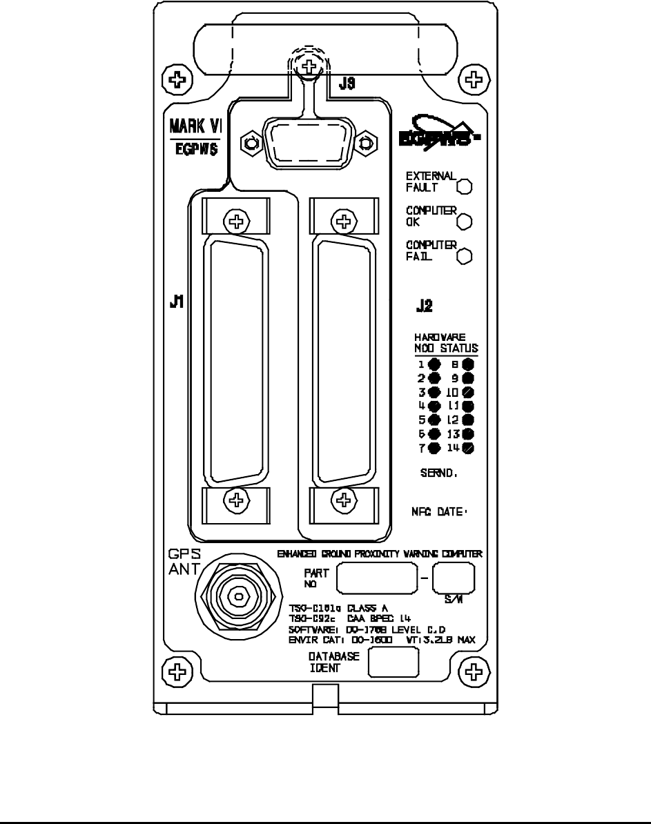
Honeywell
MK VI MK VIII EGPWS Installation Design Guide
Proprietary notice on title page applies
CAGE CODE: 97896 SCALE: NONE SIZE: A DWG NO: 060-4314-150 REV: SHEET 322
Figure 8.1-1, Front Panel Connector Orientation - J1, J2, J3, GPS ANT
Note: The GPS ANT connector only applies to the 965-1190-0xx and the 965-1220-0xx. MK VI EGPWS shown.
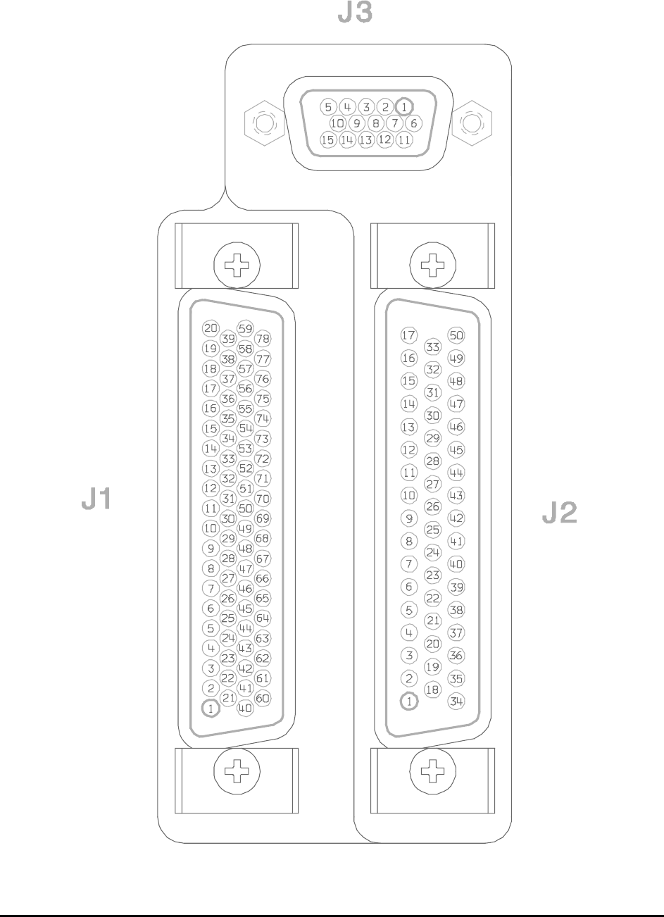
Honeywell
MK VI MK VIII EGPWS Installation Design Guide
Proprietary notice on title page applies
CAGE CODE: 97896 SCALE: NONE SIZE: A DWG NO: 060-4314-150 REV: SHEET 323
Figure 8.1-2, Connector Pin References - J1, J2, J3

Honeywell
MK VI MK VIII EGPWS Installation Design Guide
Proprietary notice on title page applies
CAGE CODE: 97896 SCALE: NONE SIZE: A DWG NO: 060-4314-150 REV: SHEET 324
9 DEFINITIONS
The following acronyms are provided for use with this document:
Acronym Interpretation
AAAS Alternate Audio Alert Selec
t
ADC Air Data Com
p
ute
r
ADS Air Data S
y
ste
m
AGC Automatic Gain Control
AGL Above Ground Level
AHRS Attitude Headin
g
Reference S
y
ste
m
AIC Analo
g
In
p
ut Controlle
r
AIMS Air
p
lane Information Mana
g
ement S
y
ste
m
ASA AlliedSi
g
nal Aeros
p
ace
AOA An
g
le of Attac
k
ASL Above Sea Level
ATP Acce
p
tance Test Procedure
BCD Binar
y
Coded Decimal
BIST Built in Self Tes
t
BIT Built In Tes
t
BITE Built In Test E
q
ui
p
men
t
BNR Binar
y
C/O Callouts
CAA Civil Aviation Authorit
y
CAIMS Central Aircraft Information/Maintenance S
y
ste
m
CFDS Centralized Fault Dis
p
la
y
S
y
ste
m
CFIT Controlled Fli
g
ht Into Terrain
CFM Cubic Feet
p
er Minute
CISRD CFDS Interface S
y
stem Re
q
uirements Documen
t
CMC Central Maintenance Com
p
ute
r
COTS Commercial Off the Shelf
CP Control Panel
CRS Course
CW Clockwise
DAA Di
g
ital/Analo
g
Ada
p
te
r
DADC Di
g
ital Air Data Com
p
ute
r
DAU Data Ac
q
uisition Uni
t
DC Di
g
ital Command
DDM Difference in De
p
th of Modulation
DEVN Deviation
DH Decision Hei
g
h
t
DITS Di
g
ital Information Transfer S
y
ste
m
DME Distance Measurin
g
E
q
ui
p
men
t
DO Discrete Out
p
u
t
DSP Di
g
ital Si
g
nal Processo
r
DSU Dis
p
la
y
Switchin
g
Uni
t
DSWC Di
g
ital Stall Warnin
g
Com
p
ute
r
EEPROM Electricall
y
Erasable Pro
g
rammable Read Onl
y
Memor
y
EFCP EFIS Control Panel
EFIS Electronic Fli
g
ht Instrument S
y
ste
m
EGPWC Enhanced Ground Proximit
y
Warnin
g
Com
p
ute
r
EGPWD Enhanced Ground Proximit
y
Warnin
g
Dis
p
la
y
EGPWS Enhanced Ground Proximit
y
Warnin
g
S
y
ste
m
EICAS En
g
ine Indication and Crew Alert S
y
ste
m
EMI Electroma
g
netic Interference
ENB Enabled
EPROM Erasable Pro
g
rammable Read Onl
y
Memor
y
F/T Functional tes
t
F/W Fail/Warnin
g

Honeywell
MK VI MK VIII EGPWS Installation Design Guide
Proprietary notice on title page applies
CAGE CODE: 97896 SCALE: NONE SIZE: A DWG NO: 060-4314-150 REV: SHEET 325
Acronym Interpretation
FAA Federal Aviation Administration
FCC Fli
g
ht Control Com
p
ute
r
FDR Fli
g
ht Data Recorde
r
FIAS Fli
g
ht Ins
p
ection Aircraft S
y
ste
m
FMC Fli
g
ht Mana
g
ement Com
p
ute
r
FMS Fli
g
ht Mana
g
ement S
y
ste
m
FPM Feet
p
er Minute
FSEU Fla
p
s/Slats Electronic Uni
t
FWC Fault Warnin
g
Com
p
ute
r
G/S Glideslo
p
e
GMT Greenwich Mean Time
GPS Global Position S
y
ste
m
GPW Ground Proximit
y
Warnin
g
GPWS Ground Proximit
y
Warnin
g
S
y
ste
m
GT Greater Than
H/W Hardware
HDG Headin
g
HDOP Horizontal Dilution of Position
HFOM Horizontal Fi
g
ure of Meri
t
HSID Hardware/Software Interface Documen
t
I/O In
p
ut/Out
p
u
t
IAC Inte
g
rated Avionics Com
p
ute
r
ICD Interface Control Documen
t
ILS Instrument Landin
g
S
y
ste
m
INOP Ino
p
erative
IOC In
p
ut/Out
p
ut Concentrato
r
IRS Inertial Reference S
y
ste
m
ISO International Standards Or
g
anization
IVS Inertial Vertical S
p
eed
KT Knots
KTS Knots
LED Li
g
ht Emittin
g
Diode
LRRA Low Ran
g
e Radio Altimete
r
LRU Line Re
p
laceable Uni
t
LSB Least Si
g
nificant Bi
t
LT Less Than
MCP Mode Control Panel
MDA Minimum Barometric Altitude
MFD Multi-Functional Dis
p
la
y
MKII Mark Two Warnin
g
Com
p
ute
r
MKV Mark Five Warnin
g
Com
p
ute
r
MKVI Mark Six Warnin
g
Com
p
ute
r
MKVII Mark Seven Warnin
g
Com
p
ute
r
MKVIII Mark Ei
g
ht Warnin
g
Com
p
ute
r
MLS Microwave Landin
g
S
y
ste
m
MMU Memor
y
Mana
g
ement Uni
t
MSB Most Si
g
nificant Bi
t
MSL Mean Sea Level
N
/A
N
ot A
pp
licable
N
CD
N
o Com
p
uted Data
N
D
N
avi
g
ation Dis
p
la
y
N
VM
N
on Volatile Memor
y
OMS Onboard Maintenance S
y
ste
m
P/N Part Numbe
r
PAR Parit
y
PC Personal Com
p
ute
r
PCMCIA Personal Com
p
uter Memor
y
Card Industr
y
Association
PFD Primar
y
Fli
g
ht Dis
p
la
y

Honeywell
MK VI MK VIII EGPWS Installation Design Guide
Proprietary notice on title page applies
CAGE CODE: 97896 SCALE: NONE SIZE: A DWG NO: 060-4314-150 REV: SHEET 326
Acronym Interpretation
PMAT Portable Maintanence Access Terminal
PP Pro
g
ram Pin
PVM Processor/Voice/Memor
y
PWS Predictive Windshear S
y
ste
m
Q
FE Corrected Baro Alt relative to field elevation
Q
NH Corrected Baro Alt relative to sea level
RA Radio Altitude
RAM Random Access Memor
y
RDOP Radar Dis
p
la
y
Out
p
ut Processin
g
ROM Read Onl
y
Memor
y
RTCA Re
q
uirements and Technical Conce
p
ts for Aviation
RTS Read
y
to Transmit Si
g
nal
RWY Runwa
y
S/T Self Tes
t
S/W Software
SDI Source/Destination Identifie
r
SDRD Software Desi
g
n Re
q
uirements Documen
t
SIG Si
g
nifican
t
SPC Stall Protection Com
p
ute
r
SRD S
y
stem Re
q
uirements Documen
t
SSM Si
g
n Status Matrix
ST Self Tes
t
SWC Stall Warnin
g
Com
p
ute
r
TA&D Terrain Awareness & Dis
p
la
y
TACAN Tactical Air Navi
g
ation
TAD Terrain Awareness Dis
p
la
y
TBD To Be Determined
TCAS Traffic Collision Avoidance S
y
ste
m
TCF Terrain Clearance Floo
r
TERPS United States’ Standards for Terminal Instrument Procedures
TK Trac
k
TLB Translation Lookaside Buffe
r
TSO Technical Standin
g
Orde
r
TTL Tuned To Localize
r
UART Universal As
y
nchronous Receiver Transmitte
r
USM Unsi
g
ned Ma
g
nitude
UTC Universal Time Correlation
UUT Unit Under Tes
t
VDC Volts, DC
VDOP Vertical Dilution of Precision
VFOM Vertical Fi
g
ure of Meri
t
VHF Ver
y
Hi
g
h Fre
q
uenc
y
VLSI Ver
y
Lar
g
e Scale Inte
g
rated Circui
t
VOR VHF Omni-directional Ran
g
e
W/S Windshea
r
WC Warnin
g
Com
p
ute
r
WGS-84 World Geodetic S
y
stem 1984
(
ICAO Standard
)
WX Weather Rada
r
