Honeywell Rthl2310 Quick Installation Guide 69 2578ES 01 RTHL2310/RTHL221 Series
2015-08-26
: Honeywell Honeywell-Rthl2310-Quick-Installation-Guide-803444 honeywell-rthl2310-quick-installation-guide-803444 honeywell pdf
Open the PDF directly: View PDF ![]() .
.
Page Count: 52

69-2578ES-01
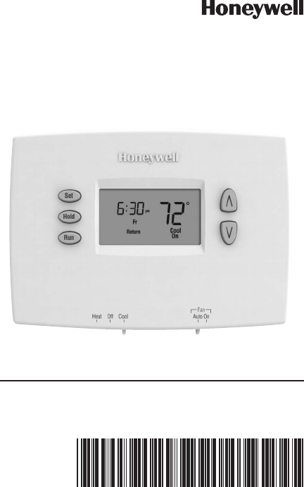
Quick Installation Guide
RTHL2310/RTHL221 Series
Programmable Thermostat

69-2578ES— 01 ii
Identify System Type
This thermostat is compatible with the following systems:
Gas, oil or electric furnace
Central air conditioner
Hot water system with or without pump
Millivolt system
Central heating and cooling system
Heat pump without auxiliary/backup heat
Do you need assistance?
We are here to help.
Call 1-800-468-1502 for wiring
assistance before returning
the thermostat to the store.
This thermostat cannot be used on heat pumps or on
multistage systems.
1 69-2578ES—01
M28097
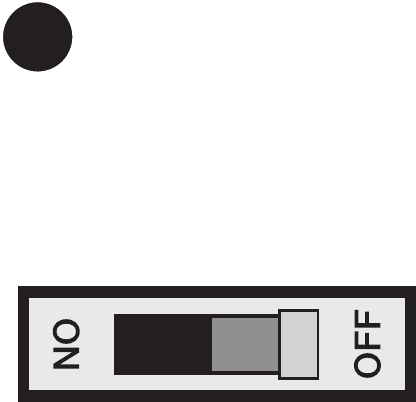
1Turn Off Power to Heating/
Cooling System
69-2578ES— 01 2
Is there a sealed tube containing
mercury? If so, see back cover
for proper disposal instructions.
M28099
Old thermostat
Cover
Remove old thermostat but leave wallplate with
wires attached.
Remove Old Thermostat
Do not remove
wallplate yet
2
3 69-2578ES—01
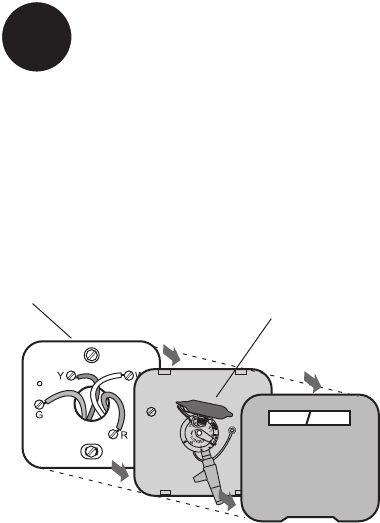
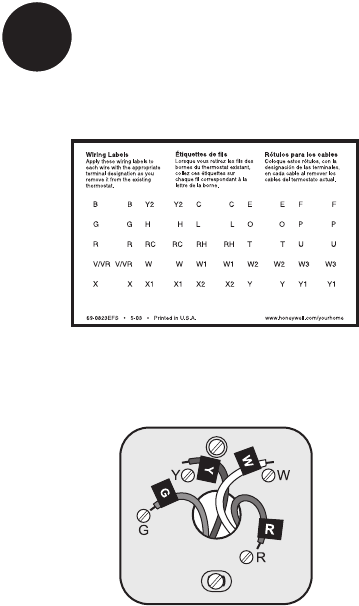
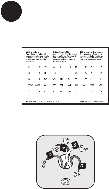
Label Wires with Tags
3
Label the wires using the supplied wire labels as you
disconnect them.
Wire Labels
M28100
M28093
69-2578ES— 01 4
M32731
TO REMOVE WALLPLATE
PULL HERE
Separate Wallplate from
New Thermostat
4
Remove wallplate from the new thermostat and mount
onto wall.
Wallplate
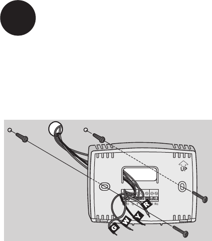
5 69-2578ES—01
Mount the new wallplate using the included screws
and anchors.
5Mount Wallplate
Drill 3/16-in. holes for drywall
Drill 3/32-in. holes for plaster
W/
Aux
Not
Used
M32714
69-2578ES— 01 6
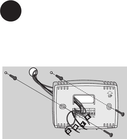
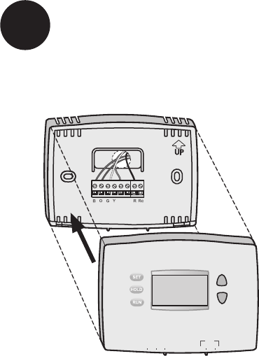
Connect Wires
6
M32732
SCREW
INSERT WIRES
AND TIGHTEN
SCREWS
WIRE
HOLE
LABELED
WIRES
W
G
R
Not
Used
W
Y
Simply match wire labels.
Remove metal jumper if you have both R and Rc wires.
Labels don’t match? See page 20.
We are here to help.
Call 1-800-468-1502 for wiring assistance.
7 69-2578ES—01
RTHXXXX
M32707
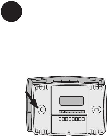
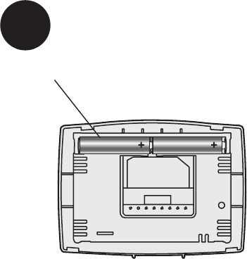
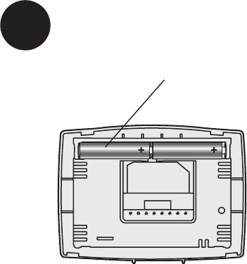
Install two AAA alkaline batteries.
Back of thermostat
7Install Batteries
69-2578ES— 01 8
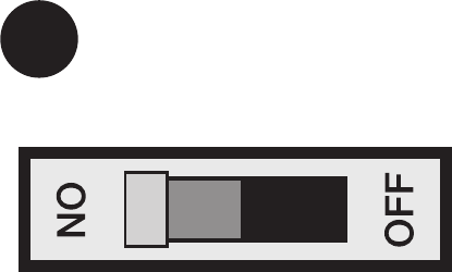
Move the switch to the proper setting:
Gas or Oil: For gas or oil heating systems, leave the fan
operation switch in this factory-set position (for systems
that control the fan in a call for heat).
Electric or Heat Pump: Change the switch to this setting
for heat pump or electric heat systems. (This setting is for
systems that allow the thermostat to control the fan in a
call for heat, if a fan wire is connected to the G terminal.)
8Set fan operation switch
RTHXXXX
M32716
GAS OR OIL
ELECTRIC OR HEAT PUMP
GAS OR OIL
ELECTRIC OR HEAT PUMP
9 69-2578ES—01
W/
Aux
Not
Used
Heat Off Cool Auto On
Fan
M32705
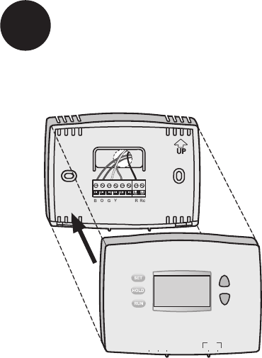
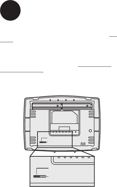
Install thermostat onto the wallplate on the wall.
9Install Thermostat onto Wallplate
69-2578ES—01 10
Turn the power back on to the heating/cooling system.
10 Turn Power Back On
M28098

11 69-2578ES—01
If your system type is:
q Single Stage Heat and Cool
q Heat Only or Cool Only
Congratulations, you’re done!
If your system type is:
q Heat Pump* with Backup Heat
Continue with advanced installation
on next page to match your thermostat to your sys-
tem type.
*Heat Pump—an air conditioner that provides cooling
in the summer, and also runs in reverse in the winter to
provide heating.
If you are not sure of your system type or if you have
other questions, call us toll-free at 1-800-468-1502.
This thermostat works on 24 volt or 750 mV systems. It
will NOT work on multi-stage conventional systems or
120/240 Volt systems.
11 If your system type is...

Advanced Installation
Enter system setup ............................................................13
Changing settings ..............................................................14
Heating cycle rate ..............................................................15
Temperature display ...........................................................16
Compressor protection ......................................................17
Clock display ......................................................................18
Restore program schedule default .................................... 19
Alternate wiring ..................................................................20
Troubleshooting ..................................................................21
Customer assistance .........................................................22
Limited warranty ................................................................. 23
RTHL2310/RTHL221
13 69-2578ES—01
SETUP WIRING ASSISTANCE TROUBLESHOOTING
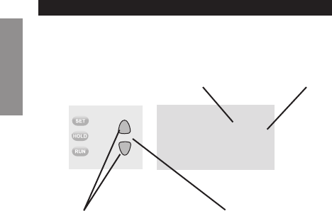
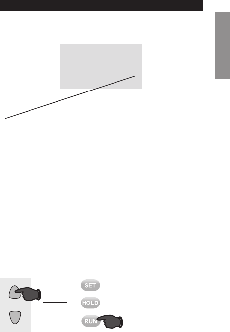
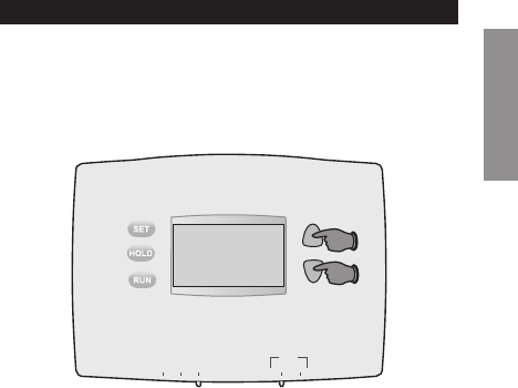
Enter System Setup
System setup
To enter system setup, press and hold both the s and
t buttons until the display changes (approximately 5
seconds).
M32713
Heat Off Cool Auto On
Fan
Advanced Installation Guide
69 -2578ES — 01 14
SETUPWIRINGASSISTANCETROUBLESHOOTING
55
M32779
System setup
Change Function Change Setting
See pages 15–19 to change Function Settings.
Changing Settings
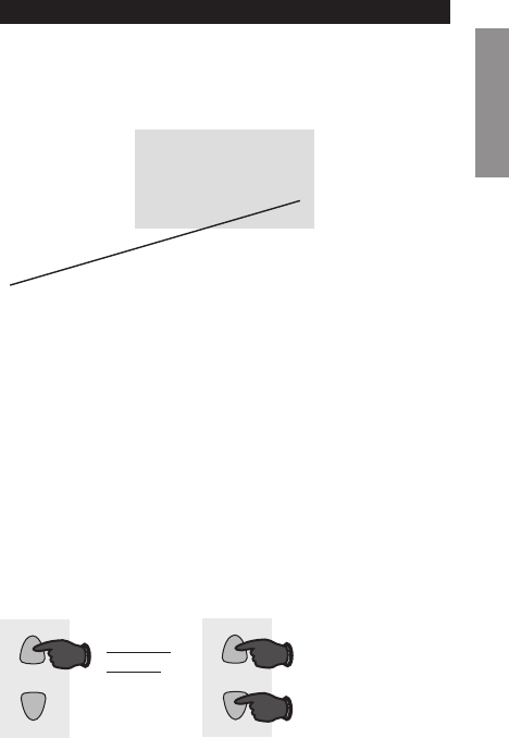
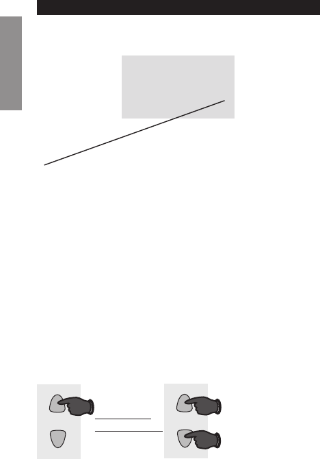
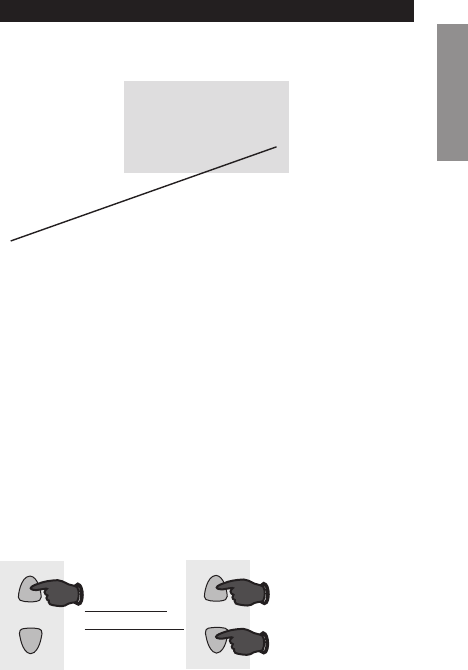
Function Setting
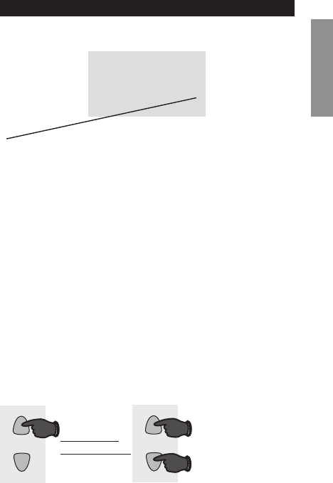
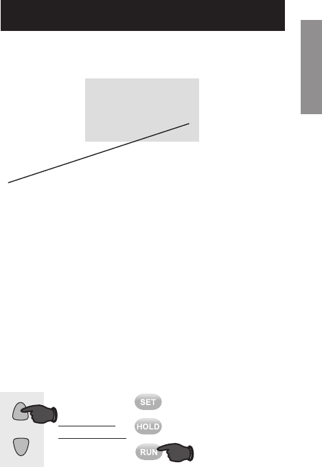
1. Press the s or t button to change the setting.
2. Press the s and t buttons simultaneously for one
second to advance to the next function.
3. Press the Run button to exit and save settings.
NOTE: If you do not press any button for 60 seconds
while you are in the setup menu, the thermostat
automatically saves any changes made and exits the
menu.
RTHL2310/RTHL221
15 69-2578ES—01
About your new thermostat
SETUP WIRING ASSISTANCE TROUBLESHOOTING
55
M32720
System setup
Press the s or t button to select your heating system
and optimize its operation.
Function 5: Heating cycle rate
5 Gas or oil furnace: Use this setting if you have a
standard gas or oil furnace that is less than 90%
efficient.
6 Electric furnace: Use this setting if you have any
type of electric heating system.
3 Hot water or high-efficiency furnace: Use this
setting if you have a hot water system or a gas
furnace of greater than 90% efficiency.
2 Gas/oil steam or gravity system: Use this setting
if you have a steam or gravity heat system.
Press to
change
setting.
When finished,
press s and t
to advance to
the next function.
M32719
AND
OR
Advanced Installation Guide
69-2578ES — 01 16
SETUPWIRINGASSISTANCETROUBLESHOOTING
System setup
Function 14: Temperature display
0 Fahrenheit temperature display (°F)
1 Celsius temperature display (°C)
Press the s or t button to select Fahrenheit or
Celsius temperature display.
14 0
M32722
Press to
change
setting.
When finished,
press s and t
to advance to
the next function.
M32719
AND
OR

RTHL2310/RTHL221
17 69-2578ES—01
SETUP WIRING ASSISTANCE TROUBLESHOOTING
System setup
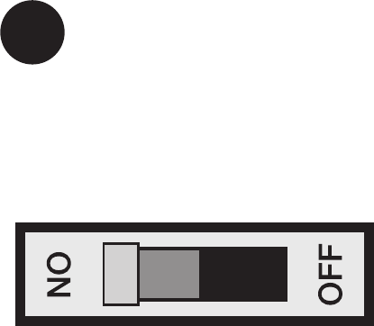
Function 15: Compressor Protection
1 On
0 Off
Press the s or t button to select Compressor
Protection settings.
Compressor Protection: This feature forces the com-
pressor to wait approximately 5 minutes before restart-
ing, to prevent equipment damage. During the wait
time, the message “Cool On” or “Heat On” is displayed
on screen.
15 1
M32723
Press to
change
setting.
When finished,
press s and t
to advance to
the next function.
M32719
AND
OR

Advanced Installation Guide
69-2578ES— 01 18
SETUPWIRINGASSISTANCETROUBLESHOOTING
System setup
Function 20: Clock Display
0 12-hour display
1 24-hour display
Press the s or t button to select clock display.
Press to
change
setting.
When finished,
press s and t
to advance to
the next function.
M32719
AND
OR
20 0
M32724
RTHL2310/RTHL221
19 69-2578ES—01
SETUP WIRING ASSISTANCE TROUBLESHOOTING
System setup (RTHL2310 only)
Function 40: Restore Program Schedule to Default
0 Off
1 On - Program schedule default settings are listed in
the operating manual.
Press the s or t button to select restore program
schedule to default settings.
M32729
OR
Press to
change
setting.
When finished,
press Run to
exit and save
changes.
40 0
M32725
Advanced Installation Guide
69-2578ES— 01 20
SETUPWIRINGASSISTANCETROUBLESHOOTING
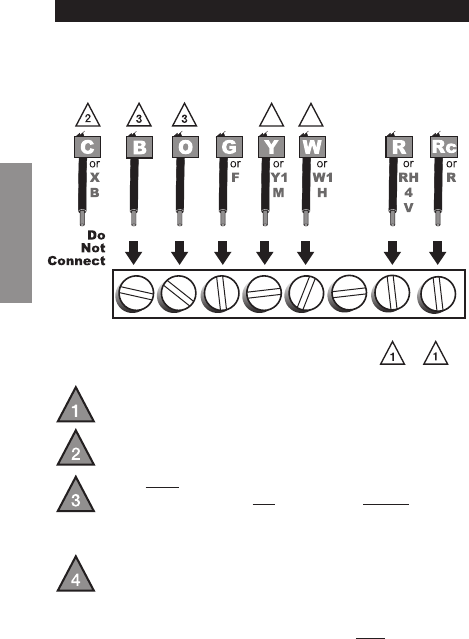
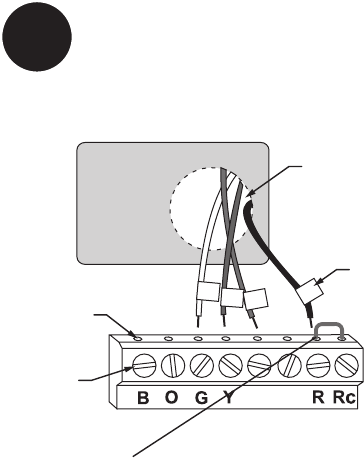
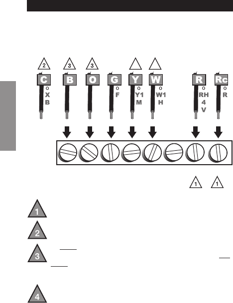
If labels do not match letters on the thermostat, check
the chart below and connect to terminal as shown here
(see notes, below).
Alternate Wiring
If wires will be connected to both R and Rc
terminals, remove metal jumper (see page 6).
Do not use C or X. Wrap bare end of wire with
electrical tape.
If you have a heat pump without auxiliary/backup
heat connect O or B, not both. If you do not have
a heat pump, do not connect B. Wrap bare end of
wire with electrical tape.
Place a jumper (piece of wire) between Y and W if
you are using a heat pump without auxiliary/backup
heat.
Thermostat does not work on Heat Pumps with auxiliary/
backup heat.
B O G Y
WNOT
USED
R Rc
M32734
44

RTHL2310/RTHL221
21 69-2578ES—01
Troubleshooting
SETUP WIRING ASSISTANCE TROUBLESHOOTING
If you have difficulty with your thermostat, please try
the following suggestions. Most problems can be cor-
rected quickly and easily.
Display is
blank
• Makesurefurnacedoorisclosed
securely.
• MakesurefreshAAAalkaline
batteries are correctly installed
(see page 7).
Heating or
cooling system
does not
respond
• SetSystemswitchtoHeat. Make
sure the temperature is set higher
than the Inside temperature.
• SetSystemswitchtoCool. Make
sure the temperature is set lower
than the Inside temperature.
• Checkcircuitbreakerandresetif
necessary.
• Makesureheating&coolingpower
switches are on.
• Makesurefurnacedoorissecurely
closed.
• Wait5minutesforthesystemto
respond.

Advanced Installation Guide
69-2578ES— 01 22
Troubleshooting
SETUPWIRINGASSISTANCETROUBLESHOOTING
Customer assistance
For assistance with this product, please visit
http://yourhome.honeywell.com or call Honeywell
Customer Care toll-free at 1-800-468-1502.
Temperature
settings do not
change
Make sure heating and cooling
temperatures are set to acceptable
ranges:
• Heat:40°to90°F(4.5°to32°C).
• Cool:50°to99°F(10°to37°C).
“Cool On” or
“Heat On” is
flashing
• Compressor protection feature is
engaged. Wait 5 minutes for the
system to restart safely, without
damage to the compressor.
“Heat On” is
not displayed
• Set the System switch to Heat, and
set the temperature level above the
current room temperature.
“Cool On” is
not displayed
• Set the System switch to Cool, and
set the temperature level below the
current room temperature.

23 69-2578ES—01
One-year limited warranty
Honeywell warrants this product, excluding battery, to be free from defects
in the workmanship or materials, under normal use and service, for a
period of one (1) year from the date of purchase by the consumer. If at any
time during the warranty period the product is determined to be defective
or malfunctions, Honeywell shall repair or replace it (at Honeywell’s option).
If the product is defective,
(i) return it, with a bill of sale or other dated proof of purchase, to the place
from which you purchased it; or
(ii) call Honeywell Customer Care at 1-800-468-1502. Customer Care
will make the determination whether the product should be returned to
the following address: Honeywell Return Goods, Dock 4 MN10-3860,
1885 Douglas Dr. N., Golden Valley, MN 55422, or whether a replacement
product can be sent to you.
This warranty does not cover removal or reinstallation costs. This warranty
shall not apply if it is shown by Honeywell that the defect or malfunction
was caused by damage which occurred while the product was in the
possession of a consumer.
Honeywell’s sole responsibility shall be to repair or replace the product
within the terms stated above. HONEYWELL SHALL NOT BE LIABLE FOR
ANY LOSS OR DAMAGE OF ANY KIND, INCLUDING ANY INCIDENTAL OR
CONSEQUENTIAL DAMAGES RESULTING, DIRECTLY OR INDIRECTLY,
FROM ANY BREACH OF ANY WARRANTY, EXPRESS OR IMPLIED, OR
ANY OTHER FAILURE OF THIS PRODUCT. Some states do not allow the
exclusion or limitation of incidental or consequential damages, so this
limitation may not apply to you.
THIS WARRANTY IS THE ONLY EXPRESS WARRANTY HONEYWELL
MAKES ON THIS PRODUCT. THE DURATION OF ANY IMPLIED
WARRANTIES, INCLUDING THE WARRANTIES OF MERCHANTABILITY
AND FITNESS FOR A PARTICULAR PURPOSE, IS HEREBY LIMITED TO
THE ONE-YEAR DURATION OF THIS WARRANTY.
Some states do not allow limitations on how long an implied warranty
lasts, so the above limitation may not apply to you. This warranty gives
youspeciclegalrights,andyoumayhaveotherrightswhichvaryfrom
state to state.
If you have any questions concerning this warranty, please write
Honeywell Customer Relations, 1985 Douglas Dr, Golden Valley, MN 55422
or call 1-800-468-1502. In Canada, write Retail Products ON15-02H,
Honeywell Limited/ Honeywell Limitée, 35 Dynamic Drive, Toronto, Ontario
M1V4Z9.

Automation and Control Solutions
Honeywell International Inc.
1985 Douglas Drive North
Golden Valley, MN 55422
Honeywell Limited-Honeywell Limitée
35 Dynamic Drive
Toronto, Ontario M1V 4Z9
http://yourhome.honeywell.com
® U.S. Registered Trademark
© 2011 Honeywell International Inc.
69-2578ES—01 M.S. 05-11
Printed in U.S.A.
CAUTION: To avoid possible compressor
damage, do not run air conditioner if the outside
temperature drops below 50°F (10°C).
MERCURY NOTICE: Do not place your old
thermostat in the trash if it contains mercury in a
sealed tube. Contact the Thermostat Recycling
Corporation at www.thermostat-recycle.org
or 800-238-8192 for information on how and
where to properly and safely dispose of your old
thermostat.
69-2578ES-01
Serie RTHL2310/RTHL221
Termostato programable
Guía de instalación rápida

69-2578ES— 01 ii
Identifique el tipo de sistema
Este termostato es compatible con los siguientes
sistemas:
Calefactor a gas, aceite o eléctrico
Aire acondicionado central
Sistema a agua caliente con o sin bomba
Sistema de milivoltios
Calefacción y aire acondicionado centrales
Bomba de calor sin calefacción auxiliar
¿Necesita ayuda?
¡Aquí estamos!
Llame al 1-800-468-1502 para
obtener asistencia con el
cableado antes de devolver el
termostato a la tienda.
Este termostato no puede usarse en bombas de
calor ni en sistemas multietapas.
1 69-2578ES—01
1
Desconecte la alimentación
en el sistema de calefacción/
refrigeración
M28097

69-2578ES— 01 2
M28099
Termostato viejo
Cubierta
Retire el termostato existente pero deje la placa de
montaje con los cables adheridos.
Remueva su viejo termostato
No retirar la placa
mural todavía
2
¿Hay un tubo sellado que
contiene mercurio? Si es así,
consulte en la cubierta de
este manual las instrucciones
para su desecho apropiado.
3 69-2578ES—01
Identifique los cables
3
Rótulos para los cables
M28100
M28093
Identifique los cables a medida que los desconecta,
utilizando las etiquetas que se suministran.
69-2578ES— 01 4
Separe la placa de montaje del
termostato nuevo
4
Placa de montaje
Retire la placa de montaje del termostato nuevo y móntela
en la pared.
M32731
TO REMOVE WALLPLATE
PULL HERE
5 69-2578ES—01
Monte la nueva placa de montaje utilizando los tornillos y
anclajes que se suministran.
5Coloque la placa de montaje
Taladre agujeros de 3/32 in. (2,4 mm) en yeso
Taladre agujeros de 3/16 in. (4,8 mm) en paneles de yeso
W/
Aux
Not
Used
M32714
69-2578ES— 01 6
MS32732
W
G
R
Not
Used
W
Y
TORNILLO
INSERTE
LOS CABLES
Y APRIETE
LOS TORNILLOS
ORIFICIO DE
CABLEADO
CABLES
ETIQUETADOS
Conecte los cables
6
Simplemente haga corresponder las etiquetas de los
cables.
Retire el empalme metálico si tiene los cables “R” y “Rc”.
¿Los rótulos no coinciden? Vea la página 20.
Estamos aquí para ayudarle.
Llame al 1-800-468-1502 para asistencia con el
cableado.
7 69-2578ES—01
RTHXXXX
M32707
Instale dos baterías alcalinas AAA en la parte de atrás del
termostato.
Parte de atrás del termostato
7Instale las baterías
69-2578ES— 01 8
8Configure el interruptor de
funcionamiento del ventilador
RTHXXXX
M32716
GAS OR OIL
ELECTRIC OR HEAT PUMP
GAS OR OIL
ELECTRIC OR HEAT PUMP
Mueva el interruptor a la configuración adecuada:
Gas o aceite: para los sistemas de calefacción de gas o
aceite, deje el interruptor del ventilador en esta posición
configurada de fábrica (para sistemas que controlan el
ventilador en una orden de calefacción).
Eléctrico o bomba de calor: cambie el interruptor a
esta configuración para sistemas de bomba de calor o de
calefacción eléctrica. (Esta configuración es para sistemas
que permitan que el termostato controle el ventilador en
una orden de calefacción, si un cable del ventilador está
conectado al terminal G).
9 69-2578ES—01
Instale el termostato en la placa de montaje en la pared.
9Instale el termostato en la placa
de montaje
W/
Aux
Not
Used
Heat Off Cool Auto On
Fan
M32705
69-2578ES— 01 10
Active nuevamente el suministro eléctrico del sistema
de calefacción/aire acondicionado.
10 Active nuevamente el
suministro eléctrico
M28098

11 69-2578ES—01
Si su tipo de sistema es:
q Calor y frío de una sola etapa
q Calefacción únicamente o Refrigeración únicamente
¡Felicitaciones, ya está listo!
Si su tipo de sistema es:
q Bomba de calor* con calor de respaldo
Continúe con la instalación avanzada
en la próxima página para adaptar el termostato a su
tipo de sistema.
*Bomba de calor —un acondicionador de aire que
proporciona enfriamiento en el verano y también funciona
en reversa en el invierno, proporcionando calor.
Si no está seguro del tipo de sistema que tiene o si
tiene otras preguntas, llámenos gratis al
1-800-468-1502.
Este termostato funciona con sistemas de 24 voltios o
750 mV. NO funcionará con sistemas convencionales de
etapas múltiples ni con sistemas de 120/240 voltios
11 Si su tipo de sistema es...

Guía de instalación avanzada
Ingrese la configuración del sistema ................................13
Cómo cambiar la configuración ........................................14
Frecuencia del ciclo de calefacción ..................................15
Indicador de temperatura ..................................................16
Protección del compresor .................................................17
Visualizador del reloj ..........................................................18
Restablecimiento del cronograma del
programa a la configuración predeterminada ..................19
Conexión alternativa ..........................................................20
En caso de dificultades .....................................................21
Asistencia al cliente ...........................................................22
Garantía limitada ................................................................23
RTHL2310/RTHL221
13 69-2578ES—01
CONFIGURACIÓN WIRING ASSISTANCE TROUBLESHOOTING
Configuración del sistema
M32713
Heat Off Cool Auto On
Fan
Ingrese la configuración del sistema
Para ingresar la configuración del sistema, presione
y mantenga presionados los botones s (arriba) y t
(abajo) hasta que el visualizador cambie (5 segundos
aproximadamente).

Guía de instalación avanzada
69 -2578ES — 01 14
CONFIGURACIÓNWIRINGASSISTANCETROUBLESHOOTING
Configuración del sistema
55
M32779
NOTA: si no se presiona ningún botón durante
60 segundos mientras esté abierto el menú de
configuración, el termostato salvaguarda los cambios
automáticamente y sale del menú.
Consulte las páginas 15-19 para cambiar la
configuración de las funciones.
Cómo cambiar la configuración
1. Presionar s o t para cambiar la función.
2. Presionar s y t al mismo tiempo por un segundo
para ir a la función siguiente.
3. Presione el botón Run para salir y guardar los
cambios.
Cambio de
función
Cambio de
configuración
Función Configuración
RTHL2310/RTHL221
15 69-2578ES—01
About your new thermostat
CONFIGURACIÓN WIRING ASSISTANCE TROUBLESHOOTING
55
M32720
Configuración del sistema
MS32719
Y
O
Presione
para
cambiar la
configuración
Cuando termine,
presione s y t
para avanzar
hasta la siguiente
función.
Presione el botón s o t para elegir su sistema de
calefacción y optimizar su funcionamiento
Función 5: Frecuencia del ciclo de calefacción
5 Sistema de calefacción de gas o aceite:
utilice esta configuración si tiene un sistema
de calefacción estándar de gas o aceite cuyo
rendimiento sea inferior al 90%.
6 Sistema de calefacción eléctrico: utilice esta
configuración si tiene cualquier tipo de sistema de
calefacción eléctrica.
3 Sistema de calefacción de agua caliente o de
alto rendimiento: utilice esta configuración si tiene
un sistema de agua caliente o de calefacción de gas
cuyo rendimiento sea superior al 90%.
2 Sistema de vapor o de gravedad a gas/aceite:
utilice esta configuración si tiene un sistema de
calefacción de vapor o gravedad.
Guía de instalación avanzada
69-2578ES — 01 16
CONFIGURACIÓNWIRINGASSISTANCETROUBLESHOOTING
14 0
M32722
Configuración del sistema
MS32719
Y
O
Presione
para
cambiar la
configuración
Cuando termine,
presione s y t
para avanzar
hasta la siguiente
función.
Función 14: Indicador de temperatura
0 Indicador de temperatura en grados Fahrenheit (°F)
1 Indicador de temperatura en grados
Centígrados (°C)
Presione el botón s or t para elegir el indicador de
temperatura en grados Fahrenheit o Centígrados.
RTHL2310/RTHL221
17 69-2578ES—01
CONFIGURACIÓN WIRING ASSISTANCE TROUBLESHOOTING
15 1
M32723
Configuración del sistema
1 Encendido
0 Apagado
MS32719
Y
O
Presione
para
cambiar la
configuración
Cuando termine,
presione s y t
para avanzar
hasta la siguiente
función.
Función 15: Protección del compresor
Presione el botón s or t para elegir la configuración
de protección del compresor.
Protección del compresor: Esta función hace que
el compresor demore aproximadamente 5 minutos
antes de volver a iniciarse, para evitar daños al equipo.
Durante este período de espera, el mensaje “Cool
on” (Refrigeración activada) o “Heat on” (calefacción
activada) aparece en el visualizador.

Guía de instalación avanzada
69-2578ES— 01 18
CONFIGURACIÓNWIRINGASSISTANCETROUBLESHOOTING
20 0
M32724
Configuración del sistema
MS32719
Y
O
Presione
para
cambiar la
configuración
Cuando termine,
presione s y t
para avanzar
hasta la siguiente
función.
Función 20: Visualizador del reloj
0 Visualizador de 12 horas
1 Visualizador de 24 horas
Presione el botón s or t para elegir el visualizador del
reloj.
RTHL2310/RTHL221
19 69-2578ES—01
CONFIGURACIÓN WIRING ASSISTANCE TROUBLESHOOTING
40 0
M32725
Configuración del sistema
(RTHL2310 únicamente)
Función 40: Restablecimiento del cronograma del
programa a la configuración predeterminada
0 Apagado
1 Encendido - Las configuraciones predeterminadas
del cronograma del programa se indican en el
manual de funcionamiento.
Presione el botón s or t para restituir las
configuraciones predeterminadas del cronograma del
programa.
MS32729
O
Presione
para
cambiar la
configuración
Cuando termine,
presione el botón
Run para salir
y guardar los
cambios.
Guía de instalación avanzada
69-2578ES— 01 20
SETUPCABLEADOASSISTANCETROUBLESHOOTING
Conexión alternativa
B O G Y
WNOT
USED
R Rc
MS32734
44
No
Conecte
El termostato no trabaja con bombas de calor con calor
auxiliar/de reserva.
Si las etiquetas no corresponden con las letras del
termostato, revise la tabla que sigue y conecte al
terminal como se indica aquí (refiérase a las notas que
siguen).
Si los cables se conectarán a los terminales R y Rc,
retireelpuentemetálico(reérasealaPage6).
No utilice C o X. Envuelva los extremos pelados del
cable con cinta aislante.
Si tiene una bomba de calor sin calefacción
auxiliar/de reserva conecte O o B, no ambos. Si no
tiene una bomba de calor, no conecte B. Envuelva
los extremos pelados del cable con cinta aislante.
Coloque un puente (trozo de cable) entre Y y W/
Aux si está utilizando una bomba de calor sin
calefacción auxiliar/de reserva.

RTHL2310/RTHL221
21 69-2578ES—01
SETUP WIRING ASSISTANCE EN CASO DE DIFICULTADES
En caso de dificultades
Si usted tiene dificultades con su termostato, pruebe
las sugerencias que figuran a continuación. La mayoría
de los problemas se pueden solucionar rápida y
fácilmente.
Pantalla en
blanco
• Asegúresedequelapuertadel
sistema de calefacción esté bien
cerrada.
• Asegúresedequelasbaterías
AAA alcalinas estén instaladas
correctamente (vea la página 7).
El sistema de
calefacción o
refrigeración
no responde
• Coloqueelinterruptordelsistema
en Heat (calefacción). Asegúrese
de que la temperatura sea más alta
que la temperatura interna.
• Coloqueelinterruptordelsistema
en Cool (refrigeración). Asegúrese
de que la temperatura sea más baja
que la temperatura interna.
• Reviseelinterruptordecircuitoy
reinícielo si fuese necesario.
• Compruebequelosinterruptores
del equipo de calefacción y
refrigeración estén encendidos.
• Compruebequelapuertadel
sistema de calefacción esté cerrada
de forma segura.
• Espere5minutosparaque
responda el sistema.

Guía de instalación avanzada
69-2578ES— 01 22
SETUPWIRINGASSISTANCEEN CASO DE DIFICULTADES
Las con-
figuraciones
de la
temperatura
no cambian
Asegúrese de que las temperaturas
de calor y frío estén configuradas en
rangos aceptables:
• “Heat”:De40°Fa90°F(de4,5°C
a 32 °C).
• “Cool”:De50°Fa99°F(de10°C
a 37 °C).
El mensaje
“Cool On” o
“Heat On” titila
• La función de la protección del
compresor está funcionando.
Espere 5 minutos para que el
sistema se vuelva a iniciar de forma
segura, sin dañar el compresor.
“Heat On” no
aparece en la
pantalla
• Mueva el interruptor “System” hasta
la posición “Heat” y configure el nivel
de temperatura por encima de la
temperatura ambiente actual.
“Cool On” no
aparece en la
pantalla
• Mueva el interruptor “System” hasta
la posición “Cool” y configure el nivel
de temperatura por debajo de la
temperatura ambiente actual.
Asistencia al cliente
Si necesita asistencia, visite
http://yourhome.honeywell.com o llame al número
gratuito de atención al cliente de Honeywell al
1 800 468-1502.
En caso de dificultades

23 69-2578ES—01
Garantía limitada de 1 año
Honeywell garantiza este producto, a excepción de la batería, por el
término de un (1) año contra cualquier defecto de fabricación o de los
materiales, a partir de la fecha de compra por parte del consumidor. Si
en cualquier momento durante el período de garantía se verifica que el
producto tiene un defecto o que funciona mal, Honeywell lo reparará o
reemplazará (a elección de Honeywell).
Si el producto tiene defectos,
(i) devuélvalo, con la factura de venta u otra prueba de compra fechada, al
lugar donde lo compró; o
(ii) comuníquese con el Centro de atención al cliente de Honeywell
al 1-800-468-1502. Atención al cliente decidirá si se debe devolver
el producto a la siguiente dirección: Devolución de mercaderías de
Honeywell, Dock 4 MN10-3860, 1885 Douglas Dr. N., Golden Valley, MN
55422, o si se le puede enviar un producto en reemplazo.
Esta garantía no cubre los costos de extracción o reinstalación. Esta
garantía no se aplicará si Honeywell demuestra que el defecto o mal
funcionamiento fue causado por daños ocurridos mientras el producto
estaba en posesión de un consumidor.
La única responsabilidad de Honeywell será reparar o reemplazar el
producto dentro de los plazos establecidos anteriormente. HONEYWELL
NO RESPONDERÁ POR LA PÉRDIDA O DAÑO DE NINGÚN TIPO,
INCLUIDO EL DAÑO INCIDENTAL O INDIRECTO DERIVADO, DIRECTA
O INDIRECTAMENTE, DEL INCUMPLIMIENTO DE LAS GARANTÍAS,
EXPRESAS O IMPLICÍTAS, O DE OTRAS FALLAS DE ESTE PRODUCTO.
Algunos estados no permiten la exclusión o limitación del daño incidental o
indirecto, entonces, esta limitación puede no resultar aplicable a su caso.
LA PRESENTE GARANTÍA ES LA ÚNICA GARANTÍA EXPRESA QUE
HONEYWELL PROPORCIONA RESPECTO DE ESTE PRODUCTO.
LA DURACIÓN DE LAS GARANTÍAS IMPLÍCITAS, INCLUÍDAS LAS
GARANTÍAS DE COMERCIABILIDAD Y APTITUD PARA UN OBJETIVO
PARTICULAR, ESTÁ LIMITADA A LA DURACIÓN DE UN AÑO DE LA
PRESENTE GARANTÍA.
Algunos estados no permiten las limitaciones sobre la duración del período
de una garantía implícita, entonces la limitación anterior puede no resultar
aplicable a su caso. Esta garantía le brinda derechos legales específicos, y
usted podrá tener otros derechos que varían según el estado.
Si tiene preguntas sobre la presente garantía, sírvase escribir a Honeywell
Customer Relations, 1985 Douglas Dr, Golden Valley, MN 55422 o llamar
al 1-800-468-1502. En Canadá, escriba a Retail Products ON15-02H,
Honeywell Limited/Honeywell Limitée, 35 Dynamic Drive, Toronto, Ontario
M1V4Z9.

Automatización y control desenlace
Honeywell International Inc.
1985 Douglas Drive North
Golden Valley, MN 55422
Honeywell Limited-Honeywell Limitée
35, Dynamic Drive
Toronto, Ontario M1V 4Z9
http://yourhome.honeywell.com
® Marca Registrada en los EE. UU.
© 2011 Honeywell International Inc.
69-2578ES—01 M.S. 05-11
Impreso en EE. UU.
AVISO DE MERCURIO: No arroje su viejo
termostato a la basura si contiene mercurio en
un tubo sellado. Comuníquese con Thermostat
Recycling Corporation en www.thermostat-
recycle.org o llame al 800-238-8192 para obtener
información sobre cómo y dónde desechar de
forma adecuada y segura su termostato usado.
PRECAUCIÓN: Para evitar posibles daños al
compresor, no utilice el aire acondicionado si la
temperatura externa es inferior a 50ºF (10ºC).
