Honeywell Rthl2510C Quick Installation Guide 69 2580EF 01 RTHL2510/RTHL2410
2015-08-26
: Honeywell Honeywell-Rthl2510C-Quick-Installation-Guide-803450 honeywell-rthl2510c-quick-installation-guide-803450 honeywell pdf
Open the PDF directly: View PDF ![]() .
.
Page Count: 60
Quick Installation Guide
RTHL2510/RTHL2410 Series
Programmable Thermostat
69-2580EF-01

69-2580EF—01 ii
Identify System Type
This thermostat is compatible with the following systems:
Gas, oil or electric furnace
Central air conditioner
Hot water system with or without pump
Millivolt system
Central heating and cooling system
Heat pump without auxiliary/backup heat
Heat pump with auxiliary/backup heat
Do you need assistance?
We are here to help.
Call 1-800-468-1502 for wiring
assistance before returning
the thermostat to the store.
This thermostat cannot be used on multistage systems.
1 69-2580EF—01
M28097
1Turn Off Power to Heating/
Cooling System

69-2580EF—01 2
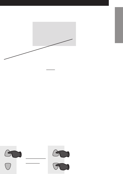
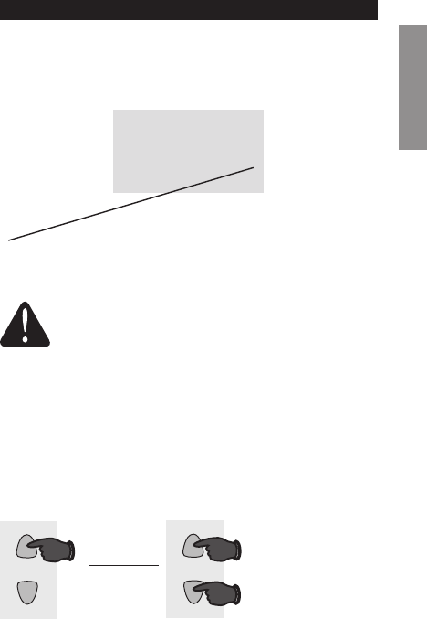
Is there a sealed tube containing
mercury? If so, see back cover for
proper disposal instructions.
M28099
Old thermostat
Cover
Remove old thermostat but leave wallplate with
wires attached.
Remove Old Thermostat
Do not remove
wallplate yet
2
3 69-2580EF—01
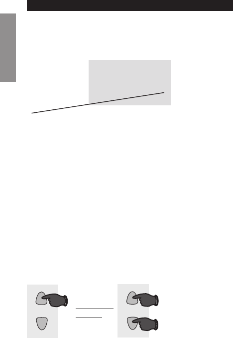
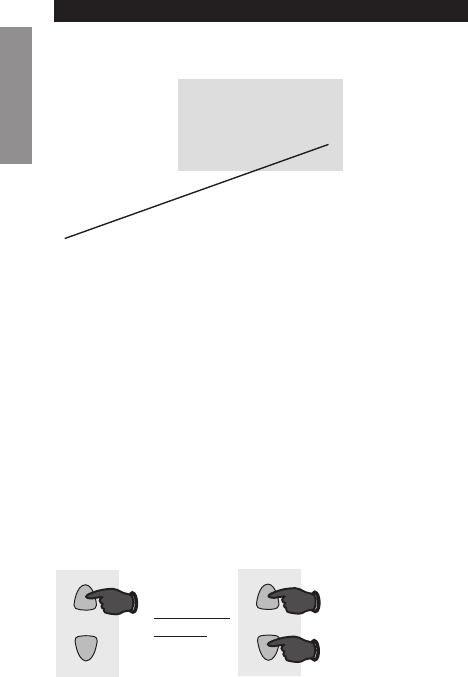
Label Wires with Tags
3
Label the wires using the supplied wire labels as you
disconnect them.
Wire Labels
M28100
M28093
69-2580EF—01 4
M32731
TO REMOVE WALLPLATE
PULL HERE
Separate Wallplate from
New Thermostat
4
Remove wallplate from the new thermostat and mount onto
wall.
Wallplate
5 69-2580EF—01
Mount the new wallplate using the included screws
and anchors.
5Mount Wallplate
Drill 3/16-in. holes for drywall
Drill 3/32-in. holes for plaster
W/
Aux
Not
Used
M32714
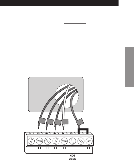
69-2580EF—01 6
M32715
SCREW
INSERT WIRES
AND TIGHTEN
SCREWS
WIRE
HOLE
LABELED
WIRES
W/
Aux
W
Y
G
R
Not
Used
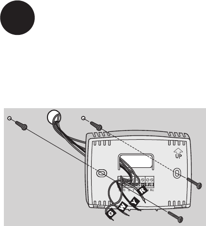
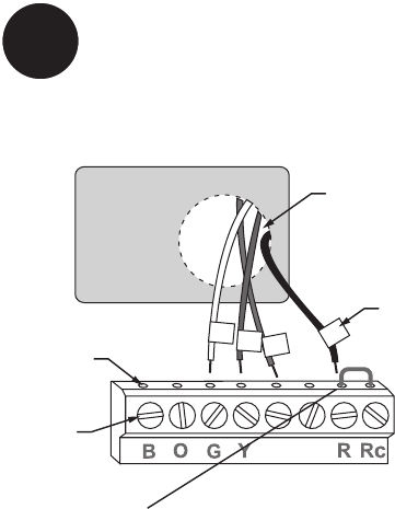
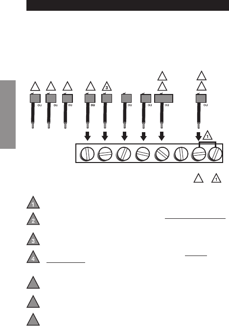
Connect Wires
6
Simply match wire labels.
Remove metal jumper if you have both R and Rc wires.
Labels don’t match? See page 22.
Have a Heat Pump system? See page 23-24.
We are here to help.
Call 1-800-468-1502 for wiring assistance.

7 69-2580EF—01
RTHXXXX
M32707
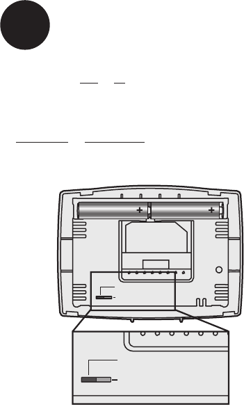
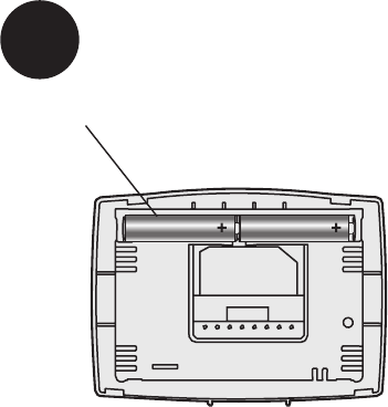
Install two AAA alkaline batteries.
Back of thermostat
7Install Batteries
69-2580EF—01 8
Move the switch to the proper setting:
Gas or Oil: For gas or oil heating systems, leave the fan
operation switch in this factory-set position (for systems that
control the fan in a call for heat).
Electric or Heat Pump: Change the switch to this setting
for heat pump or electric heat systems. (This setting is for
systems that allow the thermostat to control the fan in a call
for heat, if a fan wire is connected to the G terminal.)
8Set fan operation switch
RTHXXXX
M32716
GAS OR OIL
ELECTRIC OR HEAT PUMP
GAS OR OIL
ELECTRIC OR HEAT PUMP
9 69-2580EF—01
W/
Aux
Not
Used
Heat Off Cool Auto On
Fan
M32705
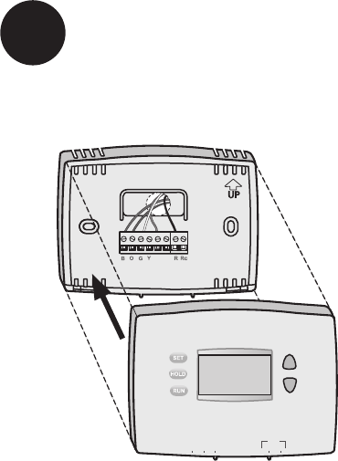
Install thermostat onto the wallplate on the wall.
9Install Thermostat onto Wallplate
69-2580EF—01 10
Turn the power back on to the heating/cooling system.
10 Turn Power Back On
M28098

11 69-2580EF—01
If your system type is:
q Single Stage Heat and Cool
q Heat Only or Cool Only
Congratulations, you’re done!
If your system type is:
q Heat Pump* with Backup Heat
Continue with advanced installation
on next page to match your thermostat to your system
type.
*Heat Pump—an air conditioner that provides cooling in the
summer, and also runs in reverse in the winter to provide
heating.
If you are not sure of your system type or if you have
other questions, call us toll-free at 1-800-468-1502.
This thermostat works on 24 volt or 750 mV systems. It will
NOT work on multi-stage conventional systems or 120/240
Volt systems.
11 If your system type is...

Advanced Installation
Enter system setup .............................................................. 13
Changing settings ................................................................ 14
System type ......................................................................... 15
Heating cycle rate ................................................................16
Early start ............................................................................17
Temperature display ............................................................18
Compressor protection ........................................................19
Clock display .......................................................................20
Restore program schedule default ......................................21
Wiring conventional system .................................................22
Wiring heat pump ................................................................23
Troubleshooting ...................................................................25
Customer assistance ...........................................................26
Limited warranty ..................................................................27
RTHL2510/RTHL2410
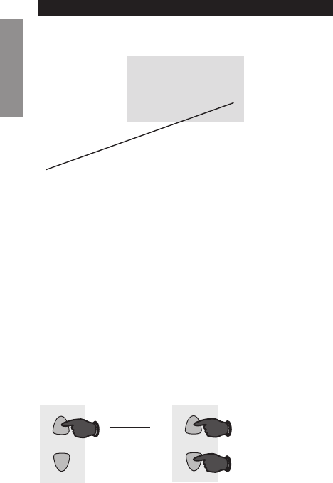
13 69-2580EF—01
SETUP WIRING ASSISTANCE TROUBLESHOOTING
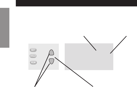
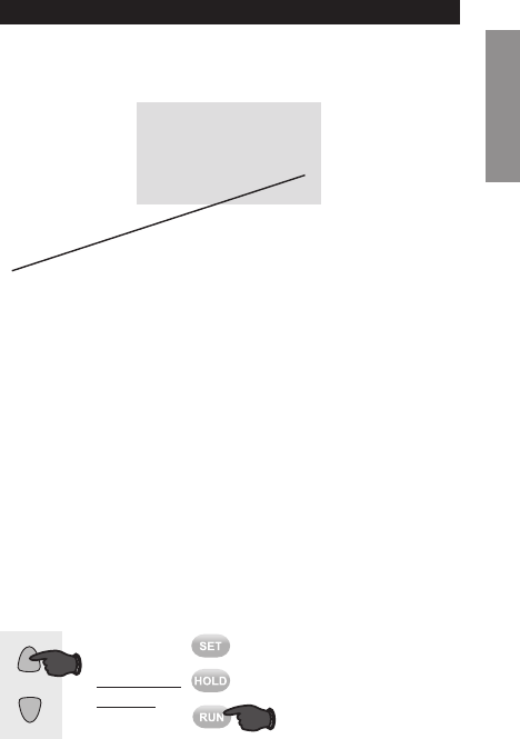
Enter System Setup
System setup
To enter system setup, press and hold both the s and
t buttons until the display changes (approximately 5
seconds).
M32713
Heat Off Cool Auto On
Fan

Advanced Installation Guide
69-2580EF—01 14
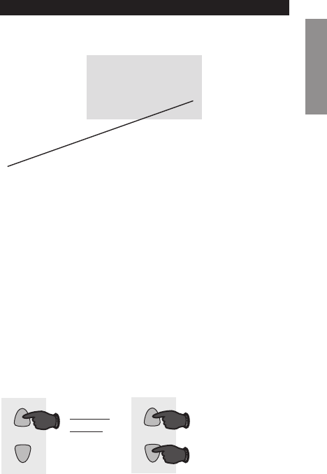
SETUPWIRINGASSISTANCETROUBLESHOOTING
10
M32717
System setup
Change Function Change Setting
See pages 16–21 to change Function Settings.
Changing Settings
Function Setting
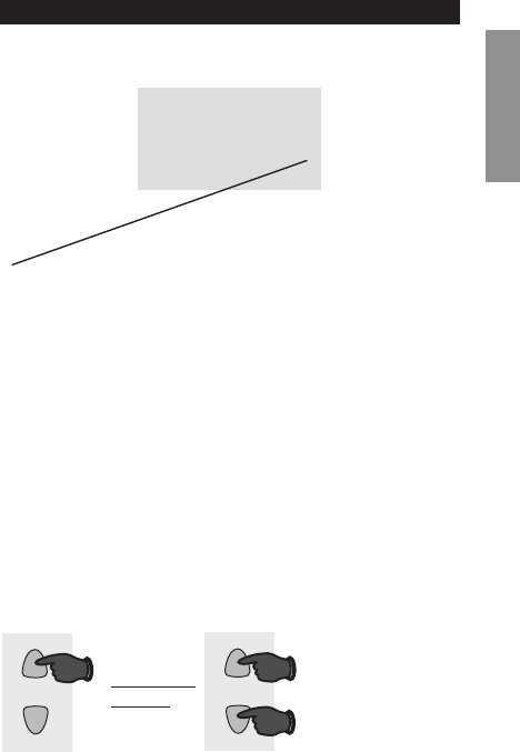
1. Press the s or t button to change the setting.
2. Press the s and t buttons simultaneously for one
second to advance to the next function.
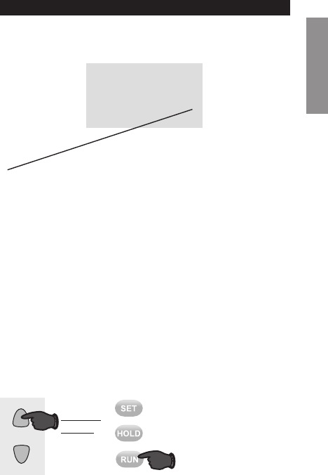
3. Press the Run button to exit and save settings.
NOTE: If you do not press any button for 60 seconds while
you are in the setup menu, the thermostat automatically
saves any changes made and exits the menu.

RTHL2510/RTHL2410
15 69-2580EF—01
SETUP WIRING ASSISTANCE TROUBLESHOOTING
10
M32718
System setup
Function 1: System Type
0 Heating & cooling: Gas, oil or electric heating with
central air conditioning or heat pump without auxiliary/
back-up heat.
1 Heat pump with auxiliary/backup heat: Outside
compressor provides both heating and cooling.
Press the s or t button to select the type of Heat/Cool
system you have in your home.
Press to
change
setting.
When finished,
press s and t
to advance to the
next function.
M32719
AND
OR
Advanced Installation Guide
69-2580EF—01 16
SETUPWIRINGASSISTANCETROUBLESHOOTING
55
M32720
System setup
Press the s or t button to select your heating system
and optimize its operation.
Function 5: Heating cycle rate
5 Gas or oil furnace: Use this setting if you have a
standard gas or oil furnace that is less than 90%
efficient.
6 Electric furnace: Use this setting if you have any type
of electric heating system.
3 Hot water or high-efficiency furnace: Use this
setting if you have a hot water system or a gas furnace
of greater than 90% efficiency.
2 Gas/oil steam or gravity system: Use this setting if
you have a steam or gravity heat system.
Press to
change
setting.
When finished,
press s and t
to advance to the
next function.
M32719
AND
OR
RTHL2510/RTHL2410
17 69-2580EF—01
SETUP WIRING ASSISTANCE TROUBLESHOOTING
13 1
M32721
System setup
Press the s or t button to select Early Start.
Function 13: Early Start
1 On
0 Off
Early start allows the heating or cooling to turn
on before the program start time, so the tem-
perature is reached at the time you set. Simply
program the desired times and temperature
into the schedule. The thermostat will turn the
heating or cooling on early so that the desired
temperature is reached at the desired time.
Press to
change
setting.
When finished,
press s and t
to advance to the
next function.
M32719
AND
OR
Advanced Installation Guide
69-2580EF—01 18
SETUPWIRINGASSISTANCETROUBLESHOOTING
System setup
Function 14: Temperature display
0 Fahrenheit temperature display (°F)
1 Celsius temperature display (°C)
Press the s or t button to select Fahrenheit or Celsius
temperature display.
14 0
M32722
Press to
change
setting.
When finished,
press s and t
to advance to the
next function.
M32719
AND
OR
RTHL2510/RTHL2410
19 69-2580EF—01
SETUP WIRING ASSISTANCE TROUBLESHOOTING
System setup
Function 15: Compressor Protection
1 On
0 Off
Press the s or t button to select Compressor Protection
settings.
Compressor Protection: This feature forces the com-
pressor to wait approximately 5 minutes before restarting,
to prevent equipment damage. During the wait time, the
message “Cool On” or “Heat On” is displayed on screen.
15 1
M32723
Press to
change
setting.
When finished,
press s and t
to advance to the
next function.
M32719
AND
OR

Advanced Installation Guide
69-2580EF—01 20
SETUPWIRINGASSISTANCETROUBLESHOOTING
System setup
Function 20: Clock Display
0 12-hour display
1 24-hour display
Press the s or t button to select clock display.
Press to
change
setting.
When finished,
press s and t
to advance to the
next function.
M32719
AND
OR
20 0
M32724
RTHL2510/RTHL2410
21 69-2580EF—01
SETUP WIRING ASSISTANCE TROUBLESHOOTING
System setup
Function 40: Restore Program Schedule to Default
0 Off
1 On - Program schedule default settings are listed in
the operating manual.
Press the s or t button to select restore program sched-
ule to default settings.
M32729
OR
Press to
change
setting.
When finished,
press Run to
exit and save
changes.
40 0
M32725
Advanced Installation Guide
69-2580EF—01 22
About your new thermostat
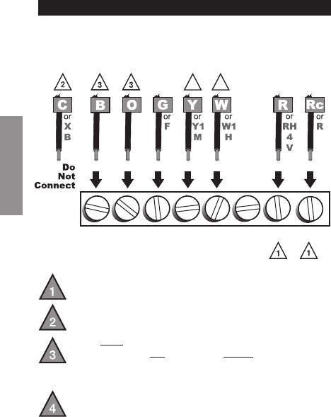
SETUPWIRINGASSISTANCETROUBLESHOOTING
If labels do not match letters on the thermostat, check the
chart below and connect to terminal as shown here (see
notes, below).
Wiring—Conventional System
If wires will be connected to both R and Rc terminals,
remove metal jumper (see page 6).
Do not use C or X. Wrap bare end of wire with
electrical tape.
If you have a heat pump without auxiliary/backup heat
connect O or B, not both. If you do not have a heat
pump, do not connect B. Wrap bare end of wire with
electrical tape.
Place a jumper (piece of wire) between Y and W/Aux
if you are using a heat pump without auxiliary/backup
heat.
B O G Y
W/
AUX
NOT
USED
R Rc
M32726
44
RTHL2510/RTHL2410
23 69-2580EF—01
SETUP CÂBLAGE ASSISTANCE TROUBLESHOOTING
M32727
GW/
AUX
OBY
Y
G
O
R
R
Rc
Aux
Wiring—Heat Pump
Connect wires: Heat Pump
1. Match each labeled wire with same letter on new
thermostat.
2. Use a screwdriver to loosen screws, insert wires into
hole under screw, then tighten screws until wire is
secure.
3. Push any excess wire back into the wall opening.
Labels don’t match? See page 24.
Wiring complete, return to Step 7.
Advanced Installation Guide
69-2580EF—01 24
SETUPWIRINGASSISTANCETROUBLESHOOTING
Wiring—Heat Pump
Alternate wiring (for heat pumps with auxiliary or
backup heat only)
If labels do not match letters on the thermostat, check the
chart below and connect to terminal as shown here (see
notes, below).
Wiring complete, return to Step 7.
Leave metal jumper in place, connecting R & Rc terminals.
If your old thermostat had both V and VR wires, stop now and contact a
qualified contractor for help.
If your old thermostat had separate O and B wires, wrap the B wire in
electrical tape and do not connect.
If your old thermostat had Y1, W1 and W2 wires, stop now and
contact a qualified contractor for help.
Do not use C or X wire. Do not use B wire if you already have O wire.
Wrap bare end of wire with electrical tape.
Do not use L wire. Wrap bare end of wire with electrical tape.
If your old thermostat had E and Aux wires (or alternate wires),
connect both wires to Aux terminal.
5
6
7
M32728
2
7
4
AUX
W
W1
W2
F
BOG
H
C
RC
V
VR
B
X
R
M
Y1
Y
E
7
X
X2
L
F
6532
1
B O G Y
W/
AUX
NOT
USED
R Rc

RTHL2510/RTHL2410
25 69-2580EF—01
Troubleshooting
SETUP WIRING ASSISTANCE TROUBLESHOOTING
If you have difficulty with your thermostat, please try the
following suggestions. Most problems can be corrected
quickly and easily.
Display is blank • Makesurefurnacedoorisclosed
securely.
• MakesurefreshAAAalkaline
batteries are correctly installed
(see page 7).
Heating or
cooling system
does not
respond
• SetSystemswitchtoHeat. Make
sure the temperature is set higher
than the Inside temperature.
• SetSystemswitchtoCool. Make
sure the temperature is set lower
than the Inside temperature.
• Checkcircuitbreakerandresetif
necessary.
• Makesureheating&coolingpower
switches are on.
• Makesurefurnacedoorissecurely
closed.
• Wait5minutesforthesystemto
respond.

Advanced Installation Guide
69-2580EF—01 26
Troubleshooting
SETUPWIRINGASSISTANCETROUBLESHOOTING
Customer assistance
For assistance with this product, please visit
http://yourhome.honeywell.com or call Honeywell
Customer Care toll-free at 1-800-468-1502.
Temperature
settings do not
change
Make sure heating and cooling
temperatures are set to acceptable
ranges:
• Heat:40°to90°F(4.5°to32°C).
• Cool:50°to99°F(10°to37°C).
“Cool On” or
“Heat On” is
flashing
• Compressor protection feature is
engaged. Wait 5 minutes for the
system to restart safely, without
damage to the compressor.
“Heat On” is
not displayed
• Set the System switch to Heat, and
set the temperature level above the
current room temperature.
“Cool On” is
not displayed
• Set the System switch to Cool, and
set the temperature level below the
current room temperature.

27 69-2580EF—01
One-year limited warranty
Honeywell warrants this product, excluding battery, to be free from defects in
the workmanship or materials, under normal use and service, for a period of
one (1) year from the date of purchase by the consumer. If at any time during
the warranty period the product is determined to be defective or malfunctions,
Honeywell shall repair or replace it (at Honeywell’s option).
If the product is defective,
(i) return it, with a bill of sale or other dated proof of purchase, to the place
from which you purchased it; or
(ii) call Honeywell Customer Care at 1-800-468-1502. Customer Care will
make the determination whether the product should be returned to the
following address: Honeywell Return Goods, Dock 4 MN10-3860, 1885
Douglas Dr. N., Golden Valley, MN 55422, or whether a replacement product
can be sent to you.
This warranty does not cover removal or reinstallation costs. This warranty
shall not apply if it is shown by Honeywell that the defect or malfunction was
caused by damage which occurred while the product was in the possession
of a consumer.
Honeywell’s sole responsibility shall be to repair or replace the product within
the terms stated above. HONEYWELL SHALL NOT BE LIABLE FOR ANY
LOSS OR DAMAGE OF ANY KIND, INCLUDING ANY INCIDENTAL OR
CONSEQUENTIAL DAMAGES RESULTING, DIRECTLY OR INDIRECTLY,
FROM ANY BREACH OF ANY WARRANTY, EXPRESS OR IMPLIED, OR
ANY OTHER FAILURE OF THIS PRODUCT. Some states do not allow
the exclusion or limitation of incidental or consequential damages, so this
limitation may not apply to you.
THIS WARRANTY IS THE ONLY EXPRESS WARRANTY HONEYWELL
MAKES ON THIS PRODUCT. THE DURATION OF ANY IMPLIED
WARRANTIES, INCLUDING THE WARRANTIES OF MERCHANTABILITY
AND FITNESS FOR A PARTICULAR PURPOSE, IS HEREBY LIMITED TO
THE ONE-YEAR DURATION OF THIS WARRANTY.
Some states do not allow limitations on how long an implied warranty lasts,
sotheabovelimitationmaynotapplytoyou.Thiswarrantygivesyouspecic
legal rights, and you may have other rights which vary from state to state.
If you have any questions concerning this warranty, please write Honeywell
Customer Relations, 1985 Douglas Dr, Golden Valley, MN 55422 or call
1-800-468-1502. In Canada, write Retail Products ON15-02H, Honeywell
Limited/ Honeywell Limitée, 35 Dynamic Drive, Toronto, Ontario M1V4Z9.

Automation and Control Solutions
Honeywell International Inc.
1985 Douglas Drive North
Golden Valley, MN 55422
Honeywell Ltd
705 Montrichard Avenue
Saint-Jean-sur-Richelieu, Québec
J2X 5K8
http://yourhome.honeywell.com
® U.S. Registered Trademark
© 2013 Honeywell International Inc.
69-2580EF—01 M.S. 06-13
Printed in U.S.A.
CAUTION: To avoid possible compressor damage,
do not run air conditioner if the outside temperature
drops below 50°F (10°C).
MERCURY NOTICE: Do not place your old
thermostat in the trash if it contains mercury in a
sealed tube. Contact the Thermostat Recycling
Corporation at www.thermostat-recycle.org or 800-
238-8192 for information on how and where to
properly and safely dispose of your old thermostat.

69-2580EF-01
Série RTHL2510/RTHL2410
Thermostat programmable
Guide d’installation rapide

69-2580EF—01 ii
Identifier le type de système
Ce thermostat est compatible avec les systèmes suivants :
Appareil de chauffage à gaz, mazout ou électrique
Climatiseur central
Système à eau chaude avec ou sans pompe
Système à millivolts
Système de chauffage et de refroidissement central
Système de chauffage sans chauffage de secours/
auxiliaire
Système de chauffage avec chauffage de secours/
auxiliaire
Besoin d’aide?
Nous sommes là pour vous
aider.
Appeler le 1-800-468-1502
pour obtenir de l’aide avec le
câblage avant de retourner
le thermostat au magasin.
Ce thermostat ne peut pas être utilisé sur les systèmes
à plusieurs étages.

1 69-2580EF—01
M28097
1Couper l’alimentation vers
le système de chauffage/
refroidissement
69-2580EF—01 2
Un tube scellé contenant du
mercure est-il présent? Si oui, voir
au dos les consignes de mise au
rebut.
M28099
Ancien thermostat
Couvercle
Retirer l’ancien thermostat mais laisser la plaque murale
avec les fils attachés.
Retirer l’ancien thermostat
Ne pas retirer la
plaque murale à
ce stade
2

3 69-2580EF—01
Étiqueter les fils
3
Étiqueter les fils au fur et à mesure qu’ils sont débranchés à
l’aide des étiquettes fournies.
Étiquettes de fils
M28100
M28093
69-2580EF—01 4
MF32731
POUR RETIRER LA PLAQUE
MURALE, TIRER ICI
Séparer la plaque murale du
nouveau thermostat
4
Retirer la plaque murale du nouveau thermostat et la monter
sur le mur.
Plaque murale

5 69-2580EF—01
Monter la plaque murale à l’aide des vis et des ancrages
inclus.
5Monter la plaque murale
Percer des trous de 3/16 po pour les cloisons sèches.
Percer des trous de 3/32 po pour le plâtre.
W/
Aux
Not
Used
M32714
69-2580EF—01 6
MF32715
VIS
INSÉRER
LES FILS
ET SERRER
LES VIS
OUVERTURE
POUR LES FILS
FILS
ÉTIQUETÉS
W/
Aux
W
Y
G
R
Not
Used
Brancher le câblage
6
Il suffit de faire correspondre les étiquettes des fils.
Retirer le cavalier métallique si les fils R et Rc sont présents.
Les étiquettes ne correspondent pas? Voir page 22.
Thermopompe présente dans le système? Voir pages
23-24.
Nous sommes là pour vous aider.
Appeler le 1-800-468-1502 pour obtenir de l’aide pour le
câblage.
7 69-2580EF—01
RTHXXXX
M32707
Installer deux piles alcalines AAA.
Dos du thermostat
7Installer les piles
69-2580EF—01 8
Mettre le sélecteur sur le réglage désiré :
Gaz ou mazout : Pour les systèmes de chauffage au
gaz ou au mazout, laisser le sélecteur du fonctionnement
du ventilateur dans la position réglée en usine (pour les
systèmes qui contrôlent le ventilateur lors d’appel de
chauffage).
Thermopompe ou électrique : Mettre le sélecteur sur ce
réglage pour les systèmes à thermopompe ou électriques.
(Ce réglage concerne les systèmes qui permettent au
thermostat de contrôler le ventilateur lors d’un appel de
chauffage, si un fil de ventilateur est connecté à la borne G.)
8Régler le sélecteur de
fonctionnement du ventilateur.
RTHXXXX
M32716
GAS OR OIL
ELECTRIC OR HEAT PUMP
GAS OR OIL
ELECTRIC OR HEAT PUMP

9 69-2580EF—01
W/
Aux
Not
Used
Heat Off Cool Auto On
Fan
M32705
Installer le thermostat sur la plaque murale sur le mur.
9Installer le thermostat sur la plaque
murale

69-2580EF—01 10
Rétablir l’alimentation sur le système de chauffage/
refroidissement.
10 Rétablir l’alimentation
M28098

11 69-2580EF—01
Si le système est de type :
q Chauffage et refroidissement à étage unique
q Chauffage uniquement ou refroidissement uniquement
Félicitations, vous avez terminé!
Si le système est de type :
q Thermopompe* avec chauffage de secours
Passer à l’installation avancée
à la page suivante pour adapter le thermostat au type de
système présent.
*Thermopompe—un climatiseur qui assure le refroidissement
durant l’été et fonctionne à l’inverse en hiver pour assurer le
chauffage.
Si vous n’êtes pas certain du type de système or pour
d’autres questions, merci de nous appeler au numéro
gratuit 1-800-468-1502.
Ce thermostat fonctionne sur systèmes de 24 V ou 750 mV.
Il ne fonctionnera pas sur les systèmes conventionnels à
plusieurs étages ou les systèmes à 120/240 V.
11 Si le système est de type…

Installation avancée
Entrer la configuration du système ......................................13
Modifier les réglages ...........................................................14
Type de système .................................................................15
Cycle de chauffage ..............................................................16
Démarrage précoce .............................................................17
Affichage de la température ................................................18
Protection du compresseur .................................................19
Affichage de l’horloge .......................................................... 20
Restaurer le programme par défaut ....................................21
Système de câblage conventionnel .....................................22
Câblage de la thermopompe ...............................................23
Dépannage ..........................................................................25
Service à la clientèle ...........................................................26
Garantie limitée ...................................................................27

RTHL2510/RTHL2410
13 69-2580EF—01
About your new thermostat
CONFIGURATION WIRING ASSISTANCE TROUBLESHOOTING
Entrer en mode de configuration du système
Configuration du système
Pour entrer en mode de configuration du système,
appuyer simultanément sur les boutons s et t jusqu’à ce
que l’affichage change (environ 5 secondes).
M32713
Heat Off Cool Auto On
Fan
Guide d’installation avancé
69-2580EF—01 14
About your new thermostat
CONFIGURATIONWIRINGASSISTANCETROUBLESHOOTING
10
M32717
Configuration du système
Modifier fonction Réglage de la date
Voir les pages 16 à 21 pour modifier les réglages de
fonction.
Modification des réglages
Fonction Réglage
1. Appuyer sur le bouton s ou t pour modifier le
réglage.
2. Appuyer simultanément sur les boutons s et t
pendant une seconde pour passer à la fonction
suivante.
3. Appuyer sur le bouton Run (Marche) pour enregistrer
les modifications et quitter le mode de réglage.
REMARQUE : Si aucun bouton n’est activé pendant 60
secondes dans le menu de configuration, le thermostat
enregistre automatiquement toute modification effectuée
et quitte le menu.
RTHL2510/RTHL2410
15 69-2580EF—01
About your new thermostat
CONFIGURATION WIRING ASSISTANCE TROUBLESHOOTING
MF32719
ET
OU
10
M32718
Configuration du système
Fonction 1 : Type de système
0 Chauffage et refroidissement : Chauffage à gaz,
mazout ou électrique avec climatisation centrale ou
thermopompe sans chauffage auxiliaire/de secours.
1 Thermopompe avec chauffage auxiliaire/de
secours : Le compresseur extérieur fournit le
chauffage et le refroidissement.
Appuyer sur le bouton s ou t pour sélectionner le type
de système de chauffage/refroidissement utilisé dans la
maison.
Appuyer
sur pour
modifier le
réglage.
Une fois terminé,
appuyer sur s et
t pour passer à
la fonction
suivante.
Guide d’installation avancé
69-2580EF—01 16
About your new thermostat
CONFIGURATIONWIRINGASSISTANCETROUBLESHOOTING
MF32719
ET
OU
55
M32720
Configuration du système
Appuyer sur le bouton s ou t pour sélectionner le
système de chauffage et optimiser son fonctionnement.
Fonction 5 : Cycle de chauffage
5 Appareil de chauffage à gaz ou à mazout : Utiliser
ce réglage si l’appareil de chauffage est un modèle
à gaz ou à mazout standard et efficace à moins de
90 %.
6 Appareil de chauffage électrique : Utiliser ce
réglage pour tout type de système de chauffage
électrique.
3 Appareil de chauffage à eau chaude ou à haut
rendement : Utiliser ce réglage si le système est un
système à eau chaude ou un appareil de chauffage à
gaz d’une efficacité supérieure à 90 %.
2 Système à gravité ou à vapeur à gaz/mazout :
Utiliser ce réglage si le système de chauffage est à
vapeur ou à gravité.
Appuyer
sur pour
modifier le
réglage.
Une fois terminé,
appuyer sur s et
t pour passer à
la fonction
suivante.
RTHL2510/RTHL2410
17 69-2580EF—01
About your new thermostat
CONFIGURATION WIRING ASSISTANCE TROUBLESHOOTING
MF32719
ET
OU
13 1
M32721
Configuration du système
Appuyer sur le bouton s ou t pour sélectionner le
démarrage précoce.
Fonction 13 : Démarrage précoce
1 En fonction
0 arrêt
Le démarrage précoce permet d’activer le
chauffage ou le refroidissement avant l’heure
d’activation pour que la température souhaitée
soit atteinte à l’heure indiquée. Il suffit de pro-
grammer les heures et la température désirées.
Le thermostat enclenche le chauffage ou le
refroidissement à l’avance pour que la tempéra-
ture désirée soit atteinte au moment voulu.
Appuyer
sur pour
modifier le
réglage.
Une fois terminé,
appuyer sur s et
t pour passer à
la fonction
suivante.
Guide d’installation avancé
69-2580EF—01 18
About your new thermostat
CONFIGURATIONWIRINGASSISTANCETROUBLESHOOTING
MF32719
ET
OU
Configuration du système
Fonction 14 : Affichage de la température
0 Affichage de température en Fahrenheit (°F)
1 Affichage de température en Celsius (°C)
Appuyer sur le bouton s ou t pour sélectionner
Fahrenheit ou Celsius.
14 0
M32722
Appuyer
sur pour
modifier le
réglage.
Une fois terminé,
appuyer sur s et
t pour passer à
la fonction
suivante.
RTHL2510/RTHL2410
19 69-2580EF—01
About your new thermostat
CONFIGURATION WIRING ASSISTANCE TROUBLESHOOTING
MF32719
ET
OU
Configuration du système
Fonction 15 : Protection du compresseur
1 En fonction
0 arrêt
Appuyer sur le bouton s ou t pour sélectionner les
réglages de protection du compresseur.
Protection du compresseur : Cette fonction force le
compresseur à attendre 5 minutes avant le redémarrage,
pour éviter les dommages de l’équipement. Durant la
période d’attente, le message Cool On (Refroidissement
activé) ou Heat On (Chauffage activé) s’affiche sur
l’écran.
15 1
M32723
Appuyer
sur pour
modifier le
réglage.
Une fois terminé,
appuyer sur s et
t pour passer à
la fonction
suivante.

Guide d’installation avancé
69-2580EF—01 20
About your new thermostat
CONFIGURATIONWIRINGASSISTANCETROUBLESHOOTING
MF32719
ET
OU
Configuration du système
Fonction 20 : Affichage de l’horloge
0 Format 12 heures
1 Format 24 heures
Appuyer sur le bouton s ou t pour sélectionner
l’affichage de l’horloge.
Appuyer
sur pour
modifier le
réglage.
Une fois terminé,
appuyer sur s et
t pour passer à
la fonction
suivante.
20 0
M32724
RTHL2510/RTHL2410
21 69-2580EF—01
About your new thermostat
CONFIGURATION WIRING ASSISTANCE TROUBLESHOOTING
Configuration du système
Fonction 40 : Restaurer le calendrier par défaut
0 arrêt
1 On - Les réglages par défaut du calendrier sont
indiqués dans le manuel de fonctionnement.
Appuyer sur le bouton s ou t pour ramener le calen-
drier au réglage par défaut.
MF32729
OU
Appuyer
sur pour
modifier le
réglage.
Une fois terminé,
appuyer sur Run
(Marche) pour
quitter et
enregistrer les
changements.
40 0
M32725
Guide d’installation avancé
69-2580EF—01 22
About your new thermostat
SETUPCÂBLAGEASSISTANCETROUBLESHOOTING
Si les étiquettes ne correspondent pas aux lettres sur
le thermostat, consulter le tableau ci-dessous et faire le
branchement aux bornes comme illustré ici (voir les notes
ci-dessous).
Câblage—Système conventionnel
SileslsvontêtreconnectésauxbornesR et Rc,
retirer le cavalier métallique (voir page 6).
Ne pas utiliser C ou X. Envelopper l’extrémité
dénudéedeslsderubanélectrique.
Si une thermopompe est installée sans chauffage
auxiliaire/de secours, connecter O ou B, mais pas les
deux. Si aucune thermopompe n’est présente, ne
pas connecter B. Appliquer du ruban électrique sur
l’extrémitédénudéedul.
Placeruncavalier(morceaudel)entreY et W/Aux
si une pompe thermique est utilisée sans chauffage
auxiliaire/de secours.
B O G Y
W/
AUX
NON
UTILISÉ
R Rc
MF32726
44
Ne
Pas
Connecter
RTHL2510/RTHL2410
23 69-2580EF—01
SETUP CÂBLAGE ASSISTANCE TROUBLESHOOTING
MF32727
GW/
AUX
OBY
Y
G
O
R
R
Rc
Aux
NON
UTILISÉ
Câblage—Thermopompe
Brancher les fils : thermopompe
1. Faire correspondre chaque fil étiqueté avec la lettre sur le
nouveau thermostat.
2. Utiliser un tournevis pour desserrer les vis, insérer les
fils dans l’orifice sous la vis, puis serrer les vis pour
maintenir les fils.
3. Repousser le fil en excès dans l’ouverture du mur.
Les étiquettes ne correspondent pas? Voir page 24.
Câblage terminé, revenir à l’étape 7.
Guide d’installation avancé
69-2580EF—01 24
About your new thermostat
SETUPCÂBLAGEASSISTANCETROUBLESHOOTING
Câblage—Thermopompe
Autre option de câblage (pour les thermopompes avec
chauffage auxiliaire ou de secours uniquement)
Si les étiquettes ne correspondent pas aux lettres sur
le thermostat, consulter le tableau ci-dessous et faire le
branchement aux bornes comme illustré ici (voir les notes
ci-dessous).
Câblage terminé, revenir à l’étape 7.
Laisser le cavalier métallique en place en connectant les bornes R
et Rc.
Si l’ancien thermostat est muni de fils V et VR, s’arrêterimmédiatement
et contacter un installateur qualifié pour obtenir de l’aide.
Si l’ancien thermostat a des fils O et B séparés, enrouler le fil B dans
du ruban électrique sans le brancher.
Si l’ancien thermostat est muni de fils Y1, W1 et W2, s’arrêter
immédiatement et contacter un installateur qualifié pour obtenir de
l’aide.
Ne pas utiliser les fils C ou X. Ne pas utiliser le fil B si un fil O est déjà
présent. Enrouler l’extrémité nue du fil avec du ruban électrique.
Ne pas utiliser le fil L. Enrouler l’extrémité nue du fil avec du ruban
électrique.
Si l’ancien thermostat a des fils E et Aux (ou d’autres fils), brancher
les deux fils à la borne Aux.
5
6
7
MF32728
2
7
4
AUX
W
W1
W2
F
BOG
H
C
RC
V
VR
B
X
R
M
Y1
Y
E
7
X
X2
L
F
6532
1
B O G Y
W/
AUX
NOT
USED
R Rc
Ne
Pas
Connecter
NON
UTILISÉ

RTHL2510/RTHL2410
25 69-2580EF—01
Dépannage
SETUP WIRING ASSISTANCE DÉPANNAGE
En cas de difficultés avec le thermostat, essayer les sug-
gestions suivantes. La plupart des problèmes peuvent
êtreréglésrapidementetfacilement.
Rien n’apparaît
à l’écran
• S’assurerquelaportedel’appareil
de chauffage est bien fermée.
• S’assurerquedespilesalcalinesAAA
neuves sont correctement installées
(voir page 7).
Le système de
chauffage ou de
refroidissement
ne répond pas
• RéglerlesélecteursurChauffage.
Vérifier si le réglage de température
est supérieur à la température
intérieure.
• Réglerlesélecteursur
Refroidissement. Vérifier si le réglage
de température est inférieur à la
température intérieure.
• Vérifierledisjoncteuretleréinitialiser
si nécessaire.
• S’assurerquelessélecteursde
chauffage et de refroidissement sont
sur marche.
• S’assurerquelaportedel’appareil
de chauffage est bien fermée.
• Attendre5minutesquelesystème
réponde.

Guide d’installation avancé
69-2580EF—01 26
Dépannage
SETUPWIRINGASSISTANCEDÉPANNAGE
Les réglages
de la
température
ne changent
pas
S’assurer que les températures de
chauffage et de refroidissement sont
réglées dans les plages permises :
• Chauffage:4,5à32°C(40à90°F).
• Refroidissement:10à37°C(50à
99 °F).
Les mentions
« Cool On »
ou « Heat On »
clignotent
• La fonction de protection du
compresseur est activée. Attendre 5
minutes que le système se remette
en marche en toute sécurité sans
endommager le compresseur.
« Heat On »
(chauffage
sur marche)
n’apparaît pas à
l’écran
• Mettre le sélecteur du système sur
Heat (chauffage) et régler le niveau
de température à une température
supérieure à la température
ambiante.
« Cool On »
(refroidissement
sur marche)
n’apparaît pas à
l’écran
• Mettre le sélecteur du système
sur Cool (refroidissement) et
régler le niveau de température
à une température inférieure à la
température ambiante.
Service à la clientèle
Pour obtenir de l’aide avec ce produit, consulter
http://yourhome.honeywell.com ou d’appeler le centre
du service à la clientèle de Honeywell au numéro gratuit
1-800-468-1502.

27 69-2580EF—01
Garantie limitée d’un an
Honeywell garantit ce produit, à l’exception des piles, contre tout défaut
de pièce ou de main-d’œuvre, durant une période d’un (1) an à partir de
la date d’achat par le consommateur si le produit est utilisé et entretenu
convenablement. En cas de défectuosité ou de mauvais fonctionnement
pendant la période de garantie, Honeywell remplacera ou réparera le produit,
à sa discrétion.
Si le produit est défectueux,
(i) le renvoyer avec la facture ou une autre preuve d’achat date au lieu
d’achat; ou
(ii) appeler le service à la clientèle de Honeywell en composant le 1-800-
468-1502.Leserviceàlaclientèledéterminerasileproduitdoitêtreretourné
à l’adresse suivante : Honeywell Return Goods, Dock 4MN10-3860, 1885
Douglas Dr. N., Golden Valley, MN 55422, ou si un produit de remplacement
peutvousêtreexpédié.
La présente garantie ne couvre pas les frais de retrait ou de réinstallation. La
présente garantie ne s’appliquera pas s’il est démontré par Honeywell que la
défectuosité ou le mauvais fonctionnement sont dus à un endommagement
du produit alors que le consommateur l’avait en sa possession.
La responsabilité exclusive de Honeywell se limite à réparer ou à remplacer
le produit conformément aux modalités susmentionnées. HONEYWELL
N’EST EN AUCUN CAS RESPONSABLE DES PERTES OU DOMMAGES, Y
COMPRIS LES DOMMAGES INDIRECTS OU ACCESSOIRES DÉCOULANT
DIRECTEMENT OU INDIRECTEMENT D’UNE VIOLATION QUELCONQUE
D’UNE GARANTIE, EXPRESSE OU TACITE, APPLICABLE AU PRÉSENT
PRODUIT, OU TOUTE AUTRE DÉFECTUOSITÉ DU PRÉSENT PRODUIT.
Certaines provinces ne permettent pas l’exclusion ou la restriction des
dommages indirects ou accessoires et, par conséquent, la présente restriction
peut ne pas s’appliquer.
CETTE GARANTIE EST LA SEULE GARANTIE EXPRESSE FAITE PAR
HONEYWELL POUR CE PRODUIT. LA DURÉE DE TOUTE GARANTIE
IMPLICITE, INCLUANT LES GARANTIES DE QUALITÉ MARCHANDE OU
D’ADAPTATION À UNE UTILISATION PARTICULIÈRE, EST LIMITÉE PAR
LES PRÉSENTES À LA PÉRIODE D’UNE ANNÉE DE LA PRÉSENTE
GARANTIE.
Certaines provinces ne permettent pas de limiter la durée des garanties
tacites et, par conséquent, la présente limitation peut ne pas s’appliquer. La
présentegarantiedonneauconsommateurdesdroitsspéciquesetcertains
autres droits qui peuvent varier d’une province à l’autre.
Pour toute question concernant la présente garantie, prière d’écrire aux
Services à la clientèle de Honeywell à l’adresse suivante : Honeywell
Customer Relations, 1985 Douglas Dr, Golden Valley, MN 55422 ou
composer le 1-800-468-1502. Au Canada, prière de s’adresser à Retail
Products ON15-02H, Honeywell Limited/Honeywell Limitée, 35 Dynamic
Drive, Toronto, Ontario M1V4Z9.

Solutions de régulation et d’automatisation
Honeywell International Inc.
1985 Douglas Drive North
Golden Valley, MN 55422
Honeywell Ltd
705 Montrichard Avenue
Saint-Jean-sur-Richelieu, Québec
J2X 5K8
http://yourhome.honeywell.com
® Marque de commerce déposée aux É.-U.
© 2013 Honeywell International Inc.
69-2580EF—01 M.S. 06-13
Imprimé aux États-Unis
MISE EN GARDE : Pour éviter d’endommager le
compresseur, ne faites pas tourner le climatiseur
si la température extérieure est inférieure à 10 °C
(50°F).
AVIS RELATIF AU MERCURE : Ne pas jeter
l’ancien thermostat dans la poubelle s’il contient
du mercure dans un tube scellé. Contacter le
Thermostat Recycling Corporation à www.
thermostat-recycle.org ou le 800-238-8192 pour
obtenir de l’information sur la façon et l’endroit
appropriés de vous débarrassez de votre vieux
thermostat.
