Honeywell Series 2000 T7300D Users Manual T7200D,E, T7300D,E,F And Q7300 Programmable Commercial Thermostats Subbases
TRADELINE Q7300L 63-4355
2015-01-23
: Honeywell Honeywell-Series-2000-T7300D-Users-Manual-262392 honeywell-series-2000-t7300d-users-manual-262392 honeywell pdf
Open the PDF directly: View PDF ![]() .
.
Page Count: 36
PRODUCT DATA
63- 4355- 4
® U.S. Registered Trademark
Copyright © 2001 Honeywell • • All Rights Reserved
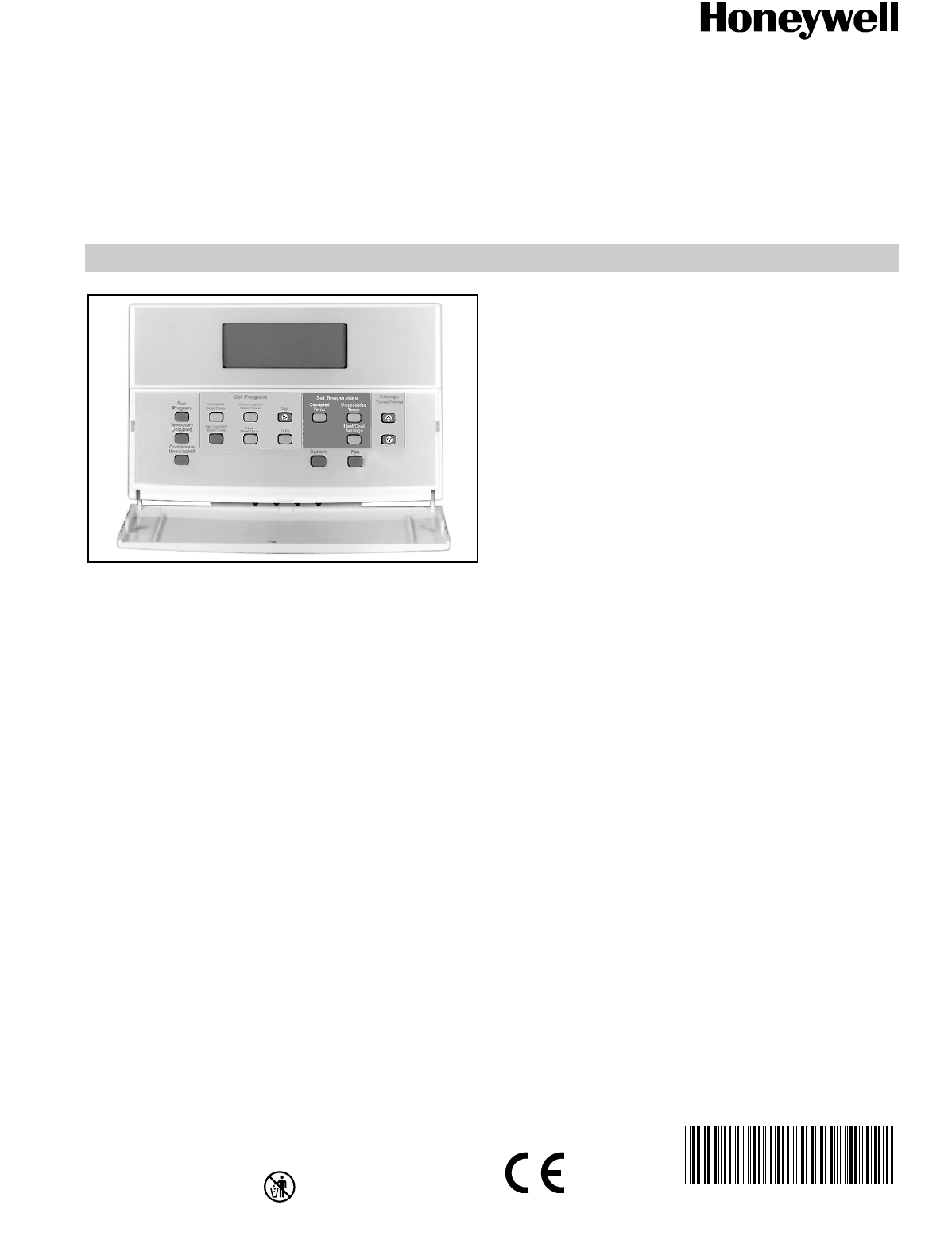
T7200D,E, T7300D,E,F and Q7300
Series 2000 Programmable Commercial
Thermostats and Subbases
APPLICATION
The T7200, T7300 Thermostats and Q7300 Subbases control
24 Vac commercial single zone heating, ventilating and air
conditioning (HVAC) equipment. In addition, the Q7300H
Communicating Subbase can communicate schedule
information and system instructions to other devices in a
LONWORKS® network.
FEATURES
All Models:
• 7-day programming.
• Two Occupied and two Unoccupied periods per day.
• Individual heat and cool setpoints available for
Occupied and Unoccupied periods.
• Proportional plus Integral (P+I) control eliminates
temperature fluctuations.
• Intelligent Recovery® control automatically optimizes
equipment start times based on building load.
• Intelligent Fan™ feature energizes fan continuously in
the Occupied periods. Fan can also be configured for
conventional heat or electric heat fan operation.
• Automatic or manual changeover models available.
• Universal Versaguard™ Thermostat guards available.
• Convenient overrides allow temporary setpoint
changes.
• Keypad lockout available.
T7200D,E Thermostats:
• Use on single-stage conventional (T7200D) or heat
pump (T7200E) applications.
T7300D,E Thermostats:
• Use on multistage conventional (T7300D) or heat pump
(T7300E) applications.
• Models available with remote sensor capability.
T7300F Thermostats:
• Use on single-stage or multistage system in
conventional or heat pump applications.
• Auxiliary contacts on Q7300 can be used to interface
with C7400/W7459 Economizer System for total
integration of rooftop control.
• Remote temperature sensors available for use with
all models.
• Different levels of keypad lockout available.
Q7300 Subbase:
• Use with T7300D,E,F Thermostats.
• Auxiliary contacts can be used to interface with
C7400/W7459 Economizer System for total integration
of rooftop control.
• When used with the T7300F (revision 4 or later), the
Q7300H communicates with other network devices.
• Q7300L two stages of heat control ML7984 and V5011/
V5013 valve: stage 1 opens valve 40%; stage 2 100%.
• Q7300L provides two-speed fan control:
— Low: heat and occupied fan.
— High: cooling.
Contents
Application ........................................................................ 1
Features ........................................................................... 1
Specifications ................................................................... 2
Ordering Information ........................................................ 2
Installation ........................................................................ 5
Wiring Subbase/Wallplate ................................................ 7
Settings ............................................................................ 9
Installer Setup .................................................................. 10
Installer System Test ........................................................ 13
Programming .................................................................... 16
Operation .......................................................................... 19
General Operation Information ......................................... 21
Troubleshooting Guide ..................................................... 22
Cross Reference .............................................................. 23
Wiring Diagrams (Fig. 20-34) ........................................... 29
T7200D,E, T7300D,E,F AND Q7300 SERIES 2000 PROGRAMMABLE COMMERCIAL THERMOSTATS AND SUBBASES
63-4355—4 2
ORDERING INFORMATION
When purchasing replacement and modernization products from your TRADELINE® wholesaler or distributor, refer to the
TRADELINE® Catalog or price sheets for complete ordering number.
If you have additional questions, need further information, or would like to comment on our products or services, please write or
phone:
1. Your local Home and Building Control Sales Office (check white pages of your phone directory).
2. Home and Building Control Customer Relations
Honeywell, 1885 Douglas Drive North
Minneapolis, Minnesota 55422-4386 (800) 328-5111
In Canada—Honeywell Limited/Honeywell Limitée, 35 Dynamic Drive, Scarborough, Ontario M1V 4Z9.
International Sales and Service Offices in all principal cities of the world. Manufacturing in Australia, Canada, Finland, France,
Germany, Japan, Mexico, Netherlands, Spain, Taiwan, United Kingdom, U.S.A.
SPECIFICATIONS
IMPORTANT
The specifications given in this publication do
not include normal manufacturing tolerances.
Therefore, this unit might not exactly match the listed
specifications. This product is tested and calibrated
under closely controlled conditions, and some minor
differences in performance can be expected if those
conditions are changed.
T7200/T7300 Thermostats: See Table 1.
Q7300 Subbases: See Table 2.
Dimensions: See Fig. 1.
Finish (color): Taupe.
Table 1. T7200 and T7300 Thermostat Features.
aWallplate provided.
bConfigured in Installer Setup.
Table 2. Q7300 Subbase Features.
aDepends on model (some specific models have fewer).
bAll subbases are down selectable and can be configured to
control fewer stages than the maximum allowed.
cWithout O/B terminals.
dWith O/B terminals.
eUsed with ML7984 Actuator and V5011 or V5013 Valve.
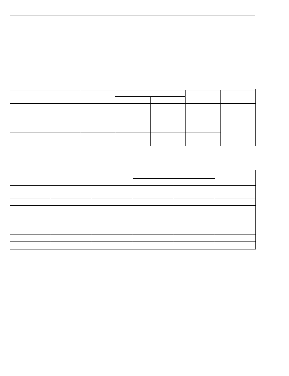
Model Applications Subbase
Required
Maximum Stages
Wiring Diagram Changeoverb
Heat Cool
T7200D Conventional Nonea1120Automatic or
Manual
T7200E Heat Pump Nonea1121
T7300D Conventional Q7300A,G,L 3 3 22-23, 28, 34
T7300E Heat Pump Q7300C,D 3 2 24-27
T7300F Conventional or
Heat Pump Q7300A,C,D,G,L 3 3 22-28,34
Q7300H 3 3 29-33
Model Applications Thermostat
Required
Maximum Stagesa,b
Wiring DiagramHeat Cool
Q7300A Conventional T7300D,F 2 2 22-23
Q7300C Heat Pump T7300E,F 3 2 24-26
Q7300D Heat Pump T7300E,F 3 2 27
Q7300G Conventional T7300D,F 3 3 28
Q7300HcHeat Pump T7300F 3 2 29
Q7300HdHeat Pump T7300F 3 2 30
Q7300H Conventional T7300F 3 3 31
Q7300H Conventional T7300F 2 1 32
Q7300L ConventionaleT7300D,F 2 1 34
T7200D,E, T7300D,E,F AND Q7300 SERIES 2000 PROGRAMMABLE COMMERCIAL THERMOSTATS AND SUBBASES
3 63-4355—4
Electrical Ratings:
24 Vac, 50/60 Hz.
20 to 30 Vac, 50/60 Hz.
Batteries: No batteries required.
Auxiliary Heat and Emergency Heat Indication:
Thermostat display indicates when Auxiliary Heat or
Emergency Heat are activated.
Loss of Power: The thermostat maintains programmed times
and temperatures for the life of the product. The clock and
day information is retained for a minimum of two hours.
Light Emitting Diodes (LED):
Two user-defined LED (not available on Q7300H).
Two defined (CHECK and MAINTENANCE) LED on select
models.
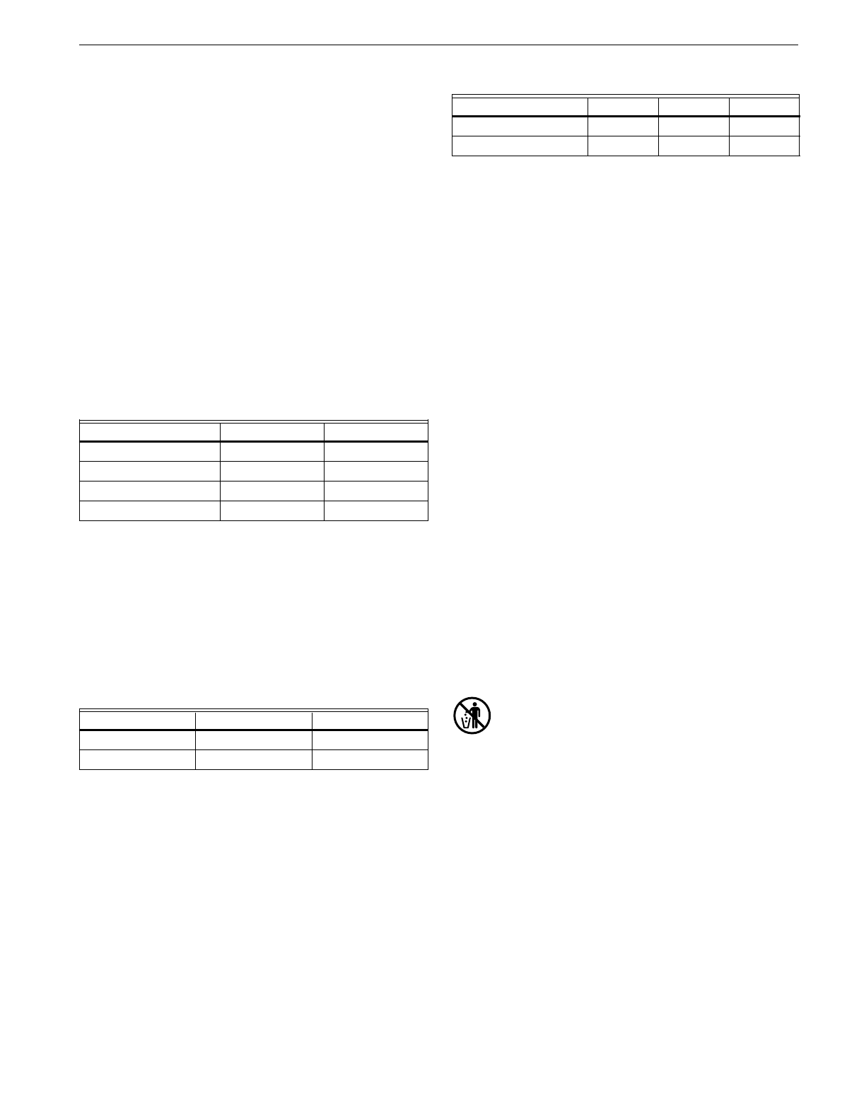
System Current Draw: 6 VA maximum at 30 Vac, 50/60 Hz.
Output Relay Current Draw: See Table 3.
Table 3. Maximum Amps at 30 Vac.
Temperature:
Ratings:
Operating Ambient: 40°F to 110°F (4°C to 43°C).
Shipping: -30°F to +150°F (-34°C to +65°C).
Display Accuracy: ±1°F (±0.5°C).
Setpoint:
Range: 45°F to 95°F (7°C to 35°C).
Deadband: 2°F (1°C).
Default Settings: See Table 4.
Table 4. Default Setpoints.
Remote Sensor Wiring Temperature Offset:
Temperature offset occurs with 500 ft (157m) to
1000 ft (305m) of 2-wire cable. See Table 5.
Humidity Ratings: 5% to 90% RH, noncondensing.
Clock Accuracy: ±1 minute per month.
Table 5. Temperature Offset.
Minimum Stage Operation Time:
Minimum On (Heat and Cool): factory setting 2 minutes;
option 0 minutes.
Minimum Off (Cool and Heat Pump): factory setting
4 minutes; option 0, 1, 3, 5 minutes.
Mounting Means:
T7200: Mounts on a wallplate.
T7300: Mounts on a Q7300 Subbase.
NOTE: Wallplate and subbase mount horizontally on a wall
or outlet box with two no. 6 x 32 screws (included).
Accessories:
C7150B1004 Discharge Air Sensor: for checkout use only
(form 63-2072).
M7415 Damper Actuator (form 63-2100).
ML7984 Valve Actuator (form 95C-10753).
Q7760A Serial LonTalk® Adapter.
R8222 Switching Relay (form 60-2056).
T675A Temperature Control (form 60-2200).
T7022A1010 Remote Temperature Sensor (form 60-0247).
T7047C Remote Temperature Sensor (form 62-3050).
T7047G Remote Temperature Sensor (form 62-3050).
T7147A Remote Temperature Sensor and Override Module
(form 62-3049).
W859F Packaged Economizer (form 63-2476).
W950A System Supervisor (form 60-2351).
W7459 Economizer Logic Module (form 63-2141).
W6210/W7210 Economizer (form 63-2528).
W6215/W7215 Economizer (form 63-2544).
Approvals:
European Community Mark (CE) Listed.
Q7300H only: LONMARK® Functional Profile No. 8060,
Thermostat Object (type 09).
MERCURY NOTICE
If this control is replacing a control that contains
mercury in a sealed tube, do not place your old
control in the trash. Dispose of properly.
Contact your local waste management authority
for instructions regarding recycling and the proper
disposal of an old control. If you have questions,
call Honeywell Customer Response Center at
1-800-468-1502.
Relay Running (A) Inrush (A)
Fan 0.5 2.5
Heat (all stages) 1.5 3.5
Cool (all stages) 1.5 7.5
Auxiliary (Economizer) 1.5 3.5
Control Occupied Unoccupied
Heating 70°F (21°C) 55°F (13°C)
Cooling 78°F (26°C) 90°F (32°C)
Temperature Range 18 AWG 20 AWG 22 AWG
50 to 90°F -0.4°F -0.7°F -1.0°F
10 to 32°C -0.3°C -0.4°C -0.6°C
T7200D,E, T7300D,E,F AND Q7300 SERIES 2000 PROGRAMMABLE COMMERCIAL THERMOSTATS AND SUBBASES
63-4355—4 4
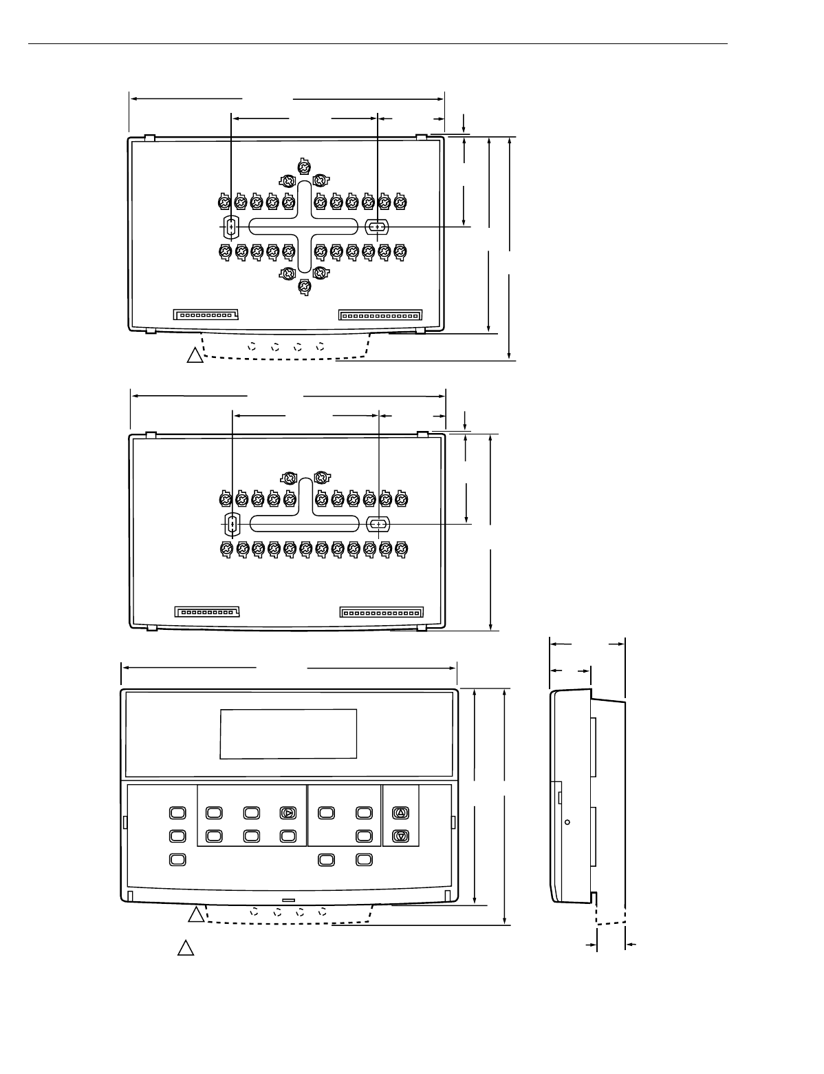
Fig. 1. Dimensions of T7200, T7300 and Q7300 in in. (mm).
Set Temperature Change
Time/Temp
Set Program
Occupied
Temp
Unoccupied
Start Time Day
System Fan
Copy
Occupied
Start Time
Run
Program
Temporary
Occupied
Continous
Unoccupied
Set Current
Day/Time Clear
Start Time
Unoccupied
Temp
Heat/Cool
Settings
1-3/8 (35)
6-3/4 (172)
3-1/4 (82)
1-7/8
(47)
4-3/4
(121)
4-1/8
(105)
1/16 (2)
7-5/16 (186)
5 (127)
4-5/8
(117)
1-11/16
(43)
7/8
(22)
9/16
(14)
M16292
1 T7200 WALLPLATE DOES NOT HAVE THE LED EXTENSION
1
1
1-3/8 (35)
6-11/16 (170)
3-3/16 (77)
1-7/8
(47)
4-1/8
(105)
1/16 (2)
Q7300A,C,D,G,L
Q7300H
T7200D,E; T7300D,E,F
T7200D,E, T7300D,E,F AND Q7300 SERIES 2000 PROGRAMMABLE COMMERCIAL THERMOSTATS AND SUBBASES
5 63-4355—4
INSTALLATION
When Installing this Product…
1. Read these instructions carefully. Failure to follow
the instructions can damage the product or cause a
hazardous condition.
2. Check the ratings given in the instructions and on the
product to make sure the product is suitable for your
application.
3. Installer must be a trained, experienced service
technician.
4. After completing installation, use these instructions to
check out the product operation.
Location
Do not install the thermostat where it can be affected by:
—drafts, or dead spots behind doors and in corners.
—hot or cold air from ducts.
—radiant heat from sun or appliances.
—concealed pipes and chimneys.
—unheated (uncooled) areas such as an outside wall behind
the thermostat.
T7200 Wallplate or Q7300 Subbase without
Remote-Mounted Temperature Sensor
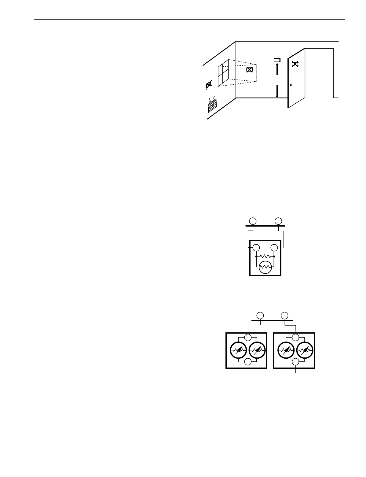
Install the thermostat about 5 ft (1.5m) above the floor in
an area with good air circulation at average temperature.
See Fig. 2.
Q7300 Subbase with Remote-Mounted
Temperature Sensor(s)
If only the remote-mounted temperature sensor(s) is used
to sense and control room temperature, then install the
thermostat in an area that is accessible for setting and
adjusting the temperature and settings.
If both the subbase and remote-mounted temperature
sensor(s) are used to sense and control room temperature,
then install the subbase about 5 ft above the floor in an area
with good air circulation.
Install the remote-mounted sensor(s) about 5 ft (1.5m) above
the floor in an area with good air circulation at average
temperature. See Fig. 2.
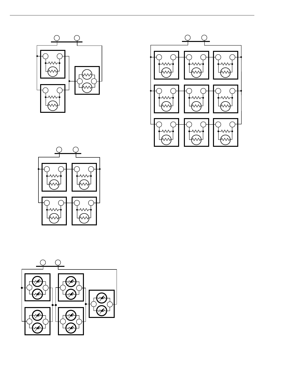
If multiple remote sensors are required, they must be
arranged in a temperature averaging network consisting of
two, three, four, five or nine sensors. See Fig. 3 through 8.
NOTES:
—When sensor averaging, the T7147A can be substituted
for the T7047C. The T7147A includes OVERRIDE and
WARMER/COOLER keys.
—Up to four T7147As can be used in parallel to place the
thermostat in Temporary Occupied.
Fig. 2. Typical location of thermostat
or remote-mounted sensor.
IMPORTANT
To avoid electrical interference, which can cause
erratic performances, keep wiring runs as short as
possible and do not run thermostat wires adjacent to
the line voltage electrical distribution systems. Use
shielded cable (Belden type 8762 or equivalent for
2-wire and Belden type 8772 or equivalent for
3-wire). The cable shield must be grounded only at
the controlled equipment case.
Fig. 3. One T7047C Sensor providing temperature
sensing for T7300/Q7300 Thermostat/Subbase.
Fig. 4. Two T7047G Sensors providing temperature
averaging network for T7300/Q7300 Thermostat/Subbase.
5 FEET
(1.5 METERS)
YES NO
NO NO
M4823A
M4839BB
TT
SUBBASE
TT
T7047C
M4838
TT
SUBBASE
T
T
T7047GT7047G
T
T
T7200D,E, T7300D,E,F AND Q7300 SERIES 2000 PROGRAMMABLE COMMERCIAL THERMOSTATS AND SUBBASES
63-4355—46
Fig. 5. Two T7047C Sensors and one T7047G Sensor
providing temperature averaging network for
T7300/Q7300 Thermostat/Subbase.
Fig. 6. Four T7047C Sensors providing temperature
averaging network for T7300/Q7300 Thermostat/Subbase.
Fig. 7. Five T7047G Sensors providing temperature
averaging network for T7300/Q7300 Thermostat/Subbase.
Fig. 8. Nine T7047C Sensors providing temperature
averaging network for T7300/Q7300 Thermostat/Subbase.
NOTE: With the thermostat configured for a temperature
averaging network (remote and internal sensing), the
internal sensor has 50% authority of the averaged
temperature.
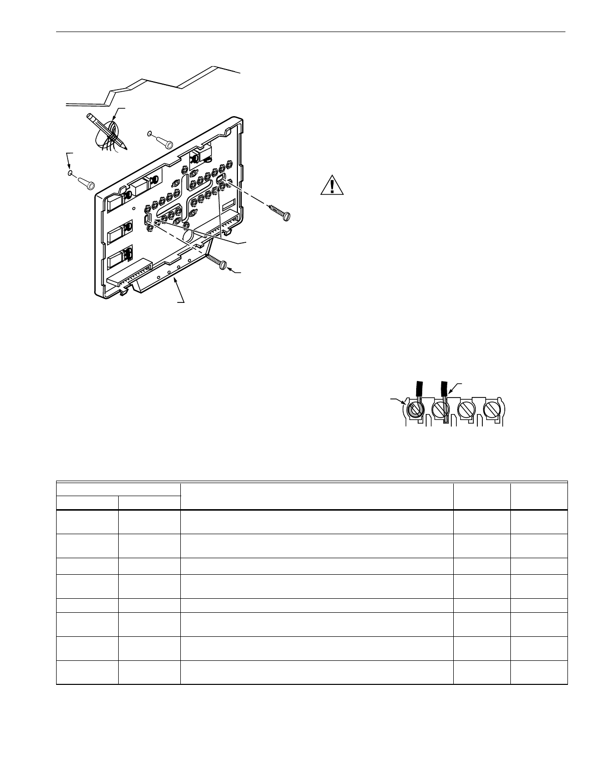
Mounting Subbase/Wallplate
The subbase/wallplate mounts horizontally on the wall or
a 2 in. by 4 in. wiring box. Position the subbase/wallplate
horizontally on the wall or on a 2 in. by 4 in. wiring box.
1. Position and level the subbase/wallplate.
NOTE: A level wallplate is only for appearance. The
thermostat functions properly when not level.
2. Use a pencil to mark the mounting holes. See Fig. 9.
3. Remove the subbase/wallplate from the wall and drill
two 3/16 inch holes in the wall (if drywall) as marked.
For firmer material such as plaster or wood, drill two
7/32 inch holes. Gently tap anchors (provided) into the
drilled holes until flush with the wall.
4. Position the subbase/wallplate over the holes, pulling
wires through the wiring opening.
5. Loosely insert the mounting screws into the holes.
6. Tighten mounting screws.
M4839
TT
SUBBASE
TT
T7047C
TT
T7047C TT
T7047G
M4840
TT
TT
SUBBASE
T7047C
TT
T7047C
TT
T7047C
TT
T7047C
M4841
TT
SUBBASE
TT
T7047G
TT
T7047G
TT
T7047G
TT
T7047G
TT
T7047G
M4842
TT
TT
SUBBASE
T7047C
TT
T7047C
TT
T7047C
TT
T7047C
TT
T7047C
TT
T7047C
TT
T7047C
TT
T7047C
TT
T7047C
T7200D,E, T7300D,E,F AND Q7300 SERIES 2000 PROGRAMMABLE COMMERCIAL THERMOSTATS AND SUBBASES
7 63-4355—4
Fig. 9. Mounting subbase or wallplate.
WIRING SUBBASE/WALLPLATE
IMPORTANT
All wiring must comply with local electrical codes
and ordinances.
Follow equipment manufacturer wiring instructions when
available. Refer to the Wiring section for typical hookups.
A letter code is located near each terminal for identification.
Refer to Table 6 for terminal designations.
CAUTION
Electrical Shock Hazard.
Power supply can cause electrical shock.
Disconnect power before beginning installation.
1. Loosen the terminal screws on the subbase/wallplate
and connect the system wires. See Fig. 10.
IMPORTANT
Use 18-gauge, solid-conductor color-coded
thermostat cable for proper wiring. If using 18- gauge
stranded wire, no more than ten wires can be used.
Do not use larger than 18-gauge wire.
2. Securely tighten each terminal screw.
3. Push excess wire back into the hole.
4. Plug the hole with nonflammable insulation to prevent
drafts from affecting the thermostat.
Fig. 10. Proper wiring technique.
WIRES
THROUGH WALL
WALL
WALL
ANCHORS
(2)
M10237
LEDS
MOUNTING
HOLES
MOUNTING
SCREWS
M4826
FOR WRAPAROUND
INSERTION STRIP
7/16 IN. (11 MM).
FOR STRAIGHT INSERTION
STRIP 5/16 IN. (8 MM).
Table 6. Terminal Designations and Descriptions.
Terminal Designations
Typical Connection Function Terminal
TypeStandard Alternate
A1 A2aDry auxiliary contacts for economizer control; A1 is normally open
during Unoccupied periods and closed during Occupied periods. Output Dry contact
A1, A2 —Damper control relay (Q7300L only). Input, Output 24V powered
contact
A2 A1aDry auxiliary contacts for economizer control (A2 is common). Input Dry contact
A3 —Dry auxiliary contacts for economizer control; A3 is normally open
during Occupied periods and closed during Unoccupied periods. Output Dry contact
AS, AS —C7150B Discharge Air Sensor connection. Input —
B—Heating changeover valve. Output 24V powered
contact
C1, C2, C3,
C4, C5 —Communication input for T7147. Input Low power
E K Emergency heat relay. Output 24V powered
contact
aSome OEM models reverse the economizer terminal designations A1 and A2.
bSome OEM models label the terminal for transformer common B.
cApplies only to Q7300H2037.

T7200D,E, T7300D,E,F AND Q7300 SERIES 2000 PROGRAMMABLE COMMERCIAL THERMOSTATS AND SUBBASES
63-4355—48
EB, EB —Q7300H LONWORKS® bus connection to LONWORKS® network. Input, Output Communi-
cations
G F Fan relay. Output 24V powered
contact
O R Cooling changeover valve. Output 24V powered
contact
R V 24V system transformer. Input —
RC —24V cooling transformer. Input —
RH —24V heating transformer. Input —
T, T —Remote sensor input for T7047 or T7147. Input —
W1 H1, R3 Stage 1 heating relay (Q7300A,G,H) or auxiliary heat relay
(Q7300C,D,H). Output 24V powered
contact
W2 H2, R4, W3, Y Stage 2 heating relay. Output 24V powered
contact
W3 —Stage 3 heating relay. Output 24V powered
contact
XBb, C, X1, X2 Common. Input
X1, X3 A, A1, A2, C,
L, X, Z User defined Light Emitting Diodes (LED). Annunciation —
X4 —LED common. Annunciation —
Y1 C1, M, Y Stage 1 compressor contactor (Q7300C,D,H). Output 24V powered
contact
Y1, Y RS, M Stage 1 cooling compressor (Q7300A,G,Hc,L). Output 24V powered
contact
Y2 C2 Stage 2 cooling compressor (conventional).
Stage 2 compressor contactor (heat pump). Output 24V powered
contact
Y3 —Stage 3 cooling compressor. Output 24V powered
contact
BM —ML7984 Actuator connection (Q7300Hc, L only); no call for heat,
valve closed; call for stage 1 heat, valve approximately one-half
open; call for stage 2 heat, valve fully open.
Output —
FC —Fan control transformer (Q7300Hc, L only). Input —
GH —High-speed fan output (Q7300Hc, L only); activate during calls for
cooling.
Output 24V powered
contact
GL —Low-speed fan output (Q7300Hc, L only); activated on calls for heat
and fan On selection.
Output 24V powered
contact
P1, P2 —Pump interlock relay (Q7300Hc, L only); operates circulator pump in
hydronic heat or energizes conventional heat system.
Input, Output 24V powered
contact
RM —ML7984A Actuator connection (Q7300Hc, L only); no call for heat,
valve closed; call for stage 1 heat, valve approximately one-half
open; call for stage 2 heat, valve fully open.
Output —
—C, H, L HSII Control Panel. ——
—O Momentary circuit changeover. ——
—PDefrost. ——
—R1, R2 Low- and high-speed fan relays. ——
—T External temperature readout, T-relay; outdoor thermistor. ——
Table 6. Terminal Designations and Descriptions. (Continued)
Terminal Designations
Typical Connection Function Terminal
TypeStandard Alternate
aSome OEM models reverse the economizer terminal designations A1 and A2.
bSome OEM models label the terminal for transformer common B.
cApplies only to Q7300H2037.
T7200D,E, T7300D,E,F AND Q7300 SERIES 2000 PROGRAMMABLE COMMERCIAL THERMOSTATS AND SUBBASES
9 63-4355—4
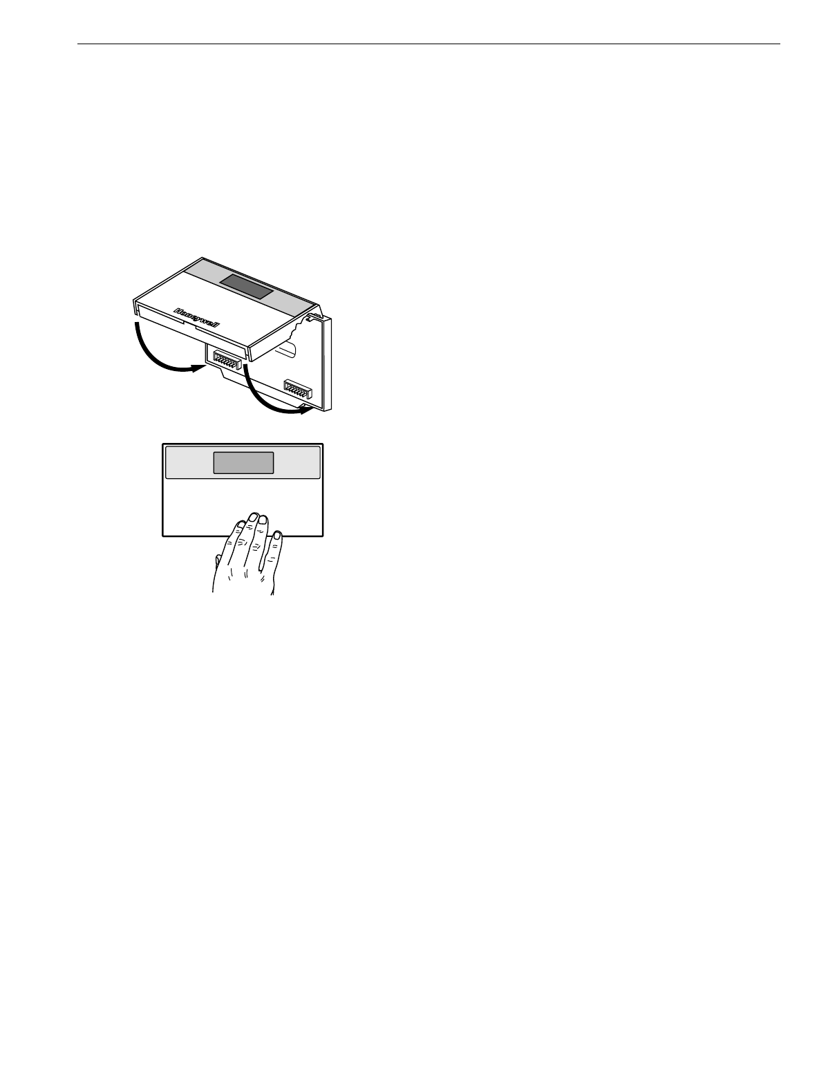
Mounting Thermostat on Subbase/Wallplate
The thermostat mounts on the subbase/wallplate after it is
installed:
1. Engage the tabs at the top of the thermostat and
subbase/wallplate. See Fig. 11.
2. Press the lower edge of the case to latch.
NOTE: To remove the thermostat from the wall, first pull out
at the bottom of the thermostat; then remove the top.
Fig. 11. Mounting thermostat on subbase/wallplate.
SETTINGS
Using Thermostat Keys
The thermostat keys are used to:
•set current time and day,
•program times and setpoints for heating and cooling,
•override the program temperatures,
•display present setting,
•set system and fan operation,
•configure Installer Setup,
•check Installer System Test.
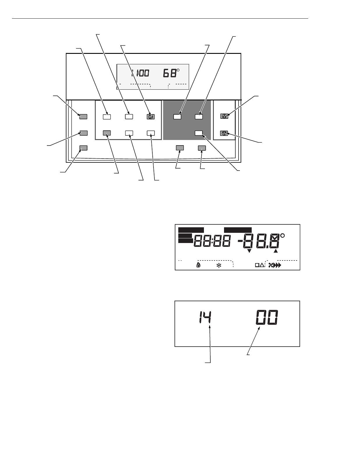
See Fig. 12 for key information.
Setting System and Fan (select models)
The system default setting is Heat. The fan default is set
so the fan operates continuously in Occupied periods,
Unoccupied period recovery times and with the heating and
cooling equipment in Unoccupied periods. Use the System
and Fan keys to change the settings. Fan and system
operation are configured in the Installer Setup options.
The system settings are:
—Em Heat (T7200E, T7300/Q7300C,D,H): Emergency heat
relay is on continuously. Thermostat cycles highest stage
of heat. Cooling system is off. Compressor is de-energized.
—Heat: Thermostat controls the heating.
—Off: Both the heating and cooling are off.
—Cool: Thermostat controls the cooling.
—Auto: Thermostat automatically changes between heating
and cooling depending on the indoor temperature.
The fan settings are:
—On: Fan operates continuously in occupied period.
—Auto: Equipment controls the fan in the Unoccupied
periods. The Intelligent Fan™ operation (Installer Setup
number 17) offers three choices for the fan operation in
Occupied periods:
—fan turns on only when there is a call for heat or cool.
—fan operates continuously in Occupied periods.
—fan is on continuously in Occupied periods and
Unoccupied period recovery times.
Setting Temperature
Refer to Table 4 for the default temperature setpoints. See
Programming section for complete instructions on changing
the setpoints.
M4824A
B. PRESS LOWER EDGE OF CASE TO LATCH.
A. ENGAGE TABS AT TOP OF THERMOSTAT AND SUBBASE OR WALLPLATE.
T7200D,E, T7300D,E,F AND Q7300 SERIES 2000 PROGRAMMABLE COMMERCIAL THERMOSTATS AND SUBBASES
63-4355—410
Fig. 12. Thermostat key locations and descriptions.
INSTALLER SETUP
NOTE: For most applications, the thermostat factory settings
do not need to be changed. Review the factory
settings in Table 7 and if no changes are necessary,
go to the Installer System Test section.
The installer uses the Installer Setup to customize the
thermostat to specific systems. (See Table 7.) The table
includes all the configuration options available.
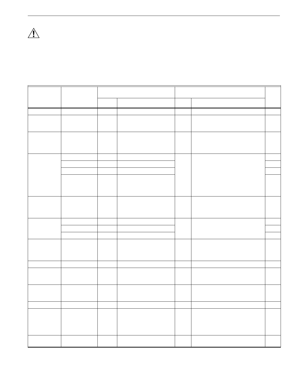
A combination of key presses are required to use the Installer
Setup feature:
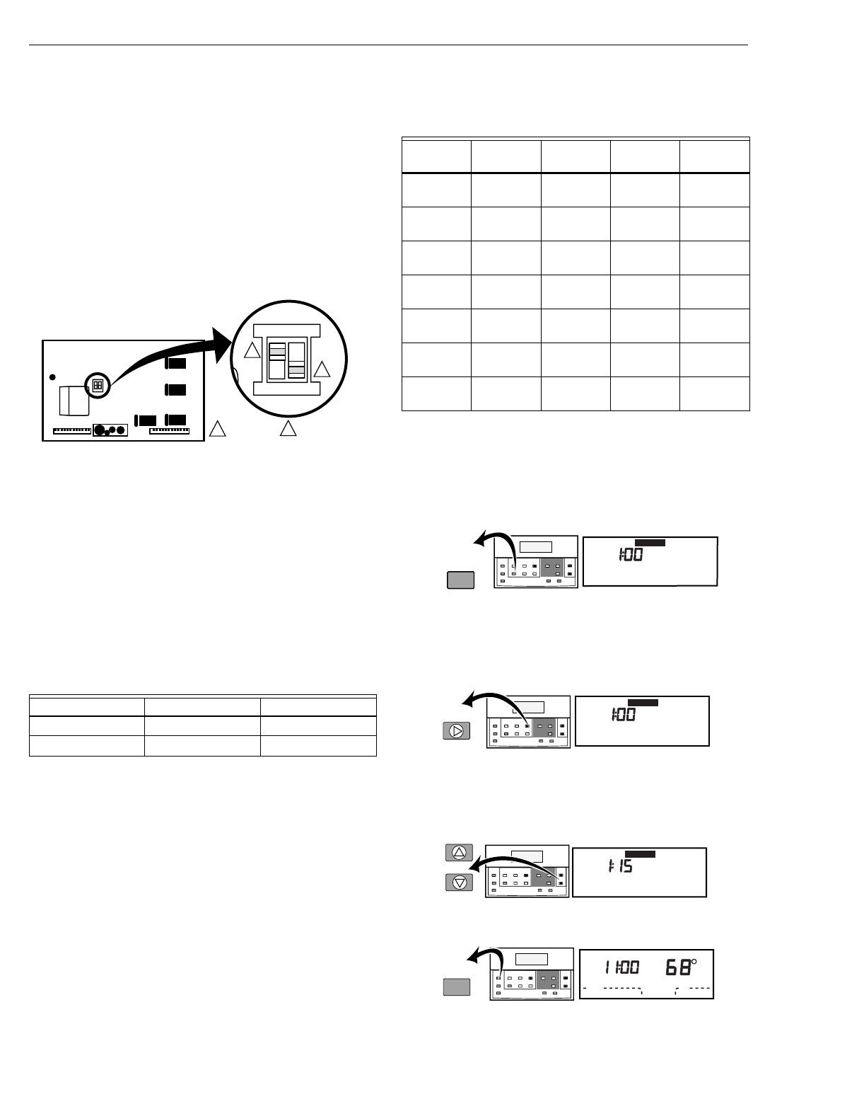
—To enter the Installer Setup, press and hold Heat/Cool
Settings and both the increase ▲▲ and decrease ▼▼ keys
until the first number is displayed. All display segments
appear for approximately three seconds before the number
is displayed. See Fig. 13 and 14.
—To advance to the next Installer Setup number, press
Unoccupied Temp.
—To return to an Installer Setup number, press Heat/Cool
Settings.
—To change a setting, use the increase ▲ or decrease ▼ key.
—To exit the Installer Setup, press Run Program.
NOTES:
—Installer Setup is automatically exited after four
minutes with no key pressed.
—Be sure to set thermostat time after exiting
Installer Setup.
—Installer Setup numbers are listed in Table 7.
Fig. 13. LED display of all segments.
Fig. 14. Installer Setup number and setting display.
Set Program Set Temperature Change
Time/Temp
Occupied
Temp
Unoccupied
Start Time Day
System Fan
Copy
Occupied
Start Time
Run
Program
Temporary
Occupied
Continuous
Unoccupied
Set Current
Day/Time Clear
Start Time
Unoccupied
Temp
Heat/Cool
Settings
Auto
System Fan
Mon
Room
AM
Occupied
Heat
M10233A
SET OVERRIDE
TEMPERATURE
OFFSET AND
ACTIVATE
TEMPORARY
OVERRIDE
ENTER HOLD MODE SET CURRENT
DAY AND TIME
CLEAR PROGRAM PERIOD COPY ONE
PROGRAMMED DAY
TO ANOTHER DAY
SELECT FAN
OPERATION
SELECT
SYSTEM
OPERATION
CHANGE BETWEEN HEATING
AND COOLING SETPOINTS
AND SCROLLS BACKWARDS
THROUGH INSTALLER SETUP
NUMBERS AND SYSTEM TEST
DECREASE
TEMPERATURE
OR TIME SETTING
INCREASE
TEMPERATURE
OR TIME SETTING
SET UNOCCUPIED TEMPERATURE
SETPOINTS AND SCROLLS
THROUGH INSTALLER SETUP
AND SYSTEM TEST
SET OCCUPIED
TEMPERATURE
SETPOINTS
SET CURRENT DAY OR
PROGRAM DAY
ENTER UNOCCUPIED
PROGRAM MODE
ENTER OCCUPIED
PROGRAM MODE
RETURNS TO
NORMAL
OPERATIONS
Heat
Auto
System Fan
Off Auto
Un
Mon
Wait
Lo
In
Room
Remote
%Humid
Auto
Sav
AM
PM
Comm Cool Duct
Only
On
Recovery
Hi
Med
Cool
TueWedThuFriSatSun
Occupied 12 Override
M4916
Aux Ht
Em Ht
Set Program
Set Day/Time
Start Time Temporary Setting Enrg
Em Heat
M10227
MODE NUMBER
DISPLAY
(COLUMN 2
OF TABLE 8)
FACTORY SETTING
OR OTHER CHOICE
DISPLAY (COLUMN 3
OR 5 OF TABLE 8)
T7200D,E, T7300D,E,F AND Q7300 SERIES 2000 PROGRAMMABLE COMMERCIAL THERMOSTATS AND SUBBASES
11 63-4355—4
CAUTION
Possible Equipment Damage.
Fan must be running when system is operating.
Heat pump and electric heat systems must be
configured correctly in Installer Setup 2 to prevent
equipment damage caused by the system running
without the fan.
IMPORTANT
Only configurable numbers are shown on the device.
Example: If the thermostat does not have a system
key, Installer Setup number 12 will not be displayed.
Review Table 7 factory settings and mark any
desired changes in the Actual Setting column. When
the Installer Setup is complete, review the settings to
confirm that they match the system.
Table 7. Thermostat Installer Setup Options.
Select
Installer Setup
Number
(Press Unoccupied
Temp to change)
Factory Setting Other Choices
(Press ▲ or ▼ to change) Actual
SettingDisplay Description Display Description
Not used 1 — — — — —
Fan operationa2 0 Conventional applications where
equipment controls fan operation
in heat mode.
1 Electric heat applications where thermostat
controls fan operation in heat mode.
Output stages of
heating 3 Subbase
dependant Stages of heat. 0, 1, 2,
or 3 0: No heating.
1: One stage of heat.
2: Two stages of heat.
3: Three stages of heat.
Heating cycle rate 4 4 Stage 1: 4 cph. 3, 6, 8 or
93: 3 cph (hot water systems or high
efficiency furnaces).
6: 6 cph (conventional systems).
8: 8 cph (conventional systems).
9: 9 cph (electric heat systems).
5 4 Stage 2: 4 cph.
6 4 Stage 3: 4 cph.
7 4 Emergency heat relay is on
continuously. Highest stage of
heat cycles at 4 cph (Q7300C or D
only).
Cooling output
stages 8 Subbase
dependant Stages of cooling. 0, 1, 2 or
30: No cooling.
1: One cooling stage.
2: Two cooling stages.
3: Three cooling stages.
Cooling cycle rate 9 4 Stage 1: 4 cph. 3 3: 3 cph.
10 4 Stage 2: 4 cph.
11 4 Stage 3: 4 cph.
System setting
adjustment
(models with
System key)
12 Model
dependant System selection. 0, 1 or 2 0: System setting key is operational.
1: Auto setting disabled.
2: Auto only setting.
Not used 13 — — — — —
Degree
temperature
display
14 0 Temperature displayed in °F. 1 Temperature displayed in °C.
Displaying
temperature
(T7300F only).
15 0 Temperature displayed. 1 Temperature not displayed.
Clock format. 16 0 12-hour clock format. 1 24-hour clock format.
Intelligent Fan™
operation. 17 2 Fan operates continuously in
Occupied and recovery modes.
Fan operates with call for heat or
cool in Unoccupied mode.
0 or 1 0: Fan operates only with call for heat or
cool (Occupied and Unoccupied modes).
1: Fan operates continuously in Occupied
mode. Fan operates with call for heat or
cool in Unoccupied mode.
Auxiliary contact
operation. 18 0 0: Time of day contact. 1 1: Economizer contacts. —
aNumber 2 must be set to 1 to extend fan operation.
bNumber 22 must be set to 1 and remote sensor(s) must be installed.

T7200D,E, T7300D,E,F AND Q7300 SERIES 2000 PROGRAMMABLE COMMERCIAL THERMOSTATS AND SUBBASES
63-4355—412
Extended fan
operation in heata
(T7300F only).
19 0 No extended fan operation after
call for heat ends. 1 Fan operation extended 90 sec after call for
heat ends.
Extended fan
operation in
cooling
(T7300F only).
20 0 No extended fan operation after
the call for cooling ends. 1 Fan operation is extended 90 seconds after
the call for cooling ends.
Fan key
adjustment
(models with Fan
key).
21 0 Fan setting key operational. 1 Fan setting key is Auto only.
Remote sensing. 22 0 Remote sensing not activated. 1 Remote sensing activated.
Temperature
averaging networkb
(T7300F only).
23 0 Temperature averaging disabled. 1 Temperature averaging between local
sensor and remote sensor(s) activated.
Not used. 24 — — — — —
Keypad lockout
level (keypad
lockout enabled/
disabled by DIP
switch 1 on
thermostat back).
(T7300F only)
25 0 No lockout. 1, 2 or 3 1: Lockout all thermostat keys except
system and fan settings, temporary
setpoint, clock and day adjustments,
increase ▲ and decrease ▼.
2: Lockout all keys except Set Current Day/
Time, increase ▲ and decrease ▼.
3: Lockout all keys except Temporary
Occupied and Set Current Day/Time (for
clock, day adjustment).
Duration of
temporary
override.
26 3 3: Three hour override. 1, 8 or
12 1: One hour override.
8: Eight hour override.
12: Twelve hour override.
Not used. 27 through 29 — — — — —
Deadband
(T7300F only). 30 2 Heating and cooling setpoints can
be set no closer than 2°F (1.1°C). 3 - 10 Heating and cooling setpoints can be set no
closer than the chosen value.
Interstage control
point (T7300F,
Q7300C,D only).
31 0 Disabled. 1 - 12 Temperature must change more than
chosen value before system calls for next
stage. (Example: heat setpoint: 68°F (20°C),
interstage setting: 2°F (1.1°C), temperature
is 65.5°F (18.5°C). Second stage turns on,
brings temperature to 66°F (19°C) and turns
off. Heat pump continues to run until setpoint
is reached.
Minimum on- time
(T7300F). 32 2 2-minute minimum on- time for
heating and cooling. 0 or 1 No minimum on-time or 1-minute minimum
on-time for heating and cooling.
Minimum
compressor off-
time.
33 4 4-minute minimum compressor
off-time. 0, 1, 2, 3
or 5 Minimum number of minutes (0 through 5)
compressor is off between compressor calls.
Temperature heat
range stops
(T7300F).
34 90 Highest heat setpoint. 40 to 89 Heat setpoint temperature range (1°F
increments).
Temperature
cooling range
stops (T7300F).
35 45 Lowest cooling setpoint. 46 to 99 Temperature range (1°F increments) for
cooling setpoint.
Not used. 36 — — — — —
Table 7. Thermostat Installer Setup Options. (Continued)
Select
Installer Setup
Number
(Press Unoccupied
Temp to change)
Factory Setting Other Choices
(Press ▲ or ▼ to change) Actual
SettingDisplay Description Display Description
aNumber 2 must be set to 1 to extend fan operation.
bNumber 22 must be set to 1 and remote sensor(s) must be installed.
T7200D,E, T7300D,E,F AND Q7300 SERIES 2000 PROGRAMMABLE COMMERCIAL THERMOSTATS AND SUBBASES
13 63-4355—4
IMPORTANT
Review the settings to confirm that they match the
system. Press Run Program to exit the Installer
Setup. The thermostat has saved the Installer Setup
changes and initiated reset in order to operate with
these new settings. Be sure to set the current day
and time immediately.
Setting Current Time/Day
1. Press Set Current Day/Time.
NOTE: On initial power up or after an extended power
loss, 1:00 pm flashes on the display until a key
is pressed.
2. Press Day until the current day is displayed.
NOTE: Sun = Sunday, Mon = Monday, Tue = Tuesday,
Wed = Wednesday, Thu = Thursday,
Fri = Friday, Sat = Saturday.
3. Press increase ▲ or decrease ▼ key until the current
time is displayed.
NOTE: Tapping Set Current Day/Time changes the
time in one hour increments.
4. Press Run Program.
INSTALLER SYSTEM TEST
Use the Installer System Test to check the thermostat
configurations and operation. Refer to Table 8 for a list of
available system tests. To start the system test:
CAUTION
Possible Equipment Damage.
Equipment damage can result if compressor is
cycled too quickly.
The minimum off time for compressors is bypassed
during the Installer System Test. Equipment damage
can occur if the compressor is cycled too quickly.
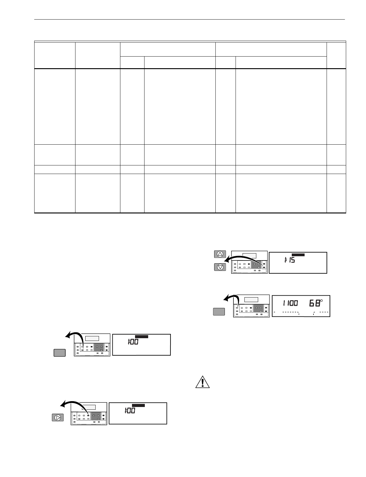
Press and hold both the increase ▲ and decrease ▼ keys
until 10 appears. All segments of the LCD display for three
seconds before 10 appears. See Fig. 15 and 16.
Temperature
display adjustment. 37 0 No difference in displayed
temperature and actual room
temperature.
1 - 6 1: Display adjusts to 1°F (0.6°C) higher
than actual room temperature.
2: Display adjusts to 2°F (1.1°C) higher
than actual room temperature.
3: Display adjusts to 3°F (1.7°C) higher
than actual room temperature.
4: Display adjusts to 1°F (0.6°C) lower than
actual room temperature.
5: Display adjusts to 2°F (1.1°C) lower than
actual room temperature.
6: Display adjusts to 3°F (1.7°C) lower than
actual room temperature.
Minimum off-time
in heating. 38 4 4: 4-minute minimum off-time 0, 1, 2,
3, or 5 Minimum number of minutes (0 through 5)
the heating equipment is off between calls
for heat.
Not used. 39 — — — — —
Installer Setup
lockout (enable/
disable keypad
lockout using DIP
switch 1 on
thermostat back).
40 0 0: No Installer Setup lockout. 1 1: Installer Setup lockout activated.
Table 7. Thermostat Installer Setup Options. (Continued)
Select
Installer Setup
Number
(Press Unoccupied
Temp to change)
Factory Setting Other Choices
(Press ▲ or ▼ to change) Actual
SettingDisplay Description Display Description
aNumber 2 must be set to 1 to extend fan operation.
bNumber 22 must be set to 1 and remote sensor(s) must be installed.
M4951B
Set Current
Day/Time Set Program Set Temperature Change
Time/Temp
Occupied
Temp
Unoccupied
Start Time Day
System Fan
Copy
Occupied
Start Time
Run
Program
Temporary
Occupied
Continous
Unoccupied
Set Current
Day/Time Clear
Start Time
Unoccupied
Temp
Heat/Cool
Settings
Mon
PM
Set Day/Time
M4952B
Set Program Set Temperature Change
Time/Temp
Occupied
Temp
Unoccupied
Start Time Day
System Fan
Copy
Occupied
Start Time
Run
Program
Temporary
Occupied
Continous
Unoccupied
Set Current
Day/Time Clear
Start Time
Unoccupied
Temp
Heat/Cool
Settings
Day PM
Tue
Set Day/Time
M4953B
Set Program Set Temperature Change
Time/Temp
Occupied
Temp
Unoccupied
Start Time Day
System Fan
Copy
Occupied
Start Time
Run
Program
Temporary
Occupied
Continous
Unoccupied
Set Current
Day/Time Clear
Start Time
Unoccupied
Temp
Heat/Cool
Settings
PM
Tue
Set Day/Time
M4954A
Set Program Set Temperature Change
Time/Temp
Occupied
Temp
Unoccupied
Start Time Day
System Fan
Copy
Occupied
Start Time
Run
Program
Temporary
Occupied
Continous
Unoccupied
Set Current
Day/Time Clear
Start Time
Unoccupied
Temp
Heat/Cool
Settings
Auto
System Fan
Mon
Room
AM
Occupied 1
Heat
Run
Program
T7200D,E, T7300D,E,F AND Q7300 SERIES 2000 PROGRAMMABLE COMMERCIAL THERMOSTATS AND SUBBASES
63-4355—414
Fig. 15. LCD display of all segments.
Fig. 16. Test number display.
Table 8. Tests Available in Installer System Test.
NOTE: If a duct temperature sensor is installed
(T7300F only), duct temperature is also displayed.
Refer to Table 9 and Thermostat Information section for
directions and results of the specific system tests.
NOTE: Press Run Program to exit the system test. The
system test times out after four minutes without any
key presses.
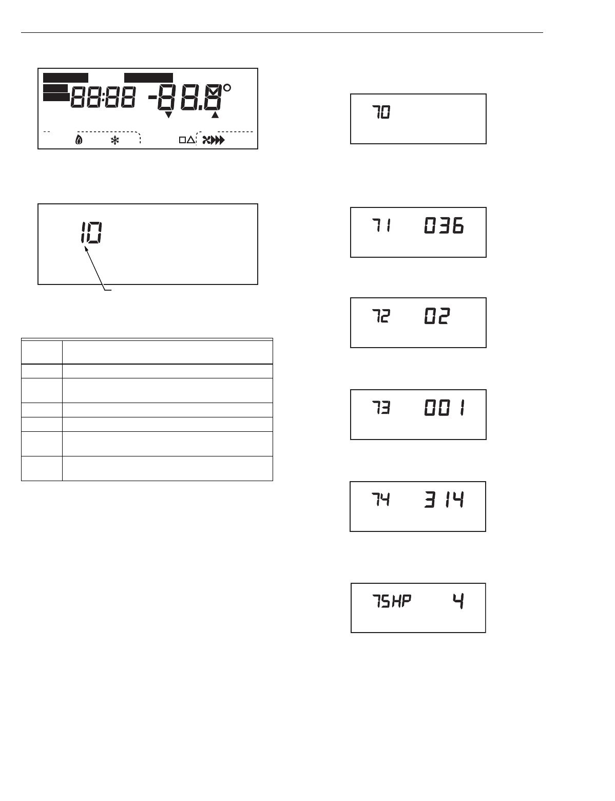
Thermostat Information
1. Press Heat/Cool Settings to access thermostat
information.
2. Press increase ▲ to display the production date code.
The first two large digits are the month and the third digit
is the last digit of the year.
(Example: 036 = March 1996).
3. Press increase ▲ again to display the software
identification code. (Example: 02 = software ID code 2).
4. Press increase ▲ again to display the software revision
number. (Example: 001 = revision number 1).
5. Press increase ▲ again to display the EEPROM
identification code. (Example: 314 = EEPROM ID 313).
6. Press increase ▲ again to display the subbase
identification code.
(Example: HP = heat pump subbases).
7. Press Run Program to exit the self-test. The self-test
times out after four minutes without any key presses.
Test
Number System Test Description
10 to 19 Heating equipment can be turned on and off.
20 to 29 Emergency heat equipment can be turned on and
off (Q7300C,D,H only).
30 to 39 Cooling equipment can be turned on and off.
40 to 49 Fan equipment can be turned on and off.
60 0 to
60 19 Keyboard keys test.
70 to 79 Thermostat information including date code and
software versions are displayed.
Heat
Auto
System Fan
Off Auto
Un
Mon
Wait
Lo
In
Room
Remote
%Humid
Auto
Sav
AM
PM
Comm Cool Duct
Only
On
Recovery
Hi
Med
Cool
TueWedThuFriSatSun
Occupied 12 Override
M4916
Aux Ht
Em Ht
Set Program
Set Day/Time
Start Time Temporary Setting Enrg
Em Heat
M10257A
TEST NUMBER
M4934
M4931
M4932A
M10229
M4933A
M10290

T7200D,E, T7300D,E,F AND Q7300 SERIES 2000 PROGRAMMABLE COMMERCIAL THERMOSTATS AND SUBBASES
15 63-4355—4
Table 9. Installer System Test Options.
Key to Press Test
Number Description
Heating Equipment System Test
Heat/Cool Settings 10 Enter heating equipment system test.
▲ 11 Stage-one heat turns on. The system fan is also energized.
▲ 12 Stage-two heat turns on. Stage-one heat and system fan remain on.
▲ 13 Stage-three heat turns on. Stage-one and stage-two heat with the system fan are on.
▼ 12 Stage-three heat turns off.
▼ 11 Stage-two heat turns off.
▼ 10 Stage-one heat and system fan turn off.
Emergency Heating Equipment System Test (T7300E,F with Q7300C,D)
Heat/Cool Settings 20 Change from heating to emergency heating equipment system test (Em Heat on).
▲ 21 Fan turns on.
▼20 Fan and highest stage heat turns off.
Cooling Equipment System Test
Heat/Cool Settings 30 Change from heating or emergency heating to cooling equipment system test.
▲ 31 Stage-one cooling and system fan turn on.
▲ 32 Stage-two cool turn on. Stage-one cool and system fan remain on.
▲ 33 Stage-three cool turns on (Q7300G,H only). Stage-one and stage-two cool with system
fan remain on.
▼ 32 Stage-three cool turns off.
▼ 31 Stage-two cool turns off.
▼ 30 Stage-one cool and system fan turn off.
Fan Equipment System Test
Heat/Cool Settings 40 Change from cooling to fan equipment system test.
▲ 41 Fan turns on.
▲ 42 High speed fan turns on (Q7300Ha, L only).
▼ 41 High speed fan turns off.
▼ 40 Fan turns off.
Key Operation System Test
Heat/Cool Settings 60 2 Change from fan to key operation system test.
Unoccupied Temp 60 0 Unoccupied Temp test number is displayed.
Occupied Temp 60 1 Occupied Temp test number is displayed.
▲ 60 3 Increase test number is displayed.
▼ 60 5 Decrease test number is displayed.
Clear Start Time 60 7 Clear Start Time test number is displayed.
Day 60 8 Day test number is displayed.
Copy 60 9 Copy test number is displayed.
Unoccupied Start TIme 60 10 Unoccupied Start Time test number is displayed.
System (select models) 60 11 System test number is displayed.
Fan (select models) 60 12 Fan test number is displayed.
Set Current Day/Time 60 14 Set Current Day/Time test number is displayed.
Run Program 60 15 Run Program test number is displayed.
Temporary Occupied 60 16 Temporary Occupied test number is displayed.
Occupied Start Time 60 17 Occupied Start Time test number is displayed.
Continuous Unoccupied 60 19 Continuous Unoccupied test number is displayed.
T7200D,E, T7300D,E,F AND Q7300 SERIES 2000 PROGRAMMABLE COMMERCIAL THERMOSTATS AND SUBBASES
63-4355—416
Setting Keypad Lockout Switch (T7300 only)
The DIP switch 1, on the thermostat back, activates the
lockout features. The switch must be set ON (up) to activate
the lockout feature (see Fig. 17).
NOTE: The factory setting is off (down).
If keypad lockout is desired:
1. Remove the thermostat from the subbase.
2. Set the switch to ON.
3. Enter the Installer Setup.
4. Select option 25 to choose the level of keypad lockout
(see Table 7).
5. Activate the lockout by setting option 40 to 1.
Fig. 17. Set keypad lockout DIP switch 1.
PROGRAMMING
The thermostat operates at the Unoccupied temperature
setting unless the thermostat is programmed. Table 10 shows
the default temperature settings. (The program has four):
—Occupied heat.
—Occupied cool.
—Unoccupied heat.
—Unoccupied cool.
Table 10. Occupied and Unoccupied
Default Temperature Settings.
The keyboard is located behind the thermostat cover. Up to
sixteen keys are used to set, review and modify programmed
times and temperature settings. The thermostat display shows
day, time, program period and temperature.
The thermostat can be set for two Occupied and two
Unoccupied times for each day of the week (28 independent
time settings). Temporary Occupied key provides quick
temporary temperature changes for increased occupant
comfort. The Continuous Unoccupied key provides energy
efficient operation for extended periods of time.
IMPORTANT
To program the thermostat, 24 Vac is required (turn
on system power). The keyboard lockout feature
must be disabled by setting the DIP switch 1 on the
back of the thermostat to the Off position.
NOTE: Before starting the program procedure, use Table 11
to organize the program schedule.
Table 11. Occupied and Unoccupied Periods Start Times.
Setting Current Day/Time
1. Press Set Current Day/Time.
NOTE: On initial power up or after an extended power
loss, the display flashes 1:00 pm until a key
is pressed.
2. Press Day until the current day is displayed.
NOTE: Sun = Sunday, Mon = Monday, Tue = Tuesday,
Wed = Wednesday, Thu = Thursday,
Fri = Friday, Sat = Saturday.
3. Press increase ▲ or decrease ▼ until the current time
is displayed.
NOTE: Tapping Set Current Day/Time changes the
time in one hour increments.
4. Press Run Program.
Control Occupied Unoccupied
Heating 70°F (21°C) 55°F (13°C)
Cooling 78°F (26°C) 90°F (32°C)
ON
12
M10235BACK OF THERMOSTAT
1
2
12
DIP 1 IS ON DIP 2 IS NOT USED.
Day Occupied
Period 1 Unoccupied
Period 1 Occupied
Period 2 Unoccupied
Period 2
Monday
Tuesday
Wednesday
Thursday
Friday
Saturday
Sunday
M4951B
Set Current
Day/Time Set Program Set Temperature Change
Time/Temp
Occupied
Temp
Unoccupied
Start Time Day
System Fan
Copy
Occupied
Start Time
Run
Program
Temporary
Occupied
Continous
Unoccupied
Set Current
Day/Time Clear
Start Time
Unoccupied
Temp
Heat/Cool
Settings
Mon
PM
Set Day/Time
M4952B
Set Program Set Temperature Change
Time/Temp
Occupied
Temp
Unoccupied
Start Time Day
System Fan
Copy
Occupied
Start Time
Run
Program
Temporary
Occupied
Continous
Unoccupied
Set Current
Day/Time Clear
Start Time
Unoccupied
Temp
Heat/Cool
Settings
Day PM
Tue
Set Day/Time
M4953B
Set Program Set Temperature Change
Time/Temp
Occupied
Temp
Unoccupied
Start Time Day
System Fan
Copy
Occupied
Start Time
Run
Program
Temporary
Occupied
Continous
Unoccupied
Set Current
Day/Time Clear
Start Time
Unoccupied
Temp
Heat/Cool
Settings
PM
Tue
Set Day/Time
M4954A
Set Program Set Temperature Change
Time/Temp
Occupied
Temp
Unoccupied
Start Time Day
System Fan
Copy
Occupied
Start Time
Run
Program
Temporary
Occupied
Continous
Unoccupied
Set Current
Day/Time Clear
Start Time
Unoccupied
Temp
Heat/Cool
Settings
Auto
System Fan
Mon
Room
AM
Occupied 1
Heat
Run
Program
T7200D,E, T7300D,E,F AND Q7300 SERIES 2000 PROGRAMMABLE COMMERCIAL THERMOSTATS AND SUBBASES
17 63-4355—4
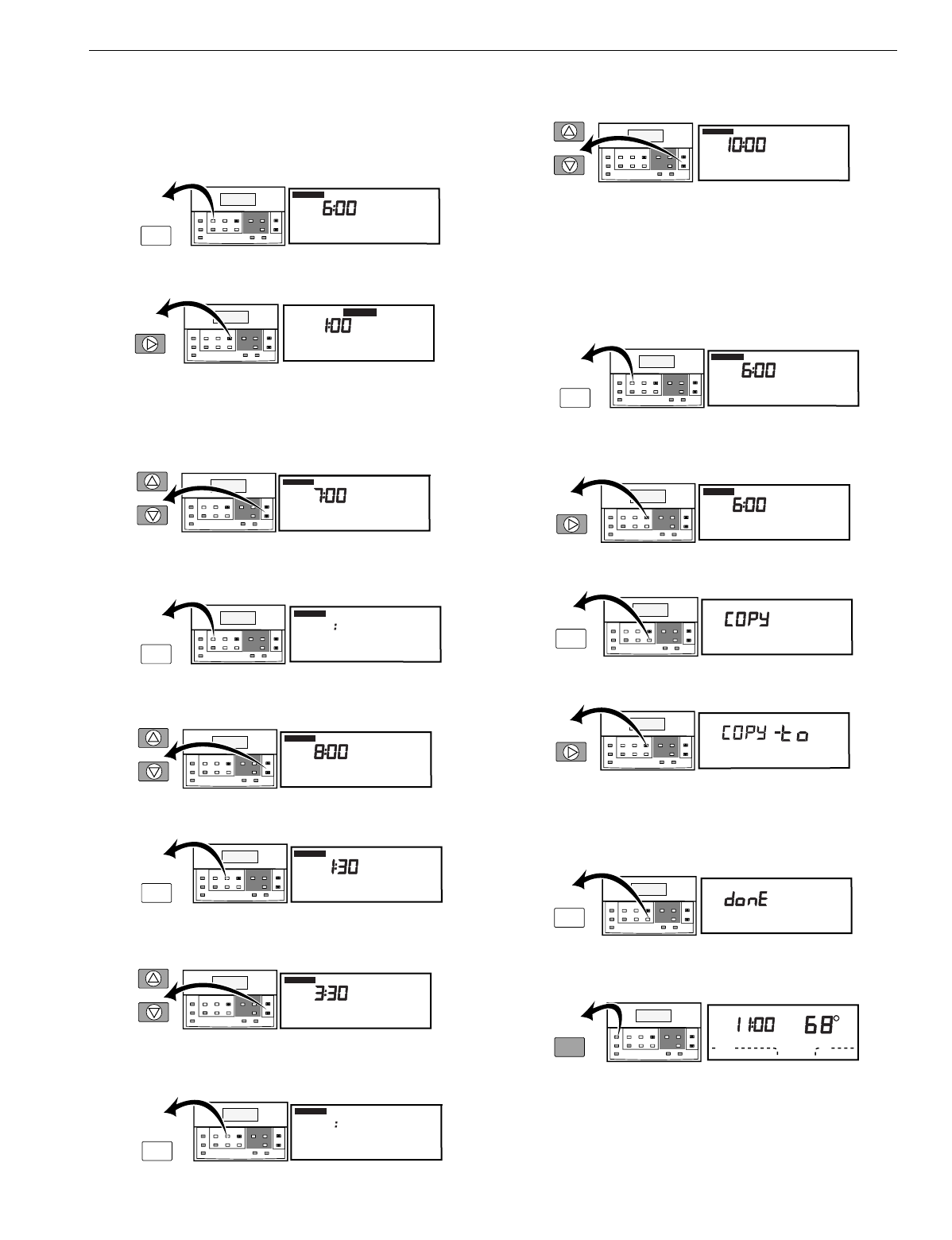
Setting Program Times
1. Press Occupied Start Time.
NOTE: Anytime a start time is not required, press
Clear Start Time.
2. Press Day until the desired day is displayed.
3. Press increase ▲ or decrease ▼ until the desired start
time is displayed.
NOTE: The program times are in fifteen minute
intervals. (Example: 8:00, 8:15, 8:30).
4. Press Occupied Start Time a second time to set a
second Occupied Start Time.
5. Press increase ▲ or decrease ▼ until the desired start
time is displayed.
6. Press Unoccupied Start Time.
7. Press increase ▲ or decrease ▼ until the desired start
time is displayed.
8. Press Unoccupied Start Time a second time to set a
second Unoccupied Start Time.
9. Press increase ▲ or decrease ▼ until the desired start
time is displayed.
Copying a Day
NOTE: The thermostat must be in program mode to use
the copy feature. If the thermostat is already in the
program mode, go to step 2.
1. Press Occupied Start Time.
2. Press Day to select the day to be copied if different from
the day displayed.
3. Press Copy.
4. Press Day until the day to be copied to is displayed.
5. Press Copy.
NOTE: donE will be displayed for two seconds and
then the program display is shown.
6. Repeat steps 3 through 5 for all the days desired.
7. Press Run Program.
AM
Mon
Occupied 1
Set Program
Start Time
M4955A
Set Program Set Temperature Change
Time/Temp
Occupied
Temp
Unoccupied
Start Time Day
System Fan
Copy
Occupied
Start Time
Run
Program
Temporary
Occupied
Continous
Unoccupied
Set Current
Day/Time Clear
Start Time
Unoccupied
Temp
Heat/Cool
Settings
Occupied
Start Time
M4952B
Set Program Set Temperature Change
Time/Temp
Occupied
Temp
Unoccupied
Start Time Day
System Fan
Copy
Occupied
Start Time
Run
Program
Temporary
Occupied
Continous
Unoccupied
Set Current
Day/Time Clear
Start Time
Unoccupied
Temp
Heat/Cool
Settings
Day PM
Tue
Set Day/Time
AM
Wed
Occupied 1
Set Program
Start Time
M4957A
Set Program Set Temperature Change
Time/Temp
Occupied
Temp
Unoccupied
Start Time Day
System Fan
Copy
Occupied
Start Time
Run
Program
Temporary
Occupied
Continous
Unoccupied
Set Current
Day/Time Clear
Start Time
Unoccupied
Temp
Heat/Cool
Settings
Wed
Occupied 2
Set Program
Start Time
M4958B
Set Program Set Temperature Change
Time/Temp
Occupied
Temp
Unoccupied
Start Time Day
System Fan
Copy
Occupied
Start Time
Run
Program
Temporary
Occupied
Continous
Unoccupied
Set Current
Day/Time Clear
Start Time
Unoccupied
Temp
Heat/Cool
Settings
Occupied
Start Time
PM
Wed
Occupied 2
Set Program
Start Time
M4959A
Set Program Set Temperature Change
Time/Temp
Occupied
Temp
Unoccupied
Start Time Day
System Fan
Copy
Occupied
Start Time
Run
Program
Temporary
Occupied
Continous
Unoccupied
Set Current
Day/Time Clear
Start Time
Unoccupied
Temp
Heat/Cool
Settings
Un
PM
Wed
Occupied 1
Set Program
Start Time
M4960A
Set Program Set Temperature Change
Time/Temp
Occupied
Temp
Unoccupied
Start Time Day
System Fan
Copy
Occupied
Start Time
Run
Program
Temporary
Occupied
Continous
Unoccupied
Set Current
Day/Time Clear
Start Time
Unoccupied
Temp
Heat/Cool
Settings
Unoccupied
Start Time
Un
PM
Wed
Occupied 1
Set Program
Start Time
M4961A
Set Program Set Temperature Change
Time/Temp
Occupied
Temp
Unoccupied
Start Time Day
System Fan
Copy
Occupied
Start Time
Run
Program
Temporary
Occupied
Continous
Unoccupied
Set Current
Day/Time Clear
Start Time
Unoccupied
Temp
Heat/Cool
Settings
Un Wed
Occupied 2
Set Program
Start Time
M4962B
Set Program Set Temperature Change
Time/Temp
Occupied
Temp
Unoccupied
Start Time Day
System Fan
Copy
Occupied
Start Time
Run
Program
Temporary
Occupied
Continous
Unoccupied
Set Current
Day/Time Clear
Start Time
Unoccupied
Temp
Heat/Cool
Settings
Unoccupied
Start Time
Un
PM
Wed
Occupied 2
Set Program
Start Time
M4963A
Set Program Set Temperature Change
Time/Temp
Occupied
Temp
Unoccupied
Start Time Day
System Fan
Copy
Occupied
Start Time
Run
Program
Temporary
Occupied
Continous
Unoccupied
Set Current
Day/Time Clear
Start Time
Unoccupied
Temp
Heat/Cool
Settings
AM
Mon
Occupied 1
Set Program
Start Time
M4955A
Set Program Set Temperature Change
Time/Temp
Occupied
Temp
Unoccupied
Start Time Day
System Fan
Copy
Occupied
Start Time
Run
Program
Temporary
Occupied
Continous
Unoccupied
Set Current
Day/Time Clear
Start Time
Unoccupied
Temp
Heat/Cool
Settings
Occupied
Start Time
M4966A
Set Program
Set Program Set Temperature Change
Time/Temp
Occupied
Temp
Unoccupied
Start Time Day
System Fan
Copy
Occupied
Start Time
Run
Program
Temporary
Occupied
Continous
Unoccupied
Set Current
Day/Time Clear
Start Time
Unoccupied
Temp
Heat/Cool
Settings
Day AM
Occupied 1
Start Time
Wed
M4967A
Set Program Set Temperature Change
Time/Temp
Occupied
Temp
Unoccupied
Start Time Day
System Fan
Copy
Copy
Occupied
Start Time
Run
Program
Temporary
Occupied
Continous
Unoccupied
Set Current
Day/Time Clear
Start Time
Unoccupied
Temp
Heat/Cool
Settings
Wed
M4968A
Set Program Set Temperature Change
Time/Temp
Occupied
Temp
Unoccupied
Start Time Day
System Fan
Copy
Occupied
Start Time
Run
Program
Temporary
Occupied
Continous
Unoccupied
Set Current
Day/Time Clear
Start Time
Unoccupied
Temp
Heat/Cool
Settings
Day
Wed Thu
M4969A
Set Program Set Temperature Change
Time/Temp
Occupied
Temp
Unoccupied
Start Time Day
System Fan
Copy
Copy
Occupied
Start Time
Run
Program
Temporary
Occupied
Continous
Unoccupied
Set Current
Day/Time Clear
Start Time
Unoccupied
Temp
Heat/Cool
Settings
M4954A
Set Program Set Temperature Change
Time/Temp
Occupied
Temp
Unoccupied
Start Time Day
System Fan
Copy
Occupied
Start Time
Run
Program
Temporary
Occupied
Continous
Unoccupied
Set Current
Day/Time Clear
Start Time
Unoccupied
Temp
Heat/Cool
Settings
Auto
System Fan
Mon
Room
AM
Occupied 1
Heat
Run
Program

T7200D,E, T7300D,E,F AND Q7300 SERIES 2000 PROGRAMMABLE COMMERCIAL THERMOSTATS AND SUBBASES
63-4355—418
Setting Program Temperature Setpoints
NOTE: The setpoint temperature range is 40°F to 90°F
(7°C to 31°C) for heating and 45°F to 99°F
(9°C to 37°C) for cooling.
1. Press Occupied Temp.
2. Press increase ▲ or decrease ▼ until the desired
temperature is displayed.
3. Press Heat/Cool Settings to change between heat and
cool settings.
4. Press increase ▲ or decrease ▼ until the desired
temperature is displayed.
5. Press Unoccupied Temp.
6. Press increase ▲ or decrease ▼ until the desired
temperature is displayed.
7. Press Heat/Cool Settings to change between heat and
cool settings.
8. Press increase ▲ or decrease ▼ until the desired
temperature is displayed.
9. Press Run Program.
Clearing Program Start Times
1. Press Occupied Start Time or Unoccupied Start Time
until the start time to be cleared is displayed.
2. Press Day until the desired day is displayed.
3. Press Clear Start Time.
4. Repeat steps 1 through 3 for all the start times to
be cleared.
5. Press Run Program.
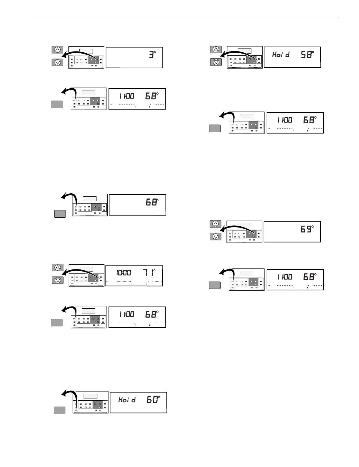
Temporary Occupied Override
Setting Temperature Offset for Temporary Override
1. Press Occupied Temp.
2. Press Temporary Occupied.
M4970B
Heat
Setting
Occupied
Set Program
Set Program Set Temperature Change
Time/Temp
Occupied
Temp
Occupied
Temp Unoccupied
Start Time Day
System Fan
Copy
Occupied
Start Time
Run
Program
Temporary
Occupied
Continous
Unoccupied
Set Current
Day/Time Clear
Start Time
Unoccupied
Temp
Heat/Cool
Settings
M4971B
Set Program Set Temperature Change
Time/Temp
Occupied
Temp
Unoccupied
Start Time Day
System Fan
Copy
Occupied
Start Time
Run
Program
Temporary
Occupied
Continous
Unoccupied
Set Current
Day/Time Clear
Start Time
Unoccupied
Temp
Heat/Cool
Settings
Heat
Setting
Occupied
Set Program
Cool
Occupied
Setting
M4972A
Set Program Set Temperature Change
Time/Temp
Occupied
Temp
Unoccupied
Start Time Day
System Fan
Copy
Occupied
Start Time
Run
Program
Temporary
Occupied
Continous
Unoccupied
Set Current
Day/Time Clear
Start Time
Unoccupied
Temp
Heat/Cool
Settings
Heat/Cool
Settings
Set Program
Cool
Setting
Occupied
M4973B
Set Program
Set Program Set Temperature Change
Time/Temp
Occupied
Temp
Unoccupied
Start Time Day
System Fan
Copy
Occupied
Start Time
Run
Program
Temporary
Occupied
Continous
Unoccupied
Set Current
Day/Time Clear
Start Time
Unoccupied
Temp
Heat/Cool
Settings
Heat
Setting
UnOccupied
M4974B
Set Program Set Temperature Change
Time/Temp
Occupied
Temp
Unoccupied
Start Time Day
System Fan
Copy
Occupied
Start Time
Run
Program
Temporary
Occupied
Continous
Unoccupied
Set Current
Day/Time Clear
Start Time
Unoccupied
Temp
Unoccupied
Temp Heat/Cool
Settings
Set Program
Heat
Setting
UnOccupied
M4975B
Set Program
Set Program Set Temperature Change
Time/Temp
Occupied
Temp
Unoccupied
Start Time Day
System Fan
Copy
Occupied
Start Time
Run
Program
Temporary
Occupied
Continous
Unoccupied
Set Current
Day/Time Clear
Start Time
Unoccupied
Temp
Heat/Cool
Settings
Un Cool
Setting
Occupied
M4976B
Set Program Set Temperature Change
Time/Temp
Occupied
Temp
Unoccupied
Start Time Day
System Fan
Copy
Occupied
Start Time
Run
Program
Temporary
Occupied
Continous
Unoccupied
Set Current
Day/Time Clear
Start Time
Unoccupied
Temp
Heat/Cool
Settings
Heat/Cool
Settings
Set Program
Un Cool
Setting
Occupied
M4977B
Set Program Set Temperature Change
Time/Temp
Occupied
Temp
Unoccupied
Start Time Day
System Fan
Copy
Occupied
Start Time
Run
Program
Temporary
Occupied
Continous
Unoccupied
Set Current
Day/Time Clear
Start Time
Unoccupied
Temp
Heat/Cool
Settings
Set Program
M4954A
Set Program Set Temperature Change
Time/Temp
Occupied
Temp
Unoccupied
Start Time Day
System Fan
Copy
Occupied
Start Time
Run
Program
Temporary
Occupied
Continous
Unoccupied
Set Current
Day/Time Clear
Start Time
Unoccupied
Temp
Heat/Cool
Settings
Auto
System Fan
Mon
Room
AM
Occupied 1
Heat
Run
Program
AM
Mon
Occupied 1
Set Program
Start Time
M4955A
Set Program Set Temperature Change
Time/Temp
Occupied
Temp
Unoccupied
Start Time Day
System Fan
Copy
Occupied
Start Time
Run
Program
Temporary
Occupied
Continous
Unoccupied
Set Current
Day/Time Clear
Start Time
Unoccupied
Temp
Heat/Cool
Settings
Occupied
Start Time
AM
Occupied 1
Set Program
Start Time
M4978A
Mon
Set Program Set Temperature Change
Time/Temp
Occupied
Temp
Unoccupied
Start Time Day
System Fan
Copy
Occupied
Start Time
Run
Program
Temporary
Occupied
Continous
Unoccupied
Set Current
Day/Time Clear
Start Time
Unoccupied
Temp
Heat/Cool
Settings
Day
Occupied 1
Set Program
Start Time
M4979B
Mon
Set Program Set Temperature Change
Time/Temp
Occupied
Temp
Unoccupied
Start Time Day
System Fan
Copy
Occupied
Start Time
Run
Program
Temporary
Occupied
Continous
Unoccupied
Set Current
Day/Time Clear
Start Time
Unoccupied
Temp
Heat/Cool
Settings
Clear
Start Time
M4954A
Set Program Set Temperature Change
Time/Temp
Occupied
Temp
Unoccupied
Start Time Day
System Fan
Copy
Occupied
Start Time
Run
Program
Temporary
Occupied
Continous
Unoccupied
Set Current
Day/Time Clear
Start Time
Unoccupied
Temp
Heat/Cool
Settings
Auto
System Fan
Mon
Room
AM
Occupied 1
Heat
Run
Program
M10231
Heat
Set Program Set Temperature Change
Time/Temp
Occupied
Temp
Occupied
Temp Unoccupied
Start Time Day
System Fan
Copy
Occupied
Start Time
Run
Program
Temporary
Occupied
Continous
Unoccupied
Set Current
Day/Time Clear
Start Time
Unoccupied
Temp
Heat/Cool
Settings
Wed
Occupied
Setting
M4980A
Set Program Set Temperature Change
Time/Temp
Occupied
Temp
Unoccupied
Start Time Day
System Fan
Copy
Occupied
Start Time
Run
Program
Temporary
Occupied
Temporary
Occupied
Continous
Unoccupied
Set Current
Day/Time Clear
Start Time
Unoccupied
Temp
Heat/Cool
Settings
T7200D,E, T7300D,E,F AND Q7300 SERIES 2000 PROGRAMMABLE COMMERCIAL THERMOSTATS AND SUBBASES
19 63-4355—4
3. Press increase ▲ or decrease ▼ until the desired
temperature offset is displayed (range is 0°F to 5°F).
4. Press Run Program.
Using Temporary Override
NOTE: The temporary override temperature is held for one,
three, eight or twelve hours (depending on installer
setup number 26) and then the thermostat returns to
the program.
1. Press Temporary Occupied.
NOTE: The default temperature setting is the
Occupied setpoint.
2. Press increase ▲ or decrease ▼ to change the default
setting by the offset (range is 0°F to 5°F), if desired.
NOTE: With zero offset, the default setting changes in
one degree increments. If the offset is 1 - 5, the
default setting changes by ± the offset.
3. Press Run Program to cancel the override.
Using Continuous Unoccupied
1. Press Continuous Unoccupied.
NOTE: The default temperature setting is the
Unoccupied setpoint. The default appears for
approximately five seconds and then the room
temperature is displayed.
2. Press increase ▲ or decrease ▼ to change the default
setting, if desired.
3. Press Heat/Cool Settings to change between heat and
cool settings. Press increase ▲ or decrease ▼ to adjust
the temperature settings.
4. Press Run Program to cancel the Hold and return to the
program.
Changing Temperature Setpoint Until Next
Program Period
1. Press increase ▲ or decrease ▼ until the desired
temperature is displayed.
NOTE: If ▲ or ▼ appear under the temperature
display, it means that both the heat and cooling
setpoints are being adjusted. Tapping the key
changes both setpoints by one degree. Press
Heat/Cool Settings after the desired setpoint is
reached to review the settings.
2. Press Run Program to cancel the Hold and return to
the program.
OPERATION
T7200/T7300 Relay Logic
The T7200/T7300 contains three switching relays. In
conventional applications, the relays control first stage
cooling, first stage heating, and fan. In heat pump
applications, the relays control the heat pump compressor,
auxiliary heat, and the fan. Because of this change in
switching logic, it is important to use a Q7300C,D,
Q7300H2003, or Q7300H2011 Subbase when the T7300 is
set for heat pump applications and a Q7300A,G,
Q7300H2029 Subbase when the T7300 is set for
conventional applications.
The T7200D Relay Logic is for conventional applications.
The T7200E Relay Logic is for heat pump applications.
M4981A
Set Program Set Temperature Change
Time/Temp
Occupied
Temp
Unoccupied
Start Time Day
System Fan
Copy
Occupied
Start Time
Run
Program
Temporary
Occupied
Continous
Unoccupied
Set Current
Day/Time Clear
Start Time
Unoccupied
Temp
Heat/Cool
Settings
M4954A
Set Program Set Temperature Change
Time/Temp
Occupied
Temp
Unoccupied
Start Time Day
System Fan
Copy
Occupied
Start Time
Run
Program
Temporary
Occupied
Continous
Unoccupied
Set Current
Day/Time Clear
Start Time
Unoccupied
Temp
Heat/Cool
Settings
Auto
System Fan
Mon
Room
AM
Occupied 1
Heat
Run
Program
Override
Setting
Heat
M4982B
Set Program Set Temperature Change
Time/Temp
Occupied
Temp
Unoccupied
Start Time Day
System Fan
Copy
Occupied
Start Time
Run
Program
Temporary
Occupied
Temporary
Occupied
Continous
Unoccupied
Set Current
Day/Time Clear
Start Time
Unoccupied
Temp
Heat/Cool
Settings
Auto
System Fan
Auto
AM
Wed Override
Temporary
Room
M4983B
Set Program Set Temperature Change
Time/Temp
Occupied
Temp
Unoccupied
Start Time Day
System Fan
Copy
Occupied
Start Time
Run
Program
Temporary
Occupied
Continous
Unoccupied
Set Current
Day/Time Clear
Start Time
Unoccupied
Temp
Heat/Cool
Settings
M4954A
Set Program Set Temperature Change
Time/Temp
Occupied
Temp
Unoccupied
Start Time Day
System Fan
Copy
Occupied
Start Time
Run
Program
Temporary
Occupied
Continous
Unoccupied
Set Current
Day/Time Clear
Start Time
Unoccupied
Temp
Heat/Cool
Settings
Auto
System Fan
Mon
Room
AM
Occupied 1
Heat
Run
Program
M4984B
Set Program Set Temperature Change
Time/Temp
Occupied
Temp
Unoccupied
Start Time Day
System Fan
Copy
Occupied
Start Time
Run
Program
Temporary
Occupied
Continous
Unoccupied
Continuous
Unoccupied Set Current
Day/Time Clear
Start Time
Unoccupied
Temp
Heat/Cool
Settings
Heat
Setting
M10232A
Set Program Set Temperature Change
Time/Temp
Occupied
Temp
Unoccupied
Start Time Day
System Fan
Copy
Occupied
Start Time
Run
Program
Temporary
Occupied
Continous
Unoccupied
Set Current
Day/Time Clear
Start Time
Unoccupied
Temp
Heat/Cool
Settings
Heat
Setting
M4954A
Set Program Set Temperature Change
Time/Temp
Occupied
Temp
Unoccupied
Start Time Day
System Fan
Copy
Occupied
Start Time
Run
Program
Temporary
Occupied
Continous
Unoccupied
Set Current
Day/Time Clear
Start Time
Unoccupied
Temp
Heat/Cool
Settings
Auto
System Fan
Mon
Room
AM
Occupied 1
Heat
Run
Program
M4987B
Set Program Set Temperature Change
Time/Temp
Occupied
Temp
Unoccupied
Start Time Day
System Fan
Copy
Occupied
Start Time
Run
Program
Temporary
Occupied
Continous
Unoccupied
Set Current
Day/Time Clear
Start Time
Unoccupied
Temp
Heat/Cool
Settings
Heat
Temporary Setting
Occupied
M4954A
Set Program Set Temperature Change
Time/Temp
Occupied
Temp
Unoccupied
Start Time Day
System Fan
Copy
Occupied
Start Time
Run
Program
Temporary
Occupied
Continous
Unoccupied
Set Current
Day/Time Clear
Start Time
Unoccupied
Temp
Heat/Cool
Settings
Auto
System Fan
Mon
Room
AM
Occupied 1
Heat
Run
Program
T7200D,E, T7300D,E,F AND Q7300 SERIES 2000 PROGRAMMABLE COMMERCIAL THERMOSTATS AND SUBBASES
63-4355—420
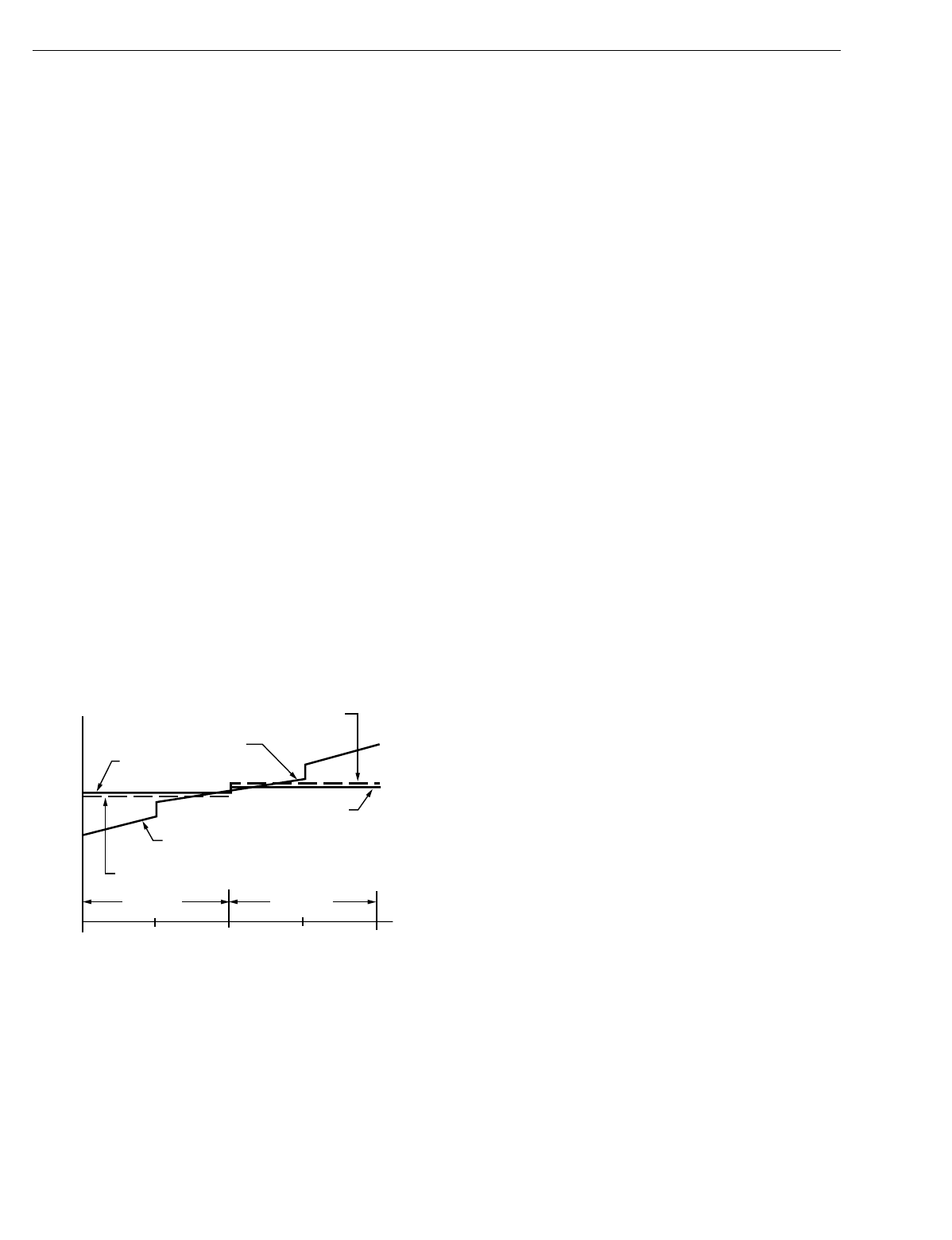
T7200/T7300 and Conventional Thermostats
P+I Control
The T7200/T7300 microprocessor based control requires that
the user understands temperature control and thermostat
performance. A conventional electromechanical or electronic
thermostat does not control temperature precisely at setpoint.
Typically, there is an offset (droop) in the control point as the
system load changes. This is a phenomenon that most people
in the industry know and accept. Many factors contribute to
offset including switch differential, thermal lag, overshoot,
cycle rates and system load.
The thermostat microprocessor simultaneously gathers,
compares and computes data. Using this data, it controls a
wide variety of functions. The special proprietary algorithm
(program) in the thermostat eliminates the factors causing
offset. This makes temperature control more accurate than
the conventional electromechanical or electronic thermostats.
The temperature control algorithm is called proportional plus
integral (P+I) control.
The thermostat sensor, located on the thermostat or remote,
senses the current space temperature. The proportional error
is calculated by comparing the sensed temperature to the
programmed setpoint. The deviation from the setpoint is the
proportional error.
The thermostat also determines integral error, which is a
deviation based on the length of error time. The sum of the
two errors is the (P+I) error. The cycle rate used to reach and
maintain the setpoint temperature is computed using the P+I.
The addition of the integral error is what differentiates the
thermostat from many other electronic and electromechanical
thermostats. See Fig. 18.
Fig. 18. Proportional temperature control
versus P+I temperature control.
Equipment Protection
As part of the operational sequence, the T7200/T7300
microprocessor also incorporates minimum on and off times
for all heating and cooling stages. Minimum on time is set in
the installer setup number 32. Using the minimum on and off
times assures that rapid cycling of equipment does not occur,
which extends equipment life. Minimum on and off times are
set in the Installer Setup.
T7200/T7300 Thermostat Operation
Startup
When power to the thermostat is turned on, a startup and
initialization program begins. The startup occurs only on initial
powerup. After total loss of power for an extended period, the
current time and day may need to be set, but the user
program is held. The initial default values are heating 68°F
(20°C) and cooling 78°F (26°C) for the Occupied periods.
Unoccupied default values are heating 55°F (13°C) and
cooling 90°F (32°C).
NOTE: The thermostat controls to the Unoccupied default
setpoints of 55°F (13°C) for heat and 90°F (32°C) for
cool when no program is set.
Occupied Operation
When the thermostat is operating in the Occupied period,
the temperature is controlled to the occupied heat or cool
setpoint. The normally open (A1) auxiliary relay contacts are
closed and the normally closed (A3) auxiliary relay contacts
are opened during the Occupied periods (if the subbase being
used has this option). The fan operates as follows: fan
selection can be set to On (always energized) or Auto (cycles
with Y1 or W1).
Unoccupied Operation
When the thermostat is operating in the Unoccupied period,
the temperature is controlled to the Unoccupied heat or cool
setpoint. The normally open (A1) relay contact is open and the
normally closed (A3) relay contact is closed. The fan operates
as follows: fan is always intermittent (cycles with Y1 or W1).
Intelligent Recovery® Feature
Intelligent Recovery is a Honeywell trademarked feature
for the way the thermostat controls heating and cooling
equipment during recovery from the Unoccupied to Occupied
setting. During recovery, the control point changes gradually
rather than shifting immediately from the energy saving
setting to the comfort setting.
When Intelligent Recovery is used in heating, the control point
raises gradually, maximizing the use of the more economical
first stage heat to bring the sensed temperature to the desired
comfort setpoint. This minimizes using the typically more
expensive second-stage heat.
Advantages of Intelligent Recovery are:
•Comfort setting is achieved at the programmed time and
maintained regardless of weather conditions; occupants
are comfortable.
•Drafts from low-temperature discharge air are minimized
during Occupied periods.
•The more economical first stage of heat is the primary heat
source during recovery, minimizing use of the expensive
second-stage heat.
•Comfort and energy savings can be achieved in both
heating and cooling.
•Heat cycling reduced, extending equipment life.
RECOVERY FROM UNOCCUPIED
The heat pump heat recovery ramp is 3°F (1.6°C) per hour.
This differs from the 5°F (2.8°C) per hour for conventional
systems. The 3°F helps the system use the economical heat
pump more and the expensive auxiliary heat less. The cooling
ramp is 5°F, the same as for conventional systems.
HEATING COOLING
PERCENT LOAD
TEMPERATURE
THERMOSTAT
HEAT SETPOINT
P+I CONTROL
POINT
PROPORTIONAL COOL
CONTROL POINT
THERMOSTAT
COOL SETPOINT
P+I CONTROL POINT
PROPORTIONAL HEAT
CONTROL POINT
M4414
100 50 0 50 100
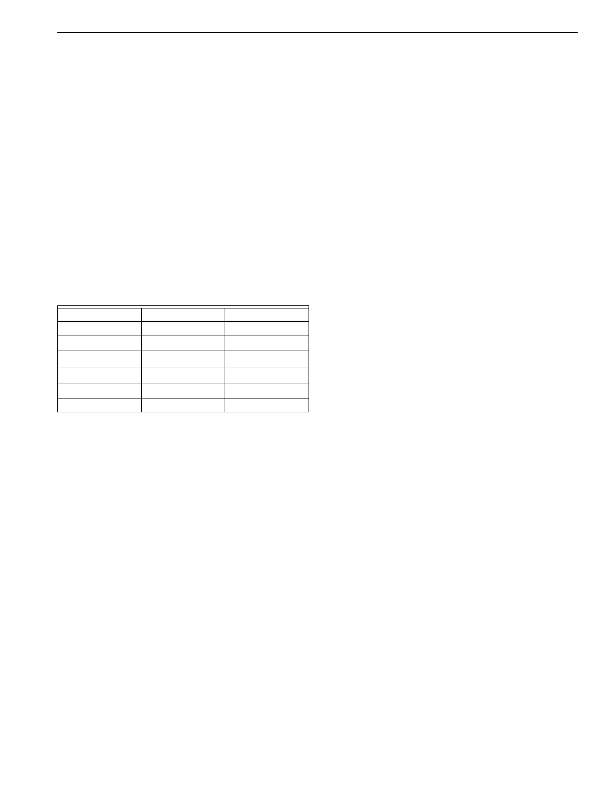
T7200D,E, T7300D,E,F AND Q7300 SERIES 2000 PROGRAMMABLE COMMERCIAL THERMOSTATS AND SUBBASES
21 63-4355—4
Conventional System
The T7200 and T7300D,F Thermostats with Q7300A,G,H
Subbases are designed for conventional heat/cool
applications.
Heat Pump Operation
The T7200E and T7300E,F Thermostats with Q7300C,D,H
Subbases are designed for heat pump applications. Additional
information is required when configured for heat pump
applications.
O AND B TERMINALS FOR HEATING OR COOLING CHANGEOVER
The Q7300C controls heat pump changeover. The Q7300D,H
is only used in a heat pump application when the heat pump
controls the reversing valve changeover. See Table 12 for the
operation of the O and B terminals on the Q7300C, H2003.
O AND B TERMINALS ON A CONVENTIONAL SUBBASE
Conventional subbase O and B terminals can be used to drive
dampers and valves. The O terminal is energized on a call for
cool and the B terminal is energized on a call for heat.
Table 12. Operation of Q7300 O and B terminals.
aWhen the system is calling for heat or is de-energized, but
the last function was heat.
bWhen the system is calling for cool or is de-energized, but
the last function was cool.
cWhen the last function was heating, the operation is the
same as Auto (Heat). If the last function was cooling, the
operation is the same as Auto (Cool).
FAN OPERATION
When the fan is set to On, the fan is energized continuously in
the Occupied period. The Auto setting energizes the fan with
the heating or cooling system. If the subbase is Q7300D, the
fan cycles with Y1 and W1 during Unoccupied period.
EMERGENCY HEAT (SELECT T7300 THERMOSTATS ONLY)
With the system set for Em Heat, auxiliary heat serves as
stage one; compressor stages are locked off. The fan cycles
with the auxiliary heat.
COMMUNICATING SUBBASE
Select T7300F Thermostats with the Q7300H Communicating
Subbase are designed for conventional or heat pump
applications in a LonWorks® network. The Q7300H Subbase
allows remote access and the sharing of clock, schedule,
setpoints, bypass and other system parameters in a
LONWORKS® network. See Fig. 33 for a T7300F/Q7300H
wiring layout in a LONWORKS® network.
GENERAL OPERATION INFORMATION
Cycle Rates
The thermostat control algorithm maintains the temperature
by cycling stages of heating or cooling to meet setpoint.
Subbase Auxiliary Relay
The Q7300 Auxiliary Relay output acts as a time-of-day switch
to be used with an economizer minimum position control. The
normally open (A1) auxiliary relay contacts are closed during
the Occupied period and open during the Unoccupied period.
The normally closed (A3) auxiliary relay contacts are open
during the Occupied period and closed during the Unoccupied
period. The contacts are in the normal state during recovery.
Interfacing with Electromechanical
Economizers (Subbases with Auxiliary Relay)
Mechanical cooling is often used when outside temperatures
are in the 50°F (10°C) to 60°F (16°C) range and humidity is
below 50 percent. In central and northern climates, hundreds
of hours fall into this temperature category. By permitting 80 to
100 percent outside air into the system, mechanical cooling
may not be needed at all, particularly during Spring and Fall.
An economizer is used to take advantage of the outside air.
The typical economizer consists of an outside air damper,
motor, outdoor air changeover control and a minimum position
potentiometer. The motor controls the dampers. Suitability of
the outside air for cooling is determined by the outdoor air
changeover control. The potentiometer is used for adjusting
the minimum position of the economizer dampers, which
provide a minimum amount of fresh air for ventilation.
The economizer reduces compressor run time, thereby saving
energy and extending the compressor life. The drawback to
using the economizer is that during the Unoccupied period, if
there is no call for cool or outdoor air is not suitable for free
cooling, the economizer is controlled to minimum position.
This position allows some percentage of outdoor air to enter
the building, regardless of air suitability. The situation can
cause the heating or cooling to run more often than if suitable
outdoor air is permitted to enter the building.
The thermostat can take advantage of an economizer by
connecting the subbase auxiliary relay contacts (A1 and A2)
to control the economizer minimum position potentiometer.
The contacts close during the Occupied period, allowing the
economizer to operate normally. The contacts open during the
Unoccupied period, disabling the minimum position feature of
the economizer. The open contacts cause the economizer to
drive dampers fully closed instead of staying at minimum open
position. This reduces the possibility of unsuitable outdoor air
from entering the building, which lowers the internal load on
the HVAC system and saves additional energy.
Other Uses for the Auxiliary Relay
Examples of other uses of the auxiliary relay are hot water
heaters, lighting or baseboard heat. The additional loads are
connected to the auxiliary relay contacts on the subbase. The
contacts are rated for 1.6A at 30 Vac, but can be adapted to
higher current applications with the use of an external relay
and transformer. See Fig. 19.
System Selection O Terminal B Terminal
Heat Open Closed
Cool Closed Open
Auto (Heat)aOpen Closed
Auto (Cool)bClosed Open
Emergency Heat Open Closed
Off cc
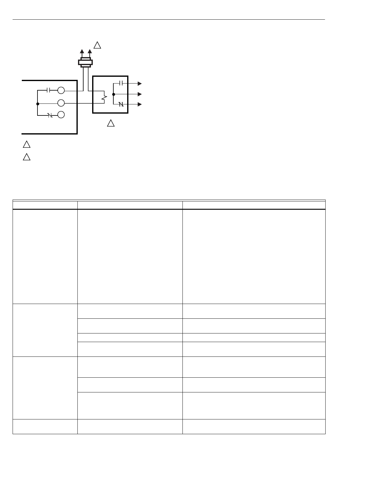
T7200D,E, T7300D,E,F AND Q7300 SERIES 2000 PROGRAMMABLE COMMERCIAL THERMOSTATS AND SUBBASES
63-4355—422
Fig. 19. Use of external relay and transformer for
auxiliary loads greater than 1.6A.
TROUBLESHOOTING GUIDE
Refer to Table 13 for troubleshooting information.
M4944
L1
(HOT) L2 1
1
2
2
POWER SUPPLY. PROVIDE DISCONNECT MEANS AND OVERLOAD
PROTECTION AS REQUIRED.
RELAY REQUIRED (R8222 OR SIMILAR).
Q7300 SUBBASE
TO
LOAD
AUXILIARY
RELAY
CONTACTS
A1
A2
A3
Table 13. Troubleshooting Information.
Symptom Possible Cause Action
Display will not come on. Thermostat is not being powered. •Check that X terminal is connected to the system
transformer.
•Check for 24 Vac between X and R or RH terminals.
—If missing 24 Vac:
—check if the circuit breaker is tripped; if so, reset
the circuit breaker.
—check if the system fuse is blown; if so, replace
the fuse.
—check if the HVAC equipment power switch on
the is in the Off position; if so, set to the On
position.
—check wiring between thermostat and HVAC
equipment and replace any broken wires and
tighten any loose connections.
—If 24 Vac is present, proceed with troubleshooting.
Temperature display is
incorrect. Room temperature display has been
reconfigured. Enter Installer Setup number 37 and reconfigure the
display.
Thermostat is configured for °F or °C
display. Enter Installer Setup number 14 and reconfigure the
display.
Bad thermostat location. Relocate the thermostat.
Display shows two dashes and a degree
sign. Installer Setup 22 is set for remote sensing and the
sensor is missing or the circuit is open or shorted.
Temperature settings will
not change.
(Example: Cannot set
heating higher or cooling
lower.)
Upper or lower temperature limits were
reached. Check the temperature setpoints:
•Heating limits are 40 to 90°F (7 to 31°C)
•Cooling limits are 45 to 99°F (9 to 37°C)
The setpoint temperature range stops
were configured. Check Installer Setup number 34 and 35 and reconfigure
the setpoint stops.
Keypad is locked. When a locked key is
pressed, LOC flashes on the LCD. •Reset DIP switch 1 on back of thermostat to enable
keypad.
•Enter Installer Setup number 25 or 40 and reconfigure
keypad lockout level.
Unable to configure
Installer Setup Installer Setup is locked out. Reset the DIP switch 1 on back of thermostat to enable
keypad.

T7200D,E, T7300D,E,F AND Q7300 SERIES 2000 PROGRAMMABLE COMMERCIAL THERMOSTATS AND SUBBASES
23 63-4355—4
CROSS REFERENCE
All T7300/Q7300 Series 2000 models are different from the existing T7300/Q7300 T8611 and T8621 devices as summarized in
Table 14.
Temperature settings
change from original
setting.
Trying to set heat and cooling setpoints
too close together. Automatic changeover
thermostat models have a deadband.
Example: cool setpoint: 72, deadband: 3,
heat setpoint: 68; changing heat setpoint
to 70 automatically changes cool setpoint
to 73.
•Check that the heating setpoint is lower than the
cooling setpoint.
•Check Installer Setup number 30 to identify the
deadband between heating and cooling setpoints.
Reconfigure if desired.
Room temperature is out
of control. Remote temperature sensing is not
working. Checkout all remote sensors.
Heating will not come on. No power to the thermostat. •Check that X terminal is connected to the system
transformer.
•Check for 24 Vac between X and R or RH terminals.
—If missing 24 Vac:
—check if the circuit breaker is tripped; if so, reset
the circuit breaker.
—check if the system fuse is blown; if so, replace
the fuse.
—check if the HVAC equipment power switch on
the is in the Off position; if so, set to the On
position.
—check wiring between thermostat and HVAC
equipment and replace any broken wires and
tighten any loose connections.
—If 24 Vac is present, proceed with troubleshooting.
Heating will not come on
(Continued). Thermostat minimum off time is activated
and wait indicator is displayed. •Wait up to five minutes for the system to respond.
•Enter Installer Setup number 38. Reconfigure
minimum off time (if required).
System selection is not set to Heat. Set system selection to Heat.
Cooling will not come on. No power to the thermostat. •Check that X terminal is connected to the system
transformer.
•Check for 24 Vac between X and R or RC terminals.
—If missing 24 Vac:
—check if the circuit breaker is tripped; if so, reset
the circuit breaker.
—check if the system fuse is blown; if so, replace
the fuse.
—check if the HVAC equipment power switch on
the is in the Off position; if so, set to the On
position.
—check wiring between thermostat and HVAC
equipment and replace any broken wires and
tighten any loose connections.
—If 24 Vac is present, proceed with troubleshooting.
Thermostat minimum off time is activated
and wait indicator is displayed. •Wait up to five minutes for the system to respond.
•Enter Installer Setup number 33. Reconfigure
minimum off- time (if required).
System selection is not set to Cool. Set system selection to Cool.
System on indicator
(flame: heat,
snowflake: cool) is
displayed, but no warm
or cool air is coming from
the registers.
Conventional heating equipment turns on
the fan only once the furnace has warmed
up to a setpoint.
Wait one minute after seeing the on indicator and then
check the registers.
Heating or cooling equipment is not
operating. Verify operation of heating or cooling equipment in self-
test.
Table 13. Troubleshooting Information. (Continued)
Symptom Possible Cause Action
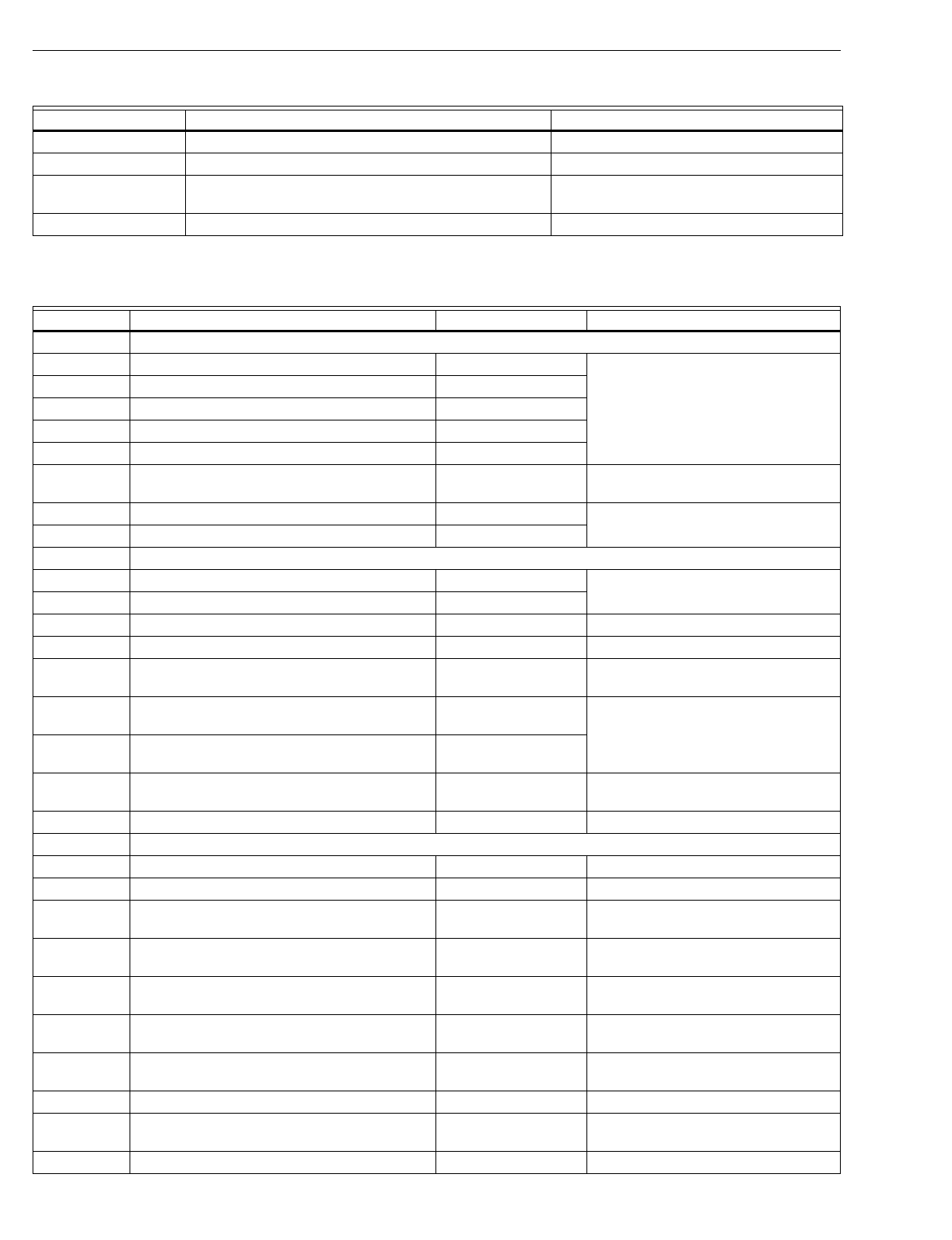
T7200D,E, T7300D,E,F AND Q7300 SERIES 2000 PROGRAMMABLE COMMERCIAL THERMOSTATS AND SUBBASES
63-4355—424
Table 14. Differences from existing T7300/Q7300 to new T7300/Q7300 Series 2000 devices.
Refer to Table 15 for thermostat and subbase cross referencing information.
Feature/Function Present T7300/Q7300, T8611, T8621 Families T7300/Q7300 Series 2000 Family
System switching Mechanical switch on Q7300 subbase. Keyboard entry on T7300 thermostat.
Fan switching Mechanical switch on Q7300 subbase. Keyboard entry on T7300 thermostat.
Installer configuration Field settings made via DIP switches on the back of the
thermostat and subbase. Field settings made through the T7300
thermostat keyboard.
Device color Beige or Premier White®. Taupe or Premier White®.
Table 15. Thermostat and Subbase Cross Reference.
Model Number Description Trade Replacement Remarks
Q7300A Multistage conventional subbase; system switch: none; fan switch: none.
Q7300A1000 1-stage heat and 1-stage cool. T7300F2002/Q7300A2008
Q7300A1018 2-stage heat and 2-stage cool. T7300F2002/Q7300A2016
Q7300A1034 1-stage heat and 1-stage cool; Trane part no. BAS-0444. T7300F2002/Q7300A2008
Q7300A1042 2-stage heat and 2-stage cool; Trane part no. BAS-0445. T7300F2002/Q7300A2016
Q7300A1059 2-stage heat and 2-stage cool; Micrometl part no. 901-3. T7300F2002/Q7300A2016
Q7300A1067 2-stage heat and 2-stage cool; Carrier part no.
HH93AX005. T7300F2002/ Q7300A2016 Wiring differences (old=new): C=X, A1=A2,
A2=A1.
Q7300A1075 1-stage heat and 1-stage cool; gray color. T7300F2002/Q7300A2008
Q7300A1083 2-stage heat and 2-stage cool; gray color. T7300F2002/Q7300A2016
Q7300B Multistage conventional subbase; system switch: AUTO-COOL-OFF-HEAT; fan switch: AUTO-ON.
Q7300B1008 2-stage heat and 2-stage cool. T7300F2010/Q7300A2016
Q7300B1016 2-stage heat and 2-stage cool; Lennox part no. 81G6001. T7300F2010/Q7300A2016
Q7300B1024 2-stage heat and 2-stage cool; York part no. 025-27507. T7300F2010/Q7300A2016 Wiring differences (old=new): B=X.
Q7300B1032 2-stage heat and 2-stage cool; Trane part no. BAS-0446. T7300F2010/Q7300A2016
Q7300B1040 2-stage heat and 2-stage cool; Carrier part no.
HH93AX004. T7300F2010/Q7300A2016 Wiring differences (old=new): C=X, A1=A2,
A2=A1.
Q7300B1057 2-stage heat and 2-stage cool; Snyder General part no.
1520510. T7300F2010/Q7300A2016
Q7300B1065 2-stage heat and 2-stage cool; Snyder General part no.
490249B-04. T7300F2010/Q7300A2016
Q7300B1073 2-stage heat and 2-stage cool; Honeywell TRADELINE®
model. T7300F2010/Q7300A2016 Wiring differences (old=new): B=X.
Q7300B1081 2-stage heat and 2-stage cool; gray color. T7300F2010/Q7300A2016
Q7300C Multistage heat pump subbase; system switch: AUTO-COOL-OFF-HEAT-EM HEAT; fan switch: AUTO-ON.
Q7300C1006 Single-stage heat pump with auxiliary heat (2H/1C). T7300F2010/ Q7300C2004 Wiring differences (old=new): W1=W2, B=A3.
Q7300C1014 2-stage heat pump with auxiliary heat (3H/2C). T7300F2010/Q7300C2012 Wiring differences (old=new): B=A3.
Q7300C1022 2-stage heat pump with auxiliary heat (3H/2C); Lennox
part no. 81G6901. T7300F2010/Q7300C2012 Wiring differences (old=new): B=A3.
Q7300C1030 2-stage heat pump with auxiliary heat (3H/2C); York part
no. 025-27508. T7300F2010/Q7300C2012 Wiring differences (old=new): B=X, X=E.
Q7300C1048 Single-stage heat pump with auxiliary heat (2H/1C); Trane
part no. BAS-0447. T7300F2010/Q7300C2004 Wiring differences (old=new): W1=W2, B=A3.
Q7300C1055 2-stage heat pump with auxiliary heat (3H/2C); Trane part
no. BAS-0048. T7300F2010/Q7300C2012 Wiring differences (old=new): B=A3.
Q7300C1063 Single-stage heat pump with auxiliary heat (2H/1C);
Micrometl part no. 901-24. T7300F2010/Q7300C2004 Wiring differences (old=new): W1=W2, B=A3.
Q7300C1071 2-stage heat pump with auxiliary heat (3H/2C). T7300F2010/Q7300C2012 Wiring differences (old=new): B=A3.
Q7300C1089 2-stage heat pump with auxiliary heat (3H/2C); Honeywell
TRADELINE® model. T7300F2010/Q7300C2012 Wiring differences (old=new): B=X, X=E.
Q7300C1097 Single-stage heat pump with auxiliary heat (2H/1C). T7300F2010/Q7300C2004 Wiring differences (old=new): W1=W2, B=A3.
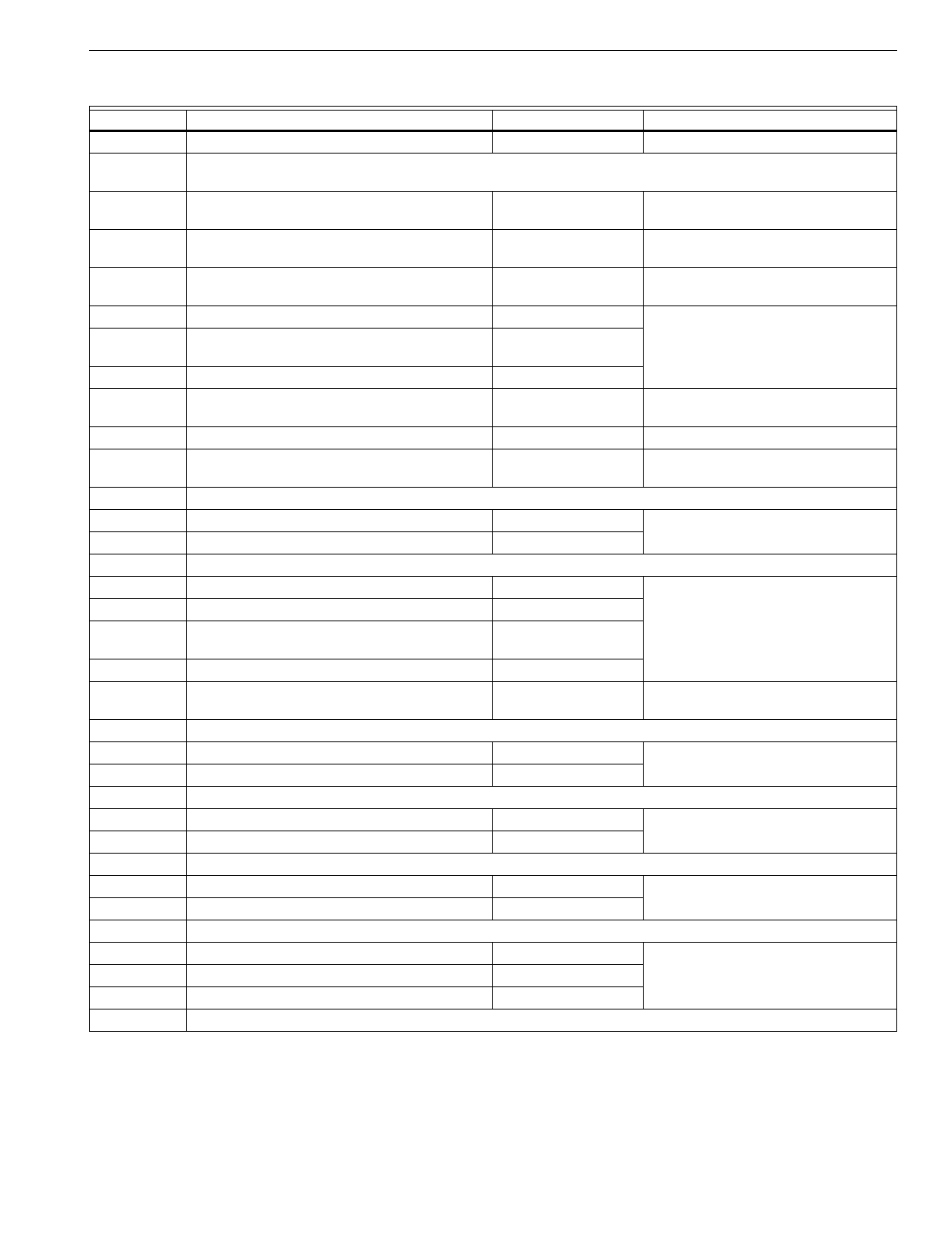
T7200D,E, T7300D,E,F AND Q7300 SERIES 2000 PROGRAMMABLE COMMERCIAL THERMOSTATS AND SUBBASES
25 63-4355—4
Q7300C1105 2-stage heat pump with auxiliary heat (3H/2C); gray color. T7300F2010/Q7300C2012 Wiring differences (old=new): B=A3.
Q7300D Multistage heat pump subbase; does not include O or B terminals; system switch: AUTO-COOL-OFF-HEAT-EM HEAT; fan
switch: AUTO-ON.
Q7300D1004 2-stage heat pump with auxiliary heat (3H/2C); Carrier
part no. HH93AX002. T7300F2010/ Q7300D2002 Wiring differences (old=new): C=X, A1=A2,
A2=A1.
Q7300D1012 Single-stage heat pump with auxiliary heat (2H/1C);
Carrier part no. HH93AX003. T7300F2010/ Q7300D2002 Wiring differences (old=new): C=X, A1=A2,
A2=A1.
Q7300D1020 2-stage heat pump with auxiliary heat (3H/2C); York part
no. 025-27724-000. T7300F2010/ Q7300D2002 Wiring differences (old=new): B=X, X=X1.
Q7300D1038 2-stage heat pump with auxiliary heat (3H/2C). T7300F2010/Q7300D2002
Q7300D1046 2-stage heat pump with auxiliary heat (3H/2C); Lennox
part no. 13H7601. T7300F2010/Q7300D2002
Q7300D1053 Single-stage heat pump with auxiliary heat (2H/1C). T7300F2010/Q7300D2010
Q7300D1061 2-stage heat pump with auxiliary heat (3H/2C); Honeywell
TRADELINE® model. T7300F2010/Q7300D2002 Wiring differences (old=new): B=X, X=X1.
Q7300D1079 2-stage heat pump with auxiliary heat (3H/2C); gray color. T7300F2010/Q7300D2002
Q7300D1087 Single-stage heat pump with auxiliary heat (2H/1C); gray
color. T7300F2010/Q7300D2002
Q7300E Multistage conventional subbase; system switch: none; fan switch: AUTO-ON.
Q7300E1001 2-stage heat and 2-stage cool. T7300F2010/Q7300A2016
Q7300E1019 2-stage heat and 2-stage cool; gray color. T7300F2010/Q7300A2016
Q7300F Multistage heat pump subbase; system switch: none; fan switch: none.
Q7300F1009 Single-stage heat pump with auxiliary heat (2H/1C). T7300F2002/Q7300C2004
Q7300F1017 2-stage heat pump with auxiliary heat (3H/2C). T7300F2002/Q7300C2012
Q7300F1025 Single-stage heat pump with auxiliary heat (2H/1C); gray
color. T7300F2002/Q7300C2004
Q7300F1033 2-stage heat pump with auxiliary heat (3H/2C); gray color. T7300F2002/Q7300C2012
Q7300F1041 Single-stage heat pump with auxiliary heat (2H/1C);
Carrier part no. HH93AX006. T7300F2002/Q7300C2004 Wiring differences (old=new): C=X.
Q7300G Conventional heat pump subbase; system switch: AUTO-COOL-OFF-HEAT; fan switch: none.
Q7300G1007 1-stage heat and three-stage cool. T7300F2010/Q7300G2005
Q7300G1015 1-stage heat and three-stage cool; gray color. T7300F2010/Q7300G2005
Q7300L Multistage conventional subbase used with ML984A and V5013; system switch: none; fan switch: AUTO-ON.
Q7300L1006 2-stage heat and 1-stage cool. T7300F2010/Q7300L2004
Q7300L1014 2-stage heat and 1-stage cool; gray color. T7300F2010/Q7300L2004
T7200A 1-stage heat and 1-stage cool conventional thermostat.
T7200A1006 Honeywell logo. T7200D2008
T7200A1022 Honeywell logo with international faceplate. T7200D2008
T7200B 1-stage heat and 1-stage cool heat pump thermostat.
T7200B1004 Honeywell logo. T7200E2005
T7200B1012 Mammoth logo; part no. 71116701. T7200E2005
T7200B1020 Carrier logo; part no. HH07AX010A. T7200E2005
T7300A Multistage conventional and heat pump thermostat.
Table 15. Thermostat and Subbase Cross Reference. (Continued)
Model Number Description Trade Replacement Remarks
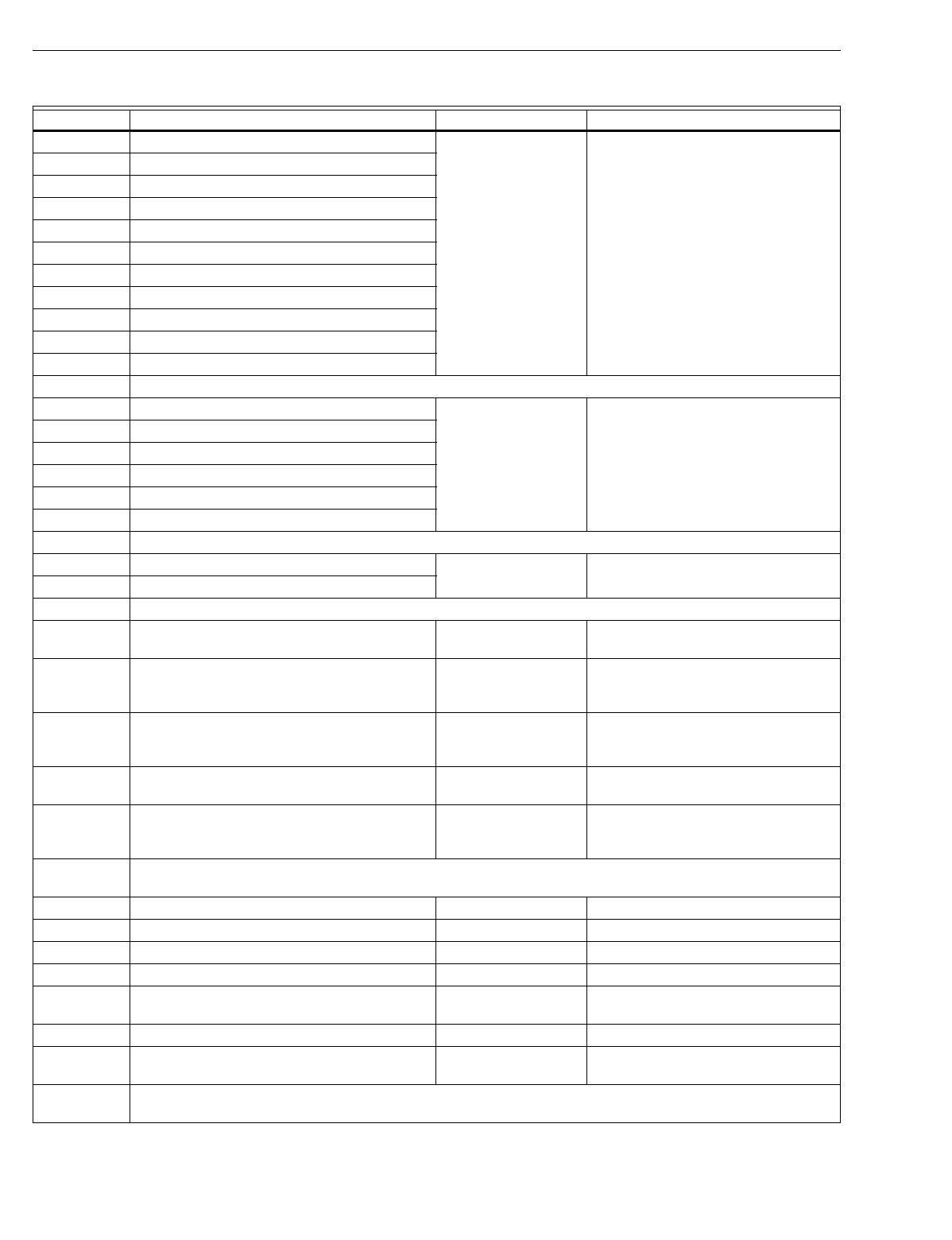
T7200D,E, T7300D,E,F AND Q7300 SERIES 2000 PROGRAMMABLE COMMERCIAL THERMOSTATS AND SUBBASES
63-4355—426
T7300A1005 Honeywell logo. See subbase description for replacement
information.
T7300A1013 York logo; part no. 025-27506.
T7300A1021 Lennox logo; part no. 81G5901.
T7300A1039 Trane logo; part no. THT-0608.
T7300A1047 Micrometl logo; part no. 901-114.
T7300A1054 Honeywell logo with international faceplate.
T7300A1062 Carrier logo; part no. HH07AX005.
T7300A1070 Roca logo with international faceplate.
T7300A1088 Honeywell logo with Spanish faceplate.
T7300A1104 Honeywell logo; Premier White® color.
T7300A1120 Luxaire logo; part no. 6ET04700224A.
T7300B Multistage conventional and heat pump thermostat with 3-HOUR OVERRIDE key on cover.
T7300B1003 Honeywell logo. See subbase description for replacement
information.
T7300B1011 Climate Control logo; part no. 490249B-05.
T7300B1029 McQuay logo; part no. 490249B-06.
T7300B1037 Arcoaire logo; part no. 1506746.
T7300B1045 Comfortmaker logo; part no. 1505746.
T7300B1052 Honeywell logo; Premier White® color.
T7300C Multistage conventional and heat pump thermostat with limited access cover.
T7300C1001 Honeywell logo. See subbase description for replacement
information.
T7300C1019 Honeywell logo; Premier White® color.
T8611M Three-stage heat and 2-stage cool heat pump thermostat; System: EM HEAT-HEAT-OFF-AUTO-COOL; fan switch: ON-AUTO.
T8611M7008 Honeywell logo; TRADELINE® model. T7300E2004/Q7300C2020 Wiring differences (old=new): C=X, X4 to X
field-installed jumper required.
T8611M7040 Honeywell logo; TRADELINE® model; remote sensor
capability. T7300E2020/Q7300C2020 Wiring differences (old=new): C=X, X4 to X
field-installed jumper required; purchase new
remote 2-wire sensors separately.
T8611M7057 Honeywell logo; TRADELINE® Premier White® color
model; remote sensor capability. T7300E2020/Q7300C2020 Wiring differences (old=new): C=X, X4 to X
field-installed jumper required; purchase new
remote 2-wire sensors separately.
T8611M7065 Trol-A-Temp® by Honeywell logo; Premier White® color. None See Trol-A-Temp® representative for
replacement.
T8611M7073 Trane logo; white styling; part no. TAYSTAT502. T7300E2004/Q7300C2020 Wiring differences (old=new): B=X, F=X1,
X2=E, Y1=Y, X4 to X field-installed jumper
required.
T8621A 1-stage heat and 1-stage cool conventional thermostat; two transformer capability; system switch: HEAT-AUTO-COOL-OFF;
fan switch: ON-AUTO.
T8621A7002 Honeywell logo; TRADELINE® model. T7300D2007/Q7300A2008 Wiring differences (old=new): C=X.
T8621A7010 Honeywell logo; Canadian TRADELINE® model. T7300D2007/Q7300A2008 Wiring differences (old=new): C=X.
T8621A7028 Amana logo. T7300D2007/Q7300A2008 Wiring differences (old=new): C=X.
T8621A7036 Trane logo; part no. THT-0605, order no. 13510323-15-7. T7300D2007/Q7300A2008 Wiring differences (old=new): C=X.
T8621A7044 Honeywell logo; TRADELINE® model; remote sensor
capability. T7300D2049/Q7300A2008 Wiring differences (old=new): C=X; purchase
new remote 2-wire sensors separately.
T8621A7051 McQuay logo; Premier White® color; part no. 067114201. T7300D2007/Q7300A2008 Wiring differences (old=new): C=X.
T8621A7069 Honeywell logo; TRADELINE® Premier White® color
model; remote sensor capability. T7300D2049/Q7300A2008 Wiring differences (old=new): C=X; purchase
new remote 2-wire sensors separately.
T8621B 1-stage heat and 2-stage cool conventional thermostat; one transformer capability; System: HEAT-AUTO-COOL-OFF; fan
switch: ON-AUTO
Table 15. Thermostat and Subbase Cross Reference. (Continued)
Model Number Description Trade Replacement Remarks
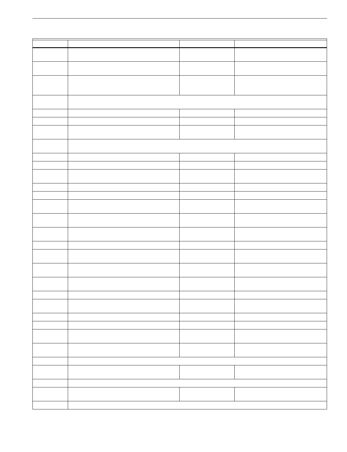
T7200D,E, T7300D,E,F AND Q7300 SERIES 2000 PROGRAMMABLE COMMERCIAL THERMOSTATS AND SUBBASES
27 63-4355—4
T8621B7000 Carrier logo; LOW and HIGH SPEED LED; used on
multispeed equipment; part no. HH07AX011. T7300D2007/Q7300A2008 Wiring differences (old=new): L=X1; X4 to X
and RC to RH field-installed jumper required.
T8621B7018 BDP multi-logo; LOW and HIGH SPEED LED; used on
multispeed equipment; part no. HH07AX012. T7300D2007/Q7300A2008 Wiring differences (old=new): L=X1; X4 to X
and RC to RH field-installed jumper required.
T8621B7026 Honeywell logo; TRADELINE® model; Premier White®
color; direct replacement for T8621B7000 and
T8621B7018.
T7300D2007/Q7300A2008 Wiring differences (old=new): L=X1; X4 to X
and RC to RH field-installed jumper required.
T8621C 2-stage heat and 1-stage cool conventional thermostat; two transformer capability; system switch: HEAT-AUTO-COOL-OFF;
fan switch: ON-AUTO.
T8621C7008 Honeywell logo; TRADELINE® model. T7300D2007/Q7300A2040 Wiring differences (old=new): C=X.
T8621C7016 Honeywell logo; Canadian TRADELINE® model. T7300D2007/Q7300A2040 Wiring differences (old=new): C=X.
T8621C7032 Trane logo; system switch: HEAT-OFF-COOL; one
transformer; dual fuel switch; part no. TAYSTAT302. T7300D2007/Q7300A2040 Wiring differences (old=new): B=X; RC to RH
field-installed jumper required.
T8621D 2-stage heat and 2-stage cool conventional thermostat; two transformer capability; system switch: HEAT-AUTO-COOL-OFF;
fan: ON-AUTO.
T8621D7006 Honeywell logo; TRADELINE® model. T7300D2007/Q7300A2008 Wiring differences (old=new): C=X.
T8621D7014 Honeywell logo; Canadian TRADELINE® model. T7300D2007/Q7300A2008 Wiring differences (old=new): C=X.
T8621D7022 Honeywell logo; TRADELINE® model; system switch:
HEAT-OFF-COOL; dual fuel switch; O and B terminals. T7300D2007/Q7300A2057 Wiring differences (old=new): C=X.
T8621D7030 Trane logo; part no. THT-0607; order no. 13510323-17-7. T7300D2007/ Q7300A2008 Wiring differences (old=new): C=X.
T8621D7048 BDP multi-logo. T7300D2007/Q7300A2008 Wiring differences (old=new): C=X.
T8621D7055 Lennox logo; one transformer capability; part no.
27H2901. T7300D2007/Q7300A2008 Wiring differences (old=new): C=X. RC to RH
field-installed jumper required.
T8621D7063 Trol-A-Temp® by Honeywell logo; system switch: HEAT-
OFF-COOL; O and B terminals. None Wiring differences (old=new): C=X; see Trol-A-
Temp® representative for replacement.
T8621D7071 Trol-A-Temp® by Honeywell logo; no system or fan
switching. None See Trol-A-Temp® representative for
replacement.
T8621D7089 Carrier logo; part no. HH641-103. T7300D2007/Q7300A2008 Wiring differences (old=new): C=X.
T8621D7097 Honeywell logo; TRADELINE® model; remote sensor
capability. T7300D2007/Q7300A2008 Wiring differences (old=new): C=X; purchase
new remote 2-wire sensors separately.
T8621D7105 Friedrich logo; L terminal; extra switch for louver control;
part no. 616-789-01. None See OEM for replacement information.
T8621D7113 Honeywell Logo; Canadian TRADELINE® Premier
White® color model. T7300D2007/Q7300A2008 Wiring differences (old=new): C=X.
T8621D7139 McQuay logo; Premier White® color; part no. 067114301. T7300D2007/Q7300A2008 Wiring differences (old=new): C=X.
T8621D7147 Honeywell logo; TRADELINE® Premier White® color
model; remote sensor capability. T7300D2007/Q7300A2008 Wiring differences (old=new): C=X.; purchase
new remote 2-wire sensors separately.
T8621D7154 Carrier Weathermaker logo; part no. H07AX014. T7300D2007/Q7300A2008 Wiring differences (old=new): C=X.
T8621D7162 Carrier Zone Perfect logo; part no. HH07AX015. T7300D2007/Q7300A2008 Wiring differences (old=new): C=X.
T8621D7170 Honeywell logo; TRADELINE® Premier White® color
model. T7300D2007/Q7300A2008 Wiring differences (old=new): C=X.
T8621D7188 Carrier logo; Premier White® color; part no.
HH07AT014W. T7300D2007/Q7300A2008 Wiring differences (old=new): C=X.
T8621E 2-stage cool only model with louver control; system switch: COOL-OFF; fan switch: ON-AUTO.
T8621E7003 Friedrich logo; L terminal; extra switch for louver control;
part no. 616-789-00. None See OEM for replacement information.
Y7200 1-stage heat and 1-stage cool heat pump thermostat.
Y7200B1009 Contains six T7200B1020 Thermostats; Carrier part no.
50QE90016101. T7200E2005 Wiring differences (old=new): C=X.
Y7300 Multistage T7300 thermostat and Q7300 subbase.
Table 15. Thermostat and Subbase Cross Reference. (Continued)
Model Number Description Trade Replacement Remarks
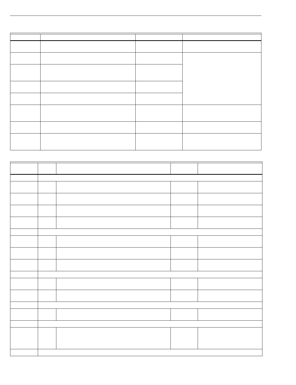
T7200D,E, T7300D,E,F AND Q7300 SERIES 2000 PROGRAMMABLE COMMERCIAL THERMOSTATS AND SUBBASES
63-4355—428
Y7300A1000 Contains one T7300A1047 Thermostat and one
Q7300A1059 Subbase; Micrometl part no. 1060A-100. T7300F2002/Q7300A2016 Wiring differences (old=new): B=X.
Y7300A1018 Contains one T7300A1062 Thermostat and one
Q7300F1041 Subbase; Carrier part no. 50QE90028101. T7300F2002/Q7300C2004
Y7300B1008 Contains one T7300A1013 Thermostat and one
Q7300B1024 Subbase; York part no. 025-27504; York
model no. 2ET04700224.
T7300F2010/Q7300A2016
Y7300B1016 Contains one T7300B1045 Thermostat and one
Q7300B1057 Subbase; Comfortmaker part no. 1505748. T7300F2010/Q7300A2016
Y7300B1024 Contains one T7300B1037 Thermostat and one
Q7300B1057 Subbase; Arcoaire part no. 1506748. T7300F2010/Q7300A2016
Y7300C1006 Contains one T7300A1013 Thermostat and one
Q7300C1030 Subbase; York part no. 025-27505; York
model no. 2ET04700324.
T7300F2010/Q7300C2012 Wiring differences (old=new): B=X, X=E.
Y7300C1014 Contains one T7300A1047 Thermostat and one
Q7300C1063 Subbase; Micrometl part no. 1060A-200. T7300F2010/Q7300C2004 Wiring differences (old=new): W1=W2, B=A3.
Y7300D1004 Contains one T7300A1013 Thermostat and one
Q7300D1020 Subbase; York part no. 025-27724-000;
York model no. 2ET04700424A.
T7300F2010/Q7300D2002 Wiring differences (old=new): B=X, X=L1.
Table 16. T7300/Q7300 Series 2000 Cross Reference.
Model Number Figure
Number Description Trade
Replacement Remarks
Q7300A Multistage conventional subbase used with T7300D or F Thermostat.
Q7300A2008 21 One-stage heat and one-stage cool; TRADELINE® model; remote
sensor capability; taupe color. Q7300A2008 Direct replacement for T8621A
Thermostats.
Q7300A2016 24 Two-stage heat and two-stage cool; TRADELINE® model; remote
sensor and discharge air sensor capability; taupe color. Q7300A2016
Q7300A2040 22 Two-stage heat and one-stage cool; TRADELINE® model; taupe
color. Q7300A2040 Direct replacement for T8621C
Thermostats.
Q7300A2057 23 Two-stage heat and two-stage cool; TRADELINE® model; O and B
terminals; taupe color. Q7300A2057 Direct replacement for T8621D7022
Thermostat.
Q7300C Multistage heat pump subbase used with T7300E or F Thermostat.
Q7300C2004 25 Single-stage heat pump with auxiliary heat (2H/1C); TRADELINE®
model; remote sensor and discharge air sensor capability; taupe color Q7300C2004
Q7300C2012 26 Two-stage heat pump with auxiliary heat (3H/2C); TRADELINE®
model; remote sensor and discharge air sensor capability; taupe color. Q7300C2012
Q7300C2053 27 Two-stage heat pump with auxiliary heat (3H/2C); TRADELINE®
model; CHECK LED and FAIL LED; taupe color. Q7300C2020 Direct replacement for T8611M
Thermostats.
Q7300D Multistage heat pump subbase used with T7300E or F Thermostat.
Q7300D2002 28 Two-stage heat pump with auxiliary heat (3H/2C); TRADELINE®
model; remote sensor and discharge air sensor capability; taupe color. Q7300D2002
Q7300D2010 29 Single-stage heat pump with auxiliary heat (2H/1C); TRADELINE®
model; remote sensor and discharge air sensor capability; taupe color. Q7300D2010
Q7300G Multistage conventional subbase used with T7300D or F Thermostat.
Q7300G2005 30 Three-stage heat and three-stage cool (3H/3C); TRADELINE® model;
remote sensor and discharge air sensor capability; taupe color. Q7300G2005
Q7300L Multistage subbase used with ML7984A, V5011, V5013 and T7300D or F Thermostat.
Q7300L2004 31, 32 Two-stage heat and one-stage cool (2H/1C); TRADELINE® model;
multispeed fan; contacts for damper control relay and pump interlock
relay; HEAT LED and COOL LED; remote sensor and discharge air
sensor capability; taupe color.
Q7300L2004 Direct replacement for Q7300L1006
and Q7300L1014 Subbases.
T7200D One-stage heat and one-stage cool conventional thermostat.
Table 15. Thermostat and Subbase Cross Reference. (Continued)
Model Number Description Trade Replacement Remarks
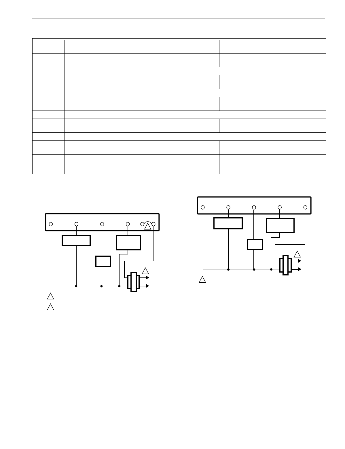
T7200D,E, T7300D,E,F AND Q7300 SERIES 2000 PROGRAMMABLE COMMERCIAL THERMOSTATS AND SUBBASES
29 63-4355—4
WIRING DIAGRAMS (FIG. 20-34)
Fig. 20. T7200D with wallplate.
Fig. 21. T7200E with one-stage heat pump system.
T7200D2008 19 Honeywell logo; no system or fan settings. T7200D2008 Direct replacement for T7200A
Thermostats.
T7200E One-stage heat and one-stage cool heat pump thermostat.
T7200E2005 20 Honeywell logo; no system or fan settings. T7200E2005 Direct replacement for T7200B
Thermostats.
T7300D Multistage conventional thermostat used with Q7300A,G, or L Subbase.
T7300D2007 Refer to
subbase Honeywell logo; TRADELINE® model; remote sensor capability;
system settings: Heat-Off-Cool-Auto; taupe color. T7300D2007 Direct replacement for T8621
Thermostats.
T7300E Multistage heat pump thermostat used with Q7300C or D Subbase.
T7300E2020 Refer to
subbase Honeywell logo; TRADELINE® model; remote sensor capability;
system settings: Em Heat-Heat-Off-Cool-Auto; taupe color. T7300E2020 Direct replacement for T8611M
Thermostats.
T7300F Multistage thermostat for heat pump (Q7300C or D Subbase) and conventional (Q7300A,G or L Subbase) applications.
T7300F2002 Refer to
subbase Honeywell logo; SUPER TRADELINE® model; remote sensor and
discharge air sensor capability; no system or fan settings; taupe color. T7300F2002
T7300F2010 Refer to
subbase Honeywell logo; SUPER TRADELINE® model; remote sensor and
discharge air sensor capability; system settings: configurable; fan
settings: Auto-On; taupe color.
T7300F2010
Table 16. T7300/Q7300 Series 2000 Cross Reference. (Continued)
Model Number Figure
Number Description Trade
Replacement Remarks
L1
(HOT)
L2
POWER SUPPLY. PROVIDE DISCONNECT MEANS AND
OVERLOAD PROTECTION AS REQUIRED.
1
HEATING
RELAY OR
VALVE COIL
JUMPER RC AND RH FOR SINGLE TRANSFORMER SYSTEMS.
2
2
M4942A
RCRHXY1GW1
THERMOSTAT
1
COMPRESSOR
CONTACTOR
FAN
RELAY
L1
(HOT)
L2
POWER SUPPLY. PROVIDE DISCONNECT MEANS AND
OVERLOAD PROTECTION AS REQUIRED.
1
COOL
CHANGEOVER
VALVE
M4943A
RXYGO
THERMOSTAT
1
COMPRESSOR
CONTACTOR
FAN
RELAY
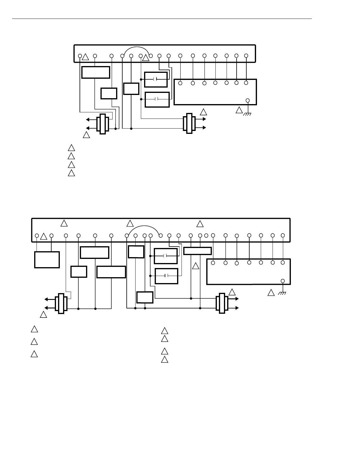
T7200D,E, T7300D,E,F AND Q7300 SERIES 2000 PROGRAMMABLE COMMERCIAL THERMOSTATS AND SUBBASES
63-4355—430
Fig. 22. Typical hookup of T7300D,F/Q7300A2008 in one-stage heat
and one-stage cool conventional system with two transformers.
Fig. 23. Typical hookup of T7300D,F/Q7300A2016 in two-stage heat
and two-stage cool conventional system with two transformers.
POWER SUPPLY. PROVIDE DISCONNECT MEANS AND OVERLOAD PROTECTION AS REQUIRED.
JUMPER RC TERMINAL TO RH TERMINAL WHEN INSTALLED ON A SYSTEM WITH ONE TRANSFORMER.
CONNECT GND TO EARTH GROUND.
INSTALL FIELD JUMPER BETWEEN X4 AND X TO POWER LEDS FROM SYSTEM TRANSFORMER.
1
1
4
3
4
13
M4939B
2
2
L1
(HOT)
L2
FAN
RELAY
Y1 G X
SUBBASE
RC
HEAT
RELAY
RH C1 T
T7147 REMOTE COMFORT ADJUST MODULE
GND
W1 C2
L1
(HOT)
L2
COMPRESSOR
CONTACTOR
C4 C3C5
CA1 T
CA2
CA4 CA3CA5
T
T
HEATING
TRANSFORMER
COOLING
TRANSFORMER
X3 X1X4
EQUIPMENT
MONITOR 2
EQUIPMENT
MONITOR 1
POWER SUPPLY. PROVIDE DISCONNECT MEANS AND OVERLOAD
PROTECTION AS REQUIRED.
JUMPER RC TERMINAL TO RH TERMINAL WHEN INSTALLED ON A
SYSTEM WITH ONE TRANSFORMER.
USE A1 AND A2 WHEN THE CONTACTS SHOULD BE NORMALLY
CLOSED IN OCCUPIED MODE. USE A2 AND A3 WHEN THE
CONTACTS SHOULD BE NORMALLY OPEN IN OCCUPIED MODE.
1
1
1
M4945B
2
2
3
4
5
6
7
7
3
5
6
4
W2
L1
(HOT)
L2
FAN
RELAY
Y1GX
SUBBASE
RC
HEAT
RELAY 1
RH C1 T
T7147 REMOTE COMFORT ADJUST MODULE
GND
W1 C2
L1
(HOT)
L2
COMPRESSOR
CONTACTOR 1
C4 C3
C5
CA1 T
CA2
CA4 CA3
CA5
T
T
Y2
COMPRESSOR
CONTACTOR 2
HEATING
TRANSFORMER
COOLING
TRANSFORMER
A2 A3A1X3 X1X4
EQUIPMENT
MONITOR 2
EQUIPMENT
MONITOR 1
ECONOMIZER
AS AS
DISCHARGE
AIR
SENSOR
HEAT
RELAY 2
CONNECT GND TO EARTH GROUND.
INSTALL FIELD JUMPER BETWEEN X4 AND X TO POWER LEDS
FROM SYSTEM TRANSFORMER.
USE ECONOMIZER INSTRUCTIONS FOR INSTALLATION DIRECTIONS.
DISCHARGE AIR SENSOR IS ONLY COMPATIBLE WITH T7300F
THERMOSTAT.
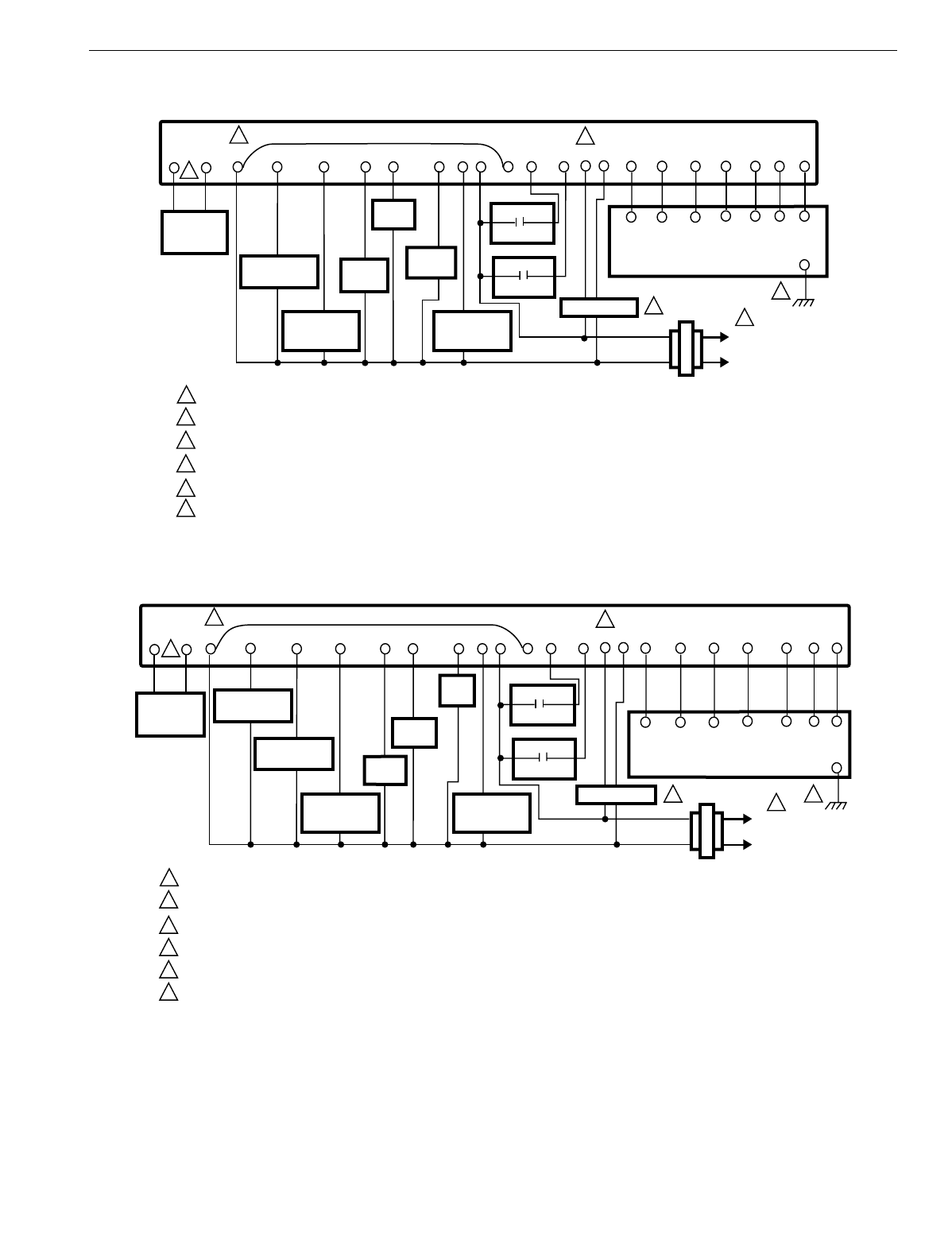
T7200D,E, T7300D,E,F AND Q7300 SERIES 2000 PROGRAMMABLE COMMERCIAL THERMOSTATS AND SUBBASES
31 63-4355—4
Fig. 24. Typical hookup of T7300E,F/Q7300C2004 in two-stage heat and one-stage cool heat pump system.
Fig. 25. Typical hookup of T7300E,F/Q7300C2012 in three-stage heat and two-stage cool heat pump system.
POWER SUPPLY. PROVIDE DISCONNECT MEANS AND OVERLOAD PROTECTION AS REQUIRED.
USE ECONOMIZER INSTRUCTIONS FOR INSTALLATION DIRECTIONS.
USE A1 AND A2 WHEN THE CONTACT SHOULD BE NORMALLY CLOSED IN OCCUPIED MODE.
CONNECT GND TO EARTH GROUND.
INSTALL FIELD JUMPER BETWEEN X4 AND X TO POWER LEDS FROM SYSTEM TRANSFORMER.
DISCHARGE AIR SENSOR IS ONLY COMPATIBLE WITH T7300F THERMOSTAT.
1
1
4
2
M4946B
2
3
4
5
6
6
53
W2
L1
(HOT)
L2
Y1 O G
SUBBASE
X
EM. HT.
RELAY
RC1 T
T7147 REMOTE COMFORT ADJUST MODULE
GND
BC2
COMPRESSOR
CONTACTOR 1
C4 C3C5
CA1 T
CA2
CA4 CA3CA5
T
T
TRANSFORMER
E
HEAT
RELAY 2
HEAT
CHANGEOVER
VALVE
X3 X1X4
EQUIPMENT
MONITOR 2
EQUIPMENT
MONITOR 1
FAN
RELAY
COOL
CHANGEOVER
VALVE
A2A1
AS AS
DISCHARGE
AIR
SENSOR
ECONOMIZER
POWER SUPPLY. PROVIDE DISCONNECT MEANS AND OVERLOAD PROTECTION AS REQUIRED.
USE ECONOMIZER INSTRUCTIONS FOR INSTALLATION INSTRUCTIONS.
USE A1 AND A2 WHEN THE CONTACTS ARE NORMALLY CLOSE IN OCCUPIED MODE.
CONNECT GND TO EARTH GROUND.
INSTALL FIELD JUMPER BETWEEN X4 AND X POWER LEDS FROM SYSTEM TRANSFORMER.
DISCHARGE AIR SENSOR IS ONLY COMPATIBLE WITH T7300F THERMOSTAT.
1
14
M4947B
2
3
4
5
6
6
5
2
3
W1
L1
(HOT)
L2
Y1 O G
SUBBASE
X
EM. HT.
RELAY
RC1 T
T7147 REMOTE COMFORT ADJUST MODULE
GND
BC2
COMPRESSOR
CONTACTOR 1
C4 C3C5
CA1 T
CA2
CA4 CA3CA5
T
T
TRANSFORMER
E
AUX.
HEAT
HEAT
CHANGEOVER
VALVE
X3 X1X4
EQUIPMENT
MONITOR 2
EQUIPMENT
MONITOR 1
FAN
RELAY
COOL
CHANGEOVER
VALVE
A2A1
AS AS
DISCHARGE
AIR
SENSOR
Y2
COMPRESSOR
CONTACTOR 2
ECONOMIZER
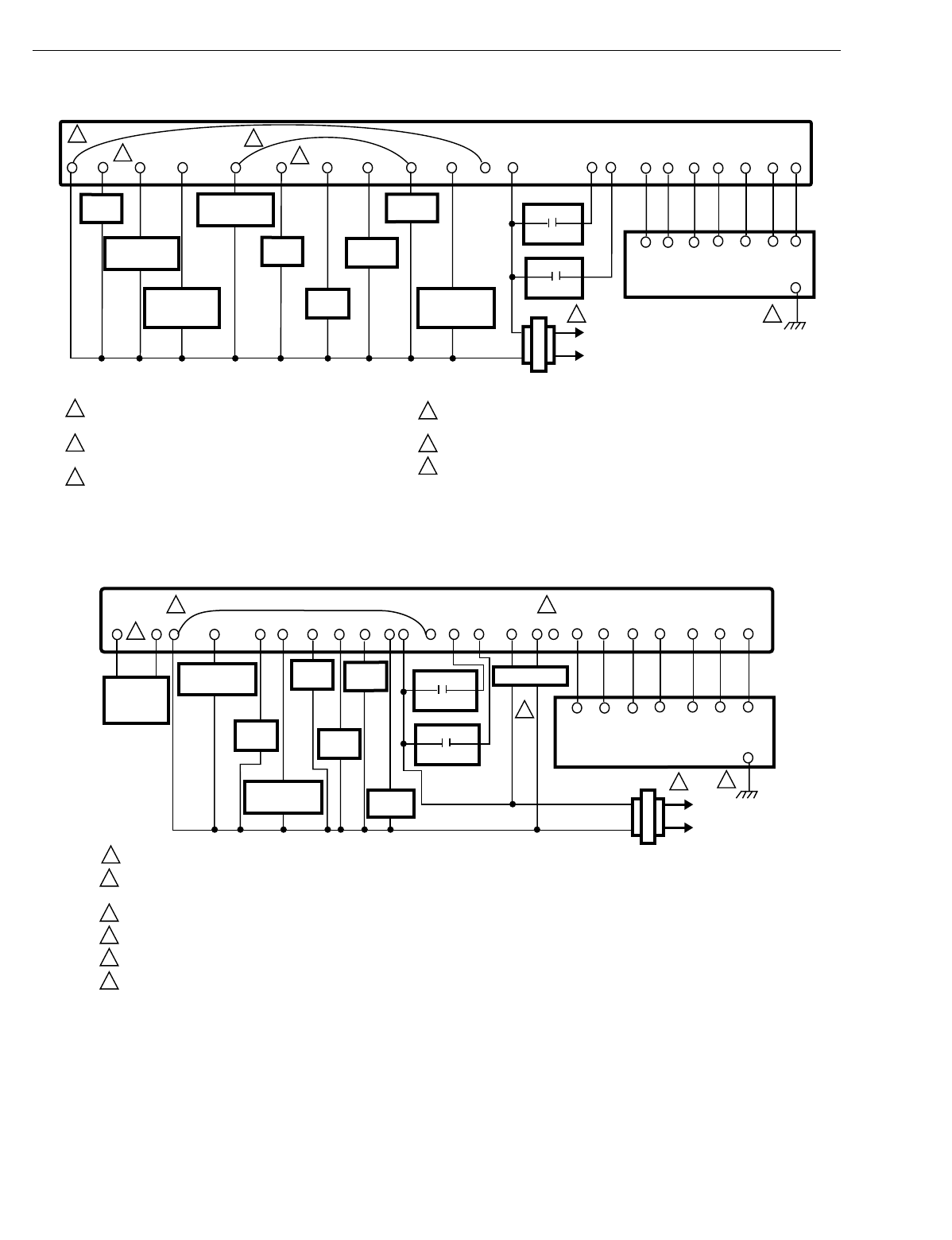
T7200D,E, T7300D,E,F AND Q7300 SERIES 2000 PROGRAMMABLE COMMERCIAL THERMOSTATS AND SUBBASES
63-4355—432
Fig. 26. Typical hookup of T7300E,F/Q7300C2053 in three-stage heat and two-stage cool
heat pump system.This thermostat and subbase can replace the T8611M.
Fig. 27. Typical hookup of T7300E,F/Q7300D2002 in three-stage heat and two-stage cool heat pump system.
POWER SUPPLY. PROVIDE DISCONNECT MEANS AND OVERLOAD
PROTECTION AS REQUIRED.
EM. MODE IS ON CONTINUOUSLY IN EMERGENCY HEAT MODE.
24 VAC ARE PRESENT DURING EMERGENCY HEAT MODE.
EM. HT. RELAY CYCLES IN EMERGENCY HEAT MODE.
1
2
3
4
5
6
46
3
2
1
M4940B
HEAT
RELAY 3
W2
L1
(HOT)
L2
YO G
SUBBASE
X
EM. HT.
RELAY
RBX4
COMPRESSOR
CONTACTOR 1
Y2
COMPRESSOR
CONTACTOR 2
TRANSFORMER
W3E
HEAT
RELAY 2
HEAT
CHANGEOVER
VALVE
X1 X2L
EQUIPMENT
MONITOR 2
EQUIPMENT
MONITOR 1
FAN
RELAY
COOL
CHANGEOVER
VALVE
EM.
MODE
INSTALL FIELD JUMPER BETWEEN X4 AND X POWER LEDS
FROM SYSTEM TRANSFORMER.
CONNECT GND TO EARTH GROUND.
JUMPER W2 TO Y2 FOR SECOND COMPRESSOR. W3 IS AUXILIARY HEAT.
5
C1 T
T7147 REMOTE COMFORT
ADJUST MODULE GND
C2C4 C3C5
CA1 T
CA2
CA4 CA3CA5
T
T
POWER SUPPLY. PROVIDE DISCONNECT MEANS AND OVERLOAD PROTECTION AS REQUIRED.
USE A1 AND A2 WHEN THE CONTACTS SHOULD BE NORMALLY CLOSED IN OCCUPIED MODE. USE A2 AND A3 WHEN THE
CONTACTS SHOULD BE NORMALLY OPEN IN OCCUPIED MODE.
CONNECT GND TO EARTH GROUND.
INSTALL FIELD JUMPER BETWEEN X4 AND X TO POWER LEDS FROM SYSTEM TRANSFORMER.
USE ECONOMIZER INSTRUCTIONS FOR INSTALLATION DIRECTIONS.
DISCHARGE AIR SENSOR IS ONLY COMPATIBLE WITH T7300F THERMOSTAT.
1
13
M4948B
2
3
4
5
6
6
2
5
4
HEAT
RELAY 3
W2
L1
(HOT)
L2
FAN
RELAY
Y1 G
SUBBASE
X R C1 T
T7147 REMOTE COMFORT ADJUST MODULE
GND
W1 C2
COMPRESSOR
CONTACTOR 1
C4 C3C5
CA1 T
CA2
CA4 CA3CA5
T
T
Y2
COMPRESSOR
CONTACTOR 2
TRANSFORMER
W3E
HEAT
RELAY 2
EM. HT.
RELAY
A2 A3A1X3 X1X4
EQUIPMENT
MONITOR 2
EQUIPMENT
MONITOR 1
ECONOMIZER
AS AS
DISCHARGE
AIR
SENSOR
HEAT
RELAY 1
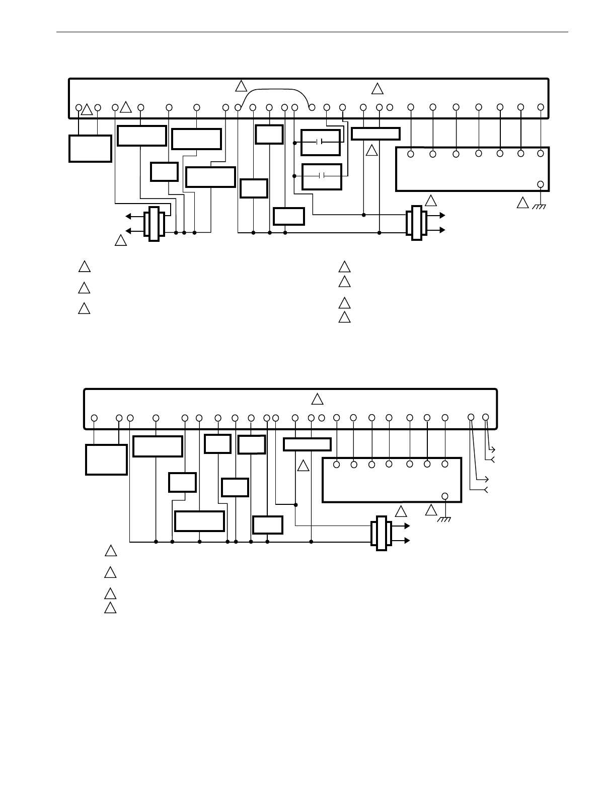
T7200D,E, T7300D,E,F AND Q7300 SERIES 2000 PROGRAMMABLE COMMERCIAL THERMOSTATS AND SUBBASES
33 63-4355—4
Fig. 28. Typical hookup of T7300D,F/Q7300G2005 in three-stage heat and three-stage cool conventional system.
Fig. 29. Typical hookup of T7300F/Q7300H2011 in three-stage heat
and two-stage cool heat pump system (without O/B terminals).
POWER SUPPLY. PROVIDE DISCONNECT MEANS AND OVERLOAD
PROTECTION AS REQUIRED.
JUMPER RC TERMINAL TO RH TERMINAL WHEN INSTALLED ON A
SYSTEM WITH ONE TRANSFORMER.
USE A1 AND A2 WHEN THE CONTACTS SHOULD BE NORMALLY CLOSED
IN OCCUPIED MODE. USE A2 AND A3 WHEN CONTACTS
SHOULD BE NORMALLY OPEN IN OCCUPIED MODE.
1
1
14
6
M4949B
2
2
3
4
5
6
7
7
3
5
HEAT
RELAY 3
W2
L1
(HOT)
L2
FAN
RELAY
Y1 G X
SUBBASE
RC RH C1 T
T7147 REMOTE COMFORT ADJUST MODULE
GND
W1 C2
L1
(HOT)
L2
COMPRESSOR
CONTACTOR 1
C4 C3C5
CA1 T
CA2
CA4 CA3CA5
T
T
Y2
COMPRESSOR
CONTACTOR 2
HEATING
TRANSFORMER
COOLING
TRANSFORMER
W3Y3
HEAT
RELAY 2
COMPRESSOR
CONTACTOR 3
A2 A3A1X3 X1X4
EQUIPMENT
MONITOR 2
EQUIPMENT
MONITOR 1
ECONOMIZER
AS AS
DISCHARGE
AIR
SENSOR
HEAT
RELAY 1
CONNECT GND TO EARTH GROUND.
INSTALL FIELD JUMPER BETWEEN X4 AND X TO POWER LEDS
FROM SYSTEM TRANSFORMER.
USE ECONOMIZER INSTRUCTIONS FOR INSTALLATION DIRECTIONS.
DISCHARGE AIR SENSOR IS ONLY COMPATIBLE WITH T7300F
THERMOSTAT.
POWER SUPPLY. PROVIDE DISCONNECT MEANS AND OVERLOAD
PROTECTION AS REQUIRED.
USE A1 AND A2 WHEN CONTACTS ARE NORMALLY CLOSED IN OCCUPIED MODE.
USE A2 AND A3 WHEN CONTACTS ARE NORMALLY OPEN IN OCCUPIED MODE.
CONNECT GND TO EARTH GROUND.
USE ECONOMIZER INSTRUCTIONS FOR INSTALLATION DIRECTIONS.
1
13
M16057
2
3
4
2
4
HEAT
RELAY 3
W2
L1
(HOT)
L2
FAN
RELAY
Y1 G
SUBBASE
X R C1 T
T7147 REMOTE COMFORT ADJUST MODULE
GND
W1 C2
COMPRESSOR
CONTACTOR 1
C4 C3C5
CA1 T
CA2
CA4 CA3CA5
T
T
Y2
COMPRESSOR
CONTACTOR 2
TRANSFORMER
W3E
HEAT
RELAY 2
EM. HT.
RELAY
A2 A3A1
ECONOMIZER
AS AS
DISCHARGE
AIR
SENSOR
HEAT
RELAY 1
EB EB
LonWorks® BUS
LonWorks® BUS
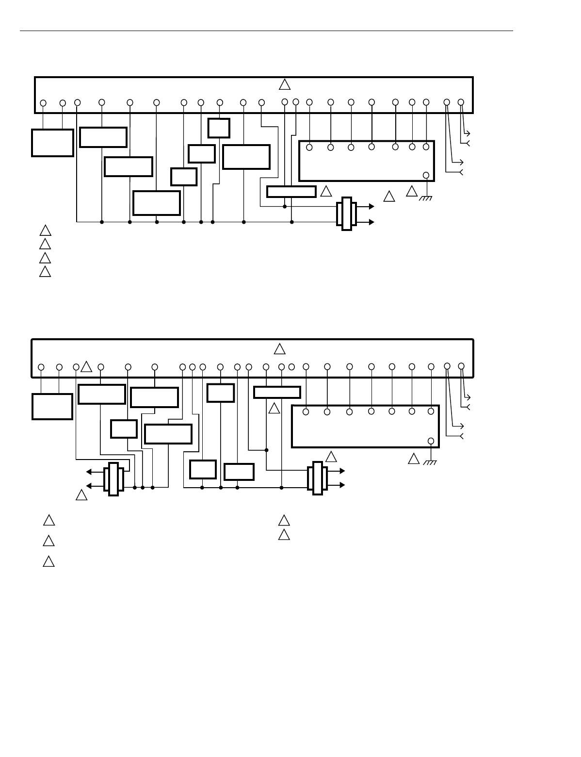
T7200D,E, T7300D,E,F AND Q7300 SERIES 2000 PROGRAMMABLE COMMERCIAL THERMOSTATS AND SUBBASES
63-4355—434
Fig. 30. Typical hookup of T7300F/Q7300H2003 in three-stage heat
and two-stage cool heat pump system (with O/B terminals).
Fig. 31. Typical hookup of T7300F/Q7300H2029 in three-stage heat and three-stage cool conventional system.
POWER SUPPLY. PROVIDE DISCONNECT MEANS AND OVERLOAD PROTECTION AS REQUIRED.
USE ECONOMIZER INSTRUCTIONS FOR INSTALLATION INSTRUCTIONS.
USE A1 AND A2 WHEN CONTACTS ARE NORMALLY CLOSED IN OCCUPIED MODE.
CONNECT GND TO EARTH GROUND.
1
14
M16056
2
3
4
2
3
W1
L1
(HOT)
L2
Y1 O G
SUBBASE
X
EM. HT.
RELAY
RC1 T
T7147 REMOTE COMFORT ADJUST MODULE
GND
BC2
COMPRESSOR
CONTACTOR 1
C4 C3C5
CA1 T
CA2
CA4 CA3CA5
TEBEB
T
TRANSFORMER
E
AUX.
HEAT
HEAT
CHANGEOVER
VALVE
FAN
RELAY
COOL
CHANGEOVER
VALVE
A2A1
AS AS
DISCHARGE
AIR
SENSOR
Y2
COMPRESSOR
CONTACTOR 2
ECONOMIZER
LonWorks®
BUS
LonWorks®
BUS
POWER SUPPLY. PROVIDE DISCONNECT MEANS AND OVERLOAD
PROTECTION AS REQUIRED.
JUMPER RC TERMINAL TO RH TERMINAL WHEN INSTALLED ON A
SYSTEM WITH ONE TRANSFORMER.
USE A1 AND A2 WHEN CONTACTS ARE NORMALLY CLOSED
IN OCCUPIED MODE. USE A2 AND A3 WHEN CONTACTS
ARE NORMALLY OPEN IN OCCUPIED MODE.
1
1
14
5
M16058
2
2
3
4
5
3
HEAT
RELAY 3
W2
L1
(HOT)
L2
FAN
RELAY
Y1 G X
SUBBASE
RC RH C1 T
T7147 REMOTE COMFORT ADJUST MODULE
GND
W1 C2
L1
(HOT)
L2
COMPRESSOR
CONTACTOR 1
C4 C3C5
CA1 T
CA2
CA4 CA3CA5
T
T
Y2
COMPRESSOR
CONTACTOR 2
HEATING
TRANSFORMER
COOLING
TRANSFORMER
W3Y3
HEAT
RELAY 2
COMPRESSOR
CONTACTOR 3
A2 A3A1
ECONOMIZER
AS AS
DISCHARGE
AIR
SENSOR
HEAT
RELAY 1
CONNECT GND TO EARTH GROUND.
USE ECONOMIZER INSTRUCTIONS FOR INSTALLATION DIRECTIONS.
EB EB
LonWorks®
BUS
LonWorks®
BUS
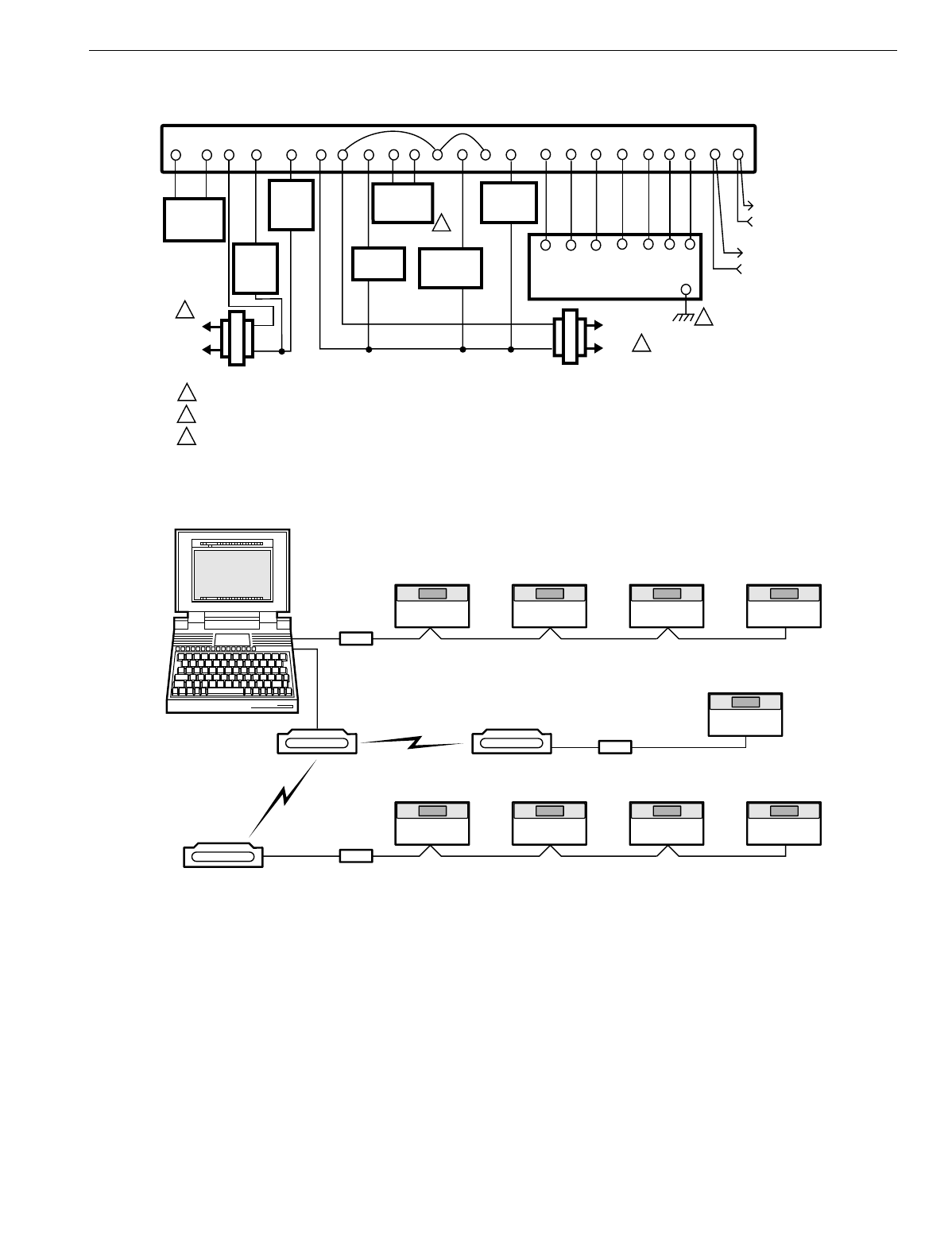
T7200D,E, T7300D,E,F AND Q7300 SERIES 2000 PROGRAMMABLE COMMERCIAL THERMOSTATS AND SUBBASES
35 63-4355—4
Fig. 32. Typical hookup of T7300F/Q7300H2037 in two-stage heat and one-stage cool conventional system.
Fig. 33. Typical hookup for T7300F/Q7300H devices in LONWORKS® network.
L1
(HOT)
L2
M16059
LOW
SPEED
FAN
RELAY
GL GH R
SUBBASE
FC Y C1 T
T7147 REMOTE COMFORT
ADJUST MODULE GND
C2
L1
(HOT)
L2
COOLING
RELAY
C4 C3C5
CA1 TCA2
CA4 CA3CA5
T
T
X
TRANSFORMER
FAN TRANSFORMER
A2A1P1 P2BM
DAMPER
CONTROL
RELAY
HIGH
SPEED
FAN
RELAY
RM
ML7984
VALVE
ACTUATOR
PUMP
INTERLOCK
RELAY
AS AS
DISCHARGE
AIR
SENSOR
EB EB
POWER SUPPLY. PROVIDE DISCONNECT MEANS AND OVERLOAD PROTECTION AS REQUIRED.
CONNECT GND TO EARTH GROUND.
SEE TABLE 2 FOR VALVE AND VALVE ACTUATOR MODELS.
1
1
1
2
2
3
3
LonWorks® BUS
LonWorks® BUS
NOTEBOOK PC
RS-232
SLTA
SLTA
SLTA
LonWorks® BUS
LonWorks® BUS
LonWorks® BUS
RS-232
RS-232
T7300 T7300 T7300
T7300
T7300
T7300 T7300 T7300 T7300
MODEM
MODEM
MODEM
M16063A
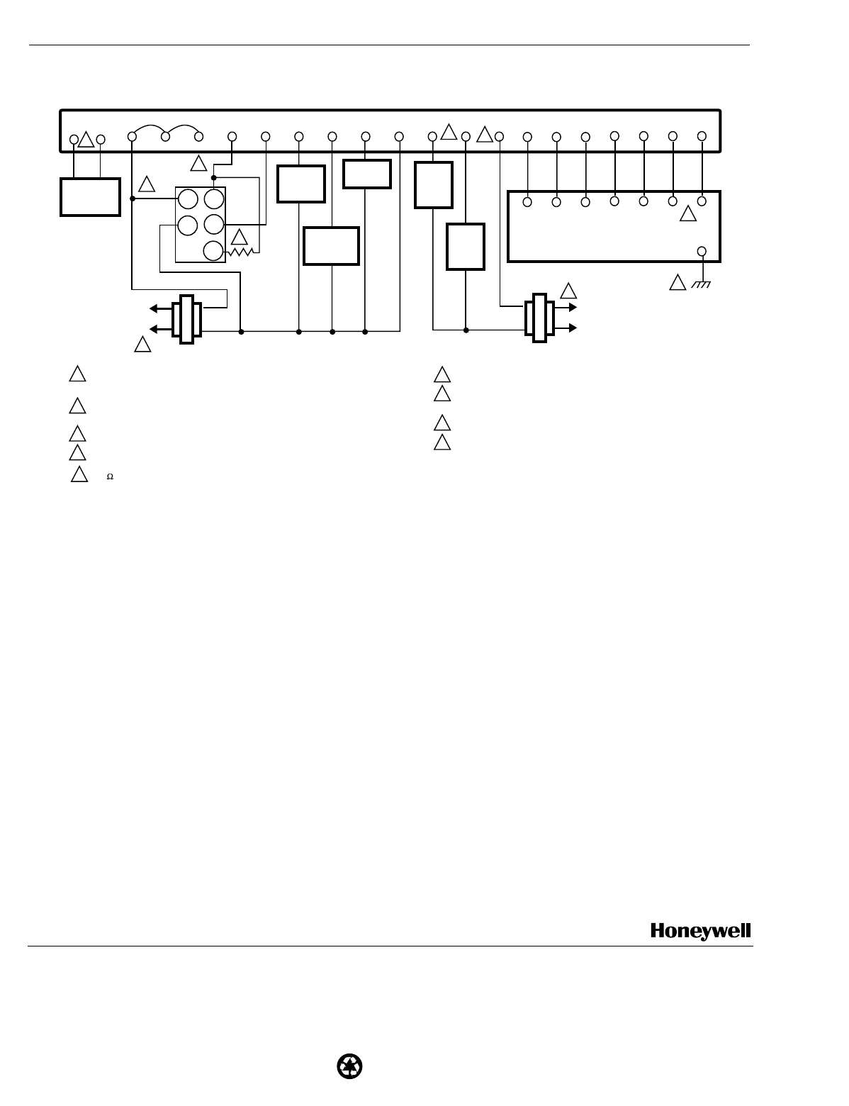
63-4355—4 B.B. Rev. 10-01 www.honeywell.com
Printed in U.S.A. on recycled
paper containing at least 10%
post-consumer paper fibers.
T7200D,E, T7300D,E,F AND Q7300 SERIES 2000 PROGRAMMABLE COMMERCIAL THERMOSTATS AND SUBBASES
Home and Building Control Home and Building Control Honeywell Asia Pacific Inc. Honeywell Europe S.A. Honeywell Latin American
Honeywell Honeywell Limited-Honeywell Limitée Room 3213-3225 3 Avenue du Bourget Region
1985 Douglas Drive North 35 Dynamic Drive Sun Hung Kai Centre 1140 Brussels 480 Sawgrass Corporate Parkway
Golden Valley, MN 55422 Scarborough, Ontario No. 30 Harbour Road Belgium Suite 200
M1V 4Z9 Wanchai Sunrise FL 33325
Hong Kong
Fig. 34. T7300D,F/Q7300L2004 for two-stage heating with three-position
ML7984 Valve Actuator and V5013B Valve and one-stage cooling.
GH
L1
(HOT)
L2
POWER SUPPLY. PROVIDE DISCONNECT MEANS AND OVERLOAD
PROTECTION AS REQUIRED.
INDEPENDENT FAN TRANSFORMER IS OPTIONAL. JUMPER FC TO R
WHEN SINGLE TRANSFORMER IS USED.
REFER TO ML7984 INSTRUCTIONS FOR TERMINAL CONNECTIONS.
T7047 HAS T-T TERMINALS ONLY.
180 2W RESISTOR MUST BE INSTALLED AS SHOWN.
1
M4950B
T
A1 RM Y
SUBBASE
1
R FC C1 T
T7147 REMOTE COMFORT ADJUST MODULE
GND
GL C2
L1
(HOT)
L2
1
2
2
C4 C3C5
TCA1 TCA2
CA4 CA3CA5
A2
COOLING
RELAY
XP2
P1 BM
LOW
SPEED
FAN
RELAY
DAMPER
CONTROL
RELAY
PUMP
INTERLOCK
RELAY
3
9
3
4
7
5
6
7
8
9
8
4
6
HIGH
SPEED
FAN
RELAY
ML7984
VALVE
ACTUATOR
R1
B3
W
T5
T6
5
TRANSFORMER
FAN
TRANSFORMER
AS AS
DISCHARGE
AIR
SENSOR
CONNECT GND TO EARTH GROUND.
DISCHARGE AIR SENSOR IS ONLY COMPATIBLE WITH T7300F
THERMOSTAT.
JUMPER GH AND GL FOR SINGLE SPEED FAN.
SET THE DIP SWITCHES ON THE ML7984 TO MECHANICAL
SERIES 90 TO USE WITH Q7300L
