Honeywell Thm5421C1008 Users Manual 68 0287 1 VisionPRO IAQ Total Home Comfort System
THM5421C1008 68_0287
THM5421C1008 to the manual b1ec5513-3a99-4545-a4d9-6448597ba9cc
2015-01-23
: Honeywell Honeywell-Thm5421C1008-Users-Manual-262536 honeywell-thm5421c1008-users-manual-262536 honeywell pdf
Open the PDF directly: View PDF ![]() .
.
Page Count: 40
- Application
- Features
- Specifications
- Installation
- Wiring
- Power the Thermostat
- Wiring 24 Vac Common
- Mount Thermostat to Wallplate
- Locate and Mount C7089U1006 Outdoor Temperature Sensor (Optional)
- Wire C7089U1006 Outdoor Sensor
- Locate and Mount C7189U1005 Remote Indoor Temperature Sensor (Optional)
- Wire C7189U1005 Indoor Sensor
- Install Discharge Air Temperature Sensor (Optional):
- Set Calendar and Time
- Installer Setup
- INSTALLER SYSTEM TEST
- Operation
- Heat Pump Operation
- Programming
- Operate VisionPRO® IAQ
- Communication error codes
- Troubleshooting
- Compatibility
PRODUCT DATA
68-0287-1
VisionPRO® IAQ
Total Home Comfort System
APPLICATION
The VisionPRO® IAQ Total Home Comfort System features an
effortless, 7-Day programmable touchscreen thermostat that
provides control of temperature, humidification,
dehumidification, and ventilation.
FEATURES
• Large, clear display with backlight shows the current
and set temperature and time—even in the dark.
• Touchscreen interaction
• Real-time clock keeps time during power failures and
automatically updates to daylight savings.
• Change/check reminders let you know when to service
or replace filters.
• Various Hold options allow you to override the
program schedule, as desired.
• Controls humidification to increase homeowner
comfort while protecting woodwork and furnishings.
• Controls dehumidification using air conditioner with
high or low speed fan or a whole house dehumidifier.
• Controls ventilation with other HRV, ERV, or Freshair
damper. Vent on demand and automatically using
patented advanced ventilation control.
• Advanced heat pump control featuring balance point
plus 2°F droop to increase homeowner comfort.
Contents
Application/Features.......................................................... 1
Specifications/Ordering Information .................................. 2
Installation ........................................................................ 4
Wiring ............................................................................... 5
Power the Thermostat ...................................................... 8
Installer Setup .................................................................. 12
Operation .......................................................................... 19
Programming .................................................................... 25
Troubleshooting ................................................................ 35
VISIONPRO® IAQ TOTAL HOME COMFORT SYSTEM
68-0287—1 2
SPECIFICATIONS
Thermostat Description:
Electrical Ratings:
Temperature Setting Range:
Heating: 40°F to 90°F(4.5°C to 32°C).
Cooling: 50°F to 99°F (10°C to 37°C).
Operating Ambient Temperature:
VisionPRO® IAQ Thermostats: 0°F to 120°F
(-18°C to 49°C).
THM5421C1008: -30°F to 150°F (-34°C to 66°C).
C7089U1006: -40°F to 120°F (-40°C to 49°C).
C7189U1005: 45°F to 88°F (7°C to 32°C).
Shipping Temperature:
VisionPRO® IAQ Thermostats: -30°F to 150°F
(-34°C to 66°C).
THM5421C1008: -30°F to 150°F (-34°C to 66°C).
Operating Relative Humidity (Non-condensing):
VisionPRO® IAQ Thermostats: 5% to 90%.
THM5421C1008: 5% to 90%.
C7089U1006: 5% to 95%.
C7189U1005: 5% to 95%.
Humidification Setting Range:
Heating: 10% to 60% RH.
Dehumidification Setting Range:
Heating: 40% to 80% RH.
Humidity Display Range:
0% to 99%.
Cycle Rates (at 50% Load):
Heating: Selectable 1 - 12 cycles per hour.
Cooling: Selectable 1 - 6 cycles per hour.
Finish:
VisionPRO® IAQ Thermostats: Premier White® color.
THM5421C1008: Premier White® color.
C7189U1005 Wall Mount Remote Indoor Sensor: Premier
White® color.
Clock Accuracy: +/- 1 minute per year.
Resistance Characteristics of Remote Sensors:
C7089U1006 Outdoor Sensor: Negative temperature coeffi-
cient (NTC) means that resistance decreases as the tem-
perature increases. See Table 12 in the Operation section
for sensor resistance characteristics.
C7189U1005 Remote Indoor Sensor: Negative temperature
coefficient (NTC), means that resistance decreases as the
temperature increases. See Table 13 in the Operation sec-
tion for sensor resistance characteristics.
Cool Indication:
VisionPRO® IAQ Comfort Systems show “Cool On” on the
thermostat screen when Cool is activated.
Heat Indication:
VisionPRO® IAQ Comfort Systems show “Heat On” on the
thermostat screen when Heat is activated.
Auxiliary Heat Indication:
VisionPRO® IAQ Comfort Systems show “Aux. Heat On” on
the thermostat screen when Auxiliary Heat is activated.
Calibration:
C7089U1006, C7189U1005 and VisionPRO
®
IAQ Comfort Sys-
tems are factory-calibrated and require no field calibration.
Interstage Differential:
VisionPRO® IAQ Comfort Systems operate with droopless
control. Once the thermostat senses that 1st stage is run-
ning at 90% capacity, the thermostat energizes 2nd stage.
Mounting Means:
VisionPRO® IAQ Comfort System: Thermostat mounts directly
on the wall in the living space using mounting screws and
anchors provided. Fits a vertical or horizontal 2 x 4 in. junc-
tion box.
THM5421C1008 Equipment Interface Module (EIM) mounts on
HVAC equipment or on a wall in the equipment room.
C7089U1006 Outdoor Sensor: Mounts outside of living space
with mounting clip and screws provided.
C7189U1005 Remote Indoor Sensor: Mounts directly on the
wall using mounting screws and anchors provided.
Cover Plate:
32003796-001 Cover Plate is used to cover marks left on the
wall by the old thermostat.
Dimensions:
VisionPRO® IAQ Comfort System: see Fig. 1.
THM5421C1008: see Fig. 2
C7089U1006 Outdoor Sensor Mounting Clip: see Fig. 3.
32003796-001 Cover Plate: see Fig. 4.
C7189U1005 Remote Indoor Sensor: see Fig. 5.
Feature Description
Powering method •Common wire only
System types (up to
4 heat/2 cool)
•Gas, oil or electric heat with air
conditioning
•Warm air, hot water, high-efficiency
furnaces, heat pumps, steam and
gravity
•Heat only with fan
•Cool only
Changeover Manual or Auto changeover selectable
System setting Heat-Off-Cool-Auto
Fan setting Auto-On-Circ
Terminal Voltage (50/60 Hz) Running Current
W1 Heating 20 - 30 Vac .02 - 1.0A
W2/Aux Heating 20 - 30 Vac .02 - 1.0A
W3/Aux2 Heating 20 - 30 Vac .02 - 1.0A
Y Cooling 20 - 30 Vac .02 - 1.0A
Y2 Cooling 20 - 30 Vac .02 - 1.0A
G Fan 20 - 30 Vac .02 - 1.0A
VISIONPRO® IAQ TOTAL HOME COMFORT SYSTEM
368-0287—1
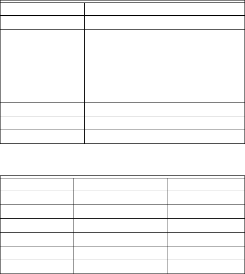
Fig. 1. VisionPRO® IAQ Comfort System
dimensions in in. (mm).
Fig. 2. THM5421C1008 Equipment Interface Module
dimensions in in. (mm).
Fig. 3. C7089U1006 Outdoor Sensor Mounting Clip
dimensions in in. (mm).
Fig. 4. 32003796-001 Cover Plate dimensions in in. (mm).
M23539
6 (152)
THERMOSTAT
4-9/16
(116)
3-3/8 (86)
WALLPLATE
3-3/8 (86)
THERMOSTAT
AND WALLPLATE
1-3/8 (35)
7-9/32
(185)
1-21/64
(34)
6-57/64
(175)
4-35/64
(116)
M23544
FRONT VIEW SIDE VIEW
M4488
1-1/2 (38)
7-7/8 (200)
3-5/16 (84)
3-5/16
(84)
M22139
5-1/2
(140)
VISIONPRO® IAQ TOTAL HOME COMFORT SYSTEM
68-0287—1 4
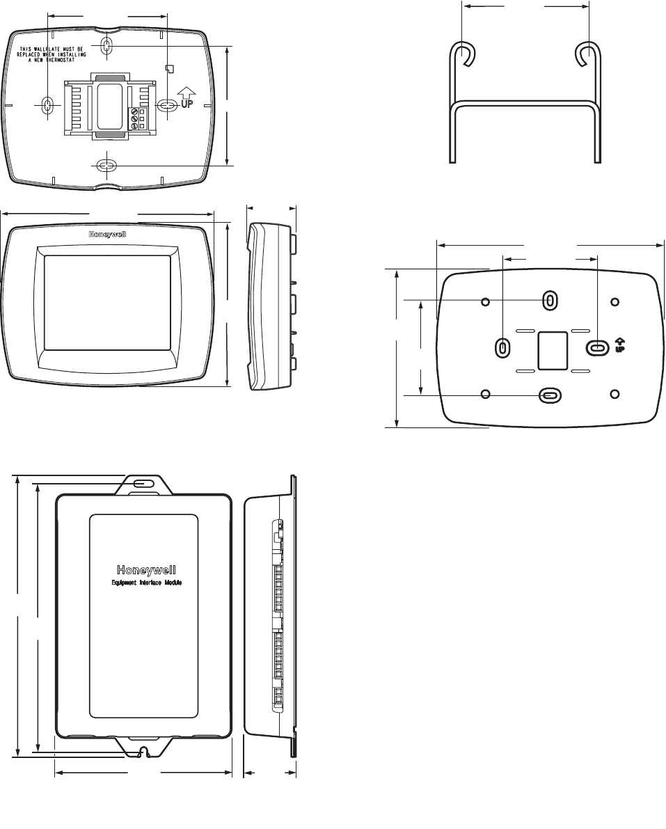
Fig. 5. C7189U1005 Remote Indoor Sensor dimensions in in. (mm).
INSTALLATION
When Installing this Product...
1. Read these instructions carefully. Failure to follow the
instructions can damage the product or cause a hazard-
ous condition.
2. Check the ratings given in the instructions to make sure
the product is suitable for your application.
3. Installer must be a trained, experienced service
technician.
4. After completing installation, use these instructions to
verify the product operation.
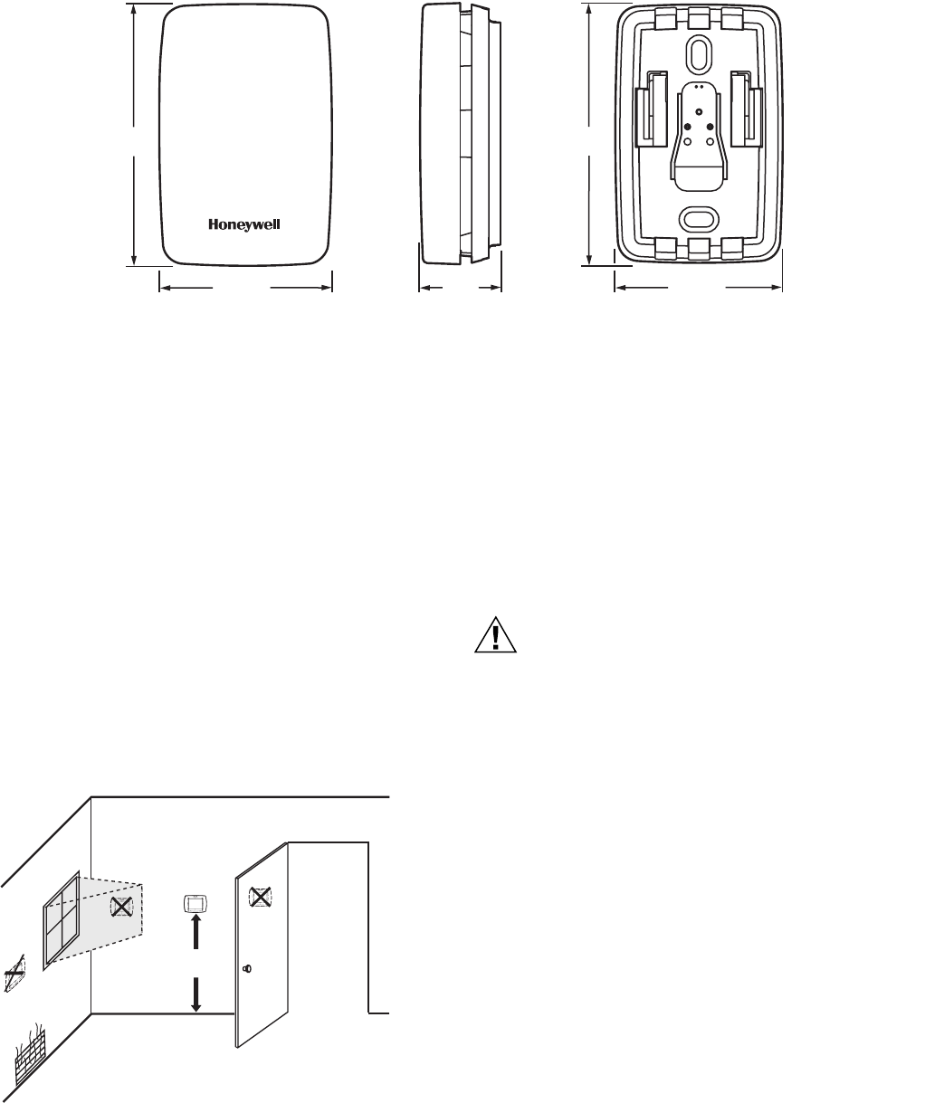
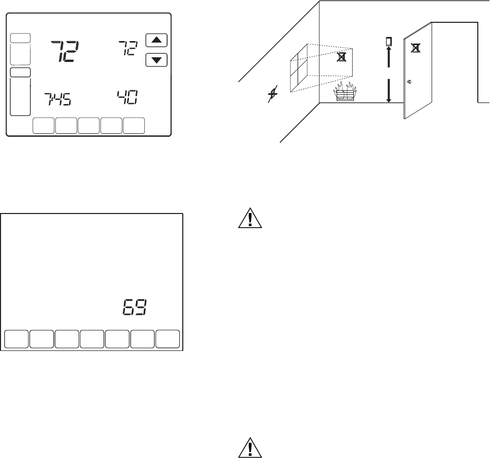
Selecting Location
Install the thermostat about 5 ft. (1.5m) above the floor in an area
with good air circulation at average temperature. See Fig. 6.
Fig. 6. Selecting thermostat location.
Do not install the thermostat where it can be affected by:
— Drafts or dead spots behind doors and in corners.
— Hot or cold air from ducts.
— Radiant heat from sun or appliances.
— Concealed pipes and chimneys.
— Unheated (uncooled) areas such as an outside wall behind
the thermostat.
Installing Wallplate
CAUTION
Electrical Hazard.
Can cause electrical shock or equipment damage.
Disconnect power before wiring.
The thermostat can be mounted horizontally on the wall or on a
4 in. x 2 in. (101.6 mm x 50.8 mm) wiring box.
1. Position and level the wallplate (for appearance only).
2. Use a pencil to mark the mounting holes.
3. Remove the wallplate from the wall and, if drywall, drill
two 3/16-in. holes in the wall, as marked. For firmer
material such as plaster, drill two 7/32-in. holes. Gently
tap anchors (provided) into the drilled holes until flush
with the wall.
M23522
2-9/32
(58)
1-1/2 (38)
2-9/32
(58)
1-1/2 (38)
45/64
(18)
FRONT VIEW SIDE VIEW FRONT VIEW (COVER OFF)
5 FEET
[1.5 METERS]
YES NO
NO
NO
M19925
VISIONPRO® IAQ TOTAL HOME COMFORT SYSTEM
568-0287—1
4. Position the wallplate over the holes, pulling wires
through the wiring opening. See Fig. 7.
5. Insert the mounting screws into the holes and tighten.
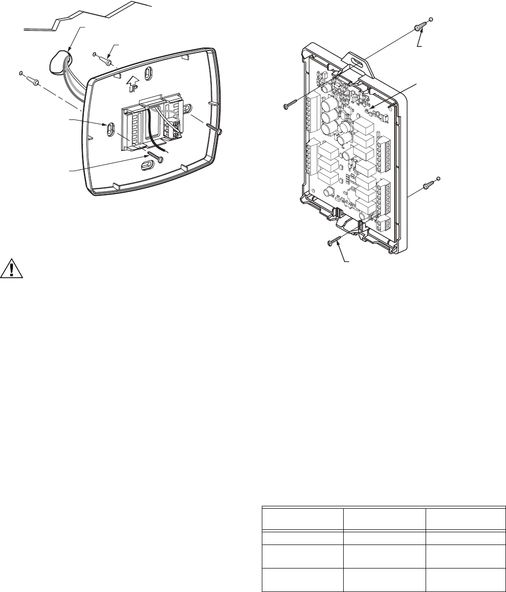
Fig. 7. Mounting wallplate.
Installing Equipment Interface Module (EIM)
CAUTION
Electrical Hazard.
Can cause electrical shock or equipment damage.
Disconnect power before wiring.
The EIM can be mounted vertically on the HVAC equipment or
on a wall in the equipment room.
1. Position the EIM.
2. Use a pencil to mark the mounting holes.
3. Remove the wallplate from the wall and, if drywall, drill
two 3/16-in. holes in the wall, as marked. For firmer
material such as plaster, drill two 7/32-in. holes. Gently
tap anchors (provided) into the drilled holes until flush
with the wall.
4. Position the wallplate over the holes, pulling wires
through the wiring opening.
5. Insert the mounting screws into the holes and tighten.
See Fig. 8.
Communication LED
The EIM has an LED (see Fig. 8) that communicates the EIM
status as follows.
•LED blinks rapidly: Normal information transfer.
•LED blinks once: Incoming message to EIM.
•LED blinks continuously: Wiring problem. Check wiring to
terminals 1, 2, 3.
•LED always off: Wiring problem. Check wiring to terminals
1, 2, 3.
•LED always on: EIM may need replacement.
NOTE: It is normal for the LED to blink continuously during
startup, and while checking equipment status (Auto
Discover mode).
Fig. 8. Mounting EIM.
WIRING
All wiring must comply with local electrical codes and
ordinances. See Fig. 10–20.
1. Select set of terminal identifications (Table 1) that corre-
sponds with system type.
2. Loosen the screws for the appropriate system type
selected; see Table 1. See Table 2 for terminal designa-
tion descriptions. Insert wires in the terminal block under
the loosened screw. See Fig. 9.
3. Securely tighten each screw.
4. Push excess wire back into the hole.
5. Plug the hole with nonflammable insulation to prevent
drafts from affecting the thermostat.
6. See Fig. 10–20 for typical wiring hookups.
WALL
MOUNTING
HOLES
M23543
MOUNTING
SCREWS (2)
WALL ANCHORS (2)
WIRES THROUGH WALL
AND WIRE SLOT
M23541
Table 1. Selecting Terminal Identifications for System Type.
System Type
Wallplate Terminal
Identifications
Wiring Diagram
Reference
Standard Heat/Cool Conventional 10, 11
Standard Multistage
up to 3 Heat/2 Cool
Conventional 12
Heat Pump with
Auxiliary Heat
Heat Pump 13
WALL ANCHOR
MOUNTING SCREW
DRILL 3/16 IN. HOLES
FOR DRYWALL. DRILL
7/32 IN. HOLES FOR
PLASTER
COMMUNICATION LED
M2
3
4
8
4

VISIONPRO® IAQ TOTAL HOME COMFORT SYSTEM
68-0287—1 6
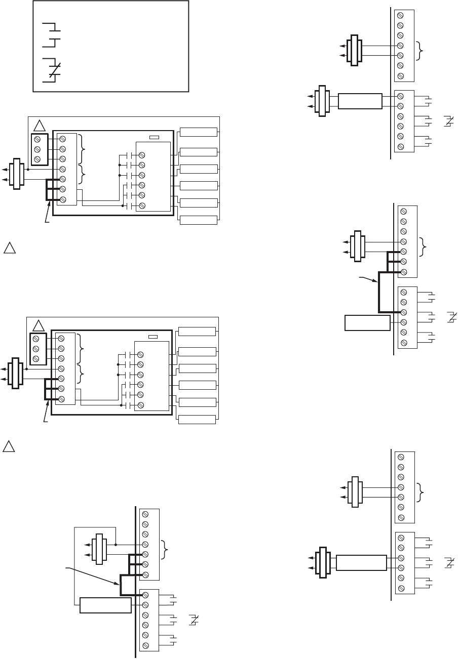
Fig. 9. Inserting wires in terminal block.
IMPORTANT
Use 18-gauge thermostat wire.
NOTES:
1. When used in a single-transformer system, leave
the metal jumper wires in place between R and Rc,
and Rc and Rh. If used on a two-transformer sys-
tem, remove metal jumper wire between Rc and Rh.
2. If thermostat is configured for a heat pump system
in the Installer Setup, configure changeover valve
for cool (O-factory setting) or heat (B).
For wiring to a W8835 Zone panel please refer to the product
data sheet included with the panel.
Fig. 10. Typical hookup of conventional single-stage heat
and cool system with single transformer
(1H/1C conventional).
Fig. 11. Typical hookup of conventional single-stage heat
and cool system with oil primary (1H/1C conventional).
Table 2. Terminal Designation Descriptions.
THM5421C1008
Terminal
Designations Function
1 Terminal 1—data to/from thermostat
2 Terminal 2—power from thermostat (24Vac)
3 Terminal 3—common from thermostat
(24Vac)
C 24 Vac Transformer Common
R 24 Vac Transformer
RC 24 Vac Cooling Transformer
RH 24 Vac Heating Transformer
HUM1/HUM2 Humidification Connection (normally open)
DHM1/DHM2 Dehumidification Connection (normally
open or closed based on installer setup)
VNT1/VNT2 Ventilation connection (normally open)
W1/O/B Stage 1 Heating Relay (Conventional)
Change-over Relay (Heat Pump)
W2/AUX Stage 2 Heating Relay (Conventional)
Auxiliary Heat (fossil fuel or electric) (Heat
Pump)
W3/AUX2 Stage 3 Heating Relay (Conventional)
Auxiliary Heat (fossil fuel or electric) (Heat
Pump)
Y Stage 1 Compressor Relay
Y2 Stage 2 Compressor Relay
GFan Relay
L Heat Pump Equipment Monitor
OUT1/OUT2 Outdoor Temperature Sensor
IN1/IN2 Remote Indoor Temperature Sensor
DATS1/DATS2 Discharge Air Temperature Sensor
M23541
M23485
FACTORY INSTALLED
JUMPER BETWEEN R,
RC AND RH
1
2
3
C
R
RC
RH
COMMUNICATION
TERMINALS
COMMUNICATION LED
W1
W2
W3
Y
Y2
G
24 VAC
O/B
AUX
AUX2
Y
Y2
G
1
2
3
WIRE TO TERMINALS ON THERMOSTAT.1
1
CONV. HP
M23486
FACTORY INSTALLED JUMPER BETWEEN R,
AND RC (REMOVE FACTORY INSTALLED
JUMPER BETWEEN RC AND RH
1
2
3
C
R
RC
RH
COMMUNICATION
TERMINALS
COMMUNICATION LED
W1
W2
W3
Y
Y2
G
24 VAC
O/B
AUX
AUX2
Y
Y2
G
1
2
3
OIL PRIMARY/
AQUASTAT
WIRE TO TERMINALS ON THERMOSTAT.1
1
CONV. HP
VISIONPRO® IAQ TOTAL HOME COMFORT SYSTEM
768-0287—1
Fig. 12. Typical hookup of conventional system with up to
three-stage heat and two-stage cool with one transformer
(3H/2C, 2H/2C, 2H/1C, 1H/2C, 1H/1C conventional).
Fig. 13. Typical hookup of heat pump system
(up to 4H/2C heat pump).
Fig. 14. Typical hookup of non-powered humidifier.
Fig. 15. Typical hookup of powered humidifier.
Fig. 16. Typical hookup of variable speed blower for
dehumidification in low speed (contacts normally closed).
NOTE: Connect DHM2 to low-speed fan terminal on air han-
dler for dehumidification with air conditioner and a
low-speed fan.
Fig. 17. Typical hookup of powered whole house
dehumidifier (contacts normally open).
M23685
KEY
= NORMALLY OPEN, DRY CONTACTS
= NORMALLY CLOSED, DRY CONTACTS
M23487
FACTORY INSTALLED
JUMPER BETWEEN R,
RC AND RH
1
2
3
C
R
RC
RH
COMMUNICATION
TERMINALS
COMMUNICATION LED
W1
W2
W3
Y
Y2
G
24 VAC
O/B
AUX
AUX2
Y
Y2
G
1
2
3
CONV. HP
HEAT 1 RELAY
HEAT 2 RELAY
HEAT 3 RELAY
COOL 1 RELAY
COOL 2 RELAY
FAN RELAY
WIRE TO TERMINALS ON THERMOSTAT.
1
1
M23488
FACTORY INSTALLED
JUMPER BETWEEN R,
RC AND RH
1
2
3
C
R
RC
RH
COMMUNICATION
TERMINALS
COMMUNICATION LED
W1
W2
W3
Y
Y2
G
24 VAC
O/B
AUX
AUX2
Y
Y2
G
1
2
3
CONV. HP
CHANGEOVER
AUX 1 (HEAT 3)
AUX 2 (HEAT 4)
COMP 1
COMP 2
FAN RELAY
WIRE TO TERMINALS ON THERMOSTAT.
1
1
M23489
FIELD INSTALLED
JUMPER BETWEEN
R AND HUM 1
1
2
3
C
R
RC
RH
24 VAC
H1
U
M2
D1
H
M2
V1
N
T2
OR
NON-POWERED
HUMIDIFIER
M23490
1
2
3
C
R
RC
RH
24 VAC
H1
U
M2
D1
H
M2
V1
N
T2
OR
POWERED
HUMIDIFIER
M23491
FIELD INSTALLED
JUMPER BETWEEN
R AND DHM 1
1
2
3
C
R
RC
RH
24 VAC
H1
U
M2
D1
H
M2
V1
N
T2
OR
LOW SPEED
FAN
M23492
1
2
3
C
R
RC
RH
24 VAC
H1
U
M2
D1
H
M2
V1
N
T2
OR
POWERED
DEHUMIDIFIER
VISIONPRO® IAQ TOTAL HOME COMFORT SYSTEM
68-0287—1 8
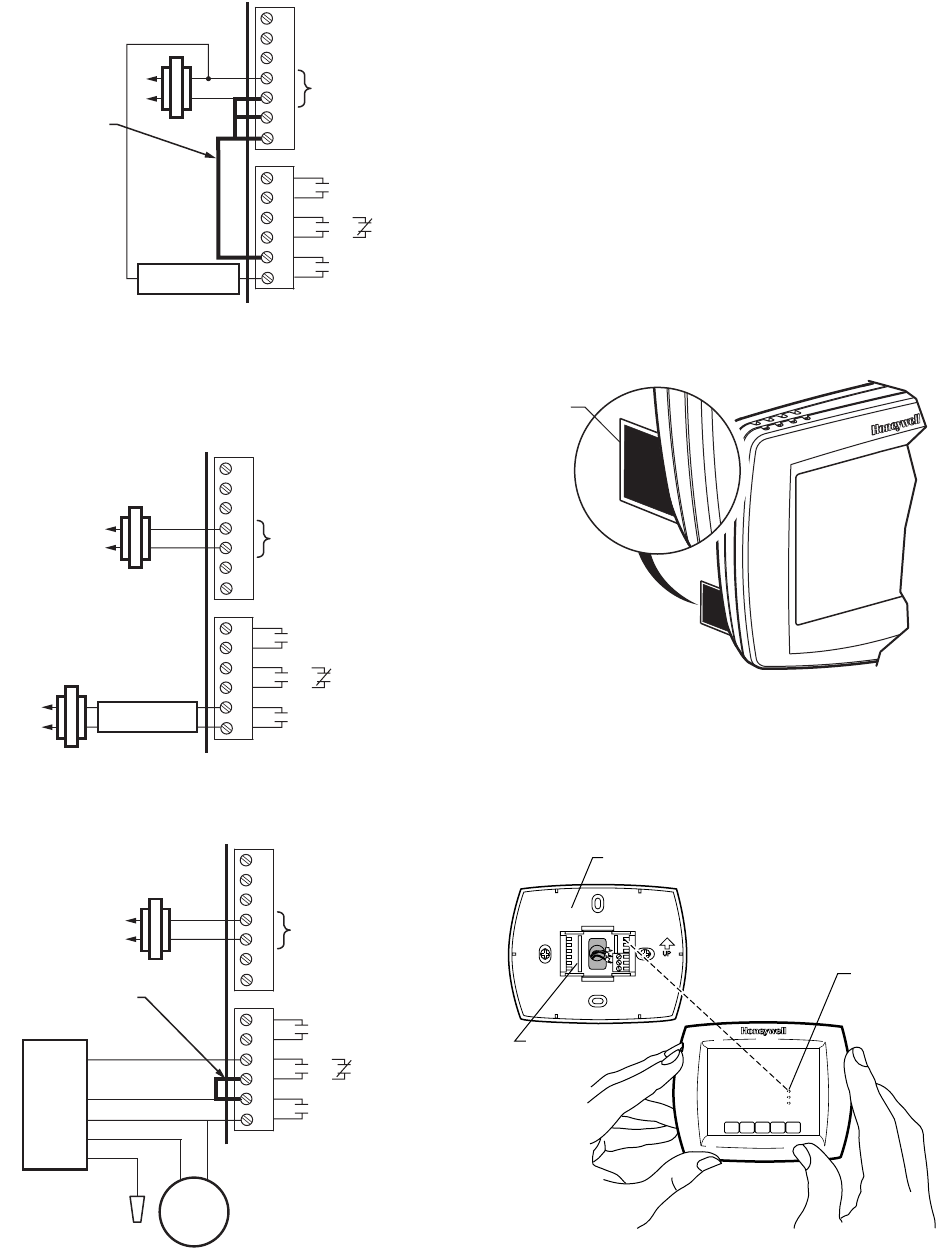
Fig. 18. Typical hookup of fresh air damper.
NOTE: Use this hookup for ventilation using a fresh air
damper.
Fig. 19. Typical hookup of powered ventilation.
Fig. 20. Hookup of Honeywell DH90 with fresh air intake for
ventilation.
POWER THE THERMOSTAT
• 24 Vac common wire only to EIM or zone panel.
Wiring 24 Vac Common
• Single-Transformer System—Connect the common side of
the transformer to the C screw terminal of the EIM. Leave
the metal jumper wires in place between R, Rc, and RH.
• Two-Transformer System—Connect the common side of
the cooling transformer to the C screw terminal of the EIM.
Remove the metal jumper wire between Rc and Rh.
Connect the hot side of heating transformer to Rh and leave
the jumper wire between R and Rc and connect the hot side
of cooling transformer to R or Rc.
1. Locate and remove the tab labeled, Remove, in the
lower left corner on the thermostat back. See Fig. 21.
Fig. 21. Remove tab labeled, Remove, on thermostat back
Mount Thermostat to Wallplate
1. Align the terminal screw blocks with the pins on the back
of the thermostat. Push the thermostat straight onto the
wallplate until it snaps into place. See Fig. 22.
Fig. 22. Mount thermostat to wallplate.
M23493
FIELD INSTALLED
JUMPER BETWEEN
R AND VNT 1
1
2
3
C
R
RC
RH
24 VAC
H1
U
M2
D1
H
M2
V1
N
T2
OR
NON-POWERED
VENTILATOR
M23494
1
2
3
C
R
RC
RH
24 VAC
H1
U
M2
D1
H
M2
V1
N
T2
OR
POWERED
VENTILATOR
M23495
1
2
3
C
R
RC
RH
24 VAC
H1
U
M2
D1
H
M2
V1
N
T2
OR
FRESH
AIR
DAMPER
DH90
BLUE
GREEN
YELLOW
RED
WHITE
FIELD INSTALLED
JUMPER BETWEEN
DHM 1 AND VNT 1
REMOVE DURING
INSTALLATION
M19920
REMOVE
TAB
REMOVE DURING
INSTALLATION
M23542
PINS ON
BACK OF
THERMOSTAT
WALLPLATE
TERMINAL
SCREW
BLOCK
VISIONPRO® IAQ TOTAL HOME COMFORT SYSTEM
968-0287—1
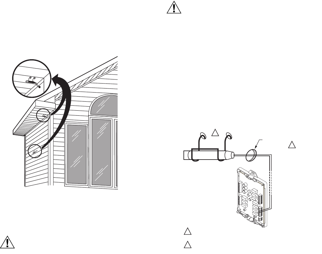
Locate and Mount C7089U1006 Outdoor
Temperature Sensor (Optional)
Mount the sensor where (see Fig. 23):
• cannot tamper with settings.
• there is good air circulation.
• it can measure true outdoor ambient temperature.
• surface is flat.
• wire distance between C7089U1006 and EIM is less than
200 feet.
Do not mount the sensor:
• in direct sunlight.
• where hot or cold air blows on the sensor. Discharge line
from an outdoor compressor unit, vent or fan causes
inaccurate temperature readings.
• where snow, ice or debris can cover it.
Use the following steps to mount the sensor:
1. Remove the sensor from the mounting clip.
2. Mark the area on the location selected for mounting the
sensor mounting clip.
3. Mount the clip.
Fig. 23. Typical locations for C7089U1006 Outdoor Sensor.
Wire C7089U1006 Outdoor Sensor
CAUTION
Electrical Interference (Noise) Hazard.
Can cause erratic system operation.
Keep wiring at least one foot away from large inductive
loads such as motors, line starters, lighting ballasts and
large power distribution panels.
Use shielded cable to reduce interference when
rerouting is not possible.
IMPORTANT
Erratic temperature readings from a sensor can occur
as a result of any of the wiring practices described
below. Avoid these practices to assure correct opera-
tion. Use shielded cable to reduce interference if
rerouting sensor wiring is not possible.
— Be sure wires have a cable separate from the thermo-
stat cable.
— Do not route temperature sensor wiring with building
power wiring, next to control contactors or near light
dimming circuits, electric motors or welding
equipment.
— Avoid poor wiring connections.
— Avoid intermittent or missing building earth ground.
CAUTION
Electrical Shock Hazard.
Can cause electrical shock or equipment damage.
Disconnect power supply before connecting wiring.
Wiring must comply with applicable codes, ordinances and
regulations:
1. Wire C7089U1006 Outdoor Sensor to OUT1and OUT2
terminals on the EIM. If leadwire provided is not long
enough (60 in.), run a cable to a hole at C7089U1006
location.
a. Using color-coded, 18-gauge thermostat wire is
recommended. For example of general wiring of
C7089U1006, see Fig. 24.
b. Pigtail wiring can be used.
2. Mount C7089U1006 in its mounting clip.
3. Plug wiring hole using nonhardening caulk or putty.
Fig. 24. Wire C7089U1006 Outdoor Sensor to the EIM.
If an outdoor temperature sensor is installed, the thermostat
displays the outside temperature in the lower right corner of the
Home Screen.
M7514
1
2
2
1
USE APPROPRIATE MOUNTING MEANS FOR THE
TYPE OF STRUCTURE.
PLUG WIRING HOLE WITH NON-HARDENING CAULK
OR PUTTY.
C7089
WIRING HOLE
THROUGH
STRUCTURE
M23525
VISIONPRO® IAQ TOTAL HOME COMFORT SYSTEM
68-0287—1 10
If thermostat is set to Auto Changeover System mode, press
the More key until the outside temperature is shown on the
screen.
Locate and Mount C7189U1005 Remote
Indoor Temperature Sensor (Optional)
1. Choose a location (see Fig. 25) for mounting the sensor
on an inside wall about 5 ft (1.5m) above the floor.
2. Be sure wire distance between C7189U1005 and EIM is
less than 200 feet.
3. Make sure there is good air circulation at average tem-
perature at the chosen location. Avoid the following loca-
tions because they can introduce errors in sensor
measurements. See Fig. 25.
a. Hot areas caused by:
(a)Concealed pipes or ducts.
(b)Drafts from fireplaces or other heat sources.
(c)Convection or radiant heat from the sun or
electrical equipment.
b. Cold areas caused by:
(a)Concealed pipes or ducts.
(b)Drafts from windows and doors.
(c)Unheated areas on the other side of the wall
location.
c. Dead air areas:
(a)Behind doors, furniture and curtains.
(b)In corners and alcoves.
4. Mark the area on the wall selected for mounting the
C7189U1005 Sensor.
5. Run wire cable to a hole at the selected wall location.
Pull approximately three inches of wire through the
opening. Color-coded, 18-gauge thermostat wire is
recommended.
Fig. 25. Typical location for C7189U1005 Indoor Sensor.
Wire C7189U1005 Indoor Sensor
CAUTION
Electrical Interference (Noise) Hazard.
Can cause erratic system operation.
Keep wiring at least one foot away from large inductive
loads such as motors, line starters, lighting ballasts and
large power distribution panels.
IMPORTANT
Erratic temperature readings from a sensor can occur
as a result of any of the wiring practices described
below. Avoid these practices to assure correct
operation.
— Be sure wires have a cable separate from the thermo-
stat cable.
— Do not route temperature sensor wiring with building
power wiring, next to control contactors or near light
dimming circuits, electric motors or welding equipment.
— Avoid poor wiring connections.
— Avoid intermittent or missing building earth ground.
CAUTION
Electrical Shock Hazard.
Can cause electrical shock or equipment damage.
Disconnect power supply before connecting wiring.
Wiring must comply with applicable codes, ordinances and
regulations.
1. Wire C7189U1005 Indoor Sensor to IN1and IN2 termi-
nals on the EIM. For an example of general wiring of
C7189U1005, see Fig. 26 to wire one sensor and Fig. 27
to wire multiple sensors.
2. Push excess wire back into the hole. Plug the hole using
nonhardening caulk, putty or insulation to prevent drafts
from affecting performance.
3. Remove C7189U1005 cover.
4. Mount C7189U1005 to the wall using the screws and
anchors provided.
5. Level the C7189U1005 for appearance only. Device
functions correctly even when not level.
6. Install C7189U1005 cover.
SCHED HOLD CLOCK SCREEN MORE
MON
T
UE
WED
THU
FRI
SA
T
A
A
T
SUN
AM
FAN
A
U
T
O
SYSTEM
HEAT
Following
Schedule
In
s
i
de
Outside
Se
t T
o
M22453
SCHED
SCHED
HOLD
HOLD
CLOCK SCREEN
DONE WAKE LEAVE RETURN SLEEP CANCEL
MON TUE WED THU FRI SAT SUN
Outside
M22448
5 FEET
(1.5 METERS)
YES
NO
NO
NO
M4476
VISIONPRO® IAQ TOTAL HOME COMFORT SYSTEM
11 68-0287—1
Fig. 26. Wiring a single C7189U1005 Indoor Sensor.
Fig. 27. Wiring Multiple C7189U1005 Sensors.
If a remote indoor temperature sensor is installed, the
thermostat has several options for displaying the current indoor
temperature. This is configured in ISU 340. The thermostat can
display either the temperature measured at the thermostat
location, the sensor location, or a 50-50 average of both.
ONE REMOTE INDOOR SENSOR INSTALLED (OPTIONAL)
If one remote indoor temperature sensor is used, based on
configuration during installer setup, either of the following
options are available:
• The thermostat will display the temperature measured at
the sensor location (internal thermostat sensor is disabled).
• The thermostat will display a 50-50 average of the
temperature measured at the thermostat location and the
remote indoor sensor location.
MULTIPLE REMOTE INDOOR SENSORS INSTALLED (OPTIONAL)
If more than one remote indoor sensor is used, based on
configuration during installer setup, either of the following
options are available:
• The thermostat will display the temperature measured at
the sensor locations (internal thermostat sensor is
disabled). Sensors must be in square numbers (e.g., 4, 9,
16, and so on) and the displayed temperature will be an
average of the temperatures measured at each location.
• The thermostat will display a 50-50 average of the
temperature measured at the thermostat location and the
average of the temperatures measured at the remote indoor
sensor locations. In this case, the thermostat sensor still
carries a 50% weighting of the displayed temperature.
Install Discharge Air Temperature Sensor
(Optional):
Prior to installing Discharge Air Temperature Sensor (DATS)
refer to the installation instructions included with the product for
more information on placement and wiring.
When using a DATS with network zoning the DATS will monitor
the duct air temperature and communicate with the thermostat
and will disable the heating and/or cooling if installer set high or
low temperature limits are reached.
When using a DATS with an Equipment Interface Module the
DATS is for testing only. When the installer is in any of the
Installer Tests pressing the “More” button will display the
temperature measured at the DATS. This allows the installer
to view the temperature of each stage of heating and or
cooling. The DATS will not be used for control and will not
disable heating or cooling based on duct air temperature.
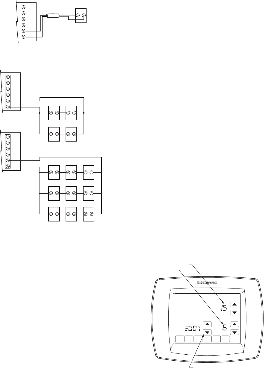
Set Calendar and Time
Thermostat keeps current time and day for up to ten years
under normal use after the calendar is set.
When the thermostat is first powered, the display is ready to
set the calendar and time.
NOTE: Calendar can also be set in the Installer Setup.
1. Press the arrow keys to set the year, month and day.
2. Press the Done key.
3. Press the arrow keys to set the current time.
4. Press the Done Key.
C7189
1 OUT
L
2 IN
1 IN
M23523
2 OUT
M23524
C7189 C7189
C7189 C7189
C7189 C7189
C7189 C7189
C7189
C7189
C7189 C7189 C7189
1 OUT
L
2 IN
1 IN
2 OUT
1 OUT
L
2 IN
1 IN
2 OUT
DONE
MO
MO
WE
WE
TH
TH
FR
FR
S
S
A
A
SU
CHANGE FILTER UV LAMP
OK TO PICK MULTIPLE DAYS SCREEN LOCKED
SET CURRENT DAY
SET MONTH
USE ARROWS TO SET YEAR AND TIME
M22424
VISIONPRO® IAQ TOTAL HOME COMFORT SYSTEM
68-0287—1 12
INSTALLER SETUP
Auto Discover is available when the TH9421C thermostat is
connected to an EIM. The EIM communicates information to
the thermostat. Thermostat settings can be specified using the
up and down arrow keys on the screen or set to Auto Discover.
Using Auto Discover
Some Installer setups are defaulted to Auto Discover. If not
defaulted, the installer can change the option to Auto Discover,
however, it is always important that the installer verify that the
auto discovered values are correct for the system that is
present.
When using the thermostat with an equipment interface
module, Auto Discover will discover factory default settings
and will not receive communications as to proper system
settings. The equipment interface module is preprogrammed at
the factory as a one heat one cool product and the thermostat
will “auto discover” those settings. The equipment interface
module will be reprogrammed when the installer manually
changes the configuration in the installer set up. It is not
recommended to use Auto Discover with an equipment
interface module.
When using the VisionPRO® IAQ thermostat with a W8835
zone panel, configure the zone panel, using the DIP switches
on the panel, for the proper system settings. Enter the installer
setup on each thermostat and assign zone numbers, and
change the system settings (ISU 172–180) to Auto Discover
(E) then press the discover button on the zone panel. The zone
panel will then communicate those settings back to the
thermostats and the thermostats will automatically configure
the ISU settings in Auto Discover, again it is important to verify
that the auto discovered values are correct.
NOTE: When a VisionPRO® IAQ thermostat is being added
to an existing zoning system with T8635 Thermostats
the new VisionPRO® IAQ must be set up as the Zone
One Thermostat (master zone controller), and can
only be used with a W8835 zone panel.
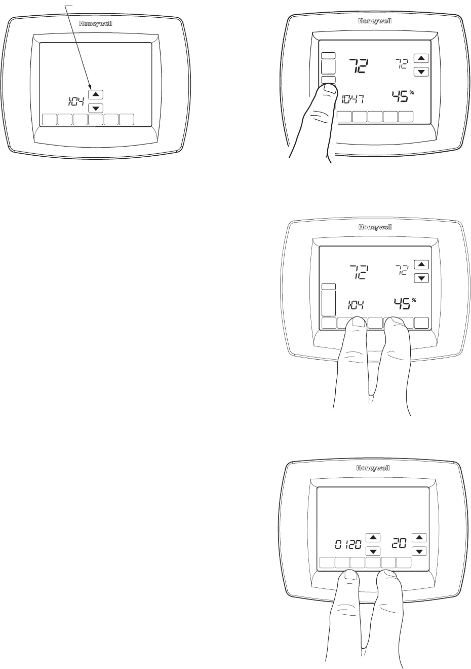
Follow these steps to enter the Installer Setup:
1. Press and release the System Key.
2. Press and hold the two blank keys on either side of the
center blank key for approximately five seconds until
screen changes.
3. Release the two blank keys when the screen on the ther-
mostat matches the screen below.
D
O
N
E
MO
WE
TH
FR
SA
SU
USE ARROWS TO SET YEAR AND TIME
M22425
W
SCHED HOLD CLOCK SCREEN
FAN
ON
AUTO
A
M
THU
SYSTEM
EM HEAT
OFF
COOL
Following
Schedule
Inside
M23498
Humidity
DONE CANCEL
MO
MO
TU WE
WE
TH
TH
FR
FR
S
S
A
A
SU
SYSTE
M
EM
HEAT
OFF
CHANGE FILTER UV LAMP
Following
Schedule
Inside Set
OK TO PICK MULTIPLE DAYS SCREEN LOCKED
M23499
Humidity
D
O
NE
M22442
VISIONPRO® IAQ TOTAL HOME COMFORT SYSTEM
13 68-0287—1
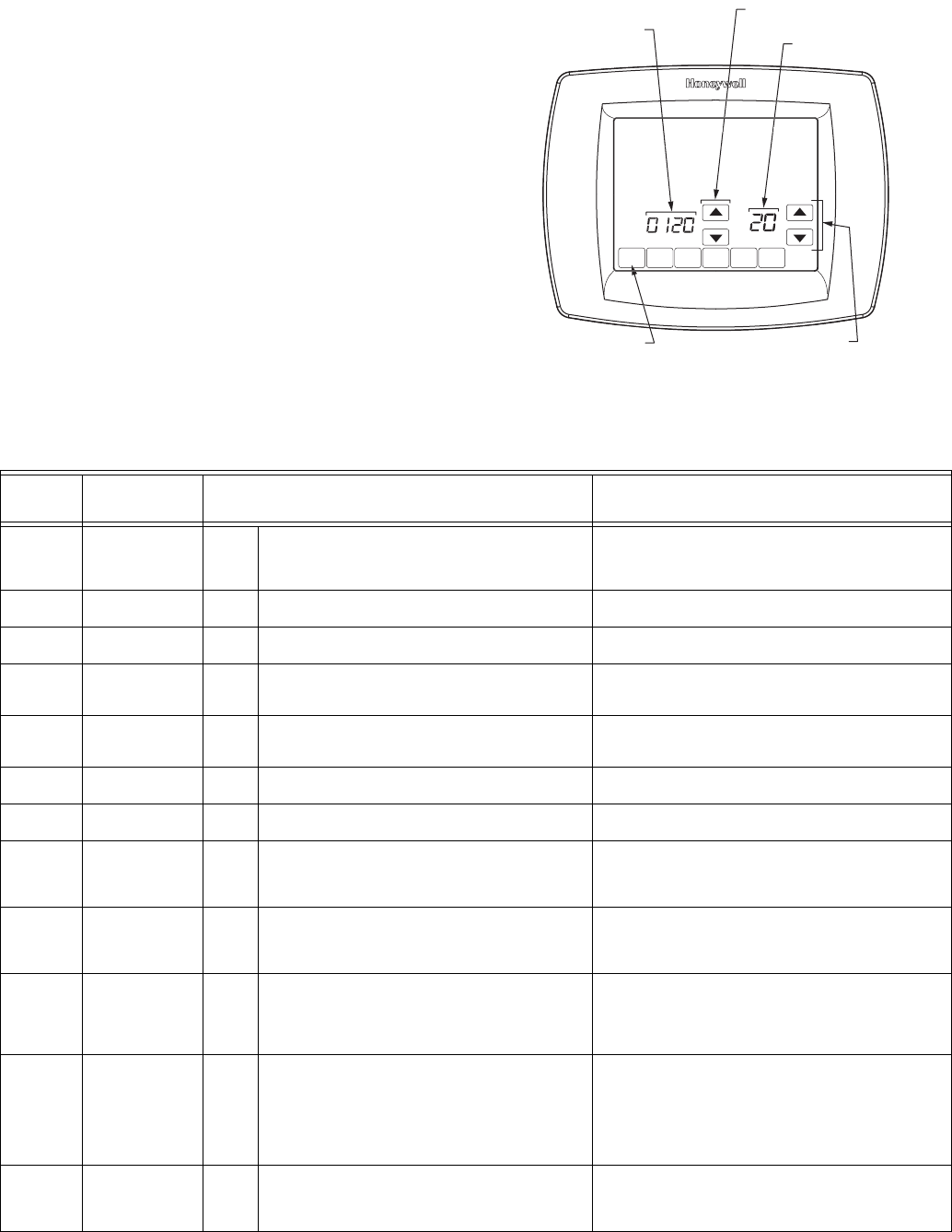
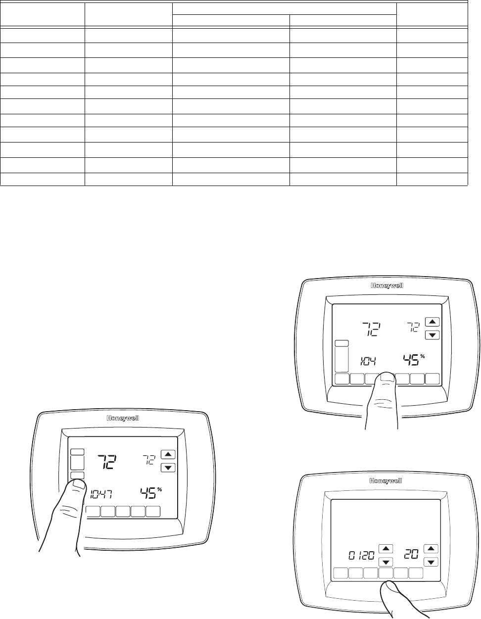
4. See screen below to review how the thermostat keys are
used during Installer Setup. See Table 3–4 for the
Installer Setup Numbers and Settings.
5. Press the Done key to exit the Installer Setup screen.
DONE
O
MON
WED
THU
FRI
SA
T
A
A
T
SUN
INSTALLER
SETUP
NUMBER
CURRENT
SETTING
ADVANCE TO NEXT
INSTALLER SETUP
PRESS TO EXIT
INSTALLER SETUP
CHANGE THE
CURRENT
SETTING M22443
A
U
Table 3. Installer Setup Menu.
ISU
Parameter
Number
Installer Setup
Name
Settings
(Factory Defaults Shown in Bold) Notes
110 Zone Number 0
1–9
Not zoned
Zone number
Select zone number.
Zone 0 = not zoned
Zone 1 = master zone controller
Zone 2–9 = satellite thermostat
120
USU
Date (Year
Upper)
20
21
Select first two digits of current calendar year (2006 for
example) - (2001-2178 available).
130
USU
Date (Year
Lower)
01-99 Default = 06 Select last two digits of current calendar year (2006 for
example) - (2001-2178 available).
140
USU
Date (Month) 1-12 Select number that represents current calendar
month.
Default = 06
150
USU
Date (Day) 1-31 Select number that represents current calendar
date.
Default = 15
160
USU
Schedule Options 4
0
Seven-day programmable
Non-programmable
165
USU
Restore Energy
Star Schedule
0
1
No
Yes
172 System Selection 1
2
3
E
Conventional
Heat Pump
Heat Only No Fan
Auto Discover
Selection of a specific system setting will automatically
modify some default settings and/or hide other installer
setup options that follow.
174 Number of Cool/
Compressor
Stages
0
1
2
E
none
1
2
Auto Discover
Not shown if ISU172 = 3.
Conventional systems = number of cooling stages.
Heat Pump systems = number of compressor stages.
176 Number of
Conventional
Heat or Heat
Pump Aux Stages
0
1
2
3
E
none
1
2
3
Auto Discover
Conventional systems = number of heating stages
(maximum of 3).
Heat Pump systems = number of auxiliary heat
stages (maximum of 2).
180 Fan Operation
Conventional
heat only
0
1
2
E
Gas or oil furnace equipment controls fan in
heating
Electric furnace—thermostat controls fan in
heating
Equipment controls stage 1; thermostat controls
stage 2+
Auto Discover
Only shown if ISU172 = 1 (conventional system).
Use 0 for fossil fuel systems (equipment controls fan).
Use 1 for electric systems (thermostat controls fan).
Use 2 if stage 1 is radiant heating and stage 2+ is a hot
water fan coil.
190 Reversing Valve
O/B
0
1
Changeover valve—O/B terminal is energized
in cooling
Changeover valve—O/B terminal is energized in
heating
Only shown if ISU172 = 2.

VISIONPRO® IAQ TOTAL HOME COMFORT SYSTEM
68-0287—1 14
200 Back-up Heat
Source Applies to
both Aux and
EmHeat
0
1
E
Electric backup heat
Fossil fuel backup heat
Auto Discover
Only shown if ISU172 = 2 and ISU176 = 1 or greater.
210 External Fossil
Fuel Kit
0
1
Thermostat controls backup heat
External Fossil Fuel kit controls backup heat
Only shown if ISU172 = 2 and ISU200 = 1.
220 CPH for 1st
Stage Cool/
Compressor
1-6
E
3—cph recommended for compressors
1, 2, 4, 5, 6—other cycle rate settings
Auto Discover
230 CPH for 2nd
Stage Cool/
Compressor
1-6
E
3—cph recommended for compressors
1, 2, 4, 5, 6—other cycle rate settings
Auto Discover
Only shown if ISU174 = 2.
240 CPH for 1st
Stage
Conventional
Heat or Auxiliary
1-12
E
1—1 cph used for steam and gravity
3—3 cph used for hot water system and high
efficiency (90% or better) furnaces
5—5 cph used for standard fossil fuel forced air
(less than 80% efficient) systems
9—9 cph used for electric furnaces
2, 4, 6, 7, 8, 10, 11, 12—other cycle rate settings
Auto Discover
Only shown if ISU172 = 2 and ISU176 = 1 or higher.
Default varies based on types of heating.
250 CPH for 2nd
Stage
Conventional
Heat or 2nd
Stage Auxiliary
1-12
E
1—1 cph used for steam and gravity
3—3 cph for hot water systems and high efficiency
(90% or better) furnaces
5—5 cph for standard fossil fuel forced air (less
than 90% efficient) systems
9—9 cph used for electric furnaces or electric
auxiliary heat for heat pump systems
2, 4, 6, 7, 8, 10, 11, 12—other cycle rate settings
Auto Discover
Only shown if ISU176 = 2 or for Heat Pump systems
with 2 stages of Auxiliary Heat.
Default varies based on types of heating.
260 CPH for 3rd
Stage Heat
1-12
E
1—1 cph used for steam and gravity
3—3 cph for hot water systems and high efficiency
(90% or better) furnaces
5—5 cph for standard fossil fuel forced air (less
than 90% efficient) systems
9—9 cph used for electric furnaces or electric
auxiliary heat for heat pump systems
2, 4, 6, 7, 8, 10, 11, 12—other cycle rate settings
Auto Discover
Only shown if ISU176 = 3.
Default varies based on types of heating.
280
USU
Continuous
Backlight
0
1
Backlight not on continuously. Thermostat
backlight comes on with each key press.
Backlight is on continuously.
If backlight is on continuously, it is low-intensity. Light
changes to full brightness after pressing any key.
300 Changeover 0
1
Manual
Auto
Auto Changeover allows user to choose heat, cool, off
or auto. When set to Auto the thermostat will
automatically choose heat or cool based on room
temperature and heat/cool set points. Manual
changeover allows the user to manually toggle
between heat, cool and off.
310 Deadband 21.5
32.0
42.5
53.0
63.5
74.0
84.5
95.0
2°F 1.5°C
3°F 2.0°C
4°F 2.5°C
5°F 3.0°C
6°F 3.5°C
7°F 4.0°C
8°F 4.5°C
9°F 5.0°C
Note: degrees C is not same as degrees F
Only shown if ISU300 = 0. The deadband indicates the
minimum number of degrees that are allowed between
the heat and cool settings when in auto changeover.
For example, if the deadband is set to 3°F and the cool
setpoint is 75°F the warmest heat setpoint allowed
would be 72°F.
320
USU
Temperature
Indication Scale
0
1
Fahrenheit temperature display
Celsius temperature display
330
USU
Daylight Saving 0
1
2
Disabled
Enabled (US 1987)
Enabled (US 2007)
Set to 0 in areas that do not follow daylight savings
time.
340 Indoor Temp
Sensor
0
1
2
Thermostat location only
Remote indoor sensor(s) location(s) only
Average between thermostat and sensor locations
Indoor temperature sensors will display the
temperature at the sensor location or an average of
two indoor temperature sensors, not including the
temperature sensor in the thermostat. The
temperature sensor in the thermostat is disabled when
using remote indoor temperature sensor(s).
342 Outdoor Temp
Sensor
0
1
E
None
Yes
Auto Discover
An outdoor temperature sensor is required for heat
pump compressor lockout (ISU350), heat pump
auxiliary lockout (ISU360), dual fuel heat pump
balance point (ISU360) and Humidification with Frost
Protection (ISU372).
Table 3. Installer Setup Menu. (Continued)
ISU
Parameter
Number
Installer Setup
Name
Settings
(Factory Defaults Shown in Bold) Notes

VISIONPRO® IAQ TOTAL HOME COMFORT SYSTEM
15 68-0287—1
345 Dual Fuel Heat
Pump Control
0
1
2
Balance point only
Balance point plus 2° droop
Balance point/auxiliary heat lockout plus 2° droop.
See Dual Fuel Heat Pump control on page 22.
346 Dual Fuel Heat
Pump Upstage to
Furnace Timer
0
30
45
60
75
Disabled
30 minutes
45 minutes
60 minutes
75 minutes
See Dual Fuel Heat Pump control on page 22.
350 Heat Pump
Balance Point
(also compressor
lockout)
Temperature
0
5-15
10 -12
15 -9.5
20 -6.5
25 -4
30 -1
35 1.5
40 4.5
45 7
50 10
55 13
60 15.5
No heat pump compressor lockout
5°F -15.0°C
10°F -12.0°C
15°F -9.5°C
20°F -6.5°C
25°F -4.0°C
30°F -1.0°C
35°F 1.5°C
40°F 4.5°C
45°F 7.0°C
50°F 10.0°C
55°F 13.0°C
60°F 15.5°C
(Show 1/2 degree C)
Only shown for heat pump applications with an
outdoor temperature sensor present.
360 Heat Pump
Auxiliary Heat
Lockout
Temperature
0
5-15
10 -12
15 -9.5
20 -6.5
25 -4
30 -1
35 1.5
40 4.5
45 7
50 10
55 13
60 15.5
65 18.5
No heat pump auxiliary lockout
5°F -15.0°C
10°F -12.0°C
15°F -9.5°C
20°F -6.5°C
25°F -4.0°C
30°F -1.0°C
35°F 1.5°C
40°F 4.5°C
45°F 7.0°C
50°F 10.0°C
55°F 13.0°C
60°F 15.5°C
65°F 18.5°C
(Show 1/2 degree C)
Only shown for heat pump applications with an
outdoor temperature sensor present.
365 Discharge Temp
Sensor
0
1
E
None
Remote
Auto Discover
366 Zoning High
Temperature
Limit
160
0
110–170
160°F (71°C)
Disabled
110°F to 170°F (43.5°C to 76.5°C)
Only Shown if ISU110 = 1 (Master Zone Controller)
and Discharge Temperature Sensor is available.
367 Zoning Low
Temperature
Limit
40
0
35-50
160°F (71°C)
Disabled
35°F to 50°F (1.5°C to 10°C)
Only Shown if ISU110 = 1 (Master Zone Controller)
and Discharge Temperature Sensor is available.
368 Staging
Discharge
Temperature
High Limit
110
0
80-130
110°F (43.5°C)
Disabled
80°F to 130°F (26.5°C to 54.5°C)
Only Shown if ISU110 = 1 (Master Zone Controller)
and ISU174 = 2 or more. Must have Discharge
Temperature Sensor present.
369 Staging
Discharge
Temperature
Low Limit
55
0
50-60
55°F (13°C)
Disabled
50°F to 60°F (10°C to 15.5°C)
Only Shown if ISU110 = 1 (Master Zone Controller)
and ISU176 = 2. Must have Discharge Temperature
Sensor present.
370 Indoor Humidity
Sensor
0
1
2
E
Disabled
Internal—sensor in thermostat
Remote
Auto Discovered
If there is a remote sensor installed and the setting is
either auto discover or “remote” the internal thermostat
humidity sensor is disabled. If set to “internal” the
internal thermostat sensor is presented on the screen.
If set to “disabled” the internal sensor and any remote
sensors are disabled, there will be no humidity
displayed and will have no humidification/
dehumidification control.
372 Indoor
Humidification
Control
0
1
3
E
Off
Humidify with no Frost Protection
Humidify with Frost Protection
Auto Discover
Shown only if ISU370 = 1, 2 or E.
Table 3. Installer Setup Menu. (Continued)
ISU
Parameter
Number
Installer Setup
Name
Settings
(Factory Defaults Shown in Bold) Notes

VISIONPRO® IAQ TOTAL HOME COMFORT SYSTEM
68-0287—1 16
374 Hum Fan Action 0
1
2
3
Humidify only while fan or heat is on
Humidify will force fan on
Humidify only when heat is on
Humidifier operates independent of fan
Setting 0 will run the humidifier only during a call for
heat or if the fan is running.
Setting 1 will force the fan to run if there is a call for
humidification.
Setting 2 will humidify only during a call for heat.
Setting 3 assumes the humidifier has it own internal
fan and will not require the system fan or heat to be
operating during a call for humidification.
379 Dehumidification
Control
0
1
3
None
Dehumidify with Air Conditioning
Whole house Dehumidifier
Option 1 uses dehum terminal as a normally closed
relay to wire to a low-speed fan terminal.
Option 3 uses dehum terminal as a normally open
relay to wire to a whole-house dehumidifier.
383 Over-Cooling
Limit 10.5
21.0
31.5
1°F 0.5°C
2°F 1.0°C
3°F 1.5°C
(Show 1/2 degree C)
Only shown if ISU379 = 1.
384 Dehumidification
Fan Action
0
1
System fan turns on with dehumidifier
Dehumidifier operates independent of system fan
Only shown if ISU379 = 3.
390 Southern
Dehumidification
Away Mode
0
1
No
Yes
Not shown if ISU379 = 0.
ISU 391-394 will only be shown if ISU390 = 1.
391 Southern
Dehumidification
Away Mode Fan
Setting
0
1
2
Fan Auto
Fan On
Fan Circulate
If ISU391 = 1 or 2 to help remove condensation from
the air handler and the A-coil, some humidity may be
re-introduced into the living space.
392 Southern
Dehumidification
Away Mode Low
Limit
Temperature
Setting
70-80 70°F–80°F
Default = 76°F
The air conditioner will be allowed to cool the living
space to this temperature to meet the humidity setting
that set in ISU394.
393 Southern
Dehumidification
Away
Temperature
Setting
70-99 70°F–99°F
Default = 85°F
The A/C will maintain this temperature provided the
humidity setting is satisfied. This temperature setting
can not be set lower than the temperature set in ISU
392.
394 Southern
Dehumidification
Away
Dehumidification
Setting
55-70 55%–70% relative humidity
Default = 65%
Set the desired humidity level to maintain within the
living space
400 Ventilation control 0
1
2
No ventilation
Ventilation on at all times
Ventilation on except during sleep period
If ISU300 = 0, ISU401-405 will not be shown.
401 Number of
bedrooms
1-6 1–6 bedrooms
Default = 2
402 Total house
Sq. Ft.
10-50 1000–5000 sq. ft. in increments of 100
Default = 1000 sq. ft.
403 Ventilation CFM 30-195 30–195 CFM in increments of 5
Default = 160 CFM
404 Max ventilation
percentage limit
30-60
100
30%–60%
Default = 50%
unlimited
The thermostat will determine if ventilation is meeting
ASHRAE standard 62.2. The display will show a P
above the setup number if the setting passes the
ASHRAE standard, or F if it does not. Best practice is
to move the setting down until F is displayed, then
move up one setting to the minimum passing value.
405 Ventilation Fan
Action
1
2
Vent on will force fan on also
Vent will not force fan ON
406 Ventilation in
High Humidity
0
1
Off
On
Only shown if ISU372 and ISU400 are not set to 0.
When set to On will use ventilation to remove humidity
when thermostat is in the heat mode.
Table 3. Installer Setup Menu. (Continued)
ISU
Parameter
Number
Installer Setup
Name
Settings
(Factory Defaults Shown in Bold) Notes

VISIONPRO® IAQ TOTAL HOME COMFORT SYSTEM
17 68-0287—1
500
USU
Furnace Filter
Change
Reminder
0
1
2
3
4
5
6
7
8
9
10
11
12
13
14
E
Disabled
10 R.T. Days
30 R.T. Days
60 R.T. Days
90 R.T. Days
120 R.T Days
180 R.T. Days
270 R.T. Days
365 R.T. Days
30 C Days
60 C Days
90 C Days
120 C Days
180 C Days
365 C Days
Auto Discover
502 Furnace filter
reminder run time
equipment counts
0
1
Counts runtime Heat and Cool
Counts runtime Cool only
510
USU
Humidifier Pad
Replacement
Reminder
0
1
2
3
E
Disabled
90 C Days or 30 R.T. Days
180 C Days or 60 R.T. Days
365 C Days or 90 R.T. Days
Auto Discover
Display will show Calendar Days if ISU372 = 0; Run
Time Days if ISU372 = 1 or 3.
520
USU
UV Lamp
Replacement
Reminder
0
1
2
E
Disabled
365 Days
730 Days (2 years)
Auto Discover
530
USU
Adaptive
Intelligent
Recovery
0
1
Conventional
Adaptive
See Temperature Recovery on page 31.
540
USU
Number of
Periods
2
4
2 Periods
4 Periods
2 periods = Wake and Sleep.
4 periods = Wake, Leave, Return, and Sleep.
580 Min Compressor
Off Time
0
1
2
3
4
5
Off
1 minute
2 minutes
3 minutes
4 minutes
5 minutes
600 Heat Temp
Range Stops
40-90 40°F–90°F (Show 1/2 degree C)
Default = 90°F
610 Cool Temp
Range Stops
60-99 60°F–99°F (Show 1/2 degree C)
Default = 60°F
640
USU
Clock Format 12
24
12 Hour
24 Hour
650 Extended Fan on
time Heat (Blower
Off Delay Heat)
0
30
60
90
120
Off
30 seconds
60 seconds
90 seconds
120 seconds
660 Extended Fan on
time Cool (Blower
Off Delay Heat)
0
30
60
90
120
Off
30 seconds
60 seconds
90 Seconds
120 Seconds
This can be used to remove condensation from A-coil;
however, could re-introduce humidity into the living
space.
670
USU
Keypad Lockout 0
1
2
Unlocked
Partial Locked
Full Locked
680 Temp Control
Heat
1
2
3
Less Aggressive temp control (may cause temp
undershoot)
Standard (recommended)
More Aggressive temp control (may cause temp
overshoot)
690 Temp Control
Cool
1
2
3
Less Aggressive temp control (may cause temp
undershoot)
Standard (recommended)
More Aggressive temp control (may cause temp
overshoot)
Table 3. Installer Setup Menu. (Continued)
ISU
Parameter
Number
Installer Setup
Name
Settings
(Factory Defaults Shown in Bold) Notes
VISIONPRO® IAQ TOTAL HOME COMFORT SYSTEM
68-0287—1 18
INSTALLER SYSTEM TEST
Use the Installer System Test to test the heating, cooling and
fan (and emergency heat for heat pump systems).
CAUTION
Equipment Damage Hazard.
Minimum compressor off time is bypassed during
Installer System Test
Avoid cycling compressor quickly.
How to Use the Installer System Test
The Installer Test is part of the Installer Setup Menu.
1. Enter the Installer System Test by entering the Installer
Setup.
2. Note that the test appears at the end of the Installer
Setup Numbers.
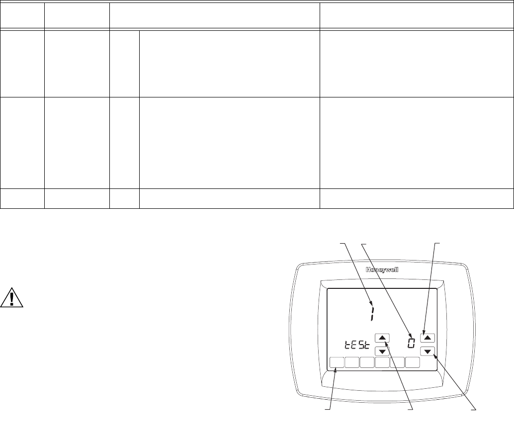
3. See Fig. 28 to review how the thermostat buttons are
used during the Installer System Test. See Table 6 for
available Installer System Tests.
4. If installed with a Discharge Air Temperature Sensor
(ISU365=1) press the “MORE” button to view the dis-
charge temperature, and press Cancel to return to the
Installer test screen.
Fig. 28. Review thermostat buttons used during Installer
System Test.
700 Temperature
Display Offset
-3
-2
-1
0
1
2
3
-3°F -1.5°C
-2°F -1°C
-1°F -.5°C
0°F 0. °C — (no difference in displayed
temperature and actual room temperature)
1°F .5°C
2°F 1°C
3°F 1.5°C
701 Humidity Display
Offset
-5
-4
-3
-2
-1
0
1
2
3
4
5
-5%
-4%
-3%
-2%
-1%
0%
1%
2%
3%
4%
5%
710 Restore Factory
Defaults
0
1
No
Yes
Restoring factory defaults will re-set installer setup and
programming.
Table 3. Installer Setup Menu. (Continued)
ISU
Parameter
Number
Installer Setup
Name
Settings
(Factory Defaults Shown in Bold) Notes
DO
N
E
M22428
SYSTEM TEST
NUMBER
SYSTEM STATUS
NUMBER
DONE KEY
EXITS INSTALLER
SYSTEM TEST
UP ARROW KEY
ADVANCES TO
NEXT SYSTEM
TEST NUMBER
UP ARROW
TURNS THE
SYSTEM ON
DOWN ARROW
TURNS THE
SYSTEM OFF
VISIONPRO® IAQ TOTAL HOME COMFORT SYSTEM
19 68-0287—1
Installer System Tests
When VisionPRO® IAQ is used in a zoning system you must exit the installer test on one thermostat before entering the installer
test on another thermostat.
OPERATION
Thermostat Keys
Thermostat Display
Table 4. Installer System Test.
System Test Number Test Type ISU Value System Status Number and Description
Test 1 Installer Test Cool 0
1
2
Off
Cool Stage 1
Cool Stages 1 & 2
Test 2 Installer Test Fan 0
1
Off
Fan On
Test 3 Installer Test Heat 0
1
2
3
4
Off
Heat Stage 1
Heat Stages 1, 2
Heat Stages 1,2,3
Heat Stages 1,2,3,4
Test 4 Emergency Heat Test 0
1
2
Off
AUX Heat Stage 1
AUX Heat Stages 1 and 2
Test 5 Installer Test Humidifier 0
1
Off
Humidifier On
Test 6 Installer Test Dehumidifier 0
1
Off
Dehumidifier On
Test 7 Installer Test Ventilator 0
1
Off
Ventilator On
Err Diagnostic Recall 00-99 See “Communication Error Codes” on page 34
Press the Next button to go to the beginning of the Installer Setup or press the Done button to exit the Installer System Test.
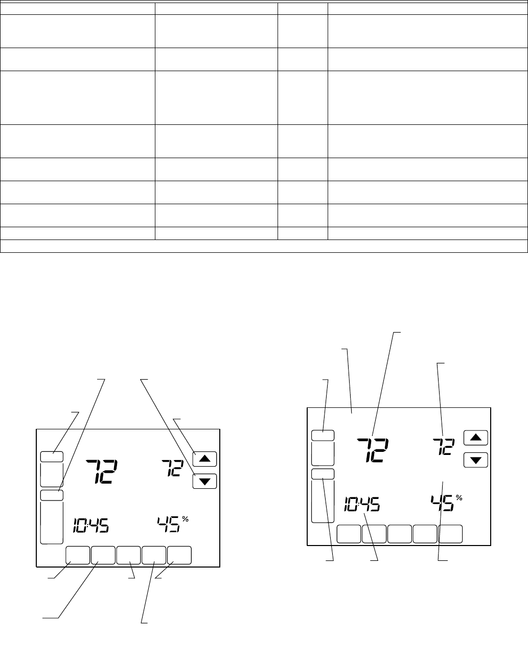
SCHED HOLD CLOCK SCREEN MORE
TUE
AM
FAN
AUTO
SYSTEM
HEAT
COOL
Following
Schedule
Inside Set To
M23500
FAN
SELECTS
ON/AUTO/CIRC
SYSTEM
SELECTS EM.
HEAT/HEAT/OFF/COOL
UP ARROW
RAISES
TEMPERATURE
SETTING
DOWN ARROW
LOWERS TEMPERATURE
SETTING
SCHED
ENTERS
SCHEDULING
MODE
MORE
SHOWS ADDITIONAL
ACCESSORY AND
MAINTENANCE
OPTIONS
SCREEN
LOCKS OUT THE
SCREEN TO ALLOW
FOR CLEANING
CLOCK
SETS THE
TIME
FORWARD
OR BACK
HOLD
SETS A PERMANENT
HOLD AND ACTIVITIES
VACATION HOLD
Humidity
SCHED HOLD CLOCK SCREEN MORE
TU
A
M
FAN
AUTO
SYSTEM
EM HEAT
HEAT
OFF
COOL
Following
Schedule
Inside Set To
M23501
FAN
SHOWS FAN
SETTING
TUE
SHOWS CURRENT DAY
OF THE WEEK
SYSTEM
SHOWS
CURRENT
SYSTEM
POSITION
TIME
DISPLAY CURRENT
TIME OF DAY, HOLD
TIME REMAINING OR
NUMBER OF VACATION
DAYS REMAINING
INSIDE TEMPERATURE
SHOWS THE CURRENT INSIDE
TEMPERATURE
SET TO
TEMPERATURE
SHOWS THE
CURRENT SET
TEMPERATURE
FOLLOWING
SCHEDULE
SHOWS THE
THERMOSTAT IS
FOLLOWING THE
PROGRAMMED
SCHEDULE
Humidity

VISIONPRO® IAQ TOTAL HOME COMFORT SYSTEM
68-0287—1 20
System and Fan Settings
System
The System key selections vary based on your heating and/or
cooling system type.
Heat — Thermostat controls the heating system.
Off — Both heating and cooling systems are off.
Cool — Thermostat controls the cooling system.
Auto — Thermostat automatically changes between heating
and cooling operation, depending on indoor temperature.
Em. Heat — Emergency heat cycles to maintain temperature.
Compressor is locked out and auxiliary heat turns on as
needed.
Fan
The Fan key selections vary based on the heating and/or
cooling system type.
On — Fan runs continuously. Use this setting for improved air
circulation or for more efficient central air cleaning.
Auto — fan follows the fan program schedule.
Circ — fan runs randomly approximately 35% of the time. Use
this setting for improved air circulation or for more efficient
central air cleaning when you do not want the fan running
continuously.
Control Humidification Level
The VisionPRO® IAQ Touchscreen Thermostat reads the
inside humidity level and allows for a humidification setting with
or without frost protection. Humidification will only take place
when the thermostat is in Heat mode or in Auto mode when the
previous call was a call for heating.
WITH FROST PROTECTION
Controlling humidification with frost protection requires an
outdoor temperature sensor. The Frost Index (scale 1–10) will
limit the amount of humidity added to the air based on outdoor
temperature, with 1=most dry and 10=most humid. This
prevents frost from accumulating on windows.
WITHOUT FROST PROTECTION
The frost setpoint is not displayed, but a humidity setpoint can
still be set.
1. Press the More key until the inside humidity level set-
point is shown.
2. Use Up and Down arrow keys, located to the right of the
humidity setpoint, to set desired humidity level.
3. Press Done key.
Control Dehumidification Level
The VisionPRO® IAQ Touchscreen Thermostat reads the
inside humidity level and allows for a dehumidification setting,
and can be set to dehumidify using the air conditioner or a
whole house dehumidifier.
With Air Conditioner
The set range for dehumidification is 40 to 80%, and can be set
in 5% increments. The thermostat must be in Cool mode or
Auto mode when the previous call was a call for cooling.
Dehumidifying in this manner runs the air conditioner longer
than simply cooling the house would require, and can be set to
run 1, 2, or 3°F below the temperature setpoint. This feature is
called Dehumidification Droop Control.
NOTE: You must use this setting if:
— No powered, whole house dehumidifier is present,
and
— The system uses the air conditioner as the
dehumidifier.
MORE
DONE
Inside
Humidity
M23518
HUMIDIFIER
CANCEL
MORE
DONE CANCEL
DEHUMIDIFIER
Inside
Humidity
M23496
CURRENT
INDOOR
HUMIDITY
DEHUMIDIFIER
SETTING
(AUTO/OFF)
HUMIDITY SET
POINT
DONE CANCEL
DEHUMIDIFIER
Inside
M23514
VISIONPRO® IAQ TOTAL HOME COMFORT SYSTEM
21 68-0287—1
DEHUMIDIFICATION DROOP CONTROL
In extremely high humidity conditions, the thermostat keeps
the air conditioner running (energizing Y/Y2 and G) for up to
3°F below the temperature setpoint. It does this while trying to
achieve the desired humidity setpoint and balancing that with
the temperature setpoint. The thermostat controls up to 3° F
below the temperature setting until either the humidity setpoint
is satisfied or conditions change.
With Whole House Dehumidifier
Controls humidity levels in the house by dehumidifying without
the use of the air conditioner. This setting requires a dedicated
unit for dehumidification. Dehumidification with a whole house
dehumidifier will take place when the thermostat is in the Cool,
Off, Auto, Heat or Em.Heat modes. If the system is installed
with a whole house humidifier, dehumidification with a whole
house dehumidifier will only take place when the thermostat is
in Cool, Off or Auto modes (Auto only if the previous call was a
call for cooling).
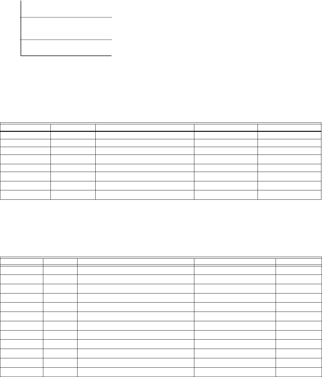
When controlling a whole-house dehumidifier the user can
toggle between auto (dehumidify when needed based on
setpoint and current humidity level) and off (see Fig. 29).
Fig. 29. Display when controlling a whole-house
dehumidifier.
1. Press the More key until the inside humidity percent and
dehumidification setpoint are shown.
2. Use Up and Down arrow keys, located to the right of the
dehumidifier setpoint, to set desired humidity level for
dehumidification in the summer.
3. Press Done key.
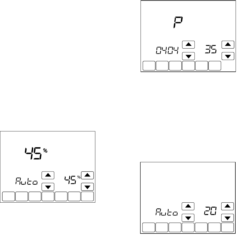
Ventilation Control
Ventilation setup options include ISUs 400, 401, 402, 403, and
404. Combined, these will determine a percentage of
maximum ventilation limit. The thermostat will calculate
whether or not this level of ventilation meets ASHRAE
standard 62.2. If ASHRAE 62.2 is met a P will appear in the
display above the setup number. If ASHRAE 62.2 is not met an
F will appear in the display above the setup number.
Passing ASHRAE 62.2 is only applicable when vent is running.
For example, if installer has set to not vent during sleep period,
ASHRAE 62.2 would be met at all times except during sleep
period.
Ventilation occurs two ways:
AUTOMATIC
Uses installer setup to determine amount of ventilation
required based on house and equipment size. To disable
automatic ventilation, switch the ventilation setting to Off. The
user can still use the timer to request ventilation.
ON DEMAND
User can also set a vent timer that will circulate fresh air into
the home for a set period of time from 20 to 180 minutes in 20-
minute increments. The vent timer is enabled whether
ventilation is set to “Auto” or “Off.”
VENTILATION IN HIGH HUMIDITY CONDITIONS (SETUP FUNCTION 0406)
If Ventilation Control is available (setup function 0400 set to 1
or 2), this allows the ventilation equipment to turn on if the
humidity rises approximately 10% above the RH setting in
heating mode to exhaust the extra humidity.
HEAT PUMP OPERATION
Heat Pump LED Indication
A red LED indication is located in the upper right corner of the
thermostat. It is only visible when lighted.
When the L terminal is wired to an equipment monitor, the LED
signals when a check or fail signal is sent to the thermostat
from the system. This is operational in the Heat, Off, Cool or
Auto positions.
MORE
DONE CANCEL
DEHUMIDIFIER
Inside
Humidity
M23515
DONE
M23520
MORE
DONE CANCEL
VENT
Minutes
M23519

VISIONPRO® IAQ TOTAL HOME COMFORT SYSTEM
68-0287—1 22
Heat Pump Emergency Heat LED Indication
The thermostat uses a red LED indicator that lights when the
thermostat is in the Emergency Heat mode. The LED is located
in the upper right corner of the thermostat. It is visible only
when on.
Heat Pump Temperature Lockouts
Dual Fuel Heat Pump and Outdoor Temperature
Sensor
In this operation, there is no external fossil fuel kit (dual fuel kit)
installed; the thermostat controls this function.
1. Choose correct heat pump application in Installer Setup
Number 0172.
2. Choose Fossil Fuel Option as the backup heat source
in Installer Setup Number 0200.
3. Choose No External Fossil Fuel Kit Option is control-
ling back up heat in Installer Setup Number 0210.
4. Choose Outdoor Temperature Sensor for Heat Pump
Temperature Lockouts in Installer Setup Number 0342.
5. Choose appropriate Balance Point Temperature in
Installer Setup Number 0350.
Dual Fuel Heat Pump Control
Balance Point Only (ISU345 = 0)
NOTE: System must have an outdoor temperature sensor.
When the outdoor temperature is above the selected balance
point temperature, only the compressor operates and the fan
(G terminal) energizes when the thermostat calls for heat. See
Fig. 30. When the outdoor temperature is below the selected
balance point temperature, only the fossil fuel (auxiliary heat)
operates and the fan (G terminal) does not energize when the
thermostat calls for heat.
Fig. 30. Dual Fuel Heat Pump Operation in Heat mode with
Balance Point Set.
Balance Point Plus 2° Droop (ISU345 = 1)
The fossil fuel will turn on when the outdoor temperature is
above the balance point if the room temperature droops
approximately 2 degrees below the temperature setting, and
the compressor will be disabled.
Balance Point/Auxiliary Heat Lockout Plus 2° Droop
(ISU 345 = 2)
When the outdoor temperature is above the Auxiliary Heat
Lockout Temperature only the compressor operates; below the
balance point temperature (setup function 0360) only the fossil
fuel operates. Between the balance point temperature and
auxiliary heat lockout temperature the compressor will operate.
However, the fossil fuel will turn on if the room temperature
droops approximately 2°F below the temperature setting,
compressor will be disabled.
Fig. 31. Balance Point with Auxiliary Lockout Temperature.
AUXILIARY LOCKOUT FOR ELECTRIC HEAT BACKUP
Heat Pump systems with electric heat backup can select a
compressor lockout temperature (function 0350) and/or
auxiliary heat lockout temperature (function 0360). When the
outdoor temperature is below the compressor lockout
temperature, only the auxiliary heat operates. When the
outdoor temperature is between the compressor and auxiliary
lockout temperatures, both the compressor and auxiliary heat
can operate.
NOTE: System must have an outdoor temperature sensor.
Heat Pump with Electric Auxiliary (Backup) Heat and
Outdoor Temperature Sensor
1. Choose correct heat pump application in Installer Setup
Number 0172.
2. Choose Electric as Auxiliary (Backup) Heat Source in
Installer Setup Number 0200.
3. Choose Outdoor Temperature Sensor in Installer
Setup Number 0342.
4. Choose Compressor Lockout Temperature in Installer
Setup Number 0350.
5. Choose Auxiliary Lockout Temperature in Installer
Setup Number 0360.
NOTE: There is a 5°F deadband between the Compressor
and Auxiliary Heat Lockout Temperatures.
Operation in Heat Mode
When the outdoor temperature is below the Compressor
Lockout Temperature, only the Auxiliary Heat operates.
When the outdoor temperature is above the Auxiliary Lockout
Temperature, only the Compressor operates. See Fig. 32.
30
M22441
BALANCE
POINT
COMPRESSOR ONLY
FOSSIL FUEL ONLY
OUTDOOR TEMPERATURE
50
35
OUTDOOR TEMPERATURE
BALANCE
POINT
AUX.
LOCKOUT
COMPRESSOR ONLY
COMPRESSOR+2 °F
DROOP UPSTAGE TO
FURNACE
FURNACE ONLY
M23497
VISIONPRO® IAQ TOTAL HOME COMFORT SYSTEM
23 68-0287—1
Fig. 32. Heat Pump Operation with Lockout
Temperatures Set.
When the outdoor temperature is between the two
temperatures, both the Compressor and Auxiliary Heat operate.
Operation in Emergency Heat Mode
Once the thermostat is placed into the Emergency Heat mode,
the compressor and auxiliary lockout features are turned off. In
the Emergency heat mode, the compressor is locked out. The
first stage of heat is whatever is connected to the AUX
terminal. The second stage of heat is connected to the AUX2.
terminal.
Operating Sequence
The thermostat energizes specific terminal(s), depending on
the demand for heating, cooling or fan. The thermostat screen
shows the time, inside temperature, system and fan selections.
Additional indicators are shown when the heating, cooling or
fan is energized. See Table 5 and 6 for specification
information.
aG energizes only if Installer set up number 180 is set to Option 1 (Electric Heat).
bIf installer setup (ISU174) is configured for two stages of cooling.
cIf installer setup (ISU 176) is configured for two or more stages of heating.
dIf installer setup (ISU 176) is configured for three stages of heating.
eG energizes only if Installer set up number 180 is set to Option 1 (Electric Heat) or 2 (Hot water coil).
aConfigure O/B in Installer Setup. Based on last piece of equipment called (cooling = O or Heating = B).
bRed LED is on. See LED indication section for more details (page 21).
cIf installer setup (ISU 174) is configured for 2 compressor stages.
dIf installer setup (ISU 176) is configured for one or more stages of Auxiliary Heat.
eIf installer setup (ISU 176) is configured for two stages of Auxiliary Heat.
fIf thermostat is controlling backup heat, see temperature lockout section (page 22).
35
M19950
COMPRESSOR
LOCKOUT
TEMPERATURE
AUXILIARY
LOCKOUT
TEMPERATURE
COMPRESSOR ONLY
BOTH COMPRESSOR AND
AUXILIARY HEAT
AUXILIARY ONLY
50
OUTDOOR TEMPERATURE
Table 5. Sequence of Operation for Conventional Systems.
System Setting Fan Setting Call for Action Energize Terminals Screen Message
Off Auto None None None
Cool or Auto Auto None None None
Cool or Auto Auto Stage 1 Cooling Y, G Cool On
Cool or Auto Auto Stage 1 and Stage 2 cooling Y, Y 2 b, G Cool On
Heat or Auto Auto None None None
Heat or Auto Auto Stage 1 heating W1, GaHeat On
Heat or Auto Auto Stage 1 and Stage 2 heating W1, W2c, GeHeat On
Heat or Auto Auto Stage 1, Stage 2 and Stage 3 heating W1, W2c, W3d, GeHeat On
Table 6. Sequence of Operation for Heat Pump Systems.
System Setting Fan Setting Call for Action Energize Terminals Screen message
Off Auto none O/BaNone
Cool or Auto Auto none O/BaNone
Cool or Auto Auto Stage 1 cooling Y, G, O/BaCool On
Cool or Auto Auto Stage 1 and Stage 2 cooling Y, Y 2 c, G, O/BaCool On
Heat or Auto Auto none O/BaNone
Heat or Auto Auto Stage 1 heating Y, G, O/BaHeat On
Heat or Auto Auto Stage 1 and Stage 2 heating Y, Y 2 c, G, O/BaHeat On
Heat or Auto Auto Stage 1, Stage 2 and Stage 3 heating Yf, Y2c,f, AUXd, G, O/BaAux Heat On
Heat or Auto Auto Stage 1, Stage 2, Stage 3 and Stage 4 heating Yf, Y2c,f, AUXd, AUX2e, G, O/BaAux Heat On
Em.HeatbAuto None O/BaNone
Em.HeatbAuto Stage 1 Heating AUXd, G, O/BaAux Heat On
Em.HeatbAuto Stage 1 and Stage 2 heating AUXd, AUX2e, G, O/BaAux Heat On
VISIONPRO® IAQ TOTAL HOME COMFORT SYSTEM
68-0287—1 24
aHumidification only operates in heating or when last call was for heating.
bDehumidification only operates in cooling or when last call was for cooling.
cMust be set up in installer setup (ISU 379) for dehumidification with air conditioning.
dInstaller setup (ISU 406) must be setup for Ventilation in high humidity or nothing will happen.
eOnly with whole house dehumidifier.
Multi-Stage Heat and Cool Control
In a multi-stage system, while maintaining setpoint, several
factors affect when the next stage energizes, such as load
conditions, environmental conditions, P+I control, and home
insulation. The next stage energizes when the thermostat
senses the previous stage is running at 90% capacity. This
operation is droopless control.
User Setup
Follow these steps to enter the User Setup:
1. Press and release the System key.
2. Press and hold the center blank key for approximately
five seconds until the screen changes.
3. Release the center blank key when the screen on the
thermostat matches the screen below.
Table 7. Indoor Air Quality Operation.
System Setting Call For Action
Last call Energize
terminalsHeat Cool
Auto Humidification HUM1 and HUM2 CloseaNothingaNone
Auto Dehumidification NothingbDHM1 and DHM2 closeeNone
Auto Dehumidification NothingbDHM1 and DHM2 opencYc and Gc
Auto Ventilation VNT1 and VNT2 Close VNT1 and VNT2 Close None
Heat or Em.Heat Humidification HUM1 and HUM2 Close NA None
Heat or Em.Heat Dehumidification VNT1 and VNT2 ClosedNA None
Heat or Em.Heat Ventilation VNT1 and VNT2 Close NA None
Cool Humidification NA NothingaNone
Cool Dehumidification NA DHM1 and DHM2 closeeNone
Cool Dehumidification NA DHM1 and DHM2 opencYc and Gc
Cool Ventilation NA VNT1 and VNT2 Close None
SCHED HOLD CLOCK SCREEN
FAN
ON
AUTO
A
M
THU
SYSTEM
EM HEAT
OFF
COOL
Following
Schedule
Inside
M23502
Humidity
DONE CANCEL
TUE
SYSTEM
EM HEAT
OFF
COOL
CHANGE FILTER UV LAMP HUMIDIFIER PAD
Following
Schedule
Inside Set To
M23503
Humidity
D
O
NE
M22440
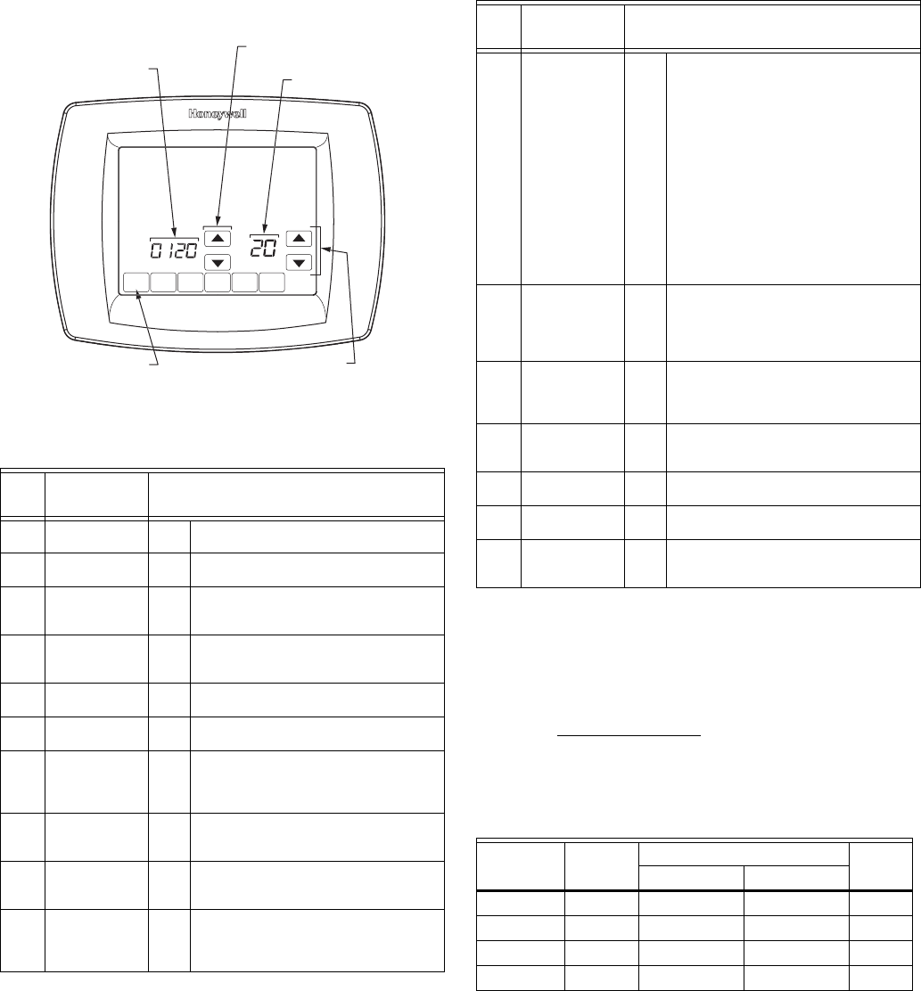
VISIONPRO® IAQ TOTAL HOME COMFORT SYSTEM
25 68-0287—1
4. See the screen below to review how the thermostat keys
are used during the User Setup. See Table 8 for the User
Setup numbers and settings.
5. Press the Done key to exit the User Setup screen.
PROGRAMMING
Preprogrammed Energy Star Settings
Table 9 shows default program settings. Visit the Energy Star
web site at www.energystar.gov for additional education and
resources on programmable touchscreen thermostats.
Program Heating and Cooling Schedule
Your thermostat can control up to four different schedule
periods per day:
Wake—Period when you awaken and want your home at a
comfortable temperature.
Leave—Period when you are away from home and want an
energy-saving temperature.
Return—Period when you return home and want your home
Table 8. User Setup Menu.
User
Setup
No.
User Setup
Name Settings
120 Date (Year
Upper)
20
21
130 Date (Year
Lower)
01-99 Default = 06
140 Date (Month) 1-12 Select number that represents current
calendar month.
Default = 06
150 Date (Day) 1-31 Select number that represents current
calendar date.
Default = 15
160 Schedule
Options
4
0
Seven-day programmable
Non-programmable
165 Restore Energy
Star Schedule
0
1
No
Yes
280 Continuous
Backlight
0
1
Backlight not on continuously.
Thermostat backlight comes on with
each key press.
Backlight is on continuously.
320 Temperature
Indication
Scale
0
1
Fahrenheit temperature display
Celsius temperature display
330 Daylight Saving 0
1
2
Disabled
Enabled (US 1987)
Enabled (US 2007)
400 Ventilation
control
0
1
2
No ventilation
Ventilation on at all times
Ventilation on except during sleep
period
DONE
O
MON
WED
THU
FRI
SA
T
A
A
T
SUN
USER SETUP
NUMBER CURRENT
SETTING
ADVANCE TO NEXT
USER SETUP
PRESS TO EXIT
USER SETUP
CHANGE THE
CURRENT
SETTING M19922
A
U
500 Furnace Filter
Change
Reminder
0
1
2
3
4
5
6
7
8
9
10
11
12
13
14
E
Disabled
10 R.T. Days
30 R.T. Days
60 R.T. Days
90 R.T. Days
120 R.T Days
180 R.T. Days
270 R.T. Days
365 R.T. Days
30 C Days
60 C Days
90 C Days
120 C Days
180 C Days
365 C Days
Auto Discover
510 Humidifier Pad
Replacement
Reminder
0
1
2
3
E
Disabled
90 C Days
180 C Days
365 C Days
Auto Discover
520 UV Lamp
Replacement
Reminder
0
1
2
E
Disabled
365 Days
730 Days (2 years)
Auto Discover
530 Adaptive
Intelligent
Recovery
0
1
Conventional
Adaptive
540 Number of
Periods
2
4
2 Periods
4 Periods
640 Clock Format 12
24
12 Hour
24 Hour
670 Keypad
Lockout
0
1
2
Unlocked
Partial Locked
Full Locked
Table 9. Energy Star Default Program Settings.
Schedule
Period Time
Setpoints Fan
SettingHeat Cool
Wake 6:00AM 70°F (21°C) 78°F (25.5°C) Auto
Leave 8:00AM 62°F (16.5°C) 85°F (29.5°C) Auto
Return 6:00PM 70°F (21°C) 78°F (25.5°C) Auto
Sleep 10:00PM 62°F (16.5°C) 82°F (28°C) Auto
Table 8. User Setup Menu. (Continued)
User
Setup
No.
User Setup
Name Settings
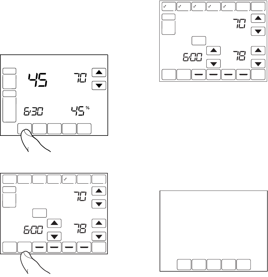
VISIONPRO® IAQ TOTAL HOME COMFORT SYSTEM
68-0287—1 26
back to a comfortable temperature.
Sleep—Period when you are asleep and want an energy-
saving temperature.
NOTE: Schedule times are in 15-minute intervals.
Edit Schedule
1. Press Sched key.
2. Press Edit key.
3. It is OK to pick multiple days. Select any combination of
days to edit. These days are scheduled with the same
times and temperatures. Check marks appear next to
days selected.
4. Press Wake key. Once pressed, Wake flashes to show it
is selected.
5. Press Up and Down keys to modify time and heat and
cool temperatures from this screen.
NOTE: The Fan setting can be programmed for On, Auto, or
Circ for each period selected. See Fan Schedule sec-
tion for more information.
6. Press Leave key and repeat step 5.
7. Press Return key and repeat step 5.
8. Press Sleep key and repeat step 5.
9. When complete, press Done key. “Saving Changes”
appears on the screen to indicate changes are being
saved to the day(s) modified.
NOTE: To set a Program Schedule for the remaining days of
the week, repeat steps 1–9. Example: If Mon–Fri was
selected first, go back and repeat steps 1–9 for Sat
and Sun.
10. To exit schedule without saving changes, press Cancel
key any time.
Cancel a Schedule Period
1. Press Sched key.
2. Press Edit key.
3. Select the Day(s) of the week desired.
4. Press schedule period you want to cancel (Wake, Leave,
Return or Sleep). Once selected, the period flashes.
5. Press Cancel Period key.
SCHED HOLD CLOCK SCREEN
FRI
AM
PM
FAN
AUTO
SYSTEM
HEAT
Following
Schedule
Inside Set
M23504
Humidity
SCHED
SCHED
HOLD
HOLD
CLOCK SCREEN
DONE WAKE LEAVE RETURN SLEEP CANCEL
MON TUE WED THU FRI SAT SUN
AM
PM
PM
FAN
AUTO
SYSTEM
EM HEAT
HEAT
OFF
COOL
AUTO
CANCEL
PERIOD
HEAT
COOL
Following
Schedule
Inside Set To
OK TO PICK MULTIPLE DAYS SCREEN LOCKED
M22553
EDIT
DONE WAKE LEAVE RETURN SLEEP CANCEL
MON TUE WED THU FRI SAT SUN
AM
FAN
ON
AUTO
CIRC
CANCEL
PERIOD
HEAT
COOL
OK TO PICK MULTIPLE DAYS
M19955
MON TUE WED THU FRI
SAVING
CHANGES
M19956
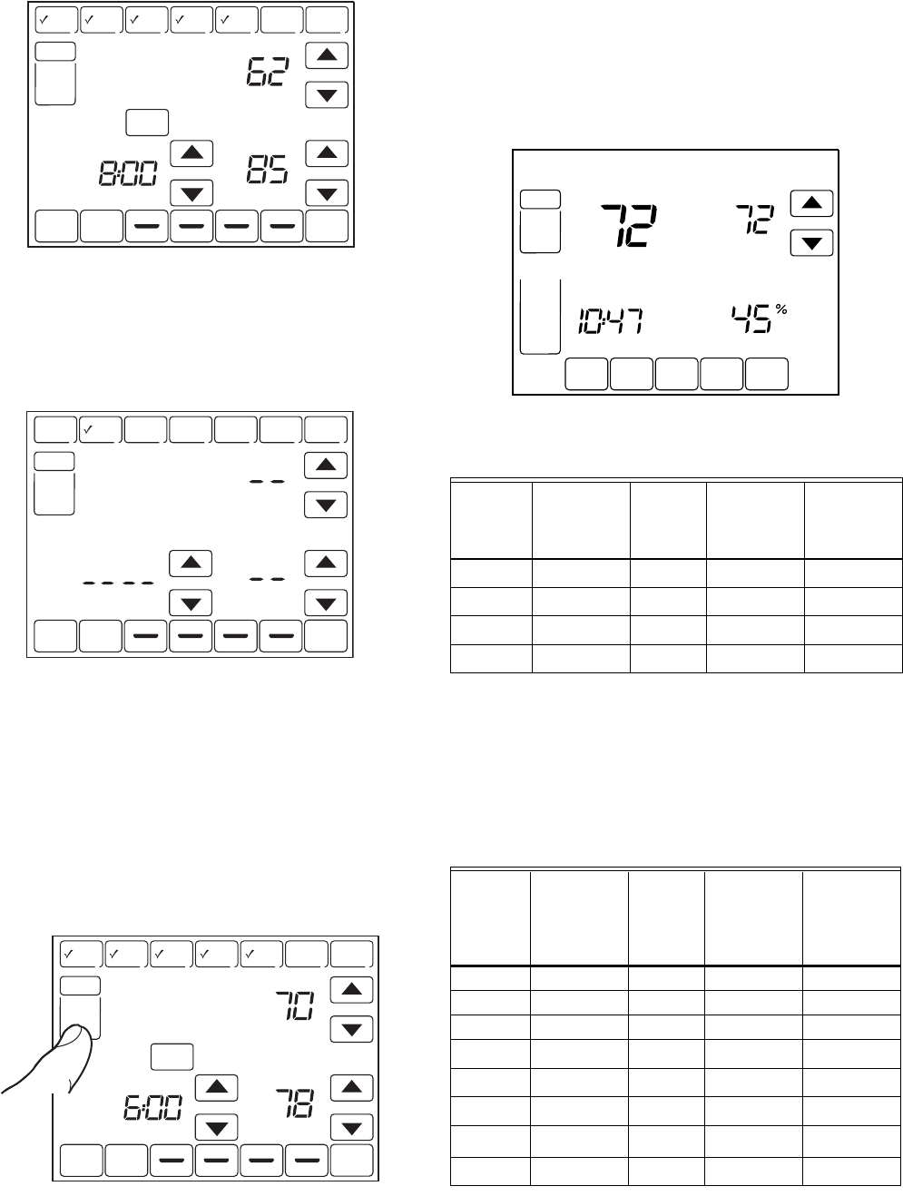
VISIONPRO® IAQ TOTAL HOME COMFORT SYSTEM
27 68-0287—1
6. The time, temperature(s) and fan setting disappear. The
bar above the selected period is removed, indicating the
scheduled period was cancelled.
NOTE: To reinstate a schedule period, press arrow keys to
set desired time and temperatures.
7. Press Done key.
Fan Schedule
Press Fan key while in the Scheduling Screen to program the
System Fan. Choices available from the Scheduling Screen:
Auto (default position)—fan runs with equipment.
Programmable for all schedule periods (Wake, Leave, Return
and Sleep).
On—fan runs continuously (programmable for all schedule
periods).
Circ—fan runs randomly for approximately 35% of schedule
period (programmable for all schedule periods).
Fan Control
If the Fan program is scheduled, Auto is shown and any
programmable mode that is set; for example, if during Wake
period, Fan is set to Auto, only Auto is shown in the Fan area.
However, if during the Wake period, fan is scheduled to On,
both Auto and On are shown. Auto indicates fan is running its
schedule; On indicates Fan schedule is set to On.
Manual Override of Fan Schedule
Auto—fan is automatically following the Fan schedule (choices
are Auto, On or Circulate).
On—overrides Fan schedule. Fan is continuously On.
Circ—overrides Fan schedule. Fan circulates randomly for
approximately 35% of time until the Auto position is selected.
aAuto Override resumes the Fan Program in each schedule
period (Wake, Leave, Return and Sleep)
SCHED
SCHED
HOLD
HOLD
CLOCK SCREEN
DONE WAKE LEAVE RETURN SLEEP CANCEL
MON TUE WED THU FRI SAT SUN
AM
PM
PM
FAN
AUTO
SYSTEM
EM HEAT
HEAT
OFF
COOL
AUTO
CANCEL
PERIOD
HEAT
COOL
Following
Schedule
Inside Set To
OK TO PICK MULTIPLE DAYS SCREEN LOCKED
M22446
DONE WAKE LEAVE RETURN SLEEP CANCEL
MON TUE WED THU FRI SAT SUN
FAN
HEAT
COOL
OK TO PICK MULTIPLE DAYS
M19957
SCHED
SCHED
HOLD
HOLD
CLOCK SCREEN
DONE WAKE LEAVE RETURN SLEEP CANCEL
MON TUE WED THU FRI SAT SUN
AM
PM
PM
FAN
AUTO
SYSTEM
EM HEAT
HEAT
OFF
COOL
AUTO
CANCEL
PERIOD
HEAT
COOL
Following
Schedule
Inside Set To
OK TO PICK MULTIPLE DAYS SCREEN LOCKED
M22447
Table 10. Fan Program Operation and Screen Status.
Fan
Setting
Fan
Program
Schedule
Call
for
Action
Energize
Terminal
Fan
Status
shown on
Screen
Auto Auto None None Auto
Auto On Fan G Auto/On
Auto Circ None None Auto/Circ
Auto Circ Fan G Auto/Circ
Table 11. Manual Override of Fan Schedule Operation.
Fan
Setting
Fan
Schedule
Override
Setting
Call
for
Action
Energize
Terminal
Screen
Message
Under
Fan
Setting
Auto On Fan G On
Auto Circ None None Circ
Auto Circ Fan G Circ
On Autoa —— —
On Circ None None Circ
On Circ Fan G Circ
Circ Autoa —— —
Circ On Fan G On
SCHED HOLD CLOCK SCREEN
THU
AM
FAN
ON
AUTO
SYSTEM
HEAT
COOL
Following
Schedule
Inside Set
M23505
Humidity
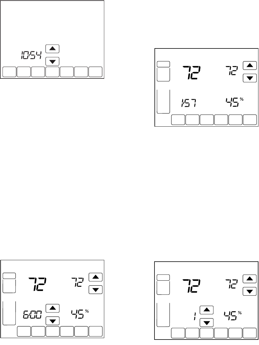
VISIONPRO® IAQ TOTAL HOME COMFORT SYSTEM
68-0287—1 28
OPERATE VISIONPRO® IAQ
Set Time
1. Press Clock.
2. Use arrows to set current time.
3. Press Done key.
IMPORTANT
The current day of the week should already be set
correctly. If not, see Installer Setup to set the day.
Set Temperature Overrides
The thermostat has four temperature override options: Hold
Temperature Until, Permanent Hold, Vacation Hold, and
Southern Dehumidification Away Setting.
HOLD TEMPERATURE UNTIL (TEMPORARY HOLD)
Holds temperature temporarily until the next scheduled period
time or until the time the user sets.
1. Press Up or Down arrow next to the temperature you
want to adjust. “Hold Temperature Until” time appears on
the screen. The Hold Temperature Until time defaults to
the start time of the next scheduled period.
NOTE: The Time Up and Down arrows are shown for approx-
imately seven seconds. Pressing on the screen time
(where the Hold Temperature Until time is shown)
allows the arrows to reappear.
2. Press Up or Down arrow next to the Time key to set
desired time for the thermostat to resume schedule.
3. Press the Cancel or Sched key to cancel “Hold
Temperature Until” and resume schedule.
NOTE: Once “Hold Temperature Until” time is reached, the
thermostat shows “Following Schedule” on the screen
to indicate that “Temporary Hold” has ended.
PERMANENT HOLD
Permanent Hold changes the temperature setting until
Permanent Hold is cancelled.
1. Press Hold key. “Permanent Hold” appears on the
screen.
2. Press Up or Down arrow next to the temperature you
want to set during “Hold.”
3. Press Cancel key to cancel “Permanent Hold” and
resume the schedule.
VACATION HOLD
Changes temperature setting for a designated number of days.
1. Press the Up and Down arrow keys to set the desired
temperature while away on vacation. Notice that “Hold
Temperature Until” time is shown on the screen. (This is
the time the Vacation Hold override expires after the
number of days ends.)
2. Press Hold key twice. Screen shows “Hold Temperature
Until” one day.
3. Press Up and Down arrow keys to change the number of
Days you desire thermostat to override the schedule.
NOTE: Days Up and Down arrows appear for approximately
seven seconds. Pressing just below Hold Tempera-
ture Until on the screen allows the Days Up and Down
arrows to reappear.
DONE CANCEL
TUE
AM
M19958
SCHED HOLD CLOCK SCREEN
CANCEL
TUE
PM
FAN
AUTO
SYSTEM
COOL
Inside
Hold Temperature
Until
Set
M23506
Humidity
SCHED HOLD CLOCK SCREEN
CANCEL
TUE
AM
FAN
AUTO
SYSTEM
COOL
Inside Set To
Permanent
Hold
M23507
Humidity
SCHED CLOCK SCREEN
CANCEL
THU
FAN
AUTO
SYSTEM
HEAT
OFF
COOL
Inside
DAYS
Hold Temperature
Until
Set To
M23508
Humidity
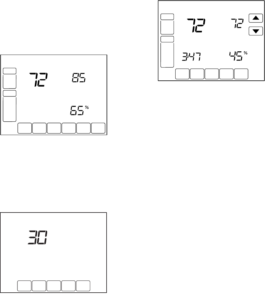
VISIONPRO® IAQ TOTAL HOME COMFORT SYSTEM
29 68-0287—1
4. To cancel the Vacation Hold override early, press the
Cancel key.
NOTE: When the number of days of Vacation Hold expires,
the screen shows “Following Schedule” to indicate
that Vacation Hold has ended.
SOUTHERN DEHUMIDIFICATION AWAY SETTING
Southern Dehumidification Away Setting is an option that only
appears if ISU number 390 is set to yes. It can be used to
maintain the desired humidity level and temperature in the
living space while away for extended periods of time. See ISU
Numbers 390–394 for more information.
1. Press Hold three times to enter the Southern Dehumidifi-
cation Away Setting.
2. These settings can only be changed in installer setup.
Clean Thermostat Screen
The thermostat has a touch screen interaction. Follow these
steps to clean the screen without making thermostat changes:
1. Press the Screen key. Thermostat locks out all touch
keys for 30 seconds to allow for cleaning.
2. Use damp cloth slightly moistened with water or house-
hold glass cleaner to clean the screen.
3. Repeat the above steps, as necessary.
IMPORTANT
Do not spray any type of liquid directly on the thermo-
stat itself. If using household glass cleaner, spray
cleaner on cloth. Then use a cloth to clean the ther-
mostat screen.
4. Press the Done key to return to the Home Screen and
normal operation.
Screen Locks
Partially Locked Screen
When partially locked, the screen indicates Screen Locked for
5 to 7 seconds whenever the user attempts to press a key that
is locked. Pressing a locked key, while Screen Locked is
shown, flashes “Screen Locked” on the screen.
In this mode, all keys are locked except the Temperature Up
and Down arrow keys:
— User can change temperature up or down but cannot
change schedule settings.
— Temporary temperature change lasts until next scheduled
period and that time shows on screen.
— To cancel temperature override and begin following
schedule, press Cancel key.
— To unlock screen, see Installer Setup section.
Fully Locked Screen
In this mode, all keys are locked and not functional. To unlock
screen, see Installer Setup section. The screen continuously
displays “Screen Locked.”
Humidification Control
If you have a humidifier and outdoor temperature sensor, you
can use Frost Control to reduce window condensation.
1. Press MORE until the humidifier screen is displayed.
2. Press the Up or Down arrow to set the humidity and
Frost Control level. (Use a lower Frost Control level if
frost appears on windows. Use a higher setting if the air
is too dry.)
3. Press DONE to save and exit, or press CANCEL to exit
without saving changes.
NOTE: If you do not have an outdoor temperature sensor, the
Frost Control level will not be displayed.
Dehumidification Control
If installed to control a dehumidifier, the thermostat can activate
it as needed to reduce humidity.
MORE
CANCEL
FRI
AM
FAN
AUTO
SYSTEM
HEAT
COOL
DEHUMIDIFIER
Inside Set To
Permanent
Hold
M23521
OK TO
CLEAN
SCREEN
M19964
SCHED HOLD CLOCK SCREEN MORE
TUE
FAN
AUTO
SYSTEM
COOL
Following
Schedule
Inside Set
SCREEN LOCKED
M23509
Humidity
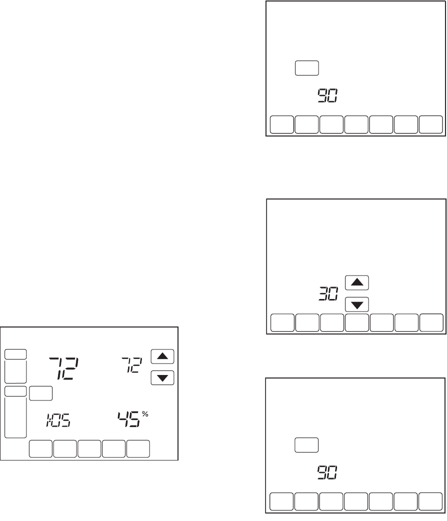
VISIONPRO® IAQ TOTAL HOME COMFORT SYSTEM
68-0287—1 30
If you don’t have a dehumidifier, the thermostat activates the
air conditioner to reduce humidity (may cool as much as 3°F
lower than your temperature setting).
1. Press MORE until the dehumidifier screen is displayed.
2. Press the Up or Down arrow to set the desired humidity
level and operation (Auto or Off).
3. Press DONE to save and exit, or press CANCEL to exit
without saving changes.
Ventilation Control
You can ventilate your home at any time:
1. Press MORE until the ventilation screen is displayed.
2. Press the Up or Down arrow to set the ventilation timer.
You can set the timer to ventilate from 20 to 180 minutes,
in 20-minute increments. To turn off the ventilator, select
0.
3. Press DONE to save and exit, or press CANCEL to exit
without saving changes.
If programmed for auto-ventilation by the installer, the
thermostat will ventilate your home as needed.
Indoor Air Quality Reminders
Filter Change Reminder
The filter change reminder must be turned on from the Installer
Setup. Once expired, the screen flashes, “Change Filter” and a
Reset key appears. Press the Reset key to reset the change
reminder. The installer can configure the Filter Change
Reminder to display remaining run-time or calendar days.
NOTE: When using run-time days, the days are counted as
fan run time, so anytime the fan is running, the
reminder is counting that time against the number of
days selected.
The remaining days can be viewed by pressing the More key;
the remaining days can be edited using the More key or from
the Installer Setup. To view or reset the reminder before it
expires, follow these steps using the More key:
1. Press the More key until the filter reminder appears on
the screen. This is the number of fan run-time or calen-
dar days remaining on the filter reminder.
2. Press the Edit key.
3. Use the Up and Down keys to change the number of run-
time or calendar days.
4. Press the Done key to go back to the viewing screen.
SCHED HOLD CLOCK SCREEN MORE
MON
MON
TUE WED
WED
THU
THU
FRI
FRI
S
S
A
A
SUN
PM
FAN
AUTO
SYSTEM
HEAT
HEAT
COOL
RESET
CHANGE FILTER UV LAMP HUMIDIFIER PAD
Following
Schedule
Inside Set To
OK TO PICK MULTIPLE DAYS SCREEN LOCKED
M23511
Humidity
SCHED
SCHED
HOLD
HOLD
CLOCK SCREEN MORE
DONE WAKE LEAVE RETURN SLEEPEDIT CANCEL
MON TUE WED THU FRI SAT SUN
RESET
CHANGE FILTER UV LAMP HUMIDIFIER PAD
DAYS
M22449
SCHED
SCHED
HOLD
HOLD
CLOCK SCREEN
DONE WAKE LEAVE RETURN SLEEP CANCEL
MON TUE WED THU FRI SAT SUN
CHANGE FILTER UV LAMP HUMIDIFIER PAD
DAYS
M22450
SCHED
SCHED
HOLD
HOLD
CLOCK SCREEN MORE
DONE WAKE LEAVE RETURN SLEEPEDIT CANCEL
MON TUE WED THU FRI SAT SUN
RESET
CHANGE FILTER UV LAMP HUMIDIFIER PAD
DAYS
M22449
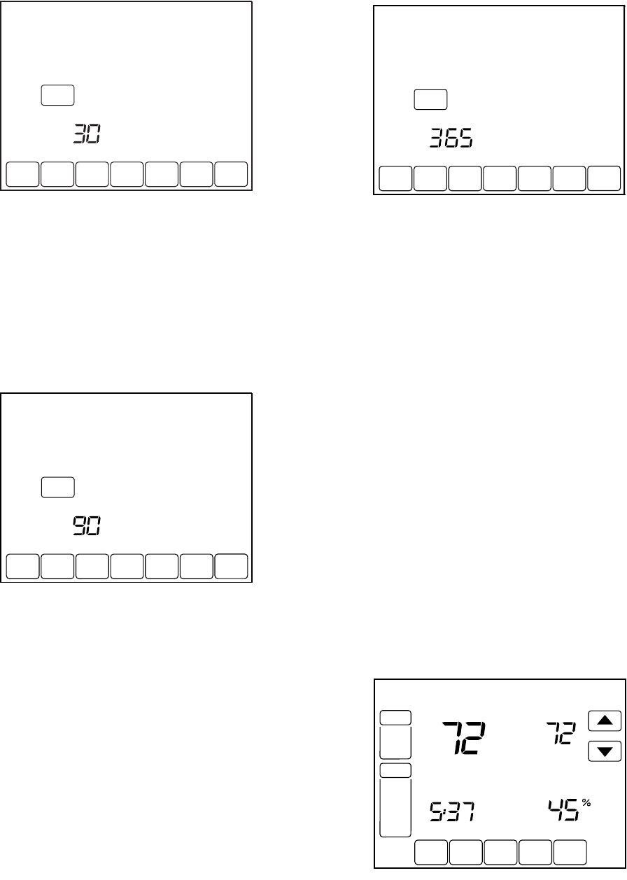
VISIONPRO® IAQ TOTAL HOME COMFORT SYSTEM
31 68-0287—1
5. Press the Reset key to activate the new number of days
selected in the previous screen.
6. Press the Done key to return to the Home screen.
Humidifier Pad Reminder
The Humidifier Pad change reminder must be turned on from
the Installer Setup. Once expired, the screen flashes, “Change
Humidifier Pad” and a Reset key appears. Press the Reset key
to reset the change reminder.
The remaining calendar or run time days can be viewed by
pressing the More key. The remaining days can be edited
using the More key or from the Installer Setup.
To view or reset the reminder before it expires, follow these
steps using the More key:
1.
Press the More key until the Humidifier Pad change
reminder appears on the screen. This is the number of
calendar days remaining on the Humidifier Pad reminder.
2. Press the Edit key.
3. Use the Up and Down keys to change the number of cal-
endar or run time days.
4. Press the Done key to go back to the viewing screen.
5. Press the Reset key to activate the new number of days
selected in the previous screen.
6. Press the Done key to return to the Home Screen.
UV Lamp Reminder
The UV Lamp change reminder must be turned on from the
Installer Setup. Once expired, the screen flashes, “Change UV
Lamp” and a Reset key appears. Press the Reset key to reset
the change reminder.
The remaining calendar days can be viewed by pressing the
More key.
NOTE: While the reminder is set according to calendar days,
the display shows the equivalent run time days.
The remaining days can be edited using the More key or from
the Installer Setup. To view or reset the reminder before it
expires, follow these steps using the More key:
1. Press the More key until the UV Lamp change reminder
appears on the screen. This is the number of run time
days remaining on the UV Lamp reminder.
2. Press the Edit key.
3. Use the Up and Down keys to change the number of cal-
endar days.
4. Press the Done key to go back to the viewing screen.
5. Press the Reset key to activate the new number of days
selected in the previous screen.
6. Press the Done key to return to the Home Screen.
Temperature Recovery
The thermostat feature, Adaptive Intelligent Recovery™,
eliminates all guesswork when setting the thermostat schedule.
Simply set the program schedule to the time that the comfort
temperature is desired. The thermostat then turns on the
heating or cooling at just the right time to have the home reach
the scheduled temperature at the scheduled time.
For example—get up at 6:00 AM and want the temperature to
be 70°F. Set the Wake period for 6:00 AM and 70°F. The
thermostat then turns on the heat before 6:00 AM to raise the
temperature to 70°F by 6:00 AM.
The thermostat alerts that the heating or cooling system is
coming on before a scheduled time by showing “Recovery” on
the screen.
SCHED
SCHED
HOLD
HOLD
CLOCK SCREEN MORE
DONE WAKE LEAVE RETURN SLEEPEDIT CANCEL
MON TUE WED THU FRI SAT SUN
RESET
CHANGE FILTER UV LAMP HUMIDIFIER PAD
DAYS
M22451
SCHED
SCHED
HOLD
HOLD
CLOCK SCREEN MORE
DONE WAKE LEAVE RETURN SLEEPEDIT CANCEL
MON TUE WED THU FRI SA SUN
CHANGE FILTER UV LAMP HUMIDIFIER PAD
DAYS
M23516
RESET
SCHED
SCHED
HOLD
HOLD
CLOCK SCREEN MORE
DONE WAKE LEAVE RETURN SLEEPEDIT CANCEL
MON TUE WED THU FRI SA SUN
CHANGE FILTER UV LAMP HUMIDIFIER PAD
DAYS
M23517
RESET
SCHED HOLD CLOCK SCREEN MORE
TUE
PM
FAN
AUTO
SYSTEM
COOL
Following
Schedule
Inside Set To
Recovery
M23512
Humidity
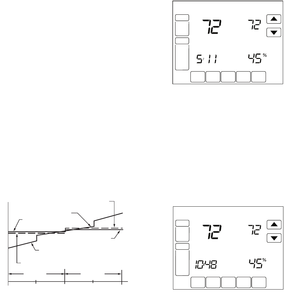
VISIONPRO® IAQ TOTAL HOME COMFORT SYSTEM
68-0287—1 32
NOTE: It takes about a week for the thermostat to adjust to
local weather, the schedule, the construction of the
home and the heating and/or cooling system. Each
day it adjusts the next day’s recovery start time
accordingly.
P+I Control
The thermostat microprocessor-based control requires that the
user understands temperature control and thermostat
performance. A conventional mechanical or electronic
thermostat does not control temperature precisely at setpoint.
Typically there is an offset (droop) in the control point as the
system load changes. This is a phenomenon that most people
in the industry know and accept. Many factors contribute to
offset including switch differential, thermal lag, overshoot, cycle
rates and system load.
The thermostat microprocessor simultaneously gathers,
compares and computes data. Using this data, it controls a
wide variety of functions. The special proprietary algorithm
(program) in the thermostat eliminates the factors causing
offset. This makes temperature control more accurate than the
conventional mechanical or electronic thermostats. The
temperature control algorithm is called proportional plus
integral (P+I) control.
The thermostat sensor, located on the thermostat or remote,
senses the current space temperature. The proportional error
is calculated by comparing the sensed temperature to the
programmed setpoint. The deviation from the setpoint is the
proportional error.
The thermostat also determines integral error, which is a
deviation based on the length of error time. The sum of the two
errors is the (P+I) error. The cycle rate used to reach and
maintain the setpoint temperature is computed using the P+I.
The addition of the integral error is what differentiates the
thermostat from many other electronic and mechanical
thermostats. See Fig. 33.
Fig. 33. Proportional temperature control versus P+ I
temperature control.
Minimum Off-Timer
The Thermostat has built-in compressor protection (minimum-
off timer) that prevents the compressor from restarting too
early after a shutdown. The minimum-off timer is activated after
the compressor turns off.
If there is a call during the minimum-off timer, the thermostat
shows “Wait” in the display.
When the minimum-off timer expires, “Cool On” or “Heat On”a
appears in the display and the compressor and fan turn on.
_________
aHeat Pumps only.
Inside Humidity Level
The humidity level in the home is shown in the lower right
corner of the Home Screen.
NOTE: If an outdoor temperature sensor is present, the out-
door temperature will be displayed in this location
rather than the indoor humidity. To see indoor humid-
ity, display the humidity settings menu.
If thermostat is set to Auto Changeover System mode, press
the More key until the humidity level is shown on the screen.
HEATING COOLING
PERCENT LOAD
TEMPERATURE
THERMOSTAT
HEAT SETPOINT
P+I CONTROL
POINT
PROPORTIONAL COOL
CONTROL POINT
THERMOSTAT
COOL SETPOINT
P+I CONTROL POINT
PROPORTIONAL HEAT
CONTROL POINT
M4414
100 50 0 50 100
M23513
Wait
SCHED HOLD CLOCK SCREEN MORE
WED
AM
PM
FAN
AUTO
SYSTEM
HEAT
COOL
Following
Schedule
Inside Set To
Humidity
SCHED HOLD CLOCK SCREEN MORE
TUE
PM
FAN
AUTO
SYSTEM
COOL
Following
Schedule
Inside Set
Humidity
M23678
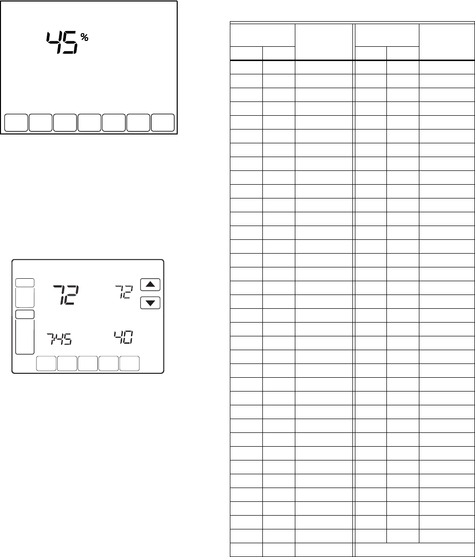
VISIONPRO® IAQ TOTAL HOME COMFORT SYSTEM
33 68-0287—1
C7089U1006 Outdoor Temperature Sensor
Operation
When installed with Thermostat Installer Setup Number 0342
set to 1, the outside temperature can be displayed on the
thermostat. See Fig. 34.
Fig. 34. Outside temperature reading on
VisionPRO® IAQ Thermostat.
The C7089U1006 Outdoor Sensor converts outdoor ambient
temperature to a resistance that the thermostat can interpret.
The C7089U1006 has a negative temperature coefficient
(NTC), which means that resistance decreases as the
temperature increases. See Table 12.
Checkout
Allow C7089U1006 Outdoor Sensor to absorb outdoor air for a
minimum of twenty minutes before taking a reading.
With an accurate thermometer (±1°F [0.5°C]) measure the
temperature at the sensor location, allowing time for the
thermometer to stabilize before reading.
To verify sensor resistance, remove one wire from one of the
C7089U1006 60-in. leadwires. Use an ohmmeter to measure
the resistance across the sensor. Then verify the sensor
accuracy with the temperature/resistance in Table 12.
Calibration
The C7089U1006 Outdoor Sensor is calibrated at the factory
and cannot be recalibrated in the field.
C7189U1005 Remote Indoor Temperature
Sensor
Operation
When installed with Thermostat Installer Setup Number 0340
set to 1, the remote inside temperature is displayed on the
thermostat home screen as Inside Temperature. The
thermostat internal temperature sensor is not used. When
SCHED
SCHED
HOLD
HOLD
CLOCK SCREEN
DONE WAKE LEAVE RETURN SLEEP CANCEL
MON TUE WED THU FRI SA SUN
Inside
M23679
SCHED HOLD CLOCK SCREEN MORE
MON
T
UE
WED
THU
FRI
SA
T
A
A
T
SUN
AM
FAN
A
U
T
O
SYSTEM
HEAT
Following
Schedule
In
s
i
de
Outside
Se
t T
o
M22453
Table 12. Sensor Resistance at
Outdoor Temperature.
Outdoor
Temperature Ohms of
Resistance
Outdoor
Temperature Ohms of
Resistance°F °C °F °C
-20 -28.9 106926 52 11.1 17136
-18 -27.8 100923 54 12.2 16387
-16 -26.7 95310 56 13.3 15675
-14 -25.6 90058 58 14.4 14999
-12 -24.4 85124 60 15.6 14356
-10 -23.3 80485 62 16.7 13743
-8 -22.2 76137 64 17.8 13161
-6 -21.1 72060 66 18.9 12607
-4 -20.0 68237 68 20.0 12081
-2 -18.9 64631 70 21.1 11578
0 -17.8 61246 72 22.2 11100
2 -16.7 58066 74 23.3 10644
4 -15.6 55077 76 24.4 10210
6 -14.4 53358 78 25.6 9795
8 -13.3 49598 80 26.7 9398
10 -12.2 47092 82 27.8 9020
12 -11.1 44732 84 28.9 8659
14 -10.0 42506 86 30.0 8315
16 -8.9 40394 88 31.1 7986
18 -7.8 38400 90 32.2 7672
20 -6.7 36519 92 33.3 7372
22 -5.6 34743 94 34.4 7086
24 -4.4 33063 96 35.6 6813
26 -3.3 31475 98 36.7 6551
28 -2.2 29975 100 37.8 6301
30 -1.1 28558 102 38.9 6062
32 0.0 27219 104 40.0 5834
34 1.1 25949 106 41.1 5614
36 2.2 24749 108 42.2 5404
38 3.3 23613 110 43.3 5203
40 4.4 22537 112 44.4 5010
42 5.6 21516 114 45.6 4826
44 6.7 20546 116 46.7 4649
46 7.8 19626 118 47.8 4479
48 8.9 18754 120 48.9 4317
50 10.0 17926 —
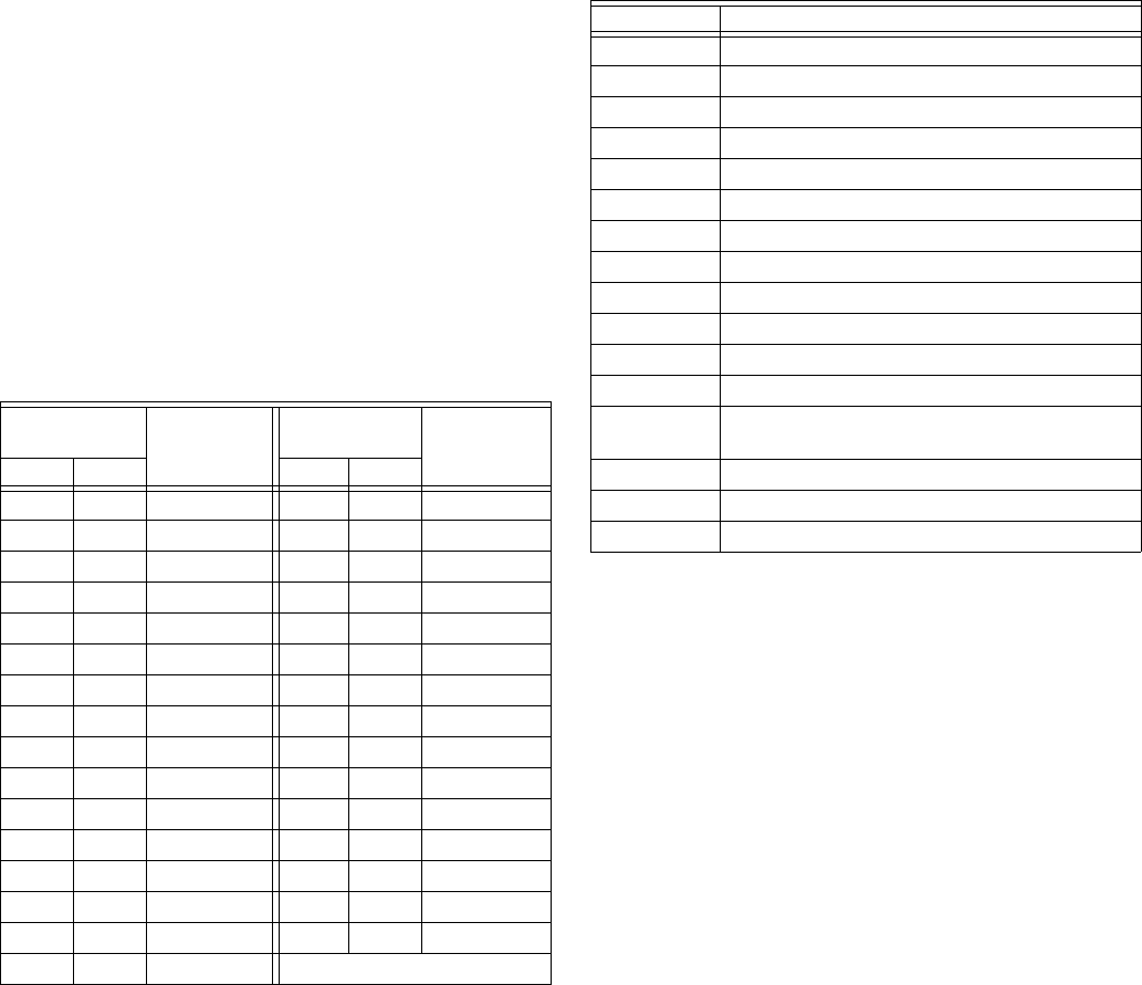
VISIONPRO® IAQ TOTAL HOME COMFORT SYSTEM
68-0287—1 34
installed with Thermostat Installer Setup Number 340 set to 2,
the temperature displayed on the thermostat home screen as
Inside Temperature will be a 50/50 average between the
temperature sensed at the remote sensor location and the
temperature sensed at the thermostat location.
The C7189U1005 Wall Mount Temperature Sensor converts
room temperature to a resistance that the thermostat can
interpret.
The C7189U1005 has a negative temperature coefficient
(NTC), which means that resistance decreases as the
temperature increases. See Table 13.
The C7189U1005 can be used to provide one remote sensor
input (see Fig. 26) or as a temperature averaging network with
multiple C7189U1005 Sensors connected, as shown in Fig. 27.
Checkout
For best results, allow C7189U1005 Wall Mount Temperature
Sensor to absorb the air moving through the room for a
minimum of twenty minutes before taking a resistance
measurement.
With an accurate thermometer (±1°F [0.5°C]) measure the
temperature at the sensor location, allowing time for the
thermometer to stabilize before reading.
To verify sensor resistance, remove one wire from one of
C7189U1005 wiring terminals. Use an ohmmeter to measure
the resistance across the sensor. Then verify the sensor
accuracy with the temperature/resistance in Table 13.
Calibration
The C7189U1005 Wall Mount Temperature Sensor is
calibrated at the factory and cannot be recalibrated in the field.
COMMUNICATION ERROR CODES
VisionPRO® IAQ can alert the homeowner and installer to
problems with the HVAC equipment, thermostat, or equipment
interface module by using error codes. Please see Table 14 for
a list of error codes. When an error is active (the condition
causing the error is still present) it will be displayed in the time
field on the thermostat home screen. The home screen can
display up to 5 active errors. The time field will flash the time,
“Err,” and a list of up to 5 error codes, beginning with the most
critical, and repeat until the errors have been remedied.
A log of error codes can be viewed at the end of the installer
setup after the system tests. Active errors will be shown first.
The Error Log will log the last ten errors (active and inactive).
Pressing the reset button will clear all inactive errors from the
error log; active errors can not be cleared until the condition
has been remedied.
Table 13. Sensor Resistance at Room Temperature.
Room
Temperature Ohms of
Resistance
Room
Temperature Ohms of
Resistance°F °C °F °C
40 4.4 22537 72 22.2 11100
42 5.6 21516 74 23.3 10644
44 6.7 20546 76 24.4 10210
46 7.8 19626 78 25.6 9795
48 8.9 18754 80 26.7 9398
50 10.0 17926 82 27.8 9020
52 11.1 17136 84 28.9 8659
54 12.2 16387 86 30.0 8315
56 13.3 15675 88 31.1 7986
58 14.4 14999 90 32.2 7672
60 15.6 14356 92 33.3 7372
62 16.7 13743 94 34.4 7086
64 17.8 13161 96 35.6 6813
66 18.9 12607 98 36.7 6551
68 20.0 12081 100 37.8 6301
70 21.1 11578 —
Table 14. VisionPRO® IAQ Error Codes.
Error Code Meaning
027 Faulty thermostat (must be replaced
036 Duplicate UV timer
037 Duplicate filter timer
038 Duplicate humidifier pad timer
039 Duplicate indoor humidity sensor
040 Compressor should be running but it is not
050 Duplicate outdoor temperature sensor
052 Faulty post-coil air discharge sensor
053 Faulty outdoor temperature sensor
054 Faulty indoor humidity sensor
089 Heating/cooling equipment is missing
090 Data interface is continuously busy
091 Thermostat is not receiving data from other
equipment
118 Faulty discharge air temperature sensor
119 Faulty temperature sensor
121 Duplicate post-coil air discharge sensor

VISIONPRO® IAQ TOTAL HOME COMFORT SYSTEM
35 68-0287—1
TROUBLESHOOTING
Table 15. Troubleshooting.
Symptom Possible Cause Action
Display does not come on Thermostat is not being powered Check if the thermostat is mounted and latched on the wall
plate. If not:
— Mount and latch the thermostat on the wallplate.
Check if the circuit breaker is tripped or the fuse is blown; if
it is:
— Reset the circuit Breaker or replace the fuse.
Check if the power switch at the equipment is in the off
position; if it is:
— Set to the on position.
Check for 24 Vac between terminals 2 and 3 at the
thermostat.
— Replace any broken wires if 24Vac is not present.
— Replace thermostat if 24Vas is present.
Check for 24 Vac between terminals R and C at the
Equipment interface module.
— If 24Vac is not present consult electrician.
— If 24 Vac is Present replace Equipment interface
module.
Temperature setting does not
change
The upper and lower temperature
limits reached
Check temperature setpoints.
Check installer setup Numbers 0600 and 610; modify as
needed.
Keypad is fully locked Check Installer Setup Number 670 to change keypad
locked options.
Heating or cooling does not
come on and thermostat is not
calling for heat or cool.
Thermostat minimum off timer is
activated
Wait up to 5 minutes for the system to respond (Wait is
displayed on the Thermostat home screen.
System selection is not set to Heat
or Cool
Set system selection to correct setting.
Heating or cooling does not
come on and thermostat is
calling for heat or cool.
Heating or cooling equipment is not
operating
Check Wiring.
Check installer setup number 172 and verify the correct
system type is chosen.
Verify operation of equipment in system test mode.
Heat does not turn on (“Heat On”
is solid in the display)
Heating Equipment failure Check for 24 Vac at the equipment on the secondary side
of the transformer between power and common. If voltage
is not present check the heating equipment to find the
cause of the problem.
Check for 24 Vac between the heat terminal(s) on the
equipment interface Module and transformer common. If
present check heating equipment to find the cause of the
problem.
Loose or broken wire connection
between Equipment Interface
Module and heating equipment.
Check for 24 Vac between the heat terminal(s) on the
HVAC equipment and system transformer common. If
voltage is not present check for loose or broken wires
between the EIM and heating equipment.
Communication is not being
completed
End the call for heat at the thermostat then repeat the call
for heat. Check the communication LED on the EIM board.
— If the LED does not blink, check communication
wiring (wire between terminal 1 on both the EIM
and thermostat.
— If the LED does blinks correctly, check for 24 Vac
between heating terminals on the EIM and the sys-
tem common.
If 24 Vac is not present check the R to Rh connection on
the EIM, if the connection is good replace the EIM.

VISIONPRO® IAQ TOTAL HOME COMFORT SYSTEM
68-0287—1 36
Cooling does not turn on (“Cool
On” is solid in the display)
Cooling Equipment failure Check for 24 Vac at the equipment on the secondary side
of the transformer between power and common. If voltage
is not present check the cooling equipment to find the
cause of the problem.
Check for 24 Vac between the cool terminal(s) on the
equipment interface Module and transformer common. If
present check cooling equipment to find the cause of the
problem.
Loose or broken wire connection
between Equipment Interface
Module and cooling equipment.
Check for 24 Vac between the cool terminal(s) on the
cooling equipment and system transformer common. If
voltage is not present check for loose or broken wires
between the EIM and cooling equipment.
Communication is not being
completed
End the call for cool at the thermostat then repeat the call
for cool. Check the communication LED on the EIM board.
— If the LED does not blink, check communication
wiring (wire between terminal 1 on both the EIM
and thermostat.
— If the LED does blinks correctly, check for 24 Vac
between heating terminals on the EIM and the sys-
tem common.
If 24 Vac is not present check the R to Rh connection on
the EIM, if the connection is good replace the EIM.
2nd stage heat or cool does not
energize
Stage configuration is not set
correctly to match the number of
selected stage
Set the stage configuration in installer setup for additional
stages of cool (ISU 174) or additional stages of heat (ISU
176).
Terminals not connected properly at
EIM
Check that 24 Vac is present at W2/AUX and W3/AUX2 for
2nd and 3rd stages of conventional heating and for 3rd and
4th stages of heat pump heating. Also check that 24VAC is
present at Y2 for 2nd stage of cooling or 2nd stage heat in
heat pump applications.
“Err” appears in time field of
home screen on thermostat
Thermostat has detected an error
on the communication bus
Refer to error code section for more information.
Fan does not turn on in a call for
heat (electric furnace).
Fan Control in Heating is set to Gas
or Oil Furnace (Setting 0180).
Set Fan Control in Heating to Electric Furnace (Setting
0180).
Heat pump puts out cool air in
the heat mode and warm air in
the cool mode.
Changeover Valve (Installer Setup
Number 0190) is not configured to
match the changeover required by
the installed heat pump.
Set Changeover Valve (Installer Setup Number 0190) to
match the changeover required by the installed heat pump.
Both the heating and cooling
equipment are running at the
same time.
The heating equipment is not a heat
pump but the System Type (Installer
Setup Number 0172) is set to Heat
Pump.
Set System Type (Installer Setup Number 0172) to match
the installed heating and/or cooling equipment.
Heating and cooling wires are
shorted together.
Separate the shorted heating and cooling wires.
Heating equipment is running in
the cool mode.
Heating equipment is not a heat
pump but System Type (Installer
Setup Number 0172) is set to Heat
Pump.
Set System Type (Installer Setup Number 0172) to match
the installed heating and/or cooling equipment.
Heating equipment does not turn
off and heat temperature setting
is set below room temperature
(Heat On is not in the display).
Heating equipment is not a heat
pump but System Type (Installer
Setup Number 0172) is set to Heat
Pump.
Set System Type (Installer Setup Number 0172) to match
the installed heating and/or cooling equipment.
Cannot set the system setting to
Heat.
System Type (Installer Setup
Number 0172) is set to Cool Only.
Set System Type (Installer Setup Number 0172) to match
the installed heating and/or cooling equipment.
Cannot set the system setting to
Cool.
System Type (Installer Setup
Number 0172) is set to Heat Only or
Heat Only with Fan.
Set System Type (Installer Setup Number 0172) to match
the installed heating and/or cooling equipment.
Table 15. Troubleshooting. (Continued)
Symptom Possible Cause Action

VISIONPRO® IAQ TOTAL HOME COMFORT SYSTEM
37 68-0287—1
Heat On is not in the display. System setting is not set to Heat
and/or temperature setting is not set
above room temperature.
Set the system setting to Heat and set the temperature
setting above the room temperature.
Cool On is not in the display. System setting is not set to Cool
and/or the temperature setting is
not set below room temperature.
Set the system setting to Cool and set the temperature
setting below the room temperature.
Wait is in the display. Compressor minimum off timer is
active.
Wait up to five minutes for the cooling or heating (heat
pump) equipment to turn on.
“Screen Locked” appears on the
screen and all or some of the
keys do not respond.
The keypad is fully or partially
locked.
Check Installer Setup Number 0670 to change keypad
locked options.
Table 15. Troubleshooting. (Continued)
Symptom Possible Cause Action

VISIONPRO® IAQ TOTAL HOME COMFORT SYSTEM
68-0287—1 38
COMPATIBILITY
Recommend the following products for use with the VisionPRO® IAQ.
Following is a list of compatible communicating products.
* T8635L thermostats used with TH9421C thermostats must be used with a W8835A Zone Panel and the TH9421C must be the
Master Zone Controller (zone 1 thermostat)
Table 16. Humidifiers
HE440A1005—Powered Steam Humidifier with 13 gpd capacity
HE365A1006—Powered Bypass Flow-through humidifier with 18 gpd capacity
HE265A1007—Bypass Flow-through humidifier with 17 gpd capacity
HE225A1006—Bypass Flow-through humidifier with 12 gpd capacity
Table 17. Dehumidifier
DH90A1007—90 Pint Whole House Dehumidifier
Table 18. Ventilation
HR150B1005—heat recovery ventilator 150cfm with built in defrost
HR200B1005—heat recovery ventilator 200cfm with built in defrost
ER150B2006—energy recovery ventilator 150cfm with built in defrost
ER150C2004—energy recovery ventilator 150cfm with no defrost
ER200B2006—heat recovery ventilator 200cfm with built in defrost
ER200C2004—heat recovery ventilator 200cfm with no defrost
EARD5—5” round damper NC Power Open/Spring Close
EARD6—6” round damper NC Power Open/Spring Close
EARD7—7” round damper NC Power Open/Spring Close
EARD8—8” round damper NC Power Open/Spring Close
Table 19. Communicating Products
THM5421C—Equipment Interface Module Universal up to 4H2C systems
T8635L1013*—3H3C communicating Thermostat
W8635A1006—Equipment Interface Module for 2H2C conventional systems
W8635B1004—Equipment Interface Module for 2H2C heat pump systems
W8735A1005—EnviraCOM Serial Port Adapter
W8735B1003—Telephone Access Module
W8735D1009—Telephone Access Module two Channel communicating
W8735D1017—Telephone Access Module four channel communicating
W8835A1004—Envirazone Zone Panel
C7835A1009—Communicating Discharge Air Sensor
W8703A1003—Damper Interface Module
L7224C1004—120VAC Electronic Aquastat
L7248—Aquastat
R7184—Oil Primary
Table 20. UV Lights
UV100E2009
UV100E1043
UV100E3007
VISIONPRO® IAQ TOTAL HOME COMFORT SYSTEM
39 68-0287—1

Automation and Control Solutions
Honeywell International Inc. Honeywell Limited-Honeywell Limitée
1985 Douglas Drive North 35 Dynamic Drive
Golden Valley, MN 55422 Toronto, Ontario M1V 4Z9
customer.honeywell.com
VISIONPRO® IAQ TOTAL HOME COMFORT SYSTEM
® U.S. Registered Trademark
© 2006 Honeywell International Inc.
US Patent No. 6,208,263; 6,373,376; 6,448,901; 6,926,076;
7,044,397; D509151; H25192; H25193 and other patents pending
68-0287—1 M.S. Rev. 10-06
