Honeywell Totalzone Tz 3 Users Manual 68 0223 Zone Control Panel
TOTALZONE TZ-3 68-0223
TZ-3 to the manual 66eae3d8-8a2c-45c0-9d4e-f5a1a5e06d62
2015-01-23
: Honeywell Honeywell-Totalzone-Tz-3-Users-Manual-261445 honeywell-totalzone-tz-3-users-manual-261445 honeywell pdf
Open the PDF directly: View PDF ![]() .
.
Page Count: 16
PRODUCT DATA
68- 022
3
-
2
® U.S. Re
g
istered Trademark
Co
py
ri
g
ht © 2001 Hone
y
well • All Ri
g
hts Reserved
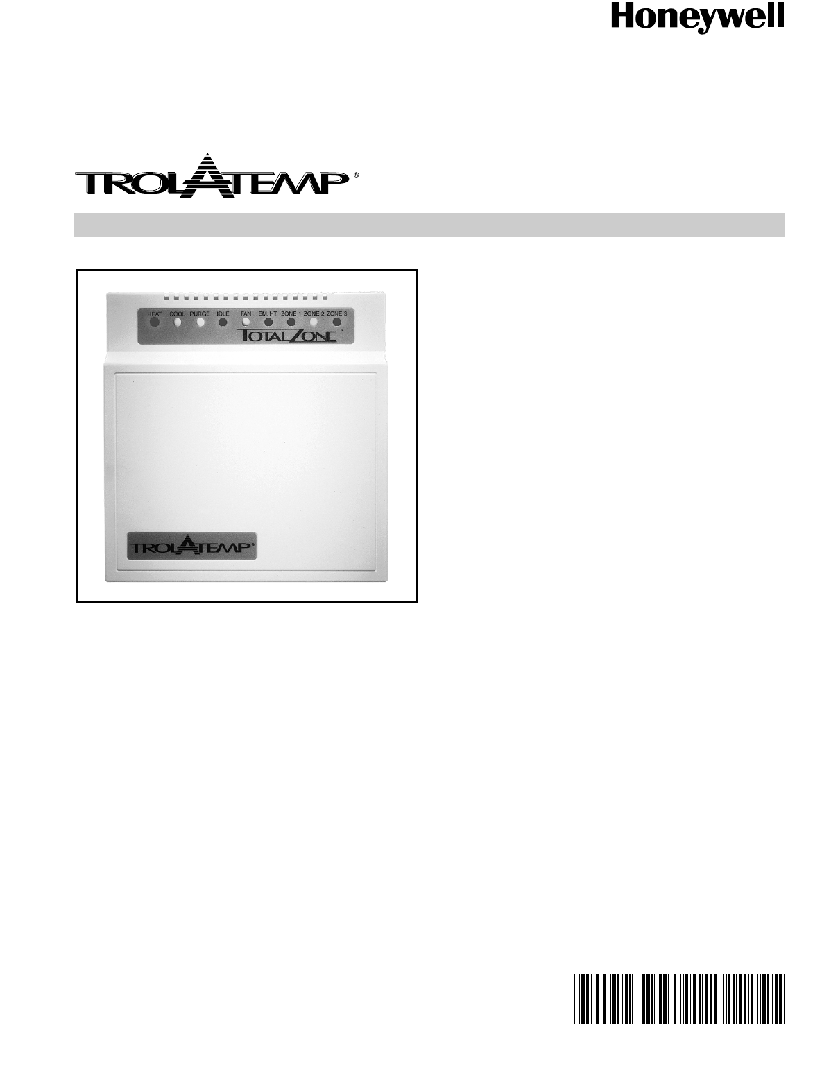
TZ-3 TotalZone® Zone Control Panel
APPLICATION
The TZ-3 TotalZone Zone Control Panel controls sin
g
le-sta
g
e,
multi-sta
g
e, conventional or heat
p
um
p
heat/cool e
q
ui
p
ment.
It controls 2 or 3 zones, and is ex
p
andable u
p
to 30 zones with
o
p
tional TotalZone® Add-A-Zone™ Zone Control Panel.
FEATURES
• Up to three stages heat and two stages cooling can be
controlled by thermostat or built-in timer, based on the
number of zones calling.
• Controls up to three zones and can be expanded with
TotalZone Add-A-Zone zone Control Panel for up to 30
zones.
• Uses virtually any Honeywell four-wire, single-stage,
multi-stage, or Trol-A-Temp heat pump thermostat.
• Zone-A-Lone central setback feature.
• Purge timer protects equipment between calls for heat
or cool with choice of continually on or equipment
controlled fan.
• System and zone damper LEDs indicate system and
damper status.
• Individual zone fan control.
• Optional Discharge Air Temperature Sensor for
capacity control with adjustable high and low limits.
• Thermal circuit breaker protects panel and transformer
from damage if miswired.
For Internet access: www.trolatem
p
.com or
www.hone
y
well.com/
y
ourhome/zonin
g
/zonin
g
_home.htm
For technical su
pp
ort, call 1-800-TAT-Tem
p
(
1-800-828-8367
)
.
To download Zonin
g
literature: htt
p
://hbctechlit.hone
y
well.com
Contents
A
pp
lication.........................................................................1
Features ............................................................................1
S
p
ecifications ....................................................................2
Installation .........................................................................4
Startu
p
and Checkout........................................................9
O
p
eration...........................................................................10
Troubleshootin
g
.................................................................13
TZ-3 TOTALZONE® ZONE CONTROL PANEL
68-0223-2 2
SPECIFICATIONS
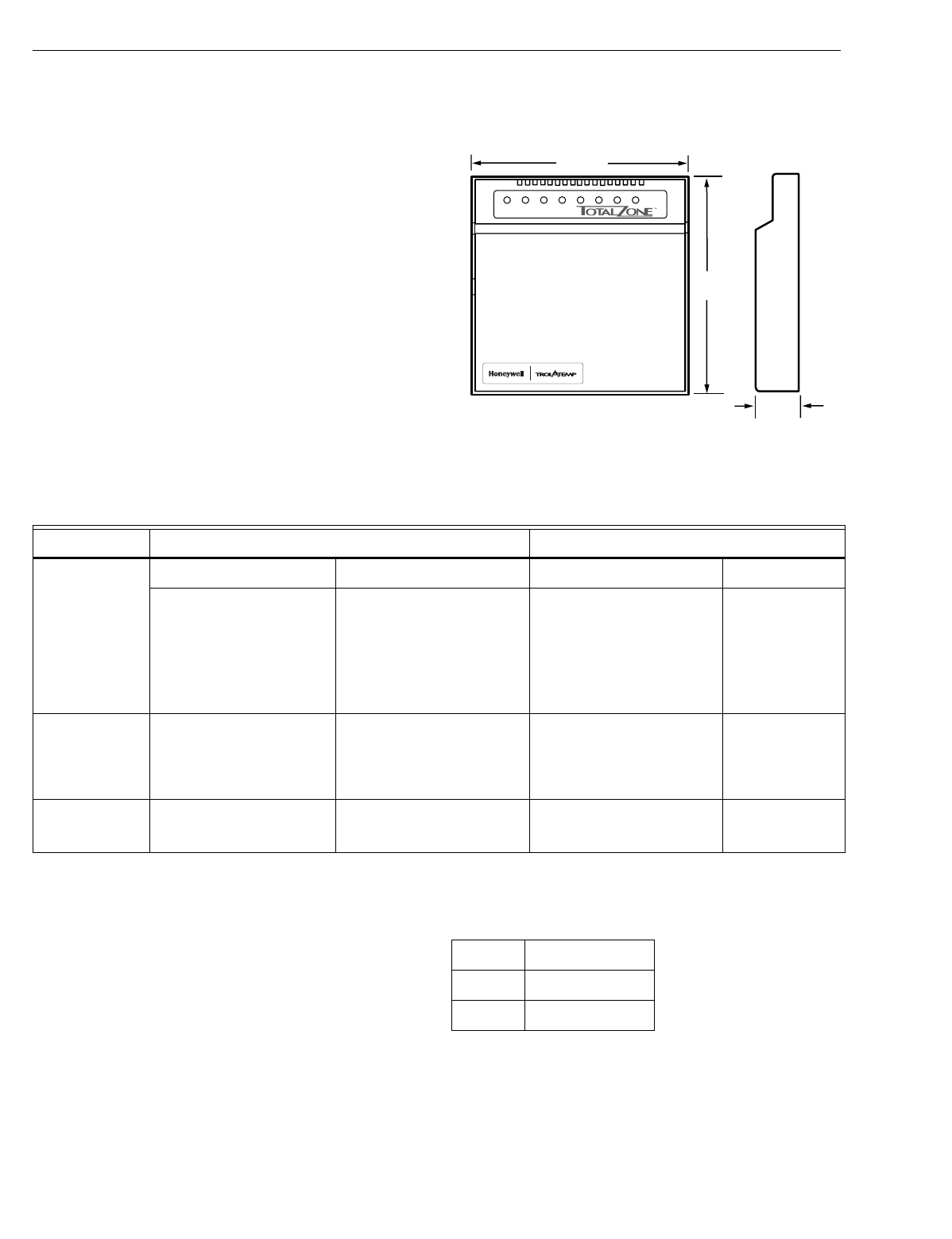
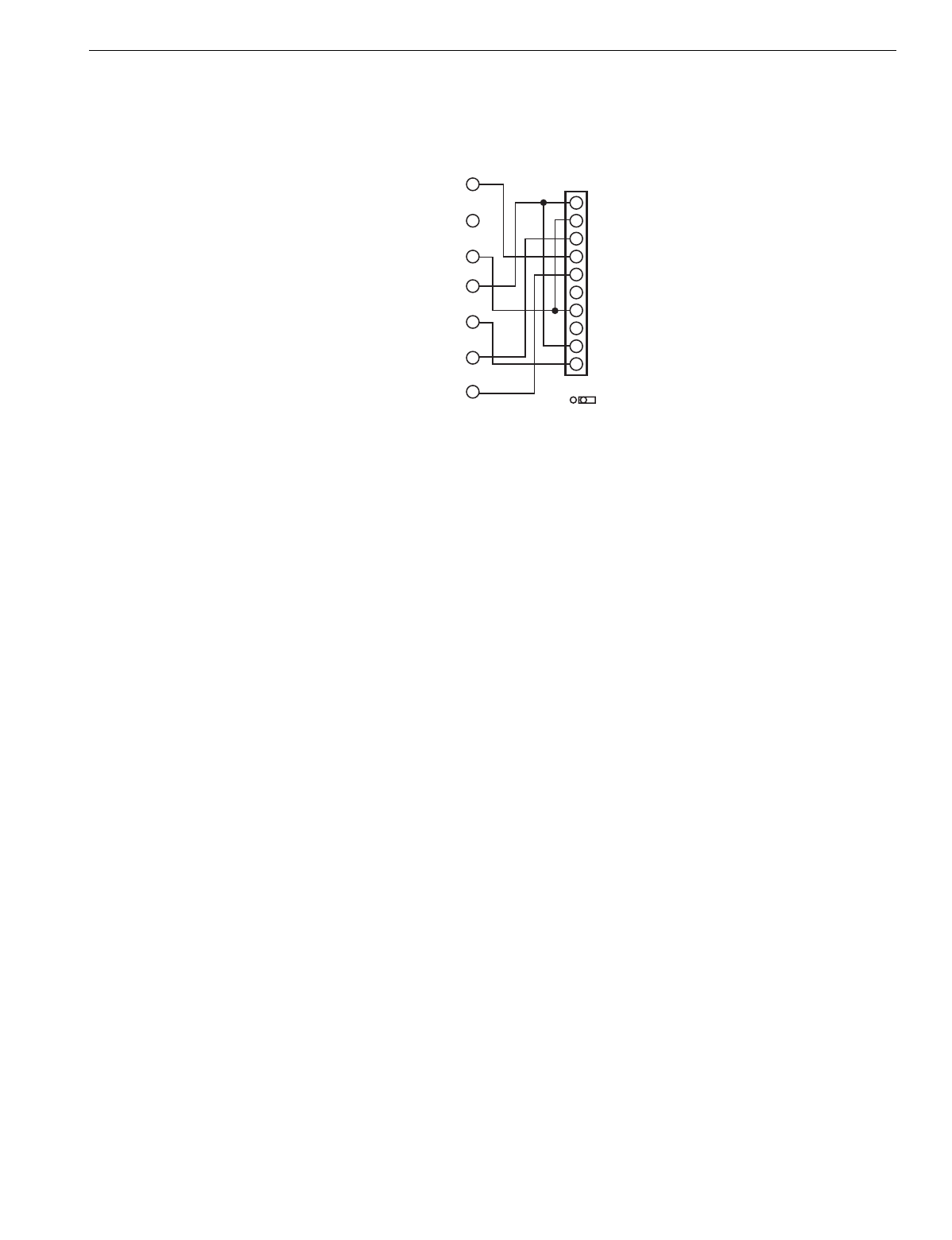
Electrical: 24 Vac, 60 Hz.
Dimensions: See Fi
g
. 1.
Mounting: Mounts with three screws
(p
rovided
)
throu
g
h
holes in cabinet back
Wiring: 18-
g
au
g
e wire for all e
q
ui
p
ment and s
y
stem
connections
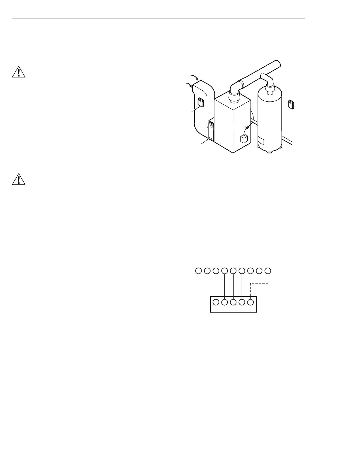
Wiring Connections:
Thermostat: W2, L, G, Y, R, W
Dam
p
ers: M6
(
Closed
)
; M4
(
O
p
en
)
; M1
(
Common
)
ZoneMax TL, TL
Zone-A-Lone: OC,OC.
Transformer: TR1
(
hot
)
, TR2
(
common
)
.
E
q
ui
p
ment: Y2, Y1, O, R, G, B, W1, E, W2, W3.
Thermostats (See Table 1):
Conventional 4-wire
(
R,W,Y,G
)
thermostats.
Manual or automatic chan
g
eover switchin
g
subbase for
each zone thermostat.
Multi-sta
g
e or select heat
p
um
p
thermostats can be used.
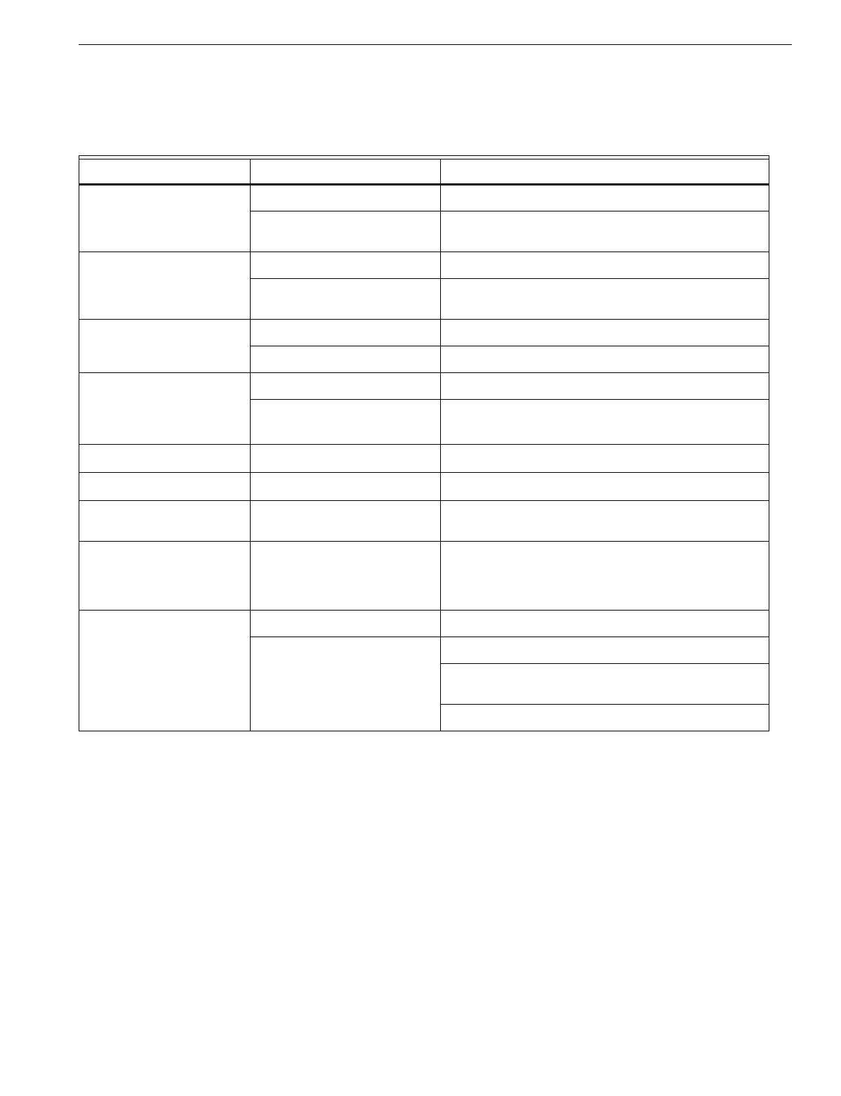
Fig. 1. TZ-3 dimensions in in. (mm).
Table 1. Recommended Thermostats.
aHeat
p
um
p
thermostat with sin
g
le Y first-sta
g
e terminals. See Heat Pum
p
Thermostats with Sin
g
le Y Out
p
ut section and Fi
g
. 3.
bMulti-sta
g
e and heat
p
um
p
thermostats are not re
q
uired to control multi-sta
g
e and heat
p
um
p
s
y
stems with TotalZone. The
y
are
used onl
y
when second sta
g
e or emer
g
enc
y
heat control from the zone thermostat is needed.
Dampers (See Table 2):
Five dam
p
ers maximum connected to each
p
anel.
Use SDCR for additional dam
p
ers re
q
uired on one zone.
Use isolation rela
y
when CDO-32 Dam
p
er or ML6161
Motor Actuator is used
(
see Fi
g
. 10
)
.
Dam
p
ers are connected to M1, M4, and M6
(
see Fi
g
. 6-10
for hooku
p
s
)
.
Accessories: For re
q
uired accessories, see Table 3.
1-5/8
(41)
7-5/8 (195)
7-13/16
(198)
M19062
HEAT COOL PURGE FAN EM. HT. ZONE 1 ZONE 2 ZONE 3
®
System Trol-A-Temp Logo Honeywell Logo
Sin
g
le Sta
g
eNon-Programmable Programmable Non-Programmable Programmable
T87F3715/Q539A1436
T87F3707Q539A1428 T8601D2027
T8131C1020 T87F1859/Q539A1014
Q87F4010/Q539A4026
T8400C1016
T8400C1040
T8600D2069
T8600D2028
T8601D2019
T8602D2018
T8602D2000
T8000C1002
T8000C1010
Heat Pum
p
a—T8611G2051aY594R1243a
Y594G1252a
T8411R1002
T8411R1028
T8011R1006
T8011R1014
Multi-Sta
g
eb— — Y594D1347bT8624D2004a
T8624D2012b
M1 Common
M4 Power O
p
en
M6 Power Close
TZ-3 TOTALZONE® ZONE CONTROL PANEL
3 68-0223-2
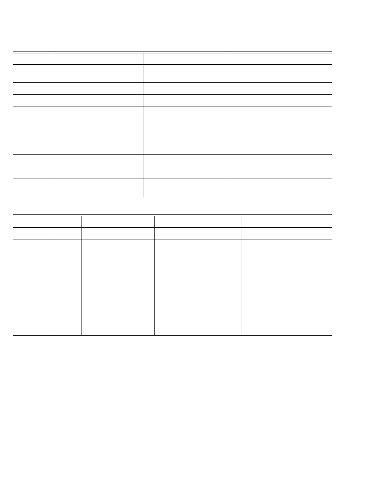
Table 2. Recommended Dampers.
Table 3. Required Accessories (Not Supplied With Panel).
Honeywell Damper Type Round Rectangular
Power-o
p
en/
p
ower-closed MARD IOBD
AOBD
AOBD-BM
CDO-51
S
p
rin
g
-o
p
en/
p
ower-closed ARD ZDB
ZDS
Accessory Description Bypass Rating
(cfm)
40 VA transformer AT140D1046
(
PMT-40
)
—
Ca
p
acit
y
p
rotector ZMS, DATS
(
C7735A1000
)
—
Round static
p
ressure re
g
ulator
dam
p
er 7 SPRD
8 SPRD
9 SPRD
10 SPRD
12 SPRD
14 SPRD
16 SPRD
18 SPRD
300
400
600
750
1200
1800
2400
3200
Rectan
g
ular static
p
ressure re
g
ulator
dam
p
er 12 x 8 SPRD
12 x 10 SPRD
12 x 12 SPRD
20 x 8 SPRD
20 x 10 SPRD
20 x 12 SPRD
1000
1200
1400
1600
2000
3000
TZ-3 TOTALZONE® ZONE CONTROL PANEL
68-0223-2 4
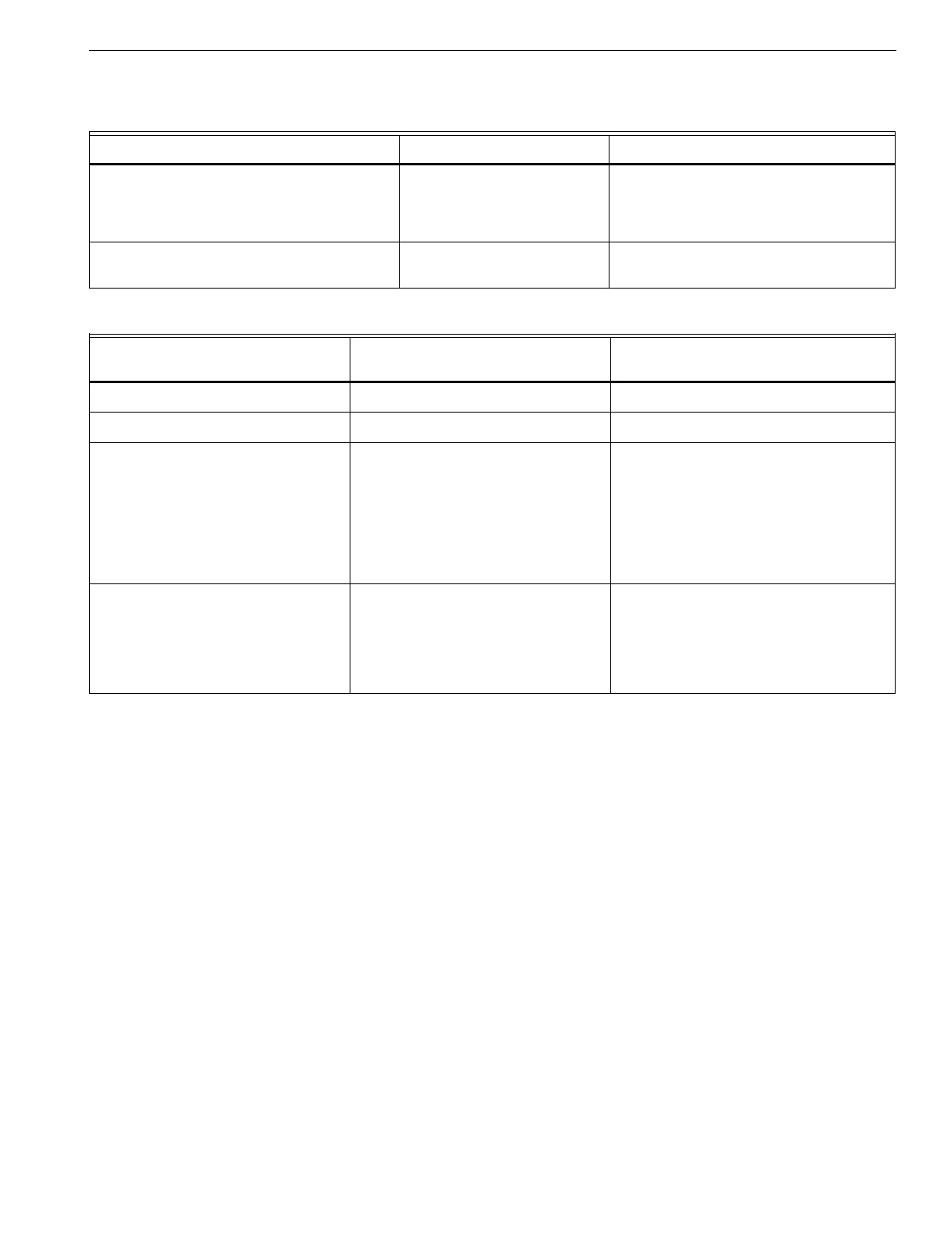
INSTALLATION
Mounting
CAUTION
Equipment Damage Hazard.
Do not mount TZ-3 inside HVAC equipment
Mount onl
y
on wall or on cold air return
1. Mount the thermostats in each zone of the livin
g
s
p
ace
usin
g
the installation instructions
p
rovided with each
thermostat.
2. Mount the dam
p
ers in the ductwork usin
g
the installa-
tion instructions
p
rovided with each dam
p
er.
3. Mount the TZ-3 zone
p
anel near the HVAC e
q
ui
p
ment;
locate it on a wall or on the cold-air return. See Fi
g
. 2.
4. Level the TZ-3 for a
pp
earance onl
y
.
Wiring
CAUTION
Voltage Hazard.
Can cause electrical shock or equipment damage.
Disconnect
p
ower before continuin
g
installation.
Wirin
g
must com
p
l
y
with a
pp
licable codes, ordinances, and
re
g
ulations.
1. Connect thermostats as shown in Fi
g
. 3-5.
2. Connect dam
p
ers as shown in Fi
g
. 6-10.
3. Connect the Dischar
g
e Air Tem
p
erature Sensor
(
not
su
pp
lied
)
to the TL terminals.The wires are not
p
olar-
ized. See Fi
g
.12.
4. Connect Add-A-Zone
p
anels
(
if used
)
to the AZ1 and
AZ2 terminals. The AZ1 terminal on the TZ-3 must be
wired to the AZ1 terminal on the TAZ
p
anel. Similarl
y
,
the AZ2 terminal must be wired on the TZ-3 to the AZ2
on the TAZ. See Fi
g
. 13.
5. Connect the HVAC e
q
ui
p
ment to the EQUIP terminals
on the
p
anel. See Fi
g
. 14-17.
6. Connect a 40 VA, 24 volt transformer to TR1
(
hot
)
and
TR2
(
common
)
. This must be a dedicated transformer
and an
y
additional TAZ boards also each re
q
uire a
transformer. See Fi
g
. 11.
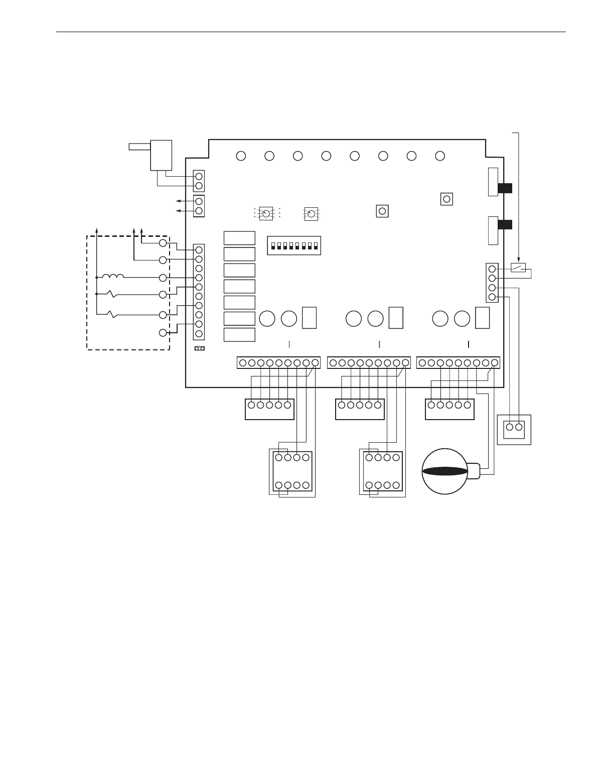
Fig. 2. TZ-3 mounting location.
Wiring Diagrams (Fig. 3-17)
Conventional Thermostats
The C
(
common
)
terminal is used onl
y
on thermostats that
re
q
uire a common
(
for exam
p
le:T8601
)
. See Fi
g
. 3. Wire the
W2 terminal on a multi-sta
g
e thermostat
(
for exam
p
le: T8624
)
to the W2 on the
p
anel for second sta
g
e control from the
thermostat. If the thermostat has a Y2 terminal, do not
connect it to the
p
anel.
Fig. 3. Typical single-stage thermostat wiring.
Heat Pump Thermostats
Select a heat
p
um
p
thermostat from Table 1. If the thermostat
selected has a se
p
arate Y1 and W1, see Fi
g
. 4. When usin
g
the thermostat to control the second sta
g
e of heat
(
W2
)
, set
DIP switch 5 to On, and DIP switch 1 to Off. Set both DIP
switches 6 and 7 to Off.
M19063
WATER
HEATER
T2-3
ELECTRONIC AIR CLEANER
RETURN
AIR
T2-3
OPTIONAL
LOCATION
FURNACE
OR BOILER
HIGH
EFFICIENCY
AIR CLEANER
LW2 G Y R W M6
GYRWC
M4 M1
THERMOSTAT
ZONE CONNECTIONS ON PANEL
ZONE THERMOSTAT M19064
MOTOR
TZ-3 TOTALZONE® ZONE CONTROL PANEL
5 68-0223-2
Fig. 4. Heat pump thermostat with separate Y1 and W1
terminals and multi-stage thermostat wiring.
If the thermostat selected has a sin
g
le Y terminal, see Fi
g
. 5.
Select a sin
g
le Y thermostat for each zone. See Table 1.
Set DIP switch 6 or 7
(
not both
)
to the On
p
osition. Set switch
6 to On when B on the thermostat is wired to W on the
p
anel.
Set switch 7 to On when 0 on the thermostat is wired to W on
the
p
anel.
When usin
g
the zone thermostat to control the second sta
g
e
of heat
(
W2
)
, set DIP switch 5 to On, and DIP switch 1 to Off.
Fig. 5. Heat pump thermostat with single Y thermostat
wiring.
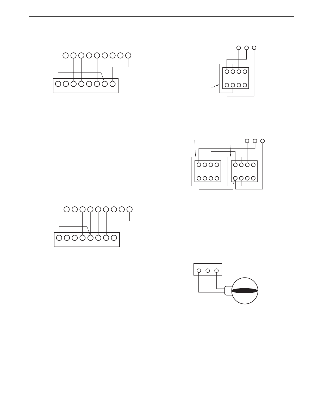
AOBD Dampers
Wire the AOBD, AOBD-BM and IOBD Dam
p
ers to the
p
anel
as shown in Fi
g
. 6. See Fi
g
. 7 when usin
g
two dam
p
ers on
one zone. When three or more dam
p
ers are controlled on
one zone, a slave dam
p
er control rela
y
(
SDCR
)
is re
q
uired.
Fig. 6. AOBD single damper wiring.
Fig. 7. AOBD multiple damper wiring.
ARD or ZD Dampers
Wire the ARD or ZD Dam
p
er to the
p
anel as shown in Fi
g
. 8.
Multi
p
le dam
p
ers can be wired in
p
arallel. When ARD or ZD
dam
p
er is used, the zone LEDs switch directl
y
from red to
g
reen
(
never amber
)
.
Fig. 8. ARD or ZD Damper wiring.
MARD or CDO-51 Dampers
Wire the MARD or CDO-51 Dam
p
er to the
p
anel as shown in
Fi
g
. 9. These are floatin
g
control modulatin
g
dam
p
ers, but are
controlled as two-
p
osition dam
p
ers on the TZ-3
p
anel.Two
dam
p
ers can be wired in
p
arallel.
LW2 G Y R W M6
GLW2E Y1 R W1 C/X
M4 M1
THERMOSTAT
ZONE CONNECTIONS ON PANEL
ZONE THERMOSTAT M19065
MOTOR
LGYR W M6
E W2 L G Y R O C/X
M4 M1W2
THERMOSTAT
ZONE CONNECTIONS ON PANEL
HEAT PUMP ZONE THERMOSTAT
M19066
MOTOR
4
M6 M4 M1
5 6
123
Z
X
DAMPER MOTOR
FIELD JUMPER
M19067
MOTOR TERMINALS
4
M6 M4 M1
5 6
123
DAMPER MOTORS M19068
MOTOR TERMINALS
4 5 6
123
Z
X
Z
X
FIELD JUMPER
M6 M4 M1
M19037A
DAMPER TERMINALS
ON PANEL
POWER CLOSE
SPRING OPEN
MODEL ARD, ZDS, ZDB
TZ-3 TOTALZONE® ZONE CONTROL PANEL
68-0223-2 6
Fig. 9. MARD and CDO-51 Damper wiring.
ML6161 Motor Actuator
When the ML6161 Motor Actuator is used, wire as shown in
Fi
g
. 10. Wire the R8222 rela
y
to
p
revent the dam
p
er LED from
constantl
y
li
g
htin
g
amber.
Fig. 10. ML6161 Damper Motor Actuator wiring.
Transformer
Wire the transformer to the
p
anel as shown in Fi
g
. 11.
NOTE: If the installation includes an Add-A-Zone
p
anel, see
the TotalZone Add-A-Zone Panels section.
Fig. 11. Transformer wiring.
Discharge Air Temperature Sensor
Wire the C7735A or the ZMS to the
p
anel as shown in Fi
g
. 12.
Fig. 12. Discharge Air Temperature Sensor (C7735A or
ZMS) wiring.
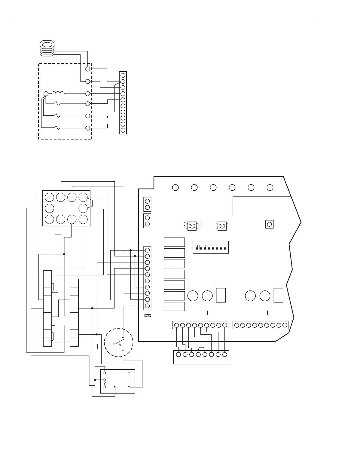
Add-A-Zone Panel
Wire the Add-A-Zone
(
TAZ
)
Panel to the TotalZone
(
TZ-3
)
Panel as shown in Fi
g
. 13. U
p
to nine TAZ Panels can be
wired to one TZ-3
p
anel. See Fi
g
. 13.
Use 18-
g
au
g
e thermostat wire for runs u
p
to a maximum of
500 feet. Kee
p
these wires at least 12 in. from line volta
g
e
wirin
g
and e
q
ui
p
ment; otherwise, use shielded cable wirin
g
.
IMPORTANT:
When multiple panels are used, it is important that
the transformers be in-phase. Check the phasing by
measuring for 24V across the TR2 transformer termi-
nals on each panel. There should be 0 Vac. If not,
reverse the TR1and TR2 transformer wires on one of
the panels and recheck.
Fig. 13. TotalZone Add-A-Zone wiring.
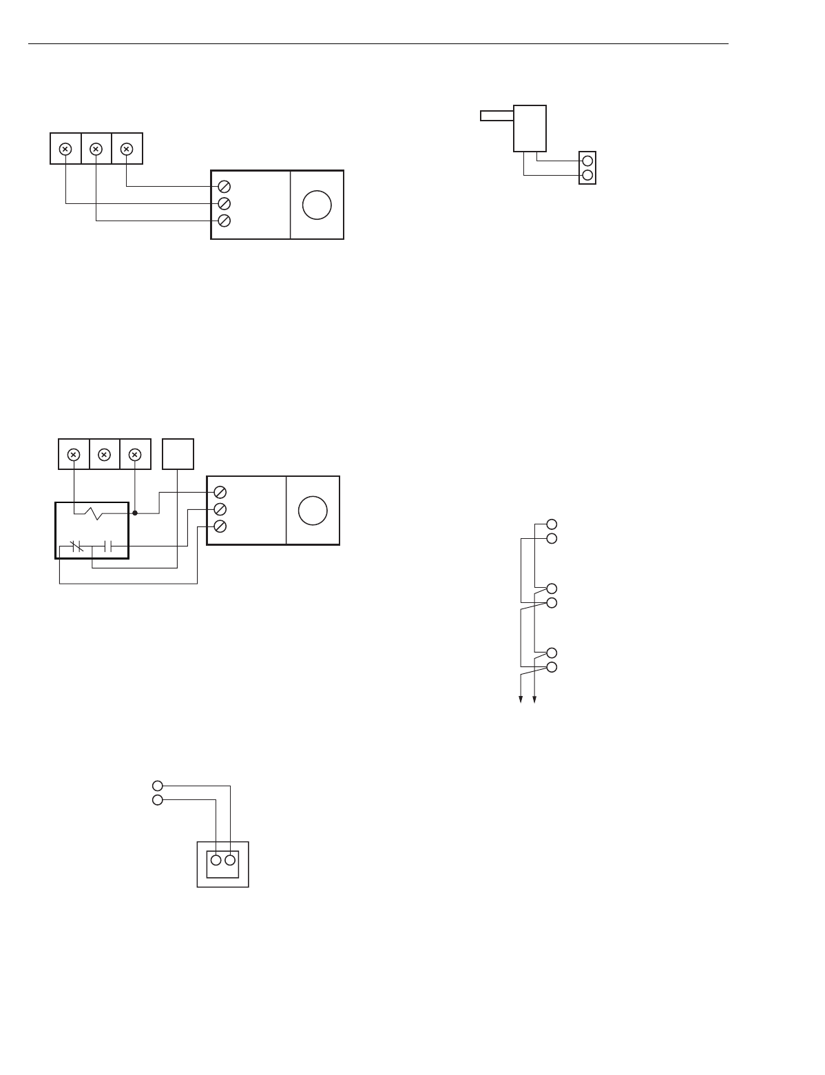
Conventional Equipment
Wire the heatin
g
and coolin
g
e
q
ui
p
ment to the e
q
ui
p
ment
terminals on the TZ-3 Panel as shown in Fi
g
. 14.
Electric Furnaces: Set DIP switch 8 to On to ener
g
ize the fan
with a call for heat.
H
y
dro-Air: Wire the zone valve or circulator rela
y
to the W1
e
q
ui
p
ment terminal.
(
If the circulator rela
y
has
p
owered
terminals, use an isolation rela
y
.
)
Set DIP switch 8 to On to
ener
g
ize the fan with a call for heat.
Oil Heat: Wire an isolation rela
y
on the W e
q
ui
p
ment wire to
isolate the oil
p
rimar
y
from the
p
anel.
COM / M1
CL / M6
OP / M4
MARD OR CDO-51
ZONE CONTROL PANEL
DAMPER TERMINALS
M19069
M6 M4 M1
COM / M1
CL / M6
OP / M4
ML6161
R8222 RELAY
ZONE CONTROL PANEL
DAMPER TERMINALS
M19070
M6 M4 M1 ZONE
THERMOSTAT
TERMINAL
R
C
24 VOLT
TRANSFORMER
R
TR1
TR2
24V, 40 VA
TRANSFORMER
MODEL AT140D1046 M19071
TL
TL
ZMS
SENSOR
M19072
TO ADDITIONAL
TAZ PANELS M19073
AZ2
AZ1 TAZ
AZ2
AZ1 TAZ
AZ2
AZ1 TZ-3
TZ-3 TOTALZONE® ZONE CONTROL PANEL
7 68-0223-2
Multi-Sta
g
e: Wire the e
q
ui
p
ment as shown in Fi
g
. 14 usin
g
the
W2 terminal for second sta
g
e of heat and the W3 terminal for
third sta
g
e of heat. Wire the Y2 for second sta
g
e of coolin
g
.
Fig. 14. Heating and cooling equipment.
Heat Pump Equipment
Wire the heat
p
um
p
to the e
q
ui
p
ment terminals on the
p
anel
as shown in Fi
g
. 15. Refer to manufacturer’s instructions for
additional wirin
g
instructions and substitute the TZ-3
e
q
ui
p
ment terminals for the thermostat terminals shown.
IMPORTANT
Some heat pump manufacturers (such as York and
Trane) use the B terminal as the transformer com-
mon. Do not connect the common from the equip-
ment to the zone control panel.
Two-s
p
eed Com
p
ressor: Wire the second sta
g
e com
p
ressor
to both Y2 and W2. Wire the auxiliar
y
heat to W3. Remove the
two-sta
g
e emer
g
enc
y
heat
j
um
p
er and install a
j
um
p
er from
W3 to E.
Fossil Fuel Kits with Heat Pum
p
s: Wire these s
y
stems like
Fi
g
.15 but use the manufacturer’s fossil fuel kit. Wire the
Trane XL 1800 and the TAYPLUS 103 as shown in Fi
g
. 16.
The recommended thermostat is theT8611G2051.
CGYRW
ZONE 1
THERMOSTAT
24V, 40 VA
TRANSFORMER
M19074
W2
W3
E
W1
B
G
R
O
Y1
Y2
TL
TL
2 STAGE
EM HEAT
MODEL TZ-3
CR
OC
OC
TR1
TR2
HEAT
TO TERMINAL AZ1 ON TAZ (IF USED)
OUTDOOR CONDENSING UNIT
HVAC CONTROLS
ZoneMAX
Add-A-Zone
TM
COOL PURGE FAN EM.HT ZONE 1 ZONE 2 ZONE 3
BOOT
OVERRIDE
PURGE
REMOTE OCCUPIED/
UNOCCUPIED CONTROL
(CLOSE IN UNOCCUPIED)
ON
OFF
Emergency Heat
ON
1
LW2 G Y R W M6 M4 M1
THERMOSTAT MOTOR
2345678
OCCUP
REMOTE
UNOCCUP
Zone-A-Lone
C
123X
456Z
GYRW
ZONE 3
THERMOSTAT
MODEL ARD OR
ZD DAMPERS
ZONE 2
LW2 G Y R W M6 M4 M1
THERMOSTAT MOTOR
ZONE 1
LW2 G Y R W M6 M4 M1
THERMOSTAT MOTOR
ZONE 3
CGYRW
ZONE 2
THERMOSTAT
123X
456Z
OPPOSED BLADE DAMPER MOTORS
AZ1
AZ2
TO TERMINAL AZ2 ON TAZ (IF USED)
ZoneMAX
TEMPERATURE
SENSOR
TM
15 MINUTES
10 MINUTES
5 MINUTES
20 MINUTES
25 MINUTES
30 MINUTES
STAGE TIMER
130 F
MAXIMUM
TEMPERATURE
120 F
110 F
140 F
150 F
160 F
W
W2
24V TRANSFORMER
FAN RELAY
HEAT RELAY
R
Y
Y2
C
G
TZ-3 TOTALZONE® ZONE CONTROL PANEL
68-0223-2 8
Fig. 15. Heat pump with auxiliary heat wiring.
.
Fig. 16. Trane XL 1800 with TAYPLUS 103 in restricted mode wiring.
Water Source Heat Pumps
Wire the e
q
ui
p
ment, as a
pp
licable, to the TZ-3 as shown in
Fi
g
. 17. Turn DIP switch number 8 to On for fan on in heat.
Remove the two-sta
g
e emer
g
enc
y
heat
j
um
p
er.
W2
W3
M19075
E
W1
W2
E
B
G
R
24V TRANSFORMER
FAN RELAY
REVERSING
VALVE (COOL)
EMERGENCY
HEATING RELAY
2 STAGE
HEATING RELAY
HEAT PUMP CONTROLS
TZ-3
PANEL
EQUIP
R
C
O
G
O
Y1
Y2
COMPRESSOR
RELAY Y
OUTDOOR CONDENSING UNIT
YERW2
W3
T
L
1
2
3
1
4
K2
ODT
5
3
G O/B C
T8611G2051
TRANE XL1800
CONDENSING
UNIT
VARIABLE
SPEED
GAS
FURNACE
TAYPLUS 103
NOTES:
M19076
W2
W3
E
W1
B
G
R
O
Y1
Y2
TL
TL
2 STAGE
EM HEAT
MODEL TZ-3
HEAT
ZoneMAX
Add-A-Zone
TM
COOL PURGE FAN EM.HT ZONE 1
OVERRIDE
PURGE
ON
1
LW2 G Y R W M6 M4 M1
THERMOSTAT MOTOR
2 3 4 5 6 7 8
ZONE 2
LW2 G Y R W M6 M4 M1
THERMOSTAT MOTOR
ZONE 1
AZ1
AZ2
15 MINUTES
10 MINUTES
5 MINUTES
20 MINUTES
25 MINUTES
30 MINUTES
STAGE TIMER
130 F
MAXIMUM
TEMPERATURE
120 F
110 F
140 F
150 F
160 F
1. DIP SWITCHES 6 OFF AND 7 ON.
2. DIP SWITCHES 1 OFF AND 5 ON.
3. T8011R OR T8411R MAY ALSO BE USED.
4. REMOVE THE 2 STAGE EM HEAT JUMPER.
F
Y2
R
B
Y1
O
X2
G
W2
W1
B
O
Y
YLO
BK
R
Y3 X3 G3
Y2 G1
X2 Y1 BW1
TZ-3 TOTALZONE® ZONE CONTROL PANEL
9 68-0223-2
Waterfurnace: Wire this s
y
stem to the
p
anel as shown in Fi
g
.
17 exce
p
t use two isolation rela
y
s on com
p
ressor wires W1,
Y1 and W2, Y2.
Fig. 17. Water source heat pump wiring.
STARTUP AND CHECKOUT
After the installation is com
p
lete, verif
y
correct o
p
eration as
follows:
1. Place the Em Heat switch in the Off
(
down
)
p
osition.
2. Place the Zone-A-Lone switch in the Occu
p
/Remote
(
u
p)
p
osition.
3. Verif
y
that the DIP switches are set correctl
y
. See
Se
q
uence of O
p
eration section and Table 6 for correct
confi
g
uration.
4. Power u
p
the TZ-3 and set the thermostats so no zones
are callin
g
. The board then enters the Pur
g
e mode
where all dam
p
ers o
p
en and the fan o
p
erates for two or
three and one-half minutes
(
confi
g
urable
)
.
(
If there is
no Dischar
g
e Air Tem
p
erature Sensor connected to the
p
anel, the Idle LED flashes seven times before enterin
g
the Pur
g
e mode.
)
Then the Idle LED turns red and each
dam
p
er LED turns
g
reen.
5. Set zone one thermostat to heat and raise the set
p
oint
to call for heat. Verif
y
that the heat LED is red and zone
one dam
p
er remains
g
reen while the other dam
p
er LED
turns red.
6. Raise zone two set
p
oint to call for heat. Lower zone one
set
p
oint to sto
p
the call for heat to that zone. Verif
y
that
zone one LED turns red
(
it ma
y
be amber while movin
g)
and zone two LED turns
g
reen.
7. Re
p
eat for zone three.
8. Alternatel
y
, lower the set
p
oint to call for coolin
g
.Verif
y
that the
g
reen cool LED illuminates.
W2
W3
M19077
E
W1
O
G
W
B
G
R
2ND STAGE COMPRESSOR
1ST STAGE COMPRESSOR
AUXILIARY HEAT
Y1
C
Y2
O
Y1
Y2
R
2 STAGE
EM. HT.
TZ-3 TOTALZONE® ZONE CONTROL PANEL
68-0223-2 10
OPERATION
Sequence of Operation
On a call for heatin
g
or coolin
g
, the zone dam
p
er sta
y
s o
p
en
to the callin
g
zone, and the dam
p
ers close to the zones that
are not callin
g
. The TZ-3
p
anel brin
g
s on the heatin
g
or
coolin
g
and conditioned air is delivered to the callin
g
zone
until that zone is satisfied. When the call is satisfied, the
s
y
stem enters the Pur
g
e mode. This holds o
p
en the dam
p
er
of the last zone callin
g
and
p
ur
g
es into that zone. The
p
ur
g
e
time can be set to three and one-half or two minutes. After
p
ur
g
e, all dam
p
ers return to the O
p
en
p
osition.
An
y
zone thermostat can call for heatin
g
or coolin
g
. If there
are co-existin
g
calls for heat and cool, the
p
anel first acce
p
ts
the first call. Once that call is satisfied, or a maximum of 20
minutes has ela
p
sed, the
p
anel switches to allow the o
pp
osite
call.
On a call for heatin
g
or coolin
g
, the heat LED illuminates red
or the cool LED illuminates
g
reen. The zone dam
p
er LED
turns
g
reen for the zone callin
g
, and the dam
p
ers in the zones
not callin
g
close and turn red. As AOBD dam
p
ers move, the
LEDs turn amber.
Purge Mode
At the end of ever
y
call for heat or cool, the
p
anel enters a
Pur
g
e mode that holds o
p
en the callin
g
zone dam
p
er for three
and one-half or two minutes. Durin
g
this time, the
p
anel or the
HVAC e
q
ui
p
ment can o
p
erate the fan. Pur
g
e also serves as a
time dela
y
to
p
revent short c
y
clin
g
of the heatin
g
and coolin
g
e
q
ui
p
ment after each call. Pur
g
e LED li
g
hts to si
g
nal that the
s
y
stem is in the Pur
g
e mode. Pressin
g
the
p
ur
g
e override
button for two seconds overrides the Pur
g
e mode. Unless
there is a new call for heat or cool durin
g
the Pur
g
e mode, all
dam
p
ers are moved to the O
p
en
p
osition at the end of
p
ur
g
e.
Individual Zone Fan Control
When all zones are satisfied, the Fan switch of each
thermostat controls the fan o
p
eration for that zone. When the
Fan switch is in the On
p
osition, the fan is ener
g
ized, and the
dam
p
ers close to zones where the Fan switch is in the Auto
p
osition. If there is a call for heat or cool durin
g
this time, the
circulation mode ceases, and the heat or cool call is honored.
When the zone callin
g
is satisfied, the circulation call
resumes.
Single and Multi-Stage Operation
The
p
anel can control u
p
to three sta
g
es of heatin
g
and two
sta
g
es of coolin
g
. The first sta
g
e is ener
g
ized b
y
the
thermostat. The second sta
g
e of heatin
g
is brou
g
ht on b
y
the
thermostat, timer, or number of zones callin
g
. The third sta
g
e
of heatin
g
is brou
g
ht on b
y
the timer or number of zones
callin
g
. The second sta
g
e of coolin
g
is brou
g
ht on b
y
the timer
or number of zones callin
g
.
The followin
g
instructions show how to confi
g
ure the
p
anel for
sta
g
e control.
If the e
q
ui
p
ment is sin
g
le sta
g
e, set the DIP switches as
follows:
1st Stage by Thermostat, 2nd and 3rd Stages by
Timer (Fig. 18)
The thermostat controls the first sta
g
e of heat or cool. If the
call is not satisfied b
y
the first sta
g
e within the time set on the
timer, the
p
anel ener
g
izes the second sta
g
e. If the call for heat
is not satisfied b
y
the second sta
g
e within the time set on the
timer, the
p
anel brin
g
s on the third sta
g
e.
Set the DIP switches as follows:
Fig. 18. Stage timer.
1st Stage by Thermostat, 2nd Stage Heat by
Thermostat
The thermostat controls the first sta
g
e of heat or cool and the
second sta
g
e of heat. The timer controls the second sta
g
e of
cool and third sta
g
e of heat. If the first and second sta
g
es
combined do not satisf
y
the heat call within the time s
p
ecified
on the timer, the
p
anel brin
g
s on the third sta
g
e of heat.
Set the DIP switches as follows:
DIP Switch
Number Status Purge Time
3Off 3.5 minutes
3On 2 minutes
DIP Switch
Number Status Fan Control
4Off Panel control of fan
in
p
ur
g
e
4On HVAC control of fan
in
p
ur
g
e
DIP Switch Number Status
1Off
5Off
DIP Switch Number Status
1Off
5Off
15 MINUTES
10 MINUTES
5 MINUTES
20 MINUTES
25 MINUTES
30 MINUTES
STAGE TIMER M19078
TZ-3 TOTALZONE® ZONE CONTROL PANEL
11 68-0223-2
.
Stages Based On Number of Zones Calling
The thermostat controls the first sta
g
e of heat or cool. The
second sta
g
e of heat and cool and the third sta
g
e of heat are
ener
g
ized b
y
the
p
ercenta
g
e of zones callin
g
. See Table 4.
Set the DIP switches as follows:
See Table 4 to determine the number of zones re
q
uired to
activate sta
g
es of e
q
ui
p
ment based on the number of zones in
the s
y
stem. Sta
g
in
g
is based on the zones available in the
s
y
stem, not the number of zones used for the
p
articular
a
pp
lication. As zones satisf
y
, sta
g
es 2 and 3 dro
p
out.
Thermostat Operation
Conventional Thermostats
Conventional
(
R,W,Y,G
)
heat/cool thermostats can be used
with the TZ-3 to control sin
g
le or multi-sta
g
e
g
as, electric or oil
s
y
stems and heat
p
um
p
s with auxiliar
y
heat. The
p
anel can
be confi
g
ured to control second sta
g
e heat and cool and third
sta
g
e heat usin
g
a 5-30 minute
p
anel, or sta
g
in
g
can be
controlled b
y
the
p
ercenta
g
e of zones callin
g
. The O and B
e
q
ui
p
ment terminals are ener
g
ized for chan
g
eover use with
heat
p
um
p
s.
Heat Pump Thermostats
HEAT PUMP THERMOSTATS WITH SINGLE Y OUTPUT
Heat
p
um
p
thermostats can be used if thermostat control of
2nd sta
g
e is desired. Thermostats that have a sin
g
le Y
terminal for first sta
g
e heat and cool can be used. When
selected, all thermostats must be similar.
If the thermostat ener
g
izes O on a call for cool, DIP switch 7
must be set to On and the O thermostat wire connected to W
on the thermostat connections for that zone. If the thermostat
ener
g
izes B on a call for heat, DIP switch 6 must be set to On
and the B wire connected to W on the
p
anel. In either case,
the O is alwa
y
s ener
g
ized to the e
q
ui
p
ment in coolin
g
, and the
B is alwa
y
s ener
g
ized to the e
q
ui
p
ment in heatin
g
.
IMPORTANT
Be sure DIP switches 6 and 7 are never both in the
On position.
HEAT PUMP THERMOSTATS WITH SEPARATE Y1 AND W1
TERMINALS
Use heat
p
um
p
thermostats with se
p
arate Y1 and W1
terminals for first sta
g
e heat and cool. Kee
p
DIP switches 6
and 7 in the Off
p
osition when thermostat O or B wire is not
used.
Emergency Heat Control
Emer
g
enc
y
heat is defined as usin
g
an auxiliar
y
heat source
without usin
g
the heat
p
um
p
. When the Em Heat switch or a
thermostat
p
uts the
p
anel in the emer
g
enc
y
heat mode, the
heat
p
um
p
is locked out and calls for heat are sent to the E
terminal.
A heat
p
um
p
thermostat can also control emer
g
enc
y
heat
from the thermostat s
y
stem switch. An L terminal ener
g
ized
durin
g
the emer
g
enc
y
heat mode is re
q
uired. The
recommended heat
p
um
p
thermostats all have hot L
terminals. See Table 1.
The two sta
g
e Em heat
j
um
p
er connects W2 and E. Jum
p
er
both
p
ins to ener
g
ize the W2 e
q
ui
p
ment on a call for
emer
g
enc
y
heat. When E is a different source of heat than
W2, remove the
j
um
p
er
(
for exam
p
le, two-sta
g
e heat
p
um
p
with electric heat stri
p
auxiliar
y
heat
)
. The
j
um
p
er is located
below the e
q
ui
p
ment terminals on the lower-left corner of the
p
anel.
Multi-Stage Thermostats
Use multi-sta
g
e thermostats to control two sta
g
es of heat via
W1 and W2 thermostat terminals. Control the third sta
g
e of
heat throu
g
h the sta
g
e timer built into the
p
anel. Control the
second sta
g
e of coolin
g
with the timer.
Manual and Automatic Changeover Thermostats
Automatic chan
g
eover thermostats
p
rovide automatic
chan
g
eover b
y
zone. Manual chan
g
eover thermostats heat or
cool based on the mode of each zone thermostat.
DIP Switch Number Status
1Off
5On
DIP Switch Number Status
1On
5Off
Table 4. Staging by Percentage of Zones Calling.
Number of
Zones in
System
Number of Zones Required
2nd Stage
Heat 3rd Stage
Heat 2nd Stage
Cool
32 32
42 33
52 43
63 54
73 54
83 65
94 75
10 4 7 6
11 4 8 6
12 5 9 7
TZ-3 TOTALZONE® ZONE CONTROL PANEL
68-0223-2 12
Rebooting Microprocessor
Certain conditions can han
g
u
p
the micro
p
rocessor. To reset
it,
p
ress and release the Boot button. The s
y
stem reboots and
enters the Pur
g
e mode.
Discharge Air Temperature Sensor
The Dischar
g
e Air Tem
p
erature Sensor
(
not included
)
is a
su
pp
l
y
-duct-mounted tem
p
erature
p
robe used to control
ca
p
acit
y
and
p
revent over-heatin
g
or coil-icin
g
. The sensor
attaches to the TL terminals on the
p
anel.
Set the hi
g
h limit tem
p
erature on the maximum tem
p
erature
dial on the
p
anel, located left of the sta
g
e timer. See. Fi
g
. 19.
Set the tem
p
erature from 110 °F to 160°F in ten-de
g
ree
increments. The recommended settin
g
for fossil fuel/ electric
s
y
stems is 160°F
(
default factor
y
settin
g)
. For heat
p
um
p
s
y
stems, the recommended settin
g
is 120F.
The coolin
g
tem
p
erature limit can be set at 40°F or 48°F.
Fig. 19. Maximum temperature dial.
IMPORTANT
Be sure the Discharge Air Temperature Sensor wir-
ing does not run parallel with line voltage wiring
unless more than 12 in. of separation exists or
shielded cable is used.
Use DIP switch 2 to chan
g
e coolin
g
limit settin
g
s.
If the s
y
stem tri
p
s due to exceedin
g
a hi
g
h or low tem
p
erature
limit, the heatin
g
or coolin
g
s
y
stem shuts down and the fan
continues runnin
g
to
p
ur
g
e the conditioned air from the
p
lenum.
When the low limit is tri
pp
ed, the Cool LED flashes until it
resets. When the hi
g
h limit is tri
pp
ed, the Heat LED flashes
until it resets.
Once the tem
p
erature recovers b
y
ten de
g
rees, the
e
q
ui
p
ment run resumes.
Zone-A-Lone Switch
When the Zone-A-Lone switch is in the occu
p
ied
p
osition and
the OC/OC terminals are not used, the s
y
stem functions as a
normal zone control s
y
stem. When switched to the
unoccu
p
ied
p
osition, all dam
p
ers are o
p
ened and all re
q
uests
for heat, cool, or fan, exce
p
t from zone one, are not honored.
The zone one thermostat becomes the controllin
g
thermostat
for the entire s
y
stem. Durin
g
lon
g
unoccu
p
ied
p
eriods, one
thermostat can be set back instead of ad
j
ustin
g
each zone
thermostat in the buildin
g
.
The T8601D2027 and T8611G2051 include two OC terminals.
When wired to the TZ-3 OC terminals, and with the Zone-A-
Lone switch in the occu
p
ied
p
osition, the board enters the
unoccu
p
ied mode durin
g
the Leave and Slee
p
p
ro
g
rams. This
feature re
q
uires two extra wires to the Zone 1 thermostat.
Circuit Breaker Protection
A built-in thermal circuit breaker
p
rotects the TotalZone
p
anel.
This circuit breaker
p
rotects the
p
anel a
g
ainst shorts in the
thermostat and dam
p
er wirin
g
and the remote occu
p
ied/
unoccu
p
ied switch. It does not
p
rotect a
g
ainst shorts in the
wirin
g
of the HVAC e
q
ui
p
ment into the
p
anel.
When the circuit breaker is tri
pp
ed, none of the LEDs
illuminate and the
y
ellow rectan
g
ular com
p
onent located to
the left of the TR1 and TR2 terminals is hot to the touch.
Remove
p
ower to the
p
anel for at least ten seconds to allow
the circuit breaker to cool off and reset. To eliminate the short,
verif
y
the dam
p
ers and thermostat wirin
g
.
Fan On In Heat
The s
y
stem blower can be set to come on with a call for heat
as re
q
uired for h
y
dro-air, heat
p
um
p
, or electric heat s
y
stems.
Set the blower usin
g
DIP switch 8.
TotalZone Add-A-Zone Panels
Usin
g
TotalZone Add-A-Zone Panels, the s
y
stem can be
ex
p
anded to u
p
to 30 zones. There are three models: TAZ-1,
one zone; TAZ-2, two zone; and TAZ-3, three zone. Two wires
are re
q
uired to connect the TAZ to the TZ-3.
IMPORTANT:
When multiple panels are used, it is important that
the transformers be in-phase. Check the phasing by
measuring for 24V across the TR2 transformer termi-
nals on each panel. There should be 0 Vac. If not,
reverse the TR1and TR2 transformer wires on one of
the panels and recheck.
See Fi
g
. 13 and the TAZ installation instructions for more
information.
Dip Switch Status
Cooling
Temperature
Limit
2Off 40°F
2On 48°F
130 F
MAXIMUM
TEMPERATURE M19079
120 F
110 F
140 F
150 F
160 F
DIP Switch 8 Fan Control
Off HVAC s
y
stem
On Fan on in heat
TZ-3 TOTALZONE® ZONE CONTROL PANEL
13 68-0223-2
TROUBLESHOOTING
Table 5. Troubleshooting.
Symptom Possible Cause Action
No LEDs are Illuminated No
p
ower to the board. Check for 24 Vac
(
±10%
)
across TR1 and TR2
Shorted wire. Check fuse. If hot, a short exists in thermostat, dam
p
er,
or Zone-A-Lone wirin
g
.
Dam
p
er LEDs on, but no
other LEDs illuminated. Insufficient volta
g
e. Check for 24 Vac
(
±10%
)
across TR1 and TR2.
Incorrect confi
g
uration. Check
j
um
p
ers and DIP switches for correct
confi
g
uration.
Erratic O
p
eration Emer
g
enc
y
Heat switch on. Turn off
(
down
)
Emer
g
enc
y
Heat switch.
Zone-A-Lone Feature on. Turn off
(
u
p)
Zone-A-Lone.
Heat
p
um
p
o
p
erates
incorrectl
y
or not at all. Incorrectl
y
wired. Verif
y
that W1 and Y1 e
q
ui
p
ment terminals are
j
um
p
ed.
Incorrectl
y
confi
g
ured. Verif
y
DIP switches 6 and 7 are correctl
y
set for the t
yp
e
of thermostat used.
Heat LED flashin
g
.Hi
g
h limit reached. LED sto
p
s flashin
g
with ten-de
g
ree fall.
Cool LED flashin
g
.Low limit reached. LED sto
p
s flashin
g
with ten-de
g
ree rise.
Idle LED flashes five times
on bootu
p
.ZMS
p
roblem or not
connected. Verif
y
that ZMS
(
if an
y)
is connected, and wired
correctl
y
.
Idle LED flashes
continuousl
y
ZMS failure. Check for dc volta
g
e across TL terminals:
If 0 volt = short.
If 1 volt = o
p
en.
If .2 to .8 volt = normal.
Add-A-Zone not o
p
eratin
g
.Incorrectl
y
confi
g
ured. Verif
y
DIP switch settin
g
s on the TAZ
p
anels.
Incorrectl
y
wired. Check AZ1and AZ2 for correct wirin
g
.
Be sure that AZ1 and AZ2 are at least 12 in. from line
volta
g
e wirin
g
.
Be sure the transformers are in-
p
hase.
TZ-3 TOTALZONE® ZONE CONTROL PANEL
68-0223-2 14
Table 6. DIP Switch Settings and Functions.
Table 7. LED Indicators.
DIP Switch Function Off (default) On
1Sta
g
in
g
b
y
number of zones
callin
g
.Sta
g
es timer or thermostat
controlled. Sta
g
es controlled b
y
number of zones
callin
g
.
2ZMS low limit. 40°F 48°F
3Pur
g
e mode timin
g
.Three and one-half minutes. Two minutes.
4Fan control durin
g
p
ur
g
e. Controlled b
y
p
anel. HVAC e
q
ui
p
ment controlled
5Control of W2 out
p
u.t Timer controlled. Controlled b
y
W2 from thermostat,
6Cool chan
g
eover from
thermostat. Not usin
g
B on sin
g
le Y
thermostats; or usin
g
conventional thermostats.
Usin
g
B on sin
g
le Y thermostat.
7Heat chan
g
eover from
thermostat. Not usin
g
O on sin
g
le Y
thermostats; or usin
g
conventional thermostats.
Usin
g
O on sin
g
le Y thermostat.
8Fan control in heat. Fan controlled b
y
p
anel in cool
and HVAC e
q
ui
p
ment in heat. Panel in heat and cool controllin
g
fan.
LED Color Illuminated Not Illuminated Flashing
Heat Red Heat call No heat calls. Hi
g
h limit reached
Cool Green Cool call No cool calls. Low limit reached
Pur
g
eAmber Pur
g
e mode Not in Pur
g
e mode. ZMS failure
Idle Red No calls Call for heat, cool, or fan. Initial
p
oweru
p
without ZMS
wired
Fan Green Fan onl
y
call No fan onl
y
call. —
EM Heat Red Emer
g
enc
y
Heat mode Not in emer
g
enc
y
Heat mode. —
Zone 1,2,3 Zone
1,2,3 Green—o
p
en
Red—closed
Amber—movin
g
(
some
dam
p
ers
)
— —
TZ-3 TOTALZONE® ZONE CONTROL PANEL
15 68-0223-2
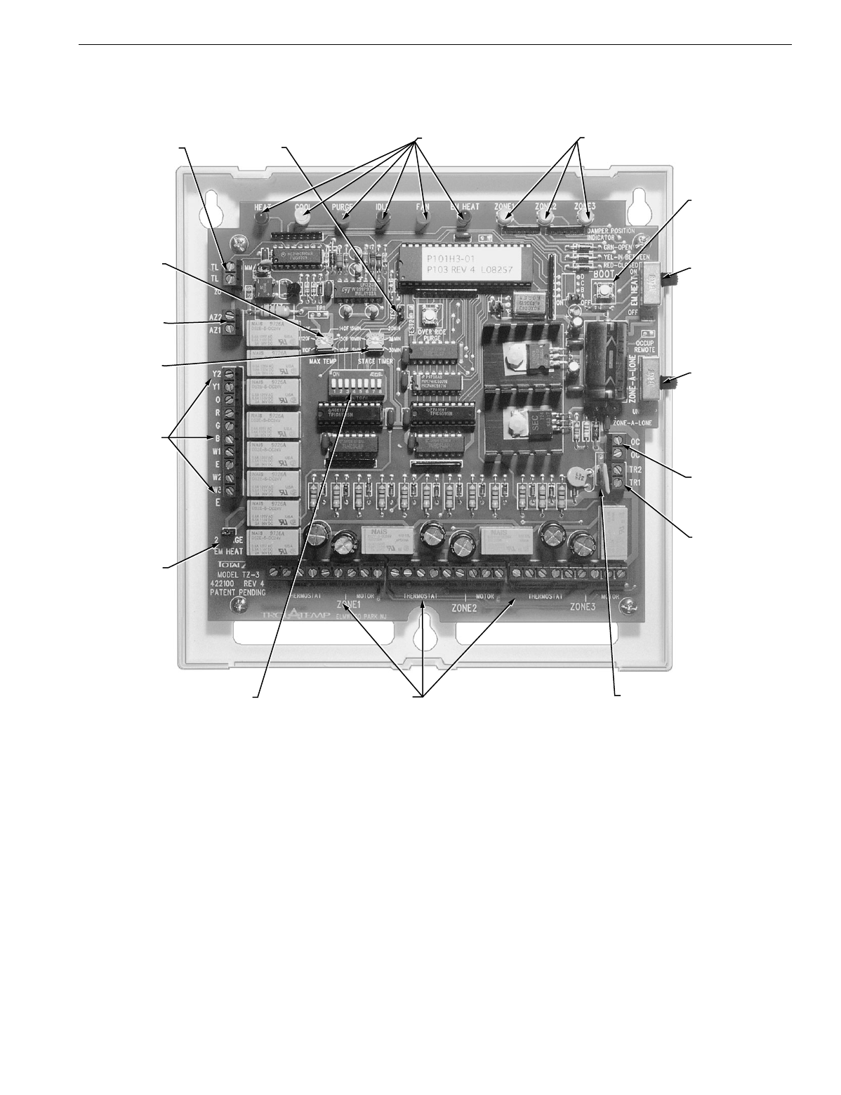
See Fi
g
. 20 for TZ-TotalZone Zone Control Panel.
Fig. 20. TZ-3 TotalZone Zone Control Panel.
ZoneMAX™
TERMINALS
SYSTEM STATUS
LED INDICATIORS
TEST JUMPERS
(NOT USED)
ZONE DAMPER
LED INDICATORS
ZONE-A-
LONE™
SWITCH
BOOT
BUTTON
EMERGENCY
HEAT SWITCH
RESETTABLE
FUSE
TRANSFORMER
TERMINALS
ZoneMAX™
TEMP
SETTING
ZONE, THERMOSTAT & DAMPER
MOTOR TERMINALS
REMOTE
ZONE-A-LONE™
CONTROL
TERMINALS
STAGE
TIMER
DIP SWITCHES FOR
SYSTEM CONFIGURATION
2 STAGE
EM HEAT
JUMPER
HVAC
EQUIPMENT
TERMINALS
ADD-A-
ZONE™
TERMINALS
M13421

68-0223-2 G.H. Rev. 9-01 www.hone
y
well.com/
y
ourhome
Home and Building Control Home and Building Control
Honeywell Honeywell Limited-Honeywell Limitée
1985 Douglas Drive North 35 Dynamic Drive
Golden Valley, MN 55422 Scarborough, Ontario
M1V 4Z9
Printed in U.S.A. on recycled
paper containing at least 10%
post-consumer paper fibers.
TZ-3 TOTALZONE® ZONE CONTROL PANEL
