Honeywell Universal Digital Controller Udc 3300 Users Manual
UDC 3300 to the manual 91c200c6-83ea-41d6-9a2d-4cbdebe83b07
2015-01-23
: Honeywell Honeywell-Universal-Digital-Controller-Udc-3300-Users-Manual-262617 honeywell-universal-digital-controller-udc-3300-users-manual-262617 honeywell pdf
Open the PDF directly: View PDF ![]() .
.
Page Count: 294 [warning: Documents this large are best viewed by clicking the View PDF Link!]

Sensing and Control
UDC 3300
Universal Digital Controller
Product Manual
51-52-25-55D
4/00

ii UDC 3300 Controller Product Manual 4/00
Copyright, Notices, and Trademarks
Printed in U.S.A. – © Copyright 2000 by Honeywell
Revision D – April, 2000
WARRANTY/REMEDY
Honeywell warrants goods of its manufacture as being free of defective materials and faulty
workmanship. Contact your local sales office for warranty information. If warranted goods are
returned to Honeywell during the period of coverage, Honeywell will repair or replace without
charge those items it finds defective. The foregoing is Buyer’s sole remedy and is in lieu of all
other warranties, expressed or implied, including those of merchantability and fitness for a
particular purpose. Specifications may change without notice. The information we supply is
believed to be accurate and reliable as of this printing. However, we assume no responsibility for
its use.
While we provide application assistance personally, through our literature and the Honeywell web
site, it is up to the customer to determine the suitability of the product in the application.
Sensing and Control
Honeywell
11 West Spring Street
Freeport, Illinois 61032

4/00 UDC 3300 Controller Product Manual iii
About This Document
Abstract
This manual describes the installation, configuration, operation, and maintenance of the UDC3300
Controller.
References
Publication Title Publication Number
UDC 3300 Limit Controller 51-52-25-56
UDC 3000/UDC 3300/UDC5000/UDC6000U/DC6300
RS422/485 Communications Option Manual 51-51-25-35
UDC 3000/3300 DMCS Communications Option Section of the Gateway Manual 82-50-10-23
Modbus® RTU Serial Communications User Manual 51-52-25-66
Modbus® RTU Serial Communications User Manual Configuration Interface for
UDC 3300 51-52-25-70
UDC 3300 Controller Specification Sheet 51-52-03-23
UDC 3000 Modbus 485RTU Communications Option 51-52-25-38
How to Apply Digital Instrumentation in Severe Electrical Noise Environments 51-52-05-01
Contacts
World Wide Web
The following lists Honeywell’s World Wide Web sites that will be of interest to our customers.
Honeywell Organization WWW Address (URL)
Corporate http://www.honeywell.com
Sensing and Control http://www.honeywell.com/sensing
International http://www.honeywell.com/Business/global.asp
Telephone
Contact us by telephone at the numbers listed below.
Organization Phone Number
United States and Canada Honeywell 1-800-423-9883 Tech. Support
1-888-423-9883 Q&A Faxback
(TACFACS)
1-800-525-7439 Service
Asia Pacific Honeywell Asia Pacific
Hong Kong (852) 2829-8298
Europe Honeywell PACE, Brussels, Belgium [32-2] 728-2111
Latin America Honeywell, Sunrise, Florida U.S.A. (854) 845-2600
iv UDC 3300 Controller Product Manual 4/00
Symbol Definitions
The following table lists those symbols used in this document to denote certain conditions.
Symbol Definition
This CAUTION symbol on the equipment refers the user to the Product Manual for
additional information. This symbol appears next to required information in the
manual.
WARNING
PERSONAL INJURY: Risk of electrical shock. This symbol warns the user of a
potential shock hazard where HAZARDOUS LIVE voltages greater than 30 Vrms,
42.4 Vpeak, or 60 Vdc may be accessible. Failure to comply with these
instructions could result in death or serious injury.
ATTENTION, Electrostatic Discharge (ESD) hazards. Observe precautions for
handling electrostatic sensitive devices
Protective Earth (PE) terminal. Provided for connection of the protective earth (green
or green/yellow) supply system conductor.
Functional earth terminal. Used for non-safety purposes such as noise immunity
improvement. NOTE: This connection shall be bonded to protective earth at the
source of supply in accordance with national local electrical code requirements.
Earth Ground. Functional earth connection. NOTE: This connection shall be bonded
to Protective earth at the source of supply in accordance with national and local
electrical code requirements.
Chassis Ground. Identifies a connection to the chassis or frame of the equipment
shall be bonded to Protective Earth at the source of supply in accordance with
national and local electrical code requirements.

4/00 UDC 3300 Controller Product Manual v
Table of Contents
SECTION 1 – OVERVIEW.................................................................................................. 1
1.1 Introduction...................................................................................................... 1
1.2 Operator Interface ........................................................................................... 3
SECTION 2 – INSTALLATION........................................................................................... 7
2.1 Overview.......................................................................................................... 7
2.2 Model Number Interpretation......................................................................... 12
2.3 Mounting........................................................................................................ 13
2.4 Wiring ............................................................................................................ 15
2.5 Wiring Diagrams............................................................................................ 18
2.6 Control and Alarm Relay Contact Information............................................... 34
SECTION 3 – CONFIGURATION .................................................................................... 35
3.1 Overview........................................................................................................ 35
3.2 Configuration Prompts................................................................................... 36
3.3 How To Get Started....................................................................................... 38
3.4 Configuration Tips ......................................................................................... 39
3.5 Configuration Procedure................................................................................ 40
3.6 Loop 1 Tuning Parameters Set Up Group..................................................... 42
3.7 Loop 2 Tuning Parameters Set Up Group (Cascade or Two Loops.............. 44
3.8 SP Ramp, SP Rate, or SP Programming Set Up Group ............................... 45
3.9 Accutune Set Up Group................................................................................. 47
3.10 Algorithm Data Set Up Group........................................................................ 49
3.11 Output Algorithm Parameters Set Up Group................................................. 53
3.12 Input 1 Parameters Set Up Group................................................................. 54
3.13 Input 2 Parameters Set Up Group................................................................. 56
3.14 Input 3 Parameters Set Up Group................................................................. 57
3.15 Loop 1 Control Parameters Set Up Group .................................................... 58
3.16 Loop 2 Control Parameters Set Up Group .................................................... 60
3.17 Options Set Up Group ................................................................................... 62
3.18 Communications Set Up Group..................................................................... 64
3.19 Alarms Set Up Group .................................................................................... 66
3.20 Display Parameters Set Up Group ................................................................ 69
3.21 Calibration Group .......................................................................................... 70
3.22 Maintenance Set Up Group........................................................................... 71
3.23 Status Group ................................................................................................. 72
3.24 Configuration Record Sheet Basic Model: DC330B-XX-XXX
DMCS Model: DC330D-XX-XXX................................................................... 73
3.25 Configuration Record Sheet Expanded Model: DC330E-XX-XXX .............. 75

vi UDC 3300 Controller Product Manual 4/00
SECTION 4 – CONFIGURATION PROMPT DEFINITIONS ............................................ 79
4.1 Overview ....................................................................................................... 79
4.2 Loop 1 Tuning Parameters Set Up Group..................................................... 80
4.3 Loop 2 Tuning Parameters Set Up Group..................................................... 84
4.4 Setpoint Ramp/Rate/Programming Set Up Group ........................................ 85
4.5 Accutune Set Up Group ................................................................................ 88
4.6 Algorithm Data Set Up Group........................................................................ 92
4.7 Output Algorithm Parameters Set Up Group............................................... 109
4.8 Input 1 Parameters Set Up Group............................................................... 112
4.9 Input 2 Parameters Set Up Group............................................................... 116
4.10 Input 3 Parameters Set Up Group............................................................... 117
4.11 Loop 1 Control Parameters Set Up Group .................................................. 118
4.12 Loop 2 Control Parameters Set Up Group .................................................. 124
4.13 Options Set Up Group ................................................................................. 129
4.14 Communications Set Up Group................................................................... 135
4.15 Alarms Set Up Group .................................................................................. 139
4.16 Display Parameters Set Up Group .............................................................. 143
4.17 Calibration Data........................................................................................... 144
4.18 Maintenance Group..................................................................................... 144
4.19 Status Test Data.......................................................................................... 146
SECTION 5 – OPERATION............................................................................................ 147
5.1 Overview ..................................................................................................... 147
5.2 How to Power Up the Controller.................................................................. 148
5.3 Entering a Security Code............................................................................. 150
5.4 Monitoring Your Controller .......................................................................... 151
5.5 Start-up Procedure ...................................................................................... 155
5.6 Operating Modes......................................................................................... 156
5.7 Setpoints...................................................................................................... 160
5.8 Setpoint Ramp Rate.................................................................................... 163
5.9 Single Setpoint Ramp.................................................................................. 164
5.10 Using Two Sets of Tuning Constants.......................................................... 168
5.11 Alarm Setpoints ........................................................................................... 171
5.12 Two Loops of Control Overview .................................................................. 172
5.13 Configuring Two Loops of Control............................................................... 177
5.14 Monitoring Two Loops of Control ................................................................ 180
5.15 Operating Two Loops of Control ................................................................. 181
5.16 Three Position Step Control Algorithm ........................................................ 182
5.17 Input Math Algorithms.................................................................................. 183
5.18 Digital Input Option (Remote Switching)...................................................... 186
5.19 Auto/Manual Station .................................................................................... 190
5.20 Fuzzy Overshoot Suppression .................................................................... 193
5.21 Accutune...................................................................................................... 194
5.22 Carbon Potential.......................................................................................... 202
5.23 HealthWatch................................................................................................ 204
SECTION 6 – SETPOINT RAMP/SOAK PROGRAMMING OPTION............................ 205
6.1 Overview ..................................................................................................... 205
6.2 Program Contents ....................................................................................... 206
6.3 Drawing a Ramp/Soak Profile ..................................................................... 209
6.4 Entering the Setpoint Program Data ........................................................... 211
6.5 Run/Monitor the Program ............................................................................ 214

4/00 UDC 3300 Controller Product Manual vii
SECTION 7 – INPUT CALIBRATION ............................................................................ 219
7.1 Overview...................................................................................................... 219
7.2 Minimum and Maximum Range Values....................................................... 220
7.3 Preliminary Information................................................................................ 221
7.4 Input #1, #2, or #3 Set Up Wiring ................................................................ 223
7.5 Input #1, #2, or #3 Calibration Procedure.................................................... 229
7.6 Restoring Factory Calibration...................................................................... 231
SECTION 8 – OUTPUT CALIBRATION ........................................................................ 233
8.1 Overview...................................................................................................... 233
8.2 Current Proportional Output Calibration ...................................................... 234
8.3 Position Proportional and Three Position Step Output Calibration.............. 236
8.4 Auxiliary Output Calibration......................................................................... 240
SECTION 9 – TROUBLESHOOTING / SERVICE ......................................................... 243
9.1 Overview...................................................................................................... 243
9.2 Troubleshooting Aids................................................................................... 245
9.3 Power-up Tests ........................................................................................... 247
9.4 Status Tests................................................................................................. 248
9.5 Background Tests........................................................................................ 250
9.6 Controller Failure Symptoms....................................................................... 252
9.7 Troubleshooting Procedures ....................................................................... 253
9.8 Parts Replacement Procedures................................................................... 261
9.9 Maintenance................................................................................................ 270
SECTION 10 – PARTS LIST.......................................................................................... 271
10.1 Exploded View............................................................................................. 271
SECTION 11 – APPENDIX A – MANUAL TUNING....................................................... 273
11.1 Overview...................................................................................................... 273
11.2 Time, Position, or Current Proportional Simplex Control............................. 274
11.3 Time Proportional Duplex or Current Proportional Duplex Control.............. 276
11.4 Two Sets of Tuning Parameters for Single Output Operation ..................... 276

viii UDC 3300 Controller Product Manual 4/00
Figures
Figure 1-1 Operator Interface Displays and Indicators......................................................................3
Figure 2-1 Model Number Interpretation .........................................................................................12
Figure 2-2 Dimensions ....................................................................................................................13
Figure 2-3 Mounting Method ........................................................................................................... 14
Figure 2-4 Composite Wiring Diagram ............................................................................................ 18
Figure 2-5 Line Voltage Wiring ........................................................................................................19
Figure 2-6 Input #1/Input #2 Connections ....................................................................................... 20
Figure 2-7 Two HLAI Replace 2nd LLAI Connections.....................................................................21
Figure 2-8 Electromechanical Relay Output—Model DC330X-EE-XXX..........................................22
Figure 2-9 Solid State Relay Output—Model DC330X-AA-XX........................................................ 23
Figure 2-10 10-amp Solid State Relay Output—Model DC330X-SS-XX...........................................24
Figure 2-11 Open Collector Output—Model DC330X-TT-XXX .........................................................25
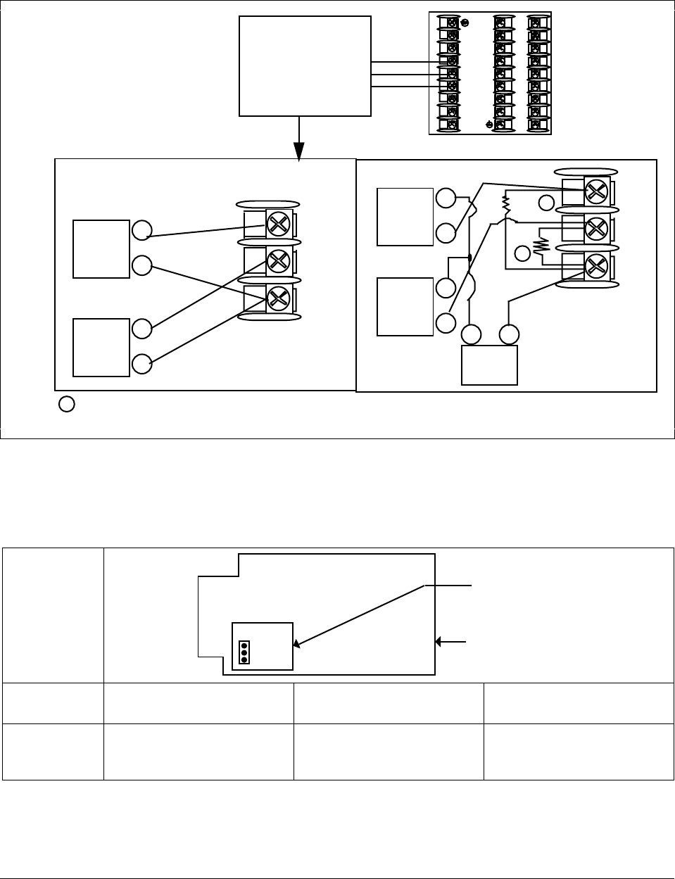
Figure 2-12 Current Output—Current /Time Duplex, Time/Current Duplex, Position
Proportional, or Three Position Step Control .................................................................26
Figure 2-13 Auxiliary Output and Three Relay Outputs..................................................................... 27
Figure 2-14 Position Proportional Output or Three Position Step—Models
DC330X-EE-XXX-X2, DC330X-AA-XXX-X2.................................................................. 28
Figure 2-15 Auxiliary Output Connections—Models DC330X-XX-2XX, DC330X-XX-5XX................29
Figure 2-16 Digital Inputs Connections—Model DC330X-XX-XX3.................................................... 29
Figure 2-17 RS422/485/Modbus Communications Option Connections ...........................................30
Figure 2-18 DMCS Communications Option Connections ................................................................31
Figure 2-19 Transmitter Power for 4-20 mA 2-wire Transmitter Using Open Collector
Alarm 2 Output—Model DC330X-XT-XXX.....................................................................32
Figure 2-20 Transmitter Power for 4-20 mA 2-wire Transmitter Using Auxiliary Output—
Model DC330X-XX-2XX or DC330X-XX-5XX................................................................33
Figure 3-1 Overview of UDC 3300 Prompt Hierarchy .....................................................................36
Figure 4-1 Example of Mass Flow Compensation using Multiplier/Divider Algorithm....................102
Figure 4-2 Example of Eight Segment Characterizer....................................................................106
Figure 5-1 Operator Interface........................................................................................................ 151
Figure 5-2 Functional Overview Block Diagram of a Single Loop (Loop #1) or Dual
Loop Controller (Loop #1 and Loop #2) ....................................................................... 173
Figure 5-3 Functional Overview Block Diagram of Internal Cascade of a 2-loop Controller.......... 174
Figure 5-4 Hi/Lo Override Selector................................................................................................175
Figure 5-5 Auto/Manual Station and Backup Control Feature.......................................................190
Figure 5-6 Carbon Potential Control.............................................................................................. 203
Figure 6-1 Ramp/Soak Profile Example ........................................................................................209
Figure 6-2 Program Record Sheet ................................................................................................210
Figure 7-1 Inputs #1, #2, and #3 Wiring Terminals .......................................................................221
Figure 7-2 Wiring Connections for Thermocouple Inputs Using an Ice Bath................................. 223
Figure 7-3 Wiring Connections for Thermocouple Inputs Using a Precision Resistor................... 224
Figure 7-4 Wiring Connections for RTD ........................................................................................225
Figure 7-5 Wiring Connections for Radiamatic, Millivolts, or Volts (except 0 to 10 Volts) .............226
Figure 7-6 Wiring Connections for 0 to 10 Volt Inputs................................................................... 227
Figure 7-7 Wiring Connections for 4 to 20 mA inputs.................................................................... 228
Figure 8-1 Wiring Connections for Calibrating Current Proportional Output .................................234
Figure 8-2 Wiring Connections for Calibrating Auxiliary Output ....................................................240
Figure 9-1 Chassis Removal ......................................................................................................... 262
Figure 9-2 Display/Keyboard Replacement................................................................................... 263
Figure 9-3 Removing the Printed Wiring Boards ...........................................................................264
Figure 9-4 Printed Wiring Board Identification............................................................................... 265
Figure 10-1 UDC 3300 Exploded View............................................................................................ 271

4/00 UDC 3300 Controller Product Manual ix
Tables
Table 1-1 Function of Keys...............................................................................................................4
Table 2-1 Specifications ...................................................................................................................8
Table 2-2 Procedure for Mounting the Controller ...........................................................................14
Table 2-3 Permissible Wiring Bundling...........................................................................................16
Table 2-4 Input 2 Jumper Selections..............................................................................................21
Table 2-5 Universal Output Wiring Functionality and Restrictions for Figure 2-12.........................26
Table 2-6 Universal Output Wiring Functionality and Restrictions for Figure 2-13.........................27
Table 2-7 Control Relay Contact Information .................................................................................34
Table 2-8 Alarm Relay Contact Information ...................................................................................34
Table 3-1 Configuration Tips ..........................................................................................................39
Table 3-2 Configuration Procedure ................................................................................................40
Table 3-3 Tuning Group Function Prompts ....................................................................................42
Table 3-4 Tuning Loop 2 Group Function ......................................................................................44
Table 3-5 SP Ramp Group Function Prompts................................................................................45
Table 3-6 Accutune Group Function Prompts ................................................................................48
Table 3-7 Algorithm Group Function Prompts................................................................................49
Table 3-8 Output Algorithm Group Function Prompts....................................................................53
Table 3-9 Input 1 Group Function Prompts ....................................................................................54
Table 3-10 Input 2 Group Function Prompts ....................................................................................56
Table 3-11 Input 3 Group Function ..................................................................................................57
Table 3-12 Control Group Function Prompts ...................................................................................58
Table 3-13 Control 2 Group Function Prompts ................................................................................60
Table 3-14 Options Group Function Prompts...................................................................................62
Table 3-15 Communications Group Function Prompts ....................................................................64
Table 3-16 Alarms Group Function Prompts....................................................................................66
Table 3-17 Display Group Function Prompts ...................................................................................69
Table 3-18 Maintenance Group Function Prompts ..........................................................................71
Table 4-1 Tuning Group Prompt Definitions...................................................................................80
Table 4-2 Loop 2 Tuning Group Prompt.........................................................................................84
Table 4-3 Setpoint Ramp/Rate Group Definitions ..........................................................................85
Table 4-4 Accutune Group Definitions............................................................................................88
Table 4-5 Algorithm Group Definitions ...........................................................................................92
Table 4-6 Output Algorithm Group Definitions .............................................................................109
Table 4-7 Input 1 Group Definitions .............................................................................................112
Table 4-8 Input 2 Group Definitions .............................................................................................116
Table 4-9 Input 3 Group Definitions .............................................................................................117
Table 4-10 Control Group Definitions.............................................................................................118
Table 4-11 Control 2 Group Definitions..........................................................................................124
Table 4-12 Options Group Definitions ............................................................................................129
Table 4-13 Communications Group Definitions..............................................................................135
Table 4-14 Alarms Group Definitions .............................................................................................139
Table 4-15 Display Group Definitions.............................................................................................143
Table 4-16 Maintenance Group Definitions....................................................................................144
Table 5-1 Power Up Diagnostic Tests..........................................................................................148
Table 5-2 Procedure for Testing the Displays and Keys ..............................................................149
Table 5-3 Procedure for Entering a Security Code ......................................................................150
Figure 5-1 Operator Interface........................................................................................................151
Table 5-4 Lower Display Key Parameter......................................................................................153

x UDC 3300 Controller Product Manual 4/00
Table 5-5 Error Messages............................................................................................................154
Table 5-6 Procedure for Starting Up the Controller......................................................................155
Table 5-7 Operating Mode Definitions..........................................................................................156
Table 5-8 Changing Operating Modes .........................................................................................157
Table 5-9 Procedure for Selecting Automatic or Manual Mode....................................................158
Table 5-10 Procedure for Selecting the Local Setpoint Source......................................................160
Table 5-11 Procedure for Changing the Local Setpoints ...............................................................161
Table 5-12 Procedure for Enabling (or Disabling) the Remote Setpoint ........................................162
Table 5-13 Setpoint Selection Indication........................................................................................162
Table 5-14 Procedure for Configuring a Setpoint Ramp ................................................................164
Table 5-15 Procedure for Running a Setpoint Ramp .....................................................................166
Table 5-16 Procedure for Selecting Two Sets of Tuning Constants ..............................................168
Table 5-17 Procedure for Setting Switchover Values.....................................................................169
Table 5-18 Procedure for Setting Tuning Constant Values............................................................169
Table 5-19 Procedure for Switching PID SETS from the Keyboard...............................................170
Table 5-20 Procedure for Displaying or Changing the Alarm Setpoints.........................................171
Table 5-21 Control Loop Selections ...............................................................................................172
Table 5-22 Two-loop Functionality and Restrictions (Model DC330E-EE-2XX or
Model DC330E-EE-5XX)..............................................................................................175
Table 5-23 Two-loop Functionality and Restrictions (Model DC330E-KE-2XX or
Model DC330E-KE-5XX)..............................................................................................176
Table 5-24 Procedure for Selecting 2-loop Algorithm ....................................................................177
Table 5-25 Procedure for Selecting Output Algorithm....................................................................177
Table 5-26 Procedure for Selecting Control Parameters ...............................................................178
Table 5-27 Procedure for Selecting Tuning Parameters................................................................179
Table 5-28 Digital Display Indication—Two Loops.........................................................................180
Table 5-29 Procedure for Displaying the 3PSTEP Motor Position .................................................182
Table 5-30 Digital Input Option Action on Contact Closure............................................................186
Table 5-31 Digital Input Combinations “DIG IN1” or “DIG IN2”......................................................188
Table 5-32 Digital Inputs 1 and 2 Combination ..............................................................................189
Table 5-33 Auto/Manual Station Mode Configuration Procedure...................................................191
Table 5-34 Accutune Rules and Regulations .................................................................................195
Table 5-35 Procedure for Starting TUNE (Demand) Tuning ..........................................................196
Table 5-36 Procedure for Using TUNE at Start-up for Duplex .......................................................197
Table 5-37 Procedure for Using SP Tuning at Start-up..................................................................198
Table 5-38 Procedure for Using SP Tuning at Start-up for Duplex ................................................199
Table 5-39 Accutune* Error Prompt Definitions .............................................................................201
Table 6-1 Setpoint Program Data Entry Procedure......................................................................211
Table 6-2 Prompt Hierarchy and Available Selections .................................................................212
Table 6-3 Run/Monitor Functions.................................................................................................214
Table 6-4 Procedures for Changing a Running Setpoint Program...............................................217
Table 7-1 Voltage and Resistance Equivalents for 0% and 100% Range Values........................220
Table 7-2 Equipment Needed ......................................................................................................222
Table 7-3 Set Up Wiring Procedure for Thermocouple Inputs Using an Ice Bath........................223
Table 7-4 Set Up Wiring Procedure for Thermocouple Inputs Using a Precision Resistor ..........224
Table 7-5 Input #1, #2, or #3 Calibration Procedure ....................................................................229
Table 7-6 Restoring Factory Calibration.......................................................................................231
Table 8-1 Set Up Wiring Procedure Current Proportional Output ................................................234
Table 8-2 Current Proportional Output Calibration Procedure .....................................................235
Table 8-3 Position Proportional and 3 Position Step Output Calibration Procedure ....................237
Table 8-4 Set Up Wiring Procedure for Auxiliary Output..............................................................240
Table 8-5 Auxiliary Output Calibration Procedure ........................................................................241
Table 9-1 Error Message Prompts ...............................................................................................245

4/00 UDC 3300 Controller Product Manual xi
Table 9-2 Procedure for Identifying the Software Version............................................................246
Table 9-3 Power-up Tests............................................................................................................247
Table 9-4 Procedure for Displaying the Status Tests Results......................................................248
Table 9-5 Status Tests .................................................................................................................249
Table 9-6 Background Tests ........................................................................................................250
Table 9-7 Controller Failure Symptoms........................................................................................252
Table 9-8 Troubleshooting Power Failure Symptoms ..................................................................253
Table 9-9 Troubleshooting Current Proportional Output Failure ..................................................254
Table 9-10 Troubleshooting Position Proportional Output Failure..................................................255
Table 9-11 Troubleshooting Time Proportional Output Failure ......................................................256
Table 9-12 Troubleshooting Time/Current or Current/Time Proportional Output Failure...............257
Table 9-13 Troubleshooting Alarm Relay Output Failure ...............................................................258
Table 9-14 Troubleshooting a Keyboard Failure ............................................................................259
Table 9-15 Troubleshooting a Communications Failure.................................................................260
Table 9-16 How to Remove the Chassis........................................................................................262
Table 9-17 Display/Keyboard Assembly Replacement Procedure.................................................263
Table 9-18 Printed Wiring Board Removal from Chassis...............................................................264
Table 9-19 Second Input Board Replacement Procedure..............................................................266
Table 9-20 Power Input Board Replacement Procedure................................................................266
Table 9-21 Digital Input Board Replacement Procedure................................................................267
Table 9-22 Aux.Out/Communications Board Replacement Procedure ..........................................268
Table 9-23 MCU/Output Board Replacement Procedure...............................................................269
Table 10-1 Parts Identification........................................................................................................272
Table 10-2 Parts Not Shown ..........................................................................................................272
Table 11-1 Manual Tuning Procedure for Simplex Control ............................................................274
Table 11-2 Manual Tuning Formulas .............................................................................................275

xii UDC 3300 Controller Product Manual 4/00

4/00 UDC 3300 Controller Product Manual 1
Section 1 – Overview
1.1 Introduction
Function The UDC 3300 is a microprocessor-based stand alone controller. It
combines the highest degree of functionality and operating simplicity
offered in a 1/4 DIN size controller.
With a typical accuracy of ± 0.20 % of span, the UDC 3300 is an ideal
controller for regulating temperature and other process variables in
numerous heating and cooling applications, in metal working, food, and
pharmaceuticals, and testing and environmental work.
Easy to read displays The dedicated vacuum fluorescent displays with multi-language prompts
make the operator interface easy to read, understand and operate.
Programmed sequences of displays assure quick and accurate entry of all
configurable parameters.
Easy to operate Simple keystrokes let you select input and range configuration, set the
operating parameters that meet your process control needs now, and
change them later to meet new ones.
The tactile keyboard provides positive operator feedback. Self diagnostics,
fault tolerant design and keyboard security provide maximum assurance
of trouble-free operation.
Mount anywhere The UDC is industrial control equipment that must be panel mounted.
The wiring terminals must be enclosed within the panel. The UDC is
environmentally hardened and, when suitably enclosed, can be mounted
virtually anywhere in plant or factory; on the wall, in a panel, or even on
the process machine. It withstands ambient temperatures up to 55 °C
(133 °F) and resists the effects of vibration and mechanical shock.
CE Conformity (Europe) This product is in conformity with the protection requirements of the
following European Council Directives: 73/23/EEC, the Low Voltage
Directive, and 89/336/EEC, the EMC Directive. Conformity of this
product with any other “CE Mark” Directive(s) shall not be assumed.
Product Classification: Class I: Permanently connected, panel-mounted
Industrial Control Equipment with protective earthing (grounding).
(EN61010-1).
Enclosure Rating: Panel-mounted equipment, IP 00. This controller must
be panel-mounted. Terminals must be enclosed within the panel. Front
panel IP 65 (IEC 529).
Installation Category (Overvoltage Category): Category II: Energy-
consuming equipment supplied from the fixed installation, local level
appliances, and Industrial Control Equipment. (EN61010-1)
Pollution Degree: Pollution Degree 2: Normally non-conductive pollution
with occasional conductivity caused by condensation. (Ref. IEC 664-1)

2 UDC 3300 Controller Product Manual 4/00
EMC Classification: Group 1, Class A, ISM Equipment (EN55011,
emissions), Industrial Equipment (EN50082-2, immunity)
Method of EMC Assessment: Technical File (TF)
Declaration of Conformity: 51309602-000
Deviation from the installation conditions specified in this manual, and
the special conditions for CE conformity in Section 2.1, may invalidate
this product’s conformity with the Low Voltage and EMC Directives.
ATTENTION: The emission limits of EN 50081-2 are designed to provide reasonable
protection against harmful interference when this equipment is operated in an
industrial environment. Operation of this equipment in a residential area may cause
harmful interference. This equipment generates, uses, and can radiate radio
frequency energy and may cause interference to radio and television reception when
the equipment is used closer than 30 meters (98 feet) to the antenna(e). In special
cases, when highly susceptible apparatus is used in close proximity, the user may
have to employ additional mitigating measures to further reduce the electromagnetic
emissions of this equipment.
4/00 UDC 3300 Controller Product Manual 3
1.2 Operator Interface
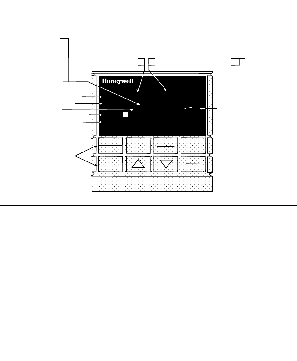
Displays and indicators Figure 1-1 shows the operator interface and defines the displays and
indicators. The function of the keys is shown in Table 1-1.
Figure 1-1 Operator Interface Displays and Indicators
ALM
RSP
OUT
%
1 2 3
1 2
1 2 F C MAN
FUNCTION
LOOP 1/2
SET UP
LOWER
DISPLAY MANUAL
AUTO
SETPOINT
SELECT
RUN
HOLD
DI 3300
SP 3300
Indicator definition when lit
ALM - Alarm conditions exist
DI - Digital input active
OUT - Control relay 1 or 2 on
Upper Display - six characters
• Normal Operation - four digits dedicated to display the process variable
• Configuration Mode - displays parameter value or selection
Lower Display - eight characters
• Normal Operation - displays operating parameters and values
• Configuration Mode - displays function groups and parameters
MAN - controller in manual mode
A - controller in automatic mode
F - °Fahrenheit being used
C - °Centigrade being used
Indicator definition when lit
Deviation Bargraph
• Center bar indicates PV is
within ±1% of setpoint.
• Next bar will light if PV is
between ±1% but less than
±2% in deviation.
• If PV is equal to or greater than
±10% deviation, the center bar
plus all ten deviation bars will
light.
MAN and A off —
communications
option active
Keys - See Table 1-1
T - Accutune in progress
t - PV tune in progress
L" - Loop 2 display
I - Cascade control
C - Computer setpoint active
O - Output override active
R - Run SP ramp/program
H - Hold SP ramp/program
RSP - Remote SP or SP2 active
24157
R
3 - LSP 3 active

4 UDC 3300 Controller Product Manual 4/00
Function of keys Table 1-1 shows each key on the operator interface and defines its
function.
Table 1-1 Function of Keys
Key Function
SET UP •Places the controller in the Configuration Set Up group
select mode. Sequentially displays Set Up groups and
allows the FUNCTION key to display individual functions in
each Set Up group.
FUNCTION
LOOP 1/2 •Used in conjunction with the SET UP key to select the
individual functions of a selected Configuration Set Up
group.
•Used to switch the display between Loop 1 and Loop 2
when the controller has a 2-Loop or Cascade configuration.
•Used during field calibration procedure.
LOWER
DISPLAY •Selects an operating parameter to be shown in the
lower display:
OUT = Output (Note 1)
OT2 = Output 2 (Cascade or 2-Loop
applications
SP = Local Setpoint (also current SP value
when using SP ramp) (Note 2)
2SP = Local Setpoint 2 (Note 2)
3SP = Local Setpoint 3 (Note 2)
RSP = Remote Setpoint
1IN = Input 1—when used with combinational
input algorithms
2IN = Input 2
3IN = Input 3
POS =3 Position Step motor position when
slidewire is connected
CSP = Computer Setpoint Override
DEV = Deviation
PIDSETX = Tuning Parameter Set X=1 or 2 (Note 3)
2PIDSETX = Loop 2 Tuning Parameter Set X=1 or 2
ET_XX.XX = Elapsed Time
TR_XX.XX = Time Remaining
RAMPXXOM = Minutes Remaining in Setpoint Ramp
*Or estimated Three Position Step motor position when no slidewire
exists.

4/00 UDC 3300 Controller Product Manual 5
Key Function
LOWER
DISPLAY 1PV =For Cascade or 2 Loops
2PV =For Cascade or 2 Loops
AUX =Auxiliary Output
OC1 =Characterized Output 1
OC2 =Characterized Output 2
SPn = Setpoint Now (for setpoint rate)
• (Sigma) =Current Totalizer Value
BIA = Output Bias/Manual Reset Value
TUNE OFF =Appears when Limit Cycle tuning is disabled
TUNE RUN =Press ▲ and LOWER DISPLAY to initiate
Limit Cycle tuning.
Display will read TUNE RUN.
ToBEGIN =Reset SP Program to start of first segment
OTI = Internal Loop 1 Output Value is being
displayed (Override has been selected and
Loop 1 is in Automatic mode.)
Note 1: Value can be changed if in manual mode
Note 2: Value can be changed via increment/decrement keys.
Note 3: The selected set can be changed via increment/decrement
keys.
MANUAL
AUTO •Alternately selects:
AUTO Lower display automatically displays setpoint
value in engineering units.
MAN Lower display automatically indicates output in %.
SETPOINT
SELECT •Hold key down to cycle through configured setpoints.
RUN
HOLD •Alternate action switch initiates or holds the Setpoint Ramp
or Setpoint Program.
•Acknowledges a latched alarm 1.
▲•Increases the selected parameter value.
▼•Decreases the selected parameter value.

6 UDC 3300 Controller Product Manual 4/00

4/00 UDC 3300 Controller Product Manual 7
Section 2 – Installation
2.1 Overview
Introduction Installation of the UDC 3300 Controller consists of mounting and wiring
the controller according to the instructions given in this section.
Read the pre-installation information, check the model number
interpretation and become familiar with your model selections, then
proceed with installation.
What’s in this section? This section contains the following information:
Topic See Page
2.1 Overview
Specifications 7
8
2.2 Model Number Interpretation 12
2.3 Mounting 13
2.4 Wiring 15
2.5 Wiring Diagrams
Composite Wiring Diagram
Line Voltage
Input #1/Input #2
Two HLAI
Time Proportional Output
Electromechanical
Solid State
10-amp Solid State
Open Collector
Current Output/Universal Output
Two Current or Two Relay
One Current (Auxiliary) and Three Relay
Position Proportional Output
Auxiliary Output
Digital Inputs
Communications
RS422/485/Modbus
DMCS
Transmitter Power for 4-20 mA 2-wire Transmitter
Using Open Collector Alarm 2 Output
Using Auxiliary Output
18
18
19
20
21
22
22
23
24
25
26
26
27
28
29
29
30
30
31
32
32
33
2.6 Control and Alarm Relay Contact Information 34

8 UDC 3300 Controller Product Manual 4/00
Pre-installation
information If the controller has not been removed from its shipping carton, inspect
the carton for damage and remove the controller. Inspect the unit for any
obvious shipping damage and report any damage due to transit to the
carrier.
Make sure that the carton with the controller includes
• a bag containing mounting hardware and
• a bag containing input resistors.
Check that the model number shown on the inside of the case agrees with
what you have ordered.
CE conformity special
conditions (Europe) Shielded twisted pair cables are required for all Analog I/O, Process
Variable, RTD, Thermocouple, dc millivolt, low level signal, 4-20 mA,
Digital I/O, and computer interface circuits. Refer to the Severe Electrical
Noise Environments document (51-52-05-01) for additional information.
Specifications We recommend that you review the specifications and adhere to the
operating limits listed in Table 2-1 when you install your controller.
Table 2-1 Specifications
Design
Input Accuracy ± 0.20 % of span typical (± 1 digit for display)
Field calibratable to ± 0.05 % of span typical
15 bit resolution typical
Sampling Rate Inputs sampled six times a second
Temperature Stability ± 0.01 % of Full Scale/°C change typical
Input Signal Failure
Protection Thermocouple Inputs: Upscale or downscale burnout
Burnout Current: 0.13 microamps
Failsafe Output Level: Configurable 0-100 %
Input Impedance 4-20 Milliampere Input: 250 ohms
0-10 Volt Input: 200K ohms
All Other: 10 megohms
Maximum Lead Wire
Resistance Thermocouples: 100 ohms/leg
100, 200, and 500 RTD: 100 ohms/leg
100 ohm Low RTD: 10 ohms/leg
Stray Rejection Common Mode
AC (50 or 60 Hz): 120 dB (with maximum source impedance of 100 ohms) or ± 1 LSB
(least significant bit) whichever is greater with line voltage applied.
DC: 120 dB (with maximum source impedance of 100 ohms) or a ±1 LSB whichever is
greater with 120 Vdc applied.
DC (to 1 KHz): 80 dB (with maximum source of impedance of 100 ohms) or ±1 LSB
whichever is greater with 50 Vac applied.
Normal Mode
AC (50 or 60 Hz): 60 dB (with 100 % span peak-to-peak maximum)

4/00 UDC 3300 Controller Product Manual 9
Design (continued)
Isolation (Functional) AC Power: Is electrically isolated from all other inputs and outputs to withstand a HIPOT
potential of 1900 Vdc for 2 seconds per Annex K of EN61010-1.
Analog Inputs and Outputs: Are isolated from each other and all other circuits at 850 Vdc
for 2 seconds.
Digital Input and Digital Output: Are isolated from all other circuits at 850 Vdc for 2
seconds.
Relay Contacts: With a working of 115/230 Vac, isolated from each other and all other
circuits at 345 Vdc for 2 seconds.
Alarm Outputs One SPDT electromechanical relay.
A second alarm is available using the second control relay. This is not available with Relay
Duplex, Position Proportional, or Three Position Step control.
Alarm Relay Contacts Rating
Resistive Load: 5 ampere at 120 Vac or 30 Vdc, 2.5 A at 240 Vac.
Controller Output
Types Current Output (Isolated)
Range can be set anywhere between 0 to 21 mA, and as direct or reverse action.
Resolution: 11 bits for 0 to 21 mA
Accuracy: 0.5 % full scale
Temperature Stability: 0.1 % F.S./°C
Load Resistance: 0 to 1000 ohms
Electromechanical Relays (One or Two)
SPDT contacts. Both Normally Open and Normally Closed contacts are brought out to the
rear terminals.
Internally socketed
Resistive Load: 5 amps @ 120 Vac or 30 Vdc, 2.5A at 240 Vac
Inductive Load: 50 VA @ 120 Vac or 240 Vac
Motor: 1/6 H.P.
Solid State Relays (One or Two)
SPST solid state contacts consisting of a triac N.O. output.
Internally socketed
Resistive Load: 1.0 amp @ 25 °C and 120 or 240 Vac
0.5 amp @ 55 °C and 120 or 240 Vac
Inductive Load: 50 VA @ 120 Vac or 240 Vac
Minimum Load: 20 milliamps
Open Collector Outputs (One or Two)
Maximum Sink Current: 20 mA
Overload Protection: 100 mA
Internally powered @ 30 Vdc
Opto-isolated from all other circuits except current output, but not from each other.
Socketed jumper assembly replaces relay.
Solid State Relays (10 amps)
One or two externally mounted SPST triac N.O. outputs for use with open collector outputs.
Resistive Load: 15 amps @ 25 °C and 120 or 240 Vac
10 amps @ 55 °C and 120 or 240 Vac
Inductive Load: 50 VA @ 120 Vac or 240 Vac
Motor Rating: 1 HP @ 25 °C
0.75 HP @ 55 °C
Controller Output
Algorithms See Section 4.7.

10 UDC 3300 Controller Product Manual 4/00
Design (continued)
Digital Inputs
(Optional) (Isolated) +15 Vdc source for external dry contacts or isolated solid state contacts. The
Digital Input option detects the state of external contacts for either of the two inputs.
On contact closure the controller will respond according to how each digital input is
configured. Opening contact causes return to previous state.
Auxiliary Linear
Output (Optional)
(Isolated)
21 mA dc maximum into a negative or positive grounded load or non-grounded load of 0 to
1000 ohms.
Output range can be set anywhere between 0 mA to 21 mA, and as direct or reverse
action. It can be configured to represent either Input, PV, Setpoint, Deviation, or Control
output. The range of the auxiliary output, as a function of the selected variable, can be
scaled. This output can be used as a second current output for current duplex outputs.
Resolution: 12 bits over 0 mA to 21 mA
Accuracy: 0.05 % of full scale
Temperature Stability: 0.0075 % F.S./°C
Load Resistance: 0 to 1000
Communications
Interface (Optional)
DMCS Baud Rate: 19200 baud
Length of Link: 4000 ft. maximum
Link Characteristics: Two-wire, multi-drop proprietary protocol, 31 drops maximum
RS422/485 ASCII Baud Rate: 2400, 4800, 9600, or 19200 baud selectable
Parity: Odd or Even
Length of Link: 4000 ft. maximum
Link Characteristics: Two-wire or four-wire, multi-drop RS422 ASCII, 15 drops maximum or
up to 31 drops for shorter link length.
RS422/485 Modbus
RTU Baud Rate: 2400, 4800, 9600, 19200 baud selectable
Data Format: Floating point or integer
Length of Link: 4000 ft. maximum
Link Characteristics: Two-wire, multi-drop Modbus RTU protocol, 15 drops maximum or up
to 31 drops for shorter link length.
Power Consumption 18 VA maximum (90 Vac to 264 Vac); 12 VA maximum (24 Vac/dc)
Power Inrush Current 10A maximum for 4 ms (under operating conditions)
CAUTION When applying power to more than one UDC 3300, make sure that sufficient
power is supplied. Otherwise, the controllers may not start up normally due to voltage drop
from the inrush current.
Weight 1.3 kg (3 lb.)

4/00 UDC 3300 Controller Product Manual 11
Environmental and Operating Conditions
Parameter Reference Rated Operative
Limits Transportation and
Storage
Ambient Temperature 25 ± 3 °C
77 ± 5 °F 15 to 55 °C
58 to 131 °F 0 to 55 °C
32 to 131 °F –40 to 66 °C
–40 to 151 °F
Relative Humidity 10 to 55* 10 to 90* 5 to 90* 5 to 95*
Vibration
Frequency (Hz)
Acceleration (g) 0
00 to 70
0.4 0 to 200
0.6 0 to 200
0.5
Mechanical Shock
Acceleration (g)
Duration (ms)) 0
01
30 5
30 20
30
Voltage (Vdc) +24 ± 1 20 to 27 20 to 27 - -
Voltage (Vac)
90 to 240 Vac
24 Vac
120 ± 1
240 ± 2
24 ± 1
90 to 240
20 to 27
90 to 264
20 to 27
- -
- -
- -
Frequency (Hz)
(For Vac) 50 ± 0.2
60 ± 0.2 49 to 51
59 to 61 48 to 52
58 to 62 - -
- -
* The maximum rating only applies up to 40 °C (104 °F). For higher temperatures, the RH specification is derated to
maintain constant moisture content.
12 UDC 3300 Controller Product Manual 4/00
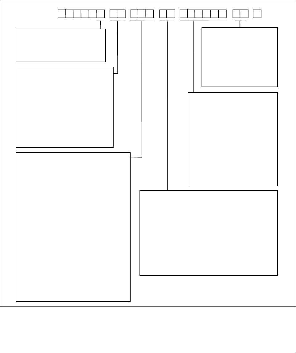
2.2 Model Number Interpretation
Model number The model number interpretationis shown in Figure 2-1. Write the model
number into the spaces provided and compare it to the model number
interpretation. This information will also be useful when you wire your
controller.
Figure 2-1 Model Number Interpretation
24151
0DC3 3 0
Table VITable VTable IVTable IIITable IITable IKey Number
Output #1
C0 =
K – =
E – =
A – =
S – =
T – =
Output #2 or Alarm #2
– 0 =
– E =
– A =
– S =
– T =
B =
E =
L =
D =
Basic Controller Model
Expanded Controller Model
Limit Controller Model
Basic Model with UDC 3000 DMCS
Functionality
Current without Alarms or Output 2
Current with Alarm 1
Relay, E-M with Alarm 1
Relay, SS 1 amp with Alarm 1
Relay, SS 10 amp with Alarm 1
Open Collector Output
None
Relay, E-M
Relay, SS 1 amp
Relay, SS 10 amp
Open Collector Output
External Interface
0 –– =
1 ––
=
2 –– =
4 –– =
5 –– =
Software Options
– 0 – =
– A – =
– B – =
– C – =
– D – =
– E – =
Digital Inputs
–– 0
=
–– 3
=
None
RS422/485 ASCII / Modbus
Auxiliary Output (Loop 2 Current Output)
DMCS Communications
Auxiliary Output + RS422/485 / Modbus
Standard Functions (includes Accutune II)
Setpoint Programming (SPP)—DMCS Model
SPP
Math Option + SPP
2 Loops/Internal Cascade + SPP
Math Option + 2 Loops/Internal Cascade +
SPP
None
Two Digital Inputs
PV Input
1 – =
2 – =
3 – =
1 5 =
1 6 =
Optional Input(s)
– 0 =
– 1 =
– 2 =
– 3 =
– 4 =
T/C, RTD, Radiamatic, mV, 0-5V, 1-5V
T/C, RTD, Radiamatic, mV, 0-5V, 1-5V, 0-20 mA, 4-20 mA
T/C, RTD, Radiamatic, mV, 0-5V, 1-5V, 0-20 mA, 4-20 mA,
0-10V
Relative Humidity (includes optional input)
Carbon, Oxygen, or Dewpoint (includes optional input)
None
T/C, RTD, Radiamatic, mV, 0-5V, 1-5V, 0-20 mA, 4-20 mA
Slidewire Input
T/C, RTD, Radiamatic, mV, 0-5V, 1-5V, 0-20 mA, 4-20 mA,
0-10V
Two High Level AIs instead of 2nd Universal AI
Options
0 –––––
=
1 –––––
=
– 0 ––––
=
– A ––––
=
–F ––––
=
––0 –––
=
–– B –––
=
–– T –––
=
––– 0 ––
=
––– P ––
=
––– T ––
=
––– U ––
=
–––– 0 –
=
–––– D –
=
––––– 0
=
90 to 264 Vac Power
24 Vac/dc Power
None
CSA, FM, and UL
FM and UL
Gray Elastomer Bezel
Blue Elastomer Bezel
Tan Elastomer Bezel
None
Rear Terminal Cover
Customer ID Tag
Rear Terminal Cover & Tag
None
DIN Cutout Adapter
None
Manuals
0 – =
F – =
G – =
T – =
S – =
Certificate
– 0 =
– C =
English
French
German
Italian
Spanish
None
Certificate of Conformance
(F3391)
– F – = Math Option + SPP + HealthWatch
– G –
= 2 Loops/Internal Cascade + SPP +
HealthWatch
– H – = Math Option + 2 Loops/Internal Cascade +
SPP + HealthWatch
– 1 – = Standard Functions (includes Accutune II
and HealthWatch)
4/00 UDC 3300 Controller Product Manual 13
2.3 Mounting
Physical considerations The controller can be mounted on either a vertical or tilted panel using the
mounting kit supplied. Adequate access space must be available at the
back of the panel for installation and servicing activities.
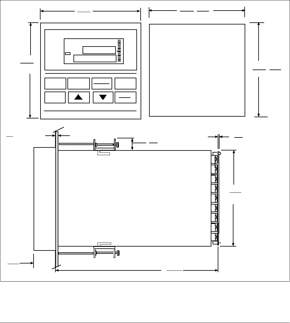
The overall dimensions and panel cutout requirements for mounting the
controller are shown in Figure 2-2.
Overall dimensions Figure 2-2 shows the overall dimensions for mounting the controller.
Figure 2-2 Dimensions
Panel Cutout
L
ALM
RSP
OUT
%
1 2
1 2 F C MAN
PV 1 2 3 4
96
3.780
L
AL
M%
1
2
1 2
1
2
F
C M
A
N
DI
ALM
RSP
OUT
%
1 2
1 2 F C MAN
DI
FUNCTION
L1/L2
LOWER
DISPLAY
MANUAL
AUTO SETPOINT
SELECT
SET UP
1 2 3
24
.945 Max Panel
Thickness 10
.394 Max (2)
5.82
147.3
21.6
.850
.093
2.4 with optional
rear cover
90.7
3.57
24152
RUN
HOLD
+0.008
92
3.622 +0.03
-0.0
-0.0
+0.008
92
3.622 +0.03
-0.0
-0.0
96
3.780
14 UDC 3300 Controller Product Manual 4/00
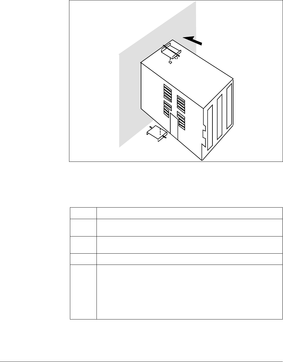
Mounting method Before mounting the controller, refer to the nameplate on the inside of the
case and make a note of the model number. It will help later when
selecting the proper wiring configuration.
Figure 2-3 shows you the mounting method for the UDC 3300 controller.
Figure 2-3 Mounting Method
Panel
22605
Mounting procedure Refer to Figure 2-3 and follow the procedure in Table 2-2 to mount the
controller.
Table 2-2 Procedure for Mounting the Controller
Step Action
1Mark and cut out the controller hole in the panel according to the dimension
information in Figure 2-2.
2Remove the screw cover and loosen the screw on the front of the controller.
Pull the chassis out of the case.
3Orient the case properly and slide it through the panel hole from the front.
4Remove the mounting kit from the shipping container, and install the kit as
follows:
•Install the screws into the threaded holes of the clips.
•Insert the prongs of the clips into the two holes in the top and
bottom of the case.
•Tighten both screws to secure the case against the panel.
•Carefully slide the chassis assembly into the case, press to close and
tighten the screw. Replace the screw cover.

4/00 UDC 3300 Controller Product Manual 15
2.4 Wiring
Electrical
considerations The controller is considered “rack and panel mounted equipment” per
EN 61010-1, Safety Requirements for Electrical Equipment for
Measurement, Control, and Laboratory Use, Part 1: General
Requirements. Conformity with 72/23/EEC, the Low Voltage Directive
requires the user to provide adequate protection against a shock hazard.
The user shall install this controller in an enclosure that limits
OPERATOR access to the rear terminals.
Controller grounding PROTECTIVE BONDING (grounding) of this controller and the
enclosure in which it is installed shall be in accordance with National and
local electrical codes. To minimize electrical noise and transients that may
adversely affect the system, supplementary bonding of the controller
enclosure to a local ground, using a No. 12 (4 mm2) copper conductor, is
recommended.
Control/alarm circuit
wiring The insulation of wires connected to the Control/Alarm terminals shall be
rated for the highest voltage involved. Extra Low Voltage (ELV) wiring
(input, current output, and low voltage Control/Alarm circuits) shall be
separated from HAZARDOUS LIVE (>30 Vac, 42.4 Vpeak, or 60 Vdc)
wiring per Table 2-3.
Electrical Noise
Precautions Electrical noise is composed of unabated electrical signals which produce
undesirable effects in measurements and control circuits.
Digital equipment is especially sensitive to the effects of electrical noise.
Your controller has built-in circuits to reduce the effect of electrical noise
from various sources. If there is a need to further reduce these effects:
•Separate External Wiring - separate connecting wires into bundles (see
Table 2-3) and route the individual bundles through separate conduits
or metal trays.
•Use Suppression Devices - for additional noise protection, you may
want to add suppression devices at the external source. Appropriate
suppression devices are commercially available.
ATTENTION For additional noise information, refer to document
number 51-52-05-01, How to Apply Digital Instrumentation in Severe
Electrical Noise Environments.

16 UDC 3300 Controller Product Manual 4/00
Permissible wire
bundling Table 2-3 shows which wire functions should be bundled together.
NOTE For installation where high EMI/RFI noise cannot be avoided, we
recommend you use shielded twisted pair wires for the signals in bundle 2.
Table 2-3 Permissible Wiring Bundling
Bundle No. Wire Functions
1 • Line power wiring
•Earth ground wiring
•Control relay output wiring
•Line voltage alarm wiring
2 Analog signal wire, such as:
•Input signal wire (thermocouple, 4 to 20 mA, etc.)
•4-20 mA output signal wiring
•Slidewire feedback circuit wiring
•Digital input signals
•Communications
3 • Low voltage alarm relay output wiring
•Low voltage wiring to solid state type control circuits
Identify your wiring
requirements To determine the appropriate diagrams for wiring your controller, refer to
the model number interpretation in this section. The model number of the
controller can be found on the inside of the case.

4/00 UDC 3300 Controller Product Manual 17
Wiring the controller Using the information contained in the model number, select the
appropriate wiring diagrams from the figures listed below and wire the
controller accordingly.
Wiring Requirements Figure
Composite Wiring Diagram 2-4
Line Power 90–264 Vac or 24Vac/dc 2-5
Input #1 and Input #2 Wiring 2-6
Two HLAI Wiring 2-7
Time Proportional Output
• Electromechanical Relay Output
• Solid State Relay Output
• 10-amp Solid State Relay Output
• Open Collector Output
2-8
2-9
2-10
2-11
Current Output/Universal Output
• Two Current and Two Relay Outputs
• One Current (Auxiliary) and Three Relay Outputs 2-12
2-13
Position Proportional Output 2-14
Auxiliary Output Wiring 2-15
Digital Inputs Wiring 2-16
Communications Wiring
•RS422/485/Modbus
•DMCS 2-17
2-18
Transmitter Power for 4-20 mA 2-wire Transmitters
• Open Collector Alarm 2 Output
• Auxiliary Output 2-19
2-20
18 UDC 3300 Controller Product Manual 4/00
2.5 Wiring Diagrams
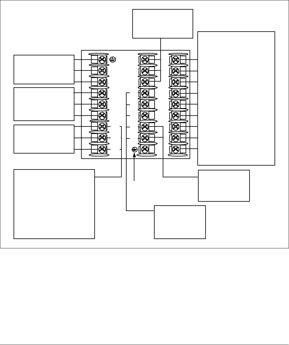
Composite wiring
diagram Figure 2-4 is a composite wiring diagram of the UDC 3300 controller. It
identifies the terminal designations and their functions. Refer to the
individual diagrams listed to wire the controller according to your
requirements.
Figure 2-4 Composite Wiring Diagram
1
2
3
4
5
6
7
8
9
L1
L2/N
22
23
24
Communications
Terminals
See Figures
2-17, 2-18
Auxiliary Output
Terminals
See Figure 2-15
Outputs and Alarms
Terminals
• Time Proportional Output
See Figures 2-8, 2-9, 2-10,
2-11
• Current Output/Universal
Output
See Figures 2-12, 2-13
• Position Proportional
Output
See Figure 2-14
For Control and Alarm Relay
Contact information, See
Tables 2-7 and 2-8.
Digital Inputs
Terminals
See Figure 2-16
AC Line Voltage
Terminals
See Figure 2-5
Input #2 Terminals
See Figure 2-6
Two HLAI Terminals
See Figure 2-7
Input #1
Terminals
See Figure 2-6
10
11
12
13
14
15
16
17
24158
Transmitter Power for
4-20 mA 2-wire
Transmitters
• Using Alarm 2 Output
See Figure 2-19
• Using Auxiliary Output
See Figure 2-20
I/O shield ground
(Do not use for
Communications shield)
25
26
27
4/00 UDC 3300 Controller Product Manual 19
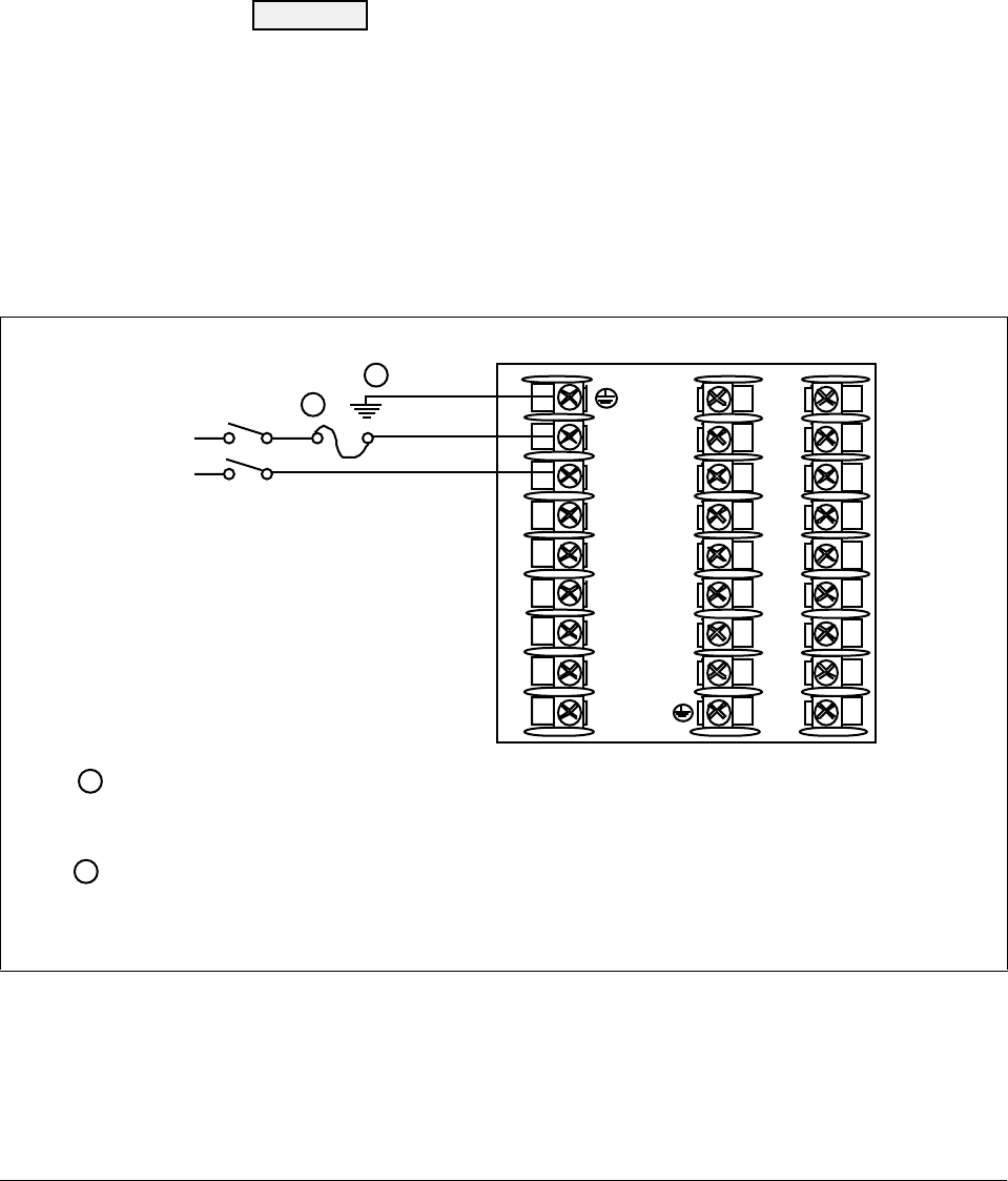
Line voltage wiring This equipment is suitable for connection to 90-264 Vac or 24 Vac/dc,
50/60 Hz, power supply mains. It is the user’s responsibility to provide a
switch and non-time delay (North America), quick-acting, high breaking
capacity, Type F, (Europe) 1/2 A, 250 V fuse(s) or circuit-breaker for 90-
264 V; or 1 A, 125 V fuse or circuit breaker for 24 Vac/dc operation, as
part of the installation. The switch or circuit-breaker should be located
close to the controller, within easy reach of the operator. The switch or
circuit-breaker should be marked as the disconnecting device for the
controller (4 mm2).
CAUTION Applying 90-264 Vac to a controller rated for 24 Vac/dc
will severely damage the controller and is a fire and smoke hazard.
When applying power to multiple instruments, make sure that sufficient
current is supplied. Otherwise, the instruments may not start up normally
due to the voltage drop caused by the in-rush current.
Figure 2-5 shows the wiring connections for line voltage.
Figure 2-5 Line Voltage Wiring
1
2
3
4
5
6
7
8
9
10
11
12
13
14
15
16
17
L1
L2/N
22
23
24
25
26
27
Ground
Hot
Neutral
AC/DC
Line
Voltage
PROTECTIVE BONDING (grounding) of this controller and the enclosure in which it is installed, shall be
in accordance with National and local electrical codes. To minimize electrical noise and transients that
may adversly affect the system, supplementary bonding of the controller enclosure to a local ground,
using a No. 12 (4 mm
1
2
1
2
22607
2) copper conductor, is recommended.
Provide a switch and non-time delay (North America), quick-acting, high breaking capacity, Type F, (Europe)
1/2 A, 250 V fuse(s) or circuit-breaker for 90-264 V; or 1 A, 125 V fuse or circuit breaker for 24 Vac/dc
operation, as part of the installation.
20 UDC 3300 Controller Product Manual 4/00
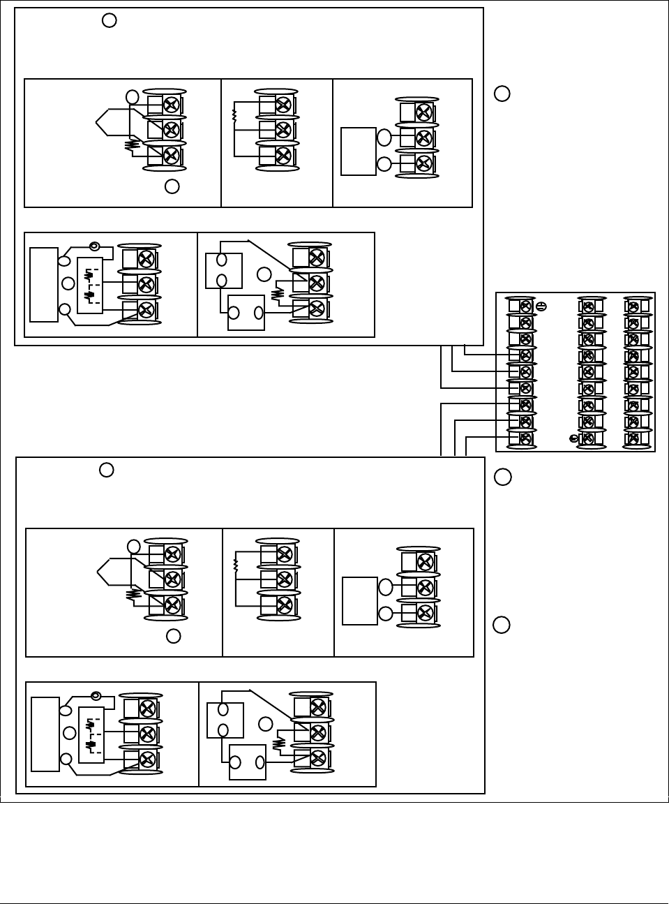
Input #1/Input #2
connections Figure 2-6 shows the wiring connections for Input #1 and Input #2.
Figure 2-6 Input #1/Input #2 Connections
25
26
27
Use Thermocouple
extension wire only
Thermocouple RTD Carbon, mV or Volts
except 0-10 Volts
mV or Volt
source
0-10 Volts 4-20 milliamps
–
+
+
R
–
1
2
3
–
0–10
Volt
source
+100K
100K Power
Supply
–+
Xmitter
+
–
250Ω
1
Remove screw and
install C/J on the "R" terminal,
connect tang to "–" terminal. 2
25
26
27
+
R
–
25
26
27
+
R
–
25
26
27
+
R
–
1
25
26
27
+
R
–
1
INPUT #1 3
R
+
–
The 250Ω load resistor for
4-20 mA or the voltage divider
for 0-10 volts or the 500 ohm
C/J compensation resistor is
supplied with the controller
when the input is specified.
These items must be installed
when you wire the controller
before start-up.
1
2
When installing the cold
junction (Part number
30757088-001) for a T/C
input, remove the screws
from terminals 25 and 27
(Input 1) or 22 and 24 (Input
2), and install the assembly
into place.
24159
3
For Relative Humidity
option, use Input 1 as the
wet bulb input and Input 2
and the dry bulb input.
For Carbon Potential
option, use Input 1 as the
Carbon Probe input.
1
2
3
4
5
6
7
8
9
10
11
12
13
14
15
16
17
L1
L2/N
22
23
24
25
26
27
22
23
24
Use Thermocouple
extension wire only
Thermocouple RTD mV or Volts
except 0-10 Volts
Carbon, mV
or Volt
source
0-10 Volts 4-20 milliamps
–
+
+
R
–
1
2
3
–
0–10
Volt
source
+100K
100K Power
Supply
–+
Xmitter
+
–
250Ω
1
Remove screw and
install C/J on the "R" terminal,
connect tang to "–" terminal. 2
22
23
24
+
R
–
22
23
24
+
R
–
22
23
24
+
R
–
1
22
23
24
+
R
–
1
INPUT #2 3
Input #2 is not
available with
Position
Proportional
Output.
R+
–
Refer to Table 2-4 for Input 2 Jumper selections.
mV or Volt
source
Carbon,
mV or Volt
source
For Relative Humidity
option, use Input 1 as the
wet bulb input and Input 2
as the dry bulb input.
For Carbon Potential
option, use Input 1 as the
Carbon Probe input.
4/00 UDC 3300 Controller Product Manual 21
Two HLAI replace
second LLAI
connections
Figure 2-7 shows the wiring connections for replacing the second LLAI
with two HLAI.
Figure 2-7 Two HLAI Replace 2nd LLAI Connections
1
2
3
4
5
6
7
8
9
10
11
12
13
14
15
16
17
L1
L2/N
22
23
24
25
26
27
+
+
–
1-5V Connections 4-20 mA Connections
250Ω
22
23
24
+
+
–
The 250Ω load resistors are supplied by Honeywell with the controller when the input is
specified. These items must be installed when you wire the controller before start-up.
1
1
24161
22
23
24
+
+
–
High Level
Analog Input
Connections
See Below
Input 3 Source
Input 2 Source
–
+
–
+
250Ω
Transmitter 3
Transmitter 2
–
+
–
+
Power
Supply
1
–+
ATTENTION:
Remove Input 2 jumper when
replacing second LLAI with two
HLAI. Refer to Table 2-3.
ATTENTION:
Remove Input 2 jumper when
replacing second LLAI with two
HLAI. Refer to Table 2-4.
Input 2 jumper Table 2-4 shows the location of the second input jumper and the input
types available for each jumper position.
Table 2-4 Input 2 Jumper Selections
Jumper
Location
W2
W1
Power/Input PWA
2nd Input
24162
Jumper
Position W1 W2 None (remove jumper)
Input Types
Available Slidewire Thermocouple, RTD, mV,
Radiamatic, Carbon, Oxygen,
4-20 mA, 0-20 mA, 1-5 V, 0-5 V
Two HLAI replace LLAI
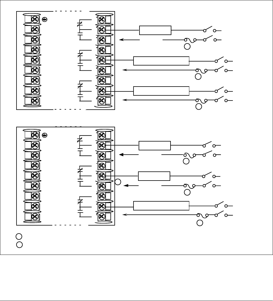
22 UDC 3300 Controller Product Manual 4/00
Time proportional
output There are three types of Time Proportional outputs available on the
UDC 3300.
• Electromechanical Relay Output (Model DC330X-EE-XXX)–Figure 2-8
• Solid State Relay Output (Model DC330X-AA(SS)-XXX)–Figure 2-9
• Open Collector Output (Model DC330X-TT-XXX)–Figure 2-11
The Alarm wiring connections are the same for all three outputs.
For Control and Alarm Relay Contact information, see Tables 2-7 and 2-8.
Figure 2-8 shows the Output and Alarm wiring connections for models
with Electromechanical Relay Output.
Figure 2-8 Electromechanical Relay Output—Model DC330X-EE-XXX
Alarm
Relay#1
To terminal
7 or 9
Alarm
Relay#2
To terminal
4 or 6
Output
Relay#1
L1
L2/N
22
23
24
25
26
27
N.C.
N.O.
N.O.
N.C.
N.O.
Output
Relay#1
Output
Relay#2
Alarm
Relay#1
L1
L2/N
22
23
24
25
26
27
N.O.
To terminal
7 or 9
Relay Load Load
Supply
Power
To terminal
1 or 3
Relay Load Load
Supply
Power
To terminal
1 or 3
Relay Load Load
Supply
Power
To terminal
4 or 6
Time Proportional Simplex
Time Proportional Duplex
1
2
2
1
2
Alarm #2 is not available with Time Proportional Duplex or Three Position Step Control or Position Proportional Control.
Electromechanical relays are rated at 5 Amps @120 Vac or 30 Vdc and 2.5 Amps at 240 Vac.
Customer should size fuses accordingly. Use Fast Blo fuses only.
1
2
3
4
5
6
7
8
9
N.C.
N.C.
N.O.
N.O.
N.C.
N.C.
Alarm Relay #2 Load Load
Supply
Power
Alarm Relay #1 Load Load
Supply
Power
Load
Supply
Power
Alarm Relay #1 Load
24163
2
1
2
3
4
5
6
7
8
9
2
2
2
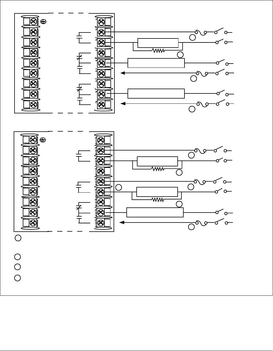
4/00 UDC 3300 Controller Product Manual 23
Time proportional
output, continued Figure 2-9 shows the Output and Alarm wiring connections for models
with Solid State Relay Output (Model DC330X-AA-XX).
For Control and Alarm Relay Contact information, see Tables 2-7 and 2-8.
Figure 2-9 Solid State Relay Output—Model DC330X-AA-XX
Alarm
Relay#2
Alarm
Relay#1
L1
L2/N
22
23
24
25
26
27
Output
Relay#1
To terminal
7 or 9
To terminal
4 or 6
AC Load
Supply
Power
Relay Load
Dummy Resistor
N.O.
1
2
3
4
5
6
7
8
9
Time Proportional Duplex
Time Proportional Simplex
Alarm
Relay#1
L1
L2/N
22
23
24
25
26
27
Output
Relay#1
To terminal
7 or 9
Output
Relay#2
AC Load
Supply
Power
Relay Load
Dummy Resistor
N.O.
N.O.
AC Load
Supply
Power
Relay Load
Dummy Resistor
If the load current is less than the minimum rated value of 20 mA, there may be a residual voltage across both ends of
the load even if the relay is turned off. Use a dummy resistor as shown to counteract this. The total current through the
resistor and the load current must exceed 20 mA.
2
3
Alarm #2 not available with Time Proportional Duplex or Three Position Step Control or Position Proportional control.
1
Solid State relays are rated at 0.5 amps. Customer should size fuses accordingly. Use Fast Blo fuses only.
1
1
3
3
2
3
1
1
2
3
4
5
6
7
8
9
N.C.
N.C.
N.O.
N.O.
N.C.
N.O.
AC Load
Supply
Power
Alarm Relay #2 Load
AC Load
Supply
Power
Alarm Relay #1 Load
AC Load
Supply
Power
Alarm Relay #1 Load
24164
Electromechanical relays are rated at 5 Amps @120 Vac or 30 Vdc and 2.5 Amps at 240 Vac.
Customer should size fuses accordingly. Use Fast Blo fuses only.
WARNING: Only connect Vac to solid state relays.
4
4
4
4
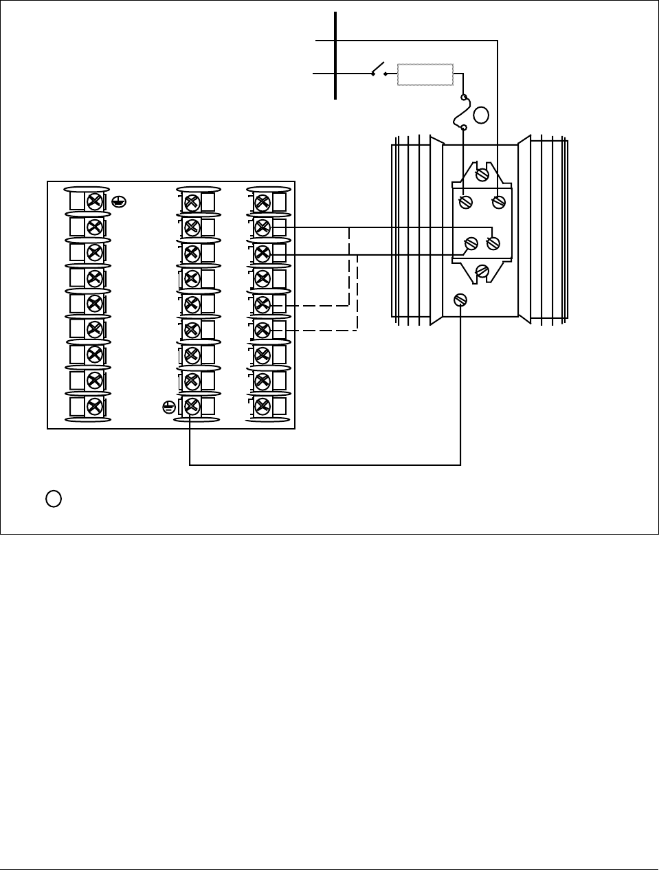
24 UDC 3300 Controller Product Manual 4/00
Time proportional
output, continued Figure 2-10 shows the wiring connections for the external 10-amp Solid
State Relay Output (Model DC330X-SS-XX).
Figure 2-10 10-amp Solid State Relay Output—Model DC330X-SS-XX
1
2
3
4
5
6
7
8
9
10
11
12
13
14
15
16
17
L1
L2
22
23
24
25
26
27
AC
–+
Green
White
Black
Output 1
Output 2
L2/N
L1 HOT LOAD
Solid
State
Relay
+
+
–
–
24165
1
1
External solid state relays are rated at 15 amps @25°C derated to 10 amps at 55°C.
Customer should size fuses accordingly. Use Fast Blo fuses only.
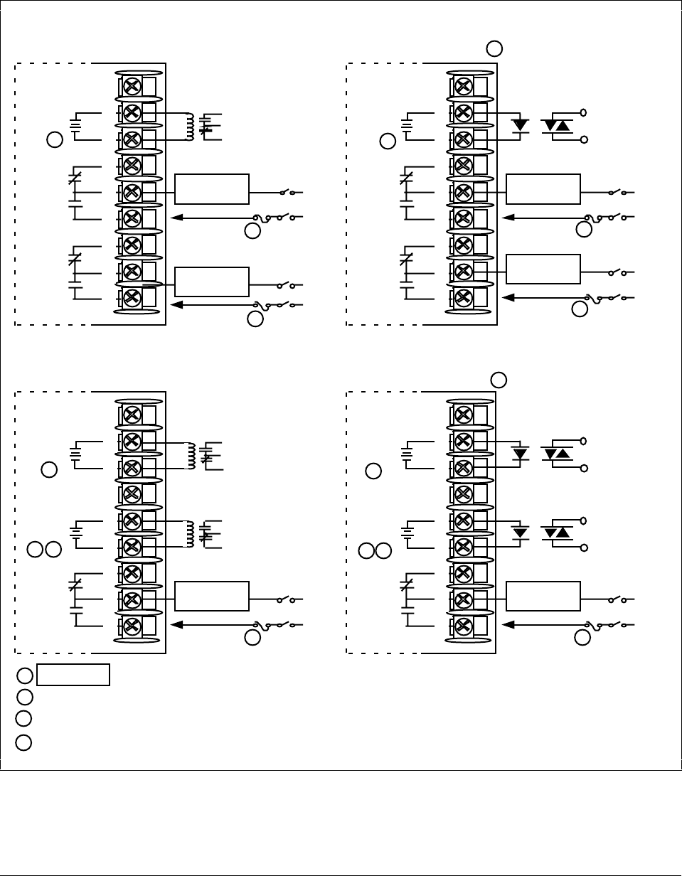
4/00 UDC 3300 Controller Product Manual 25
Time proportional
output, continued Figure 2-11 shows the Output and Alarm wiring connections for models
with Open Collector Output (DC330X-TT-XXX)
For Control and Alarm Relay Contact information, see Tables 2-7 and 2-8.
Figure 2-11 Open Collector Output—Model DC330X-TT-XXX
Customer Supplied
Solid State Relay
Customer Supplied
Electromechanical Relay
To terminal
4 or 6
–
++
–
+
–
+
–
Customer Supplied
Electromechanical Relay
–
+
+
–
Alarm
Relay#1
To terminal
7 or 9
Alarm
Relay#2
Alarm
Relay#1
To terminal
7 or 9
To terminal
4 or 6
–
+
+
–
Customer Supplied
Solid State Relay
–
+
Alarm
Relay#1
To terminal
7 or 9
Output #2
Alarm
Relay#1
To terminal
7 or 9
+
–
+
–
+
–
Alarm
Relay#2
Output #1
Output #1
Output #1
Output #2
Output #1
Time Proportional Simplex
Time Proportional Duplex
CAUTION Open collector outputs are internally powered.
Connecting an external supply will damage the controller.
Alarm #2 not available with Time Proportional Duplex or Three Position Step Control or Position Proportional control.
11
1
1
1
1
22
1
2
1
2
3
4
5
6
7
8
9
N.C
.
N.C
.
N.O.
N.O.
1
2
3
4
5
6
7
8
9
N.C
.
N.C
.
N.O.
N.O.
1
2
3
4
5
6
7
8
9
N.C
.N.O.
1
2
3
4
5
6
7
8
9
N.C
.N.O.
Alarm Relay
#2 Load Load
Supply
Power
Alarm Relay
#1 Load Load
Supply
Power
Alarm Relay
#2 Load Load
Supply
Power
Alarm Relay
#1 Load Load
Supply
Power
Alarm Relay
#1 Load Load
Supply
Power
Alarm Relay
#1 Load Load
Supply
Power
24166
3
3
3Can also use10 amp solid state relay, Part Number 30756018-003
Electromechanical relays are rated at 5 Amps @120 Vac or 30 Vdc and 2.5 Amps at 240 Vac.
Customer should size fuses accordingly. Use Fast Blo fuses only.
4
4
4
4
4
4
4
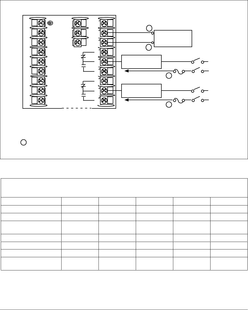
26 UDC 3300 Controller Product Manual 4/00
Current output/
universal output
connections
Figure 2-12 shows the Output and Alarm wiring connections for models
with Current Output (Model DC330X-KE-XXX and Model
DC330X-C0-XXX). See Table 2-5 for wiring restrictions.
For Control and Alarm Relay Contact information, see Tables 2-7 and 2-8.
Figure 2-12 Current Output—Current /Time Duplex, Time/Current Duplex, Position Proportional,
or Three Position Step Control
+
ATTENTION:
All current outputs are isolated from each other, case ground, and all inputs.
L1
L2/N
22
23
24
25
26
27
10
11
12
Controller Load
0–1000 Ohms
–
Current Output
4–20 mA
N.C.
N.O.
N.O.
N.C.
For Duplex Current Output use Auxiliary Output for Output 2 (cool) (see Figure 2-14).
To terminal
7 or 9
Output#1
or
Alarm#2
Relay To terminal
4 or 6
Load
Supply
Power
Output or Alarm
Relay 2 Load
Load
Supply
Power
Output or Alarm
Relay 3 Load
24167
Output#2
or
Alarm#1
Relay
See Table 2-7 for relay
terminal connections for
Output Algorithm selected.
1
2
3
4
5
6
7
8
9
Electromechanical relays are rated at 5 Amps @120 Vac or 2.5 Amps at 240 Vac.
Customer should size fuses accordingly. Use Fast Blo fuses only.
Relays are NOT available on DC330X-C0-XXX.
1
1
1
Table 2-5 Universal Output Wiring Functionality and Restrictions for Figure 2-12
Controller with Two Current Outputs and Two Relay Outputs
SINGLE LOOP OR CASCADE CONTROL OUTPUT
Output Type Current Auxiliary Relay #1 Relay #2 Relay #3
Time Simplex Not used Not used N/A Output 1 Alarm 1
Current Output 1 Not used N/A Alarm 2 Alarm 1
Position (not available on
Cascade Control) Not used Not used N/A Output 1 Output 2
Time Duplex or TPSC Not used Not used N/A Output 1 Output 2
Current Duplex 100% Output 1 Not used N/A Alarm 2 Alarm 1
Current Duplex 50% Output 1 Output 2 N/A Alarm 2 Alarm 1
Current/Time or
Time/Current Output 1 or 2 Not used N/A Output 1 or 2 Alarm 1
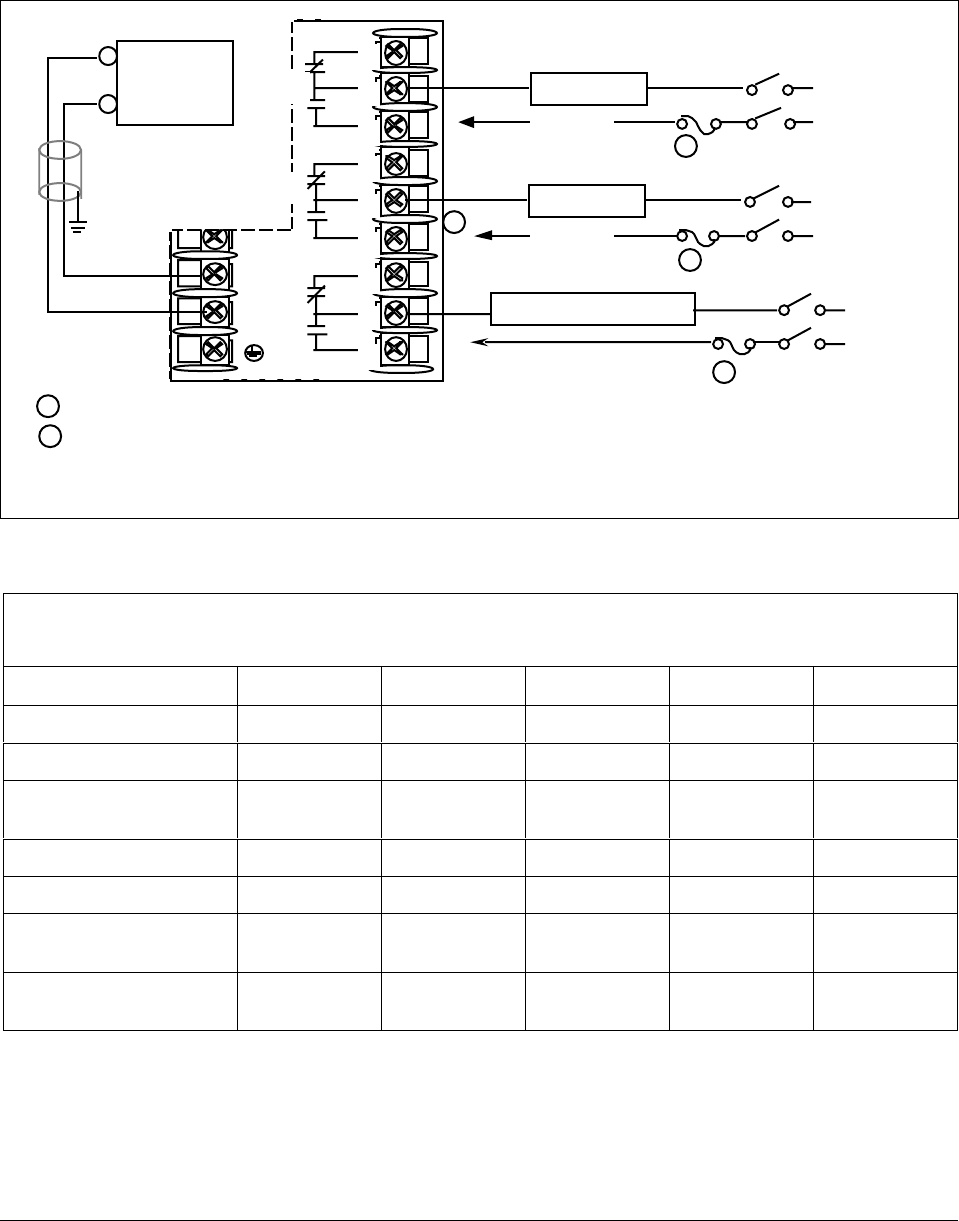
4/00 UDC 3300 Controller Product Manual 27
Current output/
universal output
connections, continued
Figure 2-13 shows the Output and Alarm wiring connections for models
with a Current Output (Auxiliary Output) and three Relay Outputs (Model
DC330X-EE-2XX). See Table 2-6 for wiring restrictions.
For Control and Alarm Relay Contact information, see Tables 2-7 and 2-8.
Figure 2-13 Auxiliary Output and Three Relay Outputs
Alarm
Relay#1
16 +
17 –
N.O.
To terminal
7 or 9
Relay Load Load
Supply
Power
To terminal
1 or 3
Relay Load Load
Supply
Power
To terminal
4 or 6
1
2
1
2
Alarm #2 is not available with Time Proportional Duplex or Three Position Step Control or Position Proportional Control.
Electromechanical relays are rated at 5 Amps @120 Vac or 2.5 Amps at 240 Vac.
Customer should size fuses accordingly. Use Fast Blo fuses only.
1
2
3
4
5
6
7
8
9
N.C.
N.O.
N.O.
N.C.
N.C.
Load
Supply
Power
Alarm Relay #1 Load
24160
2
2
Output
Relay#2
Output
Relay#1
Auxiliary
Load
0-1000
+
–
Connect
shield to
ground at
one end
only
All current outputs are isolated from each other, case ground, and all inputs.
Table 2-6 Universal Output Wiring Functionality and Restrictions for Figure 2-13
Controller with One Current Output (Auxiliary Output) and Three Relay Outputs
SINGLE LOOP OR CASCADE CONTROL OUTPUT
Output Type Current Auxiliary Relay #1 Relay #2 Relay #3
Time Simplex N/A Not used Output 1 Alarm 2 Alarm 1
Current N/A Output 1 Not used Alarm 2 Alarm 1
Position (not available on
Cascade Control) N/A Not used Output 1 Output 2 Alarm 1
Time Duplex or TPSC N/A Not used Output 1 Output 2 Alarm 1
Current Duplex 100% N/A Output N/A Alarm 2 Alarm 1
Current Duplex 50%
(N/A) N/A N/A N/A N/A N/A
Current/Time or
Time/Current N/A Output 1 or 2 Output 1 or 2 Alarm 2 Alarm 1
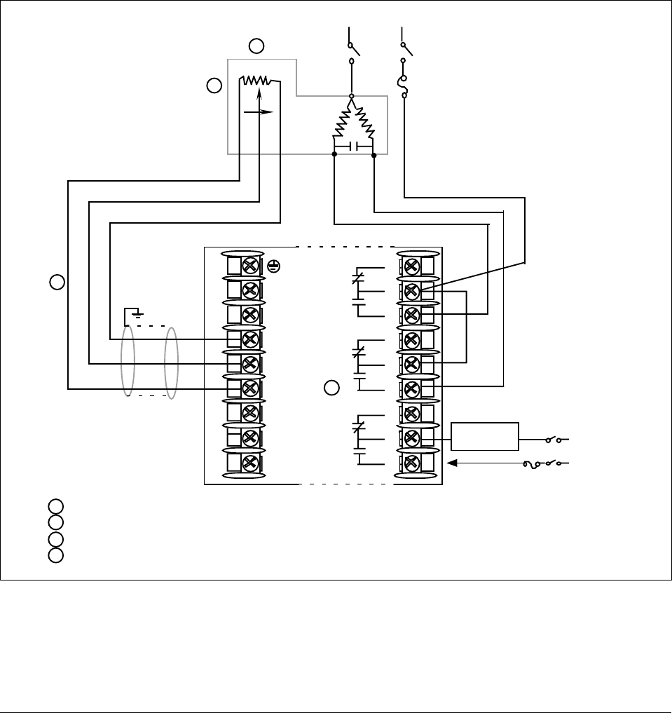
28 UDC 3300 Controller Product Manual 4/00
Position proportional
output connections Figure 2-14 shows the Output and Alarm wiring connections for models
with Position Proportional Output or Three Position Step Control (Models
DC330X-EE-XXX-X2, DC330X-AA-XXX-X2).
For Control and Alarm Relay Contact information, see Tables 2-7 and 2-8.
Calibration Position Proportional Output or Three Position Step models must have the
output calibrated after installation (see Section 8—Position Proportional
Output Calibration) to ensure that the displayed output (slidewire
position) agrees with the actual final control element position.
Three Position Step models only require that the motor time be entered.
Full calibration is not required.
Figure 2-14 Position Proportional Output or Three Position Step—Models DC330X-EE-XXX-X2,
DC330X-AA-XXX-X2
L1
L2/N
22
23
24
25
26
27
Slidewire 100 to 1000 Ω
mechanically linked
to motor
Connect shield to ground
at one end only
Neutral Hot
Motor Power
Supply
Open Closed
To terminal
7 or 9
Open
Alarm
Relay#1
Output
Relay#1
Output
Relay#2
N.C.
N.C.
N.O.
N.O.
N.C.
N.O.
Closed
Wiper
2
1
1
2
3
Alarm #2 is not available with Position Proportional output or Three Position Step control.
Do not run slidewire cable in the same conduit as AC power.
Electrical noise suppression may be required. Refer to Section 12.
Slidewire input is not required for Three Position Step control but can be used for motor position indication.
4
3
4
Alarm Relay
#1 Load Load
Supply
Power
24168
5 Amp Fast Blo fuse
5 Amp Fast Blo fuse
1
2
3
4
5
6
7
8
9
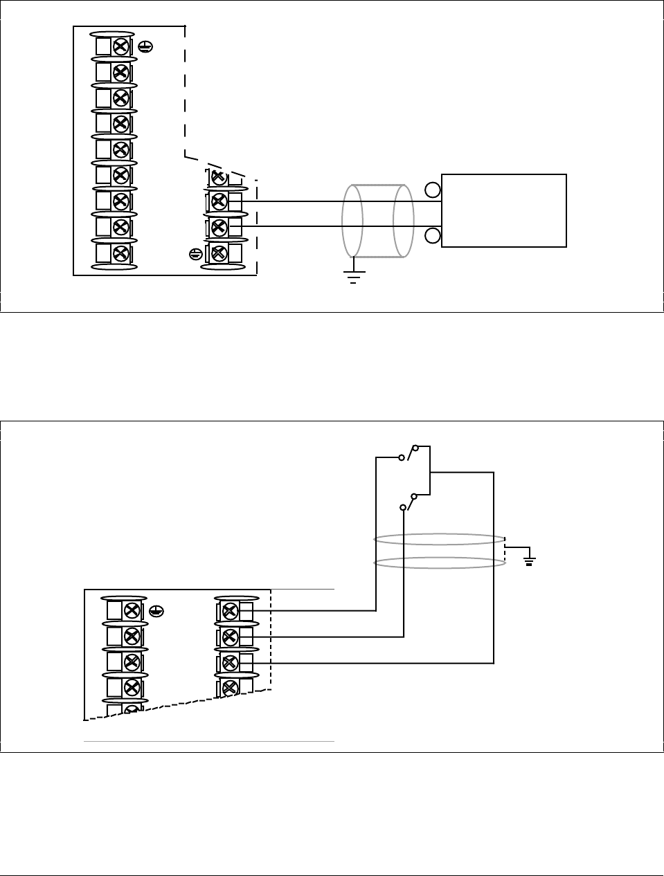
4/00 UDC 3300 Controller Product Manual 29
Auxiliary output
connections Figure 2-15 shows the wiring connections for the Auxiliary Output option
(Models DC330X-XX-2XX, DC330X-XX-5XX).
Figure 2-15 Auxiliary Output Connections—Models DC330X-XX-2XX, DC330X-XX-5XX
15
16
17
L1
L2/N
22
23
24
25
26
27
+
–
Auxiliary Load
0 –1000Ω
+
–
Connect shield to
ground at one end only
22619
For Duplex Current Output use Control Output for Output 1 (heat)
Attention:
Both current outputs (control and auxiliary) are isolated from
each other, case ground, and all inputs.
Digital inputs
connections Figure 2-16 shows the wiring connections for the Digital Inputs option
(Model DC330X-XX-XX3).
Figure 2-16 Digital Inputs Connections—Model DC330X-XX-XX3
10
11
12
13
L1
L2/N
22
Digital Input
Switch #1
Digital Input
Switch #2
Connect shield
to ground at
one end only
Switch
Common 22620
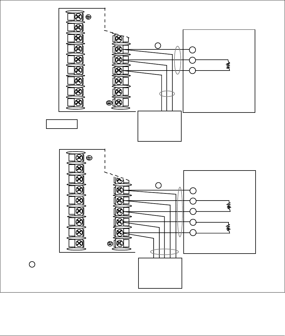
30 UDC 3300 Controller Product Manual 4/00
Communications option
connections There are two types of Communications option available:
•RS422/485/Modbus (Model DC330X-XX-1XX or
DC330X-XX-5XX)—Figure 2-17 [also refer to Document
#51-51-25-35 (RS422/485 ASCII) or #51-52-25-66 and #51-52-25-70
(Modbus)]
•DMCS (Model DC330X-XX-4XX)—Figure 2-18 (also refer to
Document #82-50-10-23)
Figure 2-17 RS422/485/Modbus Communications Option Connections
12
13
14
15
16
17
L1
L2/N
22
23
24
25
26
27
Master
TX+
SHD
TX–
RX+
RX–
Do not mix half and
full duplex wiring.
Do not run these
lines in the same
conduit as AC power
CAUTION
12
13
14
15
16
17
L1
L2/N
22
23
24
25
26
27
Master
TX–/RX–
SHD
TX+/RX+
Do not run these
lines in the same
conduit as AC power
MODBUS OR
RS422/485
HALF DUPLEX
To Other
Communication
Instruments
(maximum 15)
SHD
TX+/RX+
TX–/RX–
MODBUS OR
RS422/485
FULL DUPLEX
RX+
SHD
RX–
TX+
TX–
120 Ohm
Resistor
To Other
Communication
Instruments
(maximum 15) 120 Ohm Resistor
on Last Leg
120 Ohm
Resistor
120 Ohm
Resistor
120 Ohm Resistor
on Last Leg
24169
1
1
1
Use shielded twisted pair cables
(Belden 9271 Twinax or equivalent)
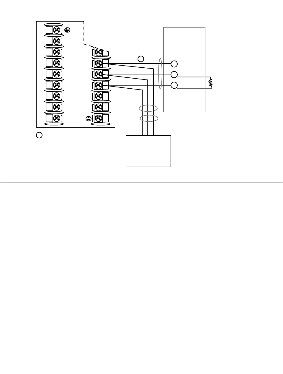
4/00 UDC 3300 Controller Product Manual 31
Figure 2-18 shows the wiring connections for the DMCS Communications
option (Model DC330X-XX-4XX).
Figure 2-18 DMCS Communications Option Connections
12
13
14
15
16
17
L1
L2/N
22
23
24
25
26
27
Master
SHD
Do not run these
lines in the same
conduit as AC power
SHD
D +
D –
DMCS
Communications
D +
D –
To Other
Communication
Instruments*
DMCS is a proprietary
protocol. Host computer
must be either the
Honeywell Gateway 500
or LPM Series 9000.
120 Ohm Resistor
on Last Leg
120 Ohm
Resistor
24170
1Use shielded twisted pair cables
(Belden 9271 Twinax or equivalent)
1
*DMCS: Maximum 31 drops.
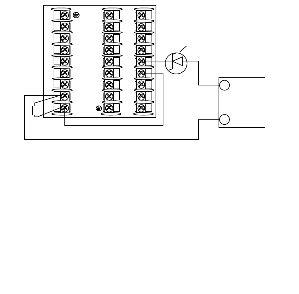
32 UDC 3300 Controller Product Manual 4/00
Transmitter power for
4-20 mA 2-wire
transmitter—open
collector alarm 2 output
The wiring diagram example shown in Figure 2-19 (Model
DC330X-XT-XXX) provides 30 Vdc at terminals 5 and 6 with the
capability of driving up to 22 mA, as required by the transmitter which is
wired in series.
If the transmitter terminal voltage must be limited to less than 30 volts,
you can insert a zener diode between the positive transmitter terminal and
terminal 5. For example, an IN4733A zener diode will limit the voltage at
the transmitter to 25 Vdc.
Configure:
A2S1TYPE = NONE
A2S2TYPE = NONE
Figure 2-19 Transmitter Power for 4-20 mA 2-wire Transmitter Using Open Collector Alarm 2
Output—Model DC330X-XT-XXX
24171
1
2
3
4
5
6
7
8
9
L1
L2/N
22
23
24
10
11
12
13
14
15
16
17
25
26
27
+
–
2-wire
Transmitter
250 ohm
resistor
+
–
+
–
If necessary, install zener diode here to
reduce voltage at transmitter.
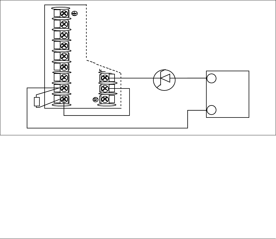
4/00 UDC 3300 Controller Product Manual 33
Transmitter power for
4-20 mA 2-wire
transmitter—auxiliary
output
The wiring diagram example shown in Figure 2-20 (Model
DC330X-XX-2XX or DC330X-XX-5XX) provides 30 Vdc at terminal 16
with the capability of driving up to 22 mA, as required by the transmitter
which is wired in series.
If the transmitter terminal voltage must be limited to less than 30 volts,
you can insert a zener diode between the positive transmitter terminal and
terminal 16. For example, an IN4733A zener diode will limit the voltage
at the transmitter to 25 Vdc.
Configure:
AUX OUT = OUTPUT
Calibrate the Auxiliary Output using the procedure given in Section 8.4 –
Auxiliary Output Calibration.
ZERO VAL = 4095
SPAN VAL = 4095
Figure 2-20 Transmitter Power for 4-20 mA 2-wire Transmitter Using Auxiliary Output—
Model DC330X-XX-2XX or DC330X-XX-5XX
24172
L1
L2/N
22
23
24
16
17
25
26
27
+
–
2-wire
Transmitter
250 ohm
resistor
+
–
+
–
15
If necessary, install zener
diode here to reduce
voltage at transmitter.
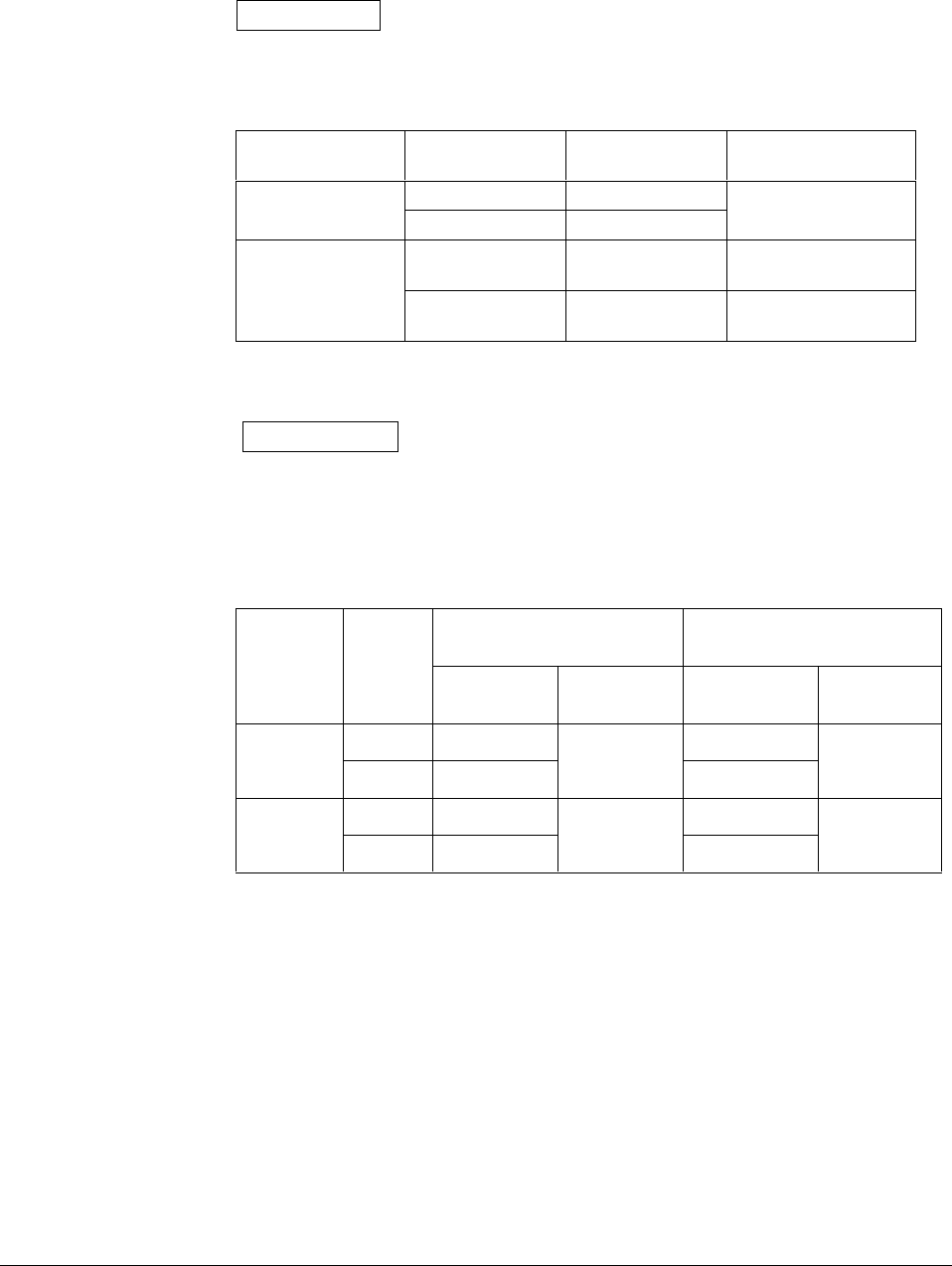
34 UDC 3300 Controller Product Manual 4/00
2.6 Control and Alarm Relay Contact Information
Control relays Table 2-7 lists the Control Relay contact information.
ATTENTION Control relays operate in the standard control mode;
i.e., energized when output state is on.
Table 2-7 Control Relay Contact Information
Unit Power Control Relay
Wiring Control Relay
Contact #1 or #2 Output
Indicator Status
N.O. Open
Off N.C. Closed Off
N.O. Open
Closed Off
On
On N.C. Closed
Open Off
On
Alarm relays Table 2-8 lists the Alarm Relay contact information.
ATTENTION Alarm relays are designed to operate in a failsafe mode;
i.e., de-energized during alarm state. This results in alarm actuation
when power is OFF or when initially applied, until the unit completes self
diagnostics. If the unit loses power, the alarms will function.
Table 2-8 Alarm Relay Contact Information
Variable NOT
in Alarm State Variable
in Alarm StateUnit
Power Alarm
Relay
Wiring Relay
Contact Indicators Relay
Contact Indicators
N.O. Open Open
Off
N.C. Closed
Off
Closed
Off
N.O. Closed Open
On
N.C. Open
Off
Closed
On

4/00 UDC 3300 Process Controller Product Manual 35
Section 3 – Configuration
3.1 Overview
Introduction Configuration is a dedicated operation where you use straightforward
keystroke sequences to select and establish (configure) pertinent control
data best suited for your application.
What’s in this section? The table below lists the topics that are covered in this section.
Topic Page
3.1 Overview 35
3.2 Configuration Prompts 36
3.3 How to Get Started 38
3.4 Configuration Tips 39
3.5 Configuration Procedure 40
3.6 Loop 1 Tuning Parameters Set Up Group 42
3.7 Loop 2 Tuning Parameters Set Up Group 44
3.8 Setpoint Ramp/Rate/Programming Set Up Group 45
3.9 Accutune Set Up Group 47
3.10 Algorithm Data Set Up Group 49
3.11 Output Algorithm Set Up Group 53
3.12 Input 1 Parameters Set Up Group 54
3.13 Input 2 Parameters Set Up Group 56
3.14 Input 3 Parameters Set Up Group 57
3.15 Loop 1 Control Parameters Set Up Group 58
3.16 Loop 2 Control Parameters Set Up Group 60
3.17 Options Parameters Set Up Group 62
3.18 Communications Parameters Set Up Group 64
3.19 Alarms Parameters Set Up Group 66
3.20 Display Parameters Set Up Group 69
3.21 Calibration Group 70
3.22 Maintenance Group 71
3.23 Status Group 72
3.24 Configuration Record Sheet for Basic and DMCS Models 73
3.25 Configuration Record Sheet for Extended Model 75
Prompts To assist you in the configuration process, there are prompts that appear in
the upper and lower displays. These prompts let you know what group of
configuration data (Set Up prompts) you are working with and also, the
specific parameters (Function prompts) associated with each group.
Figure 3-1 shows you an overview of the prompt hierarchy.
As you will see, the configuration data is divided into 15 main Set Up
groups plus prompts for calibration and prompts that show the status of
the continuous background tests that are being performed.
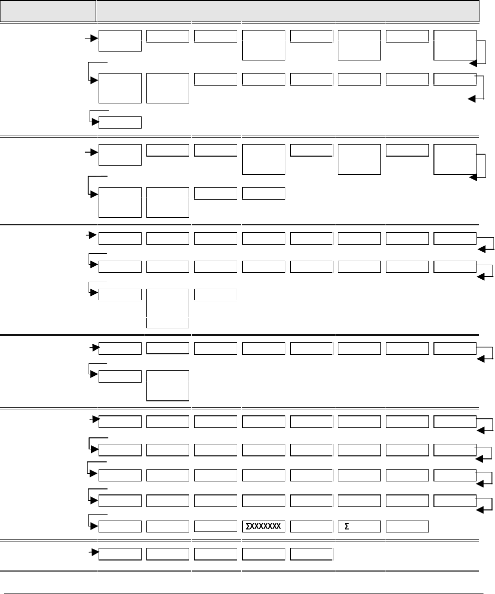
36 UDC 3300 Process Controller Product Manual 4/00
3.2 Configuration Prompts
Diagram: prompt
hierarchy Figure 3-1 shows an overview of the UDC 3300 Set Up prompts and their
associated Function prompts. Read from left to right.
Figure 3-1 Overview of UDC 3300 Prompt Hierarchy
Set Up Group Function Prompts
TUNING PROP BD
or GAIN GAINVALn RATE MIN RSET MIN
or
RSET RPM
MAN RSET PROPBD2
or
GAIN 2
RATE2MIN RSET2MIN
or
RSET2RPM
CYC SEC
or
CYC SX3
CYC2 SEC
or
CYC2 SX3
SECURITY LOCKOUT AUTO MAN SP SEL RUN HOLD PVEUVALx
GAINVALx
TUNINGL2 PROP3BD
or GAIN3 GAINVALn RATE3MIN RSET3MIN
or
RSET3RPM
MANRSET3 PROPBD4
or
GAIN 4
RATE4MIN RSET4MIN
or
RSET4RPM
CYC3 SEC
or
CYC3 SX3
CYC4 SEC
or
CYC4 SX3
PVEUVALx GAINVALx
SP RAMP SP RAMP TIME MIN FINAL SP SP RATE EU/HR UP EU/HR DN EUHRUP2 EUHRDN2
SP PROG STRT SEG END SEG RAMPUNIT RECYCLES SOAK DEV PROG END STATE
ToBEGIN SEGxRAMP
or
SEGxRATE
*
SEGx SP* * x = 1 to 12. Program concludes after segment 12
ACCUTUNE FUZZY ACCUTUNE ACCUTUN2 SP CHANG KPG SP CHAN2 KPG 2 CRITERIA
CRITERA2 AT ERROR
or
AT ERR2
ALGORTHM CONT ALG PIDLOOPS CONT2ALG OUT OVRD TIMER PERIOD START L DISP
INP ALG1 MATH K CALC HI CALC LO ALG1 INA ALG1 INB ALG1 INC ALG1BIAS
PCO SEL PCT CO ATM PRES INP ALG2 MATH K2 CALC HI CALC LO ALG2 INA
ALG2 INB ALG2 INC PCT H2 ALG2BIAS 8SEG CH1 Xx VALUE* Yx VALUE* 8SEG CH2
Xx VALU2 Yx VALU2 TOTALIZER TOT SEC RSET ? TOT RATE * x = 0 to 8
OUT ALG OUT ALG 4-20 RNG OUT2 ALG RLYSTATE RLY TYPE
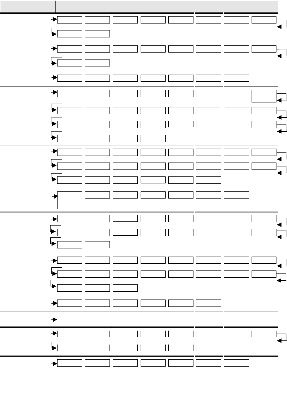
4/00 UDC 3300 Process Controller Product Manual 37
Set Up Group Function Prompts
INPUT 1 IN1 TYPE XMITTER1 ANALYTIC IN1 HI IN1 LO RATIO 1 BIAS IN1 FILTER 1
BURNOUT1 EMISSIV1
INPUT 2 IN2 TYPE XMITTER2 ANALYTIC IN2 HI IN2 LO RATIO 2 BIAS IN2 FILTER 2
BURNOUT2 EMISSIV2
INPUT 3 IN3 TYPE XMITTER3 IN3 HI IN3 LO RATIO 3 BIAS IN3 FILTER 3
CONTROL PV SOURC PID SETS SW VALUE LSP’S RSP SRC AUTOBIAS SP TRACK PWR
MODE
PWR OUT SP HiLIM SP LoLIM ACTION OUT RATE PCT/M UP PCT/M DN OUTHiLIM
OUTLoLIM I Hi LIM I Lo LIM DROPOFF DEADBAND OUT HYST FAILMODE FAILSAFE
MAN OUT AUTO OUT PBorGAIN MINorRPM
CONTROL2 PV 2 SRC FORCE MA PID SETS SW VALUE LSP’S RSP SRC AUTOBIAS SPTRACK
SP HiLIM SP LoLIM ACTION OUT RATE PCT/M UP PCT/M DN OUTHiLIM OUTLoLIM
I Hi LIM I Lo LIM DROPOFF DEADBAND FAILMODE FAILSAFE
OPTIONS AUX OUT
or
CUR OUT2
4 mA VAL 20mA VAL DIG IN 1 DIG1 COM DIG IN 2 DIG2 COM
COM ComSTATE Com ADDR ComADDR2 SHEDTIME SHEDENAB PARITY BAUD DUPLEX
WSFLOAT TX DELAY SHEDMODE SHEDSP UNITS CSP RATO CSP BIAS CSP2RATO
CSP2BIAS LOOPBACK
ALARMS A1S1 VAL A1S2 VAL A2S1 VAL A2S2 VAL A1S1TYPE A1S2 TYPE A2S1TYPE A2S2TYPE
A1S1 H L A1S1 EV A1S2 H L A1S2 EV A2S1 H L A2S1 EV A2S2 H L A2S2 EV
AL HYST ALM OUT1 BLOCK
DISPLAY DECIMAL DECIMAL2 TEMPUNIT PWR FREQ RATIO 2 LANGUAGE
CALIB USED FOR FIELD CALIBRATION
MAINTNCE TIME1 HRS.MIN1 TIME2 HRS.MIN2 TIME3 HRS.MIN3 COUNTER1 COUNTS1
COUNTER2 COUNTS2 COUNTER3 COUNTS3 RESET ID RES TYPE
STATUS VERSON FAILSAFE FAILSF 2 RAM TEST CONFTEST CALTEST FACT CRC

38 UDC 3300 Process Controller Product Manual 4/00
3.3 How To Get Started
Read the configuration
tips Read “Configuration Tips” shown on the next page. These tips will help
you to easily and quickly accomplish the tasks at which you will be
working when you configure your controller.
Read configuration
procedure Read “Configuration Procedure”. This procedure tells you how to
access the Set Up groups, and the Function parameters within each of
these groups that are shown in the Prompt Hierarchy in Figure 3-1.
Set up groups The Set Up groups and Function parameters are listed in the order of
their appearance. The list includes the name of the prompt, the range of
setting selections available, the factory setting, and the section to
reference for further details, if necessary.
Parameter explanations
or definitions If you need a detailed explanation of any prompt listed, refer to Section 4
– Configuration Parameter Definitions.
Section 4 lists the Set Up and Function prompts, the selections or range
of settings that you can make for each, plus a detailed explanation or
definition of each parameter.
Configuration record
sheet Located on the last page of this section is a “Configuration Record
Sheet”. When you make your configuration selections, record them on
this sheet. Then you will have a record of how the controller was
configured.
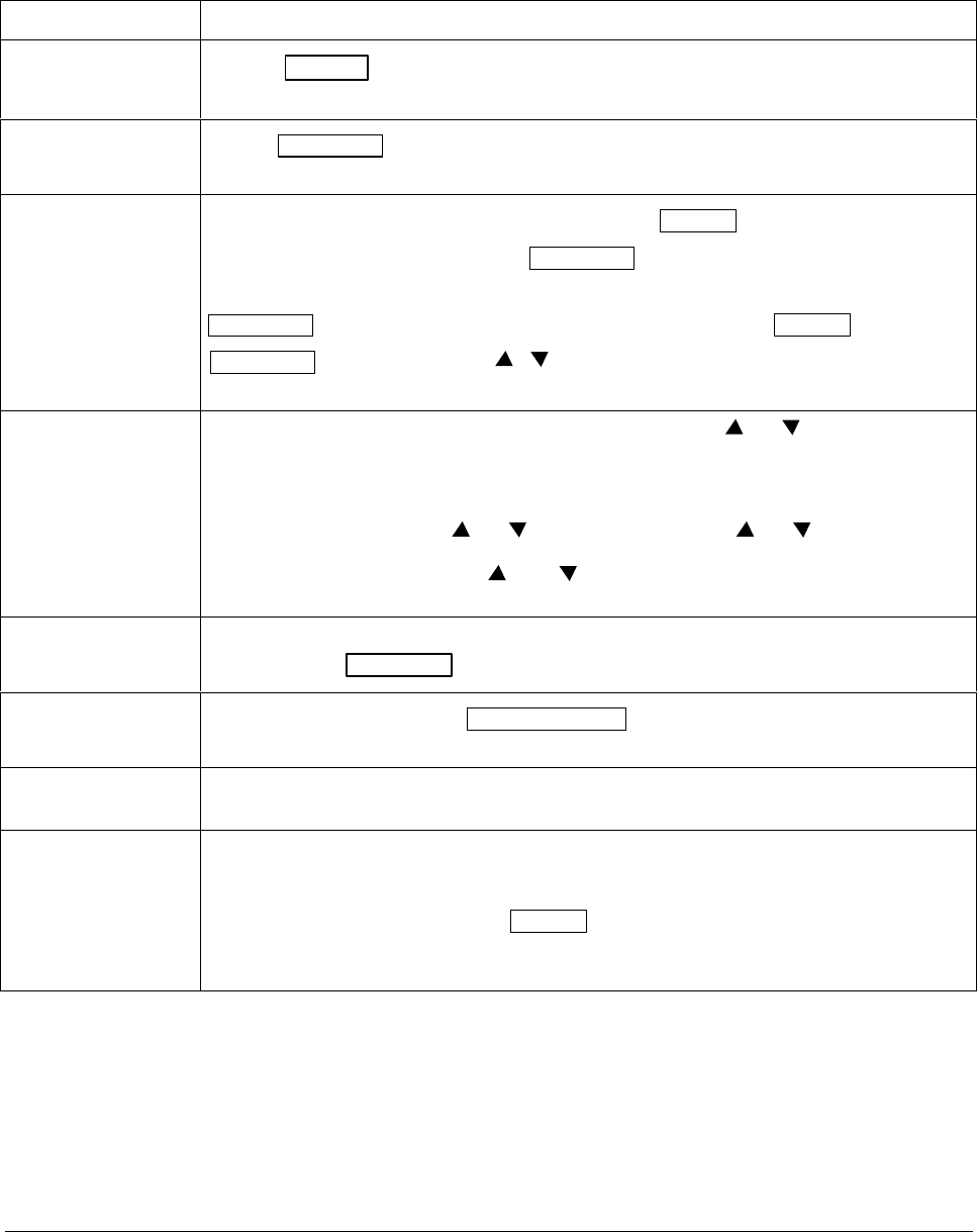
4/00 UDC 3300 Process Controller Product Manual 39
3.4 Configuration Tips
Introduction Listed below in Table 3-1 are some tips that will help you enter the
configuration data more quickly.
Table 3-1 Configuration Tips
Function Tip
Displaying Groups Use the SET UP key to display the Set Up groups. The group titles are listed in this
section in the order that they appear in the controller.
Displaying
Functions Use the FUNCTION key to display the individual parameters under each group. The
prompts are listed in the order of their appearance in each group.
Scrolling To get to a Set Up group prompt more quickly, hold the SET UP key in. To get to a
Function prompt more quickly, hold the FUNCTION key in. The display will scroll through
the parameters.
ATTENTION The prompting scrolls at a rate of 2/3 seconds when the SET UP or
FUNCTION key is held in. Also, [ ] [ ] keys will move group prompts forward or
backward at a rate twice as fast.
Changing values
quickly When changing the value of a parameter, you can use a single [ ] or [ ] key. Hold the key
in to increase the rate of change. Stop pressing the key for 1/2 second, then press again to
restart at a slow rate.
When changing the value of a parameter, you can adjust a more significant digit in the upper
display by holding in one key [ ] or [ ], and pressing the other [ ] or [ ] at the same time.
The adjustment will move one digit to the left. Press the key again and you will move one
more digit to the left. (Holding the [ ] and [ ] keys down will change the value twice as
quickly.)
Restoring to the
original value
When you change the value or selection of a parameter while in Set Up mode and decide not
to enter it, press RUN/HOLD once, the original value or selection will be recalled.
Exiting SET UP
mode To exit Set Up mode, press the LOWER DISPLAY key. This returns the display to the same
state it was in immediately preceding entry into the Set Up mode.
Timing out from
Set Up mode
If you are in Set Up mode and do not press any keys for 30 seconds, the controller will time
out and revert to the mode and display that was being used prior to entry into Set Up mode.
Key Error When a key is pressed and the prompt “KEY ERROR” appears in the lower display, it will be
for one of the following reasons:
• parameter not available
• not in Set Up mode, press SET UP key first
• key malfunction, do keyboard test (operation)
• Individual key locked out
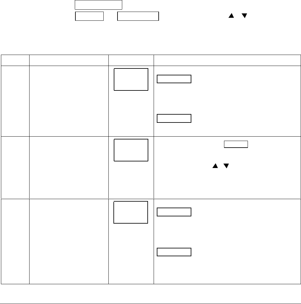
40 UDC 3300 Process Controller Product Manual 4/00
3.5 Configuration Procedure
Introduction Each of the Set Up groups and their functions are pre-configured at the
factory.
The factory settings are shown in Tables 3-3 through 3-18 which follow
this procedure.
If you want to change any of these selections or values, follow the
procedure in Table 3-2. This procedure tells you the keys to press to get to
any Set Up group and any associated Function parameter prompt.
If you need a detailed explanation of any prompt, refer to Section 4 –
Configuration Parameter Definitions.
Procedure Follow the procedure listed in Table 3-2 to access the Set Up groups and
Function prompts.
ATTENTION The prompting scrolls at a rate of 2/3 seconds when the
SET UP or FUNCTION key is held in. Also, [ ] [ ] keys will move
group prompts forward or backward at a rate twice as fast.
Table 3-2 Configuration Procedure
Step Operation Press Result
1Select Set Up mode
SET UP SET UP
Upper Display
Lets you know you are in the
configuration mode and a Set Up group
title is being displayed in the lower
display.
TUNING *
Lower Display
This is the first Set Up group title.
2Select any Set Up group
SET UP Successive presses of the SET UP key will
sequentially display the other Set Up group titles shown
in the prompt hierarchy in Figure 3-1.
You can also use the [ ] [ ] keys to scan the Set Up
groups in both directions.
Stop at the Set Up group title which describes the group
of parameters you want to configure. Then proceed to
the next step.
3Select a Function Parameter FUNCTION
LOOP 1/2
Upper Display
1.0 Shows you the current value or selection
for the first function prompt of the
particular Set Up group that you have
selected.
Lower Display
GAIN Shows the first Function prompt within
that Set Up group.
Example displays show Set Up group “Tuning”, Function
prompt “Gain”, and the value selected.
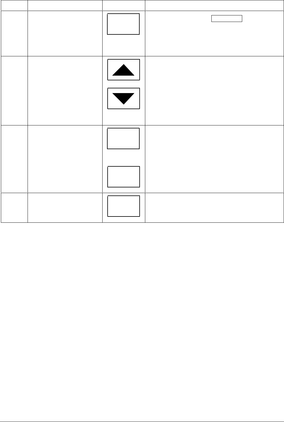
4/00 UDC 3300 Process Controller Product Manual 41
Step Operation Press Result
4Select other Function
Parameters FUNCTION
LOOP 1/2
Successive presses of the FUNCTION key will
sequentially display the other function prompts of the
Set Up group you have selected.
Stop at the function prompt that you want to change,
then proceed to the next step.
5Change the value or
selection
or
These keys will increment or decrement the value or
selection that appears for the function prompt you have
selected.
See “Configuration Tips” for instructions to increase or
decrease value quickly.
Change the value or selection to meet your needs.
If the display flashes, you are trying to make an
unacceptable entry.
6Enter the value or selection FUNCTION
LOOP 1/2
or
SET UP
This key selects another function prompt.
This key selects another Set Up group.
The value or selection you have made will be entered
into memory after another key is pressed.
7Exit Configuration LOWER
DISPLAY
This exits configuration mode and returns the controller
to the same state it was in immediately preceding entry
into the Set Up mode. It stores any changes you have
made.
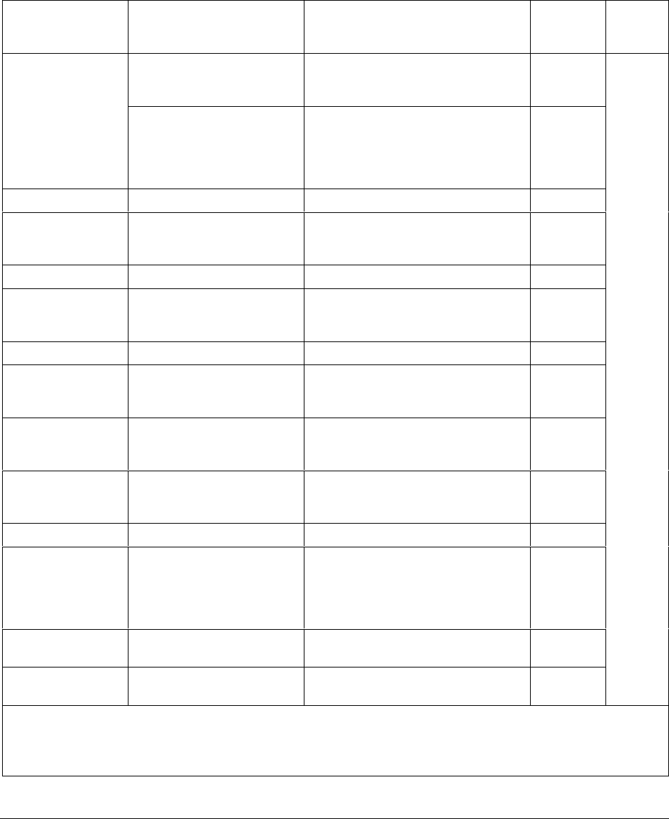
42 UDC 3300 Process Controller Product Manual 4/00
3.6 Loop 1 Tuning Parameters Set Up Group
Function prompts Table 3-3 lists all the function prompts in the Tuning Set Up group. How
the Algorithm and Control Set Up groups are configured determines
which prompts will appear.
Table 3-3 Tuning Group Function Prompts
Function Prompt
Lower Display Function
Name Selections or
Range of Setting
Upper Display
Factory
Setting Refer
to
PROP BD
or
GAIN
Proportional Band
or
Gain
0.1 to 9999 %
0.001 to 1000
- -
1.000
Section
4.2
or
GAINVALn*** or
Gain Value being used by
Gain Scheduling when
enabled in Control Setup
group “PID SETS”
Read Only - -
RATE MIN Rate in Minutes 0.00 to 10.00 minutes 0.00
RSET MIN
or
RSET RPM
Reset in minutes/repeat
or
Reset in repeats/minute
0.02 to 50.00 1.00
- -
MAN RSET Manual Reset –100 to 100 % output 0
PROPBD2
or
GAIN 2
Proportional Band 2
or
Gain 2
0.1 to 9999 %
0.001 to 1000
- -
1.000
RATE2MIN Rate 2 in Minutes 0.00 to 10.00 minutes 0.00
RSET2MIN
or
RSET2RPM
Reset 2 in minutes/repeat
or
Reset 2 in repeats/minute
0.02 to 50.00 1.00
- -
CYC SEC*
or
CYC SX3*
Cycle Time (Heat) 1 to 120 20
CYC2 SEC*
or
CYC2 SX3*
Cycle Time (Cool) 1 to 120 20
SECURITY Security Code 0 to 4095 0
LOCKOUT Configuration Lockout NONE
CALIB
+ CONF
+ VIEW
MAX
CALIB
AUTO MAN** Manual/Auto Key Lockout DISABL
ENABLE ENABLE
SP SEL** Setpoint Select Key Lockout DISABL
ENABLE ENABLE
*Cycle times are in either 1 second or 1/3 second increments, depending upon the RLY TYPE configuration in the
Output Algorithm Set Up group.
**Only appears if LOCKOUT = NONE.
***Requires Math software option

4/00 UDC 3300 Process Controller Product Manual 43
Function Prompt
Lower Display Function
Name Selections or
Range of Setting
Upper Display
Factory
Setting Refer
to
RUN HOLD** Run/Hold Key Lockout DISABL
ENABLE ENABLE Section
4.2
PVEUVAL1
PVEUVAL2
PVEUVAL3
PVEUVAL4
PVEUVAL5
PVEUVAL6
PVEUVAL7
PVEUVAL8
PV1 (through PV8) Value for
Gain Scheduling PV value within the PV limits.
In engineering units 0
GAINVAL1*
GAINVAL2*
GAINVAL3*
GAINVAL4*
GAINVAL5*
GAINVAL6*
GAINVAL7*
GAINVAL8*
Gain 1 (through Gain 8)
Value for Gain Scheduling 0.001 to 1000 floating
Gain or Proportional Band 1.000
* ATTENTION If units of percent proportional band (PB) are selected under the Control Set Up prompt, function
prompt PBorGAIN, then the displayed values are in %PB, but the lower display will still show Gain.
**Only appears if LOCKOUT = NONE.
44 UDC 3300 Process Controller Product Manual 4/00
3.7 Loop 2 Tuning Parameters Set Up Group (Cascade or
Two Loops
Function prompts Table 3-4 lists all the function prompts in the Tuning 2 Set Up group. This
group is only displayed if the controller is configured for Cascade or
2-Loop control (prompt PIDLOOPS in Algorithm Data Set Up group).
Table 3-4 Tuning Loop 2 Group Function
Function Prompt
Lower Display Function
Name Selections or
Range of Setting
Upper Display
Factory
Setting Refer
to
PROPBD3
or
GAIN 3
Proportional Band 3
or
Gain 3
0.1 to 9999
0.001 to 1000
- -
1.000
Section
4.3
or
GAINVALn or
Gain Value being used by
Gain Scheduling when
enabled
Read Only - -
RATE3MIN Rate 3 in Minutes 0.00 to 10.00 minutes 0.00
RSET3MIN
or
RSET3RPM
Reset 3 in minutes/repeat
or
Reset 3 in repeats/minute
0.02 to 50.00 1.00
- -
MANRSET3 Manual Reset 3 –100 to 100 % Output 0.0
PROPBD4
or
GAIN 4
Proportional Band 4
or
Gain 4
0.1 to 9999 %
0.001 to 1000
- -
1.000
RATE4MIN Rate 4 in Minutes 0.00 to 10.00 minutes 0.00
RSET4MIN
or
RSET4RPM
Reset 4 in minutes/repeat
or
Reset 4 in repeats/minute
0.02 to 50.00 1.00
- -
CYC3 SEC*
or
CYC3 SX3*
Cycle Time 3 (Heat) 1 to 120 20
CYC4 SEC*
or
CYC4 SX3*
Cycle Time 4 (Cool) 1 to 120 20
PVEUVAL1
PVEUVAL2
PVEUVAL3
PVEUVAL4
PVEUVAL5
PVEUVAL6
PVEUVAL7
PVEUVAL8
PV1 (through PV8) Value for
Gain Scheduling PV value within the PV limits.
In engineering units 0
GAINVAL1**
GAINVAL2**
GAINVAL3**
GAINVAL4**
GAINVAL5**
GAINVAL6**
GAINVAL7**
GAINVAL8**
Gain 1 (through Gain 8)
Value for Gain Scheduling 0.001 to 1000 floating
Gain or Proportional Band 1.000
*Cycle times are in either 1 second or 1/3 second increments, depending upon the RLY TYPE configuration in the
Output Algorithm Set Up group.
** ATTENTION If units of percent proportional band (PB) are selected under the Control Set Up prompt, function
prompt PBorGAIN, then the displayed values are in %PB, but the lower display will still show Gain.
4/00 UDC 3300 Process Controller Product Manual 45
3.8 SP Ramp, SP Rate, or SP Programming Set Up Group
Single Setpoint Ramp The Setpoint Ramp Set Up group
contains the Function parameters that let
you configure a single setpoint ramp to occur between the current local
setpoint and a final setpoint over a time interval (SP RAMP).
Setpoint rate The Setpoint Ramp Set Up group also contains the function parameters
that let you configure a specific rate of change for any Local Setpoint
change (SP RATE). It includes selections for Rate Up and Rate Down.
Function prompts Table 3-5 lists all the function prompts in the SP Ramp Set Up group.
Table 3-5 SP Ramp Group Function Prompts
Function Prompt
Lower Display Function
Name Selections or
Range of Setting
Upper Display
Factory
Setting Refer
to
If SP Rate and SP Programming are disabled
SP RAMP Single Setpoint Ramp
Selection DISABL
ENABLE
ENABL2
ENAB12
DISABL Section
4.4
TIME MIN Single Setpoint Ramp Time
(SP ramp enabled) 0 to 255 minutes 3
FINAL SP Single Setpoint Final
Setpoint (SP ramp enabled) Enter a value within the setpoint limits. 1000
If SP Ramp and SP Programming are disabled
SP RATE Setpoint Rate DISABL
ENABLE
ENABL2
ENAB12
DISABL
EU/HR UP Rate Up Value for
Loop 1 (SP Rate enabled) 0 to 9999
in engineering units per hour 0
EU/HR DN Rate Down Value for
Loop 1 (SP Rate enabled) 0 to 9999
in engineering units per hour 0
EU/HRUP2 Rate Up Value for
Loop 2 (SP Rate enabled) 0 to 9999
in Units per Hour 0
EU/HRDN2 Rate Down Value for
Loop 2 (SP Rate enabled) 0 to 9999
in Units per Hour 0
If SP Ramp and SP Rate are disabled
SP PROG* Setpoint Ramp/Soak
Programming DISABL
ENABLE
ENABL2
ENAB12
SP PROG must be enabled to view
the remaining prompts.
DISABL
STRT SEG Start Segment Number 1 to 11 ––
END SEG End Segment Number 2 to 12
Always end in a soak segment
(2, 4, ... 12)
––
RAMPUNIT Engineering Units for Ramp
Segments TIME (hours.minutes)
EU/MIN (engineering units/minute)
EU/HR (engineering units/hour)
TIME

46 UDC 3300 Process Controller Product Manual 4/00
Function Prompt
Lower Display Function
Name Selections or
Range of Setting
Upper Display
Factory
Setting Refer
to
RECYCLES Number of Program
Recycles 0 to 99 recycles –– Section
4.4
SOAK DEV Guaranteed Soak Deviation
Value 0 to 99
The number selected will be the PV
value (in engineering units) above or
below the setpoint outside of which
the timer halts.
––
PROG END Program Termination State LASTSP (Hold at last setpoint in the
program)
F SAFE (Manual mode/Failsafe
output)
––
STATE Program State at Program
End DISABL
HOLD ––
KEYRESET Reset/Rerun SP Program DISABL
TOBEGN
RERUN
DISABL
HOTSTART Hot Start DISABL
ENABL DISABL
SEG1RAMP or
SEG1RATE Segment #1 Ramp Time or
Segment #1 Ramp Rate 0-99 hours.0-59 minutes
Engineering units/minute or
Engineering units/hour
Select TIME, EU/MIN, or EU/HR at
prompt RAMPUNIT. All ramps will
use the same selection.
––
SEG2 SP Segment #2 Soak Setpoint
Value Within the Setpoint limits ––
SEG2TIME Segment #2 Soak Duration 0-99 hours.0-59 minutes ––
SEG3RAMP or
SEG3RATE
SEG4 SP
SEG4TIME
SEG5RAMP or
SEG5RATE
SEG6 SP
SEG6TIME
SEG7RAMP or
SEG7RATE
SEG8 SP
SEG8TIME
SEG9RAMP or
SEG9RATE
SG10 SP
SG10TIME
SG11RAMP or
SG11RATE
SG12 SP
SG12TIME
Same as above Selections are same as above. ––
*Requires SP Programming option

4/00 UDC 3300 Process Controller Product Manual 47
3.9 Accutune Set Up Group
Introduction The Accutune Set Up group offers these selections:
• FUZZY
Fuzzy Overshoot Suppression—Uses fuzzy logic to suppress or
eliminate any overshoot that may occur when the PV approaches
setpoint.
• TUNE
Demand Tuning—The tuning process is initiated through the operator
interface keys or via a digital input (if configured). The algorithm then
calculates new tuning parameters and enters them in the tuning group.
TUNE does operate with 3 Position Step Control.
• SP*
SP Tuning—SP tuning continuously adjusts the PID parameters in
response to setpoint changes. You can select tuning on minimum
setpoint changes of 5 % up to 15 % span. Perform SP tuning after you
have configured the controller.
SP tuning does not operate with 3 Position Step Control algorithm.
• TUN+PV*
or
SP+PV*
PV Tuning—The (TUNE) Demand Tuning or the (SP) Setpoint
Tuning portions of these selections work as stated above. PV Adapt
will occur during Process Variable (PV) disturbances (0.3 % span or
larger) which result from non-linearities, process dynamics, load
changes, or other operating conditions. When this condition exists, the
controller monitors the process response for 1 and 1/2 process cycles
around the setpoint to determine whether there has been a true process
change or a momentary upset.
Process retuning occurs as the process dynamics are learned. When the
process is being learned with possible retune, a t is shown in the upper
left display digit.
*SP + PV Tuning not available on Basic Model DC330B.

48 UDC 3300 Process Controller Product Manual 4/00
Function prompts Table 3-6 lists the function prompts in the Accutune Set Up group.
Table 3-6 Accutune Group Function Prompts
Function Prompt
Lower Display Function
Name Selections or
Range of Setting
Upper Display
Factory
Setting Refer
to
FUZZY Fuzzy Overshoot
Suppression DISABL
ENABLE
ENABL2
ENAB12
DISABL Section
4.5
ACCUTUNE Accutune—Loop 1 DISABL
TUNE (Demand Tuning)
SP (SP Tuning)
TUN+PV
SP+PV
DISABL
ACCUTUN2 Accutune—Loop 2 DISABL
TUNE (Demand Tuning)
SP (SP Tuning)
TUN+PV
SP+PV
DISABL
SP CHANG* Setpoint Change Value—
Loop 1 5 to 15 % Input Span 10
KPG* Process Gain—Loop 1 0.10 to 10.00 1.00
SP CHAN2* Setpoint Change Value –
Loop 2 5 to 15 % Input Span 10
KPG 2* Process Gain – Loop 2 0.10 to 10.00 1.00
CRITERIA* Tuning Criteria—Loop 1 NORMAL
FAST FAST
CRITERA2* Tuning Criteria – Loop 2 NORMAL
FAST FAST
AT ERROR
or
AT ERR 2
(depending on
Loop)
Accutune Error Codes Read Only
RUNING (Accutune process in
operation)
NONE
OUTLIM
IDFAIL
ABORT
LOW PV
- -
*Applies to SP and SP+PV only.

4/00 UDC 3300 Process Controller Product Manual 49
3.10 Algorithm Data Set Up Group
Introduction This data deals with various algorithms residing in the controller:
•Control algorithms,
• Input Math algorithms,
•selecting the 1 or 2 PID Loops,
•Output Override,
•2 Eight Segment Characterizers,
•the Timer function, and
•Totalizer function.
•Gain Scheduler
ATTENTION Math option (two algorithms, two characterizers,
totalizer) and Two Loops of Control are only available on Expanded
Model DC330E.
Function prompts Table 3-7 lists all the function prompts in the Algorithm Set Up group.
Table 3-7 Algorithm Group Function Prompts
Function Prompt
Lower Display Function
Name Selections or
Range of Setting
Upper Display
Factory
Setting Refer
to
CONT ALG Control Algorithm ON-OFF
PID A
PID B
PD+MR
3PSTEP
PID A Section
4.6
PIDLOOPS
(NOTE 1)
PID Loop Selection 1 LOOP
2LOOPS
CASCAD
1 or 2
CONT2ALG
(NOTE 1)
Control 2 Algorithm PID A
PID B
PD+MR
PID A
OUT OVRD
(NOTE 2)
Output Override Select DISABL
HI SEL
LO SEL
DISABL
TIMER Timer Enable/Disable ENABLE
DISABL DISABL
PERIOD* Timeout Period 00:00 to 99:59 00:01
START* Start Initiation KEY (Run/Hold key)
ALARM2 KEY
L DISP* Lower Display Selection TI REM (time remaining)
E time (elapsed time) TI REM
*Prompt appears only when Timer is enabled.
NOTE 1: Two Loops and Cascade are only available on Expanded Model DC330E.
NOTE 2: Does not apply to Three Position Step Control.
50 UDC 3300 Process Controller Product Manual 4/00
Function Prompt
Lower Display Function
Name Selections or
Range of Setting
Upper Display
Factory
Setting Refer
to
INP ALG1 Input 1 Algorithm
(formulas are located in
Section 4)
ATTENTION All Input
Algorithms operate in
engineering units except
feedforward which operates
in percent of output units.
PV or RSP source in the
Control Set Up group must
be set to IN AL1.
NONE MuDIV
W AVG MULT
F FWRD CARB A
FFWDMu CARB B
RELHUM CARB C
SUMMER CARB D
HI SEL FCC
LO SEL DEW PT
√MuDIV OXYGEN
√MULT
NONE Section
4.6
MATH K Weighted Average Ratio or K
Constant for Math Selections 0.001 to 1000 floating - -
CALC HI Calculated Variable High
Scaling Factor for Input
Algorithm
–999. to 9999. floating
(in engineering units) - -
CALC LO Calculated Variable Low
Scaling Factor for Input
Algorithm
–999. to 9999. floating
(in engineering units) - -
ALG1 INA Input Algorithm 1
Input A Selection INP 1 IN AL1
INP 2 IN AL2
LP1OUT INP 3
LP2OUT
- -
ALG1 INB Input Algorithm 1
Input B Selection INP 1 IN AL1
INP 2 IN AL2
LP1OUT INP 3
LP2OUT
- -
ALG1 INC Input Algorithm 1
Input C Selection NONE LP2OUT
INPUT 1 IN AL1
INPUT 2 IN AL2
LP1OUT INP 3
- -
PCO SEL Percent Carbon Source
(Input 3 must be enabled) DISABL
ONLINE DISABL
PCT CO Percent Carbon Monoxide 0.020 to 0.350 (fractional percent of
CO) 0.200
ATM PRES Atmospheric Pressure
Compensation 590.0 to 760.0 (mm Hg) 760.0
ALG1BIAS Input Algorithm1 Bias -999 to 9999 floating (in engineering
units) 0.000
INP ALG2* Input 2 Algorithm
(formulas are located in
Section 4)
ATTENTION All Input
Algorithms operate in
engineering units except
feedforward which operates
in percent of range units.
NONE LO SEL
W AVG √MuDIV
F FWD √MULT
FFWDMu MuDIV
A–B/C MULT
HI SEL DEW PT
NONE
MATH K2 Weighted Average Ratio or K
Constant for Math Selections 0.001 to 1000 - -

4/00 UDC 3300 Process Controller Product Manual 51
Function Prompt
Lower Display Function
Name Selections or
Range of Setting
Upper Display
Factory
Setting Refer
to
CALC HI Calculated Variable High
Scaling Factor for Input
Algorithm 2
–999. To 9999. Floating
(in engineering units) - -
CALC LO Calculated Variable Low
Scaling Factor for Input
Algorithm 2
–999. To 9999. Floating
(in engineering units) - -
ALG2 INA Input Algorithm 2
Input A Selection INP 1 IN AL1
INP 2 IN AL2
LP1OUT INP 3
LP2OUT
- -
ALG2 INB Input Algorithm 2
Input B Selection INP 1 IN AL1
INP 2 IN AL2
LP1OUT INP 3
LP2OUT
- -
ALG2 INC Input Algorithm 2
Input C Selection NONE LP2OUT
INP 1 IN AL1
INP 2 IN AL2
LP1OUT INP 3
- -
PCT H2 Hydrogen Content for
Dewpoint 1.0 to 99.0 % 1.0
ALG2 BIAS Input Algorithm2 Bias -999 to 9999 floating (in engineering
units) 0.000
8SEG CH1* Eight Segment Characterizer
If Characterizer 1 is
enabled, the following Xn
VALUE and Yn VALUE
parameters appear.
DISABL
INPUT1
INPUT2
L1 OUT
L2 OUT
DISABL
X0 VALUE
X1 VALUE
X2 VALUE
X3 VALUE
X4 VALUE
X5 VALUE
X6 VALUE
X7 VALUE
X8 VALUE
Xn Input Value (X Axis)
(n = 0 through 8)
0 to 99.99 % 0
Y0 VALUE
Y1VALUE
Y2VALUE
Y3VALUE
Y4VALUE
Y5VALUE
Y6VALUE
Y7VALUE
Y8 VALUE
Yn Output Value (Y Axis)
(n = 0 through 8)
0 to 99.99 % 0
8SEG CH2* Eight Segment Characterizer
2
If Characterizer 2 is
enabled, the following Xn
VALU2 and Yn VALU2
parameters appear.
DISABL
INPUT1
INPUT2
L1 OUT
L2 OUT
DISABL

52 UDC 3300 Process Controller Product Manual 4/00
Function Prompt
Lower Display Function
Name Selections or
Range of Setting
Upper Display
Factory
Setting Refer
to
X0 VALU2
X1 VALU2
X2 VALU2
X3 VALU2
X4 VALU2
X5 VALU2
X6 VALU2
X7 VALU2
X8 VALU2
Xn Input Value (X Axis)
(n = 0 through 8)
0 to 99.99 % 0
Y0 VALU2
Y1 VALU2
Y2 VALU2
Y3 VALU2
Y4 VALU2
Y5 VALU2
Y6 VALU2
Y7 VALU2
Y8 VALU2
Yn Output Value (Y Axis)
(n = 0 through 8)
0 to 99.99 % 0
TOTALIZE* Totalization Function DISABL
INPUT1
IN AL1
IN AL2
DISABL
ΣXXXXXXX Current Scale Factor
(upper display)
Actual Current Totalized
Value (lower display)
Σ*En
Where:
n = Totalizer Scale Factor Value
- -
TOT SCAL Totalizer Scale Factor *E0
*E1
*E2
*E3
*E4
*E5
*E6
E0
TOT SEC Totalizer Reset Lock UNLOCK
LOCK UNLOCK
Σ RSET ? Totalizer Reset NO
YES NO
TOT RATE Totalizer Rate of Integration SECOND (once per second)
MINUTE (once per minute)
HOUR (once per hour)
DAY (once per day)
ML/DAY (millions per day)
SECOND
*Not available on DC330B

4/00 UDC 3300 Process Controller Product Manual 53
3.11 Output Algorithm Parameters Set Up Group
Introduction This data deals with various Output types that are available for use in the
controller. It also lists the Digital Output Status, the Current Duplex
functionality, and Relay Time Cycle increments.
Function prompts Table 3-8 lists all the function prompts in the Output Algorithm Set Up
group.
Table 3-8 Output Algorithm Group Function Prompts
Function Prompt
Lower Display Function
Name Selections or
Range of Setting
Upper Display
Factory
Setting Refer
to
OUT ALG Loop 1 Output Algorithm TIME Time Simplex
CURRNT Current Simplex
POSITN Position Proportional
TIME D Time Duplex
CUR D Current Duplex
CUR TI Current/Time Duplex
TI CUR Time/Current Duplex
CURRNT Section
4.7
4–20 RNG Current Duplex Range 100PCT
50 PCT 100PCT
OUT2 ALG* Loop 2 Output Algorithm NONE
TIME
CURRNT
CUR D
CUR TI
TI CUR
CURRNT
RLYSTATE Digital Output State at 0 %
Output 1OF2OF (Output relays 1 and 2 are
both de-energized)
1ON2OF (Output relay 1 is
energized, output relay 2
is de-energized)
1OF2ON (Output relay 1 is de-
energized, output relay 2
is energized)
1ON2ON (Output relays 1 and 2 are
both energized)
1OF2ON
RLY TYPE Relay Cycle Time Increments MECHAN (Cycle time in one second
increments)
SOL ST (Cycle time in 1/3 second
increments: 1 = .33
seconds, 120 = 40
seconds)
MECHAN
*Not available on DC330B

54 UDC 3300 Process Controller Product Manual 4/00
3.12 Input 1 Parameters Set Up Group
Introduction This data deals with various parameters required to configure Input 1.
Function prompts Table 3-9 lists all the function prompts in the Input 1 Set Up group.
Table 3-9 Input 1 Group Function Prompts
Function Prompt
Lower Display Function
Name Selections or
Range of Setting
Upper Display
Factory
Setting Refer
to
IN1 TYPE Input 1 Actuation Type DISABL W TC H
B TC W TC L
E TC H 100 PT
E TC L 100 LO
J TC H 200 PT
J TC L 500 PT
K TC H RAD RH
K TC L RAD RI
NNM H 0-20mA
NNM L 4-20mA
NM90 H 0-10mV
NM90 L 0-50mV
NIC TC 0-5 V
R TC 1-5 V
S TC 0-10 V
T TC H CARBON
T TC L OXYGEN
0-10mV Section
4.8
XMITTER1 Transmitter Characterization B TC S TC
E TC H T TC H
E TC L T TC L
J TC H W TC H
J TC L W TC L
K TC H 100 PT
K TC L 100 LO
NNM H 200 PT
NNM L 500 PT
NM90 H RAD RH
NM90 L RAD RI
NIC TC LINEAR
R TC SQROOT
ANALYT*
LINEAR
ANALYTIC* Analytic Selections
XMITTER1 must be set to
ANALYT for this prompt to
appear
NONE
PH
ORP mV
CONDmS
CONDuS
RSTVM^
TDS PPm
TDS PPb
CONCPt
DO PPm
DO PPb
NONE
IN1 HI Input 1 High Range Value
(Linear Inputs only) –999. To 9999. Floating
(in engineering units) 1000
IN1 LO Input 1 Low Range Value
(Linear Inputs only) –999. to 9999. floating
(in engineering units) 0
RATIO 1 Input 1 Ratio –20.00 to 20.00
(floats to 3 decimal places) 1.000

4/00 UDC 3300 Process Controller Product Manual 55
Function Prompt
Lower Display Function
Name Selections or
Range of Setting
Upper Display
Factory
Setting Refer
to
BIAS IN1 Input 1 Bias –999. to 9999.
(in engineering units) 0
FILTER 1 Input 1 Filter 0 to 120 seconds 0
BURNOUT1 Burnout Protection NONE
UP
DOWN
NO_FS
NONE
EMISSIV1 Emissivity 0.01 to 1.00 0.00
*Not available on DC330B

56 UDC 3300 Process Controller Product Manual 4/00
3.13 Input 2 Parameters Set Up Group
Introduction This data deals with various parameters required to configure Input 2.
Function prompts Table 3-10 lists all the function prompts in the Input 2 Set Up group.
Table 3-10 Input 2 Group Function Prompts
Function Prompt
Lower Display Function
Name Selections or
Range of Setting
Upper Display
Factory
Setting Refer
to
IN2 TYPE Input 2 Actuation Type DISABL NM90 L 500 PT
B TC NIC TC RAD RH
E TC H R TC RAD RI
E TC L S TC 0-20mA
J TC H T TC H 4-20mA
J TC L T TC L 0-10mV
K TC H W TC H 0-50mV
K TC L W TC L 0-5 V
NNM H 100 PT 1-5 V
NNM L 100 LO 0-10 V
NM90 H 200 PT SLIDEW
0-10mV Section
4.9
XMITTER2 Transmitter Characterization B TC S TC
E TC H T TC H
E TC L T TC L
J TC H W TC H
J TC L W TC L
K TC H 100 PT
K TC L 100 LO
NNM H 200 PT
NNM L 500 PT
NM90 H RAD RH
NM90 L RAD RI
NIC TC LINEAR
R TC SQROOT
ANALYT*
LINEAR
ANALYTIC* Analytic Selections
XMITTER2 must be set to
ANALYT for this prompt to
appear
NONE
PH
ORP mV
CONDmS
CONDuS
RSTVM^
TDS PPm
TDS PPb
CONCPt
DO PPm
DO PPb
NONE
IN2 HI Input 2 High Range Value
(Linear Inputs only) –999. to 9999. floating
(in engineering units) 1000
IN2 LO Input 2 Low Range Value
(Linear Inputs only) –999. to 9999. floating
(in engineering units) 0
RATIO 2 Input 2 Ratio –20.00 to 20.00 1.000
BIAS IN2 Input 2 Bias –999. to 9999.
(in engineering units) 0
FILTER 2 Input 2 Filter 0 to 120 seconds 0
BURNOUT2 Burnout Protection NONE
UP
DOWN
NO_FS
NONE
EMISSIV2 Emissivity 0.01 to 1.00 0.00
*Not available on DC330B

4/00 UDC 3300 Process Controller Product Manual 57
3.14 Input 3 Parameters Set Up Group
Introduction This data deals with various parameters required to configure Input 3.
Function prompts Table 3-11 lists all the function prompts in the Input 3 Set Up group.
Table 3-11 Input 3 Group Function
Function Prompt
Lower Display Function
Name Selections or
Range of Setting
Upper Display
Factory
Setting Refer
to
IN3 TYPE* Input 3 Actuation Type DISABL
0-20mA
4-20mA
0-5 V
1-5 V
DISABL Section
4.10
XMITTER3 Transmitter Characterization B TC S TC
E TC H T TC H
E TC L T TC L
J TC H W TC H
J TC L W TC L
K TC H 100 PT
K TC L 100 LO
NNM H 200 PT
NNM L 500 PT
NM90 H RAD RH
NM90 L RAD RI
NIC TC LINEAR
R TC SQROOT
LINEAR
IN3 HI Input 3 High Range Value
(Linear Inputs only) –999. to 9999. floating
(in engineering units) 1000
IN3 LO Input 3 Low Range Value
(Linear Inputs only) –999. to 9999. floating
(in engineering units) 0
RATIO 3 Input 3 Ratio –20.00 to 20.00 1.000
BIAS IN3 Input 3 Bias –999. to 9999.
(in engineering units) 0
FILTER 3 Input 3 Filter 0 to 120 seconds 0
*Not available on DC330B

58 UDC 3300 Process Controller Product Manual 4/00
3.15 Loop 1 Control Parameters Set Up Group
Introduction The functions listed in this group define how the Single Loop process
controller or Loop 1 of a Two Loop process controller will control the
process.
Function prompts Table 3-12 lists all the function prompts in the Control Set Up group.
Table 3-12 Control Group Function Prompts
Function Prompt
Lower Display Function
Name Selections or
Range of Setting
Upper Display
Factory
Setting Refer
to
PV SOURC Process Variable Source INP 1 IN AL1 INP 3
INP 2 IN AL2 INP 1 Section
4.11
PID SETS Tuning Parameter Sets 1 ONLY
2KEYBD
2PV SW
2SP SW
GAIN S (Gain scheduling
automatically disables Accutune for
this loop)
1 ONLY
SW VALUE Automatic Switchover Value Value in engineering units within PV
or SP range limits 0.00
LSP’S Local Setpoint Source 1 ONLY
TWO
THREE (Selection automatically
disables RSP SRC)
1 ONLY
RSP SRC Remote Setpoint Source NONE IN AL1 INP 3
INP 2 IN AL2 NONE
AUTOBIAS Automatic Bias ENABLE
DISABL DISABL
SP TRACK Local Setpoint Tracking NONE
PV
RSP
NONE
PWR MODE Power Up Mode Recall MANUAL
A LSP
A RSP
AM SP
AM LSP
MANUAL
PWR OUT TPSC Output Start-up Mode LAST
F’SAFE LAST
SP HiLIM Setpoint High Limit 0 to 100 % of span input in
engineering units 1000
SP LoLIM Setpoint Low Limit 0 to 100 % of span input in
engineering units 0
ACTION Control Output Direction DIRECT
REVRSE REVRSE
4/00 UDC 3300 Process Controller Product Manual 59
Function Prompt
Lower Display Function
Name Selections or
Range of Setting
Upper Display
Factory
Setting Refer
to
OUT RATE
ATTENTION
Does not apply to 3
Position Step
Control algorithm.
Output Change Rate ENABLE
DISABL DISABL Section
4.11
PCT/M UP Output Rate Up Value 0 to 9999 % per minute 0
PCT/M DN Output Rate Down Value 0 to 9999 % per minute 0
OUTHiLIM High Output Limit –5.0 to 105 % of output 100
OUTLoLIM Low Output Limit –5.0 to 105 % of output 0.0
I Hi LIM High Reset Limit Within the range of the output limits 100.0
I Lo LIM Low Reset Limit Within the range of the output limits 0.0
DROPOFF Controller Dropoff Value –5 to 105 % of output 0
DEADBAND Output Relay Deadband Time Duplex:
–5.0 to 25.0 %
On/Off Duplex:
0.0 to 25.0 %
Position Prop. and 3P Step:
0.5 to 5.0 %
1.0
OUT HYST Output Relay Hysteresis 0.0 to 100.0 % of PV Span for On/Off
control. 0.5
FAILMODE Failsafe Mode NO LAT
LATCH NO LAT
FAILSAFE Failsafe Output Value for all
outputs except 3P Step Set within the range of the output
limits. 0 to 100 % 0.0
Failsafe Output Value for 3P
Step 0 PCT (motor goes to closed position)
100PCT (motor goes to open position) - -
SW_FAIL PDMR/Position Proportional
motor position when
slidewire fails
0 PCT (motor goes to closed position)
100PCT (motor goes to open position)
MAN OUT Power-up Preset Output for
Manual Output Within the range of output limits - -
AUTO OUT Power-up Preset Output for
Automatic Output Within the range of output limits - -
PBorGAIN Proportional Band or
Gain Units PB PCT
GAIN GAIN
MINorRPM Reset Units RPM
MIN MIN

60 UDC 3300 Process Controller Product Manual 4/00
3.16 Loop 2 Control Parameters Set Up Group
Introduction The functions listed in this group define how Loop 2 of a Two Loop
process controller will control the process.
Only available on Expanded Controller Model DC330E-XX-XXX.
Function prompts Table 3-13 lists all the function prompts in the Control 2 Set Up group.
Table 3-13 Control 2 Group Function Prompts
Function Prompt
Lower Display Function
Name Selections or
Range of Setting
Upper Display
Factory
Setting Refer
to
PV 2 SRC Process Variable Source INP 1
INP 2
IN AL1
IN AL2
INP 3
INP 2 Section
4.12
FORCE MA Force Manual DISABL
LINK12 DISABL
PID SETS Tuning Parameter Sets 1 ONLY
2KEYBD
2PV SW
2SP SW
GAIN S (Gain scheduling
automatically disables Accutune for
this loop)
1 ONLY
SW VALUE Automatic Switchover Value Value in engineering units within PV
or SP range limits 0.00
LSP’S Local Setpoint Source 1 ONLY
TWO
THREE (Selection automatically
disables RSP SRC)
1 ONLY
RSP SRC Remote Setpoint Source NONE
INP 2
IN AL1
IN AL2
INP 3
NONE
AUTOBIAS Automatic Bias ENABLE
DISABL DISABL
SPTRACK Local Setpoint Tracking NONE
PV
RSP
NONE
SP HiLIM Setpoint High Limit 0 to 100 % of PV span input in
engineering units 1000
SP LoLIM Setpoint Low Limit 0 to 100 % of PV span input in
engineering units 0
ACTION Control Output Direction DIRECT
REVRSE REVRSE
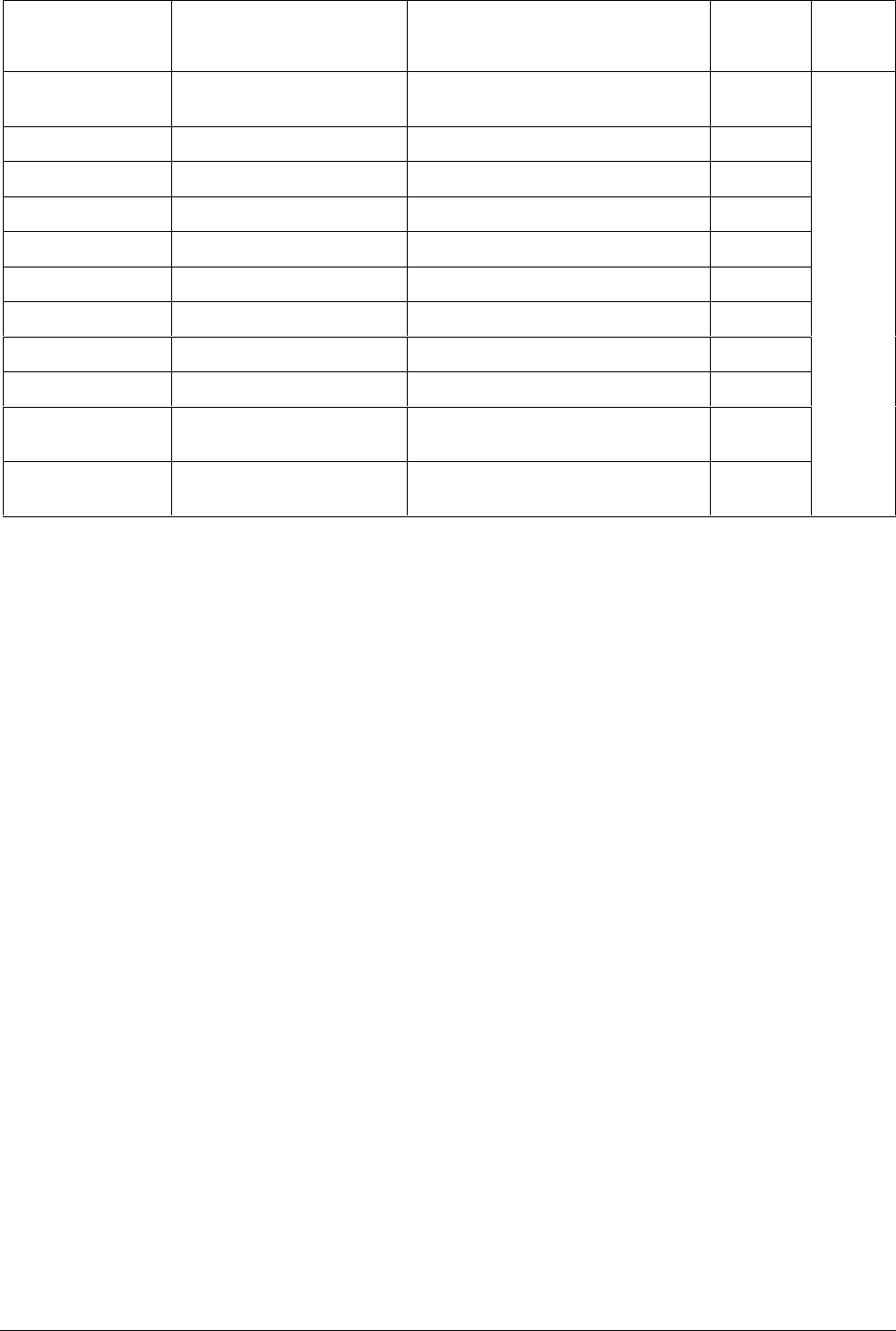
4/00 UDC 3300 Process Controller Product Manual 61
Function Prompt
Lower Display Function
Name Selections or
Range of Setting
Upper Display
Factory
Setting Refer
to
OUT RATE Output Change Rate ENABLE
DISABL DISABL Section
4.12
PCT/M UP Output Rate Up Value 0 to 9999 % per minute 0
PCT/M DN Output Rate Down Value 0 to 9999 % per minute 0
OUTHiLIM High Output Limit –5 to 105 % of output 100
OUTLoLIM Low Output Limit –5 to 105 % of output 0
I HiLIM High Reset Limit Within the range of the output limits 100.0
I LoLIM Low Reset Limit Within the range of the output limits 0.0
DROPOFF Controller Dropoff Value –5 to 105 % of output 0
DEADBAND Output Relay Deadband –5.0 to 5.0 % 1.0
FAILMODE Failsafe Mode NO LAT
LATCH NO LAT
FAILSAFE Failsafe Output Value Set within the range of the output
limits. 0 to 100 % 0

62 UDC 3300 Process Controller Product Manual 4/00
3.17 Options Set Up Group
Introduction This data deals with various options that are available with your
controller. If your controller does not have any of these options the
prompts will not appear.
Function prompts Table 3-14 lists all the function prompts in the Options Set Up group.
Table 3-14 Options Group Function Prompts
Function Prompt
Lower Display Function
Name Selections or
Range of Setting
Upper Display
Factory
Setting Refer
to
AUX OUT
or
CUR OUT2*
Auxiliary Output One Loop
Selection
or
Auxiliary Output Two
Loops/Cascade Selection
DISABL LSP 1
INP 1 IN AL1
INP 2 IN AL2
INP 3 PV 2
CBOUT DEV 2
PV OUTPT2
DEV SP L2
OUTPUT LSP1 2
SP CBOUT2
DISABL Section
4.13
4mA VAL Auxiliary Output Low Scaling
Factor Low scale value to represent 4 mA.
Value in % for output, all others in
engineering units.
0.0
20mA VAL Auxiliary Output High Scaling
Factor High scale value to represent 20 mA.
Value in % for output, all others in
engineering units.
0
DIG IN 1 Digital Input 1 Selections NONE
TO MAN
TO LSP
TO 2SP
TO 3SP
TO DIR
ToHOLD
ToPID2
PV 2IN
PV 3IN
RERUN
TO RUN
ToBEGN
STOP I
MAN FS
ToLOCK
ToAout
TIMER
AM STA
ToTUNE
SPinit
TRACK1
TRACK2
ToOUT2
TO RSP
D L1/2
RST FB
ToPURG
LoFIRE
MAN LT
REStot
HealthWatch option
prompts*:
RESETT1
RESETT2
RESETT3
R ALL T
RESETC1
RESETC2
RESETC3
R ALL C
RALLTC
NONE

4/00 UDC 3300 Process Controller Product Manual 63
Function Prompt
Lower Display Function
Name Selections or
Range of Setting
Upper Display
Factory
Setting Refer
to
DIG1 COM Digital Input 1 Combinations DISABL
+PID2
+ToDIR
+ToSP2
+DISAT
+ToSP1
+RUN
DISABL Section
4.13
DIG IN 2 Digital Input 2 Selections Same as DIG IN 1 NONE
DIG2 COM Digital Input 2 Combinations Same as DIG1 COM DISABL
*Not available on DC330B

64 UDC 3300 Process Controller Product Manual 4/00
3.18 Communications Set Up Group
Introduction This data deals with the Communications option that is available with
your controller. This option allows the controller to be connected to a host
computer via an RS422/485 or Modbus protocol.
If your controller does not have this option the prompts will not appear.
Function prompts Table 3-15 lists all the function prompts in the Communications Set Up
group.
Table 3-15 Communications Group Function Prompts
Function Prompt
Lower Display Function
Name Selections or
Range of Setting
Upper Display
Factory
Setting Refer
to
ComSTATE Communications Option
State DISABL
MOD3K
MODBUS
RS422
DISABL Section
4.14
Com ADDR Communications Station
Address 1 to 99 0
ComADDR2 Loop 2 Communications
Station Address 1 to 99
When ComSTATE = MODBUS,
ComADDR2 = Com ADDR
0
SHEDENAB Shed Enable DISABL
ENABL DISABL
SHEDTIME Shed Time 0 to 255 sample periods
(1 sample period = 0.333 seconds)
0 = No Shed
0
PARITY Parity ODD
EVEN
Fixed at NONE when ComSTATE =
MODBUS
ODD
BAUD Baud Rate 2400
4800
9600
19200
2400
DUPLEX Duplex Operation HALF
FULL
ATTENTION
•When ComSTATE = MODBUS,
this selection is fixed at HALF.
•When the RS422/485/Auxiliary
output option board is installed, this
selection is fixed at HALF.
HALF

4/00 UDC 3300 Process Controller Product Manual 65
Function Prompt
Lower Display Function
Name Selections or
Range of Setting
Upper Display
Factory
Setting Refer
to
WS_FLOAT Word swap order FP_B Floating point big endian
FP_BB Floating point big endian with
byte-swapped
FP_L Floating point little endian
FP_LB Floating point little endian
with byte-swapped
TX DELAY Transmission Delay 1 to 500 milliseconds 1
SHEDMODE Shed Controller Mode and
Output Level LAST
ToAUTO
FSAFE
TO MAN
LAST
SHEDSP Shed Setpoint Recall TO LSP
TO CSP TO LSP
UNITS Communication Units PERCNT
ENG PERCNT
CSP RATO Loop 1 Computer Setpoint
Ratio –20.0 to 20.0 1.0
CSP BIAS Loop 1 Computer Setpoint
Bias –999. to 9999.
(in engineering units) 0
CSP2RATO* Loop 2 or Cascade
Computer Setpoint Ratio –20.0 to 20.0 1.0
CSP2BIAS* Loop 2 or Cascade
Computer Setpoint Bias –999. to 9999.
(in engineering units) 0
LOOPBACK Local Loop Back DISABL
ENABLE DISABL
*Not available on DC330B
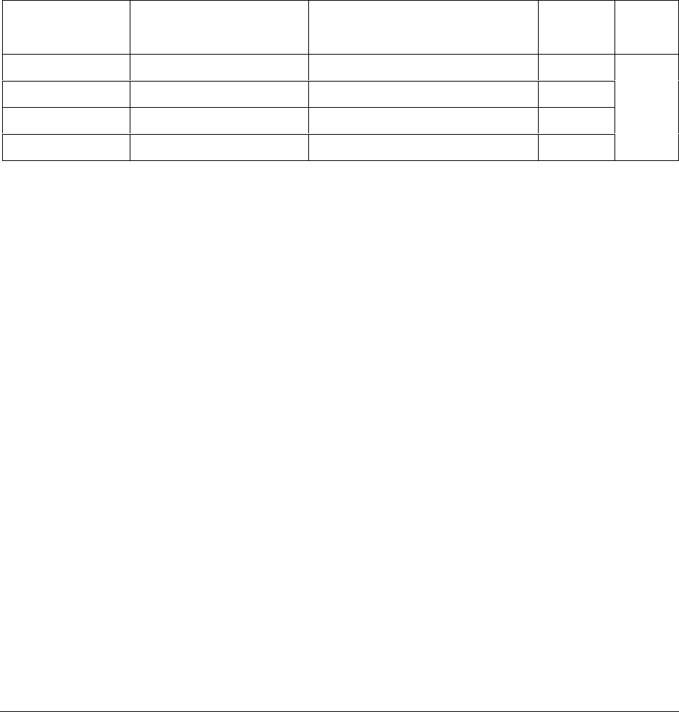
66 UDC 3300 Process Controller Product Manual 4/00
3.19 Alarms Set Up Group
Introduction This data deals with the Alarms function that is available with your
controller.
There are two alarms available. Each alarm has two setpoints. You can
configure each of these two setpoints to alarm on one of several events
and you can configure each setpoint to alarm high or low. You can also
configure the two setpoints to alarm on the same event and to alarm both
high and low, if desired.
Function prompts Table 3-16 lists all the function prompts in the Alarms Set Up group.
Table 3-16 Alarms Group Function Prompts
Function Prompt
Lower Display Function
Name Selections or
Range of Setting
Upper Display
Factory
Setting Refer
to
A1S1 VAL Alarm 1 Setpoint 1 Value Value in engineering units 90
A1S2 VAL Alarm 1 Setpoint 2 Value Value in engineering units 10
Section
4.15
A2S1 VAL Alarm 2 Setpoint 1 Value Value in engineering units 95
A2S2 VAL Alarm 2 Setpoint 2 Value Value in engineering units 5

4/00 UDC 3300 Process Controller Product Manual 67
Function Prompt
Lower Display Function
Name Selections or
Range of Setting
Upper Display
Factory
Setting Refer
to
A1S1TYPE Alarm 1 Setpoint 1 Type NONE
INP 1
INP 2
INP 3
PV (Loop 1 Process Variable)
DEV (Loop 1 Deviation)
OUTPUT (Loop 1 Output)
SHED (Both Loops)
EV ON (Event On – SP Program)
EV OFF (Event Off – SP Program)
MANUAL (Loop 1)
REM SP (Loop 1 Remote Setpoint)
F SAFE (Loop 1 Failsafe)
PVRATE (Loop 1 PV Rate of Change)
Expanded models:
PV 2 (Loop 2 Process Variable)
DEV 2 (Loop 2 Deviation)
OUT 2 (Loop 2 Output)
MAN 2 (Loop 2 Manual )
RSP 2 (Loop 2 Remote Setpoint)
F SAF2 (Loop 2 Failsafe)
PVRAT2 (Loop 2 PV Rate of Change)
BREAK
BREAK2
TOTAL
HealthWatch:**
TIMER1 (HealthWatch Maintenance
Timer 1)
TIMER2 (HealthWatch Maintenance
Timer 2)
TIMER3 (HealthWatch Maintenance
Timer 3)
COUNT1 (HealthWatch Maintenance
Counter 1)
COUNT2 (HealthWatch Maintenance
Counter 2)
COUNT3 (HealthWatch Maintenance
Counter 3)
NONE Section
4.15
A1S2TYPE Alarm 1 Setpoint 2 Type Same as A1S1TYPE NONE
A2S1TYPE Alarm 2 Setpoint 1 Type Same as A1S1TYPE NONE
A2S2TYPE Alarm 2 Setpoint 2 Type Same as A1S1TYPE NONE
A1S1 H L Alarm 1, Setpoint 1 State LOW
HIGH HIGH
A1S1 EV SP Programming Event
Alarm State for Alarm 1,
Setpoint 1
BEGIN
END - -
A1S2 H L Alarm 1, Setpoint 2 State LOW
HIGH LOW
A1S2 EV SP Programming Event
Alarm State for Alarm 1,
Setpoint 2
BEGIN
END - -

68 UDC 3300 Process Controller Product Manual 4/00
Function Prompt
Lower Display Function
Name Selections or
Range of Setting
Upper Display
Factory
Setting Refer
to
A2S1 H L Alarm 2, Setpoint 1 State LOW
HIGH HIGH Section
4.15
A2S1 EV SP Programming Event
Alarm State for Alarm 2,
Setpoint 1
BEGIN
END - -
A2S2 H L Alarm 2, Setpoint 2 State LOW
HIGH LOW
A2S2 EV SP Programming Event
Alarm State for Alarm 2,
Setpoint 2
BEGIN
END - -
AL HYST Alarm Hysteresis 0.0 to 100.0 % of output or span, as
appropriate 0.1
ALM OUT1* Latching Alarm for Output 1 NO LAT
LATCH NO LAT
BLOCK Alarm Blocking DISABL
BLOCK1
BLOCK2
BLK 12
DISABL
*For CE conformity, Performance Criterion A, select NO LAT.

4/00 UDC 3300 Process Controller Product Manual 69
3.20 Display Parameters Set Up Group
Introduction This data deals with the Decimal Place, Units of Temperature, Power
Frequency, and Process ID Tag.
Function prompts Table 3-17 lists all the function prompts in the Display Set Up group.
Table 3-17 Display Group Function Prompts
Function Prompt
Lower Display Function
Name Selections or
Range of Setting
Upper Display
Factory
Setting Refer
to
DECIMAL Control Loop 1 Decimal
Place XXXX
XXX.X
XX.XX
X.XXX
ATTENTION Auto-ranging will occur
to whichever decimal place has been
selected.
XXXX Section
4.16
DECIMAL2 Control Loop 2 Decimal
Place XXXX
XXX.X
XX.XX
X.XXX
XXXX
TEMPUNIT Control Loop 1 Temperature
Units DEG F
DEG C
NONE
NONE
PWR FREQ Power Frequency 60 HZ
50 HZ 60 HZ
RATIO 2 Ratio for Input 2—Set from
the front of the controller DISABL
ENABLE DISABL
LANGUAGE Display Language ENGLIS
FRENCH
GERMAN
SPANIS
ITALAN
ENGLIS

70 UDC 3300 Process Controller Product Manual 4/00
3.21 Calibration Group
Calibration data The prompts used here are for field calibration purposes. Refer to Section
7 – Calibration in this manual for complete information and instructions.

4/00 UDC 3300 Process Controller Product Manual 71
3.22 Maintenance Set Up Group
Introduction The Maintenance group prompts are part of the HealthWatch feature
(available only on DC330E model). These prompts let you count and
time the activity of discrete events such as relays, alarms, control modes
and others, to keep track of maintenance needs.
Function prompts Table 3-18 lists all the function prompts in the Maintenance Set Up group.
Table 3-18 Maintenance Group Function Prompts
Function Prompt
Lower Display Function
Name Selections or
Range of Setting
Upper Display
Factory
Setting Refer
to
TIME1 TIMER 1 DISABL
LASTR
AL1SP1
AL1SP2
AL2SP1
AL2SP2
MANUAL
GSOAK
SOOTNG
DIGIN1
DIGIN2
MAN2
DISABL Section
4.18
HRS.MIN1
OR
DAYS.HRS1
ELAPSED TIME 1 Read only
TIME2 TIMER 2 Same as TIME1 DISABL
HRS.MIN2
OR
DAYS.HRS2
ELAPSED TIME 2 Read only
TIME3 TIMER 3 Same as TIME1 DISABL
HRS.MIN3
OR
DAYS.HRS3
ELAPSED TIME 3 Read only
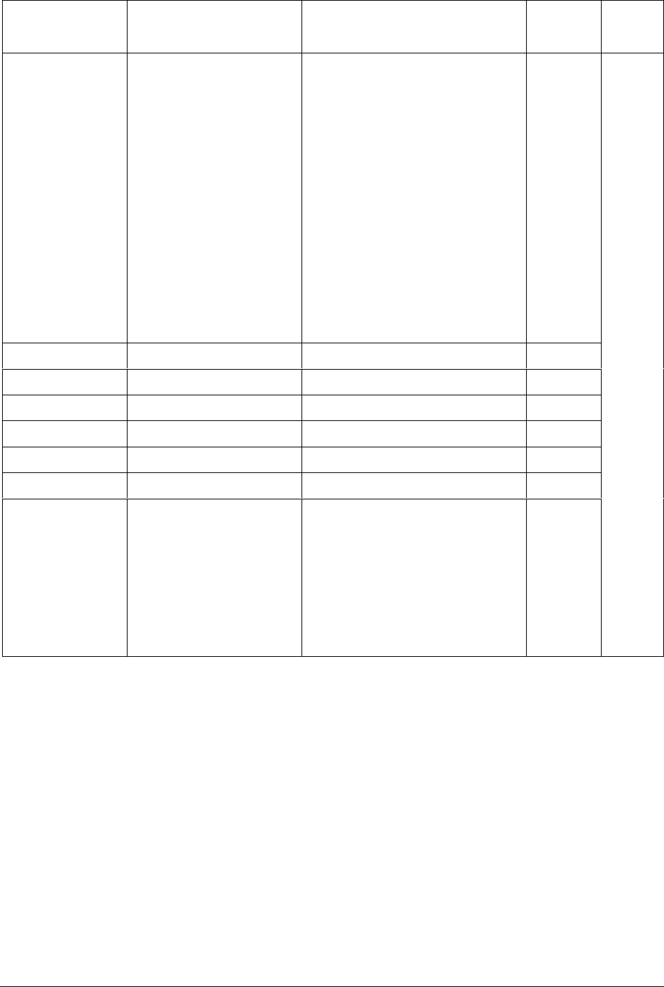
72 UDC 3300 Process Controller Product Manual 4/00
Function Prompt
Lower Display Function
Name Selections or
Range of Setting
Upper Display
Factory
Setting Refer
to
COUNTER1 COUNTER 1 DISABL
MANUAL
AL1SP1
AL1SP2
AL2SP1
AL2SP2
DIGIN1
DIGIN2
OUT1*1K
OUT2*1K
GSOAK
PWRCYC
PV_RNG
FAILSF
TUNE
MAN2
PVRNG2
FSF2
TUNE2
DISABL Section
4.18
COUNTS1 NUMBER OF COUNTS 1 Read only
COUNTER2 COUNTER 2 Same as COUNTER1 DISABL
COUNTS2 NUMBER OF COUNTS 2 Read only
COUNTER3 COUNTER 3 Same as COUNTER1 DISABL
COUNTS3 NUMBER OF COUNTS 3 Read only
PASSWORD PASSWORD 0-9999 0
RES TYPE RESET TYPE NONE
TIMER1
TIMER2
TIMER3
ALL TM
COUNT1
COUNT2
COUNT3
ALL CO
ALL TC
NONE
3.23 Status Group
Status test data The prompts used here are read only. They are used to determine the
reason for a controller failure. Refer to Section 9 – Troubleshooting in this
manual for complete information.

4/00 UDC 3300 Process Controller Product Manual 73
3.24 Configuration Record Sheet
Basic Model: DC330B-XX-XXX
DMCS Model: DC330D-XX-XXX
Keep a record Enter the value or selection for each prompt on this sheet so you will have
a record of how your controller was configured.
Group
Prompt Function
Prompt Value or
Selection Factory
Setting Group
Prompt Function
Prompt Value or
Selection Factory
Setting
TUNING
SP RAMP
ACCUTUNE
PROP BD
or
GAIN
or
GAINVALn
RATE MIN
RSET MIN
or
RSET RPM
MAN RSET
PROPBD2
or
GAIN 2
RATE2MIN
RSET2MIN
or
RSET2RPM
CYC SEC
or
CYC SX3
CYC2 SEC
or
CYC2 SX3
SECURITY
LOCKOUT
AUTO MAN
SP SEL
RUN HOLD
SP RAMP
TIME MIN
FINAL SP
PVHOTSTART
SP RATE
EU/HR UP
EU/HR DN
SP PROG
FUZZY
ACCUTUNE
AT ERROR
__________
__________
Read Only
__________
__________
__________
__________
__________
__________
__________
__________
__________
__________
__________
__________
__________
__________
__________
__________
__________
__________
__________
__________
__________
__________
__________
__________
__________
__________
__________
Read Only
- -
1.000
- -
0.00
1.00
- -
0
- -
1.000
0.00
1.00
- -
20
20
20
20
0
CALIB
ENABLE
ENABLE
ENABLE
DISABL
3
1000
DISABL
DISABL
0
0
DISABL
DISABL
DISABL
NONE
ALGORTHM
OUT ALG
INPUT 1
INPUT 2
CONT ALG
TIMER
PERIOD
START
L DISP
INP ALG1
MATH K
CALC HI
CALC LO
ALG1 INA
ALG1 INB
ALG1 INC
ALG1BIAS
PCT CO
OUT ALG
4–20 RNG
RLYSTATE
RLY TYPE
IN1 TYPE
XMITTER1
IN1 HI
IN1 LO
RATIO 1
BIAS IN1
FILTER 1
BURNOUT1
EMMISIV1
IN2 TYPE
XMITTER2
IN2 HI
IN2 LO
RATIO 2
BIAS IN2
FILTER 2
BURNOUT2
EMMISIV2
__________
__________
__________
__________
__________
__________
__________
__________
__________
__________
__________
__________
__________
__________
__________
__________
__________
__________
__________
__________
__________
__________
__________
__________
__________
__________
__________
__________
__________
__________
__________
__________
__________
__________
__________
__________
PID A
DISABL
0.01
KEY
TI REM
NONE
- -
- -
- -
- -
- -
- -
- -
0.200
CURRNT
100PCT
1OF2ON
MECHAN
0-10mV
LINEAR
1000
0
1.00
0
0
NONE
0.00
0-10mV
LINEAR
1000
0
1.00
0
0
NONE
0.00

74 UDC 3300 Process Controller Product Manual 4/00
Group
Prompt Function
Prompt Value or
Selection Factory
Setting Group
Prompt Function
Prompt Value or
Selection Factory
Setting
CONTROL
OPTIONS
PV SOURC
PID SETS
SW VALUE
LSP’S
RSP SRC
AUTOBIAS
SP TRACK
PWR MODE
PWR OUT
SP HiLIM
SP LoLIM
ACTION
OUT RATE
PCT/M UP
PCT/M DN
OUTHiLIM
OUTLoLIM
I Hi LIM
I Lo LIM
DROPOFF
DEADBAND
OUT HYST
FAILMODE
FAILSAFE
MAN OUT
AUTO OUT
PBorGAIN
MINorRPM
AUX OUT
4mA VAL
20mA VAL
DIG IN 1
DIG1 COM
DIG IN 2
DIG2 COM
__________
__________
__________
__________
__________
__________
__________
__________
__________
__________
__________
__________
__________
__________
__________
__________
__________
__________
__________
__________
__________
__________
__________
__________
__________
__________
__________
__________
__________
__________
__________
__________
__________
__________
__________
INP 1
1 ONLY
0.00
1 ONLY
NONE
DISABL
NONE
MANUAL
LAST
1000
0
REVRSE
DISABL
0
0
100
0.0
100.0
0.0
0
1.0
0.5
NO LAT
0.0
- -
- -
GAIN
MIN
DISABL
0.0
0
NONE
DISABL
NONE
DISABL
COM
ALARMS
DISPLAY
ComSTATE
Com ADDR
SHEDENAB
SHEDTIME
PARITY
BAUD
DUPLEX
WSFLOAT
TX DELAY
SHEDMODE
SHEDSP
UNITS
CSP RATO
CSP BIAS
LOOPBACK
A1S1 VAL
A1S2 VAL
A2S1 VAL
A2S2 VAL
A1S1TYPE
A1S2TYPE
A2S1TYPE
A2S2TYPE
A1S1 H L
A1S1 EV
A1S2 H L
A1S2 EV
A2S1 H L
A2S1 EV
A2S2 H L
A2S2 EV
AL HYST
ALM OUT1
BLOCK
DECIMAL
TEMPUNIT
PWR FREQ
RATIO 2
LANGUAGE
__________
__________
__________
__________
__________
__________
__________
__________
__________
__________
__________
__________
__________
__________
__________
__________
__________
__________
__________
__________
__________
__________
__________
__________
__________
__________
__________
__________
__________
__________
__________
__________
__________
__________
__________
__________
__________
__________
__________
DISABL
0
DISABL
0
ODD
2400
HALF
FP B
1
LAST
TO LSP
PERCNT
1.0
0
DISABL
90
10
95
5
NONE
NONE
NONE
NONE
HIGH
- -
LOW
- -
HIGH
- -
LOW
- -
0.1
NO LAT
DISABL
XXXX
NONE
60 HZ
DISABL
ENGLIS

4/00 UDC 3300 Process Controller Product Manual 75
3.25 Configuration Record Sheet
Expanded Model: DC330E-XX-XXX
Keep a record Enter the value or selection for each prompt on this sheet so you will have
a record of how your controller was configured.
Group
Prompt Function
Prompt Value or
Selection Factory
Setting Group
Prompt Function
Prompt Value or
Selection Factory
Setting
TUNING PROP BD
or
GAIN
or
GAINVALn
RATE MIN
RSET MIN
or
RSET RPM
MAN RSET
PROPBD2
or
GAIN 2
RATE2MIN
RSET2MIN
or
RSET2RPM
CYC SEC
or
CYC SX3
CYC2 SEC
or
CYC2 SX3
SECURITY
LOCKOUT
AUTO MAN
SP SEL
RUN HOLD
PVEUVAL1
PVEUVAL2
PVEUVAL3
PVEUVAL4
PVEUVAL5
PVEUVAL6
PVEUVAL7
PVEUVAL8
GAINVAL1
GAINVAL2
GAINVAL3
GAINVAL4
GAINVAL5
GAINVAL6
GAINVAL7
GAINVAL8
__________
__________
Read Only
__________
__________
__________
__________
__________
__________
__________
__________
__________
__________
__________
__________
__________
__________
__________
__________
__________
__________
__________
__________
__________
__________
__________
__________
__________
__________
__________
__________
__________
__________
__________
__________
__________
__________
- -
1.000
- -
0.00
1.00
- -
0
- -
1.000
0.00
1.00
- -
20
20
20
20
0
CALIB
ENABLE
ENABLE
ENABLE
0
0
0
0
0
0
0
0
1.000
1.000
1.000
1.000
1.000
1.000
1.000
1.000
TUNING2
SP RAMP
PROPBD3
or
GAIN 3
or
GAINVALn
RATE3MIN
RSET3MIN
or
RSET3RPM
MANRSET3
PROPBD4
or
GAIN 4
RATE4MIN
RSET4MIN
or
RSET4RPM
CYC3 SEC
or
CYC3 SX3
CYC4 SEC
or
CYC4 SX3
PVEUVAL1
PVEUVAL2
PVEUVAL3
PVEUVAL4
PVEUVAL5
PVEUVAL6
PVEUVAL7
PVEUVAL8
GAINVAL1
GAINVAL2
GAINVAL3
GAINVAL4
GAINVAL5
GAINVAL6
GAINVAL7
GAINVAL8
SP RAMP
TIME MIN
FINAL SP
PVHOTSTART
SP RATE
EU/HR UP
EU/HR DN
EU/HRUP2
EU/HRDN2
SP PROG
__________
__________
Read Only
__________
__________
__________
__________
__________
__________
__________
__________
__________
__________
__________
__________
__________
__________
__________
__________
__________
__________
__________
__________
__________
__________
__________
__________
__________
__________
__________
__________
__________
__________
__________
__________
__________
__________
__________
__________
__________
__________
__________
- -
1.000
- -
0.00
1.00
- -
0
- -
1.000
0.00
1.0
- -
20
20
20
20
0
0
0
0
0
0
0
0
1.000
1.000
1.000
1.000
1.000
1.000
1.000
1.000
DISABL
3
1000
DISABL
DISABL
0
0
0
0
DISABL

76 UDC 3300 Process Controller Product Manual 4/00
Group
Prompt Function
Prompt Value or
Selection Factory
Setting Group
Prompt Function
Prompt Value or
Selection Factory
Setting
ACCUTUNE
ALGORTHM
FUZZY
ACCUTUNE
ACCUTUN2
SP CHANG
KPG
SP CHAN2
KPG 2
CRITERIA
CRITERA2
AT ERROR
or
AT ERR2
CONT ALG
PIDLOOPS
CONT2ALG
OUT OVRD
TIMER
PERIOD
START
L DISP
INP ALG1
MATH K
CALC HI
CALC LO
ALG1 INA
ALG1 INB
ALG1 INC
PCO SEL
PCT CO
ATM PRES
INP ALG2
MATH K2
CALC HI
CALC LO
ALG2 INA
ALG2 INB
ALG2 INC
PCT H2
8SEG CH1
X0 VALUE
X1 VALUE
X2 VALUE
X3 VALUE
X4 VALUE
X5 VALUE
X6 VALUE
X7 VALUE
X8 VALUE
Y0 VALUE
Y1 VALUE
Y2 VALUE
Y3 VALUE
Y4 VALUE
Y5 VALUE
Y6 VALUE
Y7 VALUE
Y8 VALUE
__________
__________
__________
__________
__________
__________
__________
__________
__________
Read Only
__________
__________
__________
__________
__________
__________
__________
__________
__________
__________
__________
__________
__________
__________
__________
__________
__________
__________
__________
__________
__________
__________
__________
__________
__________
__________
__________
__________
__________
__________
__________
__________
__________
__________
__________
__________
__________
__________
__________
__________
__________
__________
__________
__________
__________
DISABL
DISABL
DISABL
10
1.00
10
1.00
FAST
FAST
NONE
NONE
PID A
1 or 2
PID A
DISABL
DISABL
0.01
KEY
TI REM
NONE
- -
- -
- -
- -
- -
- -
DISABL
0.200
760.0
NONE
- -
- -
- -
- -
- -
- -
1.0
DISABL
0
0
0
0
0
0
0
0
0
0
0
0
0
0
0
0
0
0
ALGORITHM
(continued)
OUT ALG
INPUT 1
INPUT 2
INPUT 3
8SEG CH2
X0 VALU2
X1 VALU2
X2 VALU2
X3 VALU2
X4 VALU2
X5 VALU2
X6 VALU2
X7 VALU2
X8 VALU2
Y0 VALU2
Y1 VALU2
Y2 VALU2
Y3 VALU2
Y4 VALU2
Y5 VALU2
Y6 VALU2
Y7 VALU2
Y8 VALU2
TOTALIZE
•XXXXXXX
TOT SCAL
TOT SEC
• RSET ?
TOT RATE
OUT ALG
4–20 RNG
OUT2 ALG
RLYSTATE
RLY TYPE
IN1 TYPE
XMITTER1
ANALYTIC
IN1 HI
IN1 LO
RATIO 1
BIAS IN1
FILTER 1
BURNOUT1
EMMISIV1
IN2 TYPE
XMITTER2
ANALYTIC
IN2 HI
IN2 LO
RATIO 2
BIAS IN2
FILTER 2
BURNOUT2
EMMISIV2
IN3 TYPE
XMITTER3
IN3 HI
IN3 LO
RATIO 3
BIAS IN3
FILTER 3
__________
__________
__________
__________
__________
__________
__________
__________
__________
__________
__________
__________
__________
__________
__________
__________
__________
__________
__________
__________
__________
__________
__________
__________
__________
__________
__________
__________
__________
__________
__________
__________
__________
__________
__________
__________
__________
__________
__________
__________
__________
__________
__________
__________
__________
__________
__________
__________
__________
__________
__________
__________
__________
__________
__________
__________
__________
DISABL
0
0
0
0
0
0
0
0
0
0
0
0
0
0
0
0
0
0
DISABL
- -
E0
UNLOCK
NO
SECOND
CURRNT
100PCT
CURRNT
1OF2ON
MECHAN
0-10mV
LINEAR
DISABL
1000
0
1.00
0
0
NONE
0.00
0-10mV
LINEAR
DISABL
1000
0
1.00
0
0
NONE
0.00
DISABL
LINEAR
1000
0
1.00
0
0

4/00 UDC 3300 Process Controller Product Manual 77
Group
Prompt Function
Prompt Value or
Selection Factory
Setting Group
Prompt Function
Prompt Value or
Selection Factory
Setting
CONTROL
CONTROL2
OPTIONS
PV SOURC
PID SETS
SW VALUE
LSP’S
RSP SRC
AUTOBIAS
SP TRACK
PWR MODE
PWR OUT
SP HiLIM
SP LoLIM
ACTION
OUT RATE
PCT/M UP
PCT/M DN
OUTHiLIM
OUTLoLIM
I Hi LIM
I Lo LIM
DROPOFF
DEADBAND
OUT HYST
FAILMODE
FAILSAFE
MAN OUT
AUTO OUT
PBorGAIN
MINorRPM
PV2 SRC
FORCE MA
PID SETS
SW VALUE
LSP’S
RSP SRC
AUTOBIAS
SPTRACK
SP HiLIM
SP LoLIM
ACTION
OUT RATE
PCT/M UP
PCT/M DN
OUTHiLIM
OUTLoLIM
I Hi LIM
I Lo LIM
DROPOFF
DEADBAND
FAILMODE
FAILSAFE
AUX OUT
or
CUR OUT2
4mA VAL
20mA VAL
DIG IN 1
DIG1 COM
DIG IN 2
DIG2 COM
__________
__________
__________
__________
__________
__________
__________
__________
__________
__________
__________
__________
__________
__________
__________
__________
__________
__________
__________
__________
__________
__________
__________
__________
__________
__________
__________
__________
__________
__________
__________
__________
__________
__________
__________
__________
__________
__________
__________
__________
__________
__________
__________
__________
__________
__________
__________
__________
__________
__________
__________
__________
__________
__________
__________
__________
__________
__________
INP 1
1 ONLY
0.00
1 ONLY
NONE
DISABL
NONE
MANUAL
LAST
1000
0
REVRSE
DISABL
0
0
100
0.0
100.0
0.0
0
1.0
0.5
NO LAT
0.0
- -
- -
GAIN
MIN
INP 2
DISABL
1 ONLY
0.00
1 ONLY
NONE
DISABL
NONE
1000
0
REVRSE
DISABL
0
0
100
0
100.0
0.0
0
1.0
NO LAT
0
DISABL
DISABL
0.0
0
NONE
DISABL
NONE
DISABL
COM
ALARMS
DISPLAY
MAINTNCE
ComSTATE
Com ADDR
ComADDR2
SHEDTIME
PARITY
BAUD
DUPLEX
TX DELAY
SHEDMODE
SHEDSP
UNITS
CSP RATO
CSP BIAS
CSP2RATO
CSP2BIAS
LOOPBACK
A1S1 VAL
A1S2 VAL
A2S1 VAL
A2S2 VAL
A1S1TYPE
A1S2TYPE
A2S1TYPE
A2S2TYPE
A1S1 H L
A1S1 EV
A1S2 H L
A1S2 EV
A2S1 H L
A2S1 EV
A2S2 H L
A2S2 EV
AL HYST
ALM OUT1
BLOCK
DECIMAL
DECIMAL2
TEMPUNIT
PWR FREQ
RATIO 2
LANGUAGE
TIME1
TIME2
TIME3
COUNTER1
COUNTER2
COUNTER3
PASSWORD
RES TYPE
__________
__________
__________
__________
__________
__________
__________
__________
__________
__________
__________
__________
__________
__________
__________
__________
__________
__________
__________
__________
__________
__________
__________
__________
__________
__________
__________
__________
__________
__________
__________
__________
__________
__________
__________
__________
__________
__________
__________
__________
__________
__________
__________
__________
__________
__________
__________
__________
__________
DISABL
0
0
0
ODD
2400
HALF
1
LAST
TO LSP
PERCNT
1.0
0
1.0
0
DISABL
90
10
95
5
NONE
NONE
NONE
NONE
HIGH
- -
LOW
- -
HIGH
- -
LOW
- -
0.1
NO LAT
DISABL
XXXX
XXXX
NONE
60 HZ
DISABL
ENGLIS
DISABL
DISABL
DISABL
DISABL
DISABL
DISABL
0
NONE

78 UDC 3300 Process Controller Product Manual 4/00

4/00 UDC 3300 Process Controller Product Manual 79
Section 4 – Configuration Prompt Definitions
4.1 Overview
Introduction This section provides information for all the user configurable parameters
listed in Section 3 - Configuration. If you are not familiar with these
parameters, this section gives you the parameter prompt, the selection or
range of setting that you can make, and a definition of how each parameter
setting affects controller performance. It will also refer you to any other
prompts that might be affected by your selection.
What’s in this
section? The table below lists the topics that are covered in this section. They are
listed in the order of their appearance in the controller.
Topic See Page
4.1 Overview 79
4.2 Loop 1 Tuning Parameters Set Up Group 80
4.3 Loop 2 Tuning Parameters Set Up Group 84
4.4 Setpoint Ramp/Rate/Programming Set Up Group 85
4.5 Accutune Set Up Group 88
4.6 Algorithm Data Set Up Group 92
4.7 Output Algorithm Set Up Group 109
4.8 Input 1 Set Up Group 112
4.9 Input 2 Set Up Group 116
4.10 Input 3 Set Up Group 117
4.11 Loop 1 Control Set Up Group 118
4.12 Loop 2 Control Set Up Group 124
4.13 Options Set Up Group 129
4.14 Communications Set Up Group 135
4.15 Alarms Set Up Group 139
4.16 Display Parameters Set Up Group 143
4.17 Calibration Data 144
4.18 Maintenance Set Up Group 144
4.19 Status Test Data 146

80 UDC 3300 Process Controller Product Manual 4/00
4.2 Loop 1 Tuning Parameters Set Up Group
Introduction Tuning consists of establishing the appropriate values for the tuning
constants for a single loop controller. These parameters are also for Loop
1 of a 2-Loop or Cascade control configuration.
The Accutune feature automatically selects Gain, Rate, and Reset.
This section also contains Keyboard Lockout/Security selections.
Set this group last Because this group contains functions that have to do with security and
lockout, we recommend that you configure this group last, after all the
other configuration data has been loaded.
Tuning group
prompts Table 4-1 lists all the function prompts in the Tuning Set Up group and
their definitions.
Table 4-1 Tuning Group Prompt Definitions
Lower Display
Prompt Upper Display
Range of Setting
or Selection
Parameter
Definition
PROP BD
or
GAIN
0.1 to 9999 %
or
0.001 to 1000
PROPORTIONAL BAND (simplex) is the percent of the
range of the measured variable for which a proportional
controller will produce a 100 % change in its output.
GAIN is the ratio of output change (%) over the measured
variable change (%) that caused it.
G = 100%
PB%
where PB is the proportional band (in %)
If the PB is 20 %, then the Gain is 5. And, at those
settings, a 3 % change in the error signal (SP-PV) will
result in a 15 % change in the controller’s output due to
proportional action. If the Gain is 2, then the PB is 50 %.
Also defined as "HEAT" Gain on Duplex models for
variations of Heat/Cool applications.
The selection of Proportional Band or Gain is made in the
CONTROL parameter group under prompt PBorGAIN.
or
GAINVALn Read Only LOOP 1 GAIN—This is the value being provided by Gain
Scheduling when enabled.
RATE MIN 0.00 to 10.00 minutes
0.08 or less = OFF RATE action, in minutes, affects the controller's output
whenever the deviation is changing; and affects it more
when the deviation is changing faster.
Also defined as "HEAT" Rate on Duplex models for
variations of Heat/Cool applications.

4/00 UDC 3300 Process Controller Product Manual 81
Lower Display
Prompt Upper Display
Range of Setting
or Selection
Parameter
Definition
RSET MIN
or
RSET RPM
0.02 to 50.00 RSET MIN = Reset in Minutes per Repeat
RSET RPM = Reset in Repeats per Minute
RESET (Integral Time) adjusts the controller’s output in
accordance with both the size of the deviation
(SP–PV) and the time it lasts. The amount of the
corrective action depends on the value of Gain. The Reset
adjustment is measured as how many times proportional
action is repeated per minute or how many minutes before
one repeat of the proportional action occurs.
Used with control algorithm PID-A or PID-B.
Also defined as "HEAT" Reset on Duplex models for
variations of Heat/Cool applications.
The selection of minutes per repeat or repeats per minute
is made in the CONTROL parameters group under prompt
MINorRPM.
MAN RSET –100 to +100
(in % output) MANUAL RESET is only applicable if you use control
algorithm PD WITH MANUAL RESET in the Algorithm Set
Up group. Because a proportional controller will not
necessarily line out at setpoint, there will be a deviation
(offset) from setpoint. This eliminates the offset and lets
the PV line out at setpoint.
Bias appears on the lower display.
PROPBD2
or
GAIN 2
0.1 to 9999 %
or
0.001 to 1000
PROPORTIONAL BAND 2 or GAIN 2, RATE 2, and
RESET 2 parameters are the same as previously
described for “Heat” except that they refer to the cool
zone tuning constants on duplex models or the second set
of PID constants, whichever is pertinent.
RATE2MIN 0.00 to 10.00 minutes
0.08 or less = OFF
RSET2MIN
RSET2RPM 0.02 to 50.00
ATTENTION
Set 2 Tuning Parameters are not available when the
Accutune selection for Loop 1 is SP+PV.
CYC SEC
or
CYC SX3
1 to 120
ATTENTION If 1/3 second
increments are used, value
of 120 = .33 seconds x 120
= 40 seconds maximum.
CYCLE TIME (HEAT) determines the length of one time
proportional output relay cycle. Defined as "HEAT" cycle
time for Heat/Cool applications.
CYC SEC—Electromechanical relays
CYC SX3—Solid state relays
Cycle times are in either second or 1/3-second increments
depending upon the configuration of RLY TYPE in the
Output Algorithm Set Up group.
CYC2 SEC
or
CYC2 SX3
1 to 120
ATTENTION If 1/3 second
increments are used, value
of 120 = .33 seconds x 120
= 40 seconds maximum.
CYCLE TIME 2 (COOL) is the same as above except it
applies to Duplex models as the cycle time in the "COOL"
zone of Heat/Cool applications or for the second set of
PID constants.
CYC2 SEC—Electromechanical relays
CYC2 SX3—Solid state relays
Cycle times are in either second or 1/3-second increments
depending upon the configuration of RLY TYPE in the
Output Algorithm Set Up group.

82 UDC 3300 Process Controller Product Manual 4/00
Lower Display
Prompt Upper Display
Range of Setting
or Selection
Parameter
Definition
SECURITY 0 to 4095 SECURITY CODE—The level of keyboard lockout may be
changed in the Set Up mode. Knowledge of a security
code may be required to change from one level to another.
Select this number here, copy it, and keep it in a secure
location.
NOTE: The Security Code is for keyboard entry only and is
not available via communications.
Can only be changed if LOCKOUT selection is NONE.
LOCKOUT
NONE
CALIB
+ CONF
+ VIEW
MAX
LOCKOUT applies to one of the functional groups:
Configuration, Calibration, Tuning, Accutune. DO NOT
CONFIGURE UNTIL ALL CONFIGURATION IS
COMPLETE.
NONE—No lockout; all groups are read/write.
CALIB—All groups are available for read/write except for
the Calibration and Keyboard Lockout groups.
+ CONF—Tuning, SP Ramp, and Accutune groups are
read/write. All other groups are read only. Calibration and
Keyboard Lockout groups are not available.
+VIEW—Tuning and Setpoint Ramp parameters are
read/write. No other parameters are viewable.
MAX—Tuning and Setpoint Ramp parameters are
available for read only. No other parameters are viewable.
AUTO MAN
DISABL
ENABLE
MANUAL/AUTO KEY LOCKOUT—Allows you to disable
the Manual/Auto key.
Disable
Enable
Can only be viewed if LOCKOUT is configured for NONE.
SP SEL
DISABL
ENABLE
SETPOINT SELECT KEY LOCKOUT—Allows you to
disable the Setpoint Select key.
Disable
Enable
Can only be viewed if LOCKOUT is configured for NONE.
RUN HOLD
DISABL
ENABLE
RUN/HOLD KEY LOCKOUT—Allows you to disable the
Run/Hold key, for either SP Ramp or SP Program. The
Run/Hold key is never disabled when used to
acknowledge a latched alarm 1.
Disable
Enable
Can only be viewed if LOCKOUT is configured for NONE.
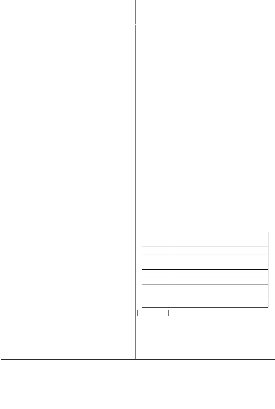
4/00 UDC 3300 Process Controller Product Manual 83
Lower Display
Prompt Upper Display
Range of Setting
or Selection
Parameter
Definition
PVEUVAL1
PVEUVAL2
PVEUVAL3
PVEUVAL4
PVEUVAL5
PVEUVAL6
PVEUVAL7
PVEUVAL8
PV1 Value for Gain
Scheduling
PV2 Value for Gain
Scheduling
PV3 Value for Gain
Scheduling
PV4 Value for Gain
Scheduling
PV5 Value for Gain
Scheduling
PV6 Value for Gain
Scheduling
PV7 Value for Gain
Scheduling
PV8 Value for Gain
Scheduling
Gain Scheduling allows you to schedule eight user-defined
Gain Values (GAINVALn) applied over eight user-defined
PV bands (PVEUVALn).*
PVEUVAL1 is the first PV value to be used in the
schedule. Enter a value, in engineering units, that is within
the PV limits.
To complete the PV selections for the segments, enter a
PV value for all the PVEUVAL prompts listed.
The table on the following page shows the relationship
between the GAIN Values and the PVEU Values.
Gain Scheduling prompts are only available when
PID SETS in the Control Set Up group is configured
for GAIN S.
*Apply to Expanded Model DC330E-XX-X(C or E)X only
(requires math option).
GAINVAL1
GAINVAL2
GAINVAL3
GAINVAL4
GAINVAL5
GAINVAL6
GAINVAL7
GAINVAL8
Gain Value 1 for Gain
Scheduling
Gain Value 2 for Gain
Scheduling
Gain Value 3 for Gain
Scheduling
Gain Value 4 for Gain
Scheduling
Gain Value 5 for Gain
Scheduling
Gain Value 6 for Gain
Scheduling
Gain Value 7 for Gain
Scheduling
Gain Value 8 for Gain
Scheduling
GAIN VAL 1 is the first of eight user-defined Gain values.
Enter a Gain Value you want to be used with PVEUVAL n
previously entered. Gain values are between 0.001 and
1000 floating.
To complete the Gain selections, enter a Gain value for all
the GAINVAL prompts listed.
The table below shows the relationship between the GAIN
Values and the PVEU Values.
Gain PV band over which each
Value X Gain applies
1 Low range limit to PVEUVAL2
2 PVUEVAL2 to PVEUVAL3
3 PVUEVAL3 to PVEUVAL4
4 PVUEVAL4 to PVEUVAL5
5 PVUEVAL5 to PVEUVAL6
6 PVUEVAL6 to PVEUVAL7
7 PVUEVAL7 to PVEUVAL8
8 PVUEVAL8 to High Range Limit
ATTENTION When PB is configured (instead of Gain) in
the Control group prompt PBorGAIN, the displayed
GAINVALn is in units of %PB. The lower display will still
show Gain.
Gain Scheduling prompts are only available when
PID SETS in the Control Set Up group is configured for
GAIN S.
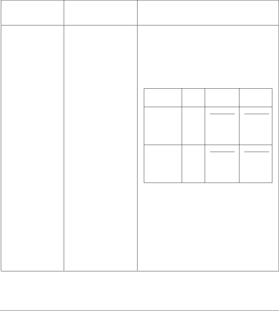
84 UDC 3300 Process Controller Product Manual 4/00
4.3 Loop 2 Tuning Parameters Set Up Group
Introduction Tuning 2 (Loop 2) consists of establishing the appropriate values for the
tuning constants for Loop 2 on 2-Loop or Internal Cascade control.
Loop 2 is only available on Expanded Model DC330E.
Tuning 2 group
prompts Table 4-2 lists all the function prompts in the Tuning 2 Set Up group and
their definitions.
Table 4-2 Loop 2 Tuning Group Prompt
Lower Display
Prompt Upper Display
Range of Setting
or Selection
Parameter
Definition
PROPBD3 or
GAIN 3 or
GAINVALn
RATE3MIN
RSET3MIN or
RSET3RPM
MANRSET3
PROPBD4 or
GAIN 4
RATE4MIN
RSET4MIN or
RSET4RPM
CYC3 SEC or
CYC3 SX3
CYC4 SEC or
CYC4 SX3
PVEUVAL1
PVEUVAL2
PVEUVAL3
PVEUVAL4
PVEUVAL5
PVEUVAL6
PVEUVAL7
PVEUVAL8
GAINVAL1
GAINVAL2
GAINVAL3
GAINVAL4
GAINVAL5
GAINVAL6
GAINVAL7
GAINVAL8
Same as TUNING The definitions listed for the parameters at the left are the
same as those listed previously for the Tuning Set Up
group parameters except they are for Loop 2.
The table below shows you how to use them for Duplex
Heat/Cool applications.
DUPLEX OUTPUT RANGES
0 to 50 %—TUNING SETS 2 AND 4: COOL
50 to 100 %—TUNING SETS 1 AND 3: HEAT
Duplex Heat
Output or Loop 1 Loop 2
Range Cool
0 to 50 % Cool PID SET 2 PID SET 4
Gain 2 Gain 4
Rate 2 Rate 4
Reset 2 Reset 4
Cycle 2 Cycle 4
50 to 100 % Heat PID SET 1 PID SET 3
Gain Gain 3
Rate Rate 3
Reset Reset 3
Cycle Cycle 3
Set 4 Tuning Parameters are not available when
ACCUTUN2 is configured for SP+PV.
Gain Scheduling prompts are only available when
PID SETS in the Loop 2 Control Set Up group is
configured for GAIN S.

4/00 UDC 3300 Process Controller Product Manual 85
4.4 Setpoint Ramp/Rate/Programming Set Up Group
Introduction This data deals with enabling Single Setpoint Ramp function or Setpoint
Rate on one or both control loops. You can start or stop the single SP
Ramp by pressing the RUN/HOLD key.
A single setpoint ramp can be configured to occur between the current
local setpoint and a final local setpoint over a time interval of from 1 to
255 minutes.
There is also a configurable rate of change for any local setpoint change.
ATTENTION SP RAMP and SP RATE will probably cause the SP portion
of Accutune to abort. PV Tune will continue to function normally;
however, during tuning (TUNE configuration) SP Ramp and Program are
placed into HOLD until tuning completes.
SP Ramp/Rate/
Programming group
prompts
Table 4-3 lists all the function prompts in the Setpoint Ramp/Rate Set Up
group and their definitions.
Table 4-3 Setpoint Ramp/Rate Group Definitions
Lower Display
Prompt Upper Display
Range of Setting
or Selection
Parameter
Definition
SP RAMP*
*SP Ramp parameters
(TIME MIN and FINAL
SP) appear when Ramp
is enabled and SP Rate
and SP Programming
are disabled.
DISABL
ENABLE
ENABL2
ENAB12
SINGLE SETPOINT RAMP—Make a selection to enable
or disable the setpoint ramp function. Make sure you
configure a ramp time and a final setpoint value.
SP Rate and SP Programming must be disabled.
DISABLE SETPOINT RAMP—Disables the setpoint ramp
option.
ENABLE SETPOINT RAMP—Allows the single setpoint
ramp prompts for Loop 1 to be shown.
ENABLE SETPOINT RAMP 2—Allows the single setpoint
ramp to run in Loop 2.
ENABLE SETPOINT RAMP 12—Allows the single
setpoint ramp to be run on Loop 1 and Loop 2.
TIME MIN 0 to 255 minutes SETPOINT RAMP TIME—Enter the number of minutes
desired to reach the final setpoint. A ramp time of “0”
implies an immediate change of setpoint.

86 UDC 3300 Process Controller Product Manual 4/00
Lower Display
Prompt Upper Display
Range of Setting
or Selection
Parameter
Definition
FINAL SP Within setpoint limits SETPOINT RAMP FINAL SETPOINT—Enter the value
desired for the final setpoint. The controller will operate at
the setpoint set here when ramp is ended.
ATTENTION If the ramp is on HOLD, the held setpoint can
be changed by the and keys. However, the ramp time
remaining and original ramp rate is not changed.
Therefore, when returning to RUN mode, the setpoint will
ramp at the same rate as previous to the local setpoint
change and will stop if the final setpoint is reached before
the time expires. If the time expires before the final
setpoint is reached, it will jump to the final setpoint.
ATTENTION SP RAMP and SP RATE will cause the SP
portion of Accutune to abort. PV Tune will continue to
function normally. Ramp is placed into HOLD while tuning
(TUNE configuration).
SP RATE*
*SP Rate parameters
(EU/HR UP, EU/HR DN,
EU/HRUP2, EU/HRDN2)
appear when Rate is
enabled and SP Ramp
and SP Programming
are disabled.
DISABL
ENABLE
ENABL2
ENAB12
SETPOINT RATE—Lets you configure a specific rate of
change for any local setpoint change.
SP Ramp and SP Programming must be disabled.
DISABLE SETPOINT RATE—Disables the setpoint rate
option.
ENABLE SETPOINT RATE—Allows the SP rate feature
for Loop 1.
ENABLE SETPOINT RATE 2—Allows the SP rate feature
for Loop 2.
ENABLE SETPOINT RATE 12—Allows the SP rate
feature for Loop 1 and Loop 2.
EU/HR UP 0 to 9999 in engineering
units per hour RATE UP—Rate up value for Loop 1. When making a
setpoint change, this is the rate at which the controller will
change from the original setpoint up to the new one. The
ramping (current) setpoint can be viewed as SPn in the
lower display.
Entering a 0 will imply an immediate change in Setpoint
(i.e., no rate applies).
EU/HR DN 0 to 9999 in engineering
units per hour RATE DOWN—Rate down value for Loop 1. When
making a setpoint change, this is the rate at which the
controller will change from the original setpoint down to
the new one. The ramping (current) setpoint can be
viewed as SPn in the lower display.
Entering a 0 will imply an immediate change in Setpoint
(i.e., no rate applies).
EU/HRUP2 0 to 9999 in engineering
units per hour RATE UP—Rate up value for Loop 2. When making a
setpoint change, this is the rate at which the controller will
change from the original setpoint up to the new one. The
ramping (current) setpoint can be viewed as SPn in the
lower display.

4/00 UDC 3300 Process Controller Product Manual 87
Lower Display
Prompt Upper Display
Range of Setting
or Selection
Parameter
Definition
EU/HRDN2 0 to 9999 engineering units
per hour RATE DOWN—Rate down value for Loop 2. When
making a setpoint change, this is the rate at which the
controller will change from the original setpoint down to
the new one. The ramping (current) setpoint can be
viewed as SPn in the lower display.
Entering a 0 will imply an immediate change in Setpoint
(i.e., no rate applies).
SP PROG
(option)
DISABL
ENABLE
ENABL2
ENAB12
SETPOINT RAMP/SOAK PROGRAM—Available only
with controllers that contain this option.
SP RAMP and SP RATE must be disabled.
DISABLE—Disables setpoint programming.
ENABLE—Enables setpoint programming for Loop1 only.
ENABL2—Enables setpoint programming for Loop 2 only.
ENAB12—Enables setpoint programming for both Loop 1
and Loop 2.
For reasons of convenience, the information for the
prompts when SP PROG is enabled are included in
Section 6 – Setpoint Programming Option.

88 UDC 3300 Process Controller Product Manual 4/00
4.5 Accutune Set Up Group
Introduction Accutune continuously adjusts the PID parameters in response to process
variable disturbances and/or setpoint changes. Also, it can be used during
start-up without prior initialization or process knowledge.
Accutune offers the following selections:
• FUZZY—Fuzzy Overshoot Suppression
• TUNE—Demand Tuning (operates with SP Ramp or SP Program), or
• SP*—Setpoint Tuning, or
• TUN+PV*—Demand Tuning plus PV Adaptive Tune, or
• SP+PV*—Setpoint Tuning plus PV Adaptive Tune
Descriptions of their functions are listed with each selection in Table 4-4.
*Not available on Basic Model DC330B
ATTENTION Selecting Gain Scheduling in the Control or Control 2 Set
Up groups automatically disables Accutune for that group.
Accutune group
prompts Table 4-4 lists all the function prompts in the Accutune Set Up group and
their definitions.
Table 4-4 Accutune Group Definitions
Lower Display
Prompt Upper Display
Range of Setting
or Selection
Parameter
Definition
FUZZY
DISABL
ENABLE
ENABL2
ENAB12
FUZZY OVERSHOOT SUPPRESSION—Can be enabled
or disabled independently of whether Demand Tuning or
SP Tuning is enabled or disabled.
DISABLE—Disables Fuzzy Overshoot Suppression.
ENABLE ON LOOP 1 ONLY—The UDC uses Fuzzy Logic
to suppress or minimize any overshoot that may occur
when PV approaches SP. It will not recalculate any new
tuning parameters.
ENABLE ON LOOP 2 ONLY—Same as ENABLE except
for Loop 2 only.
ENABLE ON BOTH LOOPS—Same as ENABLE except
for both Loops.

4/00 UDC 3300 Process Controller Product Manual 89
Lower Display
Prompt Upper Display
Range of Setting
or Selection
Parameter
Definition
ACCUTUNE
DISABL
TUNE
SP
TUN+PV
SP+PV
ACCUTUNE for Loop 1
DISABLE —Disables the Accutune function.
DEMAND TUNING—If TUNE is selected, and tuning is
initiated through the operator interface or digital input (if
configured), the algorithm calculates new tuning
parameters and enters them into the tuning group. This
tuning requires no process knowledge and does not
require line out for initialization.
SETPOINT TUNING —This selection tunes on setpoint
changes only. It employs time domain analysis to
accelerate line out at any desired setpoint without prior
initialization or process knowledge.
SP is the recommended start-up mode—to be used when
no knowledge of the process tuning values is available. In
the Start-up mode, and after enabling ACCUTUNE, the
operator simply lines out the process variable in manual
mode, selects the desired SP value and switches to
automatic mode.
DEMAND TUNING PLUS PV ADAPTIVE TUNE—This
selection provides “TUNE” On Demand tuning plus PV
Adaptive tuning whenever a PV process disturbance of
0.3 % span or greater occurs. It will take 1-1/2 process
cycles around setpoint before any process recognition and
re-tuning can occur due to PV disturbances.
SETPOINT TUNING PLUS PV ADAPTIVE TUNE—This
selection tunes on setpoint changes but also whenever a
PV process disturbance of 0.3 % span or greater occurs. It
will take 1-1/2 process cycles around setpoint before any
process recognition and re-tuning can occur due to PV
disturbances.
ACCUTUN2
DISABL
TUNE
SP
TUN+PV
SP+PV
ACCUTUNE for Loop 2—Available only if configured for
2-Loop or Cascade control.
DISABLE ACCUTUNE—Disables the Accutune function
for Loop 2.
DEMAND TUNING—Same as ACCUTUNE.
SETPOINT TUNING—Same as ACCUTUNE.
DEMAND TUNING PLUS PV ADAPTIVE TUNE—Same
as ACCUTUNE.
SETPOINT TUNING PLUS PV ADAPTIVE TUNE—Same
as ACCUTUNE.
SP CHANG* 5 to 15 % SETPOINT CHANGE LOOP 1—The minimum setpoint
change on Loop 1 that will result in re-tuning must be
configured between 5 % and 15 %; i.e., if the range is 0 to
2400 and 5 % is configured, re-tuning will occur if the
setpoint change is 120 or larger.

90 UDC 3300 Process Controller Product Manual 4/00
Lower Display
Prompt Upper Display
Range of Setting
or Selection
Parameter
Definition
KPG* 0.10 to 10.00 PROCESS GAIN LOOP 1—This is the Gain of the
process being tuned on Loop 1. It is automatically
calculated during tuning process. This is normally a READ
only value. It should only need to be changed if the
controller fails to identify the process. In this case, set the
value to the algebraic value of PV in percent, divided by
output in percent while in the manual mode.
ATTENTION Note you must disable Accutune to change
tuning constant values from the keyboard.
SP CHAN2* 5 to 15 % SETPOINT CHANGE LOOP 2—The minimum setpoint
change on Loop 2 that will result in re-tuning must be
configured between 5 % and 15 %.
KPG 2* 0.10 to 10.00 PROCESS GAIN LOOP 2—This is the Gain of the
process being tuned on Loop 2. It is automatically
calculated during tuning process. This is normally a READ
only value. It should only need to be changed if the
controller fails to identify the process. In this case, set the
value to the algebraic value of PV in percent, divided by
output in percent while in the manual mode.
ATTENTION Note you must disable Accutune to change
tuning constant values from the keyboard.
CRITERIA*
NORMAL
FAST
TUNING CRITERIA (SETPOINT ADAPTIVE)—Select a
criteria best suited for your process on Loop 1.
NORMAL—Original critical damping (no overshoot).
FAST—A more aggressive tuning with a minimal possible
overshoot of less than 0.5 %.
CRITERA2*
NORMAL
FAST
TUNING CRITERIA FOR LOOP 2 (SETPOINT
ADAPTIVE)—Select a criteria best suited for your process
on Loop 2.
NORMAL—Original critical damping (no overshoot).
FAST—A more aggressive tuning with a minimal possible
overshoot of less than 0.5 %.
For Example: Slightly underdamped

4/00 UDC 3300 Process Controller Product Manual 91
Lower Display
Prompt Upper Display
Range of Setting
or Selection
Parameter
Definition
AT ERROR
or
AT ERR 2
(depending on loop)
Read Only RUNING
NONE
OUTLIM*
IDFAIL*
ABORT
LOW PV*
ACCUTUNE ERROR STATUS—When an error is
detected in the Accutune process, an error prompt will
appear.
RUNNING—An Accutune process is still active checking
process gain, even though “T” is not lit. It does not affect
keyboard operation.
NONE—No errors occurred during last Accutune
procedure.
OUTPUT REACHED LIMITS (HIGH OR LOW)—Output
set insufficiently to get to SP value.
ATTENTION This error will cause the controller to switch
from Automatic to Manual mode. The output is then set to
the value present at the beginning of the Accutune
process.
IDENTIFICATION PROCESS FAILED—An illegal value
for Gain, Rate, or Reset was calculated.
CURRENT ACCUTUNE PROCESS ABORTED—Caused
by one of the following conditions:
•changing to manual mode
•digital input detected
•changing SP while PV (error) tune in progress
•in heat region of output but a cool output is
calculated, or vice versa.
LOW PV—PV not changed sufficiently or the PV has
increased by more than 4 % and Deadtime not
determined.
*Applies to SP and SP+PV tuning only.

92 UDC 3300 Process Controller Product Manual 4/00
4.6 Algorithm Data Set Up Group
Introduction This data deals with various algorithms residing in the controller:
•Control algorithms,
• Input Math algorithms,
•selecting the 1 or 2 PID Loops,
•Output Override,
•2 Eight Segment Characterizers,
•the Timer function,
•Totalizer function, and
•Gain Scheduling.
ATTENTION Math option (two algorithms, two characterizers, totalizer)
and Two Loops of Control are only available on Expanded Model
DC330E.
Algorithm group
prompts Table 4-5 lists all the function prompts in the Algorithm Set Up group and
their definitions.
Table 4-5 Algorithm Group Definitions
Lower Display
Prompt Upper Display
Range of Setting
or Selection
Parameter
Definition
CONT ALG The CONTROL ALGORITHM lets you select the type of
control that is best for your process.
ON-OFF ON/OFF is the simplest control type. The output can be
either ON (100 %) or OFF (0 %). The Process Variable
(PV) is compared with the setpoint (SP) to determine the
sign of the error (ERROR = PV–SP). The ON/OFF
algorithm operates on the sign of the error signal.
In Direct Acting Control, when the error signal is positive,
the output is 100 %; and when the error signal is negative,
the output is 0 %. If the control action is reverse, the
opposite is true. An adjustable overlap (Hysteresis Band)
is provided between the on and off states.
Other prompts affected: OUT HYST
DUPLEX ON/OFF is an extension of this algorithm when
the output is configured for Duplex. It allows the operation
of a second ON/OFF output. There is a deadband
between the operating ranges of the two inputs and an
adjustable overlap (hysteresis) of the on and off states of
each output. Both Deadband and Hysteresis are
separately adjustable. With no relay action the controller
will read 50 %.
Other prompts affected: OUT HYST and DEADBAND

4/00 UDC 3300 Process Controller Product Manual 93
Lower Display
Prompt Upper Display
Range of Setting
or Selection
Parameter
Definition
CONT ALG PID A
ATTENTION PID A should
not be used for Proportional
only action; i.e., no integral
(reset) action. Instead, use
PD+MR with rate set to 0.
PID A is normally used for three-mode control. This means
that the output can be adjusted somewhere between 100
% and 0 %. It applies all three control actions—
Proportional (P), Integral (I), and Derivative (D)—to the
error signal.
Proportional (Gain)—Regulates the controller’s output in
proportion to the error signal (the difference between
Process Variable and Setpoint).
Integral (Reset)—Regulates the controller’s output to the
size of the error and the time the error has existed. (The
amount of corrective action depends on the value of
proportional Gain.)
Derivative (Rate)—Regulates the controller’s output in
proportion to the rate of change of the error. (The amount
of corrective action depends on the value of proportional
Gain.)
PID B PID B—Unlike the PID A equation, the controller gives
only an integral response to a setpoint change, with no
effect on the output due to the gain or rate action, and it
gives full response to PV changes. Otherwise controller
action is as described for the PID A equation. See note on
PID A.
PD+MR PD WITH MANUAL RESET is used whenever integral
action is not wanted for automatic control. The equation is
computed with no integral contribution. The MANUAL
RESET, which is operator adjustable, is then added to the
present output to form the controller output.
Switching between manual and automatic mode will be
bumpless.
If you select PD with Manual Reset you can also configure
the following variations:
•PD (Two Mode) control,
•P (Single Mode) control.
Set Rate (D) to 0.
Other prompts affected: MAN RSET in the Tuning Set Up
group

94 UDC 3300 Process Controller Product Manual 4/00
Lower Display
Prompt Upper Display
Range of Setting
or Selection
Parameter
Definition
CONT ALG
(continued) 3PSTEP THREE POSITION STEP—The Three Position Step
Control algorithm allows the control of a valve (or other
actuator) with an electric motor driven by two controller
relay outputs; one to move the motor upscale, the other
downscale without a feedback slidewire linked to the
motor shaft. The deadband is adjustable in the same
manner as the duplex output algorithm.
The Three Position Step Control algorithm provides an
output display (OUT) which is an estimated motor position,
since the motor is not using any slidewire feedback.
Although this output indication is only an approximation, it
is “corrected” each time the controller drives the motor to
one of its stops (0 % or 100 %). It avoids all the control
problems associated with the feedback slidewire (wear,
dirt, noise). When operating in this algorithm, the
estimated OUT display is shown to the nearest percent
(i.e., no decimal).
Refer to the Operation section for motor position displays.
As a customer configurable option, when a second input
board is installed, the motor slidewire can be connected to
the controller. The actual slidewire position is then shown
on the lower display as POS. This value is used for
display only. It is NOT used in the Three Position Step
algorithm. To configure this option, set Input 2 actuation
to SLIDEW. Calibrate the slidewire.
Other prompts affected: DEADBAND
PIDLOOPS*
*Only available on
Expanded Model
DC330E Dual loop.
1 LOOP
2LOOPS*
CASCAD*
PID LOOPS—This is the PID loop selection.
1 LOOP—Select to use one loop of control.
2 LOOPS—Select to use two PID loops of control, each
with two sets of tuning parameters and a set of control
parameters.
CASCADE—Select for Cascade Control. In a cascade
control system the output of one PID loop is used to adjust
the setpoint of the second control loop and the second
loop’s output actually adjusts the final control element.
ATTENTION To enable a cascade loop, hold in the
SETPOINT SELECT key until the RSP Annunciator
lights and an “I” appears as the upper display’s leftmost
character to indicate Cascade mode. Pressing the key
again disables the Cascade Loop and the annunciators
turn off.
CONT2ALG The CONTROL 2 ALGORITHM lets you select the type of
control for Loop 2 that is best for your process. Only
available if the controller is configured for Cascade or
2-Loop control.
3Pstep and On/Off are not available for the second control
loop.

4/00 UDC 3300 Process Controller Product Manual 95
Lower Display
Prompt Upper Display
Range of Setting
or Selection
Parameter
Definition
PID A
ATTENTION PID A should
not be used for Proportional
only action; i.e., no integral
(reset) action. Instead, use
PD+MR with rate set to 0.
PID A is normally used for three-mode control. This means
that the output can be adjusted somewhere between 100
% and 0 %. It applies all three control actions—
Proportional (P), Integral (I), and Derivative (D)—to the
error signal.
Proportional (Gain)—Regulates the controller’s output in
proportion to the error signal (the difference between
Process Variable and Setpoint).
Integral (Reset)—Regulates the controller’s output to the
size of the error and the time the error has existed. (The
amount of corrective action depends on the value of
proportional Gain.)
Derivative (Rate)—Regulates the controller’s output in
proportion to the rate of change of the error. (The amount
of corrective action depends on the value of proportional
Gain.)
PID B PID B—Unlike the PID A equation, the controller gives
only an integral response to a setpoint change, with no
effect on the output due to the gain or rate action, and it
gives full response to PV changes. Otherwise controller
action is as described for the PID A equation. See note on
PID A.
PD+MR PD WITH MANUAL RESET is used whenever integral
action is not wanted for automatic control. The equation is
computed with no integral contribution. The MANUAL
RESET, which is operator adjustable, is then added to the
present output to form the controller output.
Switching between manual and automatic mode will be
bumpless.
If you select PD with Manual Reset you can also configure
the following variations
• PD (Two Mode) control,
• P (Single Mode) control.
Set Rate (D) to 0.
Other prompts affected: MANRSET3
OUT OVRD OUTPUT OVERRIDE SELECT—This selection lets you
select high or low output override. Only available if the
controller is configured for 2-Loop operation. (NOTE 1)
ATTENTION Loop 1 must be in Automatic for this
selection to work. While the output is being overridden, an
“O” appears as the leftmost digit of the upper display.
DISABL DISABLE—Disables Output Override.
HI SEL HIGH SELECT—The controller will select the higher of
output 1 or output 2 and direct it to output 1 rear terminals.
LO SEL LOW SELECT—The controller will select the lower of
output 1 or output 2 and direct it to output 1 rear terminals.

96 UDC 3300 Process Controller Product Manual 4/00
Lower Display
Prompt Upper Display
Range of Setting
or Selection
Parameter
Definition
TIMER ENABLE
DISABL TIMER allows you to enable or disable the timer option.
The timer option allows you to configure a timeout period
and to select timer start by either the keyboard
(RUN/HOLD key) or Alarm 2. A digital input can also be
configured to start the timer.
When the timer is enabled, it has exclusive control of the
alarm 1 relay; any previous alarm configuration is ignored.
At timeout, the timer is ready to be re-activated by
whatever action has been configured. Alarm 1 is activated
at the end of the timeout period.
PERIOD 0:00 to 99:59 PERIOD allows you to configure the length of timeout
period (from 0 to 99 hours:59 minutes).
START KEY
ALARM2 START allows you to select whether the timer starts with
the keyboard (Run/Hold key) or Alarm 2.
L DISP TI REM
E TIME L DISP allows you to select whether time remaining (TI
REM) or elapsed time (E TIME) is displayed for the timer
option.
The time is shown on the lower display in HH:MM format
along with a rotating “clock” character.
•If the “clock” rotation is clockwise, elapsed time is
indicated.
•If the “clock” rotation is counterclockwise, time
remaining is indicated.
INPUT MATH ALGORITHMS—The controller is provided with two input algorithms. Each algorithm can be
configured to provide a derived (calculated) PV or a derived Remote setpoint. Up to three inputs may be applied to
the calculation. In addition, the two algorithms may be “linked” to combine two calculations by configuring one
algorithm to be an input to the other algorithm. See Inputs A, B, and C for definitions per equation.
All algorithms operate in engineering units except Feedforward which operates in percent of output units.
ATTENTION For the General Math functions, when Input C is set to NONE, the value of Input C used in the
functions is automatically set to 1.0, except for Summer where it is set to 0.0.
INP ALG1 INPUT ALGORITHM 1 has the following selections from
which to choose:
NONE NONE—No algorithm configured
W AVG*
*Standard feature on
DC330E
WEIGHTED AVERAGE—When you configure for
Weighted Average, the controller will compute a PV or SP
for the control algorithm from the following equation:
(Input A x Ratio A + Bias A) + (K x Input B x Ratio B + Bias B)
PV = (1 + K)
Both Inputs must have the same range in engineering
units.
F FWRD*
*Standard feature on
DC330E
FEEDFORWARD SUMMER—Feedforward uses Input A,
following a Ratio and Bias calculation as a value summed
directly with the PID computed output value and sent, as
an output value, to the final control element. Applies to
Loop 1 only. (NOTE 1)
This algorithm will only function in automatic mode.
The following formula applies:
Controller Output = PID Output + (Input A x Ratio A + Bias A ) x (100/Input A Range)

4/00 UDC 3300 Process Controller Product Manual 97
Lower Display
Prompt Upper Display
Range of Setting
or Selection
Parameter
Definition
FFWDMu FEEDFORWARD MULTIPLIER—Feedforward uses Input
A, following a Ratio and Bias calculation as a value
multiplied directly with the PID computed output value and
sent, as an output value, to the final control element.
(NOTE 1)
The following formula applies:
Controller Output = PID Output x (Input A x Ratio A + Bias A )/Input A Range
RELHUM RELATIVE HUMIDITY—Input 1 reads the wet bulb
temperature. Input 2 reads the dry bulb temperature. Both
inputs must be 100 ohm RTD inputs.
ATTENTION The Relative Humidity selection will
automatically force both Analog Input actuations to the
100 ohm low setting.
The controller will indicate measured Relative Humidity as
a Process Variable (PV) with a setpoint range of 0 % to
100 % RH.
SUMMER SUMMER WITH RATIO AND BIAS—The following
formula applies:
PV = (Input A x Ratio A + Bias A) + (Input B x Ratio B + Bias B) + (Input C x Ratio C + Bias C)
HI SEL INPUT HIGH SELECT WITH RATIO AND BIAS—This
selection specifies the PV or SP as the higher of Input 1 or
Input 2. The following formula applies:
PV = higher of (Input A x Ratio A + Bias A) or (Input B x Ratio B + Bias B)
LO SEL INPUT LOW SELECT WITH RATIO AND BIAS—This
selection specifies the PV or SP as the lower of Input 1 or
Input 2. The following formula applies:
PV = lower of (Input A x Ratio A + Bias A) or (Input B x Ratio B + Bias B)
MuDIV (note 2) MULTIPLIER DIVIDER WITH SQUARE ROOT—The
following formula applies:
*PV = K x (Input B x Ratio B + Bias B)
(Input A x Ratio A + Bias A) x (Input C x Ratio C + Bias C) x (Calc Hi – Calc Lo)
See Figure 4-1 at the end of this section for an example of Mass Flow
Compensation using Multiplier/Divider Algorithm.
MULT (note 2) MULTIPLIER WITH SQUARE ROOT—The following
formula applies:
(Input A x Ratio A + Bias A) x (Input C x Ratio C + Bias C) x (Input B x Ratio B + Bias B)*PV = K x x (Calc Hi – Calc Lo)
MuDIV MULTIPLIER DIVIDER—The following formula applies:
*PV = K x (Input B x Ratio B + Bias B)
(Input A x Ratio A + Bias A) x (Input C x Ratio C + Bias C) x (Calc Hi – Calc Lo)
MULT MULTIPLIER—The following formula applies:
*PV = K x [(Input A x Ratio A + Bias A) x (Input C x Ratio C + Bias C) x (Input B x Ratio B + Bias B)] x (Calc Hi – Calc Lo)
CARB A CARBON POTENTIAL A—Make this selection if you have
a Cambridge or Marathon monitor type Zirconium Oxide
sensor.

98 UDC 3300 Process Controller Product Manual 4/00
Lower Display
Prompt Upper Display
Range of Setting
or Selection
Parameter
Definition
CARB B CARBON POTENTIAL B—Make this selection if you have
a Corning type Zirconium Oxide sensor. This algorithm
requires a temperature range within the region of 1400 to
2000°F.
CARB C CARBON POTENTIAL C—Make this selection if you have
an A.A.C.C. type Zirconium Oxide sensor. This algorithm
requires a temperature range within the region of 1400 °F
to 2000 °F.
CARB D CARBON POTENTIAL D—Make this selection if you have
a Barber Coleman, MacDhui, or Bricesco type Zirconium
Oxide sensor. This algorithm requires a temperature range
within the region of 1400 to 2000°F.
FCC CARBON POTENTIAL FCC—Make this selection if you
have a Furnace Controls Corp Accucarb type Zirconium
Oxide sensor. This algorithm requires a temperature range
within the region of 1400 °F to 2000 °F.
DEW PT DEWPOINT OF CARBONIZING ATMOSPHERE—Use
this selection if you are using any Zirconium Oxide Carbon
Probe and you want to measure the atmosphere in terms
of Dewpoint. The range is –50 °F to 100 °F or
–48 °C to 38 °C. This algorithm requires a temperature
range within the region of 1000 °F to 2200 °F.
OXYGEN PERCENT OXYGEN RANGE—Make this selection if you
are using a Zirconium Oxide Oxygen Probe to measure
Percent of Oxygen in a range of 0 to 40 % O2. This
algorithm requires a temperature range within the region
of 800 °F to 3000 °F.
ATTENTION The Carbon and Dewpoint selections will automatically set the first input actuation to Carbon.
The Oxygen selection will automatically set the first input actuation to Oxygen.
MATH K 0.001 to 1000 floating WEIGHTED AVERAGE RATIO OR MASS FLOW
ORIFICE CONSTANT (K) FOR MATH SELECTIONS—
Only applicable for algorithms W AVG or General Math
selections ¥MuDIV, ¥MULT, MuDIV, or MULT.
CALC HI –999. To 9999. Floating
(in engineering units) CALCULATED VARIABLE HIGH SCALING FACTOR
FOR INPUT ALGORITHM 1—Used only when either
Summer, Input Hi/Lo, or one of the General Math functions
was selected as the Input Algorithm. Range is used for
either PV or RSP, depending upon Algorithm application.
CALC LO –999. To 9999. Floating
(in engineering units) CALCULATED VARIABLE LOW SCALING FACTOR
FOR INPUT ALGORITHM 1—Used only when either
Summer, Input Hi/Lo, or one of the General Math functions
was selected as the Input Algorithm. Range is used for
either PV or RSP, depending upon Algorithm application.

4/00 UDC 3300 Process Controller Product Manual 99
Lower Display
Prompt Upper Display
Range of Setting
or Selection
Parameter
Definition
ALG1 INA
INP 1
INP 2
LP1OUT
LP2OUT
IN AL1
IN AL2
INP 3
ALGORITHM 1, INPUT A SELECTION will represent one
of the available selections.
Input 1
Input 2
Output 1 (NOTE 1)
Output 2
Input Algorithm 1
Input Algorithm 2
Input 3
ALG1 INB
INP 1
INP 2
LP1OUT
LP2OUT
IN AL1
IN AL2
INP 3
ALGORITHM 1, INPUT B SELECTION will represent one
of the available selections.
Input 1
Input 2
Output 1 (NOTE 1)
Output 2
Input Algorithm 1
Input Algorithm 2
Input 3
ALG1 INC
NONE
INP 1
INP 2
LP1OUT
LP2OUT
IN AL1
IN AL2
INP 3
ALGORITHM 1, INPUT C SELECTION will represent one
of the available selections.
None
Input 1
Input 2
Output 1 (NOTE 1)
Output 2
Input Algorithm 1
Input Algorithm 2
Input 3
PCO SEL
DISABL
ONLINE
PERCENT CARBON SOURCE allows a live Input 3 value
to be substituted for the static % CO value (PCT CO).
DISABLED
ONLINE—Input 3 must be enabled
PCT CO 0.020 to 0.350 (fractional
percent of CO) PERCENT CARBON is only applicable when Carbon
Potential is selected. Enter the value in percent carbon
monoxide that is applicable for the enriching gas used in
fractional form.
FOR EXAMPLE:
Natural Gas = 20.0 % CO, then setting is 0.200
Propane Gas = 23.0 % CO, setting is 0.230
ATM PRES 590.0 to 760.0 (mm Hg) ATMOSPHERIC PRESSURE COMPENSATION is only
applicable when Relative Humidity is selected. Enter the
value of the atmospheric pressure of the process.
ALG1 BIAS -999 to 9999 floating (in
engineering units) INPUT ALGORITHM 1 BIAS—Does not apply to
selections: FFWRD, FFWDM2, HISEL, or LOSEL.

100 UDC 3300 Process Controller Product Manual 4/00
Lower Display
Prompt Upper Display
Range of Setting
or Selection
Parameter
Definition
INP ALG2
ATTENTION
• All Input Algorithms
operate in engineering
units except Feed-
forward which operates
in percent of range units.
• For General Math
functions, when Input C
is disabled, the value of
Input C used in the
functions is
automatically set to 1.0.
NONE
W AVG
F FWR2
FFWDM2
A-B/C*
HI SEL
LO SEL
MuDIV
MULT
MuDIV
MULT
DEW PT
INPUT ALGORITHM 2—The selections from which to
choose are listed to the left.
The formulas are the same as shown for IN ALG 1.
* ATTENTION Selection A–B/C algorithm subtracts
Input B with Ratio/Bias from Input A with Ratio/Bias and
divides the result by Input C with Ratio/Bias using
engineering units.
EXAMPLE:
PV or SP = K (A–B)
C (Calc Hi – Calc Lo)
MATH K2 0.001 to 1000 floating WEIGHTED AVERAGE RATIO OR MASS FLOW
ORIFICE CONSTANT (K) FOR MATH SELECTIONS—
Only applicable for algorithm W AVG or General Math
selections MuDIV, MULT, MuDIV, or MULT.
CALC HI –999. To 9999. Floating
(in engineering units) CALCULATED VARIABLE HIGH SCALING FACTOR
FOR INPUT ALGORITHM 2—Does not apply to
Feedforward algorithms. Range is used for either PV or
RSP, depending upon Algorithm application.
CALC LO –999. To 9999. Floating
(in engineering units) CALCULATED VARIABLE LOW SCALING FACTOR
FOR INPUT ALGORITHM 2—Does not apply to
Feedforward algorithms. Range is used for either PV or
RSP, depending upon Algorithm application.
ALG2 INA
INP 1
INP 2
LP1OUT
LP2OUT
IN AL1
IN AL2
INP 3
ALGORITHM 2, INPUT A SELECTION will represent one
of the available selections.
Input 1
Input 2
Output 1 (NOTE 1)
Output 2
Input Algorithm 1
Input Algorithm 2
Input 3
ALG2 INB
INP 1
INP 2
LP1OUT
LP2OUT
IN AL1
IN AL2
INP 3
ALGORITHM 2, INPUT B SELECTION will represent one
of the available selections.
Input 1
Input 2
Output 1 (NOTE 1)
Output 2
Input Algorithm 1
Input Algorithm 2
Input 3
ALG2 INC
NONE
INP 1
INP 2
LP1OUT
LP2OUT
IN AL1
IN AL2
INP 3
ALGORITHM 2, INPUT C SELECTION will represent one
of the available selections.
None
Input 1
Input 2
Output 1 (NOTE 1)
Output 2
Input Algorithm 1
Input Algorithm 2
Input 3

4/00 UDC 3300 Process Controller Product Manual 101
Lower Display
Prompt Upper Display
Range of Setting
or Selection
Parameter
Definition
PCT H2 1.0 to 99.0 (% H2)HYDROGEN CONTENT FOR DEWPOINT is only
applicable when Dewpoint is selected. Enter a value for
the percentage of Hydrogen content that is applicable.
ALG2BIAS -999 to 9999 floating (in
engineering units) INPUT ALGORITHM 2 BIAS—Does not apply to
selections: FFWR2, FFWM2, HI SEL, or LO SEL.

102 UDC 3300 Process Controller Product Manual 4/00
Figure 4-1 Example of Mass Flow Compensation using Multiplier/Divider Algorithm
Example - Mass Flow Compensation
A gas flow rate of 650 SCFM develops a differential pressure of 90" H O across an orifice plate
at reference conditions of 30 psig and 140 F. Compensate this gas flow for temperature and
pressure variations.
Apply Multiplier/Divider Algorithm:
Flow = K DPfxP
f
Tf
T
ref
xP
ref
PV = K (Input B x Ratio + Bias )BB
(Input A x Ratio + Bias ) x (Input C x Ratio + Bias )
AAC
CX (Calc – Calc )HI LO
Where:
f = flowing conditions
ref = reference conditions (in absolute units)
Note: If temperature and pressure signals are already ranged in absolute units,
no Bias is required for inputs B and C.
Assign inputs using Engineering units:
Let:
Input A = DP = IN1 (in H O)
Input B = T = IN2 + Bias2 = IN2 F + 460 ( R)
Input C = P = IN3 + Bias3 = IN3psig + 14.7(psia)
T = 140 F + 460 = 600 R
P = 30 psig + 14.7 = 44.7 psia
Calc = 650.0
Calc = 0.0
2
f
f
ref
ref
Hi
Lo Flow in SFCM at Reference Conditions
K = to be determined next
f
2
22049
Example continued
on next page
PV = Q = DPf(IN3 + 14.7)x
SCFM (IN2 + 460) K2
x(650.0 - 0.0)
x
DPf
90
(IN3 + 14.7)
x(IN2 + 460)
T
ref
xP
ref
SCFM
Q = x650
Note: When IN2 and IN3 are at the reference conditions of 600 R (140 F) and 44.7psia (30
psig) respectively and DP = 90" H O, the equation must calculate 650 SCFM. To accomplish
this, divide the DP value by "90" to normalize the equation.
2
f
Rearranging terms:
Variable Constant = K 2
DPf(IN3 + 14.7)
x(IN2 + 460) x1
90
Tref
Pref
xx
650
SCFM
Q =
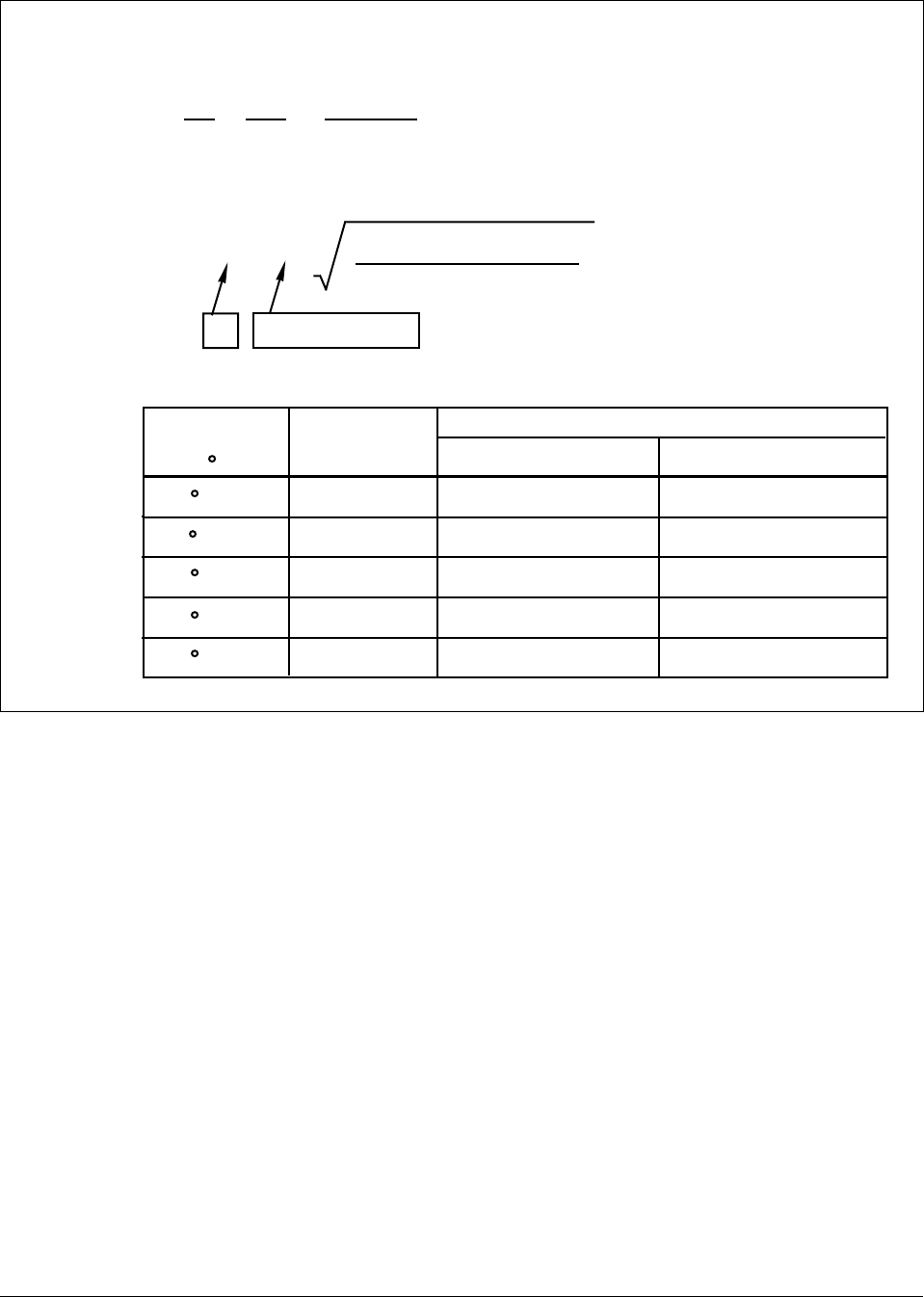
4/00 UDC 3300 Process Controller Product Manual 103
Figure 4-1 Example of Mass Flow Compensation using Multiplier/Divider Algorithm, continued
Example - Mass Flow Compensation
Determined value of K:
K2=x
1
90
Tref
Pref ==
0.14914
600
(90) (44.7)
Therefore K = 0.386
SCFM
Q = (0.386) (650)
(Calc - Calc )
HI LO
K
DPf(in H O) (IN3 + 14.7)
(IN2 + 460)
2
140 F + 460
170 F + 460
170 F + 460
110 F + 460
110 F + 460
30 psi + 14.7
50 psi + 14.7
20 psi + 14.7
50 psi + 14.7
20 psi + 14.7
459
539
395
567
415
Flow (SFCM)
DP = 45" H O (50%)
f2
650
763
559
802
587
DP = 90" H O (100%)
f2
Temp (T )
( R) f
Summary of Flow Values At Values Conditions
Pressure (T )
(psia) f
Reference
Conditions
22050
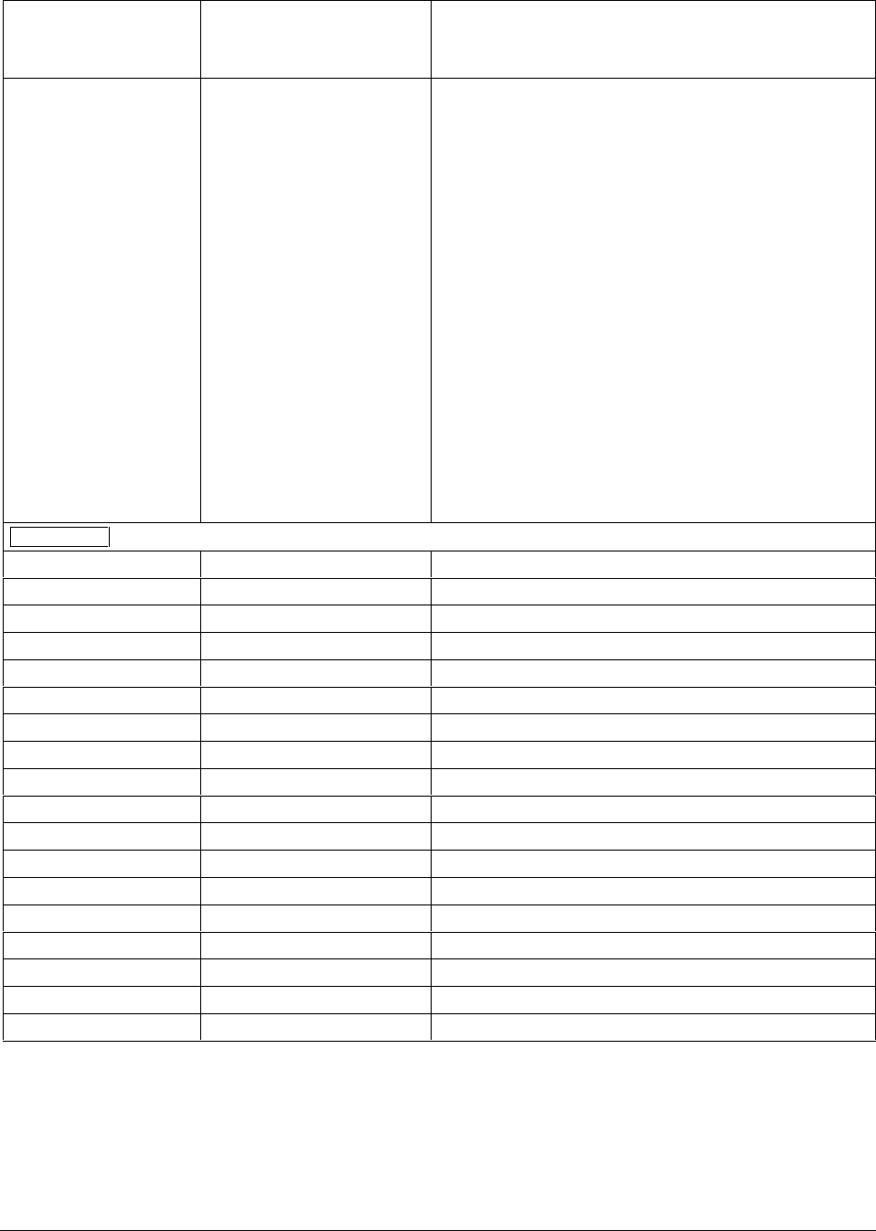
104 UDC 3300 Process Controller Product Manual 4/00
Table 4-5 Algorithm Group Definitions, Continued
Lower Display
Prompt Upper Display
Range of Setting
or Selection
Parameter
Definition
8SEG CH1
DISABL
INPUT1
INPUT2
L1 OUT
L2 OUT
8 SEGMENT CHARACTERIZER #1—An eight segment
characterizer can be applied to either Input 1, Input 2,
Output 1, or Output 2.
DISABLE—Disables characterizer.
INPUT 1—Characterizer is applied to Input 1.
INPUT 2—Characterizer is applied to Input 2.
LOOP 1 OUTPUT—Characterizer is applied to Loop 1
Output. (NOTE 1)
LOOP 2 OUTPUT—Characterizer is applied to Loop 2
Output.
There are eight (Xn) Input values and eight (Yn) Output
values to be selected. The following rules apply:
•When Input 2 is used, Input 2 Ratio and Bias are
applied to the Xn Values.
•When one of the Loop outputs are selected, the Xn
Input values are the Output from the control algorithm,
and the Yn Output is the final control element action.
This application is useful for non-linear control elements
or Process Variable.
A simple example is shown in Figure 4-2.
ATTENTION The X values below should be entered as increasing values (from 0% to 100%) from N = 0 to 8.
X0 VALUE 0.00 to 99.99 % X0 INPUT VALUE (X AXIS)
X1 VALUE 0.00 to 99.99 % X1 INPUT VALUE (X AXIS)
X2 VALUE 0.00 to 99.99 % X2 INPUT VALUE (X AXIS)
X3 VALUE 0.00 to 99.99 % X3 INPUT VALUE (X AXIS)
X4 VALUE 0.00 to 99.99 % X4 INPUT VALUE (X AXIS)
X5 VALUE 0.00 to 99.99 % X5 INPUT VALUE (X AXIS)
X6 VALUE 0.00 to 99.99 % X6 INPUT VALUE (X AXIS)
X7 VALUE 0.00 to 99.99 % X7 INPUT VALUE (X AXIS)
X8 VALUE 0.00 to 99.99 % X8 INPUT VALUE (X AXIS)
Y0 VALUE 0.00 to 99.99 % Y0 INPUT VALUE (Y AXIS)
Y1 VALUE 0.00 to 99.99 % Y1 INPUT VALUE (Y AXIS)
Y2 VALUE 0.00 to 99.99 % Y2 INPUT VALUE (Y AXIS)
Y3 VALUE 0.00 to 99.99 % Y3 INPUT VALUE (Y AXIS)
Y4 VALUE 0.00 to 99.99 % Y4 INPUT VALUE (Y AXIS)
Y5 VALUE 0.00 to 99.99 % Y5 INPUT VALUE (Y AXIS)
Y6 VALUE 0.00 to 99.99 % Y6 INPUT VALUE (Y AXIS)
Y7 VALUE 0.00 to 99.99 % Y7 INPUT VALUE (Y AXIS)
Y8 VALUE 0.00 to 99.99 % Y8 INPUT VALUE (Y AXIS)
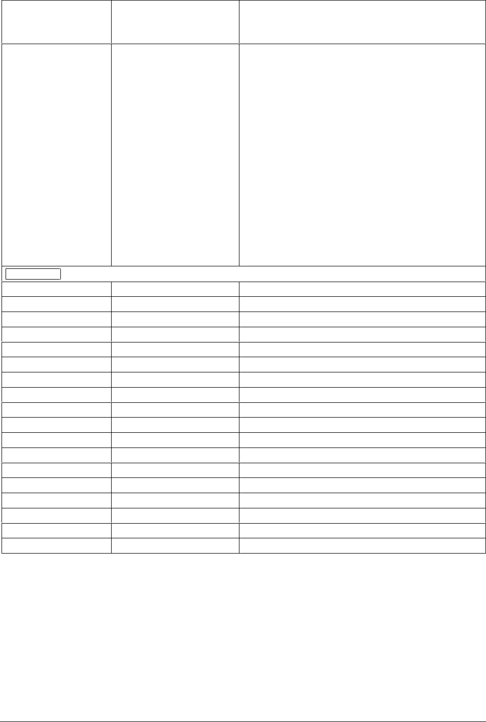
4/00 UDC 3300 Process Controller Product Manual 105
Lower Display
Prompt Upper Display
Range of Setting
or Selection
Parameter
Definition
8SEG CH2
DISABL
INPUT1
INPUT2
L1 OUT
L2 OUT
8 SEGMENT CHARACTERIZER #2—A second eight
segment characterizer can be applied to either
Input 1, Input 2, Output 1, or Output 2.
DISABLE—Disables characterizer.
INPUT 1—Characterizer applied to Input 1.
INPUT 2—Characterizer applied to Input 2.
LOOP 1 OUTPUT—Characterizer applied to Loop 1
Output. (NOTE 1)
LOOP 2 OUTPUT—Characterizer applied to Loop 2
Output.
There are eight (Xn) Input values and eight (Yn) Output
values to be selected. The following rules apply:
•When Input 2 is used, Input 2 Ratio and Bias are
applied to the Xn Values.
•When one of the Loop outputs are selected, the Xn
Input values are the Output from the control algorithm,
and the Yn Output is the final control element action.
This application is useful for non-linear control elements
or Process Variable.
A simple example is shown in Figure 4-2.
ATTENTION The X values below should be entered as increasing values (from 0% to 100%) from N=0 to 8.
X0 VALU2 0.00 to 99.99 % X0 INPUT VALUE (X AXIS)
X1 VALU2 0.00 to 99.99 % X1 INPUT VALUE (X AXIS)
X2 VALU2 0.00 to 99.99 % X2 INPUT VALUE (X AXIS)
X3 VALU2 0.00 to 99.99 % X3 INPUT VALUE (X AXIS)
X4 VALU2 0.00 to 99.99 % X4 INPUT VALUE (X AXIS)
X5 VALU2 0.00 to 99.99 % X5 INPUT VALUE (X AXIS)
X6 VALU2 0.00 to 99.99 % X6 INPUT VALUE (X AXIS)
X7 VALU2 0.00 to 99.99 % X7 INPUT VALUE (X AXIS)
X8 VALU2 0.00 to 99.99 % X8 INPUT VALUE (X AXIS)
Y0 VALU2 0.00 to 99.99 % Y0 INPUT VALUE (Y AXIS)
Y1 VALU2 0.00 to 99.99 % Y1 INPUT VALUE (Y AXIS)
Y2 VALU2 0.00 to 99.99 % Y2 INPUT VALUE (Y AXIS)
Y3 VALU2 0.00 to 99.99 % Y3 INPUT VALUE (Y AXIS)
Y4 VALU2 0.00 to 99.99 % Y4 INPUT VALUE (Y AXIS)
Y5 VALU2 0.00 to 99.99 % Y5 INPUT VALUE (Y AXIS)
Y6 VALU2 0.00 to 99.99 % Y6 INPUT VALUE (Y AXIS)
Y7 VALU2 0.00 to 99.99 % Y7 INPUT VALUE (Y AXIS)
Y8 VALU2 0.00 to 99.99 % Y8 INPUT VALUE (Y AXIS)
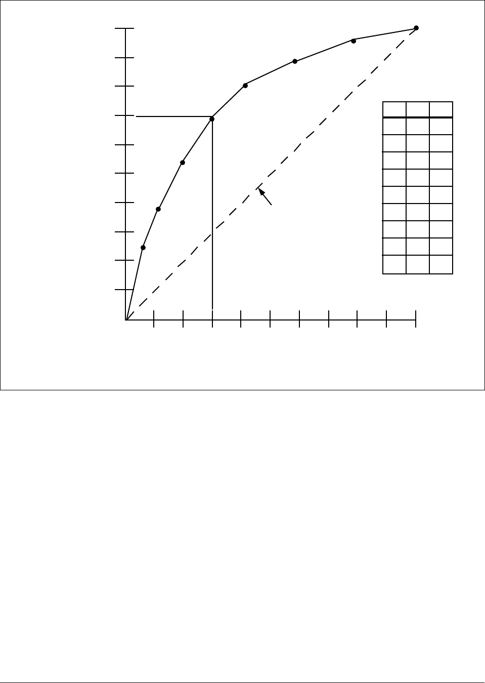
106 UDC 3300 Process Controller Product Manual 4/00
Figure 4-2 Example of Eight Segment Characterizer
NXn
Yn
0
1
2
3
4
5
6
7
8
0.00
5.00
10.00
20.00
31.00
45.00
60.00
80.00
99.99
0.00
25.00
37.00
55.00
70.00
81.00
87.00
94.50
99.99
100% Y AXIS
Y4
Output
from
Characterizer
0%
0% X4
Input to Characterizer
100%
X AXIS
Characterizer
Disabled
22673

4/00 UDC 3300 Process Controller Product Manual 107
Table 4-5 Algorithm Group Definitions, Continued
Lower Display
Prompt Upper Display
Range of Setting
or Selection
Parameter
Definition
TOTALIZE
DISABL
INPUT1
IN AL1
IN AL2
TOTALIZER FUNCTION calculates and displays the total
flow volume as measured by Input 1 or applied to either
Input Algorithm 1 or Algorithm 2 to totalize the
compensated flow rate being calculated by the algorithm.
Displayed value is eight digits with a configurable scale
factor.
DISABLE—Disables the totalizer function.
INPUT 1—Totalizer is applied to Input 1.
IN AL1—Totalizer is applied to Input Algorithm 1.
IN AL2—Totalizer is applied to Input Algorithm 2.
ATTENTION The totalizer should always be reset to
initialize the counters whenever it is enabled. Otherwise,
the Σ (sigma) display will blink.
ΣXXXXXXX Σ*En READ ONLY
Current Scale Factor (Upper Display)
Actual Current Totalized Value (Lower Display)
TOT SCAL *E0 = 1 x 100 = 1
*E1 = 1 x 101 = 10
*E2 = 1 x 102 = 100
*E3 = 1 x 103 = 1,000
*E4 = 1 x 104 = 10,000
*E5 = 1 x 105 = 100,000
*E6 = 1 x 106 = 1,000,000
TOTALIZER SCALE FACTOR—Selects the desired Scale
Factor (i.e., Multiplier).
The desired factor is applied to the calculated value to
extend the maximum flow range that can be displayed.
TOT SEC
UNLOCK
LOCK
TOTALIZER RESET LOCK—Allows the totalizer to be
reset.
UNLOCK—Allows the totalizer value to be reset.
LOCK—Prevents the totalizer value from being reset.
Σ RSET ?
NO
YES
TOTALIZER RESET—Appears only if the totalizer is
unlocked.
NO—No Reset
YES—Resets on next FUNCTION key press and
displays the reset value.

108 UDC 3300 Process Controller Product Manual 4/00
Lower Display
Prompt Upper Display
Range of Setting
or Selection
Parameter
Definition
TOT RATE
SECOND
MINUTE
HOUR
DAY
ML/DAY
TOTALIZER INTEGRATION RATE—Determines the rate
at which the Totalizer is updated.
SECOND —Engineering units per second
MINUTE—Engineering units per minute
HOUR—Engineering units per hour
DAY —Engineering units per day
MIL/DAY—Millions of units per day
ATTENTION The source of the Totalizer is averaged
over the sample and update rates. For example, since the
loop cycle speed is six per second, then with the Totalizer
Rate set at once per minute, the source is averaged six
times per second and the Totalizer value is updated with
this average value ÷ 60 once per second.
NOTE 1: Does not apply to Three Position Step Control.
NOTE 2. If the calculated value of the quantity under the square root sign decreases to a value less than 0.010, the
calculation will become linear as the calculated value decreases below 0.010.
*Where: K = 0.001 to 1000 (configurable)
Calc Hi and Calc Lo are configurable over a range of –999 to 9999

4/00 UDC 3300 Process Controller Product Manual 109
4.7 Output Algorithm Parameters Set Up Group
Introduction This data deals with various output types in the controller, the Digital
Output Status, and the Current Duplex functionality.
Output algorithm
group prompts Table 4-6 lists all the function prompts in the Output Algorithm Set Up
group and their definitions.
Table 4-6 Output Algorithm Group Definitions
Lower Display
Prompt Upper Display
Range of Setting
or Selection
Parameter
Definition
OUT ALG The OUTPUT ALGORITHM lets you select the type of
output you want. Not applicable with Control algorithm
prompt 3PSTEP.
Selections are hardware dependent. For example, if the
controller does not have a current output, then none of the
prompts for Output Algorithms that need a current output
will appear. Likewise, if the controller does not have a
relay output, then none of the prompts that need a relay
output will appear.
ATTENTION For all Duplex Output forms, PID heat
parameters apply for controller output greater than 50 %;
PID cool parameters apply for controller output less than
50 %.
TIME TIME SIMPLEX—This output algorithm uses Digital
Output 1 for Time Proportional Control. The output is
updated per the Loop sampling rate selection. Time
Proportional Output has a resolution of 4.44 msec. Cycle
Time is adjustable from 1 to 120 seconds.
CURRNT CURRENT SIMPLEX—Type of output using one 4 mA to
20 mA signal that can be fed into a positive or negative
grounded load of 0 to 1000 ohms. The signal can be
recalibrated for any desired range from 4 mA to 20 mA for
0 % to 100 % output.
POSITN POSITION PROPORTIONAL SIMPLEX—Type of output
using two SPDT relays and a motor which has a 100 to
1000 ohms feedback slidewire.
Forces Input 2 to SLIDEW selection.
ATTENTION Position Proportional is not available on
two-loop or cascade controllers.
Other prompts affected: DEADBAND, IN2 TYPE
TIME D TIME DUPLEX—This output algorithm uses Digital
Outputs 1 and 2 for Duplex Time Proportional Control. The
outputs are updated per the Loop sampling rate selection.
Time Proportional Output has a resolution of 4.44 msec.
Cycle Time is adjustable from 1 second to 120 seconds.

110 UDC 3300 Process Controller Product Manual 4/00
Lower Display
Prompt Upper Display
Range of Setting
or Selection
Parameter
Definition
OUT ALG
(continued) CUR D CURRENT DUPLEX is similar to current simplex but uses
a second current output. The second output is usually
scaled so that zero and span correspond with 0 % and
50 % output (cool zone). When the output is 0 % to 50 %,
the controller uses tuning parameter set #2, when the
output is 50 % to 100 % it uses set #1.
Other prompts affected: 4-20 RNG
CUR TI CURRENT/TIME DUPLEX is a variation of duplex with
current active for 0 % to 50 % output (tuning set 2) and
time is active 50 % to 100 % output (tuning set 1).
Relay controls heat, current controls cool.
Other prompts affected: 4-20 RNG
TI CUR TIME CURRENT DUPLEX is similar to CUR TI except that
current is active for 50 % to 100 % and time is active for 0
% to 50 %.
Relay controls cool, current controls heat.
Other prompts affected: 4-20 RNG
4-20 RNG CURRENT DUPLEX RANGE ALGORITHM — Used with
Output Algorithm selections CUR D, CUR TI, or TI CUR.
50 PCT CURRENT DUPLEX RANGE (SPLIT)—This setting
should be used for Relay/Current and Current/Relay
Duplex Outputs. It can also be used for Current Duplex
when an Auxiliary Output board is present. This enables
the normal control current output to provide heat control
and the auxiliary current output to provide cool control. To
enable this:
•AUX OUT in the Options Set Up group must be selected
for Output.
•The Auxiliary Current Output is scaled as desired for 0-
50 % controller output.
•Deadband for this configuration only applies to the
Current Output. The Auxiliary Output must have the
Deadband scaled in.
FOR EXAMPLE: If a 2 % Deadband is desired, then enter
2.0 for the Deadband selection in the Control Algorithm
group. This will apply Deadband to the Current Output. In
the Options group, set the Auxiliary Output 4mA VAL
selection to 49.0 and the 20mA VAL selection to 0.0.
100PCT CURRENT DUPLEX RANGE (FULL) enables the Current
Output to provide both heat and cool functions for control
over 0-100 % of the controller output. The PID heat
parameters apply when the output is greater than 50 %
and the PID cool parameters apply when the output is less
than 50 %. The second current output is not required for
this type of duplex operation.

4/00 UDC 3300 Process Controller Product Manual 111
Lower Display
Prompt Upper Display
Range of Setting
or Selection
Parameter
Definition
OUT2 ALG
NONE
TIME
CURRNT
CUR D
CUR TI
TI CUR
The OUTPUT ALGORITHM lets you select the type of
output you want for the second control loop
See OUT ALG for definitions.
NONE
TIME SIMPLEX
CURRENT SIMPLEX (AUX OUT)
CURRENT DUPLEX (AUX OUT)
CURRENT/TIME DUPLEX
TIME/CURRENT DUPLEX
ATTENTION If Time Duplex or TPSC is selected as the
first control loop output, then TIME, CUR TI, and TI CUR
are not available as the second control loop output.
RLYSTATE
1OF2OF
1ON2OF
1OF2ON
1ON2ON
DIGITAL OUTPUT STATUS AT 0 % OUTPUT allows the
following selections:
1OF2OF Output 1 de-energized
Output 2 de-energized
1ON2OF Output 1 energized
Output 2 de-energized
1OF2ON Output 1 de-energized
Output 2 energized
1ON2ON Output 1 energized
Output 2 energized
RLY TYPE
MECHAN
SOL ST
RELAY CYCLE TIME INCREMENT selection is used only
for Time Simplex and Duplex output configurations and
affects both loops. This configuration sets the increment
size of the relay cycle times in the Tuning and Tuning 2
Set Up groups.
ELECTROMECHANICAL RELAY—Cycle time in one-
second increments.
SOLID STATE RELAY—Cycle time in 1/3 second
increments. This is useful for solid state relay applications
that require shorter cycle times. DO NOT use this setting
unless cycle times of less than 1 second are required.
The Lockout selection must be set to NONE in order to
view this selection.

112 UDC 3300 Process Controller Product Manual 4/00
4.8 Input 1 Parameters Set Up Group
Introduction These are the parameters required for Input 1: actuation, transmitter
characterization, high and low range values in engineering units, ratio,
bias, filter, burnout, and emissivity.
Input 1 group prompts Table 4-7 lists all the function prompts in the Input 1 Set Up group and
their definitions.
Table 4-7 Input 1 Group Definitions
Lower Display
Prompt Upper Display
Range of Setting
or Selection
Parameter
Definition
IN1 TYPE
ATTENTION
Changing the input type
will result in the loss of
Field Calibration values
and will restore Factory
Calibration values.
DISABL
B TC
E TC H
E TC L
J TC H
J TC L
K TC H
K TC L
NNM H
NNM L
NM90 H
NM90 L
NIC TC
R TC
S TC
T TC H
T TC L
W TC H
W TC L
100 PT
100 LO
200 PT
500 PT
RAD RH
RAD RI
0-20mA
4-20mA
0-10mV
0-50mV
0-5 V
1-5 V
0-10 V
CARBON
OXYGEN
INPUT 1 ACTUATION TYPE – This selection determines
what actuation you are going to use for Input 1.
DISABLE—Disables Input.
B TC—B Thermocouple
E TC H—E Thermocouple High
E TC L—E Thermocouple Low
J TC H—J Thermocouple High
J TC L—J Thermocouple Low
K TC H—K Thermocouple High
K TC L—K Thermocouple Low
NNM H—Ni-Ni-Moly Thermocouple High
NNM L—Ni-Ni-Moly Thermocouple Low
NM90 H—NiMo-NiCo Thermocouple High
NM90 L—NiMo-NiCo Thermocouple Low
NIC TC—Nicrosil-Nisil Thermocouple
R TC—R Thermocouple
S TC—S Thermocouple
T TC H—T Thermocouple High
T TC L—T Thermocouple Low
W TC H—W5W26 Thermocouple High
W TC L—W5W26 Thermocouple Low
100 PT—100 Ohm RTD High
100 LO—100 Ohm RTD Low
200 PT—200 Ohm RTD
500 PT—500 Ohm RTD
RAD RH—Radiamatic RH
RAD RI—Radiamatic RI
0-20mA—0 to 20 Milliamperes
4-20mA—4 to 20 Milliamperes
0-10mV—0 to 10 Millivolts
0-50mV—0 to 50 Millivolts
0-5 V—0 to 5 Volts
1-5 V—1 to 5 Volts
0-10 V—0 to 10 Volts
Carbon
Oxygen

4/00 UDC 3300 Process Controller Product Manual 113
Lower Display
Prompt Upper Display
Range of Setting
or Selection
Parameter
Definition
XMITTER Select one from the columns
below
B TC S TC
E TC H T TC H
E TC L T TC L
J TC H W TC H
J TC L W TC L
K TC H 100 PT
K TC L 100 LO
NNM H 200 PT
NNM L 500 PT
NM90 H RAD RH
NM90 L RAD RI
NIC TC LINEAR
R TC SQROOT
ANALYTIC
TRANSMITTER CHARACTERIZATION—This selection
lets you instruct the controller to characterize a linear input
to represent a non-linear one.
ATTENTION Prompt only appears when a linear
actuation is selected at prompt IN1 TYPE.
FOR EXAMPLE:
If input 1 is a 4 to 20 mA signal, but the signal represents
a type K thermocouple, select K TC H and the controller
will characterize the 4 to 20 mA signal so that it is treated
as a type K thermocouple input (high range).
Parameter definitions are the same as in IN1 TYPE.
ANALYTIC*
* Expanded models only
NONE
PH
ORP mV
CONDmS
CONDuS
RSTVM^
TDS PPm
TDS PPb
CONCPt
DO PPm
DO PPb
Analytic Input Selections and Ranges—This prompt
appears only when XMITTER is set to ANALYTIC.
Choosing an Analytic setting here will set the Input Range
to appropriate Hi and Low values for that analytical
application. You can adjust the Input Range if you want.
Input Hi Input Low
NONE
as configured as configured
pH 14.00 0.00
ORP 1600 –999
(millivolts)
CONDUCTIVITY 20.00 0.00
(milli Siemens)
CONDUCTIVITY 2000 0.00
(micro Siemens)
RESISTIVITY 2000 0.00
(Megaohms)
TOTAL DISSOLVED SOLIDS 9999 0.00
(parts per million)
TOTAL DISSOLVED SOLIDS 9999 0.00
(parts per billion)
CONCENTRATION 20.00 0.00
(parts per thousand)
DISSOLVED OXYGEN 20.00 0.00
(parts per million)
DISSOLVED OXYGEN 2000 0.00
(parts per billion)
IN1 HI –999. To 9999. Floating
(in engineering units) INPUT 1 HIGH RANGE VALUE in engineering units is
displayed for all inputs but can only be configured for
linear or square root transmitter characterization.
Scale the #1 input signal to the display value you want for
100 %.
EXAMPLE:
Actuation (Input) = 4 to 20 mA
Process Variable = Flow
Range of Flow = 0 to 250 Gal/Min
High Range display value = 250
Then 20 mA = 250 Gal/Min
The control setpoint will be limited by the range of units
selected here.

114 UDC 3300 Process Controller Product Manual 4/00
Lower Display
Prompt Upper Display
Range of Setting
or Selection
Parameter
Definition
IN1 LO –999. To 9999. Floating
(in engineering units) INPUT 1 LOW RANGE VALUE in engineering units is
displayed for all inputs but can only be configured for
linear or square root transmitter characterization. Scale
the #1 input signal to the display value you want for 0 %.
See example above. The control setpoint for Input 1 will
be limited by the range of units selected here.
RATIO 1 –20.00 to 20.00
Floats to 3 decimal places RATIO ON INPUT 1—Select the Ratio value you want on
Input 1.
BIAS IN1 –999. to 9999.
(in engineering units) BIAS ON INPUT 1 — Bias is used to compensate the
input for drift of an input value due to deterioration of a
sensor, or some other cause. Select the bias value you
want on Input 1.
FILTER 1 0 to 120 seconds
No filter = 0 FILTER FOR INPUT 1—A software digital filter is provided
for Input 1 to smooth the input signal. You can configure
the first order lag time constant from 1 to 120 seconds. If
you do not want filtering, enter 0.
BURNOUT
NONE
UP
DOWN
NO_FS
BURNOUT PROTECTION (SENSOR BREAK) provides
most input types with upscale or downscale protection if
the input fails.
1-5V, 0-10V, or 4-20 mA inputs require no burnout or
NONE selection.
NO BURNOUT—Pre-configured Failsafe output applied if
failed input is detected (does not apply for an input out of
range). Error message INPUT 1 FAIL is flashed on the
lower display intermittently every 10 seconds.
UPSCALE BURNOUT will make the PV signal increase to
full scale when a sensor fails, and flash INPUT 1 FAIL on
the lower display intermittently every 10 seconds.
The controller remains in Automatic control mode and
adjusts the controller output signal in response to the full
scale PV signal developed by the Burnout circuitry.
DOWNSCALE BURNOUT will make the PV signal
decrease to the lower range value when a sensor fails,
and flash INPUT 1 FAIL on the lower display intermittently
every 10 seconds.
The controller remains in Automatic control mode and
adjusts the controller output signal in response to the zero
percent PV signal developed by the Burnout circuitry.
NO FAILSAFE—This selection does not provide input
failure detection and should only be used when an
absolute accuracy is the most important criteria. (For this
selection, no burnout signal is sent to the sensor.)
ATTENTION For no Burnout, i.e. NONE, to function
properly on a 4-20 mA input, there must be a dropping
resistor directly across the input terminals (i.e., not
remote), then the unit can detect the “zero” voltage that
occurs when the 4-20 mA line is opened.

4/00 UDC 3300 Process Controller Product Manual 115
Lower Display
Prompt Upper Display
Range of Setting
or Selection
Parameter
Definition
EMISSIV1 0.01 to 1.00 EMISSIVITY is a correction factor applied to the
Radiamatic input signal that is the ratio of the actual
energy emitted from the target to the energy which would
be emitted if the target were a perfect radiator.
Available only for Radiamatic inputs.

116 UDC 3300 Process Controller Product Manual 4/00
4.9 Input 2 Parameters Set Up Group
Introduction These are the parameters required for Input 2: actuation, transmitter
characterization, high and low range values in engineering units, ratio,
bias, filter, burnout, and emissivity.
ATTENTION Prompts for Input 2 appear only if the Input 2 PWA is
installed. If the Loop1 Control Algorithm is set for PID A, PID B, or
PD+MR and the Loop1 Output Algorithm is set for Position Proportional
then the Input 2 configuration prompts are not displayed.
Input 2 group prompts Table 4-8 lists all the function prompts in the Input 2 Set Up group and
their definitions.
Table 4-8 Input 2 Group Definitions
Lower Display
Prompt Upper Display
Range of Setting
or Selection
Parameter
Definition
IN2 TYPE
ATTENTION
Changing the input type
will result in the loss of
Field Calibration values
and will restore Factory
Calibration values.
Same as for Input 1 (except
Carbon and Oxygen are not
used) plus:
SLIDEW*
INPUT 2 ACTUATION TYPE – This selection determines
what actuation you are going to use for Input 2.
SLIDEWIRE
*If the Loop 1 Output Algorithm is set for Position
Proportional, then the Input 2 actuation is forced to
slidewire (SLIDEW). If Loop 1 Control Algorithm is set for
Three Position Step Control, then the SLIDEW setting
allows the motor position to be shown on the Lower
Display. The SLIDEW setting is not available on two-loop
or cascade controllers.
XMITTER2
ANALYTIC
IN2 HI
IN2 LO
RATIO 2
BIAS IN2
FILTER 2
BURNOUT2
EMISSIV2
Input 2 ranges and
selections are same as for
Input 1.
Refer to Input 1 parameters for definitions.

4/00 UDC 3300 Process Controller Product Manual 117
4.10 Input 3 Parameters Set Up Group
Introduction These are the parameters required for Input 3: actuation, transmitter
characterization, high and low range values in engineering units, ratio,
bias, and filter.
ATTENTION Input 3 prompts appear on expanded models only. Prompts
for Input 3 only appear if Input 2 PWA is installed and the actuation for
Input 2 is configured for one of the following types: 0-5 Vdc, 1-5 Vdc,
0-20 mA, or 4-20 mA.
Input 3 group prompts Table 4-9 lists all the function prompts in the Input 3 Set Up group and
their definitions.
Table 4-9 Input 3 Group Definitions
Lower Display
Prompt Upper Display
Range of Setting
or Selection
Parameter
Definition
IN3 TYPE
ATTENTION
Changing the input type
will result in the loss of
Field Calibration values
and will restore Factory
Calibration values.
DISABL
0-20mA
4-20mA
0-5 V
1-5 V
INPUT 3 ACTUATION TYPE – This selection determines
what actuation you are going to use for Input 3.
DISABL—Disables Input 3
0-20mA—0 to 20 milliamperes
4-20mA—4 to 20 milliamperes
0-5 V—0 to 5 volts
1-5 V—1 to 5 volts
XMITTER2
IN3 HI
IN3 LO
RATIO 3
BIAS IN3
FILTER 3
Input 3 ranges and
selections are same as for
Input 1 except Burnout and
Emissivity are not available.
Refer to Input 1 parameters for definitions.
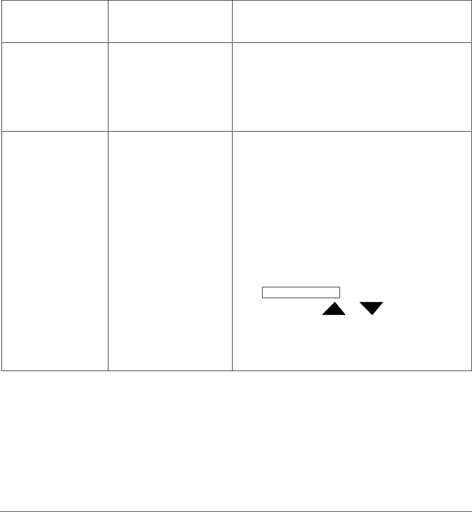
118 UDC 3300 Process Controller Product Manual 4/00
4.11 Loop 1 Control Parameters Set Up Group
Introduction The functions listed in this group deal with how the Single-Loop process
controller or Loop 1 of a Two-Loop process controller will control the
process including: PV source, Number of tuning parameter sets, Setpoint
source, Tracking, Power-up recall, Setpoint limits, Output direction, rate
and limits, Power-up preset outputs, Dropoff, Deadband, and Hysteresis.
Control group
prompts Table 4-10 lists all the function prompts in the Control Set Up group and
their definitions.
Table 4-10 Control Group Definitions
Lower Display
Prompt Upper Display
Range of Setting
or Selection
Parameter
Definition
PV SOURCE
INP 1
INP 2
IN AL1
IN AL2
INP 3
PROCESS VARIABLE SOURCE —Select the source of
the Process Variable.
INPUT 1
INPUT 2
INPUT ALGORITHM 1
INPUT ALGORITHM 2
INPUT 3
PID SETS NUMBER OF TUNING PARAMETER SETS—This
selection lets you choose one or two sets of tuning
constants (gain, rate, and reset).
1 ONLY ONE SET ONLY—Only one set of tuning parameters is
available. Configure the values for:
Gain (proportional band),
Rate,
Reset Time, and
Cycle Time (if time proportional is used).
2KEYBD TWO SETS KEYBOARD SELECTABLE—Two sets of
tuning parameters can be configured and can be selected
at the operator interface or by using the Digital Inputs.
Press LOWER DISPLAY key until you see PID SET1 or
PID SET2 then press or to switch between
sets. Configure the values for:
Gain, Rate, Reset, Cycle Time
Gain #2, Rate #2, Reset #2, Cycle #2 Time
See Subsection 5.10 for procedures.

4/00 UDC 3300 Process Controller Product Manual 119
Lower Display
Prompt Upper Display
Range of Setting
or Selection
Parameter
Definition
PID SETS
(continued) 2PV SW TWO SETS PV AUTOMATIC SWITCHOVER—When the
process variable is GREATER than the value set at
prompt SW VALUE (Switchover Value), the controller will
use Gain, Rate, Reset, and Cycle Time. The active PID
SET can be read in the lower display.
When the process variable is LESS than the value set at
prompt SW VALUE, the controller will use Gain #2, Rate
#2, Reset #2, and Cycle #2 Time. The active PID SET can
be read in the lower display.
Other prompts affected: SW VALUE
2SP SW TWO SETS SP AUTOMATIC SWITCHOVER—When the
setpoint is GREATER than the value set at prompt SW
VALUE (Switchover Value), the controller will use Gain,
Rate, Reset, and Cycle.
When the setpoint is LESS than the value set at prompt
SW VALUE, the controller will use Gain #2, Rate #2,
Reset #2, and Cycle #2.
Other prompts affected: SW VALUE
GAIN S* GAIN SCHEDULING allows you to schedule eight user-
defined Gain segments applied over a user-defined PV
range. Enter Gain and PV values under Tuning Set Up
prompts. PB or GAIN selection in this group also applies.
*Part of Math option DC330E
ATTENTION Gain scheduling automatically disables
Accutune for this loop.
SW VALUE Value in engineering units
within PV or SP range limits AUTOMATIC SWITCHOVER VALUE—This is the value of
Process Variable or Setpoint at which the controller will
switch from Tuning Constant Set #2 to Set #1.
Only appears when PID SETS selection is configured for
either 2 PVSW or 2 SPSW.
LSP’S LOCAL SETPOINT SOURCE—This selection determines
what your local setpoint source will be.
1 ONLY LOCAL SETPOINT—The setpoint entered from the
keyboard.
TWO TWO LOCAL SETPOINTS—This selection lets you
switch between two local setpoints using the
SETPOINT SELECT key.
THREE THREE LOCAL SETPOINTS—This selection lets you
switch between three local setpoints using the
SETPOINT SELECT key. LSP 3 is mutually exclusive
with RSP or Internal Cascade.

120 UDC 3300 Process Controller Product Manual 4/00
Lower Display
Prompt Upper Display
Range of Setting
or Selection
Parameter
Definition
RSP SRC
NONE
INP 2
IN AL1
IN AL2
INP 3
REMOTE SETPOINT SOURCE—This selection
determines what your remote setpoint source will be when
toggled by the SETPOINT SELECT key or Digital Input.
Not available for Cascade PID Loop.
RSP, Cascade, and SP3 are mutually exclusive.
NONE—No remote setpoint.
INP 2—Remote Setpoint is Input 2.
IN AL1—Remote Setpoint using Input 1 algorithm.
IN AL2—Remote Setpoint using Input 2 algorithm.
INP 3—Remote Setpoint is Input 3.
ATTENTION To cycle through the available local
setpoints and remote setpoint, press and hold in the
[SETPOINT SELECT] key. When the key is released, the
setpoint selection currently displayed will be the new
setpoint selection.
AUTOBIAS
ENABLE
DISABL
AUTOBIAS is used for bumpless transfer when
transferring from local setpoint to remote setpoint. Auto
Bias calculates and adds a bias to remote setpoint input
each time a transfer is made.
Only available if no tracking is selected.
ENABLE—Enables auto bias.
DISABLE—Disables auto bias.
SP TRACK SETPOINT TRACKING—The local setpoint can be
configured to track either PV or RSP as listed below. Not
configurable when Auto Bias is set.
ATTENTION For selections other than NONE, LSP is
stored in nonvolatile memory only when there is a mode
change; i.e., when switching from RSP to LSP or from
Manual to Automatic. If power is lost, then the current LSP
value is also lost.
NONE NO TRACKING—If local setpoint tracking is not
configured, the LSP will not be altered when transfer from
RSP to LSP is made.
PV PV—Local setpoint tracks the PV when in manual.
RSP RSP—Local setpoint tracks remote setpoint when in
automatic. When the controller transfers out of remote
setpoint, the last value of the remote setpoint (RSP) is
inserted into the local setpoint.
PWR MODE POWER UP CONTROLLER MODE RECALL—This
selection determines which mode and setpoint the
controller will use when the controller restarts after a
power loss. It applies to both loops.
MANUAL MANUAL, LSP—At power-up, the controller will use
manual mode with the local setpoint displayed.
A LSP AUTOMATIC MODE, LAST LSP—At power-up, the
controller will use automatic mode with the last local
setpoint used before power down displayed.
A RSP AUTOMATIC MODE, LAST RSP—At power-up, the
controller will use automatic mode with the last remote
setpoint used before power down displayed.

4/00 UDC 3300 Process Controller Product Manual 121
Lower Display
Prompt Upper Display
Range of Setting
or Selection
Parameter
Definition
AM SP LAST MODE/LAST SETPOINT used before power down.
AM LSP LAST MODE/LAST LOCAL SETPOINT on power down.
PWR OUT
For Three Position
Step Control Only
(Note 3) LAST
F’SAFE
TPSC (Three-Position Step Control) OUTPUT START-
UP MODE—This selection determines what position the
motor will be in when powered up or in the failsafe
position.
LAST OUTPUT—At power-up in automatic mode, the
motor position will be the last one prior to power down.
When the unit goes into FAILSAFE, it will stay in
automatic mode; motor will not be driven to the configured
failsafe position.
FAILSAFE OUTPUT—At power-up in manual mode, the
motor will be driven to either the 0 % or 100 % output
position, whichever is selected at prompt FAILSAFE. For
Burnout/None, when the unit goes into FAILSAFE, it will
go to manual mode; motor will be driven to the configured
failsafe position.
SP HiLIM 0 to 100 % of PV span in
engineering units SETPOINT HIGH LIMIT*—This selection prevents the
local and remote setpoints from going above the value
selected here. The setting must be equal or less than the
upper range of the inputs.
SP LoLIM 0 to 100 % of PV span in
engineering units SET POINT LOW LIMIT*—This selection prevents the
local and remote setpoints from going below the value
selected here. The setting must be equal or greater than
the lower range of the inputs.
ACTION CONTROL OUTPUT DIRECTION—Select direct or
reverse acting.
DIRECT DIRECT ACTING CONTROL—The controller’s output
increases as the process variable increases.
REVRSE REVERSE ACTING CONTROL—The controller’s output
decreases as the process variable increases.
*The local setpoint will automatically adjust itself to be within the setpoint limit range. For example, if SP = 1500 and
the SP HiLIM is changed to 1200, the new local setpoint will be 1200.
OUT RATE
ENABLE
DISABL
OUTPUT CHANGE RATE—Enables or disables the
Output Change Rate. The maximum rate is set at prompt
PCT/M UP or PCT/M DN. Only available for PID-A, PID-B,
PD+MR control algorithms.
ENABLE—Allows output rate.
DISABLE—Disables output rate.
PCT/M UP 0 to 9999 % per minute OUTPUT RATE UP VALUE—This selection limits the rate
at which the output can change upward. Enter a value in
percent per minute. Appears only if OUT RATE is enabled.
“0” means no output rate applied.
PCT/M DN 0 to 9999 % per minute OUTPUT RATE DOWN VALUE—This selection limits the
rate at which the output can change downward. Enter a
value in percent per minute. Appears only if OUT RATE is
enabled. “0” means no output rate.
OUTHiLIM –5.0 to 105 % of output HIGH OUTPUT LIMIT—This is the highest value of output
beyond which you do not want the controller automatic
output to exceed. Use 0 % to 100 % for digital output type.
Use –5 % to 105 % for current position output.

122 UDC 3300 Process Controller Product Manual 4/00
Lower Display
Prompt Upper Display
Range of Setting
or Selection
Parameter
Definition
OUTLoLIM –5.0 to 105 % of output LOW OUTPUT LIMIT—This is the lowest value of output
below which you do not want the controller automatic
output to exceed.
Use 0 % to 100 % for digital output type.
Use –5 % to 105 % for current position output.
I Hi LIM* Within the range of the
output limits HIGH RESET LIMIT—This is the highest value of output
beyond which you want no reset to occur.
I Lo LIM* Within the range of the
output limits LOW RESET LIMIT—This is the lowest value of output
beyond which you want no reset to occur.
DROPOFF* –5 to 105 % of output CONTROLLER DROPOFF VALUE—Output value below
which the controller output will drop off to the low output
limit value set in prompt OUTLoLIM.
DEADBAND
–5.0 to 25.0 %
0.0 to 25.0 %
0.5 to 5.0 %
DEADBAND is an adjustable gap between the operating
ranges of output 1 and output 2 in which neither output
operates (positive value) or both outputs operate (negative
value).
Time Duplex
On-Off Duplex
Position Proportional and Three Position Step
*Reset limits and Dropoff are not displayed when Three Position Step Control is configured.
OUT HYST 0.0 to 100.0 % of PV span HYSTERESIS (OUTPUT RELAY) is an adjustable overlap
of the ON/OFF states of each control output. This is the
difference between the value of the process variable at
which the control outputs energize and the value at which
they de-energize.
Only applicable for ON/OFF control.
FAILMODE
NO LAT
LATCH
FAILSAFE MODE
NON LATCHING—Controller stays in last mode that was
being used (automatic or manual); output goes to failsafe
value. (NOTE 1, NOTE 2)
LATCHING—Controller goes to manual mode; output
goes to failsafe value. (NOTE 2)
FAILSAFE 0 to 100 % FAILSAFE OUTPUT VALUE—The value used here will
also be the output level when you have Communications
SHED set to failsafe or when NO BURNOUT is configured
and Input 1 fails.
Applies for all output types except 3 Position Step.
0 PCT
100PCT
THREE POSITION STEP FAILSAFE OUTPUT
0 PCT—Motor goes to closed position.
100PCT—Motor goes to open position.
SW_FAIL
0 OCT
100 PCT
PDMR/Position Proportional motor position when slidewire
fails.
0 PCT—Motor goes to closed position.
100PCT—Motor goes to open position.
Note: PWR OUT must be configured for FSAF.

4/00 UDC 3300 Process Controller Product Manual 123
Lower Display
Prompt Upper Display
Range of Setting
or Selection
Parameter
Definition
MAN OUT 0 to 100 % POWER-UP PRESET MANUAL OUTPUT—At power-up,
the controller will go to manual and the output to the value
set here. (NOTE 1)
AUTO OUT 0 to 100 % POWER-UP PRESET AUTOMATIC OUTPUT—At power-
up, the controller will begin its automatic control at the
output value set here. (NOTE 1)
PBorGAIN* PROPORTIONAL BAND UNITS—Select one of the
following for the Proportional (P) term of the PID algorithm:
PB PCT PROPORTIONAL BAND selects units of percent
proportional band for the P term of the PID algorithm.
Where: PB % = 100 % FS
GAIN
GAIN GAIN selects the unitless term of gain for the P term of the
PID algorithm.
Where: GAIN = 100 % FS
PB%
MINorRPM* RESET UNITS—Selects units of minutes per repeat or
repeats per minute for the I term of the PID algorithm.
20 Repeats per Minute = 0.05 Minutes per Repeat.
RPM REPEATS PER MINUTE—The number of times per
minute that the proportional action is repeated by reset.
MIN MINUTES PER REPEAT—The time between each repeat
of the proportional action by reset.
*Selection here is used for both Loop 1 and Loop 2 if available. Also applies to Gain Scheduling on Loops 1 and 2.
NOTE 1: Does not apply to Three Position Step Control.
NOTE 2: If controller is in Manual upon failure, output will maintain its value at time of failure.
NOTE 3:These selections appear when:
1. Control Algorithm is selected for 3PSTEP.
2. Control Algorithm is selected for PD+MR and Output Algorithm is selected for Position Proportional.
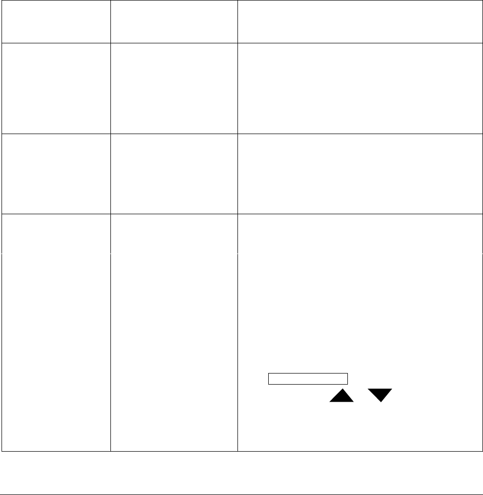
124 UDC 3300 Process Controller Product Manual 4/00
4.12 Loop 2 Control Parameters Set Up Group
Introduction The functions listed in this group deal with how Loop 2 of a Two-Loop
process controller will control the process including: PV source, Number
of tuning parameter sets, Setpoint source, Tracking, Power-up recall,
Setpoint limits, Output direction, rate and limits, Dropoff, Deadband, and
Hysteresis.
Only available on Expanded Model DC330E-XX-XXX.
Control 2 group
prompts Table 4-11 lists all the function prompts in the Control 2 Set Up group and
their definitions.
Table 4-11 Control 2 Group Definitions
Lower Display
Prompt Upper Display
Range of Setting
or Selection
Parameter
Definition
PV 2 SRC
INP 1
INP 2
IN AL1
IN AL2
INP 3
PROCESS VARIABLE 2 SOURCE—Select the source of
the Process Variable for Loop 2.
INPUT 1
INPUT 2
INPUT ALGORITHM 1
INPUT ALGORITHM 2
INPUT 3
FORCE MA
DISABL
LINK12
FORCE MANUAL/AUTO links Auto/Manual modes. If
either loop changes mode due to a front panel change,
digital input action, or failsafe action, the other loop tracks
that mode.
DISABL—Disables FORCE MA.
LINK12—Links modes for both loops.
PID SETS NUMBER OF TUNING PARAMETER SETS—This
selection lets you choose one or two sets of tuning
constants (gain, rate, and reset).
1 ONLY ONE SET ONLY—Only one set of tuning parameters is
available. Configure the values for:
Gain (proportional band)
Rate
Reset Time
Cycle Time (if time proportional is used)
2KEYBD TWO SETS KEYBOARD SELECTABLE—Two sets of
tuning parameters can be configured and can be selected
at the operator interface or by using the Digital Inputs.
Press LOWER DISPLAY key until you see PID SET3 or
PID SET4 then press or to switch between
sets. Configure the values for:
Gain #3, Rate #3 , Reset #3, Cycle #3 Time
Gain #4, Rate #4, Reset #4, Cycle #4 Time
See Subsection 5.10 for procedure.

4/00 UDC 3300 Process Controller Product Manual 125
Lower Display
Prompt Upper Display
Range of Setting
or Selection
Parameter
Definition
PID SETS
(continued) 2PV SW TWO SETS PV AUTOMATIC SWITCHOVER—When the
process variable is GREATER than the value set at
prompt SW VALUE (Switchover Value), the controller will
use Gain #3, Rate #3, Reset #3, and Cycle #3 Time. The
active PID SET can be read in the lower display.
When the process variable is LESS than the value set at
prompt SW VALUE, the controller will use Gain #4, Rate
#4, Reset #4, and Cycle #4 Time. The active PID SET can
be read in the lower display.
Other prompts affected: SW VALUE
2SP SW TWO SETS SP AUTOMATIC SWITCHOVER—When the
setpoint is GREATER than the value set at prompt SW
VALUE (Switchover Value), the controller will use Gain #3,
Rate #3, Reset #3, and Cycle #3.
When the setpoint is LESS than the value set at prompt
SW VALUE, the controller will use Gain #4, Rate #4,
Reset #4, and Cycle #4.
Other prompts affected: SW VALUE
GAIN S GAIN SCHEDULING allows you to schedule eight user-
defined Gain segments applied over a user-defined PV
range. Enter Gain and PV values under Loop 2 Tuning Set
Up prompts. PBorGAIN selection in Control Set Up group
also applies.
ATTENTION Gain scheduling automatically disables
Accutune for this loop.
SW VALUE Value in engineering units
within PV or SP range limits AUTOMATIC SWITCHOVER VALUE—This is the value of
Process Variable or Setpoint at which the controller will
switch from Tuning Constant Set #4 to Set #3.
Only appears when PID SETS selections 2 PVSW or 2
SPSW are selected.
LSP’S LOCAL SETPOINT SOURCE—This selection determines
what your local setpoint source will be.
1 ONLY LOCAL SETPOINT—The setpoint entered from the
keyboard.
TWO TWO LOCAL SETPOINTS—This selection lets you switch
between two local setpoints using the
SETPOINT SELECT key.
THREE THREE LOCAL SETPOINTS—This selection lets you
switch between three local setpoints using the
SETPOINT SELECT key. LSP 3 is mutually exclusive
with RSP or Internal Cascade.

126 UDC 3300 Process Controller Product Manual 4/00
Lower Display
Prompt Upper Display
Range of Setting
or Selection
Parameter
Definition
RSP SRC
NONE
INP 2
IN AL1
IN AL2
INP 3
REMOTE SETPOINT SOURCE—This selection
determines what your remote setpoint source will be when
toggled by the SETPOINT SELECT or Digital Input.
NONE—No remote setpoint,
INPUT 2—Remote Setpoint is Input 2.
INPUT ALGORITHM 1—Remote Setpoint using Input 1
algorithm.
INPUT ALGORITHM 2—Remote Setpoint using Input 2
algorithm.
INP 3—Remote Setpoint is Input 3.
ATTENTION To cycle through the available local
setpoints and remote setpoint, press and hold in the
[SETPOINT SELECT] key. When the key is released, the
setpoint selection currently displayed will be the new
setpoint selection.
AUTOBIAS
ENABLE
DISABL
AUTO BIAS is used for bumpless transfer when
transferring from local setpoint to remote setpoint. Auto
Bias calculates and adds a bias to the remote setpoint
input each time a transfer is made. Available for any
analog input RSP source and if no tracking is selected.
ENABLE—Enables auto bias.
DISABLE—Disables auto bias.
SPTRACK SETPOINT TRACKING—The local setpoint can be
configured to track either PV or RSP as listed below. Not
configurable when Auto Bias is set.
ATTENTION For selections other than NONE, LSP is
stored in nonvolatile memory only when there is a mode
change; i.e., when switching from RSP to LSP or from
Manual to Automatic. If power is lost, then the current LSP
value is also lost.
NONE NO TRACKING—If local setpoint tracking is not
configured, the LSP will not be altered when transfer from
RSP to LSP is made.
PV PV—Local setpoint tracks the PV when in manual mode.
RSP RSP—Local setpoint tracks remote setpoint. When the
controller transfers out of remote setpoint, the last value of
the remote setpoint (RSP) is inserted into the local
setpoint.
SP HiLIM 0 to 100 % of span input in
engineering units with
decimal place
SETPOINT HIGH LIMIT*—This selection prevents the
local and remote setpoints from going above the value
selected here. The setting must be equal or less than the
upper range of the inputs.
SP LoLIM 0 to 100 % of span input in
engineering units with
decimal place
SETPOINT LOW LIMIT*—This selection prevents the
local and remote setpoints from going below the value
selected here. The setting must be equal or greater than
the lower range of the inputs.
ACTION CONTROL OUTPUT DIRECTION—Select direct or
reverse acting control.
DIRECT DIRECT ACTING CONTROL—The controller's output
increases as the process variable increases.

4/00 UDC 3300 Process Controller Product Manual 127
Lower Display
Prompt Upper Display
Range of Setting
or Selection
Parameter
Definition
REVRSE REVERSE ACTING CONTROL—The controller's output
decreases as the process variable increases.
OUT RATE
DISABL
ENABLE
OUTPUT CHANGE RATE—Enables or disables the
Output Change Rate. The maximum rate is set at prompt
PCT/M UP or PCT/M DN.
DISABLE—Disables output rate.
ENABLE—Allows output rate.
PCT/M UP 0 to 9999 % per minute OUTPUT RATE UP VALUE—This selection limits the rate
at which the output can change upward. Enter a value in
percent per minute. Appears only if OUT RATE is enabled.
“0” means no output rate applied.
PCT/M DN 0 to 9999 % per minute OUTPUT RATE DOWN VALUE—This selection limits the
rate at which the output can change downward. Enter a
value in percent per minute. Appears only if OUT RATE is
enabled. “0” means no output rate.
OUT HiLIM –5 to 105 % of output HIGH OUTPUT LIMIT—This is the highest value of output
beyond which you do not want the controller automatic
output to exceed.
Use 0 to 100 % for digital output type.
Use 5 to 105 % for current output.
OUT LoLIM –5 to 105 % of output LOW OUTPUT LIMIT—This is the lowest value of output
below which you do not want the controller automatic
output to exceed.
Use 0 % to 100 % for digital output type.
Use 5 % to 105 % for current output.
*The Local Setpoint will automatically adjust itself to be within the setpoint limit range. For example, if SP = 1500 and
the SP HiLIM is changed to 1200, the new Local Setpoint will be 1200.
I Hi LIM Within the range of the
output limits HIGH RESET LIMIT—This is the highest value of output
beyond which you want no reset to occur.
I Lo LIM Within the range of the
output limits LOW RESET LIMIT—This is the lowest value of output
beyond which you want no reset to occur.
DROPOFF –5 to 105 % of output CONTROLLER DROPOFF VALUE—Output value below
which the controller output will drop off to the low output
limit value set in prompt OUTLoLIM.
DEADBAND –5.0 to 5.0 % DEADBAND is an adjustable gap between the operating
ranges of output 1 and output 2 in which neither output
operates (positive value) or both outputs operate (negative
value).
FAILMODE
NO LAT
LATCH
FAILSAFE MODE
NON LATCHING—Controller stays in last mode
(automatic or manual); output goes to failsafe value.
LATCHING—Controller goes to manual mode; output
goes to failsafe value.

128 UDC 3300 Process Controller Product Manual 4/00
Lower Display
Prompt Upper Display
Range of Setting
or Selection
Parameter
Definition
FAILSAFE 0 to 100 % FAILSAFE OUTPUT 2 VALUE—The value used here will
also be the output level when you have Communications
SHED set to failsafe or when NO BURNOUT is configured
and input 1 fails.
ATTENTION At power-up, the Loop 2 Output is set to
the Failsafe Output 2 value.

4/00 UDC 3300 Process Controller Product Manual 129
4.13 Options Set Up Group
Introduction Configure the remote mode switch (Digital Inputs) to a specific contact
closure response, or configure the Auxiliary Output to be a specific
selection with desired scaling.
Option group prompts Table 4-12 lists all the function prompts in the Options Set Up group and
their functions.
Table 4-12 Options Group Definitions
Lower Display
Prompt Upper Display
Range of Setting
or Selection
Parameter
Definition
AUX OUT
or
CUR OUT2*
ATTENTION Prompts
for the Auxiliary Output
Selection appear only if
one of the Auxiliary
Output boards is
installed.
*DE330E only
AUXILIARY OUTPUT SELECTION FOR ONE LOOP
or
AUXILIARY OUTPUT SELECTION FOR TWO LOOPS
This selection provides an mA output representing one of
several control parameters. The display for auxiliary output
viewing will be in engineering units for all but output.
Output will be displayed in percent.
Other prompts affected by these selections: 4mA VAL and
20mA VAL.
ATTENTION When the controller is configured for Two-
Loop operation, and the Loop 2 Output selection requires
a current output, the Auxiliary Output selection is
automatically set to Output 2 and all other selections are
locked out.
ATTENTION Output cannot be configured when Three
Position Step Control is used.
DISABL NO AUXILIARY OUTPUT
INP 1 INPUT 1—This represents the configured range of input 1.
FOR EXAMPLE:
Type J Thermocouple (0 °F to 1600 °F)
0 °F display = 0 % output
1600 °F display = 100 % output
INP 2 INPUT 2 represents the value of the configured range of
input 2.
INP 3 INPUT 3 represents the value of the configured range of
input 3.
CB OUT CONTROL BLOCK OUTPUT—Represents the
uncharacterized use of automatic control valve which
allows the characterizer to characterize the output on
Analog Output 1 and the Auxiliary Output to use the
uncharacterized output value as Output 2.
PV PROCESS VARIABLE—Represents the value of the
Process Variable. PV = Input XxRatioX + BiasX

130 UDC 3300 Process Controller Product Manual 4/00
Lower Display
Prompt Upper Display
Range of Setting
or Selection
Parameter
Definition
AUX OUT DEV DEVIATION (PROCESS VARIABLE MINUS
SETPOINT)—Represents –100 % to +100 % of the
selected PV span in engineering units.
FOR EXAMPLE:
Type T Thermocouple
PV range = –300 °F to +700 °F
PV span = 1000 °F
Deviation Range = –1000 °F to +1000 °F
If PV = 500 °F
and SP = 650 °F
then Deviation Display = –150 °F
Auxiliary Output = 42.5 %
When Deviation is selected, only one operating parameter
will be entered. This value represents the deviation level
that will produce 20 mA (100 %) output. Zero deviation will
produce a center scale (12 mA or 50 %) output. A
negative deviation equal in magnitude to the auxiliary
output high value will produce a low end (4 mA or 0 %)
output.
OUTPUT OUTPUT—Represents the displayed controller Loop 1
output in percent (%). Cannot be used with
3 Position Step Control.
SP SETPOINT—Represents the Loop1 value of the setpoint
in units of PV.
LSP 1 LOCAL SETPOINT ONE—Auxiliary output represents
Loop1 local setpoint one regardless of active setpoint.
IN AL1 INPUT ALGORITHM 1 OUTPUT—Represents the output
from input algorithm 1.
IN AL2 INPUT ALGORITHM 2 OUTPUT—Represents the output
from input algorithm 2.
PV2 PROCESS VARIABLE 2—Represents the value of the
Process Variable for Loop 2.
DEV 2 DEVIATION 2 (PROCESS VARIABLE MINUS
SETPOINT)—Represents –100 % to +100 % of the
selected PV span in engineering units for Loop 2.
When Deviation is selected, only one operating parameter
will be entered. This value represents the deviation level
that will produce 20 mA (100 %) output. Zero deviation will
produce a center scale (12 mA or 50 %) output. A
negative deviation equal in magnitude to the auxiliary
output high value will produce a low end (4 mA or 0 %)
output.
OUTPT2 OUTPUT 2—Represents the displayed controller output in
percent (%) for Loop 2.
SP L2 SETPOINT 2—Represents the value of the setpoint in
units of PV for Loop 2.
LSP1 2 LOCAL SETPOINT 2—Represents the value of local
setpoint #1 in units of PV for Loop 2.

4/00 UDC 3300 Process Controller Product Manual 131
Lower Display
Prompt Upper Display
Range of Setting
or Selection
Parameter
Definition
AUX OUT
(continued) CB OUT2 CONTROL BLOCK OUTPUT2—Represents the
uncharacterized use of automatic control valve which
allows the characterizer to characterize the output on
Analog Output 1 and the Auxiliary Output to use the
uncharacterized output value as Output 2.
4mA VAL* Low Scale Value within the
range of the selected
variable to represent 4 mA
AUXILIARY OUTPUT LOW SCALING FACTOR—Use a
value in engineering units to represent all AUX OUT
parameters except output.
Use value in percent (%) for output. (Output can be
between –5 % and +105 %.)
20mA VAL* High Scale Value within the
range of the selected
variable to represent 20 mA
AUXILIARY OUTPUT HIGH SCALING FACTOR—Use a
value in engineering units to represent all AUX OUT
parameters except output.
Use a value in percent (%) for Output. (Output can be
between –5 % and +105 %.)
*When Deviation is selected, only one operating parameter will be entered. This value represents the deviation level
that will produce 20 mA (100 %) output. Zero deviation will produce a center scale (12 mA or 50 %) output. A
negative deviation equal in magnitude to the auxiliary output high value will produce a low end (4 mA or 0 %) output.
DIG IN 1 DIGITAL INPUT 1 SELECTIONS—All selections are
available for Input 1. The controller returns to its original
state when contact opens, except when overruled by the
keyboard.
ATTENTION When the controller is configured for either
Cascade or Two-Loop control, then digital input #1
operates only on Loop 1 and digital input #2 operates only
on Loop 2.
NONE NO DIGITAL INPUT SELECTIONS
TO MAN TO MANUAL—Contact closure puts the affected loop into
manual mode. Contact open returns controller to former
mode.
TO LSP TO LOCAL SETPOINT—When a remote setpoint is
configured, contact closure puts the controller into local
setpoint 1. When contact opens, the controller returns to
former operation—local or remote setpoint—unless
SETPOINT SELECT key is pressed while digital input is
active. If this happens, the controller will stay in the local
setpoint mode when contact opens.
TO 2SP TO LOCAL SETPOINT TWO—Contact closure puts the
controller into local setpoint 2.
TO 3SP TO LOCAL SETPOINT THREE—Contact closure puts the
controller into local setpoint 3.
TO DIR TO DIRECT ACTION—Contact closure selects direct
controller action.

132 UDC 3300 Process Controller Product Manual 4/00
Lower Display
Prompt Upper Display
Range of Setting
or Selection
Parameter
Definition
DIG IN 1
(continued) ToHOLD TO HOLD—Contact closure suspends Setpoint Program
or Setpoint Ramp. When contact reopens, the controller
starts from the Hold point of the Ramp/Program unless the
Ramp/Program was not previously started via the
RUN/HOLD key.
This selection applies to either loop.
ToPID2 TO PID2—Contact closure selects PID Set 2.
PV 2IN PV=INPUT 2—Contact closure selects PV = Input 2.
PV 3IN PV=INPUT 3—Contact closure selects PV = Input 3.
RERUN RERUN--Allows the Setpoint Programmer to be reset to
the initial segment of its current cycle , unit stays in
previous mode.
TO RUN RUN—Contact closure starts a stopped SP Ramp or
Program. Upper left character blinks “R”. Reopening the
contact puts controller in HOLD mode.
This selection applies to either loop.
ToBEGN EXTERNAL SP PROGRAM RESET—Contact closure
resets SP Program back to the beginning of the first
segment in the program and places the program in the
HOLD mode. Program cycle number is not affected.
Reopening switch has no effect.
This selection applies to either loop.
ATTENTION Once the last segment of the setpoint
program has timed out, the controller enters the mode of
action specified in the configuration data and the program
cannot be reset to the beginning of the first segment by
digital input closure.
STOP I INHIBIT INTEGRAL (RESET)—Contact closure disables
PID Integral (Reset) action.
MAN FS MANUAL FAILSAFE OUTPUT—Controller goes to
Manual mode, output goes to the Failsafe value.
ATTENTION This will cause a bump in the output when
switching from Automatic to Manual. The switch back from
Manual to Automatic is bumpless. When the switch is
closed, the output can be adjusted from the keyboard.
ToLOCK KEYBOARD LOCKOUT—Contact closure disables all
keys. Lower display shows LOCKED if a key is pressed.
ToAout AUTOMATIC OUTPUT—Contact closure sends output to
the value set at Control prompt AUTO OUT when the
controller is in the Automatic mode. Reopening the
contact returns the controller to the normal output.
(NOTE 1)
This selection is only available on Loop 1.
TIMER TIMER—Contact closure starts timer, if enabled.
Reopening the switch has no effect.

4/00 UDC 3300 Process Controller Product Manual 133
Lower Display
Prompt Upper Display
Range of Setting
or Selection
Parameter
Definition
DIG IN 1
(continued) AM STA TO AUTO/MANUAL STATION—Contact closure causes
the loop to perform as follows:
PV = Input 2
Action = Direct
Control algorithm = PD+MR
PID SET = 2
SP = LSP 2
This selection is only available on Loop 1.
ToTUNE INITIATE LIMIT CYCLE TUNING—Contact closure starts
the tuning process. The lower display shows TUNE ON.
Opening the contact has no effect.
SPinit SETPOINT INITIALIZATION—Contact closure forces the
setpoint to the current PV value. Opening the contact has
no effect.
TRACK1 OUTPUT 1 TRACKS INPUT 2*—Contact closure allows
Output 1 to track Input 2. (NOTE 1)
TRACK2 OUTPUT 2 TRACKS INPUT 2*—Contact closure allows
Output 2 to track Input 2.
ToOUT2 OUTPUT 2 OVERRIDES OUTPUT 1—Contact closure
allows physical Output 1 to be a copy of Output 2. When
contact is released, Loop 1 output will switch back to
normal PID controller action starting with the last output
value. (NOTE 1)
TO RSP TO REMOTE SETPOINT—Contact closure selects the
Remote setpoint.
RST FB EXTERNAL RESET FEEDBACK—Contact closure allows
Input 2 to override the internal reset value.
ToPURG TO PURGE—Contact closure forces the loop to Manual
mode with the output set to the Output High Limit
configuration. MAN lights and the Output value is shown
on the lower display. Opening the switch has no effect.
(NOTE 1)
LoFIRE LOW FIRE—Contact closure forces the loop to Manual
mode with the output set to the Output Low Limit
configuration. MAN lights and the Output value is shown
on the lower display. Opening the switch has no effect.
(NOTE 1)
MAN LT MANUAL LATCHING—Contact closure transition forces
the loop to Manual mode. Opening the switch has no
effect. If the MANUAL/AUTO key is pressed while the
switch is closed, the loop will return to Automatic mode.
REStot RESET TOTALIZER—Contact closure transition resets
the accumulated totalizer value. Opening the switch has
no effect.

134 UDC 3300 Process Controller Product Manual 4/00
Lower Display
Prompt Upper Display
Range of Setting
or Selection
Parameter
Definition
DIG IN 1
(continued) HealthWatch option prompts:
RESETT1
RESETT2
RESETT3
R ALL T
RESETC1
RESETC2
RESETC3
R ALL C
RALLTC
TIMER 1 will be reset when contact closes.
TIMER 2 will be reset when contact closes.
TIMER 3 will be reset when contact closes.
ALL TIMERS will be reset when contact closes.
COUNTER 1 will be reset when contact closes.
COUNTER 2 will be reset when contact closes.
COUNTER 3 will be reset when contact closes.
ALL COUNTERS will be reset when contact closes.
ALL TIMERS AND COUNTERS will be reset when
contact closes.
DIG 1 COM DIGITAL INPUT 1 COMBINATION SELECTIONS — All
selections are available in combination with Input 1.
DISABL DISABLE—Disables combination function.
+PID2 Any Digital Input Selection PLUS PID2—Contact
closure selects PID Set 2.
+ToDIR Any Digital Input Selection PLUS DIRECT ACTION—
Contact closure selects direct controller action.
+ToSP2 Any Digital Input Selection PLUS SETPOINT 2—
Contact closure puts the controller into setpoint 2.
+DISAT Any Digital Input Selection PLUS DISABLE ADAPTIVE
TUNE—Contact closure disables Accutune process on
Loop 1.
+ToSP1 Any Digital Input Selection PLUS SETPOINT 1—
Contact closure puts the controller into setpoint 1.
+RUN Any Digital Input Selection PLUS RUN SETPOINT
PROGRAM/RAMP—Contact closure starts SP
Program/Ramp if enabled.
DIG IN 2 Same selections as for
Digital Input 1 DIGITAL INPUT 2 SELECTIONS
DIG2 COM Same selections as Digital
Input 1 Combinations DIGITAL INPUT 2 COMBINATIONS
*For the Output Tracking selections, when the switch is open, the output is in accordance with its pre-defined
functionality. When the switch is closed, the output value (in percent) will track the Input 2 percent of range value.
When the switch is reopened, the output will start at this last output value and normal PID action will then take over
control. The transfer is bumpless.
NOTE 1: Does not apply to Three Position Step Control.

4/00 UDC 3300 Process Controller Product Manual 135
4.14 Communications Set Up Group
Introduction This option allows the controller to be connected to a host computer via
RS-422/485 or Modbus protocol.
The controller looks for messages from the computer at regular intervals.
If these messages are not received within the configured shed time, the
controller will SHED from the communications link and return to stand-
alone operation. Depending on the protocol selected, the device address,
parity, and baud rate are configurable. You can also set the SHED output
mode and setpoint recall, and communication units.
Up to 99 addresses can be configured over this link. The number of units
that can be configured depends on the protocol chosen:
•RS-422/485—15 drops maximum
•Modbus—15 drops (or 31 for shorter link length) maximum
Communications
group prompts Table 4-13 lists all the function prompts in the Communications Set Up
group and their definitions.
Table 4-13 Communications Group Definitions
Lower Display
Prompt Upper Display
Range of Setting
or Selection
Parameter
Definition
ComSTATE
DISABL
MOD3K
MODBUS
RS422
COMMUNICATIONS SELECTION
DISABLE—Disables the communications option.
MB3K—Allows the UDC3300 to emulate the UDC3000A
Modbus protocol.
MODBUS—Allows Modbus RTU communication prompts.
RS-422/485—Allows RS422/485 ASCII communication
prompts.
Com ADDR 1 to 99 COMMUNICATIONS STATION ADDRESS (LOOP 1)—
This is a number that is assigned to a controller that is to
be used with the communications option. This number will
be its address.
ComADDR2 1 to 99 COMMUNICATIONS STATION ADDRESS (LOOP 2)—
This is a number that is assigned to a controller that is to
be used with the communications option. This number will
be its address. When ComSTATE = MODBUS,
ComADDR2 = Com ADDR.
ATTENTION If RS-422/485 addresses on both loops are
the same, then only Loop 1 will respond.
SHED ENAB DISABL
ENABLE SHED ENABLE—Disables/enables shed functionaliy.
Applies to Modbus protocol only.

136 UDC 3300 Process Controller Product Manual 4/00
Lower Display
Prompt Upper Display
Range of Setting
or Selection
Parameter
Definition
SHEDTIME 0 to 255 SHED TIME—The number that represents how many
sample periods there will be before the controller sheds
from communications. Each period equals 1/3 seconds; 0
equals No shed.
Note: If ComSTATE is set to MODBUS or MB3K and if
SHEDENAB is set to DISABL, Shed Time will not be
configurable.
PARITY
ODD
EVEN
PARITY pertains to the use of a self-checking code
employing binary digits in which the total number of ONE's
(or ZERO's) in each permissible code expression is either
ODD or EVEN.
Fixed at NONE when ComSTATE = MODBUS
ODD PARITY
EVEN PARITY
BAUD
2400
4800
9600
19200
BAUD RATE is the transmission speed in bits per second.
2400 BAUD
4800 BAUD
9600 BAUD
19200 BAUD
DUPLEX
(RS422/485 ASCII only) HALF
FULL
DUPLEX—Transmission Type
HALF DUPLEX—Two wires
FULL DUPLEX—Four wires
ATTENTION
•When the Auxiliary Output/RS422/485 Option board is
installed, this selection is fixed at HALF.
WS_FLOAT
FP_B
FP_BB
FP_L
FP_LB
Defines word/byte order of floating point data for
communications.
0 1 2 3
seeeeeee emmmmmmm mmmmmmmm mmmmmmmm
0 1 2 3
1 0 3 2
3 2 1 0
2 3 0 1
TX DELAY 1 to 500 milliseconds TX DELAY—Configurable response-delay timer allows
you to force the UDC to delay its response for a time
period of from 1 to 500 milliseconds compatible with the
host system hardware/software.

4/00 UDC 3300 Process Controller Product Manual 137
Lower Display
Prompt Upper Display
Range of Setting
or Selection
Parameter
Definition
SHEDMODE
LAST
TOAUTO
FSAFE
To MAN
SHED CONTROLLER MODE AND OUTPUT LEVEL—
Determines the mode of local control you want when the
controller is shed from the communications link.
Note: If COMSTATE = MODBUS or MB3K and if
SHEDENAB=DISABLE, this prompt will not be
configurable.
LAST—SAME MODE AND OUTPUT—The controller will
return to the same mode (manual or automatic) at the
same output level that it had before shed.
ToAUTO—AUTOMATIC MODE, LAST SP—The controller
will return to the automatic mode and the last setpoint
used before shed.
FSAFE—MANUAL MODE, FAILSAFE OUTPUT—The
controller will return to manual mode at the output value
selected at Control prompt FAILSAFE.
TO MAN—MANUAL MODE, SAME OUTPUT—The
controller will return to manual mode at the same output
level that it had before shed.
SHED SP
TO LSP
TO CSP
SHED SETPOINT RECALL
Note: If COMSTATE = MODBUS or MOD3K and if
SHEDENAB=DISABLE, this prompt will not be
configurable.
TO LSP—Controller will use last local or remote setpoint
used.
TO CSP—When in “slave” mode, the controller will store
the last host computer setpoint and use it at the Local
setpoint. When in “monitor” mode, the controller will shed
to the last UDC Local or Remote setpoint used, and the
LSP is unchanged.
UNITS
(RS422/485 ASCII only)
PERCNT
ENG
COMMUNICATION UNITS—This selection determines
how the controller values are expressed (on both loops)
during communications.
PERCENT OF SPAN
ENGINEERING UNITS
CSP RATO –20.0 to 20.0 LOOP 1 COMPUTER SETPOINT RATIO—Computer
setpoint ratio for Loop 1.
CSP BIAS –999. to 9999.
(engineering units) LOOP 1 COMPUTER SETPOINT BIAS—Computer
setpoint bias for Loop 1.
CSP2RATO –20.0 to 20.0 LOOP 2 COMPUTER SETPOINT RATIO—Computer
setpoint ratio for Loop 2.
CSP2BIAS –999. to 9999
(engineering units) LOOP 2 COMPUTER SETPOINT BIAS—Computer
setpoint bias for Loop 2.

138 UDC 3300 Process Controller Product Manual 4/00
Lower Display
Prompt Upper Display
Range of Setting
or Selection
Parameter
Definition
LOOPBACK
DISABL
ENABLE
LOCAL LOOPBACK tests the communications hardware.
DISABLE—Disables the Loopback test.
ENABLE—Allows loopback test. The UDC goes into
Loopback mode in which it sends and receives its own
message. The UDC displays PASS or FAIL status in the
upper display and LOOPBACK in the lower display while
the test is running. The UDC will go into manual mode.
The test will run until the operator disables it here, or until
power is turned off and on.
ATTENTION The UDC does not have to be connected
to the RS-485 link to perform this test. If it is connected,
only one UDC 3300 should run the loopback test at a time.
The computer should not be transmitting on the link while
the loopback test is active.

4/00 UDC 3300 Process Controller Product Manual 139
4.15 Alarms Set Up Group
Introduction An alarm is an indication that an event that you have configured (for
example—Process Variable) has exceeded one or more alarm limits. There
are two alarms available. Each alarm has two setpoints. You can configure
each of these two setpoints to alarm on various controller parameters.
There are two alarm output selections, High and Low. You can configure
each setpoint to alarm either High or Low. These are called single alarms.
You can also configure the two setpoints to alarm on the same event and
to alarm both high and low. A single adjustable Hysteresis of 0 % to 100
% is configurable for the alarm setpoint.
See Table 2-8 in the Installation section for Alarm relay contact
information.
The prompts for the Alarm Outputs appear whether or not the alarm relays
are physically present. This allows the Alarm status to be shown on the
display and/or sent via communications to a host computer.
Alarms group
prompts Table 4-14 lists all the function prompts in the Alarms Set Up group and
their definitions.
Table 4-14 Alarms Group Definitions
Lower Display
Prompt Upper Display
Range of Setting
or Selection
Parameter
Definition
A1S1 VAL* Value in engineering units ALARM 1 SETPOINT 1 VALUE—This is the value at
which you want the alarm type chosen in prompt
A1S1TYPE to actuate. The value depends on what the
setpoint has been configured to represent. NO setpoint is
required for Communications SHED. For SP Programming
the value is the segment number for which the event
applies.
For Maintenance Timers, the setpoint value is
HOURS.TENTHS OF HOURS. Example: setpoint value
4.2 means 4 hours 12 minutes. (Be aware that the value of
the Timer itself is displayed in HOURS.MINUTES.
Example: 4.2 means 4 hours 2 minutes.)
For Maintenance Counters for output relays 1 and 2, the
setpoint value is in thousands of counts (1 = 1000 counts).
This prompt does not appear for “Alarm on Manual” type
alarm. For example: A1S1TYPE = MANUAL.
A1S2 VAL* Value in engineering units ALARM 1 SETPOINT 2 VALUE—This is the value at
which you want the alarm type chosen in prompt
A1S2TYPE to actuate.
The details are the same as A1S1 VAL.
A2S1 VAL* Value in engineering units ALARM 2 SETPOINT 1 VALUE—This is the value at
which you want the alarm type chosen in prompt
A2S1TYPE to actuate.
The details are the same as A1S1 VAL.

140 UDC 3300 Process Controller Product Manual 4/00
Lower Display
Prompt Upper Display
Range of Setting
or Selection
Parameter
Definition
A2S2 VAL* Value in engineering units ALARM 2 SETPOINT 2 VALUE—This is the value at
which you want the alarm type chosen in prompt
A2S2TYPE to actuate.
The details are the same as A1S1 VAL.
*When the associated type is configured for Alarm on Totalizer Value, the Alarm SP value represents the four lowest digits for the
selected Totalizer Scale Factor. When the Totalizer value exceeds the Alarm SP, the alarm is activated. The range is 0 to 9999 x
Totalizer Scale Factor.
*When the associated type is configured for a HealthWatch Maintenance Timer, the Alarm SP represents number of hours.
A1S1TYPE
NONE
INP 1
INP 2
INP 3
PV
DEV
OUTPUT
SHED
EV ON
EV OFF
MANUAL
REM SP
F SAFE
PVRATE
PV 2
DEV 2
OUT 2
MAN 2
RSP 2
F SAF2
PVRAT2
BREAK
BREAK2
TOTAL
TIMER1
TIMER2
TIMER3
COUNT1
COUNT2
COUNT3
ALARM 1 SETPOINT 1 TYPE—Select what you want
Setpoint 1 of Alarm 1 to represent. It can represent the
Process Variable, Deviation, Input 1, Input 2, Output, and
if you have a model with communications, you can
configure the controller to alarm on SHED. If you have
setpoint programming, you can alarm when a segment
goes ON or OFF.
NO ALARM
INPUT 1
INPUT 2
INPUT 3
PROCESS VARIABLE (Loop 1)
DEVIATION (Loop 1)
OUTPUT (Loop 1) (NOTE 1)
SHED FROM COMMUNICATIONS (Both Loops)
EVENT ON (SP PROGRAMMING)
EVENT OFF (SP PROGRAMMING)
ALARM ON MANUAL MODE (Loop 1) (NOTE 2)
REMOTE SETPOINT
FAILSAFE
PV RATE OF CHANGE (Loop 1)
PROCESS VARIABLE (Loop 2)
DEVIATION (Loop 2)
OUTPUT (Loop 2) (NOTE 1)
ALARM ON MANUAL MODE (Loop 2) (NOTE 2)
REMOTE SETPOINT (Loop 2)
FAILSAFE (Loop 2)
PV RATE OF CHANGE (Loop 2)
LOOP BREAK (Loop 1) (NOTE 3)
LOOP BREAK (Loop 2) (NOTE 3)
ALARM ON TOTALIZER VALUE
HEALTHWATCH MAINTENANCE TIMER 1 VALUE
HEALTHWATCH MAINTENANCE TIMER 2 VALUE
HEALTHWATCH MAINTENANCE TIMER 3 VALUE
HEALTHWATCH MAINTENANCE COUNTER 1 VALUE
HEALTHWATCH MAINTENANCE COUNTER 2 VALUE
HEALTHWATCH MAINTENANCE COUNTER 3 VALUE
ATTENTION
NOTE 1. When the controller is configured for Three
Position Step Control, alarms set for Output will not
function.
NOTE 2. Not available if Timer is enabled because Alarm
1 is dedicated to Timer output.
NOTE 3. When enabled, the control output is checked for
minimum and maximum limits. When this occurs, a timer
begins and, if the output has not caused the PV to be
corrected by a pre-determined amount and time, the alarm
activates. For loop break alarms, the timer value may be
changed only for loops configured for On-Off control.

4/00 UDC 3300 Process Controller Product Manual 141
Lower Display
Prompt Upper Display
Range of Setting
or Selection
Parameter
Definition
A1S2TYPE Same as A1S1 TYPE ALARM 1 SETPOINT 2 TYPE—Select what you want
Setpoint 2 of Alarm 1 to represent.
The selections are the same as A1S1TYPE.
A2S1TYPE Same as A1S1 TYPE ALARM 2 SETPOINT 1 TYPE—Select what you want
Setpoint 1 of Alarm 2 to represent.
The selections are the same as A1S1TYPE.
ATTENTION Not applicable with Relay Duplex or
Position Proportional outputs.
A2S2TYPE Same as A1S1 TYPE ALARM 2 SETPOINT 2 TYPE—Select what you want
Setpoint 2 of Alarm 2 to represent.
The selections are the same as A1S1TYPE.
ATTENTION Not applicable with Relay Duplex or Position
Proportional outputs.
A1S1 H L
A1S1 EV
HIGH
LOW
BEGIN
END
If Setpoint Programming is disabled or if the Alarm
Type is not configured for Event On/Off:
ALARM 1 SETPOINT 1 STATE—Select whether you want
the alarm type chosen in prompt A1S1TYPE to alarm High
or Low.
HIGH ALARM
LOW ALARM
If Setpoint Programming is enabled and if the Alarm
Type is configured for Event On/Off:
ALARM 1 SEGMENT EVENT 1—Select whether you want
the alarm type chosen in prompt A1S1TYPE to alarm the
beginning or end of a segment in setpoint Ramp/Soak
programming.
BEGINNING OF SEGMENT
END OF SEGMENT
ATTENTION Alarms configured for events will not
operate on Setpoint Program segments of zero length.
A1S2 H L
A1S2 EV
HIGH
LOW
BEGIN
END
ALARM 1 SETPOINT 2 STATE—Same as A1S1 H L.
ALARM 1 SEGMENT EVENT 2—Same as A1S1 EV.
A2S1 H L
A2S1 EV
HIGH
LOW
BEGIN
END
ALARM 2 SETPOINT 1 STATE—Same as A1S1 H L.
ALARM 2 SEGMENT EVENT 1—Same as A1S1 EV.
A2S2 H L
A2S2 EV
HIGH
LOW
BEGIN
END
ALARM 2 SETPOINT 2 STATE—Same as A1S1 H L.
ALARM 2 SEGMENT EVENT 2—Same as A1S1 EV.

142 UDC 3300 Process Controller Product Manual 4/00
Lower Display
Prompt Upper Display
Range of Setting
or Selection
Parameter
Definition
AL HYST 0.0 to 100.0 % of span or full
output as appropriate ALARM HYSTERESIS—A single adjustable hysteresis is
provided on alarms such that when the alarm is OFF it
activates at exactly the alarm setpoint; when the alarm is
ON, it will not deactivate until the variable is 0.0 % to
100 % away from the alarm setpoint.
Configure the hysteresis of the alarms based on INPUT
signals as a % of input range span.
Configure the hysteresis of the alarm based on OUTPUT
signals as a % of the full scale output range.
ALM OUT1
NO LAT
LATCH
LATCHING ALARM FOR OUTPUT 1—Each alarm output
can be configured to be Latching or Non-latching.
NO LAT—Non-latching
LATCH—Latching
ATTENTION When configured for latching, the alarm will
stay on, after the alarm condition ends, until the
RUN/HOLD key is pressed.
BLOCK
DISABL
BLOCK1
BLOCK2
BLK 12
ALARM BLOCKING—Prevents nuisance alarms when the
controller is first powered up. The alarm is suppressed
until the parameter gets to the non-alarm limit or band.
Alarm blocking affects both alarm setpoints.
DISABL—Disables blocking
BLOCK1—Blocks alarm 1 only
BLOCK2—Blocks alarm 2 only
BLK 12—Blocks both alarms
ATTENTION When enabled on power up or initial
enabling via configuration, the alarm will not activate
unless it has not been in alarm for one cycle (167 ms).
How to configure alarm
to turn on and off with
HealthWatch
Configure Alarm n Setpoint 1 Value as the turn-on time or count, that is,
the alarm turns on when the timer or counter reaches this value.
Configure Alarm n Setpoint 2 Value as the turn-off time or count, that is,
the alarm turns off after being on for this much time or this many counts.
When the setpoint is reached it resets any HealthWatch timer or counter
associated with Alarm1 Setpoint1 or 2 and Alarm 2.
Example
To turn on Alarm 1 after 30 days for 2 minutes.
1. Under Alarms group, configure A1S1TYPE as TIMER1. Configure
A1S1 VAL as 720 hours (30 days x 24 hours). Configure A1S2 VAL
as 0.033 hours (2 minutes/60 minutes because setpoint units are in
hours).
2. Under Maintenance group, configure TIME1 as LAST R (time since
last reset). Configure TIME2 as AL1SP1.

4/00 UDC 3300 Process Controller Product Manual 143
4.16 Display Parameters Set Up Group
Introduction This group includes selections for Decimal place, Units of temperature,
and Power frequency.
Display group
prompts Table 4-15 lists all the function prompts in the Display Set Up group and
their definitions.
Table 4-15 Display Group Definitions
Lower Display
Prompt Upper Display
Range of Setting
or Selection
Parameter
Definition
DECIMAL
XXXX
XXX.X
XX.XX
X.XXX
DECIMAL POINT LOCATION FOR LOOP 1—This
selection determines where the decimal point appears in
the display.
XXXX—No Decimal Place—fixed, no auto-ranging
XXX.X—One Place
XX.XX—Two Places
X.XXX—Three Places
ATTENTION Auto-ranging will occur for selections of
one, two, or three places.
DECIMAL2
XXXX
XXX.X
XX.XX
X.XXX
DECIMAL POINT LOCATION FOR LOOP 2—This
selection determines where the decimal point appears in
the display for Loop 2.
XXXX—No Decimal Place—fixed, no auto-ranging
XXX.X—One Place
XX.XX—Two Places
X.XXX—Three Places
ATTENTION Auto-ranging will occur for selections of
one, two, or three places.
TEMP UNIT
DEG F
DEG C
NONE
TEMPERATURE UNITS FOR BOTH LOOPS—This
selection will affect the indication and operation.
DEG F—Degrees Fahrenheit
DEG C—Degrees Centigrade
NONE—No display of units
PWR FREQ 60 HZ
50 HZ POWER LINE FREQUENCY—Select whether your
controller is operating at 50 or 60 Hertz.
ATTENTION For controllers powered by +24 Vdc, this
configuration should be set to the AC line frequency used
to produce the +24 Vdc supply.
Incorrect setting of this parameter can cause normal mode
noise problems in the input readings.
RATIO 2
DISABL
ENABLE
INPUT 2 RATIO—This enables the Ratio for Input 2 to be
set from the front panel. Input 2 must be installed and
enabled for this configuration to operate.
DISABLE—Disables setting Ratio 2 from front panel.
ENABLE—Allows the Ratio for Input 2 to be set through
the keyboard.

144 UDC 3300 Process Controller Product Manual 4/00
Lower Display
Prompt Upper Display
Range of Setting
or Selection
Parameter
Definition
LANGUAGE
ENGLIS
FRENCH
GERMAN
SPANIS
ITALAN
LANGUAGE—This selection designates the prompt
language.
ENGLISH
FRENCH
GERMAN
SPANISH
ITALIAN
4.17 Calibration Data
Introduction The prompts used here are for field calibration purposes. Refer to Section
6 – Input Calibration in this manual for complete information.
4.18 Maintenance Group
Introduction The Maintenance group prompts are part of the HealthWatch feature.
These prompts let you count and time the activity of discrete events such
as relays, alarms, control modes and others, to keep track of maintenance
needs.
Maintenace group
prompts Table 4-16 lists all the function prompts in the Maintenance Set Up group.
Table 4-16 Maintenance Group Definitions
Lower Display
Prompt Upper Display
Range of Setting
or Selection
Parameter
Definition
TIME1
DISABL
LASTR
AL1SP1
AL1SP2
AL2SP1
AL2SP2
MANUAL
TIMER 1—The timer tracks the elapsed time of the
selected event.
DISABL—Disables the timer.
LAST RESET—Time elapsed since the last reset.
ALARM 1 SETPOINT 1—Cumulative time Alarm 1
Setpoint 1 was activated.
ALARM 1 SETPOINT 2— Cumulative time Alarm 1
Setpoint 2 was activated.
ALARM 2 SETPOINT 1— Cumulative time Alarm 2
Setpoint 1 was activated.
ALARM 2 SETPOINT 2— Cumulative time Alarm 2
Setpoint 2 was activated.
LOOP 1 MANUAL—Cumulative time Loop 1 was in
Manual.

4/00 UDC 3300 Process Controller Product Manual 145
Lower Display
Prompt Upper Display
Range of Setting
or Selection
Parameter
Definition
TIME1 (continued) GSOAK
SOOTNG
DIGIN1
DIGIN2
MAN2
GUARANTEED SOAK— Cumulative time the process
was outside the guaranteed soak band.
SOOTING— Cumulative time process was in sooting state
DIGITAL INPUT1— Cumulative time Digital Input 1 was
closed
DIGITAL INPUT 2— Cumulative time Digital Input 2 was
closed
LOOP 2 MANUAL— Cumulative time Loop 2 was in
Manual.
HRS.MIN1
OR
DAYS.HRS1
00.00 to 23.59
1.00 to 416.15
Shows elapsed time of Timer 1 in Hours and Minutes. At
24.00, units change automatically to Days and Hours.
TIME 2 Same as TIME 1 The timer tracks the elapsed time of the selected event.
HRS.MIN2
OR
DAYS.HRS2
00.00 to 23.59
1.00 to 416.15
Shows elapsed time of Timer 2 in Hours and Minutes. At
24.00, units change automatically to Days and Hours.
TIME 3 Same as TIME 1 The timer tracks the elapsed time of the selected event.
HRS.MIN3
OR
DAYS.HRS3
00.00 to 23.59
1.00 to 416.15
Shows elapsed time of Timer 3 in Hours and Minutes. At
24.00, units change automatically to Days and Hours.
COUNTER1
COUNTER 1
DISABL
MANUAL
AL1SP1
AL1SP2
AL2SP1
AL2SP2
DIGIN1
DIGIN2
OUT1*1K
OUT2*1K
GSOAK
PWRCYC
PV_RNG
FAILSF
TUNE
MAN2
PVRNG2
FSF2
COUNTER 1—The counter counts the number of times
the selected event has occurred.
DISABLE—Counter is not in use.
LOOP 1 MANUAL—Number of times Loop 1 has been in
Manual mode.
ALARM 1 SETPOINT 1—Number of times Alarm 1
Setpoint 1 has been activated.
ALARM 1 SETPOINT 2—Number of times Alarm 1
Setpoint 2 has been activated.
ALARM 2 SETPOINT 1—Number of times Alarm 2
Setpoint 1 has been activated.
ALARM 2 SETPOINT 2—Number of times Alarm 2
Setpoint 2 has been activated.
DIGITAL INPUT 1—Number of times Digital Input 1 has
closed.
DIGITAL INPUT 2—Number of times Digital Input 2 has
closed.
OUTPUT 1 RELAY x 1000—Thousands of times Output 1
relay has been activated.
OUTPUT 2 RELAY x 1000—Thousands of times Output 2
relay has been activated.
GUARANTEED SOAK—Number of times unit has been in
guaranteed soak.
POWER CYCLE—Number of times unit’s power has
cycled off and on.
LOOP 1 PV RANGE—Number of times Loop 1’s PV has
been out of range.
LOOP 1 FAILSAFE—Number of times Loop 1 has been in
Failsafe mode.
LOOP 1 TUNE—Number of times Loop 1 has been tuned
(manually and automatically)
LOOP 2 MANUAL—Number of times Loop 2 has been in
Manual mode.
LOOP 2 PV RANGE—Number of times Loop 2’s PV has
been out of range.
LOOP 2 FAILSAFE—Number of times Loop 2 has been in

146 UDC 3300 Process Controller Product Manual 4/00
Lower Display
Prompt Upper Display
Range of Setting
or Selection
Parameter
Definition
(continued) TUNE2 Failsafe mode.
LOOP 2 TUNE—Number of times Loop 2 has been tuned
(manually and automatically).
COUNTS1 0-9999 (1 = 1000 counts for
output relays 1 and 2) Shows the value of Counter 1. Read only.
COUNTER2 Same as COUNTER1 Counter 2 counts the number of times the selected event
has occurred.
COUNTS2 Same as COUNTS1 Shows the value of Counter 2. Read only.
COUNTER3 Same as COUNTER1 Counter 3 counts the number of times the selected event
has occurred.
COUNTS3 Same as COUNTS1 Shows the value of Counter 3. Read only.
PASSWORD 0-9999 PASSWORD—Entering the designated number resets to
zero the timer or counter specified by Reset Type.
To designate a number as the password:
1. Set all timers and counters to DISABL.
2. Enter the desired PASSWORD (0-9999).
3. Select a Reset Type (next prompt). The PASSWORD
goes into effect when you press FUNC , that is, you can
use it to reset the counters and timers.
RES TYPE
NONE
TIMER1
TIMER2
TIMER3
ALL TM
COUNT1
COUNT2
COUNT3
ALL CO
ALL TC
RESET TYPE—Select which timers and/or counters will
be reset to zero when the PASSWORD is entered.
NONE—No values will be reset
TIMER 1 will be reset
TIMER 2 will be reset
TIMER 3 will be reset
ALL TIMERS will be reset
COUNTER 1 will be reset
COUNTER 2 will be reset
COUNTER 3 will be reset
ALL COUNTERS will be reset
ALL TIMERS AND COUNTERS will be reset
4.19 Status Test Data
Introduction The prompts used here are for determining the reason for a controller
failure. Refer to the Section 8 – Troubleshooting in this manual for
complete information.

4/00 UDC 3300 Controller Product Manual 147
Section 5 – Operation
5.1 Overview
Introduction This section gives you all the information necessary to monitor and
operate your controller. Review the Operator Interface shown in
“Monitoring” to make sure you are familiar with the indicator definitions.
The key functions are listed in Section 1 – Overview.
What’s in this section? This section contains the following topics:
Topic See Page
5.1 Overview 147
5.2 How to Power Up the Controller 148
5.3 Entering a Security Code 150
5.4 Monitoring Your Controller 151
5.5 Start-up Procedure 155
5.6 Operating Modes 156
5.7 Setpoints 160
5.8 Setpoint Ramp Rate 163
5.9 Single Setpoint Ramp 164
5.10 Using Two Sets of Tuning Constants 168
5.11 Alarm Setpoints 171
5.12 Two Loops of Control Overview 172
5.13 Configuring Two Loops of Control 177
5.14 Monitoring Two Loops of Control 180
5.15 Operating Two Loops of Control 181
5.16 Three Position Step Control Algorithm 182
5.17 Input Math Algorithms 183
5.18 Digital Input Option (Remote Switching) 186
5.19 Auto/Manual Station 190
5.20 Fuzzy Overshoot Suppression 193
5.21 Accutune 194
5.22 Carbon Potential 202
5.23 HealthWatch 204

148 UDC 3300 Controller Product Manual 4/00
5.2 How to Power Up the Controller
Apply power When power is applied, the controller will run three diagnostic tests. All
the displays will light and then the controller will go into automatic mode.
Diagnostic tests Table 5-1 lists the three diagnostic tests.
Table 5-1 Power Up Diagnostic Tests
Prompt on Lower Display Condition
RAM TEST Check RAM
CONFTEST Check Non-volatile Memory
CAL TEST Check Calibration
Test failures If one or more of these tests fail, the controller will go to the Fail-safe
Manual Mode, and “FAILSAFE” will flash in the lower display.
If the output type is Position Proportional, and AUTO-CAL has never
been done, a prompt “CAL MTR” will appear suggesting that the
controller be calibrated.
Troubleshooting Refer to “STATUS TESTS” in Section 9 - Troubleshooting to identify and
correct the problem.
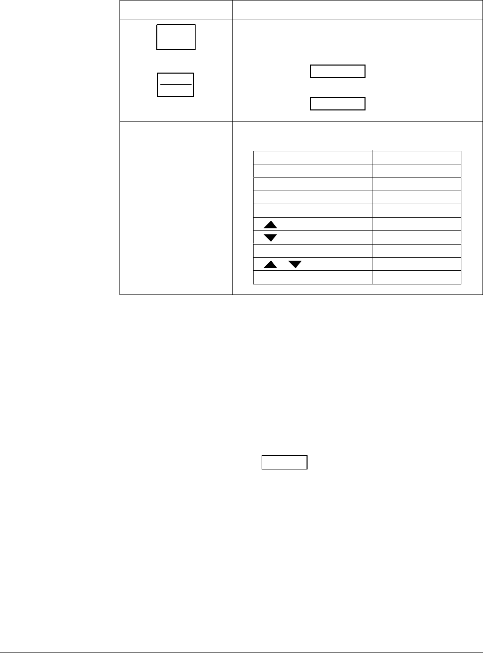
4/00 UDC 3300 Controller Product Manual 149
Check the displays and
keys Use the procedure in Table 5-2 to run the display and key test.
Table 5-2 Procedure for Testing the Displays and Keys
Press Result
SET UP
and hold in,
then
FUNCTION
LOOP 1/2
at the same time
The controller will run a display test. All the displays will
light for 8 seconds, then the displays will look like this:
try all
Lower Display
keys
Upper Display
Press each key to see if it
works When the key is pressed, the lower display will indicate the
name of the key pressed.
Key Pressed Lower Display
FUNCTION LOOP 1/2 FUNCTION
LOWER DISPLAY LWR DISP
MANUAL/AUTO AUTO MAN
SETPOINT/SELECT SP SEL
INCRMENT
DECRMENT
RUN/HOLD RUN HOLD
+ INCRDECR
FUNCTION+SETUP FUNC SU
If no key is pressed for 20 seconds, the test will time out and the controller
will go into control mode.
If any test fails, go to “Controller Failure Symptoms” in Section 9 -
Troubleshooting.
Key error When a key is pressed and the prompt “KEY ERROR” appears in the
lower display, it will be for one of the following reasons:
•parameter is not available,
•not in Set Up mode, press SET UP key first,
•key malfunction, do keyboard test.
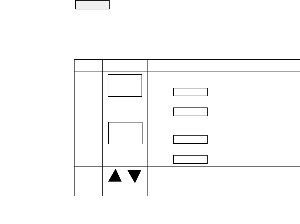
150 UDC 3300 Controller Product Manual 4/00
5.3 Entering a Security Code
Introduction The LOCKOUT feature in the UDC 3300 is used to inhibit changes (via
keyboard) of certain functions or parameters by unauthorized personnel.
There are different levels of LOCKOUT depending on the level of
security required. These levels are:
NONE
CALIB
+CONF
+VIEW
MAX
See Section 4 - Configuration Definitions for details.
Security code numbers The level of keyboard lockout may be changed in the Set Up mode.
However, knowledge of a security code number (1 to 4095) may be
required to change from one level of lockout to another. When a controller
leaves the factory, it has a security code of 0 which permits changing from
one lockout level to another without entering any other code number.
Procedure If you require the use of a security code, select a number from 0001 to
4095 and enter it when the lockout level is configured as NONE.
Thereafter, that selected number must be used to change the lockout level
from something other than NONE.
CAUTION Write the number on the Configuration Record Sheet in the
configuration section so you will have a permanent record.
Use the procedure in Table 5-3 to enter a security code.
Table 5-3 Procedure for Entering a Security Code
Step Press Action
1
SET UP
until you see
TUNING
Lower Display
SET UP
Upper Display
2FUNCTION
LOOP 1/2
until you see
SECURITY
Lower Display
0
Upper Display
3or to enter a four digit number in the upper display
(1 to 4095)
This will be your security code.
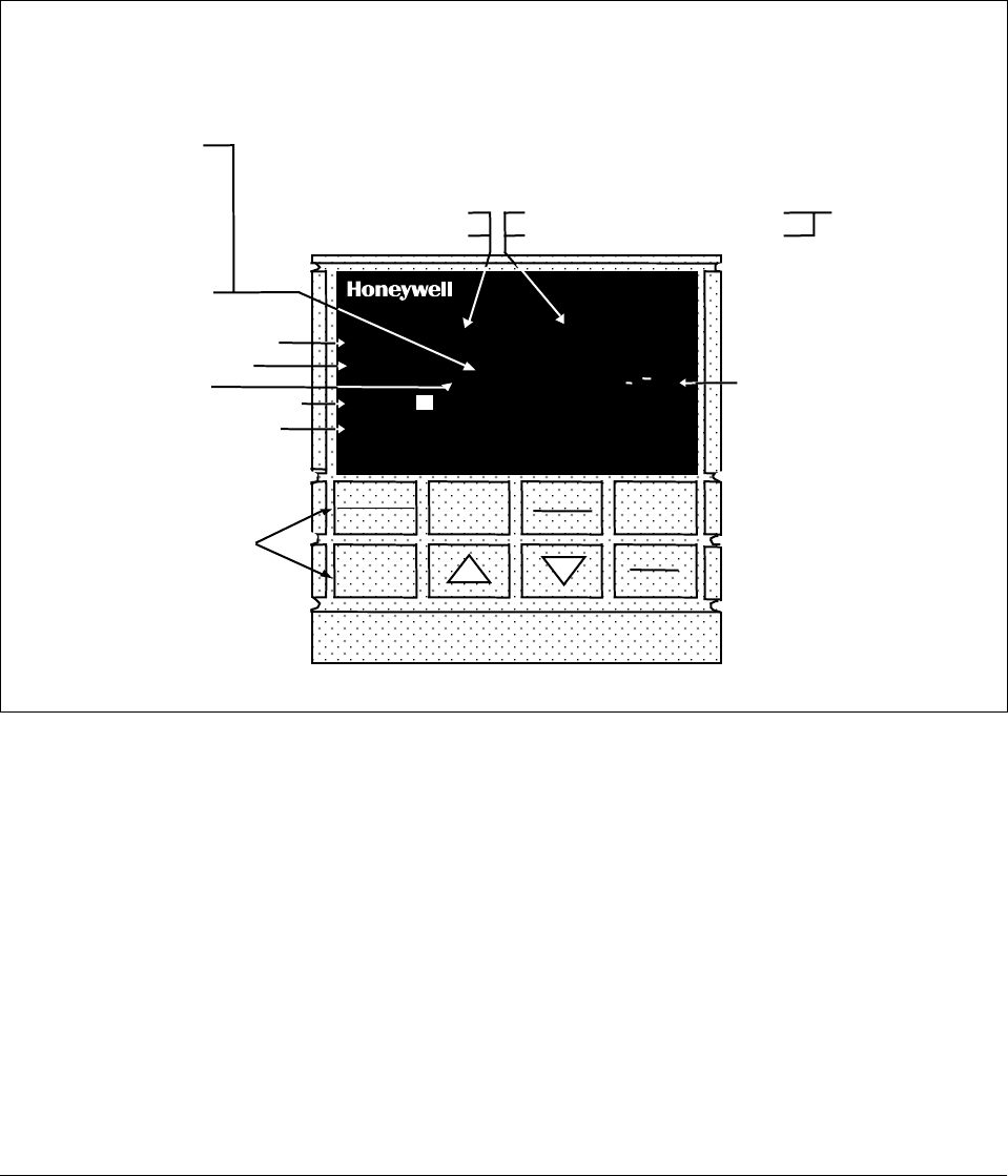
4/00 UDC 3300 Controller Product Manual 151
5.4 Monitoring Your Controller
Operator interface The indicators and displays on the operator interface let you see what is
happening to your process and how the controller is responding.
Figure 5-1 is a view of the operator interface. A description of the displays
and indicators is included.
Figure 5-1 Operator Interface
ALM
RSP
OUT
%
1 2 3
1 2
1 2 F C MAN
FUNCTION
LOOP 1/2
SET UP
LOWER
DISPLAY MANUAL
AUTO
SETPOINT
SELECT
RUN
HOLD
DI 3300
SP 3300
Indicator definition when lit
ALM - Alarm conditions exist
DI - Digital input active
OUT - Control relay 1 or 2 on
Upper Display - six characters
• Normal Operation - four digits dedicated to display the process variable
• Configuration Mode - displays parameter value or selection
Lower Display - eight characters
• Normal Operation - displays operating parameters and values
• Configuration Mode - displays function groups and parameters
MAN - controller in manual mode
A - controller in automatic mode
F - °Fahrenheit being used
C - °Centigrade being used
Indicator definition when lit
Deviation Bargraph
• Center bar indicates PV is
within ±1% of setpoint.
• Next bar will light if PV is
between ±1% but less than
±2% in deviation.
• If PV is equal to or greater than
±10% deviation, the center bar
plus all ten deviation bars will
light.
MAN and A off —
communications
option active
Keys - See Table 1-1
T - Accutune in progress
t - PV tune in progress
L" - Loop 2 display
I - Cascade control
C - Computer setpoint active
O - Output override active
R - Run SP ramp/program
H - Hold SP ramp/program
RSP - Remote SP or SP2 active
24157
R
3 - LSP 3 active
Decimal point position In each display, when no decimal place is configured, the right-most
character is blank.
When a single decimal position has been configured and values greater
than 1000 are displayed, the right-most character is blank but the decimal
point will be lit.

152 UDC 3300 Controller Product Manual 4/00
Annunciators The following annunciator functions have been provided:
A visual indication of each alarm
ALM 1 2
Blinking 1 indicates alarm latched and needs to be
acknowledged before extinguishing when the alarm
condition ends.
A visual indication of the control relays
OUT 1 2
A visual indication of the mode of the controller
A—Automatic Mode
MAN—Manual Mode
A visual indication of the temperature units
F—Degrees Fahrenheit
C—Degrees Celsius
A visual indication of the digital inputs
1 2
A visual lamp when the RSP or LSP 2 is active
■
A visual indication when LSP 3 is active
3
The upper left digit of the display is used to show other annunciator
functions
T—Accutuning in process
t—PV tune in process
L″—Loop 2 display
I—Cascade control (when Loop 1 is displayed)
C—Computer setpoint active
O—Output override active
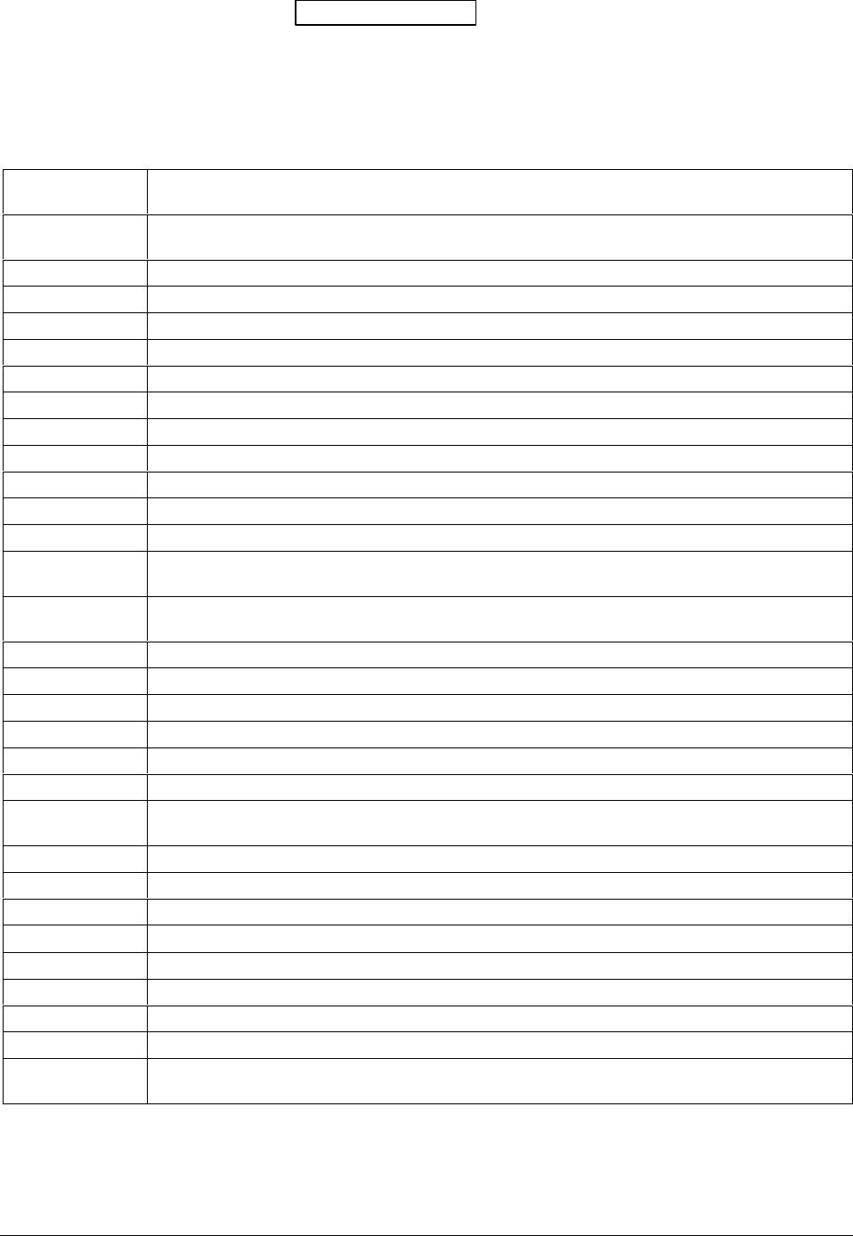
4/00 UDC 3300 Controller Product Manual 153
Viewing the operating
parameters Press the LOWER DISPLAY key to scroll through the operating
parameters listed in Table 5-4. The lower display will show only those
parameters and their values that apply to your specific model and the way
in which it was configured.
Table 5-4 Lower Display Key Parameter
Lower Display
Indication Description
OUT OUTPUT #1—Output value is percent; for Three Position Step control, this is an estimated motor
position when no slidewire exists.
OT2 OUTPUT #2—Appears only if 2-loop or Cascade control is configured.
SP LOCAL SETPOINT #1—Also current setpoint when using SP Ramp.
2SP LOCAL SETPOINT #2
3SP LOCAL SETPOINT #3
RSP REMOTE SETPOINT
1IN INPUT 1—Used only with combinational input algorithms.
2IN INPUT 2
3IN INPUT 3
POS SLIDEWIRE POSITION—Used only with TPSC.
CSP COMPUTER SETPOINT—When SP is in override.
DEV DEVIATION—Maximum negative display is –999.9.
PIDSETX TUNING PARAMETER SET 1—Selected set for single loop or primary loop configuration where
X is either 1 or 2.
2PIDSETX TUNING PARAMETER SET 2—Selected set for secondary loop configuration where X is either
1 or 2.
ET XX.XX ELAPSED TIME—Time that has elapsed on timer in Hours.Minutes.
TR XX.XX TIME REMAINING—Time that remains on timer in Hours.Minutes
RAMPXXXM SETPOINT RAMP TIME—Time remaining in the setpoint ramp in minutes.
O SK XXXX TIME REMAINING IN SOAK
1PV PROCESS VARIABLE 1—For Cascade or 2-loop applications.
2PV PROCESS VARIABLE 2—For cascade or 2-loop applications.
AUX AUXILIARY OUTPUT—Displayed only when Loop 2 is not used, or when Loop 2 is Time
Simplex and Loop 1 is not Current Duplex.
OC1 CHARACTERIZED OUTPUT 1—Displayed if Loop 1 output is characterized.
OC2 CHARACTERIZED OUTPUT 2—Displayed if Loop 2 output is characterized.
SPn SP RATE SETPOINT—Current setpoint for setpoint rate applications
Σ (Sigma) CURRENT TOTALIZER VALUE—Displays the total flow volume being measured.
BIA BIAS—Displays the manual reset value for algorithm PD+MR.
TUNE OFF LIMIT CYCLE TUNING NOT RUNNING—Appears when Accutune is disabled.
TUNE RUN LIMIT CYCLE TUNING RUNNING—Appears when Accutune is enabled.
ToBEGIN RESET SP PROGRAM TO START OF FIRST SEGMENT
OTI OUTPUT OVERRIDE (2 PID LOOPS ONLY)—Appears when Internal Loop 1 Output value is
displayed. This represents the internal output 1 value before override.
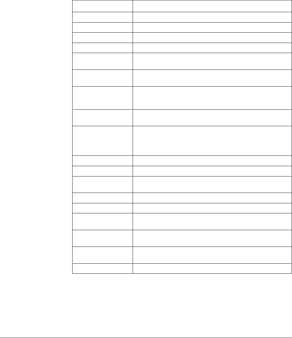
154 UDC 3300 Controller Product Manual 4/00
Diagnostic error
messages The UDC 3300 performs background tests to verify data and memory
integrity. If there is a malfunction, an error message will be displayed. In
the case of more than one simultaneous malfunction, only the one with the
highest priority will appear on the lower display.
A list of error messages is contained in Table 5-5. If any of these error
messages occur, refer to Section 9 - Troubleshooting for information to
correct the failure.
Table 5-5 Error Messages
Prompt Description
EE FAIL Unable to write to nonvolatile memory.
INP1FAIL Two consecutive failures of input 1 integration.
INP2FAIL Two consecutive failures of input 2 integration.
INP3FAIL Two consecutive failures of input 3 integration.
SW FAIL Slidewire input failure. Position Proportional Control
automatically switched to Three Position Step Control.
CONF ERR Configuration Errors for Loop 1—Low limit greater than high
limit for PV, SP, Reset, or Output.
CONF ER2 Configuration Errors for Loop 2—Low limit greater than high
limit for PV, SP, Reset, or Output, or Loop 2 output has not
been selected.
SOOTING Input Combination Errors—Percent Carbon falls outside of
“sooting boundary.”
IN1 RNG Input 1 Out-of-Range
Out-of-range criteria:
Linear range: ± 10 % out-of-range
Characterized range: ± 1 % out-of-range
IN2 RNG Input 2 Out-of-Range—Same as Input 1.
IN3 RNG Input 3 Out-of-Range—Same as Input 1.
PV RNG PV Out-of-Range
PV = (PV source x PV source ratio) + PV source bias
FAILSAFE Failsafe Loop 1—Check inputs or configuration.
FAILSF2 Failsafe Loop 2—Check inputs or configuration.
RV LIMIT Remote Variable Out-of-Range
RV = (RV source x RV source ratio) + RV source bias
RH LO RH Excessive Temperature Depression—Calculated % RH is
less than 0 %.
SEG ERR Segment Error—SP Program starting segment number is less
than ending segment number.
CAL MTR Not calibrated. Perform Position Proportional calibration.
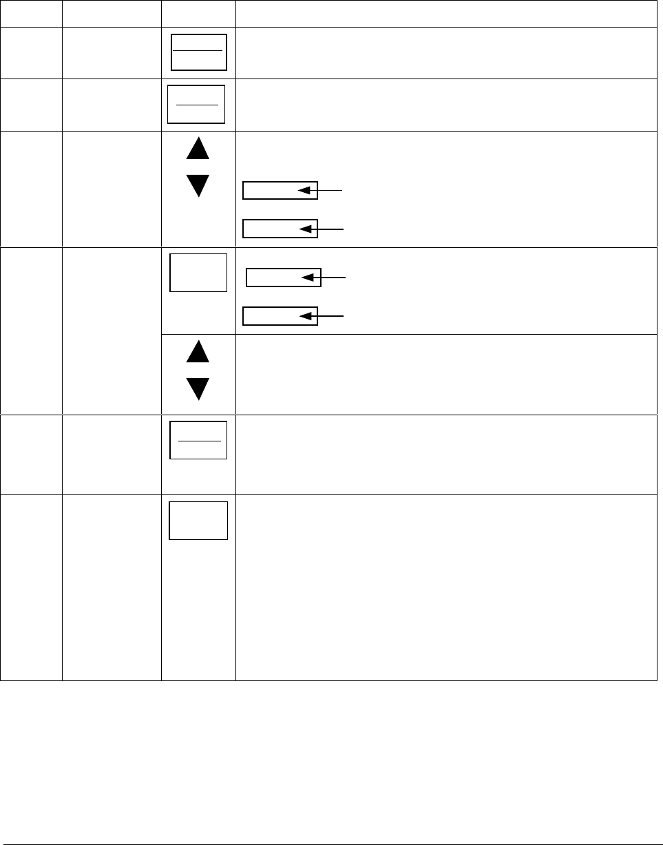
4/00 UDC 3300 Controller Product Manual 155
5.5 Start-up Procedure
Procedure The Start-up procedure is given in Table 5-6.
Table 5-6 Procedure for Starting Up the Controller
Step Operation Press Action
1Select the loop FUNCTION
LOOP 1/2
to toggle between Loop 1 and Loop 2, if configured.
2Select manual
mode MANUAL
AUTO
until “MAN” indicator is ON.
The controller is in manual mode.
3Adjust the
output or
to adjust the output value and ensure that the final control element is
functioning correctly.
Upper Display
shows the PV value
Lower Display
shows OUT and the output value in %.
4Enter the local
setpoint LOWER
DISPLAY
Upper Display
shows the PV Value
Lower Display
SP and the local setpoint value
or
to adjust the local setpoint to the value at which you want the process
variable maintained.
The local setpoint cannot be changed if the Setpoint Ramp function is
running. “R” appears in the upper display.
5Select
Automatic
Mode
MANUAL
AUTO
until “A” indicator is ON.
The controller is in Automatic mode.
The controller will automatically adjust the output to maintain the process
variable at setpoint, if the controller is properly tuned.
6Tune the
controller SET UP Tuning is required on the first startup. First enable "TUNE" selection in the
Accutune Group.
Refer to Tuning Set Up group to ensure that the proper selections for
PROP BD or GAIN, RATE MIN, and RSET MIN, or RSET RPM, have
been entered.
Use Accutune to tune the controller; see the procedure in this section.
For 2-loop or Cascade control, refer to the Loop 2 Tuning Set Up group
parameters.
To tune your controller manually, see Appendix A.

156 UDC 3300 Controller Product Manual 4/00
5.6 Operating Modes
Available modes The controller can operate in any of three basic modes:
•Manual—One or Two Loops
•Automatic with Local Setpoint—One or Two Loops
•Automatic with Remote Setpoint—One or Two Loops
•Manual Cascade
•Automatic Cascade
The manual and automatic control modes with Local and Remote setpoint
are standard with the instrument; cascade control is optional.
Mode definitions Table 5-7 lists the available modes and their definitions.
Table 5-7 Operating Mode Definitions
Operating Mode Definition
MANUAL In the manual mode, the operator directly controls the
controller output level. The process variable and the
percent output are displayed. The configured High and Low
Output Limits are disregarded and the operator can change
the output value using the increment and decrement keys to
the limits allowed by the output type (0 % to 100 % for a
time proportioning output or –5 % to 105 % for a current
output).
AUTOMATIC with LOCAL
SETPOINT In automatic local mode, the controller operates from the
local setpoints and automatically adjusts the output to
maintain the setpoint at the desired value.
In this mode you can adjust the setpoint.
See Section 5.7 - Setpoints.
AUTOMATIC with
REMOTE SETPOINT In automatic remote mode, the controller operates from the
setpoint measured at the Remote setpoint input.
Adjustments are available to ratio this input and add a
constant bias before it is applied to the control equation.
See Section 3 - Configuration, Control Set up group.
MANUAL CASCADE In the manual cascade mode, both control loops are in
manual although there is still only one output active. This
mode is used to bring both loops into a reasonable
operation area, at which point the unit is placed into the
automatic cascade mode.
If Loop 1 is placed in Manual control mode, then Loop 2, if
in auto, is then placed in a pseudo-manual mode thereby
eliminating output bumps when Loop 1 is returned to
Automatic control mode.
AUTOMATIC CASCADE In Automatic cascade mode, there are two control loops,
with one loop’s output acting as the setpoint for the second
control loop. There is only one physical output in this mode.

4/00 UDC 3300 Controller Product Manual 157
What happens when
you change modes Table 5-8 explains what happens to the controller when you switch from
one mode to another.
Table 5-8 Changing Operating Modes
Mode Change Description
Manual to Automatic
Local Setpoint The Local Setpoint is usually the value previously stored as
the Local Setpoint.
PV tracking is a configurable feature which modifies this.
For this configuration, when a loop is in manual mode, the
local setpoint value tracks the process variable value
continuously.
Manual or Auto Local to
Automatic Remote SP The Remote Setpoint uses the stored ratio and bias to
calculate the control setpoint.
Auto bias is a configurable feature which modifies this.
When it is selected the transfer from automatic local to
automatic remote or from manual remote to automatic
remote adjusts the bias based on the local setpoint such
that Bias = LSP – (RSP Input x R).
Automatic Remote
Setpoint to Manual or
Auto Local Setpoint
If configured for Local Setpoint Tracking, when the
controller transfers out of remote setpoint the last value of
the control setpoint is inserted into the local setpoint.
If LSP tracking is not configured, the local setpoint will not
be altered when the transfer is made.
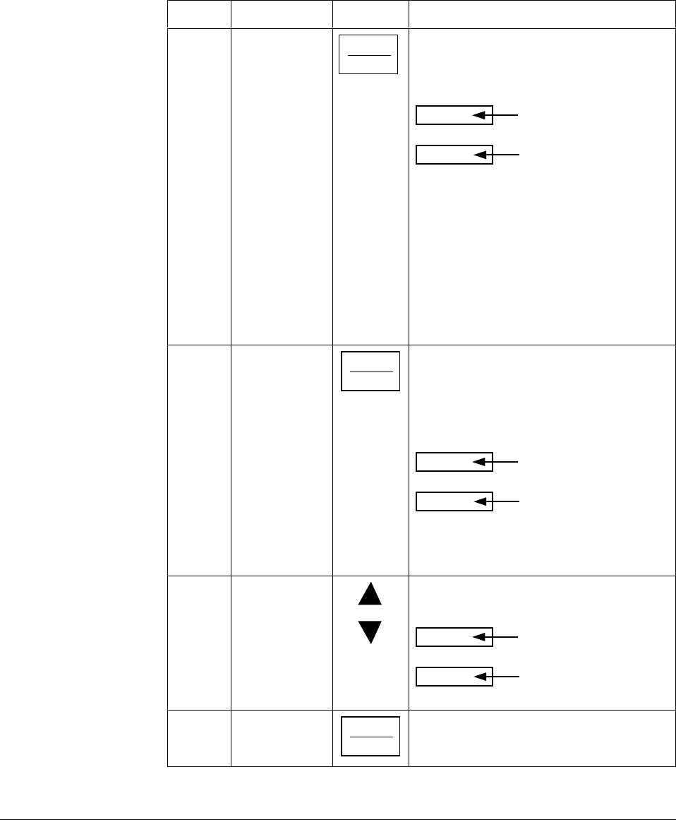
158 UDC 3300 Controller Product Manual 4/00
Selecting manual or
automatic mode An alternate action switch places the controller in the Automatic or
Manual mode of operation. Switching between manual and automatic will
be bumpless, except when PD+MR algorithm is selected.
Table 5-9 includes procedures for selecting automatic or manual mode
and changing the output while in manual.
Table 5-9 Procedure for Selecting Automatic or Manual Mode
Step Operation Press Action
1Selecting
Automatic
Mode
MANUAL
AUTO
until “A” indicator is ON.
The controller regulates its output to
maintain the PV at the desired setpoint.
Upper Display
shows the PV value
Lower Display
shows SP and the
setpoint value
The deviation bargraph indicates the PV
deviation from the setpoint.
The annunciators indicate whichever setpoint
is in use:
SP Local Setpoint
2SP Second Local Setpoint
3SP Third Local Setpoint
RSP Remote Setpoint
CSP Computer Setpoint
2Selecting
Manual Mode MANUAL
AUTO
until “MAN” indicator is ON.
The controller holds its output at the last
value used during automatic operation and
stops adjusting the output for changes in
setpoint or process variable.
Upper Display
shows the PV value
Lower Display
shows OUT and the
output value in (%).
The deviation bargraph indicates the PV
deviation from the setpoint.
3Adjust the
Output in
Manual Mode or
to adjust the output value while in manual
mode.
Upper Display
shows the PV value
Lower Display
shows OUT and the
output value in %.
4Return to
Automatic
Mode
MANUAL
AUTO
The “A” indicator will appear indicating
Automatic mode.

4/00 UDC 3300 Controller Product Manual 159
Position proportional
backup mode This feature provides for Position Proportional models to automatically
change to a Three Position Step algorithm if the slidewire input signal
fails. This will maintain control of your process.
“IN2 RNG” or “SW FAIL” will flash in the lower display and the “OUT”
display will show an estimated motor position WITHOUT a decimal
point.
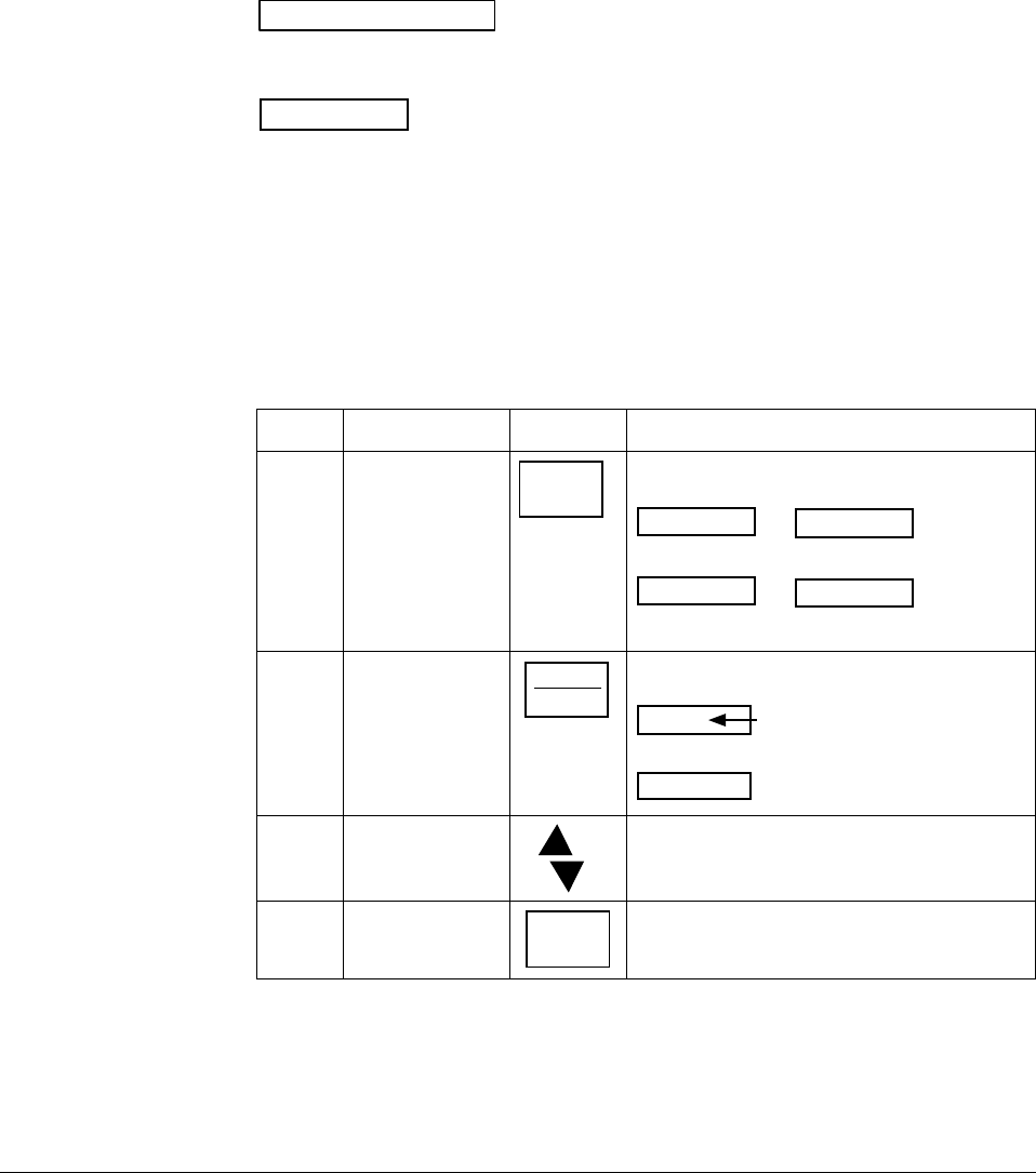
160 UDC 3300 Controller Product Manual 4/00
5.7 Setpoints
Introduction You can configure the following setpoints for the UDC 3300 controller.
•A single local setpoint,
•Two local setpoints,
•One local setpoint and one remote setpoint,
•Three local setpoints,
•Two local setpoints and one remote setpoint.
To scroll through the setpoint type menu, press and hold in the
SETPOINT SELECT key. Release when the desired setpoint selection
is displayed.
ATTENTION “KEY ERROR” will appear in the lower display if:
•You choose either local setpoint 2 or 3 or remote setpoint and your
choice has not been configured as the setpoint source.
•You attempt to change the setpoint while a setpoint ramp is enabled.
Setpoint ramp rate will apply, if enabled.
Selecting the local
setpoint source Use the procedure in Table 5-10 to select a local setpoint source.
Table 5-10 Procedure for Selecting the Local Setpoint Source
Step Operation Press Action
1Enter Set Up
mode LOWER
DISPLAY
until the displays read:
CONTROL
Lower Display
SET UP
Upper Display
CONTROL2
Lower Display
SET UP
Upper Display
for Loop 1 for Loop 2or
2Display Local
Setpoint Source
selections
FUNCTION
LOOP 1/2
until the displays read:
Lower Display
Upper Display
LSP’S
Setpoint source selections
1 ONLY
TWO
THREE
3Select the
desired source or to select the desired setpoint source in the
upper display.
4Return to control LOWER
DISPLAY
The controller will assume normal control.
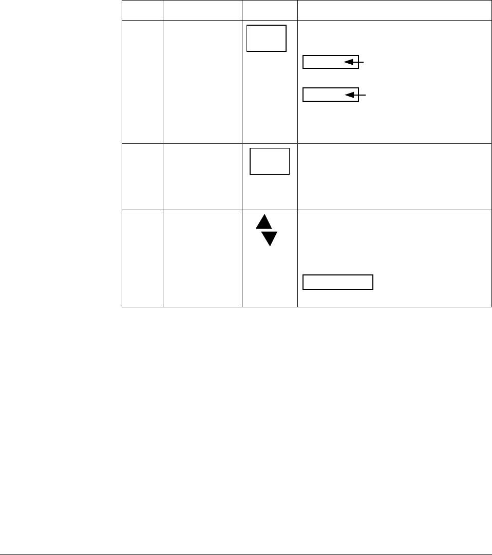
4/00 UDC 3300 Controller Product Manual 161
Changing local setpoint
1, 2, or 3 Use the procedure in Table 5-11 to change any of the local setpoint
values.
After changing a local setpoint value, if no other key is pressed, a
minimum of 30 seconds time will elapse before the new value is stored in
nonvolatile memory. If power is removed before this time, the new
setpoint value is lost and the previous setpoint value is used at power up.
If after changing the LSP value another key is pressed, then the value is
stored immediately.
Table 5-11 Procedure for Changing the Local Setpoints
Step Operation Press Action
1Select the
setpoint SETPOINT
SELECT
until you see
Lower Display
Upper Display
The PV value
SP, 2SP, or 3SP and
the local setpoint value
or RSP and the remote
setpoint value
2Select a different
setpoint or the
remote setpoint
SETPOINT
SELECT
and hold
in
to cycle through the setpoint type menu as
long as the key is pressed. When the key is
released, the setpoint selection currently
displayed will be the new setpoint selection.
3Change the
value or to change the local setpoint to the value at
which you want the process maintained.
SP, 2SP, or 3SP indicator will light to match
the lower display.
ATTENTION The remote setpoint
cannot be changed at the keyboard.
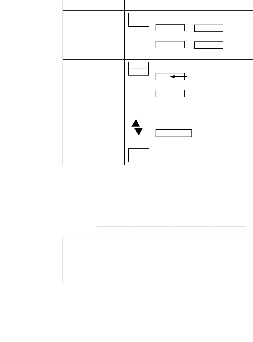
162 UDC 3300 Controller Product Manual 4/00
Enabling (or disabling)
the remote setpoint Use the procedure in Table 5-12 to enable the remote setpoint source.
Table 5-12 Procedure for Enabling (or Disabling) the Remote Setpoint
Step Operation Press Action
1Select Set Up
Group SET UP until you see:
CONTROL
Lower Display
SET UP
Upper Display
CONTROL2
Lower Display
SET UP
Upper Display
for Loop 1 for Loop 2or
2Select the
Remote Setpoint
Source prompt
FUNCTION
LOOP 1/2
Until you see:
Lower Display
Upper Display
RSP SRC
The Remote Setpoint
source selection
NONE—not used
INP 2—Input 2 as RSP
IN AL1—Input algorithm 1
IN AL2—Input algorithm 2
INP 3—Input 3 as RSP
3Change
selection or to enable or disable the remote setpoint.
ATTENTION You cannot change the
remote setpoint value using these keys.
4Return to normal
operation LOWER
DISPLAY
This will return the controller to normal
operation.
Setpoint selection
indication Table 5-13 shows how the indicators react and what the displays show for
each type of setpoint.
Table 5-13 Setpoint Selection Indication
Using Local
Setpoint Using Remote
Setpoint Using 2nd
Local
Setpoint
Using 3rd
Local
Setpoint
SP RSP 2SP 3SP
Upper
Display PV and the PV
value PV and the PV
value PV and the PV
value PV and the PV
value
Lower
Display SP and the
Local Setpoint
Source
RSP and
Remote Setpoint
Value
2SP and the
2nd Local
Setpoint Value
3SP and the
3rd Local
Setpoint Value
Annunciator None "■" lights "■" lights "3" lights

4/00 UDC 3300 Controller Product Manual 163
5.8 Setpoint Ramp Rate
Configuration You can configure a Setpoint Ramp Rate that will apply to any Local
setpoint change immediately.
Refer to the Configuration Section to enable the ramp for either loop and
set an upscale or downscale rate value.
Make sure SP RAMP and SP PROG are disabled.
Operation When a local setpoint change is made, the controller will ramp from the
original setpoint to the new one at the rate specified. This changing
(current) setpoint can be viewed as SPn on the lower display.
Press the LOWER DISPLAY key until you see SPn and the setpoint
value in the lower display.
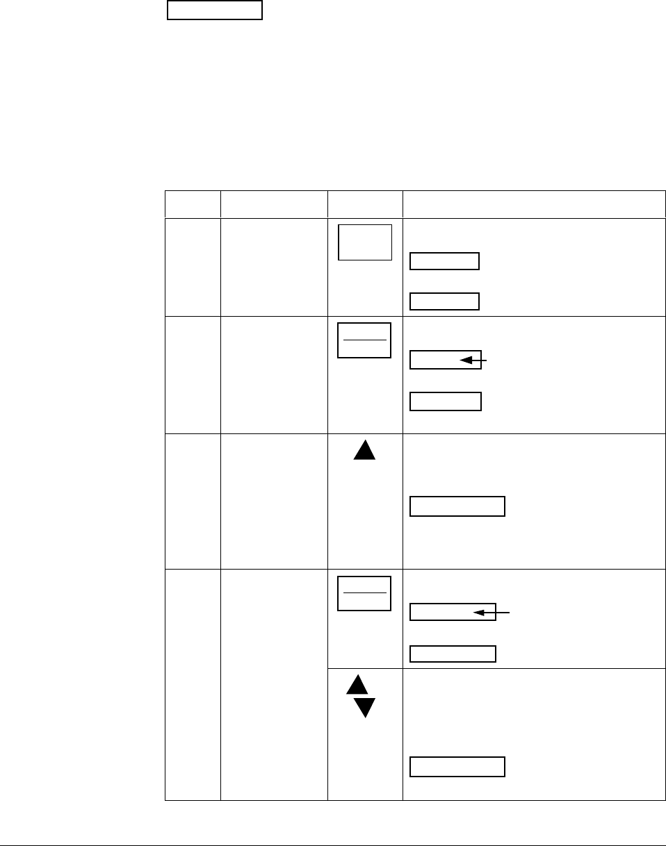
164 UDC 3300 Controller Product Manual 4/00
5.9 Single Setpoint Ramp
Configuring the
setpoint ramp You can configure a single setpoint ramp to occur between the current
local setpoint and a final local setpoint over a time interval of from 1 to
255 minutes. You can RUN or HOLD the ramp at any time.
ATTENTION The UDC 3300 has PV Hot Start functionality as standard
feature. This means that at power-up Local Setpoint #1 is set to the current
PV value and the Ramp, Rate, or Program then starts from this value.
Procedure Table 5-14 lists the procedure for configuring the Setpoint Ramp
parameters. The procedure for SP Program is in Section 6 – Setpoint
Programming Option.
Table 5-14 Procedure for Configuring a Setpoint Ramp
Step Operation Press Action
1Select
SP RAMP
Set Up Group
SET UP until you see:
SP RAMP
Lower Display
SET UP
Upper Display
2Select the
Setpoint Ramp
function
FUNCTION
L1/L2
until you see:
SP RAMP
Lower Display
Upper Display
DISABL—Disables SP Ramp
ENABLE—Enables SP Ramp for Loop 1
ENABL2—Enables SP Ramp for Loop 2
ENAB12—Enables Sp Ramp for
Loops 1 and 2
3Enable Setpoint
Ramp to enable the setpoint ramp function. Choose
the loop(s) on which you want the ramp to
operate.
ATTENTION You cannot change the
current local setpoint if the setpoint ramp
function is enabled. Make sure SP RATE is
disabled.
4Set the Ramp
Time FUNCTION
L1/L2
until you see:
Lower Display
Upper Display
TIME MIN
The ramp time
in minutes
or to change the upper display value to the
number of minutes in which you want the
final setpoint to be reached.
Setting Range = 1 to 255 minutes
ATTENTION Entering “0” will imply an
immediate step change to the final SP.

4/00 UDC 3300 Controller Product Manual 165
Step Operation Press Action
5Set the Final
Setpoint value FUNCTION
L1/L2
Lower Display
Upper Display
FINAL SP
The final
Setpoint value
or to change the upper display value to the
desired final setpoint value.
Setting Range = within the setpoint limits
6Exit
Configuration LOWER
DISPLAY
To exit configuration.
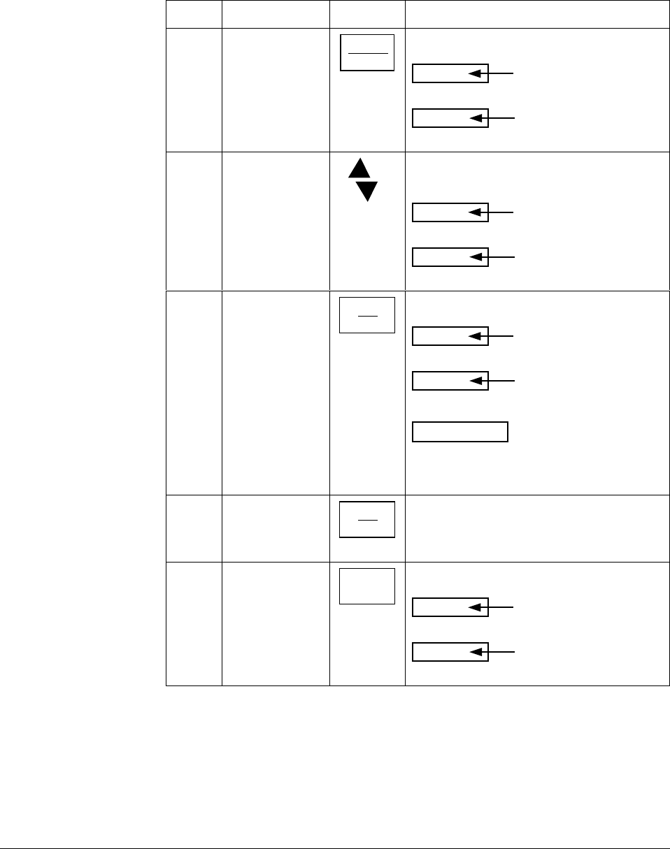
166 UDC 3300 Controller Product Manual 4/00
Running the setpoint
ramp Running a Setpoint Ramp includes starting, holding, viewing the ramp
time, ending the ramp, and disabling it.
Procedure Table 5-15 lists the procedure for running the Setpoint Ramp.
Table 5-15 Procedure for Running a Setpoint Ramp
Step Operation Press Action
1Put the controller
into Automatic
mode
MANUAL
AUTO
until “A” indicator is ON and you will see:
Lower Display
Upper Display
H and the PV value
SP and the present
setpoint value
2Set Start
Setpoint or until the start setpoint value you desire is
indicated in the lower display:
Lower Display
Upper Display
H and the PV value
SP and the start
setpoint value
3Start the Ramp RUN
HOLD
You will see:
Lower Display
Upper Display
R and the PV value
SP and a changing
setpoint value
ATTENTION The value in the lower
display will be increasing or decreasing
toward the final setpoint value. The PV value
in the upper display will also change.
4Hold/Run the
Ramp RUN
HOLD
This holds the ramp at the current setpoint
value.
Press again to continue run.
5View the
remaining ramp
time
LOWER
DISPLAY
until you see:
Lower Display
Upper Display
R or H and
the PV value
RAMP XXXM
(Time remaining)
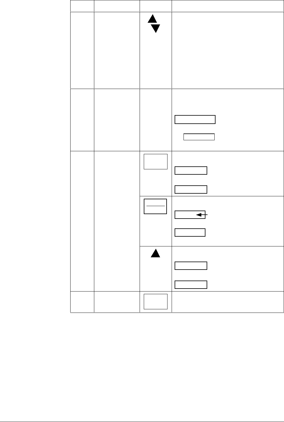
4/00 UDC 3300 Controller Product Manual 167
Step Operation Press Action
6Change setpoint
during Hold
mode
or to change the “HELD” setpoint if the ramp is
on “HOLD.”
However, the ramp time remaining is not
changed. Therefore, when returning to RUN
mode, the setpoint will ramp at the same rate
as prior to local setpoint changes and will
stop if the final setpoint is reached before
time expires.
If the time expires before the final setpoint is
reached, it will jump to the final setpoint.
7End the Ramp When the final setpoint is reached, the
“R” changes to “H” in the upper display and
the controller operates at the new setpoint.
ATTENTION Any time the local setpoint
is different from the final setpoint value and
the RUN/HOLD key is pressed, the ramp
will start again.
8Disable the
setpoint ramp
function
SET UP until you see:
SP RAMP
Lower Display
SET UP
Upper Display
FUNCTION
LOOP 1/2
You will see:
SP RAMP
Lower Display
Upper Display
DISABL—Disables SP Ramp
ENABLE—Enables SP Ramp for Loop 1
ENABL2—Enables SP Ramp for Loop 2
ENAB12—Enables Sp Ramp for
Loops 1 and 2
until you see:
SP RAMP
Lower Display
DISABL
Upper Display
9Return to normal
operating mode LOWER
DISPLAY
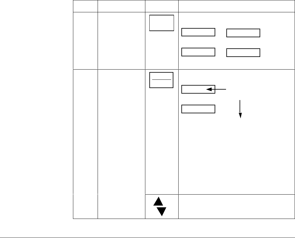
168 UDC 3300 Controller Product Manual 4/00
5.10 Using Two Sets of Tuning Constants
Introduction You can use two sets of tuning constants for single output types and
2-loop or cascade control, and choose the way they are to be switched.
(Does not apply for Duplex control.)
The sets can be:
•keyboard selected,
•automatically switched when a predetermined process variable value
is reached,
•automatically switched when a predetermined setpoint value is
reached.
The following procedures show you how to:
•select two sets or gain scheduling,
•set the switch-over value,
•set tuning constant value for each set, and
•switch between two sets via the keyboard (without automatic
switchover)
Select two sets or gain
scheduling The procedure in Table 5-16 tells you how to select two sets or gain
scheduling.
Table 5-16 Procedure for Selecting Two Sets of Tuning Constants
Step Operation Press Action
1Select Control
Set Up group SET UP until you see:
CONTROL
Lower Display
SET UP
Upper Display
CONTROL2
Lower Display
SET UP
Upper Display
for Loop 1 for Loop 2or
2Select
PID SETS
function
FUNCTION
LOOP 1/2
until you see:
Lower Display
Upper Display
PID SETS
Available selections
are listed below
1 ONLY—1 set of constants
2KEYBD—2 sets, keyboard selectable
2 PVSW—2 sets, auto switch at PV value
2 SPSW—2 sets, auto switch at SP value
GAIN S—Gain used in control algorithm
calculations can be pre-entered into eight
user-defined segments, with each segment
applied over a user-defined PV range. Refer
to Section 3 – Configuration under Tuning
Set Up group to set Gain segment values
and PV range values.
or to select the type of PID SET.
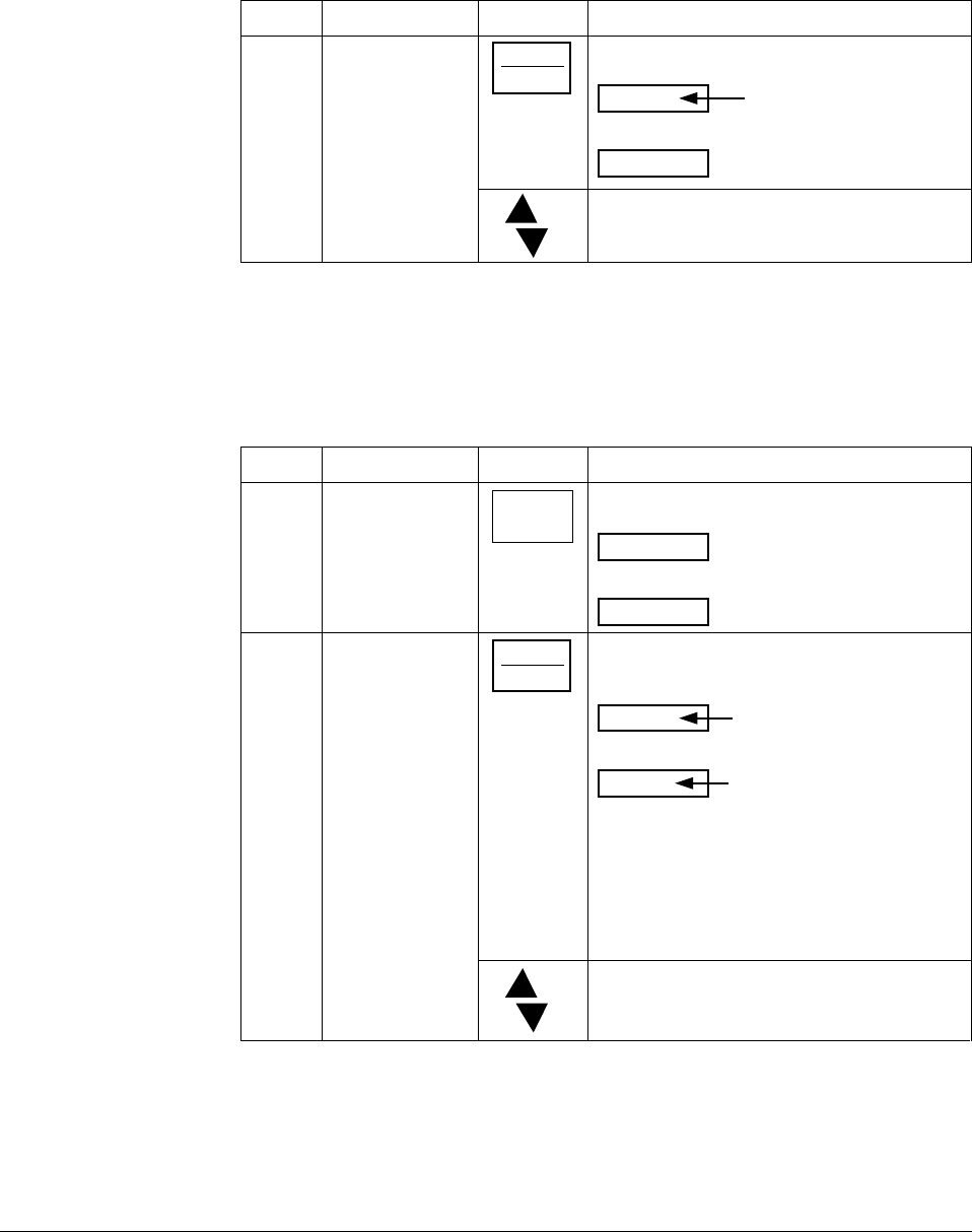
4/00 UDC 3300 Controller Product Manual 169
Set switchover value If you select 2 PVSW or 2 SPSW, you must set a value at which the sets
will switch over. The procedure in Table 5-17 shows you how to set this
value. This procedure assumes that you are still in the Control Set Up
group from Table 5-16.
Table 5-17 Procedure for Setting Switchover Values
Step Operation Press Action
1Select
Switchover value
function
FUNCTION
L1/L2
assuming you
are still in
Control Set Up
group
until you see:
Lower Display
Upper Display
SW VALUE
The switchover
value
or to select the switch-over value in the upper
display.
Set tuning constant
values for each set There are specific tuning constants that must be set for each set. The
procedure in Table 5-18 shows you how to access these constants and
change their values.
Table 5-18 Procedure for Setting Tuning Constant Values
Step Operation Press Action
1Select Tuning
Set Up Group SET UP until you see:
TUNING
Lower Display
SET UP
Upper Display
2Select the tuning
constants FUNCTION
LOOP 1/2
to successively display the following
constants:
Lower Display
Upper Display The tuning constant
value
PROP BD or GAIN*
RATE*
RSET*
CYC SEC or CYC SX3*
PROP BD2 or GAIN2**
RATE 2**
RSET2**
CYC2 SEC or CYC2 SX3**
or To change the value of any of the above
listed prompts in the lower display.
*PIDSET1 will be used when PV or SP, whichever is selected, is greater than the
switch-over value.
**PIDSET2 will be used when PV or SP, whichever is selected, is less than the switch-
over value.
170 UDC 3300 Controller Product Manual 4/00
Switch between two
sets via the keyboard
(without automatic
switchover)
This procedure is operational only if 2 PID SETS was configured at the
Control Set Up group. The procedure in Table 5-19 shows you how to
switch from one set to another.
Table 5-19 Procedure for Switching PID SETS from the Keyboard
Step Operation Press Action
1Access the PID
set display LOWER
DISPLAY
until you see:
Lower Display
Upper Display
PIDSETX
The PV value
X = 1 or 2
or to change PID SET 1 to PID SET 2 or vice
versa.
You can use Accutune on each set.
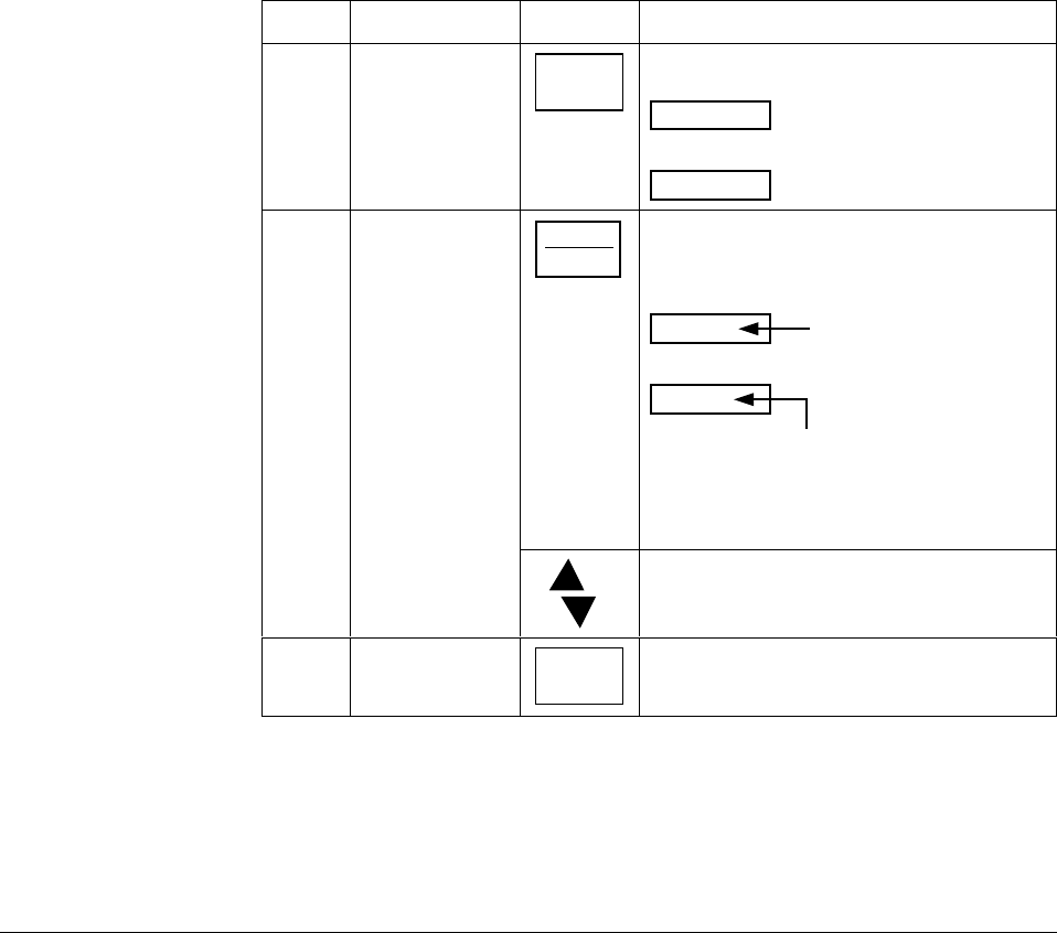
4/00 UDC 3300 Controller Product Manual 171
5.11 Alarm Setpoints
Introduction An alarm consists of a relay contact and an operator interface indication.
The alarm relay is de-energized if setpoint 1 or setpoint 2 is exceeded.
The alarm relay is energized when the monitored value goes into the
allowed region by more than the hysteresis.
The relay contacts can be wired for normally open (NO) energized or
normally closed (NC) de-energized at the rear terminals. See Table 2-8 in
the Section 2 – Installation for alarm relay contact information.
There are four alarm setpoints, two for each alarm. The type and state
(High or Low) is selected during configuration. See Section 3 –
Configuration for details.
Procedure for
displaying the alarm
setpoints
Table 5-20 lists the procedure for displaying and changing the alarm
setpoints.
Table 5-20 Procedure for Displaying or Changing the Alarm Setpoints
Step Operation Press Action
1Access the
Alarm Set Up
group
SET UP until you see:
ALARMS
Lower Display
SET UP
Upper Display
2Access the
Alarm Setpoint
Values
FUNCTION
LOOP 1/2
to successively display the alarm setpoints
and their values. Their order of appearance
is shown below.
Lower Display
Upper Display The alarm setpoint
value
A1S1 VAL = (Alarm 1, Setpoint 1 value)
A1S2 VAL = (Alarm 1, Setpoint 2 value)
A2S1 VAL = (Alarm 2, Setpoint 1 value)
A2S2 VAL = (Alarm 2, Setpoint 2 value)
or to change any alarm setpoint value you
select in the upper display.
3Return to normal
operation LOWER
DISPLAY

172 UDC 3300 Controller Product Manual 4/00
5.12 Two Loops of Control Overview
Introduction The UDC 3300 can operate using two independent loops of control or
internal Cascade control.
Available only on Expanded Model DC330E-XX-XXX.
TWO INDEPENDENT LOOPS—See Functional Overview Block
Diagrams for Loop 1 and Loop 2 (Figure 5-2) and Table 5-21 for
selections based on these diagrams.
The following rules apply for two independent loops:
•Current output on Loop 2 requires auxiliary output.
• Loop 2 Current Duplex output is limited to 2nd Current output signal
only.
•Loop 2 relay output is always dedicated to relay output 2.
•No Time Duplex outputs on Loop 2.
•No ON/OFF or 3 Position Step algorithms on Loop 2.
•No Position Proportional output is available on 2-loop controllers.
INTERNAL CASCADE CONTROL—See Functional Overview Block
Diagram (Figure 5-3) and Table 5-25 for selections based on these
diagrams.
The following rules apply for internal Cascade control:
•Loop 2 must be the primary loop.
•Loop 1 must be the secondary (internal or slave) loop because all
output forms exist on Loop 1.
•Loop 1 remote setpoint is fixed as Loop 2 output.
•No Position Proportional output is available on cascade controllers.
Selections Refer to Figures 5-2, 5-3, and 5-4 Block Diagrams and Table 5-21 for
selections based on these diagrams.
Table 5-21 Control Loop Selections
Loop Input 1 Input 2 Input Algorithm
LOOP 1 Process Variable* Via Configuration or
Digital Inputs Via Configuration or
Digital Inputs Yes
Remote Setpoint No Via configuration or
Digital Inputs Yes
Feedforward No Yes Yes
LOOP 2 Process Variable* Via Configuration or
Digital Inputs Via Configuration or
Digital Inputs Yes
Remote Setpoint No Via Configuration or
Digital Inputs Yes
Feedforward No Yes Yes
*The PV may be a combination of multiple inputs via a Loop input algorithm.
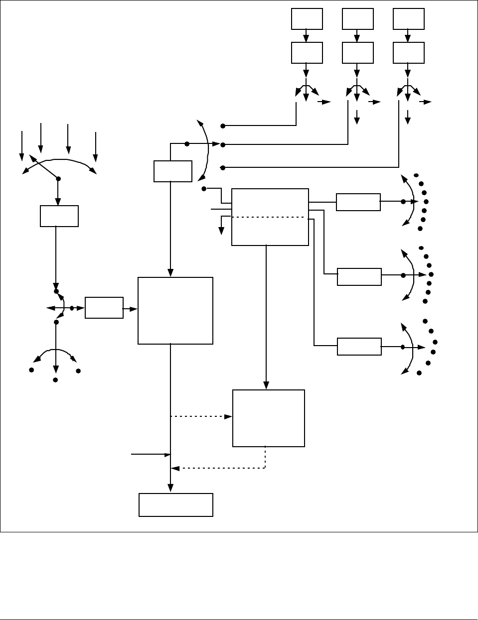
4/00 UDC 3300 Controller Product Manual 173
Functional overview Figure 5-2 is a block diagram of a Loop 1 of a single loop controller and
Loop 1 and Loop 2 of a dual loop controller.
Figure 5-2 Functional Overview Block Diagram of a Single Loop (Loop #1) or Dual Loop
Controller (Loop #1 and Loop #2)
24180
IN 1
Ratio
Bias
•
••
IN 2
Ratio
Bias
•
••
12
PV
Source
IN 2 In Alg2
RSP
Source
Input 1
Input 2
Output 1
Output 2
INPUT A
INPUT B
INPUT C
INPUT
ALGORITHM 1 or 2
FEEDFORWARD
INPUT A ONLY
To RSP
SP
Source
SP
PV
Remote SP
Local SP
SP
2SP
3SP
To RSP •
To RSP
PID
CONTROL
ALGORITHM
Loop 1 or Loop 2
FEEDFORWARD
SUMMER OR
MULTIPLIER
OUTPUT
Output
without
Feedforward
or Manual
Mode
To Final
Control
Element
None
OUT 2
In Alg1
IN 3
Ratio
Bias
•
••
3
•
To RSP
IN 3
Input 1
Input 2
In Alg 1
In Alg 2
Output 2
Output 1
Input 3
Input 1
Input 2
In Alg 1
In Alg 2
Output 2
Output 1
Input 3
Input 3
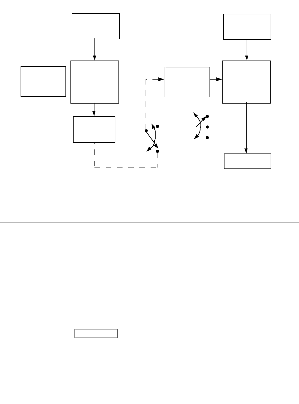
174 UDC 3300 Controller Product Manual 4/00
Internal cascade Figure 5-3 is a block diagram of internal Cascade for a 2-loop controller.
Figure 5-3 Functional Overview Block Diagram of Internal Cascade of a 2-loop Controller
PID
CONTROL
ALGORITHM
Loop 2
OUTPUT
To Final
Control
Element
PV SOURCE
See Loop 2
Block Diagram
PRIMARY LOOP
PV SOURCE
See Loop 1
Block Diagram
SECONDARY LOOP
PID
CONTROL
ALGORITHM
Loop 1
SETPOINT
SOURCE
Loop #1
INTERNAL
OUTPUT
SIGNAL
SETPOINT
SOURCE
See Loop #2
Block Diagram
INTERNAL CASCADE RULES
• Loop #2 must be the primary loop.
• Loop #1 must be the secondary (internal or slave) loop
because all output forms exist on Loop 1.
• Loop #1 Remote Setpoint is fixed as loop #2 output. 24182
Remote Setpoint
Local Setpoint
SP
2SP
3SP
Override rules The UDC 3300 allows you to select high or low output override. Refer to
Section 3 - Configuration to select High or Low.
The following rules apply for high/low override:
•Only one physical output is required when override is enabled. It is the
output from Loop 1 because Loop 2’s internal output is routed through
the selector.
•Loop 2 output can also be available at all times if desired.
•In Manual mode, the Output may be overridden.
•Does not apply for Three Position Step Control.
•OTI on bottom display shows value of the internal Loop 1 output
before any override.
ATTENTION The output of the unselected loop tracks the selected loop
to within 5 % when in Auto mode to eliminate windup. This tracking is
done in the direction opposite to the Override Select configuration; i.e., for
High Select, the unselected output tracks within 5 % of lower, and vice
versa.
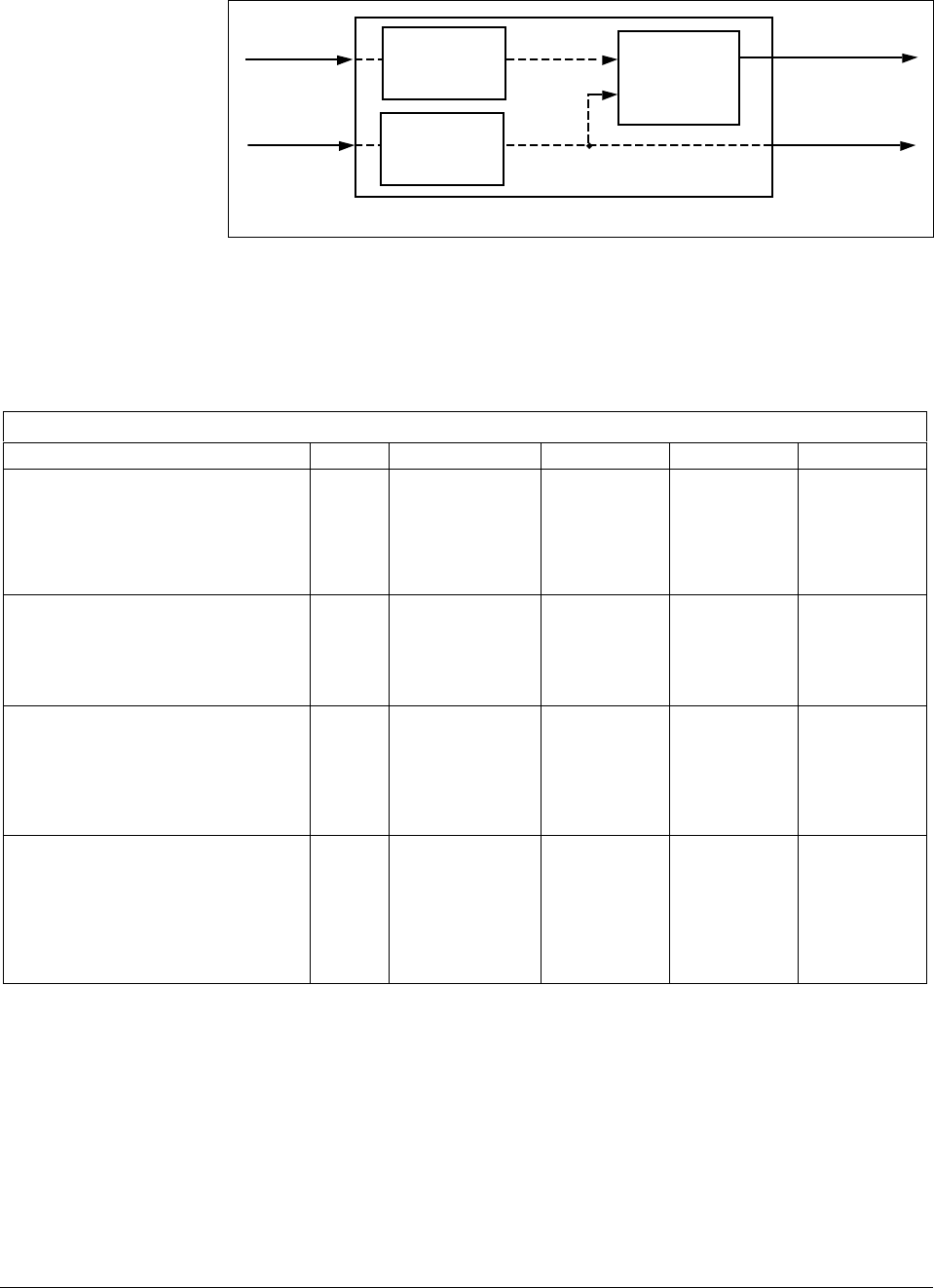
4/00 UDC 3300 Controller Product Manual 175
Figure 5-4 is a block diagram of the Hi/Lo Override Selector.
Figure 5-4 Hi/Lo Override Selector
HI/LO
OVERRIDE
SELECTOR
PID
LOOP 1
PID
LOOP 2
PV 1
PV 2
OUTPUT 1
OUTPUT 2
OUTPUT 1 TERMINALS
OUTPUT 2 TERMINALS
IF DESIRED
24183
Two-loop restrictions Table 5-22 gives two-loop functionality and restrictions for controllers
with one current output (Auxiliary output) and three relay outputs.
Table 5-22 Two-loop Functionality and Restrictions (Model DC330E-EE-2XX or
Model DC330E-EE-5XX)
Controller with One Current Output (Auxiliary Output) and Three Relay Outputs
Output Type Current Auxiliary Relay #1 Relay #2 Relay #3
Loop 1 is TIME SIMPLEX,
Loop 2 is:
Time Simplex
Current or Current Duplex (100 %)
Current/Time or Time/Current
N/A
N/A
N/A
Not used
Loop 2 Output
Loop 2:
Output 1 or 2
Loop 1 Output
Loop 1 Output
Loop 1 Output
Loop 2 Output
Alarm 2
Loop 2:
Output 1 or 2
Alarm 1
Alarm 1
Alarm 1
Loop 1 is TIME DUPLEX/TPSC,
Loop 2 is:
Time Simplex (N/A)
Current or Current Duplex (100 %)
Current/Time or Time/Current (N/A)
—
N/A
—
—
Loop 2 Output
—
—
Loop 1,Output 1
—
—
Loop 1,Output 2
—
—
Alarm 1
—
Loop 1 is CURRENT OUTPUT or
CURRENT DUPLEX – 100 %,
Loop 2 is:
Time Simplex
Current or Current Duplex (N/A)
Current/Time or Time/Current (N/A)
N/A
—
—
Loop 1 Output
—
—
Loop 2 Output
—
—
Alarm 2
—
—
Alarm 1
—
—
Loop 1 is TIME/CURRENT or
CURRENT/TIME,
Loop 2 is:
Time Simplex
Current or Current Duplex (N/A)
Current/Time or Time/Current (N/A)
N/A
—
—
Loop 1:
Output 1 or 2
—
—
Loop 1:
Output 1 or 2
—
—
Loop 2 Output
—
—
Alarm 1
—
—
TWO-LOOP RESTRICTIONS:
1. Time Duplex and Three Position Step Control are not available on Control Loop 2.
2. Position Proportional Control is not available on Two-Loop or Cascade Controllers.
3. If either Time Duplex or Three Position Step Control is selected as Control Loop 1 Output, then Time Simplex,
Current/Time Duplex and Time/Current Duplex are not available for Control Loop 2 Output.
4. Current Duplex 50 % is not available on Model No. DC330E-EE-2XX.

176 UDC 3300 Controller Product Manual 4/00
Two-loop restrictions Table 5-23 gives two-loop functionality and restrictions for controllers
with two current outputs (including Auxiliary output) and two relay
outputs.
Table 5-23 Two-loop Functionality and Restrictions (Model DC330E-KE-2XX or
Model DC330E-KE-5XX)
Controller with Two Current Outputs (including Auxiliary Output) and Three Relay Outputs
Output Type Current Auxiliary Relay #1 Relay #2 Relay #3
Loop 1 is TIME SIMPLEX,
Loop 2 is:
Time Simplex
Current or Current Duplex (100 %)
Current/Time or Time/Current
Not used
Not used
Not used
Not used
Loop 2 Output
Loop 2:
Output 1 or 2
N/A
N/A
N/A
Loop 1 Output
Loop 1 Output
Loop 1 Output
Loop 2 Output
Alarm 1
Loop 2:
Output 1 or 2
Loop 1 is TIME DUPLEX/TPSC,
Loop 2 is:
Time Simplex (N/A)
Current or Current Duplex (100 %)
Current/Time or Time/Current (N/A)
—
Not used
—
—
Loop 2 Output
—
—
N/A
—
—
Loop 1,Output 1
—
—
Loop 1,Output 2
—
Loop 1 is CURRENT OUTPUT or
CURRENT DUPLEX – 100 %,
Loop 2 is:
Time Simplex
Current or Current Duplex (100 %)
Current/Time or Time/Current (N/A)
Loop 1 Output
Loop 1 Output
Loop 1 Output
Not used
Loop 2 Ouptut
Loop 2:
Output 1 or 2
N/A
N/A
N/A
Loop 2 Output
Alarm 2
Loop 2:
Output 1 or 2
Alarm 1
Alarm 1
Alarm 1
Loop 1 is CURRENT DUPLEX – 50 %,
Loop 2 is:
Time Simplex
Current (N/A)
Current/Time or Time/Current (N/A)
Loop 1,Output 1
—
—
Loop 1,Output 2
—
—
N/A
—
—
Loop 2 Output
—
—
Alarm 1
—
—
Loop 1 is TIME/CURRENT or
CURRENT/TIME,
Loop 2 is:
Time Simplex
Current or Current Duplex (100 %)
Current/Time or Time/Current
Loop 1:
Output 1 or 2
Loop 1:
Output 1 or 2
Loop 1:
Output 1 or 2
Not used
Loop 2 Output
Loop 2:
Output 1 or 2
N/A
N/A
N/A
Loop 1:
Ouptut 1 or 2
Loop 1:
Output 1 or 2
Loop 1:
Output 1 or 2
Loop 2 Output
Alarm 1
Loop 2:
Output 1 or 2
TWO-LOOP RESTRICTIONS:
1. Time Duplex and Three Position Step Control are not available on Control Loop 2.
2. Position Proportional Control is not available on Two-Loop or Cascade Controllers.
3. If either Time Duplex or Three Position Step Control is selected as Control Loop 1 Output, then Time Simplex,
Current/Time Duplex and Time/Current Duplex are not available for Control Loop 2 Output.
4. Current Duplex 50 % is not available on Model No. DC330E-EE-2XX.
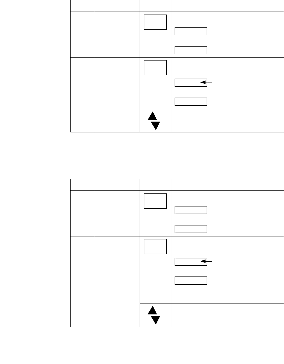
4/00 UDC 3300 Controller Product Manual 177
5.13 Configuring Two Loops of Control
Select 2-loop algorithm The procedure in Table 5-24 shows you how select the 2-loop algorithm.
Table 5-24 Procedure for Selecting 2-loop Algorithm
Step Operation Press Action
1Select Algorithm
Set Up Group SET UP until you see:
ALGORTHM
Lower Display
SET UP
Upper Display
2Select the PID
Loops FUNCTION
LOOP 1/2
to successively display the following
constants:
ALGORTHM
Lower Display
Upper Display
1 LOOP
2LOOPS
CASCAD
or To select two Loops or Cascade control.
Select the output
algorithm for each loop See Section 5.12 for rules and regulations, then follow the procedure in
Table 5-25.
Table 5-25 Procedure for Selecting Output Algorithm
Step Operation Press Action
1Select Output
Algorithm Set Up
Group
SET UP until you see:
OUT ALG
Lower Display
SET UP
Upper Display
2Select Loop 1
Algorithms FUNCTION
LOOP 1/2
to successively display the following
constants:
OUT ALG
Lower Display
Upper Display
TIME
CURRNT
POSITN
TIME D
CUR D
CUR TI
TI CUR
or to select Loop 1 algorithm.
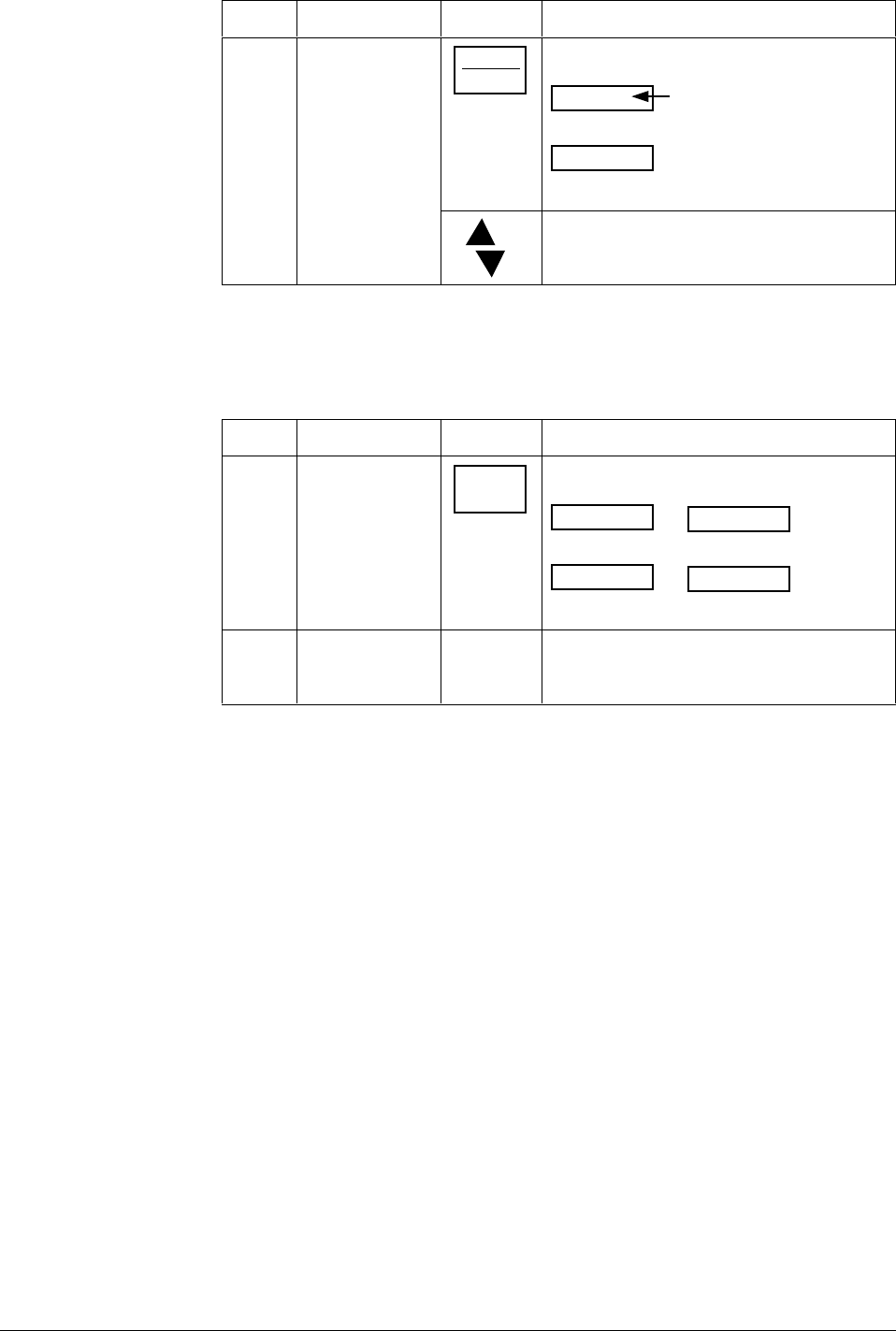
178 UDC 3300 Controller Product Manual 4/00
Step Operation Press Action
3Select Loop 2
algorithms FUNCTION
LOOP 1/2
until you see:
OUT2 ALG
Lower Display
Upper Display
NONE
TIME
CURRNT
CUR D
CUR TI
TI CUR
or to select Loop 2 algorithm.
Select control
parameters for each
loop
The procedure in Table 5-26 shows you how select the 2 loop algorithm.
Table 5-26 Procedure for Selecting Control Parameters
Step Operation Press Action
1Select Control
Set Up Group SET UP until you see:
CONTROL
Lower Display
SET UP
Upper Display
CONTROL2
Lower Display
SET UP
Upper Display
for Loop 1 for Loop 2or
2Refer to Section 5.12 for rules and
restrictions and to Section 3 – Configuration
to select the individual parameters.
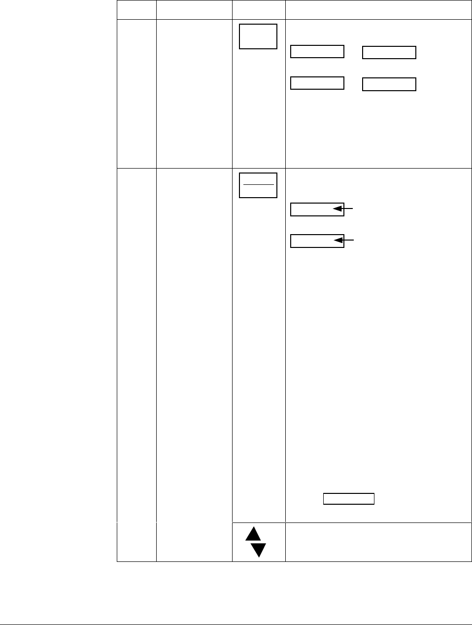
4/00 UDC 3300 Controller Product Manual 179
Select tuning
parameters for each
group
The procedure in Table 5-27 shows you how select the Tuning
Parameters.
Table 5-27 Procedure for Selecting Tuning Parameters
Step Operation Press Action
1Select Tuning
Set Up Group SET UP until you see:
TUNING
Lower Display
SET UP
Upper Display
TUNING 2
Lower Display
SET UP
Upper Display
for Loop 1 for Loop 2or
PID sets 1 and 2 (TUNING) are for Loop 1
and single loop applications.
PID sets 3 and 4 (TUNING 2) are for Loop 2
in two-loop and cascade control applications.
2Select Tuning
constants FUNCTION
LOOP 1/2
to successively display the following
constants:
Lower Display
Upper Display
TUNING CONSTANTS for
Primary Loop
PROP BAND or GAIN
RATE (MIN)
RESET (MIN OR RPM)
CYCLE
PROP BAND2 or GAIN2
RATE2 (MIN)
RESET2 (MIN OR RPM)
CYCLE2
The Tuning Constant Value
TUNING CONSTANTS for
LOOP 2
PROP BAND3 or GAIN3
RATE3 (MIN)
RESET3 (MIN OR RPM)
CYCLE3
PROP BAND4 or GAIN4
RATE4 (MIN)
RESET4 (MIN OR RPM)
CYCLE4
OR
Refer to Section 3 - Configuration for
detailed information.
You can Autotune both sets on either loop.
Refer to Section 5.21.
Use the FUNCTION key to switch
between loops.
or To change the values.

180 UDC 3300 Controller Product Manual 4/00
5.14 Monitoring Two Loops of Control
Introduction Monitoring two individual loops of control or internal Cascade is the same
as a single loop except as indicated in Table 5-28.
Table 5-28 Digital Display Indication—Two Loops
Indicator Loop Indication Definition
none
(two-loop)
I
(cascade)
Loop 1 •Upper display shows the Process Variable
(PV) for Loop 1
•Lower display shows the Loop 1
parameters and the PV and Output for
Loop 2
•Controller setpoint annunciators show the
setpoint currently being used for Loop 1
L” Loop 2 •Upper display shows the Process Variable
(PV) for Loop 2
•Lower display shows the Loop 2
parameters and the PV and Output for
Loop 1
•Controller setpoint annunciators show the
setpoint currently being used for Loop 2
Loop display Display of Loop 1 or Loop 2 (if configured) is selected by toggling the
FUNCTION / LOOP 1/2 key.
Viewing each loop’s
process variable Regardless of which loop is being displayed, 1 or 2, the process variable
of the non-displayed loop can be shown in the lower display by repeated
presses of the LOWER DISPLAY key until 1PVXXXX or 2PVXXXX
is displayed.
Internal cascade
indication When internal Cascade has been configured, an “I” will appear on the left
side of the upper display as long as Loop 1 is operating in the remote
setpoint mode. Hold in the SETPOINT SELECT key until RSP appears
in the lower display then release the key to select remote setpoint.
Switching between automatic and manual mode on either loop will not
affect the internal Cascade indication.

4/00 UDC 3300 Controller Product Manual 181
5.15 Operating Two Loops of Control
Loop operation Operation of two individual loops of control is identical to operating a
single loop of control except that TUNING 2 group applies to Loop 2 only
and two PID sets, 3 and 4, are available. TUNING group applies to Loop
1 with PID sets 1 and 2 applicable.
Operating modes and
setpoint source The rules for Auto/Manual modes and changing setpoint sources are the
same as single loop operation.
Keyboard operation Note that the loop being displayed is the only loop affected by normal
keyboard operation. However, either loop can be reconfigured when in the
Set Up mode regardless of which is being displayed during normal
operation.
Accutune Two independent loops or cascaded loops can be tuned at the same time,
if configured.
Setpoint ramp or SP
programming Either loop or both loops can be configured for a single setpoint ramp
operation by enabling the desired loop or loops (see Section 3 –
Configuration).
An “H” or “R” will appear when applicable, depending upon which loop
is being displayed.
The RUN/HOLD operation is shown in Table 5-15 Procedure for Running
a Setpoint Ramp.
Digital inputs (remote
mode switching) Digital Input 2 is dedicated to Loop 2 and Digital Input 1 is dedicated to
Loop 1 when two loops or Cascade control is configured.
Output override Hi/Lo
select Output Override allows you to select the higher of Output 1 and Output 2
(Hi Select) or the lower of Output 1 and Output 2 (Lo Select) to appear at
Output 1 terminals to drive the final control element. Refer to Section 5.12
for Override rules and block diagram.
Override prompts appear under the Algorithm Set Up group, function
prompt OUT OVRD.
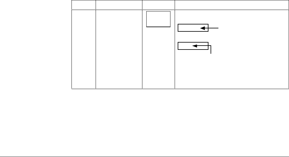
182 UDC 3300 Controller Product Manual 4/00
5.16 Three Position Step Control Algorithm
Introduction The Three Position Step Control algorithm (Loop 1 only) allows the
control of a valve (or other actuator) with an electric motor driven by two
controller output relays; one to move the motor upscale, the other to move
it downscale, without a feedback slidewire linked to the motor shaft.
Accutune SP or SP+PV tuning does not function with this algorithm.
Accutune TUNE will operate with this algorithm.
Estimated motor
position Models DC330X-EE-XXX-X0, DC330X-AA-XXX-X0
The Three Position Step control algorithm provides an output display
(OUT) which is an estimated motor position since the motor is not using
any feedback. Although this output indication is only accurate to a few
percent, it is corrected each time the controller drives the motor to one of
its stops (0 % or 100 %).
It avoids all the control problems associated with the feedback slidewire
(wear, dirt, noise). When operating in this algorithm, the estimated “OUT”
display is shown to the nearest percent (i.e. no decimal).
Accurate motor
position Models DC330X-EE-XXX-X2, DC330X-AA-XXX-X2
In the event that an accurate and repeatable indication in motor position is
required, Position Proportional model’s slidewire input can be used to
read the motor position and display it on the lower display as “POS” while
still operating in the Three Position Step control mode.
The slidewire must be calibrated for this to operate correctly.
Displaying the motor
position Table 5-29 lists the procedure for displaying the motor position.
Table 5-29 Procedure for Displaying the 3PSTEP Motor Position
Step Operation Press Action
1Access the
displays LOWER
DISPLAY
until you see:
Lower Display
Upper Display
The PV value
POS = 3PStep motor position with
slidewire connected
or
OUT = Estimated 3PStep motor
position when no slidewire exists
Power-up output When the controller powers up after a power outage, the position of the
motor will correspond to whatever was configured at the Control Set Up
function prompt PWR OUT, selection LAST or F’SAFE. Refer to Section
4.10, Table 4-9 for definition of each selection.

4/00 UDC 3300 Controller Product Manual 183
5.17 Input Math Algorithms
Introduction If selected via Math options, this controller has two input algorithms
available. Each algorithm can be configured to provide a derived
(calculated) PV or a derived remote setpoint. Up to three inputs may be
applied to the calculation. In addition, the two algorithms may be “linked”
to combine two calculations by configuring one algorithm to be an input
to the other algorithm.
Standard functionality:
•Basic models (DC330B) contain as standard: Weighted Average,
Feedforward Summer, Feedforward Multiplier.
•Expanded models (DC330E) provide as standard: Weighted Average,
Feedforward Summer, Feedforward Multiplier, Relative Humidity.
The Math option, which provides additional algorithms plus two
Characterizers, Totalizer, and Gain Scheduling, is available only on
Expanded Model DC330E-XX-XXX.
Input algorithm
selections Algorithm selections are made in Section 3 – Configuration. The
following function prompts can be found in the Algorithm Set Up group:
IN ALG1
IN ALG2
These selections include the following algorithms:
Weighted Average
Feedforward Summer
Relative Humidity
Summer
Hi Select
Lo Select
√ Multiply Divide
√ Multiply
Multiply Divide
Multiply
Feedforward Multiplier
Carbon Potential (several types)
Dewpoint
The formulas for these selections are given in Table 4-5 in Section 4 –
Configuration Prompt Definitions.
Input A, Input B, and Input C selections for these formulas are found in
Section 4 – Configuration Prompt Definitions; Set Up group
ALGORTHM, under the following function prompts:
ALG1 INA
ALG1 INB
ALG1 INC
ALG2 INA
ALG2 INB
ALG2 INC

184 UDC 3300 Controller Product Manual 4/00
8-segment
characterization This is available as part of the Math Algorithm option. Two 8- selections
can made in Section 3 – Configuration; Set Up group ALGORTHM,
under function prompts:
8SEG CH1
Xn VALUE
Yn VALUE
8SEG CH2
Xn VALU2
Yn VALU2
An 8-segment characterizer can be applied to either Input 1, Input 2,
Output 1, or Output 2. When Input 1 or Input 2 is used, the selected
input’s Ratio and Bias are applied to the Xn values.
When one of the loop outputs is selected, the Xn Values are the output
from the control algorithm, and the Yn Output is the final control element
action.
An example of 8-segment characterization is shown in Figure 4-2.
Totalizer function A Flow Totalizer is available as part of the Math Algorithm option. This
calculates and displays the total flow volume being measured by Input 1.
Alternatively, it can be applied to either Input Algorithm 1 or Input
Algorithm 2 to totalize the compensated flow rate being calculated by the
algorithm.
The totalizer displays the current totalized flow value (up to seven digits
maximum). Seven scaling factors are available (from one to one million).
The desired scaling factor is applied to the calculated value to extend the
maximum total flow range that can be displayed.
Five integration rates are available to match the totalizer rate to the rate
of flow being measured. The rates are:
Engineering units (EU) per second
EU per minute
EU per hour
EU per day
Millions of units per day
The totalizer value is stored in nonvolatile memory once every eight
hours. If power is lost while the totalizer is in operation, the current value
of the totalizer will be lost. When power is restored, the totalizer will
start operation for the last value stored in nonvolatile memory. The Σ
(Sigma) display will blink to indicate this condition. Reset the totalizer.
The totalizer can be reset from the keyboard whenever desired. The
totalizer should always be reset to initialize the counters whenever it is
enabled, otherwise, the “Σ” (Sigma) display will blink.
Refer to Section 3 – Configuration, Set Up group ALGORTHM, function
prompt TOTALIZER to select an application, and the function prompts
that follow TOTALIZER to enter your scale factor and rate of integration.

4/00 UDC 3300 Controller Product Manual 185
Alarm on totalizer
value The alarm type configuration includes an Alarm on Totalizer value. This
allows an alarm setpoint value to be used to cause an alarm when
exceeded. The alarm setpoint represents the lowest four digits of the
selected Totalizer Scale Factor and has a range from 0 to 9999 x Totalizer
Scale Factor.
Totalizer reset via
digital input The digital input type configuration includes a Reset Totalizer that resets
the accumulated totalizer value when the DI is closed.

186 UDC 3300 Controller Product Manual 4/00
5.18 Digital Input Option (Remote Switching)
Introduction The Digital Input option detects the state of external contacts for either of
two inputs. On contact closure, the controller will respond according to
how each digital input is configured. If the controller is configured for
either 2-loop or Cascade control, then switch #1 operates only on Loop 1
and switch #2 operates only on Loop 2.
Make your selection under the Option Set Up group function prompt
“DIG IN1” or “DIG IN2.” See Section 3 – Configuration .
Action on closure Table 5-30 lists the configuration prompt selections, the “Action on
Closure,” and the display indication for each selection available.
Table 5-30 Digital Input Option Action on Contact Closure
DIG IN1 or
DIG IN2
Selections
Display Indication Action on Contact Closure
Returns (toggles) to original state when contact opens,
unless otherwise noted.
None DI 1 2 always off* No Digital Input selection
*The Digital Input Annunciator will always show the Digital Input status.
TO MAN MAN blinks Puts the controller into manual mode. Contact open returns the
controller to former mode unless MANUAL/AUTO key is pressed
while digital input is active, then it stays in the manual mode.
TO LSP Puts the controller into local setpoint 1. When contact opens, the
controller returns to former operation, local or remote setpoint, unless
the SETPOINT SELECT key is pressed while digital input is active,
then it stays in the local setpoint mode.
TO 2SP RSP annunciator blinks Puts the controller into local setpoint 2. When contact opens, the
controller returns to former operation, local or remote setpoint, unless
the SETPOINT SELECT key is pressed while digital input is active,
then it stays in the local setpoint 2 mode.
TO 3SP RSP annunciator blinks Puts the controller into local setpoint 3. When contact opens, the
controller returns to former operation, local or remote setpoint, unless
the SETPOINT SELECT key is pressed while digital input is active,
then it stays in the local setpoint 3 mode.
TO DIR Selects direct controller action.
ToHOLD H blinks Suspends setpoint program or setpoint ramp operation. Contact open
runs the ramp/program from the Hold point unless the Ramp/Program
was not previously started via the RUN/HOLD key. This selection
applies to either loop.
ToPID2 PIDSET 2 in lower
display Selects PID set 2.
PV 2IN II (II blinks)
IN Selects the PV to equal Input 2.
PV 3IN III (III blinks)
IN Selects the PV to equal Input 3.
RERUN Resets the Setpoint program back to the beginning of the first segment
in the program and leaves the program in the same Run or Hold mode
that it was in when the DI closed. Opening the DI has no further affect.
4/00 UDC 3300 Controller Product Manual 187
DIG IN1 or
DIG IN2
Selections
Display Indication Action on Contact Closure
Returns (toggles) to original state when contact opens,
unless otherwise noted.
TO RUN R indicator blinks Starts a stopped SP Program. Reopening contact puts the controller in
Hold mode. This selection applies to either loop.
ToBEGN Resets the Setpoint Program back to the beginning of the first segment
in the program and places the program into the Hold mode. Reopening
the contact has no effect. This selection applies to either loop.
STOP I Disables PID Integral (I) action.
MAN FS MAN blinks Unit goes to manual mode, output goes to the failsafe value. This will
cause a bump in the output when switching from AUTO to MANUAL.
The switch back from MANUAL to AUTO is bumpless.
ToLOCK LOCKED when a key is
pressed Disables all keys.
ToAout Output is forced to value set at control prompt “AUTO OUT” when
controller is in automatic mode. Reopening contact returns the
controller to the normal output. This selection is only available on Loop
1.
TIMER Timer clock ( ) and
time appear in lower
display.
Starts timer (momentary). Reopening switch has no effect.
AM STA Causes switch to Auto Manual Station mode. Refer to Figure 5-5 in
Section 5.19 for auto manual station information. This selection is only
available on Loop 1.
ToTUNE TUNE ON in lower
display Starts the Accutune process. Opening the switch has no effect.
SPinit Forces the SP to initialize at the current PV value.
TRACK1 O blinks Allows Output 1 to track Input 2.
TRACK2 O blinks Allows Output 2 to track Input 2.
ToOUT2 O blinks Allows Output 2 to override Output 1.
TO RSP RSP annunciator blinks Selects remote setpoint.
D L1/2 Displays loop not being displayed at time of closure.
RST FB Allows Input 2 to override the internal reset value, providing external
reset feedback.
ToPURG MAN blinks and output
value shows in lower
display
Forces loop to manual mode with the output values set to the Output
High Limit configuration.
LoFIRE MAN blinks and output
value shows in lower
display
Forces loop to manual mode with the output set to the Output Low
Limit configuration.
MAN LT Forces loop to manual mode. This is a momentary switch input,
therefore no action occurs when the switch is opened.
To return to automatic mode, press the MANUAL/AUTO key.
REStot Resets the accumulated totalizer value. Opening the switch has no
effect.
188 UDC 3300 Controller Product Manual 4/00
Keyboard operation Front panel keys have no effect on the digital input action in the closed
state.
Digital inputs 1 and 2
combination selections The Digital Input combination selections listed in Table 5-31 can be used
in combination with the digital inputs 1 and 2 listed in Table 5-30.
Refer to Section 3 – Configuration and make your selections under the
Options Set Up group function prompt “DIG 1 COMB” or “DIG 2
COMB.”
When 2-loop or cascade control is configured, digital input 1 operates on
Loop 1 and digital input 2 operates on Loop 2, unless otherwise noted.
Table 5-31 Digital Input Combinations “DIG IN1” or “DIG IN2”
Selections used in
Combination with
“DIG IN1” or
“DIG IN2”
Display Indication Action on contact closure
Returns (toggles) to original state
when contact opens.
+PID2 PIDSET 2 in lower display Selects PID set 2.
+ToDIR Puts the controller into direct controller action.
+ToSP2 RSP blinks Selects the second local setpoint.
+DISAT T indicator is no longer lit Disables Adaptive tune.
+ToSP1 Selects the local setpoint.
+RUN R indicator blinks Starts or restarts RUN of SP Ramp/Program.
Digital inputs 1 and 2
combination operation There are five possible situations that can occur when working with
digital input combinations. Table 5-32 lists these situations and the
resulting action when the switch is active.
In the table:
Enabled means that the parameter is configured and the action
will occur when the digital input is active.
Action Disabled means that the digital input or digital combination
parameter is configured but the action cannot occur
when the digital input is active because the selected
parameter is disabled.

4/00 UDC 3300 Controller Product Manual 189
Table 5-32 Digital Inputs 1 and 2 Combination
DIG IN1 DIG COMB Action Example
NONE Any Selection No action will occur when the digital
input is active.
ENABLED DISABLED The DIG IN condition will occur
when the Digital Input is active. DIG IN1 = TO MAN
DIG1 COM = DISABL
Loop 1 will switch to MANUAL
when digital input 1 is active.
ACTION
DISABLED ENABLED No action will occur when the digital
input is active. DIG IN1 = ToPID2
PID SETS = 1 ONLY
DIG1 COM = +ToSP2
LSP’S = TWO
DIG IN1 is action disabled
because PID SETS is set to
1 ONLY. Therefore, when digital
input 1 is active, no action will
occur even though DIG1 COM is
enabled.
ENABLED ACTION
DISABLED Action is indeterminate when the
digital input is active. DIG IN1 = ToPID2
PID SETS = 2KEYBD
DIG1 COM = +ToSP2
LSP’S =1 ONLY
Because DIG1 COM is action
disabled, the action will be
indeterminate when DIG IN1 is
active.
ENABLED ENABLED Both DIG IN and DIG COM action
will occur.
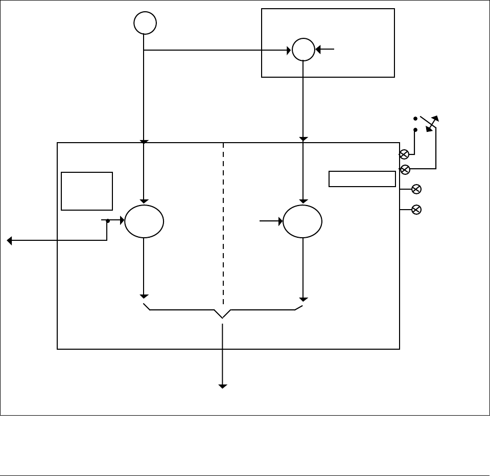
190 UDC 3300 Controller Product Manual 4/00
5.19 Auto/Manual Station
Introduction When you select “AM STA” (auto manual station) under the Option Set
Up group function prompt “DIG IN1” or “DIG IN2” (digital input option),
contact closure on the selected digital input causes the controller to switch
to Auto/Manual Station mode.
Function As shown in Figure 5-5, State 2 is the “A/M Station mode” where the
programmable logic controller (PLC) output is sent through the
Auto/Manual Station. You can switch to manual and change the output at
the controller. (It uses PID set 2.)
State 1 is the “Backup PID mode” which is triggered by opening the
digital input. (It uses PID set 1.)
Figure 5-5 Auto/Manual Station and Backup Control Feature
T/C
T/C
PLC
PV SP
IN1 IN2
PID A
OUT1 OUT1
Output 1
4-20 mA
To valve
Aux
Output
SP1 =
new
selection
DI #1 = "AM STA"
(new
selection)
State 1:
DI #1: Open
BACKUP
PID
CONTROL
State 2:
DI #1: Closed
A/M STATION
LSP = SP1 LSP = 2SP
– Direct action
– PD+MR
– SP = 2SP
– PV = IN2
– PIDSET2
PIDSET1
P =
I =
D =
same
as
PLC
Configure
State 2 per
next page.
Control output
4-20 mA
PVPV Alarm
Output on
Manual
Mode
(new
selection)
PD+MR
}
24184
OPEN
CLOSED

4/00 UDC 3300 Controller Product Manual 191
Description The “AM STA” selection of digital input creates a repeater station when
the digital input is closed. This is accomplished by a multi-selection from
the digital input menu.
•“ACTION” is forced as “DIRECT”.
•“CONT ALG” is forced as “PD+MR”.
•Active setpoint is forced to 2SP.
•The PV is switched to “PV 2IN”.
•The tuning parameters used are the second set of parameters.
When the switch is open the unit becomes a normal controller with
“CONT ALG” of “PID A”, using tuning parameters set 1, SP, PV as IN1
and “DIRECT” or “REVERSE” as selected by customer configuration.
Input 1 is typically the PV of some upper controller and Input 2 is
typically that controller’s output. If the upper control fails, the upper
device or some watchdog opens the digital input switch and UDC 3300
back-up PID A control is active.
When the upper control reactivates, the digital input switch is closed and
the Auto/Manual Station becomes a repeater station and allows the upper
control output signal to pass through.
Configuration There are some things to consider when configuring the controller.
The PV range stays as the IN1 range, even while IN2 is the PV when the
switch is closed; therefore:
•The IN2 HI must be less than or equal to the IN1 HI.
(Suggest: IN2 HI = 100.0)
•The IN2 LO must be greater than or equal to the IN1 LO.
(Suggest: IN2 LO = 0.0)
•The TUNING GAIN2 must be equal to
(IN1 HI – IN1 LO) / (IN2 HI – IN2 LO).
Configuration Refer to Table 5-33 and set up the controller in the order shown.
Table 5-33 Auto/Manual Station Mode Configuration Procedure
Step Press SET
UP
to Select Set
Up Group
Press FUNC to
Select
Function
Prompts
Press ▲ ▼
to Enter
Value or
Selection
Remarks
1 Control PID SETS 2KEYBD
LSP’STWO
SP TRACK NONE
Select other control parameters as needed by the
application.
2 Algorithm CONT ALG PD+MR This allows setting of the Manual Reset value.
3 Tuning MAN RSET 0 Manual reset of 0 for no output bias and requires
LSP2 = 0 %. If bias is required, set MR to equal the
desired output bias value.
192 UDC 3300 Controller Product Manual 4/00
Step Press SET
UP
to Select Set
Up Group
Press FUNC to
Select
Function
Prompts
Press ▲ ▼
to Enter
Value or
Selection
Remarks
4 Algorithm CONT ALG PID A Defines back-up control algorithm.
5 Tuning RSET2MIN 50.00
GAIN2 See Note 1 Note 1. Set the Gain 2 equal to
Input 1 Span
Input 2 Span
If “PB” is selected under the Control Set Up group
function prompt “PBorGAIN”, set the PROP BD2 to
100 x Input 2 Span
Input 1 Span
RATE2MIN 0.00 Select PIDSET 1 tuning parameters as needed by the
application.
6 Options DIG IN1 or
DIG IN2 AM STA
CAUTION DO NOT SELECT
•In the CONTROL set up list, do not select SP TRACK as PV or RSP.
•In the SP RAMP set up list, do not select SP RATE as ENABLE.
•In the ALGORTHM set up list, do not select CONT ALG as
PID B, ON-OFF, or 3PSTEP.
•In the Display menu when PIDSET # is displayed, DO NOT change the
selection.
Operation Set the local setpoint 2 to 0 % of the Input 2 range.
These features work with the Auto/Manual Station.
•In the SP RAMP set up list, SP PROG (acts on SP1 for backup
operation).
•In the SP RAMP set up list, SP RAMP (acts on SP1 for backup
operation).
•In the CONTROL set up list, ACTION as DIRECT or REVERSE for
the backup PID A operation.
The PD+MR action is forced to be DIRECT as required for the pass
through of the output signal.

4/00 UDC 3300 Controller Product Manual 193
5.20 Fuzzy Overshoot Suppression
Introduction Fuzzy Overshoot Suppression minimizes overshoot after a setpoint change
or a process disturbance. This is especially useful in processes which
experience load changes or where even a small overshoot beyond the
setpoint may result in damage or lost product.
How it works The fuzzy logic observes the speed and direction of the PV signal as it
approaches the setpoint and temporarily modifies the internal controller
response action as necessary to avoid an overshoot. There is no change to
the PID algorithm, and the fuzzy logic does not alter the PID tuning
parameters. This feature can be independently enabled or disabled, as
required by the application, to work with TUNE On-Demand tuning, the
SP tuning algorithm, or Adaptive Tune.
Configuration To configure this item, refer to Section 3 – Configuration:
• Set Up Group ACCUTUNE
• Function Prompt FUZZY
• Select ENABLE or DISABL ( or )

194 UDC 3300 Controller Product Manual 4/00
5.21 Accutune
Introduction There are several types of Accutune from which to choose:
•(TUNE) Demand Tuning—Tuning is done on demand
–by pressing the LOWER DISPLAY and ▲ keys simultaneously,
–by selecting prompt “TUNE” in the lower display,
–via digital input.
•(SP) Setpoint Tuning*—SP only tuning will continually adjust the
Gain or Proportional Band (P), Reset (I), and Rate (D) tuning constants
in response to setpoint changes.
•(TUN+PV) Demand Tuning + PV Adapt—Provides TUNE On
Demand tuning plus PV adaptive tuning whenever a PV process
disturbance of 0.3 % span or greater occurs.
•(SP+PV) Setpoint Tuning* + PV Adapt—Provides SP only tuning
plus PV adaptive tuning whenever a PV process disturbance of 0.3 %
span or greater occurs.
*Not available on Basic Model DC330B
Configuration To configure this item, refer to Section 3 – Configuration:
•Set Up Group ACCUTUNE.
•Function Prompt ACCUTUNE or ACCUTUN2 depending on which
loop you are tuning.
•Select DISABL, TUNE, SP, TUN+PV, or SP+PV. Use the ▲ or ▼
key.
If SP is selected:
–Enter the setpoint change value, function prompt SP CHANG or SP
CHAN2.
–Verify or change the process gain value, function prompt KPG or
KPG 2.
–Verify criteria, function prompt CRITERIA or CRITERA2.
Two-loop and cascade
operation Accutune can be used on either or both loops. However, while one loop is
operating by SP tuning, the configuration of either loop cannot be
changed. When one loop is operating by PV adaptive tuning, the other
loop can have its configuration changed.
4/00 UDC 3300 Controller Product Manual 195
Rules Table 5-34 is a list of rules for Accutune.
Table 5-34 Accutune Rules and Regulations
TUNE SP* Applicable Rule
XTUNE On Demand tuning will work for all control algorithms except ON/OFF. Process
line out is not required.
XTUNE On Demand tuning works for integrating processes.
XSP tuning will work only for algorithm PID a or PID B selections; i.e., it will NOT work
with ON/OFF, Three Position Step, or PD+MR control algorithms.
XSP tuning can tune on all local or computer setpoints except ramping setpoints; i.e.,
cannot be done during SP Ramp or SP Program or when using remote setpoint.
XX
Tuning is done in automatic mode.
XX
Tuning can be monitored or reconfigured using communications option.
XX
Tuning can be enabled via digital inputs.
XX
Tuning can be aborted by going to manual mode or disabling via configuration.
XX
When tuning is in progress, a large T appears in the upper display and disappears as
soon as tuning is completed.
XX
Can tune two independent loops.
XSetpoint changes can be made during operation. The setpoint at the time tuning
starts is captured and Tune runs until completion, then proceeds to the new SP value
following the completion of tuning.
*SP ADAPT not available on Basic Model DC330B
How TUNE (demand)
tuning works TUNE tuning provides virtually foolproof, trouble-free on-demand tuning
in the UDC 3300 controller. No knowledge of the process is required at
start-up. The operator simply enters the desired setpoint and initiates the
tuning.
The controller immediately starts controlling to the setpoint while it
identifies the process, calculates the tuning constants and enters them into
the Tuning group, and begins PID control with the correct tuning
parameters. This works with any process, including integrating type
processes, and allows returning at a fixed setpoint.
The tuning sequence will cycle the controller’s output two full cycles
between 0 % and 100 % (or configured output limits) while allowing only
a very small process variable change above and below the SP during each
cycle. The algorithm then calculates new tuning parameters and enters
them into the Tuning group. A large T appears in the upper display while
tuning is active.

196 UDC 3300 Controller Product Manual 4/00
Starting TUNE
(demand) tuning After TUNE or TUN+PV has been enabled, use the procedure in Table
5-35 to start tuning.
Table 5-35 Procedure for Starting TUNE (Demand) Tuning
Step Action
1Set the setpoint to the desired value.
2Switch to Automatic mode by pressing the MANUAL/AUTO key.
3Initiate Tuning by:
•pressing the ▲ key when the lower display prompt = TUNE-OFF,
•pressing the LOWER DISPLAY and ▲ keys simultaneously, or
•using the digital input, if configured.
Aborting tuning If it is necessary to stop or abort the tuning process, press the
MANUAL/AUTO key and the controller will return to manual mode.
You can also disable TUNE or TUN+PV in the ACCUTUNE or
ACCUTUN2 Set Up group.
TUNE for duplex
(heat/cool) TUNE can be done for applications using duplex (heat/cool) control.
During tuning, Accutune requires that setpoint 1 will cause a Heating
demand, and then the calculated tuning parameters will be automatically
entered as PID set 1. Likewise, it requires that tuning at local setpoint 2
will cause a Cooling demand, and then the cooling parameters will be
entered as PID set 2.
The tuning sequence will cycle the controller’s output two full cycles
between the high output limit and 50 % for HEAT or between 50 % and
the low output limit for COOL while allowing only a small process
variable change above and below the setpoint during each cycle.
Configuring TUNE for
duplex (heat/cool) To configure this item, refer to Section 3 – Configuration:
•Set Up Group ACCUTUNE
•Function Prompt ACCUTUNE or ACCUTUN2
•Select TUNE or TUN+PV, using either ▲ or ▼.
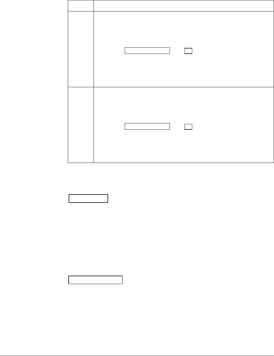
4/00 UDC 3300 Controller Product Manual 197
Using TUNE at start-up
for duplex (heat/cool) After TUNE or TUN+PV has been enabled, use the procedure in Table
5-36 to use TUNE at start-up for duplex (heat/cool) control.
Table 5-36 Procedure for Using TUNE at Start-up for Duplex
Step Action
1Heat Zone:
•Adjust Local Setpoint 1 to a value within the Heat zone.
•Put the controller in Automatic mode.
•Press the LOWER DISPLAY and ▲ keys simultaneously to initiate
Heat tuning.
The output will cycle between 50 % and 100 % (or high output limit). A large
T appears in the upper display until tuning is completed and final Heat
parameters are entered for PID set 1 in the Tuning group.
2Cool Zone:
•Adjust Local Setpoint 2 to a value within the Cool zone.
•Put the controller in Automatic mode.
•Press the LOWER DISPLAY and ▲ keys simultaneously to initiate
Cool tuning.
The output will cycle between 0 % and 50 % (or low output limit). A large T
appears in the upper display until tuning is completed and final Cool
parameters are entered for PID set 2 in the Tuning group.
How SP tuning works SP tuning will continually adjust the Gain or Proportional Band (P), Reset
(I), and Rate (D) tuning constants in response to setpoint changes.
ATTENTION SP tuning is not available on Basic Model DC330B.
SP tuning handles all Local and Computer setpoint changes. It uses time
domain analysis, and the rule based expert system techniques to identify
the two most dominant process lags plus any dead time. It then
automatically readjusts the PID parameters as necessary. It does this while
controlling to setpoint in automatic (closed loop) control mode.
These calculated PID values can be changed, if desired, whenever the
tuning is not active. Tuning can be aborted by pushing the
MANUAL/AUTO key to return to the manual mode.
Two criteria are available—Normal and Fast—through configuration.
Setpoint changes During start-up, or whenever the setpoint changes beyond the “SP
Change” value, SP tuning employs time domain analysis to tune the
process at any desired setpoint without any prior initialization or process
knowledge.

198 UDC 3300 Controller Product Manual 4/00
Using SP tuning at
start-up After SP or PV+PV has been enabled, use the procedure in Table 5-37 to
use SP tuning at start-up.
Table 5-37 Procedure for Using SP Tuning at Start-up
Step Action
1Put the controller in manual mode by pressing the MANUAL/AUTO key.
2Let the PV stabilize.
3Adjust the setpoint to the desired value.
4Put the controller in automatic mode by pressing the MANUAL/AUTO
key.
The controller will switch to automatic mode and the process will start to
move toward the setpoint and will line out with the proper tuning constants.
A large T appears on the left side of the upper display to indicate that SP
tuning is in progress.
SP tuning for duplex
(heat/cool) SP tuning can be done for applications using duplex (heat/cool) control.
Configuring SP tuning
for duplex (heat/cool) To configure this item, refer to Section 3 – Configuration:
•Set Up Group ACCUTUNE
•Function Prompt ACCUTUNE or ACCUTUN2
•Select SP or SP+PV, using either ▲ or ▼.
•Enter the Setpoint Change Value, Function Prompt SP CHANG or
SP CHAN2.
–Verify the Process Gain Value to be 1.0, Function Prompt KPG or
KPG 2.
–Verify Criteria selected is FAST, Function Prompt CRITERIA or
CRITERA2.

4/00 UDC 3300 Controller Product Manual 199
Using SP tuning at
start-up for duplex
(heat/cool)
After SP or SP+PV has been enabled, use the procedure in Table 5-38 to
use SP tuning at start-up for duplex (heat/cool) control.
Table 5-38 Procedure for Using SP Tuning at Start-up for Duplex
Step Action
1Put the controller into manual mode—MANUAL/AUTO key.
2Heat Zone:
•Adjust the Output to a value above 50 % and at least 5 % lower than the
normal heating setpoint value.
•Let the PV stabilize.
•Press the MANUAL/AUTO key to start tuning for Heat zone.
The controller will switch to automatic mode and the process will start to
move toward the setpoint and will line out with the proper Heat tuning
constants. A large T appears on the left side of the upper display to indicate
that SP tuning is in progress.
When the T disappears, tuning is completed and final values are entered for
PID set 1 parameters in the Tuning group.
3Cool Zone:
•Adjust the Output to a value below 50 % and at least 5 % above the
normal cooling setpoint value.
•Let the PV stabilize.
•Press the MANUAL/AUTO key to start tuning for Cool zone.
The controller will switch to automatic mode and the process will start to
move toward the setpoint and will line out with the proper Cool tuning
constants. A large T appears on the left side of the upper display to indicate
that SP tuning is in progress.
When the T disappears, tuning is completed and final values are entered for
PID set 2 parameters in the Tuning group.
SP tuning after start-up SP tuning will occur whenever the controller is in automatic mode and a
setpoint change occurs which is greater than the previously configured
minimum setpoint change value.
The controller will delay using any setpoint changes for 30 seconds to
enable it to calculate whether to SP tune or not. But if the controller is
toggled between LSP1 and LSP2 or if any other key (such as LOWER
DISPLAY) is pressed, the setpoint change is immediate.
A large T is displayed in the upper display whenever tuning is in progress.
During this time, no changes to the configuration parameters, including
the setpoint, are permitted.
Aborting SP tuning If it is necessary to stop or abort the tuning:
•Press the MANUAL/AUTO key to return to manual mode. This will
cause an immediate abort of tuning.
•Disable SP or SP+PV in the Accutune Set Up group at function prompt
ACCUTUNE or ACCUTUN2.

200 UDC 3300 Controller Product Manual 4/00
Retuning The controller will evaluate current tuning as SP changes occur. When
retuning is required, the controller operates in automatic mode and
identifies new tuning constants. At the point, the T appears and tuning
values are entered and used until retuning occurs again.
TUN+PV or SP+PV
(process variable
disturbance)
The TUNE demand tuning or the SP tuning portions of these selections
work as stated previously.
During process variable (PV) disturbances which result from
nonlinearities, process dynamics, load changes, or other operating
conditions, PV adapt tuning will occur whenever a PV disturbance of
0.3 % span or larger occurs. When this condition exists, the controller
monitors the process response to determine whether there has been a true
process change or a momentary upset. It will take 1 and 1/2 process cycles
around the setpoint before any process recognition can occur to an
oscillating process.
However, if no oscillation occurs, Adaptive may alter the parameters to
speed up or slow down the process response, if it determines the time to
return to the SP is excessive or too fast (overshoot occurs).
For this configuration, the controller operates with only one set of tuning
parameters for each loop. The second set, normally used for duplex output
or for keyboard, PV or SP switching, is not used because Adaptive tune
continually updates the tuning parameters based on the PV deviation.
PV tuning indications A small t is displayed in the upper display whenever PV adapt mode is in
progress. During this time, changes to the configuration parameters are
permitted. Whenever the t is displayed it signifies that the process
response is being monitored and this may or may not result in parameter
retuning.
The selection of Fast or Normal criteria has no effect on PV adaptive
tuning.
Aborting PV adaptive
tuning If it is necessary to stop or abort the tuning:
•Press the MANUAL/AUTO key to return to manual mode. This will
cause an immediate abort of tuning.
•Disable TUN+PV or SP+PV in the Accutune Set Up group at function
prompt ACCUTUNE or ACCUTUN2.
Error prompt accessing
procedure When an error is detected in the Accutune process, the message AT
ABORT will appear in the lower display.
In order to determine what is causing the error:
•Select ACCUTUNE or ACCUTUN2 Set Up Group.
•Access Function Prompt AT ERROR or AT ERR 2 for error prompt.

4/00 UDC 3300 Controller Product Manual 201
Error prompt Table 5-39 lists the Accutune error prompts and their definitions.
Table 5-39 Accutune* Error Prompt Definitions
Upper Display
Prompt Prompt Definition Action to Take
NONE No errors None
OUTLIM SP Adapt step is greater than high output
limit or less than low output limit
Output step insufficient to get to SP value
• Check the output limits under Control Set
Up group function prompts OUTHiLIM and
OUTLoLIM in Section 3 – Configuration.
• Verify the Process Gain Value, function
prompt KPG or KPG 2.
IDFAIL Process Identification Failure
An illegal value of gain, rate, or reset was
calculated.
Try to SP tune again. Insure the process is at
line-out prior to initiation of SP tune.
ABORT
(Only error code
available for TUNE)
• Manual abort has occurred
– Accutune will abort if the
MANUAL/AUTO key is pressed
during tuning
• Digital input detected
• Automatic abort has occurred
– Accutune will automatically abort when
a PV oscillation has been detected
during SP adapt, whenever any SP
values are changed during a PV adapt
tune, or when Accutune is disabled.
Try to TUNE or SP tune again.
LOW PV PV not changed sufficiently or the PV has
increased by more than 4 % and dead
time not determined.
NONE—After a period of about five minutes,
the SP adaptive tuning will be retried
automatically with a larger output step.
RUNING Informational prompt indicating that SP
tune is still active checking process gain
even though T is not lit. It does not affect
the keyboard operation.
NONE
*Does not apply to PV Adapt.

202 UDC 3300 Controller Product Manual 4/00
5.22 Carbon Potential
Introduction Figure 5-6 shows a UDC 3300 controller being used to control the carbon
potential of a furnace’s atmosphere. A carbon probe consisting of a ZrO2
sensor and a thermocouple (to measure the temperature at the sensor)
provides two inputs to the controller. The microprocessor-based controller
computes the atmosphere’s actual carbon potential from these two inputs
and compares the computed value with the desired setpoint. As an on-off
or PID control algorithm determines the controller output necessary to
keep the actual carbon potential at the setpoint. Usually only one output is
used to add more or less enriching gas (typically natural gas) to the
furnace’s base atmosphere, which has a relatively low carbon potential.
The enriching gas then raises the carbon potential to the desired level;
however, there are occasions when it is necessary to add dilution air to
lower the carbon potential instead of enriching gas to raise it. In those
instances, a second output from the controller provides this function.
When proportional control is used, a different set of PID tuning constants
is used for the dilution air than those used for the enriching gas.
Features •Direct calculation of carbon percentage with seven different
manufacturers’ probes
–Advanced Atmosphere Control Corporation (AACC)
–Corning
–Cambridge Instruments
–Marathon Monitors
–Furnace Control Corporation
–MacDhui (Barber Colman)
–Bricesco
•± 0.02 % accuracy
•No nomographs—no mistakes
•Two controller outputs are available for duplex control.
•Probe temperature input type is selectable from complete input menu.
•Three different local setpoints—standard feature
•Duplex control with second set of PID constants for dilution air control
•Process factor adjustment capability
•Automatic sooting warning via flashing display
•New Dewpoint algorithm is available. Range: –50 °F to +100 °F
•New % Oxygen algorithm is available. Range: 0 % to 40 %
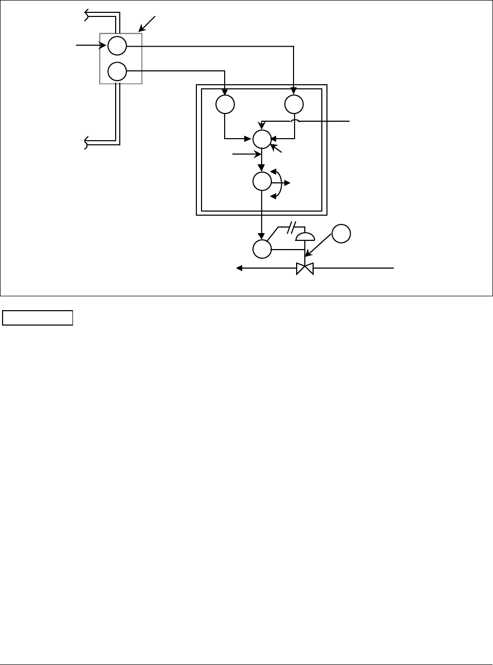
4/00 UDC 3300 Controller Product Manual 203
Diagram Figure 5-6 is a diagram illustrating the application of the UDC 3300 for
carbon potential control.
Figure 5-6 Carbon Potential Control
T/C
f(x) f(x)
PID
E/P
CV
Carbon
Probe
O2
Sensor
Carburizing
Furnace
%
Carbon
PV
%
Carbon
Calc.
Output
Enrichment Gas
• SP
• 2SP
• 3SP or
RSP
Input 2 Input 1
UDC 3300
24185
millivolts
CP
Input 3—
Optional Online
CO Compensation
ATTENTION •For Carbon control, set Input Algorithm 1 to the proper carbon sensor
used and set the PV source to IN AL 1. Input 1 will automatically
become CARBON.
•For % Oxygen control, set Input Algorithm 1 to OXYGEN. Input 1 will
automatically become OXYGEN.
• For Dewpoint control, set Input Algorithm 1 or Input Algorithm 2 to
DEW PT. Input 1 will automatically become CARBON. The
availability of Dewpoint on Input Algorithm 2 provides the capability
of controlling Carbon Potential on Loop 1 and also reading the
Dewpoint value from the same probe.
•CO Compensation—Receives external CO transmitter signal via Input
3 to provide online compensation fo the carbon calculation. Requires
that the Input 2 temperature signal be a transmitter type input.

204 UDC 3300 Controller Product Manual 4/00
5.23 HealthWatch
Introduction The HealthWatch feature puts diagnostic data at your fingertips so you
can monitor vital performance status to improve your process, predict
failures, and minimize downtime.
Valuable data regarding maintenance and diagnostic selections can be
read by operator-accessed displays. Alarms can be configured to activate
when the desired threshold is reached.
See Section 4.18 Maintenance for details on using the various
HealthWatch timers and counters. See Section 4.15 Alarms for details on
HealthWatch maintenance alarms.

4/00 UDC 3300 Controller Product Manual 205
Section 6 – Setpoint Ramp/Soak Programming Option
6.1 Overview
What is programming? The term “programming” is used here to identify the process for selecting
and entering the individual ramp and soak segment data needed to
generate the required setpoint versus time profile (also called a program).
A segment is a ramp or soak function which together make up a setpoint
program. Setpoint Ramp/Soak Programming lets you configure 6 ramp
and 6 soak segments to be stored for use as one program or several small
programs. You designate the beginning and end segments to determine
where the program is to start and stop.
Review program data
and configuration While the procedure for programming is straightforward, and aided by
prompts, we suggest that you read “Program Contents” in this section as
well as “Section 3 - Configuration” before doing the setpoint
programming.
Fill out the worksheet Draw a Ramp/Soak Profile on the worksheet provided and fill in the
information for each segment. This will give you a record of how the
program was developed.
What’s in this section The table below lists the topics that are covered in this section.
Topic See Page
6.1 Overview 205
6.2 Program Contents 206
6.3 Drawing a Ramp/Soak Profile 209
6.4 Entering the Setpoint Program Data 211
6.5 Run/Monitor the Program 214

206 UDC 3300 Controller Product Manual 4/00
6.2 Program Contents
What you will configure Basically, you will configure all the data that is relevant to each ramp and
soak segment for a given setpoint versus time profile. The controller will
prompt you through the sequence of segments and associated functions.
Ramp segments A ramp segment is the time it will take to change the setpoint to the next
setpoint value in the program.
Ramps are odd number segments. Segment #1 will be the initial ramp
time.
Ramp time is determined in either:
TIME* - Hours.Minutes Range = 0-99hr.59 min.
or
RATE* - EU/MIN or EU/HR Range = 0 to 999
* This selection of time or rate is made at prompt “RAMP UNIT”.
Set this prompt before entering any Ramp.
ATTENTION Entering “0” will imply an immediate step change in
setpoint to the next soak.
Soak segments A soak segment is a combination of soak setpoint (value) and a soak
duration (time).
Soaks are even number segments.
Segment 2 will be the initial soak value and soak time.
The soak setpoint range value must be within the setpoint high and low
range limits in engineering units.
SOAK TIME is the duration of the soak and is determined in:
TIME - Hours.Minutes RANGE = 0-99hr.59 min.
Start segment number This designates the number of the first segment (odd number).
Range = 1 to 11
End segment number This designates the number of the last segment. It must be a soak segment
(even number).
Range = 2 to 12
Recycle number This number allows the program to recycle a specified number of times
from beginning to end.
Range = 0 to 99

4/00 UDC 3300 Controller Product Manual 207
Guaranteed soak Each soak segment can have a deviation value of from 0 to ± 99 which
guarantees the value for that segment.
Guaranteed soak segment values >0 guarantee that the segments process
variable is within the ± deviation for the configured soak time. Whenever
the ± deviation is exceeded, soak timing is frozen.
There are no guaranteed soaks whenever the deviation value is configured
to 0; i.e., soak segments start timing soak duration as soon as the soak
setpoint is first reached, regardless of where the process variable remains
relative to the soak segment.
The value is the number in engineering units, above or below the setpoint,
outside of which the timer halts. The range is 0 to 99.
The decimal location corresponds to input 1 decimal selection.
Program state This selection determines the program state after completion.
The selections are:
DISABL = Program is disabled
HOLD = Program on hold (RUN key restarts the program.)
Program termination
state This function determines the status of the controller upon completion.
The selections are:
LASTSP = controls to last setpoint and last control mode
F SAFE = manual mode, failsafe output
ATTENTION If power is lost during a program, upon power-up the
controller will be in hold and the setpoint value will be the setpoint value
prior to the beginning of the setpoint program. The program is placed in
hold at the beginning of the first segment in the program.
Hot Start This function determines whether LSP1 or PV is used as the setpoint
when the program is initially changed from HOLD to RUN.
The selections are:
DISABL = When the program is initially changed from HOLD to
RUN the present LSP1 value is captured as the default setpoint. If the
program is terminated or the power cycled before the program has
completed, the LSP1 is used as the control setpoint. The beginning
segment uses this value as the initial ramp setpoint.
ENABL = When the program is initially changed from HOLD to
RUN the present PV value is captured and used as the beginning setpoint
value for the ramp segment. If the program is terminated before
completion, the setpoint value will revert back to the PV value captured at
the initial HOLD to RUN transition. If the power is cycled before
program completion, upon power-up the setpoint is set to the PV value at
power-up and when the program is restarted that setpoint value is used
initially.

208 UDC 3300 Controller Product Manual 4/00
Ramp unit This determines the engineering units for the ramp segments.
The selections are:
TIME = Hours.Minutes
RATE = EU/MIN or EU/HR
ATTENTION This selection cannot be changed while a program is in
operation.
ATTENTION The Accutune TUNE selection will operate during setpoint programming.
When it is initiated during a program, it places the program into Hold
until it completes, then returns it to either Run or Hold depending what
the state was before Tuning started.
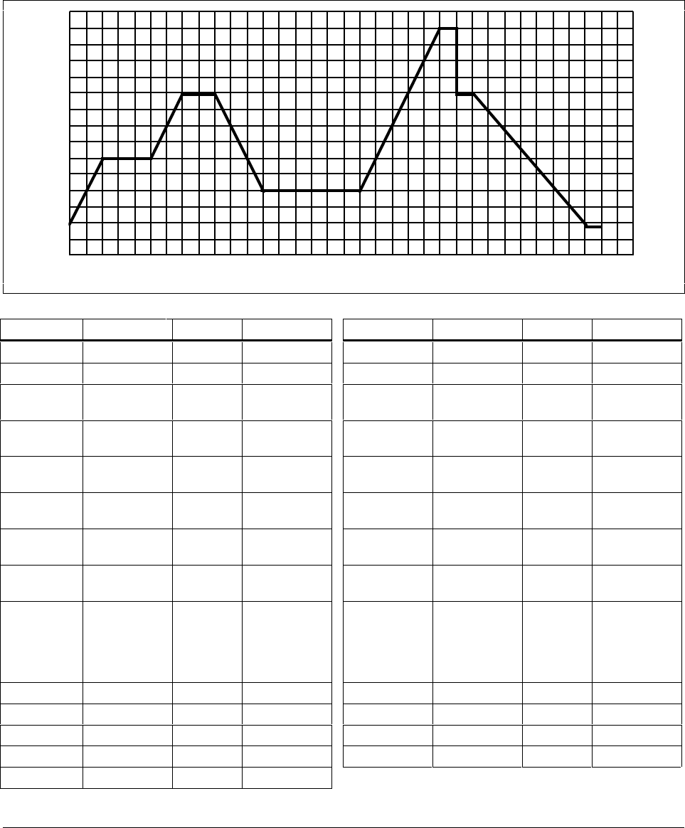
4/00 UDC 3300 Controller Product Manual 209
6.3 Drawing a Ramp/Soak Profile
Ramp/Soak Profile
example Before you do the actual configuration, we recommend that you draw a
Ramp/Soak profile in the space provided on the “Program Record Sheet”
(Figure 6-2) and fill in the associated information. An example of a
Ramp/Soak Profile is shown in Figure 6-1.
Figure 6-1 Ramp/Soak Profile Example
500
400
200
300
°F
Time/
Hours 0 1 2 3 4 5 6 7 8 9 10 11 12 13 14 15 16 17
SEG 2 SEG 3
SEG 4
SEG 5
SEG 6
SEG 7
SEG 8
SEG 9
SG 10
SG 11
SG 12
SEG 1
22624
Prompt Function Segment Value Prompt Function Segment Value
STRT SEG Start Seg. 1 SEG4TIME Soak Time 4 1 hr.
END SEG End Seg. 12 SEG5RAMP Ramp Time 5 1 hr.:30 min.
RAMP UNIT Engr. Unit for
Ramp TIME SEG6 SP Soak SP 6 250
RECYCLES Number of
Recycles 2SEG6TIME Soak Time 6 3 hr.:0 min.
SOAK DEV Deviation
Value 0SEG7RAMP Ramp Time 7 2 hr:30 min.
PROG END Controller
Status LAST SP SEG8 SP Soak SP 8 500
STATE Controller
State at end HOLD SEG8TIME Soak Time 8 0 hr.:30 min.
KEYRESET Reset SP
Program DISABL SEG9RAMP Ramp Time 9 0
HOT
START PV Hot Start
Program
Initialization
or power up
in SPP
DISABL SG10 SP Soak SP 10 400
SEG1RAMP Ramp Time 1 1 hr. SG10 TIME Soak Time 10 0 hr.:30 min.
SEG2 SP Soak SP 2 300 SG11RAMP Ramp Time 11 3 hr:30 min.
SEG2TIME Soak Time 2 1 hr.:30 min. SG12 SP Soak SP 12 200
SEG3RAMP Ramp Time 3 1 hr. SG12TIME Soak Time 12 0 hr.:30 min.
SEG4 SP Soak SP 4 400
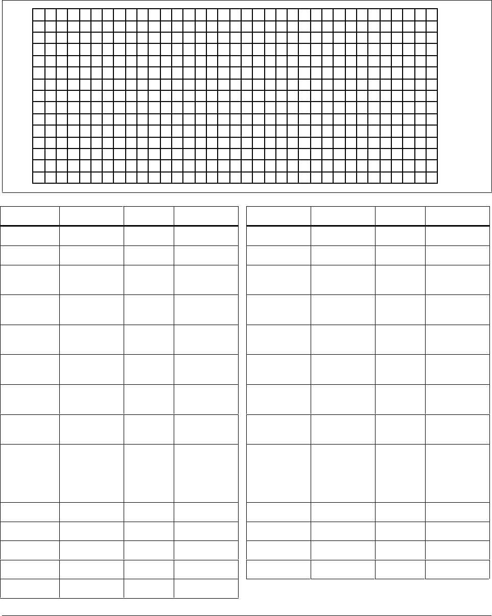
210 UDC 3300 Controller Product Manual 4/00
Program Record Sheet Draw your ramp/soak profile on the record sheet shown in Figure 6-2 and
fill in the associated information in the blocks provided. This will give
you a permanent record of your program and will assist you when entering
the Setpoint data.
Figure 6-2 Program Record Sheet
22625
Prompt Function Segment Value Prompt Function Segment Value
STRT SEG Start Seg. SEG4TIME Soak Time 4
END SEG End Seg. SEG5RAMP Ramp Time 5
RAMPUNIT Engr. Unit for
Ramp SEG6 SP Soak SP 6
RECYCLES Number of
Recycles SEG6TIME Soak Time 6
SOAK DEV Deviation
Value SEG7RAMP Ramp Time 7
PROG END Controller
Status SEG8 SP Soak SP 8
STATE Controller
State at end SEG8TIME Soak Time 8
KEYRESET Reset SP
Program SEG9RAMP Ramp Time 9
HOT
START PV Hot Start
Program
Initialization
or power up
in SPP
SG10 SP Soak SP 10
SEG1RAMP Ramp Time 1 SG10 TIME Soak Time 10
SEG2 SP Soak SP 2 SG11RAMP Ramp Time 11
SEG2TIME Soak Time 2 SG12 SP Soak SP 12
SEG3RAMP Ramp Time 3 SG12TIME Soak Time 12
SEG4 SP Soak SP 4
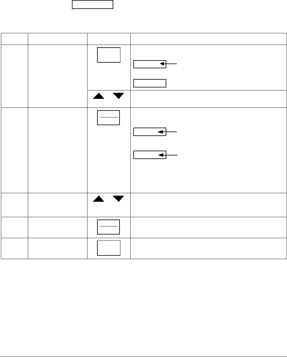
4/00 UDC 3300 Controller Product Manual 211
6.4 Entering the Setpoint Program Data
Introduction The procedure listed in Table 6-1 tells you what keys to press and what
prompts you will see when entering the setpoint program data. Follow the
prompt hierarchy listed in Table 6-2 when selecting the functions for
setpoint programming.
ATTENTION Make sure SP RAMP and SP RATE are disabled first.
Table 6-1 Setpoint Program Data Entry Procedure
Step Action Press Result
1Select SP PROG
Group SET UP until you see
SP PROG
Lower Display
Upper Display
ENABLE
ENABL2
ENAB12
or to enable the setpoint programming option on Loop 1, Loop 2,
or both.
2Select the functions FUNCTION
LOOP 1/2
This accesses the function prompts SP Programming.
Upper Display
Shows the current value for each
prompt.
Lower Display
The individual function prompts within
the setpoint program group are shown.
Successive presses of the [FUNCTION] key will sequentially
display all the functions and their values or selections. Follow
the prompt hierarchy shown in Table 6-2.
3Change the value or
selection of a function
prompt
or This changes the value or selection in the upper display. If the
display blinks, you are trying to select an unacceptable value.
4Enter value or
selection into memory FUNCTION
LOOP 1/2
This enters the value or selection and goes to another prompt.
Repeat steps 3 and 4 for each function you want to change.
5Exit configuration LOWER
DISPLAY
This exits from the configuration mode.
Alarms on the setpoint
program You can configure an event to go ON or OFF at the beginning or end of
any segment. Refer to Section 3 - Configuration under “Alarms
Parameters Group” for details.
Prompt hierarchy Table 6-2 lists all the function prompts for Setpoint Program data
configuration in the order of their appearance. Follow the procedure in
Table 6-1 to transfer the data from your setpoint Ramp/Soak profile into
the controller. All parameters may be changed while the program is
disabled or in HOLD.

212 UDC 3300 Controller Product Manual 4/00
Table 6-2 Prompt Hierarchy and Available Selections
Prompt
(Lower
Display)
Definition Value or Selection (use ▲ or ▼)
(Upper Display)
SP RAMP Setpoint Ramp Selection Selections: DISABL
SP RAMP must be disabled to allow
Setpoint Programming.
SP RATE Setpoint Rate of Change Selections: DISABL
SP RATE must be disabled to allow
Setpoint Programming.
SP PROG Setpoint Ramp/Soak
Programmer Selections:
DISABL
ENABLE—Loop 1
ENABL2—Loop 2
ENAB12—Loops 1 and 2
SP PROG must be enabled to view
the remaining prompts.
STRT SEG Start Segment Number Enter Value: 1 to 11
END SEG End Segment Number Enter Value: 2 to 12
Always end in a soak Segment
(2,4,.....12)
RAMPUNIT Engineering Units from
Ramp Segments Selections:TIME
EU/MIN
EU/HR
RECYCLES Number of Program
Recycles Enter Value: 0 to 99 recycles
SOAK DEV Guaranteed Soak Deviation
Value Enter Value: 0 to +99.00
The number selected will be
0 to 99 ± from setpoint.
PROG END Program Termination State Selections: LASTSP—Hold at
last setpoint in the
program
F SAFE—Manual
mode/Failsafe
output
STATE Program State at Program
End Selections: DISABL
HOLD (hold mode)
KEYRESET Reset/rerun SP Program Selections: DISABL
RERUN
TOBEGN
HOTSTART PV Hot Start
Program Initialization or
power up in SPP
Selections: DISABL—LSP1 is
used as the initial
ramp setpoint.
ENABL—PV value is
used as the initial
ramp setpoint.
SEG1RAMP
or
SEG1RATE
Segment #1 Ramp Time
or
Segment #1 Ramp Rate
Enter Value:
Ramp Time = 0-99hr.0-59min, or
Ramp Rate = Engineering units/min
or Engineering units/hr
Select TIME, EU/MIN, or EU/HR at
prompt “RAMP UNIT”. All ramps will
use the same selection.

4/00 UDC 3300 Controller Product Manual 213
Prompt
(Lower
Display)
Definition Value or Selection (use ▲ or ▼)
(Upper Display)
SEG2 SP Segment #2 Soak Setpoint
Value Enter Value: Within the Setpoint
limits
SEG2TIME Segment #2 Soak Duration Enter Value: 0-99hr.0-59min
SEG3RAMP
or
SEG3RATE
Segment #3 Ramp Time or
Segment #3 Ramp Rate Enter Value:
Ramp Time = 0-99hr:0-59min, or
Ramp Rate = EU/MIN or EU/HR
SEG4 SP Segment #4 Soak Setpoint
Value Enter Value: Within the Setpoint
limits
SEG4TIME Segment #4 Soak Duration Enter Value: 0-99hr.0-59min
SEG5RAMP
or
SEG5RATE
Segment #5 Ramp Time or
Segment #5 Ramp Rate Enter Value:
Ramp Time = 0-99hr.0-59min, or
Ramp Rate = EU/MIN or EU/HR
SEG6 SP Segment #6 Soak Setpoint
Value Enter Value: Within the Setpoint
limits
SEG6TIME Segment #6 Soak Duration Enter Value: 0-99hr.0-59min
SEG7RAMP
or
SEG7RATE
Segment #7 Ramp Time or
Segment #7 Ramp Rate Enter Value:
Ramp Time = 0-99hr.0-59min, or
Ramp Rate = EU/MIN or EU/HR
SEG8 SP Segment #8 Soak Setpoint
Value Enter Value: Within the Setpoint
limits
SEG8TIME Segment #8 Soak Duration Enter Value: 0-99hr.0-59min
SEG9RAMP
or
SEG9RATE
Segment #9 Ramp Time
or
Segment #9 Ramp Rate
Enter Value:
Ramp Time = 0-99hr.0-59min, or
Ramp Rate = EU/MIN or EU/HR
SG10 SP Segment #10 Soak Setpoint
Value Enter Value: Within the Setpoint
limits
SG10TIME Segment #10 Soak
Duration Enter Value: 0-99hr.0-59min
SG11RAMP
or
SG11RATE
Segment #11 Ramp Time
or
Segment #11 Ramp Rate
Enter Value:
Ramp Time = 0-99hr.0-59min, or
Ramp Rate = EU/MIN or EU/HR
SG12 SP Segment #12 Soak Setpoint
Value Enter Value: Within the Setpoint
limits
SG12TIME Segment #12 Soak
Duration Enter Value: 0-99hr.0-59min
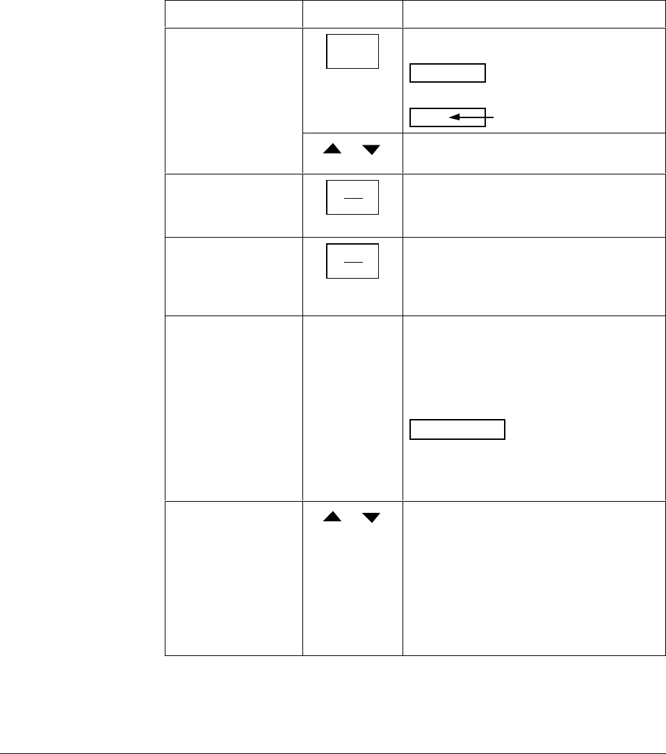
214 UDC 3300 Controller Product Manual 4/00
6.5 Run/Monitor the Program
Introduction Make sure all the “SP PROG” function prompts under the Set Up group
“SP RAMP” have been configured with the required data.
An “H” will appear in the upper display indicating that the program is in
the HOLD state.
Run/monitor functions Table 6-3 lists all the functions required to run and monitor the program.
Table 6-3 Run/Monitor Functions
Function Press Result
Set the Local
Setpoint SETPOINT
SELECT
You will see
SP
Lower Display
Upper Display
Local Setpoint Value
or to set the Local Setpoint value to where you
want the program to start out.
Run State RUN
HOLD
Initiates the setpoint program.
An “R” appears in the upper display
indicating that the program is running.
Hold State RUN
HOLD
Holds the setpoint program. An “H” appears
in the upper display indicating that the
program is in the HOLD state.
The setpoint holds at the current setpoint.
External Hold
DI = “To Hold”
If Remote Switching (Digital Input option) is
present on your controller, contact closure
places the controller in the HOLD state, if the
setpoint program is running. The “H” in the
upper display will blink indicating external
hold is in effect.
ATTENTION The keyboard takes
priority over external switch for the
RUN/HOLD function.
Contact reopening runs program.
Changing a Segment
while in Hold or These keys will operate and allow you to
change the segment number while in HOLD.
If a different segment is selected, it will be
started at the beginning when placed in
RUN. If the original segment is brought back,
the program will continue from the point
placed in HOLD.
NOTE: Changing a segment number may
affect the alarms/events.
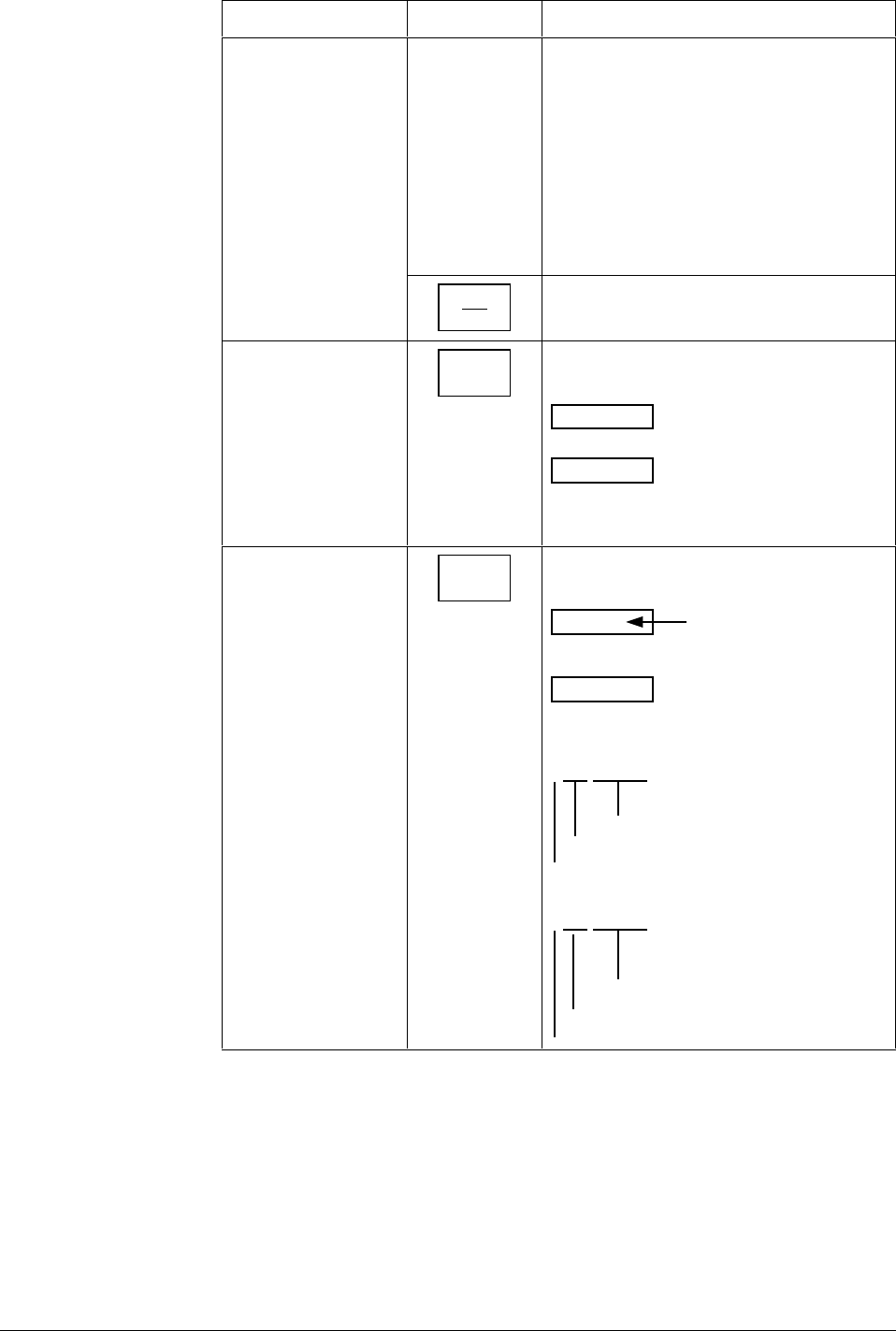
4/00 UDC 3300 Controller Product Manual 215
Function Press Result
External Program
Reset
“To Begin”
If Remote Switching (Digital Input option) is
present on your controller, contact closure
resets the SP Program back to the start of
the first segment.
Program cycle number is not affected.
Reopening the contact has no effect and
places the program in HOLD mode.
The setpoint is changed to what the setpoint
was when the program was first started.
RUN
HOLD
restarts the Setpoint Program
Keyboard Reset LOWER
DISPLAY
until you see
Upper Display
Lower Display
ToBEGIN
Press [▲] key to reset program to beginning
at Hold state.
Viewing the present
ramp or soak
segment number
and time
LOWER
DISPLAY
until you see
Upper Display
“R” and the PV value
Lower Display
For Ramp segments:
# RA XX.XX
Segment Number (odd only)
Indicates Ramp segment
Ramp Time - Hours.Minutes or
Ramp Rate - EU/MIN or EU/HR
For Soak segments:
# SK XX.XX
Segment Number (even only)
Indicates Soak segment
Time remaining in segment in
Hrs.Minutes including current
partially completed minute
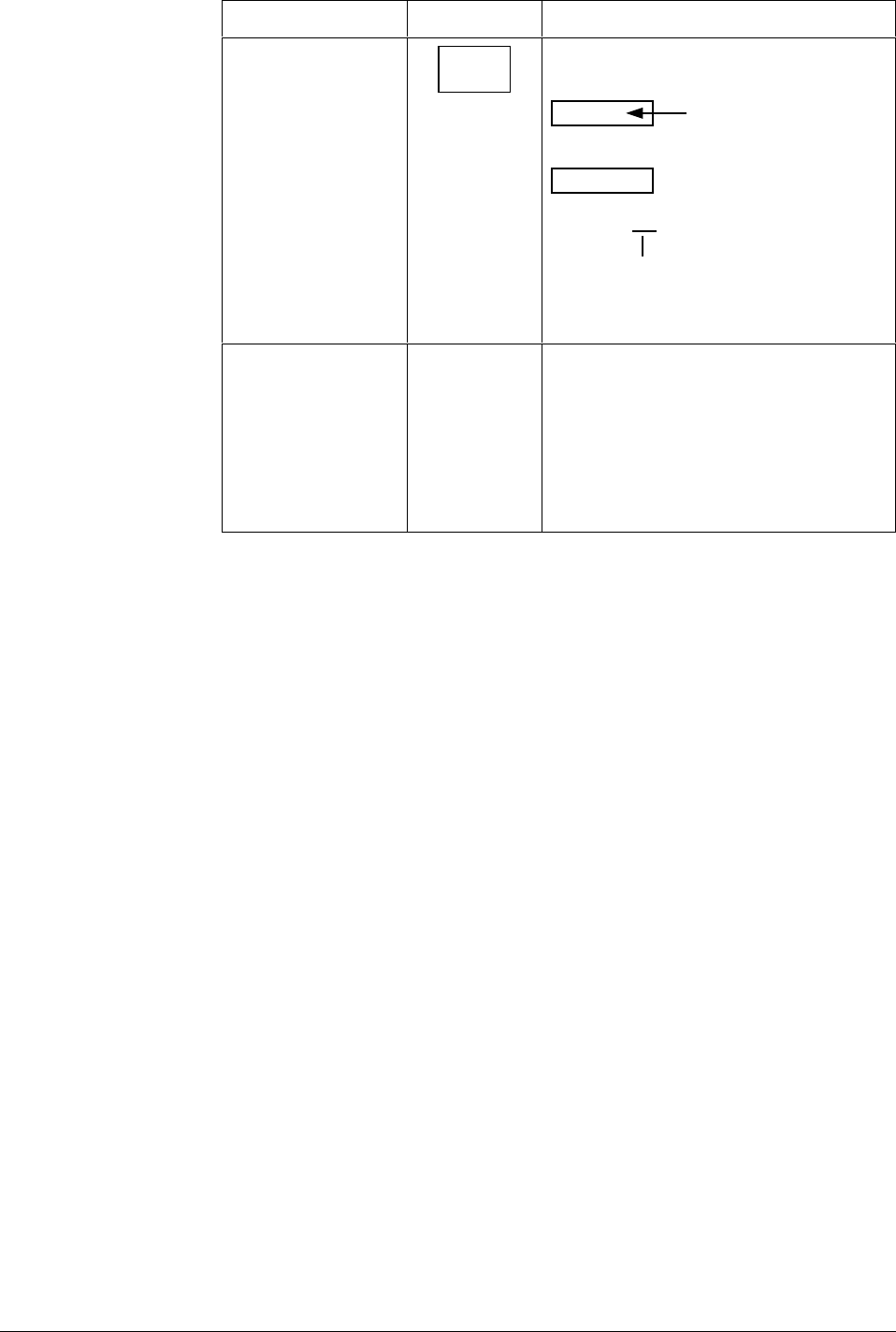
216 UDC 3300 Controller Product Manual 4/00
Function Press Result
Viewing the number
of cycles left in the
program
LOWER
DISPLAY
until you see
Upper Display
“R” and the PV value
Lower Display
RECYC XX
Remaining Cycles 0 to 99
This number does not
include the current partially
completed cycle.
End Program When the final segment is completed, the “R”
in the upper display either changes to “H” if
configured for HOLD state, or disappears if
configured for disable of setpoint
programming.
The controller operates at the last setpoint in
the program in automatic or will be in manual
mode at the failsafe output.
Power-up state The program will be placed in HOLD mode at the beginning of the
program at the local setpoint value prior to the beginning of the program.
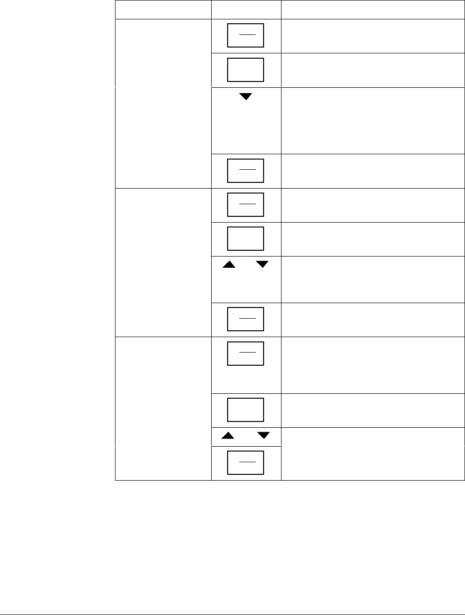
4/00 UDC 3300 Controller Product Manual 217
SP programming tips Table 6-4 gives procedures for restarting, advancing, and changing the
current segment time or setpoint of a running setpoint program.
Table 6-4 Procedures for Changing a Running Setpoint Program
Function Press Result/Action
Restarting a running
SP program RUN
HOLD
to place SP PROG into HOLD mode.
LOWER
DISPLAY
until you see X RA XXX or X SK XX.XX in
the lower display.
until you see 1 RA XX.XX in the lower
display.
If the lower display already reads 1 RA
XX.XX then press the [▲] key before
pressing the [▼] key.
RUN
HOLD
to place SP PROG into RUN mode.
Advancing a running
SP program RUN
HOLD
to place SP PROG into HOLD mode.
LOWER
DISPLAY
until you see X RA XXX or X SK XX.XX in
the lower display.
and
together to select the segment number to advance to.
EXAMPLE: Change 2 SK XX.XX to 3 RA
XX.XX.
RUN
HOLD
to place SP PROG into RUN mode.
Changing the
current segment
time or setpoint in a
running SP program
RUN
HOLD
to place SP PROG into HOLD mode.
Enter SP PROG configuration and change
the segment to the new time or setpoint
desired.
LOWER
DISPLAY
until you see X RA XXX or X SK XX.XX in
the lower display.
then
RUN
HOLD
to place SP PROG into RUN mode.

218 UDC 3300 Controller Product Manual 4/00
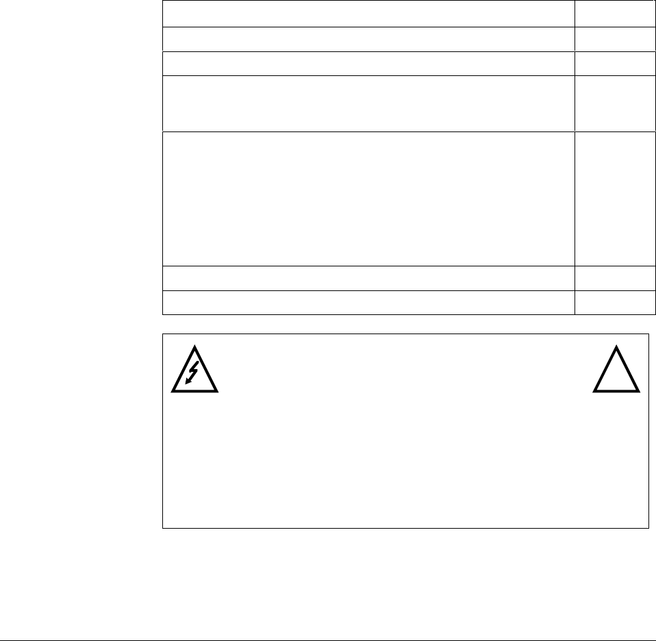
4/00 UDC 3300 Process Controller Product Manual 219
Section 7 – Input Calibration
7.1 Overview
Introduction This section describes the field calibration procedures for Input 1 and
Input 2. Every UDC 3300 controller contains all input actuation ranges
fully factory calibrated and ready for configuration to range by the user.
However, these procedures can be implemented if the factory calibration
of the desired range is not within specifications.
Note that the field calibration will be lost if a change in input type
configuration is implemented at a later time. The original factory
calibration data remains available for later use after a field calibration is
done.
What’s in this section This section contains the following topics:
Topic See Page
7.1 Overview 219
7.2 Minimum and maximum range values 220
7.3 Preliminary Information
• Disconnect the field wiring
• Equipment needed
221
221
222
7.4 Input 1, 2, or 3 Set Up Wiring
• Thermocouple inputs using an ice bath
• Thermocouple inputs using a precision resistor
• RTD (Resistance Thermometer Device) inputs
• Radiamatic, Millivolts, or Volts except 0-10 Volts
inputs
• 0 to 10 Volts input
• 4-20 Milliamps input
223
223
224
225
226
227
228
7.5 Input 1, 2, or 3 Calibration Procedure 229
7.6 Restoring Factory Calibration 231
WARNING—SHOCK HAZARD !
INPUT CALIBRATION MAY REQUIRE ACCESS TO
HAZARDOUS LIVE CIRCUITS, AND SHOULD ONLY BE
PERFORMED BY QUALIFIED SERVICE PERSONNEL.
MORE THAN ONE SWITCH MAY BE REQUIRED TO DE-
ENERGIZE UNIT BEFORE CALIBRATION.
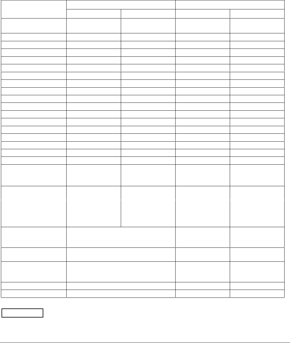
220 UDC 3300 Process Controller Product Manual 4/00
7.2 Minimum and Maximum Range Values
Select the range values You should calibrate the controller for the minimum (0 %) and maximum
(100 %) range values of your particular sensor. If you have a two-input
controller, calibrate each input separately.
Select the Voltage or Resistance equivalent for 0 % and 100 % range
values from Table 7-1. Use these value when calibrating your controller.
Table 7-1 Voltage and Resistance Equivalents for 0 % and 100 % Range Values
PV Input Range Range Values
Sensor Type ° F ° C 0 % 100 %
Thermocouples
B 0 to 3300 –18 to 1816 –0.100 mV 13.769 mV
E-454 to 1832 –270 to1000 –9.835 mV 76.373 mV
E (low) -200 to 1100 –129 to 593 –6.472 mV 44.455 mV
J0 to 1600 –18 to871 –0.886 mV 50.060 mV
J (low) 20 to 770 –7 to 410 –0.334 mV 22.400 mV
K0 to 2400 –18 to1816 –0.692 mV 52.952 mV
K (low) –20 to 1000 –29 to 538 –1.114 mV 22.255 mV
NiNiMoly (NNM68) 32 to 2500 0 to1371 0.000 mV 71.330 mV
NiNiMoly (low) 32 to 1260 0 to682 0.000 mV 31.820 mV
NiMo-NiCo (NM90) 32 to 2500 0 to 1371 0.000 mV 71.773 mV
NiMo-NiCo (low) 32 to 1260 0 to682 0.000 mV 31.825 mV
Nicrosil Nisil (Nic) 0 to 2372 –18 to 1300 –0.461 mV 47.513 mV
R0 to 3100 –18 to1704 –0.090 mV 20.281 mV
S0 to 3100 –18 to1704 –0.092 mV 17.998 mV
T-300 to 700 –184 to371 –5.341 mV 19.097 mV
T (low) -200 to 500 –129 to 260 –4.149 mV 12.574 mV
W5W26 0 to 4200 –18 to2315 –0.234 mV 37.075 mV
W5W26 (low) 0 to 2240 –18 to1227 –0.234 mV 22.283 mV
Honeywell Radiamatic
Type RH
Type RI*
0 to 3400
0 to 9999 max.
–18 to1871
–18 to 9999 max.
0.00 mV
0.00 mV 57.12 mV
60.08 mV
RTD
(IEC Alpha=0.00385)
100 ohms
100 ohms (low)
200 ohms
500 ohms
-300 to 1200
-300 to 300
-300 to 1200
-300 to 1200
–184 to649
–184 to149
–184 to649
–184 to649
25.18 ohms
25.18 ohms
50.36 ohms
125.90 ohms
329.13 ohms
156.90 ohms
658.26 ohms
1645.65 ohms
Linear
Milliamps 4 to 20 mA
0 to 20 mA 4.00 mA
0.00 mA 20.00 mA
20.00 mA
Millivolts 0 to 10 mV
0 to 50 mV 0.00 mV
0.00 mV 10.00 mV
50.00 mV
Volts 1 to 5 Volts
0 to 5 Volts
0 to 10 Volts
1.00 Volts
0.00 Volts
0.00 Volts
5.00 Volts
5.00 Volts
10.00 Volts
Carbon 0 to 1250 mV 0.00 mV 1250 mV
Oxygen –30 to 510 mV –30.00 mV 510.00 mV
*User must enter the range manually per RI type and application.
ATTENTION Thermocouple voltages are for a reference junction temperature of 32 °F (0 °C).
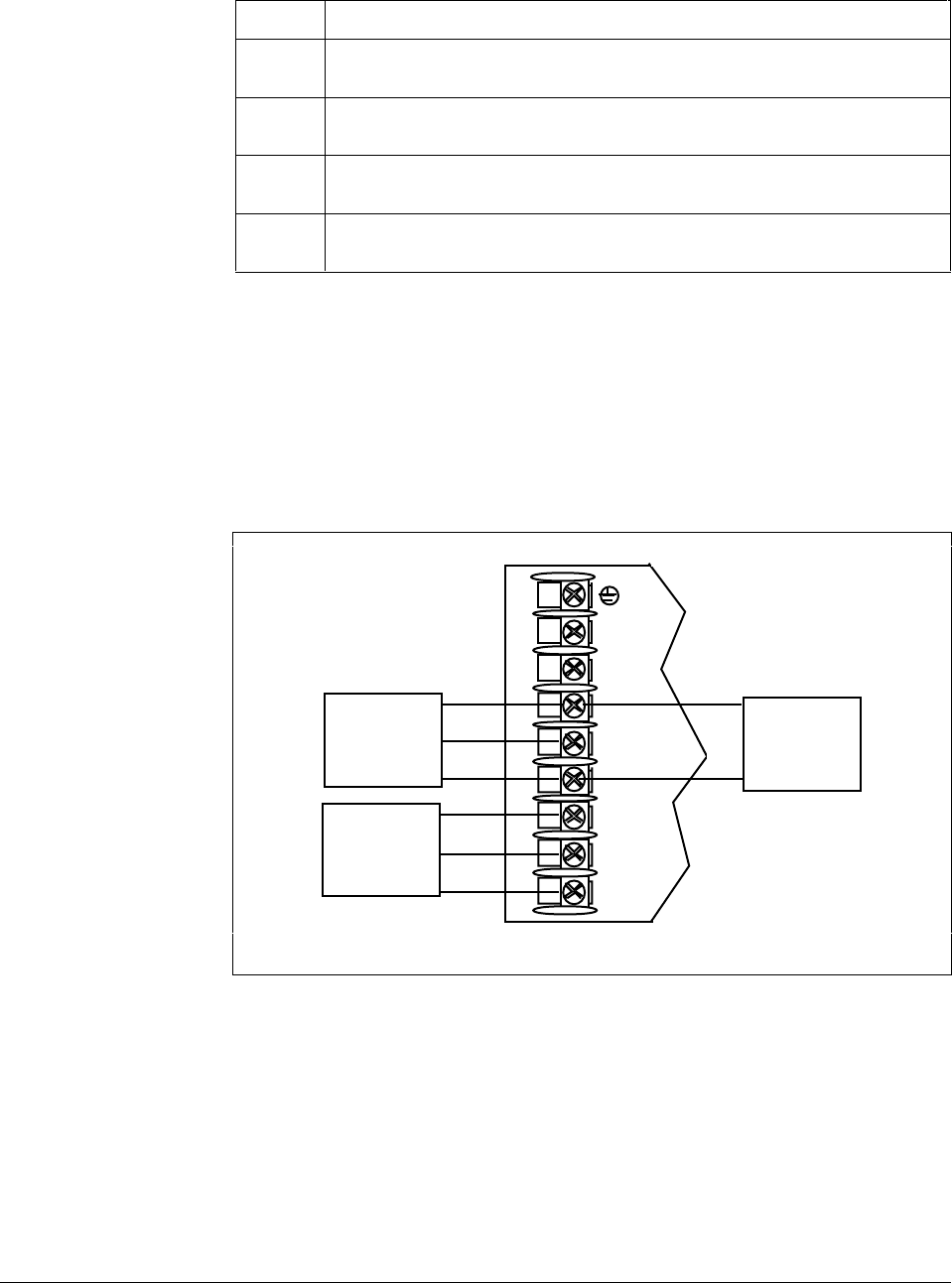
4/00 UDC 3300 Process Controller Product Manual 221
7.3 Preliminary Information
Calibration steps Use the following steps when calibrating an input.
Step Action
1Find the minimum and maximum range values for your PV input range from
Table 7-1.
2Disconnect the field wiring and find out what equipment you will need to
calibrate. DO NOT remove external resistor assemblies (if present).
3Wire the calibrating device to your controller according to the Set Up wiring
instructions for your particular input.
4Follow the calibration procedure given for Input #1, Input #2, or Input #3,
after the controller has warmed up for a minimum of 15 minutes.
Disconnect the field
wiring Depending on which input (#1, #2, or #3) you are going to calibrate, tag
and disconnect any field wiring connected to the input terminals on the
rear of the controller.
Figure 7-1 shows the wiring terminal designations for Input #1, Input #2,
and Input #3.
Figure 7-1 Inputs #1, #2, and #3 Wiring Terminals
24173
L1
L2/N
22
23
24
25
26
27
R
+
–
+
–
Input 1
connections
R
Input 2
connections Input 3
connections
+
–

222 UDC 3300 Process Controller Product Manual 4/00
Equipment needed Table 7-2 lists the equipment you will need to calibrate the specific types
of inputs that are listed in the table. You will need a screwdriver to
connect these devices to your controller.
Table 7-2 Equipment Needed
Type of Input Equipment Needed
Thermocouple Inputs
(Ice Bath) •A calibrating device with ± 0.02 % accuracy for use
as a signal source such as a millivolt source.
•Thermocouple extension wire that corresponds with
the type of thermocouple that will be used with the
controller input.
•Two insulated copper leads for connecting the
thermocouple extension wire from the ice baths to
the precision calibrator.
•Two containers of crushed ice.
Thermocouple Inputs
(Precision Resistor) •A calibrating device with ± 0.02 % accuracy for use
as a signal source such as a millivolt source.
•Two insulated copper leads for connecting the
calibrator to the controller.
•A precision 500 ohm resistor ± 0.1 % connected
across input #1 terminals 25 (R) and 27 (–) or input
#2 terminals 22 (R) and 24 (–).
RTD (Resistance Thermometer
Device) •A decade box, with ± 0.02 % accuracy, capable of
providing stepped resistance values over a
minimum range of 0 to 1400 ohms with a resolution
of 0.1 ohm.
•Three insulated copper leads for connecting the
decade box to the controller.
Milliampere, Millivolt, Volts, and
Radiamatic •A calibrating device with ± 0.02 % accuracy for use
as a signal source.
•Two insulated copper leads for connecting the
calibrator to the controller.
•Place current source at zero before switching ON.
•Do not switch current sources OFF/ON while
connected to the UDC 3300 input.
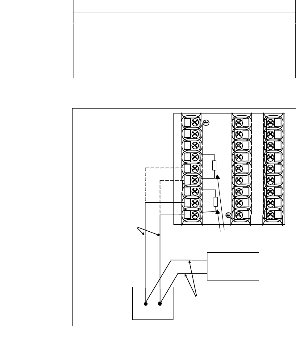
4/00 UDC 3300 Process Controller Product Manual 223
7.4 Input #1, #2, or #3 Set Up Wiring
Thermocouple inputs
using an ice bath Referring to Figure 7-2, wire the controller according to the procedure
given in Table 7-3.
Table 7-3 Set Up Wiring Procedure for Thermocouple Inputs Using an
Ice Bath
Step Action
1Connect the copper leads to the calibrator.
2Connect a length of thermocouple extension wire to the end of each copper
lead and insert the junction points into the ice bath.
3Connect the thermocouple extension wires to the terminals for Input #1 or
Input #2. See Figure 7-2.
4Connect a cold junction resistor to terminals 25 and 27 for Input #1 or
terminals 22 and 24 for Input #2. See Figure 7-2.
Figure 7-2 Wiring Connections for Thermocouple Inputs
Using an Ice Bath
1
2
3
4
5
6
7
8
9
10
11
12
13
14
15
16
17
L1
L2/N
22
23
24
25
26
27
+
–
Ice Bath
Millivolt
Source
T/C Extension Wire
Copper Leads
+
–
24174
C/J Resistor
+
–
Input 2
Input 1
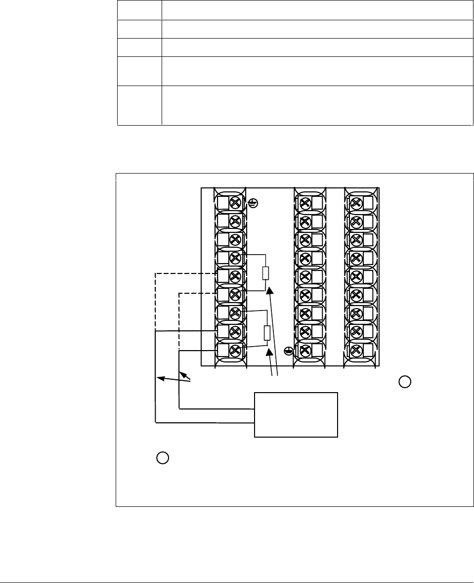
224 UDC 3300 Process Controller Product Manual 4/00
Thermocouple inputs
using a precision
resistor
Referring to Figure 7-3, wire the controller according to the procedure
given in Table 7-4.
Table 7-4 Set Up Wiring Procedure for Thermocouple Inputs
Using a Precision Resistor
Step Action
1Connect the copper leads to the calibrator.
2Disconnect the cold junction resistor.
3Install a 500-ohm precision resistor across Input 1 terminals 25 (R) and
27 (–) or Input 2 terminals 22 (R) and 24 (–). See Figure 7-3.
4Subtract the millivolt value for 77 °F (25 °C) from the zero and span value for
your range (see Table 7-1 for zero and span values) and use the adjusted
value when calibrating.
Figure 7-3 Wiring Connections for Thermocouple Inputs
Using a Precision Resistor
1
2
3
4
5
6
7
8
9
10
11
12
13
14
15
16
17
L1
L2/N
22
23
24
25
26
27
+
–
Precision 500 Ohm Resistor
Copper Leads
Millivolt
Source
+
–
R
1
1Caution: The accuracy of the controller is directly affected by the
accuracy of this resistor. At a minimum, use a 0.1%, 25ppm resistor.
24175
+
–
R
Input 2
Input 1
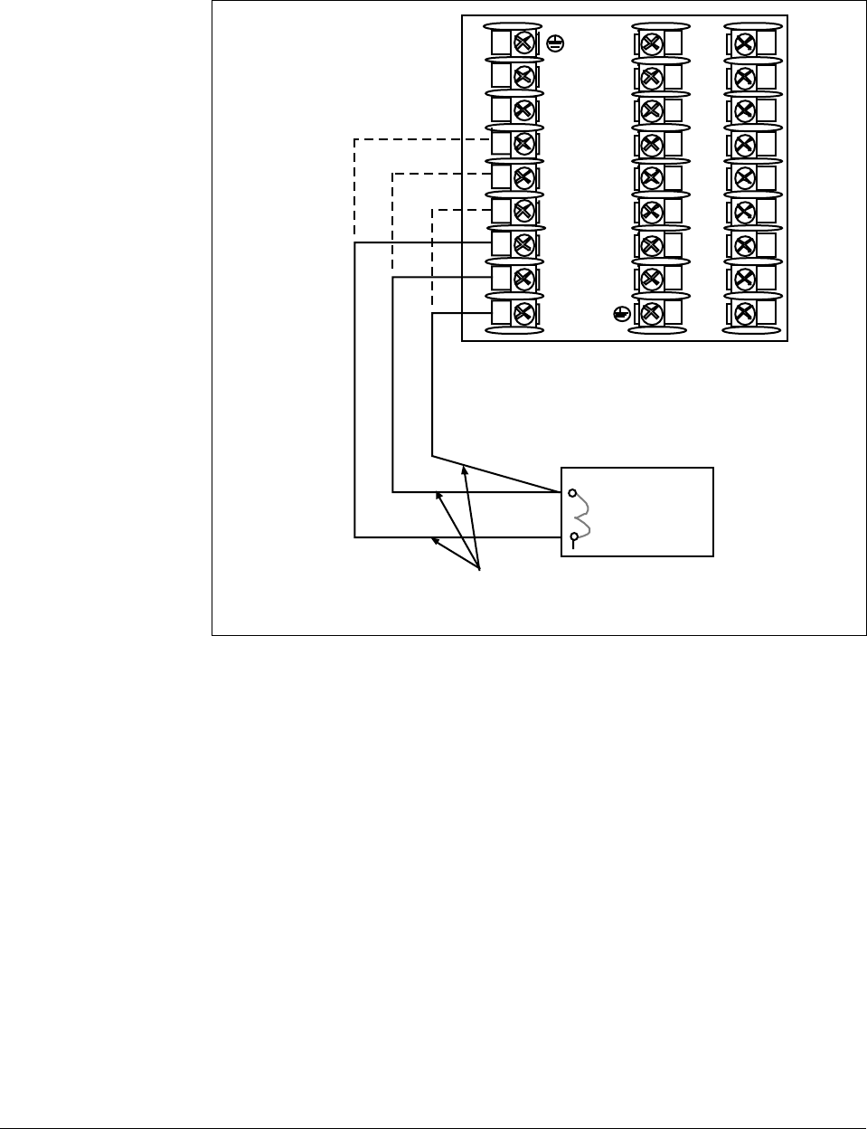
4/00 UDC 3300 Process Controller Product Manual 225
RTD inputs Use the copper leads and connect the calibrator to the rear terminals of
Input #1 or #2. See Figure 7-4.
Figure 7-4 Wiring Connections for RTD
1
2
3
4
5
6
7
8
9
10
11
12
13
14
15
16
17
L1
L2/N
22
23
24
25
26
27
R
+
–
Decade
Resistance
Box
Copper Leads
equal length 24176
R
+
–
Input 2
Input 1
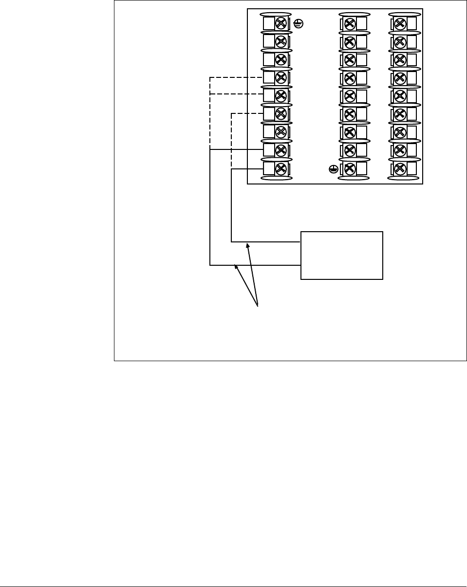
226 UDC 3300 Process Controller Product Manual 4/00
Radiamatic, millivolts,
or volts (except 0 to 10
volts) inputs
Use the copper leads and connect the calibrator to the rear terminals of
Input #1, #2, or #3. See Figure 7-5.
Figure 7-5 Wiring Connections for Radiamatic, Millivolts, or Volts
(except 0 to 10 Volts)
+
1
2
3
4
5
6
7
8
9
10
11
12
13
14
15
16
17
L1
L2/N
22
23
24
25
26
27
–
Millivolt/Volt
Source
Copper Leads
+
–
24177
+
–
Input 2*
Input 1
+
Input 3*
(0-5, 1-5
volts only)
*Terminals for Input 3 are 22 (+) and 24 (–).
Terminals for Input 2 are 23 (+) and 24 (–).
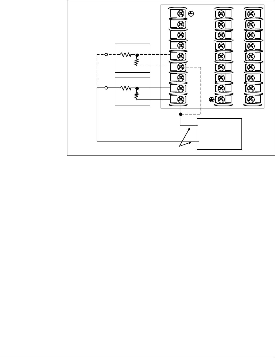
4/00 UDC 3300 Process Controller Product Manual 227
0 to 10 volt inputs Use the copper leads and connect the calibrator to the rear terminals of
Input #1 or #2. See Figure 7-6.
Figure 7-6 Wiring Connections for 0 to 10 Volt Inputs
1
2
3
4
5
6
7
8
9
10
11
12
13
14
15
16
17
L1
L2/N
22
23
24
25
26
27
0 to 10
Volt
Source
Copper Leads +
–
100K
100K
24178
100K
100K
Input 2
Input 1
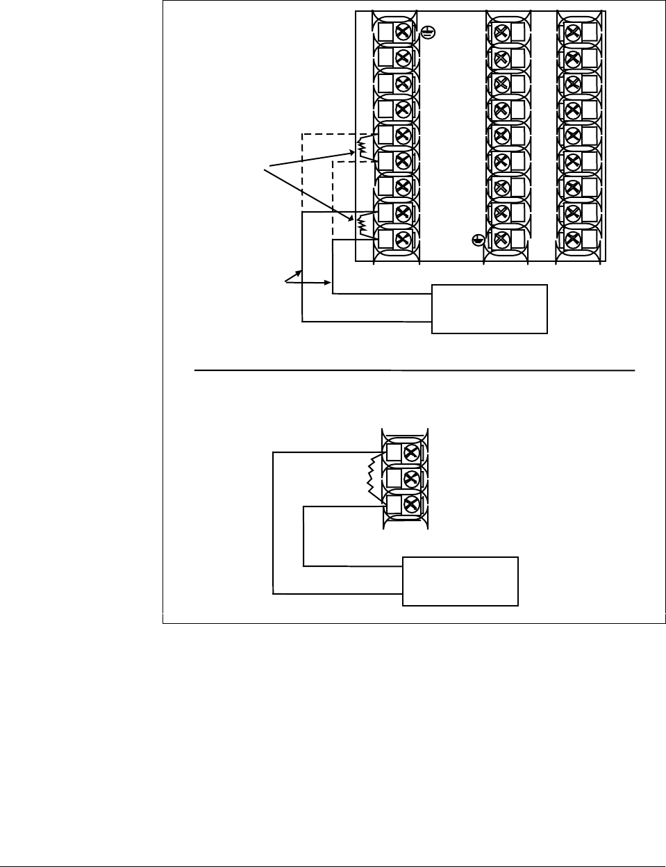
228 UDC 3300 Process Controller Product Manual 4/00
4 to 20 mA inputs Use the copper leads and connect the calibrator to the rear terminals of
Input #1, #2, or #3. See Figure 7-7.
Figure 7-7 Wiring Connections for 4 to 20 mA inputs
+
1
2
3
4
5
6
7
8
9
10
11
12
13
14
15
16
17
L1
L2/N
22
23
24
25
26
27
–
4 to 20 mA
Source
Copper Leads
+
–
250Ω
resistor
assy
24179
+
–
Input 2
Input 1
22
23
24
+
–
Input 3—Wire terminals as shown below.
4 to 20 mA
Source
+
–
250 ohm
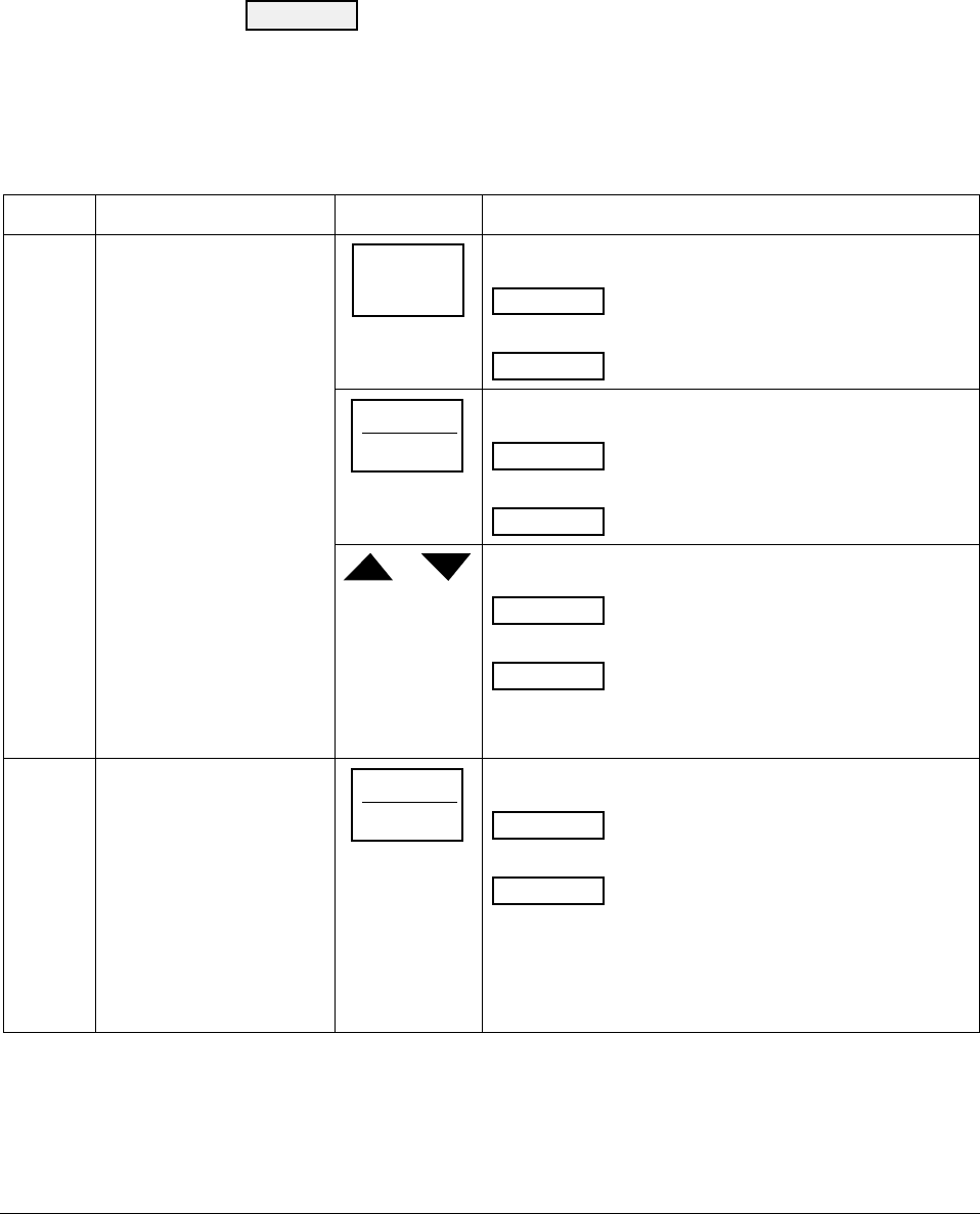
4/00 UDC 3300 Process Controller Product Manual 229
7.5 Input #1, #2, or #3 Calibration Procedure
Introduction Apply power and allow the controller to warm up for 15 minutes before
you calibrate. Read “Set Up Wiring” before beginning the procedure.
Make sure you have LOCKOUT set to NONE. See Section 3 –
Configuration.
CAUTION For linear inputs, avoid step changes in inputs. Vary smoothly
from initial value to final 100 % value.
Procedure The Calibration procedure for Input #1, #2, or #3 is listed in Table 7-5.
Table 7-5 Input #1, #2, or #3 Calibration Procedure
Step Description Press Action
1Enter Calibration Mode
SET UP
until you see
INPUT n
Lower Display
CALIB
Upper Display
n = 1, 2, or 3
FUNCTION
LOOP 1/2
You will see:
CAL IN n
Lower Display
DISABL
Upper Display
n = 1, 2, or 3
or The calibration sequence is enabled and you will see:
CAL IN n
Lower Display
BEGIN
Upper Display
n = 1, 2, or 3
At the completion of the sequence, the selection
automatically reverts to disable.
2Calibrate 0 % FUNCTION
LOOP 1/2
You will see:
INn ZERO
Lower Display
APPLY
Upper Display
n = 1, 2, or 3
Adjust your calibration device to an output signal equal to
the 0 % range value for your particular input sensor. See
Table 7-1 for Voltage or Resistance equivalents.
Wait 15 seconds, then go to the next step.
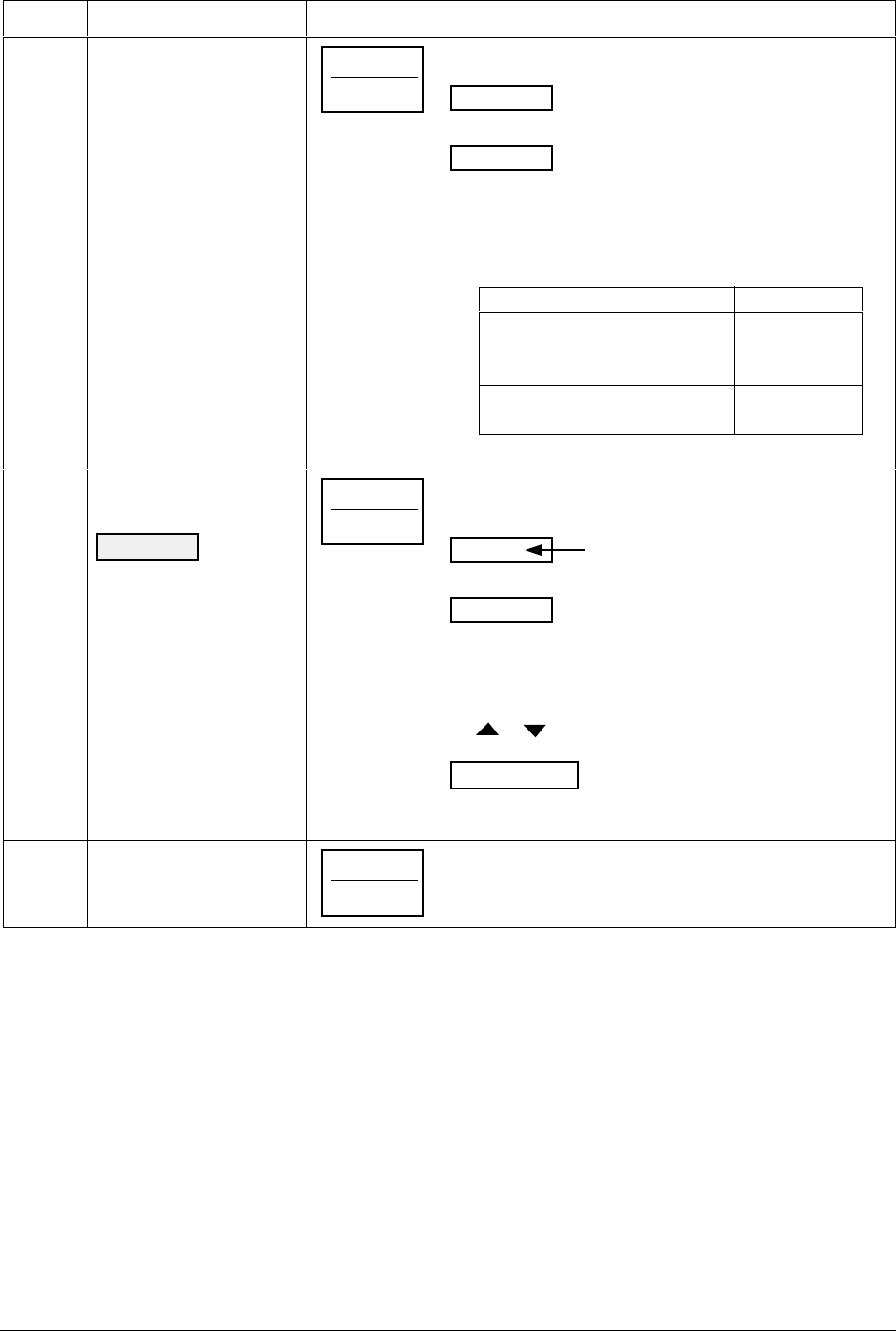
230 UDC 3300 Process Controller Product Manual 4/00
Step Description Press Action
3Calibrate 100 % FUNCTION
LOOP 1/2
You will see:
INn SPAN
Lower Display
APPLY
Upper Display
n = 1, 2, or 3
Adjust your calibration device to an output signal equal to
the 100 % range value for your particular input sensor.
See Table 7-1 for Voltage or Resistance equivalents.
Wait 15 seconds, and
If…Then…
you are calibrating a Go to step 4
thermocouple input
(Input 1 or 2)
you are calibrating other Go to step 5
than a thermocouple input
4Check the Cold Junction
Temperature
CAUTION The
accuracy of the controller
is directly affected by the
accuracy of this value.
Change this value only if
the zero and span
calibration procedures did
not bring the controller
within the specified
accuracy requirements.
FUNCTION
LOOP 1/2
The calculations for zero and span are now stored and
you will see:
Lower Display
Upper Display
C-J TEMP
The cold junction
temperature at the
rear terminals
The value in the upper display is in the tenths of a degree.
It is the current reading of the temperature as measured at
the thermocouple terminals and recognized by the
controller. You can change this value, if it is in error, using
the or key.
ATTENTION When calibrating T/C inputs using a
precision 500-ohm resistor, calibrate the cold junction as
77°F (25°C).
5Exit the Calibration Mode FUNCTION
LOOP 1/2
The controller will store the calibration constants and exit
calibration mode.
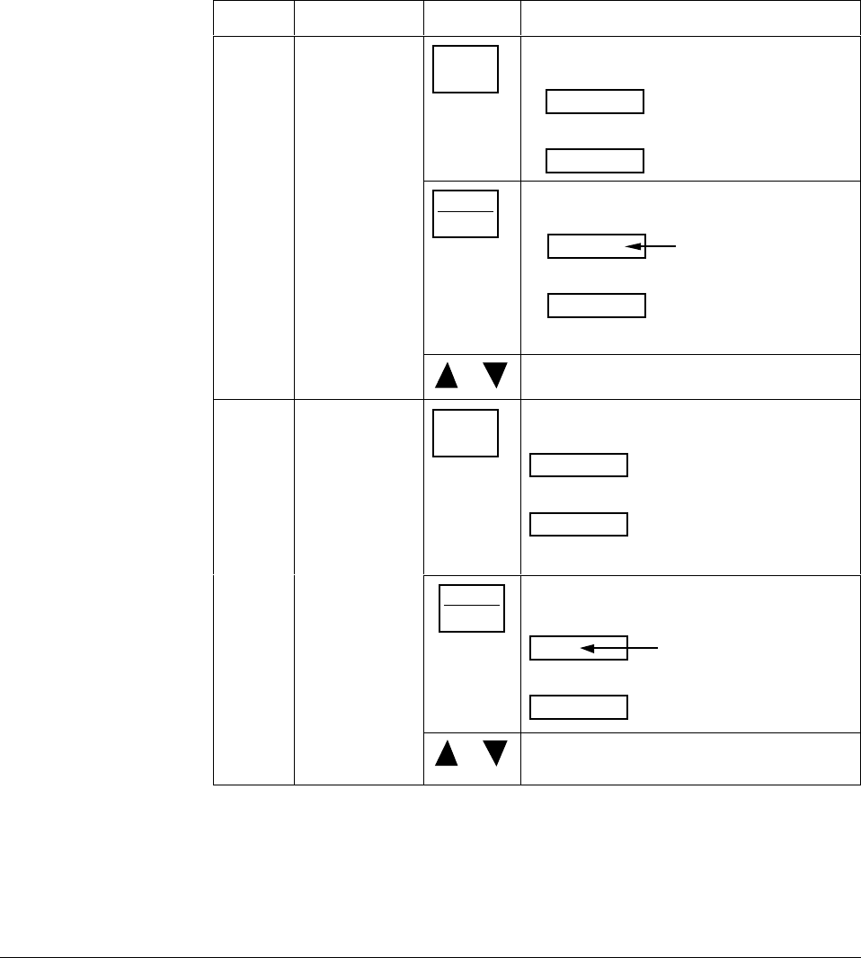
4/00 UDC 3300 Process Controller Product Manual 231
7.6 Restoring Factory Calibration
How to restore it The factory calibration constants for all the input actuation types that can
be used with the controller are stored in its nonvolatile memory. Thus,
you can quickly restore the “Factory Calibration” for a given input
actuation type by simply changing the actuation type to another type and
then changing it back to the original type. See Table 7-6 for the procedure.
Procedure Table 7-6 lists the procedure for restoring factory calibration.
Table 7-6 Restoring Factory Calibration
Step Operation Press Action/Result
1Set LOCKOUT
to CALIB or
NONE
SET
UP
until you see:
Upper Display
Lower Display
SET UP
TUNING
FUNCTION
LOOP 1/2
until you see:
Upper Display
Lower Display
LOCKOUT
One of the following
NONE
CALIB
+CONF
+VIEW
MAX
or Until CALIB or NONE is in the upper display.
2Enter
INPUT 1 or 2
Setup Group
SET
UP
until you see:
Upper Display
Lower Display
SET UP
INPUTn
n = 1, 2, or 3
FUNCTION
LOOP 1/2
until you see:
Upper Display
Lower Display
IN nTYPE
Current Selection
n = 1, 2, or 3
or to change the current selection to another
selection.
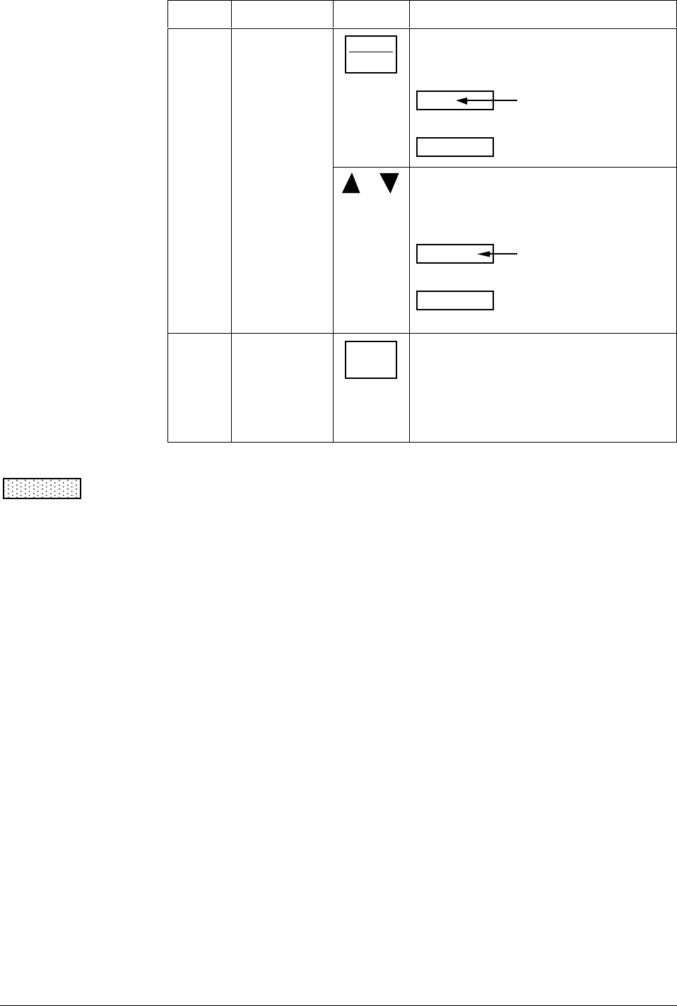
232 UDC 3300 Process Controller Product Manual 4/00
Step Operation Press Action/Result
FUNCTION
LOOP 1/2
until the lower display rolls through the rest
of the functions and returns to
Upper Display
Lower Display
IN nTYPE
New Selection
n = 1, 2, or 3
or until you change the input selection in the
upper display back to the proper selection.
You will see:
Upper Display
Lower Display
Original input
selection that
matches your
type of sensor.
IN nTYPE
n = 1, 2, or 3
3Return to
normal
operating mode
LOWER
DISPLAY
to return to Normal operating mode.
The factory calibration will be restored. If the
problem is not corrected, contact the
Honeywell Technical Assistance Center.
1-800-423-9883 USA and Canada
CAUTION A restored factory calibration overwrites any previous field calibration
done for the input and may change the High and Low Range Limits. Be
sure to protect any field calibration from accidental overwrites by
configuring the appropriate LOCKOUT selection after calibration. See the
Section 3 - Configuration for specific instructions to set the lockout.
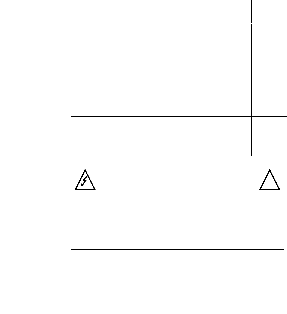
4/00 UDC 3300 Controller Product Manual 233
Section 8 – Output Calibration
8.1 Overview
Introduction This section describes the field calibration procedures for the following
types of outputs:
• Current Output
• Position Proportional and 3 Position Step Output
• Auxiliary Output
What’s in this section This section contains the following topics:
Topic See Page
8.1 Overview 233
8.2 Current Proportional Output Calibration
• Introduction
• Equipment Needed
• How to Connect the Calibrator
• Calibration Procedure
234
234
234
234
235
8.3 Position Proportional and Three Position Step Output
Calibration
• Position Proportional Control
• 3 Position Step Control
• Equipment Needed
• What connection to make
• Calibration Procedure
236
236
236
236
236
237
8.4 Auxiliary Output Calibration
• Introduction
• Equipment Needed
• How to Connect the Calibrator
• Calibration Procedure
240
240
240
240
241
WARNING—SHOCK HAZARD !
OUTPUT CALIBRATION MAY REQUIRE ACCESS TO
HAZARDOUS LIVE CIRCUITS, AND SHOULD ONLY BE
PERFORMED BY QUALIFIED SERVICE PERSONNEL.
MORE THAN ONE SWITCH MAY BE REQUIRED TO DE-
ENERGIZE UNIT BEFORE CALIBRATION.
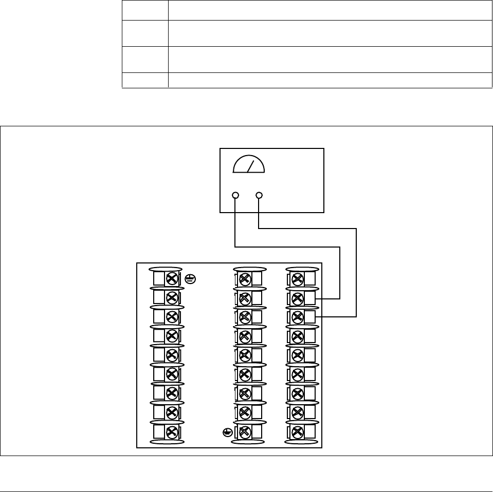
234 UDC 3300 Controller Product Manual 4/00
8.2 Current Proportional Output Calibration
Introduction Calibrate the controller so that the output provides the proper amount of
current over the desired range. The controller can provide an output
current range of from 0 to 21 milliamperes and can be calibrated at 4 mA
for 0 % of output and 20 mA for 100 % of output or any other values
between 0 mA and 21 mA.
Equipment needed You will need a standard shop type milliammeter, with whatever accuracy
is required, capable of measuring 0 to 20 milliamps.
Calibrator connections Referring to Figure 8-1, wire the controller according to the procedure
given in Table 8-1.
Table 8-1 Set Up Wiring Procedure Current Proportional Output
Step Action
1Apply power and allow the controller to warm up 15 minutes before you
calibrate.
2Tag and disconnect the field wiring, at the rear of the controller, from
terminals 2 (+) and 3 (–). See Figure 8-1.
3Connect a milliammeter across these terminals.
Figure 8-1 Wiring Connections for Calibrating Current Proportional Output
+
1
2
3
4
5
6
7
8
9
10
11
12
13
14
15
16
17
L1
L2/N
22
23
24
25
26
27
–
Milliammeter
+–
22635

4/00 UDC 3300 Controller Product Manual 235
Procedure The procedure for calibrating the Current Proportional Output is listed in
Table 8-2. Make sure LOCKOUT in the Tuning Set Up group is set to
NONE. See Section 3 – Configuration.
Table 8-2 Current Proportional Output Calibration Procedure
Step Description Press Action
1Enter Calibration Mode SET UP until you see
CURRENT
Lower Display
CALIB
Upper Display
2Calibrate 0 % FUNCTION
LOOP 1/2
You will see:
Lower Display
Upper Display
ZERO VAL
a value between 1 and 2048
or until the desired 0 % output is read on the milliammeter.
Use the values shown below depending on the action of
your valve.
0 mA For 0 to 20 mA Direct Action*
20 mA For 0 to 20 mA Reverse Action
4 mA For 4 to 20 mA Direct Action
20 mA For 4 to 20 mA Reverse Action
3Calibrate 100 % FUNCTION
LOOP 1/2
This stores the 0 % value and you will see:
Lower Display
Upper Display
SPAN VAL
a value between 1 and 2048
or until the desired 100 % output is read on the milliammeter.
Use the values shown below depending on the action of
your valve.
20 mA For 0 to 20 mA Direct Action
0 mA For 0 to 20 mA Reverse Action*
20 mA For 4 to 20 mA Direct Action
4 mA For 4 to 20 mA Reverse Action
4Exit the Calibration Mode FUNCTION
LOOP 1/2
The controller will store the span value.
LOWER
DISPLAY
or
SET UP
To exit the calibration mode.
*When attempting to achieve 0 mA, always adjust the output to about 0.5 mA, and slowly decrease until the
output just goes to zero. Further decrementing will not change the output current (since the circuit cannot
produce negative current) but will affect the accuracy of the output by creating a dead zone where no
current flows.

236 UDC 3300 Controller Product Manual 4/00
8.3 Position Proportional and Three Position Step Output Calibration
Position proportional
control When the UDC 3300 controller has a Position Proportional control output,
calibrate the controller so that the increase and decrease relays operate
properly with respect to the position of the external feedback slidewire.
Three position step
control Three Position Step Control Output Models with Motor Position
Indication
(Model Numbers DC330X-EE-XXX-X2, DC330X-AA-XXX-02)
This model must have its output calibrated per the entire procedure to
ensure the displayed output (slidewire position) agrees with the final
control element position.
Three Position Step Control Output Models without Motor Position
Indication
(Model Numbers 330X-EE-XXX-X0, DC330X-AA-XXX-X0)
This model only requires that the “Motor Time” be entered as shown in
the calibration procedure. FULL CALIBRATION IS NOT REQUIRED.
Equipment needed None
Connections Apply power and allow the controller to warm up 30 minutes before you
calibrate. Leave all field wiring connected to the rear terminals.
Auto mode vs manual
mode There are two ways in which to calibrate Position Proportional or 3
Position Step control:
AUTO mode or MANUAL mode.
Rules for auto mode vs
manual mode The Auto-mode selection must be done at least once before the manual
mode will operate properly. Failure to use the Auto-mode procedure will
prevent the controller from going into automatic control mode.
Displayed values During the Auto-mode calibration procedure, the values being displayed
are used only to indicate if the motor is still traveling. To view the actual
calibration value, use the manual mode after the Auto-mode is completed.
These values can be changed for purposes of tweaking the calibration.
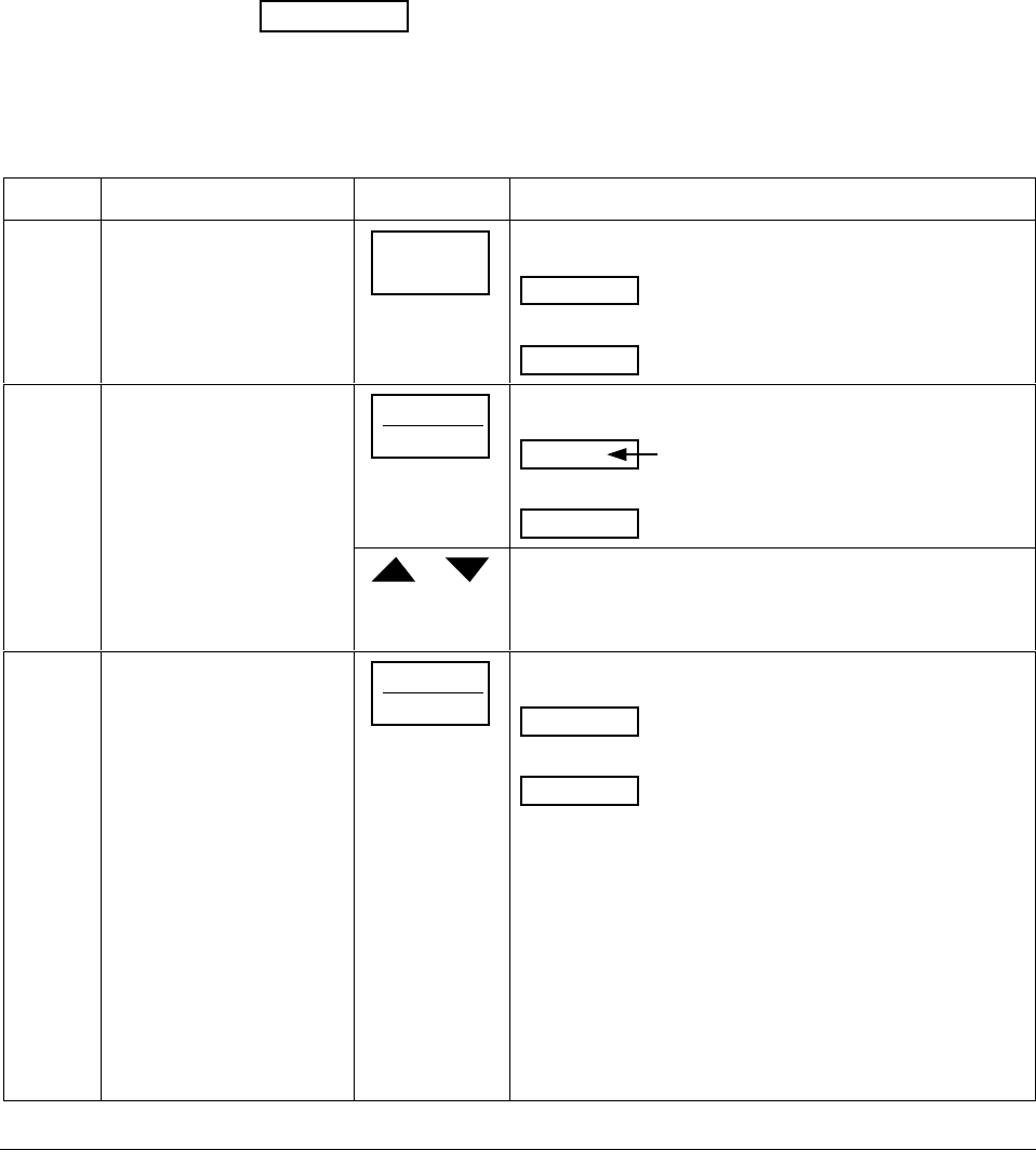
4/00 UDC 3300 Controller Product Manual 237
Procedure The procedure for calibrating the Position Proportional output and
3 Position Step control output is listed in Table 8-3. Make sure
LOCKOUT in Tuning Set Up group is set to NONE. See Section 3 –
Configuration.
For Three Position Step Control Output models without Motor Position
Indication, do steps 1 and 2 only.
For Position Proportional Output and Three Position Step Control Output
models with Motor Position Indication, follow the entire calibration
procedure.
ATTENTION These prompts only appear when position OUT ALG is
selected. If motor position for 3PSTEP is desired, first configure unit for
“position.” After calibration the unit can be switched to 3PSTEP.
Table 8-3 Position Proportional and 3 Position Step Output Calibration Procedure
Step Description Press Action
1Enter Calibration Mode SET UP until you see
POS PROP
Lower Display
CALIB
Upper Display
2Set Motor Traverse Time
NOTE: This is the time it
takes the motor to travel
from 0 % to 100 %.
FUNCTION
LOOP 1/2
until you see:
Lower Display
Upper Display
MTR TIME
a value
or until the proper motor stroke time is reached (see the
motor specs or measure the time)
Range of setting = 5 to 1800 Seconds
3Select Automatic or
Manual Calibration FUNCTION
LOOP 1/2
until you see:
POS PROP
Lower Display
DISABLE
Upper Display
You can calibrate the controller output manually or let the
controller calibrate the output automatically.
If the slidewire has never been calibrated, you must use
DO AUTO first. In the “Automatic Calibration Mode” (DO
AUTO), the controller relays automatically move the motor
in the proper direction.
If desired, however, the motor may be manually positioned
to 0 % and 100 % positions. Disconnect the relay wires.
Use DO MAN. In the “Manual Calibration Mode” (DO
MAN), the motor does not move. Instead, the existing 0 %
and 100 % values may be changed with the ▲ or ▼ key.
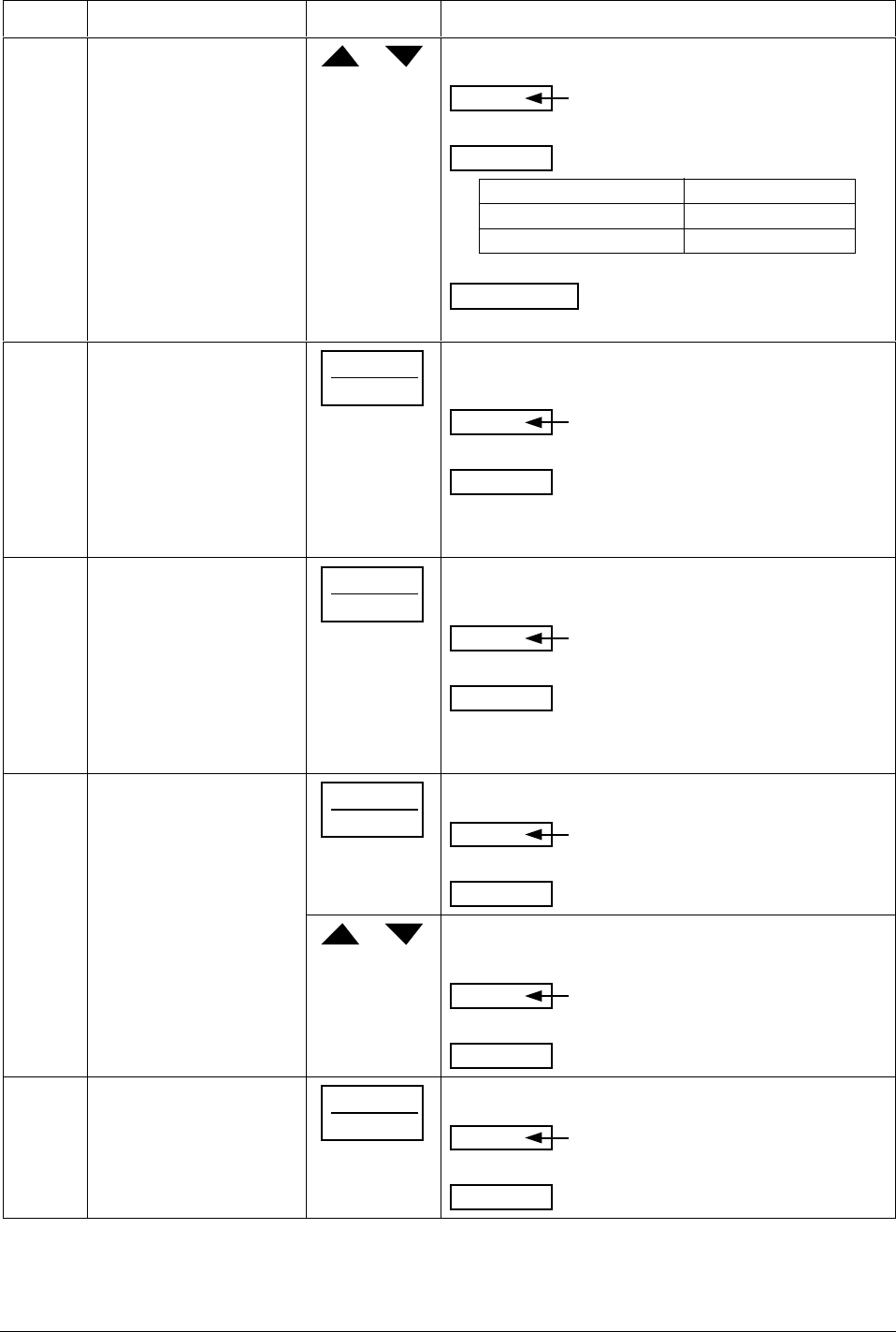
238 UDC 3300 Controller Product Manual 4/00
Step Description Press Action
or to select automatic or manual calibration.
Lower Display
Upper Display
POS PROP
DO AUTO
or
DO MAN
If you select…Then…
DO AUTO go to Step 4
DO MAN go to Step 6
ATTENTION When calibration is terminated, this
selection reverts to DISABL.
4 DO AUTO
Set 0 % value FUNCTION
LOOP 1/2
The decrement relay is turned on to move the motor to
0 % position.
Lower Display
Upper Display
ZERO VAL
counts of feedback
slidewire (0 to 3000)
When the motor stops, the display should stop counting,
then go to the next step.
5 DO AUTO
Set 100 % value FUNCTION
LOOP 1/2
The increment relay is turned on to move the motor to
100 % position.
Lower Display
Upper Display
SPAN VAL
counts of feedback
slidewire (0 to 3000)
When the motor stops, the display should stop counting,
then, go to Step 8.
6DO MAN
Set 0 % value FUNCTION
LOOP 1/2
You will see:
Lower Display
Upper Display
ZERO VAL
The existing zero
calibration value
in counts.
or until the desired zero value is reached in the upper
display.
Lower Display
Upper Display
ZERO VAL
The desired zero
value
7DO MAN
Set 100 % value FUNCTION
LOOP 1/2
The controller will store the 0 % value and you will see:
Lower Display
Upper Display
SPAN VAL
The existing span
calibration value
in counts
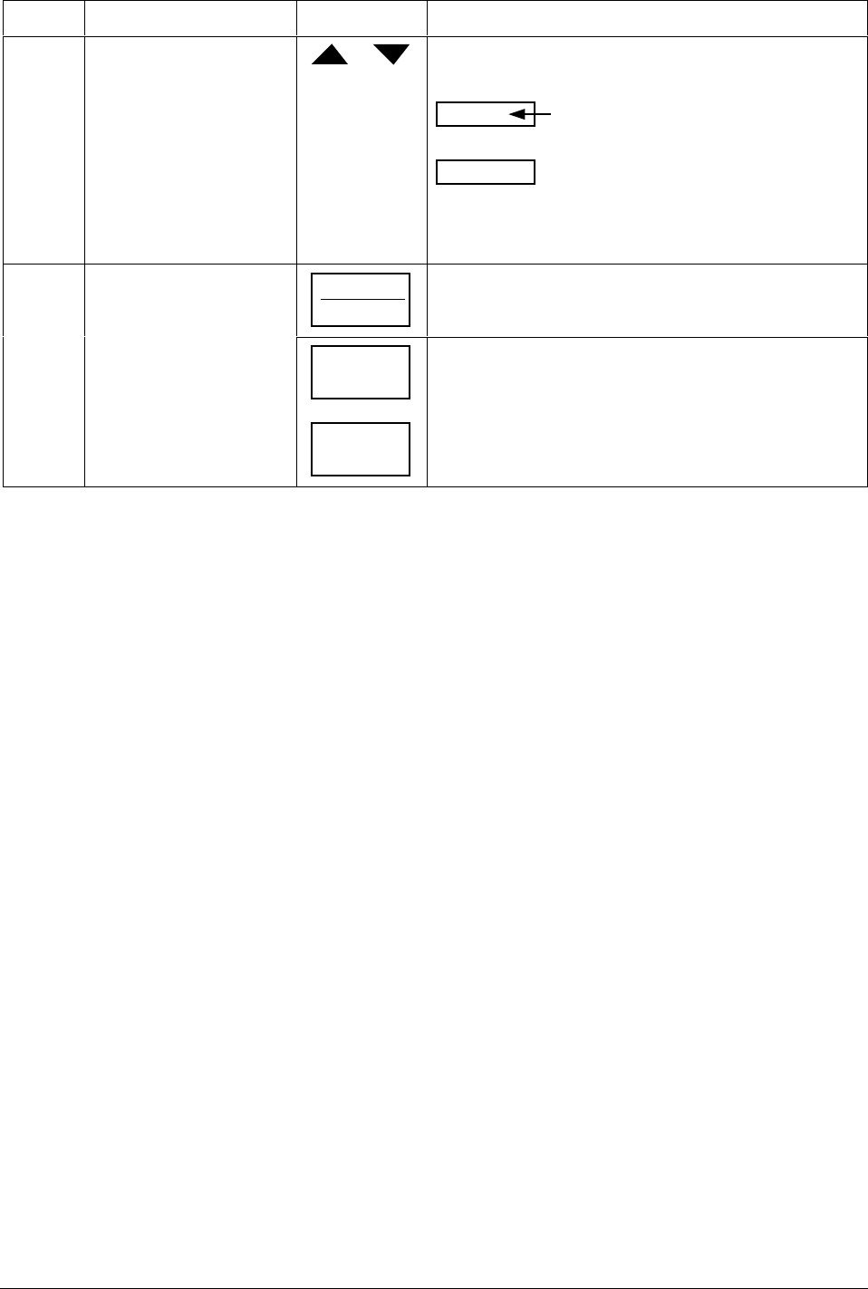
4/00 UDC 3300 Controller Product Manual 239
Step Description Press Action
or until the desired span value is reached in the upper
display.
Lower Display
Upper Display
SPAN VAL
The desired span
value
For manual calibration, the motor does not move from its
position prior to the start of Position Proportional
calibration.
8Exit the Calibration Mode FUNCTION
LOOP 1/2
The controller will store the 100 % value.
LOWER
DISPLAY
or
SET UP
To exit the calibration mode.
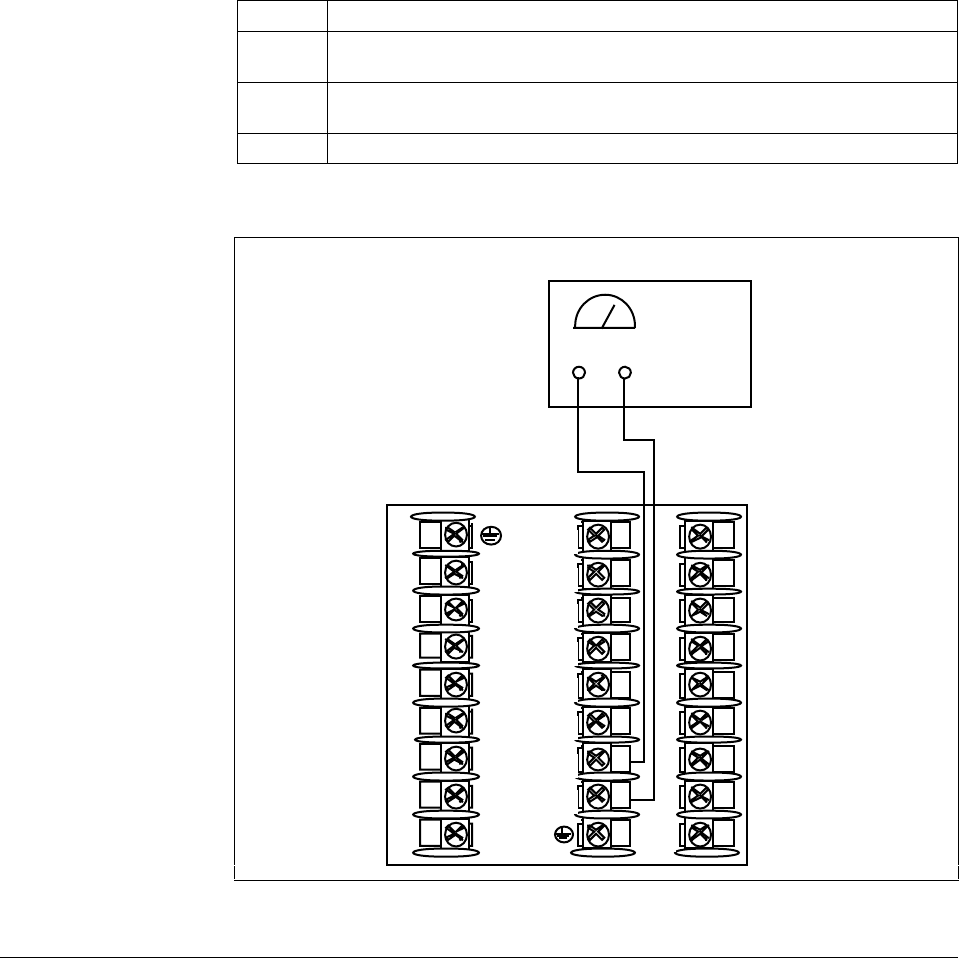
240 UDC 3300 Controller Product Manual 4/00
8.4 Auxiliary Output Calibration
Introduction Calibrate the controller so that the Auxiliary output provides the proper
amount of current over the desired range. The controller can provide an
auxiliary output current range of from 0 to 21 milliamperes and can be
calibrated at 4 mA for 0 % of output and 20 mA for 100 % of output or
any other values between 0 mA and 21 mA.
Equipment needed You will need a standard shop type milliammeter with whatever accuracy
is required, capable of measuring 0 to 20 milliamps.
Calibrator connections Referring to Figure 8-2, wire the controller according to the procedure
given in Table 8-4.
Table 8-4 Set Up Wiring Procedure for Auxiliary Output
Step Action
1Apply power and allow the controller to warm up 30 minutes before you
calibrate.
2Tag and disconnect the field wiring, at the rear of the controller, from
terminals 16 (+) and 17 (–). See Figure 8-2.
3Connect a milliammeter across these terminals.
Figure 8-2 Wiring Connections for Calibrating Auxiliary Output
1
2
3
4
5
6
7
8
9
10
11
12
13
14
15
16
17
L1
L2/N
22
23
24
25
26
27
–
Milliammeter
+–
+
22636
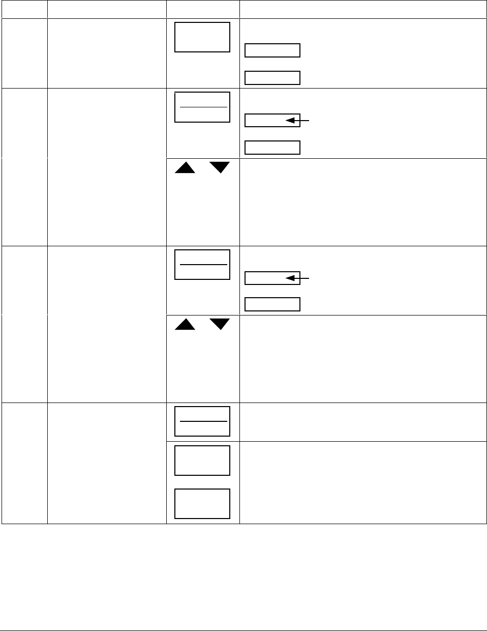
4/00 UDC 3300 Controller Product Manual 241
Procedure The procedure for calibrating the Auxiliary Output is listed in Table 8-5.
Make sure LOCKOUT in the Tuning Set Up group is set to NONE. See
Section 3 – Configuration.
Table 8-5 Auxiliary Output Calibration Procedure
Step Description Press Action
1Enter Calibration Mode SET UP until you see
AUX OUT
Lower Display
CALIB
Upper Display
2Calibrate 0 % FUNCTION
LOOP 1/2
You will see:
Lower Display
Upper Display
ZERO VAL
a value between 0 and 4095
or until the desired 0 % output is read on the milliammeter.
Use the values shown below depending on the action of
your valve.
0 mA For 0 to 20 mA Direct Action *
20 mA For 0 to 20 mA Reverse Action
4 mA For 4 to 20 mA Direct Action
20 mA For 4 to 20 mA Reverse Action
3Calibrate 100 % FUNCTION
LOOP 1/2
This stores the 0 % value and you will see:
Lower Display
Upper Display
SPAN VAL
a value
or until the desired 100 % output is read on the milliammeter.
Use the values shown below depending on the action of
your valve.
20 mA For 0 to 20 mA Direct Action
0 mA For 0 to 20 mA Reverse Action*
20 mA For 4 to 20 mA Direct Action
4 mA For 4 to 20 mA Reverse Action
4Exit the Calibration Mode FUNCTION
LOOP 1/2
The controller will store the span value.
LOWER
DISPLAY
or
SET UP
To exit the calibration mode.
*When attempting to achieve 0 mA, always adjust the output to about 0.5 mA, and slowly decrease until the output just
goes to zero. Further decrementing will not change the output current (since the circuit cannot produce negative
current) but will affect the accuracy of the output by creating a dead zone where no current flows.

242 UDC 3300 Controller Product Manual 4/00

4/00 UDC 3300 Controller Product Manual 243
Section 9 – Troubleshooting / Service
9.1 Overview
Introduction Instrument performance can be adversely affected by installation and
application problems as well as hardware problems. We recommend that
you investigate the problems in the following order:
• installation related problems
• application related problems
• hardware and software related problems
and use the information presented in this section to solve them. If a
replacement of any part is required, follow the procedures listed under
“Parts Replacement Procedures.”
What’s in this section? The following topics are covered in this section.
Topic See Page
9.1 Overview 243
9.2 Troubleshooting Aids
• Overall Error Messages
• Controller Failure Symptoms
• Customer Support
• Determining the Software Version Number
245
245
246
246
246
9.3 Power-up Tests 247
9.4 Status Tests 248
9.5 Background Tests 250
9.6 Controller Failure Symptoms 252
9.7 Troubleshooting Procedures
• Power Failure
• Current Proportional Output Failure
• Position Proportional Output Failure
• Time Proportional Output Failure
• Time/Current - Current/Time Proportional Output Failure
• Alarm Relay Output Failure
• Keyboard Failure
• Communications Failure
253
253
254
255
256
257
258
259
260
9.8 Parts Replacement Procedures
• How to remove the chassis
• How to replace the display/keyboard assembly
• How to remove printed wiring boards from the chassis
• Printed wiring board identification
• 2nd input board replacement procedure
• Power input board replacement procedure
• Digital input board replacement procedure
• Aux. output/commun. board replacement procedure
• MCU/output board replacement procedure
261
262
263
264
265
266
266
267
268
269
9.9 Maintenance 270

244 UDC 3300 Controller Product Manual 4/00
Installation related
problems Read the Installation section in this manual to make sure the UDC 3300
has been properly installed. The installation section provides information
on protection against electrical noise, connecting external equipment to
the controller, and shielding and routing external wiring.
ATTENTION System noise induced into the controller will result in
diagnostic error messages recurring. If the diagnostic error messages can
be cleared, it indicates a “soft” failure and is probably noise related.
If system noise is suspected, completely isolate the controller from all
field wiring. Use calibration sources to simulate PV and check all
controller functions; i.e. Gain, Rate, Reset, Output, Alarms, etc.
Application related
problems Review the application of the controller; then, if necessary, direct your
questions to the local sales office.
Hardware and software
related problems Use the troubleshooting error message prompts and controller failure
symptoms to identify typical failures which may occur in the controller.
Follow the troubleshooting procedures to correct them.

4/00 UDC 3300 Controller Product Manual 245
9.2 Troubleshooting Aids
Overall error messages An error message can occur
•at power-up,
•during continuous background tests while in normal operation,
•when the Status Tests are requested.
Table 9-1 lists all the error message prompts that you could see, the reason
for the failure, and under what test group the prompt could appear. Refer
to Tables 9-3 (Power-up), 9-5 (Status), and 9-6 (Background) for the
particular test group indicated.
Table 9-1 Error Message Prompts
Error Message
(lower display) Reason for Failure Test Group Refer to Table
CAL MTR Auto calibration never performed. Power-up and
Background 9-3
9-6
CAL TEST Calibration test failure Power-up or Status 9-3
9-5
CONF ERR Low limit greater than high limit for PV, SP,
Reset, or Output Background 9-6
CONFTEST Configuration test failure Power-up or Status 9-3
9-5
E E FAIL Unable to write to nonvolatile memory Background 9-6
FACT CRC Factory Calibration Cyclic Redundancy Status 9-5
FAILSAFE
or
FAILSF2 (Loop 2)
Controller in Failsafe Power-up, Background,
or Status 9-3
9-5
9-6
INP1FAIL Two consecutive failures of Input 1 integration Background 9-6
INP2FAIL Two consecutive failures of Input 2 integration Background 9-6
INP3FAIL Two consecutive failures of Input 3 integration Background 9-6
INP1 RNG Input 1 out of range Background 9-6
INP2 RNG Input 2 out of range Background 9-6
INP3 RNG Input 3 out of range Background 9-6
PV LIMIT PV out of range Background 9-6
RAM TEST RAM test failed Power-up or Status 9-3
9-5
RV LIMIT Remote Variable out of range Background 9-6
SEG ERR Start segment greater than ending segment Background 9-6
SOOTING Percent Carbon falls outside sooting boundary Background 9-6
SW FAIL Position Proportional slidewire input failure Background 9-6
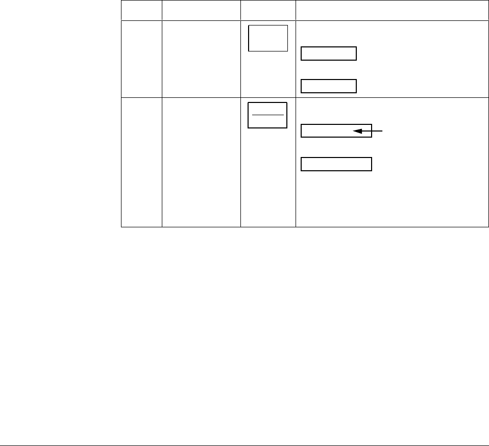
246 UDC 3300 Controller Product Manual 4/00
Controller failure
symptoms Other failures may occur that deal with the Power, Output, or Alarms.
Refer to the controller failure symptom in Table 9-7 to determine what is
wrong and the troubleshooting procedures to use to correct the problem.
Check Installation If a set of symptoms still persists, refer to Section 2 - Installation and
ensure proper installation and proper use of the controller in the system.
Customer support If you cannot solve the problem using the troubleshooting procedures
listed in this section, you can get technical assistance by contacting us.
Refer to the contact information in the front of this manual. An engineer
will discuss your problem with you. Please have your complete model
number, serial number, and Software version available. The model
and serial numbers can be found on the chassis nameplate. The software
version can be viewed under Setup Group “Status.” See Table 9-2.
Determining the
software version Table 9-2 lists the procedure for identifying the software version number.
Table 9-2 Procedure for Identifying the Software Version
Step Operation Press Action
1Select
STATUS
Set Up Group
SET UP until you see:
STATUS
Lower Display
READ
Upper Display
2Read the
software version FUNCTION
LOOP 1/2
until you see:
Lower Display
Upper Display
VERSION
Software
version
Number
Please give this number to the Customer
Support person. It will indicate which version
of UDC 3300 you have and help them
determine a solution to your problem.
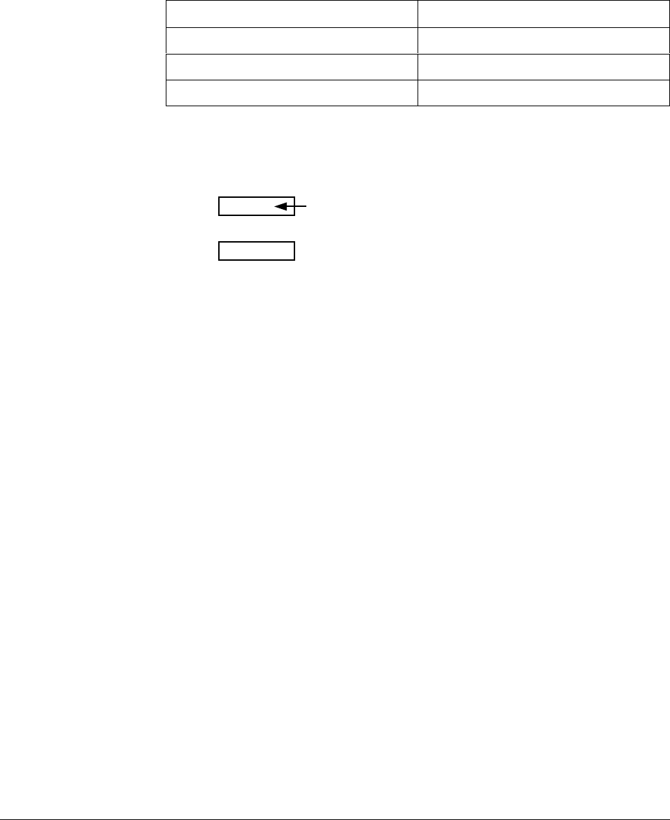
4/00 UDC 3300 Controller Product Manual 247
9.3 Power-up Tests
What happens at
power-up When the controller is powered-up, three tests are run by the UDC 3300
software to ensure memory integrity. As the tests are run, the displays will
appear as shown in Table 9-3.
Table 9-3 Power-up Tests
Lower Display Upper Display
RAM TEST PASS or FAIL
CONFTEST PASS or FAIL
CAL TEST PASS or FAIL
Test failures If any of these three tests fail, FAIL will appear momentarily in the upper
display, then a display test is run, after which the controller will go into
manual mode and you will see:
Lower Display
Upper Display
FAILSAFE
PV value
(blinking)
Refer to “Status Tests” to determine which tests have failed and how to
correct them.
Position proportional
or 3 position step test
failures
For controller configured for Position Proportional or 3 Position Step
control with motor position indication and Auto-cal has never been done,
a prompt CAL MTR will appear suggesting that the controller be
calibrated.
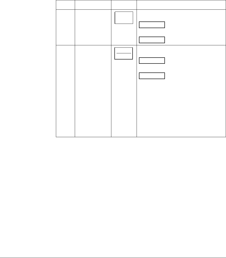
248 UDC 3300 Controller Product Manual 4/00
9.4 Status Tests
Introduction When required, the results of these tests can be checked to determine the
reason the controller has gone to Failsafe.
How to check the
status tests The procedure in Table 9-4 tells you how to display the results of the
status tests. Table 9-5 lists the tests, the reason for the failure, and how to
correct the problem.
Table 9-4 Procedure for Displaying the Status Tests Results
Step Operation Press Action
1Select
STATUS
Set Up Group
SET UP until you see:
STATUS
Lower Display
READ
Upper Display
2Read the status
tests results FUNCTION
LOOP 1/2
until you see:
Lower Display
Upper Display
FAILSAFE
NO or YES YES indicates
a failure
Successive presses of the [FUNCTION] key
will display the results of the status tests in
the following order:
RAM TEST
CONF TEST
CAL TEST
FACT CRC
Identify the problem and correct the failure
as shown in Table 9-5.

4/00 UDC 3300 Controller Product Manual 249
Status Tests Table 9-5 lists the Status tests, the reason for their failure, and how to
correct the failure.
Table 9-5 Status Tests
Test
(Lower
Display)
Definition Upper
Display Reason for Failure How to Correct the Failure
FAILSAFE Failsafe Fault NO No Failure
FAILSF2
(Loop 2) YES Burnout configured for none
and input fails.
–RAM TEST failed
–CONFTEST failed
–CALTEST failed
1. Step through the rest of the STATUS
check to identify the particular failure.
Also see Table 9-6, Background tests
RAM TEST PASS No Failure RAM test passed.
RAM test run at
power-up FAIL RAM Failure 1. Power cycle to see if the error clears.
PASS No Failure Configuration checksum passed.
CONF
TEST Configuration
Checksum FAIL Configuration data is in
error. 1. Step through STATUS tests – the
controller will recalculate the
checksum.
2. Check all configuration prompts for
accuracy. See Section 3 -
Configuration
CAL TEST Working
Calibration PASS No Failure Working calibration checksum passed.
FAIL The working calibration
constants in the controller
are in error.
1. If the controller has not been field
calibrated, see Section 3 -
Configuration and change the input to
a different type. Enter it, loop through
the status tests, then return the input
type to the original one.
2. If the controller has been field
calibrated, recalibrate the controller.
FACT CRC Factory
calibration test PASS No Failure Factory calibration cyclic redundancy test
passed
FAIL Factory set input constants
have been changed due to
the change in input type.
1. Cycle through Status to clear the error.
2. Check the calibration. Make sure 0 %
and 100 % are correct values.
3. Recalibrate if step 1 is unsatisfactory.
Refer to Section 7 - Input Calibration.
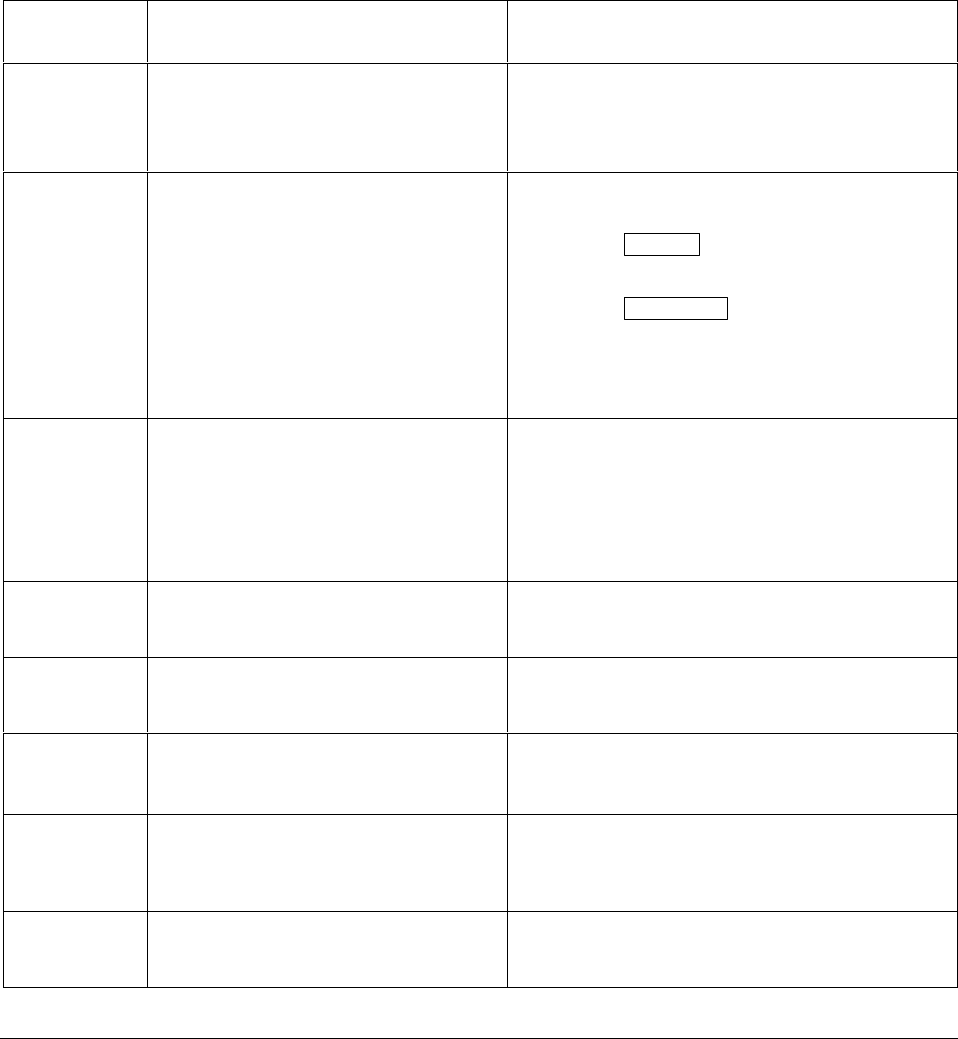
250 UDC 3300 Controller Product Manual 4/00
9.5 Background Tests
Introduction The UDC 3300 performs on-going background tests to verify data and
memory integrity. If there is a malfunction, an error message will be
displayed (blinking) in the lower display.
Background tests In the case of more than one simultaneous malfunction, only the one with
the highest priority will appear in the lower display. Table 9-6 lists these
background tests, the reason for their failure, and how to correct the
problem.
Table 9-6 Background Tests
Lower
Display Reason for Failure How to Correct the Problem
EE FAIL Unable to write to non-volatile memory.
Anytime you change a parameter and it is
not accepted, you will see EE FAIL.
1. Check the accuracy of the parameter and re-enter.
2. Try to change something in configuration.
3. Run through STATUS tests to re-write to
EEPROM.
FAILSAFE
or
FAILSF2
(Loop 2)
This error message shows whenever the
controller goes into a failsafe mode of
operation. This will happen if:
•RAM test failed
•Configuration test failed
•Calibration test failed
•Burnout configured for none and
the input failed.
1. Run through STATUS check to determine the
reason for the failure.
2. Press the SET UP key until STATUS appears in
the lower display.
3. Press the FUNCTION key to see what tests
pass or fail, then run through the STATUS codes a
second time to see if the error cleared.
Correct according to the recommendations given
in Table 9-5.
INP1FAIL Two consecutive failures of input 1
integration. i.e., cannot make analog to
digital conversion. This will happen if:
•Upscale or Downscale burnout is
selected
•Input not configured correctly
1. Make sure the actuation is configured correctly.
See Section 3 - Configuration.
2. Make sure the input is correct.
3. Check for gross over-ranging.
4. Replace factory calibration. See Section 7.6.
5. Replace the cold junction assembly.
INP2FAIL Two consecutive failures of input 2
integration. i.e., cannot make analog to
digital conversion.
Same as INP1FAIL above.
INP3FAIL Two consecutive failures of input 3
integration, i.e., cannot make analog to
digital conversion.
Same as INP1FAIL above.
SW FAIL Position Proportional input slidewire failure 1. Check motor slidewire connections.
2. Recalibrate the slidewire motor position. see the
calibration section (Section 8.3).
CAL MTR Position Proportional or 3 Position Step
Control with Motor Position Indication,
Auto Cal never performed.
1. Calibrate the controller for Position Proportional
output. Refer to Subsection 8.3 – Position
Proportional and 3 Position Step Output
Calibration.
CONF ERR • PV low limit is > PV high limit
• SP low limit is > SP high limit
• Output low limit > Output high limit
1. Check the configuration for each item and
reconfigure if necessary.

4/00 UDC 3300 Controller Product Manual 251
Lower
Display Reason for Failure How to Correct the Problem
INP1 RNG Input 1 out of range. The process input is
outside the range limits. 1. Make sure the range and actuation are configured
properly.
2. Check the input source.
3. Restore the factory calibration. (See Section 7.6.)
4. Field calibrate. See Section 7 - Input Calibration.
INP2 RNG Input 2 out of range. The remote input is
outside the range limits. Same as INP1 RNG above.
INP3 RNG Input 3 out of range. The remote input is
outside the range limits. Same as INP1 RNG above.
PV LIMIT PV out of range.
PV = INP1 + INP1 BIAS 1. Make sure the input signal is correct.
2. Make sure the Bias setting is correct
3. Recheck the calibration. Use Bias of 0.0
RV LIMIT The result of the formula shown below is
beyond the range of the remote variable.
RV = INP2 X RATIO + BIAS
1. Make sure the input signal is correct.
2. Make sure the Ratio and Bias settings are correct.
3. Recheck the calibration. Use a Ratio of 1.0 and a
Bias of 0.0.

252 UDC 3300 Controller Product Manual 4/00
9.6 Controller Failure Symptoms
Introduction In addition to the error message prompts, there are failure symptoms that
can be identified by noting how the controller displays and indicators are
reacting.
Symptoms Compare your symptoms with those shown in Table 9-7 and refer to the
troubleshooting procedure indicated to correct the problem.
Table 9-7 Controller Failure Symptoms
Upper
Display Lower
Display Indicators Controller
Output Probable
Cause Trouble-
shooting
Procedure
Blank Blank Off None Power Failure 1
OK OK Current
Proportional
Output
2
OK OK Position
Proportional
Output
3
OK OK Time Proportional
Output 4
OK
Displayed
Output
disagrees
with Controller
Output
OK
Controller
Output
disagrees
with Displayed
Output
Current/Time
Proportional
Output
5
OK OK OK External Alarm
function does
not operate
properly
Malfunction in
alarm output 6
Display does not function when a key is pressed Keyboard
Malfunction 7
Controller fails to go into “Slave” operation during communications Communications
Failure 8
Other symptoms If a set of symptoms or prompts other than the one you started with
appears while troubleshooting, re-evaluate the symptoms. This may lead
to a different troubleshooting procedure.
If the symptom still persists, refer to the installation section in this manual
to ensure proper installation and proper use of the controller in your
system.
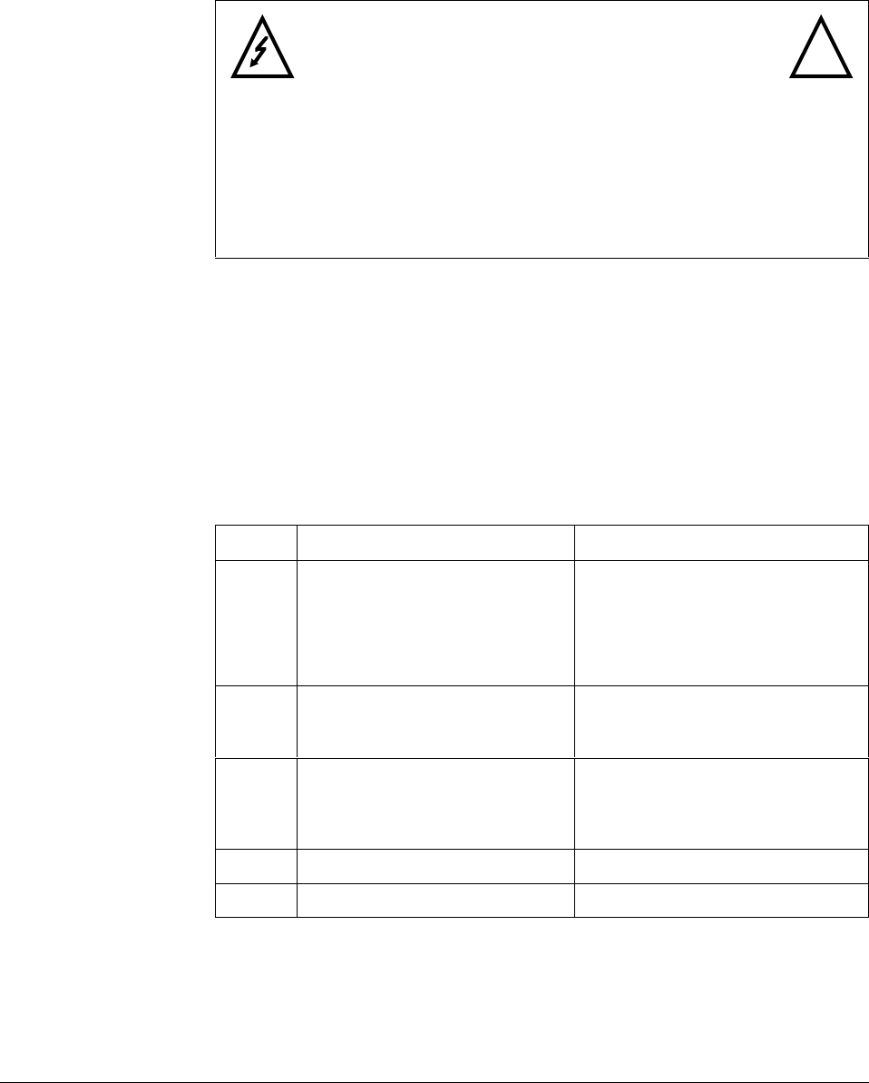
4/00 UDC 3300 Controller Product Manual 253
9.7 Troubleshooting Procedures
Introduction The troubleshooting procedures are listed in numerical order as they
appear in Table 9-7. Each procedure lists what to do if you have that
particular failure and how to do it or where to find the data needed to
accomplish the task.
WARNING—SHOCK HAZARD !
TROUBLESHOOTING MAY REQUIRE ACCESS TO
HAZARDOUS LIVE CIRCUITS, AND SHOULD ONLY BE
PERFORMED BY QUALIFIED SERVICE PERSONNEL. MORE
THAN ONE SWITCH MAY BE REQUIRED TO DE-ENERGIZE
UNIT BEFORE SERVICING.
Equipment needed You will need the following equipment in order to troubleshoot the
symptoms listed in the tables that follow:
• DC Milliammeter – mAdc
• Calibration sources – T/C, mV, Volt, etc.
• Voltmeter
Procedure #1 Table 9-8 explains how to troubleshoot power failure symptoms.
Table 9-8 Troubleshooting Power Failure Symptoms
Step What to do How to do it
1Check the AC line voltage. Use a voltmeter to measure the AC
voltage across terminals L1 and L2 on
the rear terminal panel of the
controller.
Check the earth ground connection.
2Make sure the chassis plugs into
the rear of the case properly. Withdraw the chassis and visually
inspect the controller board and the
inside of the case.
3Check the system for Brown-outs,
heavy load switching, etc., and
conformance to installation
instructions.
Refer to Section 2 - Installation.
4Change PS/Input board. Refer to Table 9-20.
5Change MCU/Output board. Refer to Table 9-23.

254 UDC 3300 Controller Product Manual 4/00
Procedure #2 Table 9-9 explains how to troubleshoot Current Proportional Output
failure symptoms.
Table 9-9 Troubleshooting Current Proportional Output Failure
Step What to do How to do it
1Make sure the controller is
configured for Current output. Make Algorithm Set Up group function
prompt OUT ALG or OUT2 ALG =
CURRNT.
Refer to Section 3 - Configuration.
2Check the field wiring. Output impedance must be less than
or equal to 1000 ohms.
3Make sure all the configurable
tuning constants, limits, and
configuration data stored in the
controller are correct. Reconfigure,
if necessary.
Refer to Section 3 - Configuration to
check all this data and how to
reconfigure.
4Check the output. Put the controller into Manual mode
and change the output from 0 % to
100 % (4-20 mA). Use a DC
milliammeter at the rear terminals to
verify the output.
5Recalibrate the Current Proportional
output. Refer to Section 8 - Output Calibration
for details.
6Change MCU/Output board. Refer to Table 9-23.

4/00 UDC 3300 Controller Product Manual 255
Procedure #3 Table 9-10 explains how to troubleshoot Position Proportional Output
failure symptoms.
Table 9-10 Troubleshooting Position Proportional Output Failure
Step What to do How to do it
1Make sure the controller is
configured for Position Proportional
output.
Make Output Algorithm Set Up group
function prompt OUT ALG = POSITN.
Refer to Section 3 - Configuration.
2Check the field wiring. Refer to Section 2 - Installation for
Position Proportional Wiring
information.
3Check the output. Put the controller into Manual mode
and change the output from 0 % to
100 %.
4Check whether the motor drives in
both directions. If it does go to Step
6.
See the Position Proportional
calibration procedure in Section 8 for
motor slidewire calibration.
5Check whether the motor drives in
either direction. If the motor drives
in one direction, check the
slidewire. If the motor does not
drive in either direction, check the
motor.
Refer to the motor instructions.
6Check the output voltage to the
slidewire. Should equal from 1.3 to 1.0 volts.
See wiring in the installation section
for terminal designations. The
feedback slidewire output voltage
must vary with the valve position.
7Make sure the output relays are
actuating properly. Put the controller into Manual mode.
Vary the output above and below the
present value. Observe “OUT”
indicator on the operator interface.
If they are not working properly, check
the field wiring, then go to Step 5.
If they are, go to Step 8.
8Recalibrate the controller. Refer to Section 8 - Output
Calibration.
9Change MCU/Output board. Refer to Table 9-23.

256 UDC 3300 Controller Product Manual 4/00
Procedure #4 Table 9-11 explains how to troubleshoot Time Proportional Output
failure.
Table 9-11 Troubleshooting Time Proportional Output Failure
Step What to do How to do it
1Make sure the controller is
configured for Time Proportional
output.
Make Output Algorithm Set Up group
function prompt OUT ALG = TIME or
TIME D or function prompt OUT2 ALG
= TIME.
Refer to Section 3 - Configuration.
2Check the field wiring. Make sure the NO or NC contact
wiring is correct at the rear terminals.
Refer to Section 2 - Installation for
details.
3Make sure all the configurable
tuning constants, limits, and
configuration data stored in the
controller are correct. Reconfigure,
if necessary.
Refer to Section 3- Configuration to
check all this data and how to
reconfigure.
4Check the output. Put the controller into Manual mode.
Vary the output above and below the
present value. Observe OUT indicator
on the operator interface.
5Change MCU/Output board. Refer to Table 9-23.

4/00 UDC 3300 Controller Product Manual 257
Procedure #5 Table 9-12 explains how to troubleshoot Current/Time or Time/Current
Proportional Output failure.
Table 9-12 Troubleshooting Time/Current or Current/Time Proportional
Output Failure
Step What to do How to do it
1Make sure the controller is
configured for Time/Current or
Current/Time Proportional output.
Make Output Algorithm Set Up group
function prompt OUT ALG or OUT2
ALG = TI CUR or CUR TI.
Refer to Section 3 - Configuration.
2Check the field wiring. Make sure the NO or NC contact
wiring is correct at the rear terminals.
Refer to Section 2 - Installation for
details.
3Make sure all the configurable
tuning constants, limits, and
configuration data stored in the
controller are correct. Reconfigure,
if necessary.
Refer to Section 3 - Configuration to
check all this data and how to
reconfigure.
4Check the relay output. Put the controller into Manual mode.
Vary the output above and below the
present value. Observe OUT indicator
on the operator interface.
5Check the Current Proportional
Output. Put the controller into Manual mode
and change the output from 0 % to
100 % (4-20 mA). Use a DC
milliammeter at the rear terminals to
verify the output.
6Recalibrate the controller. Refer to Section 8 - Output Calibration
for details.
7Change MCU/Output board. Refer to Table 9-23.

258 UDC 3300 Controller Product Manual 4/00
Procedure #6 Table 9-13 explains how to troubleshoot Alarm Relay Output failure.
Table 9-13 Troubleshooting Alarm Relay Output Failure
Step What to do How to do it
1Check the alarm configuration data.
If it is correct, check the field wiring. Reconfigure if necessary.
Refer to Section 3 - Configuration for
details.
2Check that the applicable alarm
relay actuates properly depending
on what you have set at prompt
AxSxTYPE.
If it does, check the field wiring.
If the alarm type is set for PV, place
the controller in manual mode. Vary
the input to raise and lower the PV
around the setpoint. Listen for a click
from the relay as the PV moves in
either direction and note that the
proper ALM1 or ALM2 is lit.
EXAMPLE: If the alarm is set for
MANUAL, put the controller into
manual mode. The alarm light is ON.
Put the controller into automatic mode
and the alarm light is OFF.
3Check the field wiring. Make sure the NO or NC contact
wiring is correct on the alarm output
terminals.
Refer to Section 2 - Installation for
details.
4Change MCU/Output board. Refer to Table 9-23.
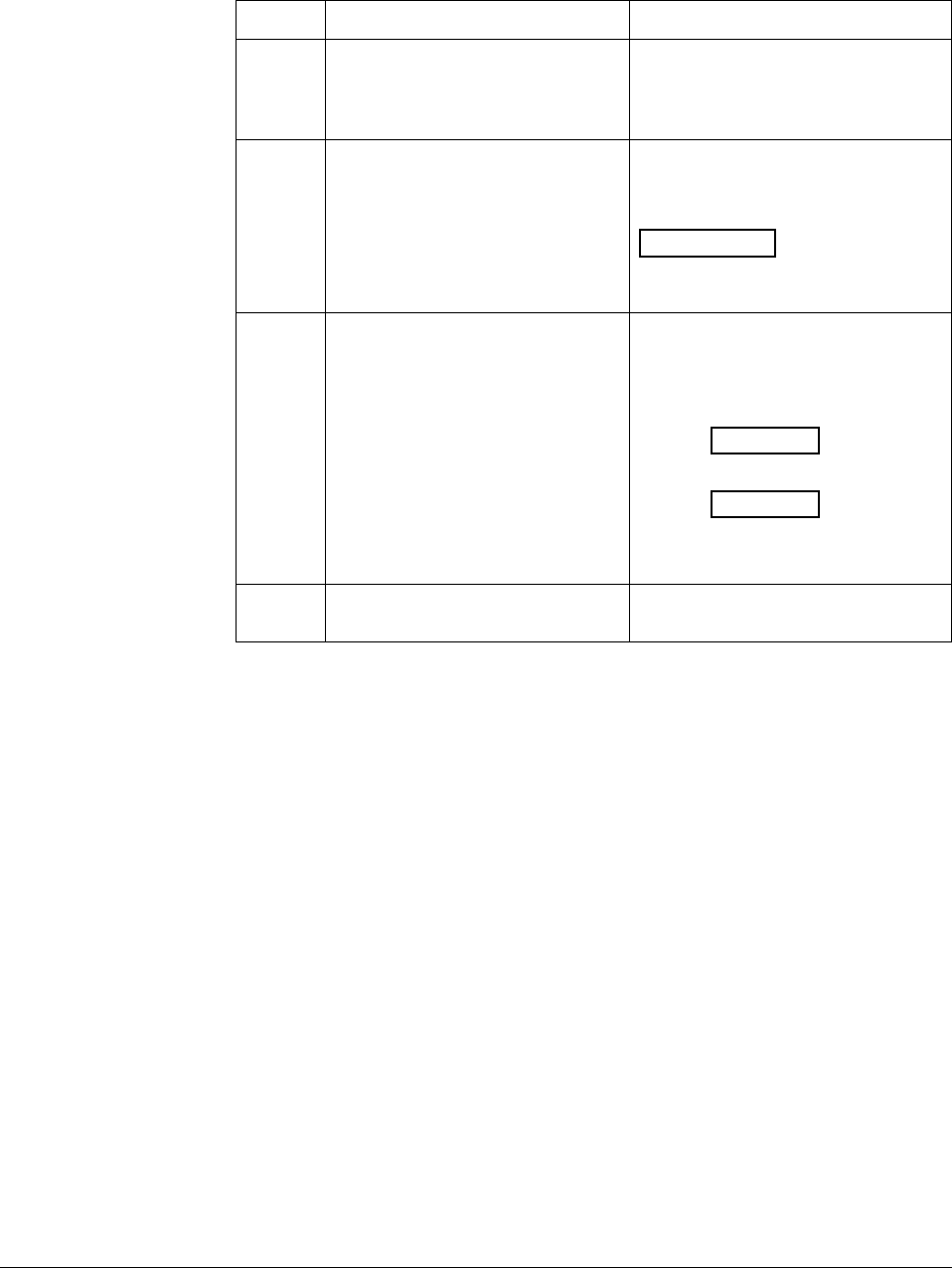
4/00 UDC 3300 Controller Product Manual 259
Procedure #7 Table 9-14 explains how to troubleshoot a Keyboard failure.
Table 9-14 Troubleshooting a Keyboard Failure
Step What to do How to do it
1Make sure the keyboard is
connected properly to the
MCU/output and power/input
boards.
Withdraw the chassis from the case
and visually inspect the connection.
2Controller Keyboard or specific keys
may be LOCKED OUT via the
security code.
Use your four-digit security code
number to change the lockout level.
Refer to Section 3 – Configuration.
ATTENTION Using “1000” as a
security code number will override the
4-digit code previously entered.
3Run the keyboard test. Press the [SET UP] key and hold in,
then press the [FUNCTION] key at the
same time. The controller will run a
display test. Then you will see:
TRY ALL
Lower Display
KEYS
Upper Display
Press each key. If it works, the key
name will appear in the lower display.
4Replace the display/keyboard if any
keys are shorted out. Refer to “Parts Replacement
Procedures” in this section.
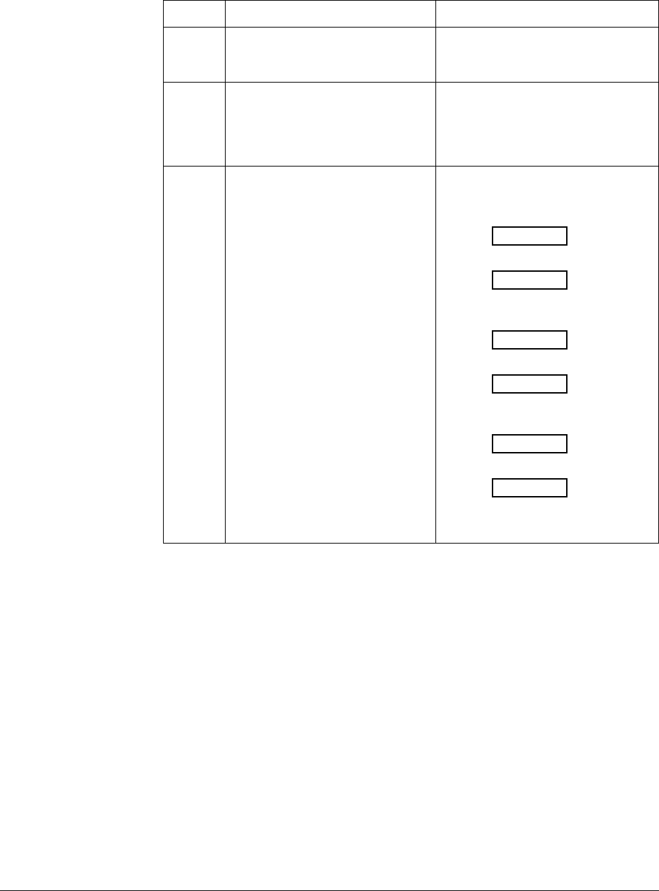
260 UDC 3300 Controller Product Manual 4/00
Procedure #8 Table 9-15 explains how to troubleshoot a Communications failure.
Table 9-15 Troubleshooting a Communications Failure
Step What to do How to do it
1Check the field wiring and
termination resistor. Depending on the protocol used, refer
to the proper communications manual
installation section.
2Make sure the Communications
Printed Wiring Board is installed
properly in the controller.
Withdraw the chassis from the case
and inspect the board. See the
exploded view (Figure 10-1) for
location of the board. Return the
chassis to the case.
3Determine if the Communications
board is faulty by running a LOCAL
LOOPBACK TEST.
If the test fails, replace the board.
Run the Local Loopback Test.
Press [SET UP] until you see:
COM
Lower Display
SET UP
Upper Display
Press [FUNCTION] until you see:
LOOPBACK
Lower Display
DISABL
Upper Display
Press ▲ or ▼, you will see:
LOOPBACK
Lower Display
ENABLE
Upper Display
The test will run until the operator
disables it here.

4/00 UDC 3300 Controller Product Manual 261
9.8 Parts Replacement Procedures
Introduction These procedures tell you how to access and replace the following printed
wiring boards in your controller.
•Display/Keyboard
•MCU/Output
•Power/Input
•2nd Input
•Digital Input
•Auxiliary Output
•DMCS Communications
•RS422/485 Communications
•Modbus Communications
Equipment needed To accomplish the procedures that follow, you will need the following
equipment:
•Phillips Head Screwdriver
•Flat Bladed Screwdriver
•Small Pliers
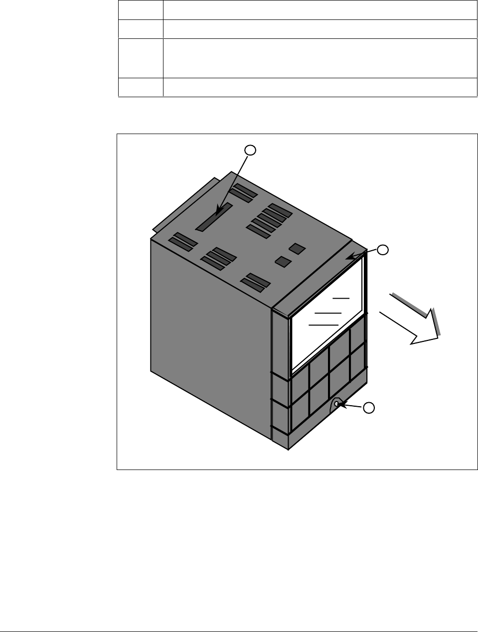
262 UDC 3300 Controller Product Manual 4/00
How to remove the
chassis Refer to Figure 9-1 for steps and follow the procedure listed in Table
9-16.
Table 9-16 How to Remove the Chassis
Step Action
1Loosen the screw on the front face.
2Insert a flat-bladed screwdriver into the hole on the top of the case as shown
in Figure 9-1 and pry chassis forward slightly until the chassis connectors
separate from the back of the case.
3Grasp the bezel and pull the chassis out of the case.
Figure 9-1 Chassis Removal
Loosen screw
Insert screwdriver
and pry forward
Grasp bezel
and pull
chassis out
2
3
1
22637
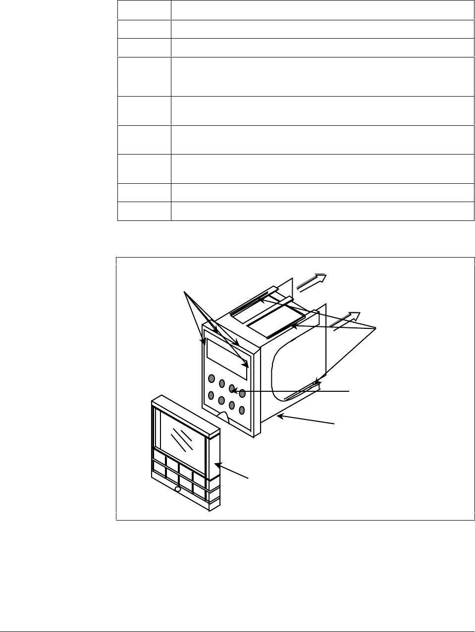
4/00 UDC 3300 Controller Product Manual 263
How to replace the
display/keyboard
assembly
Refer to Figure 9-2 and follow the procedure listed in Table 9-17.
Table 9-17 Display/Keyboard Assembly Replacement Procedure
Step Action
1Remove the chassis from the case as shown in Figure 9-1.
2Peel the rubber bezel and display window off the chassis assembly.
3Separate the chassis frame at the four release points shown in Figure 9-2
and wiggle each printed wiring board out of its socket on the
display/keyboard assembly. Pull out slightly.
4Insert a small flat-bladed screwdriver into each of the display/keyboard
release points (Figure 9-2) and pry out the board.
5Install the new board, bottom end in first, and push in the top until it clicks
into place.
6Reinstall the printed wiring boards into the rear of the display board
making sure that the boards click into their release points.
7Replace the bezel and window assembly.
8Reinstall chassis into case. Press in hard, then tighten the screw.
Figure 9-2 Display/Keyboard Replacement
Display keyboard
release points Pull printed
wiring boards
out slightly
Printed wiring
boards
release points
Display/keyboard
Chassis assembly
Rubber bezel
and window 22638
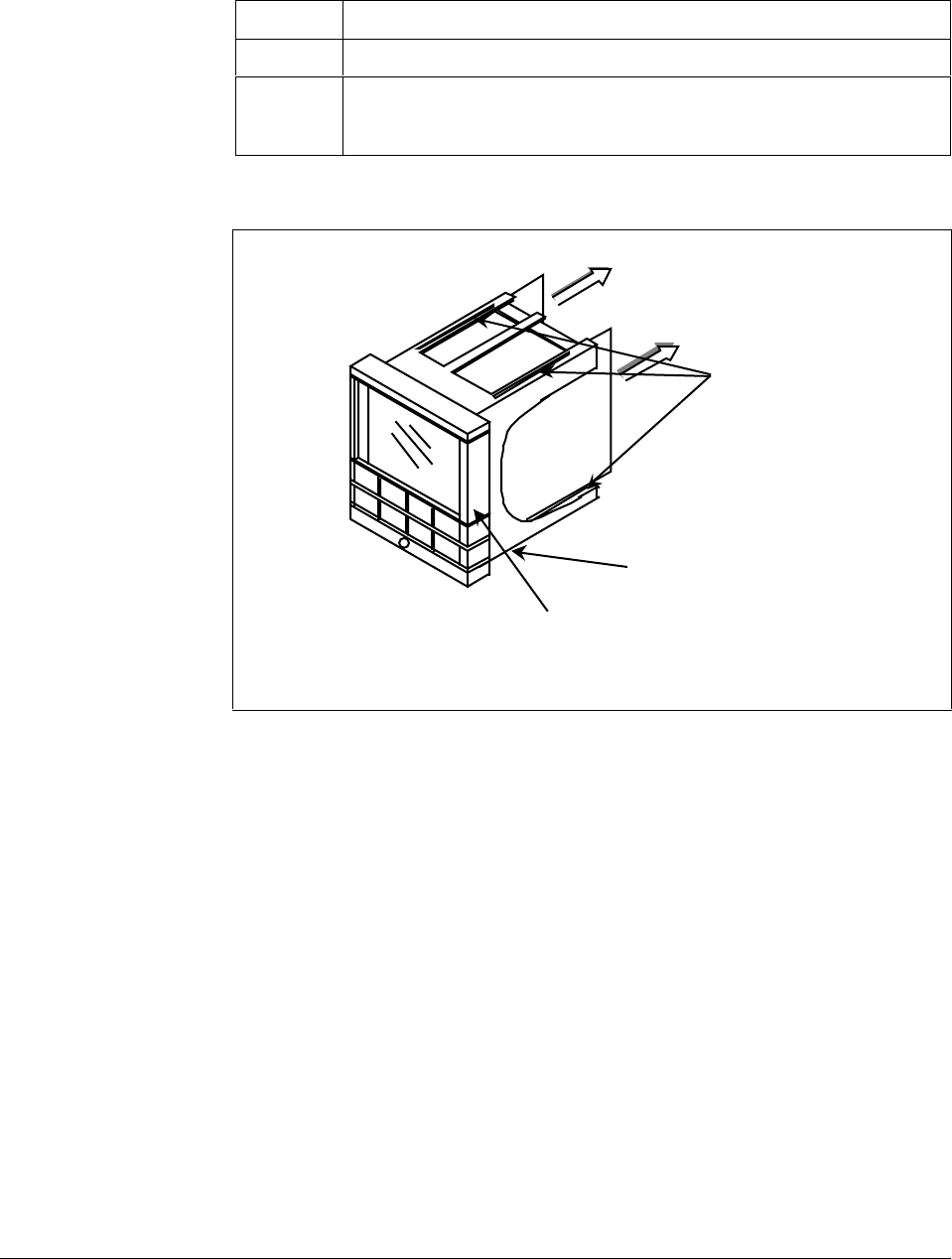
264 UDC 3300 Controller Product Manual 4/00
How to remove the
printed wiring boards
from the chassis
To remove the printed wiring boards from the chassis, refer to Figure 9-3
and follow the procedure in Table 9-18.
Table 9-18 Printed Wiring Board Removal from Chassis
Step Action
1Remove the chassis from the case as shown in Figure 9-1.
2Separate the chassis frame at the release points shown in Figure 9-3 and
wiggle each printed wiring board out of its socket on the display/keyboard
assembly. Pull both boards out of the chassis assembly.
Figure 9-3 Removing the Printed Wiring Boards
Pull printed
wiring boards out
of chassis
Printed wiring
boards
release points
Chassis assembly
Rubber bezel
and window
22639
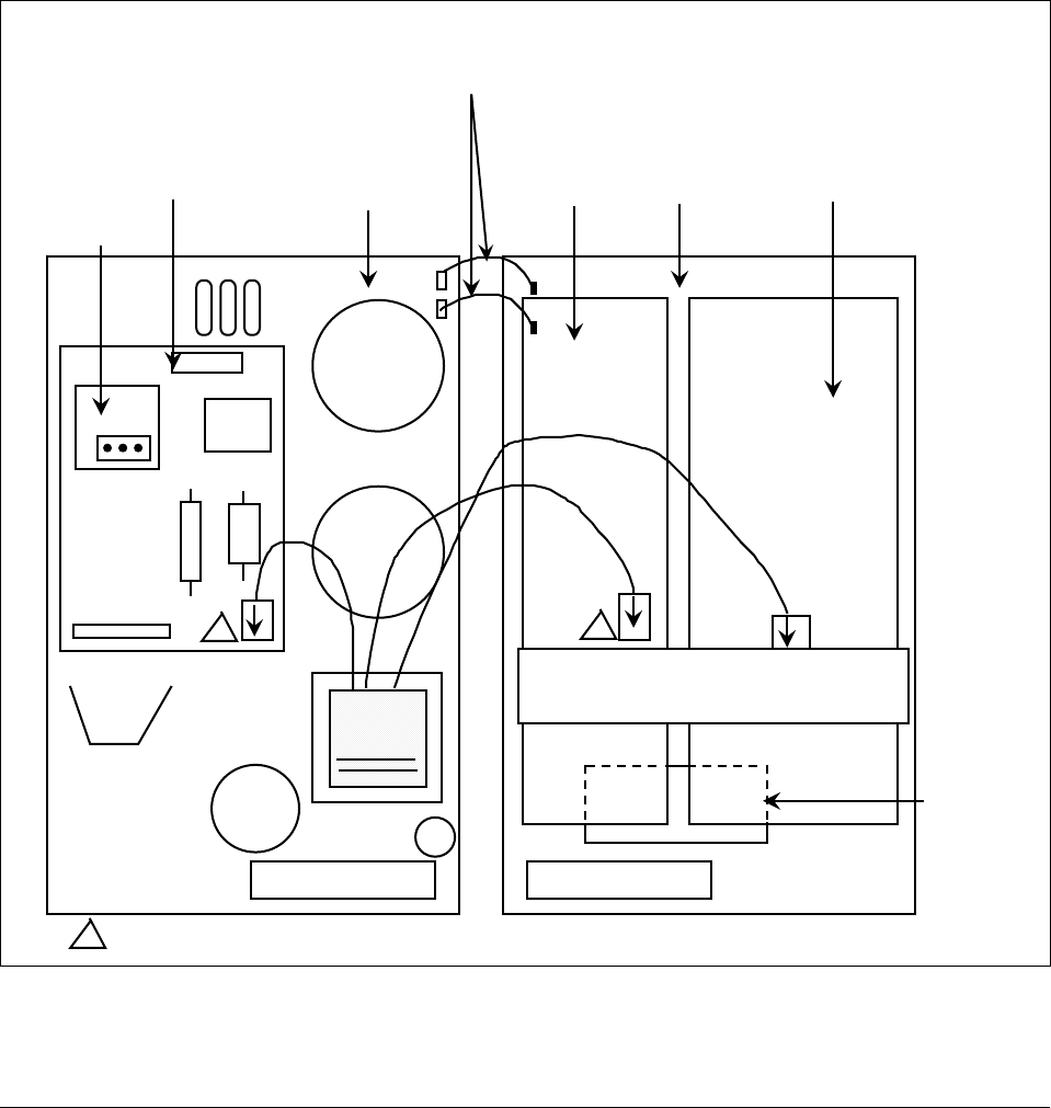
4/00 UDC 3300 Controller Product Manual 265
Printed wiring board
identification Figure 9-4 identifies each of the printed wiring boards that can be
replaced. Refer to this drawing when following the replacement
procedures for each of the boards, since you have to remove all of them
from the chassis to replace the one you want.
In order to lay boards flat, remove the transformer lead from the Auxiliary
Output/Communications board and the Digital Input board.
Refer to the specific procedure table to remove the desired board.
•2nd Input Board—Table 9-19
•Power Input Board—Table 9-20
•Digital Input Board—Table 9-21
•Auxiliary Output/Communications Board—Table 9-22
•MCU/Output Board—Table 9-23
Figure 9-4 Printed Wiring Board Identification
2nd input
board Power/input
board
WG connectors
on Digital Input and
MCU/Output boards
Digital
input
board
MCU/
output
board
Aux.out/
communications
board
Note: the transformer connectors are
polarized and will only go on one way
1
1
12-Pin Transformer connections are interchangeable. Either may be used on Digital Input Board or the second Input Board.
PROM
24279
W1/W2
jumper
W1
W2
266 UDC 3300 Controller Product Manual 4/00
2nd input board Follow the procedure listed in Table 9-19 to replace the Second Input
board—P/N 30756715-501.
Table 9-19 Second Input Board Replacement Procedure
Step Action
1Remove the chassis from the case. See Figure 9-1.
2Remove the printed wiring boards from the chassis. See Figure 9-3.
3Lay the boards flat and identify the 2nd Input board. See Figure 9-4.
4Remove the transformer plug from connector J14.
5The 2nd Input board is attached to the Power Input board by three
mounting posts. Locate these posts under the power input board.
6Use a small pliers and squeeze the ends of each post together and push it
up through the board. Remove 2nd Input board.
7Orient the new 2nd Input board onto the Power Input board and push the
mounting posts down through the Power Input board until they click into
place.
8Replace the transformer plug onto connector J14. Make sure the Input 2
jumper (W1/W2) is in the correct position. (Refer to Table 2-4.)
9Slide the printed wiring boards back into the chassis. Make sure the
connections to the display/keyboard assembly are made and that the
release points on the chassis snap into place on the printed wiring boards.
10 Reinstall the chassis into the case. Push in hard, then tighten screw.
Power input board Follow the procedure listed in Table 9-20 to replace the Power Input
board—P/N 51309404-502 (90 to 264 Vac) or 51309404-501 (24 Vac/dc).
Table 9-20 Power Input Board Replacement Procedure
Step Action
1Remove the chassis from the case. See Figure 9-1.
2Remove the printed wiring boards from the chassis. See Figure 9-3.
3Lay the boards flat and identify the Power Input board. See Figure 9-4.
4Remove the 2nd Input board, if present. See procedure in
Table 9-19.
5Remove the transformer connections to the Digital Input board and
Auxiliary Output/Communications board, if present.
6Remove the connector from plug WG if present (current output models
only). Slide a small screwdriver under the connector and lift the release.
7Replace the Power Input board.
8Reinstall WG connector and transformer connections to Digital Input board
and Auxiliary Output/Communications board, if present.
9Reinstall the 2nd Input board. See procedure in Table 9-19.
10 Slide the printed wiring boards back into the chassis. Make sure the
connections to the display/keyboard assembly are made and that the
release points on the chassis snap into place on the printed wiring boards.
11 Reinstall the chassis into the case. Push in hard, then tighten screw.

4/00 UDC 3300 Controller Product Manual 267
Digital input board Follow the procedure listed in Table 9-21 to replace the Digital Input
board—P/N 30756696-501.
Table 9-21 Digital Input Board Replacement Procedure
Step Action
1Remove the chassis from the case. See Figure 9-1.
2Remove the printed wiring boards from the chassis. See Figure 9-3.
3Lay the boards flat and identify the Digital Input board. See Figure 9-4.
4Remove the transformer plug from connector J9.
5The Digital Input board is attached to the MCU/output board by three
mounting posts. Locate these posts under the MCU/output board.
6Use small pliers and squeeze the ends of each post together and push it
up through the board. Remove the Digital Input board.
7Orient the new Digital Input board onto the MCU/Output board and push
the mounting posts down through the MCU/Output board until they click
into place.
8Replace the transformer plug onto connector J9.
9Slide the printed wiring boards back into the chassis. Make sure the
connections to the display/keyboard assembly are made and that the
release points on the chassis snap into place on the printed wiring boards.
10 Reinstall the chassis into the case. Push in hard, then tighten the screw.

268 UDC 3300 Controller Product Manual 4/00
Aux.Out/
communications board Follow the procedure listed in Table 9-22 to replace the following boards:
•Auxiliary Output Board—P/N 30756687-501
•Auxiliary Output/RS422/485 Board—P/N 30756687-502
•DMCS Communications Board—P/N 30756690-502
•RS422/485 Communications Board—P/N 30756693-502 (Basic)
or P/N 30756693-503 (Expanded)
Table 9-22 Aux.Out/Communications Board Replacement Procedure
Step Action
1Remove the chassis from the case. See Figure 9-1.
2Remove the printed wiring boards from the chassis. See Figure 9-3.
3Lay the boards flat and identify the Auxiliary Output or the
Communications board. See Figure 9-4.
4Remove the transformer plug from connector J8.
5The Aux.Out/Communications board is attached to the MCU/Output board
by three mounting posts. Locate these posts under the MCU/Output
board.
6Use small pliers and squeeze the ends of each post together and push it
up through the board. Remove the Aux.Out/Communications board.
7If you are replacing a Communications Board, a new PROM is supplied
with the board. Locate the PROM (shown in Figure 9-4) and gently pry out
the old PROM. Orient the new PROM supplied and gently press into
place.
8Orient the new Aux.Out/Communications board onto the MCU/Output
board and push the mounting posts down through the MCU/Output board
until they click into place.
9Replace the transformer plug onto connector J8.
10 Slide the printed wiring boards back into the chassis. Make sure the
connections to the keyboard assembly are made and that the release
points on the chassis snap into place on the printed wiring boards.
11 Reinstall the chassis into the case. Push in hard, then tighten the screw.

4/00 UDC 3300 Controller Product Manual 269
MCU/output board Follow the procedure listed in Table 9-23 to replace the following
MCU/output boards:
Basic
•Current Output—P/N 51309401-504
•Relay Output—P/N 51309401-505
Expanded
•Current Output—P/N 51309401-504
•Relay Output—P/N 51309401-505
Table 9-23 MCU/Output Board Replacement Procedure
Step Action
1Remove the chassis from the case. See Figure 9-1.
2Remove the printed wiring boards from the chassis. See Figure 9-3.
3Lay the boards flat and identify the MCU/Output board. See Figure 9-4.
4Each option board is held onto the MCU/Output board with three posts.
Locate these posts under the MCU/Output board.
5Use small pliers and squeeze the ends of each post together and push it
up through the board. Remove the option boards present.
6Remove the transformer connections to the Digital Input board and the
Auxiliary Output/Communications board, if present.
7Remove the Digital Input Board, if present. See Table 9-21.
8Remove the Auxiliary Output/Communications board, if present. See
Table 9-22.
9Remove the connector from plug WG. Slide a small screwdriver under the
connector and lift the release.
10 Replace the MCU/Output board.
11 Reinstall the Digital Input board, if present, onto the new MCU/Output
board.
12 Reinstall the Auxiliary Output/Communications board, if present, onto the
new MCU/Output board.
13 Reinstall the WG connector and the transformer connectors to the Digital
Input board and Auxiliary Output/Communications board, if present.
14 Slide the printed wiring boards back into the chassis. Make sure the
connections to the display/keyboard assembly are made and that the
release points on the chassis snap into place on the printed wiring boards.
15 Reinstall the chassis into the case. Push in hard, then tighten the screw.

270 UDC 3300 Controller Product Manual 4/00
9.9 Maintenance
Cleaning If you find it necessary to clean the elastomer bezel, use mild soapy water.
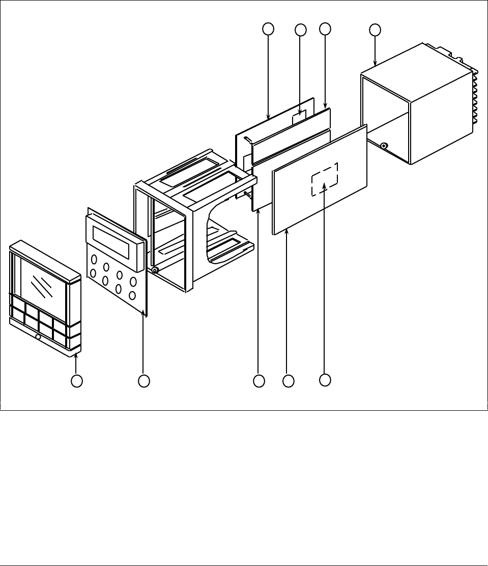
4/00 UDC 3300 Controller Product Manual 271
Section 10 – Parts List
10.1 Exploded View
Introduction Figure 10-1 is an exploded view of the UDC 3300 Controller. Each part is
labeled with a key number. The part numbers are listed by key number in
Table 10-1. There is a list of parts not shown in Table 10-2.
Figure 10-1 UDC 3300 Exploded View
12 345
678 9
24186
272 UDC 3300 Controller Product Manual 4/00
Parts identification Table 10-1 lists the part numbers for the key numbers shown in the
exploded view.
Table 10-1 Parts Identification
Key
Number Part Number Description Quantity
130756667-526 Bezel Assembly—Gray 1
230756672-501 Display/Keyboard Printed Wiring Assembly 1
330756687-501
30756687-502
30756690-502
39656693-502
30756693-503
Auxiliary Output Printed Wiring Board
Auxiliary Output/Half Duplex RS422/485 Communications Board
DMCS Communications Printed Wiring Board
RS422/485 Communications Printed Wiring Board—includes Basic Prom
RS422/485 Communications Printed Wiring Board (Full or Half Duplex)—
includes Expanded Prom
1
451309404-502
51309404-501 Power/Input Printed Wiring Board 90-264 Vac
Power/Input Printed Wiring Board 24 Vac/dc 1
530756715-501 2nd Input Printed Wiring Board 1
651309401-504
51309401-505 Current Output/MCU Printed Wiring Board
Relay Output/MCU Printed Wiring Board 1
730755306-501
30756725-501
30756679-501
Relay, Electromechanical
Relay, Solid State 1 Amp
Open Collector Output
1
per kit
830756696-501 Digital Input Printed Wiring Board 1
930756721-501 Case Assembly 1
51309713-501
51309714-501
51309715-501
51309716-501
51309717-501
FIELD UPGRADE SOFTWARE KITS:
Upgrade DC330B to SPP + Carbon
Upgrade DC330E to SPP + Math + HealthWatch
Upgrade DC330E to SPP + 2 Loops + HealthWatch
Upgrade DC330E to SPP + Math + 2 Loops + HealthWatch
Upgrade DC330D to SPP
Parts not shown Table 10-2 lists the part numbers of the parts not show in the exploded
view.
Table 10-2 Parts Not Shown
Part Number Description Quantity
30731996-506 4-20 mA Resistor Assembly, 250 ohms 1
30754465-501 0-10 Volt Input Resistor Assembly, 100K Pair 1
30732481-501
30732481-502 Varistor, 120 V
Varistor, 240 V 1
30755050-501 Mounting Kit 1
30756764-002 Rear Cover Kit 1
30755223-002
30755223-003 DIN Adapter Kit, Blue
DIN Adapter Kit, Gray 1
30757088-501 Cold Junction Resistor Kit 1
30756018-003 External Relay, Solid State 10 Amp 1
30756683-001 NEMA3 Gasket (Panel to case)
30757215-001 NEMA4 Front Face Kit 1

4/00 UDC 3300 Controller Product Manual 273
Section 11 – Appendix A – Manual Tuning
11.1 Overview
Introduction When you tune a controller, there are some things to consider:
• Process Characteristics - Gain, Time Constants, etc.
• Desired response - Minimal overshoot
Basically, controller tuning consists of determining the appropriate values
for the Gain (PB), Rate (Derivative), and Reset (Integral) time tuning
parameters (control constants) that will give the control you want.
Depending on the characteristics of the deviation of the process variable
from the setpoint, the tuning parameters interact to alter the controller’s
output and produce changes in the value of the process variable.
Since each parameter responds to a specific characteristic of the deviation,
you may not need a combination of all three. It depends on the process
characteristics and the desired control response.
Tuning technique You can estimate a starting point and the tuning parameters required to
give the desired controller response and with some experience become
proficient with this method.
An alternate approach is to rely on a tuning technique. In practice, tuning
techniques usually do not give exactly the type of response desired; thus,
some final adjustments to the tuning parameters must be made.
However, you should at least obtain a reasonable starting point from
which the desired response characteristics can be obtained.
Controller tuning
procedures There are three procedures for tuning the controller:
• Time, Position, or Current Proportional simplex control,
• Duplex Time or Current Proportional control,
• Two sets of tuning constants for single output operation.
The suggested procedures describe how to establish and store values of
Gain (PB), Rate, and Reset time constants for your process. You must
know the type of control and algorithm your controller has.
Tuning aids A graphic recorder (such as Honeywell model DPR, DR4500, or VP131)
connected to the process variable will make it easier to determine when
the oscillations are constant and also the time for one oscillation. If a
recorder is not available, you can use a stopwatch to time the oscillation of
the process variable displayed on the controller.
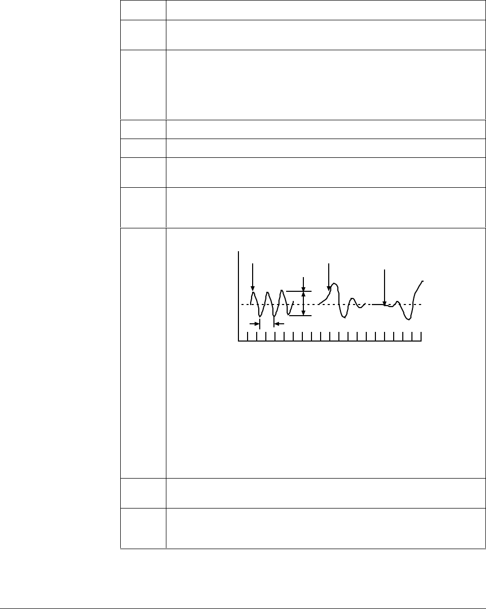
274 UDC 3300 Controller Product Manual 4/00
11.2 Time, Position, or Current Proportional Simplex Control
Procedure The procedure listed in Table 11-1 gives you the steps for manually tuning
a controller with Time, Position, or Current proportional simplex control.
Table 11-1 Manual Tuning Procedure for Simplex Control
Step Action
1In Manual Mode, adjust the output to bring the PV (Process Variable) near
the desired value.
2Set the Rate time to 0 minutes and set the Reset time to the maximum value
(50.00 minutes) or set repeats/min to the minimum value to minimize reset
action
If applicable, set the CYCLE TIME to 4 seconds and DEADBAND
to 0.5.
3Increase GAIN (decrease PB) significantly. Try a factor of 10.
4Adjust the local setpoint to equal PV and switch to Automatic control mode.
5Increase the setpoint by 5 or 10% and observe the process variable
response.
6If the PV oscillates, continue to Step 7. If it does not oscillate, return to the
original setpoint and increase GAIN (decrease PB) again by a factor of 2,
and repeat Step 5.
7Compare the oscillations with the figure below:
Pattern A Pattern B Pattern C
Amplitude
Time for one cycle
Process Variable
Time 20778
• If the oscillation matches pattern A, go to Step 8.
• If the oscillation matches pattern B, increase GAIN (decrease PB) by a
factor of 2 and repeat Steps 4 to 6.
• If the oscillation matches pattern C, decrease GAIN (increase PB) by a
factor of 0.8 and repeat Steps 4 to 6
The amplitude of the cycle is immaterial, but all of the elements of the loop
must be within the operating range (i.e., the valve must not go full open or
closed).
8Record the current value of GAIN (or PB) and measure and record the value
of time for one completed oscillation of PV.
9Select the proper set of formulas from Table 11-2. Use the values of Gain (or
PB) and time (in minutes) in the formulas to arrive at the controller’s tuning
parameters settings.
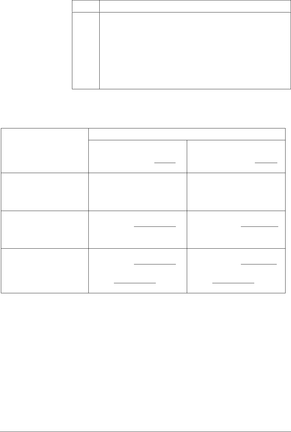
4/00 UDC 3300 Controller Product Manual 275
Step Action
10 Enter the values of GAIN (or PB), RATE, and RESET in minutes (or repeats
per minute) into the UDC 3300 controller and verify that the PV response is
adequate.
Make additional trimming adjustments, if necessary, to fine tune the
controller per the guidelines shown below:
TO REDUCE OVERSHOOT
Less Gain (more PB) perhaps a longer Rate time.
TO INCREASE OVERSHOOT OR INCREASE SPEED OR RESPONSE
More Gain (less PB), perhaps shorter Rate time.
Manual tuning formulas Table 11-2 lists the formulas used in the procedure listed in Table 11-1.
Table 11-2 Manual Tuning Formulas
Units
GAIN
and
RESET TIME in Minutes
Repeat
% PROPORTIONAL BAND
and
RESET ACTION in Repeats
Minutes
Proportional (P) only
Use PD+MR Algorithm
(i.e. No Reset)
GAIN = Measured Gain x 0.5
RESET TIME = 50.00
(minimum reset)
RATE = 0
%PB = Measured PB x 2
RESET ACTION = 0.02
(repeats/minute)
RATE = 0
Proportional + Reset
(PI) (No Rate) GAIN = Measured Gain x 0.5
RESET TIME = Measured Time
(M/R) 1.2
RATE = 0
%PB = Measured PB x 2.2
RESET ACTION =
1.2
(R/M) Measured Time
RATE = 0
Proportional + Reset + Rate
(PID) GAIN = Measured Gain x 0.6
RESET TIME = Measured Time
2
RATE = Measured Time
8
%PB = Measured PB x 1.7
RESET ACTION =
2
Measured Time
RATE = Measured Time
8

276 UDC 3300 Controller Product Manual 4/00
11.3 Time Proportional Duplex or Current Proportional Duplex Control
Introduction For HEAT/COOL applications.
Tune the controller with the output above 50% for Heat and below 50%
for Cool.
HEAT/COOL prompts The “TUNING” function prompts for HEAT/COOL are:
HEAT COOL
PB or GAIN GAIN2
RSETMIN or RSETRPM RSET2MIN or RSETRPM2
RATEMIN RATE2MIN
CYCSEC CYC2SEC
11.4 Two Sets of Tuning Parameters for Single Output Operation
Introduction You can use two sets of tuning constants for single output types and tune
each set separately.
TWO SETS prompts The “TUNING” function prompts for two sets are:
PID SET 1 PID SET 2
PB or GAIN GAIN2
RSETMIN or RSETRPM RSET2MIN or RSETRPM2
RATEMIN RATE2MIN
CYCSEC CYC2SEC

Index
4/00 UDC 3300 Controller Product Manual 277
%
% Oxygen control, 203
A
Aborting PV adaptive tuning, 200
Accutune, 181
Accutune, 194
Accutune error prompts, 201
Accutune Set Up group, 47
Accutune Set Up Group, 88
Adaptive tune, 89
Adaptive tune error status, 91
Advancing a running SP program, 217
Alarm blocking, 142
Alarm on totalizer value, 185
Alarm setpoints, 171
Algorithm Data Set Up Group, 92
Auto bias, 120, 126
Auto Manual Station mode
backup control feature, 190
Auto/Manual Station mode, 190
Automatic mode, 158
Automatic switchover value, 125
Auxiliary otuput calibration, 240
Auxiliary output, 129
Auxiliary Output board, 268
Auxiliary output connections, 29
Auxiliary Output/RS422/485 board, 268
B
Baud rate, 136
Bias, 114
Burnout protection, 114
C
Calibration mode, 229
Calibration steps, 221
Carbon control, 203
Carbon potential, 99, 202
Carbon potential selections, 97
CE Conformity, 1
Changing current segment time or setpoint in running SP
program, 217
Characterizer, 104, 105
Cleaning, 270
CO compensation, 203
Cold junction temperature, 230
Communication units, 137
Communications option connections, 30
Communications selection, 135
Communications Set Up Group, 135
Composite wiring diagram, 18
Configuration Prompt Definitions, 79
Control 2 algorithm, 94
Control algorithm, 92
Controller dropoff value, 122, 127
Controller failure symptoms, 246
Current duplex, 110
Current output 2, 129
Current output/ universal output connections, 26
Current proportional duplex, 276
Current simplex, 109
Current/time duplex, 110
Cycle time (cool), 81
Cycle time (heat), 81
D
Deadband, 122, 127
Demand Tuning, 47
Dewpoint, 98
Dewpoint control, 203
Diagnostic error messages, 154
Digital input combinations, 134
Digital Input option, 186
Digital input selections, 131
Digital inputs (remote mode switching), 181
Digital inputs 1 and 2 combination operation, 188
Digital inputs 1 and 2 combination selections, 188
Digital inputs connections, 29
Digital output status, 111
Dimensions, 13
Direct acting control, 121, 126
Disconnect the field wiring, 221
Display Parameters Set Up Group, 143
Displays and indicators, 3
DMCS Communications board, 268
Duplex, 136
Duplex Heat/Cool applications, 84
E
Eight segment characterizer, 105, 106
Eight segment characterizer, 104
Eight-segment characterization, 184
Electrical considerations, 15
Electrical noise, 15
Electromechanical Relay Output., 22
Emissivity, 115
End segment number, 206
Exploded view, 271
External program reset, 215
External setpoint program reset, 132
F
Failsafe mode, 122, 127
Failsafe output value, 122, 128
Feedforward multiplier, 97
Feedforward summer, 96
Filter, 114
Flow totalizer, 184
Function Prompts, 36
Fuzzy overshoot suppression, 193
Fuzzy Overshoot Suppression, 47

Index
278 UDC 3300 Controller Product Manual 4/00
G
Gain, 80
Gain 2, 81
Gain scheduling, 119
Gain Value for Gain Scheduling, 83
grounding, 15
Guaranteed soak, 207
H
HealthWatch
counters, 144
timers, 144
High output limit, 127
High scaling factor, 98
High select, 97
Hysteresis (output relay), 122
I, J
Input 1 actuation type, 112
Input 1 high range value, 113
Input 1 low range value, 114
Input 1/Input 2 connections, 20
Input 2 actuation type, 116
Input 3 actuation type, 117
Input algorithm selections, 183
Integration rates, 184
Internal Cascade control:, 172
Internal cascade indication, 180
K
Key functions, 4
L
Line voltage wiring, 19
Local setpoint source, 119, 125, 160
Lockout, 82
Loop 1 Control Parameters Set Up Group, 118
Loop 1 Tuning Parameters Set Up Group, 80
Loop break, 140
Loopback, 138
Low scaling factor, 98
Low select, 97
Lower display key, 153
M, N
Maintenance
counters, 71, 144
timers, 71, 144
Maintenance Group, 71
Manual mode, 158
Manual reset, 81
Manual tuning formulas, 275
Manual tuning procedure, 274
Manual/Auto key lockout, 82
Mass flow orifice constant (K) for math selections, 98
Math algorithms, 96, 183
Monitoring two-loop control, 180
Mounting
Overall dimensions, 13
Mounting method, 14
Mounting procedure, 14
Multiplier, 97
Multiplier divider, 97
Multiplier divider with square root, 97
Multiplier with square root, 97
O
Open Collector Output Connections, 25
Operating limits, 8
Operating parameters, 153
Operation of two-loop control, 181
Operator interface, 3
Options Set Up Group, 129
Output algorithm, 109, 111
Output change rate, 121, 127
Output override, 181
Output override (2 PID loops only), 153
Output Override., 95
Output rate down value, 121, 127
Output rate up value, 121, 127
Override selector, 175
Oxygen, 98
P, Q
Parity, 136
PD with manual reset, 93, 95
Percent carbon source, 99
Physical considerations, 13
PID A, 93, 95
PID B, 93, 95
PID loop selection, 94
Position proportional backup mode, 159
Position Proportional control output calibration, 236
Position proportional output connections, 28
Power up, 148
Printed wiring board identification, 265
Printed wiring board removal, 264
Process gain Loop 2, 90
Program record sheet, 210
Program state, 207
Program termination state, 207
Prompt hierarchy, 36
Proportional band, 80
Proportional band 2, 81
Proportional band units, 123
Protective bonding, 15
PV Tuning, 47
R
Ramp segments, 206
Ramp unit, 208
Ramp/Soak profile, 205
Ramp/Soak profile example, 209
Ramp/Soak programming, 205
Range values, 220
Rate, 80
Rate 2, 81
Ratio, 114
Recycle number, 206
Relative humidity, 97, 99

Index
4/00 UDC 3300 Controller Product Manual 279
Relay Output, 22
Remote mode switching, 181
Remote setpoint, 162
Remote setpoint source, 120, 126
Remote switching, 186
Reset, 81
Reset 2, 81
Reset totalizer value, 187
Reset units, 123
Restarting a running SP program, 217
Restoring factory calibration, 231
Restrictions for two-loop control, 175
Reverse acting control, 121, 127
RS422/485 Communications board, 268
Run/Hold key lockout, 82
Run/monitor SP program, 214
S
Security code, 82
Set Up Group, 36
Setpoint high limit, 121, 126
Setpoint low limit, 121, 126
Setpoint ramp, 85
Setpoint ramp final setpoint, 86
Setpoint Ramp Set Up group, 45
Setpoint ramp time, 85
Setpoint Ramp/Rate/Programming Set Up Group, 85
Setpoint rate, 45, 86
Setpoint Select key lockout, 82
Setpoint selection indication, 162
Setpoint tracking, 120
Setpoint tracking, 126
Shed controller mode and output level, 137
Shed time, 136
Shock hazard warning, 219, 233, 253
Single Setpoint Ramp, 45
Soak segments, 206
Software version, 246
Solid State Relay Output Connections, 23
SP programming tips, 217
SP Tuning, 47
Start segment number, 206
Summer with ratio and bias, 97
T, U, V
Three Position Step, 94
Three Position Step Control algorithm, 182
Time duplex, 109
Time proportional output, 109
Time simplex, 109
Timer, 96
Totalizer displays, 184
Totalizer function, 107, 184
Totalizer reset via digital input, 185
Transmitter characterization, 113
Tuning 2 Set Up group, 44
Tuning constant values, 169
Tuning parameter sets, 118
Tuning parameter sets—Loop 2, 124
Tuning parameters, 179
Two HLAI replace second LLAI connections, 21
W, X, Y, Z
WARNING—SHOCK HAZARD, 219, 233, 253
Weighted average ratio, 98
Wiring diagram, 18

Index
280 UDC 3300 Controller Product Manual 4/00

Sensing and Control
Honeywell
11 West Spring Street
Freeport, IL 61032
51-52-25-55 Rev. D 0400 Printed in USA www.honeywell.com/sensing
