Honeywell Visionpro Th8110 Users Manual 68 0280—01 8000 Touchscreen Programmable Thermostat
TH8321 to the manual 8c51d0f9-9069-451e-b624-37e89670ae83
2015-01-23
: Honeywell Honeywell-Visionpro-Th8110-Users-Manual-262565 honeywell-visionpro-th8110-users-manual-262565 honeywell pdf
Open the PDF directly: View PDF ![]() .
.
Page Count: 40
- APPLICATION
- Features
- Specifications
- INSTALLATION
- WIRING (Fig. 9 - 21)
- POWER THE THERMOSTAT
- INSTALLER SETUP
- INSTALLER SYSTEM TEST
- operation
- PROGRAMMING
- Preprogrammed Energy-saving Settings
- Program Heating and Cooling Schedule
- Edit Schedule
- Cancel a Schedule Period
- Operate VisionPRO™ 8000 Touchscreen
- Set Time
- Set Temperature Overrides
- Clean Thermostat Screen
- Replace Batteries
- Battery Tips
- Screen Locks
- Outdoor Temperature
- Remote Indoor Temperature
- Indoor Air Quality Reminders
- Temperature Recovery
- P+I Control
- Minimum Off-Timer
- Dehumidification Droop Control
- Special Heat Pump Operation
- Heat Pump LED Indication (Requires 24 Vac Common Connection)
- Heat Pump Emergency Heat LED Indication (Requires 24 Vac Common Connection)
- Heat Pump Temperature Lockouts
- C7089U Outdoor Temperature Sensor
- C7189U Remote Indoor Temperature Sensor
- Troubleshooting (Table 14)
PRODUCT DATA
68-0280-01
® U.S. Registered Trademark
© 2011 Honeywell International Inc.
All Rights Reserved
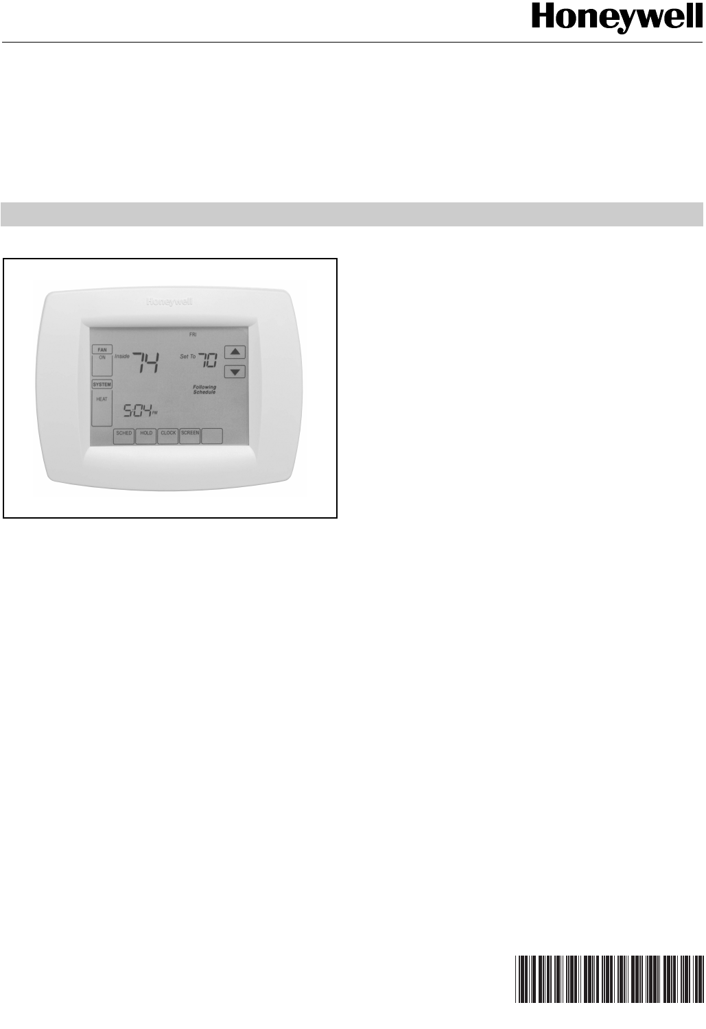
VisionPRO™ 8000 Touchscreen
Programmable Thermostat
APPLICATION
The VisionPRO 8000 Touchscreen Programmable Thermostat
is an effortless, 7-Day programmable thermostat that provides
universal system compatibility, precise comfort control and is
easy-to-program.
The TH8110 Thermostats provide temperature control for gas,
oil, electric and heat pumps for 1 heat, 1 cool systems.
The TH8320 Thermostats provide temperature control for gas,
oil, electric and heat pumps for up to 3 heat, 2 cool systems
including dual fuel operation.
The TH8321 Thermostats provide temperature control for gas,
oil, electric and heat pumps for up to 3 heat, 2 cool systems
including dual fuel operation plus dehumidification control.
FEATURES
• Large, clear display with backlight shows the current
and set temperature and time—even in the dark.
• Menu-driven programming make setup effortless.
• Beautiful ergonomic design is smart and sophisticated
to match your customers’ lifestyle.
• Touchscreen interaction
• Real-time clock keeps time during power failures and
automatically updates to daylight savings.
• "Saving Changes" notification lets you know when the
schedule changes have been saved.
• Change/check reminders let you know when to service
or replace filters or batteries.
• Various Hold options allow you to override the
program schedule, as desired.
• Speedy same-schedule programming—no need to
copy multiple days.
• Armchair programming allows you to remove the
thermostat from the wall for programming.
• Programmable fan offers increased air quality when
combined with a Honeywell whole-house air cleaner.
Contents
Application/Features..........................................................1
Specifications/Ordering Information ..................................2
Installation .........................................................................4
Wiring ................................................................................5
Power the Thermostat .......................................................11
Installer Setup ...................................................................15
Installer System Test .........................................................20
Operation...........................................................................21
Programming.....................................................................23
Troubleshooting.................................................................38
VisionPROTM 8000 Touchscreen Programmable Thermostat
68-0280—01 2
ORDERING INFORMATION
When purchasing replacement and modernization products from your TRADELINE® wholesaler or distributor, refer to the
TRADELINE® Catalog or price sheets for complete ordering number.
If you have additional questions, need further information, or would like to comment on our products or services, please write or
phone:
1. Your local Honeywell Automation and Control Products Sales Office (check white pages of your phone directory).
2. Honeywell Customer Care
1985 Douglas Drive North
Minneapolis, Minnesota 55422-4386
In Canada—Honeywell Limited/Honeywell Limitée, 35 Dynamic Drive, Toronto, Ontario M1V 4Z9.
International Sales and Service Offices in all principal cities of the world. Manufacturing in Australia, Canada, Finland, France,
Germany, Japan, Mexico, Netherlands, Spain, Taiwan, United Kingdom, U.S.A.
SPECIFICATIONS
Thermostat Description:
Electrical Ratings:
Temperature Setting Range:
Heating: 40°F to 90°F(4.5°C to 32°C).
Cooling: 50°F to 99°F (10°C to 37°C).
Operating Ambient Temperature:
TH8000 VisionPRO™ Thermostats: 0°F to 120°F
(-18°C to 49°C).
C7089U: -40°F to 120°F (-40°C to 49°C).
C7189U: 45°F to 88°F (7.2°C to 32°C).
Shipping Temperature:
TH8000 VisionPRO™ Thermostats: -30 °F to 150 °F
(-34.4°C to 65.6°C).
Operating Relative Humidity (Non-condensing):
TH8000 VisionPRO Thermostats: 5% to 90%.
C7089U: 5% to 95%.
C7189U: 5% to 95%.
Humidity Setting Range (TH8321 models only):
Cooling: 40% to 80% RH.
Humidity Display Range (TH8321 models only):
0% to 99%.
Cycle Rates (at 50% Load):
Heating: Selectable 1 - 12 cycles per hour.
Cooling: Selectable 1 - 6 cycles per hour.
Finish:
TH8000 VisionPRO™ Thermostats: Premier White® color.
C7189U Wall Mount Remote Indoor Sensor: Premier White®
color.
Clock Accuracy: +/- 1 minute per month.
Batteries:
Three replaceable AAA alkaline batteries: Power thermostats
when 24 Vac common is not used. Non-replaceable
lithium battery with ten-year life under normal use to hold
calendar and time settings. Alkaline batteries keep calen-
dar and time after lithium battery is no longer functional.
Resistance Characteristics of Remote Sensors:
C7089U Outdoor Sensor: Negative temperature coefficient
(NTC) means that resistance decreases as the
temperature increases. See Table 13 in the Operation
section for sensor resistance characteristics.
C7189U Remote Indoor Sensor: Negative temperature
coefficient (NTC), means that resistance decreases as the
temperature increases. See Table 14 in the Operation
section for sensor resistance characteristics.
Cool Indication:
TH8000 VisionPRO™ Touchscreen Thermostats show "Cool
On" on the screen when Cool is activated.
Heat Indication:
TH8000 VisionPRO™ Touchscreen Thermostats show “Heat
On” on the screen when Heat is activated.
Feature Description
Powering methods •Battery only
•Common wire only
•Common wire with battery backup
System types (up to
3 heat/2 cool or up
to 1heat/1cool,
depending on
model)
•Gas, oil or electric heat with air
conditioning
•Warm air, hot water, high-efficiency
furnaces, heat pumps, steam and
gravity
•Heat only—includes power to open
and power to close zone valves
(series 20) and normally-open zone
valves
•Heat only with fan
•Cool only
•750 mV heating systems
Changeover Manual or Auto changeover selectable
System setting Heat-Off-Cool-Auto (Em. Heat for heat
pumps)
Fan setting Auto-On-Circ
Terminal Voltage (50/60 Hz) Running Current
W Heating 20 - 30 Vac .02 - 1.0A
W Heating
(Powerpile)
750 mV dc 100 mA dc
Y Cooling 20 - 30 Vac .02 - 1.0A
G Fan 20 - 30 Vac .02 - .60A
VisionPROTM 8000 Touchscreen Programmable Thermostat
3 68-0280—01
Auxiliary Heat Indication:
TH8000 VisionPRO™ Touchscreen Thermostats show “Aux.
Heat On” on the screen when Auxiliary Heat is activated.
Emergency Heat Indication:
TH8000 VisionPRO™ Touchscreen Thermostats show “Heat
On” on the screen when Emergency Heat is activated and
the System mode is in the Em. Heat position.
Calibration:
C7089U, C7189U and TH8000 VisionPRO™ Touchscreen
Thermostats are factory-calibrated and require no field
calibration.
Interstage Differential:
TH8000 VisionPRO™ Touchscreen Thermostats operate with
droopless control. Once the thermostat senses that
1st stage is running at 90% capacity, the thermostat
energizes 2nd stage.
Nomenclature:
Mounting Means:
TH8000 VisionPRO™ Touchscreen Thermostat: Mounts
directly on the wall in the living space using mounting
screws and anchors provided. Fits a vertical or horizontal
2 x 4 in. junction box.
C7089U Outdoor Sensor: Mounts outside of living space with
mounting clip and screws provided.
C7189U Remote Indoor Sensor: Mounts directly on the wall
using mounting screws and anchors provided. Fits a
vertical 2 x 4 in. junction box.
Cover Plate:
32003796-001 Cover Plate is used to cover marks left on the
wall by the old thermostat.
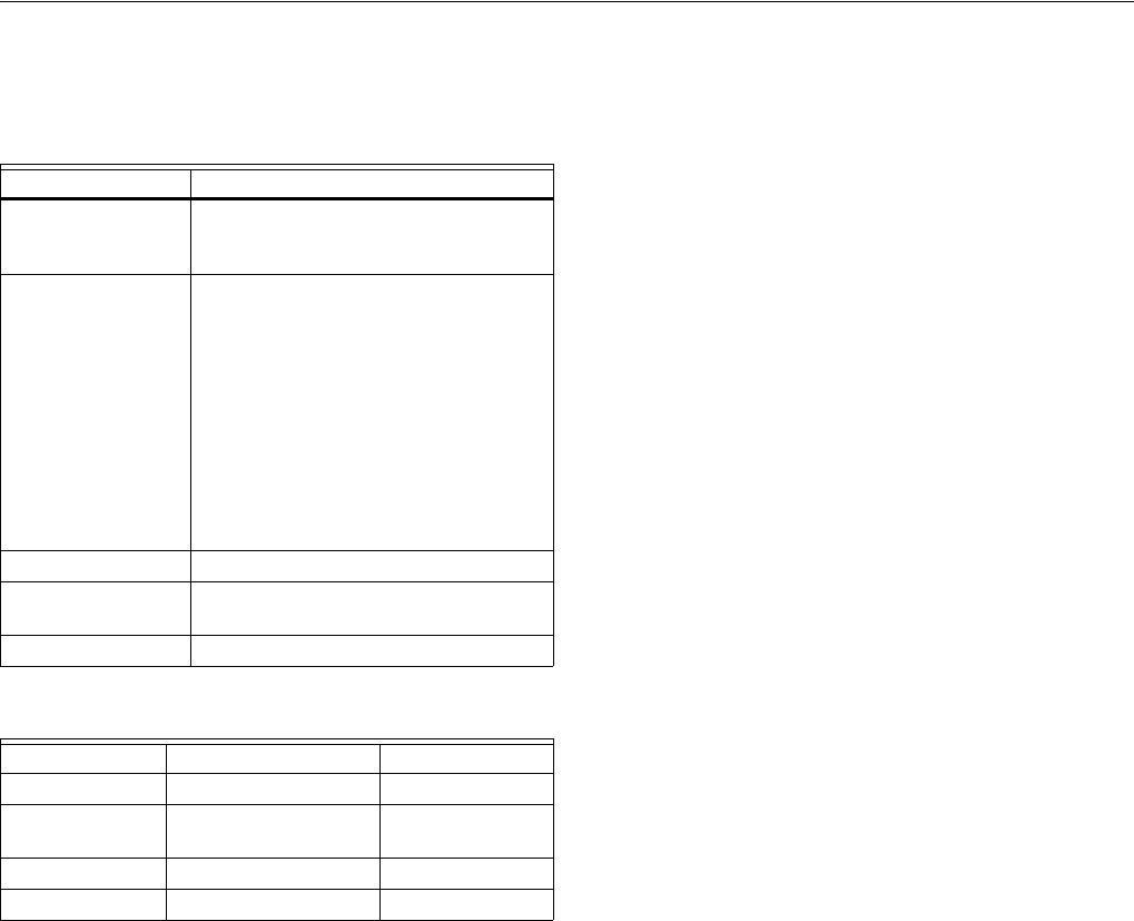
Dimensions:
TH8000 Touchscreen Thermostat: see Fig. 1.
C7089U Outdoor Sensor Mounting Clip: see Fig. 2.
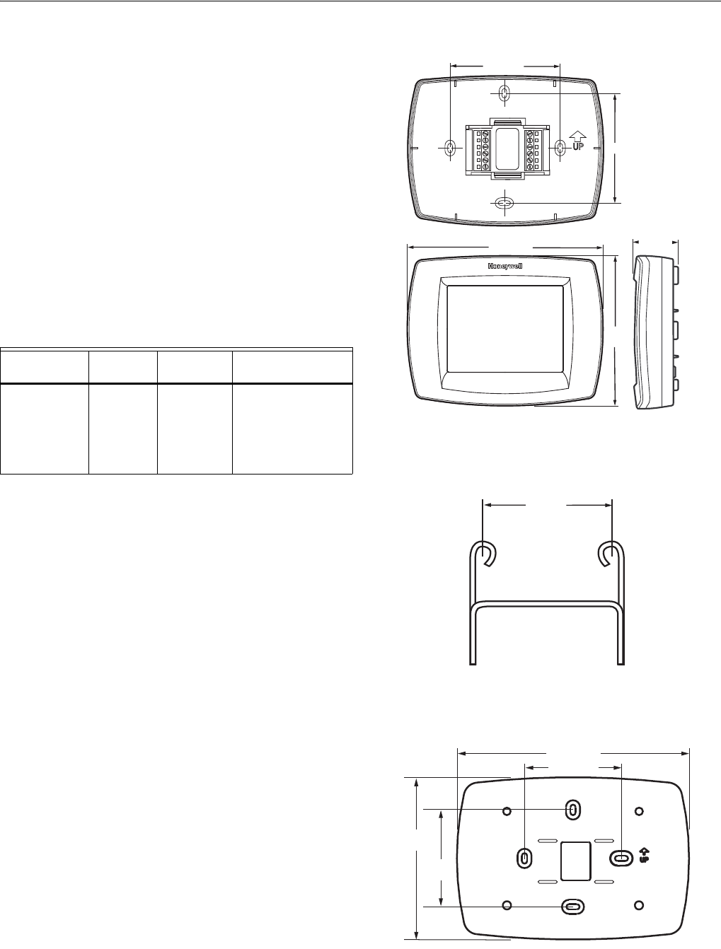
32003796-001 Cover Plate: see Fig. 3.
C7189U Remote Indoor Sensor: see Fig. 4.
Fig. 1. TH8000 Touchscreen Thermostat
dimensions in in. (mm).
Fig. 2. C7089U Outdoor Sensor Mounting Clip
dimensions in in. (mm).
Fig. 3. 32003796-001 Cover Plate dimensions in in. (mm).
Series
System
Stages Application
Power and System
Changeover
VisionPRO™
8000
Touchscreen
11 - 1H/1C
32 - 3H/2C
0 - Standard
1 - Humidity
Sensor
U - Universal (Auto
changeover and/or
manual change-
over) dual powered,
system flexibility,
schedule flexibility.
M22421
6 (152)
THERMOSTAT
4-9/16
(116)
3-3/8 (86)
WALLPLATE
3-3/8 (86)
THERMOSTAT
AND WALLPLATE
1-3/8 (35)
M4488
1-1/2 (38)
7-7/8 (200)
3-5/16 (84)
3-5/16
(84)
M22139
5-1/2
(140)
VisionPROTM 8000 Touchscreen Programmable Thermostat
68-0280—01 4
Fig. 4. C7189U Remote Indoor Sensor dimensions in in. (mm).
INSTALLATION
When Installing this Product...
1. Read these instructions carefully. Failure to follow the
instructions can damage the product or cause a hazard-
ous condition.
2. Check the ratings given in the instructions to make sure
the product is suitable for your application.
3. Installer must be a trained, experienced service
technician.
4. After completing installation, use these instructions to
check out the product operation.
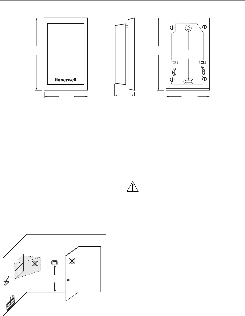
Selecting Location
Install the thermostat about 5 ft. (1.5m) above the floor in an
area with good air circulation at average temperature. See
Fig. 5.
Fig. 5. Selecting thermostat location.
Do not install the thermostat where it can be affected by:
— Drafts or dead spots behind doors and in corners.
— Hot or cold air from ducts.
— Radiant heat from sun or appliances.
— Concealed pipes and chimneys.
— Unheated (uncooled) areas such as an outside wall behind
the thermostat.
Installing Wallplate
CAUTION
Electrical Hazard.
Can cause electrical shock or equipment damage.
Disconnect power before wiring.
The thermostat can be mounted horizontally on the wall or on
a 4 in. x 2 in. (101.6 mm x 50.8 mm) wiring box.
1. Position and level the wallplate (for appearance only).
2. Use a pencil to mark the mounting holes.
3. Remove the wallplate from the wall and, if drywall, drill
two 3/16-in. holes in the wall, as marked. For firmer
material such as plaster, drill two 7/32-in. holes. Gently
tap anchors (provided) into the drilled holes until flush
with the wall.
M4465
4-5/8
(117)
4-5/8
(117)
2-3/4 (70) 2-3/4 (70)
1-1/8
(29)
FRONT VIEW SIDE VIEW FRONT VIEW (COVER OFF)
3-1/4
(83)
5 FEET
[1.5 METERS]
YES NO
NO
NO
M19925
VisionPROTM 8000 Touchscreen Programmable Thermostat
5 68-0280—01
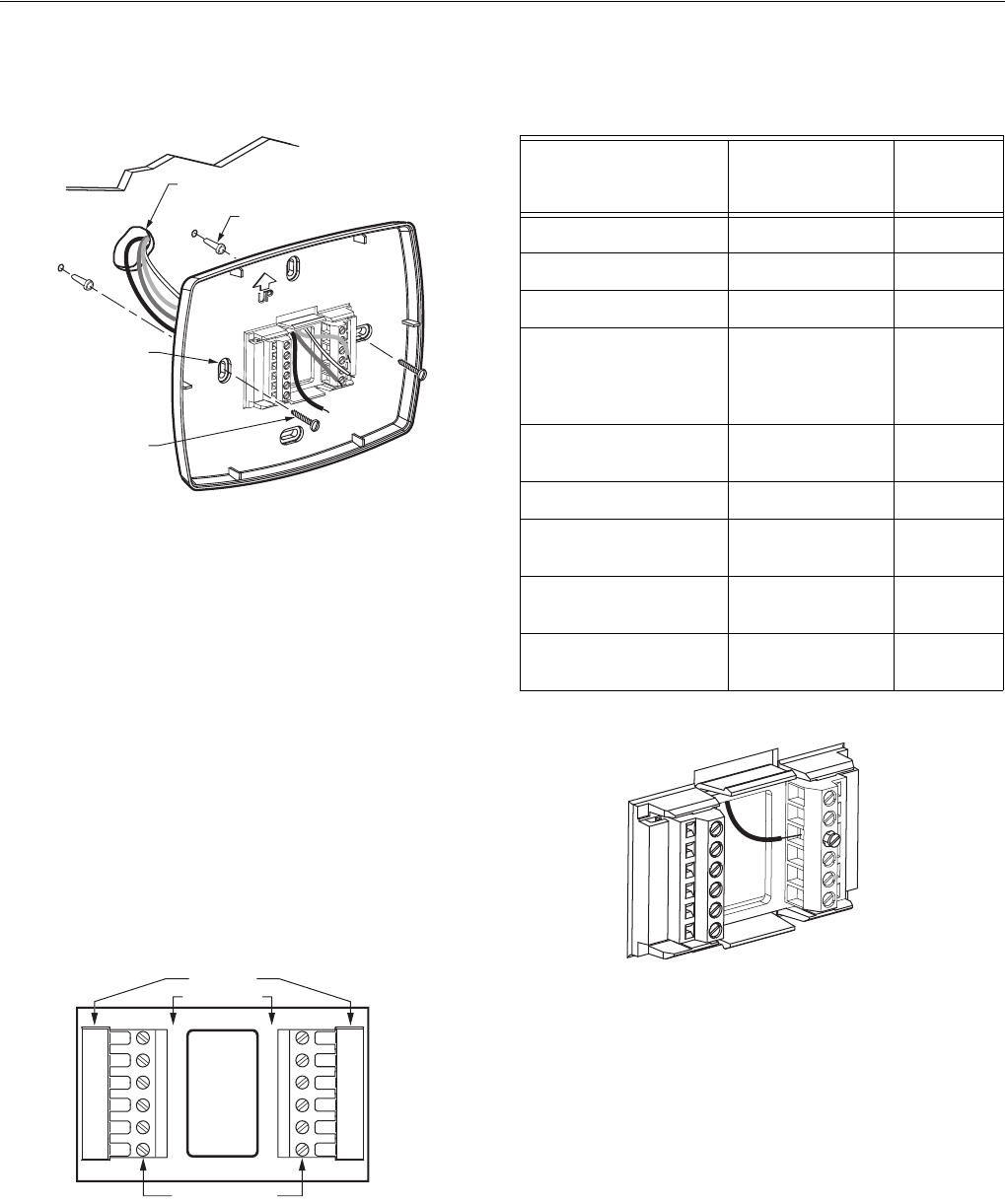
4. Position the wallplate over the holes, pulling wires
through the wiring opening. See Fig. 6.
5. Insert the mounting screws into the holes and tighten.
Fig. 6. Mounting wallplate.
WIRING (FIG. 9 - 21)
All wiring must comply with local electrical codes and
ordinances.
1. Select set of terminal identifications (Table 1) that
corresponds with system type (conventional or heat
pump in Fig. 7).
2. Loosen the screws for the appropriate system type
selected; see Table 1. See Table 2 for terminal
designation descriptions. Insert wires in the terminal
block under the loosened screw. See Fig. 8.
3. Securely tighten each screw.
4. Push excess wire back into the hole.
5. Plug the hole with nonflammable insulation to prevent
drafts from affecting the thermostat.
6. See Fig. 9 through 21 for typical wiring hookups.
Fig. 7. Selecting terminal identifications for
system type.
Fig. 8. Inserting wires in terminal block.
IMPORTANT
Use 18 gauge thermostat wire.
WALL
MOUNTING
HOLES
M19916
MOUNTING
SCREWS (2)
WALL ANCHORS (2)
WIRES THROUGH WALL
AND WIRE SLOT
CO
NVENTI
O
NA
L
SC
REW TERMINAL
S
H
EAT P
UMP
M19951
Y2
L
E
AUX
S1
S2
Y2
W2
S1
S
2
RC
R
O/B
Y
G
C
R
C
R
W
Y
G
C
Table 1. Selecting Terminal Identifications for
System Type.
System Type
Wallplate
Terminal
Identifications
Wiring
Diagram
Reference
Standard Heat/Cool Conventional 9, 10
Heat Only Conventional 11
Heat Only with Fan Conventional 12
Heat Only (Series 20)
Power to open and
power to close zone
valves
Conventional 13
Normally Open Zone
Valves—Heat Only
Conventional 14
Cool Only Conventional 15
Standard Multistage up
to 2 Heat/2 Cool
Conventional 16, 17
Heat Pump with No
Auxiliary Heat
Heat Pump 18, 19
Heat Pump with
Auxiliary Heat
Heat Pump 20, 21
M19917
VisionPROTM 8000 Touchscreen Programmable Thermostat
68-0280—01 6
NOTES:
1. When used in a single-transformer system, leave
metal jumper wire in place between Rc and R. If
used on a two-transformer system, remove metal
jumper wire between Rc and R.
2. Common wire is optional when thermostat is used
with batteries.
3. If thermostat is configured for a heat pump system
in the Installer Setup, configure changeover valve
for cool (O-factory setting) or heat (B).
4. L terminal is an input (system monitor) when the
System mode is in the Heat, Off, Cool or Auto
position. L terminal is a 24 Vac output when
System mode is Emergency Heat. Must connect
the 24 Vac Common when using the L terminal.
See LED Indication section for more details.
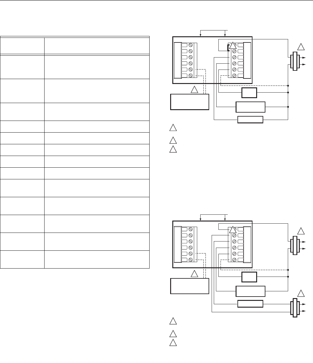
Fig. 9. Typical hookup of conventional single-stage heat
and cool system with single transformer
(1H/1C conventional).
Fig. 10. Typical hookup of conventional single-stage heat
and cool system with two transformers
(1H/1C conventional).
Table 2. Terminal Designation Descriptions.
Terminal
Designation Description
Rc (see Note
1)
Power for cooling--connect to
secondary side of cooling system
transformer
R (see Note 1) Power for heating--connect to
secondary side of heating system
transformer
C (see Note 2) Common wire from secondary side of
cooling system transformer
W Heat relay
Y Compressor contactor
GFan relay
Y2 Second stage cooling
W2 Second stage heat relay
O/B (see Note
3)
Changeover valve for heat pump
systems
AUX Auxiliary heat relay for heat pump
systems
E Emergency heat relay for heat pump
systems
L (see note 4) Equipment monitor for heat pump
systems
S1, S2 Optional outdoor or indoor remote
sensor
COMPRESSOR
CONTACTOR
M19895
OUTDOOR/INDOOR
TEMPERATURE
SENSOR
HEAT RELAY
FAN
RELAY
R
C
POWER SUPPLY. PROVIDE DISCONNECT MEANS AND OVERLOAD
PROTECTION AS REQUIRED.
FACTORY INSTALLED JUMPER.
OPTIONAL OUTDOOR OR INDOOR REMOTE SENSOR. AVAILABLE
ON SELECT MODELS. WIRES MUST HAVE A CABLE SEPARATE
FROM THE THERMOSTAT CABLE.
1
1
3
2
3
OPTIONAL
24 VAC
COMMON
CONNECTION
Y2 RC
S1
R
S2
W
W2 Y
G
C
2
CONVENTIONAL
C
R
1
COMPRESSOR
CONTACTOR
M19896
OUTDOOR/INDOOR
TEMPERATURE
SENSOR
HEAT RELAY
FAN
RELAY
R
C
POWER SUPPLY. PROVIDE DISCONNECT MEANS AND OVERLOAD
PROTECTION AS REQUIRED.
REMOVE FACTORY INSTALLED JUMPER.
OPTIONAL OUTDOOR OR INDOOR REMOTE SENSOR. AVAILABLE
ON SELECT MODELS. WIRES MUST HAVE A CABLE SEPARATE
FROM THE THERMOSTAT CABLE.
1
1
3
2
3
OPTIONAL
24 VAC
COMMON
CONNECTION
Y2 RC
S1
R
S2
W
W2 Y
G
C
2
CONVENTIONAL
VisionPROTM 8000 Touchscreen Programmable Thermostat
7 68-0280—01
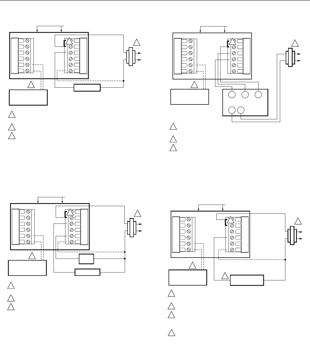
Fig. 11. Typical hookup of heat-only system
(1 H conventional).
Fig. 12. Typical hookup of heat only system with fan
(1H conventional).
Fig. 13. Typical hookup of heat only power to open and
power to close zone valve (Series 20) system.
Fig. 14. Typical hookup of heat only system with normally
open zone valves.
M19897
OUTDOOR/INDOOR
TEMPERATURE
SENSOR
HEAT RELAY
R
C
POWER SUPPLY. PROVIDE DISCONNECT MEANS AND OVERLOAD
PROTECTION AS REQUIRED.
FACTORY INSTALLED JUMPER.
OPTIONAL OUTDOOR OR INDOOR REMOTE SENSOR. AVAILABLE
ON SELECT MODELS. WIRES MUST HAVE A CABLE SEPARATE
FROM THE THERMOSTAT CABLE.
1
1
3
2
3
OPTIONAL
24 VAC
COMMON
CONNECTION
Y2 RC
S1
R
S2
W
W2 Y
G
C
2
CONVENTIONAL
M19898
OUTDOOR/INDOOR
TEMPERATURE
SENSOR HEAT RELAY
FAN
RELAY
R
C
POWER SUPPLY. PROVIDE DISCONNECT MEANS AND OVERLOAD
PROTECTION AS REQUIRED.
FACTORY INSTALLED JUMPER.
OPTIONAL OUTDOOR OR INDOOR REMOTE SENSOR. AVAILABLE
ON SELECT MODELS. WIRES MUST HAVE A CABLE SEPARATE
FROM THE THERMOSTAT CABLE.
1
1
3
2
3
OPTIONAL
24 VAC
COMMON
CONNECTION
Y2 RC
S1
R
S2
W
W2 Y
G
C
2
CONVENTIONAL
M19899
OUTDOOR/INDOOR
TEMPERATURE
SENSOR
POWER SUPPLY. PROVIDE DISCONNECT MEANS AND OVERLOAD
PROTECTION AS REQUIRED.
FACTORY INSTALLED JUMPER.
OPTIONAL OUTDOOR OR INDOOR REMOTE SENSOR. AVAILABLE
ON SELECT MODELS. WIRES MUST HAVE A CABLE SEPARATE
FROM THE THERMOSTAT CABLE.
1
3
2
3
Y2 RC
S1
R
S2
W
W2 Y
G
C
2
CONVENTIONAL
R
TR
C
1
TR
WBR
SERIES 20
MOTOR OR
VALVE
M22422
OUTDOOR/INDOOR
TEMPERATURE
SENSOR
R
C
POWER SUPPLY. PROVIDE DISCONNECT MEANS AND OVERLOAD
PROTECTION AS REQUIRED.
FACTORY INSTALLED JUMPER.
OPTIONAL OUTDOOR OR INDOOR REMOTE SENSOR. AVAILABLE
ON SELECT MODELS. WIRES MUST HAVE A CABLE SEPARATE
FROM THE THERMOSTAT CABLE.
CONFIGURE SYSTEM TYPE TO HEAT ONLY WITH NORMALLY OPEN
ZONE VALVES IN INSTALLER SETUP.
1
1
3
2
3
OPTIONAL
24 VAC
COMMON
CONNECTION
Y2 RC
S1
R
S2
W
W2 Y
G
C
2
CONVENTIONAL
NORMALLY OPEN
ZONE VALVE
4
4
VisionPROTM 8000 Touchscreen Programmable Thermostat
68-0280—01 8
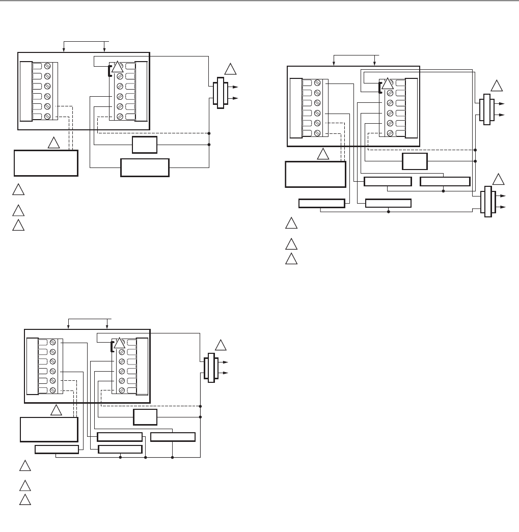
Fig. 15. Typical hookup of cool only system
(1C conventional).
Fig. 16. Typical hookup of conventional multistage
two-stage heating and two-stage cooling in a
single-transformer system
(2H/2C, 2H/1C or 1H/2C conventional).
Fig. 17. Typical hookup of conventional multistage
two-stage heating and two-stage cooling in a
two-transformer system (2H/2C, 2H/1C or
1H/2C conventional).
M19900
OUTDOOR/INDOOR
TEMPERATURE
SENSOR
FAN
RELAY
R
C
POWER SUPPLY. PROVIDE DISCONNECT MEANS AND OVERLOAD
PROTECTION AS REQUIRED.
FACTORY INSTALLED JUMPER.
OPTIONAL OUTDOOR OR INDOOR REMOTE SENSOR. AVAILABLE
ON SELECT MODELS. WIRES MUST HAVE A CABLE SEPARATE
FROM THE THERMOSTAT CABLE.
1
1
3
2
3
OPTIONAL
24 VAC
COMMON
CONNECTION
Y2 RC
S1
R
S2
W
W2 Y
G
C
2
CONVENTIONAL
COMPRESSOR
CONTACTOR
M22438B
HEAT RELAY 2
COOL RELAY 2
OUTDOOR/INDOOR
TEMPERATURE
SENSOR
FAN
RELAY
R
C
POWER SUPPLY. PROVIDE DISCONNECT MEANS AND OVERLOAD
PROTECTION AS REQUIRED.
FACTORY INSTALLED JUMPER.
OPTIONAL OUTDOOR OR INDOOR REMOTE SENSOR. AVAILABLE
ON SELECT MODELS. WIRES MUST HAVE A CABLE SEPARATE
FROM THE THERMOSTAT CABLE.
1
1
3
2
3
OPTIONAL
24 VAC
COMMON
CONNECTION
MUST COME
FROM THE
COOLING
TRANSFORMER.
Y2 RC
S1
R
S2
W
W2 Y
G
C
2
CONVENTIONAL
COOL RELAY 1
HEAT RELAY 1
M19902B
HEAT RELAY 2
OUTDOOR/INDOOR
TEMPERATURE
SENSOR
FAN
RELAY
R
C
POWER SUPPLY. PROVIDE DISCONNECT MEANS AND OVERLOAD
PROTECTION AS REQUIRED.
FACTORY INSTALLED JUMPER.
OPTIONAL OUTDOOR OR INDOOR REMOTE SENSOR. AVAILABLE
ON SELECT MODELS. WIRES MUST HAVE A CABLE SEPARATE
FROM THE THERMOSTAT CABLE.
1
1
3
2
3
OPTIONAL
24 VAC
COMMON
CONNECTION
MUST COME
FROM THE
COOLING
TRANSFORMER.
Y2 RC
S1
R
S2
W
W2 Y
G
C
2
CONVENTIONAL
COOL RELAY 1
HEAT RELAY 1
R
C
COOL RELAY 2 1
VisionPROTM 8000 Touchscreen Programmable Thermostat
9 68-0280—01
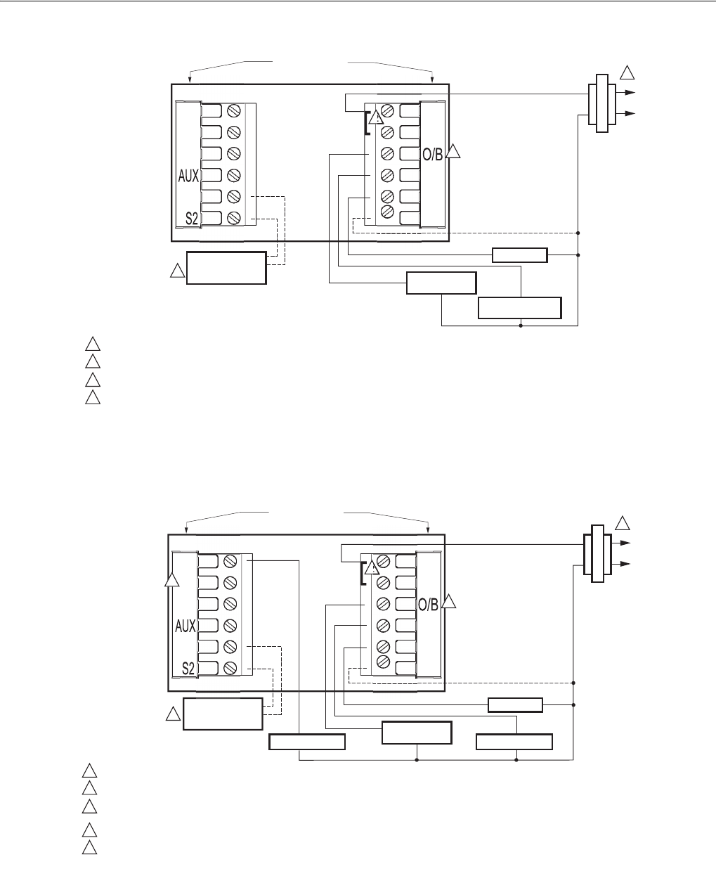
Fig. 18. Typical hookup of single-stage heat pump with no auxiliary/backup heat (1H/1C heat pump).
Fig. 19. Typical hookup of multistage heat pump with no auxiliary/backup heat (2H/2C heat pump).
R
C
R
Y
G
C
Y2
L
E
SI
H
EAT P
U
M
P
COMPRESSOR
RELAY
M19903B
CHANGEOVER
VALVE
FAN RELAY
R
C
1
1
2
2
3
4
3
3
4
OPTIONAL 24 VAC
CO
MM
O
N
CO
NNE
C
TI
ON
POWER SUPPLY. PROVIDE DISCONNECT MEANS AND OVERLOAD PROTECTION AS REQUIRED.
FACTORY INSTALLED JUMPER.
"O/B" TERMINAL SET TO CONTROL AS EITHER "O" OR "B" IN THE INSTALLER SETUP.
OPTIONAL OUTDOOR OR INDOOR REMOTE SENSOR. AVAILABLE ON SELECT MODELS. WIRES MUST HAVE A CABLE SEPARATE
FROM THE THERMOSTAT CABLE.
OUTDOOR/INDOOR
TEMPERATURE
SENSOR
R
C
R
Y
G
C
Y2
L
E
SI
H
EAT P
U
M
P
COMPRESSOR 1COMPRESSOR 2
M19904
CHANGEOVER
VALVE
FAN RELAY
R
C
1
1
2
2
3
4
5
5
4
4
3
3
OPTIONAL 24 VAC
CO
MM
O
N
CO
NNE
C
TI
ON
POWER SUPPLY. PROVIDE DISCONNECT MEANS AND OVERLOAD PROTECTION AS REQUIRED.
FACTORY INSTALLED JUMPER.
MUST CONNECT THE 24 VAC COMMON WHEN USING L. THE TERMINAL IS SHOWN AS EQUIPMENT MONITOR, CAN ALSO BE USED AS A 24 VAC
OUTPUT. SEE "HEAT PUMP LED" SECTION FOR MORE INFORMATION.
"O/B" TERMINAL SET TO CONTROL AS EITHER "O" OR "B" IN THE INSTALLER SETUP.
OPTIONAL OUTDOOR OR INDOOR REMOTE SENSOR. AVAILABLE ON SELECT MODELS. WIRES MUST HAVE A CABLE SEPARATE FROM THE
THERMOSTAT CABLE.
OUTDOOR/INDOOR
TEMPERATURE
SENSOR
VisionPROTM 8000 Touchscreen Programmable Thermostat
68-0280—01 10
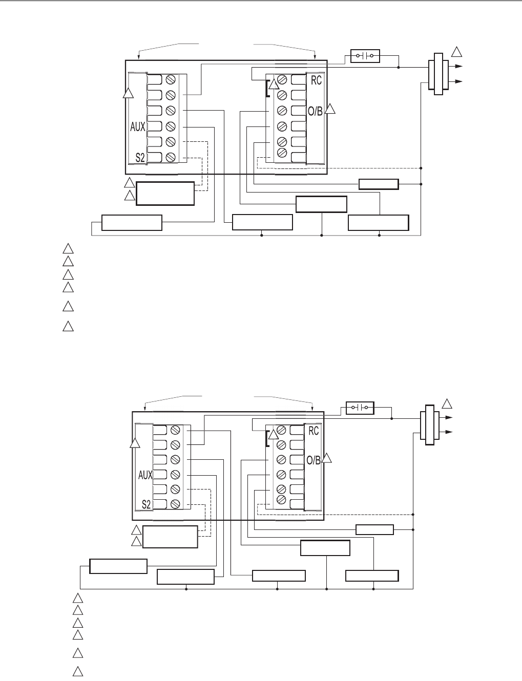
Fig. 20. Typical hookup of single-stage heat pump with auxiliary/backup heat (2H/1C heat pump).
Fig. 21. Typical hookup of multistage heat pump with auxiliary/backup heat (3H/2C heat pump).
R
Y
G
C
Y2
L
E
SI
H
EAT P
U
M
P
COMPRESSOR
RELAY
M19905
CHANGEOVER
VALVE
FAN RELAY
HEAT 2 RELAY
(AUXILIARY HEAT)
R
C
1
1
2
2
3
4
5
6
6
6
4
5
5
OPTIONAL 24 VAC
CO
MM
O
N
CO
NNE
C
TI
ON
EQUIPMENT
MONITOR
POWER SUPPLY. PROVIDE DISCONNECT MEANS AND OVERLOAD PROTECTION AS REQUIRED.
FACTORY INSTALLED JUMPER.
OUTDOOR SENSOR REQUIRED IN SYSTEM WITH FOSSIL FUEL BACKUP HEAT THAT IS NOT USING AN EXTERNAL FOSSIL FUEL KIT.
OPTIONAL OUTDOOR OR INDOOR REMOTE SENSOR. AVAILABLE ON SELECT MODELS. WIRES MUST HAVE A CABLE SEPARATE
FROM THE THERMOSTAT CABLE.
MUST CONNECT THE 24 VAC COMMON WHEN USING L. THE TERMINAL IS SHOWN AS EQUIPMENT MONITOR, CAN ALSO BE USED AS
A 24 VAC OUTPUT. SEE "HEAT PUMP LED" SECTION FOR MORE INFORMATION.
"O/B" TERMINAL SET TO CONTROL AS EITHER "O" OR "B" IN THE INSTALLER SETUP.
EMERGENCY
HEAT RELAY
3OUTDOOR/INDOOR
TEMPERATURE
SENSOR
R
Y
G
C
Y2
L
E
SI
H
EAT P
U
M
P
COMPRESSOR 2 COMPRESSOR 1
M19906
CHANGEOVER
VALVE
FAN RELAY
HEAT 2 RELAY
(AUXILIARY HEAT)
R
C
1
1
2
2
3
4
5
6
6
6
3
5
5
OPTIONAL 24 VAC
CO
MM
O
N
CO
NNE
C
TI
ON
EQUIPMENT
MONITOR
POWER SUPPLY. PROVIDE DISCONNECT MEANS AND OVERLOAD PROTECTION AS REQUIRED.
FACTORY INSTALLED JUMPER.
OUTDOOR SENSOR REQUIRED IN SYSTEM WITH FOSSIL FUEL BACKUP HEAT THAT IS NOT USING AN EXTERNAL FOSSIL FUEL KIT.
OPTIONAL OUTDOOR OR INDOOR REMOTE SENSOR. AVAILABLE ON SELECT MODELS. WIRES MUST HAVE A CABLE SEPARATE
FROM THE THERMOSTAT CABLE.
MUST CONNECT THE 24 VAC COMMON WHEN USING L. THE TERMINAL IS SHOWN AS EQUIPMENT MONITOR, CAN ALSO BE USED AS
A 24 VAC OUTPUT. SEE "HEAT PUMP LED" SECTION FOR MORE INFORMATION.
"O/B" TERMINAL SET TO CONTROL AS EITHER "O" OR "B" IN THE INSTALLER SETUP.
EMERGENCY
HEAT RELAY
4
OUTDOOR/INDOOR
TEMPERATURE
SENSOR
VisionPROTM 8000 Touchscreen Programmable Thermostat
11 68-0280—01
POWER THE THERMOSTAT
You can choose from three methods to power the thermostat:
• Batteries only (AAA alkaline).
• 24 Vac common wire only.
• 24 Vac common wire with battery backup (AAA alkaline).
Wiring 24 Vac Common
• Single-Transformer System—Connect the common side of
the transformer to the C screw terminal of the thermostat
wallplate. Leave the metal jumper wire in place between
Rc and R.
• Two-Transformer System—Connect the common side of
the cooling transformer to the C screw terminal of the
thermostat wallplate. Remove the metal jumper wire
between Rc and R.
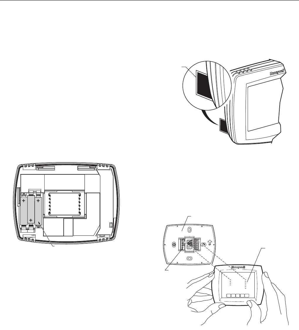
Installing Batteries
1. Install three AAA alkaline batteries on the back of the
thermostat as marked on the thermostat. See
Fig. 22.
Fig. 22. Installing batteries.
2. Locate and remove the tab labeled, Remove, in the
lower left corner on the thermostat back. See
Fig. 23.
Fig. 23. Remove tab labeled, Remove, on
thermostat back.
Mount Thermostat to Wallplate
1. Align the terminal screw blocks with the pins on the
back of the thermostat. Push the thermostat straight
onto the wallplate until it snaps into place. See Fig 24.
Fig. 24. Mount thermostat to wallplate.
M19918
BATTERIES (3)
REMOVE DURING
INSTALLATION
M19920
REMOVE
TAB
REMOVE DURING
INSTALLATION
M22213
PINS ON
BACK OF
THERMOSTAT
WALLPLATE
TERMINAL
SCREW
BLOCK
VisionPROTM 8000 Touchscreen Programmable Thermostat
68-0280—01 12
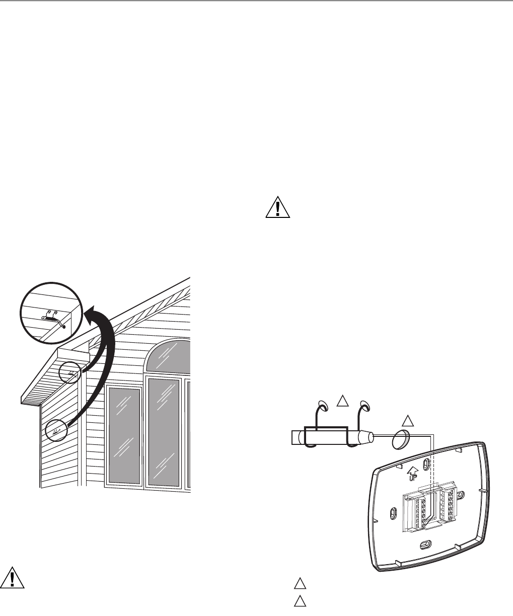
Locate and Mount C7089U Outdoor
Temperature Sensor (Optional)
Mount the sensor where (see Fig. 25):
• cannot tamper with settings.
• there is good air circulation.
• it can measure true outdoor ambient temperature.
• surface is flat.
• wire distance between C7089 and thermostat is less than
200 feet.
Do not mount the sensor:
• in direct sunlight.
• where hot or cold air blows on the sensor. Discharge line
from an outdoor compressor unit, vent or fan causes
inaccurate temperature readings.
• where snow, ice or debris can cover it.
Use the following steps to mount the sensor:
1. Remove the sensor from the mounting clip.
2. Mark the area on the location selected for mounting the
sensor mounting clip.
3. Mount the clip.
Fig. 25. Typical locations for C7089U Outdoor Sensor.
Wire C7089U Outdoor Sensor
CAUTION
Electrical Interference (Noise) Hazard.
Can cause erratic system operation.
Keep wiring at least one foot away from large inductive
loads such as motors, line starters, lighting ballasts
and large power distribution panels.
Use shielded cable to reduce interference when
rerouting is not possible.
IMPORTANT
Erratic temperature readings from a sensor can
occur as a result of any of the wiring practices
described below. Avoid these practices to assure
correct operation. Use shielded cable to reduce
interference if rerouting sensor wiring is not possible.
— Be sure wires have a cable separate from the
thermostat cable.
— Do not route temperature sensor wiring with building
power wiring, next to control contactors or near light
dimming circuits, electric motors or welding
equipment.
— Avoid poor wiring connections.
— Avoid intermittent or missing building earth ground.
CAUTION
Electrical Shock Hazard.
Can cause electrical shock or equipment damage.
Disconnect power supply before connecting wiring.
Wiring must comply with applicable codes, ordinances and
regulations:
1. Wire C7089 Outdoor Sensor to S1and S2 terminals on
the thermostat. If leadwire provided is not long enough
(60 in.), run a cable to a hole at C7089 location.
a. Using color-coded, 18-gauge thermostat wire is
recommended. For example of general wiring of
C7089, see Fig. 26.
b. Pigtail wiring can be used.
2. Mount C7089 in its mounting clip.
3. Plug wiring hole using nonhardening caulk or putty.
Fig. 26. Wire C7089 Outdoor Sensor to the thermostat.
M7514
1
2
2
1
USE APPROPRIATE MOUNTING MEANS FOR THE
TYPE OF STRUCTURE.
PLUG WIRING HOLE WITH NON-HARDENING CAULK
OR PUTTY.
C7089
WIRING HOLE
THROUGH
STRUCTURE
M19970
VisionPROTM 8000 Touchscreen Programmable Thermostat
13 68-0280—01
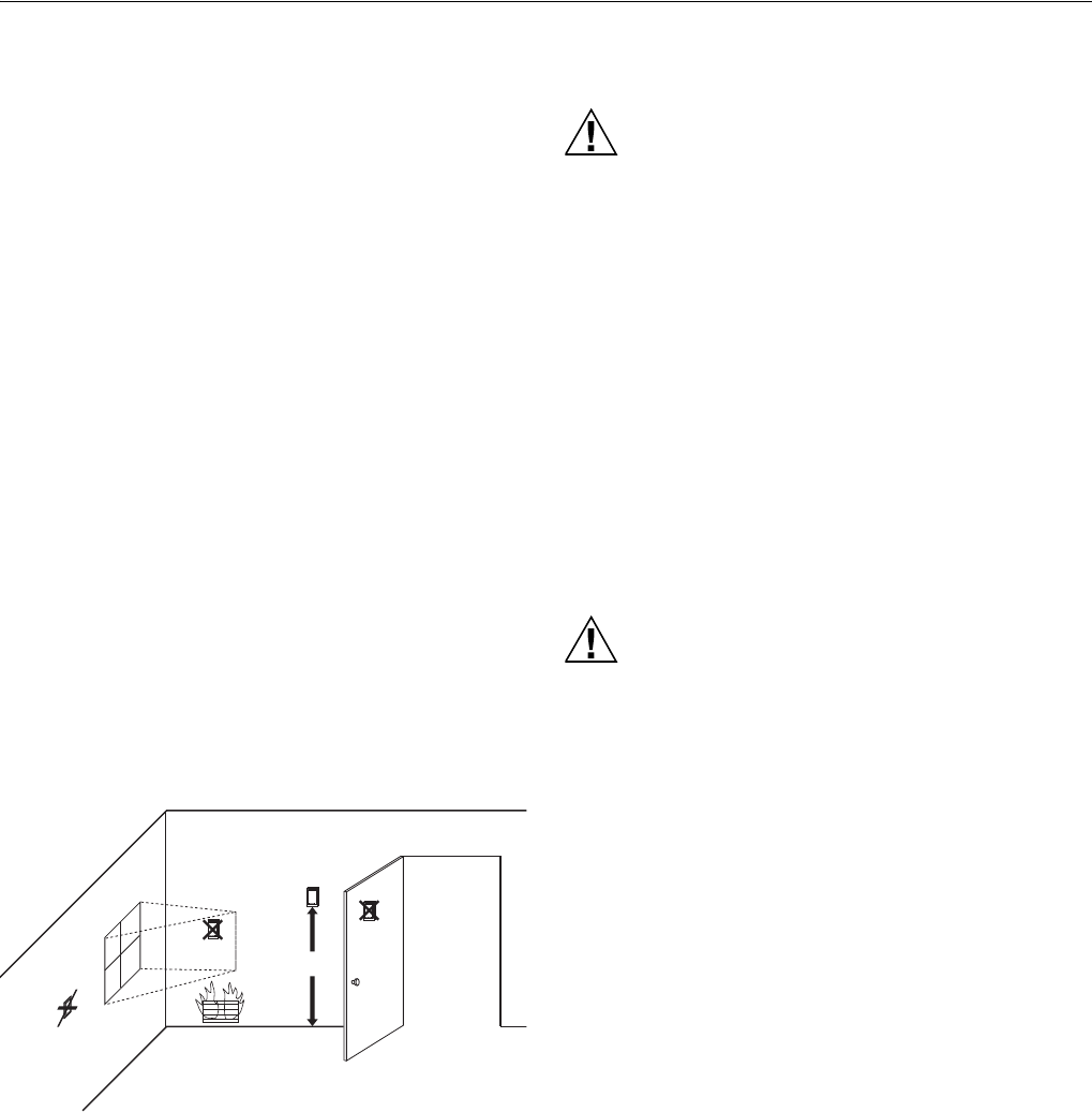
Locate and Mount C7189U Remote Indoor
Temperature Sensor (Optional)
1. Choose a location (see Fig. 27) for mounting the sensor
on an inside wall about 5 ft (1.5m) above the floor. A
vertically-mounted standard 2 x 4 in. (51 x 102 mm)
junction box can also be used.
2. Be sure wire distance between C7189 and thermostat is
less than 200 feet.
3. Make sure there is good air circulation at average
temperature at the chosen location. Avoid the following
locations because they can introduce errors in sensor
measurements. See Fig. 27.
a. Hot areas caused by:
(a) Concealed pipes or ducts.
(b) Drafts from fireplaces or other heat sources.
(c) Convection or radiant heat from the sun or
electrical equipment.
b. Cold areas caused by:
(a) Concealed pipes or ducts.
(b) Drafts from windows and doors.
(c) Unheated areas on the other side of the wall
location.
c. Dead air areas:
(a) Behind doors, furniture and curtains.
(b) In corners and alcoves.
4. Mark the area on the wall selected for mounting the
C7189 Sensor or junction box.
5. Run wire cable to a hole at the selected wall location.
Pull approximately three inches of wire through the
opening. Color-coded, 18-gauge thermostat wire is
recommended.
Fig. 27. Typical location for C7189 Indoor Sensor.
Wire C7189 Indoor Sensor
CAUTION
Electrical Interference (Noise) Hazard.
Can cause erratic system operation.
Keep wiring at least one foot away from large inductive
loads such as motors, line starters, lighting ballasts
and large power distribution panels.
IMPORTANT
Erratic temperature readings from a sensor can
occur as a result of any of the wiring practices
described below. Avoid these practices to assure
correct operation.
— Be sure wires have a cable separate from the
thermostat cable.
— Do not route temperature sensor wiring with building
power wiring, next to control contactors or near light
dimming circuits, electric motors or welding
equipment.
— Avoid poor wiring connections.
— Avoid intermittent or missing building earth ground.
CAUTION
Electrical Shock Hazard.
Can cause electrical shock or equipment damage.
Disconnect power supply before connecting wiring.
Wiring must comply with applicable codes, ordinances and
regulations.
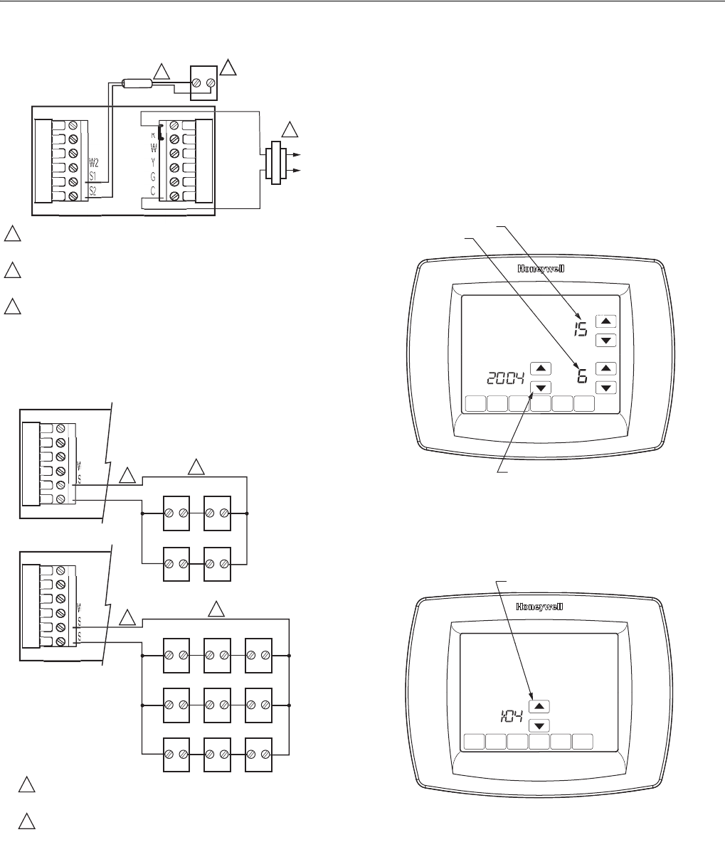
1. Wire C7189 Indoor Sensor to S1and S2 terminals on
the thermostat. For an example of general wiring of
C7189, see Fig. 28 to wire one sensor and 29 to wire
multiple sensors.
2. Push excess wire back into the hole. Plug the hole
using nonhardening caulk, putty or insulation to prevent
drafts from affecting performance.
3. Remove C7189 cover.
4. Mount C7189 to the wall or junction box using the
screws and anchors provided.
5. Level the C7189 for appearance only. Device functions
correctly even when not level.
6. Install C7189 cover.
5 FEET
(1.5 METERS)
YES
NO
NO
NO
M4476
VisionPROTM 8000 Touchscreen Programmable Thermostat
68-0280—01 14
Fig. 28. Wiring a single C7189 Indoor Sensor.
Fig. 29. Wiring Multiple C7189 Sensors.
Set Calendar and Time
Thermostat keeps current time and day for up to ten years
under normal use after the calendar is set.
When the thermostat is first powered, the display is ready to
set the calendar and time.
NOTE: Calendar can also be set in the Installer Setup.
1. Press the arrow keys to set the year, month and day.
2. Press the Done key.
3. Press the arrow keys to set the current time.
4. Press the Done Key.
2
C7189
R
C
R
Y2
M19972
R
C
POWER SUPPLY. PROVIDE DISCONNECT MEANS AND
OVERLOAD PROTECTION AS REQUIRED.
IF MORE THAN ONE C7189 REMOTE SENSOR IS REQUIRED,
REFER TO FIGURE 3.
WIRES MUST HAVE A CABLE SEPARATE FROM THE
THERMOSTAT CABLE.
1
1
3
2
3
M19973
SENSORS MUST BE ARRANGED IN THIS
CONFIGURATION TO OPERATE CORRECTLY.
WIRES MUST HAVE A CABLE SEPARATE FROM THE
THERMOSTAT CABLE.
1
2
Y2
W2
S2
1
1
2
C7189 C7189
C7189 C7189
Y2
W2
2
1
1
2
C7189 C7189
C7189 C7189
C7189
C7189
C7189 C7189 C7189
DO
N
E
MO
T
UE
WE
TH
FR
SA
SU
SET CURRENT DAY
SET MONTH
USE ARROWS TO SET YEAR AND TIME
M22424
E
R
D
O
N
E
MO
WE
TH
FR
SA
SU
USE ARROWS TO SET YEAR AND TIME
M22425
W
VisionPROTM 8000 Touchscreen Programmable Thermostat
15 68-0280—01
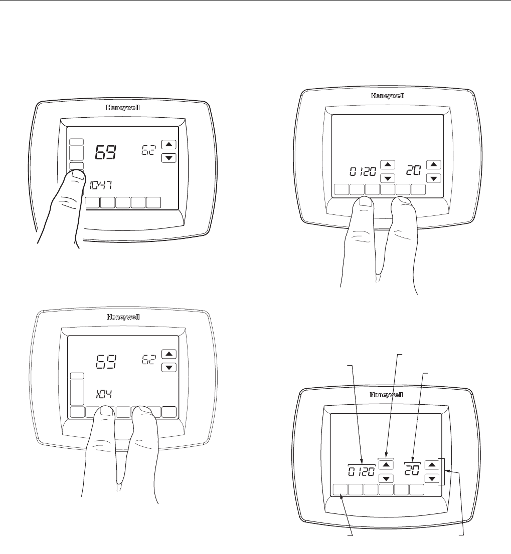
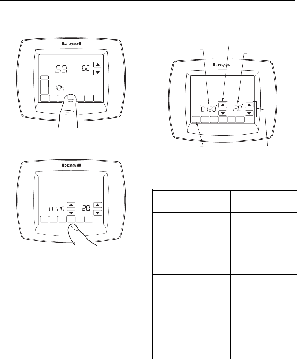
INSTALLER SETUP
Follow these steps to enter the Installer Setup:
1. Press and release the System Key.
2. Press and hold the two blank keys on either side of the
center blank key for approximately five seconds until
screen changes.
3. Release the two blank keys when the screen on the
thermostat matches the screen below.
4. See screen below to review how the thermostat keys
are used during Installer Setup. See Tables 3-5 for the
Installer Setup Numbers and Settings.
5. Press the Done key to exit the Installer Setup screen.
SCHED HOLD CLOCK SCREE
FAN
ON
AUTO
A
M
THU
SYSTEM
EM HEAT
OFF
COOL
Following
Schedule
Inside Set To
M22426
A
D
O
N
E
CANCEL
MON
T
UE
WED
THU
FRI
SA
T
A
A
T
SUN
PM
S
Y
S
TE
M
EM HEAT
O
F
F
COOL
Followin
g
Sc
h
edu
l
e
In
s
i
de
Se
t T
o
M19923
D
O
NE
M22442
DONE
O
MON
WED
THU
FRI
SA
T
A
A
T
SUN
INSTALLER
SETUP
NUMBER
CURRENT
SETTING
ADVANCE TO NEXT
INSTALLER SETUP
PRESS TO EXIT
INSTALLER SETUP
CHANGE THE
CURRENT
SETTING
M22443
A
U

VisionPROTM 8000 Touchscreen Programmable Thermostat
68-0280—01 16
Table 3. Installer Setup Menu.
Installer Setup
Number Installer Setup Name Settings Notes
0120 Date (Year Upper) Select first two digits of current calendar year (2005, etc) 2001 - 2178 available
0130 Date (Year Lower) Select last two digits of current calendar year (05 for year
2005, etc)
2001 - 2178 available
0140 Date (Month) Select number that represents current calendar month —
0150 Date (Day) Select number that represents current calendar date —
0160 Schedule Options 0—nonprogrammable
4—7-day programmable
—
0170 System Type Selection 1—1 heat/1 cool conventional (factory setting)
2—single-stage heat pump (no auxiliary heat)
3—heat only conventional (no fan) Also for 750mV.
4—heat only conventional (with fan)
5—heat only (power to open and power to close zone
valves or normally-open zone valves)
6—cool only conventional
7—2 heat/1 cool heat pump (with auxiliary heat)
8—2 heat/2 cool multistage conventional
9—2 heat/1 cool multistage conventional
10—1 heat/2 cool multistage conventional
11—2 heat/2cool heat pump (no auxiliary heat)
12—3 heat/2cool heat pump (with auxiliary heat)
Available options and
defaults vary by
thermostat. System
selection automatically
modifies some default
settings and/or hides
other Installer Setup
options.
0180 Fan Control in Heating 0—gas or oil furnace equipment controls fan in heating
(factory setting)
1—electric furnace—thermostat controls fan in heating
Only shown if
conventional system is
selected. If heat pump is
chosen, fan defaults to
electric.
0190 Changeover Valve—O/B
Terminal Energized in
Heating or Cooling
(Heat Pumps Only)
0—changeover valve—O/B terminal is energized in
cooling (factory setting)
1—changeover valve—O/B terminal is energized in
heating
Only shown if heat pump
system is chosen.
0200 Backup Heat Source
(Auxiliary Heat)
0—heat pump backup heat source is electric (factory
setting)
1—heat pump backup heat source is fossil fuel
Only shown if 2 heat/
1 cool or 3 heat/2 cool
heat pump is chosen
0210 External Fuel Fossil
Fuel Kit
0—no external fossil fuel kit is controlling heat pump
backup heat. This thermostat controls the dual fuel. Must
install outdoor sensor and set Installer Setup Number
0340 to number 2.
1—external fossil fuel kit is controlling heat pump backup
heat
Only shown if fossil fuel is
chosen as backup heat
source.
0220 Cycles per hour (cph) for
1st Stage Compressor
3—cph recommended for compressors (factory setting)
1, 2, 4, 5, 6—other cycle rate settings
—
0230 Cycles per hour (cph) for
2nd Stage Compressor
3—cph recommended for compressors (factory setting)
1, 2, 4, 5, 6—other cycle rate settings
Only shown if two stages
of cool are selected.
0240 Cycles per hour (cph) for
1st Stage Conventional
Heat
1— 1 cph used for steam and gravity
3—3 cph used for hot water system and high efficiency
(90% or better) furnaces
5—5 cph used for standard fossil fuel forced air (less than
80% efficient) systems (factory setting)
9—9 cph used for electric furnaces
2, 4, 6, 7, 8, 10, 11, 12—other cycle rate settings
Not shown if system
selection is heat pump.
Selection in this stage
changes default cph for
2nd stage heat.
0250 Cycles per hour (cph) for
2nd Stage Heat (Aux
Heat for 2H/1C Heat
Pumps)
1—1 cph used for steam and gravity
3—3 cph for hot water systems and high efficiency (90%
or better) furnaces
5—5 cph for standard fossil fuel forced air (less than 90%
efficient) systems (factory setting)
9—9 cph used for electric furnaces or electric auxiliary
heat for heat pump systems
2, 4, 6, 7, 8, 10, 11, 12—other cycle rate settings
Only shown if two stages
of heat are selected.

VisionPROTM 8000 Touchscreen Programmable Thermostat
17 68-0280—01
0260 Cycles per hour (cph) for
3rd Stage Heat
(Aux Heat for 3H/2C
Heat Pumps)
1—1 cph used for steam and gravity
3—3 cph for hot water systems and high efficiency (90%
or better) furnaces
5—5 cph for standard fossil fuel forced air (less than 90%
efficient) systems (factory setting)
9—9 cph used for electric furnaces or electric auxiliary
heat for heat pump systems
2, 4, 6, 7, 8, 10, 11, 12—other cycle rate settings
Only shown if 3H/2C
heat pump is selected.
0270 Cycles per hour (cph) for
Em Heat
3—3 cph for hot water systems and high efficiency (90%
or better) furnaces
5—5 cph for standard fossil fuel forced air (less than 90%
efficient or better) systems
9—9 cph for electric strip heat for heat pumps
Only shown if 2H/1C or
3H/2C heat pump is
selected.
0280 Continuous Backlight 0—Backlight not on continuously. Thermostat backlight
comes on with each key press.
1—Backlight is on continuously (thermostat must have a
common wire attached for this function).
Option is always shown;
however, continuously on
backlight works only if
thermostat is wired with
24 Vac Common.
0300 Changeover 0—manual changeover (factory setting)
1—auto changeover
—
0310 Deadband Heating and cooling setpoints can be set no closer than
chosen value:
2—2°F (1.5°C)
3—3°F (2°C)
4—4°F (2.5°C)
5—5°F (3°C)
6—6°F (3.5°C)
7—7°F (4°C)
8—8°F (4.5°C)
9—9°F (5°C)
Shown only if automatic
changeover is selected.
0320 Temperature Indication
Scale
0—fahrenheit temperature display (factory setting)
1—celsius temperature display
—
0330 Daylight Savings 1—daylight savings is on (factory setting).
0—daylight savings is off.
Set to 0 in areas that do
not follow daylight
savings.
0340 Remote Temperature
Sensor (Outdoor or
Indoor)
0—no remote temperature sensor
1— o u t d o o r t e m p e r a t u r e s e n s o r f o r d i s p l a y o n l y .
2—outdoor temperature sensor for control. Outdoor
sensor used for Heat Pump Lockout settings. (See Heat
Pump Temperature Lockout section for more details.)
3—indoor temperature sensor
Defaults and Options
depend on System Type
selection.
Indoor Temperature
Sensor uses an averaging
network and does not
include on-board sensor.
0350 Heat Pump Compressor
Lockout or (Balance
Point)
0—no compressor lockout.
15°F (-9.5°C)
20°F (-6.5°C)
25°F (-4°C)
30°F (-1°C)
35°F (1.5°C)
40°F (4.5°C)
45°F (7°C)
Default depends on other
selections. Shown if
Outdoor Temperature for
control is selected. (See
Advanced Features
section for more
information.)
Table 3. Installer Setup Menu. (Continued)
Installer Setup
Number Installer Setup Name Settings Notes

VisionPROTM 8000 Touchscreen Programmable Thermostat
68-0280—01 18
0360 Heat Pump Auxiliary
Lockout
0—no auxiliary heat lockout.
40°F (4.5°C)
45°F (7°C)
50°F (10°C)
55°F (13°C)
60°F (15.5°C)
Shown if electric is
chosen for backup heat
source and outdoor
temperature sensor for
control is selected. (See
Advanced Features
section for more
information.)
0380 Indoor Dehumidification
Control
0—No indoor dehumidification control.
1—Dehumidification control activated.
Available on select
models.
If dehumidification control
is activated and auto-
changeover is selected in
Installer Setup Number
0300, the deadband
minimum is defaulted to
5°F (3°C) in Number
0310.
0500 Furnace Change
Reminder
0—furnace filter reminder off
1—10 run time days
2—30 run time days
3—60 run time days
4—90 run time days
5—120 run time days
6—365 run time days
Run time based on call for
fan.
0510 Humidifier Pad
Replacement Reminder
0—humidifier pad replacement reminder off
1—9 0 c a l en d a r d a y s
2—1 80 ca le nd a r d ay s
3—365 calendar days
—
0520 UV Lamp Replacement
Reminder
0—UV lamp replacement reminder off
1—365 calendar days
—
0530 Adaptive Intelligent
Recovery™
1—Adaptive Intelligent Recovery™ control is activated
(system starts early so setpoint is reached by start of
program period).
0—Conventional Recovery (system starts recovery at
programmed time)
—
0540 Number of Periods 2—two periods available (Wake and Sleep)
4—four periods available (Wake, Leave, Return and
Sleep)
Not shown if non-
programmable is
selected. 2 or 4 applies to
all days of the week.
0580 Minimum Compressor
Off Time
5—five-minute compressor off-time setting (factory
setting)
0, 2, 3, 4—other compressor off-time settings
—
0600 Heat Temperature
Range Stop
40-90—temperature range (1°F increments) of heating
setpoint.
Shown in 1/2 °C.
0610 Cool Temperature
Range Stop
50-99—temperature range (1°F increments) of cooling
setpoint.
Shown in 1/2 °C.
0640 Clock Format 12—12 hour clock (factory setting)
24—24 hour clock
—
Table 3. Installer Setup Menu. (Continued)
Installer Setup
Number Installer Setup Name Settings Notes

VisionPROTM 8000 Touchscreen Programmable Thermostat
19 68-0280—01
0650 Extended Fan OnTime
Heat
0—no extended fan operation after call for heat ends
90— fan operation is extended 90 seconds after call for
heat ends.
Not shown if fan operation
is set to fossil fuel or in
Cool Only Systems
0660 Extended Fan On Time
Cool
0—no extended fan operation after call for cool ends
90—fan operation is extended 90 seconds after call for
cool ends.
Not shown in Heat Only
Systems.
0670 Keypad Lockout 0—unlocked keypad
1—partially locked keypad
2—fully locked keypad
Unlocked—all functions
are available.
Partially locked—only
temperature up and down
keys and ability to enter
and modify Installer Setup
m o d e a r e a v a i l a b l e .
Fully locked—only ability
to enter and modify
Installer Setup mode are
available.
0680 Temperature Control in
Heat
1—less aggressive temperature control (could cause
temperature undershoot)
2—Standard temperature control in heating (factory
setting)
3—more aggressive temperature control (could cause
temperature overshoot)
Applies to recovery ramp
and use of auxiliary heat
during recovery.
Choose 1 if getting
temperature overshoot.
Choose 3 if getting
temperature undershoot.
0690 Temperature Control in
Cool
1—less aggressive temperature control (could cause
temperature undershoot)
2—Standard temperature control in cooling
(factory setting)
3—more aggressive temperature control (could cause
temperature overshoot)
Applies to recovery ramp.
Choose 1 if getting
temperature overshoot.
Choose 3 if getting
temperature undershoot.
0700 Temperature Display
Offset -3 —°F (-1.5°C)
-2 —°F (-1°C)
-1 —°F (-.5°C)
0 —°F (0. °C) — (no difference in displayed temperature
a nd ac tua l r oo m te mp er at ur e )
1 —°F (.5°C)
2 —°F (1°C
3 —°F (1.5°C)
—
0710 Reset Thermostat 0—no thermostat reset.
1—resets all Installer Setup Options to default values and
resets schedule to default setting.
Only calendar settings
and time are retained.
Table 3. Installer Setup Menu. (Continued)
Installer Setup
Number Installer Setup Name Settings Notes
VisionPROTM 8000 Touchscreen Programmable Thermostat
68-0280—01 20
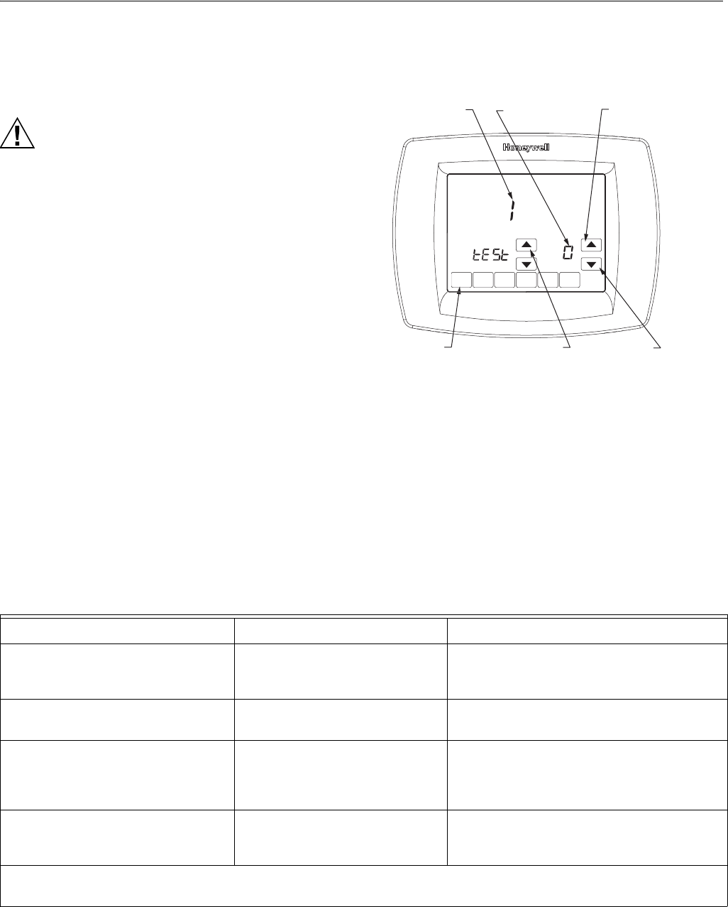
INSTALLER SYSTEM TEST
Use the Installer System Test to test the heating, cooling and
fan (and emergency heat for heat pump systems).
CAUTION
Equipment Damage Hazard.
Minimum compressor off time is bypassed during
Installer System Test
Avoid cycling compressor quickly.
How to Use the Installer System Test
The Installer Test is part of the Installer Setup Menu.
1. Enter the Installer System Test by entering the Installer
Setup.
2. Note that the test appears at the end of the Installer
Setup Numbers.
3. See Fig. 30 to review how the thermostat buttons are
used during the Installer System Test. See Table 6 for
available Installer System Tests.
Fig. 30. Review thermostat buttons used during Installer
System Test.
Installer System Tests
IMPORTANT
Use the Installer System Test to test the heating, cooling, fan and emergency heat. The setting you choose for System
Type (Installer Setup Number 0170) may prevent some System Test Numbers from appearing.
DO
N
E
M22428
SYSTEM TEST
NUMBER
SYSTEM STATUS
NUMBER
DONE KEY
EXITS INSTALLER
SYSTEM TEST
UP ARROW KEY
ADVANCES TO
NEXT SYSTEM
TEST NUMBER
UP ARROW
TURNS THE
SYSTEM ON
DOWN ARROW
TURNS THE
SYSTEM OFF
Table 4. Installer System Test.
System Test Number Test Type System Status Number and Description
Test 1 Cooling System Test 1—Cool stage 1 turns on.
2—Cool stage 1 and stage 2 turn on.
0—Cool is off.
Test 2 Fan System Test 1—Fan turns on.
0—Fan turns off.
Test 3 Heating System Test 1—Heat stage 1 turns on.
2—Heat stage 1 and stage 2 (aux heat) turn
on.
0—Heat is off.
Test 4 Emergency Heat Test 1—Emergency heat turns on.
2—Emergency heat and auxiliary heat turn on.
0—Emergency heat turns off.
Press the Next button to go to the beginning of the Installer Setup or press the Done button to exit the Installer
System Test.
VisionPROTM 8000 Touchscreen Programmable Thermostat
21 68-0280—01
OPERATION
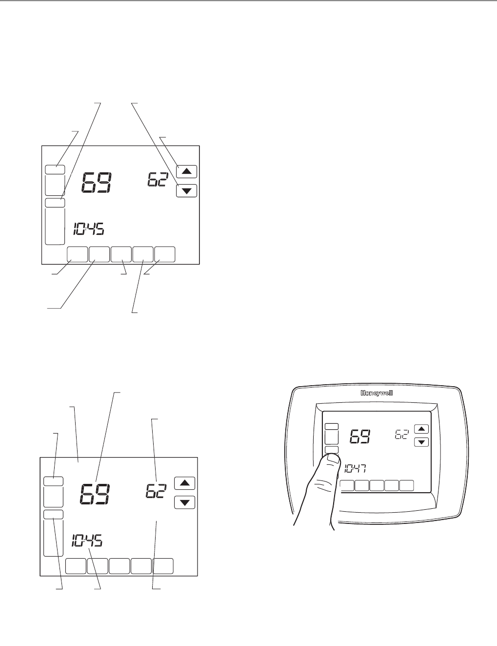
Thermostat Keys
Thermostat Display
System and Fan Settings
System
The System key selections vary based on your heating and/or
cooling system type.
Heat — Thermostat controls the heating system.
Off — Both heating and cooling systems are off.
Cool — Thermostat controls the cooling system.
Auto — Thermostat automatically changes between heating
and cooling operation, depending on indoor temperature.
Em. Heat — Emergency heat cycles to maintain temperature.
Compressor is locked out (used only for 2H/1C or 3H/2C heat
pump systems) and auxiliary heat turns on as second stage if
needed.
Fan
The Fan key selections vary based on the heating and/or
cooling system type.
On — Fan runs continuously. Use this setting for improved air
circulation or for more efficient central air cleaning.
Auto — fan follows the fan program schedule.
Circ — fan runs randomly approximately 35% of the time.
Use this setting for improved air circulation or for more
efficient central air cleaning when you do not want the fan
running continuously.
User Setup
Follow these steps to enter the User Setup:
1. Press and release the System key.
SC
HE
D
H
O
L
D
C
L
OCK
SC
REE
N
M
O
R
E
TUE
AM
FAN
A
U
T
O
S
Y
S
TE
M
HEAT
Followin
g
Sc
h
edu
l
e
Inside
Se
t T
o
M22444
FAN
SELECTS
ON/AUTO/CIRC
SYSTEM
SELECTS EM.
HEAT/HEAT/OFF/COOL
UP ARROW
RAISES
TEMPERATURE
S
ETTIN
G
U
n
DOWN ARROW
LOWERS TEMPERATURE
SETTING
SCHED
ENTERS
SCHEDULING
MODE
MORE
SHOWS ADDITIONAL
ACCESSORY AND
MAINTENANCE
OPTIONS
SCREEN
LOCKS OUT THE
SCREEN TO ALLOW
FOR CLEANING
CLOCK
SETS THE
TIME
FORWARD
OR BACK
HOLD
SETS A PERMANENT
HOLD AND ACTIVITIES
VACATION HOLD
SC
HE
D
HOLD
C
L
OCK
SC
REE
N
M
O
R
E
T
UE
AM
FAN
A
U
T
O
S
Y
S
TE
M
HEAT
Followin
g
Sc
h
edu
l
e
In
s
i
de
S
et T
o
M22239
FAN
SHOWS FAN
SETTING
TUE
SHOWS CURRENT DAY
OF THE WEEK
SYSTEM
SHOWS
CURRENT
SYSTEM
POSITION
TIME
DISPLAY CURRENT
TIME OF DAY, HOLD
TIME REMAINING OR
NUMBER OF VACATION
DAYS REMAINING
INSIDE TEMPERATURE
SHOWS THE CURRENT INSIDE
TEMPERATURE
SET TO
TEMPERATURE
SHOWS THE
CURRENT SET
TEMPERAT
U
RE
FOLLOWING
SCHEDULE
SHOWS THE
THERMOSTAT IS
FOLLOWING THE
PROGRAMMED
SCHEDULE
SCHED HOLD CLOCK SCREE
FAN
ON
AUTO
A
M
THU
SYSTEM
EM HEAT
OFF
COOL
Following
Schedule
Inside Set To
M22426
A
VisionPROTM 8000 Touchscreen Programmable Thermostat
68-0280—01 22
2. Press and hold the center blank key for approximately
five seconds until the screen changes.
3. Release the center blank key when the screen on the
thermostat matches the screen below.
4. See the screen below to review how the thermostat
keys are used during the User Setup. See Table 5 for
the User Setup numbers and settings.
5. Press the Done key to exit the User Setup screen.
D
O
N
E
CANCEL
TUE
PM
SYSTEM
EM HEAT
O
F
F
COOL
CHANGE FILTER UV LAMP HUMIDIFIER PAD
Following
Schedule
Inside Set To
M22439
D
O
NE
M22440
Table 5. User Setup Settings.
User
Setup
Number
User Setup
Name Settings
0120 Date (first two
digits of year)
Select first two digits of
current calendar year (20
for year 2005, etc)
0130 Date (last two
digits of year)
Select last two digits of
current calendar year (05
for year 2005, etc)
0140 Date (month) Select number of current
calendar month (1-12)
0150 Date (day) Select number of current
calendar date (1-31)
0160 Schedule options 0—Non-programmable
4—7-day programmable
(factory setting)
0320 Display
temperature
in °F or °C
0—°F setting (factory
setting)
1—°C setting
0330 Daylight savings
time
1—Daylight savings is on
(factory setting)
0—Daylight savings is off
DONE
O
MON
WED
THU
FRI
SA
T
A
A
T
SUN
USER SETUP
NUMBER CURRENT
SETTING
ADVANCE TO NEXT
USER SETUP
PRESS TO EXIT
USER SETUP
CHANGE THE
CURRENT
SETTING M19922
A
U

VisionPROTM 8000 Touchscreen Programmable Thermostat
23 68-0280—01
PROGRAMMING
Preprogrammed Energy-saving Settings
Table 6 shows default program settings.
Program Heating and Cooling Schedule
Your thermostat can control up to four different schedule
periods per day:
Wake—Period when you awaken and want your home at a
comfortable temperature.
Leave—Period when you are away from home and want an
energy-saving temperature.
Return—Period when you return home and want your home
back to a comfortable temperature.
Sleep—Period when you are asleep and want an energy-
saving temperature.
NOTE: Schedule times are in 15-minute intervals.
0500 Furnace air filter 0—off (factory setting)
1—10 fan run time days
(about one month)
2—30 fan run time days
(about three months)
3—60 fan run time days
(about six months)
4—90 fan run time days
(about nine months)
5—120 fan run time days
(about one year)
6—365 fan run time days
(about three years)
0510 Humidifier pad
reminder
0—off
1—3 months
2—6 months
3—12 months
0520 UV lamp reminder 0—off (factory setting)
1—1 year
0540 Number of
schedule periods
available
2—two (Wake and Sleep)
4—four (Wake, Leave,
Return, Sleep)—factory
setting
0640 Clock format 12—12-hour clock
(factory setting)
24—24-hour clock
0670 Screen lockout 0—all keys available;
screen is unlocked
(factory setting)
1—screen is partially
locked. All key functions
locked except Temper-
ature Up and Down keys
and Cancel key.
2—screen is fully locked
Table 5. User Setup Settings.
User
Setup
Number
User Setup
Name Settings
Table 6. Energy-saving Default Program Settings.
Schedule
Period Time
Setpoints
Fan
SettingHeat Cool
Wake 6:00AM 70°F
(21°C)
78°F
(25.5°C)
Auto
Leave 8:00AM 62°F
(16.5°C)
85°F
(29.50C)
Auto
Return 6:00PM 70°F
(21°C)
78°F
(25.5°C)
Auto
Sleep 10:00PM 62°F
(16.5°C)
82°F
(28°C)
Auto
VisionPROTM 8000 Touchscreen Programmable Thermostat
68-0280—01 24
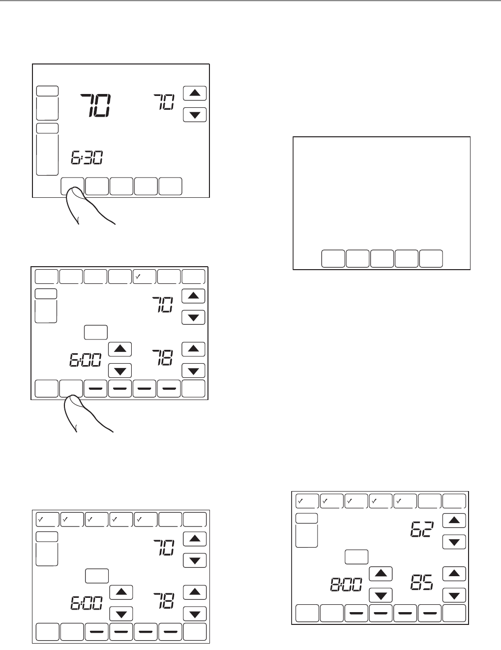
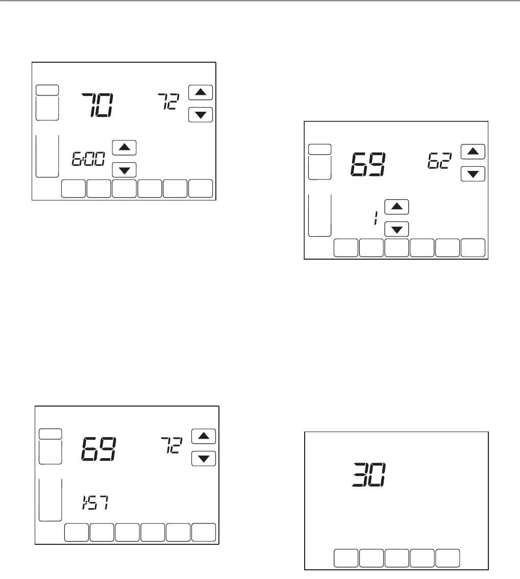
Edit Schedule
1. Press Sched key.
2. Press Edit key.
3. It is OK to pick multiple days. Select any combination of
days to edit. These days are scheduled with the same
times and temperatures. Check marks appear next to
days selected.
4. Press Wake key. Once pressed, Wake flashes to show it
is selected.
5. Press Up and Down keys to modify time and heat and
cool temperatures from this screen.
NOTE: The Fan setting can be programmed for On, Auto, or
Circ for each period selected. See Fan Schedule
section for more information.
6. Press Leave key and repeat step 5.
7. Press Return key and repeat step 5.
8. Press Sleep key and repeat step 5.
9. When complete, press Done key. “Saving Changes”
appears on the screen to indicate changes are being
saved to the day(s) modified.
NOTE: To set a Program Schedule for the remaining days of
the week, repeat steps 1-9. Example: If Mon - Fri
was selected first, go back and repeat steps 1-9 for
Sat and Sun.
10. To exit schedule without saving changes, press Cancel
key any time.
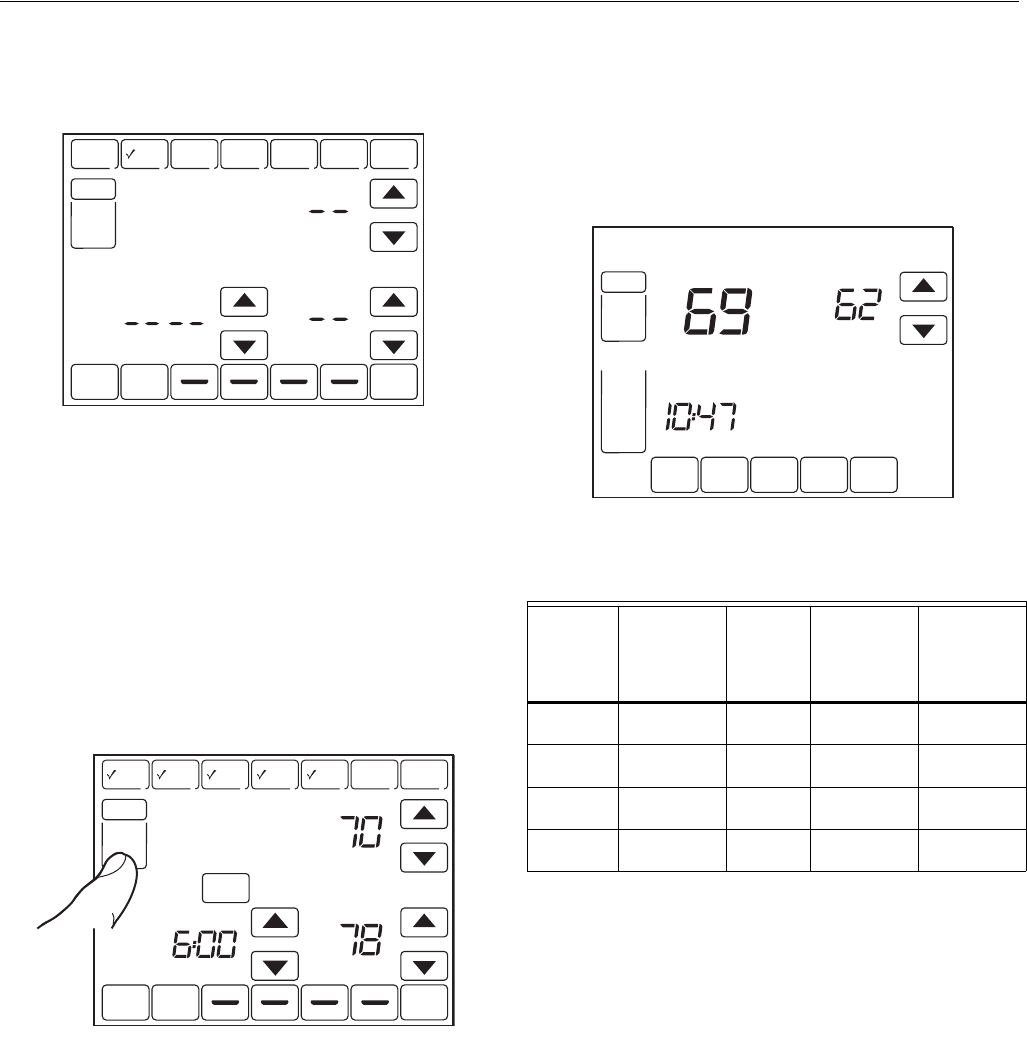
Cancel a Schedule Period
1. Press Sched key.
2. Press Edit key.
3. Select the Day(s) of the week desired.
4. Press schedule period you want to cancel (Wake,
Leave, Return or Sleep). Once selected, the period
flashes.
5. Press Cancel Period key.
6. The time, temperature(s) and fan setting disappear. The
bar above the selected period is removed, indicating the
scheduled period was cancelled.
SCHED HOLD CLOCK SCREEN
FRI
AM
PM
FAN
AUTO
SYSTEM
HEAT
Following
Schedule
Inside Set To
M22445
SCHED
SCHED
HOLD
HOLD
CLOCK SCREEN
DONE WAKE LEAVE RETURN SLEEP CANCEL
MON TUE WED THU FRI SAT SUN
AM
PM
PM
FAN
AUTO
SYSTEM
EM HEAT
HEAT
OFF
COOL
AUTO
CANCEL
PERIOD
HEAT
COOL
Following
Schedule
Inside Set To
OK TO PICK MULTIPLE DAYS SCREEN LOCKED
M22553
EDIT
DONE WAKE LEAVE RETURN SLEEP CANCEL
MON TUE WED THU FRI SAT SUN
AM
FAN
ON
AUTO
CIRC
CANCEL
PERIOD
HEAT
COOL
OK TO PICK MULTIPLE DAYS
M19955
MON TUE WED THU FRI
SAVING
CHANGES
M19956
SCHED
SCHED
HOLD
HOLD
CLOCK SCREEN
DONE WAKE LEAVE RETURN SLEEP CANCEL
MON TUE WED THU FRI SAT SUN
AM
PM
PM
FAN
AUTO
SYSTEM
EM HEAT
HEAT
OFF
COOL
AUTO
CANCEL
PERIOD
HEAT
COOL
Following
Schedule
Inside Set To
OK TO PICK MULTIPLE DAYS SCREEN LOCKED
M22446
VisionPROTM 8000 Touchscreen Programmable Thermostat
25 68-0280—01
NOTE: To reinstate a schedule period, press arrow keys to
set desired time and temperatures.
7. Press Done key.
Fan Schedule
Press Fan key while in the Scheduling Screen to program the
System Fan. Choices available from the Scheduling Screen:
Auto (default position)—fan runs with equipment.
Programmable for all schedule periods (Wake, Leave, Return
and Sleep).
On—fan runs continuously (programmable for all schedule
periods).
Circ—fan runs randomly for approximately 35% of schedule
period (programmable for all schedule periods).
Fan Control (Table 7)
If the Fan program is scheduled, Auto is shown and any
programmable mode that is set; for example, if during Wake
period, Fan is set to Auto, only Auto is shown in the Fan area.
However, if during the Wake period, fan is scheduled to On,
both Auto and On are shown. Auto indicates fan is running its
schedule; On indicates Fan schedule is set to On.
DONE WAKE LEAVE RETURN SLEEP CANCEL
MON TUE WED THU FRI SAT SUN
FAN
HEAT
COOL
OK TO PICK MULTIPLE DAYS
M19957
SCHEDSCHED HOLDHOLD CLOCK SCREEN
DONE WAKE LEAVE RETURN SLEEP CANCEL
MON TUE WED THU FRI SAT SUN
AM
PMPM
FAN
AUTO
SYSTEM
EM HEAT
HEAT
OFF
COOL
AUTO
CANCEL
PERIOD
HEAT
COOL
Following
Schedule
Inside Set To
OK TO PICK MULTIPLE DAYS SCREEN LOCKED
M22447
Table 7. Fan Program Operation and Screen Status.
Fan
Setting
Fan
Program
Schedule
Call
for
Action
Energize
Terminal
Fan
Status
shown on
Screen
Auto Auto None None Auto
Auto On Fan G Auto/On
Auto Circ None None Auto/Circ
Auto Circ Fan G Auto/Circ
SCHED HOLD CLOCK SCREEN
THU
AM
FAN
ON
AUTO
SYSTEM
HEAT
Following
Schedule
Inside Set To
M19962
VisionPROTM 8000 Touchscreen Programmable Thermostat
68-0280—01 26
Manual Override of Fan Schedule (Table 8)
Auto—fan is automatically following the Fan schedule
(choices are Auto, On or Circulate).
On—overrides Fan schedule. Fan is continuously On.
Circ—overrides Fan schedule. Fan circulates randomly for
approximately 35% of time until the Auto position is selected.
aAuto Override resumes the Fan Program in each schedule
period (Wake, Leave, Return and Sleep)
Operate VisionPRO™ 8000 Touchscreen
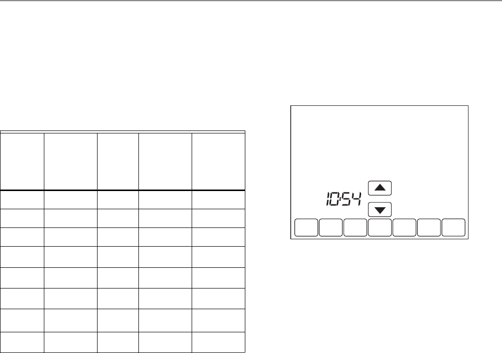
Set Time
1. Press Clock.
2. Use arrows to set current time.
3. Press Done key.
IMPORTANT
The current day of the week should already be set
correctly. If not, see Installer Setup to set the day.
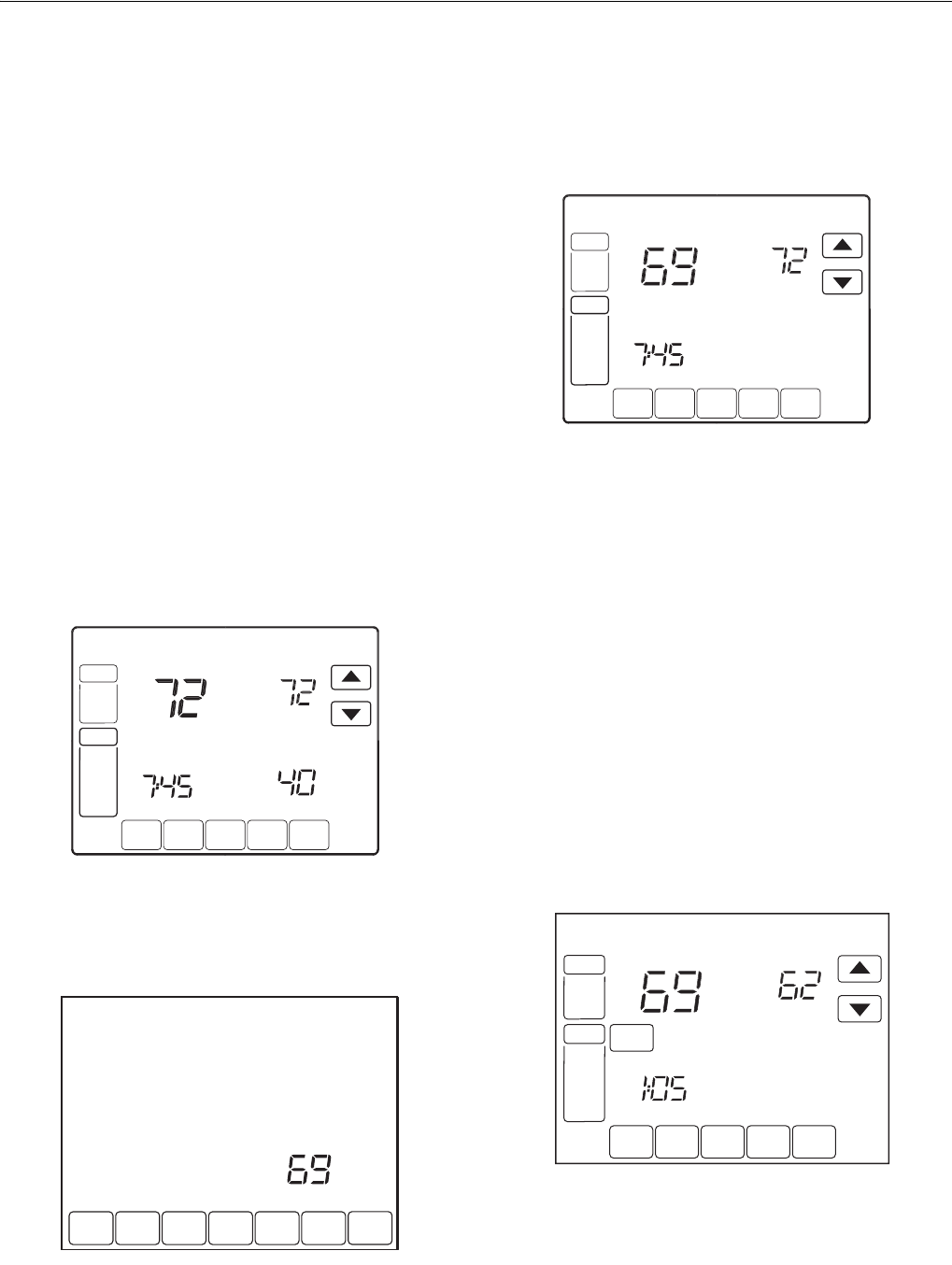
Set Temperature Overrides
The thermostat has three temperature override options: Hold
Temperature Until, Permanent Hold and Vacation Hold.
HOLD TEMPERATURE UNTIL (TEMPORARY HOLD)
Holds temperature temporarily until the next scheduled period
time or until the time the user sets.
1. Press Up or Down arrow next to the temperature you
want to adjust. “Hold Temperature Until” time appears
on the screen. The Hold Temperature Until time defaults
to the start time of the next scheduled period.
NOTE: The Time Up and Down arrows are shown for
approximately seven seconds. Pressing on the
screen time (where the Hold Temperature Until time
is shown) allows the arrows to reappear.
Table 8. Manual Override of Fan Schedule Operation.
Fan
Setting
Fan
Schedule
Override
Setting
Call
for
Action
Energize
Terminal
Screen
Message
Under
Fan
Setting
Auto On Fan G On
Auto Circ None None Circ
Auto Circ Fan G Circ
On Autoa —— —
On Circ None None Circ
On Circ Fan G Circ
Circ Autoa —— —
Circ On Fan G On
DONE CANCEL
TUE
AM
M19958
VisionPROTM 8000 Touchscreen Programmable Thermostat
27 68-0280—01
2. Press Up or Down arrow next to the Time key to set
desired time for the thermostat to resume schedule.
3. Press the Cancel or Sched key to cancel “Hold
Temperature Until” and resume schedule.
NOTE: Once “Hold Temperature Until” time is reached, the
thermostat shows “Following Schedule” on the
screen to indicate that “Temporary Hold” has ended.
PERMANENT HOLD
Permanent Hold changes the temperature setting until
Permanent Hold is cancelled.
1. Press Hold key. “Permanent Hold” appears on the
screen.
2. Press Up or Down arrow next to the temperature you
want to set during “Hold.”
3. Press Cancel key to cancel “Permanent Hold” and
resume the schedule.
VACATION HOLD
Changes temperature setting for a designated number of
days.
1. Press the Up and Down arrow keys to set the desired
temperature while away on vacation. Notice that “Hold
Temperature Until” time is shown on the screen. (This is
the time the Vacation Hold override expires after the
number of days ends.)
2. Press Hold key twice. Screen shows “Hold Temperature
Until” one day.
3. Press Up and Down arrow keys to change the number
of Days you desire thermostat to override the schedule.
NOTE: Days Up and Down arrows appear for approximately
seven seconds. Pressing just below Hold Temper-
ature Until on the screen allows the Days Up and
Down arrows to reappear.
4. To cancel the Vacation Hold override early, press the
Cancel key.
NOTE: When the number of days of Vacation Hold expires,
the screen shows “Following Schedule” to indicate
that Vacation Hold has ended.
Clean Thermostat Screen
The thermostat has a touch screen interaction. Follow these
steps to clean the screen without making thermostat changes:
1. Press the Screen key. Thermostat locks out all touch
keys for 30 seconds to allow for cleaning.
2. Use damp cloth slightly moistened with water or house-
hold glass cleaner to clean the screen.
3. Repeat the above steps, as necessary.
IMPORTANT
Do not spray any type of liquid directly on the
thermostat itself. If using household glass cleaner,
spray cleaner on cloth. Then use a cloth to clean
the thermostat screen.
4. Press the Done key to return to the Home Screen and
normal operation.
SCHED HOLD CLOCK SCREEN
CANCEL
TUE
PM
FAN
AUTO
SYSTEM
HEAT
Inside
Hold Temperature
Until
Set To
M19959
SCHED HOLD CLOCK SCREEN
CANCEL
TUE
AM
FAN
AUTO
SYSTEM
HEAT
Inside Set To
Permanent
Hold
M19960
SCHED CLOCK SCREEN
CANCEL
THU
FAN
AUTO
SYSTEM
HEAT
Inside
DAYS
Hold Temperature
Until
Set To
M19961
OK TO
CLEAN
SCREEN
M19964
VisionPROTM 8000 Touchscreen Programmable Thermostat
68-0280—01 28
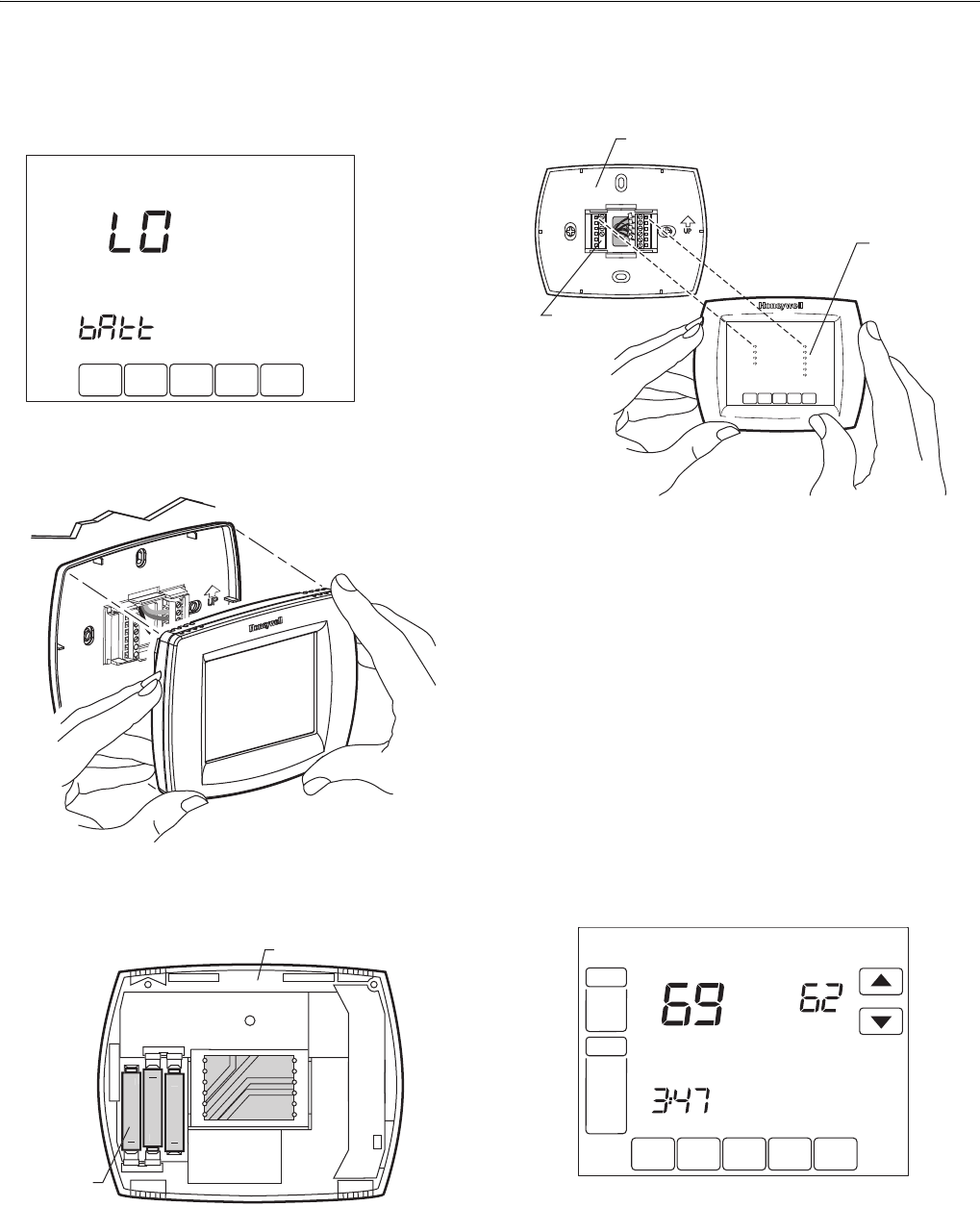
Replace Batteries
1. When the LO Battery indicator is flashing, replace the
batteries promptly with three fresh AAA alkaline
batteries
2. Remove thermostat from the wallplate by pulling
straight out.
3. Remove the old batteries and insert three fresh AAA
alkaline batteries, as marked on the thermostat.
4. Align the screw blocks with the pins on the back of the
thermostat.
5. Push the thermostat straight onto the wallplate until it
snaps into place.
Battery Tips
1. Replace the batteries as soon as LO Batt flashes in the
display. The LO Battery indicator flashes in the display
one month before the batteries run down completely.
2. Always use fresh AAA alkaline batteries. Non-alkaline
batteries do not last as long and can leak, causing
thermostat damage.
3. Although the thermostat has a Low Battery indicator,
replace the batteries once a year to prevent the thermo-
stat and heating/cooling system from shutting down due
to lack of battery power.
Screen Locks
M19963
M22430
WALL
BACK OF THERMOSTAT
M22212
BATTERIE
S
(3)
+
+
+
+
+
M22213
PINS ON
BACK OF
THERMOSTAT
WALLPLATE
TERMINAL
SCREW
BLOCK
SCHED HOLD CLOCK SCREEN MORE
TUE
PM
FAN
AUTO
SYSTEM
HEAT
Following
Schedule
Inside Set To
SCREEN LOCKED
M19965
VisionPROTM 8000 Touchscreen Programmable Thermostat
29 68-0280—01
Partially Locked Screen
When partially locked, the screen indicates Screen Locked for
5 to 7 seconds whenever the user attempts to press a key that
is locked. Pressing a locked key, while Screen Locked is
shown, flashes “Screen Locked” on the screen.
In this mode, all keys are locked except the Temperature Up
and Down arrow keys:
— User can change temperature up or down but cannot
change schedule settings.
— Temporary temperature change lasts until next scheduled
period and that time shows on screen.
— To cancel temperature override and begin following
schedule, press Cancel key.
— To unlock screen, see Installer Setup section.
Fully Locked Screen
In this mode, all keys are locked and not functional. To unlock
screen, see Installer Setup section. The screen continuously
displays “Screen Locked.”
Outdoor Temperature
If an outdoor temperature sensor is installed, the thermostat
displays the outside temperature in the lower right corner of
the Home Screen.
If thermostat is set to Auto Changeover System mode, press
the More key until the outside temperature is shown on the
screen.
Remote Indoor Temperature
If a remote indoor temperature sensor is installed, the
thermostat displays the inside temperature on the screen from
the remote sensor(s).The thermostat internal temperature
sensor is not used.
ONE REMOTE INDOOR SENSOR INSTALLED (OPTIONAL)
If one remote indoor temperature sensor is used, the screen
showing the Inside temperature reading shows the
temperature at the indoor remote sensor location. The
thermostat internal temperature sensor is not used.
MULTIPLE REMOTE INDOOR SENSORS INSTALLED (OPTIONAL)
If more than one remote indoor sensor is used, the screen
showing Inside temperature reading shows the average of all
the remote indoor sensors. The thermostat internal
temperature sensor is not used.
Indoor Air Quality Reminders
Filter Change Reminder
The filter change reminder must be turned on from the
Installer Setup. Once expired, the screen flashes, “Change
Filter” and a Reset key appears. Press the Reset key to reset
the change reminder.
NOTE: The days are counted as fan run time, so anytime
the fan is running, the reminder is counting that time
against the number of days selected.
SCHED HOLD CLOCK SCREEN MORE
MON
T
UE
WED
THU
FRI
SA
T
A
A
T
SUN
AM
FAN
A
U
T
O
SYSTEM
HEAT
Following
Schedule
In
s
i
de
Outside
Se
t T
o
M22453
SCHED
SCHED
HOLD
HOLD
CLOCK SCREEN
DONE WAKE LEAVE RETURN SLEEP CANCEL
MON TUE WED THU FRI SAT SUN
Outside
M22448
Heat
On
SCHED HOLD CLOCK SCREEN MORE
MON
T
UE
WED
THU
FRI
SA
T
A
A
T
SUN
AM
FAN
A
U
T
O
SYSTEM
HEAT
Following
Schedule
In
s
i
de
Se
t T
o
M19974
SCHED HOLD CLOCK SCREEN MORE
MON
T
UE
WED
THU
FRI
SA
T
A
A
T
SUN
PM
FAN
AUTO
SYSTEM
HEAT
RESET
C
HAN
GE
FILTER
UV LAMP HUMIDIFIER PAD
R
Following
Schedule
In
s
i
de
S
et T
o
O
K T
O
PI
C
K M
U
LTIPLE DAY
S
SC
REEN L
OC
KE
D
M19975
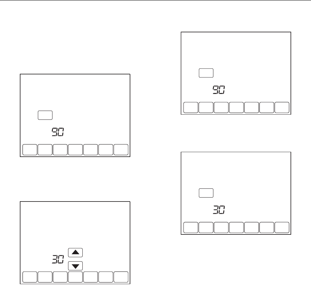
VisionPROTM 8000 Touchscreen Programmable Thermostat
68-0280—01 30
The remaining run time days can be viewed by pressing the
More key; the remaining days can be edited using the More
key or from the Installer Setup. To view or reset the reminder
before it expires, follow these steps using the More key:
1. Press the More key until the filter reminder appears on
the screen. This is the number of fan run-time days
remaining on the filter reminder.
2. Press the Edit key.
3. Use the Up and Down keys to change the number of
run-time days.
4. Press the Done key to go back to the viewing screen.
5. Press the Reset key to activate the new number of days
selected in the previous screen.
6. Press the Done key to return to the Home screen.
SCHED
SCHED
HOLD
HOLD
CLOCK SCREEN MORE
DONE WAKE LEAVE RETURN SLEEPEDIT CANCEL
MON TUE WED THU FRI SAT SUN
RESET
CHANGE FILTER UV LAMP HUMIDIFIER PAD
DAYS
M22449
SCHED
SCHED
HOLD
HOLD
CLOCK SCREEN
DONE WAKE LEAVE RETURN SLEEP CANCEL
MON TUE WED THU FRI SAT SUN
CHANGE FILTER UV LAMP HUMIDIFIER PAD
DAYS
M22450
SCHED
SCHED
HOLD
HOLD
CLOCK SCREEN MORE
DONE WAKE LEAVE RETURN SLEEPEDIT CANCEL
MON TUE WED THU FRI SAT SUN
RESET
CHANGE FILTER UV LAMP HUMIDIFIER PAD
DAYS
M22449
SCHED
SCHED
HOLD
HOLD
CLOCK SCREEN MORE
DONE WAKE LEAVE RETURN SLEEPEDIT CANCEL
MON TUE WED THU FRI SAT SUN
RESET
CHANGE FILTER UV LAMP HUMIDIFIER PAD
DAYS
M22451
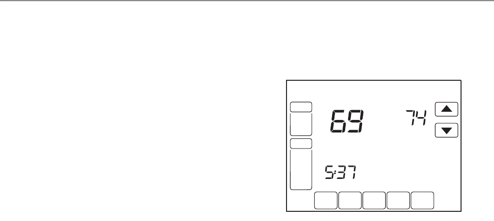
VisionPROTM 8000 Touchscreen Programmable Thermostat
31 68-0280—01
Humidifier Pad Reminder
The Humidifier Pad change reminder must be turned on from
the Installer Setup. Once expired, the screen flashes,
“Change Humidifier Pad” and a Reset key appears. Press the
Reset key to reset the change reminder.
The remaining calendar days can be viewed by pressing the
More key. The remaining days can be edited using the More
key or from the Installer Setup. To view or reset the reminder
before it expires, follow these steps using the More key:
1. Press the More key until the Humidifier Pad change
reminder appears on the screen. This is the number of
calendar days remaining on the Humidifier Pad
reminder.
2. Press the Edit key.
3. Use the Up and Down keys to change the number of
calendar days.
4. Press the Done key to go back to the viewing screen.
5. Press the Reset key to activate the new number of days
selected in the previous screen.
6. Press the Done key to return to the Home Screen.
UV Lamp Reminder
The UV Lamp change reminder must be turned on from the
Installer Setup. Once expired, the screen flashes, “Change
UV Lamp” and a Reset key appears. Press the Reset key to
reset the change reminder.
The remaining calendar days can be viewed by pressing the
More key. The remaining days can be edited using the More
key or from the Installer Setup. To view or reset the reminder
before it expires, follow these steps using the More key:
1. Press the More key until the UV Lamp change reminder
appears on the screen. This is the number of calendar
days remaining on the UV Lamp reminder.
2. Press the Edit key.
3. Use the Up and Down keys to change the number of
calendar days.
4. Press the Done key to go back to the viewing screen.
5. Press the Reset key to activate the new number of days
selected in the previous screen.
6. Press the Done key to return to the Home Screen.
Temperature Recovery
The thermostat feature, Adaptive Intelligent Recovery™,
eliminates all guesswork when setting the thermostat
schedule.
Simply set the program schedule to the time that the comfort
temperature is desired. The thermostat then turns on the
heating or cooling at just the right time to have the home
reach the scheduled temperature at the scheduled time.
For example—get up at 6:00 AM and want the temperature to
be 70°F. Set the Wake period for 6:00 AM and 70°F. The
thermostat then turns on the heat before 6:00 AM to raise the
temperature to 70°F by 6:00 AM.
The thermostat alerts that the heating or cooling system is
coming on before a scheduled time by showing “Recovery” on
the screen.
NOTE: It takes about a week for the thermostat to adjust to
local weather, the schedule, the construction of the
home and the heating and/or cooling system. Each
day it adjusts the next day’s recovery start time
accordingly.
P+I Control
The thermostat microprocessor-based control requires that
the user understands temperature control and thermostat
performance. A conventional mechanical or electronic
thermostat does not control temperature precisely at setpoint.
Typically there is an offset (droop) in the control point as the
system load changes. This is a phenomenon that most people
in the industry know and accept. Many factors contribute to
offset including switch differential, thermal lag, overshoot,
cycle rates and system load.
The thermostat microprocessor simultaneously gathers,
compares and computes data. Using this data, it controls a
wide variety of functions. The special proprietary algorithm
(program) in the thermostat eliminates the factors causing
offset. This makes temperature control more accurate than
the conventional mechanical or electronic thermostats. The
temperature control algorithm is called proportional plus
integral (P+I) control.
The thermostat sensor, located on the thermostat or remote,
senses the current space temperature. The proportional error
is calculated by comparing the sensed temperature to the
programmed setpoint. The deviation from the setpoint is the
proportional error.
The thermostat also determines integral error, which is a
deviation based on the length of error time. The sum of the
two errors is the (P+I) error. The cycle rate used to reach and
maintain the setpoint temperature is computed using the P+I.
The additon of the integral error is what differentiates the
thermostat from many other electronic and mechanical
thermostats. See Fig. 31.
SCHED HOLD CLOCK SCREEN MORE
TUE
PM
FAN
AUTO
SYSTEM
HEAT
Following
Schedule
Inside Set To
Recovery
M22301
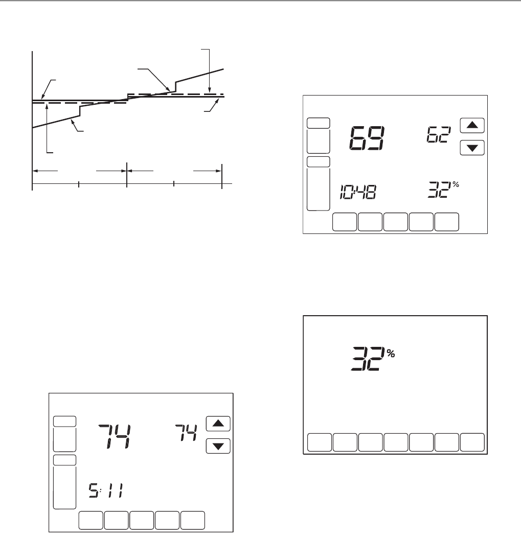
VisionPROTM 8000 Touchscreen Programmable Thermostat
68-0280—01 32
Fig. 31. Proportional temperature control versus P+ I
temperature control.
Minimum Off-Timer
The Thermostat has built-in compressor protection (minimum-
off timer) that prevents the compressor from restarting too
early after a shutdown.
The minimum-off timer is activated after the compressor turns
off.
If there is a call during the minimum-off timer, the thermostat
shows “Wait” in the display.
When the minimum-off timer expires, “Cool On” or “Heat On”a
appears solidly in the display and the compressor and fan turn
on.
_________
aHeat Pumps only.
Inside Humidity Level
Select models can sense the humidity level in the home. The
humidity level in the home is shown in the lower right corner of
the Home Screen.
If thermostat is set to Auto Changeover System mode, press
the More key until the humidity level is shown on the screen.
HEATING COOLING
PERCENT LOAD
TEMPERATURE
THERMOSTAT
HEAT SETPOINT
P+I CONTROL
POINT
PROPORTIONAL COOL
CONTROL POINT
THERMOSTAT
COOL SETPOINT
P+I CONTROL POINT
PROPORTIONAL HEAT
CONTROL POINT
M4414
100 50 0 50 100
M
222
44
W
a
i
t
C
oo
l
SC
HE
D
H
O
L
D
C
L
OCK
SC
REE
N
M
O
R
E
T
UE
WED
AM
PM
FAN
A
U
T
O
S
Y
S
TE
M
HEAT
COOL
Followin
g
Sc
h
edu
l
e
In
s
i
de
S
et T
o
SCHED HOLD CLOCK SCREEN MORE
TUE
PM
FAN
AUTO
SYSTEM
HEAT
Following
Schedule
Inside Set To
Humidity
M19966
SCHED
SCHED
HOLD
HOLD
CLOCK SCREEN
DONE WAKE LEAVE RETURN SLEEP CANCEL
MON TUE WED THU FRI SAT SUN
Inside
M22452
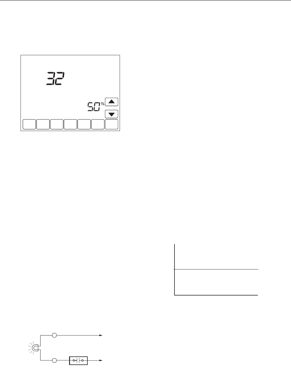
VisionPROTM 8000 Touchscreen Programmable Thermostat
33 68-0280—01
Control Dehumidification Setting (Select Models)
Select models read the inside humidity level and allow for a
dehumidification setting:
1. Press the More key until the inside humidity percent and
dehumidification setpoint are shown.
2. Use Up and Down arrow keys, located to the right of the
dehumidifier setpoint, to set desired humidity level for
dehumidification in the summer.
3. Press Done key.
Dehumidification Droop Control
The dehumidification control attempts to control to the user's
humidity setpoint by turning on the air conditioner. In
extremely high humidity conditions, the thermostat keeps the
air conditioner running (energizing Y and G) for up to 3°F
below the temperature setpoint. It does this while trying to
achieve the desired humidity setpoint and balancing that with
the temperature setpoint. The thermostat controls up to 3° F
below the temperature setting until either the humidity is
satisfied or conditions change.
Special Heat Pump Operation
Heat Pump LED Indication (Requires 24 Vac
Common Connection)
A red LED indication is located in the upper right corner of the
thermostat. It is only visible when lighted.
When the L terminal is wired to an equipment monitor, the
LED signals when a check or fail signal is sent to the
thermostat from the system. This is operational in the Heat,
Off, Cool or Auto positions. See Fig. 32.
Fig. 32. L terminal switch to R (power) side of system
transformer.
Heat Pump Emergency Heat LED Indication
(Requires 24 Vac Common Connection)
The thermostat uses a red LED indicator that lights when the
thermostat is in the Emergency Heat mode. The LED is
located in the upper right corner of the thermostat. It is visible
only when on. When the thermostat is in the Em. Heat system
mode, the L terminal is continuously energized and the LED is
on.
Heat Pump Temperature Lockouts
Dual Fuel Heat Pump and Outdoor Temperature
Sensor
In this operation, there is no external fossil fuel kit (dual fuel
kit) installed; the thermostat controls this function.
1. Choose correct heat pump application in Installer Setup
Number 0170.
2. Choose Fossil Fuel Option as the backup heat source
in Installer Setup Number 0200.
3. Choose No External Fossil Fuel Kit Option is control-
ling back up heat in Installer Setup Number 0210.
4. Choose Outdoor Temperature Sensor for Heat Pump
Temperature Lockouts Option in Installer Setup Num-
ber 0340.
5. Choose appropriate Balance Point Temperature in
Installer Setup Number 0350.
OPERATION IN HEAT MODE ABOVE BALANCE POINT (OUTDOOR
TEMPERATURE)
When the outdoor temperature is above the selected Balance
Point Temperature (ISU 0350), only the compressor operates
and the fan (G terminal) energizes when the thermostat calls
for heat. See Fig. 33.
Fig. 33. Dual Fuel Heat Pump Operation in Heat mode with
Balance Point Set.
OPERATION IN HEAT MODE BELOW BALANCE POINT (OUTDOOR
TEMPERATURE)
When the outdoor temperature is below the selected Balance
Point Temperature (ISU 0350), only the Fossil Fuel (auxiliary
heat) operates and the fan (G terminal) does not energize
when the thermostat calls for heat.
DONE CANCEL
DEHUMIDIFIER
Inside
Humidity
M19967
M19907
EQUIPMENT
MONITOR
L TO R
TO C
C
30
M22441
BALANCE
POINT
COMPRESSOR ONLY
FOSSIL FUEL ONLY
OUTDOOR TEMPERATURE
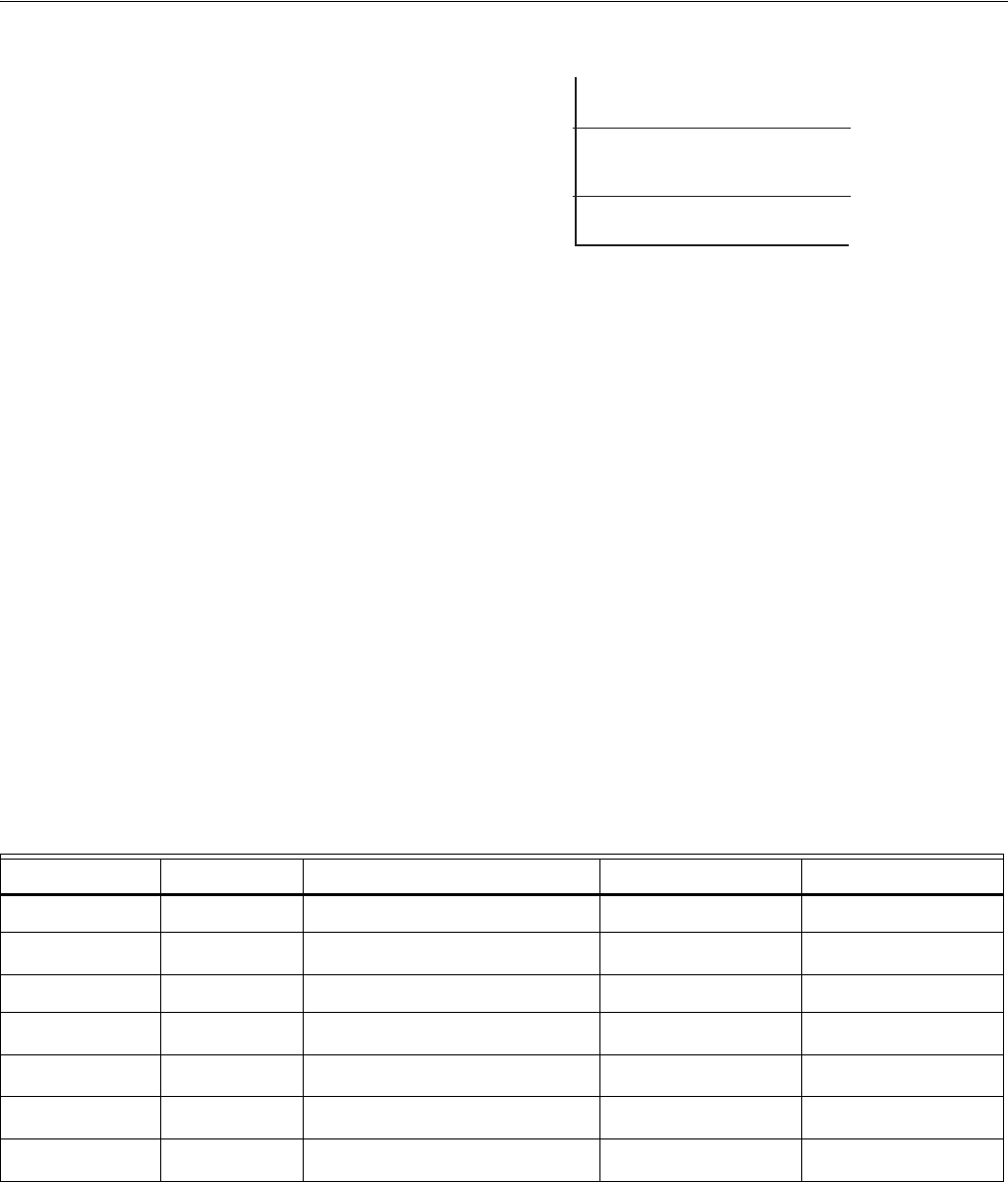
VisionPROTM 8000 Touchscreen Programmable Thermostat
68-0280—01 34
OPERATION IN EMERGENCY HEAT MODE
The balance point (outside) temperature is not used in the
Emergency heat mode. When the thermostat is moved to the
Emergency Heat position, the compressor is locked out. The
first stage of heat is whatever is connected to the E terminal.
The second stage of heat is what is connected to the Aux.
terminal. Often there is only one source of non-compressor
heat and the E terminal is jumped to the Aux. terminal.
Heat Pump with Electric Auxiliary (Backup) Heat and
Outdoor Temperature Sensor
1. Choose correct heat pump application in Installer Setup
Number 0170.
2. Choose Electric as Auxiliary (Backup) Heat Source in
Installer Setup Number 0200.
3. Choose Outdoor Temperature Sensor for
Control Option in Installer Setup Number 0340.
4. Choose Compressor Lockout Temperature in
Installer Setup Number 0350.
5. Choose Auxiliary Lockout Temperature in Installer
Setup Number 0360.
NOTE: There is a 5°F deadband between the Compressor
and Auxiliary Heat Lockout Temperatures.
Operation in Heat Mode
When the outdoor temperature is below the Compressor
Lockout Temperature, only the Auxiliary Heat operates.
When the outdoor temperature is above the Auxiliary Lockout
Temperature, only the Compressor operates. See Fig. 34.
Fig. 34. Heat Pump Operation with Lockout
Temperatures Set.
When the outdoor temperature is between the two
temperatures, both the Compressor and Auxiliary Heat
operate.
Operation in Emergency Heat Mode
Once the thermostat is placed into the Emergency Heat
mode, the compressor and auxiliary lockout features are
turned off. In the Emergency heat mode, the compressor is
locked out. The first stage of heat is whatever is connected to
the E terminal. The second stage of heat is connected to the
Aux. terminal. Usually the emergency and auxiliary heat
sources are electric strip heat in these cases.
Operating Sequence
The thermostat energizes specific terminal(s), depending on
the demand for heating, cooling or fan. The thermostat screen
shows the time, inside temperature, system and fan
selections. Additional indicators are shown when the heating,
cooling or fan is energized. See Tables 9 - 11 for specification
information.
aG energizes only if Installer Setup number 0180 is set to Electric.
bIf Installer Setup System type is set to two stages of cooling.
cIf Installer Setup System type is set to two stages of heating.
35
M19950
COMPRESSOR
LOCKOUT
TEMPERATURE
AUXILIARY
LOCKOUT
TEMPERATURE
COMPRESSOR ONLY
BOTH COMPRESSOR AND
AUXILIARY HEAT
AUXILIARY ONLY
50
OUTDOOR TEMPERATURE
Table 9. Sequence of Operation for Conventional Systems.
System Setting Fan Setting Call for Action Energize Terminals Screen Message
Off Auto None None None
Cool Auto None None None
Cool or Auto Auto Stage 1 Cooling Y, G Cool On
Cool or Auto Auto Stage 1 and Stage 2 Cooling Y, Y 2 b, G Cool On
Heat Auto None None None
Heat or Auto Auto Stage 1 Heating W, GaHeat On
Heat or Auto Auto Stage 1 and Stage 2 Heating W, W2c, GaHeat On
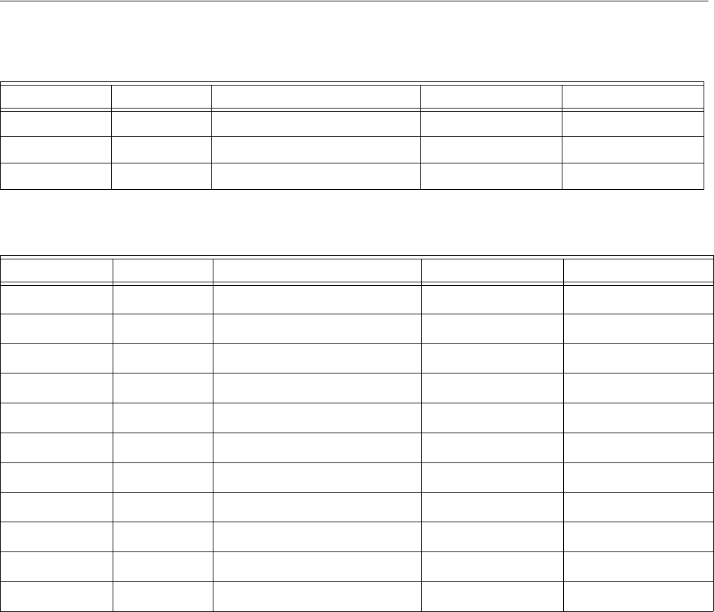
VisionPROTM 8000 Touchscreen Programmable Thermostat
35 68-0280—01
aConfigure O/B in Installer Setup. Based on last piece of equipment called (cooling = O or heating = B).
bRed LED is on. See LED Indication section for more details.
cIf Installer Setup System Type is set to 2Heat/1Cool Heat Pump with Auxiliary Heat.
dIf Installer Setup System Type is set to 3Heat/2Cool Heat Pump with Auxiliary Heat.
eThis terminal does not energize if Installer Setup System type is set to 2 Heat/2 Cool Heat Pump with no Auxiliary Heat.
Second Stage Heat and Cool Control
While maintaining setpoint, several factors affect when 2nd
stage energizes such as load conditions, environmental
conditions, P+I control, and home insulation. The second
stage energizes when the thermostat senses 1st stage is
running at 90% capacity. This operation is droopless control.
Table 10. Sequence of Operation for Power Open and Power Closed Valves or Normally Open Valves.
System Setting Fan Setting Call for Action Energize Terminals Screen message
Off N/A None Y None
Heat N/A None Y None
Heat N/A Heat W Heat On
Table 11. Sequence of Operation for Heat Pump Systems.
System Setting Fan Setting Call for Action Energize Terminals Screen message
Off Auto None O/BaNone
Cool Auto None O/BaNone
Cool or Auto Auto Stage 1 Cooling Y, G, O/BaCool On
Cool or Auto Auto Stage 1 and Stage 2 Cooling Y, Y 2 d, G, O/BaCool On
Heat Auto None O/BaNone
Heat or Auto Auto Stage 1 Heating Y, G, O/BaHeat On
Heat or Auto Auto Stage 1 and Stage 2 Heating Y, AU X c, G, O/BaAux Heat On
Heat or Auto Auto Stage 1, 2 and 3 Heating Y, Y2 d, AUXe, G, O/BaAux Heat On
Em. Heat Auto None Lb, O/BaNone
Em. Heat Auto Stage 1 Heating E, G, Lb, O/BaHeat On
Em. Heat Auto Stage 1 and Stage 2 Heating E, AUX, G, Lb, O/BaAux. Heat On
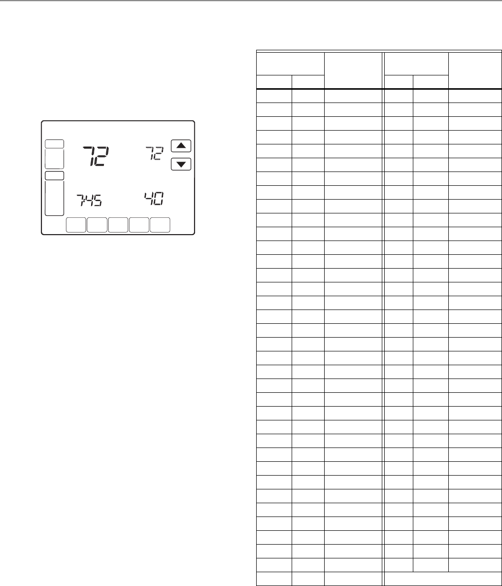
VisionPROTM 8000 Touchscreen Programmable Thermostat
68-0280—01 36
C7089U Outdoor Temperature Sensor
Operation
When installed with Thermostat Installer Setup Number 0340
set to 1 or 2, the outside temperature can be displayed on the
thermostat. See Fig. 35.
Fig. 35. Outside temperature reading on
TH8000 Series Thermostat.
The C7089 Outdoor Sensor converts outdoor ambient
temperature to a resistance that the thermostat can interpret.
The C7089 has a negative temperature coefficient (TC), which
means that resistance decreases as the temperature
increases. See Table 12.
Checkout
Allow C7089U Outdoor Sensor to absorb outdoor air for a
minimum of twenty minutes before taking a reading.
With an accurate thermometer (±1°F [0.5°C]) measure the
temperature at the sensor location, allowing time for the
thermometer to stabilize before reading.
To verify sensor resistance, remove one wire from one of the
C7089 60-in. leadwires. Use an ohmmeter to measure the
resistance across the sensor. Then verify the sensor accuracy
with the temperature/resistance in Table 12.
Calibration
The C7089 Outdoor Sensor is calibrated at the factory and
cannot be recalibrated in the field.
SCHED HOLD CLOCK SCREEN MORE
MON
T
UE
WED
THU
FRI
SA
T
A
A
T
SUN
AM
FAN
A
U
T
O
SYSTEM
HEAT
Following
Schedule
In
s
i
de
Outside
Se
t T
o
M22453
Table 12. Sensor Resistance at Outdoor Temperature.
Outdoor
Temperature Ohms of
Resis-
tance
Outdoor
Temperature Ohms of
Resis-
tance°F °C °F °C
-20 -28.9 106926 52 11.1 17136
-18 -27.8 100923 54 12.2 16387
-16 -26.7 95310 56 13.3 15675
-14 -25.6 90058 58 14.4 14999
-12 -24.4 85124 60 15.6 14356
-10 -23.3 80485 62 16.7 13743
-8 -22.2 76137 64 17.8 13161
-6 -21.1 72060 66 18.9 12607
-4 -20.0 68237 68 20.0 12081
-2 -18.9 64631 70 21.1 11578
0 -17.8 61246 72 22.2 11100
2 -16.7 58066 74 23.3 10644
4 -15.6 55077 76 24.4 10210
6 -14.4 53358 78 25.6 9795
8 -13.3 49598 80 26.7 9398
10 -12.2 47092 82 27.8 9020
12 -11.1 44732 84 28.9 8659
14 -10.0 42506 86 30.0 8315
16 -8.9 40394 88 31.1 7986
18 -7.8 38400 90 32.2 7672
20 -6.7 36519 92 33.3 7372
22 -5.6 34743 94 34.4 7086
24 -4.4 33063 96 35.6 6813
26 -3.3 31475 98 36.7 6551
28 -2.2 29975 100 37.8 6301
30 -1.1 28558 102 38.9 6062
32 0.0 27219 104 40.0 5834
34 1.1 25949 106 41.1 5614
36 2.2 24749 108 42.2 5404
38 3.3 23613 110 43.3 5203
40 4.4 22537 112 44.4 5010
42 5.6 21516 114 45.6 4826
44 6.7 20546 116 46.7 4649
46 7.8 19626 118 47.8 4479
48 8.9 18754 120 48.9 4317
50 10.0 17926 —
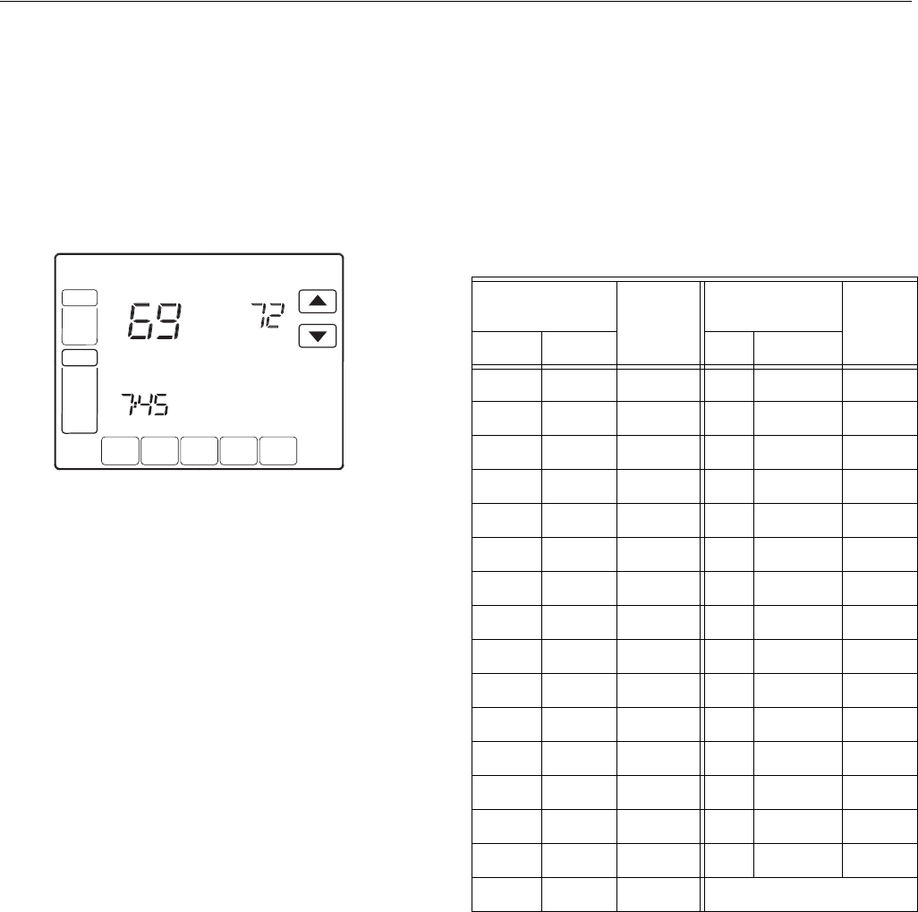
VisionPROTM 8000 Touchscreen Programmable Thermostat
37 68-0280—01
C7189U Remote Indoor Temperature Sensor
Operation
When installed with Thermostat Installer Setup Number 0340
set to 3, the remote inside temperature is displayed on the
Thermostat Home Screen as Inside Temperature. The
thermostat internal temperature sensor is not used. See Fig.
36.
Fig. 36. Inside temperature reading on
TH8000 Series Thermostat.
The C7189 Wall Mount Temperature Sensor converts room
temperature to a resistance that the thermostat can interpret.
The C7189 has a negative temperature coefficient (NTC),
which means that resistance decreases as the temperature
increases. See Table 13.
The C7189 can be used to provide one remote sensor input
(see Fig. 28) or as a temperature averaging network with
multiple C7189 Sensors connected, as shown in Fig. 29.
Checkout
For best results, allow C7189 Wall Mount Temperature Sensor
to absorb the air moving through the room for a minimum of
twenty minutes before taking a resistance measurement.
With an accurate thermometer (±1°F [0.5°C]) measure the
temperature at the sensor location, allowing time for the
thermometer to stabilize before reading.
To verify sensor resistance, remove one wire from one of
C7189 wiring terminals. Use an ohmmeter to measure the
resistance across the sensor. Then verify the sensor accuracy
with the temperature/resistance in Table 13.
Calibration
The C7189 Wall Mount Temperature Sensor is calibrated at
the factory and cannot be recalibrated in the field.
Heat
On
SCHED HOLD CLOCK SCREEN MORE
MON
T
UE
WED
THU
FRI
SA
T
A
A
T
SUN
AM
FAN
A
U
T
O
SYSTEM
HEAT
Following
Schedule
In
s
i
de
Se
t T
o
M19974
Table 13. Sensor Resistance at Room Temperature.
Room
Temperature
Ohms
of
Resis-
tance
Room
Temperature
Ohms
of
Resis-
tance°F °C °F °C
40 4.4 22537 72 22.2 11100
42 5.6 21516 74 23.3 10644
44 6.7 20546 76 24.4 10210
46 7.8 19626 78 25.6 9795
48 8.9 18754 80 26.7 9398
50 10.0 17926 82 27.8 9020
52 11.1 17136 84 28.9 8659
54 12.2 16387 86 30.0 8315
56 13.3 15675 88 31.1 7986
58 14.4 14999 90 32.2 7672
60 15.6 14356 92 33.3 7372
62 16.7 13743 94 34.4 7086
64 17.8 13161 96 35.6 6813
66 18.9 12607 98 36.7 6551
68 20.0 12081 100 37.8 6301
70 21.1 11578 —
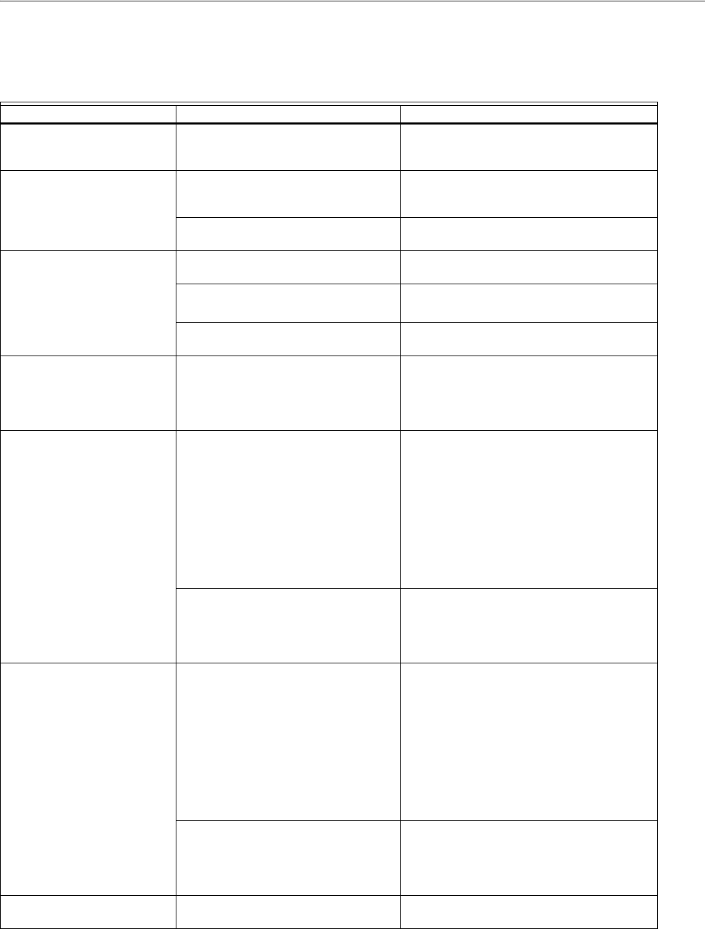
VisionPROTM 8000 Touchscreen Programmable Thermostat
68-0280—01 38
TROUBLESHOOTING (TABLE 14)
Table 14. Troubleshooting.
Symptom Possible Cause Action
Display does not come on. Thermostat is not being powered. Check for 24 Vac between C and Rc.
Check that AAA batteries are installed
correctly and are good.
Temperature settings do not
change.
The upper or lower temperature limits
were reached.
Check temperature setpoints.
Check Installer Setup Numbers 0600 and
0610; modify as needed.
The keypad is fully locked. Check Installer Setup Number 0670 to
change keypad locked options.
Heating or cooling does not
come on.
Thermostat minimum off-time is
activated.
Wait up to five minutes for the system to
respond.
System selection is not set to Heat or
Cool.
Set system Selection to correct position.
System type Selection is incorrect. Check Installer Setup Number 0170 and
make sure correct System type is chosen.
Thermostat is calling for Heat
(Heat on) or Cool (Cool on) but
no heating or cooling is
running.
Heating or cooling equipment is not
operating.
Check wiring.
Check Installer Setup Number 0170 and
make sure correct system type is chosen.
Verify operation of equipment in System Test
mode.
Heat does not turn on (Heat
On is solid in the display).
Heating equipment failure. Check for 24 Vac at the equipment on the
secondary side of the transformer between
power and common. If voltage is not present,
check the heating equipment to find the cause
of the problem.
Check for 24 Vac between the heat terminal
(W) and transformer common. If 24 Vac is
present, the thermostat is functional. Check
the heating equipment to find the cause of the
problem.
Loose or broken wire connection
between thermostat and heating
equipment.
Check for 24 Vac between the heat terminal
(W) and transformer common. If voltage is not
present, check wire connection (loose or
broken) between the thermostat and the
heating equipment.
Cooling does not turn on (Cool
On is solid in the display).
Cooling equipment failure. Check for 24 Vac at the equipment on the
secondary side of the transformer between
power and common. If voltage is not present,
check the cooling equipment to find the cause
of the problem.
Check for 24 Vac between the cool terminal
(Y) and transformer common. If 24 Vac is
present, the thermostat is functional. Check
the cooling equipment to find the cause of the
problem.
Loose or broken wire connection
between thermostat and cooling
equipment.
Check for 24 Vac between the cool terminal
(Y) and transformer common. If voltage is not
present, check the wire connection (loose or
broken) between the thermostat and the
cooling equipment.
Fan does not turn on in a call
for heat (electric furnace).
Fan Control in Heating is set to Gas or
Oil Furnace (Setting 0180).
Set Fan Control in Heating to Electric Furnace
(Setting 0180).

VisionPROTM 8000 Touchscreen Programmable Thermostat
39 68-0280—01
Heat pump puts out cool air in
the heat mode and warm air in
the cool mode.
Changeover Valve (Installer Setup
Number 0190) is not configured to
match the changeover required by the
installed heat pump.
Set Changeover Valve (Installer Setup
Number 0190) to match the changeover
required by the installed heat pump.
Both the heating and cooling
equipment are running at the
same time.
The heating equipment is not a heat
pump but the System Type (Installer
Setup Number 0170) is set to Heat
Pump.
Set System Type (Installer Setup Number
0170) to match the installed heating and/or
cooling equipment.
Heating and cooling wires are shorted
together.
Separate the shorted heating and cooling
wires.
Heating equipment is running
in the cool mode.
Heating equipment is not a heat pump
but System Type (Installer Setup
Number 0170) is set to Heat Pump.
Set System Type (Installer Setup Number
0170) to match the installed heating and/or
cooling equipment.
Heating equipment does not
turn off and heat temperature
setting is set below room
temperature (Heat On is not in
the display).
Heating equipment is not a heat pump
but System Type (Installer Setup
Number 0170) is set to Heat Pump.
Set System Type (Installer Setup Number
0170) to match the installed heating and/or
cooling equipment.
Cannot set the system setting
to Heat.
System Type (Installer Setup Number
0170) is set to Cool Only.
Set System Type (Installer Setup Number
0170) to match the installed heating and/or
cooling equipment.
Cannot set the system setting
to Cool.
System Type (Installer Setup Number
0170) is set to Heat Only or Heat Only
with Fan.
Set System Type (Installer Setup Number
0170) to match the installed heating and/or
cooling equipment.
Heat On is not in the display. System setting is not set to Heat and/or
temperature setting is not set above
room temperature.
Set the system setting to Heat and set the
temperature setting above the room
temperature.
Cool On is not in the display. System setting is not set to Cool and/or
the temperature setting is not set below
room temperature.
Set the system setting to Cool and set the
temperature setting below the room
temperature.
Wait is in the display. Compressor minimum off timer is
active.
Wait up to five minutes for the cooling or
heating (heat pump) equipment to turn on.
“Screen Locked” appears on
the screen and all or some of
the keys do not respond.
The keypad is fully or partially locked. Check Installer Setup Number 0670 to
change keypad locked options.
Table 14. Troubleshooting. (Continued)
Symptom Possible Cause Action

68-0280—01 M.S. Rev. 03-11 Printed in U.S.A. www.honeywell.com/yourhome
Automation and Control Solutions
Honeywell International Inc. Honeywell Limited-Honeywell Limitée
1985 Douglas Drive North 35 Dynamic Drive
Golden Valley, MN 55422 Toronto, Ontario
M1V 4Z9
VisionPROTM 8000 Touchscreen Programmable Thermostat
