Honeywell Vrx180 Users Manual DPR 180.
VRX180 to the manual db5c89da-dec5-4f1c-8026-40b96a800124
2015-01-23
: Honeywell Honeywell-Vrx180-Users-Manual-261339 honeywell-vrx180-users-manual-261339 honeywell pdf
Open the PDF directly: View PDF ![]() .
.
Page Count: 294 [warning: Documents this large are best viewed by clicking the View PDF Link!]

Issue 3 – 03/03 US1I-6228
V
ideo Recorder
V
RX180
User Manual

Issue 3 – 03/03 US1I-6228

Video Recorder – User Manual i
Copyright, Notices, and Trademarks
© Copyright 2000 by Honeywell Inc.
While this information is presented in good faith and believed to be
accurate, Honeywell disclaims the implied warranties of
merchantability and fitness for a particular purpose and makes no
express warranties except as may be stated in its written agreement
with and for its customer.
In no event is Honeywell liable to anyone for any indirect, special or
consequential damages. The information and specifications in this
document are subject to change without notice.
This document was prepared using Information Mapping
methodologies and formatting principles.
Information Mapping is a trademark of Information Mapping Inc.
Windows is a registered trademark of Microsoft Inc.
Modbus is a registered trademark of MODICON, Inc.
The omission of a name from this list is not to be interpreted that the
name is not a trademark.

ii Video Recorder – User Manual
About This Document
Abstract
This manual describes the installation, configuration, operation, and maintenance of the Video
Recorder.
Warranty
The device described herein has been manufactured and tested for correct operation and is warranted
as follows: The Video Recorder carries an 18 month warranty. This warranty includes immediate
technical assistance and replacement of the defective part or instrument, if necessary.
Honeywell warrants goods of its manufacture as being free of defective materials and faulty work-
manship. Contact your local sales office of warranty information. If warranted goods are returned to
Honeywell during the period of coverage, Honeywell will repair of replace without charge those items it
finds defective. The foregoing is Buyer’s sole remedy and is in lieu of all other warranties,
expressed or implied, including those of merchantability and fitness for a particular purpose.
Specifications may change without notice. The information we supply is believed to be accurate and
reliable as of printing. However, we assume no responsibility for its use. While we provide application
assistance personally, through our literature and the Honeywell website, it is up to the customer to
determine the suitability of the product in the application.
Contacts
If you encounter any problem with your video recorder, please contact your nearest Sales Office. (See
the address list at the end of this manual).
An engineer will discuss your problem with you. Please have your complete model
number, serial number, and software version available. Model number and serial
number are located on the chassis nameplate. Software version can be viewed under
Maintenance mode; see Section 8 of this manual.
If it is determined that a hardware problem exists, a replacement instrument or part will be shipped
with instructions for returning the defective unit. Do not return your instrument without authorization
from your Sales Office or until the replacement has been received.
Video Recorder – User Manual iii
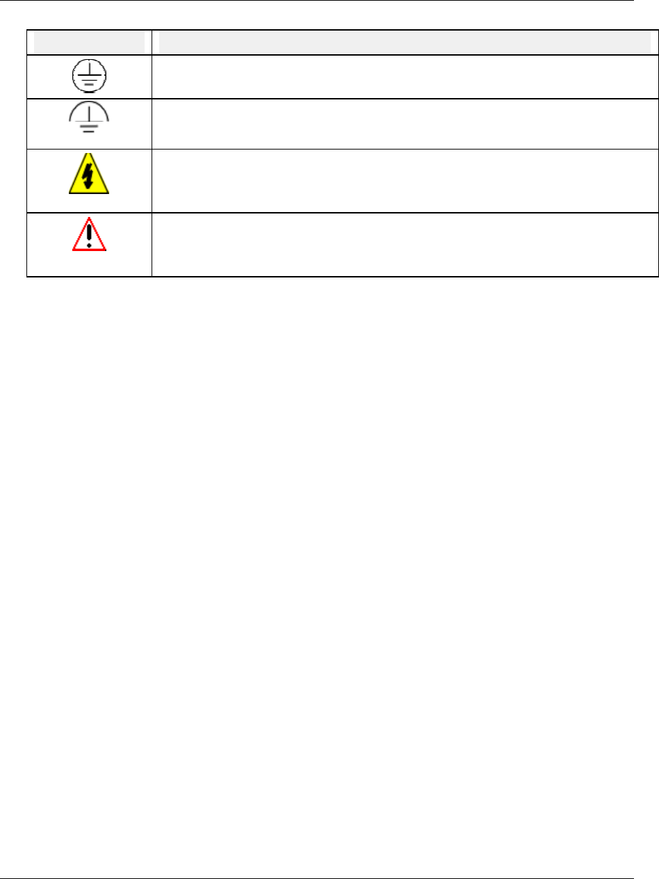
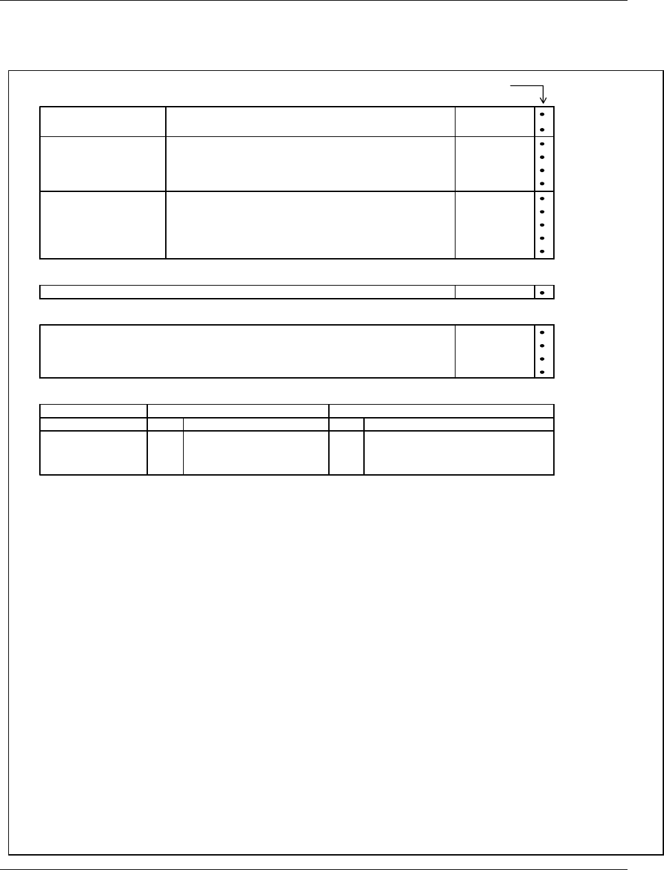
Symbol Meanings
Symbol What it means
Protective ground terminal. Provided for connection of the protective earth green (green
or green/yellow) supply system conductor.
Functional ground terminal. Used for non-safety purposes such as noise immunity
improvement.
WARNING. Risk of electric shock. This symbol warns the user of a potential shock
hazard where voltages greater than 30 Vrms, 42.4 Vpeak, or 60 Vdc may be accessible.
Failure to comply with these instructions could result in death or serious injury
CAUTION. When this symbol appears on the product, see the user manual for more
information. This symbol appears next to the required information in the manual.
Failure to comply with these instructions may result in product damage.
CE conformity
This product conforms with the protection requirements of the following European Council
Directives: 89/336/EEC, the EMC directive, and 73/23/EEC, the low voltage directive. Do not
assume this product conforms with any other “CE Mark” Directive(s).
Attention
The emission limits of EN 50081-2 are designed to provide reasonable protection against harmful
interference when this equipment is operated in an industrial environment. Operation of this
equipment in a residential area may cause harmful interference. This equipment generates, uses, and
can radiate radio frequency energy and may cause interference to radio and television reception when
the equipment is used closer than 30 meters to the antenna(e). In special cases, when highly
susceptible apparatus is used in close proximity, the user may have to employ additional mitigating
measures to further reduce the electromagnetic emissions of this equipment.

iv Video Recorder – User Manual

Video Recorder – User Manual v
Contents
1. INTRODUCTION ................................................................................................................ 1
1.1 Video Recorder Overview ...............................................................................................................1
1.2 Specifications..................................................................................................................................2
1.3 Model Selection Guide..................................................................................................................12
2 INSTALLATION................................................................................................................. 13
2.1 Warning.........................................................................................................................................13
2.2 Unpacking .....................................................................................................................................14
2.3 Panel mounting the video recorder...............................................................................................15
2.4 Wiring the video recorder..............................................................................................................17
2.5 Terminal connections....................................................................................................................19
3. PROGRAMMING AND OPERATING CONCEPTS AND PROCEDURES........................ 35
3.1 Overview .......................................................................................................................................35
3.2 Quick Start Programming..............................................................................................................35
3.3 Modes of Operation.......................................................................................................................35
3.4 Menu Navigation ...........................................................................................................................36
3.5 Button functions ............................................................................................................................41
3.6 Text Entry From External Sources................................................................................................45
3.7 Connecting a keyboard or a barcode reader ................................................................................47
3.8 Installing and removing a floppy disk............................................................................................48
3.9 Definition of Function Blocks.........................................................................................................49
3.10 Components of function blocks.....................................................................................................51
3.11 How to program input parameters ................................................................................................55
3.12 How to program function block parameters ..................................................................................58
3.13 How to program a simple configuration ........................................................................................58
3.14 How to program common configurations ......................................................................................60
3.15 Data Storage.................................................................................................................................74
4. HOW TO PROGRAM FUNCTION BLOCKS AND FEATURES........................................ 79
4.1 Overview .......................................................................................................................................79
4.2 Programming tips..........................................................................................................................80
4.3 The Program mode menu.............................................................................................................81
4.4 Frequently used programming prompts........................................................................................82
4.5 Set Mode.......................................................................................................................................83

vi Video Recorder – User Manual
4. HOW TO PROGRAM FUNCTION BLOCKS AND FEATURES..........CONT………………….
4.6 Enter Labels..................................................................................................................................84
4.7 Program Analog Inputs .................................................................................................................87
4.8 Program Control Loops.................................................................................................................90
4.9 Program Analog Outputs ............................................................................................................101
4.10 Program Discrete Inputs .............................................................................................................104
4.11 Program Discrete Outputs ..........................................................................................................105
4.12 Program Calculated Values ........................................................................................................105
4.13 Program Alarms ..........................................................................................................................143
4.14 Program Totalizers......................................................................................................................144
4.15 Program Profiles .........................................................................................................................146
4.16 Program Constants .....................................................................................................................147
4.17 Copy Block ..................................................................................................................................149
4.18 Program Displays........................................................................................................................150
4.19 Enable Features..........................................................................................................................159
4.20 Program Security ........................................................................................................................160
4.21 Serial Communications ...............................................................................................................161
4.22 Set Clock.....................................................................................................................................162
4.23 Load/Store Configuration ............................................................................................................163
4.24 Scan Rate ...................................................................................................................................164
4.25 Select Language .........................................................................................................................165
4.26 Data Storage...............................................................................................................................166
5. SETPOINT PROFILER................................................................................................... 175
5.1 Overview of the Setpoint Profiler ................................................................................................175
5.2 Components of a profile..............................................................................................................178
5.3 Parameters that control a profile’s execution..............................................................................185
5.4 How to set up a profiler ...............................................................................................................189
5.5 How to load and run a profiler.....................................................................................................197
6. ONLINE OPERATIONS USING PRIMARY DISPLAYS.................................................. 209
6.1 Overview .....................................................................................................................................209
6.2 Interacting With Primary Displays...............................................................................................210
6.3 Display Messages and Symbols.................................................................................................217

Video Recorder – User Manual vii
7. ONLINE OPERATION USING MENUS .......................................................................... 221
7.1 Overview .....................................................................................................................................221
7.2 Data Storage...............................................................................................................................222
7.3 Access Summaries .....................................................................................................................228
7.4 Data Entry ...................................................................................................................................232
7.5 Setpoint Profiles..........................................................................................................................234
7.6 Tune Loop ...................................................................................................................................235
7.7 Set Mode.....................................................................................................................................242
7.8 Review Programming..................................................................................................................242
8. MAINTENANCE ............................................................................................................. 243
8.1 Overview .....................................................................................................................................243
8.2 Routine Maintenance ..................................................................................................................245
8.3 Set Mode.....................................................................................................................................245
8.4 Calibrate Analog Inputs...............................................................................................................245
8.5 AO MODULE calibration .............................................................................................................246
8.6 Off-line Diagnostics.....................................................................................................................247
8.7 Database Services......................................................................................................................248
8.8 Reset Unit ...................................................................................................................................248
8.9 Product Information.....................................................................................................................248
8.10 Mains Frequency.........................................................................................................................248
8.11 Warm Start Time.........................................................................................................................249
8.12 Demo...........................................................................................................................................250
9. DIAGNOSTIC AND ERROR MESSAGES...................................................................... 251
9.1 Diagnostic Messages..................................................................................................................251
9.2 Loop Error Indicators...................................................................................................................254
9.3 Error Messages...........................................................................................................................255
10. PARTS ........................................................................................................................... 259
APPENDIX A ........................................................................................................................ 263
SAFETY................................................................................................................................ 265
INDEX................................................................................................................................... 277
SALES AND SERVICE

viii Video Recorder – User Manual
TABLES
Table 1-1 Specifications........................................................................................................................................ 2
Table 1-2 Analog Input Accuracy--Linear types .................................................................................................. 7
Table 1-3 Analog Input --Non-linear types........................................................................................................... 8
Table 1-4 Standards ............................................................................................................................................... 9
Table 2-1 Universal Analog Input Board Specifications ..................................................................................... 22
Table 3-1 Button Functions................................................................................................................................. 41
Table 3-2 QWERTY Key Equivalents................................................................................................................ 45
Table 3-3 Function Block Types........................................................................................................................... 50
Table 3-4 Function Block Parameter Designators .............................................................................................. 53
Table 3-5 Output Code Connection Procedure ................................................................................................... 55
Table 3-6 Example Number Selection Procedure Using Front Panel Buttons..................................................... 57
Table 3-7 Example Programming Discrete Input Parameter with a Number....................................................... 57
Table 3-8 Example Function Block Parameter Selection Procedure ................................................................... 58
Table 3-9 Function Block Configuration Procedure ........................................................................................... 58
Table 3-10 Example Configuration Procedure..................................................................................................... 59
Table 3-11 Data Storage File Extensions............................................................................................................. 75
Table 4-1 Program Mode Menu........................................................................................................................... 81
Table 4-2 Frequently Used Programming Prompts............................................................................................. 82
Table 4-3 Labels for Function Blocks................................................................................................................. 85
Table 4-4 Other Labels ....................................................................................................................................... 86
Table 4-5 Analog Input Algorithm Selection...................................................................................................... 87
Table 4-6 Standard Algorithm Prompts .............................................................................................................. 87
Table 4-7 Custom Algorithm Prompts................................................................................................................ 89
Table 4-8 Loop Characteristics ........................................................................................................................... 90
Table 4-9 Control Loop Type Menu Selections.................................................................................................. 92
Table 4-10 Loop Prompts.................................................................................................................................... 94
Table 4-11 Analog Output Types....................................................................................................................... 101
Table 4-12 Prompts For Analog Output Types.................................................................................................. 101
Table 4-13 Analog Output Prompts .................................................................................................................. 102
Table 4-14 Discrete Input Prompts ................................................................................................................... 104
Table 4-15 Discrete Output Prompts................................................................................................................. 105
Table 4-16 CV Types......................................................................................................................................... 106
Table 4-17 Peak Picking Prompts..................................................................................................................... 107
Table 4-18 Signal Select Prompts..................................................................................................................... 108
Table 4-19 Compare Prompts ............................................................................................................................ 109
Table 4-20 Compare’s Condition Type and Condition Time Prompts ............................................................. 111
Table 4-21 Counter Prompts............................................................................................................................. 113
Table 4-22 Math Prompts.................................................................................................................................. 114
Table 4-23 Free Form Math Prompts................................................................................................................ 115
Table 4-24 Free Form Math Functions ............................................................................................................. 116
Table 4-25 Logic Prompts................................................................................................................................. 117
Table 4-26 Logic Operators .............................................................................................................................. 118
Table 4-27 Free Form Logic Prompts............................................................................................................... 119
Table 4-28 (A OR B) AND C ............................................................................................................................ 120
Table 4-29 Results of Logic Equation Using Iteration....................................................................................... 120
Table 4-30 Inverter Prompts ............................................................................................................................. 120
Table 4-31 BCD Prompts.................................................................................................................................. 121
Table 4-32 How Profiles Are Saved In Memory .............................................................................................. 122
Table 4-33 Function Generator Prompts........................................................................................................... 123
Table 4-34 Interval Timer Prompts.................................................................................................................... 125
Table 4-35 Periodic Timer Prompts.................................................................................................................. 127

Video Recorder – User Manual ix
Table 4-36 Set Up Timer Prompts ..................................................................................................................... 127
Table 4-37 Mass Flow Prompts ........................................................................................................................ 128
Table 4-38 Carbon Prompts.............................................................................................................................. 129
Table 4-39 Relative Humidity Prompts ........................................................................................................... 131
Table 4-40 F0 Sterilization Prompts.................................................................................................................. 132
Table 4-41 Advanced Splitter Prompts............................................................................................................... 134
Table 4-42 Standard Splitter Prompts................................................................................................................. 135
Table 4-43 Scaling Prompts.............................................................................................................................. 136
Table 4-44 Signal Clamp Prompts .................................................................................................................... 137
Table 4-45 1 Point Block Average Prompts...................................................................................................... 138
Table 4-46 Rolling Average Prompts................................................................................................................ 139
Table 4-47 Multiple Average Prompts.............................................................................................................. 140
Table 4-48 CEMS Block Average Prompts ...................................................................................................... 141
Table 4-49 CEMS Rolling Average Prompts.................................................................................................... 142
Table 4-50 Alarm Prompts................................................................................................................................ 143
Table 4-51 Totalizer Prompts.............................................................................................................................. 145
Table 4-52 Constant Prompts............................................................................................................................ 147
Table 4-53 Copy Block Prompts........................................................................................................................ 149
Table 4-54 Display Setup Procedure................................................................................................................. 152
Table 4-55 Set Up Trend 1 Prompts ................................................................................................................. 152
Table 4-56 Paper Chart Speed Equivalents to Time Base Selections ............................................................... 153
Table 4-57 1 trend group live buffer size............................................................................................................ 154
Table 4-58 2 trend group live buffer size........................................................................................................... 154
Table 4-59 4 trend group live buffer size........................................................................................................... 155
Table 4-60 Set Up Bar Graph 1 Prompts .......................................................................................................... 156
Table 4-61 Set Up Panel Display Prompts........................................................................................................ 156
Table 4-62 Set Up Unit Data Display Prompts................................................................................................. 156
Table 4-63 Set Up Profile Display Prompts...................................................................................................... 156
Table 4-64 Assign Displays To Keys Prompts ................................................................................................. 157
Table 4-65 Enable Features Prompts ................................................................................................................ 159
Table 4-66 Security Prompts.............................................................................................................................. 160
Table 4-67 Serial Communications Prompts ...................................................................................................... 161
Table 4-68 Set Clock Prompts .......................................................................................................................... 162
Table 4-69 Load/Store Config Files Prompts.................................................................................................... 163
Table 4-70 Suggested Scan Rates ...................................................................................................................... 164
Table 4-71 Data Storage Setup Procedure ........................................................................................................ 166
Table 4-72 Prompts For Storage Setup Of Trends, Alarms, Events, Diagnostics............................................. 168
Table 4-73 Stored Events.................................................................................................................................. 169
Table 4-74 Unit Data Prompts .......................................................................................................................... 170
Table 4-75 Disk capacity Prompts .................................................................................................................... 172
Table 4-76 Disk Storage Capacity of LS120 or ZIP disk.................................................................................. 173
Table 4-77 Disk Storage Capacity for the 1.44 Mbyte Floppy Disk................................................................... 174
Table 5-1 Example of Segment Events............................................................................................................. 183
Table 5-2 Parameters That Control Profiler Execution..................................................................................... 185
Table 5-3 Program Profiler Prompts................................................................................................................. 190
Table 5-4 Setpoint Profiles Prompts ................................................................................................................... 191
Table 5-5 Edit Profile Prompts ......................................................................................................................... 193
Table 5-6 Edit Segments Prompts..................................................................................................................... 196
Table 5-7 How Profiles Are Stored In Memory................................................................................................ 198
Table 5-8 Procedure To Load A Program From Memory Using Online Menu................................................. 199
Table 5-9 Procedure To Load A Program From Memory Using Point/Detail Menu......................................... 199
Table 5-10 How Profiles Are Stored On Disk .................................................................................................. 200
Table 5-11 Disk Program Capacity................................................................................................................... 200
Table 5-12 Procedure To Load A Program From Disk..................................................................................... 201

x Video Recorder – User Manual
Table 5-13 Profiler Starting Procedure ............................................................................................................. 202
Table 5-14 Profiler Hold Procedure.................................................................................................................. 203
Table 5-15 Profiler Reset Procedure................................................................................................................. 203
Table 5-16 Profiler Advance Procedure............................................................................................................ 204
Table 5-17 Profiler Shutdown Procedure.......................................................................................................... 204
Table 5-18 Event Viewing Procedure............................................................................................................... 205
Table 5-19 Details Viewing Procedure............................................................................................................. 205
Table 5-20 Summary Viewing Procedure......................................................................................................... 206
Table 5-21 Segment Editing Procedure ............................................................................................................ 207
Table 6-1 Displays Accessed With Display Button .......................................................................................... 209
Table 6-2 Point/Detail Menu Prompts .............................................................................................................. 211
Table 6-3 Stop Panel_4 Display Rotation Procedure........................................................................................ 214
Table 6-4 Resume Panel_4 Display Rotation Procedure .................................................................................. 214
Table 6-5 Interacting With Loop Displays........................................................................................................ 216
Table 6-6 Messages and Symbols at Bottom of Display................................................................................... 218
Table 6-7 Messages and Symbols Elsewhere on Display .................................................................................. 219
Table 7-1 Online Main Menu............................................................................................................................. 221
Table 7-2 Floppy Disk Insertion/Removal Procedure....................................................................................... 222
Table 7-3 Disk Status......................................................................................................................................... 223
Table 7-4 Storage Start/Stop Controls .............................................................................................................. 225
Table 7-5 Data Storage Replay Procedure........................................................................................................ 226
Table 7-6 Alarm Acknowledgment Procedure................................................................................................... 229
Table 7-7 Diagnostic Acknowledgment Procedure............................................................................................ 230
Table 7-8 Delete All Diagnostics Procedure..................................................................................................... 231
Table 7-9 Tune Loop Prompts ........................................................................................................................... 235
Table 7-10 Stages Of Pretune ............................................................................................................................ 238
Table 7-11 Pretune STOPPED Prompts............................................................................................................. 238
Table 7-12 Pretune IDENTIFYING & CALCULATING Prompts.................................................................. 239
Table 7-13 Pretune COMPLETE Prompts......................................................................................................... 240
Table 7-14 Pretune Abort Messages .................................................................................................................. 241
Table 8-1 Maintenance Mode Menu................................................................................................................. 243
Table 8-2 Calibrate Analog Output Procedure................................................................................................... 247
Table 8-3 Offline Diagnostic Prompts ............................................................................................................... 247
Table 8-4 Database Services Prompts............................................................................................................... 248
Table 9-1 Diagnostic Error Messages................................................................................................................ 251
Table 9-2 Internal Error Messages.................................................................................................................... 252
Table 9-3 Abnormal Loop Conditions And Indicators...................................................................................... 254
Table 9-4 Error Messages ................................................................................................................................. 255
Table 10-1 Parts................................................................................................................................................ 259
Table A-1 Security Bypass Procedure ...............................................................................................................263

Video Recorder – User Manual xi
Figures
Figure 1-1 Video Recorder .............................................................................................................................. 1
Figure 1-2 Video Recorder Model Number ................................................................................................. 10
Figure 2-1 AI Board Terminal Block Connections...................................................................................... 22
Figure 2-2 10 ohm Copper Connections ..................................................................................................... 22
Figure 2-3 DI Board Terminal Block Connections...................................................................................... 23
Figure 2-4 AO Board Terminal Block Connections.................................................................................... 24
Figure 2-5 DO Board Terminal Block Connections .................................................................................... 25
Figure 2-6 DO Board Relay Contact Setting............................................................................................... 26
Figure 2-7 RS232 wiring configuration......................................................................................................... 29
Figure 2-8 RS422 wiring configuration ........................................................................................................ 30
Figure 2-9 RS422 Interface Connections.................................................................................................... 30
Figure 2-10 RS485 wiring configuration ........................................................................................................ 32
Figure 2-11 Interface connector ..................................................................................................................... 32
Figure 3-1 Video Recorder Front Door Buttons.......................................................................................... 36
Figure 3-2 Menu Navigation Guide Through ON LINE, PROGRAM, and MAINTENANCE mode
MAIN MENUs............................................................................................................................... 37
Figure 3-3 ON LINE mode MAIN MENU ...................................................................................................... 38
Figure 3-4 PROGRAM mode MAIN MENU.................................................................................................. 39
Figure 3-5 MAINTENANCE mode MAIN MENU ......................................................................................... 40
Figure 3-6 Connection of a keyboard or a barcode reader........................................................................ 47
Figure 3-7 Alarm 1 Function Block Components......................................................................................... 51
Figure 3-8 Example Input Parameter Connection....................................................................................... 55
Figure 3-9 Function Block Connection Format ............................................................................................ 56
Figure 3-10 Example Configuration................................................................................................................ 59
Figure 3-11 Control Of Furnace Zone Temperature With 4-20 mA (CAT) Control Signal ..................... 60
Figure 3-12 Basic Function Blocks Required For Control Configuration Of Figure 3-11........................ 61
Figure 3-13 Labeling Each Function Block’s Name And Major Inputs And Outputs............................... 62
Figure 3-14 Labels For Internal Function Block Parameters...................................................................... 63
Figure 3-15 Interconnections Between Function Blocks ............................................................................. 62
Figure 3-16 Complete Function Block Diagram Of Figure 3-11................................................................. 64
Figure 3-17 Control Of Wastewater pH Using A Time Proportioning (DAT) Control Signal .................. 65
Figure 3-18 Function Block Diagram Of Figure 3-17 ................................................................................... 65
Figure 3-19 Temperature Control Of Water Using Split Output Or Duplex Control ................................ 66
Figure 3-20 Function Block Diagram Of Figure 3-19 ................................................................................... 67
Figure 3-21 Temperature Control Of An Oil Heated Chemical Reaction Chamber ................................ 68
Figure 3-22 Function Block Diagram Of The Cascade Control Strategy.................................................. 69
Figure 3-23 Example Set Point Profile........................................................................................................... 70
Figure 3-24 Function Block Diagram Of Set Point Profile Control Of Figure 3-16 .................................. 71
Figure 3-25 Discrete Inputs Controlling Execution Of Set Point Profiler Function Block ....................... 71
Figure 3-26 Up To 16 Discrete Events May Be Programmed Per Step Of A Set Point Profile............. 72
Figure 3-27 Tying A Profile Function Block’s Discrete Events With Discrete Output Hardware ........... 73
Figure 3-28 Categories of Stored Data.......................................................................................................... 74
Figure 4-1 Function Block Configuration of a Typical Ratio Control Loop ....................................... 100
Figure 4-2 Compare Signal Flow...................................................................................................... 109
Figure 4-3 Compare’s Greater Than Result, With Hysteresis.......................................................... 110
Figure 4-4 Math CV Feedback Programming................................................................................... 114
Figure 4-5 Logic Signal Flow............................................................................................................ 116
Figure 4-6 Free Form Logic Signal Flow.......................................................................................... 119
Figure 4-7 Function Generator Curve .............................................................................................. 123

xii Video Recorder – User Manual
Figure 4-8 Function Generator Configuration For Valve Characterization....................................... 124
Figure 4-9 Function Generator Configuration For Input Signal Characterization............................. 124
Figure 4-10 Periodic Timer................................................................................................................. 126
Figure 4-11 Typical Carbon Potential Control Configuration.............................................................. 130
Figure 4-12 Advanced Splitter (Default Outputs) .............................................................................. 133
Figure 4-13 Heat/Cool Configuration................................................................................................. 133
Figure 4-14 Standard Split Output Function...................................................................................... 135
Figure 4-15 CEMS Rolling Average .................................................................................................. 142
Figure 4-16 Example of Constant Destination................................................................................... 148
Figure 4-17 Displays Accessible by the Display Buttons (continued) ............................................... 150
Figure 5-1 Setpoint Profiler Schematic..................................................................................................... 176
Figure 5-2 Single and Multi-phase Profiles.............................................................................................. 177
Figure 5-3 Value/Duration Ramp Type..................................................................................................... 178
Figure 5-4 Time Ramp Type ...................................................................................................................... 179
Figure 5-5 Rate Ramp Type....................................................................................................................... 180
Figure 5-6 External Ramp Type................................................................................................................. 181
Figure 5-7 Guaranteed Soak and Hysteresis ........................................................................................... 182
Figure 5-8 Activating Events In Mid-Segment .......................................................................................... 183
Figure 5-9 Example Of A Segment Loop .................................................................................................. 184
Figure 5-10 Hot Start ...................................................................................................................................... 186
Figure 5-11 Fast Forward............................................................................................................................... 187
Figure 5-12 Shutdown .................................................................................................................................... 188
Figure 5-13 Allowable and Non-Allowable Program Storage ................................................................... 192
Figure 5-14 Buttons ........................................................................................................................................ 197
Figure 6-1 Changing Profile Batch Tag ..................................................................................................... 210
Figure 6-2 Horizontal and Vertical Trend Displays .................................................................................. 211
Figure 6-3 Vertical Trend at 2X Zoom........................................................................................................ 213
Figure 6-4 Panel Display.............................................................................................................................. 214
Figure 6-5 Loop Displays............................................................................................................................. 215
Figure 6-6 Example of Primary Display ..................................................................................................... 217
Figure 7-1 Data Storage Status Display.................................................................................................... 226
Figure 7-2 Control Loop Tuning Display.................................................................................................... 237
Figure 8-1 AO Module Jumper ST1 ............................................................................................................ 246
Introduction
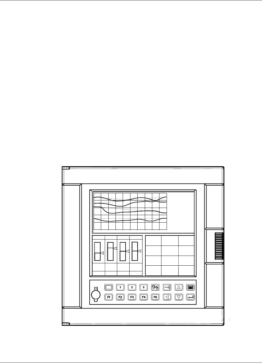
Video Recorder - User Manual 1
1. Introduction
1.1 Video Recorder Overview
The Video Recorder (Figure 1-1) is part of the family of multi-point, multi-function video products. The
instrument offers display versatility, flexible data storage, up to 8 control loops, each one can run its own
profile, and advanced math functions. This integration of several functions eliminates the need for
multiple devices and reduces installation costs.
The instrument features a high resolution LCD display which is capable of displaying up to 16 different
colors simultaneously. The front door opens to allow access to a 100MB ZIP disk drive. A mini DIN
connector can be used on the front door for connecting a PC keyboard or barcode reader for easy
labeling of parameters. Barcode reader also stores Event Records to disk.
Sixteen panel keys control all functions of the instrument, including configuration.
The instrument will accept thermocouple, RTD, pyrometer, milliamp, millivolt and volt inputs. Up to eight
analog outputs are available for retransmission or control. Data can be directed to various display
formats, stored on floppy disk, or read from an optional serial communications link. Analog and discrete
data can be displayed in trend or tabular format. Viewed data can be either “live” (real time inputs) or
historical (retrieved from disk).
Flexible modular design and several options make this instrument adaptable to nearly any industrial
application.
PV 405.00
SP 405.00
OUT 15.0
A S1
LP1
1000.00
0.00
LP2
1500.00
0.00
1054.00
1040.00
10.0
M S2
LP4
2400.00
0.00
1266.00
1244.00
5.0
A S1
LP3
1200.00
0.00
623.00
622.00
5.0
M S1
TAG1
VALUE1
TAG2
VALUE2
TAG3
VALUE3
TAG4
VALUE4
TAG5
VALUE5
TAG6
VALUE6
TAG7
VALUE7
TAG8
VALUE8
TAG9
VALUE9
TAG10
VALUE10
TAG11
VALUE11
TAG12
VALUE12
ZONE1
123.45
DEG F
ZONE2
123.45
DEG C
ZONE3
123.45
DEG F
ZONE4
123.45
DEG F
ZONE5
123.45
DEG F
ZONE6
123.45
DEG C
ZONE7
123.45
DEG F
ZONE8
123.45
DEG C
ZONE9
123.45
DEG F
ZONEA
123.45
DEG F
ZONEB
123.45
DEG
ZONEC
123.45
DEG F
Figure 1-1 Video Recorder

Introduction
Video recorder – User Manual 2
1.2 Specifications
Table 1-1 Specifications
Physical
Enclosure Metal case and rugged die cast aluminium door and frame. High impact resistant
polycarbonate keypad and glass or polycarbonate window. IP55 rating (NEMA 3) from front
panel.
Mounting (Panel) 40 mm thickness (max.) (1,57")
Dimensions Compact size: 320 mm (12.60") depth
310 mm front face height x 317 mm width (12.21" x 12.48")
278 mm x 278 mm (10.95" x 10.95") cutout
Weight 14 kg, depending on configuration (30 lbs)
I/O Ports Standard PC keyboard Connector (6 pin mini DIN type) - on front panel. May be used to connect to a
QWERTY keyboard or to an ASCII Barcode Reader.
Environmental
Temperature Operating: 5 to 40°C (41 to104°F).
Storage: -20 to 60°C (-4 to 158°F).
Relative Humidity: 10 to 90%, non-condensing at 40°C.
Altitude < 2000 meters
Installation
Category II
Pollution Degree 2
Power Universal power supply, 100 to 240 Vac/dc, 100 VA max.
Fuse Rating 3.15 Amps, 250 Vac slow blow
Attributes
Display Type: Color LCD active matrix.
Screen Size: 10.4" diagonal.
Resolution: 640 x 480 pixels.
Update Rate: 1 second.
Trend Timebase: 5 min. to 24 hrs/screen; 0.5 cm/hr to 154 cm/hr vertical (0.2"/hr to 61"/hr
vertical), 0.8 cm/hr to 250 cm/hr horizontal (0.3"/hr to 100"/hr horizontal).
Keys 16 membrane switches.
Data Archiving Media: 100MB ZIP disk drive.
Data Types: Analog points, calculations, discrete status, alarms, diagnostics.
Trends: 4 max. (up to 12 points max. per trend)
Unit Data: 1 (up to 12 points, 10,000 records)
Alarm History: Up to 1600 records
Event History: Up to 1600 records
Diagnostic History: Up to 1600 records
Setpoint Programs: 224 maximum on LS120 floppy disk.
Storage Rate Range: 0.25 to 3600 sec.
Capacity: Automatically calculates storage time based on storage rate.
Setpoint
programmers Up to 4

Introduction
Video Recorder - User Manual 3
Table 1-1 Specifications (continued)
Program Capability
Number of
Programs
Memory can store 96 programs for a single channel programmer, 48 programs for a dual
channel programmer, 32 programs for a three channel programmer, and 24 for a four
channel programmer. Programs can also be stored to floppy disk. Programmer has ability
to start a program at a predetermined time.
Number of
Segments 63 segments per profile
Ramping Capability Ramp X - Ramp rate is set by specifying x degrees per second, per minute, or per hour.
Ramp T - Ramp rate is set by selecting the time to go from previous setpoint to next
setpoint in t time.
Ramp E - Ramp rate is set to increment by ∆SP for every pulse of a digital input.
Value Duration Ramp - Ramp rate is based on the start value of the ramp and the time
specified to reach the next soak start value.
Ramp Time Range 0-9,999,999 hours, minutes, or seconds.
Soak Guaranteed or non-guaranteed. Can be applied to ramp or soak segment or across entire
profile/program.
Soak time range 0-9,999,999 hours, minutes, or seconds.
Program Cycling Entire programs or portions of a program can be cycled up to 99 times. Loops can be
nested up to 4 deep.
Startup/Shutdown Can be set up to use a predefined startup profile separate from the normal processing
programs. Shutdown profile can be attached to the end of a profile and can be jumped to
for emergency shutdown.
PV Hot Start Can start the profile at the point where the present PV value first intersects the profile.
Batch Programming 1 to 255 Batch numbers. Batch number is assigned by the programmer and is incremented
automatically when batch is started.
Using a keyboard or bar code reader and the front keyboard connector, a batch can be
labeled with a name of up to 8 characters.
Profile Events Up to 16 events can be defined in each segment of a profile. Each event’s state is
activated at the beginning of the segment and is held throughout the segment.

Introduction
Video recorder – User Manual 4
Table 1-1 Specifications (continued)
Universal Analog Inputs
Number 4 per module, up to 12 modules per video recorder
Input Types mV, V, mA, T/C, RTD, pyrometers
Signal source Thermocouple with cold junction compensation
Line resistance up to 1000 ohms, T/C, mV, mA, V
RTD, 3-wire connections, 40 ohms balanced maximum
Input Impedance 10 megohms for T/C and mV inputs; >1 megohm for volt inputs
Input Isolation 400 Vdc point-to-point
1350 Vac RMS A/D converter to logic
Stray rejection Series mode >60 dB. Common mode at 120 Vac >130 dB.
Burnout T/C, Pyrometry configurable to upscale, downscale or none.
Linear types: none except following ranges:
Volt: -500 to 500 mV; -1 to 1V; -2 to 2V; -5 to 5V; 0 to 10V; -10 to 10V; inherent to
zero volt
RTD: Inherent upscale
mA: Inherent downscale
T/C Break Detection Via current pulse
Scan rate Fastest rate:
250 ms up to 4 inputs, 500 ms up to 12 inputs, 750 ms up to 16 inputs,
1s up to 24 inputs,1,5 s up to 28 inputs, 2 s up to 44 inputs, 3 s up to 48 inputs.
A/D Converter Resolution Better than 1 part in 50,000 at 50 Hz.
Better than 1 part in 41,667 at 60 Hz.
Analog Outputs
Number 4 per module (non-isolated), up to 2 modules per video recorder (8 outputs)
Type Current output configurable within 0 to 20 mA. Maximum load 400 ohms per output.
Voltage output configurable 0 to 5 V.
Isolation from ground 350 Vac
Accuracy Factory configured accuracy = 0.1% at reference conditions
Field calibration accuracy = 0.05%
Temperature Effects 0.1% per 10°C in the rated limits
D/A Resolution 16 bits
Digital Inputs
AC Inputs DC Inputs
Number 6 per module, up to 6 modules per
video recorder 6 (sink/source) per module, up to 6 modules
per video recorder
Input Voltage Range 80 to 264 Vac 10.2 to 26.4 Vdc
Peak Voltage 264 Vac 26.4 Vdc
AC Frequency 47 to 63 Hz N/A
Isolation from ground 2300 Vac/1 min. 1100 Vac/1 min.
Isolation between inputs 350 Vac 30 Vac
ON Voltage Level 75 Vac minimum 9.5 Vdc minimum
OFF Voltage Level 20 Vac maximum 3.5 Vdc maximum

Introduction
Video Recorder - User Manual 5
Table 1-1 Specifications (continued)
Input Impedance 51K 5.6K
Input Current 0.9 mA @ 100 Vac 1.1 mA @ 12 Vdc
3.2 mA @ 24 Vdc
Minimum ON Current 0.3 mA 0.3 mA
Maximum OFF Current 0.15 mA 0.2 mA
Base Power Required* 50 mA maximum 50 mA maximum
OFF to ON Response 5 to 30 ms 1 to 8 ms
ON to OFF Response 10 to 50 ms 1 to 8 ms
Logic Inputs
Number 6 (dry contact) per module, up to 6 modules per video recorder
Isolation from ground 2300 Vac/1 min.
Switching Voltage 5 Vdc
Switching Current 5 mA
Digital Outputs
AC Outputs DC Outputs
Number 6 per module, up to 6 modules per video
recorder. Only 1-5 on each module can
be configured as DAT outputs.
6 (current sinking) per module, up to 6
modules per video recorder. Only 1-5
on each module can be configured as
DAT outputs.
Operating Voltage 15 to 264 Vac 10.2 to 26.4 Vdc
Output Type SSR (Triac) NPN open collector
Peak Voltage 264 Vac 40 Vdc
AC Frequency 47 to 63 Hz N/A
Isolation from ground 2300 Vac/1 min. 1100 Vac/1 min.
Isolation between outputs 350 Vac 30 Vac
ON Voltage Drop <1.5 Vac (>0.1A)
<3.0 Vac (<0.1A) 1.5 Vdc maximum
Maximum Load Current 0.5A per point 0.3A per point
Maximum Leakage Current 4 mA (264 Vac, 60 Hz)
1.2 mA (100 Vac, 60 Hz)
0.9 mA (100 Vac, 50 Hz)
0.1 mA @ 40 Vdc
Maximum Inrush Current 10A for 10 ms 1A for 10 ms
Minimum Load 10 mA 0.5 mA
Base Power required* 20 mA/ ON pt. 250 mA
maximum 120 mA maximum
5V
OFF to ON Response 1 ms 1 ms
ON to OFF Response 1 ms +1/2 cycle 1 ms
Fuses (European type 5 x
20mm) 1 per output, 1.0A slow blow 1 per output
1A fast blow
Relay (Alarm) Outputs
Number 6 per module, up to 6 modules per video recorder. Only 1-5 on each module can be
configured as DAT outputs.
Contact Rating 2A, 250 Vac on resistive load
Isolation from ground 2300 Vac/1 min.
Isolation between outputs 2300 Vac/1 min.
Contact Type SPST normally open (NO), individually configurable to normally closed (NC) via
jumper
* Base Power Required is the power required to provided module operation within specifications.

Introduction
Video recorder – User Manual 6
Table 1-1 Specifications (continued)
Time Proportional Outputs (TPO) on digital output
Time Resolution Equals the Scan Cycle time of the recorder.
Module Only Digital outputs 1 to 5 can be configured as DAT outputs.
Synchronization Individual TPOs are not synchronized with others.
Performance/Capacities
Math Calculations Standard Math package includes: 24 Calculated Values along with the following Math
functions: Free Form Math, Math Operators (+, -, x, ÷, Absolute Value, Square Root, Std.
Deviation), Free Form Logic, Logic Operators (AND, OR, XOR, Inverter, Flip Flop, One-
Shot), Inverter algorithms.
Advanced Math package includes: 64 Calculated Values with the functions from Standard
Math along with the following types of pre-packaged algorithms: Signal Select, Compare,
Signal Clamp, Periodic Timer, Interval Timer, Counter, Relative Humidity, Standard Splitter,
Scaling.
Constants 32
Alarms 96
Totalizers 0, 4 or 48
Control Loops Up to 8 (PID, ON/OFF, Cascade, Split, Ratio).
Auto Tune Each loop can be pre-tuned automatically to establish acceptable tuning parameters. On-
line fuzzy overshoot suppression.
Primary Displays Up to 10 displays may be assigned from the 32 formats selected among trend screens,
Bargraph screens, Panel screens, Summary screens, loop screens, Setpoint profiler
screens.
Support Displays 13 (menu access).
Communications
(optional) Type: RS-422/485, Modbus RTU protocol
Connection: 2 or 4 wire RS485.
Distance: 600 meters, (2000 feet).
Number of links: Up to 30
Baud Rate: 1200, 2400, 4800, 9600, 19.2K, 38.4K.
Parity: Selectable; odd, even, none.

Introduction
Video Recorder - User Manual 7
Table 1-1 Specifications (continued)
Analog input accuracy and rated limits
Accuracy Reference conditions Temperature = 23°C ± 2°C (73°F ± 3°F)
Humidity = 65% RH ± 5%
Line voltage = Nominal ± 1%
Source resistance = 0 ohm
Series mode and common mode = 0 V
Frequency = Nominal ± 1%
Accuracy Field calibration accuracy 0.05% of the selected range (IEC 873)
Factory calibration: 0.1%
Cold junction accuracy: ± 0.5°C
Rated limits and
associated drifts Parameters Rated limits Influence on accuracy
Temperature 0 to 50°C (32 to 120 °F) 0.15% per 10°C of change (See
Note A)
Cold junction 0.3°C/10°C
Supply voltage 85 to 250 V No influence
Source resistance T/C, mV 6 µV per 400 Ohms of line
resistance max. = 1000 Ohms
RTD 0.1°C per Ohm in each wire
balanced leads
40 Ohms max. (from 0 to 400°C)
Humidity 10 to 90% RH at 25°C 0.1% max.
Long-term stability 0.1% per year
Table 1-2 Analog Input Accuracy--Linear types
Millivolts Volts Current Ohms
0 to 10 mV
-10, +10 mV
0 to 20 mV
-20, 0, +20 mV
0, 50 mV
-50, 0, +50 mV
10 to 50 mV
0 to 100 mV
-100, 0, +100 mV
0 to 500 mV
-500, 0, +500 mV
0 to 1 V
-1, 0, 1 V
0 to 2 V
-2, 0, +2 V
0 to 5 V
-5, 0, +5 V
1 to 5 V
0 to 10 V
-10, 0, +10 V
0, 20 mA
4, 20 mA 0 to 200
0 to 2000
NOTE:
- The mA inputs must be connected to a 250 ohms resistor across the input terminals.
Introduction
Video recorder – User Manual 8
Table 1-3 Analog Input --Non-linear types
Thermocouples -ITS-90 except where noted
Accuracy (1) Operating span
Min value Reference range (2)
Type
°F °C
% Range
°F °C °F °C
J 0 to 2190 -18 to 1199 0.1 0.4 0.2
K 0 to 2500 -18 to 1371 0.1 0.4 0.2
E -450 to 1830 -268 to 999 0.1 0.4 0.2
T -300 to 752 -184 to 400 0.1 0.4 0.2
N 0 to 2372 -18 to 1300 0.1 0.6 0.3
B 110 to 3300 43 to 1816 0.1 2.5 1.4 752 to 3300 400 to 1816
R 0 to 3210 -18 to 1766 0.1 1.5 0.8
S 0 to 3210 -18 to 1766 0.1 1.6 0.9
W5/W26 (3) 0 to 4200 -18 to 2316 0.1 0.9 0.5 32 to 3272 0 to 1800
PLAT II (3) -100 to 2500 -73 to 1371 0.1 0.4 0.2
NI-NIMO 32 to 2502 0 to 1372 0.1 0.4 0.2
RTD (4)
CU10 -100 to 310 -73 to 154 0.5 2.5 1.4
PT100 IEC -300 to 1570 -184 to 854 0.1 0.5 0.3
Pyrometry (Rayotube & Spectray) Types
Accuracy ( 5 )
Operating span Max value Min value
Type
°F °C °F °C °F °C
18890-0035 1200 to 2600 649 to 1426 4 2 1 0.6
18890-0073 800 to 1800 427 to 982 12.5 7 1 0.6
18890-0074 1100 to 2300 594 to 1260 3 1.7 1 0.6
18890-0075 1500 to 3300 816 to 1815 6 3 1.8 1
18890-0163 200 to 1000 94 to 537 11 6 1.5 0.8
18890-0216 2110 to 4600 1155 to 2537 8 4.4 1.8 1
18890-0412 1375 to 3000 747 to 1648 10 5.6 1.3 0.7
18890-00643 1850 to 4000 1010 to 2204 8 4.4 1 0.6
18890-1729 1650 to 3600 899 to 1982 5 3 1.5 0.8
18890-3302 750 to 1600 399 to 871 6 3 1 0.6
18890-5423 2210 to 5000 1210 to 2760 18 10 2 1.1
18894-0579 752 to 2552 400 to 1400 33 18 3.6 2
18899-8814 340 to 1800 172 to 982 11 6 2 1.1
18894-9014 752 to 2552 400 to 1400 20 11 2.6 1.4
Spectray 18885 1832 to 3452 1000 to 1900 30 17 0.6 0.3
Spectray 18885-1 1292 to 2912 700 to 1600 60 33 0.6 0.3
Spectray 18885-2 806 to 1400 430 to 760 38 21 0.2 0.1
Spectray 18886 1833 to 3452 1001 to 1900 20 11 0.6 0.3
Spectray 18886-1 1292 to 2912 700 to 1600 80 44 0.6 0.3
18874-0578 752 to 2552 400 to 1400 3.6 2 1.8 1
18875-0579 752 to 2552 400 to 1400 3.6 2 1.8 1
NOTES:
1: The accuracy will be the larger value between Min Value and %range of the selected limits
2: Reference range = operating range when blank
3: IPTS-68
4: T° influence: 0.5% per 10°C on Cu 10 ohms, 0.3% per 10°C on Pt 100 ≤ 200°C
5: For Pyrometry, the worst accuracy (Max value) is at the low range limit , the best (Min value) is at the high limit.
- For non linear temperature transmitter, the transmitter range MUST be identical to the input range of the recorder.

Introduction
Video Recorder - User Manual 9
Table 1-4 Standards
This product is designed and manufactured to be in conformity with applicable U.S., Canadian, and International
(IEC/CENELEC/CE) standards for intended instrument locations. The following Standards and Specifications are
met or exceeded.
Case Protection IP55 on front door only, when the instrument is panel mounted and the front door
securely closed.
Rear of Panel EN 60529, IP 20
Flammability Rating UL 94 - V2
Vibration Level 10 to 40 Hz, 0.07 mm displacement; 40 to 60 Hz, 0.2g acceleration
Electromagnetic
Compatibility CE EMC Directive 89/336/EEC
Safety IEC1010 Installation Category II for personal protection
Intended Instrument
Locations Rack or panel mounting in control room or industrial environments (operator
accessibility front of panel only)
Installation Category II with grounded mains supply from isolation transformer or GFI
(ground fault interrupter)
Pollution Degree 2 with rear of panel enclosed, in industrial environment

Introduction
Video recorder – User Manual 10
1.3 Model Selection Guide
This table helps you to identify correctly the unit in front of you. Please refer to the product label and
verify that you have the right unit.
Select the desired key number. The mark to the right shows the selection available. A complete model
number has the requested number of digits from each table as follows.
Video Recorder Model Number Figure 1-2 Video Recorder Model Number
Instructions
Make the desired selection from Tables I to VI .
The arrow to the right marks the selection available.
A dot ( ) denotes unrestricted availability.
Key Number I II III IV V VI
VRX180 - _ _ - _ _ _ _ _ _ - _ _ _ _ _ - _ - _ _ _ _ _ _ -_ _
KEY NUMBER Selection Availability
Description
Video Recorder VRX180
TABLE I - ANALOG INPUTS
Analog Universal Inputs 4 Universal Analog Inputs 04
( slot A to F ) 8 Universal Analog Inputs 08
12 Universal Analog Inputs 12
16 Universal Analog Inputs 16
20 Universal Analog Inputs 20
24 Universal Analog Inputs 24
TABLE II - ADDITIONAL INPUTS AND OUTPUTS
None 0 _ _ _ _ _
Slot J 4 Universal Analog Inputs A _ _ _ _ _
6 Digital Inputs ( contact closure) B _ _ _ _ _
6 Di
g
ital In
p
uts 24 Vdc C _ _ _ _ _
6 Digital Inputs 120 / 240 Vac E _ _ _ _ _
6 Relays Outputs R _ _ _ _ _
6 Digital Outputs 24 Vdc ( open collector) G _ _ _ _ _
6 Digital Outputs 120 / 240 Vac ( triac ) H _ _ _ _ _
None _0 _ _ _ _
Slot K 4 Universal Analog Inputs _A _ _ _ _
6 Digital Inputs ( contact closure) _B_ _ _ _
6 Di
g
ital In
p
uts 24 Vdc _C_ _ _ _
6 Digital Inputs 120 / 240 Vac _E_ _ _ _
6 Relays Outputs _R_ _ _ _
6 Digital Outputs 24 Vdc ( open collector) _G_ _ _ _
6 Digital Outputs 120 / 240 Vac ( triac ) _H_ _ _ _
None _ _ 0 _ _ _
Slot L 4 Universal Analog Inputs _ _ A _ _ _
6 Digital Inputs ( contact closure) _ _ B _ _ _
6 Di
g
ital In
p
uts 24 Vdc _ _ C _ _ _
6 Digital Inputs 120 / 240 Vac _ _ E _ _ _
6 Relays Outputs _ _ R _ _ _
6 Digital Outputs 24 Vdc ( open collector) _ _ G _ _ _
6 Digital Outputs 120 / 240 Vac ( triac ) _ _ H _ _ _
None _ _ _ 0 _ _
Slot M 4 Universal Analog Inputs _ _ _ A _ _
6 Digital Inputs ( contact closure) _ _ _ B _ _
6 Di
g
ital In
p
uts 24 Vdc _ _ _ C _ _
6 Digital Inputs 120 / 240 Vac _ _ _ E _ _
6 Relays Outputs _ _ _ R _ _
6 Digital Outputs 24 Vdc ( open collector) _ _ _ G _ _
6 Digital Outputs 120 / 240 Vac ( triac ) _ _ _ H _ _

Introduction
Video Recorder - User Manual 11
Model Selection Guide (cont.)
VRX180
TABLE II - ADDITIONAL INPUTS AND OUTPUTS (continued) Selection
None _ _ _ _ 0 _
Slot N 4 Universal Analog Inputs _ _ _ _ A _
6 Digital Inputs ( contact closure) _ _ _ _ B _
6 Di
g
ital In
p
uts 24 Vdc _ _ _ _ C _
6 Digital Inputs 120 / 240 Vac _ _ _ _ E _
6 Relays Outputs _ _ _ _ R _
6 Digital Outputs 24 Vdc ( open collector) _ _ _ _ G _
6 Digital Outputs 120 / 240 Vac ( triac ) _ _ _ _ H _
4 Current Outputs (Note 7) _ _ _ _ M _
None _ _ _ _ _ 0
Slot P 4 Universal Analog Inputs _ _ _ _ _ A
6 Digital Inputs ( contact closure) _ _ _ _ _ B
6 Di
g
ital In
p
uts 24 Vdc _ _ _ _ _ C
6 Digital Inputs 120 / 240 Vac _ _ _ _ _ E
6 Relays Outputs _ _ _ _ _ R
6 Digital Outputs 24 Vdc ( open collector) _ _ _ _ _ G
6 Digital Outputs 120 / 240 Vac ( triac ) _ _ _ _ _ H
4 Current Outputs _ _ _ _ _ M
TABLE III - FIRMWARE - DATA STORAGE
None 0 _ _ _ _
Control Loops 1 Control Loop 1 _ _ _ _
(Notes 1, 5) 2 Control Loops 2 _ _ _ _
4 Control Loops 4 _ _ _ _
6 Control Loops 6 _ _ _ _
8 Control Loops 8 _ _ _ _
None _ 0 _ _ _
Set Point Programs 1 Set Point Program _ 1 _ _ _
(Note 4) 2 Set Point Programs _ 2 _ _ _
3 Set Point Programs _ 3 _ _ _
4 Set Point Programs _ 4 _ _ _
Math Standard Math _ _ 0 _ _
(Note 2) Advance Math _ _ 1 _ _
Advance Math and 4 Totalizers _ _ 2 _ _
Advance Math and 48 Totalizers _ _ 3 _ _
Data stora
g
e
(
Note 6
)
100 Mb ZIP Drive _ _ _ 2 _
Other None _ _ _ _ 0
TABLE IV - COMMUNICATION
Communication None 0
RS485 - Modbus RTU C
Ethernet Interface E c
TABLE V - OPTIONS
Documentation English E _ _ _ _ _
(prompts language, French F _ _ _ _ _
manual) German G _ _ _ _ _
Italian I _ _ _ _ _
Spanish S _ _ _ _ _
English - (U.S. format) U _ _ _ _ _
Certificates None _ 0 _ _ _ _
Certificate of Conformance _ B _ _ _ _
Calibration Certificate (Note 3) _ C _ _ _ _
Calibration and Conformance Certificates (Note 3) _ E _ _ _ _
Tagging None _ _ 0 _ _ _
Linen _ _ L _ _ _
Stainless steel _ _ S _ _ _
Introduction
Video recorder – User Manual 12
Model Selection Guide (cont.)
VRX180
TABLE V - OPTIONS (continued) Selection
Approvals CE Mark Compliant _ _ _ 0 _ _
CSA/NRTLc/CE Mark _ _ _ C _ _
Software None _ _ _ _ 0 _
SDA and SCF _ _ _ _ B _
SCF (Configuration Software) _ _ _ _ C _
SDA
(
Data Anal
y
sis Software
)
_ _ _ _ E _
Case Galvanized Case, Grey Door, Glass Window, Latch _ _ _ _ _ 0
Galvanized Case, Grey Door, Glass Window, Key Lock _ _ _ _ _ 1
Galvanized Case, Grey Door, Plastic Window, Latch _ _ _ _ _ 2
Galvanized Case, Grey Door, Plastic Window, Key Lock _ _ _ _ _ 3
Portable Case (Painted Case, Handles) _ _ _ _ _ 6
TABLE VI
Factory Use Only 00
SOFTWARES AND SUPPORT PARTS Part #
SDA Data Analysis Software (can be ordered separately if not selected in Table V) 045501
SCF Configuration Software (can be ordered separately if not selected in Table V) 045502
SDI Disk Initialization Software (Note 6) 46193351-501
Kit of 4 resistors 250 Ohms for 4-20 mA in
p
ut 46181080-503
RESTRICTIONS
Restriction Letter Available With Not Available With
Table Selection Table Selection
cII _ _ _ _ _ A, _ _ _ _ _ B, _ _ _ _ _ C,
_ _ _ _ _ E, _ _ _ _ _ R, _ _ _ _ _ G,
_ _ _ _ _ H, _ _ _ _ _ M
Notes:
1. The available algorithms include: PID (standard and advance), Cascade, Split Output and On/Off.
The appropriate outputs from Table I must be specified - Current or Relays.
If Split (Duplex) output Control is required, advance math must be selected ( Table III ).
2. Standard Math includes 24 Calculated Values and the following pre-packaged algorithms
Free Form Math Logic Operators Flip-Flop/One Shot Periodic Timer
Free Form Logic Math Operators Invertor
Advance Math includes 64 Calculated Values and the followin
g
additional of
p
re-
p
acka
g
e al
g
orithms.
Signal Select Interval Timer Counter
Compare Relative Humidity Scaling
Signal Clamp Mass Flow Advanced Splitter
Peak Picking Fo Calculation Continuous Emissions Monitoring
Function Generator Multi
p
le In
p
ut Avera
g
e - CEM Block Average
Carbon Potential Single Point Average - CEM Rolling Average
Rolling Average Standard Splitter
3. Customer must supply Input Actuation Type and Range for each input for inclusion in the free form
section of the Factor
y
order to su
pp
l
y
the Custom Calibration Certificate, otherwise the calibration will be
based on the factory default ranges.
4. When selectin
g
SP
p
ro
g
ram make sure to select analo
g
out
p
ut
(
current
)
as necessar
y
(
Table II slot N,P
)
.
5. When selecting Control loops, make sure to select outputs (as necessary in Table II)
6. Provided with each VRX180 are : one pre-initialized disk and one SDI software pack.
SDI software should be installed on a PC and used for initialization of new disks.
7. Must purchase Table II _ _ _ _ M _ in order to select Table II Selection _ _ _ _ _ M.
Installation
Video Recorder - User Manual 13
2. Installation
What’s in this section?
The following topics are covered in this section.
Topic Page
Warning 13
Unpacking 14
Panel mounting the video recorder 15
Wiring the video recorder 17
Terminal connections 19
NOTICE
If this instrument is used in a manner not specified by the manufacturer, the protection provided by the
instrument may be impaired.
2.1 Warning
To avoid the risk of electrical shock which could cause personal injury, follow all safety notices in
this documentation.
Protective earth terminal. Provided for connection of the protective earth supply system conductor.
• POWER SUPPLY
Ensure the source voltage matches the supply voltage of the video recorder before power on.
(In the rear of the video recorder, near to the connector of the power supply)
• PROTECTIVE GROUNDING
Make sure to connect the protective grounding to prevent an electric shock before power on.
Do not operate the instrument when protective grounding or fuse might be defective.
To avoid a potential shock hazard, never cut off the internal or external protective grounding
wire or disconnect the wiring of protective grounding terminal.
• FUSE
To prevent a fire, make sure to use the appropriate fuse (current, voltage, type). Before
replacing the fuse, turn off the power and disconnect the power source. Do not use a different
fuse or short-circuit the fuse holder.
• DO NOT OPERATE IN AN EXPLOSIVE ATMOSPHERE
Do not operate the instrument in the presence of flammable liquids or vapors. Operation of any
electrical instrument in such an environment constitutes a safety hazard.
• NEVER TOUCH THE INTERIOR OF THE INSTRUMENT
Inside this instrument, there are areas of high voltage; therefore, never touch the interior if the
power is connected. This instrument has an internal changeable system; however, internal
inspection and adjustments should be done by qualified personnel only.
• If the equipment is used in a manner not specified by the manufacturer, the protection
provided by the equipment may be impaired.
• Do not replace any component (or part) not explicitly specified as replaceable by your supplier.
• INSTALL INDOOR ONLY.
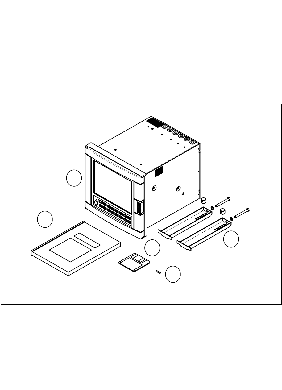
Installation
Video Recorder - User Manual 14
2.2 Unpacking
Examine the shipping container carefully. If there are visible signs of damage, notify the carrier and your local
sales office immediately.
If there is no visible damage, compare the contents with the packing list. Notify your local sales office if there is
equipment shortage.
To obtain proper credit and to avoid delays, return goods only after contacting your local sales office in
advance.
Carefully remove the instrument and remove any shipping ties or packing material. Follow the instructions on
any attached tags or labels and then remove such tags or labels.
5
4
2
1
3
1. Fuse (spare) use only 3.15 AT (slow blow) fuses size 5 x 20 mm
2. Floppy disk
3. Mounting brackets with nuts
4. Video recorder
5. Product manual
NOTE: In the event that any items are missing, please contact your nearest sales office.
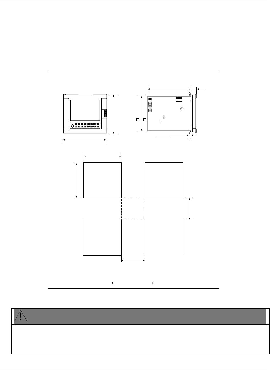
Installation
Video Recorder - User Manual 15
2.3 Panel mounting the video recorder
2.3.1 Recommendations
This video recorder is designed to operate under specific conditions. If you need more information, refer to the
product specification sheet.
2.3.2 External dimensions and cut-out
Prepare panel cut-out as detailed below:
0
0
0
317
12.48
320
12.60
310
12.21
45
1.77
40 max.
1.55
10.83
275
10.95
+0.06
10.95
+0.06
> 75
> 3
> 75
> 3
0
278
+1.5
0
millimeters
inches
278
+1.5
NOTE: Maximum panel thickness 40 mm (1.55")
CAUTION
The maximum temperature inside the cabinet should not exceed the ambient conditions specific for the
video recorders.
The video recorder must be mounted into a panel to limit operator access to the rear terminals.
Failure to comply with these instructions may result in product damage.
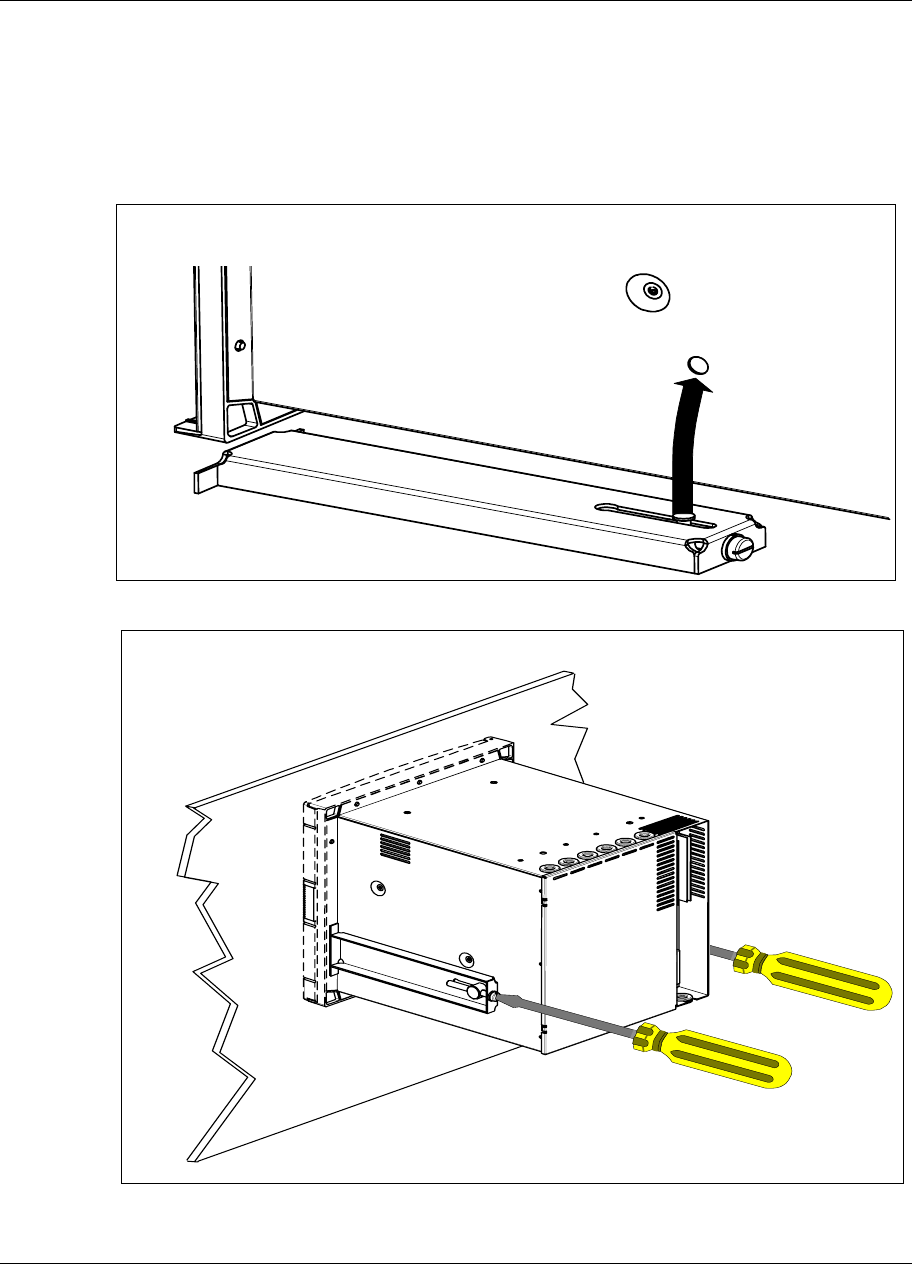
Installation
Video Recorder - User Manual 16
2.3.3 Installing the video recorder
To install the video recorder, follow the figure below:
Step 1: Remove rear cover and wire access holes
Step 2: Insert video recorder through the panel cutout
Step 3: Attach mounting brackets to the sides of the video recorder
Bracket position
Step 4: Tighten the mounting screws
Mounting brackets
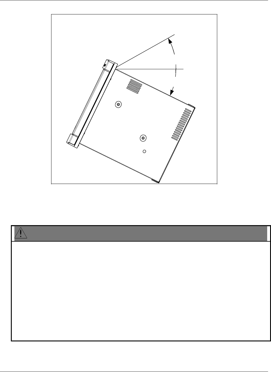
Installation
Video Recorder - User Manual 17
NOTE: When installing the video recorder, the following limits should be respected:
- 15 Deg
+ 15 Deg
Mounting angle limits
2.4 Wiring the video recorder
2.4.1 Recommendations
CAUTION
• All wiring must be in accordance with local electrical codes and should be carried out by authorized and
experienced personnel.
• The ground terminal must be connected before any other wiring (and disconnected last).
• A switch in the main supply is mandatory near the equipment.
• If an external fuse is used to protect the electrical circuit to the video recorder, the fuse should match the
video recorder fuse rating (fuse type) as well as for the fuseholder.
• Sensor wiring should be run as far as possible from power wiring. (motors, contactors, alarms, etc.)
• To reduce stray pick-up, we recommend the use of a twisted pair sensor wiring.
• EMI effects can be further reduced by the use of shielded cable sensor wiring. The shield must be
connected to the ground terminal.
Failure to comply with these instructions may result in product damage.
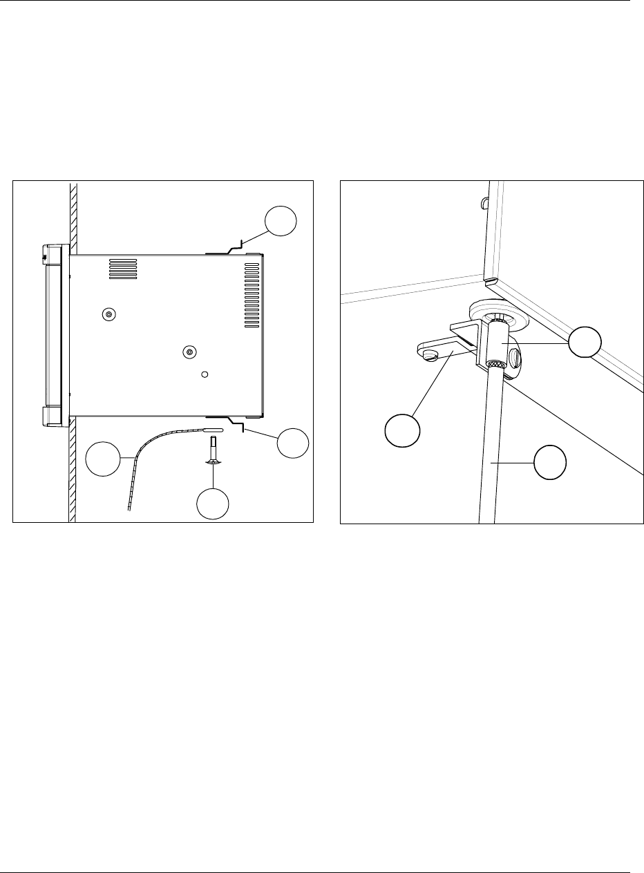
Installation
Video Recorder - User Manual 18
• EXAMPLE:
Rep. A: Cable retaining bracket (46210075-501)
Rep. B: Grounding screw
Rep. C: Clamp
Rep. D: Shielded cable (inputs)
Rep. E: External grounding cable
• The use of spade terminals on all wiring is recommended.
A
A
B
E
A
C
D
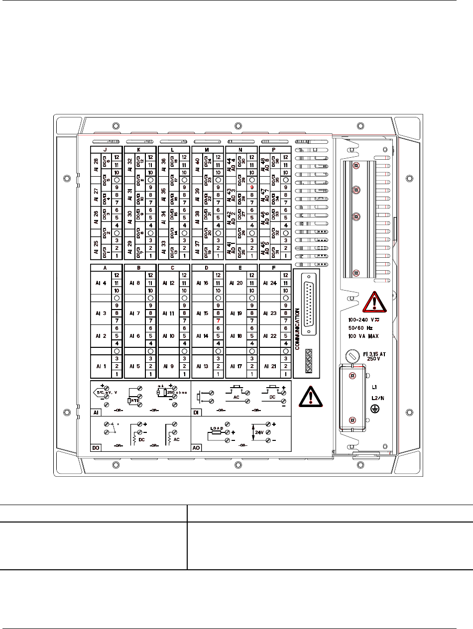
Installation
Video Recorder - User Manual 19
2.5 Terminal connections
2.5.1 Rear cover
The rear cover protects the I/O boards terminal connectors. On the rear cover, a drawing reminds the user of the
terminals use.
Positions
AI = Analog input
AO = Analog output
DI = Digital input
DO = Digital output (relay)
From A to F + J to P (Upper and lower rack)
From N to P (Upper rack)
From J to P (Upper rack)
From J to P (Upper rack)
Note: Terminal blocks can be removed from the board for easier wiring and board replacement.
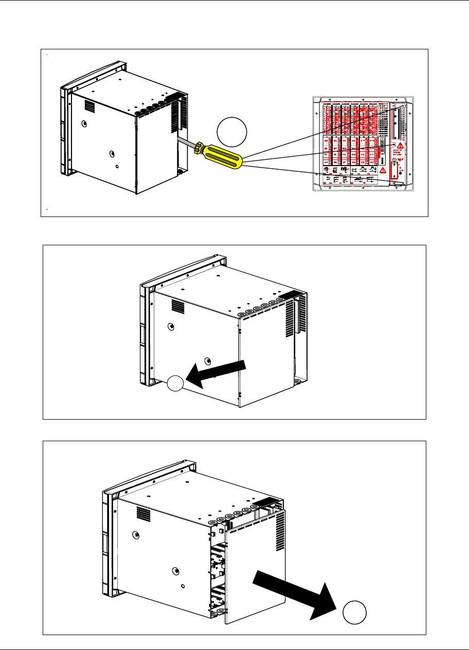
Installation
Video Recorder - User Manual 20
Removing the rear cover grants access to the terminals location:
Step A: Turn off power
Step B: Loosen screws holding rear cover
Step C: Slide rear cover to the left
C
Step D: Remove rear cover
B
D
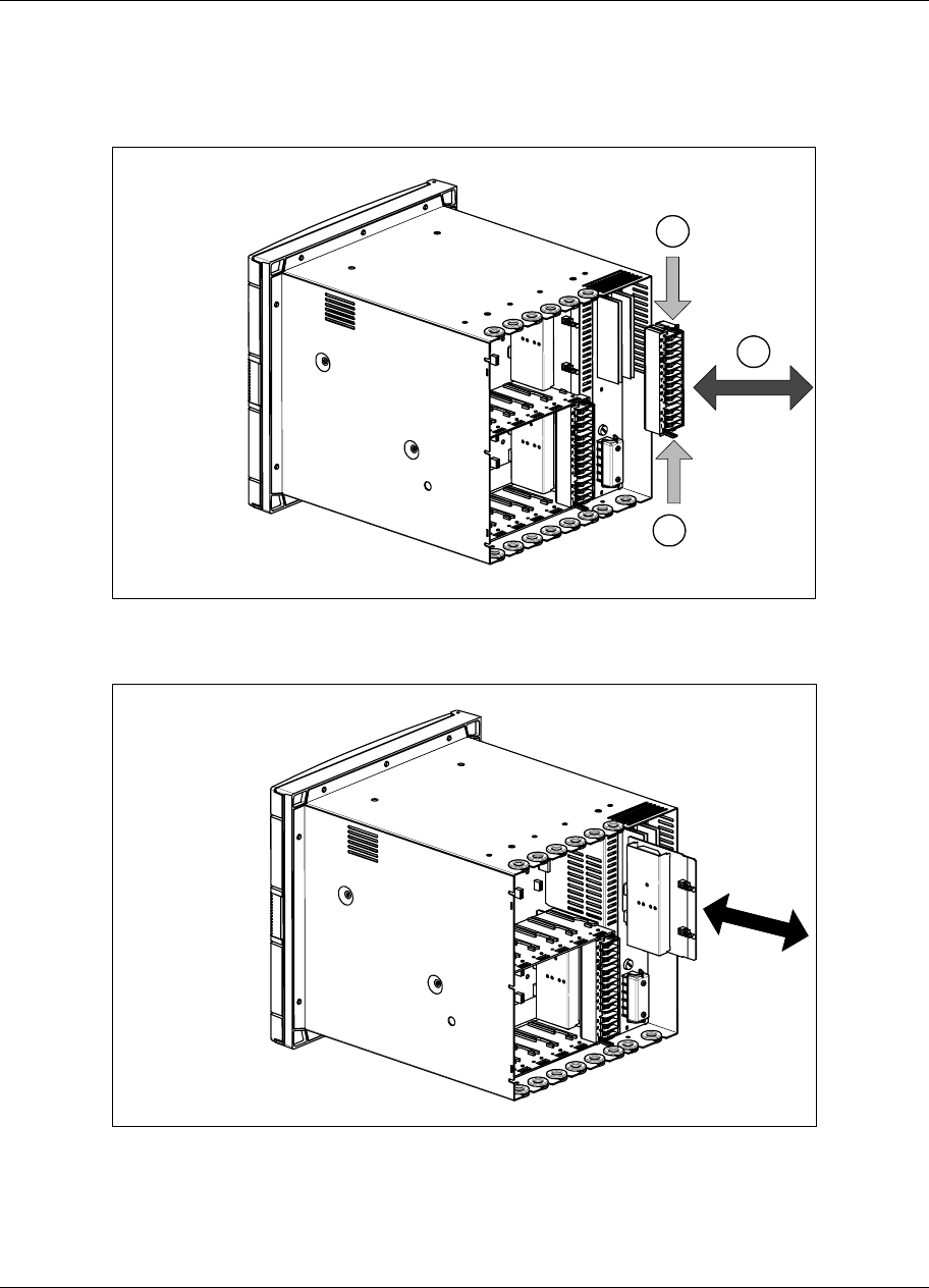
Installation
Video Recorder - User Manual 21
2.5.2 Inserting and extracting inputs and outputs board:
Steps A and B show how to insert or extract a board from the video recorder.
To extract a board: Step A then Step B.
To insert a board: Step B then Step A.
2
1
1
Step A
(1) Press down on terminal block clips
(2) Push in or pull out to insert or remove from board
Step B
Push in or pull out on the board to insert or remove from video recorder
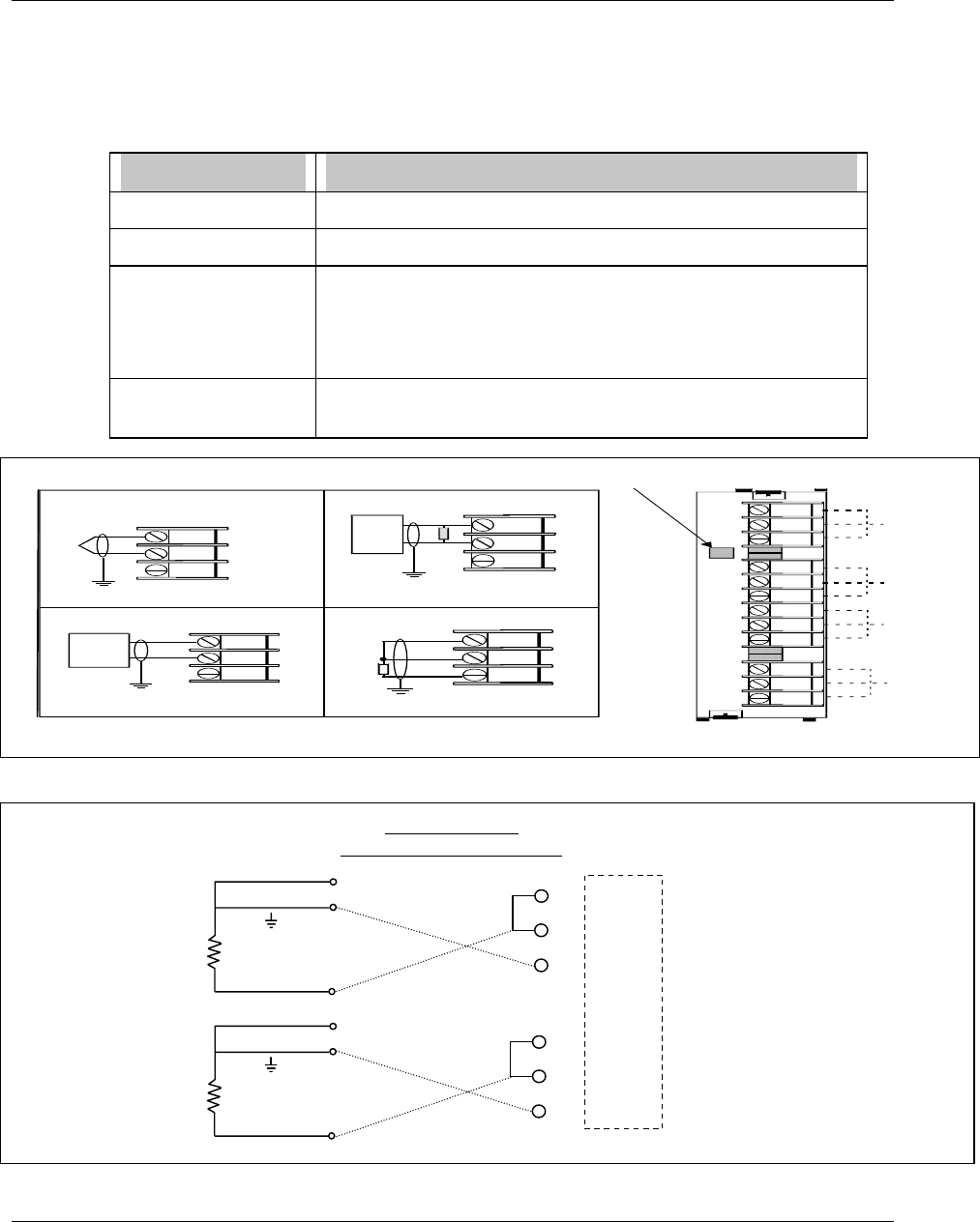
Installation
Video Recorder - User Manual 22
2.5.3 Analog input boards
A universal Analog Input board accepts a variety of input signals from field devices.
Figure 2-1 illustrates the terminal block connections for the various inputs. One AI board can be
configured to accept multiple input types.
Table 2-1 Universal Analog Input Board Specifications
Specification Description
Input Types mV, V, mA, T/C, RTD, and Ohms
Number of Inputs 4 per board, up to 12 boards per video recorder (48 inputs)
Signal Source Thermocouple with cold junction compensation, for operation
between 0 to 80º C (32 to 176º F)
Line resistance up to 1000 ohms, T/C, mV, mA, V
RTD, 3-wire connections, 40 ohms balanced max.
Input Impedance 10 Meg Ω for T/C, mV inputs,
> 1 Meg Ω for volt inputs
+
-
T/C , m V, V
+
-
*
4 to 2 0
mA
Source
12
11
10
9
8
7
6
5
4
3
2
1
1
C hannel 4
C hannel 3
C hannel 2
C hannel 1
+
-
+
-
+
-
RTD
+
-
RTD
Therm ocouple input
Ground Terminal
RTD Input (3 wires)
+
-
RTD
C urrent Input m A
*
A 250 ohm resistor is required for the
input range
G round Term inal
mV, V
Inputs
+
-
mV or V
source
G round T erm inal G round T erm inal
Slot ID
Figure 2-1 AI Board Terminal Block Connections
Figure 2-2 10 ohm Copper connections
-
+
RTD
-
+
RTD
10 ohm Copper
with common
g
round lead
Grounded lead of
RTD should be
connected to RTD
terminal of VRX
terminal block
All RTD connections are
common on Universal AI
board.
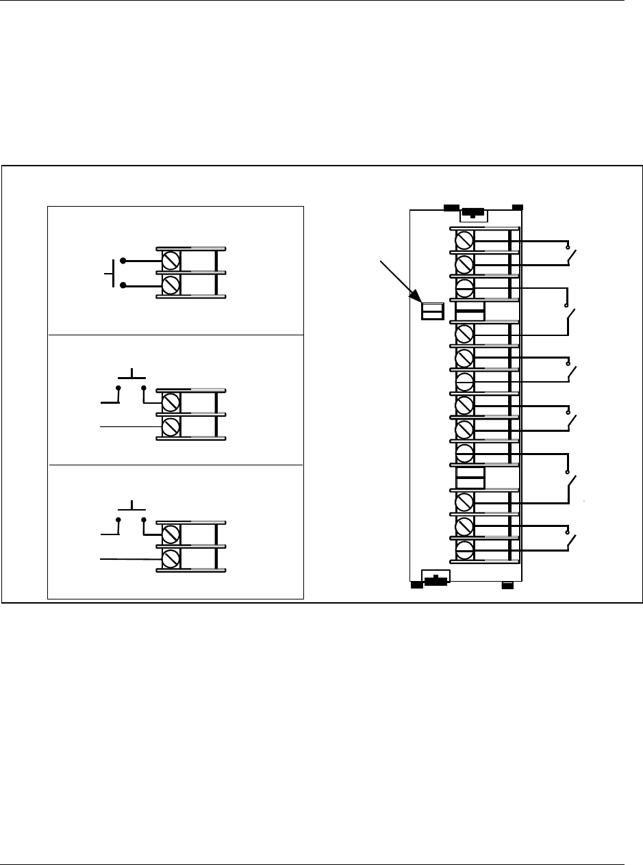
Installation
Video Recorder - User Manual 23
2.5.4 Digital Inputs Boards
Three types of Digital Input (DI) boards accept three types of input signals.
1. Logic Input
2. DC Input
3. AC Input
Each type is described on the following pages. Figure 2-3 shows the terminal block connections for all
DI boards. See Section 1 for details on all I/O board specifications.
12
11
10
9
8
7
6
5
4
3
2
1
DI 6
DI 5
DI 2
DI 1
DI 4
DI 3
Contact Closure
+
-
24 VDC
120/240 VAC
L1
L2
Logic input
DC input
AC input
SLOT ID
Figure 2-3 DI Board Terminal Block Connections
2.5.5 Analog Outputs
The Analog Output (AO) board provides four outputs at 0 to 20 mA (configurable for 4 to 20 mA or any
span between 0 to 20 mA). When not used for an analog output, an output channel may be used to
power a transmitter with 24 Vdc power. The video recorder will support up to two AO boards, for a total
of eight outputs. Figure 2-4 shows the terminal connections for the AO board. See Section 1 for details
on all I/O board specifications.
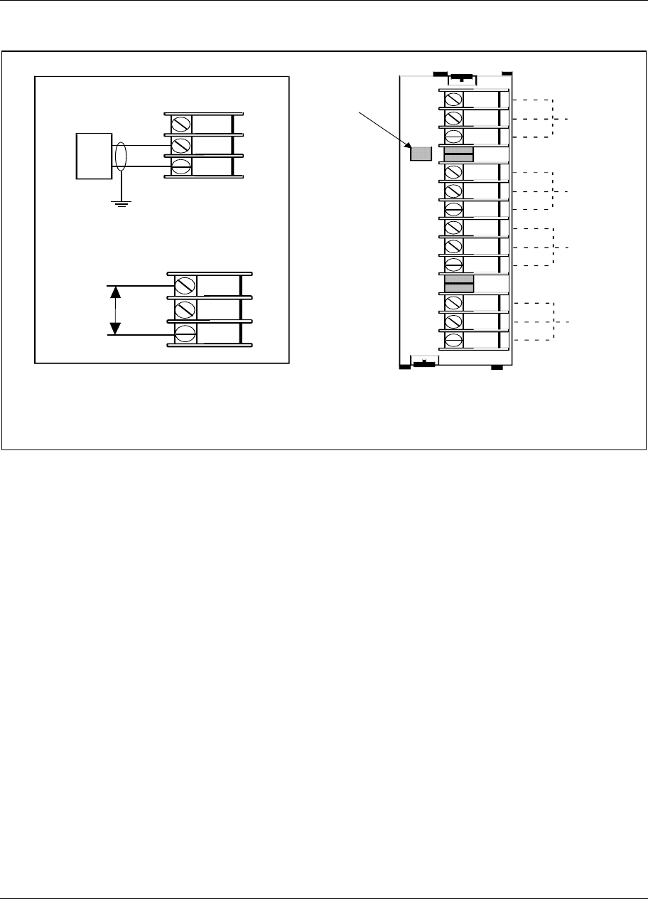
Installation
Video Recorder - User Manual 24
Channel 4
Channel 3
Channel 2
Channel 1
4 to 20 mA output
Ground Terminal
+
-
Load
+
-
24V
12
11
10
9
8
7
6
5
4
3
2
1
2
Slot ID
NOTE - Channels not used as analog outputs can be used
to supply a transmitter with 24 Vdc power.
Figure 2-4 AO Board Terminal Block Connections
2.5.6 Digital Outputs
There are three types of Digital Output (DO) boards which provide three types of Off/On control.
1. Relay (alarm) Output
2. DC Output
3. AC output
Figure 2-4 shows the terminal block connections for the DC output and AC output DO boards. See
Section 1 for details on all I/O board specifications.
Installation
Video Recorder - User Manual 25
Figure 2-5 DO Board Terminal Block Connections
The Digital Output board with relay outputs contain jumpers to set the de-energized state of the relay
contacts. The relays are factory set to Normally Closed (NC) for each output on the relay output board,
To change the state of the contacts: See Figure 2-6 DO Board Relay Contact Setting. Use a pair
of needle-nose pliers and move the jumper from the location NC (normally closed ) to the location NO
(normally open).
Installation
Video Recorder - User Manual 26
11
12
10
NO NC
!
8
9
7
5
6
4
2
3
1
Digital Output Board
S1
NC1
N
O1
S2
NC2
N
O2
S3
NC3
N
O3
S4
NC4
N
O4
S5
NC5
N
O5
S6
NC6
N
O6
NC
NO
Normally Open
Contacts
Normally Closed
Contacts
Figure 2-6 DO Board Relay Contact Setting
2.5.7 Wiring communications
This software package has been designed to operate with three kinds of serial communication
standards which are: RS232, RS422 and RS485. Refer to the following chapters for the wiring
configuration of each of them. For more details on the wiring, please refer to your computer product
manual.
Installation
Video Recorder - User Manual 27
2.5.7.1 RS232 wiring configuration
VIDEO RECORDER
Figure 2-7 RS232 wiring configuration
2.5.7.1.1 Switch configuration
RS232
LEFT
away from PC board
RIG HT
towa rd PC b o a rd
1
2
3
Installation
Video Recorder - User Manual 28
2.5.7.1.2 Interface connector
• With DB9 connector
Interface cable connectors pin arrangement and signal functions.
1 2 3 4 5 6 7 8 9 10 11 12 13
14 15 16 17 18 19 20 21 22 23 24 25
5 4 3 2 1
9 8 7 6
VIDEO RECORDER SIDE
DB25 male connector face view
PC SIDE
DB9 female connector face view
RECORDER PC
Pin n° Pin n°
2 2
3 3
5 4
7 5
20 6
20 8
Note : Check compatibility with your PC as far as no standard for DB9 connector exists yet.
2
3
7
1 DCD
2 RD
3 TD
4 DTR
5 S.G.
6 DSR
7 RTS
8 CTS
VIDEO RECORDER PC
Installation
Video Recorder - User Manual 29
• With DB25 connector
Interface cable connectors pin arrangement and signal functions.
VIDEO RECORDER SIDE
DB25 male connector face view
PC SIDE
DB25 female connector face view
1 2 3 4 5 6 7 8 9 10 11 12 13
14 15 16 17 18 19 20 21 22 23 24 25
13 12 11 10 9 8 7 6 5 4 3 2 1
25 24 23 22 21 20 19 18 17 16 15 14
VIDEO RECORDER PC
Pin n° Pin n° Direction Description
3 2 to video recorder transmitted DATA
2 3 from video recorder received DATA
- 4 from DTE request to send
- 5 to DTE clear to send
7 7 - ground
7
2 TD
3 RD
4 RTS
5 CTS
6 DSR
7 S.G.
8 DCD
20 DTR
VIDEO RECORDER PC
2
3
Installation
Video Recorder - User Manual 30
2.5.7.2 RS422 wiring configuration
VIDEO RECORDER VIDEO RECORDER VIDEO RECORDER
Figure 2-8 RS422 wiring configuration
2.5.7.2.1 Switch configuration
LEFT
away from PC board
RIG HT
towa rd PC b o a rd
RS422
1
2
3
Installation
Video Recorder - User Manual 31
2.5.7.2.2 Interface connector
TOP SIDE
BOTTOM SIDE
RXB (+)
TXA (-)
TXB (+)
RXA (-)
Figure 2-9 RS422 Inferface connections
2.5.7.3 RS485 (2 wires) wiring configuration
VIDEO RECORDER VIDEO RECORDER VIDEO RECORDER
Figure 2-10 RS485 wiring configuration
Installation
Video Recorder - User Manual 32
2.5.7.3.1 Switch configuration
1
2
3
LEFT
away from PC board
RIGHT
toward PC board
RS485
2.5.7.3.2 Interface connector
TOP SIDE
BOTTOM SIDE
RX/TXB (+)
RX/TXA (-)
Figure 2-11 Interface connector

Installation
Video Recorder - User Manual 33
2.5.7.4 Connecting the RS422/485 link to a computer
The VRX180 video recorder with the RS422/485 Communications option can be connected your
computer using one of two arrangements :
• Wired to an RS422/485 compatible serial port (if the computer is equipped with such a port).
• Wire the RS232 serial port of the computer to an RS232 to RS485 converter. The RS485 port
of the converter should be wired to the Communications port of the VRX recorder.
Arrangement
ICS plug-in I/O board
Description
Wired directly to the RS422/485 port in your computer using an ICS plug-
in I/O board which is specifically designed to interface with the IBM (or
IBM compatible) PC, PC/XT; or PC/AT computer.
This board is available from...
ICS Computer Products, Inc.
5466 Complex Street
Suite 208
San Diego, California 92123
Burr-Brown Converter Using the RS232 port a Burr-Brown RS232 to RS422/485 converter
installed between the RS232 port and the video recorder.
This converter is available from :
Burr-Brown
International Airport Industrial Park
P.O. Box 11400
Tucson, Arizona 85734
Part number LDM485ST, limited distance modem
Westermo converter The Westermo MA44 converts RS232 to RS422/485. It is installed
between the RS232 port and the video recorder.
2.5.7.5 Rear connection
The video recorder has built in circuits to reduce the effects of most electrical noise. We recommend
that you review the following guidelines, to minimize the noise effects.
1. Separate the communication leadwires from the line voltage, the alarm output, contactors, motors etc...
2. For a communication distance, over 1.5 meters, use a separate metal tray, or metal conduit.
3. Use wiring cable composed of twisted pair wirings, with a shield for RS485 and RS422. Use a shielded
cable for RS232.
4. Connect the shield wire to the ground, at one end only, preferably at the video recorder. Use for example
a wiring cable type: Belden 9271 twinax, or equivalent.
5. We recommend to install a 120 ohms resistor between TXA and TXB, on the last video recorder on
communication link.
6. The maximum capabilities are:
Type of communication Distances max. # of Unit
RS232 15 meters / 50 feet 1
RS422 1000 meters / 3280 feet 15
RS485 1200 meters / 4000 feet 31

Installation
Video Recorder - User Manual 34

Programming and Operating Concepts
Video Recorder – User Manual 35
3. Programming and Operating Concepts and Procedures
3.1 Overview
This section explains the instrument’s programming and operating concepts and procedures. Read and
understand this section before attempting to program and operate your instrument.
3.2 Quick Start Programming
Use this section to quickly start up your instrument. This section contains the basic concepts you should
know for configuring the instrument. For more details on specific topics, you should refer to section 4 and
5 of this manual.
Step Action See
1 To program analog inputs Section 4.7 Program Analog Inputs
2 To program control (if your
application has control)
Section 3.14 How to program common configurations
Section 4.8 Program Control Loops
Section 5 Setpoint Profiler (if your instrument has a setpoint profiler)
Section 4.9 Program Analog Outputs
3 To configure displays Section 4.18 Program Displays
4 To configure data storage Section 4.26 Data Storage
5 To program other functions Remaining sections in
Section 4 How To Program Function Blocks and Features
3.3 Modes of Operation
The instrument has three modes of operation: Program, Online, and Maintenance. Each mode has its
own menus. Most menu items provide access to sub-level menus. The SET MODE item switches the
instrument from one mode to another. Your instrument may have reduced menus if options are not
present.
Program mode
Program Mode is an off-line mode for programming (configuring) the instrument. In this mode, all inputs
and outputs are frozen. If any of the five relays are assigned as DAT outputs the recorder will stop
pulsing them when it is placed into Program Mode. The outputs will remain frozen in their present state,
either On or Off.
Online Mode
Online Mode enables full use of the instrument with its inputs, outputs and internal programming. In this
mode, it is fully interactive with all externally connected elements.
Maintenance Mode
Maintenance Mode is an off-line mode for maintaining proper and complete functioning of the instrument.
Functions include calibration, off-line diagnostic testing, and various setups for operation. In
Maintenance Mode, all inputs and outputs are frozen. If any of the five relays are assigned as DAT
outputs the recorder will stop pulsing them when it is placed into Maintenance Mode. The outputs will
remain frozen in their present state, either On or Off.
Programming and Operating Concepts
Video Recorder – User Manual 36
3.4 Menu Navigation
Moving between the Program, Online, and Maintenance modes of the instrument is accomplished
through use of the instrument’s Menu, Up Arrow, Down Arrow, and Enter keys located on its front door.
Refer to Figure 3-1.
Display 1
Display 2
Display 3
Auto/
Manual
Tab Up
Arrow
Down
Arrow
F1 F2 F3
Display
Left
Arrow
Menu
Enter
F4 F5
PV 405.00
SP 405.00
OU T 15 .0
A S1
LP1
1000.00
0.00
LP2
1500.00
0.00
1054.00
1040.00
10.0
M S2
LP4
2400.00
0.00
1266.00
1244.00
5. 0
A S1
LP3
1200.00
0.00
623.00
622.00
5 .0
M S1
TAG1
VALUE1
TAG2
VALUE2
TAG3
VALUE3
TAG4
VALUE4
TAG5
VALUE5
TAG6
VALUE6
TAG7
VALUE7
TAG8
VALUE8
TAG9
VALUE9
TAG10
VALUE10
TAG11
VALUE11
TAG12
VALUE12
ZONE1
123.45
DEG F
ZONE2
123.45
DEG C
ZONE3
123.45
DEG F
ZONE4
123.45
DEG F
ZONE5
123.45
DEG F
ZONE6
123.45
DEG C
ZONE7
123.45
DEG F
ZONE8
123.45
DEG C
ZONE9
123.45
DEG F
ZONEA
123.45
DEG F
ZONEB
123.45
DEG
ZONEC
123.45
DEG F
Figure 3-1 Video Recorder Front Door Buttons
Programming and Operating Concepts
Video Recorder – User Manual 37
A more detailed explanation of the function of each button appears in Section 3.5.
To develop a feel for navigating between modes, power up the instrument and perform the sequence of
steps that follows.
Upon powering up the instrument for the very first time, the logo display will initially appear. Press the
Menu button several times until the ON LINE, PROGRAM, or MAINTENANCE mode MAIN MENU is
displayed. Refer to Figure 3-2. Note: Menus are shown with all possible options; your menu may not
have all options.
PRODUCT
INFO
S/N YXXXXXXXXXXXXXXX
PARTNUMBER46900052-001
VER SIO N X .X
Product Info Display
ACCESS SUMMARIES DATA ENTRY
DATA STORAGE
SETMODE ONLINE
SET ANALOG OUTPUTS TUNE LOOP SETPOINT PROFILES
PROGRAM LABELS ANALOG INPUTS CONTROL LOOPS
ALARMS TOTALIZERS PROFILERS CONSTANTS
CALCULATED VALUES DISCRETE OUTPUTS DISCRETE INPUTS ANALOG OUTPUTS
COPY BLOCK CLOCK LOAD/STORE CONFIG SCAN RATE
SERIAL COMMUNICATIONS SECURITY FEATURES DISPLAYS
LANGUAGE
SETMODE MAINTENANCE CALIBRATE ANALOG INPUTS CALIBRATE ANALOG OUTPUTS OFF-LINE DIAGNOSTICS
DATABASE SERVICESRESET UNITPRODUCT INFORMATIONMAINS FREQUENCY
WARM START TIME DEMO
MAIN MENU - PROGRAM
MAIN MENU - ONLINE
SETMODE
MAIN MENU - MAINTENANCE
REVIEW PROGRAMMING
Figure 3-2 Menu Navigation Guide Through ON LINE, PROGRAM, and MAINTENANCE
mode MAIN MENUs.
Once you have established which MAIN MENU you are on, use the Up Arrow and Down Arrow buttons
to verify each MAIN MENU choice as indicated in Figure 3-2.
Use the Up Arrow and Down Arrow buttons to find and highlight the menu’s SET MODE prompt.
When the SET MODE prompt is highlighted, press the Enter button.
Use the Up Arrow or Down Arrow buttons to switch the instrument to one of the other two instrument
modes and press the Enter button.
Programming and Operating Concepts
Video Recorder – User Manual 38
Once within the mode selected in Step 5, scroll through the mode’s MAIN MENU using the Up Arrow and
Down Arrow buttons. Verify each menu choice as indicated in Figure 3-2.
Repeat Steps 3 through 6 for the last of the three mode selections possible.
Having completed the preceding exercise, changing the instrument’s mode should now be a simple task.
Furthermore, a fundamental understanding of how the Menu, Up Arrow, Down Arrow, and Enter buttons
work should now be at your fingertips.
Now use the Menu, Up Arrow, Down Arrow, and Enter buttons to verify the ON LINE, PROGRAM, and
MAINTENANCE mode sub-level menus detailed in Figure 3-3, Figure 3-4 and Figure 3-5. The sub-level
menus shown represent only the first sub-level below each mode’s MAIN MENU. There are several sub-
level menus, not indicated here, that run further below each first sub-level. Note that once inside of a
sub-level menu, regardless of how “deep” the level is, a press of the Menu button will return you to the
next highest menu level. In case you get lost within a mode’s sub-level menu, keep pressing the Menu
button until the ON LINE, PROGRAM, or MAINTENANCE mode MAIN MENU appears on screen.
Be advised that Figure 3-2 through Figure 3-5 comprise a basic “road map” for navigating the menus
within the programmer’s three modes. Sections 4 through 8 of this manual will provide detailed
descriptions of each menu choice and complete guides through all the sub-level menus that run below
the levels indicated in these Figures.
ATTENTION
The following menus contain all possible options. Your instrument may not include some items shown here.
ACCESS SUMMARIES
MAIN MENU - ON LINE
DATA ENTRY
DATA STORAGE DATA STOR AGE STATUS
SETPOI NT PROFI LES
TUNE LOOP
SET ANALO G OUTPUTS
SET MODE ON LINE
DISPLAY ALARM
SUMMARY
DISPLAY ALARM
HISTORY
DISPLAY
DIAGNOSTICS
DISPLAY ALL
ANALOGS
DISPLAY ALL
DISCRETES
DELETE ALL
DIAGNOSTICS
PRODUCT
INFO RMATION
EDIT ALARM
SETPOINTS EDIT CONSTANTS FORCE DISCRET E
INPUTS
FO RCE DISCRETE
OUTPUTS
ADJUST ANALOG
INPUTS
RESET
TOTALIZERS
ENABLE STORAGE REPLAY FROM
DISK INITIALIZE DISK LIST DISK FILES SET UP NEW
SCHEDULES
REVIEW CURRENT
SCHEDULES
WARNING
LEVEL
BATCH STATEBATCH NUMBER
EDIT PROFILE #1 EDIT PROFILE #2 EDIT PROFILE #3 EDIT PROFILE #4 STORE PROGRAM
TO DISK
STOR E PROGRAM
TO MEMORY
LOAD PROGRAM
FROM DISK
LOAD PROGRAM
FROM MEMORY
LOOP #1 LOOP #2 LOOP #3 LOOP #4
OUTPUT #1 OUTPUT #2 OUTPUT #3 OUTPUT #4
RESET ALL
TOTALIZERS
SET ANALO G
OUTPUTS
LOOP #8
. . .
. . . OUTPUT #8
REVIEW PROGRAMMING CONTROL LOOPS
ANALOG INPUTS ANALOG OUTPUTS DISCRETE INPUTS
DISCRETE OUTPUTS
CALCULATED
VALUES
ALARMSTOTALIZERS
CONSTANTS FEATURES
DISPLAYS SECURITY SERIAL COMMUNICATIONS
PROFILES
SCAN RATE
Figure 3-3 ON LINE mode MAIN MENU
Programming and Operating Concepts
Video Recorder – User Manual 39
SET MODE PROGRAM
LABELS
ANAL OG INPUTS
CONTROL LOOPS
ANAL OG O UT PUT S
DISCRETE INPUTS
DISCRETE OU TPUTS
CALCUL AT ED V AL UES
AL ARMS
TOTALI ZERS
PROFILES
CO NST ANTS
DISPLAYS
FEATURES
SE CURI TY
SERIAL C OMMUNICATI ONS
CLOCK
LOA D/STO RE CONFIG
SCAN RATE
SELECT LANGUAGE
ANALOG
INPUTS
ANALOG
OUTPUTS
DISCRETE
INPUTS
DISCRETE
OUTPUTS
CALCULATED
VALUES
CONTROL
LOOPS ALARMS TOTALIZERS SETPOINT
PROFILES
CONSTANTSUNIT
ENGI NEERING
UNITS
FILENAMES
INPUT #1
AI1
INPUT #2
AI2
INPUT #3
AI3
INPUT #4
AI4
INPUT #5
AI5
INPUT #6
AI6
LOOP #1
LP1
LOOP #2
LP2
LOOP #3
LP3
LOOP #4
LP4
OUTPUT #1
AO1
OUTPUT #2
AO2
OUTPUT #3
AO3
OUTPUT #4
AO4
OUTPUT #5
AO5
OUTPUT #6
AO6
INPUT #1
DI1
INPUT #2
DI2
INPUT #3
DI3
INPUT #36
DI36
INPUT #35
DI35
INPUT #34
DI34
! ! ! ! ! !
OUTPUT #1
DO1
OUTPUT #2
DO2
OUTPUT #3
DO3
OUTPUT #34
DO34
OUTPUT #35
DO35
OUTPUT #36
DO36
! ! ! ! ! !
CALC
VALUE #1
CALC
VALUE #2
CALC
VALUE #3
CALC
VALUE #62
CALC
VALUE #63
CALC
VALUE #64
! ! ! ! ! !
ALARM #1
AL1
ALARM #2
AL2
ALARM #3
AL3
ALARM #94
AL94
ALARM #95
AL95
ALARM #96
AL96
! ! ! ! ! !
TOTALIZER #1
TL1
TOTALIZER #2
TL2
TOTALIZER #3
TL3
PROFILE #1
SP1
PROFILE #2
SP2
PROFILE #3
SP3
PROFILE #4
SP4
CONSTANT #1
CN1
CONSTANT #2
CN2
CONSTANT #3
CN3 ! ! ! ! ! ! CONSTANT #30
CN30
CONSTANT #31
CN31 CONSTANT #32
CN32
SET UP TREND
DISPLAYS
SET UP BARGRAPH
DISPLAYS
SET UP PANEL
DISPLAY
SET UP UNIT
DATA DISPLAY
SET UP PROFILE
DISPLAYS
ASSIGN DISPLAYS
TO KEYS
EXPANDED
INPUT PYROMETRY AI VALUE
ADJUST
DI/DO
FORCING ALARMS CONSTANTS LABELING REVIEW
PROGRAM
DISK
REPLAY ZOOM
POINT
DETAIL
TIMEBASE
SELECT
CUSTOM
INPUT
ENABLE
SECURITY
MASTER
SEC CODE SET MODE OPERATOR
SEC CODE A UT O/ MANUA L SP1/SP2 SETPOINT
PROFILE
SETUP
PARAMETERS
REVIEW
PROGRAM
DATA
STORAGE
UNIT
ADDRESS
HOURS MINUTES MONTH DAY YEAR DATE
FORMAT
STORE CONFIG
TO DISK
LOAD CONFIG
FROM DISK
MAIN MENU - PROGRAM
OUTPUT #7
AO7
OUTPUT #8
AO8
TOTALIZER #4
TL4
TOTALIZER #5
TL5
BAUD
RATE
DOWNLOAD
LOCKOUT
! ! ! INPUT #48
AI48
! ! ! TOTALIZER 48
TL48
LOOP #5
LP5
LOOP #6
LP6
LOOP #7
LP7
LOOP #8
LP8
COPY BLOCK BLOCK
TYPE
FROM
NUMBER
TO
NUMBER
COPY
BLOCK
Figure 3-4 PROGRAM mode MAIN MENU
Programming and Operating Concepts
Video Recorder – User Manual 40
MAIN MENU - MAINTENANCE
SET MODE MAINTENAN CE
CALIBRATE ANALOG INPUTS
CALIBRATE ANALOG OUTPUTS
OFF-LINE DIAGNOSTICS
DATABASE SERVICES
RESET UNIT
PRODUCT IN FORMATION
MAINS FREQUENCY
WARM START TIME
DEMO
CALIBRATE ANALOG
INPUTS
CALIBRATE
REFERENCE JUNCTION
RESET ANALOG INPUT
CALIBRATION
RESET REF. JUNCTION
CALIBRATION
OUTPUT #1
LOW
OUTPUT #1
HIGH
OUTPUT #2
LOW
OUTPUT #2
HIGH
OUTPUT #3
LOW
OUTPUT #3
HIGH
RAM SIZE
(KB)
KEYBOARD
TEST
DISPLAY
TEST
DISK READ/
WRITE TEST
CLEAR ALL MEMORY FULL UPGRADE INCREMENTAL
UPGRADE
OUTPUT #4
LOW
OUTPUT #8
HIGH
SOFTWARE
UPGRADE
! ! !
! ! ! ! ! !
! ! !
COPY ANALOG INPUT
CALIBRATION
Figure 3-5 MAINTENANCE mode MAIN MENU

Programming and Operating Concepts
Video Recorder – User Manual 41
3.5 Button functions
In all modes, the instrument is operated by using the front panel buttons to view and select items from
menus and displays. Table 3-1 describes each panel button and its functions.
Table 3-1 Button Functions
Symbol Name Function Operating mode in which
function applies
Program Online Maint
Menu • Accesses Online Mode Menu from
online primary display.
• Backs cursor out of a menu to next
higher menu level. Use when finished
looking at or changing menu items.
• If changes were made and you are
prompted to PRESS ENTER TO SAVE,
press to exit menu without saving
changes.
#
#
#
#
#
#
#
Up Arrow/
Previous
• Moves cursor up a menu or list of
choices.
• Immediately after selecting a menu item
to change, repeatedly scrolls through
NONE or OFF, PARM(parameters), 0-9
(of most significant digit of a number),
minus sign (-). Once you move the
cursor off a number's most significant
digit, then only 0-9 are choices. You can
change a number to a parameter,
NONE, or OFF only while the cursor is
initially on the most significant digit.
• When selecting most significant digit of
a number, scrolls through 0-9, minus
sign, and OFF or NONE (if available).
For other digits, scrolls through 0-9.
• When entering a label such as a
DESCRIPTOR or TAG, scrolls through
A-Z, 0-9, period (.), hyphen (-), slash (/),
plus (+), asterisk (*), blank ( ).
• In loop display, increases loop's
setpoint value (loop must be in Auto
mode).
• In loop display, increases loop's output
(loop must be in Manual mode).
• Scrolls a trend forward in time.
#
#
#
#
#
#
#
#
#
#
Programming and Operating Concepts
Video Recorder – User Manual 42
Table 3-1 Button functions (continued)
Symbol Name Function Operating mode in which
function applies
Program Online Maint
Down
Arrow/ Next
• Moves cursor down a list/menu.
• When selecting a number, letter, or decimal
point position, moves cursor one character to
the right, then wraps around to leftmost
character.
• In loop display, decreases loop's setpoint
value.
• In loop display, decreases loop's output (loop
must be in Manual mode).
• Scrolls a trend backward in time.
#
#
#
#
#
#
#
#
#
Left Arrow • Numeric entry: moves one digit to left.
• Text entry: moves one character to right.
# # #
Enter • Selects displayed menu item and either
displays its submenu or moves cursor to the
right for data entry.
• Enters a changed value or parameter.
• If prompted to SAVE CHANGES?, saves
changes made and returns to higher menu.
#
#
#
#
#
#
#
#
Tab • When trend or panel display is on, accesses
Trend menu or panel display menu to adjust
the appearance of the display.
• When either above menu is shown,
advances display to next live point.
• When Setpoint Profile Trend display is
shown, accesses a menu for viewing and
controlling operation of the profile.
• On Loop displays, tabs cursor to next loop
data field for adjustment.
#
#
#
#
Display From any display or menu, pressing this button
changes the instrument to online mode* and
accesses the display programmed as Display #4.
Repeated presses accesses displays #5 through
#10, then wraps around to display #4 again.
See Table 4-64 on page 154 for more information
on the Displays.
#
#
#
Programming and Operating Concepts
Video Recorder – User Manual 43
Table 3-1 Button functions (continued)
Symbol Name Function Operating mode in which
function applies
Program Online Maint
1
Display 1 From any display or menu, pressing this button
changes the instrument to online mode* and
accesses the display programmed as Display #1.
See Table 4-64 on page 154 for more information
on Displays.
# # #
2
Display 2 From any display or menu, pressing this button
changes the instrument to online mode* and
accesses the display programmed as Display #2.
See Table 4-64 on page 154 for more information
on Displays.
# # #
3
Display 3 From any display or menu, pressing this button
changes the instrument to online mode* and
accesses the display programmed as Display #3.
See Table 4-64 on page 154 for more information
on Displays.
# # #
* Note: Changing to ONLINE mode by pressing any of the Display buttons can cause incorrect values to be
displayed. The values will correct themselves in a few seconds. To avoid this potential annoyance, first
change to online mode by selecting SET MODE from the PROGRAM or MAINTENANCE menus, then press a
Display button to access the displays.
Programming and Operating Concepts
Video Recorder – User Manual 44
Table 3-1 Button functions (continued)
Symbol Name Function Operating mode in which
function applies
Program Online Maint
Auto/
Manual
• In a loop display, toggles loop between
Auto and Manual modes (loop's Force
Remote Manual discrete must be OFF).
• In a loop display, toggles loop between
Remote Manual and Manual modes
(loop's Remote Manual discrete must
be ON).
• Does not function if loop's Discrete vs.
Key discrete is ON. In this case, the
button's functioning has been
transferred to the loop's
Auto/Manual Select discrete.
#
#
#
ATTENTION
The following keys are like Digital Inputs on the keypad of the instrument. They must be configured as part of
the instrument’s function blocks in order to be active.
F1
F1
START
• When pressed, this key raises the SY1
F1 signal for 1 machine scan cycle.
• For instruments with the Setpoint
Profiler, user typically programs it to
Profiler Start input or Totalizer Reset.
#
F2
F2
HOLD
• When pressed, this key raises the SY1
F2 signal for 1 machine scan cycle.
• User typically programs it to Profiler
Hold input (Use Edge/Level input
selection) or to Totalizer Reset.
#
F3
F3
RESET
• When pressed, this key raises the SY1
F3 signal for 1 machine scan cycle.
• User typically programs it to Profiler
Reset input or Totalizer Reset.
#
F4
F4 • When pressed, this key raises the SY1
F4 signal for 1 machine cycle.
#
F5
F5 • When pressed, this key raises the SY1
F5 signal for 1 machine cycle.
#
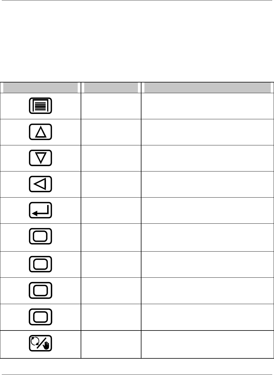
Programming and Operating Concepts
Video Recorder – User Manual 45
3.6 Text Entry From External Sources
QWERTY keyboard
To use a keyboard to enter text such as labels, numbers, and equations, connect an AT Qwerty
keyboard to the mini DIN connector. See Table 3-2 for key functions.
The instrument’s cursor must be on the text to be changed (on the right side of the display) before you
type in the new text. Press Enter to accept the changes or press Menu to reject the changes.
Table 3-2 QWERTY Key Equivalents
Button QWERTY key Function
ESC • Exits prompt or menu without saving changes.
• Changes from online display to online menu.
↑ • Scrolls up a menu or list
↓ • Scrolls down a menu or list
← • Increments the value of the selected field.
Enter ↵ • Selects menu item to change it.
• Saves changes made.
F4 • Changes to online mode and shows online
displays.
• Exits Point/Details menu.
1
F3 Accesses Display #1.
2
F10 Accesses Display #2
3
F11 Accesses Display #3
F2 • Toggles Loop between Automatic and Manual.
• This button can also be used as Display 4 when
the instrument does not have control.

Programming and Operating Concepts
Video Recorder – User Manual 46
Table 3-2 QWERTY Key Equivalents (continued)
Button QWERTY key Function
F1 • Moves cursor around displays.
• Accesses Point/Details menu.
F1
F5 Initiates a discrete action programmed to this key,
such as Starting a Setpoint Profile or resetting a
totalizer.
F2
F6 Initiates a discrete action programmed to this key,
such as Holding a Setpoint Profile or resetting a
totalizer.
F3
F7 Initiates a discrete action programmed to this key,
such as Resetting a Setpoint Profile or resetting a
totalizer.
F4
F8 Initiates a discrete action programmed to this key.
F5
F9 Initiates a discrete action programmed to this key.
ASCII barcode reader
To enter text such as labels, numbers, and equations with a barcode reader, connect the barcode reader
to the mini DIN connector with an adapter (part No. 104286). The instrument buttons remain functional.
See section 3.7 on how to connect a mini DIN connector.
To enter labels, the instrument’s cursor must be on the text to be changed (on the right side of the
display) before you scan in the new text from the barcode. Press Enter to accept the changes, or press
Menu to reject the changes.
The barcode reader may also be used on the instrument trend screens to enter text data that will be
stored as a time stamped event. The ASCII data is split up into three fields:
Description 16 characters
Tag 7 characters
State 6 characters
The first 16 characters will go into the description field. The next 7 into the tag field and so on.
This data will be time stamped and stored in the event file (.LNE) on the floppy disk.
Barcode Reader Recommendation
The barcode reader should output ASCII keyboard data.
The reader should be capable of Code 39 barcode input.
The connector should be able to connect to the Keyboard connector located under the door.
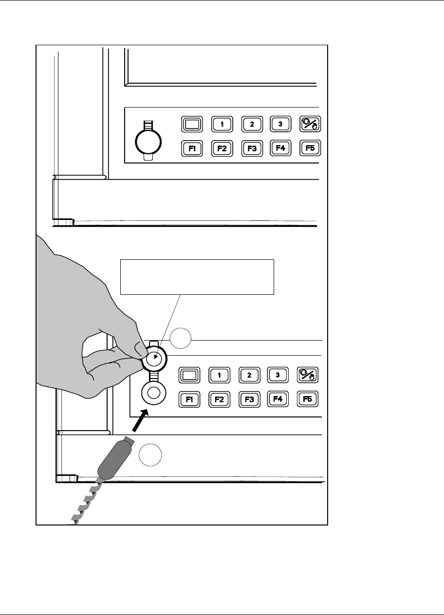
Programming and Operating Concepts
Video Recorder – User Manual 47
3.7 Connecting a keyboard or a barcode reader
The mini DIN connector is located on the front door of the instrument.
Lift the rubber cap (1) to
connect the mini DIN
connector (2)
1
2
Figure 3-6 Connection of a keyboard or a barcode reader
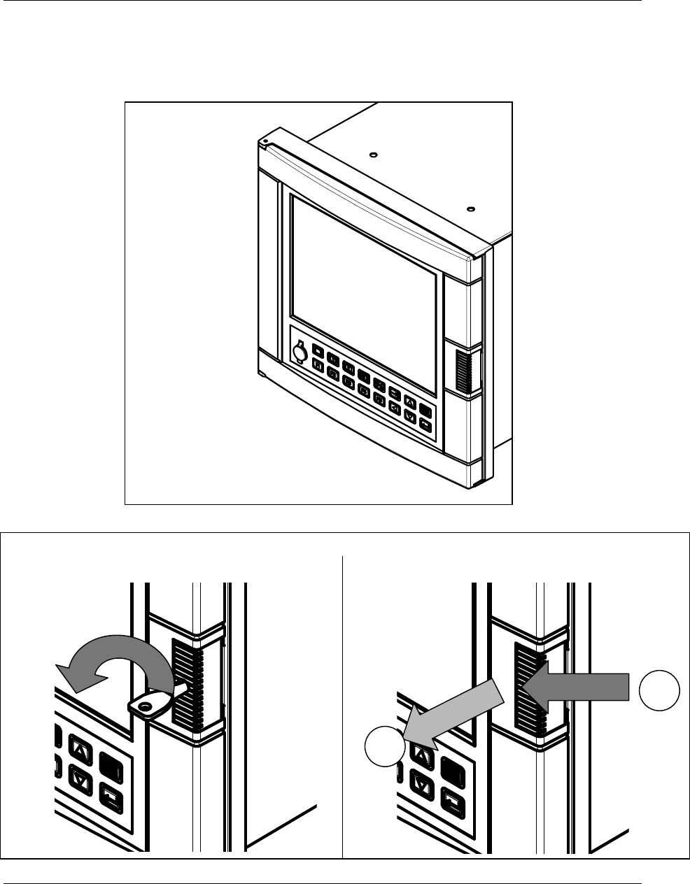
Programming and Operating Concepts
Video Recorder – User Manual 48
3.8 Installing and removing a floppy disk
To install or remove a floppy disk from the instrument, open the door as described in the following
drawings.
NOTE: recording on the disk stops when door is open.
Open the door latch
Door with key lock Door with latch
1
2

Programming and Operating Concepts
Video Recorder – User Manual 49
3.9 Definition of Function Blocks
Definition
A function block is a unit of software that performs a set of operations on its input parameters and
function block parameters and produces output parameters. These output parameters can be
programmed as inputs to other function blocks, whose output parameters can be programmed as inputs
to other function blocks, and so on. By programming all desired function blocks' input parameters and
function block parameters, you configure the instrument to measure and control your process.
Types of function blocks
Each function block performs a set of operations which fulfills a unique purpose. For example, the
Analog Input function blocks processes the analog input data, the alarm function block processes
alarms, and so on.
Table 3-3 describes each function block.
Some function blocks—namely, Analog Input, Analog Output, Discrete Input, and Discrete Output—
interface with the hardware; that is, they are the link between the instrument and the input or output
hardware. The Analog Input and Discrete Input function blocks convert the incoming process data (like
the process variable or any discrete on/off signals from a switch) into information usable by the
instrument. This incoming information is processed according to the entire function block configuration in
the instrument, and it is ultimately passed on to the output function blocks. The Analog Output and
Discrete Output function blocks convert this output information into a voltage or current which is fed to
the corresponding output hardware (like a current output or relay).
Other function blocks are not directly “seen” by the hardware; they are purely software. They can be
thought of as the middle of the process described in the previous paragraph. For example, a Standard
Splitter Calculated Value can split a control loop’s output into 2 values: one for heating and one for
cooling. These 2 values can be passed on to the Analog Output function block which ultimately controls
the amount of output current or voltage.
Flow of information
The “flow” of information— from the input hardware to the input function blocks to the function block
configuration to the output function blocks to the output hardware—can be likened to a river flowing from
upstream to downstream. In some cases, like with a control loop’s feedback, this analogy is not true
because the information is flowing in a circle, but it is a helpful way to view how function blocks are
generally interconnected. For example, the Analog Input function block is typically upstream of the
Control Loop function, which is typically upstream of the Analog Output function block. Of course, if two
function blocks are not directly or indirectly connected, there is no flow between the two. Just remember
that every function block has input, does a set of operations, and produces an output. When several
function blocks are linked together, there is a flow of information.

Programming and Operating Concepts
Video Recorder – User Manual 50
Table 3-3 Function Block Types
Function block
name
Type Maximum
available*
Purpose
Alarm AL 96 Causes alarms under specified conditions.
Analog Input AI 48 Interfaces with measuring input hardware (thermocouple,
RTD, mA, volts).
Analog Output AO 8 Interfaces with analog output hardware (current output
(CAT)) or with output relay hardware (time proportion
(DAT)).
Calculated Value CV 96 Performs various calculations on specified parameters.
Constant CN 32 Outputs a number or an analog parameter value.
Discrete Input DI 36 Interfaces with discrete input hardware (dry contact
closure).
Discrete Output DO 36 Interfaces with output relay hardware (AC relay, DC
relay, mechanical relay, open collector output).
Loop LP 8 PID or ON/OFF control with various outputs.
Setpoint Profiler SP 4 Generates a time-varying setpoint for a loop’s Setpoint
#2.
System SY 1 Outputs discrete status of alarms, data storage, and
diagnostics; outputs analog value of reference junction
temperature. This function block is not programmable; its
outputs are produced automatically.
Totalizer TL 48 Outputs accumulated total over time.
* Depends on options ordered.
Why use function blocks?
Function blocks give you configuration flexibility. For instance, the instrument does not have a dedicated
relay that is activated during an alarm; instead, you can program any of several Alarm function blocks to
control any relay. Also, there is not a specific input for your process variable; any of several Analog Input
function blocks can be programmed to be your process variable. In general, function blocks let you
connect the output parameter of any function block to the input parameter of any function block.
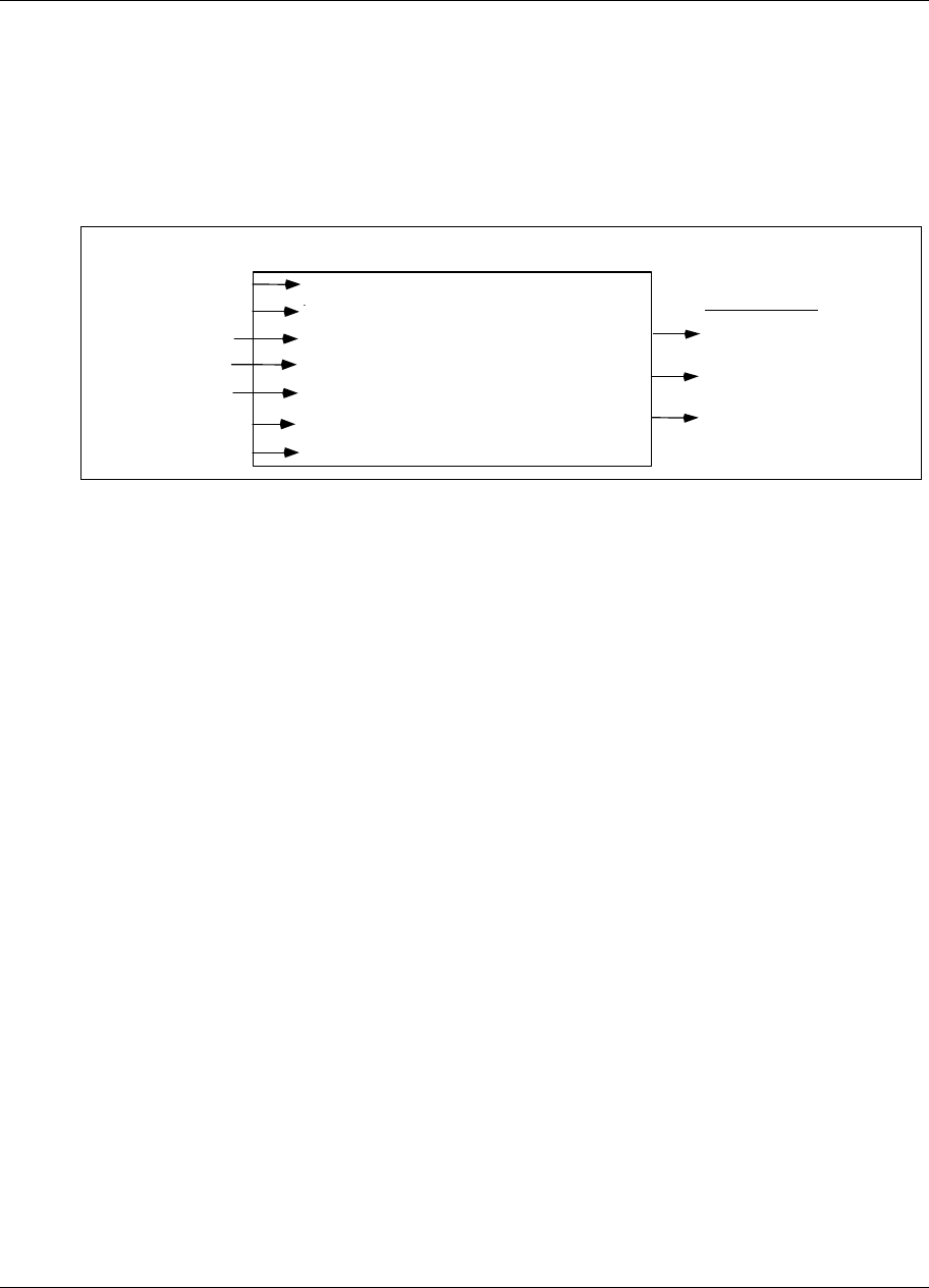
Programming and Operating Concepts
Video Recorder – User Manual 51
3.10 Components of function blocks
The three components of a function block are:
Input parameter(s)
Function block parameter(s)
Output parameter(s).
Figure 3-7 shows the function block Alarm #1’s components.
In put p aram e te r
Outp ut para m et ers
AL 1 OS (Alarm state)
AL 1 S2 (Compare point of
De vi ation al arm o nly )
AL 1 P V (Value of a l arm' s IN PUT)
ALARM ACTION ( Select H igh, Low, Dev , LR at e, H Rate )
IN DECIMAL POS ( Select input decimal position)
IN PUT (Selec t O FF , Nu mb er, or PARM)
SETPOI N T (Se lect OF F, Nu mb e r or PARM)
COMPARE POINT (Select OFF, Number, or PARM)
HY STER ESIS ( Select OF F o r Numb er)
DELAY TIME (Selec t OFF or Number)
Al a rm 1 F u nc ti on Bl o c k
Func ti on block p aram eter
Functi on block paramete r
Functi on block paramete r
Func ti on block p aram eter
In put param ete r
In put param ete r
Figure 3-7 Alarm 1 Function Block Components
Input parameter
A function block's input parameter can be configured to be OFF, a number, or it can receive its data from
outside the block from another block's output codes. These output codes are shown in
Table 3-4. That is, an input parameter is any menu item that can be programmed as (connected to) one
of these output codes. These output codes are grouped under the menu choice PARM. When you are
programming a function block and one of your choices is PARM, you know you are programming an
input parameter. See Figure 3-7.
For example, suppose you are programming an alarm function block. One of the alarm’s menu items is
INPUT, which specifies which point will be monitored for an alarm condition. One of the choices for the
INPUT is PARM, which lets you connect the INPUT to one of the output codes in Table 3-4. Therefore,
the INPUT is an input parameter because it receives its data from another function block.
Some function blocks can have multiple input parameters. For example, an Alarm function block has an
INPUT and a SETPOINT, both of which can be connected to other function blocks.
Discrete Input function blocks have no input parameters; that is, they have no inputs that can be
connected to another block’s output codes.

Programming and Operating Concepts
Video Recorder – User Manual 52
Function block parameter
A function block parameter’s data is contained within the block. When you are programming a function
block and are not given a choice of PARM, you are programming a function block parameter. Typical
choices when programming a function block parameter are NONE, OFF, any numerical value, or a list of
options for the parameter, but not PARM. See Figure 3-7.
For example, to program an Alarm function block’s ALARM ACTION, you select from a list of choices:
NONE, LOW, HIGH, DEV, LRATE, HRATE.
Other function block parameters are an Analog Input’s RANGE LOW and RANGE HIGH, where you
specify the voltage range or temperature range.
Output code
An output code is the result of the function block's operations on the input parameters and function block
parameters. It is designated by one of the two-character output codes shown in Table 3-4. An output
code can be programmed to be the input to one or several other function blocks. See Figure 3-7.
Output codes are either discrete (can be on or off) or analog (numerical value). For example, DI1 OS is
the output status of Discrete Input #1: on or off. AI1 OV is the output value of Analog Input #1: a voltage
or temperature. Therefore, a discrete input parameter must be programmed with only a discrete output
code, and an analog input parameter must be programmed with only an analog output code.
ATTENTION
The function block SYSTEM PARAMETER, abbreviated SY, does not have input parameters or function block
parameters like the other function blocks; SY produces output codes only. These output codes, shown in Table
3-4, are mostly values or states that indicate the status of system-wide parameters. For example, if any Alarm
function block’s output status is ON, the SY function block’s AG (alarm global) output code is also ON.
Another example is the SY F1 output code, which produces a quick ON-to-OFF discrete signal when the F1
key is pressed. This SY F1 can be used as a trigger to another action. For example, to allow an operator to
start the Profile or reset the Totalizer by pressing the F1 key, you can program a Setpoint Profile’s Start
parameter or a Totalizer’s Reset parameter with SY F1.

Programming and Operating Concepts
Video Recorder – User Manual 53
Table 3-4 Function Block Parameter Designators
Function
Block
Type
Function Block
Name
Output
code
Parameter Name Parameter
Type
AI Analog Input OV Output Value Analog
SY System Parameter RT
AG
AH
AL
DF
DG
SF
SW
AX
DX
F1
F2
F3
F4
F5
Reference Junction Temp.
Alarm Global
Alarm High
Alarm Low
Diagnostic failure
Diagnostic General
Storage Full
Storage Warning
Analog Safe Parameter
Discrete Safe Parameter
F1 or Start Key on keyboard
F2 or Hold Key on keyboard
F3 or Reset Key on keyboard
F4
F5
Analog
Discrete
Discrete
Discrete
Discrete
Discrete
Discrete
Discrete
Analog
Discrete
Discrete
Discrete
Discrete
Discrete
Discrete
AO Analog Output OV
BC
S2
Output Value
Back Calculation Value (Feedback)
Process Variable (AO’s input)
Analog
Analog
Analog
DI Discrete Input OS Output State Discrete
DO Discrete Output OS Output State Discrete
LP Control Loop
ON/OFF Loop only
OV
PV
DV
WS
S1
S2
BC
AM
SS
OS
Output Value
Process Variable
Deviation Value
Working Setpoint
Setpoint #1 Value
Setpoint #2 Value
Back Calculation Value (Cascade feedback)
Auto/Manual Status
Setpoint #1/Setpoint #2 Status
Output Status
Analog
Analog
Analog
Analog
Analog
Analog
Analog
Discrete
Discrete
Discrete

Programming and Operating Concepts
Video Recorder – User Manual 54
Table 3-4 Function Block Parameter Designators (continued)
Function
Block
Type
Function Block
Name
Output
code
Parameter Name Parameter
Type
SP Setpoint Profiler OV
A1
PV
SN
SH
SE
SA
SI
SR
E1
thru
E9
EA
EB
thru
EG
Output Value
Auxiliary Output Value
Process Variable (Guaranteed Soak PV #1)
Segment Number
Hold Status
End Status
Active Status
Active or Hold Status
Ready Status
Event#1 Output
thru
Event#9 Output
Event#10 Output
Event#11 Output
thru
Event#16 Output
Analog
Analog
Analog
Analog
Discrete
Discrete
Discrete
Discrete
Discrete
Discrete
$
Discrete
AL Alarm PV
S2
OS
Process Variable (alarm’s input)
Compare Point (of Deviation alarm)
Output Status
Analog
Analog
Discrete
CN Constant OV
PV
Output Value
Process Variable (Constant’s input)
Analog
Analog
CV Calculated Value* OV
PV**
A(n)
BC
S2
D(n)
OS
Output Value
Process Variable
Analog Output #n
Back Calculation
Auxiliary input (link to totalizer preset)
Discrete Output
Output Status
Analog
Analog
Analog
Analog
Analog
Discrete
Discrete
*CV output codes are available for programming only if the CV has been programmed. For example, you
cannot program an input parameter with CV1 OV unless CV1 has been programmed.
**Input to the following CV types: Peak Pick, 1 Point Block Avg., 1 Point Rolling Avg., Scaling, Signal Select
TL Totalizer OV
PV
OS
S2
Output Value
Process Variable (Totalizer’s input)
Output Status
Preset Value
Analog
Analog
Discrete
Analog
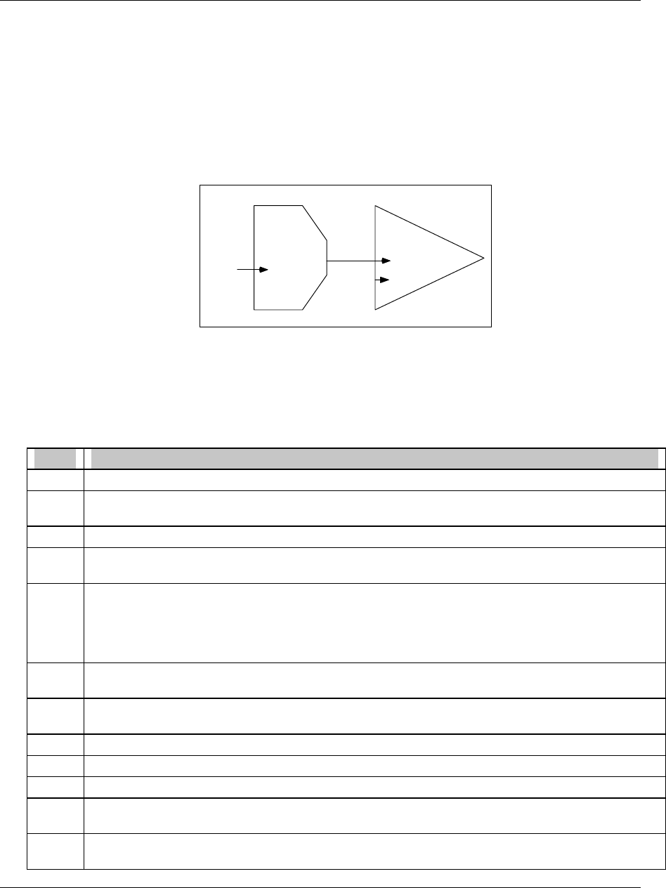
Programming and Operating Concepts
Video Recorder – User Manual 55
3.11 How to program input parameters
A function block has two types of programmable parameters: input parameters and function block
parameters. When in a function block’s Program menu, if a menu item has choices OFF, a number, or
PARM, then the menu item is an input parameter to that function block. That is, if you choose PARM
you can connect the input parameter to another function block’s output code.
How to connect an input parameter to another function block
One way to program an input parameter is to connect it to an output parameter from another function
block. We will show you this procedure using a specific function block’s input parameter, but the
keystrokes used in the procedure will apply when you are making any input parameter connection.
CONTROL
LOOP #2
ANALOG
OUTPUT #1
Loop
output
value
LP2 OV INPUT
SOURCE
SETPOINT#2
Number
FAILSAFE
Figure 3-8 Example Input Parameter Connection
Assume we want to make the connections shown in Figure 3-8. We want Analog Output#1, a current
output, to get its input from Control Loop#2’s output value. Therefore, we must program Analog
Output#1’s Input Source parameter with the output code that represents Control Loop#2’s output value.
The following procedure shows how.
Table 3-5 Output Code Connection Procedure
Step Action
1 In the Program Analog Output menu, select ANALOG OUTPUT#1.
2 Consult the Program Analog Output section of this manual to learn about the menu item you wish to
change, namely, INPUT SOURCE.
3 Press Down Arrow button to move the cursor to the menu choice INPUT SOURCE.
4 Press Enter to move the cursor to the right side of the display where the choices for INPUT SOURCE
are.
5 Press Up Arrow until PARM is displayed. If you press too many times and a number is displayed,
continue pressing Up Arrow until PARM is displayed again. If you press Down Arrow while the
number is displayed, the instrument assumes you want to enter a number, not a parameter. If you
pressed Down Arrow, you must press Menu, then press Enter, then Up Arrow until PARM is
displayed.
6 Press Enter to select PARM, which gives you choices for output codes to connect to. Figure 3-9
shows the format for all output codes.
7 Press Up Arrow or Down Arrow until LP is displayed. From Table 3-4, we know LP is the designator
for the Control Loop function block type.
8 Press Enter to select LP.
9 Press Up Arrow or Down Arrow until 2, the Control Loop number we want, is displayed.
10 Press Enter to select 2.
11 Press Up Arrow or Down Arrow until OV is displayed. From Table 3-4 we know OV is the output
code for the Control Loop’s output value.
12 Press Enter to select OV. The cursor moves to the left and the connection from LP2 OV to Analog
Output#1’s INPUT SOURCE has been made.

Programming and Operating Concepts
Video Recorder – User Manual 56
LP 2 OV
2-character output code
OV
OS
BC
See Table 3-4 for all choices.
Channel number of function block
Type of
function block
Choices:
AI - Analog Input
AL - Alarm
AO - Analog Output
CV - Calculated Value
CN - Constant
DI - Discrete Input
DO - Discrete Output
LP - Loop (control)
SP - Setpoint Profiler
Choices depend on type of function block.
Commonly used choices:
Choices vary depending on type of function
block
SY - System
TL - Totalizer
Figure 3-9 Function Block Connection Format
Before programming a function block’s input parameter with a CV’s (Calculated Value) output code, you
must program the CV first. Otherwise, the CV’s output parameter will not be available for programming.
The function block SY (System Parameter) operates internally and cannot be programmed. It
automatically produces outputs which reflect the status of alarms, data storage, diagnostics, and
reference junction temperature. These outputs can be used as inputs to function blocks.
How to program an input parameter with a number
Besides connecting an input parameter to another function block, you can program an input parameter
with a number. The instrument will accept -999,999 to 9,999,999.
Continuing with the previous example, assume we want Loop #2’s Setpoint #2 to be a number.
Therefore, we must program Loop #2’s Setpoint #2 parameter with a number, say 95. The following
procedure shows how.

Programming and Operating Concepts
Video Recorder – User Manual 57
Table 3-6 Example Number Selection Procedure Using Front Panel Buttons
Step Action
1 In the Program Control Loops menu, select LOOP #2.
2 Consult the Program Control Loops section of this manual to learn about the menu item you wish to
change, namely, SETPOINT #2.
3 Press Down Arrow button to move the cursor to the menu choice SETPOINT #2.
4 Press Enter to move the cursor to the right side of the display where the choices for SETPOINT #2
are.
5 Press Up Arrow until NUMBER is displayed. Press Enter.
6 The rightmost digit will slowly flash on and off, indicating the cursor position.
Since we want to change the number to 95.00, press the Left Arrow until the ones digit flashes. The
Left Arrow moves the cursor to the left.
7 Press Up Arrow to change the 0 to a 5.
8 To change the tens digit, press Left Arrow to move the cursor one place to the left.
9 To change the 0 to a 9, press Up Arrow nine times.
10 At this point, 95.00 should be displayed with the 9 flashing. Since 95.00 is the value we want, press
Enter to select it. The cursor moves left to the SETPOINT #2 prompt and the value is selected.
ATTENTION
To enter a number with a connected keyboard, instead of steps 5-10 simply type in the number 95 and press
Enter.
How to program a discrete input parameter with a number
Table 3-6 shows how to connect Setpoint #2, an analog parameter, to a number. You can also connect a
discrete parameter to a number. A discrete parameter, such as an alarm’s input source, can be
connected to any discrete parameter type in Table 3-7, or it can be programmed with a 0 to signify the off
state or with a 1 to signify the on state. Enter a value of 1 or 0. For example, if you program an alarm’s
input source (Figure 3-7) with a value of 1, the alarm’s output (AL1 OS) will always be on.
To program a discrete parameter with a 1 or 0, perform the following procedure. The procedure uses
Alarm1’s Input source as the parameter being programmed.
Table 3-7 Example Programming Discrete Input Parameter with a Number
Step Action
1 In the Program Alarms menu, select ALARM #1.
2 Consult the Program Alarm section of this manual to learn about the menu item you wish to change,
namely, INPUT SOURCE.
3 Press Down Arrow to move the cursor to INPUT SOURCE.
4 Press ENTER to move the cursor to the right side of the display where the choices for INPUT
SOURCE are.
5 Press Up Arrow until 1 or 0 is displayed.
6 Press ENTER to select. The cursor moves to the left and the display indicates your choice of 1 or 0
has been made.

Programming and Operating Concepts
Video Recorder – User Manual 58
ATTENTION
Note the difference between programming a discrete parameter with OFF and programming it with a 0. “OFF”
means “not connected”; 0 means “off state”.
3.12 How to program function block parameters
The second type of programmable parameter is a function block parameter. A function block
parameter’s data is contained within a function block and cannot be connected to another function block.
When you are programming a function block and are not given a choice of PARM, you are programming
a function block parameter. Typical choices when programming a function block parameter are NONE,
OFF, any numerical value, or a list of options—but not PARM.
Programming procedure
Here is the procedure for programming a function block parameter. It is an example using a specific
function block parameter, but the keystrokes used will apply when you are programming any function
block parameter.
Continuing with the example from Figure 3-8, assume we want Analog Output#1 to default to its lowest
value if the input source, LP2 OV, fails. Therefore, we must program Analog Output#1’s failsafe
parameter with the appropriate selection. The following procedure shows how.
Table 3-8 Example Function Block Parameter Selection Procedure
Step Action
1 In the Program Analog Output menu, select ANALOG OUTPUT#1.
2 Consult the Program Analog Output section of this manual to learn about the menu item you wish to
change, namely, FAILSAFE.
3 Press the Down Arrow button to move the cursor down to FAILSAFE.
4 Press Enter to move the cursor to the right side of the display where the choices for FAILSAFE are.
5 Press Up Arrow or Down Arrow until DOWN is displayed.
6 Press Enter to select DOWN. The cursor moves to the left and DOWN is selected.
3.13 How to program a simple configuration
This section describes how to program your instrument. You should practice doing these procedures
until you are familiar with the buttons and menus.
Table 3-9 Function Block Configuration Procedure
Step Action
1 Select the desired function block from the Program menu.
2 Program each of the function block’s input parameters with OFF, a number, or an output code from
another function block. See section 3.11 for this procedure.
3 Program each function block parameter with a number, selection, NONE, or OFF. See section 3.11
for this procedure.
Continued
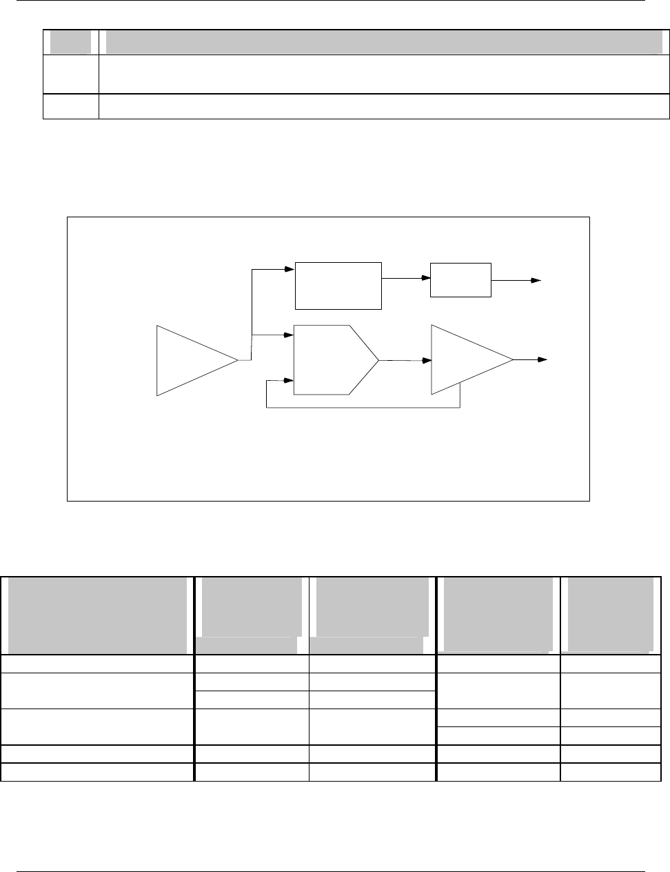
Programming and Operating Concepts
Video Recorder – User Manual 59
Table 3-9 Function Block Configuration Procedure (continued)
Step Action
4 Program the function block’s other items as desired. Other items include decimal point positions,
descriptor, tag, and various labels for identifying the function block.
5 Repeat steps 1-4 for all desired function blocks until the instrument is configured.
Example configuration
Figure 3-10 shows a simplified configuration using typical function block connections. Note that several
parameters are left out to simplify the drawing and procedure.
Table 3-10 describes how to program these connections.
AI 1
LP 1 AO 1
PV
LP1OV IN P U T
SETPOINT#1 =
15 00
AL 1 DO 1
AI1OV IN P U T
IN P U T
SETPOINT = 500
AL1OS
TYPE = CAT
TYPE = Type J
DO1OS
AO1OV
AO1BC
FEEDBACK
KEY :
FUNCTION BLOCK TYPE
INPUT PARAM ETER
FUNCTION BLOCK PARAMETER
PARAMETER CO DE
ACTION = HIGH
AI1OV
Figure 3-10 Example Configuration
Table 3-10 Example Configuration Procedure
Function block type (Full name
as displayed in the Program
menu)
1. Select this menu item from
the Program menu.
2. Select this
input parameter
from the function
block’s menu...
...and program it
with this output
code. See Section
3.11 for details.
3. Select this
Function block
parameter from the
function block’s
menu...
...and program
it with this
choice. See
Section 3.12
for details.
AI 1 (ANALOG INPUT #1) -- -- TYPE TYPE J
LP 1 (LOOP #1) PV AI1 OV SETPOINT#1 1500
FEEDBACK AO1 BC
AL 1 (ALARM #1) INPUT AI1 OV SETPOINT 500
ACTION HIGH
DO 1 (DISCRETE OUTPUT #1) INPUT AL1 OS -- --
AO 1 (ANALOG OUTPUT #1) INPUT LP1 OV TYPE CAT
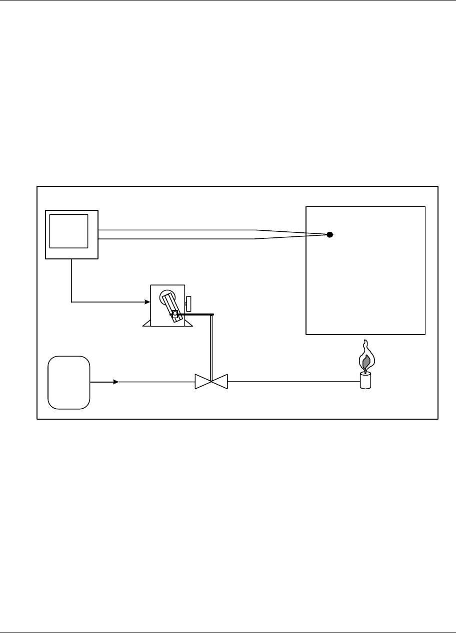
Programming and Operating Concepts
Video Recorder – User Manual 60
3.14 How to program common configurations
Being able to diagram a control configuration in terms of function blocks makes it easier to program and
configure your instrument for its intended process control application. This function block diagram you
create can be used as a “construction blue print” to program the instrument. Each block in the diagram
relates to a dedicated instrument programming menu in the instrument’s PROGRAM mode.
What follows are examples where common control configurations are presented along with their function
block diagrams. The first example is a simple control arrangement in great detail to help you understand
function block diagram basics, followed by more sophisticated examples. Once you understand how to
diagram function blocks, you will be able to draw a diagram for virtually any control strategy regardless of
complexity. Understanding the relationship between such diagrams and the instrument’s programming
menus is key to successfully mastering the instrument’s many capabilities and features.
Programming a Current Driven Heat Treat Element
An example of one of the most common and simple control strategies is in Figure 3-11 below.
GAS
SUPPLY
VALVE BURNER
FURNACE ZONE
TYPE J THERMOCOUPLE
VALVE
ACTUATOR
4 TO 20 mA
(CAT)
PV 200
SP 500
OUT 83.5%
INSTRUMENT
Figure 3-11 Control Of Furnace Zone Temperature With 4-20 mA (CAT) Control Signal

Programming and Operating Concepts
Video Recorder – User Manual 61
1. Diagram the function blocks
To configure this application using the instrument, your task is to build up a simple current control loop.
Note that this control loop must monitor and control the temperature of the furnace zone to a local set
point of 500 ºF. Using a 4 to 20 mA signal applied to a gas valve actuator, the furnace zone’s
temperature will be controlled by regulating the flow of gas to the zone’s burner.
The instrument will measure temperature, in a range between 0 and 1000 ºF, by means of a Type J
thermocouple.
To support this application, a 4 to 20 mA control loop with a thermocouple process variable must be
configured. Three function blocks—one for specifying a thermocouple analog input, a second for a
standard PID control loop, and a third defining a 4 to 20 mA analog output—are needed to produce this
control strategy’s function block diagram.
Each function block should first be arranged as in Figure 3-12. Analog input and output function blocks
are represented by right-pointed triangles. Control loop function blocks are represented by right-pointed
parallelograms.
AI
AO
LP
AI = ANALOG INPUT
LP = CONTROL LOOP
AO = ANALOG OUTPUT
Figure 3-12 Basic Function Blocks Required For Control Configuration Of Figure 3-11
2. Label input parameters
Properly label each function block. First, assign to each function block a name that identifies it within the
hardware and feature capacities of the instrument being worked with. You may assign any of the analog
inputs, control loops, and analog outputs that your instrument has to the blocks comprising the function
block diagram drawn. For simplicity, AI1, LP1, and AO1 will be used in this example.
Refer to Figure 3-13. Note that AI5, LP2, and AO2 could just as easily have been used.

Programming and Operating Concepts
Video Recorder – User Manual 62
3. Label output parameters
The second part in labeling each function block is to denote the blocks’ major input and output
parameters. Each of these parameters will correspond to actual menu settings that you program on the
instrument. As shown in Figure 3-13, the AI1 function block’s input parameter will be the actual Type J
thermocouple run from the furnace to the instrument’s AI1 input terminals. The AI1 block will process the
thermocouple’s millivolt signal to generate a temperature measurement. AI1’s output value, denoted
“AI1 OV”, will essentially be the furnace zone temperature. The LP1 function block is shown, for now,
with one input denoted by “PV”. Here, the control loop block will expect to find the data comprising its
process variable. The LP1 block’s single output is the loop’s main control output. Denoted “LP1 OV
(Loop 1’s Output Value)”, it will range between 0 and 100%. The value of LP1 OV at any given instant
will be determined by the control loop function block’s PID algorithm.
The last block in the diagram is the analog output function block, AO1. Drawn at this point with just a
single input and output, its primary purpose will be to generate a 4 to 20 mA signal that linearly
corresponds to whatever value is applied at its input. For example, if AO1’s input is defined as some
value that ranges from 0 to 100%, an input value of 0% will cause AO1 to generate a 4 mA signal at the
instrument’s AO1 output terminals. A 12 mA signal will be generated in response to an input of 50%,
while 20 mA will result when a 100% input value is applied. AO1’s input parameter is denoted “IN”, with
its output parameter labeled to identify it as the physical 4 to 20 mA signal detectable at the pair of
instrument rear terminals dedicated to AO1.
AI1
TYPE J
THERMOCOUPLE
AI1 OV
LP
PV LP1 OV
AO1IN
4 TO 20 mA
Figure 3-13 Labeling Each Function Block’s Name And Major Inputs And Outputs
4. Label function block parameters
Finally, label each block’s internal parameters. “Internal parameters” may also be referred to as “function
block parameters.” As in the case of input and output parameters, internal parameters associated with
each block correspond to actual menu settings you program in the instrument. While input and output
parameters constitute either data exchanged between function blocks or physical signals exchanged
between the instrument and the outside world, internal parameters are settings that uniquely define the
operation of the function block they are associated with. Use of a function block’s internal parameters is
for the most part limited to within the operations of the function block itself.
It is not always possible, or even practical, to draw every internal parameter that a function block has or
might need. Therefore, as a rule-of-thumb for starting out, you should first think of internal parameters
as simple labels that further define and clarify the internal operation of the function block. With this rule-
of-thumb in mind, internal parameters become items that are hopefully intuitively obvious. At this point,
what may or may not be an “intuitively obvious” internal parameter will depend on your level of process
control expertise. For the function block diagram built up so far, internal parameters that can be
presumed from the control strategy of Figure 3-11 are indicated in Figure 3-14. Here, the AI1 function
block has been labeled to show that its “INPUT TYPE” will be a Type J thermocouple with a
measurement range between 0 (RANGE LOW) and 1000 ºF (RANGE HIGH).
The label “STANDARD” has been used to indicate the type of control loop LP1 will be, along with the
notation “SP = 500” to show that the loop’s set point will be 500 ºF. The loop tuning constants of GAIN,
RESET, and RATE have been initially indicated as 10, 1 repeat/minute, and 0 minutes, respectively. As
far as the AO1 function block is concerned, its input range has been defined between 0 (IN LOW LIMIT)
and 100 (IN HIGH LIMIT) in anticipation of using LP1’s output to drive the 4 to 20 mA signal it will
generate. Note how AO1’s output range has been defined through use of the notation “OUT LOW LIMIT
= 4” and “OUT HIGH LIMIT = 20.”
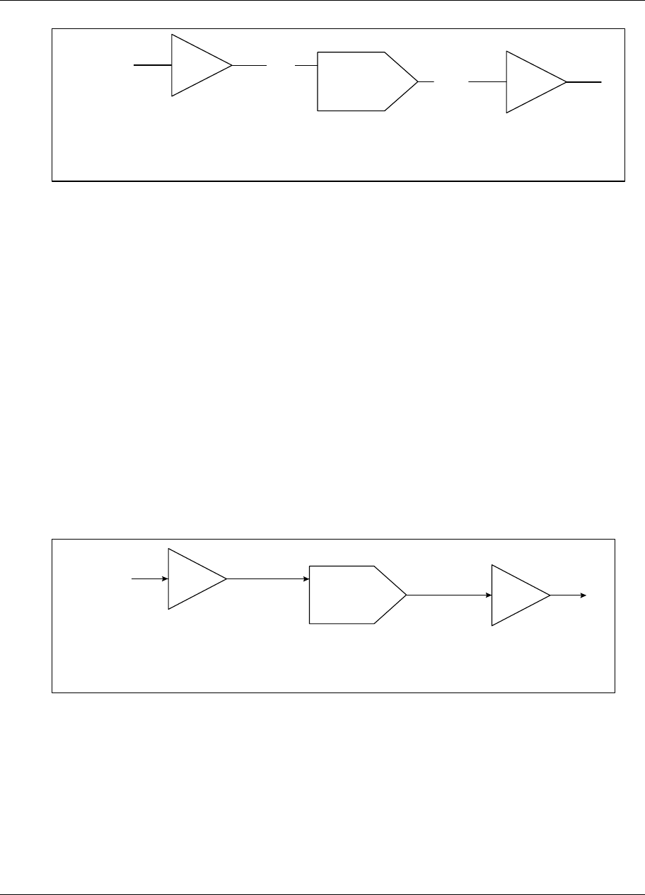
Programming and Operating Concepts
Video Recorder – User Manual 63
AI1
TYPE J
THERMOCOUPLE
AI1 OV
INPUT TYPE = J
RANGE LOW = 0
RANGE HIGH = 1000
LP1
PV LP1 OV
TYPE = STANDARD
SP1 = 500
GAIN = 10
RESET = 1
RATE = 0
AO1IN
4 TO 20 mA
OUTPUT TYPE = CAT
IN LOW LIMIT = 0
IN HIGH LIMIT = 100
OUT LOW LIMIT = 4
OUT HIGH LIMIT = 20
Figure 3-14 Labels For Internal Function Block Parameters
Note that the internal parameters that we have specified in the function block diagram built up so far are
based largely on what can be inferred from the elements of the control configuration depicted in
Figure 3-11. These internal parameters will relate directly to settings found in instrument programming
menus that exist for each particular function block. As your experience and familiarity with programming
the instrument increases, you will become more familiar with some of the less intuitive parameters and
you will include these in your diagrams.
5. Connect the blocks
The next step is to connect the function blocks in the diagram. Refer to Figure 3-15.
The interconnection lines drawn depict the flow of information between function blocks and represent
how the blocks work together to support the complete control strategy. As shown, the furnace zone
temperature measurement that AI1 generates will essentially be used as the process variable of the LP1
control loop. Based on the values of the loop’s tuning constants and on how far AI1 OV deviates from
the 500 ºF set point, the control loop function block’s PID algorithm will accordingly adjust LP1 OV to
whatever value will be necessary to maintain the process’ set point. LP1 OV, which ranges from 0 to
100 %, will in turn be applied to AO1’s input to drive the 4 to 20 mA control signal applied to the valve
actuator. By modulating the valve actuator’s position, this 4 to 20 mA signal will regulate the gas flow to
the furnace zone burner and thereby allow the instrument to control the heat levels measured in the
zone.
AI1
TYPE J
THERMOCOUPLE
AI1 OV
INPUT TYPE = J
RANGE LOW = 0
RANGE HIGH = 1000
LP1
PV LP1 OV
TYPE = STANDARD
SP1 = 500
GAIN = 10
RESET = 1
RATE = 0
AO1IN
4 TO 20 mA
OUTPUT TYPE = CAT
IN LOW LIMIT = 0
IN HIGH LIMIT = 100
OUT LOW LIMIT = 4
OUT HIGH LIMIT = 20
Figure 3-15 Interconnections Between Function Blocks
Programming and Operating Concepts
Video Recorder – User Manual 64
6. Draw the Feedback connection
To fully complete the function block diagram, one final and very important interconnection must be
drawn. In setting up control loops in this instrument, a feedback path must be specified between the loop
function block itself and the hardware element that externalizes the loop’s output to the real world. That
is, the control loop block needs confirmation from the analog output block connected to it that the percent
output levels it calls for have been correctly translated into accurate output signals. The feedback path
that provides LP1 with this confirmation is established by means of program settings depicted in
Figure 3-16.
AI1
TYPE J
THERMOCOUPLE
AI1 OV
INPUT TYPE = J
RANGE LOW = 0
RANGE HIGH = 1000
LP1
PV LP1 OV
TYPE = STANDARD
SP1 = 500
GAIN = 10
RESET = 1
RATE = 0
AO1IN
4 TO 20 mA
OUTPUT TYPE = CAT
IN LOW LIMIT = 0
IN HIGH LIMIT = 100
OUT LOW LIMIT = 4
OUT HIGH LIMIT = 20
FB
AO1 BC
Figure 3-16 Complete Function Block Diagram Of Figure 3-11
Here, the function block diagram is drawn to include the key components of a typical loop feedback path.
The AO1 function block has been changed to feature a second output denoted “AO1 BC.” This output
has been connected to a feedback input at LP1 identified by the notation “FB.” The “AO1 BC” designator
stands for “Analog Output 1’s Back Calculation.” When the control loop is brought on-line, AO1 BC will
essentially represent the value of AO1’s 4 to 20 mA output at any particular instant. The term “Back
Calculation” is used to reinforce the idea that this information is being sent “upstream” against the flow of
all other information within the function block diagram.
Programming and Operating Concepts
Video Recorder – User Manual 65
Time Proportioning Relay Driven Pump
A second control scheme is to use a relay to produce a time proportioning or Duration Adjusting Type
(DAT) control signal. Such an application is depicted in Figure 3-17.
PV 4.00
SP 7.00
OUT 90.5%
INSTRUMENT
LINEAR pH
TRANSMITTER
4.00
pH
CAUSTIC
REAGENT
4 TO 20 mA
DAT CONTROL
SIGNAL
PUMP
WASTE WATER TREATMENT VESSEL
WITH IMMERSION STYLE pH ELECTRODE
AND MIXING IMPELLER
Figure 3-17 Control Of Wastewater pH Using A Time Proportioning (DAT) Control
Signal
This application requires a basic time proportioning control loop to monitor and control the pH of the
wastewater to a local set point of 7 pH units. That is, the loop will “neutralize” the wastewater so that it
can be safely released to the environment. The wastewater pH, which is assumed to be primarily acidic,
will be controlled by introducing a caustic reagent to the contents of the treatment vessel. This will be
done through use of a time proportioning relay signal that will pulse a pump connected to a caustic
reagent source.
A function block diagram representing the control scheme of Figure 3-17 has been drawn in
Figure 3-18. The same diagram method was used to produce Figure 3-16.
%
CONNECT
TO PUMP
AI1 AI1 OV
RANGE LOW = 0
RANGE HIGH = 14
CIRCUIT LOW = 1
CIRCUIT HIGH = 5
LP1
PV LP1 OV
TYPE = STANDARD
SP1 = 7.00
AO1
IN
OUTPUT TYPE = DAT
IN LOW LIMIT = 0
IN HIGH LIMIT = 100
IMPULSE TIME = 150
FB
AO1 BC
DO1
4 TO 20
mA
250 Ω
+
1 TO 5
VDC
-
Figure 3-18 Function Block Diagram Of Figure 3-17
This drawing is similar to the temperature control application. The analog input, control loop, and analog
output function blocks (AI1, LP1, and AO1) have been used similarly. The discrete output function block
was added, drawn as a circle at AO1’s apex and named “DO1.” Recall that any analog input, control
loop, analog output, or discrete output available may be used. Up to 36 discrete outputs (DO1 through
DO36) are potentially available depending on the instrument’s model number.
Programming and Operating Concepts
Video Recorder – User Manual 66
From Figure 3-18, the instrument’s AI1 function block will essentially process the 4 to 20 mA transmitter
signal to generate a pH measurement. This measurement will be “AI1 OV” which, in turn, will be applied
to LP1’s process variable input, “PV.” Before the 4 to 20 mA signal is applied to AI1, it will be converted
to a 1 to 5 VDC signal with a 250 Ω shunt resistor. AI1 will be configured to generate a pH measurement
in a range from 0 (RANGE LOW = 0) to 14 (RANGE HIGH = 14) in response to a voltage input between
1 (CKT LOW = 1) and 5 (CKT HIGH = 5) VDC. The PID algorithm of the control loop function block will
adjust the value assumed by LP1 OV between 0 and 100%. This 0 to 100% signal will be applied to
AO1, which will be configured as a DAT type analog output. The internal parameter of “IMPULSE TIME”
in AO1 is the DAT analog output’s cycle time or period. With a specified impulse time of 150 seconds
(an arbitrarily picked value), the DAT output will be ON for 75 seconds and OFF for 75 seconds when the
input from LP1 is set to 50%. The ON and OFF times will be determined completely by the % output
levels called for by LP1. Finally, to externalize the ON and OFF output states of AO1 to the outside
world, the DO1 output relay, represented by the DO1 function block, will be programmed for AO1’s
exclusive use. Hence, as AO1 switches between ON and OFF states in response to LP1 OV’s % output
levels, so too will the DO1 output relay to generate the pulses required to drive the caustic reagent
pump.
Split Output or Duplex Control
Split output or duplex control loops are typically used in heat/cool applications. Temperature is
controlled through simultaneous use of both heating and cooling elements. If the instrument was to
support a heat/cool control configuration, an example of the control scheme that might be dealt with is
illustrated in Figure 3-19.
VALVE
ACTUATOR
INSTRUMENT
PV 85
SP 95
OUT 73.5%
HOT
WATER
HOT WATER
VALVE
VALVE
ACTUATOR
4 TO 20 mA
(CAT)
COLD
WATER
COLD WATER
VALVE
4 TO 20 mA
(CAT)
WATER TANK
100 Ω
PLATINUM
RTD
Figure 3-19 Temperature Control Of Water Using Split Output Or Duplex Control
The instrument must be set up to produce two 4 to 20 mA control signals. By applying them to current-
controlled valve actuators coupled to hot and cold water valves, these signals will regulate the amount of
hot and cold water introduced to the vessel to maintain the water temperature at whatever set point will
be programmed. The temperature of the water will be measured by means of a three-wire 100 Ω
Platinum RTD. This process may be likened to manipulating hot and cold faucets regulate water
temperature.
Programming and Operating Concepts
Video Recorder – User Manual 67
In Figure 3-20, the analog input function block AI1 is depicted processing the resistance values produced
by the RTD. The resulting water temperature measurements (AI1 OV) are then fed to the process
variable input (PV) of the LP1 control loop block. Note how LP1 has been defined as a split output
control loop using the notation “TYPE = SPLIT.” Unique to this control loop is the defined range of its
output value, LP1 OV. Where the standard control loops mentioned thus far have had outputs ranging
exclusively between 0 and 100%, the % values of the split output control loop vary between -100 and
100. 0% is considered the midpoint for this control loop’s output range. When brought on-line, a 0 to
100% output value will be generated by LP1 when hot water is needed to maintain the temperature at set
point. When the addition of cold water is necessary, the loop’s output will assume a value between 0
and -100%. Note that to externalize the control signals generated by LP1, two analog output blocks,
AO1 and AO2, will be used. AO1’s 4 to 20 mA signal will be tied to the hot water valve actuator, while
the actuator that adjusts the position of the cold water valve will receive its mA control signal from AO2.
To provide AO1 and AO2 with usable input driving signals, LP1’s output will be applied to a function
called a “standard splitter (STD SPLITTER).” Made from one of the instrument’s calculated value
function blocks (“CV’s”), the standard splitter will essentially be a mechanism that translates the %
values of the split output control loop into two distinct 0 to 100% signals. They will be applied to the
inputs of AO1 and AO2 and, as such, will drive and linearly correspond with AO1 and AO2’s 4 to 20 mA
outputs.
0-100%
100%
00
100%
100%
CV1 A2 CV1 A1
LP1 OV
AI1
100 Ω
PLATINUM
RTD
AI1 OV
INPUT TYPE = PT100 TYPE = STD SPLITTER
AO1IN
4 TO 20 mA
AO1 BC
AO2
IN
4 TO 20 mA
FB1
FB2
IN
A2
A1
CV1
AO2 BC
FB
LP1
PV LP1 OV
TYPE = SPLIT
CV1 BC
CV1 A1
CV1 A2
Figure 3-20 Function Block Diagram Of Figure 3-19
The two outputs on CV1 that will drive AO1 and AO2 are respectively labeled “CV1 A1” and “CV1 A2.”
CV1’s basic operation is described by a plot of these outputs versus LP1 OV. Shown in the lower left of
Figure 3-20, the plot demonstrates that CV1 will produce a 0 to 100% value at its CV1 A1 output when
LP1 calls for an output level between 0 and 100%. CV1 A2 will remain at 0%. When applied to AO1, the
CV1 A1 value will activate the 4 to 20 mA signal needed at the hot water valve actuator to make the
water temperature in the vessel rise. Similarly, when LP1 calls for an output level between 0 and -100%,
CV1 will produce a corresponding 0 to 100% value at CV1 A2. This time, CV1 A1 will remain at 0% and
the CV1 A2 value generated will induce the introduction of cold water into the vessel to cool its contents
down.
Note the function block diagram’s use of three back calculated feedback paths. Two such paths are
labeled AO1 BC and AO2 BC. They are connected to CV1 from the analog output function blocks at
inputs denoted “FB1” and “FB2.” CV1 BC, the third feedback path, runs from CV1 to the FB input of
LP1. All three feedback paths work together to acknowledge to LP1 that the appropriate output signals
have been generated in response to the % output levels the loop has called for.
Programming and Operating Concepts
Video Recorder – User Manual 68
Cascade Control
An example of a cascade control application is featured in Figure 3-21. Cascade control is typically used
when two process values must be simultaneously controlled, with one process value directly influencing
the behavior of the other. In this control strategy, each process value is supported by its own dedicated
control loop. The term “cascade” is used because it describes how this control approach literally
attaches both control loops together. This act of linking control loops allows for the regulation of both
process values using one and only one % output control signal.
+~-
THERMOCOUPLES
INSTRUMENT
PV 200
SP 500
OUT 83.5%
4 TO 20 mA
(CAT)
SCR
AC POWER
SOURCE
ELECTRIC
HEATING
ELEMENT
CHEMICAL
REACTION
VESSEL
OIL
OIL JACKET
Figure 3-21 Temperature Control Of An Oil Heated Chemical Reaction Chamber
InFigure 3-21, the temperature in a chemical reaction chamber is determined by the temperature of the
heated oil surrounding it. Heating the oil is done by an electric heating element driven by a 4 to 20 mA
controlled SCR and external power source. In this application the instrument controls the temperature of
the chemical reaction chamber through control of the heat emitted by the jacket tank oil. The instrument
must provide a single 4 to 20 mA control output to govern the voltage switched by the SCR and, hence,
the heat applied to the entire system. Temperature is monitored with thermocouples.
The function block diagram of the required instrument configuration is featured in Figure 3-22
Note that this diagram illustrates the classic cascade arrangement of two control loops that defines the
cascade control strategy. The first control loop, LP1, is designated as the primary cascade loop by the
notation “CAS_P.” The notation “CAS_S” indicates LP2’s designation as the secondary cascade loop.
Note how both control loops are joined together. In addition to the back-calculated feedback path set up
between the two (LP2 BC), LP1’s output is connected to an input on LP2 that at this time must be
introduced. Denoted as SP2, this input is LP2’s remote set point input.
Programming and Operating Concepts
Video Recorder – User Manual 69
AI1
REACTION
VESSEL
THERMOCOUPLE
AI1 OV
LP1
PV LP1 OV
TYPE = CAS_P
SP1 = 1234.5
FB
AO1
IN
4 TO 20 mA
LP2
SP2 LP2 OV
TYPE = CAS_S
FB
PV
AI2
OIL
THERMOCOUPLE
AI2 OV
LP2 BC AO1 BC
NOTE: 1) SP1 is desired reaction vessel temperature.
2) SP2 is the remote setpoint input of LP2.
Figure 3-22 Function Block Diagram Of The Cascade Control Strategy
Recall that based on the instrument’s model number, up to eight control loops (LP1 through LP8) are
potentially available for use within the instrument. All control loops in this product may be programmed
to operate using up to two user defined set point parameters, designated by SP1 and SP2. Should you
implement a control loop using one or both setpoints? That depends on what is necessary to meet the
requirements of the specific application being dealt with. When in the on line mode and viewing a control
loop’s dedicated on line display, the working set point of the live control loop can be switched between
SP1 or SP2 by simply pushing the “SP” key on the instrument’s front door. Note that while both set point
parameters may be programmed to have straight numeric values, only SP2 may be defined as a remote
set point. That is, SP2 may be set up so that its value is determined by the output value of another
function block, such as a setpoint profile. In the cascade control strategy demonstrated in Figure 3-22,
SP2’s remote set point functionality is exploited by the LP2 secondary cascade loop. When this control
configuration is made operational, LP2’s working set point, SP2, will have a value determined by LP1
OV.
In Figure 3-22, the process values of each loop are the output values of the AI1 and AI2 analog input
function blocks. AI1 will produce temperature measurements of the reaction chamber and provide them
to the process variable input of LP1, while measurements of the oil temperature in the jacket tank will be
furnished to LP2’s PV input by AI2. Because LP1 OV will provide LP2 with its operating set point, LP1’s
output range will be defined in engineering units of temperature instead of the usual 0 to 100%. LP2’s
output range is 0 to 100%, in anticipation of using it to drive the AO1 function block’s 4 to 20 mA signal.
Note that the range covered by LP1 OV will have to be consistent with the operating temperature range
of the oil. For example, if it is determined that the oil temperature will be manipulated between 75 and
500 ºF, the low and high limits assumed by LP1 OV (and, for that matter, SP2) will equal 75 and 500,
respectively. Finally, LP2 BC and AO1 BC are the two back-calculated feedback paths shown. As is
true for the operation of all back-calculated feedback paths, both LP2 BC and AO1 BC work together to
acknowledge the cascaded control loops that the appropriate actions have taken place in response to
both loops’ output values.
The method used to coordinate the tuning of the cascaded loops is particularly interesting. Using the
diagram of Figure 3-22, the first priority is to tune the secondary cascade loop of LP2. With LP1 kept in
manual mode, tuning may begin by first placing LP2 in manual mode and then manipulating LP1’s
output. This will allow the generation of an LP2 set point that will induce a process upset when the
secondary loop is placed back in automatic mode. Only after LP2 has been tuned can LP1 be tuned.
When tuning LP1, LP2 will be kept in automatic mode throughout the entire time LP1 is exercised. Since
the tuning of LP2 will have already been established, tuning LP1 may be approached by first mentally
“blocking out” the secondary control loop’s existence and visualizing LP1’s output as connected to a sort
of virtual analog output function block. In this light, tuning the overall cascade control configuration
becomes the considerably simpler matter of tuning a single control loop.

Programming and Operating Concepts
Video Recorder – User Manual 70
Set Point Profile Implementation
By definition, set point profiles are essentially user specified plots of process values against time. These
plots are characterized by “segments” which are a series of intervals of varying time lengths that divide
the plots into several segments. Within each segment, process values are typically drawn as straight
lines that ramp up or down or stay constant at predetermined levels. An example of a simple five-
segment set point profile is shown in Figure 3-23. Set point profiles with up to 63 segments can be
specified using the instrument. Note that when a segment depicts the process value as sloping up or
down, it is referred to as a “ramp.” The term “soak” is used to describe a segment when the process
value is made to stay constant. In Figure 3-23, segments 1, 3, and 5 are ramps while segments 2 and 4
are soaks.
PROCESS
VALUE IN
ENGINEERING
UNITS
&'()*
TIME
Figure 3-23 Example Set Point Profile
To force a process value to vary linearly with time at various rates within successive time intervals is the
job of a set point profiler, another class of function blocks available within the instrument. Be advised
that use of set point profilers is typically observed in thermal or heat treat applications. For example,
being able to vary temperature in accordance with a set point profile is vital in the tempering of metal or
ceramic parts.
Refer to the application of Figure 3-11 discussed at the beginning of this section. This application dealt
with controlling a furnace zone’s temperature by means of a 4 to 20 mA gas valve actuator. If the
furnace zone temperature were to be manipulated so that it followed the ramps and soaks of a set point
profile, the first step would be to implement the function block diagram established in Figure 3-16In
general, the control configuration that holds a process value to a local set point, must be programmed
and on line before allowing the process value to be characterized by a profile. With regard to the
application at hand, a set point profiler function block programmed with a user defined set point profile
may be brought into the configuration once the furnace zone’s basic temperature control loop is
operational. Note that the output of the profiler function block will essentially be the set point profile.
From the cascade control strategy’s explanation, recall that all control loop function blocks within the
instrument have a Setpoint #2 parameter that may be used as a remote set point input for connecting to
the profiler’s output.
LP1 in the function block diagram of Figure 3-16 will make use of SP2’s remote set point functionality so
that a set point profiler’s time varying set point may be applied to it. Refer to Figure 3-24.
Programming and Operating Concepts
Video Recorder – User Manual 71
AI1
TYPE J
THERMOCOUPLE
AI1 OV
INPUT TYPE = J
RANGE LOW = 0
RANGE HIGH = 1000
LP1
PV LP1 OV
TYPE = STANDARD
SP1 = 500
SP2 = SP1 OV
GAIN = 10
RESET = 1
RATE = 0
AO1IN
4 TO 20 mA
OUTPUT TYPE = CAT
IN LOW LIMIT = 0
IN HIGH LIMIT = 100
OUT LOW LIMIT = 4
OUT HIGH LIMIT = 20
FB
AO1 BC
SP2
SP1
SP1 OV
Figure 3-24 Function Block Diagram Of Set Point Profile Control Of Figure 3-16
Figure 3-24 basically depicts all the components of the Figure 3-16’s control configuration with a set
point profiler function block denoted by SP1. The profiler’s output (SP1 OV) is connected to the remote
set point input of LP1. Depending on the model number of the instrument, up to four set point profiler
function blocks (SP1 through SP4) may be included within the instrument’s feature capacities. Note that
while the profiler of SP1 was specified in Figure 3-24’s diagram, any of the profilers within the instrument
could have been used.
When a set point profile is executed, discrete inputs are typically used in conjunction with external
switches to control the set point profiler function block. For example, the set point profiler function block
can be programmed to start, hold, or reset based on discrete input statuses. See Figure 3-25.
External
Switches
DI1 DI1 OS
DI2 DI2 OS
DI3 DI3 OS
AI1
TYPE J
THERMOCOUPLE
AI1 OV
INPUT TYPE = J
RANGE LOW = 0
RANGE HIGH = 1000
LP1
PV LP1 OV
TYPE = STANDARD
SP1 = 500
SP2 = SP1 OV
GAIN = 10
RESET = 1
RATE = 0
AO1
IN
4 TO 20 mA
OUTPUT TYPE = CAT
IN LOW LIMIT = 0
IN HIGH LIMIT = 100
OUT LOW LIMIT = 4
OUT HIGH LIMIT = 20
FB
AO1 BC
SP2
SP1
SP1 OV
START
HOLD
RESET
“OS” = OUTPUT STATE
Figure 3-25 Discrete Inputs Controlling Execution Of Set Point Profiler Function Block

Programming and Operating Concepts
Video Recorder – User Manual 72
Also typical in the execution of a set point profile is the generation of discrete events during each profile
step. Discrete events are simply status indicators that are programmed to assume either an ON or OFF
state during a step of a profile. As simple discrete status indicators, these events may, for example, be
used to initiate a logic control scheme on the process being controlled upon the occurrence of a
particular profile segment. In this product, note that up to 16 discrete events may be programmed per
segment. See Figure 3-26.
& ' ( ) *
PROCESS
VALUE IN
ENGINEERING
UNITS
TIME
SEGMENT
#1
SEGMENT
#2
SEGMENT
#3
SEGMENT
#4
SEGMENT
#5
SP1 EVENT
#1
ON OFF ON ON OFF
•
•
•
•
•
•
•
•
•
•
•
•
•
•
•
•
•
•
SP1 EVENT
#16
OFF ON ON OFF ON
Figure 3-26 Up To 16 Discrete Events May Be Programmed Per Step Of A Set Point Profile
Discrete events, whose ON or OFF states depend on the step number of the profile they are associated
with, may be externalized using the discrete output hardware available in the instrument. Figure 3-
27features the function block diagram elements that represent how to program the instrument’s discrete
outputs so that their states coincide with those assumed by a profile’s discrete events.
Programming and Operating Concepts
Video Recorder – User Manual 73
+ + +
External
Switches
DI1 DI1 OS
DI2 DI2 OS
DI3 DI3 OS
AI1
TYPE J
THERMOCOUPLE
AI1 OV
INPUT TYPE = J
RANGE LOW = 0
RANGE HIGH = 1000
LP1
PV LP1 OV
TYPE = STANDARD
SP1 = 500
SP2 = SP1 OV
GAIN = 10
RESET = 1
RATE = 0
AO1IN
4 TO 20 mA
OUTPUT TYPE = CAT
IN LOW LIMIT = 0
IN HIGH LIMIT = 100
OUT LOW LIMIT = 4
OUT HIGH LIMIT = 20
FB
AO1 BC
SP2
SP1
SP1 OV
START
HOLD
RESET
E1 + + + E16
DO1
DO16
+ + +
+ + +
+ + +
SP1 E1
SP1 E16
Figure 3-27 Tying A Profile Function Block’s Discrete Events With Discrete Output Hardware
Refer to your instrument’s model number to verify its complement of discrete input and output hardware.
The available combinations of discrete inputs and outputs are featured in the Specifications section.

Programming and Operating Concepts
Video Recorder – User Manual 74
3.15 Data Storage
This instrument supports either floppy 1,44 MB or 100 MB ZIP disks. Note that only DOS formatted
floppy disks may be used in the instrument’s disk drive and the unit’s front door must be closed for any
disk drive operations to take place. The floppy disks may be initialized in the instrument or on an IBM-
PC with the initialize utility.
Read this overview thoroughly to understand the fundamentals behind the instrument’s data storage
capabilities.
Categories of Stored Data
There are four categories of disk storable data. Each category of data is stored in its own unique file.
The categories are:
Data Storage
Configuration Storage
Setpoint Program Storage
Calibration Storage
Data Storage Configuratio n CalibrationSetpoint Program
Process Data Diagnostic Data
Trends
Unit Data
Ala rm s
Eve nts
Figure 3-28 Categories of Stored Data
The first category of stored data, Data Storage, is comprised of two types of data: process data and
diagnostic data. When the instrument stores these data types it is essentially functioning as a recorder.
Process data is comprised of up to four files containing historical information on the process that the
instrument is monitoring and/or controlling, such as the temperature trend or a log of a furnace over time.
Process data also includes any alarm or discrete event information.
Diagnostic data is the result of the instrument’s execution of diagnostic routines during instrument start-
up and maintenance procedures (such as calibration). Online operation is also monitored to detect both
process faults and internal electronic errors. If a diagnostic error occurs, a record of it can be stored to a
single diagnostic file.
The second category of stored data is configuration storage, which is a single file comprised of the
instrument’s programming and configuration. Configuration storage includes the programming of the
instrument’s analog input characteristics, the configuration of its control loops, or, perhaps, the
programming of any math or logic functions.
The third category of stored data is Setpoint Program storage, which is a single file –a setpoint program–
containing one to eight setpoint profiles, depending on the instrument. Recall that set point profiles are
user specified plots of process values against time that are divided into ramp and soak segments of
varying time lengths. Setpoint programs may be stored to disk or to the instrument’s memory.
The fourth category of stored data is calibration storage, which is a file containing the instrument’s
analog input and output calibration. This file may be used to restore calibration in the event that a full
calibration, using a calibration source and/or meter, cannot be performed.

Programming and Operating Concepts
Video Recorder – User Manual 75
Performing Data Storage
Configuring the instrument to store the first category, Data Storage (process and diagnostic data) is done
through an Online menu entitled DATA STORAGE. All aspects of preparing a DOS formatted disk to
accept process and diagnostic data information are managed through this menu’s selections. Process
and diagnostic data may be stored on the same disk, but not along with other storage types (i.e.,
configuration, setpoint programs, or calibration).
The four types of process data are:
Trends - Data comprising the classic horizontal or vertically oriented time-varying traces that represent
process parameters.
Unit Data - Process parameter information collected and displayed in tabular or datalog format.
Alarms - A record of any alarms that activated while the instrument was monitoring and/or controlling
your process.
Events - A record of any discrete events that might have occurred while the instrument was monitoring
and/or controlling your process. Discrete events may occur, for example, in the instrument’s execution of
a set point profile.
When the instrument is On line and performing Data Storage, a separate and distinct disk file will be
established for each process data type along with a file for diagnostic errors. Each file will be
distinguished by a file extension as indicated in Table 3-11.
Table 3-11 Data Storage File Extensions
Data Type File extension
Trends .LNT
Unit Data .LNU
Alarm History .LNA
Discrete Event .LNE
Diagnostics .LND
You can specify which process data types are written to disk and whether or not diagnostic errors are
stored by setting up data storage schedules, accessible under a prompt entitled SET UP NEW
SCHEDULES under the DATA STORAGE menu. Up to Eight files may be written to disk while the
instrument performs Data Storage – four trend files, one unit data file, one alarm file, one event file, and
one diagnostics file.
SET UP NEW SCHEDULES lets you designate several other parameters, such as the data storage rate
(i.e., the distance in time between adjacent samples of a recorded process data parameter), the eight-
character file names used to identify each process and diagnostic data file, and whether or not the Data
Storage takes place in continuous or batch modes. Data Storage files may be configured to “rollover”
after they have become full. That is, after the space on the disk for each file type has run out, all of the
oldest data on the disk is overwritten with the most recent data.
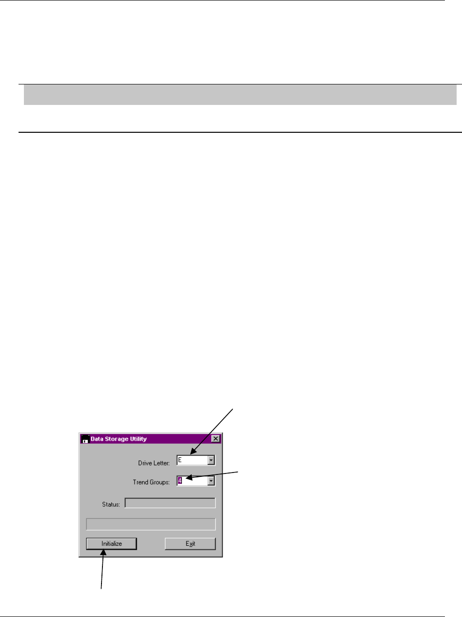
Programming and Operating Concepts
Video Recorder – User Manual 76
Initializing a ZIP disk
To activate the new data storage schedules that have been configured in the SET UP NEW
SCHEDULES menu requires you to “initialize” the DOS formatted disk to which process and diagnostic
data will be stored. This is done by executing a routine entitled INITIALIZE DISK, also found in the
DATA STORAGE menu. This task can also be done on a PC. The task of initializing a disk and
activating data storage schedules are one in the same.
ATTENTION
Initializing a disk is only necessary for performing Data Storage. You do not have to initialize a disk to perform
Configuration, Set Point Program, or Calibration Storage
When executing the INITIALIZE DISK menu prompt, you will observe two selections: USE NEW
SCHEDULES and USE CURRENT SCHEDULES. The “SCHEDULES” in both selections refer to the
data storage schedules prepared in the SET UP NEW SCHEDULES menu described earlier. USE NEW
SCHEDULES to initialize the disk to activate a newly configured data storage schedule for the very first
time. The only time you will USE NEW SCHEDULES again is after you have made any changes to the
way the data storage schedules have been configured. You must USE NEW SCHEDULES to initialize
the disk in order for these changes to take effect. USE CURRENT SCHEDULES to initialize a disk if the
disk will replace one that has become full. This will ensure that data being recorded continues
uninterrupted over the space of both the full and replacement disks. During the time when the full disk is
being replaced with a new disk, recorded data will be stored to the instrument’s memory buffer. Upon
completing initialization via the USE CURRENT SCHEDULES prompt, all buffered data will be written to
the new disk and data storage will resume, with no lapses of storage between disks.
Disk initialization allocates sections of the disk to each of the files you have elected to store per the SET
UP NEW SCHEDULES menu. Once the instrument completes initializing the disk, process and
diagnostic data recording begins immediately, indicated by a yellow-colored letter “S” in the lower right
hand corner of the instrument screen.
Pre-initializing a ZIPdisk on a PC
Pre-initializing a ZIP disk on the video recorder takes time, there is a more efficient way to do it : using
theSDI tool. The SDI tool is a very basic, straightforward Win 95/98/NT program that can be used to
quickly pre-initialize a ZIP disk on a PC. This tool is provided with the video recorder. Install it on your
PC, as per instructions on the floppy disk label.
Here are the 3 steps to follow when running the SDI utility.
Select the drive letter where the
disk to initialize can be found
Select the number of trend
groups you want to initialize
Click on initialize
,
-
.

Programming and Operating Concepts
Video Recorder – User Manual 77
The next step to complete is to initialize the disk on the video recorder as you would have done normally,
as explained in the «Initializing a zip disk» section, except that this time, it will take just a few seconds.
Note: it is recommended to dedicate a ZIP disk to storage of data only and store configurations of
products on a separate disk.
Data Storage Status
The prompt DATA STORAGE STATUS, accessed from the Online DATA STORAGE menu item,
displays a calculation of how long a particular disk will last based on the configured data storage
schedule. Disk capacity is indicated in days, hours, and minutes remaining on the disk.
After the instrument has been Online and actively performing Data Storage to disk, a warning message
will appear when the disk reaches the default 90% capacity, or a user-specified capacity. Once a disk
has reached its programmed capacity, a DISK FULL message will be displayed.
Data storage considerations
In order to guarantee a proper operation of the instrument (e.g. no sample lost), there is a maximum load
that the video recorder should not overcome. This load can be theorically computed by considering the
number of data storage trends, live trends and live screens programmed and their associated sample
rate.
1 ) One live screen counts for one schedule per second. At least one live screen is present in the
instrument. A live screen is a display that require any measurement information to be built.
2 ) Each ENABLED Data Storage schedule has a user defined sample rate.
3 ) Each ENABLED Live Trend has the following sample rates :
Screen Size Schedule Sample Rate
5 Min Screen 1 Second
15 Minute Screen 3 Seconds
30 Minute Screen 6 Seconds
1 Hour 12 Seconds
2 Hours 24 Seconds
4 Hours 47 Seconds
8 Hours 93 Seconds (1.55 Minutes)
24 Hours 279 Seconds (4.65 Minutes)
7 Days 1951 Seconds (32.5 Minutes)
31 Days 8640 Seconds (2.4 Hours)
Therefore, to guarantee a proper operation of the instrument, the following inequation should allways be
true :
ΣProgrammed trend
(
live or data stora
g
e
)
A
ssociated sam ple rate
Number of
live screens
+< 6

Programming and Operating Concepts
Video Recorder – User Manual 78
EXAMPLES :
Example #1 : 4 Live Trends all having 1 Hour Screens + 1 Data Storage Trend at 5 Seconds + 1 Data
Storage Trend at 10 Seconds + 1 Live Screen.
The result = ((1/12) * 4) + 1/5 + 1/10 + 1 = 1.6333 (BELOW THE LIMIT)
Example #2 : 1 Live Trends with 5 Minute Screen + 1 Data Storage Trend at 0.25 Seconds + 1 Live
Screen.
The result = 1/1 + 1/0.25 + 1 = 6 (AT THE LIMIT)
Example #3 : 2 Live Trends with 5 Minute Screen + 1 Data Storage Trend at 0.25 Seconds + 1 Live
Screen.
The result = (1/1 * 2) + 1/0.25 + 1 = 7 (ABOVE THE LIMIT)
Process and Diagnostic Data Integrity
The instrument is equipped with several features to ensure data integrity. The instrument will not store
data to disk if its front door is open. A BEZEL OPEN message will appear on all displays and process
and diagnostic data meant for disk storage will be kept in the instrument’s memory buffer. Data
corruption and loss are, therefore, not issues if someone walks up to the instrument and simply removes
the Data Storage disk. Note that when performing Data Storage, the instrument writes to the disk only
once a minute. This ensures that the latest data is always on disk. In the event of a power failure, at
most one minute of data would be lost.
Performing Configuration Storage
Configuration storage is performed through a Program mode MAIN MENU prompt LOAD/STORE
CONFIG. Here, a file containing the instrument’s programming and configuration is created by executing
a routine called STORE CONFIG TO DISK. The applicable file extensions for configuration files are
.LNC.
Note that an instrument configuration file may also be created and stored to disk using optionally
purchased SCF Configuration Software. You do not need a live instrument to create a configuration file
using SCF.
Once stored to disk, the instrument configuration file may be downloaded into other instruments that
have an identical model number. This helps to greatly reduce the amount of time required to program
and configure multiple units sharing the same application. Having the instrument configuration on disk
can also drastically minimize down time in the event of an instrument failure. The file can be used to
program and configure a replacement unit within seconds.
Performing Set Point Program Storage
Refer to Section 5 of the manual for a detailed explanation of how Set Point Program Storage is
accomplished.

Programming Function Blocks and Features
Video Recorder – User Manual 79
4. How To Program Function Blocks and Features
4.1 Overview
This section describes all the programming procedures to get your instrument up and running, except
Profiles which are discussed in Section 5. It describes the entire Program Mode menu and some items
from the Online Mode menu.
What’s in this section?
The following topics are covered in this section.
Topic Page
Overview 79
Programming Tips 80
The Program Mode Menu 81
Frequently used programming prompts 82
Set Mode 83
Enter Labels 84
Program Analog Inputs 87
Program Control Loops 90
Program Analog Outputs 101
Program Discrete Inputs 104
Program Discrete Outputs 105
Program Calculated Values 106
Program Alarms 143
Program Totalizers 144
Program Profiles 146
Program Constants 147
Copy Block 149
Program Displays 150
Enable Features 159
Program Security 160
Serial Communications 161
Set Clock 162
Load/Store Configuration 163
Scan Rate 164
Select Language 165
Data Storage 166

Programming Function Blocks and Features
Video Recorder – User Manual 80
4.2 Programming tips
• See Section 3 for general programming procedures.
• Before programming a function block’s input parameter with a CV’s (Calculated Value) output
parameter, you must program the CV first; otherwise, the CV’s output parameter will not be
available for programming.
• The function block SY (System Parameter) operates internally and has no menu. It automatically
produces outputs which reflect the status of alarms, data storage, diagnostics, and reference
junction temperature. These outputs can be programmed as inputs to function blocks. See Table
3-5 in Section 3.
• Each function block can be labeled with custom descriptors and tags to identify the function on
displays. You can enter these labels under the menu item ENTER LABELS or within each function
block’s menu item. See Section 4.4 Frequently used programming prompts.
• All Program mode menu items and settings can be reviewed but not changed in the Online mode
by selecting “REVIEW PROGRAMMING” on the main Online menu. See Enable Features, Section
4.19.
• We recommend you save the instrument configuration to a floppy disk after you have completed
programming the instrument. See 4.23 Access LOAD/STORE CONFIG.

Programming Function Blocks and Features
Video Recorder – User Manual 81
4.3 The Program mode menu
Program mode is an off-line mode for programming (configuring) the instrument. In this mode, all
outputs are frozen.
Table 4-1 shows the top level of the Program Mode menu with all available options. Your instrument
may have a reduced menu if options are not present or if features have been disabled.
Table 4-1 Program Mode Menu
Prompt Function
SET MODE Change operating mode of programmer
LABELS Enter descriptive labels for parameters using instrument’s buttons
or a QWERTY keyboard or barcode reader.
ANALOG INPUTS Program Analog Inputs.
CONTROL LOOPS Program Control Loops.
ANALOG OUTPUTS Program Analog Outputs.
DISCRETE INPUTS Program Discrete Inputs.
DISCRETE OUTPUTS Program Discrete Outputs.
CALCULATED VALUES Program Calculated Values.
ALARMS Program Alarms.
TOTALIZERS Program Totalizers.
PROFILERS Program Set point Profiles.
CONSTANTS Program Constants.
DISPLAYS Assign primary Online displays to the Display button.
FEATURES Enable/disable certain menu items.
SECURITY Enable/disable security on certain items.
SERIAL COMMUNICATIONS Program Serial Communication.
COPY BLOCK Copy any function block to another channel.
CLOCK Set time and date.
LOAD/STORE CONFIG Store and load configurations/calibrations.
SCAN RATE Set scan rate of instrument.
LANGUAGE Select language of instrument.

Programming Function Blocks and Features
Video Recorder – User Manual 82
4.4 Frequently used programming prompts
When programming the instrument you will see certain prompts repeatedly in different menus. These
are described in Table 4-2, rather than in each menu in which they appear.
Table 4-2 Frequently Used Programming Prompts
Prompt Range/Selections Definition
IN DECIMAL POS X.XXXXX
XX.XXXX
XXX.XXX
XXXX.XX
XXXXX.X
XXXXXX.
X.XXEXX
Select the decimal point position to be
used for all inputs to the function.
Select X.XXEXX to display the function’s
values in exponential notation.
Example: 1.23E4 means 1.23 x 10⁴ .
OUT DECIMAL POS Same as IN DECIMAL POS selections Select the decimal point position that will
be used for all outputs of the function.
ON LABEL* OFF
UP
START
LOW
RESET
TRUE
LEFT
DECRS
LOAD
COOL
ON
DOWN
STOP
HIGH
RUN
FALSE
RIGHT
INCRS
UNLOAD
HEAT
FILL
EMPTY
IN
OPEN
HOLD
READY
ALARM
AUTO
SP1
NO
PAUSE
DRAIN
FULL
OUT
CLOSED
ACTIVE
ABORT
NORMAL
MANUAL
SP2
YES
Select the discrete function’s ON(1)
state label.
OFF LABEL* Same as ON LABEL selections Select the discrete function’s OFF state
label.
DESCR* Enter up to 16 characters. Usually appears as a header or title on
some displays and reports. For alarms,
this is the actual alarm message.
TAG* Enter 7 characters maximum. Identifies the point or function on most
displays and reports. Each tag must be
unique.
UNITS* Default choices:
PSI DEGR
BAR K
MW MV
GPH V
GPM OHM
GPS HZ
GAL MA
LPH %
LPM PH
LPS KG
LITR GRAM
DEGC LB
DEGF
Shows units of measure for analog
values on most displays and reports.
These 25 choices can be changed. See
Table 4-4.
* Prompt does not appear if labeling is disabled under ENABLE FEATURES.

Programming Function Blocks and Features
Video Recorder – User Manual 83
4.5 Set Mode
Select this item to change the operating mode of the instrument to Online, Program or Maintenance.
The top of the display will show which mode you have changed to.
Program mode
Program mode is an off-line mode for programming (configuring) the instrument. In this mode, all
outputs are frozen.
Online mode
Online Mode enables full use of the instrument with its inputs, outputs and internal programming. In this
mode, it is fully interactive with all externally connected elements.
Maintenance mode
Maintenance Mode is an off-line mode for maintaining proper and complete functioning of the
instrument. Functions include calibration, off-line diagnostic testing, and various setups for operation.
In Maintenance Mode, all outputs are frozen.
ATTENTION
Note: Changing to ONLINE mode by pressing any of the Display buttons can cause incorrect values to be
displayed. The values will correct themselves in a few seconds. To avoid this potential annoyance, change to
online mode through SET MODE instead of through the Display buttons.

Programming Function Blocks and Features
Video Recorder – User Manual 84
4.6 Enter Labels
Overview
Labeling lets you use the front panel buttons, a QWERTY keyboard, or barcode reader to assign
custom text identifiers to most data and functions to make them easily recognized on displays. Labeling
items makes programming and operation easier but is not required. You can assign all labels here or at
each individual programming menu (that is, at Program Analog Inputs, Program Alarms, etc.). For the
latter, you must enable labeling under ENABLE FEATURES in the main Program menu.
Entering labels with the front panel buttons
Use the Up Arrow and Down Arrow keys to select a character and the left arrow to move the cursor.
See Table 3-6 for these buttons’ functions. If you are entering several labels, this method can be
tedious because you must scroll through A-Z and 0-9 to pick each character. Consider using a
keyboard or barcode reader instead.
Entering labels with a QWERTY keyboard
Using a QWERTY keyboard is easier and faster if you are entering many labels. See Section 3.6 for
keyboard connection procedure.
To enter label with the keyboard:
1. Select Enter Labels.
2. Select the function block whose label you want to change.
3. Select the label you want to change (Table 4-3).
4. Press Enter to move cursor to the right side of the display.
5. Type in the new label with the keyboard. The instrument accepts A…Z, a…z, 0…9, (,), -, +, /, *, ^,
(.), =.
6. Press Enter to accept the new label.
Entering labels with a barcode reader
Using a barcode reader is easier and faster if you are entering many labels. See Section 3.6 for
barcode reader connection procedure.
To enter label with the barcode reader:
1. Select Enter Labels.
2. Select the function block whose label you want to change.
3. Select the label you want to change (Table 4-3).
4. Press Enter to move cursor to the right side of the display.
5. Scan in the new label with the barcode reader. Allowable characters are: 0…9, A…Z, -, +, /,
6. Press Enter to accept the new label.
After selecting ENTER LABELS, choose an item (such as Analog Inputs) to label. Use the prompts in
Table 4-3. All text and numeric keys may be used for labels; no characters are prohibited. To cancel an
entry, press the ESC key on the keyboard or press the Menu button on the front panel.

Programming Function Blocks and Features
Video Recorder – User Manual 85
Table 4-3 Labels for Function Blocks
Prompt Range/Selections Definition
DESCR Enter 16 characters maximum. Called a descriptor. Usually appears as
a header or title on some displays and
reports. For alarms, this is the actual
alarm message. If labeling is enabled,
the descriptor can be edited in the
function block’s program menu.
TAG Enter 7 characters maximum. Identifies the point or function on most
displays and reports. Each tag must be
unique. If labeling is enabled, the tag
can be edited in the function block’s
program menu.
UNITS Default choices:
PSI DEGR
BAR K
MW MV
GPH V
GPM OHM
GPS HZ
GAL MA
LPH %
LPM PH
LPS KG
LITR GRAM
DEGC LB
DEGF
Shows units of measure for analog
values on most displays and reports.
This list of units can be changed under
the ENGINEERING UNITS menu item. If
labeling is enabled, the units can be
edited in the function block’s program
menu.
ON STATE OFF
UP
START
LOW
RESET
TRUE
LEFT
DECRS
LOAD
COOL
ON
DOWN
STOP
HIGH
RUN
FALSE
RIGHT
INCRS
UNLOAD
HEAT
FILL
EMPTY
IN
OPEN
HOLD
READY
ALARM
AUTO
SP1
NO
PAUSE
DRAIN
FULL
OUT
CLOSED
ACTIVE
ABORT
NORMAL
MANUAL
SP2
YES
Select a label describing the ON(1) state
of the discrete function. These labels
cannot be changed.
OFF STATE See ON STATE for default choices. Select a label to describe the OFF (0)
state of the discrete function. These
labels cannot be changed.

Programming Function Blocks and Features
Video Recorder – User Manual 86
Table 4-4 Other Labels
Prompt Range/Selections Definition
UNIT Enter up to 16 characters to specify a
label for the instrument. The unit name appears on all Data Storage
floppy disks coming from this instrument.
ENGINEERING
UNITS Enter up to 4 characters to change
available engineering units from the
defaults:
You can change the 25 engineering units
available in Table 4-3 as UNITS.
PSI DEGR
BAR K
MW MV
GPH V
GPM OHM
GPS HZ
GAL MA
LPH %
LPM PH
LPS KG
LITR GRAM
DEGC LB
DEGF
To reset the 25 engineering units to their
defaults, select RESET DEFAULTS.
FILENAMES Enter up to 6 characters to change
available filenames from these defaults:
FILE CYCLE DRYER
PROD RECORD TANK
UNIT LOOP REACTR
CONFIG KILN VESSEL
CALIB WCHEM PRESS
FURNCE DEMIN CONTRL
BATCH FERMTR LEHR
LINE STRLZR OVEN
ZONE
These filenames will appear as choices on
other menus.
To reset the filenames to their defaults,
select RESET DEFAULTS.

Programming Function Blocks and Features
Video Recorder – User Manual 87
4.7 Program Analog Inputs
To program Analog Inputs, select PROGRAM ANALOG INPUTS on the Main Program Menu. Select an
AI to program.
Table 4-5 Analog Input Algorithm Selection
Prompt Range/Selections Definition
INPUT ALGORITHM Standard or Custom This prompt appears only if “CUSTOM INPUT” is
enabled under Enable Features in the Program
Mode Menu (Section 0). If “CUSTOM INPUT” is
disabled you will see the Standard prompts (Table
4-6).
Standard lets you choose a thermocouple, RTD,
EMF, or pyrometer type. The Standard prompts
are shown in Table 4-6.
Custom lets you convert the input from a
thermocouple or EMF to engineering units using a
custom curve containing up to 20 points.
Standard algorithm prompts
Table 4-6 describes all the prompts associated with the standard algorithm. These are the default
prompts for analog input programming. See Table 4-2 for additional prompts.
Table 4-6 Standard Algorithm Prompts
Prompt Range/Selections Definition
INPUT TYPE See Table 1-3 for selections. The
default type is OFF. Input type (thermocouple, RTD, pyrometer)
RANGE LOW The value must be within the limits
specified for the input type (see Table
1-3). Be sure to use the correct value
for the temperature units used (°F, °C,
K, °R). To enter the full range for the
temperature units selected (see
TEMPERATURE UNITS), select TYPE
again and press Enter without changing
the range type.
Low end of the input range.
RANGE HIGH The value must be within the limits
specified for the input type (see Table
1-3). Be sure to use the correct value
for the temperature units used (°F, °C,
K, °R). To enter the full range for the
temperature units selected (see
TEMPERATURE UNITS), select TYPE
again and press Enter without changing
the range type.
High end of the input range.

Programming Function Blocks and Features
Video Recorder – User Manual 88
Table 4-6 Standard Algorithm Prompts (continued)
Prompt Range/Selections Definition
TEMPERATURE UNIT Select C for Degrees Celsius, F for
Degrees Fahrenheit, K for Kelvin, R for
Rankine, or NONE.
Specifies the temperature units used for
thermocouple, pyrometer, and RTD input
types. The default setting is F. If you change
the default, be sure to change the analog
input’s RANGE LOW and RANGE HIGH
values accordingly. The instrument will not
adjust these values by itself.
Ignore the TEMPERATURE UNIT prompt or
set it to NONE, if the analog input being
programmed will not be used for temperature
measurements.
DIRECT/INDIRECT Select DIRECT for thermocouple,
pyrometer, or RTD inputs. Select INDIR
(Indirect) for volt or millivolt signal inputs
from linear or non-linear transmitters.
Select SQRT (Square Root) for extracting
flow measurements from a voltage input
representing differential pressure
measurements. If SQRT is chosen, the
RANGE LOW and RANGE HIGH must be
adjusted to specify the upper and lower
limits of the flow units span.
Note that the term “direct” generally applies to
input types where the sensors in direct
physical contact with the monitored process
are also in direct physical contact with the
instrument terminal board. The term “indirect”
applies to inputs from transmitters since the
sensors in direct physical contact with the
monitored process are indirectly connected to
the instrument through the transmitter circuitry
and wiring.
CIRCUIT LOW OFF or number Appears only if “INDIR” or “SQRT” was
previously selected. Is the actual low end
value of voltage to be used for Indirect
measurements.
CIRCUIT HIGH OFF or number Appears only if “INDIR” or “SQRT” was
previously selected. Is the actual high end
value of voltage to be used for Indirect
measurements.
ELECTRICAL UNITS Select whether the CIRCUIT LOW or
CIRCUIT HIGH values specified are in
units of VOLTS, MV (millivolts), or OHMS.
Circuit low and circuit high units.
LAG ≥ 0 seconds or OFF “LAG” is a time constant applied to the input
measurement value. This provides digital
filtering (LAG) to the measurement.
Lag appears on menu only if EXPANDED
INPUT is enabled under Enable Features in
the Program menu.
SAMPLE HOLD OFF, discrete parameter, 0, 1 Holds Input. The input value is measured
normally when this discrete is OFF and holds
its last value when the discrete is ON(1).
Hold appears on menu only if EXPANDED
INPUT is enabled under Enable Features in
the Program menu.
FAILSAFE For thermocouples only, Upscale (UP),
Downscale (DOWN) or None. Determines whether or not failsafe is active
and, if so, which direction.
CLAMPING HI RANGE clamps the input at the
RANGE HIGH value. LO RANGE clamps
input at the RANGE LOW value. RANGE
clamps input over both the low and high
range values. NONE gives no clamping.
Clamps input at specified value.
ATTENTION: Clamping is not recommended
for process variable inputs to control loops.

Programming Function Blocks and Features
Video Recorder – User Manual 89
Custom algorithm prompts
Table 4-7 describes the custom algorithm prompts. See Table 4-2 for additional prompts. These
prompts appear only if CUSTOM INPUT is enabled under FEATURES. See Section 0.
Table 4-7 Custom Algorithm Prompts
Prompt Range/Selections Definition
INPUT SIGNAL EMF, TC, or RTD. Selects the input hardware.
RJ ENABLE Select YES for reference junction
compensation, NO for no
compensation.
Reference junction
compensation.
EMISSIVITY ENABLE Select YES for emissivity
compensation for emf input. Emissivity compensation for
emf input.
Xn
Yn
You must input at least 2 coordinates.
X must increase by at least 0.00001.
Y values are not limited except in the
following 2 cases.
1. If the incoming signal is from a
thermocouple and reference junction
compensation is on, make sure that
a, b, and c are all true.
a) All Y's are increasing or all are
decreasing.
b) Y range includes 0-65°C.
c) Temperature units are °F, °C, K,
or °R.
2. If Online adjustment of the value is
desired, make sure that all Y's are
increasing or all are decreasing.
Use these prompts to plot a
curve of up to 20 points, where
Xn is the incoming signal in
the electrical units selected
and Yn is its corresponding
value in the temperature units
selected. Interpolation is
straight-line.
ELECTRICAL UNITS MV, OHMS, VOLTS Units of the electrical signal.
LAG ≥ 0 seconds or OFF LAG is a time constant applied
to the input measurement
value. This provides digital
filtering (LAG) to the
measurement.
Lag appears on menu only if
EXPANDED INPUT is enabled
under Enable Features in the
Program menu.
SAMPLE HOLD OFF, discrete parameter, 0, 1 Holds Input. The input value is
measured normally when this
discrete is OFF(0) and holds
its last value when the discrete
is ON(1).
Hold appears on menu only if
EXPANDED INPUT is enabled
under Enable Features in the
Program menu.
Press Menu when entries are complete. At the prompt "PRESS ENTER TO SAVE", press Enter to save
your changes, or press Menu again to exit the session without saving the changes.

Programming Function Blocks and Features
Video Recorder – User Manual 90
4.8 Program Control Loops
Control Loop Programming Structure
Programming a control loop requires configuring at least 3 function blocks: an Analog Input (AI), a loop
algorithm and an Analog Output (AO). The term AO is applied to any type of control output; current
(CAT), or time proportioning (DAT). The structure of the instrument permits many variations on this
concept by allowing Calculated Values (CVs), both digital and analog, to be used as inputs to the
different parameters within the control algorithms. It also allows a single parameter to be read by any
number of function blocks in the unit.
Loop Characteristics
Table 4-8 lists loop characteristics to be aware of when configuring your instrument.
Table 4-8 Loop Characteristics
Characteristic What to be aware of
Choice of algorithm type Two PID algorithm types, interactive and noninteractive. Noninteractive is the
default type; however, this may be changed.
Gain or proportional band PB is the default; however this may be changed.
7 loop types available If the loop type is changed after a configuration is completed, all previously
programmed entries will be deleted.
Diagnostic routines You will be prompted to save your entries when leaving the loop program
sequence. Diagnostic routines are executed at this time to verify all entries are
complete and compatible. A FAIL message at this time may indicate incomplete
entries or incompatible selections.
Split output tuning When programming Split Output control loops, tuning parameter set #1 is
automatically applied to output values between 0 and +100. Tuning parameter
set #2 is automatically applied to output values between 0 and -100.
Programming loop
parameters Control loop programming may require entry of numerical values, analog
parameters or discrete parameters as determined by the specific loop feature. In
some cases the choices may be a numeral, an analog parameter or OFF. For
parameter choices, refer to Table 3-2 for definitions of the discrete and analog
parameter types available. OFF or NONE are listed as menu choices where
applicable. Scroll to locate.
Minimum programming
requirements Many of the prompted entry fields for control loops are optional. As a general
rule, the minimum entry information for control loops includes the Process
Variable (PV) with range limits, set point value, some combination of gain, reset
and rate, and a source for the feedback. In most cases, the feedback source will
be the back-calculation output (BC) value of the analog output (AO) function
block.

Programming Function Blocks and Features
Video Recorder – User Manual 91
Table 4-8 Loop Characteristics (continued)
Characteristic What to be aware of
Split output programming
requirements A splitter output type (Standard or Advanced) calculated value is used to send
the Split loop output to 2 or 3 different analog output (AO) functions. In this
case, program the control loop to receive a feedback from the back calculation
output of the splitter calculated value. In other words, loop Feedback = CVn BC
(where CVn is a Splitter type calculated value and BC is its output).
Program the splitter calculated value to accept the back-calculation values (BC)
of each analog output function block (AO) as its feedback source. In other
words, CVn FB = AOn BC.
Cascade primary loop Be sure to scale the cascade primary loop’s output limits to match the process
variable range of the secondary control loop. (Note: Output scaling is only
available on the cascade primary type of control loop.) The primary loop
feedback should be connected to the back calculation value of the secondary
control loop.
Miscellaneous loop
characteristics Other parameters affecting loops are latching and reset limit. These are
described in the loop prompt table.
Programming Procedure
To program Control Loops, select "PROGRAM CONTROL LOOPS" in the Main Program Menu. Select
a loop to program.
Table 4-9 illustrates the menu selections for the various loop types. See Table 4-10 for an alphabetical
listing of these parameters’ descriptions. Enter all desired choices, then repeat the procedure, if
desired, for the other Loops.

Programming Function Blocks and Features
Video Recorder – User Manual 92
Table 4-9 Control Loop Type Menu Selections
STD ADV SPLIT ON OFF CAS P CAS S RATIO DIAT
IN DECIMAL POS IN DECIMAL POS IN DECIMAL POS IN DECIMAL POS IN DECIMAL POS IN DECIMAL POS IN DECIMAL POS IN DECIMAL POS
OUT DECIMAL
POS OUT DECIMAL
POS OUT DECIMAL
POS OUT DECIMAL
POS OUT DECIMAL
POS OUT DECIMAL
POS OUT DECIMAL
POS OUT DECIMAL
POS
PV PV PV PV OUT UNITS PV PV PV
PV HIGH LIMIT PV HIGH LIMIT PV HIGH LIMIT PV HIGH LIMIT PV PV HIGH LIMIT PV HIGH LIMIT PV HIGH LIMIT
PV LOW LIMIT PV LOW LIMIT PV LOW LIMIT PV LOW LIMIT PV HIGH LIMIT PV LOW LIMIT PV LOW LIMIT PV LOW LIMIT
CONTROL
ACTION CONTROL
ACTION CONTROL
ACTION CONTROL
ACTION PV LOW LIMIT CONTROL
ACTION CONTROL
ACTION CONTROL
ACTION
GAIN/PROP
BAND GAIN/PROP
BAND GAIN/PROP
BAND SP1 TRACKING CONTROL
ACTION GAIN/PROP
BAND GAIN/PROP
BAND GAIN/PROP
BAND
PROP
BAND#1/GAIN#1 PROP
BAND#1/GAIN#1 PROP
BAND#1/GAIN#1 SETPOINT#1 GAIN/PROP
BAND PROP
BAND#1/GAIN#1 PROP
BAND#1/GAIN#1 PROP
BAND#1/GAIN#1
RESET#1 RESET#1 RESET#1 SETPOINT#2 PROP
BAND#1/GAIN#1 RESET#1 RESET#1 RESET#1
RATE#1 RATE#1 RATE#1 SP INC SLEW
LIMIT RESET#1 RATE#1 RATE#1 RATE#1
PROP
BAND#2/GAIN#2 PROP
BAND#2/GAIN#2 PROP
BAND#2/GAIN#2 SP DEC SLEW
LIMIT RATE#1 PROP
BAND#2/GAIN#2 PROP
BAND#2/GAIN#2 PROP
BAND#2/GAIN#2
RESET#2 RESET#2 RESET#2 SP HIGH LIMIT PROP
BAND#2/GAIN#2 RESET#2 RESET#2 RESET#2
RATE#2 RATE#2 RATE#2 SP LOW LIMIT RESET#2 RATE#2 RATE#2 RATE#2
MANUAL RESET MANUAL RESET MANUAL RESET PV TRACKING RATE#2 MANUAL RESET MANUAL RESET MANUAL RESET
SP1 TRACKING APPROACH
HIGH APPROACH
HIGH HYSTERESIS MANUAL RESET SETPOINT#1 APPROACH
HIGH APPROACH
HIGH
SETPOINT#1 APPROACH LOW APPROACH LOW MANUAL OFF SP1 TRACKING SETPOINT#2 APPROACH LOW APPROACH LOW
SETPOINT#2 SP1 TRACKING SP1 TRACKING INTERACTIVE SETPOINT#1 SP INC SLEW
LIMIT SP1 TRACKING SP1 TRACKING
SP HIGH LIMIT SETPOINT#1 SETPOINT #1 RESET LIMIT SETPOINT#2 SP DEC SLEW
LIMIT SETPOINT #1 SETPOINT#1
SP LOW LIMIT SETPOINT#2 SETPOINT #2 LATCHING SP INC SLEW
LIMIT SP HIGH LIMIT SP INC SLEW
LIMIT SETPOINT#2
SUPPRESS
OVERSHOOT SP INC SLEW
LIMIT SP INC SLEW
LIMIT SP DEC SLEW
LIMIT SP LOW LIMIT SP DEC SLEW
LIMIT SP INC SLEW
LIMIT
PV TRACKING SP DEC SLEW
LIMIT SP DEC SLEW
LIMIT SP HIGH LIMIT SOFT PID SP HIGH LIMIT SP DEC SLEW
LIMIT
FEEDBACK SP HIGH LIMIT SP HIGH LIMIT SP LOW LIMIT FEEDBACK SP LOW LIMIT SP HIGH LIMIT
INTERACTIVE SP LOW LIMIT SP LOW LIMIT SUPPRESS
OVERSHOOT FEEDFORWARD RATIO SETPOINT SP LOW LIMIT
RESET LIMIT SUPPRESS
OVERSHOOT SUPPRESS
OVERSHOOT SOFT PID FEEDFORWARD
GAIN RATIO BIAS SUPPRESS
OVERSHOOT
LATCHING PV TRACKING PV TRACKING FEEDBACK OUTPUT
TRACKING WILD VARIABLE PV TRACKING
SOFT PID SOFT PID FEEDFORWARD FORCE REMOTE
MAN PV TRACKING SOFT PID
FEEDBACK FEEDBACK FEEDBACK
(continued)

Programming Function Blocks and Features
Video Recorder – User Manual 93
Table 4-9 Control Loop Type Menu Selections (continued)
STD ADV SPLIT ON OFF CAS P CAS S RATIO DIAT
FEEDFORWARD FEEDFORWARD FEEDFORWARD
GAIN CHG ACTION
INPUT SOFT PID FEEDFORWARD
FEEDFORWARD
GAIN FEEDFORWARD
GAIN CHG ACTION
INPUT DUAL TUNING
SEL FEEDBACK FEEDFORWARD
GAIN
OUTPUT
TRACKING OUTPUT
TRACKING DUAL TUNING
SEL DISCR VS KEY
SEL FEEDFORWARD OUTPUT
TRACKING
FORCE REMOTE
MAN FORCE REMOTE
MAN DISCR VS KEY
SEL SETPOINT
SELECT FEEDFORWARD
GAIN FORCE REMOTE
MAN
CHG ACTION
INPUT CHG ACTION
INPUT SETPOINT
SELECT AUTO/MAN
SELECT OUTPUT
TRACKING CHG ACTION
INPUT
DUAL TUNING
SEL DUAL TUNING
SEL AUTO/MAN
SELECT INTERACTIVE FORCE REMOTE
MAN DUAL TUNING
SEL
DISCR VS KEY
SEL DISCR VS KEY
SEL OUTPUT LOW
LIMIT RESET LIMIT CHG ACTION
INPUT DISCR VS KEY
SEL
SETPOINT
SELECT SETPOINT
SELECT OUTPUT HIGH
LIMIT LATCHING DUAL TUNING
SEL SETPOINT
SELECT
AUTO/MAN
SELECT AUTO/MAN
SELECT INTERACTIVE DISCR VS KEY
SEL AUTO/MAN
SELECT
INTERACTIVE INTERACTIVE RESET LIMIT SETPOINT
SELECT INTERACTIVE
RESET LIMIT RESET LIMIT LATCHING AUTO/MAN
SELECT RESET LIMIT
LATCHING LATCHING INTERACTIVE LATCHING
RESET LIMIT
LATCHING

Programming Function Blocks and Features
Video Recorder – User Manual 94
Loop Menu Items
Table 4-10 alphabetically describes every loop menu item. See Table 4-2 for additional prompts.
Table 4-10 Loop Prompts
Prompt Range/Selections Definition
APPROACH HIGH Enter a value 0.1 to 100 or
OFF. This function affects the process variable approach to set
point when the process variable value is less than the set
point value. The value entered is the percent of span
deviation from set point at which a recalculation of the
loop integral value will occur. Enter a starting value equal
to the proportional band value (1/gain value) x 100 if Gain
is used, or OFF at initial configuration. The value may be
altered Online for final loop tuning. This function is useful
for batch startup from a "cold" condition to control
excessive overshoot when set point is reached.
APPROACH LOW Enter a value 0.1 to 100 or
OFF. Affects the process variable approach to set point when
the process variable value is greater than the set point
value.
AUTO/MAN SELECT OFF, discrete parameter, 0, 1 This parameter takes the place of the Auto/Man button
when the DISCR VS KEY SEL discrete is ON (1).
AUTO/MAN SELECT = ON(1) = Manual mode
AUTO/MAN SELECT = OFF (0) = Automatic mode
When DISCR VS KEY SEL is OFF(0), AUTO/MAN SEL
has no effect.
CHG ACTION INPUT OFF, discrete parameter, 0, 1 Change Action Input. Selects the opposite control action
from that selected for the control action (see CONTROL
ACTION). Control action is opposite when the discrete
value is ON or "1".
CONTROL ACTION Reverse (REV) or Direct (DIR)
Acting Control. When Reverse Acting Control is selected, the loop output
will increase as the process variable becomes less than
set point, and will decrease as it becomes greater than
the set point. When Direct Acting Control is selected, the
output action is opposite.
DISCR VS KEY SEL OFF, discrete parameter, 0, 1 Discrete vs. Keyboard select. When this discrete is ON
(1), the Auto/Man and Set point buttons are disabled; their
functioning is transferred to the AUTO/MAN SELECT and
SETPOINT SELECT discretes. See AUTO/MAN SELECT
and SETPOINT SELECT. Status changes made by
AUTO/MAN SELECT and SETPOINT SELECT will remain
when DISCR VS KEY SEL is OFF (0).
DUAL TUNING SEL OFF, discrete parameter, 0, 1 When ON(1), selects the second set of tuning constants
(#2). A bumpless transfer (integral term adjusted)
calculation will be made on transition.

Programming Function Blocks and Features
Video Recorder – User Manual 95
Table 4-10 Loop Prompts (continued)
Prompt Range/Selections Definition
ENGINEERING
UNITS Select letter Units of measure for values of process variable or set point
which will appear on Online loop displays.
FEEDBACK OFF, analog parameter,
number Provides verification to the loop that the loop output request
(LP OV) was achieved by the analog output module (AO).
Feedback sources are typically pointed to the associated
Back Calculation Value (BC) of an analog output module.
Feedback inputs must have a span equal to the loop output
span when they are not pointed directly to analog output
modules.
FEEDFORWARD OFF, analog parameter,
number Modifies the control loop output independent of the PID
calculation. The range of the value should not exceed 0 to
100 units. Feedforward is typically used to provide an output
change in anticipation of a change to the loop process
variable.
FEEDFORWARD
GAIN -10.00 to 10.00 Applies gain to the feedforward input value.
FORCE REMOTE
MAN OFF, discrete parameter, 0,
1 When discrete is ON(1), forces loop from automatic mode to
remote manual mode. In remote manual, loop output is
determined by the OUTPUT TRACKING value and the local
Down Arrow and Up Arrow buttons for manual output
adjustment are disabled. In remote manual the automatic
indicator (AUTO) of the display will flash. Selecting Manual
mode from the Auto/Manual button will override remote
manual operation.
When the loop’s Set point #2 is programmed as the Set point
Profiler (SPn OV), Force Remote manual should be
programmed as OFF.
GAIN/PROP BAND PB or GAIN Select whether gain or proportional band will be used for
tuning the control loop.
GAIN#1 OR GAIN#2 Enter a value of 0.1 to 200
for Gain, or 0.5 to 1000.0 for
Proportional Band. Enter
OFF to allow integral only
control. (Variable Gain1 or
PB1 is available by
programming a constant's
Destination with GN or PB.
See Program Constants,
Section 4.16.)
Gain is the proportional gain entry for the control loop (The
value entered here is the gain applied to the error signal to
determine the loop output). For example, a 10% change in
process variable (with respect to the input range) from a
balanced condition will result in a 10% change in output,
when a gain of 1.0 is used. Enter a starting value at initial
configuration. The value may be altered Online for final loop
tuning. If an indirect source is specified as in an adaptive
gain configuration, the value can only be altered at the
source.
Gain and Proportional Band are interchangeable values
(Proportional Band = 100/Gain). For loops with dual tuning,
Gain 1 is the gain for the first set of tuning parameters. Gain
2 is for the second set.
HYSTERESIS Enter 0-100% of PV span Deadband value prevents excessive output oscillation when
using ON/OFF control.

Programming Function Blocks and Features
Video Recorder – User Manual 96
Table 4-10 Loop Prompts (continued)
Prompt Range/Selections Definition
IN DECIMAL
POSITION Select decimal position Used for all input parameters of the loop.
INTERACTIVE YES, NO Select interactive (YES) or noninteractive (NO) for the control
algorithm operation. Interactive causes the Gain, Rate, and
Reset terms to interact to make up the proportional term of
the algorithm (similar to analog controllers). In noninteractive
the proportional term is simply related to Gain.
LATCHING YES, NO Select the desired action required after a failure to the
failsafe status.
When the loop’s PV or Set point #2 fails, the downstream
function block activates its failsafe (See Table 9-3, Default
condition column). If latching = YES, when the failure is
corrected the operator must take specific action to cancel
these failsafe measures and return the loop to normal
operation. (See Table 9-3 for action needed.) If latching =
NO, when the failure is corrected the loop will automatically
return to normal operation with no action needed by the
operator.
MANUAL OFF OFF, discrete parameter, 0,
1 When this discrete input goes ON (1) it causes the control
output to go off.
MANUAL RESET -100 to +100 This feature functions only when OFF is entered for RESET.
Enter a value equal to the desired loop output when the
process variable is at set point. This allows correction of
output to account for load changes to bring the process
variable up to set point.
OUTPUT LOW LIM &
OUTPUT HIGH LIM OFF or number For cascade primary loop, set to PV LOW LIMIT and PV
HIGH LIMIT of the cascade secondary loop, respectively.
OUTPUT TRACKING 0-100%, Analog parameter,
OFF This will be the loop's output value when the FORCE
REMOTE MAN input to the loop is high (1). See Force
Remote Man.
PROCESS
VARIABLE OFF, analog parameter,
number Process variable for the loop.
PROP BAND#1 &
PROP BAND#2 See GAIN#1 OR GAIN#2
PV LOW LIMIT &
PV HIGH LIMIT OFF or number Enter the high and low limits for the process variable being
controlled. Loop tuning parameters are based on the span
selected by the high and low limit values.
PV TRACKING PV, OFF A selection of Process Variable (PV) will cause Set point #1
of the control loop to track the process variable when the
loop is in Manual mode. A transfer to Automatic mode will
maintain the tracked set point value as the working set point
of the loop unless the loop was operating from Set point 2
prior to the transfer to Manual.

Programming Function Blocks and Features
Video Recorder – User Manual 97
Table 4-10 Loop Prompts (continued)
Prompt Range/Selections Definition
RATE#1 &
RATE#2 0.02-10.00 minutes Modifies the loop output based on the rate of change of the
process variable. The output is modified by a value that
assumes the rate of change of the process variable will
continue for the time period specified. Enter a starting value
or OFF at the time of configuration. The value may be altered
Online for final loop tuning. For loops with dual tuning, Rate 1
is the rate for the first set of tuning parameters. Rate 2 is for
the second set. (Variable Rate1 is available by programming
a constant's Destination with RT. Program Constants, Section
4.16.)
RESET#1 &
RESET#2 0.005-99.99 repeats/minute Determines the period of time for a repeat of the proportional
gain output. Enter a starting value at initial configuration. The
value may be altered Online for final loop tuning. For loops
with dual tuning, Reset 1 is the time for the first set of tuning
parameters. Reset 2 is for the second set. (Variable Reset1
is available by programming a constant's Destination with RS.
See Program Constants, Section 4.16.)
A value of OFF may be entered to allow proportional-only
control. When turned off, the manual reset value determines
the loop output at set point. Bumpless manual to automatic
transfer is canceled when proportional only control is
selected.
RESET LIMIT OFF or 100 to 200%. This value restricts the calculated integral value of the loop
during Cold Start or on a manual-to-automatic transfer.
RATIO BIAS Enter a bias value to be used in calculating the working set
point of the ratio control loop. This is essentially a value that
will be added to the product that results when RATIO
SETPOINT is multiplied by the ratio loop’s wild variable input
value. For example, in the fuel-air ratio control scenario
introduced in the RATIO SETPOINT section, suppose fuel
flow is the wild variable that measured to be 60. With the
RATIO SETPOINT prompt set to 0.5, the result will be 30
when the RATIO SETPOINT is multiplied by the fuel flow. If
the RATIO BIAS prompt is then set to 10, the actual set point
that the ratio loop will use to control air flow will be 30 + 10 =
40.
To make a ratio control loop’s working set point equal to:
(RATIO SETPOINT x Wild Variable value) + RATIO BIAS
the loop’s working set point must be toggled to SP2 using the
“SP (Set Point select)” key while viewing the loop’s ON LINE
display. Refer to Figure 4-1.

Programming Function Blocks and Features
Video Recorder – User Manual 98
Table 4-10 Loop Prompts (continued)
Prompt Range/Selections Definition
RATIO SETPOINT Enter a number will equal the ratio that the ratio control loop
will maintain between its process variable and a “wild
variable.” The wild variable may be the Output Value of any
analog input or calculated value function block over which the
ration loop will have no control.
The RATIO SETPOINT menu choice is essentially a multiplier
applied to the wild variable’s value. This multiplication’s result
will be a working set point for the loop that will ensure the
desired “process variable-to-wild variable” ratio. For example,
suppose you intend to use the ratio control loop to maintain a
50% fuel-air ratio in the operation of a furnace. If the loop will
be directly controlling air flow (i.e. - air flow will be the loop’s
process variable) and fuel flow will be used as a wild variable
to generate the ratio loop’s working set point, the RATIO
SETPOINT menu choice will have to be set to 0.50. Hence, if
fuel flow is measured to be 60, the working set point that will
be used in the ratio loop’s control of air flow will be (60) x
(0.50) = 30.
To make a ratio control loop’s working set point equal to the
product of RATIO SETPOINT and a specific wild variable
value, the loop’s working set point must be toggled to SP2
using the “SP (Set Point Select)” key while viewing the loop’s
ON LINE display. Refer to Figure 4-1.
SETPOINT SELECT OFF, discrete parameter, 0,
1 When the DISCR VS KEY SEL discrete is ON (1) this
parameter takes the place of the On-Line Tune Loop menu’s
Toggle Set point Source prompt.
SETPOINT SELECT = ON (1) = Set point2
SETPOINT SELECT = OFF (0) = Set point1
When DISCR VS KEY SEL is OFF(0), SETPOINT SELECT
has no effect.
SETPOINT#1 &
SETPOINT#2 Set point #1 can be a
number only. Set point #2
can be a number, an analog
parameter, or OFF.
Set point #1 and #2 are independent set points. Either may be
the active set point for the loop. When viewing a live ON
LINE mode control loop display, a loop may be switched
between SETPOINT #1 and SETPOINT #2 by accessing the
Tune Loop menu and selecting TOGGLE SETPOINT
SOURCE. Operation of the loop using SETPOINT #1 will be
indicated by the presence of an “SP1” symbol on the loop’s
display. “SP2” will be the symbol observed when the loop is
operating using SETPOINT #2.
While SETPOINT #2 may be programmed as a numerical
value, it may also be used as a remote set point input to the
loop. You may link SETPOINT #2 to any of several analog
parameters that include the Output Values of analog input or
calculated value function blocks. If used as a remote set point
input, SETPOINT #2’s value may not be manually changed
from within any live ON LINE mode control loop displays.
SOFT PID YES, NO Soft PID action (YES) causes the control algorithm to not
calculate proportional output corresponding to errors resulting
from changes to set point. The algorithm will adjust its Reset
(Integral) term to a value required to maintain the present
output when the set point is changed. Normal proportional
action should occur for all changes and variations to the
controlled variable.

Programming Function Blocks and Features
Video Recorder – User Manual 99
Table 4-10 Loop Prompts (continued)
Prompt Range/Selections Definition
SP INC SLEW LIMIT &
SP DEC SLEW LIMIT Enter a number Working set point slew limits for increasing and decreasing
slew rates. (Variable slew limits are available by
programming a constant's Destination with IS or DS. See
Program Constants, Section 4.16.)
SP LOW LIMIT & SP
HIGH LIMIT OFF or number Limits will be imposed on the working set point value,
regardless of source. A set point value above or below the
limits will be entered into the loop at the limit value. OFF entry
will assume process variable limits. (Variable limits are
available by programming a constant's Destination with HS or
LS. See Program Constants, Section 4.16.)
SP1 TRACKING SP2, NONE A selection of Set point #2 will cause the Set point #1 value to
be set to the Set point #2 value on a transfer from Set point
#2 to Set point #1. Set point #1 adjustment may be made
after the transfer.
SUPPRESS
OVERSHOOT YES, NO This parameter set to YES limits overshoot of the Set point
(SP) by the Process Variable (PV) after a disturbance in the
process such as a load or SP change. Through fuzzy logic,
the working SP of the control loop is dynamically modified by
the control algorithm to reduce or eliminate overshoot.
ATTENTION
Regardless of the setting of this SUPPRESS OVERSHOOT selection, overshoot is not suppressed when the process
disturbance causes an initial deviation (PV-SP) value between -0.7 and +0.7 engineering units. Consequently,
overshoot may not be suppressed in applications which require numerically small control loop PV ranges such as
carbon potential where this range is typically 0.0 to 2.0 engineering units.
WILD VARIABLE Enter an analog input (AIn OV) or calculated value (CVn OV)
parameter that represents a second input signal applied to
the ratio control loop whose value will be multiplied by the
RATIO SETPOINT multiplier. The product of this multiplication
may be specified as the ratio control loop’s working set point
and can be biased by specifying a RATIO BIAS value. This
input parameter is referred to as the “WILD VARIABLE” since
the ratio loop has no control over its value whatsoever. In the
fuel-air ratio control examples used in RATIO SETPOINT
AND RATIO BIAS, fuel flow was for all intents and purposes
the WILD VARIABLE.
Note that the typical function block diagram one will use to
represent a ratio control loop is illustrated in Figure 4-1.
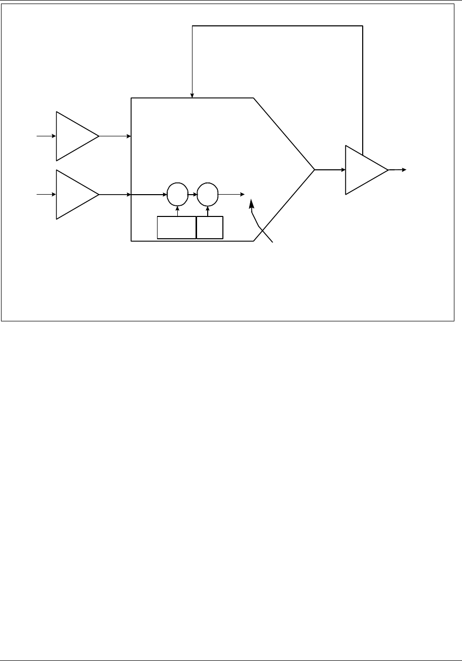
Programming Function Blocks and Features
Video Recorder – User Manual 100
AI3
FUEL∆P
SIGNAL
AI3 OV
AI2 OV
AIR∆P
SIGNAL AI2
×+
RATIO
SETPOINT RATIO
BIAS
WILD
VARIABLE SP2
LP2
PV
FEEDBACK
4 TO 20 mA
TO AIR FLOW
CONTROL
VALVE
LP2 OV
OUTPUT TYPE = CAT
IN LOW LIMIT = 0
IN HIGH LIMIT = 100
OUT LOW LIMIT = 4
OUT HIGH LIMIT = 20
AO2IN
TYPE = RATIO
SETPOINT #1 = 500
WILD VARIABLE = AI3 OV
RATIO SETPOINT = 0.50
RATIO BIAS = 0.75
GAIN = 10
RESET = 1
RATE = 0
AO2 BC
UNITS = FPS
INPUT TYPE = LINEAR
DIRECT/INDIRECT/SQRT = SQRT
RANGE LOW = 0
RANGE HIGH = 40
CIRCUIT LOW = 1
CIRCUIT HIGH = 5
ELECTRICAL UNITS = VOLTS
UNITS = FPS
INPUT TYPE = LINEAR
DIRECT/INDIRECT/SQRT = SQRT
RANGE LOW = 0
RANGE HIGH = 40
CIRCUIT LOW = 1
CIRCUIT HIGH = 5
ELECTRICAL UNITS = VOLTS
Working set point of loop when use of WILD
VARIABLE is desired to establish proper control
of PV. If ratio control using WILD VARIABLE
must be temporarily suspended, loop’s working
set point may be switched ON LINE to SETPOINT
#1 via “SP (Set Point Select)” key oninstrument’s
front door.
Figure 4-1 Function Block Configuration of a Typical Ratio Control Loop
When the ratio control loop in Figure 4-1 is brought ON LINE, its ON LINE display must be accessed to
allow the instrument’s SP (Set Point Select) key to be operational. To make the working set point of the
ratio control loop equal the equation (WILD VARIABLE X RATIO SETPOINT) + RATIO BIAS, then
select the TUNE LOOP menu item TOGGLE SETPOINT SOURCE so that an “SP2” is seen in the loop’s
ON LINE display. Note that within the ratio control loop’s programming menu (accessed under
PROGRAM CONTROL LOOPS), you will not find a SETPOINT #2 menu choice. The ratio control loop
function block operates with the formula (WILD VARIABLE X RATIO SETPOINT ) + RATIO BIAS
assuming all the functionality of the ratio loop’s second set point. Pressing the SP key to switch the
working set point of a live ratio control loop from SP2 to SP1 will essentially suspend any ratio control
and cause the loop to behave like a standard PID controller. This standard PID loop will have a local set
point equal to the value programmed for SETPOINT #1. To control the process variable using a fixed set
point that is independent of the loop’s WILD VARIABLE input, toggle the ratio control loop’s working set
point to SP1.

Programming Function Blocks and Features
Video Recorder – User Manual 101
4.9 Program Analog Outputs
The analog outputs will be accessible if an analog output board is detected upon power up.
If the instrument will be used for control, program the loops first. See Program Control Loops in Section
4.8.
Select an analog output to program.
Analog output type
Select the output type from Table 4-11.
Table 4-11 Analog Output Types
Type as displayed Full name of output type
CAT Current Adjusting Type (Current output)
DAT Duration Adjusting Type (Time proportioning output)
Table 4-12 shows the prompts for each type of Analog Output.
Table 4-12 Prompts For Analog Output Types
CAT DAT
IN DECIMAL POS IN DECIMAL POS
OUT DECIMAL POS INPUT SOURCE
INPUT SOURCE INC SLEW LIMIT
IN LOW LIMIT DEC SLEW LIMIT
IN HIGH LIMIT IMPULSE TIME
OUT LOW LIMIT MIN ON TIME
OUT HIGH LIMIT MIN OFF TIME
INC SLEW LIMIT FAILSAFE
DEC SLEW LIMIT FAILSAFE VALUE
FAILSAFE OUTPUT RELAY
FAILSAFE VALUE
Table 4-13 describes each prompt.

Programming Function Blocks and Features
Video Recorder – User Manual 102
Table 4-13 Analog Output Prompts
Prompt Range/Selections Definition
INPUT SOURCE Enter OFF, analog
parameter, number as the
analog output source.
For a control loop, this is typically set to a control output
(LP# OV). However, it may be directed to any analog value,
such as a calculated value, to retransmit the value to an
external device.
INPUT LOW LIMIT
INPUT HIGH LIMIT
If the AO's input source is a
PID control loop, specify a
high value of 100 and a low
value of 0. For other input
sources, specify limits using
the same units as the AO's
input source.
Input limits. (Variable input limits are available by
programming a constant's Destination with HS or LS. See
Program Constants, Section 4.16.)
OUTPUT LOW LIMIT
OUTPUT HIGH LIMIT
For CAT, enter any output
range within 0-20 mA These limits scale the output to the input limits.
For a CAT output a low limit of 4 and high limit of 20 will
provide a 4-20 mA output range.
INC SLEW LIMIT
DEC SLEW LIMIT
Enter OFF or 0.1 to 999.9
units/minute (units of the
AO's input source).
Limits the rate of increase or decrease of the analog output.
Value entered is in terms of the AO's input source, not in
terms of the output as defined by OUTPUT LOW LIMIT &
OUTPUT HIGH LIMIT. (Variable slew limits are available by
programming a constant's Destination with IS or DS. See
Program Constants, Section 4.16.)
FAILSAFE NONE
UP (Upscale)
DOWN (Downscale)
VALUE
Select failure action to occur on input signal loss. If VALUE is
selected, enter the value desired in FAILSAFE VALUE
FAILSAFE VALUE Enter a value between Input
Low Limit and Input High
Limit or analog parameter or
OFF.
The value at which the output will be held for failsafe. This
value is also the initial output of the loop on "cold start". If
the value is set to OFF, the output will go to 0. Value entered
is in terms of the AO's input source, not in terms of the output
as defined by OUTPUT LOW LIMIT & OUTPUT HIGH LIMIT.
IMPULSE TIME OFF or ≥ 1 The cycle time (in seconds) for On and Off time of the output.
For example, a time of 150 seconds will cause the output to
be on for 75 seconds and off for 75 seconds when the input
source is at 50%. (Variable impulse time is available by
programming a constant's Destination with IT. Program
Constants, Section 4.16.)

Programming Function Blocks and Features
Video Recorder – User Manual 103
Table 4-13 Analog Output Prompts (continued)
Prompt Range/Selections Definition
MIN ON TIME
OFF or ≥ 0 The minimum on time (in seconds) for the output. If the input
source calls for the output to be on for less than this time, the
output will not turn on at all.
Example 1
Impulse Time = 100. Min On Time = 5 seconds. The output
will not come on unless the input source is ≥ 5%. For
instance, if input source = 3%, output would be on for 3% of
impulse time, or 3 seconds, but since 3 seconds is less than
the Min On Time, output will not turn on.
Example 2
Impulse Time = 150. Min On Time = 3 seconds. The output
will not come on unless the input source is ≥ 2%. For
instance, if input source = 1%, output would be on for 1% of
impulse time, or 1.5 seconds, but since 1.5 seconds is less
than the Min On Time, output will not turn on.
MIN OFF TIME
OFF or number The minimum off time (in seconds) for the output. If the input
source calls for the output to be off for less than this time, the
output will not turn off at all.
Example 1
Impulse Time = 100. Min Off Time = 5 seconds. The output
will not turn off unless the input source is ≤ 95%. For
instance, if input source = 98%, output would be off for 2% of
impulse time, or 2 seconds, but since 2 seconds is less than
Min Off Time, output will not turn off.
Example 2
Impulse Time = 150. Min Off Time = 3 seconds. The output
will not turn off unless the input source is ≤ 98%. For
instance, if input source = 99%, output would be off for 1% of
impulse time, or 1.5 seconds, but since 1.5 seconds is less
than the Min Off Time, output will not turn off.
OUTPUT RELAY Select discrete output
channel. This is the discrete output channel if using DAT output
algorithm. This discrete output will be unprogrammable
under the PROGRAM DISCRETE OUTPUTS programming
menu. Only discrete outputs 1 though 5 will be programable
on any of the installed discrete output cards. Programming of
discrete output 6 is not allowed.
ATTENTION
ON/OFF loop types provide direct output without the use of an analog output. To complete an ON/OFF loop
configuration, assign the ON/OFF loop’s output (LPn OS) to a Discrete Output Relay. (see Program Discrete Outputs,
section 4.11).

Programming Function Blocks and Features
Video Recorder – User Manual 104
4.10 Program Discrete Inputs
Discrete Input function blocks are controlled by the on/off status of the input hardware. The output of
the function block, DIn OS, reflects the status of the associated input hardware. This output DIn OS can
be connected to other function blocks’ input parameters to trigger actions such as starting a profile or
selecting a control loop’s Set point #1 or Set point #2, among many other possibilities.
The Program Discrete Input menu item will appear if a DI/DO card is installed.
Select a discrete input to program, then program the prompts in Table 4-14. See Table 4-2 for
additional prompts.
Table 4-14 Discrete Input Prompts
Prompt Range/Selections Definition
ACTION STATE NORMAL, INVERT Determines whether the input will be normally closed or
normally open when ON(1). To select closed when ON (1),
enter NORMAL (not inverted). To select closed when OFF(0),
enter INVERT (inverted).
DELAY TIME Number of seconds When the DI is placed in its ON(1) state, the DI function will
wait for the specified delay time before indicating the ON(1)
condition as an output. If the DI "ON" state changes before
the delay time expires, no ON output will be indicated.
EVENT ENABLE NONE, RISING, FALLING,
BOTH Determines whether changes in DI’s status can be recorded
as events in data storage.
NONE - status changes are not stored
RISING - OFF(0)-to-ON(1) changes can be stored
FALLING - ON(1)-to-OFF(0) changes can be stored
BOTH - Both changes can be stored

Programming Function Blocks and Features
Video Recorder – User Manual 105
4.11 Program Discrete Outputs
Discrete Output function blocks control the relay or open collector output hardware. The Program
Discrete Outputs menu item will appear if a Discrete Outputs board is installed.
ATTENTION
If a discrete output has been assigned to a time proportioning output (DAT), it will not be programmable here.
See "OUTPUT RELAY" in Table 4-13.
Select a DO to program, then program the prompts in Table 4-15. See Table 4-2 for additional prompts.
Table 4-15 Discrete Output Prompts
Prompt Range/Selections Definition
ACTION STATE NORMAL, INVERT Determines whether the relay will normally be energized or
de-energized when the DO’s Input is ON(1). To select
energized when ON, enter NORMAL (not inverted). To select
energized when OFF, enter INVERT (inverted).
INPUT OFF, discrete parameter, 0,
1 Source of the Discrete Output.
EVENT ENABLE NONE, RISING, FALLING,
BOTH Determines whether changes in DO’s status can be recorded
as events in data storage. For storage to occur, Data
Storage must also be programmed to store Events.
NONE - status changes are not stored
RISING - OFF(0)-to-ON(1) changes can be stored
FALLING - ON(1)-to-OFF(0) changes can be stored
BOTH - Rising and falling changes can be stored

Programming Function Blocks and Features
Video Recorder – User Manual 106
4.12 Program Calculated Values
A Calculated Value (CV) is a data point whose value is derived from calculations involving other data
points. The CV Output can be analog or discrete. A CV can include other CVs in its calculations. Once a
CV is created, it can be used by any function block as many times as desired.
Select "CALCULATED VALUES" on the Main Program Menu. Select a CV to program, then choose
from the types shown in
Table 4-16.
ATTENTION
• If you plan to program another function block using a Calculated Value as a parameter, you must program
the Calculated Value first.
• Once you change the type and press Enter, the previous type’s settings are deleted and cannot be
recovered.
• If your unit has the "standard math" package, you still have access to "advanced math" package types but
the fields will be blank and unaccessible.
Table 4-16 CV Types
Type Math
Package Description Page
NONE No CV Programmed --
PEAK PICKING A Picks maximum input value 107
SIGNAL SELECT A Selects signal per your criteria 108
COMPARE A Compares input and outputs result 109
COUNTER A Counts transitions of input status 113
MATH S Calculates math on 8 inputs using one operator 114
FREE FORM MATH S Calculates math on 8 inputs using several operators 115
LOGIC S Outputs logic of inputs 117
FREE FORM LOGIC S Outputs logic of inputs using custom equation 119
INVERTER S Inverts status of input 120
BCD S Binary Coded Decimal conversion 121
FUNCTION
GENERATOR A Generates custom y = f(x) curve 123
INTERVAL TIMER A Counts time in minutes 125
PERIODIC TIMER S Generates periodic pulse 126
MASS FLOW A Calculates mass flow with square root 128
CARBON
POTENTIAL A Generates a %C value 129
RELATIVE
HUMIDITY A Calculates relative humidity 131
STERILIZATION A Calculates F0 Sterilization 132
ADV SPLITTER A Splits input into 3 outputs 133
STD SPLITTER A Splits input into 2 outputs 135
SCALING A Scales input to output 136
SIGNAL CLAMP A Clamps input to specified values 137
1 PT BLOCK AVG A Averages one input 138
ROLLING AVG A Computes rolling average of one input 139
MULTIPLE AVG A Averages multiple inputs 140
CEM BLOCK AVG A Averages one input over specified intervals 141
CEM ROLLING AVG A Computes rolling average of one input over specified intervals 142
S: Standard Math package
A: Advanced Math package
Refer to the page shown for the desired CV programming procedures. Press Enter when the "PRESS
ENTER TO SAVE" prompt appears to save your entries made during the session.

Programming Function Blocks and Features
Video Recorder – User Manual 107
Peak Picking
This type monitors the input and determines a “peak” value reached during the specified time interval (in
minutes). The peak can be chosen to be a maximum, minimum, average, or standard deviation. At the
end of the time interval, the output CVn OV steps to the value of the peak and holds this value until the
end of the next time interval. If the Reset Input turns ON(1), the output is held and the time interval
restarts.
Table 4-17 describes the Peak Picking prompts. See Table 4-2 for additional prompts.
Table 4-17 Peak Picking Prompts
Prompt Range/Selections Definition
RANGE LOW
RANGE HIGH
OFF or number Enter the output's display limits. Output is not clamped or
flashed when it exceeds these limits.
INPUT OFF, analog parameter,
number Input source whose peak is picked
RESET OFF, discrete parameter, 0,
1 Holds output and restarts time interval
ACTION NONE, MIN, MAX, AVG,
STDDEV Type of peak pick. MIN selects the minimum, MAX selects
the maximum, AVG selects the mean average, STDDEV
selects the standard deviation over the time interval.
PERIOD MINUTES 0-999,999.9 Number of minutes in time interval

Programming Function Blocks and Features
Video Recorder – User Manual 108
Signal Select
Selects one of 48 inputs based on the action and outputs it as CVn OV.
Table 4-18 describes the Signal Select prompts. See Table 4-2 for additional prompts.
Table 4-18 Signal Select Prompts
Prompt Range/Selections Definition
OUTPUT LOW LIMIT
OUTPUT HIGH LIMIT
OFF or number Displayed output value will be clamped and will flash when
these limits are exceeded.
INPUT #1 - INPUT #48 OFF, analog parameter,
number Up to 48 input sources to be selected from according to the
ACTION.
ACTION HIGH Selects the highest value input.
LOW Selects the lowest value input.
AVG Averages the input values.
MIDDLE Selects the middle (median) input value. If the number of
inputs is even, selects the sum of the middle two input values
divided by 2.
F-GOOD (First Good) If inputs fail, selects the first good input to the
function block. For example, if inputs 1 and 2 fail, then input
3 is selected.
ANA-SW (Analog Switch) Selects an input equal to the value of the
ANALOG SELECT parameter.
DIS-SW (Discrete Switch) Selects Input #1 or #2 according to state of
DISCRETE SELECT.
ANALOG SELECT OFF, analog parameter,
number Example: if ASEL=3, then Input #3 is selected. If ANALOG
SELECT < 1, Input #1 is selected. The value of ANALOG
SELECT is truncated to a whole number. For example, if
ANALOG SELECT is 3.55, the value is truncated to 3 and
Input #3 is selected.
DISCRETE SELECT OFF, discrete parameter,
0, 1 Selects Input #1 when DISCRETE SELECT is off (0); selects
Input #2 when DISCRETE SELECT is ON (1). Inputs 3-48
are unused.
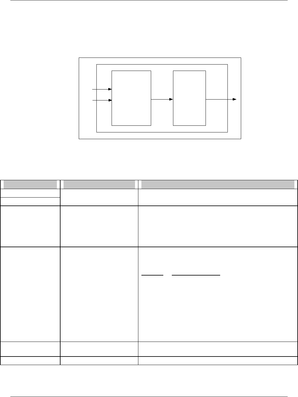
Programming Function Blocks and Features
Video Recorder – User Manual 109
Compare
Compare can be used instead of an Alarm’s output to control a relay. It can also provide on/off control
with hysteresis.
Compares 2 inputs. Call the result of this comparison “Result”. Result is a pulse that goes ON(1) when
comparison is true, and OFF(0) when comparison is not true. If hysteresis is given a value, then Result
will not go OFF(0) until hysteresis value is exceeded. Result is then processed according to the
specified condition type and condition time. The final output is a discrete pulse CVn OS.
COMPARE
OPERATOR
&
HYSTERESIS
Input #1
Input #2 Result
CONDITION
TYPE
&
CONDITION
TIME
CVn OS
Figure 4-2 Compare Signal Flow
Table 4-19 and Table 4-20 describe the Compare prompts. See Table 4-2 for additional prompts.
Table 4-19 Compare Prompts
Prompt Range/Selections Definition
INPUT #1
INPUT #2
OFF, analog parameter,
number Input sources to be compared.
OPERATOR EQ, GT, LT, GTE, LTE, NEQ The Result will be set to ON(1) when the comparison is true:
Input #1 OPERATOR Input #2
where OPERATOR is:
EQ(=), GT(>), LT(<), GTE (≥), LTE (≤), NEQ(≠)
The Result will be set to OFF(0) when the comparison is false.
HYSTERESIS Number, OFF Applies to all operators except EQ and NEQ. If given a value,
hysteresis determines when Result goes OFF(0) after the
comparison becomes false.
Operator Hysteresis Function
GT: Result goes OFF when Input #2 - Input #1 ≥ Hyst
GTE: Result goes OFF when Input #2 - Input #1 > Hyst
LT: Result goes OFF when Input #1 - Input #2 ≥ Hyst
LTE: Result goes OFF when Input #1 - Input #2 > Hyst
See Figure 4-3.
CONDITION TYPE NONE, DELAY, EXTEND,
PULSE, RT PULSE See Table 4-20.
CONDITION TIME OFF or number Enter number of seconds of condition time. See Table 4-20.

Programming Function Blocks and Features
Video Recorder – User Manual 110
Input # 2 - Input #1 Hysteresis
Result switches OFF
Time
1 Degree
Result ON
Operator GT (Greater than)
Hysteresis = 2 degrees
Input # 1 > Input # 2
Result switches ON
Result OFF Result OFF
Input #2
Input #1
Figure 4-3 Compare’s Greater Than Result, With Hysteresis
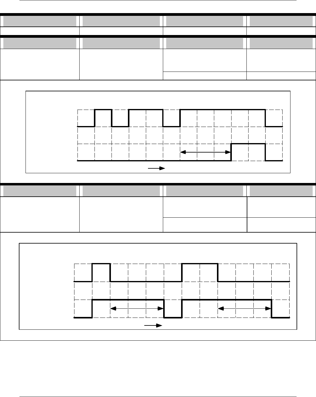
Programming Function Blocks and Features
Video Recorder – User Manual 111
Table 4-20 Compare’s Condition Type and Condition Time Prompts
Condition type Application If this is true then CVn OS is
NONE -- Result Result
Condition type Application If this is true then CVn OS is
DELAY Filters short pulses
Delays rising edge of Result for
CONDITION TIME
Result switches ON(1) for n
seconds ≥ CONDITION TIME. ON n seconds minus
CONDITION TIME
Result switches OFF(0) OFF(0)
If Result is:
Then CVn OS is:
1 sec 2 sec On at least 3 sec
2 sec
Time
Condition Type = Delay
Condition Time = 3 seconds
3 sec delay
Not on at least 3 sec
Condition type Application If this is true then CVn OS is
EXTEND Used for interfacing with slower
circuits. Result switches ON(1) for n
seconds, then OFF(0) ON(1) for n seconds plus
CONDITION TIME, then
OFF(0)
Extends falling edge of Result
for CONDITION TIME. Result switches ON(1) ON with no delay
2 sec
1 sec
3 sec extend
If Result is:
Then CVn OS is:
Time
Condition Type = Extend
Condition Time = 3 seconds
3 sec extend
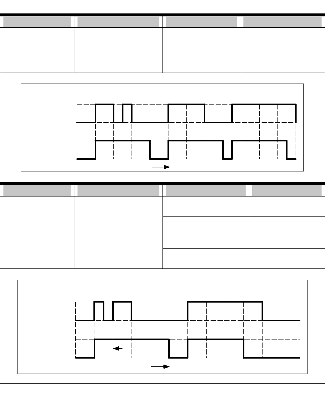
Programming Function Blocks and Features
Video Recorder – User Manual 112
Table 4-20 Compare’s Condition Type and Condition Time Prompts (continued)
Condition type Application If this is true then CVn OS is
PULSE Used for interfacing with slower
circuits.
On rising edge of Result,
creates pulse length
CONDITION TIME and ignores
additional rising edges of Result
within that CONDITION TIME.
Result switches ON(1) for ≤
CONDITION TIME, then
OFF(0).
ON(1) for CONDITION TIME,
then OFF(0). During
CONDITION TIME, any
additional OFF(0)-to-ONs of
Result are ignored.
3 sec
Condition Type = Pulse
Condition Time = 3 seconds
3 sec
2 sec
If Result is:
Then CVn OS is: 3 sec
3.5 sec
Time
Condition type Application If this is true then CVn OS is
RT PULSE
(Re-triggerable pulse) Used for slower circuits. Result switches ON(1) for ≤
CONDITION TIME, then
OFF(0)
ON(1) for CONDITION
TIME, then OFF(0).
Guarantees that CVn OS will be
ON for CONDITION TIME after
most recent rising edge of
Result.
Result switches ON(1) multiple
times before CONDITION TIME
expires
ON(1) when Result first
switches ON(1) and
remains ON(1) until Result
has not switched ON(1) for
CONDITION TIME.
Result switches ON(1) for ≥
CONDITION TIME, then
OFF(0)
ON(1) for CONDITION
TIME then OFF(0).
3 sec
If Result is:
Then CVn OS is:
Time
Pulse is
re-triggered
4 sec
Condition Type = Re-triggerable Pulse
Condition Time = 3 seconds

Programming Function Blocks and Features
Video Recorder – User Manual 113
Counter
Counts the number of OFF(0)-to-ON(1) transitions of the input. This number is output as CVn
OV. When this number reaches the Preset value, a discrete output parameter CVn OS goes
ON(1) until Reset occurs.
Table 4-21 describes the Counter prompts. See Table 4-2 for additional prompts.
Table 4-21 Counter Prompts
Prompt Range/Selections Definition
RANGE LOW
RANGE HIGH
OFF or number Enter the output's trend display limits. Output is not clamped
or flashed when it exceeds these limits.
INPUT OFF, discrete parameter, 0,
1 Input source.
RESET OFF, discrete parameter, 0,
1 When Reset is level high, output state (OS) is ON and the
counter resets to zero if counting up or to the Preset value if
counting down from it. When Reset is level low, counter
resumes counting.
PRESET OFF, analog parameter,
number The number of input transitions after which the CVn OS
output will go ON(1). To count forever, set to OFF. If OFF,
CVn OS will not be triggered.
COUNT DOWN YES or NO Select NO to count up from zero to the Preset value; YES to
count down from the Preset value to zero. If Preset is OFF,
Count Down must be NO.
Programming Function Blocks and Features
Video Recorder – User Manual 114
Math
Performs math on up to 8 inputs using a single operator. Output is CVn OV. Division by 0 is indicated
by CVn OV’s displayed value flashing 0.
Table 4-22 describes the Math prompts. See Table 4-2 for additional prompts.
Table 4-22 Math Prompts
Prompt Range/Selections Definition
INPUT A - INPUT H OFF, analog parameter,
number. Enter up to 8 input sources.
If connecting to an upstream loop, that loop output (LP# OV)
MUST be INPUT A (see Feedback).
OUTPUT LOW LIMIT
OUTPUT HIGH LIMIT
Enter limits Displayed output value will be clamped and will flash when
these limits are exceeded.
OPERATOR ADD, SUBT, MULT, DIV,
ABSVAL, SQRT and
STDDEV.
1. Input A OPERATOR Input B OPERATOR...Input H
where OPERATOR is one of these:
add, subtract, multiply, or standard deviation
(Standard Deviation uses all inputs.)
Example: Input A minus Input B minus ...Input H.
2. OPERATOR Input A
where OPERATOR is absolute value or square
root.
3. Input A OPERATOR Input B
where OPERATOR is divide.
Note: Inputs 3-8 are not used in division.
FEEDBACK OFF, analog parameter,
number Select LP# BC or AO# BC to propagate the back calculation
(BC) value from a downstream loop or AO. Also, program
the upstream loop's feedback with this Math CV's back
calculation value (CV# BC). You MUST program this CV's
feedback to NONE if this CV is not used as part of a control
loop output configuration (Figure 4-4). If it is part of a loop
configuration, the math operator cannot be ABSVAL, SQRT,
or STDDEV.
BC
PID
AO
PID
FB
INP 1 MATH
CV
BCFB
OR
Figure 4-4 Math CV Feedback Programming

Programming Function Blocks and Features
Video Recorder – User Manual 115
Free Form Math
The output CVn OV is the result of a user-specified equation. QWERTY keyboard may be used for
easier equation entry.
Table 4-23 describes the Free Form Math prompts. See Table 4-2 for additional prompts.
Table 4-23 Free Form Math Prompts
Prompt Range/Selections Definition
OUT LOW LIMIT
OUT HIGH LIMIT
OFF or number • Displayed output value will be clamped and will flash
when these limits are exceeded.
EQ See Table 4-24. • Enter the equation using the keyboard.
• See Table 4-24 for allowable characters and functions.
• Enter up to 64 characters (upper or lower case)
• Spaces are permitted.
• Enclose a function’s argument with parentheses ().
• Square root argument must be absolute value to prevent
square root of a negative value.
• Only whole numbers may be used as exponents.
Example: To input this equation
CN 5 OV X 12 AI 1OV
AI 2 OV 5+
enter these settings:
INPUT A: CN5OV
INPUT B: 12.0
INPUT C: AI1OV
INPUT D: AI2OV
EQ: A*B*SQRT (ABS(C/D))+5
Note how constants can be entered through the Constant
function block (as in example’s Input A), assigned to an input
(as in example’s Input B), or entered directly in the equation
(as in example with 5).
INPUT A - INPUT H OFF, analog
parameter, number Enter the parameters or numbers to be used in the equation.
RESET OFF, discrete
parameter, 0, 1 Resets the function block. Use only when the equation result
is the input to itself (integrating); that is, when the equation
contains the letter O.

Programming Function Blocks and Features
Video Recorder – User Manual 116
Table 4-24 Free Form Math Functions
For this function or value Type this in the equation
n (constant) n
Negation (-n) NEG(n)
Value of Input A A
Value of Input B B
Value of Input C C
Value of Input D D
Value of Input E E
Value of Input F F
Value of Input G G
Value of Input H H
Add +
Subtract -
Multiply *
Divide /
Constant number n (for example, 123.45)
Absolute value of n ABS(n)
Square root of n SQRT(n)
y n y^n
e x where x=n EX(n)
Log base 10 of n LOG(n)
Natural log of n LN(n)
Integration: Result of equation
as of last machine cycle O
(Letter ‘O’, not zero ‘0’.)
Programming Function Blocks and Features
Video Recorder – User Manual 117
Logic
The input or inputs are processed by a logic operator. Call the result of this logic operation “Result”.
Result is a pulse that goes ON(1) when the logic is true, and OFF(0) when the logic is not true. Result
is then processed according to the specified condition type and condition time. The final output is a
discrete pulse CVn OS. See Figure 4-5.
LOGIC
OPERATOR
Inputs
A
B
C
D
E
F
G
H
Result
CONDITION
TYPE
&
CONDITION
TIME
CVn OS
Figure 4-5 Logic Signal Flow
Table 4-25 describes the Logic prompts. See Table 4-2 for additional prompts.
Table 4-25 Logic Prompts
Prompt Range/Selections Definition
OPERATOR AND, OR, XOR, RESET/SET FF,
TOGGLE/FF, ONE SHOT, PASS See Table 4-26.
INPUT A OFF, discrete parameter, 0, 1. Program at least 2 inputs. Only inputs
programmed with parameter, 1, or 0 are processed
with the operator.
INPUT B
INPUT C
INPUT D
INPUT E
INPUT F
INPUT G
INPUT H
CONDITION TYPE NONE, DELAY, EXTEND, PULSE,
RT PULSE See Table 4-20 on page 111.
CONDITION TIME OFF or number Enter number of seconds of condition time. See
Table 4-20 on page 111.
Programming Function Blocks and Features
Video Recorder – User Manual 118
Table 4-26 Logic Operators
For this operator Definition if this is true then Result is
AND If all programmed inputs are ON,
Result is ON. All programmed inputs are
ON(1) ON(1)
OR If at least 1 programmed input is ON,
Result is ON. At least 1 programmed
input is ON(1) ON(1)
XOR Uses Inputs A and B only. Input A is ON(1) and Input
B is OFF(0). ON(1)
If one and only one input is ON, Result
is ON. Input A is OFF(0) and Input
B is ON (1). ON(1)
RESET/SET FF Rising edge of Input A turns Result
ON. Input A is ON(1). ON(1)
(Reset/Set Flip-Flop) Rising edge of Input B resets Result. Input A is OFF(0) and Input
B is ON (1). OFF(0)
Reset/Set FF
Input A
Input B
Result
TOGGLE/FF Toggle Flip-Flop. Rising edge of Input
A inverts Result Input A changes from
OFF(0) to ON(1) (rising
edge)
ON(1) if it was
OFF(0), or OFF(0)
if it was ON(1).
Input A changes from
ON(1) to OFF(0) (falling
edge)
unchanged
Input A
Toggle/Flip-Flop
Result
ONE SHOT Rising edge of Input A turns Result
ON for one machine scan cycle. Input A is ON(1) for any
length of time ON(1) for 1 scan
cycle of the
instrument, then
OFF(0)
Result
Input A
One Shot
PASS Passes Input A’s state unchanged to
CONDITION TYPE. Input A changes state same as Input A
Programming Function Blocks and Features
Video Recorder – User Manual 119
Free Form Logic
Lets you enter up to 64 characters as a custom logic equation (EQ) containing inputs and logical
operators. The result of this equation is called “Result”. Result is then processed according to the
specified condition type and condition time. The final output is CVn OS. See Figure 4-6.
FREE FORM
LOGIC
EQUATION
Inputs
A
B
C
D
E
F
G
H
Result
CONDITION
TYPE
&
CONDITION
TIME
CVn OS
Figure 4-6 Free Form Logic Signal Flow
Table 4-27 describes the Free Form Logic prompts. See Table 4-2 for additional prompts.
Table 4-27 Free Form Logic Prompts
Prompt Range/Selections Definition
EQ * Symbol for AND operator
+ Symbol for OR operator
^ Symbol for XOR operator
NEG Symbol for NOT operator
A, B, C, D, E, F, G, H Symbols for Input A through Input H
O Letter O is the symbol for output CVn OS from the previous
logic calculation. Use for iterative calculations.
1 One = ON
0 Zero = OFF
( ) Expressions enclosed by parentheses are evaluated first.
INPUT A - INPUT H OFF, discrete parameter, 0,
1. Up to 8 input sources.
RESET OFF, discrete parameter, 0,
1 Resets the output to OFF (0). Use when using the letter O
in equations.
CONDITION TYPE NONE, DELAY, EXTEND,
PULSE, RT PULSE See Table 4-20 on page 111.
CONDITION TIME OFF or number Enter number of seconds of condition time. See Table 4-20
on page 111.
Programming Function Blocks and Features
Video Recorder – User Manual 120
Order of evaluation
1. Parentheses ()
2. NOT
3. AND
4. OR, XOR
Example equation using operators and inputs
(A+B)*C computes the result of (A OR B) AND C.
Table 4-28 (A OR B) AND C
A B C Result
0 0 0 0
0 0 1 0
0 1 0 0
0 1 1 1
1 0 0 0
1 0 1 1
1 1 0 0
1 1 1 1
Example equation using iteration
The equation A+B*O computes the result of:
(Input A OR Input B from current machine cycle) AND (Input A OR Input B from previous machine cycle).
Table 4-29 shows some possible results of this equation.
Table 4-29 Results of Logic Equation Using Iteration
[Input A (current)
OR Input B (current)]
AND [Input A (previous)
OR Input B (previous)] = Result
1 1 1 1 1
1 0 1 0 1
0 0 1 0 0
1 0 0 0 0
Inverter
The output CVn OS is the logical inverse of the input parameter.
Table 4-30 describes the Inverter prompts. See Table 4-2 for additional prompts.
Table 4-30 Inverter Prompts
Prompt Range/Selections Definition
INPUT OFF, discrete parameter, 0, 1 Input source to be inverted.

Programming Function Blocks and Features
Video Recorder – User Manual 121
BCD
Converts up to 8 discrete inputs’ binary coded decimal into an unsigned integer and output the integer
as CVn OV. For example, 00000100 = 4.
On the instrument, when the enable is triggered, the set point program specified by the value of CVn OV
is copied from internal storage to the Profile function block(s) where the profile(s) can be programmed
or executed.
Table 4-31 describes the BCD prompts. See Table 4-2 for additional prompts.
Table 4-31 BCD Prompts
Prompt Range/Selections Definition
OUT LOW LIMIT
OUT HIGH LIMIT
OFF or number Displayed output value will be clamped and will flash when
these limits are exceeded.
BIT 0
through
BIT 7
OFF, discrete parameter, 0,
1 The binary coded decimal represented by the states of these
discretes will be converted into an unsigned integer. BIT 7 is
the most significant bit and BIT 0 is the least significant bit.
ENABLE OFF, discrete parameter, 0,
1 On the instrument, when this discrete transitions from off(0)
to on(1), the specified program’s profile(s) will be loaded from
internal memory to the Profile function block(s). See Table
4-32.
Example #1, loading a 2-profile program
You are programming a 2-programmer instrument. According to Table 4-32, a 2-programmer
instrument can run 2 profiles at a time and can store in its internal memory up to 6 programs, each
containing 2 profiles.
Suppose the BCD bits are programmed as follows: Bit 2 = 1, Bit 1 = 1, Bit 0 = 0. This sequence of bits
equals the number 6 and is the value of CVn OV. When the Enable discrete is triggered ON(1), the
profiles in Program #6 will be loaded from internal memory into the function blocks for Profile #1 and
Profile #2, where they can be edited or run.
Example #2, loading a 4-profile program
You are programming a 4-programmer instrument. According to Table 4-32, a 4-programmer
instrument can run 4 profiles at a time and can store in its internal memory up to 3 programs, each
containing 4 profiles.
Suppose the BCD bits are programmed as follows: Bit 2 = 0, Bit 1 = 1, Bit 0 = 0. This sequence of bits
equals the number 2 and is the value of CVn OV. When the Enable discrete is triggered ON(1), the
profiles in Program #2 will be loaded from internal memory into the function blocks for Profiles #1
through #4, where they can be edited or run.

Programming Function Blocks and Features
Video Recorder – User Manual 122
Table 4-32 How Profiles Are Saved In Memory
1-programmer
instrument
1 Profile per Program
2-programmer
instrument
2 Profiles per Program
3-programmer
instrument
3 Profiles per Program
4-programmer
instrument
4 Profiles per Program
This
Program… …contains
this Profile This
Program… …contains
these
Profiles
This
Program… …contains
these
Profiles
This
Program… …contains
these
Profiles
1 1 1 1 1 1 1 1
2 1 2 2 2
3 1 2 1 3 3
4 1 2 2 1 4
5 1 3 1 2 2 1
6 1 2 3 2
7 1 4 1 3 1 3
8 1 2 2 4
9 1 5 1 3 3 1
10 1 2 4 1 2
11 1 6 1 2 3
12 1 2 3 4
• • • •
• • • •
• • • •
93 1 47 1 • 24 1
94 1 2 32 1 2
95 1 48 1 2 3
96 1 2 3 4
Programming Function Blocks and Features
Video Recorder – User Manual 123
Function Generator
This CV type can be used to characterize a valve (Figure 4-8) or an input signal (Figure 4-9). You enter
a custom curve of up to 19 segments (20 X,Y coordinates). The input is compared with the X values
and its corresponding Y value becomes the output CVn OV. Interpolation between coordinates is
straight line. See Figure 4-7.
If the input value is outside the range of X values, the nearest X value is used, the output will be
clamped to the corresponding Y value and the displayed output value will flash.
X1 X2 X3 X4 X5 X6
Y1, Y2
Y3, Y4
Y5
Y6
Figure 4-7 Function Generator Curve
Table 4-33 describes the Function Generator prompts. See Table 4-2 for additional prompts.
Table 4-33 Function Generator Prompts
Prompt Range/Selections Definition
RANGE LOW OFF or number Enter the output’s lower display limit. Output is not clamped
or flashed when it exceeds this limit. Default value is Y1
value.
RANGE HIGH OFF or number Enter the output’s lower display limit. Output is not clamped
or flashed when it exceeds this limit. Default value is Y1
value.
INPUT OFF, analog parameter,
number This value will be compared with the X values of the curve.
The corresponding Y value will be the CV output.
X1, Y1, X2, Y2…X20,
Y20 OFF or number Use these prompts to plot a curve using 2 to 20 X,Y
coordinates. X values must increase as Xn increases.
FEEDBACK OFF, analog parameter,
number For valve characterization, select AO# BC to propagate the
back calculation (BC) value from a downstream Analog
Output. Also, program the upstream loop’s feedback with
this CV’s back calculation value (CV# BC). See Figure 4-8.
Attention: If feedback is programmed to an analog
parameter or a number, the X and Y values must define a
curve that is not bell shaped or complex. That is, all Y values
must be increasing or decreasing.
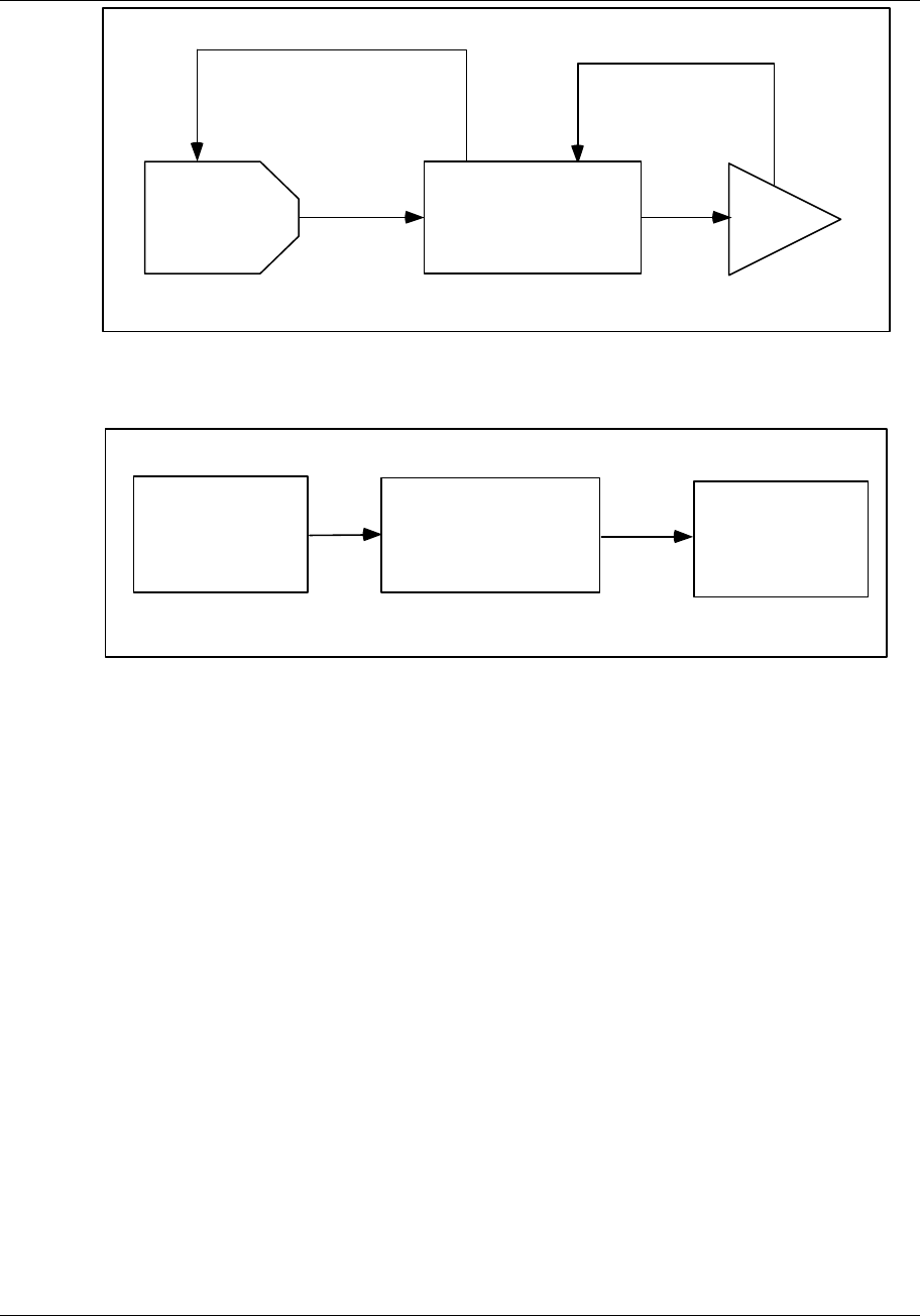
Programming Function Blocks and Features
Video Recorder – User Manual 124
BC
PID AO
FB
INPUT
FUNCTION
GENERATOR
CV
BCFB
OV
OV
Figure 4-8 Function Generator Configuration For Valve Characterization
AI INPUT
FUNCTION
GENERATOR
CV
ANOTHER
FUNCTION BLOCK
OV
Figure 4-9 Function Generator Configuration For Input Signal Characterization

Programming Function Blocks and Features
Video Recorder – User Manual 125
Interval Timer
This timer counts down from the preset value in minutes. This time remaining is CVn OV. The timer
has a single discrete output CVn OS which is ON(1) while the timer is actively counting or while RESET
is ON(1), and OFF(0) while the timer has timed out to zero. When RESET/RUN switches ON(1) the
timer resets to the preset value; an ON(1) to OFF(0) transition starts the timer.
Table 4-34 describes the Interval Timer prompts. See Table 4-2 for additional prompts.
Table 4-34 Interval Timer Prompts
Prompt Range/Selections Definition
PRESET OFF, analog parameter,
number Timer counts to zero from this number of minutes.
RESET/RUN OFF, discrete parameter, 0, 1 Controls the operation of the timer.
RANGE LOW
RANGE HIGH
OFF or number Enter the output’s display limits. Output is not clamped or
flashed when it exceeds these limits.

Programming Function Blocks and Features
Video Recorder – User Manual 126
Periodic Timer
Generates a discrete output pulse CVn OS which is ON(1) for 1 machine cycle (250ms, 500ms, 1 sec)
at specified Start time and repeated at a specified Period thereafter. Use this to activate a discrete
parameter at a particular time and at regular intervals.
Start Time of first pulse
(Day, Hour, Min, Sec)
Period
(Hours, Min, Sec)
Time
CVn OS pulses ON at Start Time and at every Period
Figure 4-10 Periodic Timer
Table 4-35 describes the Periodic Timer prompts. See Table 4-2 for additional prompts.

Programming Function Blocks and Features
Video Recorder – User Manual 127
Table 4-35 Periodic Timer Prompts
Prompt Range/Selections Definition
SET UP TIMER See Table 4-36 for prompts Selects the timer format.
Table 4-36 Set Up Timer Prompts
Prompt Range/Selections Definition
PHASE NONE, DAILY, WEEKLY,
MONTHLY Select the timer format. Remaining prompts will vary per
phase selected.
PERIOD HOURS 0-23 Number of hours in the period
PERIOD MINUTES 0-59 Number of minutes in the period
PERIOD SECONDS 0-59 Number of seconds in the period
RESET OFF, discrete parameter, 0, 1 Phase NONE only. When this discrete is ON(1), timer stops
and resets to beginning of period. When discrete is OFF(0),
timer begins again.
START DAY MONDAY,
TUESDAY…SUNDAY For Phase DAILY, select the day of the week to start the
timer.
1-31 For Phase MONTHLY, select the day of the month to start
the timer. If this number exceeds the number of days in any
given month, then the discrete switches ON(1) the last day
of that month.
START HOURS 0-23 Hours of the Start time.
START MINUTES 0-59 Minutes of the Start time.
START SECONDS 0-59 Seconds of the Start time.
ATTENTION
The Start Time’s value cannot exceed the Period. An error message is displayed if you enter a Start Time of 8:00:00
and a Period of 4:00:00, for example.

Programming Function Blocks and Features
Video Recorder – User Manual 128
Mass Flow
By compensating for variations in fluid temperature and pressure, Mass Flow is used to obtain a more
precise fluid flow measurement from an orifice plate developing a differential pressure. The output CVn
OV is mass flow and is calculated from the following formula for U.S. Units Of Measurement:
MF = FACTOR 1 x SQRT [DP INPUT x (PRESSURE INPUT+14.7) / (TEMPERATURE INPUT + 459)]
where
FACTOR 1 is calculated by user
DP INPUT is differential pressure in inches of water
PRESSURE INPUT is in PSIG
TEMPERATURE INPUT is in °F
Or, Mass flow is calculated from the following formula for International Units Of Measurement:
MF = FACTOR 1 x .569 x SQRT [DP INPUT x (PRESSURE INPUT +101.4)/(TEMPERATURE INPUT + 273)]
where
FACTOR 1 is calculated by user
DP INPUT is differential pressure in KPASCALS
PRESSURE INPUT is in KPASCALS
TEMPERATURE INPUT is in °C
Table 4-37 describes the Mass Flow prompts. See Table 4-2 for additional prompts.
Table 4-37 Mass Flow Prompts
Prompt Range/Selections Definition
OUT LOW LIMIT
OUT HIGH LIMIT
OFF or number Displayed output value will be clamped and will flash
when these limits are exceeded.
DP INPUT OFF, analog parameter,
number Differential pressure input
PRESSURE INPUT OFF, analog parameter,
number Pressure input in PSIG or KPASCALS
TEMP INPUT OFF, analog parameter,
number Temperature in °C or °F
UNITS OF MEASURE US or International Units of measure
FACTOR 1 OFF, analog parameter,
number Flow factor for the particular installation

Programming Function Blocks and Features
Video Recorder – User Manual 129
Carbon Potential
The Carbon Potential Control Function Block provides for weight percent (wt%) control of carbon in
carburizing, hardening, and atmosphere generating applications.
Table 4-38 Carbon Prompts
Prompt Range/Selections Definition
PROBE TYPE NONE, AACP, SUPER
SYS, MARATHON, FCC Selection which represents the manufacturer of the
oxygen probe being used. This determines which
linearization equations are used for %C and dewpoint
calculations.
CARBON PROBE IN NUMBER, PARM, OFF Analog input that is connected to the oxygen probe mV
output.
PROBE TEMP INPUT NUMBER, PARM, OFF Analog input that is connected to the oxygen probe
temperature output.
TEMPERATURE UNIT NONE, F, C, K, R Temperature scale for this block. This selection must
match the temperature scale of the analog input that is
connected to the oxygen probe temperature output.
TEMP LOW LIMIT NUMBER, OFF Probe temperature value below which this block’s low
temperature discrete output (OS) is turned ON. This limit
and subsequent discrete output may be used to force the
control loop’s output to a known value when the probe
temperature is too low for carbon potential control.
CO COMPENSATION NUMBER, PARM, OFF Number used in the %C calculation which represents the
%CO present in the endothermic gas.
FURNACE FACTOR NUMBER, PARM, OFF Correction factor used to account for environmental
variation within the furnace chamber. In units of %C, this
factor is added directly to the %C value calculated from
probe output linearization.
SOOTING FACTOR ON, OFF Boolean value that determines whether the anti-sooting
factor output (A1) will be based linearly on probe
temperature (SOOTING FACTOR=ON) or a constant
value of 2.0 (SOOTING FACTOR=OFF). If SOOTING
FACTOR is ON, a probe temperature of 1408 °F or
below limits %C output to 0.75% and 2086 °F or above
limits %C output to 2.0%.
PERCENTAGE
HYDROGEN NUMBER, OFF Number representing %H2 that is used in the dewpoint
calculation.
Programming Function Blocks and Features
Video Recorder – User Manual 130
Figure 4-11 Typical Carbon Potential Control Configuration
O2 Probe Output
%CO
O2 Probe Temp.
%C
Anti-Sooting
Factor
Dewpoint
Low Temperature
Discrete
CARBON
POTENTIAL
CONTROL
CV
PV
SP HIGH
RMAN
CONSTANT
AI
AI
AI
%C
CONTROL LP AO
LINEAR
XXXXX.X
0.0
1250.0
INDIRECT
0.0 mV
1250.0 mV
TYPE K (typ.)
XXXXX.X
0.0
2800.0
DIRECT
F/SAFE DOWN
LINEAR
(Config as req’d
by CO analyzer)
CONSTANT
OR
FB
DI Burn Off
OV
A1
OS
A2
PV FURNACE
TEMPERATURE
CONTROL LP AO
FB
Furnace Temperature
AI TYPE K (typ.)
XXXXX.X
-450.0
2800.0
DIRECT
F/SAFE UP
F/SAFE DOWN
CV
CONSTANT
OTRK

Programming Function Blocks and Features
Video Recorder – User Manual 131
Relative Humidity
Outputs CVn OV relative humidity as a function of dry-bulb temperature, wet-bulb temperature, and
atmospheric pressure.
Table 4-39 describes the Relative Humidity prompts. See Table 4-2 for additional prompts.
Table 4-39 Relative Humidity Prompts
Prompt Range/Selections Definition
RANGE LOW
RANGE HIGH
OFF or number Enter the output’s display limits. Output is not clamped
or flashed when it exceeds these limits.
DRY BULB TEMP OFF, analog parameter,
number Dry bulb temperature in temperature units selected.
WET BULB TEMP OFF, analog parameter,
number Wet bulb temperature in temperature units selected.
ATM PRESS (PA) OFF, analog parameter,
number Enter atmospheric pressure in Pascals. 101325 Pa. Is
one standard atmosphere.
TEMPERATURE UNITS F, C, K, R Select the temperature units for the calculation. Units
are for wet bulb and dry bulb.

Programming Function Blocks and Features
Video Recorder – User Manual 132
Sterilization
The output CVn OV is a “kill time”, F0, which quantifies the destruction of microorganisms during a
sterilization process. F0 represents the number of minutes after which the microorganism population is
decreased by one decimal or log unit. The F0 formula is:
F0 = ∑ [dt x (10(T-Tref)/Z)]
where:
dt = time between F0 measurements, in minutes. Dt is equal to the scan cycle of the instrument in
minutes.
T = measured temperature input, in °C
Tref = reference temperature (121°C typical)
Z = product-dependent temperature constant
This function also compares the calculated F0 value to the desired F0 value, Fd (Preset). When F0
equals or exceeds Fd, the function activates its discrete output CVn OS; this output remains ON(1) until
the F0 calculation is reset via the Reset Input.
The output CVn A2 is the Time Remaining (Tr) at the current temperature to achieve Fd and is
calculated as follows:
(Fd – F0)
Tr = _________
10(T-Tref)/Z
The F0 calculation will be reset and the F0 value will remain at zero while the Reset Input is ON(1). The
calculation will resume when the Reset Input goes OFF(0) again.
Table 4-40 describes the Sterilization prompts. See Table 4-2 for additional prompts.
Table 4-40 F0 Sterilization Prompts
Prompt Range/Selections Definition
OUT LOW LIMIT
OUT HIGH LIMIT
OFF or number Displayed output value will be clamped and will flash
when these limits are exceeded.
RESET OFF, discrete parameter, 0,
1 Reset input
TEMP INPUT OFF, analog parameter,
number Measured temperature in degrees C
REFERENCE TEMP OFF, analog parameter,
number Reference temperature
TEMP CONSTANT OFF, analog parameter,
number Temperature constant Z
DESIRED F0 OFF, analog parameter,
number Desired F0 (Fd)
Programming Function Blocks and Features
Video Recorder – User Manual 133
Advanced Splitter Output (ADV SPLITTER)
This function can be used for heat/cool applications. It splits an input into 3 independently scaled
outputs: CVn_A1, CVn_A2 and CVn_A3 (Figure 4-12). For each output, when the input is between IN
LO LIM and IN HI LIM, the output is scaled between the OUT LO LIM and OUT HI LIM. Each output
holds its OUT LO LIM value when the input < the IN LO LIM value for that output. Each output holds its
OUT HI LIM value when the input > the IN HI LIM value for that output. Output limits (OUT LO LIM &
OUT HI LIM) cannot exceed 100% but can be negatively sloped (OUT HI LIM < OUT LO LIM).
A1 A2 A3
0 306090100
100
0
INPUT SOURCE VALUE (%)
OUTPUT
VALUE
(%)
Figure 4-12 Advanced Splitter (Default Outputs)
SPLIT
LOOP
AO
FEEDBACK
BC
A1
OV
AO
AO
BC
A2
BC
INPUT
SPLITTER
CV
FEEDBACK #1
FEEDBACK#2
Figure 4-13 Heat/Cool Configuration
Table 4-41 describes the Advanced Splitter prompts. See Table 4-2 for additional prompts.

Programming Function Blocks and Features
Video Recorder – User Manual 134
Table 4-41 Advanced Splitter Prompts
Prompt Range/Selections Definition
RANGE LOW
RANGE HIGH
OFF or number Enter the output's display limits. Output is not clamped or
flashed when it exceeds these limits.
INPUT OFF, analog parameter,
number Input source. Typically, this is the output value (OV) of a
Split Output type of loop.
FEEDBACK #1 OFF, AOn BC, LPn BC Select the back calculation value (BC) of the analog output
assigned to the A1, A2, and A3 outputs, respectively.
FEEDBACK #2
FEEDBACK #3
OUT#1 IN LO LIM
OUT#1 IN HI LIM
OFF or number Enter a range for A1's input. Defauts are 0 for low limit & 30
for high limit. When input is between these values, A1
output is scaled between OUT#1 OUT LO LIM & OUT#2
OUT HI LIM.
OUT#1 OUT LO LIM
OUT#1 OUT HI LIM
OFF or number Enter OFF or a range for A1’s output. Defaults are 0 for low
limit & 100 for high limit. Scales A1 output.
OUT#2 IN LO LIM
OUT#2 IN HI LIM
OFF or number Enter a range for A2’s input. Defaults are 30 for low limit &
60 for high limit. When input is between these values, A2
output is scaled between OUT#2 OUT LO LIM & OUT#2
OUT HI LIM.
OUT#2 OUT LO LIM
OUT#2 OUT HI LIM
OFF or number Enter OFF or a range for A2’s output. Defaults are 0 for low
limit & 100 for high limit. Scales A2 output.
OUT#3 IN LO LIM
OUT#3 IN HI LIM
OFF or number Enter a range for A3’s input. Defaults are 60 for low limit &
90 for high limit. When input is between these values, A3
output is scaled between OUT#3 OUT LO LIM & OUT#3
OUT HI LIM.
OUT#3 OUT LO LIM
OUT#3 OUT HI LIM
OFF or number Enter OFF or a range for A3’s output. Defaults are 0 for low
limit & 100 for high limit. Scales A3 output.
Programming Function Blocks and Features
Video Recorder – User Manual 135
Standard Splitter Output (STD SPLITTER)
This function can be used for heat/cool applications. It is a deadband-based splitter that divides a Split
loop’s output (-100% to +100%) into two outputs CVn A1 and CVn A2, both of which are zero when the
loop output is zero (Figure 4-14). A deadband provides a range of loop output within which both split
outputs remain at zero. For overlapped outputs, use Advanced Splitter. Note: A third output CVnA3 is
displayed Online and should be ignored.
Deadband
100 100
00
0
-100 +100
PID Output %
CV A2 CV A1
Figure 4-14 Standard Split Output Function
Table 4-42 describes the Standard Splitter prompts. See Table 4-2 for additional prompts.
Table 4-42 Standard Splitter Prompts
Prompt Range/Selections Definition
RANGE LOW
RANGE HIGH
OFF or number Enter the output’s display limits. Output is not clamped or
flashed when it exceeds these limits.
INPUT OFF, analog parameter,
number Input source. Typically, this is the output value (OV) of a
Split Output type of loop.
FEEDBACK #1 AOn BC, LPn BC, CVn BC Enter an AO, LP or CV for the back calculation value (BC)
of the analog output assigned to the A1 output.
FEEDBACK #2 AOn BC, LPn BC, CVn BC Enter an AO, LP or CV for the back calculation value (BC)
of the analog output assigned to the A2 output.
OUTPUT
DEADBAND OFF or number Deadband up to 10% of the input span. In this range, both
split outputs will remain at zero.

Programming Function Blocks and Features
Video Recorder – User Manual 136
Scaling
The output CVn OV is a linear scaling of the input using the specified limits.
Table 4-43 describes the Scaling prompts. See Table 4-2 for additional prompts.
Table 4-43 Scaling Prompts
Prompt Range/Selections Definition
IN LOW LIMIT
IN HIGH LIMIT
OFF or number Enter limits of input to be scaled.
RANGE LOW
RANGE HIGH
OFF or number Enter the output’s scaling values and display limits. Output
is not clamped or flashed when it exceeds these limits.
INPUT OFF, analog parameter,
number Input to be scaled according to the limits.

Programming Function Blocks and Features
Video Recorder – User Manual 137
Signal Clamp
If input is between Low Select and High Select, the output CVn OV equals the input. If the input exceeds
these two limits, the output equals the preset value.
Table 4-44 describes the Signal Clamp prompts. See Table 4-2 for additional prompts.
Table 4-44 Signal Clamp Prompts
Prompt Range/Selections Definition
OUT LOW LIMIT
OUT HIGH LIMIT
OFF or number Displayed output value will be clamped and will flash
when these limits are exceeded.
LOW SELECT OFF, analog parameter,
number If input goes below this number, the output will equal the
preset value. Otherwise, the output equals the input.
HIGH SELECT OFF, analog parameter,
number. If input goes above this number, the output will equal the
preset value. Otherwise, the output equals the input.
INPUT OFF, analog parameter,
number Input to be clamped.
PRESET OFF, analog parameter,
number. Output will go to this value when the input exceeds the
low or high select values.

Programming Function Blocks and Features
Video Recorder – User Manual 138
1 Point Block Average (1 Pt Block Avg)
Outputs a block mean average CVn OV of the input over the specified Average Period. A new sample
of the input will be taken on every instrument scan cycle. The block average is only updated at the end
of the Average Period.
When the Reset Input is ON(1) all accumulated samples are discarded and the output is held until the
Reset Input is OFF(0), then the averaging period resets.
Table 4-45 describes the 1 Point Block Average prompts. See Table 4-2 for additional prompts.
Table 4-45 1 Point Block Average Prompts
Prompt Range/Selections Definition
RANGE LOW
RANGE HIGH
OFF or number Enter the output’s display limits. Output is not clamped or
flashed when it exceeds these limits.
INPUT OFF, analog parameter,
number This parameter will be averaged.
RESET OFF, discrete parameter, 0, 1 When the Reset is ON(1) all accumulated samples are
discarded and the output is held until the Reset is OFF(0),
then the averaging period resets.
AVERAGE PERIOD 0.1 to 1440 Length of averaging period in minutes.

Programming Function Blocks and Features
Video Recorder – User Manual 139
Rolling Average
Outputs a rolling mean average CVn OV of the input over the specified Average Period. As new input
samples are collected, old samples are discarded. The function will calculate a new average at equally
spaced sample intervals.
Sample interval = averaging period
# of samples
Rolling Average = sum of samples
# of samples
Example
# of samples = 10
Average Period = 30 minutes
The first average will appear after 30 minutes, then will be updated every 30/10 or 3 minutes after.
When the Reset Input is ON(1) all accumulated samples are discarded and the output is held until the
Reset Input is OFF(0), then the averaging period resets.
Table 4-46 describes the Rolling Average prompts. See Table 4-2 for additional prompts.
Table 4-46 Rolling Average Prompts
Prompt Range/Selections Definition
RANGE LOW
RANGE HIGH
OFF or number Enter the output’s display limits. Output is not clamped or
flashed when it exceeds these limits.
INPUT OFF, analog parameter,
number This parameter will be averaged.
RESET OFF, discrete parameter, 0, 1 Resets average.
# OF SAMPLES 1-60 Number of samples taken during average period.
AVG PERIOD MINS OFF or number Number of minutes in average period.

Programming Function Blocks and Features
Video Recorder – User Manual 140
Multiple Input Average (Multiple Avg)
The output CVn A1 is the instantaneous average of the assigned input points. The average is calculated
every scan cycle.
Table 4-47 describes the Multiple Average prompts. See Table 4-2 for additional prompts.
Table 4-47 Multiple Average Prompts
Prompt Range/Selections Definition
OUT LOW LIMIT
OUT HIGH LIMIT
OFF or number Displayed output value will be clamped and will flash
when these limits are exceeded.
INPUT #1- INPUT #8 OFF, analog parameter,
number Enter up to 8 inputs to be averaged
Programming Function Blocks and Features
Video Recorder – User Manual 141
CEMS Block Average
Outputs a block mean average CVn OV over the specified Average Period. The average is calculated
from input samples taken at equally spaced Sample Periods. All samples are discarded at the end of
the Average Period and the Average Period begins again.
Samples are ignored when Calibrate Hold is ON(1). After the Average Period the new average is
calculated using only the samples taken before and after the Hold. If no valid samples are taken, the
output maintains its previous value.
Table 4-48 describes the CEMS Block Average prompts. See Table 4-2 for additional prompts.
Table 4-48 CEMS Block Average Prompts
Prompt Range/Selections Definition
RANGE LOW
RANGE HIGH
OFF or number Enter the output’s display limits. Output is not clamped or
flashed when it exceeds these limits.
INPUT OFF, analog parameter, number Input to be averaged
RESET OFF, discrete parameter, 0, 1 When discrete is ON(1), average is reset to zero; when
ON(1)-to-OFF(0), average restarts.
TIME UNITS SECONDS, MINUTES, HOURS,
or DAYS. Time units of the averaging period
AVERAGE PERIOD OFF or number Number of time units per average period.
SAMPLE PERIOD OFF or number Number of time units between samples. Must divide
evenly into Average Period.
CALIBRATE HOLD OFF, discrete parameter, 0, 1 When ON(1), no samples are taken and the output is held.
CEMS Rolling Average (CEM Rolling Avg)
Outputs a rolling mean average CVn OV over the specified Average Period. Average is updated every
Frame Period thereafter. Samples are taken at every scan cycle of the instrument, except when
Calibrate Hold is ON(1).
Frame Period
Average Period
Input
Time between samples = 1 machine scan cycle
First average
Second average
Third average
Figure 4-15 CEMS Rolling Average
Table 4-49 describes the CEMS Rolling Average prompts. See Table 4-2 for additional prompts.

Programming Function Blocks and Features
Video Recorder – User Manual 142
Table 4-49 CEMS Rolling Average Prompts
Prompt Range/Selections Definition
RANGE LOW
RANGE HIGH
OFF or number Enter the output’s display limits. Output is not clamped or flashed
when it exceeds these limits.
INPUT OFF, analog
parameter, number Input to be averaged.
RESET OFF, discrete
parameter, 0, 1 When discrete is ON(1), average is reset to zero; when ON(1)-to-
OFF(0), average restarts.
TIME UNITS Seconds, minutes,
hours, or days. Time units of the averaging period.
AVERAGE PERIOD OFF or number Number of time units per average period.
FRAME PERIOD OFF or number Number of time units per Frame Period. Must divide evenly into
Average Period.
CALIBRATE HOLD OFF, discrete
parameter, 0, 1 When ON(1), no samples are taken and the output is held.
If calibrate hold is set ON, the function block stops acquiring
samples; however, the averaging will continue to update for the
remainder of the average period, after which, the output value will
hold.
If calibrate hold is set ON longer than the average period, the
display will alternate between the last output value and
*****(indicating the current value is no longer valid).
If calibrate hold is set OFF and the CEM Rolling Average is not
reset, the CEM Rolling Average will continue to update every frame
period from the last value. If the CEM Rolling Average is reset, the
average value is set to zero and the displayed value will not update
until the Average period has transpired. The average value will
update every frame period.

Programming Function Blocks and Features
Video Recorder – User Manual 143
4.13 Program Alarms
You can program an alarm to be triggered by any extreme input value. To program alarms, select
“PROGRAM ALARMS” on the Main Program Menu. Select an alarm to program.
REFERENCE
When an alarm occurs, it produces an output pulse which can be configured to trigger a discrete output (such
as a relay). Refer to Section 4.11 for instructions.
Table 4-50 describes the Alarm prompts. See Table 4-2 for additional prompts.
Table 4-50 Alarm Prompts
Prompt Range/Selections Definition
ON STATE
OFF STATE
See Table 4-3 for
choices. Enter labels for on and off states of alarm
ALARM ACTION HIGH Alarm when input value ≥ set point value.
LOW Alarm when input value ≤ set point value.
DEV Deviation. Alarm when input value deviates above or below compare
point value by an amount ≥ set point value.
HDEV High deviation
LDEV Low deviation
HRATE High Rate. Alarm when input value increases at rate ≥ set point
value, in units per minute. Negative rate set points are processed as
positive values. May take up to 30 seconds to activate.
LRATE Low Rate. Alarm when input value decreases at rate ≥ set point
value, in units per minute. Negative rate set points are processed as
positive values. May take up to 30 seconds to activate.
NONE No alarm action.
INPUT OFF, analog
parameter, number Input source monitored by alarm.
SETPOINT OFF, analog
parameter, number Point at which alarm occurs.
COMPARE
POINT OFF, analog
parameter, number DEV type only. It is the point against which the input point is
compared. The difference between the input point and the compare
point is the value which is measured against the alarm set point.
HYSTERESIS OFF or number Hysteresis affects only the point at which an alarm clears. A high
alarm will clear when the input is less than the set point minus the
hysteresis value. A low alarm will clear when the input is greater than
the set point plus the hysteresis value. A deviation alarm will clear
when the input is less than the set point minus the hysteresis value.
DELAY TIME OFF or number If the alarm condition clears before the delay time (in seconds)
expires, no alarm will be indicated. Delay time must be in multiples of
scan time.
SAMPLE HOLD OFF, discrete
parameter, 0 or 1 When this parameter level = 1, the alarm processing is disable and
the output is held.

Programming Function Blocks and Features
Video Recorder – User Manual 144
4.14 Program Totalizers
The optional totalizer integrates an analog value over time. With the input being viewed as a flow rate,
the function outputs a running total TLn OV over time.
ATTENTION
Totalizers which exceed the value 999,999 may only be displayed on the dedicated “Totalizer Display”. If the
value is programmed on other displays or stored to disk, when it exceeds the programmed limits the value may
be truncated and the value will flash.
Select a Totalizer to program. Table 4-51 describes the Totalizer prompts. See Table 4-2 for additional
prompts.

Programming Function Blocks and Features
Video Recorder – User Manual 145
Table 4-51 Totalizer Prompts
Prompt Range/Selections Definition
INPUT SOURCE OFF, analog parameter,
number. Input source to be totalized.
OUTPUT LOW LIMIT
OUTPUT HIGH LIMIT
OFF or number The range outside which the displayed output will flash
unclamped. Useful for warning operator of unusual
condition.
ACTION UP At each machine scan cycle, an integration of the input is
added to the running total. When this total reaches or
exceeds the preset value (assumed to be in eng. Units), the
discrete output of the totalizer goes high and remains high
for 1 scan cycle. The totalizer then resets and starts again.
The value resets to either zero or the residual total (final
total minus preset) if one exists.
DOWN At each machine scan cycle, an integration of the input is
subtracted from the preset value. When this result reaches
or goes below zero, the discrete output of the totalizer goes
high and remains high for 1 scan cycle. The totalizer then
resets and starts again. The value resets to either the
preset or the residual total (preset plus final total [since final
total is either zero or negative]) if one exists.
DEMAND On Demand. Same as UP, except executes only while the
ON DEMAND INPUT discrete is ON(1). Input is ignored
while ON DEMAND INPUT is OFF(0).
CONTIN Continuous. Same as UP except the total ignores the
PRESET value and integrates “forever” (continuously).
TIME UNITS SEC, MIN, HOUR, DAY Time units of the totalizer
ON DEMAND INPUT OFF, discrete parameter, 0,
1 Appears for Functions as the On Demand input for the
DEMAND action. Activates totalizer when ON(1).
PRESET
OFF, analog parameter,
number Up totalizer counts up to this value. Down totalizer counts
down from this value.
ZERO CUTOFF OFF or number Represents the least value to be accumulated in the
totalizer. Input values below this value will be input as zero.
RESETTABLE YES, NO If NO, the Totalizer is non-resettable and cannot be reset
via the operator keypad. This setting does not affect the
action of the reset discrete parameter.
RESET OFF, discrete parameter, 0,
1. When the RESET goes high (1) an UP action totalizer will
reset to zero, or a DOWN action totalizer will reset to the
preset value. Use SY1 F3 to reset with the RESET or F3
key.

Programming Function Blocks and Features
Video Recorder – User Manual 146
4.15 Program Profiles
Profile programming is explained in Section 5.

Programming Function Blocks and Features
Video Recorder – User Manual 147
4.16 Program Constants
Constants can be programmed here and their values edited Online. Select a constant to program.
Table 4-52 describes the Constant prompts. See Table 4-2 for additional prompts.
Table 4-52 Constant Prompts
Prompt Range/Selections Definition
VALUE OFF, analog
parameter, number If a number, the Constant may be altered Online from the Data
Entry menu. If a parameter, this parameter can be directed by
DESTINATION to override certain programmed values.
INPUT LOW LIMIT
INPUT HIGH LIMIT
OFF or number Display limits (for when viewing Constant on trend display or on
bar displays).
DESTINATION See Destination defined on next page.
NONE No destination
LPn GN LOOPn GAIN1
LPn PB LOOPn PROP. BAND #1
LPn RS LOOPn RESET #1
LPn RA LOOPn RATE #1
LPn RB LOOPn RATIO BIAS
LPn IS LOOPn SP INC SLEW LIMIT
LPn DS LOOPn SP DEC SLEW LIMIT
LPn HS LOOPn SP HIGH LIMIT
LPn LS LOOPn SP LOW LIMIT
AOn IS AOn INC SLEW LIMIT
AOn DS AOn DEC SLEW LIMIT
AOn HS AOn IN HIGH LIMIT
AOn LS AOn IN LOW LIMIT
AOn IT AOn IMPULSE TIME (type DAT)
COMM CONSTANT Yes/No When enabled, any constant writes via modbus communication
will only be written to the RAM copy of the configuration and not
to the non volatile flash copy.
When the unit cold starts, the constant values set up to be
periodically written via communications will revert back to any
value that was manually set via the local HMI. The local HMI will
always write the constant value to the RAM and non volatile flash
which will be preserved across a power cycle.
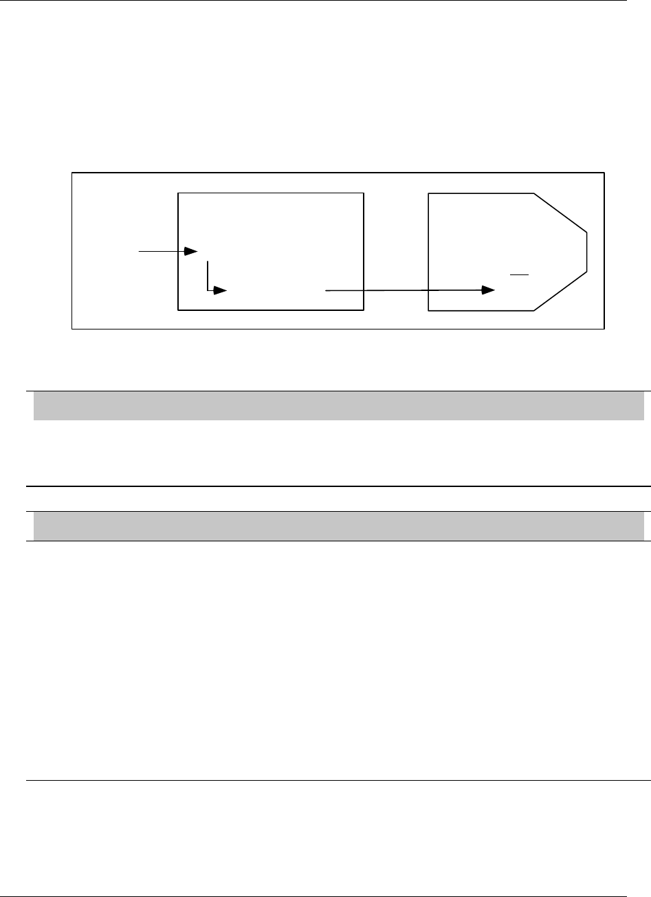
Programming Function Blocks and Features
Video Recorder – User Manual 148
Destination defined
To program Loops and Analog Outputs, you select the Program Control Loops or Program Analog
Outputs from the Program Mode Menu, then program each menu item. Some of these menu items,
such as proportional band or slew limits, are function block parameters; that is, they can be
programmed with numerical values only. A Constant’s DESTINATION overrides that numerical value
with a live value (variable) provided by the Constant’s VALUE.
For example, suppose Loop1’s Gain #1 is programmed as the number 5.00, and Constant 1’s Value is
CV 1 OV, the output of Calculated Value #2. By programming Constant1’s Destination as LP1GN,
Loop1’s Gain #1 will no longer be 5.00 but will be continuously updated by the live value provided by
CV 1 OV.
LP 1
GAIN #1 = 5.00
CV 1 OV
CN 1
VALUECV 1 OV
DEST = LP 1 GN
Figure 4-16 Example of Constant Destination
IMPORTANT
Always be certain that the destination is compatible with its associated loop or analog output. A mismatched
destination can affect your output and can be difficult to diagnose. Examples: If destination is AO1 IT (impulse
time), be sure that AO1 is programmed as a DAT. If destination is LP2 IS, be sure that Loop #2 is a type that
has increased slew limit on its menu.
ATTENTION
• If the destination is used, the parameter being overridden by the destination cannot be accessed or changed.
For example, Loop Gain cannot be tuned Online in the TUNE LOOP menu.
• If you reprogram destination to another parameter or NONE, the original destination parameter maintains its
last live value as determined by the constant’s value. If you want the destination’s last live value to be zero or
NONE:
1. change the constant value to zero or NONE,
2. change to Online mode for 5 seconds to override the previous live value with zero or NONE,
3. change back to program mode,
4. re-program constant’s destination to NONE.
• If you program multiple constants with the same destination, only the highest numbered constant’s
destination takes effect. For example, if Constant #1 and Constant #5 both have destination = AO2 IT, then
only Constant #5’s value is used by AO2 IT.

Programming Function Blocks and Features
Video Recorder – User Manual 149
4.17 Copy Block
Use Copy Block to copy the setup of any function block to another channel of the same function block.
For example, if you have programmed AI1 and want AI2 to have the same settings, use Copy Block. If
desired, you can make program changes to AI2 after the copy is complete.
If your instrument can run multiple profiles at the same time, Copy Block is useful for copying the
parameters of one profile to another. For example, if your instrument can run 2 profiles, it may be useful
to have both profiles use the same switches for starting, holding, and resetting. After you program the
first profile’s parameters, use Copy Block to copy Profile #1 to Profile #2.
Table 4-53 describes the Copy Block prompts.
Table 4-53 Copy Block Prompts
Prompt Range/Selections Definition
BLOCK TYPE AI, AO, AL, CN, CV, DI,
DO, LP, TL, SP Select the function block type to be copied.
AI: Analog Input
AO: Analog Output
AL: Alarm
CN: Constant
CV: Calculated Value
DI: Discrete Input
DO: Discrete Output
LP: Control Loop
SP: Set point Profile
TL: Totalizer
FROM NUMBER NUMBER Enter the channel number to be copied.
TO NUMBER NUMBER Enter a channel to copy to or "ALL" if you want to copy this block
to all other channels.
COPY BLOCK Select this to do the copy. A verification prompt lets you continue
or abort the copy.
Programming Function Blocks and Features
Video Recorder – User Manual 150
4.18 Program Displays
You can configure up to 10 primary displays using one or more display formats shown in Figure 4-
17and assign them to appear in specified order when the Display button is pressed.
SP1
200.00
-20 0.00
END
820.20
SEGMENT # 15
01:30:00
TRE ND
SP2
1500.00
100.00
READY
71.00
SEGMENT #1
00:00:00
TREND
Setpoint Profiler 2 Bar Summary
(SPP_2BS) Setpoint Profiler 3 Bar Summary
(SPP_3BS)
SP1
100.00
0.00
SP2
100.00
0.00
SP4
100.00
0.00
SP3
100.00
0.00
RUN
40.00
SEG 5
00:21:13
TREND
RUN
70.00
SEG 2
00:10:08
TREND
READY
50.00
SEG 1
00:00:00
TREND
HOL D
50.00
SEG 6
01:23: 00
TREND
Setpoint Profiler 4 Bar Summary
(SPP_4BS)
SP1 PROFIL01500.00
PV 241.27
SP 248.00
0.00
1:05:30
SEG6/9 RUN
Setpoint Profiler Trend
(SP_TREND)
LOOP 1
SP1 11/ 15
12: 15
25 0 0 .0 0
1500.00
PV 2205.00
SP 2000.00
DEV 205.00
OUT 83.5%
0 100%
AUTO
Loop with Bar Graph
(LOOP_BAR)
PV 405.00
SP 405.00
OUT 15 .0
A SP1
LP1 LP2
1500.00
0.00
PV 1054.00
SP 1040.00
OUT 10.0
A SP2
1000.00
0.00
Loop 2 Bar Summary
(LOOP_2BS)
PV 405.00
SP 405.00
OUT 15.0
A SP1
LP1 LP2 LP3
0.00
1500.00 1200.00
0.00 0.00
1000.00
00.00
PV
1054.00
SP
1040.00
OUT
10.0
A
SP2
PV
623.00
SP
622.00
OUT
5.0
M
SP1
Loop 3 Bar Summary
(LOOP_3BS)
RUN
40.00
SEG 5
00:21:13
TREND
READY
71.00
SEG 1
00:00:00
TR E ND
END
820.20
SEG 15
01:30:00
TREND
SP1SP2 SP3
100.00
0.00
20 0.00 1500.00
-20 0.00 10 0.00
Loop 4 Bar Summary
(LOOP_4BS)
PV 405.00
SP 405.00
OUT 15.0
A S 1
LP1
1054.00
1040.00
10.0
M S2
623. 0 0
622. 0 0
5.0
M S1
0.0
100. 0
0. 0
100 . 0
0. 0
100 . 0
0.0
100 . 0
LP2 LP3 LP4
1266 .0 0
1244 .0 0
5.0
A S1
405.00
405.00
15. 0
A S1
LP5
1054.00
1040.00
10.0
M S2
623.00
622.00
5.0
M S1
0.0
100.0
0. 0
100 . 0
0. 0
10 0. 0
0. 0
100 . 0
LP6 LP7 LP8
1266 . 00
1244 . 00
5.0
A S1
Loop 8 Bar Summary
(LOOP_8BS)
UNIT DATA
11/ 15 12: 15
TAG467
TAG467
TAG467
TAG467
TAG467
TAG467
TAG467
TAG467
TAG467
TAG467
TAG467
TAG467
2345.67
2345.67
2345.67
2345.67
2345.67
2345.67
2345.67
2345.67
2345.67
2345.67
123456789
123456789
DEGF
DEGF
DEGF
DEGF
DEGF
DEGF
DEGF
DEGF
DEGF
DEGF
DEGF
DEGF
Unit Data
(UNIT DATA)
ZONE1
123.45
DEGF
ZONE2
123.45
DEGC
ZONE3
123.45
DEGF
ZONE4
123.45
DEGF
ZONE5
123.45
DEGF
ZONE6
123.45
DEGC
ZONE7
123.45
DEGF
ZONE8
123.45
DEGC
ZONE9
123.45
DEG F
ZONEA
123.45
DEG F
ZONEB
123.45
DEG F
ZONEC
123.45
DEG F
Panel Meter
(PANMETER)
PV 405.00
SP 405.00
OUT 15 .0
A
S1
L
0.00
LP2
1500.00
0.00
1054.00
1040.00
10.0
M S 2
LP4
2400.00
0.00
1266.00
1244.00
5 .0
A S1
1200 .00
0.00
623.00
622.00
5.0
M S1
LP3
1000.00
P1
PRESS 3
30.00
PSI
ZONE1
205.00
DEGF
ZONE2
456.2
DEGF
TEMP2
134.4
DEGC
Panel Display - 4 Large Font
Points (PANEL_4) Vertical Trend
(V_TREND)
12:15
11: 45
11:15
10:45
10:15
1500.0 2500.0
AALARM 1 HIGH
DEGC TAG1
VALUE1
TAG2
VALUE2
TAG3
VALUE3
TAG4
VALUE4
TAG5
VALUE5
TAG6
VALUE6
Vertical Trend Digital
(VTRNDDIG)
TEMP 7 2261.50 DEGF
ATEMP 1 HIGH
Vertical rend w/ 4 Bar
(VTRNDBAR) Horizontal Trend
(H_TREND)
TEMP 7 2061.5 DEGF
2500.0
1500.0
AALARM 1 H IGH
TAG1
VALUE1
TAG2
VALUE2
TAG3
VALUE3
TAG4
VALUE4
TAG5
VALUE5
TAG6
VALUE6
DEGF
2500.00
1500.00
12 :1511 :4511 :15
Horizontal Trend Digital Horizontal Trend Bar
AALARM 1 HIGH
12:1511:45
11:15
TAG1
1500. 00
DEGF
2500.00
VALUE1
4 Point Horizontal Bar Graph
(H_4_BAR) 6 Point Horizontal Bar Graph
(H_6_BAR)
TEMP7 1941.5 DEGF
1500.0 2500.0
AALARM 1 HIGH
12:15
11:45
11:15
(HTRNDDIG) (HTRNDBAR)
TEMP7
1260.50
DEGF
TEMP5
1207.50
DEGF
TEMP6
1634.50
DEGF
TEMP7
1478.50
DEGF
0.0 2500.0
0.0 2500.0
0.0 2500.0
0.0 2500.0
1500.00.
TEMP7
2261.50 DEGF
11/ 15
12: 15
226 1.60
226 1.60
226 1.60
226 1.60
226 1.60
226 1.60
ATEMP 1 HIGH
Figure 4-17 Displays Accessible by the Display Buttons (continued)
Programming Function Blocks and Features
Video Recorder – User Manual 151
TEMP1
1000.00
0.00
TEMP 2 TEMP3 TEMP4
500.00 25 0.00 500.00
0.00 0.00 0.00
510.00
DE G F 282.00
DE G F 124.00
DE GF 273.00
DE GF
4 Point Vertical Bar Graph
(V_4_BAR)
TEMP7
2261.50 DEGF
11 /1 5
12 :1 5
ATEMP 1 HIGH
6 Point Vertical Bar Graph
(V_6_BAR)
DEWPOINT IN
42 DEGF
0.0
500.0
8 Point Vertical Bar Graph
(V_8_BAR)
TEMP IN
252 DEGF
12 Point Vertical Bar Graph
(V_12_BAR)
0.0
500.0
DATA ST ORA GE STATUS 13 :15
ATEMP 1 H IGH
REMAINING
TREND 1 HI
TREND 3
ALARM SAMPLES
EVENT SAMPLES
DIAG SAMPLES
UNIT DATA SAMP
SYSTEM: NORMAL
DISK: NORMAL
ENABLE STORAGE ENABLE
DD-HH-MM
O2 10 15
ROLL
20
25
ROLL
50
Y
Y
Y
N
Y
N
YES
Storage Status
(STORAGE)
TOTALIZERS 13 :2 5
TOTLZR1
TOTLZR2
TOTLZR3
123456789
123456789
123456789
EU12
EU12
EU12
A D D ISK FULL
Totalizer
(TOTALIZR)
ALARM SUMMARY
PA GE 414:25
PROCESS 1
TEMP 7
01 :12:59
PR OCESS 3
TEMP 9
01 :12:59
HIGH
CURR=1234.56
04/12/97
LO W
CURR=2345.54
04/12 /97
HRATE
CURR=1234.56
04/12 /97
ADDISK FULL
PROCESS 1
TEMP 8
01 :12:59
Alarm Summary
(ALARMSUM)
PV 405.00
SP 405.00
OUT 1 5.0
A S1
LP1
1000.00
0.00
LP2
1500.00
0.00
1054.00
1040.00
10.0
M S2
LP4
2400.00
0.00
1266.00
1244.00
5.0
A S1
LP3
1200.00
0.00
623.00
622.00
5.0
M S1
TAG 1
VALUE1
TAG 2
VALUE2
TAG 3
VALUE3
TAG 4
VALUE4
TAG 5
VALUE5
TAG 6
VALUE6
TAG7
VALUE 7
TAG8
VALUE 8
TAG9
VALUE 9
TAG 10
VALUE10
TAG 11
VALUE11
TAG 12
VALUE12
ZONE1
123.45
DEG F
ZONE2
123.45
DEG C
ZONE3
123.45
DEG F
ZONE4
123.45
DEG F
ZONE5
123.45
DEG F
ZONE6
123.45
DEG C
ZONE7
123.45
DEG F
ZONE8
123.45
DEG C
ZONE9
123.45
DEG F
ZONEA
123.45
DEG F
ZONEB
123.45
DEG F
ZONEC
123.45
DEG F
Process Summary (PRO_SUM)
contains these screens:
Horizontal Trend Bar (HTRNDBAR)
4 Loop Bar (LOOP_4BS)
Panel Meter (PANMETER)
Figure 4-17 Displays Accessible by the Display Buttons

Programming Function Blocks and Features
Video Recorder – User Manual 152
Display Setup Procedure
Table 4-54 describes the display setup procedure.
Table 4-54 Display Setup Procedure
Step Action
1 Select Program Displays from the Program mode menu.
2 For each display format desired (trend, bar graph, panel display, unit data), specify points to be
displayed.
3 Assign up to 10 displays to the Display buttons.
Set Up Trend 1
Table 4-55 describes the trend display setup procedure.
Table 4-55 Set Up Trend 1 Prompts
Prompt Range/Selections Definition
ENABLE Yes, No Enables or disables a specific trend.
POINT #1
POINT #12 Analog or discrete
parameters Select up to 12 analog or discrete points to be displayed as a
vertical or horizontal trend. Trends of discrete points will
show a value of 1 when ON and 0 when OFF.
NORM TIME BASE 5, 15, or 30 minutes, or 1, 2,
4, 8, 24 hours, 7 days or
31 days. Equivalent paper
chart speeds are listed in
Table 4-56.
Enter the trend display time base for Normal (typically slow
speed). The time base is the time period shown for one full
screen.
ALT TIME BASE 5, 15, or 30 minutes, or 1, 2,
4, 8, 24 hours, 7 days or 31
days. Equivalent paper
chart speeds are listed in
Table 4-56.
Enter the trend display time base for Alternate (typically fast
speed). The time base is the time period shown for one full
screen.
SET DISPLAY
LIMITS OFF or number Set the high and low full-scale display limits for each point. If
you select OFF for a limit on this display, the limits
programmed for the analog point (either RANGE LOW and
RANGE HIGH or OUT LOW LIMIT and OUT HIGH LIMIT) will
be used as the trend limits for that point.
The accuracy of a trended point is determined only by the
original output limits of the point, not by setting wider or
narrower limits here. Setting excessively narrower limits here
will result in a viewable trend with a high degree of
inaccuracy when viewed as a % of the screen. To increase
accuracy over a narrower range, decrease the programmed
output range (limits) of the point itself.
TIMEBASE
SELECTOR OFF, discrete parameter, 0,
1 Enter a discrete parameter which will cause trend to display
alternate timebase when ON and normal timebase when
OFF.
Programming Function Blocks and Features
Video Recorder – User Manual 153
Table 4-56 Paper Chart Speed Equivalents to Time Base Selections
Instrument
Time/Screen
Paper Chart Vertical Trend
cm/hour (inches/hour)
Paper Chart Horizontal Trend
cm/hour (inches/hour)
5 minutes 154 (60.6) 246 (96.8)
15 minutes 51.3 (20.2) 82 (32.2)
30 minutes 25.6 (10.1) 41 (16.2)
1 hour 12.8 (5.1) 20.5 (8.1)
2 hours 6.9 (2.7) 10.25 (4.0)
4 hours 3.4 (1.34) 5.1 (2.0)
8 hours 1.6 (0.63) 2.56 (1.0)
24 hours 0.53 (0.21) 0.85 (0.33)
7 days 0.076 (0.03) 0.122 (0.048)
31 days 0.017 (0.007) 0.027 (0.011)
Set Up Trend 2 - 3 - 4
See Table 4-55 for prompts. For Point #1 - Point #12, enter a second group of up to 12 points that will
be displayed as a horizontal or vertical trend.
Log scale trending
This feature enables trending of logarithmic trending on the video chart. This feature is enabled by the following
rules :
1. Programming the decimal point for trend point #1 as X.XXEXX and then trend point #1 and any
subsequent trend point that also has X.XXEXX as the decimal point will be plotted logarithmically
with the number of log divisions derived automatically from the low and high limit of point #1.
2. Setting up the trend display limits decimal position to be X.XXEXX and then any trend point that
also has X.XXEXX as its decimal position will be plotted logarithmically with the number of log
divisions derived automatically from the low and high of the first trend point found with X.XXEXX
decimal position.
Programming Function Blocks and Features
Video Recorder – User Manual 154
Live Trend Buffer Size
Table 4-57 1 trend group live buffer size
1 Trend Group
Display length Number of
points in the
trend
Number of
pages in the
buffer 5 min 15 min 30 min 1 hr 2 hrs 4 hrs 8 hrs 24 hrs
1
2
3
4
5
6
7
8
9
10
11
12
634
423
317
254
211
181
159
141
127
115
106
98
52,9
35,2
26,4
21,1
17,6
15,1
13,2
11,7
10,6
9,6
8,8
8,1
158,6
105,7
79,3
63,4
52,9
45,3
39,6
35,2
31,7
28,8
26,4
24,4
317,1
211,4
158,6
126,8
105,7
90,6
79,3
70,5
63,4
57,7
52,9
48,8
634,2
422,8
317,1
253,7
211,4
181,2
158,6
140,9
126,8
115,3
105,7
97,6
1 268,4
845,6
634,2
507,4
422,8
362,4
317,1
281,9
253,7
230,6
211,4
195,1
2 536,9
1 691,3
1 268,4
1 014,8
845,6
724,8
634,2
563,8
507,4
461,3
422,8
390,3
5 073,8
3 382,5
2 536,9
2 029,5
1 691,3
1 449,6
1 268,4
1 127,5
1 014,8
922,5
845,6
780,6
15 221,3
10 147,5
7 610,6
6 088,5
5 073,8
4 348,9
3 805,3
3 382,5
3 044,3
2 767,5
2 536,9
2 341,7
Buffer Size in hours
Table 4-58 2 trend group live buffer size
2 Trend Groups
Display length Number of
points in the
trend
Number of
pages in the
buffer 5 min 15 min 30 min 1 hr 2 hrs 4 hrs 8 hrs 24 hrs
1
2
3
4
5
6
7
8
9
10
11
12
317
211
159
127
106
91
79
70
63
58
53
49
26,4
17,6
13,2
10,6
8,8
7,6
6,6
5,9
5,3
4,8
4,4
4,1
79,3
52,9
39,6
31,7
26,4
22,7
19,8
17,6
15,9
14,4
13,2
12,2
158,6
105,7
79,3
63,4
52,9
45,3
39,6
35,2
31,7
28,8
26,4
24,4
317,1
211,4
158,6
126,8
105,7
90,6
79,3
70,5
63,4
57,7
52,9
48,8
634,2
422,8
317,1
253,7
211,4
181,2
158,6
140,9
126,8
115,3
105,7
97,6
1 268,4
845,6
634,2
507,4
422,8
362,4
317,1
281,9
253,7
230,6
211,4
195,1
2 536,9
1 691,3
1 268,4
1 014,8
845,6
724,8
634,2
563,8
507,4
461,3
422,8
390,3
7 610,6
5 073,8
3 805,3
3 044,3
2 536,9
2 174,5
1 902,7
1 691,3
1 522,1
1 383,8
1 268,4
1 170,9
Buffer Size in hours
Programming Function Blocks and Features
Video Recorder – User Manual 155
Table 4-59 4 trend group live buffer size
4 Trend Groups
Display length Number of
points in the
trend
Number of
pages in the
buffer 5 min 15 min 30 min 1 hr 2 hrs 4 hrs 8 hrs 24 hrs
1
2
3
4
5
6
7
8
9
10
11
12
159
106
79
63
53
45
40
35
32
29
26
24
13,2
8,8
6,6
5,3
4,4
3,8
3,3
2,9
2,6
2,4
2,2
2,0
39,6
26,4
19,8
15,9
13,2
11,3
9,9
8,8
7,9
7,2
6,6
6,1
79,3
52,9
39,6
31,7
26,4
22,7
19,8
17,6
15,9
14,4
13,2
12,2
158,6
105,7
79,3
63,4
52,9
45,3
39,6
35,2
31,7
28,8
26,4
24,4
317,1
211,4
158,6
126,8
105,7
90,6
79,3
70,5
63,4
57,7
52,9
48,8
634,2
422,8
317,1
253,7
211,4
181,2
158,6
140,9
126,8
115,3
105,7
97,6
1 268,4
845,6
634,2
507,4
422,8
362,4
317,1
281,9
253,7
230,6
211,4
195,1
3 805,3
2 536,9
1 902,7
1 522,1
1 268,4
1 087,2
951,3
845,6
761,1
691,9
634,2
585,4
Buffer Size in hours

Programming Function Blocks and Features
Video Recorder – User Manual 156
Set Up Bar Graph 1
Table 4-60 describes the prompts for setting up Bar Graph 1.
Table 4-60 Set Up Bar Graph 1 Prompts
Prompt Range/Selections Definition
POINT #1 –
POINT #12 OFF, analog parameter,
numbers Select up to 12 analog points, each to be displayed as a
vertical or horizontal bar graph.
Set Up Bar Graph 2 - 3 - 4
See Table 4-60 for prompts. For Point #1 - Point #12, enter a second group of up to 12 points that will
be displayed as horizontal or vertical bar graphs.
Set Up Panel Displays
Table 4-61 describes the prompts for setting up a Panel Display and Panel Meter Display.
Table 4-61 Set Up Panel Display Prompts
Prompt Range/Selections Definition
POINT #1-POINT #12 Analog or discrete
parameters Select up to 12 analog or discrete points. On the Panel_4
Display, these points will be displayed four at a time at a
specified rotation rate and can be seen from 15 feet
(5 meters). On a panel meter display, these 12 points will be
displayed all at once.
Set Up Unit Data Display
Table 4-62 describes the prompts for setting up a Unit Data Display.
Table 4-62 Set Up Unit Data Display Prompts
Prompt Range/Selections Definition
POINT #1-
POINT #12 Analog or discrete
parameters Select up to 12 analog or discrete points. These points will
be displayed as a list.
Set Up Profile Displays
Table 4-63 describes the prompts for setting up a Profile display. Affects the Set point Profiler Trend
displays only.
Table 4-63 Set Up Profile Display Prompts
Prompt Range/Selections Definition
PROFILE #1
PROFILE #2
PROFILE #3
PROFILE #4
Select a profile display to set up.
DISPLAY TIME Number Enter the time width of the profile trend display, in the time units
of the profile. The higher this number, the more of a profile will
fit on the screen at a time. A value of zero means the entire
profile will be displayed, if the profile has no infinite segment
loops, no infinite auto cycling, and no external ramp type.

Programming Function Blocks and Features
Video Recorder – User Manual 157
Assign Displays to Keys
Your instrument has 4 display keys. You can assign a total of 10 displays to these keys. Pressing the
Display 1 key ( 1) accesses the format you assign to Display 1. Display 2 key ( 2) accesses Display
2 and Display 3 key (
3
) accesses Display 3. The Display key ( ) accesses displays 4-10.
Table 4-64 describes the prompts for assigning displays to keys.
Table 4-64 Assign Displays To Keys Prompts
Prompt Range/Selections Definition
BLANKING TIME OFF, 1 HOUR, 30 MIN, 15
MIN, 5 MIN, 1MIN This is a screen-saver type function. If enabled, the screen
will blank after time selected. Screen will unblank if a key is
pressed or an alarm/diagnostic occurs.
DISPLAY KEY 0, 1, OFF, PARM By selecting PARM, you can connect a discrete input
parameter which will function as the Display key. Each off-
to-on transition of this discrete will behave as if the Display
key were pressed.
Select 0, 1, or OFF to disable this function.
BACKGROUND
COLOR WHITE, BLACK This sets the background color of displays to black or white.
Affects all Trend (live and replay), Bar Graph, and Panel
displays. Does not affect Loop, Unit Data, Summary, or
menus.
SELECT PEN
COLOR PEN #1
PEN #2
.
.
.
PEN #12
Assign a color to each of up to 12 points. Affects points
displayed on all Trend (live and replay), Bar Graph, Loop,
and Panel displays. Pen #1 corresponds to Point #1, Pen #2
corresponds to Point #2, etc.
Choices: Green, Cyan, Yellow, Purple, Blue, Brown, Red,
Black, White.
Attention: A Yellow pen appears yellow on a black
background and orange on a white background.
Caution: Do not select a white pen color for a white
background or a black pen color on a black background;
these will render your points invisible.
(continued)

Programming Function Blocks and Features
Video Recorder – User Manual 158
Table 4-64 Assign Displays To Keys Prompts (continued)
Prompt Range/Selections Definition
DISPLAY 1
DISPLAY 2
.
.
.
DISPLAY 10
FORMAT Select one of the following display formats. The
corresponding format will be shown when the Display keys
are pressed.
V_TREND (Vertical Trend)
VTRNDDIG (Vertical Trend Digital)
VTRNDBAR (Vertical Trend Bar)
VT_6DIV (Vertical Trend-6 Division)
H_TREND (Horizontal Trend)
HTRNDDIG (Horizontal Trend Digital)
HTRNDBAR (Horizontal Trend Bar)
V_4_BAR (4-Point Vertical Bar Graph)
V_6_BAR (6-Point Vertical Bar Graph)
V_8_BAR (8-Point Vertical Bar Graph)
V_12_BAR (12-Point Vertical Bar Graph)
H_4_BAR (4-Point Horizontal Bar Graph)
H_6_BAR (6-Point Horizontal Bar Graph)
PANEL_4 (4-Point Panel Display)
UNIT DATA (Unit Data Display)
PANMETER (Panel Meter)
ALARMSUM (Alarm Summary)
STORAGE (Storage Status)
TOTAL (Display 1 totalizer)
TOTALIZR (Display all totalizers)
LOOP_BAR (Loop with Bar Graph)
LOOP_2BS (Loop with 2 Bar Graphs)
LOOP_3BS (Loop with 3 Bar Graphs)
LOOP_4BS (Loop 4 Bar Summary)
LOOP_8BS (Loop 8 Bar Summary)
SPP_2BS (Set point Profiles with 2 Bar Graphs)
SPP_3BS (Set point Profiles with 3 Bar Graphs)
SPP_4BS (Set point Profiles with 4 Bar Graphs)
SP_TREND (Set point Profile Trend)
PROSUM (Process Summary)
TREND Appears if a trend format is selected. Select trend data to be
displayed: TREND 1, TREND 2, TREND 3 or TREND 4
BARGRAPH Appears if a bar graph format is selected. Select bar graph
data to be displayed: BARGRAPH 1, BARGRAPH 2,
BARGRAPH 3 or BARGRAPH 4
ROTATION RATE Appears if trend, panel ,display or some bar formats are
selected. Select number of seconds each point on the panel
display will be shown: 1, 2, 3, 4, 5, 10, 15, 20, 30, 40, 50, 60
LOOP Appears if a loop format is selected. Select loop to be
displayed.
PROFILE Appears if Set point Profile Trend format is selected. Select
profile to be displayed.

Programming Function Blocks and Features
Video Recorder – User Manual 159
4.19 Enable Features
Features can be restored to or removed from menus and displays simply by turning them On (ENABLE)
or Off (DISABLE) here. Disabled functions and their data are not destroyed or erased—they just cannot
be viewed on the display. For example, a programmed constant retains its value and continues to
function in calculations whether it is disabled or enabled.
Table 4-65 Enable Features Prompts
Prompt Range/Selections Definition
EXPANDED INPUT ENABLE, DISABLE DISABLE removes the LAG and SAMPLE/HOLD functions
from the Analog Input Programming menu.
PYROMETRY ENABLE, DISABLE DISABLE removes all the Rayotube and Spectray ranges
from the list of types on the Program Analog Input menu.
AI VALUE ADJUST ENABLE, DISABLE DISABLE removes the ANALOG INPUT ADJUST from the
Online Data Entry menu, which disables the ability to apply
adjust or emissivity corrections.
DI/DO FORCING ENABLE, DISABLE DISABLE removes the FORCE DI/DO POINTS from the
Online Data Entry menu, which removes the ability to force
any DI/DO on or off.
ALARMS ENABLE, DISABLE DISABLE removes access to the entire alarm system. Any
alarms already programmed will still operate, giving message
stripes and operating relays. There will be no alarm summary
or related displays.
CONSTANTS ENABLE, DISABLE DISABLE removes the Constant entry display, thus removing
the ability to set or adjust CN values. CNs previously
programmed will continue to exist.
LABELING ENABLE, DISABLE DISABLE removes the labeling prompts from the individual
parameter programming submenus. Labeling can still be
entered from the “ENTER LABELS” item on the main
Program menu.
REVIEW PROGRAM ENABLE, DISABLE DISABLE removes the REVIEW PROGRAMMING function
from the main Online menu.
DISK REPLAY ENABLE, DISABLE DISABLE removes the menu items which allow access to the
Online retrieval of stored data.
ZOOM ENABLE, DISABLE DISABLE removes the menu items which allow access to the
Online trend Zoom feature.
POINT DETAIL ENABLE, DISABLE DISABLE removes the menu items which allow access to the
Online trend Point Detail feature.
TIMEBASE SELECT ENABLE, DISABLE DISABLE removes the menu items which allow access to the
manual Trend Timebase Select capability.
CUSTOM INPUT ENABLE, DISABLE DISABLE removes INPUT ALGORITHM prompt from the
Program Analog Input menu.

Programming Function Blocks and Features
Video Recorder – User Manual 160
4.20 Program Security
Security lets you protect certain menu items and functions from unwanted or accidental access. Access
to a secured item requires entry of a 3-digit master or operator code.
Select “PROGRAM SECURITY” to display the Security menu (if security is active, you will be prompted
to enter the master code before continuing).
REFERENCE
If the master or operator’s security code is lost or forgotten, a security bypass procedure is available. See
Appendix A.
Table 4-66 describes the Security prompts.
Table 4-66 Security Prompts
Prompt Range/Selections Definition
ENABLE SECURITY YES, NO Set to Yes to activate security on all enabled security items
having a non-zero master or operator’s code. If set to No, no
items will be secure!
MASTER SEC CODE 3 digit number Set to a non-zero value; a value of zero offers no security.
Secures the following items:
MEMORY CLEAR SERVICES in Maintenance mode.
PROGRAM SECURITY in Program mode
Changing out of Online Mode. (See SET MODE.)
SET MODE Set to Yes to secure changing from Online mode to Program or
Maintenance modes.
OPERATOR SEC
CODE 3 digit number Enter a non-zero operator security code value; a value of zero
offers no security. Secures the following items (if set to Yes).
AUTO/MANUAL Set to Yes to secure Online changes between a loop’s Auto and
Manual modes.
SP1/SP2 Set to Yes to secure Online changes between a loop’s SP1 and
SP2.
SETUP PARAMETERS Set to Yes to secure changes to:
• Online Data Entry menu items:
Alarm Set points
Analog Input Adjust
• Online Tune Loop menu
REVIEW PROGRAM Set to Yes to secure Online access to Review Programming (via
REVIEW PROGRAMMING menu).
DATA STORAGE Set to Yes to secure access to any part of data storage (via
Online DATA STORAGE SETUP menu). Does not affect access
to Online DATA STORAGE STATUS display.
PROFILER Set to Yes to secure access to all Set point Profiler menus and
displays.

Programming Function Blocks and Features
Video Recorder – User Manual 161
4.21 Serial Communications
Serial Communications is an optional feature that lets the instrument exchange data with a host device
(a PC running Honeywell or other compatible software) on an RS422/485 data link. Using Modbus RTU
protocol, this link can be used to transfer configurations and data. Set up the link as follows.
Table 4-67 describes the Serial Communications prompts.
Table 4-67 Serial Communications Prompts
Prompt Range/Selections Definition
UNIT ADDRESS 1-254 Enter the unit’s address. Use a number once only so that each
address on the link is unique.
BAUD RATE 1200, 2400, 4800,
9600, 19200, 38400,
76800.
Enter the speed of data transfer. All equipment on the link must
be set to match the host setting.
DOWNLOAD
LOCKOUT YES, NO Set to YES to prevent configurations from being downloaded from
a PC with SCF software.
BYTE ORDER FP_B : Big Endian
FP_BB : Big Endian
with Byte swap
FP_L : Little Endian
FP_LB : Little Endian
with Byte swap
This feature allows a user to select the byte order for a floating
point register.
Example for 25.38 :
Byte order Result
FP_B
FP_BB
FP_L
FP_LB
0123
1032
3210
2301
41CB0A3D
CB413D0A
3D0ACB41
0A3D41CB

Programming Function Blocks and Features
Video Recorder – User Manual 162
4.22 Set Clock
To assure data, alarms, and events are properly time stamped, the clock must be properly set. The
clock uses military time.
Select "CLOCK" from the main Program menu. Enter the date and time with the following prompts.
Table 4-68 describes the Set Clock prompts.
Table 4-68 Set Clock Prompts
Prompt Range/Selections Definition
MONTH JAN - DEC Enter the date and time.
DAY 1-31
YEAR Enter year
HOURS 0-23
MINUTE 0-59
FORMAT USA = MMDDYY
INTL = DDMMYY
Select clock format.
IMPORTANT
Resetting the clock can affect the storage schedule of a unit in service.
If the clock is set back more than 5 minutes, the following actions will take place:
Data in storage buffers will be copied to the floppy disk and the buffers will then be cleared.
Data collection for storage will stop until the operator reinitializes the schedule.
If the clock is set back less than 5 minutes, collection of data storage and trends will stop until the setback time
elapses and the clock "catches up" with the original collection schedule. A warning prompt will appear on the
display before these actions occur. You can then cancel the clock change if desired.

Programming Function Blocks and Features
Video Recorder – User Manual 163
4.23 Load/Store Configuration
Instrument configurations can be stored to and loaded from floppy disk. The front door must be closed.
Configurations have filename extension .LNC.
Table 4-69 describes the Load/Store Config prompts.
Table 4-69 Load/Store Config Files Prompts
Prompt Range/Selections Definition
STORE CONFIG TO
DISK
FILE01 CYCLE01
DRYER01 PROD01
RECORD01 TANK01
UNIT01 LOOP01
REACTR01 CONFIG01
KILN01 VESSEL01
CALIB01 WCHEM01
PRESS01 FURNCE01
DEMIN01 CONTRL01
BATCH01 FERMTR01
LEHR01 LINE01
STRLZR01 OVEN01
ZONE01
Specify a filename and number (01-99) for the
configuration. Press Enter to store the configuration.
LOAD CONFIG
FROM DISK Select a configuration
filename. First you must clear the instrument’s configuration memory.
Press Enter to clear, or Menu to abort and exit the menu.
Once the memory is clear, select a filename from the floppy
disk. Press Enter to load the configuration into the
instrument.
ATTENTION
Only function blocks that have been programmed are loaded to the instrument. Function blocks in the receiving
instrument are not replaced unless the incoming function blocks are programmed differently. For example, if the
instrument has AI1 and AI2 programmed, and the configuration being loaded from the floppy contains AI3 only,
then AI1 and AI2 are undisturbed on the instrument and AI3 is added. If the configuration being loaded contains a
different AI2 and a new AI3, then AI1 is undisturbed, AI2 is replaced by the different AI2, and AI3 is added.

Programming Function Blocks and Features
Video Recorder – User Manual 164
4.24 Scan Rate
Scan rate is the time required to measure inputs, execute function blocks (AI, Loops, AO, DI, DO, CV,
etc.) and update outputs. It is also known as the machine cycle, scan cycle, and update rate.
The Scan Rate prompt lets you set the scan rate of the instrument to a value slower than the maximum
rate allowed by the hardware. The hardware will determine the default scan rate. Allowable entries are
250 milliseconds, 500 milliseconds, 1 second, 2 or 3 seconds. 250 ms rate is only available on 4 input
units.
We recommend the following scan rates for the following configurations.
Table 4-70 Suggested Scan Rates
Inputs Scan Rate W/Control
Up to 4
Up to 12
Up to 16
Up to 24
Up to 32
Up to 44
Up to 48
250 msec
500 msec
750 msec
1 sec
1.5 sec
2.0 sec
3.0 sec
500 msec
1 sec
1 sec
1.5 sec
2 sec
2 sec
3 sec
NOTE
These are suggested scan rates. In general, if your instrument responds too slowly, use a slower (higher)
scan rate. You can use a faster (lower) scan rate than suggested here, but be aware of possible sluggish
display and button response time.

Programming Function Blocks and Features
Video Recorder – User Manual 165
4.25 Select Language
SELECT LANGUAGE on the Main Program Menu changes the instrument’s language to:
• English
• Spanish
• German
• French
• Italian

Programming Function Blocks and Features
Video Recorder – User Manual 166
4.26 Data Storage
Overview
Data Storage lets you store trends, unit data, alarms, events, and diagnostics in separate files on a
floppy disk for later analysis and review (replay). Data can be reviewed onscreen or on a PC with SDA
data analysis software or the TrendManager Pro V5 software suite. Set point Programs, instrument
configurations and calibrations are not part of the Data Storage feature.
Setup and configuration of Data Storage is described in this section; Online operation is described in
Section 7.4.
Setup procedure
Data Storage setup is performed Online to avoid interruption of current storage. The steps are
described briefly Table 4-71.
Table 4-71 Data Storage Setup Procedure
Step Action
1 Access DATA STORAGE Online. Insert an initialized 100MB ZIP disk into the drive. If necessary,
initialize disk using FORMAT DISK. See Opening/Closing the Front Door in Section 3.8.
2 Select ENABLE STORAGE. See Enable Storage below.
3 Select SET UP NEW SCHEDULES to specify storage data, mode, and other settings. See page
167.
4 Select DISK CAPACITY to specify storage rates. See page 172.
5 Select WARNING LEVEL % to define the capacity warning level.
6 Select INITIALIZE DISK, then select USE NEW SCHEDULES to initialize the disk with the settings
you created in steps 3 and 4. See section 3.15.
Enable storage
Set to Enable to turn on storage. If Disabled, no storage will occur, regardless of any other
settings.

Programming Function Blocks and Features
Video Recorder – User Manual 167
Set Up New Schedules
This item contains setup menus for all data sets. Select it to specify what data to store and how to store
it. If a type of data storage is not scheduled, no disk file will be created for it.
ATTENTION
If you make any changes to any item under SET UP NEW SCHEDULES, you must initialize using new
schedules to activate those changes.
The following items appear under SET UP NEW SCHEDULES and are described under the following
headings.
• Trend Data 1
• Trend Data 2
• Trend Data 3
• Trend Data 4
• Alarms
• Events
• Diagnostics
• Unit Data
• Disk capacity
• Batch Control
Trend Data 1
At the top of the display the message “SETUP IS CURRENT” indicates that current setup for storage of
TREND 1 is exactly as shown. If the message is “SETUP IS NOT CURRENT”, then the TREND 1 setup
has been changed since a disk was last initialized. To make a NOT CURRENT setup CURRENT, you
must initialize the disk using new schedules.
Set up Trend Data 1 as described in Table 4-72.

Programming Function Blocks and Features
Video Recorder – User Manual 168
Table 4-72 Prompts For Storage Setup Of Trends, Alarms, Events, Diagnostics
Prompt Range/Selections Definition
POINT #1 -
POINT #12 Analog or discrete parameter Select the data points for the trend.
STORAGE MODE CONTIN, BATCH, or NONE Continuous storage becomes active immediately upon
initialization. Batch storage is controlled by a discrete
parameter (see BATCH CONTROL) or by start/stop batch
menu item. Batch data may be started and stopped several
times in a single file until the file is full. Batch start
increments a batch number that is stored along with the
data. The batch number may be used for data retrieval and
analysis using SDA data analysis software.
COPY DISPLAY
SETUP Select this to copy the following Trend 1,2, 3 or 4 Display
data to Trend 1,2, 3 or 4 Storage data: Point #1–#12, set
display limits, timebase (high rate) selector. Once setup is
copied, it can be altered.
LOW RATE Seconds: .5, 1, 2, 3, 4, 5, 6, 7, 8,
9, 10, 20, 30, 40, 50
Minutes: 1, 2, 3, 4, 5, 10, 15, 20,
30, 40, 50
Hours: 1
Enter data collection rate. This is how often the data points
are sampled.
HIGH RATE Seconds: .5, 1, 2, 3, 4, 5, 6, 7, 8,
9, 10, 20, 30, 40, 50
Minutes: 1, 2, 3, 4, 5, 10, 15, 20,
30, 40, 50
Hours: 1
Enter data collection rate. This is how often the data points
are sampled.
ROLLOVER ON, OFF Select ON to continue gathering and storing data after the
file becomes full. The new data will replace the oldest data
on the disk as it is collected. No warning will be given.
Select OFF to stop storage of this data type when the disk
space for it becomes full. A “DISK FULL” message will then
appear. Data is buffered until a new disk is inserted and
initialized.
SET DISPLAY
LIMITS OFF or number Enter upper and lower limit values for the trend display for
each point. If OFF then the trend will use the programmed
limits for each point.
HIGH RATE
SELECTORS SELECTOR This discrete triggers the high storage rate when ON(1) and
the low storage rate when OFF.
CHANGE WITH KEY This option enables/disables storage rate changes from the
Trend display Point/Trend menu. If YES, storage Trend’s
high rate will be used when display Trend’s alternate
timebase is selected from the Online Point/Trend menu;
Storage Trend’s low rate will be used when display Trend’s
normal timebase is selected. See Table 6-2, Point/Detail
Menu Prompts, Timebase.
EXTERNAL
ENABLE OFF, discrete parameter, 0, 1 When ON(1), this discrete parameter will allow storage of
the data type; when off storage for the data type will stop.
This enable is independent of the storage mode; it does not
control batch start/stop.
SELECT
FILENAME
FILE CYCLE DRYER
PROD RECORD TANK
UNIT LOOP REACTR
CONFIG KILN VESSEL
CALIB WCHEM PRESS
FURNCE DEMIN CONTRL
BATCH FERMTR LEHR
LINE STRLZR OVEN
ZONE
Select a file name to identify the type of data to be stored.

Programming Function Blocks and Features
Video Recorder – User Manual 169
Trend Data 2, 3 & 4
Trend Data 2, Trend Data 3 and Trend Data 4 use the same prompts as in Table 4-72.
Alarms
Alarm data storage consists of a complete log of alarms, including time of occurrence, time of clearing,
value of the alarm parameter, the alarm sense (high, low, etc.) and the batch identification number, if
present. The alarm prompts are: STORAGE MODE, ROLLOVER, ALARM SAMPLES, EXTERNAL
ENABLE, SELECT FILENAME. See Table 4-72 for descriptions.
The number of samples which can be stored in a file (ALARM SAMPLES) can be up to
1600. Depending on your selections, data collection will begin when the first alarm occurs, or when the
first alarm occurs after a batch start.
Events
Event storage consists of a complete log of events including the event title, time of occurrence, the
status or value after the change, and the batch identification number, if present. When event storage is
running, loop and instrument mode events are always stored; discrete input and output events are
stored only if first enabled under those items’ program menus (see Sections 4.10 and 4.11).
Table 4-73 Stored Events
Event title Event status/value
Setpoint choice SP1, SP2
Control action Forward, Reverse
Tuning Set Set 1, Set 2
Instrument Mode Online, Program, Maint
Control Mode Auto, Manual, RMan
Set point 1 SP1’s value
Set point 2 SP2’s value
Control Output Loop’s output value
Discrete Input On, Off
Discrete Output On, Off
Event storage setup is done with the following parameters: STORAGE MODE, ROLLOVER, EVENT
SAMPLES, EXTERNAL ENABLE, SELECT FILENAME. See Table 4-72 for parameter descriptions.
The number of samples which can be stored in a file (EVENT SAMPLES) can be up to 1600.
Depending on your selections, data collection will begin when the first event occurs, or when the first
event occurs after a batch start.
Barcode data is also stored in the event file.

Programming Function Blocks and Features
Video Recorder – User Manual 170
Diagnostics
Data storage for Diagnostics is a complete log of all diagnostic messages. It includes the diagnostic
code or identifier message and its time and date of occurrence.
Setup is done with the following parameters: STORAGE MODE, ROLLOVER, DIAG SAMPLES,
EXTERNAL ENABLE, SELECT FILENAME. See Table 4-72 for descriptions.
Depending on your selections, data collection will begin when the first diagnostic occurs, or when the
first diagnostic occurs after a batch start occurs.
When calibration is executed, the record is time stamped and stored to the diagnostic file.
The number of samples which can be stored on a disk (DIAG SAMPLES) can be up to 1600.
Unit Data
Values for up to 12 points (analog input, calculated value, discrete input, discrete output, totalizer, etc.)
can be sampled at user-definable intervals and stored on floppy disk. The sample interval must be set
by a schedule or triggered by a discrete event. Prompts are described in Table 4-74.
Table 4-74 Unit Data Prompts
Prompt Range/Selections Definition
POINTS#1 –
POINTS#12 OFF or analog parameter or
discrete parameter Enter up to 12 points.
STORAGE MODE OFF, CONTIN, BATCH, or
ON COMMAND Continuous storage becomes active immediately upon
initialization. Batch storage is controlled by a discrete
parameter (see BATCH CONTROL, page 174) or by
start/stop batch menu item. Batch data may be started and
stopped several times in a single file until the file is full.
Batch start increments a batch number that is stored along
with the data. The batch number may be used for data
retrieval and analysis using SDA data analysis software.
ON COMMAND storage collects a single sample of data
whenever the EXTERNAL ENABLE discrete makes an off-
to-on transition. If this mode is used, then SET UP
SCHEDULE is ignored.
COPY DISPLAY
SETUP Copies the data point list already set up for a currently
active Unit Data display.
ROLLOVER ON, OFF Select ON to continue gathering and storing trend data after
the Unit data file becomes full. The new data will replace the
oldest data on the disk as it is collected. No warning will be
given.
Select OFF to stop trend storage when trend space
becomes full. A “DISK FULL” message will then appear.
Data is buffered until a new disk is inserted and initialized.
UNIT DATA
SAMPLES Enter a value from 0-1600 Number of samples.
EXTERNAL ENABLE OFF, discrete parameter, 0, 1 This discrete parameter will allow Unit data storage when
ON(1) and will stop Unit data storage when OFF(0). This
enable is independent of the storage mode; it does not
control batch start/stop.

Programming Function Blocks and Features
Video Recorder – User Manual 171
Table 4-74 Unit Data Prompts (continued)
Prompt Range/Selections Definition
SELECT FILENAME FILE CYCLE DRYER
PROD RECORD TANK
UNIT LOOP REACTR
CONFIG KILN VESSEL
CALIB WCHEM PRESS
FURNCE DEMIN CONTRL
BATCH FERMTR LEHR
LINE STRLZR OVEN
ZONE
Select a file name to identify the type of Unit data to be
stored.
START HOUR
0-23
START MINUTE 0-59
START MONTH
JAN-DEC
START DAY
1-31
START YEAR
1994-2038
INTERVAL DAYS 0-31
INTERVAL HOURS 0-24
INTERVAL MINS 0-59
If no external enable is specified, select a starting date
and time and an interval for periodic storage. Set
Interval Days to 31 if you want the timed schedule to
repeat on the same day each month.
This timer schedule will run in any Data Storage mode. In
CONTINUOUS mode, it will start as scheduled and
collect samples until stopped by manual command (the
ENABLE STORAGE in the Online Data Storage menu).
In BATCH mode, the timer schedule will be started and
stopped by an Online menu selection (BATCH STATE)
by the operator, or by an optional discrete input
designated as the BATCH CONTROL.

Programming Function Blocks and Features
Video Recorder – User Manual 172
Disk capacity
Choose DISK CAPACITY under SET UP NEW SCHEDULES menu to allocate trend storage. See
Table 4-75.
Table 4-75 Disk capacity Prompts
Prompt Range/Selections Definition
DISK CAPACITY Displays total time available for non-rollover trend storage
based on the low storage rates programmed. See Table
4-76 Disk Storage Capacity of 100MB ZIP disk.
TREND#1 LO RATE Seconds: .25, .5, 1, 2, 3, 4, 5,
6, 7, 8, 9, 10, 20, 30, 40, 50
Minutes: 1, 2, 3, 4, 5, 10, 20,
30, 40, 50
Hours: 1
This rate can be altered here or in the trend data setup (see
Table 4-72). If the low storage rates are changed, the disk
capacity will reflect the new trend capacity. Enter data
collection rate. This is how often the data points are
sampled. The .25 ms selection is only available for 2-input
instruments with no more than 3 points total in Trends 1-3.
The .5 sec rate cannot exceed 6 points total in Trends 1-3.
TREND#1 HI RATE Seconds: .25, .5, 1, 2, 3, 4, 5,
6, 7, 8, 9, 10, 20, 30, 40, 50
Minutes: 1, 2, 3, 4, 5, 10, 20,
30, 40, 50
Hours: 1
This rate can be altered here or in the trend data setup (see
Table 4-72). If the hi storage rates are changed, the disk
capacity will reflect the new trend capacity. Enter data
collection rate. This is how often the data points are
sampled. The .25 ms selection is only available for 2-input
instruments with no more than 3 points total in Trends 1-3.
The .5 sec rate cannot exceed 6 points total in Trends 1-3.
TREND#2 LO RATE See TREND#1 LO RATE
TREND#2 HI RATE See TREND#1 HI RATE
TREND#3 LO RATE See TREND#1 LO RATE
TREND#3 HI RATE See TREND#1 HI RATE
TREND#4 LO RATE See TREND#1 LO RATE
TREND#4 HI RATE See TREND#1 HI RATE

Programming Function Blocks and Features
Video Recorder – User Manual 173
Table 4-76 Disk Storage Capacity of 100MB ZIP disk
(The values shown below are for each Trend file) 24000000 bytes per file.
STORAGE RATE
1 sec. 5 sec. 10 sec. 30 sec. 1 min. 10 min. 30 min. 1 hour
2 13.5
days 2.2
months 4.5
months 1.1
years 2.2
years 22.2
years 66.8
years 133.7
years
4 8.1
days 1.3
months 2.7
months 8.1
months 1.3
years 13.3
years 40.1
years 80.2
years
6 5.9
days 29.8
days 1.9
months 5.9
months 11.9
months 9.8
years 29.4
years 58.8
years
8 4.8
days 24.4
days 1.6
months 4.8
months 9.7
months 8.0
years 24.0
years 48.1
years
10 3.7
days 18.9
days 1.2
months 3.7
months 7.5
months 6.2
years 18.7
years 37.4
years
POINTS PER FILE
12 3.2
days 16.2
days 1.0
month 3.2
months 6.5
months 5.3
years 16.0
years 32.1
years

Programming Function Blocks and Features
Video Recorder – User Manual 174
Batch Control
Specify a discrete parameter as the START/STOP switch for all data types whose storage mode is set
to “BATCH”.
ATTENTION
If no BATCH CONTROL parameter is defined here, batch storage is started/stopped instead through the menu
item BATCH STATE. If a parameter is defined here, BATCH STATE menu item is disabled.
Initializing a disk
Select INITIALIZE DISK from DATA STORAGE. Initialization activates storage and creates a file for
each data set (Trends 1-4, alarms, events, unit data, diagnostics). Filename extensions are as follows.
Table 4-77 Filename Extensions Of Data Storage Types
Data set Extension
Trend data .LNT
Alarms .LNA
Events .LNE
Unit Data .LNU
Diagnostics .LND
Select USE NEW SCHEDULES to store the new storage schedules. If you choose USE CURRENT
SCHEDULES, the disk is initialized using the current setup (the setup from the previous initialization),
not the new setup. Typically the operator will choose USE CURRENT SCHEDULES to continue storing
the same setup onto a new disk.
IMPORTANT
Initialization deletes any data already on the disk, therefore, you are prompted to press Enter to proceed or to
press Menu to abort.
When the INITIALIZING DISK message disappears, initialization has completed. If initialization fails,
see Table 6-6 for message descriptions.
ATTENTION
Refer to section 3.15 for additional information on disk initialization.

Setpoint Profiler
Video Recorder – User Manual 175
5. Setpoint Profiler
What’s in this section?
Section 5 explains the functions, configuration, and operation of the Setpoint Profiler. Terminology is
defined and all prompts are explained.
Section Page
Overview of the Setpoint Profiler 175
Components of a profile 178
Parameters that control a profile’s execution 185
How to set up a profiler 189
How to load and run a profiler 197
5.1 Overview of the Setpoint Profiler
Definitions
A profiler is a Setpoint Profiler function block. This function block is what you interact with when you
program and run a profile. The profiler is analogous to a compact disk player on a stereo, in that the
profiler “plays” a profile. Your instrument contains 1, 2, 3, or 4 profilers, depending on the option
ordered.
A profile is a series of ramp and soak segments, along with any parameters associated with those
segments, such as segment loops, events, and guaranteed soak enables. The setpoint produced by
the profile is used by a control loop’s Setpoint #2. A profile is also known as a curve or recipe. A profile
is analogous to a compact disc, in that the profile is “played” by the profiler. Your instrument contains 1,
2, 3, or 4 profiles, depending on the option ordered.
A program is a set of one to four profiles, depending on the instrument. Programs in a single profile
instrument contain 1 profile, programs in a two-profile instrument contain 2 profiles, programs in a three-
profile instrument contain 3 profiles, and programs in a four-profile instrument contain 4 profiles.
Guaranteed soak is a set of parameters that hold the profiler when the deviation between the generated
setpoint and either PV is larger than a configured limit.
Event outputs are discrete output parameters of the Setpoint Profiler function block. They may be tied
to other function blocks such as Discrete Outputs.
Profile features
Each profile has the following features:
• A second PV is available. Each PV is monitored for excessive deviation from the profile value, in
which case the profiler can be automatically put on Hold.
• Menu or discrete control of profile resetting, starting, holding, advancing, shutting down, or fast
forwarding through the profile.
• Discrete input for starting the profiler at the current value of the process variable. Known as “hot
start.”
• Discrete input for enabling/disabling guaranteed soak over the entire profile.
Setpoint Profiler
Video Recorder – User Manual 176
• Guaranteed soak configurable per segment.
• Discrete outputs to indicate profile state, including Ready, Run, Hold, In Progress, and At End.
• Up to 16 Discrete outputs (Events) programmable per segment.
• Four user-selectable methods for ramping.
• Automatic recycling of the profile.
• Up to four levels of looping within profile.
• Jumping to another segment.
• Batch operation, including shutdown profiling, activated through a discrete input or online menu.
Schematic of the Setpoint Profiler function block
SP
TIME
Setpoint output value
(SPn OV)
PV
START
HOLD
RESET/RUN
SHUTDOWN
ADVANCE
Event #1
Event #16
Ready
Run
At End
Inputs Outputs
Hold
Status Guaranteed
Hold
Figure 5-1 Setpoint Profiler Schematic
Setpoint Profiler
Video Recorder – User Manual 177
Two types of profiles
A single phase profile is the simpler of the two profile types. It does not contain startup and shutdown
segments. It runs from Segment 1 to the last segment.
A multiphase profile divides the profile into three phases: the startup phase, the batch phase, and the
shutdown phase. With a multiphase profile you can rerun the batch phase multiple times (known as
AUTO CYCLING), or skip to the shutdown phase. The batch phase of a multiphase profile is specified
by the BATCH FIRST SEGMENT and BATCH LAST SEGMENT prompts. See Figure 5-2.
Single-Phase Profile
Multi-Phase Profile
END
END (shutdown)
END (batch)
BATCH FIRST SEGMENT (3) BATCH LAST SEGMENT (6)
Batch Segments
Startup
Segments
Shutdown
Segments
Figure 5-2 Single and Multi-phase Profiles
Setpoint Profiler
Video Recorder – User Manual 178
5.2 Components of a profile
Two PVs available
Each profile can monitor up to 2 process variables. The second PV is for monitoring a second variable
related to your process. The value of each PV is compared with the value of the profile. If the
difference between either PV and the profile value exceeds specified amounts, the profiler will Hold
(soak), if enabled to do so.
Number of segments
Up to 63 segments may be in a profile.
Time Units
All segments use the same time base (seconds, minutes, or hours).
4 types of ramp segments
There are four ramp types selectable at the RAMP TYPE prompt.
1. Value/Duration
2. Time
3. Rate
4. External
Value/Duration (Val/Dur)Ramp Type
This is the only ramp type that allows consecutive ramps or soaks. VALUE is the beginning value of the
segment; TIME is the time needed to reach the VALUE of the next segment.
Segment #1
Time Segment #2
Time Segment #3
Time Segment #4
Time
Segments #1 & #2
Value
Segment #3
Value
Segments #4 & #5
Value
Segment #5
Time
Time = time to reach next segment Value
Ramp Type = Value/Duration
Time = duration of soak
Value = value of soak
Value = beginning value of current segment
Features of this ramp type
* Allows consecutive ramps or soaks
* First segment can be a ramp or soak
Ramp segments Soak segments
Figure 5-3 Value/Duration Ramp Type
Setpoint Profiler
Video Recorder – User Manual 179
To properly terminate a Val/Dur profile you must program the segment beyond the last segment with
the following:
1. The value you want the program to “end” with. Looking at Figure 5-3, the last segment is a soak,
thus the Value of segment #6 should be set to the same value used in segment #5. Any other value
will cause segment #5 to be a “ramp” since the value will ramp up (or down) from segment #5’s
value to segment #6’s value.
2. Set the TIME to “OFF”.
Time Ramp Type
Each ramp segment’s TIME is the time allotted for the profiler output to reach the next soak segment’s
VALUE. The ramp segment’s VALUE prompt is not used.
Soak segments
Segment #1
Time Segment #2
Time Segment #3
Time
Segment #1
Value
Segment #3
Value
Ramp Type = Time
Time = duration of soak
Value = value of soak
Features of this ramp type
* First and last segments must be soaks
* No consecutive ramps or soaks
Ramp segments
Value = not used in ramp segments
Time = time needed to reach next soak segment Value
Figure 5-4 Time Ramp Type
Setpoint Profiler
Video Recorder – User Manual 180
Rate Ramp Type
Each ramp segment’s TIME specifies the rate at which the profiler output will reach the next soak
segment, where the rate is specified by the prompts TIME/TIME UNITS. The ramp segment’s VALUE
prompt is not used.
Segment #1
Time Segment #3
Time
Segment #1
Value
Segment #3
Value
Ramp Type = Rate
Example: Time = 3. Time Units = Seconds. PV units = degrees F.
Therefore, profile will ramp to next soak Value at 3 degrees F per second
Value= not used with ramp segments
Value = value of soak
Segment #2
Time = Rate
Features of this ramp type
* First and last segments must be soaks
* No consecutive ramps or soaks
Ramp segments
Time = rate at which next soak Value will be reached, in PV units/Time Units.
Soak segments
Time = duration of soak
Figure 5-5 Rate Ramp Type
ATTENTION
Rate ramp type’s TIME prompt is in engineering units of the PV, not in time units (seconds, minutes, or hours).
External Ramp Type
This ramp type works with the RAMP INCREMENT discrete input. During a ramp segment, each time
RAMP INCREMENT changes from OFF to ON, the profiler output incrementally changes by the amount
specified in the ramp segment’s TIME (in units of the PV). When RAMP INCREMENT changes from ON
to OFF, the profiler output soaks at its present value. This increment-soak repeats until the profiler
output reaches the VALUE of the next soak segment. The ramp segment’s VALUE prompt is not used.
Setpoint Profiler
Video Recorder – User Manual 181
Segment #1
Time Segment #3
Time
Segment #1
Value
Segment #3
Value
Value = value of soak
Segment #2 Time
Segment #2 Time
Segment #2 Time
Segment #2
Elapsed time
Ramp Increment Off-to-On
causes incremental value
change toward next soak
Value
Ramp Type = External
Features of this ramp type
* First and last segments must be soaks
* No consecutive ramps or soaks
Ramp segments Soak segments
Time = amount profile will change toward next soak Value
when the Ramp Increment discrete switches on.
Value = not used with ramp segment.
Time = duration of soak
Figure 5-6 External Ramp Type
ATTENTION
• External ramp type’s TIME prompt is in engineering units of the PV, not in time units (seconds, minutes, or
hours).
• To increment toward a lower soak value, enter a positive TIME amount. The Setpoint Profiler “knows” to
increment or decrement this amount toward the next soak value.
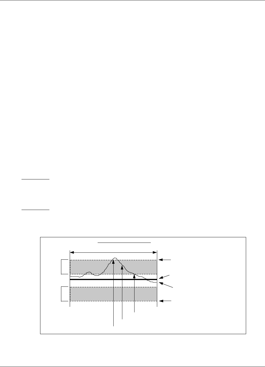
Setpoint Profiler
Video Recorder – User Manual 182
Soak segment
All soak segments have a beginning VALUE and a TIME during which that value is maintained. This is
true regardless of the ramp type used.
Guaranteed Soak
Guaranteed soak will Hold the profile value if either PV to the profile (typically a Control Loop’s PV)
deviates specified amounts above or below the profiler output. See Figure 5-7. For a guaranteed soak
to occur, the following conditions must be met:
1. The GUAR SOAK #1 and GUAR SOAK #2 prompts for the segment (ramps and soaks) must be
enabled (set to ON),
and
2. The GUARANTEED SOAK discrete input to the profile must be enabled (level high).
If either of these are disabled, a guaranteed soak cannot occur, even with excessive deviation between
profile and PV.
Hysteresis
This parameter specifies the amount the deviation between profile and PV must be reduced before the
profile resumes running after a guaranteed soak. See Figure 5-7.
After a guaranteed soak the profile will resume running when the deviation has decreased by this
amount.
The following examples assume GUARANTEED SOAK is ON(1), and the example segment’s GUAR
SOAK #1 is ON(1).
Example #1
Assume PV #1 is 20 units above the profile output, GUAR SOAK HI LIM is 15, HYSTERESIS is 5. The
profile will Hold because the deviation high limit is exceeded. The profile will resume running when the
PV #1 is 10 (15-5) units or less above the profile output.
Example #2
Assume PV #1 is 20 units below the profile output, GUAR SOAK LO LIM is 15, HYSTERESIS is 5. The
profile will Hold because the deviation low limit is exceeded. The profile will resume running when the
PV #1 is 10 (15-5) units or less below the profile output.
Setpoint (VALUE of profile)
Guaranteed Soak High Limit
Guaranteed Soak Low Limit
Hysteresis
Hysteresis Process Variable (PV#1)
Profile Segment “n”
Excessive deviation - Profile changes to HOLD State
Returned below limit and hysteresis - Profile resumes RUN
Guaranteed Soak Limit Check Guaranteed Soak (Segment “n”) = ON
AND
Guaranteed Soak (Profile) = ON
Setpoint deviation still within hysteresis - still on HOLD
Figure 5-7 Guaranteed Soak and Hysteresis
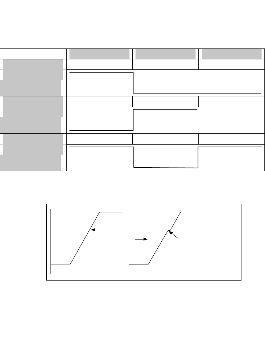
Setpoint Profiler
Video Recorder – User Manual 183
Segment Events
Each segment contains 16 programmable discrete event outputs whose ON/OFF states- specified by
you -can be used to trigger other discrete functions. The segment’s event states are activated at the
beginning of the segment and are maintained unless changed by the next segment in the profile. See
Table 5-1. The last segment’s event states are maintained after the profiler is ended.
Table 5-1 Example of Segment Events
Segment #1 Segment #2 Segment #3
Event 1 State 1 (ON) 0 (OFF) 0 (OFF)
Event 2 State 0 (OFF) 1 (ON) 0 (OFF)
Event 3 State 1 (ON) 0 (OFF) 1 (ON)
To activate events in the middle of a ramp segment, replace the desired segment with 3 segments: a
ramp, a very short soak, and another ramp. Program the second and third segment events as if they
were the middle of the segment.
To activate events here
Program this: Short soak segment
with desired events
Ramp segment
Same events as short soak
Ramp segment
Program both ramps with same slope.
Figure 5-8 Activating Events In Mid-Segment
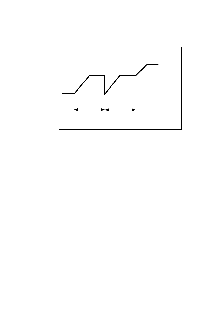
Setpoint Profiler
Video Recorder – User Manual 184
Segment Loops
You can program up to four segment loops within a profile. A segment loop is one or more consecutive
segments which must repeat a selected number of times before proceeding to the next segment outside
of the loop.
Segment loops are specified by the parameters REPEAT COUNT, FROM SEGMENT #, and TO
SEGMENT #. Loops are reset when Auto Cycle is reset and when the profile is reset. Loops can
contain other loops but cannot overlap.
Loop#1
From Segment # 2
To Segment #3
Repeat Count = 1
Segment #2
Segment #3
Segment #1
Segment #2
Segment #3
Segment #4
Segment #5
Repeated segments
Figure 5-9 Example Of A Segment Loop
Examples of valid loops
Loop #1: LOOP FROM SEGMENT = 1
LOOP TO SEGMENT = 10
Loop #2: LOOP FROM SEGMENT = 1
LOOP TO SEGMENT = 9
Loop #1: LOOP FROM SEGMENT = 1
LOOP TO SEGMENT = 10
Loop #2: LOOP FROM SEGMENT = 2
LOOP TO SEGMENT = 10
Loop #1: LOOP FROM SEGMENT = 1
LOOP TO SEGMENT = 10
Loop #2: LOOP FROM SEGMENT = 2
LOOP TO SEGMENT = 9
Example of invalid (overlapping) loops
Loop #1: LOOP FROM SEGMENT = 1
LOOP TO SEGMENT = 9
Loop #2: LOOP FROM SEGMENT = 2
LOOP TO SEGMENT = 10

Setpoint Profiler
Video Recorder – User Manual 185
5.3 Parameters that control a profile’s execution
Coordinating operation of multiple profilers
In a multi-profiler instrument the profiles in a program can be totally unrelated to each other, that is, you
can give them different times and settings. If you want the profilers to be coordinated, you must
configure each profiler that way. For example, if you want all your profilers to be started by the same
signal, you must configure each profiler with the same START parameter. The Copy Block function in
the Program menu lets you copy parameters from one profiler to another.
SPP synchronization
Allows a multiple SPP user to synchronize several SPPs for when one enter hold due to a guaranteed
hold, the others will enter hold and when the one that entered hold leaver hold the others will leave hold
also. This is done by using a block output status called SG (status guaranteed hold) that is high when
the block is in guaranteed hold mode. If different SPPs are used, the SPPx SG outputs should run
through an OR block and then the output of the OR block back to the SPPx HOLD input. The SG status
output may be viewed on the discrete status screen.
Discrete inputs
You can program a profiler with discrete inputs that enable you to reset, start, hold, advance, shut down,
or fast forward through the profiler, hot start the profiler from a live process variable, increment a ramp
segment, or enable/disable guaranteed soak. See Table 5-2.
Note that some discretes are edge-sensitive and some are level-sensitive. Edge-sensitive means that
the action is triggered by the discrete’s transition from OFF to ON (rising edge) or from ON to OFF
(falling edge). The changing status is what triggers the action, not the status itself. Some discretes,
such as START, are rising edge-sensitive only and are not affected by a falling edge. When START’s
discrete goes ON, the profiler starts to run; when the discrete goes OFF, the profiler continues running.
Level-sensitive means that one action occurs while the discrete is ON and another action occurs while
the discrete is OFF. The status is what causes the action, not the changing status. Fast forward’s
discrete is level-sensitive; that is, the profiler will run in fast forward while the discrete is ON but not
while it is OFF.
Table 5-2 Parameters That Control Profiler Execution
Paramet
er name Definition Triggere
d by Conditions
present Result
START Starts Profiler from Ready, Hold, or End state.
Activated by operator menu or by discrete input.
May be connected to the F1 key (SY1F1).
Rising
edge Profiler in Ready or
End state Profiler
starts to
Run.
RESET/
RUN The behavior of this parameter depends on START.
If the START discrete input is programmed with a
discrete, then switching RESET/RUN from OFF to
ON resets an Ended, Hold, or Ready profiler to the
starting value of segment 1.
Rising
edge Start is
programmed with a
discrete parameter
& profiler is in
Ready or Hold or
End
Profiler
changes to
Ready and
goes to
Segment
#1.
If the START discrete input parameter is not
programmed with a discrete, then switching
RESET/RUN from OFF to ON resets an Ended,
Hold, or Ready program to the starting value of
segment 1 and to the profiler’s Ready state. On a
transition from ON to OFF, starts an Ended profiler.
Rising
edge START is not
programmed with a
discrete parameter
& profiler is in
Ready or Hold or
End
Profiler
changes to
Ready and
goes to
Segment
#1.
RESET/RUN does not affect a running program.
May be connected to the F3 key (SY1F3).
Falling
edge START is not
programmed with a
discrete parameter
& profiler is at End
Profiler
goes to
Segment #1
and starts
to Run.

Setpoint Profiler
Video Recorder – User Manual 186
Table 5-2 Parameters That Control Profiler Execution (continued)
Parameter name Definition Triggered
by Conditions
present Result
HOLD Holds a profiler at its current position.
Profiler’s Elapsed Time continues but
Segment Time stops until Profiler is started
again.
Hold is activated by online operator menu or
by a discrete input. May be connected to F2
key (SY1F2).
Level ON Profiler is in
Run or Hold Profiler is
put in Hold
ADVANCE Advances a profiler on Hold to the starting
value of the next segment. If the profile is on
the last segment, it advances to the ending
value of the last segment. If the profile is on
the ending value of the last segment of the
batch, then it advances around to the starting
value of segment 1, or to the first segment of
the batch phase as defined by BATCH
SEGMENT FIRST. If within a loop, advances
to next segment in the loop.
Advance is activated by online operator menu
or by a discrete input.
Rising
edge Profiler is in
Hold Profiler
advances
HOT START When HOT START is ON and the profiler is
started, the profiler begins to run at the point
in the profile where the current value of PV #1
first occurs. Hot Start makes the profiler skip
over unneeded segments.
Hot Start is activated by a discrete input.
Example
If PV #1 is 100 and the profile contains the
value 100 in Segment 4 and Segment 6, HOT
START forces the profiler to start running at
Segment 4 at 100, not at Segment 1 or
Segment 6.
See Figure 5-10 Hot Start.
Level ON Profiler is in
Ready When
profiler
changes
from Ready
to Run,
profiler
jumps to
the same
value as
PV #1
PV#1 Profile starts here
If Hot Start = ON, Profile starts at first intersecting point between profile and PV #1.
Figure 5-10 Hot Start
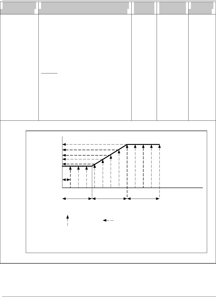
Setpoint Profiler
Video Recorder – User Manual 187
Parameter name Definition Triggered
by Conditions
present Result
FAST
FORWARD FAST FORWARD is a way to test for proper
functioning of the profiler’s events and
outputs, without having to wait for the profiler
to execute at its normal speed.
When FAST FORWARD is ON, the profiler will
run at a speed determined by the TIME
MULTIPLIER parameter. The higher the time
multiplier, the faster the profiler will run.
Fast Forward is activated by a discrete input.
Example
The Programmer is running at a 500msec
scan rate. The TIME MULTIPLIER is set to
60. Therefore the profiler will run 60 times
faster than normal. The profiler will increment
in (500msec x 60) or 30 second increments.
Put another way, every half-second the profiler
will advance 30 seconds.
See Figure 5-11 Fast Forward.
Level ON When in
Run mode,
profiler
runs at
Fast
Forward
speed.
100
Normal time of segment: 110 seconds 130 seconds 120 seconds
107
130
150
175
200
Time Multiplier = 60
Scan Rate of machine = 500 msec
Therefore, every half second the profile is incremented 30 seconds
Segment #2 begins between samples. Segment #2's events not recognized until next scan cycle.
= profile is sampled
Sample interval
60 x 500 msec
= 30 seconds
Fast forward time: < 2 seconds > 2 seconds 2 seconds
Values sampled at each
scan during fast forward
= sampled value
Figure 5-11 Fast Forward
Setpoint Profiler
Video Recorder – User Manual 188
Parameter name Definition Triggered
by Conditions
present Result
SHUTDOWN When Shutdown is activated by a discrete
input or by the operator menu, the profiler
jumps from the batch phase to the shutdown
phase of a multiphase profile. The shutdown
phase begins at the segment defined by the
parameter BATCH LAST SEGMENT+1.
Shutdown is useful when you need to shut
down your process without waiting for the
profiler to finish a batch.
Example
BATCH FIRST SEGMENT, which specifies the
start of the batch phase of the profile, is set at
Segment 3. The last segment of the batch
phase, BATCH LAST SEGMENT, is set at
Segment 7. The last segment of the profile is
Segment 9. When SHUTDOWN changes
from OFF to ON, the profiler will jump to
Segment 8, the first segment of the shutdown
phase of the profile.
See Figure 5-12 Shutdown
Rising
edge Profiler is in
Run, Hold, or
End
Profiler
jumps to
BATCH
LAST
SEGMENT
+ 1
Batch SegmentsStartup Segments Shutdown Segments
BATCH FIRST SEGMENT BATCH LAST SEGMENT
BATCH LAST SEGMENT + 1
END (batch)
END (shutdown)
Figure 5-12 Shutdown
RAMP
INCREMENT See External Ramp Type on page 180. Rising
edge Profiler is in
Run mode &
RAMP TYPE
of profiler is
External
Profiler
increments
by amount
specified
by the
segment’s
TIME.

Setpoint Profiler
Video Recorder – User Manual 189
Parameter name Definition Triggered
by Conditions
present Result
GUARANTEED
SOAK See Guaranteed Soak on page 182. Level ON Excessive
deviation
between
profiler and
PV #1 or PV
#2 & the
segment’s
GUAR SOAK
#1 or GUAR
SOAK #2 is
enabled.
Profiler is
put on Hold
HOLD
LEVEL/EDGE
EDIT Grants access to the profile’s segments
edition page, see table 5-5.
5.4 How to set up a profiler
Up to 4 profilers can be programmed, depending on the options on your instrument. There are two
menus for programming a profiler: PROGRAM PROFILERS in the Program menu, and SETPOINT
PROFILES in the Online menu. Both must be accessed to program a profiler. Both menus are
described in this section.
Program Profilers menu (in Program mode)
This menu lets you define various parameters for controlling the profiler’s execution. To access the
Program Profilers menu:
1. Press the Menu button until a main menu is displayed.
2. Select Set Mode and change the mode to Program.
3. Select Program Profilers.
4. Select a profiler (#1 through #4) to program. Only profilers that are not actively running are
selectable.
Table 5-3 briefly describes the prompts for all profilers. For detailed descriptions, refer to Sections 5.2
and 5.3. See Table 4-2 for additional prompts.

Setpoint Profiler
Video Recorder – User Manual 190
Table 5-3 Program Profiler Prompts
Prompt Range/Selections Definition
DISPLAY LO LIM OFF or number Enter the lower limit for the SP Trend
display. Allow for the maximum and
minimum Profiler and PV values.
DISPLAY HI LIM OFF or number Enter the upper limit for the SP Trend
display, allowing for the maximum and
minimum Profiler and PV values.
PV #1 OFF, analog parameter, number Program the profiler to monitor a process
variable. PV #1 is trended on the SP
Trend display. PV #1 is compared to the
profiler’s value to determine deviation.
Excessive deviation between PV #1 and
profiler value can cause a Hold
(guaranteed soak).
PV #2 OFF, analog parameter, number This is an optional PV that can also be
monitored and can be used to determine
deviation from profiler value. PV #2 is
shown on SP Trend display’s Point/Detail
menu. PV #2 is also trended on SP Trend
display.
START Discrete parameter, 1, 0, or OFF See Start on page 185.
RESET/RUN Discrete parameter, 1, 0, or OFF See Reset/Run on page 185.
HOLD Discrete parameter, 1, 0, or OFF See Hold on page 186.
ADVANCE Discrete parameter, 1, 0, or OFF See Advance on page 186.
HOT START Discrete parameter, 1, 0, or OFF See Hot Start on page 186.
FAST FORWARD Discrete parameter, 1, 0, or OFF See Fast Forward on page 187.
SHUTDOWN Discrete parameter, 1, 0, or OFF See Shutdown on page 188.
RAMP INCREMENT Discrete parameter, 1, 0, or OFF See External Ramp Type on page 180.
GUARANTEED SOAK Discrete parameter, 1, 0, or OFF See Guaranteed Soak on page 182.
HOLD LEVEL/EDGE LEVEL or EDGE Select LEVEL to Hold the profiler while
the Hold discrete is Level ON, and
resume Run when the Hold discrete is
Level OFF.
Select EDGE to Hold the profiler after the
Hold discrete changes from OFF to ON,
and resume Run after the Start discrete
changes from OFF to ON.

Setpoint Profiler
Video Recorder – User Manual 191
Setpoint Profiles Menu (in Online mode)
This menu lets you define profile ramp and soak segments and associated parameters, and store and
load programs to and from floppy disk or memory. See Figure 5-13 for allowable and non-allowable
storage.
To access the Setpoint Profiles menu:
1. Press the Menu button until a main menu is displayed.
2. Select Set Mode and change the mode to Online.
3. Select Setpoint Profiles.
4. Select a profile (#1 through #4) to program.
Table 5-4, Table 5-5, Table 5-6 and describe the Setpoint Profile prompts.
Table 5-4 Setpoint Profiles Prompts
Prompt Range/Selections Definition
EDIT PROFILE #1
EDIT PROFILE #2
EDIT PROFILE #3
EDIT PROFILE #4
Select a profile to edit. See Table 5-5 for
prompts.
STORE PROGRAM TO
DISK STARTING PROFILE # Select 1-4.
Select the lowest numbered profile to be
stored; that is, Profile 1, 2, 3, or 4. See How
programs are stored on a disk on page 200
for details.
NUMBER OF PROFILES Select 1-4.
Number of profiles (1, 2, 3, or 4) determines
how many profiles will be stored, starting with
the Starting Profile #. For example, if Starting
Profile # is 1 and Number of profiles is 3,
then Profiles 1, 2, and 3 are stored. See How
programs are stored on a disk on page 200
for details.
FILE Select the filename and number. Filename
extension is .LNS. After you select the
number and press Enter, the profile(s) are
stored to disk.
FILES ON DISK Lists all files on the disk.
STORE PROGRAM TO
MEMORY PROGRAM NUMBER
Select 1-12.
There are up to 96 “slots” allotted for profile
memory storage. Depending on how many
profiles your instrument has, each program
will contain a certain number of profiles. See
How programs are stored to memory on page
198 for details.
STORE PROGRAM TO MEMORY Select this to store program to memory.
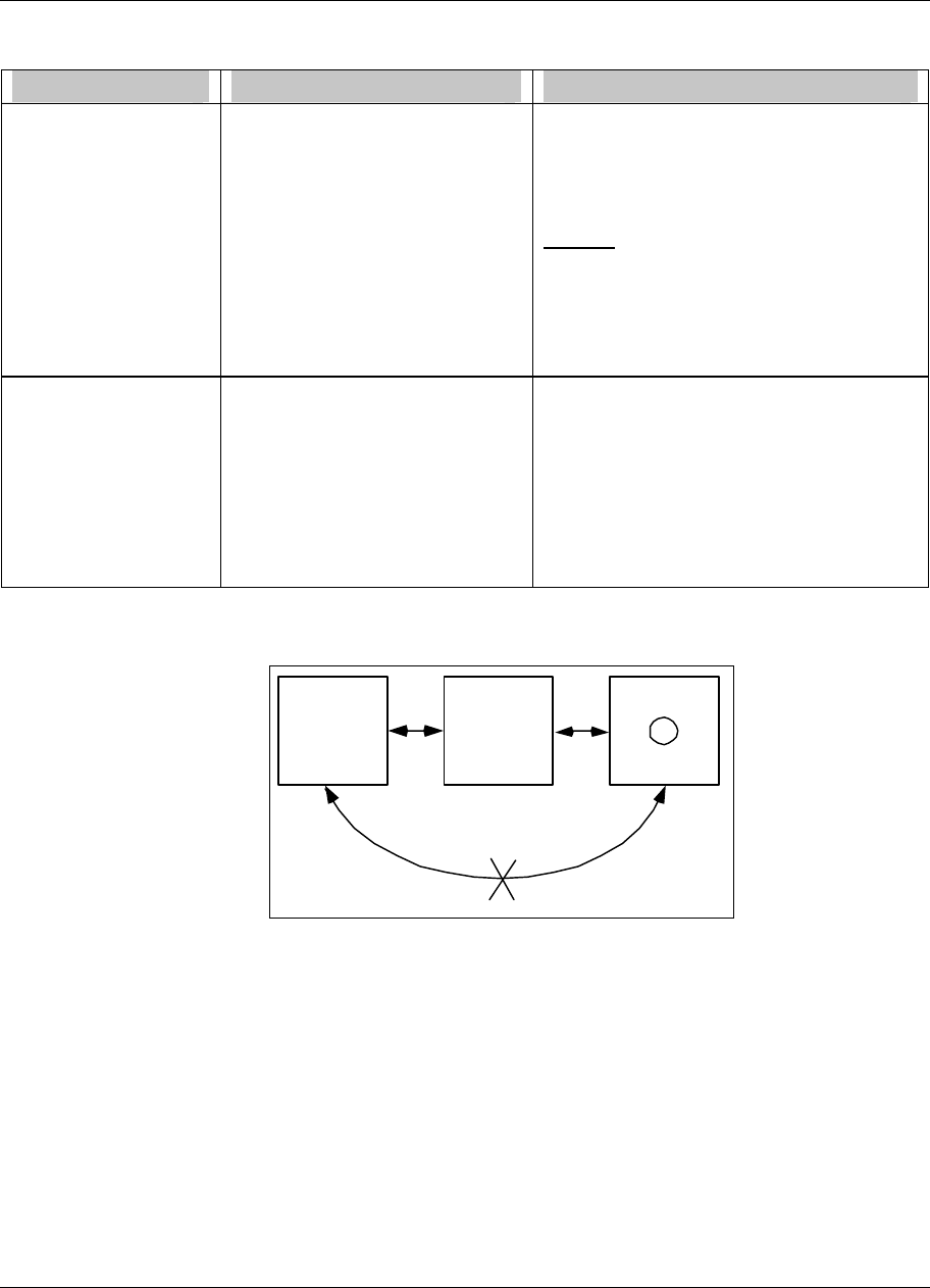
Setpoint Profiler
Video Recorder – User Manual 192
Table 5-4 Setpoint Profiles Prompts (continued)
Prompt Range/Selections Definition
LOAD PROGRAM
FROM DISK Files with .LNS extension. Select a program to load into the Setpoint
Profiler function block. Press Enter to load.
Existing profiles in the instrument will be
replaced by the profiles in the program being
loaded.
Example
You are loading Program1.LNS which
contains Profiles #1, #2, and #3. These
profiles will replace the profiles currently set
up in the instrument. Profile #4 will not be
replaced.
LOAD PROGRAM
FROM MEMORY PROGRAM NUMBER
Select a program 1-96 to load into the
Setpoint Profiler function block.
There are up to 96 “slots” allotted for program
memory storage. Depending on how many
profiles your instrument has, each program
will contain a certain number of profiles.
See How programs are stored in memory on
page 198 for details.
Program
Memory Profile
Function
Block
Floppy
Disk
Not allowed
Figure 5-13 Allowable and Non-Allowable Program Storage

Setpoint Profiler
Video Recorder – User Manual 193
Table 5-5 Edit Profile Prompts
Prompt Range/Selections Definition
RAMP TYPE VAL/DUR, TIME, RATE,
EXTERNAL See 4 types of ramp segments on page 178.
TIME UNITS SECS, MINS, HOURS Select the time units to be used by all segments
of the profile.
EDIT SEGMENTS See Table 5-6.
GUAR SOAK LO LIM OFF or number The profiler will Hold if PV #1 or PV #2 deviates
more than this much below the profiler output.
See Guaranteed Soak on page 182 for details.
GUAR SOAK HI LIM OFF or number The profiler will Hold if PV #1 or PV #2 deviates
more than this much above the profiler output.
See Guaranteed Soak on page 182 for details.
HYSTERESIS OFF or number See Hysteresis on page 182 for details.
BATCH FIRST
SEGMENT 0-63 Specify the first segment of the batch phase.
Prior segments are the start-up phase. A value
of 0 indicates a single phase profile. See Two
types of profiles on page 177 for details.
BATCH LAST
SEGMENT 0-63 Specify the last segment of the batch phase.
Segments after this segment are the shutdown
phase. A value of 0 indicates a single phase
profile. See Two types of profiles on page 177
for details.
(continued)

Setpoint Profiler
Video Recorder – User Manual 194
Table 5-5 Edit Profile Prompts (continued)
Prompt Range/Selections Definition
AUTO CYCLE OFF, ON Select ON to have the profile (or batch phase if
defined) repeat AUTO CYCLE COUNT times.
Automatically re-runs the profile when ON. The
parameter AUTO CYCLE COUNT controls the
number of additional cycles through the profile.
When AUTO CYCLE is ON and AUTO CYCLE
COUNT is zero (0), the profile will cycle forever.
For a single phase profile, the profiler must
progress to the END state before cycling back
to segment 1. Once the profiler is ENDed, the
automatic cycling function will change the
profiler to the READY state for one machine
cycle (clearing the profiler’s discrete outputs)
before proceeding to the RUN state. The
elapsed time of the profiler will continue due to
re-cycling.
For a multiphase profile, the profiler must
progress to the END state following segment
BATCH LAST SEGMENT before cycling back to
the BATCH FIRST SEGMENT. Once the
profiler is ENDed, the automatic cycling
function will change the profiler to the RUN
state. The elapsed time of the profiler will
continue running during recycling.
AUTO CYCLE COUNT 0-254 0: the profile (or batch) will repeat forever.
1-254: the profile (or batch) will repeat this
many times.
EDIT PROFILE LOOPS LOOP #1-4
FROM SEGMENT # 1-63
TO SEGMENT # 1-63
REPEAT COUNT 1-999
Define up to 4 loops per profile. Note that the
repeat count is the number of loop repetitions,
not the number of loop executions. See Loop
Segments on page 184 for details.
JUMP FROM
SEGMENT 0-63 The profile can be forced to jump from any
segment to any other segment. A jump within a
loop will continue that loop. A jump outside a
loop will exhaust that loop. A jump outside the
batch phase will exhaust any auto cycling in
effect.
At the completion of this segment, the profiler
will jump to the beginning of JUMP TO
SEGMENT.
JUMP TO SEGMENT 0-63 At the completion of JUMP FROM SEGMENT,
the profiler will jump to the beginning of this
segment.

Setpoint Profiler
Video Recorder – User Manual 195
Table 5-5 Edit Profile Prompts (continued)
Prompt Range/Selections Definition
TIME MULTIPLIER Number Time Multiplier determines the speed at which
the profiler will run when in Fast Forward mode.
It is used for testing the profiler’s execution.
See Fast Forward.
When FAST FORWARD is ON(1), the profiler
will run at a speed determined by the TIME
MULTIPLIER parameter.
Example
The instrument is running at a 500msec scan
rate. The TIME MULTIPLIER is set to 60.
Therefore the profiler will run in (500msec x 60)
or 30 second increments.
Running a profiler in FAST FORWARD is a way
to check for proper functioning of the profiler’s
events and outputs, without having to wait for
the profiler to execute at its normal speed.
See Figure 5-11.

Setpoint Profiler
Video Recorder – User Manual 196
Editing Segments
Use the following prompts to map out each segment’s value, time, and events. Up to 63 segments are
programmable per profile.
Table 5-6 Edit Segments Prompts
Prompt Range/Selections Definition
NEXT SEGMENT Select this to edit the next segment.
PREVIOUS SEGMENT Select this to edit the previous segment
VALUE OFF or number This prompt is active for soak segments
and value/duration ramp types. Enter the
value of the segment.
AUX VALUE OFF or number This value is an auxiliary soak output of
the profile. The output is identified as
SPn A1 and remains constant for the
duration of the segment.
TIME OFF or Positive number The purpose of the number entered here
depends on the ramp type of the profile.
See 4 types of ramp segments on page
178 for details.
GUAR SOAK #1 ON or OFF ON means the profiler will Hold during this
segment if deviation between PV #1 and
the profiler output exceeds the
guaranteed soak limits in Table 5-5. OFF
means the profiler will not Hold during this
segment due to deviation. See
Guaranteed Soak on page 182 for details.
GUAR SOAK #2 ON or OFF ON means the profiler will Hold during this
segment if deviation between PV #2 and
the profiler output exceeds the
guaranteed soak limits in Table 5-5. OFF
means the profiler will not Hold during this
segment due to deviation. See
Guaranteed Soak on page 182 for details.
EDIT EVENTS EVENT #1
.
.
.
EVENT #16
Enter the state of up to 16 discrete
outputs of this segment. These outputs
can be used to trigger any action requiring
a discrete signal, such as a relay or
another function block.
An event stays on or off for the entire
segment.
To trigger events in the middle of a
segment, you must divide the segment
into 3 segments. See Segment Events on
page 183 for details.
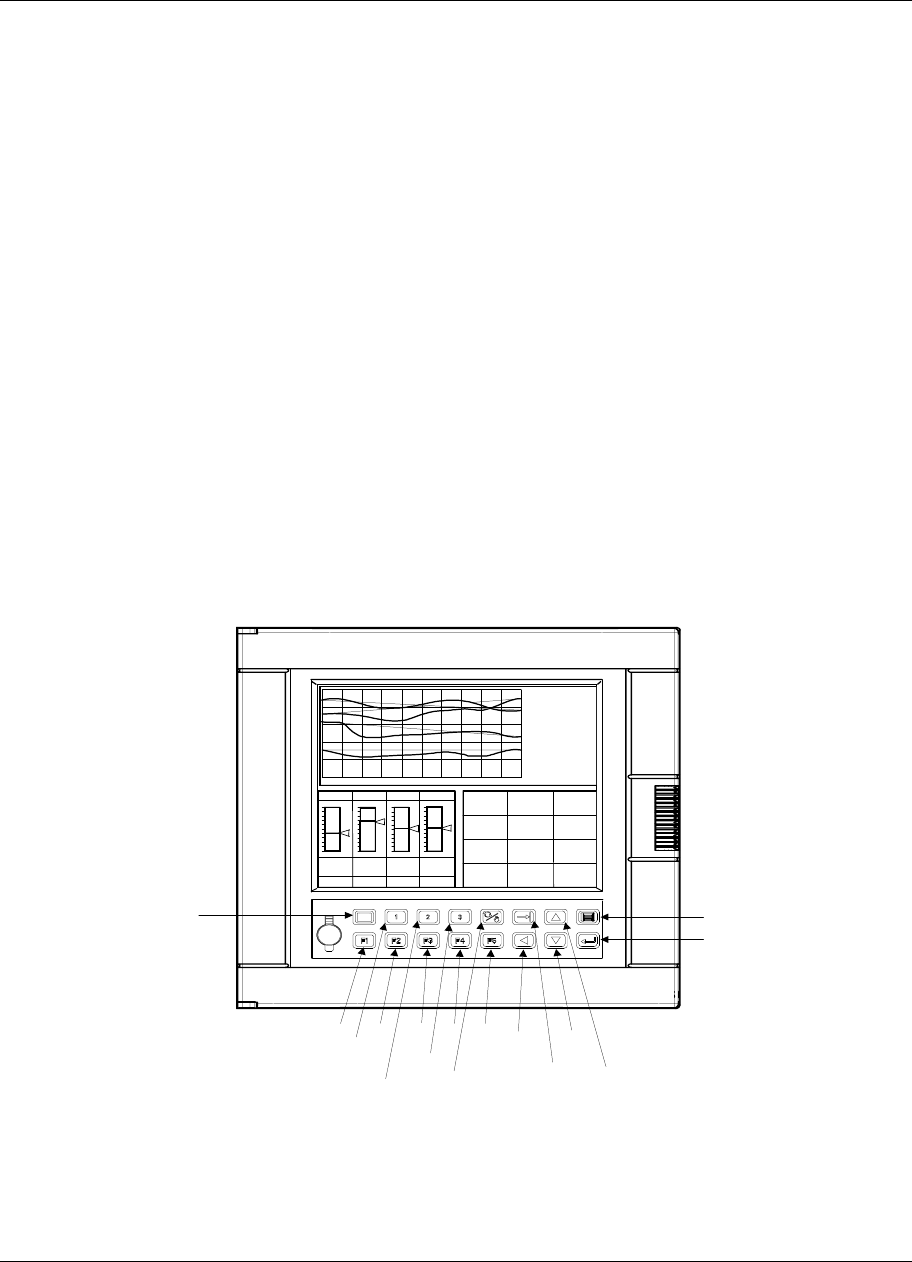
Setpoint Profiler
Video Recorder – User Manual 197
5.5 How to load and run a profiler
Overview
From the Setpoint Profile Trend’s menu you can:
• load a profiler from memory
• load a profiler from storage media
• start a profiler
• hold a profiler
• reset a profiler
• advance a profiler
• shut down a profiler
• view profiler events
• view profiler details (profiler elapsed time, segment time remaining, profiler length in seconds, PV
#2 value)
• edit profile segments,
• view various profiler displays.
All these tasks can be done using the front panel buttons shown in Figure 5-14. The procedures are
explained in the next several pages.
Display 1
Display 2
Display 3
Auto/
Manual
Tab Up
Arrow
Down
Arrow
F1 F2 F3
Display
Left
Arrow
Menu
Enter
F4 F5
PV 405.00
SP 405.00
OUT 15 .0
A S1
LP1
1000.00
0.00
LP2
1500.00
0.00
1054.00
1040.00
10.0
M S2
LP4
2400.00
0.00
1266.00
1244.00
5.0
A S1
LP3
1200.00
0.00
623.00
622.00
5.0
M S1
TAG1
VALUE1
TAG2
VALUE2
TAG3
VALUE3
TAG4
VALUE4
TAG5
VALUE5
TAG6
VALUE6
TAG7
VALUE7
TAG8
VALUE8
TAG9
VALUE9
TAG10
VALUE10
TAG11
VALUE11
TAG12
VALUE12
ZONE1
123.45
DEG F
ZONE2
123.45
DEG C
ZONE3
123.45
DEG F
ZONE4
123.45
DEG F
ZONE5
123.45
DEG F
ZONE6
123.45
DEG C
ZONE7
123.45
DEG F
ZONE8
123.45
DEG C
ZONE9
123.45
DEG F
ZONEA
123.45
DEG F
ZONEB
123.45
DEG
ZONEC
123.45
DEG F
Figure 5-14 Buttons

Setpoint Profiler
Video Recorder – User Manual 198
ATTENTION
The following procedures assume the instrument has been programmed to display the Setpoint Profiler as a
trend. To program displays, see section 4.18 Program Displays.
How to load programs from memory using Online menu
Programs stored in memory are identified by number (1-48) depending on instrument model number.
Each program stored in memory contains one to four profiles, depending on your instrument. See
Table 5-7.
For example, on an instrument with 3 profiles, you can store Program #1 which contains Profiles #1, #2,
and #3.
Table 5-7 How Profiles Are Stored In Memory
1-programmer
instrument
1 Profile per Program
2-programmer
instrument
2 Profiles per Program
3-programmer
instrument
3 Profiles per Program
4-programmer
instrument
4 Profiles per Program
This
Program… …contains
this Profile This
Program… …contains
these
Profiles
This
Program… …contains
these
Profiles
This
Program… …contains
these
Profiles
1 1 1 1 1 1 1 1
2 1 2 2 2
3 1 2 1 3 3
4 1 2 2 1 4
5 1 3 1 2 2 1
6 1 2 3 2
7 1 4 1 3 1 3
8 1 2 2 4
9 1 5 1 3 3 1
10 1 2 4 1 2
11 1 6 1 2 3
12 1 2 3 4
• • • •
• • • •
• • • •
45 1 23 1 • 12 1
46 1 2 16 1 2
47 1 24 1 2 3
48 1 2 3 4

Setpoint Profiler
Video Recorder – User Manual 199
Table 5-8 Procedure To Load A Program From Memory Using Online Menu
Step Action Result/Notes
1 Press the Display button to change to online
mode. An online display is shown.
2 Press the Menu button to display the online
menu. Online menu is displayed.
3 Press Decrement button to highlight Setpoint
Profiles. Cursor moves down.
4 Press Enter. Setpoint Profiles menu is displayed.
5 Press Decrement button to highlight Load
Program From Memory. Prompt is highlighted.
6 Press Enter. Load Program sub-menu is displayed.
7 Press Enter to select Program Number prompt. Cursor moves to the right.
8 Press Increment or Decrement to select the
desired program number to be loaded. Program number is displayed.
9 Press Enter to select. Program number is selected.
10 Press Enter again to load. Program is loaded from the disk to the
instrument.
Table 5-9 Procedure To Load A Program From Memory Using Point/Detail Menu
Step Action Result/Notes
1 Press the Display button to change to online
mode. An online display is shown.
2 Press the Tab button to display the Point/Detail
menu. Online menu is displayed.
3 Press Decrement button to highlight Setpoint
Profiles. Cursor moves down.
4 Press Enter. Setpoint Profiles menu is displayed.
5 Press Decrement button to highlight Load
Program From Memory. Prompt is highlighted.
6 Press Enter. Load Program sub-menu is displayed.
7 Press Enter to select Program Number prompt. Cursor moves to the right.
8 Press Increment or Decrement to select the
desired program number to be loaded. Program number is displayed.
9 Press Enter to select. Program number is selected.
10 Press Enter again to load. Program is loaded from the disk to the
instrument.
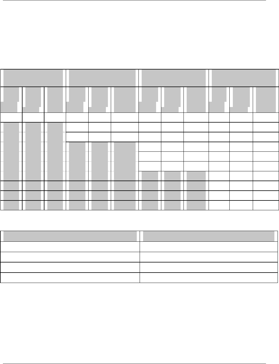
Setpoint Profiler
Video Recorder – User Manual 200
How programs are stored on a disk
Programs are saved to disk as a file name, number, and .LNS extension. Unlike memory storage, you can
specify which profiles you want stored as a program. Disk capacity depends on the number of profiles in the
program. See Table 5-11.
For example, on a 4 Programmer instrument, if you want to store Profiles #2, #3, and #4 as a program, you
enter 2 at the prompt STARTING PROFILE #, to indicate that the lowest numbered profile to be stored will be
Profile #2. At the prompt NUMBER OF PROFILES, you enter 3 to indicate that 3 profiles will be stored.
Table 5-10 shows all possible combinations of profiles that can be stored to disk.
Table 5-10 How Profiles Are Stored On Disk
1 Programmer Instrument
1 Profile per Program
2 Programmer Instrument
Up to 2 Profiles per Program
3 Programmer Instrument
Up to 3 Profiles per Program
4 Programmer Instrument
Up to 4 Profiles per Program
Starting
Profile # Number
of
Profiles
Program
contains
this
profile
Starting
Profile # Number
of
Profiles
Program
contains
these
profiles
Starting
Profile # Number
of
Profiles
Program
contains
these
profiles
Starting
Profile # Number
of
Profiles
Program
contains
these
profiles
1 1 1 1 1 1 1 1 1 1 1 1
2 1 2 2 1 2 2 1 2
1 2 1, 2 3 1 3 3 1 3
1 2 1, 2 4 1 4
2 2 2, 3 1 2 1, 2
1 3 1, 2, 3 2 2 2, 3
3 2 3, 4
1 3 1, 2, 3
2 3 2, 3, 4
1 4 1, 2, 3, 4
Table 5-11 Disk Program Capacity
Number of Profiles in Program Maximum Disk Capacity
1 224 programs
2 199 programs
3 138 programs
4 100 programs

Setpoint Profiler
Video Recorder – User Manual 201
How to load a program from disk
Table 5-12 Procedure To Load A Program From Disk
Step Action Result/Notes
1 Press the Display button to change to online
mode. An online display is shown.
2 Press the Menu button to display the online
menu. Online menu is displayed.
3 Press Decrement button to highlight Setpoint
Profiles. Cursor moves down.
4 Press Enter. Setpoint Profiles menu is displayed.
5 Press Decrement button to highlight Load
Program From Disk. Prompt is highlighted.
6 Press Enter. Load Program sub-menu is displayed.
7 Press Increment or Decrement to highlight
desired program file. Program is highlighted.
8 Press Enter to select. Press Enter again to
load. Program is loaded from the disk to the instrument.
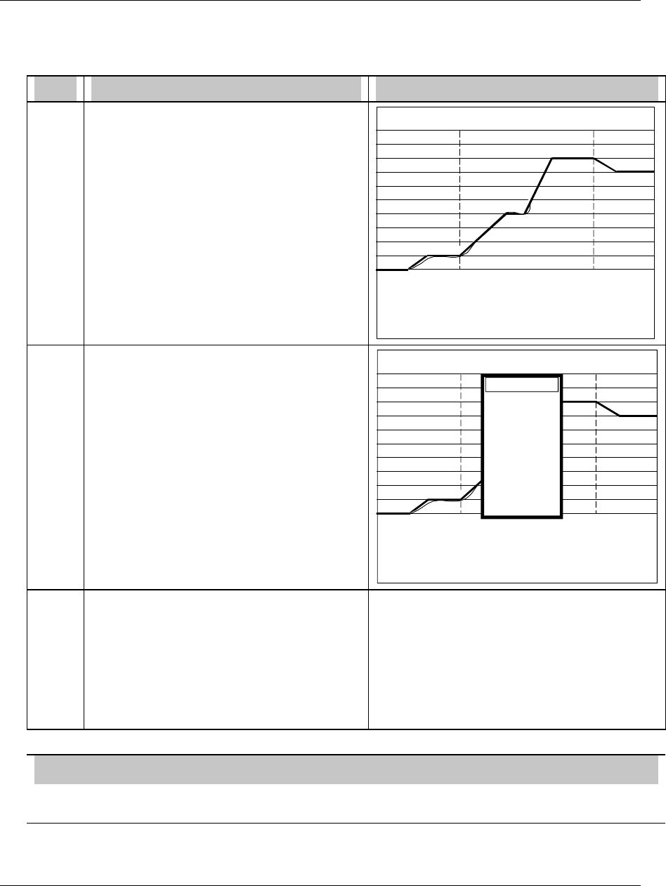
Setpoint Profiler
Video Recorder – User Manual 202
How to start a profiler
A profiler can be started from the Ready, Hold or End state.
Table 5-13 Profiler Starting Procedure
Step Action Result/Notes
1 Press Display button until the Setpoint Trend
is displayed. SP1 PROFIL01 500.00
PV 0.00
SP 0.00
0.00
0:00:00
SEG1/9 READY
2 Press Tab button to display the profile menu. SP1 500.00
PV 0.00
SP 0.00
0.00
0:00:00
SEG1/9 READY
START
HOLD
RESET
ADVANCE
SHUTDOWN
EVENTS
DETAIL
SUMMARY
EDIT
LOAD
PROFIL01
3 Cursor is on Start. Press Enter. Profiler starts running at segment #1 if in Ready
or End or resumes running from its Hold state. If
in Ready state and Hot Start has been activated,
profiler will start at the first point in the profile
where the present value of PV #1 occurs. Event
outputs assume their states as of the beginning of
the running segment. Profiler status on lower
right of display indicates RUN after you start the
profiler.
ATTENTION
A profile can also be started by pressing the F1 button, but only if that profile’s START parameter was
configured as SY1 F1. See Section 5.4.

Setpoint Profiler
Video Recorder – User Manual 203
How to hold a profiler
Table 5-14 Profiler Hold Procedure
Step Action Result/Notes
1 Perform steps 1 and 2 from Start procedure
(Table 5-13). Profile menu is displayed.
2 Press Decrement button to move cursor to
Hold. Press Enter. The profiler is held at its present value and the
segment’s events are frozen. Elapsed time
continues. Run time stops. Events are held at
their current states.
ATTENTION
A profile can also be put on HOLD by pressing the F2 button, but only if that profile’s HOLD parameter was
configured as SY1 F2. See Section 5.4.
How to reset a profiler
Table 5-15 Profiler Reset Procedure
Step Action Result/Notes
1 Place profiler in Hold. See Profiler Hold procedure inTable 5-14.
1 Perform steps 1 and 2 from Start procedure
(Table 5-13). Profile menu is displayed.
2 Press Decrement button to move cursor to
Reset. Press Enter. Profiler is reset to segment #1. All profiler timers
are reset. All events go OFF. Profiler output
goes to starting value of segment #1.
ATTENTION
A profile can also be RESET by pressing the F3 button, but only if that profile’s RESET/RUN parameter was
configured as SY1 F3. See Section 5.4.

Setpoint Profiler
Video Recorder – User Manual 204
How to advance a profiler to the next segment
Table 5-16 Profiler Advance Procedure
Step Action Result/Notes
1 Place profiler in Hold. See Profiler Hold procedure inTable 5-14.
2 Press Decrement button to move cursor to
Advance. Press Enter. Profiler advances to next segment. Each press of
Enter advances the profiler one segment. If at
the last segment, the profiler advances to the first
segment. If it is a multiphase profile, the profiler
advances within the batch phase only. Events
assume their segment states.
3 To resume running the profiler, select Start. Profile resumes running from the new segment.
How to shut down a profiler
Table 5-17 Profiler Shutdown Procedure
Step Action Result/Notes
1 Place profiler in Hold by performing Profiler
holding procedure (Table 5-14). See Profiler Hold procedure in Table 5-14.
2 Press Decrement button to move cursor to
Shutdown. Press Enter. Profiler advances to the shutdown phase.
3 To resume running the profiler, select Start. Profile resumes running from the beginning of the
shutdown phase.

Setpoint Profiler
Video Recorder – User Manual 205
How to view event status
Table 5-18 Event Viewing Procedure
Step Action Result/Notes
1 Perform steps 1 and 2 from Start procedure
(Table 5-13). Profile menu is displayed.
2 Press Decrement button to move cursor to
Events. Press Enter. Live On/Off status of all 16 events are displayed.
If Events change status, they do so at the
beginning of the segment and Hold the status
during the entire segment.
1-ON
2-ON
3-OFF
4-OFF
5-OFF
6-OFF
7-OFF
8-OFF
9-OFF
10-OFF
11-OFF
12-OFF
13-OFF
14-OFF
15-OFF
16-OFF
EVENTS
How to view profiler details
Table 5-19 Details Viewing Procedure
Step Action Result/Notes
1 Perform steps 1 and 2 from Start procedure
(Table 5-13). Profiler menu is displayed.
2 Press Decrement button to move cursor to
Detail. Press Enter. Shows:
• Elapsed time since profile was started,
including time spent in Hold.
• Segment time remaining.
• Profile length in seconds.
• PV #2 value.
PV #2 538.67
ELAPSED TIME 1:10:56
STIME REMAIN 0:09:10
LENGTH (SECS) 3900
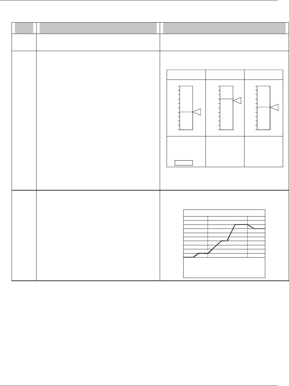
Setpoint Profiler
Video Recorder – User Manual 206
How to view profiler summary display
Table 5-20 Summary Viewing Procedure
Step Action Result/Notes
1 Perform steps 1 and 2 from Start procedure
(Table 5-13). Profiler menu is displayed.
2 Press Decrement button to move cursor to
Summary. Press Enter. Three profilers will be displayed as bar graphs.
Data for your profile(s) will be displayed.
RUN
40.00
SEG 5
00:21:13
TREND
READY
71.00
SEG 1
00:00:00
TREND
END
820.20
SEG 15
01:30:00
TREND
SP1 SP2 SP3
100.00
0.00
200.00 1500.00
-200.00 100.00
Setpoint Profiler 3 Bar Summary
(SPP_3BS)
3 Press the Tab button to move the cursor to the
TREND of the desired profiler, then press
Enter.
The profiler trend of the selected profile is
displayed.
SP1 PROFIL01 500.00
PV 241.27
SP 248.00
0.00
1:05:30
SEG6/9 RUN

Setpoint Profiler
Video Recorder – User Manual 207
How to edit a profile’s segments
Profile may be in Run, Ready, End, or Hold to edit segments.
CAUTION
For value duration ramp type, it is recommended you do not edit the currently running segment or the next
segment. Doing so may prematurely terminate the segment, that is, the profiler may jump to the next
segment.
Table 5-21 Segment Editing Procedure
Step Action Result/Notes
1 Perform steps 1 and 2 from Start procedure
(Table 5-13). Profiler menu is displayed.
2 Press Decrement button to move cursor to
Edit. Press Enter. The Edit Profile menu is displayed:
EDIT PROFILE #n
SEGMENT #n
NEXT SEGMENT
PREVIOUS SEGMENT
VALUE 100.00
AUX VALUE 50.00
TIME 20.000
The profile and segment numbers whose value
and time you are editing are shown.
3 Use Increment and Decrement buttons to
move cursor to value or time. Press Enter to
access the numbers shown. Change the
numbers with the Increment and Decrement
buttons.
Numbers are changed to their new values.
4 Press Menu button when finished editing
segments. The Profile Trend is displayed with the new
segments.

Setpoint Profiler
Video Recorder – User Manual 208

Online Operations Using Primary Displays
Video Recorder – User Manual 209
6. Online Operations Using Primary Displays
6.1 Overview
Online operation using primary displays consists of using the buttons to view and interact with the
displays that were assigned to the Display button. Pressing the Display button changes to online mode
and accesses the displays assigned to this key. Available displays are shown in Figure 4-17 and are
described in Table 6-1. In the following table, interactive means the Tab key can be pressed to access
various functions on the display.
Table 6-1 Displays Accessed With Display Button
Display Definition Function Interactive
or view only?
V_TREND Vertical trend Displays up to 12 points trended vertically. Interactive
VTRNDDIG Vertical Trend Digital Displays up to 12 points. Interactive
VT_6DIV Vertical Trend w/6 Divisions Displays up to 12 points. Interactive
H_TREND Horizontal trend Displays up to 12 points trended horizontally. Interactive
HTRNDDIG Horizontal Trend Digital Displays 12 points trended horizontally. Interactive
HTRNDBAR Horizontal Trend Bar Displays up to 12 points trended horizontally
with 4 vertical bar graphs to the right.
BAR GRAPH1 = Trend Point 1
BAR GRAPH2 = Trend Point 2
BAR GRAPH3 = Trend Point 3
BAR GRAPH4 = Trend Point 4
Interactive
V_4_BAR 4-point Vertical Bar Graph Displays 4 points. View only
V_6_BAR 6-point Vertical Bar Graph Displays 6 points. View only
V_8_BAR 8-point Vertical Bar Graph Displays 8 points. View only
V_12_BAR 12-point Vertical Bar Graph Displays 12 points. View only
H_4_BAR 4-point Horizontal Bar Graph Displays 4 points. View only
H_6_BAR 6-point Horizontal Bar Graph Displays 6 points. View only
PANEL_4 4-point Panel Displays 4 points. View only
UNIT DATA Unit Data Displays up to 12 point values at a time. View only
PANMETER Panel Meter Displays up to 12 different panel displays. View only
ALARMSUM Alarm Summary Displays current alarms. Interactive
STORAGE Storage Status Displays data storage status. View only
TOTALIZR Totalizer Displays all totalizer values. View only
LOOP_BAR Loop w/Bar Graph Displays a loop’s data as numbers and bar
graphs. Interactive
LOOP_DIG Digital Loop Displays loop data as numbers only. Interactive
LOOP_2BS Loop w/2 Bar Graphs Displays 2 Loops’ data as bar graphs. Interactive
LOOP_3BS Loop w/3 Bar Graphs Displays 3 Loops’ data as bar graphs. Interactive
LOOP_4BS Loop w/4 Bar Graphs Displays 4 Loops’ data as bar graphs. Interactive
LOOP_8BS Loop w/8 Bar Graphs Displays 8 Loops' data as bar graphs. Interactive
SPP_2BS Setpoint Profiles w/2 Bar
Graphs Displays 2 Profiles’ data as bar graphs. Interactive
SPP_3BS Setpoint Profiles w/3 Bar
Graphs Displays 3 Profiles’ data as bar graphs. Interactive
SPP_4BS Setpoint Profiles w/4 Bar
Graphs Displays 4 Profiles’ data as bar graphs. Interactive
SP_TREND Setpoint Profile Trend Displays a Profile as a Trend. Interactive
TOTAL Totalizer Displays 1 totalizer View only

Online Operations Using Primary Displays
Video Recorder – User Manual 210
6.2 Interacting With Primary Displays
Interacting with Setpoint Trend Display
When a Setpoint Trend display is shown (Figure 6-1), press the Tab key to display options for
controlling the profilers execution. See Section 5.5 for details.
SP1 500.00
PV 0.00
SP 0.00
0.00
0:00:00
SEG1/9 READY
PROFIL01
Figure 6-1 Changing Profile Batch Tag
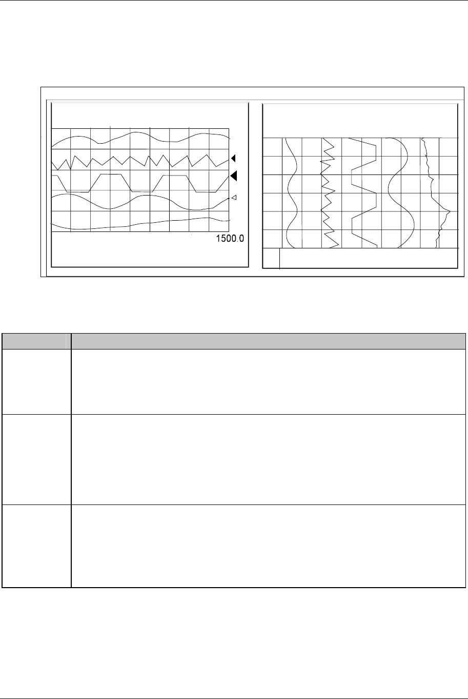
Online Operations Using Primary Displays
Video Recorder – User Manual 211
Interacting with Live or Replay Trends
With a live vertical or horizontal trend on the display, press Tab key to access the Point/Detail menu.
When replaying (stored) trends this menu is always displayed. From this menu you can press the Tab
key again to advance the scoreboard at the top of the display to the next point in the trend. Also, you
can press the Increment or Decrement buttons to scroll the trend forward or backward in time.
TEMP71941.5 DEGF
1500.02500.
0
A
A
L
A
RM 1 HIGH
12:15
11:45
11:15
TEMP 7 2061.5 DEGF
2500.0
Figure 6-2 Horizontal and Vertical Trend Displays
Table 6-2 Point/Detail Menu Prompts
Prompt Definition
SCROLL Press the Increment or Decrement buttons to scroll the trend forward or backward in time.
Press Tab key to change to the next point on a multi-point trend.
Press the Menu button to restore the Point/Detail menu. The trend display will remain at the
time determined by the SCROLL.
Press the Display button to restore the original primary display and cancel the SCROLL.
SET HOLD,
REL HOLD
Causes one point to remain displayed in the scoreboard. Available for live trend only.
Before selecting SET HOLD, press Point/Detail to change the scoreboard to the desired
point. Select SET HOLD and press Enter. An “H” appears in the lower right display. The
HOLD will remain in effect until deliberately removed with REL HOLD.
To HOLD a different point, press the Tab key until the desired point is shown, then press the
Display button.
To release the HOLD, select REL HOLD.
DETAIL Use the Increment and Decrement buttons to move the line cursor forward or backward in
time. The value of the displayed point will change to its value at the new time.
If desired, press Tab to change to the next point on a multi-point trend.
Press the Menu button to restore the Point/Detail menu. The trend display will remain at the
chosen point.
Press the Display button to restore the primary display and cancel DETAIL feature.

Online Operations Using Primary Displays
Video Recorder – User Manual 212
Table 6-2 Point/Detail Menu Prompts (continued)
Prompt Definition
FIND Lets you display the trend from a certain time. A list of times will appear on the display, as
shown. FIRST is the oldest time available in the trend. LAST is the most recent time
available.
FIRST: JAN 1 1994 12:00
LAST: JAN 5 1994 13:00
FIND: JAN 1 1994 12:00
Select month, day, year, hour and minute. To cancel the search, press Display, Menu,
Display1, Display2 or Display3 buttons.
When the data has been found, the selected time/date will appear in the center of the trend
area. The Point/Detail menu will also appear.
ZOOM Lets you magnify (zoom) the displayed scale.
Press the Increment and Decrement buttons to select the amount of magnification, shown in
the lower right corner of the display. Note that the size of the Zoom cursor changes
accordingly. See Figure 6-3.
OFF – uses point’s trend display limits (turns Zoom off)
2X – uses half of point’s trend display limits
4X – uses one fourth of point’s trend display limits
FULL – uses point’s programmed limits (not its trend display limits)
Press the Tab key to select the point/trace to be zoomed (magnified).
Press Enter to display the magnified trend. The Point/Detail menu is displayed to allow
further analysis.
Press the Display button to restore the primary display with the ZOOM limits. A “Z” appears in
the lower right of the display.
TIMEBASE Lets you change the timebase of the trend. Choices are:
NORMAL – use the trend’s normal timebase.
ALTERN (Alternate) – use the trend’s alternate timebase.
Move the cursor box to the desired timebase and press Enter. The trend will be redisplayed
in the new timebase. An arrow points to the current timebase. Timebases are specified in
the program mode. Available for live trends only.
If a storage trend CHANGE WITH KEY is set to YES, then changing the timebase will also
change the storage rate of the storage trend. That is, if the live Trend1 is displayed in
NORMAL timebase, then the storage Trend1 will be stored at the LOW rate. If the live
Trend1 is displayed in the ALTERN timebase, then the storage Trend1 will be stored at the
HIGH rate. Trend2, 3 and 4 behave the same way.
NEW FILE Select to see the Replay From Disk menu, from which you may select another stored file for
replay. Available for replay trends only.

Online Operations Using Primary Displays
Video Recorder – User Manual 213
TEMP7 1941.5 DEGF
1500.0 2500.0
A ALARM 1 HIGH
12:15
11:45
11:15
2X
Zoom cursor
Amount of
magnification
Figure 6-3 Vertical Trend at 2X Zoom

Online Operations Using Primary Displays
Video Recorder – User Manual 214
Interacting with Panel_4 Display
To stop the rotation of the panel display on a precise point series, follow the procedure in Table 6-3.
H
14 JAN 99 21:35
DEWP IM
177,6
DEG C
AIR OUT
212,3
DEG F
PRESSURE
55,2
PSI
SY1
OFF
Figure 6-4 Panel Display
Table 6-3 Stop Panel_4 Display Rotation Procedure
Step Action Result
1 Press Tab key Displays menu item SET HOLD at the lower right hand corner of the
display.
2 Press Tab key Displays the desired point series.
3 Press Enter Holds display on desired point series. An “H” appears in the lower right of
the display.
To resume rotation through all points, follow the procedure in Table 6-4.
Table 6-4 Resume Panel_4 Display Rotation Procedure
Step Action Result
1 Press Tab key Displays menu item REL HOLD at the lower right hand corner of the
display.
2 Press Enter The “H” disappears and rotation resumes.
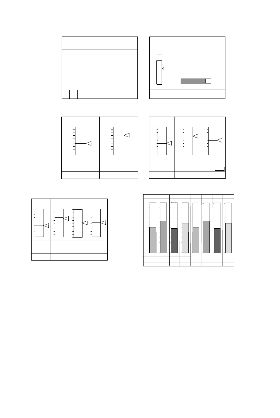
Online Operations Using Primary Displays
Video Recorder – User Manual 215
Interacting with Loop Displays
LOOP 1
SP1 11/15
12:15
PV
SP
OUT
DEV
2205.00
2000.00
83.5%
205.00
ADDISK FULL
Digital Loop
(LOOP_DIG)
AUTO
Loop with Bar Graph
(LOOP_BAR)
LOOP 1
SP1 11/15
12:15
2500.00
1500.00
PV 2205.00
SP 2000.00
DEV 205.00
OUT 83.5%
0100%
AUTO
PV 405.00
SP 405.00
OUT 15.0
A SP1
LP1 LP2
1500.00
0.00
PV 1054.00
SP 1040.00
OUT 10.0
A SP2
1000.00
0.00
Loop 2 Bar Summary
(LOOP_2BS)
PV 405.00
SP 405.00
OUT 15.0
A SP1
LP1 LP2 LP3
1000.00
0.00
1500.00 1200.00
0.00 0.00
PV 1054.00
SP 1040.00
OUT 10.0
A SP2
PV 623.00
SP 622.00
OUT 5.0
M SP1
Loop 3 Bar Summary
(LOOP_3BS)
PV 405.00
SP 405.00
OUT 15.0
A S1
LP1
1000.0
0
0.0
LP2
1500.00
0.00
1054.00
1040.00
10.0
M S2
LP4
2400.0
0.00
1266.00
1244.00
5.0
A S1
LP3
1200.00
0.00
623.00
622.00
5.0
M S1
Loop 4 Bar Summary
(LOOP_4BS) Loop 8
Bar Summary
(LOOP_8BS)
00
P1
0.0
100.0
LP
L2P
L3P
L4P
L5P
L6P
L7P
L8
100.0100.0100.0100.0100.0100.0100.0
0.0 0.0 0.0 0.0 0.0 0.0 0.0
PV
405.00
SP
405.00
OUT
1 5.0
A S 1
1054.00
1040.00
1 0.0
M S2
12 66 .00
12 4 4 .00
5.0
A S1
623.00
622.00
5.0
M S1
405.00
405.00
1 5.0
1054.00
1040.00
10 .0
1266.00
1244.00
5.0
623.00
622.00
5.0
A S1
M S2 A S1
M S1
Figure 6-5 Loop Displays
When the Loop w/Bar Graph, Loop 2 Bar, Loop 3 Bar, Loop 4 Bar, Loop 8 Bar or Digital Loop display is
shown you can:
• select Auto or Manual control mode for the loop,
• change loop output,
• change the setpoint value,
• switch to the Loop Tuning display for Setpoint 1/.Setpoint 2 toggle (for tuning parameters and
pretuning).
Detailed instructions for performing these interactions are described in Table 6-5.

Online Operations Using Primary Displays
Video Recorder – User Manual 216
Table 6-5 Interacting With Loop Displays
To perform this action Do these steps
Move the cursor box to
another area of the display Press the Tab key to move the cursor to the Loop Tag at the top of the display,
then to the setpoint value, then to the loop output value (if loop is in Manual
mode).
Toggle the loop between
Auto and Manual modes Press Auto/Manual button.
To use the Auto/Manual button all of the following conditions must be met.
1. Loop must be in Local mode, which means FORCE REMOTE MAN discrete
parameter must be OFF.
2. DISCR VS KEY SEL discrete parameter must be OFF.
3. If security is active for AUTO/MAN changes, the security code must be
entered first.
For a description of the loop parameters FORCE REMOTE MAN and DISCR
VS KEY SEL, see Table 4-10.
Lower or raise the loop
output (displayed as %). Press Tab key to move cursor to loop output. To change the output, the loop
must be in manual mode (initiated by front panel key or by external discrete
signal )– not in Remote Manual mode.
Increase or decrease
Setpoint value Press Tab key until cursor is on the setpoint value. Press Increment and
Decrement to adjust value. Only numerically assigned setpoint values can be
changed online; Setpoint #2 cannot be changed if it is acting as a remote
setpoint (e.g. running a profile).
You can also change the setpoint value by accessing the Tune Loop menu as
described in the next row.
Access the loop tuning
parameters Press Tab key until the cursor is on the loop tag at the top of the display.
Press Enter to access the Tune Loop menu for that loop. Adjust desired
parameters. To return to the loop display, press Menu. See Section 7.6 Tune
Loop.
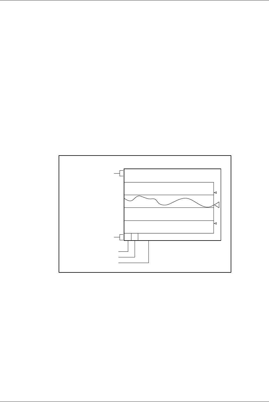
Online Operations Using Primary Displays
Video Recorder – User Manual 217
6.3 Display Messages and Symbols
Overview
Messages and symbols will appear in different areas of the display to inform the operator of a variety of
conditions. The area across the bottom of the display (Figure 6-6) is reserved for messages that
require the operator to take action. They include Active Alarm Symbols, Diagnostic Messages, and
Data Storage Messages.
Location
The Alarm and Diagnostic messages consist of a symbol on the left side of the display and a text
message next to it on the right. The Data Storage message has no symbol and includes only the text
portion.
Multiple messages
If multiple messages are present simultaneously, they will be arranged in a “cascaded” or “shingled”
arrangement, so that underlying symbols will be visible (data storage on top, diagnostics in the middle,
alarms on bottom).
Example of primary display
Figure 6-6 shows an example of a primary display.
BOILER7 2305.5 DEGF
12:15:36 11/15
2300.00 Z
A D DISK FULL
13:15:36
3300.00
The "Scoreboard"-
individual point data
Messages
Alarm
Diagnostic
Data Storage
Figure 6-6 Example of Primary Display

Online Operations Using Primary Displays
Video Recorder – User Manual 218
Description of Messages and Symbols
Table 6-6 Messages and Symbols at Bottom of Display
Message/Symbol Color Description
AAA
A
A followed by text
description of alarm
Red An active alarm exists. Flashes while unacknowledged. When the
operator acknowledges the alarm, the flashing will stop. The symbol
and text will remain until the alarm has cleared.
DDD
D
D followed by text
description of diagnostic
Blue A diagnostic error has been detected. Flashes while
unacknowledged. The symbol and text will remain until the operator
acknowledges or deletes the diagnostic in the online Access
Summaries menu.
Data Storage Messages Color Description (shown low to high priority)
UPDATING DISK Yellow Instrument is flushing all buffered data to the disk.
CHECKING DISK Yellow Whenever the front panel has been opened and closed, the
instrument checks that a properly formatted disk is installed and
ready to receive data.
INITIALIZING Yellow Initialization is in progress.
DS INIT FAILED Yellow Initialization failed. Possible reasons: disk has not been formatted, is
write-protected, or is defective.
STORAGE FULL Yellow Less than 5 minutes of space remains in the internal buffer. Data is
accumulating in the internal buffer (temporary storage) because it is
unable to store the data on the floppy disk. Possible reasons include:
• Disk is full and storage is programmed as non-rollover.
• There is no disk in the drive.
• The disk is write-protected.
• The operator is in the process of retrieving stored data from the
disk.
• The disk is “not current” (see DSK NOT CURRENT below).
• The front bezel is open.
The message will disappear when the condition is corrected, or if data
storage is disabled (turned off).
DISK FULL Yellow No more space is available on one or more of the files on the floppy
disk for storage of data as programmed. This message will appear
only if at least one partition on the disk is programmed for non-
rollover operation. The message will disappear when a new disk is
initialized, or if data storage is disabled (turned off).
DISK WARNING Yellow Floppy disk is not full but available space on one or more disk files
has reached the programmed warning limit. The message will
disappear when a new disk is initialized, or if data storage is disabled
(turned off).
BEZEL OPEN Yellow Instrument front panel is open or is not closed securely.
DISK ERROR Yellow The instrument is attempting to store data but the disk is either not
properly formatted or is faulty. The message disappears when the
disk is formatted or replaced, or if data storage is disabled (turned
off).
DSK NOT CURRENT Yellow When a disk is initialized the instrument marks it as the “current” disk.
The instrument will only store data to the “current” disk. If any other
disk is placed in the drive this message will appear. The message will
disappear when the “current” disk is inserted or a new disk is
initialized.
WRITE-
PROTECTED Yellow The disk in the drive has its write-protected tab set to the protect
position.
DISK MISSING Yellow Data storage is enabled, but no disk is installed in the disk drive.

Online Operations Using Primary Displays
Video Recorder – User Manual 219
Table 6-6 Messages and Symbols at Bottom of Display (continued)
Message/Symbol Color Description
GENERAL ERROR Yellow This message will appear if the instrument encounters any error not
mentioned above.
S
Yellow Located in bottom right of display. Indicates storage is active data is
being collected on disk or in the instrument’s internal buffer.
Z
White Located in bottom right of display. The display’s upper and lower
limits are zoomed on a smaller range. Disappears when Zoom is
turned off.
H
White Located in bottom right of display. Indicates the display is held on a
single data point and is not rotating through all data points.
Disappears when Point Hold is removed.
Table 6-7 Messages and Symbols Elsewhere on Display
Message/Symbol Color Description
REVIEW or REPLAY White Trend Replay/Review. Adjacent to detailed point information
(scoreboard) on the screen. Indicates that the trend on the display
is from historical data and does not represent the current state of
the process. REVIEW means that the data for the trend are from
current memory (RAM). REPLAY means that the data are retrieved
from floppy disk (data storage).
*
White Analog Input Value Adjust. Located to the right of the data point
value. This message appears only on the AI Value Adjust display.
It indicates that a bias has been manually applied to the value of the
particular data point. The symbol will disappear when the value is
set to OFF.
Red Low Alarm Setpoint. Located above vertical trends, right of
horizontal trends, along side of bar graph. These symbols appear
automatically if a displayed point is the input to one or more Alarm
function blocks. The first 4 low type alarm blocks using the
displayed points are represented by these symbols.
or Red High Alarm Setpoint. Located above vertical trends, right of
horizontal trends, or along side of bar graph. These symbols
appear automatically if a displayed point is the input to one or more
Alarm function blocks. The first 4 high type alarm blocks using the
displayed points are represented by these symbols.
Flashing between ******
and value Same as
data point Bad Input Values. Appears in place of the value on all displays.
Value is outside the programmed limits. Caused by an upstream AI
failure (AI is open circuit and failsafe or is type linear and outside its
programmed range by 10% or more).
Flashing between value
and blank Same as
data point Questionable Input Values. Appears in place of the value on all
displays. Value is clamped at its limit.
Flashing between value
and blank Same as
data point Output Limits of Totalizer or Interval Timer Exceeded. Appears in
place of the value on all displays. Interval Timer ‘s or Totalizer’s
value is outside its output limits. Value is not clamped.

Online Operations Using Primary Displays
Video Recorder – User Manual 220

Online Operation Using Menus
Video Recorder – User Manual 221
7. Online Operation Using Menus
7.1 Overview
Online operation involves interacting with displays and with menus. This section describes how to
interact with the online menus.
The Online Menu is accessed by pressing the Display button, then the Menu button. Or, you can
choose SET MODE from any menu to change the mode.
ATTENTION
Switching to the Online mode from the Program or Maintenance modes by pressing the Display button,
sometimes displays incorrect data for a few seconds before the display data is refreshed. You can avoid this
distraction by selecting ONLINE from the SET MODE menu instead.
The top level of the menu structure is shown in Table 7-1. Your unit may have a reduced menu if
options are not present or if features have been disabled through programming selections.
Table 7-1 Online Main Menu
Menu as displayed Function
SET MODE Change instrument’s operating mode
DATA STORAGE Set up, operate and view the status of the data storage
ACCESS SUMMARIES Display status summaries
DATA ENTRY Adjust function values and states
SETPOINT PROFILES Edit profile parameters. Store and load programs.
TUNE LOOP Enter loop tuning values. Pretune loop.
SET ANALOG OUTPUTS Adjust Analog Output values
REVIEW PROGRAMMING View all programming (read only)

Online Operation Using Menus
Video Recorder – User Manual 222
7.2 Data Storage
Overview
Data Storage lets you store trend data, unit data, alarms, events, and diagnostics for later review
onscreen or on a PC with SDA software or the TrendManager Pro V5 software suite. Setup and
configuration of Data Storage is described in Section 4.26; online operation is described here.
Typical online data storage tasks
1. Removing, installing, and labeling disks.
2. Pre-initializing a disk on a PC (see Section 3.15)
3. Initializing new disk using the current Data Storage setup schedules.
4. Checking current storage setup.
5. Starting and stopping storage (3 methods):
a) Start/stop all storage via ENABLE STORAGE menu.
b) Start/stop a particular storage file’s storage via its external enable discrete.
c) Start/stop all storage batches via BATCH STATE menu item or via BATCH CONTROL discrete.
6. Checking storage status with DATA STORAGE STATUS display.
7. Replaying data stored on disk.
8. Reading data storage messages.
Installing a disk
The disk should be pre-initialized. Pre-initializing may be done at a PC or in the instrument with DATA
STORAGE menu item INITIALIZE DISK. Maintaining a stock of several formatted disks is
recommended to minimize maintenance time on the instrument.
Disks are inserted and removed from the front panel as described in Table 7-2.
Table 7-2 Floppy Disk Insertion/Removal Procedure
Step Action
1 Open the door.
2 Insert the disk into the slot until it catches in place.
3 To remove the disk, press the rectangular button next to the slot. Be sure to label the contents of
each disk.
4 Close the door.

Online Operation Using Menus
Video Recorder – User Manual 223
How data is stored
To provide continuity of storage when the disk is removed, the data storage feature buffers data
internally for a period of time based on the storage rate and amount of storage data. Since storage files
and Setpoint program files may not be stored on the same disk, you can swap the storage disk with a
configuration disk for up to the buffered data time period while loading Setpoint programs without losing
storage data. When the storage disk is re-installed, or when another disk is initialized using the current
schedules, the buffered data will be transferred to the disk.
Initializing a disk
Initialization creates separate areas on the disk for each type of data to be stored. Data types that can
be stored are up to 3 Trends, Alarms, Events, Diagnostics, and Unit Data. You can initialize a disk
using the current storage schedule or using a new storage schedule.
When data storage is active, the instrument determines the status of the disk. Status can be one of the
following possibilities.
Table 7-3 Disk Status
Disk status Result
The “current” disk was inserted
back into the drive. The instrument will resume storage to this disk automatically.
Some other disk was inserted.
That is, disk is blank, contains
old data files or contains
configuration files.
In this case, a DISK NOT CURRENT message is displayed and data is
stored in a buffer, not on the disk.
Initializing a disk using the same storage setup
To continue storing the same data storage schedule on this disk, select the online DATA STORAGE
SETUP menu, select INITIALIZE DISK, then select USE CURRENT SCHEDULES. The instrument will
display a prompt asking for a yes or no response to initialize the disk. Initializing will destroy all
existing information on the disk. To shorten the initialization time, the disk should be pre-initialized on
a PC. With this prompt you can remove a disk inserted by mistake, or deliberately re-use an old disk
containing useless information. If you answer YES, the current schedule will be established on the new
disk, buffered data will be stored to the disk, and if any storage files are in batch mode, the batch
counter will be reset to zero(0).
Initializing a disk using a new storage setup
If you change any part of data storage schedule and you want the changed (new) schedule’s data to be
stored, select the online DATA STORAGE SETUP menu, select INITIALIZE DISK, then select USE
NEW SCHEDULES. To shorten the initialization time, the disk should be pre-initialized on a PC. All data
that was buffered since the previous disk was removed is lost. If you change the schedule but initialize
using the current schedule, the changed (new) schedule is not stored.

Online Operation Using Menus
Video Recorder – User Manual 224
Initialization errors
If an initialization error occurs, one of the following messages may appear.
Error message Definition
BEZEL OPEN Disk use is not permitted while the front panel bezel is open. The bezel must be
closed and latched.
WRITE-PROTECTED The write protect tab is set (open) on the floppy disk. The tab must be closed to
permit data storage.
DISK ERRORS The disk installed in the drive is faulty or is not a DOS formatted disk. It must be
formatted before it can be initialized. Formatting can be performed on an IBM
compatible PC or with the FORMAT DISK command in the Data Storage menu.
DISK IS MISSING No disk is installed in the drive.
Checking current storage setup
To see what is being stored and when, select DATA STORAGE SETUP, then select REVIEW
CURRENT SCHEDULES.

Online Operation Using Menus
Video Recorder – User Manual 225
Starting and stopping storage
Data Storage can be started and stopped three ways. At the highest level, the ENABLE STORAGE
menu item enables or disables all data storage. At the next highest level, EXTERNAL ENABLE enables
or disables storage for each file type (Trends #1-3, Alarms, Events, Diagnostics, Unit Data). At the
lowest level, storage for each file type is started and stopped with one of two controls: a menu item
BATCH STATE or a discrete parameter BATCH CONTROL.
Table 7-4 describes each method of starting and stopping storage.
Table 7-4 Storage Start/Stop Controls
Prompt
Comments
ENABLE
STORAGE Acts as a master enable/disable switch for all data storage. Select this item from the
DATA STORAGE menu. Set to ENABLE to allow storage of the current schedule. If this
is set to DISABLE, online data storage cannot take place, even if storage for
individual files is enabled with EXTERNAL ENABLE.
EXTERNAL
ENABLE Acts as a enable (high)/disable (low) switch for each storage file type (trends, alarms,
events, diagnostics, unit data). Any storage file whose external enable is configured with
a discrete will start and stop according to the state of that discrete. This works
independently of batch storage.
BATCH
STATE Acts as a start/stop switch for each storage file type. The ENABLE STORAGE and
EXTERNAL ENABLE both must be enabled for BATCH STATE to function.
Accessed under DATA STORAGE menu. If batch storage mode is configured for any
storage file and if BATCH CONTROL has not been configured with a discrete, then you
can manually start/stop the batches using this selection. The instrument will automatically
assign a number internally to identify the batch for storage. For example, data stored
between the first start and stop is marked as Batch #1. When the next batch starts, the
instrument will increment the batch number. These numbers identify the batches for later
retrieval.
BATCH
CONTROL Accessed under SET UP NEW SCHEDULES. If this item is configured with a discrete, it
will start and stop storage for all storage files configured with batch storage mode. The
ENABLE STORAGE and EXTERNAL ENABLE both must be enabled for BATCH
CONTROL to function. The instrument will automatically assign a number internally to
identify the batch for storage. For example, data stored between the first start and stop is
marked as Batch #1. When the next batch starts, the instrument will increment the batch
number. These numbers identify the batches for later retrieval.
BATCH
NUMBER Accessed under DATA STORAGE. Shows the number (1-255) of the active batch. The
batch number is assigned automatically by the instrument when the batch is started by
either method (BATCH CONTROL or BATCH STATE).
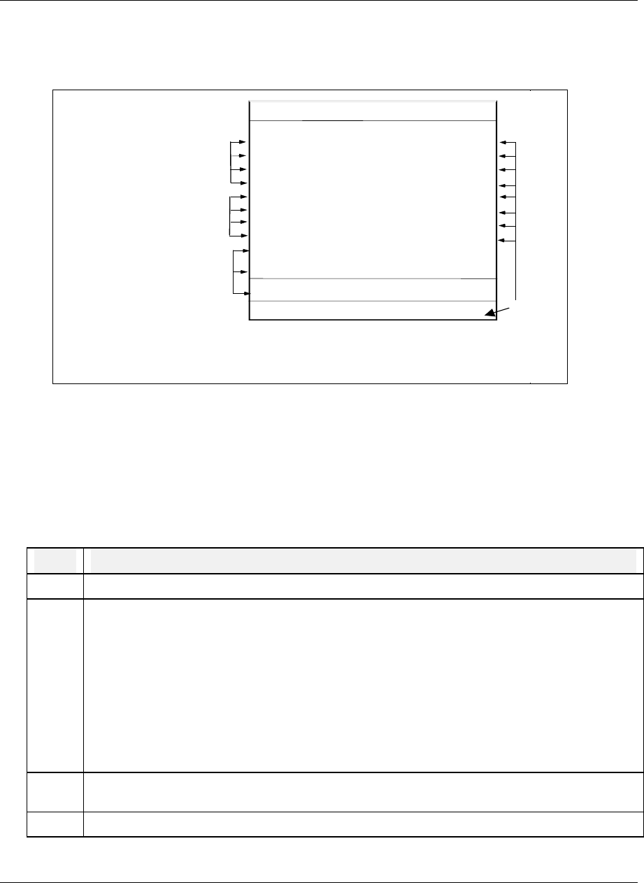
Online Operation Using Menus
Video Recorder – User Manual 226
Checking Data Storage Status
The Data Storage Status display is accessed from the Online data storage online menu. It is also
accessed by pressing any display button, if the button has this display assigned to it. See Figure 7-1.
DATA STORAGE STATUS 13:15
S
REMAINING
TREND 1
TREND 2
TREND 3
TREND 4
ALARM SAMPLES
EVENT SAMPLES
DIAG SAMPLES
UNIT DATA SAMPLES
ENABLE STORAGE ENABLE
D DD-HH-MM
135 14 52
271 ROLL
ROLL
OFF
OFF
Y
Y
Y
Y
Y
Y
Status of external enable
Y = Enabled
N = Disabled
Time remaining for
each trend (days,
hours, minutes)
Number of remaining
samples for alarms,
events, diagnostics
and unit data
SYSTEM : NORMAL
DISK : NORMAL
Y
Y
HI
LO
LO
LO
06 00
OFF
OFF
Status of system, disk
and Enable Storage
Storage
active
Figure 7-1 Data Storage Status Display
Replaying stored data
Data stored on floppy disks can be retrieved and displayed online at any time, whether data storage is
active or not. All data is stored as individual files and is retrieved by filename. To retrieve a file from
disk, follow the procedure in Table 7-5.
Table 7-5 Data Storage Replay Procedure
Step Action
1 Insert the disk containing the desired file into the instrument.
2 Select DATA STORAGE and then REPLAY FROM DISK. A list of filenames of all the files on the
disk will appear. The filename extension identifies the type of data in the file. Note: Events can
only be replayed with SDA data analysis software.
.LNT Trend
.LNA Alarms
.LNE Events
.LND Diagnostics
.LNU Unit Data
3 Select a start time within the first and last times. Data replay will begin at this time. For trends,
select horizontal or vertical replay format and screen size (timebase).
4 Select Replay to view the data.

Online Operation Using Menus
Video Recorder – User Manual 227
ATTENTION
If you are replaying data from a “non-current disk,” keep in mind that the instrument will continue acquiring
data and holding it temporarily in its active memory (RAM) until you insert a proper disk for storage. If you
spend too much time replaying data, the instrument could run out of active memory space. If this occurs, a
storage full warning message will be displayed. See Tables 6-6 and 6-7 for an explanation of the various
warning messages.
Examining replay data
For details on examining replay trend data, see Section 6.2, Interacting With Primary Displays. To
examine replayed alarms, events, and diagnostics, use the Up Arrow or Down Arrow keys.
Reading Data Storage Messages
See Data Storage Messages in Table 6-6 for message descriptions.

Online Operation Using Menus
Video Recorder – User Manual 228
7.3 Access Summaries
Summaries are available for all points, alarms and diagnostics in the instrument.
Display alarm summary
Alarms are set up as part of the instrument configuration procedure (Section 4.13). Up to 12 alarms can
be configured.
An alarm can be assigned to any analog data point (Analog Input, Analog Output, or Calculated Value)
and can be one of these types.
Alarm type Function
HIGH Alarm when input value > setpoint value.
LOW Alarm when input value < setpoint value.
DEV (Deviation) Alarm when input value deviates above or below compare point
value by an amount > setpoint value.
HRATE (High Rate) Alarm when input value increases at rate > setpoint value, in units
per minute. Negative rate setpoints are processed as positive
values. May take up to 30 seconds to activate.
LRATE (Low Rate) Alarm when input value decreases at rate > setpoint value, in units
per minute. Negative rate setpoints are processed as positive
values. May take up to 30 seconds to activate.
An alarm programmed with delay will not activate before its delay time. An alarm programmed with
hysteresis will clear after its hysteresis delay.
The alarm will remain active as long as the conditions causing it remain. When the conditions no longer
exist, the alarm will be “cleared” automatically. “Clear” means that the indicators for the particular alarm
on all displays will be removed and the alarm will be removed from the Alarm Summary list.

Online Operation Using Menus
Video Recorder – User Manual 229
What happens during an alarm
• A flashing red alarm indicator appears on the bottom of all screens. (The alarm must be
acknowledged to stop the flashing.) On displays where the alarm point appears, the value is red
and a red indicator appears.
• The alarm is entered into the active alarm summary which can be viewed at any time. The alarm
summary contains the point identification, a description of the alarm, the sense (high, low rate, etc.),
the time of occurrence and the current value of the point.
• When the alarm clears, the time of occurrence and the time of clearing will both be entered into the
Alarm History, which is an ongoing record of the occurrence and clearing of all alarms.
• If so configured, the alarm occurrence will also be logged on a summary list stored on floppy disk
(see Data Storage, section 4.26).
• If so configured, the alarm triggers a discrete output relay. The relay returns to normal state only
when the alarm is cleared.
Acknowledging alarms
When an alarm occurs, it must be acknowledged by the operator to stop its indicator from flashing.
Acknowledging an alarm does not clear the alarm. See Table 7-6for procedure.
Table 7-6 Alarm Acknowledgment Procedure
Step Action
1 Select ACCESS SUMMARIES from online menu.
2 Select DISPLAY ALARM SUMMARY to display a list of active alarms. Up to 4 pages (14 alarms)
can be listed. Unacknowledged alarms will be flashing. Use the Up Arrow and Down Arrow buttons
to view the various pages of the display, as desired.
Display Alarm Summary can also be accessed by pressing the Display button, if the Alarm Summary
display was assigned to that button. See Section 4.18.
3 Press the Up Arrow or Down Arrow button and a cursor will appear on the display. Use the Up
Arrow or Down Arrow button to position the cursor on a flashing alarm and press Enter to
acknowledge the alarm. The flashing will stop and the cursor will disappear.
If you do not press any button for a period of 5 seconds, the cursor will disappear. This is a safety
feature, because while the cursor is visible on the display, the display is temporarily disabled and a
new alarm will not be shown.
4 If there are more flashing alarms, press the Up Arrow and Down Arrow buttons to restore the cursor.
Display Alarm History
The Alarm History display is a multi-page display which lists information on cleared alarms. The most
recent 25 cleared alarms will be shown, with the oldest being dropped from the list when a new alarm
clears and is logged in.
The Alarm History includes the descriptor and tag identifiers of the alarm, the type (high, low, high rate,
etc.), the setpoint value at the time the alarm occurred and the date and times of the occurrence and
clearing of the alarm (designated as IN and OUT times, respectively).
Use the Up Arrow and Down Arrow buttons to view the various pages of the display, as desired.
Display Diagnostics
A Diagnostic is a displayed error message that indicates a serious error or failure has occurred. See
Section 9 for diagnostic descriptions and possible causes.

Online Operation Using Menus
Video Recorder – User Manual 230
What happens during a diagnostic
• A flashing blue diagnostic indicator will appear on the bottom of the screen.
• The diagnostic message will be entered into the diagnostic summary which can be viewed at any
time. The summary contains each message and the date and time of occurrence.
• If Data Storage is set up accordingly, the diagnostic occurrence will also be logged on a summary
list stored on floppy disk.
• The diagnostic summary can contain a maximum of 50 messages with the newest shown at the top
of the list. As new diagnostics occur beyond 50, the oldest will be dropped from the list. Diagnostic
messages are not automatically removed from the summary if the error condition is corrected. The
list must be deleted from the screen periodically by the operator as described under Delete All
Diagnostics.
Acknowledging Diagnostic Messages
When a diagnostic occurs, it must be acknowledged by the operator to stop its indicator from flashing.
See Table 7-7.
Acknowledging a diagnostic only stops its indicator from flashing; it does not correct the cause of the
diagnostic. You are not required to acknowledge a diagnostic. The flashing can also be stopped if all
diagnostics are erased, using the DELETE ALL DIAGNOSTICS menu selection.
Table 7-7 Diagnostic Acknowledgment Procedure
Step Action
1 Select ACCESS SUMMARIES from the main online menu.
2 Select DISPLAY DIAGNOSTICS to display a list of diagnostics. Unacknowledged diagnostics will be
flashing.
3 Press the Up Arrow or Down Arrow button and a cursor will appear on the display. Use the Up
Arrow or Down Arrow button to position the cursor on a flashing diagnostic and press Enter to
acknowledge the diagnostic. The flashing will stop and the cursor will disappear.
If you do not press any button for a period of 5 seconds, the cursor will disappear. This is a safety
feature, because while the cursor is visible on the display, the display is temporarily disabled and a
new diagnostic will not be shown.
4 If there are more flashing diagnostics, press the Up Arrow and Down Arrow buttons to restore the
cursor.
Display All Analogs
Displays current value of all analog points in the instrument. These include all analog I/O, loops,
calculated values, totalizers and system parameters. Only those points that have been programmed will
be displayed.
Display All Discretes
Displays current status of all discrete points in the instrument. These include all discrete I/O, alarms,
loops, calculated values, totalizers and system parameters. Only those points that have been
programmed will be displayed.
Delete All Diagnostics
A diagnostic is not automatically cleared from the summary when the error has been found and
corrected. Table 7-8 gives the procedure for deleting the diagnostics.

Online Operation Using Menus
Video Recorder – User Manual 231
Table 7-8 Delete All Diagnostics Procedure
Step Action
1 Select ACCESS SUMMARIES from the Main On-Line Menu.
2 Select DELETE ALL DIAGNOSTICS and press Enter to delete all diagnostics from the summary.
3 Press Menu or Display buttons to exit the menu.
Product Information
Select this item to display the logo screen, which includes the product identification, software version
number, part number of the PROM, and serial number.

Online Operation Using Menus
Video Recorder – User Manual 232
7.4 Data Entry
Data Entry lets you enter or revise data online. Choices available depend on installed options and
enabled features (see “Enable Features” in Section 4.19).
Edit Alarm Setpoints
Select this item to display a list of alarms and their setpoints. If the setpoint is a numeric value, it can be
changed on this display using the Up Arrow, Down Arrow and Left Arrow buttons. If it is programmed as
a parameter, it cannot be changed here.
Edit Constants
Select this item to display or change a list of all constants in the instrument. To change a value, use the
Up Arrow, Down Arrow and Left Arrow buttons.
Force Discrete Inputs/Outputs
Select either of these items to display or force the status of any discrete.
The STATE indicates ON or OFF. FORCE/RELEASE indicates if the discrete is forced or released
(unforced). To force a discrete, select FORCE ON or FORCE OFF. To release a forced discrete, select
RELEASE. Adjust with Up Arrow and Down Arrow. Press Enter to enter the changes. Press Menu to
leave the menu.
Adjust Analog Inputs
If the AI point has been configured with a pyrometer range, the Input Adjust is applied as a multiplier
(equal to the newly entered value divided by the actual measured valued at the time that the adjustment
is entered). In this case, the Value Adjust is referred to as an “emissivity” adjustment. If the AI point
has been configured with any other range, the value adjust is applied as a bias (equal to the newly
entered value minus the actual measured value at the time that the adjustment is entered).
All points on the display which are currently adjusted will have a Value Adjust Indicator (*) beside the
value.
To adjust a value, select the desired AI and press Enter. Press Enter to highlight the value then use the
Up Arrow, Down Arrow and Enter buttons to change the value on the display. The value can be
changed to any value within the programmed limits of the AI.
To remove the value adjustment, set the value to OFF. The AI will display its current value and the
indicator (*) will be removed.
Set Analog Outputs
This menu item will appear if the optional analog outputs are installed. It lets you adjust various analog
output parameters.
Two output types are available: current output (CAT) and time proportion/duration adjusting (DAT).
Failsafe Value
Enter a value of 0 to 100% or an analog parameter for the initial output. This is the initial output on “cold
start”. If the failsafe value is set to off, the output will go to 0.
Impulse Time
For DAT outputs, use the Up Arrow, Down Arrow and Enter buttons to adjust the impulse time. Impulse
time must be ≥ 1 second. Impulse time is the cycle time for on and off cycling of the output. For
example, an impulse time of 150 seconds will cause the output to be on for 75 seconds and off for 75
seconds when the input source is at 50.
• Reset totalizers

Online Operation Using Menus
Video Recorder – User Manual 233
Select this item to display a list of all resettable Totalizers and their current values. If the Totalizer is
non-resettable it will not appear. You may use this display to reset one Totalizer, or all at once. Note
that some or all Totalizers may be configured to be non-resettable. Use the Up Arrow, Down Arrow and
Enter buttons to select an item from the list. At the prompt “RESET”, press Enter to reset the Totalizer.
To reset all Totalizers, select the menu line “RESET ALL TOTALIZERS” and press Enter at the prompt.
All resettable Totalizers will be reset.

Online Operation Using Menus
Video Recorder – User Manual 234
7.5 Setpoint Profiles
For instructions on this menu, see Section 5.4 How to set up a profiler, Tables 5-4 and 5-5.
For instructions on common operator tasks with the Setpoint Profiler, see Section 5.5.

Online Operation Using Menus
Video Recorder – User Manual 235
7.6 Tune Loop
This option lets you tune (change) various loop parameters online. These tunable parameters depend
on the loop type in use and are described in Section 4.8, Program Control Loops. Also, the following
menu choices are available.
Table 7-9 Tune Loop Prompts
Prompt Range/Selections Definition
LOOP TYPE STD, ADV, SPLIT, ON OFF,
CAS P, CAS S, RATIO,
DIAT
STD: Standard
ADV: Advanced
SPLIT: Split Output
ON OFF: On/Off
CAS P: Cascade Primary
CAS S: Cascade Secondary
RATIO: Ratio
DIAT: DIAT
PV Number Value of PV
OUTPUT -100 to +100 Loop output %.
SETPOINT SOURCE SP1 or SP2 Indicates which setpoint is being used by the loop. SP1 must
be a number; SP2 may be a number or a value from a
function block (remote setpoint).
Bold items are read-only
TOGGLE SETPOINT
SOURCE SP1, SP2 Press Enter to change the Setpoint Source from SP1 to SP2
or vice versa.
SETPOINT #1 Number Enter the new value of SP1.
SETPOINT #2 Number or parameter Enter the new value of SP2. If SP2 is a remote setpoint you
cannot change the value here.
PROP. BAND #1 See Gain #1.
GAIN #1 Enter a value of 0.1 to 200
for Gain, or 0.5 to 1000.0 for
Proportional Band. Enter
OFF to allow integral only
control.
(Variable Gain1 or PB1 is
available by programming a
constant's Destination with
GN or PB. See Program
Constants, Section 4.16.)
Gain is the proportional gain entry for the control loop (The
value entered here is the gain applied to the error signal to
determine the loop output. For example, a 10% change in
process variable (with respect to the input range) from a
balanced condition will result in a 10% change in output,
when a gain of 1.0 is used. Enter a starting value at initial
configuration. The value may be altered Online for final loop
tuning. If an indirect source is specified as in an adaptive
gain configuration, the value can only be altered at the
source.
Gain and Proportional Band are interchangeable values
(Proportional Band = 100/Gain). For loops with dual tuning,
Gain 1 is the gain for the first set of tuning parameters. Gain
2 is for the second set.

Online Operation Using Menus
Video Recorder – User Manual 236
Table 7-9 Tune Loop Prompts (continued)
Prompt Range/Selections Definition
RESET #1 0.005-99.99 repeats/minute Determines the period of time for a repeat of the proportional
gain output. Enter a starting value at initial configuration. The
value may be altered Online for final loop tuning. For loops
with dual tuning, Reset 1 is the time for the first set of tuning
parameters. Reset 2 is for the second set. (Variable Reset1
is available by programming a constant's Destination with
RS. See Program Constants, Section 4.16.)
A value of OFF may be entered to allow proportional-only
control. When turned off, the manual reset value determines
the loop output at setpoint. Bumpless manual to automatic
transfer is canceled when proportional only control is
selected.
RATE #1 0.02-10.00 minutes Modifies the loop output based on the rate of change of the
process variable. The output is modified by a value that
assumes the rate of change of the process variable will
continue for the time period specified. Enter a starting value
or OFF at the time of configuration. The value may be altered
Online for final loop tuning. For loops with dual tuning, Rate 1
is the rate for the first set of tuning parameters. Rate 2 is for
the second set. (Variable Rate1 is available by programming
a constant's Destination with RT. Program Constants,
Section 4.16.)
PROP. BAND #2 See GAIN #1
RESET #2 See RESET #1
RATE #2 See RATE #1
MANUAL RESET -100 to +100 This feature functions only when OFF is configured for the
loop’s RESET parameter. Enter a value equal to the desired
loop output when the process variable is at setpoint. This
allows correction of output to account for load changes to
bring the process variable up to setpoint.
SUPPRESS
OVERSHOOT YES, NO This parameter set to YES limits overshoot of the Setpoint
(SP) by the Process Variable (PV) after a disturbance in the
process such as a load or SP change. Through fuzzy logic,
the working SP of the control loop is dynamically modified by
the control algorithm to reduce or eliminate overshoot.
PRETUNE Pretune calculates optimum values for a loop's Proportional
Band/Gain, Reset and Rate by analyzing the reaction of the
loop to a "step change" in setpoint or output. After these
new tuning values have been calculated you have the option
of applying (installing) or not applying them to a preselected
tune set of the loop. You can pretune a loop while another
loop is pretuning.
See Pretune Loop on page 238.
SET TIMEBASE 5 MIN, 15 MIN, 30 MIN,
1 HR, 2 HR, 4 HR Enter the timebase for the time axis of the tuning trend
display.
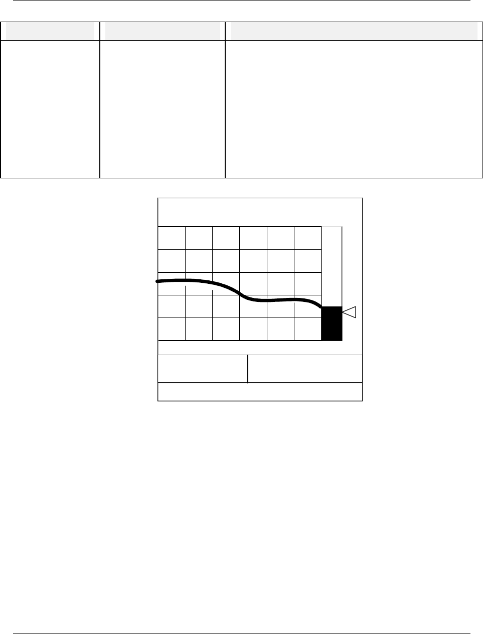
Online Operation Using Menus
Video Recorder – User Manual 237
Table 7-9 Tune Loop Prompts (continued)
Prompt Range/Selections Definition
DISPLAY TUNING
TREND Select this to display the actual tuning trend with PV and
setpoint (Figure 7-2). Data collection for this trend display
will continue as long as the display shows either the trend or
the Loop Tuning Menu. Use this display to help find the
optimal tuning parameters.
Note: If you access this display through a loop display (by
Tabbing to and selecting the loop tag name at the top of any
loop display), the trend data is not buffered when you leave
and return to this tuning trend display. Therefore, if you wish
to adjust tuning parameters and then look at the trend to see
the effects, it is recommended you select Tune Loop through
the Online menu, not through a loop display.
A
PR0297 LP1
A
UTO SP1
0.00
PV 60.00
OUT 3.5 SP 52.00
DEV 8.00
15:37
200.00
Figure 7-2 Control Loop Tuning Display

Online Operation Using Menus
Video Recorder – User Manual 238
Pretune Loop
Pretune calculates optimum values for a loop's Proportional Band/Gain, Reset and Rate by analyzing
the reaction of the loop to a "step change" in setpoint or output. After these new tuning values have
been calculated you have the option of applying (installing) or not applying them to a preselected tune
set of the loop. You can pretune a loop while another loop is pretuning.
To use pretune, your process time constant must be at least 60 seconds. The process time constant is
defined as the time needed for the PV to change by 63% of a step change in the setpoint. For example,
if the setpoint changes instantaneously by 100 degrees, the time constant is the amount of time needed
for the PV to change 63 degrees.
To pretune a loop, select PRETUNE from the TUNE LOOP online menu. Select a loop to tune. Pretune
occurs in 4 stages as indicated by the status. Each status has its own menu. Table 7-10 shows the
stages of pretune.
Table 7-10 Stages Of Pretune
Order Status Meaning
1 STOPPED Pretuning not operating, waiting to be started by operator. See STOPPED menu.
2 IDENTIFYING Pretune is identifying process dynamics as a result of a setpoint or output change.
This process may take up to 4 to 6 process time constants. See Table 7-12
3 CALCULATING Identification is complete and calculation of new tuning parameters is in process.
See Table 7-12
4 COMPLETE Calculations are complete and new parameters are ready to replace the loop's
tuning parameters, if desired. See Table 7-13
NOTE: While using Pretune, it is recommended that Overshoot Suppression is turned off. With
overshoot suppression on, Pretune may not work or may give inaccurate tunings.
Pretune STOPPED menu
Table 7-11 describes the Pretune STOPPED prompts.
Table 7-11 Pretune STOPPED Prompts
Prompt Range/Selections Definition
STATUS This is a read-only prompt. Status stopped.
PV This is a read-only prompt. Current process variable value of the loop being tuned.
OUTPUT This is a read-only prompt. Current output value of the loop being tuned.
SETPOINT This is a read-only prompt. Current working set point value of the loop being tuned
TUNE SET Select which set of tuning
parameters (#1 or #2) will
be pretuned and installed.
If tuning a split loop, set#1 applies to loop output between 0
and +100; set#2 applies to loop output between 0 and -100.
OPTIMIZE Select SET PT or LOAD This optimizes the new tuning parameters according to their
intended use (that is, controlling changes in setpoint or
process load).
OVERSHOOT Select YES or NO. This determines whether or not some overshoot is
acceptable in the pretune specified tuning.
Continued on next page

Online Operation Using Menus
Video Recorder – User Manual 239
Table 7-11 Pretune STOPPED Prompts (continued)
Prompt Range/Selections Definition
OUTPUT SIZE -100 to +100 Appears if loop is in Manual. Enter the largest change in
output (+ or -), in engineering units, that the process will
tolerate. The pretune will initiate and analyze this output
change.
SP STEP SIZE -100 to +100 Appears if loop is in Auto. Enter the largest change in
setpoint (+ or -), in engineering units, that the process will
tolerate. The pretune will initiate and analyze this setpoint
change.
START Select to start the pretune function. See Before Starting
Pretune below.
Before Starting Pretune
Before starting Pretune, configure/adjust the loop as follows:
Auto/Manual: Either mode is acceptable. Changing the loop mode after starting pretune will abort the
pretune, causing an error message to appear.
Process Variable: Adjust setpoint or output to bring the process variable to normal operation range.
Adjusting or switching setpoints or output after starting pretune will abort the pretune, causing an error
message to appear.
Gain/Proportional Band, Reset: Use known good settings. Or, set Gain = 1.0 (PB = 100), Reset = 1.0
and place loop in Manual mode.
Rate: Optional. If OFF, pretune will not calculate a Rate.
Suppress Overshoot: Set to OFF. Pretune may detect changes to the working setpoint and abort. Turn
this setting back on after pretune is complete.
After Starting Pretune
After starting the pretune, do not change/adjust the loop mode, loop output, loop setpoint, or operating
mode. If you do, the pretune will abort. See Pretune Abort Messages later in this section.
Pretune IDENTIFYING & CALCULATING menus
During IDENTIFYING and CALCULATING status, a TUNE indicator appears on all primary displays (not
on menus) for the loop being pretuned.
Table 7-12 Pretune IDENTIFYING & CALCULATING Prompts
Prompt Definition
STATUS Status Identifying or Calculating. This is a read-only prompt.
PV Current process variable value of the loop being tuned. This
is a read-only prompt.
OUTPUT Current output value of the loop being tuned. This is a read-
only prompt.

Online Operation Using Menus
Video Recorder – User Manual 240
Table 7-12 Pretune IDENTIFYING & CALCULATING Prompts
(continued)
Prompt Definition
SETPOINT Current working set point value of the loop being tuned. This
is a read-only prompt.
RUN TIME Elapsed time since pretune was started. This is a read-only
prompt.
ABORT Select to cancel identifying and calculating and return to the
stopped status.
Pretune COMPLETE menu
Table 7-13 describes the Pretune COMPLETE prompts.
Table 7-13 Pretune COMPLETE Prompts
Prompt Definition
STATUS Status Completed. This is a read-only prompt.
PB/GAIN New Prop. Band or gain determined by pretune. This is a
read-only prompt.
RESET New Reset determined by pretune. This is a read-only
prompt.
RATE New Rate determined by pretune. This is a read-only prompt.
INSTALL Select to install the new pretune values into loop’s tuning
parameters (specified by TUNE SET in Table 7-11.)
ABORT Select to delete the new pretune values if you do not wish to
install them.

Online Operation Using Menus
Video Recorder – User Manual 241
Pretune Abort messages
One of the following messages is displayed when an unusual event has aborted the pretune. “PTA”
means “Pretune Abort.”
Table 7-14 Pretune Abort Messages
Message Meaning/User action required
PTA-WARM START A warm start occurred during pretune. Repeat
pretune.
PTA-WENT OFFLINE Instrument went out of Online mode during pretune.
Repeat pretune.
PTA-LOOP STATUS Loop has PV that is bad (i.e. failed sensor)
OR
PV is a constant value such as from an upstream
block in manual
OR
Loop has back calculation value from a downstream
block that is bad or is the result of the downstream
block being in manual.
Repeat pretune.
PTA-AM SEL CHNGE Loop switched between automatic and manual
modes. Repeat pretune.
PTA-SP SEL CHNGE Loop was in automatic mode and an attempt was
made to switch between Setpoint #1 and Setpoint #2.
Repeat pretune.
PTA-OUT MOVED Loop was in manual mode and loop’s output value
changed. Repeat pretune.
PTA-SP MOVED Loop was in automatic mode and the setpoint value
changed. Repeat pretune.
PTA-LOOP OS Loop is out of service. Fix loop before repeating
pretune.
PTA-LOOP NOT CFG Loop is not configured. Configure loop before
repeating pretune.
PTA-BAD STEP SIZ Step size is turned off. Set step size to a value
before repeating pretune. See Table 7-11.
PTA-ONOFF LOOP Cannot pretune an on/off type loop.
PTA-BAD SN RATIO Increase step size. See Table 7-11.
PTA-BAD OSC Repeat pretune with smaller gain or proportional
band in loop.
PTA-BAD ID VALUE Increase step size. See Table 7-11.
PTA-DB ACCESS Unknown hardware problem. Consult service.
PTA-TASK FAIL Unknown hardware problem. Consult service.

Online Operation Using Menus
Video Recorder – User Manual 242
7.7 Set Mode
Select this item to change the operating mode of the instrument to Program or Maintenance. These
operating modes are discussed in Sections 4, 5, and 8.
7.8 Review Programming
This item is visible only if enabled under Enable Features in the Program mode.
Select this item to see how the instrument is configured. You can view all Program mode menus as if
you were in Program mode, but you cannot change anything.

Maintenance
Video Recorder – User Manual 243
8. Maintenance
8.1 Overview
This section includes information on maintenance through the Maintenance Mode menu using some off-
line utility programs and diagnostics procedures.
To avoid voiding the warranty, contact your service provider before attempting any service or repair of
this instrument.
Maintenance Mode is an off-line mode for maintaining proper operation of the instrument and setting
defaults.
Enter Maintenance Mode by selecting "MAINTENANCE" on the "SET MODE" line of the On Line or
Program Main Menu. Remember that this mode is an off-line mode.
Table 8-1 Maintenance Mode Menu
Menu as displayed Function
SET MODE Changes operating mode of instrument
CALIBRATE ANALOG INPUTS Calibrates Analog Inputs
CALIBRATE ANALOG OUTPUTS Calibrates Analog Outputs
OFF-LINE DIAGNOSTICS Runs diagnostic tests to check various instrument functions
DATABASE SERVICES Clears instrument memory. Upgrades software features
RESET UNIT Resets instrument to recognize changes to Main Frequency or Scan
Frequency
PRODUCT INFORMATION Displays product information
MAINS FREQUENCY Sets the power supply frequency (50 or 60 Hz)
WARM START TIME Sets warm start time
DEMO Enables simulated input values. For demonstration purposes only

Maintenance
Video Recorder – User Manual 244
What’s in this section
The following topics are explained in this section.
Topic Page
Routine Maintenance 245
Set Mode 245
Calibrate Analog Inputs 245
AO Module Calibration 246
Off-line Diagnostics 247
Database Services 248
Reset Unit 248
Product Information 248
Mains Frequency 248
Warm Start Time 249
Demo 250

Maintenance
Video Recorder – User Manual 245
8.2 Routine Maintenance
CAUTION
Calibrate the instrument routinely to ensure conformity to specifications. Calibration is to be performed by
qualified service personnel only.
Clean the front panel with a damp cloth. If needed, use a detergent containing no abrasives. Always clean
the front panel with the bezel closed. Do not use solvent cleaners.
Failure to comply with these instructions may result in product damage.
8.3 Set Mode
Select this to change the operating mode to Online or Program.
NOTICE
Changing to ONLINE mode by pressing any of the Display buttons can cause incorrect values to be
displayed. The values will correct themselves in a few seconds. To avoid this potential annoyance, change
to online mode through SET MODE instead of through the Display buttons.
8.4 Calibrate Analog Inputs
Note: the unit must be allowed to warm up for 30 minutes at the intended operating temperature prior to
calibration.
Selecting the CALIBRATE ANALOG INPUTS lists a number of calibration functions you can perform.
Selecting the CALIBRATE ANALOG INPUTS again allows you to specify the AI module and channel in
which to calibrate. When you Select Input, you must apply a 0% reference (low point calibration) value to
the terminal block of the module channel. Then select CALIBRATE to start the calibration routine. After
calibration of 0% value is completed, apply a 100% range value to the channel input terminals and then
begin the calibration routine for 100% input (high point calibration).
When 100% range value calibration is completed, the controller compares the new 0% and 100% range
values against the current 0% and 100% values. If the span of the 0% and 100% readings is less than
20% of the sensor range, the new values are rejected and the current calibration is retained.
Each channel must be calibrated for the specific input type to be applied to that channel. Calibration
values can be copied from one channel to all other channels of like input type and range.
NOTE: Signal generators should have an accuracy of at least 0.05 %. The type of wires depends on the
sensor used. Wait for 5 minutes after that particular sensor is connected (for compensation wires only).
WARNING
In thermocouple pay attention to the ambient temperature. If you are using a mV generator instead of
direct thermocouple generator, the leadwires are in copper and you have to subtract from the mV value
the mV corresponding to the ambient temperature of the rear terminals. (This eliminates the effect of
the cold junction compensation).
Failure to comply with these instructions could result in death or serious injury.
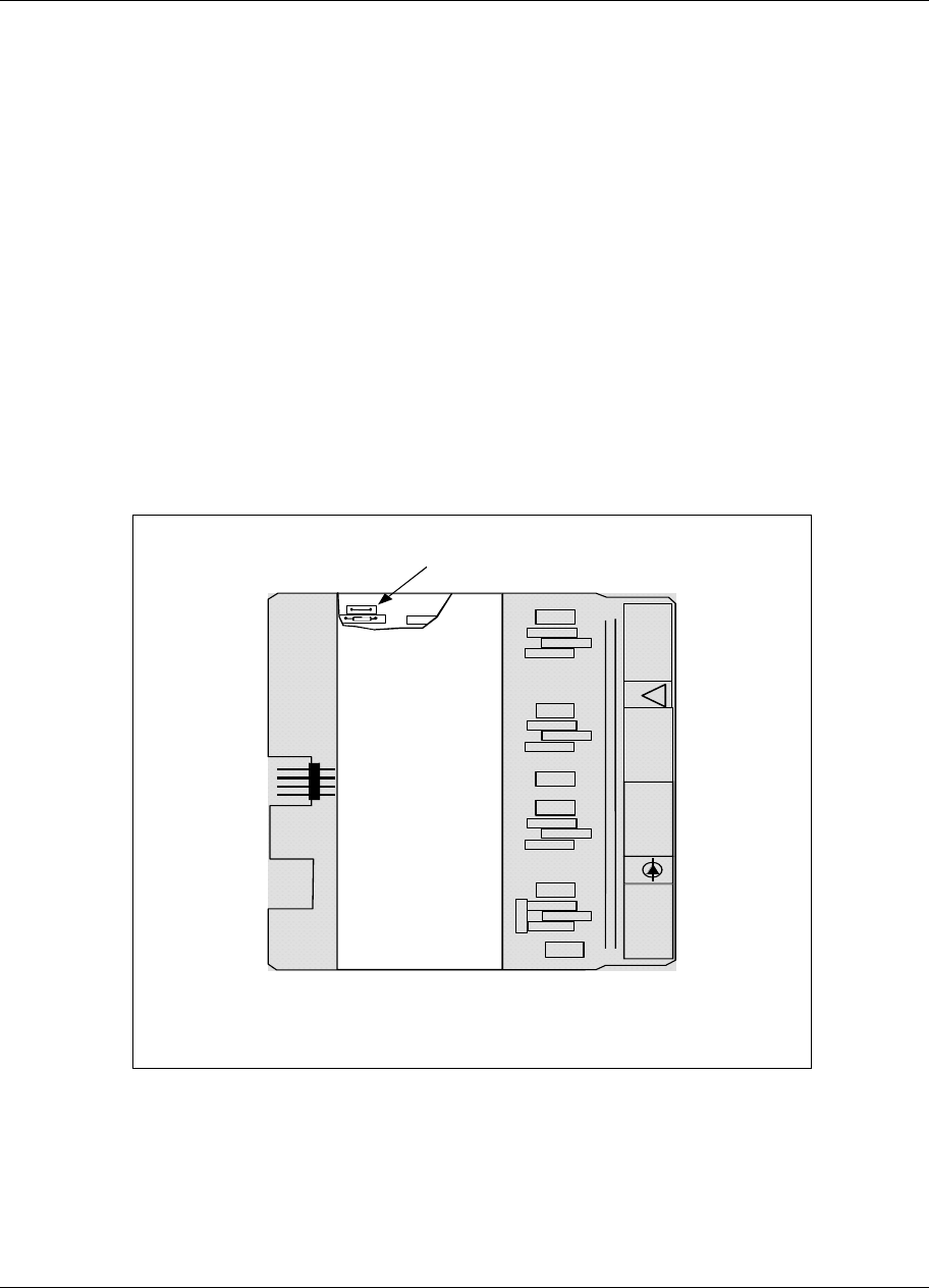
Maintenance
Video Recorder – User Manual 246
Additional calibration selections allow you to perform other calibration procedures:
CALIBRATE REFERENCE JUNCTIONS – for calibrating the two Cold Junction (CJ) references on AI
module.
COPY ANALOG INPUT CALIBRATION – for copying calibration values from one AI module channel to
another.
RESET ANALOG INPUT CALIBRATION – to restore AI module channels to their factory calibration.
RESET REF. FUNCTION CALIBRATION – to restore CJ reference to their factory calibration values.
8.5 AO MODULE calibration
Two calibration selections are accessible under the CALIBRATE AO menu selection
CALIBRATE AO CHANNEL – to calibrate the zero offset and span values of the AO module channels to
user-defined values.
RESTORE AO FACTORY CAL – to restore factory calibrated to an AO module channel.
The AO module contains a wire jumper (labeled ST1) on the PWA. Cutting this jumper will prevent any
changes to initial calibration values of the module and prevent any further field calibration.
See Figure 8-1 for the location of the jumper.
ST1
OUT 4
+
_
OUT 3
+
_
OUT 2
+
_
OUT 1
+
_
0-20mA
!
Cavalier ST1
Module de sortie
analogique
Wire Jumper ST1
Analog Output
Module
Figure 8-1 AO Module Jumper ST1
Calibrate Analog Outputs
For CAT calibration, a precision milliammeter or a precision resistor and voltmeter is required.

Maintenance
Video Recorder – User Manual 247
WARNING
Disconnect power to all terminals before connecting or disconnecting calibration leads. Hazardous
voltage is present on the mains terminals and may be present on other terminals. More than one
switch may be required to de-energize the unit before servicing.
Failure to comply with these instructions could result in death or serious injury.
NOTICE
Time-stamp and description of successful calibrations are stored to disk in the Event file.
Table 8-2 Calibrate Analog Output Procedure
Step Action
1 Connect the meter to the output #1 terminals.
2 Select CALIBRATE ANALOG OUTPUTS.
3 Select OUTPUT #1 LOW. The menu will disappear and the meter will read approximately 4 mA
(CAT).
4 Use the Increment and Decrement buttons to adjust the meter reading to the exact low value 4 mA.
Press Enter when done.
5 Select OUTPUT #1 HIGH. The menu will disappear and the meter will read approximately 20 mA
(CAT).
6 Use the Increment or Decrement buttons to adjust the meter reading to the exact high value. Press
Enter when done.
7 Repeat steps 1-6 to calibrate other CAT outputs.
8 Press Menu to restore the main Maintenance menu.
8.6 Off-line Diagnostics
The following table describes the prompts.
Table 8-3 Offline Diagnostic Prompts
Prompt Function
RAM SIZE (KB) Shows amount of RAM found during power-up self-test. If less than 3072KB,
replace the CPU.
KEYBOARD TEST Select this to verify operation of each key. When each key is pressed, its name
should appear onscreen. An AT keyboard can also be tested if connected.
DISPLAY TEST Select this then press Enter to test each display color: red, green, blue, white,
black. Any failed display pixels should be apparent.
DISK READ/WRITE TEST Select this to verify read/write disk function.

Maintenance
Video Recorder – User Manual 248
8.7 Database Services
The following table describes the prompts.
Table 8-4 Database Services Prompts
Prompt Function
CLEAR ALL MEMORY Clears the Instrument memory of all programming, tuning data, setups, etc. and
restores the original factory-set default values for all parameters, functions and
analog output calibration. Does not affect analog input calibration.
FULL UPGRADE Upgrades all function blocks of the instrument from a disk file with .LNF
extension. Overwrites all function blocks. Executes Clear All Memory after this
service.
INCREMENTAL UPGRADE Upgrades the instrument with the desired options from a disk file with .LNI
extension. Does not affect existing function blocks or configuration.
SOFTWARE UPGRADE Upgrades product software from disk.
8.8 Reset Unit
Select this item to reboot the unit after making changes to Mains Frequency. This function clears all
RAM buffers (storage and display) and accumulated values of some function blocks (Calculated Value
timers, totalizers, and control loop integral) are reset to initial values.This function does not clear
memory.
8.9 Product Information
Select this item to display the product identification, software version number, PROM part number, and
serial number.
8.10 Mains Frequency
Select either 50 Hz or 60 Hz. Afterward you must select RESET UNIT to activate this change.

Maintenance
Video Recorder – User Manual 249
8.11 Warm Start Time
The instrument will start up in one of three modes based on the length of time power is off.
First Time Start
First time start occurs when the unit is being powered up for the first time or when the memory clear
services maintenance routing is executed. All configuration and calibration is cleared and all parameters
are set to factory defaults. See “DATABASE SERVICES” Section 8.7.
Cold Start
Cold start occurs when the unit is without power for a period longer than 90 minutes or if the reset unit
maintenance routine is executed. See Section 8.8 Reset Unit. In cold start operation, all RAM buffers
(storage and display) are cleared and accumulated values of some function blocks (Calculated Value
timers, totalizers, and control loop integral) are reset to initial values. The cold start operation retains the
loop operating status of auto or manual and setpoint 1 or setpoint 2. The loop output will be set to zero
(0) unless configured to use a Failsafe value for the analog output.
No Data collected and stored to floppy disk before the onset of cold Start is lost.
Data storage is automatically resumed after a Cold Start; a maximum of 1 minute of buffered data will be
lost due to a Cold Start. If a new disk was inserted into the floppy drive while power was off, you must
initialize the new disk to resume data storage.
Warm Start
If power is off for less than 90 minutes, a warm start will be used during power-up. All buffered data prior
to power loss is retained and accumulated values in Calculated Value timers and totalizers are retained.
Control loop output values are also retained. Setpoint Profilers resume where they left off. If power is off
for more than the warm up start time, a cold start operation will occur.
Warm start times available (in minutes): 1, 2, 3, 4, 5, 10, 15, 20, 30, 60, 90, None
Note that all data storage schedules that have been initialized or started via the ON LINE mode DATA
STORAGE SETUP menu will automatically resume their execution upon the occurrence of a Warm
Start.

Maintenance
Video Recorder – User Manual 250
8.12 Demo
This item is intended primarily for sales demonstrations. It causes the instrument to display a series of
simulated values.
NOTICE
Never turn the demo on in an instrument that has already been configured to support its true application
without first saving the instrument’s configuration to floppy disk. Selecting DEMO will reconfigure Analog
Inputs 1 through 4 and Discrete Input 1. When DEMO is turned off, the demo’s function block
configurations are still used but their inputs are tied to the hardware and are no longer simulated. It is
recommended that the user clears memory after DEMO is turned off.

Diagnostic and error messages
Video Recorder – User Manual 251
9. Diagnostic and error messages
9.1 Diagnostic Messages
The instrument executes diagnostic routines during instrument start-up and during maintenance
procedures such as calibration. It also monitors online operation for both process faults and instrument
errors.
Error messages
Table 9-1shows messages that may appear on the instrument displays if a diagnostic condition is
detected, along with the action you should take.
Table 9-1 Diagnostic Error Messages
Message Description User action
INPUT FAILURE The analog input is either open/shorted Check input devices for open or short.
The analog input has been exposed to
electromagnetic noise. See Section 2 for proper wiring
techniques.
The analog input is out of range Choose a higher range.
FLOAT PT ERROR A floating point calculation error has occurred.
(divide by zero, underflow, overflow). Check Free Form Math and Math CV
inputs for division by 0. Also check for
input values producing an underflow or
overflow error (that is, calculation is not
between -1x10-38 and -3x1038 or is not
between 1x10-38 and 3x1038).
CHECKSUM
ERROR An error was detected in the database of one
or more function blocks. The affected
function blocks are reset to their defaults.
Inspect entire instrument configuration
and reconfigure as needed.
ATTENTION
Be advised that the INPUT FAILURE diagnostic will continue to be displayed even after its cause has
disappeared. After verifying that this diagnostic’s cause has been corrected, you may clear the INPUT
FAILURE message from all ON LINE screens by performing one of the following sequences of steps.
1) Acknowledge the INPUT FAILURE diagnostic.
From the ON LINE main menu, select ACCESS SUMMARIES. Select DISPLAY DIAGNOSTICS. Use the
<Up> and <Down> buttons to highlight the INPUT FAILURE diagnostic(s) that you wish to acknowledge and
then press <Enter>. Once the diagnostic has been acknowledged, it will still be listed in the DISPLAY
DIAGNOSTICS screen but will no longer be displayed on any ON LINE screen.
2) Delete the INPUT FAILURE diagnostic.
From the ON LINE main menu, select ACCESS SUMMARIES. Select DELETE ALL DIAGNOSTICS. Once
this menu choice has been executed, all diagnostic messages will be deleted from the DISPLAY
DIAGNOSTICS screen and will no longer be displayed on any ON LINE screen.
During power-up, if an analog input is open or is out of range, the setpoint and process variable values
will display OFF and the loop's AUTO mode is disabled. Check connections to determine problem.
During calibration if the input reference voltages supplied by the technician are outside acceptable limits
a "CALIB FAIL" message will be generated.

Diagnostic and error messages
Video Recorder – User Manual 252
Internal error messages
In addition to diagnostic messages, error messages are presented to indicate an internal fault. To
correct the problem, Table 9-2 lists suggested actions you should take, in the order you should take
them. To acknowledge or clear the error message, see Section 7.2 Access Summaries.
Table 9-2 Internal Error Messages
Error message Suggested Action
NONV RAM ERROR 1. Reduce the configuration by eliminating function.
2. Call service provider.
PROCESSOR EXCEPTION 1. Reset unit.
2. Clear configuration and reload.
3. If message recurs, replace CPU.
PROCESSOR RESET 1. Reset unit.
2. Clear configuration and reload.
3. If message recurs, replace CPU.
TASK INIT FAILURE 1. Reset unit.
2. Clear configuration and reload.
3. If message recurs, replace CPU.
QUEUE READ FAILURE 1. Reset unit.
2. Clear configuration and reload.
3. If message recurs, replace CPU.
RESPONSE FAILURE 1. Reset unit.
2. Clear configuration and reload.
3. If message recurs, replace CPU.
REQUEST FAILURE 1. Reset unit.
2. Increase scan rate to higher time; for example, from 500 msec to 1 second.
3. Clear configuration and reload it.
4. If message recurs, replace the CPU.
AED REPORT FAILURE 1. Reset unit.
2. Increase scan rate to higher time; for example, from 500 msec to 1 second.
3. Clear configuration and reload it.
4. If message recurs, replace the CPU.
AED HANDSHAKE FAILURE 1. Reset unit.
2. Increase scan rate to higher time; for example, from 500 msec to 1 second.
3. Clear configuration and reload it.
4. If message recurs, replace the CPU.
FB TASK OVERRUN Increase scan rate to higher time; for example, from 500 msec to 1 second.
AI TASK OVERRUN 1. Check for noise.
2. Increase scan rate to higher time; for example, from 500 msec to 1 second.
continued

Diagnostic and error messages
Video Recorder – User Manual 253
Table 9-2 Internal Error Messages (continued)
Error message Suggested Action
SLOT CARD FAILURE 1. Check for noise.
2. Check AI card connection.
3. Replace AI card.
STORAGE FAILURE 1. Check for bad floppy disk.
2. Run disk diagnostic on the disk drive.
3. Check seating of floppy cables.
4. Replace CPU.
DATA STORAGE STATUS
LOST
1. Check for bad floppy disk.
2. Run disk diagnostic on the disk drive.
3. Check seating of floppy cables.
4. Replace CPU.
RJ FAILURE 1. Check reference junction sensor connection.
2. Check AI card.
3. Replace CPU.
CLOCK FAILURE 1. Reprogram clock.
2. Reset unit.
3. Change lithium battery on interconnection board.
4. Replace CPU.
CLOCK RESET 1. Reprogram clock.
2. Reset unit.
3. Change lithium battery on interconnection board.
4. Replace CPU.
TIMING ERROR 1. Reprogram clock.
2. Reset unit.
3. Change lithium battery on interconnection board.
4. Replace CPU.
TASK ERROR 1. Reset unit.
2. Clear configuration and reload.
3. If message recurs, replace CPU.
RAM ERROR 1. Run RAM diagnostic.
2. Replace CPU.
COMM PORT ERROR 1. Check communications card seating.
2. Replace communications card.
3. Replace CPU.

Diagnostic and error messages
Video Recorder – User Manual 254
9.2 Loop Error Indicators
When a loop's PV, SP2, or other parameter fails, the loop switches to its default/failsafe condition,
indicated by certain display symbols flashing. To return the loop to its desired condition, correct the
failure. Then, if the loop's LATCHING is NO, the loop will return to normal automatically. If LATCHING
is YES, also perform the action needed to return the loop to normal.
Table 9-3 Abnormal Loop Conditions And Indicators
Desired Condition Abnormal Condition Default condition
(Failsafe) Flashing
symbols Action needed
(if LATCHING = YES)
Auto & SP2 SP2 Failure Working SP=SP1 SP2 Select SP1 then SP2
Manual & SP2 SP2 Failure Working SP=SP1 SP2 Select SP1 then SP2
Auto & SP2 SP2 & PV Failure Working SP=SP1
Mode = Suspend Auto*
Output = Failsafe
SP2
AUTO
MAN**
PV
Select SP1 then SP2
Select Manual then
Auto
Manual & SP2 SP2 & PV Failure Working SP = SP1
Mode = Manual
Output = Last value
SP2
PV Select SP1 then SP2
Auto & SP1/SP2 PV Failure or
Force Remote Manual
Failure or
Output Tracking
Failure or
Feedforward Failure
Mode = Suspend Auto*
Output = Failsafe
AUTO
MAN**
PV
Select Manual then
Auto
Manual & SP1/SP2 PV Failure Mode = Manual
Output = Last Value
PV None required
Auto & SP1/SP2 See below*** Mode = Suspend Auto*
Output = Back Calc. Value AUTO
MAN None required
Auto & SP1/SP2 Force Remote Manual Mode = Suspend Auto*
Output = Tracking value AUTO None required
*Due to the abnormal condition the loop cannot be in Auto and therefore is in a temporary mode which forces
the output as indicated.
**If loop feedback is not connected to an AO, or if loop type is ON/OFF, then MAN will be steady, not flashing.
***Status from a downstream function block indicates that there is no path to final output element. For
example, the secondary control loop of cascade configuration was changed to manual mode.

Diagnostic and error messages
Video Recorder – User Manual 255
9.3 Error Messages
Overview
Sometimes errors occur while you are programming or loading a configuration into your instrument. In
most cases the instrument displays a descriptive error message. For example, if you try to program a
function block incorrectly, the instrument tells you the problem.
Table 9-4 lists these error messages along with a description of each one and what action to take.
Table 9-4 Error Messages
Error Description User Action
Alarm/Event/Diagnostic burst
and transitions lost The instrument had an
Alarm/Event/Diagnostic burst in the controller
and some transitions were lost.
Inspect the Alarm Summary/History
and the Discrete Summary Screen to
resolve any missing or unresolved
alarms vs their current states. If the
state transition that was missing was
an off state it will be matched and
processed upon the next on-off
transition of the corresponding alarm.
Block Phase Greater Than Block
Period In Periodic Timer CV, the phase (start time)
is greater than the period. For example, the
start time is 8:00 and the period is 4:00.
Change Period to greater than phase
(Start Time) or change Start Time to
less than Period.
Channel Does Not Exist A channel was loaded that does not exist.
For example, you loaded a dual loop
configuration into a single loop instrument.
Verify programming of affected
function block.
Circuit Limits Equal Indirect circuit low/circuit high limits must be
unequal. Change to unequal limits.
Condition Type Out of Range Condition Type (Compare, Logic, Free form
Logic) is out of range. Probably caused by
someone incorrectly editing the configuration
file or by a corrupt .LNC file.
Verify programming of affected
function block.
Desired F0 Value Not
Programmed or Less Than Zero In the F0 Sterilization CV, desired F0 is not
programmed or is less than zero. Change F0 value to greater than zero.
High Limit Outside of circuit AI circuit high limit is > voltage limit of 5200
mV. Change limit to within specified limits
for that type.
High Output Limit Greater than
20 A current output (CAT) high output limit
cannot be greater than 20 Decrease high limit.
Hysteresis Less Than Zero Alarm Hysteresis parameter should be
greater than or equal to zero. Increase Hysteresis.
Impulse Time less than or Equal
to 0 Impulse time on a time
proportioning/duration adjusting output (DAT)
cannot be less than or equal to zero.
Increase impulse time.
Incompatible Curve Type AI is custom type, thermocouple class,
reference junction enabled but Y values are
not always increasing or not always
decreasing.
Reprogram curve so that for all n: Yn
> Yn+1 or Yn < Yn+1

Diagnostic and error messages
Video Recorder – User Manual 256
Table 9-4 Error Messages (continued)
Error Description User Action
Incorrect Input
coordinates The Advanced Splitter CV was programmed with
input limits for Output#2 (A2) only, or for Output#1 &
#3 (A1 & A3) only, or for Output#3 (A3) only.
Re-program input limits for
Output#1 only, Outputs #1 & #2,
or Outputs #1, #2, & #3.
Incorrect Number of
Parameters for function The function was not programmed with the minimum
number of parameters. for example, the Math CV
requires at least 2 inputs to function properly.
Program function with at least the
minimum number of parameters.
Incorrect Output
Coordinates The Advanced Splitter CV was programmed with
output limits for Output#2 (A2) only, or for Output#1 &
#3 (A1 & A3) only, or for Output#3 (A3) only.
Re-program output limits for
Output#1 only, Outputs #1 & #2,
or Outputs #1, #2, & #3.
Invalid Algorithm Code Bad algorithm code has been given, bad algorithm
choice. Probably caused by someone incorrectly
editing the configuration file or by a corrupt .LNC file.
Verify programming of affected
function block.
Invalid Block Number Probably caused by someone incorrectly editing the
configuration file or by a corrupt .LNC file. Verify programming of affected
function block.
Invalid Block Type Probably caused by someone incorrectly editing the
configuration file or by a corrupt .LNC file. Verify programming of affected
function block.
Invalid Channel in Point
spec Invalid channel has been found. Verify programming of affected
function block.
Invalid Equation Free form math equation is invalid. Check equation.
Invalid Function Block
Request Probably caused by someone incorrectly editing the
configuration file or by a corrupt .LNC file. Verify programming of affected
function block.
Invalid Index code Probably caused by someone incorrectly editing the
configuration file or by a corrupt .LNC file. Verify programming of affected
function block.
Invalid Input Connection Function block is programmed with wrong input type.
Probably caused by someone incorrectly editing the
configuration file or by a corrupt .LNC file.
Verify programming of affected
function block.
Invalid Machine Update
Rate Bad machine scan rate. Re-enter machine scan rate.
Invalid Parameter Code Bad parameter code has been found. Generally
caused by transferring configurations between
instruments with different software versions.
Verify programming of affected
function block.
Invalid Parameter for
Data Type Probably caused by someone incorrectly editing the
configuration file or by a corrupt .LNC file. Verify programming of affected
function block.
Invalid Tag Probably caused by someone incorrectly editing the
configuration file or by a corrupt .LNC file. Verify programming of affected
function block.
Invalid Tag Request Probably caused by someone incorrectly editing the
configuration file or by a corrupt .LNC file. Verify programming of affected
function block.
Invalid Type in Point
Spec A class of block was detected that is invalid for the
product. Verify programming of affected
function block.
Lag or Delay Less than
Zero AI lag or delay is less than zero. Change lag or delay to greater
than or equal to zero.

Diagnostic and error messages
Video Recorder – User Manual 257
Table 9-4 Error Messages (continued)
Error Description User Action
Low Limit Outside of
Circuit AI circuit low limit is < voltage limit of -500 mV. Change circuit low limit to > -500
mV.
Low limit Outside of
Table For thermocouple or RTD, Range Low limit is < the
low limit for that type. Change limit to within specified
limits for that type. (Table 4-3)
Low Output Limit less
than Zero A current output (CAT) low limit is less than zero. Change current output (CAT) low
limit to greater than or equal to
zero.
Monthly Periods Must Be
Phased Periodic Timer CV period is monthly but no phase is
defined. Change Periodic Timer phase.
No Room for Function
Block System has used all allocated function blocks. Verify programming of affected
function block.
Number of Frames Out of
Range Rolling Average CV # of Samples is less than 1 or
greater than 60. Change # of Samples to 1-60.
Out of EEPROM Memory No more static memory or EEPROM memory. Verify programming of affected
function block.
Out of RAM Memory No more RAM available. Verify programming of affected
function block.
Output Limits Equal Output (range) limits (low and high) must be unequal. Change to unequal limits
Pairs Inconsistent Applies to custom AI or Function Generator CV.
Curve has Xn but no Yn or vice versa. Curve does
not have at least 2 X,Y pairs.
Program a Y for each X or vice
versa. Program at least 2 X’s and
2 Y’s.
Request Made with
Invalid Tag Probably caused by someone incorrectly editing the
configuration file or by a corrupt .LNC file. Verify programming of affected
function block.
Requires a Deviation
Parameter Deviation alarm does not contain deviation. Program alarm with deviation.
Requires Input
Parameter Alarm does not contain an input. Program alarm with input.
Requires Setpoint
Parameter Alarm does not contain a setpoint. Program alarm with a setpoint.
RJ Not in Curve AI is custom type, class thermocouple, RJ enabled
but curve does not contain 0-65 degrees C (32-149
degrees F).
Y values must contain 0-65
degrees C (32-149 degrees F).
Temperature Constant
Not Programmed or Less
Than Zero
F0 Sterilization CV Temperature constant is not
programmed or is less than zero. Program Temperature constant
with value greater than or equal to
zero.
Temperature Input Not
Programmed or Less
Than Zero
F0 Sterilization CV Temperature Input is not
programmed or is less than zero. Program Temperature input with
value greater than or equal to
zero.
Temperature Reference
Not Programmed or Less
Than Zero
F0 Sterilization CV Reference Temperature is not
programmed or is less than zero. Program Reference Temperature
with value greater than or equal to
zero.

Diagnostic and error messages
Video Recorder – User Manual 258
Table 9-4 Error Messages (continued)
Error Description User Action
Trend Has Too Many
Points For Rate Selected Data Storage cannot store more than 3 points at 1/4
second scan rate. Change number of points to be
compatible with scan rate.
Type Does Not Exist A function block type was loaded that does not exist.
For example, you loaded a Profile but the unit does
not have the Profile option.
Re-program or re-load correctly.
Type Incompatible With
Hardware Analog output type is different from hardware setting.
Attempted to assign 6th relay as a DAT function. Change programming to be
compatible with the hardware or
vice versa, then reload
configuration or reconfigure the
block.
Type Requires Hardware Hardware is missing for the programmed analog
output or discrete output relay. Either ignore the message
knowing that those particular
points did not get loaded or verify
configuration and make sure that
the points that are in the
configuration match the hardware
components.
Undefined Function Block
Request Internal Error. No user action.
Value Written to
Indirected Point An input has been connected and user has tried to
write a value to that input. For example, if a control
loop setpoint is connected to AI1 OV, you will receive
this message if you try to change the loop setpoint
online.
Avoid changing connected values.
X Axis Must Increase Appears if AI is custom type or CV is Function
Generator and if Xn > Xn+1. Re-program Xn < Xn+1.
X Axis Not Increased
Enough Appears if AI is custom type or CV is Function
Generator and if X does not increase by at least
0.00001.
Re-program X.
Y Axis Not Increased
Enough Appears if AI is custom type or CV is Function
Generator and if Y does not change by at least
0.00001.
Re-program Y.

Parts
Video Recorder – User Manual
259
10. Parts
Table 10-1 Parts
Kit Description Kit Part Number CK N°
ELECTRONIC SOFTWARE
Power supply 46190250-502 189
HMI board 46193301-501 241
CPU board 46193304-501 242
Interconnection board 46190326-502 243
Relay output board with terminals 46190308-501 192
DC digital output board with terminals 46190341-501 192
AC digital output board with terminals 46190344-501 192
Analog output board with terminals 46190314-501 222
Contact closure input board with terminals 46190311-501 192
Universal analog input board with terminals 46190305-501 192
DC digital input board with terminals 46190347-501 192
AC digital input board with terminals 46190350-501 192
Keyboard card 46193310-501 248
Backlight igniter 46193060-501 249
Communication board 46190260-502 214
Firmware upgrade - Communication 46193350-501
MECHANICAL PARTS
Door complete with LCD, glass window and latch 46193090-501 244
Door complete with LCD, glass window and lock 46193090-502 244
Door complete with LCD, plastic window and latch 46193090-503 244
Door complete with LCD, plastic window and lock 46193090-504 244
Portable case 46193121-501 252
Spare case galvanised 46193120-501 253
Spare painted case 46193120-503 253
Kit of 2 keys for key lock 46180091-003
LCD screen 46193062-501 245

Parts
Video Recorder – User Manual 260
Kit Description Kit Part Number CK N°
Backlight 46193065-501 246
Cable of LCD screen 46193261-501 247
Door switch 46193112-501 250
Kit Description Kit Part Number CK N°
MISCELLANEOUS
Terminal block (for low voltage inputs) 46190202-501 201
Terminal block (for alarm relays, ac/dc I/Os) 46190204-501 201
Battery 46222201-502 204
Panel mounting kit 46182649-501
Internal 100MB ZIP disk drive 46193110-501 256
CONSUMABLES
Kit of 4 resistors 250 ohms 46181080-503
Fuse 46182886-002
Door complete with LCD, glass and latch - 46193090-501
Door complete with LCD, glass and lock - 46193090-502
Door complete with LCD, plastic window and latch - 46193090-503
Door complete with LCD, plastic window and lock - 46193090-504
Portable case - 46190112-501
Spare case galvanised - 46190104-501
Spare painted case - 46190104-503
CPU board - 46193304-501
Power supply -
46190250-502
Terminal block (for alarm relays ac/dc I/Os)
- 46190204-501
Terminal block (for low voltage inputs) -
46190202-501
Relay output board with terminals - 46190308-501
DC digital output board with terminals - 46190341-501
AC digital output board with terminals - 46190344-501
Analog output board with terminals - 46190314-501
Contact closure input board with terminals - 46190311-501
Universal analog input board with terminals - 46190305-501
DC digital input board with terminals - 46190347-501
AC digital input board with terminals - 46190350-501
Communication board
Disk LS120 - 46210116-501 or
ZIP disk 46210117-501
Kit of 2 keys for key lock - 46180091-003
Panel mounting kit - 46182649-501
Parts
Video Recorder – User Manual 262
LCD screen 46193062-501
Backlight igniter 46193060-501
Backlight 46193065-501
cable of LCD screen
46193261-501
Keyboard card 46193310-501
Internal 100MB ZIP drive 46193110-501
Interconnection board 46190326-502
HMI board 46193301-501
Door switch 46193112-501

Appendix A
Video Recorder – User Manual 263
Appendix A
A.1 Security Bypass Procedure
Overview
Your instrument has a security bypass code which allows you to enter secured areas of the product..
Use this bypass code if you have forgotten or lost the master and/or operator security code.
Bypass procedure
Table A-1 Security Bypass Procedure
Step Action
1 When you are prompted for the master or operator security code, use the Increment and Decrement
buttons to select the bypass code 783.
2 Press the Display button to display the forgotten master or operator code.
3 To return to the previous menu without entering the secured area, press the Menu button. To enter
the secured area, press Enter.
ATTENTION
Remove this page for security.

Appendix A
Video Recorder – User Manual 264

Safety
Video Recorder – User Manual 265
SIKKERHESKRAV DA2I-6063
!
For at undgå elektrisk stød med mulighed for personskade, skal alle
sikkerhedsbestemmelser i denne manual følges nøje.
Dette symbol advarer brugeren om en potentiel berøringsfare, såfremt der kan være
adgang til den livsfarlige netspænding.
Beskyttende jordterminal. Terminalen er forberedt for og skal forbindes til beskyttelses-
jordledning i henhold til stærkstrømsberkendtgørelsen (DK).
• Hvis udstyret ikke bruges som specificeret i manualen, kan den beskyttelse udstyret yder blive
nedsat eller forsvinde.
• Eerstat kun komponenter som udtrykkeligt er specificeret som udskiftelige i manualen.
• Alle ledningsforbindelser skal følge stærkstrømsberkendtgørelsen (DK) og udføres af autoriseret
erfarent personel.
• Den beskyttende jordterminal skal forbindes først af alle forbindelser (og fjernes som den sidste).
• Det anbefales jvf. stærkstrømsberkendtgørelsen, at der installeres en afbryder til
frosyningsspændingen nær udstyret.
UDSTYRS SPECIFIKATIONER
Strømforsyning 100 til 240 V AC/DC
Frekvens 50 – 60 Hz
Nominel effekt 100 VA
Sikringsværdi 3.15 A / 250 V AC/DC
OMGIVELSES SPECIFIKATIONER
Placer ikke udstyret i nærheden af brandbare væsker eller dampe.
Temperatur Rumtemperatur : 5 til 40°C
Opbevaring : -20 til 60°C
Fugtighed 10 til 90% RH ikke kondenserende / 40°C
Vibration 10 til 40 Hz, amplitude 0.07 mm
40 til 60 Hz, acceleration 0.2 g
UDSTYRS INSTALLATION
Skriveren skal monteres i en tavle for at forhindre adgang til bagterminaler.

Safety
Video Recorder – User Manual
266
VEILIGHEIDSVEREISTEN DU2I-6063
!
Ter vermindering van het gevaar van elektrische schokken die lichamelijk letsel kunnen
veroorzaken, dient u alle veiligheidsaanwijzingen in dit dokument te volgen.
Dit symbool waarschuwt de gebruiker voor een potentieel schokgevaar wanneer
toegang bestaat tot onderdelen die onder gevaarlijke spanning staan.
Beschermende aarde-aansluiting. Bestemd voor aansluiting van de aardingsdraad van
de voeding.
• Indien de apparatuur wordt gebruikt anders dan door de fabrikant gespecificeerd, kan de
bescherming, die de apparatuur biedt ongedaan worden gemaakt.
• Alleen die onderdelen mogen worden vervangen die door de fabrikant als uitwisselbaar zijn
aangemerkt.
• Alle bedrading moet in overeenstemming zijn met de lokale elektriciteiseisen en moet aangelegd
worden door geauthoriseerd, ervaren personeel.
• De aardingsdraad moet worden aangesloten vóórdat alle andere bedrading wordt aangesloten (en
als laatste worden verbroken).
• Het verdient aanbeveling een netschakelaar aan te brengen vlakbij het instrument.
APPARATUUR VOORWAARDEN
Voedingsspanning 100 tot 240 V AC/DC
Frequentie 50 – 60 Hz
Vermogen of stroomvermogen 100 VA
Zekering 3.15 A / 250 V AC/DC
OMGEVINGSCONDITIES
Gebruik het instrument niet in de aanwezigheid van ontvlambare vloeistoffen of dampen. Het gebruik
van elk elektrisch instrument in een dergelijke omgeving vormt een gevaar voor uw veiligheid.
Temperatuur In bedrijf : 5 tot 40°C
Opslag : -20 tot 60°C
Vochtigheid 10 tot 90% RH niet condenserend / 40°C
Trilling 10 tot 40 Hz, amplitude 0.07 mm
40 tot 60 Hz, versnelling 0.2 g
MONTAGE VAN DE APPARATUUR
De recorder moet worden gemonteerd in een paneel om de toegankelijkheid tot de achterste
aansluitpunten te beperken.

Safety
Video Recorder – User Manual 267
TURVALLISUUSMÄÄRÄYKSET FI2I-6063
!
Noudata tämän ohjeen kaikkia turvaohjeita välttääksesi sähkötapaturman vaaraa.
Tämä merkki varoittaa käyttäjää sähköiskun vaarasta paikassa, missä voi koskettaa
vaarallisia jännitteitä.
Suojamaaliitin. Kytke maadoitsjohdin tähän liittimeen.
• Jos laitetta käytetään olosuhteissa, joihin sitä ei ole suunniteltu, käyttöturvallisuus voi heikentyä.
• Älä vaihda mitään komponettia tai osaa, jota valmistaja ei ole määritellyt käyttäjän vaihdettavaksi.
• Asennus ja johdotus on tehtävä paikallisten varmuusmääräysten mukaisesti valtuutetun
sähköasentajan toimesta.
• Ensimmäiseksi on kytkettävä suojamaa-liitin (ja viimeiseksi irroittettava).
• Laitteen läheisyyteen suositellaan asennettavaksi verkkokytkin.
LAITTEEN VAATIMUKSET
Syöttöjännite 100 – 240 V AC/DC
Taajuus 50 – 60 Hz
Teho 100 VA
Sulakearvo 3.15 A / 250 V AC/DC
KÄYTTÖOLOSUHTEET
Älä käytä laitetta paikassa jossa on syttyviä nesteitä tai kaasuja, koska laitteen käyttö aiheuttaa
räjähdysvaaran.
Lämpötila ympäröivä : 5 ... 40°C
Varastossa : -20 ... 60°C
Kosteus 10 ... 90% RH non condensing / 40°C
Tärinä 10 ... 40 Hz, amplitude 0.07 mm
40 ... 60 Hz, Kiihtyvyys 0.2 g
LAITTEEN ASENNUS
Piirturi on asennettava paneeliin siten, että peräliitimille jää riittävästi tilaa.

Safety
Video Recorder – User Manual
268
CONSIGNES DE SECURITE FR2I-6063
!
Pour réduire tout risque de décharge électrique qui pourrait provoquer une lésion
corporelle, respectez toutes les consignes de sécurité de cette documentation.
Ce symbole avertit l'utilisateur d'un risque électrique potentiel lorsqu'il peut avoir accès à
des éléments sous tension.
Borne de mise à la terre. Destinée au raccordement du conducteur de mise à la terre de
l'alimentation.
• Si l'équipement est utilisé dans un but non spécifié par le constructeur, la protection fournie avec
cet équipement peut être affectée.
• Aucun composant (ou pièce) ne doit être remplacé s'il n'est pas explicitement spécifié comme tel
par le constructeur.
• Tous les câblages doivent être conformes aux normes locales et doivent être réalisés par un
personnel autorisé et expérimenté.
• La borne de masse doit être raccordée avant tout autre câblage (et débranchée en dernier).
• Il est obligatoire de connecter cet appareil sur une ligne possédant un moyen de coupure près de
l'appareil.
CARACTERISTIQUES DE L'EQUIPEMENT
Tension d'alimentation 100 à 240 Vca/cc
Fréquence 50 – 60 Hz
Puissance ou courant 100 VA
Fusible 3.15 A / 250 Vca/cc
CONDITIONS AMBIANTES
Ne jamais utiliser cet équipement en présence de liquides ou vapeurs inflammables.
L'utilisation de tout instrument électrique dans un tel environnement pourrait présenter un risque pour
la sécurité.
Température Ambiante : 5 à 40°C
Stockage : -20 à 60°C
Humidité 10 à 90 % HR non-condensé à 40°C
Vibration 10 à 40 Hz, amplitude 0,07 mm
40 à 60 Hz, accélération 0,2 g
INSTALLATION DE L'EQUIPEMENT
Cet appareil doit être monté dans un panneau pour limiter l'accès aux bornes arrières par l'opérateur.

Safety
Video Recorder – User Manual 269
SICHERHEITSHINWEISE GE2I-6063
!
Befolgen Sie alle Sicherheitshinweise in diesen Unterlagen, um das Risiko eines
Stromschlags zu verringern, der zu Körperverletzung führen kann.
Dieses Symbol warnt den Benutzer vor eventueller Berührungsgefahr, wo
lebensgefährliche Spannungen zugänglich sein können.
Schützende Erdung. Für den Anschluß der schützenden Erdung der
Versorgungssystemleitung.
• Bei Benutzung der Ausrüstungen auf nicht vom Hersteller angegebene Art und Weise kann der
von der Ausrüstung gewährleistete Schutz beeinträchtigt werden.
• Ersetzen Sie keine Komponente (oder Teil), die/das nicht ausdrücklich vom Lieferanten als
ersetzbar angegeben ist.
• Die gesamte Verkabelung muß den örtlichen Normen entsprechen und von zugelassenem,
erfahrenem Personal durchgeführt werden.
• Die Erde muß vor allen anderen Kabeln angeschlossen (und zuletzt abgeklemmt) werden.
• In der Nähe der Ausrüstung muß ein Schalter in der Hauptstromversorgung vorhanden sein.
AUSRÜSTUNGSDATEN
Netzspannung 100 bis 240 VAC
Frequenz 50 – 60 Hz
Nennleistung 100 VA
Sicherungswert 3.15 A / 250 VAC
UMGEBUNGSBEDINGUNGEN
Betreiben Sie das Gerät nicht in Gegenwart entflammbarer Flüssigkeiten oder Dämpfe. Der Betrieb
elektrischer Geräte in solchen Umgebungen stellt ein Sicherheitsrisiko dar.
Temperatur Umgebung : 5 bis 40°C
Lager : -20 bis 60°C
Feuchtigkeit 10 bis 90% RH ohne Kondensation / 40°C
Vibration 10 bis 40 Hz, Amplitude 0,07 mm
40 bis 60 Hz, Beschleunigung 0,2 g
ANBRINGUNG DER AUSRÜSTUNGEN
Der Regler muß in ein Pult eingebaut sein, damit der Bediener nicht zu oft auf die hinteren Anschlüsse
zugreifen muß.

Safety
Video Recorder – User Manual
270
ΑΠΑΙΤΗΣΕΙΣ ΑΣΦΑΛΕΙΑΣ
ΓΡ2Ι−6063
ΓΡ2Ι−6063ΓΡ2Ι−6063
ΓΡ2Ι−6063
!
Για την αποφυγή του κινδύνου ηλεκτροπληξίας που θα µπορούσε να προκαλέσει
προσωπικό τραυµατισµό, ακολουθείστε όλες τις υποδείξεις ασφαλείας αυτών των
οδηγιών.
Το σύµβολο αυτό προειδοποιεί το χρήστη για πιθανό ηλεκτρικό κίνδυνο σε
περίπτωση επαφής µε επικίνδυνα µέρη της συσκευής.
Προστατευτικό τερµατικό γείωσης. Παρέχεται για σύνδεση µε τον αγωγό
προστατευτικής γείωσης του συστήµατος τροφοδοσίας.
• Εάν ο εξοπλισµός χρησιµοποιηθεί κατά τρόπο που δεν προβλέπεται από τον
κατασκευαστή, διακινδυνεύεται η παρεχόµενη από τον εξοπλισµό προστασία.
• Μην αντικαταστήσετε κανένα µέρος (ή εξάρτηµα) του οποίου η αντικατάσταση δεν
προβλέπεται από τον κατασκευαστή.
• Όλες οι ηλεκτρικές εγκαταστάσεις πρέπει να είναι σύµφωνες µε τα τοπικά πρότυπα και
να πραγµατοποιούνται από έµπειρους τεχνικούς.
• Το τερµατικό εδάφους πρέπει να συνδέεται πριν από κάθε άλλη σύνδεση (και να
αποσυνδέεται τελευταίο).
• Απαιτείται ένας διακόπτης στην κύρια ηλεκτρική εγκατάσταση τροφοδοσίας ηλεκτρικού
κοντά στη συσκευή.
ΣΥΝΘΗΚΕΣ ΛΕΙΤΟΥΡΓΙΑΣ
Τροφοδοσία ισχύος 100 ως 240 V ac/dc
Συχνότητα 50 – 60 Hz
Ισχύς ρεύµατος 100 VA
Ηλεκτρική ασφάλεια 3.15 A / 250 V ac/dc
ΠΕΡΙΒΑΛΛΟΝΤΙΚΕΣ ΣΥΝΘΗΚΕΣ
Αποφεύγετε τη λειτουργία του κοντά σε εύφλεκτα υγρά ή αέρια. Η λειτουργία οποιασδήποτε
ηλεκτρικής συσκευής σε τέτοιο περιβάλλον εκθέτει σε κίνδυνο για την ασφάλεια
Θερµοκρασία Περιβάλλοντος : 5 ως 40°C
Αποθήκευσης : -20 ως 60°C
Υγρασία 10 ως 90 % RH µη συµπυκνώσιµη / 40°C
∆όνηση 10 – 40 Hz, ⊂⊕℘⊕∪∉ 0.07 ∆∆
40 – 60 Hz Επιτάχυνση 0.2 g
ΕΓΚΑΤΑΣΤΑΣΗ ΕΞΟΠΛΙΣΜΟΥ
Η µονάδα αυτή πρέπει να µπει µέσα σε πλαίσιο για να περιορίζεται η πρόσβαση του χρήστη
στα πίσω τερµατικά.

Safety
Video Recorder – User Manual 271
NORME DI SICUREZZA IT2I-6063
!
Per ridurre i rischi di scariche elettriche che potrebbero causare alle persone, seguire
tutte le precauzioni circa la sicurezza indicate in questa documentazione.
Questo simbolo avverte del pericolo di scossa elettrica nelle aree in cui sono accessibili
conduttori sotto tensione.
Terminale di protezione verso terra. Previsto per il collegamento del conduttore di
protezione verso terra del sistema di alimentazione.
• Se lo strumento viene utilizzato in modo diverso dalla specifica del costruttore, la protezione fornita
dallo strumento puó essere diversa.
• Non sostituire alcun componente (o parte) non specificato esplicitamente come ricambio dal vostro
fornitore.
• Tutti i cablaggi devono essere in accordo con i regolamenti locali e devono essere eseguiti da
personale esperto ed autorizzato.
• Il terminale di massa deve essere collegato prima di ogni altro filo (e scollegato per ultimo).
• E necessario che sia presente un interruttore nell’alimentazione principale accanto all’apparecchio.
ALIMENTAZIONE APPARECCHIATURA
Tensione di alimentazione Da 100 a 240 Vca/cc
Frequenza 50 – 60 Hz
Potenza o corrente 100 VA
Fusibile 3.15 A / 250 Vca/cc
CONDIZIONI AMBIENTALI
Non far funzionare l’apparecchio in presenza di liquidi o gas infiammabili, in quanto questo potrebbe
essere estremamente pericoloso.
Temperatura Ambiente : da 5 a 40°C
Stoccaggio : da –20 a 60°C
Umidità relativa Da 10 a 90% UR non condensata a 40°C
Vibrazioni Da 10 a 40 Hz, ampiezza 0.07 mm
Da 40 a 60 Hz, accelerazione 0.2 g
INSTALLAZIONE DELL’APPARECCHIO
Il apparecchio deve essere montato su un pannello per limitare l’accesso ai terminali posteriori.

Safety
Video Recorder – User Manual
272
SIKKERHETSKRAV NO2I-6063
!
Følg alle retningslinjene i dette dokumentet, slik at du reduserer risikoen for
elektrisk støt og mulige personskader.
Dette symbolet advarer brukeren om tilgjengelige terminaler med farlige
spenninger og en potensiell fare for elektrisk støt.
Jordingsterminal. kabelen for jording av systemet skal tilknyttes til denne
terminalen.
• Dersom utstyret benyttes på en måte annerledes enn spesifisert av produsent, kan utstyrets
beskyttelsesgrad forringes.
• Ingen komponenter eller deler skal skiftes ut dersom de ikke er uttrykkelig spesifisert som
utskiftbare av din forhandler.
• Det er påkrevet med en hovedstrømsbryter i nærheten av utstyret.
• All kabling må utføres i henhold til gjeldende forskrifter og installeres av autoriser og erfaren
installatør.
• Jord må tilknyttes før all annen kabling (og frakobles sist).
UTSTYRSPESIFIKASJONER
Strømtilførsel 100 til 240 V AC/DC
Nettfrekvens 50 – 60 Hz
Kraftforbruk 100 VA
Sikringstørrelse 3.15 A / 250 V AC/DC
OMGIVELSER
Instrumentet må ikke opereres i nærheten av lettantennelige væsker eller gasser. Bruk av elektriske
instrumenter i slike omgivelser utgjør en sikkerhetsrisiko.
Temperatur Omgivelse : 5 til 40°C
Lagring : -20 til 60°C
Fuktighet 10 til 90% HR ingen kondensering / 40°C
Vibrasjon 10 til 40 Hz, amplitude 0,07 mm
40 til 60 Hz, akselerasjon 0,2 g
UTSTYRSINSTALLASJON
Pass på å montere panelene på regulatoren, slik at berøring av terminalene
på baksiden forhindres.

Safety
Video Recorder – User Manual 273
INSTRUÇÕES DE SEGURANÇA PO2I-6063
!
Para reduzir o risco de choque eléctrico que pode causar danos corporais, seguir todas
as normas de segurança contidas nesta documentação.
Este símbolo avisa o utilizador sobre um eventual perigo de choque quando são
acessíveis voltagens sob tensão perigosas.
Terminal de protecção de terra. Fornecido para ligação do condutor do sistema da
protecção de terra.
• Se este equipamento for usado de modo não especificado pelo fabricante, a protecção fornecida
pelo equipamento pode não ser adequada.
• Não se deve substituir qualquer componente (ou peça) que não seja explicitamente especificado
como substituível pelo nosso revendedor.
• Toda a cablagem deve estar de acordo com os códigos eléctricos locais e deve ser realizada por
pessoal experiente devidamente autorizado.
• O terminal de terra deve ser ligado antes de ser feita qualquer outra cabelagem (e desligado em
último lugar).
• Recomenda-se um comutador na fonte de alimentação principal próximo do equipamento.
ESPECIFICAÇÕES DO EQUIPAMENTO
Voltagem 100 a 240 Vca/cc
Frequência 50 – 60 Hz
Potência ou consumo de
corrente
100 VA
Fusíveis 3.15 A / 250 Vca/cc
CONDIÇÕES AMBIENTAIS
Não operar o instrumento na presença de líquidos ou vapores inflamáveis. A operação de qualquer
instrumento eléctrico em tal ambiente constitui um perigo para a segurança.
Temperatura Ambiente : 5 a 40°C
Armazenamento : -20 a 60°C
Humidade 10 a 90% RH não condensado a 40°C
Vibração 10 a 40 Hz, amplitude 0,07 mm
40 a 60 Hz, aceleração 0,2 g
INSTALAÇÃO DO EQUIPAMENTO
O Registrador deve ser montado num painel para limitar o acesso do operador aos terminais traseiros.

Safety
Video Recorder – User Manual
274
NORMAS DE SEGURIDAD SP2I-6063
!
Para reducir el riesgo de choque eléctrico el cual podría causar lesiones personales,
seguir todas las indicaciones de este documento.
Este símbolo previene al usuario de un riesgo potencial de descarga cuando se puede
acceder a corrientes de tensión peligrosas.
Terminal de tierra de protección. Proporcionado para la conexión de la tierra de
protección del conductor del sistema de alimentación.
• Si el equipo es utilizado de forma no especificada por el fabricante, la protección suministrada con
el mismo podría resultar dañada.
• No reemplazar ningún componente (o parte) no explicitamente especificado por el suministrador.
• Todo el cableado debe realizarse de acuerdo con las normas eléctricas locales y debe ser
realizado por personal experimentado.
• El terminal de tierra debe ser conectado antes que cualquier otro cable y desconectado el último.
• Se recomienda la instalación de un interruptor de la alimentación principal, cerca del equipo.
DATOS ELECTRICOS DEL EQUIPO
Tensión de alimentación 100 a 240 V ca/cc
Frecuencia 50 – 60 Hz
Potencia o corriente 100 VA
Fusible 3.15 A / 250 V ca/cc
CONDICIONES AMBIENTALES
No operar con el instrumento en presencia de liquidos o gases inflamables. La operación de cualquier
equipo eléctrico en tal ambiente constituye un riesgo contra la seguridad.
Temperatura Ambiente : 5 a 40°C
Almacenamiento : -20 a 60°C
Humedad 10 a 90% RH sin condensados a 40°C
Vibración 10 a 40 Hz, amplitud 0,07 mm
40 a 60 Hz, acceleración 0,2 g
INSTALACION DEL EQUIPO
Este equipo debe ser montado en un panel para limitar al operador el acceso a los terminales
traseros.

Safety
Video Recorder – User Manual 275
SÄKERHETSFÖRESKRIFTER SW2I-6063
!
För att reducera riskerna av elektriska chocker som kan orsaka personskador, följ alla
säkerhetsföreskrifter i denna dokumentation.
Denna symbol varnar användaren för risk för elchock vid tillfällig åtkomst av
spänningsförande del.
Anslutning av skyddsjord. Avsedd för anslutning av elsysternets skyddsjordsledare.
• Om utrustningen används på ett sådant sätt, att det inte innefattas av tillverkarens specifikation,
kan de inbyggda säkerhetsfunktionerna äventyras.
• Ersätt aldrig någon komponent (eller del) som inte är specificerad som ersättningsbar av
tillverkaren.
• All ledningsdragning måste utföras i enlighet med lokala bestämmelser och skall utföras av
behörig personal med erfarenhet av sådant arbete.
• Skyddsjordsanslutningen skall anslutas före alla andra anslutningar (och losskopplas sist).
• En strömbrytare för näströmmen rekommenderas.
STRÖMFÖRSÖRJNING
Spänning 100 a 240 V AC/DC
Frekvens 50 – 60 Hz
Effekt eller märkström 100 VA
Säkringsvärde 3.15 A / 250 V AC/DC
OMGIVNINGSVILLKOR
Använd ej instrumentet i närhet av brännbara vätskor eller gaser. Användandet av instrumentet i
sådant miljö är en direkt säkerhetsrisk.
Temperatur Omgivande : 5 till 40°C
Förvaring : -20 till 60°C
Fuktighet 10 till 90% RH ej kondenserande / 40°C
Vibration 10 till 40 Hz, amplitud 0,07 mm
40 till 60 Hz, acceleration 0,2 g
INSTALLATION
Instrumentet skall monteras i en panel eller i en låda för att undvika att personalen kommer i beröring
med bakre inkopplingsplintar.

Safety
Video Recorder – User Manual
276

Index
Video Recorder – User Manual 277
Index
A
Action State................................................ 104, 105
Advancing profile................................................ 204
Alarm
acknowledging................................................ 229
edit setpoints .................................................. 232
history............................................................. 229
summary......................................................... 228
what happens during ...................................... 229
Alarm History...................................................... 229
Analog Input Adjust ............................................ 232
Analog inputs
program............................................................ 87
Analog outputs
program.......................................................... 101
Analog point values
displaying........................................................ 230
Analog Switch..................................................... 106
Approach High and Low ....................................... 94
Auto-Manual Select .............................................. 94
B
Back-Calculation................................................... 90
Batch Control...................................................... 175
Bumpless Transfer ............................................... 94
Button functions.................................................... 41
C
Calculated Value
Compare......................................................... 109
Counter........................................................... 113
Free Form Logic ............................................. 119
Free Form Math.............................................. 115
Logic............................................................... 117
Math ............................................................... 114
Peak Picking................................................... 107
Signal Select................................................... 108
Calculated values
program.......................................................... 106
Calculated Values................................................. 90
Calibrate
Analog Outputs............................................... 246
CAT .............................................................. 90, 102
CAT Calibration .................................................. 246
Checking current storage setup.......................... 224
Clock
set................................................................... 162
Cold Start............................................................ 249
Communications, serial
program.......................................................... 161
Constant
edit.................................................................. 232
Control loop
errors.............................................................. 254
pretune ........................................................... 238
tuning.............................................................. 235
Control Loop Programming Structure................... 90
Control loops
program............................................................ 90
Custom algorithm prompts ................................... 89
D
DAT ...................................................................... 90
Data Entry .......................................................... 232
Data storage
checking current setup ................................... 224
checking status............................................... 226
examine replaying data ..... See Trend, interacting
messages......................................See Messages
replaying......................................................... 226
starting and stopping ...................................... 225
typical tasks.................................................... 222
Data Storage .............................................. 166, 222
Set Up Alarms ................................................ 169
Set Up Diagnostics......................................... 170
Set Up Events................................................. 169
Set Up Trend Capacity ................................... 172
Set Up Trend Data 1....................................... 167
Set Up Trend Data 2, 3 & 4 ............................ 169
Set Up Unit Data............................................. 170
Database Services ............................................. 248
Delete All Diagnostics......................................... 230
Demo.................................................................. 250
Diagnostic
acknowledging................................................ 230
deleting all ...................................................... 230
what happens during...................................... 230
Diagnostic messages ......................................... 251
Discrete
forcing............................................................. 232
Discrete inputs
program.......................................................... 104
Discrete outputs
program.......................................................... 105
Discrete point status
displaying ....................................................... 230
Display alarm summary...................................... 228
Display All Analogs............................................. 230
Display All Discretes........................................... 230
Display button
displays accessed by...................................... 209
Display Messages and Symbols......................... 217

Index
278 Video Recorder – User Manual
E
Edit Alarm Setpoints........................................... 232
Edit Constants.................................................... 232
Editing profile segments ..................................... 207
Electrical Units...................................................... 89
Enable storage ................................................... 166
Error messages, diagnostics .............................. 251
Error Messages .................................................. 255
Events
middle of ramp segment................................. 183
Exponential notation
how to display................................................... 82
F
First Good........................................................... 108
First Time Start................................................... 249
Floppy disk
initialize using new storage setup................... 223
initialize using same storage setup................. 223
initializing........................................................ 223
installing.......................................................... 222
Force DI/DO Points ............................................ 232
Frequency, Mains............................................... 248
Frequently used programming parameters........... 82
Function block
components...................................................... 51
Function block parameter................................. 52
Input parameter ................................................ 51
interconnecting ................................................. 55
Parameter code................................................ 52
Parameter code designators............................. 53
parameter code format ..................................... 56
programming a function block parameter ......... 58
programming input parameters......................... 55
H
Hold...................................................................... 89
Holding profile..................................................... 203
How data is stored.............................................. 223
How To Program Function Blocks and Features.. 79
I
Initialization errors .............................................. 224
Initializing a disk ................................................. 223
Initializing a disk using a new storage setup....... 223
Initializing a disk using the same storage setup.. 223
Installation ............................................................ 13
Interacting With Primary Displays....................... 210
L
Labels................................................................... 84
Lag Time Constant............................................... 89
Language
select.............................................................. 165
Load program..................................................... 201
Loop
changing between Auto & Manual modes ...... 216
changing output.............................................. 216
changing setpoint value.................................. 216
changing tuning parameters........................... 216
Loop Characteristics............................................. 90
Loop displays
interacting with................................................ 215
Loop error indicators........................................... 254
Loop Menu Items.................................................. 94
M
Mains Frequency................................................ 248
Maintenance....................................................... 243
Maintenance mode
defined.............................................................. 35
Math
Operator ......................................................... 114
Menu navigation................................................... 36
Messages........................................................... 217
location........................................................... 217
Messages and Symbols, description.................. 218
Minimum On and Off Time ................................. 101
Model Selection Guide ......................................... 10
Modes of operation............................................... 35
N
Number
how to enter...................................................... 56
O
Off-line Diagnostics ............................................ 247
Online mode
defined.............................................................. 35
Online Operation Using Menus .......................... 221
Online Operations Using Primary Displays......... 209
Online summaries
accessing ....................................................... 228
Operating mode
setting............................................................. 242

Index
Video Recorder – User Manual 279
P
Panel display
interacting with................................................ 214
Parts................................................................... 259
Pretune
Abort messages.............................................. 241
COMPLETE menu.......................................... 240
STOPPED menu ............................................ 238
Pretune Loop...................................................... 238
Primary display, example ................................... 217
Process Variable .................................................. 90
Product Information ............................................ 231
Product Information ............................................ 248
Profile
advance.......................................................... 186
auto cycle ....................................................... 194
defined............................................................ 175
event............................................................... 183
fast forward..................................................... 187
guaranteed soak............................................. 182
Hysteresis....................................................... 182
Hold................................................................ 186
hot start........................................................... 186
jump................................................................ 194
loop................................................................. 184
multiphase, defined ........................................ 177
process variables............................................ 178
ramp types...................................................... 178
reset/run ......................................................... 185
single phase, defined...................................... 177
start ................................................................ 185
start by pressing a key...................................... 50
time multiplier ................................................. 195
Program
defined............................................................ 175
Program Calculated Values................................ 106
Program Control Loops ........................................ 90
Program Discrete Inputs..................................... 104
Program Discrete Outputs.................................. 105
Program mode
defined.............................................................. 35
Program mode menu............................................ 91
Programming and Operating Concepts and
Procedures....................................................... 35
Programming Procedure ...................................... 91
Programming tips ................................................. 80
Proportional Band................................................. 96
R
Replaying stored data......................................... 226
Reset Input......................................................... 107
Reset Unit........................................................... 248
Resetting profile.................................................. 203
Review programming.......................................... 242
Routine Maintenance.......................................... 245
S
Scan Rate........................................................... 164
Security
program.......................................................... 160
Select Language ................................................ 165
Serial Communications....................................... 161
Set Clock............................................................ 162
Set Mode.................................................... 242, 245
Set Up New Schedules....................................... 167
Setpoint
source............................................................. 235
toggle.............................................................. 235
Setpoint Profiler.................................................. 175
Setpoint Trend Display
interacting with................................................ 210
Shutting down profile.......................................... 204
Signal select prompts......................................... 106
Software Version Number .................................. 248
Specifications ......................................................... 2
Split Output Loop............................................ 90, 91
Starting profile .................................................... 202
Storage Rate, Disk ............................................. 172
Storage Rate, Zip ............................................... 173
T
Text entry ............................................................. 45
Totalizer
reset by pressing a key..................................... 50
Totalizer Reset ................................................... 233
Trend
changing timebase ......................................... 212
detail............................................................... 211
find.................................................................. 212
hold................................................................. 211
new file ........................................................... 212
scroll............................................................... 211
zoom............................................................... 212
Trend, interacting with ........................................ 211
U
Upgrade.............................................................. 248
V
Viewing profile details......................................... 205
Viewing profile events......................................... 205
Viewing profile summary .................................... 206
W
Warm Start ......................................................... 249
Warm Start Time ................................................ 249

ARGENTINA
Honeywell S.A.I.C.
Belgrano 1156
Buenos Aires
Argentina
Tel. : 54 1 383 9290
ASIA PACIFIC
Honeywell Asia
Pacific Inc.
Room 3213-3225
Sun Kung Kai Centre
N° 30 Harbour Road
Wanchai
Hong Kong
Tel. : 852 829 82 98
AUSTRALIA
Honeywell Limited
5 Thomas Holt Drive
North Ryde Sydney
Nsw Australia 2113
Tel. : 61 2 353 7000
AUSTRIA
Honeywell Austria
G.M.B.H.
Handelskai 388
A1020 Vienna
Austria
Tel. : 43 1 727 800
BELGIUM
Honeywell S.A.
3 Avenue De Bourget
B-1140 Brussels
Belgium
Tel. : 32 2 728 27 11
BRAZIL
HONEYWELL DO
Brazil
And Cia
Rua Jose Alves Da
Chunha
Lima 172
Butanta
05360.050 Sao Paulo
Sp
Brazil
Tel. : 55 11 819 3755
BULGARIA
HONEYWELL EOOD
14, Iskarsko Chausse
POB 79
BG- 1592 Sofia
BULGARIA
Tel : 359-791512/
794027/ 792198
CANADA
Honeywell Limited
The Honeywell Centre
300 Yorkland Blvd.
Toronto, Ontario
M2j 1s1
Canada
Tel.: 800 461 0013
Fax:: 416 502 5001
CZECH REPUBLIC
HONEYWELL,
Spol.S.R.O.
Budejovicka 1
140 21 Prague 4
Czech Republic
Tel. : 42 2 6112 3434
DENMARK
HONEYWELL A/S
Automatikvej 1
DK 2860 Soeborg
DENMARK
Tel. : 45 39 55 56 58
FINLAND
HONEYWELL OY
Ruukintie 8
FIN-02320 ESPOO 32
FINLAND
Tel. : 358 0 3480101
FRANCE
HONEYWELL S.A.
Bâtiment « le Mercury »
Parc Technologique de St
Aubin
Route de l’Orme
(CD 128)
91190 SAINT-AUBIN
FRANCE
Tel. from France:
01 60 19 80 00
From other countries:
33 1 60 19 80 00
GERMANY
HONEYWELL AG
Kaiserleistrasse 39
D-63067 OFFENBACH
GERMANY
Tel. : 49 69 80 64444
HUNGARY
HONEYWELL Kft
Gogol u 13
H-1133 BUDAPEST
HUNGARY
Tel. : 36 1 451 43 00
ICELAND
HONEYWELL
Hataekni .hf
Armuli 26
PO Box 8336
128 reykjavik
Iceland
Tel : 354 588 5000
ITALY
HONEYWELL S.p.A.
Via P. Gobetti, 2/b
20063 Cernusco Sul
Naviglio
ITALY
Tel. : 39 02 92146 1
MEXICO
HONEYWELL S.A. DE
CV
AV. CONSTITUYENTES
900
COL. LOMAS ALTAS
11950 MEXICO CITY
MEXICO
Tel : 52 5 259 1966
THE NETHERLANDS
HONEYWELL BV
Laaderhoogtweg 18
1101 EA AMSTERDAM
ZO
THE NETHERLANDS
Tel : 31 20 56 56 911
NORWAY
HONEYWELL A/S
Askerveien 61
PO Box 263
N-1371 ASKER
NORWAY
Tel. : 47 66 76 20 00
POLAND
HONEYWELL Sp.z.o.o
UI Domainewksa 41
02-672 WARSAW
POLAND
Tel. : 48 22 606 09 00
PORTUGAL
HONEYWELL
PORTUGAL LDA
Edificio Suecia II
Av. do Forte nr 3 - Piso 3
2795 CARNAXIDE
PORTUGAL
Tel. : 351 1 424 50 00
REPUBLIC OF IRELAND
HONEYWELL
Unit 1
Robinhood Business
Park
Robinhood Road
DUBLIN 22
Republic of Ireland
Tel. : 353 1 4565944
REPUBLIC OF
SINGAPORE
HONEYWELL PTE LTD
BLOCK 750E CHAI
CHEE ROAD
06-01 CHAI CHEE
IND.PARK
1646 SINGAPORE
REP. OF SINGAPORE
Tel. : 65 2490 100
REPUBLIC OF SOUTH
AFRICA
HONEYWELL
Southern Africa
PO BOX 138
Milnerton 7435
REPUBLIC OF SOUTH
AFRICA
Tel. : 27 11 805 12 01
ROMANIA
HONEYWELL Office
Bucharest
147 Aurel Vlaicu Str.,
Sc.Z.,
Apt 61/62
R-72921 Bucharest
ROMANIA
Tel : 40-1 211 00 76/
211 79
RUSSIA
HONEYWELL INC
4 th Floor Administrative
Builiding of AO "Luzhniki"
Management
24 Luzhniki
119048 Moscow
RUSSIA
Tel : 7 095 796 98 00/01
SLOVAKIA
HONEYWELL Ltd
Mlynske nivy 73
PO Box 75
820 07 BRATISLAVA 27
SLOVAKIA
Tel. : 421 7 52 47
400/425
SPAIN
HONEYWELL S.A
Factory
Josefa Valcarcel, 24
28027 MADRID
SPAIN
Tel. : 34 91 31 3 61 00
SWEDEN
HONEYWELL A.B.
S-127 86 Skarholmen
STOCKHOLM
SWEDEN
Tel. : 46 8 775 55 00
SWITZERLAND
HONEYWELL A.G.
Hertistrasse 2
8304 WALLISELLEN
SWITZERLAND
Tel. : 41 1 831 02 71
TURKEY
HONEYWELL A.S.
Caryiryolu Sok No. 7
Ucgen Plaza, Kat 5-6-7
Icerenkoy 81120
Instanbul
Turkey
Tel (90-216) 575 66 00
UNITED KINGDOM
HONEYWELL
Newhouse Industrial Estate
Motherwell. ML1. 5SB
Scotland. UK.
Tel: +44 (0)1698 481481
Fax: +44 (0) 1698
481276
U.S.A.
HONEYWELL INC.
INDUSTRIAL PROCESS
CONTROLS
1100 VIRGINIA DRIVE
PA 19034-3260
FT. WASHINGTON
U.S.A.
Tel. : 1-800-343-0228
VENEZUELA
HONEYWELL CA
APARTADO 61314
1060 CARACAS
VENEZUELA
Tel. : 58 2 239 0211
Sales and Service
For application assistance, current specifications, pricing, or name of the nearest Authorized Distributor,
contact one of the offices below.
