Honeywell W7761A Users Manual
W7761A to the manual 045b5723-ded5-4957-9473-7bd010c1b4a2
2015-01-23
: Honeywell Honeywell-W7761A-Users-Manual-262618 honeywell-w7761a-users-manual-262618 honeywell pdf
Open the PDF directly: View PDF ![]() .
.
Page Count: 80

U.S. Registered Trademark
Copyright 1998 Honeywell Inc. • All Rights Reserved
LonWorks LonMark and LonMark logo are Registered
Trademarks of Echelon Corporation.
74-2699
CONTENTS
Table of Contents
Introduction ...........................................................................................................................
Description of Devices ....................................................................................... 4
Control Application............................................................................................. 5
Control Provided................................................................................................. 5
Products Covered............................................................................................... 6
Organization of Manual ...................................................................................... 6
Applicable Literature .......................................................................................... 6
Product Names .................................................................................................. 6
Agency Listings.................................................................................................. 7
Abbreviations and Definitions............................................................................. 7
Construction....................................................................................................... 9
Controllers ..................................................................................................... 9
Performance Specifications...................................................................... 12
Wall Modules................................................................................................. 15
Configurations.................................................................................................... 16
Mixed-Output-Type Control ........................................................................... 17
Occupancy Sensor ........................................................................................ 17
Window Open/Closed Digital Input................................................................ 17
Wall Module Options ..................................................................................... 17
Dirty Filter Monitor ......................................................................................... 17
Indoor Air Quality (IAQ) Override................................................................... 17
Application Steps ...........................................................................................................................
Overview ............................................................................................................ 18
Step 1. Plan The System.................................................................................... 18
Step 2. Determine Other Bus Devices Required................................................ 19
Step 3. Lay Out Communications and Power Wiring ......................................... 19
E-Bus Layout................................................................................................. 19
Power Wiring................................................................................................. 21
Power Budget Calculation Example:......................................................... 21
Line Loss: ................................................................................................. 22
Step 4. Prepare Wiring Diagrams ...................................................................... 24
General Considerations................................................................................. 24
W7761A Devices........................................................................................... 24
E-Bus Termination Module............................................................................ 30
Step 5. Order Equipment.................................................................................... 33
Step 6. Configure Devices.................................................................................. 36
Step 7. Troubleshooting..................................................................................... 36
Troubleshooting Excel 10 Controllers and Wall Modules.............................. 36
Temperature Sensor and Setpoint Potentiometer Resistance Ranges......... 36
Alarms ........................................................................................................... 36
Broadcasting the Service Message............................................................... 37
W7761A Controller Status LEDs ................................................................... 37
T7780 DDWM Bypass Pushbutton................................................................ 38
List of Figures ........................................................................................................................... 2
Fig. 1. Typical system overview. ........................................................................ 4
Fig. 2. Typical W7761A control application........................................................ 5
Fig. 3. Excel 10 W7761A Remote I/O Device. ................................................... 10
Fig. 4. W7761A construction.............................................................................. 11
Excel 10 W7761A Remote Input/Output
Device

EXCEL 10 W7761A INPUT/OUTPUT DEVICE
2 74-2699
Fig. 5. DIN rail adapters..................................................................................... 12
Fig. 6. T7770A,B,C,D construction (T7770A,C shown). .................................... 15
Fig. 7. T7780 construction................................................................................. 16
Fig. 8. Connecting the portable operator terminal to the E-Bus. ....................... 18
Fig. 9. Bus wiring layout for doubly terminated daisy-chain E-Bus segment..... 20
Fig. 10. Bus wiring layout for two singly terminated E-Bus segments. .............. 21
Fig. 11. NEMA class 2 transformer voltage output limits................................... 22
Fig. 12. Power wiring details for one Excel 10 per transformer. ........................ 22
Fig. 13. Power wiring details for two or more Excel 10s per transformer. ......... 23
Fig. 14. Transformer power wiring details for one Excel 10 used in UL 1995
equipment (U.S. only)........................................................................................ 23
Fig. 15. Attaching two or more wires at terminal blocks. ................................... 25
Fig. 16. Typical T7770A and C7770A wiring diagram. ...................................... 26
Fig. 17. Typical Humidity and Enthalpy (4 to 20 mA) sensor wiring diagram. ... 27
Fig. 18. Typical Window and Occupancy sensor wiring diagram. ..................... 28
Fig. 19. Typical PWM Valve Actuator and miscellaneous fan control to W7761A.29
Fig. 20. Typical Pneumatic transducer to (Series 60 - Floating) W7761A......... 30
Fig. 21. Typical E-Bus termination module wiring diagrams.............................. 31
Fig. 22. E-Bus termination wiring options.......................................................... 32
Fig. 23. Temperature sensor resistance plots. .................................................. 36
Fig. 24. Location of the Service Pin Button. ...................................................... 37
Fig. 25. LED location on W7761A. .................................................................... 38
Fig. 26. Bypass pushbutton location on T7780 DDWM..................................... 39
List of Tables ...........................................................................................................................
Table 1. Agency Listings. .................................................................................. 7
Table 2. List Of Available Points........................................................................ 12
Table 3. Application Steps................................................................................. 18
Table 4. E-Bus Configuration Rules And Device Node Numbers...................... 19
Table 5. VA Ratings For Transformer Sizing..................................................... 22
Table 6. Field Wiring Reference Table.............................................................. 24
Table 7. W7761A I/O Description...................................................................... 25
Table 8. Excel 10 W7761A Device Ordering Information.................................. 33
Table 9. Excel 10 Alarms................................................................................... 37
Table 10. LED States. ....................................................................................... 38
Appendices ...........................................................................................................................
Appendix A. Using E-Vision for Commissioning W7761A Controllers............... 39
SENSOR CALIBRATION.............................................................................. 39
CUSTOM MAPPING..................................................................................... 39
ADDING ANALOG INPUTS - ENTHALPY (4 to 20 mA)........................... 39
ADDING OTHER VOLTAGE/CURRENT SENSORS ............................... 40
Table A-1. Default PID Parameters.......................................................... 41
ADDING DIGITAL INPUTS ...................................................................... 41
Table A-2. Supported Digital Input Types ................................................ 41
ADDING DIGITAL OUTPUTS .................................................................. 41
Table A-2. Supported Digital Output Types ............................................. 42
Appendix B. Sequences of Operation. .............................................................. 42
Common Operations..................................................................................... 42
Room Temperature Sensor (RmTemp) ................................................... 42
Window Sensor (StatusWndw)................................................................ 43
Dirty Filter Monitor.................................................................................... 43
Series 60 Modulating Control................................................................... 43
Pulse Width Modulating (PWM) Control .................................................. 43
Indoor Air Quality (IAQ) Override............................................................. 43
Appendix C. Complete List of Excel 10 W7761A Remote I/O Device User
Addresses.......................................................................................................... 44
Table C0. Engineering Units For Analog Points. .......................................... 44
Table C1.Input/Output Points. ...................................................................... 46
Table C2. Control Parameters...................................................................... 56
Table C3. Status Points................................................................................ 58
Table C4. Configurations Parameters. ......................................................... 64
Table C5. Direct Access And Special Points................................................ 70
Appendix D. Q7750A Excel 10 Zone Manager Point Estimating Guide. ........... 71
Approximate Memory Size Estimating Procedure. ....................................... 71
Fig. D-1 Point capacity estimate for Zone Manager................................. 71
Appendix E. Sensor Data for Calibration........................................................... 72
Resistance Sensors...................................................................................... 72
Voltage/Current Sensors. ............................................................................. 74
EXCEL 10 W7761A INPUT/OUTPUT DEVICE
3 74-2699
INTRODUCTION
Description of Devices
The W7761A, Excel 10 Remote Input/Output device, provides auxiliary inputs and outputs for use with an Excel 10 Zone
Manager and Excel 10 controllers over the Echelon® LonWorks®E-Bus. These I/O points are configured with the E-Vision
tool. The W7761A device uses Echelon® LonWorks® communication technology and a new free topology twisted pair
transceiver (FTT) for greater network installation flexibility. The Excel 10 RIO device can be combined with the Excel 10 Zone
Manager (FTT), other Excel Controllers, and the Excel Building Supervisor, to provide a complete and low cost control solution
for small to large commercial buildings.
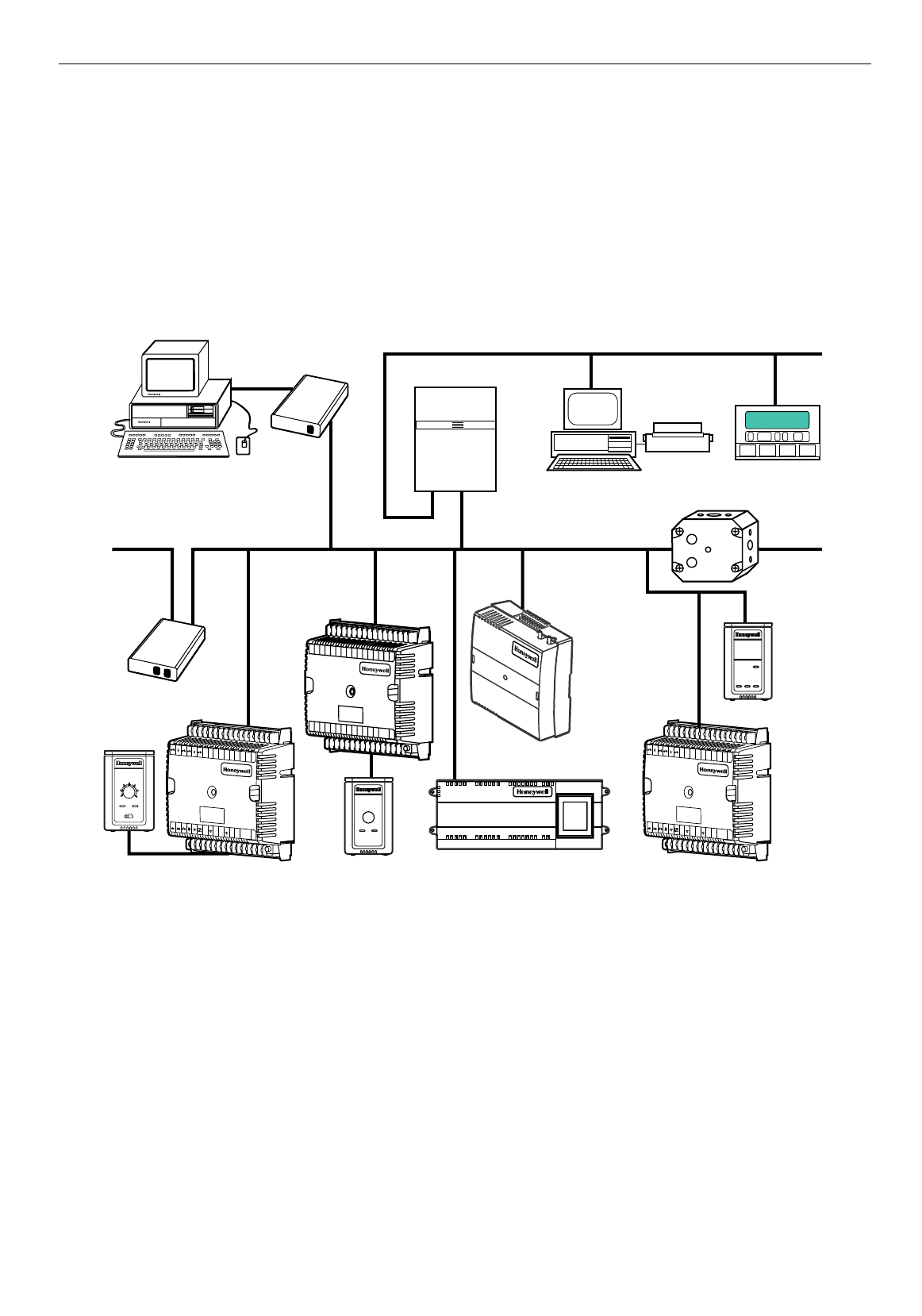
The Q7750A Excel 10 Zone Manager is a communications interface that allows devices on the E-Bus network to communicate
with devices on the standard EXCEL 5000® System C-Bus. Fig. 1 shows an overview of a typical system layout. The Q7750A
also provides some control and monitoring functions.
PERSONAL COMPUTER TOOLS
E-VISION
CARE
Q7752A
FTT E-BUS
SERIAL
ADAPTER
EXCEL 10
Q7750A
FTT ZONE
MANAGER
C-BUS COMMUNICATION NETWORK
EXCEL 500
EXCEL BUILDING SUPERVISOR
C-BUS TO E-BUS
INTERFACE DEVICE
EXCEL 10 W7751F
PANEL PLENUM
MOUNT VERSION
VARIABLE AIR
VOLUME
CONTROLLER
FTT E-BUS COMMUNICATIONS NETWORK FTT E-BUS COMMUNICATIONS NETWORK
Q7751A
FTT
E-BUS
ROUTER
EXCEL 10 T7770
WALL MODULE
EXCEL 10 W7753A UNIT
VENTILATOR CONTROLLER
EXCEL 10
T7780
DIGITAL
DISPLAY
WALL
MODULE
M12884
EXCEL 10
W7750B
CVAHU
CONTROLLER
12 3456 789101112131415J3
31 30 29 28 27 26 25 24 23 22 21 20 19 18 17 16
Q7740A
2-WAY
REPEATER
EXCEL 10 W7752 FTT FAN
COIL UNIT CONTROLLER
FTT E-BUS
COMMUNICATIONS
NETWORK
12 3456 7891011121314
15 J3
31 30 29 28 27 26 25 24 23 22 21 20 19 18 17 16
E
GND LED
BYPASS
SNSR
GND
SET PT
AI-1
OHM
GND
A1-2
OHM
AI-3
V/mA
GND
AI-4
V/mA
22VDC
OUT
E-BUS
E-BUS
JACK
DI-4 GND DI-3 DI-2 GND DI-1 24
VAC
24
VAC
COM
1
OUT
2
OUT
3
OUT
4
OUT
5
OUT
6
OUT
7
OUT
8
OUT
EXCEL 10
REMOTE
INPUT/
OUTPUT
DEVICE
12 3456 7891011121314
15 J3
31 30 29 28 27 26 25 24 23 22 21 20 19 18 17 16
E
GND LED
BYPASS
SNSR
GND
SET PT
AI-1
OHM
GND
A1-2
OHM
AI-3
V/mA
GND
AI-4
V/mA
22VDC
OUT
E-BUS
E-BUS
JACK
DI-4 GND DI-3 DI-2 GND DI-1 24
VAC
24
VAC
COM
1
OUT
2
OUT
3
OUT
4
OUT
5
OUT
6
OUT
7
OUT
8
OUT
70
65
60
55 85
80
75
auto 0 1
EXCEL 10
T7770E
WALL
MODULE
Fig. 1. Typical system overview.
EXCEL 10 W7761A INPUT/OUTPUT DEVICE
4 74-2699
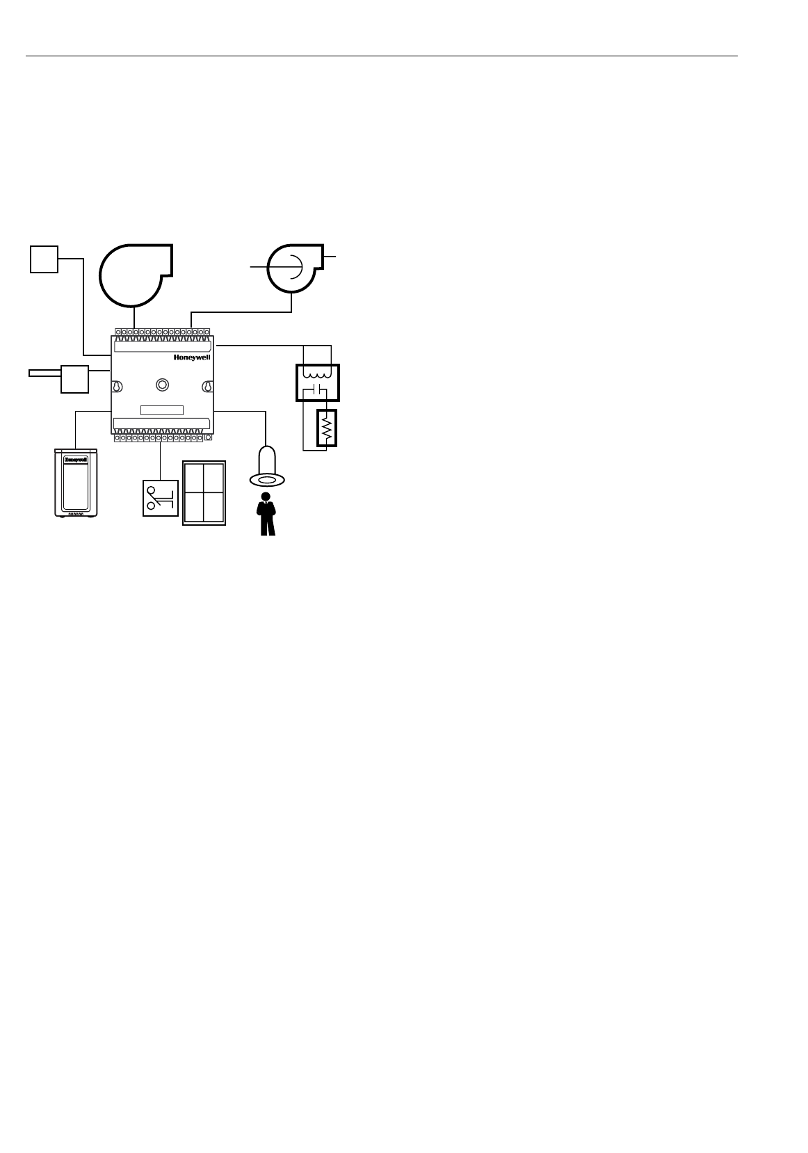
Control Application
The W7761A, Excel 10 Remote Input/Output device, provides auxiliary inputs and outputs for use with an Excel 10 Zone
Manager and Excel 10 controllers over the Echelon® LonWorks®E-Bus. The W7761A Remote Input/Output Device can be
connected to outdoor air temperature and humidity sensors that can be used by other Excel 10 controllers on the E-Bus or
Excel 5000 controllers on the C-Bus through the Excel 10 Zone Manager. This would allow the controllers to use their physical
inputs for monitoring other elements such as return humidity, IAQ, etc. to achieve better control. The W7761A can be used to
average many space temperature sensors that are located in a zone that is controlled by the W7750 Constant Volume AHU
Controller. The W7761A device has 8 Digital Outputs which may be Discrete, Modulating or Floating. For example, this allows
the control of lighting zones, miscellaneous exhaust or ventilation fans, miscellaneous pumps, and can enable freeze
protection. See Fig. 2.
WINDOW CONTACT
OCCUPANCY
SENSOR
OA
TEMPERATURE
OA
HUMIDITY MISC.
FANS PUMPS
LIGHTING
CONTROL
EXCEL 10
W7761A
REMOTE
INPUT/OUTPUT
M12885
EXCEL 10 T7770
WALL MODULE
Fig. 2. Typical W7761A control application.
Control Provided
The W7761A was not intended to control staged or modulating heating/cooling coils, mixed air economizer dampers, or system
fan/heat pump units. The W7761A contains inputs and outputs, but no control software. All control that would be associated
with the inputs and outputs in the W7761A would be accomplished though the Excel Zone Manager and would not be suitable
for VAV control, temperature control, or any control function that would require less than a 30 second update rate.
Products Covered
This System Engineering Guide describes how to apply the W7761A Excel 10 Remote Input/Output Device and related
accessories to typical applications. The specific devices covered include:
•W7761A Remote I/O device.
•T7770 A through D Wall Modules.
•Q7750A Excel 10 Zone Manager.
•Q7751A Router (FTT to FTT only).
•Q7752A Serial Interface Adapter.
•Q7740A,B Repeaters (2-way and 4-way).
•209541B FTT Termination Module.
Organization of Manual
This manual is divided into three basic parts: the Introduction, the Application Steps, and the Appendices that provide
supporting information. The Introduction and Application Steps 1 through 5 provide the information needed to make accurate
material ordering decisions. Application Step 6 and the Appendices include configuration engineering that can be started using
Excel E-Vision PC Software after the devices and accessories are ordered. Application Step 7 is troubleshooting.
The organization of the manual assumes a project is being engineered from start to finish. If an operator is adding to, or is
changing an existing system, the Table of Contents can provide the relevant information.
Applicable Literature
The following list of documents contains information related to the Excel 10 W7761 Remote I/O Device and the EXCEL 5000®
System in general.
Form No. Title

EXCEL 10 W7761A INPUT/OUTPUT DEVICE
5 74-2699
74-2698 Excel 10 W7761A Device Specification Data
74-2956 Excel 10 W7750A,B Controller Specification Data
74-2697 T7770A through G Wall Module Specification Data
74-2955 T7780 Digital Display Wall Module Specification Data
74-2950 Excel 10 Q7750A, Zone Manager Specification Data
74-2952 Excel 10 Q7751A Router Specification Data
74-2954 Excel 10 Q7752A Serial Interface Specification Data
74-2858 Excel 10 Q7740A,B FTT Repeaters Specification Data
95-7539 Excel 10 W7761A Device Installation Instructions
95-7521 Excel 10 W7750A,B Controller Installation Instructions
95-7538 T7770 Wall Module Installation Instructions
95-7558 T7780 Digital Display Wall Module Installation Instructions
95-7509 Excel 10 Q7750A Zone Manager Installation Instructions
95-7510 Excel 10 Q7751A Router Installation Instructions
95-7511 Excel 10 Q7752A Serial Interface Installation Instructions
95-7516 Excel 10 SLTA Connector Cable Installation Instructions
95-7555 Excel 10 Q7740A,B FTT Repeaters Installation Instructions
95-7554 Excel 10 209541B FTT Termination Module Installation Instructions
74-2588 Excel E-Vision User’s Guide
74-5587 CARE User’s Manual
74-5577 CARE Icon Guide
74-2039 XBS User’s Manual
74-5018 XBS Application Guide
Product Names
The W7761A Remote I/O Device is available in one model:
•W7761A Remote Input/Output Device.
The T7770 Wall Module is available in five models:
•T7770A1xxx Wall Module with temperature sensor only -
not applicable to the RIO device
(jumper switches the sensor from
20Kohm NTC to a linearized version of a 20 Kohm NTC used with the W7751A,C,E,G).
•T7770A2xxx Wall Module with temperature sensor and E-Bus network connection.
•T7770B Wall Module with temperature sensor—(current feature that can be used with the RIO Device), setpoint, and E-Bus
network connection for use with all Excel 5000 controllers (except W7751A,C,E,G).
•T7770C Wall Module with temperature sensor—(current feature that can be used with the RIO Device), setpoint, Bypass
button and LED, and E-Bus network connection for use with all Excel 5000 controllers (except W7751A,C,E,G).
•T7770D Wall Module with temperature sensor—(current feature that can be used with the RIO Device), Bypass button and
LED, and E-Bus network connection for use with all Excel 5000 controllers (except W7751A,C,E,G).
NOTE: The T7770B,C Models are available with a relative scale plate adjustable in E-Vision °F (± 5°C).
Only one PT3000 sensor is supported with the W7761A device.
The T7780 Digital Display Wall Module (DDWM) is available in one model:
•T7780 DDWM displays and provides space temperature, setpoint, Occ/Unocc override, Application Mode, and Fan
mode/speed selection for all Excel 10 controllers (except W7751 A,C,E,G).
Other products:
•Q7750A Excel 10 Zone Manager.
•Q7751A Bus Router.
•Q7752A Serial Adapter.
•Q7740A,B FTT Repeaters.
•209541B FTT Termination Module.
• ML6161 Series 60 Damper Actuator.
• M6410A Series 60 Valve Actuator (use with V5812 or V5813 Valves).
•ML684A Series 60 Versadrive Valve Actuator (use with V5011 and V5013 Valves).
•MMC325-010 Transducer, Series 60 to pneumatic 0 to 10 psi.
•MMC325-020 Transducer, Series 60 to pneumatic 0 to 20 psi.
•ML6464A Direct Coupled Damper Actuator, 66 lb-in. torque, Series 60.
•ML6474 Direct Coupled Damper Actuator, 132 lb-in. torque, Series 60.
•ML6185A Direct Coupled Damper Actuator, Spring Return, Series 60.
•ML7984B Direct Coupled Valve Actuator, PWM (use with V5011 or V5013F,G Valves).
• EL7680A1008 Wall Module Infrared Occupancy Sensor.
• EL7628A1007 Ceiling Mounted Infrared Occupancy Sensor.
• EL7611A1003 Ultrasonic Occupancy Sensor.
• EL7612A1001 Ultrasonic Occupancy Sensor.
Refer to Table 8 in Application Step 5. Order Equipment for a complete listing of all available part numbers.
NOTE: The Q7750A Zone Manager is referred to as (E-Link) in internal software and CARE.

EXCEL 10 W7761A INPUT/OUTPUT DEVICE
6 74-2699
Agency Listings
Table 1 provides information on agency listings for Excel 10 products.
Table 1. Agency Listings.
Device Agency Comments
W7761A Input/Output Device UL Tested and listed under UL916 (file number E87741).
cUL Listed (E87741).
CE General Immunity per European Consortium Standards EN50081-1 (CISPR
22, Class B) and EN 50082-1:1992 (based on Residential, Commercial, and
Light Industrial).
EN 61000-4-2: IEC 1000-4-2 (IEC 801-2) Electromagnetic Discharge.
EN 50140,
EN 50204: IEC 1000-4-3 (IEC 801-3) Radiated Electroma
g
netic Field.
EN 61000-4-4: IEC 1000-4-4 (IEC 801-4) Electrical Fast Transient (Burst).
Radiated Emissions and Conducted Emissions:
EN 55022: 1987 Class B.
CISPR-22: 1985.
FCC Complies with requirements in FCC Part 15 rules for a Class B Computing
Device. Operation in a residential area can cause interference to radio or TV
reception and require the operator to take steps necessary to correct the
interference.
T7770A through D Wall Modules UL (Not applicable.)
CSA (Not applicable.)
FCC (Not applicable.)
T7780 DDWM CE Emissions; EN50081-1, En55022 (CISPR Class B), Immunity 50082-1
UL &cUL Tested and listed under UL916, S8L9 Energy Management Equipment.
FCC Complies with requirements in FCC Part 15 rules for a Class B Computing
Device.
Q7750A Excel 10 Zone Manager UL Tested and listed under UL916, file number S4804 (QVAX, PAZY).
CSA Listing pending.
FCC Complies with requirements in FCC Part 15 rules for a Class A Computing
Device. Operation in a residential area can cause interference to radio or TV
reception and require the operator to take steps necessary to correct the
interference.
Q7751A,B Router,
Q7752A Serial Adapter
Q7740A,B FTT Repeaters
UL UL1784.
CSA Listed.
FCC Complies with requirements in FCC Part 15 rules for a Class B Computing
Device.
Abbreviations and Definitions
AHU - Air Handling Unit; the central fan system that includes the blower, heating equipment, cooling equipment, ventilation
air equipment, and other related equipment.
CO - Carbon Monoxide. Occasionally used as a measure of indoor air quality.
CO2 - Carbon Dioxide. Often used as a measure of indoor air quality.
CARE - Computer Aided Regulation Engineering; the PC based tool used to configure C-Bus and E-Bus devices.
C-Bus -Honeywell proprietary Control Bus for communications between EXCEL 5000® System controllers and components.
CPU - Central Processing Unit; an EXCEL 5000® System controller module.
cUL - Underwriters Laboratories Canada.
CVAHU -Constant Volume AHU; refers to a type of air handler with a single-speed fan that provides a constant amount of
supply air to the space it serves.

EXCEL 10 W7761A INPUT/OUTPUT DEVICE
7 74-2699
DDF - Delta Degrees Fahrenheit.
D/X - Direct Expansion; refers to a type of mechanical cooling where refrigerant is (expanded) to its cold state, within a
heat-exchanging coil that is mounted in the air stream supplied to the conditioned space.
E-Bus - Honeywell implementation of Echelon® LonWorks® network for communication among Excel 10 Controllers.
E-Bus Segment - An E-Bus section containing no more than 60 Excel 10s. Two segments can be joined together using a
router.
Echelon® - The company that developed the LON® bus and the Neuron® chips used to communicate on the E-Bus.
Economizer - Refers to the mixed-air dampers that regulate the quantity of outdoor air that enters the building. In cool outdoor
conditions, fresh air can be used to supplement the mechanical cooling equipment. Because this action saves energy,
the dampers are often referred to as
economizer dampers
.
EMI - Electromagnetic Interference; electrical noise that can cause problems with communications signals.
E-Link - Refers to the Q7750A Zone Manager. This name is used in internal software and in CARE software.
EMS - Energy Management System; refers to the controllers and algorithms responsible for calculating optimum operational
parameters for maximum energy savings in the building.
EEPROM - Electrically Erasable Programmable Read Only Memory; the variable storage area for saving user setpoint values
and factory calibration information.
EPROM - Erasable Programmable Read Only Memory; the firmware that contains the control algorithms for the Excel 10
Controller.
Excel 10 Zone Manager - A controller that is used to interface between the C-Bus and the E-Bus. The Excel 10 Zone Manager
also has the functionality of an Excel 100 Controller, but has no physical I/O points.
NOTE: The Q7750A Zone Manager can be referred to as E-Link in the internal software, CARE.
FCU - Fan Coil Unit.
Firmware - Software stored in a nonvolatile memory medium such as an EPROM.
Floating Control - Refers to Series 60 Modulating Control of a valve or damper. Floating Control utilizes one digital output to
pulse the actuator open, and another digital output to pulse it closed.
FTT - Free Topology Transceiver.
IAQ - Indoor Air Quality. Refers to the quality of the air in the conditioned space, as it relates to occupant health and
comfort.
I/O - Input/Output; the physical sensors and actuators connected to a controller.
I x R - I times R or current times resistance; refers to Ohm’s Law: V = I x R.
K - Degrees Kelvin.
Level IV - Refers to a classification of digital communication wire. Formerly known as UL Level IV, but
not
equivalent to
Category IV cable. If there is any question about wire compatibility, use Honeywell-approved cables (see Step 5 Order
Equipment section).
NEC - National Electrical Code; the body of standards for safe field-wiring practices.
NEMA - National Electrical Manufacturers Association; the standards developed by an organization of companies for safe field
wiring practices.
Node - A Communications Connection on a network; an Excel 10 Controller is one node on the E-Bus network.
NV - Network Variable; an Excel 10 parameter that can be viewed or modified over the E-Bus network.
PC - An IBM compatible Personal Computer with 386 or higher processor and capable of running Microsoft® Windows™
Version 3.1.
Pot - Potentiometer. A variable resistance electronic component located on the T7770B,C Wall Module; used to allow user-
adjusted setpoints to be input into the Excel 10 Controller.

EXCEL 10 W7761A INPUT/OUTPUT DEVICE
8 74-2699
PWM - Pulse Width Modulated output; allows analog modulating control of equipment using a digital output on the controller.
RTD - Resistance Temperature Detector; refers to a type of temperature sensor whose resistance output changes according
to the temperature change of the sensing element.
RIO - Remote Input/Output Device. Provides auxiliary inputs and outputs for use with an Excel 10 Zone Manager and Excel
10 controllers.
Subnet - An E-Bus segment that is separated by a router from its Q7750A Zone Manager.
TOD - Time-Of-Day; the scheduling of Occupied and Unoccupied times of operation.
TPT - Twisted Pair Transceiver.
UV - Unit Ventilator Controller.
VA - Volt Amperes; a measure of electrical power output or consumption as applies to an ac device.
Vac - Voltage alternating current; ac voltage rather than dc voltage.
VAV - Variable Air Volume; Refers to either a type of air distribution system, or to the W7751 Excel 10 VAV Box Controller
that controls a single zone in a variable air volume delivery system.
VOC - Volatile Organic Compound; refers to a class of common pollutants sometimes found in buildings. Sources include
out-gassing of construction materials, production-line by-products, and general cleaning solvents. A VOC is
occasionally used as a measure of indoor air quality.
W7750 - The model number of the Excel 10 CVAHU Controllers (also see CVAHU).
W7751 - The model number of the Excel 10 VAV Box Controllers (also see VAV).
W7752 - The model number of the Excel 10 FCU Controllers (also see FCU).
W7753 - The model number of the Excel 10 UV Controllers (also see UV).
W7761 - The model number of the Excel 10 RIO Device (also see RIO).
Wall Module - The Excel 10 Space Temperature Sensor and other optional controller inputs are contained in the T7770 or
T7780 Wall Modules. See Application Step 5. Order Equipment for details on the various models of Wall Modules.
XBS - Excel Building Supervisor; a PC based tool for monitoring and changing parameters in C-Bus devices.
Construction
Controllers
The Excel 10 W7761A RIO Device is available in one model. It contains 4 resistive inputs that can be configured for either
20Kohm NTC or PT3000 sensors, 2 voltage or current inputs, 4 digital inputs and 8 Digital Outputs (Triacs) which may be
Discrete (maintained or momentary), Modulating (PWM) or Floating.
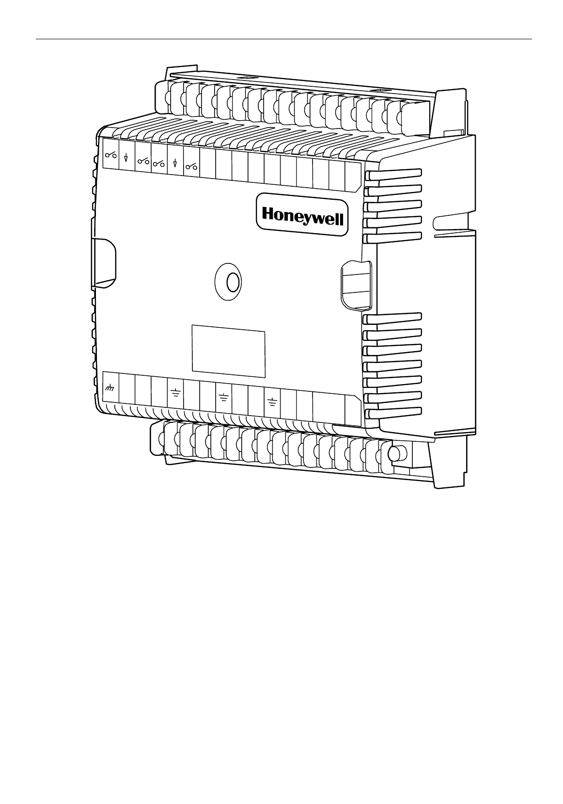
The W7761A consists of a single circuit board that is mounted in a sheet metal subbase and protected by a factory snap-on
cover. The device mounts with two screws (see Fig. 3 or 4). Using DIN rail adapters (see Fig. 5) they can also be snapped onto
standard EN 50 022 35 mm by 7.5 mm (1-3/8 in. by 5/16 in.) DIN rail. DIN rail is available through local suppliers. If using DIN
rail also purchase from Augat Inc. part number 2TK2D DIN rail (adapter) two each for every device (see Fig. 5). Wires are
attached to the screw terminal blocks on both sides of the device. Connection for operator access to the E-Bus is provided by
plugging the SLTA connector cable into the communications jack.
A channel in the cover allows the device status LED to be visible when the cover is in place. There are no field-serviceable
parts on the circuit board and, therefore,
it is intended that the cover never be removed
.
The W7761A can be mounted in any orientation. Ventilation openings were designed into the cover to allow proper heat
dissipation regardless of the mounting orientation. See Fig. 3 and 4.
EXCEL 10 W7761A INPUT/OUTPUT DEVICE
9 74-2699
M10118
123456789101112131415J3
31302928272625242322212019181716
EGND
GND
22 VDC
OUTEBUS EBUS
JACK
DI-4
W7761A
COM
NOT
USED
NOT
USED
GND
GND
DI-3 DI-2DI-1 VAC 24 VAC 24
OUT1OUT2OUT3OUT4OUT5OUT6OUT7OUT 8
AI-1
OHM AI-2
OHM AI-3
OHM GND AI-4
OHM GND
AI-5
V/mA AI-6
V/mA
Fig. 3. Excel 10 W7761A Remote I/O Device.
EXCEL 10 W7761A INPUT/OUTPUT DEVICE
10 74-2699
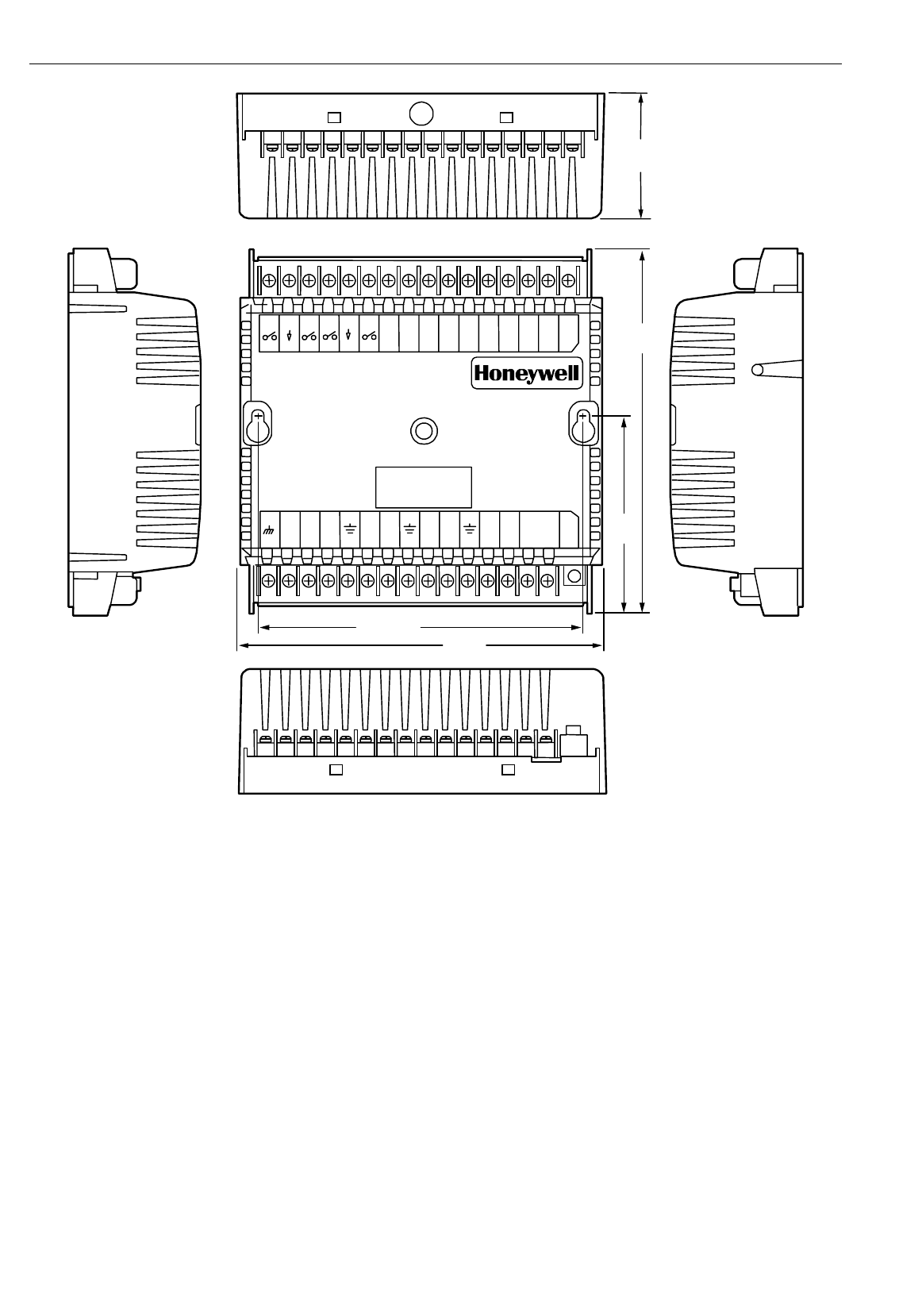
1 2 3 4 5 6 7 8 9101112131415 J3
22 VDC
OUT EBU S EB US
JAC K
31 30 29 28 27 26 25 24 23 22 21 20 19 18 17 16
COM OUT 1 OUT 2 OUT 3 OUT 4 OUT5 OUT 6 OUT 7 OUT8
5-3/16 (132)
5-5/8
(143)
3-1/16
(77)
2-1/8
(54)
6 (152)
M6856
NOT
USED NOT
USED
EGND AI-1
OHM GND AI-2
OHM AI-3
OHM GND AI-4
OHM GND
AI-5
V/mA AI-6
V/mA
VAC 24
VAC 24
DI-1
GNDGND
DI-2DI-3DI-4
Fig. 4. W7761A construction in in. (mm).
EXCEL 10 W7761A INPUT/OUTPUT DEVICE
11 74-2699
M6857
1
2
3
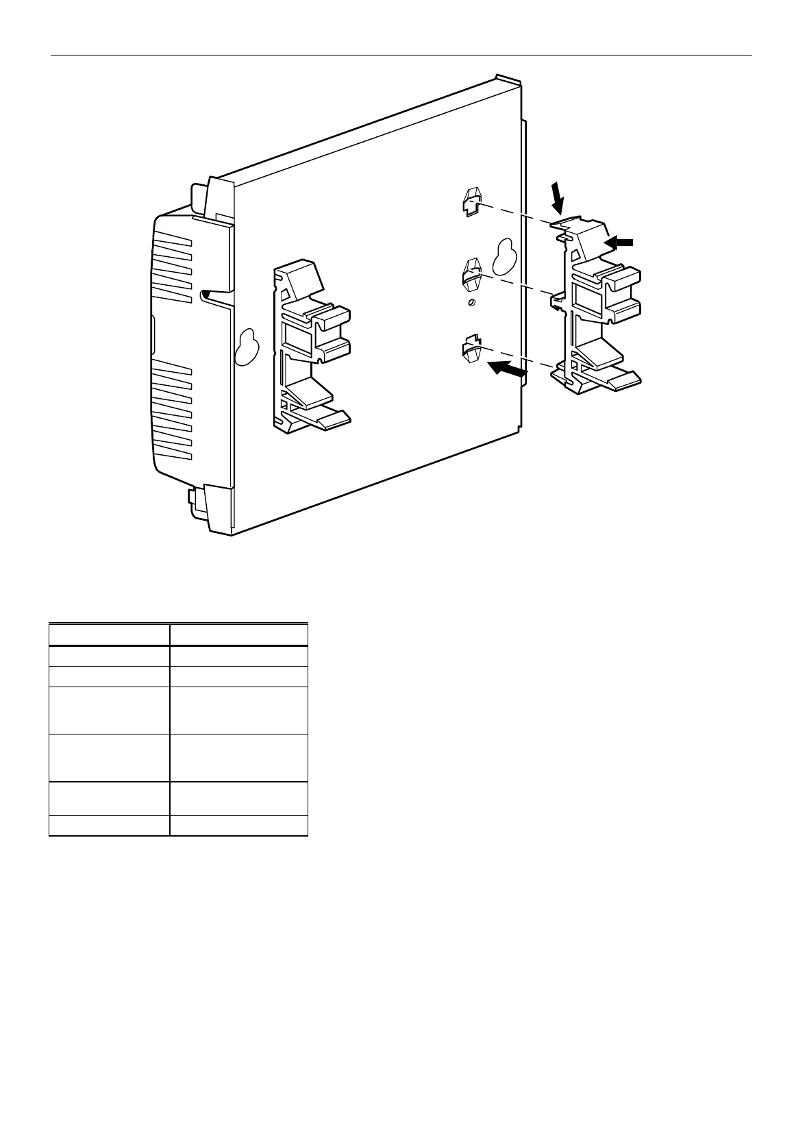
Fig. 5. DIN rail adapters.
The input/output points are summarized in Table 2.
Table 2. List Of Available Points.
W7761A
Digital Outputs 8 Triac Outputs
Digital Inputs 4
Analog Inputs 6
(4 Resistive and 2
Voltage/Current Inputs)
DC Power 20 Vdc available to
power optional sensors
(50 mA max.)
Floating (Series 60)
Control Heating or Cooling
PWM Control Heating or Cooling
Performance Specifications
Power:
24 Vac with a minimum of 20 Vac and a maximum of 30 Vac at either 50 or 60 Hz. The W7761A power consumption is 6 VA
maximum at 50 or 60 Hz. The W7761A is a NEC Class 2 rated device. This listing imposes limits on the amount of power the
product can consume or directly control to a total of 100 VA (U.S. only).
The individual Triac outputs incorporate an internal common connection with the input power transformer. The Triacs provide a
switched path from the hot side (R) of the transformer through the load to the common of the transformer. The W7761A Device
design
must
use the same power transformer for any loads connected to that device; see Fig. 19.
Each individual Triac is rated 500mA at 30 Vac maximum. Under all operating conditions, the maximum load/source power
budget for the W7761A Device is 100 VA.

EXCEL 10 W7761A INPUT/OUTPUT DEVICE
12 74-2699
CPU:
Motorola or Toshiba 3150 Neuron processor, containing three eight-bit CPU’s. Each Neuron has a unique 48-bit network
identification number.
Memory Capacity:
64K ROM/PROM (6K reserved for network operations, 58K usable for control algorithm code).
512 bytes EEPROM.
2K RAM.
Specified Space Temperature Sensing Range:
45 to 99°F (7 to 37°C) with an allowable control setpoint range from 50 to 90°F (10 to 32°C) when initiated from the network
and 55 to 85°F (13 to 29°C) when configured and connected to T7770 Wall Modules or T7780 DDWM.
Communications:
The W7761A Device uses a transformer-coupled communications port with differential Manchester-encoded data at 78 kilobits
per second (kbs). The transformer-coupled communications interface offers a much higher degree of common-mode noise
rejection while ensuring dc isolation.
Approved cable types for E-Bus communications wiring is Level IV 22 AWG (0.34 mm2) plenum or non-plenum rated
unshielded, twisted pair, solid conductor wire. For non-plenum areas, use Level IV 22 AWG (0.34 mm2) such as U.S. part
AK3781 (one pair) or U.S. part AK3782 (two pair). In plenum areas, use plenum-rated Level IV, 22 AWG (0.34 mm2) such as
U.S. part AK3791 (one pair) or U.S. part AK3792 (two pair). (See Tables 6 and 8 for part numbers.) Contact Echelon Corp.
Technical Support for the recommended vendors of Echelon approved cables.
The Free Topology Transceiver (FTT) supports polarity insensitive free topology wiring. This frees the system installer from the
need to wire using a bus topology. Star, bus, mixed, and loop wiring are all supported by this architecture. The maximum E-Bus
length when using a combination of star, loop, and bus wiring (singly terminated) is 1640 ft (500m) with the maximum node-to-
node length of 1312 ft (400m). In the event that the total wire length is exceeded, then a Q7740A 2-Way Repeater or a Q7740B
4-Way Repeater can be used to allow the number of devices to be spread out as well as increasing the length of wire over
which they communicate. The maximum number of repeaters per segment is one (on either side of the router). A Q7751A E-
Bus Router can also be used to effectively double the maximum E-Bus length. The advantage of using the router is that it will
segregate traffic to a segment while when using the repeater, all traffic is repeated on each segment. When utilizing a doubly
terminated E-Bus structure, use a continuous daisy-chain with no stubs or taps from the main backbone, The maximum E-Bus
length is 4593 ft (1400m) with the maximum node-to-node length of 3773 ft (1150m).
FTT networks are very flexible and convenient to install and maintain, but it is imperative to carefully plan the network layout
and create and maintain accurate documentation. Unknown or inaccurate wire run lengths, node-to-node distances, node
counts, total wire length, and misplaced or missing terminators can cause poor network performance. Refer to E-Bus Wiring
Guidelines form, 74-2865 for complete description of network topology rules.
LonMark Functional Profile
W7761A Device supports the LonMark Preliminary Functional Profile for a Remote Input/Output Device.
Environmental:
Operating Temperature:
-40° to 150°F (-40° to 65.5°C).
Shipping Temperature:
-40° to 150°F (-40° to 65.5°C).
Relative Humidity:
5% to 95% noncondensing.
Vibration:
Rated V2 level compliant.
Inputs/Outputs:
The W7761A Unit supports the following hardware features:
• Four 20KNTC (1000 through 150,000 ohm) or PT3000 (250 through 12,000 ohm) resistive analog inputs.
• Two 0.2 to 10 VDC or 2 to 20 mA (user selectable) analog inputs.
• Four dry contact digital inputs.
• Eight 24 Vac Triac digital outputs (500 mA MAX).
• One 22 Vdc power supply for auxiliary devices with a maximum current of 50 mA.
Analog Inputs:
Space Temperature:
Type: RTD.

EXCEL 10 W7761A INPUT/OUTPUT DEVICE
13 74-2699
Supported Sensors: T7770A,B,C,D sensor—(current feature that can be used with the RIO Device) and T7780
DDWM.
Discharge Air Temperature:
Type: RTD.
Supported Sensors: C7100A1015*, C7770A1006, C7031B1033, C7031C1031, C7031D1062, C7031J1050,
C7031K1017.
Outdoor Air Temperature:
Type: RTD.
Supported Sensors: C7170A1002.
Return Air Temperature:
Type: RTD.
Supported Sensors: C7100A1015*, C7770A1006, C7031B1033, C7031C1031, C7031D1062, C7031J1050,
C7031K1017.
Mixed Air Temperature:
Type: RTD.
Supported Sensors: C7100A1015*, C7770A1006, C7031B1033, C7031C1031, C7031D1062, C7031J1050,
C7031K1017.
*The PT3000 sensor is not recommended for floating control (real time - discharge or return configured as space sensor).
The PT3000 sensor is intended for monitoring or differential (staged) control.
Outdoor Air Humidity:
Type: Voltage/Current.
Supported Sensors: C7600B1000 and C7600B1018 (2 to 10V), C7600C1008 (4 to 20mA).
Return Air Humidity:
Type: Voltage/Current.
Supported Sensors: C7600B1000 and C7600B1018 (2 to 10V), C7600C1008 (4 to 20mA).
Outdoor Air Enthalpy:
Type: Current.
Supported Sensors: C7400A1004 (4 to 20mA).
Return Air Enthalpy:
Type: Current.
Supported Sensors: C7400A1004 (4 to 20mA).
Air Filter Differential Pressure:
Type: Voltage.
Supported Sensors: Third party 2 to 10V, 0 to 5 inw ( 0 to 1.25 kPa) differential pressure sensors.
Space CO2 Sensor:
Type: Voltage.
Supported Sensors: Third party 0 to 10V, 0 to 2000 ppm CO2 sensors.
Outdoor Air CO2 Sensor:
Type: Voltage.
Supported Sensors: Third party 0 to 10V, 0 to 2000 ppm CO2 sensors.
Outdoor Air CO Sensor:
Type: Current.
Supported Sensors: Third party 4 to 20mA, 0 to 300 ppm CO sensor.
Monitor Sensor for network use:
Type: Voltage.
Supported Sensors: Third party 2 to 10V, 2 to 10 volts displayed.
Digital Inputs:
Dry-contact inputs are sensed using a 9 milliamp at 4.8 volts detection circuit. It is very important that the device used contains
high quality, noncorroding contacts with resistivity that does not degrade; that is, increase over time. Use noble metal (such as
gold or silver) or pimpled or sealed contacts to assure consistent, long-term operation.
Triac Outputs:
Triac Outputs on the RIO:
— Power ratings: 20 Vac to 30 Vac at 25 mA MIN to 500 mA MAX current for any voltage.
EXCEL 10 W7761A INPUT/OUTPUT DEVICE
14 74-2699
CAUTION
When any device is energized by a Triac, the device must be able to sink a minimum of 25 mA.
NOTE: Triacs sink current to the 24 Vac common (COM terminal on the W7761A); see Fig. 19 for wiring example.
IMPORTANT:
If non-Honeywell motors, actuators, or transducers are to be used with Excel 10 Controllers, Triac compatibility must
be verified (see previous NOTE).
Wall Modules
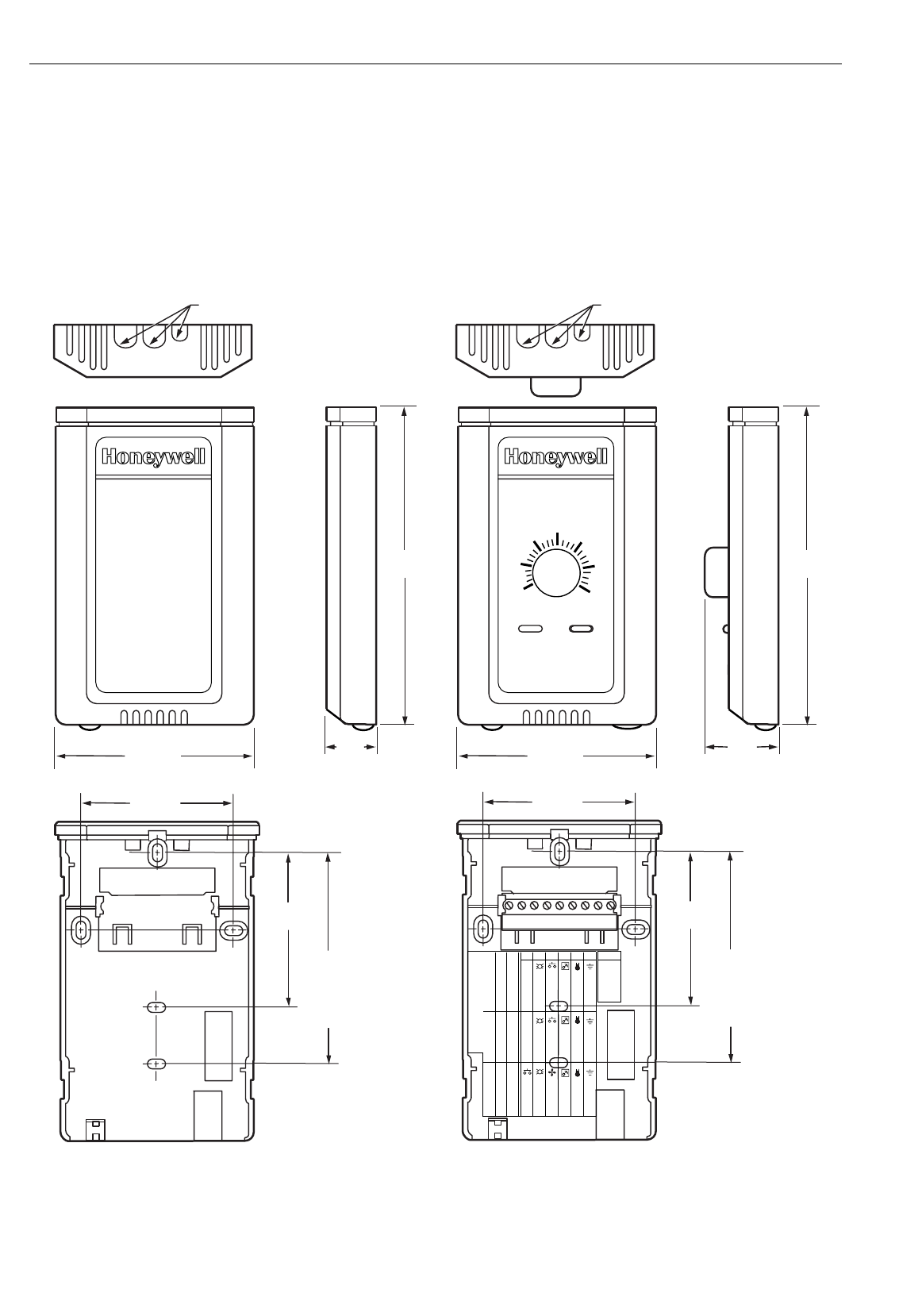
The T7770A,B,C,D Wall Module sensor—(current feature that can be used with the Excel 10 W7761A RIO Device). See Fig. 6.
STANDARD
UTILITY
CONDUIT
BOX (2 X 4)
MOUNTING
HOLES
KNOCKOUTS FOR EUROPEAN
APPLICATIONS
3-5/32 (80)
2-3/8 (60)
29/32
(23)
5-1/16
(128)
2-3/8
(60)
T7770A1006
M15119
STANDARD
UTILITY
CONDUIT
BOX (2 X 4)
MOUNTING
HOLES
KNOCKOUTS FOR EUROPEAN
APPLICATIONS
3-5/32 (80)
2-3/8 (60)
1-1/4
(32)
5-1/16
(128)
2-3/8
(60)
T7770C
70
65
60
55 85
80
75
DIP Switch S4 Settings:
1,3,5=on; 2,4=off 2,4=on; 1,3,5=off 1,2,3,4=on; 5=0ff
W7753 XL600-XL20 W7752
LED RETURN
BYPASS
LED
FAN
SETPT
SENSOR
GND
LED
SETPT
SENSOR
AL COM
LED
SETPT
SENSOR
GND
BYPASS/FAN BYPASS/FAN
9 8 7 6 5 4 3 2 1
E-BUS
E-BUS
Fig. 6. T7770A,B,C,D (T7770A,C shown) construction in in. (mm), sensor—(current feature that can be used with RIO
Device).
EXCEL 10 W7761A INPUT/OUTPUT DEVICE
15 74-2699
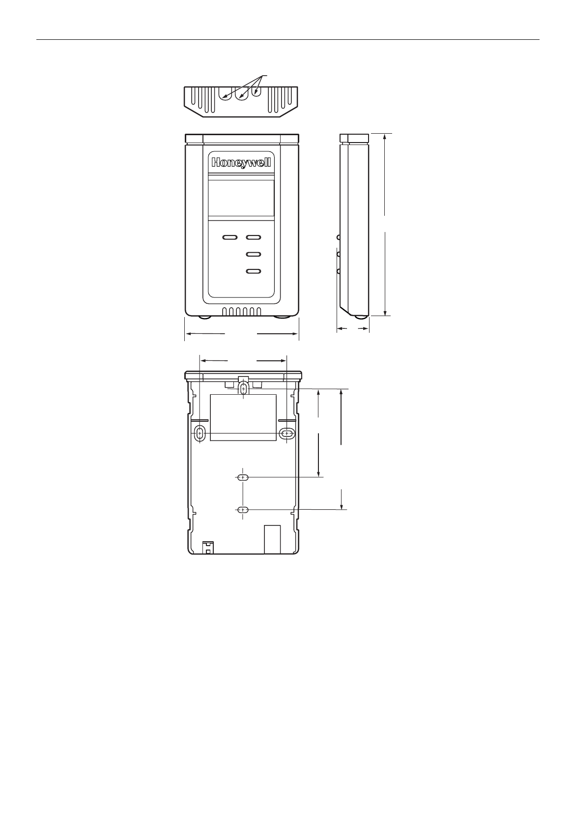
The T7780 DDWM for the Excel 10 Controllers (see Product Names section) is shown in Fig. 7.
M11391
STANDARD
UTILITY
CONDUIT
BOX (2 X 4)
MOUNTING
HOLES
KNOCKOUTS FOR EUROPEAN
APPLICATIONS
3-5/32 (80)
2-3/8 (60)
1
(25)
5-1/16
(128)
2-3/8
(60)
Fig. 7. T7780 construction, subbase dimensions in in. (mm).
Configurations
Each W7761A device can control or monitor a variety of different types of mechanical equipment. The W7761A was not
intended to control staged or modulating heating/cooling coils, mixed air economizer dampers, or system fan/heat pump units.
The W7761A contains inputs and outputs, but no control software. All control that would be associated with the inputs and
outputs in the W7761A would be accomplished though the Excel Zone Manager and would not be suitable for VAV control,
temperature control, or any control function that would require less than a 30 second update rate.
It would be suitable to control miscellaneous exhaust or ventilation fans, lighting zones that are spread out through a building
which need to be linked to a start/stop time program through the Zone Manager or to enable freeze protection. The W7761A
device can be connected to outdoor air temperature and humidity sensors that can be used by other Excel 10 controllers on
the E-Bus or Excel 5000 controllers on the C-Bus through the Excel 10 Zone Manager. The W7761A can be used to monitor
Occupancy, Window, Dirty filter, Indoor air quality, and Smoke control sensors. This allows the controllers to use their physical
inputs for monitoring other elements such as return humidity, IAQ, etc. to achieve better control. The W7761A can be used to

EXCEL 10 W7761A INPUT/OUTPUT DEVICE
16 74-2699
average many space temperature sensors that are located in a zone that is controlled by the W7750 Constant Volume AHU
Controller.
Mixed-Output-Type Control
The W7761A Device can control mixed-output-types of applications such as PWM and staged control occurring simultaneously
with Series 60 Floating Control.
Occupancy Sensor
Excel 10 W7761A device can be connected to an occupancy sensor through a digital input. This is a device, such as a passive
infrared motion detector, that contains a dry contact (see following NOTE) closure to indicate whether or not people are present
in the space. The Excel 10 W7761A Device expects a contact closure to indicate the space is Occupied. See Fig. 18 in
Application Step 4, Prepare Wiring Diagrams, for details on wiring connections. This occupancy sensor can then be bound to
other Excel 10 controllers on the E-Bus or Excel 5000 controllers on the C-Bus through the Excel 10 Zone Manager. This
would allow the other Excel 10 controllers to use their physical inputs for monitoring other elements such as return humidity,
IAQ, etc. to achieve better control.
NOTE: The Excel 10 Controllers (W7750 CVAHU and W7761A RIO) have limited power available (only 9 mA at 4.8 volts) for
checking the digital inputs for contact closures. It is very important that the device used contains high quality,
noncorroding contacts with resistivity that does not degrade; that is, increase over time. Use noble metal (such as
gold or silver), pimpled or sealed contacts to assure consistent, long-term operation.
The recommended devices for use with the Excel 10 W7750 Controller and W7761A Device are the EL7628A1007 Ceiling
Mounted Infrared or the EL7680A1008 Wall Mounted Wide View Infrared Occupancy Sensors. If ultrasonic sensors are
required, the EL7611A1003 and the EL7612A1001 Occupancy Sensors are recommended. An EL76XX Power Supply/Control
Unit is required for use with these occupancy sensors. The EL7630A1003 can power up to four sensors, and is multi-tapped for
several line voltages. The EL7621A1002 can power three sensors and it connects to 120 Vac line voltage. The EL7621A1010
can also power three sensors but it connects to 277 Vac line voltage.
Window Open/Closed Digital Input
Excel 10 W7761A device can be connected to a window sensor to indicate whether a window in the space was opened. The
Excel 10 W7761A device can be connected to a dry contact (see the NOTE for the Occupancy Sensor and Fig. 18 in
Application Step 4. Prepare Wiring Diagrams, for details) or a set of contacts wired in series (for monitoring multiple windows)
to verify that the window(s) are closed. This window(s) sensor can then be bound to other Excel 10 controllers on the E-Bus or
Excel 5000 controllers on the C-Bus through the Excel 10 Zone Manager. The algorithm in the other Excel 10 controllers
expects a contact closure to indicate the window is closed. If an open window is detected, the algorithm in the other Excel 10
controllers changes the mode of operation to FREEZE_PROTECT, which shuts down the control functions, and watches for
low space temperature conditions. The freeze protection setpoint is 46.4°F (8°C), and the frost alarm occurs at 42.8°F (6°C).
Wall Module Options
As previously discussed, there are five basic varieties of the T7770. There is one variety of the PT3000 sensor and the T7780
DDWM (see the Product Names and the Construction sections). The T7770A,B,C,D 20Kohm NTC sensor—(current feature
that can be used with the RIO Device) and one PT3000 sensor can be configured on any of the four resistive inputs. The
T7780 is an E-Bus node and would not be directly connected to the RIO Device.
Dirty Filter Monitor
The air filter in the air handler can be monitored by the W7761A RIO device and an alarm issued by the Zone Manager when
the filter media needs replacement. The two methods of monitoring the filter are:
1. Connecting a differential pressure switch to a digital input on the W7761A.
2. Wiring a 2-to-10V differential pressure sensor to a voltage input on the W7761A. If the analog input sensor is used, its
measured value 0 to 5 inw (0 to 1.25 kPa) is compared to a user-selectable setpoint. The comparison is done in the
Zone Manager —valid range: 0 to 5 inw (0 to 1.25 kPa), and the Dirty Filter alarm is issued when the pressure drop
across the filter exceeds the setpoint.
Indoor Air Quality (IAQ)
The Excel 10 W7761A device can monitor IAQ using one of two different methods of detecting poor air quality. The first is with
an IAQ switch device connected to a digital input on the W7761A, where a contact closure indicates poor air quality, and an
alarm can be issued by the Zone Manager. The device can detect poor air quality using any desired measure such as CO2,
VOC, CO, etc. The second method, is through an analog input that connects to a CO2 sensor (0 to 10V). The measured value
of CO2 from this sensor (0 to 2000 ppm) is compared to a user-selectable setpoint (the comparison is done in the Zone
Manager —valid range: 0 to 2000 ppm), and an IAQ alarm can be issued when the CO2 level exceeds the setpoint. The IAQ
sensor that is connected to the W7750 RIO, can be bound to other W7750 CVAHU Excel 10 controllers on the E-Bus.
EXCEL 10 W7761A INPUT/OUTPUT DEVICE
17 74-2699
APPLICATION STEPS
Overview
The seven application steps shown in Table 3 are planning considerations for engineering an Excel 10 W7761 Remote
Input/Output Device. These steps are guidelines intended to aid understanding of the product I/O options, bus arrangement
choices and the Excel 10 W7761A Devices role in the overall EXCEL 5000® System architecture.
Table 3 . Application Steps.
Step No. Description
1 Plan The System
2 Determine Other Bus Devices Required
3 Lay Out Communication and Power Wiring
4 Prepare Wiring Diagrams
5 Order Equipment
6 Configure Devices
7 Troubleshooting
Step 1. Plan The System
Plan the use of the W7761A Devices according to the job requirements. Determine the location, functionality and sensor or
actuator usage. Verify the sales estimate of the number of W7761A Devices and the number and type of output actuators and
other required accessories.
When planning the system layout, consider potential expansion possibilities to allow for future growth. Planning is very
important to be prepared for adding HVAC systems and controllers in future projects.
T7770A,B,C,D Wall Modules (sensor—current feature that can be used with the RIO Device)can be installed as either
hardwired I/O-only devices or additional wiring can be run to them (for the E-Bus network ) to allow a CARE/E-Vision operator
terminal to have access to the E-Bus. The application engineer needs to determine how many wall modules or other input
sensors are required. This information is required during installation to ensure that the proper number and type of wires are
pulled to the wall modules, and the building operators are informed about where they can plug in to the E-Bus network with a
portable operator terminal (see Fig. 8 through 10).
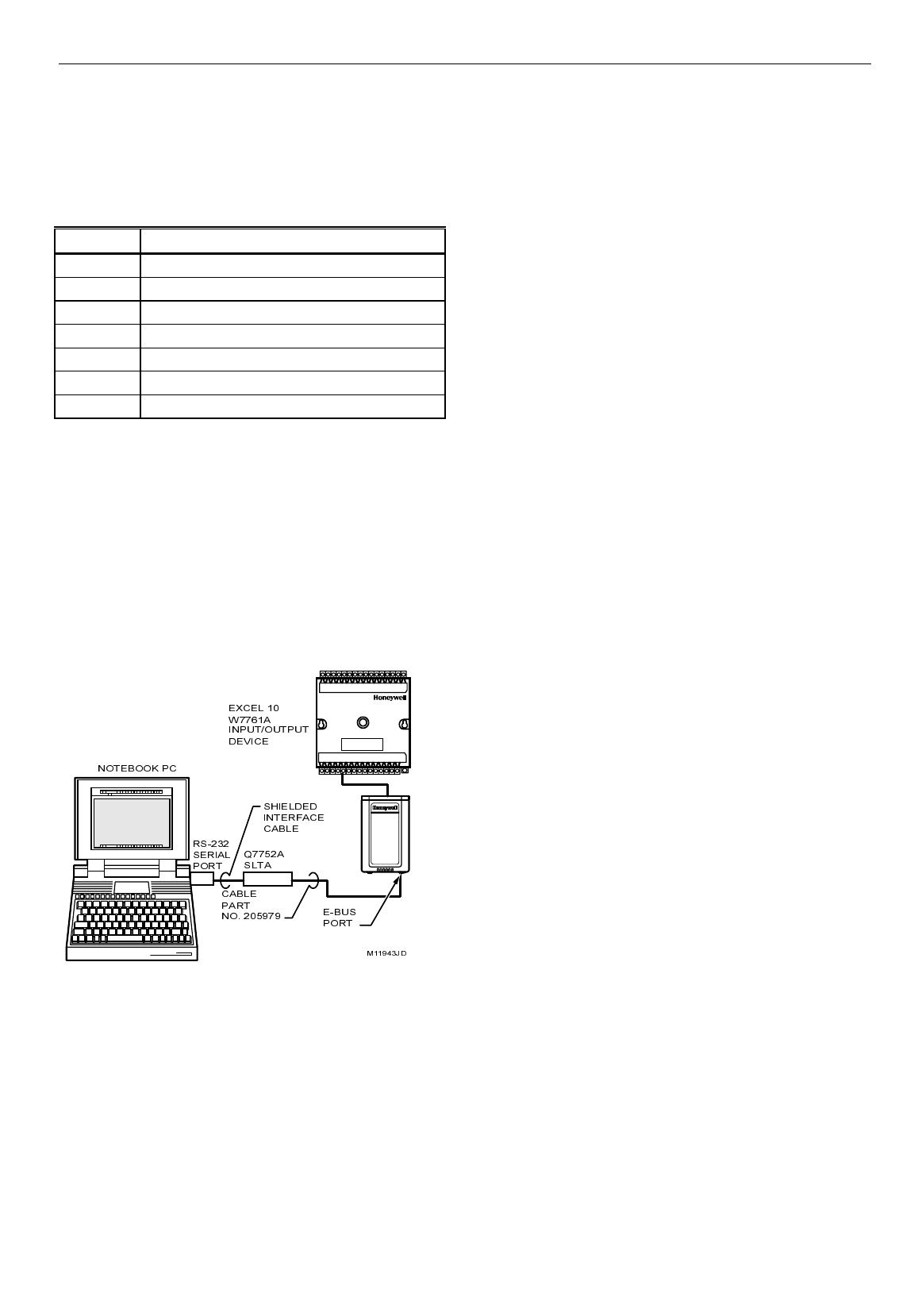
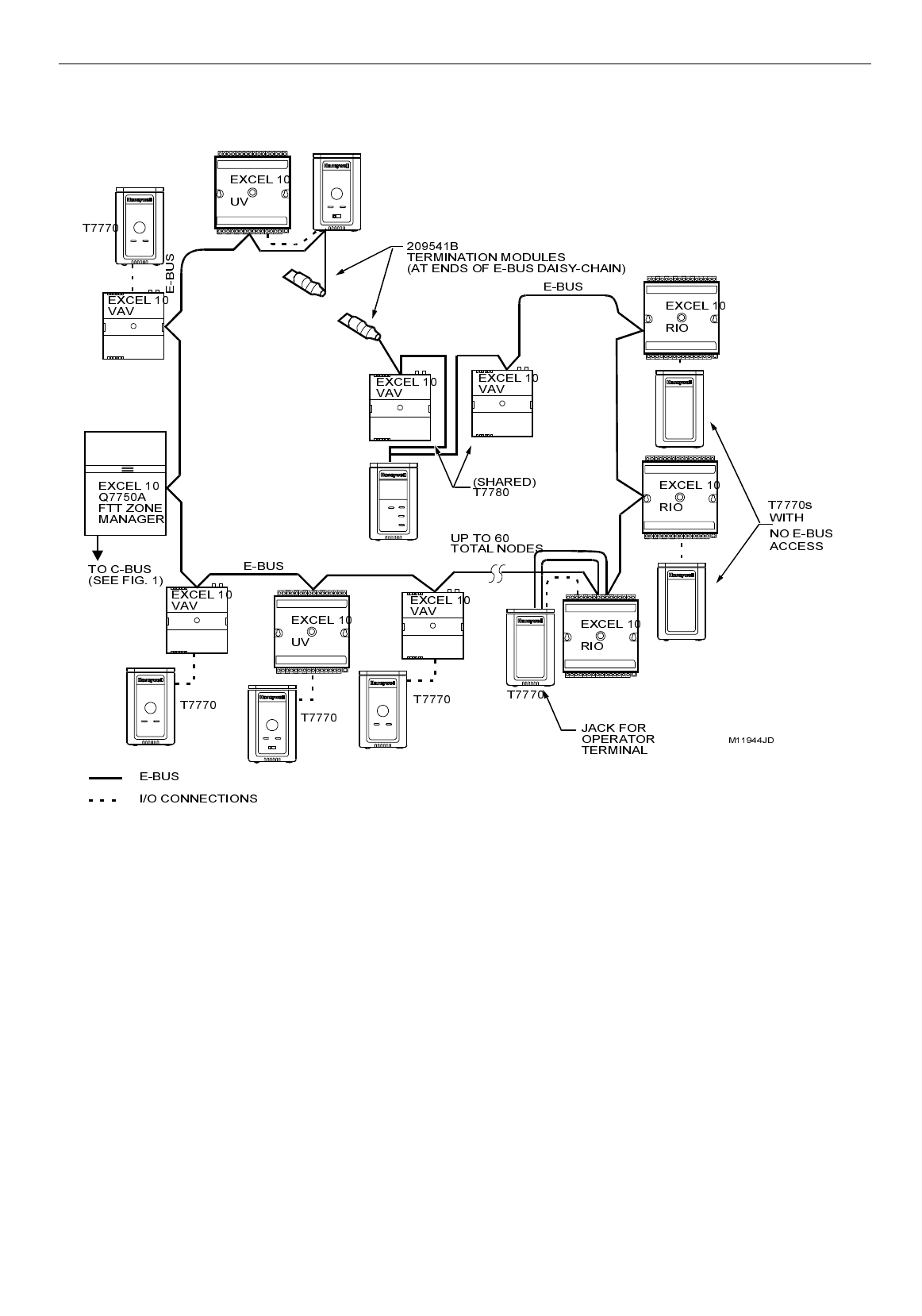
Fig. 8. Connecting the portable operator terminal to the E-Bus.
The FTT communication loop, (E-Bus) between controllers is a free topology wiring scheme that supports star, loop, and/or bus
wiring. Refer to the E-Bus Wiring Guidelines form, 74-2865 for complete description of network topology rules. See Application
Step 3. Lay Out Communications and Power Wiring, for more information on bus wiring layout, and see Fig. 16 through 19 in
Application Step 4. Prepare Wiring Diagrams, for wiring details.
The application engineer must review the Direct Digital Control (DDC) job requirements. This includes the Sequences of
Operation for the Excel 10 controllers, and for the system as a whole. Usually there are variables that must be passed between
the W7750 (CVAHU), Q7750A Zone Manager, W7761 (RIO), and other Excel 10 controller(s), or central plant controller(s) that
are required for optimum system-wide operation. Typical examples are the TOD Occ/Unocc signal, the outdoor air
temperature, demand limit control signal, and smoke control mode signal.

EXCEL 10 W7761A INPUT/OUTPUT DEVICE
18 74-2699
It is important to understand these interrelationships early in the job engineering process to ensure implementing when
configuring the controllers. (See Application Step 6. Configure Devices, for information on the various Excel 10 parameters and
on Excel 10 point mapping.)
Step 2. Determine Other Bus Devices Required
A maximum of 62 nodes can communicate on a single E-Bus segment. Each W7761A (RIO), W7750 (CVAHU), W7751 (VAV)
Controller or T7780 Wall Module constitutes one node. If more nodes are required, a Q7751A Router is necessary. Using a
router allows up to 125 nodes, divided between two E-Bus segments. The router accounts for two of these nodes (one node on
each side of the router); a Q7750A Excel 10 Zone Manager takes one node and two nodes are available for operator terminal
nodes, leaving 120 nodes available for Excel 10 Controllers and T7780 Wall Modules. All 120 controllers and T7780 Wall
Modules are able to talk to each other through the router. A Q7750A Excel 10 Zone Manager is required to connect the E-Bus
to the standard EXCEL 5000® System C-Bus. Each Excel 10 Zone Manager can support no more than 120 Excel 10
Controllers and T7780 Wall Modules. This limit is set in the Excel 10 Zone Manager database as an absolute maximum.
Each E-Bus segment is set up with two unused nodes to allow for a CARE/E-Vision or Hand Held Tool (HHT) to be connected
to the E-Bus. Multiple CARE/E-Vision or HHT terminals can be connected to the bus at the same time. Table 4 summarizes the
E-Bus segment configuration rules.
Table 4 . E-Bus Configuration Rules And Device Node Numbers.
One E-Bus Segment Example Maximum Number of Nodes Equals 62
One Q7750A Excel 10 Zone Manager 1 node
Port for operator terminal access (CARE/E-Vision or HHT) 1 node
Maximum number of Excel 10s and T7780s 60 nodes (Only T7780 Wall Modules are E-Bus nodes)
Total 62 nodes
Two E-Bus Segments Example Maximum Number of Nodes Equals 125
One Q7750A Excel 10 Zone Manager 1 node
One Q7751A Router 2 nodes (1 in each Bus Segment)
Ports for operator terminal access (two CARE/E-Vision or HHT
terminals) 2 nodes (1 in each Bus Segment)
Maximum number of Excel 10s and T7780s in segment number
one 60 nodes (Only T7780 Wall Modules are E-Bus nodes)
Maximum number of Excel 10s and T7780s in segment number
two 60 nodes (Only T7780 Wall Modules are E-Bus nodes)
Total 125 nodes
Refer to the E-Bus Wiring Guidelines form, 74-2865 for complete description of network topology rules and the maximum wire
length limitations. If longer runs are required, a Q7740A 2-way or Q7740B 4-way repeater can be added to extend the length of
the E-Bus. A Q7751A Router can be added to partition the system into two segments and effectively double the length of the
E-Bus. Only one router is allowed with each Excel 10 Zone Manager and each network segment can have a maximum of 1
repeater. In addition, all E-Bus segments require the installation of a Bus Termination Module for a singly terminated E-Bus or
two Bus Termination Modules for a doubly terminated E-Bus. For more details on E-Bus termination, refer to the E-Bus Wiring
Guidelines form, 74-2865, or see Application Step 3. Lay Out Communications and Power Wiring, and the E-Bus Termination
Module subsection in Application Step 4.
Step 3. Lay Out Communications and Power Wiring
E-Bus Layout
The communications bus, E-Bus, is a 78-kilobit serial link that uses transformer isolation and differential Manchester encoding.
Approved cable types for E-Bus communications wiring is Level IV 22 AWG (0.34 mm2) plenum or non-plenum rated
unshielded, twisted pair, solid conductor wire. For nonplenum areas, use Level IV 22 AWG (0.34 mm2), such as U.S. part
AK3781 (one pair) or U.S. part AK3782 (two pair). In plenum areas, use plenum-rated Level IV, 22 AWG (0.34 mm2) such as
U.S. part AK3791 (one pair) or U.S. part AK3792 (two pair). See Tables 9 and 10 for part numbers. Contact Echelon Corp.
Technical Support for the recommended vendors of Echelon approved cables. The FTT communications bus, E-Bus,
supports a polarity insensitive, free topology wiring scheme that supports star, loop, and/or bus wiring.
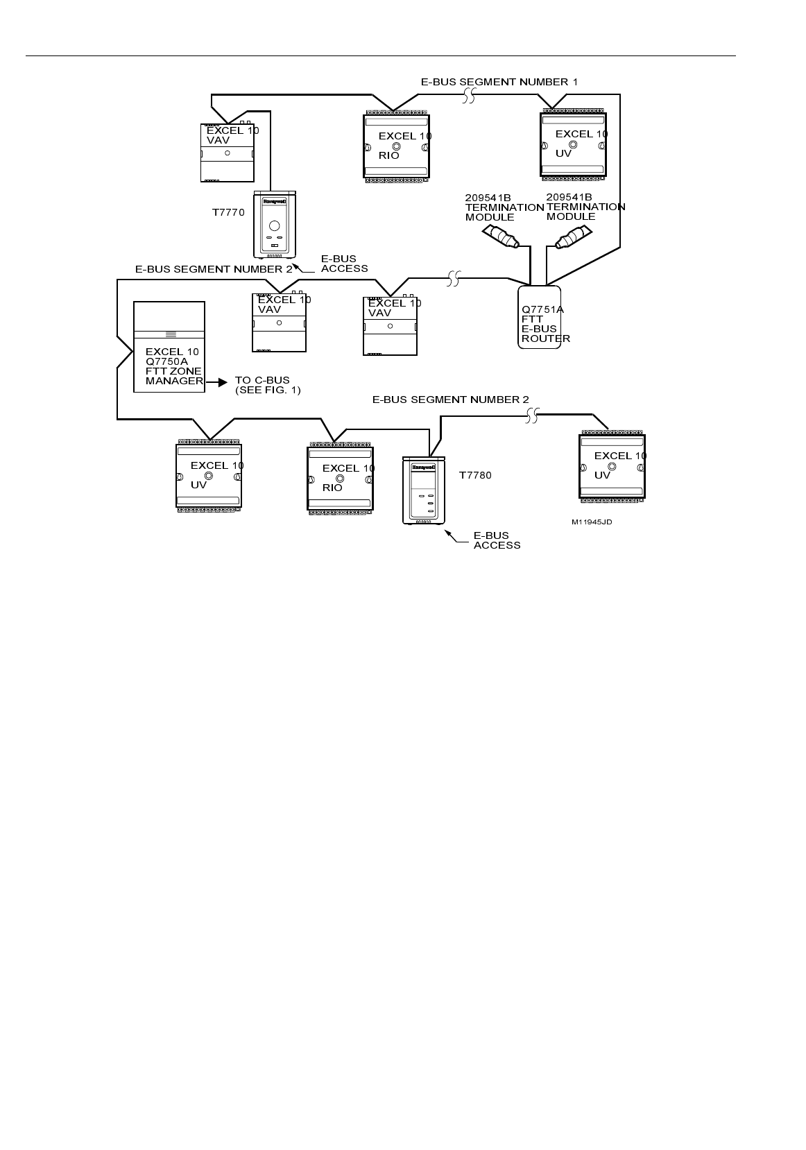
E-Bus networks can be configured in a variety of ways, so refer to the E-Bus Wiring Guidelines form, 74-2865 for a complete
description of network topology rules and Table 4. Fig. 9 and 10 depict two typical E-Bus network topologies; one as a singly
terminated bus segment that has 60 nodes or less, and one showing a doubly terminated segment. The bus configuration is
set up using the Network Manager tool from within CARE (see the CARE User’s Manual form, 74-5587 or Excel E-Vision
User’s Guide form, 74-2588).
EXCEL 10 W7761A INPUT/OUTPUT DEVICE
19 74-2699
NOTE: For wiring details see the E-Bus Termination Module subsection in Step 4. For wall module wiring, US part AK3782
(non-plenum) or US part AK3792 (plenum) can be used. These cables contain two twisted pairs (one for the run down
to the wall module, and one for the run back up to the controller) for ease of installation.
Fig. 9. Bus wiring layout for doubly terminated daisy-chain E-Bus segment.
EXCEL 10 W7761A INPUT/OUTPUT DEVICE
20 74-2699
Fig. 10. Bus wiring layout for two singly terminated E-Bus segments.
NOTE: See the E-Bus Termination Module section for wiring details.
IMPORTANT
Notes on communications wiring:
•
All field wiring must conform to local codes and ordinances.
•
Approved cable types for E-Bus communications wiring is Level IV 22 AWG (0.34 mm
2
) plenum or non-plenum
rated unshielded, twisted pair, solid conductor wire. For nonplenum areas, use Level IV 22 AWG (0.34 mm
2
), such
as U.S. part AK3781 (one pair) or U.S. part AK3782 (two pair). In plenum areas, use plenum-rated Level IV, 22
AWG (0.34 mm
2
) such as U.S. part AK3791 (one pair) or U.S. part AK3792 (two pair). See Tables 9 and 10 for part
numbers. Contact Echelon Corp. Technical Support for the recommended vendors of Echelon approved
cables.
•
Unswitched 24 Vac power wiring can be run in the same conduit as the E-Bus cable.
•
Do not use different wire types or gauges on the same E-Bus segment. The step change in line impedance
characteristics causes unpredictable reflections on the bus. When using different types is unavoidable, use a
Q7751A Router at the junction.
•
In noisy (high EMI) environments, avoid wire runs parallel to noisy power cables, or lines containing lighting
dimmer switches, and keep at least 3 in. (76 mm) of separation between noisy lines and the E-Bus cable.
•
Make sure that neither of the E-Bus wires is grounded.
Power Wiring
A power budget must be calculated for each Excel 10 W7761 Device to determine the required transformer size for proper
operation. A power budget is simply the summing of the maximum power draw ratings (in VA) of all the devices to be controlled
by an Excel 10 W7761 Device. This includes the device itself, the equipment actuators (ML6161, or other motors) and various
contactors and transducers, as appropriate, for the Excel 10 configuration.
Power Budget Calculation Example
The following is an example power budget calculation for a typical W7761A Excel 10 Device.
Device VA Information Obtained from the
Excel 10 W7761 6.0 VA W7761
Device Specification Data

EXCEL 10 W7761A INPUT/OUTPUT DEVICE
21 74-2699
ML6161 2.2 VA TRADELINE®
Damper Actuator Catalog
R8242A 21.0 VA TRADELINE®
Contactor for fan Catalog in-rush rating
M6410A Steam 0.7 VA TRADELINE®
Heating Coil Valve Catalog, 0.32A at 24 Vac
TOTAL: 29.9 VA
The Excel 10 System example requires 29.9 VA of peak power; therefore, a 40 VA AT72D Transformer is able to provide
ample power for this device and its accessories. Alternatively, a 75 VA AT88A Transformer could be used to power two Excel
10 Systems of this type, or a 100 VA AT92A Transformer could be used to power three of these controllers and meet NEC
Class 2 restrictions (no greater than 100 VA). See Fig. 12 through 14 for illustrations of power wiring details. See Table 5 for
VA ratings of various devices. Table 5 . VA Ratings For Transformer Sizing.
Device Description VA
W7761A Excel 10 W7761 Device 6.0
ML6161A/B Damper Actuator, 35 lb-in. 2.2
R8242A Contactor 21.0
R6410A Valve Actuator 0.7
MMC325 Pneumatic Transducer 5.0
ML684 Versadrive Valve Actuator 12.0
ML6464 Damper Actuator, 66 lb-in. 3.0
ML6474 Damper Actuator, 132 lb-in. 3.0
ML6185 Damper Actuator SR 50 lb-in. 12.0
For contactors and similar devices, the in-rush power ratings should be used as the worst case values when performing power
budget calculations. Also, the application engineer must consider the possible combinations of simultaneously energized
outputs and calculate the VA ratings accordingly. The worst case, that uses the largest possible VA load, should be determined
when sizing the transformer.
Line Loss
Excel 10 Controllers must receive a minimum supply voltage of 20 Vac. If long power or output wire runs are required, a
voltage drop due to Ohms Law (I x R) line loss must be considered. This line loss can result in a significant increase in total
power required and thereby affect transformer sizing. The following example is an I x R line-loss calculation for a 200 ft (61m)
run from the transformer to a W7761 Device drawing 37 VA using 18 AWG (1.0 mm2) wire.
The formula is:
Loss = [length of round-trip wire run (ft)] x [resistance in wire (ohms per ft)] x [current in wire (amperes)]
From specification data:
18 AWG twisted pair wire has 6.52 ohms per 1000 feet.
Loss = [(200 ft) x (2 - round-trip) x (6.52/1000 ohms per ft)] x [(37 VA)/(24V)] = 4.02 volts
This means that four volts are going to be lost between the transformer and the device; therefore, to assure the device receives
at least 20 volts, the transformer must output more than 24 volts. Because all transformer output voltage levels depend on the
size of the connected load, a larger transformer outputs a higher voltage than a smaller one for a given load. Fig. 11 shows this
voltage load dependence.
In the preceding I x R loss example, even though the device load is only 37 VA, a standard 40 VA transformer is not sufficient
due to the line loss. From Fig. 11, a 40 VA transformer is just under 100 percent loaded (for the 37 VA device) and, therefore,
has a secondary voltage of 22.9 volts. (Use the lower edge of the shaded zone in Fig. 11 that represents the worst case
conditions.) When the I x R loss of four volts is subtracted, only 18.9 volts reaches the device, which is not enough voltage for
proper operation.
In this situation, the engineer basically has three alternatives:
1. Use a larger transformer; for example, if an 80 VA model is used, see Fig. 11, an output of 24.4 volts minus the four volt
line loss supplies 20.4V to the device. Although acceptable, the four-volt line-loss in this example is higher than
recommended. See the following
IMPORTANT
.
2. Use heavier gauge wire for the power run. 14 AWG (2.0 mm2) wire has a resistance of 2.57 ohms per 1000 ft which,
using the preceding formula, gives a line-loss of only 1.58 volts (compared with 4.02 volts). This would allow a 40 VA
transformer to be used. 14 AWG (2.0 mm2) wire is the recommended wire size for 24 Vac wiring.
3. Locate the transformer closer to the device, thereby reducing the length of the wire run, and the line loss.
The issue of line-loss is also important in the case of the output wiring connected to the Triac digital outputs. The same formula
and method are used. The rule to remember is to keep all power and output wire runs as short as practical. When necessary,
use heavier gauge wire, a bigger transformer, or install the transformer closer to the device.
IMPORTANT
EXCEL 10 W7761A INPUT/OUTPUT DEVICE
22 74-2699
No installation should be designed where the line loss is greater than two volts to allow for nominal operation if the
primary voltage drops to 102 Vac (120 Vac minus 15 percent).
To meet the National Electrical Manufacturers Association (NEMA) standards, a transformer must stay within the NEMA limits.
The chart in Fig. 11 shows the required limits at various loads.
With 100 percent load, the transformer secondary must supply between 23 and 25 volts to meet the NEMA standard. When a
purchased transformer meets the NEMA standard DC20-1986, the transformer voltage-regulating ability can be considered
reliable. Compliance with the NEMA standard is voluntary.
The following Honeywell transformers meet this NEMA standard:
Transformer Type VA Rating
AT20A 20
AT40A 40
AT72D 40
AT87A 50
AK3310 Assembly 100
27
26
25
24
23
22
21
20
19
18
17
16
15
14
0 50 100 150
% OF LOAD
SECONDARY VOLTAGE
200
M993
Fig. 11. NEMA class 2 transformer voltage output limits.
Attach earth ground to W7761 Device terminal 1. See Fig. 12, 13 and 14, 16 through 20.
M10089
CONNECT POWER TO `
TERMINALS 24 AND 25
TRIAC LINES`
TO ACTUATORS`
AND CONTACTORS
TRANSFORMER
W7761A
EARTH`
GROUND
20222425
1
TRIAC`
COMMON
Fig. 12. Power wiring details for one Excel 10 per transformer.
EXCEL 10 W7761A INPUT/OUTPUT DEVICE
23 74-2699
M10090
24 VAC
120
/
240 VAC
TRANSFORMER
EARTH`
GROUND
2425
1
EARTH`
GROUND
2425
1
EARTH`
GROUND
2425
1
W7761A W7761A W7761A
Fig. 13. Power wiring details for two or more Excel 10s per transformer.
IMPORTANT
If the W7761A Device is used on Heating and Cooling Equipment (UL 1995 US only) devices and the transformer
primary power is more than 150 volts, connect the transformer secondary to earth ground, see Fig. 14.
M10088
24 VAC
L
I
N
E
V
O
L
T
A
G
E
`
GREATER`
THAN 150 VAC
TRANSFORMER
EARTH`
GROUND
EARTH`
GROUND
1` IF THE W7761 CONTROLLER IS USED IN UL 1995 EQUIPMENT AND `
THEPRIMARYPOWERISMORETHAN150VOLTS,GROUNDONE`
SIDE OF TRANSFORMER SECONDARY.
1
1
W7761A
Fig. 14. Transformer power wiring details for one Excel 10 used in UL 1995 equipment (U.S. only).
IMPORTANT
Notes on power wiring:
•
All field wiring must conform to local codes and ordinances.
•
To maintain NEC Class 2 and UL ratings, the installation must use transformers of 100 VA or less capacity.
•
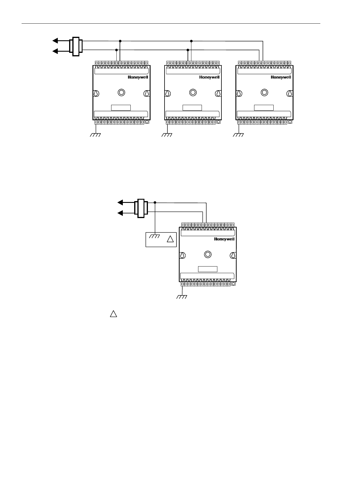
For multiple controllers operating from a single transformer, the same side of the transformer secondary must be
connected to the same input terminal in each device and the ground terminals (1 on the W7761A) must be
connected to a verified earth ground for each device in the group. See Fig. 13. (Device configurations are not
necessarily limited to three devices per transformer.)
•
For the W7761A Device (which has Triac outputs), all output devices must be powered from the same transformer
as the one powering the Excel 10 W7761A Device.
•
Use the heaviest gauge wire available, up to 14 AWG (2.0 mm
2
) with a minimum of 18 AWG (1.0 mm
2
) for all
power and earth ground connections.
•
To minimize EMI noise, do not run Triac output wires in the same conduit as the input wires or the E-Bus
communications loop.
•
Unswitched 24 Vac power wiring can be run in the same conduit as the E-Bus cable.

EXCEL 10 W7761A INPUT/OUTPUT DEVICE
24 74-2699
•
Make earth ground connections with the shortest possible wire run using 14 AWG (2.0 mm
2
) wire. A good earth
ground is essential for W7761A operation. Ideally, connect the earth ground to the ground bus at a motor control
center or circuit breaker panel. However, if the nearest ideal earth ground is inaccessible, consider an alternate
source for earth ground. Metal water pipe is generally a good ground, but do not use sprinkler pipe if prohibited by
local codes. Attention must be given when duct work, conduit, or rebar are to be considered as ground sources. It
is the responsibility of the installer to assure that these structures are tied back to a known earth ground.
Step 4. Prepare Wiring Diagrams
General Considerations
The purpose of this step is to assist the application engineer in developing job drawings to meet job specifications. Wiring
details are included for the W7761A device the T7770A,B,C,D wall module (sensor—current feature that can be used with the
RIO Device) and the T7780 DDWM. The drawings detail I/O, power, and communication bus wiring connections.
NOTE: For field wiring, when two or more wires are to be attached to the same connector block terminal, be sure to twist
them together. Deviation from this rule can result in improper electrical contact. See Fig. 15.
The connector block terminals on the W7761A and on the T7770 accept 14 through 22 AWG (2.0 to 0.34 mm2) wire. Table 6
lists wiring types, sizes, and length restrictions for Excel 10 products.
Table 6 . Field Wiring Reference Table.
Wire
Function
Recommended
Minimum Wire
Size AWG (mm2) Construction
Specification
or
Requirement Vendor Wire Type Maximum Length
ft (m)
E-Bus
(Plenum) 22 AWG
(0.34 mm2)Twisted pair solid conductor,
nonshielded or Echelon
approved shielded cable.
Level IV 140°F
(60°C) rating Honeywell
AK3791 (one twisted pair)
AK3792 (two twisted pairs)
Refer to E-Bus
Wiring Guidelines
for maximum
length
E-Bus
(Non-
Plenum)
22 AWG
(0.34 mm2)Twisted pair solid conductor,
nonshielded or Echelon
approved shielded cable.
Level IV 140°F
(60°C) rating Honeywell
AK3781 (one twisted pair)
AK3782 (two twisted pairs)
Refer to E-Bus
Wiring Guidelines
for maximum
length
Input
Wiring
Sensors
Contacts
18 to 22 AWG
(1.0 to 0.34 mm2)Multiconductor (usually five-
wire cable bundle). For runs
>200 ft (61m) in noisy EMI
areas, use shielded cable.
140°F (60°C)
rating Standard thermostat wire 1000 ft (305m)
for 18 AWG
200 ft (61m)
for 22 AWG
Output
Wiring
Actuators
Relays
14 AWG (2.0
mm2)
(18 AWG (1.0
mm2) acceptable
for short runs)
Any pair nonshielded (use
heavier wire for longer
runs).
NEC Class 2
140°F (60°C)
rating
Honeywell
AK3702 (18 AWG)
AK3712 (16 AWG)
AK3754 (14 AWG)
or equivalent
Limited by line-loss
effects on power
consumption.
(See Line Loss
subsection.)
Power
Wiring 14 AWG
(2.0 mm2)Any pair nonshielded (use
heavier wire for longer
runs).
NEC Class 2
140°F (60°C)
rating
Honeywell
AK3754 (14 AWG)
twisted pair
AK3909 (14 AWG) single
conductor or equivalent
Limited by line-loss
effects on power
consumption.
(See Line Loss
subsection.)
W7761A Devices
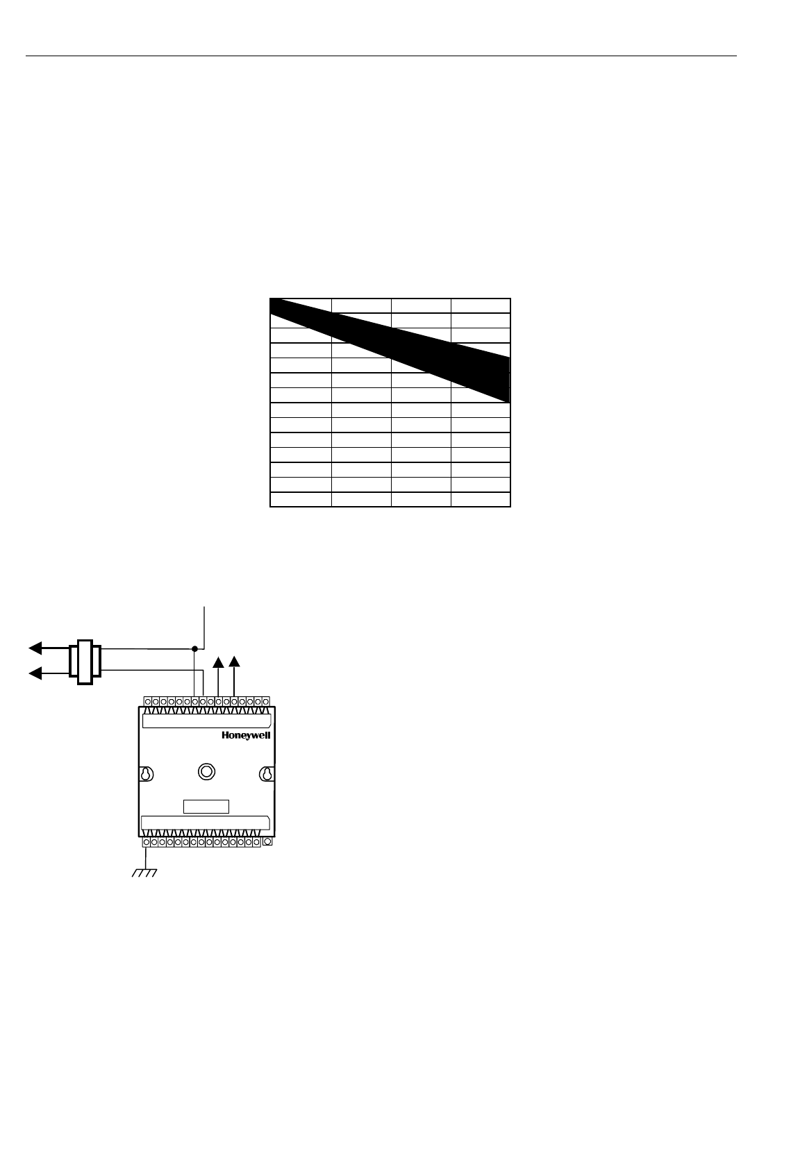
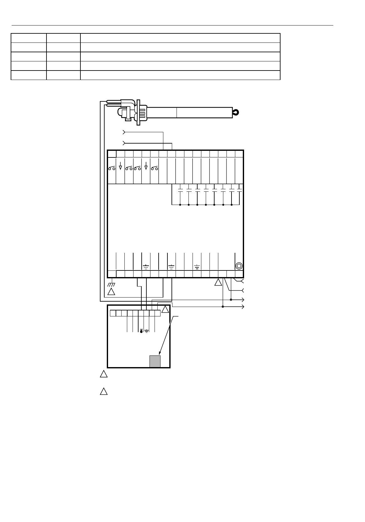
Fig. 16 through 20 illustrate W7761A Device wiring for various configurations. Connections to the wall module terminals (4
through 6) and the communications terminals (14 and 15) are made at terminal blocks. Connection for access to the E-Bus is
provided by plugging the connector into the communications jack.
NOTE: If an Excel 10 W7761A Device or Zone Manager is not connected to a good earth ground, the device internal transient
protection circuitry is compromised and the function of protecting the device from noise and power line spikes cannot
be fulfilled. This can result in a damaged circuit board and require replacing the device.

EXCEL 10 W7761A INPUT/OUTPUT DEVICE
25 74-2699
3/8`
(10)
STRIP 3/8 IN. (10 MM) FROM WIRES `
TO BE ATTACHED AT ONE TERMINAL.
1. 2. TWIST WIRES TOGETHER `
WITH PLIERS (A MINIMUM `
OF THREE TURNS).
TWO 14 AWG`
(2.0 MM2) WIRES
3. CUT TWISTED END OF WIRES TO 3/16 IN. (5 MM) `
BEFORE INSERTING INTO TERMINAL AND TIGHTENING`
SCREW. THEN PULL ON EACH WIRE IN ALL TERMINALS
`
TO CHECK FOR GOOD MECHANICAL CONNECTION.
M10086
Fig. 15. Attaching two or more wires at terminal blocks.
See Table 7 for a description of the W7761A terminals.
Table 7 . W7761A I/O Description.
Terminal Terminal
Number Description
OUT 8 16 Digital Output 8
OUT 7 17 Digital Output 7
OUT 6 18 Digital Output 6
OUT 5 19 Digital Output 5
OUT 4 20 Digital Output 4
OUT 3 21 Digital Output 3
OUT 2 22 Digital Output 2
OUT 1 23 Digital Output 1
+24Vac (H) 25 Power for the device
COM (N) 24 Return for power to device
E-Bus 15 Echelon® communications screw terminals
E-Bus 14 Echelon® communications screw terminals
DI -4 31 Digital Input 4
DGND 30 Digital Ground
DI -3 29 Digital Input 3
DI -2 28 Digital Input 2
DGND 27 Digital Ground
DI -1 26 Digital Input 1
22 VDC out 13 22 Vdc power supply for auxiliary devices with a maximum current of 50 mA.
AI-6 12 Analog Input 6 voltage or current
AGND 11 Analog ground
AI-5 10 Analog Input 5 voltage or current
AI-4 9 Analog Input 4 resistance
AGND 8 Analog ground
AI -3 7 Analog Input 3 resistance
AI-2 6 Analog Input 2 resistance
EXCEL 10 W7761A INPUT/OUTPUT DEVICE
26 74-2699
GROUND 5 Analog ground
AI-1 4 Analog Input 1 resistance
3 Not Used
2 Not Used
EGND 1 Earth Ground
See Fig. 20 to wire a pneumatic transducer to a W7761A.
12345678
E-BUS
24 VAC
W7761A
REMOTE I/O
DEVICE
1
2
1
2
EARTH GROUND WIRE LENGTH SHOULD BE HELD TO A MINIMUM.
USE THE HEAVIEST GAUGE WIRE AVAILABLE, UP TO 14 AWG (2.O MM
2
)
WITH A MINIMUM OF 18 AWG (1.O MM
2
), FOR EARTH GROUND WIRE.
TO ASSURE PROPER ELECTRICAL CONTACT, WIRES MUST BE TWISTED
TOGETHER BEFORE INSERTION INTO THE TERMINAL BLOCK.
E-BUS
E GND
GND
GND
GND
NOT USED
NOT USED
AI-1 OHM
AI-2 OHM
9 101112 14 J315
31 30 29 28 27 26 25 24 23 22 21 20
24 VAC COM
E-BUS
JACK
22 VDC OUT
19 18 17 16
AI-3 OHM
AI-4 OHM
AI-6 V/mA
OUT 7
OUT 6
OUT 5
OUT 4
OUT 8
OUT 1
OUT 3
OUT 2
AI-5 V/mA
13
DI-2
DI-4
DI-1
DI-3
M15276
GND
GND
TRIAC EQUIVALENT CIRCUIT
24 VAC
+
-
2
JACK FOR
E-BUS
NETWORK
ACCESS
7 69 8 54321
T7770A
WALL
MODULE
GND
SENSOR
E-BUS
E-BUS
C7770A AIR
TEMPERATURE SENSOR
Fig. 16. Typical T7770A and C7770A wiring diagram. (For note 2, refer to Fig. 15.)
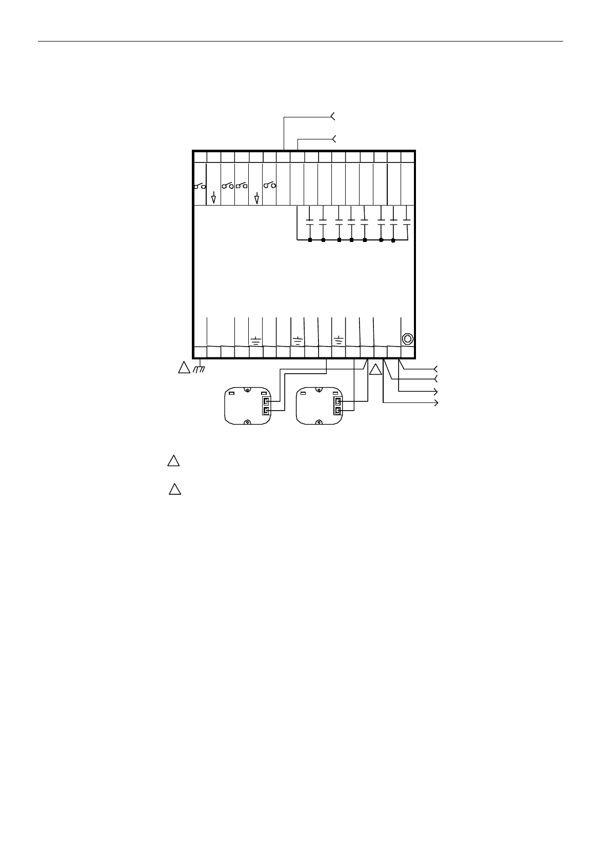
EXCEL 10 W7761A INPUT/OUTPUT DEVICE
27 74-2699
1
E-B
1234 5678
W7761A
REMOTE I/O
DEVICE
EARTH
GROUND
9101112 1415
31 30 29 2 8 27 26 25 24 23 22 2 1 20
GRO UND
E-BUS
E-BUS
JACK
22 VDC OUT
19 18 17 1 6
GROUND
13
GROUND
J3
GROUND
GROUND
TRI AC EQUIVAL ENT CIRCUIT
AI-3 OHM
OUT 7
OUT 6
OUT5
OUT4
OUT8
OUT 1
OUT 3
OUT 2
AI-5 V/mA
DI-2
DI-4
DI-1
DI-3
AI-4 OHM
AI-6 V/mA
AI-2 OHM
AI- 1 OH M
NOT
USED
COM
24 VAC
24VAC
EARTH G ROUND WIRE LENGTH SHOULD BE HELD TO A MINIMUM.
USE THE HEAVIEST GAUGE WIR E AVAILABLE, UP TO 14 AWG (2.O MM
2
)
WITH A M INIMUM OF 18 AWG (1.O MM
2
), F OR EAR TH GROUND WIRE.
TO ASSURE PROPER ELECTRICAL CONTACT, WIRES MUST BE TWISTED
TOG ETHER BEFO RE INS ERTION INTO THE TERMINAL BLOCK.
1
2
+
-
24VAC
2
+
S
C7600C +
S
C7400A
Enthalpy
(4 to 20mA)
Humidity
(4 to 20mA)
Fig. 17. Typical Humidity and Enthalpy (4 to 20mA) sensor wiring diagram. (For note 2, refer to Fig. 15.)
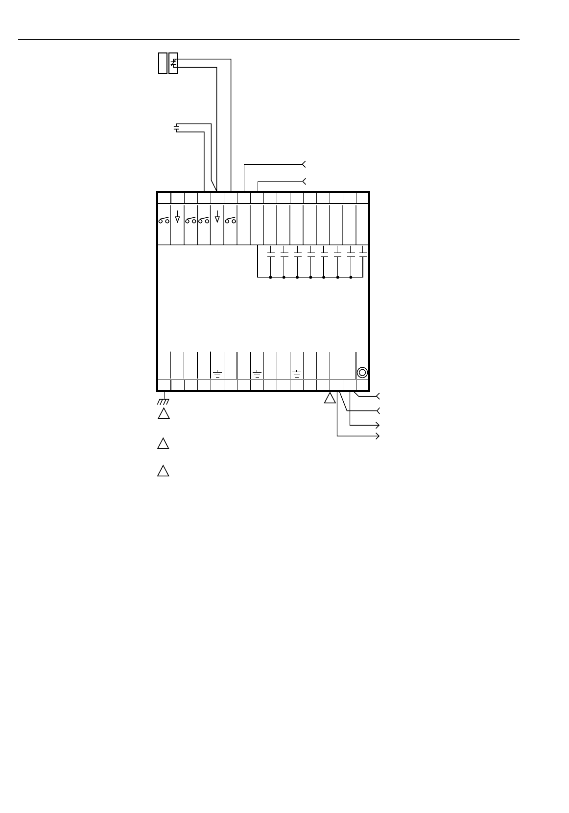
EXCEL 10 W7761A INPUT/OUTPUT DEVICE
28 74-2699
12345678
E-BUS
24 VAC
W7761A
REMOTE I/O
DEVICE
1
2
1
2
EARTH GROUND WIRE LENGTH SHOULD BE HELD TO A MINIMUM.
USE THE HEAVIEST GAUGE WIRE AVAILABLE, UP TO 14 AWG (2.O MM
2
)
WITH A MINIMUM OF 18 AWG (1.O MM
2
), FOR EARTH GROUND WIRE.
TO ASSURE PROPER ELECTRICAL CONTACT, WIRES MUST BE TWISTED
TOGETHER BEFORE INSERTION INTO THE TERMINAL BLOCK.
E-BUS
E GND
GND
GND
GND
NOT USED
NOT USED
AI-1 OHM
AI-2 OHM
9 101112 14 J315
31 30 29 28 27 26 25 24 23 22 21 20
24 VAC COM
E-BUS
JACK
22 VDC OUT
19 18 17 16
AI-3 OHM
AI-4 OHM
AI-6 V/mA
OUT 7
OUT 6
OUT 5
OUT 4
OUT 8
OUT 1
OUT 3
OUT 2
AI-5 V/mA
13
DI-2
DI-4
DI-1
DI-3
M15277
GND
GND
TRIAC EQUIVALENT CIRCUIT
24 VAC
+
-
OCCUPANCY
SENSOR
(CONTACT
CLOSED =
OCCUPIED)
WINDOW
CONTACT
(CONTACT
CLOSED =
WINDOW
CLOSED)
Fig. 18. Typical Window and Occupancy sensor wiring diagram. (For note 2, refer to Fig. 15.)
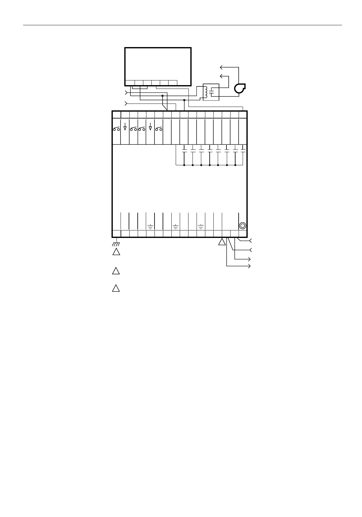
EXCEL 10 W7761A INPUT/OUTPUT DEVICE
29 74-2699
12345678
E-BUS
24 VAC
W7761A
REMOTE I/O
DEVICE
1
2
1
2
EARTH GROUND WIRE LENGTH SHOULD BE HELD TO A MINIMUM.
USE THE HEAVIEST GAUGE WIRE AVAILABLE, UP TO 14 AWG (2.O MM
2
)
WITH A MINIMUM OF 18 AWG (1.O MM
2
), FOR EARTH GROUND WIRE.
TO ASSURE PROPER ELECTRICAL CONTACT, WIRES MUST BE TWISTED
TOGETHER BEFORE INSERTION INTO THE TERMINAL BLOCK.
E-BUS
E GND
GND
GND
GND
NOT USED
NOT USED
AI-1 OHM
AI-2 OHM
9 101112 14 J315
31 30 29 28 27 26 25 24 23 22 21 20
24 VAC COM
E-BUS
JACK
22 VDC OUT
19 18 17 16
AI-3 OHM
AI-4 OHM
AI-6 V/mA
OUT 7
OUT 6
OUT 5
OUT 4
OUT 8
OUT 1
OUT 3
OUT 2
AI-5 V/mA
13
DI-2
DI-4
DI-1
DI-3
M15279
GND
GND
TRIAC EQUIVALENT CIRCUIT
24 VAC
+
-
24 (H)
24 (N)
PWM
(H 24 VAC)
PWM OUTPUT
FROM CNTRL
ML7984B
T6 T5 C B W R
PWM
VALVE ACTUATOR
FAN
CONTACTOR (24 VAC)
LINE POWER
Fig. 19. Typical PWM Valve Actuator and miscellaneous fan control to W7761A. (For note 2, refer to Fig. 15.)
EXCEL 10 W7761A INPUT/OUTPUT DEVICE
30 74-2699
12345678
E-BUS
24 VAC
W7761A
REMOTE I/O
DEVICE
5
E GND
GND
GND
GND
NOT USED
NOT USED
AI-1 OHM
AI-2 OHM
9 101112 14 J315
31 30 29 28 27 26 25 24 23 22 21 20
24 VAC COM
E-BUS
JACK
22 VDC OUT
19 18 17 16
AI-3 OHM
AI-4 OHM
AI-6 V/mA
OUT 7
OUT 6
OUT 5
OUT 4
OUT 8
OUT 1
OUT 3
OUT 2
AI-5 V/mA
13
DI-2
DI-4
DI-1
DI-3
M15278
GND
GND
TRIAC EQUIVALENT CIRCUIT
24 VAC
+
-
24 (H)
24 (N)
24 (H)
24 (N)
INCREASE
DECREASE
MMC325 PNEUMATIC
TRANSDUCER
1
4
3
5
1
2
3
4
EARTH GROUND WIRE LENGTH SHOULD BE HELD TO A MINIMUM.
USE THE HEAVIEST GAUGE WIRE AVAILABLE, UP TO 14 AWG (2.O MM
2
)
WITH A MINIMUM OF 18 AWG (1.O MM
2
), FOR EARTH GROUND WIRE.
REVERSE WIRES (INCREASE/DECREASE) TO REVERSE ACTION
(DIRECT/REVERSE).
MAKE SURE ALL TRANSFORMER/POWER WIRING IS AS SHOWN:
REVERSING TERMINATIONS WILL RESULT IN EQUIPMENT MALFUNCTION.
OPTIONAL 24 VAC WIRING TO NEXT CONTROLLER.
USE 1/4 IN (6 MM) PNEUMATIC TUBING. MINIMUM BRANCH LINE MUST BE
6 FT. (1.8M) OR LONGER.
PNEUMATIC
VALVE
M
B
M
2
Fig. 20. Typical Pneumatic transducer (Series 60 - Floating) to W7761A.
E-Bus Termination Module
One E-Bus Termination Module, part number 209541B is required for a single terminated E-Bus or two E-Bus Termination
Module, part number 209541B for a double terminated E-Bus (see Fig. 21). Refer to the E-Bus Wiring Guidelines form, 74-
2865 for termination module placement rules.

EXCEL 10 W7761A INPUT/OUTPUT DEVICE
31 74-2699
M12690
PART NO. 209541B
TERMINATION
MODULE
PART NO. 209541B
TERMINATION
MODULE
W7753A
1415 1415
W7753A
1415
W7753A
BROWN
BROWN
ORANGE
ORANGE
Fig. 21. Typical E-Bus termination module wiring diagrams (place a wire nut on each remaining wire that is not
connected to a controller or device).
See Fig. 22 for E-Bus termination wiring options.
EXCEL 10 W7761A INPUT/OUTPUT DEVICE
32 74-2699
Fig. 22. E-Bus termination wiring options.

EXCEL 10 W7761A INPUT/OUTPUT DEVICE
33 74-2699
Step 5. Order Equipment
After compiling a bill of materials through completion of the previous application steps, refer to Table 8 for ordering information.
Contact Honeywell for information about Controllers and Wall Modules with no logo.
Table 8. Excel 10 W7761A Device Ordering Information.
Part Number Product Description Comments
Excel 10 W7761A
W7761A2002 Remote Input/Output Device
Excel 10 W7750 Controllers:
W7750A1007 Constant Volume AHU Controller (W7750A) —
W7750B1005 Constant Volume AHU Controller (W7750B) —
T7770 Wall Modules:
T7770A1006 Sensor with Honeywell Logo (Not used with RIO) Used with Excel 5000 and Excel 10 Controllers
T7770A1014 Sensor with No Logo (Not used with RIO) Used with Excel 5000 and Excel 10 Controllers
T7770A2004 Sensor with Network Jack and Honeywell Logo Used with Excel 5000 and Excel 10 Controllers
T7770A2012 Sensor with Network Jack and No Logo Used with Excel 5000 and Excel 10 Controllers
T7770B1004 Sensor with Setpoint and Network Jack, Honeywell
Logo Degrees F Absolute. Sensor—(current feature
that can be used with the RIO Device).
T7770B1046 Sensor with Setpoint and Network Jack, Honeywell
Logo Relative Setpoint. Sensor—(current feature
that can be used with the RIO Device).
T7770B1012 Sensor with Setpoint and Network Jack, No Logo Degrees F Absolute. Sensor—(current feature
that can be used with the RIO Device).
T7770B1020 Sensor with Setpoint and Network Jack, Honeywell
Logo Degrees C Absolute. Sensor—(current feature
that can be used with the RIO Device).
T7770B1053 Sensor with Setpoint and Network Jack, No Logo Relative Setpoint. Sensor—(current feature
that can be used with the RIO Device).
T7770B1038 Sensor with Setpoint and Network Jack, No Logo Degrees C Absolute. Sensor—(current feature
that can be used with the RIO Device).
T7770C1002 Sensor with Setpoint, Bypass/LED and Network
Jack, Honeywell Logo Degrees F Absolute. Sensor—(current feature
that can be used with the RIO Device).
T7770C1044 Sensor with Setpoint, Bypass/LED and Network
Jack, Honeywell Logo Relative Setpoint. Sensor—(current feature
that can be used with the RIO Device).
T7770C1010 Sensor with Setpoint, Bypass/LED and Network
Jack, No Logo Degrees F Absolute. Sensor—(current feature
that can be used with the RIO Device).
T7770C1028 Sensor with Setpoint, Bypass/LED and Network
Jack, Honeywell Logo Degrees C Absolute. Sensor—(current feature
that can be used with the RIO Device).
T7770C1051 Sensor with Setpoint, Bypass/LED and Network
Jack, No Logo Relative Setpoint. Sensor—(current feature
that can be used with the RIO Device).
T7770C1036 Sensor with Setpoint, Bypass/LED and Network
Jack, No Logo Degrees C Absolute. Sensor—(current feature
that can be used with the RIO Device).
T7770D1000 Sensor with Bypass/LED and Network Jack,
Honeywell Logo Degrees F Absolute. Sensor—(current feature
that can be used with the RIO Device).
T7770D1018 Sensor with Bypass/LED and Network Jack, No
Logo Degrees C Absolute. Sensor—(current feature
that can be used with the RIO Device).
T7780A1004 Sensor, Digital Display Wall Module with Network
Jack, Honeywell Logo Degrees F Absolute (default)
T7780A1012 Sensor, Digital Display Wall Module with Network
Jack, No Logo Degrees F Absolute (default)
Sensors:
C7770A1006 Air Temperature Sensor. 20 Kohm NTC
nonlinearized Duct-mounted sensor that functions as a
primary and/or secondary sensor.
(continued)

EXCEL 10 W7761A INPUT/OUTPUT DEVICE
34 74-2699
Table 8. Excel 10 W7761A Device Ordering Information (Continued).
Part Number Product Description Comments
Sensors (Continued):
C7031J1050 Averaging Discharge/Return Air Temperature
Sensor. 20 Kohm NTC Duct element cord length 12 ft. (3.7m)
C7031B1033 Discharge Air or Hot Water Temperature Sensor.
20 Kohm NTC Use 112622AA Immersion Well
C7031C1031 Duct Discharge/Return Air Sensor. 20 Kohm 18 in. (457mm) insertion length.
C7031D1062 Hot or chilled Water Temperature Sensor. 20 Kohm
NTC —
C7031K1017 Hot or chilled Water Temperature Sensor. 20 Kohm
NTC Strap-on
C7100A1015 Averaging Discharge/Return Air Temperature
Sensor. PT3000 13 in. (330mm) insertion length.
C7170A1002 Outdoor Air Temperature Sensor. PT3000 —
Echelon® Based Components and Parts:
Q7750A1003 Excel 10 Zone Manager Free Topology Tranceiver (FTT)
Q7751A2002 Router (FTT)
Q7752A2001 Serial Interface (FTT)
Q7740A1008 Excel 10 2-Way Repeater Used to extend the length of the E-Bus.
Contains built in termination modules.
Q7740B1006 Excel 10 4-Way Repeater Used to extend the length of the E-Bus.
Contains built in termination modules.
XD 505A Standard C-Bus Communications Submodule —
XD 508 C-Bus Communications Submodule (1 me
g
abit baud
rate) —
209541B Termination Module One or two required per E-Bus segment
205979 Operator Terminal Cable for E-Bus Serial interface to wall module or controller
Accessories:
EL7680A1008 Wall Mounted Wide View Infrared Occupancy
Sensor —
EL7628A1007 Ceiling Mounted Infrared Occupancy Sensor —
EL7611A1003,
EL7612A1001 Ultrasonic Occupancy Sensors —
EL7630A1003,
EL7621A1002,
EL7621A1010
Power Supply/Control Units for Occupancy sensors —
C7400A1004 Solid State Enthalpy Sensor (4 to 20 mA) For outdoor and return air enthalpy
C7600B1000 Solid State Humidity Sensor (2 to 10 V) For outdoor and return air humidity
C7600C1008 Solid State Humidity Sensor (4 to 20 mA) For outdoor and return air humidity
C7600C1018 Solid State Humidity Sensor (2 to 10 V) For outdoor and return air humidity
MMC325-010,
MMC325-020 Pneumatic Retrofit Transducers.
Select pressure ran
g
e: (010) 0 to 10 psi (68.97 kPa)
or (020) 0 to 20 psi (137.93 kPa).
Use to control Pneumatic reheat valves
MMCA530 DIN rail adapter for MMC325 Transducers —
MMCA540 Metal enclosure for MMC325 Transducers —
ML7984B3000 Valve Actuator Pulse Width Modulation (PWM) Use with V5011 or V5013 F and G Valves
ML6161B1000 Damper Actuator Series 60 —
M6410A Valve Actuator Series 60 Use with V5812/V5813 Valves
ML684A1025 Versadrive Valve Actuator with linkage, Series 60 Use with V5011 and V5013 Valves
ML6464A1009 Direct Coupled Actuator, 66 lb-in., Series 60 —
(continued)

EXCEL 10 W7761A INPUT/OUTPUT DEVICE
35 74-2699
Table 8. Excel 10 W7761A Device Ordering Information (Continued).
Part Number Product Description Comments
Accessories (Continued):
ML6474A1008 Direct Coupled Actuator, 132 lb-in. torque, Series 60 —
ML6185A1000 Direct Coupled Actuator, 50 lb-in. spring return Series 60
EL7680A1008 Wall Mounted Wide View Infrared Occupancy Sensor —
EL7628A1007 Ceiling Mounted Infrared Occupancy Sensor —
EL7611A1003,
EL7612A1001 Ultrasonic Occupancy Sensors —
EL7630A1003,
EL7621A1002,
EL7621A1010
Power Supply/Control Units for Occupancy sensors —
C7400A1004 Solid State Enthalpy Sensor (4 to 20 mA) For outdoor and return air enthalpy
C7600B1000 Solid State Humidity Sensor (2 to 10 V) For outdoor and return air humidity
C7600C1008 Solid State Humidity Sensor (4 to 20 mA) For outdoor and return air humidity
C7600C1018 Solid State Humidity Sensor (2 to 10 V) For outdoor and return air humidity
MMC325-010,
MMC325-020 Pneumatic Retrofit Transducers.
Select pressure range: (010) 0 to 10 psi (68.97 kPa)
or (020) 0 to 20 psi (137.93 kPa).
Use to control Pneumatic reheat valves
MMCA530 DIN rail adapter for MMC325 Transducers —
MMCA540 Metal enclosure for MMC325 Transducers —
ML7984B3000 Valve Actuator Pulse Width Modulation (PWM) Use with V5011 or V5013 F and G Valves
ML6161B1000 Damper Actuator Series 60 —
M6410A Valve Actuator Series 60 Use with V5812/V5813 Valves
ML684A1025 Versadrive Valve Actuator with linkage, Series 60 Use with V5011 and V5013 Valves
ML6464A1009 Direct Coupled Actuator, 66 lb-in., Series 60 —
ML6474A1008 Direct Coupled Actuator, 132 lb-in. torque, Series 60 —
ML6185A1000 Direct Coupled Actuator, 50 lb-in. spring return Series 60
V5812A Two-way terminal unit water valve; 0.19, 0.29, 0.47,
0.74, 1.2, and 1.9 Cv 1/2 in. npt (13 mm) or
2.9 and 4.9 Cv 3/4 in. npt (19 mm)
Use with M6410 Valve Actuator. Close-off
rating for 0.19 to 1.9 Cv is 65 psi; for 2.9
and 4.9, Cv is 45 psi. (Coefficient of
volume or capacity index C
v
=
g
allons per
minute divided by the square root of the
pressure drop across the valve.)
V5813A Three-way mixing terminal unit hot water valve; 0.19,
0.29, 0.47, 0.74, 1.2, and 1.9 Cv 1/2 in. npt (13 mm)
or 2.9 and 4.9 Cv 3/4 in. npt (19 mm)
Use with M6410 Valve Actuator. Close-off
rating 0.19 to 0.74 Cv is 55 psi; 1.2, and
1.9 Cv is 22 psi; 2.9 and 4.9 Cv is 26 psi.
R8242A Contactor, 24 Vac coil, DPDT —
AT72D, AT88A, AK3310, etc. Transformers —
EN 50 022 DIN rail 35 mm by 7.5 mm (1-3/8 in. by 5/16 in.) Obtain locally: A controller requires 5 in.
— Augat Inc. part number 2TK2D DIN rail (adapter) Purchase from Augat Inc. two DIN rail
adapters for each controller
— Serial Interface Cable, male DB-9 to female DB-9 or
female DB-25. Obtain locally from any computer
hardware vendor.
Cabling
Honeywell AK3791 (one
twisted pair) AK3792 (two
twisted pairs)
E-Bus (plenum): 22 AWG (0.34 mm2) twisted pair
solid conductor, nonshielded or Echelon approved
cable.
Level IV 140°F (60°C) rating
Honeywell AK3781 (one
twisted pair) AK3782 (two
twisted pairs)
E-Bus (nonplenum): 22 AWG (0.34 mm2) twisted pair
solid conductor, nonshielded or Echelon approved
cable.
Level IV 140°F (60°C) rating
Honeywell AK3725 Inputs: 18 AWG (1.0 mm2) five wire cable bundle Standard thermostat wire
(continued)
EXCEL 10 W7761A INPUT/OUTPUT DEVICE
36 74-2699
Table 8. Excel 10 W7761A Device Ordering Information (Continued).
Part Number Product Description Comments
Cabling (Continued):
Honeywell AK3752
(typical or equivalent) Outputs/Power: 14 to 18 AWG (2.0 to 1.0 mm2) NEC Class 2 140°F (60°C) rating
Honeywell AK3702
(typical or equivalent) 18 AWG (1.0 mm2) twisted pair Non-plenum
Honeywell AK3712
(typical or equivalent) 16 AWG (1.3 mm2) twisted pair Non-plenum
Honeywell AK3754
(typical or equivalent) 14 AWG (2.0 mm2) two conductor Non-plenum
Step 6. Configure Devices
Excel E-Vision PC Software is used to configure W7761A Devices to match their intended application. The E-Vision User
Guide form, 74-2588 provides details for operating the PC software.
Step 7. Troubleshooting
Troubleshooting Excel 10 Controllers and Wall Modules
In addition to the following information, refer to the Installation Instructions and Checkout and Test manual for each product.
See the Applicable Literature section for form numbers.
Temperature Sensor and Setpoint Potentiometer Resistance Ranges
The T7770 Wall Module or the C7770A Air Temperature Sensor has the following specified calibration points, which are plotted
in Fig. 23:
Temperature (°F) Resistance Value (ohms)
99 11,520
85 16,301
70 24,039
55 36,280
45 48,000
TEMPERATURE (DEGREES)
oF
30 40 50 60 70 80 90 100 110
010 20 30 40
RESISTANCE (OHMS)
20K OHM AT
77oF (25oC)
80K
70K
60K
50K
40K
30K
20K
10K
oC
M5874A
Fig. 23. Temperature sensor resistance plots.
Alarms
When an Excel 10 has an alarm condition, it reports it to the central node on the E-Bus (typically, the Excel 10 Zone Manager).
See Table 9. Information contained in an alarm message is:
•Subnet Number:
E-Bus subnet that contains the Excel 10 node that has the alarm condition. Subnet 1 is on the Zone Manager side of the
router; Subnet 2 is on the other side.
•Node Number:
Excel 10 node that has the alarm condition (see Network Status).
•Alarm Type:
Specific alarm being issued. An Excel 10 can provide the alarm types listed in Table 9.
EXCEL 10 W7761A INPUT/OUTPUT DEVICE
37 74-2699
Table 9. Excel 10 Alarms.
Name of alarm or error bit Alarm type
number Meaning of alarm code or error bit
RETURN_TO_NORMAL 128U Return to no alarm after being in an alarm condition. This code is added
numerically to another alarm code to indicate that the alarm condition has
returned to normal.
ALARM_NOTIFY_DISABLED 255U The alarm reporting has been turned off by the DestManMode. No more
alarms are reported via nvoAlarm until DestManMode turns on alarm repo
r
or upon application restart.
NO_ALARM 0 No alarms presently detected.
INPUT_NV_FAILURE 1 One or more NV inputs have failed in receiving an update within their spe
c
FAILURE_DETECT_TIME.
NODE_DISABLED 2 The control algorithm has stopped because the RIO device is in
DISABLED_MODE, MANUAL, or FACTORY_TEST mode. No more alarm
s
reported when the device is in the DISABLED_MODE. Alarms continue to
reported if the device is in the MANUAL or FACTORY_TEST mode. The
control is shut down and disabled until power is cycled or the node is rese
t
See note 1 below.
SENSOR_FAILURE 3 One or more sensors have failed.
NOTE: The node can be reset by switching the node to MANUAL and then to the normal operating mode.
Also, the Excel 10 variables,
AlarmLogX
where
X
is 1 through 5, that store the last five alarms to occur in the device, are
available. These points can be viewed through XBS or E-Vision.
Broadcasting the Service Message
The Service Message allows a device on the E-Bus to be positively identified. The Service Message contains the device ID
number and, therefore, can be used to confirm the physical location of a particular Excel 10 in a building.
There are two methods of broadcasting the Service Message from an Excel 10 W7761A Device. One uses a hardware service
pin button on the side of the device (see Fig. 24). The other involves using the PC Configuration tool, as follows.
The commissioning tool is used to perform the ID Assignment task (see the E-Vision User’s Guide form, 74-2588).
M10094
SERVICE
PIN
BUTTON
Fig. 24. Location of the Service Pin Button.
W7761A Device Status LED
The LED on the front and center of a W7761A Device provides a visual indication of the status of the device. See Fig. 25.
When the W7761A receives power, the LED should appear in one of the following allowable states (see Table 10):
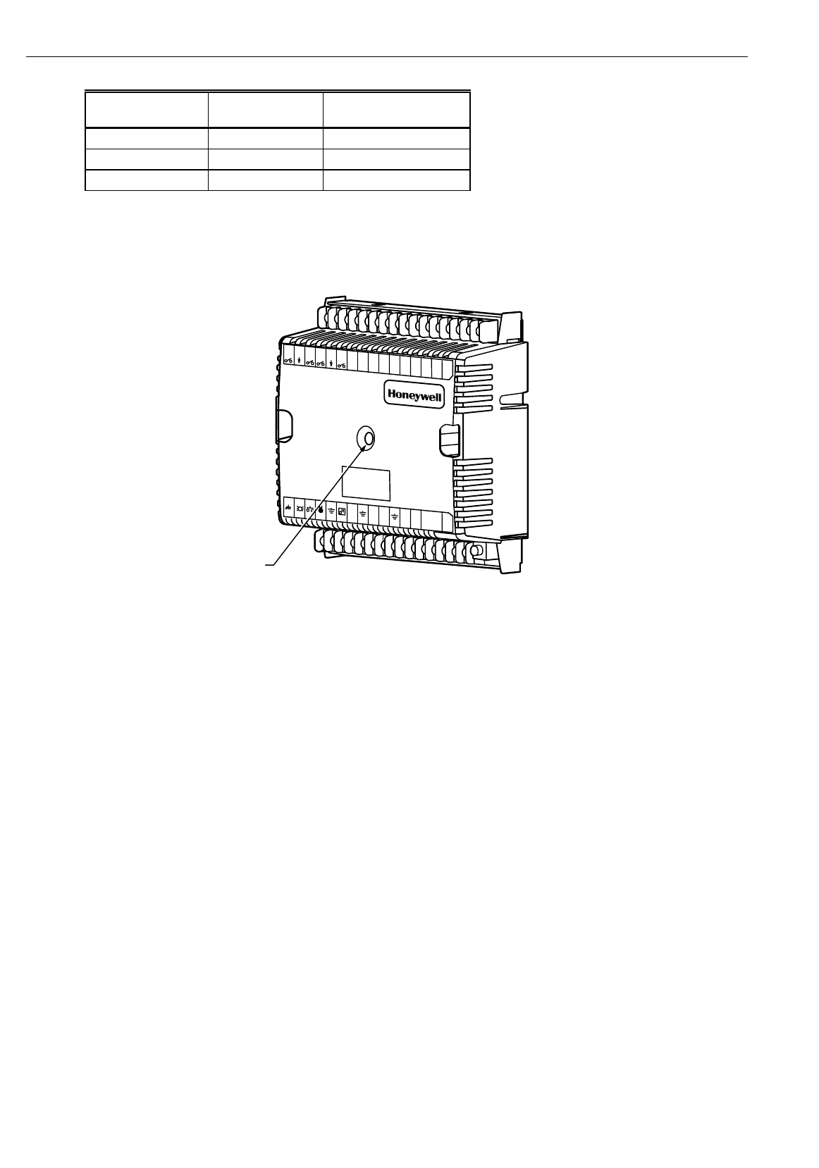
EXCEL 10 W7761A INPUT/OUTPUT DEVICE
38 74-2699
Table 10. LED States.
Alarm Condition Hardware or
Software Failure Service LED Blink Rate
(Cycles per second)
None None 1
Any alarm condition None 2
Don't Care Failed steady ON or OFF
1. Off—no power to the processor.
2. Continuously On—processor is in initialized state.
3. Slow Blink—controlling, normal state.
4. Fast Blink—when the Excel 10 has an alarm condition.
M10095
123456789101112131415J3
31302928272625242322212019181716
EART
H `
GR
OUND
L
EDBYPASSSENSORGR
OUNDSET
PTA11
RGROUNDA12 RA13`
V/mA
GROUNDA14V/mA22
VDC
`
OUT
EBUS
D14GROUN
DD13D12GR
OUNDD1124 V
ACCOMOUT
1O
UT
2OUT
3O
UT 4 O
UT
5OU
T 6O
UT
7OUT
8
STATUS`
LED
W7750
Fig. 25. LED location on W7761A.
T7780 DDWM Bypass Pushbutton
See Fig. 26 for the T7780 DDWM bypass pushbutton location (occupied or unoccupied). The T7780 DDWM has two methods
for generating its neuron ID, shorting two pads or winking.
1. Pressing the bypass pushbutton whenever a Carat (∇) on the bottom of the LCD display is flashing (Menu Selection
Mode).
2. Pressing the bypass pushbutton when the T7780A DDWM is in wink mode (LCD display shows WINK when E-Vision
sends a Service Message out on the E-Bus).
When the space covered by the T7780 DDWM is in Occupied mode, the sun symbol is shown on the left side of the LCD
display. When the space is in Standby mode, the half-sun symbol is shown. When the space is in Unoccupied mode, the moon
symbol is shown.
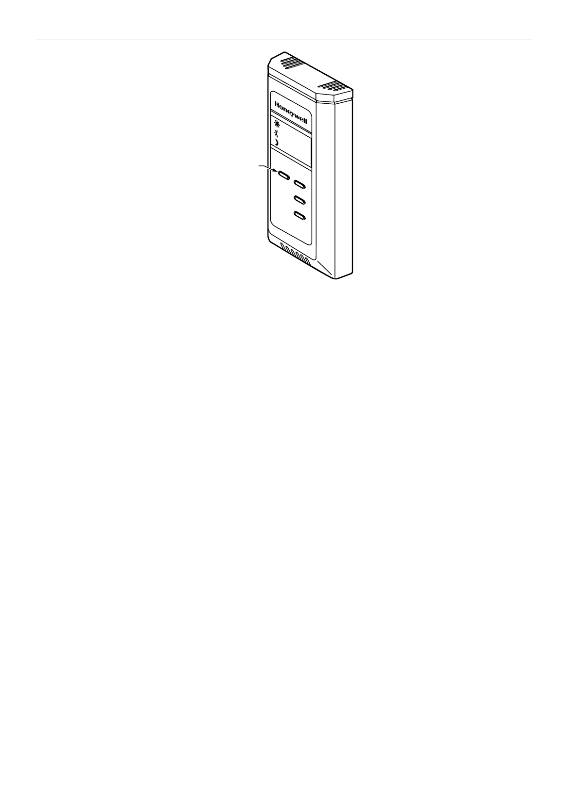
EXCEL 10 W7761A INPUT/OUTPUT DEVICE
39 74-2699
M11616
T7780A
BYPASS
PUSHBUTTON
Fig. 26. Bypass pushbutton location on T7780 DDWM.
APPENDICES
Appendix A. Using E-Vision to Commission a W7761 Device.
CARE/E-Vision must be used to configure the W7761 device. The inputs and outputs will be configured through the application
selection menu (see E-Vision user guide form, 74-2588). The RIO does not contain control loops for directly controlling the
digital outputs, therefore the Zone Manager or some other device has to be bound to the outputs to perform the control
function. Refer to the CARE User’s Manual form, 74-5587 to add Control Strategy, Switching Logic, or Time Programs for
control of the RIO digital outputs. Refer to the E-Vision user guide (form, 74-2588 for the RIO commissioning procedure and
updating/downloading of the Zone Manager files.
NOTE: The RIO device does not synchronize the floating digital outputs. This function (position is synchronized whenever an
endpoint is reached (full open or full close).and when the elapsed time since the last synchronization is 24 hours)
must be done by the controlling device (such as the Zone Manager).
SENSOR CALIBRATION
The resistive temperature sensors and
voltage/current
inputs can all be calibrated. The wall module setpoint potentiometer
is
not supported on the W7761A.
Perform the sensor calibration by adding an offset value (either positive or negative) to the
sensed value using E-Vision menus (see E-Vision user guide form, 74-2588).
When calibrating voltage/current sensors on the W7761A, the offset amount entered by the user is in volts, regardless of the
inputs actual engineering units. See Appendix E for information on how to derive the proper voltage value to enter as an offset
during calibration.
CUSTOM MAPPING
The RIO default CARE plant contains all available points that are supported on the RIO device. If the RIO plant was
customized by deleting unused points, then the Custom mapping feature will have to be used to add points back into the plant
so that they can be used or monitored by other devices. The following procedures will describe the Custom mapping process
for adding analog/digital inputs and digital outputs.
ADDING ANALOG INPUTS - ENTHALPY (4 to 20 mA)
To add an enthalpy (outdoor or return air) sensor to an RIO plant, the user must add a software point (pseudo analog) that can
be mapped to the actual hardware input through the Custom Mapping function of E-Vision. The following procedure will instruct
the user on adding the pseudo analog and using the Custom Mapping function. This allows the enthalpy input to be used with
other Excel 10 controllers (referenced) on the E-Bus, used in Zone Manager control strategy or switching logic, or be used with
Excel 5000 controllers on the C-Bus.
1. With CARE running, open an existing RIO plant. The user can go into either switching logic or control strategy to add the
pseudo analog point. If the user does not have an existing control loop through control strategy, use switching logic to
add the pseudo point, otherwise a control loop will have to be created along with unnecessary RACL to add the point.

EXCEL 10 W7761A INPUT/OUTPUT DEVICE
40 74-2699
This procedure will use switching logic to add the pseudo analog point. With the RIO plant having the focus, go into
switching logic. Select the
Software Points
menu item and then
Pseudo Analog
. The
Create/Select Software Point
<
Va
>
dialog box will be displayed. Type in a New point name for the enthalpy sensor (such as
OaEnthaply
) and click on the
OK
button. The new point that was just created will be added to the screen as the header point for switching logic table and
also added to the
Point List
. Select the
Cancel
button to exit the
Create/Select Software Point
<
Va
> dialog box. Exit
switching logic by selecting the
File
menu item and
Exit
. CARE will display the
Delete Unused Software Points
list box.
Click the
Cancel
button to continue.
2. Go into the
Data Point Editor
(
Controller/Edit/Data Point Editor
) and under
Point
select the pseudo analog point that was
just created and click the
OK
button. Select the drop down list for the
Engineering Unit
and scroll through the list until the
mA (mA matches the engineering unit of the RIO input) engineering units are displayed. Select the mA engineering unit
that is shown with one decimal place (number 66) and click the
OK
button to save the selection. Cancel the
User
Address
list box and select
File/Exit
to exit out of the Data Point Editor.
3. Translate the Zone Manager and Export the Zone Manager files to E-Vision by selecting the
Project
and
Export to E-
Vision
menu items. Type in the name of the Zone Manager Export file when the
Export Zone Manager
dialog box is
displayed. Select the project and the Zone manager within that project that is being exported and click the
Export
button.
Exit CARE and Start E-Vision. Select the E-Vision project to open and the CARE Export Filename created above. Once
the project is open, select the RIO device that the enthalpy sensor is connected to and go into the
Application Selection
screen (offline) by selecting the
Controller
, then the
Application Selection
menu items. From the
Inputs
tab of the
Application Selection
dialog box, add Oa_Enthalpy to either analog input 5 or 6 and select the
OK
button to save the
selection.
4. Select the
Controller
menu item and then
Import
from CARE to import the Zone Manager files with the new pseudo
analog point. If this function has already been performed before, the user will be prompted with the message CARE
Export File has already been imported, do you want to import again?. Select
Yes
to continue with the Import. When the
import is finished, E-Vision displays the message CARE Export File has been imported. Select
OK
to continue.
5. Select the
Network
menu item and then
Map C-Bus Points
. Select
RIO1
as the Controller Type from the
Map C-Bus
Points
dialog box. Under
Unmapped CARE
, select the name of the RIO device that the enthalpy sensor was added to in
CARE. Under
Unmapped Excel 10
, select the name of the RIO device that the actual enthalpy sensor was added to
(both names should be the same). Next, select the
Custom
button and the
Custom Mapping CARE Points
dialog box will
be displayed. Select the
OaEnthalpy
point under
CARE Points
and
CurrentAI
under
Excel 10
. CurrentAI is the user
address in the RIO device that contains the actual sensor value for the OaEnthalpy (C7400A1004, 4 to 20 mA device).
Select the
Map
button to add the OaEnthalpy point to the list of
Mapped Points
. Click on the
Close
button to exit the
Custom Mapping CARE Points
dialog box. Click on the
Close
button to exit the
Map C-Bus Points
dialog box.
6. To use the OaEnthalpy custom mapped point with other Excel 10 controllers on the E-Bus, select the
Network
menu item
and
Refer Excel 10 Points
. Select the RIO device name as the
Source Excel 10
and then scroll down the list of
Excel 10
Points
: until you reach
CurrentAI
and select it. Select an Excel 10 controller from the
Destination Excel 10
list. For
example if the user had selected a CVAHU controller from the
Destination Excel 10
list, the user would select from the
Excel 10 Points
list as the destination point and then click on the
Add
button to add the point association (Binding)
between the RIO and CVAHU controllers. If
DestOaEnth
is already being used in an association, then the message
At
Least
one of the output network variables is in an existing connection and E-Vision will not allow this association to be
added. In order to add this association, the user has to remove any other associations with the
DestOaEnth
point. Select
the
Close
button to exit out of the
Refer Excel 10 Points
dialog box. Any controllers involved in the new association or
change in an existing association will require commissioning.
7. Select the
Controller
menu item and the
Update Zone Manager Files
. E-Vision will add the custom mapping information
to the Zone Manager files. When the
Update Zone Manager Files
function is done, commission any controllers that need
to be commissioned, then close the E-Vision project and exit out of E-Vision.
8. Start CARE and open the Zone Manager that was just updated through the
Update Zone Manager Files
function and
start XI584 by selecting the
Controller
,
Tools
and
XI584
menu items. Once XI584 is started, select the
Utilities
and
File
Transfer
menu items and select
CARE Import
. Select the project and the Zone Manager that was just updated and select
Import
and click
OK
on the
Select Target Controller
dialog box. When the CARE Import is complete, close the
CARE
Import
dialog box. If this is the initial loading of the Zone Manager, then it will have to be reset and the CPU address set
by the XI581 Emulation function (
Applications
,
XI581 Emulation
menu). Select the
Utilities
,
File Transfer
menu items and
select
Download
. The
Download
dialog box will be displayed. Check the
All
selection and click the
Controller
button.
When the
Select Controller/Subsystem
dialog box is displayed, make sure that the correct CPU address or name is high
lighted and select the
OK
button. Click the
Download
button and click
Yes
to the message
Replace
updated application
part in controller (CPU address or Controller name). When the download is complete, exit out of the
Download
dialog
box. From the XI584 main menu, select the
Data
,
Access by User Address
menu items. Type
OaEnthalpy
in the
Search
For User Address
and click the
Search
button. When the
OaEnthalpy
point displays in the
User Addresses
list, click on
the point and select the
Attributes
button. XI584 will now display the value of the enthalpy sensor connected to the RIO
device. This point can now be used in the Zone Manager control strategy or switching logic. This point can be used in
other Excel 5000 (C-Bus) controllers by assigning a global analog point in the destination controller with the user address
name of
OaEnthalpy
. Refer to the CARE User’s Manual form, 74-5587 for information on creating global points in Excel
5000 controllers.
ADDING OTHER VOLTAGE/CURRENT SENSORS
See Table A-1 for the supported Voltage/Current analog input sensors that can be connected to the RIO Device. The user
must add a software point (pseudo analog - in RIO CARE Plant) that can be mapped to the actual hardware input (RIO Plant)
through the Custom Mapping function of E-Vision. The procedure described previously for adding an enthalpy ( 4 to 20 mA)
sensor should be followed and instructs the user on adding the pseudo analog point in the RIO CARE Plant and using the

EXCEL 10 W7761A INPUT/OUTPUT DEVICE
41 74-2699
Custom Mapping function. From there it can be used with other Excel 10 controllers (referenced) on the E-Bus, that are used in
the Zone Manager control strategy or switching logic, or are used with Excel 5000 controllers on the C-Bus.
Table A-1. Supported Voltage And Current Input Sensors.
E-Vision Enumerated Name in the Input
Application Selection Tab RIO Network Variable that contains the
Hardware Input Value
RA_Hum_C7600C Humidity1 or Humidity2
OA_Hum_C7600C Humidity1 or Humidity2
Filter_Diff_Pres Pressure1 or Pressure2
RA_Hum_C7600B Humidity1 or Humidity2
OA_Hum_C7600B Humidity1 or Humidity2
RA_Enthalpy CurrentAI
OA_Enthalpy CurrentAI
Space_CO2 CO2Level
Voltage_Monitor VoltageAI
ADDING DIGITAL INPUTS
See Table A-2 for the supported Digital input types that can be connected to the RIO Device. The user must add a software
point (pseudo digital nstate - in RIO CARE Plant) that can be mapped to the actual hardware input (RIO Plant) through the
Custom Mapping function of E-Vision. The procedure described previously for adding an enthalpy ( 4 to 20 mA) sensor should
be followed. The user will add a
Pseudo Digital nstate point
(<
Vd
>) in step one instead of the Pseudo Analog to the RIO CARE
Plant and then use the Custom Mapping function. From there it can be used with other Excel 10 controllers (referenced) on the
E-Bus, that are used in Zone Manager control strategy or switching logic, or are used with Excel 5000 controllers on the C-Bus.
Table A-2. Supported Digital Input Types.
E-Vision Enumerated Name in the Input
Application Selection Tab RIO Network Variable that contains the
Hardware Input Value
Digital Input 1:
Active_Short / Active_Open SrcDigIn1Sts
Digital Input 2:
Active_Short / Active_Open SrcDigIn2Sts
Digital Input 3:
Active_Short / Active_Open SrcDigIn3Sts
Digital Input 4:
Active_Short / Active_Open SrcDigIn4Sts
ADDING DIGITAL OUTPUTS
See Table A-3 for the supported digital output types that can be connected to the RIO Device.
The user must add a software point (pseudo analog) that can be mapped to the actual hardware output through the Custom
Mapping function of E-Vision. The following procedure will instruct the user on adding the pseudo analog and using the Custom
Mapping function so that the Digital Output can be used in the Zone Manager control strategy or switching logic, or be used
with Excel 5000 controllers on the C-Bus.
1. With CARE running, open an existing RIO plant. The user can go into either switching logic or control strategy to add the
pseudo analog point. If the user does not have an existing control loop through control strategy, use switching logic to
add the pseudo point, otherwise a control loop will have to be created along with unnecessary RACL to add the point.
This procedure will use switching logic to add the pseudo analog point. With the RIO plant having the focus, go into
switching logic. Select the
Software Points
menu item and then
Pseudo Analog
. The
Create/Select Software Point
<
Va
>
dialog box will be displayed. Type in a New point name for the Digital Output (such as
MiscExhFan
) and click on the
OK
button. The new point that was just created will be added to the screen as the header point for switching logic table and
also added to the
Point
list. Select the
Cancel
button to exit the
Create/Select Software Point
<
Va
> dialog box. Exit
switching logic by selecting the
File
menu item and
Exit
. CARE will display the
Delete Unused Software Points
list box.
Click the
Cancel
button to continue.
2. Go into the
Data Point Editor
(
Controller/Edit/Data Point Editor
) and under
Point
select the pseudo analog point that was
just created and the
OK
button. Select the drop down list for the
Engineering Unit
and scroll through the list until the
Pct
engineering units
are displayed. Select the Pct engineering unit that is shown with one decimal place (number 55) and
the
OK
button to save the selection.
Cancel
the
User Address
list box and select
File/Exit
to exit out of the
Data Point
Editor
.
3. Translate the Zone Manager and Export the Zone Manager files to E-Vision by selecting the
Project
and
Export
to E-
Vision menu items. Type in the name of the Zone Manager Export file when the
Export Zone Manager
dialog box is

EXCEL 10 W7761A INPUT/OUTPUT DEVICE
42 74-2699
displayed. Select the project and the Zone manager within that project that is being exported and the
Export
button. Exit
CARE and Start E-Vision. Select the E-Vision project to open and the CARE Export Filename created previously. Once
the project is open, select the RIO device that the Digital Output is connected to and go into the
Application Selection
screen (offline) by selecting the
Controller
,
Application Selection
menu items. From the
Outputs
tab of the
Application
Selection
dialog box, select the first Unused_DigOutput and scroll up until
Discrete1
is displayed and select it. Select the
OK
button to save the selection.
4. Select the
Controller
menu item and then
Import
from CARE to import the Zone Manager files with the new pseudo
analog point. If this function has already been performed before, the user will be prompted with the message
CARE
Export File
has already been imported, do you want to import again?. Select
Yes
to continue with the Import. When the
import is finished, E-Vision displays the message
CARE Export File
has been imported. Select
OK
to continue.
5. Select the
Network
menu item and then
Map C-Bus Points
. Select
RIO1
as the Controller Type from the
Map C-Bus
Points
dialog box. Under
Unmapped CARE
, select the name of the RIO device that the Digital Output was added to in
CARE. Under
Unmapped Excel 10
, select the name of the RIO device that the actual Digital Output was added to (both
names should be the same). Next, select the
Custom
button and the
Custom Mapping CARE Points
dialog box will be
displayed. Select the
MiscExhFan
point under
CARE Points
and
DigOut1Cmd
under
Excel 10
. Select the
Map
button to
add the
MiscExhFan
point to the list of
Mapped Points
. Click on the
Close
button to exit the
Custom Mapping CARE
Points
dialog box. Click on the
Close
button to exit the
Map C-Bus Points
dialog box.
6. Re-commission the RIO device that had the custom mapping done.
7. Select the
Controller
menu item and the
Update Zone Manager Files
. E-Vision will add the custom mapping information
to the Zone Manager files. When the Update Zone Manager Files function is done, close the E-Vision project and exit out
of E-Vision.
8. Start
CARE
and open the Zone Manager that was just updated through the
Update Zone Manager Files
function and
start XI584 by selecting the
Controller
,
Tools
and
XI584
menu items. Once XI584 is started, select the
Utilities
,
File
Transfer
menu items and select
CARE Import
. Select the project and the Zone Manager that was just updated and select
Import
and click
OK
on the
Select Target Controller
dialog box. When the CARE Import is complete, close the
CARE
Import
dialog box. If this is the initial loading of the Zone Manager, then it will have to be reset and the CPU address set
by the XI581 Emulation function (
Applications
,
XI581 Emulation
menu). Select the
Utilities
,
File Transfer
menu items and
select
Download
. The
Download
dialog box will be displayed. Check the
All
selection and click the
Controller
button.
When the
Select Controller/Subsystem
dialog box is displayed, make sure that the correct CPU address or name is
highlighted and select the
OK
button. Click the
Download
button and
Yes
to the message
Replace
updated application
part in controller (CPU address or Controller name). When the download is complete, exit out of the
Download
dialog
box. From the
XI584
main menu, select the
Data
,
Access by User Address
menu items. Type
MiscExhFan
in the
Search
For User Address
and click on the
Search
button. When the
MiscExhFan
point displays in the
User Addresses
list, click
on the point and select the
Attributes
button. XI584 will now display the value of the Digital Output connected to the RIO
device. To command the
MiscExhFan
to the
On
mode, put the point in the
Manual
mode and enter a value of
1.0 or
greater
. To command the
MiscExhFan
to the
Off
mode, put the point in the
Manual
mode and enter a value of
0.0
. This
point can now be used in the Zone Manager control strategy or switching logic and Time Programs. This point can be
used in other Excel 5000 controllers (C-Bus) by assigning a global analog point in the destination controller with the user
address name of MiscExhFan. Refer to the CARE User’s Manual form, 74-5587 for information on creating global points
in Excel 5000 controllers.
Table A-3. Supported Digital Output Types.
E-Vision Enumerated Name in the Output
Application Selection Tab RIO Network Variable that contains the
Hardware Output Value
Float1_Open through Float8_Open (Series 60 -
requires two outputs assigned. Float1_Open
must be assigned before Float1_Close)
DigOut1Cmd through DigOut8Cmd
Float1_Close through Float8_Close (Series 60
- requires two outputs assigned. Float1_Open
must be assigned before Float1_Close)
DigOut1Cmd through DigOut8Cmd
Discrete1 through Discrete8 (Maintained On/Off
outputs) DigOut1Cmd through DigOut8Cmd
Modulate1 through Modulate8 (PWM outputs) DigOut1Cmd through DigOut8Cmd
Appendix B. Sequences of Operation.
Common Operations
The Excel 10 W7761A Device contains inputs and outputs, but no control software. All control that would be associated with
the inputs and outputs in the W7761A would be accomplished though the Excel Zone Manager and would not be suitable for
VAV control, temperature control, or any control function that would require less than a 30 second update rate. The analog and
digital sensors could be shared or bound to other Excel 10 controllers on the E-Bus or Excel 5000 controllers on the C-Bus
through the Excel 10 Zone Manager. This would allow the other Excel 10 controllers to use their physical inputs for monitoring
other elements such as return humidity, IAQ, etc. to achieve better control.
Room Temperature Sensor (RmTemp)

EXCEL 10 W7761A INPUT/OUTPUT DEVICE
43 74-2699
The T7770A,B,C,D wall module is the room space temperature sensor—(current feature that can be used with the RIO
Device). When it is configured, it provides the temperature input that can be shared with the W7750 or W7751 controllers. If
there are multiple space sensors in a area controlled by one W7750 CVAHU, then the space temperatures can be wired into
the W7761A controller and mapped to the Zone Manager. The Zone Manager can average all of the space temperatures and
then have that value can be bound to the W7750 controlling that area.
Window Sensor (StatusWndw)
The digital input for a window contact can be wired into the W7761A device and then bound to a W7750 CVAHU to disable its
temperature control algorithm if someone has opened a window or door in the room or area that the W7750 is serving. When a
window is detected to be Open (digital input contacts Open equals window open), the normal temperature control is disabled,
and the W7750 Controller enters the Freeze Protect mode. Freeze Protect mode sets the space setpoint to 50 °F (10°C) and
brings on the fan and heat if the space temperature falls below this setpoint. Normal temperature control resumes on window
closure.
Dirty Filter Monitor
The air filter in the air handler can be monitored by a digital input in the W7761A and an alarm issued by the Zone Manager
when the filter media needs replacement. The two methods of monitoring the filter are:
1. A differential pressure switch whose contacts are connected to a digital input on the W7761A and;
2. A 2 to 10V differential pressure sensor wired to a voltage input on the W7761A. If the analog input sensor is used, its
measured value 0 to 5 inw (0 to 1.25 kPa) is compared to a user-selectable setpoint in the Zone Manager, the
comparison is done in the Zone Manager - valid range: 0 to 5 inw (0 to 1.25 kPa), and the Dirty Filter alarm is issued by
the Zone Manager when the pressure drop across the filter exceeds the setpoint.
Series 60 Modulating Control
Series 60 Control is also commonly referred to as Floating Control. The Excel 10 W7761A Device can drive Series 60 type
actuators to control a modulating damper or valve actuator. The W7761A device contains no control software, so these outputs
would have to be bound to either the Zone Manager or other Excel 10 controllers. When floating control is used, the full-stroke
motor drive time of the actuator must be entered into the configuration parameter DO1FlSpeed (for output 1), DO2FlSpeed (for
output 2). When Floating control is configured, two digital outputs are required, so the user has to change the configuration
parameter for the appropriate digital outputs.
Pulse Width Modulating (PWM) Control
The Excel 10 W7761A device can drive a PWM-type actuator to control a modulating actuator. The W7761A device contains
no control software, so these outputs would have to be bound to either the Zone Manager or other Excel 10 controllers. PWM
control positions the actuator based on the length, in seconds, of the pulse from the digital output. The controller outputs a
pulse whose length consists of two parts, a minimum and a maximum. The minimum pulse time represents the analog value of
zero percent (also indicates a signal presence) and the maximum pulse length that represents an analog value of 100 percent.
If the analog value is greater than zero percent, an additional time is added to the minimum pulse time. The length of time
added is directly proportional to the magnitude of the analog value. If PWM control is used, the configuration parameters for
the PWM operation must be specified. These parameters are DO1PWMPeriod and PWMZeroScale, and PWMFullScale.
Example: To find the pulse width of a valve actuator (for example stroke mid position - 50 percent) with the PWMZeroScale =
0.1 seconds, PWMFullScale = 25.5 seconds, and the PWMPeriod = 25.6 seconds. There are 256 increments available, so the
number of increments required for 50 percent would be (0.5 X 256) or 128. The time for each increment for this industry
standard pulse time is 0.1 seconds. The pulse width is the minimum time (0.1 second) + the number of increments (128 times
the seconds added 0.1) = 12.9 seconds. The W7750B Controller would command the valve output on for 12.9 seconds every
25.6 seconds to maintain the valve position at 50 percent.
Indoor Air Quality (IAQ) Override
The Excel 10 W7761A Device can monitor an IAQ sensor and that input can be bound to a W7750 CVAHU Controller that
supports an IAQ override feature, that upon detection of poor air quality in the space, allows the economizer dampers to be
opened above the standard minimum position setting to a value set in EconIAQPos (parameter located in W7750). Two
different methods of detecting poor air quality are supported, The first is by using an IAQ switch device connected to a digital
input on the W7761A Device, where a contact closure indicates poor air quality. This digital input would then be bound to the
W7750 Controller that is serving the area being monitored and would initiate the IAQ override mode. The second is through an
analog input that connects to a CO2 Sensor (0 to 10V). The measured value of CO2 from this sensor (0 to 2000 ppm) is
mapped into the Zone Manager where it is compared to a setpoint (parameter located in the Zone Manager). When the CO2
level is higher than the setpoint, the Zone Manager can initiate an IAQ alarm. A pseudo digital point in the Zone Manager can
be bound to the W7750 CVAHU Controller which can initiate the IAQ override mode.

EXCEL 10 W7761A INPUT/OUTPUT DEVICE
44 74-2699
Appendix C. Complete List of Excel 10 W7761A Remote I/O Device User Addresses.
C1. Input/Output Points.
C2. Control Parameters.
C3. Status Points.
C4. Configuration Parameters.
C5. Direct Access And Special Points.
Table C0 lists the applicable Engineering Units for the analog points found in the W7761A.
Table C0. Engineering Units For Analog Points.
English Units (Inch-Pound) Standard International Units (SI)
Measured Item Description Abbreviation Description Abbreviation
Temperature Degrees Fahrenheit F Degrees Celsius C
Relative
Temperature Delta Degrees Fahrenheit DDF Degrees Kelvin K
Relative Humidity Percent % Percent %
Air Flow Cubic Feet per Minute CFM Meters cubed per hour m3h
CO2 Concentration Parts Per Million PPM Parts Per Million PPM
Enthalpy British Thermal Units per Pound
of Air btu/lb kiloJoules/kilogram kJ/kg
Differential
Pressure Inches of Water Column inw kiloPascal kPa
Tables C1 through C5 list all network variables associated with the W7761A Controller and the default User Address names.
Table C1 lists the Network Variable Inputs and Outputs, which are stored in RAM memory. Table C2 lists the Control
Parameters, which are the values stored in the controllers EEPROM memory.
NOTE: Table C2. User Addresses For W7761A Control Parameters. (Control Parameters are stored in EEPROM - limited to
10,000
writes
. Do NOT use as outputs from Control Strategies, Time Programs, or Switching Tables. If these points
are changed more than 10,000 times, irreversible hardware failure results).
Tables provides point attributes as follows:
Engineering
Units— This field indicates the point valid range and displayed Engineering Unit. For digital points, the valid states
and the corresponding enumerated values are shown.
Default— The value or state of the point on controller start-up.
Shareable— The point can be set up for data sharing in Command Multiple Points, Read Multiple Points, or Refer Excel
10 Points as either a data source or a destination.
Mappable— The point can be converted into a C-Bus point used by C-Bus devices. A mappable point has a one-to-one
relationship with a C-Bus User Address.
Direct
Access— The point is accessible through the Subsystem Points mechanism in XBS.
E-Vision
Monitor— These points are viewable within the E-Vision Controller Monitoring on-line screen. PAR refers to control
parameters that are set in the Application Selection dialog boxes in E-Vision.
Hardware
Config— These are points that involve controller I/O configuration. Any change to HW Config. points causes the
W7761A to perform an application reset; therefore, these points can only be modified off-line.
Manual— These points are used to set the controller outputs when in manual mode. The W7761A is placed in manual
mode through a menu selection in the E-Vision Controller Monitor screen.
Fixable— These input points can be set to a constant value in the E-Vision Controller Monitor screen.
NOTES: 1. Mapped points can be viewed and changed,
if
applicable
, on C-Bus devices such as an XI581, XI582 and
XI584 and on an XBS central and E-Vision.
2. All Excel 10 points, mappable, calibration, configuration and internal data sharing points, can be viewed and
changed,
as allowed
, via Direct Access (DA) mode in the XBS subsystem menu or via XI584.
3. E-Vision - These points are displayed to the user and polled during the E-Vision monitor function. Monitor (M)
indicates the point appears in the Software list box. Schematic (S) indicates the point is to be displayed on the
schematic air handler diagram directly. Calibrate (C) - These points are calibratible and the calibration dialog
(either the temperature or air flow dialog) is displayed. These points are displayed in a listbox by selection of the
menu item Controller, Calibration. When the user double clicks on these points the calibration dialog is
displayed. Parameter (P) - This information is displayed to the user in the Application Selection screens. These
fields are read/write when offline and read only when online.
4. Manual - These points can be placed in the manual mode. When the user double clicks on these points the
manual dialog is displayed, this contains radio buttons; one for Auto and one for Manual.

EXCEL 10 W7761A INPUT/OUTPUT DEVICE
45 74-2699
Table C1. Input/Output Points (Left).
Engineering Units:
English (Metric) or
Digital
State
or
Value
of
User Address NvName Field Name States plus Range State Default
AI1RType ncirioIoSelect ResistiveIn0 DA_Temp_PT3000
OA_Temp_PT3000
RA_Temp_PT3000
Custom_PT3000
DA_Temp_20KNTC
RA_Temp_20KNTC
Space_Temp_T7770
Custom_20KNTC
Unused_Res_AI
0
1
2
3
4
5
6
7
255
Unused_Res_AI
AI2RType ncirioIoSelect ResistiveIn1 See AI1RType Eng. Units/States
column for selections
Unused_Res_AI
AI3RType ncirioIoSelect ResistiveIn2 See AI1RType Eng. Units/States
column for selections
Unused_Res_AI
AI4RType ncirioIoSelect ResistiveIn3 See AI1RType Eng. Units/States
column for selections
Unused_Res_AI
AI5VType ncirioIoSelect VoltageIn0 RA_Hum_C7600C
OA_Hum_C7600C
Filter_Diff_Pres
RA_Hum_C7600B
OA_Hum_C7600B
RA_Enthalpy
OA_Enthalpy
Space_CO2
Voltage_Monitor
Unused_Volt_AI
0
1
2
3
4
5
6
7
8
255
Unused_Volt_AI
AI6VType ncirioIoSelect VoltageIn1 See AI5VType Eng. Units/States
column for selections
Unused_Volt_AI
(continued)

EXCEL 10 W7761A INPUT/OUTPUT DEVICE
46 74-2699
Table C1. Input/Output Points (Right).
Share (SH), Map (MA), Direct Access (DA)
E-Vision (EV): Calibrate (C), Monitor (M),
Parameter (P), Schematic (S)
Hardware Configuration (HW),
Manual Point (MN), Test (TS)
SH MA DA EV HW MN TS Comments
X X AI1RType specifies which logical sensor is assigned to which physical analog input
sensor channel according to the enumerated list shown in the Eng. Units/States
column.
X X AI2RType: Refer to the description for AI1RType.
X X AI3RType: Refer to the description for AI1RType.
X X AI4RType: Refer to the description for AI1RType.
X X AI5VType specifies which logical voltage or current sensor is assigned to which
physical analog input sensor channel according to the enumerated list that is
shown in the Eng. Units/States column.
X X AI6VType: Refer to the description for AI5VType.
(continued)

EXCEL 10 W7761A INPUT/OUTPUT DEVICE
47 74-2699
Table C1. Input/Output Points (Left Continued).
Engineering Units:
English (Metric) or
Digital
State
or
Value
of
User Address NvName Field Name States plus Range State Default
DestOut1Cmd nviRemoteCmd(0) percent
-163 to 163
0
DestOut2Cmd nviRemoteCmd(1) percent -163 to 163 0
DestOut3Cmd nviRemoteCmd(2) percent -163 to 163 0
DestOut4Cmd nviRemoteCmd(3) percent -163 to 163 0
DestOut5Cmd nviRemoteCmd(4) percent -163 to 163 0
DestOut6Cmd nviRemoteCmd(5) percent -163 to 163 0
DestOut7Cmd nviRemoteCmd(6) percent -163 to 163 0
DestOut8Cmd nviRemoteCmd(7) percent -163 to 163 0
DI1Sel1Type ncirioIoSelect DigitalIn0S1 Active_Short
Active_Open
Unused_DigInput
0
1
255
Unused_DigInput
DI2Sel1Type ncirioIoSelect DigitalIn1S1 See DI1Sel1Type Eng.
Units/States column for
selections.
Unused_DigInput
(continued)

EXCEL 10 W7761A INPUT/OUTPUT DEVICE
48 74-2699
Table C1. Input/Output Points (Right Continued).
Share (SH), Map (MA), Direct Access (DA)
E-Vision (EV): Calibrate (C), Monitor (M),
Parameter (P), Schematic (S)
Hardware Configuration (HW),
Manual Point (MN), Test (TS)
SH MA DA EV HW MN TS Comments
X X X M DestOut1Cmd: DestOut1Cmd through DestOut8Cmd corresponds to DO1 through
DO8. Refer to the Eng. Units/States column for DO1Type for the enumerated
values that can be assigned to any output channels.
Note that a selection of FLOAT means that the two DO channels are used for
output. RIO assumes that the tool makes the proper assignment of enumerated
values to DO1 through DO8 and also takes the responsibility to avoid assignment
of multiple or overlapping commands on the same output channels. An example of
the relationship between nviRemoteCmd and ncirioIoSelect is discribed below:
RIO is receiving a command to DestOut4Cmd. This can be mapped as one of the
three output types (Discrete, Modulate, Float_Open, or Float_Close) by DO3Type.
If the user selects an enumerated value of Discrete2 for DO3Type, this value would
be stored in (DO2). Then the DestOut4Cmd will command DO2.
X X X M DestOut2Cmd: Refer to the description for DestOut1Cmd.
X X X M DestOut3Cmd: Refer to the description for DestOut1Cmd.
X X X M DestOut4Cmd: Refer to the description for DestOut1Cmd.
X X X M DestOut5Cmd: Refer to the description for DestOut1Cmd.
X X X M DestOut6Cmd: Refer to the description for DestOut1Cmd.
X X X M DestOut7Cmd: Refer to the description for DestOut1Cmd.
X X X M DestOut8Cmd: Refer to the description for DestOut1Cmd.
X X DI1Sel1Type specifies the sensor type and function connected to DigitalIn0S1
through DigitalIn3S1. The valid enumerated list of logical digital states for
DigitalIn0S1 is listed in the Eng. Units/States column.
X X DI2Sel1Type: Refer to the description for DI1Sel1Type.
(continued)

EXCEL 10 W7761A INPUT/OUTPUT DEVICE
49 74-2699
Table C1. Input/Output Points (Left Continued).
Engineering Units:
English (Metric) or
Digital
State
or
Value
of
User Address NvName Field Name States plus Range State Default
DI3Sel1Type ncirioIoSelect DigitalIn2S1 See DI1Sel1Type Eng. Units/States
column for selections.
Unused_DigInput
DI4Sel1Type ncirioIoSelect DigitalIn3S1 See DI1Sel1Type Eng. Units/States
column for selections.
Unused_DigInput
DI1Sel2Type ncirioIoSelect DigitalIn0S2 Momentary
Maintained
Unused_DigInput
0
1
255
Maintained
DI2Sel2Type ncirioIoSelect DigitalIn1S2 See DI1Sel2Type Eng. Units/States
column for selections.
Maintained
DI3Sel2Type ncirioIoSelect DigitalIn2S2 See DI1Sel2Type Eng. Units/States
column for selections.
Maintained
DI4Sel2Type ncirioIoSelect DigitalIn3S2 See DI1Sel2Type Eng. Units/States
column for selections.
Maintained
DO1Type ncirioIoSelect DigitalOut0 Discrete1
Discrete2
Discrete3
Discrete4
Discrete5
Discrete6
Discrete7
Discrete8
Modulate1
Modulate2
Modulate3
Modulate4
Modulate5
Modulate6
Modulate7
Modulate8
Float1_Open
Float2_Open
Float3_Open
Float4_Open
Float5_Open
Float6_Open
Float7_Open
Float8_Open
Float1_Close
Float2_Close
Float3_Close
Float4_Close
Float5_Close
Float6_Close
Float7_Close
Float8_Close
Unused_DigOutput
0
1
2
3
4
5
6
7
8
9
10
11
12
13
14
15
16
17
18
19
20
21
22
23
24
25
26
27
28
29
30
31
255
Unused_DigOutput

EXCEL 10 W7761A INPUT/OUTPUT DEVICE
50 74-2699
Table C1. Input/Output Points (Right Continued).
Share (SH), Map (MA), Direct Access (DA)
E-Vision (EV): Calibrate (C), Monitor (M),
Parameter (P), Schematic (S)
Hardware Configuration (HW),
Manual Point (MN), Test (TS)
SH MA DA EV HW MN TS Comments
X X DI3Sel1Type: Refer to the description for DI1Sel1Type.
X X DI4Sel1Type: Refer to the description for DI1Sel1Type.
X X DI1Sel2Type specifies the sensor type and function connected to DigitalIn0S2
through DigitalIn3S2. The valid enumerated list of logical digital states for
DI1Sel2Type is listed in the Eng. Units/States column.
X X DI2Sel2Type: Refer to the description for DI1Sel2Type.
X X DI3Sel2Type: Refer to the description for DI1Sel2Type.
X X DI4Sel2Type: Refer to the description for DI1Sel2Type.
X X DO1Type specifies which logical digital output function is assigned to the digital
physical output according to the enumerated list that is shown in the Eng.
Units/States column.

EXCEL 10 W7761A INPUT/OUTPUT DEVICE
51 74-2699
Table C1. Input/Output Points (Left Continued).
Engineering Units:
English (Metric) or
Digital
State
or
Value
of
User Address NvName Field Name States plus Range State Default
DO2Type ncirioIoSelect DigitalOut1 Refer to the Eng. Units/States
column for DO1Type for selections
available.
Unused_DigOutput
DO3Type ncirioIoSelect DigitalOut2 Refer to the Eng. Units/States
column for DO1Type for selections
available.
Unused_DigOutput
DO4Type ncirioIoSelect DigitalOut3 Refer to the Eng. Units/States
column for DO1Type for selections
available.
Unused_DigOutput
DO5Type ncirioIoSelect DigitalOut4 Refer to the Eng. Units/States
column for DO1Type for selections
available.
Unused_DigOutput
DO6Type ncirioIoSelect DigitalOut5 Refer to the Eng. Units/States
column for DO1Type for selections
available.
Unused_DigOutput
DO7Type ncirioIoSelect DigitalOut6 Refer to the Eng. Units/States
column for DO1Type for selections
available.
Unused_DigOutput
DO8Type ncirioIoSelect DigitalOut7 Refer to the Eng. Units/States
column for DO1Type for selections
available.
Unused_DigOutput
FiftySixtyHz nciIoSelect FiftySixtyHz Sixty
Fifty
0
1
Sixty
SrcCO2Level nvoRemoteCO2 PPM
0 to 65535
0
SrcCurrentAI nvoRemoteCurrent milliamps
-20.0 to 200.0
0
SrcDigIn1Sts nvoRemoteDigIn(0) DI1Value 0 to 255 0
nvoRemoteDigIn(0) DI1State ST_OFF
ST_LOW
ST_MED
ST_HIGH
ST_ON
ST_NUL
0
1
2
3
4
255
ST_NUL
(continued)

EXCEL 10 W7761A INPUT/OUTPUT DEVICE
52 74-2699
Table C1. Input/Output Points (Right Continued).
Share (SH), Map (MA), Direct Access (DA)
E-Vision (EV): Calibrate (C), Monitor (M),
Parameter (P), Schematic (S)
Hardware Configuration (HW),
Manual Point (MN), Test (TS)
SH MA DA EV HW MN TS Comments
X X DO2Type:
Refer to the description for DO1Type.
X X DO3Type:
Refer to the description for DO1Type.
X X DO4Type:
Refer to the description for DO1Type.
X X DO5Type:
Refer to the description for DO1Type.
X X DO6Type:
Refer to the description for DO1Type.
X X DO7Type:
Refer to the description for DO1Type.
X X DO8Type:
Refer to the description for DO1Type.
X X FiftySixtyHz specifies the power supply frequency. Correctly selecting FiftySixtyHz
decreases the noise picked up by analog sensor wiring from the power supply.
When FiftySixtyHz is 1, the power supply frequency is Fifty Hz and when
FiftySixtyHz is 0, the power supply frequency is Sixty Hz.
X X X M SrcCO2Level is an output network variable corresponding to the voltage or current
input channel (AI5 or AI6) if the selection for a CO2 sensor was made via
ncirioIoSelect.
X X X M SrcCurrentAI is an output network variable corresponding to the voltage or current
input channel (AI5 or AI6) if the selection for a current sensor was made via
ncirioIoSelect.
SrcDigIn1Sts: There are four digital input channels (DI1 through DI4). If any of the
four channels are configured, the corresponding output network variable will be
updated with the value whose data type is SNVT_switch.
X X X M DI1State: There are four digital input channels (DI1 through DI4). If any of the four
channels are configured, the corresponding output network variable will be updated
with the value whose data type is SNVT_switch. Refer to the enumerated list that is
shown in the Eng. Units/States column.
(continued)

EXCEL 10 W7761A INPUT/OUTPUT DEVICE
53 74-2699
Table C1. Input/Output Points (Left Continued).
Engineering Units:
English (Metric) or
Digital
State
or
Value
of
User Address NvName Field Name States plus Range State Default
SrcDigIn2Sts nvoRemoteDigIn(1) DI2Value 0 to 255 0
nvoRemoteDigIn(1) DI2State Refer to the DI1State enumerated list
shown in the Eng. Units/States column.
ST_NUL
SrcDigIn3Sts nvoRemoteDigIn(2) DI3Value 0 to 255 0
nvoRemoteDigIn(2) DI3State Refer to the DI1State enumerated list
shown in the Eng. Units/States column.
ST_NUL
SrcDigIn4Sts nvoRemoteDigIn(3) DI4Value 0 to 255 0
nvoRemoteDigIn(3) DI4State Refer to the DI1State enumerated list
shown in the Eng. Units/States column.
ST_NUL
SrcHumidAI5 nvoRemoteHum(0) percent
-163 to 163
0
SrcHumidAI6 nvoRemoteHum(1) percent
-163 to 163
0
SrcPressAI5 nvoRemotePres(0) inw -131.5 to 131.5
kPa (-32.768 to 32.767)
0
SrcPressAI6 nvoRemotePres(1) inw -131.5 to 131.5
kPa (-32.768 to 32.767)
0
SrcTempAI1 nvoRemoteTemp(0) degrees F -40 to 240
degrees C (-40 to 116)
0
SrcTempAI2 nvoRemoteTemp(1) degrees F -40 to 240
degrees C (-40 to 116)
0
SrcTempAI3 nvoRemoteTemp(2) degrees F -40 to 240
degrees C (-40 to 116)
0
SrcTempAI4 nvoRemoteTemp(3) degrees F -40 to 240
degrees C (-40 to 116)
0
SrcVoltageAI nvoRemoteVolt Volts
0.0 to 10.5
0
)

EXCEL 10 W7761A INPUT/OUTPUT DEVICE
54 74-2699
Table C1. Input/Output Points (Right Continued).
Share (SH), Map (MA), Direct Access (DA)
E-Vision (EV): Calibrate (C), Monitor (M),
Parameter (P), Schematic (S)
Hardware Configuration (HW),
Manual Point (MN), Test (TS)
SH MA DA EV HW MN TS Comments
SrcDigIn2Sts: Refer to the description for SrcDigIn1Sts.
X X X M DI2State:
Refer to the description for DI1State.
SrcDigIn3Sts: Refer to the description for SrcDigIn1Sts above.
X X X M DI3State:
Refer to the description for DI1State.
SrcDigIn4Sts: Refer to the description for SrcDigIn1Sts above.
X X X M DI4State:
Refer to the description for DI1State.
X X X M SrcHumidAI5 is an output network variable corresponding to the voltage or current
input channel (AI5) if the selection for humidity sensor was made via ncirioIoSelect
for AI5.
X X X M SrcHumidAI6 is an output network variable corresponding to the voltage or current
input channel (AI6) if the selection for humidity sensor was made via ncirioIoSelect
for AI6.
X X X M SrcPressAI5 is an output network variable corresponding to the voltage or current
input channel (AI5) if the selection for a pressure sensor was made via
ncirioIoSelect for AI5.
X X X M SrcPressAI6 is an output network variable corresponding to the voltage or current
input channel (AI6) if the selection for a pressure sensor was made via
ncirioIoSelect for AI6.
X X X M SrcTempAI1 is an output network variable corresponding to the analog input
channel (AI1). This NV will contain AI1 temperature value with the OffsetCal1AI1
applied to it.
X X X M SrcTempAI2 is an output network variable corresponding to the analog input
channel (AI2). This NV will contain AI2 temperature value with the OffsetCal1AI2
applied to it.
X X X M SrcTempAI3 is an output network variable corresponding to the analog input
channel (AI3). This NV will contain AI3 temperature value with the OffsetCal1AI3
applied to it.
X X X M SrcTempAI4 is an output network variable corresponding to the analog input
channel (AI4). This NV will contain AI4 temperature value with the OffsetCal1AI4
applied to it.
X X X M SrcVoltageAI is an output network variable corresponding to the voltage or current
input channel (AI5 or AI6) if the selection for a voltage sensor was made via
ncirioIoSelect.

EXCEL 10 W7761A INPUT/OUTPUT DEVICE
55 74-2699
Table C2. Control Parameters (Left).
Engineering Units:
English (Metric) or
Digital
State
or
Value
of
User Address NvName Field Name States plus Range State Default
nviInUse InUseNumber 0 to 65534 0xFFFF

EXCEL 10 W7761A INPUT/OUTPUT DEVICE
56 74-2699
Table C2. Control Parameters (Right).
Share (SH), Map (MA), Direct Access (DA)
E-Vision (EV): Calibrate (C), Monitor (M),
Parameter (P), Schematic (S)
Hardware Configuration (HW),
Manual Point (MN), Test (TS)
SH MA DA EV HW MN TS Comments
nviInUse is used by a management node to indicate to all other management
nodes that it is logged on, to the Excel 10 node and that they should not try to
interact with any of the Excel 10s network variables. Before the management node
reads or writes any network variables, the management node checks nviInUse for
a zero value meaning no other management nodes are already logged on and that
a management node may log on, to the node. Then the management node writes a
number, 1 through 65534, to nviInUse and periodically writes the same value to
indicate that the management node is still logged on. If there are no writes made to
nviInUse for approximately 60 seconds, then the Excel 10 resets nviInUse to zero
to automatically log off the management node. Before interacting with any network
variables, the management node verifies that the nviInUse has not changed. The
management node logs off by writing 0 to nviInUse.
During power up, an application restart, or return to on-line from off-line, the Excel
10 sets nviInUse to 65535 to indicate to the management node that it has returned
to on-line.

EXCEL 10 W7761A INPUT/OUTPUT DEVICE
57 74-2699
Table C3. Status Points (Left).
Engineering Units:
English (Metric) or
Digital
State
or
Value
of
User Address NvName Field Name States plus Range State Default
AlarmNode nvoAlarm node 0 to 127 0
AlarmSubnet nvoAlarm subnet 1 to 255 0
AlarmType nvoAlarm type
0 to 255
NO_ALARM
INPUT_NV_FAILURE
NODE_DISABLED
SENSOR_FAILURE
rINPUT_NV_FAILURE
rNODE_DISABLED
rSENSOR_FAILURE
ALARM_NOTIFY_DISABLED
0
1
2
3
129
130
131
255
NO_ALARM
AlarmTypeLog0 nvoAlarmLog type0 Refer to the AlarmType
enumerated list shown in the
Eng. Units/States column.
NO_ALARM
AlarmTypeLog1 nvoAlarmLog type1 Refer to the AlarmType
enumerated list shown in the
Eng. Units/States column.
NO_ALARM
AlarmTypeLog2 nvoAlarmLog type2 Refer to the AlarmType
enumerated list shown in the
Eng. Units/States column.
NO_ALARM
AlarmTypeLog3 nvoAlarmLog type3 Refer to the AlarmType
enumerated list shown in the
Eng. Units/States column.
NO_ALARM
AlarmTypeLog4 nvoAlarmLog type4 Refer to the AlarmType
enumerated list shown in the
Eng. Units/States column.
NO_ALARM
Errorbyte1 nvoError error_bit(0)
Byte Offset = 0
Bit Offset = 0
ResSensor1Error(AI1)
FALSE
TRUE
0
1
FALSE
(continued)

EXCEL 10 W7761A INPUT/OUTPUT DEVICE
58 74-2699
Table C3. Status Points (Right).
Share (SH), Map (MA), Direct Access (DA)
E-Vision (EV): Calibrate (C), Monitor (M),
Parameter (P), Schematic (S)
Hardware Configuration (HW),
Manual Point (MN), Test (TS)
SH MA DA EV HW MN TS Comments
AlarmNode: is the LonWorks node number (in domain entry 1 of the nodes domain
table) assigned to the node.
AlarmSubnet: is the LonWorks subnet number (in domain entry 1 of the nodes
domain table) to which the node is assigned.
AlarmType: is the alarm type being issued. When an alarm condition is no longer
TRUE, type is set to the sum of the alarm conditions numeric value and the
RETURN_TO_NORMAL numeric value. The type also is recorded in
AlarmTypeLog0 through AlarmTypeLog4. When a new alarm is detected, just the
corresponding numeric value for the alarm is reported. Refer to table 9 (Excel 10
Alarms) in the System Engineering Guide for all the error conditions that may be
reported.
X M AlarmTypeLog0 (0, 1, 2, 3, 129, 130, 131, 255)
A supervisory node may poll the AlarmTypeLog output for a short alarm history. The
last five alarm reports sent via nvoAlarm are reported via AlarmTypeLog. When
ALARM_NOTIFY_DISABLED is entered into the log, further alarms or return to
normals are not entered into the log, until alarm reporting is again enabled. If
nvoAlarm is bound and not being acknowledged, the last alarm report entered into
the AlarmTypeLog is the one that was not acknowledged.
See nvoAlarm and for related subjects.
type ( n ) specifies the alarm that was issued via nvoAlarm. See nvoAlarm for the
alarm types used in AlarmTypeLog. The newest alarm is reported in type( 0 ) and
the oldest is reported in type( 4 ). When a new entry is made to the log, the oldest
entry is lost.
X M AlarmTypeLog1:
Refer to the description for AlarmTypeLog0.
X M AlarmTypeLog2:
Refer to the description for AlarmTypeLog0.
X M AlarmTypeLog3:
Refer to the description for AlarmTypeLog0.
X M AlarmTypeLog4:
Refer to the description for AlarmTypeLog0.
X M ResSensor1Error(AI1): The nvoError is a polled output containing a list of the current
errors detected by the node. A search for error conditions in the node is made
periodically. A diagnostic tool may poll nvoError for all of the current errors. nvoError
uses one bit for each possible error condition. nvoError contains all the detected
current errors even though they may be suppressed for reporting by nvoAlarm.
There is a correspondence between the error conditions and alarm types. nvoError
includes sensor failure errors and input network variable failure detect errors. Any
sensor failure errors result in a SENSOR_FAILURE alarm. Failure to receive any
bound network variable periodically results in an INPUT_NV_FAILURE alarm.
nvoError tells which sensor(s) or network variable(s) have failed. See nvoAlarm,
AlarmTypeLog for related subjects.
(continued)

EXCEL 10 W7761A INPUT/OUTPUT DEVICE
59 74-2699
Table C3. Status Points (Left Continued).
Engineering Units:
English (Metric) or
Digital
State
or
Value
of
User Address NvName Field Name States plus Range State Default
Errorbyte2 nvoError error_bit(0)
Byte Offset = 0
Bit Offset = 1
ResSensor2Error(AI2)
FALSE
TRUE
0
1
FALSE
Errorbyte3 nvoError error_bit(0)
Byte Offset = 0
Bit Offset = 2
ResSensor3Error(AI3)
FALSE
TRUE
0
1
FALSE
Errorbyte4 nvoError error_bit(0)
Byte Offset = 0
Bit Offset = 3
ResSensor4Error(AI4)
FALSE
TRUE
0
1
FALSE
BugFixVer nroPgmVer BugVer 3
nroPgmVer NodeType RIO1
MajorVer nroPgmVer MajorVer 2
MinorVer nroPgmVer MinorVer 1
nroPgmVer NodeType 6
nvoStatus CommFailure FALSE
TRUE
0
1
FALSE
nvoStatus disabled FALSE
TRUE
0
1
FALSE
nvoStatus ElectricalFault FALSE
TRUE
0
1
FALSE
nvoStatus FailSelfTest FALSE
TRUE
0
1
FALSE
nvoStatus FeedbackFailure FALSE
TRUE
0
1
FALSE
nvoStatus InAlarm FALSE
TRUE
0
1
FALSE
nvoStatus InvalidId FALSE
TRUE
0
1
FALSE
nvoStatus InvalidRequest FALSE
TRUE
0
1
FALSE
(continued)

EXCEL 10 W7761A INPUT/OUTPUT DEVICE
60 74-2699
Table C3. Status Points (Right Continued).
Share (SH), Map (MA), Direct Access (DA)
E-Vision (EV): Calibrate (C), Monitor (M),
Parameter (P), Schematic (S)
Hardware Configuration (HW),
Manual Point (MN), Test (TS)
SH MA DA EV HW MN TS Comments
X M ResSensor2Error(AI2): Refer to the description of ResSensor1Error(AI1).
X M ResSensor3Error(AI3): Refer to the description of ResSensor1Error(AI1).
X M ResSensor4Error(AI4): Refer to the description of ResSensor1Error(AI1).
X Software version.
A four byte ASCII string indicating the type of node (model).
X Software version.
X Software version.
The NodeType is a numeric identifier that is stored in EPROM that identifies the
Excel 10 node type. Whenever a new software version or upgrade is issued, this is
reflected in nroPgmVer which typically is read by a network management node to
identify the node type. The contents of nroPgmVer contain compatible model type
information and is fixed at the time when the node software is compiled.
CommFailure:
This field is not supported and is set to 0 (FALSE).
disabled: disabled reports 1 if nvoIO mode is set to DISABLED_MODE or
FACTORY_TEST mode. Otherwise disabled is set to 0.
ElectricalFault:
This field is not supported and is set to 0 (FALSE).
FailSelfTest:
This field is not supported and is set to 0 (FALSE).
FeedbackFailure:
This field is not supported and is set to 0 (FALSE).
InAlarm: If there are currently any active alarms reported by InAlarm, or InAlarm is
set to AlarmNotifyDisabled, then InAlarm is set to True, if not InAlarm is set to False.
InvalidId: If object_id is not a valid object, invalid_id is set to 1 (TRUE) otherwise it is
set to 0 (FALSE).
InvalidRequest: If object_request is not a valid request for the object addressed,
InvalidRequest is set to 1 (TRUE) otherwise it is set to 0 (FALSE).
(continued)

EXCEL 10 W7761A INPUT/OUTPUT DEVICE
61 74-2699
Table C3. Status Points (Left Continued).
Engineering Units:
English (Metric) or
Digital
State
or
Value
of
User Address NvName Field Name States plus Range State Default
nvoStatus InOverride FALSE
TRUE
0
1
FALSE
nvoStatus LockedOut FALSE
TRUE
0
1
FALSE
nvoStatus ManualControl FALSE
TRUE
0
1
FALSE
nvoStatus MechanicalFault FALSE
TRUE
0
1
FALSE
nvoStatus ObjectId 0 TO 65535 0
nvoStatus OpenCircuit FALSE
TRUE
0
1
FALSE
nvoStatus OutOfLlimits FALSE
TRUE
0
1
FALSE
nvoStatus OutOfService FALSE
TRUE
0
1
FALSE
nvoStatus OverRange FALSE
TRUE
0
1
FALSE
nvoStatus SelfTestInProgress FALSE
TRUE
0
1
FALSE
nvoStatus UnableToMeasure FALSE
TRUE
0
1
FALSE
nvoStatus UnderRange FALSE
TRUE
0
1
FALSE

EXCEL 10 W7761A INPUT/OUTPUT DEVICE
62 74-2699
Table C3. Status Points (Right Continued).
Share (SH), Map (MA), Direct Access (DA)
E-Vision (EV): Calibrate (C), Monitor (M),
Parameter (P), Schematic (S)
Hardware Configuration (HW),
Manual Point (MN), Test (TS)
SH MA DA EV HW MN TS Comments
InOverride:
This field is not supported and is set to 0 (FALSE).
LockedOut:
This field is not supported and is set to 0 (FALSE).
ManualControl:
This field is not supported and is set to 0 (FALSE).
MechanicalFault:
This field is not supported and is set to 0 (FALSE).
ObjectId: is set to the current value of nviRequest.object_id
OpenCircuit:
This field is not supported and is set to 0 (FALSE).
OutOfLlimits:
This field is not supported and is set to 0 (FALSE).
OutOfService:
This field is not supported and is set to 0 (FALSE).
OverRange:
This field is not supported and is set to 0 (FALSE).
SelfTestInProgress:
This field is not supported and is set to 0 (FALSE).
UnableToMeasure:
This field is not supported and is set to 0 (FALSE).
UnderRange:
This field is not supported and is set to 0 (FALSE).

EXCEL 10 W7761A INPUT/OUTPUT DEVICE
63 74-2699
Table C4. Configuration Parameters (Left).
Engineering Units:
English (Metric) or
Digital
State
or
Value
of
User Address NvName Field Name States plus Range State Default
nciApplVer ApplicationType 0 to 255 0
nciDeviceName DeviceName ASCII Blanks
nciApplVer Time1Jan70 seconds 0
nciApplVer VersionNumber 0 to 255 0
AILowLimit nciEUConvrtRes LowerLimitS7 degrees F -40 to 240
degrees C (-40 to 116)
0
AIOutputRHigh nciEUConvrtRes OutputResHighS7 degrees F -40 to 240
degrees C (-40 to 116)
0
AIOutputRLow nciEUConvrtRes OutputResLowS7 degrees F -40 to 240
degrees C (-40 to 116)
0
AIResHigh nciEUConvrtRes ResHigh Ohms
10 to 150000
0
AIResLow nciEUConvrtRes ResLow Ohms
10 to 150000
0
(continued)

EXCEL 10 W7761A INPUT/OUTPUT DEVICE
64 74-2699
Table C4. Configuration Parameters (Right).
Share (SH), Map (MA), Direct Access (DA)
E-Vision (EV): Calibrate (C), Monitor (M),
Parameter (P), Schematic (S)
Hardware Configuration (HW),
Manual Point (MN), Test (TS)
SH MA DA EV HW MN TS Comments
ApplicationType identifies the current application number of the Excel 10.
nciDeviceName is an 18 character field used to identify the node uniquely as one
object at the site or project. The contents of the nciDeviceName is maintained by a
management node. If nciDeviceName is all ASCII blanks, it is considered
unconfigured.
The time stamp of the last change to the Excel 10 application configuration. Time
meets the ANSI C time stamp requirement specifying the number of seconds
elapsed since midnight (0:00:00), January 1, 1970. It is represented in the Intel
Format.
VersionNumber identifies the version number of the Excel 10 application.
X M X AILowLimit: This is the low limit value or the lowest value that will be displayed for
this sensor. This value must be between the AIOutputRLow and AIOutputRHigh and
lower than the value specified for AIUpperLimit.
X M X AIOutputRHigh: This is the equivalent temperature degrees F (degrees C) value for
the resistance entered for AIResHigh. Using the resistance example for AIResHigh
of 48,000 ohms, you would enter the equivalent temperature of 45.0 degrees F (7.2
degrees C) for the AIOutputRHigh value.
X M X AIOutputRLow: This is the equivalent temperature degrees F (degrees C) value for
the resistance entered for AIResLow. Using the resistance example for AIResLow of
11,520 ohms, you would enter the equivalent temperature of 99.0 degrees F (37.2
degrees C) for the AIOutputRLow value.
X M X AIResHigh: This is the highest resistance value of the user specified range for a
custom resistive input as selected through E-Vision in the input Tab of the
Application selection screen. The user can select between a PT3000
(Custom_PT3000) or a 20 Kohm NTC (Custom_20 Kohm NTC) sensor. This value is
specified in ohms with LSB in 10 Ohms. This means that if your high resistance
value for a 20 Kohm NTC sensor was 48,000 ohms, 45.0 degrees F (7.2 degrees C),
the value that would be entered for AIResHigh would be 4800 (the resistance value
divided by ten).
X M X AIResLow: This is the lowest resistance value of the user specified range for a
custom resistive input as selected through E-Vision in the input Tab of the
Application selection screen. The user can select between a PT3000
(Custom_PT3000) or a 20 Kohm NTC (Custom_20 Kohm NTC) sensor. This value is
specified in ohms with LSB in 10 Ohms. This means that if the low resistance value
for a 20 Kohm NTC sensor was 11,520 ohms, 99.0 degrees F (37.2 degrees C), the
value that would be entered for AIResLow would be 1152 (the resistance value
divided by ten).
(continued)

EXCEL 10 W7761A INPUT/OUTPUT DEVICE
65 74-2699
Table C4. Configuration Parameters (Left Continued).
Engineering Units:
English (Metric) or
Digital
State
or
Value
of
User Address NvName Field Name States plus Range State Default
AIUpperLimit nciEUConvrtRes UpperLimitS7 degrees F -40 to 240
degrees C (-40 to 116)
0
DeltaC nciDelta deltacurrent mA
0 to 256
0
DeltaCO2 nciDelta deltaCO2 PPM 0 to 2000 0
DeltaH nciDelta deltahum percent 0 to 163 0
DeltaP nciDelta deltapres inw 0 to 32
kPa (0 to 7.97)
0
DeltaT1 nciDelta deltatemp(0) degrees F 0 to 256
degrees C (0 to 124)
0
DeltaT2 nciDelta deltatemp(1) degrees F 0 to 256
degrees C (0 to 124)
0
DeltaT3 nciDelta deltatemp(2) degrees F 0 to 256
degrees C (0 to 124)
0
DeltaT4 nciDelta deltatemp(3) degrees F 0 to 256
degrees C (0 to 124)
0
DeltaV nciDelta deltaVolt 0 to 10.5 volts 0
DO1FlSpeed nciFloatConfig DO0 seconds
0 to 900
90
DO2FlSpeed nciFloatConfig DO1 seconds
0 to 900
90
DO3FlSpeed nciFloatConfig DO2 seconds
0 to 900
90
DO4FlSpeed nciFloatConfig DO3 seconds
0 to 900
90
(continued)

EXCEL 10 W7761A INPUT/OUTPUT DEVICE
66 74-2699
Table C4. Configuration Parameters (Right Continued).
Share (SH), Map (MA), Direct Access (DA)
E-Vision (EV): Calibrate (C), Monitor (M),
Parameter (P), Schematic (S)
Hardware Configuration (HW),
Manual Point (MN), Test (TS)
SH MA DA EV HW MN TS Comments
X M X AIUpperLimit: This is the high limit value or the highest value that will be displayed
for this sensor. This value must be between the AIOutputRLow and AIOutputRHigh
and higher than the value specified for AILowLimit.
X M P X DeltaC: The default value of delta for all RIO sensor types is set to zero. With this
default value, the RIO will send the sensor values at the fastest rate of 2 seconds
update rate. However, if the user desires to reduce the network traffic or not receive
the noisy sensor values, a delta value can be specified. This value will force the RIO
to transmit the sensor value when the current value exceeds the last sent value by
the delta amount. RIO will also send the sensor value whenever the time of update
exceeds nciRioSendT. RIO will send the sensor value at the rate of nciRioSendT
regardless of delta change.
X M P X DeltaCO2: Refer to the description for DeltaC.
X M P X DeltaH: Refer to the description for DeltaC.
X M P X DeltaP: Refer to the description for DeltaC.
X M P X DeltaT1: Refer to the description for DeltaC.
X M P X DeltaT2: Refer to the description for DeltaC.
X M P X DeltaT3: Refer to the description for DeltaC.
X M P X DeltaT4: Refer to the description for DeltaC.
X M P X DeltaV: Refer to the description for DeltaC.
X X DO1FlSpeed is how long it takes for the actuator motor to move one cycle of travel
from closed to open. This value would be required if DO1Type were configured to
either Float_Open or Float_Close.
X X DO2FlSpeed is how long it takes for the actuator motor to move one cycle of travel
from closed to open. This value would be required if DO2Type were configured to
either Float_Open or Float_Close.
X X DO3FlSpeed is how long it takes for the actuator motor to move one cycle of travel
from closed to open. This value would be required if DO3Type were configured to
either Float_Open or Float_Close.
X X DO4FlSpeed is how long it takes for the actuator motor to move one cycle of travel
from closed to open. This value would be required if DO4Type were configured to
either Float_Open or Float_Close.
(continued)

EXCEL 10 W7761A INPUT/OUTPUT DEVICE
67 74-2699
Table C4. Configuration Parameters (Left Continued).
Engineering Units:
English (Metric) or
Digital
State
or
Value
of
User Address NvName Field Name States plus Range State Default
DO5FlSpeed nciFloatConfig DO4 seconds
0 to 900
90
DO6FlSpeed nciFloatConfig DO5 seconds
0 to 900
90
DO7FlSpeed nciFloatConfig DO6 seconds
0 to 900
90
DO8FlSpeed nciFloatConfig DO7 seconds
0 to 900
90
DO1PWMPeriod nciPWMConfig1 DO0.si_period_pwm seconds
0.0 to 3000
25.6
DO1PWMZero nciPWMConfig1 DO0.si_pnct_time seconds 0.0 to 3000 0.1
DO1PWMFull nciPWMConfig1 DO0.si_delta_time seconds 0.0 to 3000 25.5
DO2PWMPeriod nciPWMConfig1 DO1.si_period_pwm seconds 0.0 to 3000 25.6
DO2PWMZero nciPWMConfig1 DO1.si_pnct_time seconds 0.0 to 3000 0.1
DO2PWMFull nciPWMConfig1 DO1.si_delta_time seconds 0.0 to 3000 25.5
DO3PWMPeriod nciPWMConfig1 DO2.si_period_pwm seconds 0.0 to 3000 25.6
DO3PWMZero nciPWMConfig1 DO2.si_pnct_time seconds 0.0 to 3000 0.1
DO3PWMFull nciPWMConfig1 DO2.si_delta_time seconds 0.0 to 3000 25.5
DO4PWMPeriod nciPWMConfig1 DO3.si_period_pwm seconds 0.0 to 3000 25.6
DO4PWMZero nciPWMConfig1 DO3.si_pnct_time seconds 0.0 to 3000 0.1
DO4PWMFull nciPWMConfig1 DO3.si_delta_time seconds 0.0 to 3000 25.5
DO5PWMPeriod nciPWMConfig2 DO4.si_period_pwm seconds 0.0 to 3000 25.6
DO5PWMZero nciPWMConfig2 DO4.si_pnct_time seconds 0.0 to 3000 0.1
DO5PWMFull nciPWMConfig2 DO4.si_delta_time seconds 0.0 to 3000 25.5
(continued)

EXCEL 10 W7761A INPUT/OUTPUT DEVICE
68 74-2699
Table C4. Configuration Parameters (Right Continued).
Share (SH), Map (MA), Direct Access (DA)
E-Vision (EV): Calibrate (C), Monitor (M),
Parameter (P), Schematic (S)
Hardware Configuration (HW),
Manual Point (MN), Test (TS)
SH MA DA EV HW MN TS Comments
X X DO5FlSpeed is how long it takes for the actuator motor to move one cycle of travel
from closed to open. This value would be required if DO5Type were configured to
either Float_Open or Float_Close.
X X DO6FlSpeed is how long it takes for the actuator motor to move one cycle of travel
from closed to open. This value would be required if DO6Type were configured to
either Float_Open or Float_Close.
X X DO7FlSpeed is how long it takes for the actuator motor to move one cycle of travel
from closed to open. This value would be required if DO7Type were configured to
either Float_Open or Float_Close.
X X DO8FlSpeed is how long it takes for the actuator motor to move one cycle of travel
from closed to open. This value would be required if DO8Type were configured to
either Float_Open or Float_Close.
X M X DO1PWMPeriod is a intermittent voltage pulse whose width varies in proportion to
the desired actuator position. The PWM signal has three parameters that have to be
configured in order for the output to function correctly. The period, is the overall pulse
lenegth in seconds. The percent_time (signal presence) is the zero percent position
of the actuator output. The actuator requires this signal (pulse width) sent once every
period, so that it knows that it is still connected to the controller and where the zero
position starts. The variable width (delta_time) portion is incremented in proportion to
the signal percentage. There are 255 increments available (for example 0.1 second).
Thus, the pulse width will be the minimum width (percent_time) plus the number of
increments (delta_time/ 255). The smallest time that can be used with the RIO
controller is 0.1 second. An example stroke at mid position is: 0.1 second
(percent_time) + 128 x 0.1 (255/0.5 - 50 percent position) = 12.9 seconds. The period
would equal the percent_time plus the delta_time (for example 0.1 seconds) + 255 x
0.1 seconds = 25.6 seconds.
X M X DO1PWMZero: Refer to the description for DO1PWMPeriod.
X M X DO1PWMFull: Refer to the description for DO1PWMPeriod.
X M X DO2PWMPeriod: Refer to the description for DO1PWMPeriod.
X M X DO2PWMZero: Refer to the description for DO1PWMPeriod.
X M X DO2PWMFull: Refer to the description for DO1PWMPeriod.
X M X DO3PWMPeriod: Refer to the description for DO1PWMPeriod.
X M X DO3PWMZero: Refer to the description for DO1PWMPeriod.
X M X DO3PWMFull: Refer to the description for DO1PWMPeriod.
X M X DO4PWMPeriod: Refer to the description for DO1PWMPeriod.
X M X DO4PWMZero: Refer to the description for DO1PWMPeriod.
X M X DO4PWMFull: Refer to the description for DO1PWMPeriod.
X M X DO5PWMPeriod: Refer to the description for DO1PWMPeriod.
X M X DO5PWMZero: Refer to the description for DO1PWMPeriod.
X M X DO5PWMFull: Refer to the description for DO1PWMPeriod.
(continued)

EXCEL 10 W7761A INPUT/OUTPUT DEVICE
69 74-2699
Table C4. Configuration Parameters (Left Continued).
Engineering Units:
English (Metric) or
Digital
State
or
Value
of
User Address NvName Field Name States plus Range State Default
DO6PWMPeriod nciPWMConfig2 DO5.si_period_pwm seconds 0.0 to 3000 25.6
DO6PWMZero nciPWMConfig2 DO5.si_pnct_time seconds 0.0 to 3000 0.1
DO6PWMFull nciPWMConfig2 DO5.si_delta_time seconds 0.0 to 3000 25.6
DO7PWMPeriod nciPWMConfig2 DO6.si_period_pwm seconds 0.0 to 3000 25.6
DO7PWMZero nciPWMConfig2 DO6.si_pnct_time seconds 0.0 to 3000 0.1
DO7PWMFull nciPWMConfig2 DO6.si_delta_time seconds 0.0 to 3000 25.5
DO8PWMPeriod nciPWMConfig2 DO7.si_period_pwm seconds 0.0 to 3000 25.6
DO8PWMZero nciPWMConfig2 DO7.si_pnct_time seconds 0.0 to 3000 0.1
DO8PWMFull nciPWMConfig2 DO7.si_delta_time seconds 0.0 to 3000 25.5
Table C4. Configuration Parameters (Right Continued).
Share (SH), Map (MA), Direct Access (DA)
E-Vision (EV): Calibrate (C), Monitor (M),
Parameter (P), Schematic (S)
Hardware Configuration (HW),
Manual Point (MN), Test (TS)
SH MA DA EV HW MN TS Comments
X M X DO6PWMPeriod: Refer to the description for DO1PWMPeriod.
X M X DO6PWMZero: Refer to the description for DO1PWMPeriod.
X M X DO6PWMFull: Refer to the description for DO1PWMPeriod.
X M X DO7PWMPeriod: Refer to the description for DO1PWMPeriod.
X M X DO7PWMZero: Refer to the description for DO1PWMPeriod.
X M X DO7PWMFull: Refer to the description for DO1PWMPeriod.
X M X DO8PWMPeriod: Refer to the description for DO1PWMPeriod.
X M X DO8PWMZero: Refer to the description for DO1PWMPeriod.
X M X DO8PWMFull: Refer to the description for DO1PWMPeriod.

EXCEL 10 W7761A INPUT/OUTPUT DEVICE
70 74-2699
Table C5. Direct Access And Special Points (Left).
Engineering Units:
English (Metric) or
Digital
State
or
Value
of
User Address NvName Field Name States plus Range State Default
DestManMode nviManualMode MODE_ENABLE
MODE_DISABLE
MODE_MANUAL
SUPPRESS_ALARMS
UNSUPPRESS_ALARMS
0
1
2
3
4
MODE_ENABLE
Table C5. Direct Access And Special Points (Right).
Share (SH), Map (MA), Direct Access (DA)
E-Vision (EV): Calibrate (C), Monitor (M),
Parameter (P), Schematic (S)
Hardware Configuration (HW),
Manual Point (MN), Test (TS)
SH MA DA EV HW MN TS Comments
X X M P DestManMode: is an input which is used to manually set the physical outputs.
DestManMode remains unchanged until another mode has been commanded or an
application restart has been performed. The valid enumerated values are:
MODE_ENABLE enables the node so that the RIO controls the physical outputs as
the normal mode. MODE_ENABLE is the default state after power is restored or an
application restart occurs. If the mode was MANUAL and DestManMode is set to
MODE_ENABLE, the node then goes through application restart.
MODE_DISABLED sets the node into the DISABLED mode. The alarm
NODE_DISABLED is initiated, and the physical outputs are turned off. The physical
inputs, network variable inputs, and network variable outputs are still functioning
when the node is in the DISABLED mode.
MODE_MANUAL sets the node into the MANUAL mode. The alarm
NODE_DISABLED is initiated, and the physical outputs are controlled manually as
commanded by DestManMode. The nodes configuration variables and
DestManMode are used to set valves, dampers, and/or digital output to the desired
manual positions or state(s). The physical inputs, network variable inputs, and
network variable outputs are still functioning when the node is in the MANUAL mode.
SUPPRESS_ALARMS causes AlarmType to be set to ALARM_NOTIFY_DISABLED,
and AlarmTypeLog to no longer record alarms. If alarms are suppressed,
UNSUPPRESS_ALARMS causes AlarmType and AlarmTypeLog to be returned to
reporting alarms. See nvoAlarm for more details. All unspecified values are the same
as MODE_ENABLE.

EXCEL 10 W7761A INPUT/OUTPUT DEVICE
71 74-2699
Appendix D. Q7750A Excel 10
Zone Manager Point Estimating Guide.
Memory size approximation is shown below: (all sizes in bytes)
When
memory size
is less than 110,000 bytes, the size is OK.
When
memory size
is between 110,000 and 128,000 bytes, the application may be too large. The user must expect to reduce
the application complexity, reduce the number of attached Excel 10s or distribute the Excel 10s over more than one Zone
Manager.
When
memory size
is greater than 128,000, the size is too large. The application size must be reduced as described above.
Approximate Memory Size Estimating Procedure.
1. Determine the number of points per controller required at the Central (for example, XBS).
NOTE: All remaining points that are not mapped can be accessed through the
Direct Access
feature.
2. Calculate the number of Excel 10 Zone Manager program points that are used in control logic and in the switching table.
3. Estimate the program complexity of the Zone Manager (one of three levels).
a. No time programs, control logic, or switching tables.
b. 10K of control logic (one time program, five switching tables, and five control loops).
c. 20K of control logic (multiple time programs, ten switching tables, and ten control loops).
Use Fig. D-1 to determine the number of Excel 10s that can be connected to the Zone Manager.
NOTE: More than 60 Excel 10s requires a Router.
4. Repeat for each Q7750A Excel 10 Zone Manager in a project.
20 60 120
600
700
800
900
600
700
800
900
920
765
610
585
740
895
NUMBER OF
C-BUS POINTS
(EXCEL 10
MAPPED
POINTS
PLUS ZONE
MANAGER
POINTS)
(OR LESS) (ADD ROUTER)
NUMBER OF EXCEL 10s
(C)
(A)
NUMBER OF
C-BUS POINTS
(EXCEL 10
MAPPED
POINTS
PLUS ZONE
MANAGER
POINTS)
NO TIME PROGRAM,
NO CONTROL LOOPS,
NO SWITCHING TABLES.
20K CONTROL PROGRAM
(I.E., MULTIPLE TIME PROGRAMS,
10 CONTROL LOOPS,
10 SWITCHING TABLES.)
10K CONTROL PROGRAM
(I.E., 1 TIME PROGRAM,
5 CONTROL LOOPS,
5 SWITCHING TABLES.)
(B)
M8729
Fig. D-1. Point capacity estimate for Zone Manager.
The exact equation for calculating memory size follows:
Memory size = 21,780
+ 4096 (in case of a time program).
+ CARE Control Program.
+ 14 x time points x Excel 10 units.
+ 50 x Excel 10 units.
+ map complexity x Excel 10 units x mapped points.
+ 57 x C-Bus points.
+ 7488 x Excel 10 types.
Where:
Time points = number of switch points in time program per Excel 10.
Excel 10 units = number of attached Excel 10s.
C-Bus points = including mapped points and others; for example, remote points.
Mapped points = number of mapped points per Excel 10,
including One-to-Many and Many-to-One
mechanism.
Excel 10 types = number of different Excel 10 types (currently three)
Map complexity =
20 = using One-to-Many and not using
points with read/write.
30 = average.
45 = many points with read/write ability.

EXCEL 10 W7761A INPUT/OUTPUT DEVICE
72 74-2699
Appendix E. Sensor Data for Calibration.
Resistance Sensors.
Sensor Type:
C7100A1015, (and C7170A1002).
Sensor Use:
Discharge air, Outdoor air.
Table E-1 lists the points for Sensor Resistance versus Temperature. Fig. E-1 shows the graph of these points.
Table E-1. Sensor Resistance Versus Temperature.
°F (°C) Resistance Ohms
-40 (-40) 2916.08
-30 (-34.5) 2964.68
-20 (-28.9) 3013.28
-10 (-23.3) 3061.88
0 (-17.8) 3110.48
10 (-12.2) 3159.08
20 (-6.7) 3207.68
30 (-1.1) 3256.28
40 (4.4) 3304.88
50 (10) 3353.48
60 (15.6) 3402.08
70 (21.1) 3450.68
80 (26.7) 3499.28
90 (32.2) 3547.88
100 (37.8) 3596.48
110 (43.4) 3645.08
120 (49) 3693.68
3050
3000
2950
2900
3100
3150
3200
3250
3300
3350
3400
3450
3500
3550
3600
3650
3700
3750
50403020100-10-20-30
-40 60 70 80 90 100 110 120
10
4.4
-1.1
-6.7
-12.2
-17.8
-23.3
-28.9
-34.5
-40 15.6 21.126.7 32.237.843.4 49
OHMS
°F
°C
SENSOR RESISTANCE VERSUS TEMPERATURE
M11959
Fig. E-1. Graph of Sensor Resistance versus Temperature.
Sensor Type:
C7031B1033, C7031C1031, C7031D1062, C7031F1018, C7031J1050, C7031K1017.
Sensor Use:
Return Air, Discharge Air Temperature.

EXCEL 10 W7761A INPUT/OUTPUT DEVICE
73 74-2699
Table E-2 lists the points for Sensor Resistance versus Temperature. Fig. E-2 shows the graph of these points.
Table E-2. Sensor Resistance Versus Temperature.
°F (°C) Resistance Ohms
30 (-1.1) 1956.79
35 (1.7) 1935.79
40 (4.4) 1914.79
45 (7.2) 1893.79
50 (10) 1872.79
55 (12.8) 1851.79
60 (15.6) 1830.79
65 (18.3) 1809.79
70 (21.1) 1788.79
75 (23.9) 1767.79
80 (26.7) 1746.79
85 (29.4) 1725.79
90 (32.2) 1704.78
95 (35) 1683.78
100 (37.8) 1662.78
105 (40.6) 1641.78
110 (43.3) 1620.78
115 (46.1) 1599.78
120 (48.9) 1578.78
1650
1600
1550
1500
1700
1750
1800
1850
1900
1950
2000
555045403530 60 65 70 75 80 85 90 95 100 105 110 115120
OHMS
°F
SENSOR RESISTANCE VERSUS TEMPERATURE
M11960
23.9
21.1
18.3
15.6
12.8
10
7.2
4.4
1.7
-1.1 26.729.432.2 35 40.6 46.1
37.8 43.3 48.9
°C
Fig. E-2. Graph of Sensor Resistance versus Temperature.
Sensor Type:
T7770A,B,C,D sensor—(current feature that can be used with the RIO Device) and C7770A.
Sensor Use:
Space Temperature and Discharge/Return Air Temperature.
Table E-3 lists the points for Sensor Resistance versus Temperature. Fig. E-3 shows the graph of these points.
Table E-3 Sensor Resistance Versus Temperature.
°F (°C) Resistance Ohms
40 (4.4) 9961.09
45 (7.2) 9700.90
50 (10) 9440.72
55 (12.8) 9180.53
60 (15.6) 8920.35

EXCEL 10 W7761A INPUT/OUTPUT DEVICE
74 74-2699
65 (18.3) 8660.16
70 (21.1) 8399.98
75 (23.9) 8139.79
80 (26.7) 7879.61
85 (29.4) 7619.42
90 (32.2) 7359.24
95 (35) 7099.06
100 (37.8) 6838.87
TEMPERATURE (DEGREES)
oF
30 40 50 60 70 80 90 100 110
010 20 30 40
RESISTANCE (OHMS)
20K OHM AT
77oF (25oC)
80K
70K
60K
50K
40K
30K
20K
10K
oC
M5874A
Fig. E-3. Graph of Sensor Resistance versus Temperature.
Voltage/Current Sensors.
Sensor Type:
C7600B1000 (Decorative Wall Mount) and C7600C1018 2 to 10V.
Sensor Use:
Humidity.
Table E-4 lists the points for Sensor Voltage versus Humidity. Fig. E-4 shows the graph of these points.
Table E-4. Sensor Voltage Versus Humidity.
Humidity Percentage Sensor Voltage
10 2.67
15 3.08
20 3.48
25 3.88
30 4.28
35 4.68
40 5.08
45 5.48
50 5.88
55 6.28
60 6.69
65 7.09
70 7.49
75 7.89
80 8.29

EXCEL 10 W7761A INPUT/OUTPUT DEVICE
75 74-2699
85 8.69
90 9.09
2.50
3.00
3.50
4.00
4.50
5.00
5.50
6.00
6.50
7.00
7.50
8.00
8.50
9.00
9.50
10.00
10 15 20 25 30 35 40 45 50 55 60 65 70 75 80 85 90
VOLTS
PERCENTAGE
SENSOR VOLTAGE VERSUS HUMIDITY PERCENTAGE
M11610
Fig. E-4. Graph of Sensor Voltage versus Humidity.
Sensor Type:
C7600C1008 (4 to 20 mA).
Sensor Use:
Humidity.
Table E-5 lists the points for Sensor Current versus Humidity. Fig. E-5 shows the graph of these points.
Table E-5. Sensor Current Versus Humidity.
Humidity Percentage Sensor Current
10 5.6
15 6.4
20 7.2
25 8.0
30 8.8
35 9.6
40 10.4
45 11.2
50 12.0
55 12.8
60 13.6
65 14.4
70 15.2
75 16.0
80 16.8
85 17.6
90 18.4

EXCEL 10 W7761A INPUT/OUTPUT DEVICE
76 74-2699
HUMIDITY IN PERCENT RELATIVE HUMIDITY
CURRENT IN MILLIAMPS
4
18
8
16
6
14
12
20
10
10
M3131B
5.6
7.2
8.8
10.4
12.0
13.6
15.2
16.8
18.4
10
20
30
40
50
60
70
80
90
20 10090807060504030
RH (%) I (mA)
0
Fig. 5. C7600C output current vs. humidity.
Sensor Type:
C7400A1004.
Sensor Use:
Enthalpy.
Table E-6 lists the points for Sensor Current versus Enthalpy (volts). Fig. E-6 shows the graph of these points.
Table E-6. Sensor Current Versus Enthalpy (Volts).
Enthalpy (volts) Sensor Current (mA)
41
51.25
61.49
71.74
81.99
92.24
10 2.49
11 2.74
12 2.99
13 3.24
14 3.49
15 3.74
16 3.98
17 4.23
18 4.48
19 4.73
20 4.98
1.00
1.25
1.50
1.75
2.00
2.25
2.50
2.75
3.00
3.25
3.50
3.75
4.00
4.25
4.50
4.75
5.00
4 5 6 7 8 9 10 11 12 13 14 15 16 17 18 19 20
ENTHALPY (VOLTS)
(MA)
SENSOR CURRENT VERSUS ENTHALPY (VOLTS)
M11607
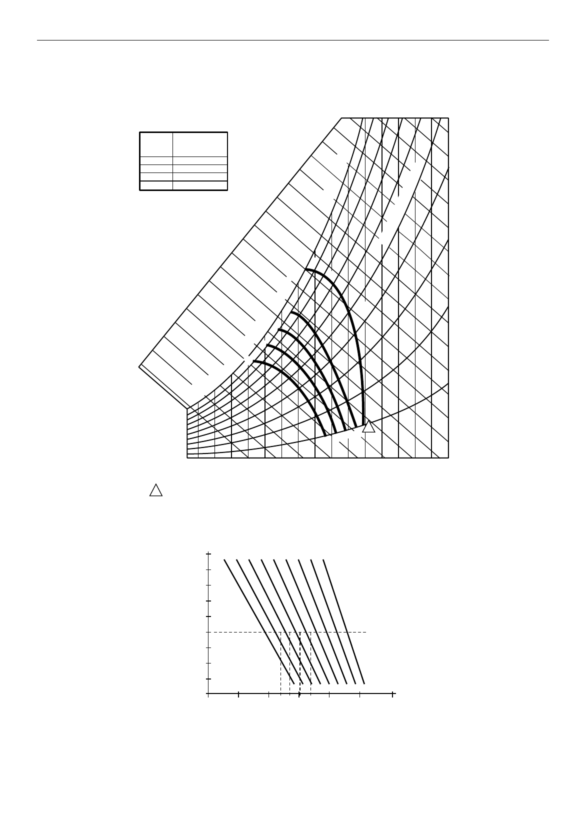
EXCEL 10 W7761A INPUT/OUTPUT DEVICE
77 74-2699
Fig. E-6. Graph of Sensor Current versus Enthalpy (volts).
See Fig. E-7 for a partial psychometric chart for the a C7400A Solid State Enthalpy Sensor.
CONTROL
CURVE
A
B
C
D
CONTROL POINT
APPROX. °F (°C)
AT 50% RH
73 (23)
70 (21)
67 (19)
63 (17)
12 14 16 18 20 22 24 26 28 30 32 34 36 38 40 42 44 46
90
100
80
70
60
50
40
30
20
10
ENTHALPY—BTU PER POUND DRY AIR
85
(29) 90
(32) 95
(35) 100
(38) 105
(41) 110
(43)
35
(2)
35
(2)
40
(4)
40
(4)
105
(41) 110
(43)
45
(7)
45
(7)
50
(10)
50
(10)
55
(13)
55
(13)
60
(16)
60
(16)
65
(18)
65
(18)
70
(21)
70
(21)
75
(24)
75
(24)
80
(27)
80
(27)
85
(29) 90
(32) 95
(35) 100
(38)
APPROXIMATE DRY BULB TEMPERATURE—°F (°C)
A
A
B
B
C
C
D
D
M11160
RELATIVE HUMIDITY (%)
1
1
HIGH LIMIT CURVE FOR W6210D,W7210D.
Fig. E-7. Partial psychometric chart for a C7400A Solid State Enthalpy Sensor.
See Fig. E-8 for a C7400A Solid State Enthalpy Sensor output current versus relative humidity.
20
10
30
40
50
60
70
80
90
100
605040 70 80 90 100
PERCENT RH
TEMPERATURE °F (°C)
M11605
C7400A OUTPUT CURRENT
4 mA
6 mA
8 mA
10 mA
20 mA
18 mA
16 mA
14 mA
12 mA
(4) (10) (16) (21) (27) (32) (38)
DC BA
D = 17 MA
C = 15.5 MA
B = 13.5 MA
A = 11 MA
Fig. E-8. C7400A Solid State Enthalpy Sensor output current vs. relative humidity.

EXCEL 10 W7761A INPUT/OUTPUT DEVICE
78 74-2699
Sensor Type:
T7242 or equivalent.
Sensor Use:
CO2 concentration.
Table E-9 lists the points for Sensor Voltage versus CO2 concentration. Fig. E-9 shows the graph of these points.
Table E-9. Sensor Voltage Versus CO2 Concentration.
CO2 Concentration PPM Sensor Voltage
00.00
100 0.50
200 1.00
300 1.50
400 2.00
500 2.50
600 3.00
700 3.50
800 4.00
900 4.50
1000 5.00
1100 5.50
1200 6.00
1300 6.50
1400 7.00
1500 7.50
1600 8.00
1700 8.50
1800 9.00
1900 9.50
2000 10.00
0
1
2
3
4
5
6
7
8
9
10
100 300 500 700 900 1100 1300 1500 1700 1900
200 400 600 800 1000 1200 1400 1600 1800 2000
VOLTS
PPM
SENSOR VOLTAGE VERSUS CO2 CONCENTRATION
M11611
Fig. E-9. Graph of Sensor Voltage versus CO2 concentration.
Sensor Type:
Third party (2 to 20V).
Sensor Use:
Monitor voltage.
Table E-10 lists the points for Sensor Voltage versus input Voltage to A/D. Fig. E-10 shows the graph of these points.
Table E-10. Sensor Voltage Versus Input Voltage To A/D.

EXCEL 10 W7761A INPUT/OUTPUT DEVICE
79 74-2699
Voltage to A/D Sensor Voltage
0.00 0.00
0.50 0.25
1.00 0.50
1.50 0.75
2.00 1.00
2.50 1.25
3.00 1.50
3.50 1.75
4.00 2.00
4.50 2.25
5.00 2.50
5.50 2.75
6.00 3.00
6.50 3.25
7.00 3.50
7.50 3.75
8.00 4.00
8.50 4.25
9.00 4.50
9.50 4.75
10.00 5.00
0
0.50
1.00
1.50
2.00
2.50
3.00
3.50
4.00
4.50
5.00
1000 300 500 700 900200 400 600 800 1000
A/D VOLTS
VOLTS
SENSOR VOLTAGE VERSUS INPUT VOLTAGE TO A/D
M11612
Fig. E-10. Graph of Sensor Voltage versus input Voltage to A/D.
Sensor Type:
Third party.
Sensor Use:
Sensor Voltage (Vdc)/Pressure Inw (kPa) 2 to 10V, 0 to 5 inw (0 to 1.25 kPa).
Table E-11 lists the points for Sensor Voltage (Vdc) versus Pressure (Inw). Fig. E-11 shows the graph of these points.
Table E-11. Sensor Voltage (Vdc) Versus Pressure (Inw).
Pressure Inw (kPa) Sensor Voltage (Vdc)
0.00 (0.00) 2.00
0.50.(0.13) 2.80
1.00 (0.25) 3.60
1.50 (0.37) 4.40
2.00 (0.5) 5.20
2.50 (0.62) 6.00

74-2699 J.D. 6-98
Printed in U.S.A. on recycled
paper containing at least 10%
post-consumer paper fibers.
www.honeywell.com
3.00 (0.75) 6.80
3.50 (0.87) 7.60
4.00 (1.00) 8.40
4.50 (1.12) 9.20
5.00 (1.25) 10.00
2.00
3.00
4.00
5.00
6.00
7.00
8.00
9.00
10.00
0 0.50 1.00 1.50 2.00 2.50 3.00 3.50 4.00 4.50 5.00
VOLTS (VDC)
SENSOR VOLTAGE VERSUS PRESSURE
M11963
Inw 0 0.13 0.25 0.37 0.5 0.62 0.75 0.87 1.0 1.12 1.25
kPa
Fig. E-11. Graph of Sensor Voltage (Vdc) versus Pressure (Inw).
