Honeywell Xl 800 Series Users Manual En1b0410 Ge51r0908a
XL 800 SERIES to the manual c888d6e5-54b8-4f30-8099-521d0f4987ba
2015-01-23
: Honeywell Honeywell-Xl-800-Series-Users-Manual-261878 honeywell-xl-800-series-users-manual-261878 honeywell pdf
Open the PDF directly: View PDF ![]() .
.
Page Count: 36

Copyright © 2008 Honeywell GmbH All Rights Reserved EN1B-0410GE51 R0908A
XL 800 Series
FOR SMOKE CONTROL
HONEYWELL EXCEL 5000 OPEN SYSTEM
INSTALLATION AND COMMISSIONING INSTRUCTIONS
CONTENTS
General ............................................................................... 3
Before Installation ............................................................. 3
Installation ......................................................................... 3
Wiring ................................................................................. 4
XL800 Series Power Consumption ................................ 5
I/O Modules ................................................................... 5
Description of the XCL8010AU Controller Module ......... 7
Overview........................................................................ 7
Interfaces and Bus Connections .................................. 10
Technical Data............................................................. 10
System Data........................................................... 10
Operational Environment ....................................... 10
Smoke Control Configuration....................................... 10
Data File Set-Up .......................................................... 11
Panel Reset ................................................................. 11
Typical Power Limited Circuit for XL800 ...................... 11
Connecting Single Bus Controller Systems ................. 11
XCL8010AU, I/O Modules on Single Rail............... 12
Multiple Rails in Single Cabinet.............................. 12
LonWorks Bus I/O Modules in Separate Rooms .... 12
How to Connect Panel Bus and LONWORKS Bus Mixed
Controller Systems ...................................................... 12
Connecting I/O Modules......................................... 12
Connecting I/O Modules to the XCL8010AU.......... 12
Setting Address of Panel Bus I/O Modules .................. 13
Setting the I/O Bus Switch ........................................... 14
LONWORKS Bus Topologies.......................................... 14
C-Bus Topologies ........................................................ 14
Mounting/Dismounting Modules.................................... 14
Mounting/Dismounting Controller/Sockets ................... 15
Mounting Sockets................................................... 15
Connecting Sockets ............................................... 15
Dismounting Sockets ............................................. 16
Mounting/Dismounting Electronic Modules .................. 16
Mounting Electronic Modules ................................. 16
Dismounting Electronic Modules ............................ 17
Connecting via C-Bus .................................................. 17
Connecting to the Controller................................... 17
Setting the C-Bus Termination Switch.................... 17
Shielding ................................................................ 17
Connecting HMIs or Laptops........................................ 17
Connecting the XI582 Operator Interface ............... 17
Connecting Laptops (XL-Online/CARE) ................. 18
XCL8010AU Terminals........................................... 18
Features....................................................................... 18
LONWORKS Interface and Terminals ....................... 18
LONWORKS Service LED and Button....................... 18
C-Bus Tx LED and Rx LED .................................... 19
Reset Button........................................................... 19
HMI Interface.......................................................... 19
Alarm and Power LEDs .......................................... 20
Watchdog Status .................................................... 20
Modem Interface..................................................... 20
I/O Bus Switch S2................................................... 20
C-Bus Termination Switch S1................................. 21
Memory .................................................................. 21
Description of the I/O Modules ....................................... 21
Common Features ....................................................... 21
Analog Input Modules .................................................. 22
Types of Analog Input Modules .............................. 22
Features ................................................................. 22
Terminals................................................................ 22
XFL821AU Connection Examples .......................... 23
Analog Output Modules................................................ 24
Types of Analog Output Modules ........................... 24
Features ................................................................. 24
Terminals................................................................ 24
Technical Data........................................................ 24
Modules with Manual Overrides ............................. 25
XFL822AU Connection Example ............................ 25
Synchronization Behavior of Analog Output Module
Configured as Floating Output................................ 25
Binary Input Modules ................................................... 26
Types of Binary Input Modules ............................... 26
Features ................................................................. 26
Terminals................................................................ 26
Technical Data........................................................ 26
Status LEDs............................................................ 27
XF823AU Connection Examples ............................ 27
Relay Output Modules.................................................. 28
Types of Relay Output Modules ............................. 28
Features ................................................................. 28
Terminals................................................................ 28
Permissible Loads .................................................. 29
Status LEDs with Manual Overrides ....................... 29
Connection Examples............................................. 30

General Excel 800
EN1B-0410GE51 R0908A 2
Troubleshooting...............................................................31
Testing Wiring Connections..........................................31
Troubleshooting on the XCL8010AU Controller............31
Power LED (green) .................................................31
Alarm LED (red) ......................................................32
LONWORKS Service LED..........................................32
C-Bus Tx and Rx LEDs...........................................33
HMI Tx and Rx LEDs ..............................................33
I/O Modules Troubleshooting........................................34
Power LED of I/O Modules .....................................34
Service LED of I/O Modules....................................35
Trademark Information
Echelon, LON, LONMARK, LONTALK, LONWORKS, Neuron, are
trademarks of Echelon Corporation registered in the United
States and other countries.
Excel 800
3 EN1B-0410GE51 R0908A
WARNING
This equipment generates, uses, and can radiate radio
frequency energy, and if not installed and used in accordance
with the instructions manual, may cause interference to radio
communications. It has been tested and found to comply with
the limits for a Class A computing device pursuant to Subpart
J of Part 15 of FCC Rules, which are designed to provide
reasonable protection against such interference when
operated in a commercial environment. Operation of this
equipment in a residential area is likely to cause interference,
in which case the user, at his own expense, will be required to
take whatever measures may be required to correct the
interference. Any unauthorized modification of this equipment
may result in the revocation of the owner’s authority to
continue its operation.
General
The XL800 Series is designed to provide heating, ventilating
and air-conditioning control. They can operate either
standalone, or networked to Honeywell central workstations
such as EBI. These controllers can also be used for smoke
control system monitoring and control, for monitor and control
of fire (UL864), and general purpose signaling (UL2017). In
UL 2017 applications, the product can be used as a type NM
(Non-Monitored) system. It is also approved for UL916
(Energy Management Equipment.)
The XL800 Series can be used for smoke control applications
when used in conjunction with a UL listed fire alarm control
panel (FACP) and UL listed fire fighters’ smoke control station
(FSCS).
Before Installation
1. Unpack door and remove the XL800 from carton. Check
equipment and report any damage to a Honeywell
representative.
2. Verify cabinet is installed correctly.
3. Securely mount the XL800 to a rigid structural surface
using at least four sets of 1/4 in. (6 mm) mounting
hardware (supplied locally).
NOTE: Anchoring materials must be suitable for the
mounting surface (wood, concrete, steel).
Mounting must comply with all local codes.
4. Obtain correct number and type of sheet metal screws for
subpanel. Installation of a full-size subpanel requires six
no. 10 x ½-inch (13 mm) sheet metal screws (not
supplied). Installation of a smaller subpanel requires four
no. 10 x ½-inch (13 mm) sheet metal screws (not
supplied).
5. Obtain 14505159-001 Tamper Switch per job
requirements. Installation of Tamper Switch is optional.
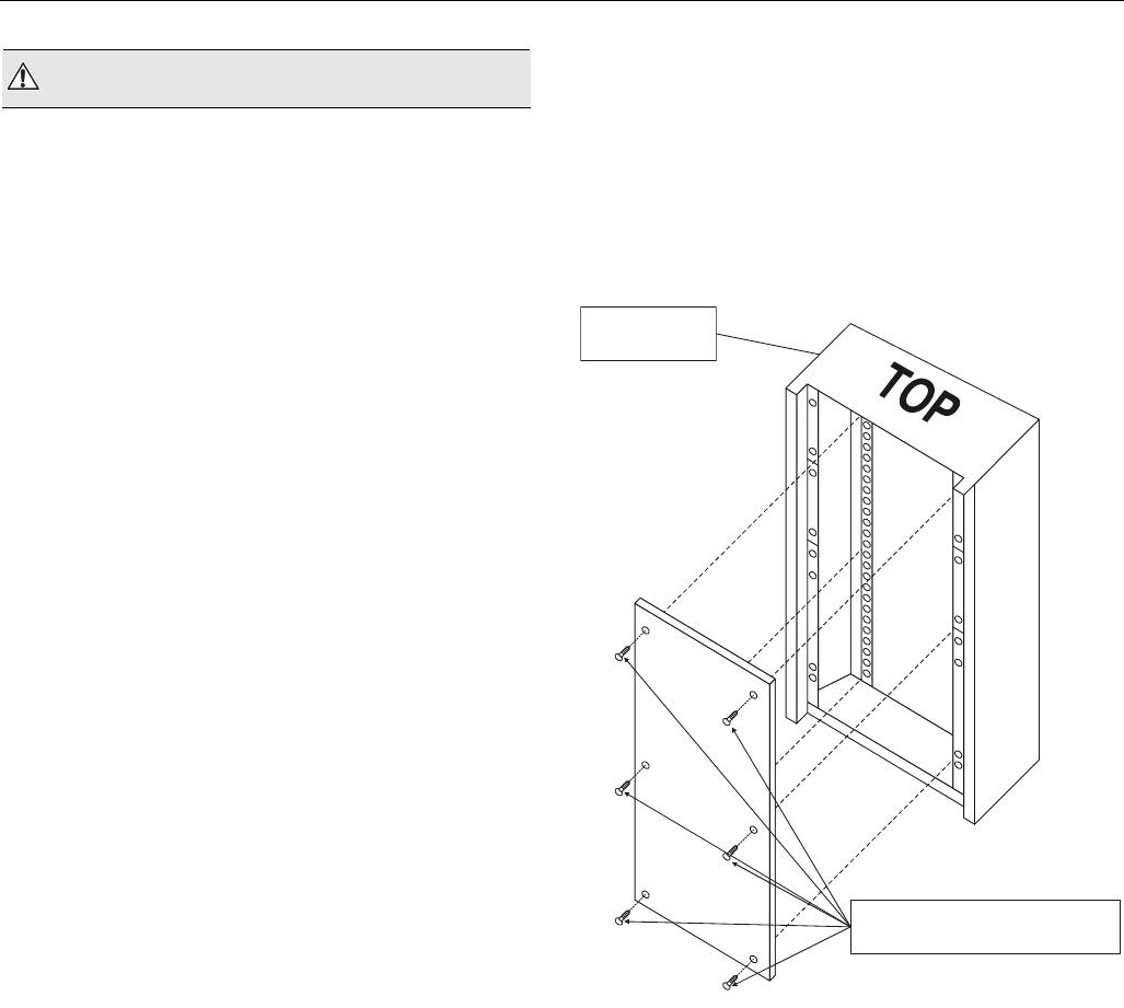
Installation
Mount controller subpanel in cabinet so all labeling is visible.
Secure full-size subpanel in place with six no. 10 x ½-inch
(13 mm) sheet metal screws (not supplied). Secure smaller
subpanel with four no. 10 x ½-inch (13 mm) sheet metal
screws (not supplied).
NOTE: Subpanel must mount flat and should not bulge or
recess anywhere.
FULL-SIZE
CABINET
SIX NO. 10 x ½-INCH (13 mm)
SHEET METAL SCREWS
Fig. 1. Mounting controller subpanel in cabinet (full-size
subpanel cabinet shown)
Wiring Excel 800
EN1B-0410GE51 R0908A 4
Wiring
All wiring to the XL800 controller is unsupervised, except as
noted.
All circuits are power limited, except for AC power circuits,
relay contacts and other circuits as noted.
All field wiring terminals accept 24 AWG to 14 AWG
(0.25 mm2 to 2 mm2) conductors except as noted.
All wiring must conform to local codes, ordinances, and
regulations. Refer to job drawings for details.
Verify that the voltage difference between any conductor and
earth ground does NOT exceed 150 Vac.
1. Connect input/output device wiring, C-Bus transmission
wiring (minimum 18 gage [0.8012 sq mm]), LON Bus
transmission wiring, and 14507063 Power Cable to
Controller per job drawings. Fig. 2 and Fig. 3 show typical
controller wiring. Four Power Module models are available
(see Table 2).
2. Connect line voltage to Terminals H and N of the
14507287 Power Module. Connect a good earth ground to
Terminal G of the Power Module. Fig. 5 through Fig. 7
show typical power wiring.
3. For Power Modules -001 through -007, leave power to
Power Supply and Controller OFF. Connect 14507063
Power Cable from Controller to Power Module.
WARNING
Risk of electric shock or equipment damage!
► Subpanel and Controller power must remain OFF until
Controller is checked.
4. Install optional Tamper Switch on cabinet per instructions
in the cabinet installation instructions. Wire Tamper
Switch per job drawings.
5. Mount cabinet door.
CAUTION
Risk of electric equipment damage! Excessive static can
burn out equipment.
► Observe proper anti-static material handling practices
when installing or servicing PC parts and related
components.
► Observe proper equipment and body grounding practices.
► Discharge static electricity from your body before handling
parts.
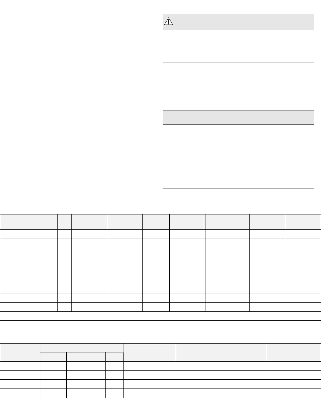
Table 1. Connector terminal specifications
connector terminal pin signal type input /
output
voltage
type
max.
voltage
max. current max.
frequency
max. line
impedance
analog input AI input SIGNAL ±12 V ±20 mA 9600 baud 8K ohms
digital input DI input SIGNAL ±10 V ±20 mA -- 15K ohms
analog output AO output(1 SIGNAL ±10 V ±20 mA 9600 baud 8K ohms
digital output DO output(2 AC/DC ±24 VAC/DC ±50 mA -- 10K ohms
totalizer output TI input SIGNAL ±12 V ±12 mA 100 Hz
signal ground GND -- -- -- -- -- --
J1 RS-485 (C-BUS) (3 1 +A input / output SIGNAL ±5 V 1 mA / 180 mA 9600 baud 100 ohms
2 -A input / output SIGNAL ±5 V 1 mA / 180 mA 9600 baud 100 ohms
3S Shield A -- -- -- -- -- --
(1 special application; (2 regulated; (3 supervised
Table 2. Power module models
transformer max. input
model Vac current draw Hz
(48 VA) controller
VAC output accessory output convenience outlet
14507287-001 120 0.5 A 60 24 120 Vac, 10A
14507287-002 120 1.7 A 60 24 24 Vac, 100 VA, 24 Vac, 40 VA 120 Vac, 10A
14507287-003 120 1.7 A 60 24 24 Vac, 100 VA, 24 Vdc, 600 mA 120 Vac, 10A
14507287-007 120 120 A 60 24 -- --
Excel 800 Wiring
5 EN1B-0410GE51 R0908A
XL800 Series Power Consumption
When selecting the appropriate power supply, the power
consumption of the XL800 modules must be taken into
account.
Table 3. XL800 power consumption
max. power consumption
model 24 Vac, 60 Hz 24 Vdc
XCL8010AU with
watchdog load
690 mA 640 mA
XCL8010AU without
watchdog load
190 mA 140 mA
XF821AU, XFL821AU 130 mA 80 mA
XF822AU, XFR822AU,
XFL822AU, XFLR822AU
160 mA 90 mA
XF823AU, XFL823AU 180 mA 130 mA
XF824AU, XFR824AU,
XFL824AU, XFLR824AU
140 mA 90 mA
XFR825AU 140 mA 90 mA
I/O Modules
Variants of I/O Modules
There are two variants of I/O modules:
• Panel Bus I/O modules with communication via Panel Bus
(light-gray housings)
Modules are automatically commissioned (with firmware
download) by the XCL8010AU
• L
ONWORKS Bus I/O modules (dark-gray housings) with
communication via LONWORKS (FTT10-A, link power
compatible) for easy integration and use with 3rd-party
controllers
Terminal Sockets
I/O modules are mounted on the appropriate terminal
sockets. Panel Bus I/O modules and LONWORKS Bus I/O
modules use the same terminal sockets.
Color Coding
To distinguish modules and components, the following color
coding is used:
Table 4. Color coding of Excel 800 Modules
color part
red All of the user-accessible adjustable
mechanical parts (i.e., bridge connectors and
locking mechanism) and operating controls
(manual overrides, etc.)
light-gray Panel Bus I/O modules
dark-gray LONWORKS Bus I/O modules
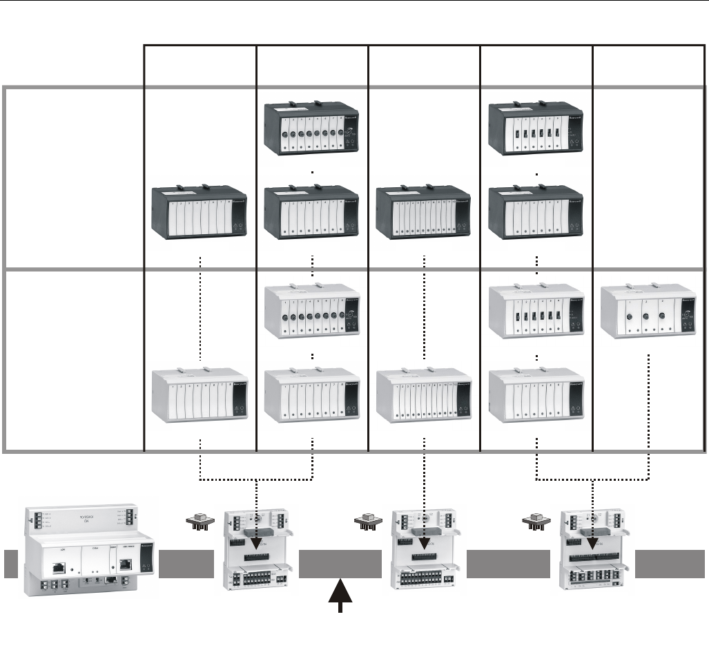
Wiring Excel 800
EN1B-0410GE51 R0908A 6
PANEL
BUS
MODULES
LonWorks
BUS
MODULES
ANALOG
OUTPUT
ANALOG
INPUT
BINARY
INPUT
FLOATING
OUTPUT
XF821AU
XS821-22
XCL8010AU
CONTROLLER MODULE
X
S823 XS824-25
XFL821AU
XFR822AU
XFLR822AU
XFL822AU XFL823AU
XF822AU XF823AU
RELAY
OUTPUT
XFR824AU
X
FLR824AU
X
FL824AU
XFR825AU
X
F824AU
LonWorks or Panel Bus
Fig. 2. Overview of I/O modules and terminal sockets
Excel 800 Description of the XCL8010AU Controller Module
7 EN1B-0410GE51 R0908A
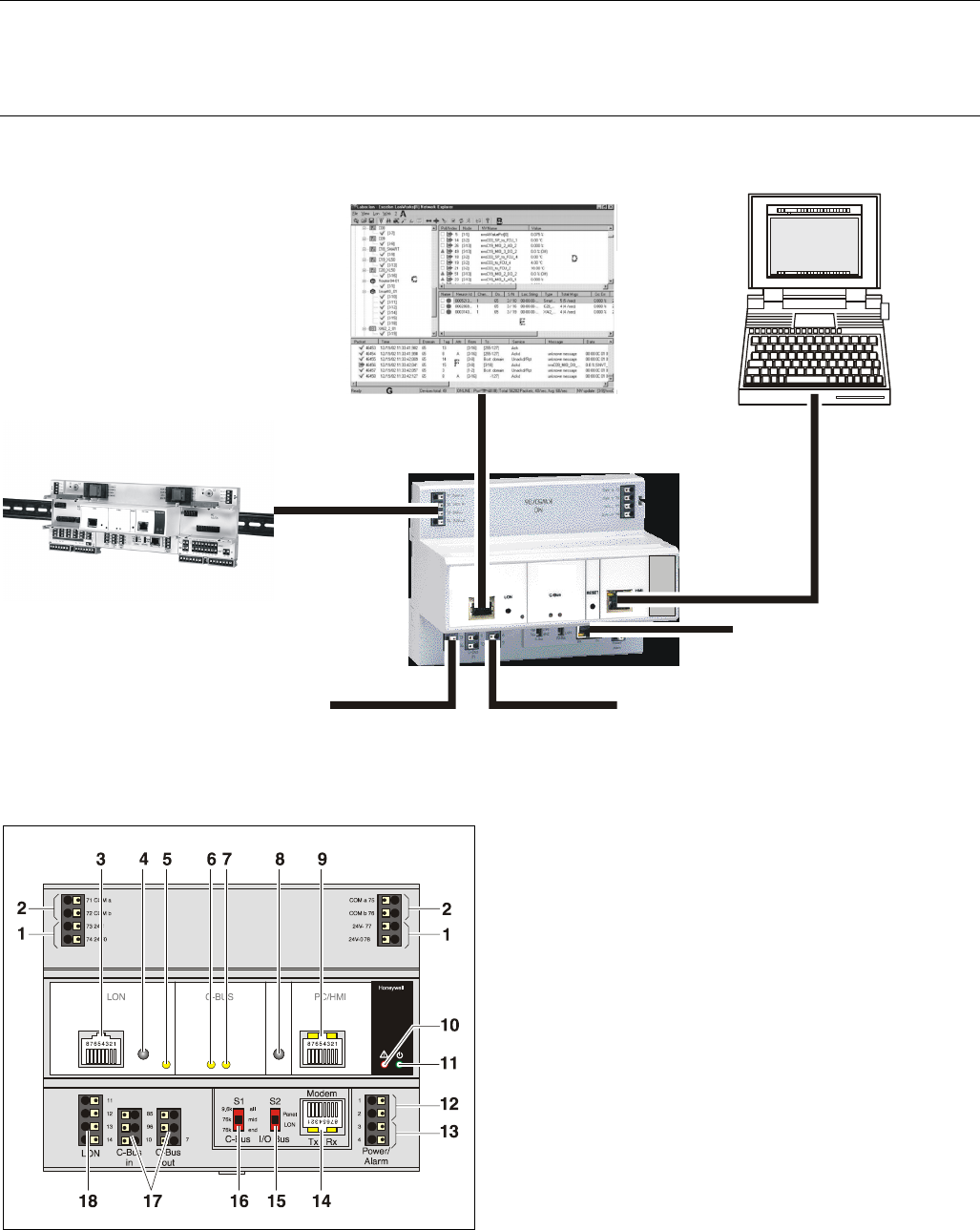
Description of the XCL8010AU Controller Module
Overview
PC or HMI
NO CONNECTION
EXCELON
I/O MODULES
LonWorks BUS C-BUS
Fig. 3. Connections to the XCL8010AU Controller
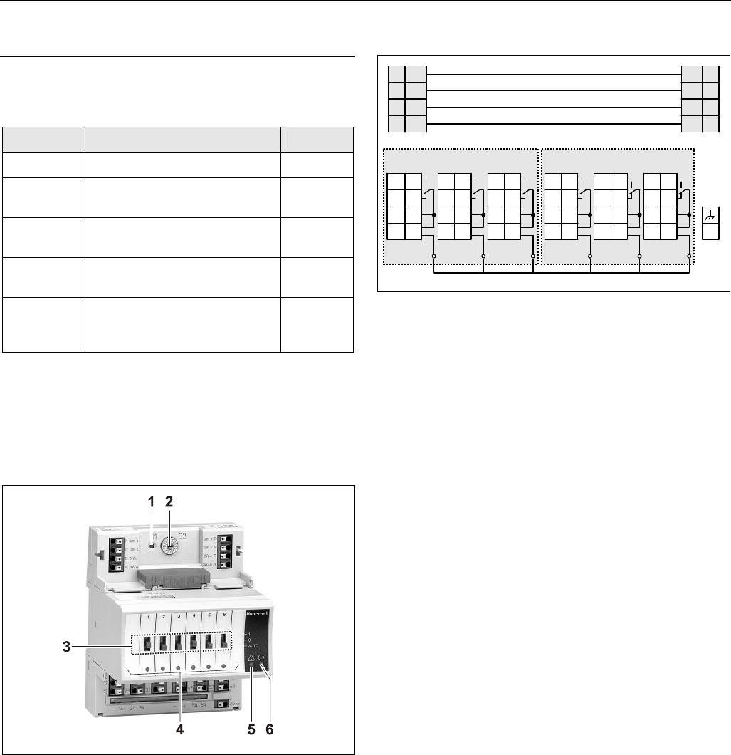
Fig. 4. XCL8010AU Controller Module front details
Legend
1 Power supply for I/O modules
2 I/O Bus communication terminals
3 LONWORKS interface
4 LONWORKS service button
5 LONWORKS service LED
6 C-Bus Tx LED
7 C-Bus Rx LED
8 Reset button
9 HMI interface (for field use, only)
10 Alarm LED
11 Power LED
12 Power supply terminals
13 Alarm/watchdog outputs
14 NO CONNECTION
15 S2 I/O Bus switch
16 S1 C-Bus termination switch
17 C-Bus terminals
18 LONWORKS terminals
Description of the XCL8010AU Controller Module Excel 800
EN1B-0410GE51 R0908A 8
““
G MUST BE
WIRED TO EARTH GROUND
14507063-002 POWER CABLE
(incl. with 14507287 power modules
14507287-001 through -003, only.)
CONNECTORS ARE KEYED TO
PREVENT MISALIGNMENT.
CONVENIENCE OUTLET
(UNFILTERED, UNSWITCHED)
-001 = 120 VAC, 10 AMP
24 VAC CONTROLLER
POWER SWITCH 120 VAC, 60 HZ
LINE INPUT
UNSWITCHED
UNFILTERED
120 VAC
BRN
GRN
BLK
ON
*
H
N
G
* 14507287-001 POWER TERMINALS LABELED H-N-G.
CONTROLLER
POWER
OFF
G
~
CONTROLLER
SUPPLY
24VAC
48VA
CONNECTOR TO
XL800 CONTROLLER
J5
MUST BE WIRED
TO EARTH GROUND
F1
2 AMP
FUSE F1 (2 AMPS) PART NUMBERS ARE AS FOLLOWS:
–HONEYWELL PART NO. 14000485-007
(AVAILABLE FROM HONEYWELL BRANCH LOCATIONS, ONLY)
–BUSSMAN PART NO. AGC-2
–LITTLEFUSE PART NO. 312002
MAIN LINE VOLTAGE
120 VAC, 60 HZ
TERMINAL MUST BE
CONNECTED TO A GOOD
EARTH GROUND.
G
““
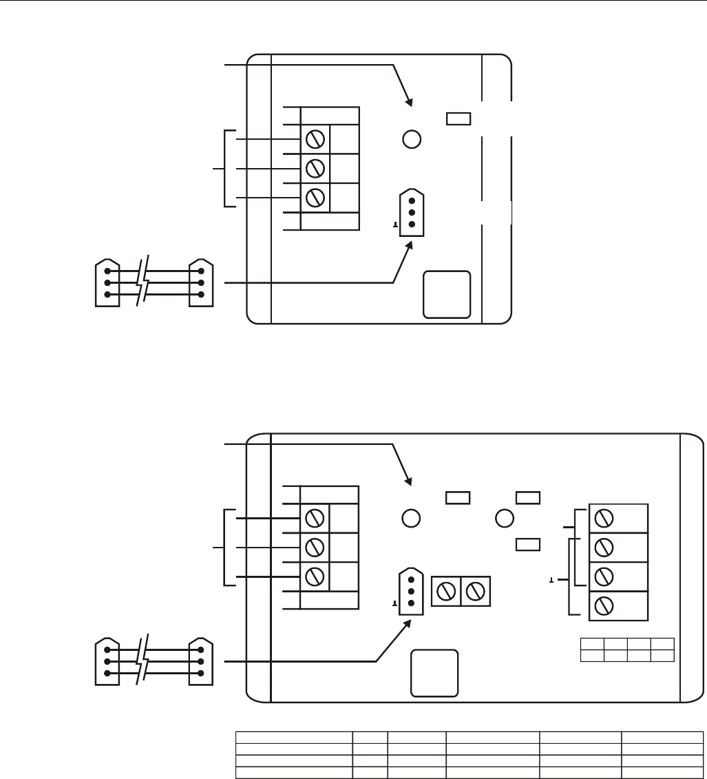
Fig. 5. Typical 14507287-001 Power Module wiring
““
G MUST BE
WIRED TO EARTH GROUND
14507063-002 POWER CABLE
(incl. with 14507287 power modules
14507287-001 through -003, only.)
CONNECTORS ARE KEYED TO
PREVENT MISALIGNMENT.
CONVENIENCE OUTLET
(UNFILTERED, UNSWITCHED)
-002 AND -003 = 10 AMP
24 VAC ACCESSORY POWER
-002 MODEL, ONLY. 2 AMP MAX.
24 VAC CONTROLLER
POWER SWITCH 120 VAC, 60 HZ
LINE INPUT
120 VAC, 60 HZ
LINE INPUT
UNSWITCHED
UNFILTERED 120 VAC
FOR 14507287-003 (24VDC)
FOR 14507287-002 (24VAC)
BRN
GRN
BLK
ON ON
*
H
N
G
* 14507287-001 POWER TERMINALS LABELED H-N-G.
CONTROLLER
POWER
OFF OFF
G
~
~
CONTROLLER
SUPPLY
24VAC
48VA
CONNECTOR TO
XL800 CONTROLLER
J5
MUST BE WIRED
TO EARTH GROUND
F1 F2
F3
2 AMP 5 AMP
2 AMP
MAIN LINE VOLTAGE
120 VAC, 60 HZ
TERMINAL MUST BE
CONNECTED TO A GOOD
EARTH GROUND.
G
““
BRN
BRNRED
GRY GRY
GRYGRY
BRN
24VAC ACCESSORY
POWER -002 AND -003
MODELS (4 AMP MAX.)
14507287-001 THROUGH -003
14507287-002 AND -003
14507287-002 AND -003
POWER MODULE
F1
F2
F3
FUSE NO.
2 AMPS
5 AMPS
2 AMPS
FUSE RATING
14000485-007
14507374-001
14000485-007
HONEYWELL PART NO.
AGC-2
GMA 5AMP
AGC-2
BUSSMAN PART NO.
312002
235005
312002
LITTLEFUSE PART NO.
Fig. 6. Typical 14507287-002, -003 Power Module wiring
Excel 800 Description of the XCL8010AU Controller Module
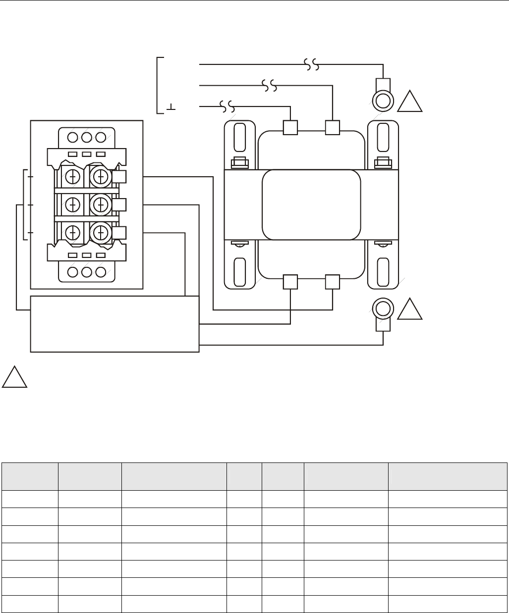
9 EN1B-0410GE51 R0908A
H
N
G
BLK
BLK
CONTROLLER TRANSFORMER
CONTROLLER
SUPPLY 24 VAC
48 VA
WHT
GRN
BRN
GRN
MAIN LINE (120 VAC, 60 Hz)
TERMINAL “G” MUST BE
CONNECTED TO A GOOD
EARTH GROUND.
24 V 50 VA
14507351-001
429P156A
E1A 1052 XXXX
COM 120 V
~71
1
3
2
4
72
70
G
1
1
1
MECHANICALLY SECURED TO SUBPANEL WITH MOUNTING SCREW
Fig. 7. Typical 14507287-007 Power Module wiring
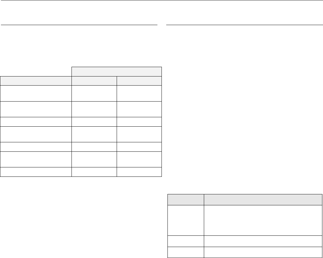
I/O Module Overview
Table 5. Overview of I/O modules
Panel Bus
module
LONWORKS
Bus module description inputs outputs manual controls LEDs 1)
XF821AU XFL821AU Analog Input Module 8 – – –
XF822AU XFL822AU Analog Output Module – 8 – 8 status LEDs
XFR822AU XFLR822AU Analog Output Module – 8 8 manual overrides 8 status LEDs
XF823AU XFL823AU Binary Input Module 12 – – 12 status LEDs
XF824AU XFL824AU Relay Output Module – 6 2) – 6 status LEDs
XFR824AU XFLR824AU Relay Output Module – 6 2) 6 manual overrides 6 status LEDs
XFR825AU – Floating Output Module – 3 3 manual overrides 3 pairs of status LEDs
1) In addition to the power LED and service LED
2) Changeover outputs
Description of the XCL8010AU Controller Module Excel 800
EN1B-0410GE51 R0908A 10
Corresponding Terminal Sockets
Table 6. I/O modules and corresponding terminal sockets
I/O module socket scope of delivery
XF821AU,
XFL821AU
XF822AU,
XFL822AU,
XFLR822AU,
XFR822AU
XS821-22
1 terminal socket,
1 bridge connector
1 swivel label holder
XF823AU,
XFL823AU XS823
1 terminal socket,
1 bridge connector
1 swivel label holder
XF824AU,
XFL824AU,
XFLR824AU,
XFR824AU
XFR825AU
XS824-25
1 terminal socket,
1 bridge connector
1 swivel label holder
1 long cross connector
Interfaces and Bus Connections
The Excel 800 System can be connected to the following
devices and systems:
Panel Bus
• For communication with up to 16 Panel Bus I/O modules
• Polarity-insensitive
LonWorks Bus
• For communication with other LONWORKS Bus devices
within the building
• FTT10, link power compatible
• Polarity-insensitive
C-Bus
• For communication with other controllers
HMI
• For connecting an operator interface, e.g., XI582 or a
laptop, e.g., for CARE
Modem
• NO CONNECTION
Technical Data
System Data
Table 7. System data
Operating voltage 24 VAC/DC, 60 Hz
Power consumption Max. 3.57 A
(1 XCL8010AU Controller
+ 16 I/O modules)
Operational Environment
Table 8. Operational environment
ambient operating
temperature
0 ─ 49 °C (32 ─ 122 °F)
ambient operating
humidity
5 ─ 93 % rel. humidity
(non-condensing)
ambient storage
temperature
–20 ─ +70 °C (–4 ─ +158 °F)
ambient storage
humidity
5 ─ 95 % rel. humidity
(non-condensing)
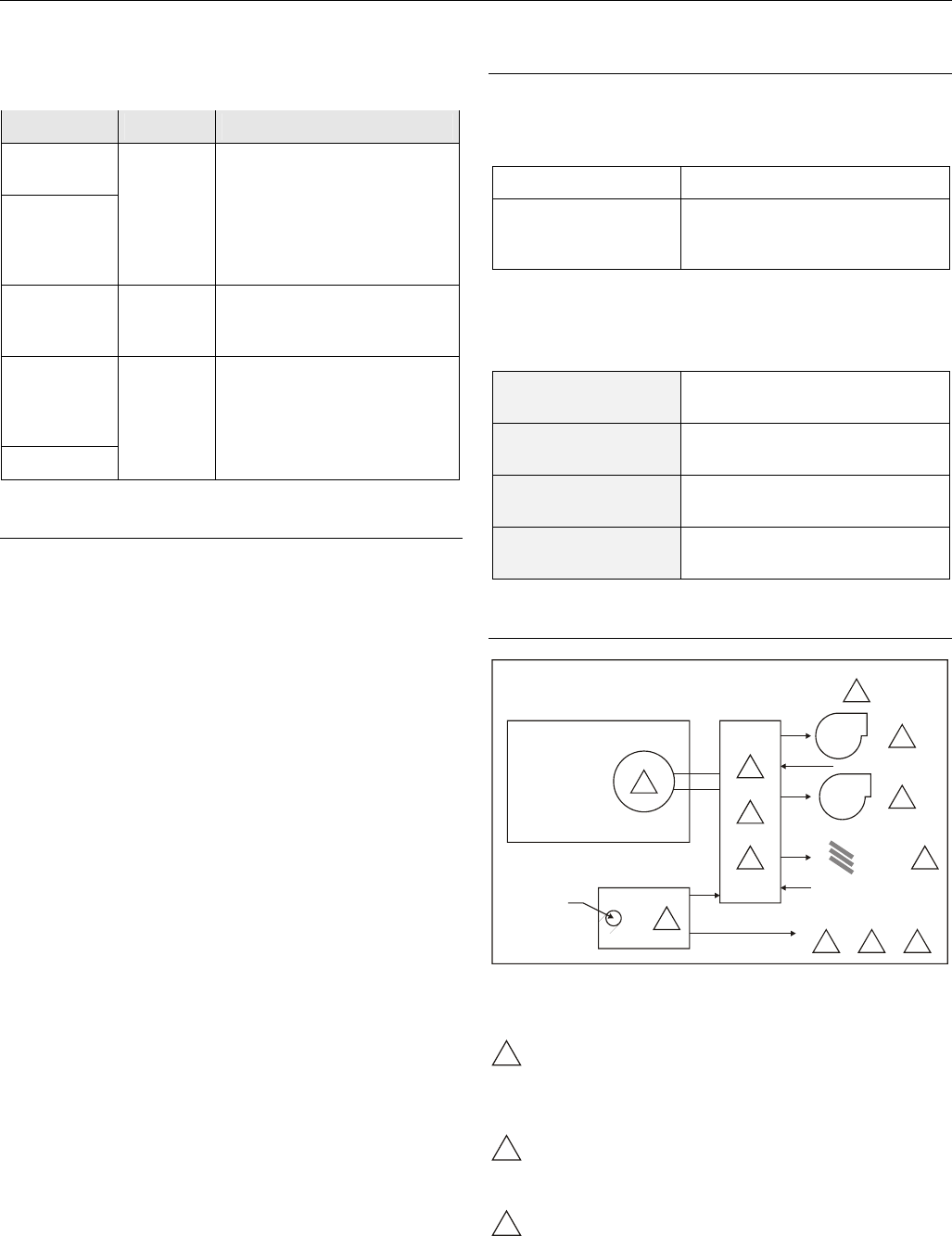
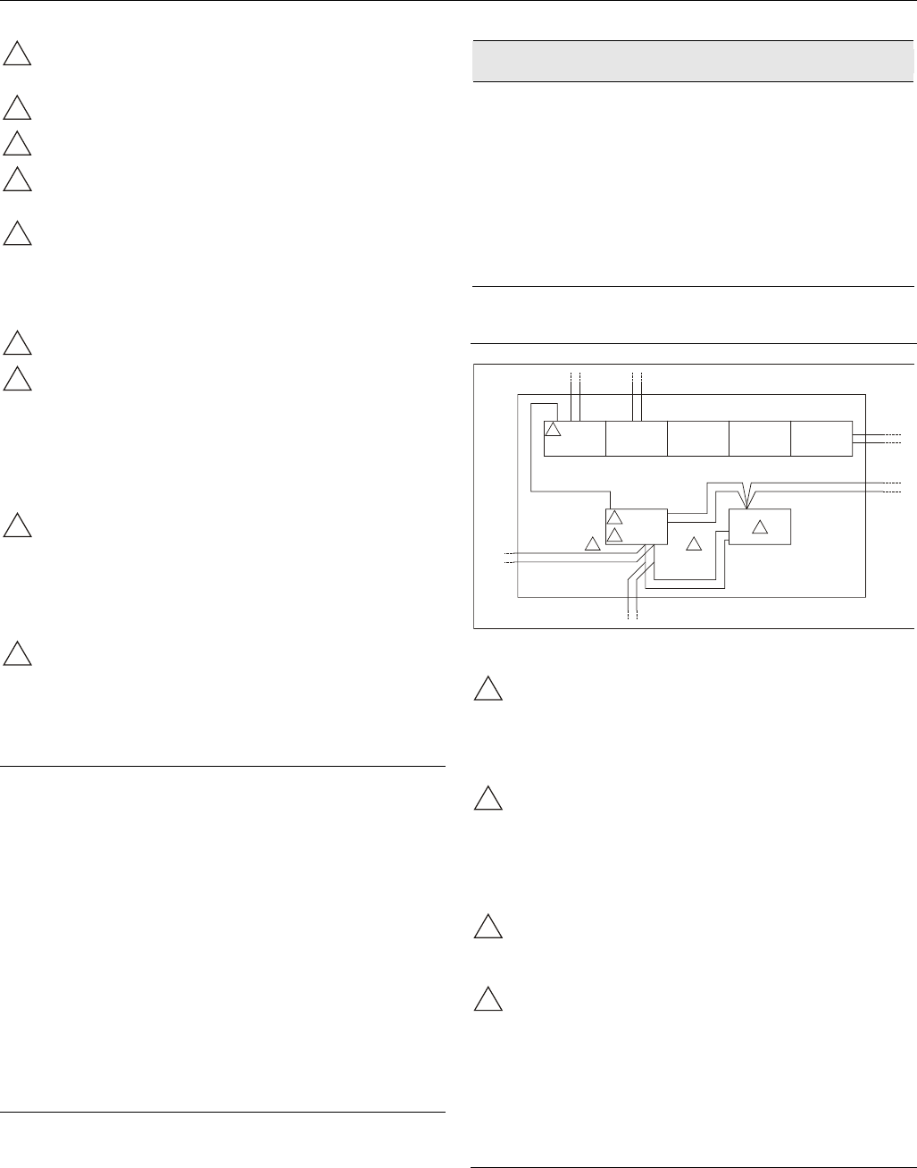
Smoke Control Configuration
X
L800
2 3
4
5
6 7
9
10
11
12
8
UL-LISTED
FIRE ALARM
CONTROL UNIT
SMOKE CONTROL CONFIGURATION
FIREFIGHTERS’
SMOKE CONTROL
PANEL (FSCS)
14505068
AUDIBLE
ANNUNCIATOR
STATUS CONTROL
VERIFICATION
DAMPER
AIRFLOW SENSOR
1
AO
AO
AO
SUPPLY
FAN
EXHAUST
FAN
Fig. 8. Typical smoke control configuration
NOTES:
1
Locate and configure per NFPA 92A, Section 3-4.3.4.
UL-listed annunciator / FSCS panel switches have a
minimum rating of 24 V, 1/10 Amp, and lamps / LEDs
have a rating of 24 V, limited to 50 mA.
2
Locate so as to minimize control wiring and piping.
Avoid running wires or piping through areas that have
a high fire risk.
3
Locate per UL 555S.
Excel 800 Description of the XCL8010AU Controller Module
11 EN1B-0410GE51 R0908A
4
Locate separate from and below all building exhaust
fans and upstream of any prevailing winds.
5
Exhaust to outside of building.
6
Locate airflow differential switch.
7
Locate UL-listed damper pressure / position indicator
per damper installation instructions.
8
Smoke control must be initiated by a listed fire alarm
control unit or in zone automatic alarm devices and not
devices located outside of the smoke control zone.
Interconnecting wiring must be within 20 ft. (6 meters)
and in conduit.
9
Refer to NFPA 92A.
10
Verify that the AC voltage source connected to the
inside of the main line voltage terminal block is from a
UL-1481 listed uninterruptible power supply. The main
line voltage terminal block maximum current draw is
0.5 A. For 220/240 VAC (60 Hz) applications, verify
that no potential between any conductor and the earth
ground exceeds 150 VAC.
11
All external LONWORKS bus field wiring must be limited
to 4000 ft. (1200 meters) and be terminated to
14506944-001 transient protector (35 V, 290 mA max.)
except C-Bus field wiring communicating at 1 MHZ,
which uses 14502412-014 transient protector (19 V,
500 mA).
12
Panel Bus wiring must be in the same enclosure or
less than 20 ft. to adjacent enclosure. No protection is
required.
Data File Set-Up
Generate the engineering data file for the XL800 Series
Controllers. This data file has a mix of hardware points for the
necessary inputs and outputs to control fans, dampers, and
other equipment. In addition to the inputs and outputs, a
custom control program is written to control the outputs per
the sequence. The XL800 controllers can reset the program
once the data from the operator interface indicates a normal
condition for the dedicated smoke control equipment. Wire
conditions must be programmed to provide annunciation of
trouble conditions.
Also required for a dedicated application for the XL800, is a
weekly time program to test control points, fans, and dampers
by exercising the equipment and verifying feedback
automatically during low building activity periods.
Panel Reset
When in Smoke Control Mode, panel reset is accomplished
by resetting the initiating panel contact circuit or by the
separate initiating/reset switch on the FSCS panel.
CAUTION
Risk of electric equipment damage!
► Failure to use listed/approved replacement parts can
damage product, degrade operation and result in loss of
safety function.
► This product must be installed and operated within its
environmental, mechanical, and electrical specifications as
contained in this document.
► When servicing, use only listed/approved replacement
parts ordered directly from the manufacturer.
Typical Power Limited Circuit for XL800
ANALOG INPUT
MODULE
CPU
CONTROL
24VAC ACCESSORY
24VAC
POWER LIMITED
24VAC
ANALOG OUTPUT
MODULE
DIGITAL INPUT
MODULE
DIGITAL OUTPUT
MODULE
2
22
3
1 1
POWER
LIMITED
POWER
LIMITED
NON-POWER
LIMITED
NON-POWER
LIMITED
NON-POWER
LIMITED
NON-POWER
LIMITED
Fig. 9. Typical power-limited circuit for XL800
1
14507287-001 through -003 power module accessory
24 VAC output (rated 2A) must be wired in accordance
with NFPA 70, Article 725 when routed within the
cabinet or adjacent cabinets and also for external field
wiring.
2
14507287-001, -002, -003, and -007 control power
module 24 VAC output is inherently power-limited.
Thus, all sourced power from the XL800 controller is
power-limited. All field wiring from these controllers
meet NFPA 70, Article 725 power limited Class II
requirements.
3
If a separate auxiliary power-limited 24 VAC power
source is required, use a control power module
(14507287-001 or -007 control supply).
4
Devices must be installed in areas as shown. All cable
must be routed as shown. All internal power-limited
wiring must be separated by ¼ inch (6 mm) or barrier
from non-power-limited wire. Excess wiring must be
cut, trimmed, and dressed properly to ensure that
proper clearances are maintained.
Connecting Single Bus Controller Systems
This section describes how to connect a controller system
which uses Panel Bus I/O modules, only or LONWORKS Bus
I/O modules, only.
Description of the XCL8010AU Controller Module Excel 800
EN1B-0410GE51 R0908A 12
XCL8010AU, I/O Modules on Single Rail
► Connect XCL8010AU Controller Module and I/O modules
using the bridge connectors.
This provides power supply and communication connection.
No further wiring is necessary.
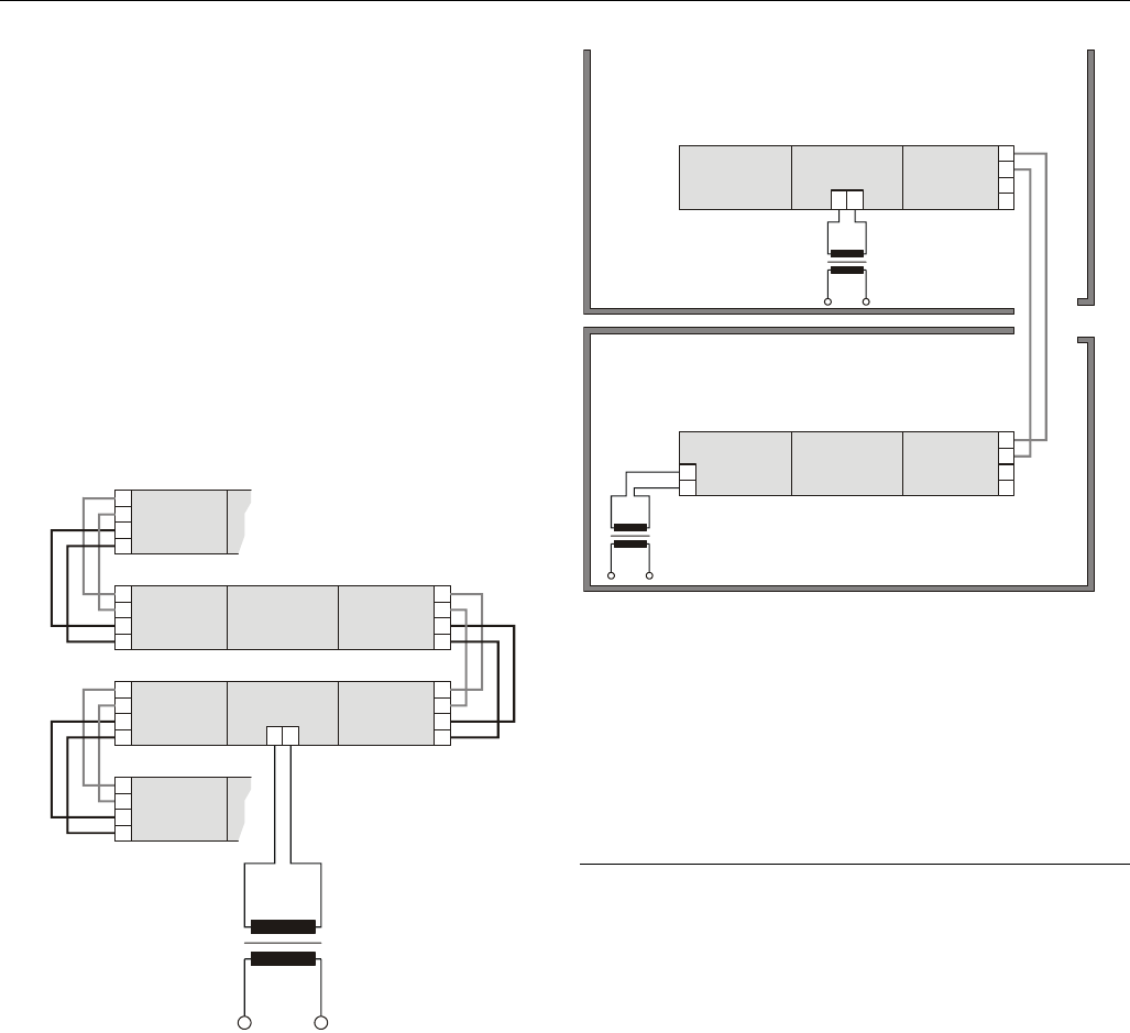
Multiple Rails in Single Cabinet
The multiple rails of a controller system are connected in
series.
► Connect the rail ends as follows:
– Power supply
via power supply terminals 73, 74 or 77, 78
– Communication
via communication terminals 71, 72 or 75, 76
I/O MODULE
XCL8010AU
1 2
I/O MODULE
71
72
73
74
I/O MODULE
71
72
73
74
I/O MODULE
71
72
73
74
I/O MODULE
75
76
77
78
I/O MODULE
75
76
77
78
I/O MODULE
71
72
73
74
Fig. 10. Wiring the power supply and the communication
lines to the I/O modules
LonWorks Bus I/O Modules in Separate Rooms
In this scenario, only communication lines must be connected
between the rooms.
► Connect the last module of room 1 to the first module of
room 2:
– via communication terminals 71, 72 or 75, 76
XCL8010AU
1 2
71
72
73
74
ROOM 2
ROOM 1
LonWorks
I/O MODULE
LonWorks
I/O MODULE
73
74
LonWorks
I/O MODULE
LonWorks
I/O MODULE
LonWorks
I/O MODULE
78
75
76
77
78
75
76
77
Fig. 11. Wiring the LONWORKS Bus I/O modules in
separate rooms
Maximum Cable Length
Max. cable length: 1200 meters (4000 ft), supervised.
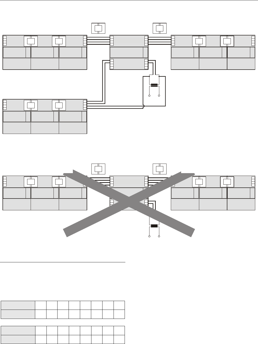
How to Connect Panel Bus and LONWORKS
Bus Mixed Controller Systems
Connecting I/O Modules
For connecting the I/O modules with each other, proceed as
described for single-bus controller systems.
Connecting I/O Modules to the XCL8010AU
Panel Bus I/O Modules
► Connect communication terminals 71 ─ 74 or 75 ─ 78 of
Panel Bus I/O modules to communication terminals 71 ─
74 or 75 ─ 78 of the XCL8010AU Controller Module using
either
– Bridge connectors
for flush mounting on a single DIN rail or
– Cables
for separate mounting, e.g., on multiple rails, separate
cabinets, etc.
LONWORKS Bus I/O Modules
► Connect communication terminals 71 ─ 74 or 75 ─ 78 of
LONWORKS Bus I/O modules to LONWORKS terminals 11 ─
14 of the XCL8010AU using cables.
Excel 800 Description of the XCL8010AU Controller Module
13 EN1B-0410GE51 R0908A
71
72
73
74
71
72
73
74
71
72
73
74
11 1
12 2
13 3
14 4
71
72
73
74
75
75
75
76
76
76
77
77
77
78
78
75
76
77
78 78
Panel Bus modules
LonWorks Bus modules
Panel Bus modules
XCL8010AU
Fig. 12. Mixed bus system – correct wiring
71
72
73
74
71
72
73
74
11 1
12 2
13 3
14 4
71
72
73
74
75 75
76 76
77 77
78
75
76
77
78 78
LonWorks Bus modulesPanel Bus modules
XCL8010AU
Fig. 13. Mixed bus system – incorrect wiring
Setting Address of Panel Bus I/O Modules
Each Panel Bus I/O module is assigned its own unique
address. For the sake of clarity for maintenance personnel, it
is recommended that you address the Panel Bus I/O modules
in ascending order 0 through F.
Table 9. HEX switch settings and addresses
HEX switch 0 1 2 3 4 5 6 7
address 01 02 03 04 05 06 07 08
HEX switch 8 9 A B C D E F
address 09 10 11 12 13 14 15 16
► Use the rotary HEX switch to set the address to the one
already defined during engineering.
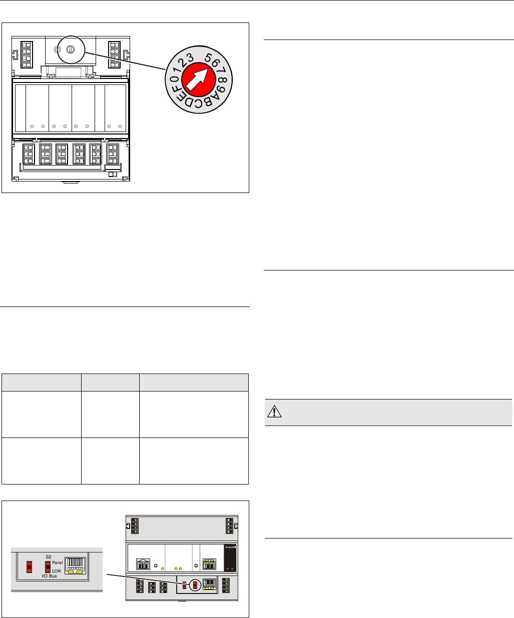
Mounting/Dismounting Modules Excel 800
EN1B-0410GE51 R0908A 14
LOCK
4
4
Fig. 14. HEX switch location
NOTE: If the HEX switch setting is changed, the Panel
Bus I/O module will revert to its default
configuration. With LONWORKS Bus I/O modules,
the HEX switch is without function.
Setting the I/O Bus Switch
► Set the I/O Bus switch S2 of the XCL8010AU Controller
Module depending on the modules connected to terminals
71 ─ 78 and the desired communication as follows:
Table 10. I/O Bus switch settings
communication S2 setting terminals
LONWORKS Bus
only
LON 71 ─ 74 LONWORKS Bus
75 ─ 78 LONWORKS Bus
11 ─ 14 LONWORKS Bus
Panel Bus and
LONWORKS Bus
Panel 71 ─ 74 Panel Bus
75 ─ 78 Panel Bus
11 ─ 14 LONWORKS Bus
Fig. 15. S2 I/O Bus switch
LONWORKS Bus Topologies
The LONWORKS Bus is a 78-kilobit serial link that uses
transformer isolation so that the bus wiring does not have a
polarity. I.e. it is not important which of the two LONWORKS
Bus terminals are connected to each wire of the twisted pair.
The LONWORKS Bus does not need to be shielded on the
controller module side.
The LONWORKS Bus can be wired in daisy chain, star, loop or
any combination thereof as long as the maximum wire length
requirements are met.
Configuration
The recommended configuration is a daisy chain with two bus
terminations. This layout allows for max. LONWORKS Bus
lengths, and its simple structure presents the least number of
possible problems, particularly when adding on to an existing
bus.
C-Bus Topologies
Via the C-Bus up to 30 C-Bus devices (e.g., controllers, etc.)
can communicate with one another and a PC central. The C-
Bus must be connected via the individual controllers (open
ring).
NOTE: Star connection is not allowed because
uncontrollable line reflections may occur.
Mounting/Dismounting Modules
WARNING
Risk of electric shock or equipment damage!
► Do not touch any live parts in the cabinet.
► Disconnect the power supply before you start to install the
Excel 800 System.
More than one disconnect switch may be required to de-
energize the system.
► Do not reconnect the power supply until you have
completed the installation.
NOTE: The terminal socket of each I/O module can be
mounted and wired before inserting and locking
the corresponding electronic module.
Excel 800 Mounting/Dismounting Modules
15 EN1B-0410GE51 R0908A
Mounting/Dismounting Controller/Sockets
Mounting Sockets
NOTE: When using both Panel Bus and LONWORKS Bus
I/O modules in an Excel 800 System, group both
Panel Bus modules (light-gray) and LONWORKS
Bus I/O modules (dark-gray), e.g., on different
rails. Up to 10 Panel Bus I/O modules can be
mounted to one side of the XCL8010AU. In total,
up to 16 Panel Bus I/O modules can be mounted
to one controller. The XCL8010AU Controller
Module is mounted on the DIN rail in the same way
as a terminal socket.
XCL8010AU
LonWorks
BUS
I/O
max. 10 max. 16 max. 10
Panel
BUS I/O
Panel
BUS I/O
Panel
BUS I/O
Panel
BUS I/O
Fig. 16. Max. number of Panel Bus I/O modules
XCL8010AU
LonWorks
BUS I/O
LonWorks
BUS
I/O
max. 10 max. 20 max. 10
LonWorks
BUS I/O
LonWorks
BUS I/O
LonWorks
BUS I/O
NOTE: MAX. OF 16 DIGITAL INPUT MODULES MAY BE USED.
Fig. 17. Max. number of LONWORKS Bus I/O modules with
power supply via XCL8010AU
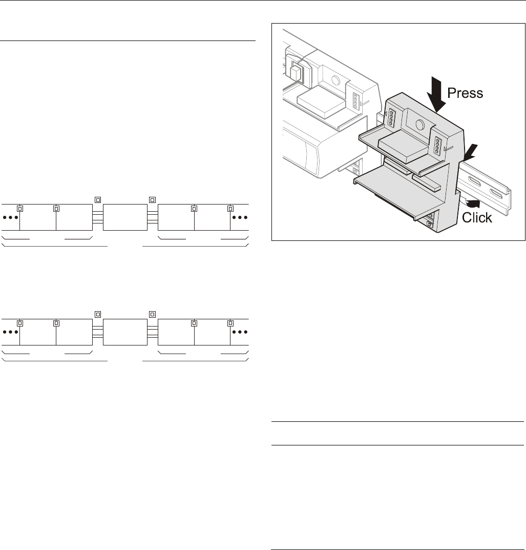
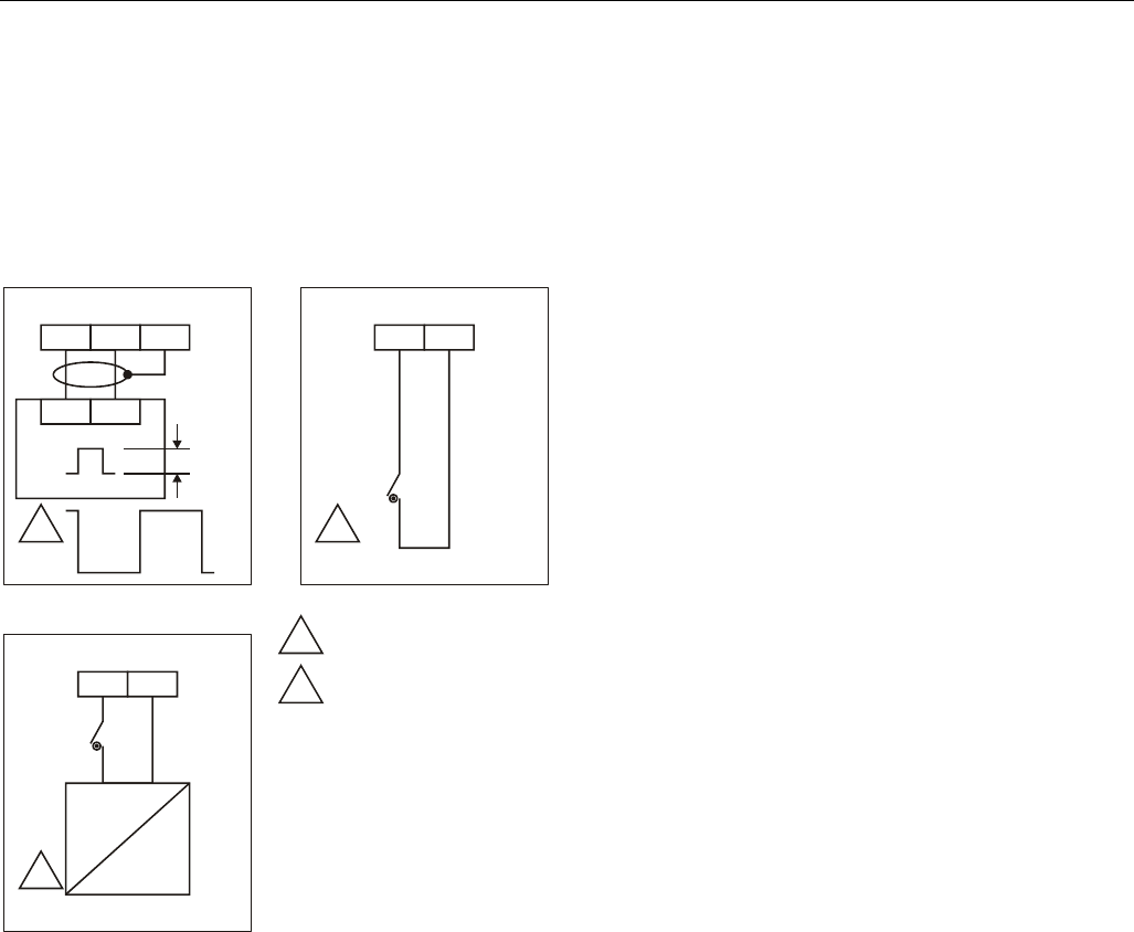
► Angle the terminal socket at the upper edge of the DIN rail
until it snaps in.
► Swing the terminal socket down and apply gentle force
until it snaps into position with an audible "click".
► Position XCL8010AU Controller Module and terminal
sockets flush with one another along the rail.
► If desired, mount stoppers at the ends of the rail to prevent
sliding.
Fig. 18. Mounting terminal sockets
NOTE: Take care to not bend the Omega clamp, which
serves to establish the electrical contact with the
DIN rail and which located on the back of the
terminal socket.
Connecting Sockets
Controller and terminal sockets on the same DIN rail can be
connected mechanically and electrically with bridge
connectors.
Controller and terminal sockets on different DIN rails must be
connected using cables.
NOTICE
Risk of malfunction!
► Wire Panel Bus I/O modules and LONWORKS Bus
I/O modules separately.
► When using both Panel Bus and LONWORKS Bus
I/O modules in an Excel 800 System, LONWORKS Bus
I/O modules must be connected to the XCL8010AU
Controller Module via LON terminals 11 ─ 14.
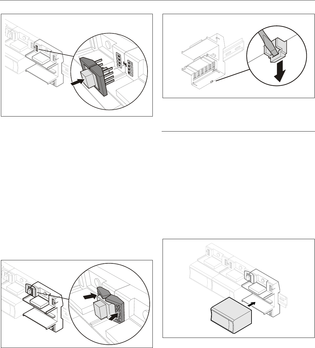
Position the bridge connector on terminals 71 ─ 74 of the
right hand terminal socket or XCL8010AU Controller Module
and on terminals 75 ─ 78 of the left hand terminal socket or
XCL8010AU Controller Module. Then press the bridge
connector down.
Mounting/Dismounting Modules Excel 800
EN1B-0410GE51 R0908A 16
Fig. 19. Connecting terminal sockets with bridge
connector
NOTE: Bridge connectors transmit both communication
signals and power supply between modules.
Removing bridge connectors will interrupt the
transmission of both communication signals and
power supply between the modules.
Dismounting Sockets
Disconnecting Sockets
Release all bridge connectors before removing the
XCL8010AU Controller Module and/or the terminal sockets
from the DIN rail.
► Press down at the same time both the gray side wings next
to the red button and then pull the bridge connector out of
the module.
Fig. 20. Releasing bridge connectors
Dismounting Controller/Terminal Sockets
► Insert a screwdriver into the latch on the underside of the
module and lever the red latch 2–3 mm downwards. The
module can then be swung away from the rail.
Fig. 21. Releasing latch
Mounting/Dismounting Electronic Modules
Mounting Electronic Modules
NOTE: Electronic modules can be removed from the
socket or inserted into the sockets without
switching off the power supply. The behavior of
connected field devices must be taken into
consideration.
► Make sure that terminal socket und I/O module match.
► Make sure that the red locking mechanism is in the open,
i.e., left, position.
► Gently push the electronic module onto the terminal socket
until snug.
Fig. 22. Inserting the electronic module
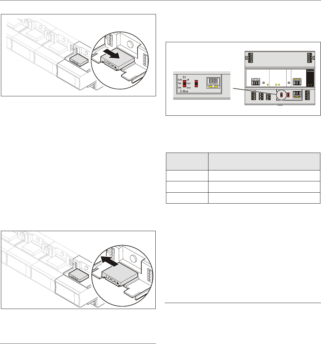
► Lock the red locking mechanism by sliding it to the right.
Excel 800 Mounting/Dismounting Modules
17 EN1B-0410GE51 R0908A
Fig. 23. Locking the electronic module
NOTE: The red locking mechanism will not close if the
electronic module is not properly mounted.
Dismounting Electronic Modules
NOTE: Electronic modules can be removed from the
socket or inserted into the sockets without
switching off the power supply. The behavior of
connected field devices must be taken into
consideration.
► Open the red locking mechanism by sliding it to the left
and then gently pull the electronic module out of the
terminal socket.
Fig. 24. Dismounting the electronic module
Connecting via C-Bus
Via C-Bus, an XCL8010AU Controller Module can be
connected to other controller systems to form a network.
Connecting to the Controller
► Connect the C-Bus to the XCL8010AU Controller Module
as follows:
– Input to C-Bus terminals 8 and 9
– Output to C-Bus terminals 5 and 6
– Do not connect the C-Bus to the cabinet earth or any
other earth ground points
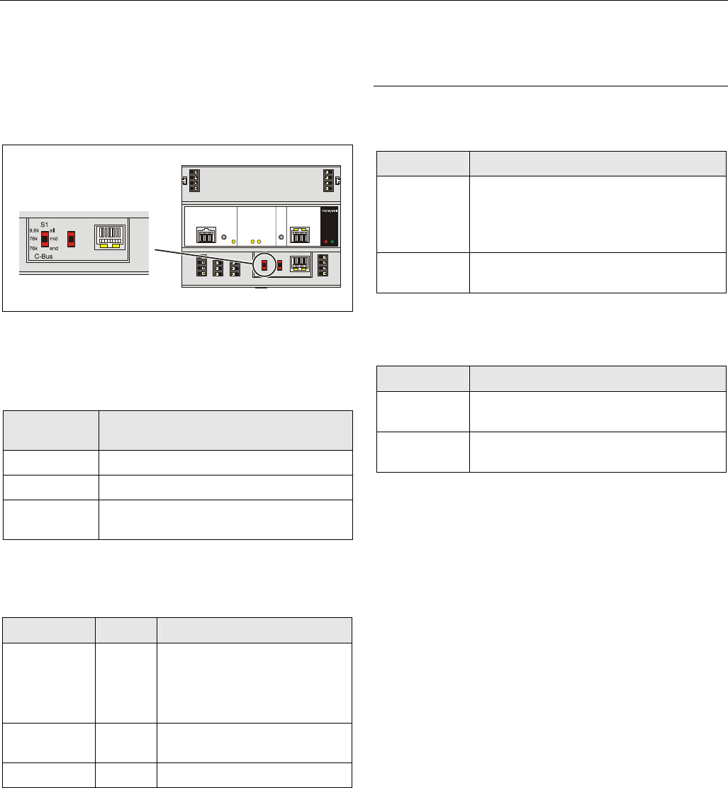
Setting the C-Bus Termination Switch
► Set the C-Bus termination switch S1 appropriately.
Fig. 25. C-Bus termination switch S1
Table 11. XCL8010AU C-Bus termination switch settings
switch setting
S1 baud rate
9.6k all Up to 9600 baud (default setting)
76k mid Up to 76800 baud without bus termination
76k end Up to 76800 baud with bus termination
Shielding
In principle, data transmitting cables should be shielded in
case of RFI.
► On the controller side, connect the shield to terminals 7
and 10.
► On the side of the device, connect the shield to the
respective terminals.
Do not connect it to the cabinet ground or any other
ground points.
Connecting HMIs or Laptops
Laptops or HMIs, e.g., XI582, can either be connected via the
HMI interface of the XCL8010AU Controller Module or via the
LONWORKS interface.
Connecting the XI582 Operator Interface
► Connect the XI582AH Operator Interface to the HMI
interface or LONWORKS interface of the XCL8010AU
Controller Module by means of
– the XW882 cable or
– the XW582 cable connected with an XW586 cable.
Mounting/Dismounting Modules Excel 800
EN1B-0410GE51 R0908A 18
Connecting Laptops (XL-Online/CARE)
► Connect a laptop (on which e.g., XL-Online or CARE has
been installed) to the HMI interface or LONWORKS interface
of the XCL8010AU Controller Module by means of
– the XW885 cable or
– the XW585 cable connected with an XW586 Cable.
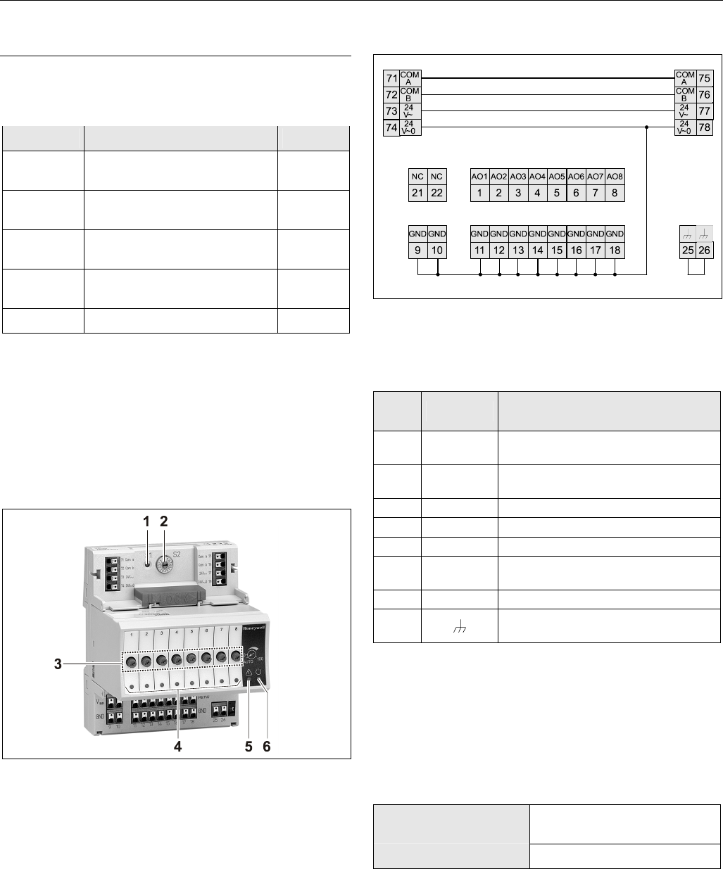
XCL8010AU Terminals
74
14 10 7
2
3
4
78
73
13 9 6
1
77
72
12 8 5
76
71
11
75
24
V~
24
V~
24
V~
24
V~ 0
LON
2
C- C-
C+ C+
LON
2
LON
1
LON
1
24
V~0
24
V~0
NC
24
V~0
COM
BCOM
B
COM
ACOM
A
SHIELD SHIELD
8 7 6 54 3 2 1
*
*Watch Dog
Relay
Fig. 26. Terminal assignment and internal connections of
the XCL8010AU Controller Module
Table 12. Description of XCL8010AU terminals
ter-
minal signal comment
71, 75 COM a 2-wire communication bus
(LON/Panel Bus)
72, 76 COM b 2-wire communication bus
(LON/Panel Bus)
73, 77 24 V~ Power supply for I/O modules
74, 78 24 V~0 Power supply for I/O modules
1 24 V~ Power supply from transformer
2 24 V~0 Power supply from transformer
3 24 V~0 Alarm/watchdog output
4 NC Alarm/watchdog output
5, 8 C+ C-Bus
6, 9 C- C-Bus
7, 10 Shield C-Bus shield
11, 12 LON LONWORKS IN
13, 14 LON LONWORKS OUT
Features
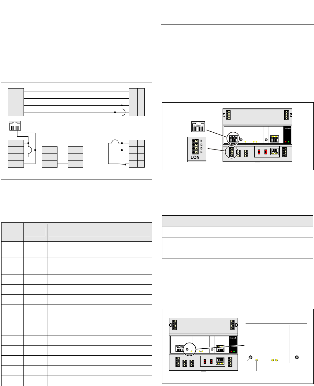
LONWORKS Interface and Terminals
The XCL8010AU Controller Module features
• An RJ45 socket serving as an interface
to connect laptops or HMIs to the LONWORKS Bus
• LONWORKS terminals 11, 12, 13, and 14
to connect LONWORKS Bus I/O modules or other
LONWORKS devices to the XCL8010AU Controller or other
LONWORKS controllers.
Fig. 27. LONWORKS interface and LONWORKS terminals
LONWORKS Interface Signals on RJ45 Socket
Table 13. Signals of LONWORKS interface
pin signal type
1 Connection to LONWORKS Bus
2 Connection to LONWORKS Bus
3 ─ 8 Not used
LONWORKS Service LED and Button
The XCL8010AU Controller Module is equipped with a
LONWORKS service button and corresponding LONWORKS
Service LED (status: yellow/OFF).
1
LON
2
Fig. 28. LONWORKS service button (1) and service LED (2)
See also section "Troubleshooting" on page 31.
Excel 800 Mounting/Dismounting Modules
19 EN1B-0410GE51 R0908A
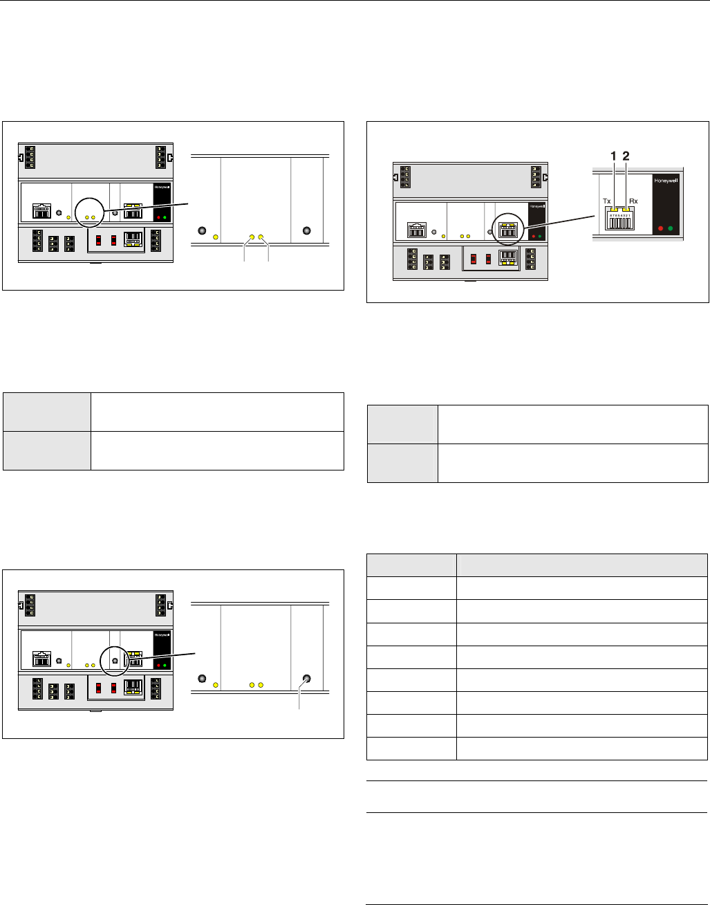
C-Bus Tx LED and Rx LED
The XCL8010AU Controller Module is equipped with a Tx
LED (status: yellow/OFF) and an Rx LED (status:
yellow/OFF).
1
C-Bus
2
Fig. 29. C-Bus Tx LED (1) and Rx LED (2)
C-Bus LEDs
Table 14. Controller C-Bus LEDs
Tx (1)
flickering
The controller is sending data onto the
C-Bus
Rx (2)
flickering
The controller is receiving data from the
C-Bus
Reset Button
The XCL8010AU Controller Module is equipped with a reset
button.
1
RESET
Fig. 30. Reset button (1)
Pushing the reset button (1), e.g. using a paperclip, will cause
the XCL8010AU Controller Module to reset.
NOTE: In the event of a reset, all non-volatile memory
contents are permanently deleted, though the
clock will not be set to zero. In order to avoid
problems, we therefore recommend that you
always save your application changes (e.g., time
program changes) to FLASH memory.
HMI Interface
The XCL8010AU Controller Module is equipped with an HMI
Interface for the connection of HMIs, e.g., XI582 Operator
Interface or a laptop (with XL-Online/CARE).
Fig. 31. HMI interface, Tx LED (1) and Rx LED (2)
HMI interface LEDs on RJ45 socket
Table 15. HMI interface LEDs
Tx (1)
flickering
The controller is transmitting data to the HMI
Rx (2)
flickering
The controller is receiving data from the HMI
HMI interface Signals on RJ45 socket
Table 16. Signals of the HMI interface
pin signal type
1 -
2 Receive
3 Transmit
4 -
5 Signal ground
6 -
7 5 V
8 -
NOTICE
Equipment damage!
► If earth grounding is required, make sure that only terminal
2 is connected to earth ground. Terminal 1 must not be
connected to earth ground. See also Appendix 1.
Mounting/Dismounting Modules Excel 800
EN1B-0410GE51 R0908A 20
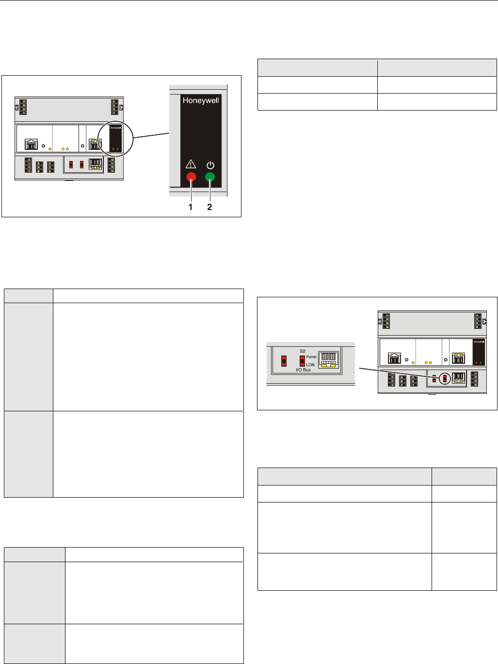
Alarm and Power LEDs
The XCL8010AU Controller Module is equipped with an alarm
LED and a power LED.
Fig. 32. Alarm LED (1) and power LED (2)
Alarm LED (1, red)
Table 17. Controller alarm LED
Off Normal operation
On Watchdog alarm output is powered
• The controller has encountered a hardware
problem
• The application has a fault
• The controller has been powered up without
an application or the operator has manually
stopped the application.
In this case, the LED will light up 13 minutes
after power-up without application
Flashing The watchdog alarm output has not yet been
powered, although the controller has
encountered a problem.
The controller performs a warm start.
If problem persists, the LED will become lit
constantly, see above.
See section "Troubleshooting" on page 31.
Power LED (2, green)
Table 18. Controller power LED
On Normal operation
Flashing One or more of the internal voltage supplies
are outside of the permissible ranges.
The controller stops operation.
► Check wiring or see section
"Troubleshooting" on page 31.
Goes out
briefly
• The operator has activated the reset
button
• The controller is performing a warm start
Watchdog Status
Table 19. Watchdog status (terminal 4)
status signal on terminal 4
Failure (= alarm) 24 V
Normal operation 0 V
Modem Interface
NO CONNECTION.
I/O Bus Switch S2
The XCL8010AU Controller Module features a 2-position I/O
Bus switch S2.
I/O Bus switch S2 must be set in accordance with the kind of
I/O modules connected to communication terminals 71, 72
and 75, 76 of the XCL8010AU Controller Module.
Terminals 71, 72 and 75, 76 must be all connected either to
Panel Bus I/O modules or to LONWORKS Bus I/O modules.
The default setting is Panel.
Fig. 33. I/O Bus switch S2
Table 20. I/O Bus switch settings
communication S2 setting
LONWORKS Bus only LON
Panel Bus and LONWORKS Bus
LONWORKS BUS modules connected to
terminals 11 ─ 14 of the XCL8010AU
Controller Module
Panel
Panel Bus connected to terminals 71, 72 or
75, 76 of the XCL8010AU Controller
Module
Panel
Excel 800 Description of the I/O Modules
21 EN1B-0410GE51 R0908A
C-Bus Termination Switch S1
The XCL8010AU Controller Module features a 3-position C-
Bus termination switch S1.
This switch must be set in accordance with the given C-Bus
configuration.
Fig. 34. C-Bus termination switch
Table 21. XCL8010AU C-Bus termination switch S1
settings
switch setting
S1 baud rate
9.6k all Up to 9600 baud (default setting)
76k mid Up to 76800 baud without bus termination
76k end Up to 76800 baud with bus termination
controller at the end of the C-Bus
Memory
Table 22. XCL8010AU memory
memory size usage
SRAM 512 KB
For controller application,
modem trend and firmware
RACL application: 128 KB
Total application: 192 KB
Flash 2 MB
Firmware (1 MB) and application
(1 MB) storage
EPROM 128 KB For bootstrap loader
NOTE: The XCL8010AU Controller Module does not
contain a battery. RAM (data and realtime
clocktime) is buffered for 3 days by a super
capacitor.
Description of the I/O Modules
Common Features
Switches Located on the Terminal Socket
Table 23. Terminal socket switches
feature function
Service button
S1
• LED test, see section "Troubleshooting"
on page 31
• L
ONWORKS service button functionality
for LONWORKS Bus I/O modules
Hex switch S2 • Module addressing for Panel Bus
I/O modules
LEDs Located on the I/O Module
Table 24. LEDs on I/O module
feature function
Service LED
(yellow)
• Service information, see section
"Troubleshooting" on page 31
Power LED
(green)
• Information on power supply, see section
"Troubleshooting" on page 31
For the location of these elements, see figures of the
respective modules.
Description of the I/O Modules Excel 800
EN1B-0410GE51 R0908A 22
Analog Input Modules
Types of Analog Input Modules
Table 25. Excel 800 Analog Input Modules
type description housing
XF821 Panel Bus Analog Input Module light-gray
XFL821 LONWORKS Bus Analog Input
Module
dark-gray
XS821-822 terminal socket light-gray
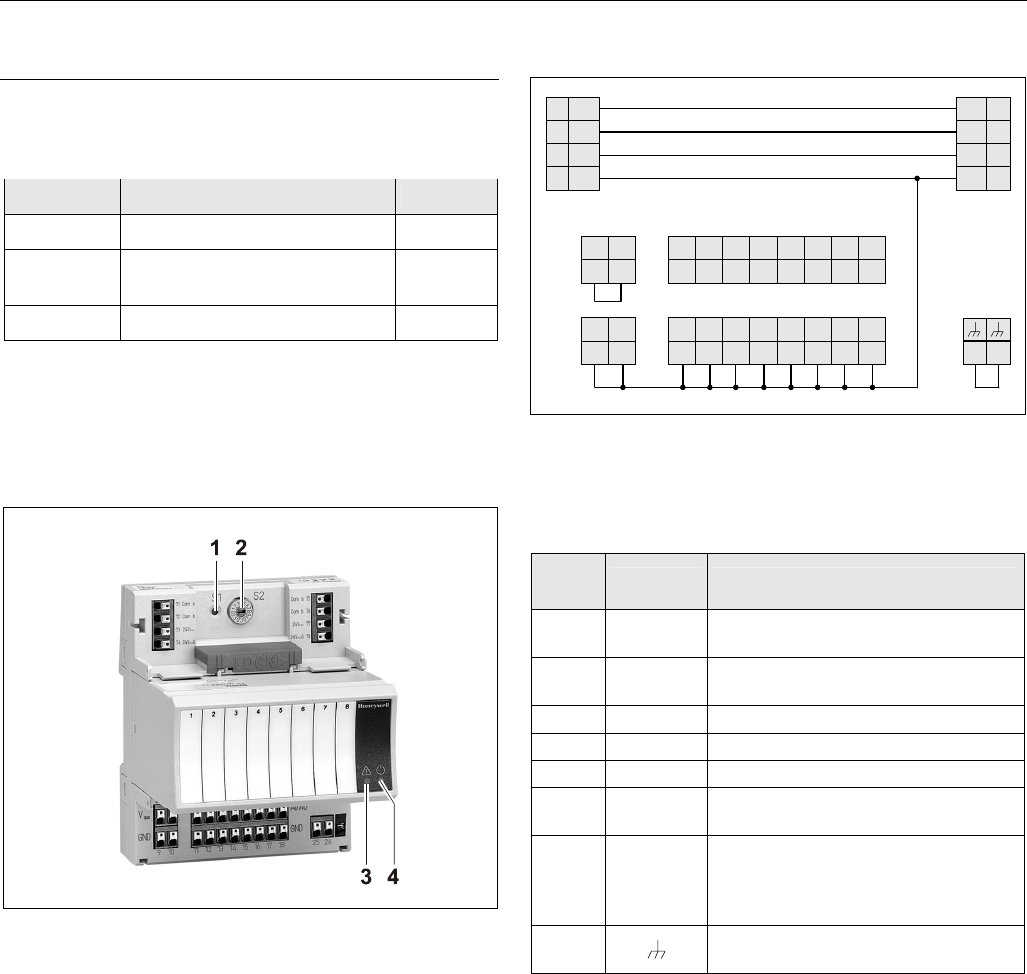
Features
• 8 analog inputs
• Sensor-break and short-circuit detection, see section
"Troubleshooting" on page 31.
Fig. 35. XF821AU Analog Input Module with terminal
socket
Legend
1 Service button S1
2 Hex switch S2
3 Service LED
4 Power LED
Functionality of service LED and power LED: see Table 42
and following.
Terminals
25 26
74 78
73 77
72 76
71 75
24
V~ 24
V~
24
V~0 24
V~0
COM
BCOM
B
COM
ACOM
A
AI8
8
AI7
7
AI6
6
AI5
5
AI4
4
AI3
3
AI2
2
AI1
1
18171615141312
GND
11
GND GND GND GND GND GND GND
22
V
21
10
GND
9
GND
AUX VAUX
Fig. 36. Terminal assignment and internal connections of
Analog Input Modules
Table 26. Description of Analog Input Module terminals
ter-
minal signal comment
71, 75 COM a 2-wire communication bus
(LON/Panel Bus)
72, 76 COM b 2-wire communication bus
(LON/Panel Bus)
73, 77 24 V~ Power supply
74, 78 24 V~0 Power supply
1 ─ 8 AI1 ─ AI8 Analog inputs 1 ─ 8
9 ─ 18 GND Ground. All grounds are connected
internally to each other
21, 22 10 VDC /
5 mA
Auxiliary voltage signal (used e.g. for
supplying setpoint potentiometers).
Connections to these terminals
must be made in the same room.
25, 26 Shield connection (functional earth),
internally connected to the DIN rail
NOTE: Shield connection to be used for shielded I/O
cables only. It is not allowed to connect a
LONWORKS shield.
Excel 800 Description of the I/O Modules
23 EN1B-0410GE51 R0908A
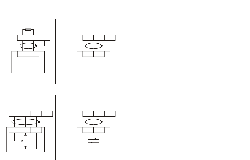
XFL821AU Connection Examples
25
22 25 25
25 2
53
1
1
10 1
1
12
14 13
18
2
11 12 2
2
0 to 10 V
VMP Pt1000 NTC20kW
0(4) to 20 mA
400 OHM
SHIELD SHIELD
SHIELD SHIELD
0(4) to 20 mA (VIA EXTERNAL
500 OHM RESISTOR). 0 TO 10 VDC
Fig. 37. XFL821AU Analog Input Module
Description of the I/O Modules Excel 800
EN1B-0410GE51 R0908A 24
Analog Output Modules
Types of Analog Output Modules
Table 27. Excel 800 Analog Output Modules
type description housing
XF822 Panel Bus Analog Output
Module
light-gray
XFR822 Panel Bus Analog Output
Module with manual overrides
light-gray
XFL822 LONWORKS Bus Analog Output
Module
dark-gray
XFLR822 LONWORKS Bus Analog Output
Module with manual overrides
dark-gray
XS821-22 terminal socket light-gray
Features
• 8 analog outputs;
can also be configured per output as binary outputs
(0 ─ 10 V, 2 ─ 10 V, ON/OFF, or floating)
• Corresponding output status LEDs (red)
• XFR822AU/XFLR822AU: 8 manual overrides, see figure
below
Fig. 38. XF822AU Analog Output Module with terminal
socket
Legend
1 Service button S1
2 Hex switch S2
3 Manual overrides
4 Output LEDs
5 Service LED
6 Power LED
Functionality of service LED and power LED: see Table 42
and following.
Terminals
Fig. 39. Terminal assignment and internal connections of
the Analog Output Modules
Table 28. Description of the Analog Output Module
terminals
ter-
minal signal comment
71, 75 COM a 2-wire communication bus
(LON/Panel Bus)
72, 76 COM b 2-wire communication bus
(LON/Panel Bus)
73, 77 24 V~ Power supply
74, 78 24 V~0 Power supply
1 ─ 8 AO1 ─ AO8 Analog outputs 1 ─ 8
9 ─ 18 GND Ground. All grounds are connected
internally to each other
21, 22 N.C. Do not use!
25, 26 Shield connection (functional earth),
internally connected to the DIN rail
NOTE: Shield connection to be used for shielded I/O
cables only. It is not allowed to connect a
LONWORKS shield.
Technical Data
Output status LEDs behavior
Table 29. Analog Output Module status LED behavior
automatic mode brightness follows the
commanded output signal
override mode flashes
Excel 800 Description of the I/O Modules
25 EN1B-0410GE51 R0908A
Modules with Manual Overrides
The XFR822AU/XFLR822AU Analog Output Modules are
equipped with manual overrides: one rotary knob for each
analog output.
The manual overrides can be set manually to either "auto" or
"0 ─ 110%".
NOTICE
Damage to the electronic module!
► Do not use a tool to adjust the rotary knobs.
► Do not use excessive force. Adjust only by hand.
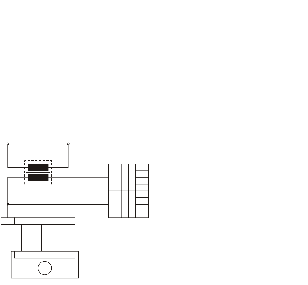
XFL822AU Connection Example
XFL822AU
173811
X
SL511
LN
Umax = 11 VDC
Imax = 1 mA, -1 mA
14507287
POWER
MODULE
GND SIGNAL 24VAC
M
24V
~
Fig. 40. XFL822AU Analog Output Module
Synchronization Behavior of Analog Output Module
Configured as Floating Output
In order to regularly update the real actuator position with the
calculated position and thus ensure that the actuator
definitely reaches its end position, a synchronization process
is performed by the Analog Output Module.
During the synchronization process, the Analog Output
Module will continue running for the configured runtime once
it reaches the calculated end position.
This updating (synchronization) is performed:
• If the calculated position of the actuator
< lower synchronization threshold (2 %)
= synchronization towards 0 %
• If the calculated position of the actuator
> upper synchronization threshold (98 %)
= synchronization towards 100 %
• Following any power-up or any reset
Description of the I/O Modules Excel 800
EN1B-0410GE51 R0908A 26
Binary Input Modules
Types of Binary Input Modules
Table 30. Excel 800 Binary Input Modules
type description housing
XF823 Panel Bus Binary Input Module light-gray
XFL823 LONWORKS Bus Binary Input
Module
dark-gray
XS823 terminal socket light-gray
Features
• 12 binary inputs
• 12 configurable status LEDs (green/red, yellow/OFF)
• Binary inputs can be used as
– Static digital inputs as dry-contacts
Fig. 41. XF823AU Binary Input Module with terminal
socket
Legend
1 Service button S1
2 Hex switch S2
3 Input LEDs
4 Service LED
5 Power LED
Functionality of service LED and power LED: see Table 42
and following.
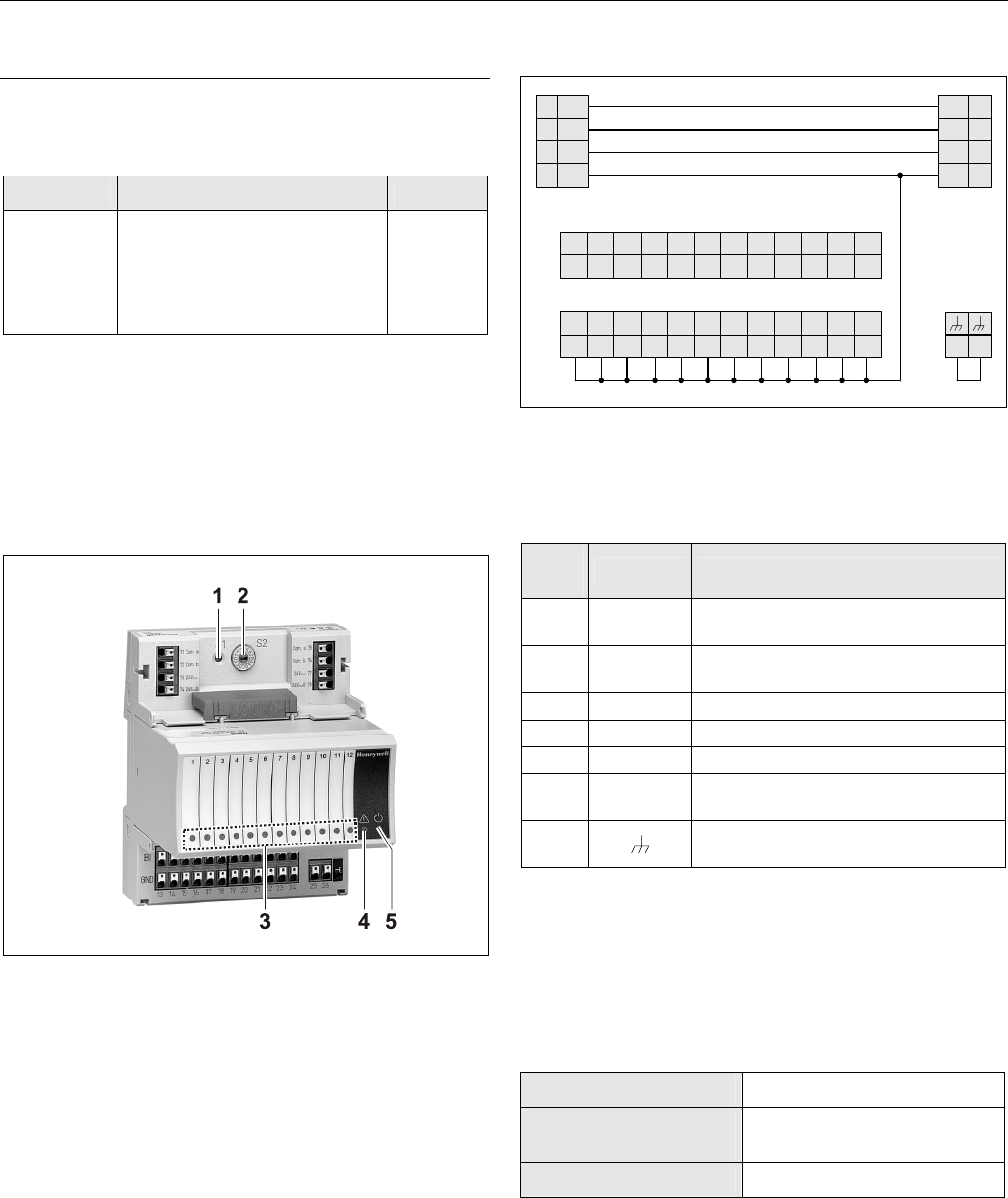
Terminals
BI12
12
25 26
74 78
73 77
72 76
71 75
24
V~ 24
V~
24
V~0 24
V~0
COM
BCOM
B
COM
ACOM
A
BI11
11
BI10
10
BI9
9
BI8
8
BI7
7
BI6
6
BI5
5
BI4
4
BI3
3
BI2
2
BI1
1
2423222120191817161514
GND
13
GND GND GND GND GND GND GND GND GND GND GND
Fig. 42. Terminal assignment and internal connections of
Binary Input Modules
Table 31. Description of Binary Input Module terminals
ter-
minal signal comment
71, 75 COM a 2-wire communication bus (LON/Panel
Bus)
72, 76 COM b 2-wire communication bus (LON/Panel
Bus)
73, 77 24 V~ Power supply
74, 78 24 V~0 Power supply
1 ─ 12 BI1 ─ BI12 Binary inputs 1 ─ 12
13 ─
24 GND Ground. All grounds are connected
internally to each other.
25, 26 Shield connection (functional earth),
internally connected to the DIN rail.
NOTE: Shield connection to be used for shielded I/O
cables only. It is not allowed to connect a
LONWORKS shield.
Technical Data
Table 32. Technical data for of Binary Input Modules
input type dry-contact
current rating (closed
input)
2 mA
open contact voltage 16 ─ 22 VDC
Excel 800 Description of the I/O Modules
27 EN1B-0410GE51 R0908A
Status LEDs
The status LEDs can be configured individually for use as
either alarm LEDs (red/green) or as status LEDs (yellow/OFF
[default]).
Given a state of "logical ON," the LED will be lit (yellow or
red).
XF823AU Connection Examples
25 21
1
14
13
2
2 1
SHIELD
5 TO 24V
MIN.
25 MS
MIN.
25 MS
2
1
CONTACT SUITABLE FOR
LOW VOLTAGE (GOLD).
PROTECTED SWITCHING
UP TO 40 VDC / 24 VAC.
315
PT1000 NTC20kW
1
5 TO 24
VDC
~ 120V
Fig. 43. XFL823AU Binary Input Module
Description of the I/O Modules Excel 800
EN1B-0410GE51 R0908A 28
Relay Output Modules
Types of Relay Output Modules
Table 33. Excel 800 Relay Output Modules
type description housing
XF824 Panel Bus Relay Output Module light-gray
XFR824 Panel Bus Relay Output Module
with manual overrides
light-gray
XFL824 LONWORKS Bus Relay Output
Module
dark-gray
XFLR824 LONWORKS Bus Relay Output
Module with manual overrides
dark-gray
XS824-25 terminal socket; can be fitted
with long (red) cross connector
(incl. in scope of the delivery)
light-gray
Features
• 6 relays (changeover contacts), arranged in two blocks
• XFLR824AU, XFR824AU: 6 manual overrides
• Low and line voltage allowed, see WARNING.
Fig. 44. XF824AU Relay Output Module with terminal
socket
Legend
1 Service button S1
2 Hex switch S2
3 Manual overrides
4 Status LEDs
5 Service LED
6 Power LED
Functionality of service LED and power LED: see Table 42
and following.
Terminals
31 41 51 61
32 42 52 62
33 43 53 63
34 44 54 64
NO
NC
COM
CON
NO
NC
COM
CON
11
12
13
14
21
22
23
24 25
NO
NC
COM
CON
NO
NC
COM
CON
NO
NC
COM
CON
NO
NC
COM
CON
Relay block 2
74 78
73 77
72 76
71 75
24
V~ 24
V~
24
V~ 0 24
V~0
COM
BCOM
B
COM
ACOM
A
Cross connector (can be removed, as desired)
Relay block 1
Fig. 45. Terminal assignment and internal connections of
Relay Output Modules
Excel 800 Description of the I/O Modules
29 EN1B-0410GE51 R0908A
Table 34. Description of Relay Output Module terminals
terminal signal comment
71, 75 COM a 2-wire communication bus
(LON/Panel Bus)
72, 76 COM b 2-wire communication bus
(LON/Panel Bus)
73, 77 24 V~ Power supply
74, 78 24 V~0 Power supply
11 REL1 N.O. Relay 1 N.O. contact
12 REL1 N.C. Relay 1 N.C. contact
13 R1 COM relay 1 common contact
14 R1 COM For connection of relay 1 common via
cross connector*
21 REL2 N.O. Relay 2 N.O. contact
22 REL2 N.C. Relay 2 N.C. contact
23 R2 COM Relay 2 common contact
24 R2 COM For connection of relay 2 common via
cross connector*
31 REL3 N.O. Relay 3 N.O. contact
32 REL3 N.C. Relay 3 N.C. contact
33 R3 COM Relay 3 common contact
RELAY BLOCK 1
34 R3 COM For connection of relay 3 common via
cross connector*
41 REL4 N.O. Relay 4 N.O. contact
42 REL4 N.C. Relay 4 N.C. contact
43 R4 COM Relay 4 common contact
44 R4 COM For connection of relay 4 common via
cross connector*
51 REL5 N.O. Relay 5 N.O. contact
52 REL5 N.C. Relay 5 N.C. contact
53 R5 COM Relay 5 common contact
54 R5 COM For connection of relay 5 common via
cross connector*
61 REL6 N.O. Relay 6 N.O. contact
62 REL6 N.C. Relay 6 N.C. contact
63 R6 COM Relay 6 common contact
RELAY BLOCK 2
64 R6 COM For connection of relay 6 common via
cross connector*
25
Shield connection (functional earth),
internally connected to the DIN rail
* Do not connect by wire!
Permissible Loads
Table 35. Permissible loads of Relay Output Modules
max. load
per relay output
module (total)
(common)
24 VAC, 60 Hz
12 A
24 VDC
12 A resistive, 12 A, 0.6 PF
per normally open
contact (common)
24 VAC, 60 Hz
4 A
24 VDC
4 A resistive, 4 A, 0.6 PF
per normally
closed contact
(common)
24 VAC, 2 A, 60 Hz
24 VDC
4 A resistive, 4 A, 0.6 PF
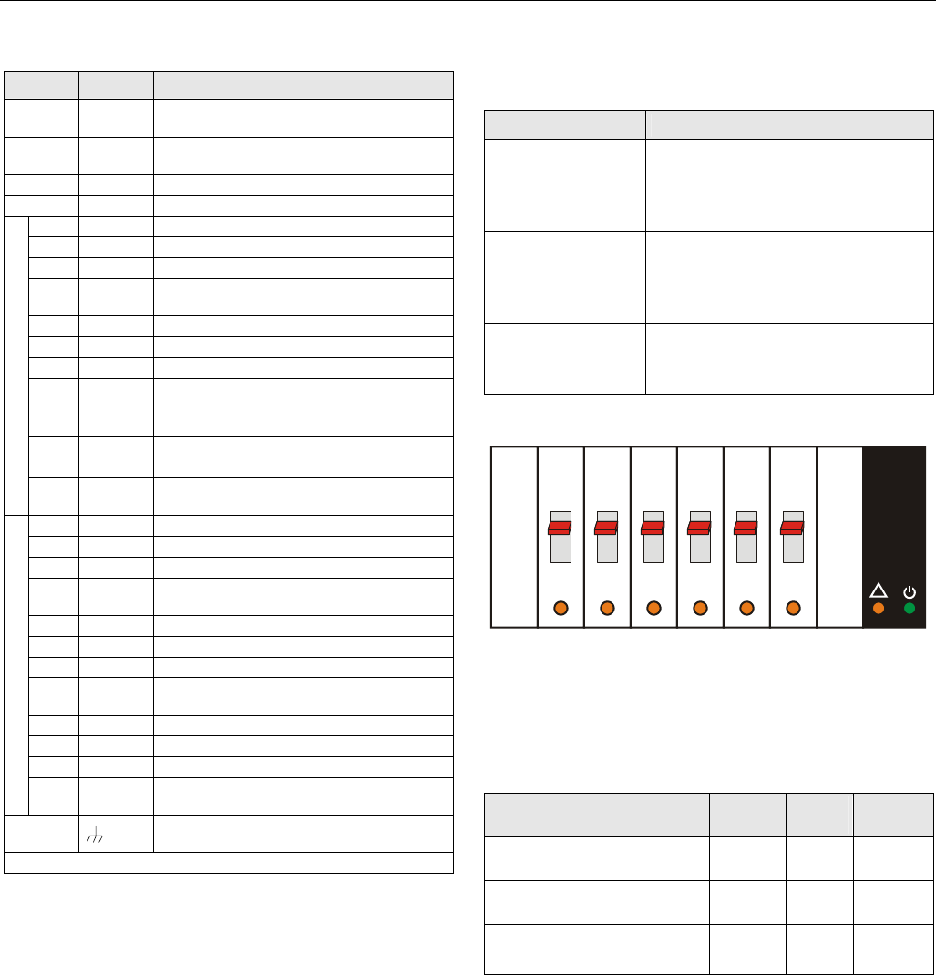
Status LEDs with Manual Overrides
123456
Honeywell
--1
--0
--AUTO
!
Fig. 46. Manual overrides (toggle switches)
The XFR824AU and XFLR824AU Relay Output Modules are
equipped with six manual overrides: one for each relay
output. These toggle switches can manually be set to either
"auto" or "0" or "1".
Table 36. Relay Output Module status LED behavior
mode LED N.O.*
(direct)
N.C.*
(reverse)
automatic mode, state
“logical ON”
ON ON OFF
automatic mode, state
“logical OFF”
OFF OFF ON
override mode (setting “0”) flashes OFF ON
override mode (setting “1”) flashes ON OFF
*As configured during engineering.
Description of the I/O Modules Excel 800
EN1B-0410GE51 R0908A 30
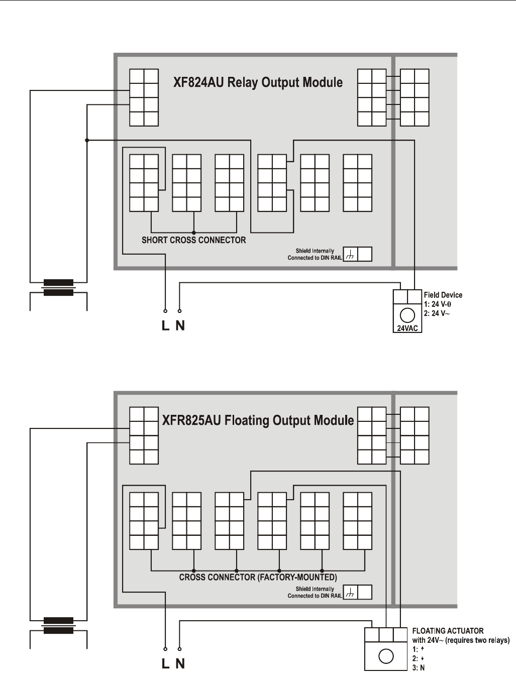
Connection Examples
74 74
78
73 7377
72 72
76
71 71
75
24
V
~
24
V
~
24
V
~
24
V
~
024
V
~
0
24
V
~
0
COM
BCOM
B
COM
B
COM
ACOM
A
COM
A
25
NO
NC
COM
11
12
13
CON
14
NO
NC
COM
21
22
23
CON
24
31
32
33
NO
NC
COM
34
CON
41
42
43
NO
NC
COM
44
CON
51
52
53
NO
NC
COM
54
CON
61
62
63
NO
NC
COM
64
CON
1 2
M
14507287 SERIES
POWER MODULE
Fig. 47. XF824AU connection example
74 74
78
73 7377
72 72
76
71 71
75
24
V
~
24
V
~
24
V
~
24
V
~
024
V
~
0
24
V
~
0
COM
BCOM
B
COM
B
COM
ACOM
A
COM
A
25
NO
NC
COM
11
12
13
CON
14
NO
NC
COM
21
22
23
CON
24
31
32
33
NO
NC
COM
34
CON
41
42
43
NO
NC
COM
44
CON
51
52
53
NO
NC
COM
54
CON
61
62
63
NO
NC
COM
64
CON
123
M
14507287 SERIES
POWER MODULE
Fig. 48. XFR825AU connection example
Excel 800 Troubleshooting
31 EN1B-0410GE51 R0908A
Troubleshooting
Testing Wiring Connections
The push-in terminals feature small holes (1 mm in diameter)
which can be used to measure the signals.
► Insert a probe (1) as shown on the right.
Fig. 49. Testing wiring connections
Troubleshooting on the XCL8010AU Controller
The following LEDs of the XCL8010AU Controller can be used for troubleshooting purposes:
• Power LED (green)
• Alarm LED (red)
• L
ONWORKS service LED
• C-Bus Tx and Rx LEDs
• HMI Tx and Rx LEDs
Power LED (green)
Table 37. XCL8010AU power LED
case power LED meaning remedy
1 ON Normal operation No action necessary
2 Flashing One or more of the internal voltage supplies
are outside of the permissible ranges. The
controller stops operation.
► Check power
► Check wiring
► If problem persists, replace hardware
3 Goes out briefly • The operator has activated the reset button
• The controller is performing a warm start
No action necessary
Excel 800
EN1B-0410GE51 R0908A 32
Alarm LED (red)
Table 38. XCL8010AU alarm LED
case alarm LED meaning remedy
1 OFF Normal operation No action necessary
2 ON Watchdog alarm output is powered
– The controller has encountered a
hardware problem
- or -
– The application has a fault
- or -
– The controller has been powered up
without an application or the operator
has manually stopped the application,
e.g., using XL-Online.
In this case, the LED will light up
13 minutes after power-up without
application
► Try powering down and then
powering up the XCL8010AU.
► If problem persists, check and – if
necessary – reload the application.
► If problem still persists, replace
hardware
3 Flashing Although the controller has encountered a
problem, the watchdog alarm output has not
yet been powered.
If problem persists, the LED will become lit
constantly, see case #2.
The controller performs a warm start.
If it happens only once, the controller
has performed a restart
If, however, it happens multiple times,
then there is an application or hardware
problem (see case #2)
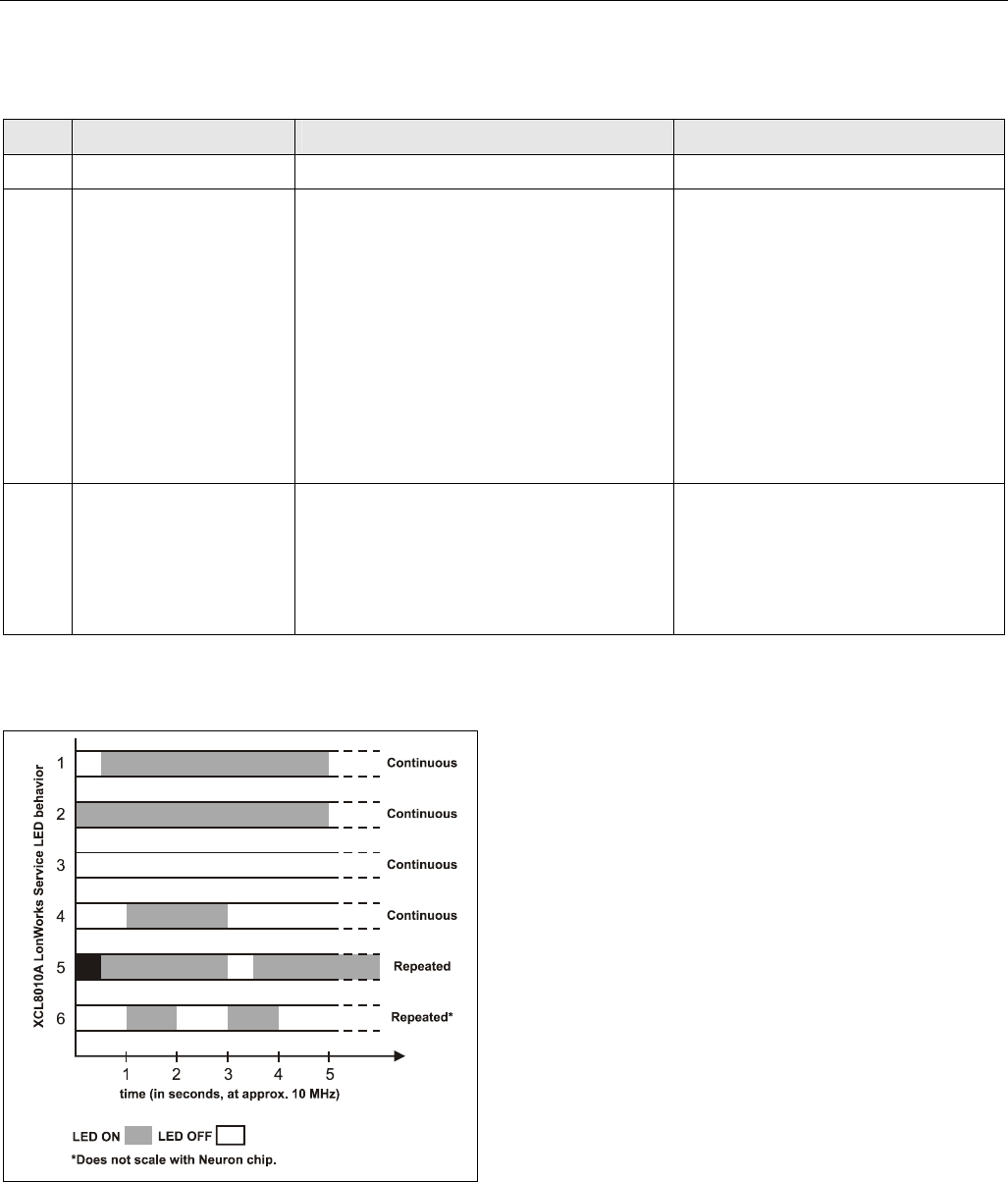
LONWORKS Service LED
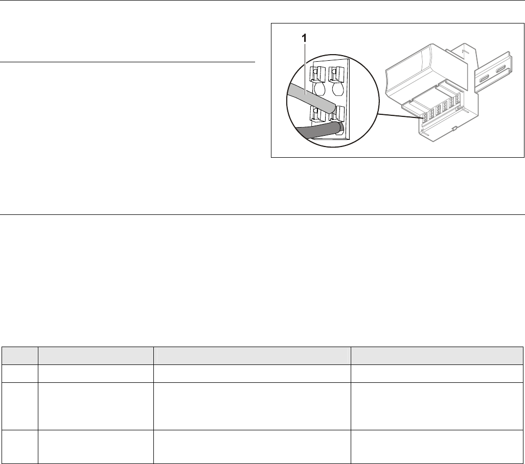
Fig. 50. Flashing pattern of the LONWORKS service LED
The LONWORKS service LED of the XCL8010AU Controller Module displays the following flashing patterns indicating possible
failure modes:
Excel 800 Troubleshooting
33 EN1B-0410GE51 R0908A
Table 39. XCL8010AU LONWORKS service LED
case When can it occur? meaning remedy
1 Anytime Node is configured and running normally No action necessary
2 Power up of controller Bad node hardware ► Replace hardware
3 Power up of controller Bad node hardware ► Replace hardware
4 Power up / reset Node lacks application.
May be caused by neuron chip firmware when
a mismatch occurs on application checksum
► Using EXCELON, set module to
“configured online”
► If problem persists, the MIP software
on LW interface has been erased due
to wrong setting performed using
ECHELON tool:
Replace hardware
5 Anytime Watchdog timer resets occurring.
Possible corrupt EEPROM and bootstrap
mode
► Download firmware
6 Anytime Node is unconfigured but has an application ► Proceed with commissioning
C-Bus Tx and Rx LEDs
Table 40. XCL8010AU C-Bus Tx and Rx LEDs
case C-Bus LEDs meaning remedy
If the C-bus is functioning properly, then the
XCL8010AU is functioning properly No action necessary
1
Both LEDs are flashing
If the C-bus is not functioning properly, then
the termination can be wrong
► Check C-bus termination switch S1
(location: see Fig. 4 on page 7)
2 Both LEDs are OFF No C-bus communication ► Check C-bus settings
3 Both LEDs are flashing
synchronously
No C-bus communication ► Check C-bus wiring
HMI Tx and Rx LEDs
Table 41. XCL8010AU HMI Tx and Rx LEDs
case HMI LEDs meaning remedy
1 Both LEDs are flashing If the HMI Interface is functioning properly,
then the XCL8010AU is functioning properly No action necessary
2 Both LEDs are OFF No HMI Interface communication ► Check HMI Interface connection and
proper earthing of connected
hardware
Excel 800
EN1B-0410GE51 R0908A 34
I/O Modules Troubleshooting
► Check if the power supply voltage level is OK and that there is no high voltage (> 24 VAC or > 40 VDC) connected to the
inputs/outputs of the XF821AU, XFL821AU, XF822AU, XFL822AU, XFR822AU, XFLR822AU, XF823AU, and XFL823AU I/O
modules.
► Replace the problem I/O module with another module of the same kind.
– If the problem persists, this is an indication that the problem is caused by the application or incorrect wiring.
– If the problem is solved, this is an indication that the I/O module was defective.
For troubleshooting purposes on all I/O modules the following features can be used:
• Power LED
• Service LED
• Service button
In addition, a module-specific troubleshooting may be necessary.
Power LED of I/O Modules
Table 42. Power LED of I/O modules
case power LED meaning remedy
1 ON I/O module is powered No action necessary
2 OFF No power ► Check power supply
3 Flashing continuously
If the I/O module’s service LED is likewise
flashing, the I/O module is in the boot mode
► Wait until rebooting (firmware
download) has been completed

Excel 800 Troubleshooting
35 EN1B-0410GE51 R0908A
Service LED of I/O Modules
Table 43. Service LED of I/O modules
case Service LED meaning remedy
1 LED remains OFF after
power-up
If the power LED is also OFF, then
– Defective device hardware
– Possible power supply problems, clock
problems, defective processor
► Replace hardware
2 LED is lit continuously after
first power-up
• L
ONWORKS Bus I/O modules:
– Defective hardware
• Panel Bus I/O modules:
– I/O module has not yet been configured
by XCL8010AU
– Boot loader is active
– Failure during last firmware download
– Checksum error
LONWORKS Bus I/O modules:
► Replace hardware
Panel Bus I/O modules:
► Set the hex address to the position configured
with CARE
► Ensure that I/O Bus switch S2 of XCL8010AU is
set to position "Panel"
► Check the Panel Bus wiring:
- Check for cable breaks
- Check for cable short-circuits
- If using separate transformers: Check ground
connection
► Eliminate any mixture of Panel Bus I/Os and
LonWorks I/Os on same wire
► Allow XCL8010AU to configure I/O module
► Unplug and replug the module
► If problem persists, replace hardware
3 Alternating flash between
service LED and power LED
Panel Bus I/O modules, only:
Download error or application checksum error.
Boot loader is running
► Panel Bus I/O modules, only:
Wait until rebooting (firmware download) has
been completed
4 LED flashes at power up,
goes OFF, and then is lit
continuously
LONWORKS Bus I/O modules, only:
LONWORKS Bus I/O module lacks application
► Download application
5 LED repeatedly blinks
ON for 1 sec and
OFF for 1 sec
LONWORKS Bus I/O modules, only:
LONWORKS Bus I/O module is unconfigured, but
has an application
► Set module to configured mode
6 LED remains OFF after a
short ON duration
I/O module is configured and running normally No action necessary
7 LED flashes continuously in
following pattern:
4 x ON/OFF followed by
pause
Sensor failure of Analog Input Module
(in case of LONWORKS Bus I/O modules, this
behavior can occur only if the appropriate NV
has been bound)
► Check sensor or connection
► Check sensor configuration
8 LED flashes continuously in
following pattern:
5 x ON/OFF followed by
pause
LONWORKS Bus I/O modules, only: LONWORKS
I/O Bus module has received the wink
command from network, physical outputs are
unaffected
No action necessary
9 LED flashes continuously in
following pattern:
6 x ON/OFF followed by
pause
Boot loader problem or hardware defect ► Replace hardware
10 LED flashes continuously in
following pattern:
7 x ON/OFF followed by
pause
Communications failure ► Check bus wiring
► Ensure that I/O Bus switch S2 of XCL8010AU is
set to correct position
► Ensure that LONWORKS Bus I/O modules and
Panel Bus I/O modules are not sharing same
bus
► In case of Panel Bus I/O modules, only:
Check for incorrect HEX addresses (2 Panel Bus
I/O modules using same HEX address)
► In case of LONWORKS Bus I/O modules, only:
Check heartbeat

Excel 800
Manufactured for and on behalf of the Environmental and Combustion Controls Division of Honeywell Technologies Sàrl, Rolle, Z.A. La Pièce 16, Switzerland by its Authorized Representative:
Automation and Control Solutions
Honeywell GmbH
Böblinger Strasse 17
71101 Schönaich / Germany
Phone: (49) 7031 63701
Fax: (49) 7031 637493
http://ecc.emea.honeywell.com
Subject to change without notice. Printed in Germany
EN1B-0410GE51 R0908A
