Honeywell Y343B1002 Users Manual 68 0014 Direct Spark Gas Burner Ignition Package
Y343B1002 68-0014
Y343B1002 to the manual dfefcc4d-040e-427f-86a4-4357999f5d2a
2015-01-23
: Honeywell Honeywell-Y343B1002-Users-Manual-261201 honeywell-y343b1002-users-manual-261201 honeywell pdf
Open the PDF directly: View PDF ![]() .
.
Page Count: 11
Honevwell
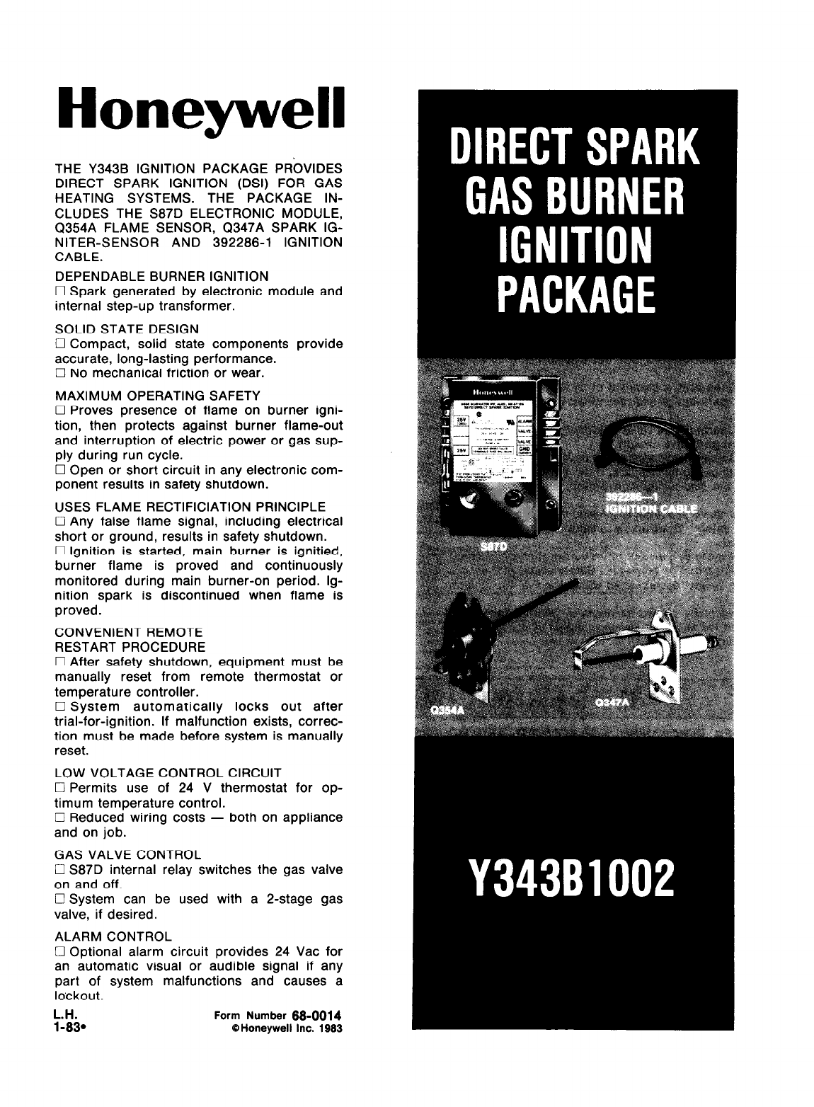
THE Y343B IGNITION PACKAGE PROVIDES
DIRECT SPARK IGNITION (DSI) FOR GAS
HEATING SYSTEMS. THE PACKAGE IN-
CLUDES THE S87D ELECTRONIC MODULE,
Q354A FLAME SENSOR, Q347A SPARK IG-
NITER-SENSOR AND 392286-l IGNITION
CABLE.
DEPENDABLE BURNER IGNITION
0 Spark generated by electronic module and
internal step-up transformer.
SOLID STATE DESIGN
17 Compact, solid state components provide
accurate, long-lasting performance.
0 No mechanical friction or wear.
MAXIMUM OPERATING SAFETY
0 Proves presence of flame on burner igni-
tion, then protects against burner flame-out
and interruption of electric power or gas sup-
ply during run cycle.
0 Open or short circuit in any electronic com-
ponent results in safety shutdown.
USES FLAME RECTIFICIATION PRINCIPLE
0 Any false flame signal, including electrical
short or ground, results in safety shutdown.
0 Ignition is started, main burner is ignitied,
burner flame is proved and continuously
monitored during main burner-on period. lg-
nition spark is discontinued when flame is
proved.
CONVENIENT REMOTE
RESTART PROCEDURE
0 After safety shutdown, equipment must be
manually reset from remote thermostat or
temperature controller.
0 System automatically locks out after
trial-for-ignition. If malfunction exists, correc-
tion must be made before system is manually
reset.
LOW VOLTAGE CONTROL CIRCUIT
0 Permits use of 24 V thermostat for op-
timum temperature control.
0 Reduced wiring costs - both on appliance
and on job.
GAS VALVE CONTROL
0 S87D internal relay switches the gas valve
on and off.
0 System can be used with a P-stage gas
valve, if desired.
ALARM CONTROL
El Optional alarm circuit provides 24 Vat for
an automatic visual or audible signal if any
part of system malfunctions and causes a
lockout.
L.H. Form Number 68-0014
1-630 0 Honeywell Inc. 1983
SPECIFICATIONS 4
The Y34381002 Direct Soark Gas Burner lanition
Package includes the S87D ilectronic Module, 6347A
Spark Igniter-Sensor, Q354A Flame Sensor and
392286-l Ignition Cable Assembly.
Other controls needed to complete the heating sys-
tem include a 24 V, DSI gas valve; 24 V thermostat;
24 V transformer and high temperature limit
controller.
S87D CONTROL MODULE
The S87D contains the electronic components of
the system and also serves as a central wiring panel
for the external controls. Powered by a 24 V trans-
former and controlled by a thermostat, it performs the
following functions.
1. Checks for a false flame condition (short to
ground). Module will lock out if false flame condition
is present.
2. Generates a potential of 15,000 V (open circuit)
at the spark-igniter stud for direct ignition of the main
burner.
3. Operates gas valve (internal relay controls inde-
pendent gas valve circuit).
4. Senses the presence of main burner flame and
discontinues ignition spark. If the burner fails to ignite
within the trial-for-ignition period, safety lockout oc-
curs.
5. If there is a loss of power, the system will shut
down safely. Start-up is initiated when power is
restored.
6. If there is a loss of main burner flame, the timed
trial-for-ignition is repeated. Safety shutdown occurs
if flame is not reestablished within the trial-for-ignition
period.
7. Normally closed contacts in internal relay may
be used for an alarm circuit to signal safety shutdown
of system.
ELECTRICAL RATINGS:
Voltage and Frequency-24 Vat, 60 Hz.
Current Rating-O.2 A plus gas valve current draw.
SAFETY LOCKOUT TIMING: 11 seconds.
FLAME FAILURE REIGNITION TIME: 0.8 seconds
maximum.
FLAME CURRENT SIGNAL REQUIRED: 1.5 YA dc
minimum.
SPARK GENERATOR VOLTAGE: 15,000 V open
circuit.
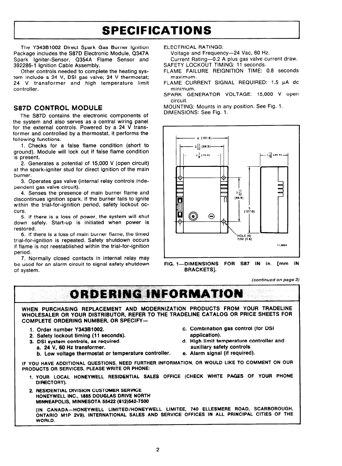
MOUNTING: Mounts in any position. See Fig. 1
DIMENSIONS: See Fig. 1.
FIG. 1-DIMENSIONS FOR S87 IN in. [mm IN
BRACKETS].
(continued on page 3)
WHEN PURCHASING REPLACEMENT AND MODERNIZATION PRODUCTS FROM YOUR TRADELINE
WHOLESALER OR YOUR DISTRIBUTOR, REFER TO THE TRADELINE CATALOG OR PRICE SHEETS FOR
COMPLETE ORDERING NUMBER, OR SPECIFY-
1. Order number Y343BlW2. c. Combination gas control (for DSI
2. Safety lockout timing (11 seconds). application).
3. DSI system controls, as required. d. High limit temperature controller and
a. 24 V, 60 Hz transformer. auxiliary safety controls.
b. Low voltage thermostat or temperature controller. e. Alarm signal (if required).
IF YOU HAVE ADDITIONAL QUESTIONS, NEED FURTHER INFORMATION, OR WOULD LIKE TO COMMENT ON OUR
PRODUCTS OR SERVICES, PLEASE WRITE OR PHONE:
1.
2.
YOUR LOCAL HONEYWELL RESIDENTIAL SALES OFFtCE (CHECK WHtTE PAGES OF YOUR PHONE
DIRECTORY).
RESIDENTIAL MVISKIN CUSTOMER SERWCE
HONEYWELL INC., 1995 DOUGLAS DRIVE NORTH
MINNEAPOLIS, MINNESOTA 55422 (612)542-7500
(IN CANADA-HONEYWELL LIMITED/HONEYWELL LIMITEE, 740 ELLESMERE ROAD, SCARBOROUGH,
ONTARIO MlP 2V9). INTERNATIONAL SALES AND SERVICE OFFICES IN ALL PRINCIPAL CITIES OF THE
WORLD.
2
AMBIENT TEMPERATURE RATING: Minus 40 F to
plus 175 F [minus 40 C to plus 79 C].
WIRING CONNECTIONS: l/4 in. [6.4 mm] male
quick-connect terminals, for all except ALARM ter-
minal. ALARM terminal, l/4 in. [6.4 mm] female
quick-connect. l/4 in. [6.4 mm] diameter stud
base for ignition cable.
REPLACEMENT PARTS: 3 A fuse.
Q347A SPARK IGNITER-SENSOR
The Q347A, powered by the S87D Electronic Mod-
ule, produces a spark for direct ignition of the main
burner. The Q347A consists of an inner electrode
(insulated rod) and an outer electrode (rigid, formed
strap bent at end to extend over tip of inner rod). Tip of
electrodes extend into path of main burner gas; arcing
across spark gap ignites gas.
SPARK GAP: 5/32 in. [4 mm].
LENGTH OF ELECTRODE ASSEMBLY (mounting sur-
face to tip): 2-318 in. [60.3 mm].
ELECTRODE MATERIAL: Kanthal.
MAXIMUM TEMPERATURE RATINGS: 1800 F [982 C]
at tip of electrode assembly, 1250 F [677 C] at
ceramic insulator.
WIRING CONNECTION: l/4 in. [8.4 mm] diameter base
stud for ignition cable.
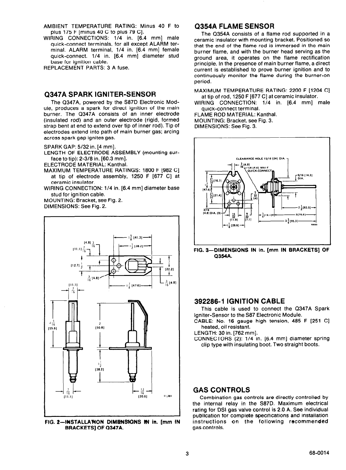
MOUNTING: Bracket, see Fig. 2.
DIMENSIONS: See Fig. 2.
FIG. 2-lUSTALLA’F(ON MMHBIONS NV in. [mm IN
BRACKETS] OF Q347A.
Q354A FLAME SENSOR
The Q354A consists of a flame rod supported in a
ceramic insulator with mounting bracket. Positioned so
that the end of the flame rod is immersed in the main
burner flame, and with the burner head serving as the
ground area, it operates on the flame rectification
principle. In the presence of main burner flame, a direct
current is established to prove burner ignition and to
continuously monitor the flame during the burner-on
period.
MAXIMUM TEMPERATURE RATING: 2200 F [1204 C]
at tip of rod, 1250 F [677 C] at ceramic insulator.
WIRING CONNECTION: l/4 in. [6.4 mm] male
quick-connect terminal.
FLAME ROD MATERIAL: Kanthal.
MOUNTING: Bracket, see Fig. 3.
DIMENSIONS: See Fig. 3.
FIG. 3-DIMENSIONS IN in. [mm IN BRACKETS] OF
Q354A.
392286-l IGNITION CABLE
This cable is used to connect the Q347A Spark
Igniter-Sensor to the S87 Electronic Module.
CABLE: No. 16 gauge high tension, 485 F [251 C]
heated, oil resistant.
LENGTH: 30 in. [762 mm].
CONNECTORS (2): l/4 in. [6.4 mm] diameter spring
clip type with insulating boot. Two straight boots.
GAS CONTROLS
Combination gas controls are directly controlled by
the internal relay in the S87D. Maximum electrical
rating for DSI gas valve control is 2.0 A. See individual
publication for complete specifications and installation
instructions in the following recommended
gas controls.
3 68-0014
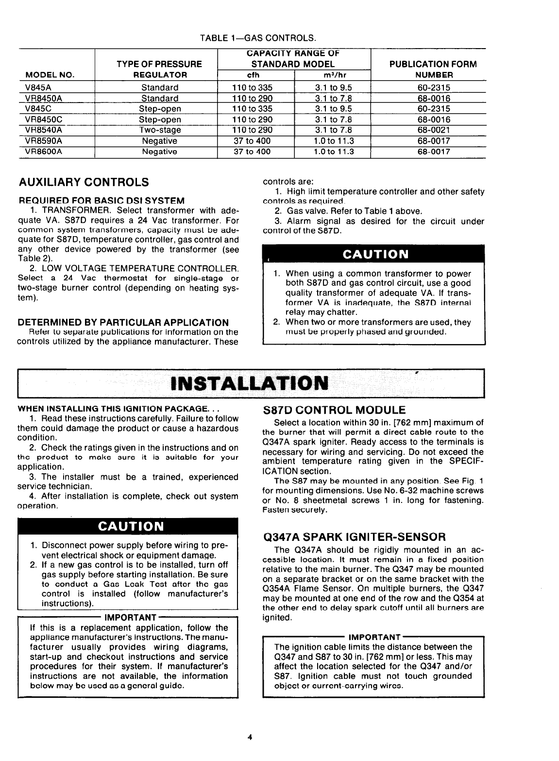
TABLE l-GAS CONTROLS.
MODEL NO.
V845A
VR8450A
V845C
VR8450C
VR8540A
VR8590A
VR8600A
TYPE OF PRESSURE
REGULATOR
Standard
Standard
Step-open
Step-open
Two-stage
Negative
Negative
CAPACITY RANGE OF
STANDARD MODEL
cfh mJ/hr
110to335 3.1 to 9.5
110to290 3.1 to 7.8
11oto335 3.1 to 9.5
110to290 3.1 to 7.8
110to290 3.1 to 7.8
37 to 400 1.oto 11.3
37 to 400 1.oto11.3
PUBLICATION FORM
NUMBER
60-2315
68-0016
60-2315
68-0016
68-0021
68-0017
68-0017
AUXILIARY CONTROLS
REQUIRED FOR BASIC DSI SYSTEM
1. TRANSFORMER. Select transformer with ade-
quate VA. S87D requires a 24 Vat transformer. For
common system transformers, capacity must be ade-
quate for S87D, temperature controller, gas control and
any other device powered by the transformer (see
Table 2).
2. LOW VOLTAGE TEMPERATURE CONTROLLER.
Select a 24 Vat thermostat for single-stage or
two-stage burner control (depending on heating sys-
tem).
DETERMINED BY PARTICULAR APPLlCATiON
Refer to separate publications for information on the
controls utilized by the appliance manufacturer. These
controls are:
1. High limit temperature controller and other safety
controls as required.
2. Gas valve. Refer to Table 1 above.
3. Alarm signal as desired for the circuit under
control of the S87D.
1. When using a common transformer to power
both S87D and gas control circuit, use a good
quality transformer of adequate VA. If trans-
former VA is inadequate, the S87D internal
relay may chatter.
2. When two or more transformers are used, they
must be properly phased and grounded.
;NSlAL~~lON * I
WHEN INSTALLING THIS IGNITION PACKAGE. . .
1. Read these instructions carefully. Failure to follow
them could damage the product or cause a hazardous
condition.
2. Check the ratings given in the instructions and on
the product to make sure it is suitable for your
application.
3. The installer must be a trained, experienced
service technician.
4. After installation is complete, check out system
operation.
1. Disconnect power supply before wiring to pre-
vent electrical shock or equipment damage.
2. If a new gas control is to be installed, turn off
gas supply before starting installation. Be sure
to conduct a Gas Leak Test after the gas
control is installed (follow manufacturer’s
instructions).
IMPORTANT
If this is a replacement application, follow the
appliance manufacturer’s instructions. The manu-
facturer usually provides wiring diagrams,
start-up and checkout instructions and service
procedures for their system. If manufacturer’s
instructions are not available, the information
below may be used as a general guide.
S87D CONTROL MODULE
Select a location within 30 in. [762 mm] maximum of
the burner that will permit a direct cable route to the
Q347A spark igniter. Ready access to the terminals is
necessary for wiring and servicing. Do not exceed the
ambient temperature rating given in the SPECIF-
ICATION section.
The S87 may be mounted in any position. See Fig. 1
for mounting dimensions. Use No. 6-32 machine screws
or No. 8 sheetmetal screws 1 in. long for fastening.
Fasten securely.
Q347A SPARK IGNITER-SENSOR
The Q347A should be rigidly mounted in an ac-
cessible location. It must remain in a fixed position
relative to the main burner. The CT347 may be mounted
on a separate bracket or on the same bracket with the
Q354A Flame Sensor. On multiple burners, the Q347
may be mounted at one end of the row and the Q354 at
the other end to delay spark cutoff until all burners are
ignited.
Q347 and S87 to 30 in. [762 mm] or less. This may
affect the location selected for the 0347 and/or
S87. Ignition cable must not touch grounded
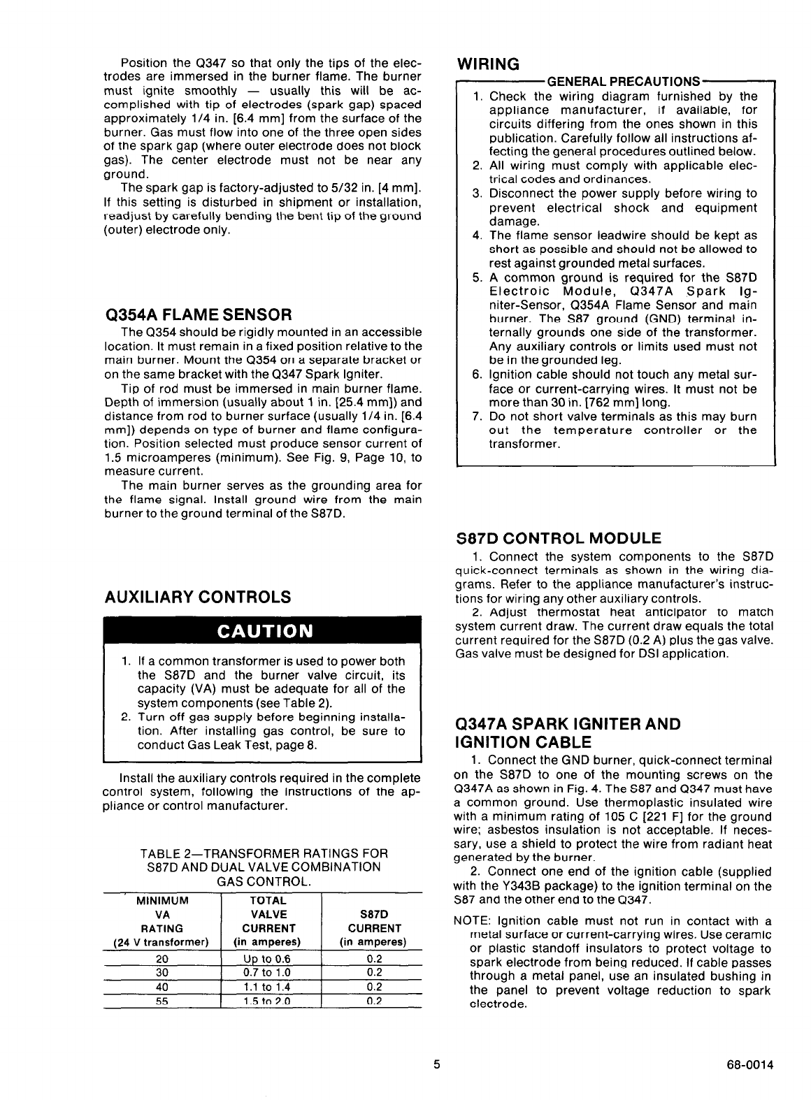
Position the Q347 so that only the tips of the elec-
trodes are immersed in the burner flame. The burner
must ignite smoothly - usually this will be ac-
complished with tip of electrodes (spark gap) spaced
approximately l/4 in. [6.4 mm] from the surface of the
burner. Gas must flow into one of the three open sides
of the spark gap (where outer electrode does not block
gas). The center electrode must not be near any
ground.
The spark gap is factory-adjusted to 5/32 in. [4 mm].
If this setting is disturbed in shipment or installation,
readjust by carefully bending the bent tip of the ground
(outer) electrode only.
Q354A FLAME SENSOR
The Q354 should be rigidly mounted in an accessible
location. It must remain in a fixed position relative to the
main burner. Mount the Q354 on a separate bracket or
on the same bracket with the Q347 Spark Igniter.
Tip of rod must be immersed in main burner flame.
Depth of immersion (usually about 1 in. [25.4 mm]) and
distance from rod to burner surface (usually l/4 in. [6.4
mm]) depends on type of burner and flame configura-
tion. Position selected must produce sensor current of
1.5 microamperes (minimum). See Fig. 9, Page 10, to
measure current.
The main burner serves as the grounding area for
the flame signal. Install ground wire from the main
burner to the ground terminal of the S87D.
AUXILIARY CONTROLS
1. If a common transformer is used to power both
the S87D and the burner valve circuit, its
capacity (VA) must be adequate for all of the
system components (see Table 2).
2. Turn off gas supply before beginning installa-
tion. After installing gas control, be sure to
conduct Gas Leak Test, page 8.
Install the auxiliary controls required in the complete
control system, following the instructions of the ap-
pliance or control manufacturer.
TABLE 2-TRANSFORMER RATINGS FOR
S87D AND DUAL VALVE COMBINATION
GAS CONTROL.
MINIMUM TOTAL
VA VALVE
RATING CURRENT
(24 V transformer) (in amperes)
S87D
CURRENT
(in amperes)
20 Up to 0.6 0.2
30 0.7 to 1 .o 0.2
40 1.1 to 1.4 0.2
55 1.5 to 2.0 0.2
WIRING
GENERAL PRECAUTIONS’-f
1.
2.
3.
4.
5.
6.
7.
Check the wiring diagram furnished by the
appliance manufacturer, if available, for
circuits differing from the ones shown in this
publication. Carefully follow all instructions af-
fecting the general procedures outlined below.
All wiring must comply with applicable elec-
trical codes and ordinances.
Disconnect the power supply before wiring to
prevent electrical shock and equipment
damage.
The flame sensor leadwire should be kept as
short as possible and should not be allowed to
rest against grounded metal surfaces.
A common ground is required for the S87D
Electroic Module, Q347A Spark lg-
niter-Sensor, Q354A Flame Sensor and main
burner. The S87 ground (GND) terminal in-
ternally grounds one side of the transformer.
Any auxiliary controls or limits used must not
be in the grounded leg.
Ignition cable should not touch any metal sur-
face or current-carrying wires. It must not be
more than 30 in. 1762 mm] long.
Do not short valve terminals as this may burn
out the temperature controller or the
transformer.
S87D CONTROL MODULE
1. Connect the system components to the S87D
quick-connect terminals as shown in the wiring dia-
grams. Refer to the appliance manufacturer’s instruc-
tions for wiring any other auxiliary controls.
2. Adjust thermostat heat anticipator to match
system current draw. The current draw equals the total
current required for the S87D (0.2 A) plus the gas valve.
Gas valve must be designed for DSI application.
Q347A SPARK IGNITER AND
IGNITION CABLE
1. Connect the GND burner, quick-connect terminal
on the S87D to one of the mounting screws on the
Q347A as shown in Fig. 4. The S87 and Q347 must have
a common ground. Use thermoplastic insulated wire
with a minimum rating of 105 C [221 F] for the ground
wire; asbestos insulation is not acceptable. If neces-
sary, use a shield to protect the wire from radiant heat
generated by the burner.
2. Connect one end of the ignition cable (supplied
with the Y343B package) to the ignition terminal on the
S87 and the other end to the Q347.
NOTE: Ignition cable must not run in contact with a
metal surface or current-carrying wires. Use ceramic
or plastic standoff insulators to protect voltage to
spark electrode from being reduced. If cable passes
through a metal panel, use an insulated bushing in
the panel to prevent voltage reduction to spark
electrode.
5 68-0014
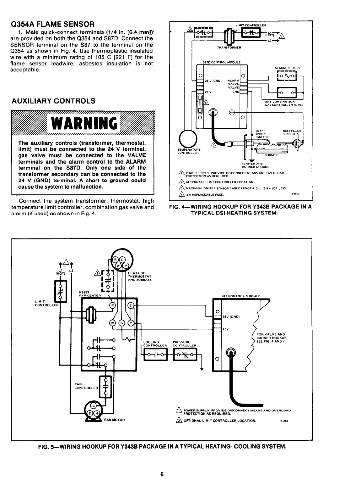
Q354A FLAME SENSOR
1. Mate quick-connect terminals (l/4 in. [6.4 mmf)’
are provided on both the Q354 and S87D. Connect the
SENSOR terminal on the 587 to the terminal on the
Q354 as shown in Fig. 4. Use thermoplastic insulated
wire with a minimum rating of 105 C [221 F] for the
flame sensor leadwire; asbestos insulation is not
acceptable.
AUXILIARY CONTROLS
The auxiliary controls (transformer, thermostat,
limit) must be connected to the 24 V terminal,
gas valve must be connected to the VALVE
terminals and the alarm control to the ALARM
terminal on the S87D. Only one side of the
transformer secondary can be connected to the
24 V (GND) terminal. A short to ground could
cause the system to malfunction.
Connect the system transformer, thermostat, high
temperature limit controller, combination gas valve and
alarm (if used) as shown in Fig. 4.
FIG. 4-WIRING HOOKUP FOR Y343B PACKAGE IN A
TYPICAL DSI HEATING SYSTEM.
IOTOR
PRESSURE
FOR VALVE AN0
WRNER HOOKUP.
SEE FIG. 4 AND 7.
n
1 POWER SUPPLY. PROVIDE 01SCONNECT MEANS AND OVERLOAD
PROTECTlON AS REQVIRED.
n 2 OPTIONAL LlMlT CONTROLLER l_OCATION. I I .3*1
FIG. 6-WIRING HOOKUP FOR Y343B PACKAGE IN A TYPICAL HEATING- COOLING SYSTEM.
6
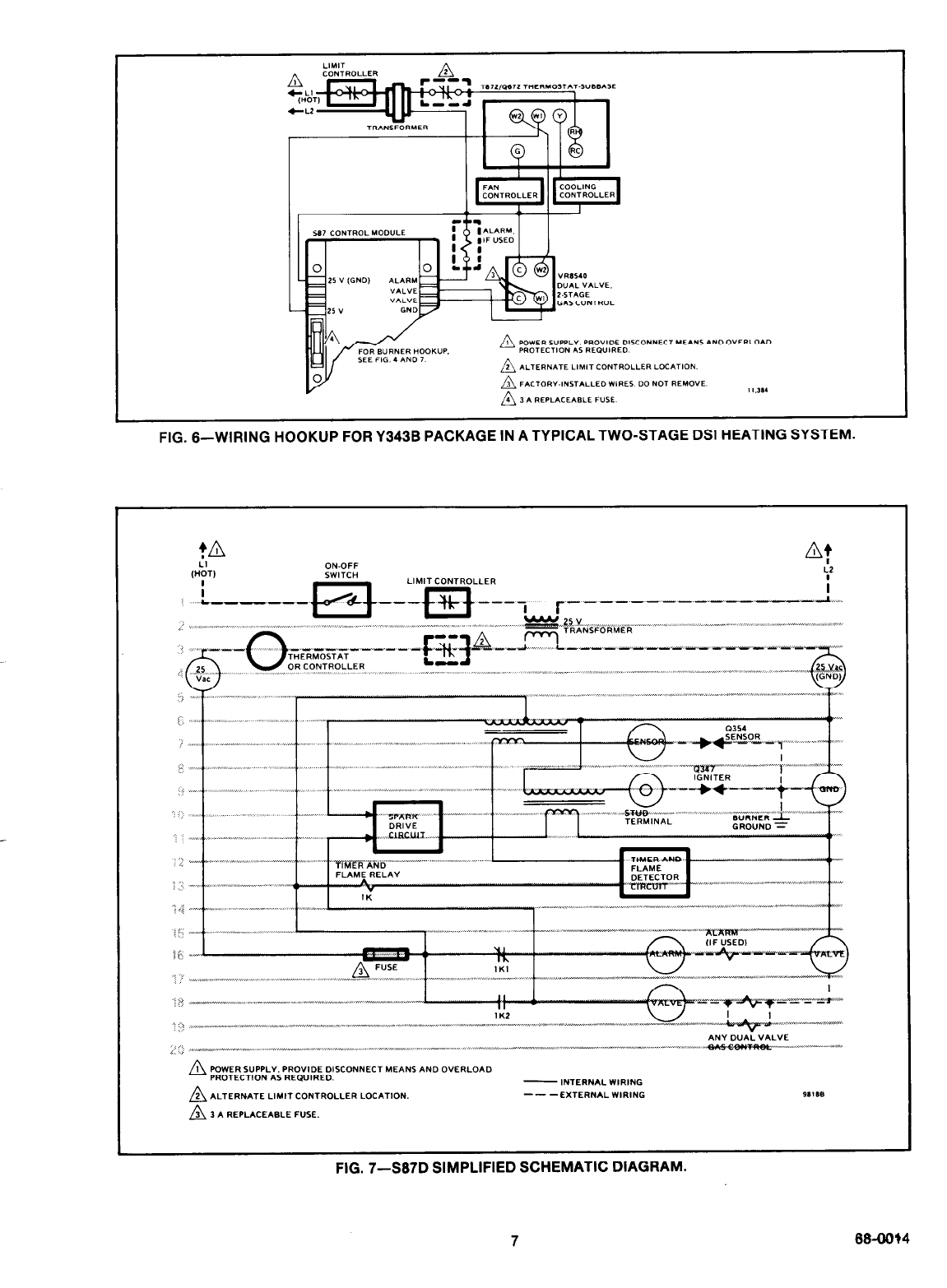
FIG. B-WIRING HOOKUP FOR Y343B PACKAGE IN A TYPICAL TWO-STAGE DSI HEATING SYSTEM.
,, “,, ~ ,,, I ,,,, ,.
,.., :. II ,, ,
.xI,. j ,,,. .,
_ ,-, CI ,x .,,, ., . .x
_^.,” ~.. ,, ,IX ^ _,
FIG. 7-S67D SIMPLIFIED SCHEMATIC DIAGRAM.
7 66-00?4
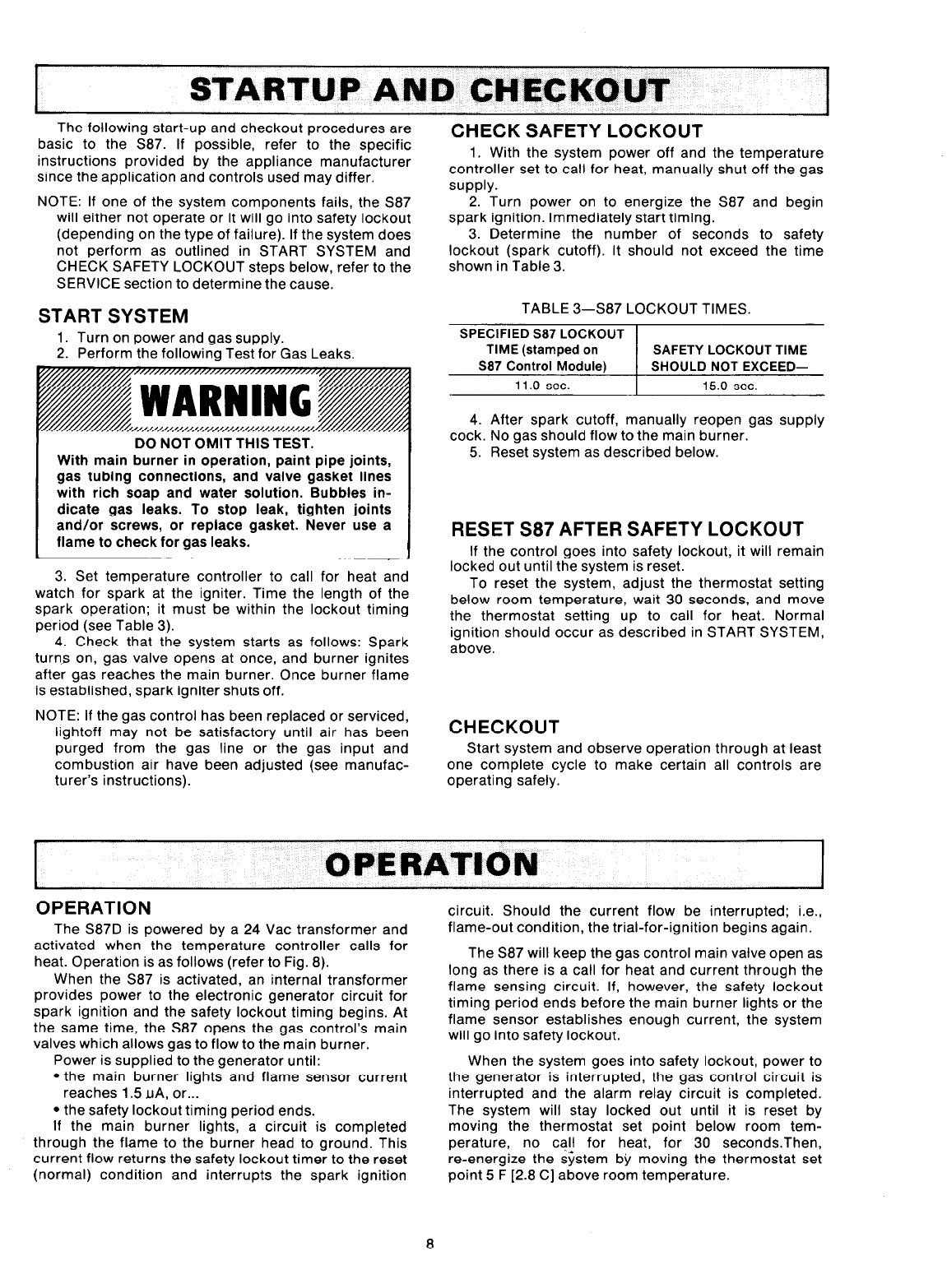
STARTUP AND CHECKOUT
The following start-up and checkout procedures are
basic to the S87. If possible, refer to the specific
instructions provided by the appliance manufacturer
since the application and controls used may differ.
NOTE: If one of the system components fails, the S87
will either not operate or it will go into safety lockout
(depending on the type of failure). If the system does
not perform as outlined in START SYSTEM and
CHECK SAFETY LOCKOUT steps below, refer to the
SERVICE section to determine the cause.
START SYSTEM
1. Turn on power and gas supply.
2. Perform the following Test for Gas Leaks.
I DO NOT OMIT THIS TEST.
With main burner in operation, paint pipe joints,
gas tubing connections, and valve gasket lines
with rich soap and water solution. Bubbles in-
dicate gas leaks. To stop leak, tighten joints
and/or screws, or replace gasket. Never use a
flame to check for gas leaks.
1 I
3. Set temperature controller to call for heat and
watch for spark at the igniter. Time the length of the
spark operation; it must be within the lockout timing
period (see Table 3).
4. Check that the system starts as follows: Spark
turns on, gas valve opens at once, and burner ignites
after gas reaches the main burner. Once burner flame
is established, spark igniter shuts off.
NOTE: If the gas control has been replaced or serviced,
lightoff may not be satisfactory until air has been
purged from the gas line or the gas input and
combustion air have been adjusted (see manufac-
turer’s instructions).
CHECK SAFETY LOCKOUT
1. With the system power off and the temperature
controller set to call for heat, manually shut off the gas
supply.
2. Turn power on to energize the S87 and begin
spark ignition. Immediately start timing.
3. Determine the number of seconds to safety
lockout (spark cutoff). It should not exceed the time
shown in Table 3.
TABLE 3-S87 LOCKOUT TIMES.
SPECIFIED S87 LOCKOUT
TIME (stamped on SAFETY LOCKOUT TIME
S87 Control Module) SHOULD NOT EXCEED-
11 .O sec. 15.0 sec.
4. After spark cutoff, manually reopen gas supply
cock. No gas should flow to the main burner.
5. Reset system as described below.
RESET S87 AFTER SAFETY LOCKOUT
If the control goes into safety lockout, it will remain
locked out until the system is reset.
To reset the system, adjust the thermostat setting
below room temperature, wait 30 seconds, and move
the thermostat setting up to call for heat. Normal
ignition should occur as described in START SYSTEM,
above.
CHECKOUT
Start system and observe operation through at least
one complete cycle to make certain all controls are
operating safely.
OPERATION
OPERATION
The S87D is powered by a 24 Vat transformer and
activated when the temperature controller calls for
heat. Operation is as follows (refer to Fig. 8).
When the S87 is activated, an internal transformer
provides power to the electronic generator circuit for
spark ignition and the safety lockout timing begins. At
the same time, the S87 opens the gas control’s main
valves which allows gas to flow to the main burner.
Power is supplied to the generator until:
l the main burner lights and flame sensor current
reaches 1.5 uA, or...
l the safety lockout timing period ends.
If the main burner lights, a circuit is completed
through the flame to the burner head to ground. This
current flow returns the safety lockout timer to the reset
(normal) condition and interrupts the spark ignition
circuit. Should the current flow be interrupted; i.e.,
flame-out condition, the trial-for-ignition begins again.
The S87 will keep the gas control main valve open as
long as there is a call for heat and current through the
flame sensing circuit. If, however, the safety lockout
timing period ends before the main burner lights or the
flame sensor establishes enough current, the system
will go into safety lockout.
When the system goes into safety lockout, power to
the generator is interrupted, the gas control circuit is
interrupted and the alarm relay circuit is completed.
The system will stay locked out until it is reset by
moving the thermostat set point below room tem-
perature, no call for heat, for 30 secondsThen,
re-energize the system by moving the thermostat set
point 5 F [2.8 C] above room temperature.
8
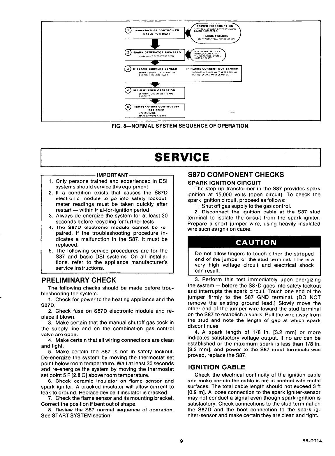
FIG. a--NORMAL SYSTEM SEQUENCE OF OPERATION.
SERVICE
l
Only persons trained and experienced in DSI
systems should service this equipment.
If a condition exists that causes the S87D
electronic module to go into safety lockout,
meter readings must be taken quickly after
restart - within trial-for-ignition period.
Always de-energize the system for at least 30
seconds before recycling for further tests.
The S87D electronic module cannot be re-
paired. If the troubleshooting procedure in-
dicates a malfunction in the S87, it must be
replaced.
The following service procedures are for the
S87 and basic DSI systems. On all installa-
tions, refer to the appliance manufacturer’s
service instructions.
1.
2.
3.
4.
5.
IMPORTANTLY
PRELIMINARY CHECK
The following checks should be made before trou-
bleshooting the system.
1. Check for power to the heating appliance and the
S87D.
2. Check fuse on S87D electronic module and re-
place if blown.
3. Make certain that the manual shutoff gas cock in
the supply line and on the combination gas control
valve are open.
4. Make certain that all wiring connections are clean
and tight.
5. Make certain the S87 is not in safety lockout.
De-energize the system by moving the thermostat set
point below room temperature. Wait at least 30 seconds
and re-energize the system by moving the thermostat
set point 5 F [2.8 C] above room temperature.
6. Check ceramic insulator on flame sensor and
spark igniter. A cracked insulator will allow current to
leak to ground. Replace device if insulator is cracked.
7. Check the flame sensor and its mounting bracket.
Correct the position if bent out of shape.
8. Review the S87 normal sequence of operation.
See START SYSTEM section.
S87D COMPONENT CHECKS
SPARK IGNITION CIRCUIT
The step-up transformer in the S87 provides spark
ignition at 15,000 volts (open circuit). To check the
spark ignition circuit, proceed as follows:
1. Shut off gas supply to the gas control.
2. Disconnect the ignition cable at the S87 stud
terminal to isolate the circuit from the spark-igniter.
Prepare a short jumper wire, using heavily insulated
wire such as ignition cable.
very high voltage circuit and electrical shock
3. Perform this test immediately upon energizing
the system -- before the S87D goes into safety lockout
and interrupts the spark circuit. Touch one end of the
jumper firmly to the 587 GND terminal. (DO NOT
remove the existing ground lead.) Slowly move the
other end of the jumper wire toward the stud terminal
on the S87 to establish a spark. Pull the wire away from
the stud and note the length of gap at which spark
discontinues.
4. A spark length of l/8 in. [3.2 mm] or more
indicates satisfactory voltage output. If no arc can be
established or the maximum spark is less than l/8 in.
[3.2 mm], and power to the S87 input terminals was
proved, replace the S87.
IGNITION CABLE
Check the electrical continuity of the ignition cable
and make certain the cable is not in contact with metal
surfaces. The total cable length should not exceed 3 ft
[0.9 m]. A loose connection to the spark igniter-sensor
may not conduct a signal even though spark ignition is
satisfactory. Check connections to the stud terminal on
the S87D and the boot connection to the spark ig-
niter-sensor and make certain they are clean and tight.
9 68-0014
GROUNDING CONNECTIONS
A common ground is required for the burner, spark
igniter-sensor mounting bracket and the GND terminal
of the 587. If ground is poor or erratic, safety shutdown
may occur occasionally even though operation is nor-
mal at time of checkout. Therefore, if nuisance shut-
downs have been reported, be sure to check ground
connections.
Electrical ground connections at the spark ig-
niter-sensor and the S87D must be clean and tight. If
leadwire is damaged or deteriorated, use only No. 14 or
No. 18 gauge, moisture-resistant, thermoplastic in-
sulated wire with 105 C [221 F] minimum rating as
replacement.
FLAME SENSOR CIRCUIT
The S87D provides ac power to the flame sensor
which the burner flame rectifies to direct current. If the
flame signal back to the S87 is not at least 1.5 uA dc, the
system will lock out.
The output of the flame sensing circuit can be
checked directly on the S87D. Check the flame sensing
circuit as follows.
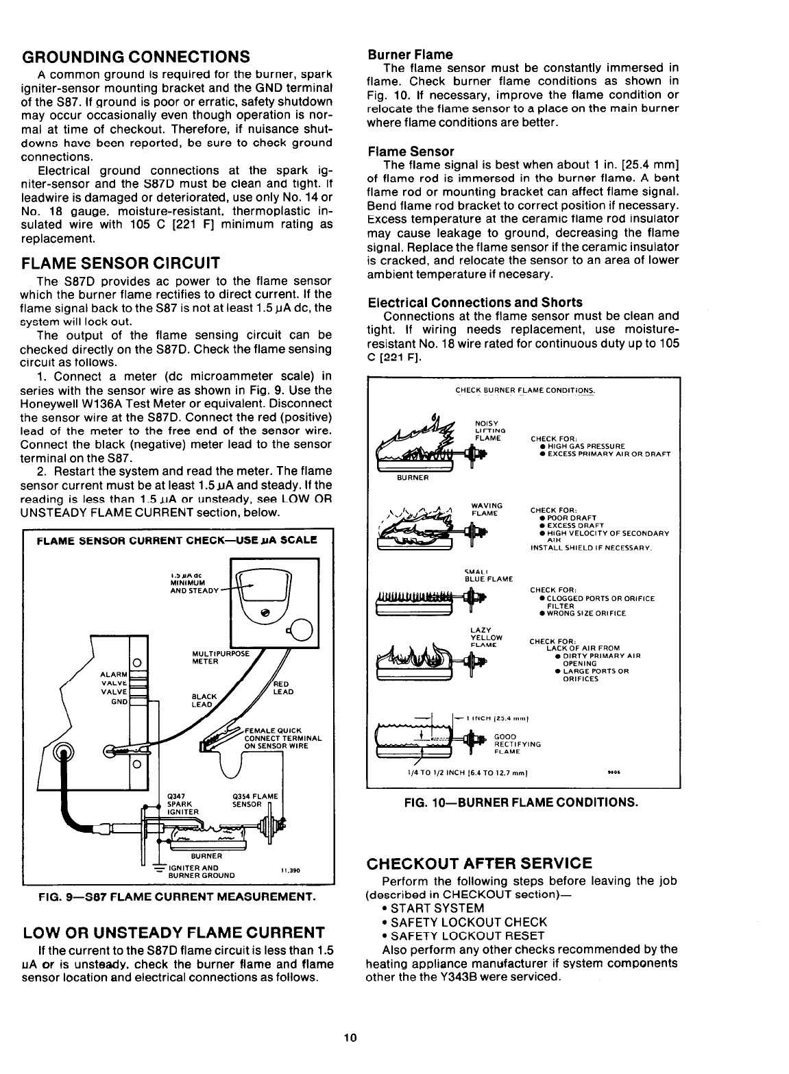
1. Connect a meter (dc microammeter scale) in
series with the sensor wire as shown in Fig. 9. Use the
Honeywell Wl36A Test Meter or equivalent. Disconnect
the sensor wire at the S87D. Connect the red (positive)
lead of the meter to the free end of the sensor wire.
Connect the black (negative) meter lead to the sensor
terminal on the S87.
2. Restart the system and read the meter. The flame
sensor current must be at least 1.5uA and steady. If the
reading is less than 1.5 uA or unsteady, see LOW OR
UNSTEADY FLAME CURRENT section, below.
FLAME SENSOR CURRENT CHECK-USE YA SCALE
FIG. g-S87 FLAME CURRENT MEASUREMENT.
LOW OR UNSTEADY FLAME CURRENT
If the current to the S87D flame circuit is less than 1.5
AIA or is unsteady, check the burner flame and flame
sensor location and electrical connections as follows.
Burner Flame
The flame sensor must be constantly immersed in
flame. Check burner flame conditions as shown in
Fig. 10. If necessary, improve the flame condition or
relocate the flame sensor to a place on the main burner
where flame conditions are better.
Flame Sensor
The flame signal is best when about 1 in. [25.4 mm]
of flame rod is immersed in the burner flame. A bent
flame rod or mounting bracket can affect flame signal.
Bend flame rod bracket to correct position if necessary.
Excess temperature at the ceramic flame rod insulator
may cause leakage to ground, decreasing the flame
signal. Replace the flame sensor if the ceramic insulator
is cracked, and relocate the sensor to an area of lower
ambient temperature if necesary.
Electrical Connections and Shorts
Connections at the flame sensor must be clean and
tight. If wiring needs replacement, use moisture-
resistant No. 18 wire rated for continuous dutv up to 105
_
C [221 F].
FIG. lo--BURNER FLAME CONDITIONS.
CHECKOUT AFTER SERVICE
Perform the following steps before leaving the job
(described in CHECKOUT section)-
* START SYSTEM
l SAFETY LOCKOUT CHECK
. SAFETY LOCKOUT RESET
Also perform any other checks recommended by the
heating appliance manufacturer if system components
other the the Y343B were serviced.
10
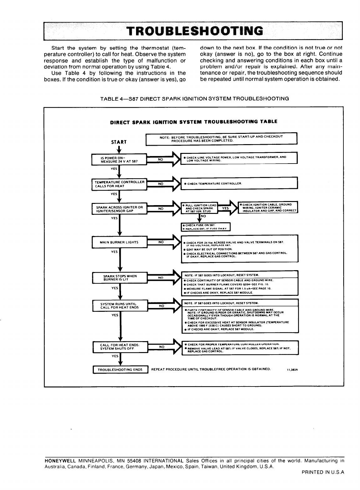
t TROUBLESHOOTING .
Start the system by setting the thermostat (tem- down to the next box. If the condition is not true or not
perature controller) to call for heat. Observe the system okay (answer is no), go to the box at right. Continue
response and establish the type of malfunction or checking and answering conditions in each box until a
deviation from normal operation by using Table 4. problem and/or repair is explained. After any main-
Use Table 4 by following the instructions in the tenance or repair, the troubleshooting sequence should
boxes. If the condition is true or okay (answer is yes), go be repeated until normal system operation is obtained.
TABLE 4-537 DIRECT SPARK IGNITION SYSTEM TROUBLESHOOTING
DIRECT SPARK IGNITIDN SYSTEM TROUBLESHOOTING TABLE
I NOTE: BEFORE TRO”BLE*HOOTING. BE S”RE START-UP AND CHECKOUT
START PROCEDURE HAS BEEN COYPLETEO. I
I TRO”BLESHOOTlNG ENDS 1 REPEAT PROCEDURE “NTlLTROUBLEFREE OPERATION IS OBTAINED. 1 I .1e.m
HONEYWELL MINNEAPOLIS, MN 55408 INTERNATIONAL Sales Offices in all principal cities of the world. Manufacturing in
Australia. Canada, Flnland, France, Germany, Japan,.Mexico. Spain, Taiwan, United Kingdom, U.S.A.
PRINTED IN U.S.A
