Honeywell IM14 IM14 User Manual 935 040
Honeywell International Inc IM14 935 040
UserManual.wiki
>
Honeywell
>
IM14 User Manual
>
User Manual
Contents
1.
user manual
2.
User Manual
User Manual
Navigation menu
Upload a User Manual
Namespaces
Wiki Guide
HTML
PDF
Info
Views
User Manual
Discussion / Help
Navigation

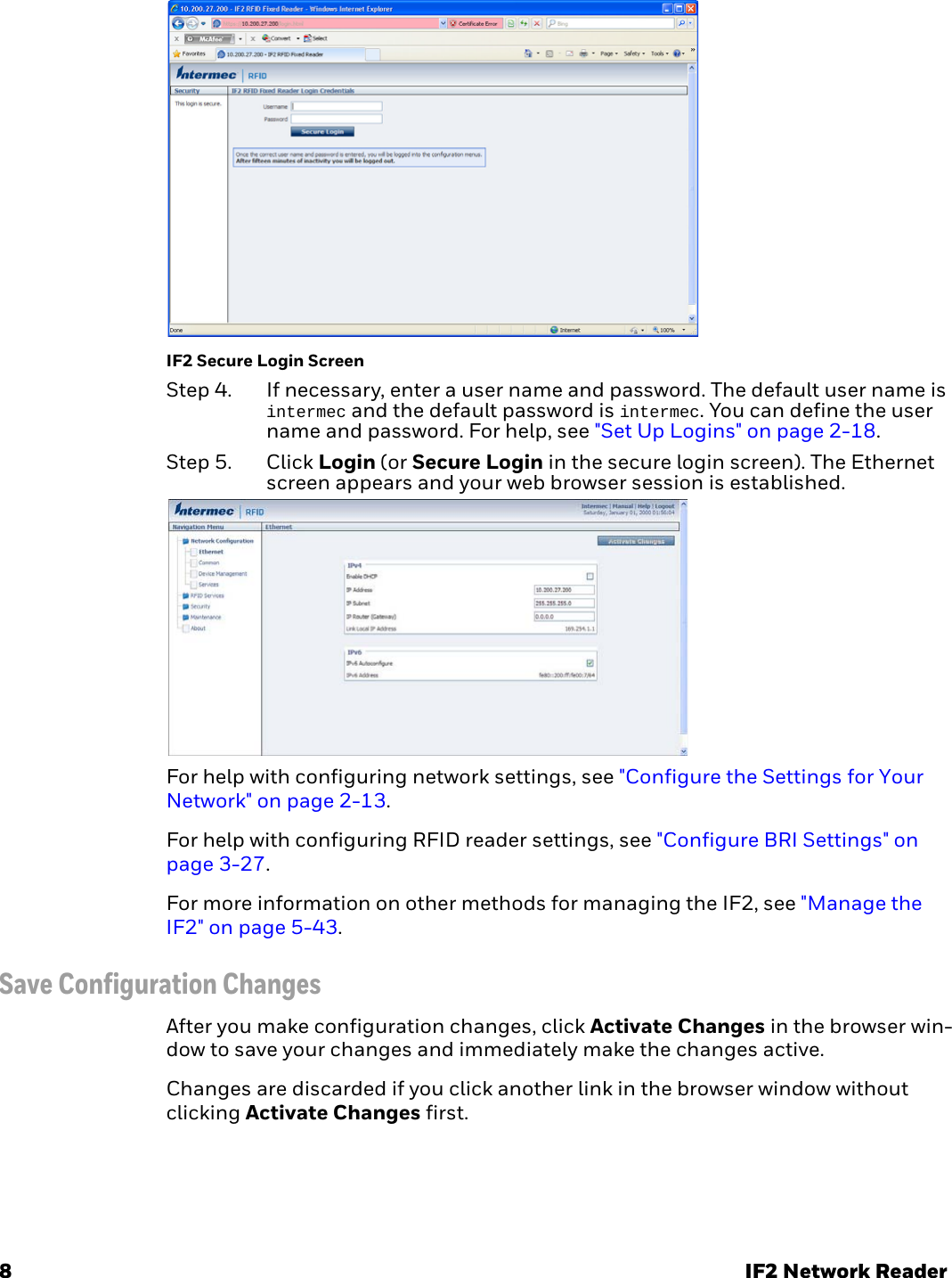
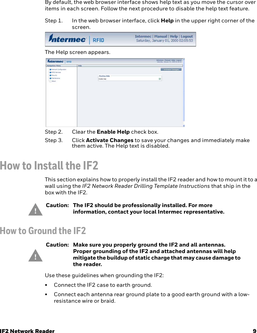
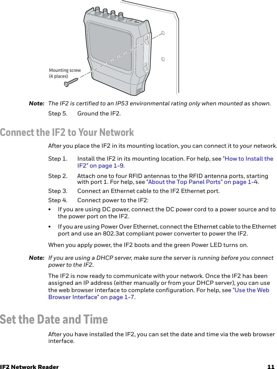

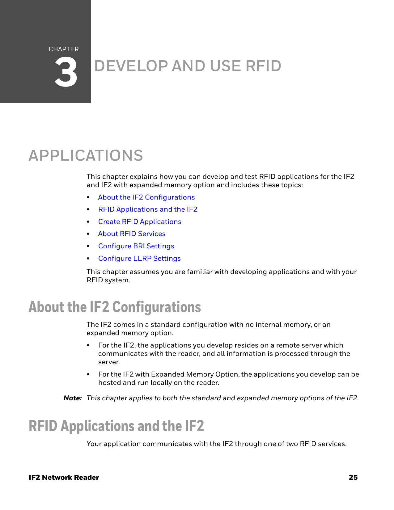
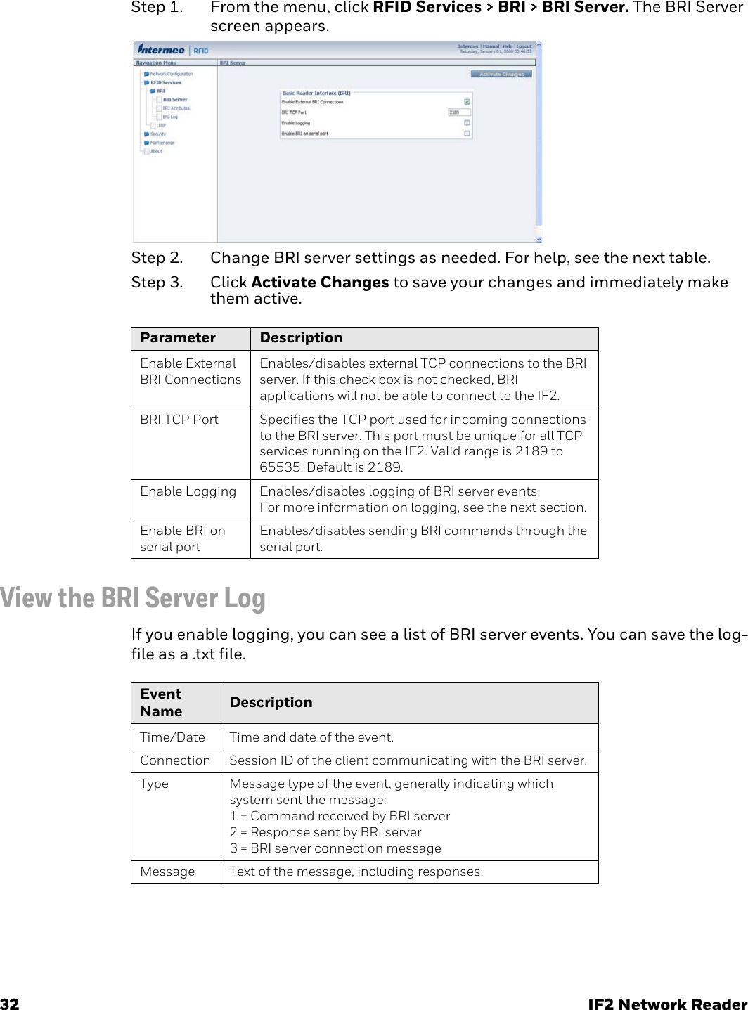
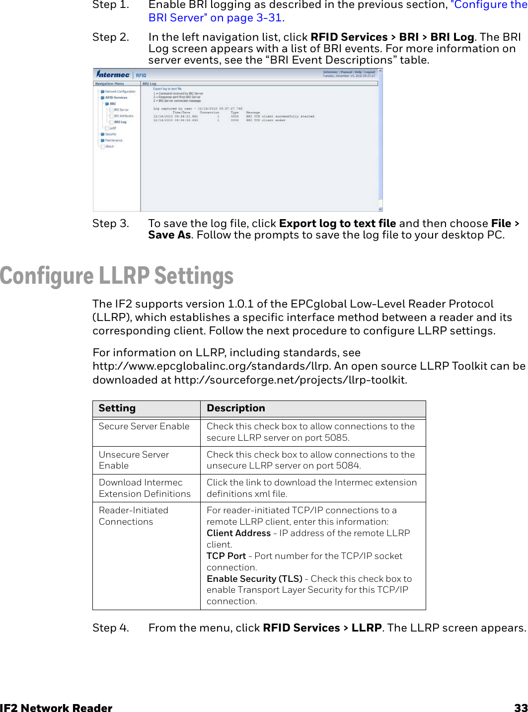
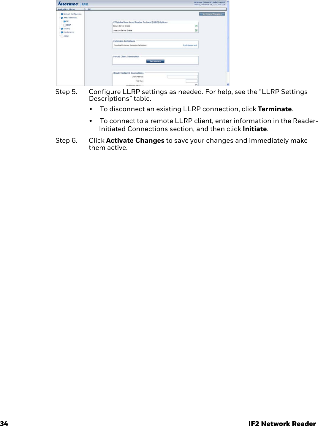


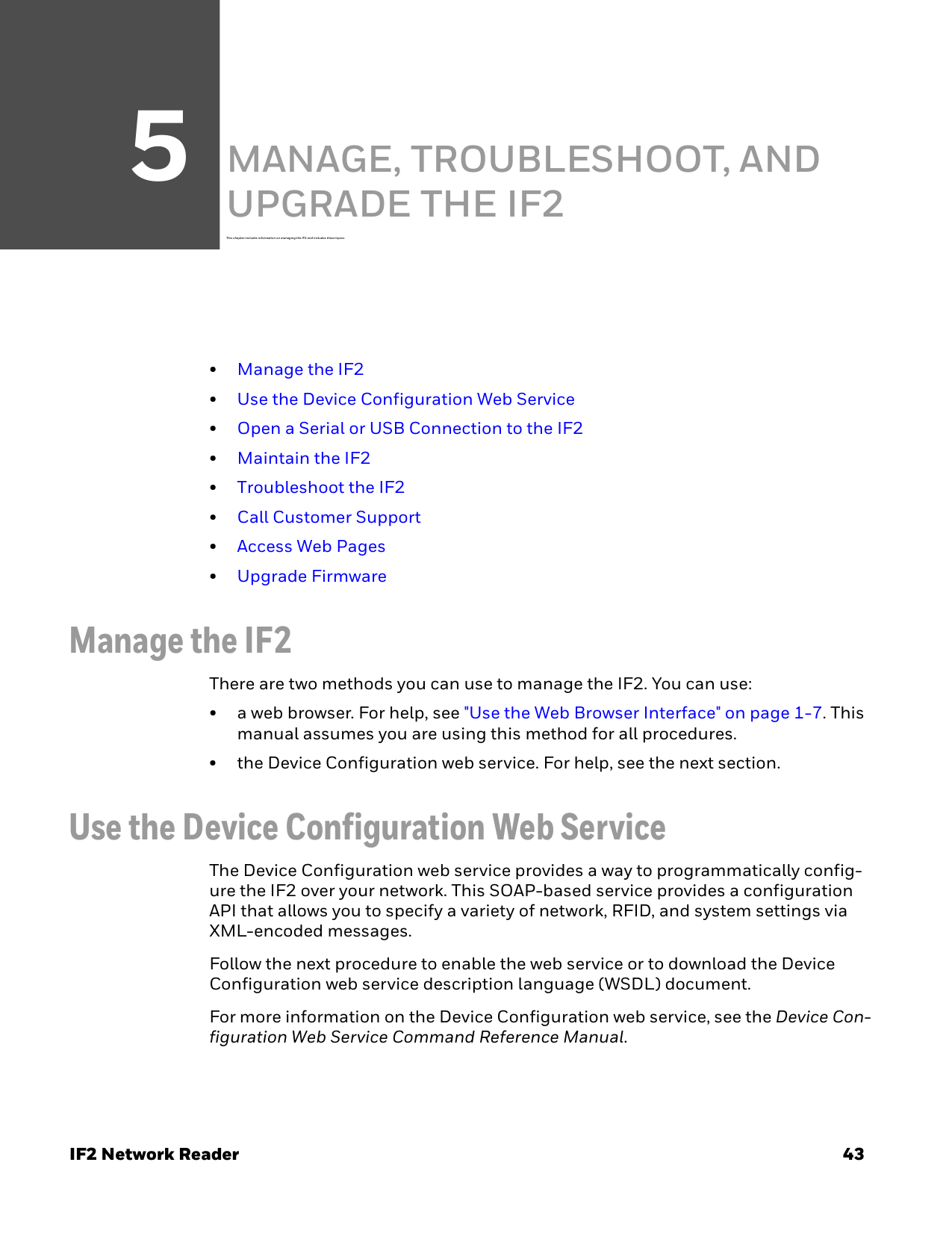
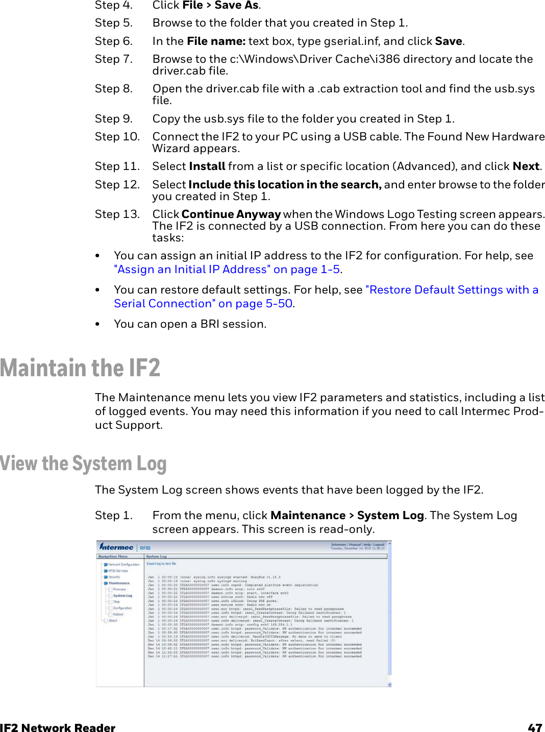
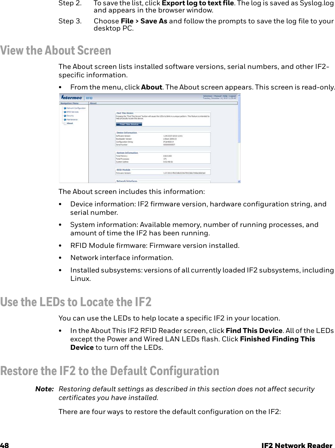
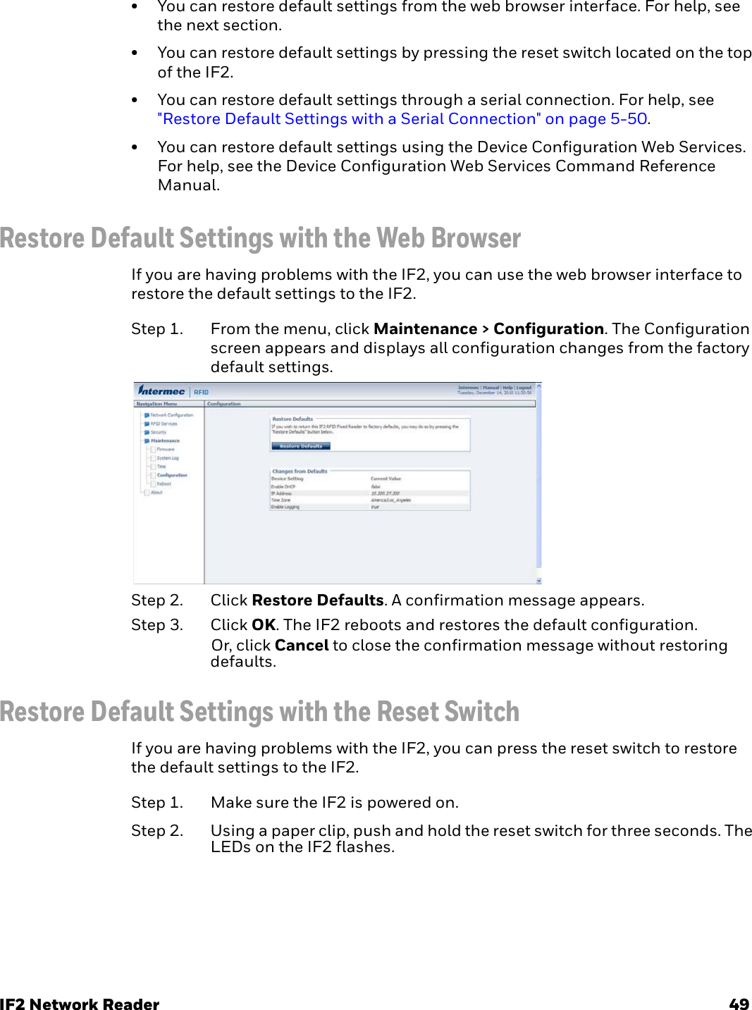
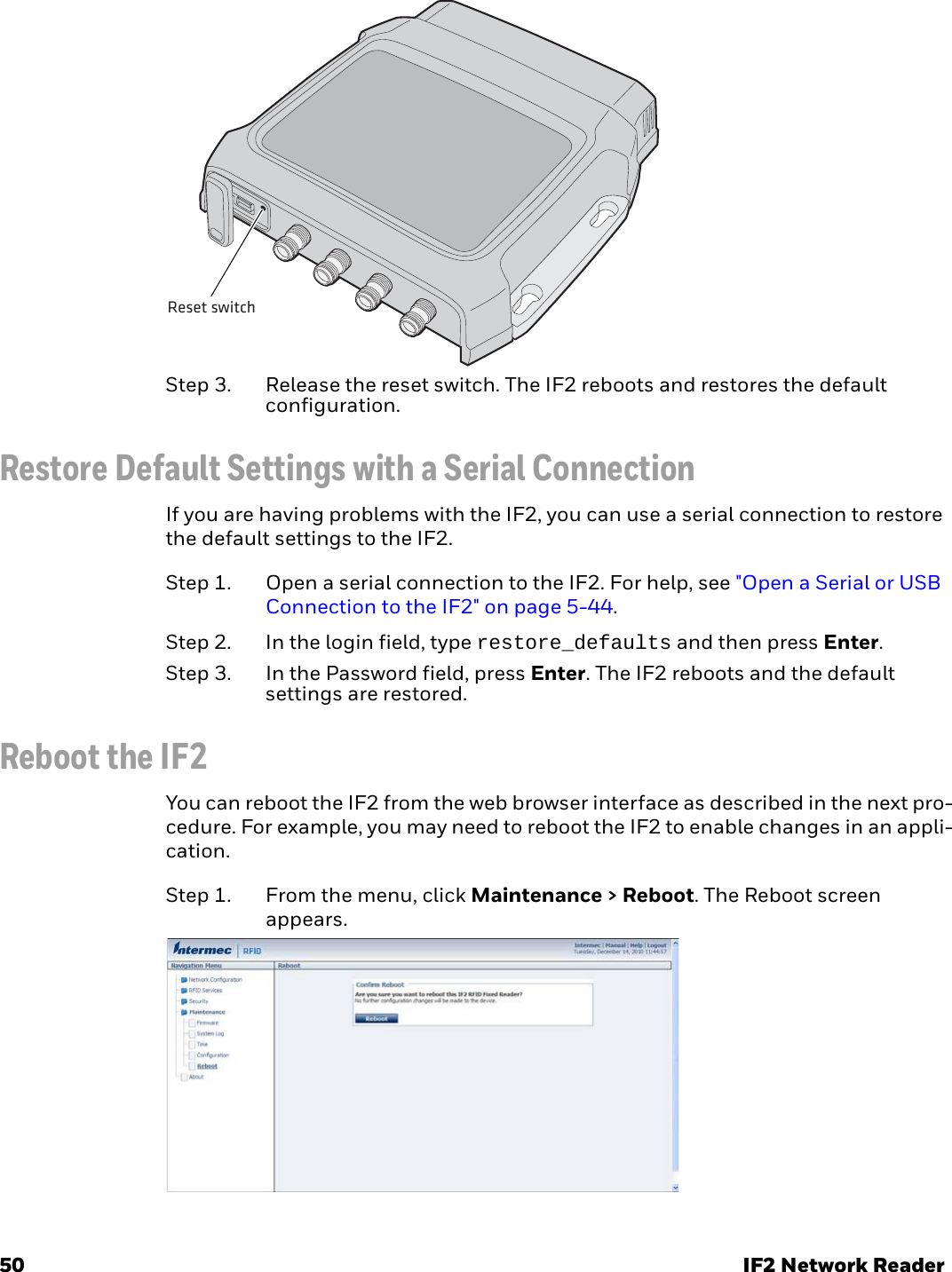
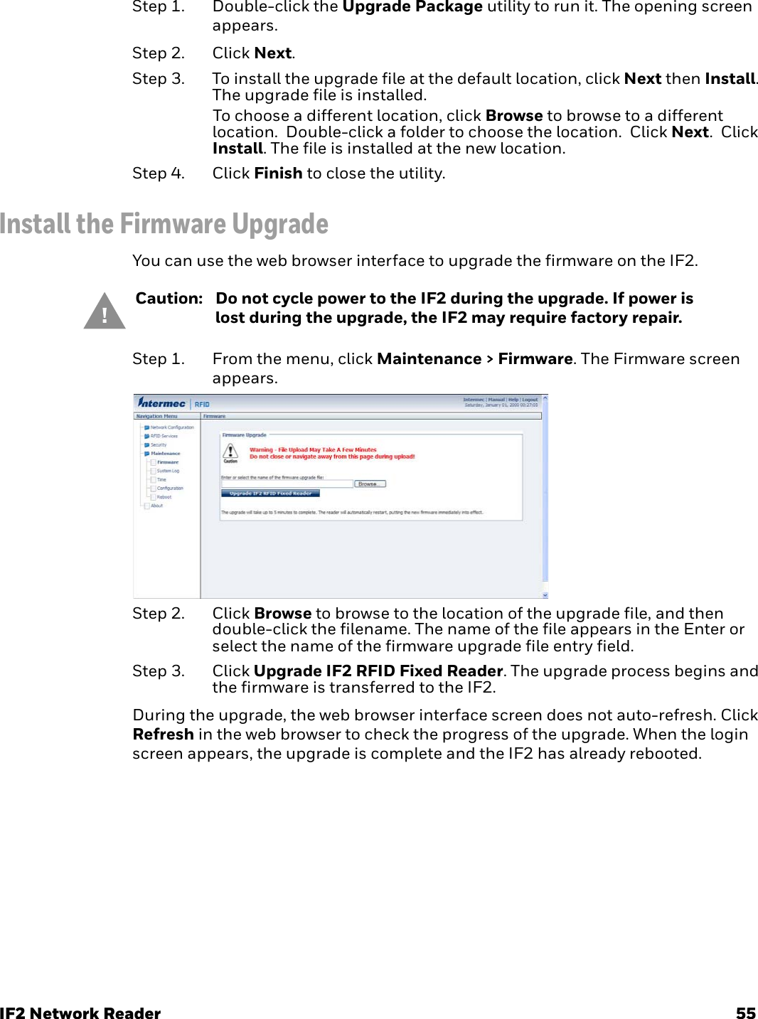
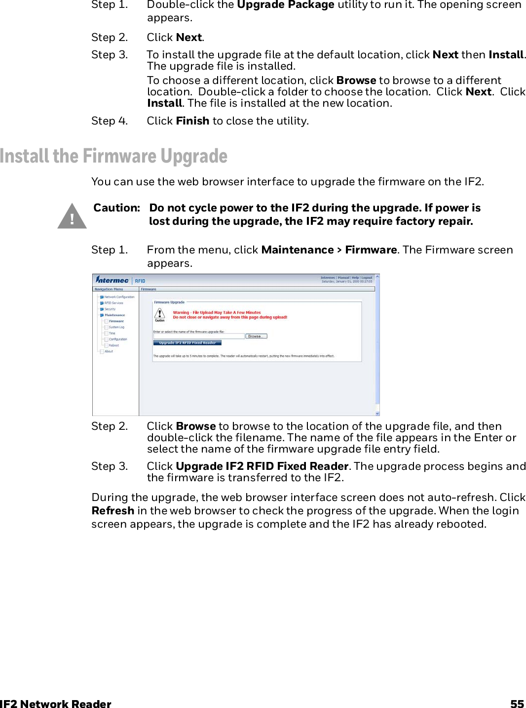
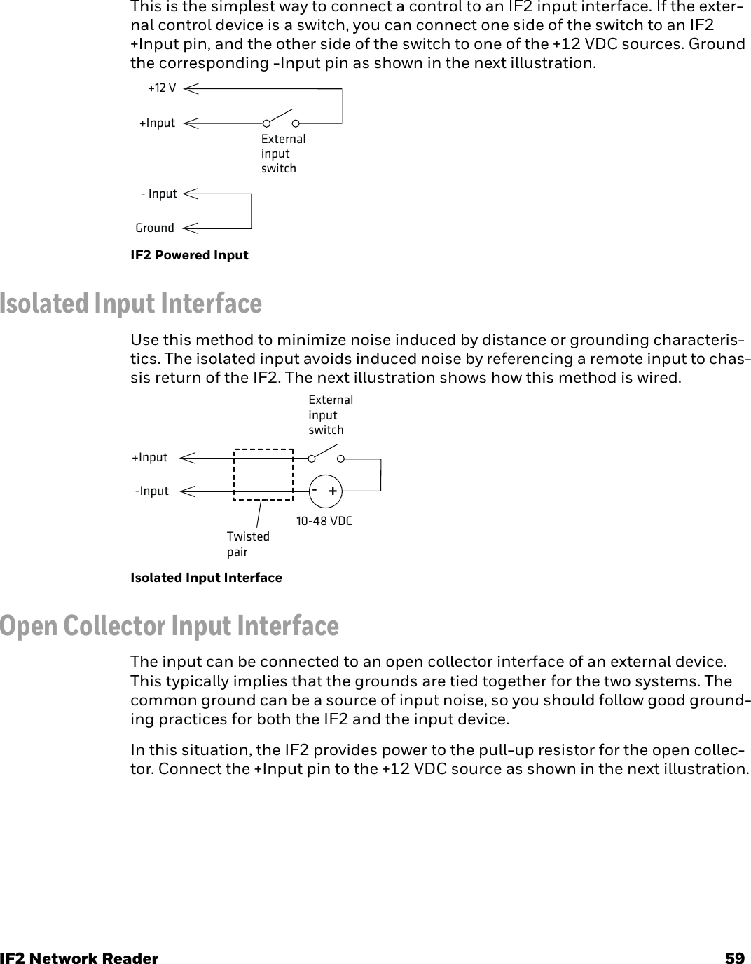
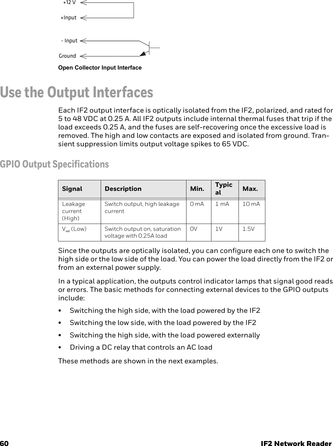
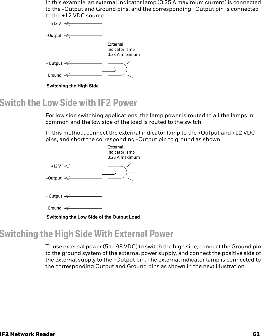
![46 IF2 Network ReaderStep 3. In Notepad, copy and paste the following text:[Version]Signature="$Windows NT$"Class=PortsClassGuid={4D36E978-E325-11CE-BFC1-08002BE10318}Provider=%LINUX%DriverVer=08/17/2004,0.0.2.0; Copyright(C)2004 Al Borchers (alborchers@steinerpoint.com)[Manufacturer]%LINUX%=GSerialDeviceList[GSerialDeviceList]%GSERIAL%=GSerialInstall, USB\VID_0525&PID_A4A7[DestinationDirs]DefaultDestDir=10,System32\Drivers[GSerialInstall]CopyFiles=GSerialCopyFilesAddReg=GSerialAddReg[GSerialCopyFiles]usbser.sys[GSerialAddReg]HKR,,DevLoader,,*ntkernHKR,,NTMPDriver,,usbser.sysHKR,,EnumPropPages32,,"MsPorts.dll,SerialPortPropPageProvider"[GSerialInstall.Services]AddService = usbser,0x0002,GSerialService[GSerialService]DisplayName = %GSERIAL_DISPLAY_NAME%ServiceType = 1 ; SERVICE_KERNEL_DRIVERStartType = 3 ; SERVICE_DEMAND_STARTErrorControl = 1 ; SERVICE_ERROR_NORMALServiceBinary = %10%\System32\Drivers\usbser.sysLoadOrderGroup = Base[Strings]LINUX = "Linux"GSERIAL = "Gadget Serial"GSERIAL_DISPLAY_NAME = "USB Gadget Serial Driver"](https://usermanual.wiki/Honeywell/IM14.User-Manual/User-Guide-3864349-Page-56.png)