Honeywell KSN770 Aviation Communications Transceiver User Manual 006 10716 0000
Honeywell International Inc. Aviation Communications Transceiver 006 10716 0000
User Manual

Draft
Honeywell International Inc.
23500 West 105th Street
Olathe, Kansas 66061-8425
U.S.A.
CAGE: 22373
Telephone: (800) 601-3099 (Toll Free U.S.A./Canada)
Telephone: (602) 365-3099 (International Direct)
Telephone: 00-800-601-30999 (EMEA Toll Free)
Telephone: 420-234-625-500 (EMEA Direct)
Website: www.myaerospace.com
Page T-1
Publication Number 006-10716-0000, Revision 0 Initial 6 Dec 2012
© Honeywell International Inc. Do not copy without express permission of Honeywell.
34-70-06
This document contains technical data and is subject to U.S. export regulations. These commodities,
technology, or software were exported from the United States in accordance with the export administration
regulations. Diversion contrary to U.S. law is prohibited.
ECCN: 7E994, NLR Eligible.
System Installation Manual
KSN 765/770 Safety Navigator
Part Number CAGE
066-01204-0101 22373
066-01204-1101 22373
066-01213-0101 22373
066-01213-1101 22373
Legal Notice
Export Control
Draft as of 10/15/2012

Draft
Page T-2
6 Dec 2012
34-70-06
SYSTEM INSTALLATION MANUAL
066-01204 / 066-01213
© Honeywell International Inc. Do not copy without express permission of Honeywell.
Proprietary Information
Honeywell – Confidential
THIS COPYRIGHTED WORK AND ALL INFORMATION ARE THE PROPERTY OF HONEYWELL
INTERNATIONAL INC., CONTAIN TRADE SECRETS AND MAY NOT, IN WHOLE OR IN PART, BE USED,
DUPLICATED, OR DISCLOSED FOR ANY PURPOSE WITHOUT PRIOR WRITTEN PERMISSION OF
HONEYWELL INTERNATIONAL INC. ALL RIGHTS RESERVED.
Honeywell Materials License Agreement
The documents and information contained herein (“the Materials”) are the proprietary data of Honeywell
International Inc. and Honeywell Intellectual Properties Inc. (collectively “Honeywell”). These Materials are
provided for the exclusive use of Honeywell Service Centers; Honeywell-authorized repair facilities; operators
of Honeywell aerospace products subject to an applicable product support agreement, their wholly
owned-subsidiaries or a formally designated third party service provider; and direct recipients of Materials from
Honeywell’s Aerospace Technical Publication Distribution. The terms and conditions of this License Agreement
govern your use of these Materials, except to the extent that any terms and conditions of another applicable
agreement with Honeywell regarding the operation, maintenance, or repair of Honeywell aerospace products
conflict with the terms and conditions of this License Agreement, in which case the terms and conditions of the
other agreement will govern. However, this License Agreement will govern in the event of a conflict between its
terms and conditions and those of a purchase order or acknowledgement.
1. License Grant - If you are a party to an applicable product support agreement, a Honeywell Service Center
agreement, or an authorized repair facility agreement, Honeywell hereby grants you a limited, non-exclusive
license to use these Materials to operate, maintain, or repair Honeywell aerospace products only in accordance
with that agreement.
If you are a direct recipient of these Materials from Honeywell’s Aerospace Technical Publication Distribution
and are not a party to an agreement related to the operation, maintenance or repair of Honeywell aerospace
products, Honeywell hereby grants you a limited, non-exclusive license to use these Materials to maintain or
repair the subject Honeywell aerospace products only at the facility to which these Materials have been shipped
("the Licensed Facility"). Transfer of the Materials to another facility owned by you is permitted only if the original
Licensed Facility retains no copies of the Materials and you provide prior written notice to Honeywell.
2. Rights In Materials - Honeywell retains all rights in these Materials and in any copies thereof that are not
expressly granted to you, including all rights in patents, copyrights, trademarks, and trade secrets. No license
to use any Honeywell trademarks or patents is granted under this License Agreement.
3. Confidentiality - You acknowledge that these Materials contain information that is confidential and proprietary
to Honeywell. You agree to take all reasonable efforts to maintain the confidentiality of these Materials.
4. Assignment And Transfer - This License Agreement may be assigned to a formally designated service
designee or transferred to a subsequent owner or operator of an aircraft containing the subject Honeywell
aerospace products. However, the recipient of any such assignment or transfer must assume all of your
obligations under this License Agreement. No assignment or transfer shall relieve any party of any obligation
that such party then has hereunder.
5. Copies of Materials - Unless you have the express written permission of Honeywell, you may not make or
permit making of copies of the Materials. Notwithstanding the foregoing, you may make copies of only portions
of the Material for your internal use. You agree to return the Materials and any copies thereof to Honeywell upon
the request of Honeywell.
Draft as of 10/15/2012

Draft
Page T-3
6 Dec 2012
34-70-06
SYSTEM INSTALLATION MANUAL
066-01204 / 066-01213
© Honeywell International Inc. Do not copy without express permission of Honeywell.
6. Term - This License Agreement is effective until terminated as set forth herein. This License Agreement will
terminate immediately, without notice from Honeywell, if you fail to comply with any provision of this License
Agreement or will terminate simultaneously with the termination or expiration of your applicable product support
agreement, authorized repair facility agreement, or your formal designation as a third party service provider.
Upon termination of this License Agreement, you will return these Materials to Honeywell without retaining any
copies and will have one of your authorized officers certify that all Materials have been returned with no copies
retained.
7. Remedies - Honeywell reserves the right to pursue all available remedies and damages resulting from a
breach of this License Agreement.
8. Limitation of Liability - Honeywell does not make any representation regarding the use or sufficiency of the
Materials. THERE ARE NO OTHER WARRANTIES, WHETHER WRITTEN OR ORAL, EXPRESS, IMPLIED
OR STATUTORY, INCLUDING, BUT NOT LIMITED TO, (i) WARRANTIES ARISING FROM COURSE OF
PERFORMANCE, DEALING, USAGE, OR TRADE, WHICH ARE HEREBY EXPRESSLY DISCLAIMED, OR (ii)
WARRANTIES AGAINST INFRINGEMENT OF INTELLECTUAL PROPERTY RIGHTS OF THIRD PARTIES,
EVEN IF HONEYWELL HAS BEEN ADVISED OF ANY SUCH INFRINGEMENT. IN NO EVENT WILL
HONEYWELL BE LIABLE FOR ANY INCIDENTAL DAMAGES, CONSEQUENTIAL DAMAGES, SPECIAL
DAMAGES, INDIRECT DAMAGES, LOSS OF PROFITS, LOSS OF REVENUES, OR LOSS OF USE, EVEN IF
INFORMED OF THE POSSIBILITY OF SUCH DAMAGES. TO THE EXTENT PERMITTED BY APPLICABLE
LAW, THESE LIMITATIONS AND EXCLUSIONS WILL APPLY REGARDLESS OF WHETHER LIABILITY
ARISES FROM BREACH OF CONTRACT, WARRANTY, TORT (INCLUDING BUT NOT LIMITED TO
NEGLIGENCE), BY OPERATION OF LAW, OR OTHERWISE.
9. Controlling Law - This License shall be governed and construed in accordance with the laws of the State of
New York without regard to the conflicts of laws provisions thereof. This license sets forth the entire agreement
between you and Honeywell and may only be modified by a writing duly executed by the duly authorized
representatives of the parties.
Safety Advisory
WARNING: BEFORE THE MATERIALS CALLED OUT IN THIS PUBLICATION ARE USED, KNOW THE
HANDLING, STORAGE AND DISPOSAL PRECAUTIONS RECOMMENDED BY THE MANUFACTURER OR
SUPPLIER. FAILURE TO OBEY THE MANUFACTURERS’ OR SUPPLIERS’ RECOMMENDATIONS CAN
RESULT IN PERSONAL INJURY OR DISEASE.
This publication describes physical and chemical processes which can make it necessary to use chemicals,
solvents, paints, and other commercially available materials. The user of this publication must get the Material
Safety Data Sheets (OSHA Form 174 or equivalent) from the manufacturers or suppliers of the materials to be
used. The user must know the manufacturer/ supplier data and obey the procedures, recommendations,
warnings and cautions set forth for the safe use, handling, storage, and disposal of the materials.
Warranty/Liability Advisory
WARNING: HONEYWELL ASSUMES NO RESPONSIBILITY FOR ANY HONEYWELL EQUIPMENT WHICH
IS NOT MAINTAINED AND/OR REPAIRED IN ACCORDANCE WITH HONEYWELL’S PUBLISHED
INSTRUCTIONS AND/OR HONEYWELL’S FAA/SFAR 36 REPAIR AUTHORIZATION. NEITHER DOES
HONEYWELL ASSUME RESPONSIBILITY FOR SPECIAL TOOLS AND TEST EQUIPMENT FABRICATED BY
COMPANIES OTHER THAN HONEYWELL.
WARNING: INCORRECTLY REPAIRED COMPONENTS CAN AFFECT AIRWORTHINESS OR DECREASE
THE LIFE OF THE COMPONENTS. INCORRECTLY FABRICATED SPECIAL TOOLING OR TEST
EQUIPMENT CAN RESULT IN DAMAGE TO THE PRODUCT COMPONENTS OR GIVE UNSATISFACTORY
RESULTS.
Draft as of 10/15/2012

Draft
Page T-4
6 Dec 2012
34-70-06
SYSTEM INSTALLATION MANUAL
066-01204 / 066-01213
© Honeywell International Inc. Do not copy without express permission of Honeywell.
Copyright - Notice
Copyright 2012 Honeywell International Inc. All rights reserved.
Honeywell is a registered trademark of Honeywell International Inc.
All other marks are owned by their respective companies.
Draft as of 10/15/2012

Draft
Page TI-1
6 Dec 2012
34-70-06
SYSTEM INSTALLATION MANUAL
066-01204 / 066-01213
© Honeywell International Inc. Do not copy without express permission of Honeywell.
TRANSMITTAL INFORMATION
THIS IS AN INITIAL RELEASE OF THE KSN 765/770 SAFETY NAVIGATOR SIM PUB. NO. 006-10716-0000
AND IS ISSUED FOR USE IN SUPPORT OF THE FOLLOWING:
Table TI-1 shows the applicable components.
Revision History
Table TI-2 shows the revision history of this SIM.
Table TI-1. Applicable Components
Component PN Nomenclature
066-01204-0101 KSN 770 Safety Navigator
066-01204-1101 KSN 770 Safety Navigator
066-01213-0101 KSN 765 Safety Navigator
066-01213-1101 KSN 765 Safety Navigator
Table TI-2. Revision History
Revision Number Revision Date
0 6 Dec 2012
Draft as of 10/15/2012

Draft
Page TI-2
6 Dec 2012
34-70-06
SYSTEM INSTALLATION MANUAL
066-01204 / 066-01213
© Honeywell International Inc. Do not copy without express permission of Honeywell.
Blank Page
Draft as of 10/15/2012

Draft
Page RR-1
6 Dec 2012
34-70-06
SYSTEM INSTALLATION MANUAL
066-01204 / 066-01213
© Honeywell International Inc. Do not copy without express permission of Honeywell.
RECORD OF REVISIONS
For each revision, write the revision number, revision date, date put in the manual, and your initials in the
applicable column.
NOTE: Refer to the Revision History in the TRANSMITTAL INFORMATION section for revision data.
Revision
Number Revision
Date Date Put
In Manual By Revision
Number Revision
Date Date Put
In Manual By
Draft as of 10/15/2012

Draft
Page RR-2
6 Dec 2012
34-70-06
SYSTEM INSTALLATION MANUAL
066-01204 / 066-01213
© Honeywell International Inc. Do not copy without express permission of Honeywell.
Blank Page
Draft as of 10/15/2012

Draft
Page RTR-1
6 Dec 2012
34-70-06
SYSTEM INSTALLATION MANUAL
066-01204 / 066-01213
© Honeywell International Inc. Do not copy without express permission of Honeywell.
RECORD OF TEMPORARY REVISIONS
Instructions on each page of a temporary revision tell you where to put the pages in your manual. Remove
temporary revision pages only when discard instructions are given. For each temporary revision, put the
applicable data in the record columns on this page.
Definition of Status column: TR may be active, cancelled, or incorporated. If TR is incorporated list the revision
number. For example enter: INC Rev 7. If TR is replaced by another TR then put “Cancelled”. For example:
Cancelled by TR NN-NN. “Active” is entered by the holder of manual.
Temporary
Revision
Number Status Page
Number Issue
Date Date Put in
Manual By
Date
Removed
From Manual By
Draft as of 10/15/2012

Draft
Page RTR-2
6 Dec 2012
34-70-06
SYSTEM INSTALLATION MANUAL
066-01204 / 066-01213
© Honeywell International Inc. Do not copy without express permission of Honeywell.
Blank Page
Draft as of 10/15/2012

Draft
Page SBL-1
6 Dec 2012
34-70-06
SYSTEM INSTALLATION MANUAL
066-01204 / 066-01213
© Honeywell International Inc. Do not copy without express permission of Honeywell.
SERVICE BULLETIN LIST
Service Bulletin/
Revision Number Title Modification Date Put in
Manual
Draft as of 10/15/2012

Draft
Page SBL-2
6 Dec 2012
34-70-06
SYSTEM INSTALLATION MANUAL
066-01204 / 066-01213
© Honeywell International Inc. Do not copy without express permission of Honeywell.
Blank Page
Draft as of 10/15/2012

Draft
Page LEP-1
6 Dec 2012
34-70-06
SYSTEM INSTALLATION MANUAL
066-01204 / 066-01213
© Honeywell International Inc. Do not copy without express permission of Honeywell.
Subheading and Page Date Subheading and Page Date
LIST OF EFFECTIVE PAGES
* indicates a changed or added page.
F indicates a foldout page.
Title
T-1 6 Dec 2012
T-2 6 Dec 2012
T-3 6 Dec 2012
T-4 6 Dec 2012
T-4 6 Dec 2012
Transmittal Information
TI-1 6 Dec 2012
TI-2 6 Dec 2012
Record of Revisions
RR-1 6 Dec 2012
RR-2 6 Dec 2012
Record of Temporary Revisions
RTR-1 6 Dec 2012
RTR-2 6 Dec 2012
Service Bulletin List
SBL-1 6 Dec 2012
SBL-2 6 Dec 2012
List of Effective Pages
LEP-1 6 Dec 2012
LEP-2 6 Dec 2012
LEP-3 6 Dec 2012
LEP-4 6 Dec 2012
Table of Contents
TC-1 6 Dec 2012
TC-2 6 Dec 2012
TC-3 6 Dec 2012
TC-4 6 Dec 2012
TC-5 6 Dec 2012
TC-6 6 Dec 2012
TC-7 6 Dec 2012
TC-8 6 Dec 2012
TC-9 6 Dec 2012
TC-10 6 Dec 2012
Introduction
INTRO-1 6 Dec 2012
INTRO-2 6 Dec 2012
INTRO-3 6 Dec 2012
INTRO-4 6 Dec 2012
INTRO-5 6 Dec 2012
INTRO-6 6 Dec 2012
INTRO-7 6 Dec 2012
INTRO-8 6 Dec 2012
Section I
General Information
1-1 6 Dec 2012
1-2 6 Dec 2012
1-3 6 Dec 2012
1-4 6 Dec 2012
1-5 6 Dec 2012
1-6 6 Dec 2012
Section II
Installation
2-1 6 Dec 2012
2-2 6 Dec 2012
2-3 6 Dec 2012
2-4 6 Dec 2012
2-5 6 Dec 2012
2-6 6 Dec 2012
2-7 6 Dec 2012
2-8 6 Dec 2012
2-9 6 Dec 2012
2-10 6 Dec 2012
2-11 6 Dec 2012
2-12 6 Dec 2012
F 2-13 6 Dec 2012
F 2-14 6 Dec 2012
F 2-15 6 Dec 2012
F 2-16 6 Dec 2012
F 2-17 6 Dec 2012
F 2-18 6 Dec 2012
F 2-19 6 Dec 2012
F 2-20 6 Dec 2012
2-21 6 Dec 2012
2-22 6 Dec 2012
2-23 6 Dec 2012
2-24 6 Dec 2012
2-25 6 Dec 2012
2-26 6 Dec 2012
2-27 6 Dec 2012
2-28 6 Dec 2012
2-29 6 Dec 2012
2-30 6 Dec 2012
2-31 6 Dec 2012
2-32 6 Dec 2012
2-33 6 Dec 2012
2-34 6 Dec 2012
F 2-35 6 Dec 2012
Draft as of 10/15/2012

Draft
Page LEP-2
6 Dec 2012
34-70-06
SYSTEM INSTALLATION MANUAL
066-01204 / 066-01213
© Honeywell International Inc. Do not copy without express permission of Honeywell.
Subheading and Page Date Subheading and Page Date
* indicates a changed or added page.
F indicates a foldout page.
F 2-36 6 Dec 2012
F 2-37 6 Dec 2012
F 2-38 6 Dec 2012
F 2-39 6 Dec 2012
F 2-40 6 Dec 2012
F 2-41 6 Dec 2012
F 2-42 6 Dec 2012
F 2-43 6 Dec 2012
F 2-44 6 Dec 2012
2-45 6 Dec 2012
2-46 6 Dec 2012
F 2-47 6 Dec 2012
F 2-48 6 Dec 2012
2-49 6 Dec 2012
2-50 6 Dec 2012
Section III
System Interconnects
3-1 6 Dec 2012
3-2 6 Dec 2012
3-3 6 Dec 2012
3-4 6 Dec 2012
F 3-5 6 Dec 2012
F 3-6 6 Dec 2012
3-7 6 Dec 2012
3-8 6 Dec 2012
F 3-9 6 Dec 2012
F 3-10 6 Dec 2012
3-11 6 Dec 2012
3-12 6 Dec 2012
F 3-13 6 Dec 2012
F 3-14 6 Dec 2012
F 3-15 6 Dec 2012
F 3-16 6 Dec 2012
3-17 6 Dec 2012
3-18 6 Dec 2012
3-19 6 Dec 2012
3-20 6 Dec 2012
3-21 6 Dec 2012
3-22 6 Dec 2012
F 3-23 6 Dec 2012
F 3-24 6 Dec 2012
F 3-25 6 Dec 2012
F 3-26 6 Dec 2012
3-27 6 Dec 2012
3-28 6 Dec 2012
3-29 6 Dec 2012
3-30 6 Dec 2012
F 3-31 6 Dec 2012
F 3-32 6 Dec 2012
3-33 6 Dec 2012
3-34 6 Dec 2012
3-35 6 Dec 2012
3-36 6 Dec 2012
F 3-37 6 Dec 2012
F 3-38 6 Dec 2012
F 3-39 6 Dec 2012
F 3-40 6 Dec 2012
F 3-41 6 Dec 2012
F 3-42 6 Dec 2012
3-43 6 Dec 2012
3-44 6 Dec 2012
3-45 6 Dec 2012
3-46 6 Dec 2012
3-47 6 Dec 2012
3-48 6 Dec 2012
3-49 6 Dec 2012
3-50 6 Dec 2012
F 3-51 6 Dec 2012
F 3-52 6 Dec 2012
F 3-53 6 Dec 2012
F 3-54 6 Dec 2012
F 3-55 6 Dec 2012
F 3-56 6 Dec 2012
F 3-57 6 Dec 2012
F 3-58 6 Dec 2012
3-59 6 Dec 2012
3-60 6 Dec 2012
3-61 6 Dec 2012
3-62 6 Dec 2012
3-63 6 Dec 2012
3-64 6 Dec 2012
F 3-65 6 Dec 2012
F 3-66 6 Dec 2012
F 3-67 6 Dec 2012
F 3-68 6 Dec 2012
F 3-69 6 Dec 2012
F 3-70 6 Dec 2012
F 3-71 6 Dec 2012
F 3-72 6 Dec 2012
3-73 6 Dec 2012
3-74 6 Dec 2012
F 3-75 6 Dec 2012
F 3-76 6 Dec 2012
F 3-77 6 Dec 2012
F 3-78 6 Dec 2012
Draft as of 10/15/2012

Draft
Page LEP-3
6 Dec 2012
34-70-06
SYSTEM INSTALLATION MANUAL
066-01204 / 066-01213
© Honeywell International Inc. Do not copy without express permission of Honeywell.
Subheading and Page Date Subheading and Page Date
* indicates a changed or added page.
F indicates a foldout page.
F 3-79 6 Dec 2012
F 3-80 6 Dec 2012
3-81 6 Dec 2012
3-82 6 Dec 2012
3-83 6 Dec 2012
3-84 6 Dec 2012
3-85 6 Dec 2012
3-86 6 Dec 2012
3-87 6 Dec 2012
3-88 6 Dec 2012
F 3-89 6 Dec 2012
F 3-90 6 Dec 2012
F 3-91 6 Dec 2012
F 3-92 6 Dec 2012
F 3-93 6 Dec 2012
F 3-94 6 Dec 2012
F 3-95 6 Dec 2012
F 3-96 6 Dec 2012
F 3-97 6 Dec 2012
F 3-98 6 Dec 2012
F 3-99 6 Dec 2012
F 3-100 6 Dec 2012
3-101 6 Dec 2012
3-102 6 Dec 2012
F 3-103 6 Dec 2012
F 3-104 6 Dec 2012
3-105 6 Dec 2012
3-106 6 Dec 2012
F 3-107 6 Dec 2012
F 3-108 6 Dec 2012
3-109 6 Dec 2012
3-110 6 Dec 2012
F 3-111 6 Dec 2012
F 3-112 6 Dec 2012
F 3-113 6 Dec 2012
F 3-114 6 Dec 2012
3-115 6 Dec 2012
3-116 6 Dec 2012
3-117 6 Dec 2012
3-118 6 Dec 2012
F 3-119 6 Dec 2012
F 3-120 6 Dec 2012
F 3-121 6 Dec 2012
F 3-122 6 Dec 2012
3-123 6 Dec 2012
3-124 6 Dec 2012
F 3-125 6 Dec 2012
F 3-126 6 Dec 2012
F 3-127 6 Dec 2012
F 3-128 6 Dec 2012
3-129 6 Dec 2012
3-130 6 Dec 2012
F 3-131 6 Dec 2012
F 3-132 6 Dec 2012
3-133 6 Dec 2012
3-134 6 Dec 2012
3-135 6 Dec 2012
3-136 6 Dec 2012
F 3-137 6 Dec 2012
F 3-138 6 Dec 2012
3-139 6 Dec 2012
3-140 6 Dec 2012
F 3-141 6 Dec 2012
F 3-142 6 Dec 2012
3-143 6 Dec 2012
3-144 6 Dec 2012
3-145 6 Dec 2012
3-146 6 Dec 2012
F 3-147 6 Dec 2012
F 3-148 6 Dec 2012
F 3-149 6 Dec 2012
F 3-150 6 Dec 2012
F 3-151 6 Dec 2012
F 3-152 6 Dec 2012
F 3-153 6 Dec 2012
F 3-154 6 Dec 2012
3-155 6 Dec 2012
3-156 6 Dec 2012
Section IV
TBD
4-1 6 Dec 2012
4-2 6 Dec 2012
Draft as of 10/15/2012

Draft
Page LEP-4
6 Dec 2012
34-70-06
SYSTEM INSTALLATION MANUAL
066-01204 / 066-01213
© Honeywell International Inc. Do not copy without express permission of Honeywell.
Blank Page
Draft as of 10/15/2012

Draft
Page TC-1
6 Dec 2012
34-70-06
SYSTEM INSTALLATION MANUAL
066-01204 / 066-01213
© Honeywell International Inc. Do not copy without express permission of Honeywell.
TABLE OF CONTENTS
Title Page
INTRODUCTION
1. How to Use This Manual .......................................................................................................INTRO-1
A. General ........................................................................................................................ INTRO-1
B. Observance of Manual Instructions ............................................................................. INTRO-1
C. Symbols ....................................................................................................................... INTRO-1
D. Units of Measure ......................................................................................................... INTRO-2
E. Standard Practices Manual ......................................................................................... INTRO-2
F. Electrostatic Discharge ................................................................................................ INTRO-2
2. Customer Support .................................................................................................................INTRO-2
A. Honeywell Aerospace Online Technical Publications Website ................................... INTRO-2
B. Global Customer Care Center ..................................................................................... INTRO-2
3. References ........................................................................................................................... INTRO-3
A. Honeywell/Vendor Publications ................................................................................... INTRO-3
B. Other Publications ....................................................................................................... INTRO-3
4. Acronyms and Abbreviations ............................................................................................... INTRO-3
A. General ........................................................................................................................ INTRO-3
5. Process Verification .............................................................................................................. INTRO-7
A. Verification Data .......................................................................................................... INTRO-7
6. Software History ................................................................................................................... INTRO-7
A. Software Data .............................................................................................................. INTRO-7
7. History of Changes ............................................................................................................... INTRO-7
A. Modification/Configuration History ............................................................................... INTRO-7
B. Change History for Parts List ...................................................................................... INTRO-7
SECTION I - GENERAL INFORMATION
1.1 Introduction .................................................................................................................................... 1-1
1.2 Applicability of the Installation Manual ........................................................................................... 1-1
1.3 Description of the Equipment ......................................................................................................... 1-1
1.3.1 KSN 7xx Safety Navigator ..................................................................................................1-1
1.3.2 GPS Antenna ..................................................................................................................... 1-2
1.3.3 KCM 200 Configuration Module ......................................................................................... 1-2
1.4 Technical Characteristics ............................................................................................................... 1-2
1.5 Units Supplied ................................................................................................................................ 1-4
1.5.1 KSN 7xx Safety Navigator ..................................................................................................1-4
1.5.2 GPS Antennas ................................................................................................................... 1-4
1.6 License Requirements ................................................................................................................... 1-4
1.7 Recommendations for IFR Approval .............................................................................................. 1-4
A. Aircraft Logbook Entry .......................................................................................................... 1-4
B. Aircraft Installation Requirements ........................................................................................ 1-4
C. Approved Airplane Flight Manual Supplement ..................................................................... 1-5
D. Pilot’s Guide ......................................................................................................................... 1-5
Draft as of 10/15/2012

Draft
Page TC-2
6 Dec 2012
34-70-06
SYSTEM INSTALLATION MANUAL
066-01204 / 066-01213
© Honeywell International Inc. Do not copy without express permission of Honeywell.
TABLE OF CONTENTS (CONT)
Title Page
SECTION II - INSTALLATION
2.1 Overview ........................................................................................................................................ 2-1
2.2 Unpacking and Inspecting Equipment ............................................................................................ 2-1
2.3 KSN 7xx Installation ....................................................................................................................... 2-1
2.3.1 General .............................................................................................................................. 2-1
2.3.2 Minimum System Configuration ......................................................................................... 2-2
2.3.3 Installation Materials .......................................................................................................... 2-2
2.3.4 KSN 7xx Installation Considerations .................................................................................. 2-7
2.3.5 KSN 7xx Cooling Requirements ...................................................................................... 2-11
2.3.6 KSN Pinouts ..................................................................................................................... 2-21
2.3.7 KSN Wiring and Cable Harness Fabrication .................................................................... 2-32
2.3.8 KSN Power Distribution ................................................................................................... 2-45
2.3.9 Placards and Labels ........................................................................................................ 2-45
2.3.10 Weight and Balance ......................................................................................................... 2-45
2.4 Antenna Installation ..................................................................................................................... 2-46
2.4.1 GPS/WAAS Antenna Location Considerations ................................................................ 2-46
2.4.2 COM and NAV Antenna Installation Considerations ........................................................ 2-49
2.5 Optional Accessory Installation .................................................................................................... 2-50
2.5.1 External Annunciators ...................................................................................................... 2-50
2.5.2 External Switches ............................................................................................................ 2-50
2.6 Magnetic Compass Recalibration ................................................................................................ 2-50
SECTION III - SYSTEM INTERCONNECT
3.1 Introduction .................................................................................................................................... 3-1
3.2 Standard Interface Definitions ........................................................................................................ 3-1
3.2.1 Discrete Input ..................................................................................................................... 3-1
3.2.2 Discrete Output .................................................................................................................. 3-1
3.2.3 EIA Standard Serial Interfaces ........................................................................................... 3-2
3.2.4 ARINC 429 Standard Serial Interfaces .............................................................................. 3-2
3.2.5 ARINC 453 Interface .......................................................................................................... 3-2
3.3 Power System Interface ................................................................................................................. 3-3
3.3.1 General .............................................................................................................................. 3-3
3.3.2 Electrical Characteristics .................................................................................................... 3-3
3.3.3 Panel Lighting Inputs ......................................................................................................... 3-4
3.3.4 Interconnect Diagram ......................................................................................................... 3-4
3.4 Position Interface ........................................................................................................................... 3-7
3.4.1 Applicable Part Numbers ...................................................................................................3-7
3.4.2 Function ............................................................................................................................. 3-7
3.4.3 Requirements and Limitations ........................................................................................... 3-7
3.4.4 Electrical Characteristics .................................................................................................... 3-7
3.4.5 Interconnect Diagram ......................................................................................................... 3-7
3.5 WX RDR Interface ....................................................................................................................... 3-11
3.5.1 Applicable Part Numbers ................................................................................................. 3-11
Draft as of 10/15/2012

Draft
Page TC-3
6 Dec 2012
34-70-06
SYSTEM INSTALLATION MANUAL
066-01204 / 066-01213
© Honeywell International Inc. Do not copy without express permission of Honeywell.
TABLE OF CONTENTS (CONT)
Title Page
3.5.2 Function ........................................................................................................................... 3-11
3.5.3 Requirements and Limitations .......................................................................................... 3-11
3.5.4 Electrical Characteristics .................................................................................................. 3-11
3.5.5 Interconnect Diagram ....................................................................................................... 3-11
3.6 EGPWS Interface ......................................................................................................................... 3-17
3.6.1 Applicable Part Numbers ................................................................................................. 3-17
3.6.2 Function ........................................................................................................................... 3-18
3.6.3 Requirements and Limitations .......................................................................................... 3-18
3.6.4 Electrical Characteristics .................................................................................................. 3-18
3.6.5 Interconnect Diagram ....................................................................................................... 3-21
3.7 Traffic Interface ............................................................................................................................ 3-27
3.7.1 Applicable Part Numbers ................................................................................................. 3-27
3.7.2 Function ........................................................................................................................... 3-27
3.7.3 Requirements and Limitations .......................................................................................... 3-27
3.7.4 Electrical Characteristics .................................................................................................. 3-28
3.7.5 Interconnect Diagram ....................................................................................................... 3-29
3.8 Heading/AHRS Interface .............................................................................................................. 3-33
3.8.1 Applicable Part Numbers ................................................................................................. 3-33
3.8.2 Function ........................................................................................................................... 3-33
3.8.3 Requirements and Limitations .......................................................................................... 3-34
3.8.4 Electrical Characteristics .................................................................................................. 3-34
3.8.5 Interconnect Diagram ....................................................................................................... 3-35
3.9 Altitude/Airdata/Fuel Interface ...................................................................................................... 3-43
3.9.1 Applicable Part Numbers ................................................................................................. 3-43
3.9.2 Functions .......................................................................................................................... 3-43
3.9.3 Requirements and Limitations .......................................................................................... 3-45
3.9.4 Electrical Characteristics .................................................................................................. 3-46
3.9.5 Interconnect Diagrams ..................................................................................................... 3-49
3.10 Flight Control Interface ................................................................................................................. 3-59
3.10.1 Applicable Part Numbers .................................................................................................3-59
3.10.2 Function ........................................................................................................................... 3-59
3.10.3 Requirements and Limitations .......................................................................................... 3-59
3.10.4 Electrical Characteristics .................................................................................................. 3-61
3.10.5 Interconnect Diagram ....................................................................................................... 3-64
3.11 DME Interface .............................................................................................................................. 3-73
3.11.1 Applicable Part Numbers .................................................................................................3-73
3.11.2 Function ........................................................................................................................... 3-73
3.11.3 Requirements and Limitations .......................................................................................... 3-73
3.11.4 Electrical Characteristics .................................................................................................. 3-73
3.11.5 Interconnect Diagram ....................................................................................................... 3-74
3.12 NAV Indicator Interface ................................................................................................................ 3-81
3.12.1 Applicable Part Numbers .................................................................................................3-81
3.12.2 Function ........................................................................................................................... 3-81
3.12.3 Requirements and Limitations .......................................................................................... 3-81
Draft as of 10/15/2012

Draft
Page TC-4
6 Dec 2012
34-70-06
SYSTEM INSTALLATION MANUAL
066-01204 / 066-01213
© Honeywell International Inc. Do not copy without express permission of Honeywell.
TABLE OF CONTENTS (CONT)
Title Page
3.12.4 Electrical Characteristics .................................................................................................. 3-82
3.12.5 Interconnect Diagram ....................................................................................................... 3-85
3.13 RMI/OBI Interface ...................................................................................................................... 3-101
3.13.1 Applicable Part Numbers ............................................................................................... 3-101
3.13.2 Function ......................................................................................................................... 3-101
3.13.3 Requirements and Limitations ....................................................................................... 3-101
3.13.4 Electrical Characteristics ................................................................................................ 3-101
3.13.5 Interconnect Diagram .....................................................................................................3-101
3.14 Dual System Interface (Cross-Fill) ............................................................................................. 3-105
3.14.1 Applicable Part Numbers ............................................................................................... 3-105
3.14.2 Function ......................................................................................................................... 3-105
3.14.3 Requirements and Limitations ....................................................................................... 3-105
3.14.4 Electrical Characteristics ................................................................................................ 3-105
3.14.5 Interconnect Diagram .....................................................................................................3-105
3.15 Audio Interface ........................................................................................................................... 3-109
3.15.1 Applicable Part Numbers ............................................................................................... 3-109
3.15.2 Function ......................................................................................................................... 3-109
3.15.3 Requirements and Limitations ....................................................................................... 3-109
3.15.4 Electrical Characteristics ................................................................................................ 3-109
3.15.5 Interconnect Diagram .....................................................................................................3-109
3.16 Annunciations - Suspend/Dead Reckoning/NAV Interface ......................................................... 3-115
3.16.1 Applicable Part Numbers ............................................................................................... 3-115
3.16.2 Function ......................................................................................................................... 3-115
3.16.3 Requirements and Limitations ....................................................................................... 3-116
3.16.4 Electrical Characteristics ................................................................................................ 3-118
3.16.5 Interconnect Diagram .....................................................................................................3-118
3.17 Miscellaneous Interface ............................................................................................................. 3-123
3.17.1 Applicable Part Numbers ............................................................................................... 3-123
3.17.2 Function ......................................................................................................................... 3-123
3.17.3 Requirements and Limitations ....................................................................................... 3-123
3.17.4 Electrical Characteristics ................................................................................................ 3-124
3.17.5 Interconnect Diagram .....................................................................................................3-124
3.18 XM Receiver Interface ............................................................................................................... 3-129
3.18.1 Applicable Part Numbers ............................................................................................... 3-129
3.18.2 Function ......................................................................................................................... 3-129
3.18.3 Requirements and Limitations ....................................................................................... 3-129
3.18.4 Electrical Characteristics ................................................................................................ 3-129
3.18.5 Interconnect Diagram .....................................................................................................3-129
3.19 Maintenance Interface ............................................................................................................... 3-133
3.19.1 Applicable Part Numbers ............................................................................................... 3-133
3.19.2 Function ......................................................................................................................... 3-133
3.19.3 Requirements and Limitations ....................................................................................... 3-133
3.19.4 Electrical Characteristics ................................................................................................ 3-134
3.19.5 Interconnect Diagram .....................................................................................................3-135
Draft as of 10/15/2012

Draft
Page TC-5
6 Dec 2012
34-70-06
SYSTEM INSTALLATION MANUAL
066-01204 / 066-01213
© Honeywell International Inc. Do not copy without express permission of Honeywell.
TABLE OF CONTENTS (CONT)
Title Page
3.20 Stormscope Interface (WX-500) ................................................................................................. 3-139
3.20.1 Applicable Part Numbers ............................................................................................... 3-139
3.20.2 Function ......................................................................................................................... 3-139
3.20.3 Requirements and Limitations ........................................................................................ 3-139
3.20.4 Electrical Characteristics ................................................................................................ 3-139
3.20.5 Interconnect Diagram .....................................................................................................3-139
3.21 NAV/COM Interface (KSN 7x0 Only) .......................................................................................... 3-143
3.21.1 Applicable Part Numbers ............................................................................................... 3-143
3.21.2 Function ......................................................................................................................... 3-143
3.21.3 Requirements and Limitations ........................................................................................ 3-143
3.21.4 Electrical Characteristics ................................................................................................ 3-144
3.21.5 Interconnect Diagram .....................................................................................................3-146
3.22 Data Bus Information ................................................................................................................. 3-155
SECTION IV - TBD
Draft as of 10/15/2012

Draft
Page TC-6
6 Dec 2012
34-70-06
SYSTEM INSTALLATION MANUAL
066-01204 / 066-01213
© Honeywell International Inc. Do not copy without express permission of Honeywell.
Blank Page
Draft as of 10/15/2012

Draft
Page TC-7
6 Dec 2012
34-70-06
SYSTEM INSTALLATION MANUAL
066-01204 / 066-01213
© Honeywell International Inc. Do not copy without express permission of Honeywell.
LIST OF FIGURES
Figure Page
INTRO-1 Symbols ............................................................................................................................. INTRO-2
2-1 Field of View - CDI Source Selection .......................................................................................... 2-9
2-2 Field of View - GPS Annunciation ............................................................................................. 2-10
2-3 Field of View - TAWS ................................................................................................................ 2-11
2-4 KSN 7xx Safety Navigator Outline Drawing .............................................................................. 2-13
2-5 KSN 7xx Back Panel ................................................................................................................. 2-21
2-6 Coaxial Right Angle Connector Instruction Sheet ..................................................................... 2-35
2-7 TNC Antenna Coax with Straight Connector ............................................................................. 2-37
2-8 Quadraxial Cable Preparation ................................................................................................... 2-39
3-1 Power System Interface Interconnect Diagram .......................................................................... 3-5
3-2 Position Interface Interconnect Diagram .....................................................................................3-9
3-3 WX RDR Interface Interconnect Diagram ................................................................................. 3-15
3-4 EGPWS Interface - Internal (Growth) Interconnect Diagram .................................................... 3-23
3-5 EGPWS Interface - External Interconnect Diagram .................................................................. 3-25
3-6 Traffic Interface Interconnect Diagram ......................................................................................3-31
3-7 Heading Interface - XYZ Interconnect Diagram ....................................................................... 3-37
3-8 AHRS Interface Interconnect Diagram ..................................................................................... 3-41
3-9 Altitude Interface Interconnect Diagram ................................................................................... 3-51
3-10 Airdata/OAT Interface Interconnect Diagram ........................................................................... 3-53
3-11 Fuel Flow/Airdata Interface Interconnect Diagram ................................................................... 3-55
3-12 Flight Control Interface - Roll Composite Steering Interconnect Diagram ................................ 3-65
3-13 Flight Control Interface - Deviation/Course Datum Interconnect Diagram ................................ 3-67
3-14 Flight Control Interface - DC Interconnect Diagram (Sheet 1 of 1) ........................................... 3-69
3-15 Flight Control Interface - ARINC 429 Interconnect Diagram .................................................... 3-71
3-16 DME Interface - Remote Interconnect Diagram ....................................................................... 3-75
3-17 DME Interface - Panel Mount Interconnect Diagram ............................................................... 3-77
3-18 DME Interface - ARINC 429 Interconnect Diagram ................................................................. 3-79
3-19 NAV Indicator Interface - OBS 1 Interconnect Diagram ........................................................... 3-89
3-20 NAV Indicator Interface - OBS 2 Interconnect Diagram ........................................................... 3-91
3-21 NAV Indicator Interface - Deviation and Flag Interconnect Diagram ....................................... 3-93
3-22 NAV Indicator Interface - ARINC 429 Interconnect Diagram .................................................... 3-95
Draft as of 10/15/2012

Draft
Page TC-8
6 Dec 2012
34-70-06
SYSTEM INSTALLATION MANUAL
066-01204 / 066-01213
© Honeywell International Inc. Do not copy without express permission of Honeywell.
LIST OF FIGURES (CONT)
Figure Page
3-23 NAV Indicator Interface - Composite Interconnect Diagram (KSN 7x0 Models Only) ............... 3-99
3-24 RMI/OBI Interface Interconnect Diagram ............................................................................... 3-103
3-25 Dual System Interface Interconnect Diagram ......................................................................... 3-107
3-26 Audio Interface 1 Interconnect Diagram ................................................................................ 3-111
3-27 Audio Interface 2 Interconnect Diagram ................................................................................ 3-113
3-28 Annunciations - Suspend/Dead Reckoning Interconnect Diagram ........................................ 3-119
3-29 Annunciations - NAV Interface Interconnect Diagram ............................................................. 3-121
3-30 Miscellaneous Interface 1 Interconnect Diagram ................................................................... 3-125
3-31 Miscellaneous Interface 2 Interconnect Diagram ................................................................... 3-127
3-32 XM Receiver Interface Interconnect Diagram ........................................................................ 3-131
3-33 Maintenance Interface Interconnect Diagram ........................................................................ 3-137
3-34 Stormscope Interface (WX-500) Interconnect Diagram .......................................................... 3-141
3-35 COM Interface Interconnect Diagram ..................................................................................... 3-147
3-36 NAV Interface Interconnect Diagram ..................................................................................... 3-149
3-37 NAV Interface - Remote DME Channeling Interconnect Diagram ......................................... 3-151
3-38 NAV Interface - Panel Mount DME Channeling Interconnect Diagram .................................. 3-153
Draft as of 10/15/2012

Draft
Page TC-9
6 Dec 2012
34-70-06
SYSTEM INSTALLATION MANUAL
066-01204 / 066-01213
© Honeywell International Inc. Do not copy without express permission of Honeywell.
LIST OF TABLES
Table Page
INTRO-1 Verification Data .............................................................................................................. INTRO-7
1-1 Installation Manual Applicability ............................................................................................... 1-1
1-2 KSN 765 Safety Navigator Leading Particulars ....................................................................... 1-2
1-3 KSN 770 Safety Navigator Leading Particulars ....................................................................... 1-3
2-1 KSN 765 Safety Navigator Installation Kit, PN PL050-03727-0000 ......................................... 2-2
2-2 KSN 770 Safety Navigator Installation Kit, PN PL050-03727-0001 ......................................... 2-3
2-3 Accessories Required But Not Supplied .................................................................................. 2-4
2-4 Accessories Required But Not Supplied .................................................................................. 2-5
2-5 Operational Software ............................................................................................................... 2-6
2-6 Americas Database .................................................................................................................. 2-6
2-7 Atlantic Database ..................................................................................................................... 2-6
2-8 Pacific Database ...................................................................................................................... 2-7
2-9 Special Tools Required ............................................................................................................ 2-7
2-10 Connector List ........................................................................................................................ 2-21
2-11 Signals Assigned to the I/O 1 Connector (J1) ........................................................................ 2-22
2-12 Signals Assigned to the I/O 2 Connector (J2) ........................................................................ 2-25
2-13 Signals Assigned to the Power Supply Interface Connector (J3) .......................................... 2-28
2-14 Signals Assigned to the Main Processor Board Interface Connector (J4) ............................. 2-28
2-15 Signals Assigned to the GPS Antenna Connector (J5) .......................................................... 2-30
2-16 Signals Assigned to the Video Connector (J6) ...................................................................... 2-30
2-17 Signals Assigned to the Rear Panel USB Connector (J8) ..................................................... 2-30
2-18 Signals Assigned to XM WX Datalink Antenna Connector (J10) ........................................... 2-31
2-19 Signals Assigned to the VHF Transceiver Antenna Connector (J11) (KSN 7x0 Only) .......... 2-31
2-20 Signals Assigned to the Navigation Radio (VOR/LOC) Antenna
Connector (J12) (KSN 7x0 Only) ........................................................................................... 2-31
2-21 Signals Assigned to the Navigation Radio (GS) Antenna
Connector (J13) (KSN 7x0 Only) ........................................................................................... 2-31
2-22 Signals Assigned to the WX RDR/EGPWS Connector (J14) ................................................. 2-31
2-23 Component Weights .............................................................................................................. 2-45
2-24 GPS Antenna Cable Information ............................................................................................ 2-47
2-25 Cable Vendor Contact Information ......................................................................................... 2-47
Draft as of 10/15/2012

Draft
Page TC-10
6 Dec 2012
34-70-06
SYSTEM INSTALLATION MANUAL
066-01204 / 066-01213
© Honeywell International Inc. Do not copy without express permission of Honeywell.
LIST OF TABLES (CONT)
Table Page
3-1 Discrete Input States ............................................................................................................... 3-1
3-2 High Current Discrete Output States ....................................................................................... 3-1
3-3 Superflag Output States .......................................................................................................... 3-2
3-4 TBD .......................................................................................................................................... 3-3
3-5 TBD .......................................................................................................................................... 3-4
3-6 WX RDR Requirements and Limitations ................................................................................ 3-13
3-7 ARINC 429 Label 017 Control Function Availability in EGPWS Units ................................... 3-20
3-8 AHRS Labels ......................................................................................................................... 3-34
3-9 ARINC 429 Serial Airdata Labels .......................................................................................... 3-47
3-10 ARINC 429 Serial Airdata Labels .......................................................................................... 3-48
3-11 ARINC 429 Label ................................................................................................................... 3-74
3-12 TBD......................................................................................................................................... 3-82
3-13 ARINC 429 Labels ................................................................................................................. 3-85
3-14 NAV Annunciators by Installation Type ............................................................................... 3-117
Draft as of 10/15/2012

Draft
Page INTRO-1
6 Dec 2012
34-70-06
SYSTEM INSTALLATION MANUAL
066-01204 / 066-01213
© Honeywell International Inc. Do not copy without express permission of Honeywell.
INTRODUCTION
1. How to Use This Manual
A. General
(1) This publication gives maintenance instructions for the equipment shown on the Title page.
(2) Standard maintenance procedures that technicians must know are not given in this manual.
(3) This publication is written in agreement with the ATA Specification.
(4) Warnings, cautions, and notes in this manual give the data that follows:
• A WARNING gives a condition or tells personnel what part of an operation or
maintenance procedure, which if not obeyed, can cause injury or death
• A CAUTION gives a condition or tells personnel what part of an operation or maintenance
procedure, which if not obeyed, can cause damage to the equipment
• A NOTE gives data, not commands. The NOTE helps personnel when they do the related
instruction.
(5) Warnings and cautions go before the applicable paragraph or step. Notes follow the
applicable paragraph or step.
B. Observance of Manual Instructions
(1) Make sure that you carefully obey all safety, quality, operation, and shop procedures for the
unit.
(2) All personnel who operate equipment and do maintenance specified in this manual must
know and obey the safety precautions.
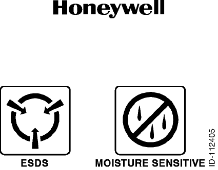
C. Symbols
(1) The symbols and special characters are in agreement with IEEE Publication 260 and IEC
Publication 27. Special characters in text are spelled out.
(2) The signal mnemonics, unit control designators, and test designators are shown in capital
letters.
(3) The signal names followed by an “*” show an active low signal.
(4) The symbols in Figure INTRO-1 show ESDS and moisture sensitive devices.
Draft as of 10/15/2012
Draft
Page INTRO-2
6 Dec 2012
34-70-06
SYSTEM INSTALLATION MANUAL
066-01204 / 066-01213
© Honeywell International Inc. Do not copy without express permission of Honeywell.
Figure INTRO-1. Symbols (Sheet 1 of 1)
D. Units of Measure
(1) Measurements, weights, temperatures, dimensions, and other values are expressed in the
USMS followed by the appropriate SI metric units in parentheses. Some standard tools or
parts such as drills, taps, bolts, nuts, etc. do not have an equivalent.
E. Standard Practices Manual
(1) Standard cleaning, check, repair, and assembly procedures applicable to multiple models
can be found in a standard practices manual. Refer to Paragraph 3, References.
F. Electrostatic Discharge
(1) Touch the items susceptible to electrostatic discharge in accordance with MIL-HDBK-263.
Refer to MIL-STD-1686 for definition of the standards and conditions.
2. Customer Support
A. Honeywell Aerospace Online Technical Publications Website
(1) Go to the Honeywell Online Technical Publications Website at (www.myaerospace.com).
• To download or see publications online
• To order a publication
• To tell Honeywell of a possible data error in a publication.
B. Global Customer Care Center
(1) If you do not have access to the Honeywell Technical Publications Website, or if you need to
speak to personnel about non-Technical Publication matters, the Honeywell Aerospace
Global Customer Care Center gives 24/7 customer service to Air Transport & Regional,
Business & General Aviation, and Defense & Space customers around the globe.
• Telephone: 800-601-3099 (Toll Free U.S.A./Canada)
• Telephone: 602-365-3099 (International)
• Telephone: 00-800-601-30999 (EMEA Toll Free)
• Telephone: 420-234-625-500 (EMEA Direct).
Draft as of 10/15/2012

Draft
Page INTRO-3
6 Dec 2012
34-70-06
SYSTEM INSTALLATION MANUAL
066-01204 / 066-01213
© Honeywell International Inc. Do not copy without express permission of Honeywell.
3. References
A. Honeywell/Vendor Publications
(1) Related Honeywell publications in this manual are shown in the list that follows:
• ATA No. 34-70-07 (Pub. No. 006-15716-0000), CMM, KSN 765/770 Safety Navigator
• Pub. No. A09-1100-004, Standard Repair Procedures for Honeywell Avionics Equipment
Instruction Manual.
B. Other Publications
(1) These publications are standard references. Check for latest version of publication.
• The United States GPO Style Manual 2000 (available at
http://www.gpoaccess.gov/stylemanual/browse.html)
• IEEE Std 260, Standard Letter Symbols for Units of Measurement (available from the
American National Standards Institute, New York, NY)
• ASME Y14.38, Abbreviations for Use on Drawings and in Text (available from the
American National Standards Institute, New York, NY)
• ANSI/IEEE Std 91, Graphic Symbols for Logic Functions (available from the American
National Standards Institute, New York, NY)
• H4/H8 CAGE Codes (available at http://www.logisticsinformationservice.dla.mil)
• IEEE 315/ANSI Y32.2, Graphic Symbols for Electrical and Electronics Diagrams
(available from the American National Standards Institute, New York, NY)
• MIL-HDBK-263, Electrostatic Discharge Control Handbook for Protection of Electrical
and Electronic Parts, Assemblies and Equipment (Excluding Electrically Initiated
Explosive Devices) (Metric) (available from any military standards database)
• MIL-STD-1686, Electrostatic Discharge Control Program for Protection of Electrical and
Electronic Parts, Assemblies and Equipment (Excluding Electrically Initiated Explosive
Devices) (Metric) (available from any military standards database).
4. Acronyms and Abbreviations
A. General
(1) The abbreviations are used in agreement with ASME Y14.38.
(2) Acronyms and non-standard abbreviations used in this publication are as follows:
List of Acronyms and Abbreviations
Term Full Term
AC alternating current
AHRS attitude heading reference system
Draft as of 10/15/2012

Draft
Page INTRO-4
6 Dec 2012
34-70-06
SYSTEM INSTALLATION MANUAL
066-01204 / 066-01213
© Honeywell International Inc. Do not copy without express permission of Honeywell.
AMP ampere
ANSI American National Standards Institute
ARTCC air route traffic control center
ARINC Aeronautical Radio, Incorporated
ASME American Society of Mechanical Engineers
ATA Air Transport Association
AWG American wire gauge
C celsius
CAGE commercial and government entity
CDI course deviation indicator
COM communication
cm centimeter
CMM component maintenance manual
dB decibel
DC direct current
DME distance measuring equipment
DPL detailed parts list
EB engineering bulletin
EGPWS enhanced ground proximity warning system
EIA Electronic Industries Association
ELT emergency locator transmitter
EMEA Europe, the Middle East, and Africa
ESDS electrostatic discharge sensitive
EZ electrically zeroed
F fahrenheit
FMS flight manual supplement
FSS flight service station
GND ground
GPO Government Printing Office
GPS ground positioning satellite
HSI horizontal situation indicator
Hz Hertz
List of Acronyms and Abbreviations (Cont)
Term Full Term
Draft as of 10/15/2012

Draft
Page INTRO-5
6 Dec 2012
34-70-06
SYSTEM INSTALLATION MANUAL
066-01204 / 066-01213
© Honeywell International Inc. Do not copy without express permission of Honeywell.
ICAO International Civil Aviation Organization
IEC International Electrotechnical Commission
IEEE Institute of Electrical and Electronics Engineers
IFIS electronic flight information system
IFR instrument flight rule
I/O input/output
INS inertial navigation system
IRU inertial reference unit
kg kilogram
KRC King Radio Company
LCD liquid crystal display
LPV localizer performance with vertical guidance
LOC localizer
mA milliampere
MAX maximum
MFD multifunction display
MOD modification
mm millimeter
MMDS multimode digital sensor
mW milliwatt
N/A not applicable
NAV navigation
NAVAID navigational aid
NBD non-directional beacon
nm nautical mile
No. number
OBS omni-bearing selector
ORZ omni-range zeroed
PN part number
Pub. publication
RAIM receiver autonomous integrated monitor
RDR radar
List of Acronyms and Abbreviations (Cont)
Term Full Term
Draft as of 10/15/2012

Draft
Page INTRO-6
6 Dec 2012
34-70-06
SYSTEM INSTALLATION MANUAL
066-01204 / 066-01213
© Honeywell International Inc. Do not copy without express permission of Honeywell.
REF reference
RF radio frequency
RX receive
SB service bulletin
SBAS satellite based augmentation system
SID standard instrument departure
SIM system installation manual
SSM sign status matrix
STAR standard terminal arrival route
STC supplemental type certificate
SUA special-use airspace
TAS traffic awareness system
TAWS terrain awareness and warning system
TCAS traffic collision avoidance system
THD TBD BY ENGINEERING
TIS traffic information service
TR temporary revision
TSO Technical Standard Order
TX transmit
VHF very high frequency
VOR very high frequency omnidirectional range
USB universal serial bus
USMS United States Measurement System
VAC volt, alternating current
VDC volt, direct current
VLOC very high frequency omni-range localizer
VNAV vertical navigation
VOR very high frequency omni-range
WAAS wide area augmentation system
WOW weight on wheels
Vrms volt, root-mean-square
WX weather
List of Acronyms and Abbreviations (Cont)
Term Full Term
Draft as of 10/15/2012

Draft
Page INTRO-7
6 Dec 2012
34-70-06
SYSTEM INSTALLATION MANUAL
066-01204 / 066-01213
© Honeywell International Inc. Do not copy without express permission of Honeywell.
5. Process Verification
A. Verification Data
(1) Honeywell does a verification of these technical instructions by performance or by simulation
of the necessary procedures. Performance shows that the procedures were checked by the
use of the manual. Simulation shows that the applicable personnel looked at the procedure
in the manual and that the procedure is technically correct. The dates of verification for this
manual are given in Table INTRO-1.
6. Software History
A. Software Data
(1) Not applicable.
7. History of Changes
A. Modification/Configuration History
(1) Not applicable.
B. Change History for Parts List
(1) Not applicable.
XM satellite based flight information services weather source
Table INTRO-1. Verification Data
Section Method Date
TBD TBD TBD
TBD TBD TBD
TBD TBD TBD
List of Acronyms and Abbreviations (Cont)
Term Full Term
Draft as of 10/15/2012

Draft
Page INTRO-8
6 Dec 2012
34-70-06
SYSTEM INSTALLATION MANUAL
066-01204 / 066-01213
© Honeywell International Inc. Do not copy without express permission of Honeywell.
Blank Page
Draft as of 10/15/2012

Draft
Page 1-1
6 Dec 2012
34-70-06
SYSTEM INSTALLATION MANUAL
066-01204 / 066-01213
© Honeywell International Inc. Do not copy without express permission of Honeywell.
SECTION I - GENERAL INFORMATION
1.1 Introduction
This manual contains information relative to the physical, mechanical, and electrical characteristics of the
KSN 7xx Safety Navigator. Installation and operating procedures are also included.
Operating instructions are provided in KSN 7xx Pilot’s Manual, Pub. No. 006-18324-0000. Information
relative to the maintenance, alignment, and procurement of the replacement parts can be found in the ATA
No. 34-70-07 (Pub. No. 006-15716-0000), CMM, KSN 765/770 Safety Navigator.
1.2 Applicability of the Installation Manual
This manual is applicable only to the KSN 7xx integrated avionics systems with the part numbers as
shown in Table 1-1.
1.3 Description of the Equipement
1.3.1 KSN 7xx Safety Navigator
The KSN 7xx product family feature is a full featured WAAS, integrated GPS navigator capable of LPV
approaches. Some of the system features include:
A. A TSO, GPS based, long range airborne database driven navigation. The primary purpose of the
KSN 7xx is to provide the pilot with present position information, to display guidance information
with respect to a flight plan defined by the pilot, and to provide communications functions to the
pilot. Flight plan information is entered by the pilot via the concentric knobs and buttons on the front
panel.
B. A front loading pilot updateable database using a USB 2.0 thumb drive. Databases contain
worldwide information on NAVAID, intersections, low altitude airways, terrain, obstructions and
minimum safe altitudes. Database also includes public use and military airports with runways at
least 3000 feet (914.4 meters) in length, airport communication frequencies, runway information,
air route traffic control center data, flight service station frequencies, and SUA. SID and STAR
waypoints and approaches are also included. The information can be selected by airport and
procedure name.
Table 1-1. Installation Manual Applicability
System PN Description
KSN 765 300-10940-0000 Top level assembly
066-01213-0101 Safety Navigator
066-01213-1101 Safety Navigator with RDR/EGPWS Support
KSN 770 300-10694-0000 Top level assembly
066-01204-0101 Safety Navigator NAV/COM
066-01204-1101 Safety Navigator NAV/COM with RDR/EGPWS
Support
Draft as of 10/15/2012
765/770 - would prefer to see this throughout the manual

Draft
Page 1-2
6 Dec 2012
34-70-06
SYSTEM INSTALLATION MANUAL
066-01204 / 066-01213
© Honeywell International Inc. Do not copy without express permission of Honeywell.
C. Information on the KSN 7xx is displayed on a large, easy-to-read color LCD. Pilot information is
input to the unit via flexible combination of touchscreen and graphics interface combined with
cursor control and by the 16 push buttons on the front panel.
D. An optional NAV receiver and COM transceiver that will allow integrated navigation and
communications on KSN 7xx units so equipped.
The KSN 7xx can use its present position information to determine crosstrack error,
distance-to-waypoint, ground speed, track angle, time-to-waypoint and bearing to waypoint.
The KSN 7xx can provide navigation data to external displays and autopilots. Some of this data is output
to external devices.
The internal database of the KSN 7xx contains information concerning airports, VOR, NDB, SUAs,
airport runways and frequency location information, and nearest FSS and ARTCC names and
frequencies. Waypoints are stored in the database by their ICAO identifiers. The ICAO identifiers are
(in most cases) taken directly from Jeppesen or government aeronautical charts.
1.3.2 GPS Antenna
The KA 96 GPS antenna, PN 071-01620-0001 or equivalent is the designated antenna for the KSN 7xx.
1.3.3 KCM 200 Configuration Module
The configuration module is used to store some installation specific information, which is used by the
KSN 7xx. The KCM 200 configuration module used with the KSN 7xx, is supplied with the KSN 7xx and
is also available under PN 071-00188-1101.
1.4 Technical Characteristics
Refer to Table 1-2 for the KSN 765 Safety Navigator leading particulars.
Refer to Table 1-3 for the KSN 770 Safety Navigator leading particulars.
Table 1-2. KSN 765 Safety Navigator Leading Particulars
Characteristic Specification
TSO compliance TSO C146c, TSO-C165, TSO-C113, TSO-C63c,
TSO-C147, TSO-C118, TSO-C157a, TSO-C110a,
TSO-C151b, ETSO-2C63c
Length 11.80 inches (299.8 mm)
Width 6.25 inches (158.8 mm)
Height 5.40 inches (137.2 mm)
Weight Refer to SECTION II - INSTALLATION
Mounting Panel mount
Environmental conditions RTCA/DO-160G
Temperature 4 to 131°F (20 to +55°C)
Altitude 25,000 feet (7,620 meters)
Draft as of 10/15/2012

Draft
Page 1-3
6 Dec 2012
34-70-06
SYSTEM INSTALLATION MANUAL
066-01204 / 066-01213
© Honeywell International Inc. Do not copy without express permission of Honeywell.
Vibration Category S, curves B & M; Category R curve G
Electrical:
Operating voltage +11 to +33 VDC
Operating current:
+28 VDC 4.9 AMP MAX
+14 VDC 8.6 AMP MAX
Software RTCA/DO-178B Levels B and C
Hardware RTCA/DO-254 Levels B and C
Table 1-3. KSN 770 Safety Navigator Leading Particulars
Characteristic Specification
TSO compliance TSO C146c, TSO-C165, TSO-C113, TSO-C63c,
TSO-C147, TSO-C118, TSO-C157a, TSO-C110a,
TSO-C151b, ETSO-2C63c, TSO-C169a,
TSO-C128a, TSO-C34e, TSO-C36e, TSO-C40c,
ETSO-2C34f, ETSO-2C36F, ETSO-2C169a,
ETSO-2C40c, and ETSO-2C128
Length 11.80 inches (299.8 mm)
Width 6.25 inches (158.8 mm)
Height 5.40 inches (137.2 mm)
Weight Refer to SECTION II - INSTALLATION
Mounting Panel mount
Environmental conditions RTCA/DO-160G
Temperature 4 to 131°F (20 to +55°C)
Altitude 25,000 feet (7,620 meters)
Vibration Category S, curves B & M; Category R curve G
Electrical:
Operating voltage +11 to +33 VDC
Operating current:
+28 VDC 4.9 AMP MAX Steady State, 12.4 AMP TX
+14 VDC 8.6 AMP MAX Steady State, 15.6 AMP TX
Software RTCA/DO-178B Levels B and C
Table 1-2. KSN 765 Safety Navigator Leading Particulars (Cont)
Characteristic Specification
Draft as of 10/15/2012

Draft
Page 1-4
6 Dec 2012
34-70-06
SYSTEM INSTALLATION MANUAL
066-01204 / 066-01213
© Honeywell International Inc. Do not copy without express permission of Honeywell.
1.5 Units Supplied
1.5.1 KSN 7xx Safety Navigator
Refer to Table 1-1 for the available configurations.
1.5.2 GPS Antennas
The KA 96 GPS active antenna, PN 071-01620-0001 is the designated antenna for the KSN 770 Safety
Navigator, and must be ordered separately.
1.6 License Requirements
An aircraft radio station license is no longer required for the KSN 7xx models that transmit for domestic
(US) operations. For international travel, forms can be obtained from your nearest FCC field office or
found online at http://transition.fcc.gov/Forms/Form605/605.html/ (See the regulatory authority for all
countries in which the KSN 7xx will be operated for more information).
1.7 Recommendations for IFR Approval
The following functions are required for IFR certification of the KSN 7xx.
A. Aircraft Logbook Entry
B. Aircraft Installation Requirements
(1) TSO’d Antenna
The antenna must be a TSO’d KA 96 GPS antenna, PN 071-01620-0001 or equivalent.
(2) NAV Instrumentation
The navigation information (D-Bar, NAV Flag, and TO-FROM) must be displayed on an
instrument in the pilot’s panel within the pilot’s field of view. Electromechanical indicators are
capable of displaying the variable scale factors of enroute, terminal, and approach modes. If
the NAV information is displayed on an EFIS system, it must be capable of displaying variable
D-Bar scaling required for GPS approaches. This may require a modification to the EFIS
system. Refer to SECTION III - SYSTEM INTERCONNECT for the typical indicator usage.
(3) OBS Interface
For approach approval, the OBS resolver must be interfaced so that selected course through
the HSI/CDI indicator will be sent to the KSN 7xx for D-Bar resolution. In mechanical
indicators, it will be accomplished by switching the OBS resolver lines; in EFIS installations,
it will usually be through the serial busses. Some EFIS applications may require an adapter.
Refer to SECTION III - SYSTEM INTERCONNECT for further information regarding OBS
resolver characteristics.
Hardware RTCA/DO-254 Levels B and C
Table 1-3. KSN 770 Safety Navigator Leading Particulars (Cont)
Characteristic Specification
Draft as of 10/15/2012

Draft
Page 1-5
6 Dec 2012
34-70-06
SYSTEM INSTALLATION MANUAL
066-01204 / 066-01213
© Honeywell International Inc. Do not copy without express permission of Honeywell.
(4) Switch/Annunciators
Refer to SECTION III - SYSTEM INTERCONNECT for specific information regarding
switch/annunciator characteristics.
(5) Altitude Source
An altitude source is required for IFR certification. The altitude may be derived from a
compatible encoding altimeter, some RS 232 air data systems, and most ARINC 429/575 air
data systems. Refer to SECTION III - SYSTEM INTERCONNECT for further information
regarding altitude source characteristics.
C. Approved Airplane Flight Manual Supplement
A flight manual supplement will need to be prepared and approved. The supplement may be
prepared based on the sample. Refer to the FMS Appendix and the STC Appendix (TBD BY
ENGINEERING), for further information.
D. Pilot’s Guide
The KSN 770 Pilot’s Guide must be placed in the aircraft in a location that is accessible to the pilot.
The Pilot’s Guide is PN 006-18324-0000.
Draft as of 10/15/2012

Draft
Page 1-6
6 Dec 2012
34-70-06
SYSTEM INSTALLATION MANUAL
066-01204 / 066-01213
© Honeywell International Inc. Do not copy without express permission of Honeywell.
Blank Page
Draft as of 10/15/2012

Draft
Page 2-1
6 Dec 2012
34-70-06
SYSTEM INSTALLATION MANUAL
066-01204 / 066-01213
© Honeywell International Inc. Do not copy without express permission of Honeywell.
SECTION II - INSTALLATION
2.1 Overview
This section contains suggestions and factors to consider before installing the KSN 7xx Safety Navigator.
Close adherence to these suggestions will assure satisfactory performance from the equipment.
NOTE: The conditions and tests performed on this article are minimum performance standards. It is the
responsibility of those desiring to install this article either on or within a specific type or class of
aircraft to determine that the aircraft installation conditions are within these performance
standards. The article may be installed only if further evaluation by the applicant documents an
acceptable installation and is approved by the Administrator.
2.2 Unpacking and Inspecting Equipment
Exercise extreme caution when unpacking equipment. Perform a visual inspection of the unit for evidence
of damage incurred during shipment. If a damage claim must be filed, save the shipping container and all
packing materials to substantiate your claim. The claim must be filed as soon as possible. The shipping
container and all packing materials must be retained in the event that storage or reshipment of the
equipment is necessary.
2.3 KSN 7xx Installation
2.3.1 General
The following paragraphs contain information pertaining to the installation of the KSN 7xx, including
instructions concerning the location and mounting of the antenna.
The equipment must be installed in the aircraft in a manner consistent with acceptable workmanship
and engineering practices, and in accordance with the instructions set forth in this publication. To ensure
the system has been properly and safely installed in the aircraft, the installer must make a thorough
visual inspection and conduct an overall operational check of the system, on the ground, prior to flight.
CAUTION: AFTER INSTALLATION OF THE CABLING AND BEFORE INSTALLATION OF THE
EQUIPMENT, A CHECK MUST BE MADE WITH THE AIRCRAFT PRIMARY POWER
SUPPLIED TO THE MOUNTING CONNECTOR TO ENSURE THAT POWER IS APPLIED
ONLY TO THE PINS SPECIFIED IN THE INTERWIRING DIAGRAMS IN SECTION III.
The KSN 7xx system installation will conform to standards designated by the customer, installing
agency, and existing conditions as to the unit location and type of installation. However, the following
suggestions must be carefully considered before installing your KSN 7xx system.
Draft as of 10/15/2012

Draft
Page 2-2
6 Dec 2012
34-70-06
SYSTEM INSTALLATION MANUAL
066-01204 / 066-01213
© Honeywell International Inc. Do not copy without express permission of Honeywell.
2.3.2 Minimum System Configuration
2.3.3 Installation Materials
2.3.3.1 Installation Kit Contents
2.3.3.1.1 KSN 765 Safety Navigator
Refer to Table 2-1 for the KSN 765 Installation Kit, PN PL050-03727-0000.
Table 2-1. KSN 765 Safety Navigator Installation Kit, PN PL050-03727-0000
Description Qty Bendix/King PN
Connector, D-SUB, 27 mixed size crimp contacts, straight 1 53500239-2
Contact, female, 10 AMP power, combo-D, 16 AWG, crimp, female 4 030-01454-0002
Connector, 2-row, 50 sockets, board to cable - 0.156, crimp, straight 1 53502330-1
Contact, socket, crimp, 20 AWG 42 030-01157-0011
Connector, SUB-D HSG 37 contact, female sockets 1 030-01175-0000
Connector, contact, board to cable, crimp, 20-24 AWG socket 24 53502674-1
Connector, 25 contact subd hood 1 030-01447-0000
Connector, 37 contact subd hood 1 030-01447-0001
Contact, D-sub, 22 AWG, crimp, female 156 030-01466-0001
Connector, high density subd, 78 contact 2 030-03296-0001
Connector, 50 ohms BNC jack to push-on adaptor 1 030-03589-0001
Connector, 75 ohms BNC jack to push-on adapter 1 030-03589-0002
Rack chassis assembly with finish 1 047-11434-0004
Nut plate, 50 pos as finish 2 073-01158-0003
Nut plate, 25 pos as finishing 1 073-01159-0003
Rear panel with hardware 1 073-01160-0004
Nut plate, 37 pos as finish 1 073-01161-0003
Spacer as finish 2 076-03228-0002
Nut clip, 6-32 10 089-02353-0001
Screw, pan head, #4-40 x 3/8 4 089-05903-0006
Screw, pan head, #4-40 x 7/16 2 089-05903-0007
Screw, pan head, #4-40 x 13/16 6 089-05903-0013
Screw, flat head, #4-40 x 3/8 4 089-06008-0006
Screw, flat head, #6-32 x 3/8 10 089-06012-0006
Draft as of 10/15/2012

Draft
Page 2-3
6 Dec 2012
34-70-06
SYSTEM INSTALLATION MANUAL
066-01204 / 066-01213
© Honeywell International Inc. Do not copy without express permission of Honeywell.
2.3.3.1.2 KSN 770 Safety Navigator
Refer to Table 2-2 for the KSN 70 Installation Kit, PN PL050-03727-0001.
Cable assembly, fan 1 155-12514-0001
Metal backshell kit, deep straight, DD shell size (kit consists of 1 shell, 2
cable clamps, 2 screws and 2 hex nuts) 2 53002878-1
Connector, board to cable - 3 mm, crimp, 1-row, sockets-004, straight,
receptacle housing, latch 1 53500258-1
Connector contact, (board to cable, crimp, 20-24 AWG socket 4 53500259-1
Fan gasket 2 57000118-001
Shoulder screw, #4-40 6 57000119-001
KCM 200 KSN 7xx configuration module 1 071-00188-0201
KSN 7xx installation drawing 1 155-01812-0000
Connector, sub-D HSG 25 contact, female pins 1 030-01173-0000
Table 2-2. KSN 770 Safety Navigator Installation Kit, PN PL050-03727-0001
Description Qty Bendix/King PN
Connector, D-sub, 27 mixed size crimp contacts, straight 1 53500239-2
Contact, female, 10 AMP power, combo-D, 16 AWG, crimp, female 4 030-01454-0002
Connector, 2-row, 50 sockets, board to cable - 0.156, crimp, straight 1 53502330-1
Contact, socket, crimp, 20 AWG 42 030-01157-0011
Connector, sub-D HSG 37 contact, female sockets 1 030-01175-0000
Connector, contact, board to cable, crimp, 20-24 AWG socket 24 53502674-1
Connector, 25 contact subd hood 1 030-01447-0000
Connector, 37 contact subd hood 1 030-01447-0001
Contact, D-sub, 22 AWG, crimp, female 156 030-01466-0001
Connector, high density subd, 78 contact 2 030-03296-0001
Connector, 50 ohms BNC jack to push-on adaptor 1 030-03589-0001
Connector, 75 ohms BNC jack to push-on adapter 1 030-03589-0002
Rack chassis assembly with finish 1 047-11434-0004
Nut plate, 50 pos as finish 2 073-01158-0003
Nut plate, 25 pos as finishing 1 073-01159-0003
Table 2-1. KSN 765 Safety Navigator Installation Kit, PN PL050-03727-0000 (Cont)
Description Qty Bendix/King PN
Draft as of 10/15/2012
REF

Draft
Page 2-4
6 Dec 2012
34-70-06
SYSTEM INSTALLATION MANUAL
066-01204 / 066-01213
© Honeywell International Inc. Do not copy without express permission of Honeywell.
2.3.3.2 Accessories Required But Not Supplied
Table 2-3 list the available equipment (but not supplied) to assist in installation of the KSN 7xx. Other
equipment may be acceptable; refer to the appropriate section in this manual for other options.
Rear panel with hardware 1 073-01160-0004
Nut plate, 37 pos as finish 1 073-01161-0003
Spacer as finish 2 076-03228-0002
Nut clip, 6-32 10 089-02353-0001
Screw, pan head, #4-40 x 3/8 4 089-05903-0006
Screw, pan head, #4-40 x 7/16 2 089-05903-0007
Screw, pan head, #4-40 x 13/16 6 089-05903-0013
Screw, flat head, #4-40 x 3/8 4 089-06008-0006
Screw, flat head, #6-32 x 3/8 10 089-06012-0006
Cable assembly, fan 1 155-12514-0001
Metal backshell kit, deep straight, DD shell size (kit consists of 1 shell, 2
cable clamps, 2 screws and 2 hex nuts) 2 53002878-1
Connector, board to cable - 3 mm, crimp, 1-row, sockets-004, straight,
receptacle housing, latch 1 53500258-1
Connector contact, board to cable, crimp, 20-24 AWG socket 4 53500259-1
Fan gasket 2 57000118-001
Shoulder screw, #4-40 6 57000119-001
KCM 200 KSN 7xx configuration module 1 071-00188-0201
KSN 7xx installation drawing 1 155-01812-0000
Connector, sub-D HSG 25 contact, female pins 1 030-01173-0000
Table 2-3. Accessories Required But Not Supplied
Description Qty Source PN 1
Circuit breaker (pull to open, 10 AMP main
power in) 1 Klixon MS26574-10
Circuit breaker (pull to open, 7.5 AMP MMDS
TX power in) 1 Klixon MS26574-7.5
Wire (single strand, 20, 22, 24 AWG) AR commercially available MIL-W-22759/16
Wire (shielded, 22 AWG) AR commercially available MIL-C-27500
Table 2-2. KSN 770 Safety Navigator Installation Kit, PN PL050-03727-0001 (Cont)
Description Qty Bendix/King PN
Draft as of 10/15/2012
REF

Draft
Page 2-5
6 Dec 2012
34-70-06
SYSTEM INSTALLATION MANUAL
066-01204 / 066-01213
© Honeywell International Inc. Do not copy without express permission of Honeywell.
2.3.3.3 Optional Accessories - Not Supplied
Refer to Table 2-4 for the accessories required but not supplied.
Screw (flat head, #6-32) 26 commercially available MS24693-S30
Wire (coaxial cable) AR commercially available MIL-DTL-17
Nut (locknut, #6-32) 26 commercially available MS21044N06
Washer (#6) 26 commercially available NAS1149FN632P
Antenna (broadband communications, 50
ohms) 1 Dorne DM C70-1/A
Antenna (VHF NAV, 50 ohms) 1 Comant CI-158C-2 3
Antenna (GPS) 1 CAGE: 22373 KA 96
Configuration module 1 CAGE: 22373 KGS 200
adhesive commercially available RTV3145
Alumiprep No. 33 Turco 594015
Alodine No. 1001 Henkel 594417
Electrical insulating compound Dow Corning DC-4
Misc. screws, washers, cable ties, etc. commercially available Installer supplied
NOTE:
1. Equivalent substitute can be used.
2. Use to mount the tray.
3. Must also order PN 0900532 for gasket and template.
Table 2-4. Accessories Required But Not Supplied
Description Qty Source PN
Annunciator panel 1 Mid-Continent MD41
CDI 1 Various Refer to Paragraph
3.12 NAV Indicator
Interface
Remote swap switch - NAV 1
Remote swap switch - COM 1
Remote switch - Next FREQ 1
Thumb drive 1
Table 2-3. Accessories Required But Not Supplied (Cont)
Description Qty Source PN 1
Draft as of 10/15/2012
Table 2-3
We should not be calling out specific brands and models of antennas, except in the case of Honeywell
specific.
Comm and Nav antennas should be generically described
I don't like the term commercially available. We will be asked for Honeywell P/N's or equivalent.
Table 2-4
We want to be more flexible about the callout of Annunciator Panels. There are a lot of vendors that shops will
want to use.
The Remote swap switches, remote switch and Thumb drives need to be better described.
We should not be calling out specific brands and models of Antenna splitter, NAV. There are many that are
suitable.

Draft
Page 2-6
6 Dec 2012
34-70-06
SYSTEM INSTALLATION MANUAL
066-01204 / 066-01213
© Honeywell International Inc. Do not copy without express permission of Honeywell.
2.3.3.4 Software Options
2.3.3.4.1 Operational Software, refer to Table 2-5.
2.3.3.4.2 Aviation Database
The Aviation Databases that are updated on a 28 day cycle are identified with a part number
specified with the following notation:
YY = Last two digits of the current year
CC – Cycle Number (01-13)
2.3.3.4.2.1 Americas Database, refer to Table 2-6.
2.3.3.4.2.2 Atlantic Database, refer to Table 2-7.
Antenna splitter, NAV 1 Comant CI-1125
Table 2-5. Operational Software
Software Description PN
KSN 765 Safety Navigator 206-0476-0101
KSN 770 Safety Navigator 206-00454-0101
Table 2-6. Americas Database
Database Description Part Number
Americas aviation database 723-429YY-00CC
Americas navigation database 723-432YY-00CC
Americas cartography database 723-435YY-00CC
Americas terrain database 723-43800-0000
Americas database data File 723-440YY-00CC
Table 2-7. Atlantic Database
Database Description Part Number
Americas aviation database 723-430YY-00CC
Americas navigation database 723-433YY-00CC
Americas cartography database 723-436YY-00CC
Americas terrain database 723-43800-0001
Americas database data File 723-441YY-00CC
Table 2-4. Accessories Required But Not Supplied (Cont)
Description Qty Source PN
Draft as of 10/15/2012
Table 2-5
Do we really want to call out Operational Software in an Install Manual.
206-xxxxx-yyyy's belong in the CMM?
Table 2-6, 2-7 & 2-8 Databases
Are 723 Numbers appropriate for the install manual? Aren't these Engineering drawing
numbers?

Draft
Page 2-7
6 Dec 2012
34-70-06
SYSTEM INSTALLATION MANUAL
066-01204 / 066-01213
© Honeywell International Inc. Do not copy without express permission of Honeywell.
2.3.3.4.2.3 Pacific Database, refer to Table 2-8.
2.3.3.5 Special Tools Required, refer to Table 2-9.
2.3.4 KSN 7xx Installation Considerations
Care must be exercised to avoid mounting components near equipment operating with high pulse
current or high power outputs such as radar and satellite communications equipment. In general, the
equipment must be installed in a location convenient for operation, inspection, and maintenance, and
in an area free from excessive vibration, heat, and noise generating sources.
2.3.4.1 KSN 7xx Mounting Considerations
The KSN 7xx installation will conform to standards designated by the customer, installing agency, and
existing conditions as to the unit location and type of installation. However, the following suggestions
will assure more satisfactory performance from the equipment.
A. Plan a location on the aircraft so that the KSN 7xx is plainly visible to the pilot, and so that the
pilot has complete access to all front panel controls (refer to Paragraph 2.3.4.2 Field of View
Considerations for more information).
NOTE: Care must be taken in selecting the optimum location for the KSN 7xx. In some
potential mounting locations, glare and reflections may cause the display to be nearly
unreadable. Therefore, careful considerations of these effects must be made before
choosing the final mounting location.
B. Check to be sure that there is adequate depth behind the unit for connectors and cabling.
Table 2-8. Pacific Database
Database Description Part Number
Americas aviation database 723-431YY-00CC
Americas navigation database 723-432YY-00CC
Americas cartography database 723-435YY-00CC
Americas terrain database 723-43800-0002
Americas database data File 723-440YY-00CC
Table 2-9. Special Tools Required
Number 1Description Source
9507 Crimp tool (D-Sub) commercially available
9502-3 Crimp tool positioner (D-Sub) commercially available
4811-1-0-0 Insertion/Extraction Tool (D-Sub) commercially available
NOTE:
1. Equivalent substitute can be used.
Draft as of 10/15/2012
same question as Table
2-6 & 2-7
Table 2-9 Special Tools
We need much better information about the tools and how to get them

Draft
Page 2-8
6 Dec 2012
34-70-06
SYSTEM INSTALLATION MANUAL
066-01204 / 066-01213
© Honeywell International Inc. Do not copy without express permission of Honeywell.
C. Ensure there is at least 1.0 inch (25.4 mm) (minimum), unobstructed from the muffin fan.
D. Be sure that the mounting location is not close to heater vents or other sources of high heat.
E. Refer to Figure 2-4 for the cutout dimensions. Mark and cut the opening.
F. Mount the rails on either side of the cutout. Ensure that the rails are electrically bonded (less
than 10 milliohms to aircraft GND).
G. Attach the cable harness to the rear connectors. The KSN 7xx must be wired according to the
interconnect diagrams in Section III of this manual.
H. Attach the coaxial cables to the rear antenna connectors. Refer to Figure 2-6 for the details for
mounting the coaxial connectors to the coaxial cable.
I. Prior to installing any equipment, make a continuity check of all wires and cables associated
with the system. Then apply power and check for proper voltages at system connectors, and
then remove power before completing the installation.
J. Slide the unit in, and secure it.
2.3.4.2 Wiring Harness Consideration
To allow for inspection or repair of the wiring of the connector assembly itself, sufficient lead length
must be left so that when the mounting hardware for the rear connectors and antenna coaxial cable
is removed the assembly may be pulled forward several inches. Also, a bend must be made in the
harness (at the rear connectors) to allow water droplets that might form on the harness due to
condensation, to drip off at the bend and not collect in the connection.
The length of cables from the KSN 7xx connector to other system units is not generally critical
because unit interfaces are designed with high impedance inputs, low impedance outputs, and low
noise susceptibility characteristics. The exceptions are the wires from the KSN 7xx to the KCM 200
Configuration Module (refer to Paragraph 3.17 Miscellaneous Interface).
2.3.4.3 Field of View Considerations
TBD BY ENGINEERING – See AC 20-138A, TSO-C146c, FAA Issue Paper clarifying “…on or near
the affected display”.
2.3.4.3.1 Centerline Determination
The centerline of the acceptable field of view is determined in the following order:
(1) The centerline of the Basic T.
(2) For aircraft without the Basic T configuration, use the centerline of the pilot side control yoke
or stick, unless it is offset from the center position of the pilot’s seat (such as with a side stick
or Beech Bonanza style throw over style yoke).
(3) For aircraft without a centered yoke or control stick, an imaginary line from the center of the
pilot’s seat through the instrument panel may be used.
Draft as of 10/15/2012
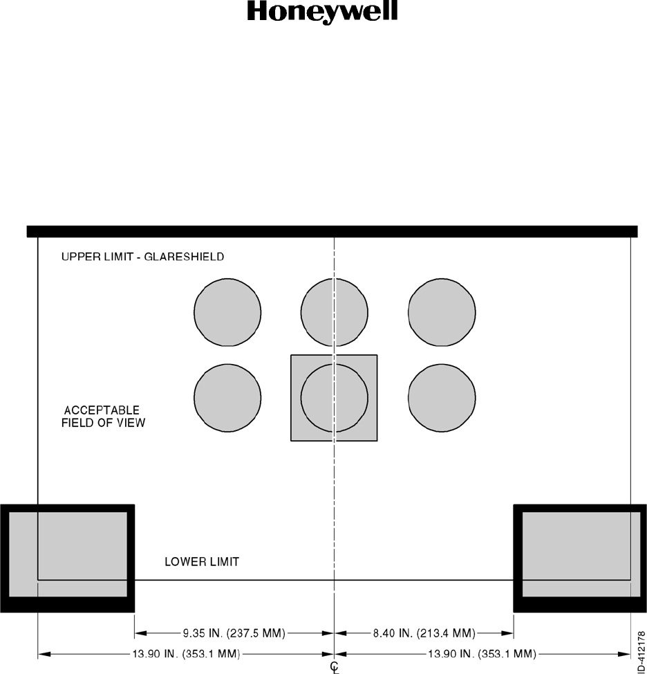
Draft
Page 2-9
6 Dec 2012
34-70-06
SYSTEM INSTALLATION MANUAL
066-01204 / 066-01213
© Honeywell International Inc. Do not copy without express permission of Honeywell.
2.3.4.3.2 CDI Source Selection
If the KSN 7xx is mounted in the field of view as shown in Figure 2-1, then no external annunciator
showing CDI source is required. If the KSN 7xx is mounted outside of this area, then an external
annunciator indicating whether VLOC or GPS is selected must be mounted in close proximity to
the CDI and within the field of view as shown in Figure 2-1.
Figure 2-1. Field of View - CDI Source Selection
Draft as of 10/15/2012
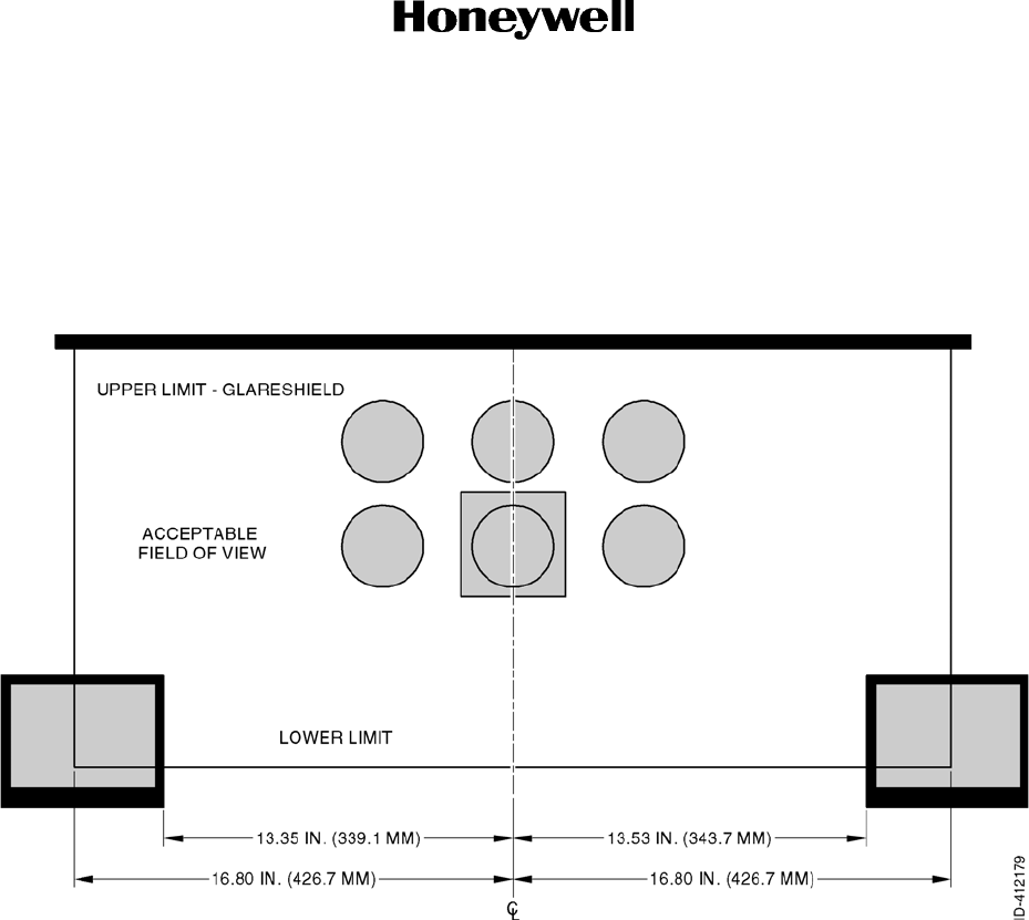
Draft
Page 2-10
6 Dec 2012
34-70-06
SYSTEM INSTALLATION MANUAL
066-01204 / 066-01213
© Honeywell International Inc. Do not copy without express permission of Honeywell.
2.3.4.3.3 GPS Annunciation
The GPS annunciations as shown in Figure 2-2 must be in the pilot’s field of view. If the KSN 7xx
is not mounted with the boarders defined in Figure 2-2, then an external annunciation must be
mounted within this field of view.
Figure 2-2. Field of View - GPS Annunciation
2.3.4.3.4 TAWS
Refer to Figure 2-3 for the TAWS.
Draft as of 10/15/2012
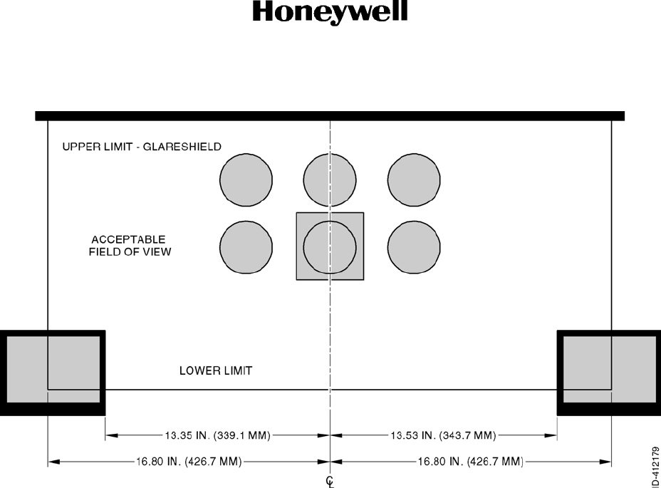
Draft
Page 2-11
6 Dec 2012
34-70-06
SYSTEM INSTALLATION MANUAL
066-01204 / 066-01213
© Honeywell International Inc. Do not copy without express permission of Honeywell.
Figure 2-3. Field of View - TAWS
2.3.4.4 Pressurized Aircraft Considerations
In pressurized aircraft, any wiring that penetrates the pressure vessel must be installed in accordance
with the Type Design of the aircraft. Considerations for penetrating the pressure vessel of the aircraft
for installation are beyond the scope of this manual.
2.3.5 KSN 7xx Cooling Requirements
External forced air cooling is not required for the KSN 7xx. Cooling fans are provided internal to the unit.
The KSN 7xx complies with DO 160C Paragraph 4.5.4 Category V for 30 minutes operation after in flight
loss of cooling at 104°F (40°C) ambient temperature and sea level pressure.
Draft as of 10/15/2012

Draft
Page 2-12
6 Dec 2012
34-70-06
SYSTEM INSTALLATION MANUAL
066-01204 / 066-01213
© Honeywell International Inc. Do not copy without express permission of Honeywell.
Blank Page
Draft as of 10/15/2012

Draft
SYSTEM INSTALLATION MANUAL
066-01204 / 066-01213
Page 2-13
6 Dec 2012
© Honeywell International Inc. Do not copy without express permission of Honeywell.
34-70-06
Figure 2-4. KSN 7xx Safety Navigator Outline Drawing
(Dwg. No. 155-01812-0000 Rev. E) (Sheet 1 of 4)
Draft as of 10/15/2012

Draft
SYSTEM INSTALLATION MANUAL
066-01204 / 066-01213
Page 2-14
6 Dec 2012
© Honeywell International Inc. Do not copy without express permission of Honeywell.
34-70-06
Blank Page
Draft as of 10/15/2012
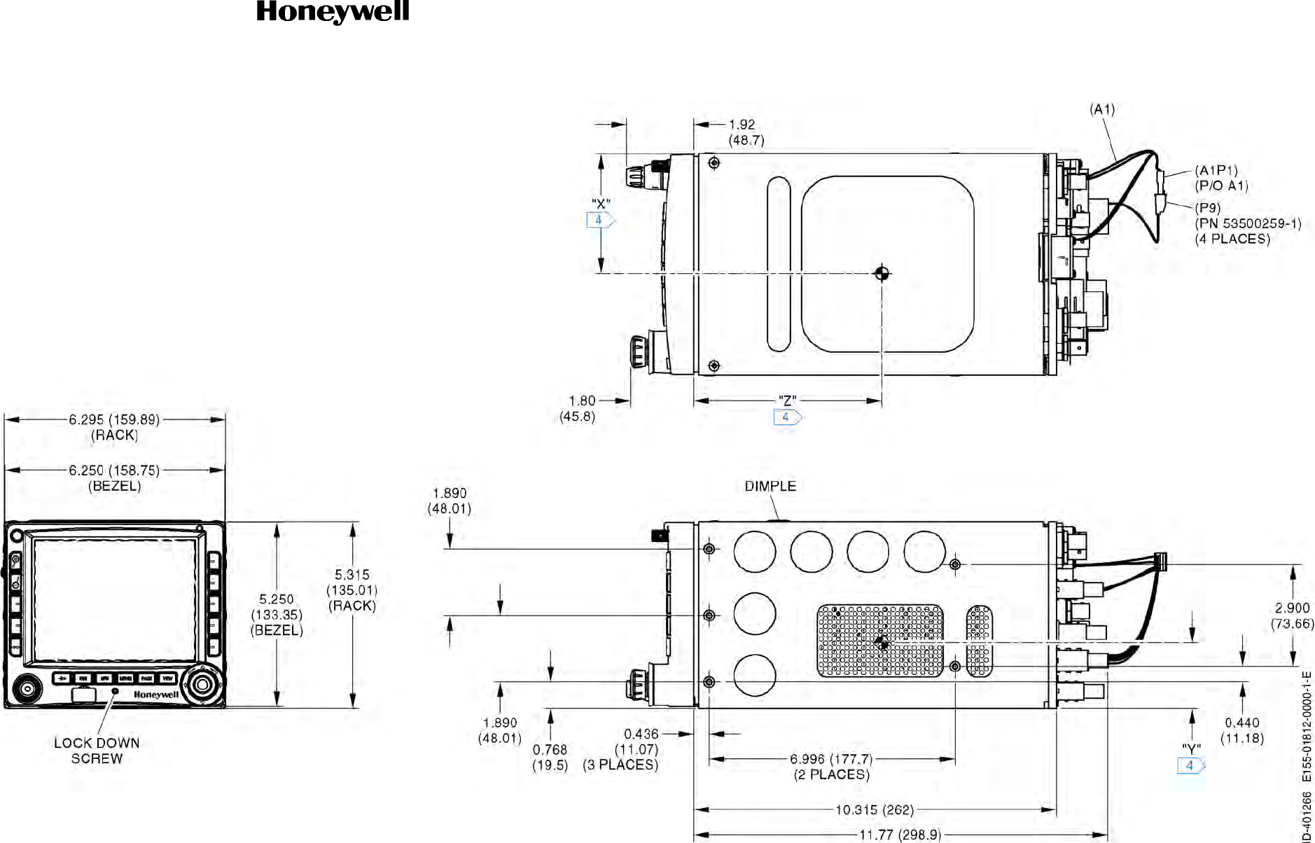
Draft
SYSTEM INSTALLATION MANUAL
066-01204 / 066-01213
Page 2-15
6 Dec 2012
© Honeywell International Inc. Do not copy without express permission of Honeywell.
34-70-06
Figure 2-4. KSN 7xx Safety Navigator Outline Drawing
(Dwg. No. 155-01812-0000 Rev. E) (Sheet 2 of 4)
Draft as of 10/15/2012

Draft
SYSTEM INSTALLATION MANUAL
066-01204 / 066-01213
Page 2-16
6 Dec 2012
© Honeywell International Inc. Do not copy without express permission of Honeywell.
34-70-06
Blank Page
Draft as of 10/15/2012
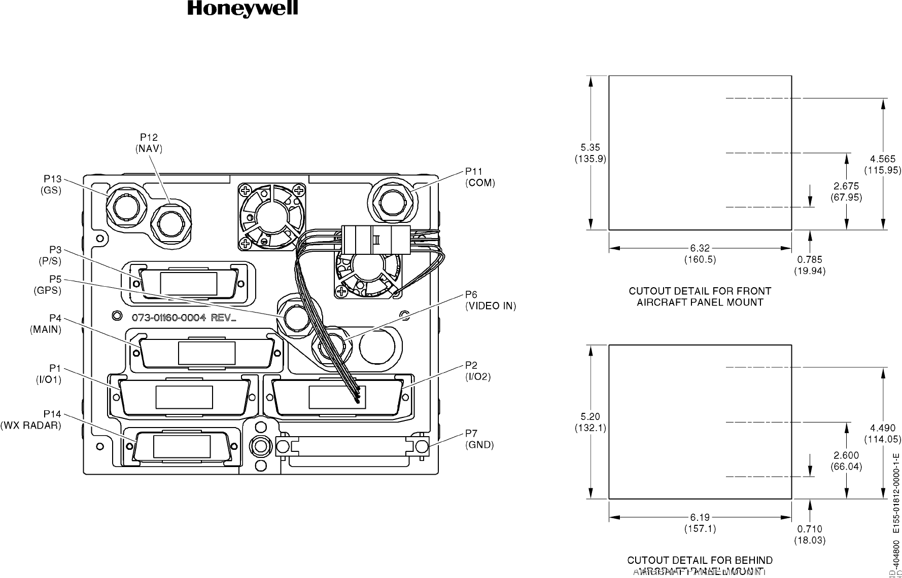
Draft
SYSTEM INSTALLATION MANUAL
066-01204 / 066-01213
Page 2-17
6 Dec 2012
© Honeywell International Inc. Do not copy without express permission of Honeywell.
34-70-06
Figure 2-4. KSN 7xx Safety Navigator Outline Drawing
(Dwg. No. 155-01812-0000 Rev. E) (Sheet 3 of 4)
Draft as of 10/15/2012

Draft
SYSTEM INSTALLATION MANUAL
066-01204 / 066-01213
Page 2-18
6 Dec 2012
© Honeywell International Inc. Do not copy without express permission of Honeywell.
34-70-06
Blank Page
Draft as of 10/15/2012
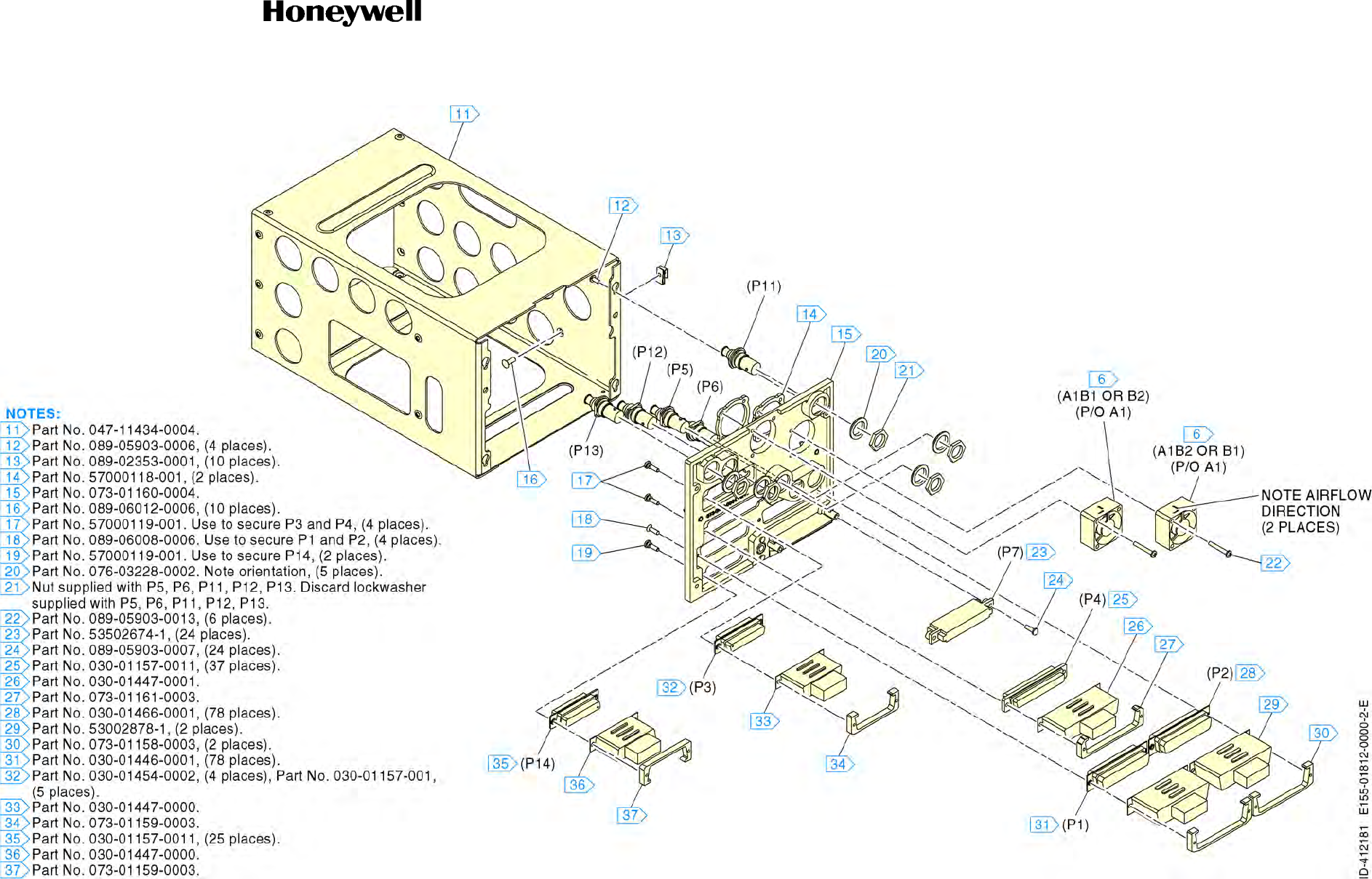
Draft
SYSTEM INSTALLATION MANUAL
066-01204 / 066-01213
Page 2-19
6 Dec 2012
© Honeywell International Inc. Do not copy without express permission of Honeywell.
34-70-06
Figure 2-4. KSN 7xx Safety Navigator Outline Drawing
(Dwg. No. 155-01812-0000 Rev. E) (Sheet 4 of 4)
Draft as of 10/15/2012

Draft
SYSTEM INSTALLATION MANUAL
066-01204 / 066-01213
Page 2-20
6 Dec 2012
© Honeywell International Inc. Do not copy without express permission of Honeywell.
34-70-06
Blank Page
Draft as of 10/15/2012
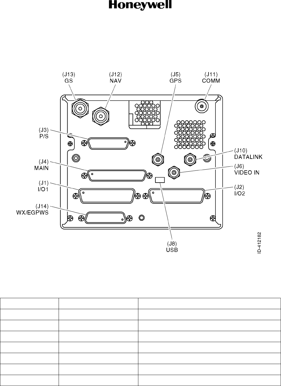
Draft
Page 2-21
6 Dec 2012
34-70-06
SYSTEM INSTALLATION MANUAL
066-01204 / 066-01213
© Honeywell International Inc. Do not copy without express permission of Honeywell.
2.3.6 KSN Pinouts
2.3.6.1 Refer to Figure 2-5 for the back panel connector locations.
Figure 2-5. KSN 7xx Back Panel
Refer to Table 2-10 for the connector list.
Table 2-10. Connector List
Connector Type Signal Descriptions
J1 78 Pin D High Density Refer to Table 2-11.
J2 78 Pin D High Density Refer to Table 2-12.
J3 13 Pin D Refer to Table 2-13.
J4 37 Pin D Refer to Table 2-14.
J5 RF Refer to Table 2-15.
J6 Video Refer to Table 2-16.
J7 - -
Draft as of 10/15/2012

Draft
Page 2-22
6 Dec 2012
34-70-06
SYSTEM INSTALLATION MANUAL
066-01204 / 066-01213
© Honeywell International Inc. Do not copy without express permission of Honeywell.
2.3.6.2 Connector Pinouts
Refer to Table 2-11 for the signals assigned to the I/O 1 connector (J1).
J8 Mini B USB (not used) Refer to Table 2-17.
J9 - -
J10 RF Refer to Table 2-18.
J11 RF Refer to Table 2-19.
J12 RF Refer to Table 2-20.
J13 RF Refer to Table 2-21.
J14 25 Pin D Refer to Table 2-22.
Table 2-11. Signals Assigned to the I/O 1 Connector (J1)
Function Description Signal Type I/O Interface
Pin No.
AHRS AHRS 429 RX A 429 Input 66
AHRS AHRS 429 RX B 429 Input 46
AHRS Heading REF HI Analog Input 6
AHRS Heading REF LO Analog Input 7
AHRS Heading Valid Discrete Input 21
AHRS Heading X Synchro Input 77
AHRS Heading Y Synchro Input 58
AHRS Heading Z Synchro Input 59
ALT Airdata/Fuel/Heading 232 RX RS-232 Input 61
NAV/IND LNAV/VNAV Approach Active
Annunciate High Current Discrete Output 15
DME 1DME Channel Request KRC Input 76
DME 1DME Common KRC Input 56
DME 1DME Serial Clock KRC Output 75
DME 1DME Serial Data KRC Output 57
EGPWS(E) Legacy PXPRESS 232 GND RS-232 REF 43
EGPWS(E) Legacy PXPRESS 232 TX RS-232 Output 63
Table 2-10. Connector List
Connector Type Signal Descriptions
Draft as of 10/15/2012

Draft
Page 2-23
6 Dec 2012
34-70-06
SYSTEM INSTALLATION MANUAL
066-01204 / 066-01213
© Honeywell International Inc. Do not copy without express permission of Honeywell.
GPS GPS Flight Plan 232 TX RS-232 Output 62
GPS GPS GAMA 429 TX A 429 Output 71
GPS GPS GAMA 429 TX B 429 Output 51
GPS GPS/Airdata/Fuel 232 GND RS-232 REF 42
Growth Spare 429 RX 3 A 429 Input 67
Growth Spare 429 RX 3 B 429 Input 47
Growth Spare 429 TX A 429 Output 70
Growth Spare 429 TX B 429 Output 50
Growth Spare 2 RS 232 RX RS-232 Input 23
NAV/IND LNAV Approach Active Annunciate High Current Discrete Output 16
NAV/IND CDI From Analog Output 8
NAV/IND CDI GPS Annunciate High Current Discrete Output 18
NAV/IND CDI Select In Discrete Input 3
NAV/IND CDI To Analog Output 27
NAV/IND CDI VLOC Annunciate High Current Discrete Output 38
NAV/IND Dead Reckoning Annunciate High Current Discrete Output 17
NAV/IND EFIS CTRL 429 RX A 429 Input 68
NAV/IND EFIS CTRL 429 RX B 429 Input 48
NAV/IND ILS Approach Energize High Current Discrete Output 40
NAV/IND Lateral Deviation (CDI) FlagAnalog Output 9
NAV/IND Lateral Deviation (CDI) Flag+ Analog Output 28
NAV/IND Lateral Deviation (CDI) Left Analog Output 10
NAV/IND Lateral Deviation (CDI) Right Analog Output 29
NAV/IND Lateral Deviation Superflag Analog Output 13
NAV/IND Loss of Integrity Annunciate High Current Discrete Output 19
NAV/IND Message Annunciate High Current Discrete Output 20
NAV/IND OBI Clock OBI Output 25
NAV/IND OBI Data OBI Output 5
NAV/IND OBI Select In Discrete Input 24
Table 2-11. Signals Assigned to the I/O 1 Connector (J1) (Cont)
Function Description Signal Type I/O Interface
Pin No.
Draft as of 10/15/2012

Draft
Page 2-24
6 Dec 2012
34-70-06
SYSTEM INSTALLATION MANUAL
066-01204 / 066-01213
© Honeywell International Inc. Do not copy without express permission of Honeywell.
NAV/IND OBI Sync OBI Output 4
NAV/IND OBS_C (REF LO) OBS I/O 74
NAV/IND OBS_D (COS HI) OBS Input 54
NAV/IND OBS_E (COS LO) OBS Input 55
NAV/IND OBS_F (SIN HI) OBS Input 34
NAV/IND OBS_G (SIN LO) OBS Input 33
NAV/IND OBS_H (REF HI) OBS I/O 14
NAV/IND OFF PATH Annunciate High Current Discrete Output 35
NAV/IND Suspend Annunciate High Current Discrete Output 36
NAV/IND Suspend In Discrete Input 2
NAV/IND LP Approach Active Annunciate High Current Discrete Output 37
NAV/IND Vertical Deviation Down Analog Output 12
NAV/IND Vertical Deviation FlagAnalog Output 11
NAV/IND Vertical Deviation Flag+ Analog Output 30
NAV/IND Vertical Deviation Superflag Analog Output 32
NAV/IND Vertical Deviation Up Analog Output 31
NAV/IND 1VOR/ILS TX A 429 Output 72
NAV/IND 1VOR/ILS TX B 429 Output 52
NAV/IND 1VOR/LOC Composite Out Analog Output 60
NAV/IND 1VOR/LOC Composite REF Analog REF 41
NAV/IND 1Waypoint Annunciate High Current Discrete Output 39
PWR GND1 Common GND REF 1
PWR GND2 Common GND REF 78
PWR KEY1 Key Key 26
Traffic TA Aural Active Discrete Input 22
Traffic Traffic Ctrl TX A 429 Output 73
Traffic Traffic Ctrl TX B 429 Output 53
Traffic Traffic Display 429 RX A 429 Input 69
Traffic Traffic Display 429 RX B 429 Input 49
Table 2-11. Signals Assigned to the I/O 1 Connector (J1) (Cont)
Function Description Signal Type I/O Interface
Pin No.
Draft as of 10/15/2012

Draft
Page 2-25
6 Dec 2012
34-70-06
SYSTEM INSTALLATION MANUAL
066-01204 / 066-01213
© Honeywell International Inc. Do not copy without express permission of Honeywell.
Refer to Table 2-12 for the signals assigned to the I/O 2 connector (J2).
WX WX-500 422 #2 RX A RS-422 Input 44
WX WX-500 422 #2 RX B RS-422 Input 45
WX WX-500 422 #2 TX A RS-422 Output 64
WX WX-500 422 #2 TX B RS-422 Output 65
NOTE: 1. KSN 7x0 Only.
Table 2-12. Signals Assigned to the I/O 2 Connector (J2)
Function Description Signal Type I/O Interface
Pin No.
ALT Airdata REF LO Analog I/O 67
ALT Airdata REF HI Analog I/O 48
ALT Baro ALT 429 A 429 Input 46
ALT Baro ALT 429 B 429 Input 65
ALT Baro Correction HI Analog Input 8
ALT Baro Correction LO Analog Input 28
ALT Gillham ALT A1 Discrete Input 18
ALT Gillham ALT A2 Discrete Input 37
ALT Gillham ALT A4 Discrete Input 57
ALT Gillham ALT B1 Discrete Input 17
ALT Gillham ALT B2 Discrete Input 36
ALT Gillham ALT B4 Discrete Input 56
ALT Gillham ALT C1 Discrete Input 16
ALT Gillham ALT C2 Discrete Input 35
ALT Gillham ALT C4 Discrete Input 55
ALT Gillham ALT D4 Discrete Input 76
EGPWS EGPWS Status 429 TX A 429 Output 45
EGPWS EGPWS Status 429 TX B 429 Output 64
EGPWS Landing Gear Discrete Input 34
EGPWS OATAnalog Input 68
Table 2-11. Signals Assigned to the I/O 1 Connector (J1) (Cont)
Function Description Signal Type I/O Interface
Pin No.
Draft as of 10/15/2012

Draft
Page 2-26
6 Dec 2012
34-70-06
SYSTEM INSTALLATION MANUAL
066-01204 / 066-01213
© Honeywell International Inc. Do not copy without express permission of Honeywell.
EGPWS OAT + Analog Input 69
EGPWS OAT GND Analog Output 49
EGPWS OAT REF Analog Output 50
EGPWS Shared - Flaps or Tactical Select
(Low ALT Mode) Discrete Input 15
EGPWS Terrain Caution Annunciate High Current Discrete Output 24
EGPWS Terrain Inhibit Discrete Input 74
EGPWS Terrain Warn Annunciate High Current Discrete Output 4
EGPWS Terrain Failure Annunciate High Current Discrete Output 3
EGPWS WOW Discrete Input 54
EGPWS Shared - Audio On or Low Altitude
Mode Annunciate High Current Discrete Output 23
EGPWS EGPWS Self Test Discrete Input 75
Flight Control GPS Steering Select Discrete Output 77
Flight Control GPS/LOC Approach Annunciate High Current Discrete Output 22
Flight Control Remote Go Around Discrete Input 72
Flight Control Roll SteerAnalog Output 9
Flight Control Roll Steer+ Analog Output 10
Flight Control Roll Steer REF HI Analog Input 30
Flight Control Roll Steer REF LO Analog Input 29
Flight Control Roll Steer Valid Discrete Output 59
Connected
Gateway XM WX 232 GND RS-232 REF 41
Connected
Gateway XM WX 232 RX RS-232 Input 60
Connected
Gateway XM WX 232 TX RS-232 Output 40
Growth Spare 429 RX 1 A 429 Input 44
Growth Spare 429 RX 1 B 429 Input 63
Growth Spare 429 RX 2 A 429 Input 47
Growth Spare 429 RX 2 B 429 Input 66
Table 2-12. Signals Assigned to the I/O 2 Connector (J2) (Cont)
Function Description Signal Type I/O Interface
Pin No.
Draft as of 10/15/2012

Draft
Page 2-27
6 Dec 2012
34-70-06
SYSTEM INSTALLATION MANUAL
066-01204 / 066-01213
© Honeywell International Inc. Do not copy without express permission of Honeywell.
Growth Spare In1 Discrete Input 12
Growth Spare In2 Discrete Input 31
Growth Spare In3 Discrete Input 51
Growth Spare In4 Discrete Input 70
Growth Spare In5 Discrete Input 11
Growth Spare In6 Discrete Input 73
Growth Spare Out1 High Current Discrete Output 38
NAV/IND LPV Approach Active Annunciate High Current Discrete Output 58
MAINT IOP 422 #4 RX A RS-422 Input 42
MAINT IOP 422 #4 RX B RS-422 Input 43
MAINT IOP 422 #4 TX A RS-422 Output 61
MAINT IOP 422 #4 TX B RS-422 Output 62
MISC FAN Return Common GND REF 19
MISC KSN Fan Discrete Output 20
MISC 1MMDS Fan Discrete Output 39
NAV/COM 1COM Audio Out HI Audio Output 5
NAV/COM 1COM Audio Out LO Audio Output 25
NAV/COM 1COM Channel Decrement Discrete Input 14
NAV/COM 1COM Channel Increment Discrete Input 13
NAV/COM 1COM Mic Audio In HI Audio Input 6
NAV/COM 1COM Mic Audio In LO Audio Input 26
NAV/COM 1COM Mic Key Discrete Input 71
NAV/COM 1COM Remote Transfer Discrete Input 52
NAV/COM 1Emergency Frequency Discrete Input 33
NAV/COM 1NAV Audio Out HI Audio Output 7
NAV/COM 1NAV Audio Out LO Audio Output 27
NAV/COM 1Transmit Interlock Discrete Input 53
PWR GND3 Common GND REF 1
Table 2-12. Signals Assigned to the I/O 2 Connector (J2) (Cont)
Function Description Signal Type I/O Interface
Pin No.
Draft as of 10/15/2012

Draft
Page 2-28
6 Dec 2012
34-70-06
SYSTEM INSTALLATION MANUAL
066-01204 / 066-01213
© Honeywell International Inc. Do not copy without express permission of Honeywell.
Refer to Table 2-13 for the signals assigned to the power supply interface connector (J3).
Refer to Table 2-14 for the signals assigned to the main processor board interface connector (J4).
PWR GND4 Common GND REF 78
PWR KEY2 Key Key 32
Traffic Traffic Disc 1 Out Discrete Output 2
Traffic Traffic Disc 2 Out Discrete Output 21
NOTE: 1. KSN 7x0 Only.
Table 2-13. Signals Assigned to the Power Supply Interface Connector (J3)
Function Description Signal Type I/O Interface
Pin No.
MAINT 33V_BOOST_TEST Analog (Test Only) Output 1
MAIN 5V_KSN_TEST Analog (Test Only) Output 4
MAINT 5V7_STARTUP-TEST Discrete (Test Only) Output 5
Main 112VPOS_MMDS_TEST Analog (Test Only) Output 3
PWR MAIN_POWER_IN Aircraft Power Input A3
PWR MAIN_POWER_IN _RTN Aircraft GND Input A1
PWR 1MAIN_POWER_IN _RTN Aircraft GND Input A4
PWR 1MMDS_TX_POWER_IN Aircraft Power Input A2
MAINT ON_OFF_Status_N Discrete (Test Only) Output 2
NOTE: 1. KSN 7x0 Only.
Table 2-14. Signals Assigned to the Main Processor Board Interface Connector (J4)
Function Description Signal Type I/O Interface
Pin No.
CONFIG
MOD Config MOD Data I2C I/O 12
CONFIG
MOD Config MOD GND I2C Output 29
CONFIG
MOD Config MOD Power I2C Output 11
Dual KSN 7XX 422 #1 RX A RS-422 Input 24
Table 2-12. Signals Assigned to the I/O 2 Connector (J2) (Cont)
Function Description Signal Type I/O Interface
Pin No.
Draft as of 10/15/2012

Draft
Page 2-29
6 Dec 2012
34-70-06
SYSTEM INSTALLATION MANUAL
066-01204 / 066-01213
© Honeywell International Inc. Do not copy without express permission of Honeywell.
Dual KSN 7XX 422 #1 RX B RS-422 Input 25
Dual KSN 7XX 422 #1 TX A RS-422 Output 6
Dual KSN 7XX 422 #1 TX B RS-422 Output 7
GPS GPS Dataload 232 GND RS-232 REF 31
GPS GPS Dataload 232 RX RS-232 Input 32
GPS GPS Dataload 232 TX RS-232 Output 13
GPS GPS Enhanced PXPRESS 232 GND RS-232 REF 21
GPS GPS Enhanced PXPRESS 232 RX RS-232 Input 20
GPS GPS Enhanced PXPRESS 232 TX RS-232 Output 2
GPS GPS Time Mark HI RS-422 Output 10
GPS GPS Time Mark LO RS-422 Output 28
Growth Spare In8 Discrete Input 3
Lighting Remote Dimming HI Analog Input 17
Lighting Remote Dimming LO Analog Input 36
MAINT Demo Mode Select Discrete Input 19
MAINT Shop Mode Select Discrete Input 18
MAINT/
AUDIO Shared - Maintenance or Voice
Recognition 422 RX B RS-422 Input 23
MAINT/
AUDIO Shared - Maintenance or Voice
Recognition 422 TX B RS-422 Output 5
MAINT/
AUDIO Shared - Maintenance or Voice
Recognition 422 RX A RS-422 Input 22
MAINT/
AUDIO Shared - Maintenance or Voice
Recognition 422 TX A RS-422 Output 4
PWR GND5 Common GND REF 1
PWR GND6 Common GND REF 37
WX Datalink Receiver 422 #3 RX A RS-422/RS-232 Input 26
WX Datalink Receiver 422 #3 RX B RS-422/RS-232 Input 27
WX Datalink Receiver 422 #3 TX A RS-422/RS-232 Output 8
WX Datalink Receiver 422 #3 TX B RS-422/RS-232 Output 9
WX Satellite Audio - Left HI Audio Output 15
Table 2-14. Signals Assigned to the Main Processor Board Interface Connector (J4) (Cont)
Function Description Signal Type I/O Interface
Pin No.
Draft as of 10/15/2012

Draft
Page 2-30
6 Dec 2012
34-70-06
SYSTEM INSTALLATION MANUAL
066-01204 / 066-01213
© Honeywell International Inc. Do not copy without express permission of Honeywell.
Refer to Table 2-15 for the signals assigned to the GPS antenna connector (J5).
Refer to Table 2-16 for the signals assigned to the video connector (J6).
Refer to Table 2-17 for the signals assigned to the rear panel USB connector (J8).
WX Satellite Audio - Left LO Audio Output 34
WX Satellite Audio - Right HI Audio Output 14
WX Satellite Audio - Right LO Audio Output 33
Table 2-15. Signals Assigned to the GPS Antenna Connector (J5)
Function Description Signal Type I/O Interface
Pin No.
GPS GPS Antenna RF I/O Center
GPS GPS Antenna GND RF I/O Shell
Table 2-16. Signals Assigned to the Video Connector (J6)
Function Description Signal Type I/O Interface
Pin No.
Video Remote Video Video Input Center
Video Remote Video GND Video Input Shell
Table 2-17. Signals Assigned to the Rear Panel USB Connector (J8)
Function Description Signal Type I/O Interface
Pin No.
Not Used USB2 DMini USB I/O 2
Not Used USB2 D+ Mini USB I/O 3
Not Used USB2 D GND Mini USB Output 5
Not Used USB2 VBUS Mini USB Output 1
Not Used USB2 ID Mini USB Output 4
Table 2-14. Signals Assigned to the Main Processor Board Interface Connector (J4) (Cont)
Function Description Signal Type I/O Interface
Pin No.
Draft as of 10/15/2012

Draft
Page 2-31
6 Dec 2012
34-70-06
SYSTEM INSTALLATION MANUAL
066-01204 / 066-01213
© Honeywell International Inc. Do not copy without express permission of Honeywell.
Refer to Table 2-18 for the signals assigned to the XM WX datalink antenna connector (J10).
Refer to Table 2-19 for the signals assigned to the VHF transceiver antenna connector (J11).
Refer to Table 2-20 for the signals assigned to the navigation radio (VOR/LOC) antenna connector
(J12).
Refer to Table 2-21 for the signals assigned to the navigation radio (GS) antenna connector (J13).
Refer to Table 2-22 for the signals assigned to the WX RDR/EGPWS connector (J14).
Table 2-18. Signals Assigned to XM WX Datalink Antenna Connector (J10)
Function Description Signal Type I/O Interface
Pin No.
WX Datalink Antenna RF Input Center
WX Datalink Antenna GND RF Input Shell
Table 2-19. Signals Assigned to the VHF Transceiver Antenna Connector (J11) (KSN 7x0 Only)
Function Description Signal Type I/O Interface
Pin No.
NAV/COM COM Antenna RF I/O Center
NAV/COM COM Antenna GND RF I/O Shell
Table 2-20. Signals Assigned to the Navigation Radio (VOR/LOC) Antenna Connector (J12) (KSN 7x0
Only)
Function Description Signal Type I/O Interface
Pin No.
NAV/COM VOR/LOC Antenna RF Input Center
NAV/COM VOR/LOC Antenna GND RF Input Shell
Table 2-21. Signals Assigned to the Navigation Radio (GS) Antenna Connector (J13) (KSN 7x0 Only)
Function Description Signal Type I/O Interface
Pin No.
NAV/COM GS Antenna RF Input Center
NAV/COM GS Antenna GND RF Input Shell
Table 2-22. Signals Assigned to the WX RDR/EGPWS Connector (J14)
Function Description Signal Type I/O Interface
Pin No.
EGPWS(E) EGPWS CTRL 429 TX A 429 Output 13
EGPWS(E) EGPWS CTRL 429 TX B 429 Output 12
Draft as of 10/15/2012

Draft
Page 2-32
6 Dec 2012
34-70-06
SYSTEM INSTALLATION MANUAL
066-01204 / 066-01213
© Honeywell International Inc. Do not copy without express permission of Honeywell.
2.3.7 KSN Wiring and Cable Harness Fabrication
The KSN MMDR receives primary power from the aircraft power source. A typical interface is shown in
Paragraph 3.3 Power System Interface. Aircraft specific interfaces with more details are provided in
separate EB or installation drawings.
The length of the wires to parallel pins must be approximately the same length, so that the best
distribution of current can be effected. Honeywell recommends that all wires (including spares) as
provided with the interconnect definition information be included in the fabrication of the wiring harness.
However, if full wiring is not desired, the installer must ensure that the minimum wiring requirements for
the features and functions to be used have been incorporated.
When cables are installed in the aircraft, they must be supported firmly enough to prevent movement
and must be carefully protected against chaffing. Additional protection must also be provided in all
locations where the cable may be subjected to abuse. In wire bundles, the cabling must not be tied
tightly together as this tends to increase the possibility of noise pickup and similar interference.
When routing cables through the aircraft the cables must cross high level RF lines at right angles.
Prior to installing any equipment, make a continuity check of all wires and cables associated with the
system. Then apply power and check for proper voltages at system connectors, and then remove power
before completing the installation. The following guidelines are recommended:
(1) The installing facility will supply and fabricate all external cables. The required connectors are
supplied as part of the installation kit (refer to Table 2-1 or Table 2-2).
EGPWS(E) External Audio Inhibit Discrete Input 24
EGPWS(E) KCPB RX A 453 Input 9
EGPWS(E) KCPB RX B 453 Input 22
EGPWS(E) KCPB RX GND 453 Input 10
Power GND10 Common GND REF 25
Power GND9 Common GND REF 1
WX WX RDR 708A 453 GND 453 Input 4
WX WX RDR 708A 453 RX A 453 Input 5
WX WX RDR 708A 453 RX B 453 Input 17
WX WX RDR CTL 429 TX B 429 Output 14
WX WX RDR CTL 429 TX A 429 Output 2
WX WX RDR Power ON/OFF Discrete Output 15
Table 2-22. Signals Assigned to the WX RDR/EGPWS Connector (J14) (Cont)
Function Description Signal Type I/O Interface
Pin No.
Draft as of 10/15/2012

Draft
Page 2-33
6 Dec 2012
34-70-06
SYSTEM INSTALLATION MANUAL
066-01204 / 066-01213
© Honeywell International Inc. Do not copy without express permission of Honeywell.
(2) The unit must be kept a minimum of 36 inches (914 mm) from all antennas. Additionally, the
antenna coax cable must not be bundled with the other wiring harnesses to the unit. Coaxial
cables must be routed separately and be kept a minimum of 1.0 inch (25.4 mm) from each
other.
(3) The length and routing of the external cables must be carefully planned before attempting the
actual installation. Avoid sharp bends or locating the cable near aircraft control cables. The
wiring cables must be of a length to allow for a “maintenance loop”; that is, the length must
be adequate to access and extend the connectors aft of the panel for future maintenance
purposes. Excess cabling must be secured and stowed by tie-wrapping until such
maintenance is required.
(4) The cables must be supported firmly enough to prevent movement. They must be carefully
protected wherever one may chafe against another or against some other object (such as the
aircraft structure). Extra protection must be provided in all locations where the cables may be
subject to abuse. Shields on shielded wires must be grounded in accordance with the system
interconnection information.
(5) Shields must be carried through any obstruction via a thru-bulkhead connector. If shielding
cannot be carried through by use of a bulkhead/connector pin, precautions must be taken to
ensure each segment of the shielded lead be grounded at only one point. A GND connection
of not more than two inches in length must be used. The preceding discussion does not apply
to coaxial and quadraxial cable.
(6) Avoid routing cabling near high noise and high power sources.
2.3.7.1 Audio Electrical Noise
Improper installation of the audio lines to an audio panel can cause GND loops and degraded audio
performance. Refer to your Audio Panel installation manual for guidance on proper installation of the
audio lines.
Draft as of 10/15/2012

Draft
Page 2-34
6 Dec 2012
34-70-06
SYSTEM INSTALLATION MANUAL
066-01204 / 066-01213
© Honeywell International Inc. Do not copy without express permission of Honeywell.
Blank Page
Draft as of 10/15/2012
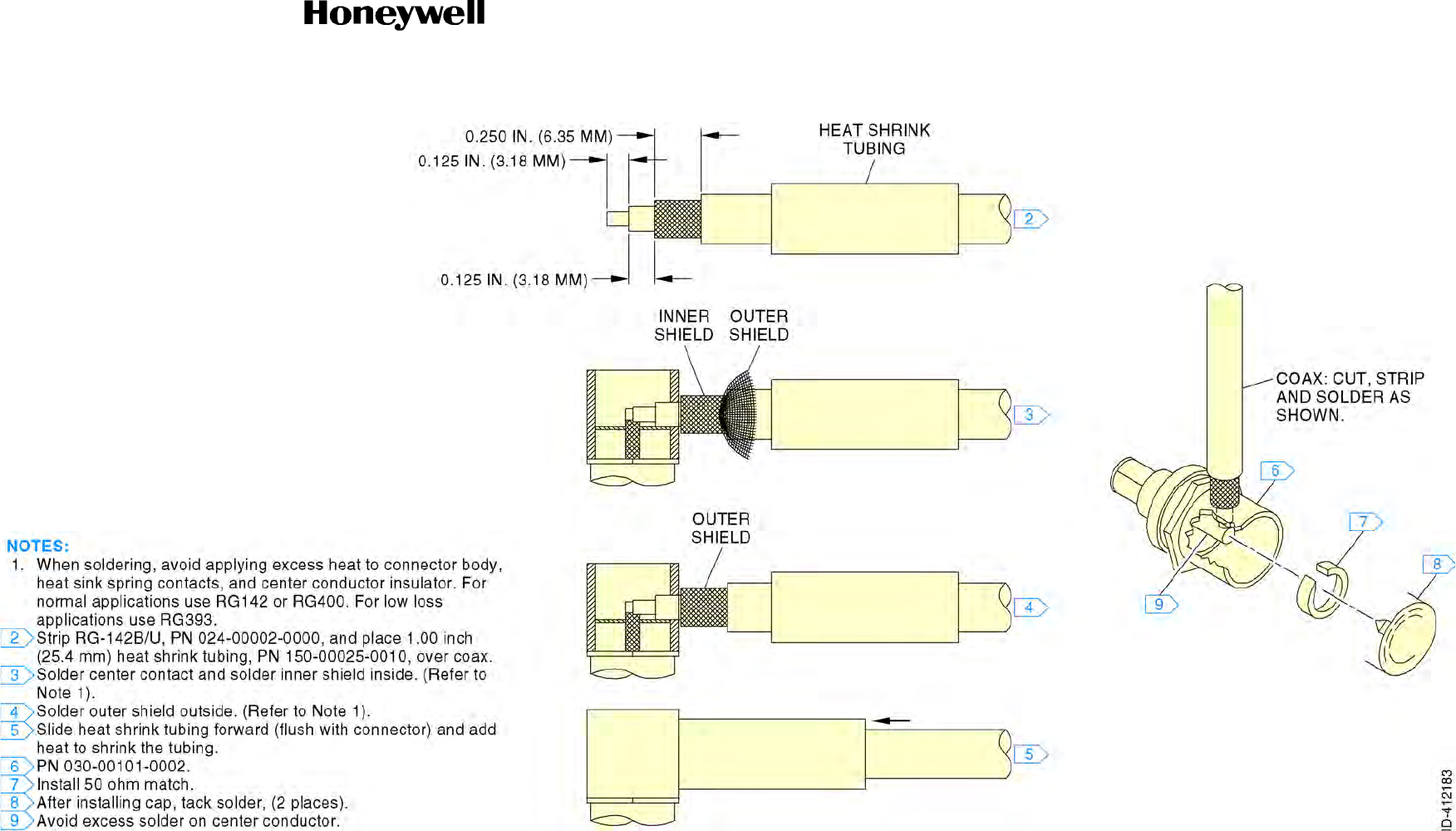
Draft
SYSTEM INSTALLATION MANUAL
066-01204 / 066-01213
Page 2-35
6 Dec 2012
© Honeywell International Inc. Do not copy without express permission of Honeywell.
34-70-06
Figure 2-6. Coaxial Right Angle Connector Instruction Sheet (Sheet 1 of 1)
Draft as of 10/15/2012

Draft
SYSTEM INSTALLATION MANUAL
066-01204 / 066-01213
Page 2-36
6 Dec 2012
© Honeywell International Inc. Do not copy without express permission of Honeywell.
34-70-06
Blank Page
Draft as of 10/15/2012

Draft
SYSTEM INSTALLATION MANUAL
066-01204 / 066-01213
Page 2-37
6 Dec 2012
© Honeywell International Inc. Do not copy without express permission of Honeywell.
34-70-06
Figure 2-7. TNC Antenna Coax with Straight Connector (Sheet 1 of 1)
Draft as of 10/15/2012

Draft
SYSTEM INSTALLATION MANUAL
066-01204 / 066-01213
Page 2-38
6 Dec 2012
© Honeywell International Inc. Do not copy without express permission of Honeywell.
34-70-06
Blank Page
Draft as of 10/15/2012
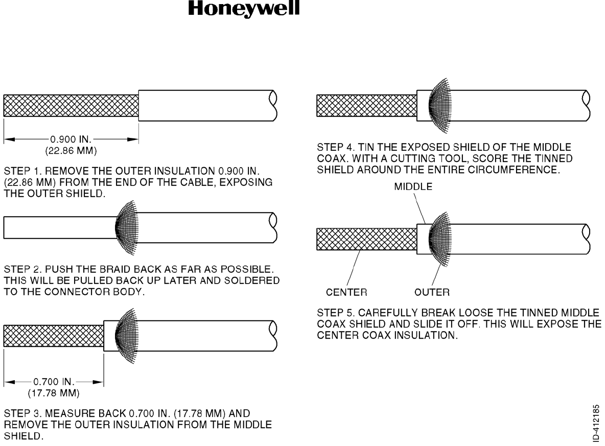
Draft
SYSTEM INSTALLATION MANUAL
066-01204 / 066-01213
Page 2-39
6 Dec 2012
© Honeywell International Inc. Do not copy without express permission of Honeywell.
34-70-06
Figure 2-8. Quadraxial Cable Preparation (Sheet 1 of 3)
Draft as of 10/15/2012

Draft
SYSTEM INSTALLATION MANUAL
066-01204 / 066-01213
Page 2-40
6 Dec 2012
© Honeywell International Inc. Do not copy without express permission of Honeywell.
34-70-06
Blank Page
Draft as of 10/15/2012
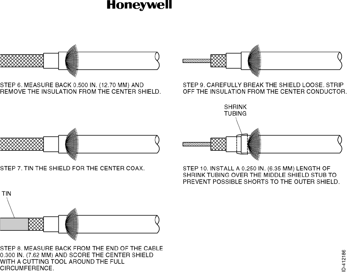
Draft
SYSTEM INSTALLATION MANUAL
066-01204 / 066-01213
Page 2-41
6 Dec 2012
© Honeywell International Inc. Do not copy without express permission of Honeywell.
34-70-06
Figure 2-8. Quadraxial Cable Preparation (Sheet 2 of 3)
Draft as of 10/15/2012

Draft
SYSTEM INSTALLATION MANUAL
066-01204 / 066-01213
Page 2-42
6 Dec 2012
© Honeywell International Inc. Do not copy without express permission of Honeywell.
34-70-06
Blank Page
Draft as of 10/15/2012
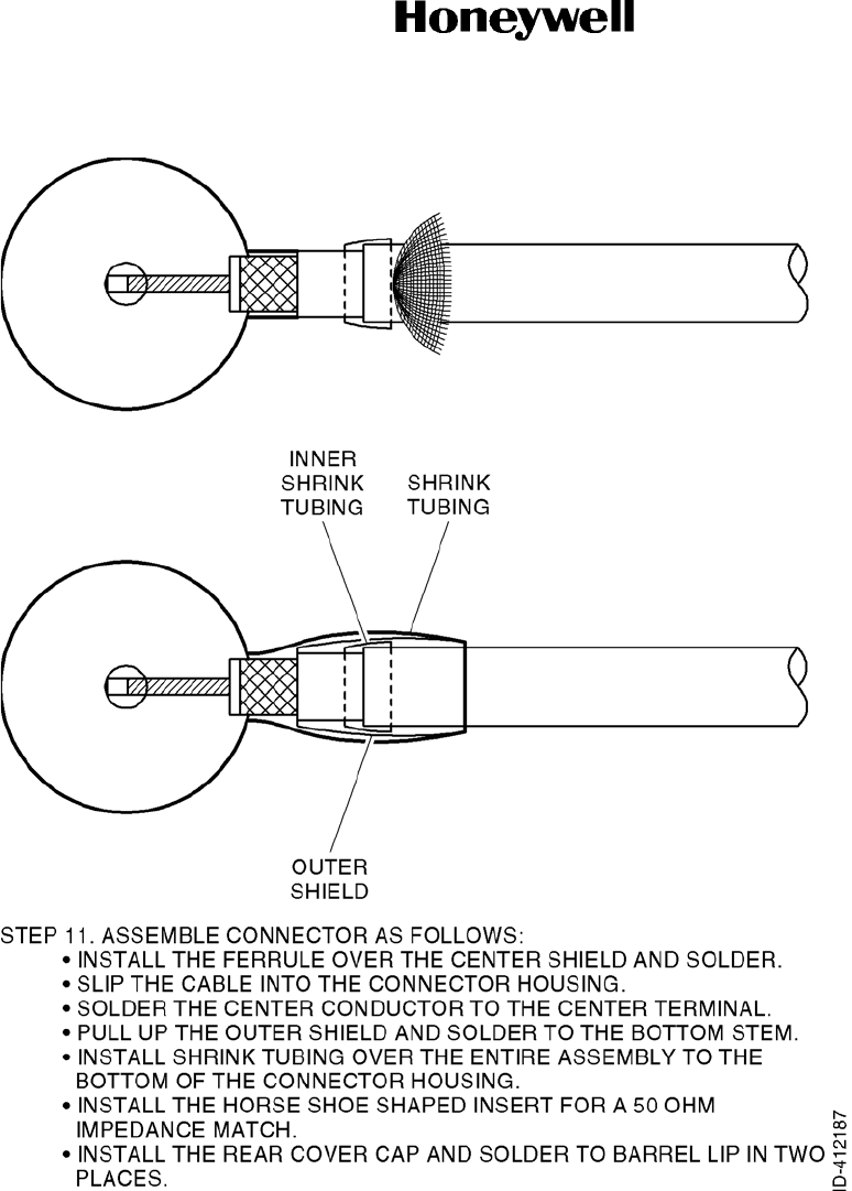
Draft
SYSTEM INSTALLATION MANUAL
066-01204 / 066-01213
Page 2-43
6 Dec 2012
© Honeywell International Inc. Do not copy without express permission of Honeywell.
34-70-06
Figure 2-8. Quadraxial Cable Preparation (Sheet 3 of 3)
Draft as of 10/15/2012

Draft
SYSTEM INSTALLATION MANUAL
066-01204 / 066-01213
Page 2-44
6 Dec 2012
© Honeywell International Inc. Do not copy without express permission of Honeywell.
34-70-06
Blank Page
Draft as of 10/15/2012

Draft
Page 2-45
6 Dec 2012
34-70-06
SYSTEM INSTALLATION MANUAL
066-01204 / 066-01213
© Honeywell International Inc. Do not copy without express permission of Honeywell.
2.3.8 KSN Power Distribution
The KSN 7xx is powered through two dedicated circuit breakers. A 10.0 AMP circuit breaker powers the
MMDS radio system. A 7.5 AMP circuit breaker powers the rest of the KSN 7xx functions. These circuit
breakers must be connected to the same power bus sources. The power bus can range from +11 to +33
VDC. For aircraft weighing less than 6000 pounds (2721.6 kg) with two KSNs, it is recommended that
each KSN is powered from a separate power bus. For aircraft weighing more than 6000 pounds (2721.6
kg) with two KSNs, it is required that each KSN is powered from a separate power bus.
2.3.9 Placards and Labels
All placards and labels must be visible in all lighting conditions. Text must be a minimum of 0.10 inch
(2.5 mm) in height, and must be a contrasting color to the background of the label/placard. Text must
be permanent and not easily disfigurable. If the KSN is not configured for IFR operation, a placard
stating “The KSN 7xx is limited to VFR use only” (or similar) must be installed in the pilots field of view.
2.3.10 Weight and Balance
Using component weights from Table 2-23 and the moment arm of the component mounting locations,
perform a weight and balance calculation per AC 43-13-1B Chapter 10. Also account for equipment
remove during the modification process.
Table 2-23. Component Weights
Component Weight
KSN 770 (standard, includes KCM 200 and rack) 9.9 pounds (4.5 kg)
KSN 770 (with WX RDR/EGPWS) 10.2 pounds (4.6 kg)
KSN 765 (standard, includes KCM-200 and rack) 8.1 pounds (3.7 kg)
KSN 765 (with WX RDR/EGPWS) 8.4 pounds (3.8 kg)
GPS Antenna (KA-96) Refer to KA 96 IM (0.5 pounds [0.2 kg] nominal)
Annunciator Panel Refer to the manufacturers data
NAV Antenna Refer to the manufacturers data
COM Antenna Refer to the manufacturers data
Indicator Refer to the manufacturers data
Draft as of 10/15/2012

Draft
Page 2-46
6 Dec 2012
34-70-06
SYSTEM INSTALLATION MANUAL
066-01204 / 066-01213
© Honeywell International Inc. Do not copy without express permission of Honeywell.
2.4 Antenna Installation
The antenna(s) must be well removed from other antenna projections, the engine(s), and propeller(s). It
must also be well removed from landing gear doors, access doors, or other openings which will break the
GND plane for the antenna(s). On metal skinned aircraft, the antenna(s) must be bonded to the surface
of the aircraft in a fore to aft location that provides the flattest GND plane. On composite aircraft, the
antenna(s) must be located at the center of a conductive GND plane, contoured to the shape of the
aircraft, having dimensions of at least 24.0 by 24.0 inches (610 by 610 mm). The antenna penetration
must be designed such that the structural integrity of the fuselage is not compromised. The antenna(s)
need to be within 5 degrees of the centerline.
Where practical, plan the antenna location(s) to keep cable lengths as short as possible and avoid sharp
bends in the cable to minimize the VSWR. Avoid running other cables or wires near the antenna cable(s).
On pressurized aircraft, the antenna(s) must be sealed using an approved sealant, such as RTV No. 3145
(Honeywell PN 016-01082-0000) or equivalent, around the connector and mounting hardware.
The antenna edge and mounting hardware recesses must be sealed from the outside for moisture
protection using RTV or equivalent.
Mount the antenna(s) in as clean as environment as possible, away from exhaust gases and oils. The
antenna(s) must be kept clean. If left dirty (oil covered), the antenna performance may be affected.
Antennas must be installed in accordance with their own installation manuals.
2.4.1 GPS/WAAS Antenna Location Considerations
The KA 96 GPS active antenna, PN 071-01620-0001 or equivalent is the designated antenna for the
KSN 7xx.
The antenna must be mounted on top of the fuselage near the cockpit. Avoid mounting the antenna near
any projections, the propeller, or the T-tail of the aircraft, where shadows could occur. It is recommended
that there be a separation of at least 36.0 inches (914 mm) between the GPS antenna and any VHF
COM antenna on the aircraft.
The antenna baseplate must be level within ±5 degrees in both axes when the aircraft is level (level is
defined as the aircraft attitude required when weighing the aircraft for weight and balance) for optimum
performance. If the antenna is tilted more than 5 degrees or is mounted close to other objects that
shadow it, loss of some of the satellites will occur and system performance may be degraded. Antenna
cable and connector information, including vendor information is listed below.
Refer to Figure 2-7 for the cable/connector assembly instructions for the 0 to 40 feet (0 to 12.2 meters)
category using RG 400/U or RG 142B/U.
Refer to Table 16 GPS Antenna Cable Information (for both TNC and BMA) for the 0 to 80 feet (0 to 24.4
meters) and 0 to 100 feet (0 to 30.5 meters) categories.
NOTE: The Nominal signal gain for the KA 96 is 27 to 31 dB, the noise figure is 1.9 dB at 77°F (25°C),
2.5 dB maximum. With 0.050 ice on the radome, gain will not decrease by more than 2.0 dB
when viewing a satellite from 30 degrees above the horizon to zenith (as compared to a no ice
condition).
Draft as of 10/15/2012

Draft
SYSTEM INSTALLATION MANUAL
066-01204 / 066-01213
Page 2-47
6 Dec 2012
© Honeywell International Inc. Do not copy without express permission of Honeywell.
34-70-06
Table 2-24. GPS Antenna Cable Information
Cable Length Cable PN TNC Connector (KSN 7xx) TNC Connector Antenna Maximum Allowable Loss
(dB) @ 1.575 GHz
0 to 40 feet (0 to 12.2 meters) PN: 024-00002-0000
VPN: RG142B/U PN: 030-00134-0000
VPN: TED Mfg. 5-10-30 PN: 030-00134-0001
VPN: TED Mfg. 5-30-102-1 8.0
PN: 024-00051-0060
VPN: RG400/U PN: 030-00134-0000
VPN: TED Mfg. 5-10-30 PN: 030-00134-0001
VPN: TED Mfg. 5-30-102-1 8.0
0 to 80 feet (0 to 24.4 meters) PN: 024-00072-0000
VPN: ECS 311601 PN: 030-00108-0002
VPN: TED Mfg. 5-10-307 PN: 030-00108-0002
VPN: TED Mfg. 5-10-307 8.0
0 to 100 feet (0 to 30.5 meters) PN: 024-00071-0000
VPN: ECS 311201 PN: 030-00108-0003
VPN: TED Mfg. 5-10-306 PN: 030-00108-0003
VPN: TED Mfg. 5-10-306 8.0
100 to 165 feet (30.5 to 50.3 meters) Contact TED, ECS or PIC for complete cable/connector assembly
Table 2-25. Cable Vendor Contact Information
TED Manufacturing Corp.
11415 Johnson Drive
Shawnee Mission, Kansas 66203
Tel: (913) 631-6211
http://www.tedmanufacturing.com
Electronic Cable Specialists (now part
of CarlisleIT)
5300 W. Franklin Drive
Franklin, Wisconsin 53132
Tel: 800 327-9473 or (414) 421-5300
http://www.ecsdirect.com/
http://www.carlisleit.com/
PIC Wire and Cable
N53 W24747 South Corporate Circle
Sussex, WI 53089-0330
Tel: (800) 742-3191 or (262) 246-0500
http://www.picwire.com/
sales@picwire.com
NOTE: Manufacturer contact information is provided as convenience only and may change any time.
Draft as of 10/15/2012

Draft
SYSTEM INSTALLATION MANUAL
066-01204 / 066-01213
Page 2-48
6 Dec 2012
© Honeywell International Inc. Do not copy without express permission of Honeywell.
34-70-06
Blank Page
Draft as of 10/15/2012

Draft
Page 2-49
6 Dec 2012
34-70-06
SYSTEM INSTALLATION MANUAL
066-01204 / 066-01213
© Honeywell International Inc. Do not copy without express permission of Honeywell.
2.4.2 COM and NAV Antenna Installation Considerations
2.4.2.1 COM Antenna Location
The VHF COM antenna must be mounted as far away as possible (8.0 feet [244 cm] minimum) from
other similar antennas and the vertical stabilizer. Mounting the COM antenna as far away as possible
from the navigation antenna will help reduce COM to NAV interference. The COM antenna must also
be mounted as far away as possible from an ELT antenna to prevent distortion of the radiated pattern
and to prevent radiated broadband noise from affecting the ELT when excited by the COM
transmissions. Radiated broadband noise from an ELT is a common cause of COM-to-COM and
COM-to-NAV interference. Mounting one antenna on top of the fuselage at the highest location to
ensure a good radiation pattern and the other on the bottom of the fuselage offers good separation
with a minimum of interaction.
It is recommended that one COM transceiver be connected to the top antenna for good GND
communication and that the other COM transceiver be connected to the bottom antenna to provide
good airborne communications. If mounting antennas on the same side of the aircraft is unavoidable,
maintain the minimum allowable separation (8.0 feet [244 cm]).
The antenna must be mounted on a section of the aircraft that is horizontal during cruise flight. The
base of the antenna must be well bonded to the metal aircraft skin. Remove any paint from around
the mounting holes to ensure a good connection between the antenna and the skin. The metal aircraft
skin at the base of the antenna must extend a minimum of 24.0 inches (610 mm) in every direction.
This provides the GND plane required for the antenna. Any less metallized area will result in reduced
communication range at some bearings around the aircraft and may increase interference to and from
other systems.
The COM transceiver performance depends heavily on the integrity of the electrical bonding to the
airframe and also the electrical integrity of the aircraft structure. If the electrical resistance between
an antenna and the aircraft or between adjacent skin panels changed intermittently, noisy
communications may result.
Connect the antenna to the COM unit with 50-ohm coaxial cable, keeping the cable length to a
minimum and avoiding sharp bends in the cable. Keep the COM antenna cable as far away from other
antenna cables as possible and do not bundle several antenna cables together. Prepare the cable to
the BNC connector as shown in Figure 2-6.
Use Dow-Corning DC-4, or equivalent, on both inside and outside of the connector and its mate as
an effective barrier against moisture and to prevent corrosion.
2.4.2.2 NAV Antenna Location
The NAV antenna must be well removed from other antennas, projections, engines or propellers. It
must have a clear line of sight area if possible. The antenna must be mounted symmetrically with the
center line of the aircraft. Avoid running other coaxial cables and wires near the NAV antenna cable.
The VOR/LOC antenna with Glideslope is a two piece dipole with one part mounted on each side of
the vertical stabilizer. It must be installed on the upper section of the vertical stabilizer of single finned
aircraft and be at least 28.0 inches (711 mm) (measured vertically) from the horizontal stabilizer.
Draft as of 10/15/2012

Draft
Page 2-50
6 Dec 2012
34-70-06
SYSTEM INSTALLATION MANUAL
066-01204 / 066-01213
© Honeywell International Inc. Do not copy without express permission of Honeywell.
On dual VOR/ILS installations, it is recommended that a splitter be used to divide signals from a single
VOR/LOC antenna into two or more receivers. Use double shielded cables to reduce interference to
the receivers.
Prepare the cable to the BNC connector as shown in Figure 2-6.
2.5 Optional Accessory Installation
2.5.1 External Annunciators
The recommended external annunciator for the KSN 7xx is the Mid Continent MD41-TBD (refer to the
Mid Continent installation manual for installation instructions).
2.5.2 External Switches
External switches may be added for functions such as external increment and decrement of channel
frequencies. Unless otherwise noted, these are signal level inputs and may be activated using MS
25089-1C Normally Open switches or equivalent necessary for system operation.
2.6 Magnetic Compass Recalibration
After the KSN 7xx has been installed and is operational, be sure to recalibrate the magnetic compass.
Draft as of 10/15/2012
Section 2.5.1
We do not want to be tied down to only one Brand and Model of
External Annunciators. Is the MD 41 the only option?
Section 2.5.2
Same comment for External switches as 2.5.1.

Draft
Page 3-1
6 Dec 2012
34-70-06
SYSTEM INSTALLATION MANUAL
066-01204 / 066-01213
© Honeywell International Inc. Do not copy without express permission of Honeywell.
SECTION III - SYSTEM INTERCONNECT
3.1 Introduction
Section III contains information relative to KSN 7xx Safety Navigator interconnection diagrams, options
available to the system planner, and specific electrical characteristics of the various interfaces where
applicable. Each paragraph in this section contains the installation wiring diagrams for that section.
For information regarding the compatibility of equipment not listed in this manual, the installing agency
must contact Bendix/King customer service at www.BendixKing.com.
Section III is divided into major sections by interface type or major topic. Each major section describes in
detail the specifications for particular types of interfaces connecting to the KSN 7xx.
3.2 Standard Interface Definitions
Unless otherwise stated, the following interface definitions will apply.
3.2.1 Discrete Input
Refer to Table 3-1 for the discrete input states.
3.2.2 Discrete Output
Unless otherwise stated, the following interface definitions will apply. Unless otherwise stated, all
outputs may be used as high current discrete outputs.
3.2.2.1 High Current
Refer to Table 3-2 for the high current discrete output states.
Table 3-1. Discrete Input States
State Voltage Upper Limit Voltage Lower Limit Comment
Open/High N/A 14 VDC for aircraft power
24.8 VDC
7.0 VCD for aircraft power
12.4 volts
Impedance is >230 kilohms
to GND
Low 3.0 VDC 0 VDC Impedance is <95ohms to
GND
Table 3-2. High Current Discrete Output States
State Voltage Upper Limit Sinking Current Comment
Active 2.0 VDC 0 to 250 mA DC -
Inactive N/A N/A Open collector
Draft as of 10/15/2012

Draft
Page 3-2
6 Dec 2012
34-70-06
SYSTEM INSTALLATION MANUAL
066-01204 / 066-01213
© Honeywell International Inc. Do not copy without express permission of Honeywell.
3.2.2.2 Superflag
Refer to Table 3-3 for the superflag output states.
3.2.3 EIA Standard Serial Interfaces
3.2.3.1 RS-232
Electrical characteristics are per ANSI TIA/EIA-232-F. Each RS-232 port will be configurable on the
maintenance pages for the following:
• Buad Rate
• Data Bits
• Parity Bit
• Stop Bits.
3.2.3.2 RS-422
Electrical characteristics are per ANSI TIA/EIA-422-A.
3.2.4 ARINC 429 Standard Serial Interfaces
Electrical characteristics are per ARINC 429.
3.2.5 ARINC 453 Interface
This bus format is 1600 bit Manchester bi-phase per ARINC 708A. The data rate on this bus is 1 Mbit/s.
Table 3-3. Superflag Output States
State Voltage Upper Limit Voltage Lower Limit Comment
Active N/A 18 VDC When the normal AC power
is 24.8 VDC and the output
is sourcing up to 250 mA.
N/A 10 VDC When the normal AC power
is 12.4 VDC and the output
is sourcing up to 250 mA.
Inactive 3.5 VDC 0 VDC
Draft as of 10/15/2012

Draft
Page 3-3
6 Dec 2012
34-70-06
SYSTEM INSTALLATION MANUAL
066-01204 / 066-01213
© Honeywell International Inc. Do not copy without express permission of Honeywell.
3.3 Power System Interface
3.3.1 General
The KSN 7xx power system interface contains information relative to both the aircraft power bus and
the lighting bus.
The KSN 7xx is compatible with 14 VDC, 28 VDC aircraft. The 16 watts VHF COM option provided with
the KSN 7xx requires a 28 VDC power source.
The KSN 7xx will accept 5 VAC, 5 VDC, 14 VDC, or 28 VDC for panel lighting control. Panel lighting on
the KSN 7xx is adjusted based on the aircraft lighting bus.
3.3.2 Electrical Characteristics
Refer to Table 3-4 for the TBD.
The KSN 7xx will draw 4.5 AMP maximum current at 28 VDC input voltage with panel lighting at
maximum brightness and all superflags active and loaded.
Total power consumption is no more than:
Unit power: 150 watts receive, 350 watts transmit.
Panel lighting at maximum brightness: 100 mA maximum.
Superflag power: Up to 0.25 AMP per active superflag (lateral, vertical, steering, and serial superflags).
Refer to Table 3-5 for the TBD.
Table 3-4. TBD
KSN 7xx
Version Pins Description Notes
KSN 765 J3-A3 MAIN POWER IN (11 to 33 VDC) Main power for unit.
KSN 770
10W COM J3-A3 MAIN POWER IN (11 to 33 VDC)
J3-A2 MAIN POWER IN (11 to 33 VDC) Main power for unit.
Power for NAV/COM
KSN 770
16W COM J3-A3 MAIN POWER IN (11 to 33 VDC)
J3-A2 MAIN POWER IN (11 to 33 VDC) Main power for unit.
Power for NAV/COM 16 watts COM must
have +28 VDC.
NOTE: These pin connects to the aircraft power with 16 AWG wire minimum.
Draft as of 10/15/2012

Draft
Page 3-4
6 Dec 2012
34-70-06
SYSTEM INSTALLATION MANUAL
066-01204 / 066-01213
© Honeywell International Inc. Do not copy without express permission of Honeywell.
3.3.3 Panel Lighting Inputs
J4-17 REMOTE DIMMING HI
J4-38 REMOTE DIMMING LO
These pins connect to airframe GND with 22 AWG wire minimum.
The KSN 7xx is compatible with 28 VDC, 14 VDC, 5 VDC, and 5 VAC for panel lighting voltages.
These inputs do not supply power to the KSN 7xx panel lighting; rather, the KSN 7xx senses the level
on this input and drives the panel lighting lamps using the 14 to 28 VDC MAIN POWER IN input.
The KSN 7xx must be configured for the correct lighting voltage on the Maintenance pages for proper
operation. No damage will occur to the KSN 7xx if the lighting is configured improperly.
If configured for too low a voltage, the lamps will be full brightness for most of the panel lighting rheostat
range. If configured for too high a voltage, the lamps will only be adjustable between dim and OFF.
3.3.4 Interconnect Diagram
Refer to Figure 3-1 for the power system interface interconnect diagram.
Table 3-5. TBD
KSN 7xx
Version Pins Description Notes
KSN 765 J3-A4 GND Main power return for unit.
KSN 770
10W COM J3-A4 GND
J3-A1 GND Main power return for unit.
Power return for NAV/COM
KSN 770
16W COM J3-A4 GND
J3-A1 GND Main power return for unit.
Power return for NAV/COM 16 watts COM must have
+28 VDC.
NOTE: These pins connect to the airframe GND with 16 AWG wire minimum.
Draft as of 10/15/2012
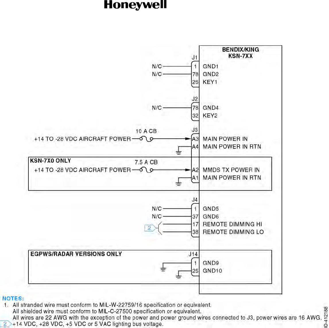
Draft
SYSTEM INSTALLATION MANUAL
066-01204 / 066-01213
Page 3-5
6 Dec 2012
© Honeywell International Inc. Do not copy without express permission of Honeywell.
34-70-06
Figure 3-1. Power System Interface Interconnect Diagram (Sheet 1 of 1)
Draft as of 10/15/2012

Draft
SYSTEM INSTALLATION MANUAL
066-01204 / 066-01213
Page 3-6
6 Dec 2012
© Honeywell International Inc. Do not copy without express permission of Honeywell.
34-70-06
Blank Page
Draft as of 10/15/2012

Draft
Page 3-7
6 Dec 2012
34-70-06
SYSTEM INSTALLATION MANUAL
066-01204 / 066-01213
© Honeywell International Inc. Do not copy without express permission of Honeywell.
3.4 Position Interface
3.4.1 Applicable Part Numbers
All part numbers and software revisions perform all position interface functions.
3.4.2 Function
The position interface outputs allow moving map products (such as the EFIS 40/50, Aspen EFD, and
ARGUS 3000/5000/7000 series of products) and ELT products to use KSN 7xx position data. Position
is output as both RS-232 data and ARINC 429 data.
3.4.3 Requirements and Limitations
The position interface must be left open if there are no using units are connected to the KSN 7xx.
3.4.4 Electrical Characteristics
J1-62 GPS FLIGHT PLAN 232 TX
J1-42 GPS/AIRDATA/FUEL 232 GND
This serial data bus conforms to EIA RS-232 electrical characteristics. This bus outputs position
information, which also includes (but may not be limited to) distance to go, groundspeed, time to go,
and flight plan waypoint data.
J1-71 GPS GAMA 429 TX A
J1-51 GPS GAMA 429 TX B
This serial data bus conforms to ARINC 429 electrical characteristics, and is configured for low
operating speed.
J1-63 LEGACY PXPRESS 232 TX
J1-43 LEGACY PXPRESS 232 GND
This serial data bus conforms to EIA RS-232 electrical characteristics, and may be configured for speed
on the maintenance pages.
3.4.5 Interconnect Diagram
Refer to Figure 3-2 for the position interface interconnect diagram.
Draft as of 10/15/2012

Draft
Page 3-8
6 Dec 2012
34-70-06
SYSTEM INSTALLATION MANUAL
066-01204 / 066-01213
© Honeywell International Inc. Do not copy without express permission of Honeywell.
Blank Page
Draft as of 10/15/2012

Draft
SYSTEM INSTALLATION MANUAL
066-01204 / 066-01213
Page 3-9
6 Dec 2012
© Honeywell International Inc. Do not copy without express permission of Honeywell.
34-70-06
Figure 3-2. Position Interface Interconnect Diagram (Sheet 1 of 1)
Draft as of 10/15/2012

Draft
SYSTEM INSTALLATION MANUAL
066-01204 / 066-01213
Page 3-10
6 Dec 2012
© Honeywell International Inc. Do not copy without express permission of Honeywell.
34-70-06
Blank Page
Draft as of 10/15/2012

Draft
Page 3-11
6 Dec 2012
34-70-06
SYSTEM INSTALLATION MANUAL
066-01204 / 066-01213
© Honeywell International Inc. Do not copy without express permission of Honeywell.
3.5 WX RDR Interface
3.5.1 Applicable Part Numbers
This function is only available when the optional KSN 7xx WX RDR/EGPWS option board is installed
and the associated product feature key is installed.
When the WX RDR is not connected to the KSN 7xx, the pins must be left open.
3.5.2 Function
Radar is a method for locating thunderstorms using radio waves. The radar transmitter generates
microwave energy in the form of pulses which are then transferred to the antenna where they are
focused into a beam by the antenna and radiated. When the beam intercepts a target, the energy is
reflected as an echo back to the antenna. It is then transferred to the receiver and processing circuits
in the receiver/transmitter unit. These echoes are displayed on the KSN 7xx.
3.5.3 Requirements and Limitations
The KSN 7xx must be configured for the radar installed for proper operation. The following radar types
are supported. Configuration of each type is covered in Section 4.
Refer to Table 3-6 for the WX RDR requirements and limitations.
3.5.4 Electrical Characteristics
A. WX RDR Control (ARINC 429)
J14-2 WX RDR CTL 429 TX A
J14-14 WX RDR CTL 429 TX B
This serial data bus conforms to ARINC 429 electrical characteristics, and may be configured for
operating speed on the maintenance pages.
B. Power ON/OFF
J14-15 WX RDR POWER ON/OFF
This pin controls the power emissions of the WX RDR, and is active low, so that when the output
is pulled low, the WX RDR turns ON.
C. WX RDR Data (ARINC 708A)
J14-5 WX RDR 708A 453 RX A
J14-17 WX RDR 708A 453 RX B
This serial data bus conforms to ARINC 708A electrical characteristics.
3.5.5 Interconnect Diagram
Refer to Figure 3-3 for the WX RDR interface interconnect diagram.
Draft as of 10/15/2012

Draft
Page 3-12
6 Dec 2012
34-70-06
SYSTEM INSTALLATION MANUAL
066-01204 / 066-01213
© Honeywell International Inc. Do not copy without express permission of Honeywell.
Blank Page
Draft as of 10/15/2012

Draft
SYSTEM INSTALLATION MANUAL
066-01204 / 066-01213
Page 3-13
6 Dec 2012
© Honeywell International Inc. Do not copy without express permission of Honeywell.
34-70-06
Table 3-6. WX RDR Requirements and Limitations
RDR Type
(Note 9) Horizontal Scan
Angle
Vertical Profile
Enable Vertical Scan
Angle
Auto Tilt
WX Manual Gain
Sector Scan
WX/ARL Mode
5,320 nm Ranges
Auto Standby
RDR 2000 100 (90) Enabled 60 N/A N/A N/A N/A N/A Enabled
RDR 2100 120 (100) Enabled 60 Enabled Disabled Disabled Enabled Enabled Enabled
RDS 8190 N/AN/AN/AN/AN/AN/AN/AEnabled
RDS 8290 N/AN/AN/AN/AN/AN/AN/AEnabled
RDS 82VP 90 Enabled 50 N/A N/A N/A N/A N/A Enabled
RDS 84 120 N/A N/A N/A N/A N/A N/A Enabled Enabled
RDS 84VP 120 Enabled 60 N/A N/A N/A N/A Enabled Enabled
RDS 86 120 N/A N/A Enabled N/A N/A Enabled Enabled Enabled
RDS 86VP 120 Enabled 60 Enabled N/A N/A Enabled Enabled Enabled
Other 120 (90) (100) Disabled 60 (50) Disabled Disabled Disabled Disabled Enabled Enabled
Draft as of 10/15/2012

Draft
SYSTEM INSTALLATION MANUAL
066-01204 / 066-01213
Page 3-14
6 Dec 2012
© Honeywell International Inc. Do not copy without express permission of Honeywell.
34-70-06
Blank Page
Draft as of 10/15/2012
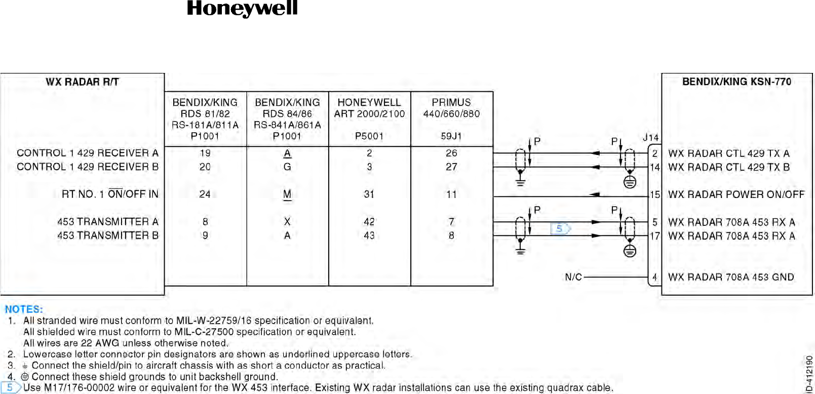
Draft
SYSTEM INSTALLATION MANUAL
066-01204 / 066-01213
Page 3-15
6 Dec 2012
© Honeywell International Inc. Do not copy without express permission of Honeywell.
34-70-06
Figure 3-3. WX RDR Interface Interconnect Diagram (Sheet 1 of 1)
Draft as of 10/15/2012

Draft
SYSTEM INSTALLATION MANUAL
066-01204 / 066-01213
Page 3-16
6 Dec 2012
© Honeywell International Inc. Do not copy without express permission of Honeywell.
34-70-06
Blank Page
Draft as of 10/15/2012

Draft
Page 3-17
6 Dec 2012
34-70-06
SYSTEM INSTALLATION MANUAL
066-01204 / 066-01213
© Honeywell International Inc. Do not copy without express permission of Honeywell.
3.6 EGPWS Interface
3.6.1 Applicable Part Numbers
A. Internal EGPWS (Growth)
All part numbers and software versions perform all published internal EGPWS functions.
B. External EGPWS
This function is only available when the optional KSN 7xx WX RDR/EGPWS option board is
installed and the associated product feature key is installed. Contact Bendix/King Product Support
for the feature key.
When the EGPWS is not connected to the KSN 7xx, the pins must be left open.
The following are part number families of the external EGPWS units that will interface with the KSN
7xx. The minimum EGPWS software versions (the last six digits) required for compatibility with
KSN 7xx installations is as follows:
• 965-0976-XXX-212-212 Mark V EGPWC
• 965-0976-XXX-212-212 Mark V EGPWC
• 965-0976-XXX-212-212 Mark V EGPWC
• 965-1076-XXX-212-212 Mark VII EGPWC
• 965-1076-XXX-212-212 Mark VII EGPWC
• 965-1076-XXX-212-212 Mark VII EGPWC
• 965-1176-005 Mark VI EGPWC
• 965-1186-005 Mark VI EGPWC
• 965-1206-005 Mark VIII EGPWC
• 965-1216-005 Mark VIII EGPWC
• 965-1227-0XX Mark XXI EGPWC
• 965-1590-006 Mark XXII EGPWC
• All versions of the KGP 560 EGPWS
• All versions of the KMH 880 EGPWS.
Draft as of 10/15/2012
and KGP 860
and KMH 980

Draft
Page 3-18
6 Dec 2012
34-70-06
SYSTEM INSTALLATION MANUAL
066-01204 / 066-01213
© Honeywell International Inc. Do not copy without express permission of Honeywell.
3.6.2 Function
EGPWS is a terrain awareness and alerting system. It uses aircraft inputs including geographic position,
attitude, airspeed, and glideslope combined with internal terrain, obstacle, and airport databases to
predict a potential conflict between an aircraft’s flight path and terrain or an obstacle. The KSN 7xx has
both an internal and an external EGPWS option which are defined below.
In a later certification, the KSN 7xx will offer an internal/integrated EGPWS function.
3.6.2.1 Internal EGPWS Function (Growth)
The internal EGPWS function uses GPS position along with altitude from a blind encoder or air data
computer to verify obstacle clearance.
3.6.2.2 External EGPWS Function
The external EGPWS function allows the KSN 7xx to interface to a variety of external EGPWS units
providing ground proximity warnings to pilots.
3.6.3 Requirements and Limitations
A. Internal EGPWS (Growth)
The KSN 7xx needs an external altitude reference for the internal EGPWS to work correctly. Refer
to Paragraph 3.9 Altitude/Airdata/Fuel Interface for sources of altitude that may be used.
B. External EGPWS
The external EGPWS unit will need a set of inputs described in its own installation manual. The
KSN 7xx can supply the GPS position needed by the EGPWS boxes.
3.6.4 Electrical Characteristics
The EGPWS will also output audio alerts. Refer to Paragraph 3.15 Audio Interface for connections to
the audio system.
A. Internal EGPWS (Growth)
(1) Terrain Inhibit
J2-74 TERRAIN INHIBIT
Normal Operation: Open
EGPWS Inhibited: GND
This input inhibits the operation of the internal EGPWS.
(2) EGPWS Self Test (Growth)
J2-75 EGPWS SELF TEST
Draft as of 10/15/2012

Draft
Page 3-19
6 Dec 2012
34-70-06
SYSTEM INSTALLATION MANUAL
066-01204 / 066-01213
© Honeywell International Inc. Do not copy without express permission of Honeywell.
Normal Operation: Open
Start Self Test: Momentary GND
This input starts the EGPWS Self Test.
(3) Landing Gear (Growth)
J2-34 LANDING GEAR
Gear Down: GND
Gear Up: Open
This input signals the state of the landing gear.
(4) Flaps or Tactical Select (Growth)
J2-15 SHARED-FLAPS OR TACTICAL SELECT (LOW ALTITUDE MODE)
For fixed wing aircraft, this indicates the position of the flaps as follows:
Flaps Retracted: Open
Flaps Extended: GND
For Rotorcraft, this input indicates normal or low altitude mode:
Normal Operation: Open
Low Altitude Operation: GND
(5) Annunciations (Growth)
J2-24 TERRAIN CAUTION ANNUNCIATE
J2-4 TERRAIN WARN ANNUNCIATE
J2-3 TERRAIN FAILURE ANNUNCIATE
J2-23 SHARED-AUDIO OR LOW ALTUTIDE MODE ANNUCIATE
These annunciations are active when grounded.
B. External EGPWS
(1) EGPWS Control
J14-13 EGPWS CTRL 429 TX A
J14-12 EGPWS CTRL 429 TX B
This serial data bus conforms to ARINC 429 electrical characteristics, and is configured for
high operating speed.
Label 017 (discretes data) is provided on this output of the KSN 7xx to implement the
EGPWS control functions.
Draft as of 10/15/2012

Draft
Page 3-20
6 Dec 2012
34-70-06
SYSTEM INSTALLATION MANUAL
066-01204 / 066-01213
© Honeywell International Inc. Do not copy without express permission of Honeywell.
Currently, the KGP 560, MK XXI and KMH-880 EGPWS units will accept label 017 from the
KSN 7xx starting with the 003 version of the EGPWS software.
Refer to Table 3-7 for the ARINC 429 Label 017 control function availability in EGPWS units.
(2) Audio Inhibit
J14-24 EXTERNAL AUDIO INHIBIT (LOW TO INHIBIT, OPEN TO ALLOW).
This is an input from the external EGPWS system telling the KSN 7xx to stop EGPWS audio
annunciations.
(3) Terrain Data
J14-9 KCPB RX A
J14-22 KCPB RX B
This serial data bus conforms to ARINC 429 electrical characteristics, and is configured for
high operating speed. This allows the KSN 7xx to receive terrain warning information from
the external EGPWS.
Table 3-7. ARINC 429 Label 017 Control Function Availability in EGPWS Units
EGPWS
Unit
Minimum EGPWS Software Revision Level Required to Support ARINC 429 Control
Test Inhibit LO ALT G/S Cancel Steep
Approach Flap
Override
KGP-560 003 003 N/A N/A N/A N/A
KMH-880 003 003 N/A N/A N/A N/A
MK-IVN/AN/AN/AN/AN/AN/A
MK-VN/AN/AN/AN/AN/AN/A
MK-VIN/AN/AN/AN/AN/AN/A
MK-VIIN/AN/AN/AN/AN/AN/A
MK-VIII N/A N/A N/A N/A N/A N/A
MK-XXI 003 003 003 N/A N/A N/A
MK-XXIIN/AN/AN/AN/AN/AN/A
NOTE: Currently, no EGWPS unit supports control of G/S cancel, steep approach or flap override through
ARINC 429.
Draft as of 10/15/2012
include KGP 860
Bendix King products
don't use hyphens

Draft
Page 3-21
6 Dec 2012
34-70-06
SYSTEM INSTALLATION MANUAL
066-01204 / 066-01213
© Honeywell International Inc. Do not copy without express permission of Honeywell.
(4) Position Data
J14-43 LEGACY PXPRESS 232 GND
J14-63 LEGACY PXPRESS 232 TX
This serial data bus conforms to EIA RS-232 electrical characteristics. This allows the KSN
7xx to transmit position information to the external EGPWS, if required.
3.6.5 Interconnect Diagram
Refer to Figure 3-4 for the EGPWS interface - internal (growth) interconnect diagram.
Refer to Figure 3-5 for the EGPWS interface - external interconnect diagram.
Draft as of 10/15/2012

Draft
Page 3-22
6 Dec 2012
34-70-06
SYSTEM INSTALLATION MANUAL
066-01204 / 066-01213
© Honeywell International Inc. Do not copy without express permission of Honeywell.
Blank Page
Draft as of 10/15/2012
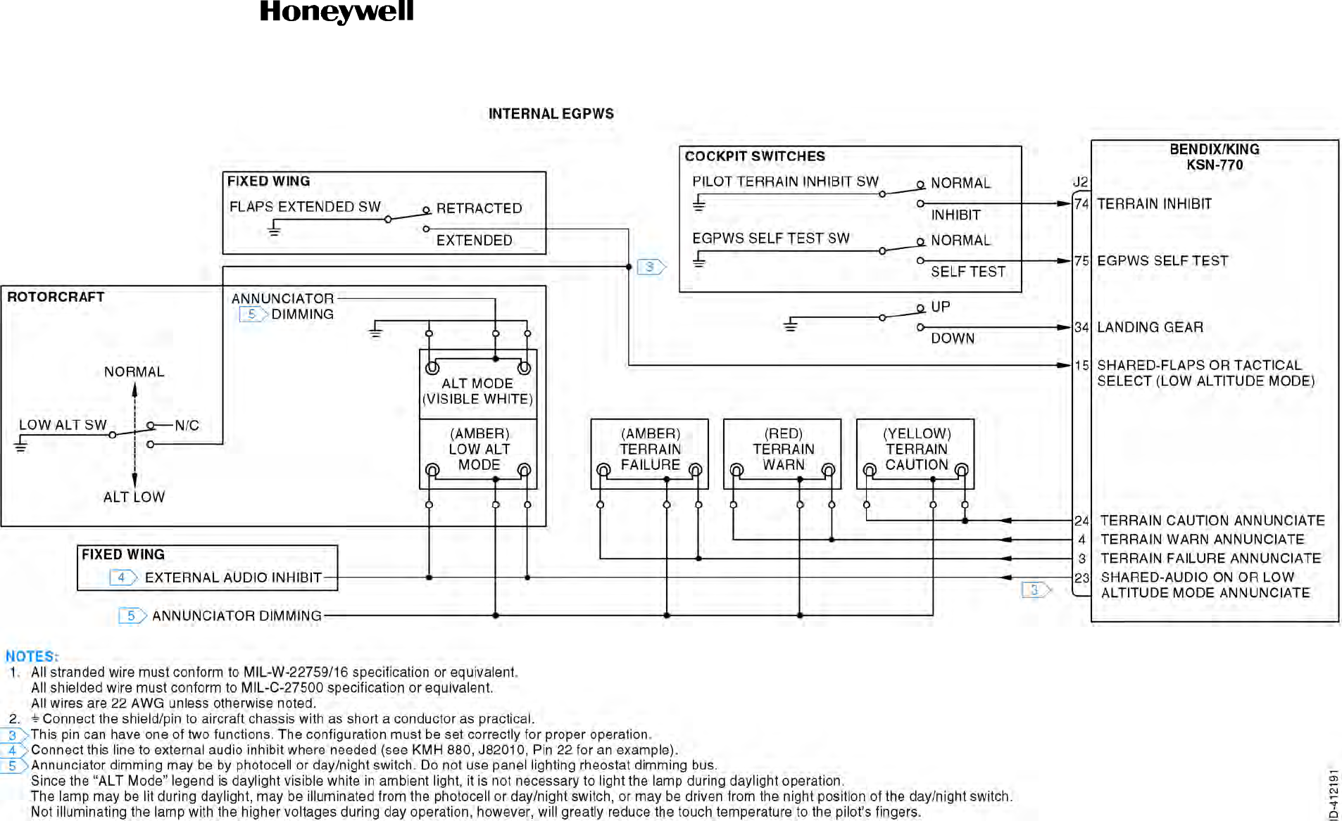
Draft
SYSTEM INSTALLATION MANUAL
066-01204 / 066-01213
Page 3-23
6 Dec 2012
© Honeywell International Inc. Do not copy without express permission of Honeywell.
34-70-06
Figure 3-4. EGPWS Interface - Internal (Growth) Interconnect Diagram (Sheet 1 of 1)
Draft as of 10/15/2012

Draft
SYSTEM INSTALLATION MANUAL
066-01204 / 066-01213
Page 3-24
6 Dec 2012
© Honeywell International Inc. Do not copy without express permission of Honeywell.
34-70-06
Blank Page
Draft as of 10/15/2012
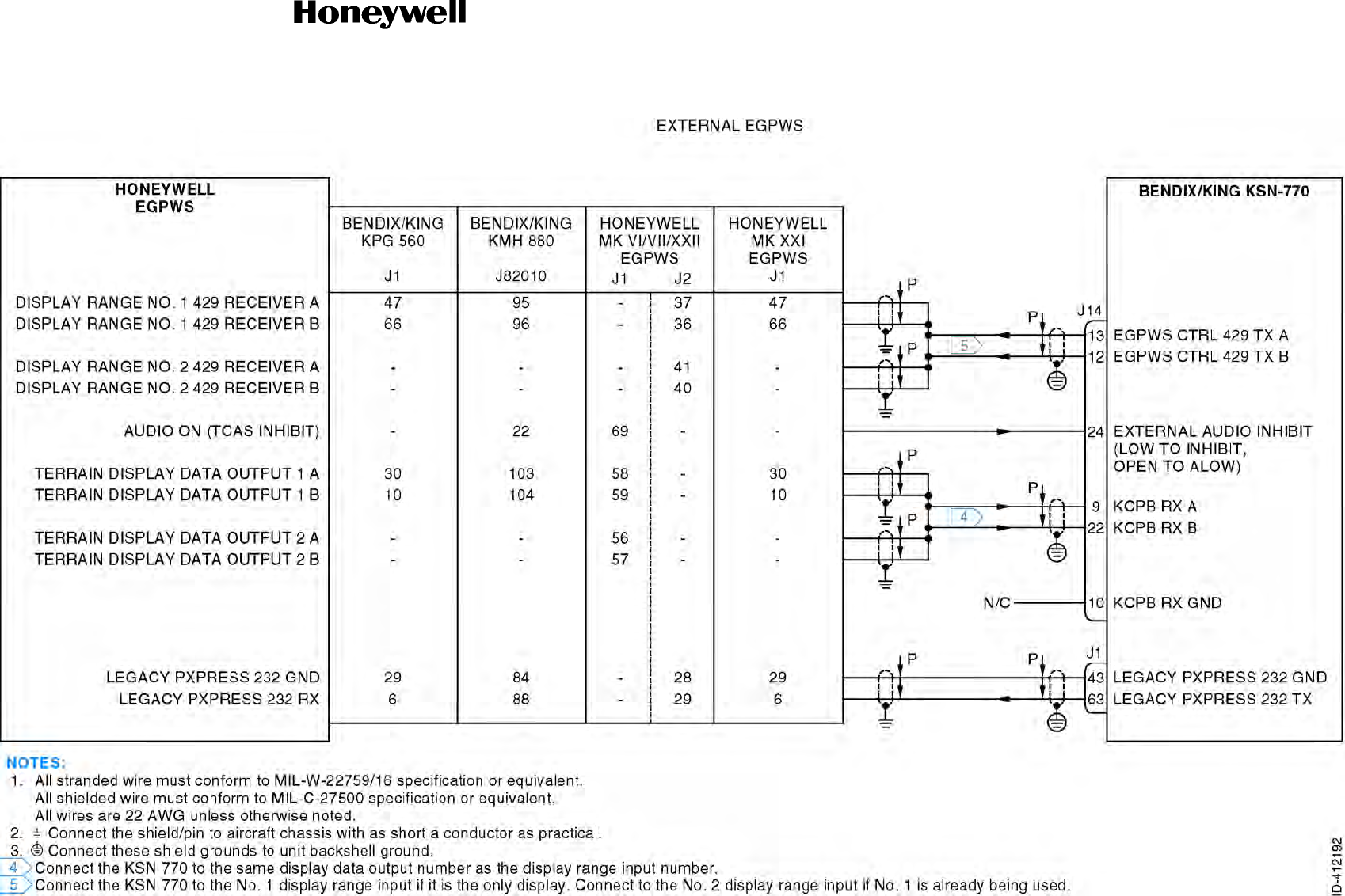
Draft
SYSTEM INSTALLATION MANUAL
066-01204 / 066-01213
Page 3-25
6 Dec 2012
© Honeywell International Inc. Do not copy without express permission of Honeywell.
34-70-06
Figure 3-5. EGPWS Interface - External Interconnect Diagram (Sheet 1 of 1)
Draft as of 10/15/2012
Figure 3-5 does not call out all of the EGPWS options, like KMH
980 and KGP 860

Draft
SYSTEM INSTALLATION MANUAL
066-01204 / 066-01213
Page 3-26
6 Dec 2012
© Honeywell International Inc. Do not copy without express permission of Honeywell.
34-70-06
Blank Page
Draft as of 10/15/2012

Draft
Page 3-27
6 Dec 2012
34-70-06
SYSTEM INSTALLATION MANUAL
066-01204 / 066-01213
© Honeywell International Inc. Do not copy without express permission of Honeywell.
3.7 Traffic Interface
3.7.1 Applicable Part Numbers
A. TIS
All part numbers and software versions perform all published TIS functions.
When the TIS is not connected to the KSN 7xx, the pins must be left open.
B. TCAS/TAS
This function is only available when the optional KSN 7xx WX RDR/EGPWS option board is
installed and the associated product feature key is installed. Contact Bendix/King Product Support
for the feature key.
When the TCAS/TAS is not connected to the KSN 7xx, the pins must be left open.
3.7.2 Function
A. TIS
TIS is a data link service that provides information similar to VFR RDR traffic advisories received
over voice radio. The data is received from the terminal Mode S radar system through the Mode S
transponder to the KSN 7xx once per radar scan (approximately every 5 seconds).
TIS provides the relative position, relative altitude, altitude trend, and estimated ground track angle
for as many as eight intruders that are within 7 nm horizontally and +3500/3000 feet (+1067 to
914 meters) vertically of the aircraft receiving TIS. This function is only available when optional
KSN 7xx software is installed.
B. TCAS/TAS
TCAS and TAS are airborne systems used to detect and track aircraft in the vicinity of a particular
aircraft through the interrogation of their transponders. Aircraft detected, tracked, and displayed by
the TCAS/TAS systems are referred to as intruders.
The system then analyzes the transponder replies to determine range, bearing, and relative
altitude. If the TCAS/TAS processor determines that a possible collision hazard exists, it issues
visual and aural warnings.
This function is only available when optional KSN 7xx software is installed.
3.7.3 Requirements and Limitations
The KSN 7xx must be configured for the traffic equipment installed for proper operation. Configuration
of each type is covered in Section 4.
Draft as of 10/15/2012

Draft
Page 3-28
6 Dec 2012
34-70-06
SYSTEM INSTALLATION MANUAL
066-01204 / 066-01213
© Honeywell International Inc. Do not copy without express permission of Honeywell.
3.7.4 Electrical Characteristics
A. Traffic Control
J14-73 TRAFFIC CTRL TX A
J14-53 TRAFFIC CTRL TX B
This serial data bus conforms to ARINC 429 electrical characteristics, and is configured for high
operating speed. This is the bus that controls the traffic LRUs.
B. Traffic Display
J14-69 TRAFFIC DISPLAY 429 RX A
J14-49 TRAFFIC DISPLAY 429 RX B
This serial data bus conforms to ARINC 429 electrical characteristics, and is configured for high
operating speed. This is the bus that supplies the KSN 7xx with traffic information to display.
C. Traffic Alert Aural Annunciation
J14-22 TA AURAL ACTIVE
Aural ON: Low
Aural OFF: High
This is a normally open discrete input to the KSN 7xx. This input signals to the KSN 7xx when the
traffic alert aural for traffic is active, for audio priority management within the KSN 7xx.
D. Traffic Discretes
(1) TPU-66A, TPU-67A, KTA 810/910, KMH 820/920
J14-2 TRAFFIC DISC 1 OUT (TRAFFIC DISPLAY VALID)
Active: Low
Inactive: High
These are high current discrete outputs. This output is set up for proper operation on the
maintenance pages.
For TPU-66A, TPU-67A, KTA 810/910, and KMH 820/920, TRAFFIC DISC 1 OUT is active
whenever the KSN 7xx is displaying traffic data. TRAFFIC DISC 2 OUT is not used in these
systems, and must remain unconnected.
Draft as of 10/15/2012

Draft
Page 3-29
6 Dec 2012
34-70-06
SYSTEM INSTALLATION MANUAL
066-01204 / 066-01213
© Honeywell International Inc. Do not copy without express permission of Honeywell.
(2) Skywatch 497
J14-2 TRAFFIC DISC 1 OUT (TEST command signal)
Normal: High
Test Command: Low
J14-21 TRAFFIC DISC 2 OUT (OPERATE / STANDBY)
Operate: Low
Standby: High
For L3 Skywatch 497, TRAFFIC DISC 1 OUT is the test command signal and TRAFFIC DISC
2 OUT is the operate/standby command. This output is set up for proper operation on the
maintenance pages.
3.7.5 Interconnect Diagram
Refer to Figure 3-6 for the traffic interface interconnect diagram.
Draft as of 10/15/2012

Draft
Page 3-30
6 Dec 2012
34-70-06
SYSTEM INSTALLATION MANUAL
066-01204 / 066-01213
© Honeywell International Inc. Do not copy without express permission of Honeywell.
Blank Page
Draft as of 10/15/2012
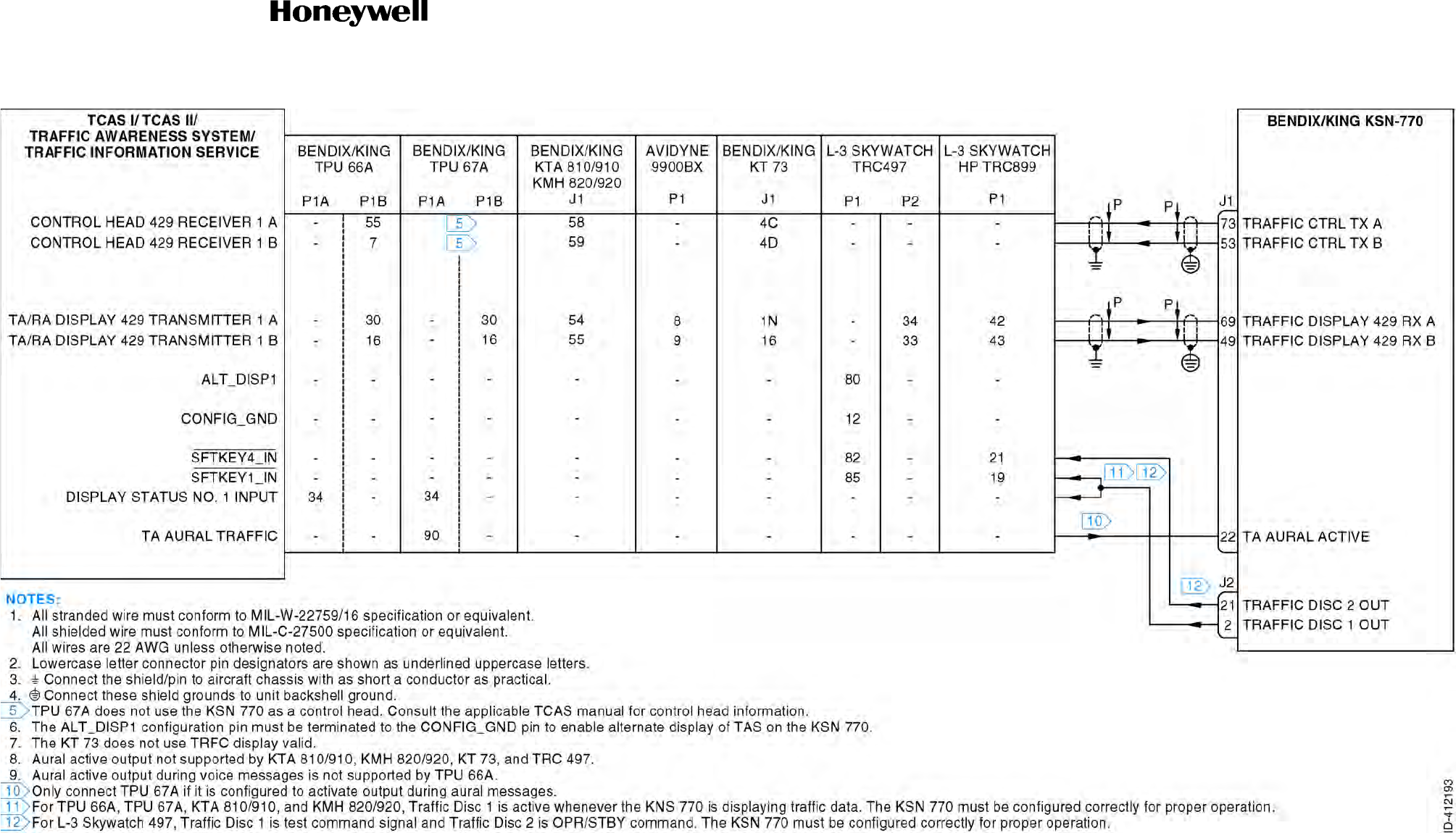
Draft
SYSTEM INSTALLATION MANUAL
066-01204 / 066-01213
Page 3-31
6 Dec 2012
© Honeywell International Inc. Do not copy without express permission of Honeywell.
34-70-06
Figure 3-6. Traffic Interface Interconnect Diagram (Sheet 1 of 1)
Draft as of 10/15/2012

Draft
SYSTEM INSTALLATION MANUAL
066-01204 / 066-01213
Page 3-32
6 Dec 2012
© Honeywell International Inc. Do not copy without express permission of Honeywell.
34-70-06
Blank Page
Draft as of 10/15/2012

Draft
Page 3-33
6 Dec 2012
34-70-06
SYSTEM INSTALLATION MANUAL
066-01204 / 066-01213
© Honeywell International Inc. Do not copy without express permission of Honeywell.
3.8 Heading/AHRS Interface
3.8.1 Applicable Part Numbers
All part numbers and software revisions perform all Heading/AHRS functions.
3.8.2 Function
Connecting a heading input to the KSN 7xx is optional, but highly recommended. However, the KSN
7xx uses its heading input to orient its map and to compute wind speed, wind direction and drift angle.
In addition, the KSN 7xx requires heading to compute both analog and ARINC 429 roll steering, and for
moving map overlays of data from heading referenced sensors.
A. All part numbers of the following AHRS systems are compatible with the KSN 7xx:
• Bendix/King KAH 460
• Rockwell Collins AHC 85
• Bendix/King KFD-840
• Bendix/King KSG-7200
• Bendix/King KFD 840
• Aspen EFD 1000.
B. All part numbers of the following compass systems are compatible with the KSN 7xx:
• Aeronetics 9100’s with remote bootstrap synchros
• Bendix/King KCS 55A (only with KI 525As with compass bootstrap synchros)
• Bendix/King KCS 305, Bendix/King KI 825
• Rockwell Collins MCS 65 (only with DGS 65’s with compass bootstrap synchros)
• Rockwell Collins PN 101 (only with 331A-3G or 331A-6P indicators with bootstrap synchros)
• Rockwell Collins MC 102
• Rockwell Collins MC 103
• Honeywell Sperry C14.
Draft as of 10/15/2012

Draft
Page 3-34
6 Dec 2012
34-70-06
SYSTEM INSTALLATION MANUAL
066-01204 / 066-01213
© Honeywell International Inc. Do not copy without express permission of Honeywell.
3.8.3 Requirements and Limitations
Although only one heading source is necessary for computations involving heading, the KSN 7xx will
operate properly with any combination of XYZ, RS 232, ARINC 429, and ARINC 429 EFIS heading
inputs connected simultaneously. In this case, the KSN 7xx will first look for ARINC 429 true heading
(EFIS, IRU or INS label 314) and the internally derived magnetic variation to create magnetic heading;
if not available, ARINC 429 magnetic heading (EFIS, AHRS, IRU or INS label 320) is used; if not
available XYZ heading is used ( XYZ heading is always assumed to be magnetic). If no other sources
of heading are available, RS232 heading is used.
If the XYZ heading output of an IRU or INS may be switched between magnetic and true, it must not be
connected to the KSN 7xx; use only the ARINC 429 heading for this installation.
The KSN 7xx INDICATOR 26 VAC input is used as the reference for detecting the XYZ heading input;
both must be the same phase. The KSN 7xx will accept either a superflag format heading valid or a
“ground-for-valid” format heading valid. The Maintenance page is used to select the correct format. No
damage to the KSN 7xx will occur if configured incorrectly; however the heading data will always be
flagged.
3.8.4 Electrical Characteristics
A. AHRS Heading
J1-66 AHRS 429 RX A
J1-46 AHRS 429 RX B
The AHRS input is for high speed ARINC 429. Low speed ARINC 429 must not be connected to
this input.
All serial data must conform to ARINC 429, ARINC 704 and ARINC 705 for electrical
characteristics, content and transmission interval (high speed bus). The KSN 7xx is configured to
know whether an AHRS is connected or not. A system may have many more labels than those
listed below. Label 314, true heading, is used if it is available, and combined with the KSN 7xx
computed magnetic variation to determine magnetic heading. If true heading is not available from
the AHRS, then the input magnetic heading is used.
Refer to Table 3-8 for the AHRS labels.
Table 3-8. AHRS Labels
Label Parameter
314 True heading
320 Magnetic heading
Draft as of 10/15/2012

Draft
Page 3-35
6 Dec 2012
34-70-06
SYSTEM INSTALLATION MANUAL
066-01204 / 066-01213
© Honeywell International Inc. Do not copy without express permission of Honeywell.
B. XYZ Heading
J1-21 HEADING VALID
This pin is configurable on the Maintenance page for either valid high or valid low. An open
HEADING VALID pin always indicates invalid.
J1-77 HEADING X
J1-58 HEADING Y
J1-59 HEADING Z
Three-wire XYZ format with Z grounded. Input impedance is no less than 10 kilohms. Maximum
lead-to-lead voltage is 11.8 Vrms.
NOTE: To accept this input HEADINGVALID (J1-21) must be valid. The 26 VAC used to excite the
heading source synchro must be of the same phase as the KSN 7xx 26 VAC reference
input.
J1-6 HDG REF HI
This is the indicator 26 VAC reference. Input impedance no less than 10 kilohms.
J1-7 HDG REF LO
This pin serves as the 26 VAC return. Impedance to AC GND less than 0.1 ohm.
3.8.5 Interconnect Diagram
Refer to Figure 3-7 for the heading interface - XYZ interconnect diagram.
Refer to Figure 3-8 for the AHRS interface interconnect diagram.
HI: No less than 18.5 VDC (or two-thirds the voltage applied to the
18-33 VDC AC POWER).
Load Resistance: No more than 3.5 VDC. Input impedance no less than 10 kilohms.
Draft as of 10/15/2012

Draft
Page 3-36
6 Dec 2012
34-70-06
SYSTEM INSTALLATION MANUAL
066-01204 / 066-01213
© Honeywell International Inc. Do not copy without express permission of Honeywell.
Blank Page
Draft as of 10/15/2012

Draft
SYSTEM INSTALLATION MANUAL
066-01204 / 066-01213
Page 3-37
6 Dec 2012
© Honeywell International Inc. Do not copy without express permission of Honeywell.
34-70-06
Figure 3-7. Heading Interface - XYZ Interconnect Diagram (Sheet 1 of 2)
Draft as of 10/15/2012

Draft
SYSTEM INSTALLATION MANUAL
066-01204 / 066-01213
Page 3-38
6 Dec 2012
© Honeywell International Inc. Do not copy without express permission of Honeywell.
34-70-06
Blank Page
Draft as of 10/15/2012
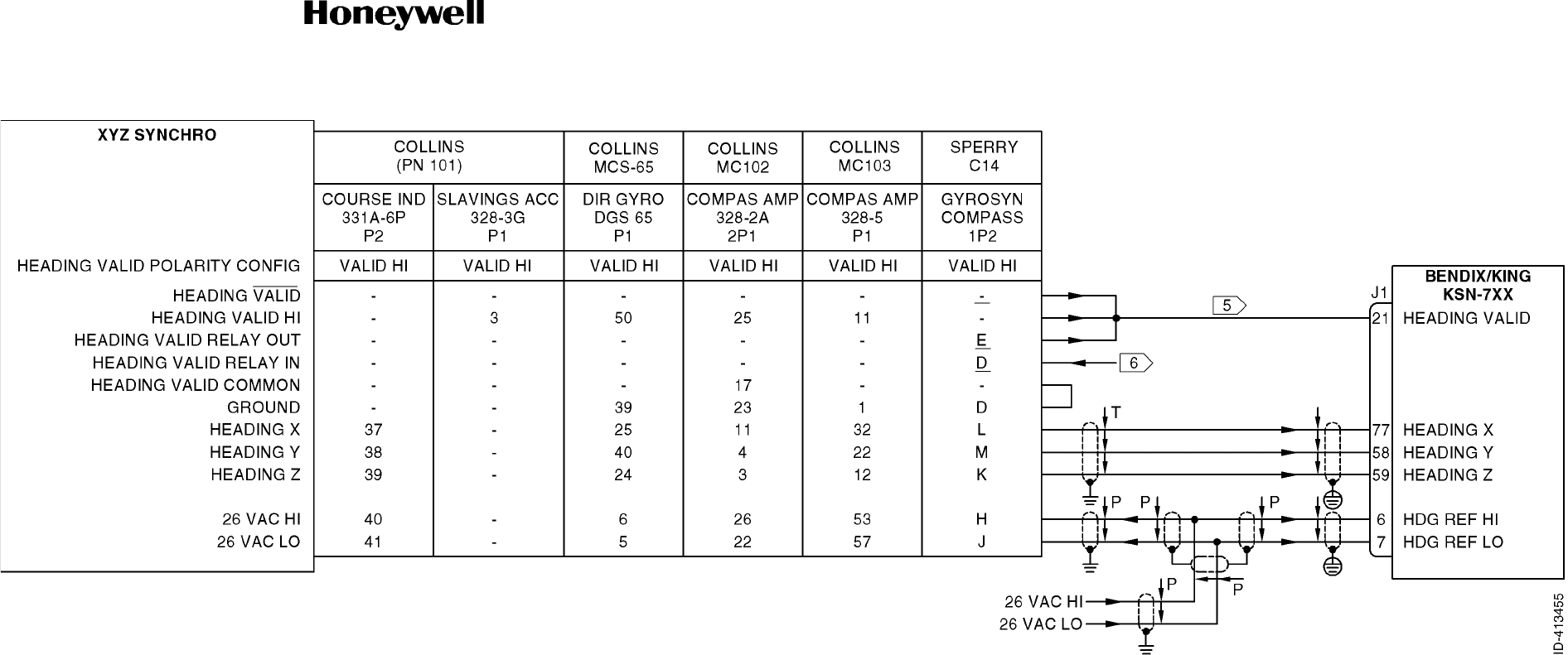
Draft
SYSTEM INSTALLATION MANUAL
066-01204 / 066-01213
Page 3-39
6 Dec 2012
© Honeywell International Inc. Do not copy without express permission of Honeywell.
34-70-06
Figure 3-7. Heading Interface - XYZ Interconnect Diagram (Sheet 2 of 2)
Draft as of 10/15/2012

Draft
SYSTEM INSTALLATION MANUAL
066-01204 / 066-01213
Page 3-40
6 Dec 2012
© Honeywell International Inc. Do not copy without express permission of Honeywell.
34-70-06
Blank Page
Draft as of 10/15/2012
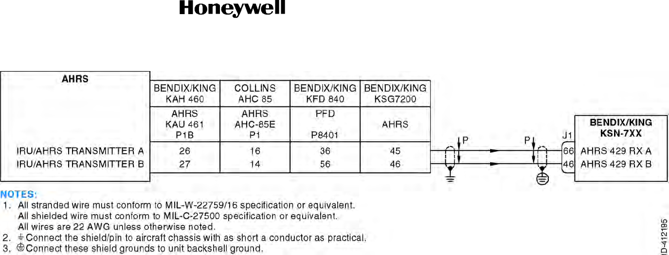
Draft
SYSTEM INSTALLATION MANUAL
066-01204 / 066-01213
Page 3-41
6 Dec 2012
© Honeywell International Inc. Do not copy without express permission of Honeywell.
34-70-06
Figure 3-8. AHRS Interface Interconnect Diagram (Sheet 1 of 1)
Draft as of 10/15/2012

Draft
SYSTEM INSTALLATION MANUAL
066-01204 / 066-01213
Page 3-42
6 Dec 2012
© Honeywell International Inc. Do not copy without express permission of Honeywell.
34-70-06
Blank Page
Draft as of 10/15/2012

Draft
Page 3-43
6 Dec 2012
34-70-06
SYSTEM INSTALLATION MANUAL
066-01204 / 066-01213
© Honeywell International Inc. Do not copy without express permission of Honeywell.
3.9 Altitude/Airdata/Fuel Interface
3.9.1 Applicable Part Numbers
All part numbers and software revisions perform all Altitude/Airdata/Fuel functions.
3.9.2 Functions
A. Altitude
All part numbers of the Bendix/King KEA 346-08 or above, with MOD 3 incorporated, are
compatible as a DC precision baro-corrected altitude or baro-setting source with the KSN 7xx
through the Analog BARO CORRECTION HI interface.
All part numbers of the Bendix/King KEA 130A (not including KEA 130) are compatible as a baro
setting source with the KSN 7xx through the analog BARO CORRECTION HI interface.
Kollsman-IDC model 519-28702-906 and Smiths model WL 1407/AM/MS 5 or 6 are compatible as
a baro setting source with the KSN 7xx through the Analog BARO CORRECTION HI interface.
Kollsman-IDC models PD 44929-935, 28704-495, and 28704-XXX are compatible as a baro
setting source with the KSN 7xx through the Analog BARO CORRECTION HI interface.
The KSN 7xx is capable of receiving barometric altitude data from multiple sources. These include
(in order of priority):
• ARINC 429/419 digital air data computers (highest priority)
• RS-232 digital air data computers
• Gillham altitude data (lowest priority).
Certain altimeters provide an internal potentiometer that is driven by a baro setting mechanism.
The baro setting mechanism can be linear with inches of mercury (kPa) or linear with feet of baro
correction. Inches of mercury (kPa) represent the sea level baro metric pressure. The altitude
value in feet represents the difference between pressure altitude (gray code altitude) and the baro
corrected altitude. The potentiometer must be excited by an external voltage. If two or more
devices are monitoring this potentiometer output then only one of them can excite the
potentiometer and the other(s) must only monitor the reference input. In some aircraft installations
the KSN 7xx will be the only user of the baro setting potentiometer and it will need to supply the
excitation. In others, it will share the potentiometer with the flight control system. Some flight
control systems must always supply their own excitation. For these systems the KSN 7xx must not
supply the excitation but must monitor what the supplied excitation is so that it can divide its value
into the value from the potentiometer to determine the potentiometer value.
The DC baro setting reference is configurable as input or output based on whether KSN 7xx is
going to provide the excitation voltage or monitor the externally supplied excitation voltage.
Refer to the maintenance pages on how to set the parameters in the configuration module. There
are two major types of DC baro setting outputs on encoding altimeters: Baro set linear and altitude
correction linear.
Draft as of 10/15/2012

Draft
Page 3-44
6 Dec 2012
34-70-06
SYSTEM INSTALLATION MANUAL
066-01204 / 066-01213
© Honeywell International Inc. Do not copy without express permission of Honeywell.
(1) Altitude Function - Baro Set Linear
Baro set linear encoding altimeters have a DC output voltage that is linear to the barometric
pressure setting (inches of mercury). Encoding altimeter models which use this type of baro
correction output include:
519-44929-935 (Kollsman-IDC, used on Cessna 525s)
519-28704-495 (Kollsman-IDC)
(2) Altitude Function - Altitude Correction Linear
Altitude correction linear encoding altimeters have a DC output voltage that is linear to the
correction from pressure altitude to indicated altitude. Encoding altimeter models which use
this type of baro correction output include:
KEA 346 (Bendix/King)
KEA 130A (Bendix/King)
519-28704-5XX (Kollsman-IDC)
B. Airdata
The -0200 and -0300 part numbers of the B&D 2600 transmit data too slowly to be compatible with
the KSN 7xx. These units may be converted to -0600 and -0700 part numbers respectively, which
are compatible with the KSN 7xx. All other part numbers of the B&D 2600 are compatible with the
KSN 7xx.
All part numbers of the B&D 2601, B&D 2800, and BENDIX/KING KDC -481 are compatible with
the KSN 7xx through the ARINC serial airdata interface using ARINC 429.
All part numbers of the Rockwell Collins ADC 81A and ADC 82 are compatible with the KSN 7xx
through the ARINC serial airdata interface using ARINC 575-3.
The following models of the Rockwell Collins ADC 80 are compatible with the KSN 7xx through the
ARINC serial airdata interface using ARINC 575-3, and transmit all airdata labels:
The following models of the Rockwell Collins ADC 80 are compatible with the KSN 7xx through the
ARINC serial airdata interface using ARINC 419 (575-3); however, they only transmit label 210,
TRUE AIRSPEED.
ABCDE -G- I J
KLM- - -Q
-----F-H--
----N--
Draft as of 10/15/2012

Draft
Page 3-45
6 Dec 2012
34-70-06
SYSTEM INSTALLATION MANUAL
066-01204 / 066-01213
© Honeywell International Inc. Do not copy without express permission of Honeywell.
The KSN 7xx can be configured to receive RS-232 serial air data in one of two different formats:
• Format C-Fuel and Airdata
• Format D-Fuel and Barometric Airdata.
The format of the RS-232 data can be configured in the Maintenance pages.
Barometric altitude information is used for aiding the GPS receiver in acquiring and tracking its
position, ensuring the accuracy of RAIM calculations (outside of SBAS coverage),for altitude
alerting functions, and for advisory VNAV calculations.
True airspeed is used to compute winds aloft.
C. Fuel Flow
The KSN 7xx may be interfaced to fuel flow systems with a separate fuel flow indicator for
enhanced flight planning.
3.9.3 Requirements and Limitations
A. Altitude/Airdata
A source of true airspeed is optional. With an airspeed input, an automatic winds aloft calculation
is provided. True airspeed may be entered manually when it is not provided electrically.
A source of barometric altitude is required for GPS installations certified for IFR.
The KSN 7xx accepts analog altitude inputs which utilize DC excitation only. Certain aircraft are
wired to excite altimeters with 400 Hz AC, and the KSN 7xx is not compatible with these
installations.
The KSN 7xx DC altitude resolution is such that you may see as much as 200 feet (61 meters) of
error between the altimeter and the altitude displayed on the KSN 7xx. This performance is
acceptable for aiding the GPS receiver, but is marginal if VNAV or altitude alerting are to be used.
Some Airdata computers require up to ten minutes warm-up time. This can result in an ALTITUDE
FAIL message on the KSN 7xx during the Airdata warm-up period. Connecting to a gray code
altitude source that does not require warm-up will prevent this message as the KSN 7xx will revert
to the gray code source until the airdata becomes valid.
B. Fuel Flow
The KSN 7xx receives fuel flow information from external equipment over the
AIRDATA/FUEL/HDG 232 RX bus. It can receive one fuel flow from each of up to two engines.
Draft as of 10/15/2012

Draft
Page 3-46
6 Dec 2012
34-70-06
SYSTEM INSTALLATION MANUAL
066-01204 / 066-01213
© Honeywell International Inc. Do not copy without express permission of Honeywell.
3.9.4 Electrical Characteristics
A. Gillham Altitude
Gillham Altitude Input
J2-13 D4
J2-34 A1
J2-35 A2
J2-49 A4
J2-17 B1
J2-54 B2
J2-53 B4
J2-45 C1
J2-18 C2
J2-31 C4
These inputs are active low, and conform to the requirements of ARINC 575-3, Attachment 5.
NOTE: Some receivers of the altitude encoder do not have internal isolation diodes to prevent the
unit from pulling the encoder lines to GND when the unit is OFF. The KSN 7xx has diodes
internal to the unit. However, some transponders and other devices do not have the
internal diodes. These units require a diode to be added to the installation harness for
every encoder line. The diodes are inserted at the connection to the unit that does not
have internal diodes. The anode is on the receiving unit’s side and the cathode is on the
encoder side. A set of diodes is required for each unit without internal diodes.
B. Analog Baro Correction
J2-8 BARO CORRECTION HI
J2-28 BARO CORRECTION LO
These pins are configured on the maintenance pages for input of either DC altitude or DC
barometric correction. This is an altimeter potentiometer voltage. The most positive lead of the
potentiometer must be connected to BARO CORRECTION HI (i.e. if the potentiometer is excited
with a negative voltage, the lead with the negative voltage must be connected to BARO
CORRECTION LO).
If the BARO CORRECTION inputs are used for baro correction, the maintenance page must be
configured properly. Some altimeters output a baro correction voltage that is linear with inches of
mercury barometric pressure. Others output a voltage that is linear with the altitude correction
between pressure altitude and indicated altitude. Refer the installation manual for the piece of
equipment being connected for more information.
HI: A voltage of not less than 10.0 volts relative to AC GND or a
resistance to AC GND of not less than 100 kilohms.
LO: A voltage of not more than 1.9 volts relative to AC GND or a
resistance to AC GND of not more than 375 ohms.
Draft as of 10/15/2012

Draft
Page 3-47
6 Dec 2012
34-70-06
SYSTEM INSTALLATION MANUAL
066-01204 / 066-01213
© Honeywell International Inc. Do not copy without express permission of Honeywell.
Maximum differential input voltage: 21 volts
Maximum voltage to GND (each side): 13.5 volts
Input impedance: 420 kilohms
J2-48 AIRDATA REFERENCE HI
J2-67 AIRDATA REFERENCE LO
These pins always read the voltage used to excite an altimeter’s potentiometer. If no other source
in the aircraft is exciting the potentiometer, the KSN 7xx may be configured to excite the
potentiometer through these pins. If this is the case, the following apply:
AIRDATA REFERENCE HI is +9.0 volts referenced to AIRDATA REFERENCE LO.
Maximum differential input voltage: 21 volts
Maximum voltage to GND (each side): 13.5 volts
Input impedance: 420 kilohms
Minimum output load impedance: 2 kilohms
NOTE: Although current limiting is provided internal to the KSN 7xx, damage could occur if the
KSN 7xx is configured to excite the potentiometer at the same time another source is
exciting it. In addition, the analog airdata interface will not function properly in this case.
C. ARINC Serial Airdata Input
J2-46 BARO ALT 429 A
J2-65 BARO ALT 429 B
This input is for high speed ARINC 429. Low speed ARINC 429 must not be connected to this input.
If the airdata source broadcasts a label used by the KSN 7xx with the SSM set to failure warning,
then the ARINC 429 AIRDATA FAIL message will appear. An example of this is when the
BENDIX/KING KDC 481 airdata computer broadcasts TAS with the SSM set to failure warning
upon its determination that the temperature probe is not connected.
A system may have many more labels than those listed. Selection of ARINC 429 or ARINC 419 is
done in the maintenance pages.
All versions of the KSN 7xx accept the following ARINC 429 serial airdata labels as shown in Table
3-9.
Table 3-9. ARINC 429 Serial Airdata Labels
429 Label Parameter
203 Altitude (1013.25 mB)
204 Barometer corrected altitude #1
205 MACH (reserved for growth)
206 Computed airspeed
210 True airspeed
Draft as of 10/15/2012

Draft
Page 3-48
6 Dec 2012
34-70-06
SYSTEM INSTALLATION MANUAL
066-01204 / 066-01213
© Honeywell International Inc. Do not copy without express permission of Honeywell.
All versions of the KSN 7xx accept the following ARINC 419 (575-3) serial airdata labels shown in
Table 3-10.
D. RS 232 Serial Airdata Input
J1-61 AIRDATA/FUEL/HDG 232 RX
This signal is referenced to AC GND. It is an EIA RS-232 format serial bus. All versions of the KSN
7xx will receive RS 232 Airdata in either "Format C" or "Format D".
When PRESSURE ALTITUDE, BAROMETRIC SETTING, and BARO-CORRECTED ALTITUDE
are all available, pressure altitude and baro-corrected altitude are used to calculate the baro setting
displayed on the KSN 7xx (rather than the KSN 7xx displaying the RS 232 BAROMETRIC
SETTING).
211 Total air temperature
212 Altitude rate
213 Static air temperature
Table 3-10. ARINC 429 Serial Airdata Labels
429 Label Parameter
203 Altitude (1013.25 mB)
204 Barometer corrected altitude #1
205 MACH
210 True airspeed
211 Total air temperature
213 Static air temperature
Table 3-9. ARINC 429 Serial Airdata Labels
429 Label Parameter
Draft as of 10/15/2012

Draft
Page 3-49
6 Dec 2012
34-70-06
SYSTEM INSTALLATION MANUAL
066-01204 / 066-01213
© Honeywell International Inc. Do not copy without express permission of Honeywell.
E. Outside Air Temperature (OAT) Input (Growth)
J2-69 OAT+
J2-68 OAT
The OAT probe is used to correct internal TAWS altitude.
The KSN 7xx is capable of interfacing directly to a standard 500-ohm temperature probe for aircraft
operated in cold environments. Very cold air temperatures cause an increase in the density of the
air mass and can result in barometric altimeter errors, both in sensitive altimeters/encoders and
blind encoders. Aircraft normally operated in very cold climates can benefit from the addition of an
OAT probe interfaced to the KSN 7xx
The Bendix/King OAT temp probe Kit is PN 050-03610-0002.
3.9.5 Interconnect Diagrams
A. Altitude Interface
Refer to Figure 3-9 for the altitude interface interconnect diagram.
B. Airdata/OAT Interface
Refer to Figure 3-10 for the airdata/OAT interface interconnect diagram.
C. Fuel Flow/Airdata Interface
Refer to Figure 3-11 for the fuel flow/airdata interface interconnect diagram.
Draft as of 10/15/2012

Draft
Page 3-50
6 Dec 2012
34-70-06
SYSTEM INSTALLATION MANUAL
066-01204 / 066-01213
© Honeywell International Inc. Do not copy without express permission of Honeywell.
Blank Page
Draft as of 10/15/2012
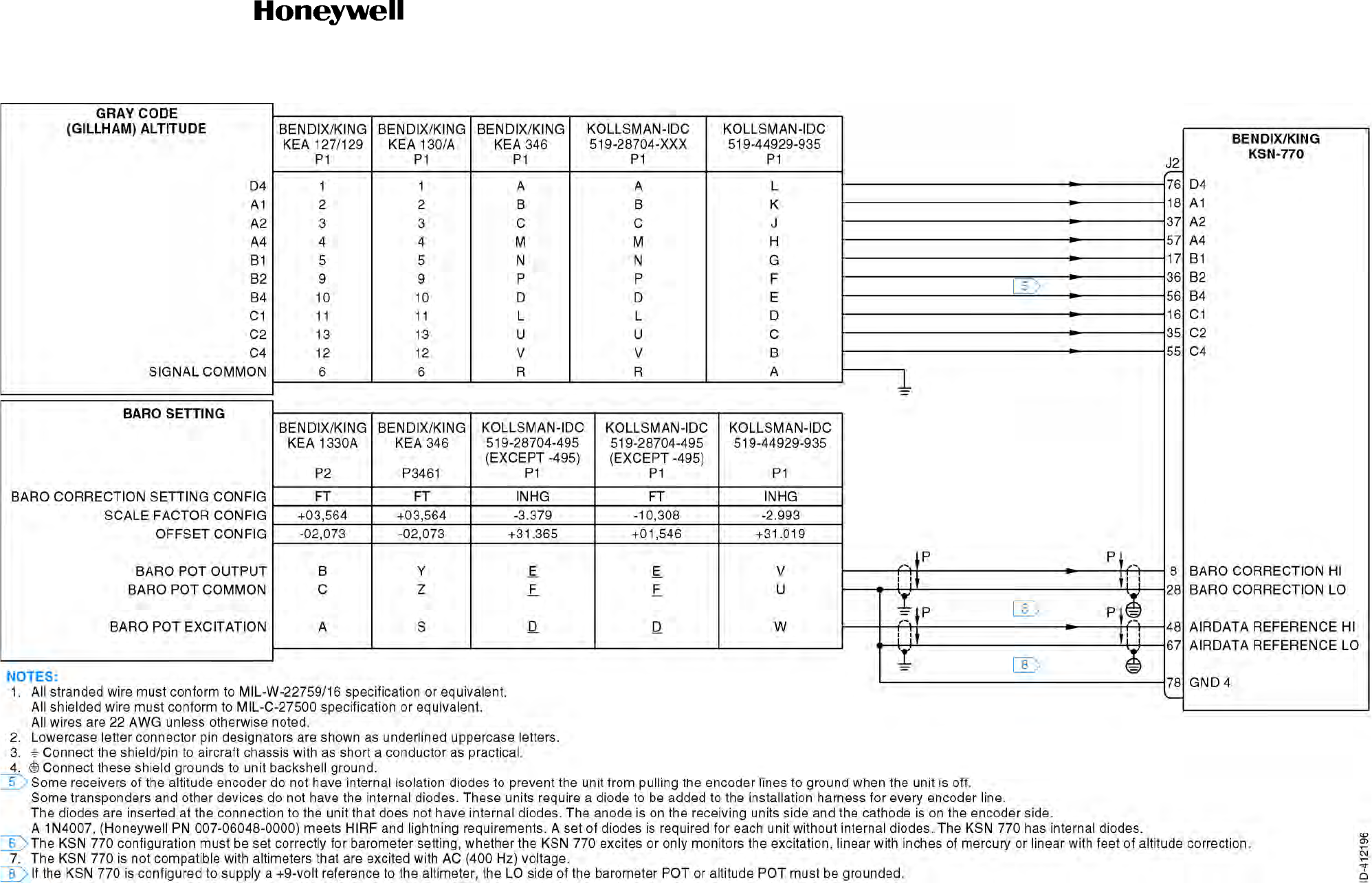
Draft
SYSTEM INSTALLATION MANUAL
066-01204 / 066-01213
Page 3-51
6 Dec 2012
© Honeywell International Inc. Do not copy without express permission of Honeywell.
34-70-06
Figure 3-9. Altitude Interface Interconnect Diagram (Sheet 1 of 1)
Draft as of 10/15/2012

Draft
SYSTEM INSTALLATION MANUAL
066-01204 / 066-01213
Page 3-52
6 Dec 2012
© Honeywell International Inc. Do not copy without express permission of Honeywell.
34-70-06
Blank Page
Draft as of 10/15/2012
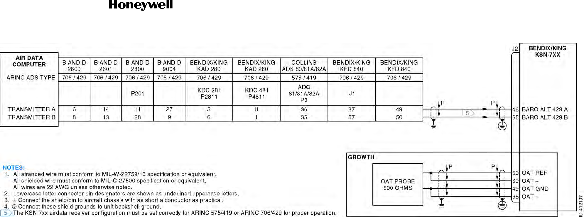
Draft
SYSTEM INSTALLATION MANUAL
066-01204 / 066-01213
Page 3-53
6 Dec 2012
© Honeywell International Inc. Do not copy without express permission of Honeywell.
34-70-06
Figure 3-10. Airdata/OAT Interface Interconnect Diagram (Sheet 1 of 1)
Draft as of 10/15/2012

Draft
SYSTEM INSTALLATION MANUAL
066-01204 / 066-01213
Page 3-54
6 Dec 2012
© Honeywell International Inc. Do not copy without express permission of Honeywell.
34-70-06
Blank Page
Draft as of 10/15/2012
Draft
SYSTEM INSTALLATION MANUAL
066-01204 / 066-01213
Page 3-55
6 Dec 2012
© Honeywell International Inc. Do not copy without express permission of Honeywell.
34-70-06
Figure 3-11. Fuel Flow/Airdata Interface Interconnect Diagram (Sheet 1 of 2)
Draft as of 10/15/2012

Draft
SYSTEM INSTALLATION MANUAL
066-01204 / 066-01213
Page 3-56
6 Dec 2012
© Honeywell International Inc. Do not copy without express permission of Honeywell.
34-70-06
Blank Page
Draft as of 10/15/2012
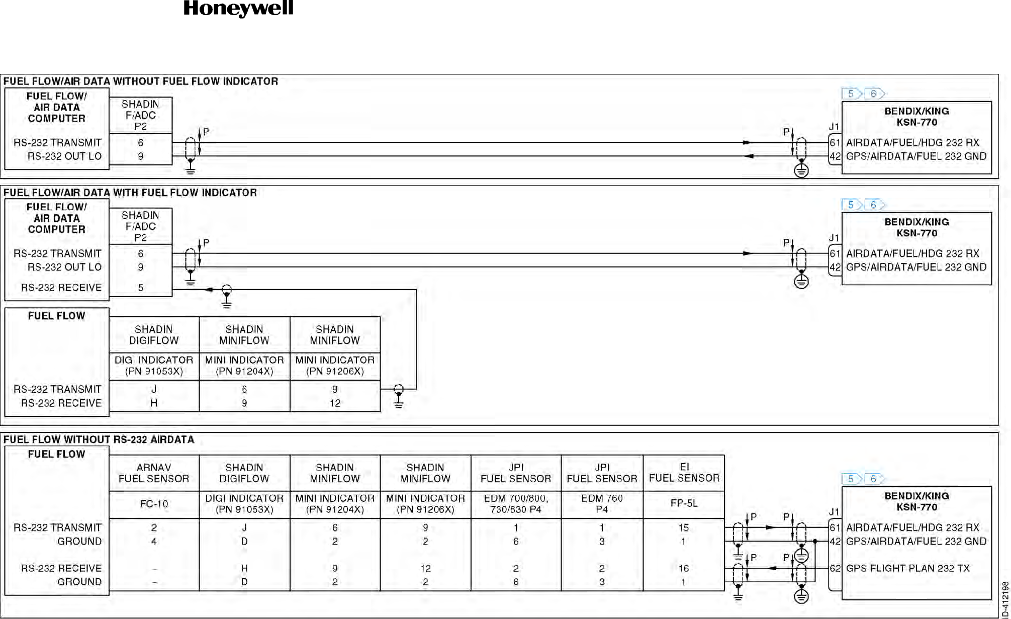
Draft
SYSTEM INSTALLATION MANUAL
066-01204 / 066-01213
Page 3-57
6 Dec 2012
© Honeywell International Inc. Do not copy without express permission of Honeywell.
34-70-06
Figure 3-11. Fuel Flow/Airdata Interface Interconnect Diagram (Sheet 2 of 2)
Draft as of 10/15/2012

Draft
SYSTEM INSTALLATION MANUAL
066-01204 / 066-01213
Page 3-58
6 Dec 2012
© Honeywell International Inc. Do not copy without express permission of Honeywell.
34-70-06
Blank Page
Draft as of 10/15/2012

Draft
Page 3-59
6 Dec 2012
34-70-06
SYSTEM INSTALLATION MANUAL
066-01204 / 066-01213
© Honeywell International Inc. Do not copy without express permission of Honeywell.
3.10 Flight Control Interface
3.10.1 Applicable Part Numbers
All part numbers and software revisions perform all flight control functions.
3.10.2 Function
A. GPS
Three different interface methods exist to couple the KSN 7xx GPS function to an automatic flight
control system. For lateral guidance, roll composite steering is provided which conforms to the
ARINC 561 format for enroute/terminal use and has increased authority for approach arm and
approach active modes. It is provide in ARINC 429, and an analog AC or DC command. If roll
steering is not supported with the autopilot, analog course datum and D-bar signals may be used
with or obtained from an HSI or NAV indicator connected to the KSN 7xx. For SBAS approaches
ILS type vertical and lateral commands are generated in both analog deviations and ARINC 429
formats.
B. VHF NAV (KSN 7x0 Only)
For VHF NAV guidance based operation, LOC/VOR/GS outputs are provided in analog
deviation/OBS resolver, an analog composite NAV output, and a dedicated ARINC 429 bus. A built
in VHF NAV/GPS switching function for the analog deviations (lateral and vertical) outputs is
incorporated internally, so that external switching is not required in the aircraft between GPS and
VHF NAV sources.
An ARINC 429 interface facilitates connection with numerous flight control systems.
3.10.3 Requirements and Limitations
A. ARINC 429
All part numbers of the Bendix/King KFC 400 are compatible with the KSN 7xx.
The following part numbers of the KFC 275 and KFC 325 are compatible with the KSN 7xx ARINC
429 roll steering through the Bendix/King EFIS 40/50 when the KSN 7xx is installed for IFR
non-precision approaches:
KCP 220 065-0064-
The following part numbers of the Bendix/King KFC 275 and KFC 325 flight control systems are
compatible with the KSN 7xx ARINC 429 roll steering through the Bendix/King EFIS 40/50 when
the KSN 7xx is not installed for IFR non-precision approaches:
01 05 06 07 08
15 -
-
Draft as of 10/15/2012

Draft
Page 3-60
6 Dec 2012
34-70-06
SYSTEM INSTALLATION MANUAL
066-01204 / 066-01213
© Honeywell International Inc. Do not copy without express permission of Honeywell.
KCP 220 065-0064-
B. Roll Composite Steering
All part numbers of the Rockwell Collins APS 65, and Bendix/King KFC 275 and KFC 325 are
compatible with the KSN 7xx.
The following part numbers of the Bendix/King KFC 275 and KFC 325 flight control systems are
compatible with the KSN 7xx roll composite steering when the KSN 7xx is installed for IFR
non-precision approaches:
KCP 220 065-0064-
The following part numbers of the Bendix/King KFC 275 and KFC 325 flight control systems are
compatible with the KSN 7xx roll composite steering when the KSN 7xx is not installed for IFR
non-precision approaches:
KCP 220 065-0064-
KSN 7xx interface to a flight control system is optional.
If the KSN 7xx installation is to be certified for GPS/SBAS approaches and the aircraft’s flight
control system uses course datum and analog deviation signals from the KSN 7xx, then use of the
FCS LOCALIZER ENGAGE signal is strongly recommended. This KSN 7xx output is active when
the KSN 7xx is in approach active mode and when the pilot manually sets the CDI scale to 0.3 nm,
and is equivalent in function to an ILS energize signal in that it indicates approach autopilot gain
scheduling is required.
01 05 06 07 08
15 16
20
01 05 06 07 08
15 -
-
01 05 06 07 08
15 16
20
Draft as of 10/15/2012

Draft
Page 3-61
6 Dec 2012
34-70-06
SYSTEM INSTALLATION MANUAL
066-01204 / 066-01213
© Honeywell International Inc. Do not copy without express permission of Honeywell.
For enroute/terminal operations, roll composite steering is the preferred method of coupling to a
flight control system. If flight control coupling is made using course datum and D-bar and the KSN
7xx cannot drive the course selector and the pilot will need to make manual course adjustments
encountered in the flight plan. For the roll steering to function on the KSN 7xx a heading source
must be connected to the KSN 7xx.
The pilot must be made aware of the problems that can occur if the course selector is not manually
updated as with simple course deviation indicators and HSIs without remote course select. The
flight control system will be able to remain on course (CDI centered) if the combination of both the
selected course error and the current cross-wind correction does not exceed the autopilot’s
cross-wind correction authority which is typically 30 degrees. Once the cross-wind correction
authority limit of the autopilot has been reached the autopilot will begin to fly the CDI with a
constant offset.
The size of the offset is proportional to the degree which the authority limit has been exceeded.
Any bank angle limiting of less than 25 degrees within the flight control system will cause
overshooting of the waypoint due to the KSN 7xx turn anticipation algorithm assuming a 25
degrees bank angle turn.
FCS LOCALIZER ENGAGE is used to make an interfaced flight control system track more
appropriately when the KSN 7xx is in approach active mode. Hookup is required if
autopilot-coupled GPS approaches will be flown using course datum and D-bar from the KSN 7xx.
For the roll steering to function on the KSN 7xx an ARINC 429 or XYZ heading source must be
connected to the KSN 7xx.
NOTE: In the cases of the following ports, unused pins must be configured as “NONE” or “N” on
the maintenance pages for proper operation. Open pins configured as being used will flag
data and may generate failure messages:
3.10.4 Electrical Characteristics
A. ARINC Output
J1-71 GPS GAMA 429 TX A
J1-51 GPS GAMA 429 TX B
This output is shared with the ARINC position interface. Refer to Paragraph 3.4.4 Electrical
Characteristics for details.
Flight computer information is broadcast on this bus. The roll steering output is groundspeed
scheduled. If there is no GPS groundspeed, 0 degree will be commanded by label 121, roll steering
command. Post-installation checkout is facilitated by data output during self-test.
While the self-test page is displayed on the KSN 7xx, label 121 goes through the following cycle
continuously:
NOTE: The output is 0 degree for 6 seconds, then ramps up to 5 degrees at 1 degree/sec. The
output is then stable at 5 degrees for 6 seconds. The output then ramps down to 0 degree
at 1 degree/sec.
Draft as of 10/15/2012

Draft
Page 3-62
6 Dec 2012
34-70-06
SYSTEM INSTALLATION MANUAL
066-01204 / 066-01213
© Honeywell International Inc. Do not copy without express permission of Honeywell.
B. 26 VAC Reference Input
J2-30 ROLL STEER REF HI (26 VAC REFERENCE)
J2-29 ROLL STEER REF LO
The KSN 7xx ROLL STEER REF HI input is a 26 VAC signal and is used to provide a phase
reference for the KSN 7xx steering output. This signal is independent of the 26 VAC phasing signal
used for the indicator interface.
Input impedance is no less than 10 kilohms.
C. Roll Steering Command Output
J2-10 ROLL STEER+
J2-9 ROLL STEER
Based on the configuration module, the KSN 7xx will output either a commanded bank angle or a
commanded turn rate. This output is groundspeed scheduled. If there is no GPS groundspeed, 0
degree will be commanded.
(1) Commanded Bank Angle (DC)
(2) Commanded Turn Rate (DC)
Scale: 550 mV/degree (of bank).
Accuracy: Less than the greater of 0.3 degree or 5% of the commanded
bank angle.
Voltage Range: 13.75 VDC
Resolution: 0.125 degree or more
Update Rate: 10 Hz or greater
Polarity: Angles between 0 and 180 degrees (commanding a right turn) are
positive angles between 180 and 360 degrees (commanding a left
turn) are negative.
Scale: 2V/degree per second (positive right turn)
Accuracy: No worse than 5% of the full scale: 0.3 dps, or 600 mV
Voltage Range: 13.75 VDC
Resolution: 0.05 degree per second, or 92 mV
Update Rate: 10 Hz or greater
Polarity: Angles between 0 and 180 degrees (commanding a right turn) are
positive angles between 180 and 360 degrees (commanding a left
turn) are negative.
Draft as of 10/15/2012

Draft
Page 3-63
6 Dec 2012
34-70-06
SYSTEM INSTALLATION MANUAL
066-01204 / 066-01213
© Honeywell International Inc. Do not copy without express permission of Honeywell.
D. Steering Superflag Output
J2-59 ROLL STEER VALID
E. GPS/LOC Approach Output
J2-22 GPS/LOC APPROACH
This is an open collector output. When active, the output device is turned on and conducting which
provides a GND path for a load such as a lamp or relay which is pulled up to a maximum voltage
of +38 VDC.
Connection of this output is not required when roll steering is used. No localizer output from any
unit must be connected directly to the flight control system. The GPS/NAV relay, or other relays,
must insure that only the navigation source that is driving the flight control system is driving the
localizer energize input. In addition, the KSN 7xx GPS/LOC APPROACH logic must not drive the
localizer energize input on an RMI or HSI as this could park the RMI pointer or remove the
TO/FROM indicator when the KSN 7xx is in approach active mode.
F. Remote Go Around Input
J2-72 REMOTE GO AROUND (Growth)
This input is normally OPEN and is activated with a momentary LOW.
G. GPS Steering Select Output
J2-77 GPS STEERING SELECT
This is a high current discrete output. This output may be used by a flight control system to activate
the flying of roll steering commands during the enroute portion of the flight.
Valid: HI (18.0 VDC when 18 to 33 volts AC POWER 24.8 volts.
10 VDC when 18 to 33 volts AC POWER 12.4 volts);
maximum current 250 mA.
Invalid: LO (No more than +3.5 VDC)
Draft as of 10/15/2012

Draft
Page 3-64
6 Dec 2012
34-70-06
SYSTEM INSTALLATION MANUAL
066-01204 / 066-01213
© Honeywell International Inc. Do not copy without express permission of Honeywell.
3.10.5 Interconnect Diagram
A. Roll Composite Steering
Refer to Figure 3-12 for the flight control interface - roll composite steering interconnect diagram.
B. Deviation/Course Datum
Refer to Figure 3-13 for the flight control interface - deviation/course datum interconnect diagram.
C. DC
Refer to Figure 3-14 for the flight control interface - DC interconnect diagram.
D. ARINC 429
Refer to Figure 3-15 for the flight control interface - ARINC 429 interconnect diagram.
Draft as of 10/15/2012
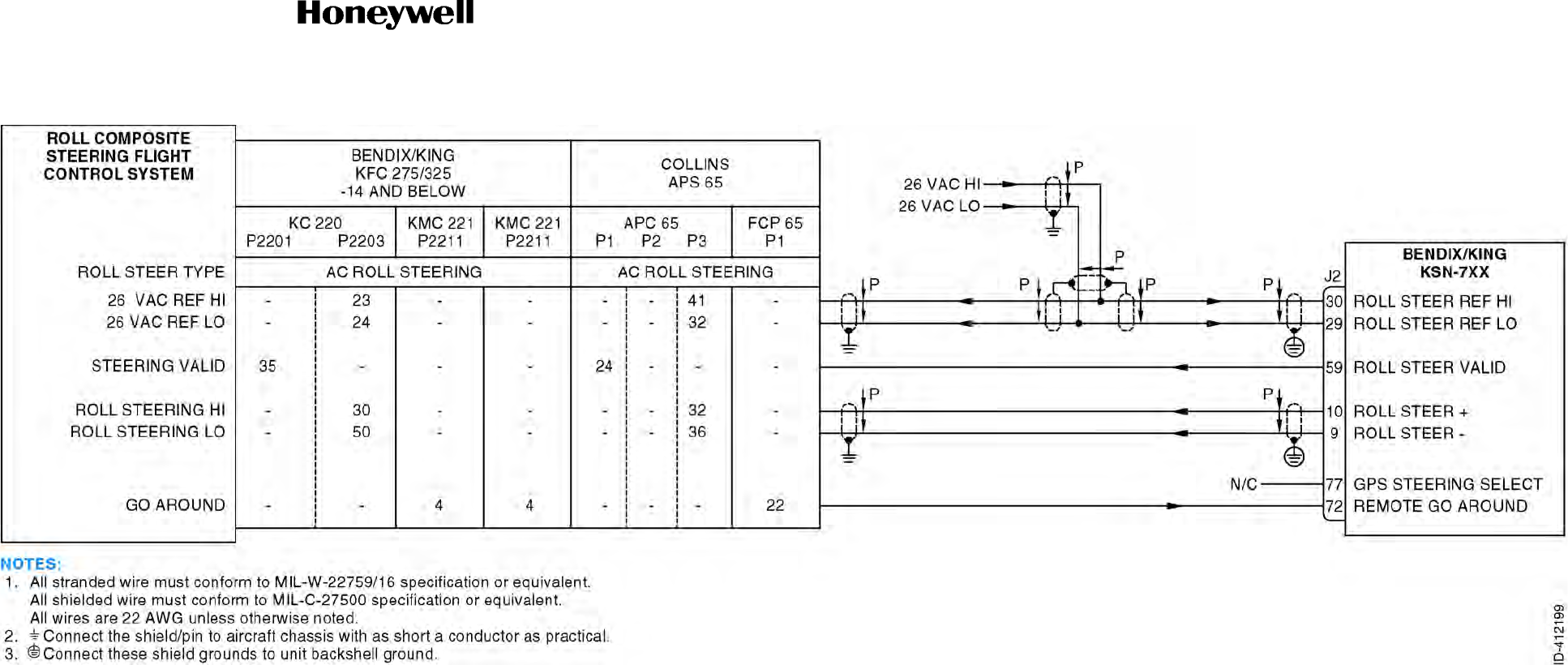
Draft
SYSTEM INSTALLATION MANUAL
066-01204 / 066-01213
Page 3-65
6 Dec 2012
© Honeywell International Inc. Do not copy without express permission of Honeywell.
34-70-06
Figure 3-12. Flight Control Interface - Roll Composite Steering Interconnect Diagram (Sheet 1 of 1)
Draft as of 10/15/2012

Draft
SYSTEM INSTALLATION MANUAL
066-01204 / 066-01213
Page 3-66
6 Dec 2012
© Honeywell International Inc. Do not copy without express permission of Honeywell.
34-70-06
Blank Page
Draft as of 10/15/2012
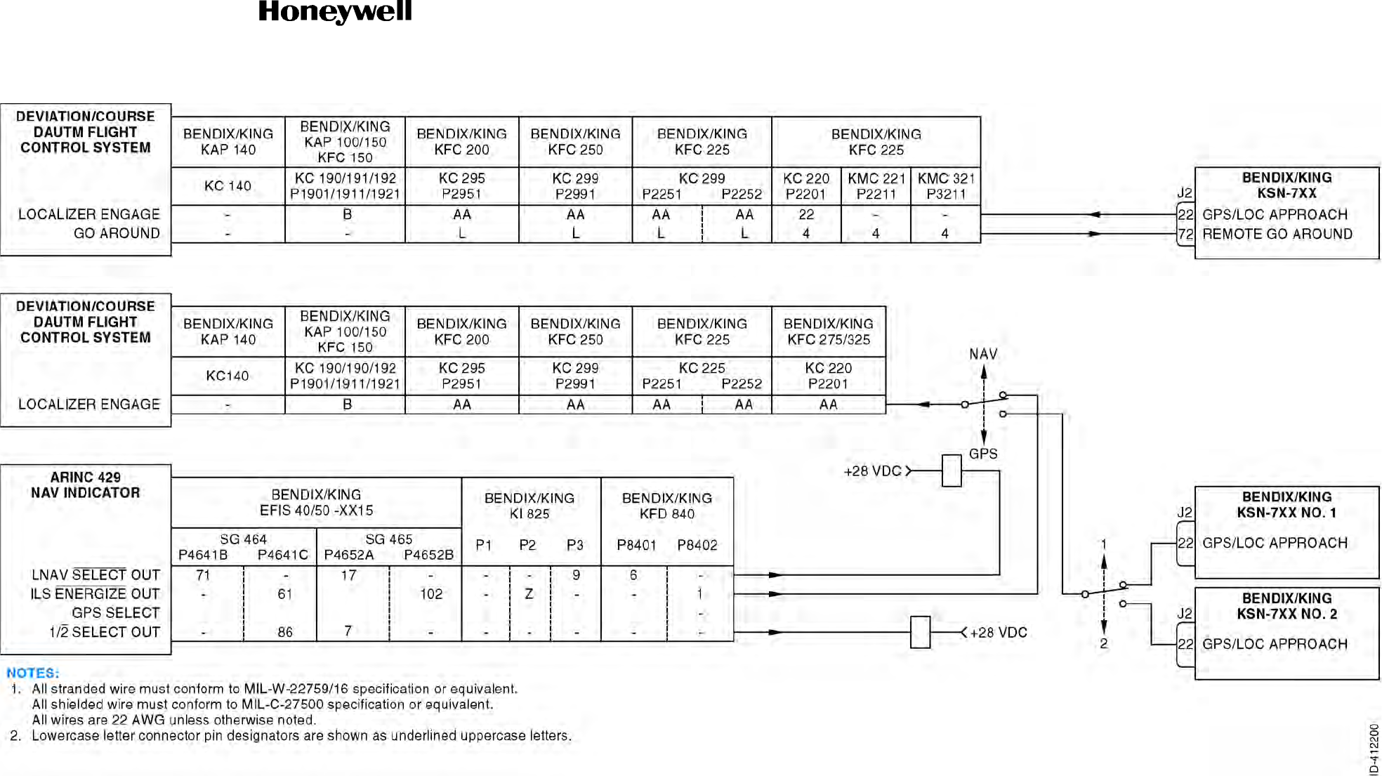
Draft
SYSTEM INSTALLATION MANUAL
066-01204 / 066-01213
Page 3-67
6 Dec 2012
© Honeywell International Inc. Do not copy without express permission of Honeywell.
34-70-06
Figure 3-13. Flight Control Interface - Deviation/Course Datum Interconnect Diagram (Sheet 1 of 1)
Draft as of 10/15/2012

Draft
SYSTEM INSTALLATION MANUAL
066-01204 / 066-01213
Page 3-68
6 Dec 2012
© Honeywell International Inc. Do not copy without express permission of Honeywell.
34-70-06
Blank Page
Draft as of 10/15/2012
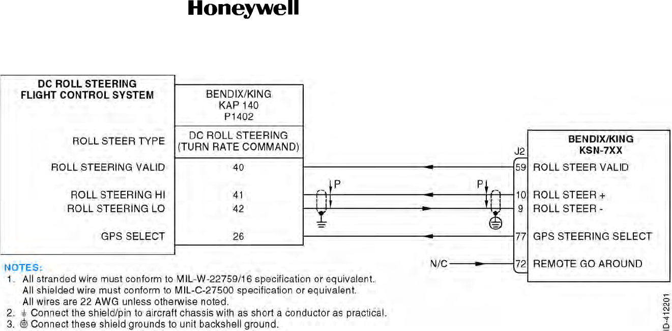
Draft
SYSTEM INSTALLATION MANUAL
066-01204 / 066-01213
Page 3-69
6 Dec 2012
© Honeywell International Inc. Do not copy without express permission of Honeywell.
34-70-06
Figure 3-14. Flight Control Interface - DC Interconnect Diagram (Sheet 1 of 1)
Draft as of 10/15/2012

Draft
SYSTEM INSTALLATION MANUAL
066-01204 / 066-01213
Page 3-70
6 Dec 2012
© Honeywell International Inc. Do not copy without express permission of Honeywell.
34-70-06
Blank Page
Draft as of 10/15/2012
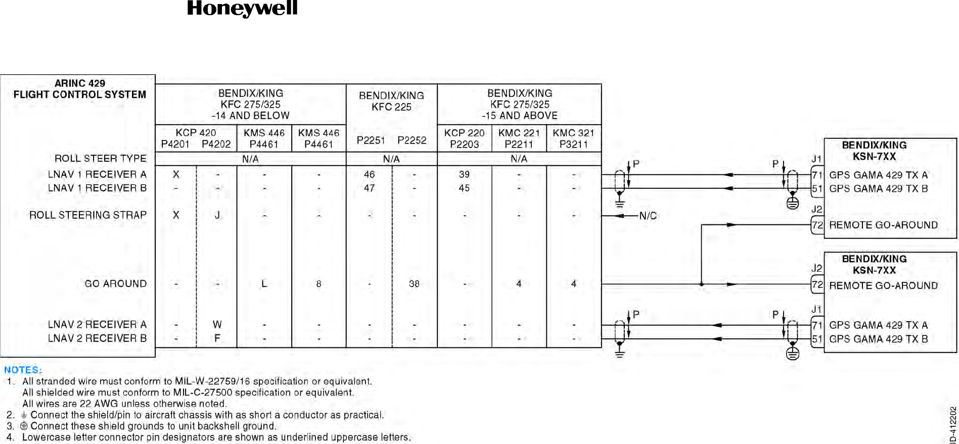
Draft
SYSTEM INSTALLATION MANUAL
066-01204 / 066-01213
Page 3-71
6 Dec 2012
© Honeywell International Inc. Do not copy without express permission of Honeywell.
34-70-06
Figure 3-15. Flight Control Interface - ARINC 429 Interconnect Diagram (Sheet 1 of 1)
Draft as of 10/15/2012

Draft
SYSTEM INSTALLATION MANUAL
066-01204 / 066-01213
Page 3-72
6 Dec 2012
© Honeywell International Inc. Do not copy without express permission of Honeywell.
34-70-06
Blank Page
Draft as of 10/15/2012

Draft
Page 3-73
6 Dec 2012
34-70-06
SYSTEM INSTALLATION MANUAL
066-01204 / 066-01213
© Honeywell International Inc. Do not copy without express permission of Honeywell.
3.11 DME Interface
3.11.1 Applicable Part Numbers
The KSN 7x0 are DME.
All part numbers and software revisions perform all DME functions.
3.11.2 Function
The SERIAL CLOCK, DATA, SYNC bus may be used to drive distance, groundspeed, and time-to-go
indicators. This is a King Serial DME bus only.
King Serial DME allows display of the KSN 7xx distance, groundspeed, and time-to-go on Bendix/King
KDI-572 and KDI-574 DME indicators.
The ARINC TRANSMITIER (ARINC 429) bus may be configured for high-speed or low-speed on the
Maintenance pages, and contains a large variety of labels that may be used by many different receivers.
Transmission of distance, groundspeed, and time-to-go is discussed in this chapter.
3.11.3 Requirements and Limitations
For proper functioning of the King Serial DME indicator interface, a DME receiver (in addition to the KSN
7xx and the indicator) must be connected to the SERIAL CLOCK and SERIAL DATA lines.
When the KSN 7xx is mounted in the aircraft pedestal, some certification agencies (including the FAA)
require a distance display in the pilot's scan area for IFR certification. Consult your approval agency for
additional information.
The KSN 7xx may display distance, groundspeed and time-to-station on the KPI-553A, KDI-572,
KDI-573 and KDI-574 DME distance displays. The DME in the aircraft continues to supply power to
these displays while the KSN 7xx information is displayed. A NAV/GPS annunciator switch and relays
can switch the DME display between displaying DME and GPS information (refer to the DME installation
documentation for details).
3.11.4 Electrical Characteristics
A. ARINC 429 Transmitter
J1-72 VOR/ILS TX A
J1-52 VOR/ILS TX B
This serial data bus conforms to ARINC 429 electrical characteristics, and may be configured for
low-speed on the Maintenance pages. Many ARINC 429 labels are output on the ARINC
TRANSMITTER bus. ARINC 429 labels relating to the distance indicator interface are shown in
Table 3-11.
Draft as of 10/15/2012

Draft
Page 3-74
6 Dec 2012
34-70-06
SYSTEM INSTALLATION MANUAL
066-01204 / 066-01213
© Honeywell International Inc. Do not copy without express permission of Honeywell.
B. King Serial DME Bus
J1-75 SERIAL CLOCK
J1-57 SERIAL DATA
J1-76 DME CHANNEL REQUEST
J1-56 DME COMMON
These connections transmit Bendix/King format serial DME information.
In the King Serial DME configuration, SERIAL SYNC is an input. When the KSN 7xx receives an
active-high pulse on SERIAL SYNC, it transmits pulses on the SERIAL CLOCK and SERIAL DATA
lines.
3.11.5 Interconnect Diagram
Refer to Figure 3-16 for the DME interface - remote interconnect diagram.
Refer to Figure 3-17 for the DME interface - panel mount interconnect diagram.
Refer to Figure 3-18 for the DME interface - ARINC 429 interconnect diagram.
Table 3-11. ARINC 429 Label
Label Parameter Type
001 Distance to go BCD
002 Time to go BCD
012 Groundspeed BCD
251 Distance to go Binary
252 Time to go Binary
312 Groundspeed Binary
Draft as of 10/15/2012
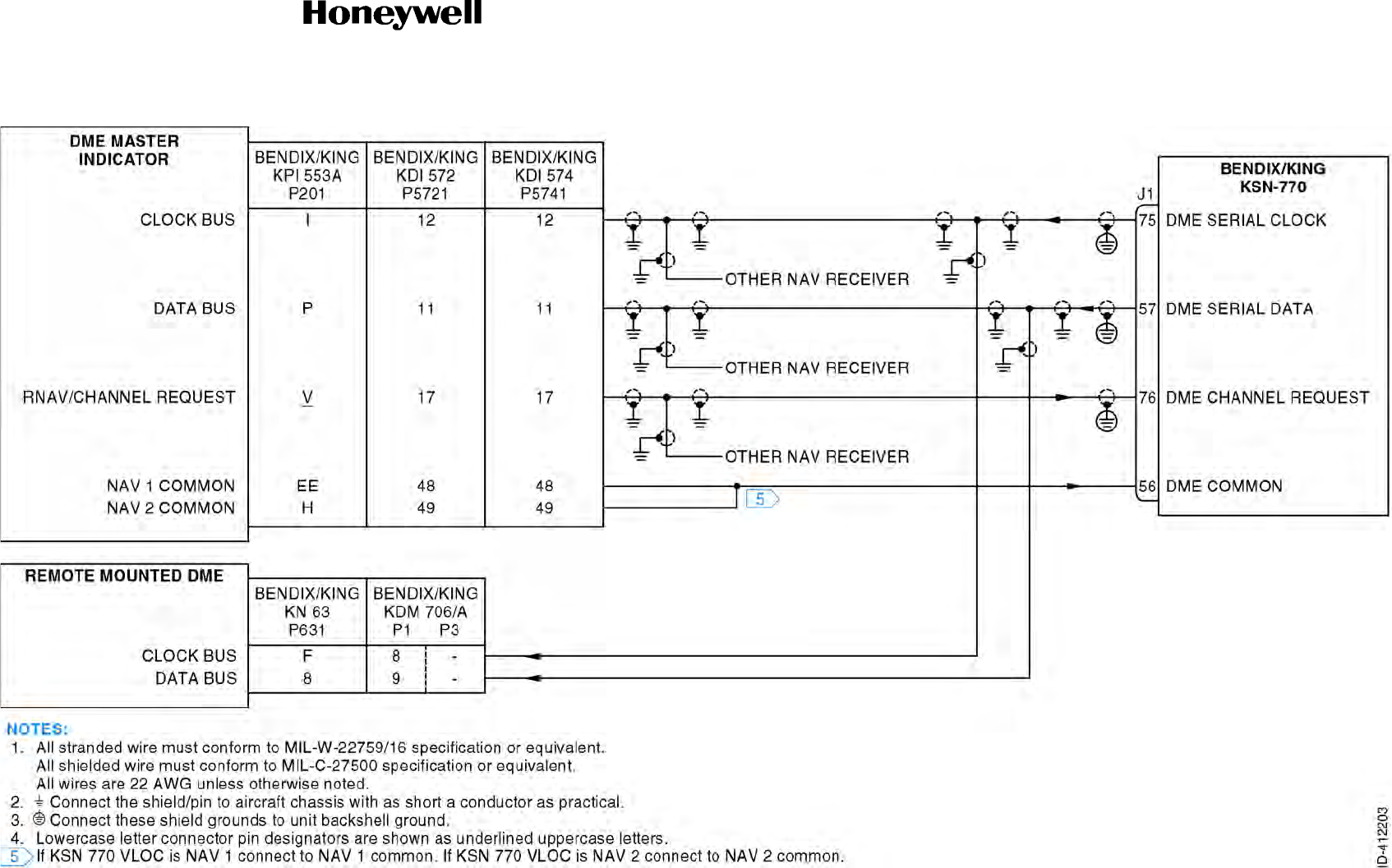
Draft
SYSTEM INSTALLATION MANUAL
066-01204 / 066-01213
Page 3-75
6 Dec 2012
© Honeywell International Inc. Do not copy without express permission of Honeywell.
34-70-06
Figure 3-16. DME Interface - Remote Interconnect Diagram (Sheet 1 of 1)
Draft as of 10/15/2012
Figure 3-16 & 17 The DME interface cannot work as drawn. It has the RNAV/Channel
Request and DME Channel Request confused and shown incorrectly. There is no
DME Channel request. There is an RNAV/Channel Request and a DME Request and
they are different functions.

Draft
SYSTEM INSTALLATION MANUAL
066-01204 / 066-01213
Page 3-76
6 Dec 2012
© Honeywell International Inc. Do not copy without express permission of Honeywell.
34-70-06
Blank Page
Draft as of 10/15/2012
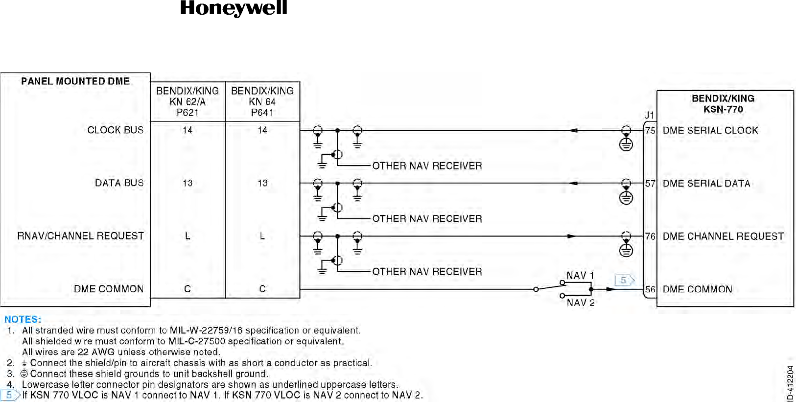
Draft
SYSTEM INSTALLATION MANUAL
066-01204 / 066-01213
Page 3-77
6 Dec 2012
© Honeywell International Inc. Do not copy without express permission of Honeywell.
34-70-06
Figure 3-17. DME Interface - Panel Mount Interconnect Diagram (Sheet 1 of 1)
Draft as of 10/15/2012
Figure 3-16 & 17 The DME interface cannot work as drawn. It has the RNAV/Channel
Request and DME Channel Request confused and shown incorrectly. There is no
DME Channel request. There is an RNAV/Channel Request and a DME Request and
they are different functions.

Draft
SYSTEM INSTALLATION MANUAL
066-01204 / 066-01213
Page 3-78
6 Dec 2012
© Honeywell International Inc. Do not copy without express permission of Honeywell.
34-70-06
Blank Page
Draft as of 10/15/2012

Draft
SYSTEM INSTALLATION MANUAL
066-01204 / 066-01213
Page 3-79
6 Dec 2012
© Honeywell International Inc. Do not copy without express permission of Honeywell.
34-70-06
Figure 3-18. DME Interface - ARINC 429 Interconnect Diagram (Sheet 1 of 1)
Draft as of 10/15/2012
Figure 3-18 cannot work.
This is mixture of King
Serial and ARINC 429.

Draft
SYSTEM INSTALLATION MANUAL
066-01204 / 066-01213
Page 3-80
6 Dec 2012
© Honeywell International Inc. Do not copy without express permission of Honeywell.
34-70-06
Blank Page
Draft as of 10/15/2012

Draft
Page 3-81
6 Dec 2012
34-70-06
SYSTEM INSTALLATION MANUAL
066-01204 / 066-01213
© Honeywell International Inc. Do not copy without express permission of Honeywell.
3.12 NAV Indicator Interface
3.12.1 Applicable Part Numbers
All part numbers and software revisions perform all NAV indicator functions. The comosite indicator
interface is only available in KSN 7x0 models.
3.12.2 Function
The NAV indicator displays the lateral deviation from selected course, TO/FROM indications, and NAV
flag (both meter level and superflag). In addition, the KSN 7xx includes outputs for vertical deviation,
meter flag, and superflag.
The KSN 7xx has the ability to read selected course from the NAV indicator. The selected course is used
by the KSN 7xx in both the leg and OBS modes. In OBS mode, the NAV indicator selected course is
input as the GPS selected course, eliminating the need for the pilot to select the course on both the
indicator and the KSN 7xx. In Leg mode, the KSN 7xx notifies the pilot when there is a discrepancy of
5 degrees or more between the KSN 7xx magnetic desired track and the NAV indicator selected course.
An input called GPS DISPLAYED tells the KSN 7xx whether its navigation information is presently being
displayed on the NAV indicator and consequently whether the NAV indicator selected course must be
used by the KSN 7xx.
The KSN 7xx provides selected course drive capability for EFIS. Slewable NAV indicators (XYZ or
SIN/COS drive) may be driven by the KSN 7xx. When interfaced with nonslewable NAV indicators, the
pilot is directed with messages to manually move the course selector to match the selected course
displayed on the KSN 7xx.
3.12.3 Requirements and Limitations
IFR certified installations of the KSN 7xx are required to have a NAV indicator installed, and it must be
located in the pilot’s primary scan area. RS-232 receivers may not be used as the primary flight display
for the KSN 7xx.
Selected course may be input as OBS SIN/COS, RS 422, or ARINC 429. Only one of the three possible
interfaces can be connected in the aircraft.
GPS DISPLAYED must be connected if the selected course is input as OBS SIN/COS or RS 422.
GPS DISPLAYED is not required if selected course is input as ARINC 429 into the EFIS RECEIVER. In
addition, the Maintenance page must be configured for OBS RESOLVER: Y, for the OBS SIN/COS
inputs to be used.
KPI 552, KPI 553, and KPI 553A units which interface with Bendix/King KNR-665A or KNR-615 units
do not have course selection knobs. Some certification agencies require entry of OBS selected course
on the CDI/HSI.
NOTE: In the cases of the following ports, unused pins must be configured as “None” or “N” on the
Maintenance pages for proper operation. Open pins configured as being used will flag data and
may generate failure messages:
Draft as of 10/15/2012

Draft
Page 3-82
6 Dec 2012
34-70-06
SYSTEM INSTALLATION MANUAL
066-01204 / 066-01213
© Honeywell International Inc. Do not copy without express permission of Honeywell.
3.12.4 Electrical Characteristics
A. Deviation
J1-29 LATERAL DEVIATION RIGHT
J1-10 LATERAL DEVIATION LEFT
J1-31 VERTICAL DEVIATION UP
J1-12 VERTICAL DEVIATION DOWN
D-Bar sensitivity depends on the navigation mode and is indicated in Table 3-12.
B. Meter Level Flags
J1-28 LATERAL DEV FLAG+
J1-9 LATERAL DEV FLAG
J1-30 VERTICAL DEV FLAG
J1-11 VERTICAL DEV FLAG
Range: 300 mVDC.
Load Resistance: 200 ohms in parallel with a capacitance of 0.01 F.
Resolution: 1.5 mV.
Accuracy: less than the greater of 4.5 mV or 5% of commanded deviation.
Update Rate: 10 Hz or greater.
Table 3-12. TBD
Mode D-Bar Sensitivity
En Route 30.0 mVDC/NM
Approach Arm (ARM) 150.0 mVDC/NM
Approach Active (ACTV) 500.0 mVDC/NM
Valid: HI (voltage at FLAG+ is no less than +350 mV and no more than
+900 mV with respect to FLAG).
Invalid: LO (voltage at FLAG+ is within 50 mV of the voltage at FLAG).
Flag current is 0 50 A.
Load Resistance: 200 ohms in parallel with a capacitance of 3 nF.
Update Rate: 10 Hz or greater.
Draft as of 10/15/2012

Draft
Page 3-83
6 Dec 2012
34-70-06
SYSTEM INSTALLATION MANUAL
066-01204 / 066-01213
© Honeywell International Inc. Do not copy without express permission of Honeywell.
C. NAV Superflags
J1-13 LATERAL DEVIATION SUPERFLAG
J1-32 VERTICAL DEVIATION SUPERFLAG
D. TO/FROM Flag
J1-27 CDI TO
J1-8 CDI FROM
CDI TO and CDI FROM are within 5 mVDC when LATERAL DEVIATION FLAG is in the invalid
state. CDI TO shall be 40 to 900 mV with respect to CDI FROM when the desired course is within
85 degrees of the bearing to active waypoint. CDI TO must be 100 to 900 mV with respect to
CDI FROM when the desired course is 180 8.5 degrees with respect to the bearing to the active
waypoint.
Valid: HI (+18.0 VDC when aircraft power 24.8 VDC; (+10.0 VDC
when aircraft power 12.4 VDC). Maximum current allowed is 250
mA.
Invalid: LO (No more than +3.5 VDC).
Update Rate: 10 Hz or greater.
TO Flag: +TO is positive with respect to +FROM
FROM Flag: +FROM is positive with respect to +TO
Range: +40 to +900 mV with respect to the CDI FROM output when in the
TO state.
40 to 900 mV with respect to the CDI FROM output when in the
FROM state
Load Resistance: 40 ohms in parallel with a capacitance of 3 nF.
Accuracy: Within 5 mV of the CDI FROM output whenever the NAV FLAG is
in the "not valid" (including "OFF state" for LOC) state.
Update Rate: 10 Hz or greater.
Draft as of 10/15/2012

Draft
Page 3-84
6 Dec 2012
34-70-06
SYSTEM INSTALLATION MANUAL
066-01204 / 066-01213
© Honeywell International Inc. Do not copy without express permission of Honeywell.
E. SIN/COS OBS Input
J1-34 OBS F (SIN HI)
J1-54 OBS D (COS HI)
This is an AC SIN/COS OBS input, indexed at 300 degrees. Nominal input impedance 36.5
kilohmseach line. This interface is compatible with indicators that are EZ at 300 degrees and
indicators that are ORZ at 300 degrees. This interface will operate properly with either "0.85 gain"
or "0.41 gain" resolvers with no special programming requirements.
Refer to the Maintenance pages for the indicator calibration procedure.
F. OBS Excitation Output
J1-14 OBS H (REF HI)
J1-74 OBS C (REF LO)
G. ARINC Selected Course Input
J1-68 EFIS CTRL 429 RX A
J1-48 EFIS CTRL 429 RX B
All serial data conforms to ARINC 429 for electrical characteristics, content and transmission
interval.
Input Impedance: 10 kilohms
Resolution: 0.25 degree.
Accuracy: 1 degree.
Update Rate: 5 Hz.
Amplitude: Unloaded peak amplitude of 5.8 volts 15%.
Wave Form: 400 Hz 20% sin wave.
Load Resistance: 10 ohms10%, or one Bendix/King 148-00043-0000 in parallel
with 0.56 F (5%).
Current Source: Minimum of 40 mA to a resistive load terminated at OBS_C.
Draft as of 10/15/2012

Draft
Page 3-85
6 Dec 2012
34-70-06
SYSTEM INSTALLATION MANUAL
066-01204 / 066-01213
© Honeywell International Inc. Do not copy without express permission of Honeywell.
All versions of the KSN 7xx accept the following ARINC 429 labels as shown in Table 3-13.
H. NAV Composite Interface (KSN 7x0 models only)
J1-60 VOR/LOC COMPOSITE OUT
J1-48 VOR/LOC COMPOSITE OUT REF
This is a standard localizer composite signal containing two tones whose nominal frequencies are
90 Hz and 150 Hz.
3.12.5 Interconnect Diagram
A. Deviation and Flags Interface
All part numbers of the Bendix/King models KI 202, KI 206, KI 525A, KPI 552/B, KPI 553/A/B, and
IN 863A, Rockwell Collins models HSI 84, 331A-6P and 331A-9G, and Honeywell Sperry models
RD 550A and RD 650 are compatible with the KSN 7xx deviation and flags interface.
Refer to Figure 3-21 for the NAV indicator interface - deviation and flag interconnect diagram.
B. OBS Resolver Interface
All part numbers of the Bendix/King models KI 202, KI 206, KI 525A, KPI 552B and IN 863A,
Rockwell Collins models HSI 84, 331A-6P and 331A-9G, and Honeywell Sperry models RD 550A
and RD 650 are compatible with the KSN 7xx OBS resolver interface.
The following part numbers of Bendix/King KPI 553 and 553B are compatible with the KSN 7xx
OBS Resolver interface:
Table 3-13. ARINC 429 Labels
Label Parameter
100 Selected course
306 NAV/WPT/APT latitude
307 NAV/WPT/APT longitude
314 True heading
320 Magnetic heading
Range: 300 to 500 mVRMS. 350 mVRMS into a 47 kilohms load (factory
setting).
Accuracy: 9% of the set point.
Update Rate: 10 Hz.
Draft as of 10/15/2012

Draft
Page 3-86
6 Dec 2012
34-70-06
SYSTEM INSTALLATION MANUAL
066-01204 / 066-01213
© Honeywell International Inc. Do not copy without express permission of Honeywell.
KPI 553 066-3027-
KPI 553B 066--3069-
The 30 Hz-only part numbers of Bendix/King KPI 552/B and KPI 553/A require a modified
interconnection. This interconnection requires the use of a spare winding on the resolver.
Some units may have been produced from the factory with the connections to this winding
reversed. These units will not work correctly if connected as shown on the alternate interconnect
for the 30 Hz only KPI 552/B and the KPI 553/A. The majority of the units will work properly when
wired per the primary drawing, and this interface must be attempted first. No damage will occur to
the units in either configuration however, the wrong configuration will result in the KSN 7xx OBS
display incrementing when the OBS decrements, and vice versa. The following part numbers are
compatible with the KSN 7xx OBS resolver interface:
KPI 552 066-3024-
KPI 553 066-3027-
------1617--
----2425----
00 - 02 03 - 05 08 -
1011 - 13 171819
20
---- -
-- - ---
-
10 12 13 - 15 - - 18 -
2021-23- -26
Draft as of 10/15/2012

Draft
Page 3-87
6 Dec 2012
34-70-06
SYSTEM INSTALLATION MANUAL
066-01204 / 066-01213
© Honeywell International Inc. Do not copy without express permission of Honeywell.
KPI 553A 066-3045-
Refer to Figure 3-19 for the NAV indicator interface - OBS 1 interconnect diagram.
Refer to Figure 3-20 for the NAV indicator interface - OBS 2 interconnect diagram.
C. ARINC 429 NAV Indicator Interface
All part numbers of the Bendix/King model KA 90 are compatible with the KSN 770 ARINC 429
NAV Indicator interface.
The Bendix/King model KA 90, PN 071-01508-0202, with software MOD status 02/02, provides a
warning through the KSN 770 if it loses the 400Hz power source.
Bendix/King models SG 464 and SG 465 with software release 11 and above are compatible with
the KSN 7xx ARINC 429 NAV Indicator interface when the KSN 7xx is to be used for non-precision
approach operations. Symbol generators with software below release 11 will not correctly display
the KSN 7xx variable deviation scale factors, but are compatible when the KSN 7xx is not
configured for non-precision approach operations.
If two KSN 7xx units are to be interfaced to a single EFIS symbol generator, the SG 464 or SG 465
must have software release 08 or above. The KSN 7xx uses the SDI bits in label 100 SELECTED
COURSE to determine which KSN 7xx’s selected course must be changed by the EFIS. In
addition, the #2 KSN 7xx’s SDI configuration must be set to “2” on the maintenance pages for
proper EFIS receiver operation.
Refer to Figure 3-22 for the NAV indicator interface - ARINC 429 interconnect diagram.
D. Composite Indicator Interface
Refer to Figure 3-23 for the NAV indicator interface - composite interconnect diagram (KSN 7x0
models only).
10 - 12 13 - 15 18 -
20 21 - 23 26
---- -
---
Draft as of 10/15/2012

Draft
Page 3-88
6 Dec 2012
34-70-06
SYSTEM INSTALLATION MANUAL
066-01204 / 066-01213
© Honeywell International Inc. Do not copy without express permission of Honeywell.
Blank Page
Draft as of 10/15/2012
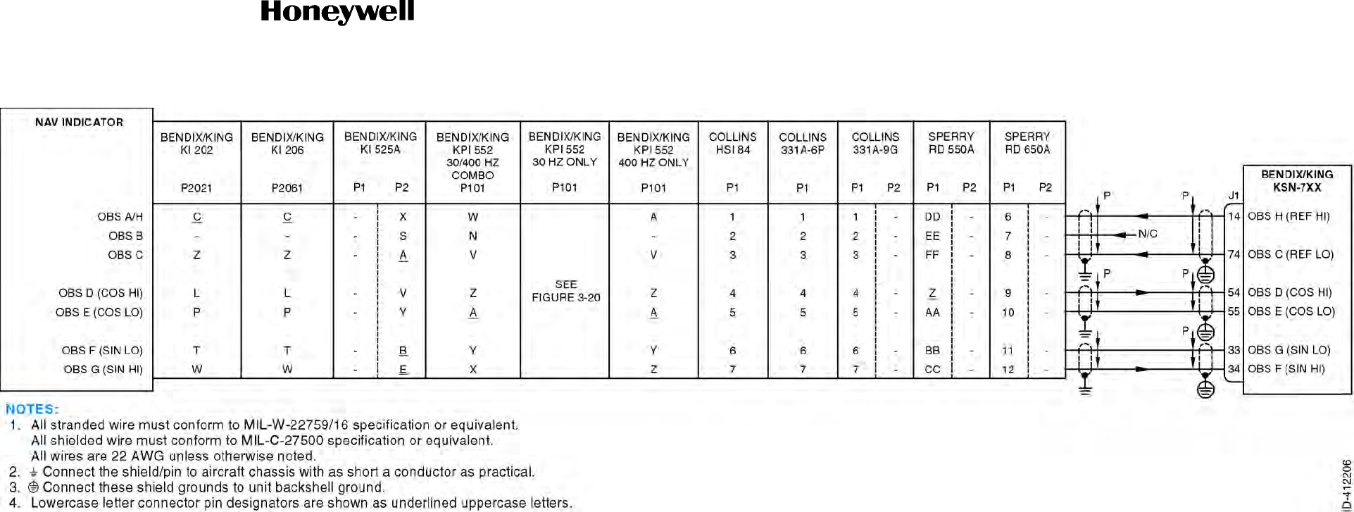
Draft
SYSTEM INSTALLATION MANUAL
066-01204 / 066-01213
Page 3-89
6 Dec 2012
© Honeywell International Inc. Do not copy without express permission of Honeywell.
34-70-06
Figure 3-19. NAV Indicator Interface - OBS 1 Interconnect Diagram (Sheet 1 of 1)
Draft as of 10/15/2012

Draft
SYSTEM INSTALLATION MANUAL
066-01204 / 066-01213
Page 3-90
6 Dec 2012
© Honeywell International Inc. Do not copy without express permission of Honeywell.
34-70-06
Blank Page
Draft as of 10/15/2012
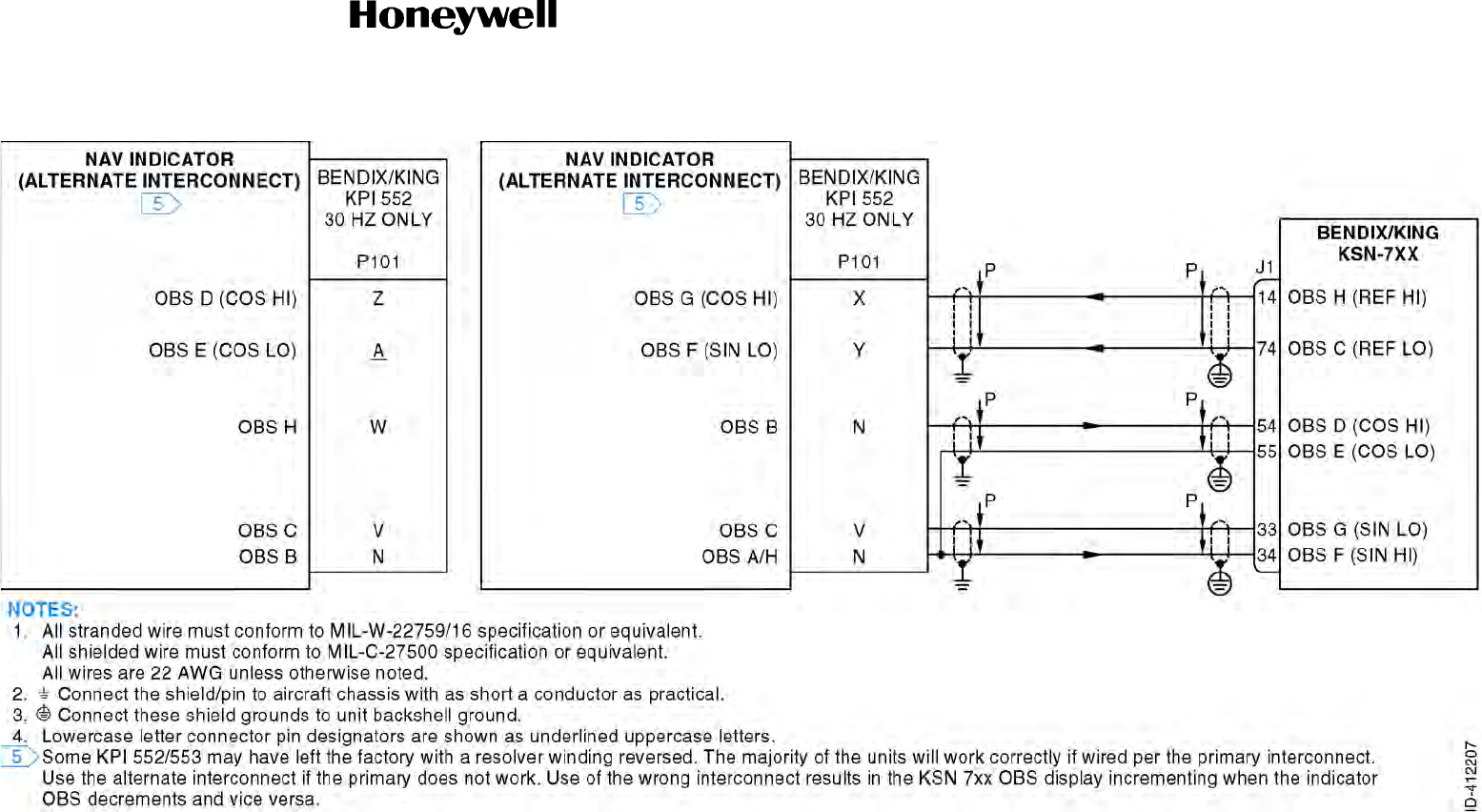
Draft
SYSTEM INSTALLATION MANUAL
066-01204 / 066-01213
Page 3-91
6 Dec 2012
© Honeywell International Inc. Do not copy without express permission of Honeywell.
34-70-06
Figure 3-20. NAV Indicator Interface - OBS 2 Interconnect Diagram (Sheet 1 of 1)
Draft as of 10/15/2012

Draft
SYSTEM INSTALLATION MANUAL
066-01204 / 066-01213
Page 3-92
6 Dec 2012
© Honeywell International Inc. Do not copy without express permission of Honeywell.
34-70-06
Blank Page
Draft as of 10/15/2012
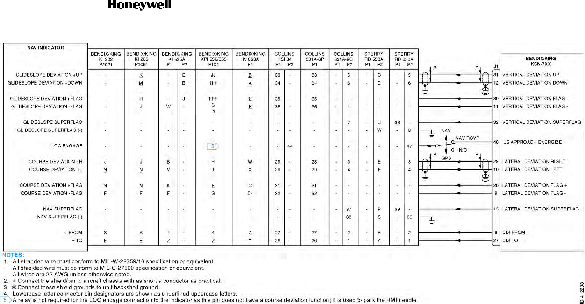
Draft
SYSTEM INSTALLATION MANUAL
066-01204 / 066-01213
Page 3-93
6 Dec 2012
© Honeywell International Inc. Do not copy without express permission of Honeywell.
34-70-06
Figure 3-21. NAV Indicator Interface - Deviation and Flag Interconnect Diagram (Sheet 1 of 1)
Draft as of 10/15/2012

Draft
SYSTEM INSTALLATION MANUAL
066-01204 / 066-01213
Page 3-94
6 Dec 2012
© Honeywell International Inc. Do not copy without express permission of Honeywell.
34-70-06
Blank Page
Draft as of 10/15/2012
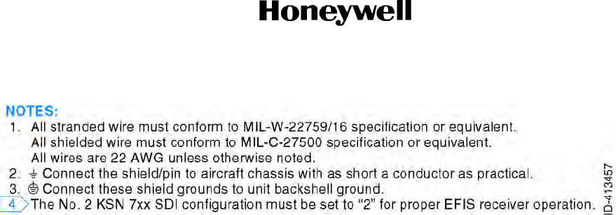
Draft
SYSTEM INSTALLATION MANUAL
066-01204 / 066-01213
Page 3-95
6 Dec 2012
© Honeywell International Inc. Do not copy without express permission of Honeywell.
34-70-06
Figure 3-22. NAV Indicator Interface - ARINC 429 Interconnect Diagram (Sheet 1 of 2)
Draft as of 10/15/2012

Draft
SYSTEM INSTALLATION MANUAL
066-01204 / 066-01213
Page 3-96
6 Dec 2012
© Honeywell International Inc. Do not copy without express permission of Honeywell.
34-70-06
Blank Page
Draft as of 10/15/2012
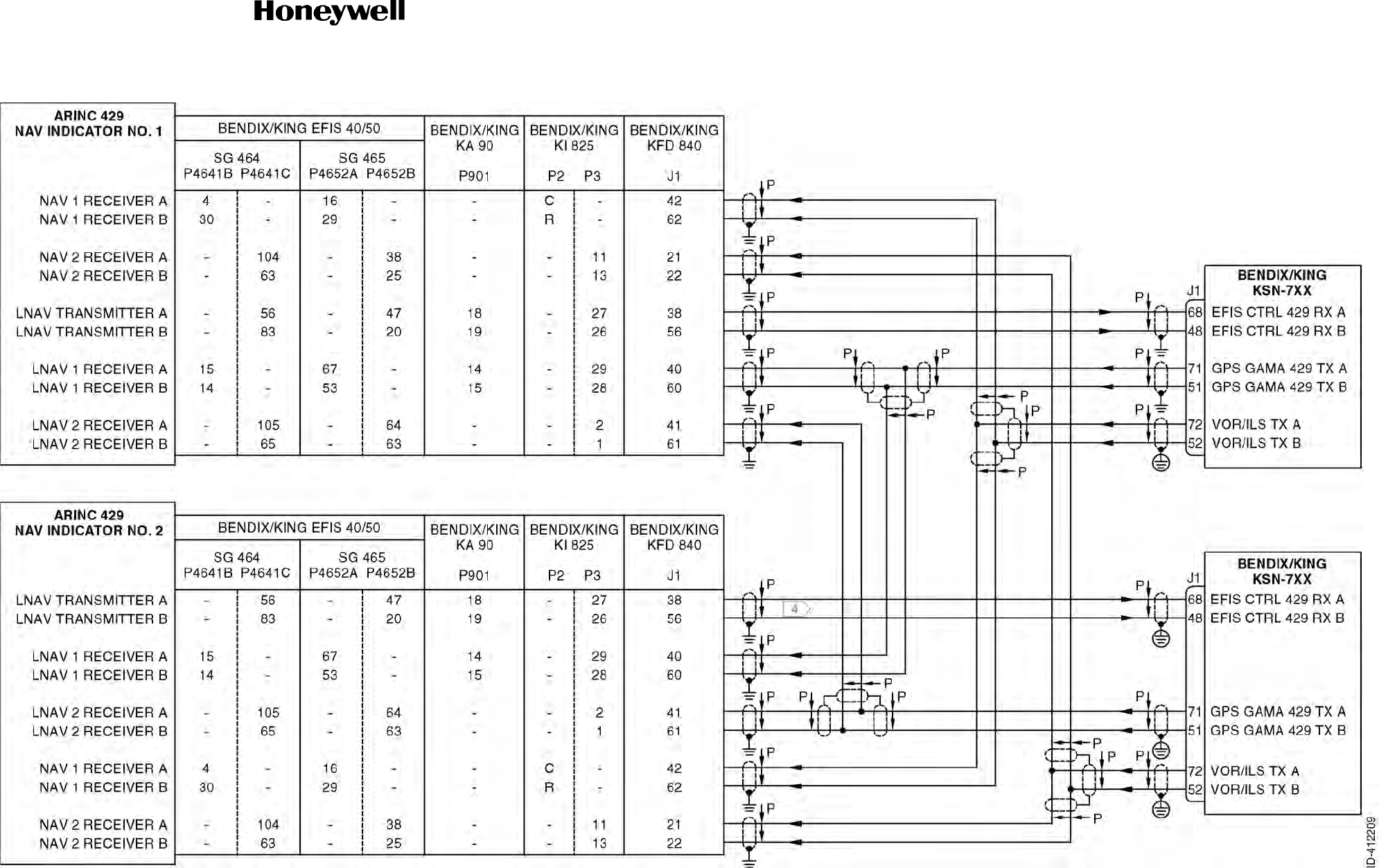
Draft
SYSTEM INSTALLATION MANUAL
066-01204 / 066-01213
Page 3-97
6 Dec 2012
© Honeywell International Inc. Do not copy without express permission of Honeywell.
34-70-06
Figure 3-22. NAV Indicator Interface - ARINC 429 Interconnect Diagram (Sheet 2 of 2)
Draft as of 10/15/2012

Draft
SYSTEM INSTALLATION MANUAL
066-01204 / 066-01213
Page 3-98
6 Dec 2012
© Honeywell International Inc. Do not copy without express permission of Honeywell.
34-70-06
Blank Page
Draft as of 10/15/2012
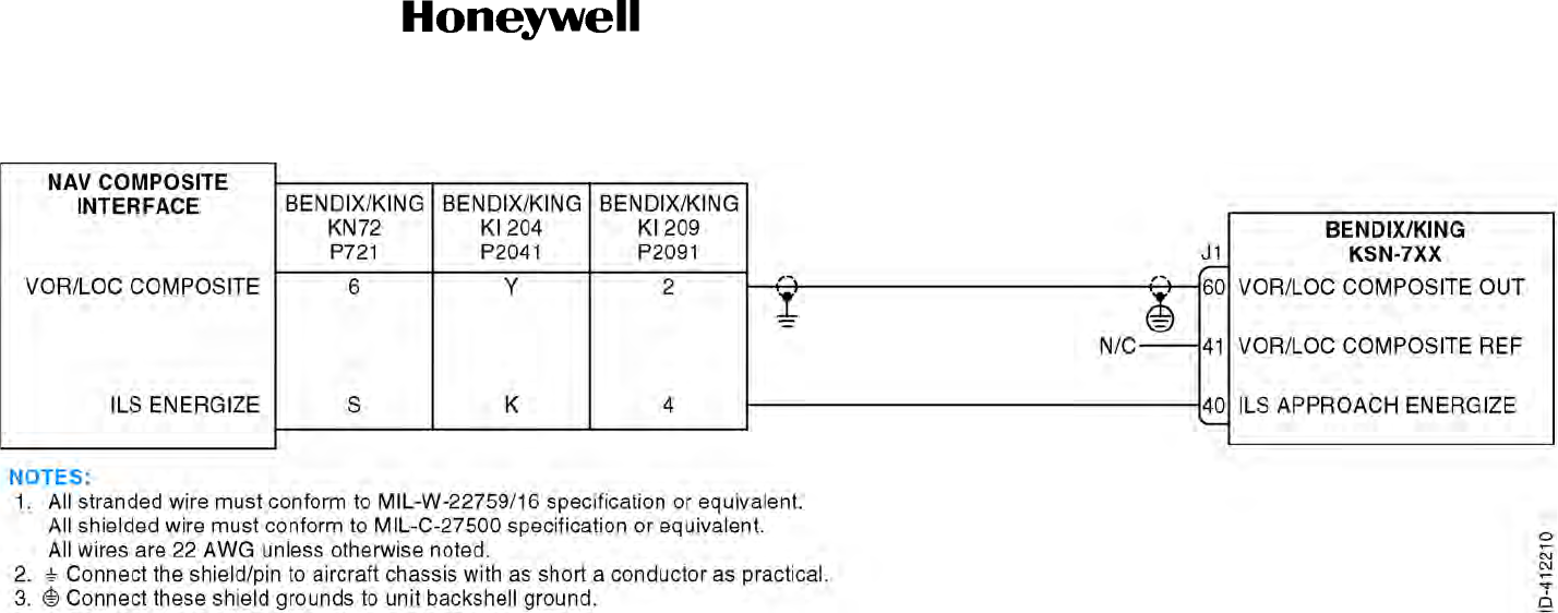
Draft
SYSTEM INSTALLATION MANUAL
066-01204 / 066-01213
Page 3-99
6 Dec 2012
© Honeywell International Inc. Do not copy without express permission of Honeywell.
34-70-06
Figure 3-23. NAV Indicator Interface - Composite Interconnect Diagram (KSN 7x0 Models Only)
(Sheet 1 of 1)
Draft as of 10/15/2012

Draft
SYSTEM INSTALLATION MANUAL
066-01204 / 066-01213
Page 3-100
6 Dec 2012
© Honeywell International Inc. Do not copy without express permission of Honeywell.
34-70-06
Blank Page
Draft as of 10/15/2012

Draft
Page 3-101
6 Dec 2012
34-70-06
SYSTEM INSTALLATION MANUAL
066-01204 / 066-01213
© Honeywell International Inc. Do not copy without express permission of Honeywell.
3.13 RMI/OBI Interface
3.13.1 Applicable Part Numbers
AC SIN/COS OBI and XYZ RMI information functions are only available when the KSN 7xx is interfaced
to a Bendix/King KA 90 (PN 071-01508-02XX only) or a Bendix/King KDA 697.
3.13.2 Function
The KSN 7xx provides bearing information TO the active waypoint in two ways:
Serial OBI (OBI CLOCK, OBI DATA, OBI SYNC) and ARINC TRANSMITTER (A and B).
The ARINC TRANSMITTER function and the SERIAL TRANSMITTER function are discussed in
Paragraph 3.11 DME Interface.
3.13.3 Requirements and Limitations
Display of KSN 7xx RMI/OBI information in the aircraft is optional. Annunciators, placards, or a
supplement to the aircraft flight manual must clearly indicate the available sources and switching
procedures for bearing pointers that are shared with other systems. An example of this would be a
NAV/GPS relay switching a bearing pointer from the KSN 7xx bearing to the VOR bearing. It may not
be possible to certify an installation that displays non-VOR bearing information on older RMIs or HSIs
with selectors or flags labeled “VOR”.
A Bendix/King KA 90 (PN 071-01508-02XX only) or a Bendix/King KDA 697 interface is required to
provide bearing data in AC SIN/COS and XYZ RMI formats.
3.13.4 Electrical Characteristics
J1-5 OBI DATA
J1-25 OBI CLOCK
J1-4 OBI SYNC
This is Bendix/King format serial OBI information.
J1-4 OBI SELECT IN
The KSN 7xx will output GPS OBI when this input is Open, and VOR OBI when the input is GND.
3.13.5 Interconnect Diagram
All part numbers of the Bendix/King KNI 582 and KI 229 RMIs and the KDA 692 RMI adapter are
compatible with this interface.
Refer to Figure 3-24 for the RMI/OBI interface interconnect diagram.
Draft as of 10/15/2012

Draft
Page 3-102
6 Dec 2012
34-70-06
SYSTEM INSTALLATION MANUAL
066-01204 / 066-01213
© Honeywell International Inc. Do not copy without express permission of Honeywell.
Blank Page
Draft as of 10/15/2012
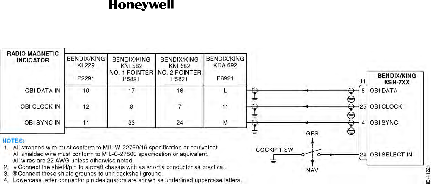
Draft
SYSTEM INSTALLATION MANUAL
066-01204 / 066-01213
Page 3-103
6 Dec 2012
© Honeywell International Inc. Do not copy without express permission of Honeywell.
34-70-06
Figure 3-24. RMI/OBI Interface Interconnect Diagram (Sheet 1 of 1)
Draft as of 10/15/2012

Draft
SYSTEM INSTALLATION MANUAL
066-01204 / 066-01213
Page 3-104
6 Dec 2012
© Honeywell International Inc. Do not copy without express permission of Honeywell.
34-70-06
Blank Page
Draft as of 10/15/2012

Draft
Page 3-105
6 Dec 2012
34-70-06
SYSTEM INSTALLATION MANUAL
066-01204 / 066-01213
© Honeywell International Inc. Do not copy without express permission of Honeywell.
3.14 Dual System Interface (Cross-Fill)
3.14.1 Applicable Part Numbers
All part numbers and software revisions perform all dual system interface functions.
3.14.2 Function
When two KSN 7xx’s are installed in an aircraft, they may be connected so they will cross-fill flight
planning information between them.
3.14.3 Requirements and Limitations
The user data cross-fill function eliminates repetitive work such as creating flight plans and user
waypoints on two individual KSN 7xx. The two units must both be KSN 7xx for the user data cross-fill
to operate
3.14.4 Electrical Characteristics
J4-6 KSN 7xx 422 TX A
J4-7 KSN 7xx 422 TX B
J4-24 KSN 7xx 422 RX A
J4-25 KSN 7xx 422 RX B
These are standard EIA-422 data busses.
3.14.5 Interconnect Diagram
Refer to Figure 3-25 for the dual system interface interconnect diagram.
Draft as of 10/15/2012

Draft
Page 3-106
6 Dec 2012
34-70-06
SYSTEM INSTALLATION MANUAL
066-01204 / 066-01213
© Honeywell International Inc. Do not copy without express permission of Honeywell.
Blank Page
Draft as of 10/15/2012
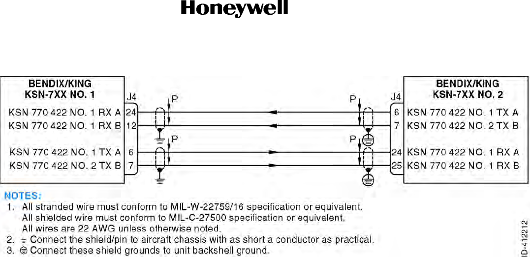
Draft
SYSTEM INSTALLATION MANUAL
066-01204 / 066-01213
Page 3-107
6 Dec 2012
© Honeywell International Inc. Do not copy without express permission of Honeywell.
34-70-06
Figure 3-25. Dual System Interface Interconnect Diagram (Sheet 1 of 1)
Draft as of 10/15/2012

Draft
SYSTEM INSTALLATION MANUAL
066-01204 / 066-01213
Page 3-108
6 Dec 2012
© Honeywell International Inc. Do not copy without express permission of Honeywell.
34-70-06
Blank Page
Draft as of 10/15/2012

Draft
Page 3-109
6 Dec 2012
34-70-06
SYSTEM INSTALLATION MANUAL
066-01204 / 066-01213
© Honeywell International Inc. Do not copy without express permission of Honeywell.
3.15 Audio Interface
3.15.1 Applicable Part Numbers
All part numbers and software revisions perform all audio interface functions.
3.15.2 Function
The KSN 7xx provides audio information to the pilot for the alert audio.
3.15.3 Requirements and Limitations
The audio interface provides audio alerts based on EGPWS and internal SBAS terrain generated
warnings.
3.15.4 Electrical Characteristics
J4-16 AUDIO ALERT OUT HI
J4-35 AUDIO ALERT OUT LO
This is an analog output from the KSN 7xx with the following characteristics:
3.15.5 Interconnect Diagram
Refer to Figure 3-26 for the audio interface 1 interconnect diagram.
Refer to Figure 3-27 for the audio interface 2 interconnect diagram.
Impedance: 500 50 ohms
Output Power: 10 mW RMS into 500 ohmsat 1 kHz
Frequency Response: Less than 3 dB variation from 350 Hz to 2.5 kHz by 20 dB relative to a
1 kHz tone. Frequencies below 200 Hz and above 10 kHz are
attenuated.
Distortion: Less than 10% at rated audio and less than 3% at 10% of rated audio
from 300 Hz to 2.5 kHz.
Noise Level: Minimum of at least 50 dB below rated output.
Protection: Electrically isolated by an audio transformer.
Draft as of 10/15/2012

Draft
Page 3-110
6 Dec 2012
34-70-06
SYSTEM INSTALLATION MANUAL
066-01204 / 066-01213
© Honeywell International Inc. Do not copy without express permission of Honeywell.
Blank Page
Draft as of 10/15/2012

Draft
SYSTEM INSTALLATION MANUAL
066-01204 / 066-01213
Page 3-111
6 Dec 2012
© Honeywell International Inc. Do not copy without express permission of Honeywell.
34-70-06
Figure 3-26. Audio Interface 1 Interconnect Diagram (Sheet 1 of 1)
Draft as of 10/15/2012
Figure 3-26 has the
Audio Hi and Lo tied
together. We cannot tie
the Hi's and Lo's
together.

Draft
SYSTEM INSTALLATION MANUAL
066-01204 / 066-01213
Page 3-112
6 Dec 2012
© Honeywell International Inc. Do not copy without express permission of Honeywell.
34-70-06
Blank Page
Draft as of 10/15/2012
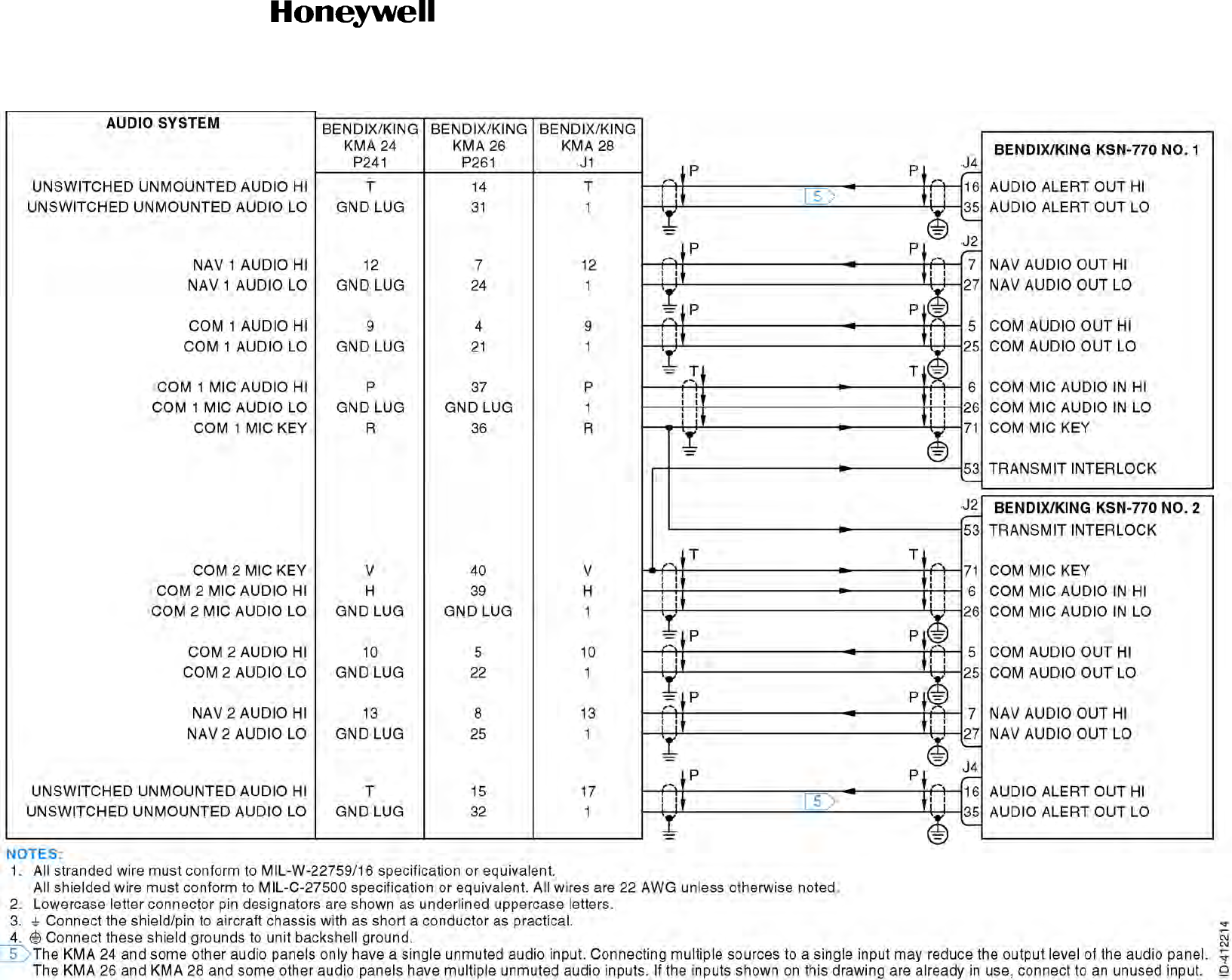
Draft
SYSTEM INSTALLATION MANUAL
066-01204 / 066-01213
Page 3-113
6 Dec 2012
© Honeywell International Inc. Do not copy without express permission of Honeywell.
34-70-06
Figure 3-27. Audio Interface 2 Interconnect Diagram (Sheet 1 of 1)
Draft as of 10/15/2012

Draft
SYSTEM INSTALLATION MANUAL
066-01204 / 066-01213
Page 3-114
6 Dec 2012
© Honeywell International Inc. Do not copy without express permission of Honeywell.
34-70-06
Blank Page
Draft as of 10/15/2012

Draft
Page 3-115
6 Dec 2012
34-70-06
SYSTEM INSTALLATION MANUAL
066-01204 / 066-01213
© Honeywell International Inc. Do not copy without express permission of Honeywell.
3.16 Annunciations - Suspend/Dead Reckoning/NAV Interface
3.16.1 Applicable Part Numbers
All part numbers and software revisions perform all annunciatons - suspend/dead reckoning/NAV
functions.
3.16.2 Function
A. Suspend
When in the suspend mode, the KSN 7xx will suspend automatic sequencing of waypoints.
SUSPEND ANNUNCIATE: When SUSPEND ANNUNCIATE is active, the KSN 7xx no longer
automatically sequencing waypoints.
SUSPEND IN: Signals to the KSN 7xx to stop automatic sequencing of waypoints.
B. Dead Reckoning
The dead reckoning function indicates to the pilot when GPS is not available and the KSN 7xx is
navigating by dead reckoning.
DEAD RECKONING ANNUNCIATE: When DEAD RECKONING ANNUNCIATE is active, the KSN
7xx is navigating via dead reckoning.
C. NAV
(1) CDI Switching Function
CDI SELECT IN: The CDI SELECT IN input pin is used to tell the KSN 7xx whether output
GPS or VLOC information to the external indicator. The input is normally open, with a
momentary GND applied when the switch is pressed. When the KSN 7xx sees this input go
low, it toggles the navigation source on the primary CDI output between GPS and VLOC.
(2) Annunciator Functions
The following outputs are provided to annunciate KSN 7xx conditions. They may be used to
illuminate lamps, engage relays, or be sensed directly by other systems. The term
“illuminated”, as used below, indicates the active low state of the annunciator output.
LNAV APPROACH ACTIVE ANNUNCIATE: Will illuminate whenever the KSN 7xx is
configured for LNAV IFR approaches and the unit is in the approach active mode.
CDI GPS ANNUNCIATE: Will illuminate whenever the KSN 7xx is outputting GPS deviation
signals to the NAV Indicator.
LOSS OF INTEGRITY ANNUNCIATE: Will illuminate whenever the KSN 7xx integrity monitor
indicates a loss of GPS integrity.
Draft as of 10/15/2012

Draft
Page 3-116
6 Dec 2012
34-70-06
SYSTEM INSTALLATION MANUAL
066-01204 / 066-01213
© Honeywell International Inc. Do not copy without express permission of Honeywell.
MESSAGE ANNUNCIATE: Will illuminate whenever the message prompt on the KSN 7xx is
ON.
LP APPROACH ACTIVE ANNUNCIATE: Will illuminate whenever the KSN 7xx is configured
for LP IFR approaches and the unit is in the approach active mode.
CDI VLOC ANNUNCIATE: Will illuminate whenever the KSN 7xx is outputting VOR or
LOCALIZER data.
WAYPOINT ANNUNCIATE: Will illuminate indicating that the aircraft will soon arrive at the
active waypoint. When in the leg navigation mode with turn anticipation enabled, the WPT
annunciator will begin flashing 20 seconds before turn anticipation begins, then will go on
solid when turn anticipation begins, through the conclusion of turn anticipation. When the
KSN 7xx is in the OBS navigation mode or in the leg mode with turn anticipation disabled, the
WPT annunciator will begin flashing 36 seconds prior to the estimated time of arrival at the
active waypoint.
LNAV/VNAV APPROACH ACTIVE ANNUNCIATE: Will illuminate whenever the KSN 7xx is
configured for LNAV/VNAV IFR approaches and is outputting GPS information to the primary
CDI.
LPV APPROACH ACTIVE ANNUNCIATE: Will illuminate whenever the KSN 7xx is
configured for LPV IFR approaches and is outputting GPS information to the primary CDI.
3.16.3 Requirements and Limitations
A. Suspend
N/A
B. Dead Reckoning
N/A
C. NAV
Requirements for remote switching and annunciation of the KSN 7xx navigation functions vary
depending on the level of certification of the installation. The following requirements represent
typical standards in the USA, but even so may vary regionally within the USA (refer to Table 3-14).
If the switches/annunciators are required, it is required that the message and waypoint alert
annunciators be in the pilot’s primary field of view area (refer to Paragraph 2.3.4.3 Field of View
Considerations). Primary field of view location is highly recommended for the remainder of the
annunciators, but not required. Many EFIS systems provide some amount of switching and
annunciation. A typical EFIS system provides NAV/GPS switching/annunciation and
message/waypoint alert annunciation.
Draft as of 10/15/2012

Draft
Page 3-117
6 Dec 2012
34-70-06
SYSTEM INSTALLATION MANUAL
066-01204 / 066-01213
© Honeywell International Inc. Do not copy without express permission of Honeywell.
(1) VFR-Only Installations
No requirement for waypoint alert and message annunciator, or an OBS/Leg course mode
annunciator. These are optional, and it may be desirable to include a waypoint alert/message
annunciator in the primary instrument scan area for the pilots’ convenience. There is no need
for approach mode switching or annunciation. A NAV/GPS navigation source switch is
required if both NAV and GPS may be displayed on a single CDI or HSI.
(2) IFR En Route and Terminal Installations
Waypoint alert and message annunciators are required.
Remote OBS/Leg course mode switch/annunciator is optional. There is no need for approach
mode switching or annunciation. A NAV/GPS navigation source switch is required if both NAV
and GPS may be displayed on a single CDI or HSI.
(3) IFR En Route, Terminal, and Non-precision Approach Installations
Waypoint alert and message annunciators are required. Remote OBS/Leg course mode
switch/annunciator is optional.
Table 3-14. NAV Annunciators by Installation Type
Annunciation
Suggested
Legend and
Color VFR Only
IFR
Enroute/
Terminal
Non-
Precision
Approach LPV
Approach
CDI GPS ANN GPS (Grn) May be Reqd May be Reqd May be Reqd May be Reqd
CDI VLOC ANN NAV (Grn) May be Reqd May be Reqd May be Reqd May be Reqd
WPT ANN WPT (Ambr) Optional Reqd Reqd Reqd
MSG ANN MSG (Ambr) Optional Reqd Reqd Reqd
LOSS OF INTEGRITY
ANN LOI (Ambr) Optional Optional Optional Optional
OFFPATH ANN OFF PATH
(Ambr) Optional Optional Optional Optional
LNAV APPROACH
ACTIVE ANN LNAV (Grn) Of No Use Of No Use Reqd Reqd
LNAV/VNAV APPROACH
ACTIVE ANN L/VNAV
(Grn) Of No Use Of No Use Reqd Reqd
LP APPROACH ACTIVE
ANN LP (Grn) Of No Use Of No Use Of No Use Reqd
LPV APPROACH ACTIVE
ANN LPV (Grn) Of No Use Of No Use Of No Use Reqd
Draft as of 10/15/2012

Draft
Page 3-118
6 Dec 2012
34-70-06
SYSTEM INSTALLATION MANUAL
066-01204 / 066-01213
© Honeywell International Inc. Do not copy without express permission of Honeywell.
Approach mode switching and annunciation are required. A NAV/GPS navigation source
switch is required if both NAV and GPS may be displayed on a single CDI or HSI.
(4) LPV Approach Installations
Waypoint alert and message annunciators are required. Remote OBS/Leg course mode
switch/annunciator is optional.
Approach mode switching and annunciation are required. A NAV/GPS navigation source
switch is required if both NAV and GPS may be displayed on a single CDI or HSI.
3.16.4 Electrical Characteristics
NOTE: Annunciators are to be DC voltage only with a maximum of +38 VDC. Annunciator dimming
may be by photocell or day/night switch. Do not use panel lighting rheostat dimmed bus.
These outputs are open collector outputs. When active, the output device is turned on and conducting
which provides a GND path for a load such as a lamp or relay that is pulled up to a maximum voltage
of +38 VDC.
J1-3 CDI SELECT IN
J1-16 LNAV APPROACH ACTIVE ANNUNCIATE
J1-18 CDI GPS ANNUNCIATE
J1-19 LOSS OF INTETRITY ANNUNCIATE
J1-20 MESSAGE ANNUNCIATE
J1-35 OFFPATH ANNUNCIATE
J1-37 LP APPROACH ACTIVE ANNUNCIATE
J1-38 CDI VLOC ANNUNCIATE
J1-39 WAYPOINT ANNUNCIATE
J2-38 LNAV/VNAV APPROACH ACTIVE ANNUNCIATE
J2-58 LPV APPROACH ACTIVE ANNUNCIATE
3.16.5 Interconnect Diagram
Refer to Figure 3-28 for the annunciations - suspend/dead reckoning interconnect diagram.
Refer to Figure 3-29 for the annunciations - NAV interface interconnect diagram.
Active: LO (1.0 VDC while sinking current up to 250 mA).
Inactive: HI (50 kilohms to GND, and up to +38 VDC).
Draft as of 10/15/2012
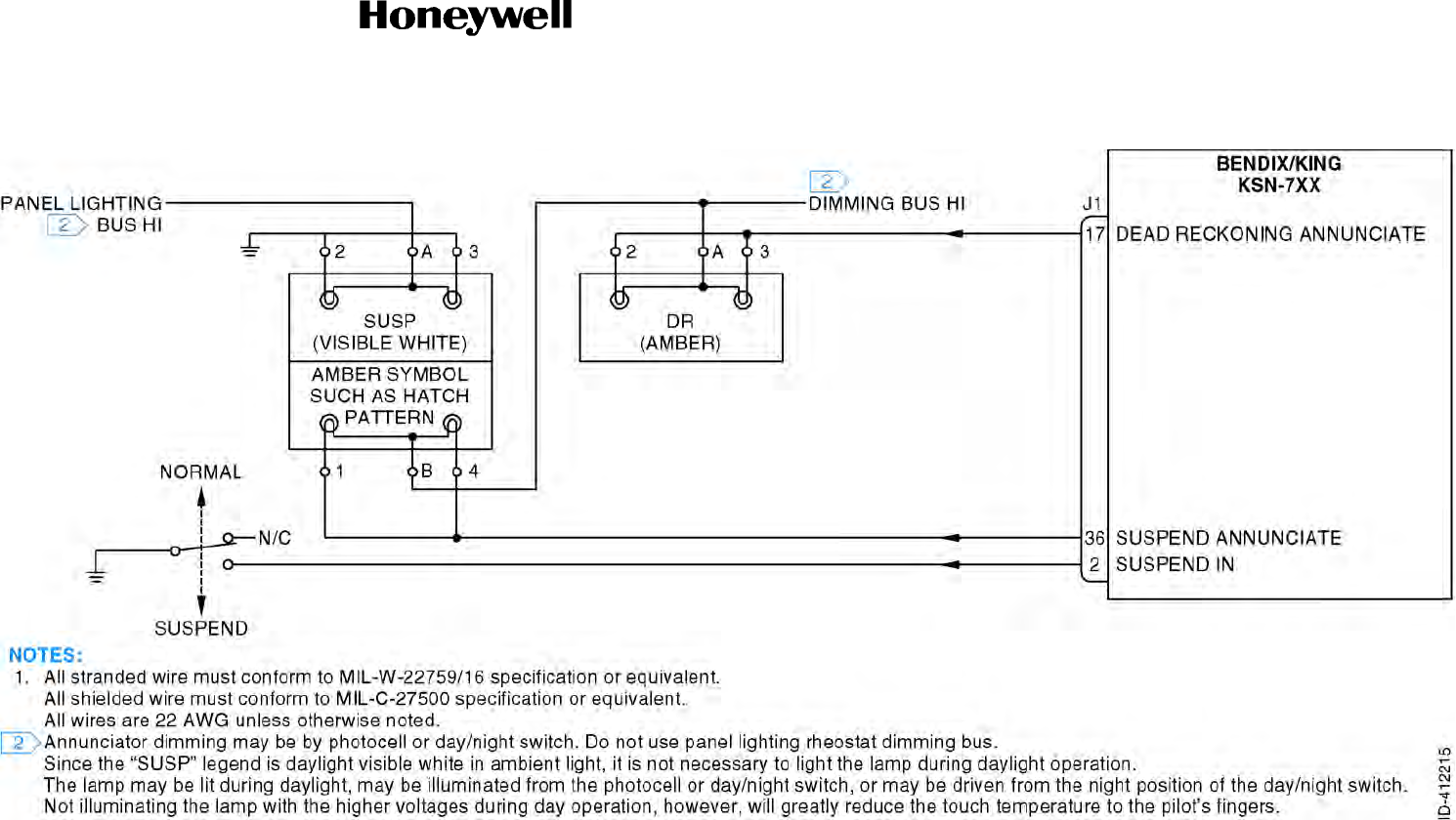
Draft
SYSTEM INSTALLATION MANUAL
066-01204 / 066-01213
Page 3-119
6 Dec 2012
© Honeywell International Inc. Do not copy without express permission of Honeywell.
34-70-06
Figure 3-28. Annunciations - Suspend/Dead Reckoning Interconnect Diagram (Sheet 1 of 1)
Draft as of 10/15/2012

Draft
SYSTEM INSTALLATION MANUAL
066-01204 / 066-01213
Page 3-120
6 Dec 2012
© Honeywell International Inc. Do not copy without express permission of Honeywell.
34-70-06
Blank Page
Draft as of 10/15/2012
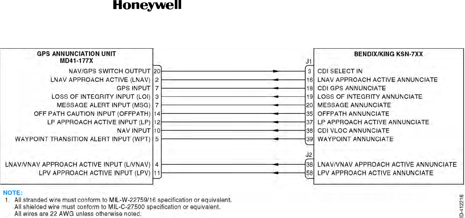
Draft
SYSTEM INSTALLATION MANUAL
066-01204 / 066-01213
Page 3-121
6 Dec 2012
© Honeywell International Inc. Do not copy without express permission of Honeywell.
34-70-06
Figure 3-29. Annunciations - NAV Interface Interconnect Diagram (Sheet 1 of 1)
Draft as of 10/15/2012

Draft
SYSTEM INSTALLATION MANUAL
066-01204 / 066-01213
Page 3-122
6 Dec 2012
© Honeywell International Inc. Do not copy without express permission of Honeywell.
34-70-06
Blank Page
Draft as of 10/15/2012

Draft
Page 3-123
6 Dec 2012
34-70-06
SYSTEM INSTALLATION MANUAL
066-01204 / 066-01213
© Honeywell International Inc. Do not copy without express permission of Honeywell.
3.17 Miscellaneous Interface
3.17.1 Applicable Part Numbers
All part numbers and software revisions perform all miscellaneous functions.
3.17.2 Function
3.17.2.1 Cooling
Two fans are used as the primary method of providing internal cooling to the KSN 7xx. Aircraft supply
of forced air cooling is not required. Two externally mounted cooling fans (part of KSN 7xx equipment
rack design) provide all required cooling for the KSN 7xx.
3.17.2.2 Configuration Module
The configuration module is used to keep implementation specific setup information on board the
aircraft. This facilitates configuration of the KSN 7xx in the event service is needed.
3.17.2.3 WOW Input
The WOW input is configurable in the maintenance pages to be active either high or low, and must
be configured correctly for proper operation.
3.17.2.4 Spare, Reserved only Pins
This is a list of spare pins that are included in the KSN 7xx, but not used in installation, and is for
reference only.
3.17.3 Requirements and Limitations
3.17.3.1 Cooling
N/A
3.17.3.2 Configuration Module
N/A
3.17.3.3 WOW Input
N/A
3.17.3.4 Spare Pins
N/A
Draft as of 10/15/2012

Draft
Page 3-124
6 Dec 2012
34-70-06
SYSTEM INSTALLATION MANUAL
066-01204 / 066-01213
© Honeywell International Inc. Do not copy without express permission of Honeywell.
3.17.4 Electrical Characteristics
3.17.4.1 Cooling Interface
J2-20 KSN FAN
J2-1 GND 3
J2-39 MMDS FAN
J2-19 FAN RETURN
These pins provide power and GND to the KSN 7xx cooling fans.
3.17.4.2 Configuration Module Interface
J4-11 CONFIG MODULE POWER
J4-29 CONFIG MODULE GND
These pins provide +5 VDC and GND to the Bendix/King KCM 200 configuration module.
J4-30 CONFIG MODULE CLOCK
J4-12 CONFIG MODULE DATA
These pins provide the serial data interface to the configuration module. The wire length between the
KSN 7xx and the KCM 200 must not exceed 72 inches (183 cm).
If the KCM 200 configuration module is not present on unit power-up, the KSN 7xx’s internal
configuration data is used. If there is an error detected in the KCM 200 configuration data and the
internal KSN 7xx configuration data is good, the internal data will be used, but not copied to KCM 200.
The message “CONFIGURATION MEM ERROR” is shown on the KSN 7xx screen. If errors are
detected in both the KCM 200 and internal configuration data, the internal data shall change to the
factory default values, and the KCM 200 data is not changed.
3.17.4.3 WOW
J2-54 WOW
The WOW input is supplied by the aircraft. The input is normally open, and grounded when there is
weight on the aircrafts wheels.
3.17.4.4 Spare RS-232
All pins identified as spare are reserved for future use.
3.17.5 Interconnect Diagram
Refer to Figure 3-30 for the miscellaneous interface 1 interconnect diagram.
Refer to Figure 3-31 for the miscellaneous interface 2 interconnect diagram.
Draft as of 10/15/2012

Draft
SYSTEM INSTALLATION MANUAL
066-01204 / 066-01213
Page 3-125
6 Dec 2012
© Honeywell International Inc. Do not copy without express permission of Honeywell.
34-70-06
Figure 3-30. Miscellaneous Interface 1 Interconnect Diagram (Sheet 1 of 1)
Draft as of 10/15/2012

Draft
SYSTEM INSTALLATION MANUAL
066-01204 / 066-01213
Page 3-126
6 Dec 2012
© Honeywell International Inc. Do not copy without express permission of Honeywell.
34-70-06
Blank Page
Draft as of 10/15/2012
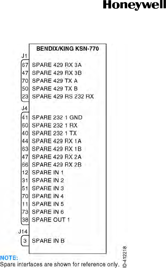
Draft
SYSTEM INSTALLATION MANUAL
066-01204 / 066-01213
Page 3-127
6 Dec 2012
© Honeywell International Inc. Do not copy without express permission of Honeywell.
34-70-06
Figure 3-31. Miscellaneous Interface 2 Interconnect Diagram (Sheet 1 of 1)
Draft as of 10/15/2012

Draft
SYSTEM INSTALLATION MANUAL
066-01204 / 066-01213
Page 3-128
6 Dec 2012
© Honeywell International Inc. Do not copy without express permission of Honeywell.
34-70-06
Blank Page
Draft as of 10/15/2012

Draft
Page 3-129
6 Dec 2012
34-70-06
SYSTEM INSTALLATION MANUAL
066-01204 / 066-01213
© Honeywell International Inc. Do not copy without express permission of Honeywell.
3.18 XM Receiver Interface
3.18.1 Applicable Part Numbers
All part numbers and software revisions perform all XM receiver functions.
3.18.2 Function
TBD
3.18.3 Requirements and Limitations
TBD
3.18.4 Electrical Characteristics
J4-26 DATALINK RECEIVER 422 #3 RX A
J4-27 DATALINK RECEIVER 422 #3 RX B
This is a standard EIA 422 data bus with the following characteristics:
3.18.5 Interconnect Diagram
Refer to Figure 3-32 for the XM receiver interface interconnect diagram.
BAUD: 57600
Data Bits: 8
Start Bits: None
Stop Bits: 2
Parity: None
Handshaking: None
Draft as of 10/15/2012

Draft
Page 3-130
6 Dec 2012
34-70-06
SYSTEM INSTALLATION MANUAL
066-01204 / 066-01213
© Honeywell International Inc. Do not copy without express permission of Honeywell.
Blank Page
Draft as of 10/15/2012
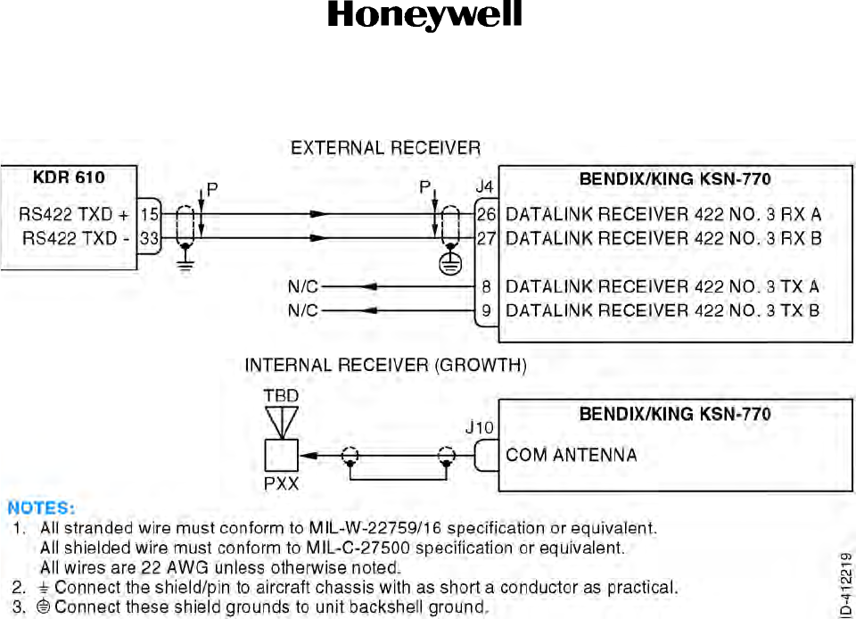
Draft
SYSTEM INSTALLATION MANUAL
066-01204 / 066-01213
Page 3-131
6 Dec 2012
© Honeywell International Inc. Do not copy without express permission of Honeywell.
34-70-06
Figure 3-32. XM Receiver Interface Interconnect Diagram (Sheet 1 of 1)
Draft as of 10/15/2012

Draft
SYSTEM INSTALLATION MANUAL
066-01204 / 066-01213
Page 3-132
6 Dec 2012
© Honeywell International Inc. Do not copy without express permission of Honeywell.
34-70-06
Blank Page
Draft as of 10/15/2012

Draft
Page 3-133
6 Dec 2012
34-70-06
SYSTEM INSTALLATION MANUAL
066-01204 / 066-01213
© Honeywell International Inc. Do not copy without express permission of Honeywell.
3.19 Maintenance Interface
3.19.1 Applicable Part Numbers
All part numbers and software revisions perform all maintenance functions.
3.19.2 Function
All pins and busses (with the exception of the front USB connector) are for shop maintenance only, and
must not be included in the aircraft harness.
A. Front USB
Information about navigational elements contained on thumb drives is transferred to the KSN 7xx
data base memory the front USB port. Data base loading need only be performed upon the receipt
of a new data (available every 28 days from Bendix/King).
The KSN 7xx will not navigate during data loading, and therefore it is necessary to load the data
base before flight. The thumb drive contains data for airports, VORs, NDBs, published
Intersections, SID and STAR waypoints, non-precision approach waypoints, and other
miscellaneous data. The procedure for updating the published data base is detailed in the KSN 7xx
pilot’s guide.
In addition to loading of the published data base, non-published data base items such as
user-defined flight plans, waypoints, navaids and airports may be transferred between the KSN 7xx
and a IBM-compatible personal computer via a thumb drive on the front USB port. The PC software
kit for this function is available through Bendix King. User data such as user defined flight plans,
waypoints, navaids, and airports may also be transferred between KSN 7xx systems in dual
installations through use of the dual system interface. It is not possible to transfer the published
data base from the KSN 7xx to a thumb drive or from one KSN 7xx to another over the dual system
interface.
B. Rear USB
TBD
3.19.3 Requirements and Limitations
All pins and busses (with the exception of the front USB connector) are for shop maintenance only, and
must not be included in the aircraft harness.
Draft as of 10/15/2012

Draft
Page 3-134
6 Dec 2012
34-70-06
SYSTEM INSTALLATION MANUAL
066-01204 / 066-01213
© Honeywell International Inc. Do not copy without express permission of Honeywell.
3.19.4 Electrical Characteristics
A. GPS Dataload RS-232
J4-13 GPS DATALOAD 232 TX
J4-32 GPS DATALOAD 232 RX
J4-31 GPS DATALOAD 232 GND
This is a standard EIA-232 serial interface that is only used for shop testing, and must not be
connected in the aircraft harness.
B. Demo Mode Select
J4-19 DEMO MODE SELECT
This pin is normally open, and when it is held low during power up, will take the KSN 7xx into demo
mode. This pin is only used for shop testing, and must not be connected in the aircraft harness.
C. Shop Mode Select
J4-18 SHOP MODE SELECT
This pin is normally open, and when it is held low during power up, will take the KSN 7xx into shop
mode. This pin is only used for shop testing, and must not be connected in the aircraft harness.
D. Maintenance RS-422
J4-22 MAINTENANCE 422 RX A
J4-23 MAINTENANCE 422 RX B
J4-4 MAINTENANCE 422 TX A
J4-5 MAINTENANCE 422 TX B
This is a standard EIA-422 data bus that is only used for shop testing, and must not be connected
in the aircraft harness.
E. IOP RS-422 A
J2-42 IOP 422 #4 RX A
J2-43 IOP 422 #4 RX B
J2-61 IOP 422 #4 TX A
J2-62 IOP 422 #4 TX B
This is a standard EIA-422 data bus that is only used for shop testing, and must not be connected
in the aircraft harness.
Draft as of 10/15/2012

Draft
Page 3-135
6 Dec 2012
34-70-06
SYSTEM INSTALLATION MANUAL
066-01204 / 066-01213
© Honeywell International Inc. Do not copy without express permission of Honeywell.
F. Discretes
J3-1 33V Boost Test
J3-4 5V KSN Test
J3-5 5V7 Startup Test
J3-3 12V POS MMDS Test
J3-2 ON OFF Status N
These discretes are all used for shop testing, and must not be connected in the aircraft harness.
G. Front USB
FRONT-2 USB 1 D
FRONT-3 USB 1 D +
FRONT-4 USB 1 D GND
FRONT-8 USB 1 VBUS
This is a standard v2.0 USB bus that is used for data loading.
H. Rear USB
J8-2 USB 2 D
J8-3 USB 2 D +
J8-5 USB 2 D GND
J8-1 USB 2 D VBUS
J8-4 USB 2 ID
This is a standard v2.0 USB bus that is only used for shop testing.
3.19.5 Interconnect Diagram
Refer to Figure 3-33 for the maintenance interface interconnect diagram.
Draft as of 10/15/2012

Draft
Page 3-136
6 Dec 2012
34-70-06
SYSTEM INSTALLATION MANUAL
066-01204 / 066-01213
© Honeywell International Inc. Do not copy without express permission of Honeywell.
Blank Page
Draft as of 10/15/2012
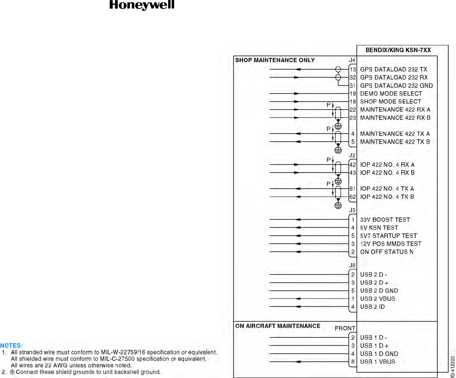
Draft
SYSTEM INSTALLATION MANUAL
066-01204 / 066-01213
Page 3-137
6 Dec 2012
© Honeywell International Inc. Do not copy without express permission of Honeywell.
34-70-06
Figure 3-33. Maintenance Interface Interconnect Diagram (Sheet 1 of 1)
Draft as of 10/15/2012

Draft
SYSTEM INSTALLATION MANUAL
066-01204 / 066-01213
Page 3-138
6 Dec 2012
© Honeywell International Inc. Do not copy without express permission of Honeywell.
34-70-06
Blank Page
Draft as of 10/15/2012

Draft
Page 3-139
6 Dec 2012
34-70-06
SYSTEM INSTALLATION MANUAL
066-01204 / 066-01213
© Honeywell International Inc. Do not copy without express permission of Honeywell.
3.20 Stormscope Interface (WX-500)
3.20.1 Applicable Part Numbers
All part numbers and software revisions perform all stormscope interface functions.
3.20.2 Function
The L3 WX-500 stormscope is a remote weather mapping sensor which detects and processes
lightning strikes. It interfaces with the KSN 7xx in order to provide this lightning detection and avoidance
information. WX-500 control and display information is communicated by a serial interface between the
WX-500 and the KSN 7xx. Two modes of weather display are available: Strike Mode and Cell Mode.
The KSN 7xx must be configured for a WX-500 on the maintenance pages for the WX-500 function to
be displayed.
3.20.3 Requirements and Limitations
The WX-500 must be installed in accordance with its own installation manual in order to assure proper
operation.
3.20.4 Electrical Characteristics
A. Stormscope Control
J1-64 WX-500 422 #2 TX A
J1-65 WX-500 422 #2 TX B
This is a standard EIA-422 data bus.
B. Stormscope Data
J1-44 WX-500 422 #2 RX A
J1-45 WX-500 422 #2 RX B
This is a standard EIA-422 data bus.
3.20.5 Interconnect Diagram
Refer to Figure 3-34 for the stormscope interface (WX-500) interconnect diagram.
Draft as of 10/15/2012

Draft
Page 3-140
6 Dec 2012
34-70-06
SYSTEM INSTALLATION MANUAL
066-01204 / 066-01213
© Honeywell International Inc. Do not copy without express permission of Honeywell.
Blank Page
Draft as of 10/15/2012
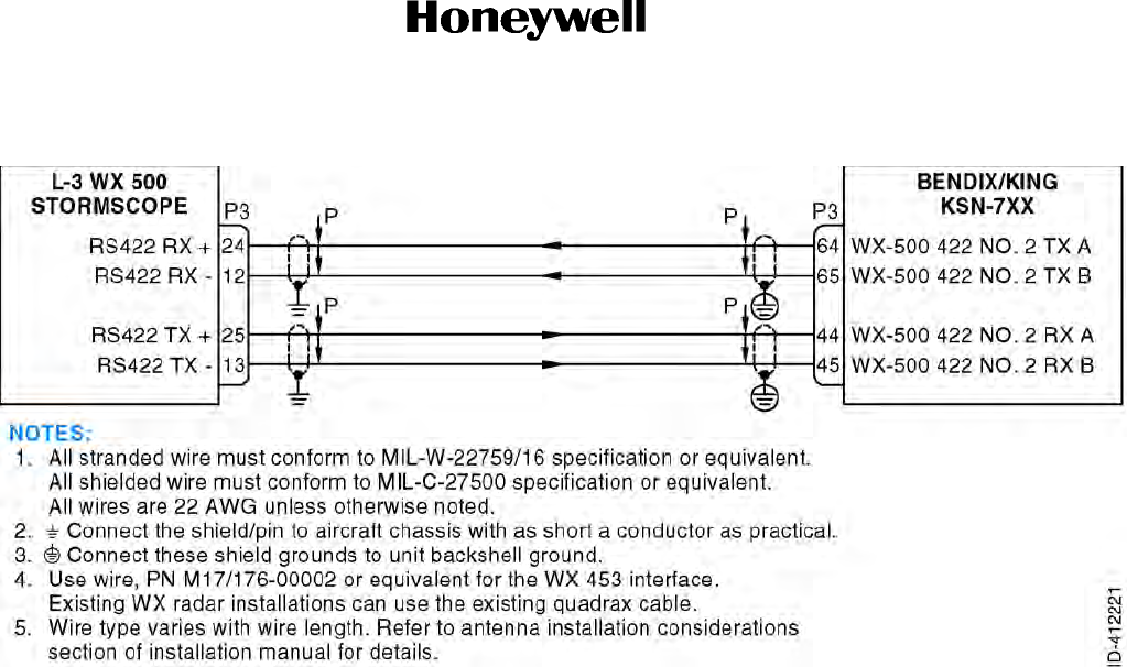
Draft
SYSTEM INSTALLATION MANUAL
066-01204 / 066-01213
Page 3-141
6 Dec 2012
© Honeywell International Inc. Do not copy without express permission of Honeywell.
34-70-06
Figure 3-34. Stormscope Interface (WX-500) Interconnect Diagram (Sheet 1 of 1)
Draft as of 10/15/2012

Draft
SYSTEM INSTALLATION MANUAL
066-01204 / 066-01213
Page 3-142
6 Dec 2012
© Honeywell International Inc. Do not copy without express permission of Honeywell.
34-70-06
Blank Page
Draft as of 10/15/2012

Draft
Page 3-143
6 Dec 2012
34-70-06
SYSTEM INSTALLATION MANUAL
066-01204 / 066-01213
© Honeywell International Inc. Do not copy without express permission of Honeywell.
3.21 NAV/COM Interface (KSN 7x0 Only)
3.21.1 Applicable Part Numbers
All KSN 7x0 navigators will be capable of all COM/NAV interface functions.
3.21.2 Function
The NAV/COM function of the KSN 7x0 integrated navigators provides the following COM/NAV
functions:
A. Two way voice communications within the frequency range of 118.000 to 136.975 MHz (760
channels) in 25 KHz increments.
B. Reception of navigation signals within the frequency range of 108.00 to 117.95 MHz in 50 kHz
increments (200 channels).
C. Reception of glide slope signals within the frequency range of 3.29.15 to 335.00 MHz in 150 kHz
increments (40 channels).
D. DME channeling to selected remote and panel mount DME equipment via the King Serial DME
bus.
3.21.3 Requirements and Limitations
A. COM
A conventional 50-ohm vertically polarized COM antenna is required with the KSN 7x0. Vertically
bent whip antennas are not recommended. Antennas must be installed per their manufacturer’s
recommendations. Additional recommendations are as follows:
(1) Mount the antenna on a flat metal surface or install a GND plane at least 18 inches (457 mm)
square.
(2) The antenna must be well removed from any projections, the engine(s), and the propeller(s).
B. NAV
A conventional 50-ohm horizontally polarized VOR/LOC/GS antenna is required with the KSN 7x0.
Antennas must be installed per their manufacturer’s recommendations. Additional
recommendations are as follows:
(1) The location must be well removed from other antennas, projections, engine(s), and
propeller(s). It must have a clear line of sight area if possible.
(2) The antenna must be mounted symmetrically with the centerline of the aircraft.
(3) Avoid running other coaxial cables and wires near the NAV antenna cable.
Draft as of 10/15/2012

Draft
Page 3-144
6 Dec 2012
34-70-06
SYSTEM INSTALLATION MANUAL
066-01204 / 066-01213
© Honeywell International Inc. Do not copy without express permission of Honeywell.
C. DME Channeling
For proper functioning of the King Serial DME indicator interface, a DME receiver (in addition to
the KSN 7xx and the indicator) must be connected to the SERIAL CLOCK and SERIAL DATA lines.
When the KSN 7xx is mounted in the aircraft pedestal, some certification agencies (including the
FAA) require a distance display in the pilot's scan area for IFR certification. Consult your approval
agency for additional information.
The KSN 7xx may display distance, groundspeed and time-to-station on the KPI-553A, KDI-572,
KDI-573 and KDI-574 DME distance displays. The DME in the aircraft continues to supply power
to these displays while the KSN 7xx information is displayed. A NAV/GPS annunciator switch and
relays can switch the DME display between displaying DME and GPS information (refer to the
DME installation documentation for details).
3.21.4 Electrical Characteristics
J2-33 EMERGENCY FREQUENCY
This input is normally open, and is active when pulled low. While pulled low, this discrete will force the
COM transceiver to:
A. Ignore all requests to change the COM channel until the input returns to open.
B. Ignore all requests to change the COM volume until the input returns to open.
C. Load the emergency frequency stored in NVM as the active frequency of the COM transceiver.
D. Set the COM volume to the emergency volume Level as per the configuration module defined
value (as set up in the maintenance pages).
J2-52 COM REMOTE TRANSFER
This input is normally open, and is activated when pulled to GND. When this input is held low for longer
than 2 seconds, the emergency frequency will be loaded into the standby channel. When a low to open
transition is detected following a low signal of <2 seconds, the KSN 7xx will transfer the active COM
frequency to standby and will transfer the standby COM frequency to active.
J2-14 COM CHANNEL DECREMENT
J2-13 COM CHANNEL INCREMENT
These inputs are normally open and are activated by being momentarily pulled to GND. When the COM
CHANNEL DECREMENT input is activated, the KSN 7xx will change the COM standby frequency to
the previous channel in the user defined COM channel list. When the COM CHANNEL INCREMENT
input is activated, the KSN 7xx will change the COM standby frequency to the next channel in the user
defined COM channel list.
Draft as of 10/15/2012

Draft
Page 3-145
6 Dec 2012
34-70-06
SYSTEM INSTALLATION MANUAL
066-01204 / 066-01213
© Honeywell International Inc. Do not copy without express permission of Honeywell.
J2-5 COM AUDIO OUT HI
J2-25 COM AUDIO OUT LO
This is an analog output from the KSN 7xx with the following characteristics:
J2-6 COM MIC AUDIO IN HI
J2-26 COM MIC AUDIO IN LO
This is an analog input to the KSN 7xx with the following characteristics:
J2-71 COM MIC KEY
This input is normally open, with a momentary GND applied when a switch is pressed. When the switch
is open, the KSN 7xx disables the COM transmitter and sidetone; when grounded the COM transmitter
and sidetone are enaled.
J2-53 TRANSMIT INTERLOCK
This discrete input signal may be optionally activated from remote equipment that might interfere with
the VHF COM. The input is normally open, and is activated momentarily as long as a GND is applied to
it. When the input is open, the COM receiver operates normally with normal sensitivity and sidetone.
When this input is held low, the COM receiver is desensitized. If held low for longer than 30 seconds
continuously, the receiver reverts to the normal mode until the signal is released (open) and pulled low
again.
Impedance: 500 50 ohms from 350 to 2500 Hz when the KSN 7xx is powered, and
450 ohms when the KSN 7xx is unpowered.
Range: 15.0 Vrms from 350 to 2500 Hz with 10% THD into an open circuit.
Rated Audio: 100 mW into 500 ohms.
Squelch: 2 mVrms signal and noise into 500 ohms
Minimum State: 2 mVrms signal and noise into 500 ohms
Impedance: 485 49 ohmsfrom 350 to 2500 Hz.
Bias Voltage: 9.0 1.0 VDC through an internal series resistance of 500 50 ohmsto a
load which can range from 0 ohm to open.
Range: 125 mVrms Signals 1.5 Vrms.
Draft as of 10/15/2012

Draft
Page 3-146
6 Dec 2012
34-70-06
SYSTEM INSTALLATION MANUAL
066-01204 / 066-01213
© Honeywell International Inc. Do not copy without express permission of Honeywell.
J2-7 NAV AUDIO OUT HI
J2-27 NAV AUDIO OUT LO
This is an analog output from the KSN 7xx with the following characteristics:
King Serial DME Bus
J1-75 SERIAL CLOCK
J1-57 SERIAL DATA
J1-76 DME CHANNEL REQUEST
J1-56 DME COMMON
These connections transmit Bendix/King format serial DME information.
In the King Serial DME configuration, SERIAL SYNC is an input. When the KSN 7xx receives an
active-high pulse on SERIAL SYNC, it transmits pulses on the SERIAL CLOCK and SERIAL DATA
lines.
3.21.5 Interconnect Diagram
Refer to Figure 3-35 for the COM interface interconnect diagram.
Refer to Figure 3-36 for the NAV interface interconnect diagram.
Refer to Figure 3-37 for the NAV interface - remote DME channeling interconnect diagram.
Refer to Figure 3-38 for the NAV interface - panel mount DME channeling interconnect diagram.
Impedance: 500 50 ohms from 350 to 2500 Hz when the KSN 7xx is powered, and
450 ohms when the KSN 7xx is unpowered.
Range: 15.0 Vrms from 350 to 2500 Hz with 10% THD into an open circuit.
Rated Audio: 100 mW into 500 ohms.
Minimum State: 2 mVrms signal and noise into 500 ohms
Draft as of 10/15/2012
Draft
SYSTEM INSTALLATION MANUAL
066-01204 / 066-01213
Page 3-147
6 Dec 2012
© Honeywell International Inc. Do not copy without express permission of Honeywell.
34-70-06
Figure 3-35. COM Interface Interconnect Diagram (Sheet 1 of 1)
Draft as of 10/15/2012

Draft
SYSTEM INSTALLATION MANUAL
066-01204 / 066-01213
Page 3-148
6 Dec 2012
© Honeywell International Inc. Do not copy without express permission of Honeywell.
34-70-06
Blank Page
Draft as of 10/15/2012
Draft
SYSTEM INSTALLATION MANUAL
066-01204 / 066-01213
Page 3-149
6 Dec 2012
© Honeywell International Inc. Do not copy without express permission of Honeywell.
34-70-06
Figure 3-36. NAV Interface Interconnect Diagram (Sheet 1 of 1)
Draft as of 10/15/2012

Draft
SYSTEM INSTALLATION MANUAL
066-01204 / 066-01213
Page 3-150
6 Dec 2012
© Honeywell International Inc. Do not copy without express permission of Honeywell.
34-70-06
Blank Page
Draft as of 10/15/2012

Draft
SYSTEM INSTALLATION MANUAL
066-01204 / 066-01213
Page 3-151
6 Dec 2012
© Honeywell International Inc. Do not copy without express permission of Honeywell.
34-70-06
Figure 3-37. NAV Interface - Remote DME Channeling Interconnect Diagram (Sheet 1 of 1)
Draft as of 10/15/2012
Figure 3-37 & 3-38 seems to be a duplicate of Figure 3-16 & 3-17. They are
wrong, because it has the RNAV/Channel Request and DME Channel Request
confused and shown incorrectly. There is no DME Channel request. There is
an RNAV/Channel Request and a DME Request and they are different
functions.

Draft
SYSTEM INSTALLATION MANUAL
066-01204 / 066-01213
Page 3-152
6 Dec 2012
© Honeywell International Inc. Do not copy without express permission of Honeywell.
34-70-06
Blank Page
Draft as of 10/15/2012
Draft
SYSTEM INSTALLATION MANUAL
066-01204 / 066-01213
Page 3-153
6 Dec 2012
© Honeywell International Inc. Do not copy without express permission of Honeywell.
34-70-06
Figure 3-38. NAV Interface - Panel Mount DME Channeling Interconnect Diagram (Sheet 1 of 1)
Draft as of 10/15/2012
Figure 3-37 & 3-38 seems to be a duplicate of Figure 3-16 & 3-17. They are
wrong, because it has the RNAV/Channel Request and DME Channel Request
confused and shown incorrectly. There is no DME Channel request. There is
an RNAV/Channel Request and a DME Request and they are different
functions.

Draft
SYSTEM INSTALLATION MANUAL
066-01204 / 066-01213
Page 3-154
6 Dec 2012
© Honeywell International Inc. Do not copy without express permission of Honeywell.
34-70-06
Blank Page
Draft as of 10/15/2012

Draft
Page 3-155
6 Dec 2012
34-70-06
SYSTEM INSTALLATION MANUAL
066-01204 / 066-01213
© Honeywell International Inc. Do not copy without express permission of Honeywell.
3.22 Data Bus Information
TBD BY ENGINEERING
Draft as of 10/15/2012

Draft
Page 3-156
6 Dec 2012
34-70-06
SYSTEM INSTALLATION MANUAL
066-01204 / 066-01213
© Honeywell International Inc. Do not copy without express permission of Honeywell.
Blank Page
Draft as of 10/15/2012

Draft
Page 4-1
6 Dec 2012
34-70-06
SYSTEM INSTALLATION MANUAL
066-01204 / 066-01213
© Honeywell International Inc. Do not copy without express permission of Honeywell.
SECTION IV
TBD
Draft as of 10/15/2012

Draft
Page 4-2
6 Dec 2012
34-70-06
SYSTEM INSTALLATION MANUAL
066-01204 / 066-01213
© Honeywell International Inc. Do not copy without express permission of Honeywell.
Blank Page
Draft as of 10/15/2012