Honeywell KTR2280 AVIATION SERVICES TRANSMITTER User Manual System Installation Manual
Honeywell International Inc. AVIATION SERVICES TRANSMITTER System Installation Manual
MANUAL

SYSTEM INSTALLATION
MANUAL (Preliminary)
KTR 2280
MULTI-MODE
DIGITAL RADIO (MMDR)
MANUAL NUMBER 006-10654-0000
Revision 0 AUGUST, 2006

Honeywell - Confidential
THIS DOCUMENT AND ALL INFORMATION AND EXPRESSION CONTAINED HEREIN ARE THE
PROPERTY OF HONEYWELL INTERNATIONAL INC., ARE PROVIDED IN CONFIDENCE, AND MAY BE
USED BY PERSONS REQUIRED BY 14 CFR 21.50 TO COMPLY WITH ANY OF THE TERMS OF THESE
INSTRUCTIONS. EXCEPT AS SET FORTH ABOVE, NO PERSON MAY, IN WHOLE OR IN PART, USE,
DUPLICATE OR DISCLOSE THIS INFORMATION FOR ANY PURPOSE WITHOUT THE PRIOR
WRITTEN PERMISSION OF HONEYWELL INTERNATIONAL INC.
This document contains technical data and is subject to U.S. export regulations. These commodities,
technology, or software were exported from the United States in accordance with the export
administration regulations. Diversion contrary to U.S. law is prohibited.
n KTR 2280 Preliminary H 08/17/06
Rev. 0, Aug/2006 ©Honeywell International Inc. Do not print without express permission of Honeywell Page MLA-1
Honeywell Materials License Agreement
The documents and information contained herein ("the Materials") are the proprietary data of
Honeywell International Inc. and Honeywell Intellectual Properties Inc. (collectively "Honeywell").
These Materials are provided for the exclusive use of Honeywell Service Centers;
Honeywell-authorized repair facilities; operators of Honeywell aerospace products subject to an
applicable product support agreement, their wholly owned-subsidiaries or a formally designated
third party service provider thereunder; and direct recipients of Materials from Honeywell's
Aerospace Technical Publication Distribution. The terms and conditions of this License Agreement
govern your use of these Materials, except to the extent that any terms and conditions of another
applicable agreement with Honeywell regarding the operation, maintenance, or repair of Honeywell
aerospace products conflict with the terms and conditions of this License Agreement, in which case
the terms and conditions of the other agreement will govern. However, this License Agreement will
govern in the event of a conflict between its terms and conditions and those of a purchase order or
acknowledgement.
1. License Grant - If you are a party to an applicable product support agreement, a Honeywell Service
Center agreement, or an authorized repair facility agreement, Honeywell hereby grants you a limited,
non-exclusive license to use these Materials to operate, maintain, or repair Honeywell aerospace products
only in accordance with that agreement.
If you are a direct recipient of these Materials from Honeywell's Aerospace Technical Publication
Distribution and are not a party to an agreement related to the operation, maintenance or repair of
Honeywell aerospace products, Honeywell hereby grants you a limited, non-exclusive license to use these
Materials to maintain or repair the subject Honeywell aerospace products only at the facility to which these
Materials have been shipped ("the Licensed Facility"). Transfer of the Materials to another facility owned
by you is permitted only if the original Licensed Facility retains no copies of the Materials and you provide
prior written notice to Honeywell.
2. Rights In Materials - Honeywell retains all rights in these Materials and in any copies thereof that are
not expressly granted to you, including all rights in patents, copyrights, trademarks, and trade secrets. No
license to use any Honeywell trademarks or patents is granted under this License Agreement.
3. Confidentiality - You acknowledge that these Materials contain information that is confidential and
proprietary to Honeywell. You agree to take all reasonable efforts to maintain the confidentiality of these
Materials.
4. Assignment And Transfer - This License Agreement may be assigned to a formally designated service
designee to the extent allowed under an applicable product support agreement or transferred to a
subsequent owner or operator of an aircraft containing the subject Honeywell aerospace products.
However, the recipient of any such assignment or transfer must assume all of your obligations under this
License Agreement. No assignment or transfer shall relieve any party of any obligation that such party then
has hereunder.
5. Copies of Materials - Unless you have the express written permission of Honeywell, you may not make
or permit making of copies of the Materials. Notwithstanding the foregoing, you may make copies of only
portions of the Material for your internal use. You agree to return the Materials and any copies thereof to
Honeywell upon the request of Honeywell.
n KTR 2280 Preliminary H 08/17/06
Rev. 0, Aug/2006 ©Honeywell International Inc. Do not print without express permission of Honeywell Page MLA-2
6. Term - This License Agreement is effective until terminated as set forth herein. This License Agreement
will terminate immediately, without notice from Honeywell, if you fail to comply with any provision of this
License Agreement or will terminate simultaneously with the termination or expiration of your applicable
product support agreement, authorized repair facility agreement, or your formal designation as a third party
service provider. Upon termination of this License Agreement, you will return these Materials to Honeywell
without retaining any copies and will have one of your authorized officers certify that all Materials have been
returned with no copies retained.
7. Remedies - Honeywell reserves the right to pursue all available remedies and damages resulting from
a breach of this License Agreement.
8. Limitation of Liability - IN NO EVENT WILL HONEYWELL BE LIABLE FOR ANY INCIDENTAL
DAMAGES, CONSEQUENTIAL DAMAGES, SPECIAL DAMAGES, INDIRECT DAMAGES, LOSS OF
PROFITS, LOSS OF REVENUES, OR LOSS OF USE, EVEN IF INFORMED OF THE POSSIBILITY OF
SUCH DAMAGES. TO THE EXTENT PERMITTED BY APPLICABLE LAW, THESE LIMITATIONS AND
EXCLUSIONS WILL APPLY REGARDLESS OF WHETHER LIABILITY ARISES FROM BREACH OF
CONTRACT, WARRANTY, TORT (INCLUDING BUT NOT LIMITED TO NEGLIGENCE), BY OPERATION
OF LAW, OR OTHERWISE.
9. Controlling Law - This License shall be governed and construed in accordance with the laws of the State
of New York without regard to the conflicts of laws provisions thereof. This license sets forth the entire
agreement between you and Honeywell and may only be modified by a writing duly executed by the duly
authorized representatives of the parties.
Copyright - Notice
Copyright 2006 Honeywell International Inc. All rights reserved.

n KTR 2280 Preliminary H 08/17/06
REVISION HIGHLIGHTS
Rev. 0, Aug/2006 ©Honeywell International Inc. Do not print without express permission of Honeywell Page RH-1
KTR 2280 Preliminary H 08/17/06
Part Number Rev Date Description
006-10654-0000 0Aug/2006 Initial Release

n KTR 2280 Preliminary H 08/17/06
REVISION HIGHLIGHTS
Rev. 0, Aug/2006 ©Honeywell International Inc. Do not print without express permission of Honeywell Page RH-2
Part Number Rev Date Description
n KTR 2280 Preliminary H 08/17/06
TABLE OF CONTENTS
Rev. 0, Aug/2006 ©Honeywell International Inc. Do not print without express permission of Honeywell Page TOC-1
SECTION 1
GENERAL INFORMATION
1.1 INTRODUCTION ......................................................................................................... 1-1
1.2 EQUIPMENT DESCRIPTION...................................................................................... 1-1
1.3 TECHNICAL CHARACTERISTICS............................................................................. 1-2
1.3.1 KTR 2280 TECHNICAL CHARACTERISTICS ............................................................ 1-2
1.3.2 KA 44B ADF ANTENNA TECHNICAL CHARACTERISTICS...................................... 1-3
1.4 UNITS AND ACCESSORIES SUPPLIED ................................................................... 1-3
1.4.1 CONFIGURATIONS AVAILABLE................................................................................ 1-3
1.4.2 KTR 2280 INSTALLATION KIT ................................................................................... 1-3
1.5 ACCESSORIES REQUIRED, BUT NOT SUPPLIED.................................................. 1-5
1.6 LICENSING REQUIREMENTS ................................................................................... 1-6
1.7 CONTINUED AIRWORTHINESS INSTRUCTIONS.................................................... 1-6
1.7.1 EQUIPMENT ............................................................................................................... 1-6
1.7.2 WIRES/COAX CABLES............................................................................................... 1-7
1.8 ANTENNA RF EXPOSURE ........................................................................................ 1-7
SECTION 2
INSTALLATION
2.1 GENERAL INFORMATION......................................................................................... 2-1
2.2 UNPACKING AND INSPECTING EQUIPMENT......................................................... 2-1
2.3 EQUIPMENT INSTALLATION .................................................................................... 2-1
2.3.1 AVIONICS COOLING REQUIREMENTS .................................................................... 2-1
2.3.2 EQUIPMENT LOCATION ............................................................................................ 2-1
2.3.2.1 MOUNTING TRAY LOCATION(S) .............................................................................. 2-2
2.3.2.2 ANTENNA(S)...............................................................................................................2-2
2.3.3 KTR 2280 MECHANICAL INSTALLATION ................................................................. 2-3
2.3.4 ANTENNA MECHANICAL INSTALLATION ................................................................ 2-3
2.3.4.1 VHF COM TRANSMITTER/RECEIVER ANTENNA .................................................... 2-3
2.3.4.2 NAVIGATION ANTENNAS .......................................................................................... 2-4
2.3.4.3 KA 44B ADF ANTENNA .............................................................................................. 2-5
2.3.5 ELECTRICAL INSTALLATION .................................................................................... 2-6
2.3.5.1 KTR 2280 INTERCONNECTION AND CABLE HARNESS FABRICATION................ 2-6
2.3.5.2 PRIMARY POWER AND CIRCUIT BREAKER REQUIREMENTS ............................. 2-7
2.3.5.3 CONNECTOR PIN FUNCTIONAL DESCRIPTIONS................................................... 2-8
2.3.5.4 CRIMP TOOL INFORMATION .................................................................................. 2-11
n KTR 2280 Preliminary H 08/17/06
TABLE OF CONTENTS
Rev. 0, Aug/2006 ©Honeywell International Inc. Do not print without express permission of Honeywell Page TOC-2
2.4 POST-INSTALLATION CHECKS ............................................................................. 2-29
2.4.1 KTR 2280 MMDR SYSTEM CHECKOUT ................................................................. 2-29
2.4.1.1 INSPECTION............................................................................................................. 2-29
2.4.1.2 POST-INSTALLATION CHECKOUT/OPERATION................................................... 2-30
SECTION 3
OPERATION
3.1 GENERAL ................................................................................................................... 3-1
3.2 RADIO TUNING WINDOW.......................................................................................... 3-1
3.2.1 VHF COM TUNING SUB-WINDOW ............................................................................ 3-2
3.2.1.1 ACTIVE FREQUENCY ................................................................................................ 3-2
3.2.1.2 VOLUME CONTROL INDICATION/SCALE ................................................................ 3-3
3.2.1.3 SOFT KEY IDENTIFIER/SOFT KEY SWAP IDENTIFIER........................................... 3-3
3.2.1.4 SQUELCH INHIBIT ANNUNCIATOR .......................................................................... 3-3
3.2.1.5 TRANSMIT/RECEIVE ANNUNCIATOR ...................................................................... 3-3
3.2.1.6 STANDBY FREQUENCY ............................................................................................ 3-3
3.2.1.7 STUCK MICROPHONE ANNUNCIATION .................................................................. 3-3
3.2.2 COM DETAIL WINDOW .............................................................................................. 3-4
3.2.3 VHF NAV TUNING SUB-WINDOW ............................................................................. 3-4
3.2.3.1 ACTIVE FREQUENCY ................................................................................................ 3-5
3.2.3.2 VOLUME CONTROL INDICATION/SCALE ................................................................ 3-5
3.2.3.3 SOFT KEY IDENTIFIER/SOFT KEY SWAP IDENTIFIER........................................... 3-5
3.2.3.4 DME ASSOCIATION/HOLD ANNUNCIATOR............................................................. 3-5
3.2.3.5 MORSE CODE ID ANNUNCIATOR ............................................................................ 3-5
3.2.3.6 STANDBY FREQUENCY/VOR BEARING .................................................................. 3-5
3.2.4 NAV DETAIL WINDOW ............................................................................................... 3-6
3.2.5 DME DETAIL WINDOW .............................................................................................. 3-6
3.2.6 ADF TUNING SUB-WINDOW ..................................................................................... 3-7
3.2.6.1 ADF FREQUENCY ...................................................................................................... 3-7
3.2.6.2 VOLUME CONTROL INDICATION/SCALE ................................................................ 3-7
3.2.6.3 SOFT KEY IDENTIFIER .............................................................................................. 3-7
3.2.6.4 ADF MODE.................................................................................................................. 3-7
3.2.7 ADF DETAIL WINDOW ............................................................................................... 3-8
3.3 KTR 2280 OPERATION .............................................................................................. 3-8
3.3.1 VHF COM CONTROLS ............................................................................................. 3-10
3.3.1.1 DETAIL BUTTON ...................................................................................................... 3-10
3.3.1.2 COM BUTTON........................................................................................................... 3-10
n KTR 2280 Preliminary H 08/17/06
TABLE OF CONTENTS
Rev. 0, Aug/2006 ©Honeywell International Inc. Do not print without express permission of Honeywell Page TOC-3
3.3.1.3 TUNING SELECT (SEL) CONTROL ........................................................................ 3-10
3.3.1.4 FREQUENCY SWAP................................................................................................. 3-10
3.3.2 VHF NAV CONTROLS .............................................................................................. 3-11
3.3.2.1 DETAIL BUTTON ...................................................................................................... 3-11
3.3.2.2 NAV BUTTON............................................................................................................ 3-11
3.3.2.3 TUNING SELECT (SEL) CONTROL ........................................................................ 3-11
3.3.2.4 FREQUENCY SWAP................................................................................................. 3-11
3.3.2.5 VOL/SQ/ID KNOB...................................................................................................... 3-12
3.3.2.6 NAV DETAIL WINDOW SOFT KEYS........................................................................ 3-12
3.3.2.7 DME DETAIL WINDOW SOFT KEYS ....................................................................... 3-12
3.3.3 ADF CONTROLS....................................................................................................... 3-12
3.3.3.1 DETAIL BUTTON ...................................................................................................... 3-12
3.3.3.2 ADF DETAIL WINDOW SOFT KEYS ........................................................................ 3-12
APPENDIX A
ENVIRONMENTAL QUALIFICATION FORMS
n KTR 2280 Preliminary H 08/17/06
TABLE OF CONTENTS
Rev. 0, Aug/2006 ©Honeywell International Inc. Do not print without express permission of Honeywell Page TOC-4
n KTR 2280 Preliminary H 08/17/06
LIST OF FIGURES
Rev. 0, Aug/2006 ©Honeywell International Inc. Do not print without express permission of Honeywell Page LOF-1
FIGURE 2-1 MAIN CONNECTOR - J1 ............................................................................. 2-8
FIGURE 2-2 KA 44/44B PIN LOCATION DIAGRAM ...................................................... 2-10
FIGURE 2-3 KTR 2280 INSTALLATION DRAWING ...................................................... 2-13
FIGURE 2-4 KTR 2280 BAR CLAMP ASSEMBLY DRAWING....................................... 2-21
FIGURE 2-5 KA 44B OUTLINE AND MOUNTING DRAWING (-0000)........................... 2-23
FIGURE 2-6 KA 44B OUTLINE AND MOUNTING DRAWING (-0010)........................... 2-25
FIGURE 2-7 KA 44B ANTENNA CABLE ASSEMBLY (-0020) ....................................... 2-27
FIGURE 3-1 RADIO TUNING WINDOW .......................................................................... 3-2
FIGURE 3-2 VHF COM TUNING SUB-WINDOW............................................................. 3-2
FIGURE 3-3 STUCK MICROPHONE ANNUNCIATION ................................................... 3-3
FIGURE 3-4 VHF COM DETAIL WINDOW ...................................................................... 3-4
FIGURE 3-5 VHF NAV TUNING SUB-WINDOW.............................................................. 3-4
FIGURE 3-6 VHF NAV BEARING DISPLAY .................................................................... 3-5
FIGURE 3-7 VHF NAV DETAIL WINDOW ....................................................................... 3-6
FIGURE 3-8 DME DETAIL WINDOW ............................................................................... 3-6
FIGURE 3-9 ADF TUNING SUB-WINDOW ...................................................................... 3-7
FIGURE 3-10 DUAL ADF DETAIL WINDOW ..................................................................... 3-8
FIGURE 3-11 KMC 2210 PFD CONTROLLER................................................................... 3-8
FIGURE 3-12 KDU 1080 DISPLAY UNIT BEZEL SOFT KEYS.......................................... 3-9
FIGURE 3-13 KMC 2220 MF CONTROLLER..................................................................... 3-9
n KTR 2280 Preliminary H 08/17/06
LIST OF FIGURES
Rev. 0, Aug/2006 ©Honeywell International Inc. Do not print without express permission of Honeywell Page LOF-2
n KTR 2280 Preliminary H 08/17/06
LIST OF TABLES
Rev. 0, Aug/2006 ©Honeywell International Inc. Do not print without express permission of Honeywell Page LOT-1
TABLE 1-1 KXP 2290 TECHNICAL CHARACTERISTICS............................................. 1-2
TABLE 2-1 J1 PIN FUNCTION LIST ............................................................................. 2-8
TABLE 2-2 ANTENNA CONNECTORS AND DESCRIPTIONS ..................................... 2-9
TABLE 2-3 KA 44B PIN FUNCTION LIST .................................................................... 2-10
TABLE 2-4 SIZE 22 HIGH DENSITY D-SUB CONTACT TOOLS ................................ 2-11
TABLE 2-5 INSPECTION/CHECK PROCEDURE........................................................ 2-29
n KTR 2280 Preliminary H 08/17/06
LIST OF TABLES
Rev. 0, Aug/2006 ©Honeywell International Inc. Do not print without express permission of Honeywell Page LOT-2
n KTR 2280 Preliminary H 08/17/06
Rev. 0, Aug/2006 ©Honeywell International Inc. Do not print without express permission of Honeywell Page 1-1
SECTION 1
GENERAL INFORMATION
1.1 INTRODUCTION
This manual contains information relative to the physical, mechanical, and electrical
characteristics of the Honeywell KTR 2280 Multi-Mode Digital Radio (MMDR). Installation
and check out procedures are also included. Information relative to the maintenance,
alignment, and procurement of the replacement parts may be found in the KTR 2280
Maintenance/Overhaul Manual, P/N 006-15654-XXXX. The only current KTR 2280
installation option is as a part of the APEX system. For additional information relating to
the APEX system, refer to the APEX System Manual 006-10667-XXXX or applicable
Engineering Bulletin (EB). This manual, the Apex System Manual, and the applicable EB
define the recommended installation for the KTR 2280. Final design of the installation and
airworthiness approval is incumbent upon the installer and their respective certification
authority.
1.2 EQUIPMENT DESCRIPTION
The KTR 2280 APEX MMDR Transceiver is a blind, panel mount integrated transceiver
containing one transmitter and four receivers. The KTR 2280 operates at a nominal
voltage of 27.5 VDC. The KTR 2280 is controlled by APEX LRU's which send control
information to the KTR 2280 via ARINC 429. Some outputs from the KTR 2280 are in
digital formats and sent to other LRU's via ARINC 429. Other outputs are more traditional
analog outputs.
The transmitter is a 2280 channel, 16 Watt COM transmitter capable of 8.33 kHz channel
spacing operation. The four receivers include one 200 channel NAV receiver, one 40
channel glideslope receiver, one COM receiver, and one ADF receiver. The COM
receivers have 2280 channels and are capable of 8.33 kHz channel spacing. The ADF
tunes frequencies from 190 kHz to 1799 kHz and 2180 kHz to 2189 kHz. The KTR 2280
has no user interface and is completely controlled by other components of the APEX
system via ARINC 429.
The KTR 2280 contains BIT (Built In Test) equipment so that the operational health of the
unit is constantly monitored. When a critical fault is detected, the unit notifies the APEX
system. The unit stores detected failures in non-volatile memory for later review. The unit
also has a temperature sensor and a timer so that faults can be time stamped and
temperature data can be collected and stored.

n KTR 2280 Preliminary H 08/17/06
Rev. 0, Aug/2006 ©Honeywell International Inc. Do not print without express permission of Honeywell Page 1-2
1.3 TECHNICAL CHARACTERISTICS
1.3.1 KTR 2280 TECHNICAL CHARACTERISTICS
TABLE 1-1 KXP 2290 TECHNICAL CHARACTERISTICS
SPECIFICATION CHARACTERISTIC
TSO COMPLIANCE
COM TRANSMIT:
COM RECEIVE:
VOR:
LOC:
GS:
ADF:
STUCK MICROPHONE:
TSO C37d, ETSO 2C37e
TSO C38d, ETSO 2C38e
TSO C40c, ETSO 2C40c
TSO C36e, ETSO 2C36f
TSO C34e, ETSO 2C34f
TSO C41D, ETSO 2C41b
TSO C41D, ETSO 2C41b
SOFTWARE CERTIFICATION
CATEGORY:
RTCA/DO-178B SOFTWARE LEVEL “C”
ENVIRONMENTAL
CATEGORIES:
SEE APPENDIX A
PHYSICAL DIMENSIONS: SEE FIGURE 2-3 KTR 2280 INSTALLATION
DRAWING
WEIGHT: SEE FIGURE 2-3 KTR 2280 INSTALLATION
DRAWING
MOUNTING: BLIND, RACK MOUNT BEHIND PANEL
TEMPERATURE: SEE APPENDIX A
ALTITUDE: SEE APPENDIX A
COOLING: INTERNAL FAN & EXTERNAL RACK MOUNTED
FAN
POWER INPUT: 16-33 VOLTS
POWER REQUIREMENTS
RECEIVE (NOMINAL):
RECEIVE (MAXIMUM):
TRANSMIT (NOMINAL):
TRANSMIT (MAXIMUM):
27.5 V @ 0.76A
27.5 V @ 1.02A
27.5 V @ 4.33A
27.5 V @ 6.11A

n KTR 2280 Preliminary H 08/17/06
Rev. 0, Aug/2006 ©Honeywell International Inc. Do not print without express permission of Honeywell Page 1-3
1.3.2 KA 44B ADF ANTENNA TECHNICAL CHARACTERISTICS
1.4 UNITS AND ACCESSORIES SUPPLIED
1.4.1 CONFIGURATIONS AVAILABLE
P/N 069-01037-0101 is the only version of the KTR 2280 that is currently available.
1.4.2 KTR 2280 INSTALLATION KIT
NOTE: The following installation kit information is presented at the revision existing at the
time of this publication. Future revisions to these kits may occur. Use the latest
revision of the kit as provided by Honeywell.
The KTR 2280 MMDR installation kit P/N 050-03721-0000 contains the following parts:
PN DESCRIPTION REV
-----------------------------------------------------------------------
050-03721-0000 INSTALL KIT KTR 2280 B
-------------------------------------------------------------------------------------------------
SYMBOL PART NUMBER FIND NO DESCRIPTION UM -0000
-------------------------------------------------------------------------------------------------
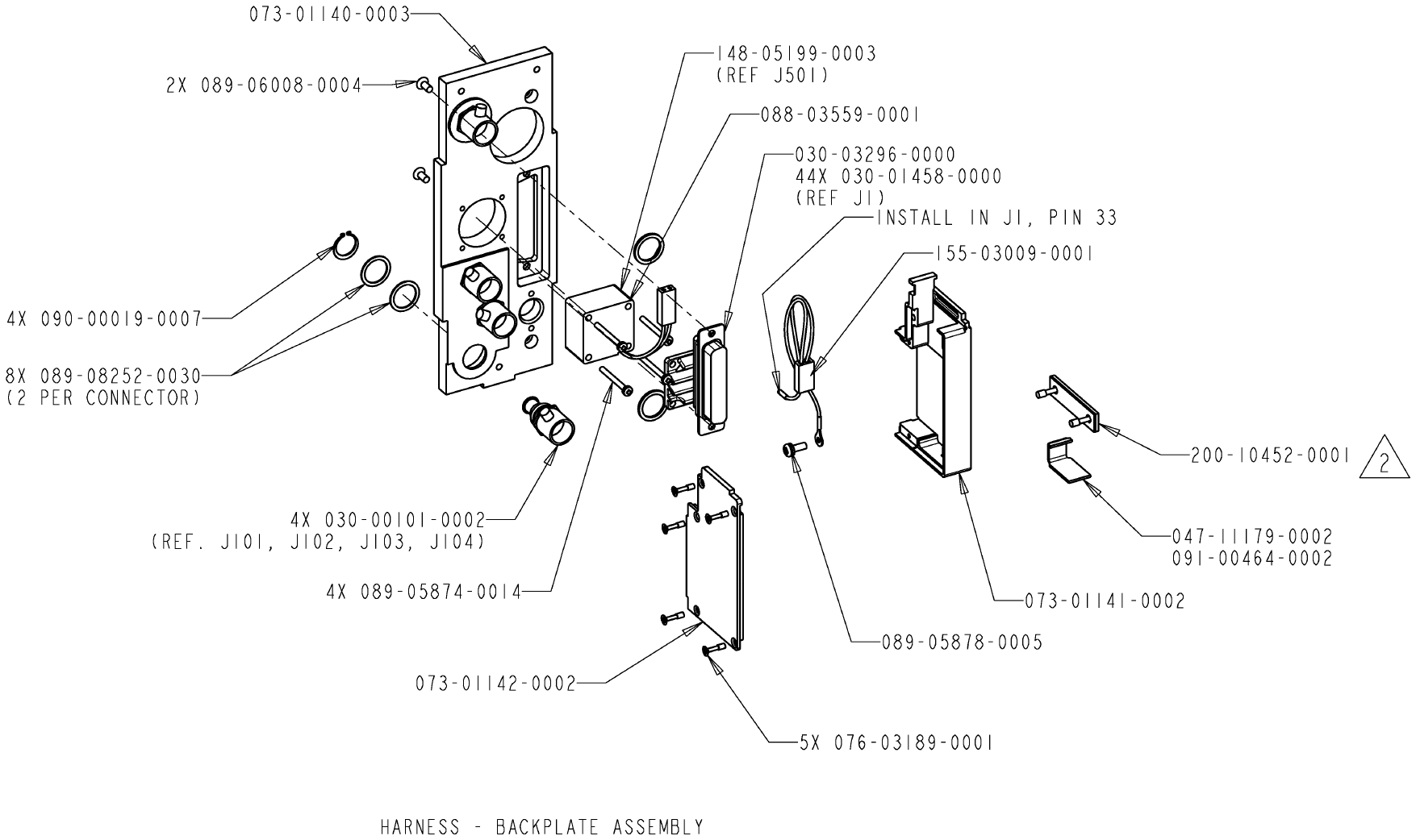
J1 030-03296-0000 HI DENSITY SUBD44P EA 1.00
J101 030-00101-0002 PANEL MOUNT PLUG EA 1.00
J102 030-00101-0002 PANEL MOUNT PLUG EA 1.00
J103 030-00101-0002 PANEL MOUNT PLUG EA 1.00
J104 030-00101-0002 PANEL MOUNT PLUG EA 1.00
J501 148-05199-0003 FAN 25X25X15MM, 4.06CFM, 55MM TEF WIRE, WITH CONN EA 1.00
001-01299-0000 INSTRUCTION FOR HARNESS ASSEMBLY PARTS RF .00
J1 030-03296-0000 HI DENSITY SUBD44P EA 1.00
SPECIFICATION CHARACTERISTIC
TSO COMPLIANCE: SEE APPENDIX A
ENVIRONMENTAL
SPECIFICATIONS:
SEE APPENDIX A
PHYSICAL DIMENSIONS: SEE FIGURE 2-5 KA 44B OUTLINE AND
MOUNTING DRAWING (-0000)/FIGURE 2-6 KA
44B OUTLINE AND MOUNTING DRAWING (-0010)
WEIGHT: SEE FIGURE 2-5 KA 44B OUTLINE AND
MOUNTING DRAWING (-0000)/FIGURE 2-6 KA
44B OUTLINE AND MOUNTING DRAWING (-0010)
POWER REQUIREMENTS: 8.5 +/-0.5 VDC at 100mA max (supplied by
KTR 2280)
n KTR 2280 Preliminary H 08/17/06
Rev. 0, Aug/2006 ©Honeywell International Inc. Do not print without express permission of Honeywell Page 1-4
PN DESCRIPTION REV
-----------------------------------------------------------------------
050-03721-0000 INSTALL KIT KTR 2280 B
-------------------------------------------------------------------------------------------------
SYMBOL PART NUMBER FIND NO DESCRIPTION UM -0000
-------------------------------------------------------------------------------------------------
030-01458-0000 CONTACT, SOCKET, SIZE 22 EA 44.00
047-11179-0002 STRAIN RELIEF CLAMP MED EA 1.00
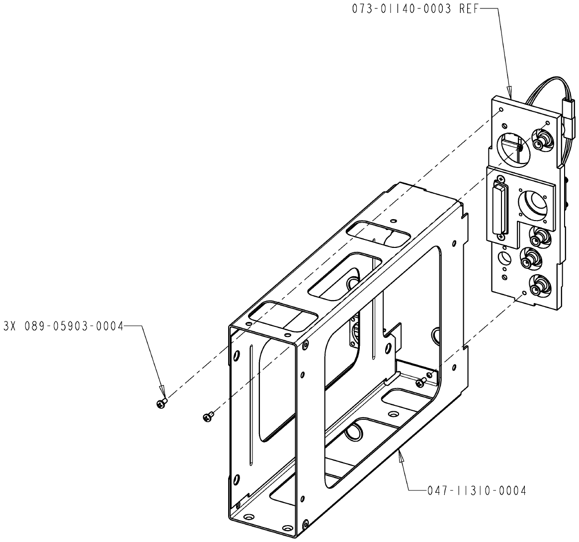
047-11310-0004 RACK, W/FINISH EA 1.00
057-05944-0073 KTR 2280 KIT TSO LABEL EA 1.00
073-01140-0003 BACKPLATE W/HARDWARE EA 1.00
073-01141-0002 CONNECTOR HOOD SUB D 25 90 DEG W/FINISH EA 1.00
073-01142-0002 CONN HOOD COVER W/FINISH EA 1.00
076-03189-0001 SCREW 100DEG FHP 2-56 X 3/8 SPECIAL EA 5.00
088-03559-0001 FAN GUARD EA 1.00
089-05874-0014 SCR PHP 2-56X7/8 EA 4.00
089-05878-0005 SCR PHP 4-40 X 5/16 EA 1.00
089-05903-0004 SCR PHP 4-40X1/4 EA 3.00
089-06008-0004 SCR FHP 4-40X1/4 EA 2.00
089-08252-0030 WASHER EA 8.00
090-00019-0007 RING RTNR .438 EA 4.00
091-00464-0002 CABLE TIE, 5.62 INCH EA 1.00
155-03009-0001 CABLE ASSY, POWER, KTR2280 FAN EA 1.00
155-06081-0000 INSTALL DRAWING MMDR KTR 2280 RF .00
200-10452-0001 BAR CLAMP ASSEMBLY -15 EA 1.00
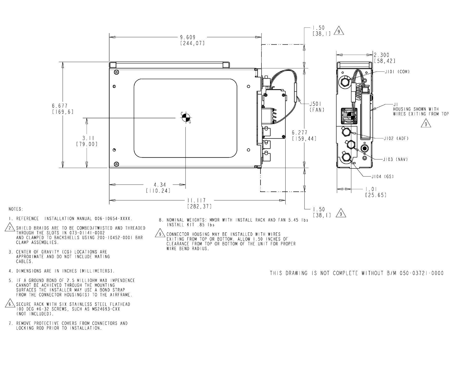
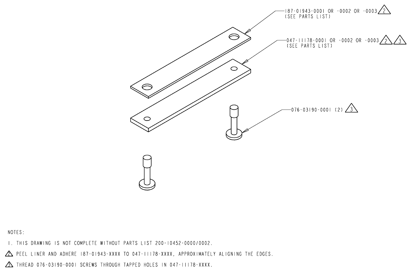
Shield braids must be clamped to the connector backshell using bar clamp assembly P/N
200-10452-0001 which contains the following parts. See FIGURE 2-3 KTR 2280
INSTALLATION DRAWING and FIGURE 2-4 KTR 2280 BAR CLAMP ASSEMBLY
DRAWING for additional information.
PN DESCRIPTION REV
-----------------------------------------------------------------------
200-10452-0001 BAR CLAMP ASSEMBLY -15 -
-------------------------------------------------------------------------------------------------
SYMBOL PART NUMBER FIND NO DESCRIPTION UM -0001
-------------------------------------------------------------------------------------------------
REF1 300-10452-0000 BAR CLAMP ASSEMBLY KMC 2220 RF .00
047-11178-0002 BACKSHELL BAR CLAMP MED EA 1.00
076-03190-0001 SCREW PHP 4-40 X 7/16 SPECIAL EA 2.00
187-01943-0002 BACKSHELL GASKET MEDIUM EA 1.00
n KTR 2280 Preliminary H 08/17/06
Rev. 0, Aug/2006 ©Honeywell International Inc. Do not print without express permission of Honeywell Page 1-5
The KA 44B antenna installation kit P/N 050-01756-0020 contains the following parts:
PN DESCRIPTION REV
-----------------------------------------------------------------------
050-01756-0020 INSTALL KIT 48 FT MMDR KA 44B SO-160D A
-------------------------------------------------------------------------------------------------
SYMBOL PART NUMBER FIND NO DESCRIPTION UM -0020
-------------------------------------------------------------------------------------------------
030-00101-0000 PANEL MNT PLUG EA 1.00
057-02259-0000 ANT MTG TEMPLATE EA 1.00
057-05944-0074 KA 44B KIT TSO LABEL EA 1.00
076-01042-0001 FERRULE W/F EA 1.00
090-00019-0007 RING RTNR .438 EA 1.00
091-00031-0005 NY CA CLAMP .312 EA 1.00
200-02586-0020 ANT CBL ASSY 48FT KA 44B DO-160D EA 1.00
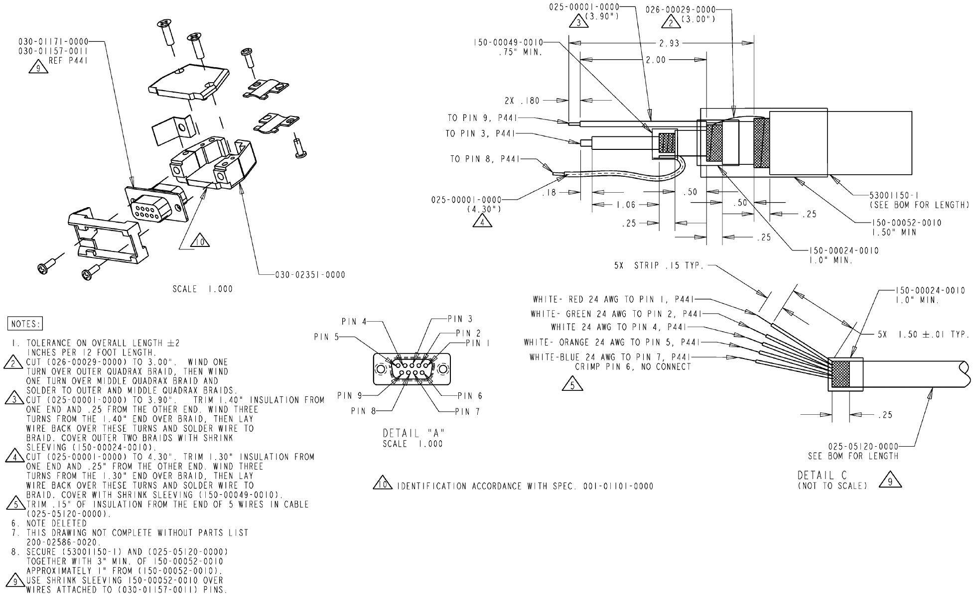
The KA 44B antenna cable assembly P/N 200-02586-0020 contains the following parts:
PN DESCRIPTION REV
-----------------------------------------------------------------------
200-02586-0020 ANT CBL ASSY 48FT KA 44B DO-160D E
-------------------------------------------------------------------------------------------------
SYMBOL PART NUMBER FIND NO DESCRIPTION UM -0020
-------------------------------------------------------------------------------------------------
025-00001-0000 WIRE, HOOKUP, PTFE, 26 (7/34)AWG SPC, BLK IN 8.20
025-05120-0000 WIRE, TIN PLTD CU SHLD, 5-24 (19/36)AWG TPC COND IN 578.00
026-00029-0000 WIRE, CU, 22AWG, TINNED IN 3.00
030-01157-0011 SOCKET CRMP 20G EA 9.00
030-01171-0000 CONN SUB-D HSG 9S (FEMALE PINS) EA 1.00
030-02351-0000 HOOD/LVR ASSY ST E EA 1.00
150-00024-0010 TUBING SHRINK 10G IN 2.00
150-00049-0010 SHRINK TUBING WHT IN .75
150-00052-0010 SHRNK TUBING WHT IN 4.50
300-02586-0020 ANTENNA CABLE INTERCONNECT KA 44B DO-160D RF .00
53001150-1 50 OHM QUADRAXIAL CABLE FT 48.17
1.5 ACCESSORIES REQUIRED, BUT NOT SUPPLIED
A. Broadband Communications Antenna (50 ohms)
B. VHF Navigation Antenna (50 ohms)
C. Glideslope Antenna
D. Antenna Splitter(s)
E. ADF Antenna (representative type KA 44B)
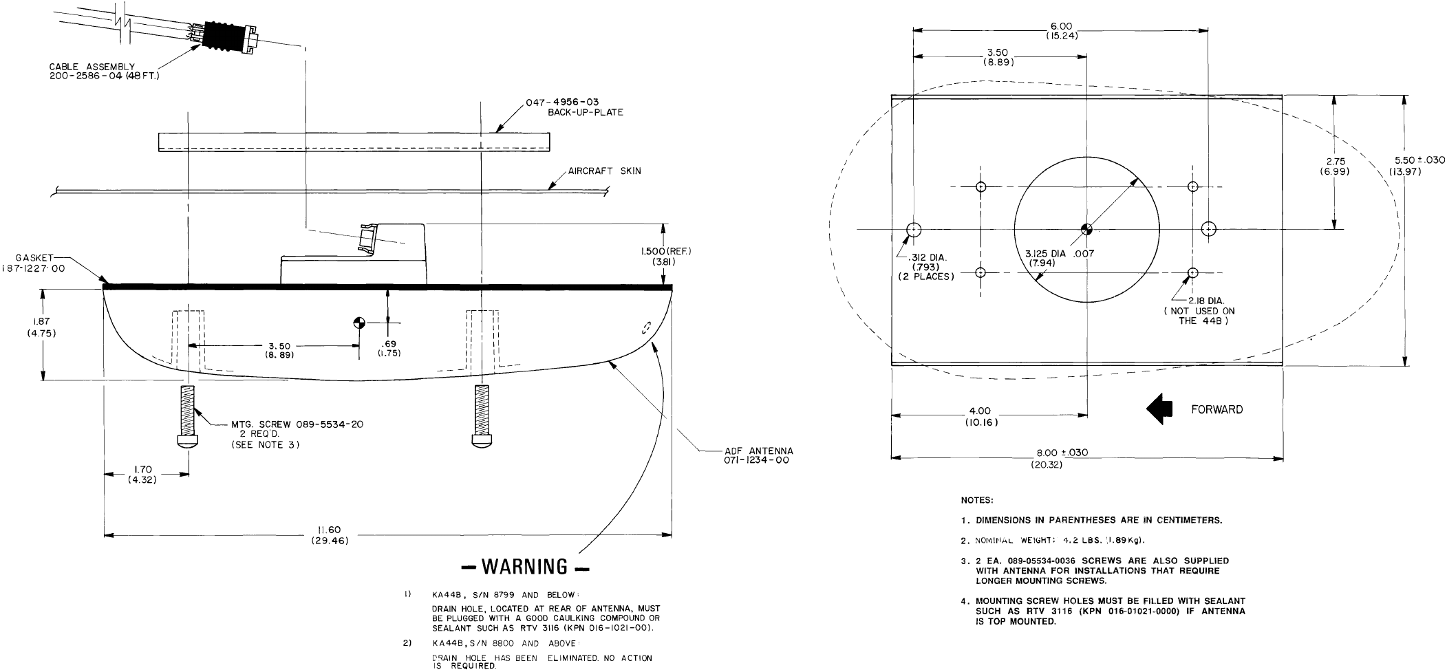
The KA 44B, P/N 071-1234-XX, is a low profile ADF Antenna which contains
both loop and sense antennas, preamplifiers, and modulators which com-
bine the antenna signals into a single RF signal which is output to the KTR
2280 via a quadaxial cable of non-critical length. The KA 44B is available
in four versions. KA 44B antenna P/N 071-1234-00/03 includes a mounting
plate. KA 44B P/N 071-1234-01 includes a grounding ring. KA 44B P/N
071-1234-02 has no mounting plate and has the QE adjust accessible ver-
tically.
n KTR 2280 Preliminary H 08/17/06
Rev. 0, Aug/2006 ©Honeywell International Inc. Do not print without express permission of Honeywell Page 1-6
1.6 LICENSING REQUIREMENTS
The KTR 2280 meets CFR Title 47, Part 15 and Part 2 (FCC Approvals) for all radio
equipment. For non-US registered aircraft, follow applicable licensing requirements as
required.
The Federal Communications Commission requires that the operator of the transmitter of
this equipment hold a restricted radio telephone operators permit (FCC Form 605) or
higher class license. A permit may be obtained by a U.S. citizen from the nearest field
office of the FCC; no examination is required. An Aircraft Station License is required for
this equipment. Forms (FCC Form 605, New Aircraft Station License, or FCC Form 405A,
Renewal of Aircraft Station License) can be obtained from the nearest FCC Field Office.
This equipment has been type accepted by the FCC and entered on their list of type
accepted equipment as Honeywell KTR 2280 and must be identified as Honeywell KTR
2280 on FCC Form 605, Aircraft Radio Station License Application.
CAUTION: THE VHF TRANSMITTER IN THIS EQUIPMENT IS GUARANTEED TO
MEET FEDERAL COMMUNICATIONS COMMISSION ACCEPTANCE
OVER THE OPERATING TEMPERATURE RANGE ONLY WHEN A
HONEYWELL CRYSTAL IS USED IN THE STABILIZED MASTER
OSCILLATOR. USE OF OTHER THAN HONEYWELL CRYSTALS IS
CONSIDERED AN UNAUTHORIZED MODIFICATION, AND WILL VOID
THE WARRANTY.
1.7 CONTINUED AIRWORTHINESS INSTRUCTIONS
1.7.1 EQUIPMENT
The instructions for continued airworthiness given in the TC or STC approvals for this
product supplements or supersedes the instructions for continued airworthiness in this
manual.
Most Honeywell products are designed and manufactured to allow "on condition
maintenance". On condition maintenance is described as follows; There are no periodic
service requirements necessary to maintain continued airworthiness. No maintenance is
required until the equipment does not properly perform its intended function. When
service is required, a complete performance test should be accomplished following any
repair action. Consult the appropriate unit Maintenance/Overhaul Manual for complete
performance test information.
14 CFR Part 25.1529 Instructions for Continued Airworthiness is met per the following
instructions:
A. The removal of the equipment is on the condition of failure. There is no re-
quired maintenance
n KTR 2280 Preliminary H 08/17/06
Rev. 0, Aug/2006 ©Honeywell International Inc. Do not print without express permission of Honeywell Page 1-7
1.7.2 WIRES/COAX CABLES
During on-condition or regularly scheduled maintenance, inspect the wires and coax
cables following the guidelines listed in AC 43.13-1B Chapter 11, 12 as necessary.
1.8 ANTENNA RF EXPOSURE
WARNING: TO MINIMIZE RF EXPOSURE TO PERSONNEL, INSTALL THE
ANTENNA GENERALLY AWAY FROM AREAS WHERE PEOPLE
ARE LOCATED. IN SITUATIONS WHERE A PERSON WOULD BE
DIRECTLY EXPOSED TO ANTENNA RADIATION, SUCH AS IN A
COMPOSITE AIRCRAFT, A MINIMUM SEPARATION OF 1.97 FT
(60 CM) IS GENERALLY REQUIRED BETWEEN ANY PART OF
THE ANTENNA AND ANY LOCATION WHERE A PERSON MAY BE
PERMANENTLY SEATED IN THE AIRCRAFT. LESSER
SEPARATION IS ACCEPTABLE IN AN AIRCRAFT WHERE METAL
SKIN SHIELDS THE OCCUPANTS FROM THE ANTENNA.
n KTR 2280 Preliminary H 08/17/06
Rev. 0, Aug/2006 ©Honeywell International Inc. Do not print without express permission of Honeywell Page 1-8
This Page Intentionally Left Blank
n KTR 2280 Preliminary H 08/17/06
Rev. 0, Aug/2006 ©Honeywell International Inc. Do not print without express permission of Honeywell Page 2-1
SECTION 2
INSTALLATION
2.1 GENERAL INFORMATION
This section contains general suggestions and information to consider before installation
of the KXP 2290. Close adherence to these suggestions will assure optimum performance
from the equipment.
NOTE: The conditions and test required for the TSO/ETSO and MOPS approval of this
article are minimum performance standards. It is the responsibility of those
installing this article either on or with a specified type or class of aircraft to
determine that the aircraft installation conditions are within the TSO/ETSO and
MOPS standards. These articles must have separate approval for installation in
an aircraft. Any features in this equipment outside the requirements of this
applicable TSO/ETSO and MOPS must be evaluated and approved as part of the
installation approval. The article may be installed only if further evaluation by the
applicant confirms that the installation is acceptable and is approved by the
Administrator.
2.2 UNPACKING AND INSPECTING EQUIPMENT
Exercise extreme care when unpacking the equipment. Make a visual inspection of the
unit for evidence of damage during shipment. If a claim for damage is to be made, save
the shipping container to substantiate the claim. The claim should be promptly filed with
the transportation company. It would be advisable to retain the container and packing
material after all equipment has been removed, in the event that equipment storage or
reshipment should become necessary.
2.3 EQUIPMENT INSTALLATION
2.3.1 AVIONICS COOLING REQUIREMENTS
The unit is cooled by a fan internal to the unit and one attached to the rear rack assembly
plate, the latter being a part of the installation (see FIGURE 2-3 KTR 2280
INSTALLATION DRAWING). During installation, do not block any holes in the unit
cover(s) which would restrict air flow.
2.3.2 EQUIPMENT LOCATION
The following paragraphs contain information pertaining to the initial installation of the
KTR 2280 MMDR, including instructions concerning the location and mounting of the
supporting antenna(s).
n KTR 2280 Preliminary H 08/17/06
Rev. 0, Aug/2006 ©Honeywell International Inc. Do not print without express permission of Honeywell Page 2-2
The equipment should be installed in the aircraft in a manner consistent with acceptable
workmanship and engineering practices and in accordance with the instructions set forth
in this publication. To ensure that the system has been properly and safely installed in the
aircraft, the installer should make a through visual inspection and conduct an overall
operational check of the system on the ground prior to flight.
The installation should be in accordance with standards established by the customer’s
installing agency and existing conditions as to unit location and type of installation;
however, the following should be considered before installing the system in order to
assure a more satisfactory performance from the equipment.
NOTE: The TSO identifies the minimum performance standards, tests, and other
conditions applicable for issuance of design and production approval of the
article. The TSO applicant is responsible for documenting all limitations and
conditions suitable for installation of the article. An applicant requesting approval
for installation of the article within a specific type or class of product is responsible
for determining environmental and functional compatibility.
Care should be exercised to avoid mounting components near equipment operating with
high pulse current or high power outputs such as radar and satellite communications
equipment. In general, the equipment should be installed in a location convenient for
operation, inspection, and maintenance, and in an area consistent with the TSO
environmental limits. Determine the mounting location for system components following
the guidelines below.
2.3.2.1 MOUNTING TRAY LOCATION(S)
The KTR 2280 MMDR mounting tray is blind-mounted behind the APEX cockpit panel
configuration.
2.3.2.2 ANTENNA(S)
The antenna(s) should be well removed from other antenna projections, the engine(s),
and propeller(s). It should also be well removed from landing gear doors, access doors,
or other openings which will break the ground plane for the antenna(s). On metal skinned
aircraft, the antenna(s) should be bonded to the surface of the aircraft in a fore to aft
location that provides the flattest ground plane. On composite aircraft, the antenna(s)
should be a located at the center of a conductive ground plane, contoured to the shape of
the aircraft, having dimensions of at least 2 feet by 2 feet. The antenna penetration should
be designed such that the structural integrity of the fuselage is not compromised.
The antenna(s) need to be within 5 degrees of the centerline
Where practical, plan the antenna location(s) to keep cable lengths as short as possible
and avoid sharp bends in the cable to minimize the VSWR.
n KTR 2280 Preliminary H 08/17/06
Rev. 0, Aug/2006 ©Honeywell International Inc. Do not print without express permission of Honeywell Page 2-3
Avoid running other cables or wires near the antenna cable(s).
On pressurized aircraft, the antenna(s) should be sealed using an approved sealant, such
as RTV No. 3145 (P/N 016-01082-0000) or equivalent, around the connector and
mounting hardware.
The antenna mounting(s) should be sealed from the outside for moisture protection using
RTV or equivalent.
Mount the antenna(s) in as clean as environment as possible, away from exhaust gases
and oils. The antenna(s) should be kept clean. If left dirty (oil covered), the antenna
performance may be affected.
2.3.3 KTR 2280 MECHANICAL INSTALLATION
The mounting tray for the MMDR should be mounted using the dimensions specified in
the outline and mounting drawing, FIGURE 2-3 KTR 2280 INSTALLATION DRAWING.
Install the unit per the following:
(1) Slide the MMDR into the tray until the locking rod engages the nut on the
back of the rack.
(2) Using an Allen wrench, turn the locking rod clockwise until it has drawn the
unit into the rack and mating connectors and is tight.
CAUTION: DO NOT OVERTIGHTEN THE LOCKING ROD
To remove the unit, turn the securing rod counter clockwise until it disengages from the
mounting tray. Then, pull the unit out of the mounting rack
For additional KXP 2290 installation information, refer to FIGURE 2-3 KTR 2280
INSTALLATION DRAWING as required
2.3.4 ANTENNA MECHANICAL INSTALLATION
2.3.4.1 VHF COM TRANSMITTER/RECEIVER ANTENNA
The VHF COM antenna should be mounted as far away as possible (8 feet, minimum)
from other similar antennas and the vertical stabilizer. Mounting the COM antenna as far
away as possible from the navigation antenna will help reduce COM to NAV interference.
The COM antenna should also be mounted as far away as possible from an ELT antenna
to prevent distortion of the radiated pattern and to prevent radiated broadband noise from
the ELT when excited by the COM transmissions. Radiated broadband noise from an ELT
is a common cause of COM-to-COM and COM-to-NAV interference. Mounting one
antenna on top of the fuselage at the highest location to ensure a good radiation pattern
and the other on the bottom of the fuselage offers good separation with a minimum of
interaction.
n KTR 2280 Preliminary H 08/17/06
Rev. 0, Aug/2006 ©Honeywell International Inc. Do not print without express permission of Honeywell Page 2-4
It is recommended that a COM be connected to the top antenna for good ground
communication and that the other COM be connected to the bottom antenna to provide
good airborne communications. If mounting antennas on the same side of the aircraft is
unavoidable, maintain the minimum allowable separation (8 feet).
The antenna should be mounted on a section of the aircraft that is horizontal during cruise
flight. The base of the antenna should be well bonded to the metal aircraft skin. Remove
any paint from around the mounting holes to ensure a good connection between the
antenna and the skin. The metal aircraft skin at the base of the antenna should extend a
minimum of twenty-four inches in every direction. This provides the ground plane required
for the antenna. Any less metallized area will result in reduced communication range at
some bearings around the aircraft and may increase interference to and from other
systems.
The COM transceiver performance depends heavily on the integrity of the electrical
bonding to the airframe and also the electrical integrity of the aircraft structure. If the
electrical resistance between an antenna and the aircraft or between adjacent skin panels
change intermittently, noisy communications may result.
Connect the antenna to the COM unit with 50 ohm coaxial cable, keeping the cable length
to a minimum and avoiding sharp bends in the cable. Keep the COM antenna cable as far
away from other antenna cables as possible and do not bundle several cables together.
Use Dow-Corning DC-4, or equivalent, on both inside and outside of the connector and
its mate as an effective barrier against moisture and to prevent corrosion.
2.3.4.2 NAVIGATION ANTENNAS
The NAV antenna should be well removed from other antennas, projections, engines or
propellers. It should have a clear line of sight area if possible. The antenna must be
mounted symmetrically with the center line of the aircraft. Avoid running other coaxial
cables and wires near the NAV antenna cable.
The VOR/LOC antenna with Glideslope is a two piece dipole with one part mounted on
each side of the vertical stabilizer. It should be installed on the upper section of the vertical
stabilizer of single finned aircraft and be at least 28 inches (measured vertically) from the
horizontal stabilizer.
On dual VOR/ILS installations, it is recommended that a splitter be used to divide signals
from a single VOR/LOC antenna into two or more receivers. Use double shielded cables
to reduce interference to the receivers.
n KTR 2280 Preliminary H 08/17/06
Rev. 0, Aug/2006 ©Honeywell International Inc. Do not print without express permission of Honeywell Page 2-5
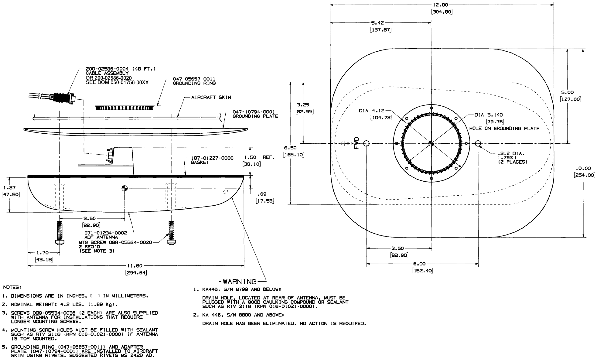
2.3.4.3 KA 44B ADF ANTENNA
The antenna installation will determine, to a large extent, whether the ADF will give
optimum performance (refer to FIGURE 2-5 KA 44B OUTLINE AND MOUNTING
DRAWING (-0000) / FIGURE 2-6 KA 44B OUTLINE AND MOUNTING DRAWING (-0010)
as required. The KA 44B antenna contains both the loop and sense antennas. The
following considerations should be taken into account before selecting a location for the
antenna:
CAUTION: KEEP THE ANTENNA AT LEAST 4 FEET AWAY FROM DME OR
TRANSPONDER ANTENNAS TO MINIMIZE L-BAND INTERFERENCE.
THE ANTENNA SHOULD BE MOUNTED WELL CLEAR OF THE
AIRCRAFT GENERATOR/ALTERNATOR AND WELL CLEAR OF ANY
GENERATOR/ALTERNATOR CABLES.
CAUTION: DO NOT ROUTE THE CABLES ALONG WITH HIGH LEVEL
TRANSMITTING CABLES. DO NOT ROUTE THE CABLES WITH OR
NEAR ALTERNATOR OR 400HZ CABLES. MAKE SURE THAT THE
CABLES DO NOT INTERFERE WITH ANY OF THE AIRCRAFT CONTROL
CABLES.
• Mount the antenna on the center line of the aircraft fuselage. Failure to do so may
result in excessive Q.E. error.
• If the antenna is to be top mounted, select a location where shadowing from the wings,
etc., is minimized.
• The antenna should be well removed from any projections such as engines and
propellers, as well as landing gear doors, access doors or other openings which will
break the ground plane for the antenna.
• Use the template included in the installation kit to mark the mounting holes on the
aircraft fuselage.
• Drill and/or punch the required holes.
• Use a piece of fine sandpaper or emery cloth to sand the area on the fuselage skin on
which the doubler plate is to be mounted.
• Apply Alumiprep No. 33, P/N 016-01127-0000, to both the inside area of the fuselage
and the back of the doubler plate, following the directions on the container to cleanse
the metal of any residue.
• Apply Alodine No. 1001, P/N 016-00128-0000, to both locations following the
directions on the container. This is used to ensure good bonding and prevent
oxidation.
• Refer to the installation manual and mount the antenna as shown. First rivet the
doubler plate in place. It is imperative that the doubler plate make a good ground plane
contact with the inside of the aircraft skin.
n KTR 2280 Preliminary H 08/17/06
Rev. 0, Aug/2006 ©Honeywell International Inc. Do not print without express permission of Honeywell Page 2-6
2.3.5 ELECTRICAL INSTALLATION
2.3.5.1 KTR 2280 INTERCONNECTION AND CABLE HARNESS FABRICATION
NOTE: The only current KTR 2280 installation option is as a part of the APEX system.
For detailed interconnection information relating to a specific installation, refer to
the applicable APEX system installation manual and/or engineering bulletin (EB).
The KTR 2280 MMDR receives primary power from the aircraft power source. Power
connections, voltage requirements, and circuit breaker requirements may be found in the
APEX system installation manual and/or engineering bulletin (EB) for a specific
installation.
The length of the wires to parallel pins should be approximately the same length, so that
the best distribution of current can be effected. Honeywell recommends that all wires,
including spares, as provided with the interconnect definition information be included in
the fabrication of the wiring harness. However; if full wiring is not desired, the installer
should ensure that the minimum wiring requirements for the features and functions to be
used have been incorporated.
When cables are installed in the aircraft, they must be supported firmly enough to prevent
movement and should be carefully protected against chaffing. Additional protection
should also be provided in all locations where the cable may be subjected to abuse.
In wire bundles, the cabling should not be tied tightly together as this tends to increase the
possibility of noise pickup and similar interference. When routing cables through the
aircraft the cables should cross high level rf lines at right angles.
Prior to installing any equipment, make a continuity check of all wires and cables
associated with the system. Then apply power and check for proper voltages at system
connectors, and then remove power before completing the installation.
The following guidelines are recommended:
(1) The installing facility will supply and fabricate all external cables. The re-
quired connectors are supplied as part of the installation kit (P/N
050-03451-0000).
(2) The unit must be kept a minimum of three feet from the antenna. Addition-
ally, the antenna coax cable should not be bundled with the other wiring har-
nesses to the unit.
(3) The length and routing of the external cables must be carefully planned be-
fore attempting the actual installation. Avoid sharp bends or locating the ca-
ble near aircraft control cables. The cables should be of a length to allow
for a “maintenance loop”. That is, the length should be adequate to access
and extend the connectors aft of the panel for future maintenance purposes.
Excess cabling should be secured and stowed by tie-wrapping until such
maintenance is required.
n KTR 2280 Preliminary H 08/17/06
Rev. 0, Aug/2006 ©Honeywell International Inc. Do not print without express permission of Honeywell Page 2-7
(4) The cables should be supported firmly enough to prevent movement. They
should be carefully protected wherever one may chafe against another or
against some other object. Extra protection should be provided in all loca-
tions where the cables may be subject to abuse. Shields on shielded wires
should be grounded in accordance with the system interconnection informa-
tion.
(5) Shields should be carried through any obstruction via a thru-bulkhead con-
nector. If shielding cannot be carried through by use of a bulkhead/connec-
tor pin, precautions should be taken to ensure each segment of the shielded
lead be grounded at only one point. A ground connection of not more than
two inches in length should be used. The preceding discussion does not ap-
ply to coaxial and quadraxial cable.
(6) Avoid routing cabling near high noise and high power sources.
2.3.5.2 PRIMARY POWER AND CIRCUIT BREAKER REQUIREMENTS
The KTR 2280 MMDR receives primary power from the aircraft power circuit breakers.
Power connections, wire sizes, and circuit breaker requirements may be found in the
APEX system installation manual and/or engineering bulletin (EB) for a specific
installation.
n KTR 2280 Preliminary H 08/17/06
Rev. 0, Aug/2006 ©Honeywell International Inc. Do not print without express permission of Honeywell Page 2-8
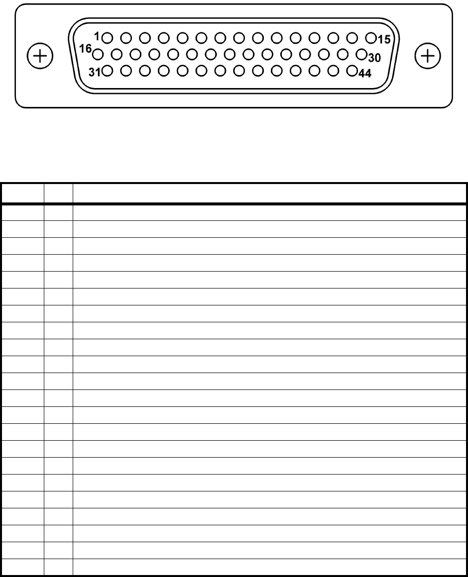
2.3.5.3 CONNECTOR PIN FUNCTIONAL DESCRIPTIONS
FIGURE 2-1 MAIN CONNECTOR - J1
Front View
Pin # I/O Description
1 O A429 Out1 A
2 O ADF Loop Enable OUT
3 I TEST
4 I Unit Pos PGM 1
5 I Unit Pos PGM 2
6 I COM TX Interlock* IN
7 I COM MIC Key* IN
8 O RS-422 RX A
9 O RS-422 RX B
10 I RS-422 TX A
11 I RS-422 TX B
12 I COM MIC GND
13 N.A. Spare
14 O ADF Audio LO OUT
15 O ADF Audio HI OUT
16 O A429 Out1 B
17 O ADF MOD/0 OUT
18 O A429 Out2 A
19 I Unit Pos Parity
20 I A429 IN1 A
21 N.A. Spare
22 I A429 IN2 A
TABLE 2-1 J1 PIN FUNCTION LIST

n KTR 2280 Preliminary H 08/17/06
Rev. 0, Aug/2006 ©Honeywell International Inc. Do not print without express permission of Honeywell Page 2-9
23 I ADF ANT PWR Return
24 I DC Return 1
25 I DC Power 2 IN
26 I Emergency Channel
27 I COM MIC Audio IN
28 N.A. Spare
29 O NAV Audio LO OUT
30 O NAV Audio HI OUT
31 O ADF 32 HZ/90 OUT
32 O A429 Out2 B
33 O MMDS FAN 5V OUT
34 I A429 IN1 B
35 N.A. Spare
36 I A429 IN2 B
37 I Pgm Pin Common
38 O ADF ANT PWR OUT
39 I DC Power 1 IN
40 I DC Return 2
41 I Download
42 I ON*
43 O COM Audio/Sidetone LO OUT
44 O COM Audio/Sidetone LO OUT
Connector Pin I/O Description
J101 1 I/O COM RF
J102 1 I ADF RF IN
J103 1 I NAV RF IN
J104 1 I Glideslope RF IN
TABLE 2-2 ANTENNA CONNECTORS AND DESCRIPTIONS
Pin # I/O Description
TABLE 2-1 J1 PIN FUNCTION LIST
n KTR 2280 Preliminary H 08/17/06
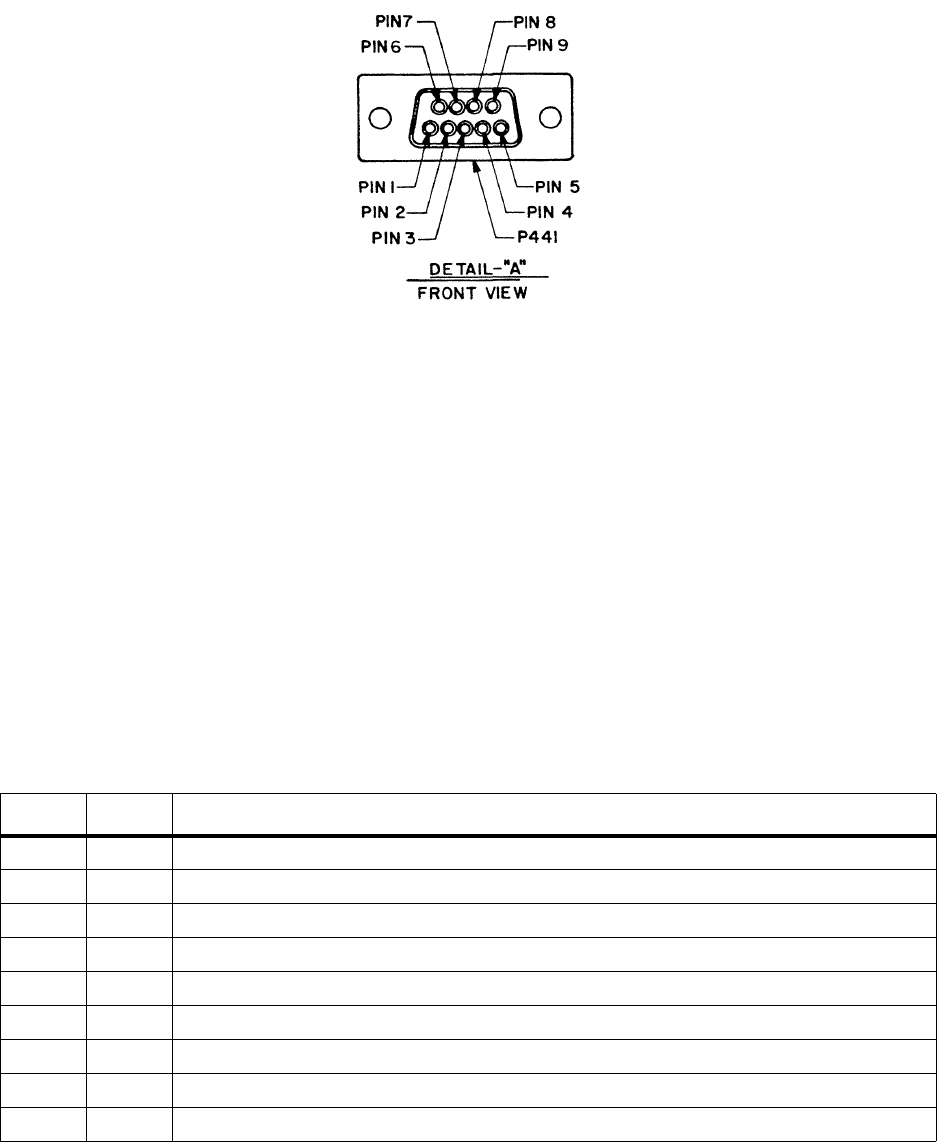
Rev. 0, Aug/2006 ©Honeywell International Inc. Do not print without express permission of Honeywell Page 2-10
FIGURE 2-2 KA 44/44B PIN LOCATION DIAGRAM
TABLE 2-3 KA 44B PIN FUNCTION LIST
PIN I/O SIGNAL NAME
1 I ANTENNA POWER
2 I LOOP ENABLE
3 O RF INPUT
4 I 32Hz +/-90 DEG.
5 I 32Hz 0 DEG.
6 NO CONNECTION
7 GROUND
8 CENTER SHIELD GND
9 OUTER SHIELD GND

n KTR 2280 Preliminary H 08/17/06
Rev. 0, Aug/2006 ©Honeywell International Inc. Do not print without express permission of Honeywell Page 2-11
2.3.5.4 CRIMP TOOL INFORMATION
The following is a listing of crimp tools and accessories for use with the KTR 2280.
* All source tools and positioners are to Mil-Spec Standard and are interchangeable.
** Positioner wire gauge (AWG) refers to barrel only.
*** SUPERCEDES MIL SPEC P/N M24308/18-1. ORDER FROM POSITRONICS, DANIELS, OR ASTRO
BY MIL SPEC P/N.
NOTE: Selections in parentheses denote optional ordering number from source.
Vendor Ordering Information:
Astro Tool Company
21615 SW TV Hwy, Beaverton, OR 97006
(503) 642-9853 * Fax: 503-591-7766 * Email: sales@astrotool.com
Daniels Manufacturing Company (DMC)
526 Thorpe Road, Orlando, FL 32824-8133 USA
Tel: 407-855-6161 * Fax: 407-855-6884 * Email: dmc@dmctools.com
Positronics Industries, Inc.
423 N. Campbell Ave P.O. Box 8247, Springfield, MO 65801
Tel: 800-641-4054 * Fax: 417-866-4115 * Email: info@connectpositronics.com
TABLE 2-4 SIZE 22 HIGH DENSITY D-SUB CONTACT TOOLS
SOURCE * CRIMP TOOL POSITIONER 22-30 AWG ** INSERTION/EXTRACTION TOOL
HONEYWELL 005-02012-0034 Not Available Not Available
MIL-SPEC M22520/2-01 M22520/2-06 M81969/1-04 ***
DANIELS MFG. AFM8 (M22520/2-01) K41 (M22520/2-06)
POSITRONICS 9507-0-0 9502-3 (K41)
ASTRO (BUCHANAN) 615717 (M22520/2-01) 615722 (M22520/2-06)
n KTR 2280 Preliminary H 08/17/06
Rev. 0, Aug/2006 ©Honeywell International Inc. Do not print without express permission of Honeywell Page 2-12
This Page Intentionally Left Blank
n KTR 2280 Preliminary H 08/17/06
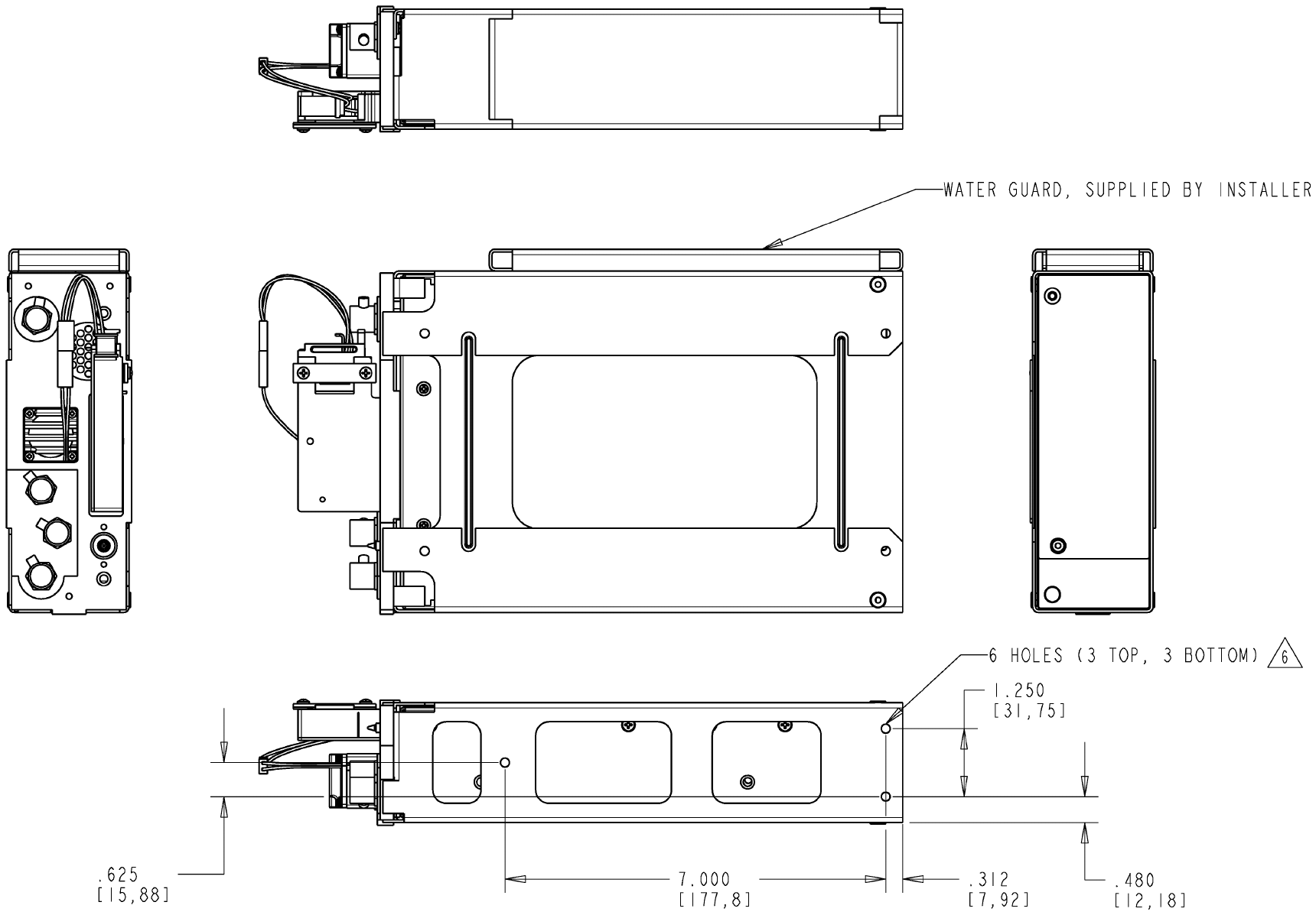
Rev. 0, Aug/2006 ©Honeywell International Inc. Do not print without express permission of Honeywell Page 2-13
FIGURE 2-3 KTR 2280 INSTALLATION DRAWING
(Dwg. 155-06081-0000 Rev. B, Sheet 1 of 4)
n KTR 2280 Preliminary H 08/17/06
Rev. 0, Aug/2006 ©Honeywell International Inc. Do not print without express permission of Honeywell Page 2-14
This Page Intentionally Left Blank
n KTR 2280 Preliminary H 08/17/06
Rev. 0, Aug/2006 ©Honeywell International Inc. Do not print without express permission of Honeywell Page 2-15
FIGURE 2-3 KTR 2280 INSTALLATION DRAWING
(Dwg. 155-06081-0000 Rev. B, Sheet 2 of 4)
n KTR 2280 Preliminary H 08/17/06
Rev. 0, Aug/2006 ©Honeywell International Inc. Do not print without express permission of Honeywell Page 2-16
This Page Intentionally Left Blank
n KTR 2280 Preliminary H 08/17/06
Rev. 0, Aug/2006 ©Honeywell International Inc. Do not print without express permission of Honeywell Page 2-17
FIGURE 2-3 KTR 2280 INSTALLATION DRAWING
(Dwg. 155-06081-0000 Rev. B, Sheet 3 of 4)
n KTR 2280 Preliminary H 08/17/06
Rev. 0, Aug/2006 ©Honeywell International Inc. Do not print without express permission of Honeywell Page 2-18
This Page Intentionally Left Blank
n KTR 2280 Preliminary H 08/17/06
Rev. 0, Aug/2006 ©Honeywell International Inc. Do not print without express permission of Honeywell Page 2-19
FIGURE 2-3 KTR 2280 INSTALLATION DRAWING
(Dwg. 155-06081-0000 Rev. B, Sheet 4 of 4)
n KTR 2280 Preliminary H 08/17/06
Rev. 0, Aug/2006 ©Honeywell International Inc. Do not print without express permission of Honeywell Page 2-20
This Page Intentionally Left Blank
n KTR 2280 Preliminary H 08/17/06
Rev. 0, Aug/2006 ©Honeywell International Inc. Do not print without express permission of Honeywell Page 2-21
FIGURE 2-4 KTR 2280 BAR CLAMP ASSEMBLY DRAWING
(300-10452-0000, Rev. -)
n KTR 2280 Preliminary H 08/17/06
Rev. 0, Aug/2006 ©Honeywell International Inc. Do not print without express permission of Honeywell Page 2-22
This Page Intentionally Left Blank
n KTR 2280 Preliminary H 08/17/06
Rev. 0, Aug/2006 ©Honeywell International Inc. Do not print without express permission of Honeywell Page 2-23
FIGURE 2-5 KA 44B OUTLINE AND MOUNTING DRAWING (-0000)
(Dwg No 155-05334-0000 R-9)
n KTR 2280 Preliminary H 08/17/06
Rev. 0, Aug/2006 ©Honeywell International Inc. Do not print without express permission of Honeywell Page 2-24
This Page Intentionally Left Blank
n KTR 2280 Preliminary H 08/17/06
Rev. 0, Aug/2006 ©Honeywell International Inc. Do not print without express permission of Honeywell Page 2-25
FIGURE 2-6 KA 44B OUTLINE AND MOUNTING DRAWING (-0010)
(Dwg No 155-05334-0010 R-AA)
n KTR 2280 Preliminary H 08/17/06
Rev. 0, Aug/2006 ©Honeywell International Inc. Do not print without express permission of Honeywell Page 2-26
This Page Intentionally Left Blank
n KTR 2280 Preliminary H 08/17/06
Rev. 0, Aug/2006 ©Honeywell International Inc. Do not print without express permission of Honeywell Page 2-27
FIGURE 2-7 KA 44B ANTENNA CABLE ASSEMBLY (-0020)
(Dwg No 300-02586-0020 R-E)
n KTR 2280 Preliminary H 08/17/06
Rev. 0, Aug/2006 ©Honeywell International Inc. Do not print without express permission of Honeywell Page 2-28
This Page Intentionally Left Blank

n KTR 2280 Preliminary H 08/17/06
Rev. 0, Aug/2006 ©Honeywell International Inc. Do not print without express permission of Honeywell Page 2-29
2.4 POST-INSTALLATION CHECKS
2.4.1 KTR 2280 MMDR SYSTEM CHECKOUT
The post-installation test is used to apply power and functionally checkout the system.
Successful completion of the post-installation test verifies the proper operation of the KTR
2280 MMDR.
TABLE 2-5 INSPECTION/CHECK PROCEDURE is a visual inspection/check procedure
that should be performed after system installation as part of a system checkout. A
post-installation test per paragraph 2.4.1.2 POST-INSTALLATION CHECKOUT/
OPERATION should be performed. In addition, the procedure should be used as a
periodic maintenance inspection check.
TABLE 2-5 INSPECTION/CHECK PROCEDURE
2.4.1.1 INSPECTION
Perform the following inspection on the overall system:
(1) Check that cables do not interfere with aircraft controls or other equipment.
(2) Check cabling for proper routing and check security of tie-down points. In-
spect and adjust cable runs to ensure that cables are not strained, kinked,
or severely twisted and are not exposed to rough or sharp surfaces.
EQUIPMENT INSPECTION/CHECK PROCEDURE
KTR 2280 A. Inspect external surface for damage.
MMDR B. Check that the unit is securely installed and that retaining
mechanism is securely tightened.
C. Ensure that all connections in the mounting tray are properly
mounted and secure.
Antennas A. Inspect external surfaces for damage.
B. Check that antenna is properly mounted and mounting
screws are tight.
C. Ensure that antenna coaxial cable connectors are properly
mated and secure.
n KTR 2280 Preliminary H 08/17/06
Rev. 0, Aug/2006 ©Honeywell International Inc. Do not print without express permission of Honeywell Page 2-30
2.4.1.2 POST-INSTALLATION CHECKOUT/OPERATION
(1) General
Installation of the MMDR system requires three stages of testing to ensure
the proper operation of the MMDR. Initially, prior to the installation of the
MMDR and antenna, a system interwiring check should be performed. This
check verifies that the aircraft and all MMDR interconnections are correct
before power is applied. After the units are installed a visual inspection of
the equipment and connections is made. Finally, a ramp test is performed.
(2) System Interwiring Check
To check the aircraft and MMDR system interconnections proceed as fol-
lows:
(a) Check that all cables and interwiring are installed in accordance with
the Interwiring and Cable Harness Fabrication instructions (para-
graph 2.3.5.1 KTR 2280 INTERCONNECTION AND CABLE HAR-
NESS FABRICATION).
(b) Using the applicable interconnection information, check wiring for
proper destination, opens, and shorts.
(c) Check rf cables for insertion loss and VSWR.
(3) Visual Inspection
In conjunction with system installation, perform the inspection/check proce-
dure (TABLE 2-5 INSPECTION/CHECK PROCEDURE).
(4) Post-Installation Test (Nav/Com Functionality)
Perform a ground check of the installation prior to the flight test. Using a lo-
cal frequency, confirm that the COM function can receive and transmit a
modulated signal. Using a ramp tester, confirm that VOR, LOC, and GS
needle deflections move in the correct direction, the To/From flag is the
proper sense, and that the warning flags are functioning properly. An oper-
ation performance flight test is recommended after the installation is com-
pleted to insure satisfactory performance of the equipment in its normal en-
vironment. Check all aircraft control movements to be sure no electrical ca-
bles interfere with their operation.
To check the communications transceiver, maintain an altitude of at least
1500 feet and contact a ground station facility at a range of at least fifty nau-
tical miles. Contact a ground station close in. Pull the volume control knob
out to defeat the automatic squelch feature and listen for any unusual elec-
trical noise which would reduce the COM receiver sensitivity by increasing
the squelch threshold. If possible, verify the communications capability on
both the high and low end of the VHF COM band.
n KTR 2280 Preliminary H 08/17/06
Rev. 0, Aug/2006 ©Honeywell International Inc. Do not print without express permission of Honeywell Page 2-31
CAUTION: AS AN ADDED PRECAUTION BEFORE THE FLIGHT, CHECK THE
ANTENNA. VSWR SHOULD BE CHECKED WITH AN IN-LINE TYPE
WATTMETER INSERTED IN THE COAXIAL TRANSMISSION LINE
BETWEEN THE TRANSCEIVER AND THE ANTENNA. ANY PROBLEM
WITH THE ANTENNA INSTALLATION WILL MOST LIKELY BE SEEN AS
A HIGH REFLECTED POWER. A VSWR OF 3:1 WILL RESULT IN A 25%
LOSS IN POWER.
To check the VOR/ILS system, select a VOR frequency within a forty nauti-
cal mile range. Listen to the VOR audio and insure that no electrical inter-
ference such as magneto noise is present. Check the tone identifier filter op-
eration. Fly inbound or outbound on a selected VOR radial and check for
proper LEFT-RIGHT and TO-FROM indications. Check the VOR accuracy.
NOTE: VOR Ground Station scalloping may be present
To check the localizer and glideslope functions, select an appropriate ILS
frequency and fly an approach to the proper runway. Check for proper
LEFT-RIGHT and UP-DOWN indications. The glideslope function will not
operate for units that do not have the glideslope receiver. Check section 1
for unit part numbers that have glideslope receivers.
(5) Post-Installation Test (ADF Functionality)
A quick preliminary check can be made by tuning to a local AM broadcast
station or a strong NDB station. Check for satisfactory audio (this should be
done where clear reception is possible, preferably outside of the hanger).
(a) Quadrantal Error Adjustments
The system has been factory adjusted to compensate for a typical
airframe. Therefore, little or no compensation should be required.
Nonetheless, the KTR 2280 provides software adjustment of Qua-
drantal Error (the average amount of quadrantal error (QE) that ex-
ists due to the shape of the airframe). The values for these align-
ments are stored within the aircraft system maintenance computer
and downloaded to the KTR 2280 on power up. If this download does
not occur the KTR 2280 uses the last values that were loaded. In
event that antenna skew and QE adjustment is required, follow the
procedure outlined below.
1. Set the QE adjustment to 0.
2. Tune in a nearby broadcast station, NDB, or compass locator
that gives a strong, clear signal free of fading. Position the air-
craft on the ramp in an area that is clear of surrounding build-
ings, such that the indicator points to 0 degrees (i.e., the air-
craft is heading directly toward the station). Note the aircraft
heading.
3. Using the aircraft directional gyro or compass, turn the aircraft
to the left 45 degrees. Note the indicated relative bearing and
the amount of error. Continue to turn the aircraft, stopping ar
each 45 degree point and noting the relative bearing error.
n KTR 2280 Preliminary H 08/17/06
Rev. 0, Aug/2006 ©Honeywell International Inc. Do not print without express permission of Honeywell Page 2-32
The errors at the 90 degree, 180 degree, and 270 degree
points should be within +/- 5 degrees.
4. Using the following formulas calculate the Quadrantal Error:
Bearing_45 = Bearing from KTR 2280 when aircraft is turned
45 degrees left of the beacon.
Bearing_135 = Bearing from KTR 2280 when aircraft is turned
135 degrees left of the beacon.
Bearing_225 = Bearing from KTR 2280 when aircraft is turned
225 degrees left of the beacon.
Bearing_315 = Bearing from KTR 2280 when aircraft is turned
315 degrees left of the beacon.
QE_45 = Bearing_45 - 45
QE_135 = Bearing_135 - 135
QE_225 = Bearing_225 - 225
QE_3155 = Bearing_3155 - 315
QE = Average of QE_45, QE_135, QE_225, and QE_315.
(b) Operational Checks
The following operational checks are to verify proper opera-
tion of the ADF function of the KTR 2280 and can be made
with the aircraft in the parking area.
1. Place the ADF in the ANT mode and tune in several known
stations. Verify that audio reception is satisfactory and that
volume control operation is normal. Verify that the ADF indica-
tor needle is parked at the 90 degree position relative to the
noise of the aircraft. Place the unit in the ADF mode and verify
that the needle points to the station.
2. Select the BFO function to enter the BFO mode and verify that
the BFO tone is present in the receiver audio (if a keyed CW
station is used the tone heard will be the coded identifier).
n KTR 2280 Preliminary H 08/17/06
Rev. 0, Aug/2006 ©Honeywell International Inc. Do not print without express permission of Honeywell Page 3-1
SECTION 3
OPERATION
3.1 GENERAL
The radio tuning philosophy used on the display is based on an association between the
tuning controls (knobs and buttons) and a graphical cursor that appears in the PFD tuning
window.
Normally, the cursor is a cyan box that surrounds the frequency, code, or mode being
controlled. The pilot positions the cursor by pressing the display bezel soft key located
adjacent to the desired data field or by pressing a window focus shortcut control key on
the MF Controller (MFC). For example, if the soft key adjacent to the NAV 1 tuning field
on the pilot's PFD is pressed the cyan box cursor will move to the NAV 1 standby
frequency field on that display. When the MF Controller is used the 'window focus' will be
on the radio window indicating control is possible through the MF Controller and the
joystick is used to move the cursor to the desired field.
The text is shown in the larger font size to enhance visibility while tuning. One second after
the controller activity stops, the cursor reverts to the smaller font, but remains on the
standby frequency field. Twenty seconds after the controller activity stops, the cursor
defaults to the onside VHF COM standby frequency field as a cyan box.
3.2 RADIO TUNING WINDOW
The Radio Tuning window is in the lower right hand corner of the pilot's PFD and the lower
left hand corner of the copilot's PFD. The cyan box surrounding the Radio Tuning window
shows that the display focus is on the radio tuning, and the MF Controller can be used to
control some of the radio functions. The cyan outline on the soft key identifier indicates
the radio that any inputs will affect. The Very High Frequency (VHF) Communication
(COM) tuning sub-window(s) are the first line(s) of the displayed radios, then the VHF
Navigation (NAV) sub-window(s) and the Automatic Direction Finder (ADF)
sub-window(s).
n KTR 2280 Preliminary H 08/17/06
Rev. 0, Aug/2006 ©Honeywell International Inc. Do not print without express permission of Honeywell Page 3-2
FIGURE 3-1 RADIO TUNING WINDOW
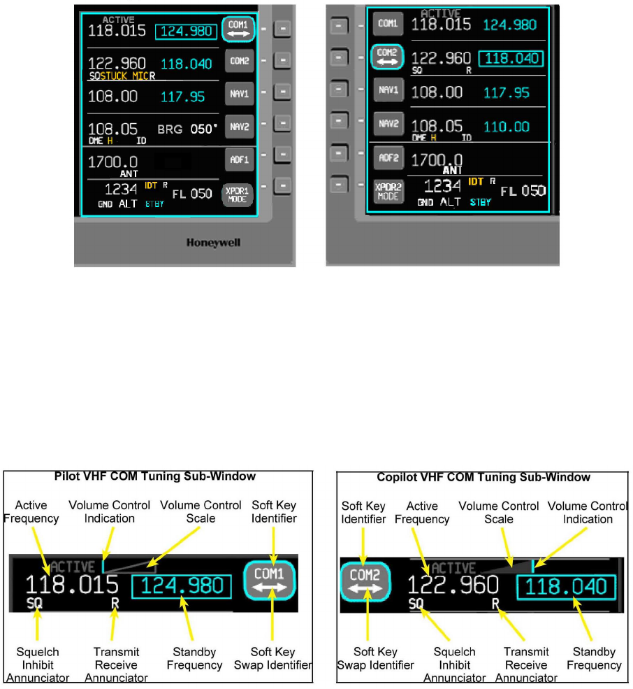
3.2.1 VHF COM TUNING SUB-WINDOW
The Pilot and Copilot VHF COM functions and display locations are as shown in the
following examples of the VHF COM tuning sub-window.
FIGURE 3-2 VHF COM TUNING SUB-WINDOW
3.2.1.1 ACTIVE FREQUENCY
The active COM frequency is displayed on the left side of the VHF COM tuning
sub-window.

n KTR 2280 Preliminary H 08/17/06
Rev. 0, Aug/2006 ©Honeywell International Inc. Do not print without express permission of Honeywell Page 3-3
3.2.1.2 VOLUME CONTROL INDICATION/SCALE
The volume control scale and the indication of the current volume level are located at the
top of the VHF COM tuning sub-window, above and between the active and standby
frequencies. The volume scale is visible only when the volume knob is being rotated, and
is automatically removed from the display one second after volume knob rotation ceases.
3.2.1.3 SOFT KEY IDENTIFIER/SOFT KEY SWAP IDENTIFIER
This shows the function of the soft key on the PFD bezel next to the identifier. The choices
are COM, COM1, or COM2. The swap identifier indicates that pressing the soft key will
swap the active and standby frequencies, and is only visible when the cursor is in the
COM tuning sub-window and the radio is in active/standby tuning mode.
3.2.1.4 SQUELCH INHIBIT ANNUNCIATOR
Indicates that the Squelch Inhibit Mode is active.
3.2.1.5 TRANSMIT/RECEIVE ANNUNCIATOR
This annunciator indicates when the radio is transmitting (T) or receiving (R).
3.2.1.6 STANDBY FREQUENCY
The Standby COM frequency is displayed to the right of the active frequency in the VHF
COM tuning sub-window.
3.2.1.7 STUCK MICROPHONE ANNUNCIATION
The STUCK MIC annunciator will be shown in amber in the VHF COM sub-window
between the squelch inhibit annunciation and the receive/transmit annunciator when the
VHF COM detects a stuck microphone.
FIGURE 3-3 STUCK MICROPHONE ANNUNCIATION
n KTR 2280 Preliminary H 08/17/06
Rev. 0, Aug/2006 ©Honeywell International Inc. Do not print without express permission of Honeywell Page 3-4
3.2.2 COM DETAIL WINDOW
The COM Detail window will be displayed when the cursor focus is on the COM tuning
sub-window and the DETAIL button is pressed on either the PFD or MF Controller.
FIGURE 3-4 VHF COM DETAIL WINDOW
The COM frequency spacing selections are shown in the detail window. The active modes
are shown with a large font in white, and the inactive modes are shown with a smaller font
in cyan.
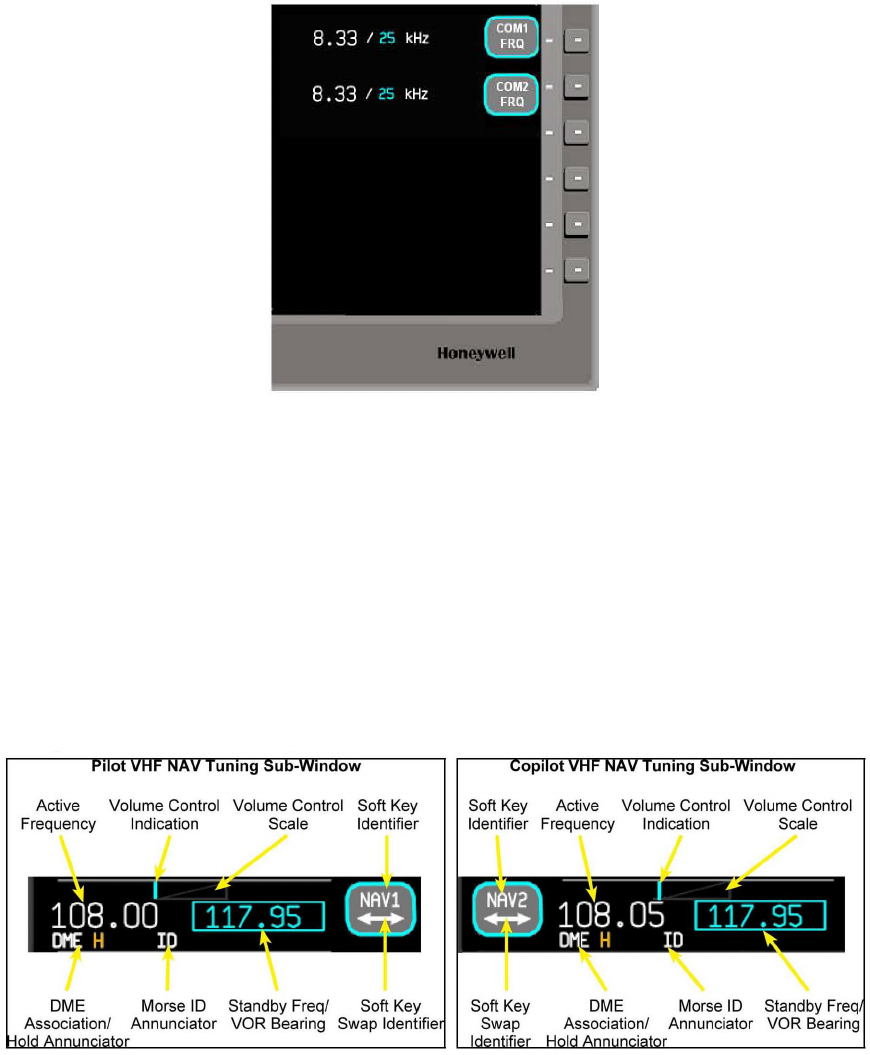
3.2.3 VHF NAV TUNING SUB-WINDOW
The Pilot and Copilot VHF NAV functions and display locations are as shown in the
following examples of the VHF NAV tuning sub-window.
FIGURE 3-5 VHF NAV TUNING SUB-WINDOW

n KTR 2280 Preliminary H 08/17/06
Rev. 0, Aug/2006 ©Honeywell International Inc. Do not print without express permission of Honeywell Page 3-5
3.2.3.1 ACTIVE FREQUENCY
The active NAV frequency is displayed in white on the left side of the VHF NAV tuning
sub-window.
3.2.3.2 VOLUME CONTROL INDICATION/SCALE
The volume control scale and the indication of the current volume level are located at the
top of the VHF NAV tuning sub-window, above and between the active and standby
frequencies. The volume scale is visible only when the volume knob is being rotated, and
is automatically removed from the display one second after volume knob rotation ceases.
3.2.3.3 SOFT KEY IDENTIFIER/SOFT KEY SWAP IDENTIFIER
This shows the function of the soft key on the PFD bezel next to the identifier. The choices
are NAV, NAV1, or NAV2. The swap identifier indicates that pressing the soft key will
swap the active and standby frequencies, and is only visible when the cursor is in the NAV
tuning sub-window and the radio is in active/standby tuning mode.
3.2.3.4 DME ASSOCIATION/HOLD ANNUNCIATOR
The DME association annunciator indicates which DME is associated with the NAV radio.
The choices are DME (single DME installation), DME1 or DME2 (for dual DME
installations). The Hold annunciator indicates the associated DME is in Hold mode.
3.2.3.5 MORSE CODE ID ANNUNCIATOR
The Morse code ID annunciator indicates that the Morse code filter has been activated,
allowing the crew to hear the Morse code through the audio system.
3.2.3.6 STANDBY FREQUENCY/VOR BEARING
Either the standby NAV frequency or the VOR bearing is displayed in cyan to the right of
the active frequency in the VHF NAV tuning sub-window. Choice of standby frequency or
bearing is made on the VHF NAV detail window. The bearing display will be shown as
either BRG XXX° or RAD XXX°, depending on the operator's selection.
FIGURE 3-6 VHF NAV BEARING DISPLAY
n KTR 2280 Preliminary H 08/17/06
Rev. 0, Aug/2006 ©Honeywell International Inc. Do not print without express permission of Honeywell Page 3-6
3.2.4 NAV DETAIL WINDOW
The NAV detail window will be displayed when the cursor focus is on the NAV tuning
sub-window and the DETAIL button is pressed on either the PFD or MF Controller.
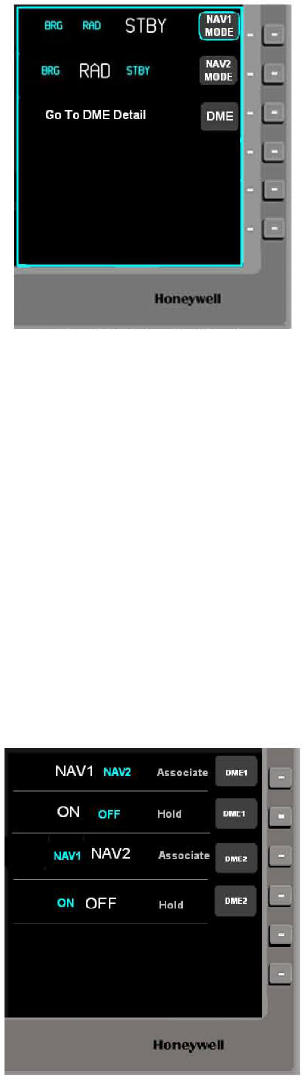
FIGURE 3-7 VHF NAV DETAIL WINDOW
The NAV mode selections (BRG, RAD and STBY) and access to the DME detail window
are shown in the NAV detail window. The active modes are shown with a large font in
white, and the inactive modes are shown with a smaller font in cyan.
3.2.5 DME DETAIL WINDOW
The DME detail window will be displayed when the cursor focus is on the NAV tuning
sub-window and the DETAIL button is pressed on either the PFD or MF Controller, when
the DME button is pressed on the PFD Controller or by selecting the "Go To DME Detail"
soft key on the NAV detail window.
FIGURE 3-8 DME DETAIL WINDOW
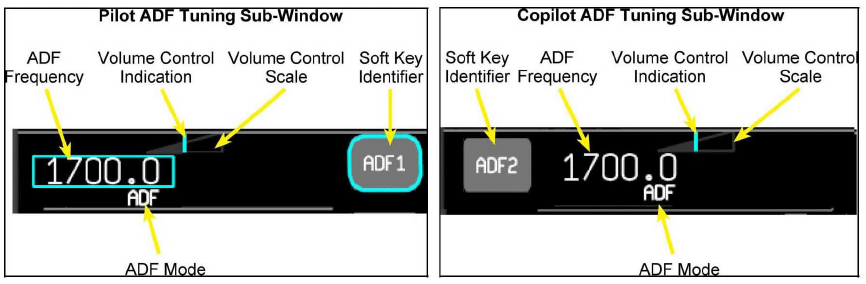
n KTR 2280 Preliminary H 08/17/06
Rev. 0, Aug/2006 ©Honeywell International Inc. Do not print without express permission of Honeywell Page 3-7
The DME association selection (NAV1, NAV2) and DME Hold mode control are shown in
the DME detail window. The active modes are shown with a large font in white, and the
inactive modes are shown with a smaller font in cyan.
3.2.6 ADF TUNING SUB-WINDOW
The Pilot and Copilot ADF functions and display locations are as shown in the following
examples of the ADF tuning sub-window.
FIGURE 3-9 ADF TUNING SUB-WINDOW
3.2.6.1 ADF FREQUENCY
The ADF frequency is displayed in white on the left side of the ADF tuning sub-window.
3.2.6.2 VOLUME CONTROL INDICATION/SCALE
The volume control scale and the indication of the current volume level are located at the
top of the ADF tuning sub-window in the middle. The volume scale is visible only when the
volume knob is being rotated, and is automatically removed from the display one second
after volume knob rotation ceases.
3.2.6.3 SOFT KEY IDENTIFIER
This shows the function of the soft key on the PFD bezel next to the identifier. The choices
are ADF, ADF1, or ADF2.
3.2.6.4 ADF MODE
This shows the function of the soft key on the PFD bezel next to the identifier. The choices
are ADF, ANT, or BFO.
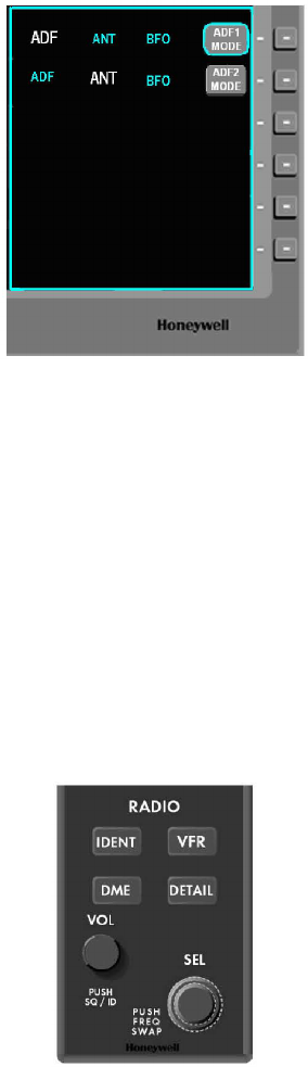
n KTR 2280 Preliminary H 08/17/06
Rev. 0, Aug/2006 ©Honeywell International Inc. Do not print without express permission of Honeywell Page 3-8
3.2.7 ADF DETAIL WINDOW
The ADF detail window will be displayed when the cursor focus is on the ADF tuning
sub-window and the DETAIL button is pressed on either the PFD or MF Controller.
FIGURE 3-10 DUAL ADF DETAIL WINDOW
The ADF mode selection(s) (ADF, ANT or BFO) are shown in the ADF detail window. The
active modes are shown with a large font in white, and the inactive modes are shown with
a smaller font in cyan.
3.3 KTR 2280 OPERATION
The VHF COM, VHF NAV, and ADF can be operated using the Display Bezel Soft Keys,
the PFD Controller, or the MF Controller.
FIGURE 3-11 KMC 2210 PFD CONTROLLER
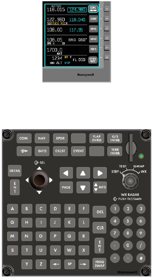
n KTR 2280 Preliminary H 08/17/06
Rev. 0, Aug/2006 ©Honeywell International Inc. Do not print without express permission of Honeywell Page 3-9
FIGURE 3-12 KDU 1080 DISPLAY UNIT BEZEL SOFT KEYS
FIGURE 3-13 KMC 2220 MF CONTROLLER
n KTR 2280 Preliminary H 08/17/06
Rev. 0, Aug/2006 ©Honeywell International Inc. Do not print without express permission of Honeywell Page 3-10
3.3.1 VHF COM CONTROLS
3.3.1.1 DETAIL BUTTON
The DETAIL button on either the PFD or MF Controller activates a secondary window
related to the currently active window providing additional details or controls related to the
item. A subsequent selection of the DETAIL button removes the secondary window and
displays the primary window for the item. Selection of modes from the MFC is
accomplished using the SEL outer knob.
3.3.1.2 COM BUTTON
The COM button on either the MF Controller transfers window focus to the pilot's Radio
Tuning window and sets the cursor focus to the NAV 1 sub-window, permitting direct
keyboard data entry.
3.3.1.3 TUNING SELECT (SEL) CONTROL
The Tuning Select Control consists of two concentric knurled knobs. The outer knob
typically controls coarse tuning and the inner knob controls fine tuning. The frequency can
also be entered using the MFC numeric keypad, followed by the Enter (ENT) key.
3.3.1.4 FREQUENCY SWAP
The Frequency Swap function exchanges the active and standby frequency. The active
frequency becomes the standby frequency, and the standby frequency becomes the
active frequency. The swap function can be accomplished using the following:
3.3.1.4.1 SOFT KEY
The function is available when the double-headed arrow is shown in the soft key identifier
window. Depressing the soft key initiates the frequency swap.
3.3.1.4.2 SEL/FREQ SWAP KNOB
Depressing the inner knob on the PFD Controller initiates the frequency swap for the radio
that has the cursor focus.
3.3.1.4.3 FREQ SWAP BUTTON
Depressing the button on the MF Controller initiates the frequency swap for the radio that
has the cursor focus.
Soft keys are also selectable from the MFC using the Joystick control followed by the ENT
key.
n KTR 2280 Preliminary H 08/17/06
Rev. 0, Aug/2006 ©Honeywell International Inc. Do not print without express permission of Honeywell Page 3-11
3.3.2 VHF NAV CONTROLS
3.3.2.1 DETAIL BUTTON
The DETAIL button on either the PFD or MF Controller activates a secondary window
related to the currently active window providing additional details or controls related to the
item. A subsequent selection of the DETAIL button removes the secondary window and
displays the primary window for the item. Selection of modes from the MFC is
accomplished using the SEL outer knob.
3.3.2.2 NAV BUTTON
The NAV button on the MF Controller transfers window focus to the pilot's Radio Tuning
window and sets the cursor focus to the NAV 1 sub-window, permitting direct keyboard
data entry.
3.3.2.3 TUNING SELECT (SEL) CONTROL
The Tuning Select Control consists of two concentric knurled knobs. The outer knob
typically controls coarse tuning and the inner knob controls fine tuning.
3.3.2.4 FREQUENCY SWAP
The Frequency Swap function exchanges the active and standby frequency. The active
frequency becomes the standby frequency, and the standby frequency becomes the
active frequency. The swap function can be accomplished using the following:
3.3.2.4.1 SOFT KEY
The function is available when the double-headed arrow is shown in the soft key identifier
window. Depressing the soft key initiates the frequency swap. If the VOR bearing has
been selected for display, the swap arrow is not shown, but a blind transfer can be done.
3.3.2.4.2 SEL/FREQ SWAP KNOB
Depressing the inner knob on the PFD Controller initiates the frequency swap for the radio
that has the cursor focus.
3.3.2.4.3 FREQ SWAP BUTTON
Depressing the button on the MF Controller initiates the frequency swap for the radio that
has the cursor focus.
Soft keys are also selectable from the MFC using the Joystick control followed by the ENT
key.
n KTR 2280 Preliminary H 08/17/06
Rev. 0, Aug/2006 ©Honeywell International Inc. Do not print without express permission of Honeywell Page 3-12
3.3.2.5 VOL/SQ/ID KNOB
Pushing the volume knob on the PFD Controller will toggle selection of the Morse code ID
filter.
3.3.2.6 NAV DETAIL WINDOW SOFT KEYS
The soft keys control the NAV mode {BRG (bearing displayed, direct NAV tuning), RAD
(radial displayed, direct NAV tuning) or STBY (standby frequency displayed, active/
standby NAV tuning)} and allow access to the DME detail window.
3.3.2.7 DME DETAIL WINDOW SOFT KEYS
The soft keys control the DME association with each NAV and toggle the DME hold mode.
3.3.3 ADF CONTROLS
3.3.3.1 DETAIL BUTTON
The DETAIL button on either the PFD or MF Controller activates a secondary window
related to the currently active window providing additional details or controls related to the
item. A subsequent selection of the DETAIL button removes the secondary window and
displays the primary window for the item. Selection of modes from the MFC is
accomplished using the SEL outer knob.
3.3.3.2 ADF DETAIL WINDOW SOFT KEYS
The soft keys control the ADF mode (ADF, ANT, or BFO). Pressing the FREQ SWAP
button on the PFD or MF Controller while on the ADF detail page also changes the ADF
modes.
n KTR 2280 Preliminary H 08/17/06
Rev. 0, Aug/2006 ©Honeywell International Inc. Do not print without express permission of Honeywell Page A-1
APPENDIX A
ENVIRONMENTAL QUALIFICATION FORMS
INCLUDING
SUPPLEMENTAL ENVIRONMENTAL PERFORMANCE INFORMATION
n KTR 2280 Preliminary H 08/17/06
Rev. 0, Aug/2006 ©Honeywell International Inc. Do not print without express permission of Honeywell Page A-2
This Page Intentionally Left Blank
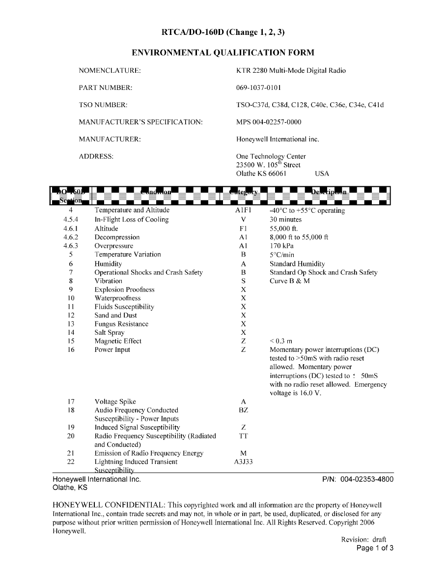
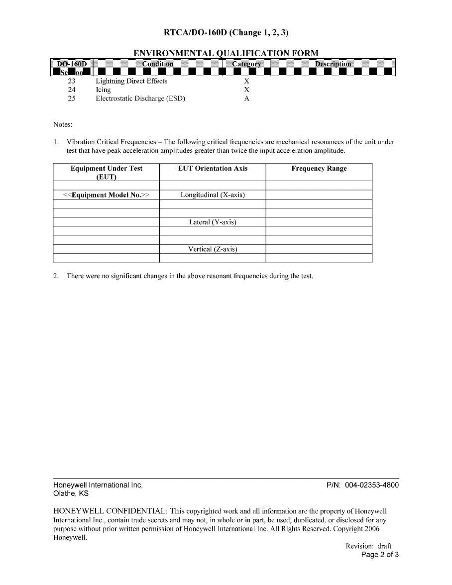
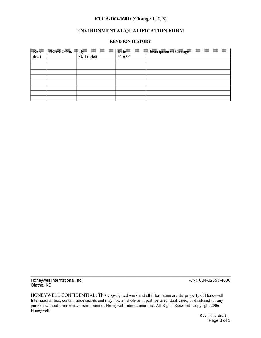
This Page Intentionally Left Blank
KA 44B ENVIRONMENTAL PERFORMANCE
The KA 44B ADF Antenna (071-1234-XX) is certified to TSO C41c with RTCA DO-160A
environmentals per B2D2/A/LJY/XXXXXX/ABABA.
Recent "not-for-certification-credit" testing has been performed on this antenna to
determine expected performance in selected DO-160D environmental conditions.
DO-160D Section 20 (RF Susceptibility) Tests
A KA 44B production test sample was subjected to Category TT fields as defined in the
test environment called out in RTCA DO-160D Section 20 (Change No. 1). This unit was
tested in conjunction with the KTR 2280 Multi-Mode Digital Radio. All conducted and
radiated susceptibility performance requirements were passed except for radiated
susceptibility in the band of interference frequencies between 277 MHz and 339 MHz.
Within this band the KA 44B could not tolerate interference levels greater than 0.8 V/m
(for acceptable audio signal-to-noise) or greater than 1.1 V/m (for acceptable bearing
error).
A KA 44B production test sample was subjected to the 100 V/M (and greater) HIRF levels
expected for aircraft system level certification. This test was done in a manner consistent
with aircraft system level HIRF certification testing. No permanent damage was noted
during the HIRF exposure and the unit returned immediately to normal operation after the
HIRF event terminated.
DO-160D Section 22 (Lightning Induced Transient Susceptibility) Tests
A KA 44B production test sample was subjected to Category A3J33 as defined and in the
test environment called out in RTCA DO-160D Section 22 (Change No. 3). The KA 44B
passed all requirements.
DO-160D Section 23 (Lightning Direct Effects) Tests
A KA 44B production test sample was subjected to Category 2A as defined in the test
environment called out in RTCA DO-160D Section 23. The KA 44B passed all
requirements.
Other DO-160D based test data has been collected and is available on request from
Honeywell.
This Page Intentionally Left Blank