Honeywell KTR2280A Licensed Non-Broadcast Aeronautical Transmitter User Manual System Installation Manual
Honeywell International Inc. Licensed Non-Broadcast Aeronautical Transmitter System Installation Manual
User Manual

Honeywell International Inc.
23500 West 105th Street
Olathe, Kansas 66061-8425
U.S.A.
CAGE: 22373
Telephone: 800-601-3099 (Toll Free U.S.A./Canada)
Telephone: 602-365-3099 (International Direct)
Website: www.myaerospace.com
Page T-1
Publication Number D201610000049, Revision 0 Initial 15 May 2017
© Honeywell International Inc. Do not copy without express permission of Honeywell.
These items are controlled by the U.S. government and authorized for export only to the country of ultimate
destination for use by the ultimate consignee or end-user(s) herein identified. They may not be resold,
transferred, or otherwise disposed of, to any other country or to any person other than the authorized ultimate
consignee or end-user(s), either in their original form or after being incorporated into other items, without first
obtaining approval from the U.S. government or as otherwise authorized by U.S. law and regulations.
ECCN: 7E994.
System Installation Manual
KTR 2280A Multi-Mode Digital Radio
Part Number CAGE
069-01039-0101 22373
Legal Notice
Export Control

Page T-2
15 May 2017
SYSTEM INSTALLATION MANUAL
KTR 2280A
© Honeywell International Inc. Do not copy without express permission of Honeywell.
Proprietary Information
Honeywell – Confidential
COPYRIGHT BY HONEYWELL INTERNATIONAL INC. (“HONEYWELL”). ALL RIGHTS RESERVED. THIS
DOCUMENT AND ALL INFORMATION CONTAINED HEREIN ARE THE CONFIDENTIAL AND PROPRIETARY
INFORMATION OF HONEYWELL AND CONTAIN HONEYWELL TRADE SECRETS. NEITHER THIS
DOCUMENT NOR THE INFORMATION CONTAINED HEREIN MAY, IN WHOLE OR IN PART, BE USED,
DUPLICATED, OR DISCLOSED FOR ANY PURPOSE WITHOUT PRIOR WRITTEN PERMISSION OF
HONEYWELL.
PLEASE REVIEW THE TERMS OF THIS AGREEMENT CAREFULLY BEFORE USING THIS DOCUMENT, AS
BY USING IT, YOU ACKNOWLEDGE THAT YOU HAVE REVIEWED THIS AGREEMENT AND AGREE TO BE
BOUND BY ITS TERMS AND CONDITIONS.
Honeywell Materials License Agreement
This document and the information contained herein (“the Materials”) are the proprietary data of Honeywell.
These Materials are provided for the exclusive use of Honeywell-authorized Service Centers;
Honeywell-authorized repair facilities; owners of a Honeywell aerospace product that is the subject of these
Materials (“Honeywell Product”) that have entered into a written agreement with Honeywell relating to the repair
or maintenance of Honeywell Product; and direct recipients of Materials from Honeywell via
https://myaerospace.honeywell.com/wps/portal/ that own a Honeywell Product. The terms and conditions of this
Honeywell Materials License Agreement (“License Agreement”) govern your use of these Materials, except to
the extent that any terms and conditions of another applicable agreement with Honeywell regarding the
maintenance or repair of a Honeywell Product and that is the subject of the Materials conflict with the terms and
conditions of this License Agreement, in which case the terms and conditions of the other agreement will govern.
However, this License Agreement will govern in the event of a conflict between these terms and conditions and
those of a purchase order or acknowledgement. Your access or use of the Materials represents your acceptance
of the terms of this License Agreement.
1. License Grant - If you are a party to an applicable written agreement with Honeywell relating to the repair or
maintenance of the subject Honeywell Product, subject to your compliance with the terms and conditions of this
License Agreement, Honeywell hereby grants you, and you accept, a limited, personal, non-transferrable,
non-exclusive license to use these Materials only in accordance with that agreement.
If you are a direct recipient of these Materials from Honeywell’s MyAerospace Technical Publication website and
are not a party to an agreement related to the maintenance or repair of the subject Honeywell Product, subject
to your compliance with the terms and conditions of this License Agreement, Honeywell hereby grants you, and
you accept, a limited, personal, non-transferrable, non-exclusive license to use a single copy of these Materials
to maintain or repair only the subject Honeywell Product installed or intended to be installed on the aircraft you
own and/or operate and only at the facility to which these Materials have been shipped (“the Licensed Facility”).
Transfer of the Materials to another facility owned by you is permitted only if the original Licensed Facility retains
no copies of the Materials, the transferee accepts all of your obligations and liabilities under this License
Agreement, and you provide prior written notice to Honeywell with the name and address of the transferee. You
agree not to use these Materials for commercial purposes.
2. Restrictions on Use - You may not sell, rent, lease or lend the Materials, except for lending your Materials for
the maintenance or repair of the subject Honeywell Product you own to someone solely acting on your behalf
You may not use the Materials to reverse engineer any Honeywell product, hardware or software, and may not
decompile or disassemble software provided under this License Agreement, except and only to the extent that
such activity is expressly permitted by applicable law notwithstanding this limitation. You may not create derivative
works or modify the Materials in any way. You agree that Materials shall only be used for the purpose of the
rights granted herein. The Material furnished hereunder may be subject to U.S. export regulations. You will
adhere to all U.S. export regulations as published and released from time to time by the U.S. Government. You

Page T-3
15 May 2017
SYSTEM INSTALLATION MANUAL
KTR 2280A
© Honeywell International Inc. Do not copy without express permission of Honeywell.
may not design or manufacture a Honeywell part or detail of a Honeywell part, to create a repair for a Honeywell
part, design or manufacture any part that is similar or identical to a Honeywell part, compare a Honeywell part
or design of a Honeywell part to another part design, or apply for FAA PMA or other domestic or foreign
governmental approval to manufacture or repair a Honeywell part.
3. Rights In Materials - Honeywell retains all rights in these Materials and in any copies thereof that are not
expressly granted to you, including all rights in patents, copyrights, trademarks, and trade secrets. The Materials
are licensed and not sold under this License Agreement. No license to use any Honeywell trademarks or patents
is granted under this License Agreement.
4. Changes - Honeywell reserves the right to change the terms and conditions of this License Agreement at any
time, including the right to change or impose charges for continued use of the Materials. Honeywell may add,
delete or otherwise modify any portion of the Materials (“Updated Materials”) at any time. You agree to stop using
outdated Materials upon issuance of any Updated Materials.
5. Confidentiality - You acknowledge that these Materials contain information that is confidential and proprietary
to Honeywell. You agree to take all reasonable efforts to maintain the confidentiality of these Materials.
6. Assignment And Transfer - This License Agreement may be assigned to a service center approved and
formally designated as a service center by Honeywell, provided, however, that you retain no copies of the
Materials in whole or in part. However, the recipient of any such assignment or transfer must assume all of your
obligations and liabilities under this License Agreement. No assignment or transfer shall relieve any party of any
obligation that such party then has hereunder. Otherwise, neither this License Agreement nor any rights, licenses
or privileges granted under this License Agreement, nor any of its duties or obligations hereunder, nor any interest
or proceeds in and to the Materials shall be assignable or transferable (in insolvency proceedings, by merger,
by operation of law, by purchase, by change of control or otherwise) by you without Honeywell’s written consent.
7.Copies of Materials - Unless you have the express written permission of Honeywell, you may not make or
permit making of copies, digital or printed, of the Materials. You agree to return the Materials and any such copies
thereof to Honeywell upon the request of Honeywell.
8.Term - This License Agreement is effective until terminated as set forth herein. This License Agreement will
terminate immediately, without notice from Honeywell, if you fail to comply with any provision of this License
Agreement or will terminate simultaneously with the termination or expiration of your applicable agreement with
Honeywell relating to the repair or maintenance of the subject Honeywell Product. Upon termination of this
License Agreement, you will return these Materials to Honeywell without retaining any copies, in whole or in part,
and will have one of your authorized officers certify that all Materials have been returned with no copies retained.
10. Remedies - Honeywell reserves the right to pursue all available remedies and damages resulting from a
breach of this License Agreement.
11. Limitation of Liability - Honeywell makes no representations or warranties regarding the use or sufficiency of
the Materials. THERE ARE NO OTHER WARRANTIES, WHETHER WRITTEN OR ORAL, EXPRESS, IMPLIED
OR STATUTORY, INCLUDING, BUT NOT LIMITED TO (i) WARRANTIES ARISING FROM COURSE OF
PERFORMANCE, DEALING, USAGE, OR TRADE, WHICH ARE HEREBY EXPRESSLY DISCLAIMED, OR (ii)
WARRANTIES AGAINST INFRINGEMENT OF INTELLECTUAL PROPERTY RIGHTS OF THIRD PARTIES,
EVEN IF HONEYWELL HAS BEEN ADVISED OF ANY SUCH INFRINGEMENT. IN NO EVENT WILL
HONEYWELL BE LIABLE FOR ANY INCIDENTAL DAMAGES, CONSEQUENTIAL DAMAGES, SPECIAL
DAMAGES, INDIRECT DAMAGES, LOSS OF PROFITS, LOSS OF REVENUES, OR LOSS OF USE, EVEN IF
INFORMED OF THE POSSIBILITY OF SUCH DAMAGES. TO THE EXTENT PERMITTED BY APPLICABLE
LAW, THESE LIMITATIONS AND EXCLUSIONS WILL APPLY REGARDLESS OF WHETHER LIABILITY
ARISES FROM BREACH OF CONTRACT, WARRANTY, INDEMNITY, TORT (INCLUDING BUT NOT LIMITED
TO NEGLIGENCE), BY OPERATION OF LAW, OR OTHERWISE.
12.Controlling Law - This License Agreement shall be governed and construed in accordance with the laws of
the State of New York without regard to the conflict of laws provisions thereof.

Page T-4
15 May 2017
SYSTEM INSTALLATION MANUAL
KTR 2280A
© Honeywell International Inc. Do not copy without express permission of Honeywell.
13. Severability - In the event any provision of this License Agreement is determined to be illegal, invalid, or
unenforceable, the validity and enforceability of the remaining provisions of this License Agreement will not be
affected and, in lieu of such illegal, invalid, or unenforceable provision, there will be added as part of this License
Agreement one or more provisions as similar in terms as may be legal, valid and enforceable under controlling
law.
14. Integration and Modification - This License Agreement and all attachments set forth the entire agreement
and understanding between the parties on the subject matter of the License Agreement and merges all prior
discussions and negotiations among them. This License Agreement may be modified only by a duly-authorized
representative of Honeywell.
Safety Advisory
WARNING: BEFORE THE MATERIALS CALLED OUT IN THIS PUBLICATION ARE USED, KNOW THE
HANDLING, STORAGE AND DISPOSAL PRECAUTIONS RECOMMENDED BY THE MANUFACTURER OR
SUPPLIER. FAILURE TO OBEY THE MANUFACTURERS’ OR SUPPLIERS’ RECOMMENDATIONS CAN
RESULT IN PERSONAL INJURY OR DISEASE.
This publication describes physical and chemical processes which can make it necessary to use chemicals,
solvents, paints, and other commercially available materials. The user of this publication must get the Material
Safety Data Sheets (OSHA Form 174 or equivalent) from the manufacturers or suppliers of the materials to be
used. The user must know the manufacturer/ supplier data and obey the procedures, recommendations,
warnings and cautions set forth for the safe use, handling, storage, and disposal of the materials.
Warranty/Liability Advisory
WARNING: HONEYWELL ASSUMES NO RESPONSIBILITY FOR ANY HONEYWELL EQUIPMENT WHICH
IS NOT MAINTAINED AND/OR REPAIRED IN ACCORDANCE WITH HONEYWELL'S PUBLISHED
INSTRUCTIONS AND/OR HONEYWELL'S FAA/SFAR 36 REPAIR AUTHORIZATION. NEITHER DOES
HONEYWELL ASSUME RESPONSIBILITY FOR SPECIAL TOOLS AND TEST EQUIPMENT FABRICATED BY
COMPANIES OTHER THAN HONEYWELL.
WARNING: INCORRECTLY REPAIRED COMPONENTS CAN AFFECT AIRWORTHINESS OR DECREASE
THE LIFE OF THE COMPONENTS. INCORRECTLY FABRICATED SPECIAL TOOLING OR TEST
EQUIPMENT CAN RESULT IN DAMAGE TO THE PRODUCT COMPONENTS OR GIVE UNSATISFACTORY
RESULTS.

Page T-5
15 May 2017
SYSTEM INSTALLATION MANUAL
KTR 2280A
© Honeywell International Inc. Do not copy without express permission of Honeywell.
Copyright - Notice
Copyright 2017 Honeywell International Inc. All rights reserved.
Honeywell is a registered trademark of Honeywell International Inc.
All other marks are owned by their respective companies.

Page T-6
15 May 2017
SYSTEM INSTALLATION MANUAL
KTR 2280A
© Honeywell International Inc. Do not copy without express permission of Honeywell.
Blank Page

Page TI-1
15 May 2017
SYSTEM INSTALLATION MANUAL
KTR 2280A
© Honeywell International Inc. Do not copy without express permission of Honeywell.
TRANSMITTAL INFORMATION
THIS IS AN INITIAL RELEASE OF KTR 2280A MULTI-MODE DIGITAL RADIO SIM PUBLICATION No.
D201610000049 ISSUED FOR USE IN SUPPORT OF THE FOLLOWING:
Table TI-1 shows the applicable components.
Revision History
Table TI-2 shows the revision history of this SIM.
Table TI-1. Applicable Components
Component PN Nomenclature
069-01039-0101 KTR 2280A Multi-Mode Digital Radio
Table TI-2. Revision History
Revision Number Revision Date
0 15 May 2017

Page TI-2
15 May 2017
SYSTEM INSTALLATION MANUAL
KTR 2280A
© Honeywell International Inc. Do not copy without express permission of Honeywell.
Blank Page

Page RR-1
15 May 2017
SYSTEM INSTALLATION MANUAL
KTR 2280A
© Honeywell International Inc. Do not copy without express permission of Honeywell.
RECORD OF REVISIONS
For each revision, write the revision number, revision date, date put in the manual, and your initials in the
applicable column.
NOTE: Refer to the Revision History in the TRANSMITTAL INFORMATION section for revision data.
Revision
Number Revision
Date Date Put
In Manual By Revision
Number Revision
Date Date Put
In Manual By

Page RR-2
15 May 2017
SYSTEM INSTALLATION MANUAL
KTR 2280A
© Honeywell International Inc. Do not copy without express permission of Honeywell.
Blank Page

Page RTR-1
15 May 2017
SYSTEM INSTALLATION MANUAL
KTR 2280A
© Honeywell International Inc. Do not copy without express permission of Honeywell.
RECORD OF TEMPORARY REVISIONS
Instructions on each page of a temporary revision tell you where to put the pages in your manual. Remove
the temporary revision pages only when discard instructions are given. For each temporary revision, put the
applicable data in the record columns on this page.
Definition of Status column: A TR may be active, incorporated, or deleted. “Active” is entered by the holder
of the manual. “Incorporated” means a TR has been incorporated into the manual and includes the revision
number of the manual when the TR was incorporated. “Deleted” means a TR has been replaced by another
TR, a TR number will not be issued, or a TR has been deleted.
Temporary
Revision
Number Status Page
Number Issue
Date Date Put in
Manual By
Date
Removed
From Manual By

Page RTR-2
15 May 2017
SYSTEM INSTALLATION MANUAL
KTR 2280A
© Honeywell International Inc. Do not copy without express permission of Honeywell.
Blank Page

Page LEP-1
15 May 2017
SYSTEM INSTALLATION MANUAL
KTR 2280A
© Honeywell International Inc. Do not copy without express permission of Honeywell.
Subheading and Page Date Subheading and Page Date
LIST OF EFFECTIVE PAGES
* indicates a changed or added page.
F indicates a foldout page.
Title
T-1 15 May 2017
T-2 15 May 2017
T-3 15 May 2017
T-4 15 May 2017
T-5 15 May 2017
T-6 15 May 2017
Transmittal Information
TI-1 15 May 2017
TI-2 15 May 2017
Record of Revisions
RR-1 15 May 2017
RR-2 15 May 2017
Record of Temporary Revisions
RTR-1 15 May 2017
RTR-2 15 May 2017
List of Effective Pages
LEP-1 15 May 2017
LEP-2 15 May 2017
Table of Contents
TC-1 15 May 2017
TC-2 15 May 2017
TC-3 15 May 2017
TC-4 15 May 2017
Introduction
INTRO-1 15 May 2017
INTRO-2 15 May 2017
INTRO-3 15 May 2017
INTRO-4 15 May 2017
INTRO-5 15 May 2017
INTRO-6 15 May 2017
Section 1 - General Information
1-1 15 May 2017
1-2 15 May 2017
1-3 15 May 2017
1-4 15 May 2017
1-5 15 May 2017
1-6 15 May 2017
1-7 15 May 2017
1-8 15 May 2017
Section 2 - Installation
2-1 15 May 2017
2-2 15 May 2017
2-3 15 May 2017
2-4 15 May 2017
2-5 15 May 2017
2-6 15 May 2017
2-7 15 May 2017
2-8 15 May 2017
2-9 15 May 2017
2-10 15 May 2017
2-11 15 May 2017
2-12 15 May 2017
2-13 15 May 2017
2-14 15 May 2017
2-15 15 May 2017
2-16 15 May 2017
F 2-17 15 May 2017
F 2-18 15 May 2017
2-19 15 May 2017
2-20 15 May 2017
2-21 15 May 2017
2-22 15 May 2017
F 2-23 15 May 2017
F 2-24 15 May 2017
F 2-25 15 May 2017
F 2-26 15 May 2017
F 2-27 15 May 2017
F 2-28 15 May 2017
F 2-29 15 May 2017
F 2-30 15 May 2017
F 2-31 15 May 2017
F 2-32 15 May 2017
F 2-33 15 May 2017
F 2-34 15 May 2017
F 2-35 15 May 2017
F 2-36 15 May 2017
F 2-37 15 May 2017
F 2-38 15 May 2017
F 2-39 15 May 2017
F 2-40 15 May 2017
F 2-41 15 May 2017
F 2-42 15 May 2017
F 2-43 15 May 2017
F 2-44 15 May 2017
2-45 15 May 2017

Page LEP-2
15 May 2017
SYSTEM INSTALLATION MANUAL
KTR 2280A
© Honeywell International Inc. Do not copy without express permission of Honeywell.
Subheading and Page Date Subheading and Page Date
* indicates a changed or added page.
F indicates a foldout page.
2-46 15 May 2017
2-47 15 May 2017
2-48 15 May 2017
2-49 15 May 2017
2-50 15 May 2017
2-51 15 May 2017
2-52 15 May 2017
Section 3 - Operation
3-1 15 May 2017
3-2 15 May 2017
3-3 15 May 2017
3-4 15 May 2017
Appendix A - Environmental
Qualification Forms
A-1 15 May 2017
A-2 15 May 2017
A-3 15 May 2017
A-4 15 May 2017
A-5 15 May 2017
A-6 15 May 2017
A-7 15 May 2017
A-8 15 May 2017
Appendix B - Deviations
B-1 15 May 2017
B-2 15 May 2017
B-3 15 May 2017
B-4 15 May 2017

Page TC-1
15 May 2017
SYSTEM INSTALLATION MANUAL
KTR 2280A
© Honeywell International Inc. Do not copy without express permission of Honeywell.
TABLE OF CONTENTS
INTRODUCTION
1. How to Use This Manual ................................................................................................INTRO-1
A. General.............................................................................................................................INTRO-1
B. Observance of Manual Instructions ..................................................................................INTRO-1
C. Symbols............................................................................................................................INTRO-1
D. Units of Measure...............................................................................................................INTRO-2
E. Standard Practices Manual...............................................................................................INTRO-2
F. Electrostatic Discharge .....................................................................................................INTRO-2
2. Customer Support ..........................................................................................................INTRO-2
A. Honeywell Aerospace Online Technical Publications Website.........................................INTRO-2
B. Honeywell Aerospace Contact Team ...............................................................................INTRO-2
3. References ......................................................................................................................INTRO-2
A. Honeywell/Vendor Publications ........................................................................................INTRO-2
B. Other Publications ............................................................................................................INTRO-2
4. Acronyms and Abbreviations........................................................................................INTRO-3
A. General.............................................................................................................................INTRO-3
SECTION 1
GENERAL INFORMATION
1.1 INTRODUCTION .......................................................................................................................1-1
1.2 EQUIPMENT DESCRIPTION....................................................................................................1-1
1.3 TECHNICAL CHARACTERISTICS...........................................................................................1-1
1.3.1 KTR 2280A Technical Characteristics .......................................................................................1-1
1.3.2 KA 44B Technical Characteristics .............................................................................................1-3
1.4 UNITS AND ACCESSORIES SUPPLIED.................................................................................1-3
1.4.1 KTR 2280A Installation Kit.........................................................................................................1-3
1.5 ACCESSORIES REQUIRED, BUT NOT SUPPLIED................................................................1-6
1.6 LICENSING REQUIREMENTS .................................................................................................1-6
1.7 CONTINUED AIRWORTHINESS INSTRUCTIONS..................................................................1-6
1.7.1 Equipment..................................................................................................................................1-6
1.7.2 Wires and Coaxial Cables .........................................................................................................1-7
1.8 ANTENNA RF EXPOSURE ......................................................................................................1-7

Page TC-2
15 May 2017
SYSTEM INSTALLATION MANUAL
KTR 2280A
© Honeywell International Inc. Do not copy without express permission of Honeywell.
SECTION 2
INSTALLATION
2.1 GENERAL INFORMATION.......................................................................................................2-1
2.2 UNPACKING and INSPECTING EQUIPMENT ........................................................................2-1
2.3 EQUIPMENT INSTALLATION..................................................................................................2-1
2.3.1 Avionics Cooling Requirements................................................................................................. 2-1
2.3.2 Equipment Location................................................................................................................... 2-1
2.3.2.1 Mounting Tray Location(s).........................................................................................................2-2
2.3.2.2 Antenna(s) ................................................................................................................................. 2-2
2.3.3 KTR 2280A Mechanical Installation...........................................................................................2-2
2.3.4 Antenna Mechanical Installation................................................................................................ 2-3
2.3.4.1 VHF COM Antennas..................................................................................................................2-3
2.3.4.2 NAV Antennas ...........................................................................................................................2-4
2.3.4.3 ADF Antennas ........................................................................................................................... 2-4
2.3.5 KTR 2380A Wiring and Cable Installation ................................................................................. 2.5
2.3.5.1 KTR 2280A Interconnection and Cable Harness Fabrication.................................................... 2-5
2.3.5.2 Taylor Backshell Instructions................................................................................................... 2-10
2.3.5.3 Primary Power and Circuit Breaker Requirements..................................................................2-19
2.3.5.4 Connectors ..............................................................................................................................2-19
2.3.5.5 Crimp Tool Information ............................................................................................................2-22
2.4 POST-INSTALLATION CHECKS ...........................................................................................2-45
2.4.1 KTR 2280A MMDR Post-Installation Inspection and Ground Test..........................................2-45
2.4.1.1 Inspection ................................................................................................................................ 2-45
2.4.1.2 Ground Tests...........................................................................................................................2-46
2.4.2 KTR 2280A Post-Installation Flight Tests................................................................................ 2-48
2.4.2.1 COM Transceiver Flight Test................................................................................................... 2-48
2.4.2.2 NAV Receiver Flight Test ........................................................................................................2-48
2.4.2.3 ADF Receiver Flight Test......................................................................................................... 2-49
2.5 KTR 2280A INSTALLATION PARAMETER MODIFICATIONS...............................................2-49
2.6 ARINC 429 Interface................................................................................................................ 2.50
SECTION 3
OPERATION
3.1 GENERAL .................................................................................................................................3-1
3.1.1 VHF COM Controls and Displays ..............................................................................................3-1
3.1.2 VHF NAV Controls and Displays ............................................................................................... 3-2
3.1.3 ADF Controls and Displays........................................................................................................ 3-2
3.1.4 VDL Mode A and VDL Mode 2 ..................................................................................................3-2
APPENDIX A
ENVIRONMENTAL QUALIFICATION FORMS
APPENDIX B
DEVIATIONS

Page TC-3
15 May 2017
SYSTEM INSTALLATION MANUAL
KTR 2280A
© Honeywell International Inc. Do not copy without express permission of Honeywell.
LIST OF FIGURES
Figure INTRO-1 Symbols ...........................................................................................................INTRO-1
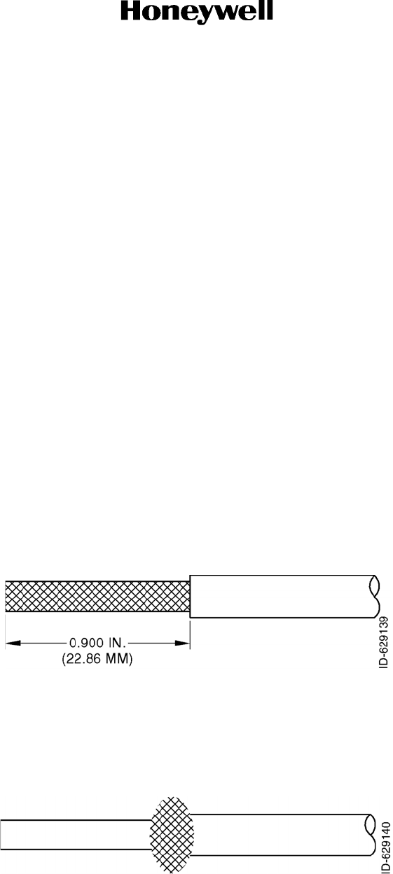
Figure 2-1 Quadrex Cable Preparation ......................................................................................2-6
Figure 2-2 Quadrex Cable Preparation ......................................................................................2-6
Figure 2-3 Quadrex Cable Preparation ......................................................................................2-7
Figure 2-4 Quadrex Cable Preparation ......................................................................................2-7
Figure 2-5 Quadrex Cable Preparation ......................................................................................2-7
Figure 2-6 Quadrex Cable Preparation ......................................................................................2-8
Figure 2-7 Quadrex Cable Preparation ......................................................................................2-8
Figure 2-8 Quadrex Cable Preparation ......................................................................................2-8
Figure 2-9 Quadrex Cable Preparation ......................................................................................2-9
Figure 2-10 Quadrex Cable Preparation ......................................................................................2-9
Figure 2-11 Connector Assembly...............................................................................................2-10
Figure 2-12 Taylor Backshell Instructions ..................................................................................2-11
Figure 2-13 Backshell Assembly Exploded View .......................................................................2-12
Figure 2-14 Assembly Details ....................................................................................................2-13
Figure 2-15 Assembly Details ....................................................................................................2-14
Figure 2-16 Shield Braid Routing and Clamping Details............................................................2-15
Figure 2-17 Securing Strain Relief Clamp..................................................................................2-16
Figure 2-18 Right Angle Connector Instruction Sheet................................................................2-17
Figure 2-19 KTR 2280A Mating Connector................................................................................2-19
Figure 2-20 KA 44B Mating Connector ......................................................................................2-21
Figure 2-21 KTR 2280A Installation Drawing.............................................................................2-23
Figure 2-22 KA 44B Outline and Mounting Drawing, PN 155-05334-0000 ...............................2-31
Figure 2-23 KA 44B Outline and Mounting Drawing, PN 155-05334-0010................................2-33
Figure 2-24 KTR 2280A Interconnect Diagram..........................................................................2-35

Page TC-4
15 May 2017
SYSTEM INSTALLATION MANUAL
KTR 2280A
© Honeywell International Inc. Do not copy without express permission of Honeywell.
LIST OF TABLES
Table 1-1 KTR 2280A Technical Characteriestics .................................................................... 1-2
Table 1-2 KA 44B Technical Characteristics ............................................................................1-3
Table 2-1 KTR 2280A Backshell Hardware ............................................................................ 2-12
Table 2-2 J1 Pin Functions .....................................................................................................2-19
Table 2-3 Antenna Connector Functions ................................................................................2-21
Table 2-4 KA 44B Pin Functions.............................................................................................2-22
Table 2-5 Crimp Tools and Accessories .................................................................................2-22
Table 2-6 Inspection/Check Procedure................................................................................... 2-45
Table 2-7 Unit Parameters......................................................................................................2-49
Table 2-8 ARINC 429 Output Labels ...................................................................................... 2-50
Table 2-9 ARINC 429 Input Labels ......................................................................................... 2-51

Page INTRO-1
15 May 2017
SYSTEM INSTALLATION MANUAL
KTR 2280A
© Honeywell International Inc. Do not copy without express permission of Honeywell.
INTRODUCTION
1. How to Use This Manual
A. General
(1) This publication gives maintenance instructions for the equipment shown on the Title page.
(2) Standard maintenance procedures that technicians must know are not given in this manual.
(3) This publication is written in agreement with the ATA Specification.
(4) Warnings, cautions, and notes in this manual give the data that follows:
• A WARNING gives a condition or tells personnel what part of an operation or
maintenance procedure, which if not obeyed, can cause injury or death
• A CAUTION gives a condition or tells personnel what part of an operation or maintenance
procedure, which if not obeyed, can cause damage to the equipment
• A NOTE gives data, not commands. The NOTE helps personnel when they do the related
instruction.
(5) Warnings and cautions go before the applicable paragraph or step. Notes follow the
applicable paragraph or step.
B. Observance of Manual Instructions
(1) Make sure that you carefully obey all safety, quality, operation, and shop procedures for the
unit.
(2) All personnel who operate equipment and do maintenance specified in this manual must
know and obey the safety precautions.
C. Symbols
(1) The symbols and special characters are in agreement with IEEE Publication 260 and IEC
Publication 27. Special characters in text are spelled out.
(2) The signal mnemonics, unit control designators, and test designators are shown in capital
letters.
(3) The signal names followed by an “*” show an active low signal.
(4) The symbols in Figure INTRO-1 show ESDS and moisture sensitive devices.
Figure INTRO-1. (Sheet 1 of 1) Symbols

Page INTRO-2
15 May 2017
SYSTEM INSTALLATION MANUAL
KTR 2280A
© Honeywell International Inc. Do not copy without express permission of Honeywell.
D. Units of Measure
(1) Measurements, weights, temperatures, dimensions, and other values are expressed in the
USMS followed by the appropriate SI metric units in parentheses. Some standard tools or
parts such as drills, taps, bolts, nuts, etc. do not have an equivalent.
E. Standard Practices Manual
(1) Not applicable.
F. Electrostatic Discharge
(1) Touch the items susceptible to electrostatic discharge in accordance with MIL-HDBK-263.
Refer to MIL-STD-1686 for definition of the standards and conditions.
2. Customer Support
A. Honeywell Aerospace Online Technical Publications Website
(1) Go to the Honeywell Online Technical Publications Website at (www.myaerospace.com).
• To download or see publications online
• To order a publication
• To tell Honeywell of a possible data error in a publication.
B. Honeywell Aerospace Contact Team
(1) If you do not have access to the Honeywell Technical Publications Website, or if you need to
speak to personnel about non-Technical Publication matters, the Honeywell Aerospace
Contact Team gives 24/7 customer service to Air Transport & Regional, Business & General
Aviation, and Defense & Space customers around the globe.
• Telephone: 800-601-3099 (Toll Free U.S.A./Canada)
• Telephone: 602-365-3099 (International).
3. References
A. Honeywell/Vendor Publications
(1) Honeywell publications related to the content of this manual are shown in the list that follows:
• Not applicable.
B. Other Publications
(1) These publications are standard references. Check for latest version of publication.
• The United States GPO Style Manual 2000 (aavailable at
http://www.gpo.gov/fdsys/pkg/GPO-STYLEMANUAL-2008/content-detail.html)
• IEEE Std 260, Standard Letter Symbols for Units of Measurement (available from the
American National Standards Institute at http://www.ansi.org)

Page INTRO-3
15 May 2017
SYSTEM INSTALLATION MANUAL
KTR 2280A
© Honeywell International Inc. Do not copy without express permission of Honeywell.
• ASME Y14.38, Abbreviations for Use on Drawings and in Text (available from the
American National Standards Institute at http://www.ansi.org)
• ANSI/IEEE Std 91, Graphic Symbols for Logic Functions (available from the American
National Standards Institute at http://www.ansi.org)
• CAGE codes and manufacturers' addresses are available at https://cage.dla.mil
• IEEE 315/ANSI Y32.2, Graphic Symbols for Electrical and Electronics Diagrams
(available from the American National Standards Institute at http://www.ansi.org)
• MIL-HDBK-263, Electrostatic Discharge Control Handbook for Protection of Electrical
and Electronic Parts, Assemblies and Equipment (Excluding Electrically Initiated
Explosive Devices) (Metric) (available from any military standards database)
• MIL-STD-1686, Electrostatic Discharge Control Program for Protection of Electrical and
Electronic Parts, Assemblies and Equipment (Excluding Electrically Initiated Explosive
Devices) (Metric) (available from any military standards database).
4. Acronyms and Abbreviations
A. General
(1) The abbreviations are used in agreement with ASME Y14.38.
(2) Acronyms and non-standard abbreviations used in this publication are as follows.
List of Acronyms and Abbreviations
Term Full Term
ACARS aircraft communications addressing and reporting system
ADF automatic direction finder
AM amplitude modulation
ANSI American National Standards Institute
ANT antenna
AOA angle of attack
APM aircraft personality module
ARINC Aeronautical Radio, Incorporated
ASME American Society of Mechanical Engineers
ATA Air Transport Association
ATN aeronautical telecommunication network
AVLC aviation link control
BFO beat frequency oscillator
BIT built-in test
CAGE commercial and government entity

Page INTRO-4
15 May 2017
SYSTEM INSTALLATION MANUAL
KTR 2280A
© Honeywell International Inc. Do not copy without express permission of Honeywell.
CPDLC controller/pilot data link communications
CFR Code of Federal Regulations
CMC central maintenance computer
CMF communications management function
CMM component maintenance manual
COM communication
dB decibel
dBm decibel (referenced to one milliwatt)
DEG degree
DME distance measuring equipment
EB engineering bulletin
ECCN export control classification number
ELT emergency locator transmitter
ESDS electrostatic discharge sensitive
ETSO European Technical Standard Order
FAA Federal Aviation Administration
FCC Federal Communications Commission
GMT Greenwich mean time
GND ground
GPO Government Printing Office
GRY grey
GS glidescope
HIRF high intensity radiated fields
Hz hertz
IEC International Electrotechnical Commission
IEEE Institute of Electrical and Electronics Engineers
ILS instrument landing system
kHz kilohertz
KTR king transceiver radio
LOC localizer
LRU line replaceable unit
mA milliampere
List of Acronyms and Abbreviations (Cont)
Term Full Term

Page INTRO-5
15 May 2017
SYSTEM INSTALLATION MANUAL
KTR 2280A
© Honeywell International Inc. Do not copy without express permission of Honeywell.
MHz megahertz
MIC microphone
MIL military
MMDF multi-mode digital function
MMDR multi-mode digital receiver
MMDS multi-mode digital sensor
MNT mount
MOPS minimum operational performance standards
NAV navigation
NDB non-directional beacon
No. number
PGM program
PN part number
POA plain old aircraft communications addressing and reporting system
PTT push-to-talk
PWR power
QE quadrantal error
REV revision
RF radio frequency
RTCA Radio Technical Commission for Aeronautics
RX receiver
SIM system installation manual
SNR signal-to-noise ratio
STC supplemental type certificate
TC type certificate
TSO technical standard order
TX transmiter
UTC universal time coordinated
VAC volts alternating current
VDC volt direct current
VHF very high frequency
VOR very high frequency omnidirectional range
List of Acronyms and Abbreviations (Cont)
Term Full Term

Page INTRO-6
15 May 2017
SYSTEM INSTALLATION MANUAL
KTR 2280A
© Honeywell International Inc. Do not copy without express permission of Honeywell.
VSWR voltage standing wave ratio
Wwatt
List of Acronyms and Abbreviations (Cont)
Term Full Term

SYSTEM INSTALLATION MANUAL
KTR 2280A
Page 1-1
15 May 2017
© Honeywell International Inc. Do not copy without express permission of Honeywell.
SECTION 1
GENERAL INFORMATION
1.1 INTRODUCTION
This manual contains information relative to the physical, mechanical, and electrical characteristics of the
Honeywell KTR 2280A MMDR. Installation and check out procedures are also included. Information relative to
the maintenance, alignment, and procurement of the replacement parts may be found in this KTR 2280A CMM,
Publication No. D201610000050. Final design of the installation and airworthiness approval is incumbent upon
the installer and their respective certification authority.
1.2 EQUIPMENT DESCRIPTION
The KTR 2280A MMDR Transceiver is a blind panel mounted integrated transceiver containing one transmitter
and six receivers. Depending on system configuration, all six receivers can be simultaneously active. The KTR
2280A will operate from a normal voltaqe of 27.5 VDC. The KTR 2280A is designed with ARINC 429 interfaces
which is intended for use in the aircraft. It is also designed with RS-422 capabilities that will be used primarily
for development and testing in the engineering lab. The KTR 2280A is controlled by other LRUs which will
send control information to the KTR 2280A through ARINC 429 data. Some outputs from the KTR 2280A are in
digital formats and sent to other LRUs through ARINC 429. Other outputs are more traditional analog outputs.
The six receivers and their modes of operation are as follows, The NAV receiver operates in one of three
modes as dynamically controlled by the system interface. These three modes are VOR, LOC, and VDB. The
GS operates in the Glideslope mode only. The ADF operates in the direction finding and AM modes. There are
three COM receivers. The first COM is a traditional AM mode receiver with either 25 or 8.33 kHz channel spac-
ing. The second AM COM receiver functions as a Guard channel receiver with either 25 or 8.33 kHz channel
spacing. The third COM receiver is capable of receiving either VDL Mode 2 (D8PSK) or VDL Mode A (MSK)
signals. The COM transmitter is capable of AM, VDL Mode 2, or VDL Mode A modes.
The KTR 2280A contains BIT equipment so that the operational health of the unit is constantly monitored. When
a critical fault is detected, the unit notifies the host system. The unit stores detected failures in non-volatile
memory for later review. The unit also has a temperature sensor and a timer so that faults can be time stamped
and temperature data can be collected and stored.
1.3 TECHNICAL CHARACTERISTICS
1.3.1 KTR 2280A Technical Characteristics

SYSTEM INSTALLATION MANUAL
KTR 2280A
Page 1-2
15 May 2017
© Honeywell International Inc. Do not copy without express permission of Honeywell.
Table 1-1 KTR 2280A Technical Characteristics
SPECIFICATION CHARACTERISTIC
TSO COMPLIANCE:
COM TRANSMIT TSO-C169a, ETSO-2C169a, DO-186B, ED-23C for
transmitter Class 3 and 5
COM RECEIVE TSO-169a, ETSO-2C169a, DO-186B for receiver Classes
C, D, E, and ED-23C for receiver Classes C, D, E and H2
VOR TSO-C40c, ETSO- 2C40c, DO-196, and ED-22B
LOC TSO-C36e, ETSO-2C36f, DO-195 for receiver Class B, and
ED-46B for automatic landing.
GS TSO-C34e, ETSO-2C34f, DO-192, and ED-47B
ADF TSO-C41d, ETSO-2C41d, DO-179 for Class A, and
ED-51
STUCK MICROPHONE TSO-128a, ETSO-2C128, DO-207, and ED-67
VDB TSO-C162a and DO-253C
VDL MODE 2 TRANSCEIVER TSO-C160a, DO-281B, and ED-92B for Class YF7
TSO/ETSO DEVIATIONS Refer to APPENDIX B
NON-TSO FUNCTIONS
TRANSCEIVER (ACARS) Mode A
SOFTWARE QUALIFICATION DO-178B Level B
HARDWARE QUALIFICATION DO-254 Level B
ENVIRONMENTAL
CATEGORIES Refer to APPENDIX A
PHYSICAL DIMENSIONS Refer to Figure 2-21 KTR 2280A Installation Drawing
WEIGHT Refer to Figure 2-21 KTR 2280A Installation Drawing
MOUNTING Remote rack mounted
TEMPERATURE Refer to APPENDIX A
ALTITUDE Refer to APPENDIX A
COOLING Internal fan and external rack mounted fan
POWER INPUT 16 to 33 VDC (Nominal voltage 27.5 VDC)
POWER REQUIREMENTS
(Note: 100% transmit is specified for short-term
operation only)

SYSTEM INSTALLATION MANUAL
KTR 2280A
Page 1-3
15 May 2017
© Honeywell International Inc. Do not copy without express permission of Honeywell.
1.3.2 KA 44B Technical Characteristics
Table 1-2 KA 44B Technical Characteristics
1.4 UNITS AND ACCESSORIES SUPPLIED
1.4.1 KTR 2280A Installation Kit
NOTE: The following installation kit information is presented at the revision existing at the time of this
publication. Future revisions to these kits can occur. Use the latest revision of the kit as provided by
Honeywell.
The KTR 2280A installation kit, PN 050-03721-0010, contains the following parts:
RECEIVE (NOMINAL) 19 Watt (0.7 A at 27.5 V)
RECEIVE (NOMINAL) W/10% TRANSMIT 33 Watt (1.19 A at 27.5 V)
RECEIVE (NOMINAL) W/100% TRANSMIT 154 Watt (5.6 A at 27.5 V)
RECEIVE (MAXIMUM) 28 Watt (1.02 A at 27.5 V)
RECEIVE (MAXIMUM) W/10% TRANSMIT 43 Watt (1.57 A at 27.5 V)
RECEIVE (MAXIMUM) W/100% TRANSMIT 179 Watt (6.5 A at 27.5 V)
SPECIFICATION CHARACTERISTIC
TSO COMPLIANCE Refer to APPENDIX A
ENVIRONMENTAL
SPECIFICATIONS Refer to APPENDIX A
PHYSICAL DIMENSIONS Refer to Figure 2-22 and Figure 2-23 for Outline and Mounting
Drawing
WEIGHT: Refer to Figure 2-22 and Figure 2-23 for Outline and Mounting
Drawing
POWER REQUIREMENTS 8.5 ±0.5 VDC at 100 mA max (supplied by
KTR 2280A)
PN DESCRIPTION REV
-------------------------------------------------------------------------------------------------------------------
050-03721-0010 INSTALL KIT KTR 2280A A
---------------------------------------------------------------------------------------------------------------------------------------------------
SYM-
BOL PART NO. FIND NO. DESCRIPTION UM -QTY
---------------------------------------------------------------------------------------------------------------------------------------------------
P1 030-03296-0000 HI DENSITY SUBD44P EA 1.00

SYSTEM INSTALLATION MANUAL
KTR 2280A
Page 1-4
15 May 2017
© Honeywell International Inc. Do not copy without express permission of Honeywell.
Shield braids must be clamped to the connector backshell using bar clamp assembly, PN 200-10452-0001,
which contains the following parts. Refer to Figure 2-12 Typical Taylor Backshell Instructions and Figure 2-21
KTR 2280A Installation Drawing for additional information.
P101 030-00101-0002 PANEL MOUNT PLUG EA 1.00
P102 030-00101-0002 PANEL MOUNT PLUG EA 1.00
P103 030-00101-0002 PANEL MOUNT PLUG EA 1.00
P104 030-00101-0002 PANEL MOUNT PLUG EA 1.00
J501 57000525-002 FAN, 25 X 25 X 10 mm, 3.5 CFM, TEFLON EA 1.00
001-01299-0000 INSTRUCTION FOR HARNESS ASSEMBLY PARTS RF .00
030-01458-0000 CONTACT, SOCKET, SIZE 22 EA 44.00
030-01466-0003 CONN, D-SUB, CONT, FEM, #22 W/ 20 AWG CRMP
BARREL EA 6.00
047-11179-0004 STAIN RELIEF CLAMP, .220 EA 1.00
047-11310-0004 RACK, W/FINISH EA 1.00
057-05944-0085 KTR 2280A KIT TSO LABEL EA 1.00
073-01140-0003 BACKPLATE W/HARDWARE EA 1.00
073-01141-0002 CONNECTOR HOOD SUB D 25 90 DEG W/FINISH EA 1.00
073-01142-0002 CONN HOOD COVER W/FINISH EA 1.00
076-03189-0001 SCREW 100DEG FHP 2-56 X 3/8 SPECIAL EA 5.00
088-03559-0001 FAN GUARD EA 1.00
089-05874-0011 SCR PHP 2-56 X 11/16 EA 3.00
089-05878-0005 SCR PHP 4-40 X 5/16 EA 1.00
089-05903-0004 SCR PHP 4-40 X 1/4 EA 3.00
089-06008-0004 SCR FHP 4-40 X 1/4 EA 2.00
089-08252-0030 WASHER EA 8.00
090-00019-0007 RING RTNR .438 EA 4.00
091-00464-0002 CABLE TIE, 5.62 INCH EA 1.00
150-00128-0009 TBG HT SHRNK WHT IN 2.00
155-03009-0001 CABLE ASSY, POWER, KTR 2280A FAN EA 1.00
155-06081-0000 INSTALL DRAWING MMDR KTR 2280A RF .00
200-10452-0001 BAR CLAMP ASSEMBLY -15 EA 1.00
PN DESCRIPTION REV
-------------------------------------------------------------------------------------------------------------------
200-10452-0001 BAR CLAMP ASSEMBLY -15 -
---------------------------------------------------------------------------------------------------------------------------------------------------
SYM-
BOL PART NO. FIND NO. DESCRIPTION UM -QTY
---------------------------------------------------------------------------------------------------------------------------------------------------

SYSTEM INSTALLATION MANUAL
KTR 2280A
Page 1-5
15 May 2017
© Honeywell International Inc. Do not copy without express permission of Honeywell.
The KA 44B antenna installation kit Honeywell PN 050-01756-0020 contains the following parts
The KA 44B antenna cable assembly Honeywell PN 200-02586-0020 contains the following parts
---------------------------------------------------------------------------------------------------------------------------------------------------
SYM-
BOL PART NO. FIND NO. DESCRIPTION UM -0001
---------------------------------------------------------------------------------------------------------------------------------------------------
REF1 -0000 BAR CLAMP ASSEMBLY KMC 2220 RF .00
047-11178-0002 BACKSHELL BAR CLAMP MED EA 1.00
076-03190-0001 SCREW PHP 4-40 X 7/16 SPECIAL EA 2.00
187-01943-0002 BACKSHELL GASKET MEDIUM EA 1.00
PN DESCRIPTION REV
-------------------------------------------------------------------------------------------------------------------
050-01756-0020 INSTALL KIT 48 FT MMDR KA 44B DO-160D C
---------------------------------------------------------------------------------------------------------------------------------------------------
SYM-
BOL PART NO. FIND NO. DESCRIPTION UM -0020
---------------------------------------------------------------------------------------------------------------------------------------------------
030-00101-0000 PANEL MNT PLUG EA 1.00
057-02259-0000 ANT MTG TEMPLATE EA 1.00
057-05944-0074 KA 44B KIT TSO LABEL EA 1.00
076-01042-0001 FERRULE W/F EA 1.00
090-00019-0007 RING RTNR .438 EA 1.00
091-00031-0005 NY CA CLAMP .312 EA 1.00
155-05334-0000 INST DWG KA44B RF 0.00
200-02586-0020 ANT CBL ASSY 48FT KA 44B DO-160D EA 1.00
PN DESCRIPTION REV
-------------------------------------------------------------------------------------------------------------------
200-02586-0020 ANT CBL ASSY 48FT KA 44B DO-160D G
---------------------------------------------------------------------------------------------------------------------------------------------------
SYM-
BOL PART NO. FIND NO. DESCRIPTION UM -0020
---------------------------------------------------------------------------------------------------------------------------------------------------
025-00001-0000 WIRE, HOOKUP, PTFE, 26 (7/34)AWG SPC, BLK IN 3.90
025-05120-0000 WIRE, TIN PLTD CU SHLD, 5-24 (19/36)AWG TPC
COND IN 578.00
026-00029-0000 WIRE, CU, 22AWG, TINNED IN 3.00
030-01157-0011 SOCKET CRMP 20G EA 9.00
030-01171-0000 CONN SUB-D HSG 9S (FEMALE PINS) EA 1.00

SYSTEM INSTALLATION MANUAL
KTR 2280A
Page 1-6
15 May 2017
© Honeywell International Inc. Do not copy without express permission of Honeywell.
1.5 ACCESSORIES REQUIRED, BUT NOT SUPPLIED
A. Broadband communications antenna (50 ohms)
B . V H F N A V a n t e n n a ( 5 0 o h m s )
C . G l i d e s l o p e a n t e n n a
D . A n t e n n a s p l i t t e r ( s )
E . A D F A n tenna (representative type KA 44B)
T h e K A 4 4 B , P N 0 7 1 - 1 2 3 4 -00/01, is a low profile ADF Antenna which contains both loop and sense
antennas, preamplifiers, and modulators which combine the antenna signals into a single RF signal
which is output to the KTR 2280A through a quadaxial cable of non-critical length. The KA 44B is
supplied with a backing plate (Refer to Figure 2-22 KA 44B Outline and Mounting Drawing for PN
155-05334-0000 and the KA 44B, PN 155-05334-0010 is supplied with a grounding ring (Ref to Fig-
ure 2-23 KA 44B Outline and Mounting Drawing for PN 155-05334-0010).
F . C o n s u m a b l e s :
( 1 ) R T V N o . 3 1 4 5 ( P N 0 1 6 - 0 1 0 8 2 - 0 0 0 0 ) .
( 2 ) A l u m i p r e p N o 3 3 ( P N 0 1 6 - 0 1 1 2 7 - 0 0 0 0 ) .
( 3 ) A l o d i n e N o 1 0 0 1 ( P N 0 1 6 - 0 0 1 2 8 - 0 0 0 0 ) .
( 4 ) D o w C o r n i n g D C - 4 o r e q u i v a l e n t .
1.6 LICENSING REQUIREMENTS
The KTR 2280A meets CFR Title 47, Part 2, 15 and 87 (FCC Approvals) for all radio equipment. For non-US
registered aircraft, follow applicable licensing requirements as required.
This device complies with Industry Canada’s license-exempt RSSs. Operation is subject to the following two
conditions:
• This device cannot cause interference: and
• This device must accept any interference, including interference that can cause undesired operation of
the device.
Le présent appareil est conforme aux CNR d'Industrie Canada applicables aux appareils radio exempts de
licence. L'exploitation est autorisée aux deux conditions suivantes:
• l'appareil ne doit pas produire de brouillage, et
030-02351-0000 HOOD/LVR ASSY ST E EA 1.00
150-00024-0010 TUBING SHRINK 10G IN 2.00
150-00049-0010 SHRINK TUBING WHT IN 0.75
350-00052-0010 SHRINK TUBING WHT IN 4.5
300-02586-0020 ANTENNA CABLE INTERCONNECT KA 44B DO-160D RF .00
53001150-1 50 OHM QUADRAXIAL CABLE FT 48.17
025-00003-0008 WIRE 22 GRY IN 4.30
710-H4TS HEAT SHRINK, 1/4, PRNTABLELABL EA 1
---------------------------------------------------------------------------------------------------------------------------------------------------
SYM-
BOL PART NO. FIND NO. DESCRIPTION UM -0020
---------------------------------------------------------------------------------------------------------------------------------------------------

SYSTEM INSTALLATION MANUAL
KTR 2280A
Page 1-7
15 May 2017
© Honeywell International Inc. Do not copy without express permission of Honeywell.
• l'utilisateur de l'appareil doit accepter tout brouillage radioélectrique subi, même si le brouillage est
susceptible d'en compromettre le fonctionnement.
1.7 CONTINUED AIRWORTHINESS INSTRUCTIONS
1.7.1 Equipment
The instructions for continued airworthiness given in the TC or STC approvals for this product supplements or
supersedes the instructions for continued airworthiness in this manual.
The KTR 2280A is designed and manufactured to allow "on-condition maintenance". On condition maintenance
is described as follows; There are no periodic service requirements necessary to maintain continued
airworthiness. No maintenance is required until the equipment does not properly perform its intended function.
When service is required, a complete performance test must be accomplished following any repair action.
Consult the KTR 2280A CMM, Pub. No. D201610000050, for complete performance test information. All
maintenance must be performed by a Honeywell approved repair center
14 CFR Part 23.1529 and 25.1529, Instructions for Continued Airworthiness is met per the following instructions:
The removal of the equipment is on the condition of failure. There is no required periodic maintenance for the
KTR 2280A.
NOTE: Upon completion of maintenance or repair, the post-installation checkout procedures must be
performed. Refer to 2.4 POST-INSTALLATION CHECKS for the procedures.
1.7.2 Wires and Coaxial Cables
During on-condition or regularly scheduled maintenance, inspect the wires and coax cables following the
guidelines listed in AC 43.13-1B Chapter 11, 12 as necessary.
1.8 ANTENNA RF EXPOSURE
WARNING: TO MINIMIZE RF EXPOSURE TO PERSONNEL, INSTALL THE ANTENNA
GENERALLY AWAY FROM AREAS WHERE PEOPLE ARE LOCATED. IN
SITUATIONS WHERE A PERSON WOULD BE DIRECTLY EXPOSED TO ANTENNA
RADIATION, SUCH AS IN A COMPOSITE AIRCRAFT, A MINIMUM SEPARATION OF
1.97 FT (60 CM) IS GENERALLY REQUIRED BETWEEN ANY PART OF THE
ANTENNA AND ANY LOCATION WHERE A PERSON MAY BE PERMANENTLY
SEATED IN THE AIRCRAFT. LESSER SEPARATION IS ACCEPTABLE IN AN
AIRCRAFT WHERE METAL SKIN SHIELDS THE OCCUPANTS FROM THE
ANTENNA

SYSTEM INSTALLATION MANUAL
KTR 2280A
Page 1-8
15 May 2017
© Honeywell International Inc. Do not copy without express permission of Honeywell.
Blank Page

SYSTEM INSTALLATION MANUAL
KTR 2280A
Page 2-1
15 May 2017
© Honeywell International Inc. Do not copy without express permission of Honeywell.
SECTION 2
INSTALLATION
2.1 GENERAL INFORMATION
This section contains general suggestions and information to consider before installation of the KTR 2280A.
Close adherence to these suggestions will assure optimum performance from the equipment.
NOTE: The conditions and test required for the TSO/ETSO approval of this article are minimum performance
standards. Those installing this article, on or within a specific type or class of aircraft, are responsible
for determining that the aircraft installation conditions are suitable for the TSO/ETSO article. TSO/
ETSO articles must have separate approval for installation in an aircraft. The article can be installed
only if performed under article 14 CFR part 43 or the applicable airworthiness requirements.
NOTE: Per AC 23.1309-1E, the probability of total loss of navigation and communication (a Hazardous
failure) must be less than 1E-7 (Part 23 Class III or Class IV) per flight hour and only dual installation
of KTR 2280A can support this probability requirement without the installation of additional navigation
or communication equipment. Additionally, other installation considerations must be analyzed (e.g.
electrical wiring and interconnect, power distribution, RF cabling and antennas) to determine the
acceptability.
2.2 UNPACKING and INSPECTING EQUIPMENT
Exercise extreme care when unpacking the equipment. Make a visual inspection of the unit for evidence of
damage during shipment. If a claim for damage is to be made, save the shipping container to substantiate the
claim. The claim must be promptly filed with the transportation company. It would be advisable to retain the
container and packing material after all equipment has been removed, in the event that equipment storage or
reshipment must become necessary.
2.3 EQUIPMENT INSTALLATION
2.3.1 Avionics Cooling Requirements
The unit is cooled by a fan internal to the unit and an external fan attached to the rear rack assembly plate, the
latter being a part of the installation (Refer to Figure 2-21 KTR 2280A Installation Drawing). During installation,
do not block any holes in the unit cover(s) which would restrict air flow.
2.3.2 Equipment Location
The following paragraphs contain information pertaining to the initial installation of the KTR 2280A MMDR,
including instructions concerning the location and mounting of the supporting antenna(s).
The equipment must be installed in the aircraft in a manner consistent with acceptable workmanship and
engineering practices and in accordance with the instructions set forth in this publication. To ensure that the
system has been properly and safely installed in the aircraft, the installer make a thorough visual inspection and
conduct an overall operational check of the system on the ground prior to flight.

SYSTEM INSTALLATION MANUAL
KTR 2280A
Page 2-2
15 May 2017
© Honeywell International Inc. Do not copy without express permission of Honeywell.
The installation must be in accordance with standards established by the customer's installing agency and
existing conditions as to unit location and type of installation; however, the following must be considered before
installing the system in order to assure a more satisfactory performance from the equipment.
NOTE: The TSO identifies the minimum performance standards, tests, and other conditions applicable for
issuance of design and production approval of the article. The TSO applicant is responsible for
documenting all limitations and conditions suitable for installation of the article. An applicant
requesting approval for installation of the article within a specific type or class of product is responsible
for determining environmental and functional compatibility.
Care must be exercised to avoid mounting components near equipment operating with high pulse current or
high rf power outputs such as radar and satellite communications equipment. In general, the equipment must
be installed in a location convenient for operation, inspection, and maintenance, and in an area consistent with
the TSO environmental limits. Determine the mounting location for system components following the guidelines
below
2.3.2.1 Mounting Tray Location(s)
The KTR 2280A MMDR mounting tray can be installed in any convenient location.
2.3.2.2 Antenna(s)
The antenna(s) must be well removed from other antenna projections, the engine(s), and propeller(s). It must
also be well removed from landing gear doors, access doors, or other openings which will break the ground
plane for the antenna(s). On metal skinned aircraft, the antenna(s) must be bonded to the surface of the aircraft
in a fore to aft location that provides the flattest ground plane. On composite aircraft, the antenna(s) must be
located at the center of a conductive ground plane, contoured to the shape of the aircraft, having dimensions of
at least 2 feet by 2 feet. The antenna penetration must be designed such that the structural integrity of the
fuselage is not compromised. The antenna(s) need to be within 5 degrees of the centerline.
Where practical, plan the antenna location(s) to keep cable lengths as short as possible and avoid sharp bends
in the cable to minimize the VSWR. Avoid running other cables or wires near the antenna cable(s).
On pressurized aircraft, the antenna(s) must be sealed using an approved sealant, such as RTV No. 3145 (PN
016-01082-0000) or equivalent, around the connector and mounting hardware.
The antenna edge and mounting hardware recesses must be sealed from the outside for moisture protection
using RTV or equivalent.
Mount the antenna(s) in as clean as environment as possible, away from exhaust gases and oils. The
antenna(s) must be kept clean. If left dirty (oil covered), the antenna performance can be affected.
2.3.3 KTR 2280A Mechanical Installation
The mounting tray for the MMDR must be mounted using the dimensions specified in the outline and mounting
drawing, Figure 2-21 (KTR 2280A Installation Drawing). Install the unit as follows:
(1) Slide the MMDR into the tray until the locking rod engages the nut on the back of the
rack.

SYSTEM INSTALLATION MANUAL
KTR 2280A
Page 2-3
15 May 2017
© Honeywell International Inc. Do not copy without express permission of Honeywell.
I M P O R T A N T : T h e l o c k i n g r o d i s l o c a t e d c l o s e t o o n e s i d e o f t h e K T R 2 2 8 0 A . A s t h e
locking rod is tightened, use the opposite hand to press the opposite side of the KTR
2280A into the installation rack. This will ensure that the KTR 2280A is
fully inserted within the mounting rack.
T h e K T R 2 2 8 0 A m u s t u s e t h e i n t e r n a l f a n s o r a p a r t o f t h e m o u n t i n g r a c k f o r a i r c o o l i ng.
The mounting racks and other objects will be installed as per the instructions in the in-
stallations in the installation drawing to allow air flow through the chassis.
CAUTION: DO NOT OVERTIGHTEN THE LOCKING ROD.
(2) Using a 3/32 inch allen wrench, turn the locking rod clockwise until it has drawn the unit
into the rack and mating connectors and is tight.
CAUTION: DO NOT USE BALL END ALLEN WRENCHES.
To remove the unit, turn the securing rod counter clockwise until it disengages from the mounting tray. Then,
pull the unit out of the mounting rack.
The KTR 2280A can be installed in any orientation. For additional KTR 2280A installation information, refer to
Figure 2-21 (KTR 2280A Installation Drawing).
2.3.4 Antenna Mechanical Installation
2.3.4.1 VHF COM Antennas
The VHF COM antenna must be mounted as far away as possible (8 feet, minimum) from other similar antennas
and the vertical stabilizer. Mounting the COM antenna as far away as possible from the navigation antenna will
help reduce COM to NAV interference. The COM antenna must also be mounted as far away as possible from
an ELT antenna to prevent distortion of the radiated pattern and to prevent radiated broadband noise from the
ELT when excited by the COM transmissions. Radiated broadband noise from an ELT is a common cause of
COM-to-COM and COM-to-NAV interference. Mounting one antenna on top of the fuselage at the highest
location to ensure a good radiation pattern and the other on the bottom of the fuselage offers good separation
with a minimum of interaction.
It is recommended that one COM transceiver be connected to the top antenna for good ground communication
and that the other COM transceiver be connected to the bottom antenna to provide good airborne
communications. If mounting antennas on the same side of the aircraft is unavoidable, maintain the minimum
allowable separation (8 feet).
The antenna must be mounted on a section of the aircraft that is horizontal during cruise flight. The base of the
antenna must be well bonded to the metal aircraft skin. Remove any paint from around the mounting holes to
ensure a good connection between the antenna and the skin. The metal aircraft skin at the base of the antenna
must extend a minimum of twenty-four inches in every direction. This provides the ground plane required for the
antenna. Any less metallized area will result in reduced communication range at some bearings around the
aircraft and can increase interference to and from other systems.
The COM transceiver performance depends heavily on the integrity of the electrical bonding to the airframe and
also the electrical integrity of the aircraft structure. If the electrical resistance between an antenna and the
aircraft or between adjacent skin panels change intermittently, noisy communications can result.

SYSTEM INSTALLATION MANUAL
KTR 2280A
Page 2-4
15 May 2017
© Honeywell International Inc. Do not copy without express permission of Honeywell.
Connect the antenna to the COM unit with 50 ohm coaxial cable, keeping the cable length to a minimum and
avoiding sharp bends in the cable. Keep the COM antenna cable as far away from other antenna cables as
possible and do not bundle several cables together. Prepare the cable to the BNC connector as shown in Figure
2-18 Right Angle Connector Instruction Sheet
Use Dow-Corning DC-4, or equivalent, on both inside and outside of the connector and its mate as an effective
barrier against moisture and to prevent corrosion.
2.3.4.2 NAV Antennas
LIMITATIONS: If radio is used for VDB installation, the total minimum installation loss must be 5 dB in NAV
antenna RF path. Installation loss includes the antenna gain and implementation loss from
antenna to MMDR.
The NAV antenna must be well removed from other antennas, projections, engines or propellers. It must have
a clear line of sight area if possible. The antenna must be mounted symmetrically with the center line of the
aircraft. Avoid running other coaxial cables and wires near the NAV antenna cable.
The VOR/LOC antenna with Glideslope is a two piece dipole with one part mounted on each side of the vertical
stabilizer. It must be installed on the upper section of the vertical stabilizer of single finned aircraft and be at least
28 inches (measured vertically) from the horizontal stabilizer.
On dual VOR/ILS installations, it is recommended that a splitter be used to divide signals from a single VOR/
LOC antenna into two or more receivers. Use double shielded cables to reduce interference to the receivers.
Prepare the cable to the BNC connector as shown in Figure 2-18 Right Angle Connector Instruction Sheet
2.3.4.3 ADF Antennas
The antenna installation will determine, to a large extent, whether the ADF will give optimum performance as
required. The KA 44B ADF Antenna contains both the loop and sense antennas. The following considerations
must be taken into account before selecting a location for the antenna:
CAUTION KEEP THE ANTENNA AT LEAST 4 FEET AWAY FROM DME OR TRANSPONDER ANTENNAS
TO MINIMIZE L-BAND INTERFERENCE. THE ANTENNA MUST BE MOUNTED WELL CLEAR
OF THE AIRCRAFT GENERATOR/ALTERNATOR AND WELL CLEAR OF ANY GENERATOR/
ALTERNATOR CABLES.
CAUTION: DO NOT ROUTE THE CABLES ALONG WITH HIGH POWER LEVEL TRANSMITTING
CABLES. DO NOT ROUTE THE CABLES WITH OR NEAR ALTERNATOR OR 400HZ CABLES.
MAKE SURE THAT THE CABLES DO NOT INTERFERE WITH ANY OF THE AIRCRAFT
CONTROL CABLES.
• Mount the antenna on the center line of the aircraft fuselage. Failure to do so can result in
excessive Q.E. error.
• If the antenna is to be top mounted, select a location where shadowing from the wings, etc., is
minimized.
• The antenna must be well removed from any projections such as engines and propellers, as well
as landing gear doors, access doors or other openings which will break the ground plane for the
antenna.

SYSTEM INSTALLATION MANUAL
KTR 2280A
Page 2-5
15 May 2017
© Honeywell International Inc. Do not copy without express permission of Honeywell.
• Use the template included in the installation kit to mark the mounting holes on the aircraft fuselage.
• Drill and/or punch the required holes.
• Use a piece of fine sandpaper or emery cloth to sand the area on the fuselage skin on which the
backup plate is to be mounted.
• Apply Alumiprep No. 33, PN 016-01127-0000, to both the inside area of the fuselage and the back
of the doubler plate, following the directions on the container to cleanse the metal of any residue.
• Apply Alodine No. 1001, PN 016-00128-0000, to both locations following the directions on the
container. This is used to ensure good bonding and prevent oxidation.
• Refer to the installation manual and mount the antenna as shown. First rivet the doubler plate in
place. It is imperative that the doubler plate make a good ground plane contact with the inside of
the aircraft skin.
• Prepare the ADF RF cable as shown in Figure 2-1 thru Figure 2-11 Quadraxial Cable Preparation.
Note that the cable provided can be cut to length as required for the installation.
2.3.5 KTR 2280A Wiring and Cable Installation
2.3.5.1 KTR 2280A Interconnection and Cable Harness Fabrication
The KTR 2280A MMDR receives primary power from the aircraft power source. A typical interface is shown in
Figure 2-24 KTR 2280A Interconnect Diagram. Aircraft specific interfaces with more details are provided in
separate EB or Installation Drawings.
The length of the wires to parallel pins must be approximately the same length, so that the best distribution of
current can be effected. Honeywell recommends that all wires, including spares, as provided with the
interconnect definition information be included in the fabrication of the wiring harness. However; if full wiring is
not desired, the installer must ensure that the minimum wiring requirements for the features and functions to be
used have been incorporated.
When cables are installed in the aircraft, they must be supported firmly enough to prevent movement and must
be carefully protected against chafing. Additional protection must also be provided in all locations where the
cable can be subjected to chafing.
In wire bundles, the cabling must not be tied tightly together as this tends to increase the possibility of noise
pickup and similar interference. When routing cables through the aircraft the cables must cross high level RF
lines at right angles.
Prior to installing any equipment, make a continuity check of all wires and cables associated with the system.
Then apply power and check for proper voltages at system connectors, and then remove power before
completing the installation.
The following guidelines are recommended:
(1) The installing facility will supply and fabricate all external cables. The required connec-
tors are supplied as part of the installation kit (Refer to 1.4.1 KTR 2280A Installation
Kit).
SYSTEM INSTALLATION MANUAL
KTR 2280A
Page 2-6
15 May 2017
© Honeywell International Inc. Do not copy without express permission of Honeywell.
( 2 ) T h e u n i t m u s t b e k ept a minimum of three feet from the antenna. Additionally, the an-
tenna coax cable must not be bundled with the other wiring harnesses to the unit.
( 3 ) T h e l e n g t h a n d r o uting of the external cables must be carefully planned before attempt-
ing the actual installation. Avoid sharp bends or locating the cable near aircraft control
cables. The cables must be of a length to allow for a “maintenance loop”. That is, the
length must be adequate to access and extend the connectors aft of the panel for future
maintenance purposes. Excess cabling must be secured and stowed by tie-wrapping
until such maintenance is required.
( 4 ) T h e c a b l e s m u s t be supported firmly enough to prevent movement. They must be care-
fully protected wherever one can chafe against another or against some other object.
Extra protection must be provided in all locations where the cables can be subject to
chafe. Shields on shielded wires must be grounded in accordance with the system in-
terconnection information.
( 5 ) S h i e l d s m u s t b e c a r r i e d t h r o u g h a n y o b s t r u c t i o n t h r o u g h a t h r u - b u l k h e a d c o n n e c t o r . I f
shielding cannot be carried through by use of a bulkhead/connector pin, precautions
must be taken to ensure each segment of the shielded lead be grounded at only one
point. A ground connection of not more than two inches in length must be used. The
preceding discussion does not apply to coaxial and quadraxial cable.
( 6 ) A v o i d routing cables near high noise and high power sources.
Quadraxial Cable Preparation
( 1 ) R e m o v e t h e o u t e r i n stallation 0.900 inch (22.88 mm) from the end of cable, to expose
the outer layer as shown in Figure 2-1.
Figure 2-1 (Sheet 1 of 1) Quadraxial Cable Preparation
(2) Push the braid back as far as possible as shown in Figure 2-2. This will be pulled back
up later and soldered to the connector body.
Figure 2-2 (Sheet 1 of 1) Quadraxial Cable Preparation
(3) Measure back 0.700 inch (17.78 mm) and remove the outer insulation from the middle
shield as shown in Figure 2-3.
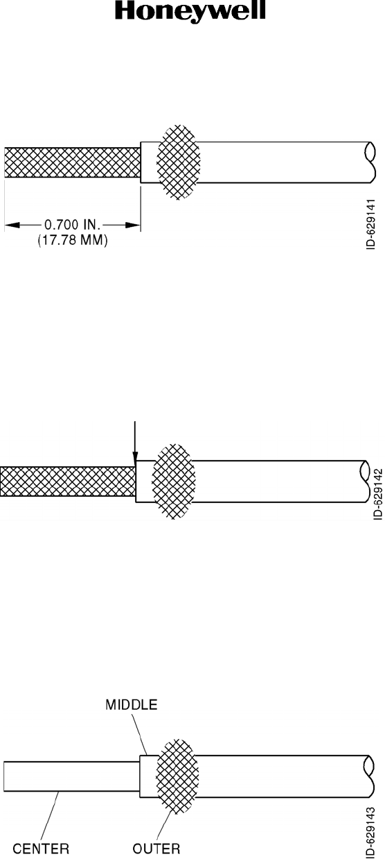
SYSTEM INSTALLATION MANUAL
KTR 2280A
Page 2-7
15 May 2017
© Honeywell International Inc. Do not copy without express permission of Honeywell.
Figure 2-3 (Sheet 1 of 1) Quadraxial Cable Preparation
( 4 ) T i n t h e e x p o s e d shield of the middle coax. With a cutting tool, score the tinned shield
around the entire circumference as shown in Figure 2-4.
Figure 2-4 (Sheet 1 of 1) Quadraxial Cable Preparation
(5) Carefully break loose the tinned middle coax shield and slide it off. This will expose the
center coax insulation as shown in Figure 2-5.
Figure 2-5 (Sheet 1 of 1) Quadraxial Cable Preparation
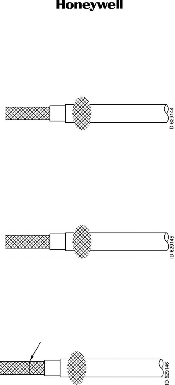
SYSTEM INSTALLATION MANUAL
KTR 2280A
Page 2-8
15 May 2017
© Honeywell International Inc. Do not copy without express permission of Honeywell.
(6) Measure back 0.500 inch (12.70 mm) and remove the insulation from the center shield
as shown in Figure 2-6.
Figure 2-6 (Sheet 1 of 1) Quadraxial Cable Preparation
( 7 ) T i n t h e s h i e l d f o r t h e c e n t e r c o a x a s s h o w n i n F i g u r e 2 - 7 .
Figure 2-7 (Sheet 1 of 1) Quadraxial Cable Preparation
(8) Measure back from the end of the cable 0.30 inch (7.6 mm) and score the center shield
with a cutting tool around the full circumference as shown in Figure 2-8.
Figure 2-8 (Sheet 1 of 1) Quadraxial Cable Preparation
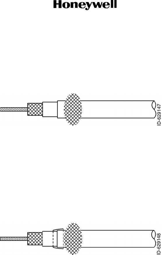
SYSTEM INSTALLATION MANUAL
KTR 2280A
Page 2-9
15 May 2017
© Honeywell International Inc. Do not copy without express permission of Honeywell.
(9) Carefully break the shield loose. Strip off the insulation from the center conductor as
shown in Figure 2-9.
Figure 2-9 (Sheet 1 of 1) Quadraxial Cable Preparation
(10) Install 0.25 inch (6.35 mm) length of shrink tubing over the middle shield stub to prevent
possible shorts to the outer shield as shown in Figure 10.
Figure 2-10 (Sheet 1 of 1) Quadraxial Cable Preparation
( 1 1 ) C o n n e c t o r A s s e m b l y
• I n s t a l l t h e f e r r u l e o v e r t h e c e n t e r s h i e l d a n d s o l d e r .
• S l i p t h e c a b l e i n t o t h e c o n n e c t o r h o u s i n g a s s h o w n i n F i g u r e 2 - 1 1 .
• S o l d e r t h e c e n t e r c o n d u c t o r t o t h e c e n t e r t e r m i n a l .
• P u l l u p t h e o u t e r s h i e l d a n d s o l d e r t o t h e b o t t o m s t e m .
• I n s t a l l s h r i n k tubing over the entire assembly to the bottom of the connector
housing as shown in Figure 2-11.
• Install the horse shoe shaped insert for a 50 ohm impedance match.
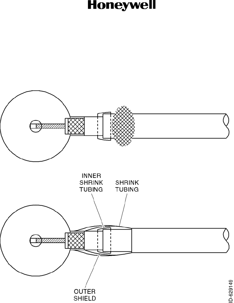
SYSTEM INSTALLATION MANUAL
KTR 2280A
Page 2-10
15 May 2017
© Honeywell International Inc. Do not copy without express permission of Honeywell.
• Install the rear cover cap and solder to barrel lip in two places.
Figure 2-11 (Sheet 1 of 1) Connector Assembly
2.3.5.2 Taylor Backshell Instructions
A . G e n e r a l I n f o r m a t i o n
( 1 ) T a y l o r B a c k s h e l l s a r e a p r o p r i e t a r y H o n e y w e l l d e s i g n d e v e l o p e d t o e x p e d i t e
cable harness fabrication while ensuring that HIRF and lightning performance
goals are met. A typical backshell is shown in Figure 2-12 Typical Taylor
Backshell. Figure 2-13 Backshell Assembly Exploded View provides an
exploded view of the backshell. Table 2-1 KTR 2280A Backshell Hardware
describes the connector type used for the KTR 2280A.
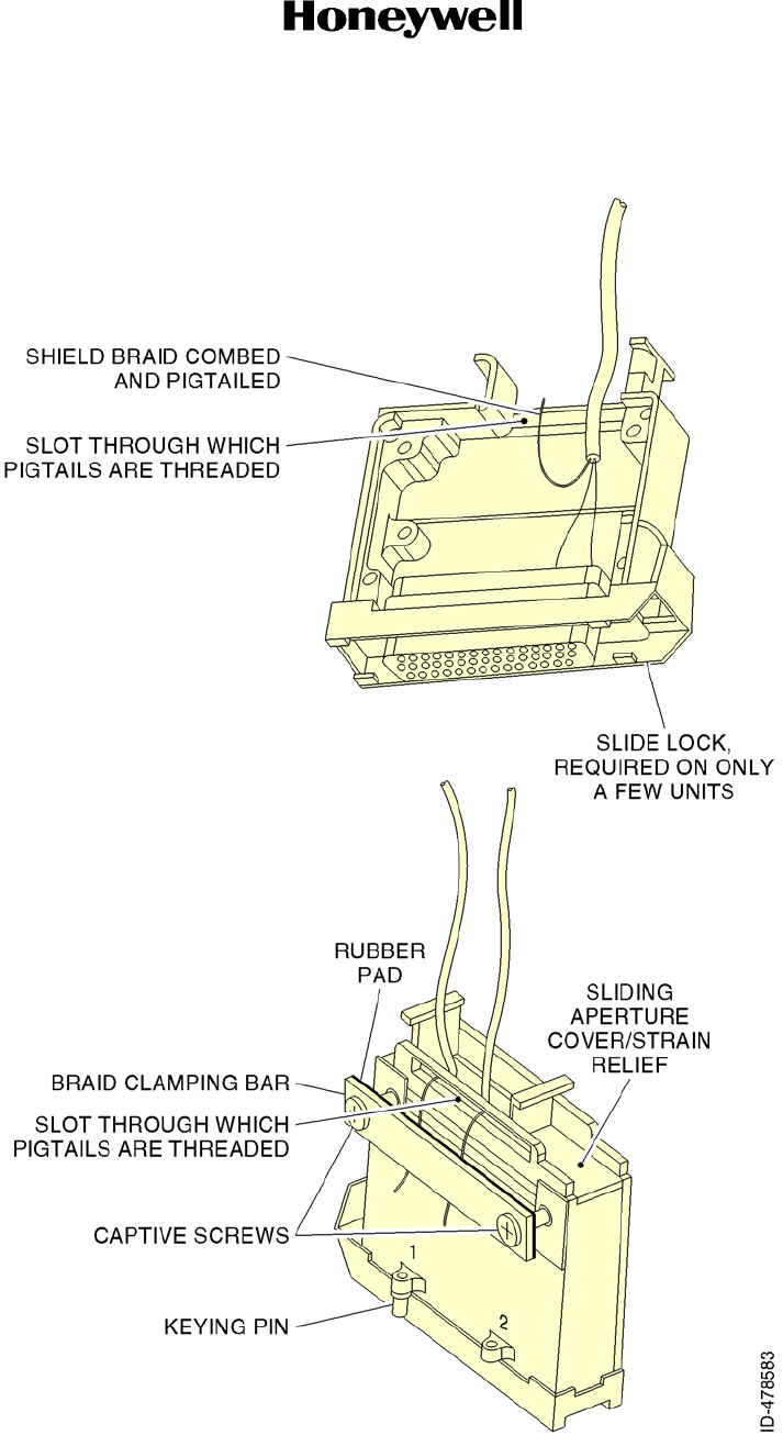
SYSTEM INSTALLATION MANUAL
KTR 2280A
Page 2-11
15 May 2017
© Honeywell International Inc. Do not copy without express permission of Honeywell.
Figure 2-12 (Sheet 1 of 1) Typical Taylor Backshell Instructions
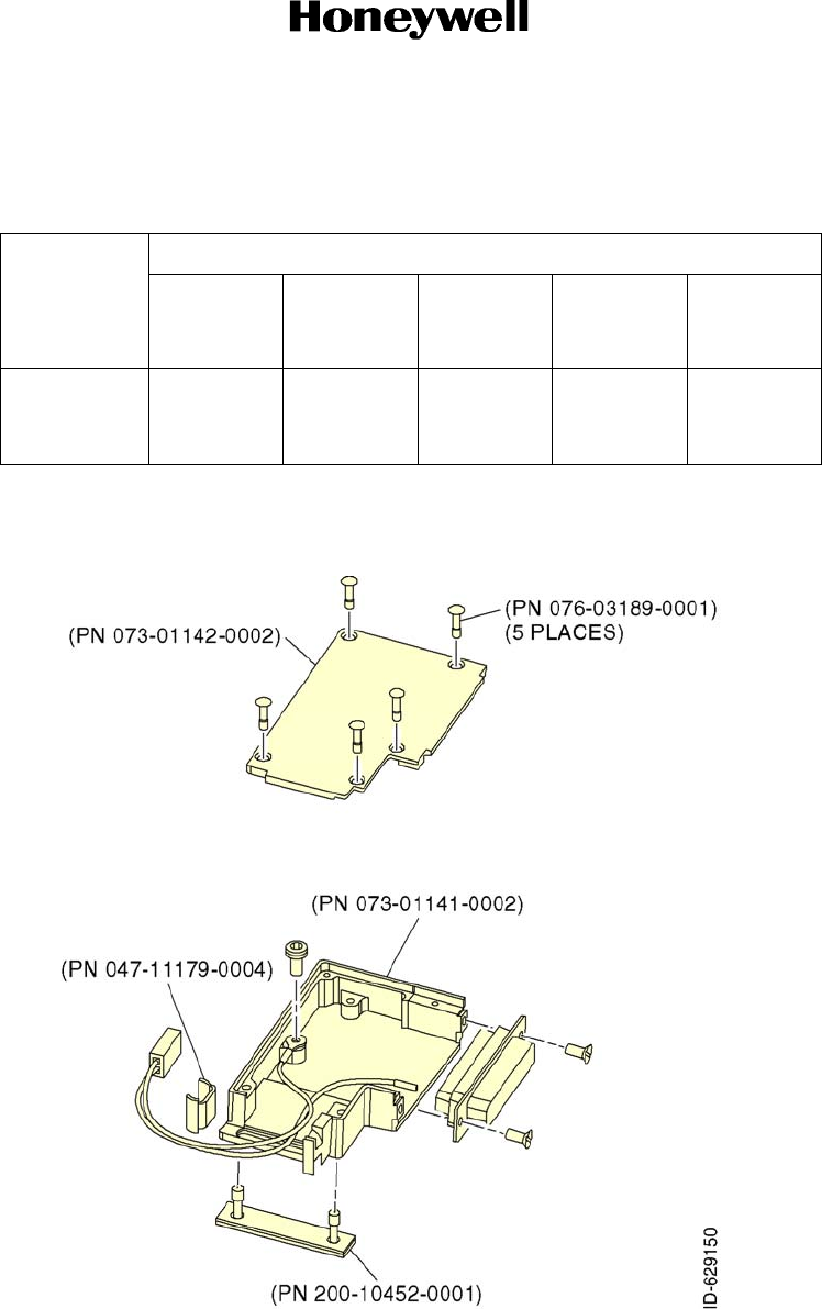
SYSTEM INSTALLATION MANUAL
KTR 2280A
Page 2-12
15 May 2017
© Honeywell International Inc. Do not copy without express permission of Honeywell.
( 2 ) A p p l y L o c t i t e 4 2 5 o r e q u i v a l e n t t o a l l s c r e w t h r e a d s w h e n
assembling components.
Figure 2-13 (Sheet 1 of 1) Backshell Assembly Exploded View
( B ) B a c k s h e l l W i r i n g
( 1 ) S t r i p t h e o u t e r j a c k e t o f t h e t w i s t e d p a i r a s s h o w n i n F i g u r e 2 - 1 4 A s s e m b l y
Details. Trim the shield braid to 1.25 inch (31.75 mm) length and then comb out
Table 2-1 KTR 2280A Backshell Hardware
Connector
Type PN
Backshell Cover Cover
Screws Bar Clamp
Assy Strain
Relief
Clamp
44 pin
right-angle
custom
073-01141
-0002 073-01142
-0002 076-03189
-0001 200-10452
-0001 047-11179
-0004
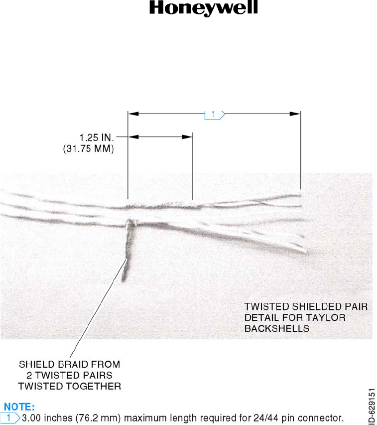
SYSTEM INSTALLATION MANUAL
KTR 2280A
Page 2-13
15 May 2017
© Honeywell International Inc. Do not copy without express permission of Honeywell.
the braid. The braids from two twisted pairs can be twisted together to maintain
the proper diameter for the twisted braid.
Figure 2-14 (Sheet 1 of 1) Assembly Details
(2) If installing a single twisted pair, the combed braid must be folded back on itself
and twisted to form the proper diameter bundle. Refer to Figure 2-15 Assembly
Details.
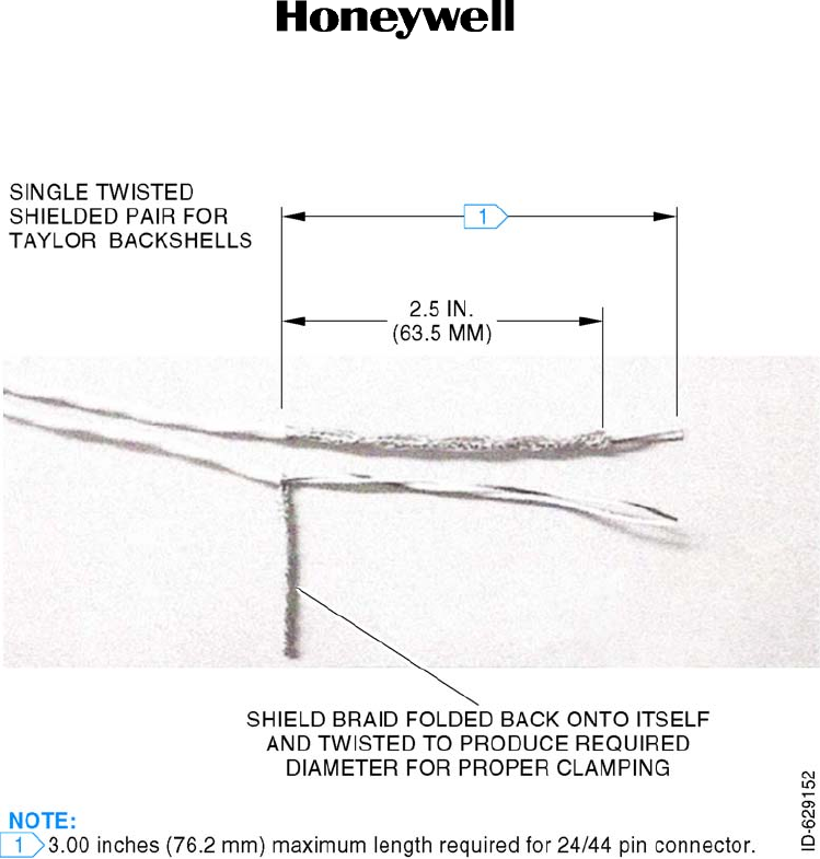
SYSTEM INSTALLATION MANUAL
KTR 2280A
Page 2-14
15 May 2017
© Honeywell International Inc. Do not copy without express permission of Honeywell.
Figure 2-15 (Sheet 1 of 1) Assembly Details
( 3 ) C r i m p p i n s o r s o c k e t s o n t o t h e w i r e s .
( 4 ) I n s e r t t h e p i ns or sockets into the connector. When using oversized power and
ground contacts, ensure heat shrink tubing is used to cover exposed ends of
contacts.
( 5 ) P l a c e t h e b a c k s h e l l o v e r t h e w i r e b u n d l e .
( 6 ) A t t a c h t h e c o n n e c t o r t o t h e b a c k s h e l l .
( 7 ) I n s e r t t h e s h i e l d b r a i d i n t o t h e s l o t i n t h e b a c k s h e l l c o v e r
( 8 ) A t t a c h t h e b a c k s h e l l c o v e r t o t h e b a c k s h e l l w i t h t h e s c r e w s p r o v i d e d .
( 9 ) D r e s s t h e t w i s t e d s h i e l d s a s s h o w n i n F i g u r e 2 - 1 6 S h i e l d B r a i d R o u t i n g a n d
Clamping Bar Details. Do not allow twisted shields to cross over each other.
Tighten the clamping bar to secure the braids and provide a reliable electrical
ground.
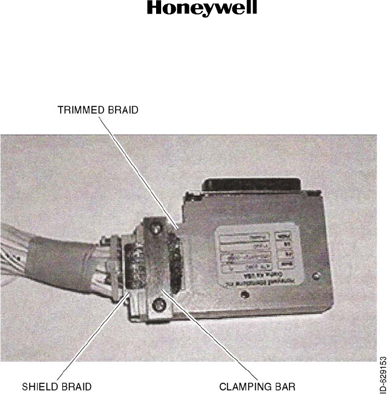
SYSTEM INSTALLATION MANUAL
KTR 2280A
Page 2-15
15 May 2017
© Honeywell International Inc. Do not copy without express permission of Honeywell.
Figure 2-16 (Sheet 1 of 1) Shield Braid Routing and Clamping Bar Details
(11) When the clamping bar is tight, the exposed braids must be trimmed as shown
in Figure 2-16 Shield Braid Routing and Clamping Bar Details.
(12) Insert the strain relief and secure with a tie wrap as shown in Figure 2-17
Securing Strain Relief Clamp.
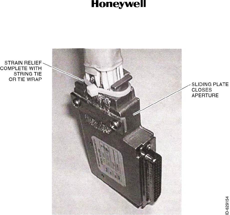
SYSTEM INSTALLATION MANUAL
KTR 2280A
Page 2-16
15 May 2017
© Honeywell International Inc. Do not copy without express permission of Honeywell.
Figure 2-17 (Sheet 1 of 1) Securing Strain Relief Clamp
( c ) I n s t a l l a t i o n C o n s i d e r a t i o n s
( 1 ) D e t e r m i n i n g W i r e L e n g t h : T h e l e n g t h o f w i r e f r o m t h e p o i n t a t w h i c h t h e s h i e l d
is split off to the terminations in the connector must be as short as possible to
allow the wire to lay in the backshell without straining the wires.
( 2 ) G r o u n d i n g : T a y l o r B a c k s h e l l s h a v e a n e x t e r n a l t a p p e d h o l e t h a t c a n b e u s e d t o
attach a ground strap. This can be used at the installer's discretion.
(3) Shell Aperture: When the strain relief is tightened against the wire bundle
ensure that there are no large openings in the shell back and that the wires are
held securely. A different size strain relief can be required if the wire bundle is
too small. Wrapping wires in the connector throat is acceptable to bring the
bundle diameter up to a size that can be properly clamped.
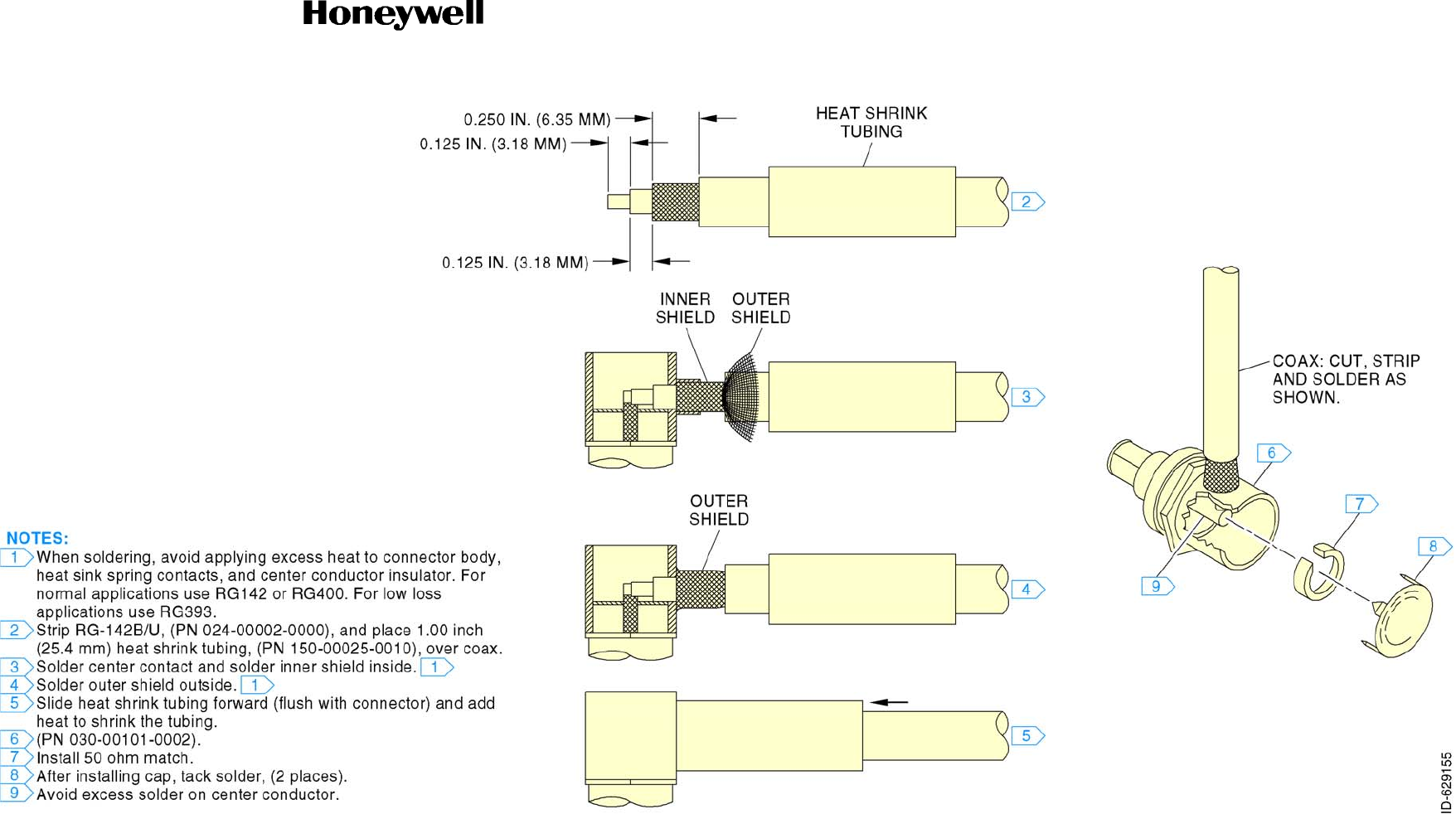
SYSTEM INSTALLATION MANUAL
KTR 2280A
Page 2-17
15 May 2017
© Honeywell International Inc. Do not copy without express permission of Honeywell.
Figure 2-18 (Sheet 1 of 1) Right Angle Connector Instruction Sheet

SYSTEM INSTALLATION MANUAL
KTR 2280A
Page 2-18
15 May 2017
© Honeywell International Inc. Do not copy without express permission of Honeywell.
Blank Page
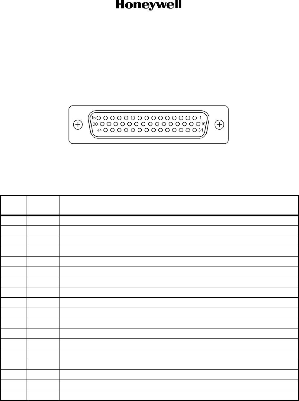
SYSTEM INSTALLATION MANUAL
KTR 2280A
Page 2-19
15 May 2017
© Honeywell International Inc. Do not copy without express permission of Honeywell.
2.3.5.3 Primary Power and Circuit Breaker Requirements
The KTR 2280A MMDR receives primary power from the aircraft power circuit breakers. Power connections,
wire sizes, and circuit breaker requirements can be found in the system installation manual and/or EB for a
specific installation.
2.3.5.4 Connectors
Figure 2-19 (Sheet 1 of 1) KTR 2280A Mating Connector
Front View
Table 2-2 J1 Pin Functions
Pin
No. Pin Name Description
1 O A429 Out1 A
2 O ADF Loop Enable OUT
3 I Test
4 I Unit Pos PGM 1*
5 I Unit Pos PGM 2*
6 I COM TX Interlock* IN
7 I COM MIC Key* IN
8 O RS-422 RX A
9 O RS-422 RX B
10 I RS-422 TX A
11 I RS-422 TX B
12 I COM MIC GND
13 I A429 IN3 A
14 O ADF Audio LO OUT
15 O ADF Audio HI OUT
16 O A429 Out1 B
17 O ADF MOD 0 OUT
18 O A429 Out2 A

SYSTEM INSTALLATION MANUAL
KTR 2280A
Page 2-20
15 May 2017
© Honeywell International Inc. Do not copy without express permission of Honeywell.
19 I Unit Pos Parity*
20 I A429 IN1 A
21 O A429 OUT3 A
22 I A429 IN2 A
23 I ADF ANT PWR Return
24 I DC Return 1
25 I DC Power 2 IN
26 I Emergency Channel*
27 I COM MIC Audio IN
28 I A429 IN3 B
29 O NAV Audio LO OUT
30 O NAV Audio HI OUT
31 O ADF MOD 90 OUT
32 O A429 Out2 B
33 O MMDS FAN 5V OUT
34 I A429 IN1 B
35 O A429 OUT3 B
36 I A429 IN2 B
37 I Pgm Pin Common
38 O ADF ANT PWR OUT
39 I DC Power 1 IN
40 I DC Return 2
41 I Download*
42 I/O VDL Interlock IN OUT*
43 O COM Audio/Sidetone LO OUT
44 O COM Audio/Sidetone HI OUT
Pin
No. Pin Name Description
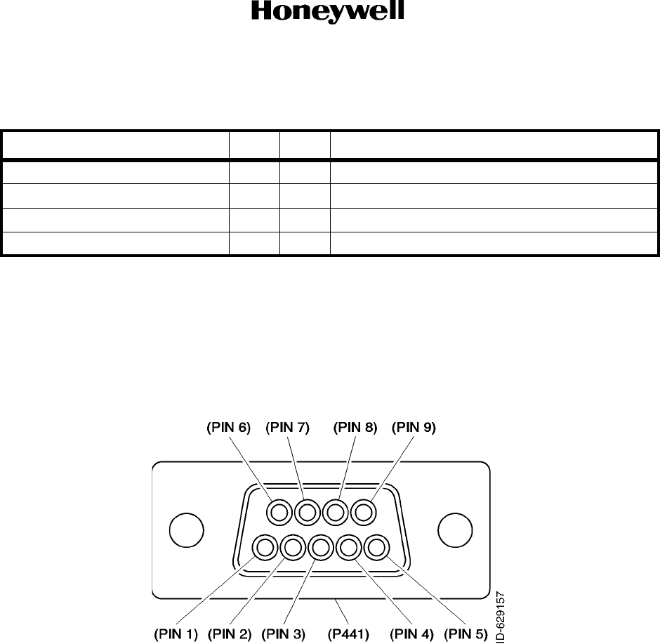
SYSTEM INSTALLATION MANUAL
KTR 2280A
Page 2-21
15 May 2017
© Honeywell International Inc. Do not copy without express permission of Honeywell.
Table 2-3 Antenna Connector Functions
Figure 2-20 (Sheet 1 of 1) KA 44B Mating Connector Front View
(Part of Antenna Cable Assembly, PN 200-02586-0020)
Connector Pin I/O Description
J101 1 I/O COM RF
J102 1 I ADF RF IN
J103 1 I NAV RF IN
J104 1 I Glideslope RF IN
Note: * indicates the Pin is active GND.

SYSTEM INSTALLATION MANUAL
KTR 2280A
Page 2-22
15 May 2017
© Honeywell International Inc. Do not copy without express permission of Honeywell.
Table 2-4 KA 44B Pin Functions
2.3.5.5 Crimp Tool Information
Table 2-5 Crimp Tools and Accessories
PIN I/O SIGNAL NAME
1 I ANTENNA POWER
2 I LOOP ENABLE
3 O RF INPUT
4 I ADF MOD 90 Out
5 I ADF MOD 0 Out
6 NO CONNECTION
7 GROUND
8 INNER SHIELD
9 MIDDLE/OUTER SHIELD
Crimp Tool Honeywell PN 005-02012-0021, Positronic 9507 or
equivalent
Positioner Positronic 9502-3 or equivalent
Insertion/Extraction Tool Positronic 4811-2-0-0 or equivalent
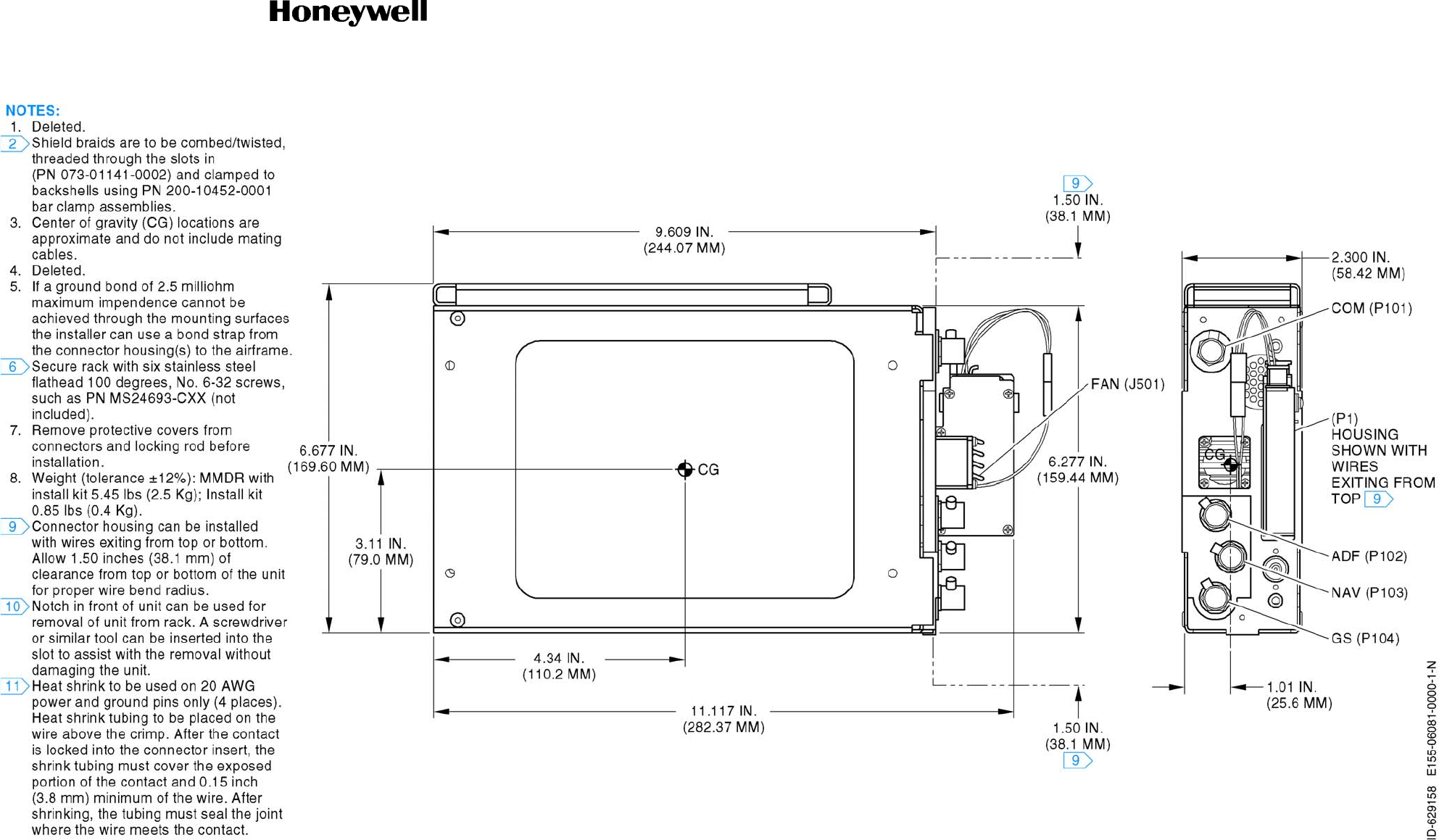
SYSTEM INSTALLATION MANUAL
KTR 2280A
Page 2-23
15 May 2017
© Honeywell International Inc. Do not copy without express permission of Honeywell.
Figure 2-21 (Sheet 1 of 4) KTR 2280A Installation Drawing
(Dwg No 155-06081-0000 Rev N)

SYSTEM INSTALLATION MANUAL
KTR 2280A
Page 2-24
15 May 2017
© Honeywell International Inc. Do not copy without express permission of Honeywell.
Blank Page

SYSTEM INSTALLATION MANUAL
KTR 2280A
Page 2-25
15 May 2017
© Honeywell International Inc. Do not copy without express permission of Honeywell.
Figure 2-21 (Sheet 2 of 4) KTR 2280A Installation Drawing
(Dwg No 155-06081-0000 Rev N)

SYSTEM INSTALLATION MANUAL
KTR 2280A
Page 2-26
15 May 2017
© Honeywell International Inc. Do not copy without express permission of Honeywell.
Blank Page
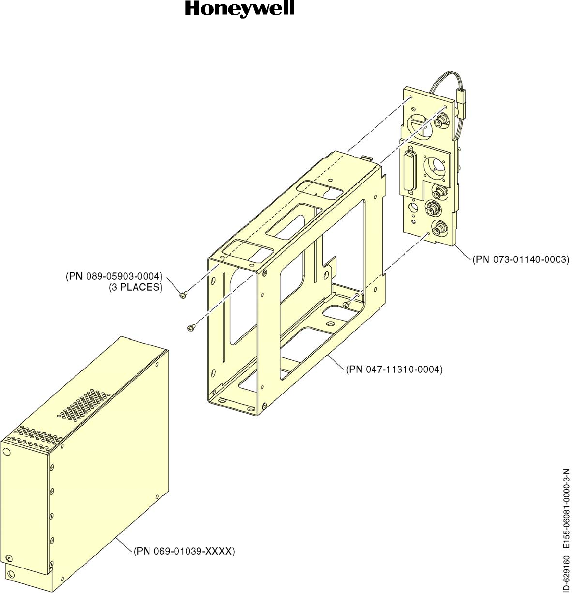
SYSTEM INSTALLATION MANUAL
KTR 2280A
Page 2-27
15 May 2017
© Honeywell International Inc. Do not copy without express permission of Honeywell.
Figure 2-21 (Sheet 3 of 4) KTR 2280A Installation Drawing
(Dwg No 155-06081-0000 Rev N)

SYSTEM INSTALLATION MANUAL
KTR 2280A
Page 2-28
15 May 2017
© Honeywell International Inc. Do not copy without express permission of Honeywell.
Blank Page
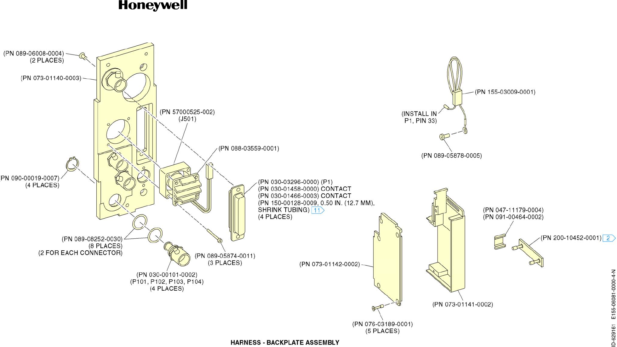
SYSTEM INSTALLATION MANUAL
KTR 2280A
Page 2-29
15 May 2017
© Honeywell International Inc. Do not copy without express permission of Honeywell.
Figure 2-21 (Sheet 4 of 4) KTR 2280A Installation Drawing
(Dwg No 155-06081-0000 Rev N)

SYSTEM INSTALLATION MANUAL
KTR 2280A
Page 2-30
15 May 2017
© Honeywell International Inc. Do not copy without express permission of Honeywell.
Blank Page
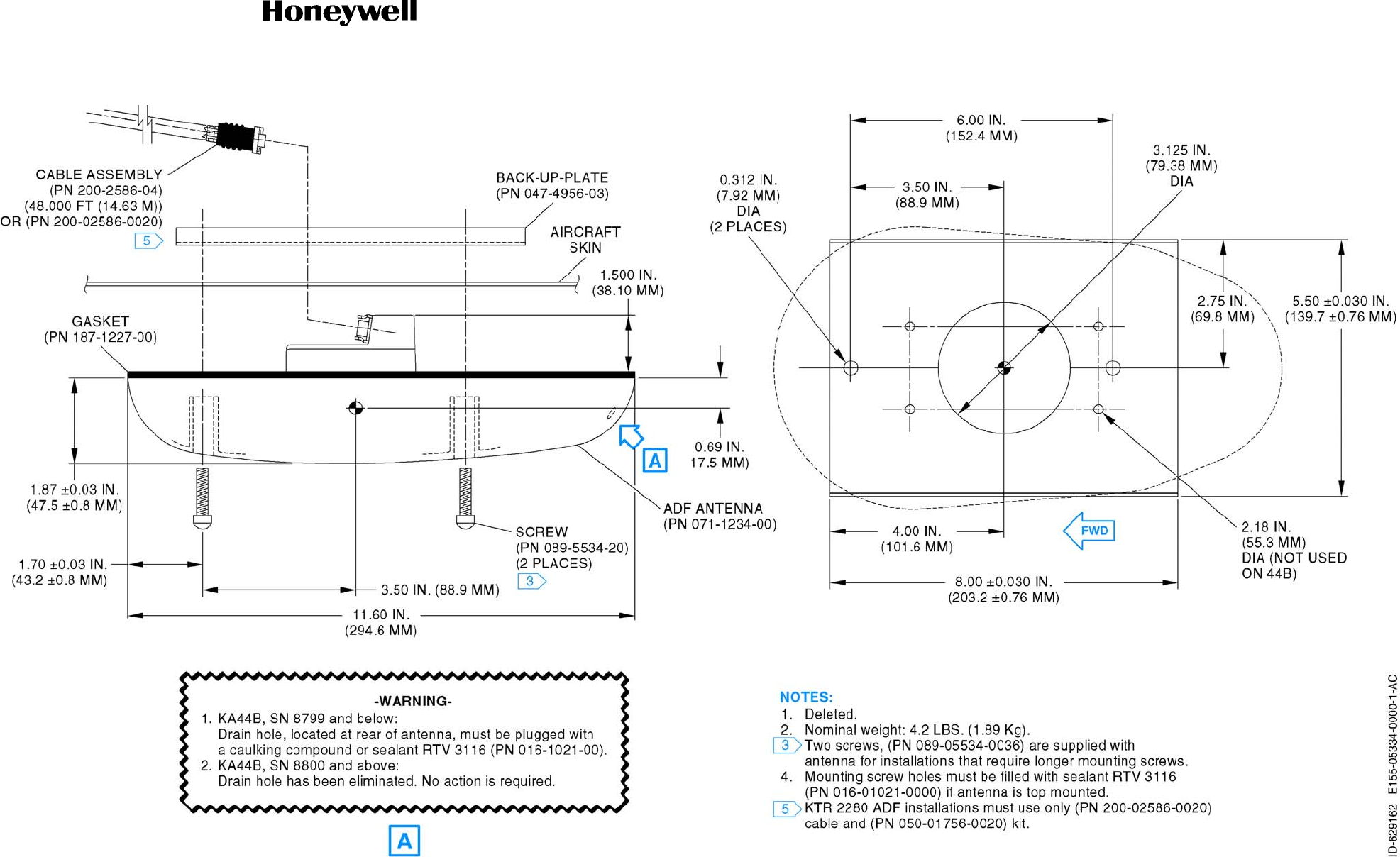
SYSTEM INSTALLATION MANUAL
KTR 2280A
Page 2-31
15 May 2017
© Honeywell International Inc. Do not copy without express permission of Honeywell.
Figure 2-22 (Sheet 1 of 1) KA 44B Outline and Mounting Drawing
(Dwg No 155-05334-0000 Rev AC)

SYSTEM INSTALLATION MANUAL
KTR 2280A
Page 2-32
15 May 2017
© Honeywell International Inc. Do not copy without express permission of Honeywell.
Blank Page
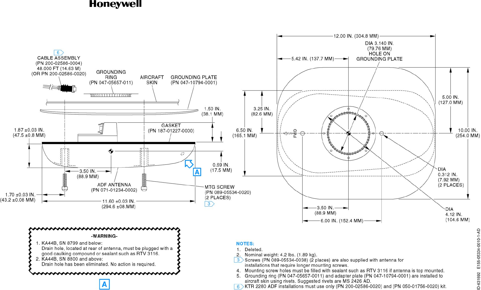
SYSTEM INSTALLATION MANUAL
KTR 2280A
Page 2-33
15 May 2017
© Honeywell International Inc. Do not copy without express permission of Honeywell.
Figure 2-23 (Sheet 1 of 1) KA 44B Outline and Mounting Drawing
(Dwg No 155-05334-0010 Rev AD)

SYSTEM INSTALLATION MANUAL
KTR 2280A
Page 2-34
15 May 2017
© Honeywell International Inc. Do not copy without express permission of Honeywell.
Blank Page
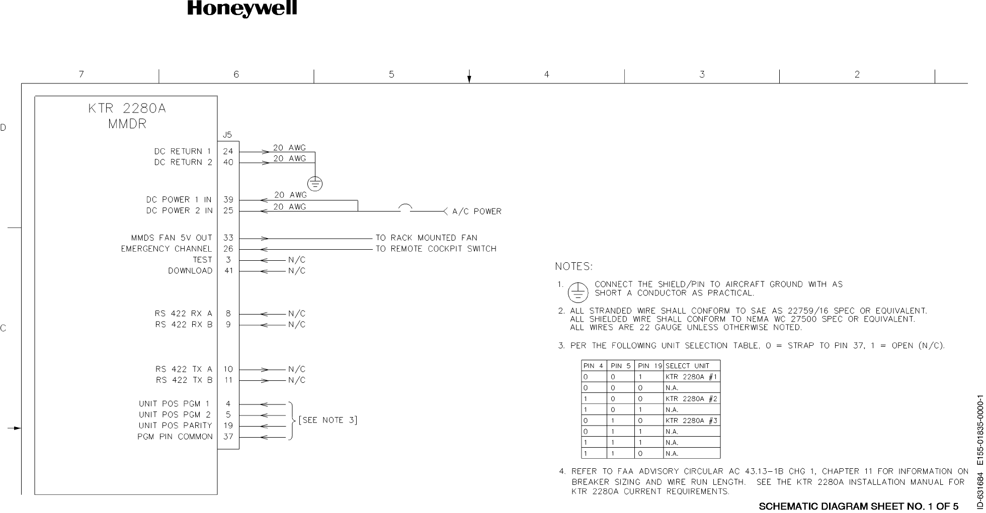
SYSTEM INSTALLATION MANUAL
KTR 2280A
Page 2-35
15 May 2017
© Honeywell International Inc. Do not copy without express permission of Honeywell.
Figure 2-24 (Sheet 1 of 5) KTR 2280A Interconnect Diagram
(Dwg No 155-01835-0000 Rev -)

SYSTEM INSTALLATION MANUAL
KTR 2280A
Page 2-36
15 May 2017
© Honeywell International Inc. Do not copy without express permission of Honeywell.
Blank Page
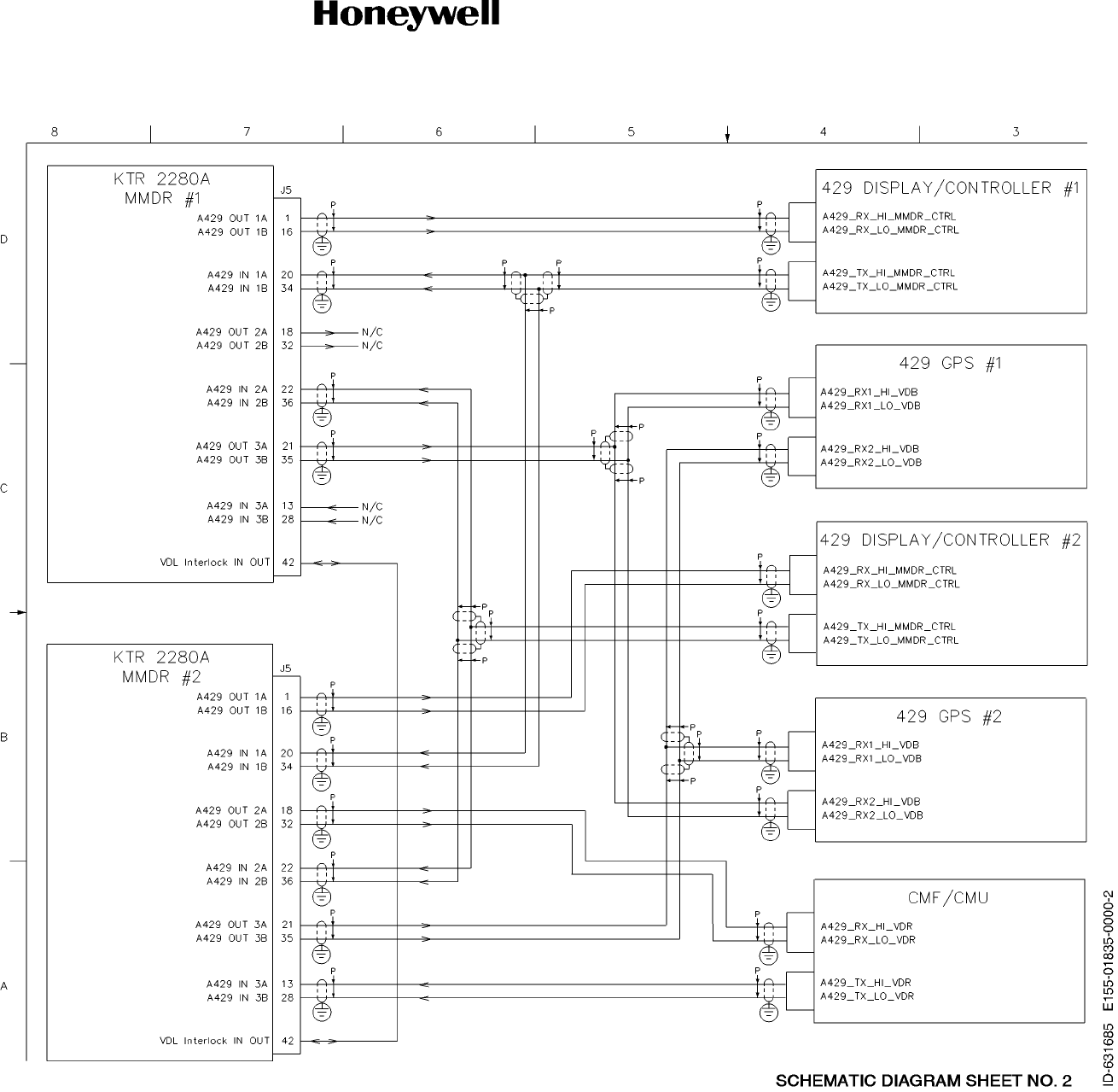
SYSTEM INSTALLATION MANUAL
KTR 2280A
Page 2-37
15 May 2017
© Honeywell International Inc. Do not copy without express permission of Honeywell.
Figure 2-24 (Sheet 2 of 5) KTR 2280A Interconnect Diagram
(Dwg No 155-01835-0000 Rev -)

SYSTEM INSTALLATION MANUAL
KTR 2280A
Page 2-38
15 May 2017
© Honeywell International Inc. Do not copy without express permission of Honeywell.
Blank Page
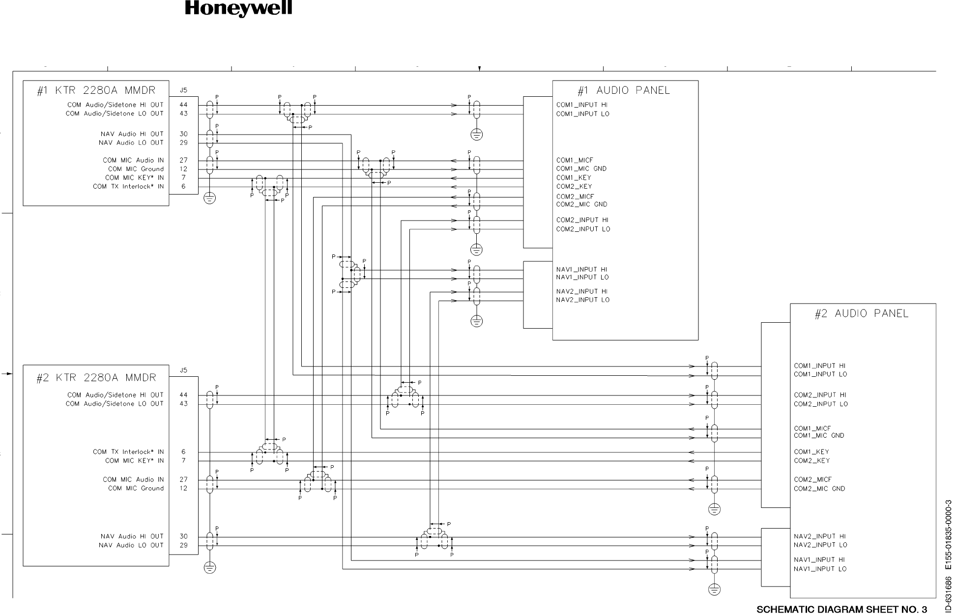
SYSTEM INSTALLATION MANUAL
KTR 2280A
Page 2-39
15 May 2017
© Honeywell International Inc. Do not copy without express permission of Honeywell.
Figure 2-24 (Sheet 3 of 5) KTR 2280A Interconnect Diagram
(Dwg No 155-01835-0000 Rev -)

SYSTEM INSTALLATION MANUAL
KTR 2280A
Page 2-40
15 May 2017
© Honeywell International Inc. Do not copy without express permission of Honeywell.
Blank Page
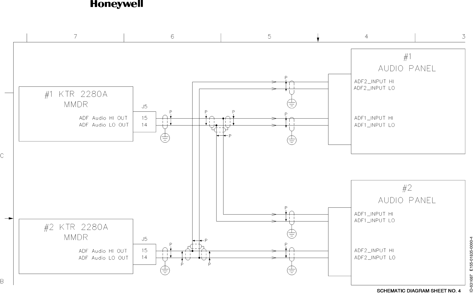
SYSTEM INSTALLATION MANUAL
KTR 2280A
Page 2-41
15 May 2017
© Honeywell International Inc. Do not copy without express permission of Honeywell.
Blank Page
Figure 2-24 (Sheet 4 of 5) KTR 2280A Interconnect Diagram
(Dwg No 155-01835-0000 Rev -)

SYSTEM INSTALLATION MANUAL
KTR 2280A
Page 2-42
15 May 2017
© Honeywell International Inc. Do not copy without express permission of Honeywell.
Blank Page
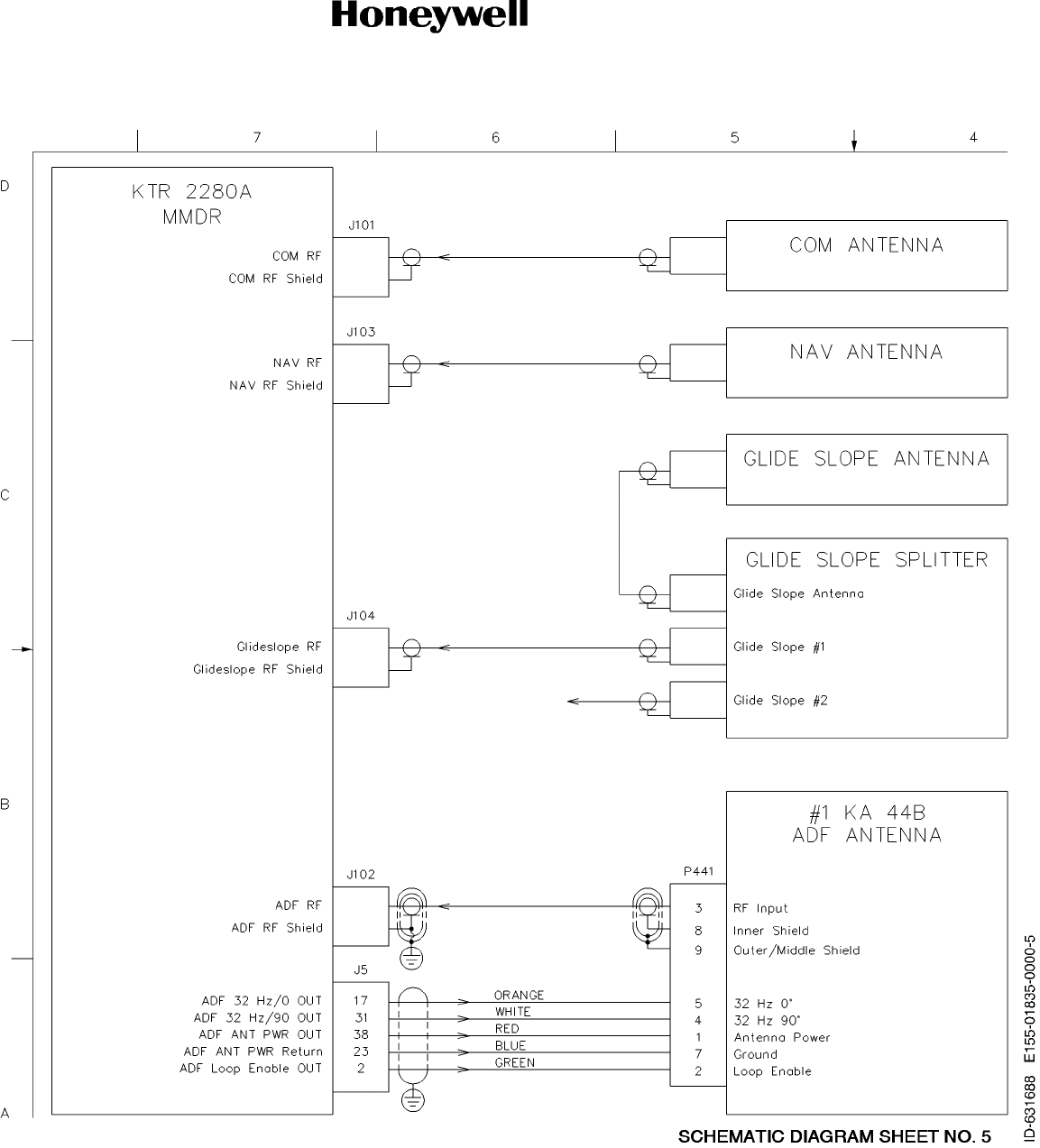
SYSTEM INSTALLATION MANUAL
KTR 2280A
Page 2-43
15 May 2017
© Honeywell International Inc. Do not copy without express permission of Honeywell.
Figure 2-24 (Sheet 5 of 5) KTR 2280A Interconnect Diagram
(Dwg No 155-01835-0000 Rev -)

SYSTEM INSTALLATION MANUAL
KTR 2280A
Page 2-44
15 May 2017
© Honeywell International Inc. Do not copy without express permission of Honeywell.
Blank Page

SYSTEM INSTALLATION MANUAL
KTR 2280A
Page 2-45
15 May 2017
© Honeywell International Inc. Do not copy without express permission of Honeywell.
2.4 POST-INSTALLATION CHECKS
2.4.1 KTR 2280A MMDR Post-Installation Inspection and Ground Test
2.4.1.1 INSPECTION
Table 2-6 Inspection/Check Procedure is a visual inspection/check procedure that must be performed after
system installation as part of a system checkout. A post-installation test per paragraph 2.4.1.2 Ground Tests
must be performed. In addition, the procedure must be used as a periodic maintenance inspection check.
Table 2-6 Inspection/Check Procedure
(1) Perform the following inspections on the overall system:
( a ) C h e c k t h a t c a b l e s d o n o t i n t e r f e r e w i t h a i r c r a f t c o n t r o l s o r o t h e r e q u i p m e n t .
(b) Check cabling for proper routing and check security of tie-down points. Inspect and adjust cable
runs to ensure that cables are not strained, kinked, or severely twisted and are not exposed to
rough or sharp surfaces.
(2) System Interwiring Check
To check the aircraft and MMDR system interconnections proceed as follows:
( a ) C h e c k t h a t a l l c a b l es and interwiring are installed in accordance with the interwiring and cable
harness fabrication instructions (refer to paragraph 2.3.5.1 KTR 2280A Interconnection and Ca-
ble Harness Fabrication).
( b ) U s i n g t h e a p p l i c a b le interconnection information, check wiring for proper destinations, opens
and shorts.
( c ) C h e c k R F c a b l e s f o r i n s e r t i o n l o s s a n d V S W R .
(3) Visual Inspection
In conjunction with system installation, perform the inspection/check procedure. Refer to Table 2-6 In-
spection/Check Procedure.
EQUIPMENT INSPECTION/CHECK PROCEDURE
KTR 2280A
MMDR A. Inspect external surface for damage.
B. Check that the unit is securely installed and that retaining
mechanism is securely tightened.
C. Ensure that all connections in the mounting tray are properly
mounted and secure.
Antennas A. Inspect external surfaces for damage.
B. Check that antenna is properly mounted and mounting
screws are tight.
C. Ensure that antenna coaxial cable connectors are properly
mated and secure.

SYSTEM INSTALLATION MANUAL
KTR 2280A
Page 2-46
15 May 2017
© Honeywell International Inc. Do not copy without express permission of Honeywell.
2.4.1.2 Ground Tests
( 1 ) P o s t - I n s t a l l a t i o n T e s t ( N A V / C O M F u n c t i o n a l i t y )
P e r f o r m a g r o u n d c h e c k o f t h e i n s t a l l a t i o n b e f o r e t h e f l i g h t t e s t . U s i n g a l o c a l f r e q uency, confirm
that the COM function can receive and transmit a modulated signal. Using a ramp tester, con-
firm that VOR, LOC, and GS needle deflections move in the correct direction, the To/From flag
is the proper sense, and that the warning flags are functioning properly. Check all aircraft con-
trol movements to be sure no electrical cables interfere with their operation.
CAUTION: AS AN ADDED PRECAUTION BEFORE ANY FLIGHT TESTS, CHECK THE ANTENNA.
VSWR MUST BE CHECKED WITH AN IN-LINE TYPE WATTMETER INSERTED IN THE
COAXIAL TRANSMISSION LINE BETWEEN THE TRANSCEIVER AND THE ANTENNA. ANY
PROBLEM WITH THE ANTENNA INSTALLATION WILL MOST LIKELY BE SEEN AS A HIGH
REFLECTED POWER.
NOTE: Installed system transmitter power may show considerably less that the manufacturer’s rating of
16 W (minimum). There are several reasons for this:
1 . I t i s n o t u n c o m m o n f o r a n i n s t a l l a t i o n t o h a v e u p t o a s m u c h a s 1 d B o f R F t r a n s m i s s i o n
line cable loss. This would reduce a 16 W transmitter output to 12.7 W.
2. RF power meter test equipment that has an accuracy of ± 0.3 dB would cause power
reading variations as high as ± 1 W.
3 . T h e e f f e c t of antenna VSWR in a given installation will affect the output power. The
VSWR is a function of the antenna design itself, aircraft skin properties and proximate
metallic features of the airframe, and the size of the metallic surface the antenna is
bonded to. Note that the committees that wrote the Minimum Operation Performance
Standards to which the VHF COM system is TSO’d are aware of this characteristic.
They have established that transmitter power for a 16 W (minimum) transmitter must
not drop below 8.0 W into a 2:1 VSWR and 6.4 W into a 3:1 VSWR (Refer to RTCA-
DO-186B and Eurocae ED-23C).
( 2 ) P o s t - I n s t a l l a t i o n T e s t ( A D F F u n c t i o n a l i t y )
A q u i c k p r e l i m i n a r y c h e c k c a n b e m a d e b y t u n i n g t o a l o c a l A M b r o a d c a s t s t a t i o n o r a strong
NDB station. Check for satisfactory audio (this must be done where clear reception is possible,
preferably outside of the hangar).
( a ) Q u a d r a n t a l E r r o r A d j u s t m e n t s
T h e s y s t e m h a s b e e n f a c t o r y a d j u s t e d t o c o m p e n s a t e f o r a t y p i c a l a i r f r a m e . T h e r e f o r e ,
little or no compensation must be required. Nonetheless, the KTR 2280A provides soft-
ware adjustment of Quadrantal Error (the average amount of quadrantal error (QE) that
exists due to the shape of the airframe). The values for these alignments are stored
within the aircraft system maintenance computer and downloaded to the KTR 2280A
on power up. If this download does not occur the KTR 2280A uses the last values that
were loaded.
T h e K A 4 4 B A D F a n t e n n a , l i k e m o s t m o d e r n A D F a n t e n n a s , c a n h a v e i n h e r e n t e r r o r s
at the quadrantal (45°, 135°, 225° and 315°) bearings relative to the antenna’s boresite.
The following procedure details the process for setting a KTR 2280A configuration pa-
rameter to allow the radio to automatically compensate for these inherent errors. It is
very important that this procedure be followed exactly as stated to ensure these qua-
drantal bearings are properly compensated.
T h i s p r o c e d u r e c a n b e c a r r i e d o u t a t a n y l o c a t i o n , h o w e v e r c a r e m u s t b e e x e r c i s e d t o
ensure that the chosen location is magnetically “clean”. Usually an airfield’s compass

SYSTEM INSTALLATION MANUAL
KTR 2280A
Page 2-47
15 May 2017
© Honeywell International Inc. Do not copy without express permission of Honeywell.
rose location is a good choice since magnetically “clean” is one of the criteria for estab-
lishing compass rose location.
NOTE: Ensure that QE = 0 is the value being fed or the last value that was fed to the KTR
2280A before performing this procedure.
1 . P o i n t t h e n o s e of the aircraft directly at the emitter (NDB or AM broadcast radio station)
being used for this purpose. Confirm this orientation by verifying the ADF indicator’s
bearing pointer is pointing directly to the lubber line (aircraft nose reference).
2 . R e c o r d t h e m a gnetic heading of the aircraft using the aircraft directional gyro or mag-
netic compass.
3 . U s i n g t h e a i r c r a f t ’ s d i r e c t i o n a l g y r o o r m a g n e t i c c o m p a s s a s a g u i d e , r o t a t e t h e a i r c r a f t
45° to the left such that the aircraft magnetic heading is now 45° less that the value
found in Step 2.
4 . R e c o r d t h e n u m b e r o f d e g r e e s b y w h i c h t h e A D F b e a r i n g h a s m o v e d r e l a t i v e t o t h e
ADF indicator’s lubber line. (This number must be a positive number and must be ap-
proximately 45°.) Log this number as Bearing_45.
5 . U s i n g t h e a i r c r a f t ’ s d i r e c t i o n a l g y r o o r m a g n e t i c c o m p a s s a s a g u i d e , r o t a t e t h e a i r c r a f t
another 45° to the left so that the aircraft magnetic heading is now 90° less than the
value found in Step 2.
6. Record the number of degrees by which the ADF bearing indication has moved relative
to the ADF indicator’s lubber line. (This number must be a positive number and must
be approximately 90°.)
7 . C o n f i r m t h a t t h e v a l u e i n S t e p 6 i s w i t h i n ± 5 ° of 90°. If not, the aircraft has a magnetic
anomaly that precludes the ability to calculate an acceptable QE adjustment The QE
alignment process must terminate at this point and not resume until any aircraft related
anomalies have been corrected. (Note: Problems with this step could also be due to the
airfield location where the QE alignment procedure is being performed if that location
is not magnetically “clean”.)
8 . U s i n g t h e a i r c r a f t ’ s d i r e c t i o n a l g y r o o r m a g n e t i c c o m p a s s a s a g u i d e , r o t a t e t h e a i r c r a f t
another 45° to the left so that the magnetic heading is now 135° less than the value
found in Step 2.
9. Record the number of degrees by which the ADF bearing indication has moved relative
to the ADF indicator’s lubber line. (This number must be a positive number and must
be approximately 135°.) Log this number as Bearing_135.
1 0 . U s i n g t h e a i r c r a f t ’ s directional gyro or magnetic compass as a guide, rotate the aircraft
another 45° to the left so that the aircraft magnetic heading is now 180° less than the
value found in Step 2.
11. Record the number of degrees by which the ADF bearing indication has moved relative
to the ADF indicator’s lubber line. (This number must be a positive number and must
be approximately 180°.)
1 2 . C o n f i r m t h e v a l u e r e c o r d e d i n S t e p 1 1 i s w i t h i n ± 5 ° of 180°. If not, the aircraft has a
magnetic anomaly the precludes the ability to calculate an acceptable QE adjustment.
The QE alignment process must terminate at this point and not resume until the aircraft
related anomalies have been corrected. (Note: Problems with this step could also be
due to the airfield location where the QE alignment procedure is being performed if that
location is not magnetically “clean”.)
1 3 . U s i n g t h e a i r c r a f t ’ s directional gyro or magnetic compass as a guide, rotate the aircraft
another 45° to the left so the aircraft magnetic heading is now 225° less than the value
found in Step 2.
14. Record the number of degrees by which the ADF bearing indication has moved relative
to the ADF indicator’s lubber line.
( T h i s n u m b e r m u s t b e a p o s i t i v e n u m b e r a n d m u s t b e a p p r o x i m a t e l y 2 2 5 °.) Log this
number as Bearing_225.
1 5 . U s i n g t h e a i r c r a f t ’ s directional gyro or magnetic compass as a guide, rotate the aircraft
another 45° to the left so that the aircraft magnetic heading is now 270° less than the
value found in Step 2.

SYSTEM INSTALLATION MANUAL
KTR 2280A
Page 2-48
15 May 2017
© Honeywell International Inc. Do not copy without express permission of Honeywell.
16. Record the number of degrees by which the ADF bearing indicator has moved relative
the ADF indicator’s lubber line (This number must be a positive number and must be
approximately 270°.)
1 7 . C o n f i r m t h e v a l u e r e c o r d e d i n S t e p 1 6 i s w i t h i n ± 5 ° of 270°. If not, the aircraft has a
magnetic anomaly that precludes the ability to calculate an acceptable QE adjustment.
The QE alignment process must terminate at this point and not resume until the aircraft
related magnetic anomalies have been corrected. (Note: Problems with this step could
also be due to the airfield location where the QE alignment procedure is being per-
formed if that location is not magnetically “clean”.)
1 8 . U s i n g t h e a i r c r a f t ’ s directional gyro or magnetic compass as a guide, rotate the aircraft
another 45° to the left so that the aircraft magnetic heading is now 315° less than the
value found in Step 2.
19. Record the number of degrees by which the ADF bearing indicator has moved relative
to the ADF indicator’s lubber line. (This number must be a positive number and must
be approximately 315°.) Log this number as Bearing_315.
2 0 . U s i n g t h e f o l l o w i n g f o r m u l a s , c a l c u l a t e t h e Q E o f f s e t :
QE_45 = 45 - Bearing_45 (This could be a negative number if Bearing_45 is > 45)
QE_135 = Bearing_135 - 135 (This could be a negative number if Bearing_135 is <
135)
QE_225 = 225 - Bearing_225 (This could be a negative number if Bearing_225 is >
225)
QE_315 = Bearing_315 - 315 (This could be a negative number if Bearing_315 is <
315)
Q E = ( ( Q E _ 4 5 ) + ( Q E _ 1 3 5 ) + ( Q E _ 2 2 5 ) + ( Q E _ 3 1 5 ) ) / ( 4 )
21. Enter the value calculated in Step 20 into the KTR 2280A Parameter table per 2.5 KTR
2280A INSTALLATION PARAMETER MODIFICATIONS.
22. Recheck the relative bearings abd readjust the QE compensation as necessary to split
the error at the quadrantal points (45°, 135°, 225° and 315°) to obtain the lowest pos-
sible error.
( b ) O p e r a t i o n a l C h e c k s
The following operational checks are to verify proper operation of the
ADF function of the KTR 2280A and can be made with the aircraft in the parking area.
1 . P l a c e t h e A D F in the ANT mode and tune in several known stations. Verify that audio
reception is satisfactory and that volume control operation is normal. Verify that the
ADF indicator needle is parked at the 90 degree position relative to the noise of the air-
craft. Place the unit in the ADF mode and verify that the needle points to the station.
2 . S e l e c t t h e B F O f u n c t i o n t o e n t e r t h e B F O m o d e a n d v e r i f y t h a t t h e B F O t o n e i s p r e s e n t
in the receiver audio (if a keyed CW station is used the tone heard will be the coded
identifier).
2.4.2 KTR 2280A Post-Installation Flight Tests
2.4.2.1 COM TRANSCEIVER FLIGHT TEST
To check the COM transceiver, maintain altitude of at least 1500 feet and contact a ground station
facility at a range of at least fifty nautical miles. Contact a ground station close in. Disable the automatic
squelch and listen for any unusual electrical noise which would reduce the COM receiver sensitivity by
increasing the squelch threshold. If possible, verify the communications capability on both the high and
low end of the VHF COM band. Ensure that the COM mode selector is capable of individually selecting
all three modes (one mode at a time).
2.4.2.2 NAV RECEIVER FLIGHT TEST
To check the VOR/ILS system, select a VOR frequency within a forty nautical mile range. Listen to the
VOR audio and ensure that no electrical interference such as magneto noise is present. Check the tone

SYSTEM INSTALLATION MANUAL
KTR 2280A
Page 2-49
15 May 2017
© Honeywell International Inc. Do not copy without express permission of Honeywell.
identifier filter operation. Fly inbound and outbound on a selected VOR radial and check for proper
LEFT-RIGHT and TO-FROM indications. Check the VOR accuracy.
NOTE: VOR ground station scalloping may be present.
To check the localizer and glideslope functions, select an appropriate ILS frequency and fly an approach
to the proper runway. Check for proper LEFT-RIGHT and UP-DOWN indications.
2.4.2.3 ADF RECEIVER FLIGHT TEST
Confirm that bearing indications to several local NDB facilities appear reasonable. Listen to the ADF
audio and ensure that no unusual electrical interference is present.
2.5 KTR 2280A INSTALLATION PARAMETER MODIFICATIONS
The KTR 2280A has several parameters that can be adjusted during installation in order to conform the unit to
a given installation. Parameter modifications must only be performed
by a qualified avionics technician. Table 2-7 Unit Parameters, lists the KTR 2280A adjustments accessible by
the technician to facilitate the unit installation.
NOTE: KTR 2280A units sent to the factory for repair will be returned to service with their factory defaults
reset as shown in Table 2-7 Unit Parameters.
The method for setting these parameters is a function of the specific installed system and the user interface used
for personality module settings. Refer to the appropriate STC Installation Manual for specific instructions. The
KTR 2280A responds to installed system personality module settings through high speed ARINC 429 labels
300, 301, 302, and 303. These labels occur periodically at a 1 Hz rate.
Table 2-7 Unit Parameters
T
NOTE: 1: This setting represents attenuation (in dB) relative to rated audio output level.
NOTE: 2: This setting is a relative number only. Each numeric value represents a change of 1.5 dB.
Nominal setting, which represents the level provided by typical microphones, is the default
Parameter MMDR Factory
Default Minimum
Setting Maximum
Setting Resolution
COM Carrier Squelch (-dBm) 88 85 100 1
COM Emergency Freq. (MHz) 121.500 118.000 136.990 *
COM Emergency Volume (dB) 120 072 1
COM Sidetone Level (dB)152 072 1
COM Squelch (SNR dB) 12 320 1
COM Microphone Gain221 031 **
QE Offset (degrees) 0-20 +20 0.1
* 8.33 kHz channel spacing
** Each resolution increment is equivalent to 1.5 dB. Total range is -31.5 dB to 15.0 dB

SYSTEM INSTALLATION MANUAL
KTR 2280A
Page 2-50
15 May 2017
© Honeywell International Inc. Do not copy without express permission of Honeywell.
numeric value of 21. This control provides amplification (for unusually weak microphones) of up
to 15 dB (setting of 31) or attentuation (for extra sensitive microphones) of up to 31.5 dB (setting
of 0) relative to the default.
2.6 ARINC 429 INTERFACE
The KTR 2280A has three high speed ARINC 429 transmitters and three high speed ARINC 429 receivers. All
labels are transmitted on both transmit channels. The same data is transmitted over both channels
Table 2-8 ARINC 429 Output Labels
Function Label Parameter Interval (ms)
NAV 034 VOR/ILS Frequency 200
053 VOR/ILS Standby (Preset) Frequency 200
173 Localizer Deviation 100
174 Glideslope Deviation 100
222 VOR Bearing 100
242 VOR/ILS Station Ident (Characters 1-2) 200
244 VOR/ILS Station Ident (Characters 3-4) 200
265 VOR/ILS Volume 200
COM 030 VHF COM Frequency 200
047 VHF Aux/Guard COM Frequency 200
052 VHF COM Standby (Preset) Frequency 200
263 VHF Aux/Guard COM Frequency 200
266 VHF COM Volume 200
267 VHF COM Status 200
ADF 032 ADF Frequency 200
162 ADF Bearing 100
262 ADF Volume 200
CMC 350 Member System Status 1000
352 MMDF System Fault Report 1000
377 Member System Identification 1000
VDL 172 System Address Label (SAL) 1000
270 VDR Status Word 1000

SYSTEM INSTALLATION MANUAL
KTR 2280A
Page 2-51
15 May 2017
© Honeywell International Inc. Do not copy without express permission of Honeywell.
Table 2-9 ARINC 429 Input Labels
VDL 304 Williamsburg BOP Burst
377 VDR Equipment ID 1000
VDB 033 Landing Mode/Frequency 200
045 Message Block Start Burst
046 Message Block Data Burst
* MMDR hardware fault (BIT 19 in Label 352) is set when the unit detects a hardware fault and/or
malfunction of the hardware that can result in incorrect data.
Function Label Parameter Interval (ms)
NAV 034 Set VOR/ILS Frequency 200
053 Set VOR/ILS Standby (Preset) Frequency 200
265 Set VOR/ILS Volume 200
COM 030 Set VHF COM Frequency 200
047 Set VHF Aux/Guard COM Frequency 200
052 Set VHF/COM Standby (Preset) Frequency 200
263 Set VHF Aux/Guard COM Volume 200
266 Set VHF COM Volume 200
ADF 032 Set ADF Frequency 200
262 Set ADF Volume 200
CLOCK 150 GMT (UTC) 1000
260 Date 1000
FLIGHT 151 Flight Leg 1000
APM 300 MMDR Configuration Options #1 1000
301 MMDR Configuration Options #2 1000
302 MMDR Configuration Options #3 1000
303 MMDR Configuration Options #4 1000
304 MMDR Configuration Options #5 1000
305 MMDR Configuration Options #6 1000
Function Label Parameter Interval (ms)

SYSTEM INSTALLATION MANUAL
KTR 2280A
Page 2-52
15 May 2017
© Honeywell International Inc. Do not copy without express permission of Honeywell.
CMC 227 CMC Command and Control 1000
VDB 033 Landing Mode/Frequency 200
VDL 172 System Address label 1000
214 Aircraft ICAO Address #1 1000
216 Aircraft ICAO Address #2 1000
251 Williamsburg BOP VDR #1 Burst
252 Williamsburg BOP VDR #2 Burst
253 Williamsburg BOP VDR #3 Burst
270 Apex CMU Status Word 1 1000
276 Apex CMU Status Word 2 1000
276 VDR Mode Command 500
Function Label Parameter Interval (ms)

SYSTEM INSTALLATION MANUAL
KTR 2280A
Page 3-1
15 May 2017
© Honeywell International Inc. Do not copy without express permission of Honeywell.
SECTION 3
OPERATION
3.1 GENERAL
The KTR 2280A is a remote mounted radio. As such, the user interface is defined by controllers and displays
unique to the particular system configuration. Refer to the appropriate pilot’s guide or flight manual supplement
for complete operating instructions.
The paragraphs below provide an overview of the controls and displays that are typically available in systems
that provide full KTR 2280A functionality.
3.1.1 VHF COM Controls and Displays
A. Frequency Selectors: An active frequency (channel) and a standby frequency (channel)
selector. A “swap” or “flip-flop” button may be available for swapping the active and standby
frequencies. The KTR 2280A responds to high speed ARINC 429 labels 030 and 052 for the
active and standby selections respectively. These labels appear only when a frequency
(channel) change is made.
B. Volume Control: A rotational knob or up/down pushbutton to adjust the volume of the COM
audio output. The KTR 2280A responds to high speed ARINC 429 label 266 for the COM
volume control setting. This label appears only when a volume change is made.
C. RX/TX Annunciators: Some display means indicate when the radio is transmitting (TX
Annunciator) and when the radio is receiving (RX Annunciator). This is keyed by the squelch
status. The KTR 2280A outputs the RX status and TX status on the high speed ARINC 429
label 267, having a 5 Hz update rate.
D. Squelch Disable Control: Normally a pushbutton that cycles between Squelch Disable and
Squelch Enable. The RX annunciator will be displayed during Squelch Disable. The KTR 2280A
responds to high speed ARINC 429 label 266 for COM squelch disable (override). This label
appears only when a status change is made.
E. Stuck Microphone Annunciator: Some display means to indicate when the Push-to-Talk (PTT)
button has been held down beyond the 30 second transmitter time-out period. The KTR 2280A
outputs the stuck microphone alert on high speed ARINC 429 label 267, having a 5 Hz update
rate.
F. Emergency COM Control: Some means to channel the KTR 2280A transmitter and receiver to
a pre-defined emergency frequency (channel) in the event of display and/or control failure. Pin
26 on main connector J1 (Refer to Figure 2-24 KTR 2280A Interconnect Diagram) is the
discrete control for this function. Grounding this normally open pin places the unit into
Emergency COM Mode.
G. AUX COM channel and volume controls are typically not available. These parameters can be
adjusted through APM settings.

SYSTEM INSTALLATION MANUAL
KTR 2280A
Page 3-2
15 May 2017
© Honeywell International Inc. Do not copy without express permission of Honeywell.
3.1.2 VHF NAV Controls and Displays
A. Frequency Selectors: An active frequency (channel) and a standby frequency (channel)
selector. A “swap” or “flip-flop” button may be available for swapping the active and standby
frequencies. The KTR 2280A responds to high speed ARINC 429 labels 034 and 053 for the
active and standby selections respectively. These labels appear only when a frequency
(channel) change is made.
B. Volume Control: A rotational knob or up/down pushbutton to adjust the volume of the NAV
audio output. The KTR 2280A responds to high speed ARINC 429 label 265 for the volume
control setting. This label appears only when a volume change is made.
C. Ident Tone Control: A means to defeat the Ident Tone notch filter in the NAV audio so the 1020
Hz Ident Tone can be heard. The KTR 2280A responds to high speed ARINC 429 label 265 for
ident filter control. This label only occurs when a status change is made.
D. The NAV Station Ident is Output on Label 242 and 244.
E. KTR 2280A responds to high speed ARINC 429 label 033 for VDB mode selection. This label
only occurs when a mode change is made.
3.1.3 ADF Controls and Displays
A. Frequency Selectors: An active frequency (channel) and a standby frequency (channel)
selector. A “swap” or “flip-flop” button may be available for swapping the active and standby
frequencies. The KTR 2280A responds to high speed ARINC 429 label 032 for frequency
selection. This label only occurs when a frequency (channel) change is made.
B. Volume Control: A rotational knob or up/down pushbutton to adjust the volume of the ADF audio
output. The KTR 2280A responds to high speed ARINC 429 label 262 for volume setting. This
label only occurs when a change is made.
C. Mode Control: A means to select the following ADF operating modes:
ADF Mode - The normal ADF operating mode.
ANT Mode - The mode in which ADF bearing information is defeated and receiver sensitivity
and bandwidth are optimized for audio reception only.
BFO Mode - The mode required in order to use first generation NDB facilities that used on/off
carrier keying for identification.
The KTR 2280A responds to high speed ARINC 429 label 032 for mode selection. This label
only occurs when a change is made.
3.1.4 VDL Mode A and VDL Mode 2
A. VDL Mode A
Mode A allows the KTR 2280A to exchange downlink and uplink POA data messages with a
CMF through a transmit/receive pair of 100 Kbps ARINC 429 digital interfaces.

SYSTEM INSTALLATION MANUAL
KTR 2280A
Page 3-3
15 May 2017
© Honeywell International Inc. Do not copy without express permission of Honeywell.
The downlink message data bits transferred to the KTR 2280A modulate the RF carrier at a rate
of 2,400 bps using the DSB-AM MSK modulation scheme.
The KTR 2280A also controls when to access the channel to transmit data. The data link
channel selection is still controlled by the CMF, but channel selection messages are exchanged
through the same high-speed ARINC 429 interface used to exchange AOA messages which
simplifies wiring.
BVDL Mode 2
VDL Mode 2 is the term used to describe a suite of air/ground protocols that increases the data
rate of the air/ground link to 31,500 bps.
VDL Mode 2 allows the transition from character-oriented ACARS protocols for end-to-end
delivery of messages to one that uses bit-oriented ATN protocols using the same VHF ground
and aircraft radios. The KTR 2280A Mode 2 capability supports the transmission and reception
of standard ACARS messages using a protocol referred to as AOA.
The KTR 2280A Mode 2 capability also supports the transmission and reception of bit-oriented
ATN application messages such as CPDLC. The set of VDL Mode 2 protocols consist of the
physical layer protocol, channel access protocol, data link service and management protocol,
and Mode 2 network access protocol. The physical layer protocol includes the modulation, data
rate, and forward error correction techniques used to transmit data over the air/ground link.
The channel access protocol is the method that allows multiple aircraft to communicate with the
ground stations on the same frequency. The data link service and management protocol
includes procedures to establish, maintain and hand-off an air/ground link, and ensure
error-free delivery of messages. The network access protocol is the interface between users
and the Mode 2 air/ground link service providers. As in Mode A, only the physical layer and
channel access protocols are performed by the KTR 2280A while the data link service and
management, and the network access protocols are performed by the CMF.
The VDL Mode 2 physical layer protocol employs a bit transmission rate of 31,500 bps over the
air/ground link on a single 25-kHz channel. The increased utilization of the 25-kHz channel is
achieved by use of a bandwidth modulation scheme known as D8PSK. A D8PSK transmitter
transmits a carrier whose phase is modulated by the data. The phase can be 0, 45, 90, 135,
180, 225, 270, or 315 degrees. The rate at which the carrier phase is changed is the modulation
rate.
The phase difference or D8PSK symbol between successive phase changes can be equal to
0, 45, 90, 135, 180, 225, 270, or 315 degrees. Since there are eight possible phase differences,
each phase change (D8PSK symbol) represents three bits of information: 000, 001, 011, 010,
110, 111, 101, or 100.
For example, if the phase changes at a 10.5-kHz rate, the bit transmission rate is equal to 31.5
Kbps. The VDL Mode 2 D8PSK modulator uses the bits in the message, three at a time, to
select the carrier phase change at a rate of 10,500 D8PSK symbols each second. A 10.5-kHz
D8PSK phase modulation rate corresponds to a D8PSK bit transmission rate of 31.5 Kbps.
The VDL Mode 2 channel access protocol is CSMA modified to let all terminals to have equal
chances to access the channel when multiple terminals have data to transmit. The ability to

SYSTEM INSTALLATION MANUAL
KTR 2280A
Page 3-4
15 May 2017
© Honeywell International Inc. Do not copy without express permission of Honeywell.
optimize the CSMA protocol is included in the VDL Mode 2 channel access protocol
specification.
As in Mode A, the Mode 2 data link channel selection is controlled by the CMF through the same
high-speed ARINC 429 interface used to exchange downlink and uplink AOA or ATN
messages. The CMF also dynamically controls the switching between Mode A and Mode 2
operation subject to available coverage. Since the VDL Mode 2 data rate and modulation
scheme differ from those used in Mode A, separate VHF frequencies and ground-based VHF
equipment must be used to give POA and AOA/ATN service coverage. As a result, the
availability of high-speed AOA service depends on the availability of ground stations.

SYSTEM INSTALLATION MANUAL
KTR 2280A
Page A-1
15 May 2017
© Honeywell International Inc. Do not copy without express permission of Honeywell.
APPENDIX A
KTR 2280A MMDR TRANSCEIVER
ENVIRONMENTAL QUALIFICATION FORMS

Page A-2
15 May 2017
SYSTEM INSTALLATION MANUAL
KTR 2280A
© Honeywell International Inc. Do not copy without express permission of Honeywell.
Blank Page

SYSTEM INSTALLATION MANUAL
KTR 2280A
Page A-3
15 May 2017
© Honeywell International Inc. Do not copy without express permission of Honeywell.

SYSTEM INSTALLATION MANUAL
KTR 2280A
Page A-4
15 May 2017
© Honeywell International Inc. Do not copy without express permission of Honeywell.
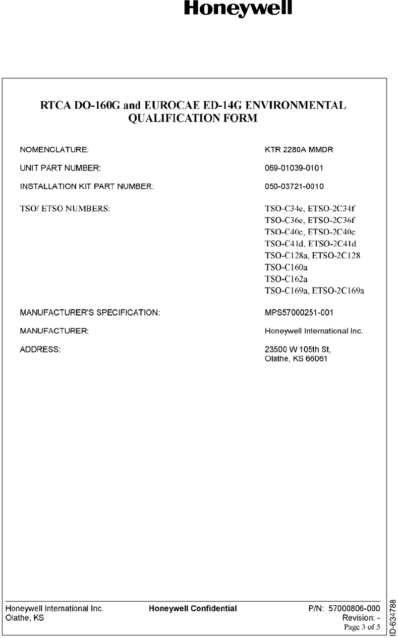
Page A-5
15 May 2017
SYSTEM INSTALLATION MANUAL
KTR 2280A
© Honeywell International Inc. Do not copy without express permission of Honeywell.

SYSTEM INSTALLATION MANUAL
KTR 2280A
Page A-6
15 May 2017
© Honeywell International Inc. Do not copy without express permission of Honeywell.
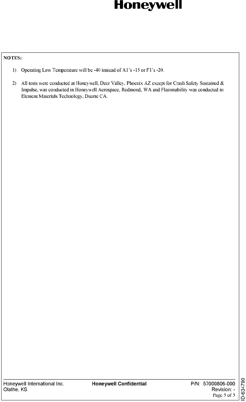
SYSTEM INSTALLATION MANUAL
KTR 2280A
Page A-7
15 May 2017
© Honeywell International Inc. Do not copy without express permission of Honeywell.

SYSTEM INSTALLATION MANUAL
KTR 2280A
Page A-8
15 May 2017
© Honeywell International Inc. Do not copy without express permission of Honeywell.
KA 44B ENVIRONMENTAL PERFORMANCE
The KA 44B ADF Antenna (Honeywell PN 071-1234-00) is certified to TSO C41c with RTCA DO-160A
environmentals per B2D2/A/LJY/XXXXXX/ABABA.
Recent "not-for-certification-credit" testing has been performed on this antenna to determine expected
performance in selected DO-160D environmental conditions.
DO-160D Section 20 (RF Susceptibility) Tests
A KA 44B production test sample was subjected to Category TT fields as defined in the test environment called
out in RTCA DO-160D Section 20 (Change No. 1). This unit was tested in conjunction with the KTR
2280 Multi-Mode Digital Radio. All conducted and radiated susceptibility performance requirements
were passed except for radiated susceptibility in the band of interference frequencies between 277 MHz
and 339 MHz. Within this band the KA 44B could not tolerate interference levels greater than 0.8 V/m
(for acceptable audio signal-to-noise) or greater than 1.1 V/m (for acceptable bearing error).
A KA 44B production test sample was subjected to the 100 V/M (and greater) HIRF levels expected for aircraft
system level certification. This test was done in a manner consistent with aircraft system level HIRF
certification testing. No permanent damage was noted during the HIRF exposure and the unit returned
immediately to normal operation after the HIRF event terminated.
DO-160D Section 22 (Lightning Induced Transient Susceptibility) Tests
A KA 44B production test sample was subjected to Category A3J33 as defined and in the test environment
called out in RTCA DO-160D Section 22 (Change No. 3). The KA 44B passed all requirements.
DO-160D Section 23 (Lightning Direct Effects) Tests
A KA 44B production test sample was subjected to Category 2A as defined in the test environment called out in
RTCA DO-160D Section 23. The KA 44B passed all requirements.
Other DO-160D based test data has been collected and is available on request from Honeywell.

SYSTEM INSTALLATION MANUAL
KTR 2280A
Page B-1
15 May 2017
© Honeywell International Inc. Do not copy without express permission of Honeywell.
APPENDIX B
DEVIATIONS
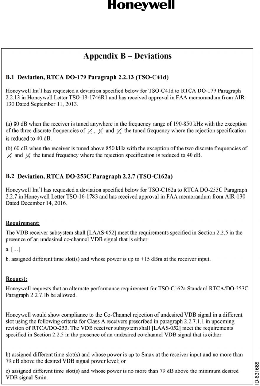
SYSTEM INSTALLATION MANUAL
KTR 2280A
Page B-2
15 May 2017
© Honeywell International Inc. Do not copy without express permission of Honeywell.
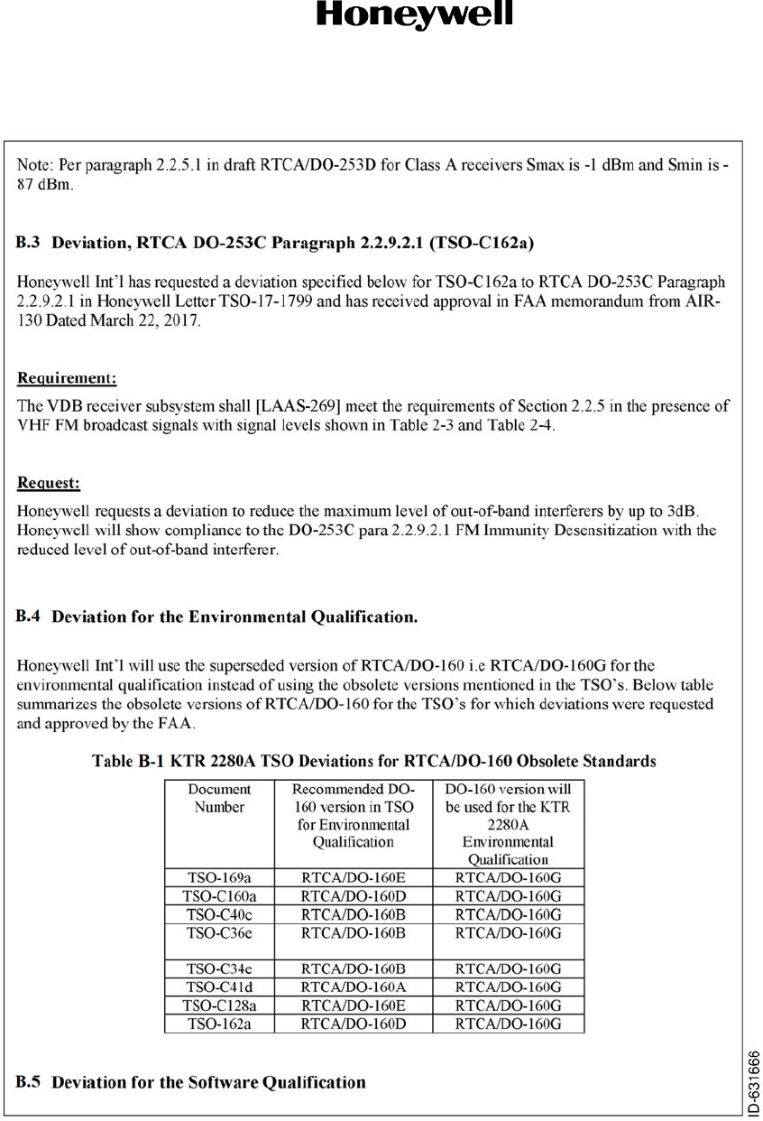
SYSTEM INSTALLATION MANUAL
KTR 2280A
Page B-3
15 May 2017
© Honeywell International Inc. Do not copy without express permission of Honeywell.
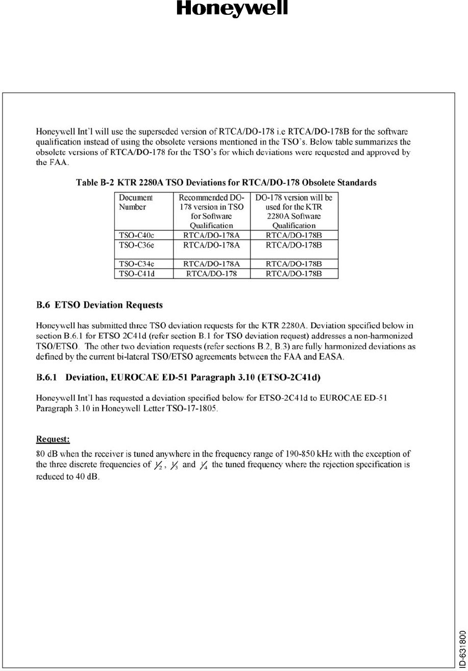
SYSTEM INSTALLATION MANUAL
KTR 2280A
Page B-4
15 May 2017
© Honeywell International Inc. Do not copy without express permission of Honeywell.