Honeywell LXE-MX7T Wireless Handheld Terminal User Manual MX7 Tecton CE User Guide
Honeywell International, Inc. Wireless Handheld Terminal MX7 Tecton CE User Guide
Manual
Draft07-For review only - Do not publish or distribute - LXE Confidential
MX7 Tecton CE User Guide
Microsoft® Windows® Embedded CE 6 Operating System
E-EQ-MX7CEOGWW-A
2010 Copyright© by LXE®, Inc, An EMS Technologies Company. All Rights
Reserved.

Notices
LXE Inc. reserves the right to make improvements or changes to published MX7 Tecton information at any time without notice.
While reasonable efforts have been made in the preparation of this publication to assure its accuracy, LXE assumes no liability
resulting from any errors or omissions in this publication, or from the use of the information contained herein. Further, LXE
Incorporated, reserves the right to revise this publication and to make changes to it from time to time without any obligation to
notify any person or organization of such revision or changes.
Trademarks
Copyright © 2010 by LXE Inc., An EMS Technologies Company, 125 Technology Parkway, Norcross, GA 30092 U.S.A. (770)
447-4224
LXE® and Spire® are registered trademarks of LXE Inc.
Microsoft®, ActiveSync®, MSN, Outlook®, Windows®, Windows Mobile®, the Windows logo, and Windows Media are
either registered trademarks or trademarks of Microsoft Corporation in the United States and/or other countries.
Intel and Intel XScale are trademarks or registered trademarks of Intel Corporation or its subsidiaries in the United States and
other countries.
Summit Data Communications, Inc. Summit Data Communications, the Summit logo, and “The Pinnacle of Performance” are
trademarks of Summit Data Communications, Inc.
The Bluetooth® word mark and logos are owned by the Bluetooth SIG, Inc. and any use of such marks by LXE, Inc. is under
license.
PowerScan is a registered trademark of Datalogic Scanning, Inc., located in Eugene, OR.
Symbol® is a registered trademark of Symbol Technologies. MOTOROLA® and the Stylized M Logo are registered
trademarks of Motorola®, Inc.
Hand Held® is a registered trademark of Hand Held Products, Inc., located in Skaneateles Falls, NY.
When any part of this publication is in PDF format: “Acrobat ® Reader Copyright © 2010 Adobe Systems Incorporated. All
rights reserved. Adobe, the Adobe logo, Acrobat, and the Acrobat logo are trademarks of Adobe Systems Incorporated”
applies.
Other product names mentioned within this publication may be trademarks or registered trademarks of other companies.

Table of Contents
Set Up A New MX7 Tecton 1
Hardware Setup 1
Software Setup 1
Laser Warnings and Labels 2
Label Location 2
Label 2
Components 3
I/O Port and Cables 4
Scanner / Imager Aperture 5
Handle 6
Handstrap 6
Keypads 7
Batteries 9
How To Connect or Remove the Battery Pack 9
Insert/Replace Battery 9
Remove Battery 10
Hotswap the Main Battery 10
Charge or Recharge the Main Battery 11
Tapping the Touchscreen with a Stylus 12
Backlights and Indicators 13
System Status LED 13
Alpha mode Status LED 13
Scan Status 13
Toggle Vibrate Indicator 13
Connecting Cables to the MX7 Tecton 14
Connecting the USB Client and Power Cable 14
Client Cable Assembly 14
Connecting the Serial and Power Cable 15
Serial/Power Cable Assembly 15
Connecting an External Power Supply 16
Connecting Vehicle Power 17
DC to DC Power Supply Installation 17
Connecting Electrical Cables to Power Sources 17
Wiring Schematic 18
How To Connect Vehicle Electrical Connection 18
Vehicle 12V Bare Wire Adapter 20
Vehicle Cable Connection Cable (Fuse Not Shown) 20
E-EQ-MX7CEOGWW-ADraft 07 [ i ] MX7 Tecton CE User Guide

Table of Contents
For review only - Do not publish or distribute - LXE Confidential - Draft 07
Connecting the Power Cable to the Vehicle 21
Connect Power Supply to Vehicle Cradle 23
Cradle Power Connector Port 23
Connecting the Headset Cable 24
Adjust Headset / Microphone and Secure Cable 25
Attaching the Handstrap 26
Attaching the Trigger Handle 27
Assemble the Carry Case 28
Carry Case with Metal Snaps 28
Set Date and Time Zone 29
Using the Input Panel / Virtual Keyboard 29
Set Power Scheme Timers 30
Battery Power Scheme 30
AC Power Scheme 30
Set Speaker Volume 31
Using the Keypad 31
Using the Control Panel 31
Touchscreen 32
Calibrating the Touchscreen 32
Adjusting the Display Backlight Timer 32
Apply the Touchscreen Protective Film 32
Cleaning the Touchscreen and Scanner Aperture 33
Setup Terminal Emulation Parameters 33
Using the AppLock Switchpad 34
Using the Keypad 34
Using the Touchscreen 34
Connecting Bluetooth Devices 35
Taskbar Connection Indicator 35
Reboot Sequences 36
Suspend / Resume 36
Warmboot 36
Troubleshooting 37
Continuous Scan Mode 37
Regulatory Notices and Safety Information 38
Class B Digital Device 38
RF Notices 39
Laser Light Safety Statement 40
Vehicle Power Supply Connection Safety Statement 42
Revision History 42
E-EQ-MX7CEOGWW-ADraft 07 [ ii ] MX7 Tecton CE User Guide


Set Up A New MX7 Tecton
Note: LXE recommends that installation or removal of accessories be performed on a clean, well-lit surface. When
necessary, protect the work surface, the MX7 Tecton, and components from electrostatic discharge.
While the MX7 Tecton is in a Hazardous Location DO NOT:
lConnect an external power source to the MX7 Tecton.
lConnect a USB device or audio jack to the MX7 Tecton.
lRemove or install a battery pack in the MX7 Tecton.
lPlace the MX7 Tecton in a powered dock or cradle.
Hardware Setup
1. Connect accessories.
2. Connect cables.
3. Insert/connect a fully charged battery
4. Press the Power key.
Software Setup
Prerequisite: Hardware setup is complete.
1. Calibrate Touch screen
2. Set Date and Time Zone
3. Set Power Schemes Timers
4. Set Speaker Volume
5. Pair Bluetooth devices
6. Setup Wireless client parameters
7. Setup terminal emulation parameters
8. Setup the LXE AppLock parameters
9. Set the LXE DCWedge parameters
Please refer to the MX7 Tecton Reference Guide for further information and instruction.
End User License Agreement (EULA)
When a new MX7 Tecton starts up a EULA is displayed on the touchscreen. It remains on the screen until the Accept or
Decline button is tapped with a stylus.
Tap the Accept button to accept the EULA terms and the MX7 Tecton continues the startup process. The EULA is not
presented to the user again.
Tap the Decline button to decline the EULA and the MX7 Tecton will reboot. It will continue to reboot until the Accept button is
tapped with the stylus.
Note: The EULA will be presented after any operating system upgrade or re-installation, including language-specific
operating systems.
E-EQ-MX7CEOGWW-ADraft 07 [ 1 ] MX7 Tecton CE User Guide
Laser Warnings and Labels
For review only - Do not publish or distribute - LXE Confidential - Draft 07
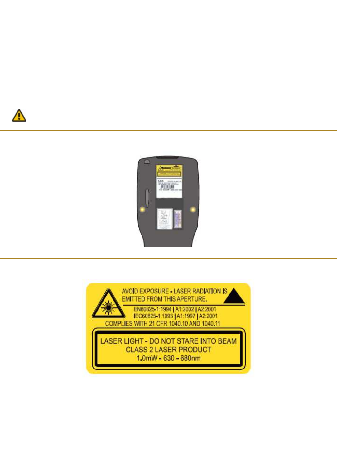
Laser Warnings and Labels
lDo not look into the laser’s lens.
lDo not stare directly into the laser beam.
lDo not remove the laser caution labels from the MX7 Tecton.
lDo not connect the laser barcode aperture to any other device. The laser barcode aperture is certified for use with the
MX7 Tecton only.
Caution
Laser radiation when open. Please read the caution labels. Use of controls, adjustments or performance of pro-
cedures other than those specified herein may result in hazardous radiation exposure.
Label Location
Label
E-EQ-MX7CEOGWW-ADraft 07 [ 2 ] MX7 Tecton CE User Guide
Components
For review only - Do not publish or distribute - LXE Confidential - Draft 07
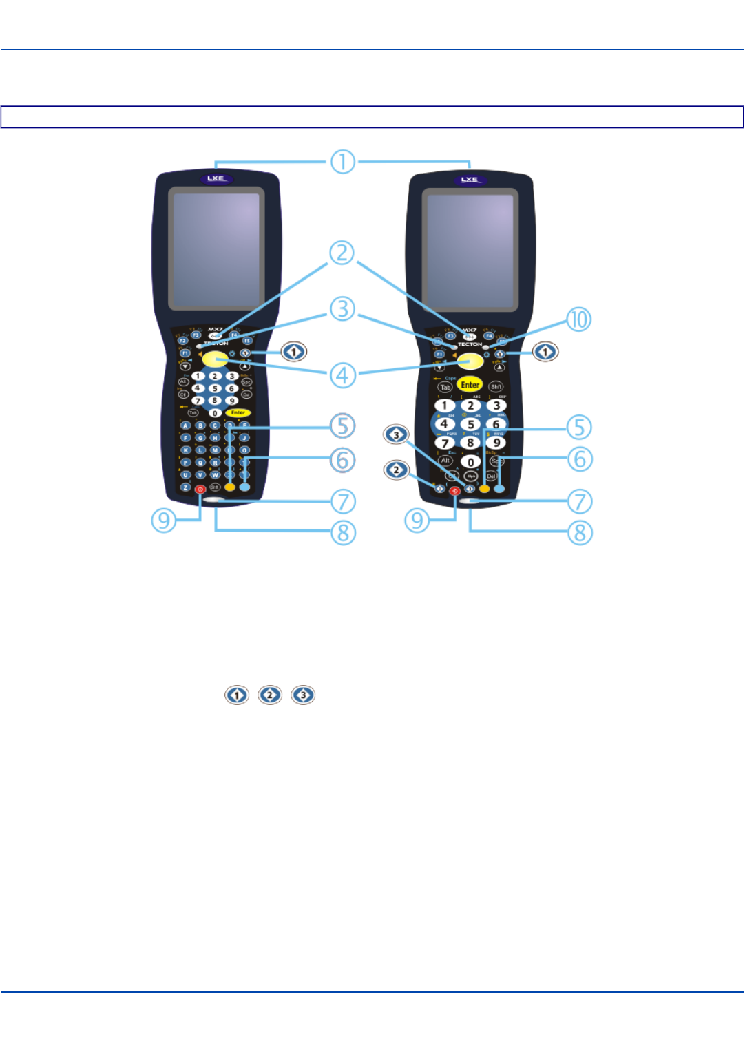
Components
Front
1. Scanner/Imager Aperture
2. Speaker
3. System Status LED
4. Scan Button
5. Orange Key (Sticky Key)
6. Blue Key (Sticky Key)
7. Scan Status LED
8. Cable Port
9. On / Off Button
10. Alpha Lock LED (32-Key only)
Diamond Keys
E-EQ-MX7CEOGWW-ADraft 07 [ 3 ] MX7 Tecton CE User Guide
I/O Port and Cables
For review only - Do not publish or distribute - LXE Confidential - Draft 07
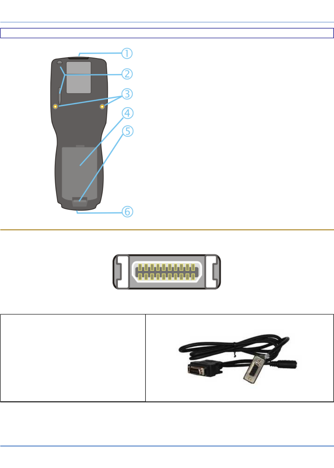
Back
1. Scanner/Imager Aperture
2. Stylus and Stylus Pocket
3. Trigger Handle Attach Points
4. Main Battery
5. Battery Fastener
6. Cable Port
I/O Port and Cables
I/O Port
Cable: Multipurpose RS-232 and Power
MX7055CABLE
E-EQ-MX7CEOGWW-ADraft 07 [ 4 ] MX7 Tecton CE User Guide
Scanner / Imager Aperture
For review only - Do not publish or distribute - LXE Confidential - Draft 07
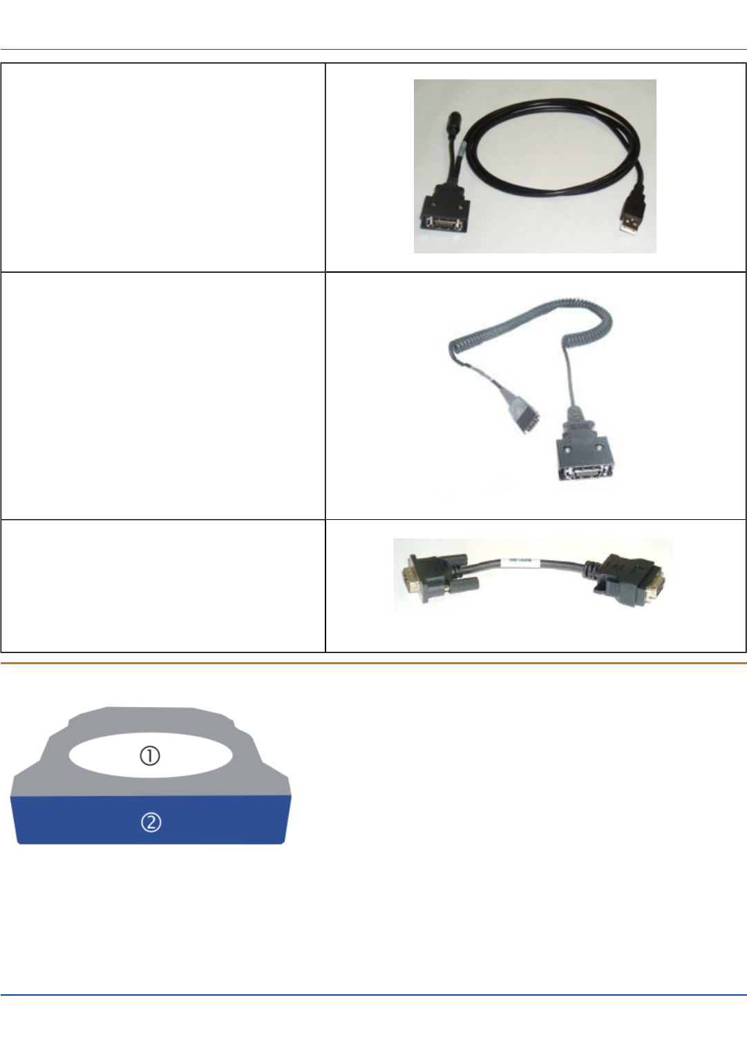
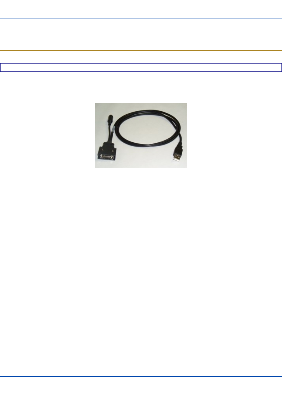
Cable: Multipurpose USB and Power
MX7052CABLE
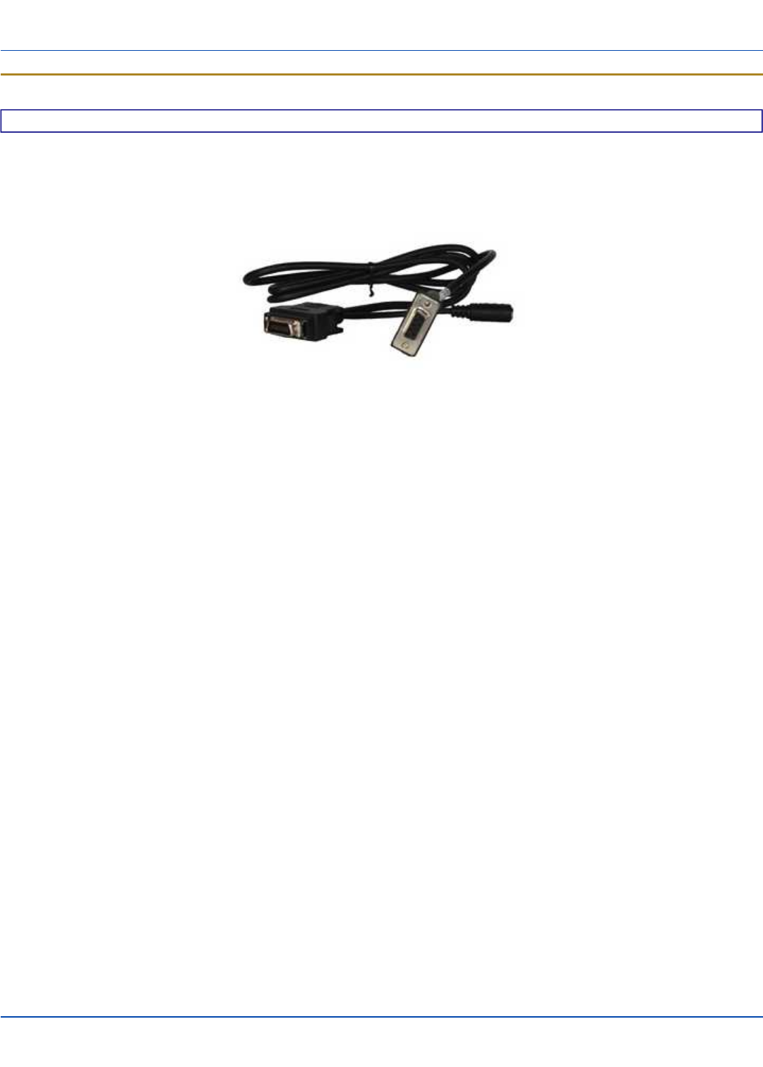
Adapter/Cable : Audio
MX7060CABLE
Adapter: RS-232 PC port to D9 male
MX7058CABLE
Scanner / Imager Aperture
1. Scanner / Imager Aperture
2. MX7 Tecton Front
Caution: Never stare directly into the beam aperture.
If Continuous Scan Mode has been enabled (default is disabled), the laser is always on and decoding. Caution: Laser beam
is emitted continuously. Do not stare into the laser beam.
E-EQ-MX7CEOGWW-ADraft 07 [ 5 ] MX7 Tecton CE User Guide
Handle
For review only - Do not publish or distribute - LXE Confidential - Draft 07
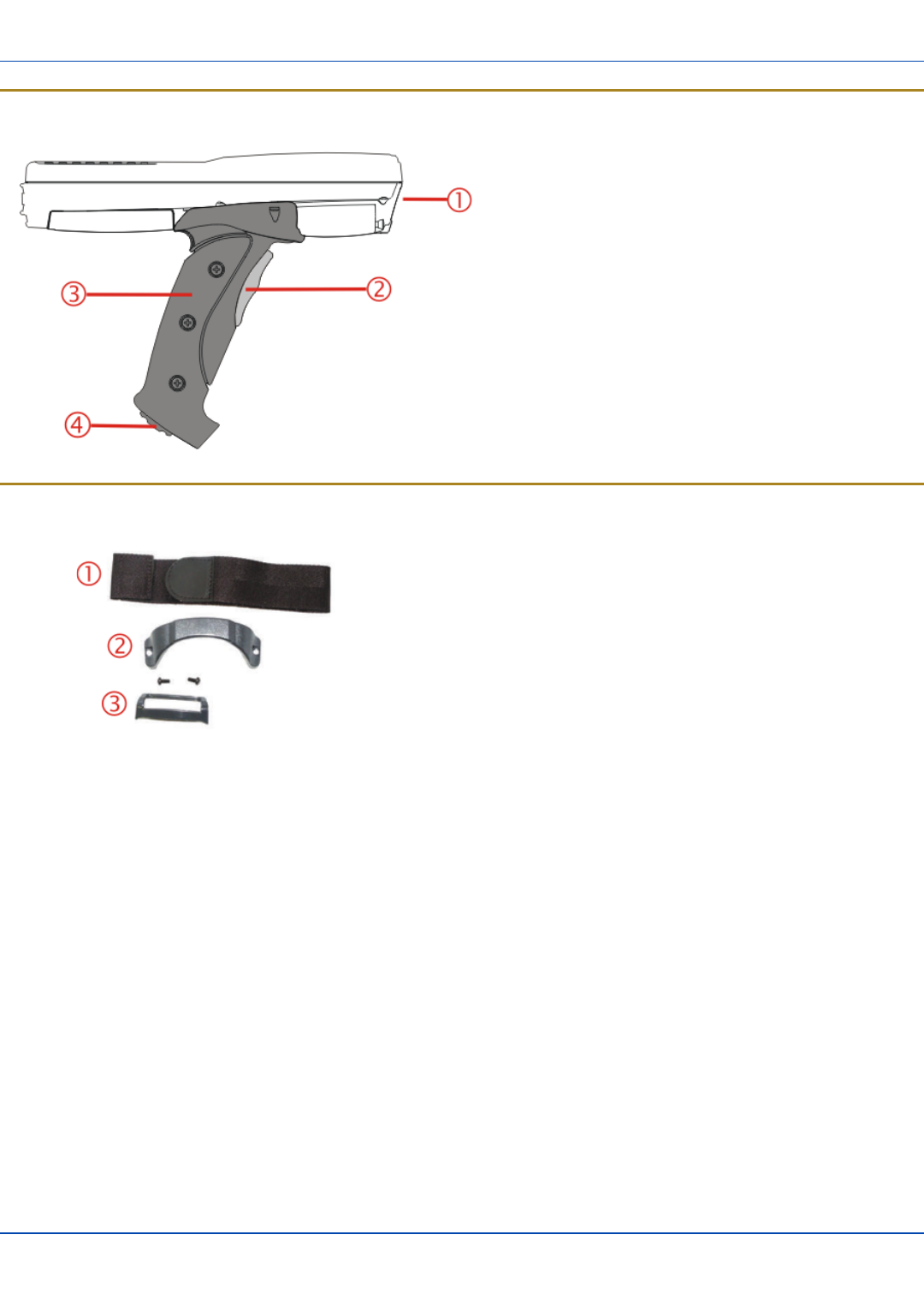
Handle
1. Imager / Scanner Aperture
2. Trigger
3. Handle
4. Tether Attach Point
Handstrap
1. Handstrap
2. Handstrap Retainer Bracket and mounting screws
3. Handstrap Clip
E-EQ-MX7CEOGWW-ADraft 07 [ 6 ] MX7 Tecton CE User Guide
Keypads
For review only - Do not publish or distribute - LXE Confidential - Draft 07
Keypads
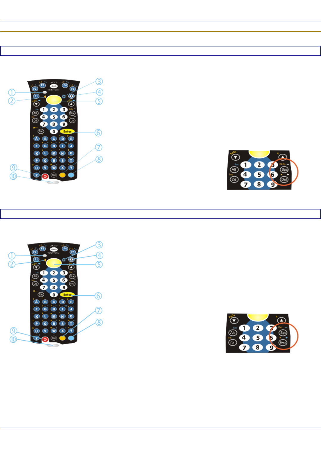
55 Key Delete Primary ANSI Keypad
1. System Status LED
2. Volume Control Icon
3. Display Brightness Icon
4. Diamond Key
5. Scan Button
6. Enter Key
7. Orange Key (Sticky Key)
8. Blue Key (Sticky Key)
9. On Off Button
10. Scan Status LED
Spc and Del key location
55 Key Backspace Primary ANSI Keypad
1. System Status LED
2. Volume Control Icon
3. Display Brightness Icon
4. Diamond Key
5. Scan Button
6. Enter Key
7. Orange Key (Sticky Key)
8. Blue Key (Sticky Key)
9. On Off Button
10. Scan Status LED
Spc and Bksp key location
E-EQ-MX7CEOGWW-ADraft 07 [ 7 ] MX7 Tecton CE User Guide
Keypads
For review only - Do not publish or distribute - LXE Confidential - Draft 07
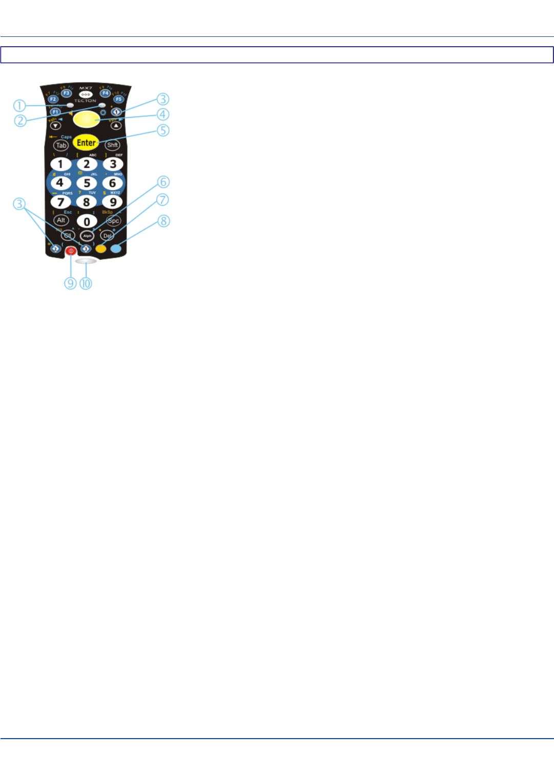
32 Key Numeric-Alpha Keypad
1. System Status LED
2. Alpha Status LED
3. Diamond Keys
4. Scan Button
5. Enter Key
6. Alph Key
7. Orange Key (Sticky Key)
8. Blue Key (Sticky Key)
9. On Off Button
10. Scan Status LED
E-EQ-MX7CEOGWW-ADraft 07 [ 8 ] MX7 Tecton CE User Guide

Batteries
For review only - Do not publish or distribute - LXE Confidential - Draft 07
Batteries
How To Connect or Remove the Battery Pack
Warning: Never remove or replace any battery in a hazardous location.
The MX7 Tecton will not function unless the battery pack is in place and securely latched.
Be sure to place the unit in Suspend Mode (by pressing the Power key or tapping Start | Suspend) before removing the battery.
Failing to properly place the device in Suspend mode will result in a loss of all unsaved data.
An MX7 Tecton will retain data, while the main battery is removed and replaced with a fully charged main battery, for 5 minutes.
Important: When the internal battery power is Low or Very Low connect the AC adapter to the MX7 Tecton before replacing the
main battery.
Note: The battery should not be replaced in a dirty, harsh or hazardous environment. When the battery is not connected to
the MX7 Tecton, any dust or moisture that enters the battery well or connector may transfer to the battery/well terminals,
potentially causing damage.
Warning:Only useLXEMX7A380BATT / 159904-0001 or a Low Temperature (CS) Battery : MX7A381BATT (Blue label)
batteries as replacements.
Insert/Replace Battery
To insert the main battery, complete the following steps:
1. Detach the bottom hook of the handstrap (if installed).
2. Tilt the end (without the latch) of the fully charged battery pack into the upper end of the battery compartment, and firmly
press the other end until it is fully inserted into the battery compartment
3. Push down on the battery until the retaining clip clicks into place.
4. Replace the handstrap clip in its holder (if installed).
The MX7 Tecton draws power from the battery immediately upon successful connection.
E-EQ-MX7CEOGWW-ADraft 07 [ 9 ] MX7 Tecton CE User Guide

Remove Battery
For review only - Do not publish or distribute - LXE Confidential - Draft 07
Remove Battery
To remove the battery, complete the following steps:
1. Place the MX7 Tecton in Suspend mode.
2. Detach the bottom hook of the handstrap (if installed).
3. Slide the battery retaining clip down to release the main battery.
4. Pull the battery up and out of the battery well.
Place the discharged battery pack in a powered battery charger.
Hotswap the Main Battery
Warning: Never replace (hotswap) the MX7 Tecton battery in a hazardous location.
Place the MX7 Tecton in Suspend Mode. LXE recommends any work in progress be saved prior to replacing the battery pack.
Simply replace the discharged battery with a fully-charged battery. An MX7 Tecton, with a fully charged internal battery, will
retain data during a battery hotswap for 5 minutes.
E-EQ-MX7CEOGWW-ADraft 07 [ 10 ] MX7 Tecton CE User Guide

Charge or Recharge the Main Battery
For review only - Do not publish or distribute - LXE Confidential - Draft 07
Charge or Recharge the Main Battery
Warning:Only useLXEMX7A380BATT / 159904-0001 or a Low Temperature (CS) Battery : MX7A381BATT (Blue label)
batteries as replacements.
Note: The MX7 Tecton Multi-Charger is designed for an indoor, protected environment. It is not authorized for use in
areas designated as Hazardous Locations.
New batteries must be fully charged prior to use.
The main battery can be recharged in an AC powered Multi-Charger after the battery has been removed from the MX7 Tecton or
its packing material when new.
The main battery while in the MX7 Tecton can be recharged using several different methods.
Note: An external power source is required before the main battery in the MX7 Tecton will recharge.
The main battery can be recharged while it is in the MX7 Tecton:
lby connecting the MX7 Tecton AC power adapter to the I/O connector at the base of the MX7 Tecton.
lby docking the MX7 Tecton in a powered desk cradle
lby docking the MX7 Tecton in a powered vehicle cradle
lor by connecting the car power adapter (CLA) to the I/O connector at the base of the MX7 Tecton.
Note: An uninterrupted external power source (wall AC adapters) transfers power to the computer’s internal charging
circuitry which, in turn, recharges the main battery and internal battery. Frequent connection to an external power source,
if feasible, is recommended to maintain internal battery charge status as the internal battery cannot be recharged by a
dead or missing main battery.
E-EQ-MX7CEOGWW-ADraft 07 [ 11 ] MX7 Tecton CE User Guide

Tapping the Touchscreen with a Stylus
For review only - Do not publish or distribute - LXE Confidential - Draft 07
Tapping the Touchscreen with a Stylus
Note: Always use the point of the stylus for tapping or making strokes on the touchscreen.
Never use an actual pen, pencil, or sharp/abrasive object to write on the touchscreen.
Hold the stylus as if it were a pen or pencil. Touch an element on the screen with the tip of the stylus then remove the stylus
from the screen.
Firmly press the stylus into the stylus holder when the stylus is not in use.
Using a stylus is similar to moving the mouse pointer then left-clicking icons on a desktop computer screen.
Using the stylus to tap icons on the touchscreen is the basic action that can:
lOpen applications
lChoose menu commands
lSelect options in dialog boxes or drop-down boxes
lDrag the slider in a scroll bar
lSelect text by dragging the stylus across the text
lPlace the cursor in a text box prior to typing in data
lPlace the cursor in a text box prior to retrieving data using the scanner/imager or an input/output device connected to the
serial port.
A stylus replacement kit is available.
E-EQ-MX7CEOGWW-ADraft 07 [ 12 ] MX7 Tecton CE User Guide
Backlights and Indicators
For review only - Do not publish or distribute - LXE Confidential - Draft 07
Backlights and Indicators
The MX7 Tecton System Status LED is located at the top left of the keypad, below the F3 key. The Alpha Mode LED is located
below the F4 key on the 32-key keypad.
LEDs (Light Emitting Diodes) are located on the front of the MX7 Tecton. They are:
1. System Status LED indicates power management status.
2. Alpha Mode Status LED applies to the 32-key keypad only.
System Status LED
Blinking Red Battery power fail; critical suspend mode
Steady Red Main battery low
Blinking Green Display turned off
Yellow / Amber A few seconds when Power key is pressed
No Color No user intervention required.
Alpha mode Status LED
Steady Green Device is in “Alpha” character input mode
No Color Device is in “Numeric” key input mode
Scan Status
An oval indicator situated below the keypad and next to the On button.
Steady Green Good scan
Steady Amber Decoder engine storing changed parameters
Steady Red Scan in progress
No Color Scanner / Imager ready for use or no scanner installed.
Toggle Vibrate Indicator
Start | Settings | Control Panel | Data Collection| Notification tab
The MX7 Tecton vibration motor is activated when a scan is completed successfully (good scan vibration) or with a failure
(scan key released before good scan, timeout, or rejected because of Data Options configuration).
The vibrations can be detected under the handstrap or through the trigger handle.
Toggle the vibrate indicator on or off by tapping the desired radio button for Good Scan Vibration and Bad Scan Vibration.
Options are:
lOff
lShort
lMedium
lLong
E-EQ-MX7CEOGWW-ADraft 07 [ 13 ] MX7 Tecton CE User Guide
Connecting Cables to the MX7 Tecton
For review only - Do not publish or distribute - LXE Confidential - Draft 07
Connecting Cables to the MX7 Tecton
Note: Do not connect or disconnect cables in a Hazardous location.
Connecting the USB Client and Power Cable
Prerequisite : AC/DC Adapter Assembled
Note: Do not connect AC power to the AC Adapter yet.
Client Cable Assembly
1. Holding the cable I/O connector, pinch the catch release buttons in until the catches are open. Connect the cable to the
MX7 Tecton I/O port by matching the shape of the I/O connector on the cable with the shape of the I/O connector at the
base of the MX7 Tecton. Release the catch release buttons.
2. Insert the AC adapter single pin cable .
3. Connect the AC Adapter to a power source (wall outlet).
4. Insert the USB client plug into the target USB Client port.
The MX7 Tecton and the USB client are connected.
E-EQ-MX7CEOGWW-ADraft 07 [ 14 ] MX7 Tecton CE User Guide
Connecting the Serial and Power Cable
For review only - Do not publish or distribute - LXE Confidential - Draft 07
Connecting the Serial and Power Cable
Prerequisite : AC/DC Adapter, Assembled
Note: Do not connect AC power to the AC Adapter yet.
Serial/Power Cable Assembly
1. Holding the cable I/O connector, squeeze the catch release buttons in until the catches are open. Connect the cable to
the MX7 Tecton I/O port by matching the shape of the I/O connector on the cable with the shape of the I/O connector at
the base of the MX7 Tecton. Release the catch release buttons.
2. Connect the AC adapter single pin cable .
3. Connect the assembled AC/DC Adapter to a power source (wall outlet).
4. Connect the RS-232 cable end to the desired serial device. Turn the thumbscrews clockwise until the connection is
finger-tight.
The MX7 Tecton and the serial device are connected.
E-EQ-MX7CEOGWW-ADraft 07 [ 15 ] MX7 Tecton CE User Guide
Connecting an External Power Supply
For review only - Do not publish or distribute - LXE Confidential - Draft 07
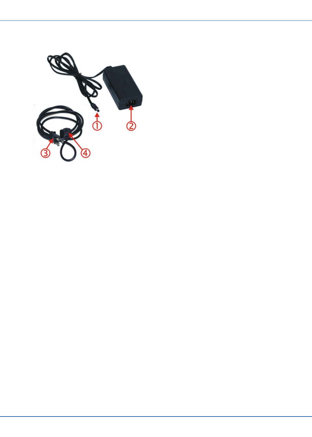
Connecting an External Power Supply
1. Connects to AC single-pin cable end
2. AC receptacle
3. Wall plug
4. AC connection from wall to adapter
To apply external power to the MX7 Tecton follow the steps below in sequence.
1. Plug the 3 prong AC adapter cable end of the external power assembly into an AC power source (e.g. wall outlet).
2. Firmly press the female end of the power cable into the male connector on the power adapter. When AC power is being
supplied to the power adapter, the LED on the power adapter illuminates green.
3. Squeeze the catches of the I/O connector and push the cable connector into the MX7 Tecton I/O port until it clicks. The
click means the connector is seated firmly.
4. Press the power cable connector pin from the power adapter into the connector on the (USB/Power or Serial/Power)
cable attached to the base of the MX7 Tecton. External power is now being supplied to the MX7 Tecton.
Whenever possible, use the AC power adapter with the MX7 Tecton to conserve the main battery power and maintain a charge
in the internal battery.
E-EQ-MX7CEOGWW-ADraft 07 [ 16 ] MX7 Tecton CE User Guide
Connecting Vehicle Power
For review only - Do not publish or distribute - LXE Confidential - Draft 07
Connecting Vehicle Power
Complete vehicle cradle mounting and power instruction is contained in the MX7 Tecton Cradle Guide.
The MX7 Tecton must have a main battery installed before docking the MX7 Tecton in a cradle.
DC to DC Power Supply Installation
For use with LXE power supplies:
l9000301PWRSPLY – Power Supply, 18-60VDC with cable
l9000302PWRSPLY – Power Supply, 60-110VDC with cable
Connecting Electrical Cables to Power Sources
The DC to DC power supply is used to provide vehicle power to the MX7 Tecton when placed in a DC powered vehicle dock.
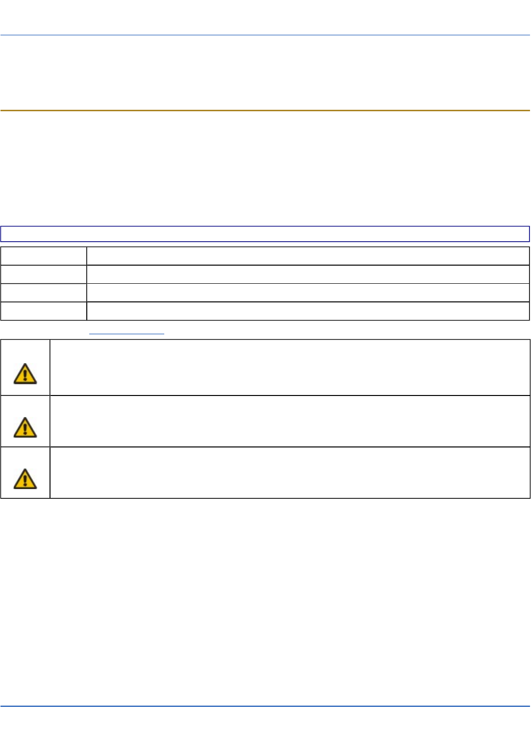
Specifications for Electrical Supply
Input Voltage Always observe input voltage range specified on the DC to DC power supply
Output Voltage 12 VDC ± 10%
Power 50 W
Fuse 5 A (slow blow fuse). Fuses are USER SUPPLIED
Note: Refer to the Wiring Schematic for wiring colors and connections.
Caution: For proper and safe installation, the input power cable must be connected to a fused circuit on the vehicle. This
fused circuit requires a five Amp maximum time delay (slow blow) high interrupting rating fuse. If the supply
connection is made directly to the battery, the fuse should be installed in the positive lead within 5 inches of the
battery positive (+) terminal. Note: For North America, a UL Listed fuse is to be used.
Caution:
For installation by trained service personnel only.
Warning:
Risk of ignition or explosion. Explosive gas mixture may be vented from battery. Work only in well ventilated
area. Avoid creating arcs and sparks at battery terminals.
E-EQ-MX7CEOGWW-ADraft 07 [ 17 ] MX7 Tecton CE User Guide
Wiring Schematic
For review only - Do not publish or distribute - LXE Confidential - Draft 07
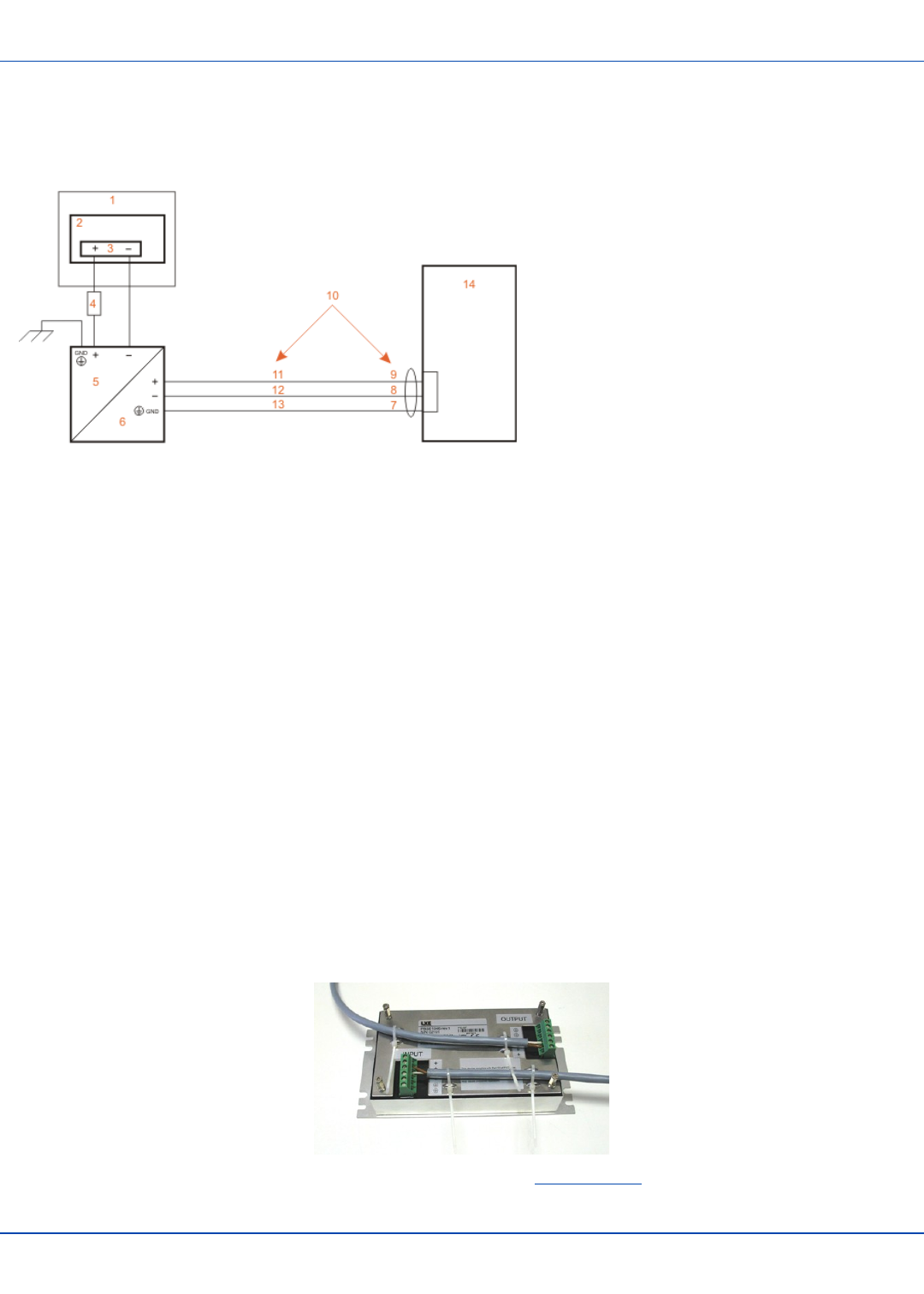
Wiring Schematic
1. Existing Circuitry on Vehicle
2. Forklift Battery
3. Main Switch
4. 5A slow fuse close to power source
5. Power input
6. Isolated DC power output
7. Green
8. Red / Black
9. Red / White
10. Use color scheme corresponding to input wire
provided
11. Brown
12. Blue
13. Green
14. Vehicle mounted cradle
How To Connect Vehicle Electrical Connection
1. The vehicle cradle must be empty.
2. Begin by connecting the power cable to the MX7 Tecton's vehicle cradle. Work from this connection with the last con-
nection being to the vehicle’s power source.
3. Route the cable from the cradle to the DC to DC converter.
4. Cut the cable to length and strip the wire ends.
Route the power cable the shortest way possible. The cable is rated for a maximum temperature of 105°C (221°F).
When routing this cable it should be protected from physical damage and from surfaces that might exceed this
temperature. Do not expose the cable to chemicals or oil that may cause the wiring insulation to deteriorate. If the
vehicle is equipped with a panel containing Silicon Controller Rectifiers (SCR’s), avoid routing the power cable in close
proximity to these devices.Always route the cable so that it does not interfere with safe operation and maintenance of
the vehicle.
5. Remove the DC to DC converter lid screws. Put them in a safe place.
6. Remove the lid from the DC to DC converter.
7. Attach the stripped wire ends to the output side of the DC to DC converter.
8. Attach the stripped wire ends to the input side of the DC to DC converter.
9. The input and output blocks each have two + plus and two – minus connectors. Either connector in the block can be
used to connect the matching polarity wire. The input and output blocks also each have two chassis ground con-
nections. When connecting the MX7 Tecton cradle to vehicle power, use one chassis ground connector in each block.
10. Wire colors depend on the type of device attached. Please refer to this illustration for wire colors.
11. Use the looms and wire ties to secure all wiring as shown above, then reattach the cover with the screws.
E-EQ-MX7CEOGWW-ADraft 07 [ 18 ] MX7 Tecton CE User Guide

How To Connect Vehicle Electrical Connection
For review only - Do not publish or distribute - LXE Confidential - Draft 07
12. Connect the DC to DC converter to the vehicle’s electrical system.
13. While observing the fuse requirements specified here, connect the power cable as close as possible to the actual bat-
tery terminals of the vehicle. When available, always connect to unswitched terminals in the vehicle fuse panel, after
providing proper fusing.
Note: ATTENTION: For uninterrupted power, electrical supply connections should not be made at any point after
the ignition switch of the vehicle.
14. Use proper electrical and mechanical fastening means for terminating the cable. Properly sized “crimp” type electrical
terminals are an accepted method of termination. Please select electrical connectors sized for use with 18AWG (1mm2)
conductors.
15. Provide mechanical support for the cable by securing it to the vehicle structure at approximately one foot intervals, tak-
ing care not to over tighten and pinch conductors or penetrate outer cable jacket.
E-EQ-MX7CEOGWW-ADraft 07 [ 19 ] MX7 Tecton CE User Guide
Vehicle 12V Bare Wire Adapter
For review only - Do not publish or distribute - LXE Confidential - Draft 07
Vehicle 12V Bare Wire Adapter
Part Number: 9000A079CBL12ML3
Caution For proper and safe installation, the input power cable must be connected to a fused circuit on the vehicle. This
fused circuit requires a Amp maximum time delay (slow blow) high interrupting rating fuse. If the supply
connection is made directly to the battery, the fuse should be installed in the positive lead within 5 inches of the
battery positive (+) terminal. Note: For North America, a UL Listed fuse is to be used.
Caution
For installation by trained service personnel only.
Warning
Risk of ignition or explosion. Explosive gas mixture may be vented from battery. Work only in well ventilated
area. Avoid creating arcs and sparks at battery terminals.
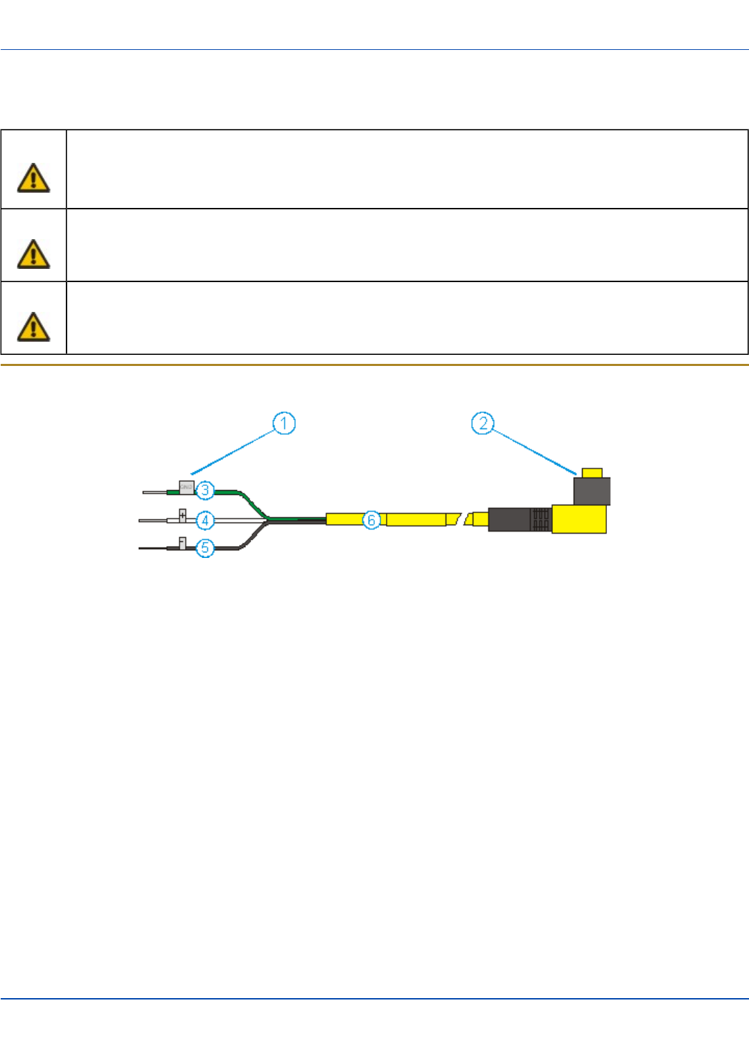
Vehicle Cable Connection Cable (Fuse Not Shown)
1. To Vehicle Battery
2. To Vehicle Mounted Device
3. Green (GND)
4. Brown (DC+)
5. Blue (DC-)
6. 12 VDC
E-EQ-MX7CEOGWW-ADraft 07 [ 20 ] MX7 Tecton CE User Guide
Connecting the Power Cable to the Vehicle
For review only - Do not publish or distribute - LXE Confidential - Draft 07
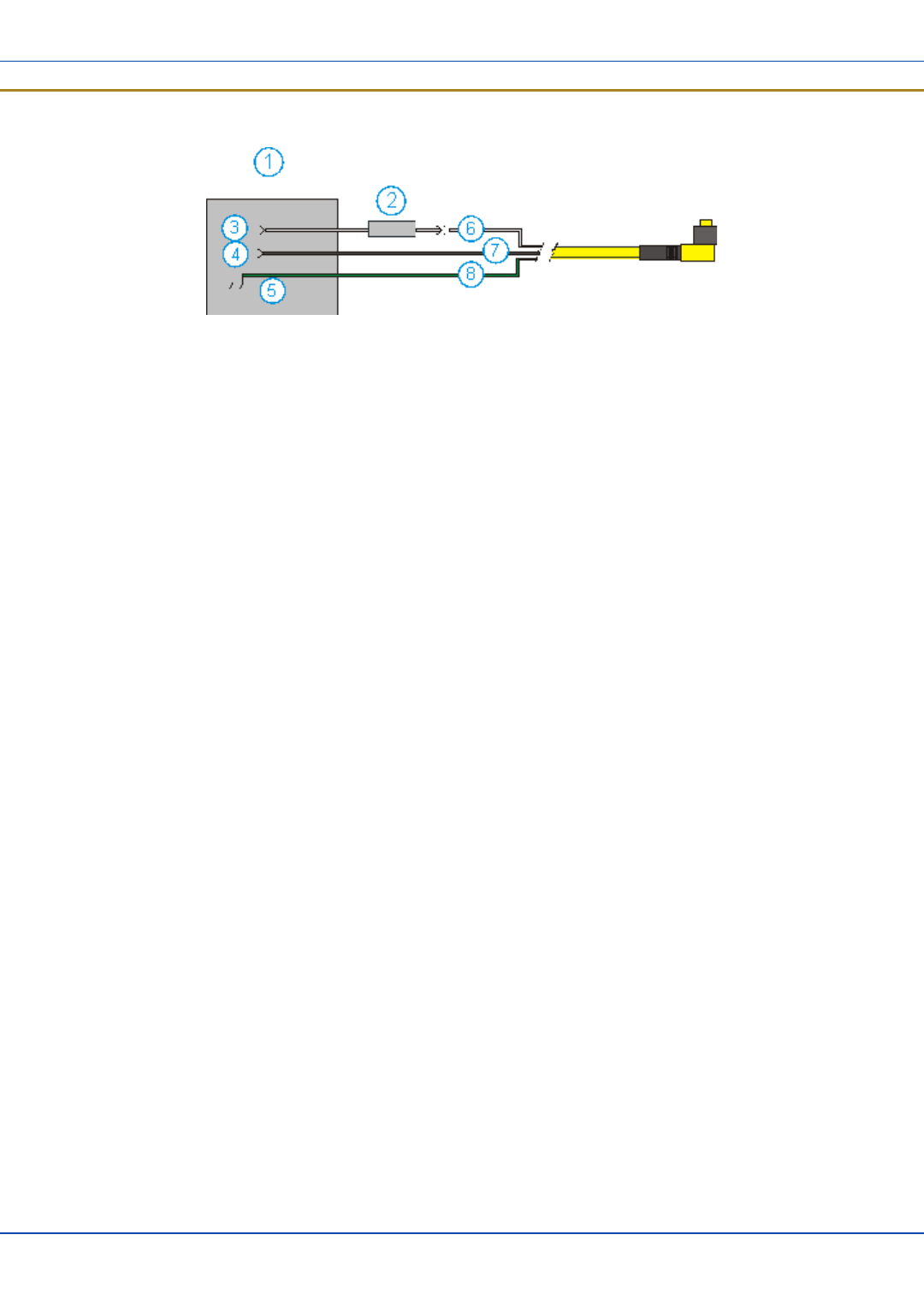
Connecting the Power Cable to the Vehicle
1. Vehicle Electrical System
2. 10 Amp Slow Blow Fuse
3. DC +
4. DC -
5. Vehicle Chassis
6. Brown
7. Blue
8. Green
Note: Correct electrical polarity is required for safe and proper installation. The cradle will not power on or function if the
cable is connected with the polarity reversed. See the following figure titled “Vehicle Connection Wiring Color Codes” for
additional wire color-coding specifics.
E-EQ-MX7CEOGWW-ADraft 07 [ 21 ] MX7 Tecton CE User Guide
Connecting the Power Cable to the Vehicle
For review only - Do not publish or distribute - LXE Confidential - Draft 07
How To: Connect Vehicle 12 VDC Connection
1. The power cable must be UNPLUGGED from the MX7 Tecton vehicle cradle.
2. While observing the fuse requirements specified above, connect the power cable as close as possible to the actual bat-
tery terminals of the vehicle. When available, always connect to unswitched terminals in the vehicle fuse panel, after
providing proper fusing.
ATTENTION: For uninterrupted power, electrical supply connections should not be made at any
point after the ignition switch of the vehicle.
3. Route the power cable the shortest way possible. The cable is rated for a maximum temperature of 105°C (221°F).
When routing this cable it should be protected from physical damage and from surfaces that might exceed this tem-
perature. Do not expose the cable to chemicals or oil that may cause the wiring insulation to deteriorate.
Note: If the vehicle is equipped with a panel containing Silicon Controller Rectifiers (SCR’s), avoid routing
the power cable in close proximity to these devices.
Always route the cable so that it does not interfere with safe operation and maintenance of the vehicle.
Use proper electrical and mechanical fastening means for terminating the cable. Properly sized “crimp” type
electrical terminals are an accepted method of termination. Select electrical connectors sized for use with
18AWG (1mm2) conductors.
Wiring color codes for LXE supplied DC input power cabling:
Vehicle Supply Wire Color
+12VDC (DC +) Brown
Return (DC -) Blue
Vehicle Chassis (GND) Green
4. Provide mechanical support for the cable by securing it to the vehicle structure at approximately one foot intervals, tak-
ing care not to over tighten and pinch conductors or penetrate outer cable jacket.
5. Refer to the following sections to complete the power connection to the MX7 Tecton vehicle cradle.
E-EQ-MX7CEOGWW-ADraft 07 [ 22 ] MX7 Tecton CE User Guide
Connect Power Supply to Vehicle Cradle
For review only - Do not publish or distribute - LXE Confidential - Draft 07
Connect Power Supply to Vehicle Cradle
The power cable connector is L-shaped.
The long end of the L (the cable) will be facing up towards the middle strain relief cable clamp.
Align the connector pins to the vehicle cradle Power connector; firmly pushing the connector into the Power port.
Tighten the nut of the plug clockwise until the power cable is securely fastened.
Secure the cable to the cradle with the LXE-installed strain relief cable clamp (see section titled Vehicle Cradle Strain Relief
Cable Clamp).
The power LED on the MX7 Tecton illuminates when it is receiving external power and an MX7 Tecton is docked.
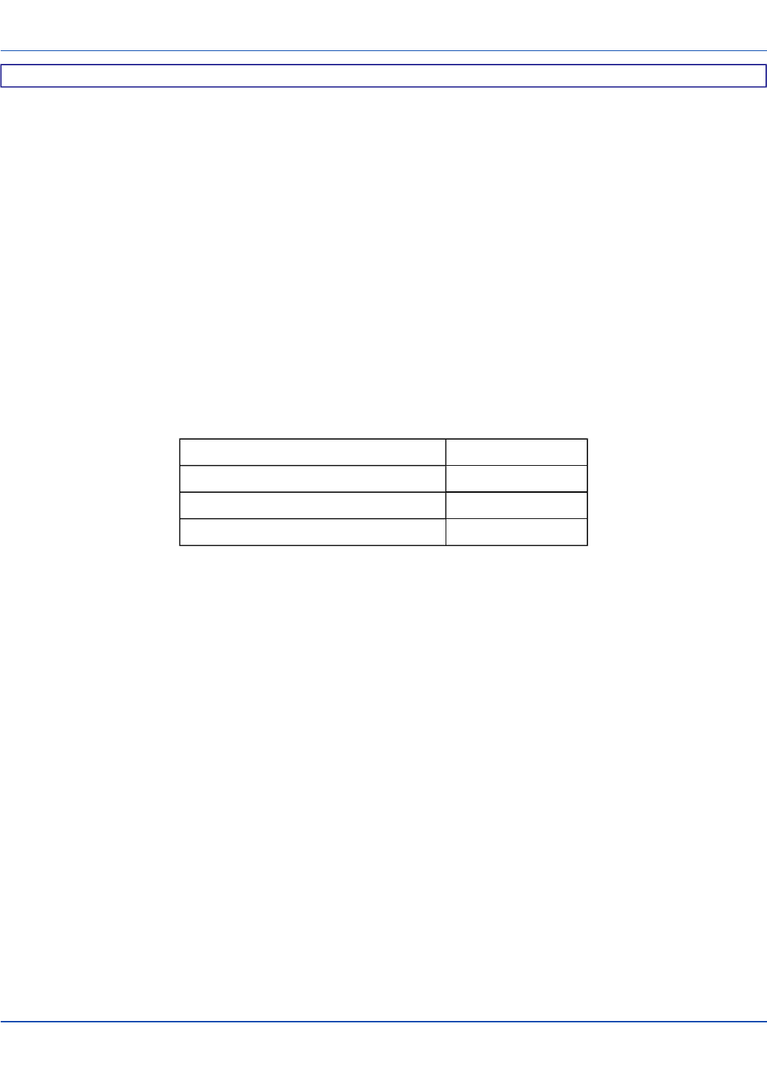
Cradle Power Connector Port
Note: When an external power supply is used to power this cradle, the external power supply should be UL Listed, with
LPS or Class 2 outputs rated 12V, minimum 2 Amps.
Pin Signal Wire Color
1 Ground (CG) Green
2 Return (-) Blue
3 +12V (+) Brown
E-EQ-MX7CEOGWW-ADraft 07 [ 23 ] MX7 Tecton CE User Guide
Connecting the Headset Cable
For review only - Do not publish or distribute - LXE Confidential - Draft 07
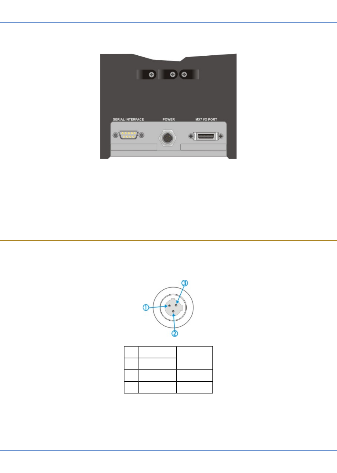
Connecting the Headset Cable
Headset
1. Connects to voice cable end of voice cable
2. Headphones
3. Microphone
MX7 Tecton Voice Cable
Connect the MX7 Tecton voice cable I/O connector to the I/O port on the MX7 Tecton. The MX7 Tecton internal microphone
and speaker are automatically disabled.
Slide the voice cable ends together until they click shut. Do not twist or bend the connectors.
The MX7 Tecton is ready for voice-enabled applications.
E-EQ-MX7CEOGWW-ADraft 07 [ 24 ] MX7 Tecton CE User Guide
Adjust Headset / Microphone and Secure Cable
For review only - Do not publish or distribute - LXE Confidential - Draft 07
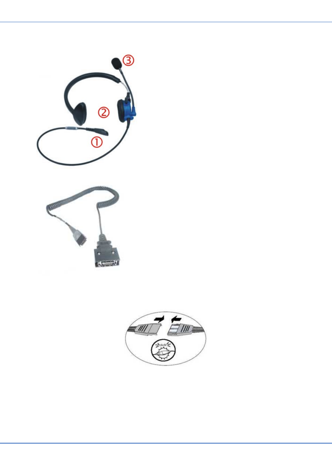
Adjust Headset / Microphone and Secure Cable
The headset consists of an earpiece, a microphone, a clothing clip and a cable. The headset attaches to the audio cable end of
the voice cable which attaches to the MX7 Tecton.
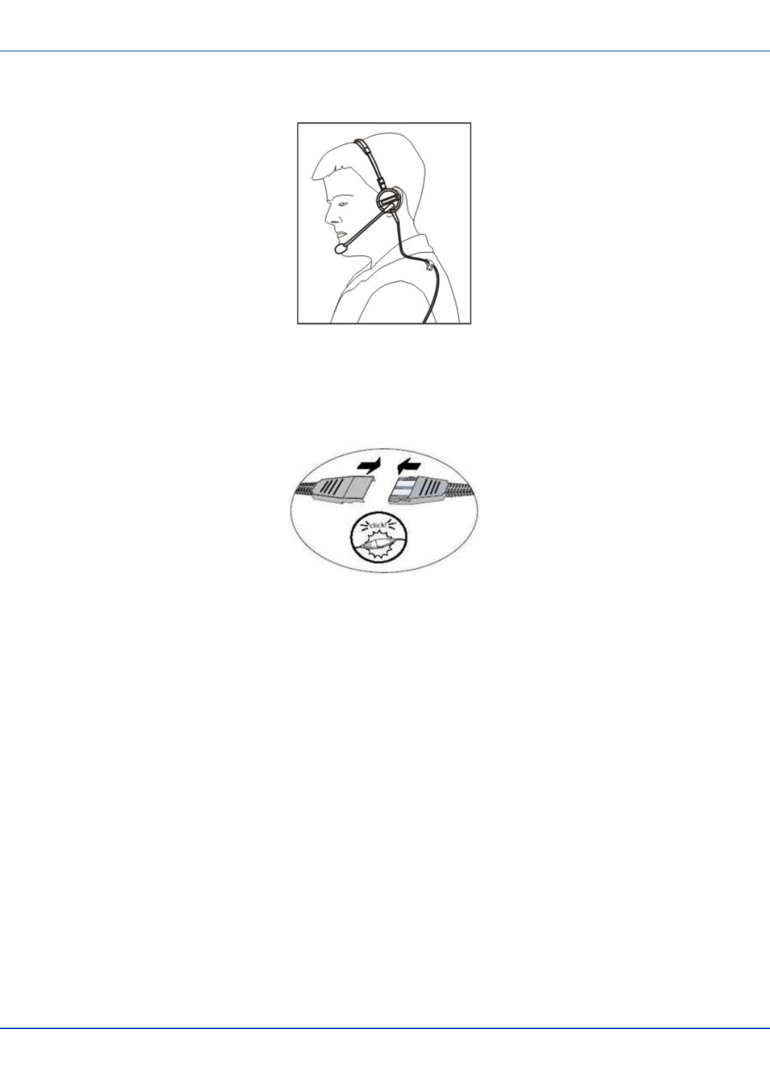
Align the audio connector and the headset quick connect cable end. Firmly push the cable ends together until they click and
lock in place.
Do not twist the microphone boom when adjusting the microphone. The microphone should be adjusted to be about two finger
widths from your mouth.
Make sure the microphone is pointed at your mouth. Note the small “Talk” label near the mouthpiece. Make sure the Talk label
is in front of your mouth. The microphone cable can be routed over or under clothing.
Under Clothing
lLeave the cable exposed only at the top of the collar.
lBe sure to leave a small loop of cable to allow movement of your head.
Over Clothing
lUse clothing clips to hold the cable close to your body.
lTuck the cable under the belt, but leave a small loop where it goes under the belt.
lDo not wear the cable on the front of your body. It may get in your way or get caught on protruding objects.
E-EQ-MX7CEOGWW-ADraft 07 [ 25 ] MX7 Tecton CE User Guide
Attaching the Handstrap
For review only - Do not publish or distribute - LXE Confidential - Draft 07
Attaching the Handstrap
Note: Either the trigger handle is attached to the MX7 Tecton or the handstrap is attached, not both. LXE recommends
that, in the absence of a trigger handle, the handstrap be used at all times. LXE pre-installs the handstrap on a MX7
Tecton that is purchased without a trigger handle.
1. Handstrap Retainer Bracket
2. Handstrap and tethered stylus
3. Handstrap Clip
Tool Required: Phillips #1 screwdriver (not supplied by LXE)
1. Place the MX7 Tecton with the screen facing down, on a flat stable surface.
2. Attach the handstrap retainer bracket to the MX7 Tecton with the screws and washers provided.
3. Slip the Handstrap Clip into the bracket at the base of the MX7 Tecton.
4. Making sure the closed loop fastener surfaces on the handstrap are facing up, slide the strap through the pin in the bot-
tom bracket and the clip.
5. Fold each end of the strap over so that the closed loop fastener surfaces mate evenly.
6. Test the strap's connection making sure the MX7 Tecton is securely connected to each end of the handstrap's con-
nectors.
Check the closed loop fastener, retainer bracket and clip connections frequently. If they have loosened, they must be tightened
or replaced before the MX7 Tecton is placed into service again.
E-EQ-MX7CEOGWW-ADraft 07 [ 26 ] MX7 Tecton CE User Guide
Attaching the Trigger Handle
For review only - Do not publish or distribute - LXE Confidential - Draft 07
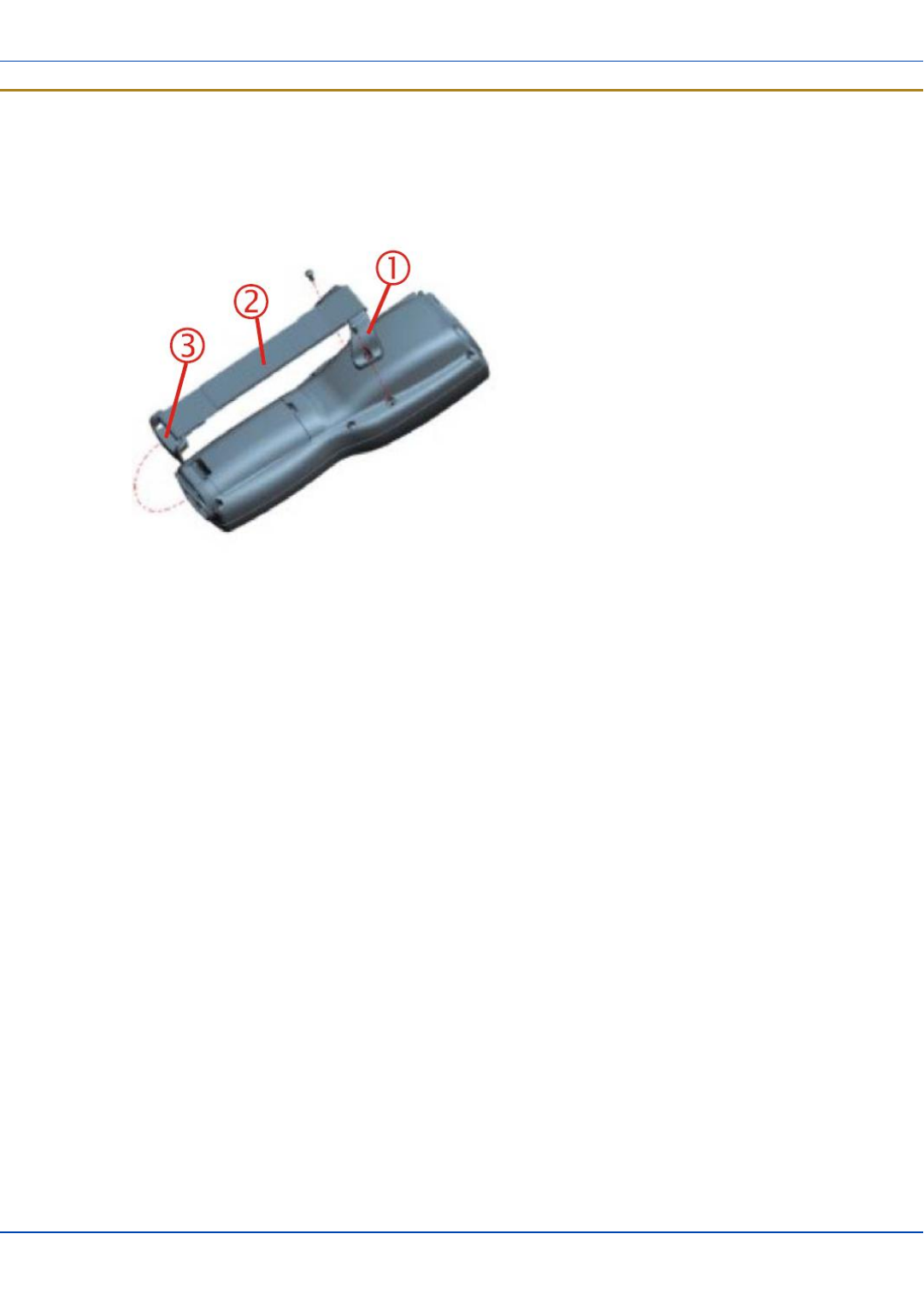
Attaching the Trigger Handle
Pressing the trigger on the trigger handle activates the integrated scanner and functions the same as the Scan key on the
keypad. With the handle installed the Scan key on the keypad remains active. The trigger duplicates the operation.
lThe handle is built of a durable, flexible plastic.
lThe handle will not detach from the MX7 Tecton if the unit is dropped.
lThe trigger handle is a mechanical device. Battery or external A/C power is not
required for operation.
lThe trigger handle does not need to be removed when replacing the main battery
pack.
lThe trigger handle might also be called a pistol grip.
Equipment needed: Torque wrench capable of torquing to 3±1 in/lb (.34±.11 N/m).
Either the trigger handle or the handstrap is attached, not both. LXE recommends that, in the absence of a trigger handle, the
handstrap be used at all times.
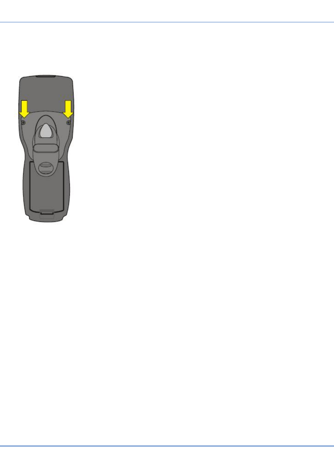
1. Place the MX7 Tecton with the screen facing down, on a flat stable surface.
2. Remove the handstrap, if installed.
3. Remove the battery.
4. Slide the locking tab on the underside of the trigger handle into the slot at the back of the battery compartment and press
it firmly into place.
5. Ensure that the battery can be inserted into the battery compartment before securing the trigger handle in place.
6. Attach the trigger handle to the MX7 Tecton (as shown above) with the screws provided.
7. Torque the pan head screws to 3±1 in/lb (.34±.11 N/m).
8. Secure the strap tether to the trigger handle.
9. Place the stylus in the stylus holder in the trigger handle.
Periodically check the trigger handle for wear and the connection for tightness. If the handle gets worn or damaged, it must be
replaced. If the trigger handle connection loosens, it must be tightened or replaced before the MX7 Tecton is placed in service.
E-EQ-MX7CEOGWW-ADraft 07 [ 27 ] MX7 Tecton CE User Guide

Assemble the Carry Case
For review only - Do not publish or distribute - LXE Confidential - Draft 07
Assemble the Carry Case
Note: LXE recommends that accessory installation or removal be performed on a clean, well-lit surface. When
necessary, protect the work surface, the MX7 Tecton, and components from electrostatic discharge.
1. Remove any cables connected to the I/O port at the bottom of the MX7 Tecton.
2. Remove the rubber boot from the MX7 Tecton.
3. Separate the hook and loop fabric on the carry case without removing the hook and loop fabric from the carry case.
4. Slip the removable, clear plastic protector for the keypad and touchscreen into the case. Position it against the openings
for the keypad and touchscreen in the case. The voice case does not require the clear plastic protector.
5. Slide the MX7 Tecton into the case, making sure the touchscreen and keypad (including the Scan LED) are visible and
accessible through the front openings of the case.
6. Securely tether the stylus to the case, if necessary. Place the stylus in the stylus holder on the handstrap or in the
trigger handle.
7. Loosen then tighten the handstrap (on cases without a trigger handle opening) until the carry case assembly is secure in
your hand.
8. When a shoulder strap is available,secure the clips at each end of the shoulder strap to the D rings on either side of the
carry case. The shoulder strap allows the MX7 Tecton to hang upside down until needed.
The main battery can be removed and inserted without taking the MX7 Tecton out of the carry case.
Carry Case with Metal Snaps
The metal snap has a bulge in the lip and a dot indentation on the opposite side. To snap the cap closed, tuck the lip bulge
under the snap lip and press on the dot to snap closed.
Pull the snap up to open.
E-EQ-MX7CEOGWW-ADraft 07 [ 28 ] MX7 Tecton CE User Guide
Set Date and Time Zone
For review only - Do not publish or distribute - LXE Confidential - Draft 07
Set Date and Time Zone
Tap Start | Settings | Control Panel | Date/Time icon or tap the Date/Time in the taskbar.
Set Date, Time, Time Zone, and assign a Daylight Savings location on the MX7 Tecton.
There is very little functional change from standard desktop PC Date/Time Properties options. Adjust the settings and tap the
OK button or the Apply button to save changes to the registry. Any changes take effect immediately.
Double-tapping the time displayed in the Taskbar causes the Date/Time Properties screen to appear.
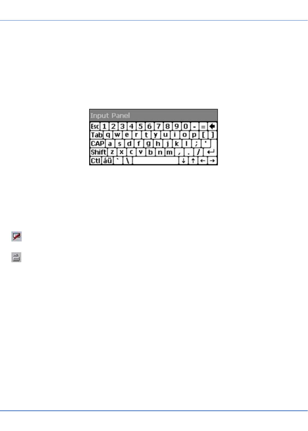
Using the Input Panel / Virtual Keyboard
The virtual keyboard is always available when needed e.g. text entry.
Place the cursor in the text entry field and, using the stylus:
lTap the Shift key to type one capital letter.
lTap the CAPS key to type all capital letters.
lTap the áü key to access symbols.
Some applications do not automatically display the Input Panel. In this case, do the following to use the Input Panel:
Input Panel icon in the taskbar
Keyboard icon in the taskbar
lTap the Input Panel or Keyboard icon in the taskbar.
lSelect Keyboard from the menu.
lMove the cursor into the text entry field when you want to enter data using the Input Panel.
When finished entering data, tap the icon in the Taskbar again.Select Hide Input Panel.
E-EQ-MX7CEOGWW-ADraft 07 [ 29 ] MX7 Tecton CE User Guide
Set Power Scheme Timers
For review only - Do not publish or distribute - LXE Confidential - Draft 07
Set Power Scheme Timers
Start | Settings | Control Panel | Power | Schemes
Change the parameter values and tap OK to save the changes.
Battery Power Scheme
Use this option when the MX7 Tecton will be running on battery power only.
Switch state to User Idle1Default is After 3 seconds
Switch state to System Idle2Default is After 15 seconds
Switch state to Suspend3Default is After 5 minutes
AC Power Scheme
Use this option when the MX7 Tecton will be running on external power (e.g. connected to an A/C power source).
Switch state to User Idle Default is After 2 minutes
Switch state to System Idle Default is After 2 minutes
Switch state to Suspend Default is After 5 minutes
The timers are cumulative. The System Idle timer begins the countdown after the User Idle timer has expired and the Suspend
timer begins the countdown after the System Idle timer has expired. When the User Idle timer is set to “Never”, the power
scheme timers never place the MX7 Tecton in User Idle, System Idle or Suspend modes (even when the MX7 Tecton is idle).
Using the Battery Power Scheme Defaults listed above, the cumulative effect results in the following:
lThe backlight turns off after 3 seconds of no activity,
lThe display turns off after 18 seconds of no activity (15 seconds + 3 seconds),
lAnd the MX7 Tecton enters Suspend after 5 minutes and 18 seconds of no activity.
1An amount of time has passed, set by the User Idle timer, and the device shuts down a minimum number of services e.g.
backlights. The System Idle timer and the Suspend timer have not expired yet.
2An amount of time has passed, set by the System Idle timer, and the device shuts down a few more services e.g. display.
The User Idle timer has expired and the Suspend timer has not expired yet.
3Suspend mode is entered when (1) the unit is inactive for a predetermined period of time, (2) the user taps the Power key, or
(3) Start | Suspend is chosen. Inactivity means that internal devices that reset the power state are not active.
E-EQ-MX7CEOGWW-ADraft 07 [ 30 ] MX7 Tecton CE User Guide

Set Speaker Volume
For review only - Do not publish or distribute - LXE Confidential - Draft 07
Set Speaker Volume
The speaker is located on the front, between MX7 and Tecton.
Speaker volume can be adjusted to a comfortable level for the listener by using the keypad or by changing parameters in the
Volume & Sounds control panel.
Using the Keypad
Note: Volume & Sounds (in Settings | Control Panel) must be enabled before the following key sequences can adjust the
volume.
The volume is increased or decreased one step each time the volume key sequence is pressed.
To adjust speaker volume:
lTap the Orange key then the Scan key to enter Volume change mode.
lUse the Up Arrow and Down Arrow keys. A beep is emitted at each arrow key press. When the volume reaches max-
imum level, two extra beeps are emitted.
lPress any key, except the keys you used to adjust the volume, to exit.
Volume control using a keypad key press has six volume settings that match those supported by the Volume and Sounds
Control panel. Volume does not “roll-over” from minimum to maximum or from maximum to minimum. Continuously holding
down the up or down arrow keys does not cause an automatic repeat of the up (or down) arrow key.
Using the Control Panel
Tap Start | Settings | Control Panel | Volume & Sounds | Volume tab. Change the volume setting and tap OK to save the
change.
You can also select / deselect sounds for key clicks and screen taps and whether each is loud or soft.
As the volume scrollbar is moved between Loud and Soft, the MX7 Tecton emits a tone each time the volume increases or
decreases.
E-EQ-MX7CEOGWW-ADraft 07 [ 31 ] MX7 Tecton CE User Guide

Touchscreen
For review only - Do not publish or distribute - LXE Confidential - Draft 07
Touchscreen
Calibrating the Touchscreen
If the touchscreen is not responding properly to stylus taps, you may need to recalibrate the touchscreen.
Recalibration involves tapping the center of a target. If you miss the center, keep the stylus on the screen, slide it over the
target's center, and then lift the stylus.
To recalibrate the screen, select Start | Settings | Control Panel | Stylus | Calibration tab.
Follow the instructions on the screen and press the Enter key to save the new calibration settings or press Esc to cancel or
quit.
Adjusting the Display Backlight Timer
Start | Settings | Control Panel | Display | Backlight
The backlight settings use the LXE set of default timeouts and are synchronized to the User Idle setting in the Schemes tab in
the Power control panel.
When the backlight timer expires, the display backlight is dimmed, not turned off. When both checkboxes are unchecked, the
backlight never turns off (or dims).
Default values are 3 seconds for Battery, 2 minutes for External and both the check boxes are enabled.
This backlight setting as well as the user idle power scheme controls both the keypad and display backlights.
Different timeouts can be set for the backlights when on battery or external power. The backlights timer can be disabled for a
particular mode by unchecking the checkbox. When the backlight timer is disabled, the backlight never turns off (or dims) in
that mode.
Apply the Touchscreen Protective Film
First, clean the touchscreen of fingerprints, lint particles, dust and smudges.
Remove the protective film from its container. Remove any protective backing from the film sheet by lifting the backing from a
corner of the film. Discard the backing.
Apply the film to the touchscreen starting at one side and smoothing it across the display. If air bubbles appear, raise the film
slightly and continue smoothing the film across the display until it covers the glass surface of the display. If dust, lint or
smudges are trapped between the protective film and the glass display, remove the protective film, clean the display and apply
the protective film again.
Contact your LXE representative about protective film packs designed specifically for your MX7 Tecton touchscreen.
E-EQ-MX7CEOGWW-ADraft 07 [ 32 ] MX7 Tecton CE User Guide

Cleaning the Touchscreen and Scanner Aperture
For review only - Do not publish or distribute - LXE Confidential - Draft 07
Cleaning the Touchscreen and Scanner Aperture
Note: These instructions are for components made of glass. If there is a removable protective film sheet on the display,
remove the film sheet before cleaning the screen.
Keep fingers and rough or sharp objects away from the scanning aperture and the mobile device touchscreen.
If the glass becomes soiled or smudged, clean only with a standard household cleaner such as Windex® without vinegar or
use Isopropyl Alcohol. Dampen the cloth with the cleaner and then wipe the surface.
Do not use paper towels or harsh-chemical-based cleaning fluids since they may result in damage to the glass surface. Use a
clean, damp, lint-free cloth.
Do not scrub optical surfaces. If possible, clean only those areas which are soiled. Lint and particulates can be removed with
clean, filtered canned air.
Setup Terminal Emulation Parameters
Before you make a host connection, you will, at a minimum, need to know:
lthe alias name or IP address (Host Address) and
lthe port number (Telnet Port) of the host system to properly set up your host session.
1. Make sure the mobile client network settings are configured and functional. If you are connecting over wireless LAN
(802.11x), make sure your mobile client is communicating with the Access Point.
2. From Start | Program, run LXE RFTerm or tap the RFTerm icon on the desktop.
3. Select Session | Configure from the application menu and select the "host type" that you require. This will depend on
the type of host system that you are going to connect to; i.e. 3270 mainframe, AS/400 5250 server or VT host.
4. Enter the "Host Address" of the host system that you wish to connect to. This may either be a DNS name or an IP
address of the host system.
5. Update the telnet port number, if your host application is configured to listen on a specific port. If not, just use the
default telnet port.
6. Select OK.
7. Select Session | Connect from the application menu or tap the "Connect" button on the Tool Bar. Upon a successful
connection, you should see the host application screen displayed.
To change options such as Display, Colors, Cursor, Barcode, etc., please refer to these sections in the RFTerm Reference
Guide for complete descriptions of these and other features.
E-EQ-MX7CEOGWW-ADraft 07 [ 33 ] MX7 Tecton CE User Guide
Using the AppLock Switchpad
For review only - Do not publish or distribute - LXE Confidential - Draft 07
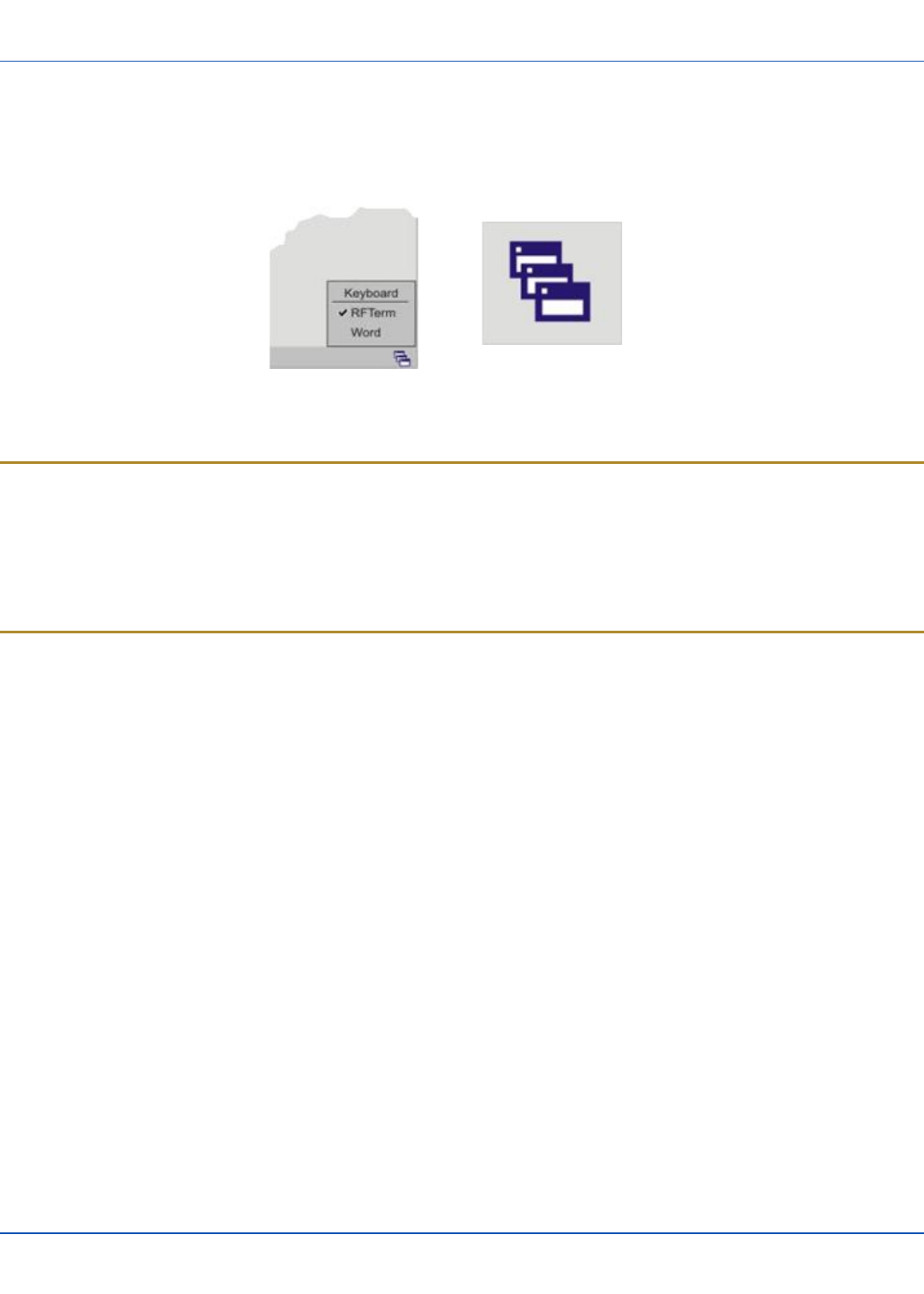
Using the AppLock Switchpad
Note: The touchscreen must be enabled. Select Start | Settings | Control Panel | Options | Misc. tab to verify
touchscreen status.
Switchpad Menu Switchpad Icon in Taskbar
A checkmark indicates applications currently active or available for Launching by the MX7 Tecton user. When Keyboard, on
the Switchpad Menu, is selected, the default input method (Input Panel, Transcriber, or custom input method) is activated.
Using the Keypad
One switch key sequence (or hotkey) is defined by the Administrator for the end-user to use when switching between locked
applications. This is known as the Activation key.
When the switch key sequence is pressed on the keypad, the next application in the AppLock configuration is moved to the
foreground and the previous application moves to the background. The previous application continues to run in the background.
MX7 Tecton key presses affect the application in focus only.
Using the Touchscreen
The figure shown above is an example and is shown only to aid in describing how the user can switch between applications
using a stylus.
When the user taps the Switchpad icon with the stylus, a menu pops up listing the applications available to the user. The user
can tap an application name in the popup menu and the selected application is brought to the foreground. The previous
application continues to run in the background. Stylus taps affect the application in focus only. When the user needs to use the
Input Panel, they tap the Keyboard option. Input Panel taps affect the application in focus only.
E-EQ-MX7CEOGWW-ADraft 07 [ 34 ] MX7 Tecton CE User Guide
Connecting Bluetooth Devices
For review only - Do not publish or distribute - LXE Confidential - Draft 07
Connecting Bluetooth Devices
Prerequisites:
lThe system administrator has discovered, paired, connected and disconnected (using LXEZ Pairing Control Panel) Blue-
tooth devices for each MX7 Tecton.
lThe system administrator has enabled and disabled LXEZ Pairing parameters for the MX7 Tecton.
lThe system administrator has also assigned a Computer Friendly Name using LXEZ Pairing Control Panel for the MX7
Tecton.
To connect Bluetooth devices, the MX7 Tecton should be as close as possible and in direct line of sight (distances up to 32.8
feet or 10 meters) with the targeted Bluetooth device during the discovery and pairing process.
If the devices are in Suspend, tap the power key to wake the MX7 Tecton.
Using the correct procedure, wake the targeted Bluetooth device if necessary.
There may be audible or visual signals as both devices discover and pair with each other.
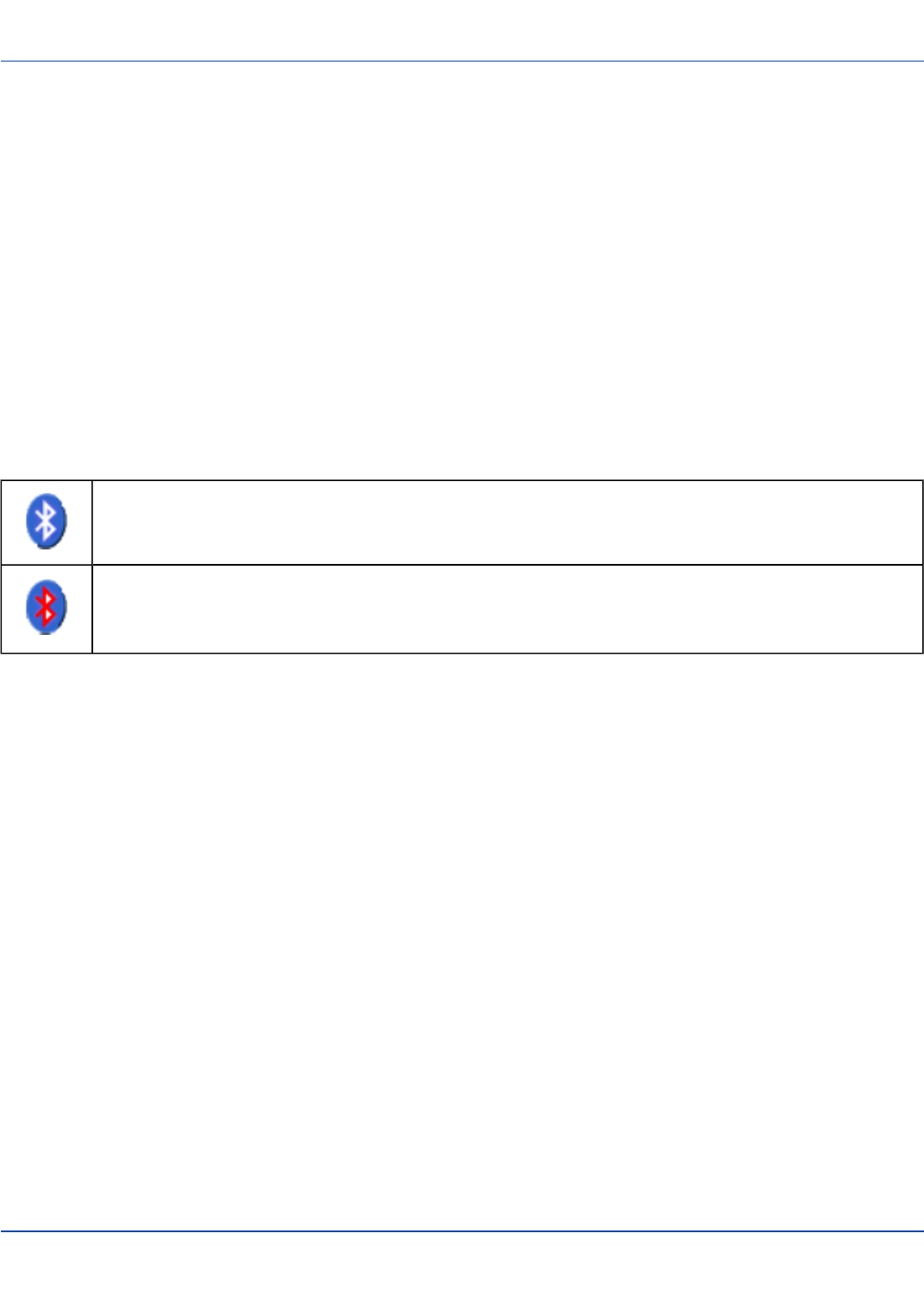
Taskbar Connection Indicator
MX7 Tecton is connected to one or more of the targeted Bluetooth device(s).
MX7 Tecton is not connected to any Bluetooth device.
MX7 Tecton is ready to connect with any Bluetooth device.
MX7 Tecton is out of range of all paired Bluetooth device(s). Connection is inactive.
There may be audible or visual signals from paired devices as they move back into range and re-connect with the Bluetooth
hardware in the MX7 Tecton.
E-EQ-MX7CEOGWW-ADraft 07 [ 35 ] MX7 Tecton CE User Guide

Reboot Sequences
For review only - Do not publish or distribute - LXE Confidential - Draft 07
Reboot Sequences
When the desktop is displayed or an application begins, the power up sequence is complete. If you have previously saved your
settings, they will be restored on reboot. Application panel changes are saved when ok is tapped on an application properties
panel.
During the processes that follow there may be small delays while the wireless client connects to the network and Bluetooth
relationships establish or re-establish.
Suspend / Resume
Quickly tapping the Power key places the MX7 Tecton in Suspend mode. Quickly tapping the Power key again, pressing any
key, pressing the trigger (on the trigger handle, if installed), or tapping the touchscreen, returns the MX7 Tecton from Suspend.
The System LED blinks green when the video display is Off (and the device is not in Suspend Mode or Critical Suspend).
or
Tap Start then tap Suspend. The MX7 Tecton enters suspend mode. Quickly tapping the Power key again, pressing any key,
pressing the trigger (on the trigger handle, if installed), or tapping the touchscreen, returns the MX7 Tecton from Suspend.
Warmboot
A warmboot reboots the computer without erasing any registry data. Configuration settings and data in RAM are preserved
during a warmboot. Network and ActiveSync sessions are lost and any data in running applications that had not been
previously saved may be lost. CAB files already installed remain installed.
There are several methods available:
lUsing the Registry, select Start | Settings | Control Panel | Registry and tap the Warmboot button. The MX7 Tecton
immediately warmboots.
lUsing the Start menu, select Start | Run and type WARMBOOT in the text box. Press Enter. The MX7 Tecton imme-
diately warmboots. The WARMBOOT text command is not case-sensitive1.
lUsing the keypad, press the Ctl key and release it, press the Alt key and release it, press the Del key and release it. The
MX7 Tecton immediately warmboots.
1The text typed in the text box can be upper or lower case or a combination of upper and lower case letters.
E-EQ-MX7CEOGWW-ADraft 07 [ 36 ] MX7 Tecton CE User Guide
Troubleshooting
For review only - Do not publish or distribute - LXE Confidential - Draft 07
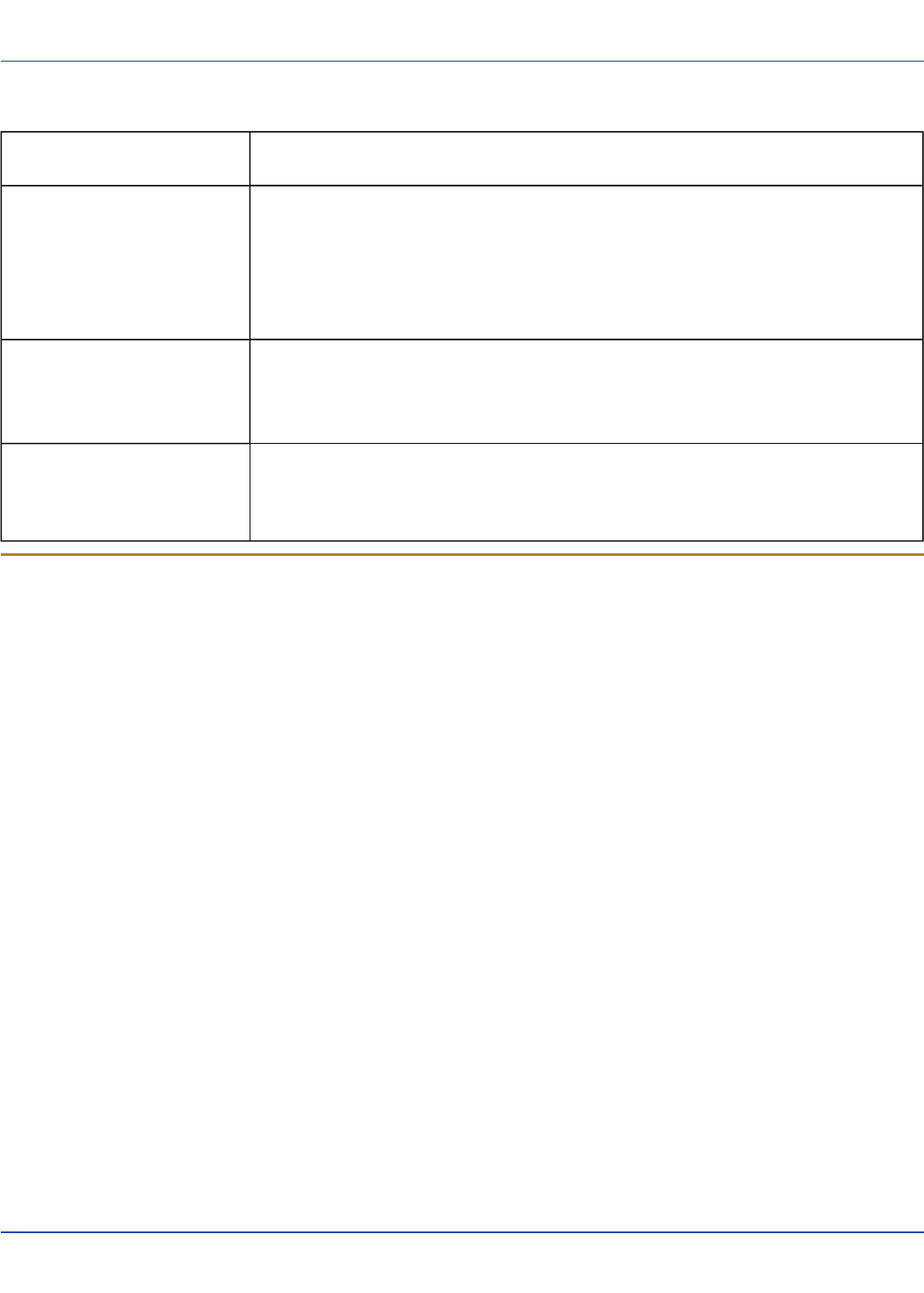
Troubleshooting
Can’t change the date/time or
adjust the volume.
AppLock is installed and may be running in User Mode on the MX7 Tecton. AppLock user
mode restricts access to the control panels.
Touchscreen is not accepting
stylus taps or needs recal-
ibration.
See "Calibrating the Touchscreen" on page 32when the touchscreen needs recalibration,
or
if the touchscreen is not accepting stylus taps, press <Ctrl>+<Esc> to force the Start
Menu to appear. Use the tab, backtab, arrow keys and Enter to move the highlight to Start |
Settings | Control Panel | Registry | Warmboot. Press Enter and the MX7 Tecton
warmboots.
MX7 Tecton seems to lockup as
soon as it is rebooted.
There may be slight delays while the wireless client connects to the network, authorization
for voice-enabled applications complete, and Bluetooth relationships establish or re-
establish.
When an application begins, the MX7 Tecton is ready for use.
New MX7 Tecton main batteries
don't last more than a few hours.
New batteries must be fully charged prior to first use. Li-Ion batteries (like all batteries) grad-
ually lose their capacity over time (in a linear fashion) and never just stop working. This is
important to remember – the MX7 Tecton is always ‘on’ even when in the Suspend state
and draws battery power at all times.
Continuous Scan Mode
If Continuous Scan Mode has been enabled (factory default setting is 'Disabled'), the laser (or imager) is always on and
decoding.
Caution: Laser beam is emitted continuously. Do not stare into the laser beam.
Note: Low Power Scanner does not support aim mode. Any attempt to adjust the aiming beam using SE955 programming
barcodes in the Integrated Scanner Programming Guide will fail. The Low Power scanner does not decode Codablock,
Code93i, Matrix 2 of 5 or Telepen symbologies.
E-EQ-MX7CEOGWW-ADraft 07 [ 37 ] MX7 Tecton CE User Guide
Regulatory Notices and Safety Information
Waste Electrical and Electronic Equipment (WEEE)
Important:
This symbol is placed on the product to remind users to dispose of Waste Electrical and Electronic Equipment
(WEEE) appropriately, per Directive 2002-96-EC. In most areas, this product can be recycled, reclaimed and re-
used when properly discarded. Do not discard labeled units with trash. For information about proper disposal,
Contact your LXE representative, or visit www lxe com.
Class B Digital Device
NOTICE
This device complies with Part 15 of the FCC Rules [and with RSS-210 of Industry Canada]. Operation is subject to the
following two conditions:
1. This device may not cause harmful interference, and
2. This device must accept any interference received, including interference that may cause undesired operation.
NOTE: This equipment has been tested and found to comply with the limits for a Class B digital device, pursuant to Part 15 of
the FCC Rules. These limits are designed to provide reasonable protection against harmful interference in a residential
installation. This equipment generates, uses and can radiate radio frequency energy and, if not installed and used in
accordance with the instructions, may cause harmful interference to radio communications. However, there is no guarantee
that interference will not occur in a particular installation. If this equipment does cause harmful interference to radio or television
reception, which can be determined by turning the equipment off and on, the user is encouraged to try to correct the
interference by one or more of the following measures:
lReorient or relocate the receiving antenna.
lIncrease the separation between the equipment and the receiver.
lConnect the equipment into an outlet on a circuit different from that to which the receiver is connected.
lConsult the dealer or an experienced radio/TV technician for help.
NOTICE
Changes or modifications made to this equipment not expressly approved by LXE, Inc., may void the FCC authorization to
operate this equipment.
EMC Directive Requirements
This is a Class B product. In a domestic environment this product may cause radio interference in which case the user may be
required to take adequate measures.
Industry Canada
This Class B digital apparatus meets all requirements of the Canadian Interference Causing Equipment Regulations. Operation
is subject to the following two conditions: (1) this device may not cause harmful interference, and (2) this device must accept
any interference received, including interference that may cause undesired operation.
Cet appareil numérique de la classe B respecte toutes les exigences du Règlement sur le matériel brouilleur du Canada. Le
présent appareil numérique n’émet pas de bruits radioélectriques dépassant les limites applicables aux appareils numériques
de Classe B prescrites dans le Règlement sur le brouillage radioélectrique édits par le ministère des Communications du
Canada.
E-EQ-MX7CEOGWW-ADraft 07 [ 38 ] MX7 Tecton CE User Guide
RF Notices
For review only - Do not publish or distribute - LXE Confidential - Draft 07
Li-Ion Battery
When disposing of the MX7 Tecton main battery, the following precautions should be observed: The battery should be
disposed of properly. The battery should not be disassembled or crushed. The battery should not be heated above 212°F
(100°C) or incinerated.
NOTICE:
This Class B digital apparatus complies with Canadian ICES-003.
Cet appareil numérique de la classe [*] est conforme á la norme NMB-003 du Canada.
RF Notices
This device (FCC ID: KDZLXE-MX7T and IC ID: 1995B-LXEMX7T) contains transmitter Module FCC ID: TWG-
SDCMSD30AG and IC ID: 6616A-SDCMSD30AG.
RF Safety Notice
Caution:
This device was tested for typical body-worn operation. Use only LXE tested and approved accessories to ensure
FCC Compliance. The use of third-party accessories may not comply with FCC RF exposure compliance
requirements, and should be avoided. To comply with FCC RF exposure requirements, this device must be
operated in the hand with a minimum separation distance of 2.5 cm (0.9842 inch) or more from a person's body.
E-EQ-MX7CEOGWW-ADraft 07 [ 39 ] MX7 Tecton CE User Guide
Laser Light Safety Statement
For review only - Do not publish or distribute - LXE Confidential - Draft 07
Laser Light Safety Statement
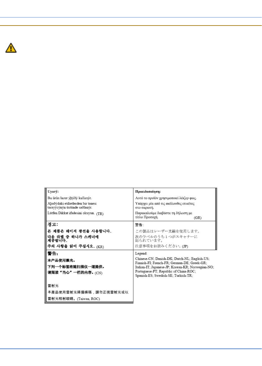
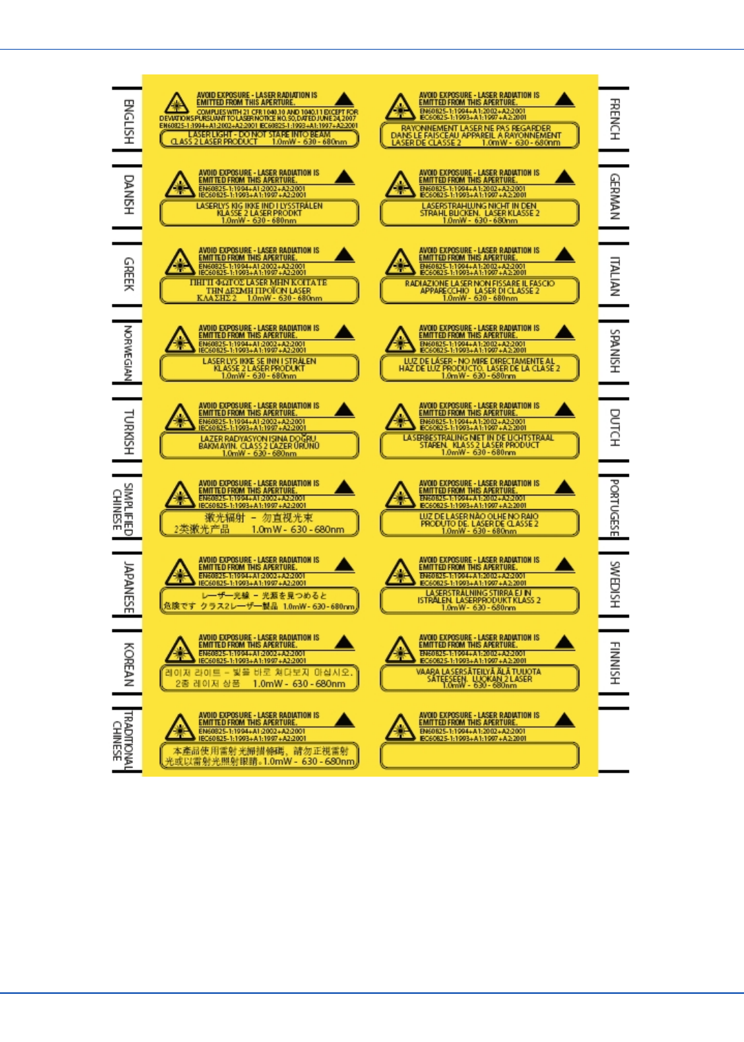
Warning: This product uses laser light. One of the following labels is provided on the scanner. Please read the
Caution statement. (US)
Mise én garde: Ce produit utilise un rayon laser. L’une des étiquettes suivantes est apposée sur le scanneur. Veuillez lire
l’avertissement qu’elle contient. (FR)
Advertência: Este produto usa luz de laser. O scanner contém um dos seguintes avisos. Favor ler o Aviso. (PT)
Varning: Denna produkt använder laserljus. En av de nedanstående etiketterna sitter på scannern. Var god läs varningstexten.
(SE)
Advarsel: Dette produkt anvender laserlys. En af følgende mærkater anvendes på scanneren. Læs venligst
sikkerhedsforanstaltningen. (DK)
Varoitus: Tämä tuote käyttää laservaloa. Skannerissa on jokin seuraavista tarroista. Lue Huomio-kohta. (FI)
Warnung: Dieses Produkt verwendet Laserlicht. Eines der folgenden Etiketten befindet sich auf dem Scanner. Bitte lesen Sie
den Gefahrenhinweis. (DE)
Attenzione: Questo prodotto utilizza luce laser. Una delle etichette seguenti c’ ubicata sullo scanner. Si raccomanda di leggere
con attenzione le avvertenze riportate. (IT)
Advarsel: Dette utstyret bruker laserlys. En av følgende etiketter er plassert på scanneren. Les advarselen på etiketten. (NO)
Advertencia: Este producto usa luz de láser. Las etiquetas se proveen en la máquina exploradora. Por favor, lea
detenidamente la explicación para las precauciones. (ES)
Waarschuwing: Dit product gebruikt laserlicht. Een van de volgende labels is op de scanner aangebracht. Lees a.u.b. de
waarschuwing onder Oppassen. (NL)
E-EQ-MX7CEOGWW-ADraft 07 [ 40 ] MX7 Tecton CE User Guide
Laser Light Safety Statement
For review only - Do not publish or distribute - LXE Confidential - Draft 07
E-EQ-MX7CEOGWW-ADraft 07 [ 41 ] MX7 Tecton CE User Guide
Vehicle Power Supply Connection Safety Statement
For review only - Do not publish or distribute - LXE Confidential - Draft 07
Vehicle Power Supply Connection Safety Statement
Vehicle Power Supply Connection: If the supply connection is made directly to the battery, a A slow-blow fuse should be
installed in the positive lead within 5 inches (12.7 cm.) of the battery positive (+) terminal. (US)
Raccordement de l’alimentation du véhicule Si l’alimentation est raccordée directement à la batterie, un fusible à action
retardée de A doit être installé sur le câble positif à moins de 12,7 cm de la borne positive (+) de la batterie. (FR)
EL forsyning af køretøjet. Er forsyningsforbindelsen direkte tilknyttet til batteriet og og tilsluttet til den positive part indenfor
12,7 cm (+ delen). vil der være en langsom tændelse af ampere. (DK)
Kytkentä ajoneuvon virtalähteeseen Jos virtaa otetaan suoraan akusta, ampeerin hidas sulake on asennettava positiiviseen
johtoon enintään 12 cm:n etäisyydelle akun positiivisesta (+) navasta. (FI)
Anschluss an Fahrzeugbatterie Bei direktem Anschluss an die Fahrzeugbatterie sollte eine träge A-Sicherung in die positive
Leitung zwischengeschaltet werden, und zwar nicht weiter als ca. 13 cm von der positiven (+) Batterieklemme entfernt. (DE)
Σύνδεση Τροφοδοτικού Ισχύος Οχήματος Αν η σύνδεση του τροφοδοτικού γίνει κατευθείαν στη μπαταρία, μια ασφάλεια
βραδείας τήξης των A θα πρέπει να τοποθετηθεί στο θετικό καλώδιο εντός 5 ιντσών (12,7 εκ.) του θετικού (+) ακροδέκτη της
μπαταρίας. (GR)
Collegamento dell’alimentazione del veicolo Se il collegamento dell’alimentazione viene stabilito direttamente con la batteria, è
necessario installare un fusibile ad azione lenta da A nel conduttore positivo a meno di 5 in. (12,7 cm) dal terminale positivo (+)
della batteria. (IT)
Tilkople strømforsyningen til kjøretøyet Hvis strømforsyningen koples direkte til batteriet, skal det installeres en A treg sikring
i den positive ledningen innen 12,7 cm fra plusspolen (+) på batteriet. (NO)
Ligação do fornecimento de corrente do veículo Se a ligação de fornecimento de corrente for ligada directamente à bateria,
deve instalar-se um fusível de A no terminal positivo, a 12,7 cm. do terminal positivo (+) da bateria. (PT)
Conexión de suministro eléctrico para el vehículo Si el suministro eléctrico se proporciona directamente a la batería, se debe
instalar un fusible de retardo de A en el conductor positivo, como máximo a 12,7 cm (5 pulgadas) del terminal positivo (+).
(ES)
Fordonets strömförsörjningskoppling Om strömkopplingen görs direkt till batteriet, måste en A-säkring installeras i den
positivt laddade ledningen inom 12.7 cm från batteriets pluspol (+). (SE)
Taşıt Güç Kaynağı Bağlantısı Kaynak bağlantısı doğrudan aküye yapılırsa, pozitif bağlantı kablosu üzerinde akünün pozitif (+)
kutbuna 12.7 cm mesafede A’lık yavaş atan bir sigorta monte edilmelidir. (TR)
Legend: Danish – DK; English – US; Finnish – FI; French- - FR; German – DE; Greek – GR; Italian – IT; Norwegian – NO;
Portuguese – PT; Spanish – ES; Swedish – SE; Turkish – TR.
Revision History
Revision / Date Location / Change
A / Dec 2010 Initial Release
E-EQ-MX7CEOGWW-ADraft 07 [ 42 ] MX7 Tecton CE User Guide

Index
A
AC Power Scheme 30
Adjust Headset / Microphone and Secure Cable 25
Alpha mode Status LED 13
AppLock Switchpad 34
Apply the Touchscreen Protective Film 32
Assembly
USB Host 14-15
Attaching the Handstrap 26
Attaching the Trigger Handle 27
B
Battery
Remove 10
Battery Power Scheme 30
Bluetooth connection 35
C
Calibrate 32
Carry case assembly 28
Carry Case with Metal Snaps 28
Charge or Recharge the Main Battery 11
Class B 38
Cleaning the Display 33
Client Cable Assembly 14
Connect or Remove the Battery Pack 9
Connect Power Supply to Vehicle Cradle 23
Connecting an External Power Supply 16
Connecting Cables 14
Connecting the Headset Cable 24
Connecting the Serial and Power Cable 15
Connecting the USB Client and Power Cable 14
Connecting Vehicle Power 17
Connection Indicators 35
Cradle Power Connector Port 23
Cumulative mode timers 30
D
Date, Time, TimeZone 29
Daylight Savings location 29
DC to DC Power Supply Installation 17
DC to DC PS
Specifications for Electrical Supply 17
E
EULA 1
H
Handstrap
assembly 26
Hardware Setup 1
Headset
Adjusting the microphone 25
Mouthpiece Talk label 25
quick connect
cable
25
Hide input panel 29
Hide online keyboard 29
Hotswap the Main Battery 10
How To
Connect Power to Vehicle Cradle 23
I
I/O Port and Cables 4
Input panel 29
L
Laser Light Safety Statement 40
Laser Warnings and Labels 2
LED
System Status 13
LEDs (Light Emitting Diodes) 13
E-EQ-MX7CEOGWW-ADraft 07 [ 43 ] MX7 Tecton CE User Guide

Index P - W
For review only - Do not publish or distribute - LXE Confidential - Draft 07
P
pan head screws 27
Pinout
Cradle Power Port 23
Power key 1
power management status 13
Protective film for touchscreen 32
R
Reboot Sequences 36
Recalibrate 32
Recharge the Main Battery 11
Remove Battery 10
Resume 36
Revision History 42
RF Notices 39
S
Safety Statement
Vehicle Power Supply 42
Scanner Vibration tab 13
Serial and Power Cable 15
Set Date and Time Zone 29
Set Power Scheme Timers 30
Set Speaker Volume 31
Set Up A New Device 1
Setup Terminal Emulation Parameters 33
SIP soft input panel 29
Software Setup 1
Strain Relief Cable Clamps 23
Stylus
how to use 12
Suspend 36
Switchpad 34
System Status LED 13
T
Toggle Vibrate Indicator 13
Toggle vibration motor on and off 13
Torque wrench 27
Touchscreen
and the stylus 12
Touchscreen protective film 32
Trigger handle
assemble 27
Troubleshooting 37
U
USB host cable assembly 14-15
Using the AppLock Switchpad 34
V
Vehicle 12V Bare Wire Adapter 20
Vehicle Cable Connection Cable 20
Vibrate 13
virtual keyboard 29
Volume adjust 31
W
Warmboot 36
WEEE 38
Wiring Schematic 18
E-EQ-MX7CEOGWW-ADraft 07 [ 44 ] MX7 Tecton CE User Guide