Honeywell LXEATH WLAN a+b+g mini-PCI Module User Manual
Honeywell International, Inc. WLAN a+b+g mini-PCI Module Users Manual
Users Manual

5015 B.U. Bowman Drive Buford, GA 30518 USA Voice: 770-831-8048 Fax: 770-831-8598
Certification Exhibit
FCC ID: KDZLXEATH
FCC Rule Part: 15E
ACS Report Number: 08-0264-15E
Applicant: LXE Inc.
Equipment: 802.11 a/g Module
Manuals (Host Device)

User Manual
Trux 700
FOR REVIEW ONLY - DO NOT PUBLISH OR DISTRIBUTE
For ENG/CERT Review - Not for Distribution or Publication - Draft 03

User manual Tx700
2 93 5128-100 C0 E-EQ-TX700OGWW
© Copyright 2008, ÅKERSTRÖMS Trux AB
The contents of this document may be changed without prior notice and therefore cannot be considered binding for
ÅKERSTRÖMS Trux AB.
ÅKERSTRÖMS Trux AB is not liable for errors that might appear in this document.
Under no circumstances can ÅKERSTRÖMS Trux AB be held liable for damages arising from use of this document
or from the hardware and software that is described herein.
The software described in this document is supplied with a license and may be used, copied, or distributed only
according to the conditions of this license.
This document may not be reproduced, copied, or in any other way duplicated, in whole or in part, except for
personal use, without the written consent of ÅKERSTRÖMS Trux AB.
Trademarks
Åkerströms are registered trademarks of Åkerströms Björbo AB in Sweden and other countries.
All other trademarks in this documentation are registered by respective owner in their respective countries.
For ENG/CERT Review - Not for Distribution or Publication - Draft 03

93 5128-100 C0 E-EQ-TX700OGWW 3
Table of Contents
1 About this manual........................................................................................ 7
1.1 Who should read this manual................................................................. 7
1.2 Notices...................................................................................................... 8
1.3 How to use this manual........................................................................... 8
1.3.1 Prerequisites.............................................................................................. 8
1.3.2 Explanation of symbols.............................................................................. 8
2 Safety ............................................................................................................ 9
2.1 Assuring personal safety........................................................................ 9
2.2 Product safety.......................................................................................... 9
2.2.1 Electrical supply......................................................................................... 9
2.2.2 Humidity, moisture, cold, and heat............................................................. 9
2.2.3 Interference................................................................................................ 9
2.2.4 Vibrations................................................................................................... 9
3 Product description ................................................................................... 11
3.1 Function and design.............................................................................. 11
3.2 Usage areas............................................................................................ 11
3.3 Basic product structure ........................................................................ 11
3.4 Tx700 series ........................................................................................... 13
3.4.1 Tx700 Wireless Application Platform ....................................................... 13
3.4.2 Tx700 Wireless Client Terminal ............................................................... 13
3.4.3 Peripherals............................................................................................... 13
4 Product installation.................................................................................... 15
4.1 Mounting the unit................................................................................... 15
4.1.1 Mounting Brackets ................................................................................... 15
4.2 Installing electrical components .......................................................... 17
4.2.1 Connecting electrical cables to power sources ........................................ 17
4.2.2 Enabling the screen black-out function .................................................... 18
4.3 Settings................................................................................................... 19
4.3.1 Using the Trux Computer Manager application........................................ 19
4.3.2 Configuring the battery backup function (UPS)........................................ 19
4.3.3 Adjusting start-up and shutdown settings ................................................ 19
4.3.4 Configuring power supply to peripherals.................................................. 19
4.3.5 Battery charge function............................................................................ 19
4.3.6 Black-out screen function......................................................................... 20
4.4 Installing peripherals............................................................................. 21
For ENG/CERT Review - Not for Distribution or Publication - Draft 03

Table of Contnets User Manual Tx700
4 E-EQ-TX700OGWW 93 5128-100 C0
4.4.1 Ports for connection of peripherals .......................................................... 21
4.4.2 Supplying power to peripherals................................................................ 22
4.4.3 Connecting keyboards and pointing devices............................................ 22
4.4.4 Installing printers...................................................................................... 22
4.4.5 Installing bar code readers....................................................................... 22
4.4.6 Connecting GPS and GSM/GPRS products ............................................ 23
4.4.7 Audio Out................................................................................................. 24
4.4.8 Mic In ....................................................................................................... 24
4.4.9 Installing aerials ....................................................................................... 24
5 Using the product ...................................................................................... 25
5.1 Operating the computer ........................................................................ 25
5.1.1 Starting the computer............................................................................... 25
5.1.2 Turning off the computer.......................................................................... 25
5.2 Working with the touch screen............................................................. 25
5.2.1 Using the stylus to select screen objects ................................................. 25
5.2.2 Adjusting screen brightness..................................................................... 26
5.2.3 LED indications........................................................................................ 26
6 Maintaining the product ............................................................................ 27
6.1 Cleaning the screen............................................................................... 27
6.2 Checking connections........................................................................... 27
6.3 Service.................................................................................................... 27
7 Troubleshooting......................................................................................... 29
7.1 Problems with the computer................................................................. 29
7.1.1 The computer will not start....................................................................... 29
7.1.2 The screen is blank.................................................................................. 29
7.2 Problems with peripherals.................................................................... 29
7.2.1 Keyboard/mouse...................................................................................... 29
7.2.2 Communication........................................................................................ 29
Appendix...................................................................................................................... 31
I Specifications ........................................................................................ 31
II Port signals ............................................................................................ 32
III Technical recommendation .................................................................. 35
IV Environmental care information........................................................... 36
V Certification............................................................................................ 37
VI Warranty, support and service ............................................................. 40
VII Batteries ................................................................................................. 41
VIII Français Avertissement et emarque .................................................... 42
For ENG/CERT Review - Not for Distribution or Publication - Draft 03

User Manual Tx700 Table of Contnets
93 5128-100 C0 E-EQ-TX700OGWW 5
Illustrations
Figure 1 Basic product structure ......................................................................................................................12
Figure 2 Different types of Tx700 brackets .....................................................................................................15
Figure 3 Templates for RAM Ball ...................................................................................................................16
Figure 4 Connection for power supply.............................................................................................................17
Figure 5 Ports for connecting peripherals ........................................................................................................21
Figure 6 Aerial Outlets.....................................................................................................................................24
Figure 7 On/Off Button....................................................................................................................................25
Figure 8 Increase or Decrease button, LED’s ..................................................................................................26
For ENG/CERT Review - Not for Distribution or Publication - Draft 03

Table of Contnets User Manual Tx700
6 E-EQ-TX700OGWW 93 5128-100 C0
For ENG/CERT Review - Not for Distribution or Publication - Draft 03

User Manual Tx700 About this manual
93 5128-100 C0 E-EQ-TX700OGWW 7
1 About this manual
This manual covers these topics related to installation, startup, operation, and maintenance of Åkerströms
Trux AB, Tx700:
• Safety considerations
• General product information
• Product installation procedures
• Product use and maintenance
• Troubleshooting
The appendices provide this reference information: technical specifications; port signals; environmental
considerations; fulfillment of EU and US compliance regulations; warranty, support, and service; and
Åkerströms Trux AB addresses and phone numbers.
1.1 Who should read this manual
Use this manual if you are responsible for installing, setting in operation, maintaining, or repairing Trux
Solutions; it provides information you need for mechanical and electrical installation of Åkerströms Trux
AB, Tx700 and configuration of basic functions.
You must:
• Be very familiar with mechanical, electrical, and computer installations.
• Have experience with computers and knowledge of the operating system that will run on the
computer.
The manual does not describe how to install and use the operating system or
applications.
For ENG/CERT Review - Not for Distribution or Publication - Draft 03

About this manual User Manual Tx700
8 E-EQ-TX700OGWW 93 5128-100 C0
1.2 Notices
This manual describes the product’s basic design and main procedures for installing, operating, and
maintaining the product. Deviation might exist between information in this manual and the appearance and
functions in the delivered product because of differences in hardware and software versions.
When product updates affect functions and security, recent, relevant, updated information is available from
Åkerströms Trux AB.
1.3 How to use this manual
To . . . Read chapter . . .
Prepare for electrical installation 2. Safety
Prepare for product installation 3. Product description
Install Åkerströms Tx700 4. Product installation
Operate Tx700 5. Using the product
Keep the product in good shape 6. Maintaining the product
Solve problems 7. Troubleshooting
1.3.1 Prerequisites
To perform some tasks listed above, you’ll need:
• The Trux Computer Manager application, which comes with Tx700.
• Åkerströms Trux AB or other manufacturers’ documentation related to options and
peripherals.
• Manufacturers’ product documentation for the:
• Operating system and other applications
• Global positioning system (GPS)
• Global system for mobile communication (GSM)
• General packet radio service (GPRS)
1.3.2 Explanation of symbols
This manual contains these symbols, abbreviations, and terms:
Symbol Heading Description
Warning! Warns about risk of damage to people or property. Always follow the
instructions provided in conjunction with this symbol.
Note! Calls your attention to problems that may arise if a measure is not taken or is
taken incorrectly.
For ENG/CERT Review - Not for Distribution or Publication - Draft 03
User Manual Tx700 Safety
93 5128-100 C0 E-EQ-TX700OGWW 9
2 Safety
2.1 Assuring personal safety
Keep this information in mind:
Always exercise caution when working with electricity.
2.2 Product safety
2.2.1 Electrical supply
You must:
• Fit the computers with an external fuse before connecting to the recommended voltage
• Connect the computers to the recommended voltage; if they are connected to another voltage,
then the product can be destroyed or its operation put at risk; see 4.2.1
Design the external electrical system so that voltage peaks do not occur in the electrical supply to the
computer.
2.2.2 Humidity, moisture, cold, and heat
Install the product in an environment as described in Appendix I, Specifications. If environmental
requirements are not met, the product can be destroyed or its function put at risk.
Never turn on the computer unless the environmental conditions are within the
specified limits (see Appendix I, Specifications). For example, ensure that the computer
is turned on before you drive into a cold storage unit.
2.2.3 Interference
Ensure that:
• Any nearby electrical cabling (mains supply) is run so that interference does not occur.
• The immediate environment meets requirements stated in the specified standards (see
Appendix IV) with regard to interference.
2.2.4 Vibrations
Mount the computer so that any vibrations that are transmitted to it do not exceed the limits at which the
computer was tested (see Appendix I, Specifications). If the vibrations exceed these limits, use rubber pads
or other insulation.
For ENG/CERT Review - Not for Distribution or Publication - Draft 03

Safety User Manual Tx700
10 E-EQ-TX700OGWW 93 5128-100 C0
For ENG/CERT Review - Not for Distribution or Publication - Draft 03

User Manual Tx700 Product description
93 5128-100 C0 E-EQ-TX700OGWW 11
3 Product description
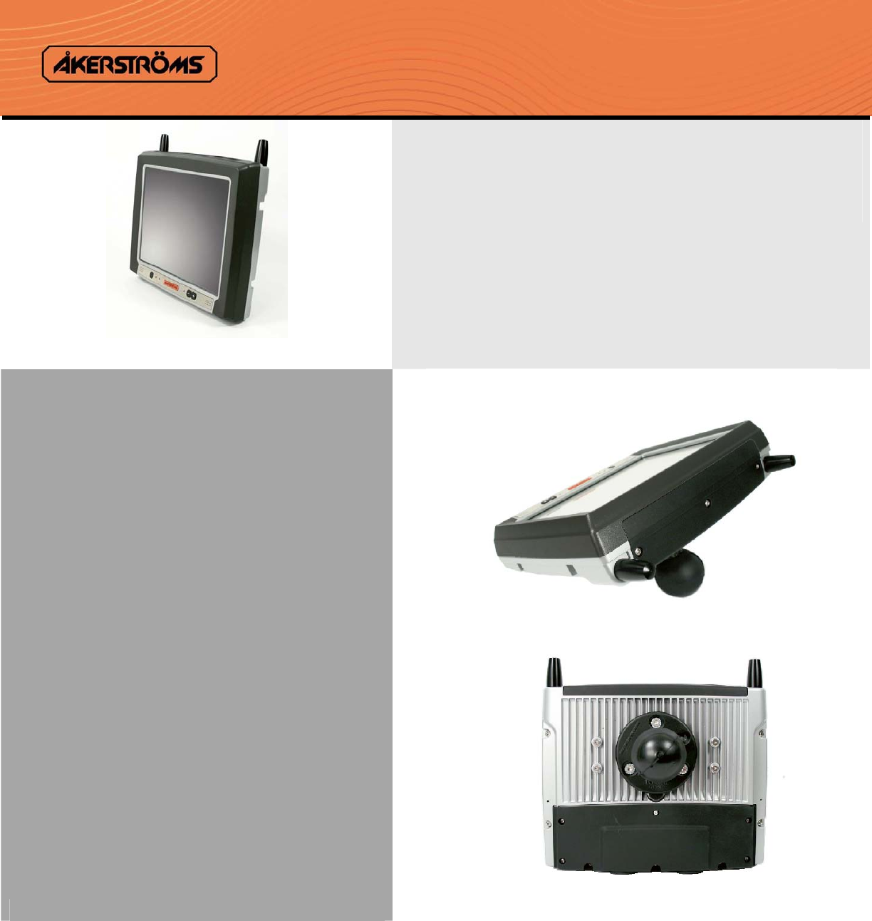
3.1 Function and design
Åkerströms Trux AB designed and developed Tx700 for mounting on mobile or stationary units. Rugged
design, intense screen brightness, and exceptional reliability make Tx700 suitable for demanding
environments in which vehicles such as forklifts, forestry machines, and trucks operate.
Tx700 is based on a standard PC platform that enables use of most types of software adapted for Windows
XP Professional or Windows XP Embedded.
Tx700 is a stand alone computer or a thin client that requires an application server.
The model is equipped with Pentium M or Celeron M processor, built-in hard disk, battery backup
function, and UPS function that prevent the computer from being turned off during short power supply
interruptions, to ensure that data is not lost.
Tx700 is available with several options and peripherals that are described in this manual.
3.2 Usage areas
Your operation can use Tx700 for mobile and fixed applications. Typical usage areas include:
• Computers mounted on forklifts that operate within a warehouse and communicate via a
wireless network.
• Trucks that contain software for global positioning system (GPS) navigation, routes, maps,
and picking lists.
• Forestry machines that contain software for GPS navigation, maps, and felling instructions.
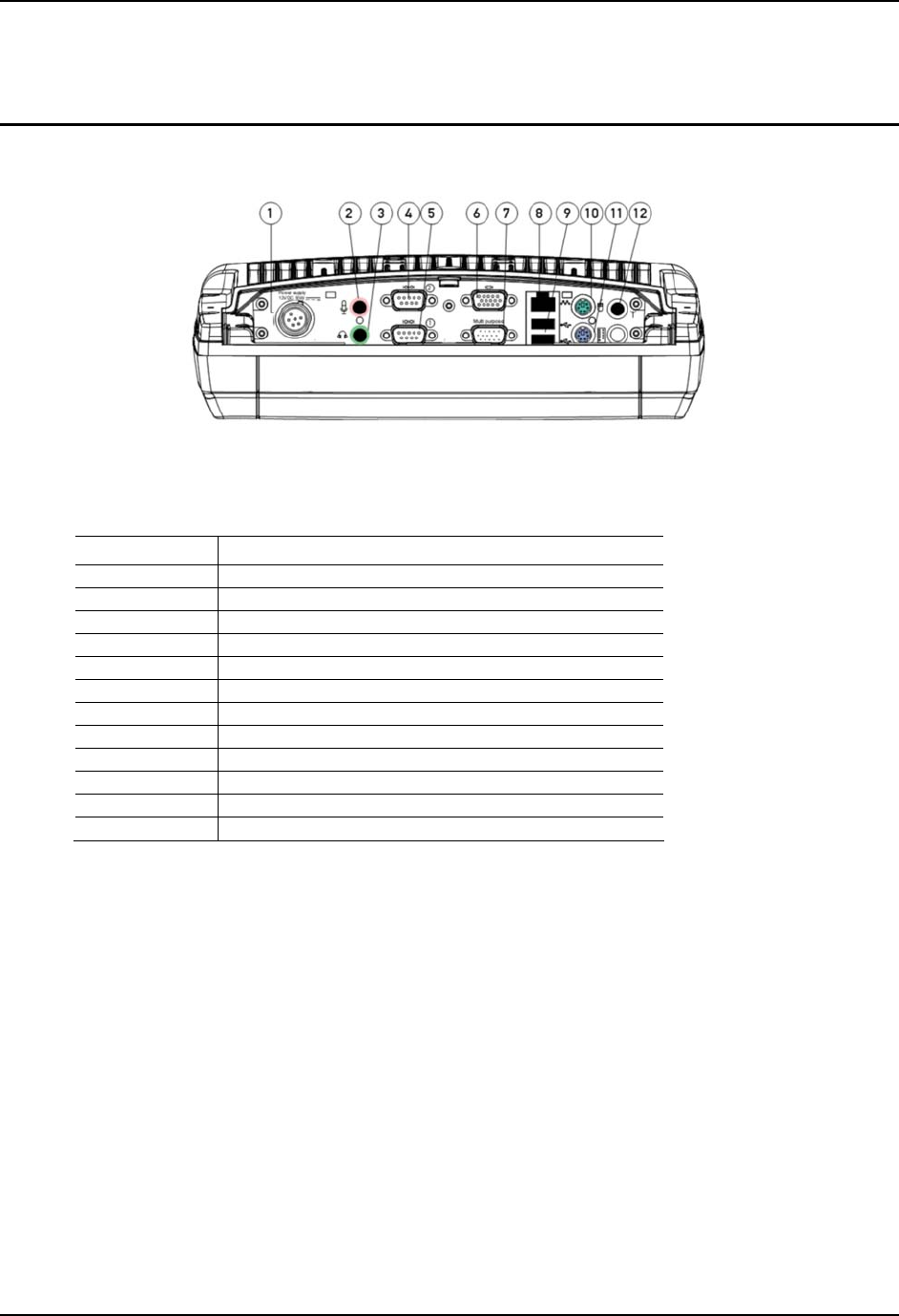
3.3 Basic product structure
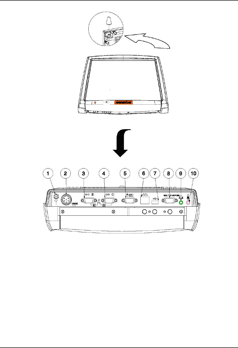
Position See Figure 1 on the following page
1 Connection for external aerial
2 Power supply
3 COM2 (serial port 2)
4 COM1 (serial port 1)
5 Keyboard/mouse
6 RJ-45 10/100 LAN
7 1 х USB 2.0 (USB 1.1 CE)
8 Connection for multi purpose usage
9 Audio Out 3.5 mm
10 Mic In 3.5 mm
For ENG/CERT Review - Not for Distribution or Publication - Draft 03
Product description User Manual Tx700
12 E-EQ-TX700OGWW 93 5128-100 C0
Figure 1 Basic product structure
For ENG/CERT Review - Not for Distribution or Publication - Draft 03

User Manual Tx700 Product description
93 5128-100 C0 E-EQ-TX700OGWW 13
3.4 Tx700 series
3.4.1 Tx700 Wireless Application Platform
Åkerströms Tx700 Wireless Application Platform is developed for companies that want total versatility and
need powerful computers that enable several heavy applications to run simultaneously.
The Tx700 Wireless Application Platform comes in various configurations to meet your requirements. You
select operating system, processor and primary memory, based on the types and numbers of applications
that you run at the same time.
3.4.2 Tx700 Wireless Client Terminal
Åkerströms Tx700 Wireless Client Terminal is developed for companies that have stringent safety demands
and want genuine, robust, thin clients for running various client server applications.
The Tx700 Wireless Client Terminal is a robust client, adapted for client/server environments. It comes
with Windows XP Embedded, which enables total control of the user environment. Users only have access
to functions needed for doing their jobs.
3.4.3 Peripherals
You can order the peripherals listed below when (or after) you order the computer. The Section column
lists the sections in this manual that describe how you should install the peripherals. For information on
use, refer to the documentation that accompanies the product.
Go to www.akerstroms.com to display a complete list of peripherals or order the list from Åkerströms Trux
AB.
Peripheral Section
Keyboard 4.4.3
Mouse 4.4.3
Printer 4.4.4
Bar-code reader 4.4.5
GPS 4.4.6
GSM/GPRS-system 4.4.6
Audio Out 4.4.7
Mic In 4.4.8
Aerials 4.4.9
For ENG/CERT Review - Not for Distribution or Publication - Draft 03

Product description User Manual Tx700
14 E-EQ-TX700OGWW 93 5128-100 C0
For ENG/CERT Review - Not for Distribution or Publication - Draft 03
User Manual Tx700 Product installation
93 5128-100 C0 E-EQ-TX700OGWW 15
4 Product installation
4.1 Mounting the unit
Tx700 is intended to be mounted so that operators can easily perform tasks while in the vehicle.
When positioning the computer on the vehicle, carefully account for operators’ working situations. An
ergonomically correct installation, with an optimal field of vision, greatly facilitates the operators’ work.
Before installation, ensure that all the environmental requirements are met. Appendix I,
Specifications, lists these requirements.
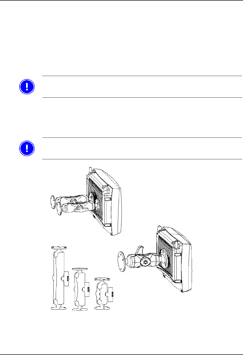
4.1.1 Mounting Brackets
You can order several different types of brackets for the Tx700. The brackets have built-in shock
absorption and can move in all directions. The arms come in three lengths, for 1,5” ball: 95 mm (3 ¾”),
154 mm (6”), 233 mm (9 2⁄14”) and three lengths for 2,25” ball: 128 mm (5”), 213 mm (8 2⁄5”), 328 mm
(13.”).
Do not change the original screws that the brackets are mounted with. Screws that are
too long can damage the computer’s electronics.
Figure 2 Different types of Tx700 brackets
For ENG/CERT Review - Not for Distribution or Publication - Draft 03
Product installation User Manual Tx700
16 E-EQ-TX700OGWW 93 5128-100 C0
1 Check that the planned location of the computer meets ergonometric and field-of-vision requirement.
2 Ensure there is sufficient space underneath the computer so that service can be performed. There
must be space to connect and disconnect the wires from the ports.
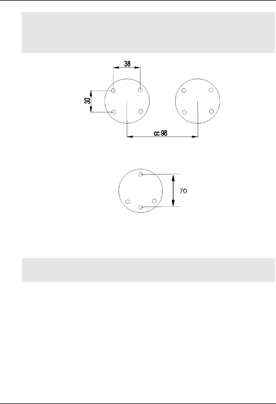
3 Mark the positions of the holes on the mounting surface. See Figure 3 below.
Location of holes for 1,5” ball
3 + 1 hole, 08 mm
Location of holes for 2,25” ball
Figure 3 Templates for RAM Ball
4 Drill holes for the attachment screws.
5 Firmly fasten the computer’s bracket onto the mounting surface with the screws.
For ENG/CERT Review - Not for Distribution or Publication - Draft 03
User Manual Tx700 Product installation
93 5128-100 C0 E-EQ-TX700OGWW 17
4.2 Installing electrical components
Always exercise caution when working with electricity.
4.2.1 Connecting electrical cables to power sources
The Tx700 comes with a four-meter, four- wired power cable; brown for positive and white for negative,
and 2 conductors; yellow and green, to enable the screen black-out function (if selected), see 4.2.2. Connect
the brown part of this cable to positive and the white part to negative on the power source (DC/DC
converter), and fuse it according to these specifications shown below:
Specifications for electrical supply
Voltage 12 VDC ± 10% always use insulated DC/DC transformers
Power 50 W
Fuse 6 A (slow blow fuse)
If the vehicle’s negative is not the same as the vehicle’s chassis, then you must mount the
computer on rubber pads.
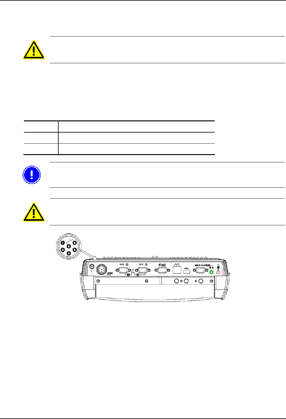
Then connect the power cable to the computer’s power supply outlet; see Figure 4.
Never connect power to pins 5 or 6, which are for the screen’s black-out function
described in section 4.2.2.
Figure 4 Connection for power supply
For ENG/CERT Review - Not for Distribution or Publication - Draft 03

Product installation User Manual Tx700
18 E-EQ-TX700OGWW 93 5128-100 C0
4.2.2 Enabling the screen black-out function
The power supply chassis connector contains two pins that are dedicated to dimming the screen for
example when the vehicle is set in motion (when the gas pedal is pressed). The screen then lights up when
the vehicle stops (when the gas pedal is released).
Connect pins 5 (green conductor) and 6 (yellow conductor) to the vehicle’s gas pedal relay via a
galvanically (electrically) isolated, open/close relay contact.
If the screen’s black-out function is not selected and installed, isolate the end of the green and yellow parts
in the open end of the cable.
You can set this function in the Trux Computer Manager application; see 4.3.1.
For ENG/CERT Review - Not for Distribution or Publication - Draft 03

User Manual Tx700 Product installation
93 5128-100 C0 E-EQ-TX700OGWW 19
4.3 Settings
4.3.1 Using the Trux Computer Manager application
To configure certain Tx700 functions you can use the Trux Computer Manager, which is installed in the
computers before shipping.
1 Start the Control Panel from the Settings option on the Start menu.
2 Double-click on the Trux icon.
The first window displays information about the application’s ID, version and release date. You might
need this information when you contact Åkerströms Trux AB support department.
Only experienced (IT) employees should use the Trux Computer Manager because
incorrect settings can have undesired effects on some functions.
4.3.2 Configuring the battery backup function (UPS)
Tx700 has a unique, in-house developed system for battery backup (UPS) if temporary power-supply
interruptions occur.
Use the Trux Computer Manager to specify values for:
• When the system should react to a power shortage
• The degree to which monitor brightness should decrease
• When the system should try to shut down the computer
Refer to the Trux Computer Manager for a more detailed description of how to configure the battery
backup function.
4.3.3 Adjusting start-up and shutdown settings
Depending on the environment in which Tx700 is used, the nature of the power supply and prevailing
environmental conditions, you might have to adjust the ways in which start-up and shutdown will occur.
For example, using the Trux Computer Manager, you can specify whether the computer can be started from
battery power when the incoming power supply is connected. You can also configure the system to shut
down the computer in different situations.
Refer to the Trux Computer Manager for a detailed description of available settings.
4.3.4 Configuring power supply to peripherals
Some peripherals require power from the computer’s COM or Multi Purpose ports. You can configure
Tx700 so that power is supplied from pin 9 on the COM port and/or from pin 5 on the Multi Purpose port.
Refer to the Trux Computer Manager for information on how the power supply at the ports is activated.
4.3.5 Battery charge function
The battery charge function can be alternate, only under operation or even when the computer is turned off
or standby.
To change the battery charge function, refer to the Trux Computer Manager.
For ENG/CERT Review - Not for Distribution or Publication - Draft 03

Product installation User Manual Tx700
20 E-EQ-TX700OGWW 93 5128-100 C0
4.3.6 Black-out screen function
The black-out screen (dim) function is not activated at delivery. About function and connection see 4.2.2.
To activate this function, refer to the Trux Computer Manager.
For ENG/CERT Review - Not for Distribution or Publication - Draft 03
User Manual Tx700 Product installation
93 5128-100 C0 E-EQ-TX700OGWW 21
4.4 Installing peripherals
Åkerströms Trux AB offers peripherals that facilitate use of Tx700. If you order peripherals with the
computer, then all drivers are pre-installed. If you order them later or from a supplier other than Åkerströms
Trux AB, you might have to install the drivers; if so, refer to the peripheral’s documentation.
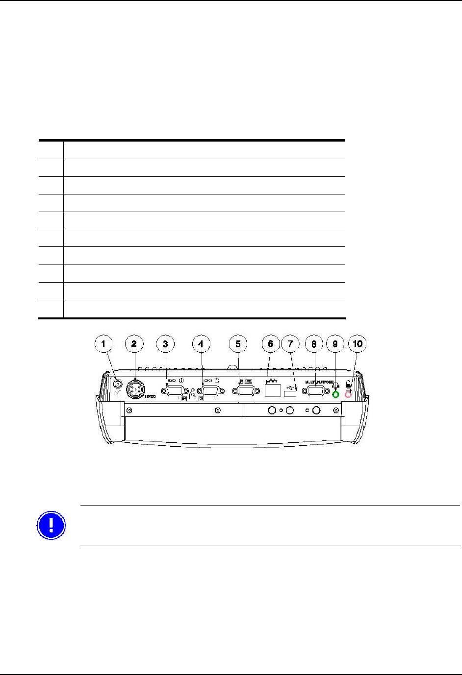
4.4.1 Ports for connection of peripherals
Position see figure below
1 Connection for external aerial
2 Power supply
3 COM2 (serial port 2) Yellow light indicates 12V out from pin 9
4 COM1 (serial port 1) Green light indicates 5V out from pin 9
5 Keyboard/mouse
6 RJ-45 10/100 LAN
7 1 х USB 2.0
8 Connection for multi purpose usage
9 Audio Out 3.5 mm
10 Mic In 3.5 mm
Figure 5 Ports for connecting peripherals
The following section describes function and use of the ports.
After peripherals are connected, the cables are to be assembling by cable straps.
For ENG/CERT Review - Not for Distribution or Publication - Draft 03

Product installation User Manual Tx700
22 E-EQ-TX700OGWW 93 5128-100 C0
4.4.2 Supplying power to peripherals
Some peripherals require power from the computer’s COM or Multi Purpose port, for example a bar-code
reader or an illuminated keyboard.
You can configure the Tx700 as follows:
• 12 V power is supplied from pin 9 on the COM 2 port.
• 5 V power is supplied from pin 9 on the COM 1 port.
• 12 V power is supplied from pin 5 on the Multi purpose port (see Appendix II, Port signals).
Peripherals, with maximum power consumption of 300 mA, can then be supplied from these ports.
Use the Trux Computer Manager to configure activation of the power supply; see 4.3.4.
4.4.3 Connecting keyboards and pointing devices
Tx700 supports USB and PS/2-compatible keyboards and mice.
Connect keyboards and pointing devices to the computer’s keyboard port; see Figure 5, pos. 5. Note that
some require an adapter and others must be configured. Follow the instructions for the type of keyboard
that you have.
PS/2-compatible keyboards and mice
1 Connect the PS/2 adapter (included) to the keyboard port on the computer; see Figure 5, position #5.
2 Connect the PS/2 connections from the keyboard to the adapter.
4.4.4 Installing printers
You can install printers via the:
• COM port; see Figure 5, pos. 3 or 4
• USB port; see Figure 5, pos. 7
For more information, refer to the printer’s documentation.
4.4.5 Installing bar code readers
Use this installation procedure for all bar code readers that Åkerströms Trux AB supplies for Tx700:
1 Connect the barcode reader to the COM port; see Figure 5, position #3 or #4.
2 Activate the power supply on the COM port according to the instructions in the Trux Computer
Manager (4.3.4) documentation.
To convert the signals from the scanner to keystrokes, you can use the FreeFloat WLinq software. WLinq
listens for signals at the COM port and converts these to the corresponding key that is sent to the active
application.
WLinq comes with all bar code readers from Åkerströms Trux AB. You can also order WLinq separately.
For ENG/CERT Review - Not for Distribution or Publication - Draft 03

User Manual Tx700 Product installation
93 5128-100 C0 E-EQ-TX700OGWW 23
4.4.6 Connecting GPS and GSM/GPRS products
You connect GPS and GSM/GPRS products to the computer’s COM port; these products usually require
power supply from the computer.
1 Connect the GPS or GSM/GPRS product to the COM port; see Figure 5, position #3 or #4.
2 Activate the power supply on the COM port according to the instructions in the Trux Computer
Manager (4.3.4) documentation.
For information about how to configure GPS and GSM/GPRS products, see the manufacturers’
documentation.
For ENG/CERT Review - Not for Distribution or Publication - Draft 03
Product installation User Manual Tx700
24 E-EQ-TX700OGWW 93 5128-100 C0
4.4.7 Audio Out
Audio Out is a standard earphone outlet, Ø 3.5 mm.
4.4.8 Mic In
Mic In is a standard microphone inlet, Ø 3.5 mm.
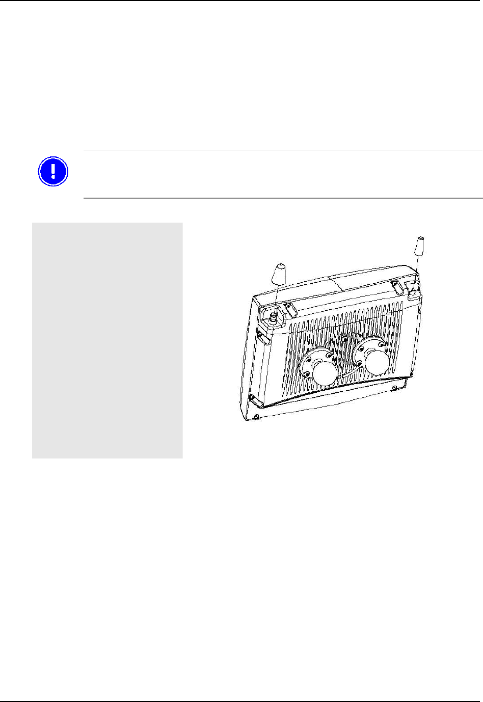
4.4.9 Installing aerials
The computer must be fitted with one or two aerials if you ordered the Tx700 with a wireless network.
To be valid, network cards for wireless networks, which are not supplied by Åkerströms
Trux AB, must meet the Radio & Telecom Terminal Equipment (R&TTE) directive for
certification; see Appendix IV.
Ariel
1 Mount the aerial on the top
of the computer; see Figure 6
Figure 6 Aerial Outlets
For ENG/CERT Review - Not for Distribution or Publication - Draft 03
User Manual Tx700 Using the product
93 5128-100 C0 E-EQ-TX700OGWW 25
5 Using the product
5.1 Operating the computer
5.1.1 Starting the computer
To turn on the computer:
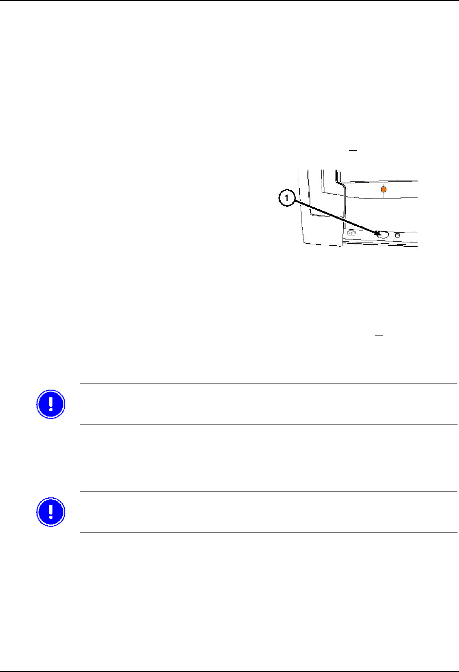
• Press the on/off button on the computer’s lower side, see pos 1 in Figure 7, or
• Click on the screen if:
− You specified this setting using the
Trux Computer Manager (see section
4.3.3) and
− The computer is equipped with an
integrated touch screen
Figure 7 On/Off Button
5.1.2 Turning off the computer
To turn off the computer:
• Press the on/off button on the computer’s left side, see pos 1 in Figure 7, or
• Select the appropriate object on the operating system’s interface
Note: Some operating systems can also be put on standby by selecting the appropriate object.
In first place, turn off the computer via the operating system, in second place by the
button. All to secure the data storage.
5.2 Working with the touch screen
The Tx700 is equipped with a pressure- sensitive touch screen. Rather than using mice for pointing devices,
users select objects by touching the screen with a stylus or a finger.
Always use the accompanying stylus to point, drag, or tap the screen. Never use sharp,
pointed objects. Click with the stylus on the screen.
5.2.1 Using the stylus to select screen objects
To select an object on the interface, gently tap the screen:
• One time to click.
• Two times in rapid succession to double-click.
• Tap on the mouse symbol in the system tray, down in the right corner, than the next click will
be a right click.
For ENG/CERT Review - Not for Distribution or Publication - Draft 03
Using the product User Manual Tx700
26 E-EQ-TX700OGWW 93 5128-100 C0
5.2.2 Adjusting screen brightness
To Use
Increase or decrease the
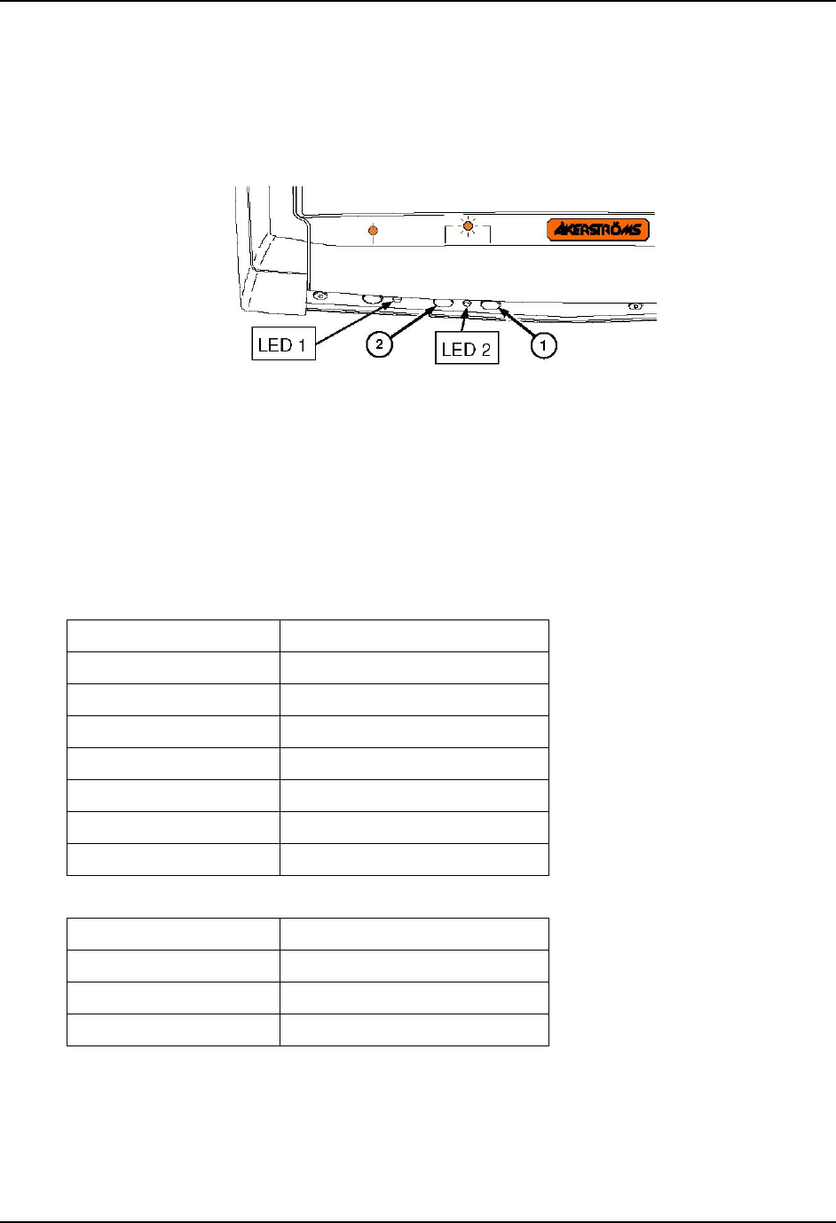
screen’s brightness The buttons on the lower side of the computer. Increase (1) or Decrease
(2) on the lower side of the computer.
Figure 8 Increase or Decrease button, LED’s
Turn off the screen’s
background lighting Both buttons on the lower side of the computer; press them
simultaneously
Restore the screen One of the buttons on the lower side or the stylus (tap lightly)
5.2.3 LED indications
See the LED´s location in Figure 8.
LED at Main Switch indicates Operating Mode
Function LED 1
Off and not powered Off (no light)
Off but powered Green flash very slow
Operating normally Green on
Suspend Green flashing slow
Black-out Screen Green flashing fast
Over voltage shutdown Red on
Over temperature Red flashing
LED at brightness controls indicates UPS Mode
Function LED 2
UPS battery powered Green flashing fast
UPS battery charging Green on or flashing slow
UPS battery charged Off (no light)
For ENG/CERT Review - Not for Distribution or Publication - Draft 03

User Manual Tx700 Maintaining the product
93 5128-100 C0 E-EQ-TX700OGWW 27
6 Maintaining the product
6.1 Cleaning the screen
Clean the screen when necessary. Use a soft, slightly damp cloth. If required, use a cleaning solution that is
intended for computer screens.
Never use strong cleaning or solvent solutions when you clean the screen.
6.2 Checking connections
Check regularly that all connections are firmly in place and that all cables are securely fastened.
6.3 Service
To secure operation of the unit, various types of support agreements are available for Tx700. Contact
Åkerströms Trux AB for more information.
For ENG/CERT Review - Not for Distribution or Publication - Draft 03

Maintaining the product User Manual Tx700
28 E-EQ-TX700OGWW 93 5128-100 C0
For ENG/CERT Review - Not for Distribution or Publication - Draft 03
User Manual Tx700 Troubleshooting
93 5128-100 C0 E-EQ-TX700OGWW 29
7 Troubleshooting
Perform the following troubleshooting procedures before contacting Åkerströms Trux AB regarding
problems with Tx700:
7.1 Problems with the computer
7.1.1 The computer will not start
If nothing happens when the button is pressed, ensure that the:
• Power supply is connected.
• Fuse is intact.
• DC/DC converter delivers correct voltage.
7.1.2 The screen is blank
If the computer is on but the screen is blank or is only faintly lit, ensure that the:
• Screen black-out (dim) function is not active.
• Screen’s brightness is not set too low; adjust the on the lower side of
the computer.
7.2 Problems with peripherals
If a peripheral:
• Does not work, always check all contacts and connections first.
• Requires a power supply, ensure that the power supply for peripherals is activated in the Trux
Computer Manager; see 4.3.4).
7.2.1 Keyboard/mouse
Restart the computer and, if possible, test by using another keyboard.
7.2.2 Communication
If communication problems arise with a wireless network and GPS and GSM/GPRS products, you can test
coverage in two ways:
• Check the computer’s software for indications of poor coverage (normally indicated by an
icon in the systray).
• Put another computer in the same location as the one with the problem to see if it has the
same problem.
For ENG/CERT Review - Not for Distribution or Publication - Draft 03

Troubleshooting User Manual Tx700
30 E-EQ-TX700OGWW 93 5128-100 C0
For ENG/CERT Review - Not for Distribution or Publication - Draft 03

93 5128-100 C0 E-EQ-TX700OGWW 31
Appendix
I Specifications
Wireless Application platform Wireless Client Terminal
Processor/RA M Intel Pentium M 1,4GHz, 512 MB
Intel Celeron M 600MHz, 512 MB Intel Celeron M 600MHz, 512 MB
Storage 40 GB IDE ATA hard disk
4 GB Compact Flash 1 GB Compact Flash (XPE)
64 MB Compact Flash (CE)
Screen 12,1” TFT Flat Panel SVGA (800x600)
Maximum brightness 400 cd/m2
Contrast Ratio 500:1 12,1"
TFT Flat Panel, XGA (1024x768)
Maximum brightness: 320 cd/m2
Contrast Ratio 550:1
Graphics card Intel Extreme Graphics 2, maximum 32 MB RAM
Ports 2 PC card, type II
1 PS/2 keyboard/mouse port
2 serial ports (COM1) and (COM2)
1 USB 2.0 port (USB 1.1 for CE)
1 Multi Purpose connector
1 RJ-45 Ethernet 10/100
1 Audio Out (Head Set)
1 Mic In (microphone)
Cooling Passive cooling
Power supply 12 VDC ± 10%, Integrated Li-ION battery Integrated battery charger
Dimensions 307 x 248 x 75 mm (12.1 x 9.8 x 3.0 inches)
Weight 3,7 Kg (8.16 lb)
Options Wireless network, Flash disk, Bluetooth, Defroster, Hardened Touch panel.
Peripherals DC/DC power supply
Operating system Windows XP Windows XP Embedded
Power Consumption Operation: 2.5 A (typical); 4 A (maximum)
Standby: 0.7 A (typical); 1.0 A (maximum)
Temperature limits Start-up: -20º – 50º C (-4º – 122º F) non-condensing
Operation: -30º – 50º C (-22º – 122º F) non-condensing
Storage: -20º – 50º C (-4º – 122º F) non-condensing
Vibrations The unit has been tested according to:
EN 60068-2-6 (1995):
Sweep 5–200 Hz with 2 g rms acceleration
amplitude in 1 hour per axis (x, y, z).
Shocks The unit has been tested according to:
EN 60068-2-9 (1993)
5000 shocks at an acceleration of 30g in
6 directions (x, y, z pos, and neg.).
For ENG/CERT Review - Not for Distribution or Publication - Draft 03
Appendix User Manual Tx700
32 E-EQ-TX700OGWW 93 5128-100 C0
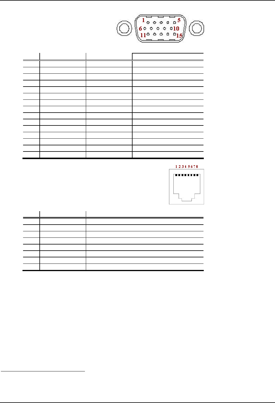
II Port signals
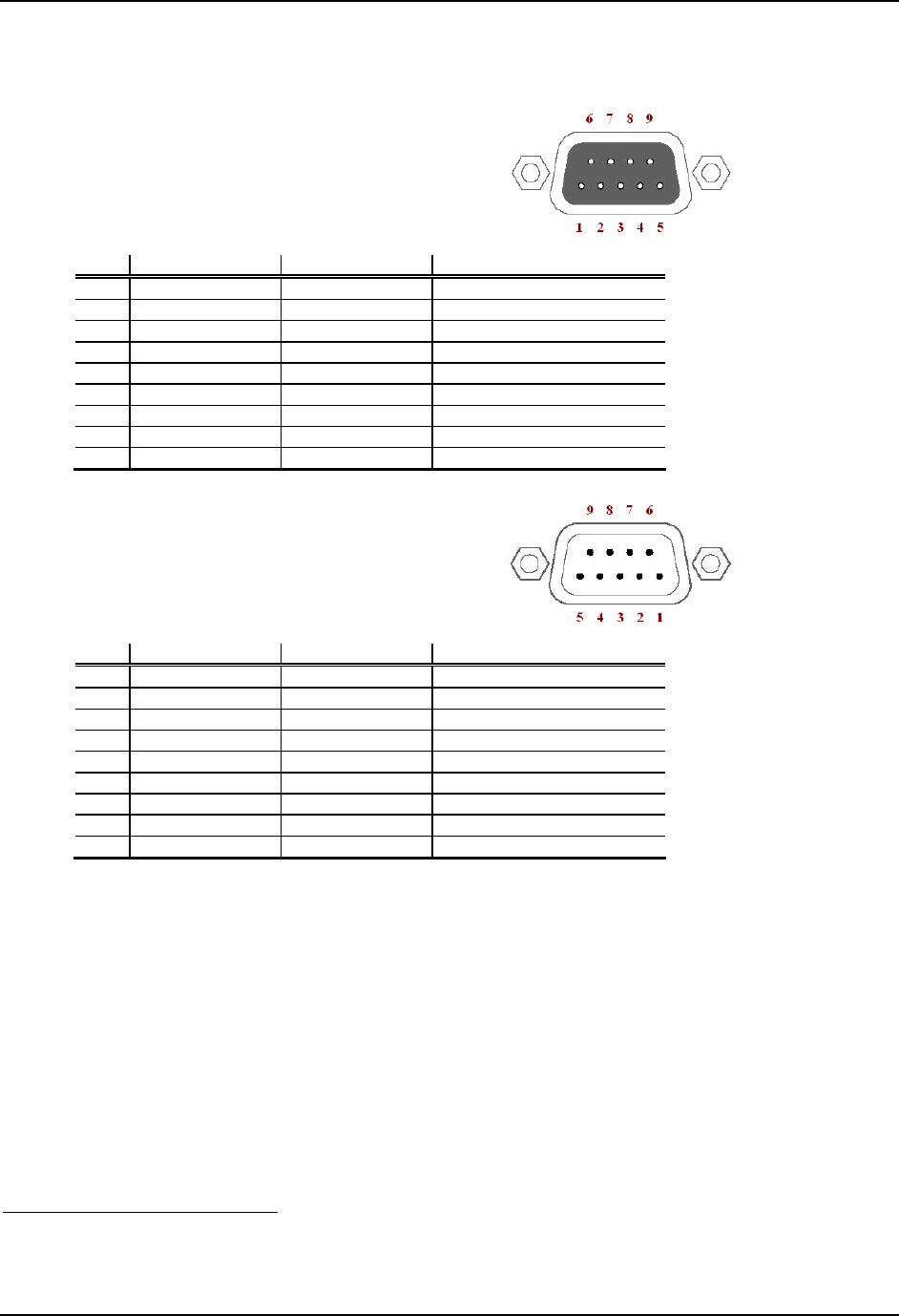
Keyboard/Mouse
9-Pin Dsub
(see Pos. 5, Figure 5)
Pin Signal Type Purpose
1 - Reserved Do not connect
2 MS_DATA Input/output Mouse data
3 MS_CLK Input/output Mouse clock
4 VCC Power output +5 V power supply
5 GND
6 +12VKB Power output +12 V power supply
7 KB_DATA Input/output Keyboard data
8 KB_CLK Input/output Keyboard clock
9 - Reserved Do not connect
Serial (COM1)
9-Pin Dsub
(see Pos. 4, Figure 5)
Pin Signal Type Purpose
1 DCD RS232 input COM1 handshake
2 RXD RS232 input COM1 receive data
3 TXD RS232 output COM1 transmit data
4 DTR RS232 output COM1 handshake
5 GND
6 DSR RS232 input COM1 handshake
7 RTS RS232 output COM1 handshake
8 CTS RS232 input COM1 handshake
9 RI (EXTPWR)
1 RS232 input COM1 power supply 5 VDC
1 Power supply 5VDC output for external utilities as bar code reader, activated in the Trux Computer
Manager application.
For ENG/CERT Review - Not for Distribution or Publication - Draft 03
User Manual Tx700 Appendix
93 5128-100 C0 E-EQ-TX700OGWW 33
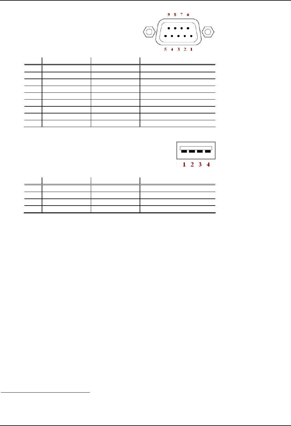
Serial (COM2)
9-Pin Dsub
(see Pos. 3, Figure 5)
Pin Signal Type Purpose
1 DCD RS232 input COM2 handshake
2 RXD RS232 input COM2 receive data
3 TXD RS232 output COM2 transmit data
4 DTR RS232 output COM2 handshake
5 GND
6 DSR RS232 input COM2 handshake
7 RTS RS232 output COM2 handshake
8 CTS RS232 input COM2 handshake
9 RI (EXTPWR)
2 RS232 input COM2 power supply 12VDC
USB
USB
(see Pos. 7, Figure 5)
Pin Signal Type Purpose
1 VCC USB power +5V power supply
2 USB0 Input/output USB differential negative
3 USB0+ Input/output USB differential positive
4 GND
2 Power supply 12VDC output for external utilities as barcode reader, activated in the Trux Computer
Manager application.
For ENG/CERT Review - Not for Distribution or Publication - Draft 03
Appendix User Manual Tx700
34 E-EQ-TX700OGWW 93 5128-100 C0
Multi Purpose
15-Pin D-sub
(see Pos. 8, Figure 5)
Pin Signal Type Purpose
1 VCC 5 5 V Power +5 V Power Supply
2 RXD RS232 Input COM 4 Receive data
3 TXD RS232 Output COM 4 Transmitting data
4 Reserved
5 +12V Power Supply
3 +12 V Power Supply
6 USB + Input/Output USB data +
7 USB Input/Output USB data
8 GND
9 Reserved Not used
10 GND
11 GND
12 RTS RS232 Outlet COM4 Handshake
13 CTS RS232 Inlet COM4 Handshake
14 Reserved Not used
15 Reserved Not used
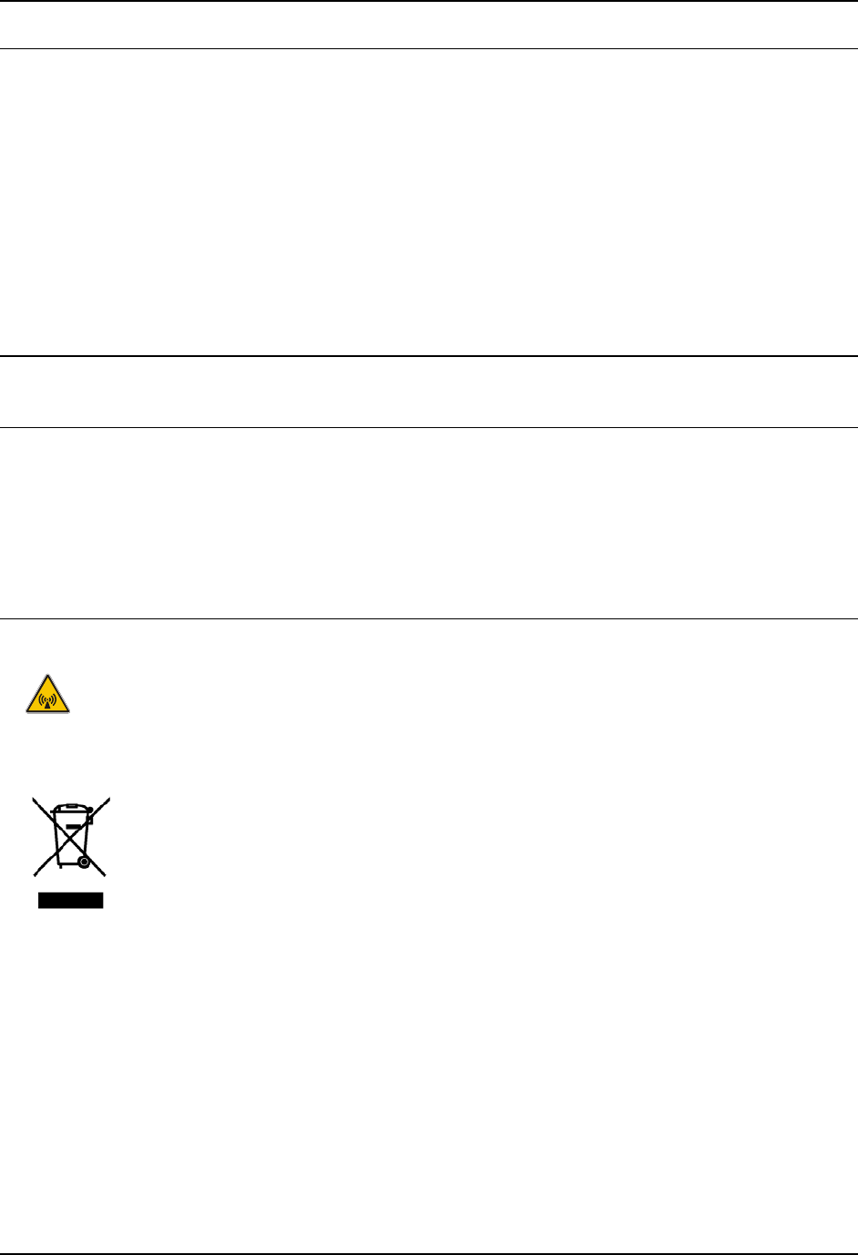
RJ-45 LAN
8-Pin Modular
(see Pos. 6, Figure 5)
Pin Name Description
1 TX+ Send data + (pair 2)
2 TX– Send data (pair 2)
3 RX+ Receive data + (pair 3)
4 Not used (pair 1)
5 Not used (pair 1)
6 RX– Receive data – (pair 3)
7 Not used (pair 4)
8 Not used (pair 4)
3 Power supply 12VDC output for external utilities, activated in the Trux Computer Manager
application.
For ENG/CERT Review - Not for Distribution or Publication - Draft 03

User Manual Tx700 Appendix
93 5128-100 C0 E-EQ-TX700OGWW 35
III Technical recommendation
To make sure that all software and hardware will be fully functional the image needs to be created from a
factory default Tx700 computer, meaning either new out of the box or reinstalled from a recovery media
supplied by Åkerströms Trux AB.
The recovery media can be ordered from Åkerströms Trux AB as a stand alone product.
From a factory default Tx700 computer you can do your own customizations and finally create an image to
be used to prepare other units based on the same hardware.
In order to achieve a successful image creation for the Tx700 it is important to follow these steps.
1 IMPORTANT! First it is very important to make sure that the boot order in BIOS is set to boot from
diskette/USB boot media/(Compact Flash) otherwise the computer will start and we will not be able to
make an image of the system in the wanted state. The master is only a master image until it is started.
As soon as it is started it can not be used as a master image anymore.
2 Boot the system with diskette/USB boot media/Compact Flash with support for USB mass storage or
network.
3 Attach a USB mass storage device or a network share containing the image software e.g. Norton Ghost,
as well as enough space for storing the image.
4 Run the image software and make an image of the disk. The image should be stored in a safe place.
All Åkerströms software products, whether imbedded in ROMs or other hardware or delivered on
CD-ROM or other media, including all related manuals and documentation (collectively “Åkerströms
Software”) are proprietary to Åkerströms. Åkerströms reserves all right, title and interest in and to the
Åkerströms Software not explicitly licensed herein, including without limitation all copyrights, patents and
other proprietary rights. Åkerströms Software contained in or embedded with purchased hardware
products may only be used with the related hardware products. No embedded Åkerströms Software may be
separated from any hardware products as shipped by Åkerströms. Åkerströms Software delivered
separately from a hardware product may only be used on a single CPU at a time. Stand-alone Åkerströms
Software may not be copied, except for (1) back-up copy in machine-readable form, provided such copy are
used for back-up only and provided all copyright information contained on the originals is included in the
copy. Except as expressly permitted by mandatory applicable law and this Agreement, Customer agrees not
to copy, modify, decompile, reverse engineer, disassemble, or otherwise discover, the Åkerströms Software,
in whole or part. Customer shall not remove or obscure any copyright notices or proprietary legends
contained within the Åkerströms Software.
The ÅKERSTRÖMS SOFTWARE IS PROVIDED “AS IS”.
All Non-Åkerströms Software products are provided under the terms and conditions of the software license
agreement (if any) from such software provider applicable to such Non-Åkerströms software. If no license
agreement is provided Non-Åkerströms software is provided with the same terms and conditions as applies
to the Åkerströms Software.
License costs, update responsibility, functionality, interoperability of the customer image are under the
responsibility of the customer. Åkerströms is not responsible to any consequence costs due to faulty, illegal
or accidentally related issues to the customer image creation.
For ENG/CERT Review - Not for Distribution or Publication - Draft 03

Appendix User Manual Tx700
36 E-EQ-TX700OGWW 93 5128-100 C0
IV Environmental care information
Thanks to its low energy consumption, the use of Tx700 has a minimal effect on the environment.
However, the computer should still be turned off or put on standby when it is not in use, to avoid the
unnecessary consumption of energy.
Information on recycling
Since the computer contains materials that can harm the environment if handled improperly, a disused
computer should always be taken to a recycling depot for electronic waste.
Åkerströms Trux AB is happy to take back disused computers and will ensure that they are recycled in
accordance with sound environmental practice. Contact Åkerströms Trux AB for more information.
Product contents that can be harmful to the environment
If the computer is sent in for recycling anywhere else than Åkerströms Trux AB, that organisation should
be informed of the following contents:
• Li-ION batteries (there is one battery for operations and one back-up battery on the
motherboard)
• Circuit boards and circuits
• Screen (LCD and glass)
• Metal casing
• Cables
For ENG/CERT Review - Not for Distribution or Publication - Draft 03

User Manual Tx700 Appendix
93 5128-100 C0 E-EQ-TX700OGWW 37
V Certification
Declaration of conformity
Type of equipment: Industrial PC
Brand name/trade mark: ÅKERSTRÖMS
Type designation/model: TRUX 700
Manufacturer: Åkerströms Trux AB
Björbovägen 143
S-780 45 BJÖRBO, Sweden
Pone +46 241 25000
Fax +46 241 25061
All models in Tx700 are CE certified, according to EMC Directive 89/336/EEC, including amendments in
the CE marking directive, 93/68/EEC.
The product complies with the harmonized European standards and technical specifications listed below:
Standard
EN 61000-6-4:2001
En 61000-6-2:2001
FCC part 15 Subpart B
Reference
Test report no.
56505 – 050584
The products are CE marked in 2005.
Additionally all models in Tx700 are CB certified and complies with the standard below.
Standard
IEC 60950-1:2001 (1st Edition)
En 61000-6-2:2001
Incl.: Group-and national differences for the CENELEC countries and national differences for US and
Canada according to CB Bulletin 109A / USCA 05 I.
Reference
Test report no.
611755-01
As a manufacturer within the EEA, we declare under our sole responsibility that the equipment follows the
provisions of the directives stated above.
Marianne Arosenius, CEO January 19, 2007, Åkerströms Trux AB
For ENG/CERT Review - Not for Distribution or Publication - Draft 03
Appendix User Manual Tx700
38 E-EQ-TX700OGWW 93 5128-100 C0
FCC Information:
This device complies with FCC Rules, part 15. Operation is subject to the following conditions:
1. This device may not cause harmful interference
and
2. This device must accept any interference that may be received, including interference that may cause
undesired operation.
Note: This equipment has been tested and found to comply with the limits for a Class A digital device, pursuant
to part 15 of the FCC rules. These limits are designed to provide reasonable protection against harmful
interference when the equipment is operated in a commercial environment. This equipment generates, uses, and
can radiate radio frequency energy and, if not installed and used in accordance with the instruction manual, may
cause harmful interference to radio communications. Operation of this equipment in a residential area is likely to
cause harmful interference in which case the user will be required to correct the interference at his own expense.
Warning: Changes or modifications to this device not expressly approved by LXE, Inc., could void the user’s
authority to operate this equipment.
EMC Directive Requirements:
This is a Class A product. In a domestic environment this product may cause radio interference in which case the
user may be required to take adequate measures.
Industry Canada:
This Class A digital apparatus meets all requirements of the Canadian Interference Causing Equipment
Regulations. Operation is subject to the following two conditions: (1) this device may not cause harmful
interference, and (2) this device must accept any interference received, including interference that may cause
undesired operation.
Cet appareil numérique de la classe A respecte toutes les exigences du Règlement sur le matériel brouilleur du
Canada. Le présent appareil numérique n’émet pas de bruits radioélectriques dépassant les limites applicables
aux appareils numériques de Classe A prescrites dans le Règlement sur le brouillage radioélectrique édits par le
ministère des Communications du Canada.
RF Safety Notice:
Caution:
This device is intended to transmit RF energy. For protection against RF exposure to humans and in
accordance with FCC rules and Industry Canada rules, this transmitter should be installed such that
a minimum separation distance of at least 20 cm (7.8 in.) is maintained between the antenna and the
general population. This device is not to be co-located with other transmitters.
Important: This symbol is placed on the product to remind users to dispose of Waste
Electrical and Electronic Equipment (WEEE) appropriately, per Directive 2002-96-EC. In most
areas, this product can be recycled, reclaimed and re-used when properly discarded. Do not
discard labeled units with trash. For information about proper disposal, contact LXE through
your local sales representative, or visit www.lxe.com.
For ENG/CERT Review - Not for Distribution or Publication - Draft 03

User Manual Tx700 Appendix
93 5128-100 C0 E-EQ-TX700OGWW 39
!
Lithium Battery Safety Statement
!
Caution:
Lithium battery inside. Danger of explosion if battery is incorrectly replaced. Replace only with same or
equivalent type recommended by battery manufacturer. (US)
Attention:
Contient une pile de lithium. Risque d’explosion dans le cas où la pile ne serait pas correctement remplacée.
Remplacer uniquement avec une pile semblable ou equivalente au type de pile recommandé par le fabricant. (FR)
Forsigtig:
Indeholder lithiumbattterier. Risiko for eksplosion, hvis batteriet udskiftes forkert. Må kun udskiftes med samme
eller tilsvarende type, som anbefalet af fabikanten. (DK)
Varoitus:
Tämä tuote käyttää laservaloa. Skannerissa on jokin seuraavista tarroista. Lue Huomio-kohta. (FI)
Vorsicht:
Enthält Lithium-Batterie. Bei unsachgemäßem Ersatz besteht Explosionsgefahr. Nur durch gleichen oder vom
Hersteller empfohlenen Typ ersetzen. (DE)
Attenzione:
Batteria al litio. Pericolo di esplosione qualora la batteria venga sostituita in maniera scorretta. Sostituire solo con lo
stesso tipo o equivalente consigliato per il fabbricante. (IT)
Atenção:
Contém pilha de lítio. Há perigo de explosão no caso de uma substituição incorreta. Substitua somente pelo mesmo
tipo, ou equivalente, recomendado pelo fabricante. (PT)
Varning:
Innehåller litiumbatteri. Fara för explosion om batteriet är felaktigt placerat eller av fel typ. Använd endast samma
eller motsvarande typ batterier rekommenderade av tillverkaren. (SE)
Advarsel:
Innmontert Lithium batteri. Eksplosjonsfare ved feil montering av batteri. Benytt kun batteri anbefalt av produsent.
(NO)
Cuidado:
Pila de litio adentro. Peligro de explosión si la pila se reemplaza incorrectamente. Reemplace solamente con el
mismo tipo o equivalente recomendado por el fabricante. (ES)
Oppassen:
Bevat Lithium-batterij. Incorrrecte plaatsing van batterij kan leiden tot explosiegevaar. Alleen vervangen door
hetzelfde of door fabrikant aanbevolen gelijkwaardig type. (NL)
For ENG/CERT Review - Not for Distribution or Publication - Draft 03

Appendix User Manual Tx700
40 E-EQ-TX700OGWW 93 5128-100 C0
VI Warranty, support and service
Warranty
The functioning of a Tx700 is under warranty for one year from date of delivery.
The warranty presupposes that the product was used in a way that can be considered normal and that all the
requirements in this manual are met.
If modifications are made to the computer without the consent of Åkerströms Trux AB, the warranty
will no longer apply.
Support
To secure operation of the unit, various types of support agreements are available for Tx700. Contact
Åkerströms Trux AB for more information.
Always start by reading section 7, Troubleshooting, if there is something that does not work
satisfactorily.
If the problem cannot be solved, check with the person in charge at your company to see whether there
are support agreements for your Tx700. Then contact Åkerströms Trux AB.
Åkerströms Trux AB can offer support for only the Windows XP, and Windows XP Embedded
operating systems.
Service
After repairs or service, the computer will be returned with the operating system and software in the same
condition as when it was sent to Åkerströms Trux AB, if possible. Otherwise, it will be returned with the
original configuration, unless agreements are reached.
For ENG/CERT Review - Not for Distribution or Publication - Draft 03

User Manual Tx700 Appendix
93 5128-100 C0 E-EQ-TX700OGWW 41
VII Batteries
CAUTION:
Risk of explosion if battery is replaced by an incorrect type. Dispose of used batteries according to the
instructions.
DISCHARGED BATTERY
Disposal of a Li-Ion battery poses a smaller threat to the environment when compared to other battery
types. However, all used Li-Ion batteries should be immediately sent to a qualified battery collection
centre for recycling.
Old batteries shall be returned for recycling.
For ENG/CERT Review - Not for Distribution or Publication - Draft 03
Appendix User Manual Tx700
42 E-EQ-TX700OGWW 93 5128-100 C0
VIII Français Avertissement et emarque
Le manuel n'explique pas comment installer et utiliser le système d'exploitation ou les
applications.
Avertissement !
Vous avertit des risques de dommages pour les individus ou les biens. Suivez toujours les
instructions qui figurent en regard de ce symbole.
Remarque !
Attire votre attention sur les problèmes qui peuvent survenir si une mesure n'est pas prise ou
est prise de manière incorrecte.
Soyez toujours prudent lorsque vous travaillez avec l'électricité.
Ne mettez jamais l'ordinateur sous tension si les conditions environnementales ne sont pas
dans les limites indiquées (cf. Annexe I, Spécifications). Par exemple, vérifiez que l'ordinateur
est mis sous tension avant d'entrer dans une unité de stockage froide.
Avant l'installation, veillez à ce que tous les critères relatifs à l'environnement soient respectés.
Vous trouverez une liste de ces critères en Annexe I, dans les Spécifications.
Ne changez pas les vis d'origine avec lesquelles sont montés les supports. Des vis trop longues
peuvent endommager le système électrique de l'ordinateur.
Soyez toujours prudent lorsque vous travaillez avec l'électricité.
Si la masse du véhicule n'est pas la même que celle du châssis du véhicule, vous devez alors
monter l'ordinateur sur des patins en caoutchouc.
Ne connectez jamais l'alimentation aux prises 5 ou 6, qui servent à la fonction de noir de
l'écran décrite à la section 4.2.2.
Vous pouvez définir cette fonction dans l'application Trux Computer Manager ; cf. 4.3.1.
Seuls les salariés (IT) expérimentés sont autorisés à utiliser le logiciel Trux Computer
Manager car des paramètres incorrects peuvent avoir des effets indésirables sur certaines
fonctions.
Si vous modifiez ou réinstallez le système d'exploitation de l'ordinateur, vous pouvez être
amené à réinstaller les pilotes pré- installés.
For ENG/CERT Review - Not for Distribution or Publication - Draft 03

User Manual Tx700 Appendix
93 5128-100 C0 E-EQ-TX700OGWW 43
Une fois que les périphériques sont connectés, fixez les câbles sur la partie inférieure de
l'ordinateur qui comporte des trous prévus pour les brides de câbles.
N'oubliez pas que les systèmes d'exploitation n'ont pas tous une prise en charge intégrée de la
souris (par exemple, DOS).
Pour être valides, les cartes réseaux utilisées pour les réseaux sans fil, qui ne sont pas fournies
par Åkerströms Trux AB, doivent respecter la directive R&TTE (Radio & Telecom Terminal
Equipment) pour la certification ; cf. Annexe IV.
Dans le premier endroit, arrêtez l'ordinateur par l'intermédiaire du logiciel d'exploitation, dans
le deuxième endroit par le bouton. Tous pour fixer le stockage de données.
Utilisez toujours le stylet fourni pour pointer, déplacer ou tapoter sur l'écran. N'utilisez jamais
d'objets tranchants ni pointus. Cliquez avec le stylet sur l'écran.
N'utilisez jamais de solutions de nettoyage fortes ni de solvants pour nettoyer l'écran.
For ENG/CERT Review - Not for Distribution or Publication - Draft 03

User Manual
Tx800 Triton
For ENG/CERT Review - Not for Distribution or Publication - Draft 02

User Manual Tx800
2 E-EQ-TX800OGWW-A 105858-100A0
© Copyright 2008, ÅKERSTRÖMS Trux AB
The contents of this document may be changed without prior notice and therefore cannot be considered binding for
ÅKERSTRÖMS Trux AB.
ÅKERSTRÖMS Trux AB is not liable for errors that might appear in this document.
Under no circumstances can ÅKERSTRÖMS Trux AB be held liable for damages arising from use of this document
or from the hardware and software that is described herein.
The software described in this document is supplied with a license and may be used, copied, or distributed only
according to the conditions of this license.
This document may not be reproduced, copied, or in any other way duplicated, in whole or in part, except for
personal use, without the written consent of ÅKERSTRÖMS Trux AB.
Trademarks
Åkerströms are registered trademarks of Åkerströms Björbo AB in Sweden and other countries.
All other trademarks in this documentation are registered by respective owner in their respective countries.
For ENG/CERT Review - Not for Distribution or Publication - Draft 02

105858-100A0 E-EQ-TX800OGWW-A 3
Table of Contents
1 ABOUT THIS MANUAL 7
1.1 Who should read this manual............................................................................ 7
1.2 Notices................................................................................................................. 7
1.3 How to use this manual...................................................................................... 8
1.3.1 Prerequisites.....................................................................................................................8
1.3.2 Symbols used...................................................................................................................8
2 SAFETY 9
2.1 2.1 Personal safety .............................................................................................9
2.2 Product safety..................................................................................................... 9
2.2.1 Supplying power..............................................................................................................9
2.2.2 Humidity, moisture, cold and heat...................................................................................9
2.2.3 Interference......................................................................................................................9
2.2.4 Vibrations ........................................................................................................................9
3 PRODUCT DESCRIPTION 11
3.1 Design and functionality .................................................................................. 11
3.2 Typical usage .................................................................................................... 11
3.3 Connections and adapters............................................................................... 12
3.3.1 Interfaces and connections.............................................................................................12
3.3.2 Under the service-lid......................................................................................................13
3.4 Tx800 series ...................................................................................................... 13
3.4.1 Peripherals and accessories............................................................................................14
4 INSTALLATION 15
4.1 Mounting the unit.............................................................................................. 15
4.1.1 Mounting brackets .........................................................................................................16
4.2 Electrical installation........................................................................................ 17
4.2.1 Connecting to power source ..........................................................................................18
4.2.2 Blackout screen function ...............................................................................................19
4.3 Settings.............................................................................................................. 19
4.3.1 Using the Trux Computer Manager application............................................................19
4.3.2 Configuring the UPS function .......................................................................................19
4.3.3 Settings for start and shutdown......................................................................................20
For ENG/CERT Review - Not for Distribution or Publication - Draft 02

Table of Contents User Manual Tx800
4 E-EQ-TX800OGWW-A 105858-100A0
4.3.4 Supplying power to peripherals.....................................................................................20
4.3.5 Battery charging options................................................................................................20
4.3.6 Blackout screen..............................................................................................................20
4.3.7 Sound, ambient light sensor and defroster.....................................................................20
4.4 Installing peripherals........................................................................................ 21
4.4.1 Ports for connecting peripherals....................................................................................21
4.4.2 Supplying power to peripherals.....................................................................................22
4.4.3 Keyboard and mouse .....................................................................................................22
4.4.4 Printers...........................................................................................................................22
4.4.5 Barcode readers .............................................................................................................23
4.4.6 External monitor............................................................................................................23
4.4.7 Other external accessories .............................................................................................23
4.4.8 Audio Out ......................................................................................................................23
4.4.9 Mic In.............................................................................................................................23
4.4.10 Antenna........................................................................................................................23
4.5 Mounting the port lid ........................................................................................ 24
5 USING THE TX800 25
5.1 Operating........................................................................................................... 25
5.1.1 Starting the computer.....................................................................................................25
5.1.2 Turning off the computer...............................................................................................25
5.2 Touchscreen...................................................................................................... 25
5.2.1 Using the stylus to select screen objects........................................................................26
5.2.2 Calibrating the touchscreen ...........................................................................................26
5.2.3 Adjusting brightness......................................................................................................26
5.2.4 LED indications.............................................................................................................27
6 MAINTENANCE 29
6.1 Cleaning the screen.......................................................................................... 29
6.2 Checking connections...................................................................................... 29
6.3 Service ............................................................................................................... 29
7 TROUBLESHOOTING 31
7.1 Computer problems.......................................................................................... 31
7.1.1 The computer will not start............................................................................................31
7.1.2 The screen is blank ........................................................................................................31
7.2 Problems with peripherals ............................................................................... 32
7.2.1 Keyboard/Mouse............................................................................................................32
7.2.2 Touchscreen accuracy....................................................................................................32
7.2.3 Communication..............................................................................................................32
For ENG/CERT Review - Not for Distribution or Publication - Draft 02

User Manual Tx800 Table of Contents
105858-100A0 E-EQ-TX800OGWW-A 5
APPENDIX 33
I Technical Specifications ...................................................................................... 33
II Port Signals.......................................................................................................... 35
III Technical Recommendations ............................................................................ 42
IV Disclaimer ........................................................................................................... 43
V Tx800 Software.................................................................................................. 44
VI Certification......................................................................................................... 45
VII Warranty, Support and Service ........................................................................ 47
VIII Environmental Care Information..................................................................... 48
IX Batteries............................................................................................................ 49
X Français Avertissement et emarque................................................................ 50
For ENG/CERT Review - Not for Distribution or Publication - Draft 02

Table of Contents User Manual Tx800
6 E-EQ-TX800OGWW-A 105858-100A0
For ENG/CERT Review - Not for Distribution or Publication - Draft 02

105858-100A0 E-EQ-TX800OGWW-A 7
1 About this manual
This manual covers the following topics related to installation, start-up, operation and maintenance of
Tx800.
• Safety considerations
General product information
Product installation procedures
Product use and maintenance
Troubleshooting
The appendices provide this reference information: technical specifications, port signals, environmental
considerations, fulfillment of EU and US compliance regulations, warranty, support, service and
Åkerströms Trux AB addresses and phone numbers.
1.1 Who should read this manual
Use this manual if you are responsible for installing, setting in operation, maintaining or repairing Trux
Solutions. It provides information you need for mechanical and electrical installation of Åkerströms Trux
AB Tx800 and configuration of basic functions. You should:
• Be familiar with mechanical, electrical and computer installations.
• Have experience using computers and knowledge of the operating system that will run on the
Tx800.
The manual does not describe how to install and use the operating system or applications.
1.2 Notices
This manual describes the product’s basic design and main procedures for installing, operating, and
maintaining the product. There might be deviations between information in this manual and the appearance
and functions in the delivered product, because of differences in hardware and software versions.
When product updates that affect function and security, are available at www.akerstromstrux.com or from
Åkerströms Trux AB’s support department.
For ENG/CERT Review - Not for Distribution or Publication - Draft 02
About this manual User Manual Tx800
8 E-EQ-TX800OGWW-A 105858-100A0
1.3 How to use this manual
To… Read Chapter…
Prepare for electrical installation 2 Safety
Prepare for product installation 3 Product description
Install Åkerströms Tx800 4 Product installation
Operate Tx800 5 Using the product
Maintain proper operation 6 Maintenance
Solve problems 7 Troubleshooting
1.3.1 Prerequisites
To perform some tasks listed above, you’ll need:
• The Trux Computer Manager application, which comes with Tx800.
• Åkerströms Trux AB or other manufacturers’ documentation related to options and
peripherals.
• Manufacturers’ product documentation for the:
• Operating system and other applications
• Global positioning system (GPS)
• Global system for mobile communication (GSM)
• General packet radio service (GPRS)
1.3.2 Symbols used
This manual contains these symbols, abbreviations, and terms:
Symbol Heading Description
Warning Warns about risk of damage to people or property. Always follow the
instructions provided in conjunction with this symbol.
Note Calls your attention to problems that may arise if a measure is not taken
or is taken incorrectly.
For ENG/CERT Review - Not for Distribution or Publication - Draft 02
105858-100A0 E-EQ-TX800OGWW-A 9
2 Safety
2.1 2.1 Personal safety
Keep this in mind:
Always exercise caution when working with electricity
2.2 Product safety
2.2.1 Supplying power
Tx800 have to be supplied with an external fuse before connecting to recommended voltage (see 4.2.1).
Connect only the recommended voltage. Any other voltage may damage the product or make its operation
fail.
The external electrical system should be designed to prevent voltage peaks.
A DC/DC transformer is predominantly used to electrically isolate the Tx800 from the vehicle chassis (see
4.2.1).
2.2.2 Humidity, moisture, cold and heat
Make sure the operating environment is within the standards described in Appendix I, Technical specs.
Don’t turn the Tx800 on, unless environmental conditions are met.
2.2.3 Interference
Ensure that:
• Any nearby electrical cabling (mains supply) is run so that interference does not occur.
• The immediate environment meets requirements stated in the specified standards (see
Appendix IV) regarding interference
2.2.4 Vibrations
Tx800 should be mounted in a way that vibrations, transmitted to it, does not exceed the limits it is
designed for (see Appendix I, Specifications).
For ENG/CERT Review - Not for Distribution or Publication - Draft 02

Safety User Manual Tx800
10 E-EQ-TX800OGWW-A 105858-100A0
For ENG/CERT Review - Not for Distribution or Publication - Draft 02

105858-100A0 E-EQ-TX800OGWW-A 11
3 Product description
3.1 Design and functionality
Åkerströms Trux AB designed and developed Tx800 for mounting on mobile or stationary units. Rugged
design, intense screen brightness, and exceptional reliability make Tx800 suitable for demanding
environments, in which vehicles such as forklifts, forestry machines, and trucks operate.
Tx800 is designed to withstand vibrations, moist and dust.
Tx800 is based on a standard PC platform that enables use of most types of software available for
Windows XP Professional or Windows XP Embedded.
Tx800 can be used as a standalone computer or as a thin client, which requires an application server.
The model is equipped with Pentium M or Celeron M processor, built-in hard disk and battery backup
function. The battery/ UPS function ensures that data isn’t lost during momentary loss of power.
Tx800 is available with several options and peripherals mentioned in this manual.
3.2 Typical usage
Typical usage areas for Tx800 include:
Mounted in forklifts, operating in warehouses connected to a logistic system via a wireless network,.
In trucks using global positioning system (GPS) navigation, routes, maps, and picking lists.
In forestry machines using GPS-navigation, maps and felling instructions.
For ENG/CERT Review - Not for Distribution or Publication - Draft 02
Product description User Manual Tx800
12 E-EQ-TX800OGWW-A 105858-100A0
3.3 Connections and adapters
3.3.1 Interfaces and connections
Figure 1: Overview connections and interfaces
Connections and interfaces (port lid)
Position Function
1 Power supply (12V DC 50W)
2 Mic. in
3 Audio out
4 COM2 RS232 +12V
5 COM1 RS232 +5V
6 VGA (external monitor)
7 Multipurpose connector (USB 2.0, RS232, +12 V)
8 RJ-45 Ethernet 10/100 (LAN)
9 2x USB 2.0
10 PS/2 Mouse
11 PS/2 Keyboard
12 Bluetooth antenna connector
For ENG/CERT Review - Not for Distribution or Publication - Draft 02
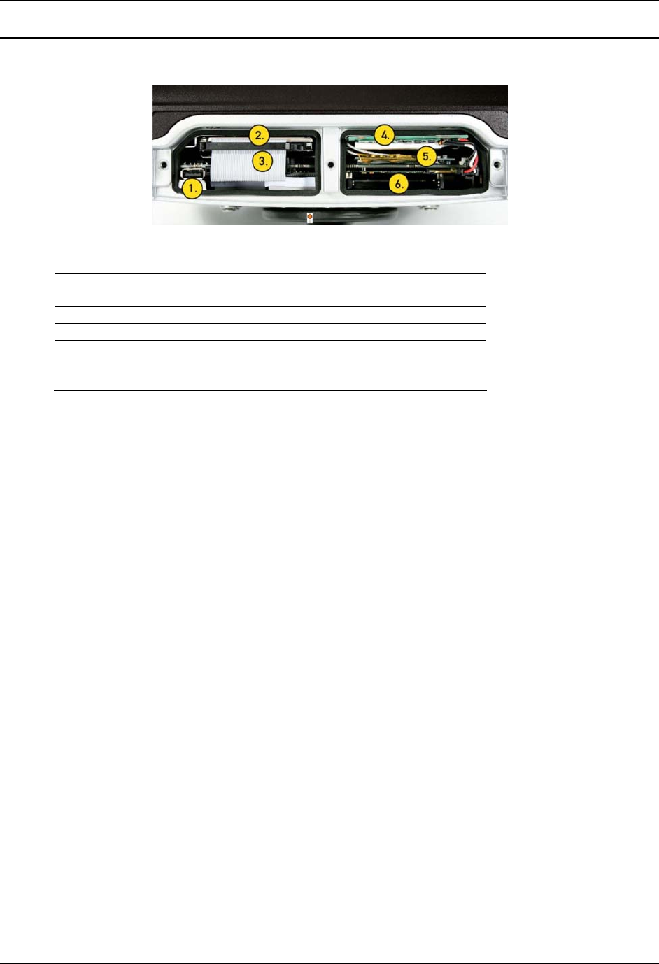
User Manual Tx800 Product description
105858-100A0 E-EQ-TX800OGWW-A 13
3.3.2 Under the service-lid
Figure 2: Overview: connections and interfaces under the service-lid
Position Function
1 USB 2.0
2 Harddrive
3 Compact Flash slot (behind HD cable)
4 Battery/UPS
5 Mini PCI slot
6 PC Card slot (option)
3.4 Tx800 series
Åkerströms Tx800 is developed for companies that want flexibility and need powerful computers that
enable several heavy applications to run simultaneously.
The Tx800 comes in various configurations to meet your requirements. You can select either the Windows
XP Professional or XP Embedded operating systems, processors and primary memory, based on the types
and numbers of applications that you run at the same time
Åkerströms Tx800 can be used as a robust, thin client running various client server applications. With
Windows XP Embedded you get total control of the user environment and users only have access to
applications on a need to use basis.
For ENG/CERT Review - Not for Distribution or Publication - Draft 02

Product description User Manual Tx800
14 E-EQ-TX800OGWW-A 105858-100A0
3.4.1 Peripherals and accessories
Listed below are some of the peripherals which can be connected to the Tx800. The Section column lists
the sections in this manual describing how to install the peripheral. For information on use, refer to the
documentation that accompanies the product.
More peripherals can be found at: www.akerstromstrux.com
Peripheral Section
Keyboard 4.4.3
Mouse 4.4.3
Printer 4.4.4
Barcode reader 4.4.5
External monitor 4.4.6
GPS-system 4.4.7
Mobile communication 4.4.7
Headset/Audio out 4.4.8
Microfon 4.4.9
Antennas 4.4.10
For ENG/CERT Review - Not for Distribution or Publication - Draft 02

105858-100A0 E-EQ-TX800OGWW-A 15
4 Installation
Before mounting the Tx800, write down the license key for the operating system. It’s
located on the chassis, under the port lid.
4.1 Mounting the unit
Tx800 should be mounted in a way that enables the operator to easily perform tasks while in the vehicle.
When positioning the computer in the vehicle, carefully account for the operators’ working situation. An
ergonomically correct installation, with an optimal field of vision, greatly facilitates the operators’ work.
Before installation, ensure that all the environmental requirements are met. Check
Appendix I Specifications. Also check with the owner/manufacturer before drilling holes
in the vehicle.
For ENG/CERT Review - Not for Distribution or Publication - Draft 02
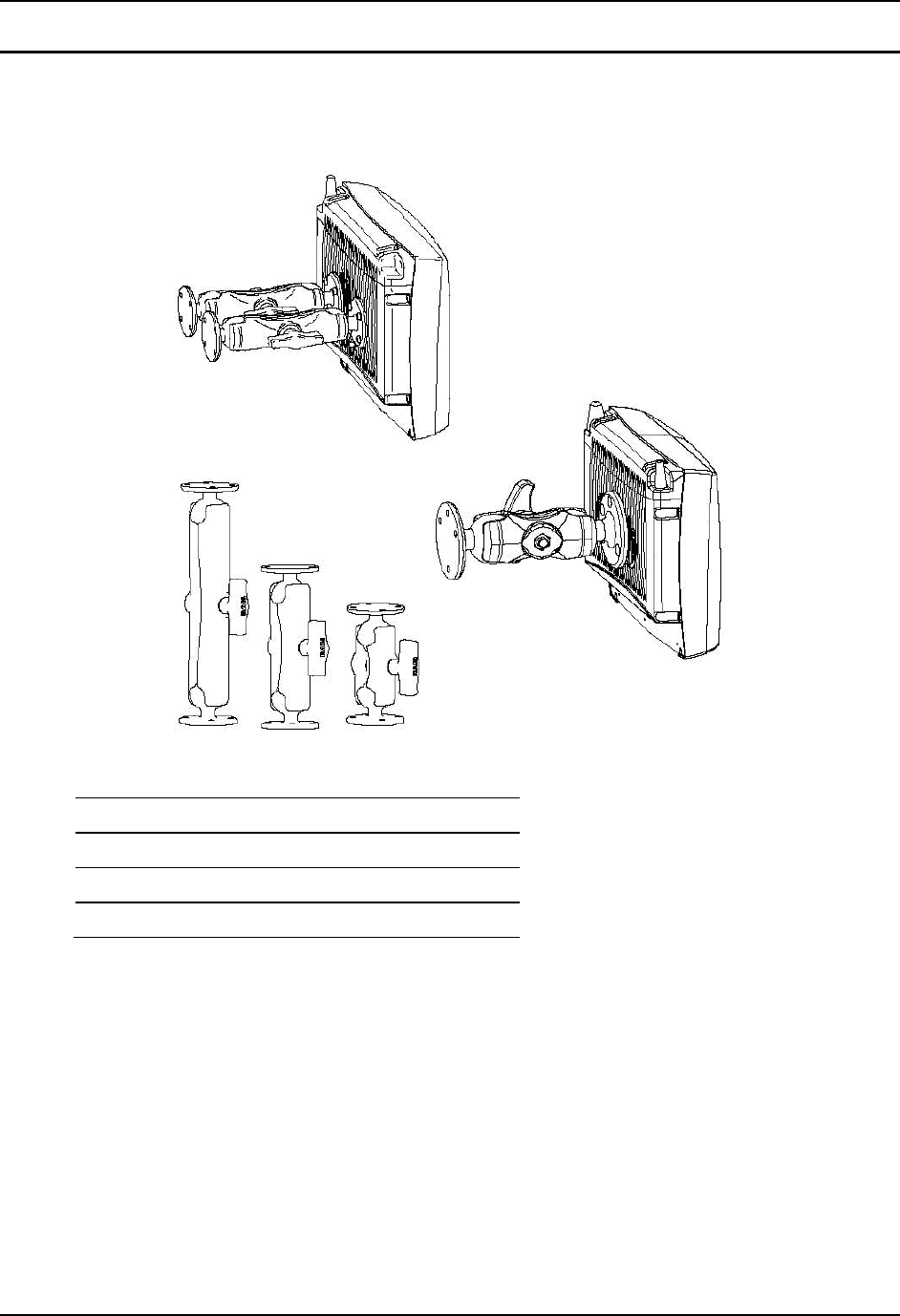
Installation User Manual Tx800
16 E-EQ-TX800OGWW-A 105858-100A0
4.1.1 Mounting brackets
You can order several different types of brackets for the Tx800. The brackets have built-in shock
absorption and can move in all directions.
Figure 3: Brackets (are available in 2 dimensions, in 3 lengths, see below)
Bracket with 1.5” ball Bracket with 2.25” ball
95 mm (3.75”) 128 mm (5.00”)
154 mm (6.00”) 213 mm (9.40”)
233 mm (9.14”) 328 mm (13.00”)
For ENG/CERT Review - Not for Distribution or Publication - Draft 02
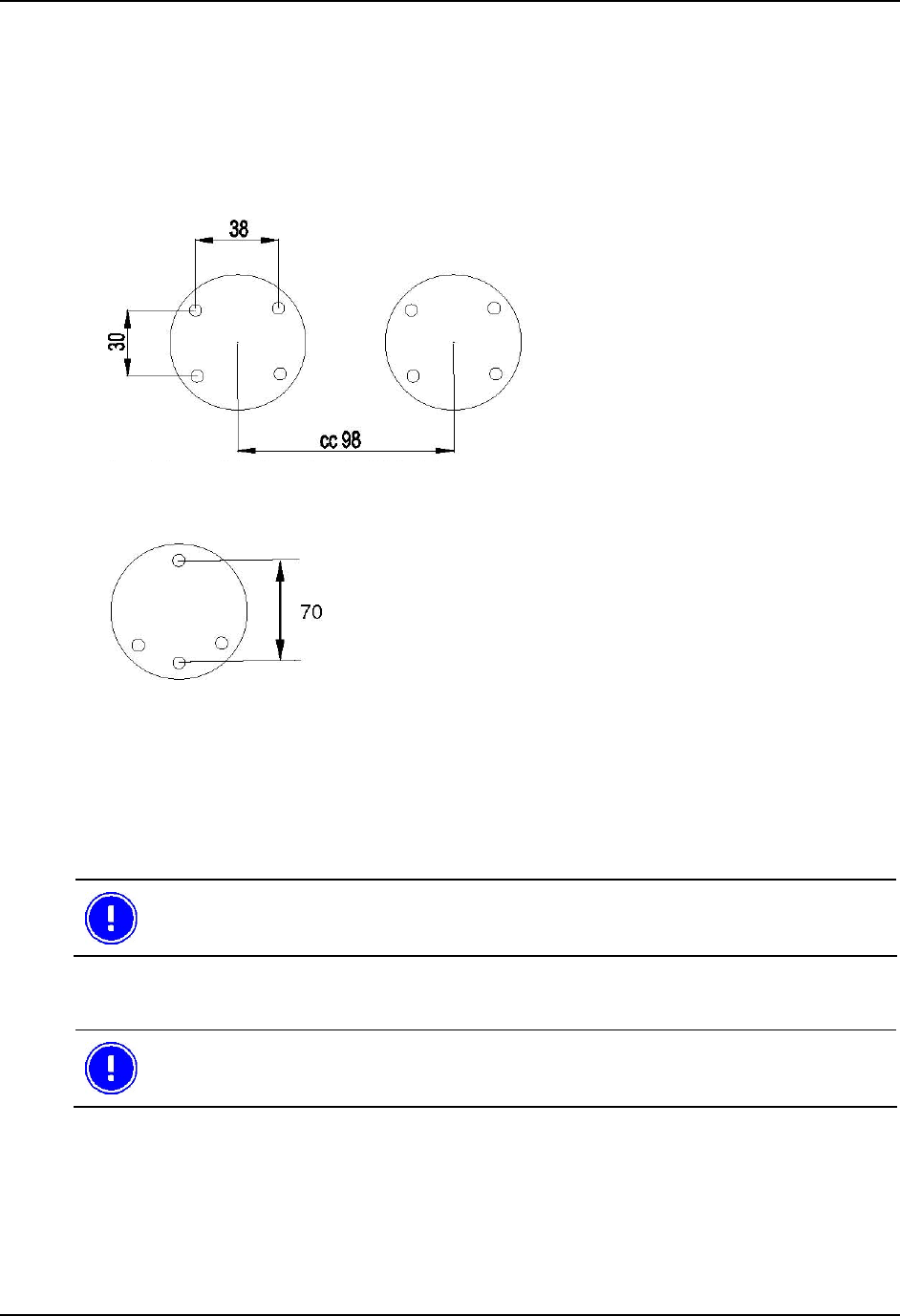
User Manual Tx800 Installation
105858-100A0 E-EQ-TX800OGWW-A 17
1 Check that the planned location of the computer meets ergonometric and field-of-vision requirement.
2 Ensure there is sufficient space underneath and above the Tx800 (easier to perform service/connect
and disconnect cables). There should be enough space behind the unit, making the passive cooling
work correctly.
3 Mark the positions of the holes on the mounting surface. See Figures 4 and 5 below.
5.5 mm holes
Figure 4 Locations of holes for 1.5” ball
8 mm holes
3 + 1 hole, 08 mm
Figure 3b Location of holes for 2.25” ball
4 Before drilling: Check behind/next to the presumed location for pre-installed electrical cabling, etc.
Verify placement with owner/manufacturer. Now drill holes for the attachment screws.
5 Firmly fasten the bracket onto the mounting surface using bolts.
Before mounting Tx800 onto the bracket, it’s easier to have all the wiring done, the
openable cable protection tube and the port lid in place.
4.2 Electrical installation
Always exercise caution when working with electricity!
For ENG/CERT Review - Not for Distribution or Publication - Draft 02
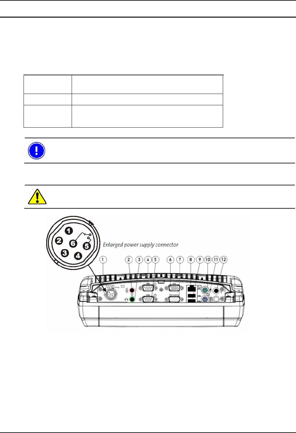
Installation User Manual Tx800
18 E-EQ-TX800OGWW-A 105858-100A0
4.2.1 Connecting to power source
The Tx800 comes with a four meter, four-wired power cable; brown for positive and white for negative,
and 2 conductors; yellow and green, to enable the screen black-out function (if selected), see 4.2.2.
Connect the brown part of this cable to positive and the white part to negative on the power source
(DC/DC converter), and fuse it according to the specifications shown below:
Specification external power source
Voltage 12 VDC ± 10%
Always use insulated DC/DC transformers in vehicles
Power 50 W
Fuse 6 A (slow blow fuse)
The vehicle’s chassis should always be electrically insulated from the Tx800.
Then connect the power cable to the computer’s power supply outlet; see Fig. 6.
Never connect power to pins 5 or 6. They are used for the black-out screen function
described in section 4.2.2.
Figure 6: Power supply connector
For ENG/CERT Review - Not for Distribution or Publication - Draft 02

User Manual Tx800 Installation
105858-100A0 E-EQ-TX800OGWW-A 19
4.2.2 Blackout screen function
This function is disabled by default but can be activated in
Trux Computer Manager.
In the power supply connector there are two pins (5 and 6), dedicated to dimming the screen for example
when the vehicle is set in motion (when the pedal is pressed). When the vehicle stops (when the pedal is
released) the screen is lit again.
Connect pins 5 (green wire) and 6 (yellow wire) to the vehicle’s pedal-relay by means of an insulated
(electrically), open/close relay contact. Blackout Screen Box is an option, from Åkerströms Trux AB,
which handles this.
If the screen’s black-out function isn’t used, insulate the end of the green and yellow wires on the open end
of the cable.
4.3 Settings
4.3.1 Using the Trux Computer Manager application
To configure certain Tx800 settings, you use the Trux Computer Manager application.
1 Start the Control Panel from the Settings option on the Start menu.
2 Double-click on the Trux icon.
The first window displays information about the application’s ID, version, and release date. This
information could be useful when contacting Åkerströms Trux AB support department.
Only experienced (IT) personnel should use the Trux Computer Manager because incorrect
settings could produce undesired results in Tx800’s behavior.
4.3.2 Configuring the UPS function
Tx800 comes with a state of the art developed system for handling momentary loss of power supply.
The UPS (Uninterruptible Power Supply) battery is located under the service-lid.
Use the Trux Computer Manager to specify values for:
• When the system should react to a power shortage
• The degree to which the monitor brightness should decrease
• When the system should try to shut down
Refer to the Trux Computer Manager for a more detailed description of how to configure the battery
backup function.
For ENG/CERT Review - Not for Distribution or Publication - Draft 02

Installation User Manual Tx800
20 E-EQ-TX800OGWW-A 105858-100A0
4.3.3 Settings for start and shutdown
Depending on the environmental conditions, in which the Tx800 is operating and the nature of the power
supply, settings for start-up and shutdown can be adjusted.
For example, using the Trux Computer Manager, you can specify whether the computer can be started
from battery power when the incoming power supply is connected or by touching the screen. You can also
configure the system to shut down the computer in different situations.
Refer to the Trux Computer Manager for a detailed description of available settings.
4.3.4 Supplying power to peripherals
Some peripherals require power from the computer’s COM or Multi Purpose ports. In Computer Trux
Manger Tx800 can be set to supply power from pin 9 on the COM ports (5V from COM1 and/or 12V from
COM2). From the Multi Purpose port, pin 5 can provide 12V. Also see Appendix II.
Refer to the Trux Computer Manager for information on how the power supply from the ports above is
activated
4.3.5 Battery charging options
The battery charge function can be set to be active while Tx800 is operating, as well as when the computer
is turned off or in standby mode.
To change the battery charge settings, refer to the Trux Computer Manager.
4.3.6 Blackout screen
The black-out screen (dim) function is not activated at delivery. About function and connection see 4.2.2.
To activate this function, refer to the Trux Computer Manager.
4.3.7 Sound, ambient light sensor and defroster
Settings for audio-out, the built-in ambient light sensor and the defroster (option) is also found in Trux
Computer Manager.
For ENG/CERT Review - Not for Distribution or Publication - Draft 02
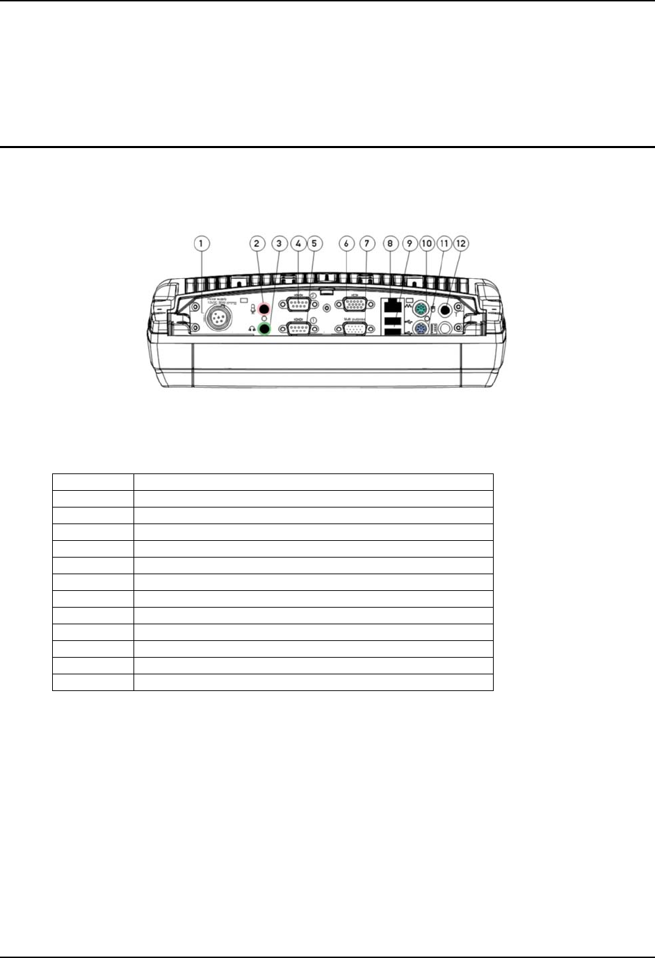
User Manual Tx800 Installation
105858-100A0 E-EQ-TX800OGWW-A 21
4.4 Installing peripherals
Åkerströms Trux AB offers peripherals to enhance the use of Tx800. Peripherals, ordered with the
computer, comes with pre-installed drivers. If you order them later, or from a supplier other than
Åkerströms Trux AB, you might have to install drivers; if so, refer to the peripheral’s documentation.
4.4.1 Ports for connecting peripherals
Port lid
Figure 7: Ports
Connections and interfaces (port lid)
Position Function
1 Power supply (12V DC 50W)
2 Mic. in
3 Audio out
COM2 RS232 (option:+12V from pin 9)
5 COM1 RS232 (option: +5V from pin 9)
6 VGA (external monitor)
7 Multipurpose connector (USB 2.0, RS232, 5/12 V)
8 RJ-45 Ethernet 10/100 (LAN)
9 2x USB 2.0
10 PS/2 Mouse
11 PS/2 Keyboard
12 Bluetooth antenna connector
The following section describes function and use of the ports.
Strain relief
Use the strain relief to prevent the contacts from disconnecting from the unit while operating.
The brackets for strain relief can be turned around, to fit various contact lengths. Use strain relief
according to fig. 8 for USB and PS/2 connectors.
For ENG/CERT Review - Not for Distribution or Publication - Draft 02
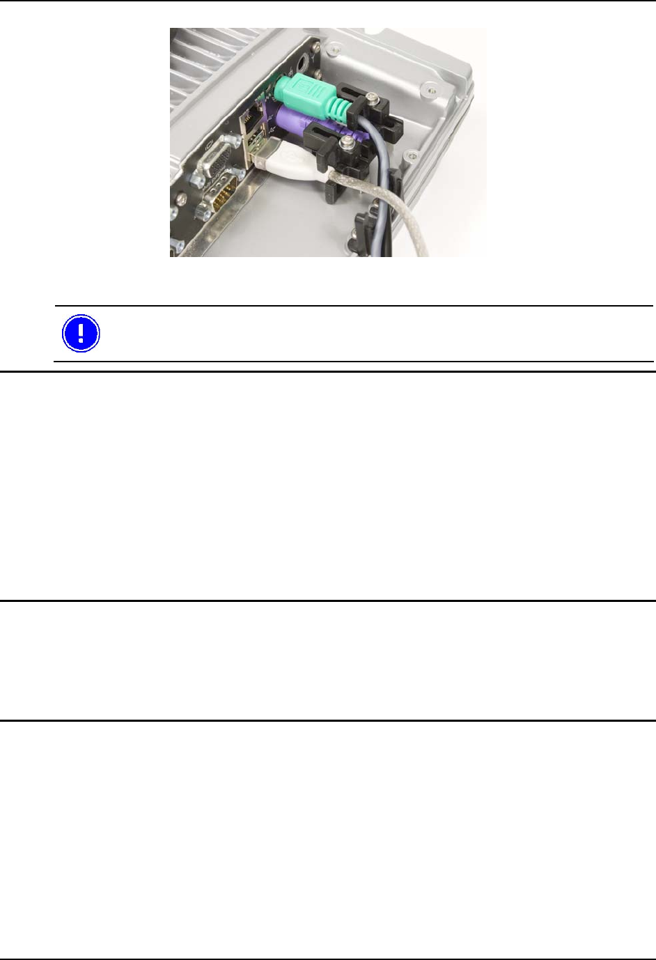
Installation User Manual Tx800
22 E-EQ-TX800OGWW-A 105858-100A0
Figure 8: Strain relieving brackets for USB and PS/2 connectors
When all peripherals are connected, the cabling should be put in the openable cable
protection tube, delivered with the unit (described in section 4.5).
4.4.2 Supplying power to peripherals
Some peripherals require power from the computer’s COM or Multi Purpose port, for example a bar-code
reader or an illuminated keyboard.
You can configure the Tx800 as follows:
• 12V power is supplied from pin 9 on the COM 2 port.
• 5V power is supplied from pin 9 on the COM 1 port.
• 12V power is supplied from pin 5 on the Multi purpose port.
Peripherals, with maximum power consumption of 300 mA, can be supplied from these ports.
Use the Trux Computer Manager to configure activation of the power supply from ports; see 4.3.4.
4.4.3 Keyboard and mouse
Tx800 supports either USB or PS/2 connected keyboard and mouse
Connect keyboards and pointing devices to the computer’s port. Use strain relief according to fig. 8,
section 4.4.1. Note that some require an adapter and others may need additional configuration. Follow the
instructions for the type of keyboard that you have.
4.4.4 Printers
You can connect printers to either:
• COM ports; see Fig 7, pos. 4 or 5, or
• USB ports; see Fig 7, pos. 9,
For more information, refer to the printer’s documentation.
The printer will need to be supplied with power separately.
For ENG/CERT Review - Not for Distribution or Publication - Draft 02

User Manual Tx800 Installation
105858-100A0 E-EQ-TX800OGWW-A 23
4.4.5 Barcode readers
Use this installation procedure for all bar code readers that Åkerströms Trux AB supplies for Tx800:
Select the appropriate port (COM2 supplies 12V, COM1 5V) or connect it using a
keyboard wedge connector.
1 Connect the barcode reader to the selected port.
2 Activate the power supply on the COM port in Trux Computer Manager (section 4.3.4).
To convert the signals from the scanner to keystrokes, you can use the FreeFloat WLinq software. WLinq
listens for signals at the COM port and converts these to the corresponding key that is sent to the active
application.
WLinq comes with all bar code readers from Åkerströms Trux. More details about WLinq is found in
Appendix IV.
4.4.6 External monitor
If needed, an external monitor can be connected to Tx800’s VGA connector.
4.4.7 Other external accessories
Mobile communication such as GPS, GSM/ GPRS/ WCDMA-systems can be connected to the
COM-ports.
Serially connected peripherals sometimes require power supply from the computer.
1 Connect the barcode reader to the correct COM port; see Figure 7 position 4 or 5.
2 Activate the power supply on the COM port (5V from COM1 or 12V from COM2) using Trux
Computer Manager (section 4.3.4).
For information about how to configure accessories like GPS and GSM/GPRS/WCDMA products, see the
manufacturers’ documentation.
4.4.8 Audio Out
Audio Out is a standard earphone outlet, Ø 3.5 mm.
4.4.9 Mic In
Mic In is a standard microphone inlet, Ø 3.5 mm.
4.4.10 Antenna
Tx800 comes with two mounted antennas, used for WLAN/GPRS communication. If externally mounted
antenna is needed, cabling and connectors for this is available from Åkerströms Trux AB. If a Bluetooth
antenna is needed, this is connected to port 12 (section 4.4.1).
Wireless communication equipment, not supplied by Åkerströms Trux AB, has to comply
with local Radio and Telecom Terminal Equipment directives.
For ENG/CERT Review - Not for Distribution or Publication - Draft 02
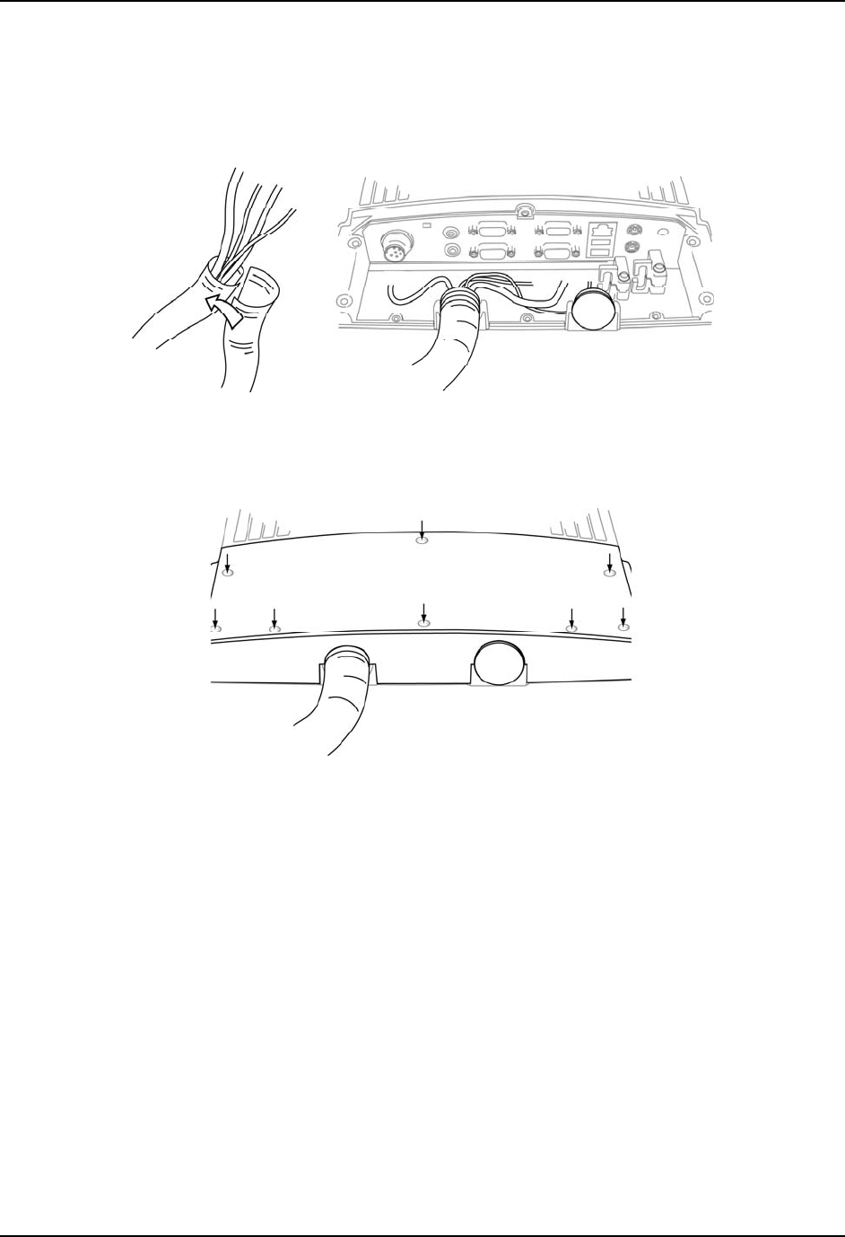
Installation User Manual Tx800
24 E-EQ-TX800OGWW-A 105858-100A0
4.5 Mounting the port lid
Cut the provided openable cable protection tube to the appropriate length. Put the cables in one half of it
and then put the other half on, according to fig. 9.
Figure 9: Applying the openable cable protection tube
Before mounting the port lid, fit the cable tube in the sockets of the chassis and lid.
Figure 10: Mounting the port lid
The screws used for the port lid should be alternately tightened to provide proper dust and moist protection
(IP65 requirement).
Fasten the cable tube in the vehicle, without putting strain on the tube. Now the Tx800 is ready to be
mounted in the vehicle.
For ENG/CERT Review - Not for Distribution or Publication - Draft 02
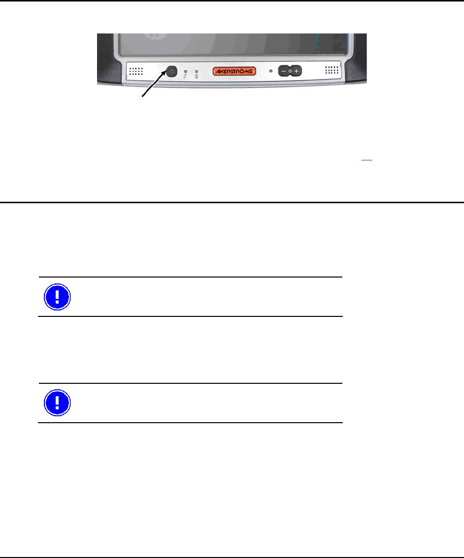
105858-100A0 E-EQ-TX800OGWW-A 25
5 Using the Tx800
5.1 Operating
5.1.1 Starting the computer
Figure 11: On/Off button
To turn on the computer:
• Press the on/off button on the computer’s front left side, see Fig. 11, or:
Depending on the settings in Trux Computer Manager (see section 4.3.3), Tx800 also can be started by
touching the integrated touch screen, or when turning the external power source on.
5.1.2 Turning off the computer
To turn off the computer:
• Shut down using the operating system’s interface, or
• Press the On/Off button on the computer’s left side.
The first hand choice is to shut down using the operating
system. This provides better protection against loss of data.
5.2 Touchscreen
The Tx800 is equipped with a pressure-sensitive touchscreen. Rather than using a mouse as pointing
device, users select objects by touching the screen with a stylus or a finger.
Always use the accompanying stylus to point, drag or tap
the screen. Never use metallic or sharp-pointed objects.
For ENG/CERT Review - Not for Distribution or Publication - Draft 02
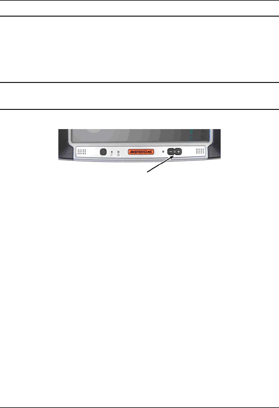
Using the Tx800 User Manual Tx800
26 E-EQ-TX800OGWW-A 105858-100A0
5.2.1 Using the stylus to select screen objects
To select an object on the interface, gently tap the screen:
• One time to click.
• Two times in rapid succession to double-click.
• Tap on the mouse symbol in the system tray, down in the right corner, the next click will then
be a right click.
5.2.2 Calibrating the touchscreen
Touch-screen accuracy is calibrated using the touch-screen application.
5.2.3 Adjusting brightness
Figure 12: Screen Brightness
Screen brightness is adjusted using the buttons (+) or (-) on the front’s right side.
The screen’s background lighting can be turned off by holding both buttons simultaneously.
Background lighting is restored by pushing one of the buttons or by touching the screen
The ambient-light autosensor is located on the front, to the left of the brightness controls.
In Trux Computer Manager there are settings for adjusting the behavior of the ambient-light-control.
For ENG/CERT Review - Not for Distribution or Publication - Draft 02
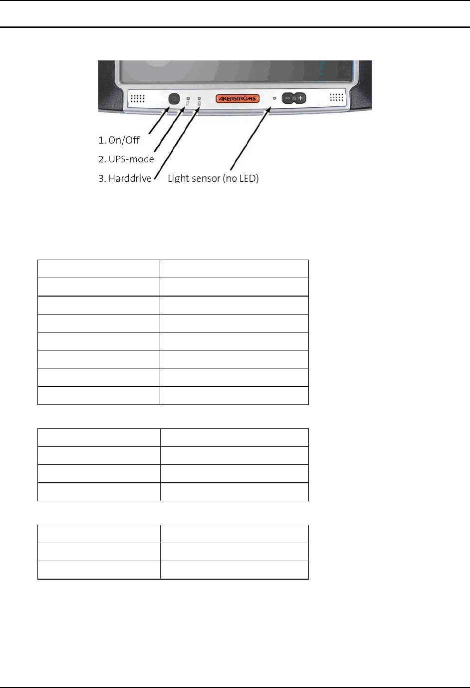
User Manual Tx800 Using the Tx800
105858-100A0 E-EQ-TX800OGWW-A 27
5.2.4 LED indications
Figure 13 LED Indicators
The On/Off button’s built-in LED, indicates operational mode.
1. On/Off LED
Operational Mode Indication
Off and not powered Off (dark)
Off but powered Green flash very slow
Operating normally Green on
Suspend Green flashing slow
Black-out Screen Green flashing fast
Over voltage shutdown Red on
Over temperature Red flashing
2. UPS Mode
Function Indication
UPS battery powered Green flashing fast
UPS battery charging Green on or flashing slow
UPS battery charged Off (dark)
3. Harddrive LED
Function Indication
Harddrive activity Green flashing
No activity Off (dark)
For ENG/CERT Review - Not for Distribution or Publication - Draft 02

Using the Tx800 User Manual Tx800
28 E-EQ-TX800OGWW-A 105858-100A0
For ENG/CERT Review - Not for Distribution or Publication - Draft 02

105858-100A0 E-EQ-TX800OGWW-A 29
6 Maintenance
6.1 Cleaning the screen
Clean the screen when necessary. Use a soft, slightly damp cloth. If required, use a cleaning solution that is
intended for computer screens.
Never use detergents or any other liquid not intended for this use when cleaning the
screen..
6.2 Checking connections
Check regularly that all connections are firmly in place and that all cables are securely fastened (check that
strain relief is working properly).
6.3 Service
To secure operation of the unit, various types of support agreements are available for Tx800.
Contact Åkerströms Trux AB for more information.
For ENG/CERT Review - Not for Distribution or Publication - Draft 02

Maintenance User Manual Tx800
30 E-EQ-TX800OGWW-A 105858-100A0
For ENG/CERT Review - Not for Distribution or Publication - Draft 02

105858-100A0 E-EQ-TX800OGWW-A 31
7 Troubleshooting
Perform the following troubleshooting procedures before contacting Åkerströms Trux AB regarding
problems with Tx800:
7.1 Computer problems
7.1.1 The computer will not start
If nothing happens when the On/Off button is pressed, ensure that the:
• Power supply is connected (On/Off LED blinking green).
• Fuse is intact.
• DC/DC converter supplies correct voltage.
• LED Indications on the front panel are correct (section 5.2.4).
7.1.2 The screen is blank
If the computer is on but the screen is blank or is only faintly lit, ensure that the:
• Screen black-out (dim) function is not active (fast green blinking On/Off button).
• Screen’s brightness is not set too low. Adjust with the brightness control buttons, (+)/(-) on
the front.
• LED Indications on frontpanel are correct (see section 5.2.4).
Try attaching an external (VGA) monitor, if nothing else works.
For ENG/CERT Review - Not for Distribution or Publication - Draft 02

Troubleshooting User Manual Tx800
32 E-EQ-TX800OGWW-A 105858-100A0
7.2 Problems with peripherals
If a peripheral doesn’t work:
• Check cabling/contacts and connections first.
• If the peripheral needs power supply, make sure the power supply for peripherals is activated
in the Trux Computer Manager (see 4.3.4).
7.2.1 Keyboard/Mouse
If keyboard or mouse doesn’t work:
• Check strain relief, cabling/contacts and connections
• Restart the computer and, if possible, try using another keyboard/mouse.
7.2.2 Touchscreen accuracy
If the touch-screen accuracy is off target:
• Calibrate the touch-screen/stylus, using the touchscreen application.
7.2.3 Communication
If communication problems arise with a wireless network, GPS or GSM/GPRS products, test coverage in
two ways:
• Check the computer’s software for indications of poor coverage (often indicated by an icon in
the systray).
• Put another computer in the same location, to see if the same problem occurs.
For ENG/CERT Review - Not for Distribution or Publication - Draft 02

105858-100A0 E-EQ-TX800OGWW-A 33
Appendix
I Technical Specifications
Processor/RAM Intel Pentium M 1,4GHz, 1024 MB DDR
Intel Pentium M 1,4GHz, 512 MB DDR
Intel Celeron M 600MHz, 1024 MB DDR
Intel Celeron M 600MHz, 512 MB DDR
Storage 40 GB IDE ATA 2,5” automotive harddrive
4 GB Compact Flash
2 GB Compact Flash
Screen 10,4” TFT Flat Panel SVGA (800X600)
Max 400 cd/m2
Contrast 500:1
Automatic ambient-light sensor
Graphics Card Intel Extreme Graphics 2
Ports/Connectors 2x PS/2 (Keyboard/mouse) 2 Serial port (COM1), (COM2)
2x USB 2.0 port
1 Multi Purpose connector (USB 2.0, RS232)
1 RJ-45 Ethernet 10/100
1 Audio Out (Head set)
1 Audio in (microphone)
Internal front-speakers
WLAN 802.11 a/b/g (h)
Internal connectors: 1x USB 2.0, 1x Mini-PCI
Antenna Dual band (2,4/5GHz)
Cooling Passive cooling
Power Supply 12 VDC ± 10%, 50W
Integrated Li-Po (Lithium-Polymer) battery
Integrated battery-charger. Option: DC/DC converter
Continued on the following page
For ENG/CERT Review - Not for Distribution or Publication - Draft 02

Troubleshooting User Manual Tx800
34 E-EQ-TX800OGWW-A 105858-100A0
Power Consumption 2,5 A (typ) 4 A (max)
0,7 A (typ) 1,0 A (max
Operating System Windows XP Professional or Windows XP Embedded
Dimensions 279 x 229 x 77 mm (11,0 x 9,0 x 3,0 inches)
Weight 2,9 kg ((7,7 lb)
Options Flash disk, 1 PC card type II, Bluetooth, Defroster,
GPRS/EDGE/WCDMA, Hardened touchscreen, external antenna
Temperature Limits -30º – 50º C (Storage)
-20º – 50º C (Operating)
Vibration tested According to:
IEC 60068-2-64, Test Fh Vibration
Shock tested According to:
IEC 60068-2-29, Test Eb Bump
Moisture tested According to:
IEC 60068-2-30, Test Db
Degree of protection IEC 60529 (IP65) Rated
Standard Conforms with CE, FCC and ETL standards
For ENG/CERT Review - Not for Distribution or Publication - Draft 02

User Manual Tx800 Troubleshooting
105858-100A0 E-EQ-TX800OGWW-A 35
II Port Signals
PS/2
PS2Connectors
Keyboard and mouse
(position: 10 and 11, section 3.3)
PS/2 Keyboard PS/2 Mouse
Pin Signal Pin Signal
1 KBDData 1 MSData
2 Reserved 2 Reserved
3 Ground 3 Ground
4 Volt 4 Volt
5 KBDClock 5 MSClock
6 Reserved 6 Reserved
For ENG/CERT Review - Not for Distribution or Publication - Draft 02

Troubleshooting User Manual Tx800
36 E-EQ-TX800OGWW-A 105858-100A0
COM1
Serial (COM1)
9-Pin D-sub M
(position: 5, section 3.3)
Pin Signal Type Purpose
1 DCD RS232 Input COM1 Handshake
2 RXD RS232 Input COM1 Receive data
3 TXD RS232 Output COM1 Send data
4 DTR RS232 Output COM1 Handshake
5 GND Ground Ground
6 DSR RS232 Input COM1 Handshake
7 RTS RS232 Output COM1 Handshake
8 CTS RS232 Input COM1 Handshake
9 EXTPWR
1 Power out COM1 Power supply 5 VDC
1 Supplies 5 VDC for peripherals, activated in Trux Computer Manager.
For ENG/CERT Review - Not for Distribution or Publication - Draft 02

User Manual Tx800 Troubleshooting
105858-100A0 E-EQ-TX800OGWW-A 37
COM2
Serial (COM1)
9-Pin D-sub M
(position: 4, section 3.3)
Pin Signal Type Purpose
1 DCD RS232 Input COM2 Handshake
2 RXD RS232 Input COM2 Receive data
3 TXD RS232 Output COM2 Send data
4 DTR RS232 Output COM2 Handshake
5 GND Ground Ground
6 DSR RS232 Input COM2 Handshake
7 RTS RS232 Output COM2 Handshake
8 CTS RS232 Input COM2 Handshake
9 EXTPWR
2 Power out COM2 Power supply 12 VDC
2 Supplies 12 VDC for peripherals, activated in Trux Computer Manager.
For ENG/CERT Review - Not for Distribution or Publication - Draft 02
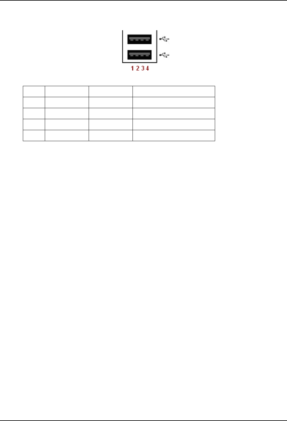
Troubleshooting User Manual Tx800
38 E-EQ-TX800OGWW-A 105858-100A0
USB
USB 2.0 x2
(position: 9, section 3.3)
Pin Signal Type Purpose
1 VCC USB power +5V Power out
2 USB0- Input/Output USB data -
3 USB0+ Input/Output USB data +
4 GND Ground Ground
For ENG/CERT Review - Not for Distribution or Publication - Draft 02

User Manual Tx800 Troubleshooting
105858-100A0 E-EQ-TX800OGWW-A 39
Multipurpose
Multi Purpose
15-Pin D-sub M
(position: 7, section 3.3)
Pin Signal Type Purpose
1 VCC 5 5 V Power +5 V USB Power Supply
2 RXD RS232 Input COM 4 Receive data
3 TXD RS232 Output COM 4 Transmitting data
4 Reserved Not used
5 +12V
3 Power out COM1 Power supply 5 VDC
6 USB + Input/Output USB data +
7 USB Input/Output USB data
8 GND Ground Ground
9 Reserved Not used
10 GND Ground Ground
11 GND Ground Ground
12 RTS RS232 Output COM4 Handshake
13 CTS RS232 Input COM4 Handshake
14 Reserved Not used
15 Reserved Not used
3 Supplies 12 VDC for peripherals, activated in Trux Computer Manager.
For ENG/CERT Review - Not for Distribution or Publication - Draft 02

Troubleshooting User Manual Tx800
40 E-EQ-TX800OGWW-A 105858-100A0
Ethernet
RJ-45 Ethernet 10/100
8-Pin Modular
(position: 8, section 3.3)
8,7,6,5,4,3,2,1
Pin Signal Function
1 TX+ Transmit data + (pair 2)
2 TX– Transmit data (pair 2)
3 RX+ Receive data + (pair 3)
4 Not used (pair 1)
5 Not used (pair 1)
6 RX– Receive data – (pair 3)
7 Not used (pair 4)
8 Not used (pair 4)
For ENG/CERT Review - Not for Distribution or Publication - Draft 02

User Manual Tx800 Troubleshooting
105858-100A0 E-EQ-TX800OGWW-A 41
VGA
VGA connector
15-Pin D-sub F.
(position 6, section 3.3)
Pin Signal Function
1 CRT_R CRT Red
2 CRT_G CRT Green
3 CRT_B CRT Blue
4 N/C Not connected
5 GND Ground
6 RGND Red Ground
7 GGND Green Ground
8 BGND Blue Ground
9 N/C Not connected
10 GND Ground
11 N/C Not connected
12 SDA DDC_Data
13 CRT_HS CRT Horisontal Sync.
14 CRT_VS CRT Vertical Sync.
15 SCL DDC_Clock
For ENG/CERT Review - Not for Distribution or Publication - Draft 02

Troubleshooting User Manual Tx800
42 E-EQ-TX800OGWW-A 105858-100A0
III Technical Recommendations
Recovery
The recovery media can be ordered as a stand alone product.
For ENG/CERT Review - Not for Distribution or Publication - Draft 02

User Manual Tx800 Troubleshooting
105858-100A0 E-EQ-TX800OGWW-A 43
IV Disclaimer
All Åkerströms Trux AB’s software products, whether imbedded in ROMs or other hardware or delivered on CD-ROM or other
media, including all related manuals and documentation (collectively “Åkerströms Software”) are proprietary to Åkerströms.
Åkerströms reserves all right, title and interest in and to the Åkerströms Software not explicitly licensed herein, including without
limitation, all copyrights, patents and other proprietary rights. Åkerströms Software contained in or embedded with purchased
hardware products may only be used with the related hardware products. No embedded Åkerströms Software may be separated from
any hardware products as shipped by Åkerströms. Åkerströms Software delivered separately from a hardware product may only be
used on a single CPU at a time. Stand-alone Åkerströms Software may not be copied, except for (1) back-up copy in
machine-readable form, provided such copy are used for back-up only and provided all copyright information contained on the
originals is included in the copy. Except as expressly permitted by mandatory applicable law and this Agreement, Customer agrees
not to copy, modify, de-compile, reverse engineer, disassemble, or otherwise discover, the Åkerströms Software, in whole or part.
Customer shall not remove or obscure any copyright notices or proprietary legends contained within the Åkerströms Software.
The ÅKERSTRÖMS SOFTWARE IS PROVIDED “AS IS”.
All Non-Åkerströms Software products are provided under the terms and conditions of the software license agreement (if any) from
such software provider applicable to such Non-Åkerströms software. If no license agreement is provided Non-Åkerströms software is
provided with the same terms and conditions as applies to the Åkerströms Software.
License costs, update responsibility, functionality, interoperability of the customer image are under the responsibility of the customer.
Åkerströms is not responsible to any consequence costs due to faulty, illegal or accidentally related issues to the customer image
creation.
For ENG/CERT Review - Not for Distribution or Publication - Draft 02

Troubleshooting User Manual Tx800
44 E-EQ-TX800OGWW-A 105858-100A0
V Tx800 Software
The following software is installed on a new Tx800.
Freefloat WLinq
WLinq is an integration tool for auto-id solutions. Featuring communication and control to devices
connected to COM-ports, physical or virtual (USB and Bluetooth). For use it with barcode readers, scales,
RFID readers and other serial devices.
WLinq is bundled with the Tx800. It will run in demo mode, if installed from scratch, or normal mode,
based on the original installation licensing regulations. Stand-alone licences for WLinq can be ordered
from Åkerströms Trux AB.
• wlinqeng.exe (English version)
• wlinqswe.exe (Swedish version)
Tx800 Computer Manager
Handles settings for; sound, light, power from ports, UPS, start-up and shutdown etc. Install the
application with all options checked.
Freefloat Access One Terminal Emulator
Terminal emulating software for accessing mainframes, AS/400:s, Unix hosts etc.
Trux Speedometer
Handles Speedstep technology supported by some CPUs. Make sure the Trux 800 power scheme has been
installed and selected. This is done via Control Panel->Performance and Maintenance->Power
Options->Power Schemes.
Touchscreen software
Drivers to support the touchscreen and software for calibrating the pointing-accuracy.
Select COM3 in the installation wizard.
Communication devices
Install the proper software for your communication device,
e.g. WLAN card.
Tx800 device drivers
All the device drivers are preinstalled.
For ENG/CERT Review - Not for Distribution or Publication - Draft 02
User Manual Tx800 Troubleshooting
105858-100A0 E-EQ-TX800OGWW-A 45
VI Certification
FCC Information:
This device complies with FCC Rules, part 15. Operation is subject to the following conditions:
1. This device may not cause harmful interference
and
2. This device must accept any interference that may be received, including interference that may cause
undesired operation.
Note: This equipment has been tested and found to comply with the limits for a Class A digital device, pursuant
to part 15 of the FCC rules. These limits are designed to provide reasonable protection against harmful
interference when the equipment is operated in a commercial environment. This equipment generates, uses, and
can radiate radio frequency energy and, if not installed and used in accordance with the instruction manual, may
cause harmful interference to radio communications. Operation of this equipment in a residential area is likely to
cause harmful interference in which case the user will be required to correct the interference at his own expense.
Warning: Changes or modifications to this device not expressly approved by LXE, Inc., could void the user’s
authority to operate this equipment.
EMC Directive Requirements:
This is a Class A product. In a domestic environment this product may cause radio interference in which case the
user may be required to take adequate measures.
Industry Canada:
This Class A digital apparatus meets all requirements of the Canadian Interference Causing Equipment
Regulations. Operation is subject to the following two conditions: (1) this device may not cause harmful
interference, and (2) this device must accept any interference received, including interference that may cause
undesired operation.
Cet appareil numérique de la classe A respecte toutes les exigences du Règlement sur le matériel brouilleur du
Canada. Le présent appareil numérique n’émet pas de bruits radioélectriques dépassant les limites applicables
aux appareils numériques de Classe A prescrites dans le Règlement sur le brouillage radioélectrique édits par le
ministère des Communications du Canada.
RF Safety Notice:
Caution:
This device is intended to transmit RF energy. For protection against RF exposure to humans and in
accordance with FCC rules and Industry Canada rules, this transmitter should be installed such that
a minimum separation distance of at least 20 cm (7.8 in.) is maintained between the antenna and the
general population. This device is not to be co-located with other transmitters.
Important: This symbol is placed on the product to remind users to dispose of Waste
Electrical and Electronic Equipment (WEEE) appropriately, per Directive 2002-96-EC. In most
areas, this product can be recycled, reclaimed and re-used when properly discarded. Do not
discard labeled units with trash. For information about proper disposal, contact LXE through
your local sales representative, or visit www.lxe.com.
For ENG/CERT Review - Not for Distribution or Publication - Draft 02

Troubleshooting User Manual Tx800
46 E-EQ-TX800OGWW-A 105858-100A0
!
Lithium Battery Safety Statement
!
Caution:
Lithium battery inside. Danger of explosion if battery is incorrectly replaced. Replace only with same or
equivalent type recommended by battery manufacturer. (US)
Attention:
Contient une pile de lithium. Risque d’explosion dans le cas où la pile ne serait pas correctement remplacée.
Remplacer uniquement avec une pile semblable ou equivalente au type de pile recommandé par le fabricant. (FR)
Forsigtig:
Indeholder lithiumbattterier. Risiko for eksplosion, hvis batteriet udskiftes forkert. Må kun udskiftes med samme
eller tilsvarende type, som anbefalet af fabikanten. (DK)
Varoitus:
Tämä tuote käyttää laservaloa. Skannerissa on jokin seuraavista tarroista. Lue Huomio-kohta. (FI)
Vorsicht:
Enthält Lithium-Batterie. Bei unsachgemäßem Ersatz besteht Explosionsgefahr. Nur durch gleichen oder vom
Hersteller empfohlenen Typ ersetzen. (DE)
Attenzione:
Batteria al litio. Pericolo di esplosione qualora la batteria venga sostituita in maniera scorretta. Sostituire solo con lo
stesso tipo o equivalente consigliato per il fabbricante. (IT)
Atenção:
Contém pilha de lítio. Há perigo de explosão no caso de uma substituição incorreta. Substitua somente pelo mesmo
tipo, ou equivalente, recomendado pelo fabricante. (PT)
Varning:
Innehåller litiumbatteri. Fara för explosion om batteriet är felaktigt placerat eller av fel typ. Använd endast samma
eller motsvarande typ batterier rekommenderade av tillverkaren. (SE)
Advarsel:
Innmontert Lithium batteri. Eksplosjonsfare ved feil montering av batteri. Benytt kun batteri anbefalt av produsent.
(NO)
Cuidado:
Pila de litio adentro. Peligro de explosión si la pila se reemplaza incorrectamente. Reemplace solamente con el
mismo tipo o equivalente recomendado por el fabricante. (ES)
Oppassen:
Bevat Lithium-batterij. Incorrrecte plaatsing van batterij kan leiden tot explosiegevaar. Alleen vervangen door
hetzelfde of door fabrikant aanbevolen gelijkwaardig type. (NL)
For ENG/CERT Review - Not for Distribution or Publication - Draft 02

User Manual Tx800 Troubleshooting
105858-100A0 E-EQ-TX800OGWW-A 47
VII Warranty, Support and Service
Warranty
The Tx800 has a warranty of one year from the date of delivery
The warranty assumes that the product was used in a way that can be considered normal and that all the
requirements in this manual are met.
If alterations are made to the computer without the consent of Åkerströms Trux AB, the warranty will no
longer apply.
Support
To secure operation of the unit, various types of support agreements are available for Tx800.
Contact Åkerströms Trux AB for more information.
If any problem occur; always start by reading section 7, Troubleshooting.
If the problem cannot be solved, check with the person in charge at your company to see whether there are
support agreements for your Tx800. Then contact Åkerströms Trux AB
Åkerströms Trux AB only offers support for Windows XP, and Windows XP Embedded operating systems
in the Tx800.
Service
After repairs or service, if possible , the computer will be returned with operating system and software in
the same condition as when it was sent to Åkerströms Trux AB,. Otherwise, it will be returned with the
original configuration, unless other agreements have been made.
For ENG/CERT Review - Not for Distribution or Publication - Draft 02

Troubleshooting User Manual Tx800
48 E-EQ-TX800OGWW-A 105858-100A0
VIII Environmental Care Information
Thanks to its low energy consumption, the use of Tx800 has a minimal effect on the environment.
However, the computer should still be turned off or put on standby when it is not in use, to avoid the
unnecessary consumption of energy.
Information on recycling
Since the computer contains materials that can harm the environment if handled improperly, a disused
computer should always be taken to a recycling depot for electronic waste.
Åkerströms Trux AB is happy to take back disused computers and will ensure that they are recycled in
accordance with sound environmental practice. Contact Åkerströms Trux AB for more information.
Contents that may be harmful to the environment
If the computer is sent in for recycling anywhere else than Åkerströms Trux AB, that organisation should
be informed of the following contents:
• Li-Po battery.
• Circuit boards and circuits
• Screen (LCD and glass)
• Metal casing (magnesium)
• Cables
For ENG/CERT Review - Not for Distribution or Publication - Draft 02

User Manual Tx800 Troubleshooting
105858-100A0 E-EQ-TX800OGWW-A 49
IX Batteries
CAUTION:
Risk of explosion if battery is replaced by an incorrect type. Dispose of used batteries according to the
instructions.
DISCHARGED BATTERY
Disposal of a Li-Po battery poses a smaller threat to the environment when compared to other battery
types. However, all used Li-Po batteries should be sent to a qualified battery collection centre for
recycling.
.
Remember to return old batteries for recycling!
For ENG/CERT Review - Not for Distribution or Publication - Draft 02
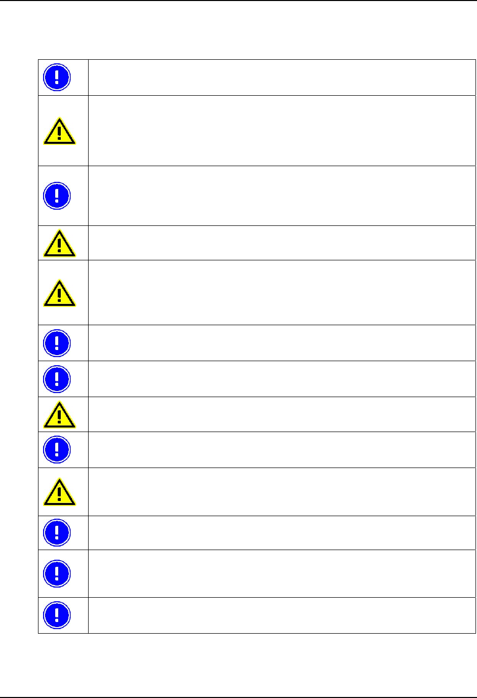
Troubleshooting User Manual Tx800
50 E-EQ-TX800OGWW-A 105858-100A0
X Français Avertissement et emarque
Le manuel n'explique pas comment installer et utiliser le système d'exploitation ou les
applications.
Avertissement !
Vous avertit des risques de dommages pour les individus ou les biens. Suivez toujours les
instructions qui figurent en regard de ce symbole.
Remarque !
Attire votre attention sur les problèmes qui peuvent survenir si une mesure n'est pas prise ou
est prise de manière incorrecte.
Soyez toujours prudent lorsque vous travaillez avec l'électricité.
Ne mettez jamais l'ordinateur sous tension si les conditions environnementales ne sont pas
dans les limites indiquées (cf. Annexe I, Spécifications). Par exemple, vérifiez que
l'ordinateur est mis sous tension avant d'entrer dans une unité de stockage froide.
Avant l'installation, veillez à ce que tous les critères relatifs à l'environnement soient
respectés. Vous trouverez une liste de ces critères en Annexe I, dans les Spécifications.
Ne changez pas les vis d'origine avec lesquelles sont montés les supports. Des vis trop
longues peuvent endommager le système électrique de l'ordinateur.
Soyez toujours prudent lorsque vous travaillez avec l'électricité.
Si la masse du véhicule n'est pas la même que celle du châssis du véhicule, vous devez alors
monter l'ordinateur sur des patins en caoutchouc.
Ne connectez jamais l'alimentation aux prises 5 ou 6, qui servent à la fonction de noir de
l'écran décrite à la section .2.2.
Vous pouvez définir cette fonction dans l'application Trux Computer Manager ; cf. 4.3.1.
Seuls les salariés (IT) expérimentés sont autorisés à utiliser le logiciel Trux Computer
Manager car des paramètres incorrects peuvent avoir des effets indésirables sur certaines
fonctions.
Si vous modifiez ou réinstallez le système d'exploitation de l'ordinateur, vous pouvez être
amené à réinstaller les pilotes pré-installés.
For ENG/CERT Review - Not for Distribution or Publication - Draft 02

User Manual Tx800 Troubleshooting
105858-100A0 E-EQ-TX800OGWW-A 51
Une fois que les périphériques sont connectés, fixez les câbles sur la partie inférieure de
l'ordinateur qui comporte des trous prévus pour les brides de câbles.
N'oubliez pas que les systèmes d'exploitation n'ont pas tous une prise en charge intégrée de
la souris (par exemple, DOS).
For ENG/CERT Review - Not for Distribution or Publication - Draft 02

Åkerströms Trux AB
Björbovägen 143
SE-780 45 Björbo
Phone: +46 241 250 00
Fax: +46 241 250 61
e-mail: sales@akerstroms.se
www.akerstromstrux.com
For ENG/CERT Review - Not for Distribution or Publication - Draft 02