Honeywell LXERFID1 RFID Reader User Manual MX3X User s Guide
Honeywell International, Inc. RFID Reader MX3X User s Guide
UserManual.wiki
>
Honeywell
>
LXERFID1 User Manual
>
user manual
Contents
1.
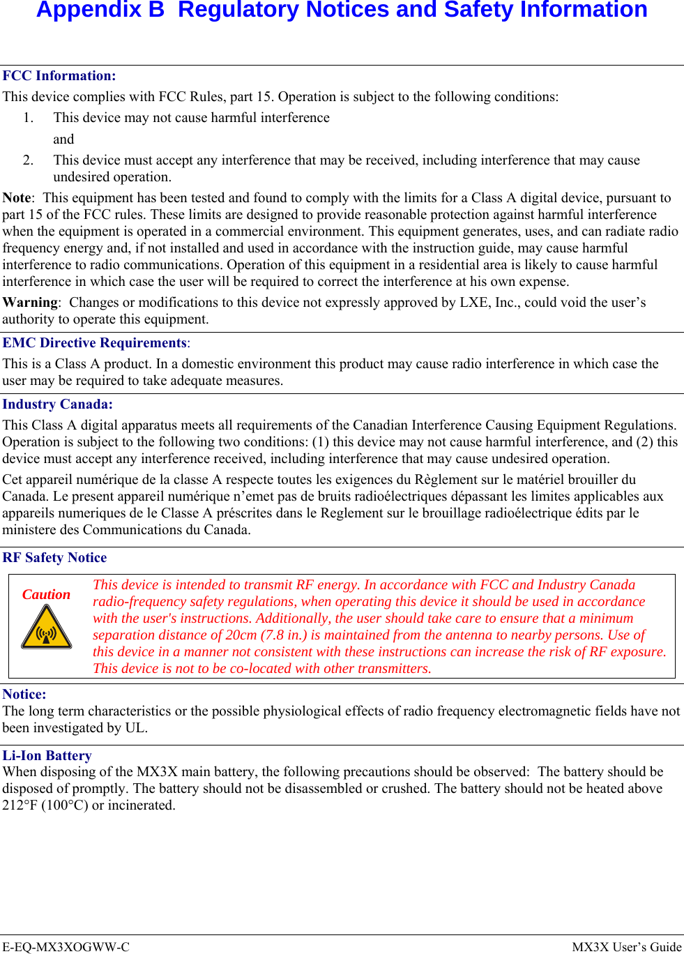
Regulatory notices and safety information
2.
user manual
user manual
Navigation menu
Upload a User Manual
Namespaces
Wiki Guide
HTML
PDF
Info
Views
User Manual
Discussion / Help
Navigation
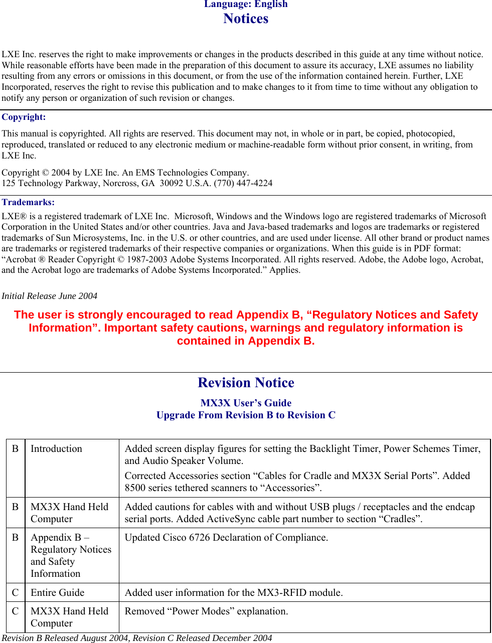
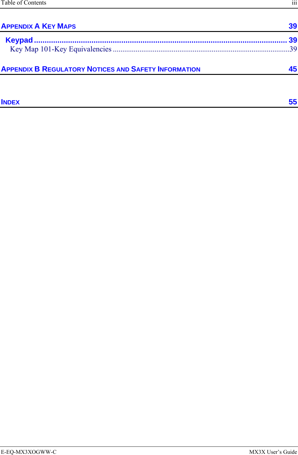
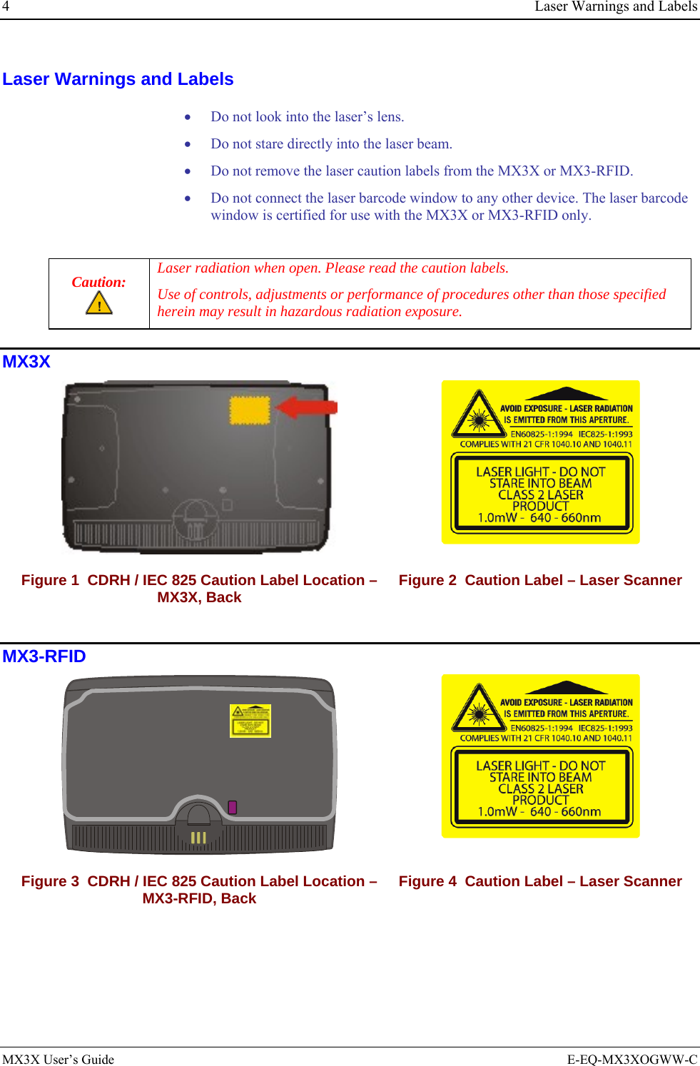
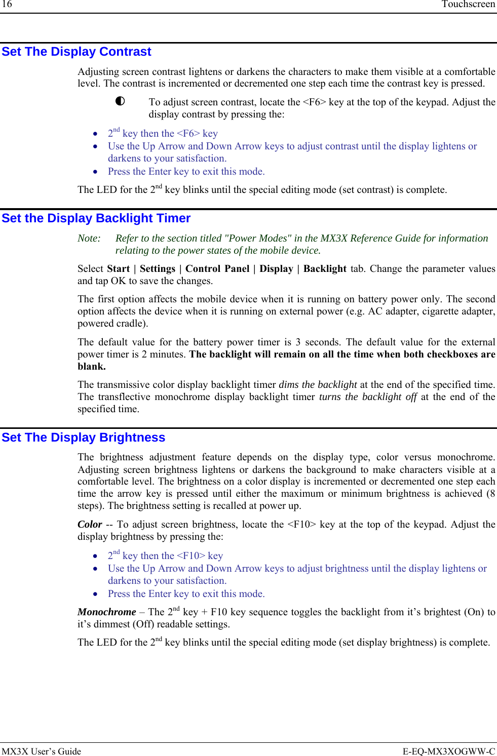
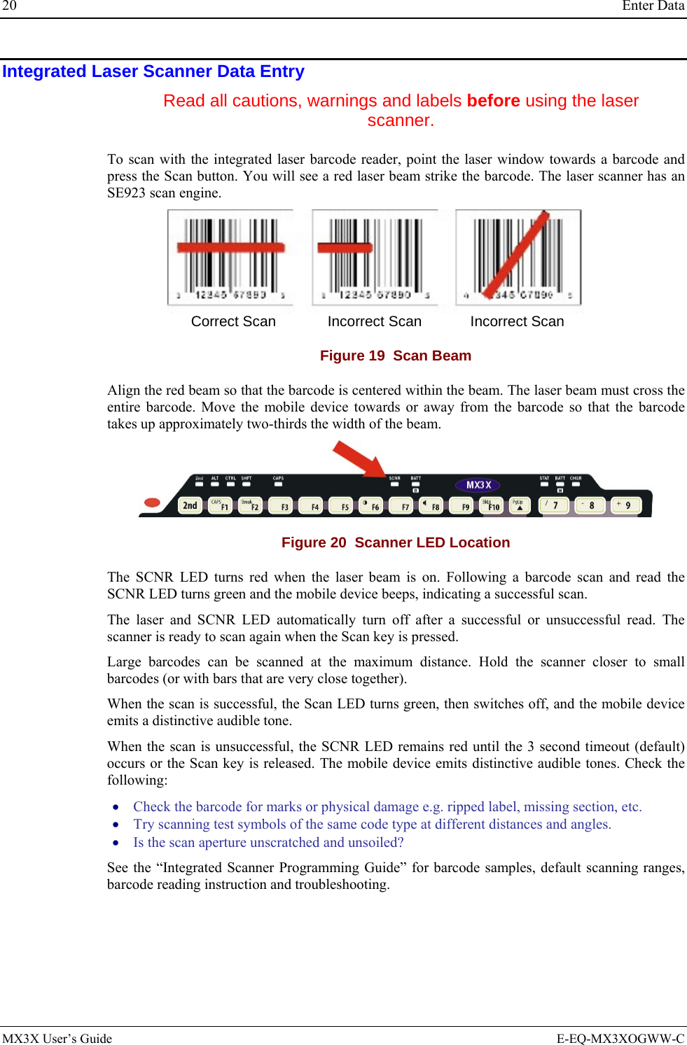
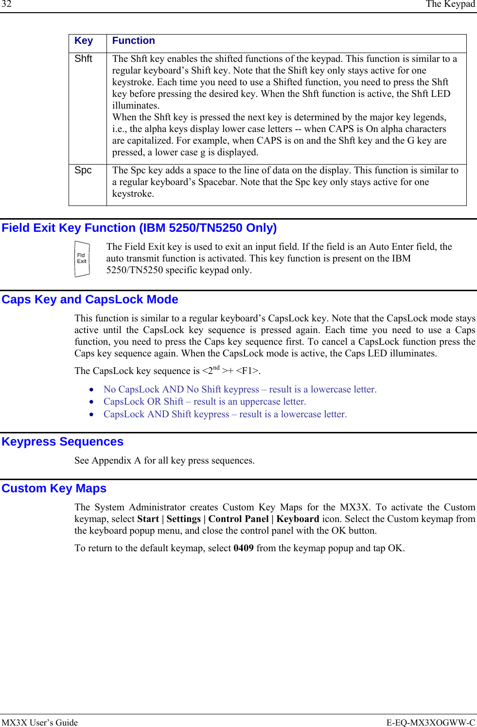
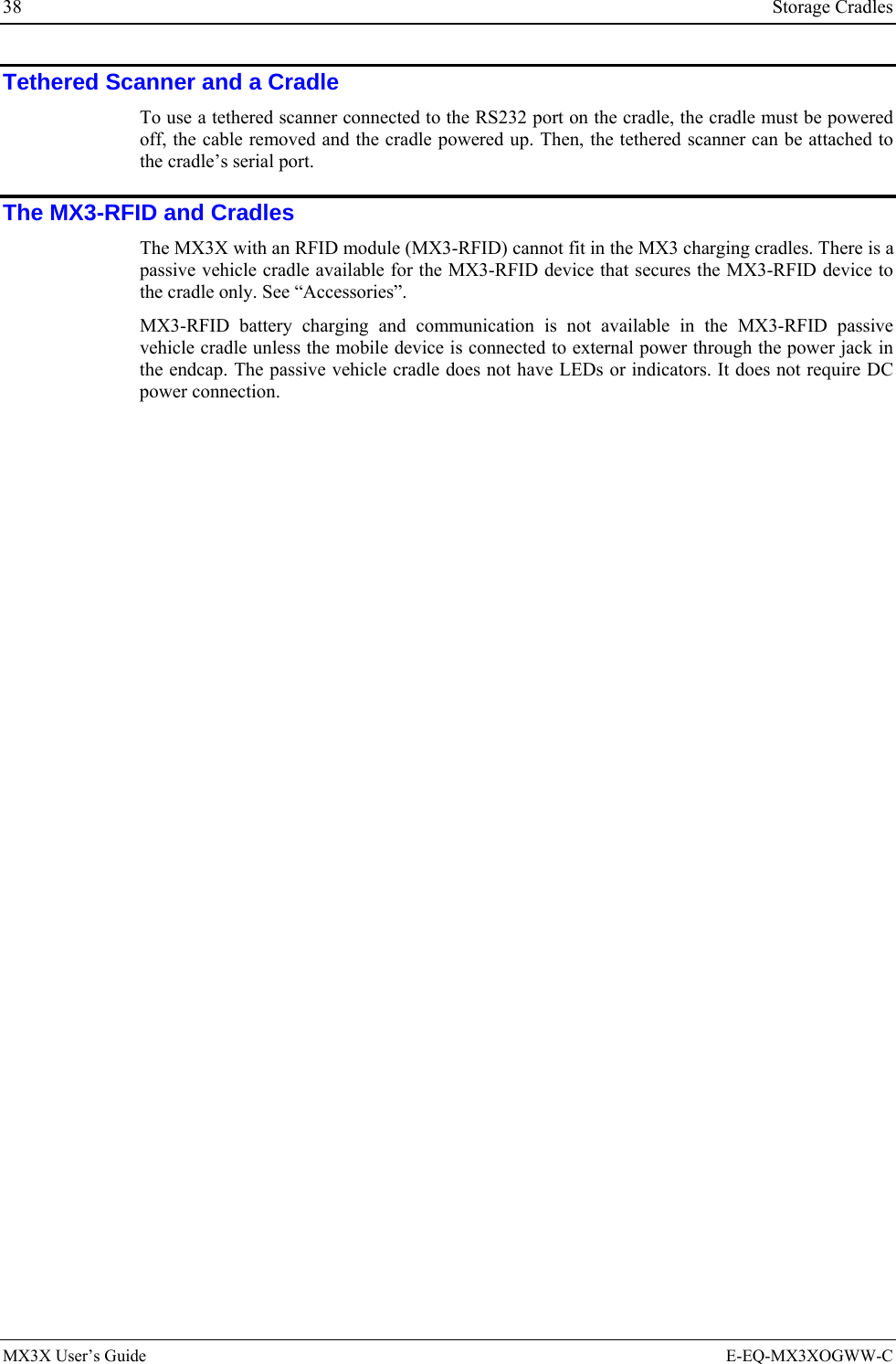
![Overview 3 Document Conventions ALL CAPS All caps are used to represent disk directories, file names, and application names. Menu | Choice Rather than use the phrase “choose the Save command from the File menu”, this guide uses the convention “choose File | Save”. “Quotes” Indicates the title of a book, chapter or a section within a chapter (for example, “Document Conventions”). < > Indicates a key on the keypad (for example, <Enter> ). Indicates a reference to other documentation. ATTENTION Keyword that indicates vital or pivotal information to follow. Attention symbol that indicates vital or pivotal information to follow. Also, when marked on product, means to refer to the user’s guide. International fuse replacement symbol. When marked on the product, the label includes fuse ratings in volts (v) and amperes (a) for the product. Note: Keyword that indicates immediately relevant information. CAUTION Keyword that indicates a potentially hazardous situation which, if not avoided, may result in minor or moderate injury. WARNING Keyword that indicates a potentially hazardous situation which, if not avoided, could result in death or serious injury. DANGER Keyword that indicates a imminent hazardous situation which, if not avoided, will result in death or serious injury. MX3X Environmental Specifications Operating Temperature Monochrome display : -4°F to 122°F (-20°C to 50°C) [non-condensing] Color display : 32°F to 122°F (0°C to 50°C) [non-condensing] Storage Temperature -22°F to 158°F (-30°C to 70°C) [non-condensing] Water and Dust MX3X = IEC IP66 MX3-RFID = IEC IP55 Operating Humidity 5% to 95% non-condensing at 104°F (40°C) Vibration Based on MIL Std 810D ESD 8 kV air, 4kV contact Shock 75G, 5ms duration, 100 shock impacts E-EQ-MX3XOGWW-C MX3X User’s Guide](https://usermanual.wiki/Honeywell/LXERFID1.user-manual/User-Guide-499953-Page-9.png)
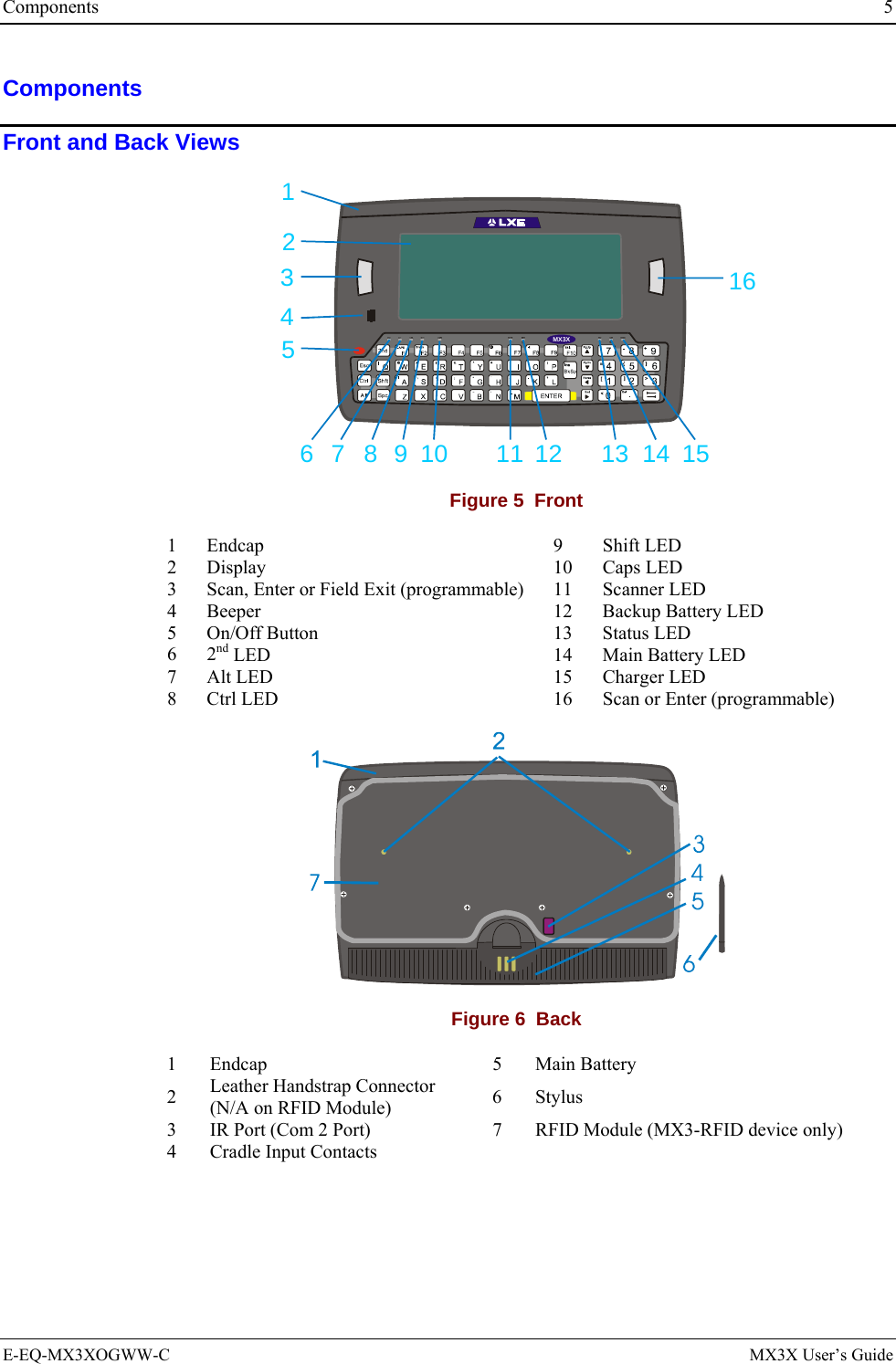
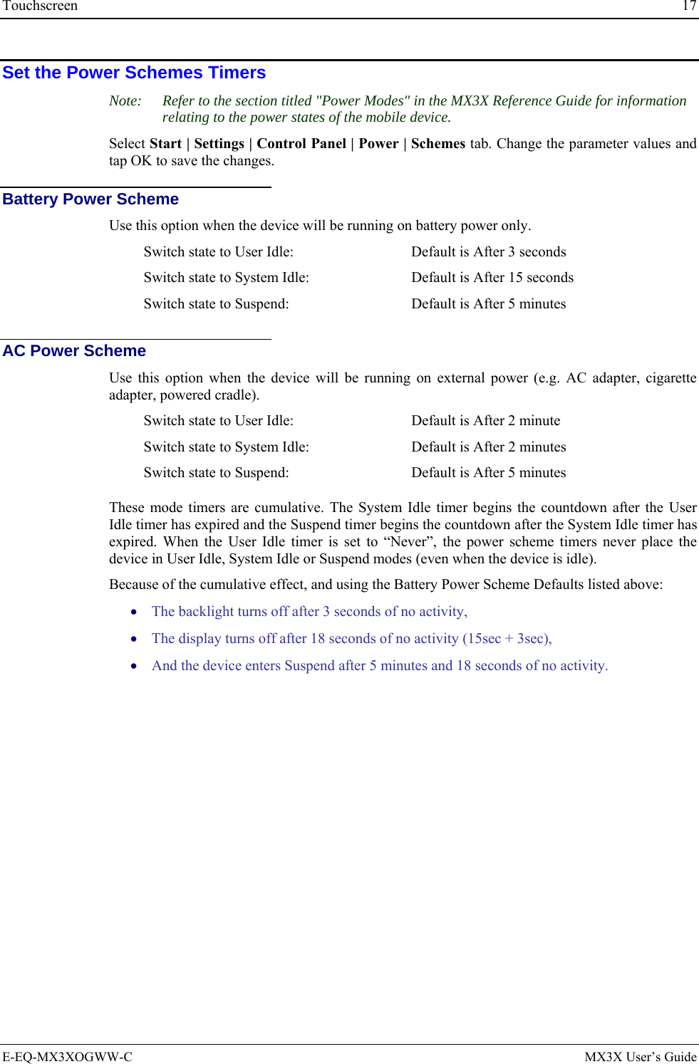
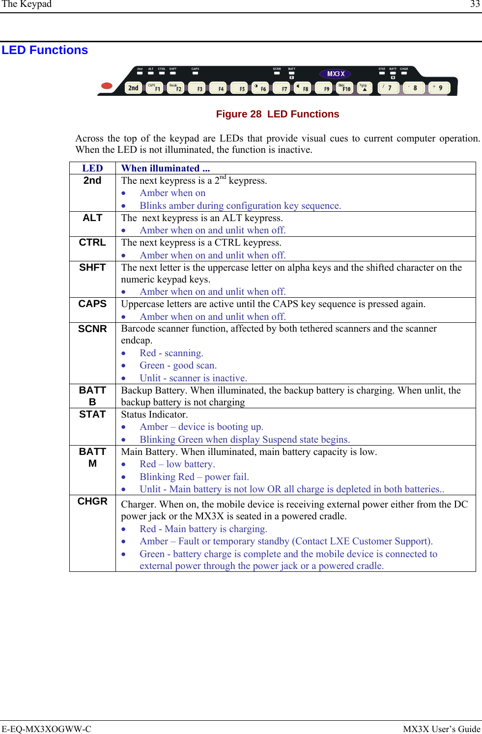
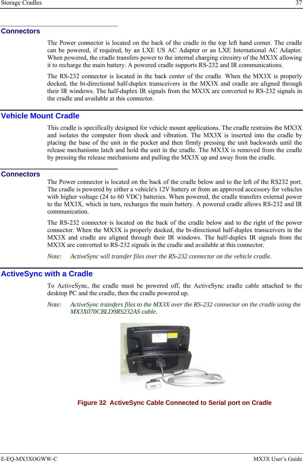
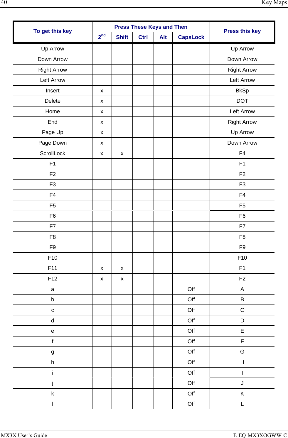
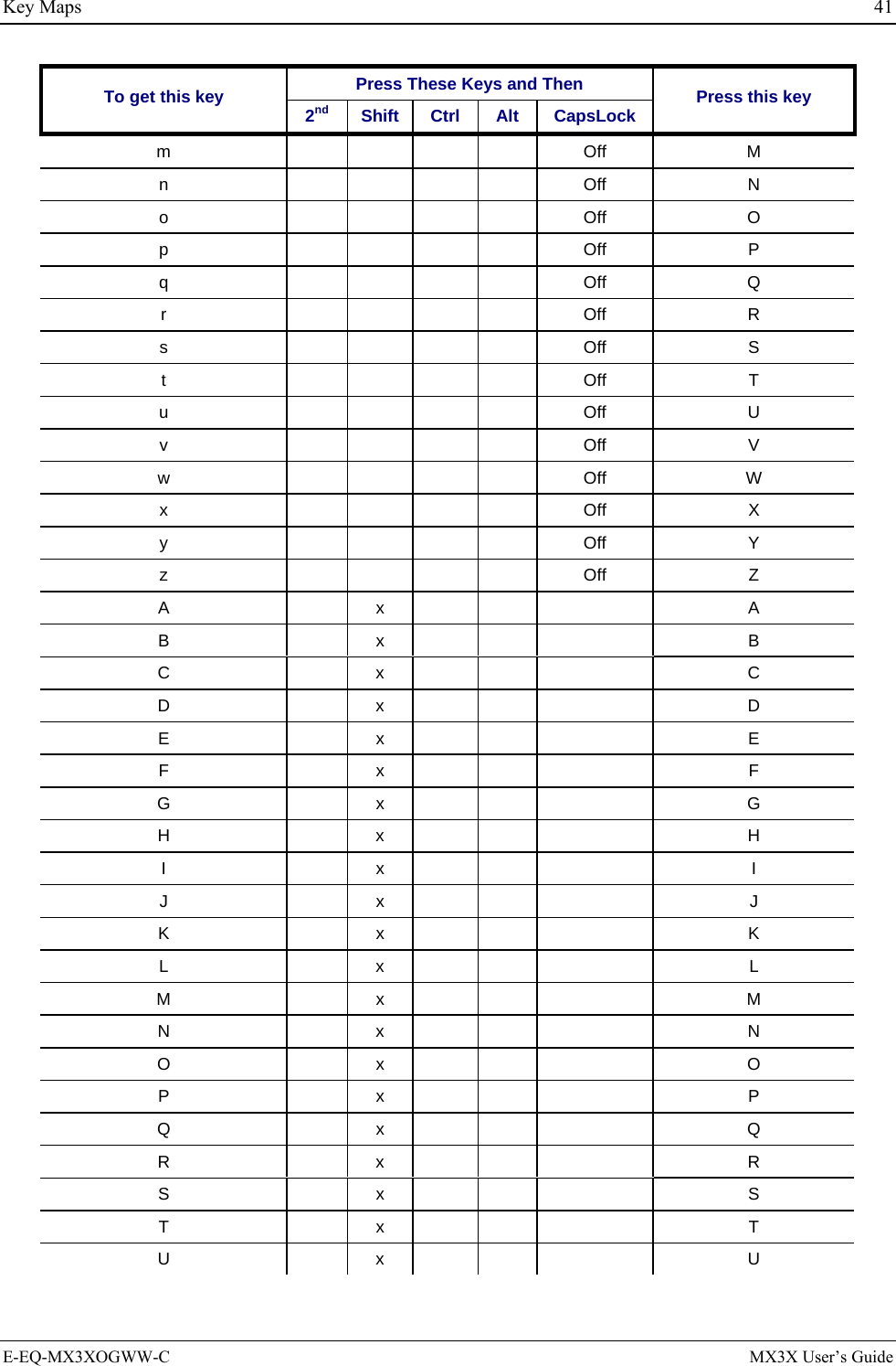
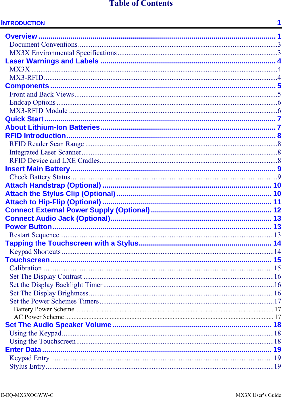
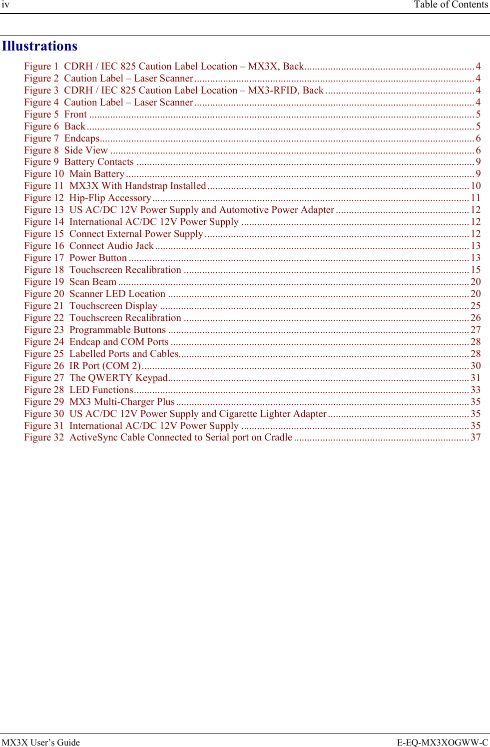
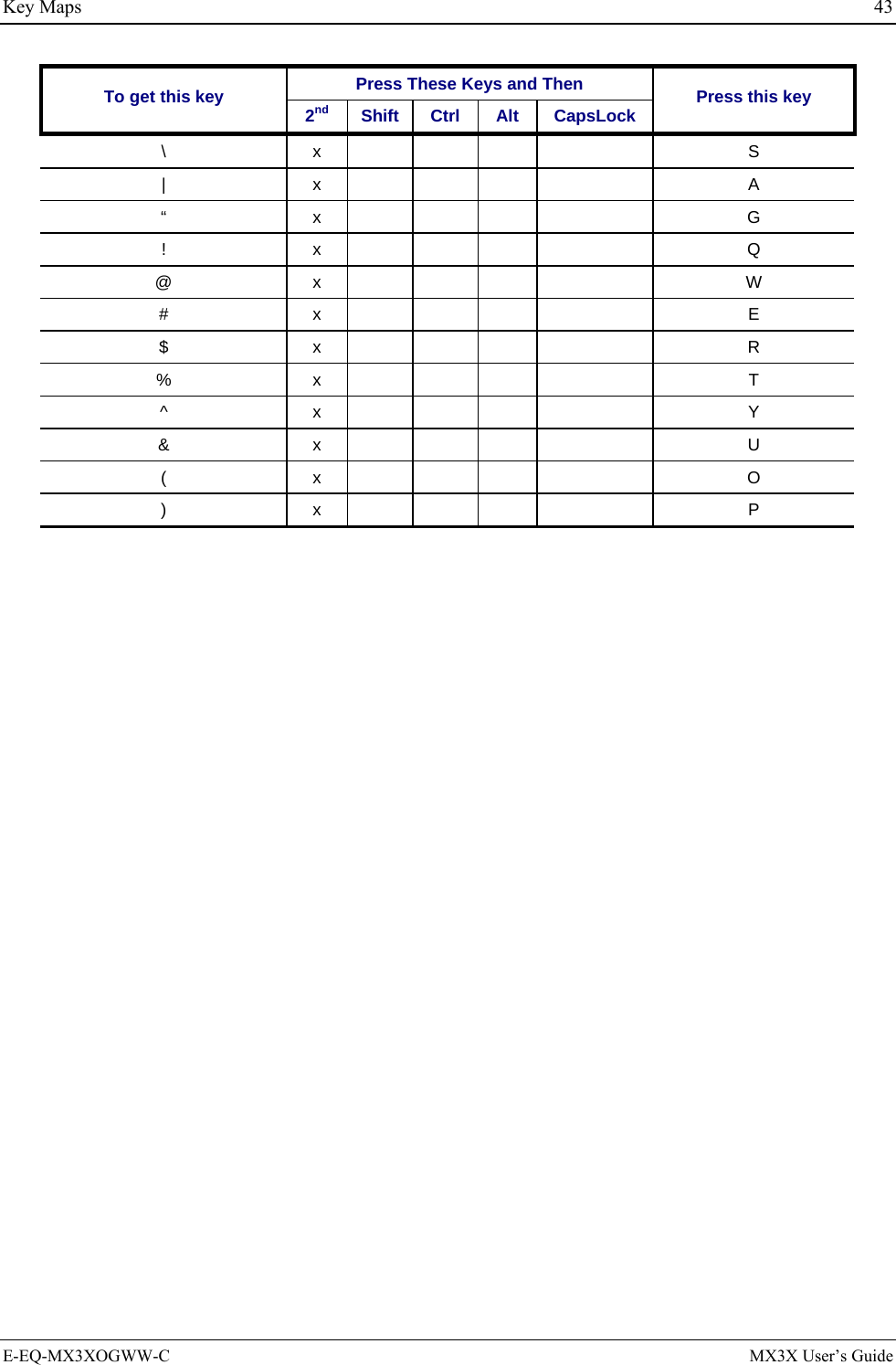
![42 Key Maps Press These Keys and Then To get this key 2nd Shift Ctrl Alt CapsLock Press this key V x V W x W X x X Y x Y Z x Z 1 1 2 2 3 3 4 4 5 5 6 6 7 7 8 8 9 9 0 0 DOT DOT < x 0 [ x 1 ] x 2 > x 3 = x 4 { x 5 } x 6 / x 7 - x 8 + x 9 * x I : (colon) x D ; (semicolon) x F ? x L ` x N _ (underscore) x M , (comma) x J ‘ (apostrophe) x H ~ (tilde) x B MX3X User’s Guide E-EQ-MX3XOGWW-C](https://usermanual.wiki/Honeywell/LXERFID1.user-manual/User-Guide-499953-Page-48.png)
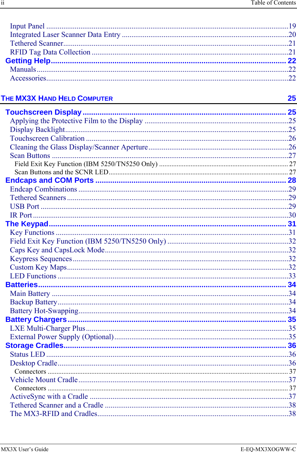
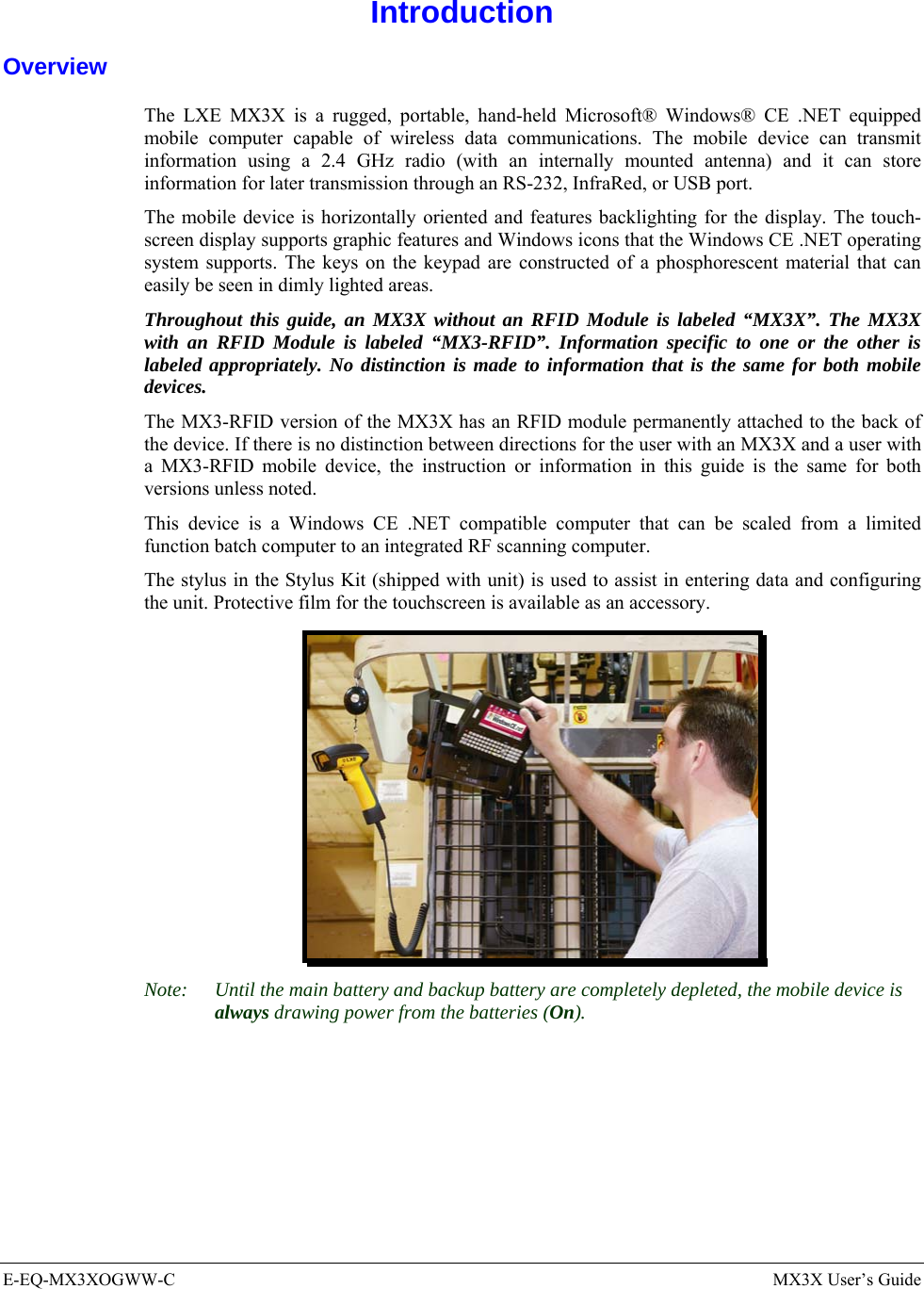
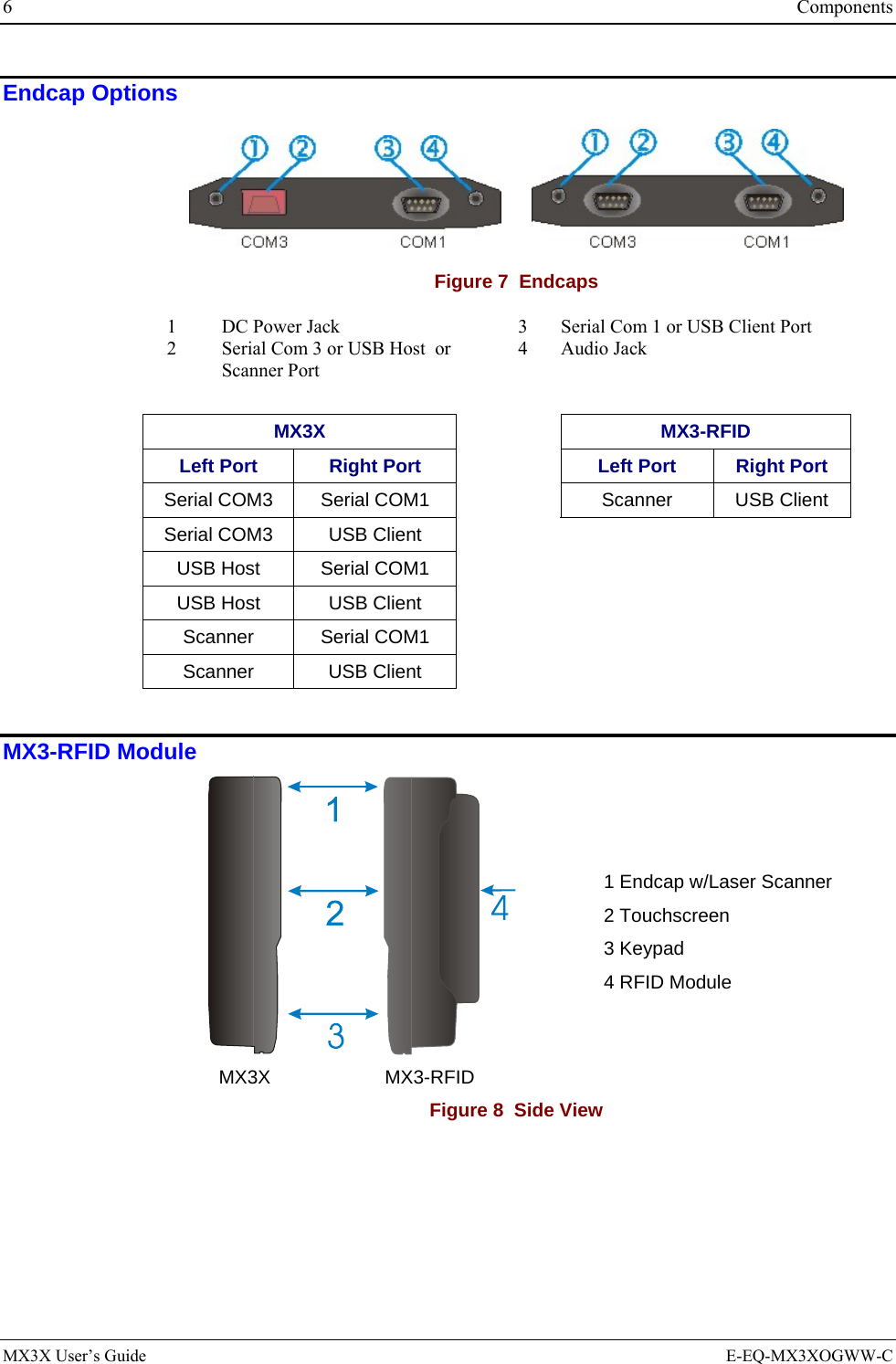
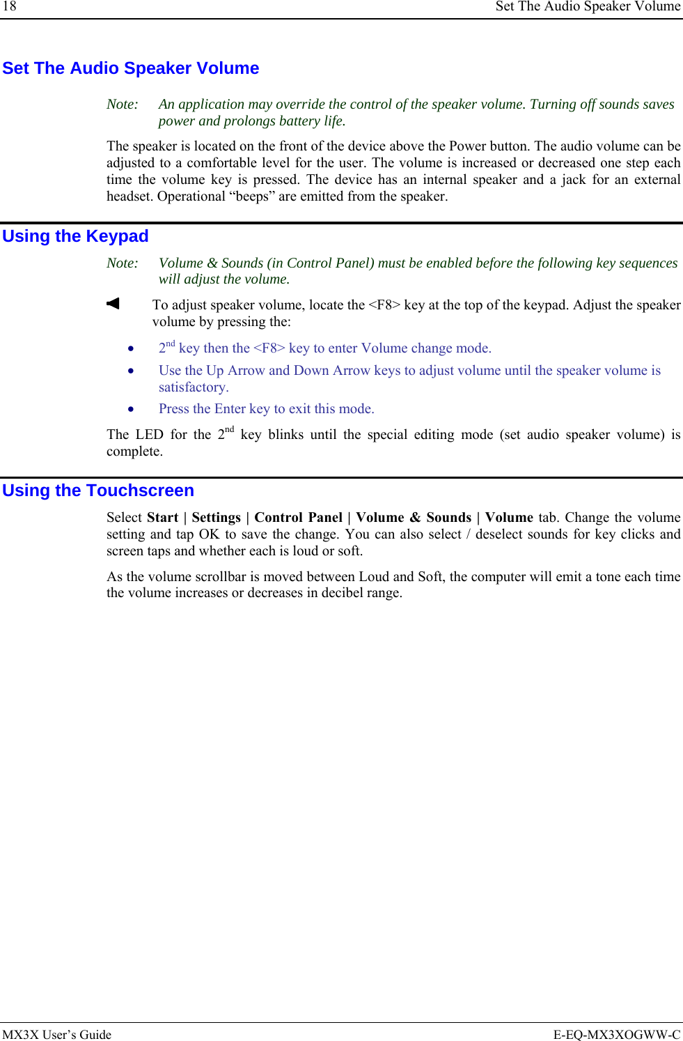
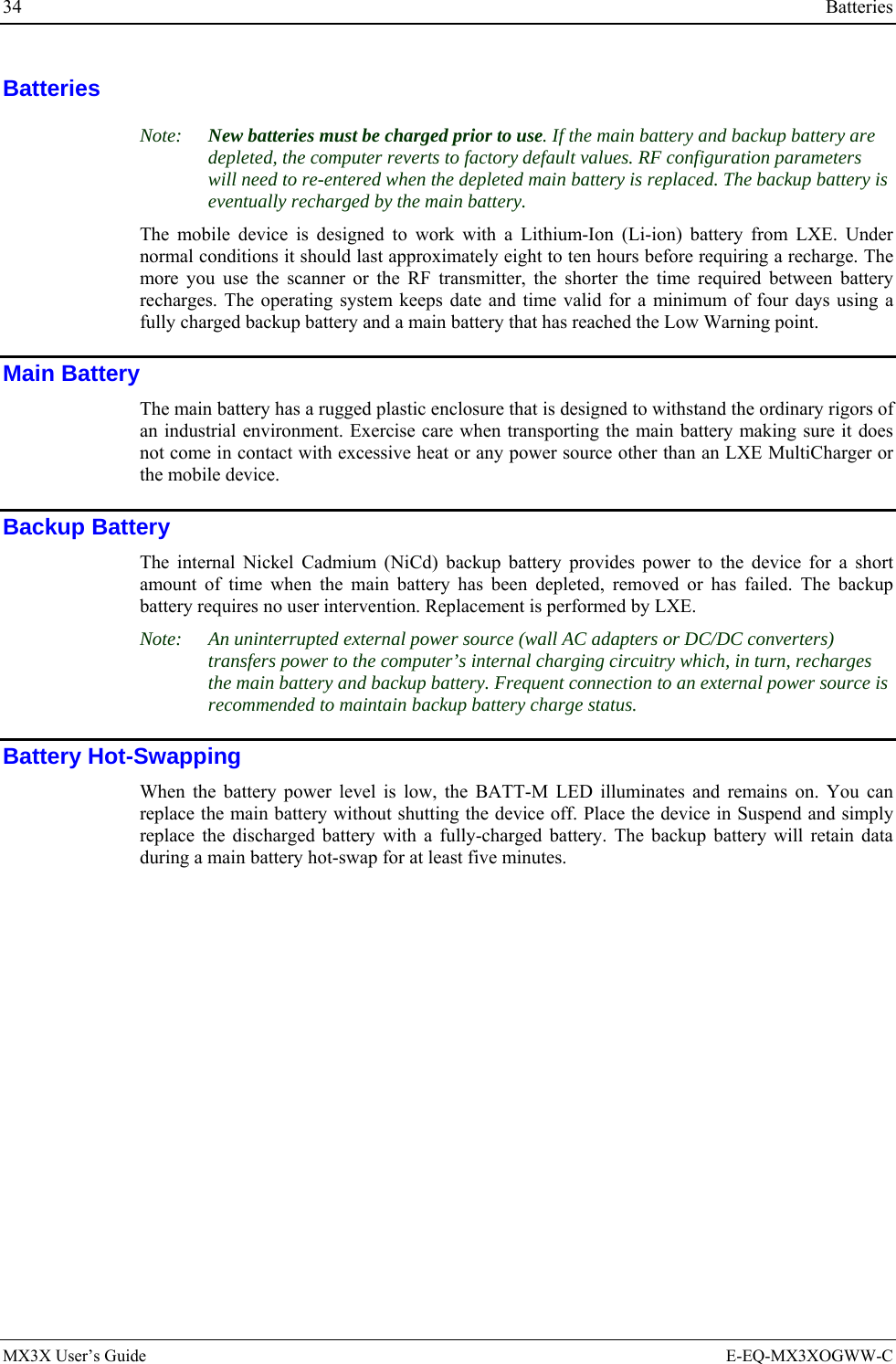
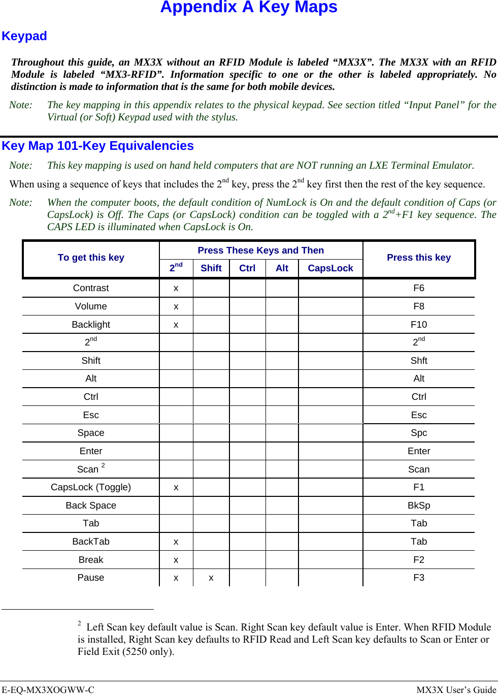
![46 Regulatory Notices and Safety Information R&TTE Directive Requirements (Applies only to equipment operated within the EU/EFTA) Information to User A label on the exterior of the device should resemble one of the labels shown below (the label contains the LXE part number of the installed radio card). The labels shown below and affixed to the device, identify where the device may be used and where its use is restricted. Use of a device is prohibited in countries not listed below or otherwise identified by the label. (May or may not include the 0560 Notifed Body No.) Permitted for use in: Austria, Belgium, Denmark, Finland, Germany, Greece, Iceland, Italy, Ireland, Liechtenstein, Luxembourg, Netherlands, Norway, Portugal, Spain, Sweden, Switzerland, and the United Kingdom Permitted for use in France. MX3X Computer Approvals: Product EMI / EMC Standards Safety Standards MX3X MX3X with RFID Module FCC Part 15 Subpart B, Class A EN 55022:1998 Class A EN 55024:1998 Industry Canada Class A UL 60950; CSA C22.2 No. 60950 CDRH: 21 CFR 1040.10 and 1040.11 EN 60950 IEC 60825-1 IEC 60950 Cradle Approvals: Product EMI / EMC Standards Safety Standards MX3 Table MX3 Vehicle Mount MX3-RFID Passive Vehicle Cradle FCC Part 15 Subpart B, Class A EN 55022:1998 Class A EN 55024:1998 Industry Canada Class A UL 60950; CSA C22.2 No. 60950 EN 60950 IEC 60950 Transceiver: Transceiver RF Standards Notes 6726 (LXE Model No.) [Cisco] FCC Part 15, Subpart C FCC Part 2 EN 300 328 EN 300 826 IC-RSS 139 IC-RSS 102 Unlicensed Operation Unlicensed Operation Requires License for Outdoor Use 6816 (LXE Model No.) [Symbol] 2.4GHz Type II PCMCIA Card FCC Part 15, Subpart C FCC Part 2 EN 300 328 EN 300 826 IC-RSS 139 IC-RSS 102 Unlicensed Operation Unlicensed Operation Requires License for Outdoor Use MX3X User’s Guide E-EQ-MX3XOGWW-C](https://usermanual.wiki/Honeywell/LXERFID1.user-manual/User-Guide-499953-Page-52.png)