Honeywell LXERFID2 RFID Reader User Manual RX2 User s Guide
Honeywell International, Inc. RFID Reader RX2 User s Guide
User Manual

FOR REVIEW ONLY – DO NOT PUBLISH OR DISTRIBUTE
DRAFT 08
RX2 User’s Guide
(Microsoft® Windows® CE .NET Equipped)
Copyright © March 2006 by LXE Inc.
All Rights Reserved
E-EQ-RX2OGWW-A
Preliminary - Draft 08

Language: English
Notices
LXE Inc. reserves the right to make improvements or changes in the products described in this guide at any time
without notice. While reasonable efforts have been made in the preparation of this document to assure its accuracy,
LXE assumes no liability resulting from any errors or omissions in this document, or from the use of the information
contained herein. Further, LXE Incorporated, reserves the right to revise this publication and to make changes to it
from time to time without any obligation to notify any person or organization of such revision or changes.
Copyright:
This manual is copyrighted. All rights are reserved. This document may not, in whole or in part, be copied,
photocopied, reproduced, translated or reduced to any electronic medium or machine-readable form without prior
consent, in writing, from LXE Inc.
Copyright © 2006 by LXE Inc. An EMS Technologies Company.
125 Technology Parkway, Norcross, GA 30092 U.S.A. (770) 447-4224
Trademarks:
LXE® is a registered trademark of LXE Inc. Microsoft, Windows and the Windows logo are registered trademarks
of Microsoft Corporation in the United States and/or other countries. Java and Java-based trademarks and logos are
trademarks or registered trademarks of Sun Microsystems, Inc. in the U.S. or other countries, and are used under
license. All other brand or product names are trademarks or registered trademarks of their respective companies or
organizations. When this guide is in PDF format: “Acrobat ® Reader Copyright © 1987-2006 Adobe Systems
Incorporated. All rights reserved. Adobe, the Adobe logo, Acrobat, and the Acrobat logo are trademarks of Adobe
Systems Incorporated.” applies.
The user is strongly encouraged to read Appendix A, “Regulatory Notices and Safety
Information”. Important safety cautions, warnings and regulatory information is
contained in Appendix A.
Important: This symbol is placed on the product to remind users to dispose of Waste Electrical and Electronic
Equipment (WEEE) appropriately, per Directive 2002-96-EC. In most areas, this product can be recycled,
reclaimed and re-used when properly discarded. Do not discard labeled units with trash. For information about
proper disposal, contact LXE through your local sales representative, or visit www lxe com.
Preliminary - Draft 08

E-EQ-RX2OGWW-A RX2 User’s Guide
Table of Contents
INTRODUCTION 1
Overview.................................................................................................................... 1
Document Conventions ............................................................................................................2
RX2 Environmental Specifications ..........................................................................................2
Battery Charger Environmental Specifications ........................................................................2
Components.............................................................................................................. 3
Quick Start................................................................................................................. 3
RFID Introduction...................................................................................................... 4
RFID Reader Scan Range.........................................................................................................4
RFID Tag Data Collection........................................................................................................4
Getting Help............................................................................................................... 5
Manuals.....................................................................................................................................5
Accessories ...............................................................................................................................5
INSTALLATION 7
Introduction............................................................................................................... 7
Mounting the RX2 .....................................................................................................7
Mounting RX2 Accessories...................................................................................... 8
Bracket for Coupler (Internal Battery and Charger or External Battery).................................8
Bracket for Terminal Block (DC to DC Power Supply)...........................................................8
DC to DC Power Supply...........................................................................................................8
Connect Power Source............................................................................................. 9
Internal Battery Pack (Optional)...............................................................................................9
External Battery Pack .............................................................................................................10
Vehicle 12VDC Power Connection........................................................................................12
DC to DC Power Supply.........................................................................................................14
The RX2 Battery Charger........................................................................................ 15
OPERATION 17
The Power Switch ................................................................................................... 17
The Power LED........................................................................................................ 18
Additional Low Power Warning.............................................................................................18
Tag Orientation and the RX2.................................................................................. 19
Preliminary - Draft 08

ii Table of Contnents
RX2 User’s Guide E-EQ-RX2OGWW-A
APPENDIX A REGULATORY NOTICES AND SAFETY INFORMATION 21
Approvals ................................................................................................................ 22
INDEX 23
Illustrations
Figure 1 RX2 Connector Panel ............................................................................................................................3
Figure 2 RX2 Components ..................................................................................................................................3
Figure 3 RFID Tag Reading Ranges....................................................................................................................4
Figure 4 Mounting Provisions..............................................................................................................................7
Figure 5 Battery Charger and Cable.....................................................................................................................9
Figure 6 External Battery, Connection to RX2..................................................................................................10
Figure 7 External Battery, Connection to Charger.............................................................................................10
Figure 8 Vehicle Power Connection Cable (Fuse Not Shown)..........................................................................12
Figure 9 Connecting the Power Cable to the Vehicle ........................................................................................12
Figure 10 Vehicle Connection Wiring Color Codes ..........................................................................................13
Figure 11 DC to DC Power Supply Cabling......................................................................................................14
Figure 12 RX2 Battery Charger.........................................................................................................................15
Figure 13 RX2 Battery Charger and Internal Battery ........................................................................................15
Figure 14 RX2 Battery Charger and External Battery .......................................................................................15
Figure 15 Power Switch.....................................................................................................................................17
Figure 16 Power LED ........................................................................................................................................18
Figure 17 Tag Rotation, Example 1...................................................................................................................19
Figure 18 Tag Rotation, Example 2...................................................................................................................19
Preliminary - Draft 08
E-EQ-RX2OGWW-A RX2 User’s Guide
Introduction
Overview
The LXE RX2 is a rugged, vehicle mounted Microsoft® Windows® CE .NET equipped mobile
computer capable of wireless data communications and equipped with an RFID module. The
mobile device can transmit information using its 2.4 GHz 802.11 radio with integrated antenna.
The RX2 does not feature a display or keypad. Configuration is performed via the USB port using
Microsoft ActiveSync and other utilities. Please refer to your system administrator for details on
configuration and application operation.
Preliminary - Draft 08
2 Overview
RX2 User’s Guide E-EQ-RX2OGWW-A
Document Conventions
ALL CAPS All caps are used to represent disk directories, file names, and application
names.
Menu | Choice Rather than use the phrase “choose the Save command from the File menu”,
this guide uses the convention “choose File | Save”.
“Quotes” Indicates the title of a book, chapter or a section within a chapter (for
example, “Document Conventions”).
< > Indicates a key on the keypad (for example, <Enter> ).
Indicates a reference to other documentation.
ATTENTION Keyword that indicates vital or pivotal information to follow.
Attention symbol that indicates vital or pivotal information to follow. Also,
when marked on product, means to refer to the user’s guide.
International fuse replacement symbol. When marked on the product, the
label includes fuse ratings in volts (v) and amperes (a) for the product.
Note: Keyword that indicates immediately relevant information.
Caution
Keyword that indicates a potentially hazardous situation which, if not
avoided, may result in minor or moderate injury.
Warning
Keyword that indicates a potentially hazardous situation which, if not
avoided, could result in death or serious injury.
Danger
Keyword that indicates a imminent hazardous situation which, if not
avoided, will result in death or serious injury.
RX2 Environmental Specifications
Operating Temperature -4°F to 122°F (-20°C to 50°C) (non-condensing)
Storage Temperature -22°F to 158°F (-30°C to 70°C) (non-condensing)
Water and Dust IEC IP66
Operating Humidity 5% to 95% non-condensing at 104°F (40°C)
Vibration Based on MIL Std 810F
ESD 8 kV air, 4kV contact
Shock 14G, 10ms, ½ Sine
Battery Charger Environmental Specifications
Operating Temperature 32°F to 104°F (0°C to 40°C) (non-condensing)
Storage Temperature 14°F to 158°F (-10°C to 70°C) (non-condensing)
Operating Humidity 5% to 95% non-condensing
Preliminary - Draft 08
Components 3
E-EQ-RX2OGWW-A RX2 User’s Guid
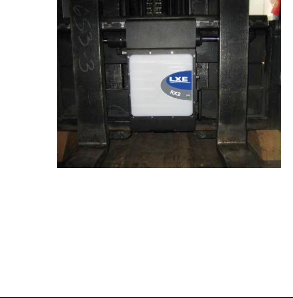
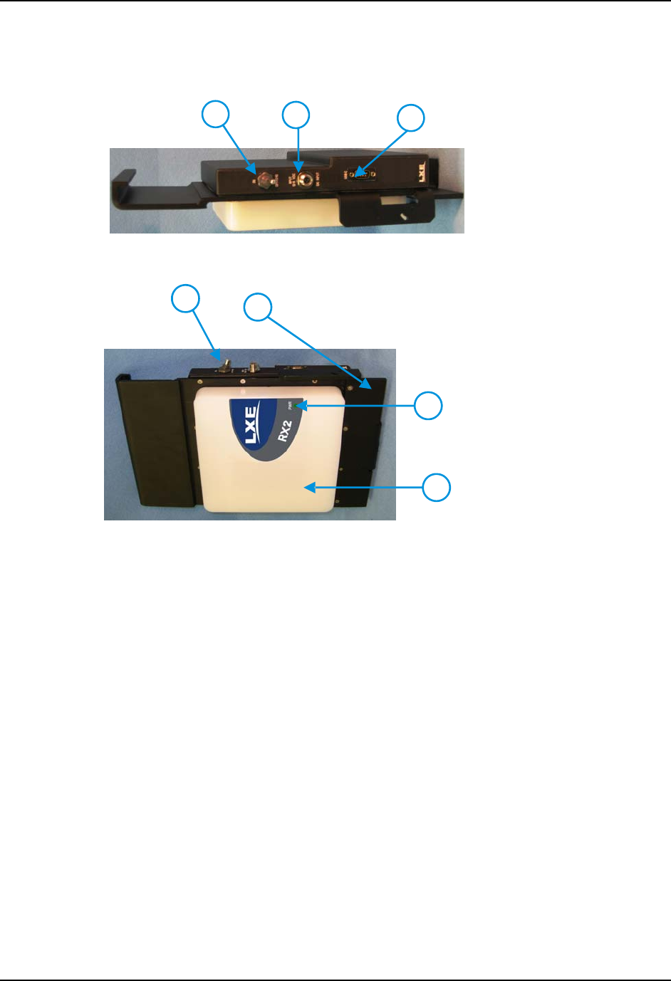
Components
1. Power Switch
2.
Input Power/Battery
Charger Connector
2
13
3. USB Client Connector
Figure 1 RX2 Connector Panel
1. RX2 Computer
2. Fork Truck Mounting
Bracket
3. Power LED
2
1
3
4
4. Antenna Enclosure
Figure 2 RX2 Components
Quick Start
Note: The RX2 is assembled with an optional internal battery pack (if ordered) and radio card
installed before shipment.
This section’s instructions are based on the assumption that your new system is pre-configured
and requires only a power source.
In general, the sequence of events is:
1. Provide a power source for the RX2:
• Connect a fully charged external battery pack.
-or-
• Connect an external power source to the unit (if required).
-or-
• Use the optional internal battery pack (the internal battery pack, if ordered, must be
fully charged before use).
2. Flip the power switch to On.
Note: Do not connect a tethered scanner cable to a USB-C labeled port. This port cannot
power a tethered scanner.
Preliminary - Draft 08

4 RFID Introduction
RX2 User’s Guide E-EQ-RX2OGWW-A
RFID Introduction
Radio frequency identification, or RFID, is a generic term for technologies that use radio waves to
automatically identify individual items. The individual items identified/read by a RFID reader
contain a tag (also known as an electronic label or transponder). Unlike barcodes that must be read
by a beam passing over the barcode, RFID tags do not have to be in the line of sight of the reader
before the reader can collect the data from the tag but they do need to be within the established
reading range of the RFID-module.
See the “RX2 Reference Guide” for further information and configuration.
RFID Reader Scan Range
Type of Tag Scan Range
Class 0 Tag 9.8 feet / 3.0 meters
Class 1 Tag 9.8 feet / 3.0 meters
Gen2 Tag 9.8 feet / 3.0 meters
Figure 3 RFID Tag Reading Ranges
Unlike barcode scanners that require line-of-sight before successfully reading a barcode, the RFID
reader does not require line-of-sight when searching for and reading tags.
The range of the RFID reader is dependent on many outside influences including the tag
construction and orientation.
RFID Tag Data Collection
Generally, when the RX2 is powered on, the RFID reader is ready for use.
• While the RX2 is booting, the Power LED is lit solid. The RFID reader is not
available until the Power LED beings flashing and all drivers have finished loading.
• Please consult your system administrator for application details. Although the reader
is ready for use, the application may not yet have enabled the reader.
• If the battery charger is connected to the RX2, the RX2 remains Off, even if the
power switch is in the On position.
The reader supports Class 0 (read only) and Class 1 (read and write) tags as well as Class 1 Gen2
(read and write) tags.
The RFID information is relayed to the network via the 802.11 radio in the RX2. Data
transmission is application specific. Please refer to your system administrator for details.
Preliminary - Draft 08

Getting Help 5
E-EQ-RX2OGWW-A RX2 User’s Guid
Getting Help
All LXE user guides are now available on one CD and they can also be viewed/downloaded from
the LXE ServicePass website. Contact your LXE representative to obtain the LXE Manuals CD.
You can also get help from LXE by calling the telephone numbers listed on the LXE Manuals CD,
in the file titled “Contacting LXE”. This information is also available on the LXE website
www.lxe.com.
Explanations of terms and acronyms used in this guide are located in the file titled “LXE
Technical Glossary” on the LXE Manuals CD.
Manuals
RX2 Reference Guide
Accessories
Data Cables
Cable, USB Host D9F to USB, 6’ MX3XA069CBL09USBCLNT
DC Power Accessories
DC Adapter Cable, 12V, with Bracket RX2A052CBLDCPWR
DC to DC Power Supply, 24-60VDC to 12V 9000A316PS24V72VBARE
Battery Chargers and Battery
Battery Charger US, with Connector Cables RX2A381CHGRUS
Cable, Adapter, RX2 to Charger, with Bracket RX2A051CBLRMT
Battery, External RX2A381BATT4AHEXT
Brackets
External Battery Mounting bracket ???
Preliminary - Draft 08

6 Getting Help
RX2 User’s Guide E-EQ-RX2OGWW-A
Preliminary - Draft 08
E-EQ-RX2OGWW-A RX2 User’s Guide
Installation
Introduction
The general installation procedure consists of
1. Mounting the RX2 and any accessories to the forklift truck.
2. Providing a power source to the RX2:
• Use the optional internal battery after it is charged with the RX2 Battery
Charger
• Use an external battery pack after it is charged with the RX2 Battery
Charger
• Use a direct connection to 12V DC vehicles
• Use a DC to DC converter for 24 – 60 VDC vehicles
Please read Appendix A, “Regulatory Notices and Safety Information” before installation.
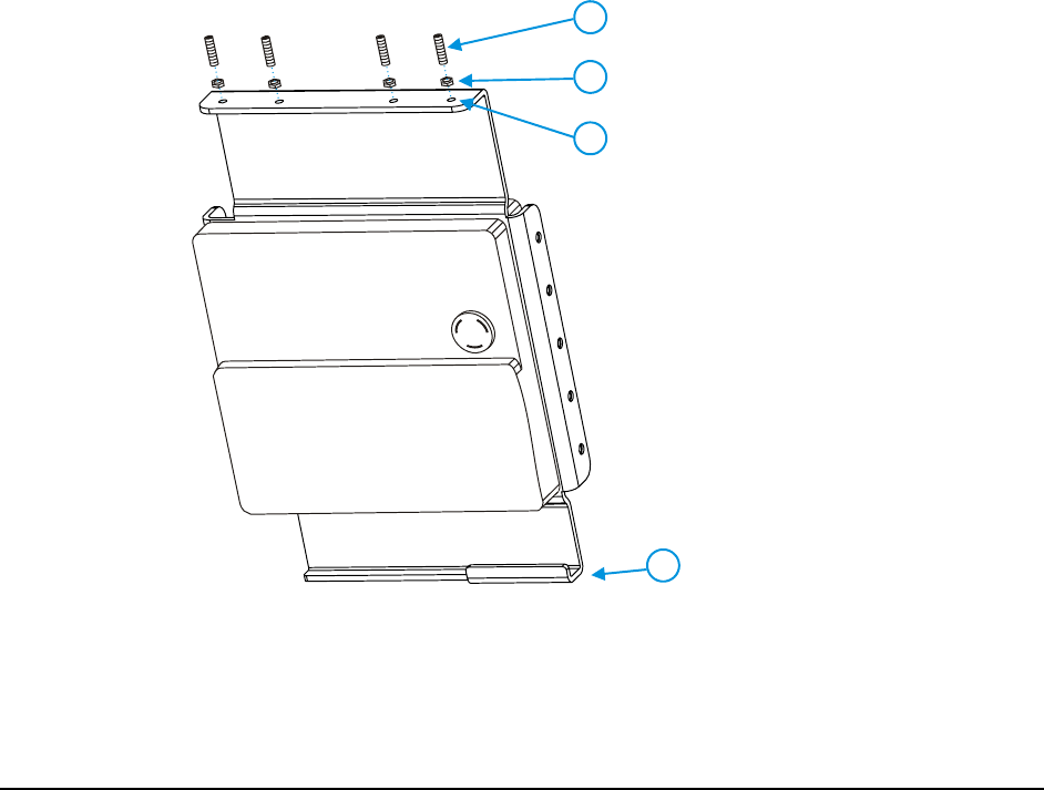
Mounting the RX2
2
3
4
1
1.
2.
3.
4.
Set Screws (4 each)
Lock Nuts (4 each)
Set Screw Holes (4)
Hook
Figure 4 Mounting Provisions
To install the RX2:
Preliminary - Draft 08

8 Mounting RX2 Accessories
RX2 User’s Guide E-EQ-RX2OGWW-A
1. Install the bracket by placing the hook (at the bottom of the bracket) over the lip of a Cascade
E or F series side shifter.
2. Slide the RX2 over to the desired position.
3. Secure with (4) 1/4-20 set screws in the threaded holes on the top surface of the bracket.
Thread a lock nut onto each set screw. Using an Allen wrench, tighten all four set screws to
an equal depth, but do not tighten the locking nuts yet.
4. After all set screws have been tightened, recheck and retighten all screws. Tighten the
locking nut while holding the set screw tight with an Allen wrench.
Mounting RX2 Accessories
Bracket for Coupler (Internal Battery and Charger or External Battery)
??
Bracket for Terminal Block (DC to DC Power Supply)
??
DC to DC Power Supply
??
Preliminary - Draft 08
Connect Power Source 9
E-EQ-RX2OGWW-A RX2 User’s Guid
Connect Power Source
A power source must be connected to the RX2 before it can be used.
Please refer to the following sections to determine the desired method to power the RX2.
Internal Battery Pack (Optional)
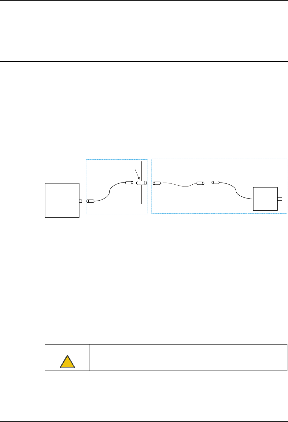
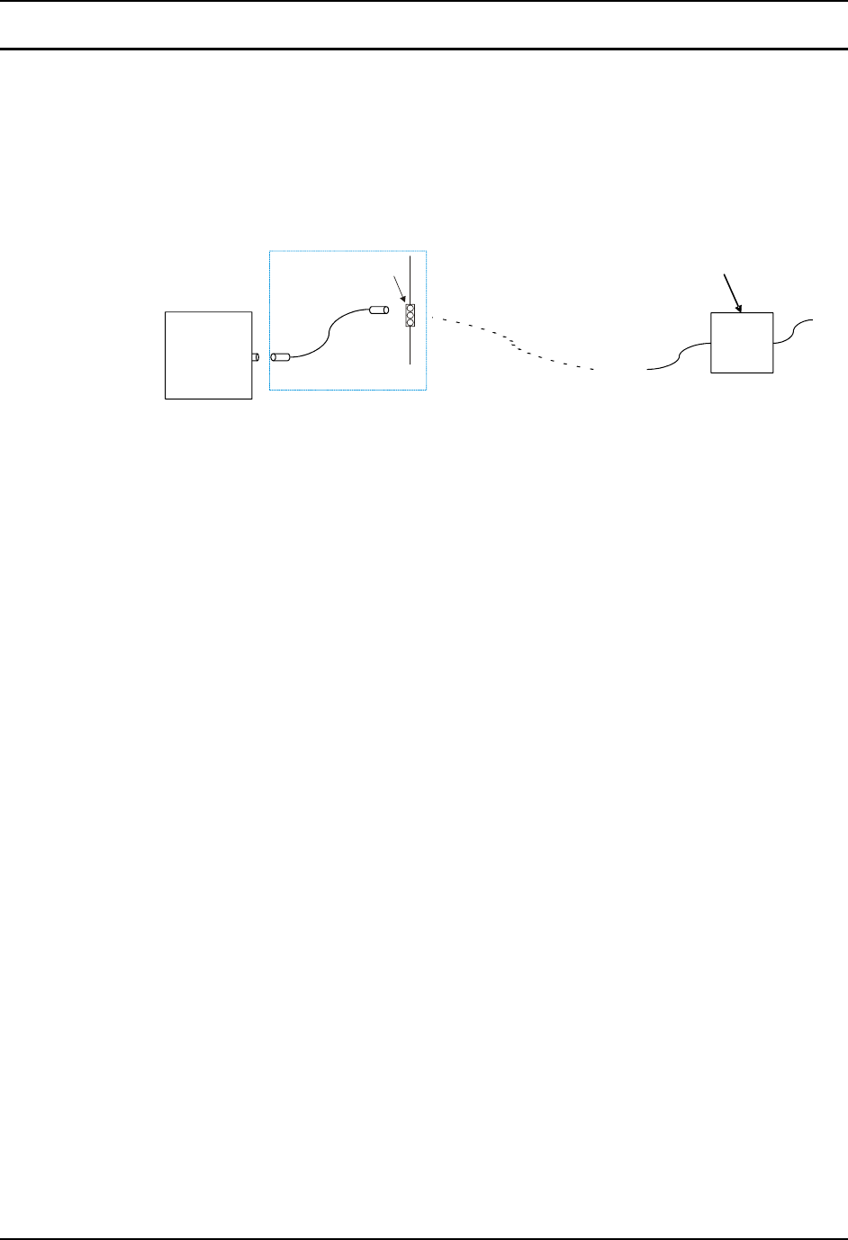
The RX2 is available with an optional internal battery pack.
Use the battery charger to charge the RX2’s internal battery. The RX2 battery charger charges the
RX2 battery pack in less than 6 hours. It is recommended the internal battery pack be fully
charged before installing the RX2.
The battery charger uses an adapter cable. One end of the cable has a “break away” connection to
reduce the chance of damage if the forklift is moved before the battery charger is disconnected.
The other end of the cable attaches to the coupler on the forklift.
The coupler is mounted on a bracket. The coupler is connected via a cable to the RX2.
RX2
RX2A051CBLRMT
AC
Charger
RX2A381CHGRUS
Bracket
Coupler
Breakaway
Connection
Figure 5 Battery Charger and Cable
Once fully charged, the internal RX2 battery pack powers the RX2 for nine hours.
The RX2 provides a low battery warning as follows:
• The power LED flashes red (or is solid red while the RX2 is booting)
• The low battery buzzer sounds
• A low battery signal can be sent via the radio card to the network host (please refer
to your system administrator for details).
When the low battery warning is displayed, there is approximately 30 minutes of power left in the
battery. If the battery is not recharged before it is depleted, the RX2 automatically shuts down.
The RFID reader remains functional until the battery can no longer power the RX2.
If time does not permit the recharging of the internal battery pack, an external battery pack may be
connected as detailed later in this chapter.
Caution:
!
To prevent damage to the RX2, the cables or the battery charger, make sure
the charger is disconnected before moving the forklift truck.
Preliminary - Draft 08
10 Connect Power Source
RX2 User’s Guide E-EQ-RX2OGWW-A
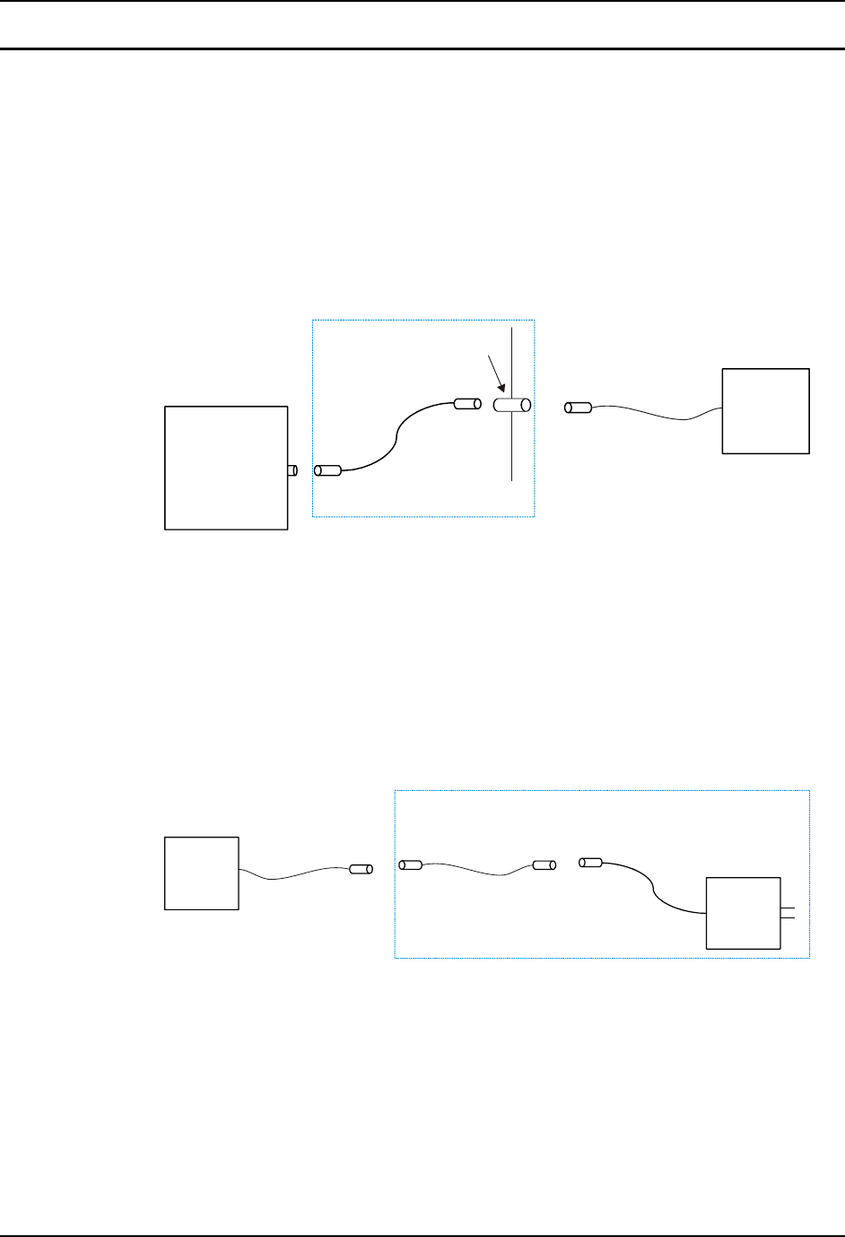
External Battery Pack
The external battery pack may be used when the optional internal battery pack was not ordered or
there is not time to permit a recharge of the optional internal RX2 battery pack.
The external battery pack mounts to the fork truck via a battery bracket and is connected to the
RX2 with cables. The cable on the external battery connects to the coupler.
The coupler is mounted on a bracket. The coupler is connected via a cable to the RX2.
The external battery pack is designed to be mounted on the same side of the fork truck as the
truck’s main battery for ease of service.
RX2
RX2A051CBLRMT
Bracket
Coupler
External
Battery
Figure 6 External Battery, Connection to RX2
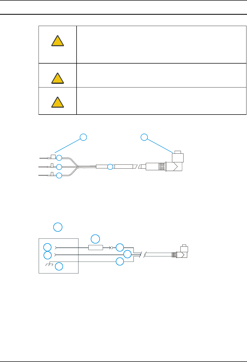
Use the battery charger to charge the external battery pack. The RX2 battery charger charges the
battery pack in less than 6 hours.
The battery charger uses an adapter cable. One end of the cable has a “break away” connection to
reduce the chance of damage if the forklift is moved before the battery charger is disconnected.
The other end of the cable attaches to the external battery.
To use the charger, connect the adapter cable to the external battery.
AC
Charger
RX2A381CHGRUS
Breakaway
Connection
External
Battery
Figure 7 External Battery, Connection to Charger
Once fully charged, the external battery pack powers the RX2 for nine hours.
The RX2 provides a low battery warning as follows:
• The power LED flashes red (or is solid red while the RX2 is booting)
• The low battery buzzer sounds
• A low battery signal can be sent via the radio card to the network host (please refer
to your system administrator for details).
Preliminary - Draft 08

Connect Power Source 11
E-EQ-RX2OGWW-A RX2 User’s Guid
When the low battery warning is displayed, there is approximately 30 minutes of power left in the
battery. If the battery is not recharged or replaced before it is depleted, the RX2 automatically
shuts down.
The RX2 internal battery pack does not charge from the external battery pack.
Caution:
!
To prevent damage to the RX2, the cables or the battery charger, make sure
the charger is disconnected before moving the forklift truck.
Preliminary - Draft 08
12 Connect Power Source
RX2 User’s Guide E-EQ-RX2OGWW-A
Vehicle 12VDC Power Connection
Caution:
!
For proper and safe installation, the input power cable must be connected to
a fused circuit on the vehicle. This fused circuit requires a 2 Amp maximum
time delay (slow blow) high interrupting rating fuse. If the supply connection
is made directly to the battery, the fuse should be installed in the positive lead
within 5 inches of the battery positive (+) terminal.
Caution:
!
For installation by trained service personnel only.
Warning:
!
Risk of ignition or explosion. Explosive gas mixture may be vented from
battery. Work only in well ventilated area. Avoid creating arcs and sparks at
battery terminals.
GND
+
-
3
4
5
6
1 2
1. To Terminal Block
or Vehicle Battery
2. To RX2
3. Gray (GND)
4. Brown (DC+)
5. Black (DC-)
6. 12 VDC
Figure 8 Vehicle Power Connection Cable (Fuse Not Shown)
5
4
3
2
1
6
7
8
1. Vehicle Electrical
System
2. 2 Amp Slow
Blow Fuse
3. DC +
4. DC -
5. Vehicle Chassis
6. Brown
7. Black
8. Gray
Figure 9 Connecting the Power Cable to the Vehicle
Note: Correct electrical polarity is required for safe and proper installation. Connecting the
cable to the RX2 with the polarity reversed will cause the power cable’s fuse to be blown.
See the following figure titled “Vehicle Connection Wiring Color Codes” for additional
wire color-coding specifics.
Preliminary - Draft 08

Connect Power Source 13
E-EQ-RX2OGWW-A RX2 User’s Guid
How To: Connect Vehicle 12VDC Connection
1. The RX2 must be turned off and the power cable must be UNPLUGGED from the
RX2.
2. While observing the fuse requirements specified above, connect the power cable to the
terminal block or as close as possible to the actual battery terminals of the vehicle.
When available, always connect to unswitched terminals in vehicle fuse panel, after
providing proper fusing.
ATTENTION: For uninterrupted power, electrical supply connections should not
be made at any point after the ignition switch of the vehicle.
3. Route the power cable the shortest way possible. The cable is rated for a maximum
temperature of 105°C (221°F). When routing this cable it should be protected from
physical damage and from surfaces that might exceed this temperature.
Do not expose the cable to chemicals or oil that may cause the wiring insulation to
deteriorate.
Note: If the vehicle is equipped with a panel containing Silicon Controller Rectifiers
(SCR’s), avoid routing the power cable in close proximity to these devices.
Always route the cable so that it does not interfere with safe operation and maintenance
of the vehicle.
Use proper electrical and mechanical fastening means for terminating the cable.
Properly sized “crimp” type electrical terminals are an accepted method of termination.
Please select electrical connectors sized for use with 18AWG (1mm2) conductors.
(Connectors already installed?).
Wiring color codes for LXE supplied DC input power cabling:
Vehicle Supply Wire Color
+12 VDC (DC +) Brown
Return (DC -) Black
Vehicle Chassis GND Gray
Figure 10 Vehicle Connection Wiring Color Codes
4. Provide mechanical support for the cable by securing it to the vehicle structure at
approximately one foot intervals, taking care not to over tighten and pinch conductors
or penetrate outer cable jacket.
Preliminary - Draft 08
14 Connect Power Source
RX2 User’s Guide E-EQ-RX2OGWW-A
DC to DC Power Supply
If the vehicle does not provide 12V DC power, the DC to DC converter may be used. The DC to
DC converter accepts 24 – 60VDC input power and provides 12VDC output power.
The DC to DC power supply is designed to be mounted in the forklift cab. Customer supplied
wiring connects the DC to DC power supply (over the forklift mast) to the terminal block mounted
on the bracket. The cable from the terminal block connects to the RX2.
DC-DC
Power
Term
Block
9000A316PS24V72VBARE
RX2
RX2A051CBLRMT
Bracket
Terminal
Block
DC Power
over
Forklift Mast
Figure 11 DC to DC Power Supply Cabling
A power filter may be required when vehicles have unclean forklift power in which power spikes
cause problems with the RX2.
Preliminary - Draft 08
The RX2 Battery Charger 15
E-EQ-RX2OGWW-A RX2 User’s Guid
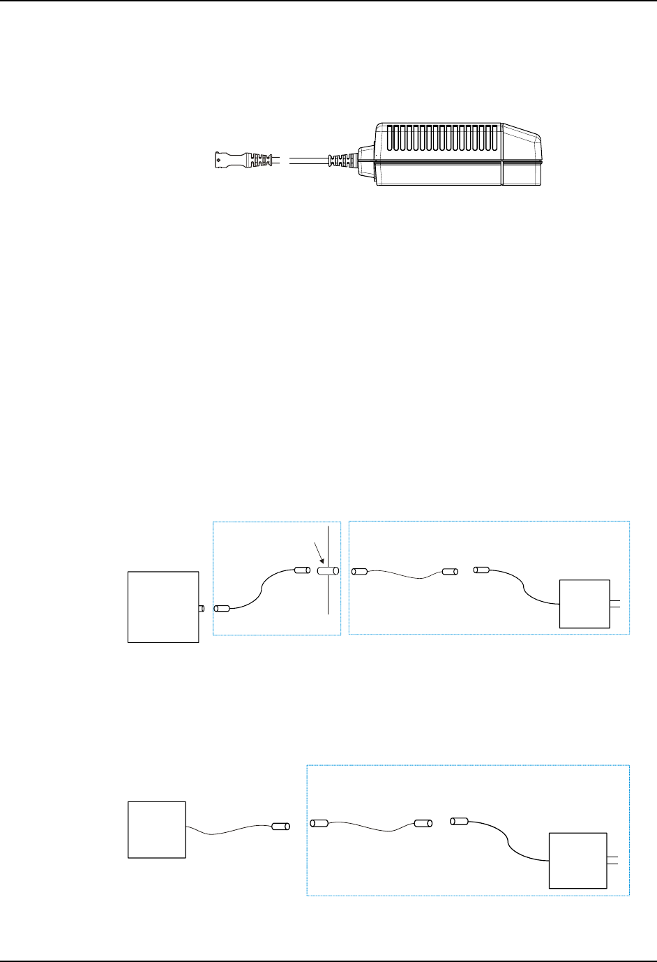
The RX2 Battery Charger
The RX2 battery charger accepts AC power input.
Figure 12 RX2 Battery Charger
The charger can be used to charger either an internal RX2 battery pack or the external battery
pack. Either type of battery pack recharges in less than six hours. The battery changer can operate
in environments from 32°F to 104°F (0°C to 40°C).
The charger has a red LED that indicates the status of the charger:
• Rapid flashing – The charger is in deep discharge mode.
• Solid – The charger is in Rapid Charge mode.
• Slowly flashing – The battery is charged and ready for use. The charger provides a
trickle charge to keep the battery at full charge.
The type of cable required for using the battery charger depends on the type of battery being
charged:
• Charger adapter cable – This is a shorter cable that provides easy access to charge
the RX2. The cable features a loop
RX2
RX2A051CBLRMT
AC
Charger
RX2A381CHGRUS
Bracket
Coupler
Breakaway
Connection
Figure 13 RX2 Battery Charger and Internal Battery
• External battery to charger adapter cable – This cable connects the charger to the
external battery.
AC
Charger
RX2A381CHGRUS
Breakaway
Connection
External
Battery
Figure 14 RX2 Battery Charger and External Battery
Preliminary - Draft 08

16 The RX2 Battery Charger
RX2 User’s Guide E-EQ-RX2OGWW-A
Preliminary - Draft 08

E-EQ-RX2OGWW-A RX2 User’s Guide
Operation
The Power Switch
The power switch is a toggle switch located on the connector panel side of the RX2.
Figure 15 Power Switch
When the switch is set to On:
• The CPU is on and the RX2 functions normally if power is present and the battery
charger is not attached.
• The CPU remains Off if the battery charger is attached, even if the power switch is
flipped to On. This allows the optional internal battery to charge.
• If the RX2 is On, the RX2 automatically powers down when the battery charger is
attached. This allows the optional internal battery to charge. If the charger is
disconnected and the switch remains in the On position, the RX2 boots up.
When the switch is set to Off:
• If the battery charger is connected, the battery recharges.
• If DC power is connected, the battery DOES NOT charge.
• If neither the battery charger nor DC power is connected, the RX2 is off.
When the power switch is flipped to On and a power source is present:
• The LED lights solid green (or solid red if battery power is low) while booting
• When the RX2 has finished booting, the LED flashes green (or red if battery power
is low). The RX2 is ready for use after a slight delay while drivers and applications
load. Consult your system administrator for more information.
• If the battery charger is connected, the RX2 remains Off, even if the power switch is
flipped to On.
Preliminary - Draft 08

18 The Power LED
RX2 User’s Guide E-EQ-RX2OGWW-A
The Power LED
The RX2 has a power status LED on the font of the antenna enclosure.
Figure 16 Power LED
The LED indicates the status of the RX2:
Off Indicates the RX2 is switched off or no power is applied to the RX2.
The LED is off when the battery charger is attached to the RX2.
Solid Green Indicates the RX2 is booting and battery power is good (or DC power
is attached).
Solid Red Indicates the RX2 is booting and battery power is low.
Flashing Green Indicates the RX2 has finished booting and is ready for use. Battery
power is good (or DC power is attached).
Flashing Red Indicates the RX2 has finished booting and is ready for use. Battery
power is low.
When the power LED switches from green to red, this indicates approximately 30 minutes of
battery power remains in the battery pack (either internal or external).
Before the 30 minutes expire, action should be taken:
• The RX2 battery charger can be used to charger either the internal or external battery
pack. The RX2 cannot be used while the battery is charging.
• A fresh external battery pack can be used to replace a depleted external battery pack
or to supplement an internal battery pack when charging time cannot be allotted.
Additional Low Power Warning
In addition to the LED turning red, other indications of a low battery may be present depending on
your configuration:
• A low battery buzzer may sound (N/A on early units).
• The network host may be configured to monitor for RX2 units with a low battery.
Please consult your system administrator for details.
Preliminary - Draft 08

Tag Orientation and the RX2 19
E-EQ-RX2OGWW-A RX2 User’s Guid
Tag Orientation and the RX2
The RX2 contains an RHCP (right had circularly polarized) antenna.
Tags orientation by rotation on the “Z” axis does not decrease the range of the RX2’s RFID
reader.
Figure 17 Tag Rotation, Example 1
However, changing tag orientation by rotating on the “X” axis or “Y” axis can reduce the range of
the RX2’s RFID reader.
Figure 18 Tag Rotation, Example 2
If you have any questions about tag orientation and its effect on the RX2’s range in your
warehouse, please consult your system administrator.
Preliminary - Draft 08

20 Tag Orientation and the RX2
RX2 User’s Guide E-EQ-RX2OGWW-A
Preliminary - Draft 08
E-EQ-RX2OGWW-A RX2 User’s Guide
Appendix A Regulatory Notices and Safety Information
FCC Information:
This device complies with FCC Rules, part 15. Operation is subject to the following conditions:
1. This device may not cause harmful interference
and
2. This device must accept any interference that may be received, including interference that may cause
undesired operation.
Note: This equipment has been tested and found to comply with the limits for a Class A digital device, pursuant to
part 15 of the FCC rules. These limits are designed to provide reasonable protection against harmful interference
when the equipment is operated in a commercial environment. This equipment generates, uses, and can radiate radio
frequency energy and, if not installed and used in accordance with the instruction guide, may cause harmful
interference to radio communications. Operation of this equipment in a residential area is likely to cause harmful
interference in which case the user will be required to correct the interference at his own expense.
Warning: Changes or modifications to this device not expressly approved by LXE, Inc., could void the user’s
authority to operate this equipment.
Industry Canada:
This Class A digital apparatus meets all requirements of the Canadian Interference Causing Equipment Regulations.
Operation is subject to the following two conditions: (1) this device may not cause harmful interference, and (2) this
device must accept any interference received, including interference that may cause undesired operation.
Cet appareil numérique de la classe A respecte toutes les exigences du Règlement sur le matériel brouiller du
Canada. Le present appareil numérique n’emet pas de bruits radioélectriques dépassant les limites applicables aux
appareils numeriques de le Classe A préscrites dans le Reglement sur le brouillage radioélectrique édits par le
ministere des Communications du Canada.
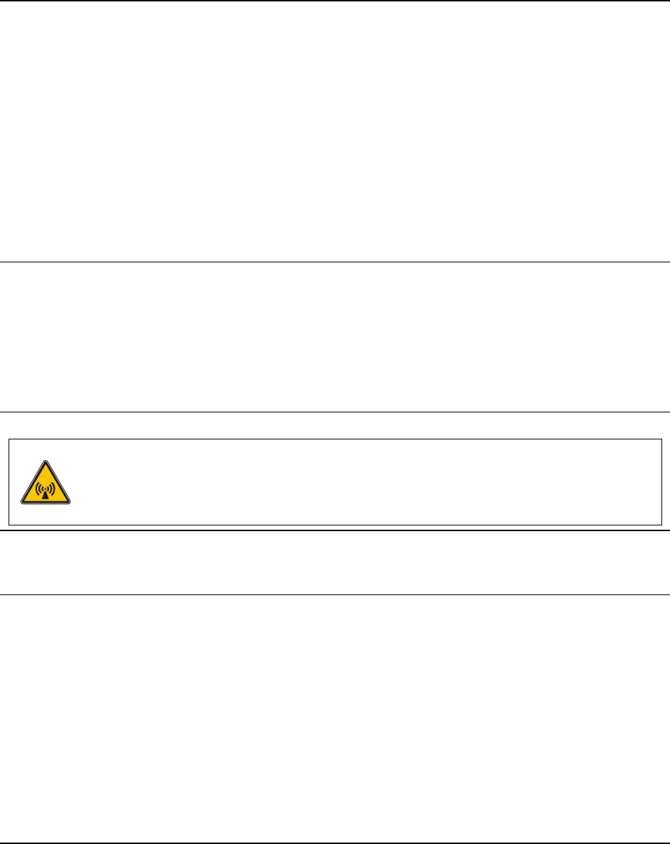
RF Safety Notice
Caution
This device is intended to transmit RF energy. For protection against excessive RF exposure to
humans and in accordance with FCC and Industry Canada rules, this transmitter should be
installed such that a minimum separation distance of at least 25cm (9.8 in.) is maintained
between the antenna and the general population. This device is not to be co-located with other
transmitters.
Notice:
The long term characteristics or the possible physiological effects of radio frequency electromagnetic fields have not
been investigated by UL.
Antenna Description:
The antenna approved to operate with the RX2 Vehicle Mount Computer is a Right Hand, Circularly Polarized
(RHCP) single-patch with 5dbi linear gain.
Preliminary - Draft 08
22 Approvals
RX2 User’s Guide E-EQ-RX2OGWW-A
Approvals
Product EMI / EMC Standards
RX2 FCC Part 15 Subpart B, Class A
Industry Canada Class A
Transceiver:
Transceiver RF Standards Notes
FCC Part 15, Subpart C
FCC Part 2 Unlicensed Operation
IC-RSS 210 Requires License for Outdoor Use
6726 (LXE Model No.) [Cisco]
IC-RSS 102
Important: This symbol is placed on the product to remind users to dispose of Waste Electrical and Electronic
Equipment (WEEE) appropriately, per Directive 2002-96-EC. In most areas, this product can be recycled,
reclaimed and re-used when properly discarded. Do not discard labeled units with trash. For information about
proper disposal, contact LXE through your local sales representative, or visit www lxe com.
!
Vehicle Power Supply Connection Safety Statement
!
Vehicle Power Supply Connection:
If the supply connection is made directly to the battery, a 2A slow-blow fuse should be installed in the positive lead
within 5 inches (12.7 cm.) of the battery positive (+) terminal. (US)
Legend: English – US
Updated 02/10/2004
Preliminary - Draft 08

E-EQ-RX2OGWW-A RX2 User’s Guide
Index
C
Color Codes, Wiring................................................13
E
Environmental Specifications....................................2
F
Features .....................................................................1
G
Getting Started...........................................................3
H
How To
Connect 12-60VDC Vehicle Power....................13
I
Input Cable, Max Temp rating.................................13
M
Manuals .....................................................................5
O
Operating Temperature..............................................2
P
Polarity ....................................................................13
Q
Quick Start Instructions.............................................3
R
Radio frequency identification (RFID)......................4
Regulatory Notices ..................................................18
RFID tags...................................................................4
S
Safety Information...................................................18
Scan Ranges
RFID .....................................................................4
Silicon Controller Rectifiers (SCR's).......................13
Sizing of electrical connectors for use with 18AWG
conductors............................................................13
Specifications
Environmental.......................................................2
W
Wiring Color Codes.................................................13
Preliminary - Draft 08

24 Index
RX2 User’s Guide E-EQ-RX2OGWW-A
Preliminary - Draft 08